Embed Size (px)
Citation preview
Servo motorsAsynchronous servo motor MQA
Project planning EN

ContentsAbout this document 5
Document description 5Further documents 5
Notations and conventions 6
Product information 7Product description 7Identification of the products 7Features 8The modular system 9
Information on project planning 10Safety instructions 11
Basic safety instructions 11Application as directed 11Foreseeable misuse 11Residual hazards 12
Drive dimensioning 13Final configuration 17
Environmental conditions 17
Information on mechanical installation 18Important notes 18Transport 18Installation 18
Information on electrical installation 19Important notes 19Preparation 19
Technical data 20Notes regarding the given data 20Standards and operating conditions 21
Conformities/approvals 21Protection of persons and device protection 21EMC data 21Environmental conditions 21
Radial forces and axial forces 22Rated data 24
Inverter mains connection 400 V, Forced ventilated 24Selection tables 26Torque characteristics 31Dimensions 36
Basic dimensions 36Additional lengths 45
Weights 46Additional weights 46
Contents
3
Product extensions 47Motor connection 47
Connection via terminal box 47Connection via ICN connector 49
Brakes 51Spring-applied brakes 53
Feedback 55Resolver 56Incremental encoder 57Absolute value encoder 57
Blower 58Temperature monitoring 59
Thermal detectors PT1000 59
Product codes 60Appendix 61
Good to know 61Approvals/directives 61Operating modes of the motor 62Enclosures 63
Contents
4
About this document
Document descriptionThis document addresses to all persons who want to carry out any configurations with theproducts described.The data and information compiled in this document serve to support you in the dimensioningand selection processes and in carrying out the electrical and mechanical installation. You willreceive information regarding product extensions and accessories.• The document includes safety instructions which must be observed.• All persons working on and with the drives must have the documentation at hand during
work and observe the information and notes relevant for it.• The documentation must always be complete and in a perfectly readable state.
NOTICEPlease observe the notes in the following chapters! Safety instructions ^ 11
Information on mechanical installation ^ 18
Information on electrical installation ^ 19
Further documents
Information and tools with regard to the Lenze products can be found on theInternet: http://www.lenze.com à Download
About this documentDocument description
Further documents
5
Notations and conventionsThis document uses the following conventions to distinguish different types of information:Numeric notation Decimal separator Point The decimal point is always used.
Example: 1 234.56Warning UL warning UL Are used in English and French. UR warning URText Engineering tools » « Software
Example: »Engineer«, »EASY Starter«Icons Page reference ¶ Reference to another page with additional information
Example: ¶ 16 = see page 16 Documentation reference , Reference to another documentation with additional information
Example: , EDKxxx = see documentation EDKxxx
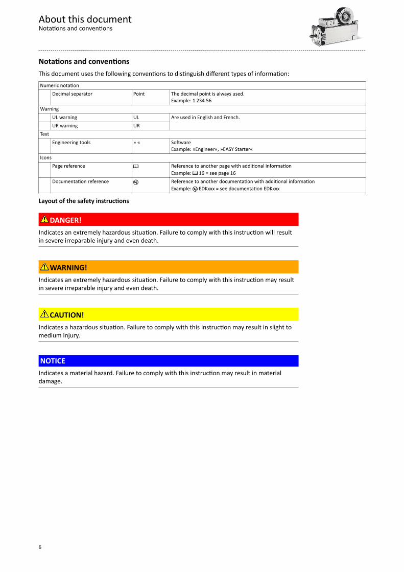
Layout of the safety instructions
DANGER!Indicates an extremely hazardous situation. Failure to comply with this instruction will resultin severe irreparable injury and even death.
WARNING!Indicates an extremely hazardous situation. Failure to comply with this instruction may resultin severe irreparable injury and even death.
CAUTION!Indicates a hazardous situation. Failure to comply with this instruction may result in slight tomedium injury.
NOTICEIndicates a material hazard. Failure to comply with this instruction may result in materialdamage.
About this documentNotations and conventions
6
Product information
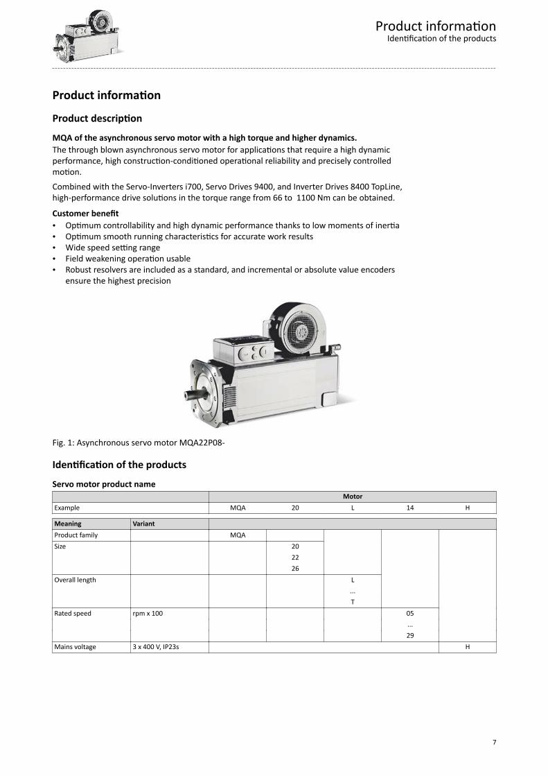
Product descriptionMQA of the asynchronous servo motor with a high torque and higher dynamics.The through blown asynchronous servo motor for applications that require a high dynamicperformance, high construction-conditioned operational reliability and precisely controlledmotion.Combined with the Servo-Inverters i700, Servo Drives 9400, and Inverter Drives 8400 TopLine,high-performance drive solutions in the torque range from 66 to 1100 Nm can be obtained.
Customer benefit• Optimum controllability and high dynamic performance thanks to low moments of inertia• Optimum smooth running characteristics for accurate work results• Wide speed setting range• Field weakening operation usable• Robust resolvers are included as a standard, and incremental or absolute value encoders
ensure the highest precision
Fig. 1: Asynchronous servo motor MQA22P08-
Identification of the productsServo motor product name MotorExample MQA 20 L 14 H
Meaning Variant Product family MQA Size 20 22 26 Overall length L ... T Rated speed rpm x 100 05 ... 29 Mains voltage 3 x 400 V, IP23s H
Product informationIdentification of the products
7
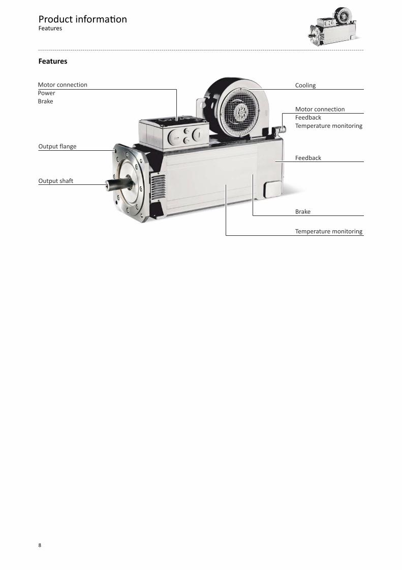
Features
Brake
Motor connectionFeedbackTemperature monitoring
Output flange
Output shaft
Motor connectionPowerBrake
Cooling
Feedback
Temperature monitoring
Product informationFeatures
8
The modular system
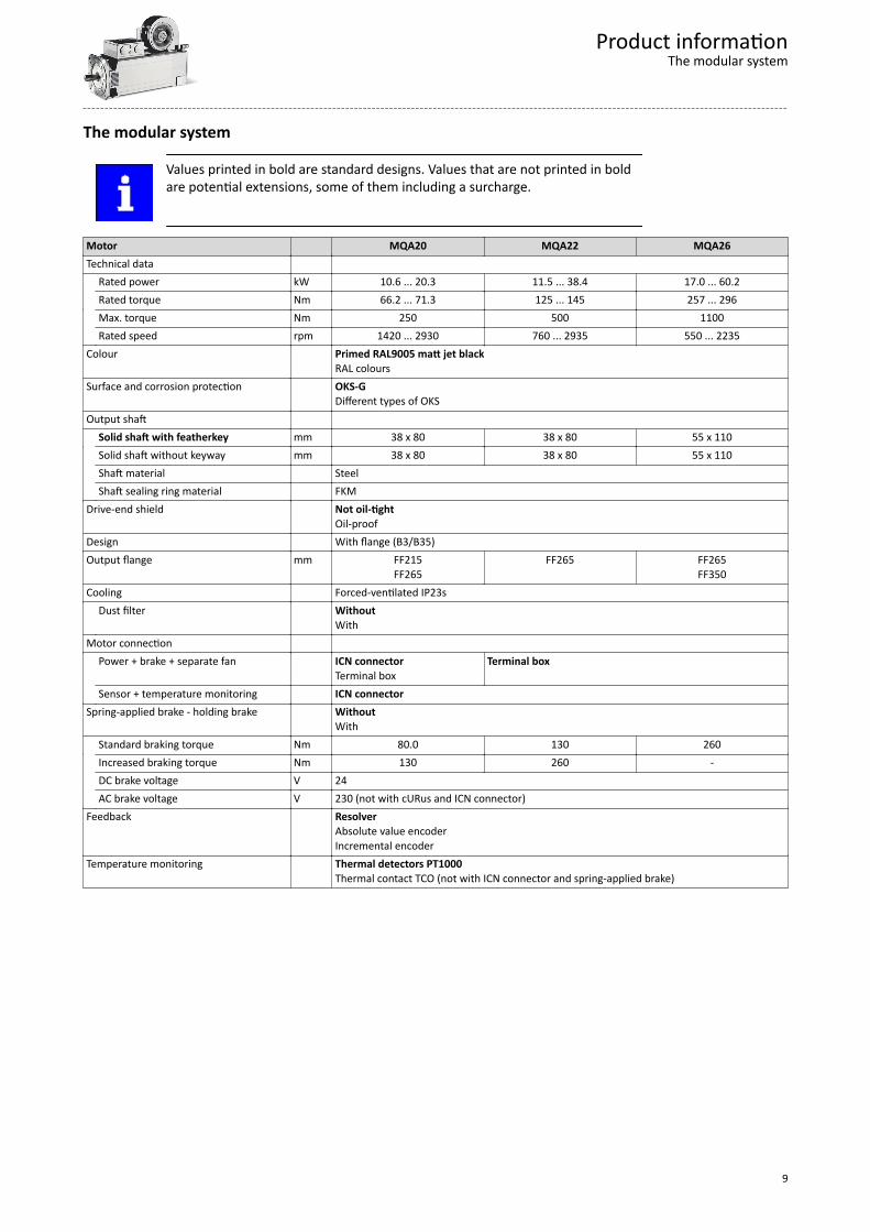
Values printed in bold are standard designs. Values that are not printed in boldare potential extensions, some of them including a surcharge.
Motor MQA20 MQA22 MQA26Technical data Rated power kW 10.6 ... 20.3 11.5 ... 38.4 17.0 ... 60.2 Rated torque Nm 66.2 ... 71.3 125 ... 145 257 ... 296 Max. torque Nm 250 500 1100 Rated speed rpm 1420 ... 2930 760 ... 2935 550 ... 2235Colour Primed RAL9005 matt jet black
RAL coloursSurface and corrosion protection OKS-G
Different types of OKSOutput shaft Solid shaft with featherkey mm 38 x 80 38 x 80 55 x 110 Solid shaft without keyway mm 38 x 80 38 x 80 55 x 110 Shaft material Steel Shaft sealing ring material FKMDrive-end shield Not oil-tight
Oil-proofDesign With flange (B3/B35)Output flange mm FF215
FF265FF265 FF265
FF350Cooling Forced-ventilated IP23s Dust filter Without
WithMotor connection Power + brake + separate fan ICN connector
Terminal boxTerminal box
Sensor + temperature monitoring ICN connectorSpring-applied brake - holding brake Without
With Standard braking torque Nm 80.0 130 260 Increased braking torque Nm 130 260 - DC brake voltage V 24 AC brake voltage V 230 (not with cURus and ICN connector)Feedback Resolver
Absolute value encoderIncremental encoder
Temperature monitoring Thermal detectors PT1000Thermal contact TCO (not with ICN connector and spring-applied brake)
Product informationThe modular system
9

Information on project planningIn order to carry out an accurate drive dimensioning process, you can use our configuringsoftware, the »Drive Solution Designer«.With the» Drive Solution Designer« you can carry out the drive dimensioning process quicklyand with top quality. The software contains profound and proven expertise with regard todrive applications and mechatronic drive components.Please refer to your competent Lenze sales company.
Information on project planning
10
Safety instructionsDisregarding the following basic safety measures and safety information may lead to severepersonal injury and damage to property!
Observe all specifications of the corresponding documentation supplied. This is theprecondition for safe and trouble-free operation and for obtaining the product featuresspecified.
Please observe the specific safety information in the other sections!
Basic safety instructions
PersonnelThe product must only be used by qualified personnel. IEC 60364 or CENELEC HD 384 definethe skills of these persons:• They are familiar with installing, mounting, commissioning, and operating the product.• They have the corresponding qualifications for their work.• They know and can apply all regulations for the prevention of accidents, directives, and
laws applicable at the place of use.
Process engineeringThe procedural notes and circuit details described are only proposals. It is up to the user tocheck whether they can be adapted to the particular applications. Lenze does not take anyresponsibility for the suitability of the procedures and circuit proposals described.
Application as directed• The product must only be actuated under the operating conditions and power limits
specified in this documentation.• The product meets the protection requirements of 2014/35/EU: Low-Voltage Directive.• The product is not a machine in terms of 2006/42/EU: Machinery Directive.• Commissioning or starting the operation as directed of a machine with the product is not
permitted until it has been ensured that the machine meets the regulations of the ECDirective 2006/42/EU: Machinery Directive; observe EN 60204−1.
• Commissioning or starting operation as directed is only permissible if the EMC Directive2014/30/EU is complied with.
• The product is not a household appliance, but is only designed as a component forcommercial or professional use in terms of EN 61000−3−2.
• The product can be used according to the technical data if drive systems have to complywith categories according to EN 61800−3.
• In residential areas, the product may cause EMC interferences. The operator is responsiblefor taking interference suppression measures.
• Do not use the built-in brakes as fail-safe brakes. Disruptive factors that cannot beinfluenced may cause the braking torque to be reduced.
• The product must only be actuated with inverters.
Foreseeable misuse• Actuate directly on the mains voltage• Use in potentially explosive areas• Use in aggressive environments• Use under water• Use under radiation• Use in generator mode
Information on project planningSafety instructions
Foreseeable misuse
11

Residual hazardsEven if notes given are taken into consideration and protective measures are implemented,the occurrence of residual risks cannot be fully prevented.
The user must take the residual hazards mentioned into consideration in the risk assessmentfor his/her machine/system.If the above is disregarded, this can lead to severe injuries to persons and damage toproperty!
Protection of persons• The product does not provide safety-related functions.
- A higher-level safety system must be implemented.- Additional monitoring and protective equipment complying with the safety regulations
applicable in each case must be used.• The power terminals may carry voltage in the switched-off state or when the motor is
stopped.- Before working, check whether all power terminals are deenergised.
• Voltages may occur on the drive components (e.g. capacitive, caused by inverter supply).- Careful earthing in the marked positions of the components must be carried out.
• Risk of burns may be caused by hot surfaces!- Provide for a protection against accidental contact.- Use the personal protective equipment or wait until the components have cooled
down completely!- Prevent contact with flammable substances.
• There is a risk of injury due to rotating parts.- Before working on the drive system, ensure that the motor is at a standstill.
• There is a danger of unintentional starting or electrical shocks!• Installed brakes are no fail-safe brakes.
- The torque may be reduced by disruptive factors that cannot be influenced such asingressing oil.
Motor protection• Design with plug:
- Never disconnect the plug when energised! Otherwise, the plug can be destroyed.- Switch off power supply and disable inverter prior to disconnecting the plug.
• Installed thermal detectors are no full protection for the machine.- If required, limit the maximum current. Parameterise the inverter so that it will be
switched off after seconds of operation with I > IN , especially if there is the danger ofblocking.
- The installed overload protection does not prevent an overload under any conditions.• The fuses are no motor protection.
- Use a current-dependent motor protection switch.- Use the built-in thermal detectors.
• Too high torques cause a fraction of the motor shaft.- The maximum torques according to catalogue must not be exceeded.
• Lateral forces from the motor shaft may occur.- Align the shafts of motor and driven machine exactly to each other.
Information on project planningSafety instructionsResidual hazards
12
Drive dimensioningThe dimensioning is suitable for:• kinematic profiles• operating modes S1, S2, S3, S6• simple linear speed profiles, not for S-curves or similar
The following 3 elements are taken into consideration in the dimensioning process :
Drive functionOn the basis of the values required for the process that are specified, a drive is selected, forwhich all operating points are within the speed-torque characteristic curve of the motor.As a result, a motor with a suitable speed with an inverter with a sufficient maximum currentis selected. Further limits (maximum speed, installation height...) are specified in tables.
Mechanical strengthOn the basis of the forces and torques which build, a drive is selected that has a sufficientmechanic strength (endurance strength for the periodically occurring torques and fatiquestrength for the sporadically occurring torques).
Thermal dimensioningFor the inverter, the thermal dimensioning process is carried out on the basis of thecontinuous inverter current or on the basis of the continuous torque from the motor-invertercombination, which can be reached.The motor is thermally dimensioned on the basis of the mean speed and the effective torque.The mean speed of the drive should not exceed the values specified.
If dimensioning processes are complex or reach limit loads, please refer to yourLenze branch office
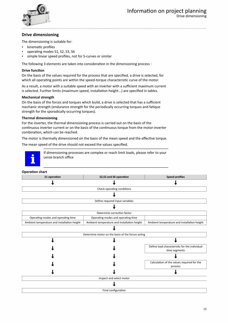
Operation chart S1 operation S2,S3 and S6 operation Speed profiles
Check operating conditions
Define required input variables
Determine correction factor Operating modes and operating time Operating modes and operating time Ambient temperature and installation height Ambient temperature and installation height Ambient temperature and installation height
Determine motor on the basis of the forces acting
Define load characteristic for the individualtime segments
Calculation of the values required for theprocess
Inspect and select motor
Final configuration
Information on project planningDrive dimensioning
13
Check operating conditionsCheckApprovalsConformity declarationsSupply voltageEnclosureAmbient temperatureSurface protection
4Conformities/approvals ^ 21
4Environmental conditions ^ 17
Define required input variablesNecessary input variables Note Symbol UnitMean speed utilisation Relating to the load speed nL %
Ambient temperature TU °C
Site altitude Amsl H mRadial force Frad N
Axial force Fax N
Transmission element at the output Gear wheels, sprockets … Effective diameter of the transmission element dw mm
Load torque Only with S1, S2, S3, and S6 operating modes ML Nm
Load speed Only with S1, S2, S3, and S6 operating modes nL rpm
Short-time maximum torque Emergency off, quick stop, occasional high startingduty
ML,max Nm
Runtime with maximum torque tL %
Determine correction factorOperating modes S1, S2, S3, S6, and operating time
Operating mode S1 Operating mode S2 Operating mode S3 Operating mode S6ED kL ED kL ED kL ED kL
% min % % 100 1.0 10 1.4 - 1.5 15 1.4 - 1.5 15 1.5 - 1.6
30 1.15 - 1.2 25 1.3 - 1.4 25 1.4 - 1.560 1.07 - 1.1 40 1.15 - 1.2 40 1.3 - 1.490 1.0 - 1.05 60 1.05 - 1.1 60 1.15 - 1.2
4Operating modes of the motor ^ 62
Ambient temperature and installation heightAmbient temperature Installation height amsl
≤ 1000 m ≤ 2000 m ≤ 3000 m ≤ 4000 mCorrection factor
TU kH kH kH kH
≤ 20 °C 1.15 1.06 0.97 0.8930 °C 1.07 0.99 0.90 0.8340 °C 1.00 0.92 0.83 0.7750 °C 0.92 0.85 0.76 0.7160 °C 0.83 0.77 0.70 0.65
Information on project planningDrive dimensioning
14
Determine product on the basis of the forcesTransmission element Gear wheels Sprockets Toothed belt pulleys Narrow V-belt ( depending on the
preloading)( depending on the
preloading)
Additional radial force factor fz
≥ 17 teeth = 1.0 ≥ 20 teeth = 1.0 With belt tightener= 2.0 -2.5
1.5 - 2.0
< 17 teeth = 1.15 < 20 teeth = 1.25 Without belt tightener= 2.5- 3.0
< 13 teeth = 1.4 Calculation Check
Radial force Frad N´
= ´ L,max zrad
M fF 2000
dwFrad ≤ Frad,max
Axial force Fax N Fax ≤ Frad,max
dw Effective diameter of transmission element
4Radial forces and axial forces ^ 22
Operating mode S1Check and select servo motor-inverter combination Check Selection UnitOutput torque MN ≥ ML/ (kL x kH) MN Nm
Output speed nN ≥ nL nN rpm
4Rated data ^ 24
Operating modes S2, S3, and S6Check and select servo motor-inverter combination Check Selection UnitOutput torque MN ≥ ML/ ( kL x kH) MN Nm
Output speed (recommendation) nN ≥ nL nN rpm
Max. output torque Mmax ≥ ML Mmax Nm
Max. output speed nmax ≥ nL nmax rpm
All operating points ( )
n [r/min]
M [N
m]
nL ML
Below the maximum torque
characteristic of the servo motor-inverter combination, taking ML,max intoconsideration
Thermally effective operating point ( ) nL ML/ (kLx kH)
Below the S1 torque characteristic ofthe servo motor
4Rated data ^ 24
4Torque characteristics ^ 31
Information on project planningDrive dimensioning
15
Speed profilesTemporal load characteristic for the individual time segments z
Total time Individual timesegments
Load speed Load speedvariation
Steady-stateload torque
Torque Accelerationtorque
Moment ofinertia
t Δtz nL,z Δ nL,z ML,z Mz Ms,z JL
s s rpm rpm Nm Nm Nm kgcm2
Calculation Symbol Unit
Load cycle duration = Då zT t T s
Calculation of the values required for the process Calculation Symbol Unit
Torque per time segmentp´D
= +´D
L,zz L,z L
z
2 nM M J
60 tMz Nm
Maximum torque of the profile MP,max = max (Mz) MP,max Nm
Effective torque = ´D £å 2eff z z
z
1M M t ,T 1minT
Meff Nm
Mean speed = = ´Dåm L,z L,z zz
1n |n | |n | tT
nm rpm
Maximum load speed nL,max = max (nL,z) nL,max rpm
Check and select servo motor-inverter combination Check Preselection UnitOutput torque MN > Meff / kH MN Nm
Output speed nN ≥ nm nN rpm
Load-matching factor
for an optimum dynamic performance/control properties
Requirement kJ = 0.5 ... 10Optimum kJ = 1
kJ= JL / (JM + JB)
Checking the motor torques
Acceleration torque ( ) p´D= + + ´
´DL,z
S,z z M Bz
2 nM M J J
60 tMS,z
Nm
Effective torque = ´Då 2S,eff S,z z
z
1M M tT
MS,eff
All operating points ( )
n [r/min]
M [N
m]
nL,z MS,z
Below the maximum torquecharacteristic of the servo motor-inverter combination, taking ML,max intoconsideration
Thermally effective operating point ( ) nm MS,eff / kH
Below the S1 torque characteristic of
the servo motor
4Rated data ^ 24
4Torque characteristics ^ 31
Information on project planningDrive dimensioning
16
Final configuration CheckConnection dimensions Output shaft
Output flangeProduct extensions Motor connection (connector/terminal box)
BrakeFeedbackBlower
More information about the final configuration:4The modular system ^ 9
4Product extensions ^ 47
Environmental conditions
Surface and corrosion protectionDepending on the ambient conditions, the surface and corrosion protection system (calledOKS) offers tailor-made solutions for optimum protection.Various surface coatings ensure that the motors operate reliably even at high air humidity, inoutdoor installation or in the presence of atmospheric impurities. Any colour from the "RALClassic" collection can be chosen for the top coat.
Surface and corrosionprotection
Applications Type
OKS-G (primed) • Dependent on subsequent top coat applied StandardOKS-S (small) • Standard applications
• Internal installation in heated buildings• Air humidity up to 90 %
Optional
OKS-M (medium) • Internal installation in non-heated buildings• Covered, protected external installation• Air humidity up to 95 %
OKS-L (large) • External installation• Air humidity above 95 %• Chemical industrial plants• Food industry
Surface and corrosionprotection
Corrosivity category Surface coating Colour Coating thickness
DIN EN ISO 12944-2 Design OKS-G (primed) • 2K PUR priming coat • RAL 9005 matt jet black 60 ... 90 µmOKS-S (small) Comparable to C1 • 2K-PUR top coat
• According to RAL Classic80 ... 120 µm
OKS-M (medium) Comparable to C2 • 2K PUR priming coat• 2K-PUR top coat
110 ... 160 µmOKS-L (large) Comparable to C3 140 ... 200 µm
Information on project planningFinal configuration
Environmental conditions
17
Information on mechanical installation
Important notes• You must install the product according to specifications in the chapter "standard and
operating" conditions.4Standards and operating conditions ^ 21
• The technical data and the data regarding the supply conditions can be found on thenameplate and in this documentation.
• Observe the information relating to the surface and corrosion protection.4Environmental conditions ^ 17
• Ambient media − especially chemically aggressive ones − may damage shaft sealing rings,lacquers and plastics. If required, contact your responsible Lenze subsidiary.
NOTICEBearing damage caused by unbalance!Shafts with keyway are balanced with a half featherkey! Balance transmission elements with a half featherkey!
Transport• Ensure appropriate handling.• Make sure that all component parts are safely mounted. Secure or remove loose
component parts.• Only use safely fixed transport aids (e.g. eye bolts or support plates).• Do not damage any components during the transport.• Avoid electrostatic discharge on electronic components and contacts.• Avoid impacts.• Check the carrying capacity of the hoists and load handling devices. The weights can be
obtained from the shipping documents.• Secure the load against tipping and falling down.• Standing under a suspended load is forbidden.
Installation• Avoid resonances with the rotational frequency and double mains frequency.• The mounting surfaces must be plane, torsionally rigid and free from vibrations.• The mounting areas must be suited to absorb the forces and torques generated during
operation.• Ensure an unhindered ventilation.• For versions with a fan, keep a minimum distance of 10 % from the outside diameter of the
fan cover in intake direction.
Information on mechanical installationInstallation
18
Information on electrical installation
Important notes
DANGER!Hazardous voltage!On the power connections even when disconnected from the mains: residual voltage >60 V! Disconnect the product from the mains and wait until the motor is at a standstill. Make sure that the product is safely isolated from supply!
• When working on energised products, comply with the applicable national accidentprevention regulations.
• Carry out the electrical installation in compliance with the relevant regulations (e.g. cablecross-sections, fuses, PE connection).
• The manufacturer of the system or machine is responsible for adherence to the limitsrequired in connection with EMC legislation.
Preparation
The notes for the electrical connection can be found in the enclosed mountinginstructions.
EMC-compliant wiring
The EMC-compliant wiring is described in detail in the documentation of theLenze inverters.
Information on electrical installationPreparation
19
Technical data
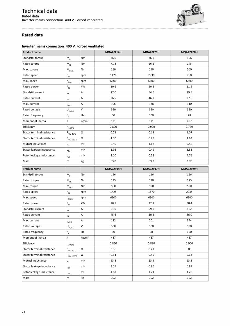
Notes regarding the given dataThe power values, torques and speeds specified in the configuration are rounded values andapply to• Ambient temperature TU = 40 °C for motors (in accordance with EN 60034)• Site altitude ≤ 1000 m above sea levelThe selection tables specify the inverter/ motor combination with the attainable torquevalues.The rated data applies to the S1 operating mode S1 (in accordance with EN 60034) and theoperation on an inverter with a switching frequency of at least 4 kHz.
NOTICEIn case of other operating conditions, the achievable values can differ for those mentioned. In case of extreme operating conditions, please contact your responsible Lenze sales
company.
Technical dataNotes regarding the given data
20
Standards and operating conditions
Conformities/approvalsConformity CE 2014/35/EU Low-Voltage Directive 2014/30/EU EMC Directive (reference: CE-typical drive system) EAC TR TC 004/2011 Eurasian conformity: safety of low voltage equipment TP TC 020/2011 Eurasian conformity: electromagnetic compatibility of technical
meansApproval cURus UL 1004-1
UL 1004-6for USA and Canada (requirements of the CSA 22.2 No.100)Industrial Control Equipment, Lenze File No. E210321
UkrSepro for Ukraine
Protection of persons and device protectionDegree of protection IP23S EN 60034-5 Forced-ventilatedTemperature class F (155 °C) EN 60034-1 Max. voltage load Limit curve A IEC/TS 60034-25:2007 IVIC C/B/B@500V IEC 60034-18-41
EMC dataNoise emission EN 60034-1 A final overall assessment of the drive system is indispensableNoise immunity EN 60034-1 A final overall assessment of the drive system is indispensable
Environmental conditionsClimate 1K3 (-20 °C ... +60 °C) EN 60721-3-1 Storage, < 3 months 1K3 (-20 °C ... +40 °C) EN 60721-3-1 Storage, > 3 months 2K3 (-20 °C ... +70 °C) EN 60721-3-2 Transport 3K3 (-15 °C ... +40 °C) EN 60721-3-3 Operation, without brake 3K3 (-10 °C ... +40 °C) EN 60721-3-3 Operation, with brake Relative humidity ≤ 85 % Without condensationSite altitude 0 … 1000 m amsl Without power reduction 1000 … 4000 m amsl Pay attention to the drop in power of the inverter and servo motorVibration resistance 3M6 EN 60721-3-3 OperationVibration severity A EN 60034-14 Vibration velocity 1.6 mm/s Free suspensionSmooth running, axial runout, concentricity Normal Class IEC 60072
Technical dataStandards and operating conditions
Environmental conditions
21

Radial forces and axial forces
The values of the bearing service life L10h refer to an average motor speed of3000 rpm. Depending on the ambient temperatures, they are also limited by thegrease lifetime.
Application of forces
0F -
Frad
ax F +axl/2
l
Fax
Frad
Application of force at l/2Bearing service life L10h Motor
MQA20 MQA22 MQA265000 h Radial force Frad N 3,400 3600 6950
Axial tensile force Fax, - N -1330 -2370 -2500
Axial compression force Fax, + N 690 1700 1580
10000 h Radial force Frad N 2500 2800 5400
Axial tensile force Fax, - N -1020 -1740 -1800
Axial compression force Fax, + N 380 1090 880
20000 h Radial force Frad N 1950 2200 4300
Axial tensile force Fax, - N -780 -1280 -1300
Axial compression force Fax, + N 140 640 380
30000 h Radial force Frad N 1700 1,900 3700
Axial tensile force Fax, - N -690 -1080 -1090
Axial compression force Fax, + N 40 440 160
50000 h Radial force Frad N 1600
Axial tensile force Fax, - N -880
Axial compression force Fax, + N 240
Technical dataRadial forces and axial forces
22
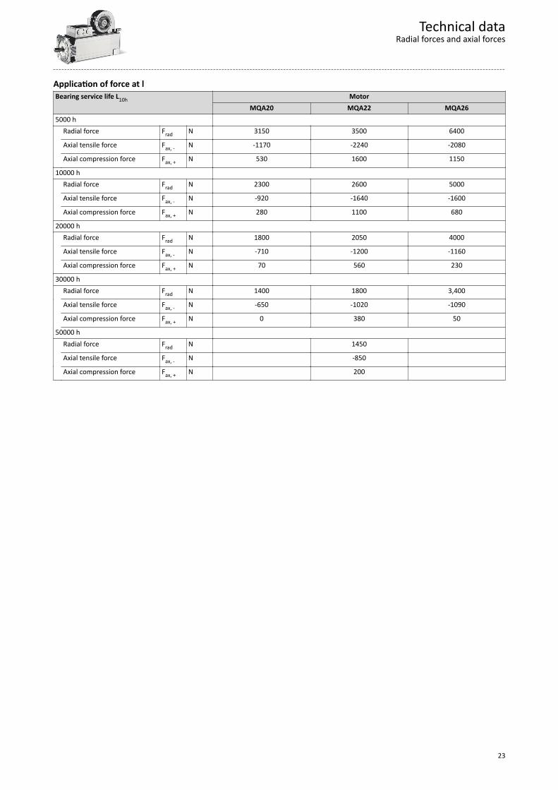
Application of force at lBearing service life L10h Motor
MQA20 MQA22 MQA265000 h Radial force Frad N 3150 3500 6400
Axial tensile force Fax, - N -1170 -2240 -2080
Axial compression force Fax, + N 530 1600 1150
10000 h Radial force Frad N 2300 2600 5000
Axial tensile force Fax, - N -920 -1640 -1600
Axial compression force Fax, + N 280 1100 680
20000 h Radial force Frad N 1800 2050 4000
Axial tensile force Fax, - N -710 -1200 -1160
Axial compression force Fax, + N 70 560 230
30000 h Radial force Frad N 1400 1800 3,400
Axial tensile force Fax, - N -650 -1020 -1090
Axial compression force Fax, + N 0 380 50
50000 h Radial force Frad N 1450
Axial tensile force Fax, - N -850
Axial compression force Fax, + N 200
Technical dataRadial forces and axial forces
23
Rated data
Inverter mains connection 400 V, Forced ventilatedProduct name MQA20L14H MQA20L29H MQA22P08H
Standstill torque M0 Nm 76.0 76.0 156
Rated torque MN Nm 71.3 66.2 145
Max. torque MMax. Nm 250 250 500
Rated speed nN rpm 1420 2930 760
Max. speed nMax. rpm 6500 6500 6500
Rated power PN kW 10.6 20.3 11.5
Standstill current I0 A 27.0 54.0 29.5
Rated current IN A 26.5 46.9 27.6
Max. current IMax. A 106 188 110
Rated voltage UN, AC V 360 360 360
Rated frequency fN Hz 50 100 28
Moment of inertia J kgcm² 171 171 487
Efficiency η100 % 0.800 0.900 0.770
Stator terminal resistance RUV 20°C Ω 0.73 0.18 1.07
Stator terminal resistance RUV 150°C Ω 1.10 0.28 1.62
Mutual inductance LH mH 57.0 13.7 92.8
Stator leakage inductance L1σ mH 1.98 0.49 3.53
Rotor leakage inductance L2σ mH 2.10 0.52 4.76
Mass m kg 63.0 63.0 102
Product name MQA22P14H MQA22P17H MQA22P29H
Standstill torque M0 Nm 156 156 156
Rated torque MN Nm 135 130 125
Max. torque MMax. Nm 500 500 500
Rated speed nN rpm 1425 1670 2935
Max. speed nMax. rpm 6500 6500 6500
Rated power PN kW 20.1 22.7 38.4
Standstill current I0 A 51.0 59.0 102
Rated current IN A 45.6 50.3 86.0
Max. current IMax. A 182 201 344
Rated voltage UN, AC V 360 360 360
Rated frequency fN Hz 50 58 100
Moment of inertia J kgcm² 487 487 487
Efficiency η100 % 0.860 0.880 0.900
Stator terminal resistance RUV 20°C Ω 0.36 0.27 .09
Stator terminal resistance RUV 150°C Ω 0.54 0.40 0.13
Mutual inductance LH mH 93.3 23.9 23.2
Stator leakage inductance L1σ mH 3.57 0.90 0.89
Rotor leakage inductance L2σ mH 4.81 1.21 1.20
Mass m kg 102 102 102
Technical dataRated dataInverter mains connection 400 V, Forced ventilated
24
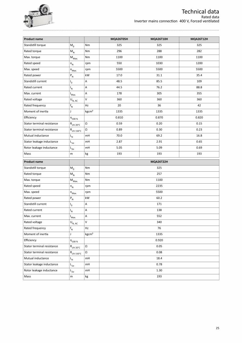
Product name MQA26T05H MQA26T10H MQA26T12H
Standstill torque M0 Nm 325 325 325
Rated torque MN Nm 296 288 282
Max. torque MMax. Nm 1100 1100 1100
Rated speed nN rpm 550 1030 1200
Max. speed nMax. rpm 5500 5500 5500
Rated power PN kW 17.0 31.1 35.4
Standstill current I0 A 48.5 85.5 109
Rated current IN A 44.5 76.2 88.8
Max. current IMax. A 178 305 355
Rated voltage UN, AC V 360 360 360
Rated frequency fN Hz 20 36 42
Moment of inertia J kgcm² 1335 1335 1335
Efficiency η100 % 0.810 0.870 0.820
Stator terminal resistance RUV 20°C Ω 0.59 0.20 0.15
Stator terminal resistance RUV 150°C Ω 0.89 0.30 0.23
Mutual inductance LH mH 70.0 69.2 16.8
Stator leakage inductance L1σ mH 2.87 2.91 0.65
Rotor leakage inductance L2σ mH 5.05 5.09 0.69
Mass m kg 193 193 193
Product name MQA26T22H
Standstill torque M0 Nm 325
Rated torque MN Nm 257
Max. torque MMax. Nm 1100
Rated speed nN rpm 2235
Max. speed nMax. rpm 5500
Rated power PN kW 60.2
Standstill current I0 A 171
Rated current IN A 138
Max. current IMax. A 552
Rated voltage UN, AC V 340
Rated frequency fN Hz 76
Moment of inertia J kgcm² 1335
Efficiency η100 % 0.920
Stator terminal resistance RUV 20°C Ω 0.05
Stator terminal resistance RUV 150°C Ω 0.08
Mutual inductance LH mH 18.4
Stator leakage inductance L1σ mH 0.78
Rotor leakage inductance L2σ mH 1.30
Mass m kg 193
Technical dataRated data
Inverter mains connection 400 V, Forced ventilated
25
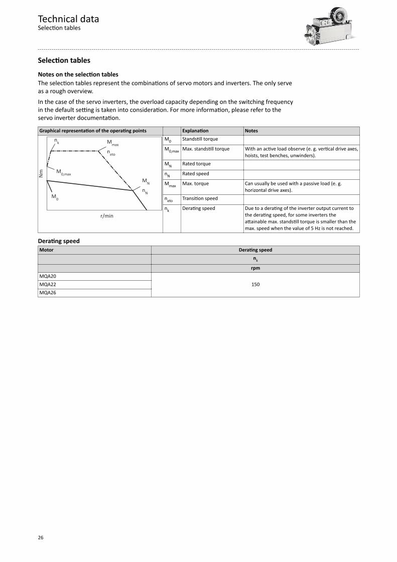
Selection tablesNotes on the selection tablesThe selection tables represent the combinations of servo motors and inverters. The only serveas a rough overview.In the case of the servo inverters, the overload capacity depending on the switching frequencyin the default setting is taken into consideration. For more information, please refer to theservo inverter documentation.
Graphical representation of the operating points Explanation Notes
r/min
Nm
M0
MN
nN
Mmax
neto
nk
M0,max
M0 Standstill torque
M0,max Max. standstill torque With an active load observe (e. g. vertical drive axes,hoists, test benches, unwinders).
MN Rated torque
nN Rated speed
Mmax Max. torque Can usually be used with a passive load (e. g.horizontal drive axes).
neto Transition speed
nk Derating speed Due to a derating of the inverter output current tothe derating speed, for some inverters theattainable max. standstill torque is smaller than themax. speed when the value of 5 Hz is not reached.
Derating speedMotor Derating speed
nk
rpmMQA20
150MQA22MQA26
Technical dataSelection tables
26
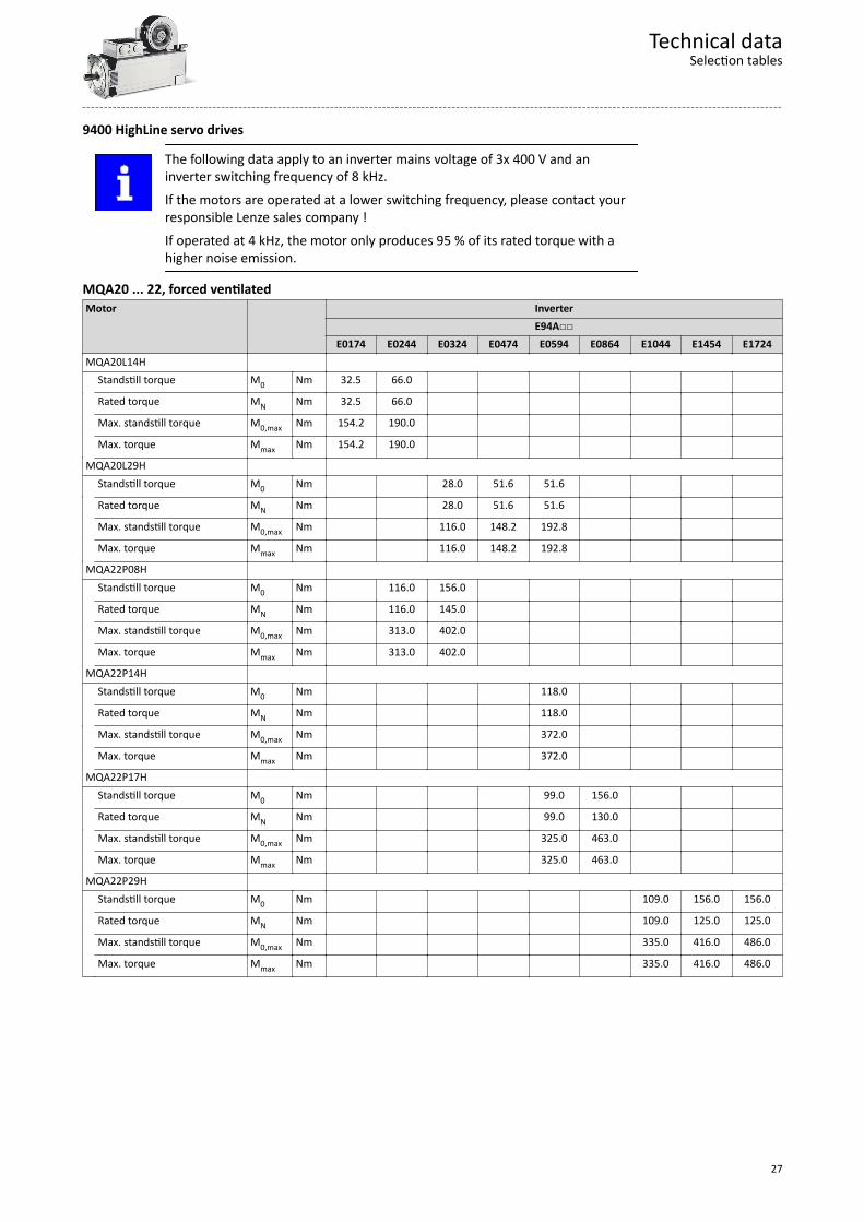
9400 HighLine servo drives
The following data apply to an inverter mains voltage of 3x 400 V and aninverter switching frequency of 8 kHz.If the motors are operated at a lower switching frequency, please contact yourresponsible Lenze sales company !If operated at 4 kHz, the motor only produces 95 % of its rated torque with ahigher noise emission.
MQA20 ... 22, forced ventilatedMotor Inverter
E94AE0174 E0244 E0324 E0474 E0594 E0864 E1044 E1454 E1724
MQA20L14H Standstill torque M0 Nm 32.5 66.0
Rated torque MN Nm 32.5 66.0
Max. standstill torque M0,max Nm 154.2 190.0
Max. torque Mmax Nm 154.2 190.0
MQA20L29H Standstill torque M0 Nm 28.0 51.6 51.6
Rated torque MN Nm 28.0 51.6 51.6
Max. standstill torque M0,max Nm 116.0 148.2 192.8
Max. torque Mmax Nm 116.0 148.2 192.8
MQA22P08H Standstill torque M0 Nm 116.0 156.0
Rated torque MN Nm 116.0 145.0
Max. standstill torque M0,max Nm 313.0 402.0
Max. torque Mmax Nm 313.0 402.0
MQA22P14H Standstill torque M0 Nm 118.0
Rated torque MN Nm 118.0
Max. standstill torque M0,max Nm 372.0
Max. torque Mmax Nm 372.0
MQA22P17H Standstill torque M0 Nm 99.0 156.0
Rated torque MN Nm 99.0 130.0
Max. standstill torque M0,max Nm 325.0 463.0
Max. torque Mmax Nm 325.0 463.0
MQA22P29H Standstill torque M0 Nm 109.0 156.0 156.0
Rated torque MN Nm 109.0 125.0 125.0
Max. standstill torque M0,max Nm 335.0 416.0 486.0
Max. torque Mmax Nm 335.0 416.0 486.0
Technical dataSelection tables
27
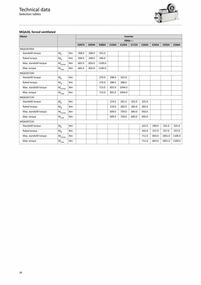
MQA26, forced ventilatedMotor Inverter
E94AE0474 E0594 E0864 E1044 E1454 E1724 E2024 E2454 E2924 E3664
MQA26T05H Standstill torque M0 Nm 268.0 268.0 325.0
Rated torque MN Nm 268.0 268.0 296.0
Max. standstill torque M0,max Nm 665.0 826.0 1100.0
Max. torque Mmax Nm 665.0 826.0 1100.0
MQA26T10H Standstill torque M0 Nm 270.0 298.0 325.0
Rated torque MN Nm 270.0 288.0 288.0
Max. standstill torque M0,max Nm 713.0 855.0 1044.0
Max. torque Mmax Nm 713.0 855.0 1044.0
MQA26T12H Standstill torque M0 Nm 219.0 291.0 325.0 325.0
Rated torque MN Nm 219.0 282.0 282.0 282.0
Max. standstill torque M0,max Nm 609.0 739.0 840.0 950.0
Max. torque Mmax Nm 609.0 739.0 840.0 950.0
MQA26T22H Standstill torque M0 Nm 242.0 290.0 325.0 325.0
Rated torque MN Nm 242.0 257.0 257.0 257.0
Max. standstill torque M0,max Nm 711.0 843.0 1001.0 1100.0
Max. torque Mmax Nm 711.0 843.0 1001.0 1100.0
Technical dataSelection tables
28
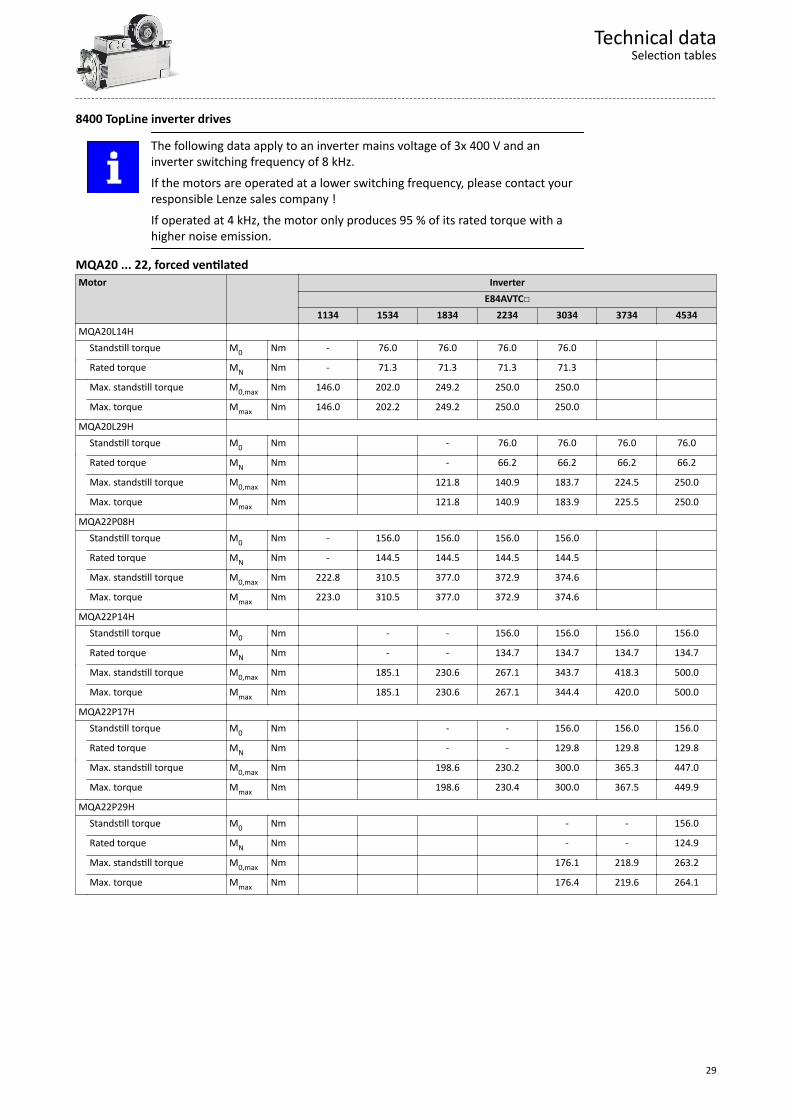
8400 TopLine inverter drives
The following data apply to an inverter mains voltage of 3x 400 V and aninverter switching frequency of 8 kHz.If the motors are operated at a lower switching frequency, please contact yourresponsible Lenze sales company !If operated at 4 kHz, the motor only produces 95 % of its rated torque with ahigher noise emission.
MQA20 ... 22, forced ventilatedMotor Inverter
E84AVTC1134 1534 1834 2234 3034 3734 4534
MQA20L14H Standstill torque M0 Nm - 76.0 76.0 76.0 76.0
Rated torque MN Nm - 71.3 71.3 71.3 71.3
Max. standstill torque M0,max Nm 146.0 202.0 249.2 250.0 250.0
Max. torque Mmax Nm 146.0 202.2 249.2 250.0 250.0
MQA20L29H Standstill torque M0 Nm - 76.0 76.0 76.0 76.0
Rated torque MN Nm - 66.2 66.2 66.2 66.2
Max. standstill torque M0,max Nm 121.8 140.9 183.7 224.5 250.0
Max. torque Mmax Nm 121.8 140.9 183.9 225.5 250.0
MQA22P08H Standstill torque M0 Nm - 156.0 156.0 156.0 156.0
Rated torque MN Nm - 144.5 144.5 144.5 144.5
Max. standstill torque M0,max Nm 222.8 310.5 377.0 372.9 374.6
Max. torque Mmax Nm 223.0 310.5 377.0 372.9 374.6
MQA22P14H Standstill torque M0 Nm - - 156.0 156.0 156.0 156.0
Rated torque MN Nm - - 134.7 134.7 134.7 134.7
Max. standstill torque M0,max Nm 185.1 230.6 267.1 343.7 418.3 500.0
Max. torque Mmax Nm 185.1 230.6 267.1 344.4 420.0 500.0
MQA22P17H Standstill torque M0 Nm - - 156.0 156.0 156.0
Rated torque MN Nm - - 129.8 129.8 129.8
Max. standstill torque M0,max Nm 198.6 230.2 300.0 365.3 447.0
Max. torque Mmax Nm 198.6 230.4 300.0 367.5 449.9
MQA22P29H Standstill torque M0 Nm - - 156.0
Rated torque MN Nm - - 124.9
Max. standstill torque M0,max Nm 176.1 218.9 263.2
Max. torque Mmax Nm 176.4 219.6 264.1
Technical dataSelection tables
29
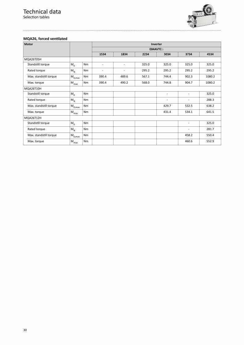
MQA26, forced ventilatedMotor Inverter
E84AVTC1534 1834 2234 3034 3734 4534
MQA26T05H Standstill torque M0 Nm - - 325.0 325.0 325.0 325.0
Rated torque MN Nm - - 295.2 295.2 295.2 295.2
Max. standstill torque M0,max Nm 390.4 489.6 567.1 744.4 902.3 1080.2
Max. torque Mmax Nm 390.4 490.2 568.0 744.8 904.7 1080.2
MQA26T10H Standstill torque M0 Nm - - 325.0
Rated torque MN Nm - - 288.3
Max. standstill torque M0,max Nm 429.7 532.5 638.2
Max. torque Mmax Nm 431.4 534.1 641.5
MQA26T12H Standstill torque M0 Nm - 325.0
Rated torque MN Nm - 281.7
Max. standstill torque M0,max Nm 458.2 550.4
Max. torque Mmax Nm 460.6 552.9
Technical dataSelection tables
30
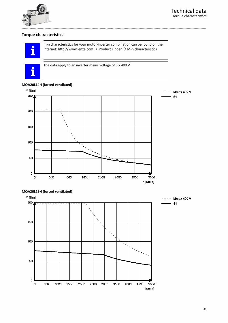
Torque characteristics
m-n characteristics for your motor-inverter combination can be found on theInternet: http://www.lenze.com à Product Finder à M-n characteristics
The data apply to an inverter mains voltage of 3 x 400 V.
MQA20L14H (forced ventilated)
MQA20L29H (forced ventilated)
Technical dataTorque characteristics
31
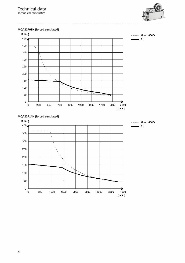
MQA22P08H (forced ventilated)
MQA22P14H (forced ventilated)
Technical dataTorque characteristics
32
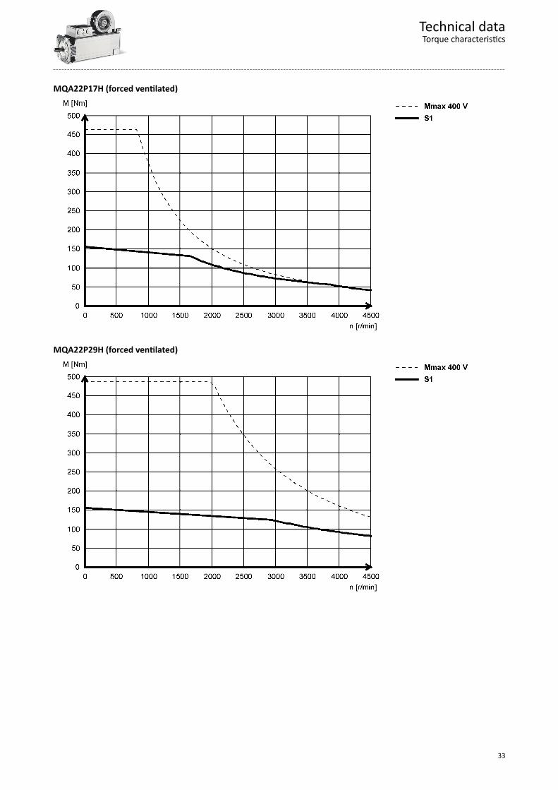
MQA22P17H (forced ventilated)
MQA22P29H (forced ventilated)
Technical dataTorque characteristics
33
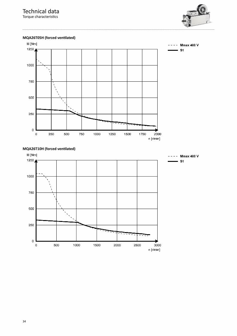
MQA26T05H (forced ventilated)
MQA26T10H (forced ventilated)
Technical dataTorque characteristics
34
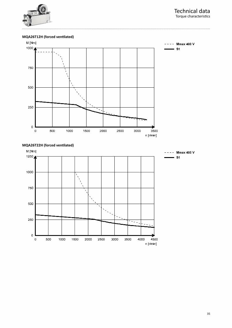
MQA26T12H (forced ventilated)
MQA26T22H (forced ventilated)
Technical dataTorque characteristics
35

Dimensions
Basic dimensions
Notes on the basic dimensionsThe following legend shows the layout of the dimension sheets:
Table content Explanation Total length without brake L Total length of the drive with resolver Total length with brake L Total length of the drive with resolver Length of motor options Δ L Additional length (longest design)
In detail 4Additional lengths ^ 45
Motor/connection distance AD Distance from motor centre to connector end / terminal box
Technical dataDimensionsBasic dimensions
36
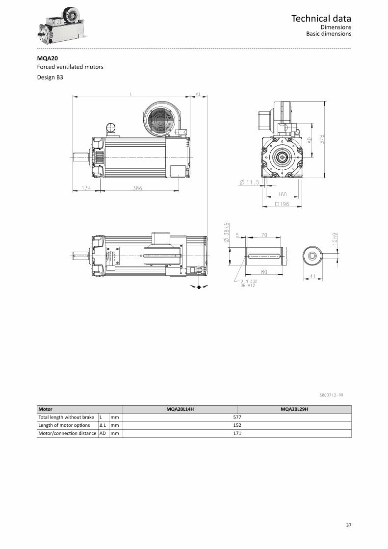
MQA20Forced ventilated motorsDesign B3
Motor MQA20L14H MQA20L29HTotal length without brake L mm 577Length of motor options Δ L mm 152Motor/connection distance AD mm 171
Technical dataDimensions
Basic dimensions
37
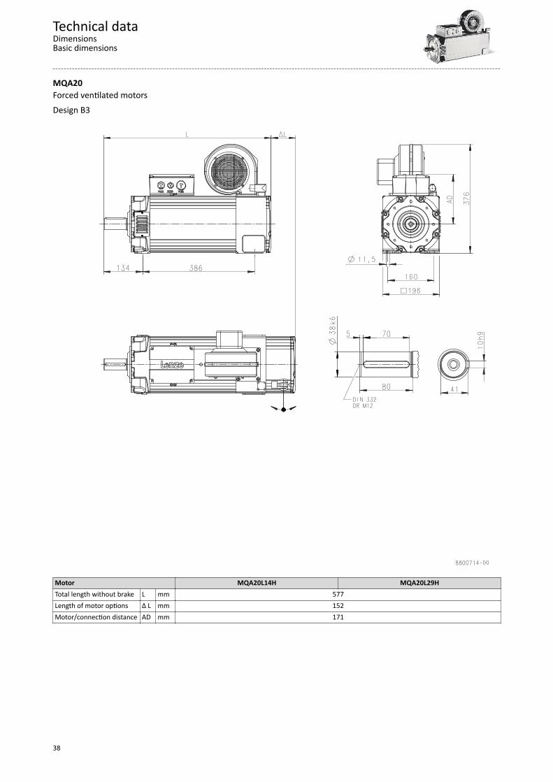
MQA20Forced ventilated motorsDesign B3
Motor MQA20L14H MQA20L29HTotal length without brake L mm 577Length of motor options Δ L mm 152Motor/connection distance AD mm 171
Technical dataDimensionsBasic dimensions
38

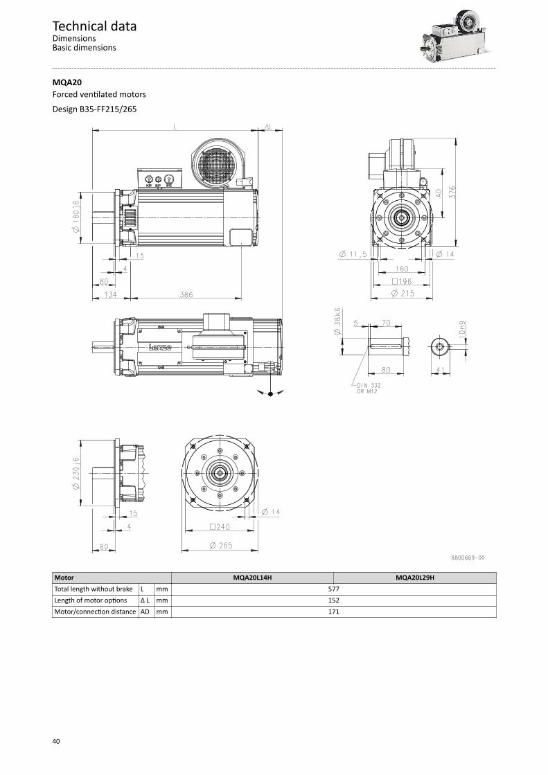
MQA20Forced ventilated motorsDesign B35-FF215/265
Motor MQA20L14H MQA20L29HTotal length without brake L mm 577Length of motor options Δ L mm 152Motor/connection distance AD mm 171
Technical dataDimensions
Basic dimensions
39
MQA20Forced ventilated motorsDesign B35-FF215/265
Motor MQA20L14H MQA20L29HTotal length without brake L mm 577Length of motor options Δ L mm 152Motor/connection distance AD mm 171
Technical dataDimensionsBasic dimensions
40
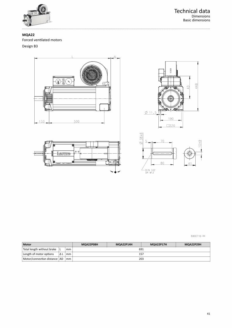
MQA22Forced ventilated motorsDesign B3
Motor MQA22P08H MQA22P14H MQA22P17H MQA22P29HTotal length without brake L mm 691Length of motor options Δ L mm 157Motor/connection distance AD mm 203
Technical dataDimensions
Basic dimensions
41
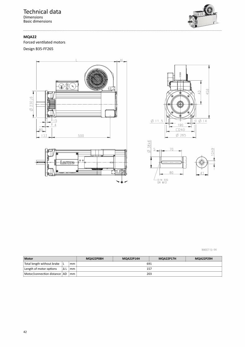
MQA22Forced ventilated motorsDesign B35-FF265
Motor MQA22P08H MQA22P14H MQA22P17H MQA22P29HTotal length without brake L mm 691Length of motor options Δ L mm 157Motor/connection distance AD mm 203
Technical dataDimensionsBasic dimensions
42
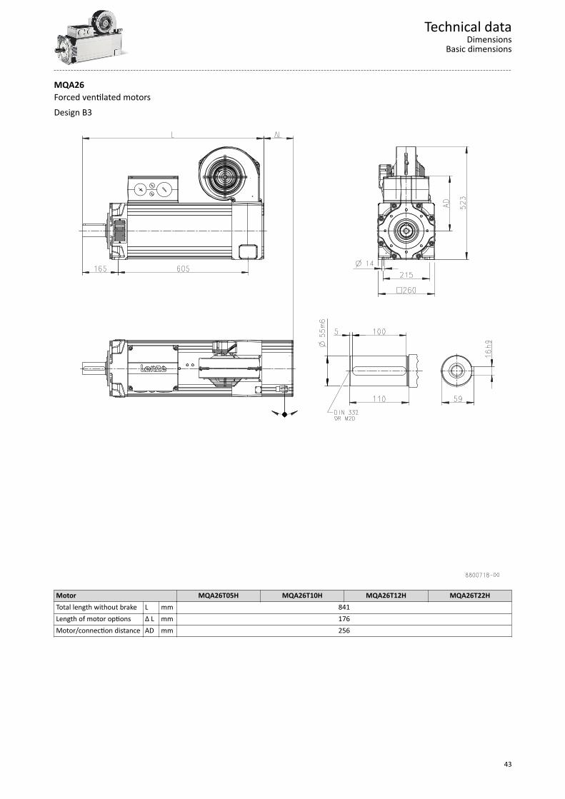
MQA26Forced ventilated motorsDesign B3
Motor MQA26T05H MQA26T10H MQA26T12H MQA26T22HTotal length without brake L mm 841Length of motor options Δ L mm 176Motor/connection distance AD mm 256
Technical dataDimensions
Basic dimensions
43
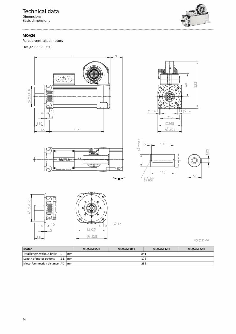
MQA26Forced ventilated motorsDesign B35-FF350
Motor MQA26T05H MQA26T10H MQA26T12H MQA26T22HTotal length without brake L mm 841Length of motor options Δ L mm 176Motor/connection distance AD mm 256
Technical dataDimensionsBasic dimensions
44
Additional lengths
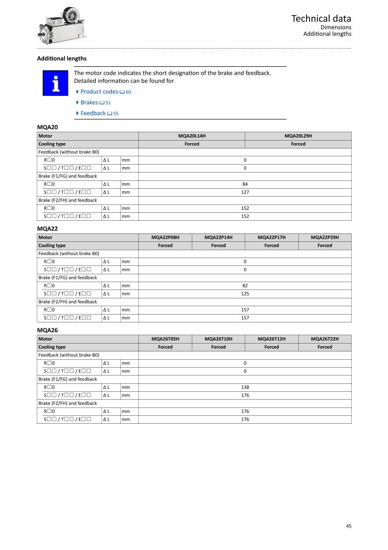
The motor code indicates the short designation of the brake and feedback.Detailed information can be found for4Product codes ^ 60
4Brakes ^ 51
4Feedback ^ 55
MQA20Motor MQA20L14H MQA20L29HCooling type Forced ForcedFeedback (without brake B0) R0 Δ L mm 0 S / T / E Δ L mm 0Brake (F1/FG) and feedback R0 Δ L mm 84 S / T / E Δ L mm 127Brake (F2/FH) and feedback R0 Δ L mm 152 S / T / E Δ L mm 152
MQA22Motor MQA22P08H MQA22P14H MQA22P17H MQA22P29HCooling type Forced Forced Forced ForcedFeedback (without brake B0) R0 Δ L mm 0 S / T / E Δ L mm 0Brake (F1/FG) and feedback R0 Δ L mm 82 S / T / E Δ L mm 125Brake (F2/FH) and feedback R0 Δ L mm 157 S / T / E Δ L mm 157
MQA26Motor MQA26T05H MQA26T10H MQA26T12H MQA26T22HCooling type Forced Forced Forced ForcedFeedback (without brake B0) R0 Δ L mm 0 S / T / E Δ L mm 0Brake (F1/FG) and feedback R0 Δ L mm 138 S / T / E Δ L mm 176Brake (F2/FH) and feedback R0 Δ L mm 176 S / T / E Δ L mm 176
Technical dataDimensions
Additional lengths
45
Weights
Additional weights
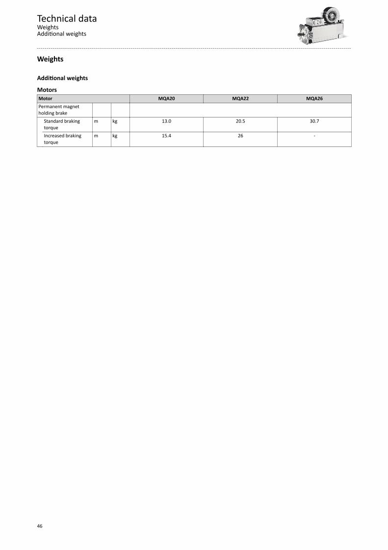
MotorsMotor MQA20 MQA22 MQA26Permanent magnetholding brake
Standard brakingtorque
m kg 13.0 20.5 30.7
Increased brakingtorque
m kg 15.4 26 -
Technical dataWeightsAdditional weights
46
Product extensions
Motor connection
Connection via terminal boxIf a motor is to be connected to an existing cable or plug connectors are not to be used forother reasons, the connection can also be made via a terminal box.The connection for feedback and temperature monitoring is generally via the ICN connectorand the electric fan is connected via a terminal box.The terminals are designed as tension spring terminals to ensure here the long-term vibrationresistance of the cable contacts with adequate contact pressure required.
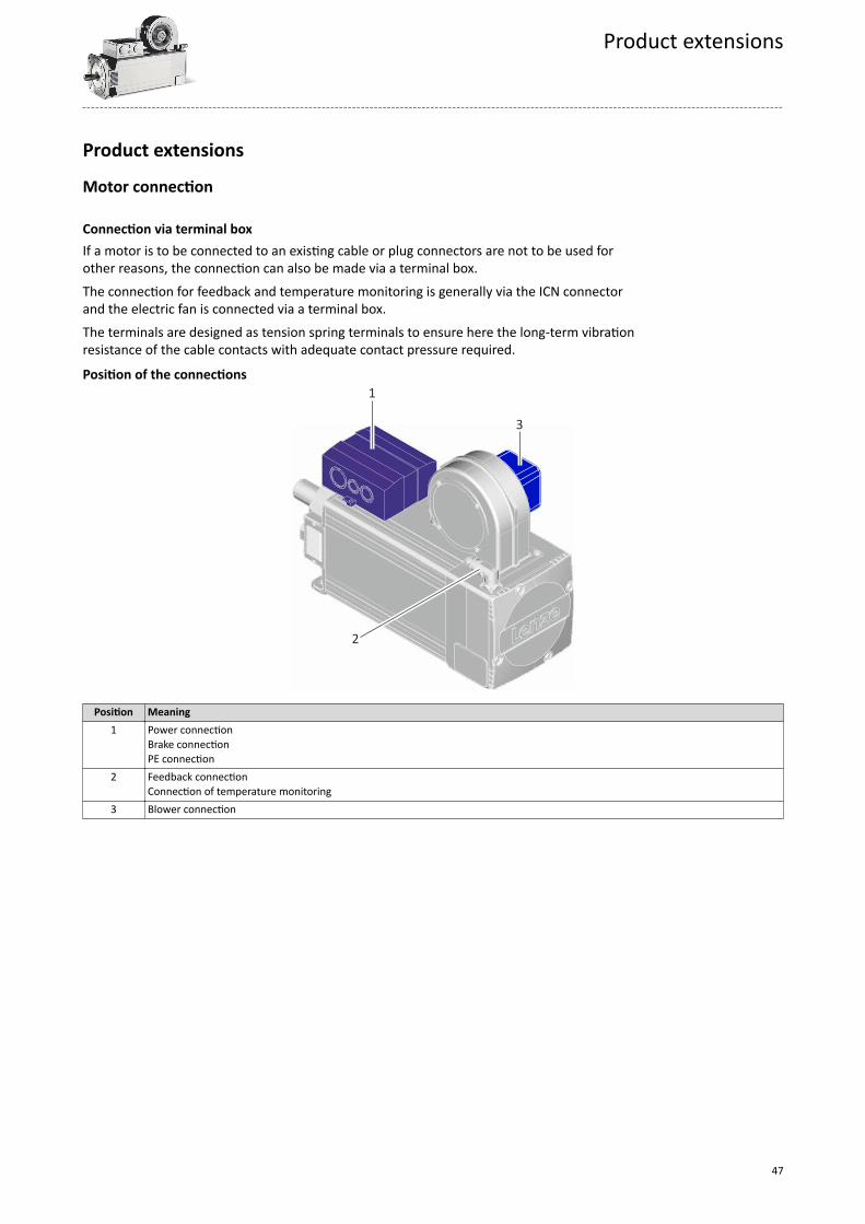
Position of the connections 1
3
2
Position Meaning1 Power connection
Brake connectionPE connection
2 Feedback connectionConnection of temperature monitoring
3 Blower connection
Product extensions
47
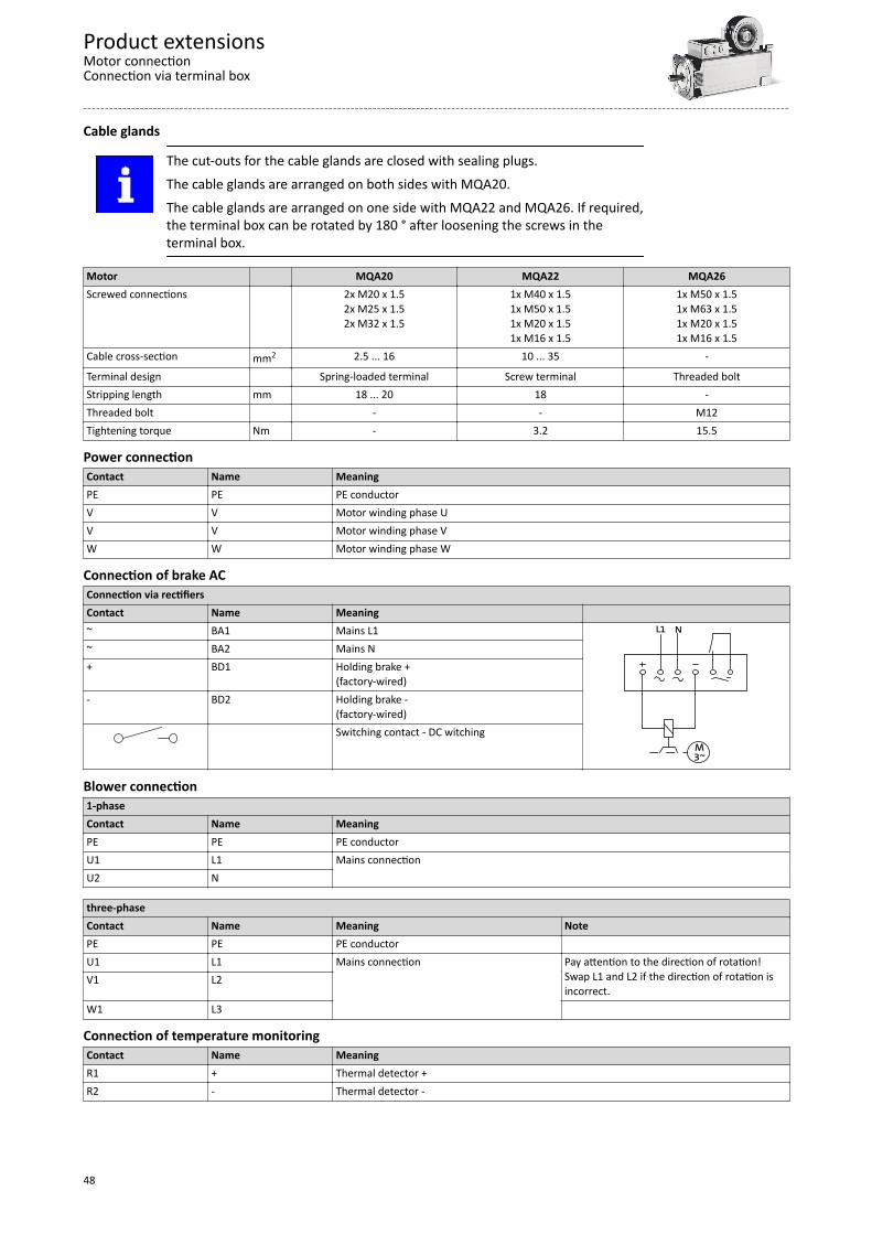
Cable glands
The cut-outs for the cable glands are closed with sealing plugs.The cable glands are arranged on both sides with MQA20.The cable glands are arranged on one side with MQA22 and MQA26. If required,the terminal box can be rotated by 180 ° after loosening the screws in theterminal box.
Motor MQA20 MQA22 MQA26Screwed connections 2x M20 x 1.5
2x M25 x 1.52x M32 x 1.5
1x M40 x 1.51x M50 x 1.51x M20 x 1.51x M16 x 1.5
1x M50 x 1.51x M63 x 1.51x M20 x 1.51x M16 x 1.5
Cable cross-section mm2 2.5 ... 16 10 ... 35 -
Terminal design Spring-loaded terminal Screw terminal Threaded boltStripping length mm 18 ... 20 18 -Threaded bolt - - M12Tightening torque Nm - 3.2 15.5
Power connectionContact Name MeaningPE PE PE conductorV V Motor winding phase UV V Motor winding phase VW W Motor winding phase W
Connection of brake ACConnection via rectifiersContact Name Meaning ~ BA1 Mains L1
M3~
L1 N
~ BA2 Mains N+ BD1 Holding brake +
(factory-wired)- BD2 Holding brake -
(factory-wired) Switching contact - DC switching
Blower connection1-phaseContact Name MeaningPE PE PE conductorU1 L1 Mains connectionU2 N
three-phaseContact Name Meaning NotePE PE PE conductor U1 L1 Mains connection Pay attention to the direction of rotation!
Swap L1 and L2 if the direction of rotation isincorrect.
V1 L2
W1 L3
Connection of temperature monitoringContact Name MeaningR1 + Thermal detector +R2 - Thermal detector -
Product extensionsMotor connectionConnection via terminal box
48
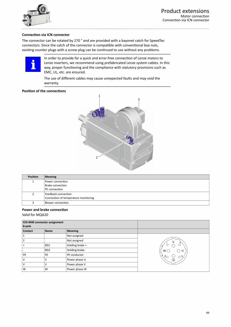
Connection via ICN connectorThe connector can be rotated by 270 ° and are provided with a bayonet catch for SpeedTecconnectors. Since the catch of the connector is compatible with conventional box nuts,existing counter plugs with a screw plug can be continued to use without any problems.
In order to provide for a quick and error-free connection of Lenze motors toLenze inverters, we recommend using prefabricated Lenze system cables. In thisway, proper functioning and the compliance with statutory provisions such asEMC, UL, etc. are ensured.The use of different cables may cause unexpected faults and may void thewarranty.
Position of the connections 1
3
2
Position Meaning1 Power connection
Brake connectionPE connection
2 Feedback connectionConnection of temperature monitoring
3 Blower connection
Power and brake connectionValid for MQA20
ICN-M40 connector assignment8-pole
Contact Name Meaning 1 Not assigned
12
W U
V- +
+
2 Not assigned+ BD1 Holding brake +- BD2 Holding brake -PE PE PE conductorV V Power phase UV V Power phase VW W Power phase W
Product extensionsMotor connection
Connection via ICN connector
49
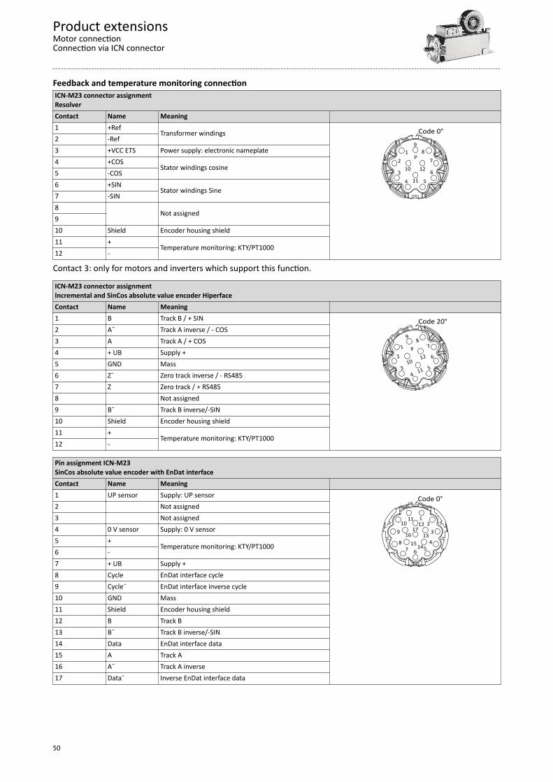
Feedback and temperature monitoring connectionICN-M23 connector assignmentResolverContact Name Meaning 1 +Ref
Transformer windings
12
34 5
6
78
9
10
11
12
P
Code 0°2 -Ref3 +VCC ETS Power supply: electronic nameplate4 +COS
Stator windings cosine5 -COS6 +SIN
Stator windings Sine7 -SIN8
Not assigned910 Shield Encoder housing shield11 +
Temperature monitoring: KTY/PT100012 -
Contact 3: only for motors and inverters which support this function.
ICN-M23 connector assignmentIncremental and SinCos absolute value encoder HiperfaceContact Name Meaning 1 B Track B / + SIN
1
2
34
5
6
78
9
10
11
12P
Code 20°2 A¯ Track A inverse / - COS3 A Track A / + COS4 + UB Supply +5 GND Mass6 Z¯ Zero track inverse / - RS4857 Z Zero track / + RS4858 Not assigned9 B¯ Track B inverse/-SIN10 Shield Encoder housing shield11 +
Temperature monitoring: KTY/PT100012 -
Pin assignment ICN-M23SinCos absolute value encoder with EnDat interfaceContact Name Meaning 1 UP sensor Supply: UP sensor
12
3
4567
910
1112
13
141516
17
8
Code 0°2 Not assigned3 Not assigned4 0 V sensor Supply: 0 V sensor5 +
Temperature monitoring: KTY/PT10006 -7 + UB Supply +8 Cycle EnDat interface cycle9 Cycle¯ EnDat interface inverse cycle10 GND Mass11 Shield Encoder housing shield12 B Track B13 B¯ Track B inverse/-SIN14 Data EnDat interface data15 A Track A16 A¯ Track A inverse17 Data¯ Inverse EnDat interface data
Product extensionsMotor connectionConnection via ICN connector
50
BrakesOptionally the motors can be ordered with a spring-applied brake as holding brake.
CAUTION!They may not be used as safety elements (particularly with hoist axes) without additionalmeasures being implemented.The brakes used are not fail-safe brakes in the sense that prospective disruptive factors, e.g.oil ingress, can lead to a reduction in torque! The brakes must only be used as holding brakes for holding the axes at a standstill or in the
deenergised state. The brake must not be used as a service brake.
CAUTION!If no suitable voltage (incorrect value, incorrect polarity) is applied to the brake, the brake willbe applied and can be overheated and destroyed by the motor continuing to rotate.
If long motor supply cables are used, pay attention to the ohmic voltage drop along the cableand compensate for it with a higher voltage at the input end of the cable.The following applies to Lenze system cables:
= + ´ ´´B Lg B
[V]U[V] U [V] 0.08 l [m] I [A][A] [m]
V V Resulting supply voltageUB V Rated voltage of the brake
lLg m Cable length
I A Rated current of the brake
NOTICE The brakes become active when the supply voltage has been switched off (closed-circuit
principle). When using the brakes purely as holding brakes, virtually no wear occurs on the friction
surfaces. The friction surfaces must always be free from oil and grease because even small amounts
of grease or oil will considerably reduce the braking torque.
NOTICEIn case of travel axes, the compliance of the permissible ratio of mass inertia load/brakemotor (JL/JMB) ensures that the permissible maximum switching energy of the brake will notbe exceeded and at least the values given for the emergency stop functions from the givenspeed (see rated data) are applied.For hoist axes, the load torque resulting from the weight acts additionally. In this case, thespecifications for (JL/JMB) do not apply.
Product extensionsBrakes
51
To simplify matters, the friction energy per switching cycle can be calculated using the formulabelow and must not exceed the limit value for emergency stops, which depends on theswitching rate:
Dæ ö= ´ ´ p´ ´ç ÷ -è ø
2N
gesN L
M1 nQ J 22 60 M M
Q J Friction energyJtotal kgm2 Total mass inertia (motor + load)
Δn rpm Differential speedMN Nm Rated torque of the brake
ML nM Load torque
The shortest operating times of the brakes are achieved by DC switching of thevoltage and an external suppressor circuit (varistor or spark suppressor).Without suppressor circuit, the operating times may increase. A varistor/ sparksuppressor limits the breaking voltage peaks. It must be ensured that the powerlimit of the suppressor circuit is not exceeded. This limit depends on the brakecurrent, brake voltage, disengagement time and the switching operations pertime unit.Furthermore the suppressor circuit is necessary for interference suppressionand for increasing the service life of the relay contacts (external, is notintegrated into the motor).
It is not possible to readjust the brake.
Product extensionsBrakes
52
Spring-applied brakes
Rated data
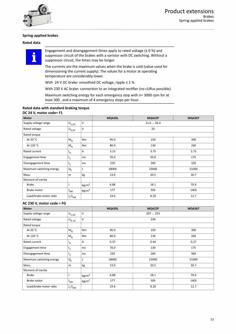
Engagement and disengagement times apply to rated voltage (± 0 %) andsuppressor circuit of the brakes with a varistor with DC switching. Without asuppressor circuit, the times may be longer.The currents are the maximum values when the brake is cold (value used fordimensioning the current supply). The values for a motor at operatingtemperature are considerably lower.With 24 V DC brake: smoothed DC voltage, ripple ≤ 1 %.With 230 V AC brake: connection to an integrated rectifier (no cURus possible).Maximum switching energy for each emergency stop with n= 3000 rpm for atleast 300 , and a maximum of 4 emergency stops per hour.
Rated data with standard braking torqueDC 24 V, motor code= F1Motor MQA20L MQA22P MQA26TSupply voltage range Uin,DC V 21.6 ... 26.4
Rated voltage UN,DC V 24
Rated torque At 20 °C MN Nm 90.0 150 300
At 120 °C MN Nm 80.0 130 260
Rated current IN A 3.13 3.75 3.75
Engagement time t1 ms 70.0 50.0 175
Disengagement time t2 ms 220 260 320
Maximum switching energy QE J 18000 23000 51000
Mass m kg 13.0 20.5 30.7Moment of inertia Brake J kgcm2 6.88 18.1 70.4
Brake motor JMB kgcm2 177 505 1405
Load/brake motor ratio JL/JMB 19.6 8.20 12.7
AC 230 V, motor code = FGMotor MQA20L MQA22P MQA26TSupply voltage range Uin,DC V 207 ... 253
Rated voltage UN, AC V 230
Rated torque At 20 °C MN Nm 90.0 150 300
At 120 °C MN Nm 80.0 130 260
Rated current IN A 0.37 0.44 0.37
Engagement time t1 ms 70.0 130 175
Disengagement time t2 ms 220 260 360
Maximum switching energy QE J 18000 23000 51000
Mass m kg 13.0 20.5 30.7Moment of inertia Brake J kgcm2 6.88 18.1 70.4
Brake motor JMB kgcm2 177 505 1405
Load/brake motor ratio JL/JMB 19.6 8.20 12.7
Product extensionsBrakes
Spring-applied brakes
53
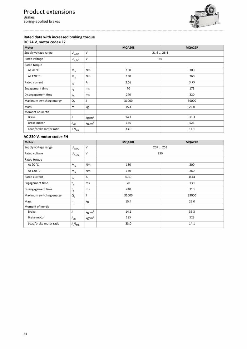
Rated data with increased braking torqueDC 24 V, motor code= F2Motor MQA20L MQA22PSupply voltage range Uin,DC V 21.6 ... 26.4
Rated voltage UN,DC V 24
Rated torque At 20 °C MN Nm 150 300
At 120 °C MN Nm 130 260
Rated current IN A 2.58 3.75
Engagement time t1 ms 70 175
Disengagement time t2 ms 240 320
Maximum switching energy QE J 31000 39000
Mass m kg 15.4 26.0Moment of inertia Brake J kgcm2 14.1 36.3
Brake motor JMB kgcm2 185 523
Load/brake motor ratio JL/JMB 33.0 14.1
AC 230 V, motor code= FHMotor MQA20L MQA22PSupply voltage range Uin,DC V 207 ... 253
Rated voltage UN, AC V 230
Rated torque At 20 °C MN Nm 150 300
At 120 °C MN Nm 130 260
Rated current IN A 0.30 0.44
Engagement time t1 ms 70 130
Disengagement time t2 ms 240 310
Maximum switching energy QE J 31000 39000
Mass m kg 15.4 26.0Moment of inertia Brake J kgcm2 14.1 36.3
Brake motor JMB kgcm2 185 523
Load/brake motor ratio JL/JMB 33.0 14.1
Product extensionsBrakesSpring-applied brakes
54
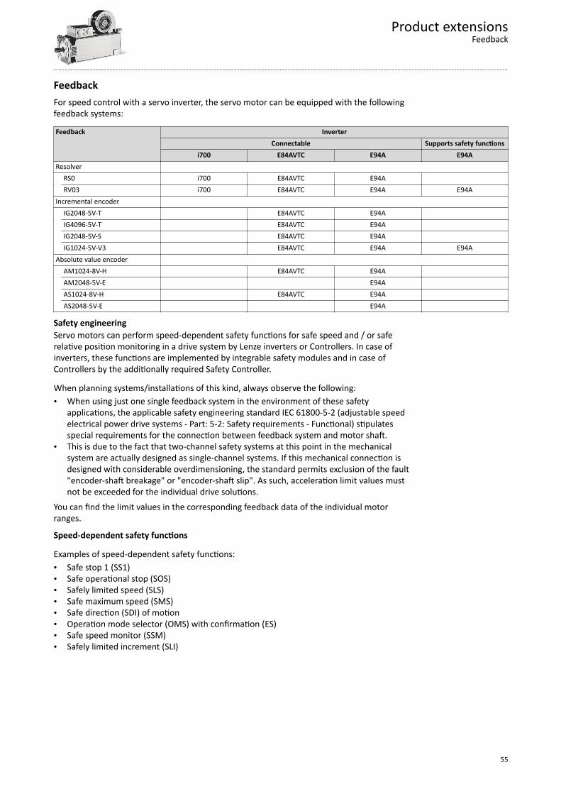
FeedbackFor speed control with a servo inverter, the servo motor can be equipped with the followingfeedback systems:
Feedback InverterConnectable Supports safety functions
i700 E84AVTC E94A E94AResolver RS0 i700 E84AVTC E94A RV03 i700 E84AVTC E94A E94AIncremental encoder IG2048-5V-T E84AVTC E94A IG4096-5V-T E84AVTC E94A IG2048-5V-S E84AVTC E94A IG1024-5V-V3 E84AVTC E94A E94AAbsolute value encoder AM1024-8V-H E84AVTC E94A AM2048-5V-E E94A AS1024-8V-H E84AVTC E94A AS2048-5V-E E94A
Safety engineeringServo motors can perform speed-dependent safety functions for safe speed and / or saferelative position monitoring in a drive system by Lenze inverters or Controllers. In case ofinverters, these functions are implemented by integrable safety modules and in case ofControllers by the additionally required Safety Controller.
When planning systems/installations of this kind, always observe the following:• When using just one single feedback system in the environment of these safety
applications, the applicable safety engineering standard IEC 61800-5-2 (adjustable speedelectrical power drive systems - Part: 5-2: Safety requirements - Functional) stipulatesspecial requirements for the connection between feedback system and motor shaft.
• This is due to the fact that two-channel safety systems at this point in the mechanicalsystem are actually designed as single-channel systems. If this mechanical connection isdesigned with considerable overdimensioning, the standard permits exclusion of the fault"encoder-shaft breakage" or "encoder-shaft slip". As such, acceleration limit values mustnot be exceeded for the individual drive solutions.
You can find the limit values in the corresponding feedback data of the individual motorranges.
Speed-dependent safety functions
Examples of speed-dependent safety functions:• Safe stop 1 (SS1)• Safe operational stop (SOS)• Safely limited speed (SLS)• Safe maximum speed (SMS)• Safe direction (SDI) of motion• Operation mode selector (OMS) with confirmation (ES)• Safe speed monitor (SSM)• Safely limited increment (SLI)
Product extensionsFeedback
55
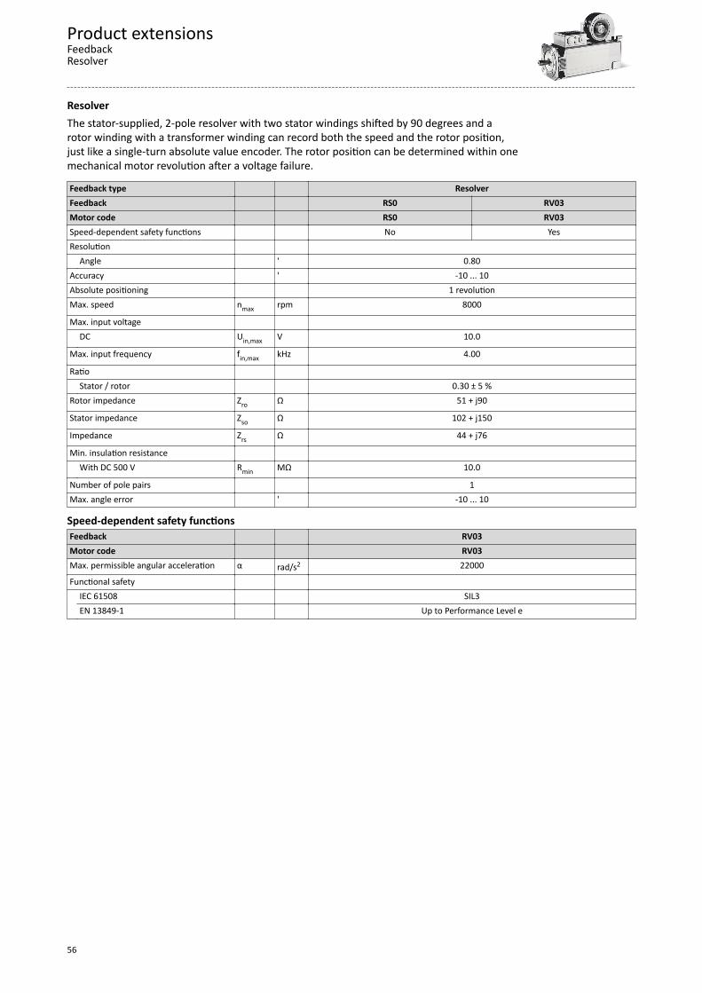
ResolverThe stator-supplied, 2-pole resolver with two stator windings shifted by 90 degrees and arotor winding with a transformer winding can record both the speed and the rotor position,just like a single-turn absolute value encoder. The rotor position can be determined within onemechanical motor revolution after a voltage failure.
Feedback type ResolverFeedback RS0 RV03Motor code RS0 RV03Speed-dependent safety functions No YesResolution Angle ' 0.80Accuracy ' -10 ... 10Absolute positioning 1 revolutionMax. speed nmax rpm 8000
Max. input voltage DC Uin,max V 10.0
Max. input frequency fin,max kHz 4.00
Ratio Stator / rotor 0.30 ± 5 %Rotor impedance Zro Ω 51 + j90
Stator impedance Zso Ω 102 + j150
Impedance Zrs Ω 44 + j76
Min. insulation resistance With DC 500 V Rmin MΩ 10.0
Number of pole pairs 1Max. angle error ' -10 ... 10
Speed-dependent safety functionsFeedback RV03Motor code RV03Max. permissible angular acceleration α rad/s2 22000
Functional safety IEC 61508 SIL3 EN 13849-1 Up to Performance Level e
Product extensionsFeedbackResolver
56
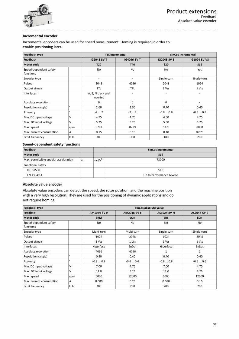
Incremental encoderIncremental encoders can be used for speed measurement. Homing is required in order toenable positioning later.
Feedback type TTL incremental SinCos incrementalFeedback IG2048-5V-T IG4096-5V-T IG2048-5V-S IG1024-5V-V3Motor code T20 T40 S20 S1SSpeed-dependent safetyfunctions
No No No Yes
Encoder type - - Single-turn Single-turnPulses 2048 4096 2048 1024Output signals TTL TTL 1 Vss 1 VssInterfaces A, B, N track and
inverted- - -
Absolute revolution 0 0 0 -Resolution (angle) ' 2.60 1.30 0.40 0.40Accuracy ' -2 ... 2 -2 ... 2 -0.8 ... 0.8 -0.8 ... 0.8Min. DC input voltage V 4.75 4.75 4.50 4.75Max. DC input voltage V 5.25 5.25 5.50 5.25Max. speed rpm 8789 8789 5273 8000Max. current consumption A 0.15 0.15 0.10 0.070Limit frequency kHz 300 300 180 200
Speed-dependent safety functionsFeedback SinCos incrementalMotor code S1SMax. permissible angular acceleration α rad/s2 73000
Functional safety IEC 61508 SIL3 EN 13849-1 Up to Performance Level e
Absolute value encoderAbsolute value encoders can detect the speed, the rotor position, and the machine positionwith a very high resolution. They are used for the positioning of dynamic applications and donot require homing.
Feedback type SinCos absolute valueFeedback AM1024-8V-H AM2048-5V-E AS1024-8V-H AS2048-5V-EMotor code SRM EQN SRS ECNSpeed-dependent safetyfunctions
No No No No
Encoder type Multi-turn Multi-turn Single-turn Single-turnPulses 1024 2048 1024 2048Output signals 1 Vss 1 Vss 1 Vss 1 VssInterfaces Hiperface EnDat Hiperface EnDatAbsolute revolution 4096 4096 1 1Resolution (angle) ' 0.40 0.40 0.40 0.40Accuracy ' -0.8 ... 0.8 -0.6 ... 0.6 -0.8 ... 0.8 -0.6 ... 0.6Min. DC input voltage V 7.00 4.75 7.00 4.75Max. DC input voltage V 12.0 5.25 12.0 5.25Max. speed rpm 6000 12000 6000 12000Max. current consumption A 0.080 0.25 0.080 0.15Limit frequency kHz 200 200 200 200
Product extensionsFeedback
Absolute value encoder
57
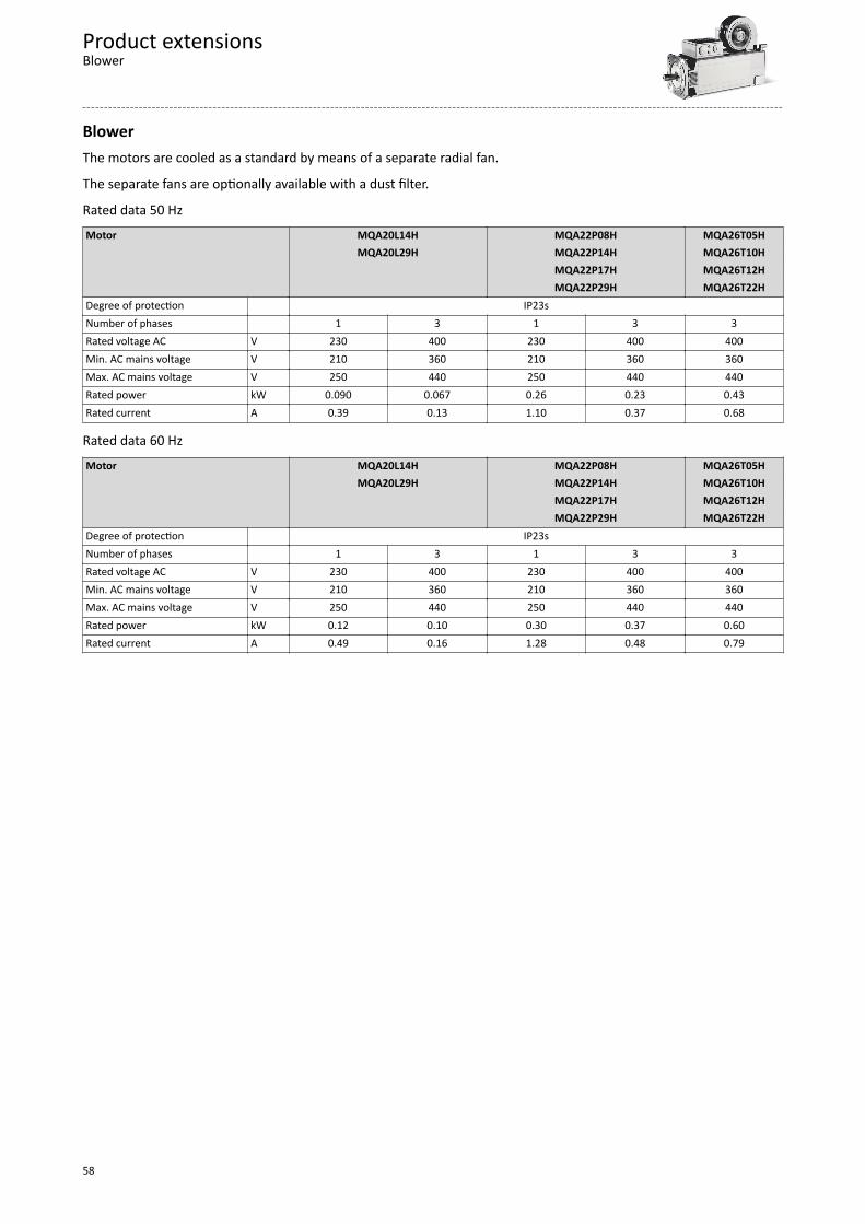
BlowerThe motors are cooled as a standard by means of a separate radial fan.
The separate fans are optionally available with a dust filter.
Rated data 50 HzMotor MQA20L14H MQA22P08H MQA26T05H
MQA20L29H MQA22P14H MQA26T10H MQA22P17H MQA26T12H MQA22P29H MQA26T22H
Degree of protection IP23sNumber of phases 1 3 1 3 3Rated voltage AC V 230 400 230 400 400Min. AC mains voltage V 210 360 210 360 360Max. AC mains voltage V 250 440 250 440 440Rated power kW 0.090 0.067 0.26 0.23 0.43Rated current A 0.39 0.13 1.10 0.37 0.68
Rated data 60 HzMotor MQA20L14H MQA22P08H MQA26T05H
MQA20L29H MQA22P14H MQA26T10H MQA22P17H MQA26T12H MQA22P29H MQA26T22H
Degree of protection IP23sNumber of phases 1 3 1 3 3Rated voltage AC V 230 400 230 400 400Min. AC mains voltage V 210 360 210 360 360Max. AC mains voltage V 250 440 250 440 440Rated power kW 0.12 0.10 0.30 0.37 0.60Rated current A 0.49 0.16 1.28 0.48 0.79
Product extensionsBlower
58
Temperature monitoring
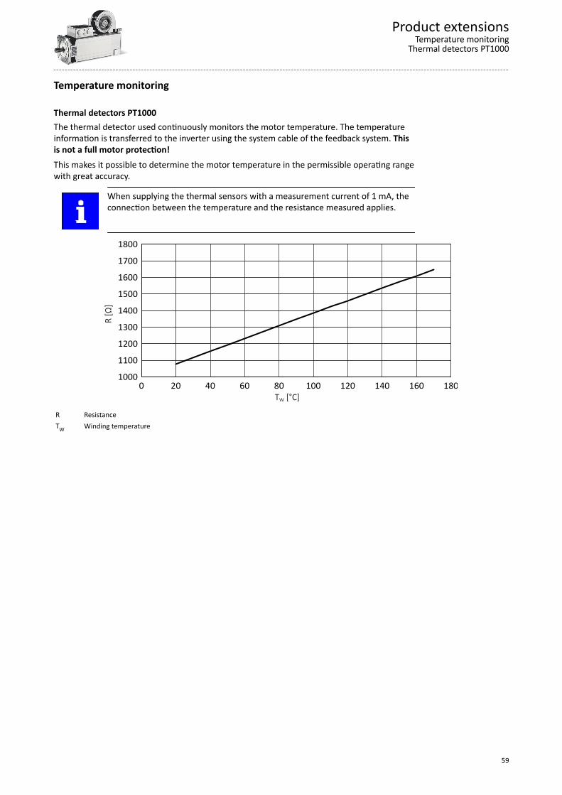
Thermal detectors PT1000The thermal detector used continuously monitors the motor temperature. The temperatureinformation is transferred to the inverter using the system cable of the feedback system. Thisis not a full motor protection!This makes it possible to determine the motor temperature in the permissible operating rangewith great accuracy.
When supplying the thermal sensors with a measurement current of 1 mA, theconnection between the temperature and the resistance measured applies.
1000
1100
1200
1300
1400
1500
1600
1700
1800
0 20 40 60 80 100 120 140 160 180
R [Ω
]
T [°C]W
R ResistanceTW Winding temperature
Product extensionsTemperature monitoring
Thermal detectors PT1000
59
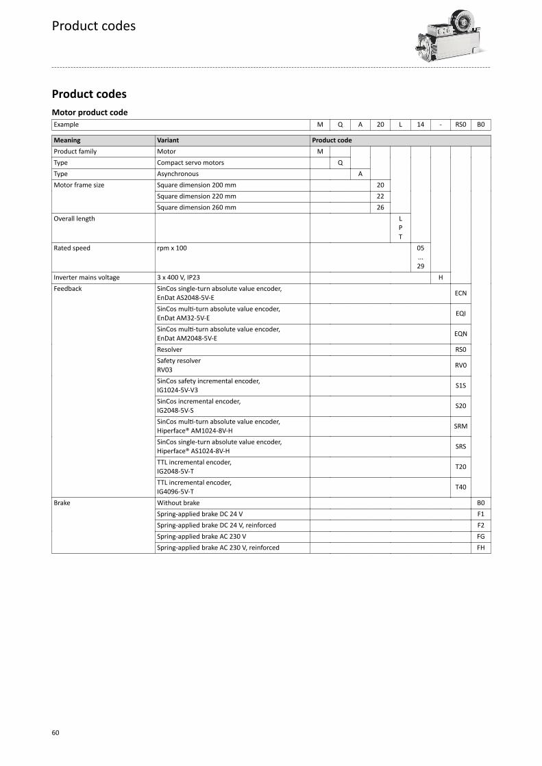
Product codesMotor product codeExample M Q A 20 L 14 - RS0 B0
Meaning Variant Product codeProduct family Motor M Type Compact servo motors Q Type Asynchronous A Motor frame size Square dimension 200 mm 20 Square dimension 220 mm 22 Square dimension 260 mm 26 Overall length
LPT
Rated speed rpm x 100
05...29
Inverter mains voltage 3 x 400 V, IP23 H Feedback SinCos single-turn absolute value encoder,
EnDat AS2048-5V-E ECN
SinCos multi-turn absolute value encoder,EnDat AM32-5V-E EQI
SinCos multi-turn absolute value encoder,EnDat AM2048-5V-E EQN
Resolver RS0 Safety resolver
RV03 RV0
SinCos safety incremental encoder,IG1024-5V-V3 S1S
SinCos incremental encoder,IG2048-5V-S S20
SinCos multi-turn absolute value encoder,Hiperface® AM1024-8V-H SRM
SinCos single-turn absolute value encoder,Hiperface® AS1024-8V-H SRS
TTL incremental encoder,IG2048-5V-T T20
TTL incremental encoder,IG4096-5V-T T40
Brake Without brake B0 Spring-applied brake DC 24 V F1 Spring-applied brake DC 24 V, reinforced F2 Spring-applied brake AC 230 V FG Spring-applied brake AC 230 V, reinforced FH
Product codes
60
Appendix
Good to know
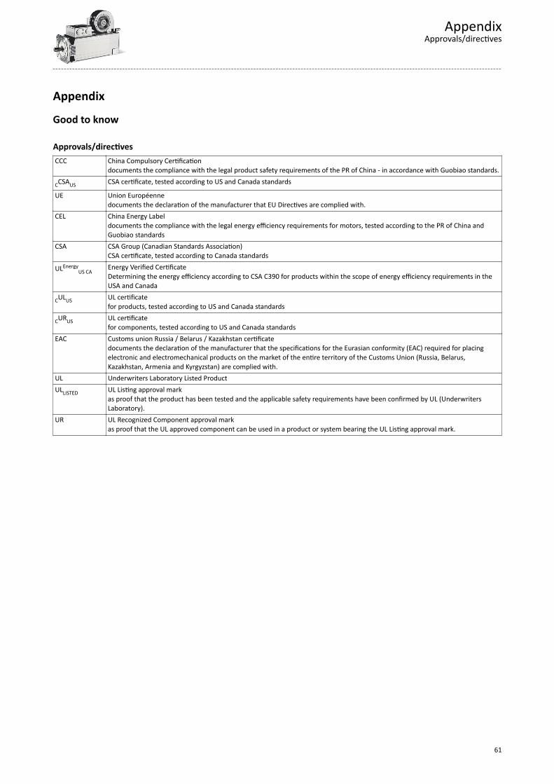
Approvals/directivesCCC China Compulsory Certification
documents the compliance with the legal product safety requirements of the PR of China - in accordance with Guobiao standards.
CCSAUS CSA certificate, tested according to US and Canada standards
UE Union Européennedocuments the declaration of the manufacturer that EU Directives are complied with.
CEL China Energy Labeldocuments the compliance with the legal energy efficiency requirements for motors, tested according to the PR of China andGuobiao standards
CSA CSA Group (Canadian Standards Association)CSA certificate, tested according to Canada standards
ULEnergyUS CA
Energy Verified CertificateDetermining the energy efficiency according to CSA C390 for products within the scope of energy efficiency requirements in theUSA and Canada
CULUS UL certificatefor products, tested according to US and Canada standards
CURUS UL certificatefor components, tested according to US and Canada standards
EAC Customs union Russia / Belarus / Kazakhstan certificatedocuments the declaration of the manufacturer that the specifications for the Eurasian conformity (EAC) required for placingelectronic and electromechanical products on the market of the entire territory of the Customs Union (Russia, Belarus,Kazakhstan, Armenia and Kyrgyzstan) are complied with.
UL Underwriters Laboratory Listed ProductULLISTED UL Listing approval mark
as proof that the product has been tested and the applicable safety requirements have been confirmed by UL (UnderwritersLaboratory).
UR UL Recognized Component approval markas proof that the UL approved component can be used in a product or system bearing the UL Listing approval mark.
AppendixApprovals/directives
61
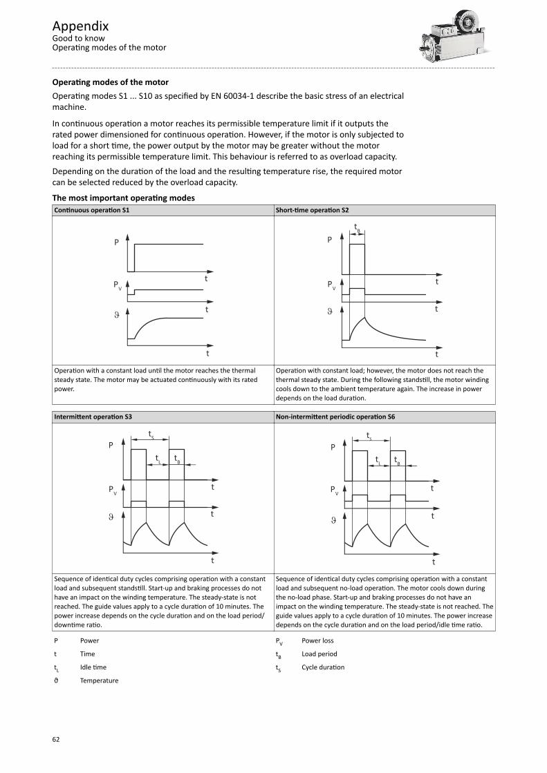
Operating modes of the motorOperating modes S1 ... S10 as specified by EN 60034-1 describe the basic stress of an electricalmachine.
In continuous operation a motor reaches its permissible temperature limit if it outputs therated power dimensioned for continuous operation. However, if the motor is only subjected toload for a short time, the power output by the motor may be greater without the motorreaching its permissible temperature limit. This behaviour is referred to as overload capacity.Depending on the duration of the load and the resulting temperature rise, the required motorcan be selected reduced by the overload capacity.
The most important operating modesContinuous operation S1 Short-time operation S2
P
PV
t
t
t
J
P
PVt
t
t
J
tB
Operation with a constant load until the motor reaches the thermalsteady state. The motor may be actuated continuously with its ratedpower.
Operation with constant load; however, the motor does not reach thethermal steady state. During the following standstill, the motor windingcools down to the ambient temperature again. The increase in powerdepends on the load duration.
Intermittent operation S3 Non-intermittent periodic operation S6
P
PVt
t
t
J
tS
tL tB
P
PVt
t
t
J
tS
tL tB
Sequence of identical duty cycles comprising operation with a constantload and subsequent standstill. Start-up and braking processes do nothave an impact on the winding temperature. The steady-state is notreached. The guide values apply to a cycle duration of 10 minutes. Thepower increase depends on the cycle duration and on the load period/downtime ratio.
Sequence of identical duty cycles comprising operation with a constantload and subsequent no-load operation. The motor cools down duringthe no-load phase. Start-up and braking processes do not have animpact on the winding temperature. The steady-state is not reached. Theguide values apply to a cycle duration of 10 minutes. The power increasedepends on the cycle duration and on the load period/idle time ratio.
P Power PV Power loss
t Time tB Load period
tL Idle time tS Cycle duration
ϑ Temperature
AppendixGood to knowOperating modes of the motor
62
EnclosuresThe degree of protection indicates the suitability of a motor for specific ambient conditionswith regard to humidity as well as the protection against contact and the ingress of foreignparticles. The degrees of protection are classified by EN 60529.
The first code number after the code letters IP indicates the protection against the ingress offoreign particles and dust. The second code number refers to the protection against theingress of humidity.Code number 1 Degree of protection Code number 2 Degree of protection0 No protection 0 No protection1 Protection against the ingress of foreign particles d >
50 mm. No protection in case of deliberate access.1 Protection against vertically dripping water (dripping
water).2 Protection against medium-sized foreign particles,
d > 12 mm, keeping away fingers or the like.2 Protection against diagonally falling water (dripping
water), 15 ° compared to normal service position.3 Protection against small foreign particles d > 2.5 mm.
Keeping away tools, wires or the like.3 Protection against spraying water, up to 60 ° from
vertical.4 Protection against granular foreign particles, d > 1 mm,
keeping away tools, wire or the like.4 Protection against spraying water from all directions.
5 Protection against dust deposits (dust-protected),complete protection against contact.
5 Protection against water jets from all directions.
6 Protection against the ingress of dust (dust-proof),complete protection against contact.
6 Protection against choppy seas or heavy water jets(flood protection).
AppendixGood to know
Enclosures
63

Ö Lenze Automation GmbH Postfach 10 13 52, D-31763 Hameln Hans-Lenze-Str. 1, D-31855 Aerzen Germany HR Hannover B 205381Ü +49 5154 82-0Ø +49 5154 82-2800Ù [email protected]Ú www.lenze.com
© 04/2019 | | 1.0