Embed Size (px)
Citation preview

Assessing Design Patterns for Concurrency
Fikre Leguesse
Supervisor: Dr. Adrian Francalanza
Department of Computer Science & Artificial Intelligence
University of Malta
May 2009
Submitted in partial fulfillment of the requirements for the degree of
B.Sc. I.T. (Hons.)

FACULTY OF INFORMATION AND
COMMUNICATION TECHNOLOGY
Declaration
Plagiarism is defined as “the unacknowledged use, as one’s own work, of work of another person,
whether or not such work has been published” (Regulations Governing Conduct at Examinations,
1997, Regulation 1 (viii), University of Malta).
I the undersigned, declare that the Final Year Project report submitted is my work, except where
acknowledged and referenced.
I understand that the penalties for making a false declaration may include, but are not limited to,
loss of marks; cancellation of examination results; enforced suspension of studies; or expulsion
from the degree programme.
Work submitted without this signed declaration will not be corrected, and will be given zero
marks.
(N.B. If the assignment is meant to be submitted anonymously, please sign this form and submit it
to the Departmental Officer separately from the assignment).
_____________________________ ____________________________
Student Name Signature
________________ ________________________________________________
Course Code Title of work submitted
_________________
Date
i
Assessing Design Patterns for Concurrency
Fikre Leguesse
B.Sc. I.T. (Hons) May 2009
Abstract
In this report we address the lack of design patterns in the message passing concurrency setting by
adapting existing design patterns from the object-oriented paradigm to Erlang, a language based
on the message passing concurrency setting. Over the years, the object-oriented community has
been reaping the benefits associated with the adoption of design patterns, such as design reusa-
bility, design flexibility, and a common vocabulary for the articulation of design ideas. The ob-
ject-oriented community has been a primary adopter of design patterns, and design patterns are
often considered to belong exclusively to this paradigm. In this report we argue that is not the
case. We attempt to show that the benefits associated with design patterns can also be achieved in
a message passing concurrency setting by implementing a number of existing concurrency related
patterns using Erlang. We then integrate these patterns in the design and implementation of a
peer-to-peer file sharing application that serves as a case study in the analysis of the applicability
and feasibility in the adoption of design patterns to this paradigm.
ii
Acknowledgements
I would like to thank my supervisor, Dr. Adrian Francalanza who guided me throughout the
project. I am truly grateful for the tireless effort and dedication with which he has given himself
to all my needs in the accomplishment of this task, and for the interest he has shown in my work.
I also appreciate the constant encouragement and support that he has always shown.
I would also like to thank my family for their moral support throughout this challenging year. It
would not have been as pleasant as it turned out to be without them by my side.
iii
Table of Contents
Assessing Design Patterns for Concurrency ..................................................................................... i
1. Introduction .............................................................................................................................. 1
1.1 Aims and Objectives ........................................................................................................ 1
1.2 Approach and Project Methodologies ............................................................................. 2
1.3 Dissertation Overview ..................................................................................................... 3
2. Background .............................................................................................................................. 5
2.1 Design Patterns ................................................................................................................ 6
2.1.1 Brief History .............................................................................................................. 6
2.1.2 Structure..................................................................................................................... 7
2.1.3 Benefits Associated with Design Patterns ................................................................. 8
2.1.4 Design Patterns for Concurrency ............................................................................... 9
2.2 General OO Concepts ...................................................................................................... 9
2.2.1 Objects and Classes ................................................................................................. 10
2.2.2 Encapsulation........................................................................................................... 10
2.2.3 Inheritance ............................................................................................................... 10
2.2.4 Polymorphism .......................................................................................................... 11
2.2.5 Object Oriented Concepts in Design Patterns ......................................................... 11
2.3 Concurrency ................................................................................................................... 11
2.3.1 Introduction ............................................................................................................. 12
2.3.2 Concurrency Models ................................................................................................ 13
2.4 Erlang ............................................................................................................................. 14
2.4.1 Introduction ............................................................................................................. 15
iv
2.4.2 History and Philosophy ............................................................................................ 15
2.4.3 Programming style ................................................................................................... 16
2.4.4 Sequential Erlang ..................................................................................................... 16
2.4.5 Data Types and Pattern Matching ............................................................................ 17
2.4.6 Concurrent Erlang .................................................................................................... 18
2.4.7 Tail-Recursion ......................................................................................................... 19
2.4.8 Maintaining state ..................................................................................................... 20
2.4.9 Erlang Behaviours ................................................................................................... 21
2.5 Object-Oriented concepts in Erlang ............................................................................... 22
2.5.1 Comparing Erlang to OOP ...................................................................................... 22
2.5.2 Conclusion ............................................................................................................... 25
2.6 Peer-to-Peer ................................................................................................................... 26
2.6.1 Introduction ............................................................................................................. 26
2.6.2 BitTorrent Protocol .................................................................................................. 27
2.7 Conclusion ..................................................................................................................... 28
3. Design Patterns: Design and Implementation as Erlang behaviours ...................................... 30
3.1 Active Object ................................................................................................................. 30
3.1.1 Intent ........................................................................................................................ 31
3.1.2 Context .................................................................................................................... 31
3.1.3 Structure and Dynamics ........................................................................................... 31
3.1.4 Behaviour Implementation ...................................................................................... 33
3.1.5 Usage ....................................................................................................................... 36
3.1.6 Conclusion ............................................................................................................... 37
3.2 Acceptor-Connector ....................................................................................................... 38
3.2.1 Intent ........................................................................................................................ 38
v
3.2.2 Context .................................................................................................................... 38
3.2.3 Structure & Dynamics ............................................................................................. 38
3.2.4 Behaviour Implementation ...................................................................................... 41
3.2.5 Usage ....................................................................................................................... 42
3.2.6 Conclusion ............................................................................................................... 44
3.3 Observer ......................................................................................................................... 45
3.3.1 Intent ........................................................................................................................ 45
3.3.2 Context .................................................................................................................... 45
3.3.3 Structure & Dynamics ............................................................................................. 45
3.3.4 Behaviour Implementation ...................................................................................... 47
3.3.5 Usage ....................................................................................................................... 49
3.3.6 Conclusion ............................................................................................................... 50
3.4 Proactor .......................................................................................................................... 52
3.4.1 Intent ........................................................................................................................ 52
3.4.2 Context .................................................................................................................... 52
3.4.3 Structure & Dynamics ............................................................................................. 52
3.4.4 Behaviour Implementation ...................................................................................... 55
3.4.5 Usage ....................................................................................................................... 58
3.4.6 Conclusion ............................................................................................................... 60
3.5 Leader Followers ........................................................................................................... 61
3.5.1 Intent ........................................................................................................................ 61
3.5.2 Context .................................................................................................................... 61
3.5.3 Structure & Dynamics ............................................................................................. 63
3.5.4 Behaviour Implementation ...................................................................................... 65
3.5.5 Usage ....................................................................................................................... 68
vi
3.5.6 Variation: without a pool manager .......................................................................... 70
3.5.7 Usage ....................................................................................................................... 72
3.5.8 Conclusion ............................................................................................................... 72
3.6 Conclusion ..................................................................................................................... 72
4. Applying the Design Patterns ................................................................................................. 74
4.1 Design ............................................................................................................................ 75
4.1.1 Tracker Application ................................................................................................. 77
4.1.2 Peer Application ...................................................................................................... 79
4.1.3 Conclusion ............................................................................................................... 86
4.2 Implementation .............................................................................................................. 87
4.2.1 Tracker Application ................................................................................................. 87
4.2.2 Peer Application ...................................................................................................... 91
5. Evaluation ............................................................................................................................ 106
5.1 Design Patterns Employed ........................................................................................... 106
5.2 Benefits achieved ......................................................................................................... 107
Facilitating design reusability .............................................................................................. 107
Provide high level view ........................................................................................................ 107
Capturing expertise and making it accessible in a standard form ........................................ 107
Providing a common vocabulary .......................................................................................... 108
Facilitate design modifications: ........................................................................................... 108
5.3 Benefits Overview ....................................................................................................... 108
6. Future Work ......................................................................................................................... 110
7. Conclusion ........................................................................................................................... 112
7.1 Achievements .............................................................................................................. 112
7.2 Challenges Faced ......................................................................................................... 113
vii
7.3 Personal Learning ........................................................................................................ 114
8. References ............................................................................................................................ 116
Appendix A ................................................................................................................................. 119
User manual ............................................................................................................................. 119
Tracker Application ............................................................................................................. 119
Client Application ................................................................................................................ 120
.Net graphical user interface ................................................................................................. 124
Appendix B .................................................................................................................................. 128
Sample Info File ....................................................................................................................... 128
Appendix C .................................................................................................................................. 129
CD Contents ............................................................................................................................. 129
Appendix D ................................................................................................................................. 130
Code Listing ............................................................................................................................. 130
active_object behaviour (Active Object Design Pattern) ..................................................... 130
gen_subject behaviour (Observer Design Pattern) ............................................................... 132
gen_proactor behaviour (Proactor Design Pattern) .............................................................. 133
gen_leader_follower behaviour – with pool manager (Leader Followers Design Pattern) .. 135
gen_leader_follower behaviour – without pool manager (Leader Followers Design Pattern)
137
viii
List of Figures
2.3-1: three communicating actors ................................................................................................ 14
2.4-1: Factorial in Erlang ............................................................................................................... 17
2.4-2: Invoking a function from the command line ....................................................................... 17
2.4-3: Erlang Tuple ........................................................................................................................ 18
2.4-4: Erlang List ........................................................................................................................... 18
2.4-5: Pattern Matching a List ....................................................................................................... 18
2.4-6: Spawning a Process ............................................................................................................. 19
2.4-7: Sending a Message .............................................................................................................. 19
2.4-8: Receiving a Message ........................................................................................................... 19
2.4-9: A Typical Server Process .................................................................................................... 20
2.5-1: Comparing OO Objects (left) to Erlang processes (right) ................................................... 24
2.6-1: generic P2P architecture ...................................................................................................... 27
3.1-1: Active Object Design Pattern – Class Diagram .................................................................. 32
3.1-2: Counter Process ................................................................................................................... 33
3.1-3: Active Object behaviour ..................................................................................................... 35
3.1-4: active_object callback module (counter process) ................................................................ 36
3.2-1: Acceptor-Connector Design Pattern – Class Diagram ........................................................ 39
3.2-2: Acceptor-Connector Design Pattern – Sequence Diagram ................................................. 41
3.2-3: gen_acceptor behaviour ....................................................................................................... 42
3.2-4: gen_acceptor callback module ............................................................................................ 43
3.3-1: Observer Design Pattern - level 0 DFD .............................................................................. 46
ix
3.3-2: Observer Design Pattern - Sequence Diagram .................................................................... 47
3.3-3: gen_subject behaviour - recursive main loop ...................................................................... 49
3.3-4:gen_subject callback module ............................................................................................... 50
3.4-1: Proactor Design Pattern - level 1 DFD ................................................................................ 53
3.4-2: Proactor Design Pattern - Sequence Diagram ..................................................................... 55
3.4-3: gen_proactor: main loop ..................................................................................................... 57
3.4-4: proactor - behaviour: gen_proactor ..................................................................................... 59
3.4-5: Initiator: setting the controlling process for a socket .......................................................... 60
3.4-6: Client Module: registering a completion handler with an event ......................................... 60
3.5-1: Leader/Followers design pattern – level 1 data flow diagram ............................................ 63
3.5-2: Process Transition ............................................................................................................... 64
3.5-3: Leader/Followers Design Pattern - sequence diagram ........................................................ 65
3.5-4: gen_leader_followers behaviour - initialization and pool manager .................................... 66
3.5-5: gen_leader_followers behaviour – select_next_process ..................................................... 67
3.5-6: gen_leader_followers behaviour – add_process.................................................................. 67
3.5-7: gen_leader_followers behaviour – process ......................................................................... 68
3.5-8: gen_leader_followers callback module (echo) .................................................................... 69
3.5-9: gen_leader_followers – process - alternative implementation (without a thread pool) ...... 71
4.1-1: Peer-To-Peer architectural overview (showing the three different applications) ................ 76
4.1-2: Peer - Level 0 DFD ............................................................................................................. 77
4.1-3: tracker - level 0 DFD ........................................................................................................... 78
4.1-4: tracker - level 1 DFD ........................................................................................................... 78
4.1-5: Peer Level 1 DFD ................................................................................................................ 80
4.1-6: Sequence Diagram - Establishing a connection with a peer & requesting a piece .............. 81
x
4.1-7: Sequence Diagram – Sending requested piece to peer ........................................................ 82
4.2-1: tracker code fragments – behaviour used: active_object ..................................................... 88
4.2-2: tracker_acceptor code fragments - behaviour used: gen_acceptor ...................................... 90
4.2-3: tracker_comms code fragments - behaviour used: gen_subject .......................................... 92
4.2-4: tracker_comms – use of multiton module to provide global access point and ensuring a
single instance per key ................................................................................................................... 94
4.2-5: peer_group_mgr code fragment (initialization and event definition) - behaviour used:
gen_proactor .................................................................................................................................. 96
4.2-6: peer_group_manager (handling ordinary requests from other processes) ........................... 97
4.2-7 peer_send code fragment ...................................................................................................... 99
4.2-8: peer_send code fragments - behaviour: active_object ...................................................... 100
4.2-9: file_system code fragments - behaviour: active_object .................................................... 101
4.2-10: acceptor code fragments - behaviour:leader/followers ................................................... 103
5.1-1: client application - processes against patterns ................................................................... 106
5.1-2: client application - processes against patterns ................................................................... 106
1
1. Introduction
Design patterns are solutions to recurring problems within a given context [1]. They provide do-
cumented techniques for solving reoccurring problems allowing for the reuse of quality design
and time tested standard approaches.
Over the years the object-oriented community has been successfully applying design patterns in
the implementation of large scale software applications. They have played a role in the develop-
ment of the object-oriented community providing it with a common problem solving mind set,
and a common vocabulary for the articulation and expression of one’s concepts in the design of
software systems [1].
Despite the success in their application in the object-oriented context, they have not been ex-
ploited as extensively in the message passing concurrency setting. This is not to say that design
patterns have not been applied to this paradigm, however they have not had the same impact as a
driving force in this community as much as they have in the former. A common misconception
about design patterns found in the software development community is the belief that design pat-
terns are only applicable to object oriented design [2]. In part this can be attributed to the exten-
sive amount of material found in the object oriented community and the lack of related work in
other paradigms. Furthermore, prominent material in the field, such as [1, 3], tends to be biased
towards the object oriented model, as patterns are described in terms of collaborating objects in
the object-oriented sense of the word. In this report we argue that this should not be the case. Pat-
terns capture expertise in a generic context. Developers often encounter design problems that
span across paradigms. The problem solving expertise for these problems can also be captured
across paradigms. It is simply the implementation of pattern which differs between contexts.
1.1 Aims and Objectives
The aim of this report is to investigate and assess the applicability of concurrency-related design
patterns from the object-oriented model to the message passing concurrency setting. This is done
with the intent of encouraging and promoting the use of design patterns in the message passing
2
concurrency setting, allowing for the adoption of standard approaches and quality design in the
solution of recurring problems. Of primary interest are patterns for concurrency. We investigate
the adaptability of these patterns and the possibility of applying them to a language that makes
use of pure message passing in order to taking advantage of its concurrency constructs.
With Erlang as the language of choice, we show how the original abstractions can be extracted
from the design patterns and re-implemented using the appropriate units of decomposition for the
message passing concurrency context. The final products include:
A proof of concept implementation of design patterns from the object-oriented context
implemented as Erlang behaviours.
A peer-to-peer file sharing application implemented using the developed behaviour suite.
This test case serves as a pragmatic analysis of the adoption of the patterns and beha-
viours in a practical context.
1.2 Approach and Project Methodologies
Being a proof-of-concept project, the task involved an extensive amount of research in order to
find the appropriate mapping for each pattern. The design and implementation stages of the pat-
tern suite took on an iterative and incremental approach. Patterns and their implementation gener-
ally undergo numerous iterations in a somewhat organic fashion. The patterns are tested by the
community in the development of large scale applications and are redesigned based on feedback
as deemed appropriate.
This process in carrying out this task involved the following stages:
Familiarizing ourselves with existing design patterns for concurrency, analyzing a number
of patterns, their intent, structure, and dynamics, restructuring them to apply to the mes-
sage passing concurrency setting,
Implementing the identified patterns as generic reusable Erlang behaviours,
Applying the implemented behaviours to a case study (the peer-to-peer file sharing appli-
cation),
3
Critically assessing the applicability of the implemented behaviours/patterns based on
their performance in the case study.
1.3 Dissertation Overview
This report is organized into the following sections. Section 2 provides the reader with the back-
ground knowledge required to follow the work in this report. This includes an introduction to de-
sign patterns in which we discuss their impact on the software community and the motivation be-
hind their adoption by the object oriented community. We present some object-oriented principles
explaining their role in the implementation of the design patterns in the presented texts. We also
provide an overview of the various concurrency models outlining the differences in their ap-
proach to concurrency related issues. This section also provides a brief overview of the Erlang
programming language, its concurrency model, and an introduction to design principles employed
by the Erlang community. Following this is a comparison between the object-oriented techniques
used in the implementation of design patterns and the possible alternatives to their implementa-
tion in Erlang. We end the section with a short discussion on peer-to-peer file sharing applica-
tions providing a brief introduction for the implementation of the final case study.
In section 3 we investigate the design and implementation of each design pattern. For each im-
plemented pattern, we provides an introduction to the pattern including the details on its use, the
benefits achieved by adopting it, and a general overview of its implementation in the object
oriented context as presented by the material in which it was found. We then discuss how the pat-
tern can be applied to the message passing concurrency model by analyzing the participants of the
pattern and the interaction between them. Once the ground is set we provide the details of the im-
plementation of the pattern in Erlang as behaviours. Each section is concluded with an implemen-
tation of a specific usage of the pattern as it might be adopted in a real situation, and with some
concluding remarks. In particular, we implement the Active-Object, the Acceptor-Connector, the
Observer, the Proactor, and the Leader/Followers design patterns.
In section 4 the design pattern behaviours implemented in section 3 are integrated in the design of
a peer-to-peer file sharing application. This serves as an analysis of the patterns as used in the im-

4
plementation of a practical test case. This section consists of a design subsection, in which the
overall structure of the application is analyzed, and an implementation subsection, in which we
demonstrate the use of the behaviour suite.
In section 5 we discuss the ways in which the implemented behaviours contributed to the design
and implementation of the peer-to-peer file sharing application in section 4. We discuss the bene-
fits that were expected to be achieved in the adoption of the design patterns, discussing whether
they have actually been achieved.
In section 6 we discuss ways in which the work presented in this paper can be extended further.
We provide some concluding remarks in chapter 7 in which we outline the achievements made
throughout the project as well as the difficulties encountered. We also discuss some of the per-
sonal lessons learned throughout.
5
2. Background
In this section we cover various topics related to our analysis. We start off with an investigation
into design patterns in which we outline their history and the philosophy behind their adoption.
We provide the general structure of a design pattern, outlining what a design pattern is and what
the benefits are in their adoption. We also introduce some object oriented concepts, and their role
in the implementation of the design patterns presented in the material.
A section is also dedicated to different styles of concurrency in which we compare the shared
memory model with the actor-model. This introduces the challenges we are faced with in translat-
ing the patterns from one model to the other.
We then provide a brief introduction to Erlang, the programming language selected for the im-
plementation of the design patterns. Erlang was selected as the language of choice as it is based
on the actor model for concurrency in which communication between processes is carried out
asynchronously using message passing. It is also an interesting test case language for our investi-
gation in the adoption of design patterns as it has been growing in popularity as a language for
concurrency, and has been used in the implementation of numerous commercial products. The
community is a pivotal component in study of design patterns. Applying this study to a language
with a maturing community is expected to fit its purpose.
In the section dedicated to Erlang we introduce the language’s syntax and some general Erlang
programming techniques. We also investigate behaviours in Erlang, a programming tool that pro-
vides the necessary abstractions for the implementation of reusable components that will be used
in the design of the design patterns.
We also dedicate a section to the comparison between the object-oriented techniques used in the
implementation of design patterns, and the corresponding techniques that can be used in Erlang to
achieve the same results.
6
A section is also dedicated to peer-to-peer file sharing applications as for the final case study we
implement such a system by applying the design patterns and behaviours. These types of applica-
tions introduce a high degree of concurrency as a single peer acts as both a client and a server in
the client-server architecture.
2.1 Design Patterns
Design patterns are solutions to recurring problems within a given context [1]. They are high lev-
el techniques that can be applied to problems that occur repeatedly within a given context. The
solutions are provided as abstract structuring guidelines describing how the given problem is to
be tackled without actually providing a language specific implementation, thus making these
techniques language independent. They capture good practice and standard approaches that have
stood the test of time by documenting the structure and dynamics of a solution to a design prob-
lem. They also document assumptions and consequences related to the pattern providing the user
the ability to make informed decisions regarding the applicability of each pattern.
2.1.1 Brief History
The concept behind the application of reusable design patterns was proposed by an architecture
professor named Christopher Alexander in the 1970s [1]. He wrote about these patterns in two of
his books A Pattern Language [4], and A Timeless Way of Building [5]. Christopher Alexander
sought to understand the features that made a good design good.
In observing and studying structures created by others, he noted that good architectural structures
had a number of things in common. These were similarities that were present in structures be-
longing to related contexts. He called these similarities patterns, defining them as “solutions to a
problem in a context” [4]. He noted that by documenting these best practices he would equip arc-
hitects with the ability to apply and reuse time tested techniques and best practices in the devel-
opment of architectural structures [5].
When Christopher Alexander wrote about patterns, he wrote about architectural design. However
the concepts and ideas he conveyed inspired designers from other fields too. Design patterns were
introduced into the world of software development by Kent Beck and Ward Cunningham in 1987
7
[11] and first appeared in the paper Using Pattern Languages for Object-Oriented programs [6]
targeting the object-oriented programming community. This led to a number of books and publi-
cations being written in this field, the most prominent of which being Design Patterns: Elements
of Reusable Object Oriented Software [1], whose four authors are commonly referred two as the
Gang of Four (GOF). The patterns presented in this book are generally referred to as the GOF pat-
terns by the object oriented community.
2.1.2 Structure
In software development, the term design pattern generally refers to the documented description
of the solution to the problem, which is usually accompanied by an instance of that solution ap-
plied to a particular problem. Different authors have their own style in documenting design pat-
terns, however, the authors of [1] describe four essential elements that all design patterns should
include. These are:
The pattern name - The name provides a point of reference allowing developers to refer to
specific patterns. Providing a pattern with a name increases the developers’ vocabulary
when sharing ideas and concepts while communicating with their peers. The name simply
provides a medium for the communication of abstract concepts.
The problem definition - This defines the situations in which the pattern is applicable. A
pattern is said to provide a solution to a problem within a context. The problem descrip-
tion defines the context in which the problem is found. This helps the developer decide
when to apply a pattern simply by iterating though a list of conditions that are to be met.
The solution: This provides a description of the units that make up the, the relationships
between them, the collaborations and their interactions with each other. It does not pro-
vide a concrete implementation but an abstract description of the design and the structure
of elements that constitute that design.
The consequences: The consequences of adopting the pattern should also be added to the
pattern’s description. This defines both the benefits obtained by adopting the pattern as
well as the trade-offs. This is important for finding the cost and benefit of applying the
8
pattern and allows developer to evaluate alternative design patterns for solving similar
problems.
2.1.3 Benefits Associated with Design Patterns
Commonly identified benefits [1, 7, 8] in the adoption of design patterns include:
Capturing expertise and making it accessible in a standard form: Design patterns provide
documented solutions to recurring problems, making hard-won experience available to the
programming community. Design patterns are documented using some standard conven-
tion. The documentation captures the problem and its solution, the consequences in adopt-
ing the pattern, as well as the requirements to be met for the suitability of the pattern’s
adoption. It provides the developer with the required information to make an informed de-
cision on its adoption.
Facilitating design reusability: Many problems we encounter in the design of software so-
lutions have been handled a number of times before by other software developers in the
community. Design patterns provide the means to capture and replicate the best practices
in solving problems that occur time and again.
Facilitate design modifications: Maintainability is a key aspect in the software develop-
ment life cycle and can take up a large percentage of the effort and time of developers.
Keeping maintainability in mind and including it as an integral requirement of the devel-
opment process is crucial to the success of software products. Design patterns promote
this by decomposing the problem into components with high cohesion and low coupling
allowing developers to easily identify the causes of problems and make changes to single
components with minimal affect on the communicating components.
Providing a common language facilitating communication among developers by Improv-
ing design understandability: Design patterns provide developers with a vocabulary for the
expression of otherwise intangible concepts. They provide a language for communicating
experiences about problems and their solutions providing the ability to discuss and reason
about them.
9
2.1.4 Design Patterns for Concurrency
Designing concurrent and distributed applications can be a challenging task for developers. With
the rise in popularity in multi-core processors, the ability to program concurrent code is becoming
essential in order to benefit from the performance gains in hardware
Concurrent programming provides a number of performance benefits over sequential code [9]:
Parallel tasks can take advantage of the underlying hardware by making use of multipro-
cessors for performance gains.
Availability is enhanced, allowing multiple clients requests to be handles simultaneously
Increased application responsiveness. The graphical user interface can execute in its own
thread of control while all worker processes run in the background for example
It provides a more natural way to model the environment around us as the world is made
up of concurrent entities.
Software that uses concurrent and distributed services can improve system performance, reliabili-
ty, and scalability however they can be complex to design, implement and even debug. Design
patterns can aid the developer in such a task by providing standard solutions to recurring concur-
rency related complexities such as synchronization issues and concurrent connection establish-
ment and service initialization [3].
Pattern-Oriented Software Architecture, Patterns for Concurrent and Networked Objects [3] has
made a significant contribution to this field. The patterns in this book cover element for building
concurrent and networked systems. They cover service access configuration patterns, event han-
dling patterns, synchronization patterns, and other concurrency related patterns. These patterns
provided by this book are suitable candidates for the investigation on the adoption of pattern to
the message passing concurrency setting.
2.2 General OO Concepts
Prominent work on the subject of design patterns makes use of object-oriented techniques for the
implementation of the patters. In this section we provide a short introduction to the object
10
oriented techniques that make the benefits of design patterns possible in the object oriented con-
text.
2.2.1 Objects and Classes
The object oriented approach is a form of modeling software systems based on a correspondence
with things in the physical world [10]. These things are modeled as objects. The standard object
oriented approach recommends that a direct mapping between objects in the real world and soft-
ware objects.
The mainstream object oriented languages are class based languages. This is centered “around the
notion of classes as descriptions of objects” [10]. Objects are instances of these classes.
2.2.2 Encapsulation
Objects encapsulate an entities state, and its functionality into a single component. Encapsulation
is achieved by specifying an interface to an object’s functionality without specifying how the
functionality is provided. A well structured object hides its members from other objects, only
making them accessible through its class methods. This style of programming decouples the de-
pendencies between objects and protects an objects data from direct manipulation.
2.2.3 Inheritance
In object-oriented programming, everything has a type. Every object inherits from the root Object
type forming a hierarchical taxonomic type structure. The Object is the most generic type. A sub-
class of a typed class provides a specialized version of that class. Subclassing provides an “is a”
relationship between two objects, where class A “is a” type B if class A subclasses class B. Inhe-
ritance is a form of reusability in which new classes are created from existing classes. When a
class extends an existing class, it takes on its parent’s functionality while adding some specific
behaviour to it.
11
2.2.4 Polymorphism
Polymorphism is a feature that allows entities of different data types to be used using a similar
interface. The motivation behind its adoption is the ability to substitute behavior. One way of
achieving polymorphism is through the use of formal interfaces.
2.2.4.1 Interface
An interface is an abstract type that specifies an interface to a certain object. The interface defines
a number of methods that each class implementing the interface must implement. Knowing that
an object implements a specific interface is enough in order to use that object. The object can be
referred to through its interface.
2.2.5 Object Oriented Concepts in Design Patterns
A key principle in the design of design patterns is to “program to an interface, not to an imple-
mentation” [1]. This ensures that code can easily be changed over time. Clients need not be aware
of the specific implementation details of particular entities used. They simply communicate using
a predefined protocol. This protocol is defined through the use of interface and subclassing in ja-
va-like languages.
Another key principle is to “favor object composition over class inheritance” [1]. Inheritance is a
powerful technique however the authors claim that ideally one “shouldn’t have to create new
components to achieve reuse”. Reusability can be achieved by composing a number of components
together. One way of achieving powerful composition is through delegation. In delegation, an ent-
ity handles a request by delegating it to one or many other entities. In heritance, the entity han-
dling the delegated request can always refer to its parent, this same result can be achieved by the
caller sending a reference to itself in order for the
2.3 Concurrency
In this section we introduce the issues related to concurrency, the way the object oriented para-
digm deals with these issues, and the way in which it is handled in the message passing context.
12
2.3.1 Introduction
With the rise in popularity in multi core processors, the need for developers to write concurrent
code has become more and more apparent. Major processor manufacturer companies have shifted
their focus to multiprocessor chips due to power issues related to overheating [12]. The clock
speed of a single processor cannot be increased much further without it overheating. The solution
manufacturer companies adopted was to exploit to the power of parallelism. The clock rate of a
single processor remains constant, while the number of processors on a single platform is in-
creased.
“Applications will increasingly need to be concurrent if they want to fully exploit continuing ex-
ponential CPU throughput gains
Efficiency and performance optimization will get more, not less, important” – Herb Sutter [13]
This shift in this design has a significant effect on the world of software development. As a single
chip’s clock speed increases, the execution time of the software running on that chip decreases
proportionally. The performance gains in increasing clock rate are achieved implicitly by soft-
ware, both sequential and concurrent.
However, once we start adding multiple processors rather than increasing the speed, then the only
way to achieve the performance gains is to write parallel code. A single threaded sequential piece
of code cannot take full advantage of a multi core processor as it can only make use of a single
core. In order to achieve the potential performance gains available as technology advances, soft-
ware must be written to run on parallel systems. This shifts the responsibility, which was pre-
viously only on the processor manufacturer, onto the software developer. Many predict that the
“free lunch will soon be over” for software developers [13]. The need for developers to paral-
lelize their code is expected to become more apparent as the number of cores increase over the
years.
13
2.3.2 Concurrency Models
The shared memory approach and the message passing concurrency model are two different ap-
proaches to dealing with concurrency. In the shared memory approach we use threads for concur-
rency [14]. This is the model adopted by languages such as java. On the other hand in the mes-
sage passing model, concurrent processes share no physical memory with each other reducing
non-deterministic behaviour.
2.3.2.1 Shared memory model
In the shared memory architecture processes share some global state [14]. Processes communicate
by reading and writing to this shared memory. Access to the shared state needs to be controlled,
as the concurrent manipulation of shared data by multiple processes can lead to a system with un-
predictable side effects. Synchronized access to the shared data can be achieved through the use
of locks, semaphores, monitors, and other synchronization abstractions however these often incur
programming complexities.
2.3.2.2 Message passing model
An alternative to the shared memory model is the message passing architecture. In the pure mes-
sage passing model each process has its own private memory that cannot be accessed by other
processes. Processes communicate with each other by sending messages to each other, possibly
asynchronously. In this model processes share no memory reducing the possibility of having ap-
plications with unpredictable side effects. The primary reason being that interference with entities
is limited to a well specified interface. The state of an entity can only be manipulated through this
single access message queue.
2.3.2.2.1 The actor model
The actor model is a concurrency model “suitable for exploiting large scale parallelism” [35] in
the message passing context. It was first proposed by Carl Hewit in 1973 [34]. It provides an ap-
proach to concurrency that avoids the problems that are associated with threading and locking.
Each entity in the actor model is an actor running in its own thread of control encapsulating the
entity’s state and functionality in a single unit. The actors execute concurrently and communicate
14
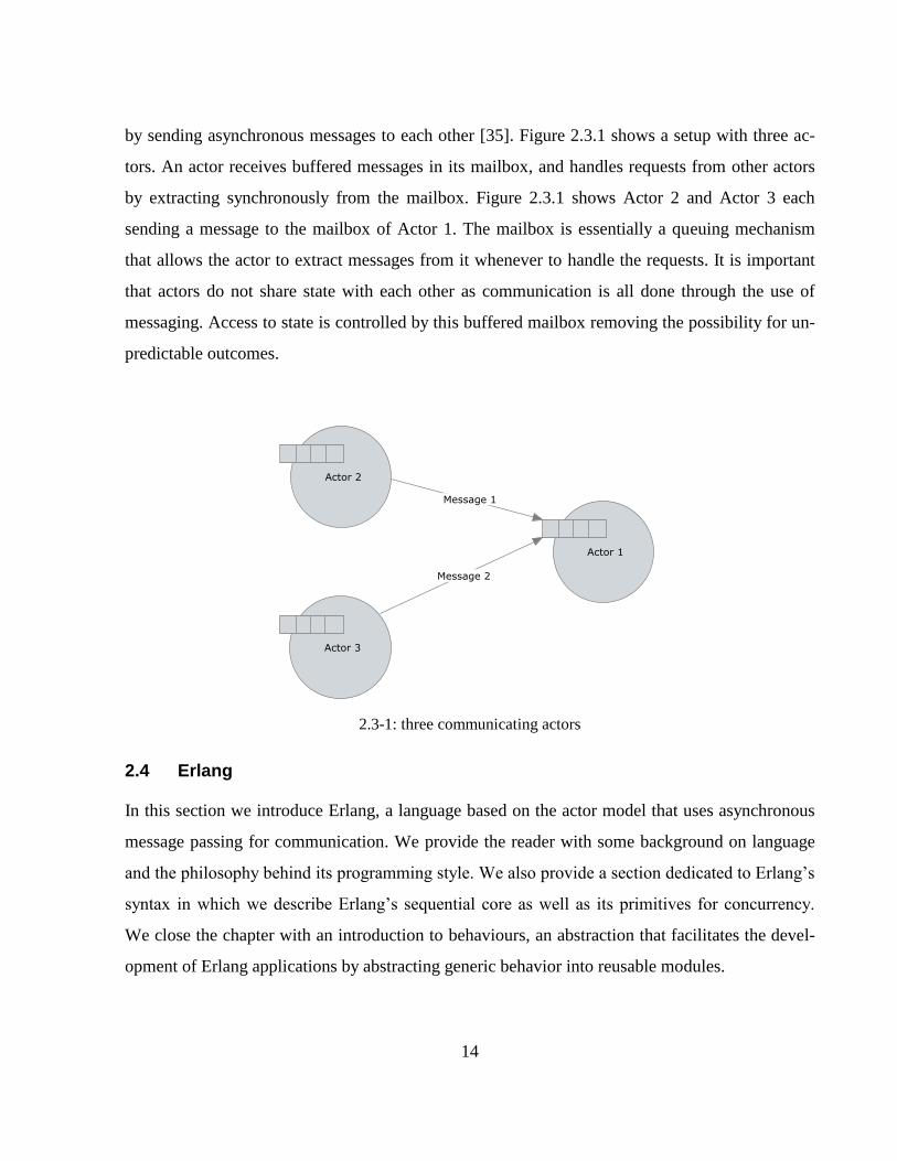
by sending asynchronous messages to each other [35]. Figure 2.3.1 shows a setup with three ac-
tors. An actor receives buffered messages in its mailbox, and handles requests from other actors
by extracting synchronously from the mailbox. Figure 2.3.1 shows Actor 2 and Actor 3 each
sending a message to the mailbox of Actor 1. The mailbox is essentially a queuing mechanism
that allows the actor to extract messages from it whenever to handle the requests. It is important
that actors do not share state with each other as communication is all done through the use of
messaging. Access to state is controlled by this buffered mailbox removing the possibility for un-
predictable outcomes.
2.3-1: three communicating actors
2.4 Erlang
In this section we introduce Erlang, a language based on the actor model that uses asynchronous
message passing for communication. We provide the reader with some background on language
and the philosophy behind its programming style. We also provide a section dedicated to Erlang’s
syntax in which we describe Erlang’s sequential core as well as its primitives for concurrency.
We close the chapter with an introduction to behaviours, an abstraction that facilitates the devel-
opment of Erlang applications by abstracting generic behavior into reusable modules.
15
2.4.1 Introduction
Erlang is a concurrent functional programming language designed for programming fault-tolerant
distributed systems. It was developed at the Ericson Computer Science Laboratory by Joe
Armstrong in 1986 [15]. Armstrong argues in [16] that the world we live in is concurrent by na-
ture, but that paradoxically, the languages we use to model the world around us are “predominant-
ly sequential” [16]. Languages such as Erlang on the other hand are inherently concurrent, allow-
ing the world to be modeled in its original concurrent form.
2.4.2 History and Philosophy
Joe Armstrong started writing Erlang while working at Ericson. The primary objective of the lan-
guage was “to provide a better way of programming telephony applications” [15]. Telephony ap-
plications are intrinsically concurrent. He argued that the conventional languages of the time were
not tailored to cater for these types of problems. He was primarily concerned with the need to
handle fault tolerance. He designed Erlang with the intent of providing a language for building
concurrent fault-tolerant systems that could “run forever” [15].
Joe Armstrong coined the term Concurrency Oriented Programming to explain what he intended
for a concurrent programming language to be. He identified the following six properties that cha-
racterize a concurrency oriented programming language [18]:
The language must support processes. Processes must be isolated such that a fault in one
process has no damaging affect on any other process. There should be no distinction be-
tween two processes running on the same machine and two processes running on physical-
ly distributed machines.
Each process has a unique identifier (the process ID). This is used to identify a process in
order to send messages t it.
Processes do not physically share state with each other. Information can be “shared” be-
tween processes by sending copies of data as messages. Processes never share references
to the same data. When sending messages, an exact copy of the data is sent to the receiver.
This decouples the processes such that a failure in one process has no affect in the other.
16
Message passing is done asynchronously. A process cannot be certain that the receiving
process has actually received the message. The only way to do this would be to send an
acknowledgement of receipt. But yet again, the acknowledgement is not guaranteed to be
received by the sender. This is essential for the required fault tolerance, as in synchronous
communication “an error in the receiver of a message can indefinitely block the sender”
[18].
A process should be able to detect faults occurring in other processes in order for it to take
the appropriate action, possibly re-spawning the process.
2.4.3 Programming style
Erlang was designed with the above principles in mind. Erlang is reputably known for its effi-
ciency in handling the creation and manipulation of processes [19]. Processes in Erlang are
lightweight. They require little memory, and the creation and destruction of processes as well as
the communication between processes, require little computational effort [20]. Most importantly,
processes are abstractions that belong to the language itself and not to the operating system [18].
Erlang adopts a message passing concurrency model. Processes are truly independent as they
share no memory, removing the need to safeguard data using semaphores or locks. The only form
of communication between processes occurs through asynchronous message passing. There is no
concept of shared data as processes work with copies of data. Processes receive messages through
a random access mailbox (similar to the one presented in figure 2.3.1) which queues messages in
a guaranteed order for messages from the same process [21]. The mailbox is accessed by the
process through the use of the blocking receive primitive. The message received is pattern
matched against a number of clauses and an action is performed accordingly.
2.4.4 Sequential Erlang
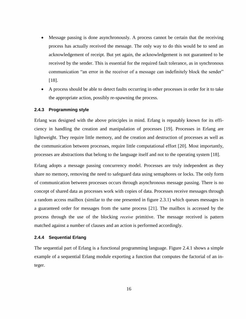
The sequential part of Erlang is a functional programming language. Figure 2.4.1 shows a simple
example of a sequential Erlang module exporting a function that computes the factorial of an in-
teger.
17
2.4-1: Factorial in Erlang
Applications in Erlang are divided into modules consisting of a number of functions. The module
name is specified using the module directive (line 1). Functions can be accessed from outside the
module by calling Module:Function, where Module is the module name, and Function is the func-
tion name. For a function to be accessible from outside the module it must be exported using the
export directive (line 2), otherwise the function would only be accessible locally. The integer at
the end of the function name in the export deceleration (line 2) specifies the number of arguments
the function takes. The export fac/1 for example, indicates that the function fac takes one argu-
ment.
The function fac/1 computes the factorial of an integer recursively. It consists of two clauses.
When a function is made up of several clauses, it uses pattern matching, starting from the topmost
clause, to decide which one to execute. The first clause (line 4) in fac/1 handles the base case.
When fac(0) is called, it returns the value 1 (line 5). The second clause evaluates the factorial of N
to N multiplied by the factorial of N – 1 (lines 7 - 8).
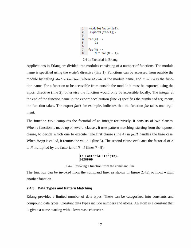
2.4-2: Invoking a function from the command line
The function can be invoked from the command line, as shown in figure 2.4.2, or from within
another function.
2.4.5 Data Types and Pattern Matching
Erlang provides a limited number of data types. These can be categorized into constants and
compound data types. Constant data types include numbers and atoms. An atom is a constant that
is given a name starting with a lowercase character.
18
Compound data types can be created using tuples or lists. Tuples are surrounded by curly brack-
ets, containing a fixed number of elements separated by commas. Figure 2.4.3 shows an example
of a tuple. The first element is an atom named event. The second element is an integer value, whe-
reas the third element consists of another tuple. The elements within this nested tuple are va-
riables (starting with upper case characters).
2.4-3: Erlang Tuple
A list is similar to a tuple but is of variable length. It is surrounded by squared brackets and is
used for storing a variable number of elements. The equivalent of the tuple as a list is shown in
figure 2.4.4.
2.4-4: Erlang List
The first element in the list is referred to as the head whereas the rest are referred to as the tail.
The head and tail of a list can be retrieved pattern matching the values to a head and tail variable
as shown in figure 2.4.6. Where Head is assigned the atom event and Tail is assigned the list [0,
{Pid, Args}].
2.4-5: Pattern Matching a List
Erlang uses single assignment variables. In the expression X = 1, the variable X is pattern matched
to the value 1, if X is a free variable then it is bound to the value 1, if it has already been assigned
the value of 1, then the statement returns true (positive match), and if it has already been assigned
value other than 1, an error is returned (negative match). Assignments of the form X = X + 1 do
not make sense in Erlang syntax as X on the left hand side and X on the right hand side of the equ-
ation should have the same value.
2.4.6 Concurrent Erlang
Concurrency is added to the language using the following primitives:
19
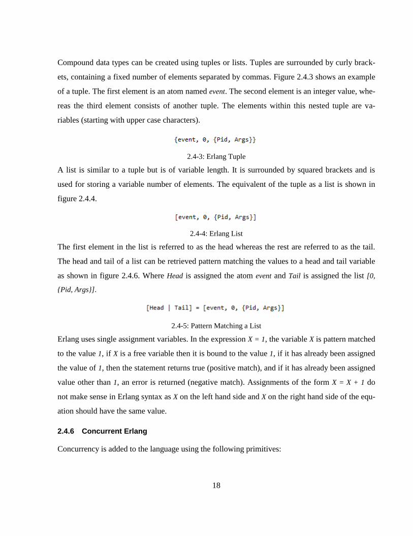
Spawn: the spawn primitive runs the given function as a separate process. Figure 2.4.6
shows an example of a function being spawned as a separate process. The spawn function
returns the process identifier (Pid) for that given process. This id can be used to send mes-
sages to its associated process.
2.4-6: Spawning a Process
Send: The send primitive (!) is used to send messages to a process’ mailbox using its giv-
en process ID as shown in figure 2.4.7.
2.4-7: Sending a Message
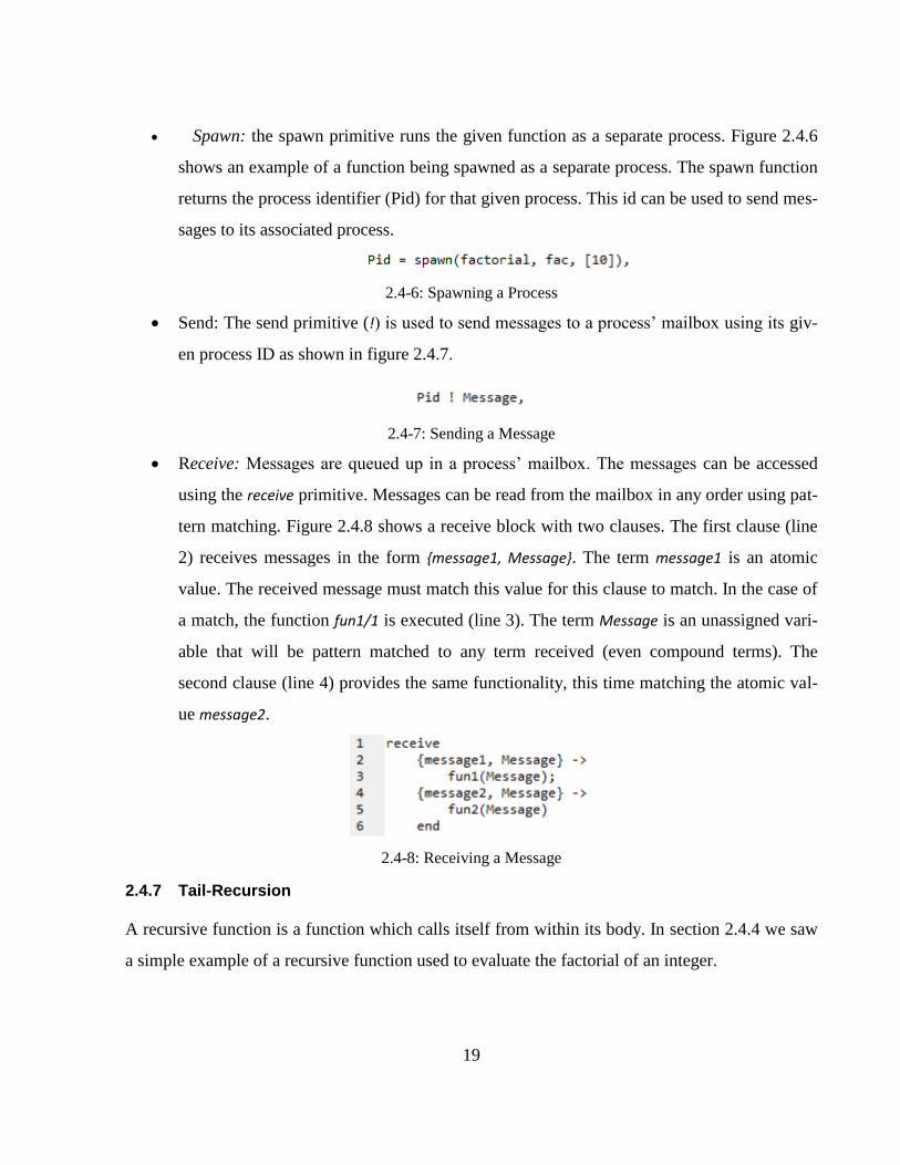
Receive: Messages are queued up in a process’ mailbox. The messages can be accessed
using the receive primitive. Messages can be read from the mailbox in any order using pat-
tern matching. Figure 2.4.8 shows a receive block with two clauses. The first clause (line
2) receives messages in the form {message1, Message}. The term message1 is an atomic
value. The received message must match this value for this clause to match. In the case of
a match, the function fun1/1 is executed (line 3). The term Message is an unassigned vari-
able that will be pattern matched to any term received (even compound terms). The
second clause (line 4) provides the same functionality, this time matching the atomic val-
ue message2.
2.4-8: Receiving a Message
2.4.7 Tail-Recursion
A recursive function is a function which calls itself from within its body. In section 2.4.4 we saw
a simple example of a recursive function used to evaluate the factorial of an integer.
20
Recursion is also used to implement the event loop of an Erlang process. Specifically tail-
recursion is used for this functionality. Tail-recursion refers to a function whose last instruction is
the recursive call. Erlang’s compiler optimizes tail recursion modeling it as iteration rather than a
recursive function.
Server processes run concurrently with numerous other processes interacting with each other to
perform some global task. The process generally sits idle waiting on some request, received in the
form of a message. This is implemented using the blocking receive primitive which forces the
process to wait until there is a message in the process’ mailbox. Once a message is received, it
performs some activity, possible interacting with other processes, and possibly returning some
response to the calling process. Once the request has been handled, the process recurses and
blocks once again until another message has been received.
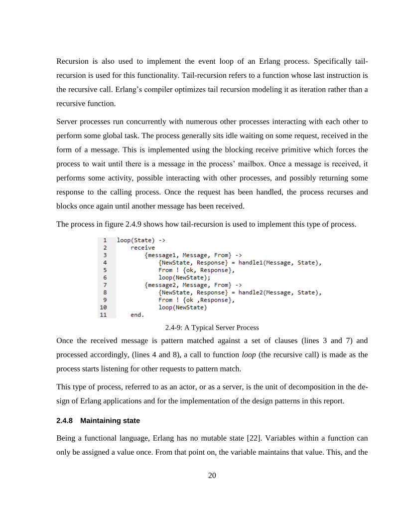
The process in figure 2.4.9 shows how tail-recursion is used to implement this type of process.
2.4-9: A Typical Server Process
Once the received message is pattern matched against a set of clauses (lines 3 and 7) and
processed accordingly, (lines 4 and 8), a call to function loop (the recursive call) is made as the
process starts listening for other requests to pattern match.
This type of process, referred to as an actor, or as a server, is the unit of decomposition in the de-
sign of Erlang applications and for the implementation of the design patterns in this report.
2.4.8 Maintaining state
Being a functional language, Erlang has no mutable state [22]. Variables within a function can
only be assigned a value once. From that point on, the variable maintains that value. This, and the
21
no shared state in the message passing concurrency setting, provides a means for controlling side
effects in Erlang. A process maintains state explicitly by using tail-recursion as described in sec-
tion 2.4.7. The loop function shown in figure 2.4.9 takes an argument representing the state of the
process. Being immutable, the variable cannot be reassigned to a new value. The process however
maintains state explicitly by passing variables around function parameters. In figure 2.4.9 the
state is altered in line 4 as the function handle1 returns the variable NewState. The recursive call to
loop is then made (line 6) passing the new variable.
It is important to note that process do not share physical memory/state with each other. If a
process requires some information about another process’ state, the process can send a message
with a copied version of the data.
2.4.9 Erlang Behaviours
The Erlang community provides a set of design patterns for building common applications. These
patterns are referred to as behaviours. They are described as “parametrizable higher order parallel
processes” [15].
They provide a way of separating the nonfunctional aspects of a problem from its functional be-
havior by “[encapsulating] common behavioral patterns” [22] into a single higher order function.
They are used to build generic reusable models such as the client-server model and event han-
dling systems.
Behaviours allow for code to be split into a generic part and a specific part. The generic part is the
behaviour. This is written once and can be reused in different contexts. The specific part is the
callback module. The callback module defines the application specific behavior to be which ex-
tends the behaviour. The behaviour specifies the specific functions the callback module must im-
plement and export (the interface between the behaviour and the callback module) by exporting a
function behaviour_info/1. The callback module simply implements these application specific
functions to be used by the behaviour.
The Erlang community provides the following standard behaviours:
22
gen_event: This is an event handler manager allowing for events to be registered with
events dynamically. When a specific event fires, all registered event handlers are automat-
ically executed by the gen_event behaviour.
gen_server: this provides a standard way of defining a server process. The callback mod-
ule defines the application specific services provided by the server. The behaviour manag-
es the event loop and the dispatching of results.
gen_fsm: this provides a standard way of defining finite state machines. The callback
module definite a function for each state, describing the state transitions. The actual tran-
sitions are handled by the behaviour itself.
application: This provides a standard way of structuring Erlang applications. It handles
starting and stopping an Erlang application. It makes use of a resource file which instructs
it on how to handle the application.
The set of behaviours can easily be extended to include custom abstractions for common design
patterns. The concurrency design patterns presented in [3] provide a number of potential Erlang
behaviours.
2.5 Object-Oriented concepts in Erlang
The design patterns we intend to implement using Erlang were originally written in an object-
oriented language using object-oriented techniques to provide the reusability and modularity that
is inherent in design patterns. Erlang is a functional programming language having a declarative
syntax that is based on the actor-model for concurrency [26]. In order to implementing the pat-
terns in Erlang, we must find alternative techniques to inheritance and techniques for achieving
reusability, extendibility, and the polymorphism. In this section we provide a comparison of the
object-oriented techniques used in the implementation of design patterns and the alternative tech-
niques used in Erlang to provide the same results.
2.5.1 Comparing Erlang to OOP
In section 2.2.5 we introduced inheritance as a key feature in the implementation of object-
oriented design patterns. However, it is not inheritance per se that makes the pattern, it is results
23
achieved through the use of inheritance, namely the polymorphism, code reusability and extensi-
bility achieved through its adoption. Although Erlang does not provide support inheritance, the
same results can be achieved through other techniques such as delegation and the use of first or-
der functions.
Even though Erlang is not an object-oriented language, Erlang processes are often compared to
object-oriented objects as they exhibit similar behaviour. Ralph Johnson, one of the authors of
[1], has said that “Erlang fits all the characteristics of an OO system, even though sequential Er-
lang is a functional language, not an OO language” [27].
Erlang is said to be “object-based” [28] rather than object oriented. It does provide data encapsu-
lation and polymorphic functions, just not in the same way object-oriented languages do. Unlike
passive objects, each Erlang process is assigned its own thread of control. For this reason an ac-
tive object (see sec. 3.1) may prove a better alternative for a comparison with Erlang processes
than passive objects. A discussion on this comparison follows in section 3.1 where we discuss the
active object design pattern and the actor model.
Where object-oriented languages use objects, Erlang uses processes. These concurrent processes
are polymorphic, in that processes responding to a set of messages may be substituted for each
other transparently [18].
In section 2.4.7 we saw the implementation of an Erlang process. Figure 2.5.1 shows a raw com-
parison between this type of process and a C#.
24
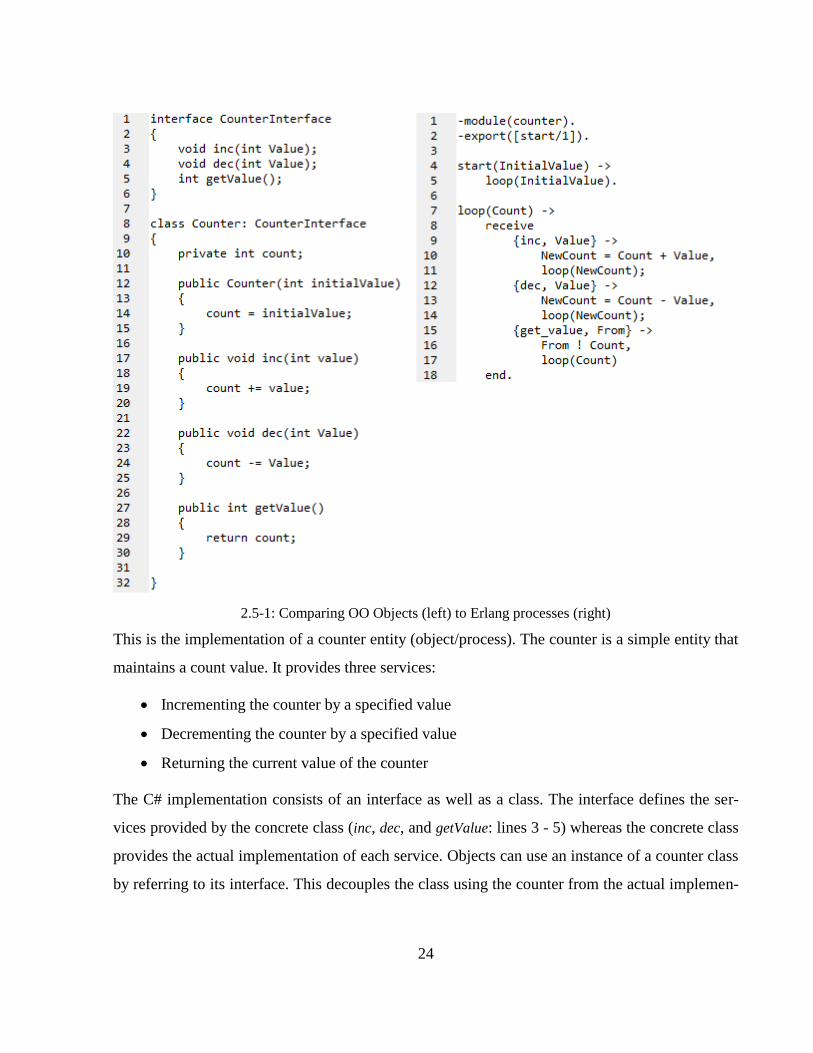
2.5-1: Comparing OO Objects (left) to Erlang processes (right)
This is the implementation of a counter entity (object/process). The counter is a simple entity that
maintains a count value. It provides three services:
Incrementing the counter by a specified value
Decrementing the counter by a specified value
Returning the current value of the counter
The C# implementation consists of an interface as well as a class. The interface defines the ser-
vices provided by the concrete class (inc, dec, and getValue: lines 3 - 5) whereas the concrete class
provides the actual implementation of each service. Objects can use an instance of a counter class
by referring to its interface. This decouples the class using the counter from the actual implemen-
25
tation of the counter itself, allowing for other object implementing the same interface to be treated
in the same way. This decoupling is paramount in the design of design patterns.
The Erlang implementation of a similar entity is shown on the right hand side of figure 2.5.1. The
start function (line 4) provides the same functionality as the C# constructor. It starts off the event
loop, by calling the loop function (line 5), and sets the initial value of the counter. This represents
the state of the counter (refer to section 2.4.8 for more information on maintaining state in func-
tional languages).
The process also provides the same three services as the C# object. Erlang processes all follow
the same message passing interface [18]. By making sure that two processes respond to the same
messages, one process can be swapped for the other transparently, achieving the same polymor-
phism achieved through the use of interfaces.
Erlang also uses delegation to get the same affect of inheritance. Delegation in Erlang involves
the use of higher order functions and callback functions. This is paramount in the use of beha-
viours. A single module (the behaviour module) can define the interface to a process by specify-
ing the messages it receives. Specific functionality can then be delegated to a function in another
module. Inheritance allows for the delegated entity to refer to its caller (in java using the this op-
erator for example). If necessary, the calling process can send a reference of itself to the delegated
function in order to replicate this behavior. We will see more on behaviours in section (3.1)
where we define our first Erlang behaviour.
In the book [1] the authors advise readers to “favor object composition over class inheritance”
when implementing design patterns. The lack of inheritance is in no way a handicap to Erlang
processes implementing design patterns as the favored compositional property can be achieved
through delegation, behaviours, and first order functions.
2.5.2 Conclusion
In this section we introduced some generic techniques that will be used in the implementation of the de-
sign patterns in Erlang. We provided a subtle comparison between objects and processes to show how a
participant in the original pattern can be implemented as a process. Although the mapping appears to be
natural, a one-to-one mapping between objects and processes is not always possible and generally not the
26
correct solution. This is simply the basis on which the transition is carried out. In the implementation we
attempt to take advantage of the concurrency constructs that are available in processes that are lacking in
passive objects
2.6 Peer-to-Peer
In assessing the design patterns we implement a peer-to-peer file sharing application in Erlang using the
behaviours. This type of application is ideal for our task at hand as it exhibits a high degree of concurren-
cy.
2.6.1 Introduction
Peer-to-peer networks provide an alternate means to the client-server approach for sharing data.
In this approach, a peer acts both as the client and as a server. Rather than having data stored in a
few centralized locations, the services and data on each node on the network is shared with every
other node [1].
This architecture addresses two issues with the client-server approach; scalability and reliability.
With the server architecture, the resources on the server are shared between all the clients. As the
number of clients increases, the demand on processing power and resources increases. This de-
sign is not scalable. On the other hand, in the P2P network, as the number of peers in a P2P in-
creases, so does the network’s capacity as each peer makes its resources and services available.
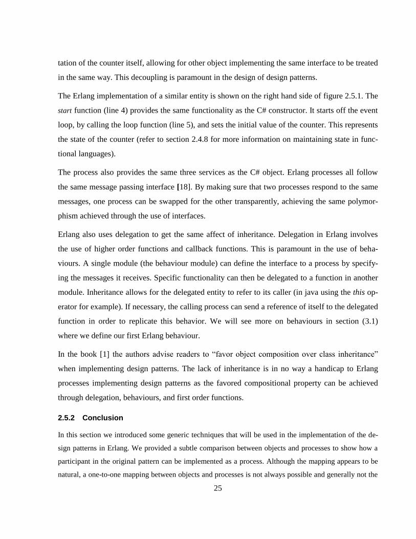
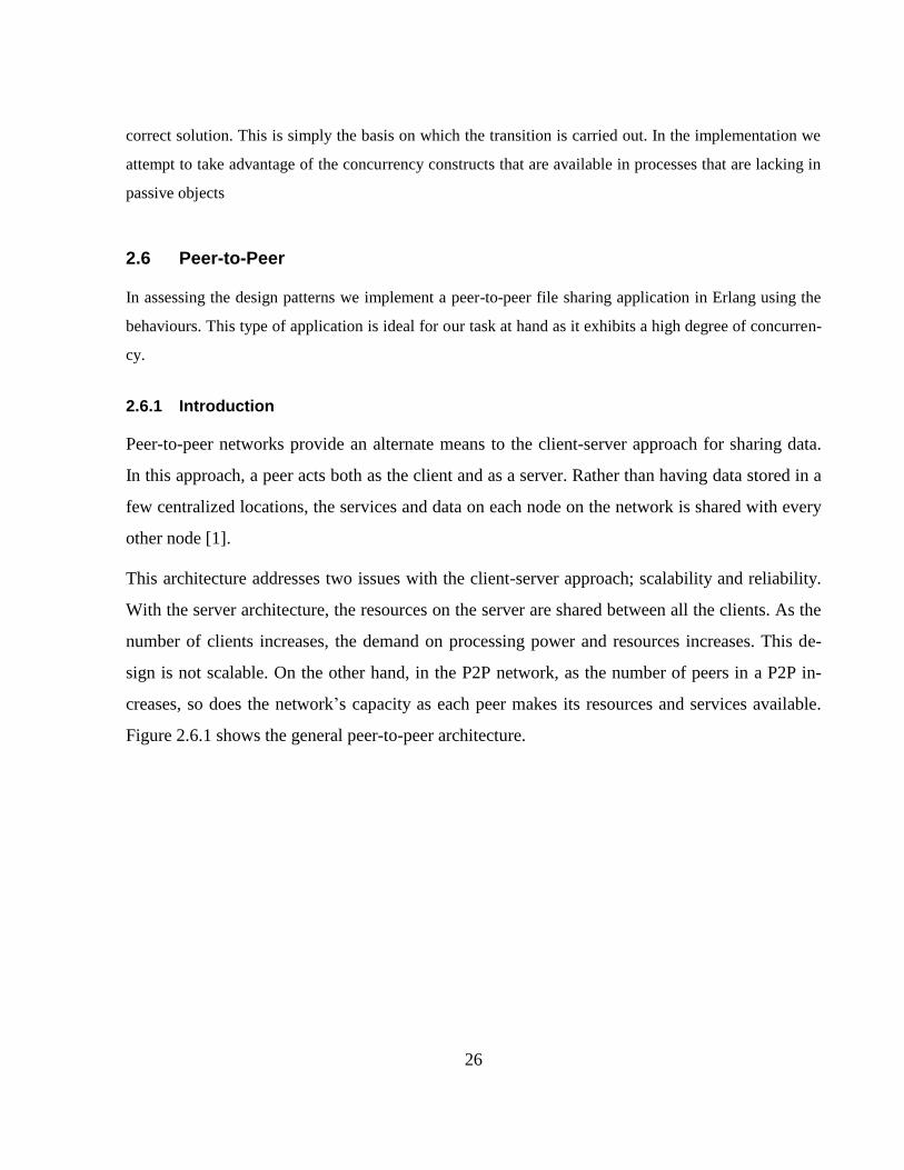
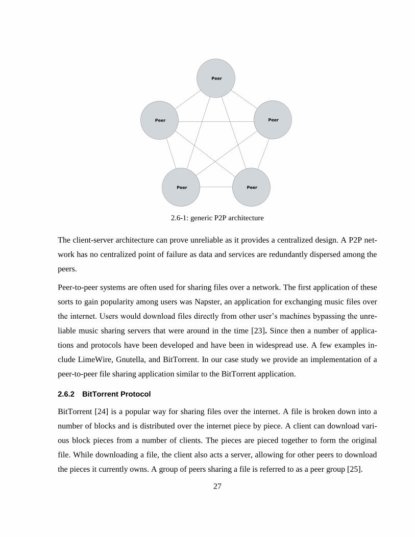
Figure 2.6.1 shows the general peer-to-peer architecture.
27
2.6-1: generic P2P architecture
The client-server architecture can prove unreliable as it provides a centralized design. A P2P net-
work has no centralized point of failure as data and services are redundantly dispersed among the
peers.
Peer-to-peer systems are often used for sharing files over a network. The first application of these
sorts to gain popularity among users was Napster, an application for exchanging music files over
the internet. Users would download files directly from other user’s machines bypassing the unre-
liable music sharing servers that were around in the time [23]. Since then a number of applica-
tions and protocols have been developed and have been in widespread use. A few examples in-
clude LimeWire, Gnutella, and BitTorrent. In our case study we provide an implementation of a
peer-to-peer file sharing application similar to the BitTorrent application.
2.6.2 BitTorrent Protocol
BitTorrent [24] is a popular way for sharing files over the internet. A file is broken down into a
number of blocks and is distributed over the internet piece by piece. A client can download vari-
ous block pieces from a number of clients. The pieces are pieced together to form the original
file. While downloading a file, the client also acts a server, allowing for other peers to download
the pieces it currently owns. A group of peers sharing a file is referred to as a peer group [25].
28
A client starts sharing a file for the first time by creating a Metainfo file [25]. This file provides
the necessary information for other peers on the network to start downloading the file such as the
file name.
A key piece of information stored by this file is a list of trackers. A tracker is a server application
which tracks the peers in a peer group. A client starts sharing an existing file by parsing its asso-
ciated Metainfo file, from which it extracts the list of trackers. It then requests the addresses of
the peers in the peer group from these trackers. Once the addresses have been obtained, the client
interacts with each peer and starts requesting pieces that it needs.
Peers communicate using the BitTorrent protocol [25]. This specifies communication protocol
each peer must follow.
Applications sharing files using the BitTorrent protocol exhibit a high degree of concurrency as
they must cater for multiple clients requesting file pieces while it is requesting file pieces from
multiple other clients itself.
2.7 Conclusion
In this chapter we covered a range of material related to our study on design patterns. We intro-
duced design patterns and some related concepts discussing the benefits in their adoption. We
discussed some basic object-oriented techniques and the way in which they are adopted in object-
oriented implementation of design patterns.
We also explored the shared memory and the message passing concurrency models outlining the
differences in their architecture and the challenges we are faced with in adapting patterns from the
former to the later.
We then introduced Erlang, a language based on the actor model that uses asynchronous message
passing for communication between processes. This is the language we adopted in the investiga-
tion of the patterns’ transferability from the object-oriented context to the message passing set-
ting.
29
We concluded the chapter with a short introduction to peer-to-peer file sharing applications and
the BitTorrent protocol. We introduce this here as we intend on implementing such an application
for the evaluation of the implemented design patterns. It is an application with a high degree of
concurrency making it ideal for our analysis. The application itself will use a similar style to the
BitTorrent protocol for the communication between peers.
In the upcoming section we set out to implement a number of design patterns from the object-
oriented context as Erlang behaviours.
30
3. Design Patterns: Design and Implementation as Erlang behaviours
In this section we cover the design and implementation of a number of design patterns from the
object-oriented context implemented in the message passing concurrency setting. The patterns
examined are the Active Object, the Acceptor-Connector, the Observer, the Leader/Followers,
and the Proactor design patterns.
The section is split into a number of subsections, one for each pattern, in which we examine the
pattern’s design and its implementation in Erlang.
Specifically, each section provides an introduction to pattern, describing the problems it addresses
and the situations in which it is to be used. It also examines the overall structure and dynamics of
the pattern, in which we cover the pattern’s participants as concurrent processes. We then provide
the implementation of the generic protocol that is adopted by the pattern. This is implemented as
an Erlang behaviour that can be reused to implement specific instances of the pattern. We then
provide an example of its usage by implementing a callback module demonstrating the generality
of the specific behaviour.
3.1 Active Object
The first pattern we investigate is the Active Object design pattern. This pattern is used to de-
couple the execution of a method, from its invocation. The applications is structured such that
each entity executes in its own thread of control communicating using asynchronous message
passing. This particular pattern provides a programming style comparable to Erlang’s approach to
concurrency. It is based on the actor model, which is the same model that Erlang processes are
built on [26].
For this reason the implementation of the patterns in Erlang is straightforward but provides a
good foundation on which to base the implementation of the remaining behaviours. The Erlang
OTP provides a behaviour that captures the essence of the active object pattern, the gen_server.
Our implementation is based on this same behaviour.
31
In the rest of this section we introduce the active object design pattern. We then provide an im-
plementation of the pattern as an Erlang behaviour. We finally provide an example of its use in
the implementation of a simple counter server.
3.1.1 Intent
The intent of the Active Object design patterns [3, 30] is to decouple the invocation of a service
on an entity from its execution. This results in enhanced concurrency and simplifies concurrent
access to entities lying in their own thread of execution.
3.1.2 Context
When dealing with multiple threads executing concurrently in a shared memory environment, one
runs into synchronization issues if the threads and are not structured adequately. When shared va-
riables are accessed and modified concurrently by multiple threads the resulting value may con-
tain unexpected results as is the case in the lost-update problem [26]. This can be avoided by
making use of locks to ensure mutual exclusion on the shared data. The use of locks however in-
troduces programming complexities as well as their own set of problems such as the deadlocks.
The Active Object pattern provides a different approach to concurrency in which an entity’s state
and functionality are encapsulated in a single module with its own active thread of control [29]. A
single active thread manages its own state rather than having multiple threads within a single ob-
ject manipulating data concurrently. Communication between threads takes place through the use
of asynchronous messaging, reducing the level of coupling between the caller and the entity
processing the request. The active object handles a message only when it is ready to handle it as
access to the entity’s data is synchronized.
3.1.3 Structure and Dynamics
The participants of the pattern in the object-oriented implementation consist of a proxy, a method
request object, a scheduler, an activation list, a servant object, and a future. Figure 3.1.1 below
shows the structure of the pattern in the form of a class diagram as found in [3].
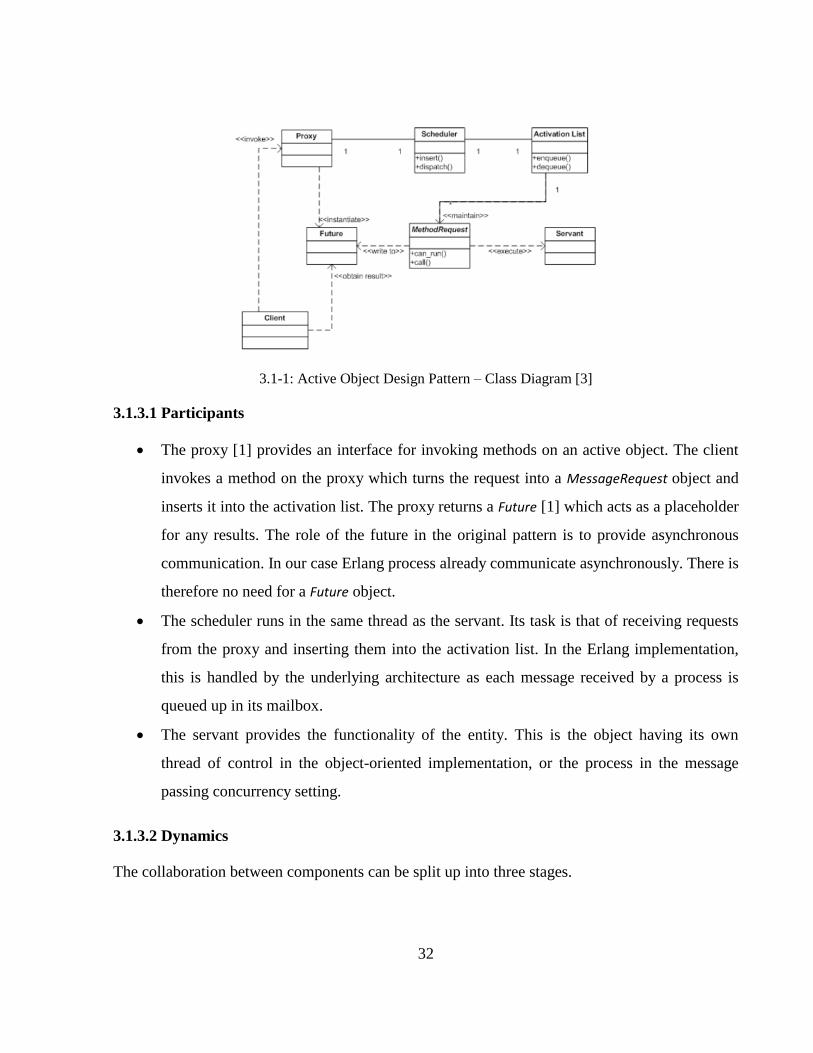
32
3.1-1: Active Object Design Pattern – Class Diagram [3]
3.1.3.1 Participants
The proxy [1] provides an interface for invoking methods on an active object. The client
invokes a method on the proxy which turns the request into a MessageRequest object and
inserts it into the activation list. The proxy returns a Future [1] which acts as a placeholder
for any results. The role of the future in the original pattern is to provide asynchronous
communication. In our case Erlang process already communicate asynchronously. There is
therefore no need for a Future object.
The scheduler runs in the same thread as the servant. Its task is that of receiving requests
from the proxy and inserting them into the activation list. In the Erlang implementation,
this is handled by the underlying architecture as each message received by a process is
queued up in its mailbox.
The servant provides the functionality of the entity. This is the object having its own
thread of control in the object-oriented implementation, or the process in the message
passing concurrency setting.
3.1.3.2 Dynamics
The collaboration between components can be split up into three stages.
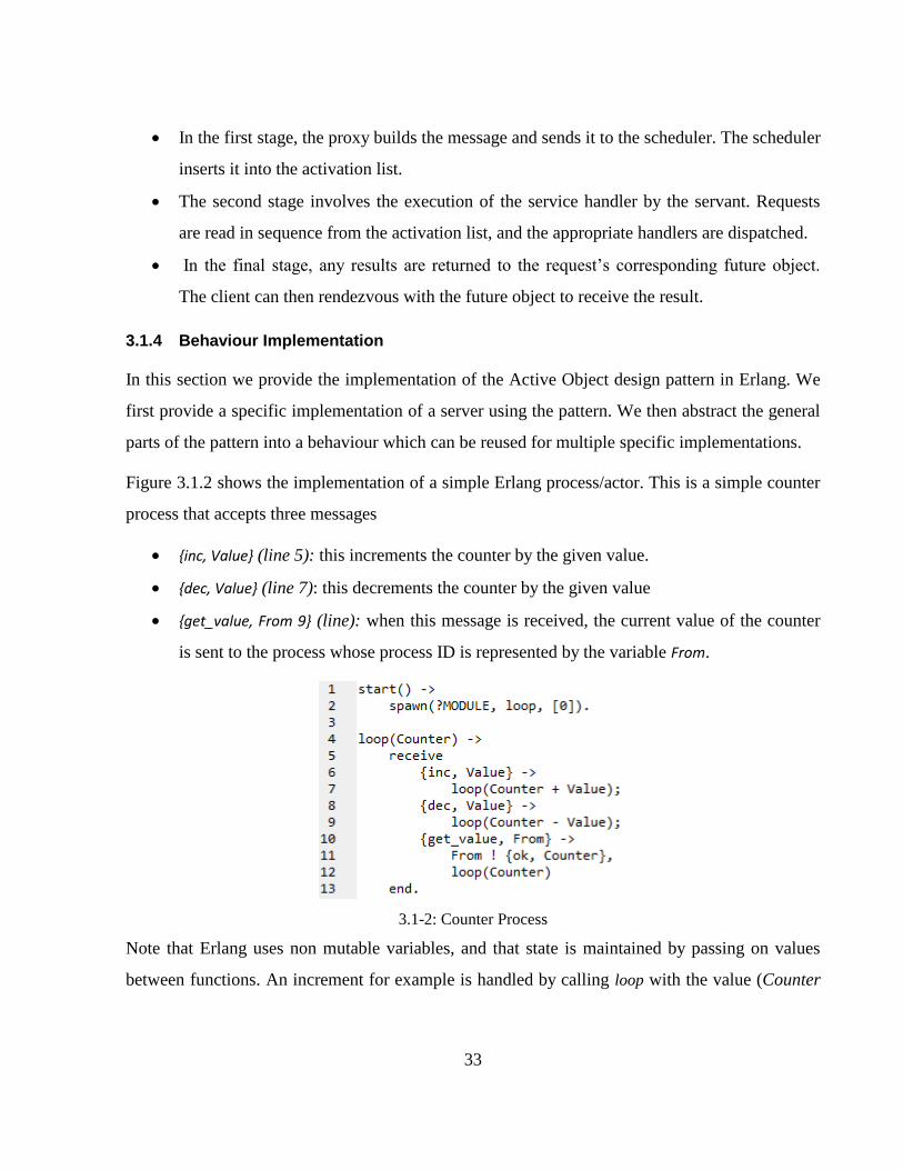
33
In the first stage, the proxy builds the message and sends it to the scheduler. The scheduler
inserts it into the activation list.
The second stage involves the execution of the service handler by the servant. Requests
are read in sequence from the activation list, and the appropriate handlers are dispatched.
In the final stage, any results are returned to the request’s corresponding future object.
The client can then rendezvous with the future object to receive the result.
3.1.4 Behaviour Implementation
In this section we provide the implementation of the Active Object design pattern in Erlang. We
first provide a specific implementation of a server using the pattern. We then abstract the general
parts of the pattern into a behaviour which can be reused for multiple specific implementations.
Figure 3.1.2 shows the implementation of a simple Erlang process/actor. This is a simple counter
process that accepts three messages
{inc, Value} (line 5): this increments the counter by the given value.
{dec, Value} (line 7): this decrements the counter by the given value
{get_value, From 9} (line): when this message is received, the current value of the counter
is sent to the process whose process ID is represented by the variable From.
3.1-2: Counter Process
Note that Erlang uses non mutable variables, and that state is maintained by passing on values
between functions. An increment for example is handled by calling loop with the value (Counter
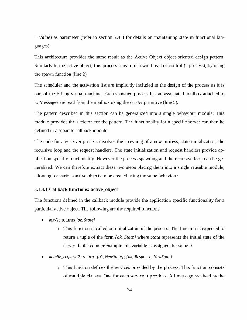
34
+ Value) as parameter (refer to section 2.4.8 for details on maintaining state in functional lan-
guages).
This architecture provides the same result as the Active Object object-oriented design pattern.
Similarly to the active object, this process runs in its own thread of control (a process), by using
the spawn function (line 2).
The scheduler and the activation list are implicitly included in the design of the process as it is
part of the Erlang virtual machine. Each spawned process has an associated mailbox attached to
it. Messages are read from the mailbox using the receive primitive (line 5).
The pattern described in this section can be generalized into a single behaviour module. This
module provides the skeleton for the pattern. The functionality for a specific server can then be
defined in a separate callback module.
The code for any server process involves the spawning of a new process, state initialization, the
recursive loop and the request handlers. The state initialization and request handlers provide ap-
plication specific functionality. However the process spawning and the recursive loop can be ge-
neralized. We can therefore extract these two steps placing them into a single reusable module,
allowing for various active objects to be created using the same behaviour.
3.1.4.1 Callback functions: active_object
The functions defined in the callback module provide the application specific functionality for a
particular active object. The following are the required functions.
init/1: returns {ok, State}
o This function is called on initialization of the process. The function is expected to
return a tuple of the form {ok, State} where State represents the initial state of the
server. In the counter example this variable is assigned the value 0.
handle_request/2: returns {ok, NewState}; {ok, Response, NewState}
o This function defines the services provided by the process. This function consists
of multiple clauses. One for each service it provides. All message received by the
35
behaviour are dispatched to this function. The function pattern matches the mes-
sage with its clauses in order to decide which to execute. It then returns the result
of the computation. The result is to be in the form {ok, Newstate} where NewState is
the variable representing the new state of the process, or {ok, Response, NewState},
where NewState is the new state and Response is the result of the computation
which is to be sent to the calling process.
3.1.4.2 Behaviour: active_object
Figure 3.1.3 shows the code for the active_object behaviour. The start/2 function launches the
server by spawning the init/2 function (line 2). This function takes the name of the callback mod-
ule as a parameter.
This module provides a number of functions that are needed by the behaviour to extend its func-
tionality. The required functions are specified by the function behaviour_info/1 (line 20). In this
case, the required callback functions are init/1 and handle_request/2.
3.1-3: Active Object behaviour
The behaviour’s init/2 function (line 4) invokes the callback module’s init/2 function which re-
turns the state of the active object. In the case of the counter server, this returned value is {ok, 0}
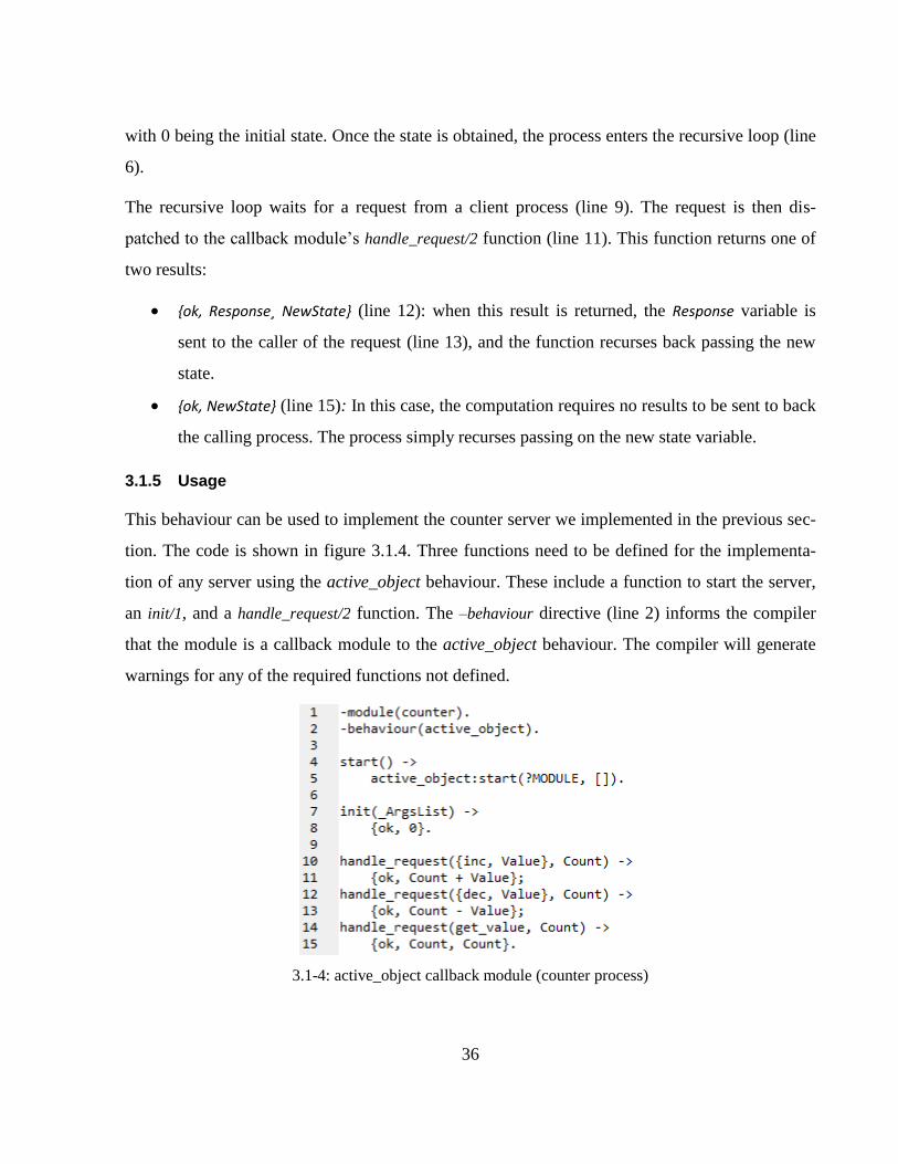
36
with 0 being the initial state. Once the state is obtained, the process enters the recursive loop (line
6).
The recursive loop waits for a request from a client process (line 9). The request is then dis-
patched to the callback module’s handle_request/2 function (line 11). This function returns one of
two results:
{ok, Response¸ NewState} (line 12): when this result is returned, the Response variable is
sent to the caller of the request (line 13), and the function recurses back passing the new
state.
{ok, NewState} (line 15): In this case, the computation requires no results to be sent to back
the calling process. The process simply recurses passing on the new state variable.
3.1.5 Usage
This behaviour can be used to implement the counter server we implemented in the previous sec-
tion. The code is shown in figure 3.1.4. Three functions need to be defined for the implementa-
tion of any server using the active_object behaviour. These include a function to start the server,
an init/1, and a handle_request/2 function. The –behaviour directive (line 2) informs the compiler
that the module is a callback module to the active_object behaviour. The compiler will generate
warnings for any of the required functions not defined.
3.1-4: active_object callback module (counter process)
37
The start/0 function (line 4) calls the active_object’s start/2 function (line 5), passing the module
name (counter) as the reference to the callback module. This starts the active_object process, with
the calling module as the callback module.
The init/1 function (line7) provides the initial state for the server process. In this case it returns a 0
setting the counter’s value to 0 (line 8).
The handle_request/2 function (lines 10 - 15) handles messages received by the server process. It
processes the request returning the new state of the server, together with any results to be sent to
the client. The function consists of three clauses, each one handling the specific messages.
By making use of the behaviour, the developer does not implement the spawning and the main
loop of the active_object as this is handled by the behaviour. This allows the developer to write
simple sequential code, while the behaviour handles all the concurrency in the background.
3.1.6 Conclusion
In this section we implemented our first behaviour showing how it can be used to implement a
specific server processes. The Active Object design pattern is an example of a pattern which turns
out to be simpler to implement in the message passing concurrency setting than in a sequential
context. Creating and debugging systems built using active objects in a Java like language can
turn into a complex task. Moreover, in a Java implementation it is the responsibility of the devel-
oper to implement the scheduler and the activation list, whereas in the Erlang implementation
these are provided by the Erlang virtual machine.
The counter process shown in figure 3.1.4, which uses the active_object behaviour, can be com-
pared to the counter process shown in figure 3.1.2, implemented without the behaviour. The use
of the behaviour allows the developer to write code that appears to be sequential. The behaviour
turns this sequential code into a concurrent process seamlessly. This allows the developer to focus
on the implementation of the application specific behavior rather than on generic concurrency is-
sues.
38
3.2 Acceptor-Connector
The Acceptor-Connector pattern [3, 31] is used in a distributed environment where a server appli-
cation must handle requests from a number of clients communicating over a network.
3.2.1 Intent
The intent of this pattern is to decouple the connection and initialization stages from the applica-
tion specific processing performed once a connection has been established [31]. This decoupling
provides the flexibility for services to be added and removed transparently without the need to re-
implement connection establishment code.
3.2.2 Context
Distributed applications using protocols over the internet, such as TCP connections, may have
complex connection establishment code and initialization that is independent of the communica-
tion that is carried out between the two endpoints once the connection has been established [3].
These may include authentication and authorization communication protocols for example. Dif-
ferent network programming interfaces provide different methods for connection establishment,
but allow transfer over the endpoints using uniform interfaces.
The services provided may be independent of which client initiated the connection. In a P2P ap-
plication for example, once a connection between two peers has been established, the peers have
identical functionality. In such a case it is irrelevant which peer established the connection [3].
The Acceptor-Connector pattern decouples the initialization aspects from the service handlers in
order to provide the necessary flexibility for these issues. This design also allows for the services
on the server to be changed without the need to modify the initialization and connection estab-
lishment code.
3.2.3 Structure & Dynamics
For each service provided by the application the Acceptor-Connector pattern can be used to de-
couple the connection establishment and service initialization from the data exchange and
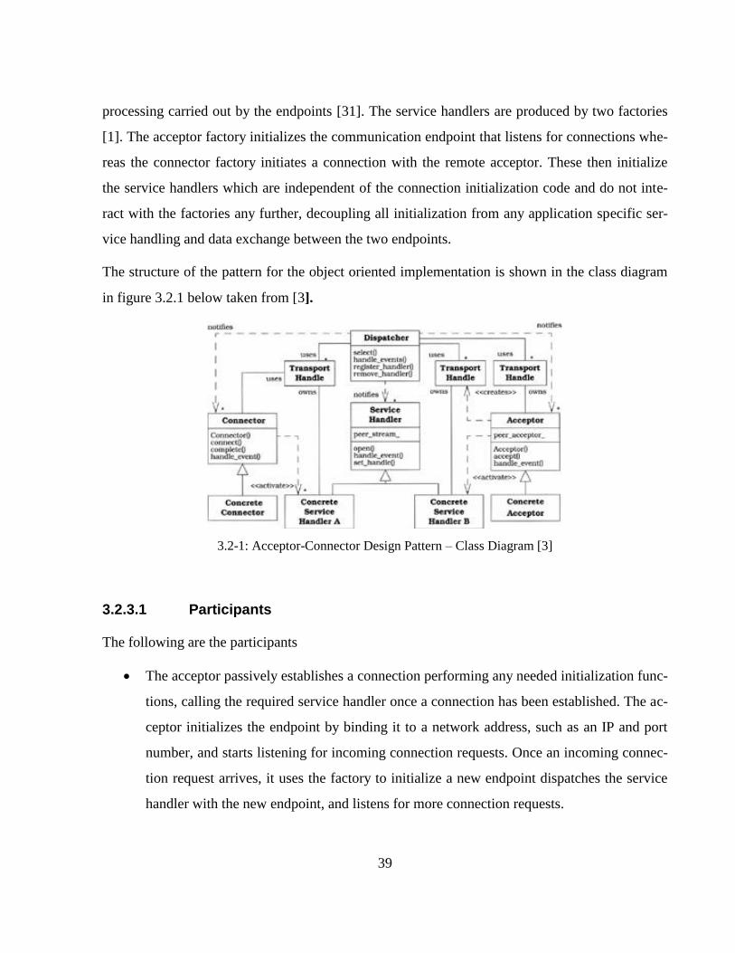
39
processing carried out by the endpoints [31]. The service handlers are produced by two factories
[1]. The acceptor factory initializes the communication endpoint that listens for connections whe-
reas the connector factory initiates a connection with the remote acceptor. These then initialize
the service handlers which are independent of the connection initialization code and do not inte-
ract with the factories any further, decoupling all initialization from any application specific ser-
vice handling and data exchange between the two endpoints.
The structure of the pattern for the object oriented implementation is shown in the class diagram
in figure 3.2.1 below taken from [3].
3.2-1: Acceptor-Connector Design Pattern – Class Diagram [3]
3.2.3.1 Participants
The following are the participants
The acceptor passively establishes a connection performing any needed initialization func-
tions, calling the required service handler once a connection has been established. The ac-
ceptor initializes the endpoint by binding it to a network address, such as an IP and port
number, and starts listening for incoming connection requests. Once an incoming connec-
tion request arrives, it uses the factory to initialize a new endpoint dispatches the service
handler with the new endpoint, and listens for more connection requests.
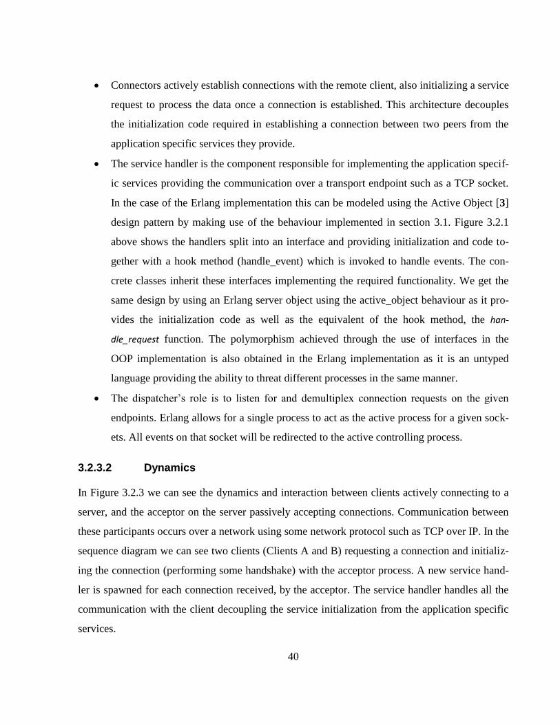
40
Connectors actively establish connections with the remote client, also initializing a service
request to process the data once a connection is established. This architecture decouples
the initialization code required in establishing a connection between two peers from the
application specific services they provide.
The service handler is the component responsible for implementing the application specif-
ic services providing the communication over a transport endpoint such as a TCP socket.
In the case of the Erlang implementation this can be modeled using the Active Object [3]
design pattern by making use of the behaviour implemented in section 3.1. Figure 3.2.1
above shows the handlers split into an interface and providing initialization and code to-
gether with a hook method (handle_event) which is invoked to handle events. The con-
crete classes inherit these interfaces implementing the required functionality. We get the
same design by using an Erlang server object using the active_object behaviour as it pro-
vides the initialization code as well as the equivalent of the hook method, the han-
dle_request function. The polymorphism achieved through the use of interfaces in the
OOP implementation is also obtained in the Erlang implementation as it is an untyped
language providing the ability to threat different processes in the same manner.
The dispatcher’s role is to listen for and demultiplex connection requests on the given
endpoints. Erlang allows for a single process to act as the active process for a given sock-
ets. All events on that socket will be redirected to the active controlling process.
3.2.3.2 Dynamics
In Figure 3.2.3 we can see the dynamics and interaction between clients actively connecting to a
server, and the acceptor on the server passively accepting connections. Communication between
these participants occurs over a network using some network protocol such as TCP over IP. In the
sequence diagram we can see two clients (Clients A and B) requesting a connection and initializ-
ing the connection (performing some handshake) with the acceptor process. A new service hand-
ler is spawned for each connection received, by the acceptor. The service handler handles all the
communication with the client decoupling the service initialization from the application specific
services.
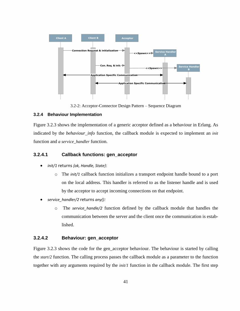
41
3.2-2: Acceptor-Connector Design Pattern – Sequence Diagram
3.2.4 Behaviour Implementation
Figure 3.2.3 shows the implementation of a generic acceptor defined as a behaviour in Erlang. As
indicated by the behaviour_info function, the callback module is expected to implement an init
function and a service_handler function.
3.2.4.1 Callback functions: gen_acceptor
init/1 returns {ok, Handle, State}:
o The init/1 callback function initializes a transport endpoint handle bound to a port
on the local address. This handler is referred to as the listener handle and is used
by the acceptor to accept incoming connections on that endpoint.
service_handler/2 returns any():
o The service_handle/2 function defined by the callback module that handles the
communication between the server and the client once the communication is estab-
lished.
3.2.4.2 Behaviour: gen_acceptor
Figure 3.2.3 shows the code for the gen_acceptor behaviour. The behaviour is started by calling
the start/2 function. The calling process passes the callback module as a parameter to the function
together with any arguments required by the init/1 function in the callback module. The first step
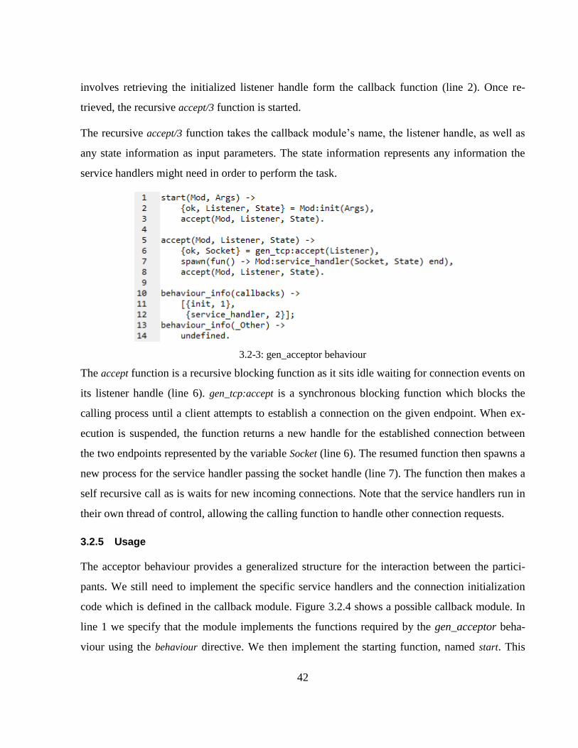
42
involves retrieving the initialized listener handle form the callback function (line 2). Once re-
trieved, the recursive accept/3 function is started.
The recursive accept/3 function takes the callback module’s name, the listener handle, as well as
any state information as input parameters. The state information represents any information the
service handlers might need in order to perform the task.
3.2-3: gen_acceptor behaviour
The accept function is a recursive blocking function as it sits idle waiting for connection events on
its listener handle (line 6). gen_tcp:accept is a synchronous blocking function which blocks the
calling process until a client attempts to establish a connection on the given endpoint. When ex-
ecution is suspended, the function returns a new handle for the established connection between
the two endpoints represented by the variable Socket (line 6). The resumed function then spawns a
new process for the service handler passing the socket handle (line 7). The function then makes a
self recursive call as is waits for new incoming connections. Note that the service handlers run in
their own thread of control, allowing the calling function to handle other connection requests.
3.2.5 Usage
The acceptor behaviour provides a generalized structure for the interaction between the partici-
pants. We still need to implement the specific service handlers and the connection initialization
code which is defined in the callback module. Figure 3.2.4 shows a possible callback module. In
line 1 we specify that the module implements the functions required by the gen_acceptor beha-
viour using the behaviour directive. We then implement the starting function, named start. This
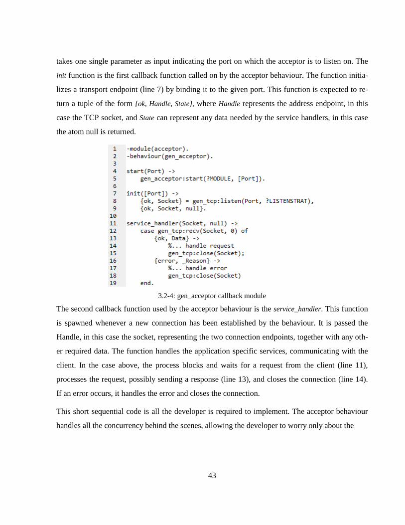
43
takes one single parameter as input indicating the port on which the acceptor is to listen on. The
init function is the first callback function called on by the acceptor behaviour. The function initia-
lizes a transport endpoint (line 7) by binding it to the given port. This function is expected to re-
turn a tuple of the form {ok, Handle, State}, where Handle represents the address endpoint, in this
case the TCP socket, and State can represent any data needed by the service handlers, in this case
the atom null is returned.
3.2-4: gen_acceptor callback module
The second callback function used by the acceptor behaviour is the service_handler. This function
is spawned whenever a new connection has been established by the behaviour. It is passed the
Handle, in this case the socket, representing the two connection endpoints, together with any oth-
er required data. The function handles the application specific services, communicating with the
client. In the case above, the process blocks and waits for a request from the client (line 11),
processes the request, possibly sending a response (line 13), and closes the connection (line 14).
If an error occurs, it handles the error and closes the connection.
This short sequential code is all the developer is required to implement. The acceptor behaviour
handles all the concurrency behind the scenes, allowing the developer to worry only about the
44
3.2.6 Conclusion
In this section we examined the design and architecture of the Acceptor-Connector design pattern.
We provided a generic implementation (as an Erlang behaviour) of the passive acceptor process.
This accepts incoming connections from multiple clients, initializing the connection and spawn-
ing the appropriate service handlers. The gen_acceptor behaviour enhances design reusability and
extensibility in “connection-oriented” software by decoupling the initialization from the commu-
nication that occurs once a connection has been established.
45
3.3 Observer
The observer design pattern [1] is a behavioral pattern that allows multiple clients to observe the
state changes on a server without the need for the client to constantly poll the server. It is a pat-
tern that is commonly used in the design of concurrent applications as it as it provides an efficient
and scalable design for decoupling clients from servers. The idea is to allow multiple observers to
register themselves with a subject. Any state changes on the subject are automatically forwarded
to the observers.
3.3.1 Intent
The intent of the pattern is to decouple an observed server (the subject) from entities observing its
state (objects). This inverts control, placing the responsibility on the server rather than having
multiple interested observers constantly checking with the server for any updates.
The decoupling makes it possible to change the behaviour of the observer or of the observed
process without having to change code in the other. It should also provide easy means for adding
and removing new observers without the need to change and code on the server.
3.3.2 Context
Concurrent applications consist of multiple processes running in separately but cooperating to-
gether to perform some global task. It is desirable to maintaining consistency between these inde-
pendent processes while also maintaining a low level of coupling between processes.
This pattern is applicable when a change to one entity requires changes in other entities, but it is
not known beforehand which entities need to be notified, or even how the entities will handle the
change [1].
3.3.3 Structure & Dynamics
The pattern has two types of entities: observers and subjects. The subjects are the processes that
have some particular state, whereas the observers are processes that are interested in the state
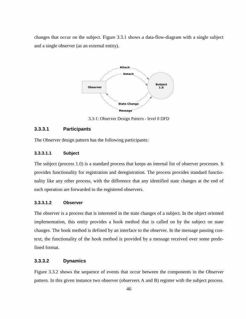
46
changes that occur on the subject. Figure 3.3.1 shows a data-flow-diagram with a single subject
and a single observer (as an external entity).
3.3-1: Observer Design Pattern - level 0 DFD
3.3.3.1 Participants
The Observer design pattern has the following participants:
3.3.3.1.1 Subject
The subject (process 1.0) is a standard process that keeps an internal list of observer processes. It
provides functionality for registration and deregistration. The process provides standard functio-
nality like any other process, with the difference that any identified state changes at the end of
each operation are forwarded to the registered observers.
3.3.3.1.2 Observer
The observer is a process that is interested in the state changes of a subject. In the object oriented
implementation, this entity provides a hook method that is called on by the subject on state
changes. The hook method is defined by an interface to the observer. In the message passing con-
text, the functionality of the hook method is provided by a message received over some prede-
fined format.
3.3.3.2 Dynamics
Figure 3.3.2 shows the sequence of events that occur between the components in the Observer
pattern. In this given instance two observer (observers A and B) register with the subject process.
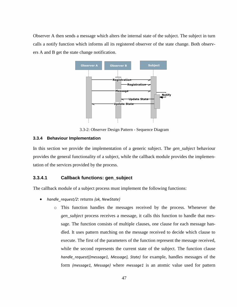
47
Observer A then sends a message which alters the internal state of the subject. The subject in turn
calls a notify function which informs all its registered observer of the state change. Both observ-
ers A and B get the state change notification.
3.3-2: Observer Design Pattern - Sequence Diagram
3.3.4 Behaviour Implementation
In this section we provide the implementation of a generic subject. The gen_subject behaviour
provides the general functionality of a subject, while the callback module provides the implemen-
tation of the services provided by the process.
3.3.4.1 Callback functions: gen_subject
The callback module of a subject process must implement the following functions:
handle_request/2: returns {ok, NewState}
o This function handles the messages received by the process. Whenever the
gen_subject process receives a message, it calls this function to handle that mes-
sage. The function consists of multiple clauses, one clause for each message han-
dled. It uses pattern matching on the message received to decide which clause to
execute. The first of the parameters of the function represent the message received,
while the second represents the current state of the subject. The function clause
handle_request({message1, Message}, State) for example, handles messages of the
form {message1, Message} where message1 is an atomic value used for pattern
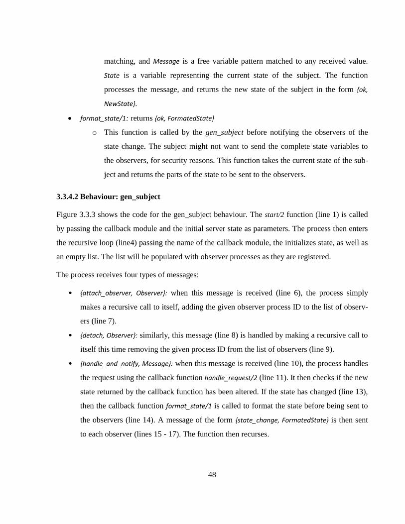
48
matching, and Message is a free variable pattern matched to any received value.
State is a variable representing the current state of the subject. The function
processes the message, and returns the new state of the subject in the form {ok,
NewState}.
format_state/1: returns {ok, FormatedState}
o This function is called by the gen_subject before notifying the observers of the
state change. The subject might not want to send the complete state variables to
the observers, for security reasons. This function takes the current state of the sub-
ject and returns the parts of the state to be sent to the observers.
3.3.4.2 Behaviour: gen_subject
Figure 3.3.3 shows the code for the gen_subject behaviour. The start/2 function (line 1) is called
by passing the callback module and the initial server state as parameters. The process then enters
the recursive loop (line4) passing the name of the callback module, the initializes state, as well as
an empty list. The list will be populated with observer processes as they are registered.
The process receives four types of messages:
• {attach_observer, Observer}: when this message is received (line 6), the process simply
makes a recursive call to itself, adding the given observer process ID to the list of observ-
ers (line 7).
• {detach, Observer}: similarly, this message (line 8) is handled by making a recursive call to
itself this time removing the given process ID from the list of observers (line 9).
• {handle_and_notify, Message}: when this message is received (line 10), the process handles
the request using the callback function handle_request/2 (line 11). It then checks if the new
state returned by the callback function has been altered. If the state has changed (line 13),
then the callback function format_state/1 is called to format the state before being sent to
the observers (line 14). A message of the form {state_change, FormatedState} is then sent
to each observer (lines 15 - 17). The function then recurses.
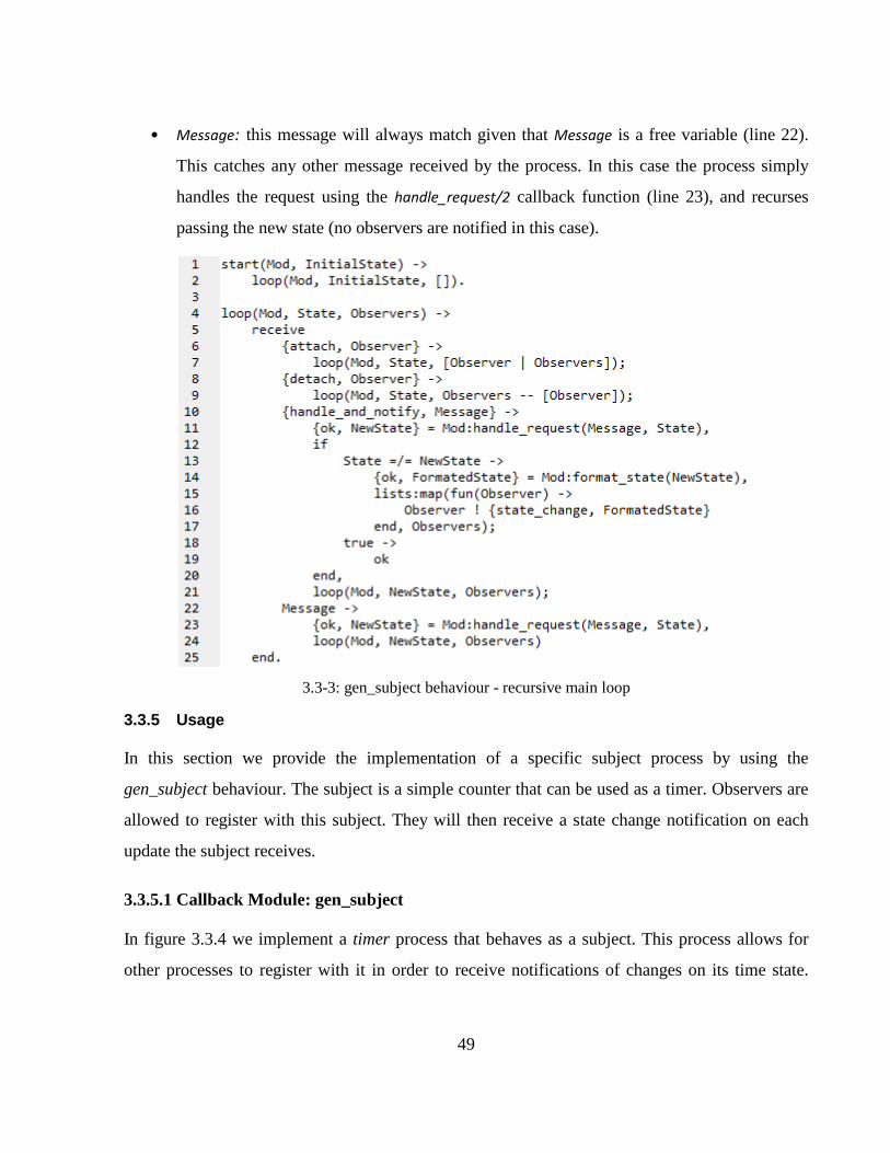
49
• Message: this message will always match given that Message is a free variable (line 22).
This catches any other message received by the process. In this case the process simply
handles the request using the handle_request/2 callback function (line 23), and recurses
passing the new state (no observers are notified in this case).
3.3-3: gen_subject behaviour - recursive main loop
3.3.5 Usage
In this section we provide the implementation of a specific subject process by using the
gen_subject behaviour. The subject is a simple counter that can be used as a timer. Observers are
allowed to register with this subject. They will then receive a state change notification on each
update the subject receives.
3.3.5.1 Callback Module: gen_subject
In figure 3.3.4 we implement a timer process that behaves as a subject. This process allows for
other processes to register with it in order to receive notifications of changes on its time state.
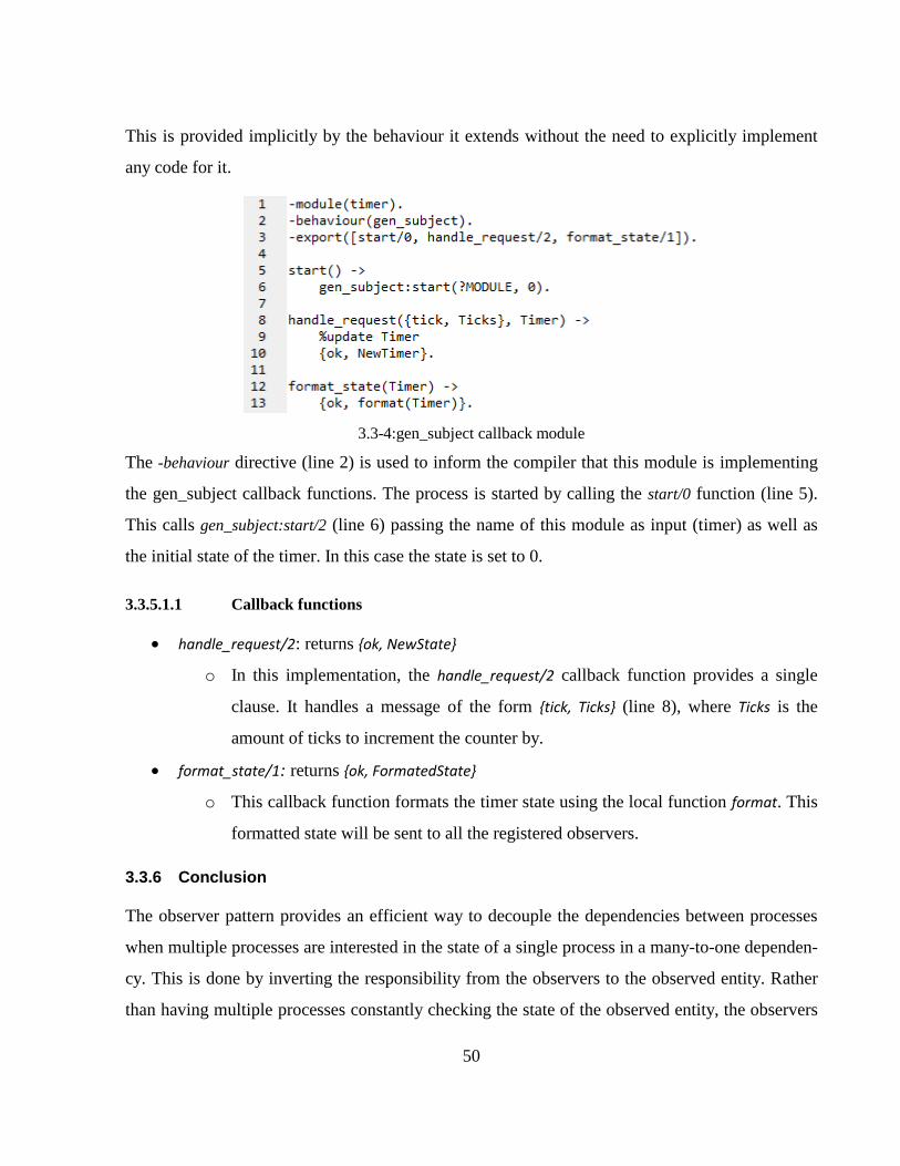
50
This is provided implicitly by the behaviour it extends without the need to explicitly implement
any code for it.
3.3-4:gen_subject callback module
The -behaviour directive (line 2) is used to inform the compiler that this module is implementing
the gen_subject callback functions. The process is started by calling the start/0 function (line 5).
This calls gen_subject:start/2 (line 6) passing the name of this module as input (timer) as well as
the initial state of the timer. In this case the state is set to 0.
3.3.5.1.1 Callback functions
handle_request/2: returns {ok, NewState}
o In this implementation, the handle_request/2 callback function provides a single
clause. It handles a message of the form {tick, Ticks} (line 8), where Ticks is the
amount of ticks to increment the counter by.
format_state/1: returns {ok, FormatedState}
o This callback function formats the timer state using the local function format. This
formatted state will be sent to all the registered observers.
3.3.6 Conclusion
The observer pattern provides an efficient way to decouple the dependencies between processes
when multiple processes are interested in the state of a single process in a many-to-one dependen-
cy. This is done by inverting the responsibility from the observers to the observed entity. Rather
than having multiple processes constantly checking the state of the observed entity, the observers
51
register themselves with the subject, and provide some callback mechanism that allows it to be
informed of any state changes as they occur.
The use of the gen_subject provides a way of abstracting the registration, deregistration, and noti-
fication functionality into a single reusable module. Any process requiring this type of functional-
ity simply provides the callback functions to handle the application specific requests, while the
gen_subject behaviour handles the communication protocol between subjects and observers.
Apart from this abstraction, the behaviour also abstracts the same concurrency that was genera-
lized by the active_object behaviour. This allows the developer to implement what appears to be
sequential code which is in actual fact running as a separate process.
52
3.4 Proactor
The Proactor pattern [3, 32] is a design pattern for efficiently handling asynchronous I/O events
from multiple sources concurrently. It provides a strategy for decoupling concurrent I/O events
from concurrent processes. The Proactor handles completion events from asynchronous opera-
tions dispatching a number of completion events registered with that given event. It provides the
same registration and deregistration functionality as the observer design pattern.
3.4.1 Intent
The intent of this pattern is to simplify the dispatching of completion events from asynchronous
operations by “integrating the demultiplexing of completion events and the dispatching of their
corresponding event handlers” [32]. A single proactor process is responsible for receiving com-
pletion events from some asynchronous event source, and spawning one or more completion
event handlers.
3.4.2 Context
The pattern is applicable when it is possible to execute numerous concurrent I/O operations asyn-
chronously in order to gain the benefits of running multiple operations concurrently without re-
quiring multiple synchronous processes to handle each operation [32]. This method provides con-
currency through the use of proactive operations dispatched to a number of completion handlers
on the completion of asynchronous events.
3.4.3 Structure & Dynamics
The applications services are split up into asynchronous services and completion handlers. Asyn-
chronous services are operations that may take some time to execute such as reading and writing
data asynchronously over a socket. These are non-blocking services allowing that control to be
returned to the caller of the operation. The completion handlers process the results of the comple-
tion events in a separate process. The demultiplexing of the completion events and their dispatch-
ing are integrated in one component; the completion dispatcher [3]. These are decoupled from the
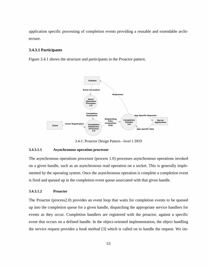
53
application specific processing of completion events providing a reusable and extendable archi-
tecture.
3.4.3.1 Participants
Figure 3.4.1 shows the structure and participants in the Proactor pattern.
3.4-1: Proactor Design Pattern - level 1 DFD
3.4.3.1.1 Asynchronous operation processor
The asynchronous operations processor (process 1.0) processes asynchronous operations invoked
on a given handle, such as an asynchronous read operation on a socket. This is generally imple-
mented by the operating system. Once the asynchronous operation is complete a completion event
is fired and queued up in the completion event queue associated with that given handle.
3.4.3.1.2 Proactor
The Proactor (process2.0) provides an event loop that waits for completion events to be queued
up into the completion queue for a given handle, dispatching the appropriate service handlers for
events as they occur. Completion handlers are registered with the proactor, against a specific
event that occurs on a defined handle. In the object-oriented implementation, the object handling
the service request provides a hook method [3] which is called on to handle the request. We im-
54
plemented this participant as a separate process which is spawned to carry out the application
specific services only when the event is fired.
3.4.3.1.3 Initiator
The initiator is the entity that initiates an asynchronous operation such as an asynchronous read
operation. In an object oriented context, a single object takes on the role of the initiator as well as
the service handler. The initiation occurs in a method, whereas the service handler is provided by
another method (the hook method).
We implement these two participants as two separate processes. For example an acceptor process,
such as the one provided in section 3.2 takes on the role of the initiator, invoking an asynchron-
ous read operation on a socket. Once the operation has been processed by the asynchronous oper-
ation processor the completion event is inserted into the event completion queue. It is then ex-
tracted by the Proactor which spawns the service handler as a separate process.
3.4.3.1.4 Completion handler
The completion handler (process 3.0) provides the application specific service for a particular
event. It is dispatched by the proactor process on the completion of an asynchronous event it was
register with. In the original design, this consists of an interface as well as a concrete class. The
use of an interface provides a contract specifying the methods the completion handlers should
implement (this includes the hook methods signature). This provides the polymorphic behaviour
required in order to decouple the service handler form its invoker.
In our implementation, this decoupling is achieved implicitly through the use of the polymorphic
functions. The original two participants (the completion handler and the concrete completion
handler) are implemented by the single completion handler (process 3.0).
3.4.3.2 Dynamics
The dynamics and interaction between the participants is shown in figure 3.4.2. The client can
register a number of completion handlers, for a particular event on a given handle, with the proac-
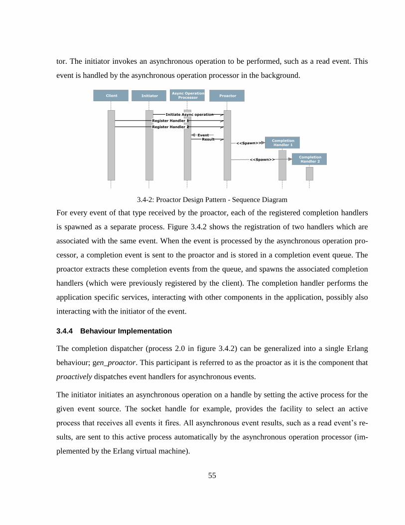
55
tor. The initiator invokes an asynchronous operation to be performed, such as a read event. This
event is handled by the asynchronous operation processor in the background.
3.4-2: Proactor Design Pattern - Sequence Diagram
For every event of that type received by the proactor, each of the registered completion handlers
is spawned as a separate process. Figure 3.4.2 shows the registration of two handlers which are
associated with the same event. When the event is processed by the asynchronous operation pro-
cessor, a completion event is sent to the proactor and is stored in a completion event queue. The
proactor extracts these completion events from the queue, and spawns the associated completion
handlers (which were previously registered by the client). The completion handler performs the
application specific services, interacting with other components in the application, possibly also
interacting with the initiator of the event.
3.4.4 Behaviour Implementation
The completion dispatcher (process 2.0 in figure 3.4.2) can be generalized into a single Erlang
behaviour; gen_proactor. This participant is referred to as the proactor as it is the component that
proactively dispatches event handlers for asynchronous events.
The initiator initiates an asynchronous operation on a handle by setting the active process for the
given event source. The socket handle for example, provides the facility to select an active
process that receives all events it fires. All asynchronous event results, such as a read event’s re-
sults, are sent to this active process automatically by the asynchronous operation processor (im-
plemented by the Erlang virtual machine).
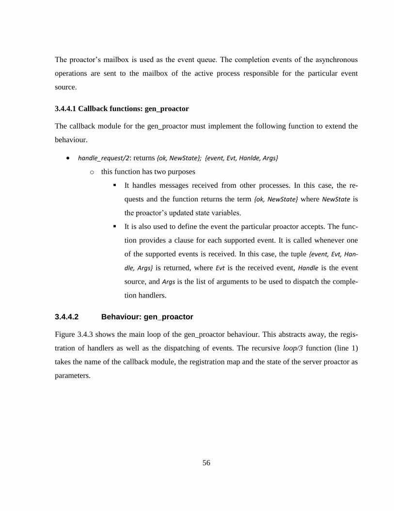
56
The proactor’s mailbox is used as the event queue. The completion events of the asynchronous
operations are sent to the mailbox of the active process responsible for the particular event
source.
3.4.4.1 Callback functions: gen_proactor
The callback module for the gen_proactor must implement the following function to extend the
behaviour.
handle_request/2: returns {ok, NewState}; {event, Evt, Hanlde, Args}
o this function has two purposes
It handles messages received from other processes. In this case, the re-
quests and the function returns the term {ok, NewState} where NewState is
the proactor’s updated state variables.
It is also used to define the event the particular proactor accepts. The func-
tion provides a clause for each supported event. It is called whenever one
of the supported events is received. In this case, the tuple {event, Evt, Han-
dle, Args} is returned, where Evt is the received event, Handle is the event
source, and Args is the list of arguments to be used to dispatch the comple-
tion handlers.
3.4.4.2 Behaviour: gen_proactor
Figure 3.4.3 shows the main loop of the gen_proactor behaviour. This abstracts away, the regis-
tration of handlers as well as the dispatching of events. The recursive loop/3 function (line 1)
takes the name of the callback module, the registration map and the state of the server proactor as
parameters.
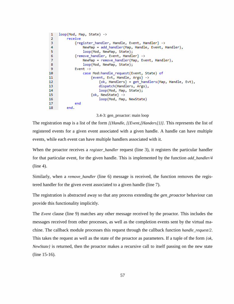
57
3.4-3: gen_proactor: main loop
The registration map is a list of the form [{Handle, [{Event,[Handers]}}]. This represents the list of
registered events for a given event associated with a given handle. A handle can have multiple
events, while each event can have multiple handlers associated with it.
When the proactor receives a register_handler request (line 3), it registers the particular handler
for that particular event, for the given handle. This is implemented by the function add_handler/4
(line 4).
Similarly, when a remove_handler (line 6) message is received, the function removes the regis-
tered handler for the given event associated to a given handle (line 7).
The registration is abstracted away so that any process extending the gen_proactor behaviour can
provide this functionality implicitly.
The Event clause (line 9) matches any other message received by the proactor. This includes the
messages received from other processes, as well as the completion events sent by the virtual ma-
chine. The callback module processes this request through the callback function handle_request/2.
This takes the request as well as the state of the proactor as parameters. If a tuple of the form {ok,
NewState} is returned, then the proactor makes a recursive call to itself passing on the new state
(line 15-16).
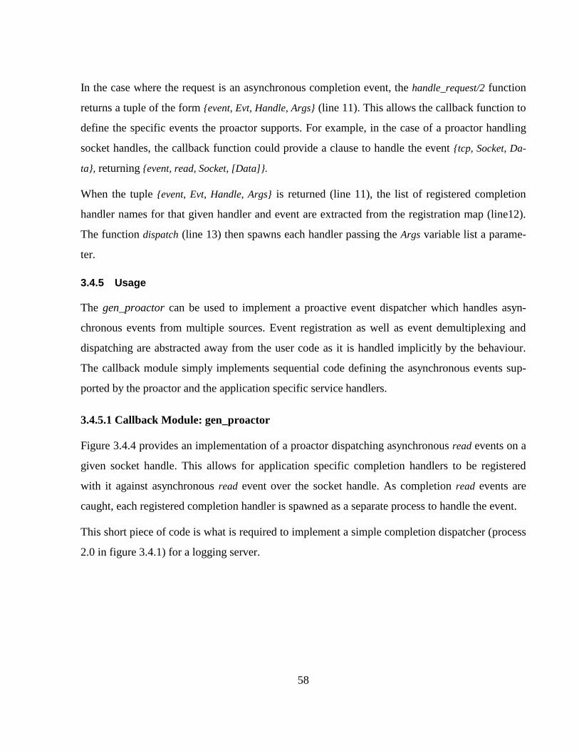
58
In the case where the request is an asynchronous completion event, the handle_request/2 function
returns a tuple of the form {event, Evt, Handle, Args} (line 11). This allows the callback function to
define the specific events the proactor supports. For example, in the case of a proactor handling
socket handles, the callback function could provide a clause to handle the event {tcp, Socket, Da-
ta}, returning {event, read, Socket, [Data]}.
When the tuple {event, Evt, Handle, Args} is returned (line 11), the list of registered completion
handler names for that given handler and event are extracted from the registration map (line12).
The function dispatch (line 13) then spawns each handler passing the Args variable list a parame-
ter.
3.4.5 Usage
The gen_proactor can be used to implement a proactive event dispatcher which handles asyn-
chronous events from multiple sources. Event registration as well as event demultiplexing and
dispatching are abstracted away from the user code as it is handled implicitly by the behaviour.
The callback module simply implements sequential code defining the asynchronous events sup-
ported by the proactor and the application specific service handlers.
3.4.5.1 Callback Module: gen_proactor
Figure 3.4.4 provides an implementation of a proactor dispatching asynchronous read events on a
given socket handle. This allows for application specific completion handlers to be registered
with it against asynchronous read event over the socket handle. As completion read events are
caught, each registered completion handler is spawned as a separate process to handle the event.
This short piece of code is what is required to implement a simple completion dispatcher (process
2.0 in figure 3.4.1) for a logging server.
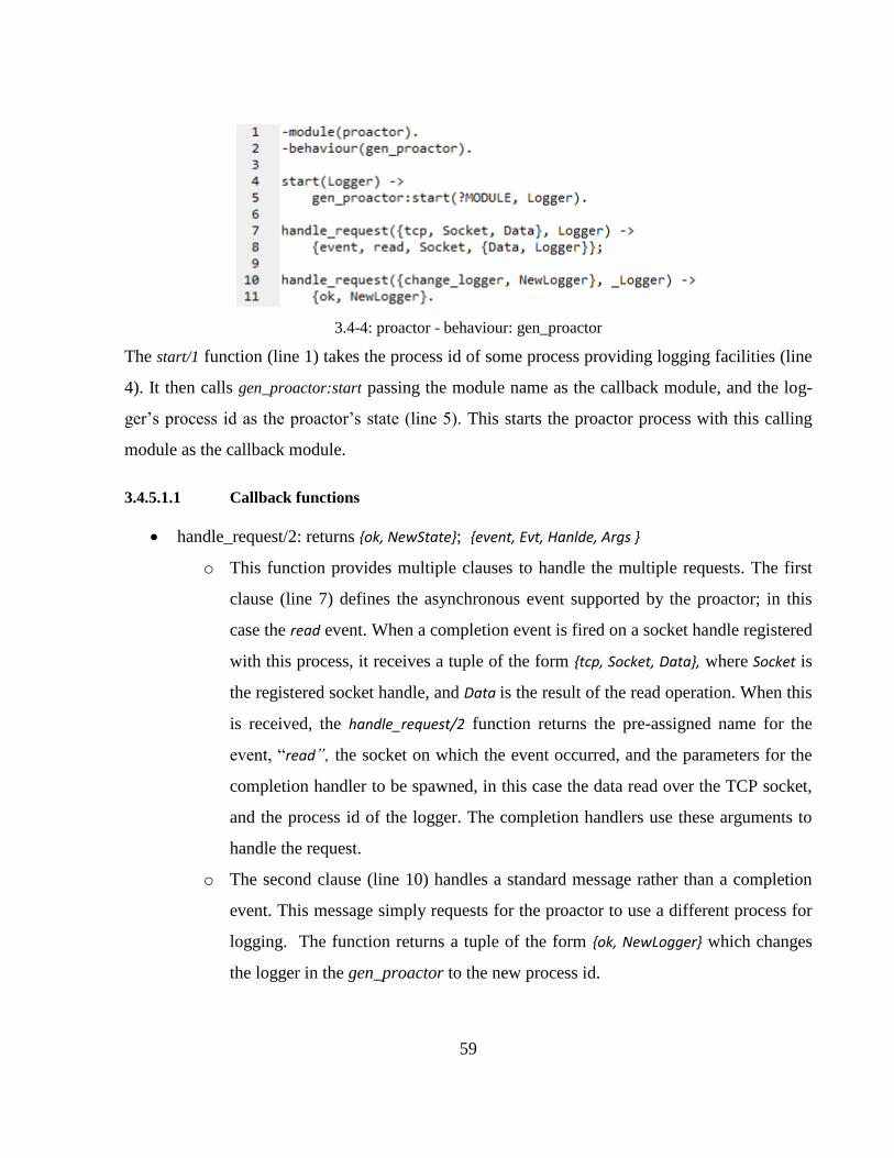
59
3.4-4: proactor - behaviour: gen_proactor
The start/1 function (line 1) takes the process id of some process providing logging facilities (line
4). It then calls gen_proactor:start passing the module name as the callback module, and the log-
ger’s process id as the proactor’s state (line 5). This starts the proactor process with this calling
module as the callback module.
3.4.5.1.1 Callback functions
handle_request/2: returns {ok, NewState}; {event, Evt, Hanlde, Args }
o This function provides multiple clauses to handle the multiple requests. The first
clause (line 7) defines the asynchronous event supported by the proactor; in this
case the read event. When a completion event is fired on a socket handle registered
with this process, it receives a tuple of the form {tcp, Socket, Data}, where Socket is
the registered socket handle, and Data is the result of the read operation. When this
is received, the handle_request/2 function returns the pre-assigned name for the
event, “read”, the socket on which the event occurred, and the parameters for the
completion handler to be spawned, in this case the data read over the TCP socket,
and the process id of the logger. The completion handlers use these arguments to
handle the request.
o The second clause (line 10) handles a standard message rather than a completion
event. This message simply requests for the proactor to use a different process for
logging. The function returns a tuple of the form {ok, NewLogger} which changes
the logger in the gen_proactor to the new process id.
60
3.4.5.2 Other Modules
The initiator process can set the proactor to be the active process for a socket as shown in figure
3.4.5. This initiator can be an acceptor process (section 3.2), registering a socket with the proactor
after establishing a connection.
3.4-5: Initiator: setting the controlling process for a socket
The client registers a completion handler as shown in figure 3.4.6, where the variable Proactor is
the process id of the proactor; Socket is the TCP socket handle, “read” is the event name; Fun is a
function that takes the data read and the process id of the logger as input.
3.4-6: Client Module: registering a completion handler with an event
3.4.6 Conclusion
In this section we saw how the Proactor design pattern can be used to effectively make use of
asynchronous I/O operations provided by the underlying operating system. In particular, we saw
how asynchronous events occurring on a TCP socket can be efficiently demultiplexer and dis-
patched to a set of preregistered completion handlers. We implemented a generic proactor process
(the gen_proactor behaviour) that can be used to register a set of generic completion handlers to
asynchronous events occurring on some particular event source. The user of the behaviour does
not need to worry about dispatching the events as they occur. They are simply registered with the
proactor on initialization. The gen_proactor process then accepts completion events from the
event source and spawns all the necessary processes to handle the event.
61
3.5 Leader Followers
The Leader/Followers [2, 33] design pattern is an architectural pattern that provides an efficient
concurrency strategy allowing a number of threads or processes to coordinate themselves taking
turns detecting, demultiplexing and dispatching events from a shared set of handles [2] to the ap-
propriate service request handlers.
3.5.1 Intent
The intent of this pattern is to minimize overhead in creating and managing multiple processes
sharing some resources. A process pool can be created once and processes can be recycled in or-
der to minimize the overhead in creating and destroying processes. The processes coordinate
themselves to ensure that only one process uses the resources at any given time (the leader
process).
3.5.2 Context
Processes operating in a non shared memory environment do not directly share physical memory,
however they may share some resources such as handles to open files on the local system, or
some socket handle for a network connection. In such a case, the processes must coordinate
themselves to share the providing controlled side effects.
If we consider the design of a web server handling multiple client requests, a simple approach
would involve the implementation of a single process server where all events are processed se-
quentially by the same process. New client requests are queued up and handled once the
processing thread is free. This design provides a simple solution however incurs scalability issues
as all clients requests are serialized, resulting in poor quality of service.
A more scalable approach can be provided by the implement of an asynchronous multithreaded
server [3]. Multiple client requests can be handled simultaneously by adopting a process per re-
quest approach, where a separate thread is spawned for each connection. This design however
does introduce concurrency and synchronization complexities that need to be catered for. Moreo-
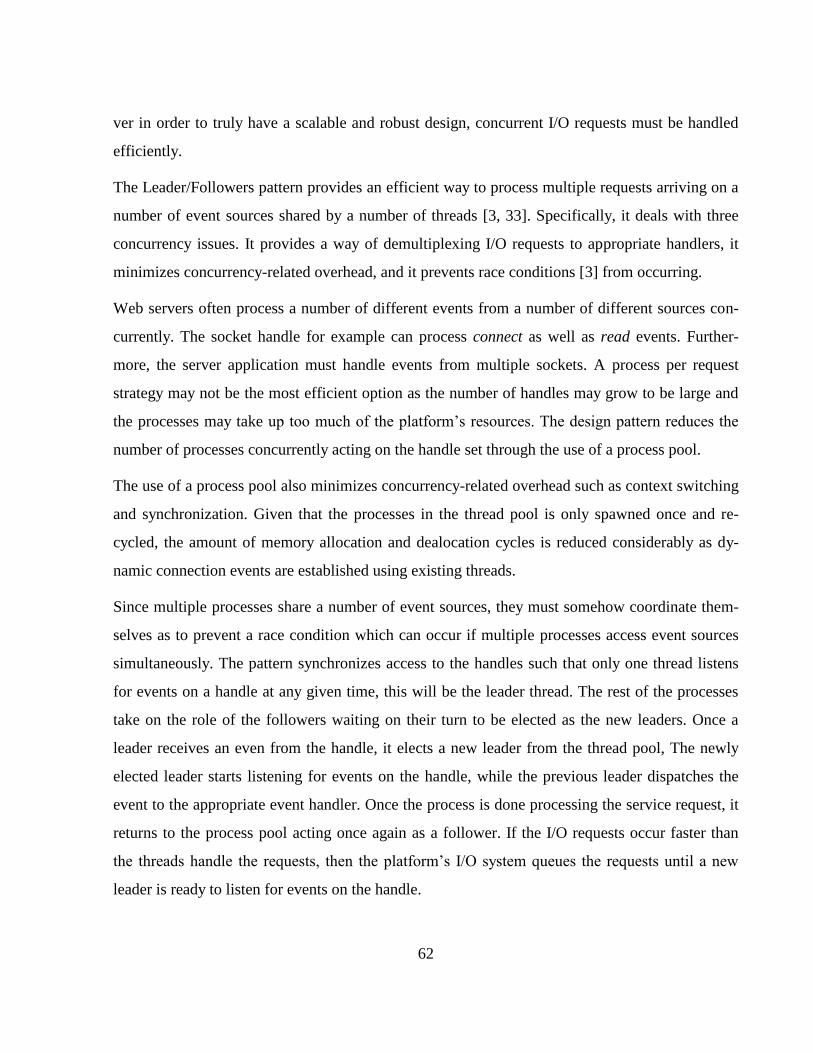
62
ver in order to truly have a scalable and robust design, concurrent I/O requests must be handled
efficiently.
The Leader/Followers pattern provides an efficient way to process multiple requests arriving on a
number of event sources shared by a number of threads [3, 33]. Specifically, it deals with three
concurrency issues. It provides a way of demultiplexing I/O requests to appropriate handlers, it
minimizes concurrency-related overhead, and it prevents race conditions [3] from occurring.
Web servers often process a number of different events from a number of different sources con-
currently. The socket handle for example can process connect as well as read events. Further-
more, the server application must handle events from multiple sockets. A process per request
strategy may not be the most efficient option as the number of handles may grow to be large and
the processes may take up too much of the platform’s resources. The design pattern reduces the
number of processes concurrently acting on the handle set through the use of a process pool.
The use of a process pool also minimizes concurrency-related overhead such as context switching
and synchronization. Given that the processes in the thread pool is only spawned once and re-
cycled, the amount of memory allocation and dealocation cycles is reduced considerably as dy-
namic connection events are established using existing threads.
Since multiple processes share a number of event sources, they must somehow coordinate them-
selves as to prevent a race condition which can occur if multiple processes access event sources
simultaneously. The pattern synchronizes access to the handles such that only one thread listens
for events on a handle at any given time, this will be the leader thread. The rest of the processes
take on the role of the followers waiting on their turn to be elected as the new leaders. Once a
leader receives an even from the handle, it elects a new leader from the thread pool, The newly
elected leader starts listening for events on the handle, while the previous leader dispatches the
event to the appropriate event handler. Once the process is done processing the service request, it
returns to the process pool acting once again as a follower. If the I/O requests occur faster than
the threads handle the requests, then the platform’s I/O system queues the requests until a new
leader is ready to listen for events on the handle.
63
3.5.3 Structure & Dynamics
The pattern has three key participants; handles, service handlers, and the process pool. Figure
3.5.1 shows a level 1 data flow diagram for a generic implementation of the Leader-Followers
pattern. Process 1.0 represents the process pool initialized by the client. In the initialization the
size of the pool is determined and the handle/s are associated with a given service handler.
3.5-1: Leader/Followers design pattern – level 1 data flow diagram
3.5.3.1 Participants
The main participants shown in figure 3.5.1 are the Process pool, the service handlers, and the
handle. The client is the entity initiating the process pool, whereas the server application is the ap-
plication the participants of the pattern form part of.
3.5.3.1.1 Handle
A handle (process 3.0) is a component that identifies event sources. Common handles include
identifiers for network connections, files, and GUI widget event sources. These can be provided
by the operating system however a developer can create custom handles for any source of events.
A number of events can occur on a single handle. The network connection socket for example can
fire a connect event as well as a read event. Moreover the events can be fired internally, or from
some external source. A timeout event is an example of an internal event.
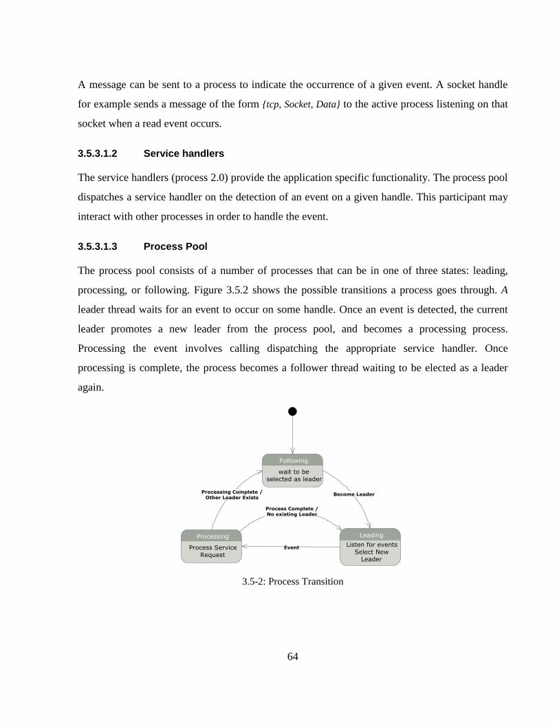
64
A message can be sent to a process to indicate the occurrence of a given event. A socket handle
for example sends a message of the form {tcp, Socket, Data} to the active process listening on that
socket when a read event occurs.
3.5.3.1.2 Service handlers
The service handlers (process 2.0) provide the application specific functionality. The process pool
dispatches a service handler on the detection of an event on a given handle. This participant may
interact with other processes in order to handle the event.
3.5.3.1.3 Process Pool
The process pool consists of a number of processes that can be in one of three states: leading,
processing, or following. Figure 3.5.2 shows the possible transitions a process goes through. A
leader thread waits for an event to occur on some handle. Once an event is detected, the current
leader promotes a new leader from the process pool, and becomes a processing process.
Processing the event involves calling dispatching the appropriate service handler. Once
processing is complete, the process becomes a follower thread waiting to be elected as a leader
again.
3.5-2: Process Transition
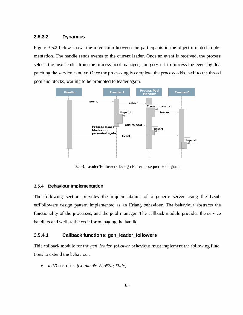
65
3.5.3.2 Dynamics
Figure 3.5.3 below shows the interaction between the participants in the object oriented imple-
mentation. The handle sends events to the current leader. Once an event is received, the process
selects the next leader from the process pool manager, and goes off to process the event by dis-
patching the service handler. Once the processing is complete, the process adds itself to the thread
pool and blocks, waiting to be promoted to leader again.
3.5-3: Leader/Followers Design Pattern - sequence diagram
3.5.4 Behaviour Implementation
The following section provides the implementation of a generic server using the Lead-
er/Followers design pattern implemented as an Erlang behaviour. The behaviour abstracts the
functionality of the processes, and the pool manager. The callback module provides the service
handlers and well as the code for managing the handle.
3.5.4.1 Callback functions: gen_leader_followers
This callback module for the gen_leader_follower behaviour must implement the following func-
tions to extend the behaviour.
init/1: returns {ok, Handle, PoolSize, State}
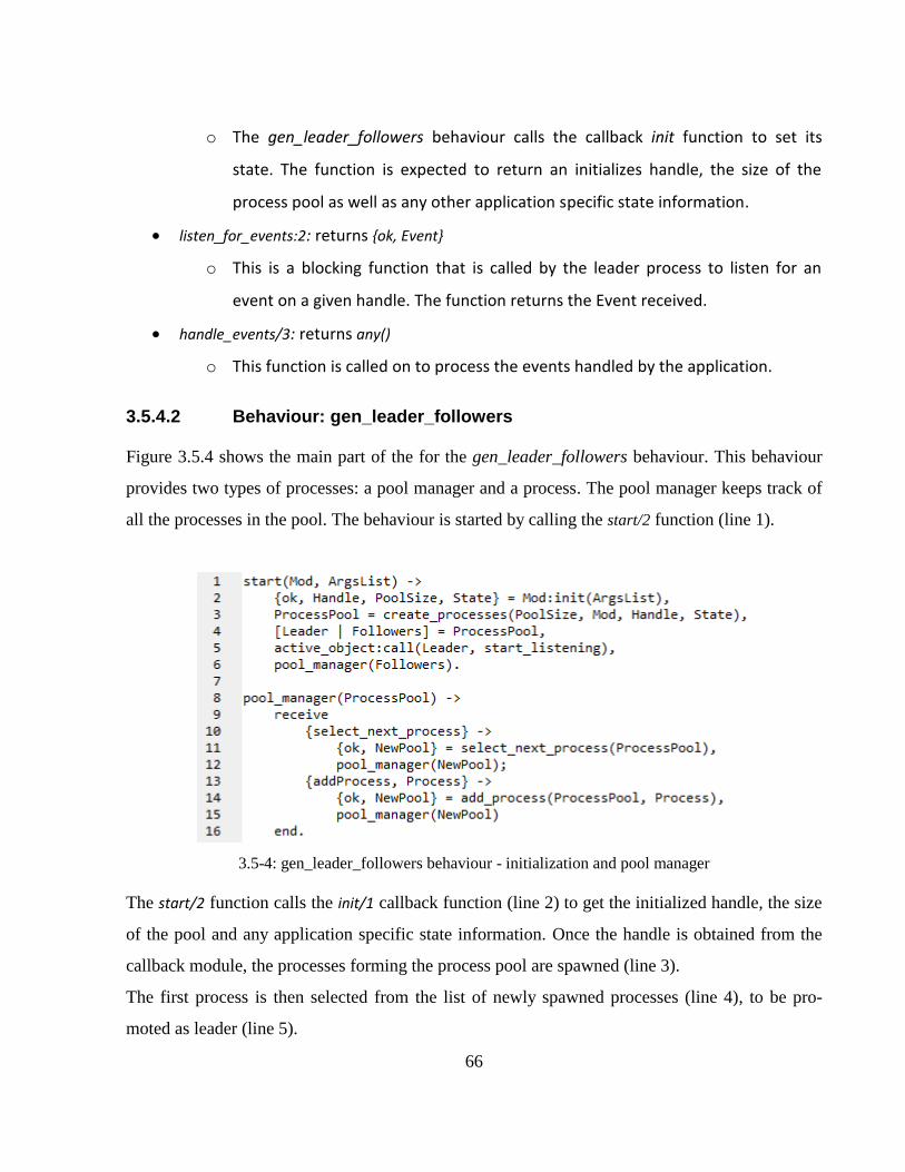
66
o The gen_leader_followers behaviour calls the callback init function to set its
state. The function is expected to return an initializes handle, the size of the
process pool as well as any other application specific state information.
listen_for_events:2: returns {ok, Event}
o This is a blocking function that is called by the leader process to listen for an
event on a given handle. The function returns the Event received.
handle_events/3: returns any()
o This function is called on to process the events handled by the application.
3.5.4.2 Behaviour: gen_leader_followers
Figure 3.5.4 shows the main part of the for the gen_leader_followers behaviour. This behaviour
provides two types of processes: a pool manager and a process. The pool manager keeps track of
all the processes in the pool. The behaviour is started by calling the start/2 function (line 1).
3.5-4: gen_leader_followers behaviour - initialization and pool manager
The start/2 function calls the init/1 callback function (line 2) to get the initialized handle, the size
of the pool and any application specific state information. Once the handle is obtained from the
callback module, the processes forming the process pool are spawned (line 3).
The first process is then selected from the list of newly spawned processes (line 4), to be pro-
moted as leader (line 5).
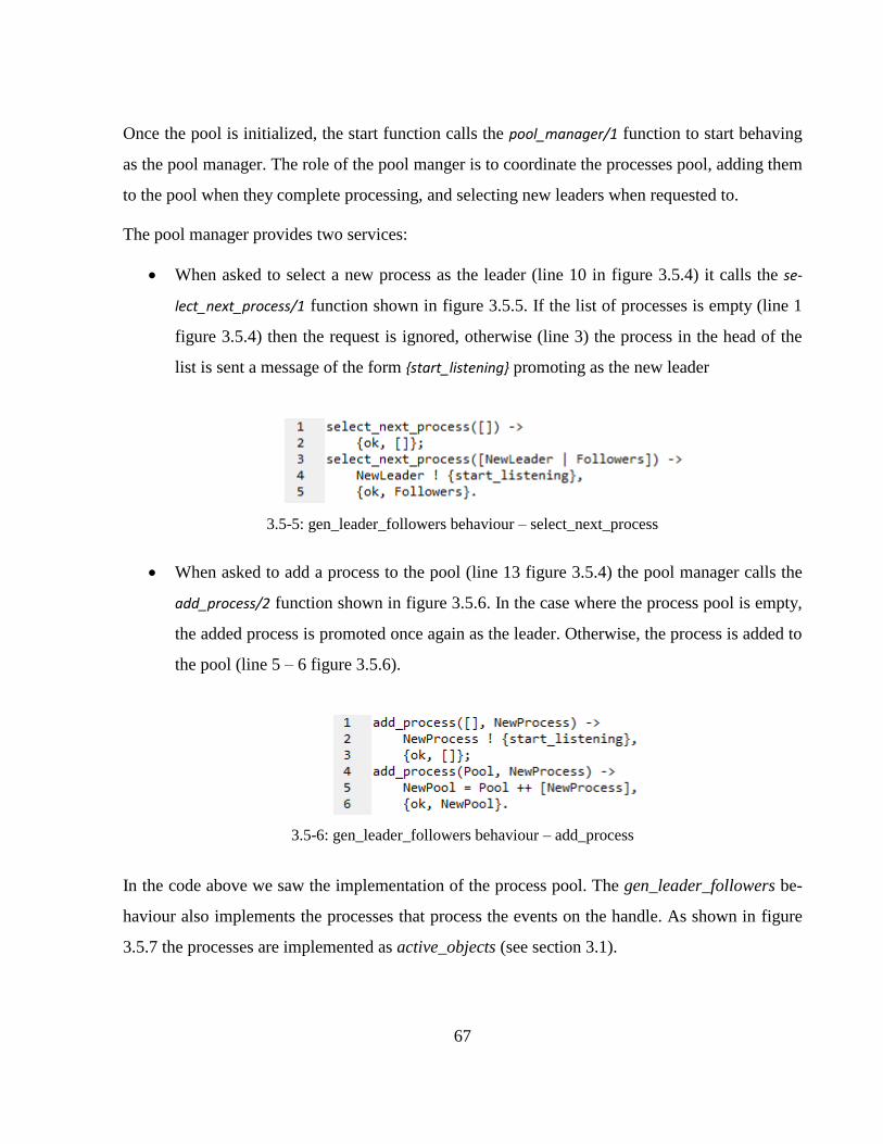
67
Once the pool is initialized, the start function calls the pool_manager/1 function to start behaving
as the pool manager. The role of the pool manger is to coordinate the processes pool, adding them
to the pool when they complete processing, and selecting new leaders when requested to.
The pool manager provides two services:
When asked to select a new process as the leader (line 10 in figure 3.5.4) it calls the se-
lect_next_process/1 function shown in figure 3.5.5. If the list of processes is empty (line 1
figure 3.5.4) then the request is ignored, otherwise (line 3) the process in the head of the
list is sent a message of the form {start_listening} promoting as the new leader
3.5-5: gen_leader_followers behaviour – select_next_process
When asked to add a process to the pool (line 13 figure 3.5.4) the pool manager calls the
add_process/2 function shown in figure 3.5.6. In the case where the process pool is empty,
the added process is promoted once again as the leader. Otherwise, the process is added to
the pool (line 5 – 6 figure 3.5.6).
3.5-6: gen_leader_followers behaviour – add_process
In the code above we saw the implementation of the process pool. The gen_leader_followers be-
haviour also implements the processes that process the events on the handle. As shown in figure
3.5.7 the processes are implemented as active_objects (see section 3.1).
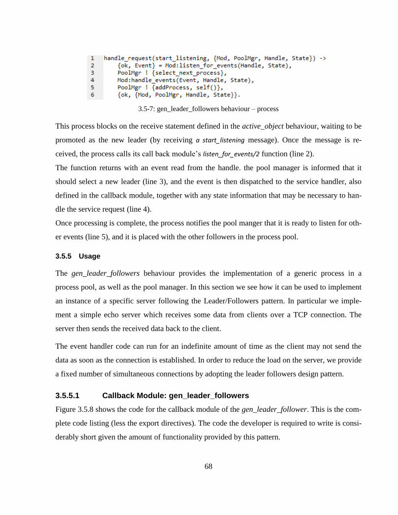
68
3.5-7: gen_leader_followers behaviour – process
This process blocks on the receive statement defined in the active_object behaviour, waiting to be
promoted as the new leader (by receiving a start_listening message). Once the message is re-
ceived, the process calls its call back module’s listen_for_events/2 function (line 2).
The function returns with an event read from the handle. the pool manager is informed that it
should select a new leader (line 3), and the event is then dispatched to the service handler, also
defined in the callback module, together with any state information that may be necessary to han-
dle the service request (line 4).
Once processing is complete, the process notifies the pool manger that it is ready to listen for oth-
er events (line 5), and it is placed with the other followers in the process pool.
3.5.5 Usage
The gen_leader_followers behaviour provides the implementation of a generic process in a
process pool, as well as the pool manager. In this section we see how it can be used to implement
an instance of a specific server following the Leader/Followers pattern. In particular we imple-
ment a simple echo server which receives some data from clients over a TCP connection. The
server then sends the received data back to the client.
The event handler code can run for an indefinite amount of time as the client may not send the
data as soon as the connection is established. In order to reduce the load on the server, we provide
a fixed number of simultaneous connections by adopting the leader followers design pattern.
3.5.5.1 Callback Module: gen_leader_followers
Figure 3.5.8 shows the code for the callback module of the gen_leader_follower. This is the com-
plete code listing (less the export directives). The code the developer is required to write is consi-
derably short given the amount of functionality provided by this pattern.
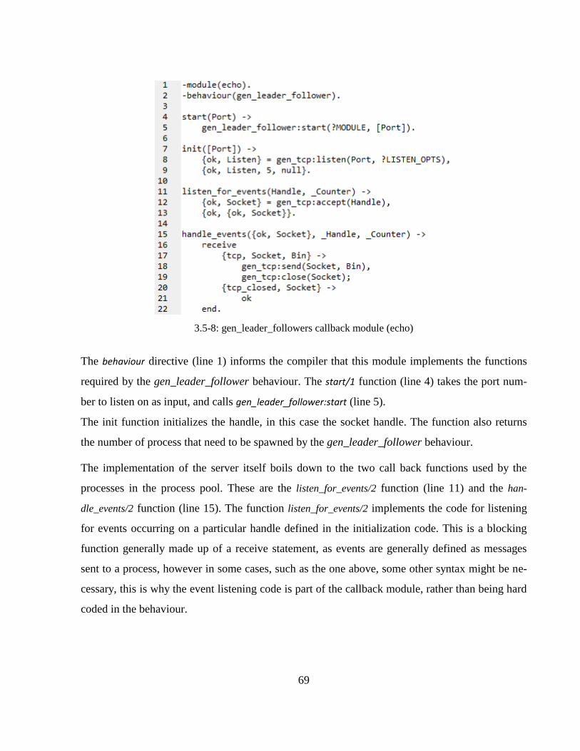
69
3.5-8: gen_leader_followers callback module (echo)
The behaviour directive (line 1) informs the compiler that this module implements the functions
required by the gen_leader_follower behaviour. The start/1 function (line 4) takes the port num-
ber to listen on as input, and calls gen_leader_follower:start (line 5).
The init function initializes the handle, in this case the socket handle. The function also returns
the number of process that need to be spawned by the gen_leader_follower behaviour.
The implementation of the server itself boils down to the two call back functions used by the
processes in the process pool. These are the listen_for_events/2 function (line 11) and the han-
dle_events/2 function (line 15). The function listen_for_events/2 implements the code for listening
for events occurring on a particular handle defined in the initialization code. This is a blocking
function generally made up of a receive statement, as events are generally defined as messages
sent to a process, however in some cases, such as the one above, some other syntax might be ne-
cessary, this is why the event listening code is part of the callback module, rather than being hard
coded in the behaviour.
70
The function handle_events/2 provides the application specific service handler that will be dis-
patched by the process once an event occurs. In this case, the handler simply accepts input from
the client sending the data back to the client.
This example shows the ease with which one can develop a server using the Leader/Followers
pattern using behaviors. The developer simply writes a few sequential functions which plug into
the behaviour defined using higher order functions, as the recursive receive loop and the interac-
tion of the spawned threads is abstracted away in the background providing an efficient multi
threaded model without incurred any programming complexities.
3.5.6 Variation: without a pool manager
In the implementation of the gen_leader_followers above, the thread pool is maintained explicitly
by a thread pool manger which provides queuing facilities. This process can be removed if we
have the processes coordinating themselves. The functionality of the pool manger will now be
integrated in the process’ body. Each process must therefore keep track of who the current leader
is. The process must cater for the situation where a leader changes before the follower has fi-
nished processing, in which case the chain of responsibility [1] pattern is used to forward the add
process request. We must also cater for the situation where there is no current leader.
3.5.6.1 Behaviour: gen_leader_followers
In the implementation shown in figure 3.5.9, the process in the pool takes on the role of the pool
manger. It must therefore cater for two new messages, the update_pool and the add_process mes-
sages. The process now keeps a reference to a list of all the followers.
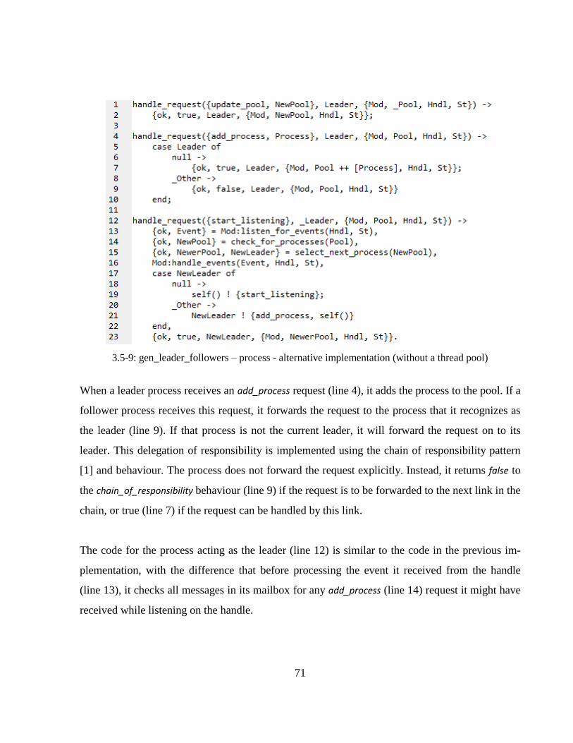
71
3.5-9: gen_leader_followers – process - alternative implementation (without a thread pool)
When a leader process receives an add_process request (line 4), it adds the process to the pool. If a
follower process receives this request, it forwards the request to the process that it recognizes as
the leader (line 9). If that process is not the current leader, it will forward the request on to its
leader. This delegation of responsibility is implemented using the chain of responsibility pattern
[1] and behaviour. The process does not forward the request explicitly. Instead, it returns false to
the chain_of_responsibility behaviour (line 9) if the request is to be forwarded to the next link in the
chain, or true (line 7) if the request can be handled by this link.
The code for the process acting as the leader (line 12) is similar to the code in the previous im-
plementation, with the difference that before processing the event it received from the handle
(line 13), it checks all messages in its mailbox for any add_process (line 14) request it might have
received while listening on the handle.
72
The process must also handle the edge case where there is no follower in the pool to promote
(line 17 - 18). In this case the process processes the request and becomes the leader once again
once processing is complete (line 19).
3.5.7 Usage
The callback module can use the behaviour in the same way that it is used the previous imple-
mentation of the gen_leader_follower. The changes have no affect on the way the echo server de-
signed in the previous section calls it. This is one of the advantages of using behaviours to im-
plement the communication protocol and behavior.
3.5.8 Conclusion
The leader/followers pattern provides an efficient concurrency strategy when multiple processes
share a number of handles providing a scalable multithreaded environment. By making use of be-
haviours, the developer is provided with a way of implementing this efficiency with minimal cod-
ing effort as all the interaction between the participants is hidden in the behaviour.
In the mapping between the object oriented implementation and the message passing concurrency
model we were able to make use mechanisms in Erlang such as the process’ mailbox to simplify
design, and use of functional techniques such as higher order functions to compensate for design
techniques not available from the object oriented setting such as inheritance.
The end result is an abstraction of the pattern that can be reused to implement a variety of differ-
ent server applications with specific service handlers using the Leader/Followers pattern for effi-
ciency purposes, without the need to worry about the implementation of generic components such
as the threads and the communication between them.
3.6 Conclusion
In this section we examined a number of design patterns from the object-oriented context and provided an
implementation of each one as an Erlang behaviour. We saw how the patterns can be translated in form
from communicating passive objects in a sequential environment, to concurrent processes using message
passing in a non-shared memory context.
73
In particular we implemented the Active Object design pattern, the Acceptor-Connector, the Observer, the
Proactor, and the Leader/’Followers design patterns.
We saw how the protocols between the participants of the pattern can be extracted into reusable modules
(the behaviour modules) making the adoption of the specific design pattern implicit in the design of soft-
ware applications. The user simply defines callback modules providing the application specific details of
the service implementation, while the behaviour handles the interaction between the participants.
In the next section we show how the behaviours can be integrated in the implementation of a peer-to-peer
file sharing.

74
4. Applying the Design Patterns
Section 3 provided a detailed description of the design patterns and an implementation of each
one as an Erlang behaviour. In the following sections we see how these behaviours can be applied
to the design and implementation of concurrent and distributed systems. We set out to implement
a peer-to-peer file sharing application by making use of the set of behaviours.
In this case study we attempt to show how the behaviours, which capture the essence of the de-
sign patterns, can be integrated in the design of large scale software applications. The behaviours
allow the developer to focus on the application specific aspects of the design as the concurrency
related issues are implicitly handled by the behaviours.
The use of behaviours is also expected to enforce the use of standard approaches in the design of
the application. This should provide an intuitive design, increasing maintainability and overall
understandability of the overall architecture.
The choice of a peer-to-peer application for our test case stems from the high degree of concur-
rency in such applications. A peer has two sides to it: It acts both as a client and as a server in the
standard client-server architecture. It must therefore be able to manage multiple concurrent con-
nections seamlessly and efficiently while handling multiple client requests.
75
4.1 Design
In this section we outline the overall design of the peer-to-peer file sharing application. Following
a concurrent programming style, the application is designed as a collection of autonomous
processes that interact by exchanging messages. We aim to outline the overall structure of the ap-
plication and the interaction between these components while introducing the design patterns and
their role in the overall design as we come across them.
Figure 4.1.1 shows a high level representation of the components that form the overall architec-
ture. The peer-to-peer network consists of:
The Peer application – The peer application represents a node on the network. We often
refer to local application as the client application. However this application provides the
same functionality as other peers on the network. The group of peers interacting with each
other, communicating to share a file (broken down in file pieces), is called a peer group.
Figure 4.1.1 shows a peer group consisting of five peers. This group is dynamic in nature
in that peers may join and leave the group as desired. In our design, the client application
is written in Erlang. The user can interact with this application by spawning it on an Er-
lang node, and sending messages to it through the command line.
The Tracker application – the tracker application keeps track of the dynamic peer groups.
It keeps a mapping between files, and their corresponding peer group. When a client ap-
plication wants to start downloading a file, it asks the tracker for the addresses of the peers
in that file’s peer group. The client then establishes a connection with the other peers on
the network and starts sharing the file pieces with them. Once it receives some file pieces
it notifies the tracker adding itself to the peer group. The tracker application is also written
in Erlang.
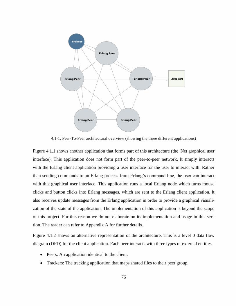
76
4.1-1: Peer-To-Peer architectural overview (showing the three different applications)
Figure 4.1.1 shows another application that forms part of this architecture (the .Net graphical user
interface). This application does not form part of the peer-to-peer network. It simply interacts
with the Erlang client application providing a user interface for the user to interact with. Rather
than sending commands to an Erlang process from Erlang’s command line, the user can interact
with this graphical user interface. This application runs a local Erlang node which turns mouse
clicks and button clicks into Erlang messages, which are sent to the Erlang client application. It
also receives update messages from the Erlang application in order to provide a graphical visuali-
zation of the state of the application. The implementation of this application is beyond the scope
of this project. For this reason we do not elaborate on its implementation and usage in this sec-
tion. The reader can refer to Appendix A for further details.
Figure 4.1.2 shows an alternative representation of the architecture. This is a level 0 data flow
diagram (DFD) for the client application. Each peer interacts with three types of external entities.
Peers: An application identical to the client.
Trackers: The tracking application that maps shared files to their peer group.
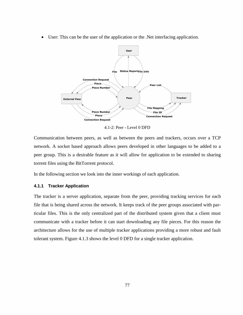
77
User: This can be the user of the application or the .Net interfacing application.
4.1-2: Peer - Level 0 DFD
Communication between peers, as well as between the peers and trackers, occurs over a TCP
network. A socket based approach allows peers developed in other languages to be added to a
peer group. This is a desirable feature as it will allow for application to be extended to sharing
torrent files using the BitTorrent protocol.
In the following section we look into the inner workings of each application.
4.1.1 Tracker Application
The tracker is a server application, separate from the peer, providing tracking services for each
file that is being shared across the network. It keeps track of the peer groups associated with par-
ticular files. This is the only centralized part of the distributed system given that a client must
communicate with a tracker before it can start downloading any file pieces. For this reason the
architecture allows for the use of multiple tracker applications providing a more robust and fault
tolerant system. Figure 4.1.3 shows the level 0 DFD for a single tracker application.
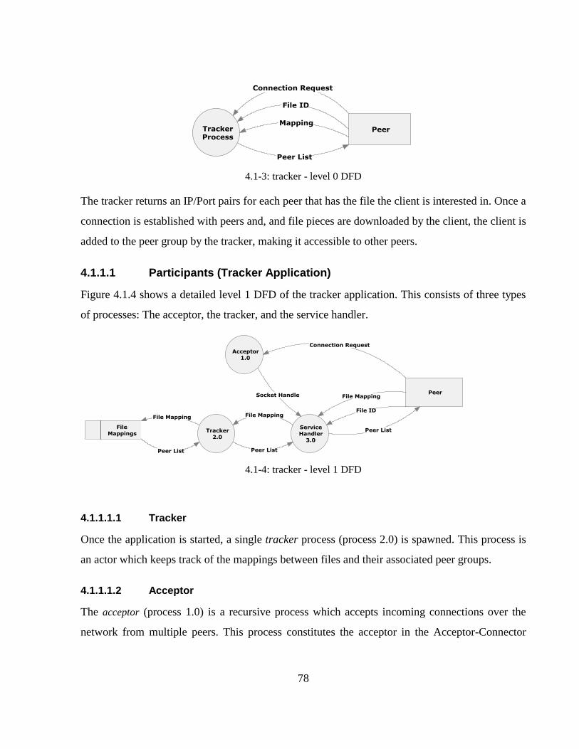
78
4.1-3: tracker - level 0 DFD
The tracker returns an IP/Port pairs for each peer that has the file the client is interested in. Once a
connection is established with peers and, and file pieces are downloaded by the client, the client is
added to the peer group by the tracker, making it accessible to other peers.
4.1.1.1 Participants (Tracker Application)
Figure 4.1.4 shows a detailed level 1 DFD of the tracker application. This consists of three types
of processes: The acceptor, the tracker, and the service handler.
4.1-4: tracker - level 1 DFD
4.1.1.1.1 Tracker
Once the application is started, a single tracker process (process 2.0) is spawned. This process is
an actor which keeps track of the mappings between files and their associated peer groups.
4.1.1.1.2 Acceptor
The acceptor (process 1.0) is a recursive process which accepts incoming connections over the
network from multiple peers. This process constitutes the acceptor in the Acceptor-Connector
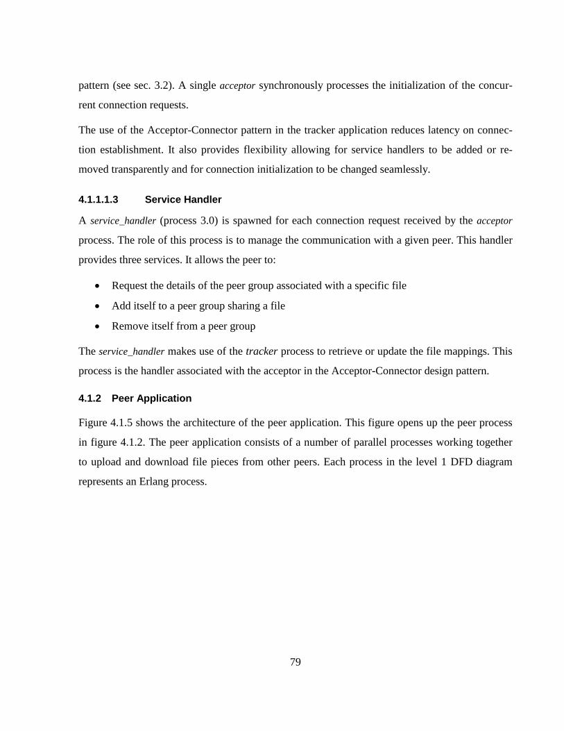
79
pattern (see sec. 3.2). A single acceptor synchronously processes the initialization of the concur-
rent connection requests.
The use of the Acceptor-Connector pattern in the tracker application reduces latency on connec-
tion establishment. It also provides flexibility allowing for service handlers to be added or re-
moved transparently and for connection initialization to be changed seamlessly.
4.1.1.1.3 Service Handler
A service_handler (process 3.0) is spawned for each connection request received by the acceptor
process. The role of this process is to manage the communication with a given peer. This handler
provides three services. It allows the peer to:
Request the details of the peer group associated with a specific file
Add itself to a peer group sharing a file
Remove itself from a peer group
The service_handler makes use of the tracker process to retrieve or update the file mappings. This
process is the handler associated with the acceptor in the Acceptor-Connector design pattern.
4.1.2 Peer Application
Figure 4.1.5 shows the architecture of the peer application. This figure opens up the peer process
in figure 4.1.2. The peer application consists of a number of parallel processes working together
to upload and download file pieces from other peers. Each process in the level 1 DFD diagram
represents an Erlang process.
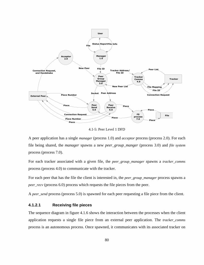
80
4.1-5: Peer Level 1 DFD
A peer application has a single manager (process 1.0) and acceptor process (process 2.0). For each
file being shared, the manager spawns a new peer_group_manger (process 3.0) and file system
process (process 7.0).
For each tracker associated with a given file, the peer_group_manager spawns a tracker_comms
process (process 4.0) to communicate with the tracker.
For each peer that has the file the client is interested in, the peer_group_manager process spawns a
peer_recv (process 6.0) process which requests the file pieces from the peer.
A peer_send process (process 5.0) is spawned for each peer requesting a file piece from the client.
4.1.2.1 Receiving file pieces
The sequence diagram in figure 4.1.6 shows the interaction between the processes when the client
application requests a single file piece from an external peer application. The tracker_comms
process is an autonomous process. Once spawned, it communicates with its associated tracker on
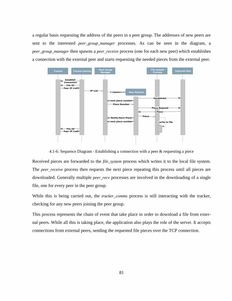
81
a regular basis requesting the address of the peers in a peer group. The addresses of new peers are
sent to the interested peer_group_manager processes. As can be seen in the diagram, a
peer_group_manager then spawns a peer_receive process (one for each new peer) which establishes
a connection with the external peer and starts requesting the needed pieces from the external peer.
4.1-6: Sequence Diagram - Establishing a connection with a peer & requesting a piece
Received pieces are forwarded to the file_system process which writes it to the local file system.
The peer_receive process then requests the next piece repeating this process until all pieces are
downloaded. Generally multiple peer_recv processes are involved in the downloading of a single
file, one for every peer in the peer group.
While this is being carried out, the tracker_comms process is still interacting with the tracker,
checking for any new peers joining the peer group.
This process represents the chain of event that take place in order to download a file from exter-
nal peers. While all this is taking place, the application also plays the role of the server. It accepts
connections from external peers, sending the requested file pieces over the TCP connection.
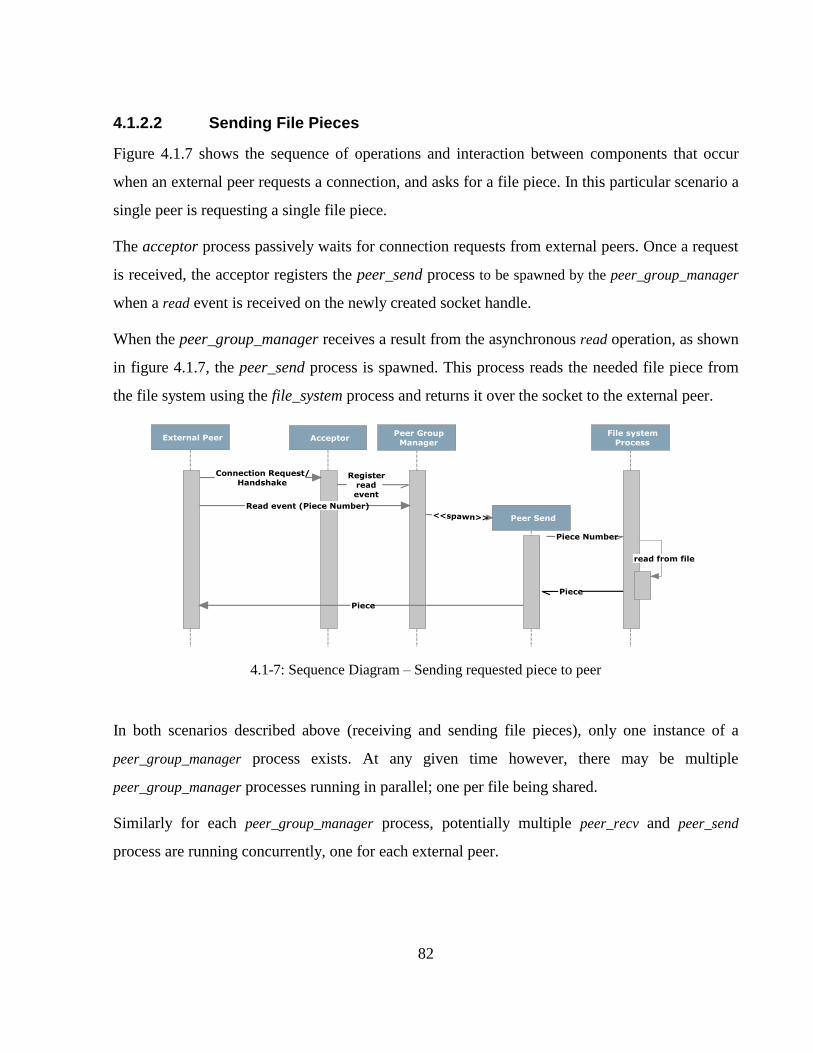
82
4.1.2.2 Sending File Pieces
Figure 4.1.7 shows the sequence of operations and interaction between components that occur
when an external peer requests a connection, and asks for a file piece. In this particular scenario a
single peer is requesting a single file piece.
The acceptor process passively waits for connection requests from external peers. Once a request
is received, the acceptor registers the peer_send process to be spawned by the peer_group_manager
when a read event is received on the newly created socket handle.
When the peer_group_manager receives a result from the asynchronous read operation, as shown
in figure 4.1.7, the peer_send process is spawned. This process reads the needed file piece from
the file system using the file_system process and returns it over the socket to the external peer.
4.1-7: Sequence Diagram – Sending requested piece to peer
In both scenarios described above (receiving and sending file pieces), only one instance of a
peer_group_manager process exists. At any given time however, there may be multiple
peer_group_manager processes running in parallel; one per file being shared.
Similarly for each peer_group_manager process, potentially multiple peer_recv and peer_send
process are running concurrently, one for each external peer.
83
4.1.2.3 Participants (Peer Application)
In the following sections we look at the each process in the design of the peer application in
greater depth, identifying their role in the design patterns they form part of.
4.1.2.3.1 Manager
The manager process (process 1.0 in figure 4.1.5) is the interface to the application. The user
submits its requests to this process in the form of Erlang messages. The manager will then spawn
the required processes to handle the request. The process is a simple actor that coordinates a list
of peer_group_manager processes. It allows the user to:
Start sharing a new file: The user submits the file it wants to share together with a list of
trackers that will track its peer group. The manager process parses the file and creates an
info file containing the information necessary for other peers to start sharing the file. This
file contains the file name, its unique ID, the piece size, the number of pieces, the list of
trackers, and the file name. The info file is a small file that can be distributed with ease
(through email, or by being uploaded to an indexing site for example). Once this file is
created, the manager spawns the peer_group_manger process which handles the communi-
cation with the peers for that particular file.
Start downloading and sharing an existing file: The user submits an info file which has the
necessary information to start sharing an existing file. In this case the manager parses the
info file and spawns the peer_group_manger passing the necessary information to start the
download.
Stop sharing a file: the manager simply forwards a stop request to the peer_group_manager
associated with that specific file.
View state information: the manager can also return the global state of the application.
This includes the list of files that are being downloaded and the list of peers associated
with each file.
4.1.2.3.2 Acceptor
84
The role of the acceptor process (process 2.0) is to accept connections from external peers. This
process makes use of the Leader-Followers design pattern (see sec. 3.5) to limit the number of
concurrent active connections by through the use of a process pool. Handlers for the incoming
connections are spawned beforehand. The processes take turns listening for events on the socket
handles dispatching the event handlers as they occur. If requests are received faster than the
processes can handle them, then the requests are queued up on the TCP socket until a process is
placed in the process pool.
Once the acceptor receives a connection request, it requests a handshake from the peer. The hand-
shake specifies the ID of the file the external peer is interested in. Once the handshake is received,
the acceptor notifies the peer_group_manager associated with that file about the new incoming
peer. From that point on, communication with the peer is handled through the
peer_group_manager and the peer_send processes it spawns.
4.1.2.3.3 Peer group manager
The peer_group_manager process (process 3.0) manages the processes spawned for a single peer
group. One peer_group_manage is spawned for each file being shared. As soon as it is spawned, it
in turn spawns a file_system process which handles reading and writing file pieces from the local
file system. It also spawns a new tracker_comms process for each tracker associated with the file.
The peer_group_manager spawns two types of peer processes:
peer_recv (process 6.0): One peer_recv process is spawned for each client owning file
pieces the client is interested in. This process initializes a connection with the peer and
starts requesting the needed pieces. This is a simple actor implementing the connection
strategy in the Acceptor-Connector (3.2) design pattern.
peer_send (process 5.0): A peer_send process is spawned for each peer requesting file
pieces from the client. The read request is dispatched by the peer_group_manager after the
connection has been established by the acceptor. It uses the file_system process to read the
requested piece from the file system, and sends it to the external peer over the TCP net-
work. This process has the role of the service handler in the Proactor pattern (see sec. 3.4).
85
The peer_send process is the counterpart to peer_recv. A peer_send in one peer application
communicates with the peer_recv of another peer application.
The peer_group_manage implements the Proactor pattern (see sec 3.4) to handle incoming connec-
tion requests from multiple clients. The acceptor registers the read event with the
peer_group_manager, such that whenever an asynchronous read event occurs, a peer_send process
is dispatched by the peer_group_manager to handle the communication with the client.
This process also plays the role of the observer in the Observer (see sec. 3.3) design pattern. The
subjects it observers are the tracker_comms processes (process 4.0 in figure 4.1.5). Whenever the
tracker_comms process goes through a state change, as peers are added to the peer group, all ob-
serving peer_group_manager processes are notified about the change. These react to the state
change by updating their internal list of peers after spawning a peer_recv for each newly added
peer to the peer group.
4.1.2.3.4 File System Process
The file_system process (process 7.0) is spawned by the peer_group_manager to handle reading
from and write to a specified file. The application has one file_system process for each of the files
being shared. This provides synchronized access to the file using the standard actor model. This
process uses the Multiton design pattern [1] to ensure that only one instance is spawned for a giv-
en key, the key being the ID of the shared file.
4.1.2.3.5 Tracker Communication
The tracker_comms process handles the communication with the trackers. Trackers are server ap-
plications that keep a number of mappings between the files being shared and their respective
peer groups. Peer groups are constantly changing. The first peer to start the group is the one that
creates the info file. Once the info file is created, the user selects a number of trackers it wishes to
notify about the file being shared. If a new peer starts downloading the file, it is added to the list
of peers associated with that file. The architecture allows for multiple trackers to be registered
with a single file providing a more reliable infrastructure given that a single tracker can be as sin-
gle point of failure.
86
The tracker_comms process is the process that controls communication with a given tracker. One
tracker_comms process is spawned for each tracker the client is communicating with. If two files
are being tracked by the same tracker, then they share the same tracker_comms process. Multiple
peer_group_manager must therefore refer to the same spawned instance (for a given key). Access
to a single instance is provided by the Multiton pattern [1].
The process contacts its associated tracker periodically, retrieving the list of peers associated with
the given file. The list of any new peers is then sent to the all the peer_group_managers handling
the file, which in turn spawns peer_recv process to request any needed pieces from that peer. This
process implements the Observer design pattern (see sec. 3.3) in which it takes on the role of the
subject. It allows for multiple peer_group_managers to register themselves with it, each of which
will be notified of any changes in the peer groups as they occur.
4.1.3 Conclusion
In this section we provided an overview of the design of the peer-to-peer file sharing application.
We discussed both applications that form the global architecture: the peers and the tracker appli-
cations. We analyzed the participants of each application pointing out the design patterns that
they adopt. In the next section we discuss the actual implementation of the patterns examining
how the implemented behaviours can be used to provide the functionality of these patterns.
87
4.2 Implementation
In the previous section we provided an overview of the general architecture discussing the design
patterns used and their role in the design. In this section we present the Erlang implementation of
the system in which we analyze each component discussing how each design pattern was applied
by making use of the behaviours implemented in section 3.
In Erlang style programming, a single module generally contains functions that make up a single
Erlang process. In the case where a behaviour is used, the module contains callback functions
used by that behaviour, while the behaviour provides the body of the process.
As seen in the design section, the architecture essentially consists of two separate applications:
the tracker application, and the peer application.
4.2.1 Tracker Application
As discussed earlier, the tracker is a standalone application that keeps track of the peer groups
sharing a particular file. When a peer wishes to join or leave a peer group, it notifies the trackers
associated with that file. Peers get the address of other peers sharing the file through the tracker.
This is the single centralized component in the whole infrastructure. However the architecture
allows for multiple trackers to be associated with a given single file providing redundancy for re-
liability and fault tolerance.
The tracker must be able to cater for multiple concurrent connections without blocking on a sin-
gle request. This is achieved by decoupling the connection initialization code from the service
handlers as described in the Acceptor-Connector (see sec. 3.2) design pattern. The gen_acceptor
behaviour implemented in section 3.2 is used to streamline this behavior.
As shown in figure 4.1.4 the tracker consists of three processes: the tracker, the acceptor, and the
service handler.
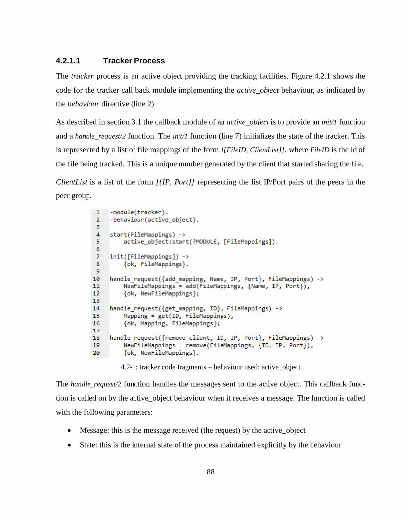
88
4.2.1.1 Tracker Process
The tracker process is an active object providing the tracking facilities. Figure 4.2.1 shows the
code for the tracker call back module implementing the active_object behaviour, as indicated by
the behaviour directive (line 2).
As described in section 3.1 the callback module of an active_object is to provide an init/1 function
and a handle_request/2 function. The init/1 function (line 7) initializes the state of the tracker. This
is represented by a list of file mappings of the form [{FileID, ClientList}], where FileID is the id of
the file being tracked. This is a unique number generated by the client that started sharing the file.
ClientList is a list of the form [{IP, Port}] representing the list IP/Port pairs of the peers in the
peer group.
4.2-1: tracker code fragments – behaviour used: active_object
The handle_request/2 function handles the messages sent to the active object. This callback func-
tion is called on by the active_object behaviour when it receives a message. The function is called
with the following parameters:
Message: this is the message received (the request) by the active_object
State: this is the internal state of the process maintained explicitly by the behaviour
89
The function returns one of two types of results:
{ok, NewState}: when a result is in this form, the server sets its state to the new state and
waits for other requests from clients.
{ok, Response, NewState}: When this result is returned, the Response is sent to the process
that sent the message. The server then sets its state to the new state and waits for more re-
quests.
This specific server accepts three types of messages:
add_mapping: when received (line 10), the calling peer’s IP and the port number are added
to the list of peers in the peer group (line 11). If there is no entry for that file ID yet, then
it is created.
get_mapping: This message is sent by a peer starting the download of a particular file. It
requests the IP/Port pair list of the peers in the given peer group. This list is retrieved by
the tracker from its internal list of mappings, and sent to the calling process
remove_client: This request (line 17) is handled in similar way that the add_mapping mes-
sage is handled, removing the client’s IP/port pair from the process’ mappings.
4.2.1.1.1 Benefits in adopted behaviour
In figure 4.2.1 we saw the tracker process implementing the callback functions for the ac-
tive_object behaviour. The active_object behaviour allows us to write sequential code which be-
haves as a concurrent process. It abstracts the concurrency away from the module. As shown in
figure 4.2.1, we only implement the functions for initialization for the process, and service hand-
ler functions.
4.2.1.2 Acceptor & Service Handler
The implemented tracker process provides the application specific service of the tracker applica-
tion. What is needed is an interface to the system over the TCP network from external peers (as
shown in figure 4.1.4).
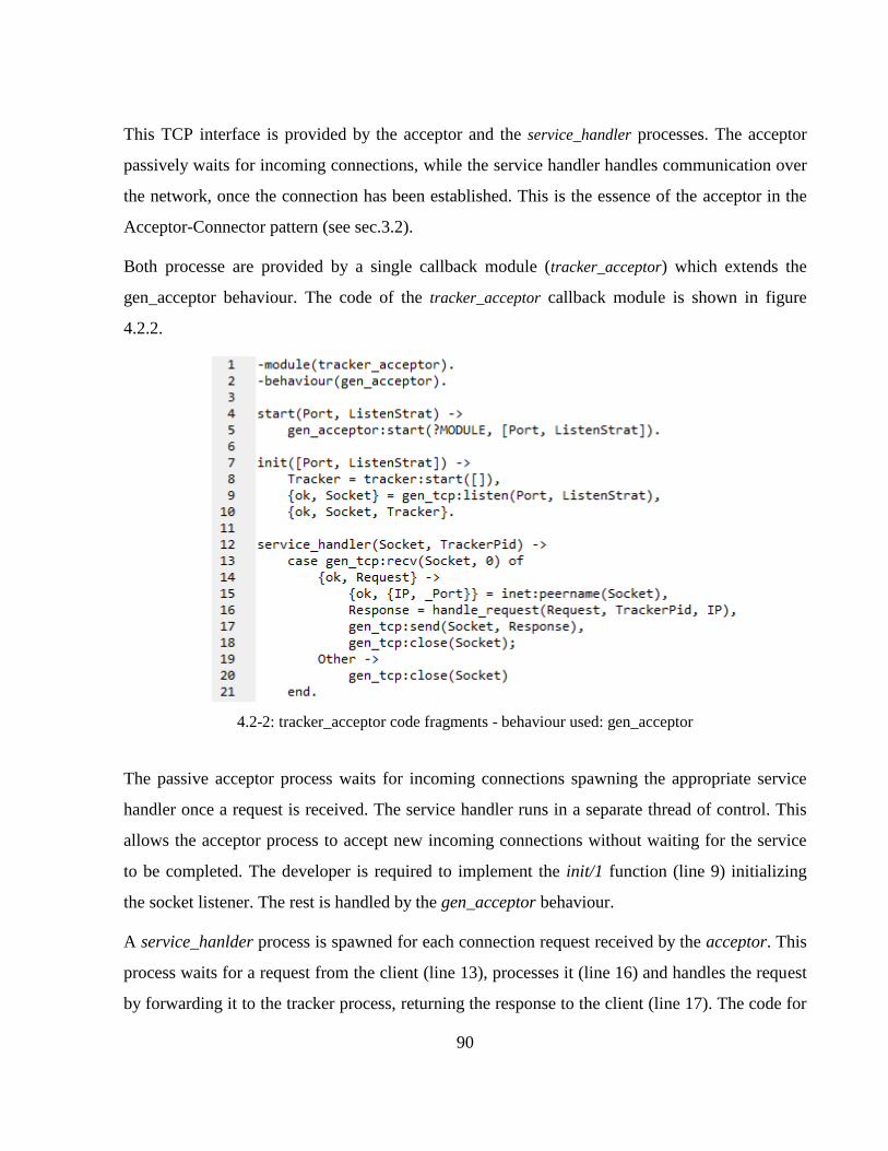
90
This TCP interface is provided by the acceptor and the service_handler processes. The acceptor
passively waits for incoming connections, while the service handler handles communication over
the network, once the connection has been established. This is the essence of the acceptor in the
Acceptor-Connector pattern (see sec.3.2).
Both processe are provided by a single callback module (tracker_acceptor) which extends the
gen_acceptor behaviour. The code of the tracker_acceptor callback module is shown in figure
4.2.2.
4.2-2: tracker_acceptor code fragments - behaviour used: gen_acceptor
The passive acceptor process waits for incoming connections spawning the appropriate service
handler once a request is received. The service handler runs in a separate thread of control. This
allows the acceptor process to accept new incoming connections without waiting for the service
to be completed. The developer is required to implement the init/1 function (line 9) initializing
the socket listener. The rest is handled by the gen_acceptor behaviour.
A service_hanlder process is spawned for each connection request received by the acceptor. This
process waits for a request from the client (line 13), processes it (line 16) and handles the request
by forwarding it to the tracker process, returning the response to the client (line 17). The code for
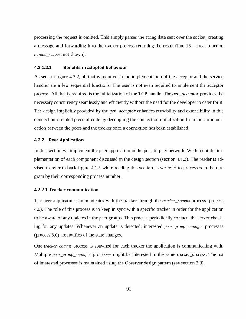
91
processing the request is omitted. This simply parses the string data sent over the socket, creating
a message and forwarding it to the tracker process returning the result (line 16 – local function
handle_request not shown).
4.2.1.2.1 Benefits in adopted behaviour
As seen in figure 4.2.2, all that is required in the implementation of the acceptor and the service
handler are a few sequential functions. The user is not even required to implement the acceptor
process. All that is required is the initialization of the TCP handle. The gen_acceptor provides the
necessary concurrency seamlessly and efficiently without the need for the developer to cater for it.
The design implicitly provided by the gen_acceptor enhances reusability and extensibility in this
connection-oriented piece of code by decoupling the connection initialization from the communi-
cation between the peers and the tracker once a connection has been established.
4.2.2 Peer Application
In this section we implement the peer application in the peer-to-peer network. We look at the im-
plementation of each component discussed in the design section (section 4.1.2). The reader is ad-
vised to refer to back figure 4.1.5 while reading this section as we refer to processes in the dia-
gram by their corresponding process number.
4.2.2.1 Tracker communication
The peer application communicates with the tracker through the tracker_comms process (process
4.0). The role of this process is to keep in sync with a specific tracker in order for the application
to be aware of any updates in the peer groups. This process periodically contacts the server check-
ing for any updates. Whenever an update is detected, interested peer_group_manager processes
(process 3.0) are notifies of the state changes.
One tracker_comms process is spawned for each tracker the application is communicating with.
Multiple peer_group_manager processes might be interested in the same tracker_process. The list
of interested processes is maintained using the Observer design pattern (see section 3.3).
92
This process also makes use of the Multiton [1] to ensure that a single tracker_proces is spawned
for a given tracker. If the peer_group_manager attempts to spawn a process to communicate with a
tracker, when one already exists for that tracker, the Multiton pattern ensures that the existing in-
stance is returned, rather than spawning a new one.
The tracker_comms process provides an implementation of the Observer design pattern. The mod-
ule provides the callback functions for the gen_subject behaviour. The observers of the subject are
the peer_group_manager processes interested in files on the tracker it is communicating with.
Figure 4.2.3 shows the main callback function for the gen_subject behaviour implemented by the
tracker_comms process. The handle_reques/2 callback function handles three requests received by
the process; however the gen_subject implicitly provides handlers for attaching and detaching ob-
servers. Therefore the tracker_comms process in total provides the following five request handlers:
4.2-3: tracker_comms code fragments - behaviour used: gen_subject
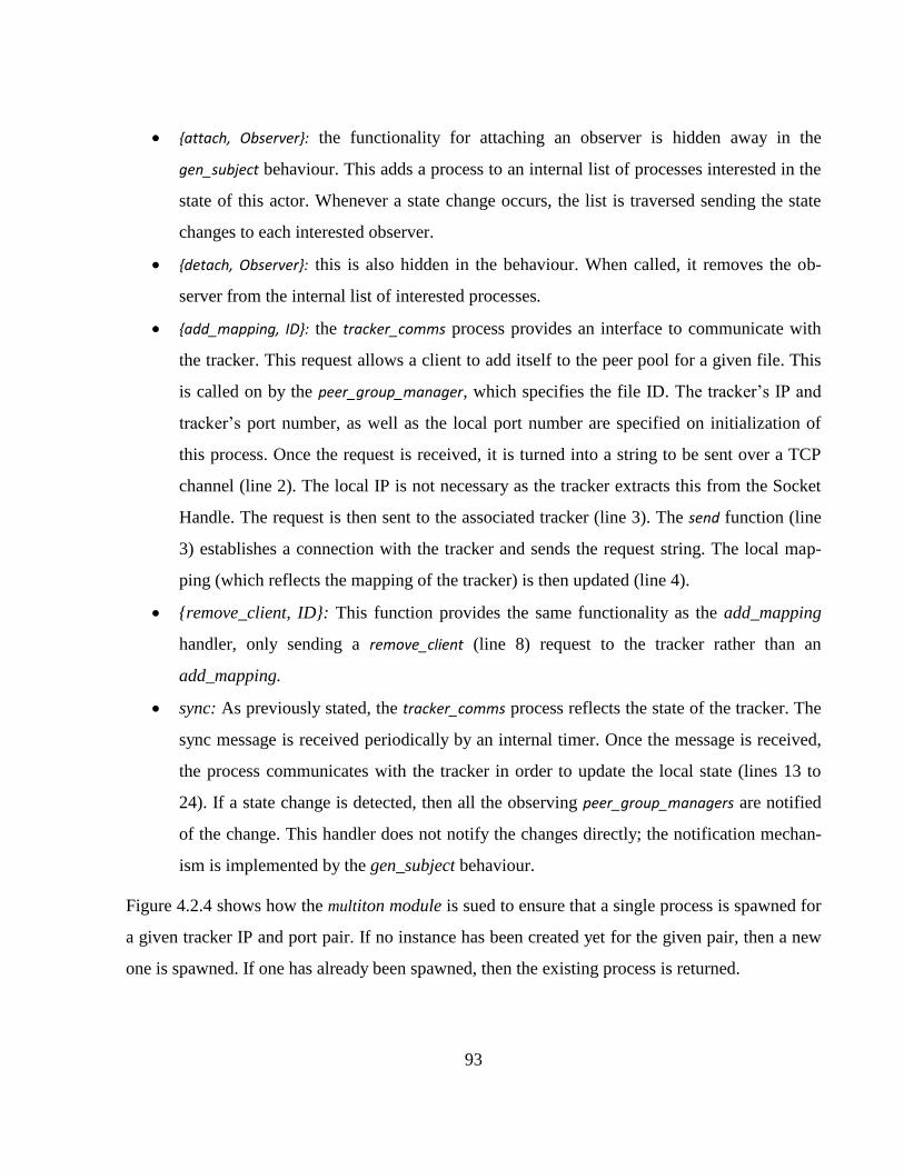
93
{attach, Observer}: the functionality for attaching an observer is hidden away in the
gen_subject behaviour. This adds a process to an internal list of processes interested in the
state of this actor. Whenever a state change occurs, the list is traversed sending the state
changes to each interested observer.
{detach, Observer}: this is also hidden in the behaviour. When called, it removes the ob-
server from the internal list of interested processes.
{add_mapping, ID}: the tracker_comms process provides an interface to communicate with
the tracker. This request allows a client to add itself to the peer pool for a given file. This
is called on by the peer_group_manager, which specifies the file ID. The tracker’s IP and
tracker’s port number, as well as the local port number are specified on initialization of
this process. Once the request is received, it is turned into a string to be sent over a TCP
channel (line 2). The local IP is not necessary as the tracker extracts this from the Socket
Handle. The request is then sent to the associated tracker (line 3). The send function (line
3) establishes a connection with the tracker and sends the request string. The local map-
ping (which reflects the mapping of the tracker) is then updated (line 4).
{remove_client, ID}: This function provides the same functionality as the add_mapping
handler, only sending a remove_client (line 8) request to the tracker rather than an
add_mapping.
sync: As previously stated, the tracker_comms process reflects the state of the tracker. The
sync message is received periodically by an internal timer. Once the message is received,
the process communicates with the tracker in order to update the local state (lines 13 to
24). If a state change is detected, then all the observing peer_group_managers are notified
of the change. This handler does not notify the changes directly; the notification mechan-
ism is implemented by the gen_subject behaviour.
Figure 4.2.4 shows how the multiton module is sued to ensure that a single process is spawned for
a given tracker IP and port pair. If no instance has been created yet for the given pair, then a new
one is spawned. If one has already been spawned, then the existing process is returned.
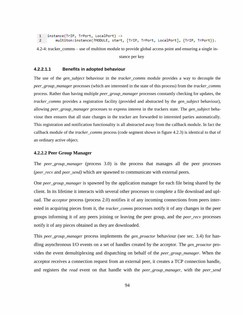
94
4.2-4: tracker_comms – use of multiton module to provide global access point and ensuring a single in-
stance per key
4.2.2.1.1 Benefits in adopted behaviour
The use of the gen_subject behaviour in the tracker_comms module provides a way to decouple the
peer_group_manager processes (which are interested in the state of this process) from the tracker_comms
process. Rather than having multiple peer_group_manager processes constantly checking for updates, the
tracker_comms provides a registration facility (provided and abstracted by the gen_subject behaviour),
allowing peer_group_manager processes to express interest in the trackers state. The gen_subject beha-
viour then ensures that all state changes in the tracker are forwarded to interested parties automatically.
This registration and notification functionality is all abstracted away from the callback module. In fact the
callback module of the tracker_comms process (code segment shown in figure 4.2.3) is identical to that of
an ordinary active object.
4.2.2.2 Peer Group Manager
The peer_group_manager (process 3.0) is the process that manages all the peer processes
(peer_recv and peer_send) which are spawned to communicate with external peers.
One peer_group_manager is spawned by the application manager for each file being shared by the
client. In its lifetime it interacts with several other processes to complete a file download and upl-
oad. The acceptor process (process 2.0) notifies it of any incoming connections from peers inter-
ested in acquiring pieces from it, the tracker_comms processes notify it of any changes in the peer
groups informing it of any peers joining or leaving the peer group, and the peer_recv processes
notify it of any pieces obtained as they are downloaded.
This peer_group_manager process implements the gen_proactor behaviour (see sec. 3.4) for han-
dling asynchronous I/O events on a set of handles created by the acceptor. The gen_proactor pro-
vides the event demultiplexing and dispatching on behalf of the peer_group_manager. When the
acceptor receives a connection request from an external peer, it creates a TCP connection handle,
and registers the read event on that handle with the peer_group_manager, with the peer_send
95
process as the completion handler. The peer_group_manager behaves as the completion dispatcher
in the Proactor pattern [3]. It receives asynchronous read events on the socket handle, dispatching
the completed event to the registered service handlers.
Figure 4.2.5 shows the initialization code for the peer_group_manager as well as the event comple-
tion dispatching code. The process is spawned by the application manager with the following pa-
rameters (line 4):
ID: the file’s unique ID which is generated using a hash function. Peers identify files using
this ID.
State: a client can be in one of the following states:
o Starting: No pieces have been downloaded yet
o Leeching: The client has pieces to share, but it is also downloading some needed
pieces itself
o Seeding: The client owns all the pieces and is making them available to other
peers
o Complete: The client owns all the pieces but is not currently sharing the pieces
PiecesSize: This specifies the size of each piece
NoOfPieces: The number of pieces the original file consists of.
TrList: This specifies a list of tracker IP/Port pairs identifying the trackers tracking the
peer group for the given file.
FileName: The file name.
Path: The physical path of the file on the local hard disk.
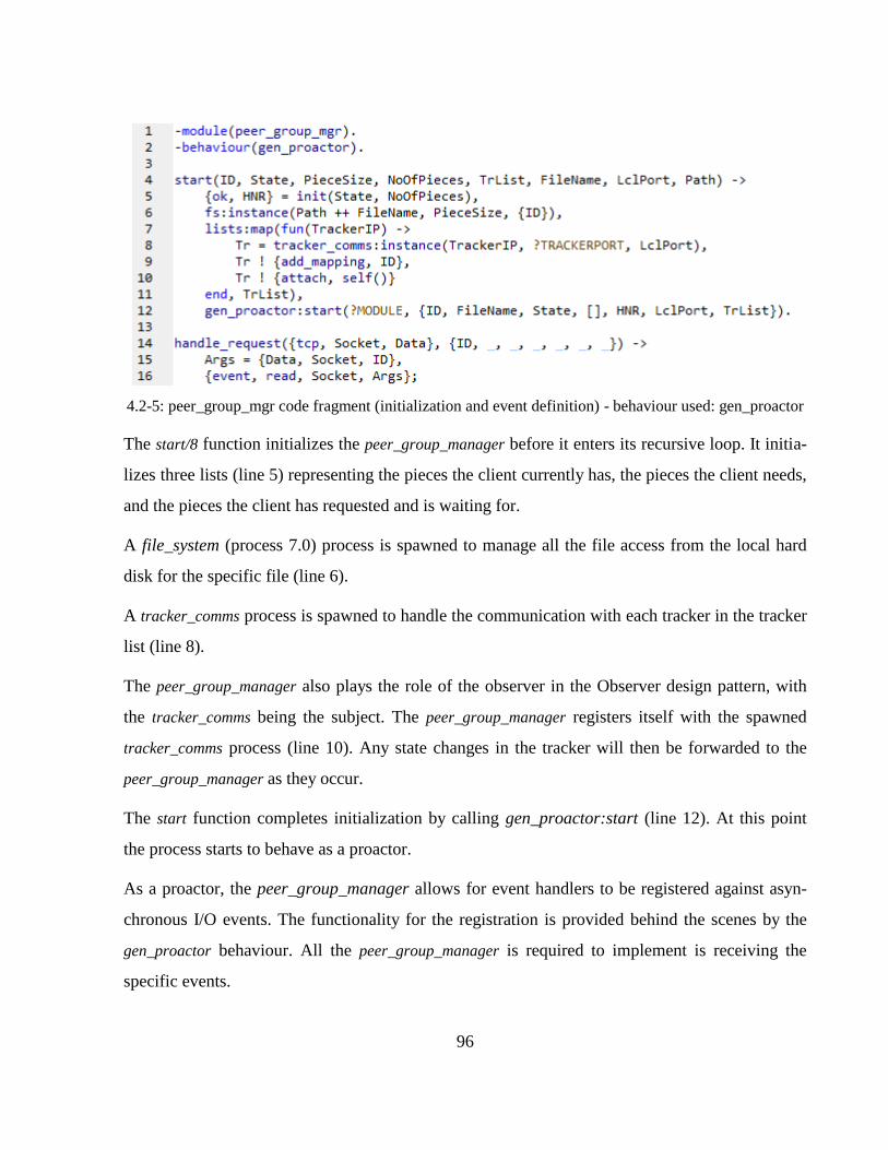
96
4.2-5: peer_group_mgr code fragment (initialization and event definition) - behaviour used: gen_proactor
The start/8 function initializes the peer_group_manager before it enters its recursive loop. It initia-
lizes three lists (line 5) representing the pieces the client currently has, the pieces the client needs,
and the pieces the client has requested and is waiting for.
A file_system (process 7.0) process is spawned to manage all the file access from the local hard
disk for the specific file (line 6).
A tracker_comms process is spawned to handle the communication with each tracker in the tracker
list (line 8).
The peer_group_manager also plays the role of the observer in the Observer design pattern, with
the tracker_comms being the subject. The peer_group_manager registers itself with the spawned
tracker_comms process (line 10). Any state changes in the tracker will then be forwarded to the
peer_group_manager as they occur.
The start function completes initialization by calling gen_proactor:start (line 12). At this point
the process starts to behave as a proactor.
As a proactor, the peer_group_manager allows for event handlers to be registered against asyn-
chronous I/O events. The functionality for the registration is provided behind the scenes by the
gen_proactor behaviour. All the peer_group_manager is required to implement is receiving the
specific events.
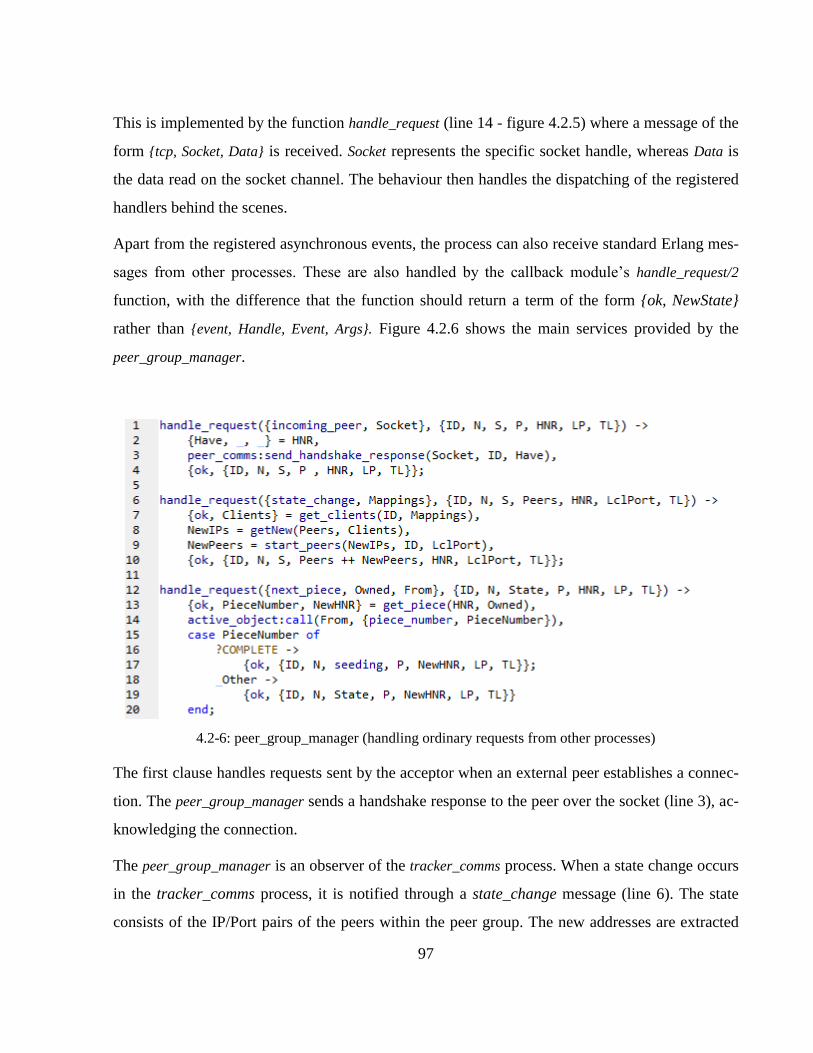
97
This is implemented by the function handle_request (line 14 - figure 4.2.5) where a message of the
form {tcp, Socket, Data} is received. Socket represents the specific socket handle, whereas Data is
the data read on the socket channel. The behaviour then handles the dispatching of the registered
handlers behind the scenes.
Apart from the registered asynchronous events, the process can also receive standard Erlang mes-
sages from other processes. These are also handled by the callback module’s handle_request/2
function, with the difference that the function should return a term of the form {ok, NewState}
rather than {event, Handle, Event, Args}. Figure 4.2.6 shows the main services provided by the
peer_group_manager.
4.2-6: peer_group_manager (handling ordinary requests from other processes)
The first clause handles requests sent by the acceptor when an external peer establishes a connec-
tion. The peer_group_manager sends a handshake response to the peer over the socket (line 3), ac-
knowledging the connection.
The peer_group_manager is an observer of the tracker_comms process. When a state change occurs
in the tracker_comms process, it is notified through a state_change message (line 6). The state
consists of the IP/Port pairs of the peers within the peer group. The new addresses are extracted
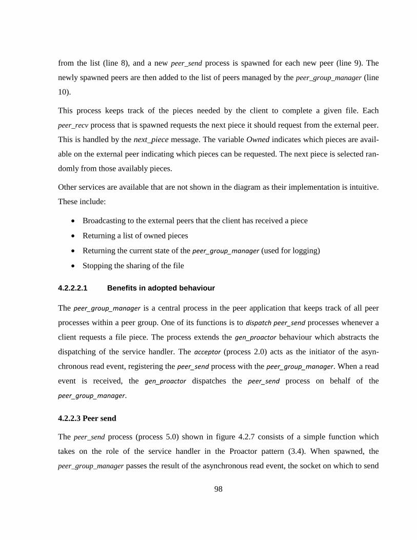
98
from the list (line 8), and a new peer_send process is spawned for each new peer (line 9). The
newly spawned peers are then added to the list of peers managed by the peer_group_manager (line
10).
This process keeps track of the pieces needed by the client to complete a given file. Each
peer_recv process that is spawned requests the next piece it should request from the external peer.
This is handled by the next_piece message. The variable Owned indicates which pieces are avail-
able on the external peer indicating which pieces can be requested. The next piece is selected ran-
domly from those availably pieces.
Other services are available that are not shown in the diagram as their implementation is intuitive.
These include:
Broadcasting to the external peers that the client has received a piece
Returning a list of owned pieces
Returning the current state of the peer_group_manager (used for logging)
Stopping the sharing of the file
4.2.2.2.1 Benefits in adopted behaviour
The peer_group_manager is a central process in the peer application that keeps track of all peer
processes within a peer group. One of its functions is to dispatch peer_send processes whenever a
client requests a file piece. The process extends the gen_proactor behaviour which abstracts the
dispatching of the service handler. The acceptor (process 2.0) acts as the initiator of the asyn-
chronous read event, registering the peer_send process with the peer_group_manager. When a read
event is received, the gen_proactor dispatches the peer_send process on behalf of the
peer_group_manager.
4.2.2.3 Peer send
The peer_send process (process 5.0) shown in figure 4.2.7 consists of a simple function which
takes on the role of the service handler in the Proactor pattern (3.4). When spawned, the
peer_group_manager passes the result of the asynchronous read event, the socket on which to send
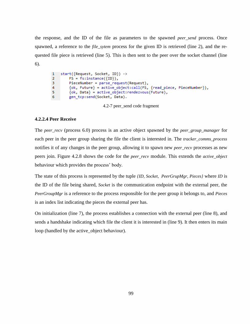
99
the response, and the ID of the file as parameters to the spawned peer_send process. Once
spawned, a reference to the file_sytem process for the given ID is retrieved (line 2), and the re-
quested file piece is retrieved (line 5). This is then sent to the peer over the socket channel (line
6).
4.2-7 peer_send code fragment
4.2.2.4 Peer Receive
The peer_recv (process 6.0) process is an active object spawned by the peer_group_manager for
each peer in the peer group sharing the file the client is interested in. The tracker_comms_process
notifies it of any changes in the peer group, allowing it to spawn new peer_recv processes as new
peers join. Figure 4.2.8 shows the code for the peer_recv module. This extends the active_object
behaviour which provides the process’ body.
The state of this process is represented by the tuple {ID, Socket, PeerGrupMgr, Pieces} where ID is
the ID of the file being shared, Socket is the communication endpoint with the external peer, the
PeerGroupMgr is a reference to the process responsible for the peer group it belongs to, and Pieces
is an index list indicating the pieces the external peer has.
On initialization (line 7), the process establishes a connection with the external peer (line 8), and
sends a handshake indicating which file the client it is interested in (line 9). It then enters its main
loop (handled by the active_object behaviour).
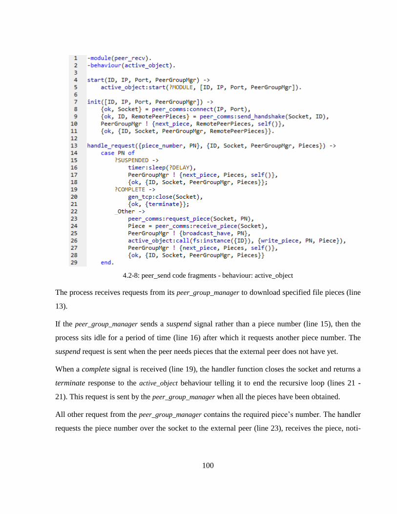
100
4.2-8: peer_send code fragments - behaviour: active_object
The process receives requests from its peer_group_manager to download specified file pieces (line
13).
If the peer_group_manager sends a suspend signal rather than a piece number (line 15), then the
process sits idle for a period of time (line 16) after which it requests another piece number. The
suspend request is sent when the peer needs pieces that the external peer does not have yet.
When a complete signal is received (line 19), the handler function closes the socket and returns a
terminate response to the active_object behaviour telling it to end the recursive loop (lines 21 -
21). This request is sent by the peer_group_manager when all the pieces have been obtained.
All other request from the peer_group_manager contains the required piece’s number. The handler
requests the piece number over the socket to the external peer (line 23), receives the piece, noti-
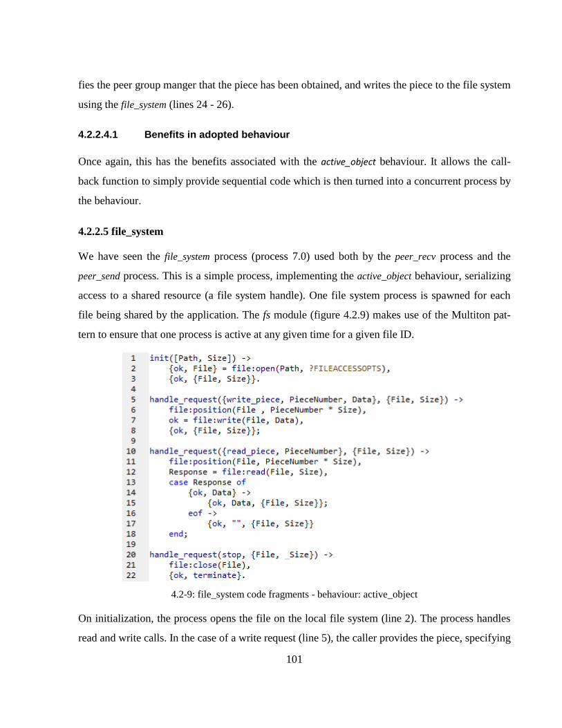
101
fies the peer group manger that the piece has been obtained, and writes the piece to the file system
using the file_system (lines 24 - 26).
4.2.2.4.1 Benefits in adopted behaviour
Once again, this has the benefits associated with the active_object behaviour. It allows the call-
back function to simply provide sequential code which is then turned into a concurrent process by
the behaviour.
4.2.2.5 file_system
We have seen the file_system process (process 7.0) used both by the peer_recv process and the
peer_send process. This is a simple process, implementing the active_object behaviour, serializing
access to a shared resource (a file system handle). One file system process is spawned for each
file being shared by the application. The fs module (figure 4.2.9) makes use of the Multiton pat-
tern to ensure that one process is active at any given time for a given file ID.
4.2-9: file_system code fragments - behaviour: active_object
On initialization, the process opens the file on the local file system (line 2). The process handles
read and write calls. In the case of a write request (line 5), the caller provides the piece, specifying
102
its index number. The file_system process calculates the position in the file where to write to by
using the piece size, which is specified on initialization, and the piece index (line 6). The piece is
then written to the local file.
A read_piece request is handled in a similar way. The caller specifies the piece number. The piece
is then read from file and returned to the user. The handle_request/2 callback function simply re-
turns a tuple of the form {ok, Response, NewState}, with Response being the file piece. This is sent
by the active_object behaviour to the calling process.
When a stop request is received the process closes the file handle (line 21), and returns a terminate
response to the active_object informing it to end the recursive loop.
4.2.2.5.1 Benefits in adopted behaviour
Once again, the adoption of the active_object behaviour simplifies the implementation of a con-
current process, allowing the developer to write sequential functions. Another important feature
the active_object to this component is the synchronized access to a shared resource. The shared
resource is the file on the local file system (or the handle to the file). Multiple processes may re-
quest reads and writes concurrently. The active_object synchronizes these requests through
process’ mailbox providing deterministic behavior.
4.2.2.6 Acceptor
The acceptor (process 2.0) process accepts incoming connections from external peers. It initializes
the connection by receiving a handshake form the peer, and forwards the request to the associated
peer_group_manager.
This process uses the leader_follower behaviour which turns a callback module into a process
pool. The callback module is to implement the services for a given server, such as the acceptor,
while the behaviour turns this into a pool of processes which take turns processing requests.
This provides an efficient concurrency model allowing for a number of processes to share in set
of connection handles. The use of the thread pool limits the number of concurrent active peer
connections. Rather than providing one service handler per request, the number of service hand-
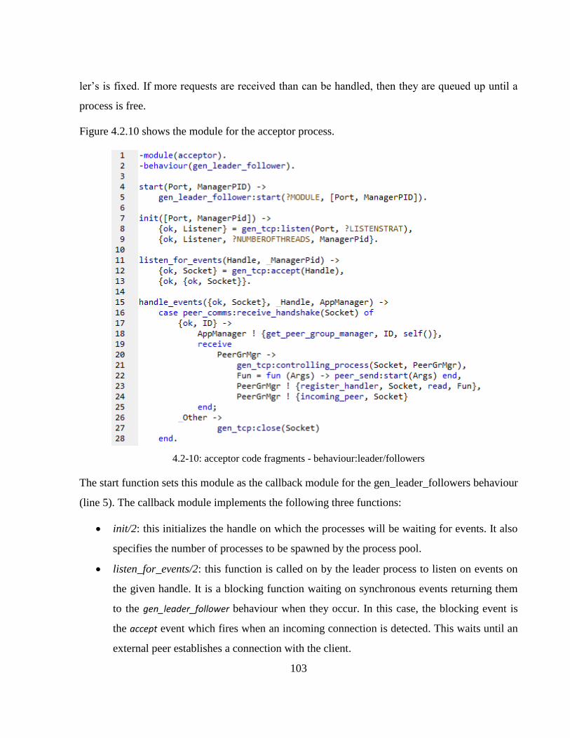
103
ler’s is fixed. If more requests are received than can be handled, then they are queued up until a
process is free.
Figure 4.2.10 shows the module for the acceptor process.
4.2-10: acceptor code fragments - behaviour:leader/followers
The start function sets this module as the callback module for the gen_leader_followers behaviour
(line 5). The callback module implements the following three functions:
init/2: this initializes the handle on which the processes will be waiting for events. It also
specifies the number of processes to be spawned by the process pool.
listen_for_events/2: this function is called on by the leader process to listen on events on
the given handle. It is a blocking function waiting on synchronous events returning them
to the gen_leader_follower behaviour when they occur. In this case, the blocking event is
the accept event which fires when an incoming connection is detected. This waits until an
external peer establishes a connection with the client.
104
handle_events/3: once the leader process selects a new leader from the follower pool it
dispatches the handle_events function. This function receives a handshake from the exter-
nal peer (line 15) determining the file that the peer is interested in. once retrieved, it regis-
ters the peer_group_manager associated with that file, for the events on the created socket
to be forwarded to it (line 21). It then registers the peer_send callback function with the
peer_group_manager associating it with a read event (line 23). This takes on the role of the
initiator in the Proactor pattern, with the peer_group_manager being the completion dis-
patcher (see sec. 3.4).
4.2.2.6.1 Benefits in adopted behaviour
The use of the gen_leader_follower provides a strategy limits the number of active client connec-
tion to a predefined number. It provides a process pool to handle client connection requests as
they occur. If requests are received faster than the processes pool can handle them, then requests
are queued up on the given handle until a process is free to handle the request. Given that the
processes share some event source to receive the requests, they synchronize themselves such that
only the leader thread is using the handle at any given time. All this functionality is abstracted
away in the gen_leader_follower behaviour. The user simply defines the application specific ser-
vices, initializes the event source handle, and specifies the size of the process pool. The use of the
behaviour ensures an efficient strategy for handling concurrent clients over a network, with little
effort on behalf of the developer.
4.2.2.7 Conclusion
In this section we designed and implemented a peer-to-peer file sharing application by integrating
the design patterns and the implemented behaviours. This served to demonstrate the applicability
of the patterns to a large scale application.
In section 4.1 we provided a quick overview of the application in which we introduced the design
patterns that were to be used, and the role of each component (process) in the implementation of
the given pattern.
105
In section 4.2 we saw how the behaviours we implemented in section 3 can be used to seamlessly
integrate these patterns into the architecture. We provided implementation details discussing each
of the behaviours used, and the role that each process played within the overall design.
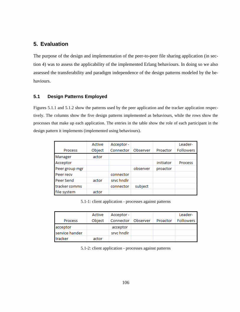
106
5. Evaluation
The purpose of the design and implementation of the peer-to-peer file sharing application (in sec-
tion 4) was to assess the applicability of the implemented Erlang behaviours. In doing so we also
assessed the transferability and paradigm independence of the design patterns modeled by the be-
haviours.
5.1 Design Patterns Employed
Figures 5.1.1 and 5.1.2 show the patterns used by the peer application and the tracker application respec-
tively. The columns show the five design patterns implemented as behaviours, while the rows show the
processes that make up each application. The entries in the table show the role of each participant in the
design pattern it implements (implemented using behaviours).
5.1-1: client application - processes against patterns
5.1-2: client application - processes against patterns
107
5.2 Benefits achieved
We assess the applicability of the design patterns by investigating whether the benefits that are
associated with design patterns were manifested in the design and implementation of the peer-to-
peer file sharing application. The benefits we identified are outlined below:
Facilitating design reusability
The implemented patterns address a number of recurring problems that developers encounter in
the implementation of concurrent applications, such as the need for efficient event demultiplexing
and the dispatching of event handlers, the need to handle interposes communication as well as
communication over network protocols.
The Acceptor-Connector pattern for example was used both in the implementation of the tracker
as well as the implementation of peer application.
The use of behaviours enabled us to reuse standard approaches by simply specifying the applica-
tion specific details, while allowing for the behaviour to manage the design of the high level
communication protocol. Design reuse also enabled code reusability which simplified and re-
duced the implementation time.
Provide high level view
The use of the patterns and behaviours provide a high level view of the overall architecture using
the patterns as architectural blocks without going into specific implementation details. They pro-
vide an overview of the participants in the application and the collaboration between them. Even
by simply observing the roles of the participants in figures 5.1.1 and 5.1.2 a user is able to make
relationships between participants. The acceptor process for example can be seen to be the initia-
tor of some asynchronous event on the peer group manager process (the proactor). The inference
of such associations aids in the overall understandability of the application’s architecture.
Capturing expertise and making it accessible in a standard form
The expertise we adopt has already been captured by the authors of [3]. They have been made
available to the object-oriented community by structuring them in a form applicable to object-
108
orientation. We managed to recapture the expertise in a format that is more applicable to message
passing concurrency through the implementation of behaviours. Even though behaviours are spe-
cific to Erlang, the concept behind behaviours can be replicated in other languages based on mes-
sage passing concurrency.
Providing a common vocabulary
Rather than providing a new vocabulary, our goal was to reuse existing patterns from the object-
oriented paradigm that a number of developers are already familiar with. It has been argued that
in order to truly provide a common vocabulary, there should be some restriction on the amount of
patterns that are in circulation [7], otherwise the social and cultural benefits tied to patterns be-
come faint.
Rather than creating a new set of patterns, introducing a new vocabulary, and a new cultural con-
text, we set out to make use of existing patterns in order to bridge the two paradigms together.
Even though the peer-to-peer application was developed using message passing techniques, a de-
veloper familiar with the patterns from the object-oriented context is able to comprehend the un-
derlying architecture of the application through the use of this shared vocabulary.
Facilitate design modifications:
The use of design patterns also makes the system more maintainable as it is decomposed into
reusable components with high cohesion and low coupling. Components can be “plugged” into
place, removed, and replaced with little effort. The behaviours make use of higher order functions
and delegation of responsibility allowing for modules to be replaced transparently.
5.3 Benefits Overview
Overall, the implementation of the peer-to-peer application turns out to be relatively modular and
maintainable. It consists of reusable pluggable components that can be extended with ease.
Chaining the communication protocol between the tracker and the peers for example would in-
volve substituting a single process (the service handler). The code for connection establishment
need not change.
109
The use of the design patterns and the behaviours also provide efficient solutions to concurrency
without the need for the developer to explicitly cater for these needs. The use of the leader fol-
lower behaviour for example provides an efficient way of to handle concurrent connection re-
quests over a network from multiple clients. However the developer simply implements the ap-
plication specific services in the same way that it would be developed using the Acceptor-
Connector strategy. The only apparent difference is in behaviour the callback module implements.
The use of patterns also structures the application using standard techniques. This makes it easier
for someone trying to understand the application (such as a new developer joining the team) to
comprehend the overall structure and dynamics of the application.
This is true however only if the person is familiar with the patterns used. Otherwise a considera-
ble amount of time is spent to familiarize oneself with the pattern before understanding the sys-
tem’s architecture.
In general, when implementing a callback module for a given behaviours, the user is oblivious to
the inner workings of the behaviour. The callback module simply provides initialization and ap-
plication services while the structure and protocol behind the pattern is abstracted away into the
behaviour making the adoption of standard design patterns a relatively easy task.
110
6. Future Work
We set out to implement the design patterns in Erlang as a proof-of-concept. We intended on de-
monstrating the feasibility and the benefits that can be achieved in adopting existing design pat-
terns from the object-oriented setting to the message passing concurrency setting.
In order for the design patterns to truly be advantages to the developer, they are to undergo rigor-
ous testing in a multitude of diverse case studies. The implementation of a design pattern is not
cast in stone. After being implemented they are generally used by the community in the develop-
ment of real world applications. The community submits feedback, and the patterns are improved
on to cater for their needs.
We would like to see more application case studies developed using the patterns, and subsequent
improvements on the existing patterns based on their outcomes.
We would also like to extend the number of design patterns implemented in order to provide the
community with a substantial amount of patterns to cater for a diverse set of problems a develop-
er may encounter.
We would also like to work on the proposal and adoption of some standard diagramming tools
and notations for graphically representing design patterns in the message passing concurrency set-
ting. The object-oriented community uses class-diagrams and sequence diagrams as a convention
for their graphical representation. However the class diagram is applicable to objects, and not
concurrent process. The Erlang community currently does not have a standard way of graphically
representing the structure of an application apart from the use supervision trees, which are not
expressive enough for expressing such complex design.
As a side project we would also like to extend the peer-to-peer application developed for the case
study in order for it to share files using the BitTorrent protocol. The client could join existing
swarms communicating using the BitTorrent protocol and share files with existing peers rather
than starting a file sharing community from the bottom up. Such an extension should prove easy
given the modularity achieved with the use of design patterns. The results of the extension would

111
also serve to asses once again the adaptability, reusability, and maintainability achieved through
the use of design patterns.
112
7. Conclusion
In this project we set out to demonstrate the feasibility in the adoption of design patterns from the object
oriented community to the message passing concurrency setting. We stated that by finding the appropriate
units of decomposition for the message passing context we could translate the implementation of these
patterns to provide a solution that can be used by the message passing community. This would provide the
message passing community with the benefits that are associated with design patterns.
With Erlang as the language of choice we set out to implement a number of concurrency related design
patterns as behaviours that can be reused in the implementation of Erlang applications.
7.1 Achievements
Our main objectives were achieved satisfactorily. We were able to take advantage of the programming
constructs found in Erlang in order to translate patterns from objects to concurrent processes. We imple-
mented a number of patterns that serve as a proof-of-concept for the transferability of the patterns in gen-
eral.
The implementations of the behaviours include the following patterns:
Active Object
Acceptor-Connector
Observer
Proactor
Leader-Followers
Once the patterns were implemented, we also set out to assess their applicability in the design large scale
applications. As a test case we decided to choose a peer-to-peer file sharing application. The integration
of the Erlang behaviours facilitated the overall design and implementation stages providing reusable de-
113
sign and reusable code components, a simplified adoption of standard approaches and techniques that are
tested to work, and a more maintainable system.
7.2 Challenges Faced
We were faced with a number of challenges throughout the project that. The first challenging task
was familiarizing ourselves with Erlang. Erlang provides a different programming style to the ob-
ject-oriented languages we were previously accustomed to. We were forced to stop thinking in
terms of objects, and start thinking in terms of processes in order to place ourselves in the right
mindset. This was not an easy feat, as we often found ourselves blindly applying object oriented
techniques to Erlang rather than taking a step back and taking advantages that are made available
by Erlang’s concurrency constructs.
Learning the patterns themselves was another challenge. Design patterns are very useful tech-
niques in the development of large scale applications. However, they are beneficial only when
one is familiar with the patterns that are being used. In order for a team of developers to success-
fully adopt design patterns and reap their benefits, each member must be familiar with the pattern
otherwise their adoption might become a burden rather than an aid due to the learning curve asso-
ciated with them. We were not familiar with the patterns we set out to implement. Before select-
ing and translating the patterns, we were faced with the challenge of familiarizing ourselves with
multiple patterns and selecting ones appropriate for our study.
The next challenge was actually translating the patterns from objects to processes. We found very
little material that compared the object oriented paradigm and shared state setting to the message
passing setting. We were therefore faced with the challenge of identifying similarities in the two
programming models for ourselves. The greatest challenge was in identifying situations where a
naïve one-to-one mapping between objects and processes was possible and where a redesign of
the patterns was necessary.
Once implemented, our next challenge was articulating the design in the pattern documentation.
The object oriented community makes use of a number of standard diagrams that aid in providing
a graphical representation of the design pattern. The most common being the class diagram. De-
114
sign in Erlang is usually expressed using a supervision tree. This is a hierarchical structure ex-
pressing the way in which processes are spawned. This notation is not expressive enough to illu-
strate the interaction between the components. We adopted the use of data flow diagrams to ex-
press the data flow between components. This is not a standard in Erlang however it was recom-
mended to us by the Erlang community. It did provide the overall structure and general data flow
required however the introduction of standard diagramming notation by the Erlang community
would in our opinion aid in the design of Erlang applications and in the adoption of design pat-
terns.
7.3 Personal Learning
Throughout this project we covered a vast amount of new material, technologies, programming
styles and standard approaches that we were not previously familiar with.
We examined new ways in which applications are designed and implemented in Erlang, a concur-
rency oriented programming language, based on the actor-model. This undertook a considerable
amount of time and effort. However the effort paid off in the end. The experience equipped us
with new techniques for modeling the physical world in software. We learnt to embrace pro-
gramming in a concurrent environment.
We also learnt to appreciate the need to familiarizing ourselves with a diversity of programming
languages, particularly languages from different paradigms. We learnt how to apply approaches
from one paradigm to the other. Not only did we equip ourselves with a set of object oriented
techniques to be used in a message passing setting, but we also learnt elegant ways of structuring
concurrent code in the shared memory environment. We set out to adopt techniques from object
oriented paradigm to the message passing context, but the other way round turned out to be true
too.
We analyzed the world of distributed memory programming which takes on a different approach
to solving problems from the more common shared memory model that is adopted by languages
such as Java and C#.

115
We also learnt the value and the potential benefits that can be achieved in the adoption of design
patterns in the design and implementation of software applications, particularly in the develop-
ment of large scale systems in which development is a team effort
116
8. References
[1] E. Gamma, et al. (1995). Design Patterns. Addison-Wesley Professional.
[2] J. M. Vlissides (1998). Pattern Hatching. Design Patterns Applied. Addison-Wesley Profes-
sional.
[3] D. Schmidt, et al. (2000). Pattern-Oriented Software Architecture, Volume 2, Patterns for
Concurrent and Networked Objects. John Wiley & Sons.
[4] C. Alexander (1977). A pattern Language. Oxford University Press
[5] C. Alexander (1979). The Timeless Way of Building. Oxford University Press
[6] K Beck & W. Cunningham (1987). Pattern Languages for Object-Oriented program.
OOPSLA 1987 Workshop on the Specification and Design for Object-Oriented Programming
[7] E. Agerbo & A. Cornils (1998). How to preserve the benefits of design patterns. SIGPLAN
Not. 33(10):134-143.
[8] M. Zandstra (2007). PHP Objects, Patterns, and Practice, Second Edition. Apress
[9] David kocher (n.d.) Concurrency Patterns: Retrieved May, 10, 2009, from
http://www.ifi.uzh.ch/swe/teaching/courses/seminar2004/abgaben/Kocher_ConcurrencyPatterns.p
df
[10] M. Abadi & L. Cardelli (1998). A Theory of Objects (Monographs in Computer Science).
Springer.
[11] E. Gamma, et al. (1993). Design Patterns: Abstraction and Reuse of Object-Oriented De-
sign.
[12] M. Herlihy & N. Shavit (2008). The Art of Multiprocessor Programming. Morgan Kaufmann
117
[13] H. Sutter (2005), The Free Lunch Is Over: A Fundamental Turn Toward Concurrency in
Software, Dr. Dobb's Journal, vol. 30, no. 3
[14] E. Hesham & A. Mostafa (2005). Advanced Computer Architecture and Parallel Processing.
Wiley-Interscience
[15] J. Armstrong (2007). A history of Erlang. In HOPL III: Proceedings of the third ACM
SIGPLAN conference on History of programming languages, New York, NY, USA. ACM Press.
[16] J. Armstrong (2003). Concurrency Oriented Programming in Erlang. Distributed Systems
Laboratory, Swedish Institute of Computer Science
[17] F. Huch (2007). Learning programming with erlang. In ERLANG '07: Proceedings of the
2007 SIGPLAN workshop on ERLANG Workshop, pp. 93-99, New York, NY, USA. ACM.
[18] J. Armstrong (2003). Making Reliable Distributed Systems in the Presence of Software Er-
rors. Ph.D. thesis, Royal Institute of Technology, Stockholm, Sweden.
[19] S. Vinoski (2007). Concurrency with Erlang. IEEE Educational Activities Department
[20] R. Virding, et al. (1996). Concurrent Programming in Erlang (2nd Edition). Prentice Hall
PTR.
[21] J. Nystrom & Bengt Jonsson (2001). Extracting the Process Structure of Erlang Applica-
tions. Erlang User Conference, Stockholm.
[22] J. Armstrong (2007). Programming Erlang: Software for a Concurrent World. Pragmatic
Bookshelf.
[23] J. Li (2008). On peer-to-peer (P2P) content delivery. Peer-to-Peer Networking and Applica-
tions 1(1):45-63.
[24] BitTorrent. http://bittorrent.com.
118
[25] BitTorrent Protocol Specification v1.0. Retrieved May, 10, 2009, from
http://wiki.theory.org/BitTorrentSpecification.
[26] R. Vermeersch (2009) Concurrency in Erlang & Scala: The Actor Model Retrieved May, 8,
2009, from http://ruben.savanne.be/articles/concurrency-in-erlang-scala
[27] R. Johnson (2007). Erlang the next java. Retrieved May, 10, 2009, from
http://www.cincomsmalltalk.com/userblogs/ralph/blogView?entry=3364027251
[28] (2000). Technical description of the Erlang programming language, Retrieved May, 02,
2009, from http://www.erlang.se/productinfo/erlang_tech.shtml
[29] Dave Clarke , et al. (2008) Minimal Ownership for Active Objects. Proceedings of the 6th
Asian Symposium on Programming Languages and Systems
[30] G. R. Lavender & D. C. Schmidt (1995). `Active Object: an Object Behavioral Pattern for
Concurrent Programming'. Proc. Pattern Languages of Programs/
[31] D. Schmidt (1997). Acceptor-connector: an object creational pattern for connecting and in-
itializing communication services.
[32] D. C. Schmidt, et al. (1997). Proactor : An Object Behavioural Pattern for Demultiplexing
Handlers for Asynchronous Events.
[33] D. C. Schmidt, et al. (2000). Leader/Followers: A Design Pattern for Efficient Multi-
Threaded Event Demultiplexing and Dispatching. In University of Washington
[34] A. Varela (1998) What after Java? From Objects to Actors. Computer Networks and ISDN
Systems: The international J. of Computer Telecommunications and Networking
[35] G. Agha (1986). Actors: a model of concurrent computation in distributed systems. MIT
Press, Cambridge, MA, USA.
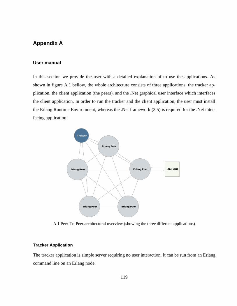
119
Appendix A
User manual
In this section we provide the user with a detailed explanation of to use the applications. As
shown in figure A.1 bellow, the whole architecture consists of three applications: the tracker ap-
plication, the client application (the peers), and the .Net graphical user interface which interfaces
the client application. In order to run the tracker and the client application, the user must install
the Erlang Runtime Environment, whereas the .Net framework (3.5) is required for the .Net inter-
facing application.
A.1 Peer-To-Peer architectural overview (showing the three different applications)
Tracker Application
The tracker application is simple server requiring no user interaction. It can be run from an Erlang
command line on an Erlang node.
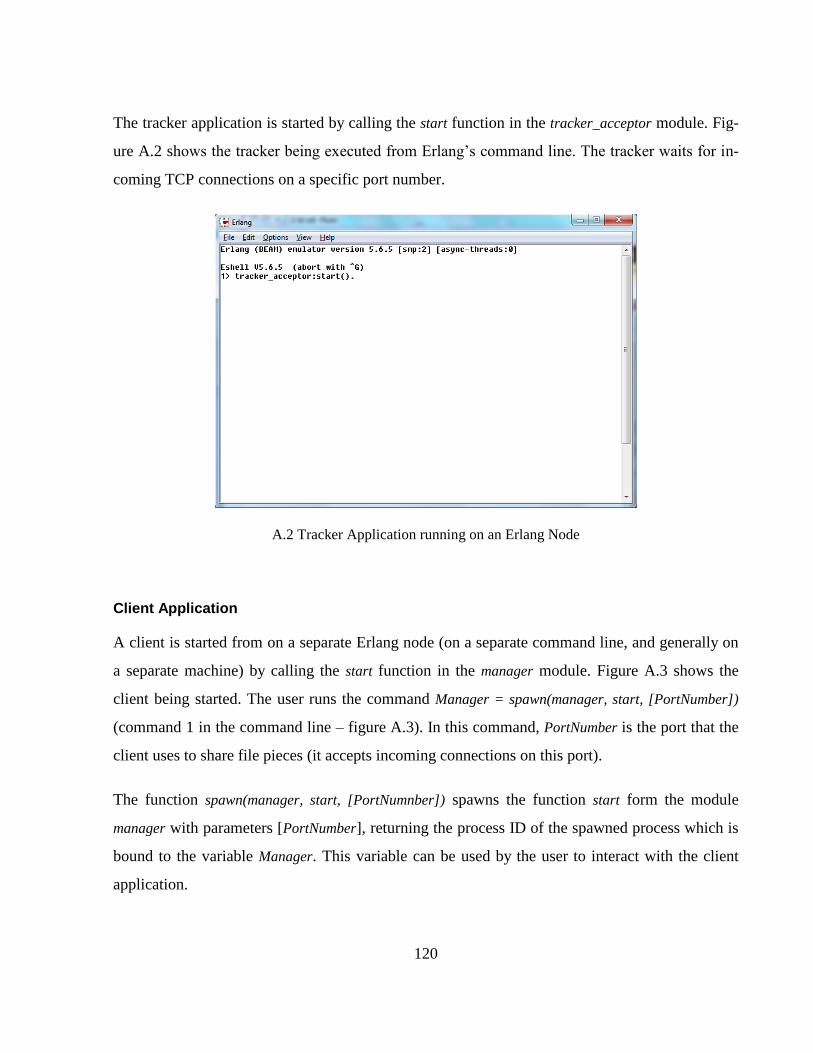
120
The tracker application is started by calling the start function in the tracker_acceptor module. Fig-
ure A.2 shows the tracker being executed from Erlang’s command line. The tracker waits for in-
coming TCP connections on a specific port number.
A.2 Tracker Application running on an Erlang Node
Client Application
A client is started from on a separate Erlang node (on a separate command line, and generally on
a separate machine) by calling the start function in the manager module. Figure A.3 shows the
client being started. The user runs the command Manager = spawn(manager, start, [PortNumber])
(command 1 in the command line – figure A.3). In this command, PortNumber is the port that the
client uses to share file pieces (it accepts incoming connections on this port).
The function spawn(manager, start, [PortNumnber]) spawns the function start form the module
manager with parameters [PortNumber], returning the process ID of the spawned process which is
bound to the variable Manager. This variable can be used by the user to interact with the client
application.
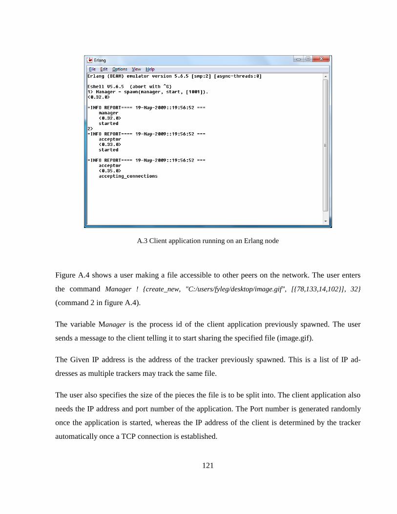
121
A.3 Client application running on an Erlang node
Figure A.4 shows a user making a file accessible to other peers on the network. The user enters
the command Manager ! {create_new, "C:/users/fyleg/desktop/image.gif", [{78,133,14,102}], 32}
(command 2 in figure A.4).
The variable Manager is the process id of the client application previously spawned. The user
sends a message to the client telling it to start sharing the specified file (image.gif).
The Given IP address is the address of the tracker previously spawned. This is a list of IP ad-
dresses as multiple trackers may track the same file.
The user also specifies the size of the pieces the file is to be split into. The client application also
needs the IP address and port number of the application. The Port number is generated randomly
once the application is started, whereas the IP address of the client is determined by the tracker
automatically once a TCP connection is established.
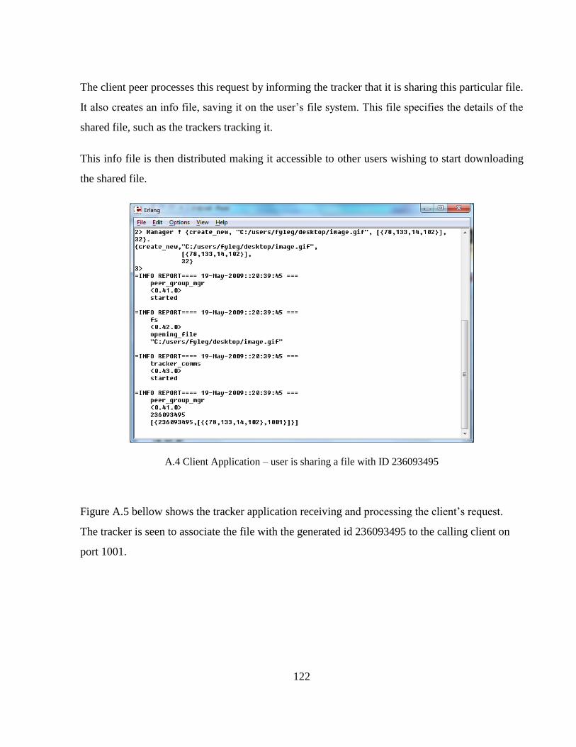
122
The client peer processes this request by informing the tracker that it is sharing this particular file.
It also creates an info file, saving it on the user’s file system. This file specifies the details of the
shared file, such as the trackers tracking it.
This info file is then distributed making it accessible to other users wishing to start downloading
the shared file.
A.4 Client Application – user is sharing a file with ID 236093495
Figure A.5 bellow shows the tracker application receiving and processing the client’s request.
The tracker is seen to associate the file with the generated id 236093495 to the calling client on
port 1001.
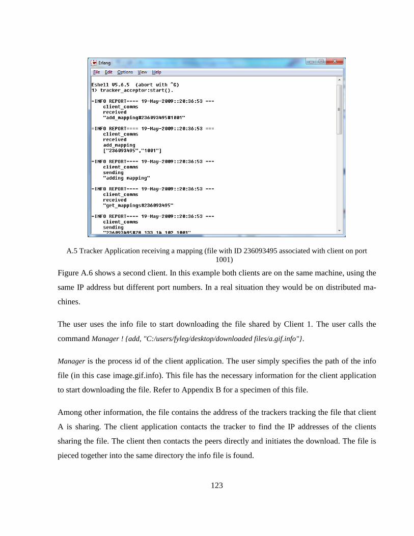
123
A.5 Tracker Application receiving a mapping (file with ID 236093495 associated with client on port
1001)
Figure A.6 shows a second client. In this example both clients are on the same machine, using the
same IP address but different port numbers. In a real situation they would be on distributed ma-
chines.
The user uses the info file to start downloading the file shared by Client 1. The user calls the
command Manager ! {add, "C:/users/fyleg/desktop/downloaded files/a.gif.info"}.
Manager is the process id of the client application. The user simply specifies the path of the info
file (in this case image.gif.info). This file has the necessary information for the client application
to start downloading the file. Refer to Appendix B for a specimen of this file.
Among other information, the file contains the address of the trackers tracking the file that client
A is sharing. The client application contacts the tracker to find the IP addresses of the clients
sharing the file. The client then contacts the peers directly and initiates the download. The file is
pieced together into the same directory the info file is found.
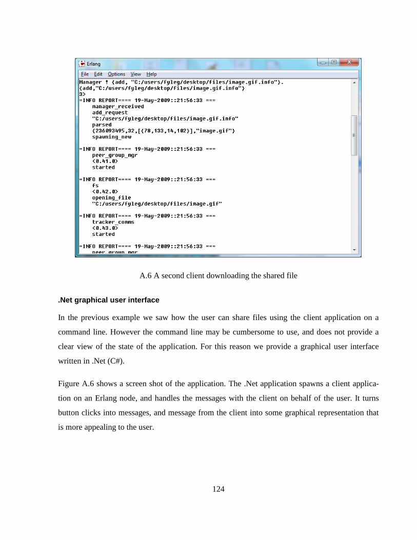
124
A.6 A second client downloading the shared file
.Net graphical user interface
In the previous example we saw how the user can share files using the client application on a
command line. However the command line may be cumbersome to use, and does not provide a
clear view of the state of the application. For this reason we provide a graphical user interface
written in .Net (C#).
Figure A.6 shows a screen shot of the application. The .Net application spawns a client applica-
tion on an Erlang node, and handles the messages with the client on behalf of the user. It turns
button clicks into messages, and message from the client into some graphical representation that
is more appealing to the user.
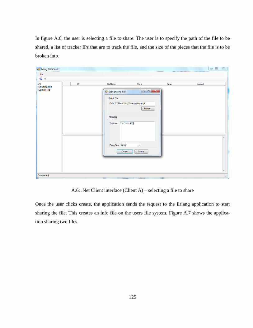
125
In figure A.6, the user is selecting a file to share. The user is to specify the path of the file to be
shared, a list of tracker IPs that are to track the file, and the size of the pieces that the file is to be
broken into.
A.6: .Net Client interface (Client A) – selecting a file to share
Once the user clicks create, the application sends the request to the Erlang application to start
sharing the file. This creates an info file on the users file system. Figure A.7 shows the applica-
tion sharing two files.
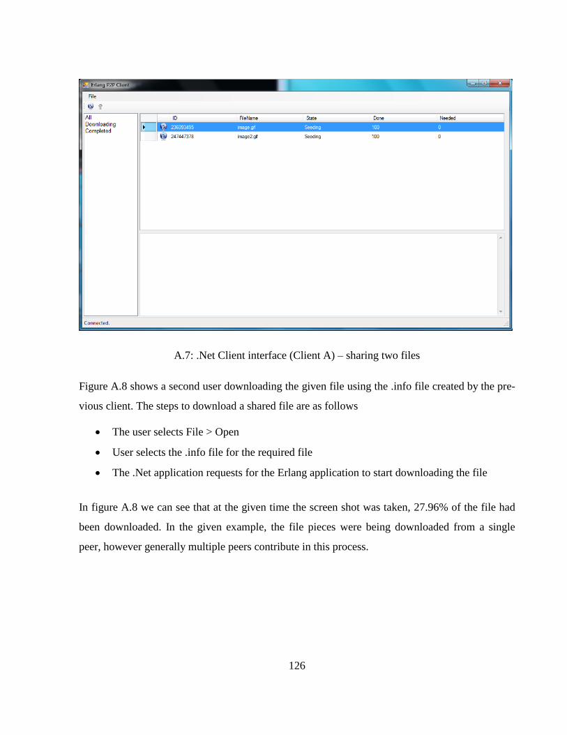
126
A.7: .Net Client interface (Client A) – sharing two files
Figure A.8 shows a second user downloading the given file using the .info file created by the pre-
vious client. The steps to download a shared file are as follows
The user selects File > Open
User selects the .info file for the required file
The .Net application requests for the Erlang application to start downloading the file
In figure A.8 we can see that at the given time the screen shot was taken, 27.96% of the file had
been downloaded. In the given example, the file pieces were being downloaded from a single
peer, however generally multiple peers contribute in this process.
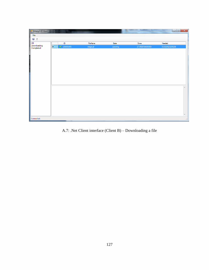
127
A.7: .Net Client interface (Client B) – Downloading a file
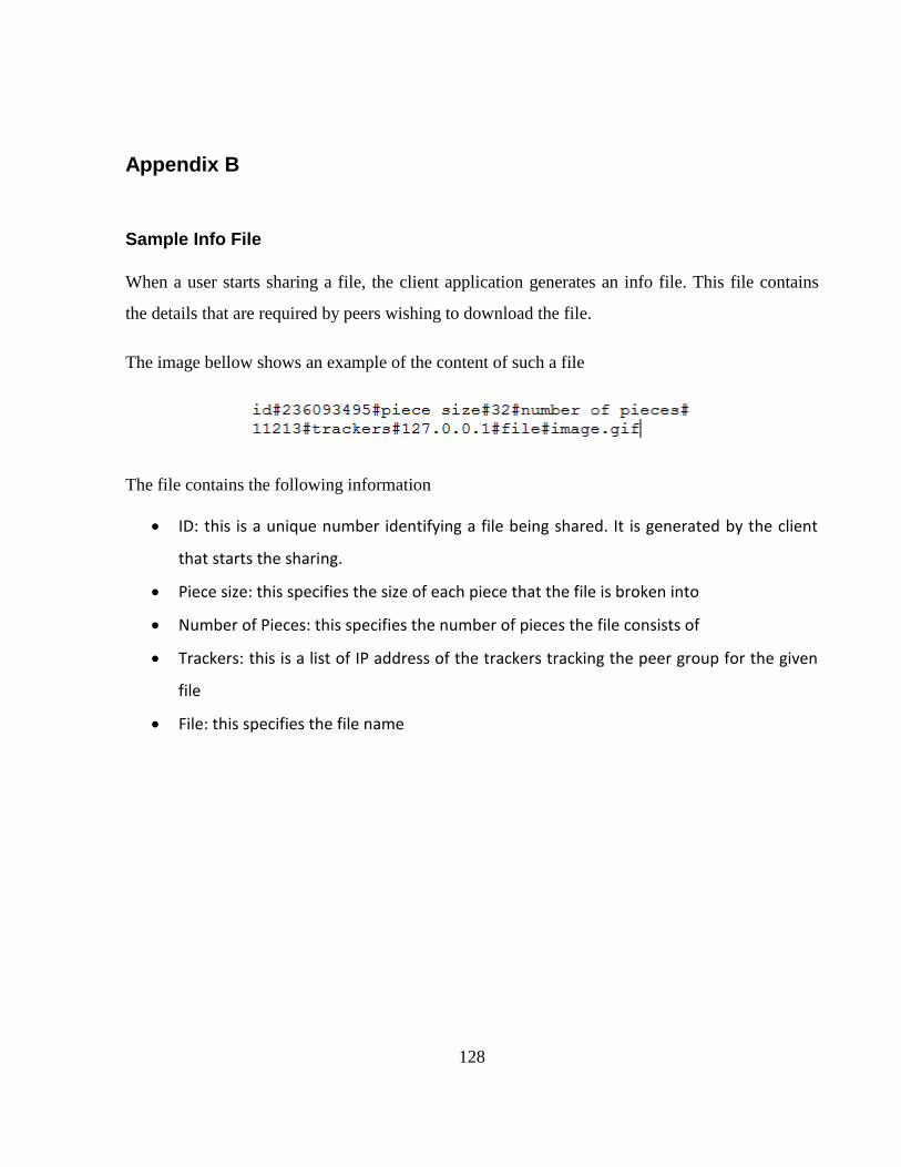
128
Appendix B
Sample Info File
When a user starts sharing a file, the client application generates an info file. This file contains
the details that are required by peers wishing to download the file.
The image bellow shows an example of the content of such a file
The file contains the following information
ID: this is a unique number identifying a file being shared. It is generated by the client
that starts the sharing.
Piece size: this specifies the size of each piece that the file is broken into
Number of Pieces: this specifies the number of pieces the file consists of
Trackers: this is a list of IP address of the trackers tracking the peer group for the given
file
File: this specifies the file name
129
Appendix C
CD Contents
Documentation:
o Electronic version of the report
Executables & Source Code
o Behaviours: Erlang source code and compiled version of the implementation of the
design Patterns as Erlang behaviours (This is library code used in the case study)
o Case Study
Tracker Application: Erlang source code and compiled version of the
tracker application. Prerequisites: Erlang Runtime Environment.
Client Application: Erlang source code and compiled version of the client
application (the peer in the peer-to-peer network). Prerequisites: Erlang
Runtime Environment.
.Net Client interface: A .Net application interfacing with the Client appli-
cation. Extends the Erlang Client application by providing a graphical user
interface for ease of use. Prerequisites: Erlang Runtime Environment &
.Net Framework 3.5.
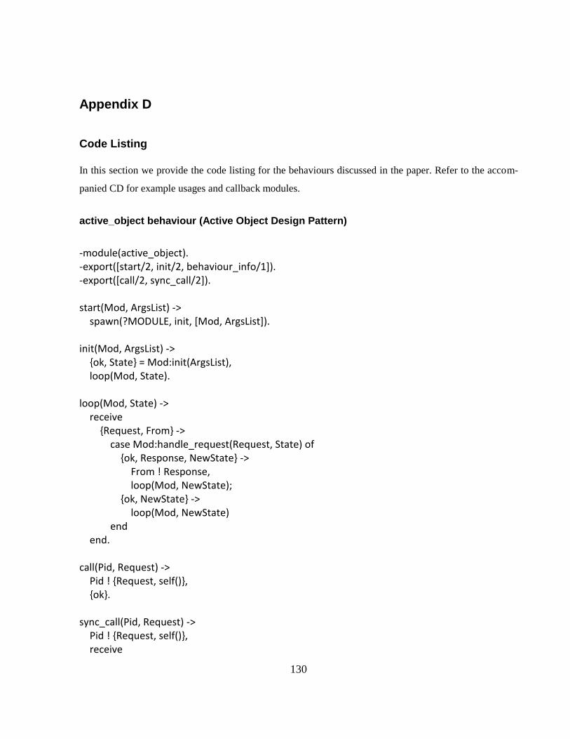
130
Appendix D
Code Listing
In this section we provide the code listing for the behaviours discussed in the paper. Refer to the accom-
panied CD for example usages and callback modules.
active_object behaviour (Active Object Design Pattern)
-module(active_object). -export([start/2, init/2, behaviour_info/1]). -export([call/2, sync_call/2]). start(Mod, ArgsList) -> spawn(?MODULE, init, [Mod, ArgsList]). init(Mod, ArgsList) -> {ok, State} = Mod:init(ArgsList), loop(Mod, State). loop(Mod, State) -> receive {Request, From} -> case Mod:handle_request(Request, State) of {ok, Response, NewState} -> From ! Response, loop(Mod, NewState); {ok, NewState} -> loop(Mod, NewState) end end. call(Pid, Request) -> Pid ! {Request, self()}, {ok}. sync_call(Pid, Request) -> Pid ! {Request, self()}, receive
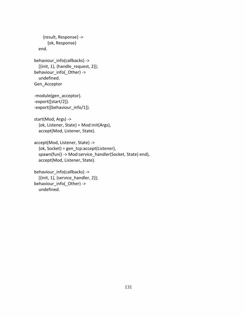
131
{result, Response} -> {ok, Response} end. behaviour_info(callbacks) -> [{init, 1}, {handle_request, 2}]; behaviour_info(_Other) -> undefined. Gen_Acceptor -module(gen_acceptor). -export([start/2]). -export([behaviour_info/1]). start(Mod, Args) -> {ok, Listener, State} = Mod:init(Args), accept(Mod, Listener, State). accept(Mod, Listener, State) -> {ok, Socket} = gen_tcp:accept(Listener), spawn(fun() -> Mod:service_handler(Socket, State) end), accept(Mod, Listener, State). behaviour_info(callbacks) -> [{init, 1}, {service_handler, 2}]; behaviour_info(_Other) -> undefined.
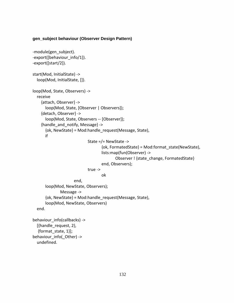
132
gen_subject behaviour (Observer Design Pattern)
-module(gen_subject). -export([behaviour_info/1]). -export([start/2]). start(Mod, InitialState) -> loop(Mod, InitialState, []). loop(Mod, State, Observers) -> receive {attach, Observer} -> loop(Mod, State, [Observer | Observers]); {detach, Observer} -> loop(Mod, State, Observers -- [Observer]); {handle_and_notify, Message} -> {ok, NewState} = Mod:handle_request(Message, State), if State =/= NewState -> {ok, FormatedState} = Mod:format_state(NewState), lists:map(fun(Observer) -> Observer ! {state_change, FormatedState} end, Observers); true -> ok end, loop(Mod, NewState, Observers); Message -> {ok, NewState} = Mod:handle_request(Message, State), loop(Mod, NewState, Observers) end. behaviour_info(callbacks) -> [{handle_request, 2}, {format_state, 1}]; behaviour_info(_Other) -> undefined.

133
gen_proactor behaviour (Proactor Design Pattern)
-module(gen_proactor). -export([behaviour_info/1]). -export([start/2]). start(Mod, State) -> loop(Mod, [], State). loop(Mod, Map, State) -> receive {register_handler, Handle, Event, Handler} -> NewMap = add_handler(Map, Handle, Event, Handler), loop(Mod, NewMap, State); {remove_handler, Event, Handler} -> NewMap = remove_handler(Map, Event, Handler), loop(Mod, NewMap, State); Event -> case Mod:handle_request(Event, State) of {event, Evt, Handle, Args} -> {ok, Handlers} = get_handlers(Map, Handle, Evt), dispatch(Handlers, Args), loop(Mod, Map, State); {ok, NewState} -> loop(Mod, Map, NewState) end end. behaviour_info(callbacks) -> [{handle_request, 2}]; behaviour_info(_Other) -> undefined. dispatch(Handlers, Args) -> lists:map(fun(Handler) -> spawn(fun() -> Handler(Args) end) end, Handlers). add_handler([], Handle, Event, Handler) -> [{Handle, [{Event, [Handler]}]}]; add_handler([{Handle, EventsMap} | R ], Handle, Event, Handler) ->
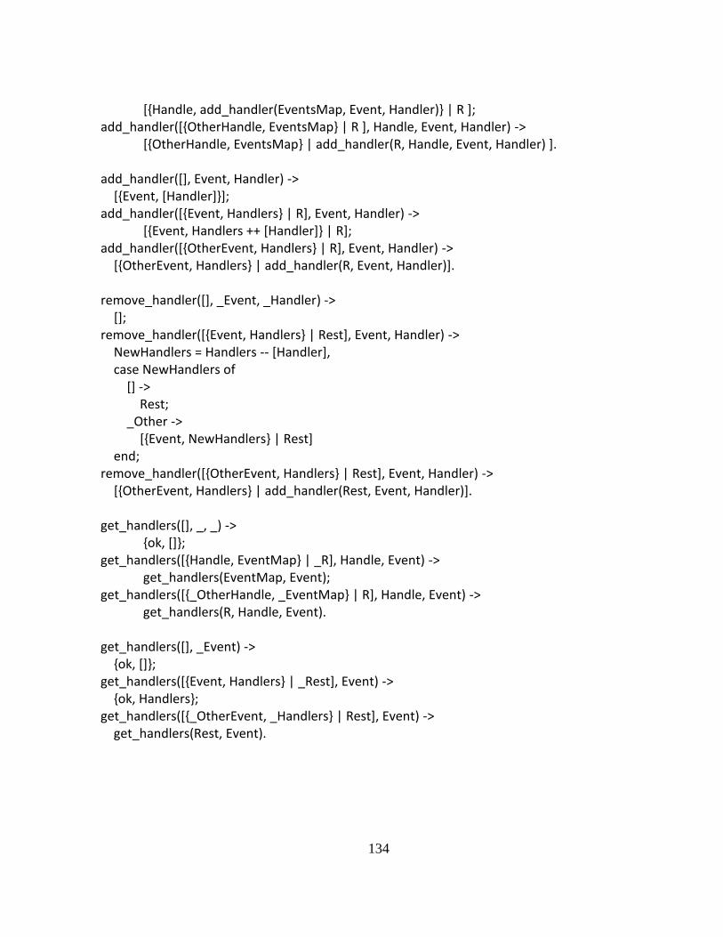
134
[{Handle, add_handler(EventsMap, Event, Handler)} | R ]; add_handler([{OtherHandle, EventsMap} | R ], Handle, Event, Handler) -> [{OtherHandle, EventsMap} | add_handler(R, Handle, Event, Handler) ]. add_handler([], Event, Handler) -> [{Event, [Handler]}]; add_handler([{Event, Handlers} | R], Event, Handler) -> [{Event, Handlers ++ [Handler]} | R]; add_handler([{OtherEvent, Handlers} | R], Event, Handler) -> [{OtherEvent, Handlers} | add_handler(R, Event, Handler)]. remove_handler([], _Event, _Handler) -> []; remove_handler([{Event, Handlers} | Rest], Event, Handler) -> NewHandlers = Handlers -- [Handler], case NewHandlers of [] -> Rest; _Other -> [{Event, NewHandlers} | Rest] end; remove_handler([{OtherEvent, Handlers} | Rest], Event, Handler) -> [{OtherEvent, Handlers} | add_handler(Rest, Event, Handler)]. get_handlers([], _, _) -> {ok, []}; get_handlers([{Handle, EventMap} | _R], Handle, Event) -> get_handlers(EventMap, Event); get_handlers([{_OtherHandle, _EventMap} | R], Handle, Event) -> get_handlers(R, Handle, Event). get_handlers([], _Event) -> {ok, []}; get_handlers([{Event, Handlers} | _Rest], Event) -> {ok, Handlers}; get_handlers([{_OtherEvent, _Handlers} | Rest], Event) -> get_handlers(Rest, Event).
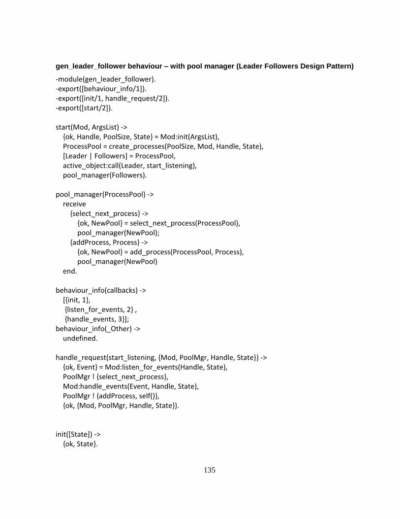
135
gen_leader_follower behaviour – with pool manager (Leader Followers Design Pattern)
-module(gen_leader_follower). -export([behaviour_info/1]). -export([init/1, handle_request/2]). -export([start/2]). start(Mod, ArgsList) -> {ok, Handle, PoolSize, State} = Mod:init(ArgsList), ProcessPool = create_processes(PoolSize, Mod, Handle, State), [Leader | Followers] = ProcessPool, active_object:call(Leader, start_listening), pool_manager(Followers). pool_manager(ProcessPool) -> receive {select_next_process} -> {ok, NewPool} = select_next_process(ProcessPool), pool_manager(NewPool); {addProcess, Process} -> {ok, NewPool} = add_process(ProcessPool, Process), pool_manager(NewPool) end. behaviour_info(callbacks) -> [{init, 1}, {listen_for_events, 2} , {handle_events, 3}]; behaviour_info(_Other) -> undefined. handle_request(start_listening, {Mod, PoolMgr, Handle, State}) -> {ok, Event} = Mod:listen_for_events(Handle, State), PoolMgr ! {select_next_process}, Mod:handle_events(Event, Handle, State), PoolMgr ! {addProcess, self()}, {ok, {Mod, PoolMgr, Handle, State}}. init([State]) -> {ok, State}.
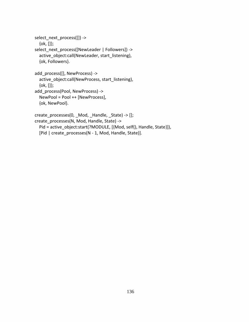
136
select_next_process([]) -> {ok, []}; select_next_process([NewLeader | Followers]) -> active_object:call(NewLeader, start_listening), {ok, Followers}. add_process([], NewProcess) -> active_object:call(NewProcess, start_listening), {ok, []}; add_process(Pool, NewProcess) -> NewPool = Pool ++ [NewProcess], {ok, NewPool}. create_processes(0, _Mod, _Handle, _State) -> []; create_processes(N, Mod, Handle, State) -> Pid = active_object:start(?MODULE, [{Mod, self(), Handle, State}]), [Pid | create_processes(N - 1, Mod, Handle, State)].
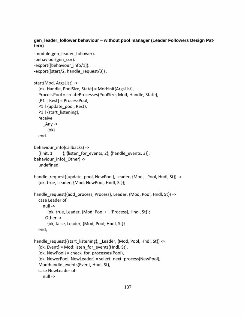
137
gen_leader_follower behaviour – without pool manager (Leader Followers Design Pat-
tern)
-module(gen_leader_follower). -behaviour(gen_cor). -export([behaviour_info/1]). -export([start/2, handle_request/3]) . start(Mod, ArgsList) -> {ok, Handle, PoolSize, State} = Mod:init(ArgsList), ProcessPool = createProcesses(PoolSize, Mod, Handle, State), [P1 | Rest] = ProcessPool, P1 ! {update_pool, Rest}, P1 ! {start_listening}, receive _Any -> {ok} end. behaviour_info(callbacks) -> [{init, 1 }, {listen_for_events, 2}, {handle_events, 3}]; behaviour_info(_Other) -> undefined. handle_request({update_pool, NewPool}, Leader, {Mod, _Pool, Hndl, St}) -> {ok, true, Leader, {Mod, NewPool, Hndl, St}}; handle_request({add_process, Process}, Leader, {Mod, Pool, Hndl, St}) -> case Leader of null -> {ok, true, Leader, {Mod, Pool ++ [Process], Hndl, St}}; _Other -> {ok, false, Leader, {Mod, Pool, Hndl, St}} end; handle_request({start_listening}, _Leader, {Mod, Pool, Hndl, St}) -> {ok, Event} = Mod:listen_for_events(Hndl, St), {ok, NewPool} = check_for_processes(Pool), {ok, NewerPool, NewLeader} = select_next_process(NewPool), Mod:handle_events(Event, Hndl, St), case NewLeader of null ->
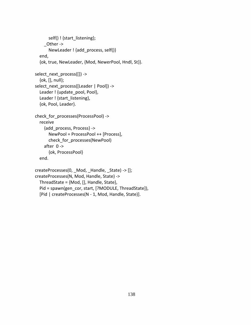
138
self() ! {start_listening}; _Other -> NewLeader ! {add_process, self()} end, {ok, true, NewLeader, {Mod, NewerPool, Hndl, St}}. select_next_process([]) -> {ok, [], null}; select_next_process([Leader | Pool]) -> Leader ! {update_pool, Pool}, Leader ! {start_listening}, {ok, Pool, Leader}. check_for_processes(ProcessPool) -> receive {add_process, Process} -> NewPool = ProcessPool ++ [Process], check_for_processes(NewPool) after 0 -> {ok, ProcessPool} end. createProcesses(0, _Mod, _Handle, _State) -> []; createProcesses(N, Mod, Handle, State) -> ThreadState = {Mod, [], Handle, State}, Pid = spawn(gen_cor, start, [?MODULE, ThreadState]), [Pid | createProcesses(N - 1, Mod, Handle, State)].