Embed Size (px)
Citation preview

Assembly steps for the
VRUZEND 18650 battery
pack assembly kit.
Each cap has a dove tail pattern made
up of two adjacent tails and sockets
This makes it easy for you to slide the
caps in and out.
Make sure to orient all the
caps in the same direction
at the time of assembly.
*For in depth detail visit http://vruzend.com/tech-center/how-to-connect-vruzend-caps/

Start out by first deciding upon the size of pack you need.
Start assembling the caps. Make sure to make the columns
first.
Similarly a 10s5p
pack will have 10
columns of 5 red
caps and 10 columns
of 5 blue caps.
So a 13s4p pack will have
13 columns of 4 red caps
and 13 columns of 4 blue
caps.
Make the columns!

There are two ways you can make a pack using these caps.
First method is placing the cells in
the individual columns made.
Pay attention to the orientation of your
tails/socket. Example, if at the bottom
your tails are facing the left then at the
top they should face the right.
View this step at
https://youtu.be/9Pxq4Au5iuc?t=4m57s

Push the caps down gently using
a block of wood or a clamp.
https://www.youtube.com/watch?v=9Pxq4Au5iuct=5m20s
From one leg end to the
other the distance should be
90mm-92mm.

Using the voltmeter check that
every cell has made a
connection.
Once you have all your
groups assembled line
them up such that the tails
and the sockets can slide
into each other.
*This is why we had asked you to keep the tails/socket facing
the opposite sides at the top and bottom ;)
For method 2, once
you are done
assembling the
columns, Start
sliding them in to
form a block.
You may want to use a light
hammer (100g) to gently tap
on the cap legs to slide
them in and level the block.

Notice how the two blocks for the top and bottom side mirror
each other. That is for a red row on one side there will be a blue
row on the other side, to mimic the positive negative cell
polarity.
Place the cells into the block.
Make sure that it is the positive
terminal going INSIDE the red cap
and the negative terminal going
INSIDE the blue cap.
It is a very common mistake to
insert the negative terminal into
the red cap and keeping the
positive terminal upwards facing
you. So be careful!

Place the block on top of
the cells (Match the polarity
of the cells to the colour
coded block ).
Once done use clamps to secure the
caps onto the cells.

Start of by clamping at the centre.
Then move the clamps to the
corner of the pack and repeat.
Maintain clamping distance as
90mm-92mm from one leg end to
the other.
Add the thickness of your wooden plank
to this clamping distance and then
maintain this distance throughout.
You can make a mark on your clamps
so as to not to tighten it further.
This mark will prevent you from over
clamping at the centre as measuring
the cap distance for a cell at the centre
of the pack will be difficult.

Like done in method one,
using a Voltmeter check that
every cell has made a
connection with the internal
contact of the cap.
If the clamping step was
done right, every cell will
make a connection.
In the rare case where a
single cell might not have
made a connection, press
down on the cap gently with
a blunt tool like the butt of a
screw driver.

Your blocks are ready!!
Mount the bus bars and do the connections

High Amp draw applications
Advice able to make parallel modules
and have them connected in series.
Use copper wires along with the bus
bars to facilitate the flow of extra
current.
Sandwich the copper wire between
the bus bars and use the nuts to
firmly fix it in place.
The gauge of your wire would depend upon your amp draw.
The pic shows the copper wires connecting groups of 4 cells
i.e 8 columns and 4 rows. The module is 8x4 module. Instead
of using 8 copper wires, you could use just 4 copper wires by
making groups of 8 i.e 4 columns and 8 rows. However that
would mean a lot more current would be flowing through the
wires which may require your gauge to be thicker.
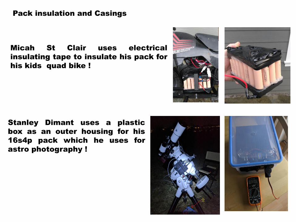
Pack insulation and Casings
Micah St Clair uses electrical
insulating tape to insulate his pack for
his kids quad bike !
Stanley Dimant uses a plastic
box as an outer housing for his
16s4p pack which he uses for
astro photography !
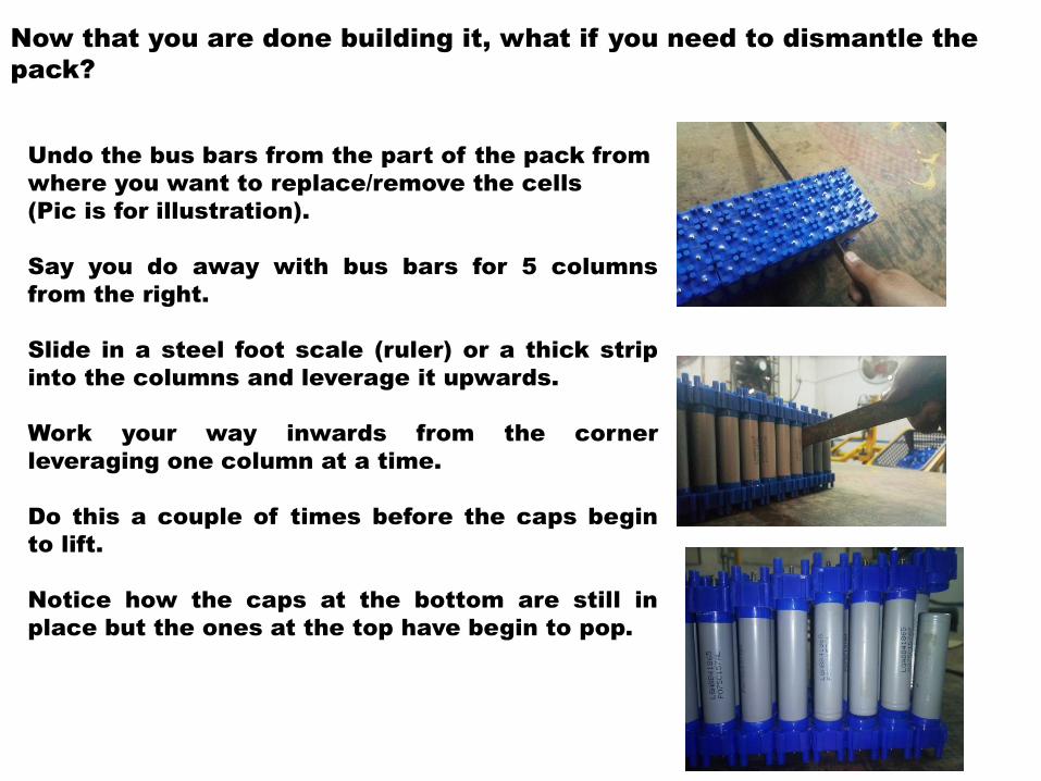
Now that you are done building it, what if you need to dismantle the
pack?
Undo the bus bars from the part of the pack from
where you want to replace/remove the cells
(Pic is for illustration).
Say you do away with bus bars for 5 columns
from the right.
Slide in a steel foot scale (ruler) or a thick strip
into the columns and leverage it upwards.
Work your way inwards from the corner
leveraging one column at a time.
Do this a couple of times before the caps begin
to lift.
Notice how the caps at the bottom are still in
place but the ones at the top have begin to pop.

How to connect a BMS to the kit?
View the detailed video at https://www.youtube.com/watch?v=m4DGDkwFr54&

How to incorporate cell level fuses?
Wound the fuse wire around the threaded post and secure it
with the nuts.
Simple and straight forward.
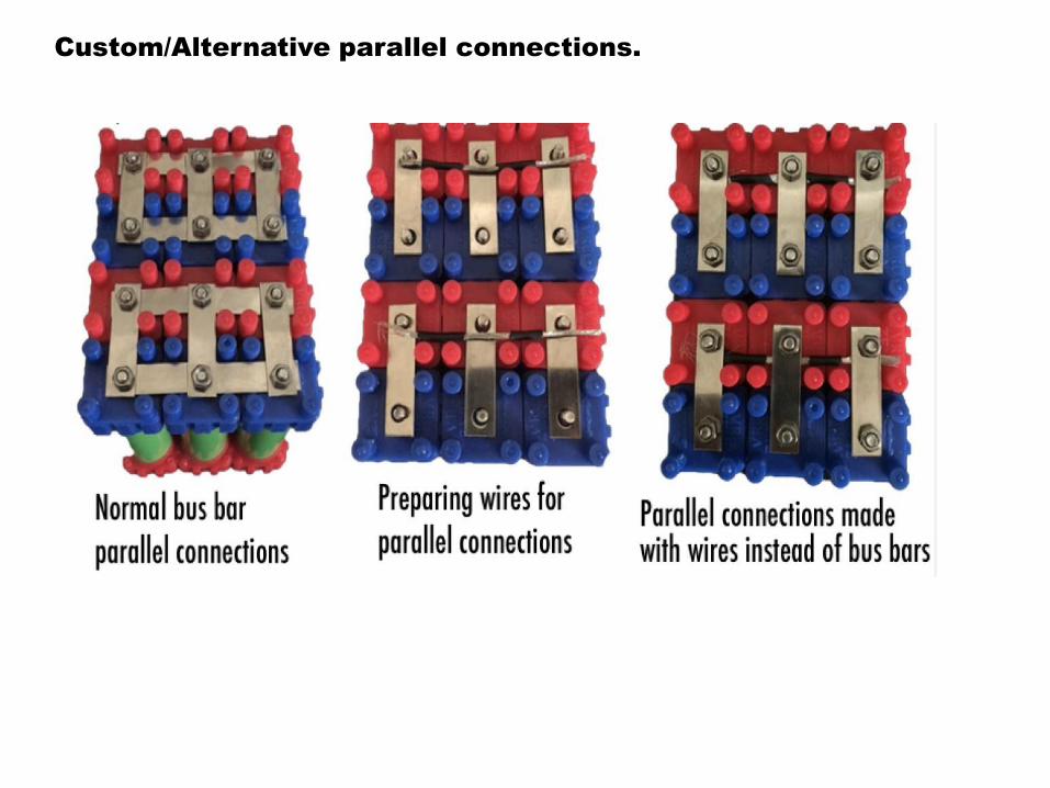
Custom/Alternative parallel connections.
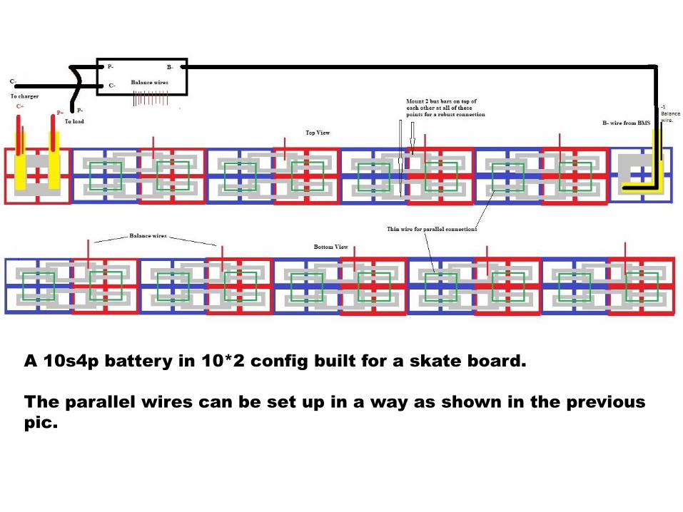
A 10s4p battery in 10*2 config built for a skate board.
The parallel wires can be set up in a way as shown in the previous
pic.
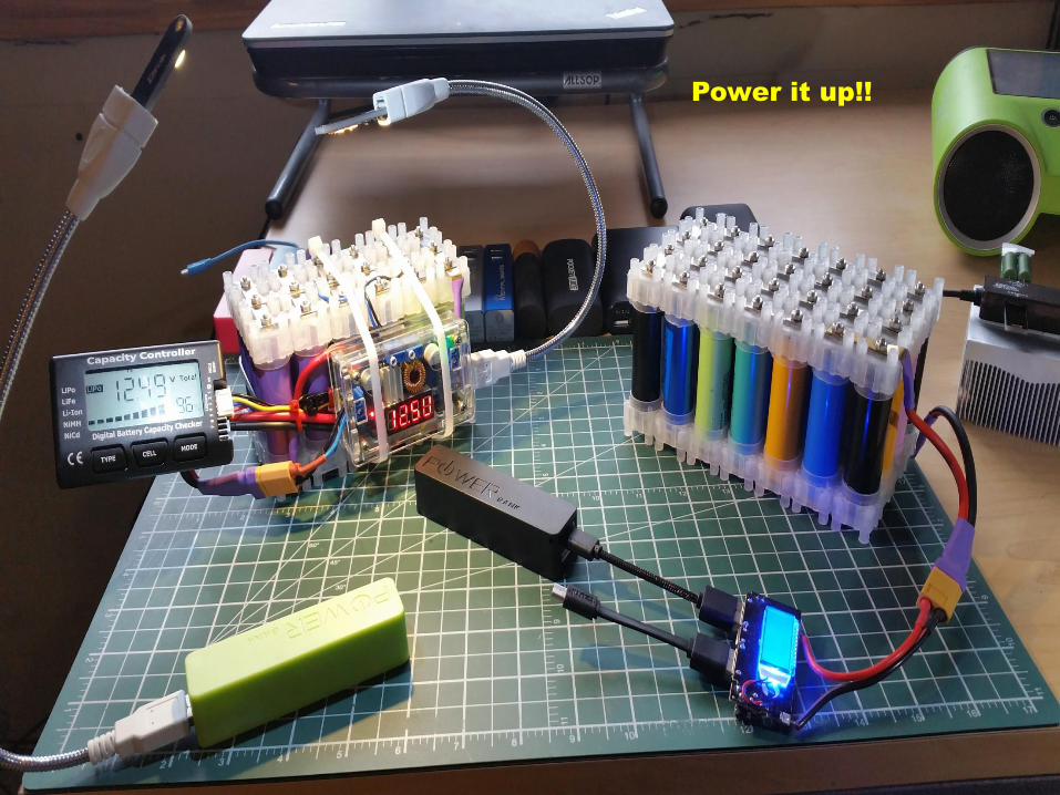
Power it up!!

Visit us !!
www.vruzend.com