Embed Size (px)
Citation preview

High Level Assembler for MVS & VM & VSE IBM
Programmer’s GuideRelease 4
SC26-4941-03


High Level Assembler for MVS & VM & VSE IBM
Programmer’s GuideRelease 4
SC26-4941-03
Note!
Before using this information and the product it supports, be sure to read the general information under“Notices” on page 379.
Fourth Edition (September 2000)
This edition applies to IBM High Level Assembler for MVS & VM & VSE, Release 4, Program Number 5696-234 and to anysubsequent releases until otherwise indicated in new editions. Make sure you are using the correct edition for the level of theproduct.
Order publications through your IBM representative or the IBM branch office serving your locality. Publications are not stocked at theaddress below.
A form for reader's comments is provided at the back of this publication. If the form has been removed, address your comments to:
IBM Corporation, Department BWE/H3 P.O.Box 49023
SAN JOSE, CA 95161-9023United States of America
When you send information to IBM, you grant IBM a nonexclusive right to use or distribute the information in any way it believesappropriate without incurring any obligation to you.
Copyright International Business Machines Corporation 1982, 2000. All rights reserved.US Government Users Restricted Rights – Use, duplication or disclosure restricted by GSA ADP Schedule Contract with IBM Corp.

Contents
Contents
About this Manual . . . . . . . . . . . . . . . . . . . . . . . . . . . . . . . . . . . . xiWho Should Use this Manual . . . . . . . . . . . . . . . . . . . . . . . . . . . . . . xiProgramming Interface Information . . . . . . . . . . . . . . . . . . . . . . . . . . . xiOrganization of this Manual . . . . . . . . . . . . . . . . . . . . . . . . . . . . . . . xiIBM High Level Assembler for MVS & VM & VSE Publications . . . . . . . . . . xivHardcopy Publications . . . . . . . . . . . . . . . . . . . . . . . . . . . . . . . . . xivOnline Publications . . . . . . . . . . . . . . . . . . . . . . . . . . . . . . . . . . . . xvRelated Publications . . . . . . . . . . . . . . . . . . . . . . . . . . . . . . . . . . . xvSyntax Notation . . . . . . . . . . . . . . . . . . . . . . . . . . . . . . . . . . . . . . xv
Summary of Changes . . . . . . . . . . . . . . . . . . . . . . . . . . . . . . . . . xviii
Part 1. Understanding and Using the Assembler . . . . . . . . . . . . . . . . . . . . . . . . 1
Chapter 1. Introduction . . . . . . . . . . . . . . . . . . . . . . . . . . . . . . . . 5Requirements . . . . . . . . . . . . . . . . . . . . . . . . . . . . . . . . . . . . . . . 5
System Requirements . . . . . . . . . . . . . . . . . . . . . . . . . . . . . . . . . 5Machine Requirements . . . . . . . . . . . . . . . . . . . . . . . . . . . . . . . . 5Storage Requirements . . . . . . . . . . . . . . . . . . . . . . . . . . . . . . . . . 6
Compatibility . . . . . . . . . . . . . . . . . . . . . . . . . . . . . . . . . . . . . . . . 6Assembler Language Support . . . . . . . . . . . . . . . . . . . . . . . . . . . . 6Migration Considerations . . . . . . . . . . . . . . . . . . . . . . . . . . . . . . . 7
Chapter 2. Using the Assembler Listing . . . . . . . . . . . . . . . . . . . . . . 8High Level Assembler Option Summary . . . . . . . . . . . . . . . . . . . . . . . . 9External Symbol Dictionary (ESD) . . . . . . . . . . . . . . . . . . . . . . . . . . 12Source and Object . . . . . . . . . . . . . . . . . . . . . . . . . . . . . . . . . . . 15Relocation Dictionary (RLD) . . . . . . . . . . . . . . . . . . . . . . . . . . . . . . 22Ordinary Symbol and Literal Cross Reference . . . . . . . . . . . . . . . . . . . 22Unreferenced Symbols Defined in CSECTs . . . . . . . . . . . . . . . . . . . . . 24Macro and Copy Code Source Summary . . . . . . . . . . . . . . . . . . . . . . 25Macro and Copy Code Cross Reference . . . . . . . . . . . . . . . . . . . . . . . 25DSECT Cross Reference . . . . . . . . . . . . . . . . . . . . . . . . . . . . . . . . 29USING Map . . . . . . . . . . . . . . . . . . . . . . . . . . . . . . . . . . . . . . . 30General Purpose Register Cross Reference . . . . . . . . . . . . . . . . . . . . . 31Diagnostic Cross Reference and Assembler Summary . . . . . . . . . . . . . . 32
Chapter 3. Controlling Your Assembly with Options . . . . . . . . . . . . . 38The Sources of Assembler Options . . . . . . . . . . . . . . . . . . . . . . . . . . 38
Precedence of Assembler Options . . . . . . . . . . . . . . . . . . . . . . . . 38Fixed Installation Default Options . . . . . . . . . . . . . . . . . . . . . . . . . 39
| *PROCESS OVERRIDE Statement Options . . . . . . . . . . . . . . . . . . . 39| ASMAOPT Options . . . . . . . . . . . . . . . . . . . . . . . . . . . . . . . . . 39
Invocation Options . . . . . . . . . . . . . . . . . . . . . . . . . . . . . . . . . . 39*Process Statement Options . . . . . . . . . . . . . . . . . . . . . . . . . . . . 40Default Options . . . . . . . . . . . . . . . . . . . . . . . . . . . . . . . . . . . . 41Invoking the Assembler Dynamically . . . . . . . . . . . . . . . . . . . . . . . 41Coding Rules . . . . . . . . . . . . . . . . . . . . . . . . . . . . . . . . . . . . . 41
Assembler Options . . . . . . . . . . . . . . . . . . . . . . . . . . . . . . . . . . . 42
Copyright IBM Corp. 1982, 2000 iii

Contents
ADATA . . . . . . . . . . . . . . . . . . . . . . . . . . . . . . . . . . . . . . . . 42ALIGN . . . . . . . . . . . . . . . . . . . . . . . . . . . . . . . . . . . . . . . . . 43ASA (MVS and CMS) . . . . . . . . . . . . . . . . . . . . . . . . . . . . . . . . 43BATCH . . . . . . . . . . . . . . . . . . . . . . . . . . . . . . . . . . . . . . . . 44
| CODEPAGE . . . . . . . . . . . . . . . . . . . . . . . . . . . . . . . . . . . . . 44COMPAT . . . . . . . . . . . . . . . . . . . . . . . . . . . . . . . . . . . . . . . 45DBCS . . . . . . . . . . . . . . . . . . . . . . . . . . . . . . . . . . . . . . . . . 46DECK . . . . . . . . . . . . . . . . . . . . . . . . . . . . . . . . . . . . . . . . . 47DISK (CMS) . . . . . . . . . . . . . . . . . . . . . . . . . . . . . . . . . . . . . . 47DXREF . . . . . . . . . . . . . . . . . . . . . . . . . . . . . . . . . . . . . . . . 47ERASE (CMS) . . . . . . . . . . . . . . . . . . . . . . . . . . . . . . . . . . . . 48ESD . . . . . . . . . . . . . . . . . . . . . . . . . . . . . . . . . . . . . . . . . . 48EXIT . . . . . . . . . . . . . . . . . . . . . . . . . . . . . . . . . . . . . . . . . . 49FLAG . . . . . . . . . . . . . . . . . . . . . . . . . . . . . . . . . . . . . . . . . 52FOLD . . . . . . . . . . . . . . . . . . . . . . . . . . . . . . . . . . . . . . . . . 55GOFF (MVS and CMS) . . . . . . . . . . . . . . . . . . . . . . . . . . . . . . . 55INFO . . . . . . . . . . . . . . . . . . . . . . . . . . . . . . . . . . . . . . . . . . 56LANGUAGE . . . . . . . . . . . . . . . . . . . . . . . . . . . . . . . . . . . . . . 57LIBMAC . . . . . . . . . . . . . . . . . . . . . . . . . . . . . . . . . . . . . . . . 58LINECOUNT . . . . . . . . . . . . . . . . . . . . . . . . . . . . . . . . . . . . . 58LIST . . . . . . . . . . . . . . . . . . . . . . . . . . . . . . . . . . . . . . . . . . 59MXREF . . . . . . . . . . . . . . . . . . . . . . . . . . . . . . . . . . . . . . . . 61OBJECT . . . . . . . . . . . . . . . . . . . . . . . . . . . . . . . . . . . . . . . . 62OPTABLE . . . . . . . . . . . . . . . . . . . . . . . . . . . . . . . . . . . . . . . 62PCONTROL . . . . . . . . . . . . . . . . . . . . . . . . . . . . . . . . . . . . . . 64PESTOP . . . . . . . . . . . . . . . . . . . . . . . . . . . . . . . . . . . . . . . . 66PRINT (CMS) . . . . . . . . . . . . . . . . . . . . . . . . . . . . . . . . . . . . . 66PROFILE . . . . . . . . . . . . . . . . . . . . . . . . . . . . . . . . . . . . . . . 66RA2 . . . . . . . . . . . . . . . . . . . . . . . . . . . . . . . . . . . . . . . . . . 67RENT . . . . . . . . . . . . . . . . . . . . . . . . . . . . . . . . . . . . . . . . . 68RLD . . . . . . . . . . . . . . . . . . . . . . . . . . . . . . . . . . . . . . . . . . 68RXREF . . . . . . . . . . . . . . . . . . . . . . . . . . . . . . . . . . . . . . . . 68SEG (CMS) . . . . . . . . . . . . . . . . . . . . . . . . . . . . . . . . . . . . . . 69SIZE . . . . . . . . . . . . . . . . . . . . . . . . . . . . . . . . . . . . . . . . . . 69SYSPARM . . . . . . . . . . . . . . . . . . . . . . . . . . . . . . . . . . . . . . 71TERM . . . . . . . . . . . . . . . . . . . . . . . . . . . . . . . . . . . . . . . . . 72TEST . . . . . . . . . . . . . . . . . . . . . . . . . . . . . . . . . . . . . . . . . . 73
| THREAD . . . . . . . . . . . . . . . . . . . . . . . . . . . . . . . . . . . . . . . 73TRANSLATE . . . . . . . . . . . . . . . . . . . . . . . . . . . . . . . . . . . . . 74USING . . . . . . . . . . . . . . . . . . . . . . . . . . . . . . . . . . . . . . . . . 75XOBJECT (MVS and CMS) . . . . . . . . . . . . . . . . . . . . . . . . . . . . . 77XREF . . . . . . . . . . . . . . . . . . . . . . . . . . . . . . . . . . . . . . . . . 78
Chapter 4. Providing User Exits . . . . . . . . . . . . . . . . . . . . . . . . . . 79Exit Types . . . . . . . . . . . . . . . . . . . . . . . . . . . . . . . . . . . . . . . . 79Specifying User Exits . . . . . . . . . . . . . . . . . . . . . . . . . . . . . . . . . . 80Loading User Exits . . . . . . . . . . . . . . . . . . . . . . . . . . . . . . . . . . . 81Calling User Exits . . . . . . . . . . . . . . . . . . . . . . . . . . . . . . . . . . . . 81Exit Parameter List . . . . . . . . . . . . . . . . . . . . . . . . . . . . . . . . . . . 82
Request Info Pointer . . . . . . . . . . . . . . . . . . . . . . . . . . . . . . . . . 84Buffer Pointer . . . . . . . . . . . . . . . . . . . . . . . . . . . . . . . . . . . . . 90Error Buffer Pointer . . . . . . . . . . . . . . . . . . . . . . . . . . . . . . . . . 90Exit-Specific Information Pointer . . . . . . . . . . . . . . . . . . . . . . . . . . 90DCB Pointer . . . . . . . . . . . . . . . . . . . . . . . . . . . . . . . . . . . . . 91
iv HLASM V1R4 Programmer’s Guide
Contents
Static Assembler Information Pointer . . . . . . . . . . . . . . . . . . . . . . . . . 91| HLASM VRM . . . . . . . . . . . . . . . . . . . . . . . . . . . . . . . . . . . . . 91| PTF Level . . . . . . . . . . . . . . . . . . . . . . . . . . . . . . . . . . . . . . . 91| System ID . . . . . . . . . . . . . . . . . . . . . . . . . . . . . . . . . . . . . . . 92
Error Handling . . . . . . . . . . . . . . . . . . . . . . . . . . . . . . . . . . . . . . 92Exit-Specific Information Block . . . . . . . . . . . . . . . . . . . . . . . . . . . . 92
Member Name . . . . . . . . . . . . . . . . . . . . . . . . . . . . . . . . . . . . 94Member Type . . . . . . . . . . . . . . . . . . . . . . . . . . . . . . . . . . . . . 94Data Set Name . . . . . . . . . . . . . . . . . . . . . . . . . . . . . . . . . . . . 94Volume Serial . . . . . . . . . . . . . . . . . . . . . . . . . . . . . . . . . . . . . 94Relative Record Number . . . . . . . . . . . . . . . . . . . . . . . . . . . . . . 95Absolute Record Number . . . . . . . . . . . . . . . . . . . . . . . . . . . . . . 96Linecount . . . . . . . . . . . . . . . . . . . . . . . . . . . . . . . . . . . . . . . 96Current Page Number . . . . . . . . . . . . . . . . . . . . . . . . . . . . . . . . 96
SOURCE Exit Processing . . . . . . . . . . . . . . . . . . . . . . . . . . . . . . . 97OPEN . . . . . . . . . . . . . . . . . . . . . . . . . . . . . . . . . . . . . . . . . 97CLOSE . . . . . . . . . . . . . . . . . . . . . . . . . . . . . . . . . . . . . . . . 97READ . . . . . . . . . . . . . . . . . . . . . . . . . . . . . . . . . . . . . . . . . 97PROCESS . . . . . . . . . . . . . . . . . . . . . . . . . . . . . . . . . . . . . . 98
LIBRARY Exit Processing . . . . . . . . . . . . . . . . . . . . . . . . . . . . . . . 99OPEN . . . . . . . . . . . . . . . . . . . . . . . . . . . . . . . . . . . . . . . . . 99CLOSE . . . . . . . . . . . . . . . . . . . . . . . . . . . . . . . . . . . . . . . . 100READ . . . . . . . . . . . . . . . . . . . . . . . . . . . . . . . . . . . . . . . . . 100PROCESS MACRO or PROCESS COPY . . . . . . . . . . . . . . . . . . . . 100FIND MACRO or FIND COPY . . . . . . . . . . . . . . . . . . . . . . . . . . . 101END OF MEMBER . . . . . . . . . . . . . . . . . . . . . . . . . . . . . . . . . . 103
LISTING Exit Processing . . . . . . . . . . . . . . . . . . . . . . . . . . . . . . . . 104OPEN . . . . . . . . . . . . . . . . . . . . . . . . . . . . . . . . . . . . . . . . . 105CLOSE . . . . . . . . . . . . . . . . . . . . . . . . . . . . . . . . . . . . . . . . 106WRITE . . . . . . . . . . . . . . . . . . . . . . . . . . . . . . . . . . . . . . . . . 106PROCESS . . . . . . . . . . . . . . . . . . . . . . . . . . . . . . . . . . . . . . 106
OBJECT (MVS and CMS) and PUNCH Exit Processing . . . . . . . . . . . . . . 108OPEN . . . . . . . . . . . . . . . . . . . . . . . . . . . . . . . . . . . . . . . . . 108CLOSE . . . . . . . . . . . . . . . . . . . . . . . . . . . . . . . . . . . . . . . . 109WRITE . . . . . . . . . . . . . . . . . . . . . . . . . . . . . . . . . . . . . . . . . 109PROCESS . . . . . . . . . . . . . . . . . . . . . . . . . . . . . . . . . . . . . . 110
ADATA Exit Processing . . . . . . . . . . . . . . . . . . . . . . . . . . . . . . . . 111OPEN . . . . . . . . . . . . . . . . . . . . . . . . . . . . . . . . . . . . . . . . . 111CLOSE . . . . . . . . . . . . . . . . . . . . . . . . . . . . . . . . . . . . . . . . 112PROCESS . . . . . . . . . . . . . . . . . . . . . . . . . . . . . . . . . . . . . . 112
TERM Exit Processing . . . . . . . . . . . . . . . . . . . . . . . . . . . . . . . . . 112OPEN . . . . . . . . . . . . . . . . . . . . . . . . . . . . . . . . . . . . . . . . . 113CLOSE . . . . . . . . . . . . . . . . . . . . . . . . . . . . . . . . . . . . . . . . 113WRITE . . . . . . . . . . . . . . . . . . . . . . . . . . . . . . . . . . . . . . . . . 113PROCESS . . . . . . . . . . . . . . . . . . . . . . . . . . . . . . . . . . . . . . 114
Sample User Exits . . . . . . . . . . . . . . . . . . . . . . . . . . . . . . . . . . . 115User Exit Coding Example . . . . . . . . . . . . . . . . . . . . . . . . . . . . . . . 115
Chapter 5. Providing External Functions . . . . . . . . . . . . . . . . . . . . . 135External Function Processing . . . . . . . . . . . . . . . . . . . . . . . . . . . . . 135Linkage Conventions . . . . . . . . . . . . . . . . . . . . . . . . . . . . . . . . . . 136External Function Parameter List . . . . . . . . . . . . . . . . . . . . . . . . . . . 136
Request Information List . . . . . . . . . . . . . . . . . . . . . . . . . . . . . . 139Pointer to User Work Area . . . . . . . . . . . . . . . . . . . . . . . . . . . . . 141
Contents v

Contents
Pointer to Msg Buffer . . . . . . . . . . . . . . . . . . . . . . . . . . . . . . . . 141Pointer to Return String (SETCF) . . . . . . . . . . . . . . . . . . . . . . . . . 141Pointer to Parm String n (SETCF) . . . . . . . . . . . . . . . . . . . . . . . . . 141
Chapter 6. Diagnosing Assembly Errors . . . . . . . . . . . . . . . . . . . . . 143Assembly Error Diagnostic Messages . . . . . . . . . . . . . . . . . . . . . . . . 143MNOTE Statements . . . . . . . . . . . . . . . . . . . . . . . . . . . . . . . . . . . 145Suppression of Error Messages and MNOTE Statements . . . . . . . . . . . . . 147Reference Information for Statements in Error . . . . . . . . . . . . . . . . . . . 147Abnormal Assembly Termination . . . . . . . . . . . . . . . . . . . . . . . . . . . 148MHELP—Macro Trace Facility . . . . . . . . . . . . . . . . . . . . . . . . . . . . . 148
Part 2. Developing Assembler Programs on MVS . . . . . . . . . . . . . . . . . . . . . . 149
Chapter 7. Assembling Your Program on MVS . . . . . . . . . . . . . . . . . 151Input to the Assembler . . . . . . . . . . . . . . . . . . . . . . . . . . . . . . . . . 151Output from the Assembler . . . . . . . . . . . . . . . . . . . . . . . . . . . . . . 151Invoking the Assembler on MVS . . . . . . . . . . . . . . . . . . . . . . . . . . . 151Invoking the Assembler on TSO . . . . . . . . . . . . . . . . . . . . . . . . . . . . 153Invoking the Assembler Dynamically . . . . . . . . . . . . . . . . . . . . . . . . . 154Batch Assembling . . . . . . . . . . . . . . . . . . . . . . . . . . . . . . . . . . . . 156Input and Output Data Sets . . . . . . . . . . . . . . . . . . . . . . . . . . . . . . 157
Work Data Set: SYSUT1 . . . . . . . . . . . . . . . . . . . . . . . . . . . . . . 160Specifying the Source Data Set: SYSIN . . . . . . . . . . . . . . . . . . . . . 160
| Specifying the Option File: ASMAOPT . . . . . . . . . . . . . . . . . . . . . . 160Specifying Macro and Copy Code Libraries: SYSLIB . . . . . . . . . . . . . . 160Specifying the Listing Data Set: SYSPRINT . . . . . . . . . . . . . . . . . . . 161Directing Assembler Messages to Your Terminal: SYSTERM . . . . . . . . . 161Specifying Object Code Data Sets: SYSLIN and SYSPUNCH . . . . . . . . . 161Specifying the Associated Data Data Set: SYSADATA . . . . . . . . . . . . . 162
Return Codes . . . . . . . . . . . . . . . . . . . . . . . . . . . . . . . . . . . . . . 162
Chapter 8. Linking and Running Your Program on MVS . . . . . . . . . . . 163The Program Management Binder . . . . . . . . . . . . . . . . . . . . . . . . . . 163The Loader . . . . . . . . . . . . . . . . . . . . . . . . . . . . . . . . . . . . . . . . 165Creating a Load Module . . . . . . . . . . . . . . . . . . . . . . . . . . . . . . . . 165
Creating a Load Module on MVS . . . . . . . . . . . . . . . . . . . . . . . . . 165Creating a Load Module on TSO . . . . . . . . . . . . . . . . . . . . . . . . . 166
Input to the Linker . . . . . . . . . . . . . . . . . . . . . . . . . . . . . . . . . . . . 166Data Sets for Linker Processing . . . . . . . . . . . . . . . . . . . . . . . . . . 167Additional Object Modules as Input . . . . . . . . . . . . . . . . . . . . . . . . 168
Output from the Linker . . . . . . . . . . . . . . . . . . . . . . . . . . . . . . . . . 169Linker Processing Options . . . . . . . . . . . . . . . . . . . . . . . . . . . . . 169Specifying Linker Options Through JCL . . . . . . . . . . . . . . . . . . . . . . 170Specifying Linker Options Using the TSO LINK Command . . . . . . . . . . . 170AMODE and RMODE Attributes . . . . . . . . . . . . . . . . . . . . . . . . . . 171Overriding the Defaults . . . . . . . . . . . . . . . . . . . . . . . . . . . . . . . 171Detecting Linker Errors . . . . . . . . . . . . . . . . . . . . . . . . . . . . . . . 172
Running Your Assembled Program . . . . . . . . . . . . . . . . . . . . . . . . . . 172Running Your Assembled Program in Batch . . . . . . . . . . . . . . . . . . . 172Running Your Assembled Program on TSO . . . . . . . . . . . . . . . . . . . 172
Chapter 9. MVS System Services and Programming Considerations . . . 173
vi HLASM V1R4 Programmer’s Guide

Contents
Adding Definitions to a Macro Library . . . . . . . . . . . . . . . . . . . . . . . . 173Using Cataloged Procedures . . . . . . . . . . . . . . . . . . . . . . . . . . . . . 174
Cataloged Procedure for Assembly (ASMAC) . . . . . . . . . . . . . . . . . . 174Cataloged Procedure for Assembly and Link (ASMACL) . . . . . . . . . . . . 176Cataloged Procedure for Assembly, Link, and Run (ASMACLG) . . . . . . . 177Cataloged Procedure for Assembly and Run (ASMACG) . . . . . . . . . . . . 178Overriding Statements in Cataloged Procedures . . . . . . . . . . . . . . . . . 180Examples of Cataloged Procedures . . . . . . . . . . . . . . . . . . . . . . . . 180
Operating System Programming Conventions . . . . . . . . . . . . . . . . . . . . 182Saving and Restoring General Register Contents . . . . . . . . . . . . . . . . 182Ending Program Execution . . . . . . . . . . . . . . . . . . . . . . . . . . . . . 183Accessing Execution Parameters . . . . . . . . . . . . . . . . . . . . . . . . . 183Object Module Linkage . . . . . . . . . . . . . . . . . . . . . . . . . . . . . . . 184
Modifying Program Modules . . . . . . . . . . . . . . . . . . . . . . . . . . . . . . 185
Part 3. Developing Assembler Programs on CMS . . . . . . . . . . . . . . . . . . . . . . 187
Chapter 10. Assembling Your Program on CMS . . . . . . . . . . . . . . . . 188Input to the Assembler . . . . . . . . . . . . . . . . . . . . . . . . . . . . . . . . . 188Output from the Assembler . . . . . . . . . . . . . . . . . . . . . . . . . . . . . . 188Accessing the Assembler . . . . . . . . . . . . . . . . . . . . . . . . . . . . . . . 188Invoking the Assembler on CMS . . . . . . . . . . . . . . . . . . . . . . . . . . . 189Batch Assembling . . . . . . . . . . . . . . . . . . . . . . . . . . . . . . . . . . . . 190Controlling Your Assembly . . . . . . . . . . . . . . . . . . . . . . . . . . . . . . . 190Input and Output Files . . . . . . . . . . . . . . . . . . . . . . . . . . . . . . . . . 191
Work file: SYSUT1 . . . . . . . . . . . . . . . . . . . . . . . . . . . . . . . . . . 193Specifying the Source File: SYSIN . . . . . . . . . . . . . . . . . . . . . . . . . 194
| Specifying the Option File: ASMAOPT . . . . . . . . . . . . . . . . . . . . . . 195Specifying Macro and Copy Code Libraries: SYSLIB . . . . . . . . . . . . . . 195Specifying the Listing File: SYSPRINT . . . . . . . . . . . . . . . . . . . . . . 196Directing Assembler Messages to Your Terminal: SYSTERM . . . . . . . . . 196Specifying Object Code Files: SYSLIN and SYSPUNCH . . . . . . . . . . . . 196Specifying the Associated Data File: SYSADATA . . . . . . . . . . . . . . . . 197
Return Codes . . . . . . . . . . . . . . . . . . . . . . . . . . . . . . . . . . . . . . 197Diagnostic Messages Written by CMS . . . . . . . . . . . . . . . . . . . . . . . . 197
Chapter 11. Running Your Program on CMS . . . . . . . . . . . . . . . . . . 199Using the CMS LOAD and START Commands . . . . . . . . . . . . . . . . . . . 199Using the CMS GENMOD Command . . . . . . . . . . . . . . . . . . . . . . . . . 199Using the CMS LKED and OSRUN Commands . . . . . . . . . . . . . . . . . . 200Using the CMS Batch Facility . . . . . . . . . . . . . . . . . . . . . . . . . . . . . 201
Chapter 12. CMS System Services and Programming Considerations . . 202Using Macros . . . . . . . . . . . . . . . . . . . . . . . . . . . . . . . . . . . . . . 202
Assembler Macros Supported by CMS . . . . . . . . . . . . . . . . . . . . . . 202Adding Definitions to a Macro Library . . . . . . . . . . . . . . . . . . . . . . . 202
Operating System Programming Conventions . . . . . . . . . . . . . . . . . . . . 202Saving and Restoring General Register Contents . . . . . . . . . . . . . . . . 202Ending Program Execution . . . . . . . . . . . . . . . . . . . . . . . . . . . . . 203Passing Parameters to Your Assembler Language Program . . . . . . . . . . 204
Part 4. Developing Assembler Programs on VSE . . . . . . . . . . . . . . . . . . . . . . 205
Contents vii

Contents
Chapter 13. Assembling Your Program on VSE . . . . . . . . . . . . . . . . 206Input to the Assembler . . . . . . . . . . . . . . . . . . . . . . . . . . . . . . . . . 206Output from the Assembler . . . . . . . . . . . . . . . . . . . . . . . . . . . . . . 206Invoking the Assembler in Batch . . . . . . . . . . . . . . . . . . . . . . . . . . . 206Invoking the Assembler on ICCF . . . . . . . . . . . . . . . . . . . . . . . . . . . 208Invoking the Assembler Dynamically . . . . . . . . . . . . . . . . . . . . . . . . . 210Batch Assembling . . . . . . . . . . . . . . . . . . . . . . . . . . . . . . . . . . . . 210Controlling Your Assembly . . . . . . . . . . . . . . . . . . . . . . . . . . . . . . . 211Input and Output Files . . . . . . . . . . . . . . . . . . . . . . . . . . . . . . . . . 212
Work File: IJSYS03 . . . . . . . . . . . . . . . . . . . . . . . . . . . . . . . . . 214Specifying the Source File: SYSIPT . . . . . . . . . . . . . . . . . . . . . . . . 215Specifying Macro and Copy Code Libraries: LIBDEF Job Control Statement 215Specifying the Listing File: SYSLST . . . . . . . . . . . . . . . . . . . . . . . . 215Directing Assembler Messages to Your Console Log: SYSLOG . . . . . . . . 215Specifying Object Code Files: SYSLNK and SYSPCH . . . . . . . . . . . . . 216Specifying the Associated Data File: SYSADAT . . . . . . . . . . . . . . . . . 216
Return Codes . . . . . . . . . . . . . . . . . . . . . . . . . . . . . . . . . . . . . . 216
Chapter 14. Link-Editing and Running Your Program on VSE . . . . . . . . 217The Linkage Editor . . . . . . . . . . . . . . . . . . . . . . . . . . . . . . . . . . . 217Creating a Phase . . . . . . . . . . . . . . . . . . . . . . . . . . . . . . . . . . . . 217Input to the Linkage Editor . . . . . . . . . . . . . . . . . . . . . . . . . . . . . . . 218
Inputting Object Modules . . . . . . . . . . . . . . . . . . . . . . . . . . . . . . 218Files for Linkage Editor Processing . . . . . . . . . . . . . . . . . . . . . . . . 218Inputting additional Object Modules . . . . . . . . . . . . . . . . . . . . . . . . 219Linkage Editor Control Statements . . . . . . . . . . . . . . . . . . . . . . . . . 219
Output from the Linkage Editor . . . . . . . . . . . . . . . . . . . . . . . . . . . . 220Running your Assembled Program . . . . . . . . . . . . . . . . . . . . . . . . . . 221
Chapter 15. VSE System Services and Programming Considerations . . . 222Adding Definitions to a Macro Library . . . . . . . . . . . . . . . . . . . . . . . . 222Processing E-Decks . . . . . . . . . . . . . . . . . . . . . . . . . . . . . . . . . . . 222Operating System Programming Conventions . . . . . . . . . . . . . . . . . . . . 223
Saving and Restoring General Register Contents . . . . . . . . . . . . . . . . 223Ending Program Execution . . . . . . . . . . . . . . . . . . . . . . . . . . . . . 224Accessing Execution Parameters . . . . . . . . . . . . . . . . . . . . . . . . . 224
Appendixes . . . . . . . . . . . . . . . . . . . . . . . . . . . . . . . . . . . . . . . . . . . . . . . . . . 225
Appendix A. Earlier Assembler Compatibility and Migration . . . . . . . . 227Comparison of Instruction Set and Assembler Instructions . . . . . . . . . . . . 227Comparison of Macro and Conditional Assembly Statements . . . . . . . . . . . 230Comparison of Macro and Conditional Assembly . . . . . . . . . . . . . . . . . . 233Comparison of Language Features . . . . . . . . . . . . . . . . . . . . . . . . . . 237Comparison of Assembler Options . . . . . . . . . . . . . . . . . . . . . . . . . . 239Comparison of Assembler Listing . . . . . . . . . . . . . . . . . . . . . . . . . . . 241Comparison of Diagnostic Features . . . . . . . . . . . . . . . . . . . . . . . . . . 243Other Assembler Differences . . . . . . . . . . . . . . . . . . . . . . . . . . . . . 244
Appendix B. Cross-System Portability Considerations . . . . . . . . . . . . 246Using Extended Architecture Instructions . . . . . . . . . . . . . . . . . . . . . . 246Using System Macros . . . . . . . . . . . . . . . . . . . . . . . . . . . . . . . . . 246Migrating Object Programs . . . . . . . . . . . . . . . . . . . . . . . . . . . . . . . 246
viii HLASM V1R4 Programmer’s Guide

Contents
Appendix C. Object Deck Output . . . . . . . . . . . . . . . . . . . . . . . . . 248| ESD Record Format . . . . . . . . . . . . . . . . . . . . . . . . . . . . . . . . . . 249
TXT Record Format . . . . . . . . . . . . . . . . . . . . . . . . . . . . . . . . . . . 250RLD Record Format . . . . . . . . . . . . . . . . . . . . . . . . . . . . . . . . . . . 251END Record Format . . . . . . . . . . . . . . . . . . . . . . . . . . . . . . . . . . 252SYM Record Format . . . . . . . . . . . . . . . . . . . . . . . . . . . . . . . . . . 252
Appendix D. Associated Data File Output . . . . . . . . . . . . . . . . . . . . 255Record Types . . . . . . . . . . . . . . . . . . . . . . . . . . . . . . . . . . . . . . 257ADATA Record Layouts . . . . . . . . . . . . . . . . . . . . . . . . . . . . . . . . 262Common Header Section . . . . . . . . . . . . . . . . . . . . . . . . . . . . . . . 262Job Identification Record—X'0000' . . . . . . . . . . . . . . . . . . . . . . . . . 264ADATA Identification Record—X'0001' . . . . . . . . . . . . . . . . . . . . . . . 264ADATA Compilation Unit Start/End Record—X'0002' . . . . . . . . . . . . . . . 265System 370/390 Output File Information Record—X'000A' . . . . . . . . . . . 265
| Options File Information—X'000B' . . . . . . . . . . . . . . . . . . . . . . . . . . 268Options Record—X'0010' . . . . . . . . . . . . . . . . . . . . . . . . . . . . . . . 268External Symbol Dictionary Record—X'0020' . . . . . . . . . . . . . . . . . . . 271Source Analysis Record—X'0030' . . . . . . . . . . . . . . . . . . . . . . . . . . 272Source Error Record—X'0032' . . . . . . . . . . . . . . . . . . . . . . . . . . . . 274DC/DS Record—X'0034' . . . . . . . . . . . . . . . . . . . . . . . . . . . . . . . 275DC Extension Record—X'0035' . . . . . . . . . . . . . . . . . . . . . . . . . . . 280Machine Instruction Record—X'0036' . . . . . . . . . . . . . . . . . . . . . . . . 281Relocation Dictionary Record—X'0040' . . . . . . . . . . . . . . . . . . . . . . . 281Symbol Record—X'0042' . . . . . . . . . . . . . . . . . . . . . . . . . . . . . . . 281Symbol Cross Reference Record—X'0044' . . . . . . . . . . . . . . . . . . . . 282Register Cross Reference Record—X'0045' . . . . . . . . . . . . . . . . . . . . 283Library Record—X'0060' . . . . . . . . . . . . . . . . . . . . . . . . . . . . . . . 283Library Member and Macro Cross Reference Record - X'0062' . . . . . . . . . 284User-supplied Information Record - X'0070' . . . . . . . . . . . . . . . . . . . . 285USING Map Record—X'0080' . . . . . . . . . . . . . . . . . . . . . . . . . . . . 285Statistics Record—X'0090' . . . . . . . . . . . . . . . . . . . . . . . . . . . . . . 286
Appendix E. Sample Program . . . . . . . . . . . . . . . . . . . . . . . . . . . 290
Appendix F. MHELP Sample Macro Trace and Dump . . . . . . . . . . . . . 301
Appendix G. High Level Assembler Messages . . . . . . . . . . . . . . . . . 309Message Code Format . . . . . . . . . . . . . . . . . . . . . . . . . . . . . . . . . 309Message Descriptions . . . . . . . . . . . . . . . . . . . . . . . . . . . . . . . . . 310Assembly Error Diagnostic Messages . . . . . . . . . . . . . . . . . . . . . . . . 312
Message Not Known . . . . . . . . . . . . . . . . . . . . . . . . . . . . . . . . . 314Messages . . . . . . . . . . . . . . . . . . . . . . . . . . . . . . . . . . . . . . . 315
Abnormal Assembly Termination Messages . . . . . . . . . . . . . . . . . . . . . 352ASMAHL Command Error Messages (CMS) . . . . . . . . . . . . . . . . . . . . 357
Appendix H. User Interface Macros . . . . . . . . . . . . . . . . . . . . . . . . 361
Appendix I. Sample ADATA User Exit (MVS and CMS) . . . . . . . . . . . . 362
Appendix J. Sample LISTING User Exit (MVS and CMS) . . . . . . . . . . . 369
Appendix K. Sample SOURCE User Exit (MVS and CMS) . . . . . . . . . . 371
Contents ix

Contents
Appendix L. How to Generate a Translation Table . . . . . . . . . . . . . . . 372
| Appendix M. How to Generate a Unicode Translation Table . . . . . . . . . 374
Notices . . . . . . . . . . . . . . . . . . . . . . . . . . . . . . . . . . . . . . . . . . 379Trademarks . . . . . . . . . . . . . . . . . . . . . . . . . . . . . . . . . . . . . . . 380
Glossary . . . . . . . . . . . . . . . . . . . . . . . . . . . . . . . . . . . . . . . . . 381
Bibliography . . . . . . . . . . . . . . . . . . . . . . . . . . . . . . . . . . . . . . 386High Level Assembler Publications . . . . . . . . . . . . . . . . . . . . . . . . . . 386Toolkit Feature Publications . . . . . . . . . . . . . . . . . . . . . . . . . . . . . . 386Related Publications (Architecture) . . . . . . . . . . . . . . . . . . . . . . . . . . 386Related Publications for MVS . . . . . . . . . . . . . . . . . . . . . . . . . . . . . 386Related Publications for VM . . . . . . . . . . . . . . . . . . . . . . . . . . . . . . 387Related Publications for VSE . . . . . . . . . . . . . . . . . . . . . . . . . . . . . 387General Publications . . . . . . . . . . . . . . . . . . . . . . . . . . . . . . . . . . 387
Index . . . . . . . . . . . . . . . . . . . . . . . . . . . . . . . . . . . . . . . . . . . 388
x HLASM V1R4 Programmer’s Guide
Organization of this Manual
About this Manual
This manual describes how to use the IBM High Level Assembler for MVS & VM &VSE licensed program, hereafter referred to as High Level Assembler, or simply theassembler. It is intended to help you assemble, link, and run your High LevelAssembler programs. It is meant to be used in conjunction with the HLASMLanguage Reference.
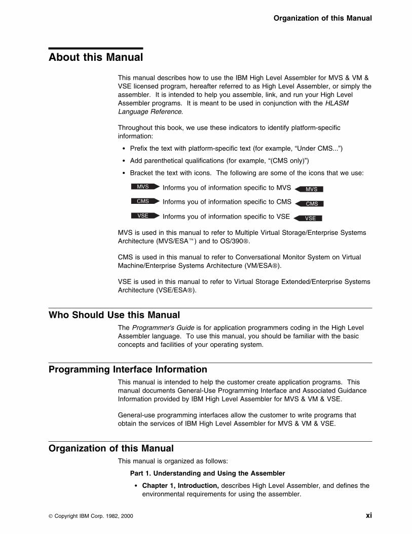
Throughout this book, we use these indicators to identify platform-specificinformation:
� Prefix the text with platform-specific text (for example, “Under CMS...”)
� Add parenthetical qualifications (for example, “(CMS only)”)
� Bracket the text with icons. The following are some of the icons that we use:
Informs you of information specific to MVS
Informs you of information specific to CMS
Informs you of information specific to VSE
MVS is used in this manual to refer to Multiple Virtual Storage/Enterprise SystemsArchitecture (MVS/ESA) and to OS/390.
CMS is used in this manual to refer to Conversational Monitor System on VirtualMachine/Enterprise Systems Architecture (VM/ESA).
VSE is used in this manual to refer to Virtual Storage Extended/Enterprise SystemsArchitecture (VSE/ESA).
Who Should Use this ManualThe Programmer's Guide is for application programmers coding in the High LevelAssembler language. To use this manual, you should be familiar with the basicconcepts and facilities of your operating system.
Programming Interface InformationThis manual is intended to help the customer create application programs. Thismanual documents General-Use Programming Interface and Associated GuidanceInformation provided by IBM High Level Assembler for MVS & VM & VSE.
General-use programming interfaces allow the customer to write programs thatobtain the services of IBM High Level Assembler for MVS & VM & VSE.
Organization of this ManualThis manual is organized as follows:
Part 1. Understanding and Using the Assembler
� Chapter 1, Introduction, describes High Level Assembler, and defines theenvironmental requirements for using the assembler.
Copyright IBM Corp. 1982, 2000 xi

Organization of this Manual
� Chapter 2, Using the Assembler Listing, describes the content andformat of the assembler listing.
� Chapter 3, Controlling your Assembly with Options, describes theassembler options that you can use to control the assembly of yourprogram.
� Chapter 4, Providing User Exits, describes how you can provide userexits to compliment the assembler's data-set processing.
� Chapter 5, Providing External Functions, describes how to provideuser-supplied routines in conditional assembly instructions to set the valueof SET symbols.
� Chapter 6, Diagnosing Assembly Errors, describes the purpose andformat of error messages, MNOTEs, and the MHELP trace facility.
Part 2. Developing Assembler Programs on MVS
� Chapter 7, Assembling your Program on MVS, describes the differentmethods of assembling your program on MVS, including invoking theassembler with job control statements, invoking the assembler on TSO/E,invoking the assembler dynamically, and batch assembling.
� Chapter 8, Linking and Running your Program on MVS, describeslinking, creating load modules, input and output for the linkage editor andbinder, detecting linking errors, and running your program on MVS.
� Chapter 9, MVS System Services and Programming Considerations,describes the MVS system services that you can use to maintain macrodefinitions in a macro library, and the cataloged procedures that areprovided to help you assemble, link-edit, and run your program on MVS.This chapter also discusses programming topics such as standard entryand exit procedures.
Part 3. Developing Assembler Programs on CMS
� Chapter 10, Assembling your Program on CMS, describes how to invokethe assembler on CMS.
� Chapter 11, Running your Program on CMS, describes how to load andrun your program on CMS.
� Chapter 12, CMS System Services and Programming Considerations,describes the CMS system services that you can use to maintain membersin a macro library. It also discusses programming topics such as standardentry and exit procedures.
Part 4. Developing Assembler Programs on VSE
� Chapter 13, Assembling your Program on VSE, describes how to invokethe assembler on VSE.
� Chapter 14, Link-Editing and Running your Program on VSE, describeslink-editing, creating load modules, input and output for the linkage editor,detecting link-edit errors, and running your program on VSE.
� Chapter 15, VSE System Services and Programming Considerations,describes the VSE system services that you can use to maintain macrodefinitions in a macro library, and the cataloged procedures that areprovided to help you assemble, link-edit, and run your program on VSE.
xii HLASM V1R4 Programmer’s Guide
Organization of this Manual
This chapter also discusses programming topics such as standard entryand exit procedures.
Appendixes
� Appendix A, Previous Assembler Compatibility and Migration, providesa comparison of High Level Assembler and Assembler H Version 2, andHigh Level Assembler and the DOS/VSE Assembler.
� Appendix B, Cross-System Portability Considerations, containsinformation that helps you prepare your program for running under adifferent operating system.
� Appendix C, Object Deck Output, describes the format of the objectmodule generated by the assembler.
� Appendix D, Associated Data File Output, describes the format of theassociated data file records generated by the assembler.
� Appendix E, Sample Program, provides a sample program thatdemonstrates many of the assembler language features.
� Appendix F, MHELP Sample Macro Trace and Dump, provides a sampleprogram listing which shows the primary functions of MHELP.
� Appendix G, High Level Assembler Messages, describes the errordiagnostic messages, abnormal termination messages, and CMS commanderror messages issued by the assembler.
� Appendix H, User Interface Macros, lists the macros that are provided asProgramming Interfaces with High Level Assembler.
� Appendix I, Sample ADATA User Exit, provides a description of thesample ADATA user exit supplied with High Level Assembler.
� Appendix J, Sample LISTING User Exit, provides a description of thesample LISTING user exit supplied with High Level Assembler.
� Appendix K, Sample SOURCE User Exit, provides a description of thesample SOURCE user exit supplied with High Level Assembler to readvariable length input files.
� Appendix L, How to Generate a Translation Table, provides instructionsfor generating a translation table to convert the characters contained incharacter data constants and literals.
Glossary defines the terms used in this manual.
Bibliography lists the IBM Publications referred to within this manual.
About this Manual xiii

IBM High Level Assembler for MVS & VM & VSE PublicationsHigh Level Assembler runs on MVS, VM and VSE. These publications aredescribed in this section.
Hardcopy PublicationsThe books in the High Level Assembler library are shown in Figure 1. This figureshows which books can help you with specific tasks, such as applicationprogramming.
General InformationIntroduces you to the High Level Assembler product by describing whatit does and which of your data processing needs it can fill. It isdesigned to help you evaluate High Level Assembler for your dataprocessing operation and to plan for its use.
Installation and Customization GuideContains the information you need to install and customize, anddiagnose failures in, the High Level Assembler product.
The diagnosis section of the book helps users determine if a correctionfor a similar failure has been documented previously. For problems notdocumented previously, the book helps users to prepare an APAR. Thissection is for users who suspect that High Level Assembler is notworking correctly because of some defect.
Language ReferencePresents the rules for writing assembler language source programs tobe assembled using High Level Assembler.
Figure 1. IBM High Level Assembler for MVS & VM & VSE Publications
Task Publication Order Number
Evaluation and Planning General Information GC26-4943
Installation andCustomization
Installation andCustomization Guide
SC26-3494
Programmer's Guide SC26-4941
Toolkit Feature InstallationGuide
GC26-8711
ApplicationProgramming
Programmer's Guide SC26-4941
Language Reference SC26-4940
General Information GC26-4943
Toolkit Feature User'sGuide
GC26-8710
Toolkit Feature InteractiveDebug Facility User'sGuide
GC26-8709
Diagnosis Installation andCustomization Guide
SC26-3494
Warranty Licensed ProgramSpecifications
GC26-4944
xiv HLASM V1R4 Programmer’s Guide
Licensed Program SpecificationsContains a product description and product warranty information for HighLevel Assembler.
Programmer's GuideDescribes how to assemble, debug, and run High Level Assemblerprograms.
Toolkit Feature Installation GuideContains the information you need to install and customize, anddiagnose failures in, the High Level Assembler Toolkit Feature.
Toolkit Feature User's GuideDescribes how to use the High Level Assembler Toolkit Feature.
Toolkit Feature Debug Reference SummaryContains a reference summary of the High Level Assembler InteractiveDebug Facility.
Toolkit Feature Interactive Debug Facility User's GuideDescribes how to use the High Level Assembler Interactive DebugFacility.
Online PublicationsThe High Level Assembler publications are available in the following softcopyformats:
� MVS Collection CD-ROM, SK2T-0710� OS/390 Collection CD-ROM, SK2T-6700� VM/ESA Collection CD-ROM, SK2T-2067� VSE Collection CD-ROM, SK2T-0060
For more information about High Level Assembler, see the High Level Assemblerweb site, at
http://www.ibm.com/software/ad/hlasm
Related PublicationsSee “Bibliography” on page 386 for a list of publications that supply information youmight need while using High Level Assembler.
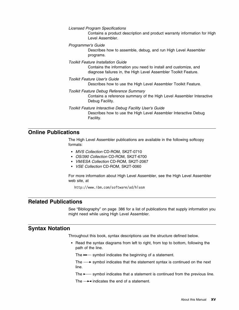
Syntax NotationThroughout this book, syntax descriptions use the structure defined below.
� Read the syntax diagrams from left to right, from top to bottom, following thepath of the line.
The ��── symbol indicates the beginning of a statement.
The ───� symbol indicates that the statement syntax is continued on the nextline.
The �─── symbol indicates that a statement is continued from the previous line.
The ──�� indicates the end of a statement.
About this Manual xv
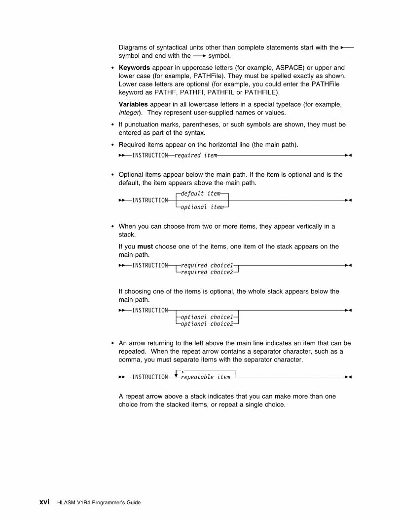
Diagrams of syntactical units other than complete statements start with the �───symbol and end with the ───� symbol.
� Keywords appear in uppercase letters (for example, ASPACE) or upper andlower case (for example, PATHFile). They must be spelled exactly as shown.Lower case letters are optional (for example, you could enter the PATHFilekeyword as PATHF, PATHFI, PATHFIL or PATHFILE).
Variables appear in all lowercase letters in a special typeface (for example,integer). They represent user-supplied names or values.
� If punctuation marks, parentheses, or such symbols are shown, they must beentered as part of the syntax.
� Required items appear on the horizontal line (the main path).
��──INSTRUCTION──required item───────────────────────────────────────��
� Optional items appear below the main path. If the item is optional and is thedefault, the item appears above the main path.
┌ ┐─default item──��──INSTRUCTION─ ──┼ ┼─────────────── ──────────────────────────────────�� └ ┘─optional item─
� When you can choose from two or more items, they appear vertically in astack.
If you must choose one of the items, one item of the stack appears on themain path.
��──INSTRUCTION─ ──┬ ┬─required choice1─ ───────────────────────────────�� └ ┘─required choice2─
If choosing one of the items is optional, the whole stack appears below themain path.
��──INSTRUCTION─ ──┬ ┬────────────────── ───────────────────────────────�� ├ ┤─optional choice1─ └ ┘─optional choice2─
� An arrow returning to the left above the main line indicates an item that can berepeated. When the repeat arrow contains a separator character, such as acomma, you must separate items with the separator character.
┌ ┐─,───────────────��──INSTRUCTION─ ───+ ┴─repeatable item─ ────────────────────────────────��
A repeat arrow above a stack indicates that you can make more than onechoice from the stacked items, or repeat a single choice.
xvi HLASM V1R4 Programmer’s Guide
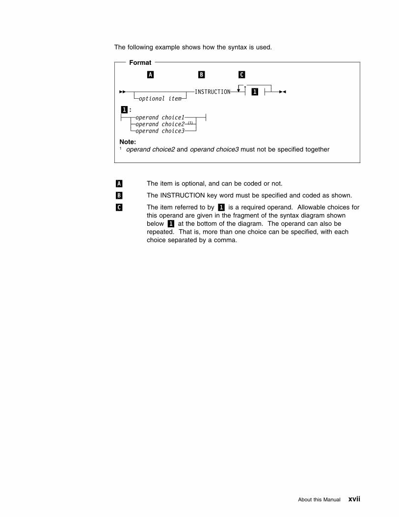
The following example shows how the syntax is used.
Format
�A� �B� �C�
┌ ┐─,───────��─ ──┬ ┬─────────────── ─INSTRUCTION─ ───+ ┴─┤ �1� ├─ ─�� └ ┘ ─optional item─
�1�:├─ ──┬ ┬─operand choice1─── ─┤ ├ ┤─operand choice2───(1)
└ ┘─operand choice3───
Note:1 operand choice2 and operand choice3 must not be specified together
�A� The item is optional, and can be coded or not.
�B� The INSTRUCTION key word must be specified and coded as shown.
�C� The item referred to by �1� is a required operand. Allowable choices forthis operand are given in the fragment of the syntax diagram shownbelow �1� at the bottom of the diagram. The operand can also berepeated. That is, more than one choice can be specified, with eachchoice separated by a comma.
About this Manual xvii

Summary of Changes
Date of Publication September 2000
Form of Publication Fourth Edition, SC26-4941-03
Assembler options changes
� Options file allows options to be specified via an external file.
� *PROCESS OVERRIDE
� New options:
THREAD
CODEPAGE
New assembler statement
� XATTR statement allows attributes of external symbols to be specified.
Changed assembler statements
� DC new constant types:
R PSECT address constant
CU Unicode character constants
AD Doubleword aligned 8-byte address
FD Doubleword aligned 8-byte fixed point constant
– Floating point symbolic value DMIN added
� AMODE
– ANY31 operand added
– 64 operand documented
� RMODE
– 31 operand added
– 64 operand documented
Miscellany
� Literals now always entered in literal pool
� Predefined absolute symbols may no longer be used in conditional assemblycharacter expressions.
xviii Copyright IBM Corp. 1982, 2000

Part 1. Understanding and Using the Assembler
Part 1. Understanding and Using the Assembler
Chapter 1. Introduction . . . . . . . . . . . . . . . . . . . . . . . . . . . . . . . . 5Requirements . . . . . . . . . . . . . . . . . . . . . . . . . . . . . . . . . . . . . . . 5
System Requirements . . . . . . . . . . . . . . . . . . . . . . . . . . . . . . . . . 5Machine Requirements . . . . . . . . . . . . . . . . . . . . . . . . . . . . . . . . 5Storage Requirements . . . . . . . . . . . . . . . . . . . . . . . . . . . . . . . . . 6
Compatibility . . . . . . . . . . . . . . . . . . . . . . . . . . . . . . . . . . . . . . . . 6Assembler Language Support . . . . . . . . . . . . . . . . . . . . . . . . . . . . 6Migration Considerations . . . . . . . . . . . . . . . . . . . . . . . . . . . . . . . 7
Chapter 2. Using the Assembler Listing . . . . . . . . . . . . . . . . . . . . . . 8High Level Assembler Option Summary . . . . . . . . . . . . . . . . . . . . . . . . 9External Symbol Dictionary (ESD) . . . . . . . . . . . . . . . . . . . . . . . . . . 12Source and Object . . . . . . . . . . . . . . . . . . . . . . . . . . . . . . . . . . . 15Relocation Dictionary (RLD) . . . . . . . . . . . . . . . . . . . . . . . . . . . . . . 22Ordinary Symbol and Literal Cross Reference . . . . . . . . . . . . . . . . . . . 22Unreferenced Symbols Defined in CSECTs . . . . . . . . . . . . . . . . . . . . . 24Macro and Copy Code Source Summary . . . . . . . . . . . . . . . . . . . . . . 25Macro and Copy Code Cross Reference . . . . . . . . . . . . . . . . . . . . . . . 25
Effects of LIBMAC and PCONTROL(MCALL) Options . . . . . . . . . . . . 27DSECT Cross Reference . . . . . . . . . . . . . . . . . . . . . . . . . . . . . . . . 29USING Map . . . . . . . . . . . . . . . . . . . . . . . . . . . . . . . . . . . . . . . 30General Purpose Register Cross Reference . . . . . . . . . . . . . . . . . . . . . 31Diagnostic Cross Reference and Assembler Summary . . . . . . . . . . . . . . 32
Chapter 3. Controlling Your Assembly with Options . . . . . . . . . . . . . 38The Sources of Assembler Options . . . . . . . . . . . . . . . . . . . . . . . . . . 38
Precedence of Assembler Options . . . . . . . . . . . . . . . . . . . . . . . . 38Fixed Installation Default Options . . . . . . . . . . . . . . . . . . . . . . . . . 39
| *PROCESS OVERRIDE Statement Options . . . . . . . . . . . . . . . . . . . 39| ASMAOPT Options . . . . . . . . . . . . . . . . . . . . . . . . . . . . . . . . . 39
Invocation Options . . . . . . . . . . . . . . . . . . . . . . . . . . . . . . . . . . 39*Process Statement Options . . . . . . . . . . . . . . . . . . . . . . . . . . . . 40Default Options . . . . . . . . . . . . . . . . . . . . . . . . . . . . . . . . . . . . 41Invoking the Assembler Dynamically . . . . . . . . . . . . . . . . . . . . . . . 41Coding Rules . . . . . . . . . . . . . . . . . . . . . . . . . . . . . . . . . . . . . 41
Assembler Options . . . . . . . . . . . . . . . . . . . . . . . . . . . . . . . . . . . 42ADATA . . . . . . . . . . . . . . . . . . . . . . . . . . . . . . . . . . . . . . . . 42ALIGN . . . . . . . . . . . . . . . . . . . . . . . . . . . . . . . . . . . . . . . . . 43ASA (MVS and CMS) . . . . . . . . . . . . . . . . . . . . . . . . . . . . . . . . 43BATCH . . . . . . . . . . . . . . . . . . . . . . . . . . . . . . . . . . . . . . . . 44
| CODEPAGE . . . . . . . . . . . . . . . . . . . . . . . . . . . . . . . . . . . . . 44COMPAT . . . . . . . . . . . . . . . . . . . . . . . . . . . . . . . . . . . . . . . 45DBCS . . . . . . . . . . . . . . . . . . . . . . . . . . . . . . . . . . . . . . . . . 46DECK . . . . . . . . . . . . . . . . . . . . . . . . . . . . . . . . . . . . . . . . . 47DISK (CMS) . . . . . . . . . . . . . . . . . . . . . . . . . . . . . . . . . . . . . . 47DXREF . . . . . . . . . . . . . . . . . . . . . . . . . . . . . . . . . . . . . . . . 47ERASE (CMS) . . . . . . . . . . . . . . . . . . . . . . . . . . . . . . . . . . . . 48ESD . . . . . . . . . . . . . . . . . . . . . . . . . . . . . . . . . . . . . . . . . . 48EXIT . . . . . . . . . . . . . . . . . . . . . . . . . . . . . . . . . . . . . . . . . . 49FLAG . . . . . . . . . . . . . . . . . . . . . . . . . . . . . . . . . . . . . . . . . 52
Copyright IBM Corp. 1982, 2000 1

Part 1. Understanding and Using the Assembler
FOLD . . . . . . . . . . . . . . . . . . . . . . . . . . . . . . . . . . . . . . . . . 55GOFF (MVS and CMS) . . . . . . . . . . . . . . . . . . . . . . . . . . . . . . . 55INFO . . . . . . . . . . . . . . . . . . . . . . . . . . . . . . . . . . . . . . . . . . 56LANGUAGE . . . . . . . . . . . . . . . . . . . . . . . . . . . . . . . . . . . . . . 57LIBMAC . . . . . . . . . . . . . . . . . . . . . . . . . . . . . . . . . . . . . . . . 58LINECOUNT . . . . . . . . . . . . . . . . . . . . . . . . . . . . . . . . . . . . . 58LIST . . . . . . . . . . . . . . . . . . . . . . . . . . . . . . . . . . . . . . . . . . 59MXREF . . . . . . . . . . . . . . . . . . . . . . . . . . . . . . . . . . . . . . . . 61OBJECT . . . . . . . . . . . . . . . . . . . . . . . . . . . . . . . . . . . . . . . . 62OPTABLE . . . . . . . . . . . . . . . . . . . . . . . . . . . . . . . . . . . . . . . 62PCONTROL . . . . . . . . . . . . . . . . . . . . . . . . . . . . . . . . . . . . . . 64PESTOP . . . . . . . . . . . . . . . . . . . . . . . . . . . . . . . . . . . . . . . . 66PRINT (CMS) . . . . . . . . . . . . . . . . . . . . . . . . . . . . . . . . . . . . . 66PROFILE . . . . . . . . . . . . . . . . . . . . . . . . . . . . . . . . . . . . . . . 66RA2 . . . . . . . . . . . . . . . . . . . . . . . . . . . . . . . . . . . . . . . . . . 67RENT . . . . . . . . . . . . . . . . . . . . . . . . . . . . . . . . . . . . . . . . . 68RLD . . . . . . . . . . . . . . . . . . . . . . . . . . . . . . . . . . . . . . . . . . 68RXREF . . . . . . . . . . . . . . . . . . . . . . . . . . . . . . . . . . . . . . . . 68SEG (CMS) . . . . . . . . . . . . . . . . . . . . . . . . . . . . . . . . . . . . . . 69SIZE . . . . . . . . . . . . . . . . . . . . . . . . . . . . . . . . . . . . . . . . . . 69SYSPARM . . . . . . . . . . . . . . . . . . . . . . . . . . . . . . . . . . . . . . 71TERM . . . . . . . . . . . . . . . . . . . . . . . . . . . . . . . . . . . . . . . . . 72TEST . . . . . . . . . . . . . . . . . . . . . . . . . . . . . . . . . . . . . . . . . . 73
| THREAD . . . . . . . . . . . . . . . . . . . . . . . . . . . . . . . . . . . . . . . 73TRANSLATE . . . . . . . . . . . . . . . . . . . . . . . . . . . . . . . . . . . . . 74USING . . . . . . . . . . . . . . . . . . . . . . . . . . . . . . . . . . . . . . . . . 75XOBJECT (MVS and CMS) . . . . . . . . . . . . . . . . . . . . . . . . . . . . . 77XREF . . . . . . . . . . . . . . . . . . . . . . . . . . . . . . . . . . . . . . . . . 78
Chapter 4. Providing User Exits . . . . . . . . . . . . . . . . . . . . . . . . . . 79Exit Types . . . . . . . . . . . . . . . . . . . . . . . . . . . . . . . . . . . . . . . . 79Specifying User Exits . . . . . . . . . . . . . . . . . . . . . . . . . . . . . . . . . . 80Loading User Exits . . . . . . . . . . . . . . . . . . . . . . . . . . . . . . . . . . . 81Calling User Exits . . . . . . . . . . . . . . . . . . . . . . . . . . . . . . . . . . . . 81Exit Parameter List . . . . . . . . . . . . . . . . . . . . . . . . . . . . . . . . . . . 82
Request Info Pointer . . . . . . . . . . . . . . . . . . . . . . . . . . . . . . . . . 84Parameter List Version . . . . . . . . . . . . . . . . . . . . . . . . . . . . . . 84Exit Type . . . . . . . . . . . . . . . . . . . . . . . . . . . . . . . . . . . . . . 84Request Type . . . . . . . . . . . . . . . . . . . . . . . . . . . . . . . . . . . 84Options . . . . . . . . . . . . . . . . . . . . . . . . . . . . . . . . . . . . . . . 85EXITCTLn . . . . . . . . . . . . . . . . . . . . . . . . . . . . . . . . . . . . . 86Return Code . . . . . . . . . . . . . . . . . . . . . . . . . . . . . . . . . . . . 86Reason Code . . . . . . . . . . . . . . . . . . . . . . . . . . . . . . . . . . . 87Buffer Length . . . . . . . . . . . . . . . . . . . . . . . . . . . . . . . . . . . 88Error Buffer Length . . . . . . . . . . . . . . . . . . . . . . . . . . . . . . . . 89Error Severity . . . . . . . . . . . . . . . . . . . . . . . . . . . . . . . . . . . 89User-Defined Field . . . . . . . . . . . . . . . . . . . . . . . . . . . . . . . . 90Common User Field . . . . . . . . . . . . . . . . . . . . . . . . . . . . . . . 90
Buffer Pointer . . . . . . . . . . . . . . . . . . . . . . . . . . . . . . . . . . . . . 90Error Buffer Pointer . . . . . . . . . . . . . . . . . . . . . . . . . . . . . . . . . 90Exit-Specific Information Pointer . . . . . . . . . . . . . . . . . . . . . . . . . . 90DCB Pointer . . . . . . . . . . . . . . . . . . . . . . . . . . . . . . . . . . . . . 91
Static Assembler Information Pointer . . . . . . . . . . . . . . . . . . . . . . . . . 91| HLASM VRM . . . . . . . . . . . . . . . . . . . . . . . . . . . . . . . . . . . . . 91
2 HLASM V1R4 Programmer’s Guide
Part 1. Understanding and Using the Assembler
| PTF Level . . . . . . . . . . . . . . . . . . . . . . . . . . . . . . . . . . . . . . . 91| System ID . . . . . . . . . . . . . . . . . . . . . . . . . . . . . . . . . . . . . . . 92
Error Handling . . . . . . . . . . . . . . . . . . . . . . . . . . . . . . . . . . . . . . 92Exit-Specific Information Block . . . . . . . . . . . . . . . . . . . . . . . . . . . . 92
Member Name . . . . . . . . . . . . . . . . . . . . . . . . . . . . . . . . . . . . 94Member Type . . . . . . . . . . . . . . . . . . . . . . . . . . . . . . . . . . . . . 94Data Set Name . . . . . . . . . . . . . . . . . . . . . . . . . . . . . . . . . . . . 94Volume Serial . . . . . . . . . . . . . . . . . . . . . . . . . . . . . . . . . . . . . 94Relative Record Number . . . . . . . . . . . . . . . . . . . . . . . . . . . . . . 95Absolute Record Number . . . . . . . . . . . . . . . . . . . . . . . . . . . . . . 96Linecount . . . . . . . . . . . . . . . . . . . . . . . . . . . . . . . . . . . . . . . 96Current Page Number . . . . . . . . . . . . . . . . . . . . . . . . . . . . . . . . 96
SOURCE Exit Processing . . . . . . . . . . . . . . . . . . . . . . . . . . . . . . . 97OPEN . . . . . . . . . . . . . . . . . . . . . . . . . . . . . . . . . . . . . . . . . 97CLOSE . . . . . . . . . . . . . . . . . . . . . . . . . . . . . . . . . . . . . . . . 97READ . . . . . . . . . . . . . . . . . . . . . . . . . . . . . . . . . . . . . . . . . 97PROCESS . . . . . . . . . . . . . . . . . . . . . . . . . . . . . . . . . . . . . . 98
LIBRARY Exit Processing . . . . . . . . . . . . . . . . . . . . . . . . . . . . . . . 99OPEN . . . . . . . . . . . . . . . . . . . . . . . . . . . . . . . . . . . . . . . . . 99CLOSE . . . . . . . . . . . . . . . . . . . . . . . . . . . . . . . . . . . . . . . . 100READ . . . . . . . . . . . . . . . . . . . . . . . . . . . . . . . . . . . . . . . . . 100PROCESS MACRO or PROCESS COPY . . . . . . . . . . . . . . . . . . . . 100FIND MACRO or FIND COPY . . . . . . . . . . . . . . . . . . . . . . . . . . . 101END OF MEMBER . . . . . . . . . . . . . . . . . . . . . . . . . . . . . . . . . . 103
LISTING Exit Processing . . . . . . . . . . . . . . . . . . . . . . . . . . . . . . . . 104OPEN . . . . . . . . . . . . . . . . . . . . . . . . . . . . . . . . . . . . . . . . . 105CLOSE . . . . . . . . . . . . . . . . . . . . . . . . . . . . . . . . . . . . . . . . 106WRITE . . . . . . . . . . . . . . . . . . . . . . . . . . . . . . . . . . . . . . . . . 106PROCESS . . . . . . . . . . . . . . . . . . . . . . . . . . . . . . . . . . . . . . 106
OBJECT (MVS and CMS) and PUNCH Exit Processing . . . . . . . . . . . . . . 108OPEN . . . . . . . . . . . . . . . . . . . . . . . . . . . . . . . . . . . . . . . . . 108CLOSE . . . . . . . . . . . . . . . . . . . . . . . . . . . . . . . . . . . . . . . . 109WRITE . . . . . . . . . . . . . . . . . . . . . . . . . . . . . . . . . . . . . . . . . 109PROCESS . . . . . . . . . . . . . . . . . . . . . . . . . . . . . . . . . . . . . . 110
ADATA Exit Processing . . . . . . . . . . . . . . . . . . . . . . . . . . . . . . . . 111OPEN . . . . . . . . . . . . . . . . . . . . . . . . . . . . . . . . . . . . . . . . . 111CLOSE . . . . . . . . . . . . . . . . . . . . . . . . . . . . . . . . . . . . . . . . 112PROCESS . . . . . . . . . . . . . . . . . . . . . . . . . . . . . . . . . . . . . . 112
TERM Exit Processing . . . . . . . . . . . . . . . . . . . . . . . . . . . . . . . . . 112OPEN . . . . . . . . . . . . . . . . . . . . . . . . . . . . . . . . . . . . . . . . . 113CLOSE . . . . . . . . . . . . . . . . . . . . . . . . . . . . . . . . . . . . . . . . 113WRITE . . . . . . . . . . . . . . . . . . . . . . . . . . . . . . . . . . . . . . . . . 113PROCESS . . . . . . . . . . . . . . . . . . . . . . . . . . . . . . . . . . . . . . 114
Sample User Exits . . . . . . . . . . . . . . . . . . . . . . . . . . . . . . . . . . . 115User Exit Coding Example . . . . . . . . . . . . . . . . . . . . . . . . . . . . . . . 115
Chapter 5. Providing External Functions . . . . . . . . . . . . . . . . . . . . . 135External Function Processing . . . . . . . . . . . . . . . . . . . . . . . . . . . . . 135Linkage Conventions . . . . . . . . . . . . . . . . . . . . . . . . . . . . . . . . . . 136External Function Parameter List . . . . . . . . . . . . . . . . . . . . . . . . . . . 136
Request Information List . . . . . . . . . . . . . . . . . . . . . . . . . . . . . . 139Parameter List Version . . . . . . . . . . . . . . . . . . . . . . . . . . . . . . 139Function Type . . . . . . . . . . . . . . . . . . . . . . . . . . . . . . . . . . . 139Number of Parameters . . . . . . . . . . . . . . . . . . . . . . . . . . . . . . 139
Part 1. Understanding and Using the Assembler 3

Part 1. Understanding and Using the Assembler
Return Code . . . . . . . . . . . . . . . . . . . . . . . . . . . . . . . . . . . . 139Flag Byte . . . . . . . . . . . . . . . . . . . . . . . . . . . . . . . . . . . . . . 139Reserved . . . . . . . . . . . . . . . . . . . . . . . . . . . . . . . . . . . . . . 140Msg Length . . . . . . . . . . . . . . . . . . . . . . . . . . . . . . . . . . . . 140Msg Severity . . . . . . . . . . . . . . . . . . . . . . . . . . . . . . . . . . . . 140Return Value (SETAF) . . . . . . . . . . . . . . . . . . . . . . . . . . . . . . 140Parm Value n (SETAF) . . . . . . . . . . . . . . . . . . . . . . . . . . . . . . 140Return String Length (SETCF) . . . . . . . . . . . . . . . . . . . . . . . . . 140Parm String n Length (SETCF) . . . . . . . . . . . . . . . . . . . . . . . . . 141
Pointer to User Work Area . . . . . . . . . . . . . . . . . . . . . . . . . . . . . 141Pointer to Msg Buffer . . . . . . . . . . . . . . . . . . . . . . . . . . . . . . . . 141Pointer to Return String (SETCF) . . . . . . . . . . . . . . . . . . . . . . . . . 141Pointer to Parm String n (SETCF) . . . . . . . . . . . . . . . . . . . . . . . . . 141
Chapter 6. Diagnosing Assembly Errors . . . . . . . . . . . . . . . . . . . . . 143Assembly Error Diagnostic Messages . . . . . . . . . . . . . . . . . . . . . . . . 143MNOTE Statements . . . . . . . . . . . . . . . . . . . . . . . . . . . . . . . . . . . 145Suppression of Error Messages and MNOTE Statements . . . . . . . . . . . . . 147Reference Information for Statements in Error . . . . . . . . . . . . . . . . . . . 147Abnormal Assembly Termination . . . . . . . . . . . . . . . . . . . . . . . . . . . 148MHELP—Macro Trace Facility . . . . . . . . . . . . . . . . . . . . . . . . . . . . . 148
4 HLASM V1R4 Programmer’s Guide

Requirements
Chapter 1. Introduction
IBM High Level Assembler for MVS & VM & VSE is an IBM licensed program thatcan be used to assemble assembler language programs that use the followingmachine instructions:
System/370System/370 Extended Architecture (370-XA)Enterprise Systems Architecture/370 (ESA/370)Enterprise Systems Architecture/390 (ESA/390) machine instructions
RequirementsThis section describes the operating systems, the processors, and the amount ofstorage required to run High Level Assembler.
System RequirementsHigh Level Assembler runs under the operating systems listed below. Unlessotherwise stated, the assembler also operates under subsequent versions,releases, and modification levels of these systems:
| OS/390 Version 1VM/ESA Version 2 Release 2
| VSE/ESA Version 1 Release 4| VSE/ESA Version 2 Release 3
High Level Assembler supports the operation codes available with the ExtendedArchitecture (370-XA) mode processor and Enterprise Systems Architecture/370(ESA/370) or Enterprise Systems Architecture/390 (ESA/390) mode processors andthe new operation codes available with Enterprise System/9000 (ES/9000)mode processors.
Machine RequirementsFor assembling High Level Assembler programs: Programs written using HighLevel Assembler can be assembled, including use of the Extended Architecturemode processor machine instructions and Enterprise System Architecture modeprocessor machine instructions, on all System/370 family and its follow-onmachines supporting the following operating systems:
| MVS/ESA| OS/390
VM/ESA VSE/ESA
You might require an operating system-specific macro library to assemble programsthat run under that operating system, depending on macro usage.
For running High Level Assembler programs: A generated object programusing Extended Architecture (370-XA), Enterprise Systems Architecture/370(ESA/370), Enterprise Systems Architecture/390 (ESA/390), EnterpriseSystems/9000 (ES/9000) or Vector instructions can be run only on an applicableprocessor under an operating system that provides the necessary architecturesupport for the instructions used.
Copyright IBM Corp. 1982, 2000 5

Compatibility
Tape device: High Level Assembler is distributed on one of the following:
Standard labeled 9-track magnetic tape written at 6250 bpi3480 tape cartridge
| 4mm DAT cartridge
An appropriate tape device is required for installation.
Double-byte data: Double-byte data can be displayed, entered, or both, in theirnational language representation on the following:
IBM 3800-8 system printerIBM 3200 system printerIBM 3820 remote printerIBM PS/55 family as an IBM 3270 terminal
Storage Requirements| Virtual storage: High Level Assembler requires a minimum of 580K bytes of main| storage. 380K bytes of storage are required for High Level Assembler load
modules. The rest of the storage allocated to the assembler is used for assemblerworking storage.
Auxiliary storage space: Depending on the assembler options used, auxiliarystorage space might be required for the following data sets:
System inputMacro instruction library—either system or private or bothAn intermediate work file, which must be a direct-access device such as 3350,3375, 3380, 3390, 9345 or FBA.
Print outputObject module outputAssociated data output
Library space: The space requirements for the High Level Assembler loadmodules (or phases) and procedures are provided in the HLASM Installation andCustomization Guide.
Installation: Please refer to HLASM Installation and Customization Guide forinstallation requirements.
CompatibilityThis section describes source program compatibility and migration issues that youneed to consider before using High Level Assembler.
Assembler Language SupportThe assembler language supported by High Level Assembler has functionalextensions to the languages supported by Assembler H Version 2 and theDOS/VSE Assembler. High Level Assembler uses the same language syntax,function, operation, and structure as these earlier assemblers. The functionsprovided by the Assembler H Version 2 macro facility are all provided by High LevelAssembler.
6 HLASM V1R4 Programmer’s Guide

Compatibility
Migration ConsiderationsSource Programs: Migration from High Level Assembler Release 1, High Level
| Assembler Release 2, High Level Assembler Release 3, Assembler H Version 2 orDOS/VSE Assembler to High Level Assembler Release 4, requires an analysis ofexisting assembler language programs to ensure that they do not contain macro
| instructions with names that conflict with the High Level Assembler Release 4| symbolic operation codes, or SET symbols with names that conflict with the names| of High Level Assembler Release 4 system variable symbols.
With the exception of these possible conflicts, and with appropriate High LevelAssembler option values, assembler language source programs written for High
| Level Assembler Release 1, High Level Assembler Release 2, High Level| Assembler Release 3, Assembler H Version 2 or the DOS/VSE Assembler, that| assemble without warning or error diagnostic messages, should assemble correctly| using High Level Assembler Release 4.
| Object Programs: Object programs generated by High Level Assembler Release| 4 in any one of the supported operating systems can be migrated to any other of
the supported operating systems for execution.
The object programs being migrated must be link-edited in the target operatingsystem environment before execution.
You should be aware of the differences in the code generated by system macros inthe supported operating systems. Operational facilities available on the sourceoperating system but not available on the target operating system should not bespecified for any program which is required to be compatible, either duringassembly or link-edit.
Chapter 1. Introduction 7

Using the Assembler Listing
Chapter 2. Using the Assembler Listing
This chapter tells you how to interpret the printed listing produced by theassembler. The listing is obtained only if the option LIST is in effect. Parts of thelisting can be suppressed by using other options; for information on the listingoptions, refer to Chapter 3, “Controlling Your Assembly with Options” on page 38.
The High Level Assembler listing consists of up to twelve sections, ordered asfollows:
� High Level Assembler Option Summary� External Symbol Dictionary (ESD)� Source and Object� Relocation Dictionary (RLD)� Ordinary Symbol and Literal Cross Reference� Unreferenced Symbols Defined in CSECTs� Macro and Copy Code Source Summary� Macro and Copy Code Cross Reference� DSECT Cross Reference
� USING Map� General Purpose Register Cross Reference� Diagnostic Cross Reference and Assembler Summary
The following assembler options are used to control the format, and which sectionsto produce, of the assembler listing:
ASA (MVS and CMS) Allows you to use American National Standard printercontrol characters, instead of machine printer control characters.
DXREF Produces the DSECT Cross Reference section.
ESD Produces the External Symbol Dictionary section.
EXIT(PRTEXIT(mod3))Allows you to supply a listing exit to replace or complement theassembler's listing output processing.
LANGUAGEProduces error diagnostic messages in the following languages:
� English mixed case (EN) � English uppercase (UE) � German (DE) � Japanese (JP) � Spanish (ES)
When you select either of the English languages, the assembler listingheadings are produced in the same case as the diagnostic messages.
When you select either the German language or the Spanish language,the assembler listing headings are produced in mixed case English.
When you select the Japanese language, the assembler listing headingsare produced in uppercase English.
The assembler uses the installation default language for messagesproduced in CMS by the ASMAHL command.
8 Copyright IBM Corp. 1982, 2000

High Level Assembler Option Summary
LINECOUNTAllows you to specify how many lines should be printed on each page.
LIST Controls the format of the Source and Object section of the listing.NOLIST suppresses the entire listing.
MXREF Produces one, or both, of the Macro and Copy Code Source Summaryand Macro and Copy Code Cross Reference sections.
PCONTROLControls which statements are printed in the listing, and overrides somePRINT instructions.
RLD Produces the Relocation Dictionary section.
RXREF Produces the General Purpose Register Cross Reference section.
USING(MAP)Produces the Using Map section.
XREF Produces one, or both, of the Ordinary Symbol and Literal CrossReference and the Unreferenced Symbols Defined in CSECTs sections.
The following additional options can be specified when you run the assembler onCMS:
LINECOUNAn abbreviation of the LINECOUNT option.
PRINT The assembler listing is written to the virtual printer instead of to a diskfile.
The sections in the listing are described on the following pages.
High Level Assembler Option SummaryHigh Level Assembler provides a summary of the options current for the assembly,including:
| � A list of the overriding parameters specified in the ASMAOPT file (MVS and| CMS) or library member ASMAOPT.USER (VSE).
� A list of the overriding parameters specified when the assembler was called
� The options specified on *PROCESS statements
� In-line error diagnostic messages for any overriding parameters and*PROCESS statements in error
You cannot suppress the option summary unless you suppress the entire listing, oryou supply a user exit to control which lines are printed.
On MVS and CMS, High Level Assembler provides a sample LISTING exit thatallows you to suppress the option summary or print it at the end of the listing. SeeAppendix J, “Sample LISTING User Exit (MVS and CMS)” on page 369.
Figure 2 shows an example of the High Level Assembler Option Summary. Theexample includes assembler options that have been specified in the followingoption sources:
| � ASMAOPT file
Chapter 2. Using the Assembler Listing 9

High Level Assembler Option Summary
� Invocation parameters
| � PROCESS statements including an example specifying the OVERRIDE| keyword.
The example shows a number of error diagnostic messages relating to the conflictsand errors in the options specified.
| High Level Assembler Option Summary Page 1| �1� �2�| HLASM R4.9 2999/99/25 17.48| Overriding ASMAOPT Parameters - sysparm(thisisatestsysparm),rxref| Overriding Parameters- NOOBJECT,language(en),size(4meg),xref(short,unrefs),nomxref,norxref,adata,noadata| Process Statements- OVERRIDE(ADATA,MXREF(full))| ALIGN| noDBCS| MXREF(FULL),noLIBMAC| FLAG(9)| noFOLD,LANGUAGE(ue)| NORA2| NODBCS| XREF(FULL)
| �3�| LL ASMA499W Error in invocation parameter - size(4meg)| LL ASMA438N Attempt to override ASMAOPT parameter. Option norxref ignored.| LL ASMA425N Option conflict in invocation parameters. NOADATA overrides an earlier setting.| LL ASMA423N Option ADATA) in a LPROCESS OVERRIDE statement conflicts with invocation or default option. Option is not permitted| in a LPROCESS statement and has been ignored.| LL ASMA422N Option LANGUAGE is not valid in a LPROCESS statement.| LL ASMA437N Attempt to override invocation parameter in a LPROCESS statement. Suboption FULL of XREF option ignored.| Options for this Assembly
| �4�| 3 NOADATA| 5 ALIGN| NOASA| BATCH| CODEPAGE(947C)| 5 NODBCS| NODECK| DXREF| ESD| NOEXIT| 5 FLAG(9,ALIGN,CONT,NOIMPLEN,NOPAGE9,PUSH,RECORD,NOSUBSTR,USING9)| 5 NOFOLD| NOGOFF| NOINFO| 3 LANGUAGE(EN)| 5 NOLIBMAC| LINECOUNT(69)| LIST(121)| 1 MXREF(FULL)| 3 NOOBJECT| OPTABLE(UNI)| NOPCONTROL| NOPESTOP| NOPROFILE| 5 NORA2| NORENT| RLD| 2 RXREF| SIZE(MAX)| 2 SYSPARM(thisisatestsysparm)| NOTERM| NOTEST| THREAD| NOTRANSLATE| USING(NOLIMIT,MAP,WARN(15))| 3 XREF(SHORT,UNREFS)| �5�| No Overriding DD Names| Active Usings: None Page 3| Loc Object Code Addr1 Addr2 Stmt Source Statement HLASM R4.9 2999/99/25 17.48| �6�| 1 LPROCESS OVERRIDE(ADATA,MXREF(full) 99991999| 2 LPROCESS ALIGN 99992999| 3 LPROCESS noDBCS any text 99993999| 4 LPROCESS MXREF(FULL),noLIBMAC 99994999| 5 LPROCESS FLAG(9) 99995999| 6 LPROCESS noFOLD,LANGUAGE(ue) 99996999| 7 LPROCESS NORA2 99997999| 8 LPROCESS NODBCS 99998999| 9 LPROCESS XREF(FULL) 99999999| 999999 99999 99999 19 A CSECT 99919999| R:F 99999 11 USING L,15 99911999
Figure 2. Option Summary Including Options Specified on *PROCESS Statements
10 HLASM V1R4 Programmer’s Guide

High Level Assembler Option Summary
The highlighted numbers in the example are:
| �1� The product description. Shown on each page of the assembler listing. (You| can use the TITLE instruction to generate individual headings for each page of| the source and object program listing.)
| �2� The date and the time of the assembly.
| �3� Error diagnostic messages for overriding parameters and *PROCESS| statements. These immediately follow the list of *PROCESS statement| options. The error diagnostic messages are:
| ASMA400W - The value specified as the size option is not valid. The valid| option is SIZE(4M).
| ASMA438N - The option RXREF is specified in the ASMAOPT file and the| conflicting option NORXREF is specified as an invocation parameter.| The ASMAOPT options have precedence over the invocation| parameters and the NORXREF option is ignored.
| ASMA425N - The ADATA option specified as an invocation parameter| overrides the option NOADATA which was also specified as an| invocation parameter. When conflicting options are received from the| same source, the last occurrence takes precedence.
| ASMA423N - The option ADATA has been specified in a *PROCESS| statement with the OVERRIDE option. The option cannot be set by a| *PROCESS statement, and the option conflicts with an invocation or| default option. This message is printed when an option that cannot be| set by a *PROCESS statement (See “*Process Statement Options” on| page 40) is included in a *PROCESS OVERRIDE statement and the| option conflicts with an invocation or default option. If the option does| not conflict with the invocation or default option no message is printed.
| ASMA422N - The option LANGUAGE is not permitted in a *PROCESS| statement.
| ASMA437N - The option XREF(FULL) which is specified in the last| *PROCESS statement conflicts with the option NORXREF which is| specified as an invocation parameter. The option XREF(FULL) is| ignored.
| �4� A flag beside each option indicates the source of the option. This table shows| the sources:
| Figure 3. Flags used in the Option Summary
| Flag| Meaning
| 1| The option came from a *PROCESS OVERRIDE statement.
| 2| The option came from the ASMAOPT options file (MVS and CMS) or| ASMAOPT.USER library member (VSE).
| 3| The option came from the invocation parameters.
| 4| The permanent job control options set by the VSE command STDOPT.
| 5| The option came from a *PROCESS statement.
| (blank)| The option came from the installation defaults.
Chapter 2. Using the Assembler Listing 11

External Symbol Dictionary
| �5� On MVS and CMS, if the assembler has been called by a program and anystandard (default) ddnames have been overridden, both the default ddnamesand the overriding ddnames are listed. Otherwise, this statement appears:
No Overriding DD Names
�6� The *PROCESS statements are written as comment statements in the Sourceand Object section of the listing.
External Symbol Dictionary (ESD)This section of the listing contains the external symbol dictionary informationpassed to the linkage editor or loader, or DFSMS/MVS binder, in the objectmodule.
This section helps you find references between modules in a multimodule program.The ESD may be particularly helpful in debugging the running of large programsconstructed from several modules.
The ESD entries describe the control sections, external references, and entry pointsin the assembled program. There are eight types of ESD entries (SD, ED, LD, ER,PC, CM, XD, and WX). Figure 4 shows the ESD entries when you specify the
| NOGOFF option. Figure 5 shows the ESD entries when you specify the GOFF| option. For each of the different types of ESD entries, an X indicates which of the
fields have values.
| Figure 6 on page 13 is an example of the External Symbol Dictionary generated| with the GOFF assembler option, and is followed by a description of its contents.
Figure 4. Types of ESD Entries when NOGOFF Option Specified
SYMBOL TYPE ID ADDR LENGTH LD ID FLAGS
X SD X X X X
X LD X X
X ER X
PC X X X X
X CM X X X X
X XD X X X
X WX X
Figure 5. Types of ESD Entries when GOFF Option Specified
SYMBOL TYPE ID ADDR LENGTH LD ID FLAGS
X SD X
X ED X X X X X
X LD X X X X
X ER X X
X CM X X X X
X XD X X X
X WX X X
12 HLASM V1R4 Programmer’s Guide

External Symbol Dictionary
SAMP91 External Symbol Dictionary Page 2�1� �2� �3� �4� �5� �6� �7� �8�Symbol Type Id Address Length LD ID Flags Alias-of HLASM R4.9 2999/99/25 17.48SAMP91 SD 99999991B_PRV ED 99999992 99999991B_TEXT ED 99999993 99999999 999999E4 99999991 99SAMP91 LD 99999994 99999999 99999993 99ENTRY1 LD 99999995 99999999 99999993 99KL_INST SD 99999996B_PRV ED 99999997 99999996B_TEXT ED 99999998 99999999 99999999 99999996 99KL_INST CM 99999999 99999999 99999998 99 SD 9999999AB_PRV ED 9999999B 9999999AB_TEXT ED 9999999C 999999E8 99999999 9999999A 99Date9991 ER 9999999D 9999999A RCNVDTERCNVTME ER 9999999E 9999999A
Figure 6. External Symbol Dictionary Listing
�1� The name of every external dummy section, control section, entry point,external symbol, and class. If the external dummy section, control section,entry point or external symbol has a corresponding ALIAS instruction, thesymbol shows the operand of the ALIAS instruction.
| When you specify the GOFF assembler option on MVS or CMS, the| assembler generates two ED entries, the first with a symbol name of B_PRV| and the second with a symbol name of B_TEXT.
�2� The type designator for the entry, as shown in the table:
SD Control section definition. The symbol appeared in the name field of aSTART, CSECT, or RSECT instruction.
LD Label definition. The symbol appeared as the operand of an ENTRYstatement.
| When you specify the GOFF assembler option, on MVS or CMS, theassembler generates an entry type of LD for each CSECT and
| RSECT name.
ER External reference. The symbol appeared as the operand of an| EXTRN statement, or appeared as an operand of a V-type address| constant.
PC Unnamed control section definition (private code). A CSECT, RSECT,or START statement that commences a control section that does nothave a symbol in the name field, or a control section that iscommenced (by any instruction which affects the location counter)before a CSECT, RSECT, or START.
| When you specify the GOFF assembler option, on MVS or CMS, theassembler does not generate an entry type of PC. For private code,the assembler creates an SD entry type with a blank name.
CM Common control section definition. The symbol appeared in the namefield of a COM statement.
XD External dummy section. The symbol appeared in the name field of aDXD statement or the operand of a Q-type address constant.
The external dummy section is also called a pseudo register in theapplicable Linkage Editor and Loader manual, and the OS/390DFSMS Program Management manual.
Chapter 2. Using the Assembler Listing 13

External Symbol Dictionary
WX Weak external reference. The symbol appeared as an operand in aWXTRN statement.
| ED Element definition (one for each class). The symbol appeared as an| operand in a CATTR statement.
When you specify the NOGOFF assembler option, on MVS or CMS,the assembler does not generate an entry type of ED.
For further information, refer to the OS/390 DFSMS ProgramManagement manual.
�3� The external symbol dictionary identification number (ESDID). The numberis a unique 8-digit hexadecimal number identifying the entry.
�4� The address of the symbol (in hexadecimal notation) for SD- and LD-typeentries, and blanks for ER- and WX-type entries. For PC- and CM-typeentries, it indicates the beginning address of the control section. ForXD-type entries, it indicates the alignment with a number one less than thenumber of bytes in the unit of alignment. For example, 7 indicatesdoubleword alignment.
| �5� The assembled length, in bytes, of the section, element, or DXD (inhexadecimal notation).
| �6� The ESDID of the control section in which the LD ID is the ESDID of the| following, depending on the type:
| LD The control section in which the label is defined.
| ED The control section to which this element belongs.
| CM The control section in which the common control section is| defined.
| ER The control section in which the external reference was declared.
�7� For SD-, PC-, and CM-type entries, this field contains the following flags:
| Bit 2: 9 = use the RMODE bit (5)| 1 = RMODE is 64| Bit 3: 9 = use the AMODE bits (6-7)| 1 = AMODE is 64
Bit 4: 9 = Section is not an RSECT1 = Section is an RSECT
Bit 5: 9 = RMODE is 24| 1 = RMODE is 31
Bits 6-7: 99 = AMODE is 2491 = AMODE is 2419 = AMODE is 3111 = AMODE is ANY
| �8� When symbol �1� is defined in an ALIAS instruction, this field shows the| name of the external dummy section, control section, entry point or external| symbol of which symbol �1� is an alias.
14 HLASM V1R4 Programmer’s Guide

Source and Object
Source and ObjectThis section of the listing documents the source statements of the module and theresulting object code.
This section is the most useful part of the listing because it gives you a copy of allthe statements in your source program (except listing control statements) exactly asthey are entered into the machine. You can use it to find simple coding errors, andto locate and correct errors detected by the assembler. By using this section withthe Ordinary Symbol and Literal Cross Reference section, you can check that yourbranches and data references are in order. The location counter values and theobject code listed for each statement help you locate any errors in a storage dump.Finally, you can use this part of the listing to check that your macro instructionshave been expanded properly.
On MVS and CMS, the assembler can produce two formats of the Source andObject section: a 121-character format and a 133-character format. To select one,you must specify either the LIST(121) assembler option or the LIST(133) assembleroption. Both sections show the source statements of the module, and the objectcode of the assembled statements.
The 133-character format shows the location counter, and the first and secondoperand addresses (ADDR1 and ADDR2) as 8-byte fields in support of 31-bit
| addresses. This format is required when producing the generalized object formatdata set (see “GOFF (MVS and CMS)” on page 55). The 133-character format alsocontains the first eight characters of the macro name in the identification-sequencefield for statements generated by macros. Figure 7 on page 16 shows an exampleof the Source and Object section of the listing. This section shows the sourcestatements of the module, and the object code of the assembled statements.
High Level Assembler lets you write your program, and print the assembler listingheadings, in mixed-case. Diagnostic messages are printed in the language youspecify in the LANGUAGE assembler option described in “LANGUAGE” onpage 57.
Figure 7 shows an example of the Source and Object section in 121-characterformat, and in mixed-case.
Chapter 2. Using the Assembler Listing 15

Source and Object
�1� �2�SAMP91 Sample Listing Description Page 3Active Usings: None
�3� �4� �5� �6� �7� �8� �9� Loc Object Code Addr1 Addr2 Stmt Source Statement HLASM R4.9 2999/99/25 17.48999999 99999 999E9 2 Samp91 Csect 99992999
3 Sav (14,12) Save caller's registers 99993999�1��LL ASMA957E Undefined operation code - SAV�11�LL ASMA435I Record 3 in FIG6 ASSEMBLE A1 on volume: ADISK
... 23 Entry1 SAMPMAC Parm1=YES 99923999999999 18CF 24+Entry1 LR 12,15 91-SAMPM �12� R:C 99999 25+ USING Entry1,12 Ordinary Using 91-SAMPM999992 9999 9999 99999 26+ LA Savearea,19 91-SAMPMLL ASMA944E Undefined symbol - SaveareaLL ASMA929E Incorrect register specification - Savearea�13�LL ASMA435I Record 5 in TEST MACLIB A1(SAMPMAC) on volume: ADISK999996 59D9 A994 99994 27+ ST 13,4(,19) 91-SAMPM99999A 59A9 D998 99998 28+ ST 19,8(,13) 91-SAMPM99999E 18DA 29+ LR 13,19 91-SAMPM
R:A35 99919 39+ USING L,19,3,5 Ordinary Using,Multiple Base 91-SAMPM �14�LL ASMA393W Multiple address resolutions may result from this USING and the USING on statement number 25LL ASMA435I Record 9 in TEST MACLIB A1(SAMPMAC) on volume: ADISK
...42+ DROP 19,3,5 Drop Multiple Registers 91-SAMPM
43 COPY SAMPLE 9992499944=L Line from member SAMPLE 99991999
C 92A 99999 9992A 45 Using IHADCB,INDCB Establish DCB addressability 99925999 C 97A 99999 9997A 46 ODCB Using IHADCB,OUTDCB 99926999 47 push using 99927999 �15�
R:2 99999 48 PlistIn Using Plist,2 Establish Plist addressability 99928999R:3 99999 49 PlistOut Using Plist,3 99929999
SAMP91 Sample Listing Description Page 4�16� Active Usings (1):Entry1(X'1999'),R12 IHADCB(X'FD6'),R12+X'2A' PlistIn.Plist(X'1999'),R2 PlistOut.Plist(X'1999'),R3 ODCB.IHADCB(X'F86'),R12+X'7A' Loc Object Code Addr1 Addr2 Stmt Source Statement HLASM R4.9 2999/99/25 17.48999919 1851 59 ?Branch LR R5,R1 Save Plist pointer 99939999LL ASMA147E Symbol too long, or first character not a letter - ?BranchLL ASMA435I Record 39 in FIG6 ASSEMBLE A1 on volume: ADISK999912 5825 9999 99999 51 L R2,9(R5) R2 = address of request list 99931999999916 47F9 C922 99922 52 B Open 99932999
... 697 End 999599999999D9 99999991 698 =f'1'9999D4 99999999 699 =v(Rcnvdte)9999D8 99999999 799 =v(Rcnvtme)9999DC 99999992 791 =f'2'
Figure 7. Source and Object Listing Section—121 Format
�1� The deck identification, if any, consisting of 1–8 characters. It is obtainedfrom the name field of the first named TITLE statement. The assemblerprints the deck identification and date on every page of the listing except theOptions Summary.
�2� The information taken from the operand field of a TITLE statement.
�3� Location field. This is the value of the location counter that represents theassembled address (in hexadecimal notation) of the object code.
� For ORG statements, the value of the location counter before the ORGis placed in the location column, and the value of the location counterafter the ORG is placed in the Addr2 field.
| � If the END statement contains an operand, the operand value (requested| entry point) appears in the location field.
� In the case of LOCTR, COM, CSECT, RSECT, and DSECT statements,the location field contains the current address of these control sections.
� In the case of EXTRN, WXTRN, ENTRY, and DXD instructions, thelocation field and object code field are blank.
� For LTORG statements, the location field contains the location assignedto the literal pool.
16 HLASM V1R4 Programmer’s Guide

Source and Object
If, at the time of the page eject, the current control section being assembledis a COM section, the heading line starts with C-LOC. If, at the time of thepage eject, the current control section being assembled is a DSECT, theheading line starts with D-LOC. If, at the time of the page eject, the currentcontrol section being assembled is an RSECT, the heading line starts withR-LOC.
�4� The object code produced by the source statement. The entries, which areshown left-justified and in hexadecimal notation, are machine instructions orassembled constants. Machine instructions are printed in full with a blankinserted after every 4 digits (2 bytes). Only the first 8 bytes of a constantappears in the listing if PRINT NODATA is in effect, unless the statementhas continuation records. The whole constant appears if PRINT DATA is ineffect. (See the PRINT assembler instruction in the HLASM LanguageReference.)
This field also shows the base registers for ordinary USING instructions, andthe base register and displacement for dependent USING instructions. See�12� and �15� for more details.
�5� Effective addresses (each the result of adding a base register value and adisplacement value):
� The field headed Addr1 contains the effective address for the firstoperand of an instruction (if applicable). It may also contain thefollowing:
– For a USING instruction, the Addr1 field contains the value of thefirst operand.
– For a CSECT, START, LOCTR, or RSECT instruction, the Addr1field contains the start address of the control section.
| – For an ORG instruction, the Addr1 field contains the value of the| location counter before the ORG.
– For an EQU instruction, the Addr1 field contains the value assigned.
� The field headed Addr2 contains the effective address of the lastoperand of any instruction referencing storage.
– For a USING instruction, the Addr2 field contains the value of thesecond operand.
– For a CSECT, START, LOCTR, or RSECT instruction, the Addr2field contains the end address of the control section.
– For an ORG instruction, the Addr2 field contains the next address asspecified by the operand field.
– For an EQU instruction, the Addr2 field contains the length assigned.
| If the assembler option LIST(121) is in effect, both address fields contain 6| digits; however, if the high-order digit is 0, it is not printed. If the assembler| option LIST (133) is in effect, both address fields contain 8 digits. For
USING and EQU instructions, the Addr2 field may contain up to 8 digits.
�6� The statement number. The column following the statement number maycontain the following values:
� A plus sign (+) indicates that the statement was generated as the resultof macro call processing.
Chapter 2. Using the Assembler Listing 17
Source and Object
� An unnumbered statement with a plus sign (+) is the result of open codesubstitution.
� A minus sign (−) indicates that the statement was read by a precedingAREAD instruction.
� An equals sign (=) indicates that the statement was included by a COPYinstruction.
� A greater-than sign (>) indicates that the statement was generated asthe result of a preceding AINSERT instruction. If the statement is readby an AREAD instruction, this will take precedence and a minus sign willbe printed.
�7� The source program statement. The following items apply to this section ofthe listing:
� Source statements are listed, including those brought into the programby the COPY assembler instruction, and including macro definitionssubmitted with the main program for assembly. Listing controlinstructions are not printed, except for PRINT, which is printed unless theNOPRINT operand is specified.
� Macro definitions obtained from a library are not listed, unless the macrodefinition is included in the source program by means of a COPYstatement, or the LIBMAC assembler option was specified.
� The statements generated as the result of a macro instruction follow themacro instruction in the listing, unless PRINT NOGEN is in effect. IfPRINT GEN is in effect and PRINT NOMSOURCE is specified, theprinting of the source statements generated during macro processingand conditional assembly substitution is suppressed, without suppressingthe printing of the generated object code of the statements. If PRINTMCALL is in effect, nested macro instructions including all parametersare printed. When the PRINT NOGEN instruction is in effect, theassembler prints one of the following on the same line as the macro callor model statement:
– The object code for the first instruction generated– The first 8 bytes of generated data from a DC instruction
When the assembler forces alignment of an instruction or data constant,it generates zeros in the object code and prints only the generatedobject code in the listing. When you use the PRINT NOGEN instructionthe generated zeros are not printed.
Diagnostic Messages and Generated Data: If the next line to printafter a macro call or model statement is a diagnostic message, thegenerated data is not shown.
� Assembler and machine instruction statements in the source programthat contain variable symbols are listed twice: first, as they appear in thesource input, and second, with values substituted for the variablesymbols. See Figure 8 on page 19 for an example of this.
� All error diagnostic messages appear in line except those suppressed bythe FLAG option. Chapter 6, “Diagnosing Assembly Errors” onpage 143 describes how error messages and MNOTEs are handled.
18 HLASM V1R4 Programmer’s Guide

Source and Object
� Literals that have not been assigned locations by LTORG statementsappear in the listing following the END statement. Literals are identifiedby the equal sign (=) preceding them.
� Whenever possible, a generated statement is printed in the same formatas the corresponding macro definition (model) statement. The startingcolumns of the operation, operand, and comments fields are preserved,unless they are displaced by field substitution, as shown in Figure 8.
Loc Object Code Addr1 Addr2 Stmt Source Statement HLASM R4.9 2999/99/25 17.481 &A SETC 'abcdefghijklmnop' 99991999
2 &A LA 4,1 Comment 99992999999999 4149 9991 99991 +abcdefghijklmnop LA 4,1 X99992999 + Comment
3 &b SETC 'abc' 99993999 4 &b LA 4,1 Comment 99994999999994 4149 9991 99991 +abc LA 4,1 Comment 99994999
Figure 8. Source and Object Listing Section
It is possible for a generated statement to occupy ten or more continuation lines onthe listing. In this way, generated statements are unlike source statements, whichare restricted to nine continuation lines.
�8� The release level of High Level Assembler.
�9� The date and time at the start of the assembly.
�1�� The error diagnostic messages immediately follow the source statement inerror. Many error diagnostic messages include the segment of the statementthat is in error. You can use the FLAG assembler option to control the levelof diagnostic messages displayed in your listing.
�11� The informational message, ASMA435I, that describes the origin of thesource statement in error. This message is only printed when you specify theFLAG(RECORD) assembler option.
�12� The Addr1 and Addr2 columns show the first and second operand addressesin the USING instructions. The base registers on an ordinary USINGinstruction are printed, right justified in the object code columns, preceded bythe characters “R:”.
�13� The informational message, ASMA435I, that describes the origin of thesource statement in error. Conditional assembly statements and commentstatements contribute to the record count of macro definitions, as suggestedby the record number which is greater than the number of generatedstatements.
�14� The identification-sequence field from the source statement. For amacro-generated statement, this field contains information identifying theorigin of the statement. The first two columns define the level of the macrocall, where a level of 91 indicates statements generated by the macrospecified within the source code, and higher level numbers indicatestatements generated from macros invoked from within a macro.
For a library macro call, the last five columns contain the first five charactersof the macro name. For a macro whose definition is in the source program(including one read by a COPY statement or by the LIBMAC assembleroption), the last five characters contain the line number of the modelstatement in the definition from which the generated statement is derived.This information can be an important diagnostic aid in analyzing outputresulting from macro calls within macro calls.
Chapter 2. Using the Assembler Listing 19

Source and Object
�15� The Addr1 and Addr2 columns show the first and second operand addressesin the USING instructions. The resolved base displacement for a dependentUSING instruction is printed in the object code columns, as registerdisplacement, where register is shown as a hexadecimal value.
�16� The current PUSH level is printed after the heading and before the firstactive USING. If the PUSH level is zero, it is not shown.
If PRINT UHEAD or PCONTROL(UHEAD) has been specified, a summary ofcurrent active USINGs is printed on up to four heading lines, following theTITLE line on each page of the source and object section. The USINGslisted are those current at the end of the assembly of the last statement onthe previous page of the listing, with the following exceptions:
� The USINGs summary shows the effect of the USING instruction when:
– It is the first statement in the source input data set, or– It is the first statement on the new page
� The USINGs summary shows the effect of the DROP instruction when:
– It is the first statement in the source input data set, or– It is the first statement on the new page
Current active USINGs include USINGs that are temporarily overridden. Inthe following example the USING for base register 12 temporarily overridesthe USING for base register 10. After the DROP instruction, the baseregister for BASE1 reverts to register 10.
USING BASE1,19USING BASE1,12 Temporarily overrides register 19LA 1,BASE1 Uses base register 12
DROP 12LA 1,BASE1 Uses base register 19
The summary of active USINGs heading lines have the format:
Active Usings (n): label.sectname+offset(range),registers
where:
n Is the current PUSH level. If the PUSH level is zero, it is notshown.
label Is the label name specified for a Labeled USING. If the USING isnot labeled, this field is omitted.
sectname Is the section name used to resolve the USING. The sectionname is listed as (PC) if the section is an unnamed CSECT,(COM) if the section is unnamed COMMON, and (DSECT) if thesection is an unnamed DSECT.
offset Is the offset from the specified section that is used to resolve theUSING. This field is omitted if it is zero.
(range) Is the total range for the USING. For example, if you specified 3registers and allowed the range to default, then the range valuedisplayed would be X'3000'.
registers Is the register or registers specified on the USING statement.
For dependent USINGs, the register is printed as register+offsetwhere register is the register used to resolve the address from
20 HLASM V1R4 Programmer’s Guide
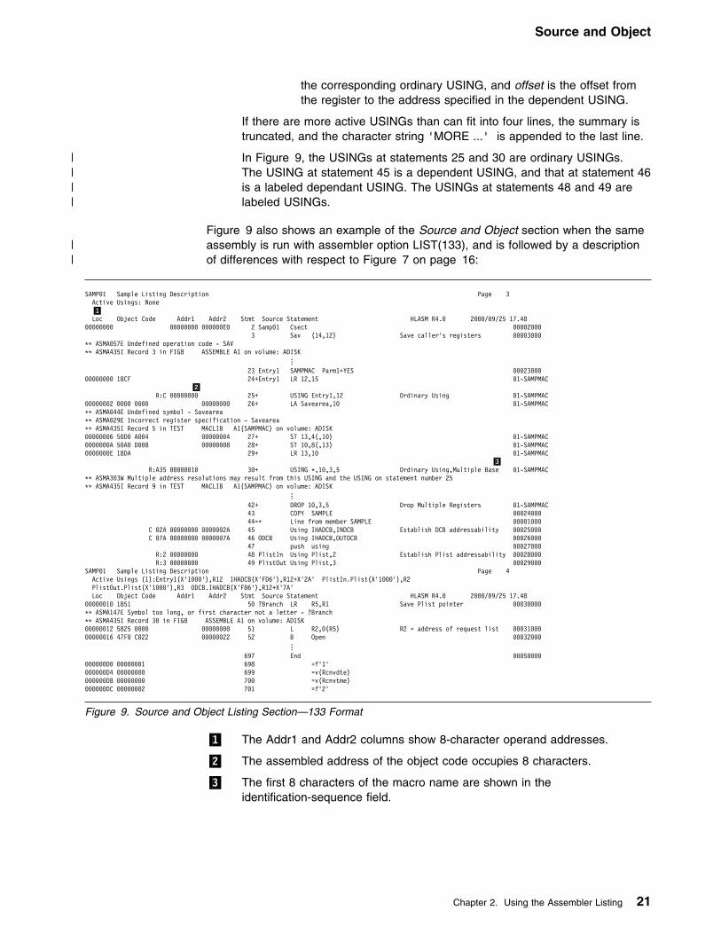
Source and Object
the corresponding ordinary USING, and offset is the offset fromthe register to the address specified in the dependent USING.
If there are more active USINGs than can fit into four lines, the summary istruncated, and the character string 'MORE ...' is appended to the last line.
| In Figure 9, the USINGs at statements 25 and 30 are ordinary USINGs.| The USING at statement 45 is a dependent USING, and that at statement 46| is a labeled dependant USING. The USINGs at statements 48 and 49 are| labeled USINGs.
Figure 9 also shows an example of the Source and Object section when the same| assembly is run with assembler option LIST(133), and is followed by a description| of differences with respect to Figure 7 on page 16:
SAMP91 Sample Listing Description Page 3Active Usings: None
�1�Loc Object Code Addr1 Addr2 Stmt Source Statement HLASM R4.9 2999/99/25 17.48
99999999 99999999 999999E9 2 Samp91 Csect 999929993 Sav (14,12) Save caller's registers 99993999
LL ASMA957E Undefined operation code - SAVLL ASMA435I Record 3 in FIG8 ASSEMBLE A1 on volume: ADISK
... 23 Entry1 SAMPMAC Parm1=YES 9992399999999999 18CF 24+Entry1 LR 12,15 91-SAMPMAC �2� R:C 99999999 25+ USING Entry1,12 Ordinary Using 91-SAMPMAC99999992 9999 9999 99999999 26+ LA Savearea,19 91-SAMPMACLL ASMA944E Undefined symbol - SaveareaLL ASMA929E Incorrect register specification - SaveareaLL ASMA435I Record 5 in TEST MACLIB A1(SAMPMAC) on volume: ADISK99999996 59D9 A994 99999994 27+ ST 13,4(,19) 91-SAMPMAC9999999A 59A9 D998 99999998 28+ ST 19,8(,13) 91-SAMPMAC9999999E 18DA 29+ LR 13,19 91-SAMPMAC �3�
R:A35 99999919 39+ USING L,19,3,5 Ordinary Using,Multiple Base 91-SAMPMACLL ASMA393W Multiple address resolutions may result from this USING and the USING on statement number 25LL ASMA435I Record 9 in TEST MACLIB A1(SAMPMAC) on volume: ADISK
...42+ DROP 19,3,5 Drop Multiple Registers 91-SAMPMAC
43 COPY SAMPLE 9992499944=L Line from member SAMPLE 99991999
C 92A 99999999 9999992A 45 Using IHADCB,INDCB Establish DCB addressability 99925999C 97A 99999999 9999997A 46 ODCB Using IHADCB,OUTDCB 99926999
47 push using 99927999R:2 99999999 48 PlistIn Using Plist,2 Establish Plist addressability 99928999R:3 99999999 49 PlistOut Using Plist,3 99929999
SAMP91 Sample Listing Description Page 4Active Usings (1):Entry1(X'1999'),R12 IHADCB(X'FD6'),R12+X'2A' PlistIn.Plist(X'1999'),R2
PlistOut.Plist(X'1999'),R3 ODCB.IHADCB(X'F86'),R12+X'7A'Loc Object Code Addr1 Addr2 Stmt Source Statement HLASM R4.9 2999/99/25 17.48
99999919 1851 59 ?Branch LR R5,R1 Save Plist pointer 99939999LL ASMA147E Symbol too long, or first character not a letter - ?BranchLL ASMA435I Record 39 in FIG8 ASSEMBLE A1 on volume: ADISK99999912 5825 9999 99999999 51 L R2,9(R5) R2 = address of request list 9993199999999916 47F9 C922 99999922 52 B Open 99932999
... 697 End 99959999999999D9 99999991 698 =f'1'999999D4 99999999 699 =v(Rcnvdte)999999D8 99999999 799 =v(Rcnvtme)999999DC 99999992 791 =f'2'
Figure 9. Source and Object Listing Section—133 Format
�1� The Addr1 and Addr2 columns show 8-character operand addresses.
�2� The assembled address of the object code occupies 8 characters.
�3� The first 8 characters of the macro name are shown in theidentification-sequence field.
Chapter 2. Using the Assembler Listing 21

Ordinary Symbol and Literal Cross Reference
Relocation Dictionary (RLD)This section of the listing describes the relocation dictionary information passed tothe linkage editor or loader, or DFSMS/MVS binder, in the object module.
The entries describe the address constants in the assembled program that areaffected by relocation. This section helps you find relocatable constants in yourprogram.
SAMP91 Relocation Dictionary Page 17 �1� �2� �3� �4� Pos.Id Rel.Id Flags Address HLASM R4.9 2999/99/25 17.4899999991 99999991 9C 999999E999999991 99999994 1C 999999DC99999991 99999995 1C 999999E499999991 99999996 1C 999999E899999991 99999997 1C 999999EC
Figure 10. Relocation Dictionary (RLD) Listing
�1� The external symbol dictionary ID number assigned to the ESD entry for thethe external symbol whose value will be used to relocate the addressconstant.
�2� The external symbol dictionary ID number assigned to the ESD entry for thecontrol section in which the referenced symbol is stored.
�3� The RLD data byte contains the following information:
| 1... .... In load modules, indicates an unresolved reference| .b.. .... If 1, add 4 to the length indicated by the LL bits| ..aa .... Indicates adcon type (00=A, 01=V, 10=Q, 11=CXD)| .... LL.. Length-1 of the adcon| .... ..S. Sign of relocation: 0=+, 1=−| .... ...T 1 means following RLD item has same R and P pointer
�4� The assembled address (in hexadecimal notation) of the field where theaddress constant is stored.
Ordinary Symbol and Literal Cross ReferenceThis section of the listing concerns symbols and literals that are defined and usedin the program.
Ordinary Symbol and Literal Cross Reference Page 29�1� �2� �3� �4� �5� �6� �7� �8�Symbol Length Value Id R Type Defn References HLASM R4.9 2999/99/25 17.48ASMAXINV 1 99999999 99999991 J 152 179U 185U 199UAXPABSREC
4 99999494 FFFFFFFC F 781 473AXPCEND 2 99999498 FFFFFFFC H 782 789AXPDSN 255 99999299 FFFFFFFC C 776 267MAXPERRL 4 9999992C FFFFFFFD F 761 279M 598M
...fl12nd 1 99999989 FFFFFFFF A U 622 414 416FullStatement
89 99999999 FFFFFFFA C 1371 343M 344 344M 344 461M 464MIHADCB 1 99999999 FFFFFFFB J 799 189U 293U 249M 879 928 999 1124 1131 1147 1154 1167 1265
1271 1298 1317 1318 1324 1365 1366IOError 2 99999499 99999991 H 489 252 569jfcb 176 99999958 FFFFFFFF X 599 256 699jix 1 99999999 99999999 C U 214 215
...WA 99999991 A U 292 293U 296D 296 297
| =a(a5,x) 4 99999978 99999991 A 251 133
Figure 11. Ordinary Symbol and Literal Cross Reference
22 HLASM V1R4 Programmer’s Guide
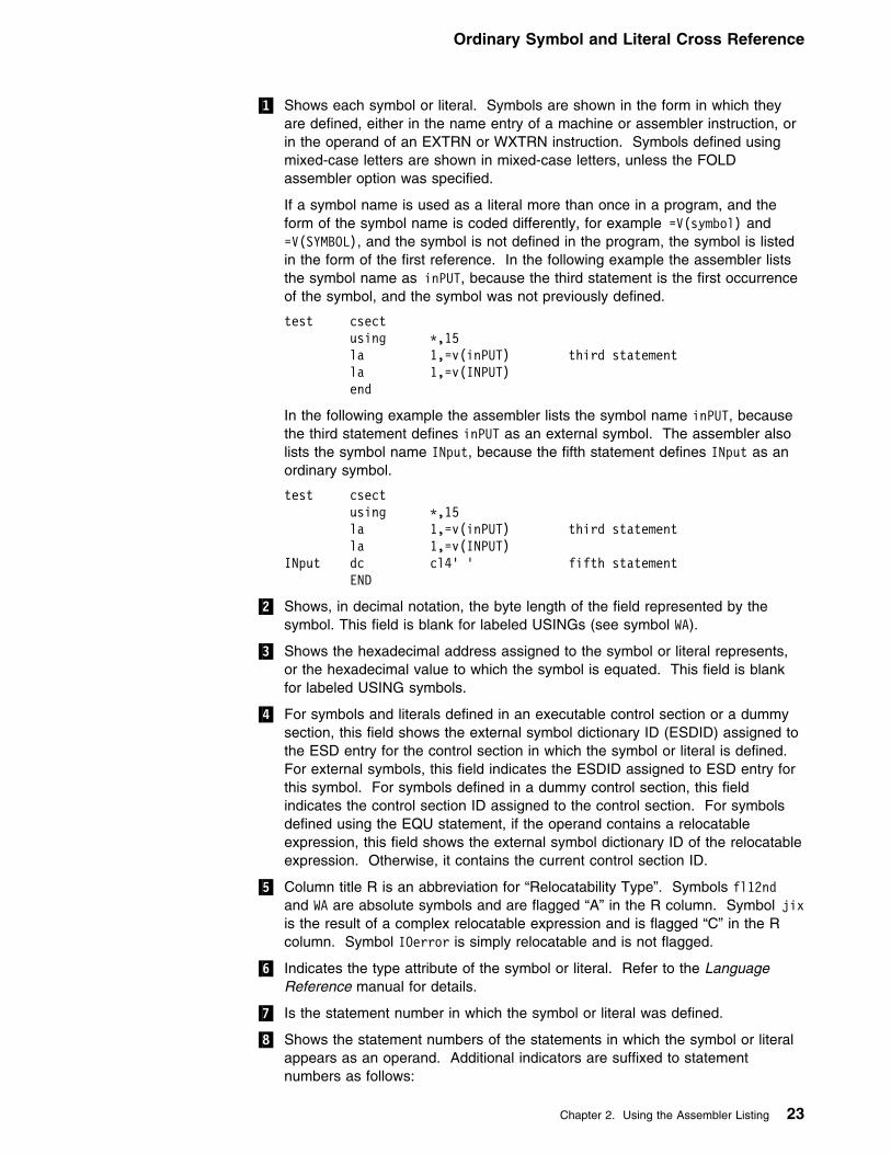
Ordinary Symbol and Literal Cross Reference
�1� Shows each symbol or literal. Symbols are shown in the form in which theyare defined, either in the name entry of a machine or assembler instruction, orin the operand of an EXTRN or WXTRN instruction. Symbols defined usingmixed-case letters are shown in mixed-case letters, unless the FOLDassembler option was specified.
If a symbol name is used as a literal more than once in a program, and theform of the symbol name is coded differently, for example =V(symbol) and=V(SYMBOL), and the symbol is not defined in the program, the symbol is listedin the form of the first reference. In the following example the assembler liststhe symbol name as inPUT, because the third statement is the first occurrenceof the symbol, and the symbol was not previously defined.
test csect using L,15 la 1,=v(inPUT) third statement la 1,=v(INPUT) end
In the following example the assembler lists the symbol name inPUT, becausethe third statement defines inPUT as an external symbol. The assembler alsolists the symbol name INput, because the fifth statement defines INput as anordinary symbol.
test csect using L,15 la 1,=v(inPUT) third statement la 1,=v(INPUT)
INput dc cl4' ' fifth statement END
�2� Shows, in decimal notation, the byte length of the field represented by thesymbol. This field is blank for labeled USINGs (see symbol WA).
�3� Shows the hexadecimal address assigned to the symbol or literal represents,or the hexadecimal value to which the symbol is equated. This field is blankfor labeled USING symbols.
�4� For symbols and literals defined in an executable control section or a dummysection, this field shows the external symbol dictionary ID (ESDID) assigned tothe ESD entry for the control section in which the symbol or literal is defined.For external symbols, this field indicates the ESDID assigned to ESD entry forthis symbol. For symbols defined in a dummy control section, this fieldindicates the control section ID assigned to the control section. For symbolsdefined using the EQU statement, if the operand contains a relocatableexpression, this field shows the external symbol dictionary ID of the relocatableexpression. Otherwise, it contains the current control section ID.
�5� Column title R is an abbreviation for “Relocatability Type”. Symbols fl12ndand WA are absolute symbols and are flagged “A” in the R column. Symbol jixis the result of a complex relocatable expression and is flagged “C” in the Rcolumn. Symbol IOerror is simply relocatable and is not flagged.
�6� Indicates the type attribute of the symbol or literal. Refer to the LanguageReference manual for details.
�7� Is the statement number in which the symbol or literal was defined.
�8� Shows the statement numbers of the statements in which the symbol or literalappears as an operand. Additional indicators are suffixed to statementnumbers as follows:
Chapter 2. Using the Assembler Listing 23

Unreferenced Symbols Defined in CSECTs
B The statement contains a branch instruction, and the relocatablesymbol is used as the branch-target operand address.
D The statement contains a DROP instruction, and the symbol is used inthe instruction operand.
M The instruction causes the contents of a register represented by anabsolute symbol, or a storage location represented by one or morerelocatable symbols, to be modified.
U The statement contains a USING instruction, and the symbol is used inone of the instruction operands.
X The statement contains an EX machine instruction, and the symbol inthe second operand is the symbolic address of the target instruction.
| In the case of a duplicate symbol this column contains the message:
LLLLDUPLICATELLLL
| A symbol name may appear in the cross reference section as both an external| symbol name and an ordinary symbol name. In this situation there is no| duplication.
The following notes apply to the cross reference section:
Notes:
1. Cross reference entries for symbols used in a literal refer to the assembledliteral in the literal pool. Look up the literals in the cross reference to findwhere the symbols are used.
2. A PRINT OFF listing control instruction does not affect the production of thecross reference section of the listing.
3. In the case of an undefined symbol, the columns Length (�2�) and Value (�3�)contain the message:
LLLLUNDEFINEDLLLL
Unreferenced Symbols Defined in CSECTsThis section of the listing shows symbols that have been defined in CSECTs butnot referenced. This helps you remove unnecessary data definitions, and reducethe size of your program. The list of symbols are shown in symbol name order. Toobtain this section of the listing, you need to specify the XREF(UNREFS)assembler option.
SAMP91 Unreferenced Symbols Defined in CSECTs Page 19 �1� �2� Defn Symbol HLASM R4.9 2999/99/25 17.48 47 ODCB 49 PlistIn 59 PlistOut 7 R9 19 R3 16 Unreferenced_Long_Symbol
Figure 12. Unreferenced Symbols Defined in CSECTS
�1� The statement number that defines the symbol.
�2� The name of the symbol.
24 HLASM V1R4 Programmer’s Guide

Macro and Copy Code Cross Reference
Macro and Copy Code Source SummaryThis section of the listing shows the names of the macro libraries from which theassembler read macros or copy code members, and the names of the macros andcopy code members that were read from each library. This section is useful forchecking that you have included the correct version of a macro or copy codemember.
SAMP91 Macro and Copy Code Source Summary Page 27 �1� �2� �3� �4� Con Source Volume Members HLASM R4.9 2999/99/25 17.48 PRIMARY INPUT A AINSERT_TEST_MACRO AL L MAC1
N O SL ST TYPCHKRX X L1 TEST MACLIB A1 ADISK SAMPLE SAMPMAC XIT1 XIT3 L2 DSECT MACLIB A1 ADISK XIT2 L3 OSMACRO MACLIB S2 MNT199 DCBD IHBERMAC SAVE
Figure 13. Macro and Copy Code Source Summary
�1� Contains a number representing the concatenation order of macro and copycode libraries. (This number is not shown when the Source �2� is “PRIMARYINPUT”.) The number is prefixed with “L” which indicates Library. Theconcatenation value is cross-referenced in the Macro and Copy Code CrossReference section.
�2� Shows either the name of each library from which the assembler reads amacro or a copy code member or, for in-line macros, the words “PRIMARYINPUT”.
�3� Shows the volume serial number of the volume on which the library resides.
�4� Shows the names of the macros or copy members that were retrieved from thelibrary.
You can suppress this section of the listing by specifying the NOMXREF assembleroption.
LIBRARY User Exit: If a LIBRARY user exit has been specified for the assembly,and the exit opens the library data set, the exit can return the name of the library tothe assembler. In this case the Macro and Copy Code Source Summary lists thelibrary names returned by the user exit.
Macro and Copy Code Cross ReferenceThis section of the listing shows the names of macros and copy code members andthe statements where the macro or copy code member was called. You can usethe assembler option MXREF(XREF) or MXREF(FULL) to generate this section ofthe listing.
Chapter 2. Using the Assembler Listing 25

Macro and Copy Code Cross Reference
SAMP91 Macro and Copy Code Cross Reference Page 28�1� �2� �3� �4� �5�Macro Con Called By Defn References HLASM R4.9 2999/99/25 17.48A PRIMARY INPUT 826 971, 973, 998AINSERT_TEST_MACRO PRIMARY INPUT 3 16AL PRIMARY INPUT 873 981, 983DCBD L3 PRIMARY INPUT - 113IHBERMAC L3 DCBD - 113L PRIMARY INPUT 816 966, 968MAC1 PRIMARY INPUT 28 36N PRIMARY INPUT 933 991O PRIMARY INPUT 953 993SAMPLE L1 PRIMARY INPUT - 85C �6�SAMPMAC L1 PRIMARY INPUT - 64SAVE L3 PRIMARY INPUT - 42SL PRIMARY INPUT 883 986, 988ST PRIMARY INPUT 836 976, 978TYPCHKRX PRIMARY INPUT 745 775, 845, 892X PRIMARY INPUT 943 996XIT1 L1 PRIMARY INPUT - 39CXIT2 L2 PRIMARY INPUT - 32CXIT3 L1 PRIMARY INPUT - 34C
Figure 14. Macro and Copy Code Cross Reference
�1� The macro or copy code member name.
�2� Shows the value representing the input source concatenation, as listed in theMacro and Copy Code Source Summary (refer to Figure 13 on page 25) andunder the sub-heading “Datasets Allocated for this Assembly” in the DiagnosticCross Reference and Assembler Summary (refer to Figure 23 on page 33).
�3� Shows either the name of the macro that calls this macro or copy codemember, or the words “PRIMARY INPUT” indicating the macro or copy codemember was called directly from the primary input source. If you use theCOPY instruction to copy a macro definition, then references to the macro areshown as called by “PRIMARY INPUT”.
�4� Either:
� The statement number for macros defined in the primary input file,or� A dash (–) indicating the macro or copy code member was retrieved from a
library.
�5� The statement number that contains the macro call or COPY instruction.
Lookahead Processing: If a COPY instruction is encountered duringlookahead, this is the number of the statement that causes lookaheadprocessing to commence.
PCONTROL(MCALL) Assembler Option: If you specify thePCONTROL(MCALL) assembler option, and you copy a macro definition froman inner macro, the number shown against the copied member is one lessthan the statement number containing the inner macro call instruction. See“Effects of LIBMAC and PCONTROL(MCALL) Options” on page 27 forexamples of assemblies using different combinations of the LIBMAC andPCONTROL(MCALL) options.
�6� Statement numbers have a suffix of “C” when the reference is to a membernamed on a COPY instruction.
Figure 15 on page 27 shows the format of the Macro and Copy Code CrossReference when you specify the assembler option, LIBMAC.
26 HLASM V1R4 Programmer’s Guide

Macro and Copy Code Cross Reference
SAMP91 Macro and Copy Code Cross Reference Page 81Macro Con Called By Defn References HLASM R4.9 2999/99/25 17.48 �1�A PRIMARY INPUT 3667 3812, 3814, 3839AINSERT_TEST_MACRO PRIMARY INPUT 3 16AL PRIMARY INPUT 3714 3822, 3824DCBD L3 PRIMARY INPUT 224X 2329IHBERMAC L3 DCBD 2331X 2954L PRIMARY INPUT 3657 3897, 3899MAC1 PRIMARY INPUT 28 36N PRIMARY INPUT 3774 3832O PRIMARY INPUT 3794 3834SAMPLE L1 PRIMARY INPUT - 195CSAMPMAC L1 PRIMARY INPUT 153X 174SAVE L3 PRIMARY INPUT 43X 139SL PRIMARY INPUT 3724 3827, 3829ST PRIMARY INPUT 3677 3817, 3819TYPCHKRX PRIMARY INPUT 3586 3616, 3686, 3733X PRIMARY INPUT 3784 3837XIT1 L1 PRIMARY INPUT - 39CXIT2 L2 PRIMARY INPUT - 32CXIT3 L1 PRIMARY INPUT - 34C
Figure 15. Macro and Copy Code Cross Reference—with LIBMAC Option
�1� The “X” flag indicates the macro was read from a macro library andimbedded in the input source program immediately preceding the invocationof that macro. For example, in Figure 15, you can see that SAMPMAC wascalled by the PRIMARY INPUT stream from LIBRARY L1, at statement number174, after being imbedded in the input stream at statement number 153. See“Effects of LIBMAC and PCONTROL(MCALL) Options” for examples ofassemblies using different combinations of the LIBMAC andPCONTROL(MCALL) options.
You can suppress this section of the listing by specifying the NOMXREF assembleroption.
Effects of LIBMAC and PCONTROL(MCALL) OptionsWhen you specify different combinations of the LIBMAC and PCONTROL(MCALL)assembler options to assemble the same source program, the definition statementand reference statement numbers can be different in each assembly listing.
The example that follows shows how these options affect the output from anassembly of the same source program. The source program is coded as follows:
MACOUTER END
The assembly of this program uses the following library members:
MACOUTER: A macro definition that issues a call to macro MACINNER.
MACINNER: A macro definition that copies member COPYCODE.
COPYCODE: A member containing an MNOTE instruction.
The following four figures illustrate the effects of using the various combinations ofthe LIBMAC and PCONTROL(MCALL) assembler options.
| Figure 16 on page 28 shows the output when you specify the LIBMAC and| PCONTROL(MCALL) options.
Chapter 2. Using the Assembler Listing 27
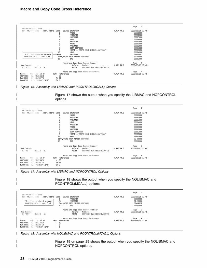
Macro and Copy Code Cross Reference
| Page 2| Active Usings: None| Loc Object Code Addr1 Addr2 Stmt Source Statement HLASM R4.9 2999/99/25 17.48| 1 MACRO 99991999| 2 MACOUTER 99992999| 3 MACINNER 99993999| 4 MEND 99994999| 5 MACOUTER 99991999| 6 MACRO 99991999| 7 MACINNER 99992999| 8 COPY COPYCODE 99993999| 9 MNOTE L,'MNOTE FROM MEMBER COPYCODE' 99991999| ┌────────────────────────────┐ 19 MEND 99994999| │ This line produced because │────�11+ MACINNER 91-99993| │ PCONTROL(MCALL) specified │ 12+L,MNOTE FROM MEMBER COPYCODE 92-99998| └────────────────────────────┘ 13 END 99992999
| Macro and Copy Code Source Summary Page 3| Con Source Volume Members HLASM R4.9 2999/99/25 17.48| L1 TEST MACLIB A1 ADISK COPYCODE MACINNER MACOUTER
| Macro and Copy Code Cross Reference Page 4| Macro Con Called By Defn References HLASM R4.9 2999/99/25 17.48| COPYCODE L1 MACINNER - 8C| MACINNER L1 MACOUTER 7X 11| MACOUTER L1 PRIMARY INPUT 2X 5
| Figure 16. Assembly with LIBMAC and PCONTROL(MCALL) Options
| Figure 17 shows the output when you specify the LIBMAC and NOPCONTROL| options.
| Page 2| Active Usings: None| Loc Object Code Addr1 Addr2 Stmt Source Statement HLASM R4.9 2999/99/25 17.48| 1 MACRO 99991999| 2 MACOUTER 99992999| 3 MACINNER 99993999| 4 MEND 99994999| 5 MACOUTER 99991999| 6 MACRO 99991999| 7 MACINNER 99992999| 8 COPY COPYCODE 99993999| 9 MNOTE L,'MNOTE FROM MEMBER COPYCODE' 99991999| 19 MEND 99994999| 11+L,MNOTE FROM MEMBER COPYCODE 92-99998| 12 END 99992999
| Macro and Copy Code Source Summary Page 3| Con Source Volume Members HLASM R4.9 2999/99/25 17.48| L1 TEST MACLIB A1 ADISK COPYCODE MACINNER MACOUTER
| Macro and Copy Code Cross Reference Page 4| Macro Con Called By Defn References HLASM R4.9 2999/99/25 17.48| COPYCODE L1 MACINNER - 8C| MACINNER L1 MACOUTER 7X 19| MACOUTER L1 PRIMARY INPUT 2X 5
| Figure 17. Assembly with LIBMAC and NOPCONTROL Options
| Figure 18 shows the output when you specify the NOLIBMAC and| PCONTROL(MCALL) options.
| Page 2| Active Usings: None| Loc Object Code Addr1 Addr2 Stmt Source Statement HLASM R4.9 2999/99/25 17.48| ┌────────────────────────────┐ 1 MACOUTER 99991999| │ This line produced because │────�2+ MACINNER 91-MACOU| │ PCONTROL(MCALL) specified │ 3+L,MNOTE FROM MEMBER COPYCODE 92-MACIN| └────────────────────────────┘ 4 END 99992999
| Macro and Copy Code Source Summary Page 3| Con Source Volume Members HLASM R4.9 2999/99/25 17.48| L1 TEST MACLIB A1 ADISK COPYCODE MACINNER MACOUTER
| Macro and Copy Code Cross Reference Page 4| Macro Con Called By Defn References HLASM R4.9 2999/99/25 17.48| COPYCODE L1 MACINNER - 1C| MACINNER L1 MACOUTER - 2| MACOUTER L1 PRIMARY INPUT - 1
| Figure 18. Assembly with NOLIBMAC and PCONTROL(MCALL) Options
| Figure 19 on page 29 shows the output when you specify the NOLIBMAC and| NOPCONTROL options.
28 HLASM V1R4 Programmer’s Guide

DSECT Cross Reference
| Page 2| Active Usings: None| Loc Object Code Addr1 Addr2 Stmt Source Statement HLASM R4.9 2999/99/25 17.48| 1 MACOUTER 99991999| 2+L,MNOTE FROM MEMBER COPYCODE 92-MACIN| 3 END 99992999
| Macro and Copy Code Source Summary Page 3| Con Source Volume Members HLASM R4.9 2999/99/25 17.48| L1 TEST MACLIB A1 ADISK COPYCODE MACINNER MACOUTER
| Macro and Copy Code Cross Reference Page 4| Macro Con Called By Defn References HLASM R4.9 2999/99/25 17.48| COPYCODE L1 MACINNER - 1C| MACINNER L1 MACOUTER - 1| MACOUTER L1 PRIMARY INPUT - 1
| Figure 19. Assembly with NOLIBMAC and NOPCONTROL Options
DSECT Cross ReferenceThis section of the listing shows the names of all internal or external dummysections defined in the program, and the number of the statement where thedefinition of the dummy section began.
Dsect Cross Reference Page 26 �1� �2� �3� �4�Dsect Length Id Defn HLASM R4.9 2999/99/25 17.48AXPRIL 9999993C FFFFFFFD 655AXPSIL 99999419 FFFFFFFC 771AXPXITP 99999914 FFFFFFFE 641IHADCB 99999969 FFFFFFFB 799Statement 99999959 FFFFFFFA 1379WORKAREA 999991A8 FFFFFFFF 595
Figure 20. DSECT Cross Reference
�1� Shows the name of each dummy section defined in your program.
�2� Shows, in hexadecimal notation, the assembled byte length of the dummysection.
�3� For external dummy sections, this field indicates the external symbol dictionaryID assigned to the ESD entry for the external dummy section. For internaldummy sections, this field indicates the control section ID assigned to thedummy control section. You can use this field in conjunction with the ID fieldin the Ordinary Symbol and Literal Cross Reference (see Figure 11 onpage 22) to relate symbols to a specific section.
�4� Shows the number of the statement where the definition of the dummy sectionbegan.
You can suppress this section of the listing by specifying the NODXREF assembleroption.
Chapter 2. Using the Assembler Listing 29

USING Map
USING MapThis section of the listing shows a summary of the USING, DROP, PUSH USING,and POP USING instructions used in your program.
Using Map Page 27 HLASM R4.9 2999/99/25 17.48 �1� �2� �3� �4� �5� �6� �7� �8� �9� �1�� �11� �12� Stmt -----Location----- Action ----------------Using----------------- Reg Max Last Label and Using Text Count Id Type Value Range Id Disp Stmt
179 99999999 99999991 USING ORDINARY 99999999 99991999 99999991 15 92A 171 asmaxinv,r15175 99999939 99999991 DROP 15 r15185 99999934 99999991 USING ORDINARY 99999999 99991999 99999991 12 999 asmaxinv,r12186 99999934 99999991 USING ORDINARY 99999999 99991999 FFFFFFFD 7 934 598 axpril,r97187 99999934 99999991 USING ORDINARY 99999999 99991999 FFFFFFFA 8 948 464 Statement,r98188 99999934 99999991 USING ORDINARY 99999999 99991999 FFFFFFFC 19 494 474 axpsil,r19189 99999934 99999991 USING ORDINARY 99999999 99991999 FFFFFFFB 11 952 465 ihadcb,r11199 99999934 99999991 USING ORDINARY 99999999 99991999 99999991 12 589 519 asmaxinv,r12292 9999994E 99999991 USING LABELED 99999999 99991999 FFFFFFFF 1 999 WA.WorkArea,r91293 9999994E 99999991 USING LAB+DEPND +9999914A 99999EB6 FFFFFFFB 1 local.ihadcb,WA.mydcb
| 294 9999994E 99999991 PUSH295 99999954 99999991 DROP 1 local
| 212 9999996A 99999991 POP 1 WA213 9999996A 99999991 USING ORDINARY 99999999 99991999 FFFFFFFF 13 14A 527 WorkArea,r13
| 214 9999996A 99999991 USING ORDINARY 99999999 99991999
Figure 21. USING Map
�1� Shows the number of the statement that contains the USING, DROP, PUSHUSING, or POP USING instruction.
�2� Shows the value of the location counter when the USING, DROP, PUSHUSING, or POP USING statement was encountered.
�3� Shows the value of the ESDID of the current section when the USING,DROP, PUSH USING or POP USING statement was encountered.
�4� Shows whether the instruction was a USING, DROP, PUSH, or POPinstruction.
�5� For USING instructions, this field indicates whether the USING is an ordinaryUSING, a labeled USING, a dependent USING, or a labeled dependentUSING.
�6� For ordinary and labeled USING instructions, this field indicates the baseaddress specified in the USING. For dependent USING instructions, thisfield is prefixed with a plus sign (+) and indicates the hexadecimal offset ofthe address of the second operand from the base address specified in thecorresponding ordinary USING.
�7� Shows the range of the USING. For more information, see the description ofthe USING statement in the HLASM Language Reference.
�8� For USING instructions, this field indicates the ESDID of the sectionspecified on the USING statement.
�9� For ordinary and labeled USING instructions, and for DROP instructions, thisfield indicates the register or registers specified in the instruction. There is aseparate line in the USING map for each register specified in the instruction.If the DROP instruction has no operands, all registers and labels aredropped and this field contains two asterisks (LL).
For dependent USING instructions, the field indicates the register for thecorresponding ordinary USING instruction that is used to resolve theaddress. If the corresponding ordinary USING instruction has multipleregisters specified, only the first register used to resolve the address isdisplayed.
30 HLASM V1R4 Programmer’s Guide

General Purpose Register Cross Reference
�1�� For each base register specified in an ordinary USING instruction or alabeled USING instruction, this field shows the maximum displacementcalculated by the assembler when resolving symbolic addresses intobase-displacement form using that base register.
�11� For ordinary and labeled USING instructions, this field indicates thestatement number of the last statement that used the specified base registerto resolve an address. Where an ordinary USING instruction is used toresolve a dependent USING, the statement number printed reflects the useof the register to resolve the dependent USING.
�12� For USING and DROP instructions, this field lists the text specified on theUSING or DROP instruction, truncated if necessary. For labeled USINGinstructions, the text is preceded by the label specified for the USING.
If a DROP instruction drops more than one register or labeled USING, thetext for each register or labeled USING is printed on the line correspondingto the register that is dropped.
You can suppress this section of the listing by specifying either of the assembleroptions, USING(NOMAP) or NOUSING.
General Purpose Register Cross ReferenceThis section of the listing shows all references in the program to each of thegeneral registers. Additional flags indicate the type of reference. This is a usefultool in checking the logic of your program; it helps you see if your use of registersis in order.
General Purpose Register Cross Reference Page 8Register References (M=modified, B=branch, U=USING, D=DROP, N=index) HLASM R4.9 2999/99/25 17.48 �1� �2� 9(9) 115
1(1) 118 129 121 122 124 126 127 128 139 131 133 135 136 1372(2) 36 37 38 39 49 41 42 43 44M 45 46 47 48 49 59 51
52M 53 54 55M 56 57 58 59M 69 61 62 63 64 65 66 6768 69 79 71 72M 73 74 75 76 77 78 79 89 81 82 8384 85 86 87 88 89M 99 91 92 93M 94 95 96 97 98 99199 191 192 193 194 195 196 197 198 199 119 111 112
3(3) (no references identified) �3� 4(4) 16M 281 5(5) 283
6(6) 66N 167N 179 171 174 178 189N 199 192 193 194 197 199 299 291N 7(7) 283 8(8) 283
9(9) 224 225 226 227 19(A) 255U 342D
11(B) 237 238 239N 249 241 242 243N 244 245N 271 12(C) 8U
13(D) 261 262 263 264 265 26614(E) 299 219 211 212 213 214 215 216
15(F) 34 144
Figure 22. General Purpose Register Cross Reference
�1� Lists the sixteen general registers (0–15).
�2� The statements within the program that reference the register. Additionalindicators are suffixed to the statement numbers as follows:
(blank) Referenced
Chapter 2. Using the Assembler Listing 31
Diagnostic Cross Reference and Assembler Summary
M Modified
B Used as a branch address
U Used in USING statement
D Used in DROP statement
N Used as an index register
�3� The assembler indicates when it has not detected any references to aregister.
Note: The implicit use of a register to resolve a symbol to a base anddisplacement does not create a reference in the General Purpose Register CrossReference.
Diagnostic Cross Reference and Assembler SummaryThis section of the listing summarizes the error diagnostic messages issued duringthe assembly, and provides statistics about the assembly.
The sample listing shown in Figure 23 on page 33 contains a combination of MVSand CMS data sets to show examples of the differences in data set information.
Note: For a complete list of the diagnostic messages issued by the assembler,see Appendix G, “High Level Assembler Messages” on page 309.
32 HLASM V1R4 Programmer’s Guide
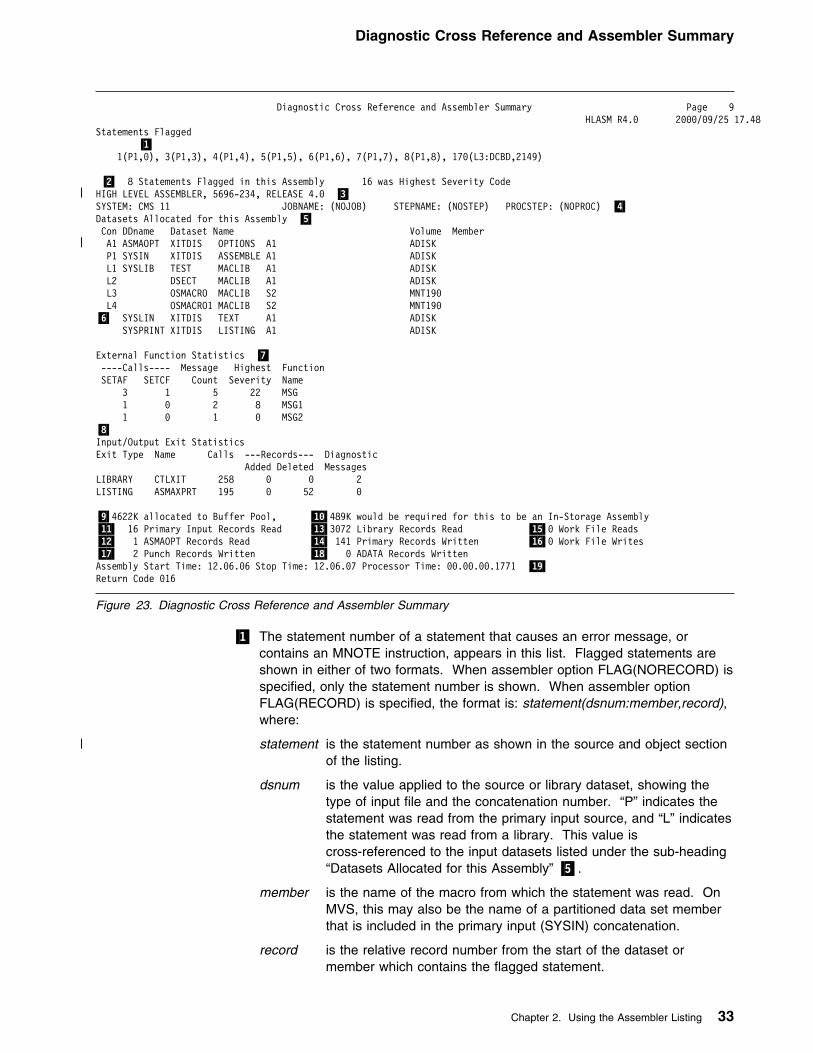
Diagnostic Cross Reference and Assembler Summary
Diagnostic Cross Reference and Assembler Summary Page 9 HLASM R4.9 2999/99/25 17.48Statements Flagged �1�
1(P1,9), 3(P1,3), 4(P1,4), 5(P1,5), 6(P1,6), 7(P1,7), 8(P1,8), 179(L3:DCBD,2149)
�2� 8 Statements Flagged in this Assembly 16 was Highest Severity Code| HIGH LEVEL ASSEMBLER, 5696-234, RELEASE 4.9 �3�
SYSTEM: CMS 11 JOBNAME: (NOJOB) STEPNAME: (NOSTEP) PROCSTEP: (NOPROC) �4�Datasets Allocated for this Assembly �5� Con DDname Dataset Name Volume Member
| A1 ASMAOPT XITDIS OPTIONS A1 ADISK P1 SYSIN XITDIS ASSEMBLE A1 ADISK L1 SYSLIB TEST MACLIB A1 ADISK L2 DSECT MACLIB A1 ADISK L3 OSMACRO MACLIB S2 MNT199 L4 OSMACRO1 MACLIB S2 MNT199�6� SYSLIN XITDIS TEXT A1 ADISK SYSPRINT XITDIS LISTING A1 ADISK
External Function Statistics �7� ----Calls---- Message Highest FunctionSETAF SETCF Count Severity Name 3 1 5 22 MSG 1 9 2 8 MSG1 1 9 1 9 MSG2�8�Input/Output Exit StatisticsExit Type Name Calls ---Records--- Diagnostic Added Deleted MessagesLIBRARY CTLXIT 258 9 9 2LISTING ASMAXPRT 195 9 52 9
�9�4622K allocated to Buffer Pool, �1��489K would be required for this to be an In-Storage Assembly�11� 16 Primary Input Records Read �13�3972 Library Records Read �15�9 Work File Reads�12� 1 ASMAOPT Records Read �14� 141 Primary Records Written �16�9 Work File Writes�17� 2 Punch Records Written �18� 9 ADATA Records WrittenAssembly Start Time: 12.96.96 Stop Time: 12.96.97 Processor Time: 99.99.99.1771 �19�Return Code 916
Figure 23. Diagnostic Cross Reference and Assembler Summary
�1� The statement number of a statement that causes an error message, orcontains an MNOTE instruction, appears in this list. Flagged statements areshown in either of two formats. When assembler option FLAG(NORECORD) isspecified, only the statement number is shown. When assembler optionFLAG(RECORD) is specified, the format is: statement(dsnum:member,record),where:
| statement is the statement number as shown in the source and object sectionof the listing.
dsnum is the value applied to the source or library dataset, showing thetype of input file and the concatenation number. “P” indicates thestatement was read from the primary input source, and “L” indicatesthe statement was read from a library. This value iscross-referenced to the input datasets listed under the sub-heading“Datasets Allocated for this Assembly” �5�.
member is the name of the macro from which the statement was read. OnMVS, this may also be the name of a partitioned data set memberthat is included in the primary input (SYSIN) concatenation.
record is the relative record number from the start of the dataset ormember which contains the flagged statement.
Chapter 2. Using the Assembler Listing 33

Diagnostic Cross Reference and Assembler Summary
�2� The number of statements flagged, and the highest non-zero severity code ofall messages issued. The highest severity code is equal to the assemblerreturn code.
If no statements are flagged, the following statement is printed:
No Statements Flagged in this Assembly
If the assembly completes with a non-zero return code, and there are noflagged statements, it indicates there is a diagnostic message in the OptionSummary section of the listing (see Figure 2 on page 10).
For a complete discussion of how error messages and MNOTEs are handled,see Chapter 6, “Diagnosing Assembly Errors” on page 143.
�3� The current release of High Level Assembler and the last PTF applied.
�4� Provides information about the system on which the assembly was run. Theseare:
� The name and level of the operating system used to run the assembly.
� The jobname for the assembly job. If the jobname is not available,“(NOJOB)” is printed.
� The stepname for the assembly job. If the stepname is not available,“(NOSTEP)” is printed.
� The procedure name for the assembly job. If the procedure name is notavailable, “(NOPROC)” is printed.
�5� On MVS and CMS, all data sets used in the assembly are listed by theirstandard ddname. The data set information includes the data set name, andthe serial number of the volume containing the data set. On MVS, the data setinformation may also include the name of a member of a partitioned data set(PDS).
If a user exit provides the data set information, then the data set name is thevalue extracted from the Exit-Specific Information block described in theHLASM Programmer's Guide.
The “Con” column shows the concatenation value assigned for each input dataset. You use this value to cross-reference flagged statements, and macrosand copy code members listed in the Macro and Copy Code Cross Referencesection.
MVS: On MVS, the data set name for all data sets is extracted from the MVSjob file control block (JFCB). If the data set is a JES2 spool file, for example,the data set name is the name allocated by JES2. If the data set is allocatedto DUMMY, or NULLFILE, the data set name is shown as NULLFILE.
CMS: On CMS, the data set name is assigned one of the values shown inFigure 24.
34 HLASM V1R4 Programmer’s Guide
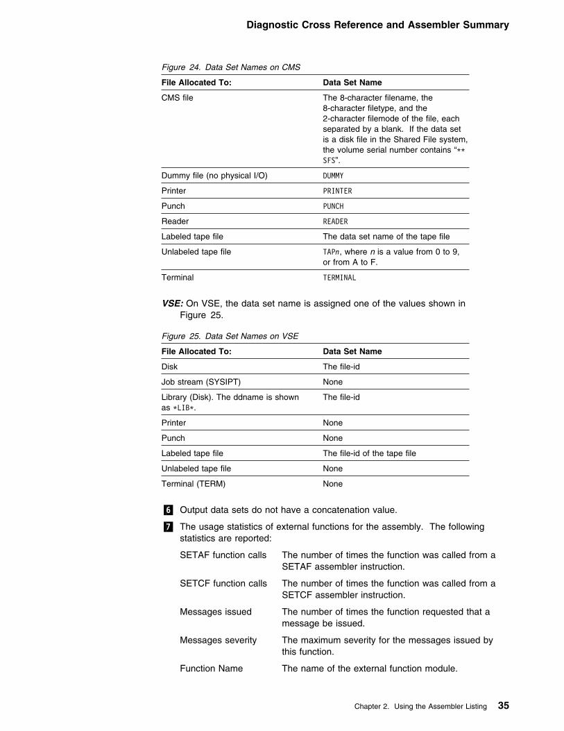
Diagnostic Cross Reference and Assembler Summary
VSE: On VSE, the data set name is assigned one of the values shown inFigure 25.
�6� Output data sets do not have a concatenation value.
�7� The usage statistics of external functions for the assembly. The followingstatistics are reported:
SETAF function calls The number of times the function was called from aSETAF assembler instruction.
SETCF function calls The number of times the function was called from aSETCF assembler instruction.
Messages issued The number of times the function requested that amessage be issued.
Messages severity The maximum severity for the messages issued bythis function.
Function Name The name of the external function module.
Figure 24. Data Set Names on CMS
File Allocated To: Data Set Name
CMS file The 8-character filename, the8-character filetype, and the2-character filemode of the file, eachseparated by a blank. If the data setis a disk file in the Shared File system,the volume serial number contains “LLSFS”.
Dummy file (no physical I/O) DUMMY
Printer PRINTER
Punch PUNCH
Reader READER
Labeled tape file The data set name of the tape file
Unlabeled tape file TAPn, where n is a value from 0 to 9,or from A to F.
Terminal TERMINAL
Figure 25. Data Set Names on VSE
File Allocated To: Data Set Name
Disk The file-id
Job stream (SYSIPT) None
Library (Disk). The ddname is shownas LLIBL.
The file-id
Printer None
Punch None
Labeled tape file The file-id of the tape file
Unlabeled tape file None
Terminal (TERM) None
Chapter 2. Using the Assembler Listing 35

Diagnostic Cross Reference and Assembler Summary
�8� The usage statistics of the I/O exits you specified for the assembly. If you donot specify an exit, the assembler does not produce any statistics. Thefollowing statistics are reported:
Exit Type The type of exit.
Name The name of the exit module as specified in the EXITassembler option.
Calls The number of times the exit was called.
Records The number of records added and deleted by the exit.
Diagnostic Messages The number of diagnostic messages printed, as a resultof exit processing.
All counts are shown right justified and leading zeroes are suppressed, unlessthe count is zero.
�9� The amount of storage allocated to the buffer pool.
�1�� The minimum value for the SIZE option that the assembler estimates wouldresult in the assembly being performed in storage. This may be less than theamount of storage allocated to the assembler. If the amount of storage in thebuffer pool is not enough for an in-storage assembly, this value contains theassembler's approximation of the amount of storage required.
�11� The number of primary input records read by the assembler. This count doesnot include any records read or discarded by the SOURCE user exit.
| �12� The number of records read from the ASMAOPT file (MVS and CMS) or the| Librarian member (VSE) by the assembler.
�13� The number of records read from the libraries allocated to SYSLIB on MVSand CMS, or assigned to the Librarian on VSE. This count does not includeany records read or discarded by the LIBRARY user exit.
�14� The count of the actual number of records generated by the assembler. If youhave used the SPACE n assembler instruction, the count may be less than thetotal number of printed and blank lines appearing in the listing. For a SPACEn that does not cause an eject, the assembler inserts n blank lines in the listingby generating n/3 blank records, rounded to the next lower integer if a fractionresults. For a SPACE 2, no blank records are generated. The assemblerdoes not generate a blank record to force a page eject.
This count does not include any listing records generated or discarded by theLISTING user exit.
�15� The number of reads from the work file (SYSUT1).
�16� The number of writes to the work file (SYSUT1).
�17� The number of object records written. This count does not include any objectrecords generated or discarded by the OBJECT or PUNCH user exits.
�18� The number of ADATA records written to the associated data file.
�19� On VSE, the assembly start and stop times in hours, minutes and seconds.
On MVS and CMS, the assembly start and stop times in hours, minutes andseconds and the approximate amount of processor time used for the assembly,in hours, minutes, and seconds to four decimal places.
The assembly start time does not include the time used during assemblyinitialization, which allocates main storage and data sets and processes the
36 HLASM V1R4 Programmer’s Guide

Diagnostic Cross Reference and Assembler Summary
assembler invocation parameters. The assembly stop time does not includethe time used during assembly termination, which deallocates main storageand data sets.
On MVS and CMS, High Level Assembler provides a sample listing exit whichallows you to suppress the Diagnostic Cross Reference and Assembler Summary.See Appendix J, “Sample LISTING User Exit (MVS and CMS)” on page 369.
Chapter 2. Using the Assembler Listing 37

Precedence of Assembler Options
Chapter 3. Controlling Your Assembly with Options
High Level Assembler offers a number of optional facilities. For example, you cansuppress printing of the assembly listing or parts of the listing, and you can specifywhether you want an object module or an associated data file. There are two typesof options:
� Simple pairs of keywords: A positive form (such as OBJECT) requests a facility,and an alternate negative form (such as NOOBJECT) excludes the facility.
� Keywords, such as LINECOUNT(50), that permit you to assign a value to afunction.
| High Level Assembler accepts options from five different sources:
| � External file (MVS and CMS)| � Library member (VSE)| � Invocation parameter| � JCL Option (VSE)| � *PROCESS statement
| This chapter describes the different sources for assembler options, each assembleroption, and when you can use the options. Each option has a default value thatthe assembler uses if you do not specify an alternative value. The way in whichthe default values are arrived at is explained under “Default Options” on page 41.
The Sources of Assembler OptionsThis section describes in detail the different sources of assembler options, and thegeneral rules for specifying the options.
Before describing the sources, the section sets out the rules of precedence bywhich the assembler works out what to do when an option is specified two or moretimes with differing values.
Precedence of Assembler OptionsAssembler options are recognized in this order of precedence (highest to lowest):
1. Fixed installation default options| 2. Options on *PROCESS OVERRIDE statements| 3. Options in the ASMAOPT file (CMS or MVS) or library member (VSE)
4. Invocation optionsa. Options on the JCL PARM parameter of the EXEC statement on MVS and
VSE, or the ASMAHL command on CMSb. Options on the JCL OPTION statement (VSE)
| c. Options specified via the STDOPT (Standard JCL Options) command| (VSE)
5. Options on *PROCESS statements6. Non-fixed installation default options
| You can specify an option as often as you want, and in as many sources as you| want. However, this may mean that you have specified the positive and negative| form of an option (for keyword pairs), or two or more different values (for a value| keyword). These option specifications are “conflicting” options. If all specifications
38 Copyright IBM Corp. 1982, 2000

| of a particular option are at the same level of precedence, the last specification| takes effect, and a warning message is issued. If some conflicting specifications| are at different levels of precedence, then the specification at the higher order of| precedence takes effect, and (in general) the assembler issues a warning message| for each option that is not accepted. A warning message is not issued if the higher| level of precedence is a *PROCESS OVERRIDE statement, unless the option| cannot be set by a *PROCESS statement.
Fixed Installation Default OptionsIf an option was specified on the DELETE operand of the ASMAOPT macro duringinstallation, you cannot change the option when you invoke the assembler.
| *PROCESS OVERRIDE Statement Options| If the keyword OVERRIDE is added to a process (*PROCESS) statement, then the| nominated assembler option is not overridden by specifications at a lower level of| precedence. Furthermore, if there is a conflicting specification at a lower level of| precedence, the assembler does not issue a warning message.
| If an option specified on the process statement is an option listed in “*Process| Statement Options” on page 40, and a different value is supplied as an ASMAOPT| or invocation option, then the ASMAOPT or invocation value is accepted, and the| assembler issues a warning message.
| ASMAOPT Options| High Level Assembler accepts options from an external file (MVS and CMS) with| the DDname ASMAOPT or library member (VSE) with the name and type| ASMAOPT.USER. The file or library member may contain multiple records. All| records are read from the file or library member.
| The contents of each record are used to build an internal buffer containing the| complete option list. Each record is processed until the first space is encountered,| unless the option being processed is a SYSPARM option which is enclosed in| quotes. The assembler appends the options string from each record, separating| the strings with commas. For example, these records:
| ADATA,MXREF| SYSPARM(TESTPARM)| XREF(FILL)
| generate this option list:
| ADATA,MXREF,SYSPARM(TESTPARM),XREF(FULL)
Invocation Options| The way you specify the invocation options depends on the environment in which
High Level Assembler is running.
On MVS batch, you select the options by specifying them in the PARMfield of the JCL EXEC statement that invokes the assembler. For example:
//ASSEMBLE EXEC PGM=ASMA99,PARM=‘LIST(133),DBCS’
You can also use catalogued procedures to invoke the assembler. To overrideoptions in a cataloged procedure, you must include the PARM field in the EXEC
Chapter 3. Controlling Your Assembly with Options 39

statement that invokes the procedure. If the cataloged procedure contains morethan one step, you must also qualify the keyword parameter (PARM) with the nameof the step within the procedure that invokes the assembler. For example:// EXEC ASMACG,PARM.C=‘LIST(133),DBCS’
For more examples on how to specify options in a cataloged procedure, see“Overriding Statements in Cataloged Procedures” on page 180.
On TSO, you select the options by specifying them in the second parameter of theTSO CALL command that invokes the assembler. For example:CALL ‘SYS1.LINKLIB(ASMA99)’ ‘LIST(133),DBCS’
You select the options by specifying them after the left parenthesis onthe CMS ASMAHL command that invokes the assembler. For example:ASMAHL filename (LIST(133) DBCS[)]
In batch, you select the options by specifying them in the PARM field ofthe EXEC JCL statement that invokes the assembler. You can also specify someof the options on the JCL OPTION statement. For example:
// OPTION TERM// EXEC ASMA99,SIZE=ASMA99,PARM=‘LIST,DBCS’
VSE ICCF: On ICCF, you select the options by specifying them in the PARM fieldof the job entry statement /LOAD that invokes the assembler. For example:/LOAD ASMA99 PARM=‘LIST,DBCS’
*Process Statement OptionsProcess (*PROCESS) statements let you specify assembler options in yourassembler source program. You can include them in the primary input data set orprovide them from a SOURCE user exit.
| If you add the OVERRIDE keyword, then the option has a higher precedence than| values set as default and invocation options (see “*PROCESS OVERRIDE| Statement Options” on page 39).
Some options cannot be set by a process statement. These are:
ADATA LANGUAGE PRINT (CMS)ASA (MVS and CMS) LINECOUNT SIZEDECK LIST SYSPARM
DISK (CMS) NOPRINT (CMS) TERM EXIT OBJECT TRANSLATE
| GOFF (MVS and CMS) OPTABLE XOBJECT (MVS and CMS)
If you specify one of these options on a normal process statement, the assemblerissues a warning message.
Refer to the Language Reference for a description of the *PROCESS statement.
40 HLASM V1R4 Programmer’s Guide

Default OptionsWhen High Level Assembler is installed, each assembler option is preset to adefault. The IBM-supplied default options are shown above the main path of thesyntax diagrams in the description of the assembler options that follow. However,these might not be the default options in effect at your installation; the defaultscould have been changed when High Level Assembler was installed. For example,NOADATA is an IBM-supplied default, and ADATA might be the default at yourinstallation. During an assembly you cannot override default options that were fixedduring installation (see “Fixed Installation Default Options” on page 39). Theassembler issues a message if you try to override a fixed option.
PESTOP: If the PESTOP option was specified during installation, and an error isdetected in the options you specify at run time, the assembly stops.
Invoking the Assembler DynamicallyAssembler options can be passed in a parameter list when the assembler isinvoked dynamically from an executing program. For further information, refer to“Invoking the Assembler Dynamically” on page 154 (for the MVS platform) or“Invoking the Assembler Dynamically” on page 210 (for the VSE platform).
Coding RulesThe rules for coding the assembler options are:
� You can specify the options in any order.
� If you specify an incorrect option the assembler issues a diagnostic message,and sets the return code to 2 or higher. You can prevent the setting of thereturn code by using the FLAG option.
If you specify two or more options, the options can be separated byspaces or execution.
If you specify two or more options, the list of options must beenclosed within single quotation marks or parentheses. Each option must beseparated by a comma.
� If you specify only one option and it does not include any special characters,the enclosing single quotation marks or parentheses can be omitted.
� All options that have suboptions must be within single quotation marks becausethey contain special characters.
� If you need to continue the PARM field onto another record, the entire PARMfield must be enclosed in parentheses. However, any part of the PARM fieldenclosed in single quotation marks must not be continued on another record.
You must enclose the options in single quotation marks andseparate each option with a comma.
� If you need to continue the PARM field onto another record, place anycharacter in column 72 of the record you wish to continue, and continue incolumn 16 on the following record.
� The operating system passes to the assembler any spaces you code in thePARM=JCL parameter, including those implied in a continuation. For example:
Chapter 3. Controlling Your Assembly with Options 41

ADATA
// EXEC ASMA99,SIZE=(ASMA99,59K),PARM='RENT,SIZE(MAX-599K),EXIT(LIBEXIT/ (EDECKXIT))'
is not equivalent to:
// EXEC ASMA99,SIZE=(ASMA99,59K),PARM='RENT,SIZE(MAX-599K), / EXIT(LIBEXIT(EDECKXIT))'
The second example results in this diagnostic message:LL ASMA499W ERROR IN INVOCATION PARAMETER - EXIT (LIBEXIT(EDECKXIT)).
| Additional rules for coding the assembler options in the external file or library| member are:
| � Trailing spaces are ignored.
| � If two or more options are specified in a record they must be separated by a| comma.
| � Only a SYSPARM options enclosed in quotes may be continued on another| record.
| � If a SYSPARM options contains embedded spaces it must be enclosed in| quotes.
| � The maximum length of the options list including the delimiting commas| inserted by the assembler is 32766.
Assembler OptionsHere are descriptions of the assembler options. The IBM-supplied default value foreach option is shown above the main path in the syntax diagram. Your installationmay have a different default (see “Default Options” on page 41).
ADATA
┌ ┐─NOADATA─��─ ──┼ ┼───────── ─�� └ ┘─ADATA───
DefaultNOADATA
AbbreviationsNone
RestrictionsYou cannot specify this option on *PROCESS statements.
ADATASpecifies that the assembler collect associated data and write it to theassociated data file. You define the associated data file with the SYSADATAddname on MVS and CMS, or with the SYSADAT filename on VSE.Appendix D, “Associated Data File Output” on page 255 describes the formatof the associated data file.
42 HLASM V1R4 Programmer’s Guide

ASA
NOADATASpecifies that the assembler is not to collect associated data. If you specifyNOADATA, then the assembler ignores the EXIT(ADEXIT) option.
ALIGN
┌ ┐─ALIGN───��─ ──┼ ┼───────── ─�� └ ┘─NOALIGN─
DefaultALIGN
AbbreviationsNone
ALIGNInstructs the assembler to check alignment of addresses in machineinstructions for consistency with the requirements of the operation code type.DC, DS, DXD, and CXD are to be aligned on the correct boundaries.
NOALIGNInstructs the assembler not to check alignment of unprivileged machineinstruction data references, but still to check instruction references andprivileged machine instruction data references. DC, DS, and DXD are to bealigned on the correct boundaries only if the duplication factor is 0.
Notes:
1. Specify the FLAG(NOALIGN) option to suppress the message issued when theassembler detects an alignment inconsistency.
2. If your program is assembled with data areas or DSECT for interfacing withIBM products, you should use the default (ALIGN) unless specifically directedotherwise.
3. On VSE, you can specify the ALIGN option on the JCL OPTION statement.
ASA (MVS and CMS)
┌ ┐─NOASA─��─ ──┼ ┼─────── ─�� └ ┘─ASA───
DefaultNOASA
AbbreviationsNone
RestrictionsYou cannot specify this option on *PROCESS statements.
ASAInstructs the assembler to use American National Standard printer controlcharacters in records written to the listing data set.
Chapter 3. Controlling Your Assembly with Options 43

CODEPAGE
NOASAInstructs the assembler to use machine printer control characters in recordswritten to the listing data set.
BATCH
┌ ┐─BATCH───��─ ──┼ ┼───────── ─�� └ ┘─NOBATCH─
DefaultBATCH
AbbreviationsNone
BATCHInstructs the assembler that multiple assembler source programs may be in theinput data set. The first statement of the second and subsequent sourceprograms must immediately follow the END statement of the previous sourceprogram. An end-of-file must immediately follow the last source program.
NOBATCHInstructs the assembler that only one assembler source program is in the inputdata set.
| CODEPAGE|
| ┌ ┐─CODEPAGE(1148|X'47C')───| ��─ ──┼ ┼───────────────────────── ─��| └ ┘─CODEPAGE(nnnnn|X'xxxx')─
| Default| CODEPAGE(1148|X'47C')
| Abbreviation| CP
| CODEPAGE(1148|X'47C')| Specifies that characters contained in the Unicode character (CU-type) data| constants (DCs) are to be converted using the ECECP: International 1| Unicode-3 mappings contained in module ASMA047C.
| CODEPAGE(nnnnn|X'xxxx')| Specifies that characters contained in the Unicode character (CU-type) data| constants (DCs) are to be converted using the Unicode mapping table module| ASMAxxxx where xxxx is the hexadecimal value of the number nnnnn which is| the number of the code page contained in the module. The number must be in| the range 1 through 64k−1.
| The following Unicode-3 code pages are supported by the assembler:
44 HLASM V1R4 Programmer’s Guide

COMPAT
| Figure 26. Unicode-3 SBCS Mapping Code Pages
| Code| Page| Module| Name| Description
| 1140| ASMA0474| ECECP: USA, Canada, Netherlands, Portugal, Brazil,| Australia, New Zealand
| 1141| ASMA0475| ECECP: Austria, Germany
| 1142| ASMA0476| ECECP: Denmark, Norway
| 1143| ASMA0477| ECECP: Finland, Sweden
| 1144| ASMA0478| ECECP: Italy
| 1145| ASMA0479| ECECP: Spain, Latin America (Spanish)
| 1146| ASMA047A| ECECP: United Kingdom
| 1147| ASMA047B| ECECP: France
| 1148| ASMA047C| ECECP: International 1
COMPAT
┌ ┐─NOCOMPAT──────────────────────────��─ ──┼ ┼─────────────────────────────────── ─�� │ │┌ ┐─,───────────────── │ ││ │┌ ┐─NOCASE─
└ ┘──COMPAT( ──(1)───+ ┴┬ ┬──┼ ┼──────── ───── ) │ │└ ┘─CASE─── │ │┌ ┐─NOLITTYPE─ ├ ┤──┼ ┼─────────── ── │ │└ ┘─LITTYPE─── │ │┌ ┐─NOMACROCASE─ ├ ┤──┼ ┼───────────── │ │└ ┘─MACROCASE─── │ │┌ ┐─NOSYSLIST─ └ ┘──┼ ┼─────────── ── └ ┘─SYSLIST───
Note:1 Choose at least one option.
DefaultNOCOMPAT
AbbreviationsCPAT(CASE, NOCASE, LIT, NOLIT, MC, NOMC, SYSL, NOSYSL) / NOCPAT
Note: You can specify the COMPAT (or NOCOMPAT) option as a parameter ofthe ACONTROL statement. For further details, refer to the High Level AssemblerLanguage Reference.
COMPAT(CASE)Instructs the assembler to maintain uppercase alphabetic character setcompatibility with earlier assemblers. It restricts language elements touppercase alphabetic characters A through Z if they were so restricted in earlierassemblers.
COMPAT(NOCASE)Instructs the assembler to allow a mixed-case alphabetic character set.
Chapter 3. Controlling Your Assembly with Options 45
DBCS
COMPAT(LITTYPE)Instructs the assembler to return “U” as the type attribute for all literals.
COMPAT(NOLITTYPE)Instructs the assembler to provide the correct type attribute for literals oncethey have been defined.
COMPAT(MACROCASE)Instructs the assembler to convert lowercase alphabetic characters (a throughz) in unquoted macro operands to uppercase alphabetic characters (A throughZ).
COMPAT(NOMACROCASE)Instructs the assembler not to convert lowercase alphabetic characters (athrough z) in unquoted macro operands.
COMPAT(SYSLIST)Instructs the assembler to treat sublists in SETC symbols as compatible withearlier assemblers. SETC symbols that are assigned parenthesized sublistsare treated as character strings, not sublists, when passed to a macro definitionin an operand of a macro instruction.
COMPAT(NOSYSLIST)Instructs the assembler not to treat sublists in SETC symbols as characterstrings, when passed to a macro definition in an operand of a macroinstruction.
NOCOMPATInstructs the assembler to allow lowercase alphabetic characters a through z inall language elements, to treat sublists in SETC symbols as sublists whenpassed to a macro definition in the operand of a macro instruction, and toprovide the correct type attribute for literals once the have been defined.
DBCS
┌ ┐─NODBCS─��─ ──┼ ┼──────── ─�� └ ┘─DBCS───
DefaultNODBCS
AbbreviationsNone
DBCSInstructs the assembler to accept double-byte character set data, and tosupport graphic (G-type) constants and self-defining terms. The assemblerrecognizes X'0E' and X'0F' in character strings enclosed by single quotationmarks, and treats them as Shift-Out and Shift-In control characters fordelimiting DBCS data.
NODBCSSpecifies that the assembler does not recognize X'0E' and X'0F' asdouble-byte character set data delimiters, and does not support graphic(G-type) constants and self-defining terms.
46 HLASM V1R4 Programmer’s Guide

DXREF
DECK
┌ ┐─NODECK─��─ ──┼ ┼──────── ─�� └ ┘─DECK───
DefaultNODECK
AbbreviationsNone
RestrictionsYou cannot specify this option on *PROCESS statements.
DECKSpecifies that the assembler generate object code and write it to the objectdata set. You define the object data set with the SYSPUNCH ddname on MVSand CMS, or with the IJSYSPH filename and by assigning SYSPCH on VSE.
NODECKInstructs the assembler not to write the object code to SYSPUNCH on MVSand CMS, or SYSPCH on VSE.
If you specify NODECK and NOOBJECT, the assembler ignores theEXIT(OBJEXIT)) option.
On VSE, you can only specify the DECK option on the JCL OPTION statement. Ifyou specify it on the PARM operand of the JCL EXEC statement, the assemblerissues message ASMA499W, and ignores the option.
DISK (CMS)See “PRINT (CMS)” on page 66.
DXREF
┌ ┐─DXREF───��─ ──┼ ┼───────── ─�� └ ┘─NODXREF─
DefaultDXREF
AbbreviationsDX / NODX
DXREFInstructs the assembler to produce the DSECT Cross Reference section of theassembler listing. The DSECT cross reference includes:
� The symbolic names of all DSECTs defined in the assembly� The assembled length of each DSECT� The ESDID of each DSECT� The statement number which defines the DSECT
Chapter 3. Controlling Your Assembly with Options 47

ESD
NODXREFInstructs the assembler not to produce the DSECT Cross Reference section ofthe assembler listing.
ERASE (CMS)
┌ ┐─ERASE───��─ ──┼ ┼───────── ─�� └ ┘─NOERASE─
DefaultERASE
AbbreviationsNone
RestrictionsThis option is not allowed on *PROCESS statements.
This option can only be specified when you use the ASMAHL command onCMS.
ERASESpecifies that the existing files with a filename the same as the filename on theASMAHL command, and a filetype of LISTING, TEXT, and SYSADATA, are tobe deleted before the assembly is run. Only files on the disk on which theassembler writes the new listing, object, and associated data files are deleted.
NOERASESpecifies that the existing LISTING, TEXT, and SYSADATA files are not to bedeleted before the assembly is run.
ESD
┌ ┐─ESD───��─ ──┼ ┼─────── ─�� └ ┘─NOESD─
DefaultESD
AbbreviationsNone
ESDInstructs the assembler to produce the External Symbol Dictionary section ofthe assembler listing. The ESD contains the external symbol dictionaryinformation that is passed to the linkage editor or loader, or DFSMS/MVSbinder, in the object module.
NOESDInstructs the assembler not to produce the External Symbol Dictionary sectionof the assembler listing.
On VSE, you can specify this option on the JCL OPTION statement.
48 HLASM V1R4 Programmer’s Guide

EXIT
EXIT
┌ ┐─NOEXIT──────────────────────────────────────────────��─ ──┼ ┼───────────────────────────────────────────────────── ─�� │ │┌ ┐─,─────────────────────────────────────── │ ││ │┌ ┐ ─NOINEXIT─────────────────────
└ ┘──EXIT( ───+ ┴──(1)──┬ ┬──┼ ┼────────────────────────────── ─ )│ │└ ┘──INEXIT(mod1 ──┬ ┬──────────── )
│ │└ ┘─(──str1──)─ │ │┌ ┐ ─NOLIBEXIT───────────────────── ├ ┤──┼ ┼───────────────────────────────
│ │└ ┘──LIBEXIT(mod2 ──┬ ┬──────────── ) │ │└ ┘─(──str2──)─ │ │┌ ┐ ─NOPRTEXIT───────────────────── ├ ┤──┼ ┼───────────────────────────────
│ │└ ┘──PRTEXIT(mod3 ──┬ ┬──────────── ) │ │└ ┘─(──str3──)─ │ │┌ ┐ ─NOOBJEXIT───────────────────── ├ ┤──┼ ┼───────────────────────────────
│ │└ ┘──OBJEXIT(mod4 ──┬ ┬──────────── ) │ │└ ┘─(──str4──)─ │ │┌ ┐ ─NOADEXIT───────────────────── ├ ┤──┼ ┼────────────────────────────── ─
│ │└ ┘──ADEXIT(mod5 ──┬ ┬──────────── ) │ │└ ┘─(──str5──)─ │ │┌ ┐ ─NOTRMEXIT───────────────────── └ ┘──┼ ┼───────────────────────────────
└ ┘──TRMEXIT(mod6 ──┬ ┬──────────── ) └ ┘─(──str6──)─
Note:1 Choose at least one option.
DefaultNOEXIT
Abbreviations| EX(INX, NOINX, LBX, NOLBX, PRX, NOPRX, OBX, NOOBX, ADX, NOADX,| TRX, NOTRX) / NOEX
RestrictionsYou cannot specify this option on *PROCESS statements.
EXIT(INEXIT)Specifies that the assembler use an input (SOURCE) exit for the assembly.mod1 is the name of the load module for the exit. The assembler passescontrol to the load module for SOURCE type exit processing, and provides apointer to str1 in a parameter list when the exit is first called. For a fulldescription, see Chapter 4, “Providing User Exits” on page 79.
You can use a SOURCE exit, for example, to read variable-length source inputrecords. See also Appendix K, “Sample SOURCE User Exit (MVS and CMS)”on page 371.
EXIT(NOINEXIT)Specifies that there is no SOURCE exit.
EXIT(LIBEXIT)Specifies that the assembler use a LIBRARY exit for the assembly. mod2 is thename of the load module for the exit. The assembler passes control to the
Chapter 3. Controlling Your Assembly with Options 49

EXIT
load module for LIBRARY type exit processing, and provides a pointer to str2 ina parameter list when the exit is first called. For a full description, seeChapter 4, “Providing User Exits” on page 79.
On CMS, you can use this exit, for example, to handle non-standard libraries,or macros and copy books that are in separate CMS files instead of CMSMACLIBs.
On VSE, you can use this exit to handle edited macros from the librarysublibraries.
Refer to VSE/ESA Guide to System Functions for a description of a LIBRARYexit to read edited macros.
EXIT(NOLIBEXIT)Specifies that there is no LIBRARY exit.
EXIT(PRTEXIT)Specifies that the assembler use a LISTING exit for the assembly. mod3 is thename of the load module for the exit. The assembler passes control to theload module for LISTING type exit processing, and provides a pointer to str3 ina parameter list when the exit is first called. For a full description, seeChapter 4, “Providing User Exits” on page 79.
You can use the LISTING exit, for example, to suppress parts of the assemblylisting, or provide additional listing lines. See also Appendix J, “SampleLISTING User Exit (MVS and CMS)” on page 369.
EXIT(NOPRTEXIT)Specifies that there is no LISTING exit.
EXIT(OBJEXIT)On MVS and CMS, specifies that the assembler use an OBJECT exit orPUNCH exit, or both, for the assembly. mod4 is the name of the load modulefor the exit. The assembler passes control to the load module for OBJECT
| type exit processing when you specify either the OBJECT or GOFF option, andprovides a pointer to str4 in a parameter list when the exit is first called. For afull description, see Chapter 4, “Providing User Exits” on page 79. Theassembler passes control to the load module for PUNCH type exit processingwhen you specify the DECK option. The OBJEXIT suboption is ignored if youspecify the assembler options NODECK and NOOBJECT.
On VSE, specifies that the assembler use a PUNCH exit for the assembly. Thename of the load module for the exit is mod4. The assembler passes control tothe load module for PUNCH type exit processing when you specify the DECKoption. You can use the PUNCH exit, for example, to catalog object modulesdirectly into a library sublibrary.
EXIT(NOOBJEXIT)Specifies that there is no OBJECT exit or PUNCH exit.
EXIT(ADEXIT)Specifies that the assembler use an ADATA exit for the assembly. mod5 is thename of the load module for the exit. The assembler passes control to theload module for ADATA type exit processing, and provides a pointer to str5 in aparameter list when the exit is first called. For a full description, see Chapter 4,“Providing User Exits” on page 79. See also Appendix I, “Sample ADATAUser Exit (MVS and CMS)” on page 362.
50 HLASM V1R4 Programmer’s Guide
EXIT
EXIT(NOADEXIT)Specifies that there is no ADATA exit.
EXIT(TRMEXIT)Specifies that the assembler use a TERM exit for the assembly. mod6 is thename of the load module for the exit. The assembler passes control to theload module for TERM type exit processing, and provides a pointer to str6 in aparameter list when the exit is first called. For a full description, see Chapter 4,“Providing User Exits” on page 79.
EXIT(NOTRMEXIT)Specifies that there is no TERM exit.
NOEXITSpecifies that there are no exits for the assembly.
The module names mod1, mod2, mod3, mod4, mod5, and mod6 can refer to thesame load module.
The suboptions str1, str2, str3, str4, str5, and str6 are optional. They are characterstrings, up to 64 characters in length, that are passed to the exit module duringOPEN processing. You may include any character in a string, but you must pairparentheses. JCL restrictions require that you specify two single quotation marksto represent a single quotation mark, and two ampersands to represent a singleampersand.
For more information about the EXIT option, see Chapter 4, “Providing User Exits”on page 79.
You specify these options in the installation default options using the ADEXIT,INEXIT, LIBEXIT, OBJEXIT, PRTEXIT, and TRMEXIT operands.
Chapter 3. Controlling Your Assembly with Options 51

FLAG
FLAG
┌ ┐─,────────────────── │ │┌ ┐─9───────��─ ──FLAG( ───+ ┴──(1)──┬ ┬──┼ ┼───────── ─ ) ─�� │ │└ ┘─integer─ │ │┌ ┐─ALIGN─── ├ ┤──┼ ┼───────── ─ │ │└ ┘─NOALIGN─ │ │┌ ┐─CONT─── ├ ┤──┼ ┼──────── ── │ │└ ┘─NOCONT─ │ │┌ ┐─NOIMPLEN─ ├ ┤──┼ ┼────────── │ │└ ┘─IMPLEN─── │ │┌ ┐─NOPAGE9─ ├ ┤──┼ ┼───────── ─ │ │└ ┘─PAGE9───
| │ │┌ ┐─PUSH─── ├ ┤──┼ ┼──────── ──
| │ │└ ┘─NOPUSH─ │ │┌ ┐─RECORD─── ├ ┤──┼ ┼────────── │ │└ ┘─NORECORD─ │ │┌ ┐─NOSUBSTR─ ├ ┤──┼ ┼────────── │ │└ ┘─SUBSTR───
| │ │┌ ┐─USING9─── └ ┘──┼ ┼──────────
| └ ┘─NOUSING9─
Note:1 Choose at least one option.
Default| FLAG(0, ALIGN, CONT, NOIMPLEN, NOPAGE0, PUSH, RECORD,| NOSUBSTR, USING0)
Abbreviations| AL, NOAL, IMP, NOIMP, PG0, NOPG0, PU, NOPU, RC, NORC, SUB, NOSUB,| US0, NOUS0
Note: You can specify the FLAG option as a parameter of the ACONTROLstatement. For further details, refer to the High Level Assembler LanguageReference.
FLAG(integer)Specifies that error diagnostic messages with this or a higher severity code areprinted in the source and object section of the assembly listing. Errordiagnostic messages with a severity code lower than integer do not appear inthe source and object section, and the severity code associated with thosemessages is not used to set the return code issued by the assembler. Anyseverity code from 0 through 255 may be specified. Error diagnostic messageshave a severity code of 0, 2, 4, 8, 12, 16, or 20. MNOTEs can have a severitycode of 0 through 255.
When specified with the TERM assembler option, FLAG controls whichmessages are displayed in the terminal output.
52 HLASM V1R4 Programmer’s Guide
FLAG
FLAG(ALIGN)Instructs the assembler to issue diagnostic message ASMA933I when aninconsistency is detected between the operation code type and the alignment ofaddresses in machine instructions. Assembler option ALIGN describes whenthe assembler detects an inconsistency.
FLAG(NOALIGN)| Instructs the assembler not to issue diagnostic messages ASMA933I, ASMA212W| and ASMA213W when an inconsistency is detected between the operation code
type and the alignment of addresses in machine instructions.
FLAG(CONT)Specifies that the assembler is to issue diagnostic messages ASMA439W throughASMA433W when one of the following situations occurs in a macro call instruction:
� The operand on the continued record ends with a comma, and acontinuation statement is present but continuation does not start in thecontinue column (usually column 16).
� A list of one or more operands ends with a comma, but the continuationcolumn (usually column 72) is blank.
� The continuation record starts in the continue column (usually column 16)but there is no comma present following the operands on the previousrecord.
� The continued record is full but the continuation record does not start in thecontinue column (usually column 16).
Note: FLAG(CONT) checks only apply to statements that appear in the outputlisting.
FLAG(NOCONT)Specifies that the assembler is not to issue diagnostic messages ASMA439Wthrough ASMA433W when an inconsistent continuation is encountered.
FLAG(IMPLEN)Instructs the assembler to issue diagnostic message ASMA169I when an explicitlength subfield is omitted from an SS-format machine instruction.
FLAG(NOIMPLEN)Instructs the assembler not to issue diagnostic message ASMA169I when anexplicit length subfield is omitted from an SS-format machine instruction.
FLAG(PAGE0)Instructs the assembler to issue diagnostic message ASMA399W when anoperand is resolved to a baseless address and a base and displacement isexpected. This message is only issued for instructions that reference storage.For example, a LOAD instruction generates the message but a LOADADDRESS instruction does not generate the message.
FLAG(NOPAGE0)Instructs the assembler not to issue diagnostic message ASMA399W when anoperand is resolved to a baseless address and a base and displacement isexpected.
The FLAG suboptions PAGE0 and IMPLEN are specified in the installationdefault options as PAGE0WARN and IMPLENWARN respectively.
Chapter 3. Controlling Your Assembly with Options 53

FLAG
| FLAG(PUSH)| Instructs the assembler to issue diagnostic warning message ASMA138W when a| PUSH/POP stack is not empty at the completion of a compile.
| FLAG(NOPUSH)| Instructs the assembler to suppress diagnostic warning message ASMA138W| when a PUSH/POP stack is not empty at the completion of a compile.
FLAG(RECORD)Instructs the assembler to do the following:
� Issue diagnostic message ASMA435I immediately after the last diagnosticmessage for each statement in error. The message text describes therecord number and input data set name of the statement in error.
� Include the member name (if applicable), the record number and the inputdata set concatenation value with the statement number in the list offlagged statements in the Diagnostic Cross Reference and AssemblerSummary section of the assembler listing.
FLAG(NORECORD)Instructs the assembler to do the following:
� Not issue diagnostic message ASMA435I for statements in error.
� Only show the statement number in the list of flagged statements in theDiagnostic Cross Reference and Assembler Summary section of theassembler listing.
FLAG(SUBSTR)Instructs the assembler to issue warning diagnostic message ASMA994 when thesecond subscript value of the substring notation indexes past the end of thecharacter expression.
FLAG(NOSUBSTR)Instructs the assembler not to issue warning diagnostic message ASMA994 whenthe second subscript value of the substring notation indexes past the end of thecharacter expression.
| FLAG(USING0)| Instructs the assembler to issue diagnostic warning message ASMA396W for a| USING that is coincident with or overlaps an implied USING 0,0, when the| USING(WARN) suboption includes the condition numbers 1 and/or 4.
| FLAG(NOUSING0)| Instructs the assembler to suppress diagnostic warning message ASMA396W.
| The FLAG suboptions ALIGN, CONT, IMPLEN, PAGE0, PUSH, RECORD,| SUBSTR, and USING0 are specified in the installation default options as| ALIGNWARN, CONTWARN, IMPLENWARN, PAGE0WARN, PUSHWARN,| RECORDINFO, SUBSTRWARN, and USING0WARN respectively.
54 HLASM V1R4 Programmer’s Guide

GOFF
FOLD
┌ ┐─NOFOLD─��─ ──┼ ┼──────── ─�� └ ┘─FOLD───
DefaultNOFOLD
AbbreviationsNone
FOLDInstructs the assembler to convert lowercase alphabetic characters (a throughz) in the assembly listing to uppercase alphabetic characters (A through Z). Alllowercase alphabetic characters are converted, including lowercase charactersin source statements, assembler error diagnostic messages, and assemblylisting lines provided by a user exit. Lowercase alphabetic characters areconverted to uppercase alphabetic characters, regardless of the setting of theCOMPAT(CASE) option.
NOFOLDSpecifies that lowercase alphabetic characters are not converted to uppercasealphabetic characters.
The assembler listing headings are not affected by the FOLD option. TheLANGUAGE option controls the case for assembler listing headings.
GOFF (MVS and CMS)
┌ ┐─NOGOFF─────────────��─ ──┼ ┼──────────────────── ─�� │ │┌ ┐─(NODATA)─ └ ┘──GOFF ──┼ ┼────────── └ ┘─(ADATA)──
DefaultNOGOFF
AbbreviationsNone
RestrictionsYou cannot specify this option on *PROCESS statements.
GOFFInstructs the assembler to produce a Generalized Object File format (GOFF)data set. You define this data set with the SYSLIN or SYSPUNCH ddname.
Note: For more information on the GOFF format, refer to DFSMS/MVSProgram Management.
GOFF(NOADATA)The same as GOFF without a suboption.
Chapter 3. Controlling Your Assembly with Options 55
GOFF(ADATA)Instructs the assembler to produce a Generalized Object File format data set,and include ADATA text records.
NOGOFFInstructs the assembler not to produce a Generalized Object File format dataset.
Notes:
1. You should specify the LIST(133) option when you specify the GOFF option. Ifthe logical record length of the listing data set is less than 133, the assemblertruncates the listing lines.
| 2. The generalized object format does not support TEST (SYM) records. If youspecify the TEST option with the GOFF option, the assembler issues adiagnostic error message.
| 3. The assembler option XOBJECT is treated as a synonym for the GOFF option| and accepts the same subparameters as GOFF.
| For more information on the 133-character format, see “Source and Object” on| page 15.
| When the GOFF option is not specified a control section is initiated or resumed by| the CSECT, RSECT, and COM statements. Any machine language text created by| statements that follow such control section declarations belongs to the control| section, and is manipulated during program linking and binding as an indivisible| unit.
| When the GOFF option is specified, the behavior of statements like CSECT is| somewhat different. By default, the assembler creates a definition of a text class| named B_TEXT, to which subsequent machine language text belongs if no other| classes are declared. If you specify other class names using the CATTR statement,| machine language text following such CATTR statements belongs to that class.
| The combination of a section name and a class name defines an element, which is| the indivisible unit manipulated during linking and binding. All elements with the| same section name are “owned” by that section, and binding actions (such as| section replacement) act on all elements owned by a section.
| When the GOFF option is specified, and if no CATTR statements are present, then| all machine language text is placed in the default class B_TEXT, and the behavior| of the elements in the bound module is essentially the same as the behavior of| control sections when the OBJECT option is specified. However, if additional| classes are declared, a section name can best be thought of as a "handle" by| which elements within declared classes are owned.
INFO
┌ ┐─NOINFO─────────��─ ──┼ ┼──────────────── ─��
├ ┤──INFO(yyyymmdd) └ ┘─INFO───────────
56 HLASM V1R4 Programmer’s Guide
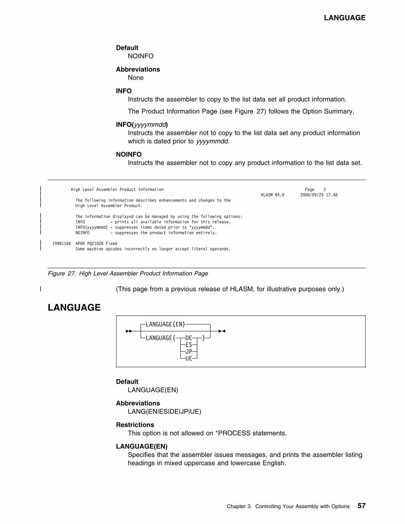
LANGUAGE
DefaultNOINFO
AbbreviationsNone
INFOInstructs the assembler to copy to the list data set all product information.
The Product Information Page (see Figure 27) follows the Option Summary,
INFO(yyyymmdd)Instructs the assembler not to copy to the list data set any product informationwhich is dated prior to yyyymmdd.
NOINFOInstructs the assembler not to copy any product information to the list data set.
| High Level Assembler Product Information Page 2| HLASM R4.9 2999/99/25 17.48| The following information describes enhancements and changes to the| High Level Assembler Product.
| The information displayed can be managed by using the following options:| INFO - prints all available information for this release.| INFO(yyyymmdd) - suppresses items dated prior to "yyyymmdd".| NOINFO - suppresses the product information entirely.
| 19981194 APAR PQ21928 Fixed| Some machine opcodes incorrectly no longer accept literal operands.
Figure 27. High Level Assembler Product Information Page
| (This page from a previous release of HLASM, for illustrative purposes only.)
LANGUAGE
┌ ┐──LANGUAGE(EN) ──────��─ ──┼ ┼──────────────────── ─��
└ ┘──LANGUAGE( ──┬ ┬─DE─ ) ├ ┤─ES─ ├ ┤─JP─ └ ┘─UE─
DefaultLANGUAGE(EN)
AbbreviationsLANG(EN|ES|DE|JP|UE)
RestrictionsThis option is not allowed on *PROCESS statements.
LANGUAGE(EN)Specifies that the assembler issues messages, and prints the assembler listingheadings in mixed uppercase and lowercase English.
Chapter 3. Controlling Your Assembly with Options 57

LIBMAC
LANGUAGE(DE)Specifies that the assembler issues messages in German. The assemblerlisting headings are printed in mixed-case English.
LANGUAGE(ES)Specifies that the assembler issues messages in Spanish. The assemblerlisting headings are printed in mixed-case English.
LANGUAGE(JP)Specifies that the assembler issues messages in Japanese. The assemblerlisting headings are printed in uppercase English.
LANGUAGE(UE)Specifies that the assembler issues messages, and prints the assembler listingheadings in uppercase English.
Note: The assembler uses the language specified in the installation defaultoptions for messages produced in CMS by the ASMAHL command.
LIBMAC
┌ ┐─NOLIBMAC─��─ ──┼ ┼────────── ─�� └ ┘─LIBMAC───
DefaultNOLIBMAC
AbbreviationsLMAC / NOLMAC
Note: You can specify the LIBMAC (or NOLIBMAC) option as a parameter of theACONTROL statement. For further details, refer to the High Level AssemblerLanguage Reference.
LIBMACSpecifies that, for each macro, macro definition statements read from a macrolibrary are to be embedded in the input source program immediately precedingthe first invocation of that macro. The assembler assigns statement numbersto the macro definition statements as though they were included in the inputsource program.
NOLIBMACSpecifies that macro definition statements read from a macro library are notincluded in the input source program.
LINECOUNT
┌ ┐──LINECOUNT(69) ─────��─ ──┼ ┼──────────────────── ─��
└ ┘──LINECOUNT(integer)
DefaultLINECOUNT(60)
58 HLASM V1R4 Programmer’s Guide

LIST
AbbreviationsLC(integer)
CMS Only:
The LINECOUNT option can be abbreviated to LINECOUN.
RestrictionsThis option is not allowed on *PROCESS statements.
LINECOUNT(integer)Specifies the number of lines to be printed on each page of the assemblylisting. integer must have a value of 0, or 10 to 32767. If a value of 0 isspecified, no page ejects are generated and EJECT, CEJECT, and TITLEstatements in the assembly are ignored.
Up to 7 lines on each page may be used for heading lines.
LIST
┌ ┐──LIST(121) ────────────��─ ──┼ ┼─────────────────────── ─�� ├ ┤──LIST ──┬ ┬───────────── │ │└ ┘──( ──┬ ┬─133─ ) │ │└ ┘─MAX─ └ ┘─NOLIST────────────────
DefaultLIST(121)
AbbreviationsNone
RestrictionsYou cannot specify this option on *PROCESS statements.
LISTInstructs the assembler to produce a listing. Specifying LIST without asuboption is equivalent to specifying LIST(121).
LIST(121) (MVS and CMS)Instructs the assembler to produce a listing, and print the Source and Objectsection in the 121-character format.
LIST(133) (MVS and CMS)Instructs the assembler to produce a listing, and print the Source and Object
| section in the 133-character format. You should use this option when you| specify the GOFF option.
LIST(MAX) (MVS and CMS)Instructs the assembler to produce a listing, and print the Source and Objectsection in either the 121-character format or the 133-character format. If thelogical record length (LRECL) of the listing data set is less than 133 then theassembler selects the 121-character format. If the LRECL of the listing data setis 133 or more then the assembler selects the 133-character format.
NOLISTInstructs the assembler to suppress the assembly listing. When you specifyNOLIST the assembler ignores the following options:
Chapter 3. Controlling Your Assembly with Options 59

LIST
DXREF PCONTROL ESD RLD EXIT(PRTEXIT) RXREF INFO USING(MAP) MXREF(MAP) XREF
60 HLASM V1R4 Programmer’s Guide

MXREF
MXREF
┌ ┐──MXREF(SOURCE) ──────────��─ ──┼ ┼───────────────────────── ─�� ├ ┤──MXREF ──┬ ┬────────────── │ │└ ┘──( ──┬ ┬─FULL─ ) │ │└ ┘─XREF─ └ ┘─NOMXREF─────────────────
DefaultMXREF(SOURCE)
AbbreviationsMX / NOMX
MXREFSpecifying MXREF without a suboption is equivalent to specifyingMXREF(SOURCE).
MXREF(SOURCE)Instructs the assembler to produce the Macro and Copy Code SourceSummary section of the assembler listing. The macro and copy code sourcesummary includes the name of each macro library or copy library accessed, thevolume serial number of the first DASD volume on which the library resides,and the names of each member retrieved from the library.
MXREF(FULL)Instructs the assembler to produce the Macro and Copy Code SourceSummary section and the Macro and Copy Code Cross Reference section ofthe assembler listing.
Note: See note following MXREF(XREF).
MXREF(XREF)Instructs the assembler to produce the Macro and Copy Code Cross Referencesection of the assembler listing. The Macro and Copy Code Cross Referenceincludes the name of each macro or copy code member referenced in theassembly, where it was referenced and where it was called or copied from.
Note: If you specify MXREF(FULL) or MXREF(XREF), you might need toreview the value of the SIZE option (as both of these assembler optionsuse considerable amounts of storage).
NOMXREFSpecifies that macro and copy code information is not generated in theassembler listing.
Chapter 3. Controlling Your Assembly with Options 61

OPTABLE
OBJECT
┌ ┐─OBJECT───��─ ──┼ ┼────────── ─�� └ ┘─NOOBJECT─
DefaultOBJECT
AbbreviationsOBJ / NOOBJ
RestrictionsYou cannot specify this option on *PROCESS statements.
OBJECTInstructs the assembler to generate object code and write it to the object dataset. You define the object data set with the SYSLIN ddname, on MVS andCMS, or with the IJSYSLN filename and by assigning SYSLNK on VSE.
NOOBJECTInstructs the assembler not to write the object code to SYSLIN, on MVS andCMS, or SYSLNK on VSE.
On VSE, you can only specify the OBJECT option by using the LINK or CATALoption on the JCL OPTION statement. If you specify OBJECT on the PARMoperand of the JCL EXEC statement, the assembler issues message ASMA499W,and ignores the option.
OPTABLE
┌ ┐──OPTABLE(UNI) ──────��─ ──┼ ┼──────────────────── ─��
└ ┘──OPTABLE( ──┬ ┬─DOS─ ) ├ ┤─ESA─ ├ ┤─XA── └ ┘─379─
DefaultOPTABLE(UNI)
AbbreviationOP
RestrictionsThis option is not allowed on *PROCESS statements.
| OPTABLE(DOS)| Instructs the assembler to load and use the DOS operation code table. The| DOS operation code is designed specifically for assembling programs| previously assembled using the DOS/VSE assembler. The operation code table| contains the System/370 machine instructions, excluding those with a vector| facility.
62 HLASM V1R4 Programmer’s Guide
OPTABLE
OPTABLE(ESA)Instructs the assembler to load and use the operation code table that containsthe ESA/370 and ESA/390 architecture machine instructions, including thosewith a vector facility.
OPTABLE(UNI)Instructs the assembler to load and use the operation code table that containsthe System/370 and System/390 architecture machine instructions, includingthose with a vector facility.
OPTABLE(XA)Instructs the assembler to load and use the operation code table that containsthe System/370 extended architecture machine instructions, including thosewith a vector facility.
OPTABLE(370)Instructs the assembler to load and use the operation code table that containsthe System/370 machine instructions, including those with a vector facility.
Notes:
1. These operation code tables do not contain symbolic operation codes formachine instructions that are unique to IBM 4300 Processors operating inECPS:VSE mode.
2. The operation codes supported by High Level Assembler are described in themanuals listed under “Related Publications (Architecture)” on page 386.
Chapter 3. Controlling Your Assembly with Options 63

PCONTROL
PCONTROL
┌ ┐─NOPCONTROL────────────────────────��─ ──┼ ┼─────────────────────────────────── ─�� │ │┌ ┐─,─────────────── │ ││ │┌ ┐─NODATA─
└ ┘──PCONTROL( ──(1)───+ ┴┬ ┬──┼ ┼──────── ─── ) │ │└ ┘─DATA─── │ │┌ ┐─NOGEN─ ├ ┤──┼ ┼─────── ──── │ │└ ┘─GEN─── │ │┌ ┐─NOMCALL─ ├ ┤──┼ ┼───────── ── │ │└ ┘─MCALL─── │ │┌ ┐─NOMSOURCE─ ├ ┤──┼ ┼─────────── │ │└ ┘─MSOURCE─── │ │┌ ┐─OFF─ ├ ┤──┼ ┼───── ────── │ │└ ┘─ON── │ │┌ ┐─NOUHEAD─ └ ┘──┼ ┼───────── ── └ ┘─UHEAD───
Note:1 Choose at least one option.
DefaultNOPCONTROL
AbbreviationsPC(DATA, NODATA, GEN, NOGEN, MC, NOMC, MS, NOMS, ON, OFF, UHD,NOUHD) / NOPC
PCONTROL(DATA)Specifies that the assembler is to print the object code of all constants in full,as though a PRINT DATA statement were specified at the beginning of thesource program. All PRINT NODATA statements in the source program areignored. However, specifying PCONTROL(DATA) does not override PRINTOFF or PRINT NOGEN statements in the source program.
PCONTROL(NODATA)Specifies that the assembler is to print only the first 8 bytes of the object codeof constants, as though a PRINT NODATA statement were specified at thebeginning of the source program. All PRINT DATA statements in the sourceprogram are ignored.
PCONTROL(GEN)Specifies that the assembler is to print all statements generated by theprocessing of a macro, as though a PRINT GEN statement were specified atthe beginning of the source program. All PRINT NOGEN statements in thesource program are ignored. However, specifying PCONTROL(GEN) does notoverride PRINT OFF statements in the source program.
PCONTROL(NOGEN)Specifies that the assembler is not to print statements generated by theprocessing of a macro or open code statements with substitution variables, asthough a PRINT NOGEN statement were specified at the beginning of the
64 HLASM V1R4 Programmer’s Guide
PCONTROL
source program. All PRINT GEN and PRINT MSOURCE statements in thesource program are ignored.
PCONTROL(MCALL)Specifies that the assembler is to print nested macro instructions, as though aPRINT MCALL statement were specified at the beginning of the sourceprogram. All PRINT NOMCALL statements in the source program are ignored.However, specifying PCONTROL(MCALL) does not override PRINT OFF orPRINT NOGEN statements in the source program.
PCONTROL(NOMCALL)Instructs the assembler not to print nested macro instructions, as though aPRINT NOMCALL statement were specified at the beginning of the sourceprogram. All PRINT MCALL statements in the source program are ignored.
PCONTROL(MSOURCE)Specifies that the assembler is to print the source statements generated duringmacro processing, as well as the assembled addresses and generated objectcode of the statements. All PRINT NOMSOURCE statements in the sourceprogram are ignored. However, specifying PCONTROL(MSOURCE) does notoverride PRINT OFF or PRINT NOGEN statements in the source program.
PCONTROL(NOMSOURCE)Instructs the assembler to suppress the printing of source statementsgenerated during macro processing, but not suppress the printing of theassembled addresses and generated object code of the statements. All PRINTMSOURCE statements in the source program are ignored.
PCONTROL(OFF)Specifies that the assembler is not to produce the Source and Object section ofthe assembly listing. All PRINT ON statements in the source program areignored.
PCONTROL(ON)Specifies that the assembler is to produce an assembly listing unless theNOLIST option is specified. All PRINT OFF statements in the source programare ignored.
PCONTROL(UHEAD)Specifies that the assembler is to print a summary of active USINGs in theheading lines of each page of the source and object code section of the listing,as though a PRINT UHEAD statement were specified at the beginning of thesource program. All PRINT NOUHEAD statements in the source program areignored. However, specifying PCONTROL(UHEAD) does not override PRINTOFF statements in the source program.
PCONTROL(NOUHEAD)Instructs the assembler not to print a summary of active USINGs, as though aPRINT NOUHEAD statement were specified at the beginning of the sourceprogram. All PRINT UHEAD statements in the source program are ignored.
NOPCONTROLSpecifies that the assembler honor all PRINT statements in the sourceprogram. The standard PRINT operands active at the beginning of anassembly are ON, GEN, NODATA, NOMCALL, MSOURCE, and UHEAD.
Chapter 3. Controlling Your Assembly with Options 65
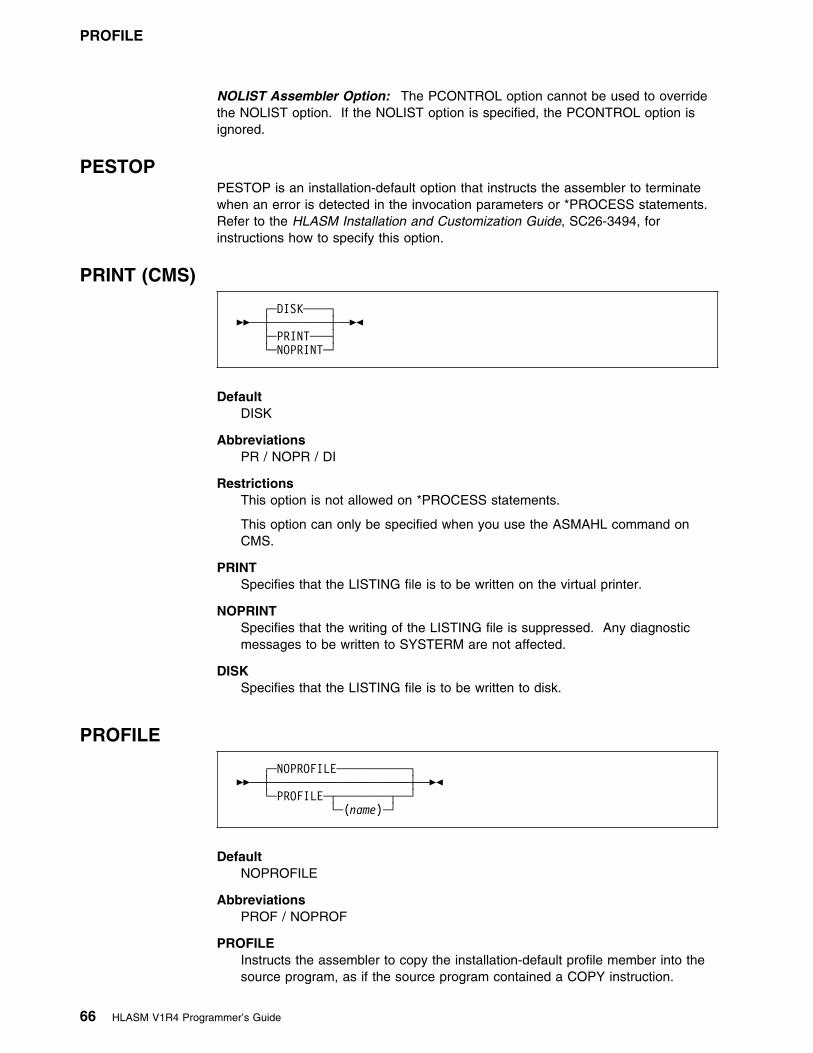
PROFILE
NOLIST Assembler Option: The PCONTROL option cannot be used to overridethe NOLIST option. If the NOLIST option is specified, the PCONTROL option isignored.
PESTOPPESTOP is an installation-default option that instructs the assembler to terminatewhen an error is detected in the invocation parameters or *PROCESS statements.Refer to the HLASM Installation and Customization Guide, SC26-3494, forinstructions how to specify this option.
PRINT (CMS)
┌ ┐─DISK────��─ ──┼ ┼───────── ─�� ├ ┤─PRINT─── └ ┘─NOPRINT─
DefaultDISK
AbbreviationsPR / NOPR / DI
RestrictionsThis option is not allowed on *PROCESS statements.
This option can only be specified when you use the ASMAHL command onCMS.
PRINTSpecifies that the LISTING file is to be written on the virtual printer.
NOPRINTSpecifies that the writing of the LISTING file is suppressed. Any diagnosticmessages to be written to SYSTERM are not affected.
DISKSpecifies that the LISTING file is to be written to disk.
PROFILE
┌ ┐─NOPROFILE───────────��─ ──┼ ┼───────────────────── ─�� └ ┘──PROFILE ──┬ ┬────────
└ ┘──(name)
DefaultNOPROFILE
AbbreviationsPROF / NOPROF
PROFILEInstructs the assembler to copy the installation-default profile member into thesource program, as if the source program contained a COPY instruction.
66 HLASM V1R4 Programmer’s Guide

RA2
PROFILE(name)Instructs the assembler to copy the member name into the source program, asif the source program contained a COPY instruction.
NOPROFILESpecifies that the assembler is not to copy a library member into the sourceprogram.
Notes:
1. The profile member is copied into the source program immediately following anICTL statement or *PROCESS statements, or both.
2. You specify the default profile member name in the PROFMEM parameter ofthe installation options macro ASMAOPT. If the PROFMEM parameter is notspecified, ASMAOPT generates a default member name of ASMAPROF. Referto the HLASM Installation and Customization Guide for instructions how to usethe ASMAOPT macro.
3. On MVS and CMS, the assembler searches for the member in the macro andcopy code libraries defined in the SYSLIB DD statement.
4. On VSE, the assembler searches for the member in the macro and copy codelibraries defined in the LIBDEF job control statement.
5. The assembler processes the source statements in the profile member thesame way it does for source statements obtained using the COPY instruction.Refer to the Language Reference for further information about the COPYinstruction.
RA2
┌ ┐─NORA2─��─ ──┼ ┼─────── ─�� └ ┘─RA2───
DefaultNORA2
AbbreviationsNone
Note: You can specify the RA2 (or NORA2) option as a parameter of theACONTROL statement. For further details, refer to the High Level AssemblerLanguage Reference.
RA2Instructs the assembler to suppress error diagnostic message ASMA966W when2-byte relocatable address constants, such as AL2(*) and Y(*), are defined inthe source program.
NORA2Instructs the assembler to issue error diagnostic message ASMA966W when2-byte relocatable address constants, such as AL2(*) and Y(*), are defined inthe source program.
Chapter 3. Controlling Your Assembly with Options 67
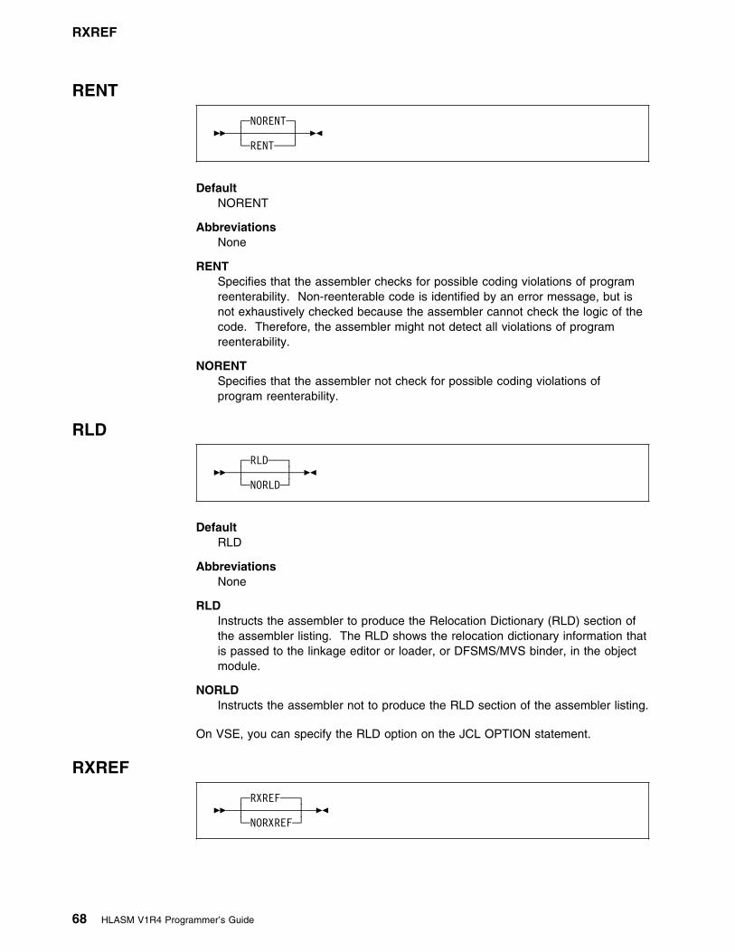
RXREF
RENT
┌ ┐─NORENT─��─ ──┼ ┼──────── ─�� └ ┘─RENT───
DefaultNORENT
AbbreviationsNone
RENTSpecifies that the assembler checks for possible coding violations of programreenterability. Non-reenterable code is identified by an error message, but isnot exhaustively checked because the assembler cannot check the logic of thecode. Therefore, the assembler might not detect all violations of programreenterability.
NORENTSpecifies that the assembler not check for possible coding violations ofprogram reenterability.
RLD
┌ ┐─RLD───��─ ──┼ ┼─────── ─�� └ ┘─NORLD─
DefaultRLD
AbbreviationsNone
RLDInstructs the assembler to produce the Relocation Dictionary (RLD) section ofthe assembler listing. The RLD shows the relocation dictionary information thatis passed to the linkage editor or loader, or DFSMS/MVS binder, in the objectmodule.
NORLDInstructs the assembler not to produce the RLD section of the assembler listing.
On VSE, you can specify the RLD option on the JCL OPTION statement.
RXREF
┌ ┐─RXREF───��─ ──┼ ┼───────── ─�� └ ┘─NORXREF─
68 HLASM V1R4 Programmer’s Guide

SIZE
DefaultRXREF
AbbreviationsRX / NORX
RXREFInstructs the assembler to produce the General Purpose Register CrossReference section of the assembler listing. The General Purpose RegisterCross Reference includes:
� The register number� An indicator showing the context in which the register was used.
NORXREFInstructs the assembler not to produce the General Purpose Register CrossReference section of the assembler listing.
SEG (CMS)
��─ ──┬ ┬─────── ─�� ├ ┤─SEG─── └ ┘─NOSEG─
DefaultNone. The assembler modules are loaded from the Logical Saved Segment(LSEG). If the LSEG is not available, the assembler modules are loaded fromdisk.
AbbreviationsNone
RestrictionsYou cannot specify this option on *PROCESS statements.
You can only specify this option on CMS using the ASMAHL command.
SEGSpecifies that the assembler modules are loaded from the Logical SavedSegment (LSEG). If the LSEG is not found the assembler stops.
NOSEGSpecifies that the assembler modules are loaded from disk.
SIZE
┌ ┐──SIZE(MAX) ─────────────────────────────��─ ──┼ ┼──────────────────────────────────────── ─��
└ ┘──SIZE( ──┬ ┬──integerK ────────────────── )├ ┤──integerM ──────────────────├ ┤──MAX,ABOVE ─────────────────├ ┤──MAX-integerK ──┬ ┬──────────
│ │└ ┘ ─,──ABOVE─└ ┘──MAX-integerM ──┬ ┬──────────
└ ┘ ─,──ABOVE─
Chapter 3. Controlling Your Assembly with Options 69

SIZE
You use the SIZE option to specify the amount of virtual storage available to theassembler to perform an in-storage assembly. If you specify an insufficient amount,the assembler uses the work data set (SYSUT1) on MVS and CMS, or the workdata set (IJSYS03) on VSE, for intermediate storage.
DefaultSIZE(MAX)
AbbreviationSZ
RestrictionsYou cannot specify this option on *PROCESS statements.
SIZE(integerK)Specifies the amount of virtual storage in 1024-byte (1K) increments.
The minimum acceptable value is 200K (refer to Note 2).
SIZE(integerM)Specifies the amount of virtual storage in 1048576-byte (1M) increments.
The minimum acceptable value is 1M.
SIZE(MAX)Specifies that the assembler requests all the available space (refer to Note 3)in the user region (MVS), or virtual machine (CMS) or in the partition GETVIS
| (VSE). When ABOVE is appended, the request is for storage above the 16MB| line.
SIZE(MAX-integerK)Specifies that the assembler requests all the available space (refer to Note 3)in the user region (MVS), virtual machine (CMS) or partition GETVIS (VSE) less
| the amount of integerK of storage (1K equals 1024 bytes). When ABOVE is| appended, the request is for storage above the 16MB line.
The minimum acceptable integerK value is 1K.
SIZE(MAX-integerM)Specifies that the assembler requests all the available space (refer to Note 3)in the user region (MVS), or virtual machine (CMS) less the amount of integerK
| of storage (1M equals 1048756 bytes). When ABOVE is appended, the| request is for storage above the 16MB line.
| The minimum acceptable integerM value is 1M.
Note:
1. The maximum storage value you can specify might not be available in the userregion (MVS), virtual machine (CMS), or in the partition GETVIS (VSE), afterstorage has been allocated for the operating system.
2. The minimum amount of working storage required by the assembler is 200K or10 times the work data set block size, whichever is greater.
3. When you specify the MAX suboption, the assembler releases 128K back tothe user region (MVS), virtual machine (CMS), or the partition GETVIS (VSE),for system usage. When you specify the MAX suboption, there might not beenough storage remaining in the user region (MVS), virtual machine (CMS), orthe partition GETVIS (VSE), to load any exits you specify, or any externalfunctions you use in your assembly or for operating system functions that may
70 HLASM V1R4 Programmer’s Guide

SYSPARM
be required during the assembly. If the assembly does fail due to a lack ofstorage, then use MAX-integerK or MAX-integerM to ensure that there issufficient free storage during the assembly for any of these functions.
4. The assembler loads user I/O exits before it obtains the working storage. If theuser exit obtains storage, then it reduces the amount available for theassembler.
5. The assembler loads external function routines after it obtains working storage.If you use external functions in your program, you should reduce the value youspecify in the SIZE option, to allow storage space for the external functionmodules, and any storage they might acquire.
High Level Assembler acquires the amount of storage you specify in the SIZEoption from the user region (MVS), virtual machine (CMS), or partition GETVIS(VSE). The assembler only requires a work data set when it has insufficient virtualstorage to perform an in-storage assembly. An in-storage assembly usuallyreduces the elapsed time needed to complete the assembly.
The statistics in the Diagnostic Cross Reference and Assembler Summary sectionof the assembly listing shows the amount of storage the assembler used and anestimate of the amount of storage it requires to perform an in-storage assembly. Ifyou do not provide a work data set, you must specify a large enough value on theSIZE option to allow the assembler to perform an in-storage assembly.
Use the STORAGE operand of the installation default options macro, ASMAOPT, tospecify the equivalent of the ABOVE suboption.
SYSPARM
┌ ┐──SYSPARM() ──────��─ ──┼ ┼───────────────── ─��
└ ┘──SYSPARM(string)
DefaultThe &SYSPARM system variable is set to NULL.
AbbreviationsNone
RestrictionsYou cannot specify this option on *PROCESS statements.
SYSPARM(string)Specifies the character string the assembler assigns to the &SYSPARM systemvariable symbol. The character string is up to 255 characters in length. Anycharacter may be included in the string, subject to the rules for buildingcharacter strings defined in the Language Reference.
On an MVS or VSE invocation parameter, if the string includes blanks,commas, or parentheses, it must be enclosed in single quotation marks. Anyparentheses inside the string must be balanced. You must use two singlequotation marks to represent a single quotation mark, and two ampersands torepresent a single ampersand. For example:
PARM='OBJECT,SYSPARM((&&((AM)),''EO).FY)'
Chapter 3. Controlling Your Assembly with Options 71

TERM
assigns the value (&AM,'EO).FY to &SYSPARM.
On MVS and VSE, JCL restrictions limit the length of the SYSPARM value.When you call the assembler from a problem program (dynamic invocation),
| you can specify a SYSPARM value up to 255 characters long. The ASMOPT| file (“ASMAOPT Options” on page 39) also supports a SYSPARM value up to| 255 characters long.
On CMS, you can specify SYSPARM(?). This causes the assembler to issuethe following message at your terminal:
ENTER SYSPARM:
In response to this message you can enter up to 255 characters. To specify aSYSPARM value of ?, you must specify SYSPARM(?) and enter ? at theterminal prompt.
TERM
┌ ┐─NOTERM─────────────��─ ──┼ ┼──────────────────── ─�� │ │┌ ┐─(WIDE)─── └ ┘──TERM ──┼ ┼────────── └ ┘─(NARROW)─
DefaultNOTERM
AbbreviationsNone
RestrictionsThis option is not allowed on *PROCESS statements.
TERMIs equivalent to TERM(WIDE). See the description of TERM(WIDE) below.
TERM(WIDE)On MVS and CMS, instructs the assembler to write error messages to theterminal data set. You define the terminal data set with the SYSTERMddname.
On VSE, instructs the assembler to write error messages to SYSLOG.SYSLOG is usually assigned at system initialization time and is assignedpermanently to the system log (console).
TERM(NARROW)The NARROW suboption instructs the assembler to compress multipleconsecutive blanks into a single blank.
On MVS and CMS, instructs the assembler to write error messages to theterminal data set. You define the terminal data set with the SYSTERMddname.
On VSE, instructs the assembler to write error messages to SYSLOG.SYSLOG is usually assigned at system initialization time and is assignedpermanently to the system log (console).
72 HLASM V1R4 Programmer’s Guide

THREAD
NOTERMInstructs the assembler not to write error messages to SYSTERM (MVS andCMS) or SYSLOG (VSE).
You can specify the TERM option on the JCL OPTION statement.
TEST
┌ ┐─NOTEST─��─ ──┼ ┼──────── ─�� └ ┘─TEST───
DefaultNOTEST
AbbreviationsNone
TESTSpecifies that the object module contains the special source symbol table (SYMrecords) required by the TSO TEST command.
NOTESTSpecifies that the object module does not contain the special source symboltable (SYM records) required by the TSO TEST command.
| On MVS and CMS, if you specify the TEST option with the GOFF option, theassembler ignores the TEST option.
| THREAD|
| ┌ ┐─THREAD───| ��─ ──┼ ┼────────── ─��| └ ┘─NOTHREAD─
| Default| THREAD
| Abbreviations| THR / NOTHR
| THREAD| Specifies that the assembler not reset the location counter to zero at the| beginning of each CSECT.
NOTHREAD| Specifies that the assembler reset the location counter to zero at the beginning| of each CSECT, except for the first CSECT.
Chapter 3. Controlling Your Assembly with Options 73
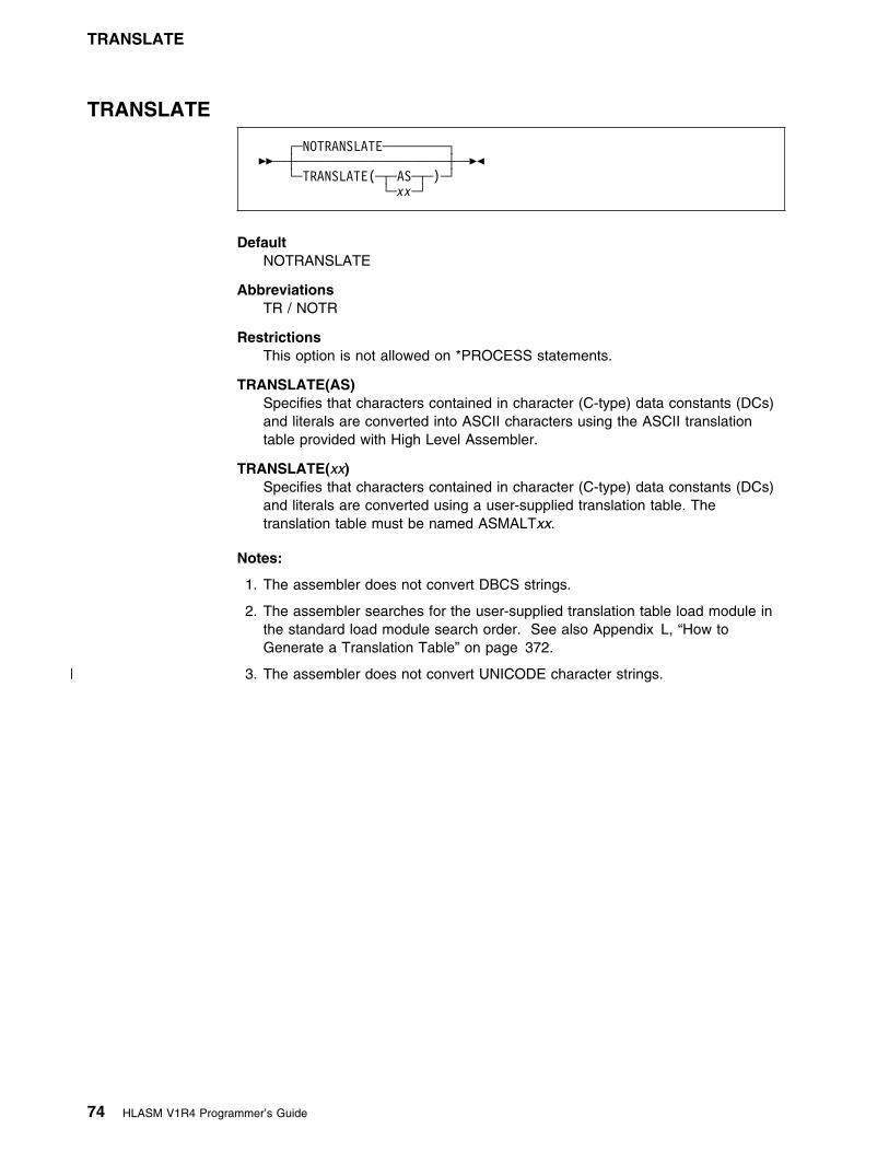
TRANSLATE
TRANSLATE
┌ ┐─NOTRANSLATE─────────��─ ──┼ ┼───────────────────── ─��
└ ┘──TRANSLATE( ──┬ ┬─AS─ ) └ ┘─xx─
DefaultNOTRANSLATE
AbbreviationsTR / NOTR
RestrictionsThis option is not allowed on *PROCESS statements.
TRANSLATE(AS)Specifies that characters contained in character (C-type) data constants (DCs)and literals are converted into ASCII characters using the ASCII translationtable provided with High Level Assembler.
TRANSLATE(xx)Specifies that characters contained in character (C-type) data constants (DCs)and literals are converted using a user-supplied translation table. Thetranslation table must be named ASMALTxx.
Notes:
1. The assembler does not convert DBCS strings.
2. The assembler searches for the user-supplied translation table load module inthe standard load module search order. See also Appendix L, “How toGenerate a Translation Table” on page 372.
| 3. The assembler does not convert UNICODE character strings.
74 HLASM V1R4 Programmer’s Guide

USING
USING
┌ ┐─USING(MAP,WARN(15))────────────────��─ ──┼ ┼──────────────────────────────────── ─�� │ │┌ ┐─,─────────────────── │ ││ │┌ ┐─MAP───
├ ┤──USING( ──(1)───+ ┴──┬ ┬──┼ ┼─────── ────── ) │ ││ │└ ┘─NOMAP─
│ ││ │┌ ┐──WARN(15) │ │├ ┤──┼ ┼────────── ───
│ ││ │├ ┤──WARN(n) ─ │ ││ │└ ┘─NOWARN─── │ ││ │┌ ┐─NOLIMIT───── │ │└ ┘──┼ ┼─────────────
│ │└ ┘──LIMIT(xxxx) └ ┘─NOUSING────────────────────────────
Note:1 Choose at least one option.
DefaultUSING(MAP,WARN(15))
AbbreviationsUS / NOUS
LIMIT(xxxx)This suboption, when used in combination with the WARN(8) suboption,specifies the maximum displacement that base-displacement address resolutionchecks.
xxxx is the decimal value of the displacement, and must be less than or equalto 4095. X'xxx' may also be used to specify the value in hexadecimal. Ifspecified, this value must be less than or equal to X'FFF'.
If more than one base register is specified in a USING statement, the valuespecified in the LIMIT suboption is used only to check the maximumdisplacement from the last specified base register. For example, ifUSING(LIMIT(X'F00'),WARN(8)) were specified at invocation, the messageswould be issued as in Figure 28.
Active Usings: None Loc Object Code Addr1 Addr2 Stmt Source Statement HLASM R4.9 2999/99/25 17.48999999 99999 91F82 1 EXAMPLE CSECT 99991999 R:AB 99999 2 USING EXAMPLE,19,11 99992999
...99949E 47F9 AB8C 99B8C 176 B LABEL111 �1� 99176999
...99B8C 496 LABEL111 EQU L 99496999
...99152E 47F9 BF89 91F89 998 B LABEL999 �2� 99998999LL ASMA394W Displacement exceeds LIMIT value specified
...91F89 1436 LABEL999 EQU L 91436999
991F89 97FE 1437 BR 14 91437999 1438 END 91438999
Figure 28. Effect of the LIMIT Suboption
Although the resolved displacement of the instruction at �1� is greater than thespecified limit, error diagnostic message ASMA394W is not issued because
Chapter 3. Controlling Your Assembly with Options 75

USING
register 10 was not the last specified base register. However, the instruction at�2� causes the message to be issued because register 11 was the lastspecified base register.
NOLIMITThis suboption specifies that displacements are not checked. Specifying thissuboption is equivalent to specifying the LIMIT suboption with a value of 4095or X'FFF'.
MAPThis suboption instructs the assembler to produce the USING Map section ofthe assembler listing. For more information, see “USING Map” on page 30.
NOMAPThis suboption specifies that no USING map is produced.
WARN(n)This suboption specifies the conditions under which warning error diagnosticmessages are issued. Each condition has an associated condition number, n.The allowable values for n are:
| 0 No USING warning messages are issued.
1 Nullified USINGs: The assembler issues message:
� ASMA399W when a previous active ordinary (unlabeled) USING's rangecoincides with and supersedes that of the USING being processed.
� ASMA391W when the range of the USING being processed coincideswith and supersedes that of a previous active ordinary (unlabeled)USING.
� ASMA396W when the range of the USING being processed coincideswith the implicit USING 0,0 (for example USING 0,2).
2 R0 based USINGs: The assembler issues message ASMA392W when aUSING specifies R0 as a base register, with a non-zero absolute orrelocatable expression for the base address.
4 Multiple resolutions: The assembler issues message:
� ASMA393W when multiple resolutions are possible for an implicitaddress.
� ASMA396W when the range of the USING being processed overlapsthe range of the implicit USING 0,0 (for example USING 16,2).
8 LIMIT: The assembler issues message ASMA394W when the calculateddisplacement in any valid resolution exceeds the threshold specified inthe LIMIT suboption. This has no effect if the LIMIT suboption is notspecified.
Several conditions may be combined by adding together the associatedcondition numbers. For example, specifying WARN(12) would request theassembler to issue warning diagnostic messages for the conditions withcondition numbers 4 and 8.
NOWARNThis suboption specifies that no USING warning messages are issued.
76 HLASM V1R4 Programmer’s Guide

XOBJECT
NOUSINGNOUSING specifies that all USING suboptions are off. It is equivalent tospecifying USING(NOLIMIT,NOMAP,NOWARN), or specifying in theASMADOPT default options: LIMIT=NO,MAP=NO,WARN=NO.
The USING suboptions LIMIT, MAP, and WARN are specified in the installationdefault options as LIMIT, MAP, and WARN.
XOBJECT (MVS and CMS)
┌ ┐─NOXOBJECT──────────────��─ ──┼ ┼──────────────────────── ─�� │ │┌ ┐─(NOADATA)─ └ ┘──XOBJECT ──┼ ┼─────────── └ ┘─(ADATA)───
DefaultNOXOBJECT
AbbreviationsXOBJ / NOXOBJ
RestrictionsYou cannot specify this option on *PROCESS statements.
XOBJECTInstructs the assembler to produce a Generalized Object File format (GOFF)data set. You define this data set with the SYSLIN or SYSPUNCH ddname.
Note: For more information on GOFF, refer to DFSMS/MVS ProgramManagement.
XOBJECT(NOADATA)The same as XOBJECT without a suboption.
XOBJECT(ADATA)Instructs the assembler to produce a Generalized Object File format data set,and include ADATA text records.
NOXOBJECTInstructs the assembler not to produce a Generalized Object File format dataset.
Notes:
1. You should specify the LIST(133) option when you specify the XOBJECToption. If the logical record length of the listing data set is less than 133, theassembler truncates the listing lines.
| 2. The generalized object format does not support TEST (SYM) records. If youspecify the TEST option with the XOBJECT option, the assembler issues adiagnostic error message.
| 3. XOBJECT is treated as a synonym for the GOFF option and accepts the same| subparameters as GOFF.
Chapter 3. Controlling Your Assembly with Options 77

XREF
XREF
┌ ┐─XREF(SHORT,UNREFS)───────��─ ──┼ ┼────────────────────────── ─��
├ ┤──XREF( ──┬ ┬─FULL───────── ) │ ││ │┌ ┐─,──────── │ │└ ┘───+ ┴┬ ┬─SHORT── │ │└ ┘─UNREFS─ └ ┘─NOXREF───────────────────
DefaultXREF(SHORT,UNREFS)
AbbreviationsNone
XREF(FULL)Instructs the assembler to produce the Ordinary Symbol and Literal CrossReference section of the assembler listing. This includes symbols that aredefined, but never referred to.
XREF(SHORT)Instructs the assembler to produce the Ordinary Symbol and Literal CrossReference section of the assembler listing. Symbols that are defined, but notreferred to, are not included in the cross reference listing. SHORT may bespecified with the UNREFS suboption to produce a list of unreferencedsymbols. The SHORT suboption can not be specified with the FULL suboption.
XREF(UNREFS)Instructs the assembler to produce the Unreferenced Symbols Defined inCSECTs section of the assembler listing. The symbols are listed in symbolname order. UNREFS may be specified with the SHORT suboption to producea cross reference list of referenced symbols. The UNREFS suboption can notbe specified with the FULL suboption.
NOXREFSpecifies that symbol cross reference information is not generated as part ofthe assembly listing.
Any suboption you specify overrides the suboptions specified in the installationdefault options, unless the XREF option is fixed.
If you specify the XREF option more than once, the assembler uses the last oneyou specify. For example, if you specify XREF(SHORT),XREF(UNREFS), the assembleruses XREF(UNREFS). To use both suboptions, specify XREF(SHORT,UNREFS).
On VSE, you can use the XREF option of the JCL OPTION statement to specifythe XREF(FULL) assembler option, and the SXREF option of the JCL OPTIONstatement to specify the XREF(SHORT) assembler option.
78 HLASM V1R4 Programmer’s Guide
Exit Types
Chapter 4. Providing User Exits
This chapter describes how you can provide user exits to complement theassembler's data set processing. It describes the type of exits, how to specify themduring assembly, and the details you need to write an exit.
Exit TypesYou can instruct the assembler to call the following types of exits:
SOURCE Exit: To process Primary Input records.
You use a SOURCE exit to replace or complement the assembler's primary inputdata set processing. You can use it to supply primary input records to theassembler, or monitor and modify records the assembler has read before theassembler processes them. The exit can supply all the primary input records, orextend the primary input by supplying additional records during the assembly. Theexit can also discard records.
LIBRARY Exit: To process Library Input records.
You use a LIBRARY exit to replace or complement the assembler's macro call(MACRO) and copy code (COPY) library processing. You can use it to supplyMACRO and COPY library records to the assembler, or monitor and modify recordsthe assembler has read before the assembler processes them. The exit can supplyall the MACRO and COPY library records, or extend the library input processing bysupplying additional MACRO and COPY records during the assembly. The exit canalso discard records.
LISTING Exit: To process Listing Output records.
You use a LISTING exit to replace or complement the assembler's listing outputprocessing. You can use it to write the listing records the assembler supplies, ormonitor and modify the records before the assembler writes them to the listing dataset. The exit can write all the listing records, or supply additional listing records forthe assembler to write during the assembly. The exit can also discard records.
OBJECT (MVS and CMS) and PUNCH Exit: To process Object and PunchOutput records.
You use an OBJECT and PUNCH exit to replace or complement the assembler'sobject module output processing. You can use it to write the object module recordsthe assembler supplies, or monitor and modify the records before the assemblerwrites them to the object data set. The exit can write all the object module records,or supply additional records for the assembler to write during the assembly. Theexit can also discard records.
ADATA Exit: To process Associated Data Output records.
You use an ADATA exit to monitor the associated data records that are written bythe assembler. The ADATA exit cannot modify the records, discard records, orprovide additional records.
Copyright IBM Corp. 1982, 2000 79

Specifying User Exits
TERM Exit: To process Terminal Output records.
You use a TERM exit to replace or complement the assembler's terminal outputprocessing. You can use it to write the terminal records the assembler supplies, ormonitor and modify the records before the assembler writes them. The exit canwrite all the terminal records, or supply additional terminal records for theassembler to write during the assembly. The exit can also discard records.
The assembler writes terminal output to SYSLOG; however, you can usethe exit to write the output to a disk data set.
Specifying User ExitsYou use the EXIT option to specify the name of one or more user exits to load, andoptionally pass to the exit a character string up to 64 characters long that isprocessed during assembly initialization. You can use the EXITCTL assemblerinstruction to pass data from the assembler source program to the user exit duringthe assembly.
The Diagnostic Cross Reference and Assembler Summary section of the assemblerlisting shows the statistics for records processed by the user exits during theassembly. See “EXIT” on page 49 for the syntax of the EXIT assembler option.
The following tables lists the exit type, the EXIT suboption, the default data setddname (MVS and CMS), or filename (VSE), that the exit corresponds to, and aPage number reference to the section that describes how the assembler processesthe exit:
Figure 29. MVS and CMS Exit Types
Exit Type Exit Suboption ddname Page Number
SOURCE INEXIT SYSIN 97
LIBRARY LIBEXIT SYSLIB 99
LISTING PRTEXIT SYSPRINT 104
PUNCH OBJEXIT SYSPUNCH 108
OBJECT OBJEXIT SYSLIN 108
ADATA ADEXIT SYSADATA 111
TERM TRMEXIT SYSTERM 112
Figure 30. VSE Exit Types
Exit Type Exit Suboption filename Page Number
SOURCE INEXIT IJSYSIN 97
LIBRARY LIBEXIT Librarysublibraries
99
LISTING PRTEXIT IJSYSLS 104
PUNCH OBJEXIT IJSYSPH 108
ADATA ADEXIT SYSADAT 111
TERM TRMEXIT SYSLOG 112
80 HLASM V1R4 Programmer’s Guide
Calling User Exits
Loading User ExitsThe assembler loads the user exits during initialization. The assembler must beable to locate the user exits as follows:
The user exit must be a link-edited load module that is located in apartitioned data set in the standard search sequence. The user exit can also belocated in the Link Pack Area (LPA).
If you use the same exit load module for more than one user exit type, for exampleas a SOURCE and LISTING exit, the load module can be loaded more than once,depending on the link edit options specified.
The user exit must be a MODULE that is located on one of the accesseddisks. You generate the module using the CMS LOAD and GENMOD commands.When the LOAD command is issued, the RLDSAVE option must be specified tomake the module relocatable. If RLDSAVE is not specified, it might result in theassembler program or data storage being overlaid.
If you use the same exit load module for more than one user exit type, for exampleas a SOURCE and LISTING exit, only one copy of the module is loaded.
The user exit must be a relocatable phase that is in a sublibrary youspecify in your JCL LIBDEF phase search chain. The user exit can also be locatedin the Shared Virtual Area (SVA).
If you use the same exit for more than one exit type, for example as a SOURCEand LISTING exit, only one copy of the phase is loaded.
The user exits may be created in any addressing mode (AMODE) and residencymode (RMODE).
Calling User ExitsThe assembler calls user exits using the standard OS Linkage conventions. Theuser exit can be written in any language that conforms to the following:
� Can be called many times via the exit module entry point� Retains storage for private variables across invocations
High Level Assembler provides an “anchor word” in the Exit Parameter List to allowyou to maintain information across calls to the exit.
Refer to the language's Programming Guide to find out if you can use it to write auser exit for the assembler.
The contents of the registers upon entry to the user exit are as follows:
Register 0 UndefinedRegister 1 Address of Exit Parameter List, see Figure 31 on
page 83.Registers 2 through 12 UndefinedRegister 13 Address of 72 byte save areaRegister 14 Return addressRegister 15 Address of entry point of user exit
Chapter 4. Providing User Exits 81

Exit Parameter List
Exit Parameter ListThe assembler passes an Exit Parameter List to the user exit. On entry to the exit,Register 1 contains the address of this parameter list. Each exit is passed aseparate copy of the parameter list. The parameter list includes a pointer to anExit-Specific block that contains information for each exit type. High LevelAssembler provides macro ASMAXITP to map the Exit Parameter List and theExit-Specific Information block. Figure 31 on page 83 describes the format of theExit Parameter List, Figure 35 on page 93 describes the format of the Exit-SpecificInformation block for the LISTING exit, and Figure 36 on page 93 describes theformat of the Exit-Specific Information block for the other exit types.
82 HLASM V1R4 Programmer’s Guide

Exit Parameter List
| 9 31| ┌─────────────────────────┐| ┌───�│ Parameter List Version │| │ ├─────────────────────────┤| │ │ Exit Type │| │ ├─────────────────────────┤| │ │ Request Type │| │ ├─────────────────────────┤| │ │ Options │| │ ├─────────────────────────┤| │ │ EXITCTL 1 │| │ ├─────────────────────────┤| │ │ EXITCTL 2 │| │ ├─────────────────────────┤| │ │ EXITCTL 3 │| │ ├─────────────────────────┤| │ │ EXITCTL 4 │| │ ├─────────────────────────┤| │ │ Return Code │| │ ├─────────────────────────┤| │ │ Reason Code │| │ ├─────────────────────────┤| │ │ Buffer Length │| │ ├─────────────────────────┤| │ │ Error Buffer Length │| │ ├─────────────────────────┤| │ │ Error Severity │| │ ├─────────────────────────┤| │ │ User-Defined Field │| │ ├─────────────────────────┤| 9 31 │ │ Common User Field │| ┌────────────┐ ┌───────────────────────┐ │ └─────────────────────────┘| │ Register 1 ├────�│ Ptr to Request Info ├────┘| └────────────┘ ├───────────────────────┤ ┌─────────────────────────┐| │ Ptr to Buffer ├────────�│ Buffer │| ├───────────────────────┤ └─────────────────────────┘| │ Ptr to Error Buffer ├──────┐| ├───────────────────────┤ │ ┌─────────────────────────┐| │ Ptr to Exit Info ├────┐ └─�│ Error Buffer │| ├───────────────────────┤ │ └─────────────────────────┘| │ Ptr to DCB │ │| ├───────────────────────┤ │ ┌─────────────────────────┐| │ Ptr to Static ├──┐ └───�│ Exit-Specific Block │| │ Assembler Information │ │ └─────────────────────────┘| └───────────────────────┘ │ 63| │ ┌──────────────────────────────┐| └─────�│ HLASM VRM │| ├──────────────────────────────┤| │ PTF Level │ 127| ├──────────────────────────────┴────┐| │ System Id │| └───────────────────────────────────┘
Figure 31. Exit Parameter List Format
Chapter 4. Providing User Exits 83

Exit Parameter List
The following sections describe the Exit Parameter List.
Request Info PointerThe request info pointer points to a list of fullword fields that describe the exitrequest. The assembler sets this pointer, which is always a valid address.
Parameter List VersionA fullword identifying the version of the parameter list. For High Level AssemblerRelease 4 this field contains a value of 2.
Exit TypeA fullword identifying the type of exit being called. You use this field when the exithandles more than one exit type. The exit type is identified by the following values:
1 SOURCE Input
2 LIBRARY Input
3 LISTING Output
4 PUNCH Output
5 OBJECT Output
6 ADATA Output
7 TERM Output
The assembler always sets this field.
Request TypeA fullword identifying the type of processing request. The request type is identifiedby the following values:
1 OPEN—exit receives control before any input or output processing.
2 CLOSE—exit receives control before the assembler does any closeprocessing.
3 READ—exit receives control to provide a record to the assembler.
4 WRITE—exit receives control to write a record provided by the assembler.
5 PROCESS (for exit types other than LIBRARY)—exit receives control toinspect or manipulate the record provided by the assembler.
5 PROCESS MACRO (LIBRARY exit type)—exit receives control to inspect ormanipulate the macro definition record provided by the assembler.
6 PROCESS COPY (LIBRARY exit type)—exit receives control to inspect ormanipulate the copy member record provided by the assembler.
7 FIND MACRO (LIBRARY exit type)—exit receives control to locate thespecified library macro.
8 FIND COPY MEMBER (LIBRARY exit type)—exit receives control to locate thespecified copy member.
9 END OF MEMBER (LIBRARY exit type)—exit receives control after the readingof a macro or copy member is completed.
The assembler always sets this field.
84 HLASM V1R4 Programmer’s Guide

Exit Parameter List
OptionsA fullword that provides additional information to the exit.
For the SOURCE and LIBRARY Exits: The following values are provided:
0 No additional information available.
1 New information is available in the Exit-Specific Information block. Theassembler updates this block whenever the primary input data set changes.
For example, the SOURCE input might be a concatenation of data sets. Whenthe first data set is opened, and when each subsequent concatenated data setis opened, this value is set to 1 to inform the exit that a data set switch hasoccurred. It is also set for LIBRARY processing to inform the exit which dataset in the concatenation is being used to provide the specific member.
2 For the LIBRARY exit, when the request type is FIND MACRO or FIND COPY,this indicates that the copy code or a macro should resume at the savedrecord position.
3 For the LIBRARY exit, when the request type is FIND MACRO or FIND COPY,this indicates that copy code or a macro definition is currently being processed.The user exit should save the position within the current member to allow it tobe resumed when the new member has been processed.
See “Nesting COPY Instructions and Macro Definitions” on page 102.
For the LISTING exit: The following decimal values are provided:
00 No additional information available10 High Level Assembler Options Summary heading line11 High Level Assembler Options Summary detail line15 High Level Assembler Options Summary diagnostic message17 High Level Assembler Product Information heading line18 High Level Assembler Product Information detail line20 External Symbol Dictionary heading line21 External Symbol Dictionary detail line30 Source and Object heading line31 Source and Object machine instruction32 Source and Object DC/DS instruction33 Source and Object comment34 Source and Object statement in error35 Source and Object diagnostic message36 Source and Object other40 Relocation Dictionary heading line41 Relocation Dictionary detail line50 Ordinary Symbol and Literal Cross Reference heading line51 Ordinary Symbol and Literal Cross Reference detail line52 Unreferenced Symbols Defined in CSECTs heading line53 Unreferenced Symbols Defined in CSECTs detail line60 Macro and Copy Code Source Summary heading line61 Macro and Copy Code Source Summary detail line62 Macro and Copy Code Cross Reference heading line63 Macro and Copy Code Cross Reference detail line70 DSECT Cross Reference heading line71 DSECT Cross Reference detail line80 USING Map heading line
Chapter 4. Providing User Exits 85

Exit Parameter List
81 USING Map detail line85 General Purpose Register Cross Reference heading line86 General Purpose Register Cross Reference detail line90 Diagnostic Cross Reference and Assembler Summary heading line91 Diagnostic Cross Reference and Assembler Summary detail line
For the PUNCH, OBJECT, and ADATA Exits: This field contains 0.
The assembler sets this field.
EXITCTLnFour fullword fields containing the exit-control values for this exit type. Exit-controlvalues are set by the EXITCTL assembler instruction during the assembly.
For the SOURCE and LIBRARY Exits: The new EXITCTL values are available tothe exit when the input record following the EXITCTL instruction is passed to theexit.
For the LISTING, ADATA, and TERM Exits: The new EXITCTL values areavailable to the exit with the output record containing the EXITCTL instruction.
For the OBJECT and PUNCH Exits: The new EXITCTL values are available tothe exit when the next object module record is passed to the exit. This mayhappen several source statements after the EXITCTL instruction statement. Apossible consequence is that one or more EXITCTL statements can be processedwithout the exit receiving the EXITCTL parameter values, if they occur betweenobject records.
Return CodeA fullword, set by the exit, that indicates success or failure of the exit call, and theaction taken by the assembler on return from the exit. Figure 32 summarizes thereturn codes.
Figure 32 (Page 1 of 2). User-Exit Return Codes
Exit Request RC=0 4 8 16 20
SOURCE OPEN Assembler toopen theprimary inputdata set1
Exit providesrecords2
Disable Operation failed
CLOSE Operationsuccessful
Operation failed
READ Exit hasprovidedrecord
End-of-fileindicator
Operation failed
PROCESS Accept record Discard record Disable Operation failed
LIBRARY OPEN Assembler toopen itslibrary1
Exit hasopened itslibrary3
Exit hasopened itslibrary,assembler toopen its library
Disable Operation failed
CLOSE Operationsuccessful
Operation failed
READ Exit hasprovidedrecord
EOD on inputsource
Operation failed
86 HLASM V1R4 Programmer’s Guide
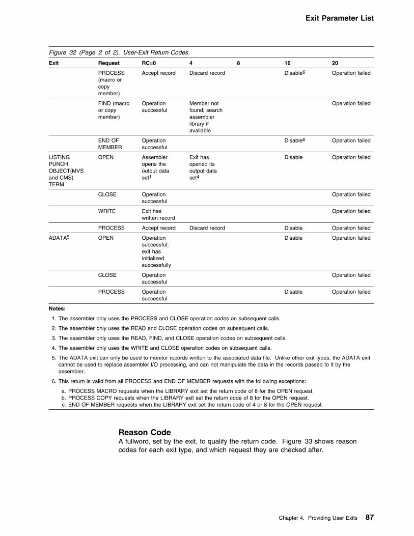
Exit Parameter List
Figure 32 (Page 2 of 2). User-Exit Return Codes
Exit Request RC=0 4 8 16 20
PROCESS(macro orcopymember)
Accept record Discard record Disable6 Operation failed
FIND (macroor copymember)
Operationsuccessful
Member notfound; searchassemblerlibrary ifavailable
Operation failed
END OFMEMBER
Operationsuccessful
Disable6 Operation failed
LISTINGPUNCHOBJECT(MVSand CMS)TERM
OPEN Assembleropens theoutput dataset1
Exit hasopened itsoutput dataset4
Disable Operation failed
CLOSE Operationsuccessful
Operation failed
WRITE Exit haswritten record
Operation failed
PROCESS Accept record Discard record Disable Operation failed
ADATA5 OPEN Operationsuccessful;exit hasinitializedsuccessfully
Disable Operation failed
CLOSE Operationsuccessful
Operation failed
PROCESS Operationsuccessful
Disable Operation failed
Notes:
1. The assembler only uses the PROCESS and CLOSE operation codes on subsequent calls.
2. The assembler only uses the READ and CLOSE operation codes on subsequent calls.
3. The assembler only uses the READ, FIND, and CLOSE operation codes on subsequent calls.
4. The assembler only uses the WRITE and CLOSE operation codes on subsequent calls.
5. The ADATA exit can only be used to monitor records written to the associated data file. Unlike other exit types, the ADATA exitcannot be used to replace assembler I/O processing, and can not manipulate the data in the records passed to it by theassembler.
6. This return is valid from all PROCESS and END OF MEMBER requests with the following exceptions:
a. PROCESS MACRO requests when the LIBRARY exit set the return code of 8 for the OPEN request.b. PROCESS COPY requests when the LIBRARY exit set the return code of 8 for the OPEN request.c. END OF MEMBER requests when the LIBRARY exit set the return code of 4 or 8 for the OPEN request.
Reason CodeA fullword, set by the exit, to qualify the return code. Figure 33 shows reasoncodes for each exit type, and which request they are checked after.
Chapter 4. Providing User Exits 87

Exit Parameter List
Figure 33. User Exit Reason Codes
Exit Request Reason Code=0 Reason Code=4
SOURCE OPEN No additional information Input source information available
READ No additional information Input source information available
LIBRARY OPEN No additional information End of member call required
FIND (macroor copymember)
No additional information Input source information available
LISTINGTERM
OPEN No additional information When return code is 0, reason code 4 indicates theexit has provided a line length in the buffer lengthfield. When return code is 4, reason code 4indicates the exit has provided the data setinformation.
SOURCELIBRARYLISTINGPUNCHOBJECT(MVSand CMS)TERM
PROCESS No additional information Return to exit with empty buffer
PUNCHOBJECT(MVSand CMS)
OPEN No additional information Exit has provided the output data set information
Buffer LengthA fullword containing the length of the area pointed to by the buffer pointer.
For OPEN Requests: This field contains the length of the optional character stringyou specified in the EXIT assembler option.
For WRITE and PROCESS Requests: This field contains the length of the recordpointed to by the buffer pointer.
For READ Requests: This field contains the length of the area pointed to by thebuffer pointer where the exit may return a record to the assembler.
All Other Requests: This field contains zero.
Setting the Length: When either the SOURCE, LIBRARY, PUNCH, or OBJECTexit is invoked for a READ, WRITE, or PROCESS request, the assembler sets thebuffer length to 80.
On MVS and CMS, if you specify the GOFF assembler option, and the OBJECTexit is invoked, the buffer length might be fixed-length 80, or variable-length,depending on the JCL (MVS) you supply. The maximum value for variable-lengthrecords is 8212.
For an OPEN request the LISTING exit can use this field to pass the listing linelength to the assembler. The exit indicates that it has provided a print line lengthby setting the return code to 0 and the reason code to 4.
The line length must be in the range 121 to 255. If it is any othervalue, the assembler issues message ASMA492W and does not call the exit toprocess listing records.
88 HLASM V1R4 Programmer’s Guide

Exit Parameter List
If the assembler opens the listing data set and the LISTING exit providesa print line length, the line length must be 121 if SYSLST is assigned to disk,otherwise it can be any value from 121 to 133. If it is any other value, theassembler issues message ASMA492W and does not call the exit to process listingrecords.
For all other calls to the LISTING exit, the assembler sets this field to the lengthdetermined during the OPEN call.
The TERM exit can use this field to indicate to the assembler the length of theterminal record. This may be done when the exit is invoked with an OPEN request.The exit indicates that it has provided a terminal line length by setting the ReturnCode to 0 and the Reason Code to 4. The value must not be zero, or negative,and must not be greater than 255 on MVS and CMS, or 125 on VSE. If the valueis not correct, the assembler issues message ASMA494W and does not call the exit toprocess terminal records.
For all other calls to the TERM exit, the assembler sets this field to the lengthdetermined during the OPEN call.
Error Buffer LengthAn unsigned fullword, set by the exit, that contains the length of the text pointed toby the error buffer pointer. The maximum length is 255 bytes. If the exit specifies alarger value, the assembler uses 255.
The assembler uses this length to determine whether to issue an error message. Ifthe length is greater than zero, the text in the error buffer is inserted into one of themessages ASMA799I to ASMA794C. The assembler selects which message to issueby checking the value of the error severity field.
Error SeverityA fullword, set by the exit, that contains the severity code the assembler uses todetermine which diagnostic message to issue.
The severity code should be a value of 0, 4, 8, 12, or 16. If the severity code is notone of these values, it is rounded up to the nearest value or, if the severity code isgreater than 16, it is reset to 16.
The values 0, 4, 8, 12, and 16 correspond to the five diagnostic messages,ASMA799I through ASMA794C, respectively. For example, severity code of 4 causesthe assembler to issue message ASMA791W. Figure 34 summarizes the return codevalues and the associated diagnostic message.
Figure 34. Error Severity and Associated Diagnostic Message
Error Severity CodeSpecified
Error Severity CodeUsed
AssociatedMessage
0 0 ASMA700I
1–4 4 ASMA701W
5–8 8 ASMA702E
9–12 12 ASMA703S
> 12 16 ASMA704C
Chapter 4. Providing User Exits 89
Exit Parameter List
User-Defined FieldA fullword, set to zero by the assembler before it calls the exit with an OPENrequest. The exit can use this field to store information (such as the address ofacquired storage) between calls. This field is separately maintained for each exittype and is preserved across all calls until the exit is closed. The assembler doesnot modify or interpret this field.
Common User FieldA fullword, set to zero by the assembler. Any exit can use this to store information(such as the address of acquired storage) between calls. This field is common forall exit types and so provides a mechanism for different exits to share information.The assembler does not modify or interpret this field.
Buffer PointerThe buffer pointer points to the area containing a record to be processed by theexit.
For OPEN Requests: This field contains the character string from the EXITassembler option. If you did not specify a character string in the EXIT assembleroption, this area contains blanks and the buffer length field is set to zero.
For READ Requests: This field points to an empty buffer area.
For PROCESS and WRITE Requests: This field points to the record supplied bythe assembler.
All Other Requests: This field is set to zero.
Error Buffer PointerThe error buffer pointer points to the error text buffer.
The assembler sets this pointer. If you want the assembler to issue a message onbehalf of the exit, you must supply the text of the error messages in the areapointed to by the error buffer pointer. The text can be up to 255 characters. Theexit must place the length of the text in the error buffer length field. The assemblerselects a message number based on the value you place in the error severity field.
Exit-Specific Information PointerThe exit-specific information pointer is a fullword that contains the address of theExit-Specific Information block. The assembler sets this pointer. For more details,see “Exit-Specific Information Block” on page 92.
90 HLASM V1R4 Programmer’s Guide

Static Assembler Information Pointer
DCB Pointer This field is a fullword and always contains zeros. It is included to
maintain compatibility with the Exit Parameter List in the MVS and CMSenvironments.
The DCB pointer is a fullword that contains the address of the DataControl Block.
The assembler sets this address which points to the applicable DCB for the exitbeing called as follows:
Exit DCB
SOURCE SYSIN
LIBRARY SYSLIB
LISTING SYSPRINT
PUNCH SYSPUNCH
OBJECT SYSLIN
ADATA SYSADATA
TERM SYSTERM
When an exit is invoked with an OPEN request, the data set referred to by the DCBis not open, and the contents of the DCB might not be complete.
When an exit is invoked with a PROCESS request, the exit may use the DCB toobtain additional information about the data set or member being used. Forexample, on MVS, the exit can obtain user information from a PDS directory byusing the BLDL system macro.
Static Assembler Information Pointer| The Static Assembler Information Pointer is a fullword that contains the address of| the Static Assembler Information block. The block is not aligned on any particular| boundary.
| HLASM VRM| This is an 8 byte field which contains the version, release and modification level of| the assembler being used to assemble the source module. For example, when| HLASM Release 4.0 is being used, this field has the value 1.4.0. The value of the| field is set to the value of the system variable &SYSVER.
| PTF Level| This is an 8 byte field which contains the current PTF level of the assembler being| used to assemble the source module. For example, when the last PTF applied to| the assembler was UQ12345 this field will have the value: UQ12345.
Chapter 4. Providing User Exits 91
Exit-Specific Information Block
| System ID| This is a 16 byte field which contains the name and release of the operating system| under which your source module is being assembled. For example, on MVS, the| field might contain the value MVS/ESA SP 5.1.0. The value of the field is set to the| value of the system variable &SYSTEM_ID.
Error HandlingExit Failure Handling: You can signal an exit failure for any call to the exit bysetting the return code field in the Exit Parameter List to 20. When the assemblerreceives this return code it issues message ASMA949U, and stops the assembly.You can provide the assembler with additional information to insert in the messagetext by placing the information in the error buffer pointed to by error buffer pointer,and the length of the information in the error buffer length.
If the exit sets the return code field in the Exit Parameter List to any value otherthan those described in Figure 32 on page 86, the assembler issues messageASMA949U and stops the assembly.
User Error Handling: You can instruct the assembler to produce an errormessage after any call to the exit by placing information in the error buffer pointedto by error buffer pointer, and the length of the information in the error buffer length.You can indicate the severity of the message by placing the severity code in theerror severity field. The message is issued as a normal assembler message and,as such, can be suppressed using the FLAG assembler option.
Exit-Specific Information BlockAll user exits are passed an Exit-Specific Information block pointed to by the ExitParameter List. It contains a list of character data items which describe the datafor the exit, and the absolute and relative record numbers for the record passed tothe exit. The Exit-Specific Information block passed to all exits, except theLISTING exit, is shown in Figure 36 on page 93. The Exit-Specific Informationblock passed to the LISTING exit has additional parameters as shown in Figure 35.
92 HLASM V1R4 Programmer’s Guide
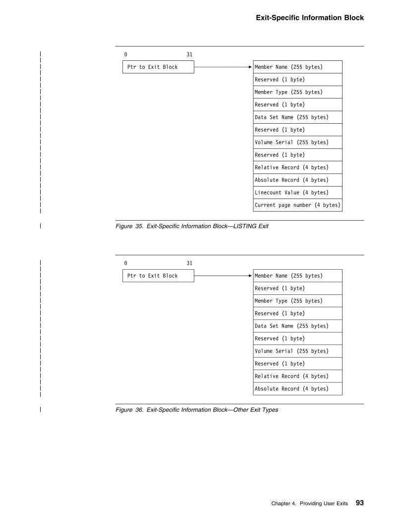
Exit-Specific Information Block
| 9 31| ┌───────────────────────┐ ┌─────────────────────────────┐| │ Ptr to Exit Block ├──────────────────�│Member Name (255 bytes) │| └───────────────────────┘ ├─────────────────────────────┤| │Reserved (1 byte) │| ├─────────────────────────────┤| │Member Type (255 bytes) │| ├─────────────────────────────┤| │Reserved (1 byte) │| ├─────────────────────────────┤| │Data Set Name (255 bytes) │| ├─────────────────────────────┤| │Reserved (1 byte) │| ├─────────────────────────────┤| │Volume Serial (255 bytes) │| ├─────────────────────────────┤| │Reserved (1 byte) │| ├─────────────────────────────┤| │Relative Record (4 bytes) │| ├─────────────────────────────┤| │Absolute Record (4 bytes) │| ├─────────────────────────────┤| │Linecount Value (4 bytes) │| ├─────────────────────────────┤| │Current page number (4 bytes)│| └─────────────────────────────┘
| Figure 35. Exit-Specific Information Block—LISTING Exit
| 9 31| ┌───────────────────────┐ ┌─────────────────────────────┐| │ Ptr to Exit Block ├──────────────────�│Member Name (255 bytes) │| └───────────────────────┘ ├─────────────────────────────┤| │Reserved (1 byte) │| ├─────────────────────────────┤| │Member Type (255 bytes) │| ├─────────────────────────────┤| │Reserved (1 byte) │| ├─────────────────────────────┤| │Data Set Name (255 bytes) │| ├─────────────────────────────┤| │Reserved (1 byte) │| ├─────────────────────────────┤| │Volume Serial (255 bytes) │| ├─────────────────────────────┤| │Reserved (1 byte) │| ├─────────────────────────────┤| │Relative Record (4 bytes) │| ├─────────────────────────────┤| │Absolute Record (4 bytes) │| └─────────────────────────────┘
| Figure 36. Exit-Specific Information Block—Other Exit Types
Chapter 4. Providing User Exits 93
Exit-Specific Information Block
The Exit-Specific Information block consists of the following fields:
Member NameMember name within the data set. It is always provided for library members and isalso provided for data set members used sequentially on MVS where the data setis a partitioned data set.
The assembler also sets this field as a parameter for the FIND operation. It isleft-justified and padded with blanks.
For output files, the information should not be updated after it has been set by theOPEN call.
The assembler uses this field to update the system variable symbols, as describedin Figure 37 (MVS and CMS) and Figure 38 (VSE).
Member Type Always blank. This field is present to maintain compatibility with High
Level Assembler running on VSE.
The file type of the member. This field is also set by the assembler as aparameter for the FIND operation. It is left-justified and padded with blanks.
Data Set NameThe name of the data set from which the last input record was retrieved, or towhich the next output record is written. It is left-justified and padded with blanks.
For library data sets, the name includes the library and sublibrary name.
For output files, the information should not be updated after it has been set by theOPEN call.
The assembler uses this field to update the system variable symbols, as describedin Figure 37 (MVS and CMS) and Figure 38 (VSE).
Volume SerialVolume serial where the data set is located. It is left-justified and padded withblanks.
For output files, the information should not be updated after it has been set by theOPEN call.
The assembler uses this field to update the system variable symbols, as describedin Figure 37 (MVS and CMS) and Figure 38 (VSE).
94 HLASM V1R4 Programmer’s Guide

Exit-Specific Information Block
Figure 37. MVS and CMS System Variable Symbols
Data Set Member Name Data Set Name Volume Serial
SYSIN &SYSIN_MEMBER &SYSIN_DSN &SYSIN_VOLUME
SYSLIB &SYSLIB_MEMBER &SYSLIB_DSN &SYSLIB_VOLUME
SYSPRINT &SYSPRINT_MEMBER &SYSPRINT_DSN &SYSPRINT_VOLUME
SYSTERM &SYSTERM_MEMBER &SYSTERM_DSN &SYSTERM_VOLUME
SYSPUNCH &SYSPUNCH_MEMBER &SYSPUNCH_DSN &SYSPUNCH_VOLUME
SYSLIN &SYSLIN_MEMBER &SYSLIN_DSN &SYSLIN_VOLUME
SYSADATA &SYSADATA_MEMBER &SYSADATA_DSN &SYSADATA_VOLUME
Figure 38. VSE System Variable Symbols
Data Set Member Name Data Set Name Volume Serial
SYSIPT (IJSYSIN) &SYSIN_MEMBER &SYSIN_DSN &SYSIN_VOLUME
Library &SYSLIB_MEMBER &SYSLIB_DSN &SYSLIB_VOLUME
SYSLST (IJSYSLS) &SYSPRINT_MEMBER &SYSPRINT_DSN &SYSPRINT_VOLUME
SYSLOG &SYSTERM_MEMBER &SYSTERM_DSN &SYSTERM_VOLUME
SYSPCH (IJSYSPH) &SYSPUNCH_MEMBER &SYSPUNCH_DSN &SYSPUNCH_VOLUME
SYSADAT &SYSADATA_MEMBER &SYSADATA_DSN &SYSADATA_VOLUME
Relative Record NumberThe relative record number is the number assigned to the current record beingprocessed.
PROCESS Calls: For PROCESS calls, it represents the total number of recordsthe assembler has passed to the exit for the current data set. Each time a newdata set or library member is opened for input, the relative record number is resetto 1 for the first record. If the new data set is a library member, caused by a macrocall or a COPY instruction, the relative record number is returned to the correctsequential number when the macro or COPY processing is complete.
LISTING Exit: The relative record number is reset to 1 for the LISTING exitwhenever the assembler forces a page eject.
BATCH Assembler Option: The relative record number is reset to 1 for all outputdata sets prior to each assembly when the BATCH assembler option is specified.
READ and WRITE Calls: For READ calls and WRITE calls, the exit shouldmaintain the relative record number. The assembler uses the relative recordnumber in information messages when you specify the FLAG(RECORD) option. Ifyou specify the ADATA option, the assembler includes the record number in theassociated data file (ADATA) Source Analysis record.
Chapter 4. Providing User Exits 95

Exit-Specific Information Block
Absolute Record NumberThe absolute record number is the number assigned to the current record beingprocessed. The number is incremented by 1 for each record since the assemblystarted. For PROCESS calls, it represents the total number of records provided tothe exit for the current exit type. It starts at 1, but is not reset when the BATCHassembler option is specified to assemble multiple source programs.
For READ calls and WRITE calls, the exit should maintain the absolute recordnumber. The number provided after READ calls is written to the associated data file(ADATA) in the Source Analysis record.
LinecountThis field is only provided for the LISTING exit.
The linecount value is set to the value of the LINECOUNT assembler option beforethe OPEN call to the LISTING exit. This option contains the number of lines perpage in the assembler listing. The exit may change the linecount value only duringthe OPEN call.
For PROCESS calls, the linecount field contains the number of logical recordswritten to the current listing page. A page eject occurs when the number exceedsthe linecount value specified in the LINECOUNT assembler option or during theOPEN call.
Current Page NumberThe assembler sets this field to the value of the current page number. Any changethe exit makes to this number is ignored.
This field is only provided for the LISTING exit and only for the PROCESS, WRITEand CLOSE call types.
96 HLASM V1R4 Programmer’s Guide

SOURCE Exit Processing
SOURCE Exit ProcessingThe assembler calls the SOURCE exit with the following request types:
OPENThe assembler calls the exit with a request type of 1 (OPEN) at the start of theassembly. This is the first call to the exit.
The exit may set the return code in the Exit Parameter List to one of the following:
0 Instructs the assembler to open the primary input data set, and supply theprimary input records to the exit in later PROCESS calls.
4 Indicates that the exit supplies the primary input records to the assembler inlater READ calls. If you wish to provide the assembler with the values forthe system variables &SYSIN_DSN, &SYSIN_MEMBER and&SYSIN_VOLUME, the user exit must set the reason code to 4 and placethe values in the data set name, member name, and volume serial fields ofthe exit-specific information block. The assembler also shows thisinformation in the Diagnostic Cross Reference and Assembler Summarysection of the listing, and includes it in the associated data file JobIdentification record.
16 Instructs the assembler to open the primary input data set, and make nofurther calls to the exit.
If you provide a character string in the str1 suboption of the EXIT assembler option,the buffer pointer points to the character string, and buffer length contains thelength of the character string. The buffer length is set to zero if there is nocharacter string.
CLOSEThe assembler calls the exit with a request type of 2 (CLOSE) at the end of theassembly. The exit should close any data sets it opened and release any storagethat it acquired.
READThe assembler calls the exit with a request type of 3 (READ) when the exit issupplying the primary input records.
The exit may set the return code in the Exit Parameter List to one of the following:
0 A record is supplied. The record must be placed in the area pointed to bythe buffer pointer field. The record area is 80 characters in length.
The user exit should maintain the absolute record number and the relativerecord number. These fields are set to zero before the OPEN request. Theassembler uses the relative record number in diagnostic messages whenyou specify the FLAG(RECORD) assembler option. If you specify theADATA assembler option, the assembler includes both fields in theassociated data file Source Analysis record.
If you wish to provide the assembler with the values for the system variables&SYSIN_DSN, &SYSIN_MEMBER and &SYSIN_VOLUME, the user exitmust set the reason code to 4 and place the values in the data set name,member name, and volume serial fields of the exit-specific information block.
Chapter 4. Providing User Exits 97

SOURCE Exit Processing
You can provide this information during the OPEN call, or whenever the exitsupplies a record to the assembler. If the exit is reading records fromconcatenated data sets, it should supply the data set information with thefirst record from each data set in the concatenation.
If the exit does not supply the data set information, the system variables areset to null, and the primary input data set details are not shown in theDiagnostic Cross Reference and Assembler Summary section of the listing,nor are they included in the ADATA Job Identification record.
16 Indicates to the assembler that there are no more records. This is equivalentto end-of-file processing for input data sets.
PROCESSThe assembler calls the exit with a request type of 5 (PROCESS) when theassembler is reading the primary input data set, and it has a record for the exit toprocess. The address of the record read is in the buffer pointer field, and thelength is in the buffer length field. The record length is always 80.
The exit can set the return code in the Exit Parameter List to one of the following:
0 Indicates that the record has been accepted, and the assembler is toprocess it. The exit may modify the record before it returns control to theassembler. The user exit may also insert extra records in the primary inputby setting the reason code to 4. The assembler processes the currentrecord and then calls the user exit with an empty buffer. The exit must placethe record in the 80-byte area pointed to by the buffer pointer field. The exitcan continue to supply additional records, by setting the reason code to 4.The exit must keep track of when the assembler calls it with an empty buffer,and ensure that it resets the reason code to zero to resume normalprocessing.
4 Instructs the assembler to discard the current record.
16 Instructs the assembler to make no further calls to the exit.
Although the user exit might insert or discard records, the assembler maintains theabsolute record number and relative record number.
If the options field is set to 1 (see “Options” on page 85), the assembler hasprovided the exit with the current primary input data set information in the data setname, member name, and volume serial fields of the exit-specific information block.The assembler updates this information when it reads the first record of each dataset in a data set concatenation.
Figure 39 summarizes the SOURCE exit processing.
98 HLASM V1R4 Programmer’s Guide

LIBRARY Exit Processing
Figure 39. SOURCE Exit Processing Summary
RequestValue=Type
ExitReturn Code
Action
1=OPEN 0 Assembler opens primary input.
4 Exit supplies primary input records.If reason code=4, exit supplies data set information.
16 Assembler opens primary input,and makes no further calls to the exit.
2=CLOSE n/a Exit should close any data sets it opened, and releaseany storage it acquired.
3=READ 0 Exit supplies record in buffer.If reason code=4, exit supplies data set information.
16 Exit indicates end-of-file.
5=PROCESS 0 Record accepted. Exit may modify record.If reason code=4, the assembler, after processing thecurrent record, provides an empty buffer for the exit toprovide additional record.
4 Requests assembler to discard record.
16 Assembler makes no further calls to the exit.
LIBRARY Exit ProcessingThe assembler calls the LIBRARY exit with the following request types:
OPENThe assembler calls the exit with a request type of 1 (OPEN) at the start of theassembly. This is the first call to the exit.
The exit can set the return code in the Exit Parameter List to one of the following:
0 Instructs the assembler to open the library data set, and supply the macroand copy code library input records to the exit in later PROCESS calls.
Note: A reason code of 4 indicates that the exit expects to receive END OFMEMBER calls.
4 Indicates that the exit supplies the macro and copy code library records tothe assembler in later READ calls. If you wish to provide the assembler withthe values for the system variables &SYSLIB_DSN, &SYSLIB_MEMBER and&SYSLIB_VOLUME, the user exit must set the reason code to 4 and placethe values in the data set name, member name, and volume serial fields ofthe exit-specific information block. The assembler also shows thisinformation in the Diagnostic Cross Reference and Assembler Summarysection of the listing, and includes it in the associated data file Libraryrecord.
Note: A reason code of 4 indicates that the exit expects to receive END OFMEMBER calls.
8 Indicates that both the assembler and user exit supply the macro and copycode library records. On return from the exit, the assembler opens the librarydata set. When a macro or copy member is required, the assembler calls
Chapter 4. Providing User Exits 99

LIBRARY Exit Processing
the exit with a FIND request. If the member is found by the exit, the exitsupplies the records in later READ calls. If the exit cannot find the member,the assembler attempts to find the member in the library data set. If theassembler finds the member, the records are passed to the exit in laterPROCESS calls.
Note: A reason code of 4 indicates that the exit expects to receive END OFMEMBER calls.
16 Instructs the assembler to open the library data set, and make no furthercalls to the exit.
If you provide a character string in the str2 suboption of the EXIT assembler option,the buffer pointer field points to the character string, and buffer length contains thelength of the character string. The buffer length is set to zero if there is nocharacter string.
CLOSEThe assembler calls the exit with a request type of 2 (CLOSE) at the end of theassembly. The exit should close any data sets it opened and release any storagethat it acquired.
READThe assembler calls the exit with a request type of 3 (READ) when the exit issupplying the library records, and after a successful FIND request. For copymembers, the assembler calls the exit until the exit indicates the end-of-file. Formacro definitions, the assembler calls the exit until it receives a MEND statement,or the exit indicates the end-of-file.
The exit can set the return code in the Exit Parameter List to one of the following:
0 The exit is supplying a record. The record must be placed in the areapointed to by the buffer pointer field. The record area is 80 characters inlength.
The user exit should maintain the absolute record number and the relativerecord number. These fields are set to zero before the OPEN request. Theassembler uses the relative record number in diagnostic messages whenyou specify the FLAG(RECORD) assembler option. If you specify theADATA assembler option, the assembler includes both fields in theassociated data file Source Analysis record.
16 Indicates to the assembler that there are no more records. This is equivalentto end-of-file processing for input members.
PROCESS MACRO or PROCESS COPYThe assembler calls the exit with a request type of 5 (PROCESS MACRO) or 6(PROCESS COPY) when the assembler is reading members from the library dataset, and it has a record for the exit to process. The exit is also called with theserequest types when both the assembler and the exit are supplying library records(return code 8 from the OPEN call), and the assembler is supplying the record.The address of the record read is in the buffer pointer field, and the length is in thebuffer length field. The record length is always 80.
The exit can set the return code in the Exit Parameter List to one of the following:
100 HLASM V1R4 Programmer’s Guide

LIBRARY Exit Processing
0 Indicates that the record has been accepted, and the assembler is toprocess it. The exit can modify the record before it returns control to theassembler. The user exit can also insert extra records in the library memberby setting the reason code to 4. The assembler processes the currentrecord and then calls the user exit with an empty buffer. The exit must placethe record in the 80-byte area pointed to by the buffer pointer field. The exitcan continue to supply additional records by setting the reason code to 4.The exit must keep track of when the assembler calls it with an empty buffer,and ensure that it resets the reason code to zero to resume normalprocessing.
4 Instructs the assembler to discard the current record.
16 Instructs the assembler to make no further calls to the exit. This will bedisregarded by the assembler if the exit return code from the OPEN was 8.
Although the user exit can insert or discard records, the assembler maintains theabsolute record number and relative record number.
If the options field is set to 1, the assembler has provided the exit with the currentprimary input data set information in the data set name, member name, and volumeserial fields of the exit-specific information block. The assembler updates thisinformation when it reads the first record of each data set in a data setconcatenation.
FIND MACRO or FIND COPYThe assembler calls the exit with a request type of 7 (FIND MACRO) whenever theassembler cannot find an operation code and the exit issued a return code onOPEN of either 4 or 8. The member name field contains the operation code, and isthe name of the macro definition that the assembler is searching for.
The assembler calls the exit with a request type of 8 (FIND COPY) whenever theassembler processes a COPY instruction and the exit issued a return code onOPEN of either 4 or 8. The member name field contains the name of the copycode member.
If the user exit is supplying the library records, the exit can set the return code inthe Exit Parameter List to one of the following:
0 Indicates that the exit supplies the library records. The assembler calls theuser exit with later READ calls to retrieve each record.
4 Indicates that the exit is not supplying the macro or copy member, and isequivalent to not finding the member in the library.
If both the assembler and the user exit are supplying the library records, the exitcan set the return code in the Exit Parameter List to one of the following:
0 Indicates that the exit supplies the library records. The assembler calls theuser exit with later READ calls to retrieve each record.
4 Indicates that the exit is not supplying the macro or copy member, and isequivalent to not finding the member in the library. On return from the exit,the assembler attempts to find the member in the library. If the assemblerfinds the member, it calls the user exit with later PROCESS MACRO orPROCESS COPY calls passing each record read from the library.
Chapter 4. Providing User Exits 101

LIBRARY Exit Processing
System Variables: If you wish to provide the assembler with the values for thesystem variables &SYSLIB_DSN, &SYSLIB_MEMBER, and &SYSLIB_VOLUME,the user exit must set the return code to 0, the reason code to 4, and place thevalues in the data set name, member name, and volume serial fields of theexit-specific information block.
If the exit does not supply the data set information, the system variables are set tonull, and the library data set details are not shown in the Diagnostic CrossReference and Assembler Summary section of the listing, nor are they included inthe ADATA Library record.
Nesting COPY Instructions and Macro Definitions: The assembler lets youcode COPY instructions and macro call instructions in copy code members. It alsolets you code COPY instructions in macro definitions. This type of coding isdescribed as nesting.
If the exit is processing a member, and supplies a record to the assemblercontaining a COPY instruction, or a macro call instruction, the assembler calls theexit with a request type of FIND COPY or FIND MACRO, respectively. In this case,the exit needs to save the position in the currently active member before readingthe new copy code or macro member. This enables the exit to resume processingthe currently active member after it finishes with the new member.
The assembler indicates that it is processing a new (or nested) member by settingthe options field to 3. When the assembler finishes processing the new memberand resumes the previous (or outer) member, it issues a FIND call to the exit withthe options field set to 2 indicating that the previous member is resumed. After theFIND call is complete, the assembler continues with PROCESS or READ calls tothe exit for the previous member.
When the assembler calls the exit with a FIND COPY or FIND MACRO request,and the options field is set to 3, the exit should save the current member controlinformation in a stack.
When the assembler calls the exit with a FIND COPY or FIND MACRO request,and the options field is set to 2, the exit should restore the previous member controlinformation from the stack. The next READ request expects the next record fromthe previous member.
The assembler does not limit the number of levels of nesting.
There is a corresponding FIND (resume) request for every successful nested FINDrequest, except under the following situations:
� An END instruction is found while reading a copy code member. The ENDinstruction causes the assembly to stop.
� When the assembler issues a PROCESS call, and provides the last record in acopy code member, and the record is a macro call. In this case there are nomore copy records to resume reading.
� When a macro call (outer macro) inside a copy code member in turn issues amacro call (inner macro). In this case, the assembler processes the outermacro to completion, and then begins to generate the outer macro. Duringgeneration, the assembler begins to process the inner macro, without issuing aFIND (resume) request for the outer macro or copy code member. The
102 HLASM V1R4 Programmer’s Guide

LIBRARY Exit Processing
assembler issues a FIND request for each nested macro call, with options setto 3. It does not issue a FIND request for the outer macro, with options set to2, because the outer macro processing is complete.
� An error occurs during the assembly that prevents the member from being readcompletely.
If the FIND COPY or FIND MACRO is unsuccessful, the position in the currentlyactive member should not be affected.
END OF MEMBERThe assembler calls the exit with a request type of 9 (END OF MEMBER)whenever the reading of a macro or copy member is completed. For a macro,processing of a MEND statement indicates completion; for a copy member, an endof file condition indicates completion.
The END OF MEMBER call simplifies stack management required in coding aLIBRARY exit which contains READs and FINDs. The exit may use the informationprovided by this call in the handling of nested FINDs where there is usually, but notalways, a corresponding resume FIND (options=2) for every nested FIND(options=3). For an example of how you can use END OF MEMBER calls toperform stack management, see page 125.
Figure 40 summarizes the LIBRARY exit processing.
Figure 40 (Page 1 of 2). LIBRARY Exit Processing Summary
RequestValue=Type
Exit ReturnCode
Action
1=OPEN 0 Assembler opens its library for input.If reason code=4, the assembler makes END OFMEMBER calls to the exit.
4 Exit supplies library records.If reason code=4, the assembler makes END OFMEMBER calls to the exit.
8 Both the assembler and the exit supply library records.The assembler opens its library.If reason code=4, the assembler makes END OFMEMBER calls to the exit.
16 Assembler opens the library data set, and makes nofurther calls to the EXIT.
2=CLOSE n/a Exit should close any data sets it opened, and releaseany storage it acquired.
3=READ 0 Exit supplies record in buffer. Record with MENDstatement indicates end of macro member.
16 Exit indicates end-of-file for member.
Chapter 4. Providing User Exits 103
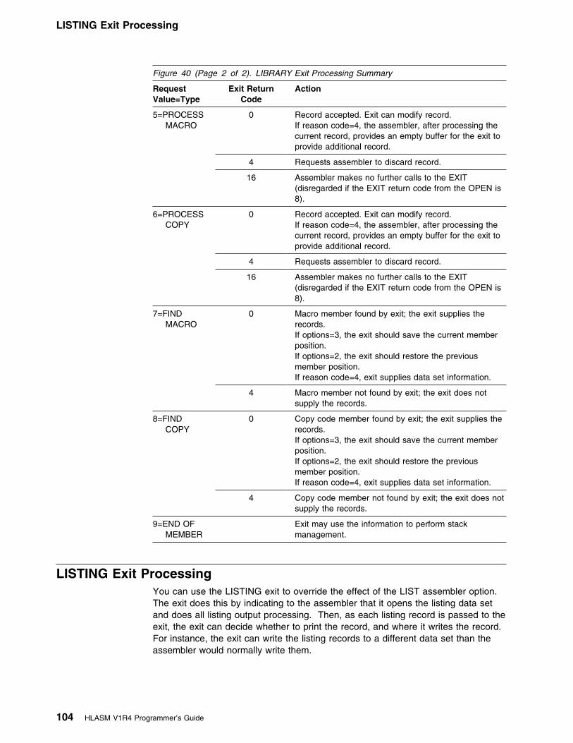
LISTING Exit Processing
Figure 40 (Page 2 of 2). LIBRARY Exit Processing Summary
RequestValue=Type
Exit ReturnCode
Action
5=PROCESS MACRO
0 Record accepted. Exit can modify record.If reason code=4, the assembler, after processing thecurrent record, provides an empty buffer for the exit toprovide additional record.
4 Requests assembler to discard record.
16 Assembler makes no further calls to the EXIT(disregarded if the EXIT return code from the OPEN is8).
6=PROCESS COPY
0 Record accepted. Exit can modify record.If reason code=4, the assembler, after processing thecurrent record, provides an empty buffer for the exit toprovide additional record.
4 Requests assembler to discard record.
16 Assembler makes no further calls to the EXIT(disregarded if the EXIT return code from the OPEN is8).
7=FIND MACRO
0 Macro member found by exit; the exit supplies therecords.If options=3, the exit should save the current memberposition.If options=2, the exit should restore the previousmember position.If reason code=4, exit supplies data set information.
4 Macro member not found by exit; the exit does notsupply the records.
8=FIND COPY
0 Copy code member found by exit; the exit supplies therecords.If options=3, the exit should save the current memberposition.If options=2, the exit should restore the previousmember position.If reason code=4, exit supplies data set information.
4 Copy code member not found by exit; the exit does notsupply the records.
9=END OF MEMBER
Exit may use the information to perform stackmanagement.
LISTING Exit ProcessingYou can use the LISTING exit to override the effect of the LIST assembler option.The exit does this by indicating to the assembler that it opens the listing data setand does all listing output processing. Then, as each listing record is passed to theexit, the exit can decide whether to print the record, and where it writes the record.For instance, the exit can write the listing records to a different data set than theassembler would normally write them.
104 HLASM V1R4 Programmer’s Guide

LISTING Exit Processing
The LISTING exit is not called if you specify the NOLIST assembler option. If youwish to process the listing records in the exit but you do not want the assembler towrite the records to the normal output data set, you can do one of the following:
� Instruct the assembler to discard the listing records by setting the exit returncode
or� Suppress the listing output as follows:
MVS Provide a //SYSPRINT DD DUMMY JCL statement.CMS Issue a FILEDEF SYSPRINT DUMMY command.VSE Assign the SYSLST to IGN.
or� Instruct the exit to issue an OPEN return code of 4
The sections of the listing that are passed to the exit depend on the assembleroptions you specify. For instance, if you specify the NORLD option, then noRelocation Dictionary listing records are passed to the exit.
Although the assembler can write to a listing data set with a recordformat of variable-length, the exit is always presented with fixed-length records.
The assembler calls the LISTING exit with the following request types:
OPENThe assembler calls the exit with a request type of 1 (OPEN) at the start of theassembly.
The exit may set the return code in the Exit Parameter List to one of the following:
0 Instructs the assembler to open the listing data set, and supply the listingoutput records to the exit in later PROCESS calls.
The exit can set the record length for the listing data set by setting thereason code to 4 and the buffer length field.
The buffer length field can be set to any value from 121 to 255.If the listing data set has a variable-length record format, the LRECLassigned is 4 bytes greater than the value the exit returns. If the value isless than 121 or greater than 255, the assembler issues message ASMA492Wand does not call the exit for any further processing.
The buffer length field can be set to any value from 121 to 133. Ifthe value is less than 121 or greater than 133, the assembler issuesmessage ASMA492W and does not call the exit for any further processing.
If you assign SYSLST to a disk data set in your JCL, the record length mustbe 121.
4 Indicates that the exit writes the listing records in later WRITE calls. If youwish to provide the assembler with the values for the system variables&SYSPRINT_DSN, &SYSPRINT_MEMBER, and &SYSPRINT_VOLUME, theexit must set the reason code to 4 and place the values in the data setname, member name, and volume serial fields of the exit-specific informationblock. The assembler also shows this information in the Diagnostic CrossReference and Assembler Summary section of the listing, and includes it inthe associated data file Output File Information record.
Chapter 4. Providing User Exits 105
LISTING Exit Processing
16 Instructs the assembler to open the listing data set, and make no furthercalls to the exit.
The assembler sets the linecount field to the value of the LINECOUNT assembleroption. This value is the number of lines per page in the listing. The exit canchange the line count to a value of 0, or any value from 10 to 32767.“LINECOUNT” on page 58 describes the LINECOUNT assembler option.
If you provide a character string in the str3 suboption of the EXIT assembler option,the buffer pointer field points to the character string, and buffer length contains thelength of the character string. The buffer length is set to zero if there is nocharacter string.
CLOSEThe assembler calls the exit with a request type of 2 (CLOSE) at the end of theassembly. The exit should close any data sets it opened and release any storagethat it acquired.
WRITEThe assembler calls the exit with a request type of 4 (WRITE) when the exit iswriting the listing records. The buffer pointer field points to the listing record, andthe buffer length contains the length of the record.
Depending on the setting of the ASA assembler option, the record haseither an American National Standard or a machine printer control character at thestart of the record.
The options field contains a value that represents the type of listing record that ispassed. The listing record types, and their corresponding options values, are shownon page 85.
The user exit should maintain the absolute record number and the relative recordnumber. These fields are set to zero before the OPEN request. The assembleruses the relative record number and the linecount value to determine when to starta new page in the assembler listing. A new page is started when the relative recordnumber exceeds the line count.
PROCESSThe assembler calls the exit with a request type of 5 (PROCESS) when theassembler is writing the listing records, and it has a record for the exit to process.The address of the record is in the buffer pointer field, and the length is in thebuffer length field.
The record has either an American National Standard or a machineprinter control character at the start of the record depending on the setting of theASA assembler option.
The options field contains a value that represents the type of listing record that ispassed. The listing record types, and their corresponding options values, are shownon page 85.
The exit can set the return code in the Exit Parameter List to one of the following:
106 HLASM V1R4 Programmer’s Guide

LISTING Exit Processing
0 Indicates that the record has been accepted, and the assembler is to write itto the listing data set. The exit may modify the record before it returnscontrol to the assembler. The user exit may also insert extra records in thelisting by setting the reason code to 4. The assembler writes the currentrecord and then calls the user exit with an empty buffer. The exit must placethe additional listing record in the area pointed to by the buffer pointer field.The exit can continue to supply additional records by setting the reason codeto 4. The exit must keep track of when the assembler calls it with an emptybuffer, and ensure that it resets the reason code to zero to resume normalprocessing.
The exit must also ensure that a valid printer control characteris placed in the first character of the record. The printer control charactermay be either American National Standard or machine. The exit can checkthe DCB, pointed to by the DCB pointer field in the Exit Parameter List, tofind out which printer control character to use.
The exit must also ensure that a valid American NationalStandard printer control character is placed in the first character of therecord.
4 Instructs the assembler to discard the listing record.
16 Instructs the assembler to make no further calls to the exit.
Although the user exit can insert or discard records, the assembler maintains theabsolute record number and relative record number.
Figure 41 summarizes the LISTING exit processing.
Figure 41. LISTING Exit Processing Summary
RequestValue=Type
Exit ReturnCode
Action
1=OPEN 0 Assembler opens listing data set.If reason code=4, exit supplies listing line length.
4 Exit writes listing records.If reason code=4, exit supplies data set information.
16 Assembler opens listing data set,and makes no further calls to the exit.
2=CLOSE n/a Exit should close any data sets it opened, and releaseany storage it acquired.
4=WRITE 0 Exit writes record.
5=PROCESS 0 Record accepted. Exit may modify record.If reason code=4, the assembler, after processing thecurrent record, provides an empty buffer for the exit toprovide additional record.
4 Requests assembler to discard record.
16 Assembler makes no further calls to the exit.
Chapter 4. Providing User Exits 107

OBJECT (MVS and CMS) and PUNCH Exit Processing
OBJECT (MVS and CMS) and PUNCH Exit ProcessingWhen you specify the OBJEXIT suboption of the EXIT assembler option, theassembler calls either the OBJECT user exit or the PUNCH user exit, or both, asfollows:
� If you specify the OBJECT assembler option, the assembler callsthe OBJECT user exit.
� If you specify the OBJECT and the DECK assembler options, the assemblercalls the user exit as an OBJECT exit, and then as a PUNCH exit.
� If you specify the DECK assembler option, the assembler calls the PUNCHuser exit.
You can use the exit to override the effect of the DECK or OBJECT assembleroptions. The exit does this by indicating to the assembler that it opens the outputdata set and does all the output processing. Then, as each object record is passedto the exit, the exit can decide whether to write the record, and where to write therecord. For instance, the exit can write the records to a different data set than theassembler would normally write them.
The exit is not called if you specify the NODECK and NOOBJECTassembler options.
The exit is not called if you specify the NODECK assembler option.
If you wish to process the object records in the exit, but you do not want theassembler to write the records to the normal output data set, you can do one of thefollowing:
� Instruct the assembler to discard the records by setting the exit return codeor� Suppress the object output as follows:
MVS Provide a //SYSLIN DD DUMMY JCL statement, and a //SYSPUNCH DDDUMMY JCL statement.
CMS Issue a FILEDEF SYSLIN DUMMY command, and a FILEDEF SYSPUNCH DUMMYcommand.
VSE Assign SYSPCH to IGN.
or� Instruct the exit to issue an OPEN return code of 4.
The assembler calls the OBJECT and PUNCH exit with the following request types:
OPENThe assembler calls the exit with a request type of 1 (OPEN) at the start of theassembly. The exit type field indicates which exit is being called. The OBJECT exitis type 5, and the PUNCH exit is type 4.
The exit can set the return code in the Exit Parameter List to one of the following:
108 HLASM V1R4 Programmer’s Guide
OBJECT (MVS and CMS) and PUNCH Exit Processing
0 Instructs the assembler to open the object data set, and supply the objectrecords to the exit in later PROCESS calls.
4 Indicates that the exit writes the object records in later WRITE calls. If youwish to provide the assembler with the values for the system variables&SYSLIN_DSN, &SYSLIN_MEMBER, and &SYSLIN_VOLUME, then duringthe OPEN call for the OBJECT exit, the exit must set the reason code to 4and place the values in the data set name, member name, and volume serialfields of the exit-specific information block. If you wish to provide theassembler with the values for the system variables &SYSPUNCH_DSN,&SYSPUNCH_MEMBER, and &SYSPUNCH_VOLUME, then during theOPEN call for the PUNCH exit, the exit must set the reason code to 4 andplace the values in the data set name, member name, and volume serialfields of the exit-specific information block. The assembler also shows theinformation for both object and punch data sets in the Diagnostic CrossReference and Assembler Summary section of the listing, and includes it inthe associated data file Output File Information record.
16 Instructs the assembler to open the object data set and make no further callsto the exit.
If you provide a character string in the str4 suboption of the EXIT assembler option,the buffer pointer field points to the character string, and the buffer length containsthe length of the character string. The buffer length is set to zero if there is nocharacter string.
CLOSEThe assembler calls the exit with a request type of 2 (CLOSE) at the end of theassembly. The exit should close any data sets it opened and release any storagethat it acquired.
WRITEThe assembler calls the exit with a request type of 4 (WRITE) when the exit iswriting the object records. The buffer pointer field points to the object record, andthe buffer length contains the length of the record.
| The record length is always 80 bytes when you specify the NOGOFF| assembler option. If you specify the GOFF assembler option, the record length is
80 bytes for fixed-length output or up to 8212 bytes for variable-length output. Therecord length for variable-length records does not include the 4-byte length of therecord descriptor word (RDW), and the buffer pointer field points at the object data,not the RDW.
The record length is always 80 bytes.
The user exit should maintain the absolute record number and the relative recordnumber. These fields are set to zero before the OPEN request.
Chapter 4. Providing User Exits 109
OBJECT (MVS and CMS) and PUNCH Exit Processing
PROCESSThe assembler calls the exit with a request type of 5 (PROCESS) when theassembler is writing the object records, and it has a record for the exit to process.The address of the record is in the buffer pointer field, and the length is in thebuffer length field.
The record length is always 80 bytes when you specify theNOXOBJECT assembler option. If you specify the XOBJECT assembler option, therecord length is 80 bytes for fixed-length output or up to 8212 bytes forvariable-length output. The record length for variable-length records does notinclude the 4-byte length of the record descriptor word (RDW), and the bufferpointer field points at the object data, not the RDW.
The record length is always 80 bytes.
The exit can set the return code in the Exit Parameter List to one of the following:
0 Indicates that the record has been accepted, and the assembler is to write itto the object data set. The exit can modify the record before it returnscontrol to the assembler. The user exit can also insert extra records in theobject data set by setting the reason code to 4. The assembler writes thecurrent record and then calls the user exit with an empty buffer. The exitmust place the additional object record in the area pointed to by the bufferpointer field. The exit can continue to supply additional records by settingthe reason code to 4. The exit must keep track of when the assembler callsit with an empty buffer, and ensure that it resets the reason code to zero toresume normal processing.
4 Instructs the assembler to discard the record.
16 Instructs the assembler to make no further calls to the exit.
Although the user exit can insert or discard records, the assembler maintains theabsolute record number and relative record number.
Figure 42 summarizes the OBJECT and PUNCH exit processing.
110 HLASM V1R4 Programmer’s Guide

ADATA Exit Processing
Figure 42. OBJECT and PUNCH Exit Processing Summary
RequestValue=Type
ExitReturn Code
Action
1=OPEN 0 Assembler opens object data set.
4 Exit writes object records.If reason code=4, exit supplies data set information.
16 Assembler opens object data set,and makes no further calls to the exit.
2=CLOSE n/a Exit should close any data sets it opened, and releaseany storage it acquired.
4=WRITE 0 Exit writes record.
5=PROCESS 0 Record accepted. Exit can modify record.If reason code=4, the assembler, after processing thecurrent record, provides an empty buffer for the exit toprovide additional record.
4 Requests assembler to discard record.
16 Assembler makes no further calls to the exit.
ADATA Exit ProcessingWhen you specify the ADEXIT suboption of the EXIT assembler option, theassembler calls the ADATA user exit if you also specify the ADATA assembleroption.
The ADATA exit is not called if you specify the NOADATA assembler option. If youwish to process the associated data records in the exit but you do not want theassembler to write the records to the normal output data set, you suppress theassociated data output as follows:
MVS Provide a //SYSADATA DD DUMMY JCL statement.CMS Issue a FILEDEF SYSADATA DUMMY command.VSE Assign SYSADAT to IGN.
The assembler calls the ADATA exit with the following request types:
OPENThe assembler calls the exit with a request type of 1 (OPEN) at the start of theassembly.
If you provide a character string in the str5 suboption of the EXIT assembler option,the buffer pointer field points to the character string, and the buffer length containsthe length of the character string. The buffer length is set to zero if there is nocharacter string.
The exit can set the return code in the Exit Parameter List to one of the following:
0 Instructs the assembler to open the ADATA data set, and supply the objectrecords to the exit in later PROCESS calls.
16 Instructs the assembler to open the ADATA data set and make no furthercalls to the exit.
Chapter 4. Providing User Exits 111

TERM Exit Processing
CLOSEThe assembler calls the exit with a request type of 2 (CLOSE) at the end of theassembly. The exit should close any data sets it opened and release any storagethat it acquired.
PROCESSThe assembler calls the exit with a request type of 5 (PROCESS) when theassembler is writing the associated data records, and it has a record for the exit toprocess. The address of the record read is in the buffer pointer field, and thelength is in the buffer length field. The record length for variable-length recordsdoes not include the 4-byte length of the record descriptor word (RDW), and thebuffer pointer field points at the ADATA header data, not the RDW. The assemblerignores all modifications to the ADATA records.
The exit can set the return code in the Exit Parameter List to one of the following:
0 Operation successful.
16 Instructs the assembler to make no further calls to the exit.
Figure 43 summarizes the ADATA exit processing.
Figure 43. ADATA Exit Processing Summary
RequestValue=Type
ExitReturn Code
Action
1=OPEN 0 Operation successful.
16 Assembler opens ADATA data set,and makes no further calls to the exit.
2=CLOSE n/a Exit should close any data sets it opened, and releaseany storage it acquired.
5=PROCESS 0 Operation successful.
16 Assembler makes no further calls to the exit.
Note: The ADATA exit is not called for WRITE request type.
TERM Exit ProcessingYou can use the TERM exit to override the effect of the TERM assembler option.The exit does this by indicating to the assembler that it opens the terminal data setand does all terminal output processing. Then, as each terminal record is passedto the exit, the exit can decide whether to write the record, and where to write therecord. For instance, the exit can write the terminal records to a different data setto which the assembler would normally write them.
The TERMINAL exit is not called if you specify the NOTERM assembler option. Ifyou wish to process the terminal records in the exit, but you do not want theassembler to write the records to the normal output data set, you can do one of thefollowing:
� Instruct the assembler to discard the terminal records by setting the exit returncode
or� Suppress the terminal output as follows:
112 HLASM V1R4 Programmer’s Guide

TERM Exit Processing
MVS Provide a //SYSTERM DD DUMMY JCL statement.CMS Issue a FILEDEF SYSTERM DUMMY command.VSE Assign SYSTERM to IGN.
or� Instruct the exit to issue an OPEN return code of 4
The assembler calls the TERMINAL exit with the following request types:
OPENThe assembler calls the exit with a request type of 1 (OPEN) at the start of theassembly.
The exit may set the return code in the Exit Parameter List to one of the following:
0 Instructs the assembler to open the terminal data set, and supply theterminal output records to the exit in later PROCESS calls.
The exit can set the record length for the terminal data set by setting thereason code to 4 and the buffer length field. The buffer length field can beset to any value from 1 to 255 on MVS and CMS, or from 1 to 125 on VSE.If the value is zero or greater than 255 on MVS and CMS, or zero or greaterthan 125 on VSE, the assembler issues message ASMA494W and does not callthe exit for any further processing.
4 Indicates that the exit writes the terminal records in later WRITE calls. If youwish to provide the assembler with the values for the system variables&SYSTERM_DSN, &SYSTERM_MEMBER, and &SYSTERM_VOLUME, theexit must set the reason code to 4 and place the values in the data setname, member name, and volume serial fields of the exit-specific informationblock. The assembler also shows this information in the Diagnostic CrossReference and Assembler Summary section of the listing, and includes it inthe associated data file Output File Information record.
16 Instructs the assembler to open the terminal data set and make no furthercalls to the exit.
If you provide a character string in the str6 suboption of the EXIT assembler option,the buffer pointer field points to the character string, and the buffer length containsthe length of the character string. The buffer length is set to zero if there is nocharacter string.
CLOSEThe assembler calls the exit with a request type of 2 (CLOSE) at the end of theassembly. The exit should close any data sets it opened and release any storagethat it acquired.
WRITEThe assembler calls the exit with a request type of 4 (WRITE) when the exit iswriting the terminal records. The buffer pointer field points to the terminal record,and the buffer length contains the length of the record.
The user exit should maintain the absolute record number and the relative recordnumber. These fields are set to zero before the OPEN request.
Chapter 4. Providing User Exits 113

TERM Exit Processing
PROCESSThe assembler calls the exit with a request type of 5 (PROCESS) when theassembler is writing the terminal records, and it has a record for the exit to process.The address of the record is in the buffer pointer field, and the length is in thebuffer length field.
The exit can set the return code in the Exit Parameter List to one of the following:
0 Indicates that the record has been accepted, and the assembler is to write itto the terminal data set. The exit may modify the record before it returnscontrol to the assembler. The user exit may also insert extra records in theterminal by setting the reason code to 4. The assembler writes the currentrecord and then calls the user exit with an empty buffer. The exit must placethe additional terminal record in the area pointed to by the buffer pointerfield. The exit can continue to supply additional records by setting thereason code to 4. The exit must keep track of when the assembler calls itwith an empty buffer, and ensure that it resets the reason code to zero toresume normal processing.
4 Instructs the assembler to discard the terminal record.
16 Instructs the assembler to make no further calls to the exit.
Although the user exit can insert or discard records, the assembler maintains theabsolute record number and relative record number.
Figure 44 summarizes the TERM exit processing.
Figure 44. TERM Exit Processing Summary
RequestValue=Type
ExitReturn Code
Action
1=OPEN 0 Assembler opens terminal data set.If reason code=4, exit supplies listing line length.
4 Exit writes terminal records.If reason code=4, exit supplies system variablesymbols.
16 Assembler opens terminal data set,and makes no further calls to the exit.
2=CLOSE n/a Exit should close any data sets it opened, and releaseany storage it acquired.
4=WRITE 0 Exit writes record.
5=PROCESS 0 Record accepted. Exit can modify record.If reason code=4, the assembler, after processing thecurrent record, provides an empty buffer for the exit toprovide additional record.
4 Requests assembler to discard record.
16 Assembler makes no further calls to the exit.
114 HLASM V1R4 Programmer’s Guide

User Exit Coding Example
Sample User ExitsThree sample exits are provided with High Level Assembler. They are describedunder:
� Appendix I, “Sample ADATA User Exit (MVS and CMS)” on page 362� Appendix J, “Sample LISTING User Exit (MVS and CMS)” on page 369� Appendix K, “Sample SOURCE User Exit (MVS and CMS)” on page 371
User Exit Coding ExampleFigure 45 on page 117 shows how to code a user exit. The exit is called“MYEXIT”. It uses all user exit types and all request types. It uses the fieldAXPUSER to anchor the storage it has acquired to make it reenterable.
| This user exit is not supplied with High Level Assembler. This exit is written for| MVS and CMS only.
The user exit does not show examples of how to open, read, write, or close a dataset when it is responsible for opening the data set. Instead, it provides sourcerecords from its own storage, and writes output records to the operator using theWTO macro.
The user exit can be invoked as the following exit types.
SOURCE Exit—INEXIT: If you specify EXIT(INEXIT(MYEXIT)), the exit allows theassembler to open the input data set. The exit issues a WTO for each record readfrom the input data set.
If you specify EXIT(INEXIT(MYEXIT(EXIT))), the exit opens the input data set. Itpasses the following records to the assembler:
SMALL TITLE 'Test the assembler exits' MACRO LITTLE BSM 9,14 Return MEND START OUTER LITTLE REPROThis is to be written to the punch data set COPY TINY END
LIBRARY Exit—LIBEXIT: If you specify EXIT(LIBEXIT(MYEXIT)), the exit allowsthe assembler to open the library data set. The exit issues a WTO for each recordread from the library data set.
If you specify EXIT(LIBEXIT(MYEXIT(EXIT))), the exit opens the library data set. Itpasses the records for the following macros and COPY members to the assembler:
� Macro OUTER � Macro INNER� COPY member TINY� COPY member TINY1
Chapter 4. Providing User Exits 115
User Exit Coding Example
If you specify EXIT(LIBEXIT(MYEXIT(BOTH))), the exit and the assembler opensthe library data sets. The exit passes the records for the following macros andCOPY members to the assembler:
� Macro OUTER � Macro INNER� COPY member TINY� COPY member TINY1
LISTING Exit—PRTEXIT: If you specify EXIT(PRTEXIT(MYEXIT)), the exit allowsthe assembler to open the listing data set. The exit issues a WTO for the first 80characters of each listing record.
If you specify EXIT(PRTEXIT(MYEXIT(EXIT))), the exit opens the listing data set.The exit issues a WTO for the first 80 characters of each listing record passed tothe exit.
OBJECT and PUNCH Exit—OBJEXIT: If you specify EXIT(OBJEXIT(MYEXIT)),the exit allows the assembler to open the object and punch data sets. The exitissues a WTO for each object record written to the object and punch data set.
If you specify EXIT(OBJEXIT(MYEXIT(EXIT))), the exit opens the object and punchdata set. The exit issues a WTO for each object record passed to the exit.
ADATA Exit—ADEXIT: If you specify EXIT(ADEXIT(MYEXIT)), the exit issues aWTO for the first 80 characters of each record written to the associated data file.
TERM Exit—TRMEXIT: If you specify EXIT(TRMEXIT(MYEXIT)), the exit allowsthe assembler to open the terminal data set. The exit issues a WTO for the first 68characters of each terminal record.
If you specify EXIT(TRMEXIT(MYEXIT(EXIT))), the exit opens the terminal data set.The exit issues a WTO for the first 68 characters of each terminal record passed tothe exit.
116 HLASM V1R4 Programmer’s Guide

User Exit Coding Example
MYEXIT TITLE '- EXAMPLE OF A USER EXIT' 99991999LLLLLLLLLLLLLLLLLLLLLLLLLLLLLLLLLLLLLLLLLLLLLLLLLLLLLLLLLLLLLLLLLLLLLLL 99992999L L 99993999L This sample user exit demonstrates how to code a user exit. L 99994999L It has code to demonstrate the use of SOURCE, LIBRARY, LISTING, L 99995999L PUNCH, OBJECT, ADATA and TERM exits. L 99996999L L 99997999L This user exit uses the field AXPUSER to anchor the storage it has L 99998999L acquired to make it reenterable. If the user exit does not need to L 99999999L be reenterable, this code is not required. L 99919999L L 99911999L REGISTER USAGE: L 99912999L R9 - WORK L 99913999L R1 - WORK L 99914999L R2 - WORK L 99915999L R3 - WORK L 99916999L R4 - WORK L 99917999L R5 - POINTER TO DCB (MVS/CMS) ONLY L 99918999L R6 - POINTER TO SOURCE INFORMATION L 99919999L R7 - POINTER TO ERROR BUFFER L 99929999L R8 - POINTER TO BUFFER L 99921999L R9 - POINTER TO REQUEST INFORMATION L 99922999L R19 - POINTER TO ORIGINAL PASSED PARAMETER L 99923999L R11 - NOT USED. L 99924999L R12 - PROGRAM SECTION BASE REGISTER L 99925999L R13 - SAVEAREA AND DYNAMIC STORAGE AREA L 99926999L R14 - RETURN ADDRESS OF CALLING MODULE L 99927999L R15 - ENTRY POINT OF CALLED MODULE L 99928999L L 99929999LLLLLLLLLLLLLLLLLLLLLLLLLLLLLLLLLLLLLLLLLLLLLLLLLLLLLLLLLLLLLLLLLLLLLLL 99939999 PRINT NOGEN 99931999 EJECT 99932999
Figure 45 (Part 1 of 18). Example of a User Exit
Chapter 4. Providing User Exits 117

User Exit Coding Example
LLLLLLLLLLLLLLLLLLLLLLLLLLLLLLLLLLLLLLLLLLLLLLLLLLLLLLLLLLLLLLLLLLLLLLL 99933999L MYEXIT Entry L 99934999L - Save the registers. L 99935999L - Acquire the dynamic storage on the first entry and save the L 99936999L address in AXPUSER. L 99937999L - Chain the save areas using the forward and backward pointers. L 99938999L - Address the data areas passed. L 99939999L - Process the required exit according to the 'Exit type' passed. L 99949999LLLLLLLLLLLLLLLLLLLLLLLLLLLLLLLLLLLLLLLLLLLLLLLLLLLLLLLLLLLLLLLLLLLLLLL 99941999MYEXIT CSECT 99942999 STM R14,R12,12(R13) Save registers 99943999
LR R12,R15 Set up first base register 99944999 USING MYEXIT,R12,R11 99945999 LA R11,2948(,R12) 99946999
LA R11,2948(,R11) Set up second base register 99947999LR PARMREG,R1 Save parameter list address 99948999
USING AXPXITP,PARMREG 99949999L REQREG,AXPRIP Get address of exit parm list 99959999
USING AXPRIL,REQREG 99951999ICM R1,B'1111',AXPUSER Get address of user area 99952999BNZ CHAIN Yes, use area 99953999LA 9,WORKLEN Otherwise, get length 99954999GETMAIN R,LV=(9) and getmain storage 99955999ST R1,AXPUSER Save it for later 99956999
XC 9(WORKLEN,R1),9(R1) Clear area 99957999CHAIN DS 9H 99958999
ST R13,4(R1) Save previous pointer 99959999ST R1,8(R13) Save next pointer 99969999LR R13,R1 Set savearea/workarea address 99961999
USING WORKAREA,R13 99962999 SPACE 1 99963999
L BUFREG,AXPBUFP Get address of buffer 99964999 USING BUFF,BUFREG 99965999
L ERRREG,AXPERRP Get address of error buffer 99966999 USING ERRBUFF,ERRREG 99967999
L SRCREG,AXPSIP Get address of source info 99968999 USING AXPSIL,SRCREG 99969999
L DCBREG,AXPDCBP Get address of DCB 99979999 USING IHADCB,DCBREG 99971999 SPACE 1 99972999
XC AXPRETC,AXPRETC Zero the return code 99973999L R15,AXPTYPE Load the exit type value (1-7) 99974999BCTR R15,9 Decrement by 1 99975999SLL R15,1 Multiply by 2 99976999LH R15,EXITADDR(R15) Index into address list 99977999AR R15,R12 Calculate the address 99978999BR R15 Branch to applicable routine 99979999
SPACE 1 99989999EXITADDR DC Y(SOURCE-MYEXIT) 99981999 DC Y(LIBRARY-MYEXIT) 99982999 DC Y(LISTING-MYEXIT) 99983999 DC Y(PUNCH-MYEXIT) 99984999 DC Y(OBJECT-MYEXIT) 99985999 DC Y(ADATA-MYEXIT) 99986999 DC Y(TERM-MYEXIT) 99987999 DC Y(L-L) 99988999 EJECT 99989999
Figure 45 (Part 2 of 18). Example of a User Exit
118 HLASM V1R4 Programmer’s Guide

User Exit Coding Example
LLLLLLLLLLLLLLLLLLLLLLLLLLLLLLLLLLLLLLLLLLLLLLLLLLLLLLLLLLLLLLLLLLLLLLL 99999999L MYEXIT Exit1 L 99991999L - Restore the callers register 13 L 99992999L - Restore the registers and set the register 15 to zero. L 99993999L - Return to the caller. L 99994999LLLLLLLLLLLLLLLLLLLLLLLLLLLLLLLLLLLLLLLLLLLLLLLLLLLLLLLLLLLLLLLLLLLLLLL 99995999EXIT1 DS 9H 99996999
MVC LASTOP,AXPRTYP+3 Save last operation code 99997999L R13,4(,R13) Unchain save areas 99998999
EXIT2 DS 9H 99999999LM R14,R12,12(R13) Restore callers registers 99199999LA R15,9 Set the return code 99191999BSM R9,R14 Return to caller 99192999
SPACE 1 99193999LLLLLLLLLLLLLLLLLLLLLLLLLLLLLLLLLLLLLLLLLLLLLLLLLLLLLLLLLLLLLLLLLLLLLLL 99194999L MYEXIT - Free storage L 99195999L - Called on a CLOSE request. L 99196999L - Free the storage acquired and zero AXPUSER. L 99197999L - Go to EXIT (after R13 is restored) L 99198999LLLLLLLLLLLLLLLLLLLLLLLLLLLLLLLLLLLLLLLLLLLLLLLLLLLLLLLLLLLLLLLLLLLLLLL 99199999FREESTOR DS 9H 99119999
XC AXPUSER,AXPUSER Zero User field 99111999LA 9,WORKLEN Length of area to free 99112999LR R1,R13 Address of area to free 99113999L R13,4(,R13) Restore callers register 13 99114999FREEMAIN R,A=(1),LV=(9) Free the storage acquired 99115999
B EXIT2 99116999 SPACE 1 99117999LLLLLLLLLLLLLLLLLLLLLLLLLLLLLLLLLLLLLLLLLLLLLLLLLLLLLLLLLLLLLLLLLLLLLLL 99118999L MYEXIT - Logic error L 99119999L - If an error occurred, set up the error message in the buffer L 99129999L and length in AXPERRL. Set the severity code. L 99121999L - Set the return code to 29. L 99122999L - Return to the caller. L 99123999LLLLLLLLLLLLLLLLLLLLLLLLLLLLLLLLLLLLLLLLLLLLLLLLLLLLLLLLLLLLLLLLLLLLLLL 99124999LOGICERR DS 9H 99125999
MVC AXPRETC,=A(AXPCBAD) Severe error occurred 99126999MVC ERRBUFF(ERRMSGL),ERRMSG Set up error message 99127999MVC AXPERRL,=A(ERRMSGL) Set up error message length 99128999MVC AXPSEVC,=A(29) Set up error message severity 99129999
B EXIT1 99139999 EJECT 99131999
Figure 45 (Part 3 of 18). Example of a User Exit
Chapter 4. Providing User Exits 119

User Exit Coding Example
LLLLLLLLLLLLLLLLLLLLLLLLLLLLLLLLLLLLLLLLLLLLLLLLLLLLLLLLLLLLLLLLLLLLLLL 99132999L SOURCE EXIT L 99133999L - Process required request type L 99134999LLLLLLLLLLLLLLLLLLLLLLLLLLLLLLLLLLLLLLLLLLLLLLLLLLLLLLLLLLLLLLLLLLLLLLL 99135999SOURCE DS 9H 99136999
L R15,AXPRTYP Get the request type value (1-5) 99137999BCTR R15,9 Decrement by 1 99138999SLL R15,1 Multiply by 2 99139999LH R15,SOURCE_ADDR(R15) Index into Address list 99149999AR R15,R12 Calculate the address 99141999BR R15 Branch to applicable routine 99142999
SOURCE_ADDR DC Y(SOURCE_OPEN-MYEXIT) 99143999 DC Y(SOURCE_CLOSE-MYEXIT) 99144999 DC Y(SOURCE_READ-MYEXIT) 99145999 DC Y(SOURCE_WRITE-MYEXIT) 99146999 DC Y(SOURCE_PROCESS-MYEXIT) 99147999 DC Y(L-L) 99148999 SPACE 1 99149999LLLLLLLLLLLLLLLLLLLLLLLLLLLLLLLLLLLLLLLLLLLLLLLLLLLLLLLLLLLLLLLLLLLLLLL 99159999L SOURCE EXIT - Process OPEN request L 99151999L - Pick up character string if it is supplied. L 99152999L - Set return code indicating whether the assembler or user exit L 99153999L will open the primary input data set. L 99154999L - Open data set if required. L 99155999LLLLLLLLLLLLLLLLLLLLLLLLLLLLLLLLLLLLLLLLLLLLLLLLLLLLLLLLLLLLLLLLLLLLLLL 99156999SOURCE_OPEN DS 9H 99157999
MVI OPENPARM,C' ' Clear open parm 99158999 MVC OPENPARM+1(L'OPENPARM-1),OPENPARM 99159999
L R1,AXPBUFL Get the Buffer length 99169999LTR R1,R1 Is string length zero? 99161999BZ SOURCE_NOSTR Yes, no string passed 99162999BCTR R1,9 Decrement for execute 99163999EX R1,UPPERSTR Move and uppercase string 99164999
SOURCE_NOSTR DS 9H 99165999CLC OPENPARM(8),=CL8'EXIT' Will user exit read input? 99166999
BE SOURCE_OPEN_EXIT Yes 99167999MVC AXPRETC,=A(9) assembler to read primary input 99168999
B EXIT1 Return 99169999SOURCE_OPEN_EXIT DS 9H 99179999 OI OPENFLAG,EXIT Set flag 99171999
MVC AXPRETC,=A(AXPCOPN) User exit to read primary input 99172999LA R1,SRC1 Address first source record 99173999ST R1,CURR_PTR Set up pointer 99174999
B EXIT1 Return 99175999 SPACE 1 99176999LLLLLLLLLLLLLLLLLLLLLLLLLLLLLLLLLLLLLLLLLLLLLLLLLLLLLLLLLLLLLLLLLLLLLLL 99177999L SOURCE EXIT - Process CLOSE request L 99178999L - Close data set if required. L 99179999L - Free storage and return. L 99189999LLLLLLLLLLLLLLLLLLLLLLLLLLLLLLLLLLLLLLLLLLLLLLLLLLLLLLLLLLLLLLLLLLLLLLL 99181999SOURCE_CLOSE DS 9H 99182999 B FREESTOR 99183999 SPACE 1 99184999
Figure 45 (Part 4 of 18). Example of a User Exit
120 HLASM V1R4 Programmer’s Guide
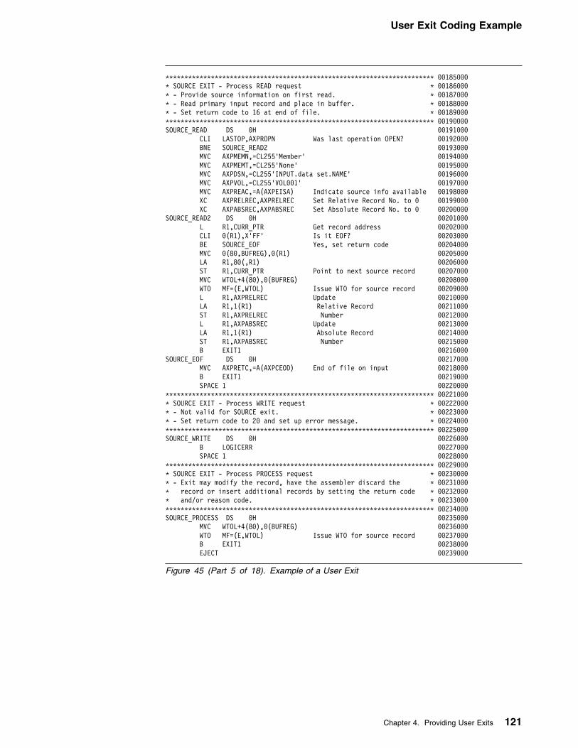
User Exit Coding Example
LLLLLLLLLLLLLLLLLLLLLLLLLLLLLLLLLLLLLLLLLLLLLLLLLLLLLLLLLLLLLLLLLLLLLLL 99185999L SOURCE EXIT - Process READ request L 99186999L - Provide source information on first read. L 99187999L - Read primary input record and place in buffer. L 99188999L - Set return code to 16 at end of file. L 99189999LLLLLLLLLLLLLLLLLLLLLLLLLLLLLLLLLLLLLLLLLLLLLLLLLLLLLLLLLLLLLLLLLLLLLLL 99199999SOURCE_READ DS 9H 99191999
CLI LASTOP,AXPROPN Was last operation OPEN? 99192999 BNE SOURCE_READ2 99193999 MVC AXPMEMN,=CL255'Member' 99194999 MVC AXPMEMT,=CL255'None' 99195999 MVC AXPDSN,=CL255'INPUT.data set.NAME' 99196999 MVC AXPVOL,=CL255'VOL991' 99197999
MVC AXPREAC,=A(AXPEISA) Indicate source info available 99198999XC AXPRELREC,AXPRELREC Set Relative Record No. to 9 99199999XC AXPABSREC,AXPABSREC Set Absolute Record No. to 9 99299999
SOURCE_READ2 DS 9H 99291999L R1,CURR_PTR Get record address 99292999CLI 9(R1),X'FF' Is it EOF? 99293999BE SOURCE_EOF Yes, set return code 99294999
MVC 9(89,BUFREG),9(R1) 99295999 LA R1,89(,R1) 99296999
ST R1,CURR_PTR Point to next source record 99297999 MVC WTOL+4(89),9(BUFREG) 99298999
WTO MF=(E,WTOL) Issue WTO for source record 99299999 L R1,AXPRELREC Update 99219999 LA R1,1(R1) Relative Record 99211999 ST R1,AXPRELREC Number 99212999 L R1,AXPABSREC Update 99213999 LA R1,1(R1) Absolute Record 99214999 ST R1,AXPABSREC Number 99215999 B EXIT1 99216999SOURCE_EOF DS 9H 99217999
MVC AXPRETC,=A(AXPCEOD) End of file on input 99218999 B EXIT1 99219999 SPACE 1 99229999LLLLLLLLLLLLLLLLLLLLLLLLLLLLLLLLLLLLLLLLLLLLLLLLLLLLLLLLLLLLLLLLLLLLLLL 99221999L SOURCE EXIT - Process WRITE request L 99222999L - Not valid for SOURCE exit. L 99223999L - Set return code to 29 and set up error message. L 99224999LLLLLLLLLLLLLLLLLLLLLLLLLLLLLLLLLLLLLLLLLLLLLLLLLLLLLLLLLLLLLLLLLLLLLLL 99225999SOURCE_WRITE DS 9H 99226999 B LOGICERR 99227999 SPACE 1 99228999LLLLLLLLLLLLLLLLLLLLLLLLLLLLLLLLLLLLLLLLLLLLLLLLLLLLLLLLLLLLLLLLLLLLLLL 99229999L SOURCE EXIT - Process PROCESS request L 99239999L - Exit may modify the record, have the assembler discard the L 99231999L record or insert additional records by setting the return code L 99232999L and/or reason code. L 99233999LLLLLLLLLLLLLLLLLLLLLLLLLLLLLLLLLLLLLLLLLLLLLLLLLLLLLLLLLLLLLLLLLLLLLLL 99234999SOURCE_PROCESS DS 9H 99235999 MVC WTOL+4(89),9(BUFREG) 99236999
WTO MF=(E,WTOL) Issue WTO for source record 99237999 B EXIT1 99238999 EJECT 99239999
Figure 45 (Part 5 of 18). Example of a User Exit
Chapter 4. Providing User Exits 121

User Exit Coding Example
LLLLLLLLLLLLLLLLLLLLLLLLLLLLLLLLLLLLLLLLLLLLLLLLLLLLLLLLLLLLLLLLLLLLLLL 99249999L LIBRARY EXIT L 99241999L - Process required request type L 99242999LLLLLLLLLLLLLLLLLLLLLLLLLLLLLLLLLLLLLLLLLLLLLLLLLLLLLLLLLLLLLLLLLLLLLLL 99243999LIBRARY DS 9H 99244999
L R15,AXPRTYP Get the request type value (1-8) 99245999BCTR R15,9 Decrement by 1 99246999SLL R15,1 Multiply by 2 99247999LH R15,LIBRARY_ADDR(R15) Index into Address list 99248999AR R15,R12 Calculate the address 99249999BR R15 Branch to applicable routine 99259999
LIBRARY_ADDR DC Y(LIBRARY_OPEN-MYEXIT) 99251999 DC Y(LIBRARY_CLOSE-MYEXIT) 99252999 DC Y(LIBRARY_READ-MYEXIT) 99253999 DC Y(LIBRARY_WRITE-MYEXIT) 99254999 DC Y(LIBRARY_PR_MAC-MYEXIT) 99255999 DC Y(LIBRARY_PR_CPY-MYEXIT) 99256999 DC Y(LIBRARY_FIND_MAC-MYEXIT) 99257999 DC Y(LIBRARY_FIND_CPY-MYEXIT) 99258999 DC Y(LIBRARY_EOM-MYEXIT) 99259999 DC Y(L-L) 99269999 SPACE 1 99261999LLLLLLLLLLLLLLLLLLLLLLLLLLLLLLLLLLLLLLLLLLLLLLLLLLLLLLLLLLLLLLLLLLLLLLL 99262999L LIBRARY EXIT - Process OPEN request L 99263999L - Pick up character string if it is supplied. L 99264999L - Set return code indicating whether the assembler, user exit or L 99265999L both will process the library. L 99266999L - Open data set if required. L 99267999LLLLLLLLLLLLLLLLLLLLLLLLLLLLLLLLLLLLLLLLLLLLLLLLLLLLLLLLLLLLLLLLLLLLLLL 99268999LIBRARY_OPEN DS 9H 99269999
MVI OPENPARM,C' ' Clear open parm 99279999 MVC OPENPARM+1(L'OPENPARM-1),OPENPARM 99271999
L R1,AXPBUFL Get the Buffer length 99272999LTR R1,R1 Is string length zero? 99273999BZ LIBRARY_NOSTR Yes, no string passed 99274999BCTR R1,9 Decrement for execute 99275999EX R1,UPPERSTR Move and uppercase string 99276999
LIBRARY_NOSTR DS 9H 99277999CLC OPENPARM(4),=CL8'EXIT' Will user exit process library 99278999
BE LIBRARY_OPEN_EXIT Yes 99279999CLC OPENPARM(4),=CL8'BOTH' Will Both process library 99289999
BE LIBRARY_OPEN_BOTH Yes 99281999MVC AXPRETC,=A(9) assembler to process library 99282999
B EXIT1 Return 99283999LIBRARY_OPEN_EXIT DS 9H 99284999 OI OPENFLAG,EXIT Set flag 99285999
MVC AXPRETC,=A(AXPCOPN) User exit to process library 99286999MVC AXPREAC,=A(AXPEEOM) EXIT to get End of member calls 99287999
B EXIT1 Return 99288999LIBRARY_OPEN_BOTH DS 9H 99289999 OI OPENFLAG,BOTH Set flag 99299999
MVC AXPRETC,=A(AXPCOPL) Both to process library 99291999MVC AXPREAC,=A(AXPEEOM) EXIT to get End of member calls 99292999
B EXIT1 Return 99293999 SPACE 1 99294999
Figure 45 (Part 6 of 18). Example of a User Exit
122 HLASM V1R4 Programmer’s Guide

User Exit Coding Example
LLLLLLLLLLLLLLLLLLLLLLLLLLLLLLLLLLLLLLLLLLLLLLLLLLLLLLLLLLLLLLLLLLLLLLL 99295999L LIBRARY EXIT - Process CLOSE request L 99296999L - Close data set if required. L 99297999L - Free storage and return. L 99298999LLLLLLLLLLLLLLLLLLLLLLLLLLLLLLLLLLLLLLLLLLLLLLLLLLLLLLLLLLLLLLLLLLLLLLL 99299999LIBRARY_CLOSE DS 9H 99399999
USING LIBSTACK,R2 Map stack entries 99391999ICM R2,B'1111',STACKPTR Check that stack is empty 99392999BZ FREESTOR It should be! 99393999
LIBRARY_FREE_LOOP DS 9H 99394999LTR R1,R2 Load address for FREEMAIN 99395999
BZ FREESTOR Finished here 99396999L R2,NEXT_MEM Prepare for next loop 99397999LA R9,LIBSTACK_LEN Load length for FREEMAIN 99398999FREEMAIN R,A=(1),LV=(9) Free the storage acquired 99399999
B LIBRARY_FREE_LOOP 99319999 SPACE 1 99311999LLLLLLLLLLLLLLLLLLLLLLLLLLLLLLLLLLLLLLLLLLLLLLLLLLLLLLLLLLLLLLLLLLLLLLL 99312999L LIBRARY EXIT - Process READ request L 99313999L - Read copy/macro source and place in buffer. L 99314999L - Set return code to 16 at end of member. L 99315999LLLLLLLLLLLLLLLLLLLLLLLLLLLLLLLLLLLLLLLLLLLLLLLLLLLLLLLLLLLLLLLLLLLLLLL 99316999LIBRARY_READ DS 9H 99317999
ICM R2,B'1111',STACKPTR Is the stack empty? 99318999BZ LIBRARY_STACK_ERR It shouldn't be! 99319999L R1,MEM_PTR Get record address 99329999CLI 9(R1),X'FF' Is it EOF? 99321999BE LIBRARY_EOF Yes, set return code 99322999
MVC 9(89,BUFREG),9(R1) 99323999LA R1,89(,R1) Point to next record address 99324999ST R1,MEM_PTR and save in stack entry 99325999
MVC WTOL+4(89),9(BUFREG) 99326999WTO MF=(E,WTOL) Issue WTO for library record 99327999
L R1,AXPRELREC Update 99328999 LA R1,1(R1) Relative Record 99329999 ST R1,AXPRELREC Number 99339999
ST R1,MEM_RELREC and save in stack entry 99331999 L R1,AXPABSREC Update 99332999 LA R1,1(R1) Absolute Record 99333999 ST R1,AXPABSREC Number 99334999 B EXIT1 99335999LIBRARY_EOF DS 9H 99336999
MVC AXPRETC,=A(AXPCEOD) End of file on input 99337999 B EXIT1 99338999 SPACE 1 99339999LLLLLLLLLLLLLLLLLLLLLLLLLLLLLLLLLLLLLLLLLLLLLLLLLLLLLLLLLLLLLLLLLLLLLLL 99349999L LIBRARY EXIT - Process WRITE request L 99341999L - Not valid for LIBRARY exit. L 99342999L - Set return code to 29 and set up error message. L 99343999LLLLLLLLLLLLLLLLLLLLLLLLLLLLLLLLLLLLLLLLLLLLLLLLLLLLLLLLLLLLLLLLLLLLLLL 99344999LIBRARY_WRITE DS 9H 99345999 B LOGICERR 99346999 SPACE 1 99347999LLLLLLLLLLLLLLLLLLLLLLLLLLLLLLLLLLLLLLLLLLLLLLLLLLLLLLLLLLLLLLLLLLLLLLL 99348999L LIBRARY EXIT - Process PROCESS MACRO/COPY request L 99349999L - Exit may modify the record, have the assembler discard the L 99359999L record or insert additional records by setting the return code L 99351999L and/or reason code. L 99352999LLLLLLLLLLLLLLLLLLLLLLLLLLLLLLLLLLLLLLLLLLLLLLLLLLLLLLLLLLLLLLLLLLLLLLL 99353999LIBRARY_PR_MAC DS 9H 99354999LIBRARY_PR_CPY DS 9H 99355999 MVC WTOL+4(89),9(BUFREG) 99356999
WTO MF=(E,WTOL) Issue WTO for library record 99357999 B EXIT1 99358999 SPACE 1 99359999
Figure 45 (Part 7 of 18). Example of a User Exit
Chapter 4. Providing User Exits 123
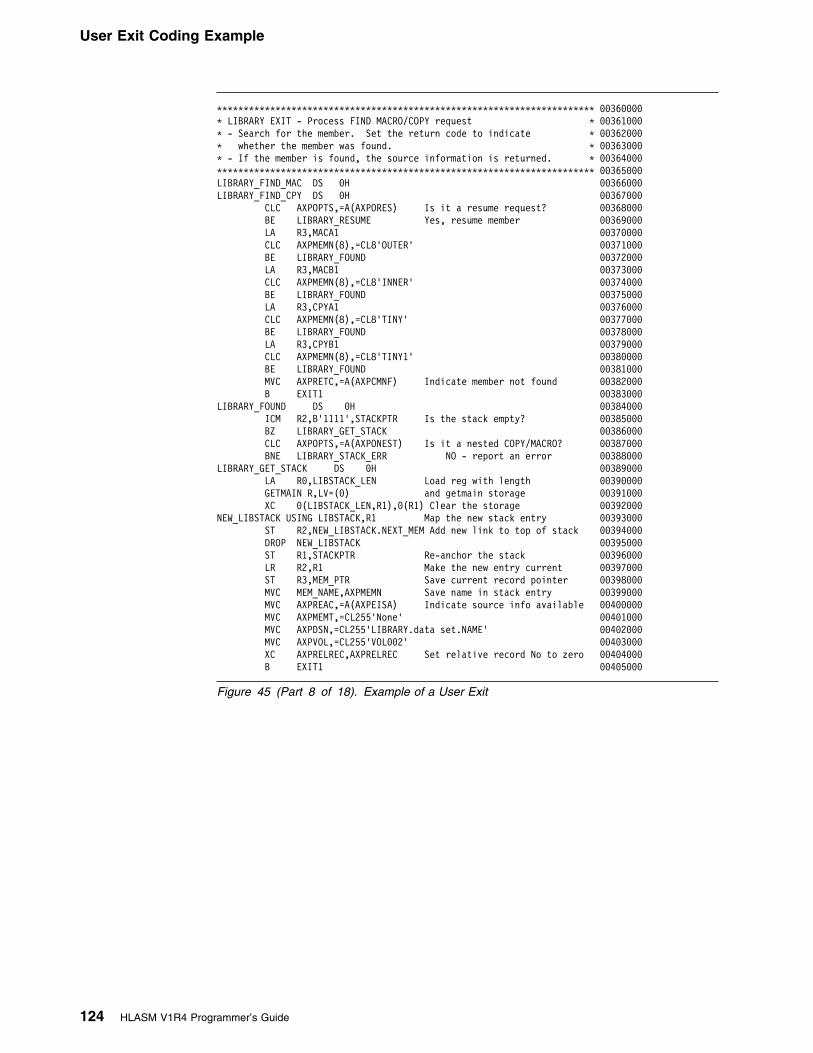
User Exit Coding Example
LLLLLLLLLLLLLLLLLLLLLLLLLLLLLLLLLLLLLLLLLLLLLLLLLLLLLLLLLLLLLLLLLLLLLLL 99369999L LIBRARY EXIT - Process FIND MACRO/COPY request L 99361999L - Search for the member. Set the return code to indicate L 99362999L whether the member was found. L 99363999L - If the member is found, the source information is returned. L 99364999LLLLLLLLLLLLLLLLLLLLLLLLLLLLLLLLLLLLLLLLLLLLLLLLLLLLLLLLLLLLLLLLLLLLLLL 99365999LIBRARY_FIND_MAC DS 9H 99366999LIBRARY_FIND_CPY DS 9H 99367999
CLC AXPOPTS,=A(AXPORES) Is it a resume request? 99368999BE LIBRARY_RESUME Yes, resume member 99369999
LA R3,MACA1 99379999 CLC AXPMEMN(8),=CL8'OUTER' 99371999 BE LIBRARY_FOUND 99372999 LA R3,MACB1 99373999 CLC AXPMEMN(8),=CL8'INNER' 99374999 BE LIBRARY_FOUND 99375999 LA R3,CPYA1 99376999 CLC AXPMEMN(8),=CL8'TINY' 99377999 BE LIBRARY_FOUND 99378999 LA R3,CPYB1 99379999 CLC AXPMEMN(8),=CL8'TINY1' 99389999 BE LIBRARY_FOUND 99381999
MVC AXPRETC,=A(AXPCMNF) Indicate member not found 99382999 B EXIT1 99383999LIBRARY_FOUND DS 9H 99384999
ICM R2,B'1111',STACKPTR Is the stack empty? 99385999 BZ LIBRARY_GET_STACK 99386999
CLC AXPOPTS,=A(AXPONEST) Is it a nested COPY/MACRO? 99387999BNE LIBRARY_STACK_ERR NO - report an error 99388999
LIBRARY_GET_STACK DS 9H 99389999LA R9,LIBSTACK_LEN Load reg with length 99399999GETMAIN R,LV=(9) and getmain storage 99391999XC 9(LIBSTACK_LEN,R1),9(R1) Clear the storage 99392999
NEW_LIBSTACK USING LIBSTACK,R1 Map the new stack entry 99393999ST R2,NEW_LIBSTACK.NEXT_MEM Add new link to top of stack 99394999
DROP NEW_LIBSTACK 99395999ST R1,STACKPTR Re-anchor the stack 99396999LR R2,R1 Make the new entry current 99397999ST R3,MEM_PTR Save current record pointer 99398999MVC MEM_NAME,AXPMEMN Save name in stack entry 99399999MVC AXPREAC,=A(AXPEISA) Indicate source info available 99499999
MVC AXPMEMT,=CL255'None' 99491999 MVC AXPDSN,=CL255'LIBRARY.data set.NAME' 99492999 MVC AXPVOL,=CL255'VOL992' 99493999
XC AXPRELREC,AXPRELREC Set relative record No to zero 99494999 B EXIT1 99495999
Figure 45 (Part 8 of 18). Example of a User Exit
124 HLASM V1R4 Programmer’s Guide

User Exit Coding Example
LLLLLLLLLLLLLLLLLLLLLLLLLLLLLLLLLLLLLLLLLLLLLLLLLLLLLLLLLLLLLLLLLLLLLLL 99496999L LIBRARY EXIT - Process FIND (resume) request L 99497999L - Set the relative record number in the parameter list L 99498999L N.B. if the EXIT read the records from disk, at this point it would L 99499999L use the information saved in the stack to reposition itself L 99419999L ready for the next read. (i.e. a FIND and POINT) L 99411999LLLLLLLLLLLLLLLLLLLLLLLLLLLLLLLLLLLLLLLLLLLLLLLLLLLLLLLLLLLLLLLLLLLLLLL 99412999LIBRARY_RESUME DS 9H Stack Management now in EOM call 99413999
MVC AXPRETC,=A(AXPCMNF) Assume member not found 99414999ICM R2,B'1111',STACKPTR Is the stack empty? 99415999BZ LIBRARY_CHECK_BOTH Yes - check open option 99416999CLC MEM_NAME,AXPMEMN Compare name with stack entry 99417999BNE LIBRARY_CHECK_BOTH Not equal - check open option 99418999MVC AXPRETC,=A(9) Correct our assumption 99419999L R9,MEM_RELREC Get saved rel rec no from stack 99429999ST R9,AXPRELREC Set relative record No 99421999
B EXIT1 99422999 SPACE 1 99423999LLLLLLLLLLLLLLLLLLLLLLLLLLLLLLLLLLLLLLLLLLLLLLLLLLLLLLLLLLLLLLLLLLLLLLL 99424999L LIBRARY EXIT - Use End of Member calls to perform stack management L 99425999L - Compare member name, if equal unstack the top entry L 99426999LLLLLLLLLLLLLLLLLLLLLLLLLLLLLLLLLLLLLLLLLLLLLLLLLLLLLLLLLLLLLLLLLLLLLLL 99427999LIBRARY_EOM DS 9H 99428999
ICM R2,B'1111',STACKPTR Is the stack empty? 99429999BZ LIBRARY_CHECK_BOTH Yes - check open option 99439999CLC MEM_NAME,AXPMEMN Compare name with stack entry 99431999BNE LIBRARY_CHECK_BOTH Not equal - check open option 99432999LR R1,R2 Load address for FREEMAIN 99433999L R2,NEXT_MEM Get address of next entry 99434999ST R2,STACKPTR and save it. 99435999
DROP R2 99436999LA R9,LIBSTACK_LEN Load length for FREEMAIN 99437999FREEMAIN R,A=(1),LV=(9) Free the storage acquired 99438999
LIBRARY_CHECK_BOTH DS 9H 99439999CLI OPENFLAG,BOTH Did EXIT open with BOTH option 99449999BE EXIT1 Yes - don't issue error msg 99441999
LLLLLLLLLLLLLLLLLLLLLLLLLLLLLLLLLLLLLLLLLLLLLLLLLLLLLLLLLLLLLLLLLLLLLLL 99442999L LIBRARY EXIT - Stack Error Routine L 99443999L - If an error occurred, set up the error message in the buffer L 99444999L and length in AXPERRL. Set the severity code. L 99445999L - Set the return code to 29. L 99446999L - Return to the caller. L 99447999LLLLLLLLLLLLLLLLLLLLLLLLLLLLLLLLLLLLLLLLLLLLLLLLLLLLLLLLLLLLLLLLLLLLLLL 99448999LIBRARY_STACK_ERR DS 9H 99449999
MVC AXPRETC,=A(AXPCBAD) Severe error occurred 99459999MVC ERRBUFF(ERRMSGL),STKMSG Set up error message 99451999MVC AXPERRL,=A(STKMSGL) Set up error message length 99452999MVC AXPSEVC,=A(29) Set up error message severity 99453999
B EXIT1 99454999 EJECT 99455999
Figure 45 (Part 9 of 18). Example of a User Exit
Chapter 4. Providing User Exits 125

User Exit Coding Example
LLLLLLLLLLLLLLLLLLLLLLLLLLLLLLLLLLLLLLLLLLLLLLLLLLLLLLLLLLLLLLLLLLLLLLL 99456999L LISTING EXIT L 99457999L - Process required request type L 99458999LLLLLLLLLLLLLLLLLLLLLLLLLLLLLLLLLLLLLLLLLLLLLLLLLLLLLLLLLLLLLLLLLLLLLLL 99459999LISTING DS 9H 99469999
L R15,AXPRTYP Get the request type value (1-5) 99461999BCTR R15,9 Decrement by 1 99462999SLL R15,1 Multiply by 2 99463999LH R15,LISTING_ADDR(R15) Index into Address list 99464999AR R15,R12 Calculate the address 99465999BR R15 Branch to applicable routine 99466999
LISTING_ADDR DC Y(LISTING_OPEN-MYEXIT) 99467999 DC Y(LISTING_CLOSE-MYEXIT) 99468999 DC Y(LISTING_READ-MYEXIT) 99469999 DC Y(LISTING_WRITE-MYEXIT) 99479999 DC Y(LISTING_PROCESS-MYEXIT) 99471999 DC Y(L-L) 99472999 SPACE 1 99473999LLLLLLLLLLLLLLLLLLLLLLLLLLLLLLLLLLLLLLLLLLLLLLLLLLLLLLLLLLLLLLLLLLLLLLL 99474999L LISTING EXIT - Process OPEN request L 99475999L - Pick up character string if it is supplied. L 99476999L - Set return code indicating whether the assembler or the user exit L 99477999L will write the listing. L 99478999L - Open data set if required. L 99479999LLLLLLLLLLLLLLLLLLLLLLLLLLLLLLLLLLLLLLLLLLLLLLLLLLLLLLLLLLLLLLLLLLLLLLL 99489999LISTING_OPEN DS 9H 99481999
MVI OPENPARM,C' ' Clear open parm 99482999 MVC OPENPARM+1(L'OPENPARM-1),OPENPARM 99483999
L R1,AXPBUFL Get the Buffer length 99484999LTR R1,R1 Is string length zero? 99485999BZ LISTING_NOSTR Yes, no string passed 99486999BCTR R1,9 Decrement for execute 99487999EX R1,UPPERSTR Move and uppercase string 99488999
LISTING_NOSTR DS 9H 99489999CLC OPENPARM(4),=CL8'EXIT' Will user exit process listing 99499999
BE LISTING_OPEN_EXIT Yes 99491999MVC AXPRETC,=A(9) assembler to write listing 99492999
B EXIT1 Return 99493999LISTING_OPEN_EXIT DS 9H 99494999 OI OPENFLAG,EXIT Set flag 99495999
MVC AXPRETC,=A(AXPCOPN) User exit to write listing 99496999 MVC AXPMEMN,=CL255' ' 99497999 MVC AXPMEMT,=CL255' ' 99498999 MVC AXPDSN,=CL255'LISTING.data set.NAME' 99499999 MVC AXPVOL,=CL255'VOL991' 99599999
MVC AXPREAC,=A(AXPEISA) Indicate data set info available 99591999XC AXPRELREC,AXPRELREC Set Relative Record No. to 9 99592999XC AXPABSREC,AXPABSREC Set Absolute Record No. to 9 99593999
B EXIT1 Return 99594999 SPACE 1 99595999
Figure 45 (Part 10 of 18). Example of a User Exit
126 HLASM V1R4 Programmer’s Guide

User Exit Coding Example
LLLLLLLLLLLLLLLLLLLLLLLLLLLLLLLLLLLLLLLLLLLLLLLLLLLLLLLLLLLLLLLLLLLLLLL 99596999L LISTING EXIT - Process CLOSE request L 99597999L - Close data set if required L 99598999L - Free storage and return. L 99599999LLLLLLLLLLLLLLLLLLLLLLLLLLLLLLLLLLLLLLLLLLLLLLLLLLLLLLLLLLLLLLLLLLLLLLL 99519999LISTING_CLOSE DS 9H 99511999 B FREESTOR 99512999 SPACE 1 99513999LLLLLLLLLLLLLLLLLLLLLLLLLLLLLLLLLLLLLLLLLLLLLLLLLLLLLLLLLLLLLLLLLLLLLLL 99514999L LISTING EXIT - Process READ request L 99515999L - Not valid for LISTING exit. L 99516999L - Set return code to 29 and set up error message. L 99517999LLLLLLLLLLLLLLLLLLLLLLLLLLLLLLLLLLLLLLLLLLLLLLLLLLLLLLLLLLLLLLLLLLLLLLL 99518999LISTING_READ DS 9H 99519999 B LOGICERR 99529999LLLLLLLLLLLLLLLLLLLLLLLLLLLLLLLLLLLLLLLLLLLLLLLLLLLLLLLLLLLLLLLLLLLLLLL 99521999L LISTING EXIT - Process WRITE request L 99522999L - Write the listing record passed. L 99523999LLLLLLLLLLLLLLLLLLLLLLLLLLLLLLLLLLLLLLLLLLLLLLLLLLLLLLLLLLLLLLLLLLLLLLL 99524999LISTING_WRITE DS 9H 99525999 MVC WTOL+4(89),9(BUFREG) 99526999
WTO MF=(E,WTOL) Issue WTO for listing record 99527999 L R1,AXPRELREC Update 99528999 LA R1,1(R1) Relative Record 99529999 ST R1,AXPRELREC Number 99539999 L R1,AXPABSREC Update 99531999 LA R1,1(R1) Absolute Record 99532999 ST R1,AXPABSREC Number 99533999 B EXIT1 99534999 SPACE 1 99535999LLLLLLLLLLLLLLLLLLLLLLLLLLLLLLLLLLLLLLLLLLLLLLLLLLLLLLLLLLLLLLLLLLLLLLL 99536999L LISTING EXIT - Process PROCESS request L 99537999L - Exit may modify the record, have the assembler discard the L 99538999L record or insert additional records by setting the return code L 99539999L and/or reason code. L 99549999LLLLLLLLLLLLLLLLLLLLLLLLLLLLLLLLLLLLLLLLLLLLLLLLLLLLLLLLLLLLLLLLLLLLLLL 99541999LISTING_PROCESS DS 9H 99542999 MVC WTOL+4(89),9(BUFREG) 99543999
WTO MF=(E,WTOL) Issue WTO for listing record 99544999 B EXIT1 99545999 EJECT 99546999
Figure 45 (Part 11 of 18). Example of a User Exit
Chapter 4. Providing User Exits 127

User Exit Coding Example
LLLLLLLLLLLLLLLLLLLLLLLLLLLLLLLLLLLLLLLLLLLLLLLLLLLLLLLLLLLLLLLLLLLLLLL 99547999L OBJECT EXIT L 99548999L - Process required request type L 99549999LLLLLLLLLLLLLLLLLLLLLLLLLLLLLLLLLLLLLLLLLLLLLLLLLLLLLLLLLLLLLLLLLLLLLLL 99559999PUNCH DS 9H 99551999OBJECT DS 9H 99552999
L R15,AXPRTYP Get the request type value (1-5) 99553999BCTR R15,9 Decrement by 1 99554999SLL R15,1 Multiply by 2 99555999LH R15,OBJECT_ADDR(R15) Index into Address list 99556999AR R15,R12 Calculate the address 99557999BR R15 Branch to applicable routine 99558999
OBJECT_ADDR DC Y(OBJECT_OPEN-MYEXIT) 99559999 DC Y(OBJECT_CLOSE-MYEXIT) 99569999 DC Y(OBJECT_READ-MYEXIT) 99561999 DC Y(OBJECT_WRITE-MYEXIT) 99562999 DC Y(OBJECT_PROCESS-MYEXIT) 99563999 DC Y(L-L) 99564999 SPACE 1 99565999LLLLLLLLLLLLLLLLLLLLLLLLLLLLLLLLLLLLLLLLLLLLLLLLLLLLLLLLLLLLLLLLLLLLLLL 99566999L OBJECT EXIT - Process OPEN request L 99567999L - Pick up character string if it is supplied. L 99568999L - Set return code indicating whether the assembler or the user exit L 99569999L will write the object/punch records. L 99579999L - Open data set if required L 99571999LLLLLLLLLLLLLLLLLLLLLLLLLLLLLLLLLLLLLLLLLLLLLLLLLLLLLLLLLLLLLLLLLLLLLLL 99572999OBJECT_OPEN DS 9H 99573999
MVI OPENPARM,C' ' Clear open parm 99574999 MVC OPENPARM+1(L'OPENPARM-1),OPENPARM 99575999
L R1,AXPBUFL Get the Buffer length 99576999LTR R1,R1 Is string length zero? 99577999BZ OBJECT_NOSTR Yes, no string passed 99578999BCTR R1,9 Decrement for execute 99579999EX R1,UPPERSTR Move and uppercase string 99589999
OBJECT_NOSTR DS 9H 99581999CLC OPENPARM(4),=CL8'EXIT' Will user exit process object 99582999
BE OBJECT_OPEN_EXIT Yes 99583999MVC AXPRETC,=A(9) assembler to write object/punch 99584999
B EXIT1 Return 99585999OBJECT_OPEN_EXIT DS 9H 99586999 OI OPENFLAG,EXIT Set flag 99587999
MVC AXPRETC,=A(AXPCOPN) User exit to write object/punch 99588999 MVC AXPMEMN,=CL255'Member' 99589999 MVC AXPMEMT,=CL255' ' 99599999 MVC AXPDSN,=CL255'OBJECT.data set.NAME' 99591999 MVC AXPVOL,=CL255'VOL991' 99592999
MVC AXPREAC,=A(AXPEISA) Indicate data set info available 99593999XC AXPRELREC,AXPRELREC Set Relative Record No. to 9 99594999XC AXPABSREC,AXPABSREC Set Absolute Record No. to 9 99595999
B EXIT1 Return 99596999 SPACE 1 99597999
Figure 45 (Part 12 of 18). Example of a User Exit
128 HLASM V1R4 Programmer’s Guide

User Exit Coding Example
LLLLLLLLLLLLLLLLLLLLLLLLLLLLLLLLLLLLLLLLLLLLLLLLLLLLLLLLLLLLLLLLLLLLLLL 99598999L OBJECT EXIT - Process CLOSE request L 99599999L - Close data set if required. L 99699999L - Free storage and return. L 99691999LLLLLLLLLLLLLLLLLLLLLLLLLLLLLLLLLLLLLLLLLLLLLLLLLLLLLLLLLLLLLLLLLLLLLLL 99692999OBJECT_CLOSE DS 9H 99693999 B FREESTOR 99694999 SPACE 1 99695999LLLLLLLLLLLLLLLLLLLLLLLLLLLLLLLLLLLLLLLLLLLLLLLLLLLLLLLLLLLLLLLLLLLLLLL 99696999L OBJECT EXIT - Process READ request L 99697999L - Not valid for OBJECT exit. L 99698999L - Set return code to 29 and set up error message. L 99699999LLLLLLLLLLLLLLLLLLLLLLLLLLLLLLLLLLLLLLLLLLLLLLLLLLLLLLLLLLLLLLLLLLLLLLL 99619999OBJECT_READ DS 9H 99611999 B LOGICERR 99612999LLLLLLLLLLLLLLLLLLLLLLLLLLLLLLLLLLLLLLLLLLLLLLLLLLLLLLLLLLLLLLLLLLLLLLL 99613999L OBJECT EXIT - Process WRITE request L 99614999L - Write the source record passed. L 99615999LLLLLLLLLLLLLLLLLLLLLLLLLLLLLLLLLLLLLLLLLLLLLLLLLLLLLLLLLLLLLLLLLLLLLLL 99616999OBJECT_WRITE DS 9H 99617999 MVC WTOL+4(89),9(BUFREG) 99618999
WTO MF=(E,WTOL) Issue WTO for object record 99619999 L R1,AXPRELREC Update 99629999 LA R1,1(R1) Relative Record 99621999 ST R1,AXPRELREC Number 99622999 L R1,AXPABSREC Update 99623999 LA R1,1(R1) Absolute Record 99624999 ST R1,AXPABSREC Number 99625999 B EXIT1 99626999 SPACE 1 99627999LLLLLLLLLLLLLLLLLLLLLLLLLLLLLLLLLLLLLLLLLLLLLLLLLLLLLLLLLLLLLLLLLLLLLLL 99628999L OBJECT EXIT - Process PROCESS request L 99629999L - Exit may modify the record, have the assembler discard the L 99639999L record or insert additional records by setting the return code L 99631999L and/or reason code. L 99632999LLLLLLLLLLLLLLLLLLLLLLLLLLLLLLLLLLLLLLLLLLLLLLLLLLLLLLLLLLLLLLLLLLLLLLL 99633999OBJECT_PROCESS DS 9H 99634999 MVC WTOL+4(89),9(BUFREG) 99635999
WTO MF=(E,WTOL) Issue WTO for object record 99636999 B EXIT1 99637999 EJECT 99638999
Figure 45 (Part 13 of 18). Example of a User Exit
Chapter 4. Providing User Exits 129

User Exit Coding Example
LLLLLLLLLLLLLLLLLLLLLLLLLLLLLLLLLLLLLLLLLLLLLLLLLLLLLLLLLLLLLLLLLLLLLLL 99639999L ADATA EXIT L 99649999L - Process required request type L 99641999LLLLLLLLLLLLLLLLLLLLLLLLLLLLLLLLLLLLLLLLLLLLLLLLLLLLLLLLLLLLLLLLLLLLLLL 99642999ADATA DS 9H 99643999
L R15,AXPRTYP Get the request type value (1-5) 99644999BCTR R15,9 Decrement by 1 99645999SLL R15,1 Multiply by 2 99646999LH R15,ADATA_ADDR(R15) Index into Address list 99647999AR R15,R12 Calculate the address 99648999BR R15 Branch to applicable routine 99649999
ADATA_ADDR DC Y(ADATA_OPEN-MYEXIT) 99659999 DC Y(ADATA_CLOSE-MYEXIT) 99651999 DC Y(ADATA_READ-MYEXIT) 99652999 DC Y(ADATA_WRITE-MYEXIT) 99653999 DC Y(ADATA_PROCESS-MYEXIT) 99654999 DC Y(L-L) 99655999 SPACE 1 99656999LLLLLLLLLLLLLLLLLLLLLLLLLLLLLLLLLLLLLLLLLLLLLLLLLLLLLLLLLLLLLLLLLLLLLLL 99657999L ADATA EXIT - Process OPEN request L 99658999L - Pick up character string if it is supplied. L 99659999LLLLLLLLLLLLLLLLLLLLLLLLLLLLLLLLLLLLLLLLLLLLLLLLLLLLLLLLLLLLLLLLLLLLLLL 99669999ADATA_OPEN DS 9H 99661999
MVI OPENPARM,C' ' Clear open parm 99662999 MVC OPENPARM+1(L'OPENPARM-1),OPENPARM 99663999
L R1,AXPBUFL Get the Buffer length 99664999LTR R1,R1 Is string length zero? 99665999BZ ADATA_NOSTR Yes, no string passed 99666999BCTR R1,9 Decrement for execute 99667999EX R1,UPPERSTR Move and uppercase string 99668999
ADATA_NOSTR DS 9H 99669999 B EXIT1 Return 99679999 SPACE 1 99671999LLLLLLLLLLLLLLLLLLLLLLLLLLLLLLLLLLLLLLLLLLLLLLLLLLLLLLLLLLLLLLLLLLLLLLL 99672999L ADATA EXIT - Process CLOSE request L 99673999L - Close data set if required. L 99674999L - Free storage and return. L 99675999LLLLLLLLLLLLLLLLLLLLLLLLLLLLLLLLLLLLLLLLLLLLLLLLLLLLLLLLLLLLLLLLLLLLLLL 99676999ADATA_CLOSE DS 9H 99677999 B FREESTOR 99678999 SPACE 1 99679999LLLLLLLLLLLLLLLLLLLLLLLLLLLLLLLLLLLLLLLLLLLLLLLLLLLLLLLLLLLLLLLLLLLLLLL 99689999L ADATA EXIT - Process READ request L 99681999L - Not valid for ADATA exit. L 99682999L - Set return code to 29 and set up error message. L 99683999LLLLLLLLLLLLLLLLLLLLLLLLLLLLLLLLLLLLLLLLLLLLLLLLLLLLLLLLLLLLLLLLLLLLLLL 99684999ADATA_READ DS 9H 99685999 B LOGICERR 99686999LLLLLLLLLLLLLLLLLLLLLLLLLLLLLLLLLLLLLLLLLLLLLLLLLLLLLLLLLLLLLLLLLLLLLLL 99687999L ADATA EXIT - Process WRITE request L 99688999L - Not valid for ADATA exit. L 99689999L - Set return code to 29 and set up error message. L 99699999LLLLLLLLLLLLLLLLLLLLLLLLLLLLLLLLLLLLLLLLLLLLLLLLLLLLLLLLLLLLLLLLLLLLLLL 99691999ADATA_WRITE DS 9H 99692999 B LOGICERR 99693999 SPACE 1 99694999LLLLLLLLLLLLLLLLLLLLLLLLLLLLLLLLLLLLLLLLLLLLLLLLLLLLLLLLLLLLLLLLLLLLLLL 99695999L ADATA EXIT - Process PROCESS request L 99696999L - Exit may check the record but it may not modify the record, L 99697999L discard the record or insert additional records. L 99698999LLLLLLLLLLLLLLLLLLLLLLLLLLLLLLLLLLLLLLLLLLLLLLLLLLLLLLLLLLLLLLLLLLLLLLL 99699999ADATA_PROCESS DS 9H 99799999 MVC WTOL+4(89),9(BUFREG) 99791999
WTO MF=(E,WTOL) Issue WTO for ADATA record 99792999 B EXIT1 99793999 EJECT 99794999
Figure 45 (Part 14 of 18). Example of a User Exit
130 HLASM V1R4 Programmer’s Guide

User Exit Coding Example
LLLLLLLLLLLLLLLLLLLLLLLLLLLLLLLLLLLLLLLLLLLLLLLLLLLLLLLLLLLLLLLLLLLLLLL 99795999L TERM EXIT L 99796999L - Process required request type L 99797999LLLLLLLLLLLLLLLLLLLLLLLLLLLLLLLLLLLLLLLLLLLLLLLLLLLLLLLLLLLLLLLLLLLLLLL 99798999TERM DS 9H 99799999
L R15,AXPRTYP Get the request type value (1-5) 99719999BCTR R15,9 Decrement by 1 99711999SLL R15,1 Multiply by 2 99712999LH R15,TERM_ADDR(R15) Index into Address list 99713999AR R15,R12 Calculate the address 99714999BR R15 Branch to applicable routine 99715999
TERM_ADDR DC Y(TERM_OPEN-MYEXIT) 99716999 DC Y(TERM_CLOSE-MYEXIT) 99717999 DC Y(TERM_READ-MYEXIT) 99718999 DC Y(TERM_WRITE-MYEXIT) 99719999 DC Y(TERM_PROCESS-MYEXIT) 99729999 DC Y(L-L) 99721999 SPACE 1 99722999LLLLLLLLLLLLLLLLLLLLLLLLLLLLLLLLLLLLLLLLLLLLLLLLLLLLLLLLLLLLLLLLLLLLLLL 99723999L TERM EXIT - Process OPEN request L 99724999L - Pick up character string if it is supplied. L 99725999L - Set return code indicating whether the assembler or the user exit L 99726999L will write the terminal records. L 99727999L - Open data set if required. L 99728999LLLLLLLLLLLLLLLLLLLLLLLLLLLLLLLLLLLLLLLLLLLLLLLLLLLLLLLLLLLLLLLLLLLLLLL 99729999TERM_OPEN DS 9H 99739999
MVI OPENPARM,C' ' Clear open parm 99731999 MVC OPENPARM+1(L'OPENPARM-1),OPENPARM 99732999
L R1,AXPBUFL Get the Buffer length 99733999LTR R1,R1 Is string length zero? 99734999BZ TERM_NOSTR Yes, no string passed 99735999BCTR R1,9 Decrement for execute 99736999EX R1,UPPERSTR Move and uppercase string 99737999
TERM_NOSTR DS 9H 99738999CLC OPENPARM(4),=CL8'EXIT' Will user exit process records? 99739999
BE TERM_OPEN_EXIT Yes 99749999MVC AXPRETC,=A(9) assembler to write records 99741999
B EXIT1 Return 99742999TERM_OPEN_EXIT DS 9H 99743999 OI OPENFLAG,EXIT Set flag 99744999
MVC AXPRETC,=A(AXPCOPN) User exit to write records 99745999 MVC AXPMEMN,=CL255' ' 99746999 MVC AXPMEMT,=CL255' ' 99747999 MVC AXPDSN,=CL255'TERM.data set.NAME' 99748999 MVC AXPVOL,=CL255'VOL991' 99749999
MVC AXPREAC,=A(AXPEISA) Indicate data set info available 99759999XC AXPRELREC,AXPRELREC Set Relative Record No. to 9 99751999XC AXPABSREC,AXPABSREC Set Absolute Record No. to 9 99752999
B EXIT1 Return 99753999 SPACE 1 99754999
Figure 45 (Part 15 of 18). Example of a User Exit
Chapter 4. Providing User Exits 131

User Exit Coding Example
LLLLLLLLLLLLLLLLLLLLLLLLLLLLLLLLLLLLLLLLLLLLLLLLLLLLLLLLLLLLLLLLLLLLLLL 99755999L TERM EXIT - Process CLOSE request L 99756999L - Close data set if required. L 99757999L - Free storage and return. L 99758999LLLLLLLLLLLLLLLLLLLLLLLLLLLLLLLLLLLLLLLLLLLLLLLLLLLLLLLLLLLLLLLLLLLLLLL 99759999TERM_CLOSE DS 9H 99769999 B FREESTOR 99761999 SPACE 1 99762999LLLLLLLLLLLLLLLLLLLLLLLLLLLLLLLLLLLLLLLLLLLLLLLLLLLLLLLLLLLLLLLLLLLLLLL 99763999L TERM EXIT - Process READ request L 99764999L - Not valid for TERM exit. L 99765999L - Set return code to 29 and set up error message. L 99766999LLLLLLLLLLLLLLLLLLLLLLLLLLLLLLLLLLLLLLLLLLLLLLLLLLLLLLLLLLLLLLLLLLLLLLL 99767999TERM_READ DS 9H 99768999 B LOGICERR 99769999LLLLLLLLLLLLLLLLLLLLLLLLLLLLLLLLLLLLLLLLLLLLLLLLLLLLLLLLLLLLLLLLLLLLLLL 99779999L TERM EXIT - Process WRITE request L 99771999L - Write the terminal record passed. L 99772999LLLLLLLLLLLLLLLLLLLLLLLLLLLLLLLLLLLLLLLLLLLLLLLLLLLLLLLLLLLLLLLLLLLLLLL 99773999TERM_WRITE DS 9H 99774999 MVC WTOL+4(68),9(BUFREG) 99775999
WTO MF=(E,WTOL) Issue WTO for terminal record 99776999 L R1,AXPRELREC Update 99777999 LA R1,1(R1) Relative Record 99778999 ST R1,AXPRELREC Number 99779999 L R1,AXPABSREC Update 99789999 LA R1,1(R1) Absolute Record 99781999 ST R1,AXPABSREC Number 99782999 B EXIT1 99783999 SPACE 1 99784999LLLLLLLLLLLLLLLLLLLLLLLLLLLLLLLLLLLLLLLLLLLLLLLLLLLLLLLLLLLLLLLLLLLLLLL 99785999L TERM EXIT - Process PROCESS request L 99786999L - Exit may modify the record, have the assembler discard the L 99787999L record or insert additional records by setting the return code L 99788999L and/or reason code. L 99789999LLLLLLLLLLLLLLLLLLLLLLLLLLLLLLLLLLLLLLLLLLLLLLLLLLLLLLLLLLLLLLLLLLLLLLL 99799999TERM_PROCESS DS 9H 99791999 MVC WTOL+4(68),9(BUFREG) 99792999
WTO MF=(E,WTOL) Issue WTO for terminal record 99793999 B EXIT1 99794999STKMSG DC C'LIBRARY EXIT encountered a stack error' 99795999STKMSGL EQU L-ERRMSG 99796999ERRMSG DC C'Invalid EXIT type or Request type passed to exit' 99797999ERRMSGL EQU L-ERRMSG 99798999WTOL WTO '1234567899123456789912345678991234567899123456789912345X99799999 6789912345678991234567899',MF=L 99899999UPPERSTR OC OPENPARM(L-L),9(BUFREG) Move and uppercase string 99891999 SPACE 1 99892999
Figure 45 (Part 16 of 18). Example of a User Exit
132 HLASM V1R4 Programmer’s Guide

User Exit Coding Example
SRC1 DC CL89'SMALL TITLE ''Test the assembler exits''' 99893999SRC2 DC CL89' MACRO' 99894999SRC3 DC CL89' LITTLE' 99895999SRC4 DC CL89' BSM 9,14 Return' 99896999SRC5 DC CL89' MEND' 99897999SRC6 DC CL89' START' 99898999SRC7 DC CL89' OUTER' 99899999SRC8 DC CL89' LITTLE' 99819999SRC9 DC CL89' REPRO' 99811999SRC19 DC CL89'This is to be written to the punch data set' 99812999SRC11 DC CL89' COPY TINY' 99813999SRC12 DC CL89' END' 99814999SRCEND DC X'FF' END OF SOURCE STMTS 99815999 SPACE 1 99816999MACA1 DC CL89' MACRO' 99817999MACA2 DC CL89' OUTER' 99818999MACA3 DC CL89' XR 15,15' 99819999MACA4 DC CL89' INNER' 99829999MACA5 DC CL89' LTR 15,15' 99821999MACA6 DC CL89' MEND' 99822999MACAEND DC X'FF' END OF MACRO STMTS 99823999 SPACE 1 99824999MACB1 DC CL89' MACRO' 99825999MACB2 DC CL89' INNER' 99826999MACB3 DC CL89' LR 12,15' 99827999MACB4 DC CL89' MEND' 99828999MACBEND DC X'FF' END OF MACRO STMTS 99829999 SPACE 1 99839999CPYA1 DC CL89'TINY DSECT LINE 1 TINY' 99831999CPYA2 DC CL89' DS C''TINY'' LINE 2 TINY' 99832999CPYA3 DC CL89' COPY TINY1 LINE 3 TINY' 99833999CPYA4 DC CL89' DS CL19''TINY'' LINE 4 TINY' 99834999CPYA5 DC CL89' DS CL89 LINE 5 TINY' 99835999CPYEND DC X'FF' END OF COPY STMTS 99836999CPYB1 DC CL89'TINY1 DSECT LINE 1 TINY1' 99837999CPYB2 DC CL89' DS C''TINY1'' LINE 2 TINY1' 99838999CPYB3 DC CL89' DS CL19''TINY1'' LINE 3 TINY1' 99839999CPYBEND DC X'FF' END OF COPY STMTS 99849999 SPACE 1 99841999
Figure 45 (Part 17 of 18). Example of a User Exit
Chapter 4. Providing User Exits 133

User Exit Coding Example
R9 EQU 9 99842999R1 EQU 1 99843999R2 EQU 2 99844999R3 EQU 3 99845999R4 EQU 4 99846999R5 EQU 5 99847999R6 EQU 6 99848999R7 EQU 7 99849999R8 EQU 8 99859999R9 EQU 9 99851999R19 EQU 19 99852999R11 EQU 11 99853999R12 EQU 12 99854999R13 EQU 13 99855999R14 EQU 14 99856999R15 EQU 15 99857999DCBREG EQU 5 Address of DCB 99858999SRCREG EQU 6 Address of Source Information 99859999ERRREG EQU 7 Address of Error Buffer 99869999BUFREG EQU 8 Address of buffer 99861999REQREG EQU 9 Address of request information 99862999PARMREG EQU 19 Address or parameter 99863999 LTORG , 99864999 SPACE 1 99865999 DCBD DSORG=PS,DEVD=DA 99866999 SPACE 1 99867999
ASMAXITP , Mapping for exit parameter list 99868999 SPACE 1 99869999BUFF DSECT , 99879999 DS CL255 Record buffer 99871999 SPACE 1 99872999ERRBUFF DSECT , 99873999
DS CL255 Error message buffer 99874999 SPACE 1 99875999WORKAREA DSECT 99876999SAVEAREA DS 18F Save area 99877999OPENPARM DS CL64 Character string passed at open time 99878999OPENFLAG DS X Type of Operation requested at OPEN 99879999EXIT EQU X'89' 99889999BOTH EQU X'C9' 99881999LASTOP DS X Previous request type 99882999CURR_PTR DS A Current record pointer 99883999STACKPTR DS A Address of top of Lib status stack 99884999WORKLEN EQU L-WORKAREA 99885999LIBSTACK DSECT Library status stack entry 99886999NEXT_MEM DS A Address of entry next in stack 99887999MEM_PTR DS A Current record pointer 99888999MEM_RELREC DS F Current relative record number 99889999MEM_NAME DS CL64 Stack of saved member names 99899999LIBSTACK_LEN EQU L-LIBSTACK 99891999 END MYEXIT 99892999
Figure 45 (Part 18 of 18). Example of a User Exit
134 HLASM V1R4 Programmer’s Guide

External Function Processing
Chapter 5. Providing External Functions
Two conditional assembly instructions, SETAF and SETCF, let you call routineswritten in a programming language that conforms to standard OS Linkageconventions. The assembler calls the external function load module and passesthe address of an external function parameter list in Register 1. Eachdifferently-named external function called in the same assembly is provided with aseparate parameter list.
The SETAF instruction calls an external function module, and passes to the moduleany number of parameters containing arithmetic values. The SET symbol in theinstruction is assigned the fullword value returned by the external function module.
The SETCF instruction calls an external function module, and passes to the moduleany number of parameters containing character values. The SET symbol in theinstruction is assigned the character string value returned by the external functionmodule. The character string value can be up to 255 characters long.
This chapter describes the external function processing requirements, the linkageconventions for generating an external function module, and the contents of theparameter list that the assembler passes to the module
External Function ProcessingThe assembler calls an external function each time it processes a SETAF orSETCF instruction. The assembler loads the external function module when thefirst call to the module is encountered. The assembler expects the externalfunction module to be generated in 31-bit addressing mode (AMODE 31). Theexternal function must return to the assembler in the same addressing mode fromwhich it was called after restoring the registers to the values they contained at thetime of the call. Only one copy of the load module is loaded, so it must be seriallyreusable. The assembler must be able to locate the external function module asfollows:
The external function must be a link-edited load module in a partitioneddata set, or a program object in a PDSE, that is in the standard search sequence.The external function can also be located in the Link Pack Area (LPA)
The external function must have a file type of MODULE and be locatedon one of the accessed disks. To generate the module, use the CMS LOAD andGENMOD commands. When the LOAD command is issued, specify the RLDSAVEoption to make the module relocatable. If RLDSAVE is not specified, theassembler program or data storage might be overlaid during execution.
The external function must be a relocatable phase in a sublibrary that isspecified in the LIBDEF phase search chain. The external function can also belocated in the Shared Virtual Area (SVA).
Using the SIZE Option to Reserve Storage: External function modules areloaded by the assembler during the assembly, which is after the assemblercompletes initialization. Therefore, you should allow enough virtual storage in theaddress space (MVS and CMS) or the partition (VSE) in which the assembler runs,
Copyright IBM Corp. 1982, 2000 135
External Function Parameter List
so that the external function modules can be loaded successfully, and for anystorage that your external function might acquire. You can reserve storage for yourexternal function modules by reducing the amount of storage the assembler uses.Use the SIZE assembler option to control the amount of storage the assembleruses.
Linkage ConventionsExternal function modules are called by the assembler using standard OS Linkageconventions. The external function can be written in any language that:
� Uses standard OS linkage conventions.
� Can be called many times using the module (or phase) entry point.
� Retains storage for variables across invocations and does not require arun-time environment to be maintained across invocations.
See the specific programming language Programmer's Guide to determine if youcan use the programming language to write an external function for the High LevelAssembler.
The contents of the registers upon entry to the external function are as follows:
Register 0 Undefined
Register 1 Address of external function parameter list
Registers 2 through 12 Undefined
Register 13 Address of the 72 byte register save area
Register 14 Return address
Register 15 Address of entry point of external function
External Function Parameter ListThe assembler passes a parameter list to the external function module. Register 1points to the parameter list, and macro ASMAEFNP maps the parameter list.Figure 46 on page 137 shows the SETAF parameter list, and Figure 47 onpage 138 shows the SETCF parameter list. A separate copy of the externalfunction parameter list is passed to each external function. The sections followingthe figures describe each of the parameters in detail.
136 HLASM V1R4 Programmer’s Guide

External Function Parameter List
9 31 ┌─────────────────────────┐
┌───────────────�│ Parameter List Version │ │ ├─────────────────────────┤
│ │ Function Type │ │ ├─────────────────────────┤
│ │ Number of Parameters │ │ ├─────────────────────────┤
│ │ Return Code │ │ ├─────────────────────────┤
│ │ Flag byte │ │ ├─────────────────────────┤ │ │ Reserved │ │ ├────────────┬────────────┤
│ │ Msg Length │Msg Severity│ │ ├────────────┴────────────┤
│ │ Return Value │ │ ├─────────────────────────┤
│ │ Parm Value 1 │ │ ├─────────────────────────┤
│ │ Parm Value 2 │ │ ├─────────────────────────┤
│ │ . ││ │ . ││ │ . │
│ ├─────────────────────────┤│ │ Parm Value n │
│ └─────────────────────────┘ 9 31 │ ┌────────────┐ ┌───────────────────────┐ ││ Register 1 ├────�│ Ptr to Request Info ├──────┘
└────────────┘ ├───────────────────────┤ ┌─────────────────────────┐│ Ptr to User Work Area ├──────────────────────�│ User Work Area 32 Bytes │
├───────────────────────┤ └─────────────────────────┘ │ Reserved │ ├───────────────────────┤ │ Reserved │ ├───────────────────────┤ ┌─────────────────────────┐
│ Ptr to Msg Buffer ├──────────────────────�│ Msg Buffer (255 Bytes) │ └───────────────────────┘ └─────────────────────────┘
Figure 46. SETAF External Function Parameter List Format
Chapter 5. Providing External Functions 137

External Function Parameter List
9 31 ┌─────────────────────────┐
┌───────────────�│ Parameter List Version │ │ ├─────────────────────────┤
│ │ Function Type │ │ ├─────────────────────────┤
│ │ Number of Parameters │ │ ├─────────────────────────┤
│ │ Return Code │ │ ├─────────────────────────┤
│ │ Flag byte │ │ ├─────────────────────────┤ │ │ Reserved │ │ ├────────────┬────────────┤
│ │ Msg Length │Msg Severity│ │ ├────────────┴────────────┤
│ │ Return String Length │ │ ├─────────────────────────┤
│ │ Parm String 1 Length │ │ ├─────────────────────────┤
│ │ Parm String 2 Length │ │ ├─────────────────────────┤ │ │ . │ │ │ . │ │ │ . │ │ ├─────────────────────────┤
│ │ Parm String n Length │ │ └─────────────────────────┘ 9 31 │ ┌────────────┐ ┌───────────────────────┐ ││ Register 1 ├────�│ Ptr to Request Info ├──────┘
└────────────┘ ├───────────────────────┤ ┌─────────────────────────┐│ Ptr to User Work Area ├──────────────────────�│ User Work Area 32 Bytes │
├───────────────────────┤ └─────────────────────────┘ │ Reserved │ ├───────────────────────┤ ┌─────────────────────────┐
│ Reserved │ ┌───────────�│Msg Buffer (255 Bytes) │ ├───────────────────────┤ │ └─────────────────────────┘
│ Ptr to Msg Buffer ├──────────┘ ┌─────────────────────────┐├───────────────────────┤ ┌───────────�│Return String (255 Bytes)││ Ptr to Return String ├──────────┘ └─────────────────────────┘
├───────────────────────┤ ┌─────────────────────────┐│ Ptr to Parm String 1 ├──────────────────────�│Parm String 1 (255 Bytes)│
├───────────────────────┤ └─────────────────────────┘│ Ptr to Parm String 2 ├──────────┐ ┌─────────────────────────┐├───────────────────────┤ └───────────�│Parm String 2 (255 Bytes)│
│ . │ └─────────────────────────┘ │ . │ . │ . │ . │ . │ . │ . │ ├───────────────────────┤ ┌─────────────────────────┐
│ Ptr to Parm String n ├──────────────────────�│Parm String n (255 Bytes)│ └───────────────────────┘ └─────────────────────────┘
Figure 47. SETCF External Function Parameter List Format
138 HLASM V1R4 Programmer’s Guide
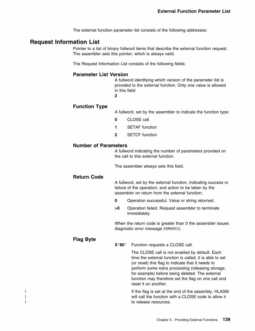
External Function Parameter List
The external function parameter list consists of the following addresses:
Request Information ListPointer to a list of binary fullword items that describe the external function request.The assembler sets this pointer, which is always valid.
The Request Information List consists of the following fields:
Parameter List VersionA fullword identifying which version of the parameter list isprovided to the external function. Only one value is allowedin this field:2
Function TypeA fullword, set by the assembler to indicate the function type:
0 CLOSE call
1 SETAF function
2 SETCF function
Number of ParametersA fullword indicating the number of parameters provided onthe call to this external function.
The assembler always sets this field.
Return CodeA fullword, set by the external function, indicating success orfailure of the operation, and action to be taken by theassembler on return from the external function:
0 Operation successful. Value or string returned.
>0 Operation failed. Request assembler to terminateimmediately.
When the return code is greater than 0 the assembler issuesdiagnostic error message ASMA941U.
Flag ByteX'80' Function requests a CLOSE call.
The CLOSE call is not enabled by default. Eachtime the external function is called, it is able to set(or reset) this flag to indicate that it needs toperform some extra processing (releasing storage,for example) before being deleted. The externalfunction may therefore set the flag on one call andreset it on another.
| If the flag is set at the end of the assembly, HLASM| will call the function with a CLOSE code to allow it| to release resources.
Chapter 5. Providing External Functions 139

External Function Parameter List
The assembler maintains the Flag Byte and provides it to theexternal function on all calls.
ReservedThis storage is reserved for future use by IBM. The externalfunction should not use this field, nor should it rely on thecontents of this field (which are liable to change withoutnotice).
External functions can request that a message be issued on their behalf. Thefunction provides the text of the message, and the assembler inserts the function'sname and the supplied text into one of five messages. The relevant information iscontained in two fields, Message Length and Message Severity:
Msg LengthA halfword, set by the external function, indicating the lengthof the message to be issued.
Msg SeverityA halfword, set by the external function, from which theassembler determines the associated message number. Theseverity code returned by the function is rounded up to amultiple of four as shown in Figure 48.
Figure 48. Message Severity and Associated Messages
Severity CodeSpecified
Severity CodeUsed
AssociatedMessage
0 0 ASMA710I
1–4 4 ASMA711W
5–8 8 ASMA712E
9–12 12 ASMA713S
>12 16 ASMA714C
Return Value (SETAF)A fullword, set by the external function. This field is set tozero by the assembler before the external function call.
Parm Value n (SETAF)A fullword, set by the assembler, containing the value of theparameter passed to the external function.
The Number of Parameters field indicates the number ofParm Value n fields in the Request Information List.
Return String Length (SETCF)An unsigned fullword, set by the external function, containing
| the length of the string pointed to by the Pointer to Parm| String field.
The assembler uses this field as the length of the returnedstring.
140 HLASM V1R4 Programmer’s Guide

External Function Parameter List
If the length is greater than 255, it is reset to 255 by theassembler. The consequence of returning a string longerthan 255 bytes is unpredictable.
Parm String n Length (SETCF)An unsigned fullword, set by the assembler, containing thelength of the string pointed to by the Ptr to Parm String nfield.
The external function should use this length to determine thelength of the Parm String n passed by the assembler.
The assembler sets this field to a value between 0 and 255inclusive.
The Number of Parameters field indicates the number ofParm String n Length fields in the Request Information List.
Pointer to User Work AreaPointer to the User Work Area.
The assembler provides four double words of storage for use by the externalfunction. This storage is double-word aligned and the assembler initializes it to zerofor the first call to the external function.
It can be used by the external function to store information (such as the address ofacquired storage) between calls. The contents of this storage area are preservedacross all call types (SETAF, SETCF, and CLOSE) until the assembly completes.The assembler does not use or modify the work area.
Pointer to Msg BufferPointer to the “function-supplied message” area.
The assembler always sets this pointer before invoking an external function. Theexternal function can put up to 255 bytes of message text into the area addressedby this field.
Pointer to Return String (SETCF)Pointer to the string returned by the external function.
The assembler always sets this pointer before invoking an external function. Theexternal function can put up to 255 bytes of character string data into the areaaddressed by this field.
Pointer to Parm String n (SETCF)Pointer to Parm String n passed to the external function.
The assembler always sets this pointer before invoking an external function. Thelength of the string pointed to by this field is contained in the Parm String nLength field.
Chapter 5. Providing External Functions 141

External Function Parameter List
The Number of Parameters field in the Request Information List indicates thenumber of Pointer to Parm String n fields in the External Function Parameter List.
142 HLASM V1R4 Programmer’s Guide

Assembly Error Diagnostic Messages
Chapter 6. Diagnosing Assembly Errors
The diagnostic facilities for High Level Assembler include:
� Diagnostic messages for assembly errors.� A macro trace and dump facility (MHELP).� Messages and dumps issued by the assembler if it ends abnormally.� Diagnostic or explanatory messages issued by the source program or by macro
definitions (MNOTEs).
This chapter provides an overview of these facilities. The assembly errordiagnostic messages and abnormal assembly termination messages are describedin detail in Appendix G, “High Level Assembler Messages” on page 309.
Assembly Error Diagnostic MessagesHigh Level Assembler prints most error messages in the listing immediatelyfollowing the statement in error. It also prints the total number of flaggedstatements and their statement numbers in the Diagnostic Cross Reference andAssembler Summary section of the assembler listing.
The messages do not follow the statement in error when:
� Errors are detected during editing of macro definitions read from a library. Amessage for such an error appears after the first call in the source program tothat macro definition. You can, however, bring the macro definition into thesource program with a COPY statement or using the LIBMAC assembleroption. The editing error messages then follow immediately after thestatements in error.
� Errors are detected by the lookahead function of the assembler. (For attributereferences, look-ahead processing scans for symbols defined on statementsafter the one being assembled.) Messages for these errors appear after thestatements in which they occur. The messages may also appear at the point atwhich lookahead was called.
� Errors are detected on conditional assembler statements during macrogeneration or MHELP testing. Such a message follows the most recentlygenerated statement or MHELP output statement.
A typical error diagnostic message is:
LL ASMA957E UNDEFINED OPERATION CODE — xxxxxxxx
A copy of a segment of the statement in error, represented above by xxxxxxxx, isappended to the end of many messages. Normally this segment begins at the badcharacter or term. For some errors, however, the segment begins after the badcharacter or term.
Copyright IBM Corp. 1982, 2000 143
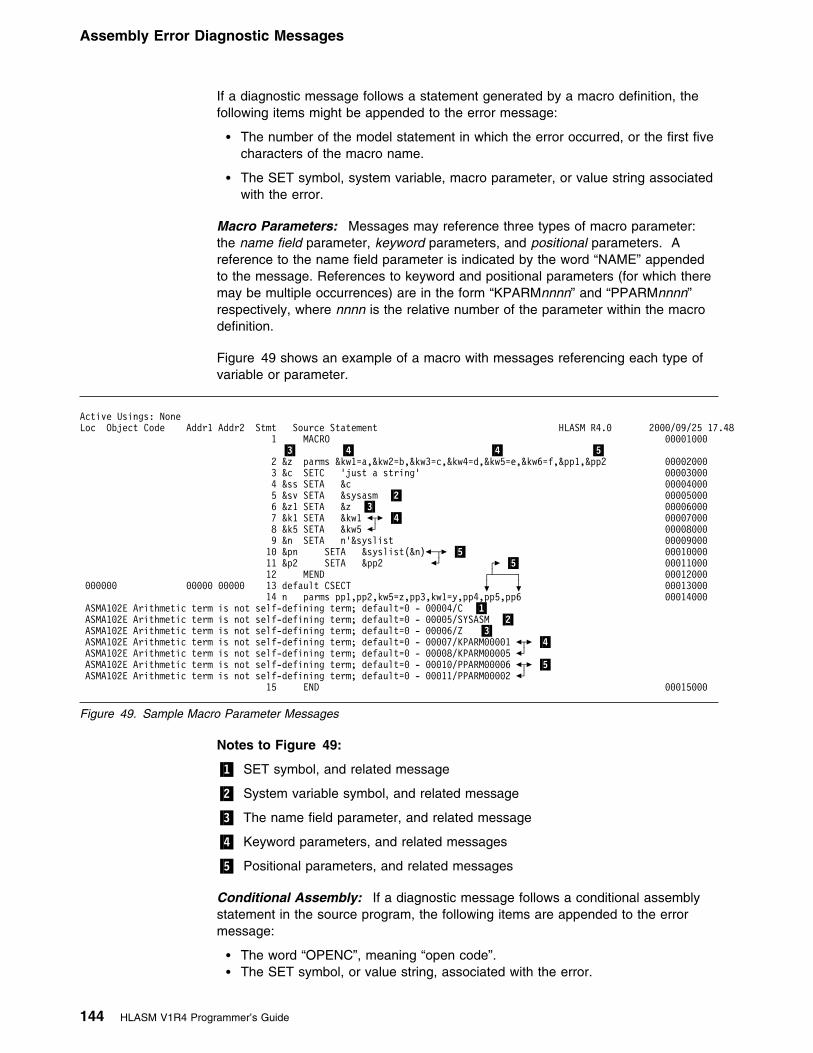
Assembly Error Diagnostic Messages
If a diagnostic message follows a statement generated by a macro definition, thefollowing items might be appended to the error message:
� The number of the model statement in which the error occurred, or the first fivecharacters of the macro name.
� The SET symbol, system variable, macro parameter, or value string associatedwith the error.
Macro Parameters: Messages may reference three types of macro parameter:the name field parameter, keyword parameters, and positional parameters. Areference to the name field parameter is indicated by the word “NAME” appendedto the message. References to keyword and positional parameters (for which theremay be multiple occurrences) are in the form “KPARMnnnn” and “PPARMnnnn”respectively, where nnnn is the relative number of the parameter within the macrodefinition.
Figure 49 shows an example of a macro with messages referencing each type ofvariable or parameter.
Active Usings: NoneLoc Object Code Addr1 Addr2 Stmt Source Statement HLASM R4.9 2999/99/25 17.48 1 MACRO 99991999 �3� �4� �4� �5� 2 &z parms &kw1=a,&kw2=b,&kw3=c,&kw4=d,&kw5=e,&kw6=f,&pp1,&pp2 99992999
3 &c SETC 'just a string' 999939994 &ss SETA &c 999949995 &sv SETA &sysasm �2� 999959996 &z1 SETA &z �3� 999969997 &k1 SETA &kw1 �┬� �4� 999979998 &k5 SETA &kw5 �┘ 99998999
9 &n SETA n'&syslist 99999999 19 &pn SETA &syslist(&n)�─┬� �5� 99919999
11 &p2 SETA &pp2 �┘ ┌� �5� 99911999 12 MEND ┌┴────┐ 99912999 999999 99999 99999 13 default CSECT + + 99913999 14 n parms pp1,pp2,kw5=z,pp3,kw1=y,pp4,pp5,pp6 99914999 ASMA192E Arithmetic term is not self-defining term; default=9 - 99994/C �1� ASMA192E Arithmetic term is not self-defining term; default=9 - 99995/SYSASM �2� ASMA192E Arithmetic term is not self-defining term; default=9 - 99996/Z �3� ASMA192E Arithmetic term is not self-defining term; default=9 - 99997/KPARM99991 �┬� �4� ASMA192E Arithmetic term is not self-defining term; default=9 - 99998/KPARM99995 �┘ ASMA192E Arithmetic term is not self-defining term; default=9 - 99919/PPARM99996 �┬� �5� ASMA192E Arithmetic term is not self-defining term; default=9 - 99911/PPARM99992 �┘ 15 END 99915999
Figure 49. Sample Macro Parameter Messages
Notes to Figure 49:
�1� SET symbol, and related message
�2� System variable symbol, and related message
�3� The name field parameter, and related message
�4� Keyword parameters, and related messages
�5� Positional parameters, and related messages
Conditional Assembly: If a diagnostic message follows a conditional assemblystatement in the source program, the following items are appended to the errormessage:
� The word “OPENC”, meaning “open code”.� The SET symbol, or value string, associated with the error.
144 HLASM V1R4 Programmer’s Guide

MNOTE Statements
Multiple Messages: Several messages can be issued for a single statement oreven for a single error within a statement. This happens because each statementis usually evaluated on more than one level (for example, term level, expressionlevel, and operand level) or by more than one phase of the assembler. Each levelor phase can diagnose errors; therefore, most or all of the errors in the statementare flagged. Occasionally, duplicate error messages may occur. This is a normalresult of the error detection process.
Figure 50 on page 146 is an example of High Level Assembler handling of errormessages, and includes message ASMA435I to show the effect of theFLAG(RECORD) assembler option.
MNOTE StatementsAn MNOTE statement is included in a macro definition or in the source program. Itcauses the assembler to generate an inline error or informational message.
An MNOTE appears in the listing as follows:
ASMA254I LLLMNOTELLL statement number, severity code, message
Unless the severity code is shown as an asterisk (L), or the severity code isomitted, the statement number of the MNOTE is listed in the diagnosticcross-reference.
Chapter 6. Diagnosing Assembly Errors 145

MNOTE Statements
Active Usings: None Loc Object Code Addr1 Addr2 Stmt Source Statement HLASM R4.9 2999/99/25 17.48
1 LLLLLLLLLLLLLLLLLLLLLLLLLLLLLLLLLLLLLLLLLLLLLLLLLLLLLLLLLLLLLLLLLLLLLLL DIA999192 L SAMPLE ERROR DIAGNOSTIC MESSAGES L DIA999293 L IN SOURCE PROGRAM (OPEN CODE) AND GENERATED BY MACRO CALLS L DIA999394 LLLLLLLLLLLLLLLLLLLLLLLLLLLLLLLLLLLLLLLLLLLLLLLLLLLLLLLLLLLLLLLLLLLLLLL DIA99949
999999 99999 9993C 5 A CSECT DIA99959999999 9999 9999 99999 6 STM 14,U2,12(13( DIA99969LL ASMA944E Undefined symbol - U2
| LL ASMA929E Incorrect register specification - U2| LL ASMA179S Delimiter error, expected right parenthesis - (
LL ASMA435I Record 6 in DIAGMSG ASSEMBLE A1 on volume: ADISK999994 95C9 7 BALR 12,9 DIA99979 R:C 99996 8 USING L,12 DIA99989999996 9999 9999 99999 9 ST 13,SAVE+4 DIA99999LL ASMA944E Undefined symbol - SAVELL ASMA435I Record 9 in DIAGMSG ASSEMBLE A1 on volume: ADISK 19 OPEN (CRDIN,(INPUT),CRDOUT,(OUTPUT) DIA99199LL ASMA988E Unbalanced parentheses in macro call operand - OPEN /(CRDIN,(INPUT),CRDOUT,(OUTPUT)LL ASMA435I Record 323 in OSMACRO MACLIB S2(OPEN) on volume: MNT19999999A 9799 11+ CNOP 9,4 ALIGN LIST TO FULLWORD 91-OPEN99999C 4119 C99E 99914 12+ LA 1,L+8 LOAD R1 W/LIST ADR @V6PXJRU 91-OPEN999919 47F9 C99E 99914 13+ B L+4 BRANCH AROUND LIST @V6PXJRU 91-OPENLL ASMA254I LLL MNOTE LLL 14+ 12,LLL IHB991 DCB OPERAND REQ'D-NOT SPECIFIED 92-IHBER 15 DROP 11 DIA99119LL ASMA945W Register or label not previously used - 11LL ASMA435I Record 11 in DIAGMSG ASSEMBLE A1 on volume: ADISK
16 LLLLLLLLLLLLLLLLLLLLLLLLLLLLLLLLLLLLLLLLLLLLLLLLLLLLLLLLLLLLLLLLLLLLLLL DIA9912917 L EDITING AND GENERATION ERRORS AND MNOTES FROM A LIBRARY MACRO L DIA9913918 LLLLLLLLLLLLLLLLLLLLLLLLLLLLLLLLLLLLLLLLLLLLLLLLLLLLLLLLLLLLLLLLLLLLLLL DIA99149
19 LOADR REG1=19,REG2=8,WOOSHA,SUMA DIA99159999914 58A9 C92E 99934 29+ L 19,WOOSHA 91-LOADR999918 5889 C932 99938 21+ L 8,SUMA 91-LOADR 22 LOADR REG1=25,REG2=8,WOOSHA,MAINY DIA9916999991C 9999 9999 99999 23+ L 25,WOOSHA 91-LOADR
| LL ASMA929E Incorrect register specification - 25LL ASMA435I Record 5 in TEST MACLIB A1(LOADR) on volume: ADISK999929 9999 9999 99999 24+ L 8,MAINY 91-LOADRLL ASMA944E Undefined symbol - MAINYLL ASMA435I Record 6 in TEST MACLIB A1(LOADR) on volume: ADISK 25 LOADR REG2=19,SUMA,MAINY DIA99179LL ASMA254I LLL MNOTE LLL 26+ 36,YOU LEFT OUT THE FIRST REGISTER 91-LOADR
Figure 50 (Part 1 of 2). Sample Error Diagnostic Messages
146 HLASM V1R4 Programmer’s Guide

Reference Information for Statements in Error
27 LLLLLLLLLLLLLLLLLLLLLLLLLLLLLLLLLLLLLLLLLLLLLLLLLLLLLLLLLLLLLLLLLLLLLLL DIA9918928 L SAMPLE IN-LINE MACRO DEFINITION L DIA9919929 LLLLLLLLLLLLLLLLLLLLLLLLLLLLLLLLLLLLLLLLLLLLLLLLLLLLLLLLLLLLLLLLLLLLLLL DIA99299
39 MACRO DIA99219 31 &NAME LOADR ®1=,®2=,&OP1,&OP2 DIA99229 32 &R(1) SETA ®1,®2 DIA99239
33 AIF (T'®1 EQ 'O').ERR DIA99249 34 L &R(1),&OP1 DIA99259 35 L &R(2),&OP2 DIA99269 36 MEXIT DIA99279
37 .ERR MNOTE 36,'YOU LEFT OUT THE FIRST REGISTER' DIA99289 38 MEND DIA99299
39 LLLLLLLLLLLLLLLLLLLLLLLLLLLLLLLLLLLLLLLLLLLLLLLLLLLLLLLLLLLLLLLLLLLLLLL DIA9939949 L SAMPLE MACRO CALLS WITH GENERATION ERRORS AND MNOTES L DIA9931941 LLLLLLLLLLLLLLLLLLLLLLLLLLLLLLLLLLLLLLLLLLLLLLLLLLLLLLLLLLLLLLLLLLLLLLL DIA99329
Page 4Active Usings: A+X'6'(X'1999'),R12
Loc Object Code Addr1 Addr2 Stmt Source Statement HLASM R4.9 2999/99/25 17.48 42 LOADR REG1=19,REG2=8,WOOSHA,SUMA DIA99339999924 58A9 C92E 99934 43+ L 19,WOOSHA 91-99934999928 5889 C932 99938 44+ L 8,SUMA 91-99935 45 LOADR REG1=25,REG2=8,WOOSHA,&MAINY DIA99349LL ASMA993E Undeclared variable symbol; default=9, null, or type=U - OPENC/MAINYLL ASMA435I Record 34 in DIAGMSG ASSEMBLE A1 on volume: ADISK99992C 9999 9999 99999 46+ L 25,WOOSHA 91-99934
| LL ASMA929E Incorrect register specification - 25LL ASMA435I Record 25 in DIAGMSG ASSEMBLE A1 on volume: ADISK999939 9999 9999 99999 47+ L 8, 91-99935LL ASMA974E Illegal syntax in expression -LL ASMA435I Record 26 in DIAGMSG ASSEMBLE A1 on volume: ADISK 48 LOADR REG2=8,SUMA,MAINY DIA99359LL ASMA254I LLL MNOTE LLL 49+ 36,YOU LEFT OUT THE FIRST REGISTER 91-99937999934 59 WOOSHA DS F DIA99369999938 51 SUMA DS F DIA99379 52 END DIA99389
Figure 50 (Part 2 of 2). Sample Error Diagnostic Messages
Suppression of Error Messages and MNOTE StatementsOptionally, you can suppress error messages and MNOTE statements below aspecified severity level by specifying the assembler option FLAG(n) (where n is thelowest severity message that the assembler issues).
Reference Information for Statements in ErrorThe FLAG(RECORD) assembler option instructs the assembler to issue messageASMA435I after the last error message for each statement in error. This messageshows reference information, including the data set name, and member name (ifapplicable), and the input record number of the statement in error. When youspecify this option, the assembler includes reference information with the flaggedstatements in the Diagnostic Cross Reference and Assembler Summary section ofthe assembler listing. The reference information includes:
� The member name (if applicable).� The input record number of the statement in error.� The input data set concatenation value.
Chapter 6. Diagnosing Assembly Errors 147

MHELP—Macro Trace Facility
Abnormal Assembly TerminationWhenever the assembly cannot complete, High Level Assembler provides amessage and, in some cases, a specially formatted dump for diagnosticinformation. This might indicate an assembler malfunction or it might indicate aprogrammer error. The statement causing the error is identified and, if possible,the assembly listing up to the point of the error is printed. Appendix G, “High LevelAssembler Messages” on page 309 describes the abnormal termination messages.The messages give enough information to enable you (1) to correct the error andreassemble your program, or (2) to determine that the error is an assemblermalfunction.
MHELP—Macro Trace FacilityThe MHELP instruction controls a set of trace and dump facilities. You selectoptions by specifying an absolute expression in the MHELP operand field. MHELPstatements can occur anywhere in open code or in macro definitions. MHELPoptions remain in effect until superseded by another MHELP statement.
Format of MHELP:
Name Operation Operand
MHELP Absolute expression, (the sum of binary or decimal options)
The options are:
B'1' or 1 Macro Call TraceB'10' or 2 Macro Branch TraceB'100' or 4 Macro AIF DumpB'1000' or 8 Macro Exit DumpB'10000' or 16 Macro Entry DumpB'100000' or 32 Global SuppressionB'1000000' or 64 Macro Hex DumpB'10000000' or 128 SuppressionOther values Control on &SYSNDX
Refer to Appendix F, “MHELP Sample Macro Trace and Dump” on page 301 forcomplete details about this facility.
148 HLASM V1R4 Programmer’s Guide

Part 2. Developing Assembler Programs on MVS
Part 2. Developing Assembler Programs on MVS
Chapter 7. Assembling Your Program on MVS . . . . . . . . . . . . . . . . . 151Input to the Assembler . . . . . . . . . . . . . . . . . . . . . . . . . . . . . . . . . 151Output from the Assembler . . . . . . . . . . . . . . . . . . . . . . . . . . . . . . 151Invoking the Assembler on MVS . . . . . . . . . . . . . . . . . . . . . . . . . . . 151Invoking the Assembler on TSO . . . . . . . . . . . . . . . . . . . . . . . . . . . . 153Invoking the Assembler Dynamically . . . . . . . . . . . . . . . . . . . . . . . . . 154Batch Assembling . . . . . . . . . . . . . . . . . . . . . . . . . . . . . . . . . . . . 156Input and Output Data Sets . . . . . . . . . . . . . . . . . . . . . . . . . . . . . . 157
Work Data Set: SYSUT1 . . . . . . . . . . . . . . . . . . . . . . . . . . . . . . 160Specifying the Source Data Set: SYSIN . . . . . . . . . . . . . . . . . . . . . 160
| Specifying the Option File: ASMAOPT . . . . . . . . . . . . . . . . . . . . . . 160Specifying Macro and Copy Code Libraries: SYSLIB . . . . . . . . . . . . . . 160Specifying the Listing Data Set: SYSPRINT . . . . . . . . . . . . . . . . . . . 161Directing Assembler Messages to Your Terminal: SYSTERM . . . . . . . . . 161Specifying Object Code Data Sets: SYSLIN and SYSPUNCH . . . . . . . . . 161Specifying the Associated Data Data Set: SYSADATA . . . . . . . . . . . . . 162
Return Codes . . . . . . . . . . . . . . . . . . . . . . . . . . . . . . . . . . . . . . 162
Chapter 8. Linking and Running Your Program on MVS . . . . . . . . . . . 163The Program Management Binder . . . . . . . . . . . . . . . . . . . . . . . . . . 163The Loader . . . . . . . . . . . . . . . . . . . . . . . . . . . . . . . . . . . . . . . . 165Creating a Load Module . . . . . . . . . . . . . . . . . . . . . . . . . . . . . . . . 165
Creating a Load Module on MVS . . . . . . . . . . . . . . . . . . . . . . . . . 165Creating a Load Module on TSO . . . . . . . . . . . . . . . . . . . . . . . . . 166
Input to the Linker . . . . . . . . . . . . . . . . . . . . . . . . . . . . . . . . . . . . 166Data Sets for Linker Processing . . . . . . . . . . . . . . . . . . . . . . . . . . 167Additional Object Modules as Input . . . . . . . . . . . . . . . . . . . . . . . . 168
Output from the Linker . . . . . . . . . . . . . . . . . . . . . . . . . . . . . . . . . 169Linker Processing Options . . . . . . . . . . . . . . . . . . . . . . . . . . . . . 169Specifying Linker Options Through JCL . . . . . . . . . . . . . . . . . . . . . . 170Specifying Linker Options Using the TSO LINK Command . . . . . . . . . . . 170AMODE and RMODE Attributes . . . . . . . . . . . . . . . . . . . . . . . . . . 171Overriding the Defaults . . . . . . . . . . . . . . . . . . . . . . . . . . . . . . . 171Detecting Linker Errors . . . . . . . . . . . . . . . . . . . . . . . . . . . . . . . 172
Running Your Assembled Program . . . . . . . . . . . . . . . . . . . . . . . . . . 172Running Your Assembled Program in Batch . . . . . . . . . . . . . . . . . . . 172Running Your Assembled Program on TSO . . . . . . . . . . . . . . . . . . . 172
Chapter 9. MVS System Services and Programming Considerations . . . 173Adding Definitions to a Macro Library . . . . . . . . . . . . . . . . . . . . . . . . 173Using Cataloged Procedures . . . . . . . . . . . . . . . . . . . . . . . . . . . . . 174
Cataloged Procedure for Assembly (ASMAC) . . . . . . . . . . . . . . . . . . 174Cataloged Procedure for Assembly and Link (ASMACL) . . . . . . . . . . . . 176Cataloged Procedure for Assembly, Link, and Run (ASMACLG) . . . . . . . 177Cataloged Procedure for Assembly and Run (ASMACG) . . . . . . . . . . . . 178Overriding Statements in Cataloged Procedures . . . . . . . . . . . . . . . . . 180
EXEC Statements . . . . . . . . . . . . . . . . . . . . . . . . . . . . . . . . . 180DD Statements . . . . . . . . . . . . . . . . . . . . . . . . . . . . . . . . . . 180
Examples of Cataloged Procedures . . . . . . . . . . . . . . . . . . . . . . . . 180Operating System Programming Conventions . . . . . . . . . . . . . . . . . . . . 182
Copyright IBM Corp. 1982, 2000 149

Part 2. Developing Assembler Programs on MVS
Saving and Restoring General Register Contents . . . . . . . . . . . . . . . . 182Ending Program Execution . . . . . . . . . . . . . . . . . . . . . . . . . . . . . 183Accessing Execution Parameters . . . . . . . . . . . . . . . . . . . . . . . . . 183Object Module Linkage . . . . . . . . . . . . . . . . . . . . . . . . . . . . . . . 184
Modifying Program Modules . . . . . . . . . . . . . . . . . . . . . . . . . . . . . . 185
150 HLASM V1R4 Programmer’s Guide

Invoking the Assembler on MVS
Chapter 7. Assembling Your Program on MVS
This chapter describes how to invoke the assembler on MVS. It describes:
� The input to the assembler.� The output from the assembler.� How to invoke the assembler on MVS and TSO.� How to invoke the assembler dynamically from a program.� How to assemble multiple source programs using the BATCH option.� The data sets used by the assembler.� The assembler return codes.� The cataloged procedures of job control language supplied by IBM.
Input to the AssemblerAs input, the assembler accepts a program written in the assembler language asdefined in the HLASM Language Reference. This program is referred to as asource module. Some statements in the source module (macro or COPYinstructions) may cause additional input to be obtained from a macro library.
Input can also be obtained from user exits. See Chapter 4, “Providing User Exits”on page 79 for more information.
Output from the AssemblerThe output from the assembler can consist of an object module, a program listing,terminal messages, and an associated data file. The object module can be writtento a data set residing on a direct access device or a magnetic tape. If you specify
| the GOFF assembler option, the assembler produces a generalized object formatmodule. Both formats of the object module are written to the same data set,however only one format can be produced at a time. From that data set, the objectmodule can be read and processed by the linkage editor, the batch loader, or theDFSMS/MVS binder. See Appendix C, “Object Deck Output” on page 248 for the
| format of the object module. The format of the generalized object format module isdescribed in DFSMS/MVS Program Management.
The program listing shows all the statements in the module, both in source andmachine language format, and gives other important information about theassembly, such as error messages and cross reference information. The listing isdescribed in detail in Chapter 2, “Using the Assembler Listing” on page 8.
Invoking the Assembler on MVSThe JCL for running an assembly includes:
� A job description.� A statement to run the assembler.� Definitions for the data sets needed.
The simplest way to assemble your program on MVS is to code JCL that uses thecataloged procedure shown in Figure 51 on page 152.
Copyright IBM Corp. 1982, 2000 151

Invoking the Assembler on MVS
//jobname JOB accountno,progrname,MSGLEVEL=1 �1�//stepname EXEC ASMAC �2�//SYSIN DD L �3�...Assembler source statements.../L
Figure 51. JCL for Assembly, Using Cataloged Procedure
�1� Identifies the beginning of your job to the operating system. jobname is thename you assign to the job. accountno specifies the account to which your jobis charged, and progrname is the name of the programmer responsible for thejob. MSGLEVEL=1 specifies that the job control statements connected with thisjob are to be listed. Check what parameters are required at your installationand how they must be specified.
�2� Calls the cataloged procedure ASMAC. As a result, a number of job controlstatements are included in the job from the procedure library. ASMAC isdescribed under “Cataloged Procedure for Assembly (ASMAC)” on page 174;an expanded job stream is shown there.
�3� Specifies that the assembler language source program follows immediatelyafter this statement.
These statements cause the assembler to assemble your program, produce alisting and write an object module to the SYSLIN data set. If you do not want anobject module written to the SYSLIN data set, use the following job controlstatements to assemble the program:
//jobname JOB accountno,progrname,MSGLEVEL=1//stepname EXEC ASMAC,PARM=NOOBJECT//SYSIN DD L...Assembler source statements.../L
Figure 52. JCL for Assembly, Using Cataloged Procedure, with NOOBJECT
Assembler Options: The second parameter (PARM) specifies the assembler optionNOOBJECT, which tells the assembler not to write the object module to SYSLIN. Fora full discussion of assembler options, see Chapter 3, “Controlling Your Assemblywith Options” on page 38.
Using your own JCL: The cataloged procedures might not comply with your dataprocessing requirements. Figure 53 on page 153 shows sample job controlstatements that you can use instead to assemble your program.
152 HLASM V1R4 Programmer’s Guide
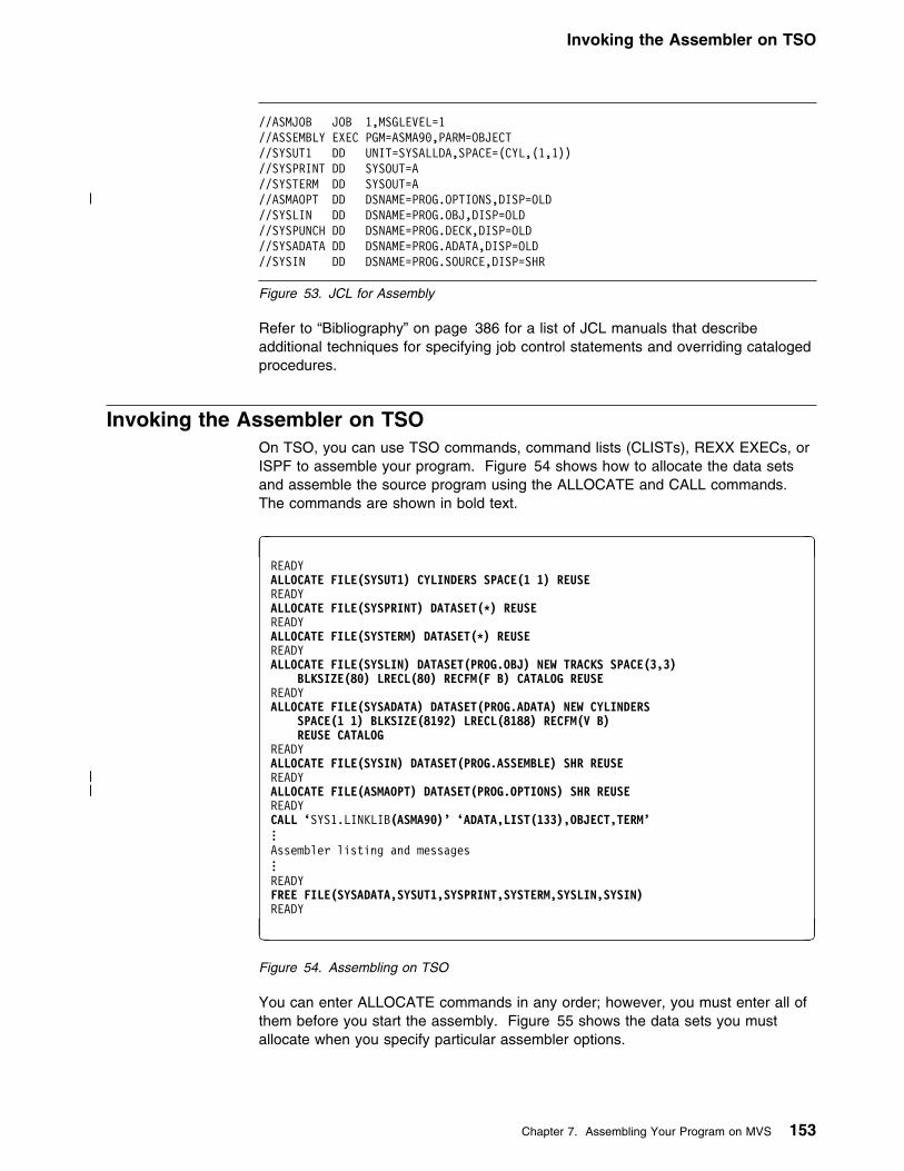
Invoking the Assembler on TSO
//ASMJOB JOB 1,MSGLEVEL=1//ASSEMBLY EXEC PGM=ASMA99,PARM=OBJECT//SYSUT1 DD UNIT=SYSALLDA,SPACE=(CYL,(1,1))//SYSPRINT DD SYSOUT=A//SYSTERM DD SYSOUT=A
| //ASMAOPT DD DSNAME=PROG.OPTIONS,DISP=OLD//SYSLIN DD DSNAME=PROG.OBJ,DISP=OLD//SYSPUNCH DD DSNAME=PROG.DECK,DISP=OLD//SYSADATA DD DSNAME=PROG.ADATA,DISP=OLD//SYSIN DD DSNAME=PROG.SOURCE,DISP=SHR
Figure 53. JCL for Assembly
Refer to “Bibliography” on page 386 for a list of JCL manuals that describeadditional techniques for specifying job control statements and overriding catalogedprocedures.
Invoking the Assembler on TSOOn TSO, you can use TSO commands, command lists (CLISTs), REXX EXECs, orISPF to assemble your program. Figure 54 shows how to allocate the data setsand assemble the source program using the ALLOCATE and CALL commands.The commands are shown in bold text.
h iREADYALLOCATE FILE(SYSUT1) CYLINDERS SPACE(1 1) REUSEREADYALLOCATE FILE(SYSPRINT) DATASET(�) REUSEREADYALLOCATE FILE(SYSTERM) DATASET(�) REUSEREADYALLOCATE FILE(SYSLIN) DATASET(PROG.OBJ) NEW TRACKS SPACE(3,3)
BLKSIZE(8!) LRECL(8!) RECFM(F B) CATALOG REUSEREADYALLOCATE FILE(SYSADATA) DATASET(PROG.ADATA) NEW CYLINDERS
SPACE(1 1) BLKSIZE(8192) LRECL(8188) RECFM(V B) REUSE CATALOGREADYALLOCATE FILE(SYSIN) DATASET(PROG.ASSEMBLE) SHR REUSE
| READY| ALLOCATE FILE(ASMAOPT) DATASET(PROG.OPTIONS) SHR REUSE
READYCALL ‘SYS1.LINKLIB(ASMA9!)’ ‘ADATA,LIST(133),OBJECT,TERM’...Assembler listing and messages...READYFREE FILE(SYSADATA,SYSUT1,SYSPRINT,SYSTERM,SYSLIN,SYSIN)READY
j k
Figure 54. Assembling on TSO
You can enter ALLOCATE commands in any order; however, you must enter all ofthem before you start the assembly. Figure 55 shows the data sets you mustallocate when you specify particular assembler options.
Chapter 7. Assembling Your Program on MVS 153

Invoking the Assembler Dynamically
Exit Option: If you specify the EXIT option, the user exit program module must bein a partitioned data set that is in the standard search sequence, including the LinkPack Area (LPA).
Figure 55. Assembler Options and Data Sets Required
Option Specified Data Sets Required
Any SYSUT1 and SYSIN
LIST SYSPRINT
TERM SYSTERM
OBJECT SYSLIN
DECK SYSPUNCH
ADATA SYSADATA
Invoking the Assembler DynamicallyYou can invoke High Level Assembler from a running program using the CALL,LINK, XCTL, or ATTACH system macro instructions.
When you use CALL, LINK, or ATTACH, you can supply:
� The assembler options.� The ddnames of the data sets to be used during processing.
If you use XCTL, you cannot pass options to the assembler. The assembler usesthe installation default options. Figure 56 shows how to invoke the assemblerdynamically.
ASMA90 The load module name and entry point to invoke the assembler.ASMA90 may be invoked in either 24-bit or 31-bit addressing mode.
EP Specifies the symbolic name of the assembler load module and entrypoint.
PARAM Specifies, as a sublist, address parameters to be passed from theprogram to the assembler. The first word in the address parameter list(optionlist) contains the address of the option list. The second word(ddnamelist) contains the address of the ddname list.
optionlistSpecifies the address of a variable-length list containing the options.The address of an option list must be provided even if no options arerequired.
Figure 56. Invoking the Assembler Dynamically
Name Operation Operand
symbol CALL
��─ ──ASMA99,(optionlist ──┬ ┬───────────── ),VL ─��└ ┘──,ddnamelist
LINKorATTACH
��─ ──EP=ASMA99,PARAM=(optionlist ──┬ ┬───────────── ),VL=1 ─��└ ┘──,ddnamelist
154 HLASM V1R4 Programmer’s Guide

Invoking the Assembler Dynamically
The option list must begin on a halfword boundary. The first twobytes contain the number of bytes in the remainder of the list. If nooptions are specified, the count must be zero. The option list is freeform, with each field separated from the next by a comma. Noblanks should appear in the list, except within the string specified forthe EXIT or SYSPARM options, providing the string is enclosedwithin single quotes.
ddnamelistSpecifies the address of a variable-length list containing alternativeddnames for the data sets used during assembler processing. Ifstandard ddnames are used, this operand can be omitted.
The ddname list must begin on a halfword boundary. The first twobytes contain the number of bytes in the remainder of the list. Eachname of less than 8 bytes must be left-justified and padded to 8bytes with blanks. If an alternative ddname is omitted, the standardname is assumed. If the name is omitted within the list, the 8-byteentry must contain binary zeros. Names can be omitted from theend merely by shortening the list. The sequence of the 8-byteentries in the ddname list is as follows:
Entry Alternative1 SYSLIN2 Not applicable3 Not applicable4 SYSLIB5 SYSIN6 SYSPRINT7 SYSPUNCH8 SYSUT19 Not applicable10 Not applicable11 Not applicable12 SYSTERM13 Not applicable14 Not applicable15 Not applicable16 SYSADATA
| 17 Not applicable| 18 Not applicable| 19 Not applicable| 20 ASMAOPT
Overriding ddname: Any overriding ddname specified when HighLevel Assembler was installed, occupies the corresponding positionin the above list. The overriding ddname can also be overriddenduring invocation. For example, if SYSWORK1 replaced SYSUT1, itoccupies position 8 in the above list. However, SYSWORK1 can beoverridden by another name during invocation.
VL specifies that the sign bit is to be set to 1 in the last word of theparameter address list. VL must be specified for the CALL macro andVL=1 for the LINK or ATTACH macros.
Chapter 7. Assembling Your Program on MVS 155

Batch Assembling
DYNAMICM CSECTDYNAMICM RMODE 24DYNAMICM AMODE ANYBEGIN SAVE (14,12) USING BEGIN,15 ST 13,SAVEAREA+4 LA 13,SAVEAREA CALL ASMA99,(OPTIONS),VL L 13,SAVEAREA+4 RETURN (14,12)SAVEAREA DS 18FOPTIONS DC Y(OPTIONSL)OPTS DC C'XREF(SHORT)'OPTIONSL EQU L-OPTS END
Figure 57. Sample Program to Call the Assembler Dynamically
Batch AssemblingA sequence of separate assembler programs may be assembled with a singleinvocation of the assembler when the BATCH option is specified. The objectprograms produced from this assembly may be linked into either a single programmodule or separate program modules.
When the BATCH option is specified, each assembler program in the sequencemust be terminated by an END statement, including the last program in the batch.If an END statement is omitted, the program will be assembled with the nextprogram in the sequence. If the END statement is omitted from the last program inthe sequence, an END statement will be generated by the assembler.
If you want to produce more than one program module, a NAME control statementmust be written for each one. The NAME statement must be written after theobject module. The following example shows how to create two program modules,SECT1 and SECT2.
SECT1 CSECT Start of first load module...
Source instructions . . .
END End of first load modulePUNCH ' NAME SECT1(R)'
ENDSECT2 CSECT Start of second load module
... Source instructions . . .
END End of second load modulePUNCH ' NAME SECT2(R)'
END
156 HLASM V1R4 Programmer’s Guide

Input and Output Data Sets
Input and Output Data SetsDepending on the options in effect, High Level Assembler requires the followingdata sets, as shown in Figure 58:
| ┌──────────────┐| │ SYSIN │ ┌─────────────┐| └───────────┬──┘ ┌──┤ ASMAOPT │| │ │ └─────────────┘| │ │| + +| ┌──────────────┐ ┌──────────────┐ ┌──────────────┐| │ SYSLIB ├──────────�│ Assembler │�──────────�│ SYSUT1 │| └──────────────┘ └───────┬──────┘ └──────────────┘| │| +| ┌──────────────┬──────────────┬──────────────┬──────────────┐| │ │ │ │ │| + + + + +| ┌───────────┐ ┌───────────┐ ┌───────────┐ ┌───────────┐ ┌───────────┐| │ SYSPRINT │ │ SYSTERM │ │ SYSLIN │ │ SYSPUNCH │ │ SYSADATA │| └───────────┘ └───────────┘ └───────────┘ └───────────┘ └───────────┘
| Figure 58. High Level Assembler Files
You can override the ddnames during installation or when invoking the assemblerdynamically (see “Invoking the Assembler Dynamically” on page 154).
High Level Assembler requires the following data sets:
SYSUT1 A work data set used as intermediate external storage whenprocessing the source program. This data set is used when thereis not enough main storage available to assemble in-storage.
If the value specified for the SIZE option is large enough, anin-storage assembly is done and the work data set SYSUT1 canbe omitted, although a warning message is issued.
SYSIN An input data set containing the source statements to beprocessed.
| In addition, the following seven data sets might be required:
| ASMAOPT An input data set containing an assembler option list.
SYSLIB A data set containing macro definitions (for macro definitions notdefined in the source program), source code to be called throughCOPY assembler instructions, or both.
SYSPRINT A data set containing the assembly listing (if the LIST option is ineffect).
SYSTERM A data set containing a condensed form of SYSPRINT, principallyflagged statements and their error messages (only if the TERMoption is in effect).
SYSPUNCH A data set containing object module output (only if the DECKoption is in effect).
SYSLIN A data set containing object module output usually for the linkageeditor, loader, or binder (only if the OBJECT option is in effect).
Chapter 7. Assembling Your Program on MVS 157

Input and Output Data Sets
SYSADATA A data set containing associated data output (only if the ADATAoption is in effect).
The data sets listed above are described on page 160. Figure 59 describes thecharacteristics of these data sets, including the characteristics set by the assemblerand those you can override. The standard ddname that defines the data setappears as the heading for each data set description.
Notes to Figure 59:
�1� If you specify EXIT(PRTEXIT) and the user exit specifies the logical recordlength, the logical record length returned is used, unless the SYSPRINT dataset has a variable-length record format in which case the LRECL used is 4bytes greater than the value returned by the exit. If EXIT(PRTEXIT) has notbeen specified or the user exit does not specify a record length, the recordlength from the DD statement or data set label is used if present. Otherwise,the record length defaults to 133, or 137 if the record format is variable-length.
The minimum record length allowed for SYSPRINT is 121, and the maximumallowed is 255. If the record format is variable-length, the LRECL should be atleast 125 or 137 depending on the LIST option.
�2� If you specify EXIT(TRMEXIT) and the user exit specifies the logical recordlength, the logical record length returned is used. If EXIT(TRMEXIT) has notbeen specified or the user exit does not specify a record length, the recordlength from the DD statement or data set label is used if present. If notpresent, the record length defaults to the record length for SYSPRINT (if theLIST option is in effect) or 133 otherwise.
The maximum record length allowed for SYSTERM is 255.
| �3� If you specify the OBJECT option the logical record length must be 80. If you| specify the GOFF option the object module can be generated with either| fixed-length records of 80 bytes, or variable-length records up to BLKSIZE of| 32720.
Figure 59. Assembler Data Set Characteristics
Data Set AccessMethod
LogicalRecordLength(LRECL)
Block Size(BLKSIZE)
Record Format(RECFM)
SYSUT1 BSAM Same asBLKSIZE
�4� F
SYSIN QSAM 80 �5� �9�
| ASMAOPT| QSAM| �12�| �7�| Fixed/Variable
SYSLIB BPAM 80 �6� �9�
SYSPRINT QSAM �1� �7��8� �1��
SYSTERM QSAM �2� �5��8� �11�
| SYSPUNCH| QSAM| 80| �5�| �13�
SYSLIN QSAM �3� �5�| �13�
SYSADATA QSAM 8188 8192 orgreater�8�
VB
158 HLASM V1R4 Programmer’s Guide

Input and Output Data Sets
Hierarchical File System: If you wish to copy the object data set to a file in a| Hierarchical File System, for example under UNIX System Services, the
object data set must be created with fixed-length records.
�4� You can specify a block size (BLKSIZE) between 2008 and 32760 bytes on theDD statement or in the data set label. The BLKSIZE should be a multiple of 8.If it is not, it is rounded to the next lower multiple of 8. If you do not specifyBLKSIZE, the assembler sets the block size to 4088.
�5� If specified, the BLKSIZE must equal the LRECL or be a multiple of theLRECL. If BLKSIZE is not specified, it is set to LRECL.
Refer to the applicable Linkage Editor and Loader manual, or DFSMS/MVSProgram Management manual, for the block size requirements of SYSPUNCH
| and SYSLIN, if you use them as input to the linkage editor, or to the| DFSMS/MVS Binder.
�6� The BLKSIZE on the DD statement or the data set label must be equal to, orbe a multiple of, the LRECL.
| �7� The blocksize must be equal to or a multiple of the record length if the record| format is fixed. If the record format is variable the blocksize must be at least 4| bytes greater than the record length.
�8� High Level Assembler supports MVS/DFP System-Determined Blocksize(SDB) for all output data sets except SYSLIN and SYSPUNCH.
System-Determined Blocksize is applicable when all of the following conditionsare true:
� The operating system is MVS/ESA with a MVS/DFP level of 3.1 or higher.� The data set is NOT allocated to SYSOUT.� A block size of zero is specified or the blocksize is not specified in the JCL.� A record length (LRECL) is specified.� A record format (RECFM) is specified.� A data set organization (DSORG) is specified.
If these conditions are met, MVS/DFP selects the appropriate blocksize for anew data set depending on the device type selected for output.
If the System-Determined Blocksize feature is not available, and your JCLomits the blocksize, or specifies a blocksize of zero, the assembler uses thelogical record length as the blocksize.
�9� Set by the assembler to F (or FB) if necessary.
�1�� Both fixed and variable formats are supported; the default is fixed. If the DDstatement or data set label specifies machine or ASA control characters, theASA option is set or reset accordingly. If machine or ASA control charactersare not specified on the DD statement or data set label, the record format ismodified according to the ASA option.
�11� Set by the assembler to F (or FB) if necessary. The record format is set toFA (or FBA) if the ASA option is specified or FM (or FBM) otherwise.
| �12� The minimum record length allowed for ASMAOPT is 5 if the record format is| variable-length or 1 if the record format is fixed-length. The maximum record| length allowed is 32756 if the record format is variable length or 32760 if the| record format is fixed-length.
| �13� Both fixed and variable formats are supported; the default is fixed.
Chapter 7. Assembling Your Program on MVS 159
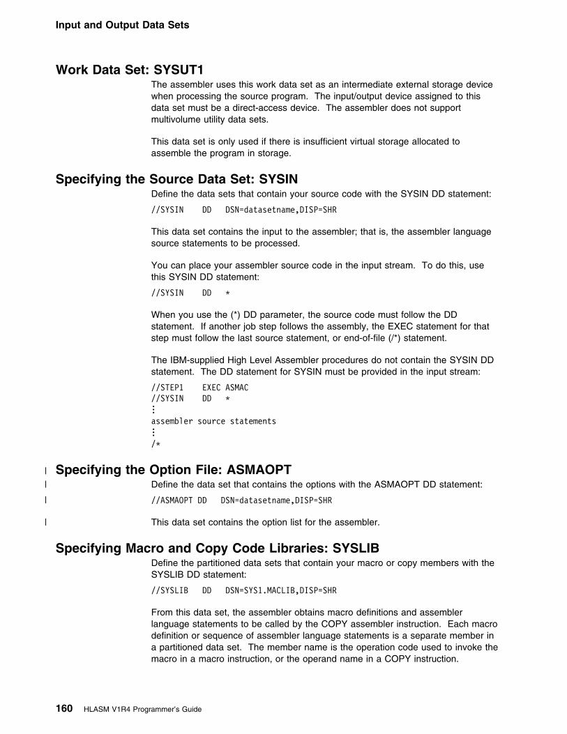
Input and Output Data Sets
Work Data Set: SYSUT1The assembler uses this work data set as an intermediate external storage devicewhen processing the source program. The input/output device assigned to thisdata set must be a direct-access device. The assembler does not supportmultivolume utility data sets.
This data set is only used if there is insufficient virtual storage allocated toassemble the program in storage.
Specifying the Source Data Set: SYSINDefine the data sets that contain your source code with the SYSIN DD statement:
//SYSIN DD DSN=datasetname,DISP=SHR
This data set contains the input to the assembler; that is, the assembler languagesource statements to be processed.
You can place your assembler source code in the input stream. To do this, usethis SYSIN DD statement:
//SYSIN DD L
When you use the (*) DD parameter, the source code must follow the DDstatement. If another job step follows the assembly, the EXEC statement for thatstep must follow the last source statement, or end-of-file (/*) statement.
The IBM-supplied High Level Assembler procedures do not contain the SYSIN DDstatement. The DD statement for SYSIN must be provided in the input stream:
//STEP1 EXEC ASMAC//SYSIN DD L...assembler source statements.../L
| Specifying the Option File: ASMAOPT| Define the data set that contains the options with the ASMAOPT DD statement:
| //ASMAOPT DD DSN=datasetname,DISP=SHR
| This data set contains the option list for the assembler.
Specifying Macro and Copy Code Libraries: SYSLIBDefine the partitioned data sets that contain your macro or copy members with theSYSLIB DD statement:
//SYSLIB DD DSN=SYS1.MACLIB,DISP=SHR
From this data set, the assembler obtains macro definitions and assemblerlanguage statements to be called by the COPY assembler instruction. Each macrodefinition or sequence of assembler language statements is a separate member ina partitioned data set. The member name is the operation code used to invoke themacro in a macro instruction, or the operand name in a COPY instruction.
160 HLASM V1R4 Programmer’s Guide

Input and Output Data Sets
The data set can be defined as SYS1.MACLIB, or your private macro definition orCOPY library. SYS1.MACLIB contains macro definitions for the system macroinstructions provided by IBM. Your private library may be concatenated withSYS1.MACLIB. The two libraries must have the same logical record length (80bytes), but the blocking factors may be different. The applicable JCL Referenceexplains the concatenation of data sets.
Specifying the Listing Data Set: SYSPRINTDefine the data set that contains your listing output with the SYSPRINT DDstatement:
//SYSPRINT DD SYSOUT=A
The assembler uses this data set to produce a listing. You can direct output to aprinter, a magnetic tape, or a direct-access storage device. The assembler usesASA or machine control characters for this data set according to the ASA option.
Directing Assembler Messages to Your Terminal: SYSTERMDefine the data set that contains your terminal message's output with theSYSTERM DD statement:
//SYSTERM DD SYSOUT=A
On TSO, the terminal messages can be sent to your terminal by using the followingALLOC statement:
ALLOC F(SYSTERM) DA(L)
This data set is used by the assembler to store a condensed form of SYSPRINTcontaining flagged statements and their associated error messages. It is intendedfor output to a terminal, but can also be routed to a printer, a magnetic tape, or adirect-access storage device. Depending on the ASA option, the assembler usesASA or machine control characters to skip to a new line for this data set.
Specifying Object Code Data Sets: SYSLIN and SYSPUNCHDefine the data set that contains your object output with the SYSLIN andSYSPUNCH DD statements. When the OBJECT option is in effect, the objectmodule is written to SYSLIN. When the DECK option is in effect, the object moduleis written to SYSPUNCH. When both OBJECT and DECK options are in effect, theobject module is written to both SYSLIN and SYSPUNCH.
You can direct the SYSLIN data set to either a card punch or an intermediatestorage device capable of sequential access:
//SYSLIN DD DSN=dsname,UNIT=SYSALLDA,// SPACE=(subparms),DISP=(MOD,PASS)
You can direct the SYSPUNCH data set to either a card punch or an intermediatestorage device capable of sequential access:
//SYSPUNCH DD SYSOUT=B
Chapter 7. Assembling Your Program on MVS 161

Return Codes
Specifying the Associated Data Data Set: SYSADATADefine the data set that contains your associated data output with the SYSADATADD statement:
//SYSADATA DD DSN=dsname,UNIT=SYSALLDA,// SPACE=(subparms),DISP=(MOD,PASS)
The associated data data set contains information regarding the assembly. Itprovides information for use by symbolic debugging and cross-reference tools. TheSYSADATA data set must be directed to an intermediate storage device capable ofsequential access.
Return CodesHigh Level Assembler issues return codes for use with the IF job control statementand the COND parameter of the JOB and EXEC job control language statements.The IF statement and the COND parameter enable you to skip or to run a job step,depending on the results (indicated by the return code) of a previous job step. It isexplained in the applicable JCL Reference.
The return code issued by the assembler is the highest severity code that isassociated with any error detected in the assembly or with any MNOTE messageproduced by the source program or macro instructions. The return code can becontrolled by the FLAG(n) assembler option described on page 52. SeeAppendix G, “High Level Assembler Messages” on page 309 for a listing of theassembler errors and their severity codes.
162 HLASM V1R4 Programmer’s Guide

The Program Management Binder
Chapter 8. Linking and Running Your Program on MVS
The output from an assembly is an object module. An object module is arelocatable module of machine code that is not executable.
Before an object module can be executed, you must use the binder to convert itinto executable machine code.
The Program Management BinderThe binder converts object modules into an executable program unit that can eitherbe read directly into virtual storage for execution, or stored in a program library.Executable program units can either be load modules, or program objects. Youcan use the binder to:
� Convert object or load modules, or program objects, into a program object andstore it in a PDSE program library.
� Convert object or load modules, or program objects, into a load module andstore it in a partitioned data set program library.
� Convert object or load modules, or program objects, into an executableprogram in virtual storage and execute the program.
For the remainder of this section, the binder is referred to as the linker, unlessotherwise stated.
Copyright IBM Corp. 1982, 2000 163

The Program Management Binder
┌──────────────────────┐ │ │ │ Source Programs │ │ │ └──────────┬───────────┘ │ + ┌──────────────────────┐ │ │ │ ASSEMBLER │ │ │ └──────────┬───────────┘ │ + ┌──────────────────────┐ │ │ │ Object Modules ├─────────────────┐ │ │ │ └──────────┬───────────┘ │ │ │ + + ┌──────────────────────┐ ┌──────────────────────┐ │ Program Management │ │ │
┌──────�│ BINDER ├──┐ │ BATCH LOADER │ │ │ │ │ │ │ │ └──────────────────────┘ │ └──────────┬───────────┘
│ l │ ││ │ │ │+ + │ │
┌──────────────────────┐ ┌──────────────────────┐ │ ││ Load Module │ │ Program Object │ │ │
│ in │ │ in │ │ ││ PDS Program Library │ │ PDSE Program Library │ │ │
└──────────┬───────────┘ └──────────┬───────────┘ │ │+ │ │ │
┌──────────────────────┐ │ │ ││ Program Management │ │ │ ││ LOADER │�─────────────┘ │ │
│ (Fetch) │ │ │ └──────────┬───────────┘ │ │ │ │ │ │ + │ │ ┌──────────────────────┐ │
│ │ Loaded Module in │ │ └─────────────────────────────�│ Virtual Storage │�─┘
│ Ready for Execution │ └──────────────────────┘
Components are shown in uppercase.
�──� = Two-way relationship.Indicates a component canproduce that structure asoutput or accept it as input.
Figure 60. Using the Program Management Components
164 HLASM V1R4 Programmer’s Guide

Creating a Load Module
The LoaderThe loader component of MVS/DFP, and the batch loader component ofDFSMS/MVS perform the same task. Given this, the batch loader is hereafterreferred to as the loader, unless otherwise stated.
The loader combines the basic editing and loading services, that can also beprovided by the linkage editor and program fetch, into one step. The loaderaccepts object modules and load modules, and loads them into virtual storage forexecution. The loader does not produce load modules that can be stored inprogram libraries.
To keep a load module for later execution, use the linkage editor or binder.
Creating a Load ModuleThe linker processes your object module (assembled source program) andprepares it for execution. The processed object module becomes a load module orprogram object.
Optionally, the linker can process more than one object module, or load module,and convert them into one or more load modules, or program objects, by using theNAME control statement. See “Batch Assembling” on page 156 for an examplethat uses the NAME control statement.
Creating a Load Module on MVSFigure 61 shows the general job control for creating a load module or programobject.
//jobname JOB acctno,name,MSGLEVEL=1...//stepname EXEC PGM=HEWL,PARM=(options)//SYSPRINT DD SYSOUT=A//SYSLMOD DD DSN=&&name(member),UNIT=SYSALLDA,// DISP=(NEW,PASS),SPACE=(subparms)//SYSLIB DD DSN=dsname,DISP=SHR//SYSUT1 DD UNIT=SYSALLDA,SPACE=(subparms)//SYSLIN DD DSN=MYOBJ,DISP=SHR
Figure 61. Sample Job Control for Creating a Load Module
The SYSUT1 DD statement is used by the linkage editor, and ignored by thebinder.
High Level Assembler provides cataloged procedures for the following:
� Assembly and link.� Assembly, link, and go (to execute your program).� Assembly and go using the loader.
See “Using Cataloged Procedures” on page 174.
Chapter 8. Linking and Running Your Program on MVS 165

Input to the Linker
Creating a Load Module on TSOYou can invoke the linker on TSO (Time Sharing Option) with the LINK andLOADGO commands.
The LINK command creates a program module and saves it in either a partitioneddata set or PDSE program library. If you run the LINK command in a system withDFSMS/MVS, you can use the BINDER and NOBINDER option on the LINKcommand to control whether your object module is linked using the binder or theMVS/DFP linkage editor.
The LOADGO command creates and executes a program module. The module isnot saved in a program library.
Examples Using the LINK Command: If your assembly produced an objectmodule in a data set called PROGRAM1.OBJ, issue the following LINK command atyour terminal:
LINK PROGRAM1
The program module is placed by default in member TEMPNAME of a partitioneddata set, or PDSE program library called userid.PROGRAM1.LOAD. If you want toput the program module in a different data set, issue the following LINK command:
LINK PROGRAM1 LOAD(data-set-name(member-name))
where data-set-name is a program library, and and member-name is the name ofthe program module.
The following example shows how to link two object modules and place theresulting program module in member TEMPNAME of the userid.LM.LOAD data set:
LINK PROGRAM1,PROGRAM2 LOAD(LM)
If your program refers to other modules (that is, external references), you caninstruct the linker to search for them by including the LIB parameter on the LINKcommand. The LIB parameter specifies one or more names of library data sets tosearch. For example:
LINK PROGRAM1 LIB('SALESLIB.LIB.SUBRT2')
This request searches library SALESLIB.LIB.SUBRT2.
You can also specify link options on the LINK and LOADGO commands. See“Specifying Linker Options Using the TSO LINK Command” on page 170.
Linker options are discussed in “Linker Processing Options” on page 169.
For more information about using the LINK and LOADGO commands, see theTSO/E Command Reference.
Input to the LinkerYour input to the linker can be:
� One or more object modules.
� Linker control statements (that you can generate using the PUNCH assemblerstatement).
166 HLASM V1R4 Programmer’s Guide
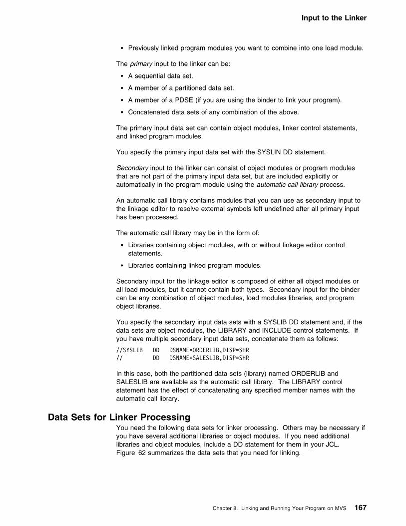
Input to the Linker
� Previously linked program modules you want to combine into one load module.
The primary input to the linker can be:
� A sequential data set.
� A member of a partitioned data set.
� A member of a PDSE (if you are using the binder to link your program).
� Concatenated data sets of any combination of the above.
The primary input data set can contain object modules, linker control statements,and linked program modules.
You specify the primary input data set with the SYSLIN DD statement.
Secondary input to the linker can consist of object modules or program modulesthat are not part of the primary input data set, but are included explicitly orautomatically in the program module using the automatic call library process.
An automatic call library contains modules that you can use as secondary input tothe linkage editor to resolve external symbols left undefined after all primary inputhas been processed.
The automatic call library may be in the form of:
� Libraries containing object modules, with or without linkage editor controlstatements.
� Libraries containing linked program modules.
Secondary input for the linkage editor is composed of either all object modules orall load modules, but it cannot contain both types. Secondary input for the bindercan be any combination of object modules, load modules libraries, and programobject libraries.
You specify the secondary input data sets with a SYSLIB DD statement and, if thedata sets are object modules, the LIBRARY and INCLUDE control statements. Ifyou have multiple secondary input data sets, concatenate them as follows:
//SYSLIB DD DSNAME=ORDERLIB,DISP=SHR// DD DSNAME=SALESLIB,DISP=SHR
In this case, both the partitioned data sets (library) named ORDERLIB andSALESLIB are available as the automatic call library. The LIBRARY controlstatement has the effect of concatenating any specified member names with theautomatic call library.
Data Sets for Linker ProcessingYou need the following data sets for linker processing. Others may be necessary ifyou have several additional libraries or object modules. If you need additionallibraries and object modules, include a DD statement for them in your JCL.Figure 62 summarizes the data sets that you need for linking.
Chapter 8. Linking and Running Your Program on MVS 167

Input to the Linker
Figure 62. Data Sets Used for Linking
DD name Type Function
SYSLIN1 Input Primary input data, normally the output of theassembler
SYSPRINT1 Output Diagnostic messagesInformative messagesModule mapCross reference list
SYSLMOD1 Output Output data set for the program module
SYSUT11 Utility Work data set. Not used by the binder.
SYSLIB Library Automatic call library
SYSTERM2 Output Numbered error or warning messages
User specified3 Additional object modules and program modules
Notes:
1 Required data set2 Required if TERM option is specified3 Optional data set
Additional Object Modules as InputYou can use the INCLUDE and LIBRARY control statements to:
1. Specify additional object modules you want included in the program module(INCLUDE statement).
2. Specify additional libraries to search for object modules to include in theprogram module (LIBRARY statement). This statement has the effect ofconcatenating any specified member names with the automatic call library.
Figure 63 shows an example that uses the INCLUDE and LIBRARY controlstatements.
...//SYSLIN DD DSNAME=&&GOFILE,DISP=(SHR,DELETE)// DD L INCLUDE MYLIB(ASMLIB,ASSMPGM) LIBRARY ADDLIB(COBREGN9)/L
Figure 63. INCLUDE and LIBRARY Control Statements
Data sets you specify on the INCLUDE statement are processed as the linkerencounters the statement. In contrast, data sets you specify on the LIBRARYstatement are used only when there are unresolved references after all the otherinput is processed.
168 HLASM V1R4 Programmer’s Guide

Output from the Linker
Output from the LinkerSYSLMOD and SYSPRINT are the data sets used for linker output. The outputvaries depending on the options you select, as shown in Figure 64.
You always receive diagnostic and informative messages as the result of linking.You can get the other output items by specifying options in the PARM parameter ofthe EXEC statement in your JCL.
The program modules are written to the data set defined by the SYSLMOD DDstatement in your JCL. Diagnostic output is written to the data set defined by theSYSPRINT DD statement.
Figure 64. Options for Controlling Linker Output
To Get This Output Use This Option
A map of the program modules generated by thelinker.
MAP
A cross-reference list of data variables XREF
Informative messages Default
Diagnostic messages Default
Listing of the linker control statements LIST
One or more program modules (which you mustassign to a library)
Default
Linker Processing OptionsLinker options can be specified either:
� In your JCL,or� When you invoke the LINK or LOADGO command on TSO.
Figure 65 describes some of these options.
Figure 65 (Page 1 of 2). Link Processing Options
Option Action Comments
LET Lets you specify the severity level of an error, tocontrol whether the linker marks the program moduleas non-executable.
The LET option is used differentlybetween the linkage editor and thebinder.
MAP NOMAP Use MAP if you want to get a map of the generatedprogram modules. NOMAP suppresses this maplisting.
The map of the program module givesthe length and location (absoluteaddresses) of the main program andall subprograms. NOMAP is thedefault.
NCAL When you use the no automatic library call option(NCAL), the linker does not search for library membersto resolve external references.
If you specify NCAL, you don't need touse the LIBRARY statement, and youdon't need to supply the SYSLIB DDstatement.
Chapter 8. Linking and Running Your Program on MVS 169

Output from the Linker
Figure 65 (Page 2 of 2). Link Processing Options
Option Action Comments
RENTNORENT
The RENT option indicates to the linker that the objectmodule is reenterable and can be used by more thanone task at a time. This type of module cannot bemodified by itself or any other module when it isrunning. The assembler RENT option can be used toassist in determining whether the object module isreentrant. NORENT indicates that the object module isnot reentrant.
The assembler RENT option and linkerRENT option are independent of eachother. NORENT is the default linkeroption.
AMODE24 | 31 | ANY
Use AMODE (addressing mode) to override the defaultAMODE attribute established by the assembler.
See “AMODE and RMODE Attributes”on page 171.
RMODE24 | ANY
Use RMODE (residence mode) to override the defaultRMODE attribute established by the assembler.
See “AMODE and RMODE Attributes”on page 171.
PRINT When you use the TSO commands LINK or LOADGO,the PRINT option specifies where to print diagnosticmessages and the module map.
PRINT is also an option of the loader, and controlswhether diagnostic messages are produced.
See also “Specifying Linker OptionsUsing the TSO LINK Command” onpage 170.
Specifying Linker Options Through JCLIn your link JCL, use the PARM statement to specify options:
PARM=(linker-options)PARM.stepname=('linker-options')
linker-optionsA list of linker options (see Figure 65 on page 169). Separate the options withcommas.
stepnameThe name of the step in the cataloged procedure that contains the PARMstatement.
Specifying Linker Options Using the TSO LINK CommandYou specify linker options on the LINK and LOADGO commands. The followingexample shows you how to specify the LET, MAP, and NOCALL options when youissue the LINK command:
LINK PROGRAM1 LET MAP NOCALL
You can use the PRINT option to display the module map at your terminal:
LINK PROGRAM1 MAP PRINT(L)
The L indicates that the output from the linker is displayed at your terminal.NOPRINT suppresses any messages.
170 HLASM V1R4 Programmer’s Guide

Output from the Linker
AMODE and RMODE AttributesEvery program that runs in MVS/ESA is assigned two attributes, an AMODE(addressing mode) and an RMODE (residency mode):
AMODE Specifies the addressing mode in which the program is designed toreceive control. Generally, the program is also designed to run in thatmode, although a program can switch modes and can have differentAMODE attributes for different entry points within a program module.
MVS/ESA uses a program's AMODE attribute to determine whether aprogram invoked using ATTACH, LINK, or XCTL is to receive control in24-bit or 31-bit addressing mode.
RMODE Indicates where the program can reside in virtual storage.
MVS/ESA uses the RMODE attribute to determine whether a programmust be loaded into virtual storage below 16 megabytes, or can resideanywhere in virtual storage (above or below 16 megabytes).
Valid AMODE and RMODE specifications are:
If you don't specify the AMODE or RMODE in the assembler program or when youlink the program, both AMODE and RMODE default to 24.
Attribute Meaning
AMODE=24 24-bit addressing mode
AMODE=31 31-bit addressing mode
AMODE=ANY Either 24-bit or 31-bit addressing mode
RMODE=24 The module must reside in virtual storage below 16megabytes. Use RMODE=24 for programs thathave 24-bit dependencies.
RMODE=ANY Indicates that the module can reside anywhere instorage, which includes addresses above the 16megabyte line.
Overriding the DefaultsThe following examples show you how to override the default AMODE and RMODEvalues:
� Using the EXEC JCL statement:
//LKED EXEC PGM=IEWBLINK, // PARM='AMODE=31,RMODE=ANY'
� Using the TSO commands LINK or LOADGO:
LINK PROGRAM1 AMODE(31) RMODE(ANY)or
LOADGO PROGRAM1 AMODE(31) RMODE(ANY)
You can also use linker control statements to override the default AMODE andRMODE values.
Chapter 8. Linking and Running Your Program on MVS 171

Running Your Assembled Program
Detecting Linker ErrorsThe linker produces a listing in the data set defined by the SYSPRINT DDstatement. The listing includes any informational or diagnostic messages issued bythe linker. You should check the load map to make sure that all the modules youexpected were included.
When linking your program, do not be concerned if you get messages aboutunresolved, “weak” external references. For example if you obtain the followingresults:
WXTRNNAM is a “weak” external reference; you need not be concerned about it.
EXTRNNAM is a “strong” external reference, which you should resolve for theprogram module to run correctly.
Figure 66. Linker Output for Unresolved External References
Location Refers to Symbol In Control Section
6A8 WXTRNNAM $UNRESOLVED(W)
6AC EXTRNNAM $UNRESOLVED
Running Your Assembled ProgramWhen you've completed the preparatory work for your assembler program(designing, coding, assembling, and linking), the program is ready to run.
You can use cataloged procedures to combine the assemble, link, and goprocedures in your programs. See “Using Cataloged Procedures” on page 174.
Running Your Assembled Program in BatchFigure 67 shows the general job control to run your program in batch.
//stepname EXEC PGM=progname[,PARM='user-parameters']//STEPLIB DD DSN=library.dsname,DISP=SHR//ddname DD (parameters for user-specified data sets)...
Figure 67. General Job Control to Run a Program on MVS
Running Your Assembled Program on TSOYou use the CALL command to run your program on TSO, as follows:
CALL 'JRL.LIB.LOAD(PROGRAM1)'
If you omit the descriptive qualifier (LOAD) and the member name (PROGRAM1),the system assumes LOAD and TEMPNAME, respectively. If your program moduleis in the data set JRL.LIB.LOAD(TEMPNAME), and your TSO userid is JRL, enter:
CALL LIB
172 HLASM V1R4 Programmer’s Guide
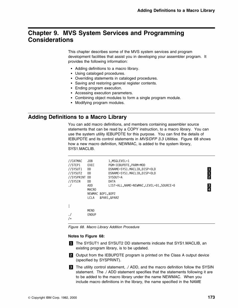
Adding Definitions to a Macro Library
Chapter 9. MVS System Services and ProgrammingConsiderations
This chapter describes some of the MVS system services and programdevelopment facilities that assist you in developing your assembler program. Itprovides the following information:
� Adding definitions to a macro library.� Using cataloged procedures.� Overriding statements in cataloged procedures.� Saving and restoring general register contents.� Ending program execution.� Accessing execution parameters.� Combining object modules to form a single program module.� Modifying program modules.
Adding Definitions to a Macro LibraryYou can add macro definitions, and members containing assembler sourcestatements that can be read by a COPY instruction, to a macro library. You canuse the system utility IEBUPDTE for this purpose. You can find the details ofIEBUPDTE and its control statements in MVS/DFP 3.3 Utilities. Figure 68 showshow a new macro definition, NEWMAC, is added to the system library,SYS1.MACLIB.
//CATMAC JOB 1,MSGLEVEL=1//STEP1 EXEC PGM=IEBUPDTE,PARM=MOD//SYSUT1 DD DSNAME=SYS1.MACLIB,DISP=OLD �1�//SYSUT2 DD DSNAME=SYS1.MACLIB,DISP=OLD �1�//SYSPRINT DD SYSOUT=A �2�//SYSIN DD DATA./ ADD LIST=ALL,NAME=NEWMAC,LEVEL=91,SOURCE=9 �3� MACRO �4� NEWMAC &OP1,&OP2 LCLA &PAR1,&PAR2
... MEND./ ENDUP/L
Figure 68. Macro Library Addition Procedure
Notes to Figure 68:
�1� The SYSUT1 and SYSUT2 DD statements indicate that SYS1.MACLIB, anexisting program library, is to be updated.
�2� Output from the IEBUPDTE program is printed on the Class A output device(specified by SYSPRINT).
�3� The utility control statement, ./ ADD, and the macro definition follow the SYSINstatement. The ./ ADD statement specifies that the statements following it areto be added to the macro library under the name NEWMAC. When youinclude macro definitions in the library, the name specified in the NAME
Copyright IBM Corp. 1982, 2000 173

Using Cataloged Procedures
parameter of the ./ ADD statement must be the same as the operation code ofthe prototype statement of the macro definition.
�4� Following the ADD utility control statement is the macro definition itself.
Using Cataloged ProceduresOften you use the same set of job control statements repeatedly; for example, tospecify the assembly, linking, and running of many different programs. To saveprogramming time and to reduce the possibility of error, standard sets of EXEC andDD statements can be prepared once and cataloged in a procedure library. Such aset of statements is termed a cataloged procedure and can be invoked by either ofthe following statements:
//stepname EXEC procname//stepname EXEC PROC=procname
The specified procedure (procname) is read from the procedure library(SYS1.PROCLIB) and merged with the job control statements that follow this EXECstatement.
This section describes four IBM cataloged procedures: a procedure for assembling(ASMAC); a procedure for assembling and linking (ASMACL); a procedure forassembling, linking, and running (ASMACLG); and a procedure for assembling andrunning the loader (ASMACG).
Cataloged Procedure for Assembly (ASMAC)This procedure consists of one job step: assembly. Use the name ASMAC to callthis procedure. The result of running this procedure is an object module written toSYSPUNCH and an assembler listing. (See “Invoking the Assembler on MVS” onpage 151 for more details and another example.)
In the following example, input is provided in the input stream:
//jobname JOB//stepname EXEC PROC=ASMAC//SYSIN DD L...assembler source statements.../L (delimiter statement)
The statements of the ASMAC procedure are read from the procedure library andmerged into the input stream.
Figure 69 on page 175 shows the statements that make up the ASMAC procedure.
174 HLASM V1R4 Programmer’s Guide
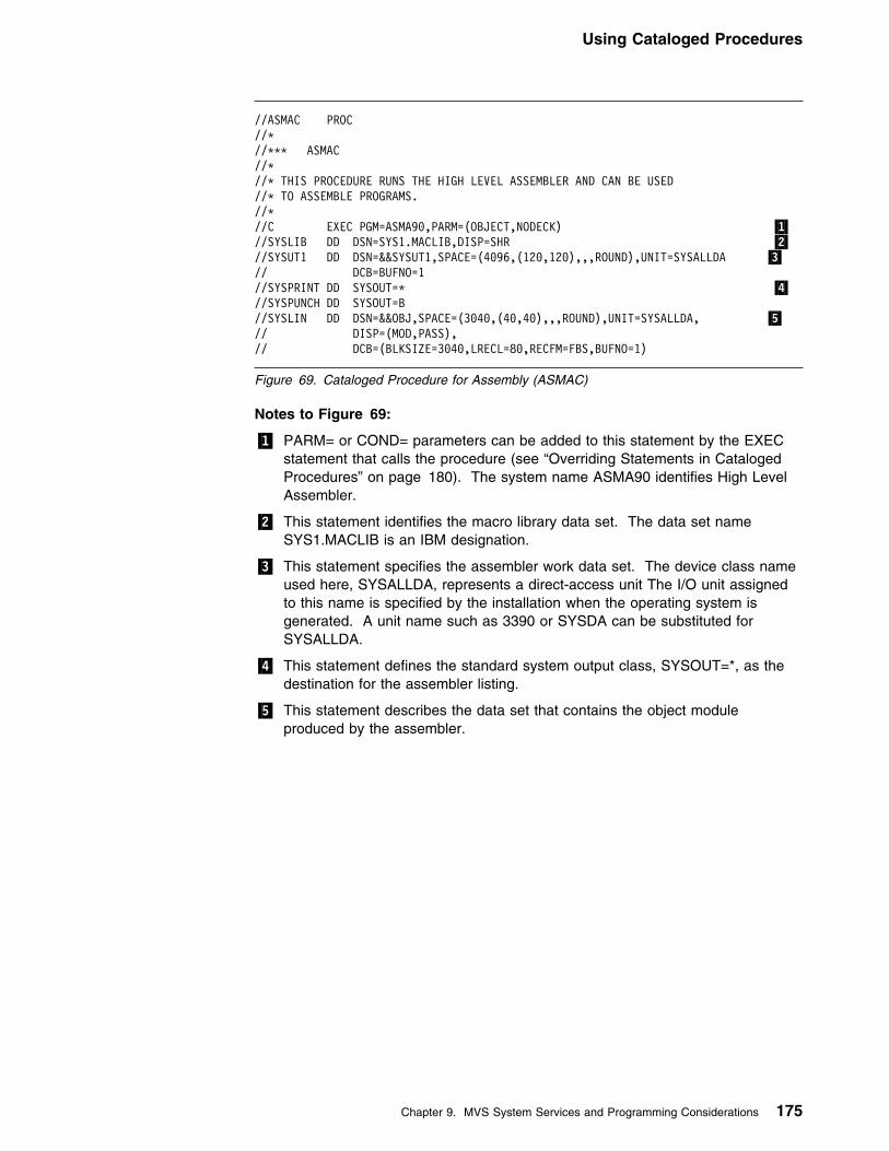
Using Cataloged Procedures
//ASMAC PROC//L//LLL ASMAC//L//L THIS PROCEDURE RUNS THE HIGH LEVEL ASSEMBLER AND CAN BE USED//L TO ASSEMBLE PROGRAMS.//L//C EXEC PGM=ASMA99,PARM=(OBJECT,NODECK) �1�//SYSLIB DD DSN=SYS1.MACLIB,DISP=SHR �2�//SYSUT1 DD DSN=&&SYSUT1,SPACE=(4996,(129,129),,,ROUND),UNIT=SYSALLDA �3�// DCB=BUFNO=1//SYSPRINT DD SYSOUT=L �4�//SYSPUNCH DD SYSOUT=B//SYSLIN DD DSN=&&OBJ,SPACE=(3949,(49,49),,,ROUND),UNIT=SYSALLDA, �5�// DISP=(MOD,PASS),// DCB=(BLKSIZE=3949,LRECL=89,RECFM=FBS,BUFNO=1)
Figure 69. Cataloged Procedure for Assembly (ASMAC)
Notes to Figure 69:
�1� PARM= or COND= parameters can be added to this statement by the EXECstatement that calls the procedure (see “Overriding Statements in CatalogedProcedures” on page 180). The system name ASMA90 identifies High LevelAssembler.
�2� This statement identifies the macro library data set. The data set nameSYS1.MACLIB is an IBM designation.
�3� This statement specifies the assembler work data set. The device class nameused here, SYSALLDA, represents a direct-access unit The I/O unit assignedto this name is specified by the installation when the operating system isgenerated. A unit name such as 3390 or SYSDA can be substituted forSYSALLDA.
�4� This statement defines the standard system output class, SYSOUT=*, as thedestination for the assembler listing.
�5� This statement describes the data set that contains the object moduleproduced by the assembler.
Chapter 9. MVS System Services and Programming Considerations 175
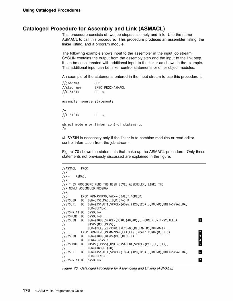
Using Cataloged Procedures
Cataloged Procedure for Assembly and Link (ASMACL)This procedure consists of two job steps: assembly and link. Use the nameASMACL to call this procedure. This procedure produces an assembler listing, thelinker listing, and a program module.
The following example shows input to the assembler in the input job stream.SYSLIN contains the output from the assembly step and the input to the link step.It can be concatenated with additional input to the linker as shown in the example.This additional input can be linker control statements or other object modules.
An example of the statements entered in the input stream to use this procedure is:
//jobname JOB//stepname EXEC PROC=ASMACL//C.SYSIN DD L...assembler source statements.../L//L.SYSIN DD L...object module or linker control statements/L
//L.SYSIN is necessary only if the linker is to combine modules or read editorcontrol information from the job stream.
Figure 70 shows the statements that make up the ASMACL procedure. Only thosestatements not previously discussed are explained in the figure.
//ASMACL PROC//L//LLL ASMACL//L//L THIS PROCEDURE RUNS THE HIGH LEVEL ASSEMBLER, LINKS THE//L NEWLY ASSEMBLED PROGRAM//L//C EXEC PGM=ASMA99,PARM=(OBJECT,NODECK)//SYSLIB DD DSN=SYS1.MACLIB,DISP=SHR//SYSUT1 DD DSN=&&SYSUT1,SPACE=(4996,(129,129),,,ROUND),UNIT=SYSALLDA,// DCB=BUFNO=1//SYSPRINT DD SYSOUT=L//SYSPUNCH DD SYSOUT=B//SYSLIN DD DSN=&&OBJ,SPACE=(3949,(49,49),,,ROUND),UNIT=SYSALLDA, �1�// DISP=(MOD,PASS),// DCB=(BLKSIZE=3949,LRECL=89,RECFM=FBS,BUFNO=1)//L EXEC PGM=HEWL,PARM='MAP,LET,LIST,NCAL',COND=(8,LT,C) �2�//SYSLIN DD DSN=&&OBJ,DISP=(OLD,DELETE) �3�// DD DDNAME=SYSIN �4�//SYSLMOD DD DISP=(,PASS),UNIT=SYSALLDA,SPACE=(CYL,(1,1,1)), �5�// DSN=&&GOSET(GO)//SYSUT1 DD DSN=&&SYSUT1,SPACE=(1924,(129,129),,,ROUND),UNIT=SYSALLDA, �6�// DCB=BUFNO=1//SYSPRINT DD SYSOUT=L �7�
Figure 70. Cataloged Procedure for Assembling and Linking (ASMACL)
176 HLASM V1R4 Programmer’s Guide
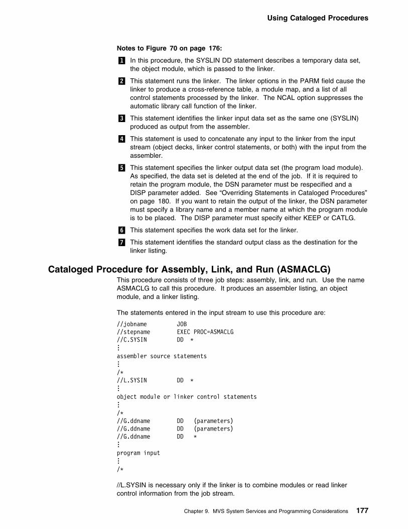
Using Cataloged Procedures
Notes to Figure 70 on page 176:
�1� In this procedure, the SYSLIN DD statement describes a temporary data set,the object module, which is passed to the linker.
�2� This statement runs the linker. The linker options in the PARM field cause thelinker to produce a cross-reference table, a module map, and a list of allcontrol statements processed by the linker. The NCAL option suppresses theautomatic library call function of the linker.
�3� This statement identifies the linker input data set as the same one (SYSLIN)produced as output from the assembler.
�4� This statement is used to concatenate any input to the linker from the inputstream (object decks, linker control statements, or both) with the input from theassembler.
�5� This statement specifies the linker output data set (the program load module).As specified, the data set is deleted at the end of the job. If it is required toretain the program module, the DSN parameter must be respecified and aDISP parameter added. See “Overriding Statements in Cataloged Procedures”on page 180. If you want to retain the output of the linker, the DSN parametermust specify a library name and a member name at which the program moduleis to be placed. The DISP parameter must specify either KEEP or CATLG.
�6� This statement specifies the work data set for the linker.
�7� This statement identifies the standard output class as the destination for thelinker listing.
Cataloged Procedure for Assembly, Link, and Run (ASMACLG)This procedure consists of three job steps: assembly, link, and run. Use the nameASMACLG to call this procedure. It produces an assembler listing, an objectmodule, and a linker listing.
The statements entered in the input stream to use this procedure are:
//jobname JOB//stepname EXEC PROC=ASMACLG//C.SYSIN DD L...assembler source statements.../L//L.SYSIN DD L...object module or linker control statements.../L//G.ddname DD (parameters)//G.ddname DD (parameters)//G.ddname DD L...program input.../L
//L.SYSIN is necessary only if the linker is to combine modules or read linkercontrol information from the job stream.
Chapter 9. MVS System Services and Programming Considerations 177

Using Cataloged Procedures
//G.ddname statements are included only if necessary.
Figure 71 shows the statements that make up the ASMACLG procedure. Onlythose statements not previously discussed are explained in the figure.
//ASMACLG PROC//L//LLL ASMACLG//L//L THIS PROCEDURE RUNS THE HIGH LEVEL ASSEMBLER, LINKS THE//L NEWLY ASSEMBLED PROGRAM AND RUNS THE PROGRAM AFTER//L THE LINK IS ACCOMPLISHED.//L//C EXEC PGM=ASMA99,PARM=(OBJECT,NODECK)//SYSLIB DD DSN=SYS1.MACLIB,DISP=SHR//SYSUT1 DD DSN=&&SYSUT1,SPACE=(4996,(129,129),,,ROUND),UNIT=SYSALLDA,// DCB=BUFNO=1//SYSPRINT DD SYSOUT=L//SYSPUNCH DD SYSOUT=B//SYSLIN DD DSN=&&OBJ,SPACE=(3949,(49,49),,,ROUND),UNIT=SYSALLDA,// DISP=(MOD,PASS),// DCB=(BLKSIZE=3949,LRECL=89,RECFM=FBS,BUFNO=1)//L EXEC PGM=HEWL,PARM='MAP,LET,LIST,NCAL',COND=(8,LT,C) �1�//SYSLIN DD DSN=&&OBJ,DISP=(OLD,DELETE)// DD DDNAME=SYSIN//SYSLMOD DD DISP=(,PASS),UNIT=SYSALLDA,SPACE=(CYL,(1,1,1)), �2�// DSN=&&GOSET(GO)//SYSUT1 DD DSN=&&SYSUT1,SPACE=(1924,(129,129),,,ROUND),UNIT=SYSALLDA,// DCB=BUFNO=1//SYSPRINT DD SYSOUT=L//G EXEC PGM=L.L.SYSLMOD,COND=((8,LT,C),(8,LT,L)) �3�
Figure 71. Cataloged Procedure for Assembly, Link, and Run (ASMACLG)
Notes to Figure 71:
�1� The LET linker option specified in this statement causes the linker to mark theprogram module as executable, even if errors are encountered duringprocessing.
�2� The output of the linker is specified as a member of a temporary data set,residing on a direct-access device, and is to be passed to a following job step.
�3� This statement runs the assembled and linker program. The notation*.L.SYSLMOD identifies the program to be run as being in the data setdescribed in job step L by the DD statement named SYSLMOD.
Cataloged Procedure for Assembly and Run (ASMACG)This procedure consists of two job steps: assembly and run, using the loader.Program modules for program libraries are not produced.
Enter these statements in the input stream to use this procedure:
178 HLASM V1R4 Programmer’s Guide

Using Cataloged Procedures
//jobname JOB//stepname EXEC PROC=ASMACG//C.SYSIN DD L...assembler source statements.../L//G.ddname DD (parameters)//G.ddname DD (parameters)//G.ddname DD L...program input.../L
//G.ddname statements are included only if necessary.
Figure 72 shows the statements that make up the ASMACG procedure. Onlythose statements not previously discussed are explained in the figure.
Use the name ASMACG to call this procedure. Assembler and loader listings areproduced. See Figure 72.
//ASMACG PROC//L//LLL ASMACG//L//L THIS PROCEDURE RUNS THE HIGH LEVEL ASSEMBLER AND WILL USE//L THE LOADER PROGRAM TO RUN THE NEWLY ASSEMBLED PROGRAM.//L//C EXEC PGM=ASMA99,PARM=(OBJECT,NODECK)//SYSLIB DD DSN=SYS1.MACLIB,DISP=SHR//SYSUT1 DD DSN=&&SYSUT1,SPACE=(4996,(129,129),,,ROUND),UNIT=SYSALLDA,// DCB=BUFNO=1//SYSPRINT DD SYSOUT=L//SYSPUNCH DD SYSOUT=B//SYSLIN DD DSN=&&OBJ,SPACE=(3949,(49,49),,,ROUND),UNIT=SYSALLDA,// DISP=(MOD,PASS),// DCB=(BLKSIZE=3949,LRECL=89,RECFM=FBS,BUFNO=1)//G EXEC PGM=LOADER,PARM='MAP,LET,PRINT,NOCALL',COND=(8,LT,C) �1�//SYSLIN DD DSN=&&OBJ,DISP=(OLD,DELETE) �2�// DD DDNAME=SYSIN//SYSLOUT DD SYSOUT=L �3�
Figure 72. Cataloged Procedure for Assembly and Running Using the Loader (ASMACG)
Notes to Figure 72:
�1� This statement runs the loader. The loader options in the PARM field causethe loader to produce a map and print the map and diagnostics. The NOCALLoption is the same as NCAL for the linker, and the LET option is the same asfor the linker.
�2� This statement defines the loader input data set as the same one produced asoutput by the assembler.
�3� This statement identifies the standard output class as the destination for theloader listing.
Chapter 9. MVS System Services and Programming Considerations 179

Using Cataloged Procedures
Overriding Statements in Cataloged ProceduresYou can override any parameter in a cataloged procedure except the PGM=parameter in the EXEC statement. Overriding of statements or fields is effectiveonly for the duration of the job step in which the statements appear. Thestatements, as stored in the procedure library of the system, remain unchanged.
To respecify, add, or nullify statements, include statements in the input stream thatcontain the required changes and identify the statements to be overridden.
EXEC StatementsAny EXEC parameter (except PGM) can be overridden. For example, the PARM=and COND= parameters can be added or, if present, respecified by including themin the EXEC statement calling the procedure. The JCL notation to specify theseparameters is:
//ASM EXEC PROC=ASMACLG,PARM.C=(NOOBJECT),COND.L=(8,LT,stepname.c)
stepname identifies the EXEC statement within the catalogued procedure(ASMACLG) to which the modification applies.
If the procedure consists of more than one job step, a PARM.procstepname= orCOND.procstepname= parameter can be entered for each step. The entries mustbe in order (PARM.procstepname1=, PARM.procstepname2=, ...).
DD StatementsAll parameters in the operand field of DD statements can be overridden byincluding in the input stream (following the EXEC statement calling the procedure) aDD statement with the notation //procstepname.ddname in the name field.procstepname refers to the job step in which the statement identified by ddnameappears.
If more than one DD statement in a procedure is to be overridden, the overridingstatements must be in the same order as the statements in the procedure.
Examples of Cataloged Procedures1. In the assembly procedure ASMAC (Figure 69 on page 175), you might want
to suppress the object module to SYSPUNCH and respecify the UNIT= andSPACE= parameters of data set SYSUT1. In this case, the followingstatements are required:
//stepname EXEC PROC=ASMAC,// PARM=NODECK//SYSUT1 DD UNIT=3399,// SPACE=(4996,(399,49))//SYSIN DD L...assembler source statements.../L
2. In procedure ASMACLG (Figure 71 on page 178), you might want to suppressthe assembler listing, and add the COND= parameter to the EXEC statementthat invokes the linker. In this case, the EXEC statement in the input streamare:
180 HLASM V1R4 Programmer’s Guide

Using Cataloged Procedures
//stepname EXEC PROC=ASMACLG,// PARM.C=(NOLIST,OBJECT),// COND.L=(8,LT,stepname.C)
For this run of procedure ASMACLG, no assembler listing is produced, andrunning of the linker job step //L would be suppressed if the return code issuedby the assembler (step C) were greater than 8.
When you override the PARM field in a procedure, the whole PARM field isoverridden. Thus, in this example, overriding the LIST parameter effectivelydeletes PARM=(OBJECT,NODECK). PARM=(OBJECT,NODECK) must berepeated in the override statement; otherwise, the assembler default values areused.
3. The following example shows how to use the procedure ASMACL (Figure 70on page 176) to:
�1� Read input from a nonlabeled 9-track tape in unit 282 that has a standardblocking factor of 10.
�2� Put the output listing on a tape labeled TAPE10, with a data set name ofPROG1 and a blocking factor of 5.
�3� Block the SYSLIN output of the assembler and use it as input to the linkerwith a blocking factor of 10.
�4� Link the module only if there are no errors in the assembly (COND=0).
�5� Link onto a previously allocated and cataloged data set USER.LIBRARYwith a member name of PROG.
//jobname JOB//stepname EXEC PROC=ASMACL,// COND.L=(9,NE,stepname.C) �4�//C.SYSPRINT DD DSNAME=PROG1,UNIT=TAPE, �2�// VOLUME=SER=TAPE19,DCB=(BLKSIZE=665)//C.SYSLIN DD DCB=(BLKSIZE=899) �3�//C.SYSIN DD UNIT=282,LABEL=(,NL), �1�// DCB=(RECFM=FBS,BLKSIZE=899)//L.SYSLIN DD DCB=stepname.C.SYSLIN �3�//L.SYSLMOD DD DSNAME=USER.LIBRARY(PROG),DISP=OLD �5�/L
The order of appearance of overriding ddnames for job step C corresponds tothe order of ddnames in the procedure; that is, SYSPRINT precedes SYSLINwithin step C. The ddname C.SYSIN was placed last because SYSIN does notoccur at all within step C. These points are covered in the applicable JCLReference.
4. The following example shows assembly of two programs, link of the two objectmodules produced by the assemblies into one program module, and runningthe generated program. The input stream appears as follows:
Chapter 9. MVS System Services and Programming Considerations 181

Operating System Programming Conventions
//stepname1 EXEC PROC=ASMAC,PARM=OBJECT//SYSIN DD L...assembler source statements for program 1.../L//stepname2 EXEC PROC=ASMACLG//C.SYSIN DD L...assembler source statements for program 2.../L//L.SYSIN DD L ENTRY PROG/L//G.ddname DD dd statements for G step
The applicable JCL Reference provides additional descriptions of overridingtechniques.
Operating System Programming ConventionsAssembler programs executing on MVS must follow a set of programmingconventions to save and restore registers, and access execution parameters.These conventions are described in the following sections.
Saving and Restoring General Register ContentsA program should save the values contained in the general registers when itreceives control and, on completion, restore these same values to the generalregisters. Thus, as control is passed from the operating system to a program and,in turn, to a subprogram, the status of the registers used by each program ispreserved. This is done through use of the SAVE and RETURN system macroinstructions.
Saving Register Contents: The SAVE macro instruction should be the firststatement in the program. It stores the contents of registers 14, 15, and 0 through12 in an area provided by the program that passes control. When a program isgiven control, register 13 contains the address of an area in which the generalregister contents should be saved.
If the program calls any subprograms, or uses any operating system services otherthan GETMAIN, FREEMAIN, ATTACH, and XCTL, it must first save the contents ofregister 13 and then load the address of an 18-fullword save area into register 13.
Restoring Register Contents: At completion, the program restores the contentsof general registers 14, 15, and 0 through 12 by use of the RETURN system macroinstruction (which also indicates program completion). The contents of register 13must be restored before issuing the RETURN macro instruction.
Example: The coding sequence that follows shows the basic process of savingand restoring the contents of the registers. A complete discussion of the SAVE andRETURN macro instructions and the saving and restoring of registers is containedin the MVS/ESA Programming: Assembler Services Reference.
182 HLASM V1R4 Programmer’s Guide
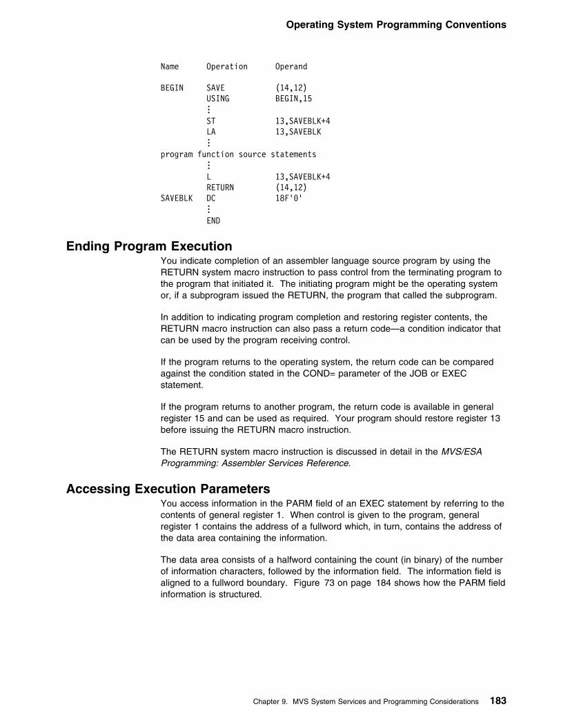
Operating System Programming Conventions
Name Operation Operand
BEGIN SAVE (14,12) USING BEGIN,15 . . . ST 13,SAVEBLK+4 LA 13,SAVEBLK . . .program function source statements
... L 13,SAVEBLK+4 RETURN (14,12)SAVEBLK DC 18F'9'
... END
Ending Program ExecutionYou indicate completion of an assembler language source program by using theRETURN system macro instruction to pass control from the terminating program tothe program that initiated it. The initiating program might be the operating systemor, if a subprogram issued the RETURN, the program that called the subprogram.
In addition to indicating program completion and restoring register contents, theRETURN macro instruction can also pass a return code—a condition indicator thatcan be used by the program receiving control.
If the program returns to the operating system, the return code can be comparedagainst the condition stated in the COND= parameter of the JOB or EXECstatement.
If the program returns to another program, the return code is available in generalregister 15 and can be used as required. Your program should restore register 13before issuing the RETURN macro instruction.
The RETURN system macro instruction is discussed in detail in the MVS/ESAProgramming: Assembler Services Reference.
Accessing Execution ParametersYou access information in the PARM field of an EXEC statement by referring to thecontents of general register 1. When control is given to the program, generalregister 1 contains the address of a fullword which, in turn, contains the address ofthe data area containing the information.
The data area consists of a halfword containing the count (in binary) of the numberof information characters, followed by the information field. The information field isaligned to a fullword boundary. Figure 73 on page 184 shows how the PARM fieldinformation is structured.
Chapter 9. MVS System Services and Programming Considerations 183

Operating System Programming Conventions
General register 1 ┌──────────────────────────────────────┐
┌────────────┤ Address of Fullword │ │ └──────────────────────────────────────┘
│ Points to │ ┌──────────────────────────────────────┐
└───────────�│ Address of Data Area ├───────────┐ └──────────────────────────────────────┘ │
Points to │ ┌───────────────────────────────────────────────────────────────┘ │ │ ┌─────────────────┬────────────────────┐
└───────────�│ Count in Binary │ Information Field │ └─────────────────┴────────────────────┘
Figure 73. Access to PARM Field
Object Module LinkageYou can combine two or more object modules, whether generated by theassembler or by another language processor, to produce a single load module.The object modules can be combined by the linkage editor, or DFSMS/MVS binder,provided each object module conforms to the data formats and the required linkageconventions. This makes it possible for you to use different programminglanguages for different parts of your program, allowing each part to be written in thelanguage best suited for it. Use the CALL system macro instruction to link anassembler language main program to subprograms produced by another languageprocessor. Refer to the MVS/ESA Programming: Assembler Services Referencefor details about linkage conventions and the CALL system macro instruction.
Figure 74 on page 185 is an example of statements used to establish theassembler language program linkage to subprograms. See the applicable languageprogrammer's guide for information about calling the language from an assemblerlanguage program.
If any input or output operations are performed by called subprograms supply thecorrect DD statements for the data sets used by the subprograms. See theapplicable language programmer's guide for an explanation of the DD statementsand special data set record formats used for the language.
184 HLASM V1R4 Programmer’s Guide
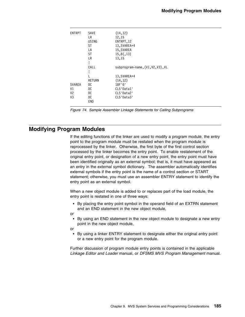
Modifying Program Modules
ENTRPT SAVE (14,12) LR 12,15 USING ENTRPT,12 ST 13,SVAREA+4 LA 15,SVAREA ST 15,8(,13) LR 13,15 . . . CALL subprogram-name,(V1,V2,V3),VL . . . L 13,SVAREA+4 RETURN (14,12)SVAREA DC 18F'9'V1 DC CL5'Data1'V2 DC CL5'Data2'V3 DC CL5'Data3' END
Figure 74. Sample Assembler Linkage Statements for Calling Subprograms
Modifying Program ModulesIf the editing functions of the linker are used to modify a program module, the entrypoint to the program module must be restated when the program module isreprocessed by the linker. Otherwise, the first byte of the first control sectionprocessed by the linker becomes the entry point. To enable restatement of theoriginal entry point, or designation of a new entry point, the entry point must havebeen identified originally as an external symbol; that is, it must have appeared asan entry in the external symbol dictionary. The assembler automatically identifiesexternal symbols if the entry point is the name of a control section or STARTstatement; otherwise, you must use an assembler ENTRY statement to identify theentry point as an external symbol.
When a new object module is added to or replaces part of the load module, theentry point is restated in one of three ways:
� By placing the entry point symbol in the operand field of an EXTRN statementand an END statement in the new object module,
or� By using an END statement in the new object module to designate a new entry
point in the new object module,or� By using a linker ENTRY statement to designate either the original entry point
or a new entry point for the program module.
Further discussion of program module entry points is contained in the applicableLinkage Editor and Loader manual, or DFSMS MVS Program Management manual.
Chapter 9. MVS System Services and Programming Considerations 185
Modifying Program Modules
186 HLASM V1R4 Programmer’s Guide

Part 3. Developing Assembler Programs on CMS
Part 3. Developing Assembler Programs on CMS
Chapter 10. Assembling Your Program on CMS . . . . . . . . . . . . . . . . 188Input to the Assembler . . . . . . . . . . . . . . . . . . . . . . . . . . . . . . . . . 188Output from the Assembler . . . . . . . . . . . . . . . . . . . . . . . . . . . . . . 188Accessing the Assembler . . . . . . . . . . . . . . . . . . . . . . . . . . . . . . . 188Invoking the Assembler on CMS . . . . . . . . . . . . . . . . . . . . . . . . . . . 189Batch Assembling . . . . . . . . . . . . . . . . . . . . . . . . . . . . . . . . . . . . 190Controlling Your Assembly . . . . . . . . . . . . . . . . . . . . . . . . . . . . . . . 190Input and Output Files . . . . . . . . . . . . . . . . . . . . . . . . . . . . . . . . . 191
Work file: SYSUT1 . . . . . . . . . . . . . . . . . . . . . . . . . . . . . . . . . . 193Specifying the Source File: SYSIN . . . . . . . . . . . . . . . . . . . . . . . . . 194
| Specifying the Option File: ASMAOPT . . . . . . . . . . . . . . . . . . . . . . 195Specifying Macro and Copy Code Libraries: SYSLIB . . . . . . . . . . . . . . 195Specifying the Listing File: SYSPRINT . . . . . . . . . . . . . . . . . . . . . . 196Directing Assembler Messages to Your Terminal: SYSTERM . . . . . . . . . 196Specifying Object Code Files: SYSLIN and SYSPUNCH . . . . . . . . . . . . 196Specifying the Associated Data File: SYSADATA . . . . . . . . . . . . . . . . 197
Return Codes . . . . . . . . . . . . . . . . . . . . . . . . . . . . . . . . . . . . . . 197Diagnostic Messages Written by CMS . . . . . . . . . . . . . . . . . . . . . . . . 197
Chapter 11. Running Your Program on CMS . . . . . . . . . . . . . . . . . . 199Using the CMS LOAD and START Commands . . . . . . . . . . . . . . . . . . . 199Using the CMS GENMOD Command . . . . . . . . . . . . . . . . . . . . . . . . . 199Using the CMS LKED and OSRUN Commands . . . . . . . . . . . . . . . . . . 200Using the CMS Batch Facility . . . . . . . . . . . . . . . . . . . . . . . . . . . . . 201
Chapter 12. CMS System Services and Programming Considerations . . 202Using Macros . . . . . . . . . . . . . . . . . . . . . . . . . . . . . . . . . . . . . . 202
Assembler Macros Supported by CMS . . . . . . . . . . . . . . . . . . . . . . 202Adding Definitions to a Macro Library . . . . . . . . . . . . . . . . . . . . . . . 202
Operating System Programming Conventions . . . . . . . . . . . . . . . . . . . . 202Saving and Restoring General Register Contents . . . . . . . . . . . . . . . . 202Ending Program Execution . . . . . . . . . . . . . . . . . . . . . . . . . . . . . 203Passing Parameters to Your Assembler Language Program . . . . . . . . . . 204
Copyright IBM Corp. 1982, 2000 187

Accessing the Assembler
Chapter 10. Assembling Your Program on CMS
This chapter describes how to invoke the assembler on CMS (ConversationalMonitor System). It describes:
� The input to the assembler.� The output from the assembler� How to gain access to the High Level Assembler product files.� How to invoke the assembler on CMS.� How to assemble multiple source programs using the BATCH option.� Special options for invoking the assembler on CMS.� The data sets used by the assembler.� The assembler return codes.� Special diagnostic messages when invoking the assembler on CMS.
To use this section effectively, you should be familiar with the assembler languagedescribed in the Language Reference.
The assembler language program can be run under control of CMS. For moreinformation about CMS, refer to the applicable CP Command Reference forGeneral Users and CMS Command and Macro Reference.
Input to the AssemblerAs input, the assembler accepts a program written in the assembler language asdefined in the Language Reference. This program is referred to as a sourcemodule. Some statements in the source module (macro or COPY instructions) cancause additional input to be obtained from a macro library.
Input can also be obtained from user exits. See Chapter 4, “Providing User Exits”on page 79 for more information.
Output from the AssemblerThe output from the assembler can consist of an object module, a program listing,terminal messages and an associated data file. The object module is stored onyour virtual disk in a TEXT file. You can bring it into your virtual storage and run itby using the CMS LOAD and START commands. The program listing lists all thestatements in the module, both in source and machine language format, and givesother important information about the assembly, such as error messages. Thelisting is described in detail in Chapter 2, “Using the Assembler Listing” on page 8.
Accessing the AssemblerTo access the High Level Assembler on CMS, you must first link to the mini-diskcontaining the assembler by issuing the CP LINK command. You must then issuethe ACCESS command to assign a file mode, and make the mini-disk available toCMS. For example:
CP LINK PRODUCT 194 198 RR PASSWORDACCESS 198 B
188 Copyright IBM Corp. 1982, 2000

Invoking the Assembler on CMS
In this example, you have linked to disk 194 of the virtual machine that contains theHigh Level Assembler product, and whose user ID is PRODUCT. You havedefined disk 194 as 198 to your VM session. You have read access to the disk(RR) and you specified the read-share password for the 194 disk (PASSWORD).
After you linked to the 194 disk as 198, you accessed the 198 disk as disk B onyour system. After you have access to the product disk, you can invoke theassembler using the ASMAHL command (see “Invoking the Assembler on CMS”).
If High Level Assembler is stored on your A-disk, or another disk to which youalready have access, you can omit the CP LINK and ACCESS commands. If HighLevel Assembler is not on a disk that you have accessed, you can put the CP LINKand ACCESS commands into your PROFILE EXEC, which issues them for youeach time you log on. For more information on the CP LINK and ACCESScommands, see the applicable CP Command Reference for your VM environment,as listed under “Bibliography” on page 386.
Invoking the Assembler on CMSUse the ASMAHL command to invoke and control assembly of assembler sourceprograms on CMS.
The format of the ASMAHL command is:
��─ ─ASMAHL─ ──┬ ┬────────── ──┬ ┬────────────────────── ─�� └ ┘─filename─ │ │┌ ┐──┬ ┬─── ─ │ ││ │└ ┘─,─ └ ┘──( ───+ ┴─option─ ──┬ ┬─── └ ┘─)─
where:
filename Is the name of your assembler source program.
Use one of the three methods available for specifying your assemblersource program. See “Specifying the Source File: SYSIN” on page 194for details on each of these methods.
option Represents one or more assembler options, separated by a blank orcomma, that you want in effect during assembly. These assembleroptions are equivalent to the options you would specify on the PARMparameter of an EXEC job control statement, if you were invoking theassembler on MVS.
A complete list and discussion of assembler options can be found underChapter 3, “Controlling Your Assembly with Options” on page 38.
The assembler options in effect are determined by the default optionsthat were set when High Level Assembler was installed, and by theoptions you specify with the ASMAHL command. There are also severalassembler options that can only be specified when running on CMS; see“Controlling Your Assembly” on page 190.
Synonym for ASMAHL Command: Your installation might have created asynonym for ASMAHL when High Level Assembler was installed. See your systemprogrammer for the specific command name.
Chapter 10. Assembling Your Program on CMS 189

Controlling Your Assembly
Batch AssemblingYou can assemble a sequence of separate assembler programs with a singleinvocation of the assembler, using the BATCH option. The object programsproduced from this assembly can be link-edited into either a single load module orseparate load modules.
When the BATCH option is specified, each assembler program in the sequencemust be terminated by an END statement, including the last program in the batch.If an END statement is omitted, the program assembles with the next program inthe sequence. If the END statement is omitted from the last program in thesequence, the assembler generates an END statement.
If separate load modules are to be produced, you must write a NAME linkage editorcontrol statement for each load module. The NAME statement must be written atthe end of the load module. Figure 75 shows how to create two load modules,SECT1 and SECT2.
SECT1 CSECT Start of first load module...
Source instructions . . .
END End of first load modulePUNCH ' NAME SECT1(R)'
ENDSECT2 CSECT Start of second load module
... Source instructions . . .
END End of second load modulePUNCH ' NAME SECT2(R)'
END
Figure 75. Example of Creating Two Load Modules on CMS
If separate TEXT files are required, you must issue two separate ASMAHLcommands.
Controlling Your AssemblyThe assembly options are specified on the ASMAHL command after the leftparenthesis. The options that can be specified to control your assembly aredescribed in Chapter 3, “Controlling Your Assembly with Options” on page 38.
On CMS, there are additional options that can be specified. These are described inChapter 3, “Controlling Your Assembly with Options” on page 38, and consist of:
ERASE Deletes LISTING, TEXT, and SYSADATA files before the assemblybegins.
LINECOUN Specifies the number of lines to be printed on each page of theassembler listing.
NOSEG Specifies that the assembler load modules are loaded from disk. Thedefault is to load the modules from the Logical Saved Segment(LSEG); but, if the LSEG is not available, then load the modules fromdisk.
190 HLASM V1R4 Programmer’s Guide

Input and Output Files
PRINT Directs the assembler listing to the virtual printer, instead of to disk.
SEG Specifies that the assembler load modules are loaded from theLogical Saved Segment (LSEG). The default is to load the modulesfrom the LSEG; but, if the LSEG is not available, then load themodules from disk.
SYSPARM A question mark (?) can be specified in the SYSPARM string, whichinstructs the assembler to prompt you for a character string at yourterminal.
Input and Output FilesDepending on the options in effect, High Level Assembler requires the files asshown in Figure 76.
| ┌──────────────┐| │ SYSIN │ ┌─────────────┐| └───────────┬──┘ ┌──┤ ASMAOPT │| │ │ └─────────────┘| │ │| + +| ┌──────────────┐ ┌──────────────┐ ┌──────────────┐| │ SYSLIB ├──────────�│ Assembler │�──────────�│ SYSUT1 │| └──────────────┘ └───────┬──────┘ └──────────────┘| │| +| ┌──────────────┬──────────────┬──────────────┬──────────────┐| │ │ │ │ │| + + + + +| ┌───────────┐ ┌───────────┐ ┌───────────┐ ┌───────────┐ ┌───────────┐| │ SYSPRINT │ │ SYSTERM │ │ SYSLIN │ │ SYSPUNCH │ │ SYSADATA │| └───────────┘ └───────────┘ └───────────┘ └───────────┘ └───────────┘
| Figure 76. High Level Assembler Files
The ddnames can be overridden during installation.
High Level Assembler requires the following files:
SYSUT1 A work file used as intermediate external storage when processingthe source program. This file is used when there is not enoughmain storage available to assemble in-storage.
If the value specified for the SIZE option is large enough, anin-storage assembly is done and the work file SYSUT1 can beomitted, though a warning message is issued.
SYSIN An input file containing the source statements to be processed.
SYSLIB A file containing macro definitions (for macro definitions notdefined in the source program), source code to be called forthrough COPY assembler instructions, or both.
SYSPRINT A file containing the assembly listing (if the LIST option is ineffect).
SYSTERM A file containing essentially a condensed form of SYSPRINT,principally error flagged statements and their error messages (onlyif the TERM option is in effect).
Chapter 10. Assembling Your Program on CMS 191

Input and Output Files
SYSPUNCH A file containing object module output, usually for punching (only ifthe DECK option is in effect).
SYSLIN A file containing object module output usually for the linkage editor(only if the OBJECT option is in effect).
SYSADATA A file containing associated data output (only if the ADATA optionis in effect).
The files listed above are described in the text following Figure 77. Thecharacteristics of these files, those set by the assembler and those you canoverride, are shown in Figure 77.
Notes to Figure 77:
�1� If you specify EXIT(PRTEXIT) and the user exit specifies the logical recordlength, the logical record length returned is used, unless the SYSPRINT dataset has a variable-length record format in which case the LRECL used is 4bytes greater than the value returned by the exit. If EXIT(PRTEXIT) has notbeen specified or the user exit does not specify a record length, the recordlength from the FILEDEF command or file label is used, if present. Otherwise,the record length defaults to 133, or 137 if the record format is variable-length.
The minimum record length allowed for SYSPRINT is 121, and the maximumallowed is 255. If the record format is variable-length, the LRECL should be atleast 125 or 137 depending on the LIST option.
�2� If you specify EXIT(TRMEXIT) and the user exit specifies the logical recordlength, the logical record length returned is used. If you do not specifyEXIT(TRMEXIT) or the user exit does not specify a record length, the recordlength from the FILEDEF command or file label is used, if present. If notpresent, the record length defaults to the record length for SYSPRINT (if theLIST option is in effect) or 133 otherwise.
The maximum record length allowed for SYSTERM is 255.
Figure 77. Assembler File Characteristics
File AccessMethod
LogicalRecordLength(LRECL)
Block Size(BLKSIZE)
Record Format(RECFM)
SYSUT1 BSAM Same asBLKSIZE
�3� F
SYSIN QSAM 80 �4� �7��1��
| ASMAOPT| QSAM| �11�| �6�| Fixed/Variable
SYSLIB BPAM 80 �5� �7��1��
SYSPRINT QSAM �1� �6� �8��1��
SYSTERM QSAM �2� �4� �9��1��
SYSPUNCH QSAM| �12�| �4�| �13�
SYSLIN QSAM �12� �4� �13�
SYSADATA QSAM 8188 8192 orgreater
VB
192 HLASM V1R4 Programmer’s Guide

Input and Output Files
�3� You can specify a block size (BLKSIZE) between 2008 and 32760 bytes on theFILEDEF command or in the file label. The BLKSIZE should be a multiple of8. If it is not, it is rounded to the next lower multiple of 8. If you do not specifyBLKSIZE, the assembler sets the block size to 4088.
�4� If specified, the BLKSIZE must equal the LRECL, or be a multiple of theLRECL. If BLKSIZE is not specified, it is set to LRECL.
�5� The BLKSIZE on the FILEDEF command or the file label must equal theLRECL, or be a multiple of the LRECL.
�6� The blocksize must be equal to or a multiple of the record length if the recordformat is fixed. If the record format is variable, then the blocksize must be atleast 4 bytes greater than the record length.
�7� Set by the assembler to F (or FB) if necessary.
�8� Both fixed and variable formats are supported; the default is variable. If theFILEDEF command or file label specifies machine or ASA control characters,the ASA option is set or reset accordingly. If machine or ASA controlcharacters are not specified on the FILEDEF command or file label, the recordformat is modified according to the ASA option.
�9� Set by the assembler to F (or FB) if necessary. The record format is set to FA(or FBA) if the ASA option is specified, or FM (or FBM) otherwise.
�1�� You can specify B, S, or T, or any combination of these.
| �11� The minimum record length allowed for ASMAOPT is 5. The maximum record| length allowed is 32756 if the record format is variable-length or 32760 if the| record format is fixed-length.
| �12� If you specify the OBJECT option,the logical record length must be 80. If you| specify the GOFF option, the object module can be generated with either| fixed-length records of 80 bytes, or variable-length records up to a BLKSIZE of| 32720.
| �13� Both fixed and variable formats are supported; the default is fixed.
Work file: SYSUT1The assembler uses this work file as an intermediate external storage device whenprocessing the source program. The input/output device assigned to this file mustbe a direct-access device.
If no SYSUT1 FILEDEF command is issued before the ASMAHL command isissued, the following FILEDEF command is issued by the ASMAHL command:
FILEDEF SYSUT1 DISK fn SYSUT1 m4 (BLOCK 4988
where fn is the filename specified on the ASMAHL command, and the file mode m4is set to use the read/write disk with the most available space. For example, ifthree read/write disks were accessed as the A, B, and D disks, and if the D diskhad the most available space, then m4 would be set to “D4” for use during theassembly.
This data set is only used if there is insufficient virtual storage allocated toassemble the program in storage.
Chapter 10. Assembling Your Program on CMS 193

Input and Output Files
Specifying the Source File: SYSINUse one of the following methods for specifying your assembler source program:
� Specify the filename of the assembler source program on the ASMAHLcommand line,
or� Issue a FILEDEF for SYSIN before issuing the ASMAHL command,
or� Supply source statements from a user-supplied module by using the EXIT
assembler option.
Specify the Filename on the Command Line: Using this method, you specifythe filename of your assembler source program on the ASMAHL command line.For example:
ASMAHL PROG1 (LIST,XREF(SHORT))
assembles the source program named PROG1 using the assembler options LISTand XREF(SHORT). The source program must have a filetype of ASSEMBLE.The ASMAHL command issues the following FILEDEF command:
FILEDEF SYSIN DISK PROG1 ASSEMBLE L (RECFM FB LRECL 89 BLOCK 16999
Issue a FILEDEF for SYSIN: Another method you can use to specify theassembler source program is to issue a FILEDEF for SYSIN before the assembly.The assembler then assembles the program specified in the FILEDEF. Forexample:
FILEDEF SYSIN DISK PROG2 ASSEMBLE AASMAHL (LIST,XREF)
assembles the program named PROG2, using the options specified on the ASMAHLcommand line. When you issue a FILEDEF for SYSIN, the source program youspecify with the FILEDEF is the one used for input by the assembler.
If the FILEDEF for SYSIN is issued and the FILEDEF specifies a DISK file, thefilename on the ASMAHL command is optional. If the filename is specified on theASMAHL command, the filename must match the filename of the file specified onthe FILEDEF. Additionally, when using a FILEDEF, the file type need not beASSEMBLE.
You can read MVS data sets and VSE files as CMS files by defining those datawith the FILEDEF command. For example,
FILEDEF SYSIN DISK OSDS ASSEMBLE fm DSN OS DATASET (options...
You can also assemble a member of an OS partitioned data set or a CMS MACLIBby using the MEMBER parameter of the FILEDEF command. When you specifymember parameter, the member name is used as the filename for the LISTING,TEXT, and SYSADATA files.
If you want to assemble a source file that is in your CMS virtual reader, issue thefollowing FILEDEF command:
FILEDEF SYSIN READER
and then issue the ASMAHL command. You must specify the filename on theASMAHL command. The filename is used as the file name of the LISTING, TEXT,and SYSADATA files.
194 HLASM V1R4 Programmer’s Guide

Input and Output Files
Similarly, if you have a tape containing an assembler input file that you want toassemble, you must issue the following command before issuing the ASMAHLcommand:
FILEDEF SYSIN TAPn (RECFM F LRECL 89 BLOCK 89
If the blocksize of the file were 800 bytes, you could specify BLOCK 800 as in thepreceding FILEDEF.
If the FILEDEF command specifies a tape file, the filename must be specified onthe ASMAHL command. The filename is used as the filename of the LISTING,TEXT, and SYSADATA files.
Make sure that any attributes specified for a file conform to the attributes expectedby the assembler for the device.
Specify Source Using the EXIT Option: If you are using an input user exit toprovide source statements to the assembler, the FILEDEF for SYSIN is notrequired. For example:
ASMAHL PROG2 (EXIT(INEXIT(INMOD1('ABCD'))),LIST,XREF(SHORT))
assembles the source statements provided by the input user module named INMOD1using the character string ABCD, and also the assembler options LIST andXREF(SHORT). (For specific details on using the EXIT assembler option, seepage 49).
Specify the filename on the ASMAHL command, or a FILEDEF for SYSIN, beforeissuing the ASMAHL command as described above. This is required even if theassembler does not read the input file. The filename specified on the ASMAHLcommand, or from the FILEDEF for SYSIN, is used as the filename of the LISTING,TEXT, and SYSADATA files.
If you specify the INEXIT option, the ASMAHL command does not check whetherthe input file exists. If the SOURCE user exit instructs the assembler to open theprimary input file, the open fails if the file does not exist.
| Specifying the Option File: ASMAOPT| You must issue an ASMAOPT FILEDEF command if you wish the assembler to use| the options in this file. For example
| FILEDEF ASMAOPT DISK PROG1 OPTIONS L
Specifying Macro and Copy Code Libraries: SYSLIBIf you don't issue SYSLIB FILEDEF before the ASMAHL command, the ASMAHLcommand issues the following FILEDEF command:
FILEDEF SYSLIB DISK CMSLIB MACLIB L (RECFM FB LRECL 89 BLOCK 8999
Use the GLOBAL command to identify which CMS libraries are to be searched formacro definitions and COPY code. Private libraries and CMSLIB can beconcatenated with each other in any order by the GLOBAL command. The formatof this command is described in the applicable CMS Command and MacroReference.
Chapter 10. Assembling Your Program on CMS 195

Input and Output Files
You can concatenate a CMS MACLIB with an OS partitioned data set. When thisis required, the library with the largest blocksize must be specified first, as in thefollowing example:
FILEDEF SYSLIB DISK MYLIB MACLIB M DSN ATR995.MACLIBFILEDEF SYSLIB DISK OSMACRO MACLIB S (CONCATGLOBAL MACLIB MYLIB OSMACRO
Specifying the Listing File: SYSPRINTIf you specify the PRINT option, and you don't issue SYSPRINT FILEDEF beforethe ASMAHL command, the ASMAHL command issues the following FILEDEFcommand:
FILEDEF SYSPRINT PRINTER
If you specify the DISK option (which is the default), and you don't issueSYSPRINT FILEDEF before the ASMAHL command, the ASMAHL commandissues the following FILEDEF command:
| FILEDEF SYSPRINT DISK fn LISTING m1 (RECFM VB BLOCK 13399
where fn is the filename specified on the ASMAHL command. If the assemblersource file (SYSIN input) is not on disk or is on a read-only disk, the file mode m isset to the first available read/write disk. If the source file is on a read/write disk, themode letter m is set to the mode of that read/write disk. For example, if the sourcefile were on a read/write B disk, the file mode m1 would be set to “B1”.
You can issue a FILEDEF command for SYSPRINT before the ASMAHL commandto direct the listing to the terminal, printer, or a disk file. See “PRINT (CMS)” onpage 66 for details about the CMS options for SYSPRINT.
Directing Assembler Messages to Your Terminal: SYSTERMIf you don't issue a SYSTERM FILEDEF command before the ASMAHL command,the ASMAHL command issues the following FILEDEF command:
FILEDEF SYSTERM TERMINAL
You can issue a FILEDEF command for SYSTERM before the ASMAHL commandto direct the listing to the terminal, printer, or a disk file.
Specifying Object Code Files: SYSLIN and SYSPUNCHIf you don't issue a SYSPUNCH or SYSLIN FILEDEF command before theASMAHL command, the ASMAHL command issues the following FILEDEFcommands:
FILEDEF SYSPUNCH PUNCHFILEDEF SYSLIN DISK fn TEXT m1 (RECFM FB LRECL 89 BLOCK 16999
where fn is the filename specified on the ASMAHL command. If the assemblersource file (SYSIN input) is not on disk or is on a read-only disk, the file mode m isset to the first available read/write disk. If the source file is on a read/write disk, themode letter m is set to the mode of that read/write disk. For example, if the sourcefile were on a read/write B disk, the file mode m1 would be set to “B1”.
You can issue a FILEDEF command for SYSPUNCH or SYSLIN before theASMAHL command is issued to direct the object output to the punch or a disk file.
196 HLASM V1R4 Programmer’s Guide
Diagnostic Messages Written by CMS
Specifying the Associated Data File: SYSADATAIf you don't issue a SYSADATA FILEDEF command before the ASMAHLcommand, the ASMAHL command issues the following FILEDEF command:
FILEDEF SYSADATA DISK fn SYSADATA m1 (RECFM VB LRECL 8188 BLOCK 8192
where fn is the filename specified on the ASMAHL command, and if the assemblersource file (SYSIN input) is not on disk or is on a read-only disk, the file mode m isset to the first available read/write disk. If the source file is on a read/write disk, themode letter m is set to the mode of that read/write disk. For example, if the sourcefile were on a read/write B disk, the file mode m1 would be set to “B1”.
A FILEDEF command for SYSADATA can be issued before the ASMAHL commandis issued to direct the associated data output to a different file.
Return CodesHigh Level Assembler issues return codes that are returned to the caller. If HighLevel Assembler is called from an EXEC, the EXEC can check the return code.
The return code issued by the assembler is the highest severity code that isassociated with any error detected in the assembly, or with any MNOTE messageproduced by the source program or macro instructions. The return code can becontrolled by the FLAG(n) assembler option described on page 52. SeeAppendix G, “High Level Assembler Messages” on page 309 for a listing of theassembler errors and their severity codes.
Diagnostic Messages Written by CMSIf an error occurs during the running of the ASMAHL command, a message mightbe written at the terminal and, at completion of the command, register 15 containsa non-zero return code.
Two types of messages might be issued:
� Messages that are issued by the assembler (see Appendix G, “High LevelAssembler Messages” on page 309).
� Messages that are issued by the ASMAHL command processor (see “ASMAHLCommand Error Messages (CMS)” on page 357).
The messages issued by the ASMAHL command processor are in two parts: amessage code and the message text. The message code is in the formASMACMSnnnt, where ASMACMS indicates that the message was generated by theASMAHL command program, nnn is the number of the message, and t is the typeof message. The message text describes the error condition.
You can use the CP command SET EMSG to control what part of the diagnosticmessage to display. Figure 78 shows the SET EMSG options you can specify, andhow they affect the message display.
Chapter 10. Assembling Your Program on CMS 197
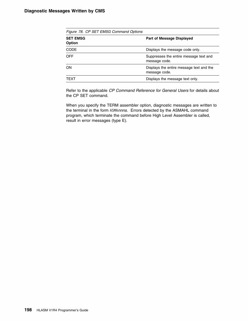
Diagnostic Messages Written by CMS
Refer to the applicable CP Command Reference for General Users for details aboutthe CP SET command.
When you specify the TERM assembler option, diagnostic messages are written tothe terminal in the form ASMAnnns. Errors detected by the ASMAHL commandprogram, which terminate the command before High Level Assembler is called,result in error messages (type E).
Figure 78. CP SET EMSG Command Options
SET EMSGOption
Part of Message Displayed
CODE Displays the message code only.
OFF Suppresses the entire message text andmessage code.
ON Displays the entire message text and themessage code.
TEXT Displays the message text only.
198 HLASM V1R4 Programmer’s Guide

Using the CMS GENMOD Command
Chapter 11. Running Your Program on CMS
There are three ways to run your assembler program under any level of CMS:
� Using the CMS LOAD and START commands.
� Using the CMS GENMOD command to create a program module and thenusing the module filename to cause the module to be run.
� Using the CMS LKED and OSRUN commands.
Any of these three methods can be used under the control of the CMS batchfacility.
Using the CMS LOAD and START CommandsAfter you have assembled your program, you can run the object program in theTEXT file produced by the assembler. The TEXT file produced is relocatable andcan be run merely by loading it into virtual storage with the LOAD command andusing the START command to begin running. For example, if you have assembleda source program named CREATE, you have a file named CREATE TEXT. Usethe LOAD command to load your program into storage, and then use the STARTcommand to run the program:
LOAD CREATESTART
In this example, the file CREATE TEXT contains the object code from theassembly.
The CMS START command can be used to pass user-defined parameters. For acomplete description of the START command, see the applicable CMS CommandReference for your VM environment, as listed under “Bibliography” on page 386.
Using the CMS GENMOD CommandWhen your programs are debugged and tested, you can use the LOAD andINCLUDE commands, in conjunction with the GENMOD command, to createprogram modules. A module is a relocatable or non-relocatable object programwhose external references have been resolved. In CMS, these files must have afiletype of MODULE.
To create a program module, load the TEXT files or TXTLIB members into storageand issue the GENMOD command:
LOAD CREATE ANALYZE PRINTGENMOD PROCESS
In this example, CREATE, ANALYZE, and PRINT are TEXT files that you arecombining into a module named PROCESS; PROCESS is the filename you areassigning to the module, which has a filetype of MODULE. If you use the name ofan existing MODULE file, the old one is replaced.
Copyright IBM Corp. 1982, 2000 199

Using the CMS LKED and OSRUN Commands
From then on, any time you want to run the program composed of the object filesCREATE, ANALYZE, and PRINT, enter:
PROCESS
If PROCESS requires input files, output files, or both, you must define these filesbefore PROCESS can run correctly.
For more information on creating program modules, see the applicable CMS User'sGuide for your particular VM environment, as listed under “Bibliography” onpage 386.
Using the CMS LKED and OSRUN CommandsA LOADLIB is another type of library available to you on CMS. LOADLIBs, likeMACLIBs and TXTLIBs, are in CMS-simulated partitioned data set formats. UnlikeTXTLIBs, which contain object programs that need to be link-edited when they areloaded, LOADLIBs contain programs that have already been link-edited, thussaving the overhead of the link-editing process every time the program is loaded.You can load the members of TXTLIBs by both CMS loading facilities (LOAD orINCLUDE command) and certain OS macros (such as LINK, LOAD, ATTACH, orXCTL), but you can only load the members of LOADLIBs that use these OSmacros.
Use the LKED command to create a CMS LOADLIB. For example:
FILEDEF SYSLIB DISK USERTXT TXTLIB LLKED TESTFILE
This example takes a CMS TEXT file with the filename of TESTFILE and creates afile named TESTFILE LOADLIB, using the SYSLIB to resolve external references.TESTFILE LOADLIB is a CMS-simulated partitioned data set containing onemember, named TESTFILE.
To use the OSRUN command to run TESTFILE, first use the GLOBAL command toidentify which libraries are to be searched when processing subsequent CMScommands. For example:
GLOBAL LOADLIB TESTFILEOSRUN TESTFILE
The OSRUN command causes the TESTFILE member of the TESTFILE LOADLIBto be loaded, relocated, and run.
User parameters can be added on the line with the OSRUN command, but they arepassed in OS format. For a complete description of the OSRUN command, see theapplicable CMS Command Reference for your particular VM environment, as listedunder “Bibliography” on page 386.
200 HLASM V1R4 Programmer’s Guide

Using the CMS Batch Facility
Using the CMS Batch FacilityThe CMS batch facility provides a way of submitting jobs for batch processing inCMS, and can be used to run an assembler program. You can use this facilitywhen either:
� You have a job that takes a lot of time, and you want to be able to use yourterminal for other work while the job is running,
or� You do not have access to a terminal.
The CMS batch facility is really a virtual machine, generated and controlled by thesystem operator, who logs onto VM using the batch user ID and invokes theCMSBATCH command. All jobs submitted for batch processing are spooled to theuser ID of this virtual machine, which runs the jobs sequentially. To use the CMSbatch facility at your location, you must contact the system operator to learn theuser ID of the batch virtual machine.
You can run High Level Assembler under the control of the CMS batch facility.Terminal input can be read from the console stack. In order to prevent your batchjob from being cancelled, make sure that stacked input is available if your programrequests input from the terminal. For further information on using the CMS batchfacility, see the applicable CMS User's Guide for your particular VM environment,as listed under “Bibliography” on page 386.
Chapter 11. Running Your Program on CMS 201

Operating System Programming Conventions
Chapter 12. CMS System Services and ProgrammingConsiderations
This chapter describes some of the CMS system services and programdevelopment facilities that assist you in developing your assembler program. Itprovides the following information:
� Assembler macros supported by CMS.� Adding definitions to a macro library.� Saving and restoring general register contents.� Ending program execution.� Passing parameters to your assembler language program.
Using Macros
Assembler Macros Supported by CMSThere are several CMS assembler macros you can use in assembler programs.Among the services provided by these macros are: the ability to write a record todisk, to read a record from disk, to write lines to a virtual printer, and so on. All theCMS assembler macros are described in the applicable CMS Command and MacroReference, listed under “Bibliography” on page 386.
Adding Definitions to a Macro LibraryMacro definitions, and members containing assembler source statements that canbe read by a COPY instruction, can be added to a macro library. Use the CMSMACLIB command to create and modify CMS macro libraries. In the followingexample, a macro with a filename of NEWMAC and filetype of MACRO is added tothe MACLIB with a filename of MYLIB.
MACLIB ADD MYLIB NEWMAC
Details of this command are described in the applicable CMS Command and MacroReference, listed under “Bibliography” on page 386.
Operating System Programming ConventionsAssembler programs executing on CMS must follow a set of programmingconventions to save and restore registers, and access execution parameters.These conventions are described in the following sections.
Saving and Restoring General Register ContentsA program should save the values contained in the general registers when itreceives control and, on completion, restore these same values to the generalregisters. Thus, as control is passed from the operating system to a program and,in turn, to a subprogram, the status of the registers used by each program ispreserved. This is done through use of the SAVE and RETURN system macroinstructions.
202 Copyright IBM Corp. 1982, 2000

Operating System Programming Conventions
Saving Register Contents: The SAVE macro instruction should be the firststatement in the program. It stores the contents of registers 14, 15, and 0 through12 in an area provided by the program that passes control. When a program isgiven control, register 13 contains the address of an area in which the generalregister contents should be saved.
If the program calls any subprograms, or uses any operating system services otherthan GETMAIN, FREEMAIN, ATTACH, and XCTL, it must first save the contents ofregister 13 and then load the address of an 18-fullword save area into register 13.This save area is in the program and is used by any subprograms or operatingsystem services called by the program.
Restoring Register Contents: At completion, the program restores the contentsof general registers 14, 15, and 0 through 12 by use of the RETURN system macroinstruction (which also indicates program completion). The contents of register 13must be restored before issuing the RETURN macro instruction.
Example: The coding sequence that follows shows the basic process of savingand restoring the contents of the registers. See the VM/ESA CMS ApplicationDevelopment Reference for Assembler for further information about the SAVE andRETURN macros.
Name Operation Operand
CSECTNAM SAVE (14,12) USING CSECTNAM,15 . . . ST 13,SAVEAREA+4 LA 13,SAVEAREA . . .program function source statements
... L 13,SAVEAREA+4 RETURN (14,12)SAVEAREA DC 18F'9'
... END
Ending Program ExecutionYou indicate completion of an assembler language source program by using theRETURN system macro instruction to pass control from the terminating program tothe program that initiated it. The initiating program may be the operating system or,if a subprogram issued the RETURN, the program that called the subprogram.
In addition to indicating program completion and restoring register contents, theRETURN macro instruction may also pass a return code—a condition indicator thatmay be used by the program receiving control.
If the program returns to the operating system, the return code can be comparedagainst the condition stated in the COND= parameter of the JOB or EXECstatement.
If return is to another program, the return code is available in general register 15,and may be used as required. Your program should restore register 13 beforeissuing the RETURN macro instruction.
Chapter 12. CMS System Services and Programming Considerations 203

Operating System Programming Conventions
The RETURN system macro instruction is discussed in detail in the VM/ESA CMSApplication Development Reference for Assembler.
Passing Parameters to Your Assembler Language ProgramOn CMS, you can pass parameters to an assembler language program by meansof the START command. The statement below shows how to pass parameters toyour program using the CMS START command:
START MYJOB PARM1 PARM2
The parameters must be no longer than 8 characters each, and must be separatedby blanks.
CMS creates a list of the parameters that are passed to the program when it is run.The address of the parameters is passed in register 1. The parameter list for thecommand above is:
PLIST DS 9D DC CL8'MYJOB' DC CL8'PARM1' DC CL8'PARM2' DC 8X'FF'
where the list is terminated by hexadecimal FFs.
If your program is started using the CMS OSRUN command, the parameters arepassed in the same way as described in “Accessing Execution Parameters” onpage 183.
If a module was created using the CMS GENMOD command and run using theMODULE name, the parameters are passed in extended parameter list format. Theaddress of the parameter list is passed in register 0.
The format of the extended parameter list is:
Offset Field0 Address of command name4 Address of beginning of options8 Address of end of options12 User word16 Reserved
204 HLASM V1R4 Programmer’s Guide

Part 4. Developing Assembler Programs on VSE
Part 4. Developing Assembler Programs on VSE
Chapter 13. Assembling Your Program on VSE . . . . . . . . . . . . . . . . 206Input to the Assembler . . . . . . . . . . . . . . . . . . . . . . . . . . . . . . . . . 206Output from the Assembler . . . . . . . . . . . . . . . . . . . . . . . . . . . . . . 206Invoking the Assembler in Batch . . . . . . . . . . . . . . . . . . . . . . . . . . . 206Invoking the Assembler on ICCF . . . . . . . . . . . . . . . . . . . . . . . . . . . 208Invoking the Assembler Dynamically . . . . . . . . . . . . . . . . . . . . . . . . . 210Batch Assembling . . . . . . . . . . . . . . . . . . . . . . . . . . . . . . . . . . . . 210Controlling Your Assembly . . . . . . . . . . . . . . . . . . . . . . . . . . . . . . . 211Input and Output Files . . . . . . . . . . . . . . . . . . . . . . . . . . . . . . . . . 212
Work File: IJSYS03 . . . . . . . . . . . . . . . . . . . . . . . . . . . . . . . . . 214Specifying the Source File: SYSIPT . . . . . . . . . . . . . . . . . . . . . . . . 215Specifying Macro and Copy Code Libraries: LIBDEF Job Control Statement 215Specifying the Listing File: SYSLST . . . . . . . . . . . . . . . . . . . . . . . . 215Directing Assembler Messages to Your Console Log: SYSLOG . . . . . . . . 215Specifying Object Code Files: SYSLNK and SYSPCH . . . . . . . . . . . . . 216Specifying the Associated Data File: SYSADAT . . . . . . . . . . . . . . . . . 216
Return Codes . . . . . . . . . . . . . . . . . . . . . . . . . . . . . . . . . . . . . . 216
Chapter 14. Link-Editing and Running Your Program on VSE . . . . . . . . 217The Linkage Editor . . . . . . . . . . . . . . . . . . . . . . . . . . . . . . . . . . . 217Creating a Phase . . . . . . . . . . . . . . . . . . . . . . . . . . . . . . . . . . . . 217Input to the Linkage Editor . . . . . . . . . . . . . . . . . . . . . . . . . . . . . . . 218
Inputting Object Modules . . . . . . . . . . . . . . . . . . . . . . . . . . . . . . 218Files for Linkage Editor Processing . . . . . . . . . . . . . . . . . . . . . . . . 218Inputting additional Object Modules . . . . . . . . . . . . . . . . . . . . . . . . 219Linkage Editor Control Statements . . . . . . . . . . . . . . . . . . . . . . . . . 219
Output from the Linkage Editor . . . . . . . . . . . . . . . . . . . . . . . . . . . . 220Running your Assembled Program . . . . . . . . . . . . . . . . . . . . . . . . . . 221
Chapter 15. VSE System Services and Programming Considerations . . . 222Adding Definitions to a Macro Library . . . . . . . . . . . . . . . . . . . . . . . . 222Processing E-Decks . . . . . . . . . . . . . . . . . . . . . . . . . . . . . . . . . . . 222Operating System Programming Conventions . . . . . . . . . . . . . . . . . . . . 223
Saving and Restoring General Register Contents . . . . . . . . . . . . . . . . 223Ending Program Execution . . . . . . . . . . . . . . . . . . . . . . . . . . . . . 224Accessing Execution Parameters . . . . . . . . . . . . . . . . . . . . . . . . . 224
Copyright IBM Corp. 1982, 2000 205

Invoking the Assembler in Batch
Chapter 13. Assembling Your Program on VSE
This chapter describes how to invoke High Level Assembler on VSE. It describesthe job control required to run the assembler, files used by the assembler andreturn codes. The job control language is described in detail in the applicableSystem Control Statements manual.
Input to the AssemblerAs input, the assembler accepts a program written in the assembler language asdefined in the Language Reference. This program is referred to as a sourcemodule. Some statements in the source module (macro or COPY instructions) cancause additional input to be obtained from a macro library.
Output from the AssemblerThe output from the assembler can consist of an object module, a program listing,terminal messages, and an associated data file. The object module can be writtento a data set residing on a direct access device or a magnetic tape. From that file,the object module can be read and processed by the linkage editor or the loader.See Appendix C, “Object Deck Output” on page 248 for the format of the objectmodule.
The program listing lists all the statements in the module, both in source andmachine language format, and gives other important information about theassembly, such as error messages. The listing is described in detail in Chapter 2,“Using the Assembler Listing” on page 8.
Invoking the Assembler in BatchThe JCL for running an assembly includes:
� A job description.� Definitions for the files needed.� A statement to run the assembler.
The following example shows how to run the assembler.
206 Copyright IBM Corp. 1982, 2000
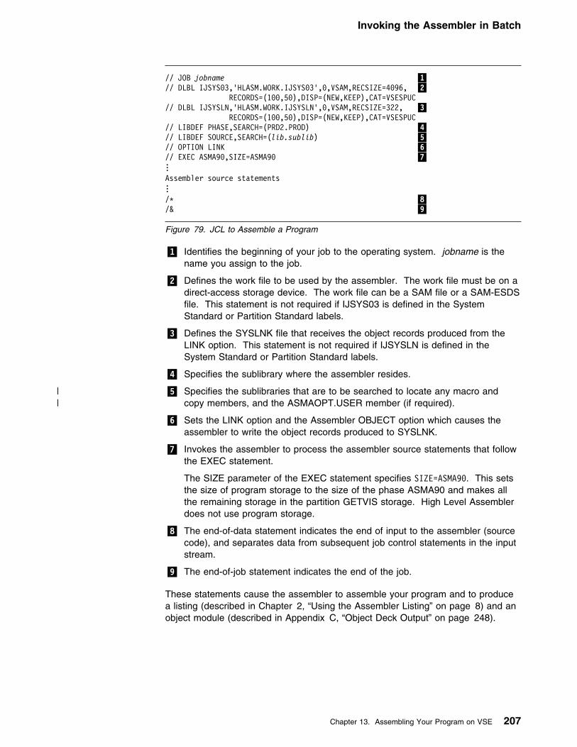
Invoking the Assembler in Batch
// JOB jobname �1�// DLBL IJSYS93,'HLASM.WORK.IJSYS93',9,VSAM,RECSIZE=4996, �2� RECORDS=(199,59),DISP=(NEW,KEEP),CAT=VSESPUC// DLBL IJSYSLN,'HLASM.WORK.IJSYSLN',9,VSAM,RECSIZE=322, �3� RECORDS=(199,59),DISP=(NEW,KEEP),CAT=VSESPUC// LIBDEF PHASE,SEARCH=(PRD2.PROD) �4�// LIBDEF SOURCE,SEARCH=(lib.sublib) �5�// OPTION LINK �6�// EXEC ASMA99,SIZE=ASMA99 �7�...Assembler source statements.../L �8�/& �9�
Figure 79. JCL to Assemble a Program
�1� Identifies the beginning of your job to the operating system. jobname is thename you assign to the job.
�2� Defines the work file to be used by the assembler. The work file must be on adirect-access storage device. The work file can be a SAM file or a SAM-ESDSfile. This statement is not required if IJSYS03 is defined in the SystemStandard or Partition Standard labels.
�3� Defines the SYSLNK file that receives the object records produced from theLINK option. This statement is not required if IJSYSLN is defined in theSystem Standard or Partition Standard labels.
�4� Specifies the sublibrary where the assembler resides.
| �5� Specifies the sublibraries that are to be searched to locate any macro and| copy members, and the ASMAOPT.USER member (if required).
�6� Sets the LINK option and the Assembler OBJECT option which causes theassembler to write the object records produced to SYSLNK.
�7� Invokes the assembler to process the assembler source statements that followthe EXEC statement.
The SIZE parameter of the EXEC statement specifies SIZE=ASMA99. This setsthe size of program storage to the size of the phase ASMA90 and makes allthe remaining storage in the partition GETVIS storage. High Level Assemblerdoes not use program storage.
�8� The end-of-data statement indicates the end of input to the assembler (sourcecode), and separates data from subsequent job control statements in the inputstream.
�9� The end-of-job statement indicates the end of the job.
These statements cause the assembler to assemble your program and to producea listing (described in Chapter 2, “Using the Assembler Listing” on page 8) and anobject module (described in Appendix C, “Object Deck Output” on page 248).
Chapter 13. Assembling Your Program on VSE 207

Invoking the Assembler on ICCF
Invoking the Assembler on ICCFTo assemble your program on ICCF, use the job entry statements /LOAD,/OPTION, /INCLUDE, and /RUN. To create and save an object module, you shouldalso use the /FILE job entry statement.
Before assembling your program on ICCF, ensure that your ICCF Administrator hasprovided the following:
� LIBDEF statements for all librarian sublibraries that are accessed duringassembly, including the sublibrary where High Level Assembler and any userexits reside. The LIBDEF statements must be provided in the VSE/ICCFinitialization job stream.
� Definitions for the assembler work file used by the assembler to process thesource program. All work files must be pre-allocated, and defined in theVSE/ICCF initialization job stream. High Level Assembler does not recognizework files defined using the /FILE job entry statement.
� An interactive partition with sufficient storage to run the assembly. The amountof storage you need depends upon the size of your source program, and thevalue you specify in the SIZE assembler option.
On ICCF, you can either enter the required ICCF commands, or you can write yourown procedure that can be used whenever you need to assemble a program.
Figure 80 shows an example of the ICCF commands you should enter to assembleyour program.
/INPUT/LOAD ASMA99,PARM='SIZE(899K)'/OPTION NOGO,RESET,DECK,GETVIS=P-249/FILE TYPE=ICCF,UNIT=SYSPCH,NAME=ASMOBJ/INCLUDE ASMPROG/END/RUN
Figure 80. Entering ICCF Commands
Figure 81 on page 209 shows a working example of an ICCF procedure forassembling a program, and generating an object module.
208 HLASM V1R4 Programmer’s Guide

Invoking the Assembler on ICCF
L - - - - - - - - - - - - - - - - - - - - - - - - - - - - - - - - - - - L ASMARUN NNNN (OBJ MMMM/L) OPTIONS L L PROCEDURE TO ASSEMBLE A HIGH LEVEL ASSEMBLER PROGRAM L - - - - - - - - - - - - - - - - - - - - - - - - - - - - - - - - - - - &&OPTIONS 9919911 &&IF &&PARMCT NE 9 &&GOTO START &&TYPE ENTER NAME (OBJ NAME/L) (OPTIONS) &&READ &&PARAMS &&IF &&PARMCT EQ 9 &&EXIT &&LABEL START /LIST 1 1 &&PARAM1 &&VARBL5 &&IF &&RETCOD NE LFILE &&GOTO SOUR &&TYPE LSOURCE MEMBER &&PARAM1 NOT IN LIBRARY OR EMPTY &&EXIT &&LABEL SOUR &&IF &&RETCOD NE LINVALID &&GOTO YESOR &&TYPE LINVALID PASSWORD OR INVALID ACCESS TO MEMBER &&PARAM1 &&EXIT &&LABEL YESOR &&IF &&RETCOD NE LMISSING &&GOTO OKSOR &&TYPE LENTER PASSWORD FOR MEMBER &&PARAM1 &&READ &&VARBL5 &&IF &&VARBL5 NE ' ' &&GOTO -START &&EXIT &&LABEL OKSOR &&SET &&VARBL1 &&PARAM1 &&SHIFT 1 &&IF &&PARAM1 NE OBJ &&GOTO NOOBJ &&SET &&VARBL2 &&PARAM2 '' &&IF &&VARBL2 EQ 'L' &&SET &&VARBL2 ' ' &&IF &&VARBL2 EQ ' ' &&GOTO +INLIB /LIST 1 1 &&VARBL2 &&IF &&RETCOD NE LFILE &&GOTO OVERW /INP NOPROMPT DUMMY RECORD TO CREATE A MEMBER FOR 'ASMARUN' PROCEDURE OUTPUT /SAVE &&VARBL2 &&IF &&RETCOD NE LLIBRARY &&GOTO INLIB &&TYPE LLIBRARY DIRECTORY FULL &&EXIT &&LABEL OVERW &&TYPE LMEMBER &&VARBL2 ALREADY EXISTS. OVERWRITE? (Y/N) &&READ &&VARBL4 &&IF &&VARBL4 EQ 'Y' &&GOTO INLIB &&TYPE LNO ASSEMBLY - TRY AGAIN WITH ANOTHER NAME &&EXIT &&LABEL INLIB &&SHIFT 1 &&SHIFT 1 &&LABEL NOOBJ /INP NOPROMPT &/LOAD ASMA99 PARM='&&PARAM1,&&PARAM2,&&PARAM3,&&PARAM4,&&PARAM5' /OPTION NOGO RESET GETVIS=P-249 &&IF &&VARBL2 NE ' ' /FILE TYPE=ICCF,UNIT=SYSPCH,NAME=&&VARBL2 &/INCLUDE &&VARBL1 &&VARBL5 /END /PEND /RUN
Figure 81. Sample Procedure for Assembling on ICCF
Chapter 13. Assembling Your Program on VSE 209

Batch Assembling
Invoking the Assembler DynamicallyTo invoke High Level Assembler from a running program, use the CDLOAD andCALL macro instructions.
You can supply assembler options in the CALL macro instruction as shown inFigure 82
DYNAMICV CSECTDYNAMICV RMODE 24DYNAMICV AMODE ANYBEGIN SAVE (14,12) USING BEGIN,15 ST 13,SAVEAREA+4 LA 13,SAVEAREA CDLOAD ASMA99 �1� LR 15,9
CALL (15),(OPTIONS) �2� �3�CDDELETE ASMA99 Required for VSE/ESA 1.3 onwards
L 13,SAVEAREA+4 RETURN (14,12)SAVEAREA DS 18FOPTIONS DC Y(OPTIONSL)OPTS DC C'XREF(SHORT)'OPTIONSL EQU L-OPTS END
Figure 82. Sample Program to Call the Assembler Dynamically
Notes on Figure 82:
�1� ASMA90 is the symbolic name of the assembler. The entry point address isreturned by CDLOAD in register 0.
�2� (15) specifies that the entry point address is in register 15.
�3� (OPTIONS) specifies the address of a variable-length list containing theoptions. The address of an option list must be provided, even if no options arerequired.
The option list must begin on a halfword boundary. The first two bytes containa count of the number of bytes in the remainder of the list. If no options arespecified, the count must be zero. The option list is free form, with each fieldseparated from the next by a comma. No blanks should appear in the list,except within the string specified for the EXIT or SYSPARM options providingthe string is enclosed within single quotes.
Batch AssemblingYou can assemble a sequence of separate assembler programs with a singleinvocation of the assembler by specifying the BATCH option. The object programsproduced from this assembly can be link-edited into either a single phase orseparate phases.
When the BATCH option is specified, each assembler program in the sequencemust be terminated by an END statement, including the last program in the batch.If an END statement is omitted, the program is assembled with the next program in
210 HLASM V1R4 Programmer’s Guide
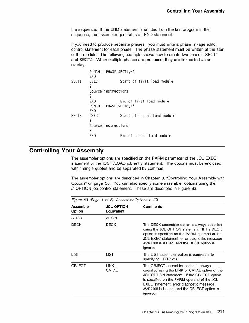
Controlling Your Assembly
the sequence. If the END statement is omitted from the last program in thesequence, the assembler generates an END statement.
If you need to produce separate phases, you must write a phase linkage editorcontrol statement for each phase. The phase statement must be written at the startof the module. The following example shows how to create two phases, SECT1and SECT2. When multiple phases are produced, they are link-edited as anoverlay.
PUNCH ' PHASE SECT1,L' ENDSECT1 CSECT Start of first load module
... Source instructions . . .
END End of first load modulePUNCH ' PHASE SECT2,L'
ENDSECT2 CSECT Start of second load module
... Source instructions . . .
END End of second load module
Controlling Your AssemblyThe assembler options are specified on the PARM parameter of the JCL EXECstatement or the ICCF /LOAD job entry statement. The options must be enclosedwithin single quotes and be separated by commas.
The assembler options are described in Chapter 3, “Controlling Your Assembly withOptions” on page 38. You can also specify some assembler options using the// OPTION job control statement. These are described in Figure 83.
Figure 83 (Page 1 of 2). Assembler Options in JCL
AssemblerOption
JCL OPTIONEquivalent
Comments
ALIGN ALIGN
DECK DECK The DECK assembler option is always specifiedusing the JCL OPTION statement. If the DECKoption is specified on the PARM operand of theJCL EXEC statement, error diagnostic messageASMA499W is issued, and the DECK option isignored.
LIST LIST The LIST assembler option is equivalent tospecifying LIST(121).
OBJECT LINKCATAL
The OBJECT assembler option is alwaysspecified using the LINK or CATAL option of theJCL OPTION statement. If the OBJECT optionis specified on the PARM operand of the JCLEXEC statement, error diagnostic messageASMA499W is issued, and the OBJECT option isignored.
Chapter 13. Assembling Your Program on VSE 211

Input and Output Files
Figure 83 (Page 2 of 2). Assembler Options in JCL
AssemblerOption
JCL OPTIONEquivalent
Comments
RLD RLD
SYSPARM SYSPARM The value specified in the SYSPARM option ofthe JCL OPTION statement is limited to 8characters. To provide longer values, use theSYSPARM assembler option. The SYSPARMvalue specified on the PARM operand of the JCLEXEC statement overrides any value specifiedon the JCL OPTION statement. A null value (//OPTION SYSPARM='') is ignored by theassembler.
TERMINAL TERM
XREF SXREFXREF
The XREF option of the JCL OPTION statementcan be used to specify the XREF(FULL)assembler option. The SXREF option of the JCLOPTION statement can be used to specify theXREF(SHORT) assembler option.
Input and Output FilesDepending on the options in effect, High Level Assembler requires the followingfiles, as shown in Figure 84:
┌──────────────┐ │ SYSIPT │ └───────┬──────┘ │ │ + ┌──────────────┐ ┌──────────────┐ ┌──────────────┐ │ Library ├──────────�│ Assembler │�──────────�│ IJSYS93 │ └──────────────┘ └───────┬──────┘ └──────────────┘ │ + ┌──────────────┬──────────────┬──────────────┬──────────────┐
│ │ │ │ │+ + + + +
┌───────────┐ ┌───────────┐ ┌───────────┐ ┌───────────┐ ┌───────────┐│ SYSLST │ │ SYSLOG │ │ SYSLNK │ │ SYSPCH │ │ SYSADAT │└───────────┘ └───────────┘ └───────────┘ └───────────┘ └───────────┘
Figure 84. High Level Assembler Files
High Level Assembler requires the following files:
IJSYS03 A work file used as intermediate external storage when processingthe source program. This file is used when there is not enoughmain storage available to do an in-storage assembly.
If the value specified for the SIZE option is large enough, anin-storage assembly is done and the work file IJSYS03 can beomitted, though a warning message is issued.
SYSIPT An input file containing the source statements to be processed.
212 HLASM V1R4 Programmer’s Guide

Input and Output Files
In addition, the following six files might be required:
Library Library sublibraries containing macro definitions (for macrodefinitions not defined in the source program), source code to becalled for through COPY assembler instructions, or both. One of
| the sublibraries may also contain a member (ASMAOPT.USER)| which contains an invocation assembler option list.
SYSLST A file containing the assembly listing (if the LIST option is ineffect).
SYSLOG A file containing flagged statements and diagnostic messages.(only if the TERM option is in effect). SYSLOG is normallyassigned to the operator console.
SYSPCH A file containing object module output, usually for punching (only ifthe DECK option is in effect).
SYSLNK A file containing object module output for input to the linkage editor(only if the OBJECT option is in effect).
SYSADAT A file containing associated data output (only if the ADATA optionis in effect).
The files listed above are described in the text following Figure 85. Thecharacteristics of these files, those set by the assembler and those you canoverride, are shown in Figure 85.
Chapter 13. Assembling Your Program on VSE 213

Input and Output Files
Notes to Figure 85:
�1� You can specify a block size (BLKSIZE) between 2008 and 32760 bytes on theDLBL statement if a SAM DLBL is provided. The block size should be amultiple of 8. If it is not, it is rounded to the next lower multiple of 8. If you donot specify BLKSIZE, the assembler sets the block size to 4088.
If a VSAM DLBL is provided, the block size can be overridden by explicitlydefining the work file with the required block size.
�2� If you specify EXIT(PRTEXIT) and the user exit specifies the logical recordlength, the logical record length returned is used. If you do not specifyEXIT(PRTEXIT) or the user exit does not specify a record length, the recordlength is set to 121 if SYSLST is assigned to disk or 133 otherwise.
The minimum record length allowed for SYSPRINT is 121, and the maximumallowed is 133.
�3� If you specify EXIT(TRMEXIT) and the user exit specifies the logical recordlength, the logical record length returned is used. If you do not specifyEXIT(TRMEXIT) or the user exit does not specify a record length, the recordlength is set to 68. The maximum record length allowed for SYSTERM is 125.
Figure 85. Assembler File Characteristics
File AccessMethod
LogicalRecordLength(LRECL)
Block Size(BLKSIZE)
Record Format(RECFM)
IJSYS03 BAM Same asBLKSIZE
�1� UNDEF
SYSIPT SAM 80 80 FIXED
Library LIBR API 80 80 FIXED
| Library| member| ASMAOPT.USER
LIBR API 80 80 FIXED
SYSLST SAM �2� Same asrecord size
FIXED
SYSLOG SAM �3� Same asrecord size
FIXED
SYSPCH SAM 80 80 FIXED
SYSLNK SAM 80 80 FIXED
SYSADAT SAM 8188 8192 VARBLK
Work File: IJSYS03The assembler uses this work file as an intermediate external storage device whenprocessing the source program. The input/output device assigned to this file mustbe a direct-access device. The assembler does not support multivolume work files.
214 HLASM V1R4 Programmer’s Guide

Input and Output Files
Specifying the Source File: SYSIPTDefine the file that contains your source code with the SYSIPT ASSGN statement.If you include your source code in your job stream, it must immediately follow theEXEC statement that invokes the assembler, and be terminated with a /* statement.
You can, however, use JCL statements to define a file that contains your sourcecode. For example, to define a direct-access device file, use the DLBL, EXTENT,and ASSGN statements:
// DLBL IJSYSIN,'file-ID',9,SD// EXTENT SYSIPT,volser,1,9,start,tracks// ASSGN SYSIPT,DISK,VOL=volser,SHR
Specifying Macro and Copy Code Libraries: LIBDEF Job ControlStatement
Include the LIBDEF job control statement if your program contains any macro callsto library macros, or any COPY instructions. LIBDEF statements define thesublibraries that contain macro definition and COPY members.
// LIBDEF SOURCE,SEARCH=(lib.sublib)
The member name in the sublibrary must match the name you specify in the macrocall or COPY instruction. The member type must be A, unless the SUBLIB jobcontrol option has changed it to D. See OPTION statement description in VSE/ESASystem Control Statements for further details.
High Level Assembler does not read edited macros (E-books). To read editedmacros from the library, provide a LIBRARY user exit using the EXIT option. See“Processing E-Decks” on page 222.
You don't need the LIBDEF SOURCE statement if your assembler source codedoes not contain any library macro calls or COPY instructions. You also don't needthe LIBDEF SOURCE statement if the library members are in a sub-library in thepermanent LIBDEF search chain.
Concatenate multiple sublibraries in the search chain if you have multiple macro orcopy sublibraries.
Specifying the Listing File: SYSLSTThe assembler uses this file to produce a listing. You can then direct the output toa printer, a direct access device, or a magnetic-tape device. The listing includesthe results of the default or specified options of the PARM parameter (for example,diagnostic messages, the object code listing). For example:
// ASSGN SYSLST,PRT1
Directing Assembler Messages to Your Console Log: SYSLOGIf you specify the TERM assembler option, the assembler writes flagged statementsand diagnostic messages to the console log.
Chapter 13. Assembling Your Program on VSE 215

Return Codes
Specifying Object Code Files: SYSLNK and SYSPCHWhen using the OBJECT assembler option, or DECK assembler option, you canstore the object code on disk or tape. The assembler uses the SYSLNK orSYSPCH files you define in your JCL to store the object code.
In the example below, the created object module is ready to be passed to thelinkage editor:
// DLBL IJSYSLN,'file-ID',9,SD// EXTENT SYSLNK,volser,1,9,start,tracks// ASSGN SYSLNK,DISK,VOL=volser,SHR
You don't need to define SYSLNK in your JCL if the NOOBJECT option is in effect.
The following example defines SYSPCH as a direct-access device file:
// DLBL IJSYSPH,'file-ID',9,SD// EXTENT SYSPCH,volser,1,9,start,tracksASSGN SYSPCH,DISK,VOL=volser,SHR
You don't need to define the SYSPCH file if the NODECK option is in effect.
Specifying the Associated Data File: SYSADATUse the SYSADAT DLBL statement to define your associated data output filestatement:
// DLBL SYSADAT,'HLASM.WORK.SYSADAT',9,VSAM,RECORDS=(199,199), X RECSIZE=8192,DISP=(NEW,KEEP),CAT=VSESPUC
The associated data file contains information about the assembly. It providesinformation for use by symbolic debugging and cross-reference tools. TheSYSADAT file must be directed to a direct-access storage device and can be aSAM file or SAM-ESDS file.
Return CodesHigh Level Assembler issues return codes that you can check with the IF and ONjob control statements. The IF and ON job control statements let you skip or run ajob step, depending on the results (indicated by the return code) of a previous jobstep. See the applicable System Control Statements manual for details about theIF and ON job control statements.
The return code issued by the assembler is the highest severity code that isassociated with any error detected in the assembly, or with any MNOTE messageproduced by the source program or macro instructions. The return code can becontrolled by the FLAG(n) assembler option described on page 52. SeeAppendix G, “High Level Assembler Messages” on page 309 for a listing of theassembler errors and their severity codes.
216 HLASM V1R4 Programmer’s Guide
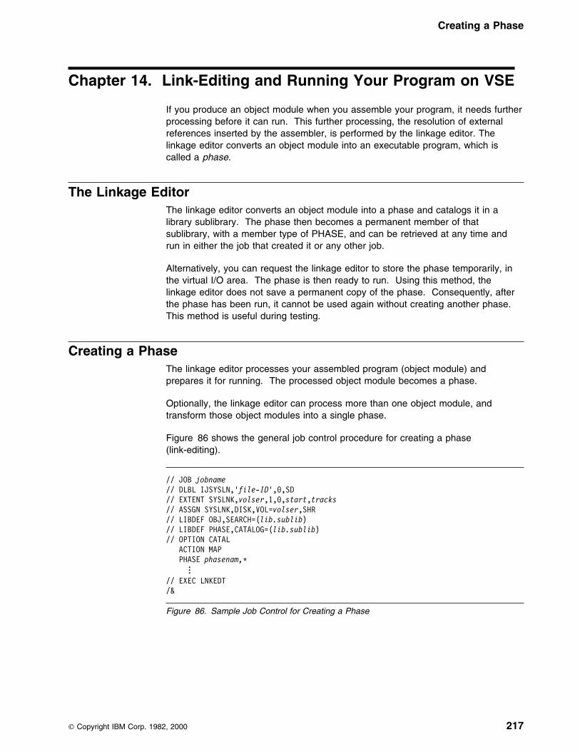
Creating a Phase
Chapter 14. Link-Editing and Running Your Program on VSE
If you produce an object module when you assemble your program, it needs furtherprocessing before it can run. This further processing, the resolution of externalreferences inserted by the assembler, is performed by the linkage editor. Thelinkage editor converts an object module into an executable program, which iscalled a phase.
The Linkage EditorThe linkage editor converts an object module into a phase and catalogs it in alibrary sublibrary. The phase then becomes a permanent member of thatsublibrary, with a member type of PHASE, and can be retrieved at any time andrun in either the job that created it or any other job.
Alternatively, you can request the linkage editor to store the phase temporarily, inthe virtual I/O area. The phase is then ready to run. Using this method, thelinkage editor does not save a permanent copy of the phase. Consequently, afterthe phase has been run, it cannot be used again without creating another phase.This method is useful during testing.
Creating a PhaseThe linkage editor processes your assembled program (object module) andprepares it for running. The processed object module becomes a phase.
Optionally, the linkage editor can process more than one object module, andtransform those object modules into a single phase.
Figure 86 shows the general job control procedure for creating a phase(link-editing).
// JOB jobname// DLBL IJSYSLN,'file-ID',9,SD// EXTENT SYSLNK,volser,1,9,start,tracks// ASSGN SYSLNK,DISK,VOL=volser,SHR// LIBDEF OBJ,SEARCH=(lib.sublib)// LIBDEF PHASE,CATALOG=(lib.sublib)// OPTION CATAL ACTION MAP PHASE phasenam,(
...// EXEC LNKEDT/&
Figure 86. Sample Job Control for Creating a Phase
Copyright IBM Corp. 1982, 2000 217

Input to the Linkage Editor
Input to the Linkage EditorYour input to the linkage editor can be:
� One or more object modules (created through the OBJECT or DECK assembleroption).
� Linkage editor control statements (including control statements generated usingthe assembler PUNCH statement).
Inputting Object ModulesThe main input to the linkage editor is the SYSLNK file that contains one or moreseparately assembled object modules, possibly with a PHASE linkage editor controlstatement.
Additional input to the linkage editor consists of object modules that are not part ofthe SYSLNK file, but are to be included in the phase.
The additional input can come from sublibraries containing other application objectmodules.
You can specify which sublibrary contains the additional object modules with theLIBDEF job control statement. If you have multiple sublibraries containing objectmodules to be included in the phase, concatenate them, as shown in the followingexample:
// LIBDEF OBJ,SEARCH=(PRD2.PROD,SALES.LIB)
In this case, the sublibraries PRD2.PROD and SALES.LIB are available foradditional input to the linkage editor.
Files for Linkage Editor ProcessingYou need the following files for linkage editor processing. Figure 87 summarizesthe function, and permissible device types, for each file.
Figure 87 (Page 1 of 2). Files Used for Link-Editing
File
Type
Function
PermissibleDevice Types
SYSIPT1 Input Additional object module input Card readerMagnetic tapeDirect access
SYSLNK Input Object module input, normally the output of theassembler
Direct access
SYSLST2 Output Diagnostic messagesInformative messagesLinkage editor map
PrinterMagnetic tapeDirect access
SYSLOG Output Operator messages Display console
SYSRDR Input Control statement input Card readerMagnetic tapeDirect access
IJSYS01(SYS001)
Work file Linkage editor work file Direct access
218 HLASM V1R4 Programmer’s Guide
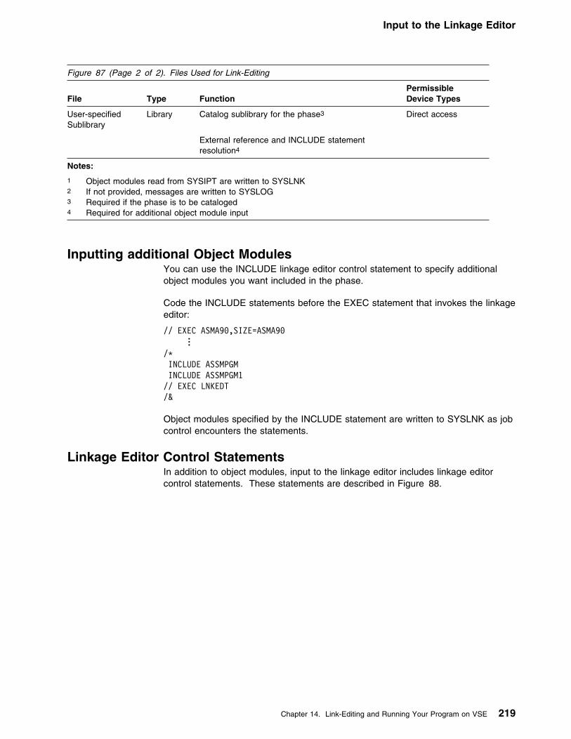
Input to the Linkage Editor
Figure 87 (Page 2 of 2). Files Used for Link-Editing
File
Type
Function
PermissibleDevice Types
User-specifiedSublibrary
Library Catalog sublibrary for the phase3
External reference and INCLUDE statementresolution4
Direct access
Notes:
1 Object modules read from SYSIPT are written to SYSLNK2 If not provided, messages are written to SYSLOG3 Required if the phase is to be cataloged4 Required for additional object module input
Inputting additional Object ModulesYou can use the INCLUDE linkage editor control statement to specify additionalobject modules you want included in the phase.
Code the INCLUDE statements before the EXEC statement that invokes the linkageeditor:
// EXEC ASMA99,SIZE=ASMA99...
/L INCLUDE ASSMPGM INCLUDE ASSMPGM1// EXEC LNKEDT/&
Object modules specified by the INCLUDE statement are written to SYSLNK as jobcontrol encounters the statements.
Linkage Editor Control StatementsIn addition to object modules, input to the linkage editor includes linkage editorcontrol statements. These statements are described in Figure 88.
Chapter 14. Link-Editing and Running Your Program on VSE 219

Output from the Linkage Editor
Figure 88. Linkage Editor Control Statements
Statement Action Comments
ACTION Use the ACTION statement to specify linkage editoroptions. The options are:
� MAP—requests the linkage editor to write a linkageeditor map to SYSLST.
� NOMAP—suppresses the MAP option.
� NOAUTO—suppresses the automatic library lookup (AUTOLINK) function; the linkage editor doesnot attempt to resolve external references using theautomatic library look-up function.
� CANCEL—requests the linkage editor to cancel thejob if a linkage editor error occurs.
� SMAP—request the linkage editor to produce asorted listing of CSECT names on SYSLST.
This statement must be the firstlinkage editor statement in your inputstream.
ACTION MAP is the default, ifSYSLST is assigned.
ENTRY Use the ENTRY statement to specify the entry point ofa phase that has multiple possible entry points.
The default entry point is the loadaddress of the phase.
INCLUDE Use the INCLUDE statement to include additionalobject modules in the phase that would not otherwisebe included.
You can use the INCLUDE statementto include an object module that wascataloged with a different name to thename used in the CALL statement inyour program.
PHASE Use the PHASE statement to provide the linkage editorwith a phase name.
You must provide a PHASE statement(and the job control option CATAL) ifyou want to catalog the phase in alibrary sublibrary.
For a complete description of these linkage editor control statements, see VSE/ESASystem Control Statements.
Output from the Linkage EditorYou can obtain a linkage editor storage map, and a listing of linkage editordiagnostics, to help you determine the reasons for particular errors in your program.To do this, use the ACTION MAP linkage editor control statement. If SYSLST isassigned, ACTION MAP is the default. You can specify ACTION NOMAP if you donot want the linkage editor to produce the storage map.
Detecting Link-Edit Errors: After link-editing, you receive a listing of diagnosticmessages on SYSLST. Check the linkage editor map to make sure that all theobject modules you expected were included.
Unresolved “weak” external references (WXTRN) can be ignored. However, all“strong” external references (EXTRN) should be resolved for a phase to runcorrectly.
You can find a description of linkage editor messages in VSE/ESA Diagnosis Tools.
220 HLASM V1R4 Programmer’s Guide

Running your Assembled Program
Running your Assembled ProgramThe general job control procedure to run a program on VSE is:
// DLBL (JCL for user-specified files)// EXEC progname[,PARM='parameters']
...
Chapter 14. Link-Editing and Running Your Program on VSE 221
Processing E-Decks
Chapter 15. VSE System Services and ProgrammingConsiderations
This chapter describes some of the system services and program developmentfacilities that assist you in developing your assembler program on VSE. It providesthe following information:
� Adding definitions to a macro library.� Saving and restoring general register contents.� Ending program execution.� Accessing execution parameters.
� Processing E-Decks.
Adding Definitions to a Macro LibraryYou can add macro definitions, and members containing assembler sourcestatements that can be read by a COPY instruction, to a macro library. Use theLIBR utility program for this purpose. Details of this program and its controlstatements are contained in the applicable System Control Statements publication.The following example adds a new macro definition, NEWMAC, to the systemlibrary, PRD2.PROD.
// JOB CATMAC// EXEC LIBRACCESS SUBLIB=PRD2.PRODCATALOG NEWMAC.A REPLACE=YES MACRO NEWMAC &OP1,&OP2 LCLA &PAR1,&PAR2 . . . MEND/+/L
The ACCESS statement specifies the sublibrary into which the macro is cataloged.The CATALOG statement specifies the member name and member type.REPLACE=YES indicates that the member is replaced if it already exists.
Processing E-DecksAn E-Deck refers to a macro source book of type E (or type F if SUBLIB=DFspecified on OPTION statement). You can use these types of macros in yourprogram; however, they must first be converted to source statement format.E-Decks are stored in edited format, and High Level Assembler requires that librarymacros be stored in source statement format.
You must use a library input exit to analyze a macro definition and, in the case ofan E-Deck, call the ESERV program to change, line by line, the E-Deck definitionback into source statement format.
See the section titled Using the High Level Assembler Library Exit for ProcessingE-Decks in the IBM VSE/ESA Guide to System Functions manual. This sectiondescribes how to set up the exit and how to use it.
222 Copyright IBM Corp. 1982, 2000

Operating System Programming Conventions
Operating System Programming ConventionsAssembler programs executing on VSE must follow a set of programmingconventions to save and restore registers, and access execution parameters.These are described in the following sections.
Saving and Restoring General Register ContentsA program should save the values contained in the general registers when it startsto run and, on completion, restore these same values to the general registers.Thus, as control is passed from the operating system to a program and, in turn, toa subprogram, the status of the registers used by each program is preserved. Thisis done through use of the SAVE and RETURN system macro instructions.
Saving Register Contents: The SAVE macro instruction should be the firststatement in the program. It stores the contents of registers 14, 15, and 0 through12 in an area provided by the program that passes control. When a program isgiven control, register 13 contains the address of an area in which the generalregister contents should be saved.
If the program calls any subprograms, or uses any operating system services otherthan GETVIS, FREEVIS, and CDLOAD, it must first save the contents of register13 and then load the address of an 18-fullword save area into register 13. Thissave area is in the program and is used by any subprograms or operating systemservices called by the program.
Restoring Register Contents: At completion, the program restores the contentsof general registers 14, 15, and 0 through 12 by use of the RETURN system macroinstruction (which also indicates program completion). The contents of register 13must be restored before issuing the RETURN macro instruction.
Example: The coding sequence that follows shows the basic process of savingand restoring the contents of the registers. A complete discussion of the SAVE andRETURN macro instructions and the saving and restoring of registers is containedin the applicable VSE/ESA System Macros Reference.
Name Operation Operand
BEGIN SAVE (14,12) USING BEGIN,15...
ST 13,SAVEBLK+4 LA 13,SAVEBLK...
L 13,SAVEBLK+4 RETURN (14,12)SAVEBLK DC 18F'9'...
END
Chapter 15. VSE System Services and Programming Considerations 223
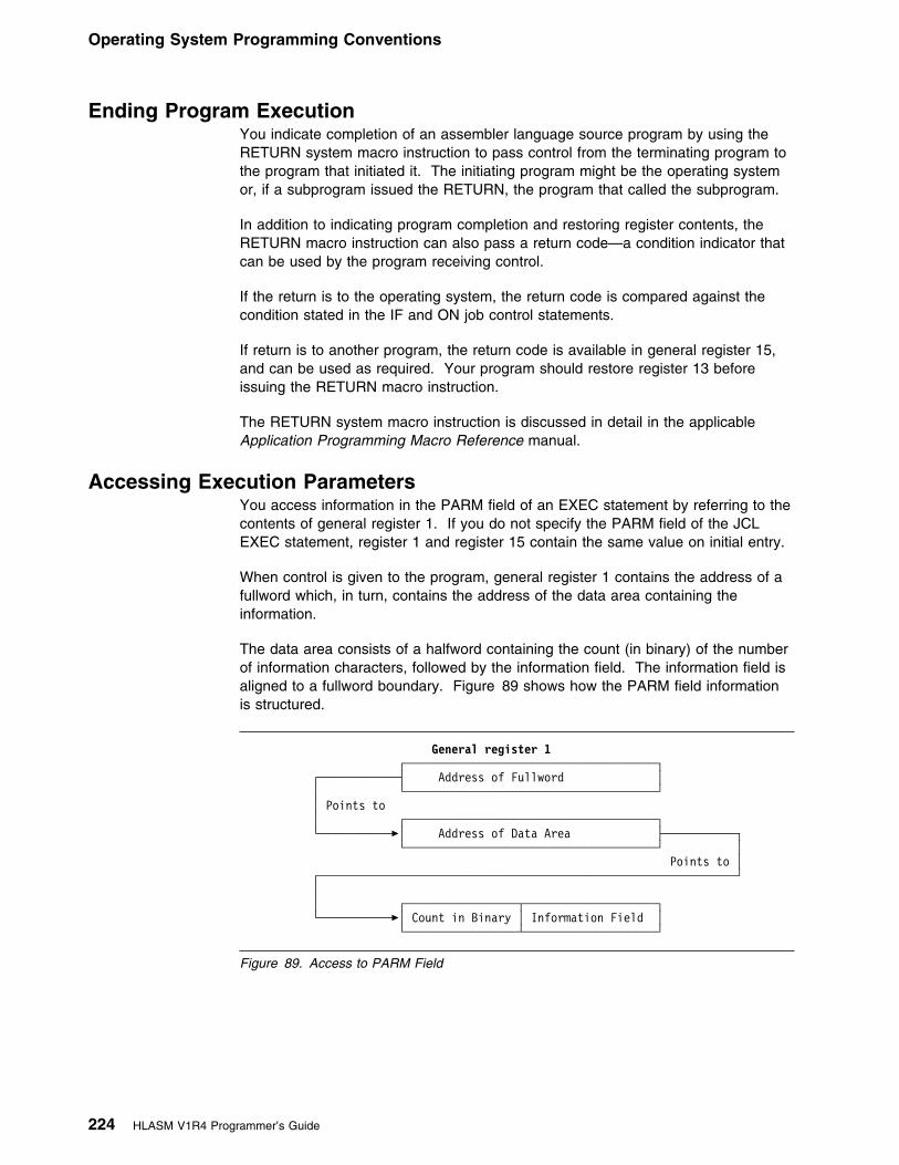
Operating System Programming Conventions
Ending Program ExecutionYou indicate completion of an assembler language source program by using theRETURN system macro instruction to pass control from the terminating program tothe program that initiated it. The initiating program might be the operating systemor, if a subprogram issued the RETURN, the program that called the subprogram.
In addition to indicating program completion and restoring register contents, theRETURN macro instruction can also pass a return code—a condition indicator thatcan be used by the program receiving control.
If the return is to the operating system, the return code is compared against thecondition stated in the IF and ON job control statements.
If return is to another program, the return code is available in general register 15,and can be used as required. Your program should restore register 13 beforeissuing the RETURN macro instruction.
The RETURN system macro instruction is discussed in detail in the applicableApplication Programming Macro Reference manual.
Accessing Execution ParametersYou access information in the PARM field of an EXEC statement by referring to thecontents of general register 1. If you do not specify the PARM field of the JCLEXEC statement, register 1 and register 15 contain the same value on initial entry.
When control is given to the program, general register 1 contains the address of afullword which, in turn, contains the address of the data area containing theinformation.
The data area consists of a halfword containing the count (in binary) of the numberof information characters, followed by the information field. The information field isaligned to a fullword boundary. Figure 89 shows how the PARM field informationis structured.
General register 1 ┌──────────────────────────────────────┐
┌────────────┤ Address of Fullword │ │ └──────────────────────────────────────┘
│ Points to │ ┌──────────────────────────────────────┐
└───────────�│ Address of Data Area ├───────────┐ └──────────────────────────────────────┘ │
Points to │ ┌───────────────────────────────────────────────────────────────┘ │ │ ┌─────────────────┬────────────────────┐
└───────────�│ Count in Binary │ Information Field │ └─────────────────┴────────────────────┘
Figure 89. Access to PARM Field
224 HLASM V1R4 Programmer’s Guide

Appendixes
Appendixes
Appendix A. Earlier Assembler Compatibility and Migration . . . . . . . . 227Comparison of Instruction Set and Assembler Instructions . . . . . . . . . . . . 227Comparison of Macro and Conditional Assembly Statements . . . . . . . . . . . 230Comparison of Macro and Conditional Assembly . . . . . . . . . . . . . . . . . . 233Comparison of Language Features . . . . . . . . . . . . . . . . . . . . . . . . . . 237Comparison of Assembler Options . . . . . . . . . . . . . . . . . . . . . . . . . . 239Comparison of Assembler Listing . . . . . . . . . . . . . . . . . . . . . . . . . . . 241Comparison of Diagnostic Features . . . . . . . . . . . . . . . . . . . . . . . . . . 243Other Assembler Differences . . . . . . . . . . . . . . . . . . . . . . . . . . . . . 244
Appendix B. Cross-System Portability Considerations . . . . . . . . . . . . 246Using Extended Architecture Instructions . . . . . . . . . . . . . . . . . . . . . . 246Using System Macros . . . . . . . . . . . . . . . . . . . . . . . . . . . . . . . . . 246Migrating Object Programs . . . . . . . . . . . . . . . . . . . . . . . . . . . . . . . 246
Appendix C. Object Deck Output . . . . . . . . . . . . . . . . . . . . . . . . . 248| ESD Record Format . . . . . . . . . . . . . . . . . . . . . . . . . . . . . . . . . . 249
TXT Record Format . . . . . . . . . . . . . . . . . . . . . . . . . . . . . . . . . . . 250RLD Record Format . . . . . . . . . . . . . . . . . . . . . . . . . . . . . . . . . . . 251END Record Format . . . . . . . . . . . . . . . . . . . . . . . . . . . . . . . . . . 252SYM Record Format . . . . . . . . . . . . . . . . . . . . . . . . . . . . . . . . . . 252
Appendix D. Associated Data File Output . . . . . . . . . . . . . . . . . . . . 255Record Types . . . . . . . . . . . . . . . . . . . . . . . . . . . . . . . . . . . . . . 257
Macro-only Assemblies . . . . . . . . . . . . . . . . . . . . . . . . . . . . . . 261ADATA Record Layouts . . . . . . . . . . . . . . . . . . . . . . . . . . . . . . . . 262Common Header Section . . . . . . . . . . . . . . . . . . . . . . . . . . . . . . . 262Job Identification Record—X'0000' . . . . . . . . . . . . . . . . . . . . . . . . . 264ADATA Identification Record—X'0001' . . . . . . . . . . . . . . . . . . . . . . . 264ADATA Compilation Unit Start/End Record—X'0002' . . . . . . . . . . . . . . . 265System 370/390 Output File Information Record—X'000A' . . . . . . . . . . . 265
| Options File Information—X'000B' . . . . . . . . . . . . . . . . . . . . . . . . . . 268Options Record—X'0010' . . . . . . . . . . . . . . . . . . . . . . . . . . . . . . . 268External Symbol Dictionary Record—X'0020' . . . . . . . . . . . . . . . . . . . 271Source Analysis Record—X'0030' . . . . . . . . . . . . . . . . . . . . . . . . . . 272Source Error Record—X'0032' . . . . . . . . . . . . . . . . . . . . . . . . . . . . 274DC/DS Record—X'0034' . . . . . . . . . . . . . . . . . . . . . . . . . . . . . . . 275DC Extension Record—X'0035' . . . . . . . . . . . . . . . . . . . . . . . . . . . 280Machine Instruction Record—X'0036' . . . . . . . . . . . . . . . . . . . . . . . . 281Relocation Dictionary Record—X'0040' . . . . . . . . . . . . . . . . . . . . . . . 281Symbol Record—X'0042' . . . . . . . . . . . . . . . . . . . . . . . . . . . . . . . 281Symbol Cross Reference Record—X'0044' . . . . . . . . . . . . . . . . . . . . 282Register Cross Reference Record—X'0045' . . . . . . . . . . . . . . . . . . . . 283Library Record—X'0060' . . . . . . . . . . . . . . . . . . . . . . . . . . . . . . . 283Library Member and Macro Cross Reference Record - X'0062' . . . . . . . . . 284User-supplied Information Record - X'0070' . . . . . . . . . . . . . . . . . . . . 285USING Map Record—X'0080' . . . . . . . . . . . . . . . . . . . . . . . . . . . . 285Statistics Record—X'0090' . . . . . . . . . . . . . . . . . . . . . . . . . . . . . . 286
Appendix E. Sample Program . . . . . . . . . . . . . . . . . . . . . . . . . . . 290
Copyright IBM Corp. 1982, 2000 225
Appendixes
Appendix F. MHELP Sample Macro Trace and Dump . . . . . . . . . . . . . 301
Appendix G. High Level Assembler Messages . . . . . . . . . . . . . . . . . 309Message Code Format . . . . . . . . . . . . . . . . . . . . . . . . . . . . . . . . . 309Message Descriptions . . . . . . . . . . . . . . . . . . . . . . . . . . . . . . . . . 310
Message Number and Text . . . . . . . . . . . . . . . . . . . . . . . . . . . 310Explanation of Message . . . . . . . . . . . . . . . . . . . . . . . . . . . . . 311Supplemental Information . . . . . . . . . . . . . . . . . . . . . . . . . . . . 311System Action . . . . . . . . . . . . . . . . . . . . . . . . . . . . . . . . . . . 311Programmer Response . . . . . . . . . . . . . . . . . . . . . . . . . . . . . . 311Severity Code . . . . . . . . . . . . . . . . . . . . . . . . . . . . . . . . . . . 311
Assembly Error Diagnostic Messages . . . . . . . . . . . . . . . . . . . . . . . . 312Message Not Known . . . . . . . . . . . . . . . . . . . . . . . . . . . . . . . . . 314Messages . . . . . . . . . . . . . . . . . . . . . . . . . . . . . . . . . . . . . . . 315
Abnormal Assembly Termination Messages . . . . . . . . . . . . . . . . . . . . . 352Messages . . . . . . . . . . . . . . . . . . . . . . . . . . . . . . . . . . . . . 352
ASMAHL Command Error Messages (CMS) . . . . . . . . . . . . . . . . . . . . 357
Appendix H. User Interface Macros . . . . . . . . . . . . . . . . . . . . . . . . 361
Appendix I. Sample ADATA User Exit (MVS and CMS) . . . . . . . . . . . . 362Function . . . . . . . . . . . . . . . . . . . . . . . . . . . . . . . . . . . . . . 362Preparing the Exit . . . . . . . . . . . . . . . . . . . . . . . . . . . . . . . . . 362Preparing the Filter Management Table . . . . . . . . . . . . . . . . . . . . 362Preparing the Filter Modules . . . . . . . . . . . . . . . . . . . . . . . . . . 363Preparing the Sample Filter Module ASMAXFLU . . . . . . . . . . . . . . . 366Invoking the Exit . . . . . . . . . . . . . . . . . . . . . . . . . . . . . . . . . 368
Appendix J. Sample LISTING User Exit (MVS and CMS) . . . . . . . . . . . 369Function . . . . . . . . . . . . . . . . . . . . . . . . . . . . . . . . . . . . . . 369Preparing the Exit . . . . . . . . . . . . . . . . . . . . . . . . . . . . . . . . . 369Invoking the Exit . . . . . . . . . . . . . . . . . . . . . . . . . . . . . . . . . 369Messages . . . . . . . . . . . . . . . . . . . . . . . . . . . . . . . . . . . . . 370
Appendix K. Sample SOURCE User Exit (MVS and CMS) . . . . . . . . . . 371Function . . . . . . . . . . . . . . . . . . . . . . . . . . . . . . . . . . . . . . 371Preparing the Exit . . . . . . . . . . . . . . . . . . . . . . . . . . . . . . . . . 371Invoking the Exit . . . . . . . . . . . . . . . . . . . . . . . . . . . . . . . . . 371
Appendix L. How to Generate a Translation Table . . . . . . . . . . . . . . . 372
| Appendix M. How to Generate a Unicode Translation Table . . . . . . . . . 374
226 HLASM V1R4 Programmer’s Guide

Appendixes
Appendix A. Earlier Assembler Compatibility and Migration
This section compares the High Level Assembler to the earlier assemblers,Assembler H Version 2 and DOS/VSE Assembler. This section can be used todetermine the changes that might be required to migrate your assembler programsto High Level Assembler. This section also lists the new facilities that are availablewith High Level Assembler that you can use for new and existing assemblerprograms.
Comparison of Instruction Set and Assembler Instructions
Element DOS/VSEAssembler
Assembler HVersion 2
High LevelAssembler
Instruction set
S/370 instructions Yes Yes Yes
XA instructions No Yes Yes
ESA instructions No Yes Yes
Vector instructions No Yes Yes
DOS operation code table No No The DOS operationcode table isdesigned specificallyfor assemblingprograms previouslyassembled using theDOS/VSE assembler.Some machineinstructions andassemblerinstructions are notincluded in thisoperation code table.See “OPTABLE” onpage 62 for furtherdetails.
Data definition statements
CCW Yes Yes Yes
CCW0 No Yes Yes
CCW1 No Yes Yes
DC Yes Yes Yes
DS Yes Yes Yes
Symbols used in the DC or DS expressionneed not be defined before they are used
No Yes Yes
J-type Constant No No Yes
Q-type Constant No Yes Yes
| R-type Constant| No| No| Yes
S-type Constant No Yes Yes
Copyright IBM Corp. 1982, 2000 227

Appendixes
Element DOS/VSEAssembler
Assembler HVersion 2
High LevelAssembler
Number of nominal values for Binary andHexadecimal constants
One Multiple Multiple
Program control statements
ACONTROL No No Yes
ADATA No No Yes
CNOP Name entry canhave sequencesymbol or blank
Name entry canhave any symbol orblank
Name entry can haveany symbol or blank
COPY Nesting depthlimited to 3
Nesting depth notlimited
Nesting depth notlimited
EQU Value operand only Value, lengthattribute and typeattribute operands
Value, lengthattribute and typeattribute operands
END END statementmust be supplied
Multiple ENDstatements areallowed. If theEND statement isomitted, theassemblergenerates an ENDstatement.
Multiple ENDstatements areallowed. If the ENDstatement is omitted,the assemblergenerates an ENDstatement.
EXITCTL No No Yes
ICTL Yes Yes Yes
ISEQ Yes Yes Yes
LTORG Yes Yes Yes
OPSYN No Yes Yes
ORG Name entry canhave sequencesymbol or blank
Name entry canhave any symbol orblank
Name entry can haveany symbol or blank
POP No Yes Yes, with NOPRINToperand
PUNCH Yes Yes Yes
PUSH No Yes Yes, with NOPRINToperand
REPRO Yes Yes Yes
Listing control statements
CEJECT No No Yes
EJECT Yes Yes Yes
PRINT Yes Yes Yes, with NOPRINT,MCALL, NOMCALL,MSOURCE,NOMSOURCE,UHEAD, andNOUHEAD operands
SPACE Yes Yes Yes
228 HLASM V1R4 Programmer’s Guide
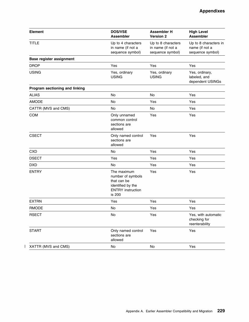
Appendixes
Element DOS/VSEAssembler
Assembler HVersion 2
High LevelAssembler
TITLE Up to 4 charactersin name (if not asequence symbol)
Up to 8 charactersin name (if not asequence symbol)
Up to 8 characters inname (if not asequence symbol)
Base register assignment
DROP Yes Yes Yes
USING Yes, ordinaryUSING
Yes, ordinaryUSING
Yes, ordinary,labeled, anddependent USINGs
Program sectioning and linking
ALIAS No No Yes
AMODE No Yes Yes
CATTR (MVS and CMS) No No Yes
COM Only unnamedcommon controlsections areallowed
Yes Yes
CSECT Only named controlsections areallowed
Yes Yes
CXD No Yes Yes
DSECT Yes Yes Yes
DXD No Yes Yes
ENTRY The maximumnumber of symbolsthat can beidentified by theENTRY instructionis 200
Yes Yes
EXTRN Yes Yes Yes
RMODE No Yes Yes
RSECT No Yes Yes, with automaticchecking forreenterability
START Only named controlsections areallowed
Yes Yes
| XATTR (MVS and CMS) No No Yes
Appendix A. Earlier Assembler Compatibility and Migration 229

Appendixes
Comparison of Macro and Conditional Assembly Statements
Element DOS/VSEAssembler
Assembler HVersion 2
High LevelAssembler
Macro definition
MACRO Yes Yes Yes
MEND Yes Yes Yes
MEXIT Yes Yes Yes
Conditional assembly
ACTR Yes Yes Yes
AEJECT No No Yes
AGO Yes Yes Yes
AIF Yes Yes Yes
AINSERT No No Yes
ANOP Yes Yes Yes
AREAD No Yes| Yes
ASPACE No No Yes
GBLA Yes Yes Yes
GBLB Yes Yes Yes
GBLC Yes Yes Yes
LCLA Yes Yes Yes
LCLB Yes Yes Yes
LCLC Yes Yes Yes
MHELP No Yes Yes
MNOTE Not allowed inopen code
Allowed in opencode
Allowed in open code
SETA Yes Yes Yes
SETB Yes Yes Yes
SETC Yes Yes Yes
SETAF No No Yes
SETCF No No Yes
System variable symbols
&SYSADATA_DSN No No Yes
&SYSADATA_MEMBER No No Yes
&SYSADATA_VOLUME No No Yes
&SYSASM No No Yes
&SYSCLOCK No No Yes
&SYSDATC No No Yes
&SYSDATE No Yes Yes
&SYSECT Yes Yes Yes
&SYSIN_DSN No No Yes
230 HLASM V1R4 Programmer’s Guide

Appendixes
Element DOS/VSEAssembler
Assembler HVersion 2
High LevelAssembler
&SYSIN_MEMBER No No Yes
&SYSIN_VOLUME No No Yes
&SYSJOB No No Yes
&SYSLIB_DSN No No Yes
&SYSLIB_MEMBER No No Yes
&SYSLIB_VOLUME No No Yes
&SYSLIN_DSN No No Yes
&SYSLIN_MEMBER No No Yes
&SYSLIN_VOLUME No No Yes
&SYSLIST Yes Yes Yes
&SYSLOC No Yes Yes
&SYSM_HSEV No No Yes
&SYSM_SEV No No Yes
&SYSMAC No No Yes
&SYSNDX Up to maximum of9999
Up to maximum of9999999
Up to maximum of9999999
&SYSNEST No No Yes
&SYSOPT_DBCS No No Yes
&SYSOPT_OPTABLE No No Yes
&SYSOPT_RENT No No Yes
&SYSOPT_XOBJECT No No Yes
&SYSPARM Yes Yes Yes
&SYSPRINT_DSN No No Yes
&SYSPRINT_MEMBER No No Yes
&SYSPRINT_VOLUME No No Yes
&SYSPUNCH_DSN No No Yes
&SYSPUNCH_MEMBER No No Yes
&SYSPUNCH_VOLUME No No Yes
&SYSSEQF No No Yes
&SYSSTEP No No Yes
&SYSSTMT No No Yes
&SYSSTYP No No Yes
&SYSTEM_ID No No Yes
&SYSTERM_DSN No No Yes
&SYSTERM_MEMBER No No Yes
&SYSTERM_VOLUME No No Yes
&SYSTIME No Yes Yes
&SYSVER No No Yes
Symbol attributes
Appendix A. Earlier Assembler Compatibility and Migration 231

Appendixes
Element DOS/VSEAssembler
Assembler HVersion 2
High LevelAssembler
Defined attribute No Yes Yes
Type attribute An ordinary symboloutside a macrocannot be used asan operand of theT' inside a macroand cannot beused to determinethe type of a SETAor SETB variable.
Only allowed inconditionalassemblyinstructions and notallowed for literals.
Yes; only allowedin conditionalassemblyinstructions and notallowed for literals.
Yes; allowed inconditional assembly,assembler, andmachine instructions
| and literals.
Length attribute Yes; allowed inconditionalassembly,assembler, andmachineinstructions and notallowed for literals.
Yes; allowed inconditionalassembly,assembler, andmachineinstructions and notallowed for literals.
Yes; allowed inconditional assembly,assembler, andmachine instructions
| and literals.
Scaling attribute Yes; only allowedin conditionalassemblyinstructions and notallowed for literals.
Yes; only allowedin conditionalassemblyinstructions and notallowed for literals.
Yes; allowed inconditional assembly,assembler, andmachine instructions
| and literals.
Integer attribute Yes; only allowedin conditionalassemblyinstructions and notallowed for literals.
Yes; only allowedin conditionalassemblyinstructions and notallowed for literals.
Yes; allowed inconditional assembly,assembler, andmachine instructions
| and literals.
Count attribute Can only be usedto determine thelength of a macroinstruction operand
Yes Yes
Number attribute Yes Can be applied toSETx variables
Can be applied toSETx variables
Operation Code Data attribute No No Yes
Type and Count attribute for system variablesymbols
No Yes Yes
Type attribute for SETA symbols that aredefined via LCLA or GBLA but are not set(via SETA)
Not applicable Returns a value of'00'
Returns a value of'N'
Type attribute for SETB symbols that aredefined via LCLB or GBLB but are not set(via SETB)
Not applicable Issues an errormessage
Returns a value of'N'
Type attribute for macro instruction operandswith a value of a previously used literal
Not applicable Returns a value of'U'
Returns the Typeattribute of theconstant defined bythe literal
232 HLASM V1R4 Programmer’s Guide
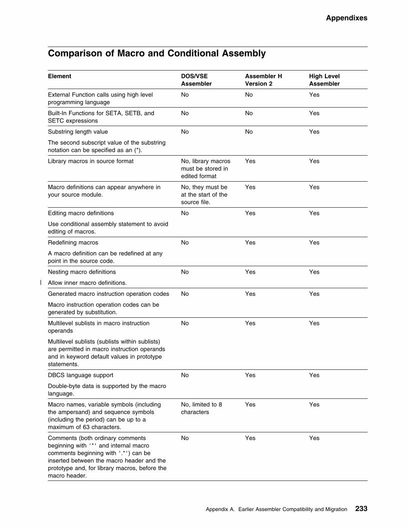
Appendixes
Comparison of Macro and Conditional Assembly
Element DOS/VSEAssembler
Assembler HVersion 2
High LevelAssembler
External Function calls using high levelprogramming language
No No Yes
Built-In Functions for SETA, SETB, andSETC expressions
No No Yes
Substring length value
The second subscript value of the substringnotation can be specified as an (*).
No No Yes
Library macros in source format No, library macrosmust be stored inedited format
Yes Yes
Macro definitions can appear anywhere inyour source module.
No, they must beat the start of thesource file.
Yes Yes
Editing macro definitions
Use conditional assembly statement to avoidediting of macros.
No Yes Yes
Redefining macros
A macro definition can be redefined at anypoint in the source code.
No Yes Yes
Nesting macro definitions
| Allow inner macro definitions.
No Yes Yes
Generated macro instruction operation codes
Macro instruction operation codes can begenerated by substitution.
No Yes Yes
Multilevel sublists in macro instructionoperands
Multilevel sublists (sublists within sublists)are permitted in macro instruction operandsand in keyword default values in prototypestatements.
No Yes Yes
DBCS language support
Double-byte data is supported by the macrolanguage.
No Yes Yes
Macro names, variable symbols (includingthe ampersand) and sequence symbols(including the period) can be up to amaximum of 63 characters.
No, limited to 8characters
Yes Yes
Comments (both ordinary commentsbeginning with '*' and internal macrocomments beginning with '.*') can beinserted between the macro header and theprototype and, for library macros, before themacro header.
No Yes Yes
Appendix A. Earlier Assembler Compatibility and Migration 233
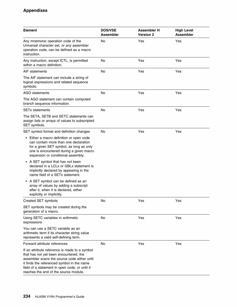
Appendixes
Element DOS/VSEAssembler
Assembler HVersion 2
High LevelAssembler
Any mnemonic operation code of theUniversal character set, or any assembleroperation code, can be defined as a macroinstruction.
No Yes Yes
Any instruction, except ICTL, is permittedwithin a macro definition.
No Yes Yes
AIF statements
The AIF statement can include a string oflogical expressions and related sequencesymbols.
No Yes Yes
AGO statements
The AGO statement can contain computedbranch sequence information.
No Yes Yes
SETx statements
The SETA, SETB and SETC statements canassign lists or arrays of values to subscriptedSET symbols.
No Yes Yes
SET symbol format and definition changes
� Either a macro definition or open codecan contain more than one declarationfor a given SET symbol, as long as onlyone is encountered during a given macroexpansion or conditional assembly.
� A SET symbol that has not beendeclared in a LCLx or GBLx statement isimplicitly declared by appearing in thename field of a SETx statement.
� A SET symbol can be defined as anarray of values by adding a subscriptafter it, when it is declared, eitherexplicitly or implicitly.
No Yes Yes
Created SET symbols
SET symbols may be created during thegeneration of a macro.
No Yes Yes
Using SETC variables in arithmeticexpressions
You can use a SETC variable as anarithmetic term if its character string valuerepresents a valid self-defining term.
No Yes Yes
Forward attribute references
If an attribute reference is made to a symbolthat has not yet been encountered, theassembler scans the source code either untilit finds the referenced symbol in the namefield of a statement in open code, or until itreaches the end of the source module.
No Yes Yes
234 HLASM V1R4 Programmer’s Guide

Appendixes
Element DOS/VSEAssembler
Assembler HVersion 2
High LevelAssembler
Attribute reference using SETC variables
You can take an attribute reference for asymbol specified as:
� The name of the ordinary symbol itself� The name of a symbolic parameter
whose value is the name of the ordinarysymbol
� The name of a SETC symbol whosevalue is the name of the ordinary symbol
No Yes Yes
Number attributes for SET symbols
The number attribute can be applied to SETxvariables to determine the highest subscriptvalue of a SET symbol array to which avalue has been assigned in a SETxinstruction.
No Yes Yes
Alternate format in conditional assembly
The alternate format allows a group ofoperands to be spread over several lines ofcode.
No Yes Yes
Maximum number of symbolic parametersand macro instruction operands
200 No fixed maximum No fixed maximum
Mixing positional and keyword symbolicparameters and macro instruction operands
All positionalparameters oroperands mustcome first.
Keywordparameters oroperands can beinterspersedamong positionalparameters oroperands.
Keyword parametersor operands can beinterspersed amongpositional parametersor operands.
SET symbol declaration Declaration of localsymbols mustimmediatelyprecede declarationof global symbols.
Declaration ofglobal and localsymbols mustimmediately followprototypestatement if inmacro definition.
Declaration ofglobal and localsymbols mustimmediately followsource macrodefinitions, if inopen code.
Declaration of localand global symbolscan be mixed.
Declaration ofglobal and localsymbols does notneed toimmediately followprototypestatement if inmacro definition.
Declaration ofglobal and localsymbols does notneed toimmediately followsource macrodefinitions, if inopen code.
Declaration of localand global symbolscan be mixed.
Declaration of globaland local symbolsdoes not need toimmediately followprototype statement ifin macro definition.
Declaration of globaland local symbolsdoes not need toimmediately followsource macrodefinitions, if in opencode.
Maximum dimension for subscripted SETSymbols
4095 Not limited Not limited
Appendix A. Earlier Assembler Compatibility and Migration 235

Appendixes
Element DOS/VSEAssembler
Assembler HVersion 2
High LevelAssembler
Duplication factor allowed in SETCinstruction
No Yes Yes
Dynamically extended variable SET symbols No Yes Yes
Number of terms in arithmetic expressions inconditional assembly
Up to 16 Not limited Not limited
Levels of parentheses in arithmeticexpressions in conditional assembly
Up to 5 Not limited Not limited
MNOTE with error in macro is flagged ateach invocation
Yes No No
Blank lines treated as equivalent to ASPACE1.
No No Yes
Name entry of macro instruction must be avalid symbol
Yes Yes No
Ampersand preceding the SET symbolsbeing declared is optional
No No Yes
Predefined absolute symbols allowed inarithmetic expression
No No Yes
Predefined absolute symbols allowed inSETx instruction
No No Yes
Type attribute of CNOP Label is set to 'I' No, set to 'J' No, set to 'J' Yes
Type, length, scaling and integer attributeallowed for ordinary symbols, SETC symbolsand literals in open code
No No Yes
Sublists assigned to SETC symbols can bepassed to macro definitions and berecognized as sublists
No No Yes
236 HLASM V1R4 Programmer’s Guide

Appendixes
Comparison of Language Features
Element DOS/VSEAssembler
Assembler HVersion 2
High LevelAssembler
Macro comment statements allowed in opencode
No No Yes
EQU instruction extension
Symbols appearing in the first operand of theEQU instruction need not have beenpreviously defined.
No Yes Yes
CNOP instruction extension
There is no restriction that symbols in theoperand field of a CNOP instruction musthave been previously defined.
No Yes Yes
COPY instruction extension
Any number of 'nestings', COPY statementswithin code that have been brought into yourprogram by another COPY statement, ispermitted.
No, nesting depthlimited to 3
Yes Yes
COPY instruction processed immediately
COPY members are read immediately after aCOPY statement is encountered in thesource, regardless of whether or notconditional processing requires it, as in thefollowing example:
AGO .LABEL COPY AFILE.LABEL ANOP
No, AFILE is neveropened, read from,or processed inany way.
Yes, AFILE isscanned duringlookaheadprocessing
Yes, AFILE isscanned duringlookaheadprocessing
COPY instruction operand can, in opencode, be specified as a variable symbol.
No No Yes
ISEQ instruction extension
Sequence checking of any column on inputrecords is allowed.
No Yes Yes
Macro names
Inline macro names may contain theunderscore character (_).
No Yes Yes
Continuation lines Up to 2 Up to 9 Up to 9
Continuation lines and double-byte data No Yes Yes
Symbol name length up to 63 characters No, limited to 8 Yes Yes
Levels within expressions
Any number of terms or levels of parenthesisin an expression is allowed.
No Yes Yes
Underscores in symbols
You can specify the underscore character (_)in ordinary symbols and variable symbols.
No Yes Yes
Underscore character accepted in anyposition in symbol name
No No Yes
Appendix A. Earlier Assembler Compatibility and Migration 237

Appendixes
Element DOS/VSEAssembler
Assembler HVersion 2
High LevelAssembler
Underscore character accepted in externalsymbols
No No Yes
Underscore character accepted in name fieldof OPSYN instruction
No No Yes
Maximum number of external symbols 511 65 535 65 535
DBCS language support
Pure double-byte data, and double-byte datamixed with single-byte data is permitted.
No Yes Yes
Location counter value printed for EQU,USING, ORG (in ADDR2 field)
3 bytes 4 bytes (up to 3leading zeroessuppressed).
4 bytes (up to 3leading zeroessuppressed).
Self-defining term Maximum value
Number of digits Binary: Decimal: Hexadecimal: Characters:
224-1 24863
231-1 311084
231-1 311084
Relocatable and absolute expressions
Value carried: Number of operators:Levels of parenthesis:
Truncated to 24bits155
Truncated to 31bitsNot limitedNot limited
Truncated to 31 bits Not limitedNot limited
All control sections initiated by a CSECTstart at location 0 in listing and objectmodule.
Yes No| Controlled by| THREAD option
Copy files read once Copy files readwhen statement isfound
Copy files readwhen macro isedited (only once)
Copy files read whenmacro is edited (onlyonce)
Operand greater than 255 characters whenSUBLIST
Error diagnosticwith message andreturn code of 8
Error diagnosticwith message andreturn code of 12
Error diagnostic withmessage and returncode of 12
Remarks generated because of generatedblanks in operand field
No Yes Yes
Blank lines treated as equivalent to SPACE1.
No No Yes
Literals usable as relocatable terms inexpressions
No No Yes
Literals usable in RX format instructions inwhich index register is used
No No Yes
Mixed case input No No Yes
2-byte relocatable address constants No No Yes
Multi-level PUSH supported
For example, PUSH USING,USING
No Yes. Notdocumented.
No
238 HLASM V1R4 Programmer’s Guide

Appendixes
Comparison of Assembler Options
Element DOS/VSEAssembler
Assembler HVersion 2
High LevelAssembler
*PROCESS statements No No Selected assembleroptions can bespecified in thesource program on*PROCESSstatements.
ADATA No No Yes
ALIGN Yes Yes Yes
ASA (MVS and CMS) No No Yes
BATCH No Yes Yes
| CODEPAGE| No| No| Yes
COMPAT No No Yes
DBCS No Yes Yes
DECK Yes Yes Yes
DISK (CMS) No Yes Yes
DXREF No No Yes
EDECK Yes No No
ERASE (CMS) No No Yes
ESD Yes Yes Yes
EXIT No No Yes
FLAG No Yes| FLAG(integer),| FLAG(ALIGN),| FLAG(CONT),| FLAG(IMPLEN),| FLAG(PAGE0),| FLAG(PUSH),| FLAG(RECORD),| FLAG(SUBSTR), and| FLAG(USING0) can| be specified.
FOLD No No Yes
GOFF (MVS and CMS) No No Yes
INFO No No Yes
LANGUAGE No No Yes. Applies tomessages and listingheadings.
LIBMAC No No Yes
LINECOUNT Yes Yes Yes
LINK Yes No No, see OBJECToption
Appendix A. Earlier Assembler Compatibility and Migration 239

Appendixes
Element DOS/VSEAssembler
Assembler HVersion 2
High LevelAssembler
LIST Yes Yes LIST(121),LIST(133), andLIST(MAX) can bespecified (MVS andCMS)
MCALL Yes No No;PCONTROL(MCALL)can be specified.
MXREF No No MXREF(SOURCE),MXREF(XREF), andMXREF(FULL) canbe specified.
NOPRINT (CMS) No No Yes
NOSEG (CMS) No No Yes
NUM No Yes (CMS) No
OBJECT Yes Yes Yes
OPTABLE No No Yes
PCONTROL No No Yes
PESTOP No No Yes
PRINT (CMS) No Yes Yes
PROFILE No No Yes
RA2 No No Yes
RENT No Yes Yes
RLD Yes Yes Yes
RXREF No No Yes
SEG (CMS) No No Yes
SIZE No No Yes
STMT (MVS and CMS) No Yes (CMS) No
SUBLIB(AE/DF) (VSE) Yes No Yes. Specify on //OPTION statement.
SYSPARM Yes Yes Yes
SXREF Yes Same asXREF(SHORT)
Same asXREF(SHORT)
TERM No Yes TERM(WIDE) andTERM(NARROW)can be specified.
TEST No Yes Yes
| THREAD| No| No| Yes
TRANSLATE No No Yes
USING No No Yes
XOBJECT (MVS and CMS) No No Yes
240 HLASM V1R4 Programmer’s Guide
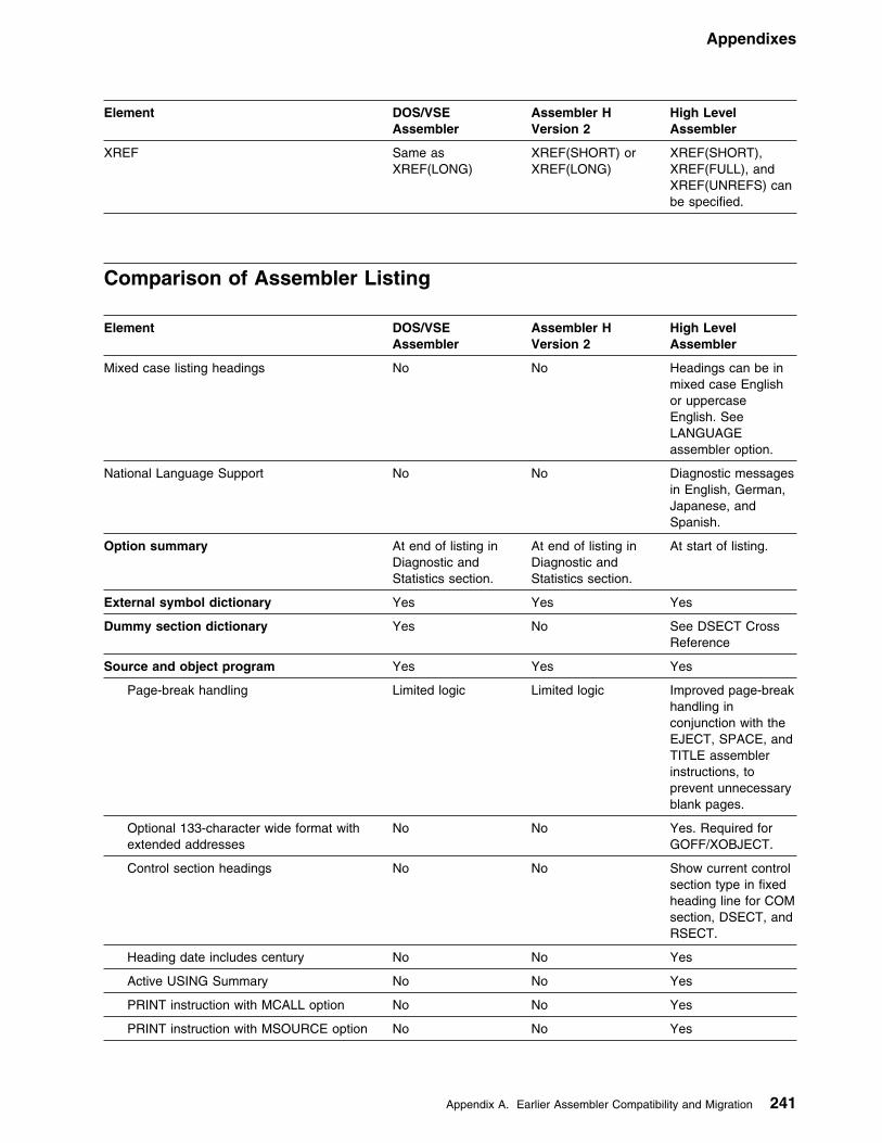
Appendixes
Element DOS/VSEAssembler
Assembler HVersion 2
High LevelAssembler
XREF Same asXREF(LONG)
XREF(SHORT) orXREF(LONG)
XREF(SHORT),XREF(FULL), andXREF(UNREFS) canbe specified.
Comparison of Assembler Listing
Element DOS/VSEAssembler
Assembler HVersion 2
High LevelAssembler
Mixed case listing headings No No Headings can be inmixed case Englishor uppercaseEnglish. SeeLANGUAGEassembler option.
National Language Support No No Diagnostic messagesin English, German,Japanese, andSpanish.
Option summary At end of listing inDiagnostic andStatistics section.
At end of listing inDiagnostic andStatistics section.
At start of listing.
External symbol dictionary Yes Yes Yes
Dummy section dictionary Yes No See DSECT CrossReference
Source and object program Yes Yes Yes
Page-break handling Limited logic Limited logic Improved page-breakhandling inconjunction with theEJECT, SPACE, andTITLE assemblerinstructions, toprevent unnecessaryblank pages.
Optional 133-character wide format withextended addresses
No No Yes. Required forGOFF/XOBJECT.
Control section headings No No Show current controlsection type in fixedheading line for COMsection, DSECT, andRSECT.
Heading date includes century No No Yes
Active USING Summary No No Yes
PRINT instruction with MCALL option No No Yes
PRINT instruction with MSOURCE option No No Yes
Appendix A. Earlier Assembler Compatibility and Migration 241

Appendixes
Element DOS/VSEAssembler
Assembler HVersion 2
High LevelAssembler
PRINT instruction with NOGEN optionshows object code for first instructiongenerated, or the first 8 bytes of datagenerated, in the object code column.
No No Yes
PRINT, PUSH and POP instructions withNOPRINT option
No No Yes
AREAD instruction with NOPRINT option No No Yes
Relocation dictionary Yes Yes Yes
Ordinary symbol and literal crossreference
Yes Yes Yes
Cross reference includes modificationand branch flags, USING and DROPflags, EXecute instruction flag, andrelocatability-type column.
No No Yes
Unreferenced symbols defined in CSECTs No No Yes
Macro and copy code source summary No No Yes
Macro and copy code cross reference No No Yes
DSECT cross reference No No Yes
USING map No No Yes
General purpose register cross reference No No Yes
Diagnostic cross reference and assemblersummary
Diagnostic andStatistics sectionincluding errordiagnosticmessages
Yes Yes
Flagged statements with input datasetinformation
No No Yes, ifFLAG(RECORD)assembler optionspecified
Print line with current PTF level ofassembler
No No Yes
Print line showing operating system,jobname, stepname and procedurestepname of assembly job
No No Yes
Print lines showing file names (data setnames), member and volume serialnumbers of each of the input and outputdata sets
No No Yes
Print lines showing statistics for I/O exits No No Yes
Print line showing the amount of storagein the buffer pool and the amount ofstorage required for an in-storageassembly
No No Yes
Record counts show the number of workfile reads and writes
No No Yes
Print line showing the return code of theassembly
No No Yes
242 HLASM V1R4 Programmer’s Guide
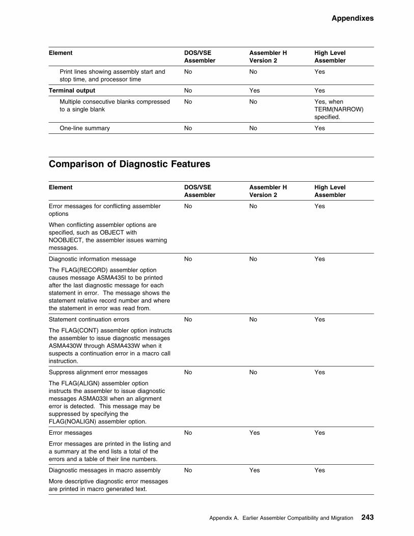
Appendixes
Element DOS/VSEAssembler
Assembler HVersion 2
High LevelAssembler
Print lines showing assembly start andstop time, and processor time
No No Yes
Terminal output No Yes Yes
Multiple consecutive blanks compressedto a single blank
No No Yes, whenTERM(NARROW)specified.
One-line summary No No Yes
Comparison of Diagnostic Features
Element DOS/VSEAssembler
Assembler HVersion 2
High LevelAssembler
Error messages for conflicting assembleroptions
When conflicting assembler options arespecified, such as OBJECT withNOOBJECT, the assembler issues warningmessages.
No No Yes
Diagnostic information message
The FLAG(RECORD) assembler optioncauses message ASMA435I to be printedafter the last diagnostic message for eachstatement in error. The message shows thestatement relative record number and wherethe statement in error was read from.
No No Yes
Statement continuation errors
The FLAG(CONT) assembler option instructsthe assembler to issue diagnostic messagesASMA430W through ASMA433W when itsuspects a continuation error in a macro callinstruction.
No No Yes
Suppress alignment error messages
The FLAG(ALIGN) assembler optioninstructs the assembler to issue diagnosticmessages ASMA033I when an alignmenterror is detected. This message may besuppressed by specifying theFLAG(NOALIGN) assembler option.
No No Yes
Error messages
Error messages are printed in the listing anda summary at the end lists a total of theerrors and a table of their line numbers.
No Yes Yes
Diagnostic messages in macro assembly
More descriptive diagnostic error messagesare printed in macro generated text.
No Yes Yes
Appendix A. Earlier Assembler Compatibility and Migration 243

Appendixes
Element DOS/VSEAssembler
Assembler HVersion 2
High LevelAssembler
Sequence field in macro-generated text
The sequence field (columns 73 through 80)of the generated statements contains thelevel of the macro call, a hyphen, and thefirst five characters of the macro-definitionname.
No Yes Yes
Format of macro-generated text
Wherever possible, a generated statement isprinted in the same format as thecorresponding macro definition (model)statement.
No Yes Yes
Error messages for a library macro definition
Format errors within a particular librarymacro definition are listed directly followingthe first call of that macro.
No Yes Yes
Error messages for source program macrodefinition
Macro definitions contained in the sourceprogram are printed in the listing, providedthe applicable PRINT options are in effect.
No Yes Yes
Error messages in macro-generated text
Diagnostic messages in generated textgenerally include a description of the error,the recovery action, model statement numberat which the error occurred, and a SETsymbol name, parameter number, or a valueassociated with the error.
No Yes Yes
Macro Trace Facility (MHELP) No Yes Yes
Other Assembler Differences
Element DOS/VSEAssembler
Assembler HVersion 2
High LevelAssembler
Object module
DXD, CXD and Q-type constants produced No Yes Yes
Named COMMON No Yes Yes
Unnamed CSECTS (private code) No Yes Yes
SYM records produced No Yes Yes
| Generalized object format module generation(MVS and CMS)
Not applicable No| Yes. Refer to| GOFF/XOBJECT| assembler option.
Diagnostics
244 HLASM V1R4 Programmer’s Guide

Appendixes
Element DOS/VSEAssembler
Assembler HVersion 2
High LevelAssembler
Diagnostic messages issued At end of assembly At line where erroroccurred ifpossible.
At line where erroroccurred if possible.
Diagnostic dump No Produced at time offailure
Produced at time offailure
Error diagnostics messages in mixed case No No Yes
Resources
Work file 3 Work Files 1 Work File 1 Work File
Associated data file No No Yes
QSAM Input/output (MVS and CMS) Not applicable No Yes
Input/Output user exits No No Yes.
System-Determined Blocksize (MVS) Not applicable No Yes; supported inMVS/ESA only.
31-bit-addressable storage exploited duringassembly
No No Yes; does not includeI/O buffers.
Minimum virtual storage requirements 200K 200K 580K
Printer control characters (MVS and CMS) American NationalStandard
Machine American NationalStandard or machinedepending on ASAoption
| Alternative assembler option sourcefile| No| No| Yes
Appendix A. Earlier Assembler Compatibility and Migration 245

Appendixes
Appendix B. Cross-System Portability Considerations
This section describes the issues you must consider when you use High LevelAssembler to assemble a program under one operating system and execute theresulting program under another operating system.
Using Extended Architecture InstructionsHigh Level Assembler supports assembly of programs using Extended Architectureinstructions, Enterprise System Architecture instructions, and Vector instructions,under all operating systems supported by High Level Assembler.
A generated object program using Extended Architecture (370-XA) instructions canonly run on a 370-XA mode processor under an operating system that provides thenecessary architecture support for the 370-XA instructions used.
Similarly, a generated object program using Enterprise Systems Architecture/370(ESA/370) or Enterprise Systems Architecture/390 (ESA/390) instructions can onlyrun on an applicable processor under an operating system that provides thenecessary architecture support for the ESA/370 or ESA/390 instructions used.
Using System MacrosMany system macros have the same name under different systems, but generatedifferent object code and have different parameters. For example, the OPEN,CLOSE, GET, and PUT macros have the same name on MVS and VSE butgenerate different object code.
Wherever the assembler program uses system macros, the system macros for thetarget system must be used when the program is assembled.
For example, when the assembler program is to be run under VSE, the VSEsystem macros must be used, even if the program is assembled under CMS.
Ensure that the macros used during assembly are for the correct release of theoperating system upon which the assembler program is to run.
Migrating Object ProgramsThe object module produced by High Level Assembler is portable across all thesupported operating systems. Therefore, an assembler program may beassembled under any of the supported operating systems and run under any of thesupported operating systems. For example, an assembler program may beassembled under CMS and run under VSE.
The object module is portable across the supported operating systems with thefollowing restrictions:
� Wherever the assembler program uses system macros, the system macros forthe target system must be used.
� The object module must be link-edited using the target system linkage editor.
246 Copyright IBM Corp. 1982, 2000
Appendixes
� The assembler instructions included in the assembler program must besupported by the system linkage editor.
The VSE linkage editor, prior to VSE/ESA Version 2 Release 1, does notsupport dummy external DSECTS. Therefore, to link-edit the assemblerprogram under earlier VSE operating systems, the assembler program must notinclude any DXD or CXD statements or Q-type address constants.
� The TEST assembler option should only be used if the object module is to belink-edited under MVS.
| The TEST option cannot be specified with the GOFF assembler| option, which produces the generalized object format module. | � A generalized object format module cannot be ported to a VSE or CMS
environment.
The AMODE and RMODE assembler instructions indicate to the linkage editor theaddressing mode and residency mode for the section. The addressing mode andresidency mode are ignored by the linkage editor on systems that do not support31-bit addressing.
The AMODE and RMODE assembler instructions have an effect on the addressingmode and residency mode only if the object module produced is link-edited usingan XA or ESA linkage editor and run on a system that supports 31-bit addressing.
Appendix B. Cross-System Portability Considerations 247
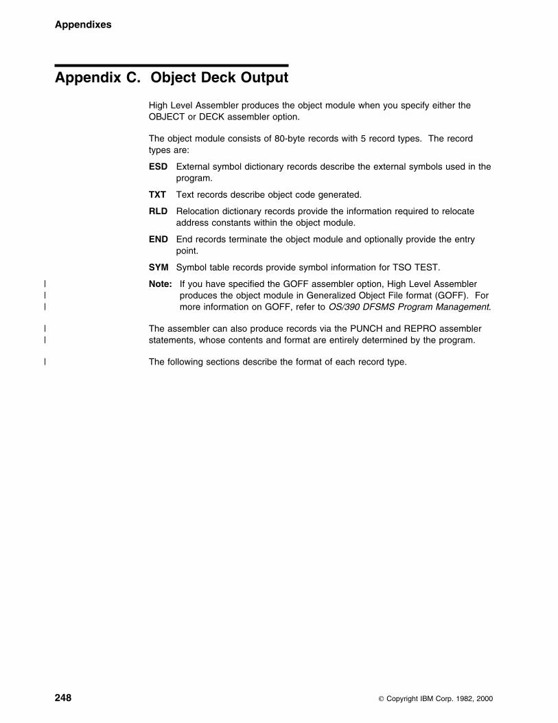
Appendixes
Appendix C. Object Deck Output
High Level Assembler produces the object module when you specify either theOBJECT or DECK assembler option.
The object module consists of 80-byte records with 5 record types. The recordtypes are:
ESD External symbol dictionary records describe the external symbols used in theprogram.
TXT Text records describe object code generated.
RLD Relocation dictionary records provide the information required to relocateaddress constants within the object module.
END End records terminate the object module and optionally provide the entrypoint.
SYM Symbol table records provide symbol information for TSO TEST.
| Note: If you have specified the GOFF assembler option, High Level Assembler| produces the object module in Generalized Object File format (GOFF). For| more information on GOFF, refer to OS/390 DFSMS Program Management.
| The assembler can also produce records via the PUNCH and REPRO assembler| statements, whose contents and format are entirely determined by the program.
| The following sections describe the format of each record type.
248 Copyright IBM Corp. 1982, 2000
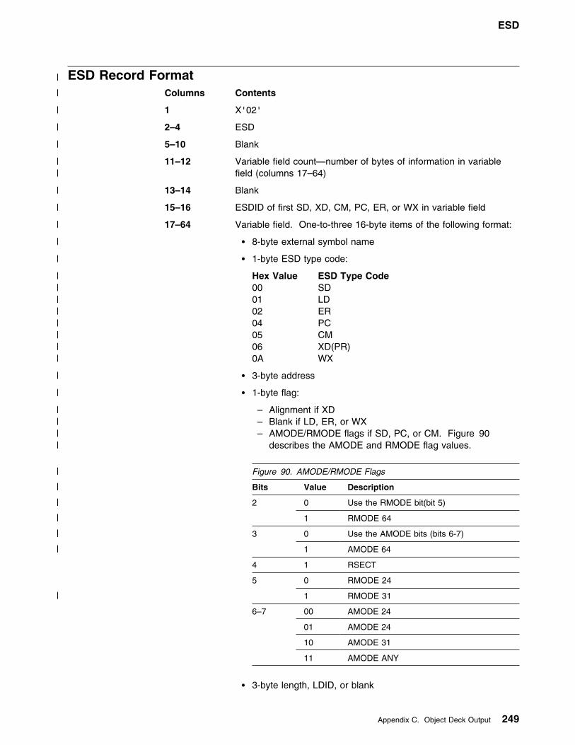
ESD
| ESD Record Format| Columns Contents
| 1 X'02'
| 2–4 ESD
| 5–10 Blank
| 11–12 Variable field count—number of bytes of information in variable| field (columns 17–64)
| 13–14 Blank
| 15–16 ESDID of first SD, XD, CM, PC, ER, or WX in variable field
| 17–64 Variable field. One-to-three 16-byte items of the following format:
| � 8-byte external symbol name
| � 1-byte ESD type code:
| Hex Value ESD Type Code| 00 SD| 01 LD| 02 ER| 04 PC| 05 CM| 06 XD(PR)| 0A WX
| � 3-byte address
| � 1-byte flag:
| – Alignment if XD| – Blank if LD, ER, or WX| – AMODE/RMODE flags if SD, PC, or CM. Figure 90| describes the AMODE and RMODE flag values.
� 3-byte length, LDID, or blank
| Figure 90. AMODE/RMODE Flags
| Bits| Value| Description
| 2| 0| Use the RMODE bit(bit 5)
| 1| RMODE 64
| 3| 0| Use the AMODE bits (bits 6-7)
| 1| AMODE 64
4 1 RSECT
5 0 RMODE 24
1| RMODE 31
6–7 00 AMODE 24
01 AMODE 24
10 AMODE 31
11 AMODE ANY
Appendix C. Object Deck Output 249

Variable field item 117–24 External symbol name25 ESD type code26–28 Address29 Flag30–32 Length, LDID, or blank
Variable field item 233–40 External symbol name41 ESD type code42–44 Address45 Flag46–48 Length, LDID, or blank
Variable field item 349–56 External symbol name57 ESD type code58–60 Address61 Flag62–64 Length, LDID, or blank
65–72 Blank
73–80 Deck ID, sequence number, or both. The deck ID is the namefrom the first TITLE statement that has a non-blank name field.This name can be 1–8 characters. If the name is fewer than 8characters or if there is no name, the remaining columns contain arecord sequence number.
TXT Record FormatColumns Contents
1 X'02'
2–4 TXT
5 Blank
6–8 Relative address of first instruction on record
9–10 Blank
11–12 Byte count—number of bytes in information field (columns 17–72)
13–14 Blank
15–16 ESDID
17–72 56-byte information field
73–80 Deck ID, sequence number, or both. The deck ID is the namefrom the first TITLE statement that has a non-blank name field.The name can be 1–8 characters. If the name is fewer than 8characters or if there is no name, the remaining columns contain arecord sequence number.
250 HLASM V1R4 Programmer’s Guide

RLD Record FormatColumns Contents
1 X'02'
2–4 RLD
5–10 Blank
11–12 Data field count—number of bytes of information in data field(columns 17–72)
13–16 Blank
17–72 Data field:
17–18 Relocation ESDID19–20 Position ESDID21 Flag byte22–24 Absolute address to be relocated25–72 Remaining RLD entries
73–80 Deck ID, sequence number, or both. The deck ID is the name fromthe first TITLE statement that has a non-blank name field. Thename can be 1–8 characters or if there is no name, the remainingcolumns contain a record sequence number.
If the rightmost bit of the flag byte is set, the following RLD entry has the samerelocation ESDID and position ESDID, and this information is not repeated; if therightmost bit of the flag byte is not set, the next RLD entry has a different relocationESDID or position ESDID, and both ESDIDs are recorded.
For example, if the RLD entries 1, 2, and 3 of the program listing contain thefollowing information:
Position RelocationEntry ESDID ESDID Flag Address
1 92 94 9C 9991992 92 94 9C 9991943 93 91 9C 999899
then columns 17–72 of the RLD record would be:
│ Entry 1 │ Entry 2 │ Entry 3 │ │ │ │ │Column:│17 18 19 29 21 22 23 24│25 26 27 28│29 39 31 32 33 34 35 36│37────�72 ├──┬──┬──┬──┬──┬──┬──┬──┼──┬──┬──┬──┼──┬──┬──┬──┬──┬──┬──┬──┤ │99│94│99│92│9D│99│91│99│9C│99│91│94│99│91│99│93│9C│99│98│99│ ├──┴──┴──┴──┴──┴──┴──┴──┼──┴──┴──┴──┼──┴──┴──┴──┴──┴──┴──┴──┤
│ ESD Ids l Address │l Address │ ESD Ids l Address │ Blanks│ │ ││ │ │ │
│ Flag │Flag │ Flag │ │ (Set) │(not │ (not │ │ │set) │ set) │
Appendix C. Object Deck Output 251
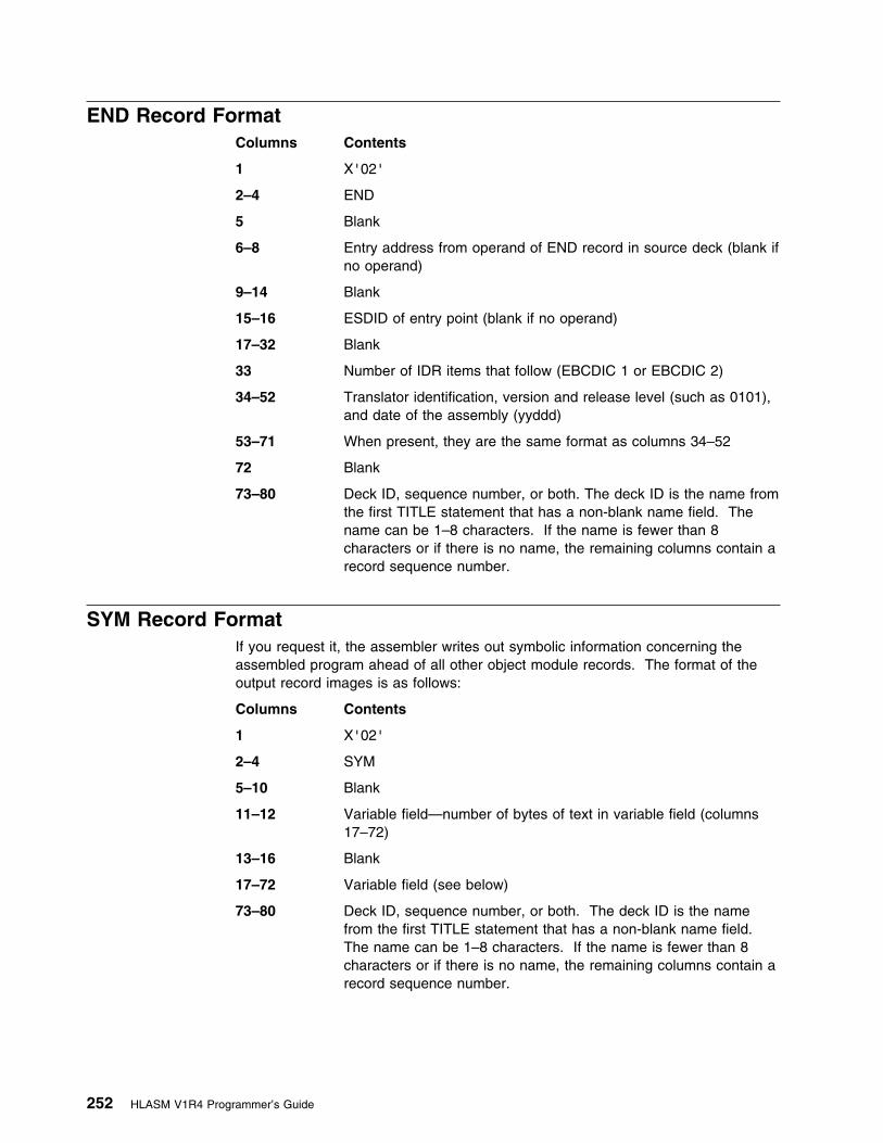
END Record FormatColumns Contents
1 X'02'
2–4 END
5 Blank
6–8 Entry address from operand of END record in source deck (blank ifno operand)
9–14 Blank
15–16 ESDID of entry point (blank if no operand)
17–32 Blank
33 Number of IDR items that follow (EBCDIC 1 or EBCDIC 2)
34–52 Translator identification, version and release level (such as 0101),and date of the assembly (yyddd)
53–71 When present, they are the same format as columns 34–52
72 Blank
73–80 Deck ID, sequence number, or both. The deck ID is the name fromthe first TITLE statement that has a non-blank name field. Thename can be 1–8 characters. If the name is fewer than 8characters or if there is no name, the remaining columns contain arecord sequence number.
SYM Record FormatIf you request it, the assembler writes out symbolic information concerning theassembled program ahead of all other object module records. The format of theoutput record images is as follows:
Columns Contents
1 X'02'
2–4 SYM
5–10 Blank
11–12 Variable field—number of bytes of text in variable field (columns17–72)
13–16 Blank
17–72 Variable field (see below)
73–80 Deck ID, sequence number, or both. The deck ID is the namefrom the first TITLE statement that has a non-blank name field.The name can be 1–8 characters. If the name is fewer than 8characters or if there is no name, the remaining columns contain arecord sequence number.
252 HLASM V1R4 Programmer’s Guide

The variable field (columns 17–72) contains up to 56 bytes of text. The itemscomprising the text are packed together; consequently, only the last record maycontain less than 56 bytes of text in the variable field. The formats of a text recordand an individual text item are shown in Figure 92 on page 254. The contents ofthe fields within an individual entry are as follows:
1. Organization (1 byte). The possible values are shown in Figure 91.
2. Address (3 bytes)—displacement from base of control section
3. Symbol Name (0–8 bytes)—symbolic name of particular item. If the entry isnon-data type and space, an extra byte is present that contains the number ofbytes that have been skipped.
4. Data Type (1 byte)—contents in hexadecimal
00 = character04 = hexadecimal or pure DBCS (G-type)08 = binary10 = fixed point, full14 = fixed point, half18 = floating point, short
Figure 91. Organization Value Byte
Bits Value Description
0 0 Non-data type
1 Data type
1–3Ifnon-datatype
000 Space
001 Control section
010 Dummy control section
011 Common
100 Instruction
101 CCW, CCW0, CCW1
1If datatype
0 No multiplicity
1 Multiplicity(indicates presenceof M Field)
2If datatype
0 Independent(not a packed or zoneddecimal constant)
1 Cluster(packed or zoneddecimal constant)
3If datatype
0 No scaling
1 Scaling(indicates presenceof S field)
4 0 Name present
1 Name not present
5–7 Length ofname minus 1
Appendix C. Object Deck Output 253
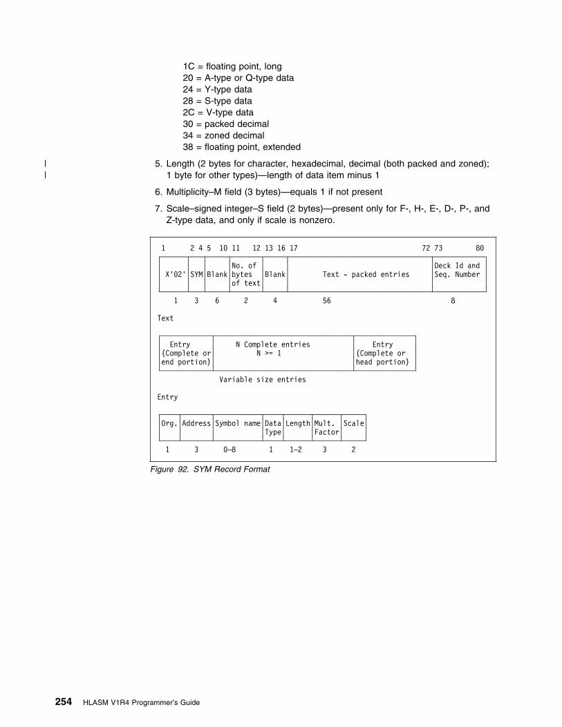
1C = floating point, long20 = A-type or Q-type data24 = Y-type data28 = S-type data2C = V-type data30 = packed decimal34 = zoned decimal38 = floating point, extended
| 5. Length (2 bytes for character, hexadecimal, decimal (both packed and zoned);| 1 byte for other types)—length of data item minus 1
6. Multiplicity–M field (3 bytes)—equals 1 if not present
7. Scale–signed integer–S field (2 bytes)—present only for F-, H-, E-, D-, P-, andZ-type data, and only if scale is nonzero.
1 2 4 5 19 11 12 13 16 17 72 73 89┌──────┬───┬─────┬───────┬─────┬──────────────────────────────────┬────────────┐│ │ │ │No. of │ │ │Deck Id and ││ X'92'│SYM│Blank│bytes │Blank│ Text - packed entries │Seq. Number ││ │ │ │of text│ │ │ │└──────┴───┴─────┴───────┴─────┴──────────────────────────────────┴────────────┘ 1 3 6 2 4 56 8
Text
┌────────────┬─────────────────────────────────┬──────────────┐│ Entry │ N Complete entries │ Entry ││(Complete or│ N >= 1 │(Complete or ││end portion)│ │head portion) │└────────────┴─────────────────────────────────┴──────────────┘
Variable size entries
Entry
┌────┬───────┬───────────┬────┬──────┬──────┬─────┐│Org.│Address│Symbol name│Data│Length│Mult. │Scale││ │ │ │Type│ │Factor│ │└────┴───────┴───────────┴────┴──────┴──────┴─────┘1 3 9–8 1 1–2 3 2
Figure 92. SYM Record Format
254 HLASM V1R4 Programmer’s Guide

Appendix D. Associated Data File Output
When you specify the ADATA assembler option, a file containing associated data isproduced by the assembler. When you specify the ADATA suboption of the GOFFassembler option, ADATA records are written to the object data set as text records.
| You can specify both ADATA and GOFF(ADATA) to produce ADATA records inboth the associated data file and the object data set. Information about theassembled program can be extracted from either data set and be used bydebugging tools or cross reference tools.
The associated data records are subject to change in future releases of High LevelAssembler without prior notice. Any utility which processes associated data filesshould not process any files with architecture levels beyond those the utility hasbeen designed and tested to process.
The ASMADATA macro maps the records in the associated data file, and the| generalized object format data set. The syntax and parameter keywords for this
macro are shown on page 256.
Copyright IBM Corp. 1982, 2000 255
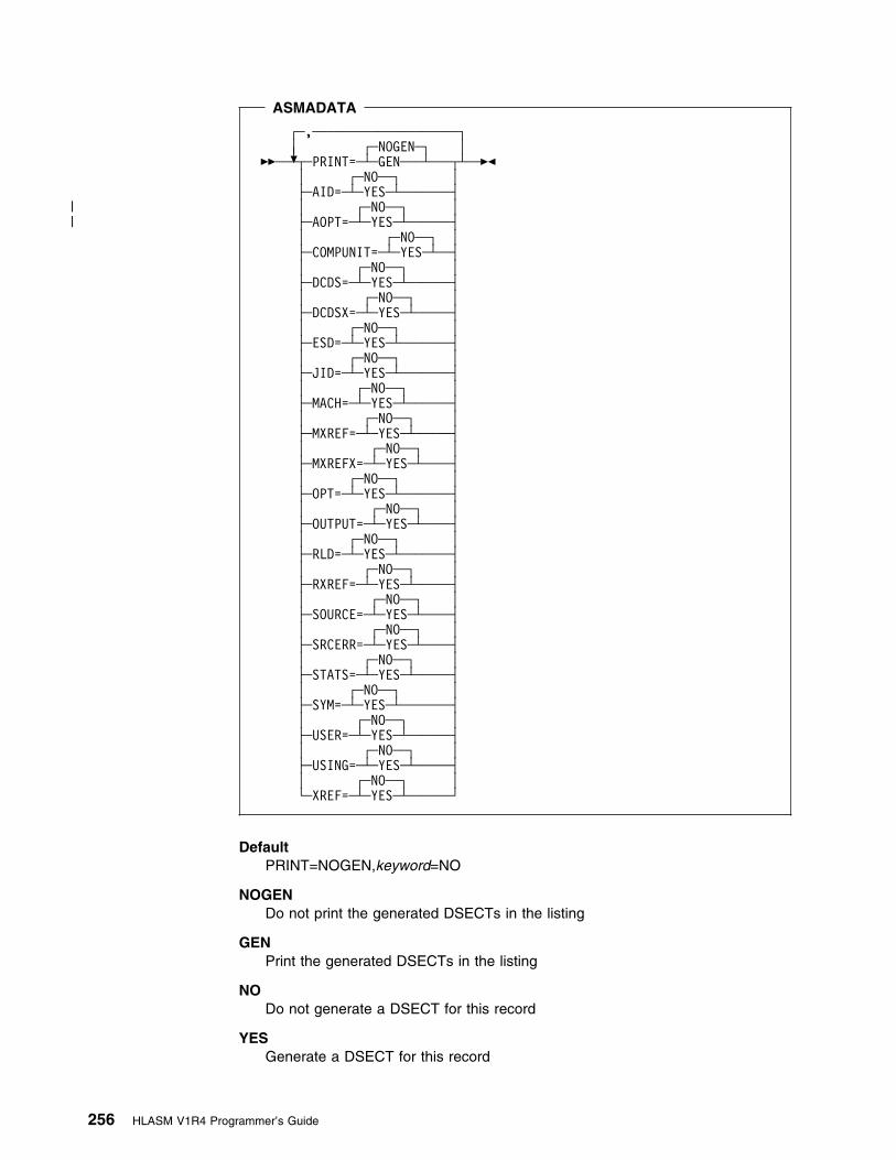
ASMADATA
┌ ┐─,──────────────────── │ │┌ ┐─NOGEN─
��─ ───+ ┴┬ ┬──PRINT= ──┴ ┴─GEN─── ─ ─�� │ │┌ ┐─NO── ├ ┤──AID= ──┴ ┴─YES─ ─────
| │ │┌ ┐─NO──| ├ ┤──AOPT= ──┴ ┴─YES─ ────
│ │┌ ┐─NO── ├ ┤──COMPUNIT= ──┴ ┴─YES─ │ │┌ ┐─NO── ├ ┤──DCDS= ──┴ ┴─YES─ ──── │ │┌ ┐─NO── ├ ┤──DCDSX= ──┴ ┴─YES─ ─── │ │┌ ┐─NO── ├ ┤──ESD= ──┴ ┴─YES─ ───── │ │┌ ┐─NO── ├ ┤──JID= ──┴ ┴─YES─ ───── │ │┌ ┐─NO── ├ ┤──MACH= ──┴ ┴─YES─ ──── │ │┌ ┐─NO── ├ ┤──MXREF= ──┴ ┴─YES─ ─── │ │┌ ┐─NO── ├ ┤──MXREFX= ──┴ ┴─YES─ ── │ │┌ ┐─NO── ├ ┤──OPT= ──┴ ┴─YES─ ───── │ │┌ ┐─NO── ├ ┤──OUTPUT= ──┴ ┴─YES─ ── │ │┌ ┐─NO── ├ ┤──RLD= ──┴ ┴─YES─ ───── │ │┌ ┐─NO── ├ ┤──RXREF= ──┴ ┴─YES─ ─── │ │┌ ┐─NO── ├ ┤──SOURCE= ──┴ ┴─YES─ ── │ │┌ ┐─NO── ├ ┤──SRCERR= ──┴ ┴─YES─ ── │ │┌ ┐─NO── ├ ┤──STATS= ──┴ ┴─YES─ ─── │ │┌ ┐─NO── ├ ┤──SYM= ──┴ ┴─YES─ ───── │ │┌ ┐─NO── ├ ┤──USER= ──┴ ┴─YES─ ──── │ │┌ ┐─NO── ├ ┤──USING= ──┴ ┴─YES─ ─── │ │┌ ┐─NO── └ ┘──XREF= ──┴ ┴─YES─ ────
DefaultPRINT=NOGEN,keyword=NO
NOGENDo not print the generated DSECTs in the listing
GENPrint the generated DSECTs in the listing
NODo not generate a DSECT for this record
YESGenerate a DSECT for this record
256 HLASM V1R4 Programmer’s Guide

keywords
AID ADATA Identification DSECT (Type X'0001')
| AOPT Options File Information (Type X'000B')
COMPUNIT ADATA Compilation Unit Start/End DSECT (Type X'0002')
DCDS DC/DS DSECT (Type X'0034')
DCDSX DC Extension DSECT(Type X'0035')
ESD External Symbol Dictionary (ESD) DSECT (Type X'0020')
JID Job Identification DSECT (Type X'0000')
MACH Machine Instruction DSECT (Type X'0036')
MXREF Macro and Copy Code Source Summary DSECT (TypeX'0060')
MXREFX Macro and Copy Code Cross Reference DSECT (TypeX'0062')
OPT Options DSECT (Type X'0010')
OUTPUT Output File DSECT (Type X'000A')
RLD Relocation Dictionary (RLD) DSECT (Type X'0040')
RXREF Register Cross Reference DSECT (Type X'0045')
SOURCE Source Analysis DSECT (Type X'0030')
SRCERR Source Error DSECT (Type X'0032')
STATS Statistics DSECT (Type X'0090')
SYM Symbol DSECT (Type X'0042')
USER User Data Record DSECT (Type X'0070')
USING Using Map DSECT (Type X'0080')
XREF Symbol Cross Reference DSECT (Type X'0044')
Record TypesThe file contains records classified into different record types. Each type of recordprovides information about the assembler language program being assembled.Each record consists of two parts:
� A 12-byte header section, which has the same structure for all record types.
� A variable-length data section, which varies by record type.
The header section contains, among other items, the record code which identifiesthe type of record.
The record types, and their contents, written to the associated data file are:
Job Identification X'0000'Provides information about the assembly job, the host systemenvironment, and the names of the primary input data sets.
Appendix D. Associated Data File Output 257

ADATA Identification X'0001'Provides a precise time stamp, and a description of the character setused for character data in the file.
The time stamp is represented as Universal Time (UT) with thelow-order bit representing 1 microsecond.
ADATA Compilation Unit Start/End X'0002'Indicates where the associated data records for each assembly unitbegin and end. The START record is written to the associated data fileat the beginning of each assembly. The END record is written to theassociated data file at the end of each assembly. The END recordcontains a count of the total number of records written to the associateddata file.
When there are multiple assembler programs in the input file, there is aSTART and END record for each program assembled.
Output File X'000A'Provides information about all the assembler output files used for theassembly.
| Options File X'000B'| Provides information about the ASMAOPT file (MVS and CMS) or library| member (VSE) used for the assembly, if applicable.
Options X'0010'Describes the assembler options used for the assembly.
External Symbol Dictionary X'0020'Describes all the control sections, including DSECTs, defined in theprogram.
Source Analysis X'0030'Describes a single source line.
There is one Source Analysis record in the file for each source recordwhich would appear in the listing as if PRINT ON,GEN was active. Thisincludes those source records generated by macro instructions, orincluded by COPY instructions. A Source Analysis record is alsoproduced for TITLE statements. The FOLD assembler option does notcause the source in the Source Analysis record to be converted touppercase.
The Source Analysis records appear in the sequence they would appearin the listing. Conditional assembly statements might cause the sourcestatements to be skipped or the sequence of the records to be altered.
Source Error X'0032'Describes errors in source program statements.
All Source Error records follow the Source Analysis record to which theyapply.
DC/DS X'0034'Describes the constant or storage defined by a source programstatement that contains a DC, DS, CXD, DXD, CCW, CCW0, or CCW1instruction.
If a source program statement contains one of the above, then a DC/DSrecord is written following the Source Analysis record.
258 HLASM V1R4 Programmer’s Guide

If there is an error in the DC, DS, CXD, DXD, CCW, CCW0, or CCW1instruction, the DC/DS record is not produced.
If the DC statement has a duplication factor greater than 1, and at leastone of the operand values has a reference to the current locationcounter (*), then a DC extension record (X'0035') is generated.
DC Extension X'0035'This record describes the object text generated by a DC statement whenthe DC statement has repeating fields. This record is only created if theDC statement has a duplication factor greater than 1 and at least one ofthe operand values has a reference to the current location counter (*).
Machine Instruction X'0036'Describes the object code generated for a source program statement.
If a source program statement causes machine instructions to begenerated, then a Machine Instruction record is written following thesource record. If there is an error in the machine instruction, theMachine Instruction record follows the Source Error record.
Relocation Dictionary X'0040'Describes the relocation dictionary information that is contained in theobject module RLD records.
Symbol X'0042'Describes a single symbol defined in the program.
There is one Symbol record for each symbol defined in the program,including literals.
Symbol and Literal Cross Reference X'0044'Describes the references to a single symbol.
All Symbol and Literal Cross Reference records follow the Symbolrecord to which they apply.
Register Cross Reference X'0045'Describes the references to a single register.
Macro and Copy Code Source Summary X'0060'Describes the source of each macro and copy code member retrievedby the program.
Macro and Copy Code Cross Reference X'0062'Describes the references to a single macro, or member copied by theCOPY assembler instruction.
User Data X'0070'Describes the data written by the ADATA assembler instruction.
Using Map X'0080'Describes all USING, DROP, PUSH USING, and POP USINGstatements in the program.
Statistics X'0090'Describes the statistics about the assembly.
Appendix D. Associated Data File Output 259

Figure 93 shows part of the listing of an assembler program. If this assemblerprogram were assembled with the ADATA option, the records produced in theassociated data file would be in the sequence shown below Figure 93.
Loc Object Code Addr1 Addr2 Stmt Source Statement HLASM R4.9 2999/99/25 17.4899999 9991E 1 CSECTNAM CSECT FIG99919
999999 99EC D99C 9999C 2 STM 14,12,12(13) FIG99929 R:F 99999 3 USING CSECTNAM,15 FIG99939999994 9999 9999 99999 4 A 2,FIELD3 FIG99949LL ASMA944E Undefined symbol - FIELD3999998 98EC D99C 9999C 5 LM 14,12,12(13) FIG9995999999C 97FE 6 BR 14 FIG99969 7 DROP 15 FIG99979 8 COPY ADATA FIG9998999999E 9=FIELD1 DS CL8 ADA99919999916 19=FIELD2 DS CL8 ADA99929 11 END FIG99999
Figure 93. Sample Assembler Program for Associated Data Output
Type DescriptionX'0002' ADATA Compilation Unit START recordX'0001' ADATA Identification recordX'0000' Job Identification recordX'0010' Options recordX'0020' External Symbol Dictionary record for CSECTNAMX'0030' Source record for statement 1
CSECTNAM CSECTX'0030' Source record for statement 2
STM 14,12,12(13)X'0036' Machine Instruction record for STM instructionX'0030' Source record for statement 3
USING CSECTNAM,15X'0030' Source record for statement 4
A 2,FIELD3X'0032' Source Error record for message ASMA044EX'0036' Machine Instruction record for A instructionX'0030' Source record for statement 5
LM 14,12,12(13)X'0036' Machine Instruction record for LM instructionX'0030' Source record for statement 6
BR 14X'0036' Machine Instruction record for BR instructionX'0030' Source record for statement 7
DROP 15X'0030' Source record for statement 8
COPY ADATAX'0030' Source record for statement 9 (From COPY member ADATA)
FIELD1 DS CL8X'0034' DC/DS record for FIELD1X'0030' Source record for statement 10 (From COPY member ADATA)
FIELD2 DS CL8X'0034' DC/DS record for FIELD2X'0030' Source record for statement 11
ENDX'0042' Symbol record for CSECTNAMX'0044' Symbol and Literal Cross Reference record for CSECTNAM
260 HLASM V1R4 Programmer’s Guide

X'0042' Symbol record for FIELD1X'0042' Symbol record for FIELD2X'0042' Symbol record for FIELD3X'0044' Symbol and Literal Cross Reference record for FIELD3X'0044' Symbol and Literal Cross Reference record for FIELD1X'0044' Symbol and Literal Cross Reference record for FIELD2X'0060' Macro and Copy Code Source Summary record for COPY ADATAX'0062' Macro and Copy Code Cross Reference record for COPY ADATAX'0080' USING Map record for USING on statement 3X'0080' USING Map record for DROP on statement 7X'0045' Register Cross Reference records......X'0045' ...for each register referenced (0–15)1
X'0090' Assembly Statistics recordX'0002' ADATA Compilation Unit END record
The count value in this record is 54.
Notes:
1. There is one X'0045' record for each of the sixteen registers due to theimplicit references by the STM and LM instructions.
Macro-only AssembliesThe associated data file can also be useful for assemblies that have macroprocessing only (SYSGENs for example). The printing of the generated assemblersource is not printed in the listing, but the information is available in the associateddata file. Figure 94 shows part of the listing of an assembler program that onlyincludes a macro instruction. The statements generated by the macro instruction(statements 9 through 11) are not printed on the listing. If this program wereassembled with the ADATA option, the records produced in the associated data filewould be in the sequence shown below.
Loc Object Code Addr1 Addr2 Stmt Source Statement HLASM R4.9 2999/99/25 17.48 1 print nogen 99991999 2 macro 99992999 3 &NAME testhla &job 99993999
4 punch '//&job JOB' 99994999 5 punch '//STEP1 EXEC PGM=ABC' 99995999
6 punch '//DDNAME1 DD DSN=DSN.&job.,DISP=SHR' 99996999 7 mend 99997999 8 TESTHLA TESTJOB 99998999 12 END 99999999
Figure 94. Sample Assembler Program for Macro Only Assembly
Type DescriptionX'0002' ADATA Compilation Unit START recordX'0001' ADATA Identification recordX'0000' Job Identification recordX'000A' Output File recordX'0010' Options recordX'0030' Source record for statement 1
print nogenX'0030' Source record for statement 2
macro
Appendix D. Associated Data File Output 261

X'0030' Source record for statement 3&NAME testhla &job
X'0030' Source record for statement 4punch '//&job JOB'
X'0030' Source record for statement 5 punch '//STEP1 EXEC PGM=ABC'
X'0030' Source record for statement 6punch '//DDNAME1 DD DSN=DSN.&job.,DISP=SHR'
X'0030' Source record for statement 7 mend
X'0030' Source record for statement 8 TESTHLA TESTJOB
X'0030' Source record for statement 9punch '//TESTJOB JOB'
X'0030' Source record for statement 10 punch '//STEP1 EXEC PGM=ABC'
X'0030' Source record for statement 11punch '//DDNAME1 DD DSN=DSN.TESTJOB,DISP=SHR'
X'0030' Source record for statement 12 END
X'0060' Macro and Copy Code Source Summary record for macro TESTHLAX'0062' Macro and Copy Code Cross Reference record for macro TESTHLAX'0090' Assembly Statistics recordX'0002' ADATA Compilation Unit END record
The count value in this record is 21.
ADATA Record LayoutsThe formats of the records written to the associated data file are shown in thesections that follow.
In the fields described in each of the record types, a notation based on theassembler language data type is used:
C indicates EBCDIC dataH indicates 2-byte binary integer dataF indicates 4-byte binary integer dataA indicates 4-byte binary integer address and offset dataX indicates hexadecimal (bit) data
No boundary alignments are implied by any data type, and you can change theimplied lengths by using a length indicator (Ln). All integer data is in System/370format; that is bit 0 is always the most significant bit, bit n is the least significant bit,and the byte ordering in the records is from most significant to the least significant.The bits within a byte are numbered from left to right starting from 0.
Common Header SectionEach ADATA record contains a 12-byte common header section.
All ADATA records at the same architecture level have the same header sectionwhich describes: the producing language, the record type, the record architecturelevel (or version), a continued-record indicator, and, starting at level 2, an editionnumber.
262 HLASM V1R4 Programmer’s Guide

High Level Assembler Release 4 produces architecture level 3 header records.This level is described in the following sections.
Figure 95. ADATA Record—Common Header Section
Field Size Description
Language code FL1 16 Assembler
Record type XL2 The record type, which can be one of the following:
X'0000' Job Identification recordX'0001' ADATA Identification recordX'0002' Compilation Unit Start/End recordX'000A' Output File Information record
| X'000B' Options File Information recordX'0010' Options recordX'0020' External Symbol Dictionary recordX'0030' Source Analysis recordX'0032' Source Error recordX'0034' DC/DS recordX'0035' DC/DS Extension recordX'0036' Machine Instruction recordX'0040' Relocation Dictionary recordX'0042' Symbol recordX'0044' Symbol and Literal Cross Reference recordX'0045' Register Cross Reference recordX'0060' Macro and Copy Code Source Summary recordX'0062' Macro and Copy Code Cross Reference recordX'0070' User Data recordX'0080' USING Map recordX'0090' Assembly Statistics record
Associated DataArchitecture level
FL1 3
Flag XL1 X'00' This record is not continuedX'01' This record is continued on the next record
All other values are reserved.
Edition Number FL1 The edition number of this record type.
Reserved CL4
Associated Data Fieldlength
HL2 The length, in bytes, of the data following the header
Note:
1. The mapping of the 12-byte header does not include the area used for the variable-length, record-descriptor wordrequired by the access method.
2. The BATCH option, when used in conjunction with the ADATA option, produces a group of records for eachassembly. Each group of records is delimited by the ADATA Compilation Start/End records.
3. All undefined and unused values are reserved.
Appendix D. Associated Data File Output 263

Job Identification Record—X'0000'
Field Size Description
Date CL8 The date of the assembly in the format YYYYMMDD
Time CL4 The time of the assembly in the format HHMM
Product Number CL8 The product number of the assembler that produced the associated data file
| Product version| CL8 The version number of the assembler that produced the associated data file, in theform V.R.M and padded to the right with blanks. For example, C'1.4.9 '.
PTF level CL8 The PTF level number of the assembler that produced the associated data file
System ID CL24 The system identification of the system on which the assembly was run
Jobname CL8 The jobname of the assembly job
Stepname CL8 The MVS stepname of the assembly step
Procstep CL8 The MVS procedure step name of the assembly procedure step
Number of input files HL2 The number of input files in this record.
The following group of seven fields will occur n times depending on the value inthis field.
...Input file number HL2 The assigned sequence number of the file
...Input file namelength
HL2 The length of the following input file name
...Volume serialnumber length
HL2 The length of the volume serial number
...Member namelength
HL2 The length of the member name
...Input file name CL(n) The name of the input file for the assembly
...Volume serialnumber
CL(n) The volume serial number of the (first) volume on which the input file resides
...Member name CL(n) Where applicable, the name of the member in the input file
Note:
1. Where the number of input files would exceed the record size for the associated data file, the record is continuedon the next record. The current number of input files (for that record) is stored in the record and the record writtento the associated data file. The next record contains the rest of the input files. The count of the number of inputfiles is a count for the current record.
2. If a SOURCE user exit has been specified for the assembly, and the SOURCE user exit has opened the input file,the input file details are those returned by the user exit.
ADATA Identification Record—X'0001'
Field Size Description
Time (binary) XL8 Universal Time (UT) with the low-order bit representing 1 microsecond.
This time may be used as a time-zone-independent time stamp.
CCSID XL2 Coded Character Set IDentifier for any character data within the file
264 HLASM V1R4 Programmer’s Guide
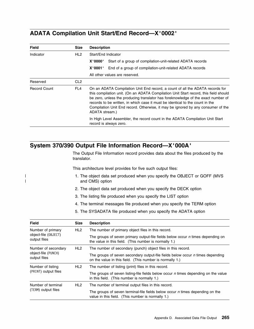
ADATA Compilation Unit Start/End Record—X'0002'
Field Size Description
Indicator HL2 Start/End Indicator
X'0000' Start of a group of compilation-unit-related ADATA records
X'0001' End of a group of compilation-unit-related ADATA records
All other values are reserved.
Reserved CL2
Record Count FL4 On an ADATA Compilation Unit End record, a count of all the ADATA records forthis compilation unit. (On an ADATA Compilation Unit Start record, this field shouldbe zero, unless the producing translator has foreknowledge of the exact number ofrecords to be written, in which case it must be identical to the count in theCompilation Unit End record. Otherwise, it may be ignored by any consumer of theADATA stream.)
In High Level Assembler, the record count in the ADATA Compilation Unit Startrecord is always zero.
System 370/390 Output File Information Record—X'000A'The Output File Information record provides data about the files produced by thetranslator.
This architecture level provides for five such output files:
| 1. The object data set produced when you specify the OBJECT or GOFF (MVS| and CMS) option
2. The object data set produced when you specify the DECK option
3. The listing file produced when you specify the LIST option
4. The terminal messages file produced when you specify the TERM option
5. The SYSADATA file produced when you specify the ADATA option
Field Size Description
Number of primaryobject-file (OBJECT)output files
HL2 The number of primary object files in this record.
The groups of seven primary output-file fields below occur n times depending onthe value in this field. (This number is normally 1.)
Number of secondaryobject-file (PUNCH)output files
HL2 The number of secondary (punch) object files in this record.
The groups of seven secondary output-file fields below occur n times dependingon the value in this field. (This number is normally 1.)
Number of listing(PRINT) output files
HL2 The number of listing (print) files in this record.
The groups of seven listing-file fields below occur n times depending on the valuein this field. (This number is normally 1.)
Number of terminal(TERM) output files
HL2 The number of terminal output files in this record.
The groups of seven terminal-file fields below occur n times depending on thevalue in this field. (This number is normally 1.)
Appendix D. Associated Data File Output 265
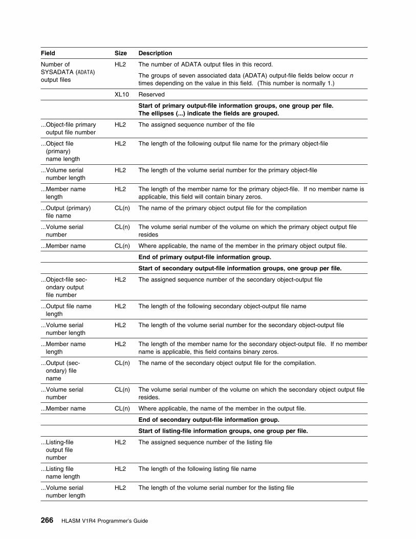
Field Size Description
Number ofSYSADATA (ADATA)output files
HL2 The number of ADATA output files in this record.
The groups of seven associated data (ADATA) output-file fields below occur ntimes depending on the value in this field. (This number is normally 1.)
XL10 Reserved
Start of primary output-file information groups, one group per file.The ellipses (...) indicate the fields are grouped.
...Object-file primaryoutput file number
HL2 The assigned sequence number of the file
...Object file(primary)name length
HL2 The length of the following output file name for the primary object-file
...Volume serialnumber length
HL2 The length of the volume serial number for the primary object-file
...Member namelength
HL2 The length of the member name for the primary object-file. If no member name isapplicable, this field will contain binary zeros.
...Output (primary)file name
CL(n) The name of the primary object output file for the compilation
...Volume serialnumber
CL(n) The volume serial number of the volume on which the primary object output fileresides
...Member name CL(n) Where applicable, the name of the member in the primary object output file.
End of primary output-file information group.
Start of secondary output-file information groups, one group per file.
...Object-file sec-ondary outputfile number
HL2 The assigned sequence number of the secondary object-output file
...Output file namelength
HL2 The length of the following secondary object-output file name
...Volume serialnumber length
HL2 The length of the volume serial number for the secondary object-output file
...Member namelength
HL2 The length of the member name for the secondary object-output file. If no membername is applicable, this field contains binary zeros.
...Output (sec-ondary) filename
CL(n) The name of the secondary object output file for the compilation.
...Volume serialnumber
CL(n) The volume serial number of the volume on which the secondary object output fileresides.
...Member name CL(n) Where applicable, the name of the member in the output file.
End of secondary output-file information group.
Start of listing-file information groups, one group per file.
...Listing-fileoutput filenumber
HL2 The assigned sequence number of the listing file
...Listing filename length
HL2 The length of the following listing file name
...Volume serialnumber length
HL2 The length of the volume serial number for the listing file
266 HLASM V1R4 Programmer’s Guide

Field Size Description
...Member namelength
HL2 The length of the member name for the listing file. If no member name isapplicable, this field contains binary zeros.
...Listingfile name
CL(n) The name of the listing output file for the compilation.
...Volume serialnumber
CL(n) The volume serial number of the volume on which the listing file resides.
...Member name CL(n) Where applicable, the name of the member for the listing file.
End of listing-file information group.
Start of terminal-file information groups, one group per file.
...Terminal fileoutput filenumber
HL2 The assigned sequence number of the terminal file
...Terminal filename length
HL2 The length of the following terminal file name
...Volume serialnumber length
HL2 The length of the volume serial number for the terminal file
...Member namelength
HL2 The length of the member name for the terminal file. If no member name isapplicable, this field contains binary zeros.
...Terminalfile name
CL(n) The name of the terminal output file for the compilation.
...Volume serialnumber
CL(n) The volume serial number of the volume on which the terminal file resides.
...Member name CL(n) Where applicable, the name of the member for the terminal file.
End of terminal-file information group.
Start of SYSADATA-file information groups, one group per file.
...ADATA fileoutput filenumber
HL2 The assigned sequence number of the SYSADATA file
...ADATA filename length
HL2 The length of the SYSADATA file name
...Volume serialnumber length
HL2 The length of the volume serial number for the SYSADATA file
...Member namelength
HL2 The length of the member name for the SYSADATA file. If no member name isapplicable, this field contains binary zeros.
...ADATAfile name
CL(n) The name of the SYSADATA output file for the compilation.
...Volume serialnumber
CL(n) The volume serial number of the volume on which the SYSADATA file resides.
...Member name CL(n) Where applicable, the name of the member for the SYSADATA file.
End of SYSADATA-file information group.
Note:
If the number of output data sets causes the record to exceed the ADATA record size, the record is continued on thenext record. The number of output files in the record is stored in the record, and the record is written to the ADATAfile. The next record contains the rest of the output files.
Appendix D. Associated Data File Output 267

| Options File Information—X'000B'
| Field| Size| Description
| Number of Option files| HL2| The number of Option files in this record.
| The following group of seven fields will occur n times depending on the value in| the field .
| Offset to file| information| AL2| Offset from the beginning of this record to the start of the Option file information
| The following group of seven fields will occur n times depending on the value in| the field 'Number of Option files'.
| ...Option file number| HL2| The assigned sequence number of the file
| ...Option file name| length| HL2| The length of the following Option file name
| ...Volume serial| number length| HL2| The length of the volume serial number
| ...Member name| length| HL2| The length of the member name
| ...Option file name| CL(n)| The name of the Option file for the assembly
| ...Volume serial| number| CL(n)| The volume serial number of the (first) volume on which the Option file resides
| ...Member name| CL(n)| Where applicable, the name of the member in the Option file
| Note:
| 1. Where the number of Option files would exceed the record size for the associated data file, the record is| continued on the next record. The current number of Option files (for that record) is stored in the record and the| record written to the associated data file. The next record contains the rest of the Option files. The count of the| number of Option files is a count for the current record.
Options Record—X'0010'This record indicates which assembler options were used for the assembly, and thevalues passed as suboptions. For example, if the PROFILE option was specified,bit 0 in option byte 8 would be 1, and the PROFILE_NAME field would contain theprofile member name.
Field Size Description
Option Byte 1 XL1 1... .... Bit 1 = ALIGN, Bit 0 = NOALIGN.1.. .... Bit 1 = ASA, Bit 0 = NOASA (MVS and CMS)..1. .... Bit 1 = BATCH, Bit 0 = NOBATCH...1 .... Bit 1 = COMPAT, Bit 0 = NOCOMPAT.... 1... Bit 1 = COMPAT(CASE), Bit 0 = not COMPAT(CASE).... .1.. Bit 1 = COMPAT(SYSLIST), Bit 0 = not COMPAT(SYSLIST).... ..1. Bit 1 = DBCS, Bit 0 = NODBCS.... ...1 Bit 1 = DECK, Bit 0 = NODECK
268 HLASM V1R4 Programmer’s Guide
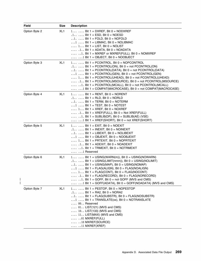
Field Size Description
Option Byte 2 XL1 1... .... Bit 1 = DXREF, Bit 0 = NODXREF.1.. .... Bit 1 = ESD, Bit 0 = NOESD..1. .... Bit 1 = FOLD, Bit 0 = NOFOLD...1 .... Bit 1 = LIBMAC, Bit 0 = NOLIBMAC.... 1... Bit 1 = LIST, Bit 0 = NOLIST.... .1.. Bit 1 = ADATA, Bit 0 = NOADATA.... ..1. Bit 1 = MXREF or MXREF(FULL), Bit 0 = NOMXREF.... ...1 Bit 1 = OBJECT, Bit 0 = NOOBJECT
Option Byte 3 XL1 1... .... Bit 1 = PCONTROL, Bit 0 = NOPCONTROL.1.. .... Bit 1 = PCONTROL(ON), Bit 0 = not PCONTROL(ON)..1. .... Bit 1 = PCONTROL(DATA), Bit 0 = not PCONTROL(DATA)...1 .... Bit 1 = PCONTROL(GEN), Bit 0 = not PCONTROL(GEN).... 1... Bit 1 = PCONTROL(UHEAD), Bit 0 = not PCONTROL(UHEAD).... .1.. Bit 1 = PCONTROL(MSOURCE), Bit 0 = not PCONTROL(MSOURCE).... ..1. Bit 1 = PCONTROL(MCALL), Bit 0 = not PCONTROL(MCALL).... ...1 Bit 1 = COMPAT(MACROCASE), Bit 0 = not COMPAT(MACROCASE)
Option Byte 4 XL1 1... .... Bit 1 = RENT, Bit 0 = NORENT.1.. .... Bit 1 = RLD, Bit 0 = NORLD..1. .... Bit 1 = TERM, Bit 0 = NOTERM...1 .... Bit 1 = TEST, Bit 0 = NOTEST.... 1... Bit 1 = XREF, Bit 0 = NOXREF.... .1.. Bit 1 = XREF(FULL), Bit 0 = Not XREF(FULL).... ..1. Bit 1 = SUBLIB(DF), Bit 0 = SUBLIB(AE) (VSE).... ...1 Bit 1 = XREF(SHORT), Bit 0 = not XREF(SHORT)
Option Byte 5 XL1 1... .... Bit 1 = EXIT, Bit 0 = NOEXIT.1.. .... Bit 1 = INEXIT, Bit 0 = NOINEXIT..1. .... Bit 1 = LIBEXIT, Bit 0 = NOLIBEXIT...1 .... Bit 1 = OBJEXIT, Bit 0 = NOOBJEXIT.... 1... Bit 1 = PRTEXIT, Bit 0 = NOPRTEXIT.... .1.. Bit 1 = ADEXIT, Bit 0 = NOADEXIT.... ..1. Bit 1 = TRMEXIT, Bit 0 = NOTRMEXIT.... ...1 Reserved
Option Byte 6 XL1 1... .... Bit 1 = USING(WARN(m)), Bit 0 = USING(NOWARN).1.. .... Bit 1 = USING(LIMIT(nnnn)), Bit 0 = USING(NOLIMIT)..1. .... Bit 1 = USING(MAP), Bit 0 = USING(NOMAP)...1 .... Bit 1 = FLAG(ALIGN), Bit 0 = FLAG(NOALIGN).... 1... Bit 1 = FLAG(CONT), Bit 0 = FLAG(NOCONT).... .1.. Bit 1 = FLAG(RECORD), Bit 0 = FLAG(NORECORD)
| .... ..1. Bit 1 = GOFF, Bit 0 = not GOFF (MVS and CMS)| .... ...1 Bit 1 = GOFF(ADATA), Bit 0 = GOFF(NOADATA) (MVS and CMS)
Option Byte 7 XL1 1... .... Bit 1 = PESTOP, Bit 0 = NOPESTOP.1.. .... Bit 1 = RA2, Bit 0 = NORA2..1. .... Bit 1 = FLAG(SUBSTR), Bit 0 = FLAG(NOSUBSTR)...1 .... Bit 1 = TRANSLATE(xx), Bit 0 = NOTRANSLATE.... 99.. Reserved.... 91.. LIST(121) (MVS and CMS).... 19.. LIST(133) (MVS and CMS).... 11.. LIST(MAX) (MVS and CMS).... ..91 MXREF(FULL).... ..19 MXREF(SOURCE).... ..11 MXREF(XREF)
Appendix D. Associated Data File Output 269

Field Size Description
Option Byte 8 XL1 1... .... Bit 1 = PROFILE, Bit 0 = NOPROFILE.1.. .... Bit 1 = PCONTROL(OFF), Bit 0 = not PCONTROL(OFF)..1. .... Bit 1 = PCONTROL(NODATA), Bit 0 = not PCONTROL(NODATA)...1 .... Bit 1 = PCONTROL(NOGEN), Bit 0 = not PCONTROL(NOGEN).... 1... Bit 1 = PCONTROL(NOUHEAD), Bit 0 = not PCONTROL(NOUHEAD).... .1.. Bit 1 = PCONTROL(NOMSOURCE), Bit 0 = not
PCONTROL(NOMSOURCE).... ..1. Bit 1 = PCONTROL(NOMCALL), Bit 0 = not PCONTROL(NOMCALL).... ...1 Bit 1 = XREF(UNREFS), Bit 0 = not XREF(UNREFS)
Warn_Value FL1 Value from USING(WARN(m))
Flag_Value FL1 Value from Flag(n)
Option Byte 9 XL1 1... .... Bit 1 = RXREF, Bit 0 = NORXREF.1.. .... Bit 1 = FLAG(IMPLEN), Bit 0 = FLAG(NOIMPLEN)..1. .... Bit 1 = FLAG(PAGE0), Bit 0 = FLAG(NOPAGE0)...1 .... Bit 1 = INFO, Bit 0 = NOINFO.... 1... Bit 1 = COMPAT(LITTYPE), Bit 0 = not COMPAT(LITTYPE)
| .... .1.. Bit 1 = FLAG(PUSH), Bit 0 = FLAG(NOPUSH)| .... ..1. Bit 1 = FLAG(USING0), Bit 0 = (NOUSING0)| .... ...1 Bit 1 = THREAD, Bit 0 = NOTHREAD
Reserved CL1 Reserved
TRANS_SUFFIX CL2 Value from TRANSLATE(xx). Blank if not provided.
PROFILE_NAME CL8 Value from PROFILE(xxxxxxxx). Blank if not provided.
Limit_Value HL2 Value from USING(LIMIT(nnnn))
LANGUAGE CL3 Language option in effect for the assembly
OPTABLE CL3 OPTABLE option in effect for the assembly
LINECOUNT HL2 Linecount option in effect for the assembly
INEXIT_PROG_LEN HL2 Length of INEXIT program name
LIBEXIT_PROG_LEN HL2 Length of LIBEXIT program name
OBJEXIT_PROG_LEN HL2 Length of OBJEXIT program name
PRTEXIT_PROG_LEN HL2 Length of PRTEXIT program name
ADEXIT_PROG_LEN HL2 Length of ADEXIT program name
TRMEXIT_PROG_LEN HL2 Length of TRMEXIT program name
INEXIT_STR_LEN HL2 Length of string supplied to exit
LIBEXIT_STR_LEN HL2 Length of string supplied to exit
OBJEXIT_STR_LEN HL2 Length of string supplied to exit
PRTEXIT_STR_LEN HL2 Length of string supplied to exit
ADEXIT_STR_LEN HL2 Length of string supplied to exit
TRMEXIT_STR_LEN HL2 Length of string supplied to exit
SYSPARM length HL2 Length of the SYSPARM string supplied
PARMS length HL2 Length of the PARM string supplied
| CODEPAGE| CL4| The four characters representing the hexadecimal suffix added to ASMA to form| the name of the codepage module.
Reserved| CL4 Reserved for future use
INEXIT_PROG CL(n) Input exit name
270 HLASM V1R4 Programmer’s Guide

Field Size Description
LIBEXIT_PROG CL(n) Library exit name
OBJEXIT_PROG CL(n) Object exit name
PRTEXIT_PROG CL(n) Print exit name
ADEXIT_PROG CL(n) ADATA exit name
TRMEXIT_PROG CL(n) Term exit name
INEXIT_STR CL(n) Field to contain the string to be passed to the exit program
LIBEXIT_STR CL(n) Field to contain the string to be passed to the exit program
OBJEXIT_STR CL(n) Field to contain the string to be passed to the exit program
PRTEXIT_STR CL(n) Field to contain the string to be passed to the exit program
ADEXIT_STR CL(n) Field to contain the string to be passed to the exit program
TRMEXIT_STR CL(n) Field to contain the string to be passed to the exit program
SYSPARM string CL(n) Field to contain the SYSPARM string that is being used for the assembly
PARM string CL(n) Field to contain the invocation option string that is being used for the assembly
External Symbol Dictionary Record—X'0020'
Field Size Description
Section Type FL1 X'00' Control Section (CSECT) SDX'01' Entry Point LDX'02' External Reference ERX'04' Private Code PCX'05' Common Section CMX'06' Dummy External DSECT XDX'0A' Weak External Reference WXX'FF' Dummy Section (DSECT) (no type designator)
Flags XL1 See “GOFF (MVS and CMS)” on page 55 for description.
Reserved HL2 Reserved for future use
ESDID FL4 External Symbol Dictionary ID (ESDID) or zero
Section Address AL4 The section address
For SD- and LD-type entries it contains the address of the symbol. For PC- andCM-type entries, it indicates the beginning address of the control section. ForXD-type entries, it indicates the number of bytes for alignment less one.
Section Length FL4 The length of the section
LD ID FL4 For LD-type entries, the ESDID of the CSECT in which the entry point was defined
Reserved CL8 Reserved for future use
External Name length HL2 Number of characters in the external name (zero if private code, unnamedcommon or unnamed DSECT)
Alias Name length HL2 Number of characters in the Alias name (zero if no alias)
External name CL(n) The external name
Alias Section name CL(n) The alias name for the section
Appendix D. Associated Data File Output 271

Source Analysis Record—X'0030'
Field Size Description
Statement number FL4 The statement number of the source record.
ESDID FL4 The ESDID for the source record.
Input record number FL4 The input source record number within the current input file.
This field is always present except when the source line is macro generated. (Thatis, the Input record origin value is X'02'.)
This field contains the value returned by the exit if the source record is provided byan exit.
Parent record number FL4 The parent source record number.
If the source record was included by a COPY statement or generated by a macroinstruction, the Parent input number is the record number of the COPY statementor macro instruction.
This field contains the value returned by the input or library exits if the sourcerecord is provided by either of these exits.
Input assigned filenumber
HL2 The input file's assigned sequence number. (Refer to the input file n in the JobIdentification record if the Input record origin is X'01', or the Library Record -X'0060' with Concatenation number n otherwise).
This field is set to zero if an exit provides the source record.
Parent assigned filenumber
HL2 The parent file's assigned sequence number. (Refer to the Input file n in the JobIdentification record if the Parent record origin is X'01', or the Library Record -X'0060' with Concatenation number n otherwise).
This field is set to zero if an exit provides the source record.
Location Counter FL4 The current location counter for the source record.
Input record origin XL1 X'91' Source line from primary inputX'92' Source line from Macro generation.X'93' Source line from library member.X'95' Source line from AINSERT internal buffer.
Parent record origin XL1 X'91' Source line from primary inputX'92' Source line from Macro generation.X'93' Source line from library member.X'95' Source line from AINSERT internal buffer
Print flags XL1 X'89' PRINT GENX'49' PRINT DATAX'29' PRINT ONX'19' PRINT NOMSOURCE (0 = PRINT MSOURCE)X'98' PRINT UHEADX'94' PRINT MCALL
Reserved XL2 Reserved for future use
Source record type(within source recordorigin)
XL1 X'91' Comment line that is not within a macro definition.X'92' Machine instruction that is not within a macro definition.X'93' Assembler instruction that is not within a macro definition. This includes
conditional assembly instructions such as AIF and SETC.X'94' Macro call instruction.X'95' Macro definition. All statements between (and including) the MACRO
prototype statement and the corresponding MEND statement. Thisincludes nested macro definitions.
272 HLASM V1R4 Programmer’s Guide
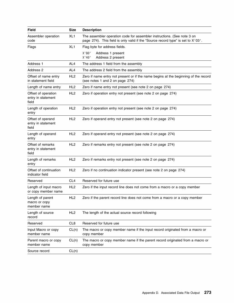
Field Size Description
Assembler operationcode
XL1 The assembler operation code for assembler instructions. (See note 3 onpage 274). This field is only valid if the “Source record type” is set to X'03'.
Flags XL1 Flag byte for address fields.
X'89' Address 1 presentX'49' Address 2 present
Address 1 AL4 The address 1 field from the assembly
Address 2 AL4 The address 2 field from the assembly
Offset of name entryin statement field
HL2 Zero if name entry not present or if the name begins at the beginning of the record(see notes 1 and 2 on page 274)
Length of name entry HL2 Zero if name entry not present (see note 2 on page 274)
Offset of operationentry in statementfield
HL2 Zero if operation entry not present (see note 2 on page 274)
Length of operationentry
HL2 Zero if operation entry not present (see note 2 on page 274)
Offset of operandentry in statementfield
HL2 Zero if operand entry not present (see note 2 on page 274)
Length of operandentry
HL2 Zero if operand entry not present (see note 2 on page 274)
Offset of remarksentry in statementfield
HL2 Zero if remarks entry not present (see note 2 on page 274)
Length of remarksentry
HL2 Zero if remarks entry not present (see note 2 on page 274)
Offset of continuationindicator field
HL2 Zero if no continuation indicator present (see note 2 on page 274)
Reserved CL4 Reserved for future use
Length of input macroor copy member name
HL2 Zero if the input record line does not come from a macro or a copy member
Length of parentmacro or copymember name
HL2 Zero if the parent record line does not come from a macro or a copy member
Length of sourcerecord
HL2 The length of the actual source record following
Reserved CL8 Reserved for future use
Input Macro or copymember name
CL(n) The macro or copy member name if the input record originated from a macro orcopy member
Parent macro or copymember name
CL(n) The macro or copy member name if the parent record originated from a macro orcopy member
Source record CL(n)
Appendix D. Associated Data File Output 273

Notes:
1. The offset and length fields are provided to allow the different fields to beretrieved from the source without being dependent on the format of the sourcerecord. The offsets are from the start of the source record.
2. The length and offset fields for the name entry, operation entry, remarks entry,and continuation indicator are zero for the following statements:
� Macro definition statements with a Source Record Type of X'04'� Macro definition statements with a Source Record Type of X'05'� EXITCTL assembler statements� ICTL assembler statements
3. The assembler operation code field can contain the operation code valuesshown in Figure 96.
Figure 96. Assembler Operation Code Values
Operation Assembler Code Instruction
Operation Assembler Code Instruction
Operation Assembler Code Instruction
X'99' GBLA X'91' GBLB X'92' GBLC X'93' LCLA X'94' LCLB X'95' LCLC X'96' SETA X'97' SETB X'98' SETC X'99' AIF X'9A' AGO X'9B' ANOP X'9C' COPY X'9D' MACRO X'9E' MNOTE X'9F' MEXIT X'19' MEND X'11' ICTL X'12' ISEQ X'13' PRINT X'14' SPACE X'15' EJECT X'16' PUNCH X'17' REPRO
X'18' TITLE X'19' ENTRY X'1A' EXTRN X'1B' START X'1C' CSECT X'1D' DSECT X'1E' COM X'1F' EQU X'29' ORG X'21' END X'22' LTORG X'23' USING X'24' DROP X'25' ACTR X'26' DC X'27' DS X'28' CCW X'29' CNOP X'2A' LOCTR X'2B' DXD X'2C' CXD X'2E' OPSYN X'2F' PUSH X'39' POP
X'33' Literal X'37' MHELP X'38' AREAD X'3B' WXTRN X'3D' AMODE X'3E' RMODE X'3F' RSECT X'49' CCW9 X'41' CCW1
| X'42' EXITCTL X'43' ASPACE X'44' AEJECT X'45' ALIAS X'46' CEJECT X'47' ADATA X'48' SETAF X'49' SETCF X'4A' CATTR
(MVS & CMS) X'4B' ACONTROL
| X'4C' XATTR| (MVS & CMS)
X'4D' AINSERT
Source Error Record—X'0032'
Field Size Description
Statement number FL4 The statement number of the statement in error
Error Identifier CL16 The error message identifier
Error Severity HL2 The severity of the error
Error message length HL2 The length of the error message text
Reserved CL8 Reserved for future use
274 HLASM V1R4 Programmer’s Guide

Field Size Description
Error Message CL(n) The error message text
Note:
1. This record also includes MNOTEs generated by the assembler.
2. The language of the error diagnostic messages is determined by the LANGUAGE assembler option.
DC/DS Record—X'0034'
Field Size Description
ESDID FL4 The ESDID for the source record.
Number of operands HL2 The number of operands defined by the source record.
Type Flag XL1 1... .... Bit 1 = Define Constant (DC, CXD, CCW, CCW0, or CCW1), Bit 0 =Define Storage (DS or DXD)
.1.. .... If “Define Constant” bit is set, bit 1 indicates the operand is a CXD. If“Define Constant” bit is not set, bit 1 indicates the operand is a DXD.
..1. .... If “Define Constant” bit is set, bit 1 indicates the operand is a CCW,CCW0, or CCW1.
...1 .... Bit 1 indicates this record is associated with an object text record(X'003A'). The object text record is created when a DC statement hasa duplication factor greater than 1, and at least one of the operandvalues has a reference to the current location counter (*).
.... 1... Reserved
.... .1.. Reserved
.... ..1. Reserved
.... ...1 Reserved
Reserved CL5 Reserved for future use
Statement Number FL4 The statement number of the source line that generated this text, if known.Otherwise it contains zeros.
...Location Counter FL4 The location counter for this operand. This field repeats within the group for thenumber of operands on the source record.
...Duplication Factor FL4 The duplication factor for the operand. This field repeats within the group for thenumber of operands on the source record.
...Bit Offset XL1 The offset within byte (0–7) for B-type operands. This field repeats within thegroup for the number of operands on the source record.
...Type Attribute CL1 The value that the assembler Type Attribute reference returns (see “Type Attribute(T')” in the chapter “How to Write Conditional Assembly Instructions” in theLanguage Reference manual). This field repeats within the group for the numberof operands on the source record.
...Number of values HL2 The number of nominal values. This field repeats within the group for the numberof operands on the source record.
...Type Extension CL1 The type extension for the operand. This field repeats within the group for thenumber of operands on the source record.
...Reserved CL7 Reserved for future use. This field repeats within the group for the number ofoperands on the source record.
......Byte length HL2 The number of bytes in the nominal value. This field repeats within the group forthe number of nominal values in the operand.
Appendix D. Associated Data File Output 275

Field Size Description
......Bit length HL2 The number of bits if the operand specifies a bit length that is not a multiple of 8.This field repeats within the group for the number of nominal values in theoperand.
......Value XL(n) If this record describes a DC, CXD, CCW, CCW0, or CCW1, then the valuecontains the nominal value. (A DC with a zero duplication factor is treated thesame as a DS and this field is not present). If this record describes a DS or DXD,this field is not present. This field repeats within the group for the number ofnominal values in the operand.
If a byte length is specified (or implied), the value contains the number of bytesspecified. The value field is aligned according to the operand type. For example,hexadecimal values are left-aligned and packed values are right-aligned.
If a bit length is specified, the length of the value is the number of bytes requiredto contain the required bits. For example, if the bit length was 10, the value is 2bytes in length. The value is in the leftmost 10 bits. Alignment within the specifiednumber of bits is according to the operand type. For example, hexadecimal valuesare left-aligned and packed values are right-aligned.
Note:
1. Only one of the two fields for byte/bit lengths contains a non-zero value. This means that there is a byte length, ora bit length, but not both.
2. No description of any padding is produced. Any padding because of alignment can be calculated by comparingthe location counter of the current operand with the sum of the location counter and length of the previousoperand.
The length of the previous operand would need to be calculated using the duplication factor, number of nominalvalues, and the length of each nominal value.
3. High Level Assembler creates the DC/DS Extension record X'0035' when the duplication factor is greater than 1and at least one of the operand values has a reference to the current location counter (L).
The following examples show the format of a DC/DS record for various DCstatements.
1. EXAMPLE1 DC 3F'5,6',H'7'
ESDID : F'1'Number of Operands : H'2'Type Flag : B'19999999'Reserved : X'9999999999'Statement Number : F'2' Location Counter : X'99999999'
Duplication Factor : F'3' Bit Offset : B'99999999' Type Attribute : C'F'
Number of values : H'2'Type Extension : C' '
Reserved : X'99999999999999' Byte length : H'4' Bit length : H'9' Value : X'99999995' Byte length : H'4' Bit length : H'9' Value : X'99999996'
276 HLASM V1R4 Programmer’s Guide

Location Counter : X'99999918'Duplication Factor : F'1'
Bit Offset : B'99999999' Type Attribute : C'H'
Number of values : H'1'Type Extension : C' '
Reserved : X'99999999999999' Byte length : H'2' Bit length : H'9' Value : X'9997'
2. EXAMPLE2 DC P'5,927'
ESDID : F'1'Number of Operands : H'1'Type Flag : B'19999999'Reserved : X'9999999999'Statement Number : F'2' Location Counter : X'99999999'
Duplication Factor : F'1' Bit Offset : B'99999999' Type Attribute : C'P'
Number of values : H'2'Type Extension : C' '
Reserved : X'99999999999999' Byte length : H'1' Bit length : H'9' Value : X'5C' Byte length : H'2' Bit length : H'9' Value : X'927C'
3. EXAMPLE3 DC B'101',2B'10111'
ESDID : F'1'Number of Operands : H'2'Type Flag : B'19999999'Reserved : X'9999999999'Statement Number : F'2' Location Counter : X'99999999'
Duplication Factor : F'1' Bit Offset : B'99999999' Type Attribute : C'B'
Number of values : H'1'Type Extension : C' '
Reserved : X'99999999999999' Byte length : H'1' Bit length : H'9' Value : X'95' B'99999191'
Appendix D. Associated Data File Output 277
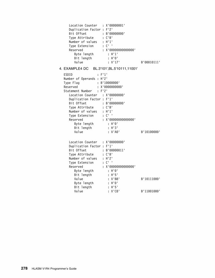
Location Counter : X'99999991'Duplication Factor : F'2'
Bit Offset : B'99999999' Type Attribute : C'B'
Number of values : H'1'Type Extension : C' '
Reserved : X'99999999999999' Byte length : H'1' Bit length : H'9' Value : X'17' B'99919111'
4. EXAMPLE4 DC BL.3'101',BL.5'10111,11001'
ESDID : F'1'Number of Operands : H'2'Type Flag : B'19999999'Reserved : X'9999999999'Statement Number : F'2' Location Counter : X'99999999'
Duplication Factor : F'1' Bit Offset : B'99999999' Type Attribute : C'B'
Number of values : H'1'Type Extension : C' '
Reserved : X'99999999999999' Byte length : H'9' Bit length : H'3' Value : X'A9' B'19199999'
Location Counter : X'99999999'Duplication Factor : F'1'
Bit Offset : B'99999911' Type Attribute : C'B'
Number of values : H'2'Type Extension : C' '
Reserved : X'99999999999999' Byte length : H'9' Bit length : H'5' Value : X'B8' B'19111999' Byte length : H'9' Bit length : H'5' Value : X'C8' B'11991999'
278 HLASM V1R4 Programmer’s Guide
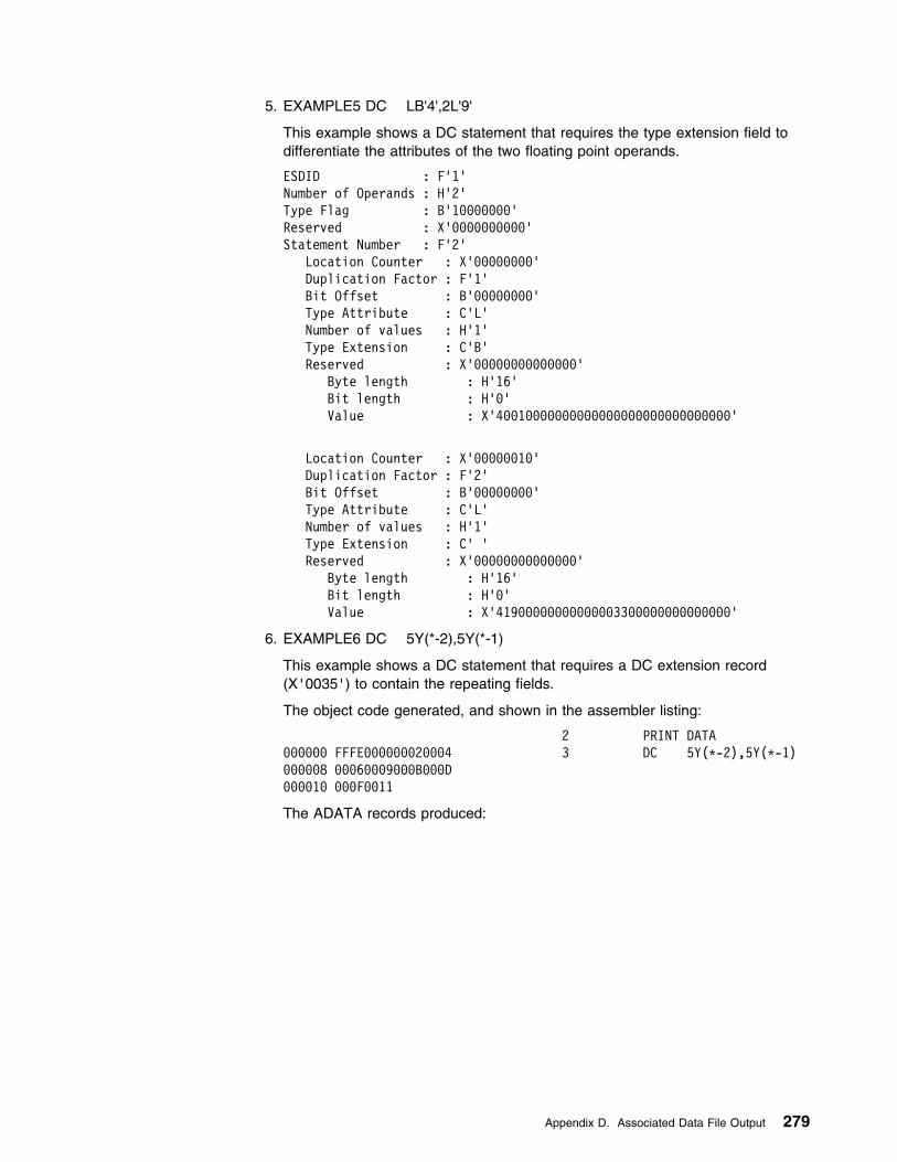
5. EXAMPLE5 DC LB'4',2L'9'
This example shows a DC statement that requires the type extension field todifferentiate the attributes of the two floating point operands.
ESDID : F'1'Number of Operands : H'2'Type Flag : B'19999999'Reserved : X'9999999999'Statement Number : F'2' Location Counter : X'99999999'
Duplication Factor : F'1' Bit Offset : B'99999999' Type Attribute : C'L'
Number of values : H'1' Type Extension : C'B' Reserved : X'99999999999999' Byte length : H'16' Bit length : H'9' Value : X'49919999999999999999999999999999'
Location Counter : X'99999919'Duplication Factor : F'2'
Bit Offset : B'99999999' Type Attribute : C'L'
Number of values : H'1'Type Extension : C' '
Reserved : X'99999999999999' Byte length : H'16' Bit length : H'9' Value : X'41999999999999993399999999999999'
6. EXAMPLE6 DC 5Y(*-2),5Y(*-1)
This example shows a DC statement that requires a DC extension record(X'0035') to contain the repeating fields.
The object code generated, and shown in the assembler listing:
2 PRINT DATA999999 FFFE999999929994 3 DC 5Y(L-2),5Y(L-1)999998 99969999999B999D999919 999F9911
The ADATA records produced:
Appendix D. Associated Data File Output 279

ESDID : F'1'Number of Operands : H'2'Type Flag : B'19919999'Reserved : X'9999999999'Statement Number : F'3' Location Counter : X'99999999'
Duplication Factor : F'5' Bit Offset : B'99999999' Type Attribute : C'Y'
Number of values : H'1'Type Extension : C' '
Reserved : X'99999999999999' Byte length : H'2' Bit length : H'9' Value : X'FFFE'
Location Counter : X'9999999A'Duplication Factor : F'5'
Bit Offset : B'99999999' Type Attribute : C'Y'
Number of values : H'1'Type Extension : C' '
Reserved : X'99999999999999' Byte length : H'2' Bit length : H'9' Value : X'9999'
The object text for the statement is in the following DC Extension Record:
ESDID : F'1'Location Counter : F'9'Statement Number : F'3'Reserved : F'9'Reserved : F'9'Length of Object : H'29'Object Text : X'FFFE99999992999499969999999B999D999F9911'
DC Extension Record—X'0035'
Field Size Description
ESDID FL4 The ESDID for the record
Location Counter FL4 Address (offset) of the text within the module
Statement number FL4 The statement number of the source line that generated this text, if known. Zerootherwise.
Reserved FL8 Reserved for future use
Length of Object text HL2 The length of the following object text
Object text XL(n) The actual object text
280 HLASM V1R4 Programmer’s Guide

Machine Instruction Record—X'0036'
Field Size Description
ESDID FL4 The ESDID for the machine instruction record
Location Counter FL4 The location counter for this instruction
Reserved CL8 Reserved for future use
Length of Instruction HL2 The length of the machine instruction
Value of Instruction XL(n) The actual value of the machine instruction
Relocation Dictionary Record—X'0040'
Field Size Description
POS.ID FL4 The external symbol dictionary ID number assigned to the ESD entry for thecontrol section in which the address constant is used as an operand.
REL.ID FL4 The external symbol dictionary ID number assigned to the ESD entry for thecontrol section in which the referenced symbol is defined.
Address AL4 The assembled address of the field where the address constant is stored.
Flags XL1 See “Relocation Dictionary (RLD)” on page 22 for a description.
Symbol Record—X'0042'
Field Size Description
ESDID FL4 ESDID of the section in which the symbol is defined. This is zero for an undefinedsymbol type.
Statement Number FL4 The number of the statement in which the symbol is defined. This is zero for anundefined symbol type.
Symbol Type XL1 X'00' Undefined nameX'01' CSECT / RSECT nameX'02' DSECT nameX'03' Common section nameX'04' Dummy External DSECT name (DXD)X'05' V-type constant nameX'06' QualifierX'07' EXTRN/WXTRN nameX'08' LOCTR nameX'09' Duplicate nameX'0A' Literal nameX'0B' *-in-literal nameX'0C' EQU name �1�X'0D' Ordinary labelX'0E' Unresolvable EQU, DC or DS symbol
Type Attribute CL1 The value that the assembler Type Attribute reference returns (see “Type Attribute(T')” in the chapter “How to Write Conditional Assembly Instructions” in theLanguage Reference manual).
Appendix D. Associated Data File Output 281

Field Size Description
Duplication Factor FL4 Number of times the first operand field named by the symbol occurs. This is zerofor an undefined symbol type.
Length attribute HL2 Length in bytes, either specified or by default.
Integer attribute HL2 Number of positions occupied by the integer portion of fixed-point and decimalconstants in their object code form. This is zero for an undefined symbol type.
Scaling attribute HL2 Number of positions occupied by the fractional portion of fixed-point and decimalconstants in their object code form. This is zero for an undefined symbol type.
Location Counter FL4 Contains the offset from the start of the DSECT, the non-relocated address of theinstruction belonging to this symbol in a CSECT (this is not always the offset fromthe start of the CSECT), or the value of the equate. For an undefined symbol, it iszero.
Symbol Flags XL1 1... .... Bit 1 = 1, the symbol is a relocatable, Bit 0 = the symbol is absolute.This bit is zero for an undefined symbol type.
11.. .... Complex relocatable..1. .... Reserved...1 .... Reserved.... 1... Reserved.... .1.. Reserved.... ..1. Reserved.... ...1 Reserved
Reserved CL7 Reserved for future use
Symbol name length HL2 Number of characters in the symbol name
Symbol name CL(n) The symbol name. Variable length.
Note:
For record type “EQU” specified at �1�, where the “EQU” is for a relocatable value, the ESDID of the “EQU” isprovided. Where the “EQU” is non-relocatable, the ESDID of the section in control will be provided. The symbol flagscan be checked to determine whether the “EQU” is relocatable or absolute.
Symbol Cross Reference Record—X'0044'
Field Size Description
Symbol length HL2 The length of the symbol
Statement Definition FL4 The statement number where the symbol is defined or declared
Number of references HL2 The number of references to the symbol
Relocatability Type CL1 C' ' Simple relocatable symbolC'A' Absolute symbolC'C' Complex relocatable symbol
Reserved CL7 Reserved for future use
Symbol name CL(n) The symbol name. Variable length.
...Reference Flag CL1 C' ' No branch or modificationC'M' Modification reference flagC'B' Branch reference flagC'U' USING reference flagC'D' DROP reference flagC'X' Execute Instruction reference flag
282 HLASM V1R4 Programmer’s Guide

Field Size Description
...Statement Number FL4 The statement number on which the symbol is referenced
Note:
1. The Reference Flag field and the Statement Number field both occur as many times as the “Number ofreferences” field dictates. That is, if there is a value of ten in the “Number of references” field, then there are tenoccurrences of the Reference Flag and Statement Number pair.
2. Where the number of references would exceed the record size for the ADATA file, then the record is continued onthe next record. The continuation flag is set in the common header section of the record.
Register Cross Reference Record—X'0045'
Field Size Description
Register number XL1 The register number (X'0' to X'F')
Register Type CL1 G—General
Total number ofreferences
FL4 The total number of references to the register
Number of referencesthis record
FL4 The number of references to the register in this record
Offset to references AL2 Offset from the beginning of this record to the start of the register referenceoccurrences
...Statement Number FL4 The statement number on which the register is referenced
...Reference Flag CL1 C' ' No branch or modificationC'M' Modification reference flagC'B' Branch reference flagC'U' USING reference flagC'D' DROP reference flagC'N' Index register reference flag
Note:
1. The Reference Flag field and the Statement Number field both occur as many times as the “Number of referencesthis record” field dictates. That is, if there is a value of ten in the “Number of references this record” field, thenthere are ten occurrences of the Reference Flag and Statement Number pair.
2. Where the number of references would exceed the record size for the ADATA file, then the record is continued onthe next record. The continuation flag is set in the common header section of the record.
Library Record—X'0060'
Field Size Description
Number of Macros /Copy code members
HL2 Count of the number of macros and copy code members described in this record.For example, if ten macros and source copy code members are retrieved from adata set, the count field contains 10 and there are ten occurrences of the lengthfield and the field containing the either the macro or source copy code names.
Data set Name length HL2 The length of the data set (file) name.
Appendix D. Associated Data File Output 283

Field Size Description
Data set Volumelength
HL2 The length of the data set (file) volume.
Concatenation number XL2 The library concatenation number.
DDNAME length HL2 The length of the ddname.
Reserved CL4 Reserved for future use.
Data set Name CL(n) The name of the data set (file) from which the macro or copy member wasretrieved, or “PRIMARY INPUT” for an in-stream macro. Under VSE, this fieldcontains the library and sublibrary name.
Data set Volume CL(n) The volume identification of the volume where the data set (file) resides.
DDNAME CL(n) The ddname of the library.
...Macro name length HL2 The length of the macro name following.
...Macro name CL(n) The name of the macro or source copy code that has been used. If the source is“PRIMARY INPUT”, then this field contains the macro name from the sourceprogram.
Note:
1. If a LIBRARY user exit has been specified for the assembly, and the LIBRARY user exit has opened the Librarydata set, the record contains the library names returned by the user exit.
| 2. If this record is continued, the Data set Name Length and Data Set Volume length fields will be zero and the first| Macro name length field will be located after the 4 byte Reserved field.
Library Member and Macro Cross Reference Record - X'0062'
Field Size Description
ConcatenationNumber
FL4 The concatenation number of the library or primary input file
Statement Definition FL4 The statement number is:
9 When the member or macro is retrieved from a library>9 When the macro is defined in the primary input file. It represents the
statement number where the macro is defined.
Concatenation Type CL1 C'L' Concatenation number refers to a libraryC'P' Concatenation number refers to the primary input
Statement DefinitionFlag
CL1 C'X' The macro is read from the library and imbedded in the primary source,using the LIBMAC option.
C' ' The flag is usually blank except in special cases, as described above
Reserved 1 CL8 Reserved for future use.
Member or Macroname
CL64 The name of the member or macro.
Parent Macro Name CL64 The name of the macro that called this macro or issued the COPY instruction.This field contains “PRIMARY INPUT” when the member or macro is called directlyfrom the primary input file.
Number of references FL4 The number of references to the member or macro. (Reserved.)
Number of referencesin this record
FL4 The number of references to the member or macro in this ADATA record.
284 HLASM V1R4 Programmer’s Guide

Field Size Description
...ReferenceStatement Number
FL4 The statement number on which the member is copied or included, or thestatement number on which the macro is called
...Reference Flag CL1 C' ' Blank means the reference is caused by a macro callC'C' Reference is caused by a COPY instruction
...Reserved 2 XL1 Reserved for future use
Note:
1. The Calling Macro Name field immediately follows Member or Macro name field.
2. The Reference Statement Number, the Reference Flag, and the Reserved 2 fields occur as many times as the“Number of references in this record” field dictates. For example, if there is a value of ten in the “Number ofreferences in this record” field, there are ten occurrences of the Reference Statement Number, the ReferenceFlag, and the Reserved 2 fields.
3. Where the number of references would exceed the record size for the ADATA file, then the record is continued onthe next record. The continuation flag is set in the common header section of the record.
User-supplied Information Record - X'0070'
Field Size Description
User Field 1 XL4 User-specified binary data
User Field 2 XL4 User-specified binary data
User Field 3 XL4 User-specified binary data
User Field 4 XL4 User-specified binary data
User data length HL2 Length of following field
User data CL(n) User-specified character data
USING Map Record—X'0080'
Field Size Description
Record type XL1 X'00' USING recordX'20' POP recordX'40' PUSH recordX'80' DROP record
USING Flag XL1 USING type (ORDINARY, LABELED, DEPENDENT, LABELED DEPENDENT)
X'00' Ordinary USINGX'10' Labeled USINGX'20' Dependent USINGX'30' Labeled Dependent USING
Location ESDID XL2 The value of the ESDID of the current section when the USING, DROP, PUSHUSING, or POP USING was issued.
Statement number FL4 The statement number of the USING, DROP, PUSH USING, or POP USING.
Location Counter FL4 The value of the location counter when the USING, DROP, PUSH USING, or POPUSING was issued.
Appendix D. Associated Data File Output 285

Field Size Description
USING value FL4 The value of the USING statements first-operand expression. This is zero forPUSH, POP, and DROP.
Last statement FL4 The last statement number for which this base-register was used in converting asymbolic address into its base-displacement form. This is zero for PUSH, POP,and DROP.
USING ESDID XL4 For ordinary and labeled USING instructions, this field indicates the ESDID of thesection specified on first operand of the USING statement. For dependent USINGinstructions, this field indicates the ESDID of the section specified on thecorresponding ordinary USING instruction that is used to resolve the address.This is zero for PUSH, POP, and DROP.
Register XL1 The register used in the USING. This is zero for PUSH and POP. Where aDROP with no operand or a DROP ALL is specified, this field contains X'FF'.
Displacement XL2 The maximum displacement for this USING register. This is zero for PUSH, POP,and DROP.
Reserved XL1 Reserved for future use.
USING range FL4 The value of the USING range.
Reserved XL2 Reserved for future use.
Label length HL2 The length of the label and USING text field following. This is zero for PUSH andPOP. This length field is rounded up to a doubleword boundary. Hence if the textwas 13 bytes in length, the length would be set at 16 and the text blank padded onthe right.
Label CL(n) The source text for the LABEL and USING from the source USING record.
Statistics Record—X'0090'
Field Size Description
Buffer pool allocation FL4 The number of Kilobytes (KB) of storage allocated to the buffer pool
Required In-storage FL4 The number of Kilobytes (KB) of storage required to make the assembly anin-storage assembly.
Primary input records FL4 The number of primary input records read for the assembly row.
Library records FL4 The number of library records read for the assembly row.
Work file reads FL4 The number of work file reads for the assembly row.
Print records written FL4 The number of print records written for the assembly row.
Object records written FL4 The number of object records written for the assembly row.
Work file writes FL4 The number of work file writes for the assembly row.
ADATA file writes FL4 The number of ADATA file writes for the assembly row.
ADATA calls FL4 The number of calls to the ADATA exit
This field is zero if no exit is present.
ADATA added records FL4 The number of records added by the ADATA exit
This field is always zero.
ADATA deletedrecords
FL4 The number of records deleted by the ADATA exit
This field is always zero.
286 HLASM V1R4 Programmer’s Guide
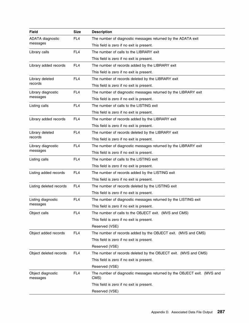
Field Size Description
ADATA diagnosticmessages
FL4 The number of diagnostic messages returned by the ADATA exit
This field is zero if no exit is present.
Library calls FL4 The number of calls to the LIBRARY exit
This field is zero if no exit is present.
Library added records FL4 The number of records added by the LIBRARY exit
This field is zero if no exit is present.
Library deletedrecords
FL4 The number of records deleted by the LIBRARY exit
This field is zero if no exit is present.
Library diagnosticmessages
FL4 The number of diagnostic messages returned by the LIBRARY exit
This field is zero if no exit is present.
Listing calls FL4 The number of calls to the LISTING exit
This field is zero if no exit is present.
Listing added records FL4 The number of records added by the LISTING exit
This field is zero if no exit is present.
Listing deleted records FL4 The number of records deleted by the LISTING exit
This field is zero if no exit is present.
Listing diagnosticmessages
FL4 The number of diagnostic messages returned by the LISTING exit
This field is zero if no exit is present.
Object calls FL4 The number of calls to the OBJECT exit. (MVS and CMS)
This field is zero if no exit is present.
Reserved (VSE)
Object added records FL4 The number of records added by the OBJECT exit. (MVS and CMS)
This field is zero if no exit is present.
Reserved (VSE)
Object deleted records FL4 The number of records deleted by the OBJECT exit. (MVS and CMS)
This field is zero if no exit is present.
Reserved (VSE)
Object diagnosticmessages
FL4 The number of diagnostic messages returned by the OBJECT exit. (MVS andCMS)
This field is zero if no exit is present.
Reserved (VSE)
Appendix D. Associated Data File Output 287

Field Size Description
Source calls FL4 The number of calls to the SOURCE exit
This field is zero if no exit is present.
Source added records FL4 The number of records added by the SOURCE exit
This field is zero if no exit is present.
Source deletedrecords
FL4 The number of records deleted by the SOURCE exit
This field is zero if no exit is present.
Source diagnosticmessages
FL4 The number of diagnostic messages returned by the SOURCE exit
This field is zero if no exit is present.
Punch calls FL4 The number of calls to the PUNCH exit
This field is zero if no exit is present.
Punch added records FL4 The number of records added by the PUNCH exit
This field is zero if no exit is present.
Punch deleted records FL4 The number of records deleted by the PUNCH exit
This field is zero if no exit is present.
Punch diagnosticmessages
FL4 The number of diagnostic messages returned by the PUNCH exit
This field is zero if no exit is present.
Term calls FL4 The number of calls to the TERM exit
This field is zero if no exit is present.
Term added records FL4 The number of records added by the TERM exit
This field is zero if no exit is present.
Term deleted records FL4 The number of records deleted by the TERM exit
This field is zero if no exit is present.
Term diagnosticmessages
FL4 The number of diagnostic messages returned by the TERM exit
This field is zero if no exit is present.
Assembly start time FL4 The local time when the assembly commenced. This time is recorded after dataset allocation, storage allocation, invocation parameter processing, and otherinitialization processing.
Stored in packed format as hhmmssth:
hh The hourmm The minutess The secondt Tenths of a secondh Hundredths of a second
Assembly stop time FL4 The local time when the assembly completed
Stored in packed format as hhmmssth:
hh The hourmm The minutess The secondt Tenths of a secondh Hundredths of a second
Processor time FL4 The number of processor seconds utilized by this assembly. (MVS and CMS)
The low order bit represents 1 microsecond.
Reserved (VSE)
288 HLASM V1R4 Programmer’s Guide

Field Size Description
| ASMAOPT input| records| FL4| The number of ASMAOPT input records read for the assembly
Reserved XL4 Reserved
External Functionsloaded
FL4 The number of functions loaded during this assembly. This is also the numberof function statistic groups to follow.
...Reserved XL4 Reserved
...SETAF functioncalls
FL4 The number of times the function was called from a SETAF assemblerinstruction. This field is part of the group of fields which is repeated for eachfunction loaded.
...SETCF functioncalls
FL4 The number of times the function was called from a SETCF assemblerinstruction. This field is part of the group of fields which is repeated for eachfunction loaded.
...Messages issued FL4 The number of times the function requested that a message be issued. Thisfield is part of the group of fields which is repeated for each function loaded.
...Messagesseverity
HL2 The maximum severity for the messages issued by this function. This field ispart of the group of fields which is repeated for each function loaded.
...Name length HL2 The length of the following field. This field is part of the group of fields which isrepeated for each function loaded.
...External Functionname
CL(n) The external function module name. This field is part of the group of fieldswhich is repeated for each function loaded.
Appendix D. Associated Data File Output 289

Appendix E. Sample Program
The sample program included with High Level Assembler is described in thisappendix. This program demonstrates some basic assembler language, macro,and conditional assembly features, most of which are unique to High LevelAssembler. The highlighted characters in the descriptions below refer tocorresponding characters in the listing that precedes the descriptions.
For more details about this program, see “ASMASAMP” in the HLASM Installationand Customization Guide.
| High Level Assembler Option Summary Page 1| HLASM R4.9 2999/99/25 17.48| No Overriding ASMAOPT Parameters| No Overriding Parameters| No Process Statements
| Options for this Assembly| NOADATA| ALIGN| NOASA| BATCH| CODEPAGE(947C)| NOCOMPAT| NODBCS| NODECK| DXREF| ESD| NOEXIT| FLAG(9,ALIGN,CONT,NOIMPLEN,NOPAGE9,PUSH,RECORD,NOSUBSTR,USING9)| NOFOLD| NOGOFF| NOINFO| LANGUAGE(EN)| NOLIBMAC| LINECOUNT(69)| LIST(121)| MXREF(SOURCE)| OBJECT| OPTABLE(UNI)| NOPCONTROL| NOPESTOP| NOPROFILE| NORA2| NORENT| RLD| RXREF| SIZE(MAX)| SYSPARM()| NOTERM| NOTEST| THREAD| NOTRANSLATE| USING(NOLIMIT,MAP,WARN(15))| XREF(SHORT,UNREFS)
| No Overriding DD Names
290 Copyright IBM Corp. 1982, 2000

| BIGNAME External Symbol Dictionary Page 2| Symbol Type Id Address Length LD ID Flags Alias-of HLASM R4.9 2999/99/25 17.48| A SD 99999991 99999999 999999DE 99| PD2 CM 99999992 99999999 99999814 99 �A�
| BIGNAME Sample program. 1ST TITLE statement has no name, 2ND one does Page 3| Active Usings: None| Loc Object Code Addr1 Addr2 Stmt Source Statement HLASM R4.9 2999/99/25 17.48| 2 LLLLLLLLLLLLLLLLLLLLLLLLLLLLLLLLLLLLLLLLLLLLLLLLLLLLLLLLLLLLLL 99992999| 3 L Licensed Materials - Property of IBM L 99993999| 4 L L 99994999| 5 L 5696-234 5647-A91 L 99995999| 6 L L 99996999| 7 L (c) Copyright IBM Corp. 1992, 2999. All Rights Reserved. L 99997999| 8 L L 99998999| 9 L US Government Users Restricted Rights - Use, L 99999999| 19 L duplication or disclosure restricted by GSA ADP L 99919999| 11 L Schedule Contract with IBM Corp. L 99911999| 12 L L 99912999| 13 LLLLLLLLLLLLLLLLLLLLLLLLLLLLLLLLLLLLLLLLLLLLLLLLLLLLLLLLLLLLLL 99913999| 14 LLLLLLLLLLLLLLLLLLLLLLLLLLLLLLLLLLLLLLLLLLLLLLLLLLLLLLLLLLLLLLLLLLLLL 99914999| 15 L DISCLAIMER OF WARRANTIES L 99915999| 16 L The following enclosed code is sample code created by IBM L 99916999| 17 L Corporation. This sample code is licensed under the terms of L 99917999| 18 L the High Level Assembler license, but is not part of any L 99918999| 19 L standard IBM product. It is provided to you solely for the L 99919999| 29 L purpose of demonstrating the usage of some of the features of L 99929999| 21 L High Level Assembler. The code is not supported by IBM and L 99921999| 22 L is provided on an "AS IS" basis, without warranty of any kind. L 99922999| 23 L IBM shall not be liable for any damages arising out of your L 99923999| 24 L use of the sample code, even if IBM has been advised of the L 99924999| 25 L possibility of such damages. L 99925999| 26 LLLLLLLLLLLLLLLLLLLLLLLLLLLLLLLLLLLLLLLLLLLLLLLLLLLLLLLLLLLLLLLLLLLLL 99926999| 999999 99999 999DE 27 a csect 99927999| R:8 99999 28 using L,8 99928999| 999999 1BFF 29 sr 15,15 Set return code to zero 99929999| 999992 97FE 39 br 14 and return. 99939999| 32 LLLLLLLLLLLLLLLLLLLLLLLLLLLLLLLLLLLLLLLLLLLLLLLLLLLLLLLLLLLLLLLLLLLLLL 99932999| 33 L PUSH and POP statements L 99933999| 34 L Push down the PRINT statement, replace it, retrieve original L 99934999| 35 LLLLLLLLLLLLLLLLLLLLLLLLLLLLLLLLLLLLLLLLLLLLLLLLLLLLLLLLLLLLLLLLLLLLLL 99935999| 37 push print Save Default setting ' PRINT ON,NODATA,GEN' 99937999| �B� 38 print nogen,data 99938999| 999994 9A23 39 wto mf=(E,(1)) Expansion not shown 99939999| 999996 91239ABC9192939A �C� 42 dc x'123,ABC',(reallylongsymbol-transylvania)b'1,19,11,1919,1911,1199' 99949999| 99999E 9B9C9192939A9B9C| 999916 9192939A9B9C9192| 99991E 939A9B9C| 43 pop print Restore default PRINT setting 99941999| 44 wto mf=(E,(1)) Expansion shown 99942999| 999922 9A23 46+ SVC 35 ISSUE SVC 35 @L2C 91-WTO| 999924 91239ABC9192939A 47 dc x'123,ABC',(reallylongsymbol-transylvania)b'1,19,11,1919,1911,1199' 99943999| 49 LLLLLLLLLLLLLLLLLLLLLLLLLLLLLLLLLLLLLLLLLLLLLLLLLLLLLLLLLLLLLLLLLLLLLL 99945999| 59 L LOCTR instruction L 99946999| 51 L LOCTR allows 'REMOTE' assembly of constant L 99947999| 52 LLLLLLLLLLLLLLLLLLLLLLLLLLLLLLLLLLLLLLLLLLLLLLLLLLLLLLLLLLLLLLLLLLLLLL 99948999| 999949 5859 89AC 999AC 54 l 5,constant 99959999| 9999AC 999AC 999DE �D�55 deecees loctr 99951999| 9999AC 99999995 56 constant dc f'5' Constant coded here, assembled behind LOCTR A 99952999| BIGNAME Sample program. 1ST TITLE statement has no name, 2ND one does Page 4| Active Usings: a(X'1999'),R8| Loc Object Code Addr1 Addr2 Stmt Source Statement HLASM R4.9 2999/99/25 17.48| 999944 99999 999DE 57 a loctr Return to 1st LOCTR in CSECT A 99953999| 59 LLLLLLLLLLLLLLLLLLLLLLLLLLLLLLLLLLLLLLLLLLLLLLLLLLLLLLLLLLLLLLLLLLLLLL 99955999| 69 L 3 operand EQUATE with forward reference in 1ST operand L 99956999| 61 LLLLLLLLLLLLLLLLLLLLLLLLLLLLLLLLLLLLLLLLLLLLLLLLLLLLLLLLLLLLLLLLLLLLLL 99957999| 999944 1812 63 a5 lr 1,2 L'A5 = 2, T'A5 = I 99959999| 64 print data 99969999| 999946 9999| 999948 413243F6A8885A39 65 a7 dc l'3.1415926535897932384626433832795928841972' L'A7 = 16,T'A7 = L 99961999| 999959 338D313198A2E937| 66 &type setc t'a7 99962999| �E� 67 a8 equ b5,l'a5,c'&type' 99963999| 999B9 99992 +a8 equ b5,l'a5,c'L' 99963999
�A� The external symbol dictionary shows a named common statement. Thenamed common section is defined in statement 216.
�B� Statement 37: Save the current status of the PRINT statement.
Statement 38: Modify the print options to DATA and NOGEN.
Statement 39: Macro call; note that the expansion (statements 40 and 41) isnot printed.
Statement 42: All 28 bytes of data are displayed to the two-operand DC.
Appendix E. Sample Program 291

Statement 43: Restore earlier status of PRINT.
Statement 45: This statement is not printed. It is a nested macro call. TheMCALL operand of the PRINT instruction or the PCONTROL assembleroption control the printing of nested macro calls.
Statements 46: The generated output of the macro WTO is shown, but onlytwo bytes of data are shown.
�C� Statements 42 and 47: Multiple constants are allowed in hexadecimal andbinary DC operands, and neither symbol in the duplication factor has beendefined yet. Definition occurs in statements 144 and 145.
�D� Statements 55, 57, 194, 212 and 213 show use of the LOCTR assemblerinstruction. This feature allows you to break down control sections into“subcontrol” sections. It can be used in CSECT, RSECT, DSECT, and COMsections. LOCTR has many of the features of a control section; for example,all of the first LOCTR in a section is assigned space, then the second, and soon. The name of the control section automatically names the first LOCTRsection. Thus LOCTR A is begun, or continued, at statements 27, 57, and213. The location counter value shown each time is the continued value of theLOCTR. On the other hand, various LOCTR sections within a control sectionhave common addressing as far as USING statements are concerned, subjectto the computed displacement falling within 0 through 4095. In the sample,CONSTANT (at statement 56) is in LOCTR DEECEES but the instructionreferring to it (statement 54) has no addressing problems.
�E� Three-operand EQU. Here, we assign: (a) the value of B5 (not yet defined) toA8, (b) the length attribute of A5 to A8, and (c) the type attribute of A7 to A8.If no second or third operand is present in an EQU statement, the typeattribute is U and the length attribute is that of the first term in the operandexpression. Symbols present in the operand field must be previously defined.You cannot express the type attribute of A7 directly in the EQU statement.The EQU statement at 67 could have been written
| a8 equ b5,2,c'L'| a8 equ b5,x'2',x'D3'
| BIGNAME Sample program. 1ST TITLE statement has no name, 2ND one does Page 5| Active Usings: a(X'1999'),R8| Loc Object Code Addr1 Addr2 Stmt Source Statement HLASM R4.9 2999/99/25 17.48| 69 LLLLLLLLLLLLLLLLLLLLLLLLLLLLLLLLLLLLLLLLLLLLLLLLLLLLLLLLLLLLLLLLLLLLLL 99965999| 79 L Implicit declaration of locals &A, &C -- Use of SETC dup factor to L 99966999| 71 L produce SETC string longer than 8, MNOTE in open code L 99967999| 72 LLLLLLLLLLLLLLLLLLLLLLLLLLLLLLLLLLLLLLLLLLLLLLLLLLLLLLLLLLLLLLLLLLLLLL 99968999| 74 &la8 seta l'a8 99979999| �F� 75 &ta8 setc t'a8 99971999| 76 mnote L,'Length of A8 = &LA8, Type of A8 = &TA8' 99972999| �G� +L,Length of A8 = 2, Type of A8 = L 99972999| 78 &a seta 2 99974999| 79 &c setc (&a+3)'STRING,' 99975999| �H� 89 mnote L,'&&C has value = &c' 99976999| +L,&C has value = STRING,STRING,STRING,STRING,STRING, 99976999| 82 LLLLLLLLLLLLLLLLLLLLLLLLLLLLLLLLLLLLLLLLLLLLLLLLLLLLLLLLLLLLLLLLLLLLLL 99978999| �I� 83 L Examples of 4 byte self-defined terms, unary + and - L 99979999| 84 LLLLLLLLLLLLLLLLLLLLLLLLLLLLLLLLLLLLLLLLLLLLLLLLLLLLLLLLLLLLLLLLLLLLLL 99989999| 999958 7FFFFFFFC1C2C3C4 86 dc a(2147483647,C'ABCD',X'ffffffff') 99982999| 999969 FFFFFFFF| 999964 181D 87 lr -1+2,16+-3 99983999| FFFFE8 89 X equ 4L-6 99985999
�F� Set symbols &LA8 and &TA8 have not been previously declared in LCL orGBL statements. Therefore, they default to local variable symbols as follows:&LA8 is an LCLA SET symbol because it appears in the name field of aSETA; &TA8 is an LCLC SET symbol because it is first used in a SETC.
292 HLASM V1R4 Programmer’s Guide

�G� MNOTEs can appear in open code. As such, they have all properties ofMNOTEs inside macros, including substitution.
�H� A SETC expression can have a duplication factor. The SETA expressionmust be enclosed in parentheses and immediately precede the characterstring, the substring notation, or the type attribute reference.
�I� Statements 86 through 89 show 4-byte self-defining values and unary + and−. The value of X appears later in a literal address constant (see statement296).
| BIGNAME Insert Programmer Macro in Source Stream now Page 6| Active Usings: a(X'1999'),R8| Loc Object Code Addr1 Addr2 Stmt Source Statement HLASM R4.9 2999/99/25 17.48| 91 LLLLLLLLLLLLLLLLLLLLLLLLLLLLLLLLLLLLLLLLLLLLLLLLLLLLLLLLLLLLLLLLLLLLLL 99987999| 92 L Mixed keywords and positional parameters, extended AGO and AIF L 99988999| 93 L statements, declaration and use of subscripted SET symbols, L 99989999| 94 L Use of created SET symbols, extended SET statements L 99999999| 95 LLLLLLLLLLLLLLLLLLLLLLLLLLLLLLLLLLLLLLLLLLLLLLLLLLLLLLLLLLLLLLLLLLLLLL 99991999| �J� 97 macro 99993999| 98 demo &p1,&key1=A,&p2,&key2=1,&p3,&key3=3,&p4 99994999| �K� 99 &loc(1) setc '2','3' &LOC is dimensioned LCLC by default 99995999| 199 gblc &xa(5),&xb(29),&xc(1) 99996999| 191 aif ('&system_id'(1,3) eq 'VSE').vse 99997999| �L� 192 &p1 &syslist(4),&syslist(5),&syslist(6),mf=E 99998999| 193 ago .notvse 99999999| 194 .vse anop Use VSE WRITE macro parameters 99199999| 195 &p1 &syslist(4),SQ,&syslist(6) 99191999| 196 .notvse anop 99192999| 197 &n seta 1 99193999| �M� 198 ago (&key2).mnote1,.mnote2,.mnote3 99194999| 199 &n seta 2 99195999| 119 mnote L,'&&KEY2 not 1,2, or 3---Use &&KEY3 in place of it' 99196999| �N� 111 aif (&key3 eq 1).mnote1, X99197999| (&key3 eq 2).mnote2,(&key3 eq 3).mnote3 99198999| 112 mnote L,'Both &&KEY2 and &&KEY3 fail to qualify' 99199999| 113 ago .common 99119999| 114 .mnote1 mnote L,'&&KEY&LOC(&N) = 1' 99111999| 115 ago .common 99112999| 116 .mnote2 mnote L,'&&KEY&LOC(&N) = 2' 99113999| 117 ago .common 99114999| 118 .mnote3 mnote L,'&&KEY&LOC(&N) = 3' 99115999| 119 .common l 5,8(,19) Note that opcodes, operands & comments 99116999| 129 &xb(2) sr 9,19 on MODEL statements 99117999| �O� 121 &(x&key1)(2) lm 12,13,=a(a5,x) are kept in place unless displaced 99118999| 122 &p2 st 7,&p3 as a result of substitution 99119999| 123 mend 99129999| 125 LLLLL DEMO MACRO instruction (call) 99122999| �P� 127 gblc &xa(1),&xb(2),&xc(3) 99124999| 128 &xa(1) setc 'A','MISSISSIPPI' 99125999| 129 &xb(1) setc 'B','SUSQUEHANNA' 99126999| 139 &xc(1) setc 'C','TRANSYLVANIA' 99127999| �Q� 131 demo key3=2,write,reallylongsymbol, M99128999| a8+8L(b5-constant-7)(3),key1=C,(6),SF, N99129999| (8),key2=7 99139999| 999966 1816 134+ LR 1,6 LOAD DECB ADDRESS 93-IHBRD| 999968 9229 1995 99995 135+ MVI 5(1),X'29' SET TYPE FIELD 93-IHBRD| 99996C 5981 9998 99998 136+ ST 8,8(1,9) STORE DCB ADDRESS 93-IHBRD| 999979 58F1 9998 99998 137+ L 15,8(1,9) LOAD DCB ADDRESS 93-IHBRD| 999974 58F9 F939 99939 138+ L 15,48(9,15) LOAD RDWR ROUTINE ADDR 93-IHBRD| 999978 95EF 139+ BALR 14,15 LINK TO RDWR ROUTINE 93-IHBRD| 149+L,&KEY2 not 1,2, or 3---Use &KEY3 in place of it 91-99119| 141+L,&KEY3 = 2 91-99116| 99997A 5859 A998 99998 142+ l 5,8(,19) Note that opcodes, operands & comments 91-99119| 99997E 1B9A �R� 143+SUSQUEHANNA sr 9,19 on MODEL statements 91-99129| 999989 98CD 8999 99999 144+TRANSYLVANIA lm 12,13,=a(a5,x) are kept in place unless displaced 91-99121| BIGNAME Insert Programmer Macro in Source Stream now Page 7| Active Usings: a(X'1999'),R8| Loc Object Code Addr1 Addr2 Stmt Source Statement HLASM R4.9 2999/99/25 17.48| 999984 5973 8998 99998 145+reallylongsymbol st 7,a8+8L(b5-constant-7)(3) X91-99122| + as a result of substitution
�J� The macro DEMO is defined after the start of the assembly. Macros can bedefined at any point and, having been defined, expanded, or both, can beredefined. The parameters on the prototype are a mixture of keywords andpositional operands. &SYSLIST may be used. The positional parameters areidentified and numbered 1, 2, 3 from left to right; keywords are skipped overin numbering positional parameters.
Appendix E. Sample Program 293

�K� Statement 99 shows the extended SET feature (as well as implicit declarationof &LOC(1) as an LCLC). Both &LOC(1) and &LOC(2) are assigned values.One SETA, SETB, or SETC statement can then do the work of many.
�L� Statement 102 is a model statement with a symbolic parameter in itsoperation field. This statement is edited as if it is a macro call; at this time,each operand is denoted as positional or keyword. At macro call time, youcannot reverse this decision. Even though it's treated as a macro, it is stillexpanded as a machine or assembler operation.
�M� Statement 108 shows the computed AGO statement. Control passes to.MNOTE1 if &KEY2 is 1, to .MNOTE2 if &KEY2 is 2, to .MNOTE3 if &KEY2 is3, or otherwise it falls through to the model statement at 109.
�N� Statement 111 shows the extended AIF facility. This statement is written inthe alternative format. The logical expressions are examined from left to right.Control passes to the sequence symbol corresponding to the first trueexpression encountered, or else falls through to the next model statement.
�O� Statement 121 contains a subscripted created SET symbol in the name field.The created SET symbol has the form &(e), where e is an expression madeup of character strings, variable symbols, or both. When the symbol isencountered during macro generation, the assembler evaluates theexpression e. The operation code DEMO is used as a macro instruction instatement 131, and &KEY1 is given the value C. The e in this case isX&KEY1, which results in the value XC. Thus the name field in statement121, &(x&key1)(2), becomes &XC(2). Statement 130 assigns the value C to&XC(1), and the value TRANSYLVANIA to &XC(2). The model statement (121)is generated at statement 144; the name field contains TRANSYLVANIA. Thesequence field of statement 144, shows that this statement is a level 01expansion of a macro, and the corresponding model statement is statementnumber 121.
You can use created SET symbols wherever regular SET symbols are used;for example: in declarations, name fields, operands of SET statements, modelstatements. Likewise, they are subject to all the restrictions of regular SETsymbols.
�P� In statements 127 and 128, &XA is declared as a subscripted global SETCvariable with a subscript of 1 and in the next statement, which is an extendedSET statement, we store the value MISSISSIPPI into &XA(2). The assemblerallows up to 2,147,483,647 array values in a subscripted global SETC symbol.
�Q� Statement 131 is the macro instruction DEMO. &P1 has the value WRITE.Therefore, the model statement at statement 102 becomes an inner macroinstruction, WRITE, producing the code at statements 134–139. Thesequence field of these statements contains 03-IHBRD, indicating that theyare generated by a level 03 macro (DEMO is 01, WRITE is 02) namedIHBRDWRS. It is an inner macro called by WRITE.
�R� Statements 144 and 145 contain some ordinary symbols longer than 8characters. The limit for ordinary symbols, operation codes (for programmerand library macros and operation codes defined through OPSYN), variablesymbols, and sequence symbols, is 63 characters (including the & and . in thelatter two instances, respectively).
294 HLASM V1R4 Programmer’s Guide

| BIGNAME Insert Programmer Macro in Source Stream now Page 8| Active Usings: a(X'1999'),R8| Loc Object Code Addr1 Addr2 Stmt Source Statement HLASM R4.9 2999/99/25 17.48| 147 LLLLLLLLLLLLLLLLLLLLLLLLLLLLLLLLLLLLLLLLLLLLLLLLLLLLLLLLLLLLLLLLLLLLLL 99132999| 148 L Copy 'NOTE' macro in from maclib, rename it 'MARK', call it under L 99133999| 149 L its ALIAS -- in expansion of MARK, notice reference back to L 99134999| 159 L definition statements in 'columns' 76-89 of expansion L 99135999| 151 LLLLLLLLLLLLLLLLLLLLLLLLLLLLLLLLLLLLLLLLLLLLLLLLLLLLLLLLLLLLLLLLLLLLLL 99136999| �S� 153 copy note 99138999| 154= MACRO 99919999| 155=&NAME NOTE &DCB,&DUMMY=,&TYPE=REL 99929999| 156=.L $MAC(NOTE): 99939999| 157=.L 5665-XA2 99932999| 158=.L CONTAINS RESTRICTED MATERIALS OF IBM 99934999| 159=.L (C) COPYRIGHT IBM CORP. 1984 99936999| 169=.L LICENSED MATERIALS - PROPERTY OF IBM 99938999| 161=.L REFER TO COPYRIGHT INSTRUCTIONS 99949999| 162=.L FORM NUMBER G129-2983. 99942999| 163=.L STATUS = MVS/XA DFP RELEASE 1.2 @H1 99944999| 164=.L 99946999| 165=.L CHANGE ACTIVITY = 99129999| 166=.L 99139999| 167=.L $H1=3489,JDP1111,,STLPKH: 3489 SUPPORT L 99149999| 168=.L 99159999| 169= AIF ('&DCB' EQ '').ERR 99169999| 179=&NAME IHBINNRA &DCB 99179999| 171= AIF ('&TYPE' NE 'REL').NOTREL @H1A 99189999| 172= L 15,84(9,1) LOAD NOTE RTN ADDRESS 99199999| 173= BALR 14,15 LINK TO NOTE ROUTINE 99299999| 174= MEXIT 99219999| 175=.NOTREL AIF ('&TYPE' NE 'ABS').ERR1 @H1A 99229999| 176= SLR 9,9 INDICATES NOTE MACRO @H1A 99239999| 177= LA 15,32 ROUTER CODE @H1A 99249999| 178= SVC 199 SUPERVISOR CALL @H1A 99259999| 179= MEXIT @H1A 99269999| 189=.ERR1 MNOTE 8,'INVALID PARAMETER FOR TYPE' @H1A 99279999| 181= MEXIT @H1A 99289999| 182=.ERR IHBERMAC 6 99299999| 183= MEND 99399999| �T� 186 mark opsyn note Comments of generated statements occupy same 99141999| 187 mark (6) 'COLUMNS' as those in MODEL statements 99142999| 999988 1816 189+ LR 1,6 LOAD PARAMETER REG 1 92-IHBIN| 99998A 58F9 1954 99954 199+ L 15,84(9,1) LOAD NOTE RTN ADDRESS 91-99172| 99998E 95EF 191+ BALR 14,15 LINK TO NOTE ROUTINE 91-99173| 193 LLLLLLLLLLLLLLLLLLLLLLLLLLLLLLLLLLLLLLLLLLLLLLLLLLLLLLLLLLLLLLLLLLLLLL 99144999| 9999B9 999AC 999DE 194 deecees loctr Switch to alternate location counter 99145999| 9999B9 9B9999B999999959 195 b5 ccw X'9b',b5,9,89 99146999| 197 LLLLLLLLLLLLLLLLLLLLLLLLLLLLLLLLLLLLLLLLLLLLLLLLLLLLLLLLLLLLLLLLLLLLLL 99148999| 198 L Display of &SYSTIME, &SYSDATE, &SYSPARM and &SYSLOC L 99149999| 199 LLLLLLLLLLLLLLLLLLLLLLLLLLLLLLLLLLLLLLLLLLLLLLLLLLLLLLLLLLLLLLLLLLLLLL 99159999| 291 print nodata 99152999| �U� 292 dc c'TIME = &systime, DATE = &sysdate, PARM = &sysparm' 99153999
| BIGNAME Insert Programmer Macro in Source Stream now Page 9| Active Usings: a(X'1999'),R8| Loc Object Code Addr1 Addr2 Stmt Source Statement HLASM R4.9 2999/99/25 17.48| 9999B8 E3C9D4C5497E49F1 + dc c'TIME = 99/25/99, DATE = 17.48, PARM = ' 99153999| 294 macro 99155999| 295 locate 99156999| �V� 296 &sysect csect Display of current control section 99157999| 297 &sysloc loctr and location counter 99158999| 298 mend 99159999| 219 locate 99161999| 9999DE 999AC 999DE 211+a csect Display of current control section 91-99296| 9999DE 999AC 999DE 212+deecees loctr and location counter 91-99297| 999999 99999 999DE 213 a loctr 99162999
Appendix E. Sample Program 295
�S� Library macros can be inserted into the source stream as programmer macrosby use of a COPY statement. The result (statements 154 to 183) is treatedas a source-stream macro definition. When a library macro is brought in andexpanded by use of a macro instruction, the assembler (1) looks the macroup by its member-name and (2) verifies that this same name is used in theoperation field of the prototype statement. Therefore, for example, DCB hasto be cataloged as DCB. However, as COPY code, the member name bearsno relationship to any of the statements in the member. Thus, severalvariations of a given macro could be stored as a library under separatenames, then copied in at various places in a single assembly as needed.(High Level Assembler allows you to define and redefine a macro any numberof times).
�T� In statement 186, MARK is made a synonym for NOTE. To identify theNOTE macro as a defined instruction mnemonic, it has to be used as either asystem macro call (that is, from a macro library), or a programmer macrodefinition, before its use in the operand field of an OPSYN statement. TheCOPY code at statements 154 through 183 is a programmer macro definition.The macro instruction at statement 187 is MARK. You can use MARK andNOTE interchangeably. If required, you could remove NOTE as a macrodefinition in the following way:
MARK OPSYN NOTENOTE OPSYN ,
You could then refer to the macro only as MARK.
�U� Statement 202 demonstrates &SYSTIME, &SYSDATE, and &SYSPARM. Thevalues for the first two are the same as in the heading line. The value for&SYSPARM is the value passed in the PARM field of the EXEC statement, orthe default value assigned to &SYSPARM when High Level Assembler isinstalled.
�V� System variable symbols &SYSLOC and &SYSECT are displayed atstatements 211 and 212. The sequence field indicates that the modelstatements are statements 206 and 207.
296 HLASM V1R4 Programmer’s Guide

| BIGNAME Ordinary, Labeled and Dependent USING Instructions Page 19| Active Usings: a(X'1999'),R8| Loc Object Code Addr1 Addr2 Stmt Source Statement HLASM R4.9 2999/99/25 17.48| 215 LLLLLLLLLLLLLLLLLLLLLLLLLLLLLLLLLLLLLLLLLLLLLLLLLLLLLLLLLLLLLLLLLLLLLL 99164999| 999999 99999 99814�W�216 pd2 com Named COMMON thrown in for good measure 99165999| 999999 217 ds 599f 99166999| 9997D9 1867 218 lr 6,7 99167999| 229 LLLLLLLLLLLLLLLLLLLLLLLLLLLLLLLLLLLLLLLLLLLLLLLLLLLLLLLLLLLLLLLLLLLLLL 99169999| 221 L Use of ordinary, labeled and dependent USING Instructions L 99179999| �X� 222 LLLLLLLLLLLLLLLLLLLLLLLLLLLLLLLLLLLLLLLLLLLLLLLLLLLLLLLLLLLLLLLLLLLLLL 99171999| R:C 997D2 224 using L,12 99173999| 9997D2 4119 C922 997F4 225 la 1,area1 99174999| 9997D6 4129 C932 99894 226 la 2,area2 99175999| R:1 99999 227 using first,1 Ordinary USING 99176999| R:2 99999 228 lab using first,2 Labeled USING 99177999| 1 998 99999 99998 229 using second,first2 Dependent USING 99178999| 2 998 99999 99998 239 labdep using third,lab.first2 Labeled dependent USING 99179999| 9997DA D297 1999 8998 99999 99998 231 mvc first1,=cl8'1st' Uses ordinary USING 99189999| 9997E9 D297 2999 8998 99999 99998 232 mvc lab.first1,=cl8'1st' Uses labeled USING 99181999| 9997E6 D293 1998 89A9 99999 999A9 233 mvc second1,=cl4'2nd' Uses dependent USING 99182999| 9997EC D291 2998 89A4 99999 999A4 234 mvc labdep.third1,=cl2'3d' Uses labeled dependent USING 99183999| 9997F4 235 area1 ds 9f First data area 99184999| 9997F4 236 area1a ds cl8 99185999| 9997FC 237 area1b ds cl8 99186999| 999894 238 area2 ds 9f Second data area 99187999| 999894 239 area2a ds cl8 99188999| 99989C 249 area2b ds cl8 99189999| 999999 99999 99919 241 first dsect First dsect 99199999| 999999 242 first1 ds cl8 99191999| 999998 243 first2 ds cl8 99192999| 999999 99999 99998 244 second dsect Second dsect 99193999| 999999 245 second1 ds cl4 99194999| 999994 246 second2 ds cl4 99195999| 999999 99999 999EC 247 third dsect Third dsect 99196999| 999999 248 third1 ds cl2 99197999| 999992 249 third2 ds cl2 99198999
�W� Illustration of named COMMON. You can establish addressability for anamed COMMON section with:
USING section-name,register
You can address data in a blank COMMON section by labeling a statementwithin the section after the COMMON statement.
�X� In statement 227, an ordinary USING is established for AREA1 using theDSECT FIRST. When the fields within DSECT FIRST are referenced usingsymbols with the “first” qualifier, register 1 is used to resolve the address as instatement 231.
In statement 228, a labeled USING is established for AREA2 using theDSECT FIRST. Register 2 is used to resolve the address for qualifiedsymbols within AREA2 when referred to using the qualifier “second” as instatement 232.
In statement 229, a dependent USING is established at the field FIRST2using the DSECT SECOND. The corresponding ordinary USING for fieldFIRST2 is the USING on statement 227. It uses register 1 to resolve theaddress. The statement on line 233 specifies a field within DSECT SECONDand the assembler uses register 1 to resolve the address.
In statement 230, a labeled dependent USING is established at the fieldFIRST2 using the DSECT THIRD. The USING specifies the labeled USINGLAB to resolve the address for field FIRST2. In statement 234, the labeleddependent USING is specified and register 2 is used to resolve the address ofthe field THIRD1.
Appendix E. Sample Program 297

| BIGNAME Predefined Absolute Symbols in SETA and SETC expressions Page 11| Active Usings: first(X'1999'),R1 second(X'FF8'),R1+X'8' a(X'1999'),R8 pd2+X'7D2'(X'1999'),R12| lab.first(X'1999'),R2 labdep.third(X'FF8'),R2+X'8'| D-Loc Object Code Addr1 Addr2 Stmt Source Statement HLASM R4.9 2999/99/25 17.48| 251 LLLLLLLLLLLLLLLLLLLLLLLLLLLLLLLLLLLLLLLLLLLLLLLLLLLLLLLLLLLLLLLLLLLLLL 99299999| 252 L Use of predefined absolute symbols in SETA and SETC expressions L 99291999| 253 LLLLLLLLLLLLLLLLLLLLLLLLLLLLLLLLLLLLLLLLLLLLLLLLLLLLLLLLLLLLLLLLLLLLLL 99292999| 99964 255 hundred equ 199 99294999| 256 &dividnd seta 29 99295999| �Y� 257 &percent seta &dividndL199/49 Predefined symbol in SETA 99296999| 99932 258 fifty equ 59 99297999| �Z� 259 &longwd setc (hundred)'a' Predefined symbol in SETC 99298999| 269 dc c'&longwd' 99219999| 999994 8181818181818181 + dc c'aaaaaaaaaaaaaaaaaaaaaaaaaaaaaaaaaaaaaaaaaaaaaaaaaaaaaaX99219999| 99999C 8181818181818181 + aaaaaaaaaaaaaaaaaaaaaaaaaaaaaaaaaaaaaaaaaaaaaa'| 261 &twowds setc (fifty)'a'.' '.(hundred/2)'B' 99211999| 262 dc c'&twowds' 99212999| 999968 8181818181818181 + dc c'aaaaaaaaaaaaaaaaaaaaaaaaaaaaaaaaaaaaaaaaaaaaaaaaaa BBBX99212999| 999979 8181818181818181 + BBBBBBBBBBBBBBBBBBBBBBBBBBBBBBBBBBBBBBBBBBBBBBB'
�Y� In statement 257, the SETA statement specifies a variable symbol(&DIVIDND) as well as other arithmetic terms.
�Z� In statement 259 the SETC statement specifies a predefined absolute symbol(HUNDRED) as the duplication factor.
| BIGNAME Symbol Attribute Enhancements Page 12| Active Usings: first(X'1999'),R1 second(X'FF8'),R1+X'8' a(X'1999'),R8 pd2+X'7D2'(X'1999'),R12| lab.first(X'1999'),R2 labdep.third(X'FF8'),R2+X'8'| D-Loc Object Code Addr1 Addr2 Stmt Source Statement HLASM R4.9 2999/99/25 17.48| 264 LLLLLLLLLLLLLLLLLLLLLLLLLLLLLLLLLLLLLLLLLLLLLLLLLLLLLLLLLLLLLLLLLLLLLL 99214999| 265 L Symbol Attribute enhancements L 99215999| 266 LLLLLLLLLLLLLLLLLLLLLLLLLLLLLLLLLLLLLLLLLLLLLLLLLLLLLLLLLLLLLLLLLLLLLL 99216999| 9999CD C1C2C3 268 SYMBOL1 DC C'ABC' 99218999| 9999D9 12345C 269 SYMBOL2 DC P'123.45' 99219999| 279 &VAR1 SETC 'SYMBOL1' 99229999| 271 &VAR2 SETC 'SYMBOL2' 99221999| 9999D3 99| 9999D4 4119 89A6 999A6 272 LA 1,=C'ABC' 99222999| 9999D8 4119 89A9 999A9 273 LA 1,=P'123.45' 99223999| �1� 275 &TYPE SETC T'=C'ABC' 99225999| 276 DC CL1'&TYPE' 99226999| 9999DC C3 + DC CL1'C' 99226999| 9999DD C3 277 DC AL1(T'SYMBOL1) 99227999| 278 DC AL1(T'&VAR1) 99228999| 9999DE C3 + DC AL1(T'SYMBOL1) 99228999| 9999DF C3 279 DC AL1(T'=C'ABC') 99229999| �2� 289 &LEN SETA L'=C'ABC' 99239999| 281 DC AL1(&LEN) 99231999| 9999E9 93 + DC AL1(3) 99231999| 9999E1 93 282 DC AL1(L'SYMBOL1) 99232999| 283 DC AL1(L'&VAR1) 99233999| 9999E2 93 + DC AL1(L'SYMBOL1) 99233999| 9999E3 93 284 DC AL1(L'=C'ABC') 99234999| �3� 285 &INT SETA I'=P'123.45' 99235999| 286 DC AL1(&INT) 99236999| 9999E4 93 + DC AL1(3) 99236999| 9999E5 93 287 DC AL1(I'SYMBOL2) 99237999| 288 DC AL1(I'&VAR2) 99238999| 9999E6 93 + DC AL1(I'SYMBOL2) 99238999| 9999E7 93 289 DC AL1(I'=P'123.45') 99239999| �4� 299 &SCALE SETA S'=P'123.45' 99249999| 291 DC AL1(&SCALE) 99241999| 9999E8 92 + DC AL1(2) 99241999| 9999E9 92 292 DC AL1(S'SYMBOL2) 99242999| 293 DC AL1(S'&VAR2) 99243999| 9999EA 92 + DC AL1(S'SYMBOL2) 99243999| 9999EB 92 294 DC AL1(S'=P'123.45') 99244999| 295 end 99245999| 999999 99999944FFFFFFE8 �5� 296 =a(a5,x)| 999998 F1A2A34949494949 297 =cl8'1st'| 9999A9 F2958449 298 =cl4'2nd'| 9999A4 F384 299 =cl2'3d'| 9999A6 C1C2C3 399 =C'ABC'| 9999A9 12345C 391 =P'123.45'
298 HLASM V1R4 Programmer’s Guide

�1� The Type attribute (T') is allowed for ordinary symbols, SET symbols, andliterals, in both conditional assembly instructions and machine or assemblerinstructions. It is allowed in both open code and macro definitions.
�2� The Length attribute (L') is allowed for ordinary symbols, SET symbols, andliterals, in both conditional assembly instructions and machine or assemblerinstructions. It is allowed in both open code and macro definitions.
�3� The Integer attribute (I') is allowed for ordinary symbols, SET symbols, andliterals, in both conditional assembly instructions and machine or assemblerinstructions. It is allowed in both open code and macro definitions.
�4� The Scaling attribute (S') is allowed for ordinary symbols, SET symbols, andliterals, in both conditional assembly instructions and machine or assemblerinstructions. It is allowed in both open code and macro definitions.
�5� If there are literals outstanding when the END statement is encountered, theyare assigned to the LOCTR now in effect for the first control section in theassembly. This may or may not put the literals at the end of the first controlsection. In this sample assembly, the first control section, A, has twoLOCTRs: A and DEECEES. Because A is active (at statement 213), theliterals are assembled there. You control placement of literal pools by meansof the LTORG statement. Note that X'FFFFFFE8' is used for the contents ofA(X), statement 296. The symbol X was assigned the value (4*-6) by anEQU in statement 89.
| BIGNAME Relocation Dictionary Page 13| Pos.Id Rel.Id Flags Address HLASM R4.9 2999/99/25 17.48| 99999991 99999991 9C 99999999| 99999991 99999991 98 999999B1
| BIGNAME Ordinary Symbol and Literal Cross Reference Page 14| Symbol Length Value Id R Type Defn References HLASM R4.9 2999/99/25 17.48| a 1 99999999 99999991 J 27 57 211 213| area1 4 999997F4 99999992 F 235 225| area2 4 99999894 99999992 F 238 226| a5 2 99999944 99999991 I 63 67 296| a8 2 999999B9 99999991 C L 67 145M| b5 8 999999B9 99999991 W 195 67 145M 195| constant 4 999999AC 99999991 F 56 54 145M| deecees 1 999999AC 99999991 J 55 194 212| first 1 99999999 FFFFFFFF J 241 227U 228U| first1 8 99999999 FFFFFFFF C 242 231M 232M| first2 8 99999998 FFFFFFFF C 243 229U 239| lab 99999992 A U 228 239U 232| labdep 99999992 A U 239 234| reallylongsymbol| 4 99999984 99999991 I 145 42 47| second 1 99999999 FFFFFFFE J 244 229U| second1 4 99999999 FFFFFFFE C 245 233M| SYMBOL1 3 999999CD FFFFFFFD C 268 277 278 282 283| SYMBOL2 3 999999D9 FFFFFFFD P 269 287 288 292 293| third 1 99999999 FFFFFFFD J 247 239U| third1 2 99999999 FFFFFFFD C 248 234M| TRANSYLVANIA| 4 99999989 99999991 I 144 42 47| X 1 FFFFFFE8 99999991 A U 89 296| =a(a5,x) 4 99999999 99999991 A 296 144| =C'ABC' 3 999999A6 99999991 C 399 272 279 284| =cl2'3d' 2 999999A4 99999991 C 299 234| =cl4'2nd'| 4 999999A9 99999991 C 298 233| =cl8'1st'| 8 99999998 99999991 C 297 231 232| =P'123.45'| 3 999999A9 99999991 P 391 273 289 294
| BIGNAME Unreferenced Symbols Defined in CSECTs Page 15| Defn Symbol HLASM R4.9 2999/99/25 17.48| 65 a7| 143 SUSQUEHANNA
Appendix E. Sample Program 299
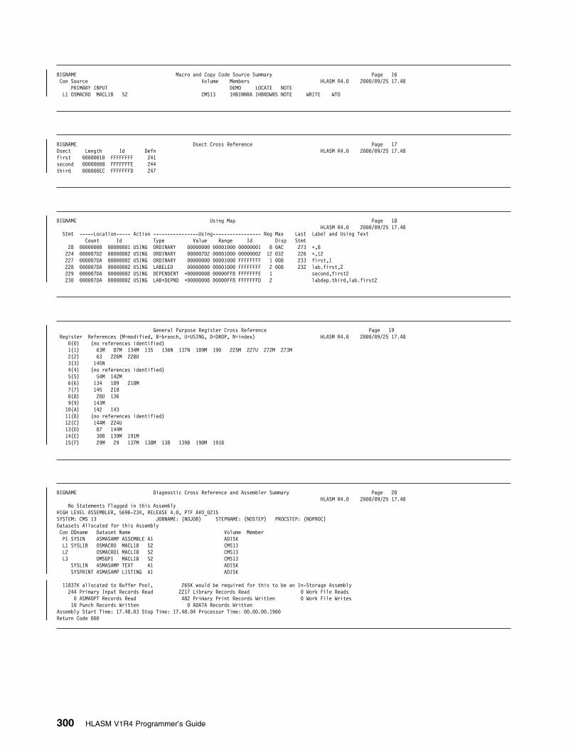
| BIGNAME Macro and Copy Code Source Summary Page 16| Con Source Volume Members HLASM R4.9 2999/99/25 17.48| PRIMARY INPUT DEMO LOCATE NOTE| L1 OSMACRO MACLIB S2 CMS13 IHBINNRA IHBRDWRS NOTE WRITE WTO
| BIGNAME Dsect Cross Reference Page 17| Dsect Length Id Defn HLASM R4.9 2999/99/25 17.48| first 99999919 FFFFFFFF 241| second 99999998 FFFFFFFE 244| third 999999EC FFFFFFFD 247
| BIGNAME Using Map Page 18| HLASM R4.9 2999/99/25 17.48| Stmt -----Location----- Action ----------------Using----------------- Reg Max Last Label and Using Text| Count Id Type Value Range Id Disp Stmt| 28 99999999 99999991 USING ORDINARY 99999999 99991999 99999991 8 9AC 273 L,8| 224 999997D2 99999992 USING ORDINARY 999997D2 99991999 99999992 12 932 226 L,12| 227 999997DA 99999992 USING ORDINARY 99999999 99991999 FFFFFFFF 1 998 233 first,1| 228 999997DA 99999992 USING LABELED 99999999 99991999 FFFFFFFF 2 998 232 lab.first,2| 229 999997DA 99999992 USING DEPENDENT +99999998 99999FF8 FFFFFFFE 1 second,first2| 239 999997DA 99999992 USING LAB+DEPND +99999998 99999FF8 FFFFFFFD 2 labdep.third,lab.first2
| General Purpose Register Cross Reference Page 19| Register References (M=modified, B=branch, U=USING, D=DROP, N=index) HLASM R4.9 2999/99/25 17.48| 9(9) (no references identified)| 1(1) 63M 87M 134M 135 136N 137N 189M 199 225M 227U 272M 273M| 2(2) 63 226M 228U| 3(3) 145N| 4(4) (no references identified)| 5(5) 54M 142M| 6(6) 134 189 218M| 7(7) 145 218| 8(8) 28U 136| 9(9) 143M| 19(A) 142 143| 11(B) (no references identified)| 12(C) 144M 224U| 13(D) 87 144M| 14(E) 39B 139M 191M| 15(F) 29M 29 137M 138M 138 139B 199M 191B
| BIGNAME Diagnostic Cross Reference and Assembler Summary Page 29| HLASM R4.9 2999/99/25 17.48| No Statements Flagged in this Assembly| HIGH LEVEL ASSEMBLER, 5696-234, RELEASE 4.9, PTF AVO_9215| SYSTEM: CMS 13 JOBNAME: (NOJOB) STEPNAME: (NOSTEP) PROCSTEP: (NOPROC)| Datasets Allocated for this Assembly| Con DDname Dataset Name Volume Member| P1 SYSIN ASMASAMP ASSEMBLE A1 ADISK| L1 SYSLIB OSMACRO MACLIB S2 CMS13| L2 OSMACRO1 MACLIB S2 CMS13| L3 DMSGPI MACLIB S2 CMS13| SYSLIN ASMASAMP TEXT A1 ADISK| SYSPRINT ASMASAMP LISTING A1 ADISK
| 11837K allocated to Buffer Pool, 265K would be required for this to be an In-Storage Assembly| 244 Primary Input Records Read 2217 Library Records Read 9 Work File Reads| 9 ASMAOPT Records Read 482 Primary Print Records Written 9 Work File Writes| 19 Punch Records Written 9 ADATA Records Written| Assembly Start Time: 17.48.93 Stop Time: 17.48.94 Processor Time: 99.99.99.1969| Return Code 999
300 HLASM V1R4 Programmer’s Guide

Appendix F. MHELP Sample Macro Trace and Dump
The macro trace and dump (MHELP) facility is a useful means of debugging macrodefinitions. MHELP can be used anywhere in the source program or in macrodefinitions. MHELP is processed during macro generation. It is completelydynamic; you can branch around the MHELP statements by using AIF or AGOstatements. Therefore, you can control its use by symbolic parameters and SETsymbols. MHELP options remain in effect until superseded by another MHELPstatement.
Figure 97 on page 302 shows a sample program that uses five functions ofMHELP. The macro dumps and traces in the listing are highlighted, for example�1A�. Most dumps refer to statement numbers. When you call a library macro, themacro name is used instead of the statement number in the identification-sequencefield. To get the statement numbers, you should use the LIBMAC assembler optionor the COPY statement to copy the library definition into the source program beforethe macro call.
MHELP 1, Macro Call Trace: Item �1A� on page 304 shows an outer macro call,�1B� on page 305 an inner one. In each case, the amount of information given isshort. This trace is given after successful entry into the macro; no dump is given iferror conditions prevent an entry.
MHELP 2, Macro Branch Trace: This trace provides a one-line trace for eachAGO and true AIF branch within a programmer macro. In any such branch, the“branched from” statement number, the “branched to” statement number, and themacro name are included, see example �2A� on page 305. The branch tracefacility is suspended when library macros are expanded and MHELP 2 is in effect.To obtain a macro branch trace for such a macro, use the LIBMAC assembleroption or insert a COPY “macro-name” statement in the source file at some pointbefore the MHELP 2 statement of interest.
MHELP 4, Macro AIF Dump: Items �4A� (page 305), �4B�, �4C�, �4D�, and �4E�(page 306) are examples of these dumps. Each dump includes a complete set ofunsubscripted SET symbols with values. This list covers all unsubscripted variablesymbols that appear in the same field of a SET statement in the macro definition.Values of elements of dimensioned SET symbols are not displayed.
MHELP 8, Macro Exit Dump: Items �8A� and �8B� (page 308) are examples ofthese dumps. This option provides a dump of the same group of SET symbols asare included in the macro AIF dump when an MEXIT or MEND is encountered.
Local and global variable symbols are not displayed at any point unless theyappear in the current macro explicitly as SET symbols.
Copyright IBM Corp. 1982, 2000 301

MHELP 16, Macro Entry Dump: This option provides a dump of the values ofsystem variable symbols and symbolic parameters at the time the macro is called.
If there are k keyword parameters, they are listed as KPARM9991 through KPARM999kin order of appearance on the prototype statement.
If there are p positional parameters, they are listed as PPARM9991 through PPARM999pin order of appearance in the macro instruction.
Item �16A� on page 304 has one keyword parameter (&OFFSET) and onepositional parameter. In both the prototype (statement 4) and the macro instruction(statement 55), the positional parameter appears in the first operand field, thekeyword in the second. A length appears between the NAME and VALUE fields. Alength of NUL indicates the corresponding item is empty.
Item �16B� on page 305 shows an inner call containing zero keywords and twopositional parameters.
MHELP 64, Macro Hex Dump: This option, when used in conjunction with theMacro AIF dump, the Macro Exit dump, or the Macro Entry dump, dumps theparameter and SETC symbol values in EBCDIC and hexadecimal formats.
The hexadecimal dump precedes the EBCDIC dump, and dumps the full value ofthe symbol. System parameters are not dumped in hexadecimal.
MHELP 128, MHELP Suppression: This option suppresses all the MHELPoptions that are active at the time.
MHELP Control on &SYSNDX: The maximum value of the &SYSNDX systemvariable can be controlled by the MHELP instruction. The limit is set by specifying anumber in the operand of the MHELP instruction, that is not one of the MHELPcodes defined above, and is in the following number ranges:
� 256 to 65535� Most numbers in the range 65792 to 9999999. Details for this number range
are described in the Language Reference.
When the &SYSNDX limit is reached, message ASMA913S ACTR counter exceeded isissued, and the assembler, in effect, ignores all further macro calls. Refer to theLanguage Reference for further information.
PAGE 3Active Usings: None
Loc Object Code Addr1 Addr2 Stmt Source Statement HLASM R4.9 2999/99/25 17.48
999999 99999 99999 1 csect 99246999 2 L copy lnsrch 99247999 3 macro 99248999 4 &name lnsrch &arg,&offset=stnumb-stchain 99249999 5 lclc &label 99259999 6 &label setc 'A&sysndx' Generate symbol 99251999
7 aif (t'&name eq 'O').skip 992529998 &label setc '&name' If MACRO call has label, use it 992539999 .skip anop instead of generated symbol 9925499919 &label la 9,&offset Load reg. 9 99255999
11 schi &arg,9(1) Search 9925699912 bc 1,&label If max reached, continue 99257999
13 mend 99258999
Figure 97 (Part 1 of 9). Sample Program Using MHELP
302 HLASM V1R4 Programmer’s Guide

Page 4Active Usings: None
Loc Object Code Addr1 Addr2 Stmt Source Statement HLASM R4.9 2999/99/25 17.48
15 L copy schi 99269999 16 macro 99261999 17 &nm schi &comp,&list 99262999 18 lcla &cnt 99263999 19 lclc &cmpadr 99264999 29 &cnt seta 1 99265999 21 &nm stm 1,15,4(13) 99266999 22 .test anop 99267999
23 &cmpadr setc '&cmpadr'.'&comp'(&cnt,1) 9926899924 aif ('&comp'(&cnt,1) eq '(').lpar 99269999
25 &cnt seta &cnt+1 9927999926 aif (&cnt lt k'&comp).test 99271999
27 .nolnth anop 99272999 28 la 3,&comp Comparand 99273999 29 ago .contin 99274999
39 .lpar aif ('&comp'(&cnt+1,1) eq ',').finish 99275999 31 &cnt seta &cnt+1 99276999
32 aif (&cnt lt k'&comp).lpar 99277999 33 ago .nolnth 99278999 34 .finish anop 99279999
35 &cmpadr setc '&cmpadr'.'&comp'(&cnt+2,k'&comp-&cnt) 9928999936 la 3,&cmpadr Comparand sans length 99281999
37 .contin anop 99282999 38 la 1,&list List header 99283999
39 mvc &comp,9(9) Dummy move to get comp length 9928499949 org L-6 Change MVC to MVI 99285999
41 dc x'92' MVI Opcode 9928699942 org L+1 Preserve length as immed opnd 9928799943 dc x'd999' Result is MVI 9(13),L 99288999
44 l 15,=v(schi) 99289999 45 balr 14,15 99299999 46 lm 1,15,4(13) 99291999 47 mexit 99292999 48 mend 99293999
Figure 97 (Part 2 of 9). Sample Program Using MHELP
Appendix F. MHELP Sample Macro Trace and Dump 303

Active Usings: None Page 5
Loc Object Code Addr1 Addr2 Stmt Source Statement HLASM R4.9 2999/99/25 17.48
999999 99999 99948 59 test csect 99295999 999999 95C9 51 balr 12,9 99296999
R 99992 52 using L,12 99297999
54 mhelp b'11111' 99299999 55 lnsrch listline,offset=listline-listnext 99399999
�1A� ++//MHELP CALL TO MACRO LNSRCH DEPTH=991 SYSNDX=9999991 STMT=99955
�16A� //MHELP ENTRY TO LNSRCH MODEL STMT=99999 DEPTH=991 SYSNDX=9999991 KWCNT=991 ////SYSTEM PARAMETERS:
//SYSVAR NAME LNTH VALUE (56 CHARS/LINE) //SYSNDX 994 9991 //SYSECT 994 test //SYSLOC 994 test //SYSTIME 995 17.48 //SYSDATE 998 99/25/99
//SYSASM 929 HIGH LEVEL ASSEMBLER //SYSVER 995 1.4.9 //SYSDATC 998 29999925 //SYSJOB 997 (NOJOB) //SYSSTEP 998 (NOSTEP) //SYSSTYP 995 CSECT //SYSSTMT 998 99999956 //SYSCLOCK 926 2999-99-25 17:48:42.914829 //SYSNEST 991 1 //SYSSEQF 998 99399999 //SYSOPT_DBCS 991 9
//SYSOPT_OPTABLE 993 UNI //SYSOPT_RENT 991 9
//SYSOPT_XOBJECT 991 9 //SYSTEM_ID 996 CMS 13
//SYSIN_DSN 929 ASMASAMP ASSEMBLE A1 //SYSIN_MEMBER NUL //SYSIN_VOLUME 995 ADISK
//SYSLIB_DSN 929 ASMASAMP ASSEMBLE A1 //SYSLIB_MEMBER NUL //SYSLIB_VOLUME 995 ADISK //SYSPRINT_DSN 929 ASMASAMP LISTING A1 //SYSPRINT_MEMBER NUL //SYSPRINT_VOLUME 995 ADISK //SYSTERM_DSN NUL //SYSTERM_MEMBER NUL //SYSTERM_VOLUME NUL //SYSPUNCH_DSN NUL //SYSPUNCH_MEMBER NUL //SYSPUNCH_VOLUME NUL //SYSLIN_DSN 929 ASMASAMP TEXT A1 //SYSLIN_MEMBER NUL //SYSLIN_VOLUME 995 ADISK //SYSADATA_DSN NUL //SYSADATA_MEMBER NUL
Figure 97 (Part 3 of 9). Sample Program Using MHELP
304 HLASM V1R4 Programmer’s Guide
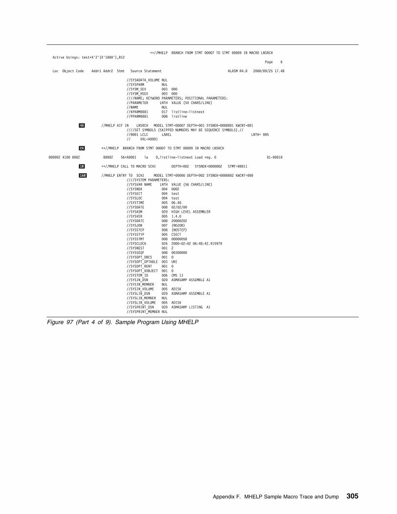
++//MHELP BRANCH FROM STMT 99997 TO STMT 99999 IN MACRO LNSRCHActive Usings: test+X'2'(X'1999'),R12
Page 6
Loc Object Code Addr1 Addr2 Stmt Source Statement HLASM R4.9 2999/99/25 17.48
//SYSADATA_VOLUME NUL //SYSPARM NUL //SYSM_SEV 993 999 //SYSM_HSEV 993 999
////NAME; KEYWORD PARAMETERS; POSITIONAL PARAMETERS://PARAMETER LNTH VALUE (54 CHARS/LINE)
//NAME NUL //KPARM9991 917 listline-listnext //PPARM9991 998 listline
�4A� //MHELP AIF IN LNSRCH MODEL STMT=99997 DEPTH=991 SYSNDX=9999991 KWCNT=991////SET SYMBOLS (SKIPPED NUMBERS MAY BE SEQUENCE SYMBOLS).//
//9991 LCLC LABEL LNTH= 995 // VAL=A9991
�2A� ++//MHELP BRANCH FROM STMT 99997 TO STMT 99999 IN MACRO LNSRCH
999992 4199 9992 99992 56+A9991 la 9,listline-listnext Load reg. 9 91-99919
�1B� ++//MHELP CALL TO MACRO SCHI DEPTH=992 SYSNDX=9999992 STMT=99911
�16B� //MHELP ENTRY TO SCHI MODEL STMT=99999 DEPTH=992 SYSNDX=9999992 KWCNT=999 ////SYSTEM PARAMETERS:
//SYSVAR NAME LNTH VALUE (56 CHARS/LINE) //SYSNDX 994 9992 //SYSECT 994 test //SYSLOC 994 test //SYSTIME 995 96.48 //SYSDATE 998 92/92/99
//SYSASM 929 HIGH LEVEL ASSEMBLER //SYSVER 995 1.4.9 //SYSDATC 998 29999292 //SYSJOB 997 (NOJOB) //SYSSTEP 998 (NOSTEP) //SYSSTYP 995 CSECT //SYSSTMT 998 99999958 //SYSCLOCK 926 2999-92-92 96:48:42.915979 //SYSNEST 991 2 //SYSSEQF 998 99399999 //SYSOPT_DBCS 991 9
//SYSOPT_OPTABLE 993 UNI //SYSOPT_RENT 991 9
//SYSOPT_XOBJECT 991 9 //SYSTEM_ID 996 CMS 13
//SYSIN_DSN 929 ASMASAMP ASSEMBLE A1 //SYSIN_MEMBER NUL //SYSIN_VOLUME 995 ADISK
//SYSLIB_DSN 929 ASMASAMP ASSEMBLE A1 //SYSLIB_MEMBER NUL //SYSLIB_VOLUME 995 ADISK //SYSPRINT_DSN 929 ASMASAMP LISTING A1 //SYSPRINT_MEMBER NUL
Figure 97 (Part 4 of 9). Sample Program Using MHELP
Appendix F. MHELP Sample Macro Trace and Dump 305

Active Usings: test+X'2'(X'1999'),R12 Page 7
Loc Object Code Addr1 Addr2 Stmt Source Statement HLASM R4.9 2999/99/25 17.48
//SYSPRINT_VOLUME 995 ADISK //SYSTERM_DSN NUL //SYSTERM_MEMBER NUL //SYSTERM_VOLUME NUL //SYSPUNCH_DSN NUL //SYSPUNCH_MEMBER NUL //SYSPUNCH_VOLUME NUL //SYSLIN_DSN 929 ASMASAMP TEXT A1 //SYSLIN_MEMBER NUL //SYSLIN_VOLUME 995 ADISK //SYSADATA_DSN NUL //SYSADATA_MEMBER NUL //SYSADATA_VOLUME NUL //SYSPARM NUL //SYSM_SEV 993 999 //SYSM_HSEV 993 999
////NAME; KEYWORD PARAMETERS; POSITIONAL PARAMETERS://PARAMETER LNTH VALUE (54 CHARS/LINE)
//NAME NUL //PPARM9991 998 listline //PPARM9992 994 9(1)
999996 991F D994 99994 58+ stm 1,15,4(13) 92-99921
�4B� //MHELP AIF IN SCHI MODEL STMT=99924 DEPTH=992 SYSNDX=9999992 KWCNT=999////SET SYMBOLS (SKIPPED NUMBERS MAY BE SEQUENCE SYMBOLS).//
//9991 LCLA CNT VAL= 9999999991 //9992 LCLC CMPADR LNTH= 991 // VAL=l
�4C� //MHELP AIF IN SCHI MODEL STMT=99926 DEPTH=992 SYSNDX=9999992 KWCNT=999////SET SYMBOLS (SKIPPED NUMBERS MAY BE SEQUENCE SYMBOLS).//
//9991 LCLA CNT VAL= 9999999992 //9992 LCLC CMPADR LNTH= 991 // VAL=l
++//MHELP BRANCH FROM STMT 99926 TO STMT 99922 IN MACRO SCHI
�4D� //MHELP AIF IN SCHI MODEL STMT=99924 DEPTH=992 SYSNDX=9999992 KWCNT=999////SET SYMBOLS (SKIPPED NUMBERS MAY BE SEQUENCE SYMBOLS).//
//9991 LCLA CNT VAL= 9999999992 //9992 LCLC CMPADR LNTH= 992 // VAL=li
�4E� //MHELP AIF IN SCHI MODEL STMT=99926 DEPTH=992 SYSNDX=9999992 KWCNT=999////SET SYMBOLS (SKIPPED NUMBERS MAY BE SEQUENCE SYMBOLS).//
//9991 LCLA CNT VAL= 9999999993 //9992 LCLC CMPADR LNTH= 992 // VAL=li
Figure 97 (Part 5 of 9). Sample Program Using MHELP
306 HLASM V1R4 Programmer’s Guide

Page 8Active Usings: test+X'2'(X'1999'),R12
Loc Object Code Addr1 Addr2 Stmt Source Statement HLASM R4.9 2999/99/25 17.48
++//MHELP BRANCH FROM STMT 99926 TO STMT 99922 IN MACRO SCHI
//MHELP AIF IN SCHI MODEL STMT=99924 DEPTH=992 SYSNDX=9999992 KWCNT=999////SET SYMBOLS (SKIPPED NUMBERS MAY BE SEQUENCE SYMBOLS).//
//9991 LCLA CNT VAL= 9999999993 //9992 LCLC CMPADR LNTH= 993 // VAL=lis
//MHELP AIF IN SCHI MODEL STMT=99926 DEPTH=992 SYSNDX=9999992 KWCNT=999////SET SYMBOLS (SKIPPED NUMBERS MAY BE SEQUENCE SYMBOLS).//
//9991 LCLA CNT VAL= 9999999994 //9992 LCLC CMPADR LNTH= 993 // VAL=lis
++//MHELP BRANCH FROM STMT 99926 TO STMT 99922 IN MACRO SCHI
//MHELP AIF IN SCHI MODEL STMT=99924 DEPTH=992 SYSNDX=9999992 KWCNT=999////SET SYMBOLS (SKIPPED NUMBERS MAY BE SEQUENCE SYMBOLS).//
//9991 LCLA CNT VAL= 9999999994 //9992 LCLC CMPADR LNTH= 994 // VAL=list
//MHELP AIF IN SCHI MODEL STMT=99926 DEPTH=992 SYSNDX=9999992 KWCNT=999////SET SYMBOLS (SKIPPED NUMBERS MAY BE SEQUENCE SYMBOLS).//
//9991 LCLA CNT VAL= 9999999995 //9992 LCLC CMPADR LNTH= 994 // VAL=list
++//MHELP BRANCH FROM STMT 99926 TO STMT 99922 IN MACRO SCHI
//MHELP AIF IN SCHI MODEL STMT=99924 DEPTH=992 SYSNDX=9999992 KWCNT=999////SET SYMBOLS (SKIPPED NUMBERS MAY BE SEQUENCE SYMBOLS).//
//9991 LCLA CNT VAL= 9999999995 //9992 LCLC CMPADR LNTH= 995 // VAL=listl
//MHELP AIF IN SCHI MODEL STMT=99926 DEPTH=992 SYSNDX=9999992 KWCNT=999////SET SYMBOLS (SKIPPED NUMBERS MAY BE SEQUENCE SYMBOLS).//
//9991 LCLA CNT VAL= 9999999996 //9992 LCLC CMPADR LNTH= 995 // VAL=listl
++//MHELP BRANCH FROM STMT 99926 TO STMT 99922 IN MACRO SCHI
//MHELP AIF IN SCHI MODEL STMT=99924 DEPTH=992 SYSNDX=9999992 KWCNT=999
Figure 97 (Part 6 of 9). Sample Program Using MHELP
Appendix F. MHELP Sample Macro Trace and Dump 307

Page 9Active Usings: test+X'2'(X'1999'),R12
Loc Object Code Addr1 Addr2 Stmt Source Statement HLASM R4.9 2999/99/25 17.48
////SET SYMBOLS (SKIPPED NUMBERS MAY BE SEQUENCE SYMBOLS).// //9991 LCLA CNT VAL= 9999999996 //9992 LCLC CMPADR LNTH= 996 // VAL=listli
//MHELP AIF IN SCHI MODEL STMT=99926 DEPTH=992 SYSNDX=9999992 KWCNT=999////SET SYMBOLS (SKIPPED NUMBERS MAY BE SEQUENCE SYMBOLS).//
//9991 LCLA CNT VAL= 9999999997 //9992 LCLC CMPADR LNTH= 996 // VAL=listli
++//MHELP BRANCH FROM STMT 99926 TO STMT 99922 IN MACRO SCHI
//MHELP AIF IN SCHI MODEL STMT=99924 DEPTH=992 SYSNDX=9999992 KWCNT=999////SET SYMBOLS (SKIPPED NUMBERS MAY BE SEQUENCE SYMBOLS).//
//9991 LCLA CNT VAL= 9999999997 //9992 LCLC CMPADR LNTH= 997 // VAL=listlin
//MHELP AIF IN SCHI MODEL STMT=99926 DEPTH=992 SYSNDX=9999992 KWCNT=999////SET SYMBOLS (SKIPPED NUMBERS MAY BE SEQUENCE SYMBOLS).//
//9991 LCLA CNT VAL= 9999999998 //9992 LCLC CMPADR LNTH= 997 // VAL=listlin
99999A 4139 C924 99926 59+ la 3,listline Comparand 92-99928
++//MHELP BRANCH FROM STMT 99929 TO STMT 99937 IN MACRO SCHI
99999E 4111 9999 99999 69+ la 1,9(1) List header 92-99938 999912 D292 C924 9999 99926 99999 61+ mvc listline,9(9) Dummy move to get comp length 92-99939 999918 99918 99912 62+ org L-6 Change MVC to MVI 92-99949 999912 92 63+ dc x'92' MVI Opcode 92-99941 999913 99913 99914 64+ org L+1 Preserve length as immed opnd 92-99942 999914 D999 65+ dc x'd999' Result is MVI 9(13),L 92-99943 999916 58F9 C92E 99939 66+ l 15,=v(schi) 92-99944 99991A 95EF 67+ balr 14,15 92-99945 99991C 981F D994 99994 68+ lm 1,15,4(13) 92-99946
�8A� //MHELP EXIT FROM SCHI MODEL STMT=99947 DEPTH=992 SYSNDX=9999992 KWCNT=999////SET SYMBOLS (SKIPPED NUMBERS MAY BE SEQUENCE SYMBOLS).//
//9991 LCLA CNT VAL= 9999999998 //9992 LCLC CMPADR LNTH= 997 // VAL=listlin
999929 4719 C999 99992 69+ bc 1,A9991 If max reached, continue 91-99912
�8B� //MHELP EXIT FROM LNSRCH MODEL STMT=99913 DEPTH=991 SYSNDX=9999991 KWCNT=991////SET SYMBOLS (SKIPPED NUMBERS MAY BE SEQUENCE SYMBOLS).//
//9991 LCLC LABEL LNTH= 995 // VAL=A9991
Figure 97 (Part 7 of 9). Sample Program Using MHELP
Page 19Active Usings: test+X'2'(X'1999'),R12
Loc Object Code Addr1 Addr2 Stmt Source Statement HLASM R4.9 2999/99/25 17.48
999924 79 listnext ds h 99391999 999926 71 listline ds fl3'9' 99392999 999939 72 ltorg 99393999 999939 99999999 73 =v(schi)
Figure 97 (Part 8 of 9). Sample Program Using MHELP
New Floating-point Constants included for Verification Page 11Active Usings: test+X'2'(X'1999'),R12
Loc Object Code Addr1 Addr2 Stmt Source Statement HLASM R4.9 2999/99/25 17.48
75 LLLLLLLLLLLLLLLLLLLLLLLLLLLLLLLLLLLLLLLLLLLLLLLLLLLLLLLLLLLLLLLLLLLLLL 9939599976 L New FP definitions included to verify correct release of HLASM L 99396999
77 LLLLLLLLLLLLLLLLLLLLLLLLLLLLLLLLLLLLLLLLLLLLLLLLLLLLLLLLLLLLLLLLLLLLLL 99397999 999934 99999999 999938 4993489999999999 78 BFP1 DC DB'1234' 99398999 999949 434D299999999999 79 HFP1 DC DH'1234' 99399999 999999 89 end test 99319999
Figure 97 (Part 9 of 9). Sample Program Using MHELP
308 HLASM V1R4 Programmer’s Guide

Appendix G. High Level Assembler Messages
High Level Assembler produces the following types of messages:
� Assembly error-diagnostic messages.� Assembly abnormal-termination messages.� ASMAHL command-error messages (CMS).
The following section describes the format and placement of messages issued bythe assembler. “Assembly Error Diagnostic Messages” on page 312, “AbnormalAssembly Termination Messages” on page 352, and “ASMAHL Command ErrorMessages (CMS)” on page 357, list and describe each message.
Message Code FormatAssembly error diagnostic messages, and assembly abnormal terminationmessages, have the following message code format:
ASMAnnns
nnn a three-character message number
s severity indicator
The severity indicators, and the corresponding severity codes are:
I—Informational(Severity code = 0)
This error does not affect the running of the program; rather, it is acoding inefficiency or other such condition that can be changed. Theassembler has not detected any conditions affecting the correctness ofthe program.
N—Notice(Severity code = 2)
This type of message brings your attention to a condition that you mightwish to correct. The assembler has not detected any conditions affectingthe correctness of the program; however, the output from the assemblymight not be what you expect.
W—Warning(Severity code = 4)
Although the statement in which the condition occurs is syntacticallycorrect, it has the potential for causing an error when the program is run.
E—Error(Severity code = 8)
The condition is definitely an error. However, the assembler has tried tocorrect the error, or has ignored the statement in error. The programprobably will not run successfully.
S—Severe(Severity code = 12)
The condition is a serious error. The assembler has either ignored thestatement in error, or the machine instruction has been assembled to
Copyright IBM Corp. 1982, 2000 309

zero. It is not likely that the program will assemble as expected or that itwill run.
C—Critical(Severity code = 16)
The condition is a critical error. It is not likely that the program will runsuccessfully.
U—Unrecoverable(Severity code = 20)
The error condition is of such magnitude that the assembler could notcontinue.
ASMAHL command error messages have the following message code format:
ASMACMSnnnE
where:
nnn Is a three-character message number
E Simply indicates an error. In some cases the assembly will proceed after themessage has been issued.
LANGUAGE Assembler Option: Unless otherwise indicated, the text of ASMAHLcommand error messages is produced in the language specified on theLANGUAGE operand in the installation default options.
Message DescriptionsEach message entry for assembly error diagnostic messages and assemblyabnormal termination messages has the following five sections:
� Message Number and Text� Explanation of Message
� System Action � Programmer Response � Severity Code
Each message entry for ASMAHL command error messages has up to five of thefollowing sections:
� Message Number and Text� Explanation of Message
� Supplemental Information � System Action � Programmer Response
Message Number and TextOnly the message number and the major fixed portion of the message text areincluded in the message description. Any abbreviations in actual message text aredescribed under the message explanation section. Unused message numbersaccount for the gaps in the message number sequence. No messages are definedfor numbers which are not included in this section (for example, ASMA222).
310 HLASM V1R4 Programmer’s Guide

Explanation of MessageFor some messages there is more than one explanation, as different sections of theassembler can generate the same message. Several assembler terminationmessages have identical explanations.
Supplemental InformationFor ASMAHL command error messages, the supplemental information describesthe possible contents of the variables in the message text.
System ActionThis section describes how the assembler handles statements with errors. Someactions include:
� A machine instruction assembles as all zeros.
� An assembler instruction is usually ignored; it is printed but has no effect on theassembly. Many assembler instructions, however, are partially processed orprocessed with a default value. For some instructions, the operands precedingthe operand in error, or every operand except the operand in error, isprocessed. For example, if one of several operands on a DROP statement is asymbol that cannot be evaluated to a register number, only that operand isignored. All the correctly-specified registers are processed correctly.
� For some assembler statements, especially macro prototype and conditionalassembly statements, the operand or term in error is given a default value.Thus the statement assembles completely, but will probably cause incorrectresults if the program is run.
For ASMAHL command error messages, this section describes the command returncode and the status of the system after the error.
Programmer ResponseMany errors have specific or probable causes. In such a case, the ProgrammerResponse section gives specific steps for fixing the error. Most messages,however, have too many possible causes to list (from keying errors to wrong use ofthe statement). The Programmer Response section for these error messages doesnot give specific directions. The cause of most such errors can be determined fromthe message text and the explanation.
Severity CodeThe level of severity code indicates how critical the error might be. The severitycodes and their meanings are described in “Message Code Format” on page 309.
ASMAHL command error messages do not have a severity code, although eachmessage issued by the ASMAHL command that causes the assembly to terminateproduces a return code higher than 20.
The severity code is used to determine the return code issued by the assemblerwhen it returns control to the operating system. The IBM-supplied catalogedprocedures (for MVS) include a COND parameter on the linkage edit and run steps.The COND parameter prevents the running of these steps if the return code fromthe assembler is greater than 8. Thus errors with a severity code of S prevent theassembled program from linkage editing or running. Errors with a severity code ofE, or lower, in the message do not prevent the assembled program from linkageediting or running.
Appendix G. High Level Assembler Messages 311

Assembly Error Diagnostic MessagesHigh Level Assembler prints most error messages in the listing immediatelyfollowing the statements in error. It also prints the total number of flaggedstatements and their statement numbers in the Diagnostic Cross Reference andAssembler Summary section of the assembler listing.
The messages do not follow the statement in error when:
� Errors are detected during editing of macro definitions read from a library. Amessage for such an error appears after the first call in the source program tothat macro definition. You can, however, bring the macro definition into thesource program with a COPY statement. The editing error messages will thenbe attached to the statements in error.
� Errors are detected by the lookahead function of the assembler. (For attributereferences, lookahead processing scans statements after the one beingassembled.). Messages for these errors appear after the statements in whichthey occur. The messages might also appear at the point at which lookaheadwas called.
� Errors are detected on conditional assembly statements during macrogeneration or MHELP testing. Such a message follows the most recentlygenerated statement or MHELP output statement.
A typical error diagnostic message is:
LL ASMA957E Undefined operation code - xxxxx
A copy of a segment of the statement in error, represented above by xxxxx, isinserted into many messages. Normally this segment begins at the bad characteror term. For some errors, however, the segment might begin after the badcharacter or term. The segment might include part of the remarks field.
If a diagnostic message follows a statement generated by a macro definition, thefollowing items might be appended to the error message:
� The number of the model statement in which the error occurred, or the first fivecharacters of the macro name.
� The SET symbol, system variable, macro parameter, or value string associatedwith the error.
Messages may reference three types of macro parameter: the name fieldparameter, keyword parameters, and positional parameters. A reference to thename field parameter is indicated by the word “NAME” appended to the message.References to keyword and positional parameters (for which there may be multipleoccurrences) are in the form “KPARMnnnn” and “PPARMnnnn” respectively, wherennnn is the relative number of the parameter within the macro definition.
Figure 98 on page 313 shows an example of a macro with messages referencingeach type of variable or parameter.
312 HLASM V1R4 Programmer’s Guide

Active Usings: NoneLoc Object Code Addr1 Addr2 Stmt Source Statement HLASM R4.9 2999/99/25 17.48 1 MACRO 99991999 �3� �4� �4� �5� 2 &z parms &kw1=a,&kw2=b,&kw3=c,&kw4=d,&kw5=e,&kw6=f,&pp1,&pp2 99992999
3 &c SETC 'just a string' �┬─��1� 999939994 &ss SETA &c �┘ 999949995 &sv SETA &sysasm �2� 999959996 &z1 SETA &z �3� 999969997 &k1 SETA &kw1 �┬� �4� 999979998 &k5 SETA &kw5 �┘ 99998999
9 &n SETA n'&syslist 99999999 19 &pn SETA &syslist(&n)�─┬� �5� 99919999
11 &p2 SETA &pp2 �┘ ┌� �5� 99911999 12 MEND ┌┴────┐ 99912999 999999 99999 99999 13 default CSECT + + 99913999 14 n parms pp1,pp2,kw5=z,pp3,kw1=y,pp4,pp5,pp6 99914999 ASMA192E Arithmetic term is not self-defining term; default=9 - 99994/C �1� ASMA192E Arithmetic term is not self-defining term; default=9 - 99995/SYSASM �2� ASMA192E Arithmetic term is not self-defining term; default=9 - 99996/NAME �3� ASMA192E Arithmetic term is not self-defining term; default=9 - 99997/KPARM99991 �┬� �4� ASMA192E Arithmetic term is not self-defining term; default=9 - 99998/KPARM99995 �┘ ASMA192E Arithmetic term is not self-defining term; default=9 - 99919/PPARM99996 �┬� �5� ASMA192E Arithmetic term is not self-defining term; default=9 - 99911/PPARM99992 �┘ 15 END 99915999
Figure 98. Sample Macro Parameter Messages
Notes to Figure 98:
�1� SET symbol, and related message
�2� System variable symbol, and related message
�3� The name field parameter, and related message
�4� Keyword parameters, and related messages
�5� Positional parameters, and related messages
If a diagnostic message follows a conditional assembly statement in the sourceprogram, the following items are appended to the error message:
� The word “OPENC”, meaning “open code”.� The SET symbol, or value string, associated with the error.
Several messages might be issued for a single statement or even for a single errorwithin a statement. This happens because each statement is usually evaluated onmore than one level (for example, term level, expression level, and operand level)or by more than one phase of the assembler. Each level or phase can diagnoseerrors; therefore, most or all of the errors in the statement are flagged.Occasionally, duplicate error messages might occur. This is a normal result of theerror-detection process.
Appendix G. High Level Assembler Messages 313
Message Not KnownThe following message might appear in a listing:
LL ASMA999S Message not known - nnn
The statement preceding this message contains an error but the assembler routinethat detected the error issued the number (nnn) of a nonexistent error message tothe assembler's message generation routine. If you can correct the error, thisstatement will assemble correctly. However, this message indicates an error in theerror detection process of the assembler. Save the output and the source deckfrom this assembly and report the problem to your IBM service representative.
314 HLASM V1R4 Programmer’s Guide
ASMA001E 1 ASMA007S
Messages
ASMA001E Operation code not allowed to begenerated - xxxxxxxx
Explanation: An attempt was made to produce arestricted operation code by variable symbolsubstitution. Restricted operation codes are:
ACTR AGO AGOB AIFAIFB ANOP AREAD COPYGBLA GBLB GBLC ICTLISEQ LCLA LCLB LCLCMACRO MEND MEXIT REPROSETA SETAF SETB SETCSETCF
System Action: The statement is ignored.
Programmer Response: If you want a variableoperation code, use AIF to branch to the correctunrestricted statement.
Severity: 8
ASMA002S Generated statement too long;statement truncated - xxxxxxxx
Explanation: The statement generated by a macrodefinition is more than 1728 characters long.
System Action: The statement is truncated; theleading 1728 characters are retained.
Programmer Response: Shorten the statement.
Severity: 12
ASMA003E Undeclared variable symbol; default=0,null, or type=U - xxxxxxxx
Explanation: A variable symbol in the operand field ofthe statement has not been declared (defined) in thename field of a SET statement, in the operand field ofan LCL or GBL statement, or in a macro prototypestatement.
System Action: The variable symbol is given a defaultvalue as follows:
SETA = 9SETB = 9SETC = null (empty) string
The type attribute (T') of the variable is given a defaultvalue of U (undefined).
Programmer Response: Declare the variable beforeyou use it as an operand.
Severity: 8
ASMA004E Duplicate SET symbol declaration; firstis retained - xxxxxxxx
Explanation: A SET symbol has been declared(defined) more than once. A SET symbol is declaredwhen it is used in the name field of a SET statement, inthe operand field of an LCL or GBL statement, or in amacro prototype statement.
System Action: The value of the first declaration ofthe SET symbol is used.
Programmer Response: Eliminate the incorrectdeclarations.
Severity: 8
ASMA005S No storage for macro call; continue withopen code
Explanation: An inner macro call could not beprocessed because no main storage was available.
System Action: The assembly continues with the nextopen code statement.
Programmer Response: Check whether the macro isrecursive, and, if so, whether termination is provided for;correct the macro if necessary. If the macro is correct,allocate more main storage.
Severity: 12
ASMA006I Lookahead invoked
Explanation: This indicates that an instruction hascaused the assembler to go into lookahead mode toresolve a symbol reference. For example:
� an attribute reference (other than D' and O') to asymbol that is not yet defined, or
� a forward AGO or AIF in open code.
System Action: The assembly continues.
Programmer Response: None.
Severity: 0
ASMA007S Previously defined sequence symbol -xxxxxxxx
Explanation: The sequence symbol in the name fieldhas been used in the name field of a previousstatement.
System Action: The first definition of the sequencesymbol is used; this definition is ignored.
Programmer Response: Remove or change one ofthe sequence symbols.
Severity: 12
Appendix G. High Level Assembler Messages 315

ASMA008S 1 ASMA011E
ASMA008S Previously defined symbolic parameter -xxxxxxxx
Explanation: The xxxxxxxx symbol has been used todefine two different symbolic parameters.
System Action: When the parameter name (thevariable symbol) is used inside the macro definition, itrefers to the first definition of the parameter in theprototype. However, if the second parameter definedby the variable symbol is a positional parameter, thecount of positional operands still increases by one. Thesecond parameter can then be referred to only throughuse of &SYSLIST.
Programmer Response: Change one of theparameter names to another variable symbol.
Severity: 12
ASMA009S System variable symbol illegallyre-defined
Explanation: A system variable symbol has beenused in the name field of a macro prototype statement.The system variable symbols are:
System Action: The name parameter is ignored. Thename on a corresponding macro instruction is notgenerated.
Programmer Response: Change the parameter toone that is not a system variable symbol.
Severity: 12
ASMA010E Invalid use of symbol qualifier - xxxxxxxx
Explanation: One of the following has occurred:
� A symbol qualifier has been used to qualify asymbol in other than:
– A machine instruction– The nominal value of an S-type address
constant– The supporting address operand of a
dependent USING statement
� A symbol qualifier is used to qualify a symbol thathas an absolute value where a symbol thatrepresents a relocatable address is required
� A symbol qualifier is used to qualify a symbol that isnot within the range of the corresponding labeledUSING statement
� A symbol qualifier is used to qualify an undefinedsymbol
� A symbol qualifier is used to qualify an incorrectsymbol
� A period is used as the last character of a term, butthe symbol preceding the period has not beendefined in the name field of a labeled USINGstatement
A symbol qualifier can only be used in machineinstructions, the nominal value of S-type addressconstants, or the second operand (supporting baseaddress) of dependent USING instructions. A symbolqualifier can only be used to qualify symbols that arewithin the range of the corresponding labeled USING.
System Action: A machine instruction assembles aszero. An assembler instruction is ignored. If there is afurther error in the statement, a message that describesthe error is issued.
Programmer Response: Correct the use of thesymbol qualifier, or check the statement for the errorindicated in the following message.
Severity: 8
ASMA011E Inconsistent global declarations; first isretained - xxxxxxxx
Explanation: A global SET variable symbol has beendefined in more than one macro definition or in a macrodefinition and in the source program, and the twodefinitions are inconsistent in type or dimension.
System Action: The first definition encountered isretained.
| Programmer Response: Assign a new SET symbol| or make the declaration compatible.
Severity: 8
&SYSADATA_DSN&SYSADATA_MEMBER&SYSADATA_VOLUME&SYSASM&SYSCLOCK&SYSDATC&SYSDATE&SYSECT&SYSIN_DSN&SYSIN_MEMBER&SYSIN_VOLUME&SYSJOB&SYSLIB_DSN&SYSLIB_MEMBER&SYSLIB_VOLUME&SYSLIN_DSN&SYSLIN_MEMBER&SYSLIN_VOLUME&SYSLIST&SYSLOC&SYSM_HSEV&SYSM_SEV&SYSMAC
&SYSNDX&SYSNEST&SYSOPT_DBCS&SYSOPT_OPTABLE&SYSOPT_RENT&SYSOPT_XOBJECT&SYSPARM&SYSPRINT_DSN&SYSPRINT_MEMBER&SYSPRINT_VOLUME&SYSPUNCH_DSN&SYSPUNCH_MEMBER&SYSPUNCH_VOLUME&SYSSEQF&SYSSTEP&SYSSTMT&SYSSTYP&SYSTEM_ID&SYSTERM_DSN&SYSTERM_MEMBER&SYSTERM_VOLUME&SYSTIME&SYSVER
316 HLASM V1R4 Programmer’s Guide

ASMA012S 1 ASMA019W
ASMA012S Undefined sequence symbol - xxxxxxxx;macro aborted
Explanation: A sequence symbol in the operand fieldis not defined; that is, it is not used in the name field ofa model statement.
System Action: Exit from the macro definition.
Programmer Response: Define the sequence symbolor correct the reference to it.
Severity: 12
ASMA013S ACTR counter exceeded - xxxxxxxx
Explanation: The conditional assembly loop counter(set by an ACTR statement) has been decremented tozero. The ACTR counter is decremented by one eachtime an AIF or AGO branch is processed successfully.The counter is halved for most errors encountered bythe macro editor phase of the assembler.
System Action: Any macro expansion stops. If theACTR statement is in the source program, the assemblystops.
Programmer Response: Check for an AIF/AGO loopor another type of error. (You can use the MHELPfacility, described in Chapter 6, “Diagnosing AssemblyErrors” on page 143 and Appendix F, “MHELP SampleMacro Trace and Dump” on page 301, to trace macrodefinition logic.) If there is no error, increase the initialcount on the ACTR instruction.
Severity: 12
ASMA014E Irreducible qualified expression
Explanation: The statement cannot be resolvedbecause two or more qualified symbols are used in acomplex relocatable expression, or two or morequalified symbols with different symbol qualifiers arepaired in an absolute expression.
System Action: A machine instruction assembles aszero. An assembler instruction is ignored.
Programmer Response: Supply an absoluteexpression, or correct the qualified symbol in error.
Severity: 8
ASMA015W Literal bounds exceeded
Explanation: The expression containing the referenceto the literal resolves to an address outside the boundsof the literal. This indicates a potential error.
System Action: The instruction assembles asspecified.
Programmer Response: Change the expression tonot exceed the bounds.
Severity: 4
ASMA016W Literal used as a branch target
Explanation: The target of a branch instruction is aliteral. This indicates a potential error.
System Action: The instruction assembles asspecified.
Programmer Response: Specify the branch targetcorrectly.
Severity: 4
ASMA017W Undefined keyword parameter; defaultto positional, including keyword -xxxxxxxx
Explanation: A keyword parameter in a macro call isnot defined in the corresponding macro prototypestatement.
This message is also generated by a valid positionalparameter that contains an equal sign.
System Action: The keyword (including the equalssign and value) is used as a positional parameter.
Programmer Response: Define the keyword in theprototype statement, or enclose the valid positionalparameter in parentheses, or single quotation marks,and adjust the macro coding appropriately.
Severity: 4
ASMA018S Duplicate keyword in macro call; lastvalue is used - xxxxxxxx
Explanation: A keyword operand occurs more thanonce in a macro call.
System Action: The latest value assigned to thekeyword is used.
Programmer Response: Eliminate one of the keywordoperands.
Severity: 12
ASMA019W Length of EQUated symbol xxxxxxxxundefined; default=1
Explanation: The value of the length attributeextracted for an EQUated symbol with an unspecifiedlength has been set to the default: 1.
System Action: The instruction assembles asspecified.
Programmer Response: Ensure that the lengthattribute of the symbol is defined.
Severity: 4
Appendix G. High Level Assembler Messages 317

ASMA020E 1 ASMA028E
ASMA020E Illegal GBL or LCL statement - xxxxxxxx
Explanation: A global (GBL) or local (LCL) declarationstatement does not have an operand.
System Action: The statement is ignored.
Programmer Response: Remove the statement oradd an operand.
Severity: 8
ASMA021E Illegal SET statement - xxxxxxxx
Explanation: The operand of a SETB statement is not0, 1, or a SETB expression enclosed in parentheses.
System Action: The statement is ignored.
Programmer Response: Correct the operand ordelete the statement.
Severity: 8
ASMA022I START value rounded up to requiredboundary
Explanation: The value specified in the operand fieldof the START instruction has been rounded up to therequired boundary.
System Action: The assembly continues.
Programmer Response: To stop the messageoccurring, specify the required boundary for the value.
Severity: 0
ASMA023E Symbolic parameter too long - xxxxxxxx
Explanation: A symbolic parameter in this statementis too long. It must not exceed 63 characters, includingthe initial ampersand.
System Action: The symbolic parameter and anyoperand following it in this statement are ignored.
Programmer Response: Make sure all symbolicparameters consist of an ampersand followed by 1 to62 alphanumeric characters, the first of which isalphabetic.
Severity: 8
ASMA024E Invalid variable symbol - xxxxxxxx
Explanation: One of these errors has occurred:
� A symbolic parameter or a SET symbol is not anampersand followed by 1 to 62 alphanumericcharacters, the first being alphabetic.
� A created SET symbol definition is not a valid SETsymbol expression enclosed in parentheses.
System Action: The statement is ignored.
Programmer Response: Supply a valid symbol orexpression.
Severity: 8
ASMA025S Invalid macro prototype operand -xxxxxxxx
Explanation: The format of the operand field of amacro prototype statement is not correct. For example,two parameters are not separated by a comma, or aparameter contains characters that are not permitted.
System Action: The operand field of the prototype isignored.
Programmer Response: Supply a valid operand field.
Severity: 12
ASMA026S Macro call operand too long; 255leading characters deleted - xxxxxxxx
Explanation: An operand of a macro instruction ismore than 255 characters long.
System Action: The leading 255 characters aredeleted.
Programmer Response: Limit the operand to 255characters, or limit it to two or more operands.
Severity: 12
ASMA027S Excessive number of operands
Explanation: One of the following has occurred:
� More than 32000 positional operands, keywordoperands, or both have been explicitly defined in amacro prototype statement.
� There are more than 255 operands in a DC, DS, orDXD statement.
System Action: The excess parameters are ignored.
Programmer Response: For a DC, DS, or DXDstatement, use more than one statement. For a macroprototype statement, delete the extra operands and use&SYSLIST to access the positional operands, orredesign the macro definition.
Severity: 12
ASMA028E Invalid displacement
Explanation: One of the following has occurred:
� The displacement field of an explicit address is notan absolute value within the range 0 through 4095.
� The displacement field of an S-type addressconstant is not an absolute value within the range 0through 4095.
System Action: The statement or constant assemblesas zero.
Programmer Response: Correct the displacement orsupply a correct USING statement containing anabsolute first operand before this statement.
Severity: 8
318 HLASM V1R4 Programmer’s Guide

ASMA029E 1 ASMA035S
| ASMA029E Incorrect register specification -| xxxxxxxx
| Explanation: The value xxxxxxxx is invalid for one ofthe following reasons:
� xxxxxxxx is not an absolute value within the range 0through 15.
� an odd register is used where an even register isrequired
� a register is not specified where one is required.
System Action: For machine instructions and S-typeaddress constants, the statement or constantassembles as zero. For USING and DROP statements,the incorrect register operand is ignored.
Programmer Response: Specify a valid register.
Severity: 8
ASMA030E Invalid literal usage - xxxxxxxx
Explanation: A literal is used in an assemblerinstruction, another literal, or a field of a machineinstruction where it is not permitted.
System Action: An assembler instruction containing aliteral is generally ignored and another message,relative to the operation code of the instruction,appears. A machine instruction assembles as zero.
Programmer Response: If applicable, replace theliteral with the name of a DC statement.
Severity: 8
ASMA031E Invalid immediate or mask field
Explanation: The value of an immediate or maskoperand of a machine instruction requires more bits torepresent it than allowed by the instruction, or the valueof the immediate operand exceeds 9 on an SRPinstruction or 15 on an MC instruction.
Immediate fields used in an arithmetic context areallowed to be signed, those in a logical context are not;for example:
AHI r1,-39999 is valid, but AHI r1,59999 is not
TMH r1,59999 is valid, but TMH r1,-39999 is not
System Action: The instruction assembles as zero.
Programmer Response: Use a valid immediateoperand, or specify the immediate information in a DCstatement or a literal and change the statement to anon-immediate type.
Severity: 8
ASMA032E Relocatable value found when absolutevalue required - xxxxxxxx
Explanation: One of the following has occurred:
� A relocatable or complex relocatable expression isused where an absolute expression is required.
� A DSECT-based expression is used as an operandfor an address constant where an expression thatresolves into a storage address is required.
System Action: A machine instruction assembles aszero. In a DC, DS, or DXD statement, the operand inerror and the following operands are ignored.
Programmer Response: Supply an absoluteexpression or term, or for an address constant supply avalid storage address expression.
Severity: 8
ASMA033I Storage alignment for xxxxxxxxunfavorable
Explanation: An address referenced by this statementmight not be aligned to the optimal boundary for thisinstruction; for example, the data referenced by a loadinstruction (L) might be on a halfword boundary.
System Action: The instruction assembles as written.
Programmer Response: Correct the operand if it is inerror. If you are using an instruction that does notrequire alignment, or you want to suppress alignmentchecking for some other reason, you can specify theNOALIGN assembler option or ACONTROLFLAG(NOALIGN). If a particular statement is correct,you can suppress this message by writing the statementwith an absolute displacement and an explicit baseregister, as in this example:
L 1,SYM-BASE(,2)
Severity: 0
ASMA034W Operand operand beyond active USINGrange by xxxx bytes
Explanation: The address of this statement does notfall within the range of an active USING statement.
System Action: The instruction assembles as zero.
Programmer Response: Increase the range of theactive USING.
Severity: 8
ASMA035S Invalid delimiter - xxxxxxxx
Explanation:
1. A required delimiter in a DC, DS, or DXD statementis missing or appears where none should be; theerror might be any of these:
� A quotation mark with an address constant.� A left parenthesis with a non-address constant.
Appendix G. High Level Assembler Messages 319

ASMA036W 1 ASMA041E
� A constant field not started with a quotationmark, left parenthesis, blank, or comma.
� An empty constant field in a DC.� A missing comma or right parenthesis following
an address constant.� A missing subfield right parenthesis in an S-type
address constant.� A missing right parenthesis in a constant
modifier expression.
2. A parameter in a macro prototype statement wasnot followed by a valid delimiter: comma, equalsign, or blank.
3. The DBCS option is on, and SO follows a variablesymbol without an intervening period.
System Action: The operand or parameter in errorand the following operands or parameters are ignored.
Programmer Response: Supply a valid delimiter.
Severity: 12
ASMA036W Reentrant check failed
Explanation: A machine instruction that might storedata into a control section or common area when runhas been detected. This message is generated onlywhen reentrant checking is requested by the assembleroption RENT or within an RSECT.
System Action: The statement assembles as written.
Programmer Response: If you want reentrant code,correct the instruction. Otherwise, for a control sectionthat has not been defined by an RSECT instruction, youcan suppress reentrancy checking by specifyingNORENT as an assembler option. You cannotsuppress reentrancy for a control section defined by anRSECT instruction.
Severity: 4
ASMA037E Illegal self-defining value - xxxxxxxx
Explanation: A decimal, binary (B), hexadecimal (X),or character (C) self-defining term contains charactersthat are not permitted or is in illegal format.
System Action: In the source program, the operand inerror and the following operands are ignored. In amacro definition, the whole statement is ignored.
Programmer Response: Supply a valid self-definingterm.
Severity: 8
ASMA038S Operand value falls outside of currentsection/LOCTR
Explanation: An ORG statement specifies a locationoutside the control section or the LOCTR in which theORG is used. ORG cannot force a change to anothersection or LOCTR.
System Action: The statement is ignored.
Programmer Response: Change the ORG statementif it is wrong. Otherwise, insert a CSECT, DSECT,COM, or LOCTR statement to set the location counterto the correct section before the ORG statement isprocessed.
Severity: 12
ASMA039S Location counter error
Explanation: The maximum location counter valuehas been exceeded. When the OBJECT or DECKassembler option is specified the maximum locationcounter value is X'FFFFFF'.
| When the GOFF assembler option is specified the| maximum location counter value is X'7FFFFFFF'.
System Action: The assembly continues, however,the resulting code will probably not run correctly.
Programmer Response: The probable cause is ahigh ORG statement value or a high START statementvalue. Correct the value or split up the control section.
Severity: 12
ASMA040S Missing operand
Explanation: The statement requires an operand, andnone is present.
System Action: A machine instruction assembles aszero. An assembler instruction is ignored.
Programmer Response: Supply the missing operand.
Severity: 12
ASMA041E Term expected; text is unclassifiable -xxxxxxxx
Explanation: One of these errors has occurred:
� A term was expected, but the characterencountered is not one that starts a term (letter,number, =, +, −, *).
� A letter and a quotation mark did not introduce avalid term; the letter is not L, C, G (DBCS option),X, or B.
System Action: Another message accompanies anassembler statement. A machine instruction assemblesas zero.
Programmer Response: Check for missingpunctuation, a wrong letter on a self-defining term, abad attribute request, a leading comma, or a danglingcomma. Note that the length attribute is the only oneaccepted here. If a defined, scale, type, or integerattribute is needed, use a SETA statement andsubstitute the variable symbol where the attribute isneeded.
Severity: 8
320 HLASM V1R4 Programmer’s Guide

ASMA042E 1 ASMA048E
ASMA042E Length attribute of symbol isunavailable; default=1
Explanation: This statement has a length attributereference to a symbol, and the length attribute of thesymbol is unavailable for one of the following reasons:
� The symbols has not been previously defined.
� The type attribute of a symbol is U.
A symbol defined by an EQU instruction has a typeattribute of U, however, a reference to its lengthdoes not produce this message.
� The length cannot be determined due to lookaheadprocessing. If a statement that defines a symbol,and references a length attribute, causes lookaheadprocessing, the symbol might not be assigned alength attribute until after lookahead processing iscomplete. References to the same length attributein subsequent conditional assembly statements,before lookahead processing completes, mightcause this message to be produced.
System Action: The L' attribute defaults to 1.
Programmer Response: Ensure the symbol isdefined. If you suspect the error might be causedbecause of lookahead processing, restructure your codeso that the symbol is defined before it is referenced.
Severity: 8
ASMA043E Previously defined symbol - xxxxxxxx
Explanation: The symbol in a name field or in theoperand field of an EXTRN or WXTRN statement wasdefined (used as a name or an EXTRN/WXTRNoperand) in a previous statement.
System Action: The name or EXTRN/WXTRNoperand of this statement is ignored. The followingoperands of an EXTRN or WXTRN are processed. Thefirst occurrence of the symbol defines it.
Programmer Response: Correct a possible spellingerror, or change the symbol.
Severity: 8
ASMA044E Undefined symbol - xxxxxxxx
Explanation: A symbol in the operand field has notbeen defined, that is, used in the name field of anotherstatement, the operand field of an EXTRN or WXTRN,or, in the case of a literal, the operand of a previouslyprocessed machine instruction statement.
System Action: A machine instruction or an addressconstant assembles as zero. In a DC, DS, or DXDstatement or in a duplication-factor or length- modifierexpression, the operand in error and the followingoperands are ignored. In an EQU statement, zero isassigned as the value of the undefined symbol. Anyother instruction is not processed.
Programmer Response: Define the symbol, orremove the references to it.
Severity: 8
ASMA045W Register or label not previously used -xxxxxxxx
Explanation: A register or label specified in a DROPstatement has not been previously specified in a USINGstatement.
System Action: Registers or labels not active at thetime are ignored.
Programmer Response: Remove the unreferencedregisters or label from the DROP statement. You candrop all active base registers and labels at once byspecifying DROP with a blank operand.
Severity: 4
ASMA046E Bit 7 of CCW flag byte must be zero
Explanation: Bit 7 of the flag byte of a channelcommand word specified by a CCW, CCW0, or CCW1statement is not zero.
System Action: The CCW, CCW0, or CCW1assembles as zero.
Programmer Response: Set bit 7 of the flag byte tozero to suppress this message during the nextassembly.
Severity: 8
ASMA047E Severity code too large
Explanation: The severity code (first operand) of anMNOTE statement is not * or an unsigned decimalnumber from 0 to 255.
System Action: The statement is printed in standardformat instead of MNOTE format. The MNOTE is giventhe severity code of this message.
Programmer Response: Choose a severity code of *or a number less than or equal to 255, or check for agenerated severity code.
Severity: 8
ASMA048E ENTRY error - xxxxxxxx
Explanation: One of the following errors was detectedin the operand of an ENTRY statement:
� Duplicate symbol (previous ENTRY)� Symbol defined in a DSECT or COM section� Symbol defined by a DXD statement
� Undefined symbol� Symbol defined by an absolute or complex
relocatable EQU statement
System Action: The external symbol dictionary outputis suppressed for the symbol.
Appendix G. High Level Assembler Messages 321

ASMA049W 1 ASMA055S
Programmer Response: Define the ENTRY operandcorrectly.
Severity: 8
ASMA049W Illegal range on ISEQ
Explanation: If this message is accompanied byanother, this one is advisory. If it appears by itself, itindicates one of the following errors:
� An operand value is less than 1 or greater than 80,or the second operand (rightmost column to bechecked) is less than the first operand (extreme leftcolumn to be checked).
� More or fewer than two operands are present, or anoperand is null (empty).
� An operand expression contains an undefinedsymbol.
� An operand expression is not absolute.� The statement is too complex. For example, it
might have forward references or cause anarithmetic overflow during evaluation.
� The statement is circularly defined.
System Action: Sequence checking stops.
Programmer Response: Supply valid ISEQ operands.Also, be sure that the records following this statementare in order; they have not been sequence checked.
Severity: 4
ASMA050E Illegal name field; name discarded -xxxxxxxx
Explanation: One of these errors has occurred:
� The name field of a macro prototype statementcontains an incorrect symbolic parameter (variablesymbol)
� The name field of a COPY statement in a macrodefinition contains an entry other than blank or avalid sequence symbol
System Action: The incorrect name field is ignored.
Programmer Response: Correct the incorrect namefield.
Severity: 8
ASMA051E Illegal statement outside a macrodefinition
| Explanation: A MEND, MEXIT, ASPACE, AEJECT orAREAD statement appears outside a macro definition.
System Action: The statement is ignored.
Programmer Response: Remove the statement or, ifa macro definition is intended, insert a MACROstatement.
Severity: 8
ASMA052S Record out of sequence - xxxxxxxx
Explanation: Input sequence checking, under controlof the ISEQ assembler instruction, has determined thatthis statement is out of sequence. The sequencenumber of the statement is appended to the message.
System Action: The statement assembles normally.However, the sequence number of the next statement ischecked relative to this statement.
Programmer Response: Put the statements in correctsequence. If you want a break in sequence, put in anew ISEQ statement and sequence number. ISEQalways resets the sequence number; the recordfollowing the ISEQ is not sequence checked.
Severity: 12
ASMA053W Blank sequence field - xxxxxxxx
Explanation: Input sequence checking, controlled bythe ISEQ assembler statement, has detected astatement with a blank sequence field. The sequencenumber of the last numbered statement is appended tothe message.
System Action: The statement assembles normally.The sequence number of the next statement is checkedrelative to the last statement having a non-blanksequence field.
Programmer Response: Put the correct sequencenumber in the statement or discontinue sequencechecking over the blank statements by means of anISEQ statement with a blank operand.
Severity: 4
ASMA054E Illegal continuation record
Explanation: A statement has more than 10 recordsor end-of-input has been encountered when acontinuation record was expected.
System Action: The records already read areprocessed as is. If the statement had more than 10records, the next record is treated as the beginning of anew statement.
Programmer Response: In the first case, break thestatement into two or more statements. In the secondcase, ensure that a continued statement does not spanthe end of a library member. Check for lost records oran extraneous continuation character.
Severity: 8
ASMA055S Recursive COPY
Explanation: A nested COPY statement (COPY withinanother COPY) attempted to copy a library memberalready being copied by a higher level COPY within thesame nest.
System Action: This COPY statement is ignored.
Programmer Response: Correct the operand of this
322 HLASM V1R4 Programmer’s Guide
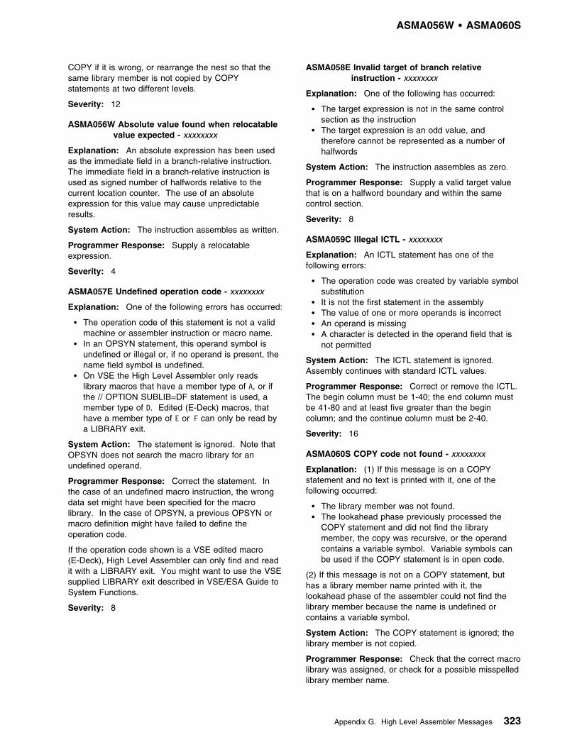
ASMA056W 1 ASMA060S
COPY if it is wrong, or rearrange the nest so that thesame library member is not copied by COPYstatements at two different levels.
Severity: 12
ASMA056W Absolute value found when relocatablevalue expected - xxxxxxxx
Explanation: An absolute expression has been usedas the immediate field in a branch-relative instruction.The immediate field in a branch-relative instruction isused as signed number of halfwords relative to thecurrent location counter. The use of an absoluteexpression for this value may cause unpredictableresults.
System Action: The instruction assembles as written.
Programmer Response: Supply a relocatableexpression.
Severity: 4
ASMA057E Undefined operation code - xxxxxxxx
Explanation: One of the following errors has occurred:
� The operation code of this statement is not a validmachine or assembler instruction or macro name.
� In an OPSYN statement, this operand symbol isundefined or illegal or, if no operand is present, thename field symbol is undefined.
� On VSE the High Level Assembler only readslibrary macros that have a member type of A, or ifthe // OPTION SUBLIB=DF statement is used, amember type of D. Edited (E-Deck) macros, thathave a member type of E or F can only be read bya LIBRARY exit.
System Action: The statement is ignored. Note thatOPSYN does not search the macro library for anundefined operand.
Programmer Response: Correct the statement. Inthe case of an undefined macro instruction, the wrongdata set might have been specified for the macrolibrary. In the case of OPSYN, a previous OPSYN ormacro definition might have failed to define theoperation code.
If the operation code shown is a VSE edited macro(E-Deck), High Level Assembler can only find and readit with a LIBRARY exit. You might want to use the VSEsupplied LIBRARY exit described in VSE/ESA Guide toSystem Functions.
Severity: 8
ASMA058E Invalid target of branch relativeinstruction - xxxxxxxx
Explanation: One of the following has occurred:
� The target expression is not in the same controlsection as the instruction
� The target expression is an odd value, andtherefore cannot be represented as a number ofhalfwords
System Action: The instruction assembles as zero.
Programmer Response: Supply a valid target valuethat is on a halfword boundary and within the samecontrol section.
Severity: 8
ASMA059C Illegal ICTL - xxxxxxxx
Explanation: An ICTL statement has one of thefollowing errors:
� The operation code was created by variable symbolsubstitution
� It is not the first statement in the assembly� The value of one or more operands is incorrect� An operand is missing� A character is detected in the operand field that is
not permitted
System Action: The ICTL statement is ignored.Assembly continues with standard ICTL values.
Programmer Response: Correct or remove the ICTL.The begin column must be 1-40; the end column mustbe 41-80 and at least five greater than the begincolumn; and the continue column must be 2-40.
Severity: 16
ASMA060S COPY code not found - xxxxxxxx
Explanation: (1) If this message is on a COPYstatement and no text is printed with it, one of thefollowing occurred:
� The library member was not found.� The lookahead phase previously processed the
COPY statement and did not find the librarymember, the copy was recursive, or the operandcontains a variable symbol. Variable symbols canbe used if the COPY statement is in open code.
(2) If this message is not on a COPY statement, buthas a library member name printed with it, thelookahead phase of the assembler could not find thelibrary member because the name is undefined orcontains a variable symbol.
System Action: The COPY statement is ignored; thelibrary member is not copied.
Programmer Response: Check that the correct macrolibrary was assigned, or check for a possible misspelledlibrary member name.
Appendix G. High Level Assembler Messages 323

ASMA061E 1 ASMA066W
If COPY member is not defined in any macro library,and is not processed because of an AGO or AIFassembler instruction, add a dummy COPY memberwith the name to the macro library.
Severity: 12
ASMA061E Symbol not name of DSECT, DXD orexternal label
Explanation: The operand of a Q-type addressconstant is not a symbol or the name of a DSECT orDXD statement, or an external label.
System Action: The constant assembles as zero.
Programmer Response: Supply a valid operand.
Severity: 8
ASMA062E Illegal operand format - xxxxxxxx
Explanation: One of the following errors has occurred:
� ADATA—more than five operands are specified, orthe value of one of the expressions specified in oneof the first four operands is outside the range −231
to +231−1, or the fifth operand is not a validcharacter expression
� ACONTROL—one or more of the operands suppliedis invalid
� AINSERT—the first operand is not a valid string, orthe second operand is not BACK or FRONT
� AMODE—the operand does not specify 24, 31, orANY
| � AREAD—the operand specifies an incorrect AREAD| operand.
� DROP or USING—more than 16 registers arespecified in the operand field
� EXITCTL—more than five operands are specified,or the first operand is not a valid exit type, or thevalue of one of the expressions specified in thesecond and subsequent operands is outside therange −231 to +231−1
� MNOTE—the syntax of the severity code (firstoperand) is not correct, or the sum of the length ofthe operands including quotes and commasexceeds 1024 bytes
� PRINT—an operand specifies an incorrect printoption
� PUSH or POP—an operand does not specify aPRINT or USING statement
� RMODE—the operand does not specify 24 or ANY� TITLE—more than 100 bytes were specified
System Action: The first 16 registers in a DROP orUSING statement are processed. The operand in errorand the following operands of a PUSH, POP, or PRINTstatement are ignored. The AMODE or RMODEinstruction is ignored, and the name field (if any) doesnot appear in the cross-reference listing. The first 100bytes of the operand of the TITLE instruction are usedas the title.
Programmer Response: Supply a valid operand field.
Severity: 8
ASMA063E No ending apostrophe - xxxxxxxx
Explanation: The quotation mark terminating anoperand is missing, or the standard value of a keywordparameter of a macro prototype statement is missing.
System Action: The operand or standard value inerror is ignored. If the error is in a macro definitionmodel statement, the whole statement is ignored.
Programmer Response: Supply the missing quotationmark.
Severity: 8
ASMA064S Floating point characteristic out ofrange
Explanation: A converted floating-point constant is toolarge or too small for the processor. The allowablerange is approximately 5.4x10−79 to 7.2x1075..
System Action: The constant assembles as zero.
Programmer Response: Check the characteristic(exponent), exponent modifier, scale modifier, andmantissa (fraction) for validity. Remember that afloating-point constant is rounded, not truncated, afterconversion.
Severity: 12
ASMA065E Unknown type - xxxxxxxx
Explanation: An unknown constant type has been| used in a DC or DS statement or in a literal, or the| assembler option required to support the constant type| has not been supplied.
System Action: The operand in error and thefollowing operands are ignored.
Programmer Response: Supply a valid constant orthe required assembler option. Look for an incorrecttype code or incorrect syntax in the duplication factor.
Severity: 8
ASMA066W 2-byte relocatable address constant
Explanation: This statement contains a relocatableY-type address constant or a 2-byte relocatable A-typeaddress constant. Addressing errors occur if theaddress constant is used to refer to a storage addressequal to or greater than 64K (65,536).
System Action: The statement assembles as written.
Programmer Response: If the address constant isused to refer to a storage address less than 64K(65,536), the 2-byte relocatable address constant isvalid. You can use the assembler option RA2 tosuppress this message.
Severity: 4
324 HLASM V1R4 Programmer’s Guide

ASMA067S 1 ASMA073E
ASMA067S Illegal duplication factor - xxxxxxxx
Explanation: One of the following errors has occurred:
� A literal has a zero duplication factor� The duplication factor of a constant is greater than
the maximum of 224−1 bytes� A duplication factor expression of a constant is not
correct
System Action: The operand in error and thefollowing operands of a DC, DS, or DXD statement areignored. The statement containing the literal assemblesas zero.
Programmer Response: Supply a valid duplicationfactor. If you want a zero duplication factor, write theliteral as a DC statement.
Severity: 12
ASMA068S Length error - xxxxxxxx
Explanation: One of the following errors has occurred:
� The length modifier of a constant is wrong� The C, X, B, Z, or P-type constant is too long� An operand is longer than 224−1 bytes� A relocatable address constant has an illegal length� The length field in a machine instruction is not
correct or is out of the permissible range| � The length modifier of a Character Unicode| constant must be a multiple of 2
System Action:
� A machine instruction assembles as zero� A new floating point constant assembles as zero� An address constant is truncated
| � For other DC, DS or DXD statements, the operand| in error and the following operands are ignored| � The operand in error, and the operands following,| are ignored.
| Programmer Response: Supply a valid length or| correct the length modifier.
Severity: 12
| ASMA069S Length of second operand must be less| than length of first
| Explanation: The length of the second operand must| be less than the length of the first operand. If it is not,| a specification exception is recognized.
| System Action: The machine instruction assembles| as zero.
| Programmer Response: Supply a second operand| with a length which is less than that of the first operand.
| Severity: 12
ASMA070E Scale modifier error - xxxxxxxx
Explanation: A scale modifier in a constant is usedillegally, is out of range, or is relocatable, or there is anerror in a scale modifier expression.
System Action: If the scale modifier is out of range, itdefaults to zero. Otherwise, the operand in error andthe following operands are ignored.
Programmer Response: Supply a valid scalemodifier.
Severity: 8
ASMA071E Exponent modifier error
Explanation: The constant contains multiple internalexponents, the exponent modifier is out of range orrelocatable, or the sum of the exponent modifier and theinternal exponent is out of range.
System Action: If the constant contains multipleinternal exponents, the operand in error and thefollowing operands are ignored. Otherwise, theexponent modifier defaults to zero.
Programmer Response: Change the exponentmodifier or the internal exponent.
Severity: 8
ASMA072E Data item too large
Explanation: The value of a Y-type address constantor H-type constant is larger than 215−1 or smaller than−215, or the value of a F-type constant is larger than231−1 or smaller than −231.
System Action: The constant is truncated. Thehigh-order bits are lost.
Programmer Response: Supply a smaller scalemodifier, a longer constant, or a smaller value.
Severity: 8
ASMA073E Precision lost
Explanation: The modifiers of a floating-point numbereither truncate the exponent or shift the fraction out ofthe converted constant.
System Action: The constant assembles with anexponent but with a fraction of zero.
Programmer Response: Change the modifier or usea longer constant type.
Severity: 8
Appendix G. High Level Assembler Messages 325

ASMA074E 1 ASMA082E
ASMA074E Illegal syntax in expression - xxxxxxxx
Explanation: An expression has two terms or twooperations in succession, or incorrect or missingcharacters or delimiters.
System Action: In a DC, DS, or DXD statement, theoperand in error and the following operands areignored. In a macro definition, the whole statement isignored. A machine instruction assembles as zero.
Programmer Response: Check the expression fortyping errors, or for missing or incorrect terms orcharacters.
Severity: 8
ASMA075E Arithmetic overflow
Explanation: The intermediate or final value of anexpression is not within the range −231 through 231−1.
| System Action: A machine instruction assembles as| zero; an assembler instruction is ignored; a conditional| assembly expression uses zero as the result.
Programmer Response: Change the expression.
Severity: 8
ASMA076E Statement complexity exceeded
Explanation: The complexity of this statement causedthe assembler's expression evaluation work area tooverflow.
System Action: A machine instruction assembles aszero. An assembler instruction is ignored.
Programmer Response: Reduce the number ofterms, levels of expressions, or references to complexrelocatable EQU names.
Severity: 8
ASMA077E Circular definition
Explanation: The value of a symbol in an expressionis dependent on itself, either directly or indirectly, viaone or more EQU statements. In the followingexample:
A EQU BB EQU CC EQU A
A is circularly defined.
System Action: The value of the EQU statementdefaults to the current value of the location counter. Allother EQU statements involved in the circularity aredefaulted in terms of this one.
Programmer Response: Supply a correct definition.
Severity: 8
ASMA078E Operand op expression complexlyrelocatable - expr
Explanation: The expression specified is complexlyrelocatable, but an absolute or simply relocatableexpression is required.
System Action: The instruction assembles as zero.
Programmer Response: Correct the expression.
Severity: 8
ASMA079E Illegal PUSH-POP
Explanation: More POP assembler instructions thanPUSH instructions have been encountered.
System Action: This POP instruction is ignored.
Programmer Response: Eliminate a POP statement,or add another PUSH statement.
Severity: 8
ASMA080E Statement is unresolvable
Explanation: A statement cannot be resolved,because it contains a complex relocatable expression orbecause the location counter has been circularlydefined.
System Action: The statement is ignored.
Programmer Response: Untangle the forwardreferences or check the complex relocatable EQUstatements.
Severity: 8
ASMA081E Created SET symbol exceeds 63characters - xxxxxxxx
Explanation: A SET symbol created by variablesymbol substitution is longer than 63 characters(including the ampersand as the first character).
System Action: If the symbol is in the operand field ofa SET, AIF, or AGO statement, its value is set to zeroor null, and the type attribute is set to undefined (U). Ifthe symbol is in the operand field of a GBL, or LCLstatement or the name field of a SET statement,processing of the macro stops.
Programmer Response: Shorten the symbol.
Severity: 8
ASMA082E Created SET symbol is null - xxxxxxxx
Explanation: A SET symbol created by variablesymbol substitution is null (empty string).
System Action: If the symbol is in the operand field ofa SET, AIF, or AGO statement, its value is set to zeroor null, and the type attribute is set to undefined (U). Ifthe symbol is in the operand field of a GBL, or LCLstatement or the name field of a SET statement,processing of the macro stops.
326 HLASM V1R4 Programmer’s Guide

ASMA083E 1 ASMA091E
Programmer Response: Supply a valid symbol.
Severity: 8
ASMA083E Created SET symbol is not a validsymbol - xxxxxxxx
Explanation: A SET symbol created by variablesymbol substitution or concatenation does not consist ofan ampersand followed by up to 62 alphanumericcharacters, the first of which is alphabetic.
System Action: If the symbol is in the operand field ofa SET, AIF, or AGO statement, its value is set to zeroor null, and the type attribute is set to undefined (U). Ifthe symbol is in the operand field of a GBL or LCLstatement or the name field of a SET statement,processing of the macro stops.
Programmer Response: Supply a valid symbol.
Severity: 8
ASMA084S Generated name field exceeds 63characters; discarded - xxxxxxxx
Explanation: The name field on a generatedstatement is longer than 63 characters.
System Action: The name field is not generated. Therest of the statement assembles normally.
Programmer Response: Shorten the generated nameto 63 characters or fewer.
Severity: 12
ASMA085I Generated operand field is null - xxxxxxxx
Explanation: The operand field of a generatedstatement is null (empty).
System Action: The statement assembles as thoughno operand were specified.
Programmer Response: Provide a non-emptyoperand field. If you want the statement assembledwith no operand, substitute a comma rather than leavethe operand blank.
Severity: 0
ASMA086S Missing MEND generated - xxxxxxxx
Explanation: A macro definition, appearing in thesource program or being read from a library by a macrocall or a COPY statement, ends before a MENDstatement is encountered to end it.
System Action: A MEND statement is generated.The portion of the macro definition read in is processed.
Programmer Response: Insert the MEND statement ifit was omitted. Otherwise, check if all the macrodefinition is on the library.
Severity: 12
ASMA087S Generated operation code is null -xxxxxxxx
Explanation: The operation code of a generatedstatement is null (blank).
System Action: The generated statement is printedbut not assembled.
Programmer Response: Provide a valid operationcode.
Severity: 12
ASMA088E Unbalanced parentheses in macro calloperand - xxxxxxxx
Explanation: Excess left or too few right parenthesesoccur in an operand (parameter) of a macro callstatement.
System Action: The parameter corresponding to theoperand in error is given a null (empty) value.
Programmer Response: Balance the parentheses.
Severity: 8
ASMA089E Arithmetic expression contains illegaldelimiter or ends prematurely - xxxxxxxx
Explanation: An arithmetic expression contains anincorrect character or an arithmetic subscript endswithout enough right parentheses.
System Action: The statement is ignored.
Programmer Response: Supply a valid expression.
Severity: 8
ASMA090E Excess right parenthesis in macro calloperand - xxxxxxxx
Explanation: A right parenthesis without acorresponding left parenthesis was detected in anoperand of a macro instruction.
System Action: The excess right parenthesis isignored. The macro expansion might be incorrect.
Programmer Response: Insert the correctparenthesis.
Severity: 8
ASMA091E SETC or character relocatable operandover 255 characters; truncated to 255characters - xxxxxxxx
Explanation: The value of the operand of a SETCstatement or the character relational operand of an AIFstatement is longer than 255 characters. This mightoccur before substrings are evaluated.
System Action: The first 255 characters are used.
Programmer Response: Shorten the SETCexpression value or the operand value.
Severity: 8
Appendix G. High Level Assembler Messages 327

ASMA092E 1 ASMA100E
ASMA092E Substring expression 1 points paststring end; default=null - xxxxxxxx
Explanation: The first arithmetic expression of aSETC substring points beyond the end of theexpression character string.
System Action: The substring is given a null value.
Programmer Response: Supply a valid expression.
Severity: 8
ASMA093E Substring expression 1 less than 1;default=null - xxxxxxxx
Explanation: The first arithmetic expression of aSETC substring is less than one; that is, it points beforethe expression character string.
System Action: The substring expression defaults tonull.
Programmer Response: Supply a valid expression.
Severity: 8
ASMA094I Substring goes past string end;default=remainder
Explanation: The second expression of a substringnotation specifies a length that extends beyond the endof the string.
System Action: The result of the substring operationis a string that ends with the last character in thecharacter string.
Programmer Response: Make sure the arithmeticexpression used to specify the length does not specifycharacters beyond the end of the string. Either changethe first or the second expression in the substringnotation. You can use the assembler optionFLAG(NOSUBSTR) to suppress this message.
Severity: 0
ASMA095W Substring expression 2 less than 0;default=null - xxxxxxxx
Explanation: The second arithmetic expression of aSETC substring is less than or equal to zero.
System Action: No characters (a null string) from thesubstring character expression are used.
Programmer Response: Supply a valid expression.
Severity: 4
ASMA096E Unsubscripted SYSLIST;default=SYSLIST(1) - xxxxxxxx
Explanation: The system variable symbol, &SYSLIST,is not subscripted. &SYSLIST(n) refers to the nthpositional parameter in a macro instruction.N'&SYSLIST does not have to be subscripted.
System Action: The subscript defaults to one so thatit refers to the first positional parameter.
Programmer Response: Supply the correct subscript.
Severity: 8
ASMA097E Invalid attribute reference to SETA orSETB symbol; default=U or 0 - xxxxxxxx
Explanation: A length (L'), scaling (S'), integer (I'),or defined (D') attribute refers to a SETA or SETBsymbol.
System Action: The attributes are set to defaultvalues: L'=0, S'=0, I'=0 ,and D'=0.
Programmer Response: Change or remove theattribute reference.
Severity: 8
ASMA098E Attribute reference to invalid symbol;default=U or 0 - xxxxxxxx
Explanation: An attribute attempted to reference asymbol that is not correct or has a null value. (A validsymbol is 1 to 63 alphanumeric characters, the first ofwhich is alphabetic.)
System Action: For a type (T') attribute, defaults toU. For all other attributes, defaults to 0.
Programmer Response: Supply a valid symbol.
Severity: 8
ASMA099W Wrong type of constant for S or Iattribute reference; default=0 - xxxxxxxx
Explanation: An integer (I') or scaling (S') attributereferences a symbol whose type is other thanfloating-point (E,D,L), decimal (P,Z), or fixed-point (H,F).
System Action: The integer or scaling attributedefaults to zero.
Programmer Response: Remove the integer orscaling attribute reference or change the constant type.
Severity: 4
ASMA100E Subscript less than 1; default tosubscript=1 - xxxxxxxx
Explanation: The subscript of a subscripted SETsymbol in the name field of a SET statement, theoperand field of a GBL or LCL statement, or an&SYSLIST statement is less than 1.
System Action: The subscript defaults to 1.
Programmer Response: Supply the correct subscript.
Severity: 8
328 HLASM V1R4 Programmer’s Guide
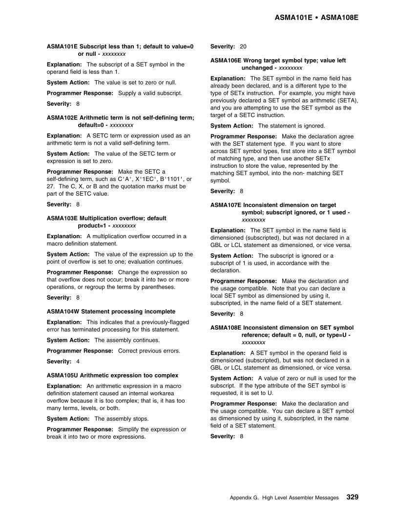
ASMA101E 1 ASMA108E
ASMA101E Subscript less than 1; default to value=0or null - xxxxxxxx
Explanation: The subscript of a SET symbol in theoperand field is less than 1.
System Action: The value is set to zero or null.
Programmer Response: Supply a valid subscript.
Severity: 8
ASMA102E Arithmetic term is not self-defining term;default=0 - xxxxxxxx
Explanation: A SETC term or expression used as anarithmetic term is not a valid self-defining term.
System Action: The value of the SETC term orexpression is set to zero.
Programmer Response: Make the SETC aself-defining term, such as C'A', X'1EC', B'1101', or27. The C, X, or B and the quotation marks must bepart of the SETC value.
Severity: 8
ASMA103E Multiplication overflow; defaultproduct=1 - xxxxxxxx
Explanation: A multiplication overflow occurred in amacro definition statement.
System Action: The value of the expression up to thepoint of overflow is set to one; evaluation continues.
Programmer Response: Change the expression sothat overflow does not occur; break it into two or moreoperations, or regroup the terms by parentheses.
Severity: 8
ASMA104W Statement processing incomplete
Explanation: This indicates that a previously-flaggederror has terminated processing for this statement.
System Action: The assembly continues.
Programmer Response: Correct previous errors.
Severity: 4
ASMA105U Arithmetic expression too complex
Explanation: An arithmetic expression in a macrodefinition statement caused an internal workareaoverflow because it is too complex; that is, it has toomany terms, levels, or both.
System Action: The assembly stops.
Programmer Response: Simplify the expression orbreak it into two or more expressions.
Severity: 20
ASMA106E Wrong target symbol type; value leftunchanged - xxxxxxxx
Explanation: The SET symbol in the name field hasalready been declared, and is a different type to thetype of SETx instruction. For example, you might havepreviously declared a SET symbol as arithmetic (SETA),and you are attempting to use the SET symbol as thetarget of a SETC instruction.
System Action: The statement is ignored.
Programmer Response: Make the declaration agreewith the SET statement type. If you want to storeacross SET symbol types, first store into a SET symbolof matching type, and then use another SETxinstruction to store the value, represented by thematching SET symbol, into the non- matching SETsymbol.
Severity: 8
ASMA107E Inconsistent dimension on targetsymbol; subscript ignored, or 1 used -xxxxxxxx
Explanation: The SET symbol in the name field isdimensioned (subscripted), but was not declared in aGBL or LCL statement as dimensioned, or vice versa.
System Action: The subscript is ignored or asubscript of 1 is used, in accordance with thedeclaration.
Programmer Response: Make the declaration andthe usage compatible. Note that you can declare alocal SET symbol as dimensioned by using it,subscripted, in the name field of a SET statement.
Severity: 8
ASMA108E Inconsistent dimension on SET symbolreference; default = 0, null, or type=U -xxxxxxxx
Explanation: A SET symbol in the operand field isdimensioned (subscripted), but was not declared in aGBL or LCL statement as dimensioned, or vice versa.
System Action: A value of zero or null is used for thesubscript. If the type attribute of the SET symbol isrequested, it is set to U.
Programmer Response: Make the declaration andthe usage compatible. You can declare a SET symbolas dimensioned by using it, subscripted, in the namefield of a SET statement.
Severity: 8
Appendix G. High Level Assembler Messages 329

ASMA109E 1 ASMA116E
ASMA109E Multiple SET operands forundimensioned SET symbol; gets lastoperand - xxxxxxxx
Explanation: Multiple operands were assigned to anundimensioned (unsubscripted) SET symbol.
System Action: The SET symbol is given the value ofthe last operand.
Programmer Response: Declare the SET symbol asdimensioned, or assign only one operand to it.
Severity: 8
ASMA110S Library macro first statement not'MACRO' or comment
Explanation: A statement other than a commentstatement preceded a MACRO statement in a macrodefinition read from a library.
System Action: The macro definition is not read fromthe library. A corresponding macro call cannot beprocessed.
Programmer Response: Ensure that the library macrodefinition begins with a MACRO statement preceded(optionally) by comment statements only.
Severity: 12
ASMA111S Invalid AIF or SETB operand field -xxxxxxxx
Explanation: The operand of an AIF or SETBstatement either does not begin with a left parenthesisor is missing altogether.
System Action: The statement is ignored.
Programmer Response: Supply a valid operand.
Severity: 12
ASMA112S Invalid sequence symbol - xxxxxxxx
Explanation: One of the following errors has occurred:
� A sequence symbol does not begin with a periodfollowed by one to 62 alphanumeric characters, thefirst being alphabetic.
� A sequence symbol in the name field was createdby substitution.
� Operand of AGO is blank or sequence symbol inAIF is blank.
System Action: The sequence symbol in the namefield is ignored. A sequence symbol in the operandfield of an AIF or AGO statement causes the wholestatement to be ignored.
Programmer Response: Supply a valid sequencesymbol.
Severity: 12
ASMA113S Continue column blank
Explanation: A SET symbol declaration in a GBL orLCL statement began with an ampersand in the endcolumn (normally column 71) of the previous record, butthe continue column (normally column 16) of this recordis blank.
System Action: This record and any following recordsof the statement are ignored. Any SET symbols thatcompletely appear on the previous record(s), areprocessed normally.
Programmer Response: Begin this record in thecontinuation column.
Severity: 12
ASMA114S Invalid COPY operand - xxxxxxxx
Explanation: The operand of a COPY statement is nota symbol of 1 to 8 alphanumeric characters, the firstbeing alphabetic.
System Action: The COPY statement is ignored.
Programmer Response: Supply a valid operand. Inopen code the operand can be specified as a previouslydefined SET symbol.
Severity: 12
ASMA115S COPY operand too long - xxxxxxxx
Explanation: The symbol in the operand field of aCOPY statement is more than 8 characters long.
System Action: The COPY statement is ignored.
Programmer Response: Supply a valid operand.
Severity: 12
ASMA116E Illegal SET symbol - xxxxxxxx
Explanation: A SET symbol in the operand field of aGBL or LCL statement or in the name field of a SETstatement does not consist of an ampersand followedby one to 62 alphanumeric characters, the first beingalphabetic.
System Action: For a GBL or LCL statement, theincorrect SET symbol and all following SET symbols ina GBL or LCL statement are ignored. For a SETstatement, the whole SET statement is ignored.
Programmer Response: Supply a SET symbol.
Severity: 8
330 HLASM V1R4 Programmer’s Guide

ASMA117E 1 ASMA124S
ASMA117E Illegal subscript - xxxxxxxx
Explanation: The subscript following a SET symbolcontained unbalanced parentheses or an incorrectarithmetic expression.
System Action: This statement is ignored.
Programmer Response: Supply an equal number ofleft and right parentheses or a valid arithmeticexpression.
Severity: 8
ASMA118S Source macro ended by 'MEND' inCOPY code
Explanation: A library member, being copied by aCOPY statement within a macro definition, contained aMEND statement.
System Action: The MEND statement is honored andthe macro definition stops. No more COPY code isread. The statements brought in before the end of theCOPY code are processed.
Programmer Response: Make sure that each librarymember to be used as COPY code contains balancedMACRO and MEND statements.
Severity: 12
ASMA119S Too few MEND statements in COPYcode
Explanation: A macro definition is started in a librarymember brought in by a COPY statement and theCOPY code ends before a MEND statement isencountered.
System Action: A MEND statement is generated toend the macro definition. The statements brought inbefore the end of the COPY code are processed.
Programmer Response: Check to see if part of themacro definition was lost. Also, ensure that each macrodefinition to be used as COPY code contains balancedMACRO and MEND statements.
Severity: 12
ASMA120S EOD where continuation recordexpected
Explanation: An end-of-data occurred when acontinuation record was expected.
System Action: The portion of the statement read inis assembled. The assembly stops if the end-of-data ison the PRIMARY INPUT. If a library member is beingcopied, the assembly continues with the statement afterthe COPY statement.
Programmer Response: Check to determine whetherany statements were omitted from the source programor from the COPY code.
Severity: 12
ASMA121S Insufficient storage for editor work area
Explanation: The macro editor module of theassembler cannot get enough main storage for its workareas.
System Action: The assembly stops.
Programmer Response: Split the assembly into twoor more parts or give the macro editor more workingstorage.
On MVS or CMS, this can be done by increasing theregion size for the assembler, decreasing blockingfactor or block size on the assembler data sets, or acombination of both.
On VSE, this can be done by decreasing the value youspecify on the SIZE parameter of the JCL EXECstatement, or by running the assembly in a largerpartition.
Severity: 12
ASMA122S Illegal operation code format
Explanation: The operation code is not followed by ablank or is missing altogether, or the first record of acontinued source statement is missing.
System Action: The statement is ignored.
Programmer Response: Ensure that the statementhas a valid operation code and that all records of thestatement are present.
Severity: 12
ASMA123S Variable symbol too long - xxxxxxxx
Explanation: A SET symbol, symbolic parameter, orsequence symbol contains more than 62 charactersfollowing the ampersand or period.
System Action: This statement is ignored.
Programmer Response: Shorten the SET symbol orsequence symbol.
Severity: 12
ASMA124S Illegal use of parameter
Explanation: A symbolic parameter was used in theoperand field of a GBL or LCL statement or in the namefield of a SET statement. In other words, a variablesymbol has been used both as a symbolic parameterand as a SET symbol.
System Action: The statement is ignored.
Programmer Response: Change the variable symbolto one that is not a symbolic parameter.
Severity: 12
Appendix G. High Level Assembler Messages 331

ASMA125S 1 ASMA130S
ASMA125S Illegal macro name - macro uncallable -xxxxxxxx
Explanation: The operation code of a macro prototypestatement is not a valid symbol; that is, one to 63alphanumeric characters, the first alphabetic.
System Action: The macro definition is edited.However, since the macro name is not correct, themacro cannot be called.
Programmer Response: Supply a valid macro name.
Severity: 12
ASMA126S Library macro name incorrect - xxxxxxxx
Explanation: The operation code of the prototypestatement of a library macro definition is not the sameas the operation code of the macro instruction (call).Library macro definitions are located by their membernames. However, the assembler compares the macroinstruction with the macro prototype.
System Action: The macro definition is edited usingthe operation code of the prototype statement as themacro name. Thus, the definition cannot be called bythis macro instruction.
Programmer Response: Ensure that the membername of the macro definition is the same as theoperation code of the prototype statement. This usuallyrequires listing the macro definition from the library, useof the LIBMAC option to cause the macro definition tobe listed, or a COPY of the member name.
Severity: 12
ASMA127S Illegal use of ampersand
Explanation: One of the following errors has occurred:
� An ampersand was found where all substitutionshould have already been done
� The standard value of a keyword parameter in amacro prototype statement contained a singleampersand or a string with an odd number ofampersands
� An unpaired ampersand occurred in a character (C)constant
System Action: In a macro prototype statement, allinformation following the error is ignored. In otherstatements, the action depends on which field the erroroccurred in. If the error occurred in the name field, thestatement is processed without a name. If the erroroccurred in the operation code field, the statement isignored. If the error occurred in the operand field,another message is issued to specify the default.However, if the error occurred in a C-type constant, theoperand in error and the following operands areignored.
Programmer Response: Ensure that ampersandsused in keyword standard values or in C-type constant
values occur in pairs. Also, avoid substituting anampersand into a statement unless there is a doubleampersand.
Severity: 12
ASMA128S Excess right parenthesis - xxxxxxxx
Explanation: An unpaired right parenthesis has beenfound.
System Action: A machine instruction assembles aszero. An assembler instruction is ignored and anadditional message relative to the statement typeappears. However, if the error is in the standard valueof a keyword on a macro prototype statement, only theoperands in error and the following operands areignored.
Programmer Response: Make sure that allparentheses are paired.
Severity: 12
ASMA129S Insufficient right parentheses - xxxxxxxx
Explanation: An unpaired left parenthesis has beenfound. Parentheses must balance at each comma in amultiple operand statement.
System Action: A machine instruction assembles aszero. An assembler instruction is ignored and anadditional message relative to the statement typeappears. However, if the error is in the standard valueof a keyword on a macro prototype statement, only theoperands in error and the following operands areignored.
Programmer Response: Make sure that allparentheses are paired.
Severity: 12
ASMA130S Illegal attribute reference - xxxxxxxx
Explanation: One of the following errors has occurred:
� The symbol following a I, L, S, or T attributereference is not a valid variable symbol or ordinarysymbol or literal that has been previously used in amachine instruction
� The symbol following a K or N attribute reference isnot a valid variable symbol
� The symbol following a D attribute reference is nota valid variable symbol or ordinary symbol
� The quotation mark is missing from a T attributereference
System Action: The statement is ignored.
Programmer Response: Supply a valid attributereference.
Severity: 12
332 HLASM V1R4 Programmer’s Guide

ASMA131S 1 ASMA140W
ASMA131S Parenthesis nesting depth exceeds 255 -xxxxxxxx
Explanation: There are more than 255 levels ofparentheses in a SETA expression.
System Action: The statement is ignored.
Programmer Response: Rewrite the SETA statementusing several statements to regroup the subexpressionsin the expression.
Severity: 12
| ASMA132S Invalid logical expression - xxxxxxxx
| Explanation: A logical expression in the operand field| of a SETB statement or an AIF statement does not
consist of valid character relational expressions,arithmetic relational expressions, and single SETBsymbols, connected by logical operators.
System Action: The statement is ignored.
| Programmer Response: Supply a valid logical| expression.
Severity: 12
ASMA133S Illegal substring reference - xxxxxxxx
Explanation: A substring expression following a SETCexpression does not consist of two valid SETAexpressions separated by a comma and enclosed inparentheses.
System Action: The statement is ignored.
Programmer Response: Supply a valid substringexpression. The second value in the substringexpression can be L.
Severity: 12
ASMA134S Invalid relational operator - xxxxxxxx
Explanation: Characters other than EQ, NE, LT, GT,LE, or GE are used in a SETB expression where arelational operator is expected.
System Action: The statement is ignored.
Programmer Response: Supply a valid relationaloperator.
Severity: 12
ASMA135S Invalid logical operator - xxxxxxxx
Explanation: Characters other than AND, OR, NOT,or XOR are used in a SETB expression where a logicaloperator is expected.
System Action: The statement is ignored.
Programmer Response: Supply a valid logicaloperator.
Severity: 12
ASMA136S Illegal logical/relational operator
Explanation: Characters other than a valid logical orrelational operator were found where a logical orrelational operator was expected.
System Action: The statement is ignored.
Programmer Response: Supply a valid logical orrelational operator.
Severity: 12
| ASMA137S Invalid character expression - xxxxxxxx
Explanation: The operand of a SETC statement or thecharacter value used in a character relation iserroneous. It must be a valid type attribute (T')
| reference, a valid operation code attribute (O') or a| valid character expression enclosed in quotation marks.
System Action: The statement is ignored.
| Programmer Response: Supply a valid character| expression.
Severity: 12
ASMA138W Non-empty PUSH xxxxxxx stack
Explanation: The number of PUSH instructionsexceeds the number of POP instructions at the end ofthe assembly. This indicates a potential error.
System Action: The assembly continues.
Programmer Response: Change your program to| issue POP instructions for all PUSHes. You can| suppress this warning by specifying the NOPUSH| suboption of the FLAG option.
Severity: 4
ASMA139S EOD during REPRO processing
Explanation: A REPRO statement was immediatelyfollowed by an end-of-data so that no valid record couldbe punched. The REPRO is either the last record ofsource input or the last record of a COPY member.
System Action: The REPRO statement is ignored.
Programmer Response: Remove the REPRO orensure that it is followed by a record to be punched.
Severity: 12
ASMA140W END record missing
Explanation: End-of-file on the source input data setoccurred before an END statement was read. One ofthe following has occurred:
� The END statement was omitted or misspelled.� The END operation code was changed or deleted
by OPSYN or by definition of a macro named END.The lookahead phase of the assembler marks whatit thinks is the END statement. If an OPSYNstatement or a macro definition redefines the ENDstatement, premature end-of-input might occur
Appendix G. High Level Assembler Messages 333

ASMA141E 1 ASMA147E
because the assembler does not pass the originalEND statement.
System Action: An END statement is generated. It isassigned a statement number but not printed. If anyliterals are waiting, they are processed as usualfollowing the END statement.
Programmer Response: Check for lost records.Supply a valid END statement; or, if you use OPSYN todefine another symbol as END, place it before thepossible entry into the lookahead phase.
Severity: 4
ASMA141E Bad character in operation code -xxxxxxxx
Explanation: The operation code contains anon-alphanumeric character, that is, a character otherthan A to Z, 0 to 9, $, #, @ or _. Embedded blanks arenot allowed.
System Action: The statement is ignored.
Programmer Response: Supply a valid operationcode. If the operation code is formed by variablesymbol substitution, check the statements leading tosubstitution.
Severity: 8
ASMA142E Operation code not complete on firstrecord
Explanation: The whole name and operation code,including a trailing blank, is not contained on the firstrecord (before the continue column—usually column 72)of a continued statement.
System Action: The statement is ignored.
Programmer Response: Shorten the name, operationcode, or both, or simplify the statement by using aseparate SETC statement to create the name oroperation code by substitution.
Severity: 8
ASMA143E Bad character in name field - xxxxxxxx
Explanation: The name field contains anon-alphanumeric character, that is, a character otherthan A to Z, 0 to 9, $, #, @ or _.
System Action: If possible, the statement isprocessed without a name. Otherwise, it is ignored.
Programmer Response: Put a valid symbol in thename field.
Severity: 8
ASMA144E Begin-to-continue columns not blank -xxxxxxxx
Explanation: On a continuation record, one or morecolumns between the begin column (usually column 1)and the continue column (usually column 16) are notblank.
System Action: The extraneous characters areignored.
Programmer Response: Check whether the operandstarted in the wrong column or whether the precedingrecord contained an erroneous continuation character.
Severity: 8
ASMA145E Operator, right parenthesis, orend-of-expression expected - xxxxxxxx
Explanation: One of the following has occurred:
� A letter, number, equal sign, quotation mark, orundefined character occurred following a termwhere a right parenthesis, an operator, a comma, ora blank ending the expression was expected
� In an assembler instruction, a left parenthesisfollowed a term
System Action: A machine instruction assembles aszero. An assembler instruction is ignored and anothermessage, relative to the operation code, is issued.
Programmer Response: Check for an omitted ormisplaced operator. Subscripting is not allowed on thisstatement.
Severity: 8
ASMA146E Self-defining term too long or value toolarge - xxxxxxxx
Explanation: A self-defining term is longer than 4bytes, (8 hexadecimal digits, 32 bits, or 4 characters),or the value of a decimal self-defining term is greaterthan 231−1.
System Action: A machine instruction assembles aszero. An assembler instruction is ignored. However,another message, relative to the operation code, isissued.
Programmer Response: Reduce the size of theself-defining term, or specify it in a DC statement.
Severity: 8
ASMA147E Symbol too long, or first character not aletter - xxxxxxxx
Explanation: A symbol does not begin with a letter oran underscore (_) or is longer than 63 characters.
System Action: If the symbol is in the name field, thestatement is processed as unnamed. If the symbol is inthe operand field, an assembler operation or a macrodefinition model statement is ignored and a machineoperation assembles as zero.
334 HLASM V1R4 Programmer’s Guide

ASMA148E 1 ASMA154E
Programmer Response: Supply a valid symbol.
Severity: 8
ASMA148E Self-defining term lacks ending quote orhas bad character - xxxxxxxx
Explanation: A hexadecimal or binary self-definingterm contains a character that is not permitted or ismissing the final quotation mark, or a pure DBCSself-defining term contains SO and SI with nodouble-byte data between them.
System Action: A machine operation assembles aszero. An assembler operation is ignored and anothermessage, relative to the operation code, is issued.
Programmer Response: Correct the incorrect term.
Severity: 8
ASMA149E Literal length exceeds 256 characters,including = sign - xxxxxxxx
Explanation: A literal is longer than 256 characters.
System Action: The instruction assembles as zero.
Programmer Response: Shorten the literal, or changeit to a DC statement.
Severity: 8
ASMA150E Symbol has non-alphanumeric characteror invalid delimiter - xxxxxxxx
Explanation: The first character following a symbol isnot a valid delimiter (plus sign, minus sign, asterisk,slash, left or right parenthesis, comma, or blank).
System Action: A machine operation assembles aszero. An assembler operation is ignored, and anothermessage, relative to this operation code, is issued.
Programmer Response: Ensure that the symbol doesnot contain a non-alphanumeric character and that it isfollowed by a valid delimiter.
Severity: 8
ASMA151E Literal expression modifiers must beabsolute and predefined - xxxxxxxx
Explanation: The duplication factor or length modifierin a literal is not a self- defining term, or an expressionusing self-defining terms or previously defined symbols.
System Action: The statement assembles as zero.
Programmer Response: Supply a valid self-definingterm or ensure that symbols appear in the name field ofa previous statement.
Severity: 8
ASMA152S External symbol too long orunacceptable character - xxxxxxxx
Explanation: One of the following errors has occurred:
� An external symbol is longer than 8 characters, orthe limit is 63 characters when the GOFF/XOBJECToption is in effect, or contains a bad character. Anexternal symbol might be the name of a CSECT,START, DXD, AMODE, RMODE, or COMstatement, or the operand of an ENTRY, EXTRN, orWXTRN statement or a Q-type or V-type addressconstant.
� The operand of an ENTRY, EXTRN, or WXTRNstatement or a Q-type or V-type address constant isan expression instead of a single term, or containsa bad character.
� A class name in a CATTR statement is longer than16 characters, or contains a bad character.
System Action: The symbol does not appear in theexternal symbol dictionary. If the error is in the namefield, an attempt is made to process the statement asunnamed. If the error is in the operand field, the badoperand is ignored and, if possible, the followingoperands are processed. A bad constant assembles aszero.
Programmer Response: Supply a shorter name orreplace the expression with a symbol.
Severity: 12
ASMA153S START statement illegal - CSECTalready begun
Explanation: A START statement occurred after thebeginning of a control section.
System Action: The statement is processed as aCSECT statement; any operand is ignored.
Programmer Response: Ensure that the STARTprecedes all machine instructions and any assemblerinstruction, such as EQU, that initiates a control section.If you want EQU statements before the START, placethem in a dummy section (DSECT).
Severity: 12
ASMA154E Operand must be absolute, predefinedsymbols; set to zero - xxxxxxxx
Explanation: The operand on a SETA, SETB, SETC,START or MHELP statement is not correct. If there isanother message with this statement, this message isadvisory. If this message appears alone, it indicatesone of the following:
� There is a location counter reference (*) in aSTART operand.
� An expression does not consist of absolute terms,predefined symbols, or both.
� The statement is too complex. For example, itmight have too many forward references or causearithmetic overflow during evaluation.
Appendix G. High Level Assembler Messages 335

ASMA155S 1 ASMA161W
� The statement is circularly defined.� A relocatable term is multiplied or divided.
System Action: The operand of the statement istreated as zero.
Programmer Response: Correct the error if it exists.Paired relocatable symbols in different LOCTRs, eventhough in the same CSECT or DSECT, are not validwhere an absolute, predefined value is required.
Severity: 8
ASMA155S Previous use of symbol is not thissection type
Explanation: The name on a CSECT, DSECT, COM,| CATTR, or LOCTR statement has been used
previously, on a different type of statement. Forexample, the name on a CSECT has been used beforeon a statement other than CSECT, such as a machineinstruction or a LOCTR.
System Action: This name is ignored, and thestatement processes as unnamed.
Programmer Response: Correct the misspelledname, or change the name to one that does not conflict.
Severity: 12
ASMA156S Only ordinary symbols, separated bycommas, allowed
Explanation: The operand field of an ENTRY,EXTRN, or WXTRN statement contains a symbol thatdoes not consist of 1-to-8 alphanumeric characters, thefirst being alphabetic, or the operands are not separatedby a comma.
System Action: The operand in error is ignored. Ifother operands follow, they process normally.
Programmer Response: Supply a correct symbol orinsert the missing comma. If you want an expressionas an ENTRY statement operand (such asSYMBOL+4), use an EQU statement to define anadditional symbol.
Severity: 12
ASMA157S Operand must be a simply-relocatableexpression
Explanation: If there is another message with thisstatement, this message is advisory. If this messageappears alone, the operand of an ORG or ENDstatement is not a simple relocatable expression, is toocomplex, or is circularly defined. The error might alsobe that the END operand symbol is not in a CSECT.
System Action: An ORG statement or the operand ofan END statement is ignored.
Programmer Response: If an error exists, supply acorrect expression. Paired relocatable symbols indifferent LOCTRs, even though in the same CSECT or
DSECT, might cause circular definition when used in anORG statement.
Severity: 12
ASMA158E Operand expression is defective; set to *
Explanation: The first operand of an EQU statementis defective. If another message appears with thisstatement, this message is advisory. If this messageappears alone, one of the following errors has occurred:
� The statement is too complex. For example, it hastoo many forward references or causes anarithmetic overflow during evaluation.
� The statement is circularly defined.� The statement contains a relocatable term that is
multiplied or divided.
System Action: The symbol in the name field isequated to the current value of the location counter (*),and operands 2 and 3 of the statement, if present, areignored.
Programmer Response: If an error exists, supply acorrect expression for operand 1 of the statement.
Severity: 8
ASMA159S Operand must be absolute, propermultiples of 2 or 4
Explanation: The combination of operands of a CNOPstatement is not one of the following valid combinations:
9,4 2,4 9,8 2,8 4,8 6,8
System Action: The statement is ignored. However,the location counter is adjusted to a halfword boundary.
Programmer Response: Supply a valid combinationof CNOP operands.
Severity: 12
ASMA160W Invalid BYTE function operand xxxxxxxx
Explanation: The value xxxxxxxx of the operand ofthe BYTE built-in function is outside the expected rangeof 0–255.
System Action: The low-order eight bits of theoperand's value are used.
Programmer Response: Supply an arithmeticexpression which returns an acceptable value.
Severity: 4
ASMA161W Only one TITLE statement may have aname field
Explanation: More than one TITLE statement has aname field. The named TITLE statement need not bethe first one in the assembly, but it must be the onlyone named.
System Action: The name on this TITLE statement is
336 HLASM V1R4 Programmer’s Guide
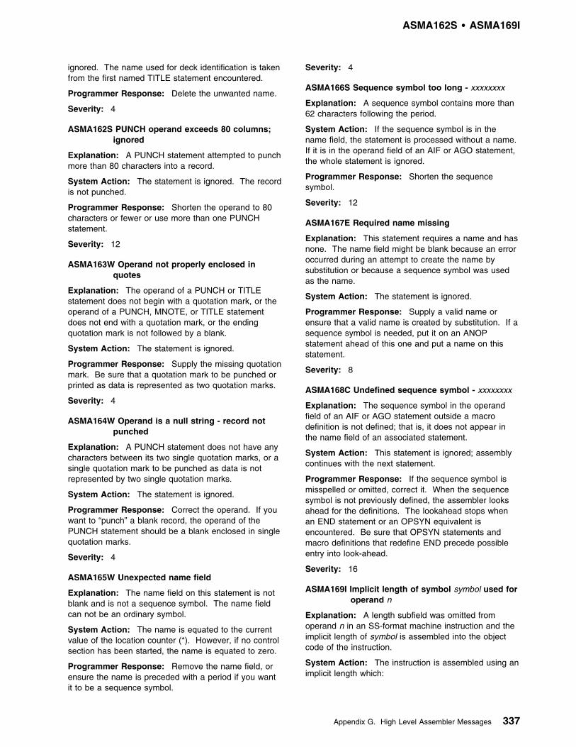
ASMA162S 1 ASMA169I
ignored. The name used for deck identification is takenfrom the first named TITLE statement encountered.
Programmer Response: Delete the unwanted name.
Severity: 4
ASMA162S PUNCH operand exceeds 80 columns;ignored
Explanation: A PUNCH statement attempted to punchmore than 80 characters into a record.
System Action: The statement is ignored. The recordis not punched.
Programmer Response: Shorten the operand to 80characters or fewer or use more than one PUNCHstatement.
Severity: 12
ASMA163W Operand not properly enclosed inquotes
Explanation: The operand of a PUNCH or TITLEstatement does not begin with a quotation mark, or theoperand of a PUNCH, MNOTE, or TITLE statementdoes not end with a quotation mark, or the endingquotation mark is not followed by a blank.
System Action: The statement is ignored.
Programmer Response: Supply the missing quotationmark. Be sure that a quotation mark to be punched orprinted as data is represented as two quotation marks.
Severity: 4
ASMA164W Operand is a null string - record notpunched
Explanation: A PUNCH statement does not have anycharacters between its two single quotation marks, or asingle quotation mark to be punched as data is notrepresented by two single quotation marks.
System Action: The statement is ignored.
Programmer Response: Correct the operand. If youwant to “punch” a blank record, the operand of thePUNCH statement should be a blank enclosed in singlequotation marks.
Severity: 4
ASMA165W Unexpected name field
Explanation: The name field on this statement is notblank and is not a sequence symbol. The name fieldcan not be an ordinary symbol.
System Action: The name is equated to the currentvalue of the location counter (*). However, if no controlsection has been started, the name is equated to zero.
Programmer Response: Remove the name field, orensure the name is preceded with a period if you wantit to be a sequence symbol.
Severity: 4
ASMA166S Sequence symbol too long - xxxxxxxx
Explanation: A sequence symbol contains more than62 characters following the period.
System Action: If the sequence symbol is in thename field, the statement is processed without a name.If it is in the operand field of an AIF or AGO statement,the whole statement is ignored.
Programmer Response: Shorten the sequencesymbol.
Severity: 12
ASMA167E Required name missing
Explanation: This statement requires a name and hasnone. The name field might be blank because an erroroccurred during an attempt to create the name bysubstitution or because a sequence symbol was usedas the name.
System Action: The statement is ignored.
Programmer Response: Supply a valid name orensure that a valid name is created by substitution. If asequence symbol is needed, put it on an ANOPstatement ahead of this one and put a name on thisstatement.
Severity: 8
ASMA168C Undefined sequence symbol - xxxxxxxx
Explanation: The sequence symbol in the operandfield of an AIF or AGO statement outside a macrodefinition is not defined; that is, it does not appear inthe name field of an associated statement.
System Action: This statement is ignored; assemblycontinues with the next statement.
Programmer Response: If the sequence symbol ismisspelled or omitted, correct it. When the sequencesymbol is not previously defined, the assembler looksahead for the definitions. The lookahead stops whenan END statement or an OPSYN equivalent isencountered. Be sure that OPSYN statements andmacro definitions that redefine END precede possibleentry into look-ahead.
Severity: 16
ASMA169I Implicit length of symbol symbol used foroperand n
Explanation: A length subfield was omitted fromoperand n in an SS-format machine instruction and theimplicit length of symbol is assembled into the objectcode of the instruction.
System Action: The instruction is assembled using animplicit length which:
Appendix G. High Level Assembler Messages 337

ASMA170S 1 ASMA178S
� For an implicit address, is the length attribute of thefirst or only term in the expression representing theimplicit address
� For an explicit address, is the length attribute of thefirst or only term in the expression representing thedisplacement
Programmer Response: Check the instruction toensure that the operation and operands are codedcorrectly. You can suppress this warning by specifyingthe NOIMPLEN suboption of the FLAG option.
Severity: 0
ASMA170S Interlude error-logging capacityexceeded
Explanation: The table that the interlude phase of theassembler uses to keep track of the errors it detects isfull. This does not stop error detection by other phasesof the assembler.
System Action: If there are additional errors, normallydetected by the interlude phase, in other statementseither before or after this one, they are not flagged.Statement processing depends on the type of error.
Programmer Response: Correct the indicated errors,and run the assembly again to diagnose any furthererrors.
Severity: 12
ASMA171S Standard value too long
Explanation: The standard (default) value of akeyword parameter on a macro prototype statement islonger than 255 characters.
System Action: The parameter in error and thefollowing parameters are ignored.
Programmer Response: Shorten the standard value.
Severity: 12
ASMA172E Negative duplication factor; default=1 -xxxxxxxx
Explanation: The duplication factor of a SETCstatement is negative.
System Action: The duplication factor is given adefault value of 1.
Programmer Response: Supply a positive duplicationfactor.
Severity: 8
| ASMA173S Delimiter error, expected blank -| xxxxxxxx
| Explanation: The character string xxxxxxxx is found| where a blank (end of operand) is required.
| System Action: A machine instruction assembles as| zero. An ORG statement is ignored. For an EQU or| END statement, the string is ignored and the operand| processes normally. For a CNOP statement, the| location counter is aligned to a halfword boundary.
| Programmer Response: Insert a comma, or replace| the string with a blank. Look for an extra operand or a| missing left parenthesis.
| Severity: 12
| ASMA174S Delimiter error, expected blank or| comma - xxxxxxxx
| Explanation: The character string xxxxxxxx is found| where a blank or a comma is required.
| System Action: A machine instruction assembles as| zero. For a USING or DROP statement, the incorrect| delimiter is ignored and the operand is processed| normally.
| Programmer Response: Insert a comma, or replace| the string with a blank. Look for an extra operand or a| missing left parenthesis.
| Severity: 12
| ASMA175S Delimiter error, expected comma -| xxxxxxxx
| Explanation: The character string xxxxxxxx is used| where a comma is required.
| System Action: A machine instruction assembles as| zero. For a CNOP statement, the location counter is| aligned to a halfword boundary.
| Programmer Response: Insert a comma, or replace| the string with a blank. Be sure each expression is| syntactically correct and that no parentheses are| omitted.
| Severity: 12
| ASMA178S Delimiter error, expected comma or right| parenthesis - xxxxxxxx
| Explanation: The character string xxxxxxxx is used in| a machine instruction when a comma or a right| parenthesis is required.
| System Action: The machine instruction assembles| as zero.
| Programmer Response: Insert a comma, or replace| the string with a right parenthesis. Look for a missing| base field.
| Severity: 12
338 HLASM V1R4 Programmer’s Guide

ASMA179S 1 ASMA185W
| ASMA179S Delimiter error, expected right| parenthesis - xxxxxxxx
| Explanation: The character string xxxxxxxx is used in| a machine instruction when a right parenthesis is| required.
| System Action: The machine instruction assembles| as zero.
| Programmer Response: Replace the string with a| right parenthesis. Look for an index field used where it| is not allowed.
| Severity: 12
ASMA180S Operand must be absolute
Explanation: The operand of a SPACE or CEJECTstatement or the first, third, or fourth operand of a CCWstatement is not an absolute term.
System Action: A SPACE or CEJECT statement isignored. A CCW statement assembles as zero.
Programmer Response: Supply an absolute operand.Paired relocatable terms can span LOCTRs but must bein the same control section.
Severity: 12
ASMA181S CCW operand value is outside allowablerange
Explanation: One or more operands of a CCWstatement are not within the following limits:
� 1st operand—0 to 255� 2nd operand—0 to 16 777 215 (CCW, CCW0); or 0
to 2 147 483 647 (CCW1)� 3rd operand—0-255 and a multiple of 8� 4th operand—0-65 535
System Action: The CCW assembles as zero.
Programmer Response: Supply valid operands.
Severity: 12
ASMA182E Operand 2 must be absolute, 0-65535;ignored
Explanation: If there is another message with thisstatement, this message is advisory. If this messageappears alone, the second operand of an EQUstatement contains one of the following errors:
� It is not an absolute term or expression whosevalue is within the range of 0 to 65,535
� It contains a symbol that is not previously defined� It is circularly defined� It is too complex; for example, it causes an
arithmetic overflow during evaluation� It is derived from an absolute value
System Action: Operand 2 is ignored, and the lengthattribute of the first operand is used. If the thirdoperand is present, it processes normally.
Programmer Response: Correct the error if it exists.Paired relocatable symbols in different LOCTRs, eventhough in the same CSECT, are not valid where anabsolute, predefined value is required.
Severity: 8
ASMA183E Operand 3 must be absolute, 0-255;ignored
Explanation: If there is another message with thisstatement, this message is advisory. If this messageappears alone, the third operand of an EQU statementcontains one of the following errors:
� It is not an absolute term or expression whosevalue is within the range of 0 to 255
� It contains a symbol that is not previously defined� It is circularly defined� It is too complex; for example, it causes an
arithmetic overflow during evaluation.
System Action: The third operand is ignored, and thetype attribute of the EQU statement is set to U.
Programmer Response: Correct the error if it exists.Note that paired relocatable symbols in differentLOCTRs, even though in the same CSECT, are notvalid where an absolute, predefined value is required.
Severity: 8
ASMA184C COPY disaster
Explanation: The assembler copied a library member(processed a COPY statement) while looking ahead forattribute references. However, when the complete textwas analyzed, the COPY operation code had beenchanged by an OPSYN statement or read by anAREAD statement, and the COPY should not havebeen processed. (Lookahead phase ignores OPSYNstatements.) This message follows the first record ofthe COPY code.
System Action: The library member assembles. If itincluded an ICTL statement, the format of that ICTL isused.
Programmer Response: Move COPY statements, orOPSYN statements that modify the meaning of COPY,to a point in the assembly before the entry intolookahead mode (that is, prior to ASMA996I Lookaheadinvoked).
Severity: 16
ASMA185W Operand 2 is erroneous - xxxxxxxx
Explanation: The second operand is incorrect, or twooperands appear where there should be only one.
System Action: The second operand is ignored.
Programmer Response: Remove or correct thesecond operand.
Severity: 4
Appendix G. High Level Assembler Messages 339

ASMA186E 1 ASMA193W
ASMA186E AMODE/RMODE already set for this ESDitem
Explanation: A previous AMODE instruction has thesame name field as this AMODE instruction, or aprevious RMODE instruction has the same name fieldas this RMODE instruction.
System Action: The instruction in error is ignored.
Programmer Response: Remove the conflictinginstruction or specify the name of another controlsection.
Severity: 8
| ASMA187E The name field is invalid - xxxxxxxx
| Explanation: The name field of an AMODE, RMODE| or XATTR instruction is invalid. The name field must be| one of the following:
| � A valid control section| � An ENTRY name (for AMODE or XATTR with the| GOFF option set)| � A valid external name (XATTR only)
| If the XATTR statement uses the PSECT operand then| the name field must specify either a valid control section| name or ENTRY name.
| System Action: The instruction in error is ignored,| and the name does not appear in the cross-reference| listing.
| Programmer Response: Specify a valid name and| resubmit the assembly.
Severity: 8
ASMA188E Incompatible AMODE and RMODEattributes
Explanation: A previous AMODE 24 instruction hasthe same name field as this RMODE ANY instruction, ora previous RMODE ANY instruction has the same namefield as this AMODE 24 instruction.
System Action: The instruction in error is ignored.
Programmer Response: Change the AMODE andRMODE attributes so they are no longer incompatible.All combinations except AMODE 24 and RMODE ANYare valid.
Severity: 8
ASMA189E OPSYN not permitted for REPRO
Explanation: REPRO is specified in either the namefield or the operand field of an OPSYN instruction, but aREPRO statement has been previously encountered inthe source module. Once a REPRO statement hasbeen encountered, the REPRO symbolic operation codecannot be redefined using the OPSYN instruction.
System Action: The OPSYN instruction is ignored.
Programmer Response: Remove the OPSYNinstruction, or remove the previously encounteredREPRO statement.
Severity: 8
ASMA190E CATTR instruction invalid because nosection started
Explanation: A CATTR instruction must be precededby a CSECT, START, or RSECT instruction.
System Action: The CATTR instruction is ignored.
Programmer Response: Remove the CATTRinstruction, or precede it with a CSECT, START, orRSECT instruction.
Severity: 8
ASMA191W CATTR instruction operands ignored
Explanation: You specified operands on a CATTRinstruction which has the same class name as aprevious CATTR instruction.
System Action: The assembler ignores the operands,and continues as if you did not specify any operands.
Programmer Response: You can correct this errorby:
� Removing the operands from the CATTR instructionin error
� Changing the class name for the CATTR instructionin error
� Removing the CATTR instruction in error
Severity: 4
ASMA192W Lost precision - underflow to zero
Explanation: The value supplied is non-zero and istoo small to be represented.
System Action: The constant assembles with anexponent and fraction of zero.
Programmer Response: Supply a larger value or alonger constant type.
Severity: 4
ASMA193W Lost precision - underflow to denormal
Explanation: The value supplied is non-zero and istoo small to be represented in normalized form, but canbe represented in denormalized form.
System Action: The constant assembles with thedenormalized form.
Programmer Response: Supply a larger value or alonger constant type,
Severity: 4
340 HLASM V1R4 Programmer’s Guide
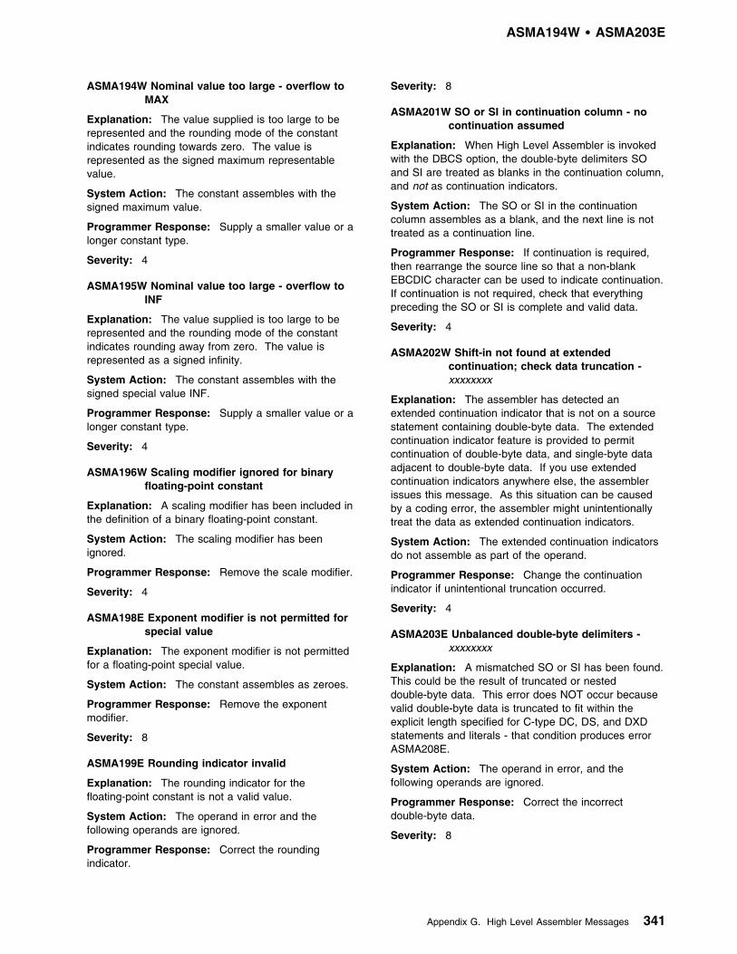
ASMA194W 1 ASMA203E
ASMA194W Nominal value too large - overflow toMAX
Explanation: The value supplied is too large to berepresented and the rounding mode of the constantindicates rounding towards zero. The value isrepresented as the signed maximum representablevalue.
System Action: The constant assembles with thesigned maximum value.
Programmer Response: Supply a smaller value or alonger constant type.
Severity: 4
ASMA195W Nominal value too large - overflow toINF
Explanation: The value supplied is too large to berepresented and the rounding mode of the constantindicates rounding away from zero. The value isrepresented as a signed infinity.
System Action: The constant assembles with thesigned special value INF.
Programmer Response: Supply a smaller value or alonger constant type.
Severity: 4
ASMA196W Scaling modifier ignored for binaryfloating-point constant
Explanation: A scaling modifier has been included inthe definition of a binary floating-point constant.
System Action: The scaling modifier has beenignored.
Programmer Response: Remove the scale modifier.
Severity: 4
ASMA198E Exponent modifier is not permitted forspecial value
Explanation: The exponent modifier is not permittedfor a floating-point special value.
System Action: The constant assembles as zeroes.
Programmer Response: Remove the exponentmodifier.
Severity: 8
ASMA199E Rounding indicator invalid
Explanation: The rounding indicator for thefloating-point constant is not a valid value.
System Action: The operand in error and thefollowing operands are ignored.
Programmer Response: Correct the roundingindicator.
Severity: 8
ASMA201W SO or SI in continuation column - nocontinuation assumed
Explanation: When High Level Assembler is invokedwith the DBCS option, the double-byte delimiters SOand SI are treated as blanks in the continuation column,and not as continuation indicators.
System Action: The SO or SI in the continuationcolumn assembles as a blank, and the next line is nottreated as a continuation line.
Programmer Response: If continuation is required,then rearrange the source line so that a non-blankEBCDIC character can be used to indicate continuation.If continuation is not required, check that everythingpreceding the SO or SI is complete and valid data.
Severity: 4
ASMA202W Shift-in not found at extendedcontinuation; check data truncation -xxxxxxxx
Explanation: The assembler has detected anextended continuation indicator that is not on a sourcestatement containing double-byte data. The extendedcontinuation indicator feature is provided to permitcontinuation of double-byte data, and single-byte dataadjacent to double-byte data. If you use extendedcontinuation indicators anywhere else, the assemblerissues this message. As this situation can be causedby a coding error, the assembler might unintentionallytreat the data as extended continuation indicators.
System Action: The extended continuation indicatorsdo not assemble as part of the operand.
Programmer Response: Change the continuationindicator if unintentional truncation occurred.
Severity: 4
ASMA203E Unbalanced double-byte delimiters -xxxxxxxx
Explanation: A mismatched SO or SI has been found.This could be the result of truncated or nesteddouble-byte data. This error does NOT occur becausevalid double-byte data is truncated to fit within theexplicit length specified for C-type DC, DS, and DXDstatements and literals - that condition produces errorASMA208E.
System Action: The operand in error, and thefollowing operands are ignored.
Programmer Response: Correct the incorrectdouble-byte data.
Severity: 8
Appendix G. High Level Assembler Messages 341

ASMA204E 1 ASMA211E
ASMA204E Invalid double-byte data - xxxxxxxx
Explanation: All data between SO and SI must bevalid double-byte characters. A valid double-bytecharacter is defined as either double-byte blank(X'4040'), or two bytes each of which must be in therange X'41' to X'FE' inclusive.
This error does not apply to the operands of macroinstructions.
System Action: The operand in error, and thefollowing operands are ignored.
Programmer Response: Correct the incorrectdouble-byte data.
Severity: 8
ASMA205E Extended continuation end column mustnot extend into continue column
Explanation: The extended continuation indicatorextended into the continue column.
System Action: The extended continuation indicator isignored. The following record or records might betreated as incorrect. The extended continuationindicators are treated as part of the source statement.
Programmer Response: If the data in the extendedcontinuation is to be regarded as valid input thenanother non-blank character must be used in thecontinuation indication column to identify the data asvalid and to continue to the next record. If the data isnot to be part of the constant then remove thecharacters of the extended continuation and add thecorrect data to the continue record to the point wherethe extended continuation is needed. This messagemight be encountered when converting code thatassembled with the NODBCS option to code that is tobe assembled with the DBCS option.
Severity: 8
ASMA206E G-type constant must not containsingle-byte data - xxxxxxxx
Explanation: A G-type constant or self-defining term,after substitution has occurred, must consist entirely ofdouble-byte data, correctly delimited by SO and SI. IfSO or SI are found in any byte position other than thefirst and last respectively (excepting redundant SI/SOpairs which are removed) then this error is reported.
System Action: The operand in error, and thefollowing operands are ignored.
Programmer Response: Either remove thesingle-byte data from the operand, or change theconstant to a C-type.
Severity: 8
ASMA207E Length of G-type constant must be amultiple of 2 - xxxxxxxx
Explanation: A G-type constant must contain onlydouble-byte data. If assembled with a length modifierwhich is not a multiple of 2, incorrect double-byte datais created.
System Action: The operand in error, and theoperands following are ignored.
Programmer Response: Either correct the lengthmodifier, or change the constant to a C-type.
Severity: 8
ASMA208E Truncation into double-byte data is notpermitted - xxxxxxxx
Explanation: The explicit length of a C-type constantin a DS, DC or DXD statement or literal must not causethe nominal value to be truncated at any point withindouble-byte data.
System Action: The operand in error, and thefollowing operands are ignored.
Programmer Response: Either correct the lengthmodifier, or change the double-byte data so that it is nottruncated.
Severity: 8
| ASMA209E Symbol not name of class, DXD or| DSECT
Explanation: The operand of a J-type address| constant is not the name of a class, DXD, or DSECT.
System Action: The constant assembles as zero.
Programmer Response: Supply a valid operand.
Severity: 8
| ASMA210E Illegal register usage
| Explanation: The register operands for the machine| instruction must be unique.
| System Action: The machine instruction assembles| as zero.
| Programmer Response: Correct the instruction such| that the operands specified are unique.
| Severity: 8
| ASMA211E Unicode conversion table not available.
| Explanation: The address of the UNICODE| conversion table is zero in the Code Page module| specified in the CODEPAGE option.
| System Action: The constant is not converted.
| Programmer Response: Ensure the code page| module is generated according to the instructions| described in Appendix M, “How to Generate a Unicode| Translation Table” on page 374
342 HLASM V1R4 Programmer’s Guide

ASMA212W 1 ASMA302W
| Severity: 12
| ASMA212W Branch address alignment for xxxxxxxx| unfavorable
| Explanation: A branch address referenced by this| statement might not be aligned to the required boundary| for this instruction; for example, the target referenced by| a Branch and Save (BAS) instruction might not be| aligned on a halfword boundary.
| System Action: The instruction assembles as written.
| Programmer Response: Correct the operand if it is in| error. To suppress this message, use the| FLAG(NOALIGN) assembler option.
| Severity: 4
| ASMA213W Storage alignment for xxxxxxxx| unfavorable
| Explanation: An address referenced by this statement| might not be aligned to the required boundary for this| instruction; for example, the data referenced by a| Compare and Swap (CS) instruction might not be| aligned on a fullword boundary.
| System Action: The instruction assembles as written.
| Programmer Response: Correct the operand if it is in| error. To suppress this message, use the| FLAG(NOALIGN) assembler option.
| Severity: 4
ASMA253C Too many errors
Explanation: No more error messages can be issuedfor this statement, because the assembler work area inwhich the errors are logged is full.
System Action: If more errors are detected for thisstatement, the messages, annotated text, or both, arediscarded.
Programmer Response: Correct the indicated errors,and rerun the assembly. If there are more errors onthis statement, they will be detected in the nextassembly.
Severity: 16
ASMA254I *** MNOTE ***
Explanation: The text of an MNOTE statement, whichis appended to this message, has been generated byyour program or by a macro definition or a librarymember copied into your program. An MNOTEstatement enables a source program or a macrodefinition to signal the assembler to generate an erroror informational message.
System Action: None.
Programmer Response: Investigate the reason forthe MNOTE. Errors flagged by MNOTE often cause theprogram to fail if it is run.
Severity: An MNOTE is assigned a severity code of 0to 255 by the writer of the MNOTE statement.
ASMA300W USING overridden by a prior activeUSING on statement number nnnnnn
Explanation: The USING instruction specifies thesame base address as a previous USING instruction atstatement number nnnnnn, and the base registerspecified is lower-numbered than the previouslyspecified base register.
System Action: The assembler uses thehigher-numbered base register for address resolution ofsymbolic addresses within the USING range.
Programmer Response: Check your USINGstatements to ensure that you have specified the correctbase address and base register and that you have notomitted a needed DROP statement for the previousbase register. You can suppress this message byreducing the value specified in the WARN sub-option ofthe USING option by 1.
Severity: 4
ASMA301W Prior active USING on statementnumber nnnnnn overridden by this USING
Explanation: The USING instruction specifies thesame base address as a previous USING instruction atstatement number nnnnnn, and the base registerspecified is higher-numbered than the previous baseregister.
System Action: The assembler uses thehigher-numbered base register for address resolution ofsymbolic addresses within the USING range.
Programmer Response: Check your USINGstatements to ensure that you have specified the correctbase address and base register and that you have notomitted a needed DROP statement for the previousbase register. You can suppress this message byreducing the value specified in the WARN sub-option ofthe USING option by 1.
Severity: 4
ASMA302W USING specifies register 0 with anon-zero absolute or relocatable baseaddress
Explanation: The assembler assumes that whenregister 0 is used as a base register, it contains zero.Therefore, regardless of the value specified for the baseaddress, displacements are calculated from base 0.
System Action: The assembler calculatesdisplacements as if the base address specified wereabsolute or relocatable zero.
Programmer Response: Check the USING statementto ensure you have specified the correct base addressand base register. You can suppress this message by
Appendix G. High Level Assembler Messages 343

ASMA303W 1 ASMA309W
reducing the value specified in the WARN suboption ofthe USING option by 2.
Severity: 4
ASMA303W Multiple address resolutions may resultfrom this USING and the USING onstatement number nnnnnn
Explanation: The USING instruction specifies a baseaddress that lies within the range of an earlier USINGinstruction at statement number nnnnnn. Theassembler might use multiple base registers whenresolving implicit addresses within the range overlap.
System Action: The assembler computesdisplacements from the base address that gives thesmallest displacement, and uses the correspondingbase register when it assembles addresses within therange overlap.
Programmer Response: Check your USINGinstructions for unintentional USING range overlaps andcheck that you have not omitted a needed DROPstatement. You can suppress this message by reducingthe value specified in the WARN suboption of theUSING option by 4.
Severity: 4
ASMA304W Displacement exceeds LIMIT valuespecified
Explanation: The address referred to by thisstatement has a valid displacement that is higher thanthe displacement limit specified in theUSING(LIMIT(xxx)) option.
System Action: The instruction assembles correctly.
Programmer Response: This error diagnosticmessage is issued at your request. You can suppressthis message by reducing the value specified in theWARN suboption of the USING option by 8.
Severity: 4
ASMA305E Operand 1 does not refer to locationwithin reference control section
Explanation: The first operand in a dependent USINGstatement does not refer to a location within a referencecontrol section defined by a DSECT, DXD, or COMinstruction.
System Action: The USING statement is ignored.
Programmer Response: Change the USINGstatement to specify a location within a referencecontrol section.
Severity: 8
ASMA306W USING range overlaps implicit USING0,0
Explanation: The USING range overlaps theassembler's implicit USING 0,0. This implicit USING isused to convert absolute implicit addresses in the range0 to 4095. As a result of this USING, the assemblermay not generate the expected object code.
System Action: The assembly continues
Programmer Response: Correct the USINGinstruction.
Severity: 4
ASMA307E No active USING for operand n
Explanation: The operand specified occurs in asection without an active USING.
System Action: The instruction assembles as zero.
Programmer Response: Provide a USING instruction.
Severity: 8
ASMA308E Repeated register reg nullifies priorUSING range
Explanation: The repeated register nullifies the rangespecified by a prior use of that register on the sameUSING instruction.
System Action: The statement is ignored.
Programmer Response: Correct the USINGinstruction.
Severity: 8
ASMA309W Operand xxxxxxxx resolved to adisplacement with no base register
Explanation: The machine instruction specifies anoperand which is resolved to a baseless address whena base and displacement are expected. This might bethe programmer's intent, but will usually be an error.
System Action: Base register zero is assembled intothe object code of the instruction.
Programmer Response: Check the instruction toensure that the operation and operands are codedcorrectly. If you want to reference page zero you canspecify a USING for the appropriate DSECT with a zerobase register. You can suppress this warning byspecifying the NOPAGE0 suboption of the FLAG option.
Severity: 4
344 HLASM V1R4 Programmer’s Guide
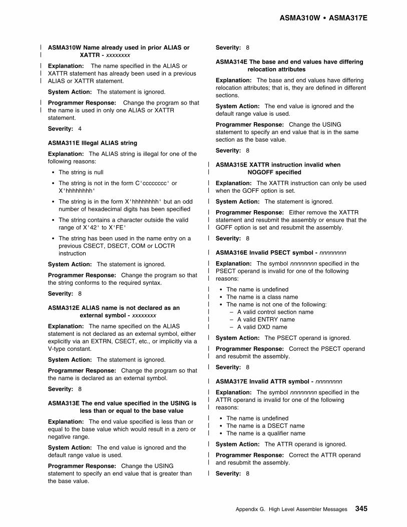
ASMA310W 1 ASMA317E
| ASMA310W Name already used in prior ALIAS or| XATTR - xxxxxxxx
| Explanation: The name specified in the ALIAS or| XATTR statement has already been used in a previous| ALIAS or XATTR statement.
System Action: The statement is ignored.
| Programmer Response: Change the program so that| the name is used in only one ALIAS or XATTR
statement.
Severity: 4
ASMA311E Illegal ALIAS string
Explanation: The ALIAS string is illegal for one of thefollowing reasons:
� The string is null
� The string is not in the form C'cccccccc' orX'hhhhhhhh'
� The string is in the form X'hhhhhhhh' but an oddnumber of hexadecimal digits has been specified
� The string contains a character outside the validrange of X'42' to X'FE'
� The string has been used in the name entry on aprevious CSECT, DSECT, COM or LOCTRinstruction
System Action: The statement is ignored.
Programmer Response: Change the program so thatthe string conforms to the required syntax.
Severity: 8
ASMA312E ALIAS name is not declared as anexternal symbol - xxxxxxxx
Explanation: The name specified on the ALIASstatement is not declared as an external symbol, eitherexplicitly via an EXTRN, CSECT, etc., or implicitly via aV-type constant.
System Action: The statement is ignored.
Programmer Response: Change the program so thatthe name is declared as an external symbol.
Severity: 8
ASMA313E The end value specified in the USING isless than or equal to the base value
Explanation: The end value specified is less than orequal to the base value which would result in a zero ornegative range.
System Action: The end value is ignored and thedefault range value is used.
Programmer Response: Change the USINGstatement to specify an end value that is greater thanthe base value.
Severity: 8
ASMA314E The base and end values have differingrelocation attributes
Explanation: The base and end values have differingrelocation attributes; that is, they are defined in differentsections.
System Action: The end value is ignored and thedefault range value is used.
Programmer Response: Change the USINGstatement to specify an end value that is in the samesection as the base value.
Severity: 8
| ASMA315E XATTR instruction invalid when| NOGOFF specified
| Explanation: The XATTR instruction can only be used| when the GOFF option is set.
| System Action: The statement is ignored.
| Programmer Response: Either remove the XATTR| statement and resubmit the assembly or ensure that the| GOFF option is set and resubmit the assembly.
| Severity: 8
| ASMA316E Invalid PSECT symbol - nnnnnnnn
| Explanation: The symbol nnnnnnnn specified in the| PSECT operand is invalid for one of the following| reasons:
| � The name is undefined| � The name is a class name| � The name is not one of the following:| – A valid control section name| – A valid ENTRY name| – A valid DXD name
| System Action: The PSECT operand is ignored.
| Programmer Response: Correct the PSECT operand| and resubmit the assembly.
| Severity: 8
| ASMA317E Invalid ATTR symbol - nnnnnnnn
| Explanation: The symbol nnnnnnnn specified in the| ATTR operand is invalid for one of the following| reasons:
| � The name is undefined| � The name is a DSECT name| � The name is a qualifier name
| System Action: The ATTR operand is ignored.
| Programmer Response: Correct the ATTR operand| and resubmit the assembly.
| Severity: 8
Appendix G. High Level Assembler Messages 345
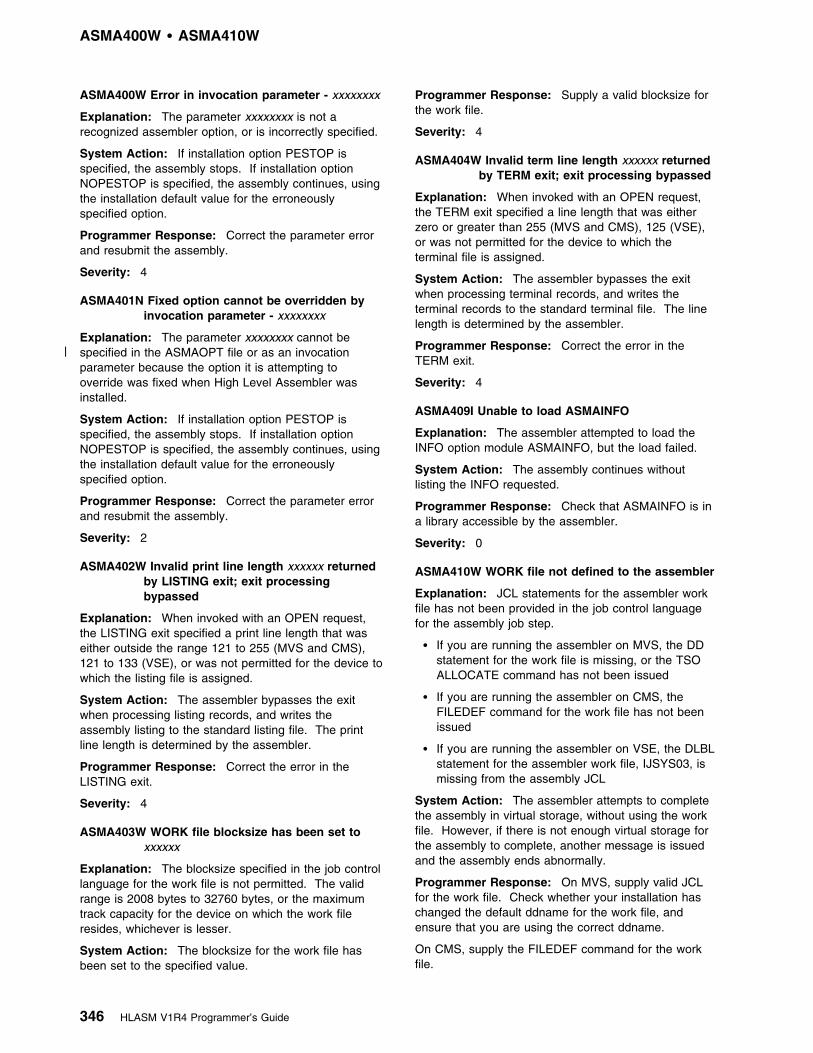
ASMA400W 1 ASMA410W
ASMA400W Error in invocation parameter - xxxxxxxx
Explanation: The parameter xxxxxxxx is not arecognized assembler option, or is incorrectly specified.
System Action: If installation option PESTOP isspecified, the assembly stops. If installation optionNOPESTOP is specified, the assembly continues, usingthe installation default value for the erroneouslyspecified option.
Programmer Response: Correct the parameter errorand resubmit the assembly.
Severity: 4
ASMA401N Fixed option cannot be overridden byinvocation parameter - xxxxxxxx
Explanation: The parameter xxxxxxxx cannot be| specified in the ASMAOPT file or as an invocation
parameter because the option it is attempting tooverride was fixed when High Level Assembler wasinstalled.
System Action: If installation option PESTOP isspecified, the assembly stops. If installation optionNOPESTOP is specified, the assembly continues, usingthe installation default value for the erroneouslyspecified option.
Programmer Response: Correct the parameter errorand resubmit the assembly.
Severity: 2
ASMA402W Invalid print line length xxxxxx returnedby LISTING exit; exit processingbypassed
Explanation: When invoked with an OPEN request,the LISTING exit specified a print line length that waseither outside the range 121 to 255 (MVS and CMS),121 to 133 (VSE), or was not permitted for the device towhich the listing file is assigned.
System Action: The assembler bypasses the exitwhen processing listing records, and writes theassembly listing to the standard listing file. The printline length is determined by the assembler.
Programmer Response: Correct the error in theLISTING exit.
Severity: 4
ASMA403W WORK file blocksize has been set toxxxxxx
Explanation: The blocksize specified in the job controllanguage for the work file is not permitted. The validrange is 2008 bytes to 32760 bytes, or the maximumtrack capacity for the device on which the work fileresides, whichever is lesser.
System Action: The blocksize for the work file hasbeen set to the specified value.
Programmer Response: Supply a valid blocksize forthe work file.
Severity: 4
ASMA404W Invalid term line length xxxxxx returnedby TERM exit; exit processing bypassed
Explanation: When invoked with an OPEN request,the TERM exit specified a line length that was eitherzero or greater than 255 (MVS and CMS), 125 (VSE),or was not permitted for the device to which theterminal file is assigned.
System Action: The assembler bypasses the exitwhen processing terminal records, and writes theterminal records to the standard terminal file. The linelength is determined by the assembler.
Programmer Response: Correct the error in theTERM exit.
Severity: 4
ASMA409I Unable to load ASMAINFO
Explanation: The assembler attempted to load theINFO option module ASMAINFO, but the load failed.
System Action: The assembly continues withoutlisting the INFO requested.
Programmer Response: Check that ASMAINFO is ina library accessible by the assembler.
Severity: 0
ASMA410W WORK file not defined to the assembler
Explanation: JCL statements for the assembler workfile has not been provided in the job control languagefor the assembly job step.
� If you are running the assembler on MVS, the DDstatement for the work file is missing, or the TSOALLOCATE command has not been issued
� If you are running the assembler on CMS, theFILEDEF command for the work file has not beenissued
� If you are running the assembler on VSE, the DLBLstatement for the assembler work file, IJSYS03, ismissing from the assembly JCL
System Action: The assembler attempts to completethe assembly in virtual storage, without using the workfile. However, if there is not enough virtual storage forthe assembly to complete, another message is issuedand the assembly ends abnormally.
Programmer Response: On MVS, supply valid JCLfor the work file. Check whether your installation haschanged the default ddname for the work file, andensure that you are using the correct ddname.
On CMS, supply the FILEDEF command for the workfile.
346 HLASM V1R4 Programmer’s Guide
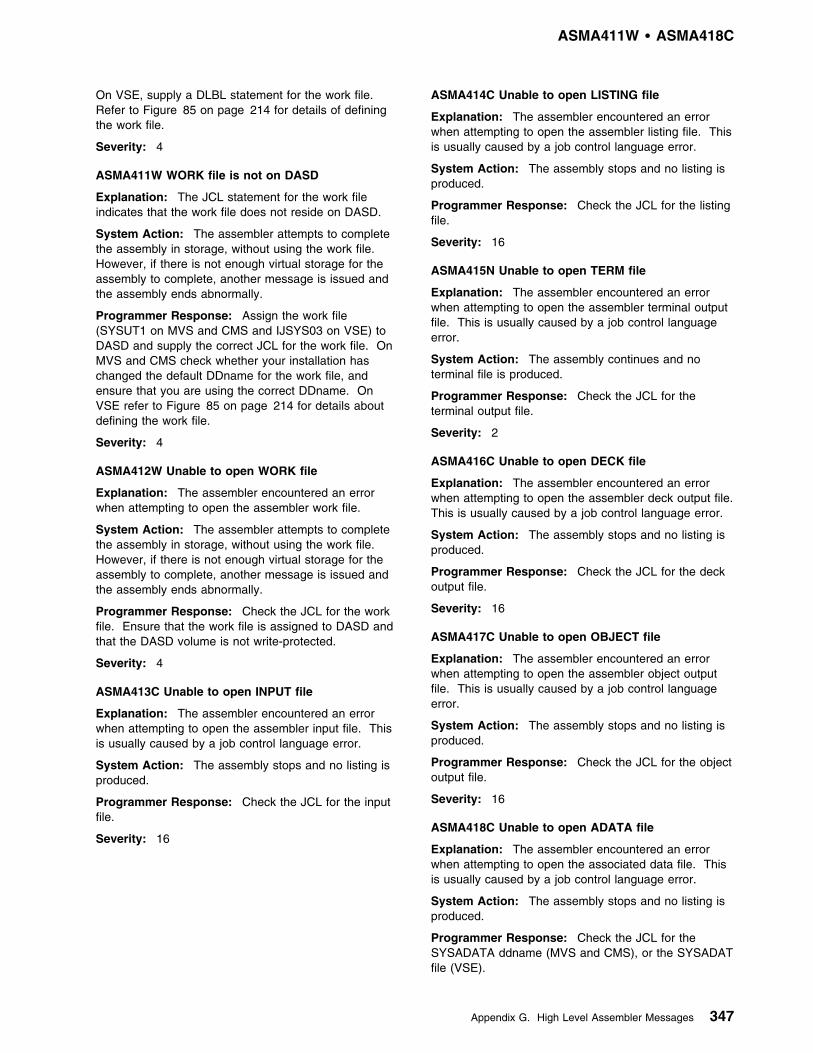
ASMA411W 1 ASMA418C
On VSE, supply a DLBL statement for the work file.Refer to Figure 85 on page 214 for details of definingthe work file.
Severity: 4
ASMA411W WORK file is not on DASD
Explanation: The JCL statement for the work fileindicates that the work file does not reside on DASD.
System Action: The assembler attempts to completethe assembly in storage, without using the work file.However, if there is not enough virtual storage for theassembly to complete, another message is issued andthe assembly ends abnormally.
Programmer Response: Assign the work file(SYSUT1 on MVS and CMS and IJSYS03 on VSE) toDASD and supply the correct JCL for the work file. OnMVS and CMS check whether your installation haschanged the default DDname for the work file, andensure that you are using the correct DDname. OnVSE refer to Figure 85 on page 214 for details aboutdefining the work file.
Severity: 4
ASMA412W Unable to open WORK file
Explanation: The assembler encountered an errorwhen attempting to open the assembler work file.
System Action: The assembler attempts to completethe assembly in storage, without using the work file.However, if there is not enough virtual storage for theassembly to complete, another message is issued andthe assembly ends abnormally.
Programmer Response: Check the JCL for the workfile. Ensure that the work file is assigned to DASD andthat the DASD volume is not write-protected.
Severity: 4
ASMA413C Unable to open INPUT file
Explanation: The assembler encountered an errorwhen attempting to open the assembler input file. Thisis usually caused by a job control language error.
System Action: The assembly stops and no listing isproduced.
Programmer Response: Check the JCL for the inputfile.
Severity: 16
ASMA414C Unable to open LISTING file
Explanation: The assembler encountered an errorwhen attempting to open the assembler listing file. Thisis usually caused by a job control language error.
System Action: The assembly stops and no listing isproduced.
Programmer Response: Check the JCL for the listingfile.
Severity: 16
ASMA415N Unable to open TERM file
Explanation: The assembler encountered an errorwhen attempting to open the assembler terminal outputfile. This is usually caused by a job control languageerror.
System Action: The assembly continues and noterminal file is produced.
Programmer Response: Check the JCL for theterminal output file.
Severity: 2
ASMA416C Unable to open DECK file
Explanation: The assembler encountered an errorwhen attempting to open the assembler deck output file.This is usually caused by a job control language error.
System Action: The assembly stops and no listing isproduced.
Programmer Response: Check the JCL for the deckoutput file.
Severity: 16
ASMA417C Unable to open OBJECT file
Explanation: The assembler encountered an errorwhen attempting to open the assembler object outputfile. This is usually caused by a job control languageerror.
System Action: The assembly stops and no listing isproduced.
Programmer Response: Check the JCL for the objectoutput file.
Severity: 16
ASMA418C Unable to open ADATA file
Explanation: The assembler encountered an errorwhen attempting to open the associated data file. Thisis usually caused by a job control language error.
System Action: The assembly stops and no listing isproduced.
Programmer Response: Check the JCL for theSYSADATA ddname (MVS and CMS), or the SYSADATfile (VSE).
Appendix G. High Level Assembler Messages 347

ASMA419C 1 ASMA425N
Severity: 16
ASMA419C Unable to open TRACE file
Explanation: The assembler encountered an errorwhen attempting to open the internal trace file. This isusually caused by a job control language error.
System Action: The assembly stops and no listing isproduced.
Programmer Response: Check the JCL for theSYSTRACE ddname (MVS and CMS), or theSYSTRAC file (VSE).
Severity: 16
ASMA420N Error in a *PROCESS statementparameter - xxxxxxxx
Explanation: The parameter xxxxxxxx is not arecognized assembler option, or is incorrectly specified.
System Action: If installation option PESTOP isspecified, the assembly stops. If installation optionNOPESTOP is specified, the assembly continues, usingthe installation default value or the invocation parametervalue for the erroneously specified option.
Programmer Response: Correct the parameter errorand resubmit the assembly.
Severity: 2
ASMA421N Fixed option cannot be overridden by*PROCESS statement parameter -xxxxxxxx
Explanation: The parameter xxxxxxxx cannot bespecified in a *PROCESS statement parameter becausethe option it is attempting to override was fixed whenHigh Level Assembler was installed.
System Action: If installation option PESTOP isspecified, the assembly stops. If installation optionNOPESTOP is specified, the assembly continues, usingthe installation default value for the erroneouslyspecified option.
Programmer Response: Remove the option from the*PROCESS statement and resubmit the assembly.
Severity: 2
ASMA422N Option xxxxxxxx is not valid in a*PROCESS statement
Explanation: The following options cannot bespecified in a *PROCESS statement:
ADATA|NOADATA OBJECT|NOOBJECT ASA|NOASA OPTABLE DECK|NODECK SIZE EXIT|NOEXIT SYSPARM GOFF|NOGOFF TERM|NOTERM LANGUAGE TRANSLATE|NOTRANSLATE LINECOUNT XOBJECT|NOXOBJECT LIST|NOLIST
System Action: If installation option PESTOP isspecified, the assembly stops. If installation optionNOPESTOP is specified, the assembly continues, usingthe installation default value or the invocation parametervalue for the erroneously specified option.
Programmer Response: Remove the option from the*PROCESS statement and resubmit the assembly.
Severity: 2
| ASMA423N Option yyyyyyyy in a *PROCESS| OVERRIDE statement conflicts with an| invocation or default option. Option is| not permitted in *PROCESS statement| and has been ignored.
| Explanation: The option yyyyyyyy specified in a| *PROCESS OVERRIDE statement conflicts with an| invocation or default option. The option is not permitted| in a *PROCESS statement and has been ignored.
| System Action: If installation option PESTOP is| specified, the assembler stops. If installation option| NOPESTOP is specified, the assembly continues using| the invocation or default option.
| Programmer Response: Correct the *PROCESS| OVERRIDE statement and resubmit the assembly.
| Severity: 2
ASMA424W Continuation column is not blank.*PROCESS statements may not becontinued.
Explanation: The continuation column (usually column72) is not blank for a *PROCESS statement.*PROCESS statements can not be continued.
System Action: If option PESTOP is specified, theassembly stops. If option NOPESTOP is specified, theassembly continues and processes the optionsspecified.
Programmer Response: Recode the *PROCESSstatement, leaving the continuation column blank. Ifyou need to specify more options that can fit on the*PROCESS statement, add another *PROCESSstatement to your code. You can specify a maximum of10 *PROCESS statements.
Severity: 4
ASMA425N Option conflict in invocationparameters. yyyyyyyy overrides anearlier setting.
Explanation: The option yyyyyyyy specified as an| invocation parameter in either the ASMAOPT file or the| invocation parameters overrides an earlier setting of the| option in either the same ASMAOPT file or the| invocation parameters.
System Action: If installation option PESTOP isspecified, the assembler stops. If installation option
348 HLASM V1R4 Programmer’s Guide

ASMA426N 1 ASMA432W
NOPESTOP is specified, the assembly continues usingthe last specified conflicting option.
Programmer Response: Correct the ASMAOPT file orthe invocation parameter and resubmit the assembly.
Severity: 2
ASMA426N Option conflict in *PROCESSstatements. yyyyyyyy overrides an earliersetting.
Explanation: The option yyyyyyyy specified in a*PROCESS statement overrides an earlier setting of theoption on the same statement or a previous *PROCESSstatement.
System Action: If installation option PESTOP isspecified, the assembly stops. If installation optionNOPESTOP is specified, the assembly continues usingthe last conflicting option encountered.
Programmer Response: Correct the *PROCESSstatement error and resubmit the assembly.
Severity: 2
ASMA427N Invocation parameter option xxxxxxxxignored. This option is not valid underVSE.
Explanation: The option xxxxxxxx specified in aninvocation parameter is not valid for the VSE operatingsystem.
System Action: If installation option PESTOP isspecified, the assembly stops. If installation optionNOPESTOP is specified, the assembly continues andthe option is ignored.
Programmer Response: Remove the option from theinvocation parameter and resubmit the assembly.
Severity: 2
ASMA428N *PROCESS statement option xxxxxxxxignored. This option is not valid underVSE.
Explanation: The option xxxxxxxx specified in a*PROCESS statement is not valid for the VSE operatingsystem.
System Action: If installation option PESTOP isspecified, the assembly stops. If installation optionNOPESTOP is specified, the assembly continues andthe option is ignored.
Programmer Response: Remove the option from the*PROCESS statement and resubmit the assembly.
Severity: 2
| ASMA429W SYSPRINT LRECL should be at least| 133 when GOFF/XOBJECT option is
specified
| Explanation: The GOFF or XOBJECT assembler| option has been specified, however the logical record
length of the listing file, SYSPRINT, is less than 133.
System Action: If installation option PESTOP isspecified, the assembly stops. If installation optionNOPESTOP is specified, the assembly continues,however the lines in the source and object section aretruncated.
Programmer Response: Specify a record length of atleast 133 for SYSPRINT.
Severity: 4
ASMA430W Continuation statement does not startin continue column.
Explanation: The operand on the continued recordends with a comma and a continuation statement ispresent but the continue column is blank. The continuecolumn is column 16, unless you redefined it with anICTL instruction.
System Action: Any remaining continuation linesbelonging to this statement are ignored.
Programmer Response: Check that the continuationwas coded as intended.
Severity: 4
ASMA431W Continuation statement may be in error- continuation indicator column is blank.
Explanation: A list of one or more operands ends witha comma, but the continuation indicator column isblank. The continuation indicator column is column 72,unless you redefined it with an ICTL instruction.
System Action: The next statement assembles as astandard assembler source statement.
Programmer Response: Check that the continuationwas coded as intended.
Severity: 4
ASMA432W Continuation statement may be in error- comma omitted from continuedstatement.
Explanation: The continuation record starts in thecontinue column (usually column 16) but there is nocomma present following the operands on the previousrecord.
System Action: Any remaining continuation linesbelonging to this statement are ignored.
Programmer Response: Check that the continuationwas coded as intended.
Severity: 4
Appendix G. High Level Assembler Messages 349

ASMA433W 1 ASMA438N
ASMA433W Statement not continued - continuationstatement may be in error
Explanation: The continued record is full but thecontinuation record does not start in the continuecolumn (usually column 16).
System Action: Any remaining continuation linesbelonging to this statement are ignored.
Programmer Response: Check that the continuationwas coded as intended.
Severity: 4
| ASMA434N GOFF/XOBJECT option specified,| option LIST(133) will be used
| Explanation: You specified the GOFF or XOBJECT| option, and the LIST suboption is 121.
System Action: The assembler sets the LISTsuboption to 133. If installation option PESTOP isspecified, the assembly stops. If installation optionNOPESTOP is specified, the assembly continues.
Programmer Response: To prevent this warning| message, run the assembly again specifying GOFF and
LIST(133).
Severity: 2
ASMA435I Record n in xxxxxxx on volume: vvvvvv
Explanation: The data set xxxxxxxx which is locatedon volume serial vvvvvv, contains an error on recordnumber n. The volume serial might not be available.
For an AINSERT instruction:
n The number of the statement within the AINSERTinternal buffer. This number may not reflect thestatement's relative statement number within thebuffer at the point of retrieval, but does reflect therelative retrieval number. This is because it ispossible to insert records into the buffer afterstatements have been retrieved from the buffer.
xxxxxxxxThe constant AINSERT BUFFER to indicate that thestatement resulted from an AINSERT instruction.
vvvvvvwill be null.
System Action: See the System Action section of theerror message(s) which immediately precede thismessage.
Programmer Response: Refer to the ProgrammerResponse section of the error messages whichimmediately precede this message.
Severity: 0
ASMA436N Attempt to override invocationparameter in a *PROCESS statement.Option yyyyyyyy ignored.
Explanation: The option yyyyyyyy specified in a| *PROCESS statement conflicts with an option specified| either in the ASMAOPT file or in an invocation| parameter.
System Action: If installation option PESTOP isspecified, the assembler stops. If installation optionNOPESTOP is specified, the assembly continues using
| the option specified in the ASMAOPT file or the| invocation parameters.
Programmer Response: Correct the *PROCESSstatement and resubmit the assembly.
Severity: 2
| ASMA437N Attempt to override invocation| parameter in a *PROCESS statement.
Suboption yyyyyyyy of xxxxxxxx optionignored.
Explanation: The suboption yyyyyyyy of optionxxxxxxxx specified on a *PROCESS statement conflictswith a suboption specified in either the ASMAOPT fileor in the invocation parameters.
System Action: If installation option PESTOP isspecified, the assembler stops. If installation optionNOPESTOP is specified, the assembly continues usingthe suboption specified in the *PROCESS OVERRIDEstatement.
Programmer Response: Correct the *PROCESSstatement and resubmit the assembly. the assembly.
Severity: 2
| ASMA438N Attempt to override ASMAOPT| parameter. Option yyyyyyyy ignored
| Explanation: The option yyyyyyyy specified as an| invocation parameter overrides the option specified in| the ASMAOPT file (CMS or MVS) or Librarian member| (VSE).
| System Action: If installation option PESTOP is| specified, the assembly stops. If installation option| NOPESTOP is specified, the assembly continues using| the option specified in the ASMAOPT file (MVS and| CMS) or library member (VSE).
| Programmer Response: Remove the option from the| invocation parameters and resubmit the assembly.
| Severity: 2
350 HLASM V1R4 Programmer’s Guide
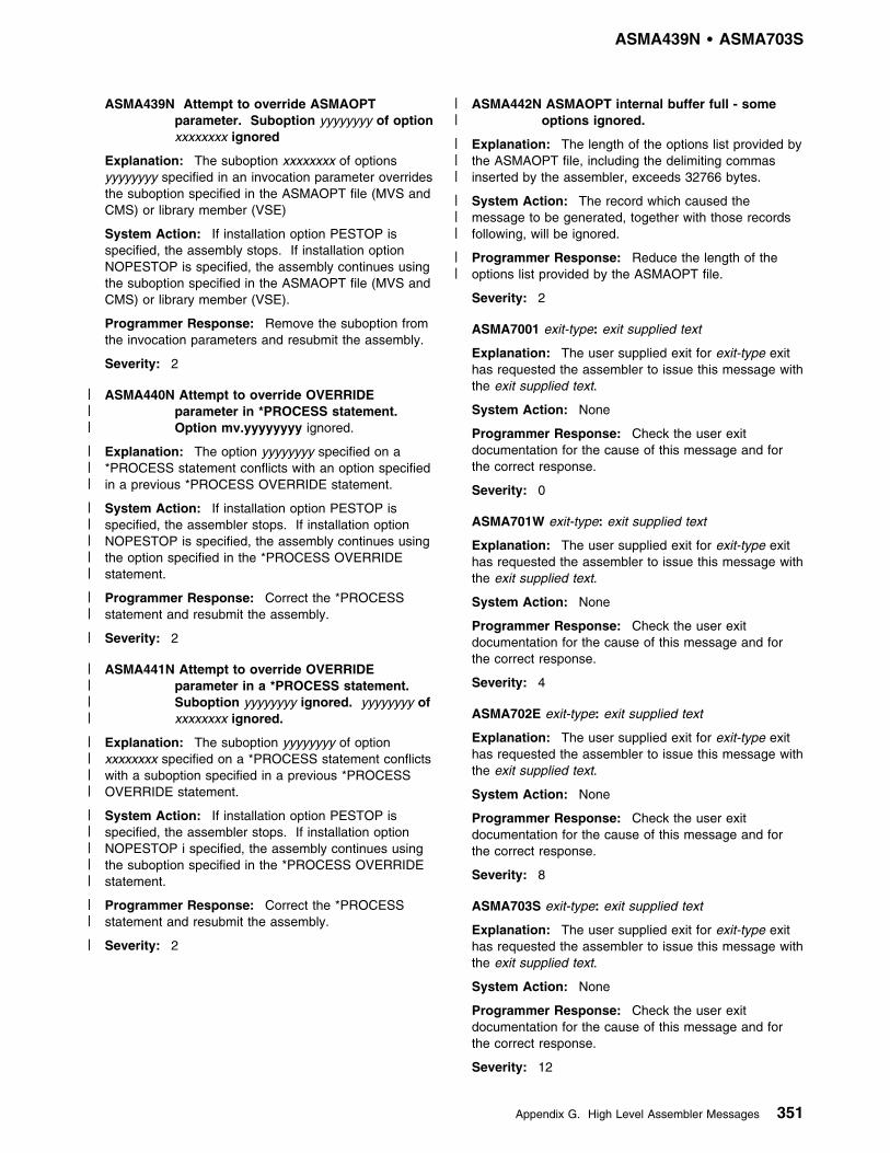
ASMA439N 1 ASMA703S
ASMA439N Attempt to override ASMAOPTparameter. Suboption yyyyyyyy of optionxxxxxxxx ignored
Explanation: The suboption xxxxxxxx of optionsyyyyyyyy specified in an invocation parameter overridesthe suboption specified in the ASMAOPT file (MVS andCMS) or library member (VSE)
System Action: If installation option PESTOP isspecified, the assembly stops. If installation optionNOPESTOP is specified, the assembly continues usingthe suboption specified in the ASMAOPT file (MVS andCMS) or library member (VSE).
Programmer Response: Remove the suboption fromthe invocation parameters and resubmit the assembly.
Severity: 2
| ASMA440N Attempt to override OVERRIDE| parameter in *PROCESS statement.| Option mv.yyyyyyyy ignored.
| Explanation: The option yyyyyyyy specified on a| *PROCESS statement conflicts with an option specified| in a previous *PROCESS OVERRIDE statement.
| System Action: If installation option PESTOP is| specified, the assembler stops. If installation option| NOPESTOP is specified, the assembly continues using| the option specified in the *PROCESS OVERRIDE| statement.
| Programmer Response: Correct the *PROCESS| statement and resubmit the assembly.
| Severity: 2
| ASMA441N Attempt to override OVERRIDE| parameter in a *PROCESS statement.| Suboption yyyyyyyy ignored. yyyyyyyy of| xxxxxxxx ignored.
| Explanation: The suboption yyyyyyyy of option| xxxxxxxx specified on a *PROCESS statement conflicts| with a suboption specified in a previous *PROCESS| OVERRIDE statement.
| System Action: If installation option PESTOP is| specified, the assembler stops. If installation option| NOPESTOP i specified, the assembly continues using| the suboption specified in the *PROCESS OVERRIDE| statement.
| Programmer Response: Correct the *PROCESS| statement and resubmit the assembly.
| Severity: 2
| ASMA442N ASMAOPT internal buffer full - some| options ignored.
| Explanation: The length of the options list provided by| the ASMAOPT file, including the delimiting commas| inserted by the assembler, exceeds 32766 bytes.
| System Action: The record which caused the| message to be generated, together with those records| following, will be ignored.
| Programmer Response: Reduce the length of the| options list provided by the ASMAOPT file.
Severity: 2
ASMA7001 exit-type: exit supplied text
Explanation: The user supplied exit for exit-type exithas requested the assembler to issue this message withthe exit supplied text.
System Action: None
Programmer Response: Check the user exitdocumentation for the cause of this message and forthe correct response.
Severity: 0
ASMA701W exit-type: exit supplied text
Explanation: The user supplied exit for exit-type exithas requested the assembler to issue this message withthe exit supplied text.
System Action: None
Programmer Response: Check the user exitdocumentation for the cause of this message and forthe correct response.
Severity: 4
ASMA702E exit-type: exit supplied text
Explanation: The user supplied exit for exit-type exithas requested the assembler to issue this message withthe exit supplied text.
System Action: None
Programmer Response: Check the user exitdocumentation for the cause of this message and forthe correct response.
Severity: 8
ASMA703S exit-type: exit supplied text
Explanation: The user supplied exit for exit-type exithas requested the assembler to issue this message withthe exit supplied text.
System Action: None
Programmer Response: Check the user exitdocumentation for the cause of this message and forthe correct response.
Severity: 12
Appendix G. High Level Assembler Messages 351

ASMA704C 1 ASMA714C
ASMA704C exit-type: exit supplied text
Explanation: The user supplied exit for exit-type exithas requested the assembler to issue this message withthe exit supplied text.
System Action: None
Programmer Response: Check the installationdocumentation for the cause of this message and forthe correct response.
Severity: 16
ASMA710I function-name: function-supplied text
Explanation: The user supplied functionfunction-name has requested the assembler to issuethis message with the function-supplied text.
System Action: None
Programmer Response: Check the external functiondocumentation for the cause of this message and forthe correct response.
Severity: 0
ASMA711W function-name: function-supplied text
Explanation: The user supplied functionfunction-name has requested the assembler to issuethis message with the function-supplied text.
System Action: None
Programmer Response: Check the external functiondocumentation for the cause of this message and forthe correct response.
Severity: 4
ASMA712E function-name : function-supplied text
Explanation: The user supplied functionfunction-name has requested the assembler to issuethis message with the function-supplied text.
System Action: None
Programmer Response: Check the external functiondocumentation for the cause of this message and forthe correct response.
Severity: 8
ASMA713S function-name : function-supplied text
Explanation: The user supplied functionfunction-name has requested the assembler to issuethis message with the function-supplied text.
System Action: None
Programmer Response: Check the external functiondocumentation for the cause of this message and forthe correct response.
Severity: 12
ASMA714C function-name : function-supplied text
Explanation: The user supplied functionfunction-name has requested the assembler to issuethis message with the function-supplied text.
System Action: None
Programmer Response: Check the external functiondocumentation for the cause of this message and forthe correct response.
Severity: 16
Abnormal Assembly TerminationMessages
Whenever an assembly cannot complete, HighLevel Assembler provides a message and, insome cases, a specially formatted dump fordiagnostic information. This might indicate anassembler malfunction or it might indicate aprogrammer error. The statement causing theerror is identified and, if possible, the assemblylisting up to the point of the error is printed. Themessages in this book give enough information toenable you to correct the error and reassembleyour program, or to determine that the error is anassembler malfunction.
Note:
| If SYSPRINT or SYSLST (VSE only) is| unavailable, the assembler uses the macro WTO| with a route code of 11 and a descriptor code of| 7, or the system defaults, to output the| message(s).
Messages
ASMA930U LOAD OF ASMA93 PHASE FAILED;INSUFFICIENT GETVIS STORAGE ORPHASE NOT FOUND
Explanation: The assembler attempted to load thephase ASMA93, but the load failed either because therewas insufficient GETVIS storage available to completethe load, or the phase could not be found.
Note: This message is only produced in uppercaseEnglish.
System Action: The assembly stops and no listing isproduced.
Programmer Response: Check the LIBDEF chain toensure that the sublibrary containing High LevelAssembler is correctly concatenated. If it is, you shouldconsider increasing the partition size.
352 HLASM V1R4 Programmer’s Guide
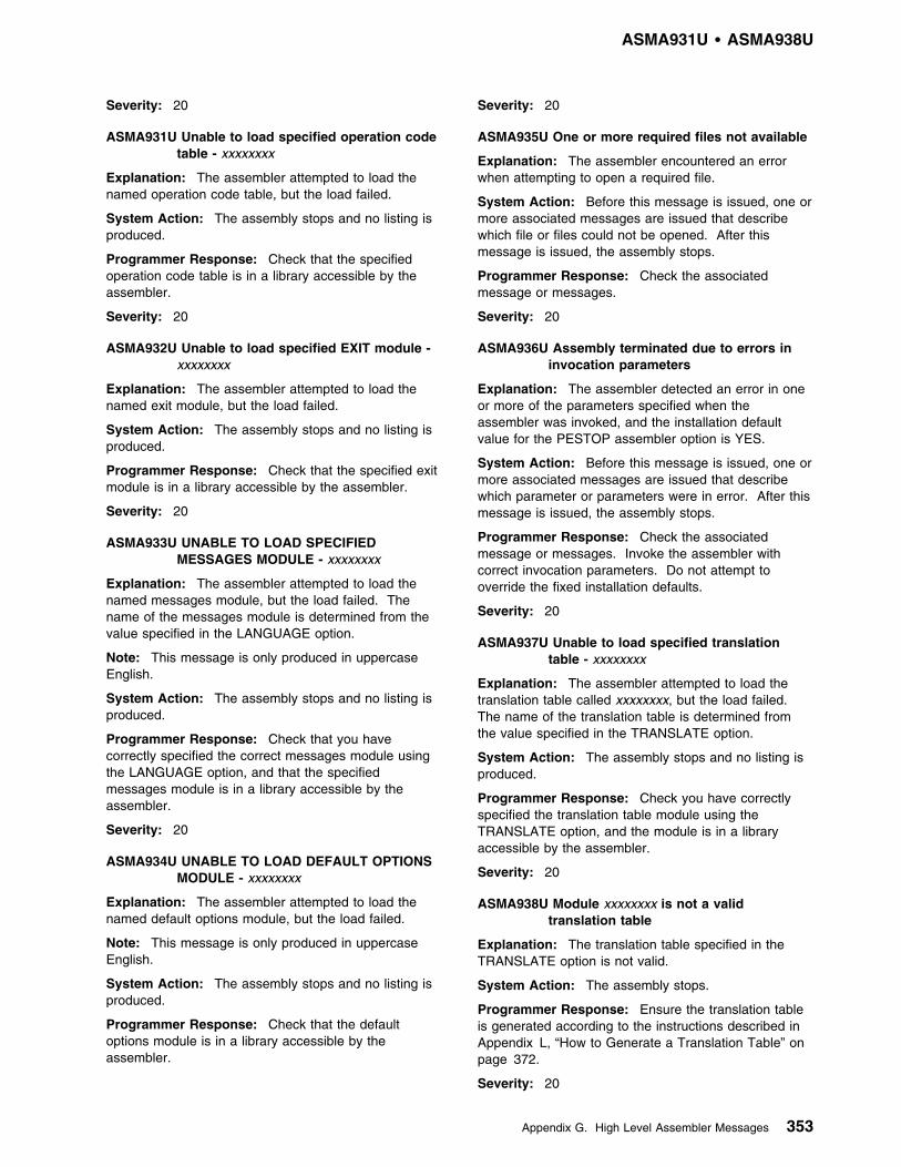
ASMA931U 1 ASMA938U
Severity: 20
ASMA931U Unable to load specified operation codetable - xxxxxxxx
Explanation: The assembler attempted to load thenamed operation code table, but the load failed.
System Action: The assembly stops and no listing isproduced.
Programmer Response: Check that the specifiedoperation code table is in a library accessible by theassembler.
Severity: 20
ASMA932U Unable to load specified EXIT module -xxxxxxxx
Explanation: The assembler attempted to load thenamed exit module, but the load failed.
System Action: The assembly stops and no listing isproduced.
Programmer Response: Check that the specified exitmodule is in a library accessible by the assembler.
Severity: 20
ASMA933U UNABLE TO LOAD SPECIFIEDMESSAGES MODULE - xxxxxxxx
Explanation: The assembler attempted to load thenamed messages module, but the load failed. Thename of the messages module is determined from thevalue specified in the LANGUAGE option.
Note: This message is only produced in uppercaseEnglish.
System Action: The assembly stops and no listing isproduced.
Programmer Response: Check that you havecorrectly specified the correct messages module usingthe LANGUAGE option, and that the specifiedmessages module is in a library accessible by theassembler.
Severity: 20
ASMA934U UNABLE TO LOAD DEFAULT OPTIONSMODULE - xxxxxxxx
Explanation: The assembler attempted to load thenamed default options module, but the load failed.
Note: This message is only produced in uppercaseEnglish.
System Action: The assembly stops and no listing isproduced.
Programmer Response: Check that the defaultoptions module is in a library accessible by theassembler.
Severity: 20
ASMA935U One or more required files not available
Explanation: The assembler encountered an errorwhen attempting to open a required file.
System Action: Before this message is issued, one ormore associated messages are issued that describewhich file or files could not be opened. After thismessage is issued, the assembly stops.
Programmer Response: Check the associatedmessage or messages.
Severity: 20
ASMA936U Assembly terminated due to errors ininvocation parameters
Explanation: The assembler detected an error in oneor more of the parameters specified when theassembler was invoked, and the installation defaultvalue for the PESTOP assembler option is YES.
System Action: Before this message is issued, one ormore associated messages are issued that describewhich parameter or parameters were in error. After thismessage is issued, the assembly stops.
Programmer Response: Check the associatedmessage or messages. Invoke the assembler withcorrect invocation parameters. Do not attempt tooverride the fixed installation defaults.
Severity: 20
ASMA937U Unable to load specified translationtable - xxxxxxxx
Explanation: The assembler attempted to load thetranslation table called xxxxxxxx, but the load failed.The name of the translation table is determined fromthe value specified in the TRANSLATE option.
System Action: The assembly stops and no listing isproduced.
Programmer Response: Check you have correctlyspecified the translation table module using theTRANSLATE option, and the module is in a libraryaccessible by the assembler.
Severity: 20
ASMA938U Module xxxxxxxx is not a validtranslation table
Explanation: The translation table specified in theTRANSLATE option is not valid.
System Action: The assembly stops.
Programmer Response: Ensure the translation tableis generated according to the instructions described inAppendix L, “How to Generate a Translation Table” onpage 372.
Severity: 20
Appendix G. High Level Assembler Messages 353
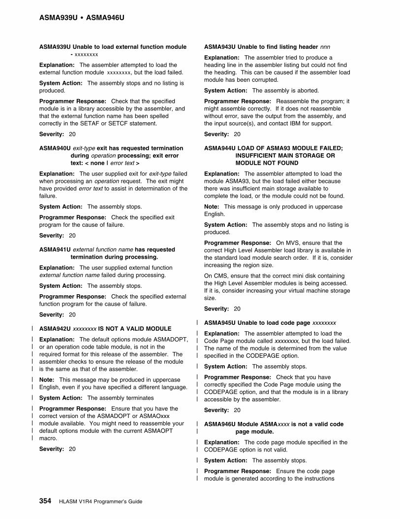
ASMA939U 1 ASMA946U
ASMA939U Unable to load external function module- xxxxxxxx
Explanation: The assembler attempted to load theexternal function module xxxxxxxx, but the load failed.
System Action: The assembly stops and no listing isproduced.
Programmer Response: Check that the specifiedmodule is in a library accessible by the assembler, andthat the external function name has been spelledcorrectly in the SETAF or SETCF statement.
Severity: 20
ASMA940U exit-type exit has requested terminationduring operation processing; exit errortext: < none | error text >
Explanation: The user supplied exit for exit-type failedwhen processing an operation request. The exit mighthave provided error text to assist in determination of thefailure.
System Action: The assembly stops.
Programmer Response: Check the specified exitprogram for the cause of failure.
Severity: 20
ASMA941U external function name has requestedtermination during processing.
Explanation: The user supplied external functionexternal function name failed during processing.
System Action: The assembly stops.
Programmer Response: Check the specified externalfunction program for the cause of failure.
Severity: 20
| ASMA942U xxxxxxxx IS NOT A VALID MODULE
| Explanation: The default options module ASMADOPT,| or an operation code table module, is not in the| required format for this release of the assembler. The| assembler checks to ensure the release of the module| is the same as that of the assembler.
| Note: This message may be produced in uppercase| English, even if you have specified a different language.
| System Action: The assembly terminates
| Programmer Response: Ensure that you have the| correct version of the ASMADOPT or ASMAOxxx| module available. You might need to reassemble your| default options module with the current ASMAOPT| macro.
Severity: 20
ASMA943U Unable to find listing header nnn
Explanation: The assembler tried to produce aheading line in the assembler listing but could not findthe heading. This can be caused if the assembler loadmodule has been corrupted.
System Action: The assembly is aborted.
Programmer Response: Reassemble the program; itmight assemble correctly. If it does not reassemblewithout error, save the output from the assembly, andthe input source(s), and contact IBM for support.
Severity: 20
ASMA944U LOAD OF ASMA93 MODULE FAILED;INSUFFICIENT MAIN STORAGE ORMODULE NOT FOUND
Explanation: The assembler attempted to load themodule ASMA93, but the load failed either becausethere was insufficient main storage available tocomplete the load, or the module could not be found.
Note: This message is only produced in uppercaseEnglish.
System Action: The assembly stops and no listing isproduced.
Programmer Response: On MVS, ensure that thecorrect High Level Assembler load library is available inthe standard load module search order. If it is, considerincreasing the region size.
On CMS, ensure that the correct mini disk containingthe High Level Assembler modules is being accessed.If it is, consider increasing your virtual machine storagesize.
Severity: 20
| ASMA945U Unable to load code page xxxxxxxx
| Explanation: The assembler attempted to load the| Code Page module called xxxxxxxx, but the load failed.| The name of the module is determined from the value| specified in the CODEPAGE option.
| System Action: The assembly stops.
| Programmer Response: Check that you have| correctly specified the Code Page module using the| CODEPAGE option, and that the module is in a library| accessible by the assembler.
Severity: 20
| ASMA946U Module ASMAxxxx is not a valid code| page module.
| Explanation: The code page module specified in the| CODEPAGE option is not valid.
| System Action: The assembly stops.
| Programmer Response: Ensure the code page| module is generated according to the instructions
354 HLASM V1R4 Programmer’s Guide
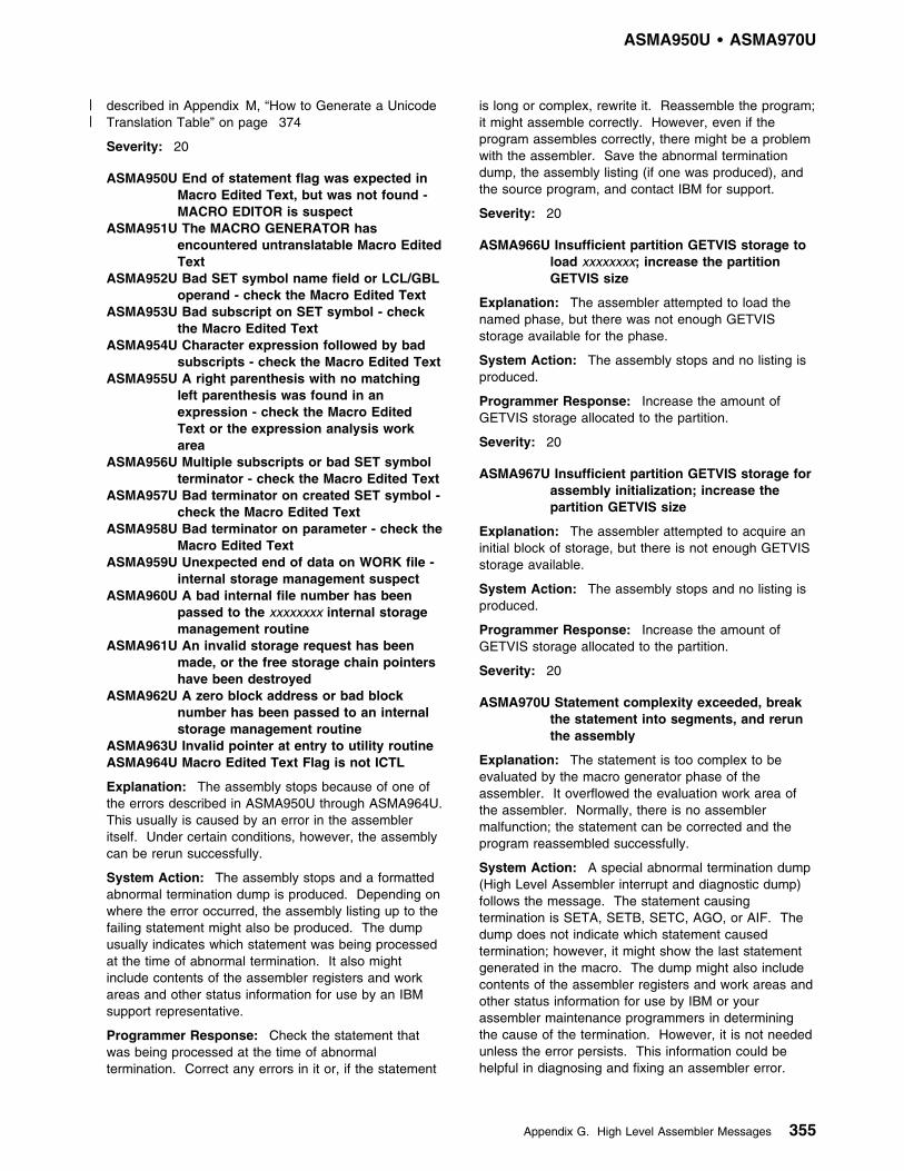
ASMA950U 1 ASMA970U
| described in Appendix M, “How to Generate a Unicode| Translation Table” on page 374
Severity: 20
ASMA950U End of statement flag was expected inMacro Edited Text, but was not found -MACRO EDITOR is suspect
ASMA951U The MACRO GENERATOR hasencountered untranslatable Macro EditedText
ASMA952U Bad SET symbol name field or LCL/GBLoperand - check the Macro Edited Text
ASMA953U Bad subscript on SET symbol - checkthe Macro Edited Text
ASMA954U Character expression followed by badsubscripts - check the Macro Edited Text
ASMA955U A right parenthesis with no matchingleft parenthesis was found in anexpression - check the Macro EditedText or the expression analysis workarea
ASMA956U Multiple subscripts or bad SET symbolterminator - check the Macro Edited Text
ASMA957U Bad terminator on created SET symbol -check the Macro Edited Text
ASMA958U Bad terminator on parameter - check theMacro Edited Text
ASMA959U Unexpected end of data on WORK file -internal storage management suspect
ASMA960U A bad internal file number has beenpassed to the xxxxxxxx internal storagemanagement routine
ASMA961U An invalid storage request has beenmade, or the free storage chain pointershave been destroyed
ASMA962U A zero block address or bad blocknumber has been passed to an internalstorage management routine
ASMA963U Invalid pointer at entry to utility routineASMA964U Macro Edited Text Flag is not ICTL
Explanation: The assembly stops because of one ofthe errors described in ASMA950U through ASMA964U.This usually is caused by an error in the assembleritself. Under certain conditions, however, the assemblycan be rerun successfully.
System Action: The assembly stops and a formattedabnormal termination dump is produced. Depending onwhere the error occurred, the assembly listing up to thefailing statement might also be produced. The dumpusually indicates which statement was being processedat the time of abnormal termination. It also mightinclude contents of the assembler registers and workareas and other status information for use by an IBMsupport representative.
Programmer Response: Check the statement thatwas being processed at the time of abnormaltermination. Correct any errors in it or, if the statement
is long or complex, rewrite it. Reassemble the program;it might assemble correctly. However, even if theprogram assembles correctly, there might be a problemwith the assembler. Save the abnormal terminationdump, the assembly listing (if one was produced), andthe source program, and contact IBM for support.
Severity: 20
ASMA966U Insufficient partition GETVIS storage toload xxxxxxxx; increase the partitionGETVIS size
Explanation: The assembler attempted to load thenamed phase, but there was not enough GETVISstorage available for the phase.
System Action: The assembly stops and no listing isproduced.
Programmer Response: Increase the amount ofGETVIS storage allocated to the partition.
Severity: 20
ASMA967U Insufficient partition GETVIS storage forassembly initialization; increase thepartition GETVIS size
Explanation: The assembler attempted to acquire aninitial block of storage, but there is not enough GETVISstorage available.
System Action: The assembly stops and no listing isproduced.
Programmer Response: Increase the amount ofGETVIS storage allocated to the partition.
Severity: 20
ASMA970U Statement complexity exceeded, breakthe statement into segments, and rerunthe assembly
Explanation: The statement is too complex to beevaluated by the macro generator phase of theassembler. It overflowed the evaluation work area ofthe assembler. Normally, there is no assemblermalfunction; the statement can be corrected and theprogram reassembled successfully.
System Action: A special abnormal termination dump(High Level Assembler interrupt and diagnostic dump)follows the message. The statement causingtermination is SETA, SETB, SETC, AGO, or AIF. Thedump does not indicate which statement causedtermination; however, it might show the last statementgenerated in the macro. The dump might also includecontents of the assembler registers and work areas andother status information for use by IBM or yourassembler maintenance programmers in determiningthe cause of the termination. However, it is not neededunless the error persists. This information could behelpful in diagnosing and fixing an assembler error.
Appendix G. High Level Assembler Messages 355
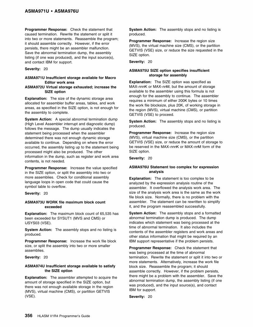
ASMA971U 1 ASMA976U
Programmer Response: Check the statement thatcaused termination. Rewrite the statement or split itinto two or more statements. Reassemble the program;it should assemble correctly. However, if the errorpersists, there might be an assembler malfunction.Save the abnormal termination dump, the assemblylisting (if one was produced), and the input source(s),and contact IBM for support.
Severity: 20
ASMA971U Insufficient storage available for MacroEditor work area
ASMA972U Virtual storage exhausted; increase theSIZE option
Explanation: The size of the dynamic storage areaallocated for assembler buffer areas, tables, and workareas, as specified in the SIZE option, is not enough forthe assembly to complete.
System Action: A special abnormal termination dump(High Level Assembler interrupt and diagnostic dump)follows the message. The dump usually indicates thestatement being processed when the assemblerdetermined there was not enough dynamic storageavailable to continue. Depending on where the erroroccurred, the assembly listing up to the statement beingprocessed might also be produced. The otherinformation in the dump, such as register and work areacontents, is not needed.
Programmer Response: Increase the value specifiedin the SIZE option, or split the assembly into two ormore assemblies. Check for conditional assemblylanguage loops in open code that could cause thesymbol table to overflow.
Severity: 20
ASMA973U WORK file maximum block countexceeded
Explanation: The maximum block count of 65,535 hasbeen exceeded for SYSUT1 (MVS and CMS) orIJSYS03 (VSE).
System Action: The assembly stops and no listing isproduced.
Programmer Response: Increase the work file blocksize, or split the assembly into two or more smallerassemblies.
Severity: 20
ASMA974U Insufficient storage available to satisfythe SIZE option
Explanation: The assembler attempted to acquire theamount of storage specified in the SIZE option, butthere was not enough available storage in the region(MVS), virtual machine (CMS), or partition GETVIS(VSE).
System Action: The assembly stops and no listing isproduced.
Programmer Response: Increase the region size(MVS), the virtual machine size (CMS), or the partitionGETVIS (VSE) size, or reduce the size requested in theSIZE option.
Severity: 20
ASMA975U SIZE option specifies insufficientstorage for assembly
Explanation: The SIZE option was specified asMAX-nnnK or MAX-nnM, but the amount of storageavailable to the assembler using this formula is notenough for the assembly to continue. The assemblerrequires a minimum of either 200K bytes or 10 timesthe work file blocksize, plus 20K, of working storage inthe region (MVS), virtual machine (CMS), or partitionGETVIS (VSE) to proceed.
System Action: The assembly stops and no listing isproduced.
Programmer Response: Increase the region size(MVS), virtual machine size (CMS), or the partitionGETVIS (VSE) size, or reduce the amount of storage tobe reserved in the MAX-nnnK or MAX-nnM form of theSIZE option.
Severity: 20
ASMA976U Statement too complex for expressionanalysis
Explanation: The statement is too complex to beanalyzed by the expression analysis routine of theassembler. It overflowed the analysis work area. Thesize of the analysis work area is the same as the workfile block size. Normally, there is no problem with theassembler. The statement can be rewritten to simplifyit, and the program reassembled successfully.
System Action: The assembly stops and a formattedabnormal termination dump is produced. The dumpindicates which statement was being processed at thetime of abnormal termination. It also includes thecontents of the assembler registers and work areas andother status information that might be required by anIBM support representative if the problem persists.
Programmer Response: Check the statement thatwas being processed at the time of abnormaltermination. Rewrite the statement or split it into two ormore statements. Alternatively, increase the work fileblock size. Reassemble the program; it shouldassemble correctly. However, if the problem persists,there might be a problem with the assembler. Save theabnormal termination dump, the assembly listing (if onewas produced), and the input source(s), and contactIBM for support.
Severity: 20
356 HLASM V1R4 Programmer’s Guide

ASMA990U 1 ASMA999U
ASMA990U Location Counter does not matchsymbol table value
Explanation: A difference has been detected betweenthe symbol table and the location counter. Theassembly stops and a special abnormal terminationdump (High Level Assembler interrupt and diagnosticdump) is taken. The listing is not completed.
System Action: The High Level Assembler interruptand diagnostic dump shows the statement that wasbeing printed when the difference between the locationcounter and the symbol table was detected.
Programmer Response: Reassemble the programusing NOALIGN. If alignment is needed, use CNOP orDS to force alignment.
Severity: 20
ASMA998U The assembler could not resumereading a LIBRARY member because itcould not FIND the member again
Explanation: The assembly stops, because theassembler cannot find a COPY member that it hasalready read. This usually is caused by an error in theassembler itself or by an Operating System I/O error.Under certain conditions, however, the assembly can bererun successfully.
System Action: A special abnormal termination dump(High Level Assembler interrupt and diagnostic dump)follows the message. The dump usually indicates whichstatement caused termination. It also might includecontents of the assembler registers and work areas andother status information for use by IBM or yourassembler maintenance programmers in determiningthe cause of the termination.
Programmer Response: Reassemble the program; itmight assemble correctly. If it does not reassemblewithout error, save the abnormal termination dump, theassembly listing (if one was produced), and the inputsource(s), and contact IBM for support.
Severity: 20
ASMA999U Assembly terminated - SYNAD Exittaken - Permanent I/O error on xxxxxxxdata set
Explanation: The assembly was stopped because of apermanent I/O error on the data set indicated in themessage. This is usually caused by a machine or anoperating system error. The assembly usually can bererun successfully. This message also appears on theconsole output device.
System Action: A special abnormal termination dump(High Level Assembler interrupt and diagnostic dump)follows the message. Depending on where the erroroccurred, the assembly listing up to the bad statementmight also be produced. The dump usually indicateswhich statement caused termination. It also might
include contents of the assembler registers and workareas and other status information for use by IBM oryour assembler maintenance programmers indetermining the cause of the termination.
Programmer Response: If the I/O error is on SYSINor SYSLIB, you might have concatenated the input or
| library data sets incorrectly. Make sure that all input or| library data sets have the same device class (all DASD| or all tape). Please also check that file attributes such
as DSORG, RECFM, LRECL, and BLKSIZE have beencorrectly specified.
If the I/O error is on SYSUT1, check that SYSUT1 isallocated to a single volume—the assembler does notsupport a multivolume work file.
Reassemble the program; it might assemble correctly.If it does not reassemble without error, save theabnormal termination dump, the assembly listing (if onewas produced), and the input source(s), and contactIBM for support. Also, if the program assemblescorrectly, submit a copy of the listing and inputsource(s) of the correct assembly.
Severity: 20
ASMAHL Command ErrorMessages (CMS)
ASMACMS002E File fn ft fm not found
Explanation: The file name you included in theASMAHL command does not correspond to the namesof any of the files on your disks.
Supplemental Information: The variable file name, filetype, and file mode in the text of the message indicatethe file that could not be found.
System Action: RC=28. Processing of the commandterminates. The system remains in the same status asbefore the command was entered.
Programmer Response: Reissue the ASMAHL withthe correct file name.
ASMACMS003E Invalid option option
Explanation: You have included an option that is notcorrect with your ASMAHL command.
Supplemental Information: The variable option in thetext of the message indicates the option that is notcorrect.
System Action: RC=24. Processing of the commandterminates. The system remains in the same status asbefore the command was entered.
Programmer Response: Check the format of theASMAHL command, and reissue the command with thecorrect option.
Appendix G. High Level Assembler Messages 357
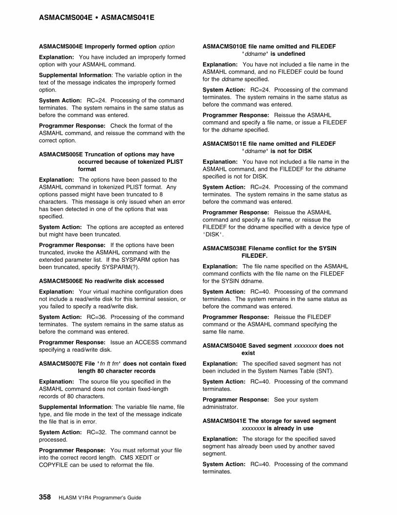
ASMACMS004E 1 ASMACMS041E
ASMACMS004E Improperly formed option option
Explanation: You have included an improperly formedoption with your ASMAHL command.
Supplemental Information: The variable option in thetext of the message indicates the improperly formedoption.
System Action: RC=24. Processing of the commandterminates. The system remains in the same status asbefore the command was entered.
Programmer Response: Check the format of theASMAHL command, and reissue the command with thecorrect option.
ASMACMS005E Truncation of options may haveoccurred because of tokenized PLISTformat
Explanation: The options have been passed to theASMAHL command in tokenized PLIST format. Anyoptions passed might have been truncated to 8characters. This message is only issued when an errorhas been detected in one of the options that wasspecified.
System Action: The options are accepted as enteredbut might have been truncated.
Programmer Response: If the options have beentruncated, invoke the ASMAHL command with theextended parameter list. If the SYSPARM option hasbeen truncated, specify SYSPARM(?).
ASMACMS006E No read/write disk accessed
Explanation: Your virtual machine configuration doesnot include a read/write disk for this terminal session, oryou failed to specify a read/write disk.
System Action: RC=36. Processing of the commandterminates. The system remains in the same status asbefore the command was entered.
Programmer Response: Issue an ACCESS commandspecifying a read/write disk.
ASMACMS007E File 'fn ft fm' does not contain fixedlength 80 character records
Explanation: The source file you specified in theASMAHL command does not contain fixed-lengthrecords of 80 characters.
Supplemental Information: The variable file name, filetype, and file mode in the text of the message indicatethe file that is in error.
System Action: RC=32. The command cannot beprocessed.
Programmer Response: You must reformat your fileinto the correct record length. CMS XEDIT orCOPYFILE can be used to reformat the file.
ASMACMS010E file name omitted and FILEDEF'ddname' is undefined
Explanation: You have not included a file name in theASMAHL command, and no FILEDEF could be foundfor the ddname specified.
System Action: RC=24. Processing of the commandterminates. The system remains in the same status asbefore the command was entered.
Programmer Response: Reissue the ASMAHLcommand and specify a file name, or issue a FILEDEFfor the ddname specified.
ASMACMS011E file name omitted and FILEDEF'ddname' is not for DISK
Explanation: You have not included a file name in theASMAHL command, and the FILEDEF for the ddnamespecified is not for DISK.
System Action: RC=24. Processing of the commandterminates. The system remains in the same status asbefore the command was entered.
Programmer Response: Reissue the ASMAHLcommand and specify a file name, or reissue theFILEDEF for the ddname specified with a device type of'DISK'.
ASMACMS038E Filename conflict for the SYSINFILEDEF.
Explanation: The file name specified on the ASMAHLcommand conflicts with the file name on the FILEDEFfor the SYSIN ddname.
System Action: RC=40. Processing of the commandterminates. The system remains in the same status asbefore the command was entered.
Programmer Response: Reissue the FILEDEFcommand or the ASMAHL command specifying thesame file name.
ASMACMS040E Saved segment xxxxxxxx does notexist
Explanation: The specified saved segment has notbeen included in the System Names Table (SNT).
System Action: RC=40. Processing of the commandterminates.
Programmer Response: See your systemadministrator.
ASMACMS041E The storage for saved segmentxxxxxxxx is already in use
Explanation: The storage for the specified savedsegment has already been used by another savedsegment.
System Action: RC=40. Processing of the commandterminates.
358 HLASM V1R4 Programmer’s Guide

ASMACMS042E 1 ASMACMS076E
Programmer Response: See your systemadministrator.
ASMACMS042E SEGMENT error nnn loading savedsegment xxxxxxxx
Explanation: An error occurred when the ASMAHLcommand attempted to load the specified savedsegment.
System Action: RC=40. Processing of the commandterminates.
Programmer Response: See your systemadministrator.
ASMACMS043E DIAGNOSE error nnn loading savedsegment xxxxxxxx
Explanation: An error occurred when the ASMAHLcommand attempted to load the specified savedsegment.
System Action: RC=40. Processing of the commandterminates.
Programmer Response: See your systemadministrator.
ASMACMS044E NUCXLOAD error nnn loadingxxxxxxxx module
Explanation: An error occurred when the ASMAHLcommand attempted to load the specified module.
System Action: RC=40. Processing of the commandterminates.
Programmer Response: See your systemadministrator.
ASMACMS052E Option list exceeds 512 characters.
Explanation: The string of options that you specifiedwith your ASMAHL command exceeded 512 charactersin length.
System Action: RC=24. Processing of the commandterminates. The system remains in the same status asbefore the command was entered.
Programmer Response: Reissue your ASMAHLcommand with fewer options specified.
ASMACMS062E Invalid character c in file namexxxxxxxx
Explanation: A character that is not permitted wasspecified in the file name specified on the ASMAHLcommand.
System Action: RC=40. Processing of the commandterminates. The system remains in the same status asbefore the command was entered.
Programmer Response: Check the format of theoption with its correct parameters, and reissue thecommand with the correct parameter.
ASMACMS070E Left parenthesis '(' required beforeoption list
Explanation: An option was specified after the filename but before the left parenthesis on the ASMAHLcommand.
System Action: RC=40. Processing of the commandterminates. The system remains in the same status asbefore the command was entered.
Programmer Response: Issue the ASMAHLcommand again with the option specified after the leftparenthesis. Only the file name can be specified beforethe left parenthesis.
ASMACMS074E Required module xxxxxxxx MODULEnot found
Explanation: The ASMAHL command was unable toload the specified module.
System Action: RC=40. Processing of the commandterminates. The system remains in the same status asbefore the command was entered.
Programmer Response: Verify you have accessedthe disk containing the assembler and issue theASMAHL command again.
ASMACMS075E Device device invalid for xxxxxxxx
Explanation: The device specified in your FILEDEFcommand cannot be used for the input or outputoperation that is requested in your program. Forexample, you have tried to read data from the printer orwrite data to the reader.
Supplemental Information: The variable device namein the text of the message indicates the incorrect devicethat was specified.
System Action: RC=40. Processing of the commandterminates. The system remains in the same status asbefore the command was entered.
Programmer Response: Reissue your FILEDEFcommand, specifying the correct device for the requiredinput operation.
ASMACMS076E xxxxxxxx MODULE IS NOT INRELEASE 4 FORMAT
Explanation: The module xxxxxxxx is not in therequired format for Release 4.
Note: This message is only produced in uppercaseEnglish.
System Action: RC=40. Processing of the commandterminates.
Programmer Response: Ensure that you have thecorrect version of the module available. Check thedisks you have linked, and make sure you are notaccessing modules from an earlier release of HighLevel Assembler. If the module is ASMADOPT, you
Appendix G. High Level Assembler Messages 359

might need to reassemble your default options modulewith the ASMAOPT macro provided with High LevelAssembler Release 4. If you cannot resolve the
problem, contact your High Level Assemblermaintenance programmer, or your IBM servicerepresentative.
360 HLASM V1R4 Programmer’s Guide

Appendix H. User Interface Macros
The macros identified in this appendix are provided as programming interfaces byHigh Level Assembler.
Attention: Do not use any High Level Assembler macros, other than thoseidentified in this appendix, as programming interfaces.
The following macros intended for customers are all General-Use ProgrammingInterfaces.
ASMADATA Maps the records in the associated data file.
ASMAEFNP Maps the parameter list passed to external function routines for theSETAF and SETCF conditional assembler instructions.
ASMAXFMB On MVS and CMS, generates the Filter Management Table used bythe sample ADATA user exit ASMAXADT.
ASMAXITP Maps the parameter list passed to the assembler user exits.
Copyright IBM Corp. 1982, 2000 361
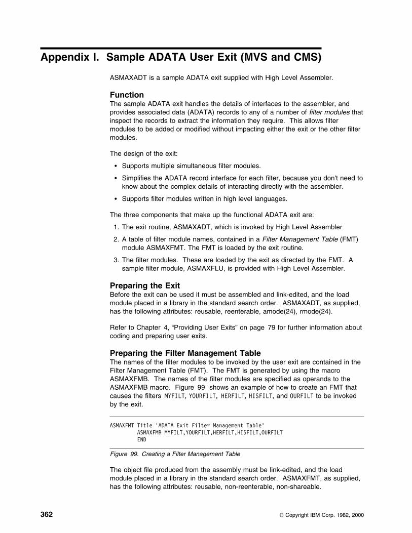
Appendix I. Sample ADATA User Exit (MVS and CMS)
ASMAXADT is a sample ADATA exit supplied with High Level Assembler.
FunctionThe sample ADATA exit handles the details of interfaces to the assembler, andprovides associated data (ADATA) records to any of a number of filter modules thatinspect the records to extract the information they require. This allows filtermodules to be added or modified without impacting either the exit or the other filtermodules.
The design of the exit:
� Supports multiple simultaneous filter modules.
� Simplifies the ADATA record interface for each filter, because you don't need toknow about the complex details of interacting directly with the assembler.
� Supports filter modules written in high level languages.
The three components that make up the functional ADATA exit are:
1. The exit routine, ASMAXADT, which is invoked by High Level Assembler
2. A table of filter module names, contained in a Filter Management Table (FMT)module ASMAXFMT. The FMT is loaded by the exit routine.
3. The filter modules. These are loaded by the exit as directed by the FMT. Asample filter module, ASMAXFLU, is provided with High Level Assembler.
Preparing the ExitBefore the exit can be used it must be assembled and link-edited, and the loadmodule placed in a library in the standard search order. ASMAXADT, as supplied,has the following attributes: reusable, reenterable, amode(24), rmode(24).
Refer to Chapter 4, “Providing User Exits” on page 79 for further information aboutcoding and preparing user exits.
Preparing the Filter Management TableThe names of the filter modules to be invoked by the user exit are contained in theFilter Management Table (FMT). The FMT is generated by using the macroASMAXFMB. The names of the filter modules are specified as operands to theASMAXFMB macro. Figure 99 shows an example of how to create an FMT thatcauses the filters MYFILT, YOURFILT, HERFILT, HISFILT, and OURFILT to be invokedby the exit.
ASMAXFMT Title 'ADATA Exit Filter Management Table' ASMAXFMB MYFILT,YOURFILT,HERFILT,HISFILT,OURFILT END
Figure 99. Creating a Filter Management Table
The object file produced from the assembly must be link-edited, and the loadmodule placed in a library in the standard search order. ASMAXFMT, as supplied,has the following attributes: reusable, non-reenterable, non-shareable.
362 Copyright IBM Corp. 1982, 2000

You can specify an initial character string as part of the filter operand that is passedto the filter routine during initialization. Figure 100 on page 363 shows two filterroutines: MYFILT, that receives the characters “A,B,C”, and ASMAXFLU, thatreceives the characters “DUMP”.
ASMAXFMT Title 'ADATA Exit Filter Management Table' ASMAXFMB (MYFILT,'A,B,C'),(ASMAXFLU,'DUMP') END
Figure 100. Passing Initial Character String to Filter Routines
The default FMT control section (CSECT) name is ASMAXFMT. You can specify adifferent CSECT name using the SECT keyword on the ASMAXFMB macro.Figure 101 shows how to generate a CSECT name of MYFMT.
ASMAXFMT Title 'ADATA Exit Filter Management Table' ASMAXFMB SECT=MYFMT,(MYFILT,'A,B,C'),YOURFILT END
Figure 101. Generating an Alternative CSECT Name
Preparing the Filter ModulesThe exit routine loads the Filter Management Table (FMT) module. The filtermodules specified in the FMT are then loaded by the exit routine. Each filtermodule is called by the exit in three ways: once to process an OPEN request,multiple times to process ADATA records, and once to process a CLOSE request.
Call Interface: The filter modules must be placed in a library in the standardsearch order.
Each filter is called by the exit using the standard call interface in the followingform:
CALL filter(exit_type,action,return_code,handle,record_length,record)
The exit branches to the filter module using the BASR assembler instruction.
Registers on Entry: Standard OS linkage conventions are used, and the registerson entry to the filter module are:
� R13 contains the address of a standard 18-word save area
� R14 contains the return address to the exit
� R15 contains the filter's entry point address
� R1 contains the address of a list of six fullwords that address:
1. A fullword containing the exit_type
2. A fullword integer containing the action code
3. A fullword integer where the filter puts the return_code
4. A 4-fullword handle area
5. A fullword integer containing the ADATA record_length
6. The ADATA record
Appendix I. Sample ADATA User Exit (MVS and CMS) 363

The high-order bit of the last fullword address is set to one.
Figure 102 shows the six fullwords in the parameter list.
┌───────────────┐ ┌───────�│ exit_type │ │ └───────────────┘ │ │ ┌───────────────┐
│ ┌─────�│ action │ ┌───────────────┐ ┌──────────────────────────┐ │ │ └───────────────┘ │ register 1 ├─────�│ address of exit_type ├─┘ │ └───────────────┘ ├──────────────────────────┤ │ ┌───────────────┐
│ address of action ├───┘ ┌───�│ return_code │ ├──────────────────────────┤ │ └───────────────┘
│ address of return_code ├─────┘ ├──────────────────────────┤ ┌───────────────┐
│ address of handle ├─────────�│ handle │ ├──────────────────────────┤ └───────────────┘
│ address of record_length ├─────┐ ├──────────────────────────┤ │ ┌───────────────┐
│ address of record ├─┐ └───�│ record_length │ └──────────────────────────┘ │ └───────────────┘ │ │ ┌───────────────┐ └───────�│ record │ └───────────────┘
Figure 102. Filter Module Parameter List Format
Parameters on Entry: The six parameters are:
exit_type (Input) The address of a fullword of storage that indicates the exittype. The value is always 4, to indicate an ADATA exit.
action (Input) The address of a fullword integer that can be one of thefollowing three values:
0 OPEN Request. Open and initialize the filter. No ADATArecord is available with this call, although there may be initialcharacter string data supplied.
The exit accepts the following return codes:
0 The open action was successful. The exit subsequentlycalls the filter module to inspect and process eachADATA record.
12 The open action was unsuccessful. The filter module isassumed to have closed itself, and is not called again.
1 CLOSE Request. The exit is requesting the filter module toclose itself. No ADATA record is available with this call andno further calls are made to the filter module.
The exit accepts the following return codes:
0 The filter module has closed successfully. The exit candelete the filter.
12 The filter module is assumed to have closed itself, and isnot called again. The exit can delete the filter.
364 HLASM V1R4 Programmer’s Guide

3 PROCESS Request. A record is available to the filter modulefor processing. The ADATA record should not be modified.
The exit accepts the following return codes:
0 The filter module has completed its processing of thisrecord, and is ready to accept further records.
12 The filter module is assumed to have closed itself, and isnot called again.
return_code (Output) The address of a fullword integer where the filter moduleshould place a return code. Valid return codes are described undereach action.
handle (Input/Output) The address of a 4-fullword area of storage that isinitialized to zero before the OPEN (action=9) call to the filter. Itscontents are preserved across subsequent calls. The handle canbe used in any way by the filter module; for example, to addressworking storage for a reenterable filter module.
record_length (Input) The address of a fullword integer containing the length ofthe ADATA record. A length is provided for PROCESS (action=3)calls, and for OPEN (action=9) calls when you supply an initialcharacter string.
record (Input) The address of the ADATA record. This points to theADATA record for PROCESS (action=3) calls, and to the initialcharacter string for OPEN (action=9) calls.
Information Messages: If all the filter modules request termination before the lastADATA record is processed, the following message is issued and the assemblycontinues:
ASMA799I All SYSADATA filter modules requested early termination
Error Diagnostic Messages: When the Filter Management Table routine detectsan error it directs the assembler to issue message ASMA940U and the assemblystops. The following text might be included in the ASMA940U message:
SYSADATA exit not coded at same level of interface definition (2) asassembler
The exit uses version 2 of the exit definition, but the assembler uses a differentversion.
SYSADATA exit called for other than SYSADATA
The exit was invoked with a valid type, but the type is not one that the exit canprocess. This is probably caused by an incorrect ADEXIT() suboption of theEXIT assembler option.
SYSADATA exit not initialized, and not entered for OPEN
The exit has not yet been initialized, but was not entered with an OPENrequest (action=9). There may be a failure in communication between theassembler and the exit.
SYSADATA exit initialized, but was entered for OPEN
The exit has been initialized, but was unexpectedly entered with an OPENrequest (action=9). There may be a failure in communication between theassembler and the exit.
Appendix I. Sample ADATA User Exit (MVS and CMS) 365

SYSADATA exit - Invalid action or operation type requested
An action was requested that is inconsistent with the type of action the exit isable or was expecting to take. There may be a failure in communicationbetween the assembler and the exit.
SYSADATA exit - Expecting input record, zero record length found
The exit was expecting an input record, but the record length was zero. Theremay be a failure in communication between the assembler and the exit.
Unable to load xxxxxxxx module. SYSADATA exit failed
The assembler was unable to load the Filter Management Table modulexxxxxxxx. No SYSADATA processing is possible.
All SYSADATA filter modules failed to open
All of the filter modules loaded by the exit failed to open. No SYSADATAprocessing is possible.
Preparing the Sample Filter Module ASMAXFLUYou can use the supplied filter routine, ASMAXFLU, to:
� Write the names of the primary input and library data sets to a data set.
� Dump the first 32 bytes of each ADATA record to a data set. This function isonly performed if you specify DUMP as the initial character string, as shown inFigure 103.
ASMAXFMT Title 'ADATA Exit Filter Management Table' ASMAXFMB (ASMAXFLU,'DUMP') END
Figure 103. Initial Character String for ASMAXFLU
Output from ASMAXFLU: The output from ASMAXFLU is written to a data setdefined by the ddname XFLUOUT. The data set record length is 80 bytes. Thefirst record in the data set is a header record, and the last record in the data set isa trailer record. The dump, header, and trailer records are prefixed with anasterisk.
The data set records have one of the following formats:
Columns Contents
1 Record type: “P”=Primary Input, “L”=Library
2 Blank
3–10 Date, in YYYYMMDD format (blank for type “L”)
11–14 Time, in HHMM format (blank for type “L”)
15–58 Data set name
59–66 Member name
67–72 Volume ID where file was found
73-80 Sequencing information
or
366 HLASM V1R4 Programmer’s Guide
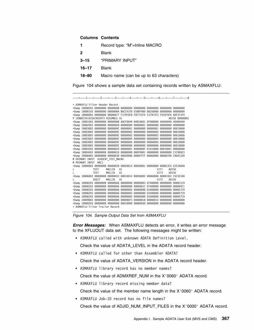
Columns Contents
1 Record type: “M”=Inline MACRO
2 Blank
3–15 “PRIMARY INPUT”
16–17 Blank
18–80 Macro name (can be up to 63 characters)
Figure 104 shows a sample data set containing records written by ASMAXFLU:
----+----1----+----2----+----3----+----4----+----5----+----6----+----7----+----8
L ASMAXFLU Filter Header RecordLDump 19999293 99999999 99999998 99999999 99999999 99999999 99999999 99999999LDump 19999193 99999999 9999999A B9CC4378 E59BF999 99259999 99999999 99999999LDump 19999993 99999999 99999977 F1F9F9F8 F9F7F2F4 F1F9F3F3 F5F6F9F6 69F2F3F4P 199897241933AINSERT3 ASSEMBLE A1 ADISK 99999991LDump 19991993 99999999 99999968 A9CF9949 84BC9691 9F998999 49494949 49494949LDump 19992993 99999999 99999928 99999999 99999991 99999999 99999999 99999999LDump 19993993 99999999 9999999C 99999991 99999999 99999991 99999999 99919999LDump 19993993 99999999 9999999C 99999992 99999999 99999992 99999999 99919999LDump 19993993 99999999 9999999C 99999993 99999999 99999993 99999999 99919999LDump 19993993 99999999 9999999C 99999994 99999999 99999994 99999999 99919999LDump 19993993 99999999 9999999C 99999995 99999999 99999995 99999999 99919999LDump 19993993 99999999 9999999C 99999996 99999999 99999996 99999999 99919999LDump 19994293 99999999 9999992A 99999991 9999999F 91D19999 99919991 99999999LDump 19994493 99999999 9999991D 99989999 999F9991 49999999 99999999 C1C9D5E3LDump 19996993 99999999 9999993B 9992999D 9999FFFF 99969999 9999D7D9 C9D4C1D9M PRIMARY INPUT AINSERT_TEST_MACROM PRIMARY INPUT MAC1LDump 19996993 99999999 99999939 99929914 99959991 99969999 9999E3C5 E2E34949L TEST MACLIB A1 XIT1 ADISKL TEST MACLIB A1 XIT3 ADISKLDump 19996993 99999999 99999933 99919914 99959992 99969999 9999C4E2 C5C3E349L DSECT MACLIB A1 XIT2 ADISKLDump 19996293 99999999 999999A6 99999999 99999993 D7499999 99999999 9999C1C9LDump 19996293 99999999 999999A6 99999999 9999991C D7499999 99999999 9999D4C1LDump 19996293 99999999 999999A6 99999992 99999999 D3499999 99999999 9999E7C9LDump 19996293 99999999 999999A6 99999993 99999999 D3499999 99999999 9999E7C9LDump 19996293 99999999 999999A6 99999992 99999999 D3499999 99999999 9999E7C9LDump 19999993 99999999 999999B9 99999DF3 999999C8 99999912 99999999 99999999LDump 19999293 99999999 99999998 99919999 9999993D 99999999 99999999 99999999L ASMAXFLU Filter Trailer Record
Figure 104. Sample Output Data Set from ASMAXFLU
Error Messages: When ASMAXFLU detects an error, it writes an error messageto the XFLUOUT data set. The following messages might be written:
� ASMAXFLU called with unknown ADATA Definition Level.
Check the value of ADATA_LEVEL in the ADATA record header.
� ASMAXFLU called for other than Assembler ADATA?
Check the value of ADATA_VERSION in the ADATA record header.
� ASMAXFLU library record has no member names?
Check the value of ADMXREF_NUM in the X'0060' ADATA record.
� ASMAXFLU library record missing member data?
Check the value of the member name length in the X'0060' ADATA record.
� ASMAXFLU Job-ID record has no file names?
Check the value of ADJID_NUM_INPUT_FILES in the X'0000' ADATA record.
Appendix I. Sample ADATA User Exit (MVS and CMS) 367
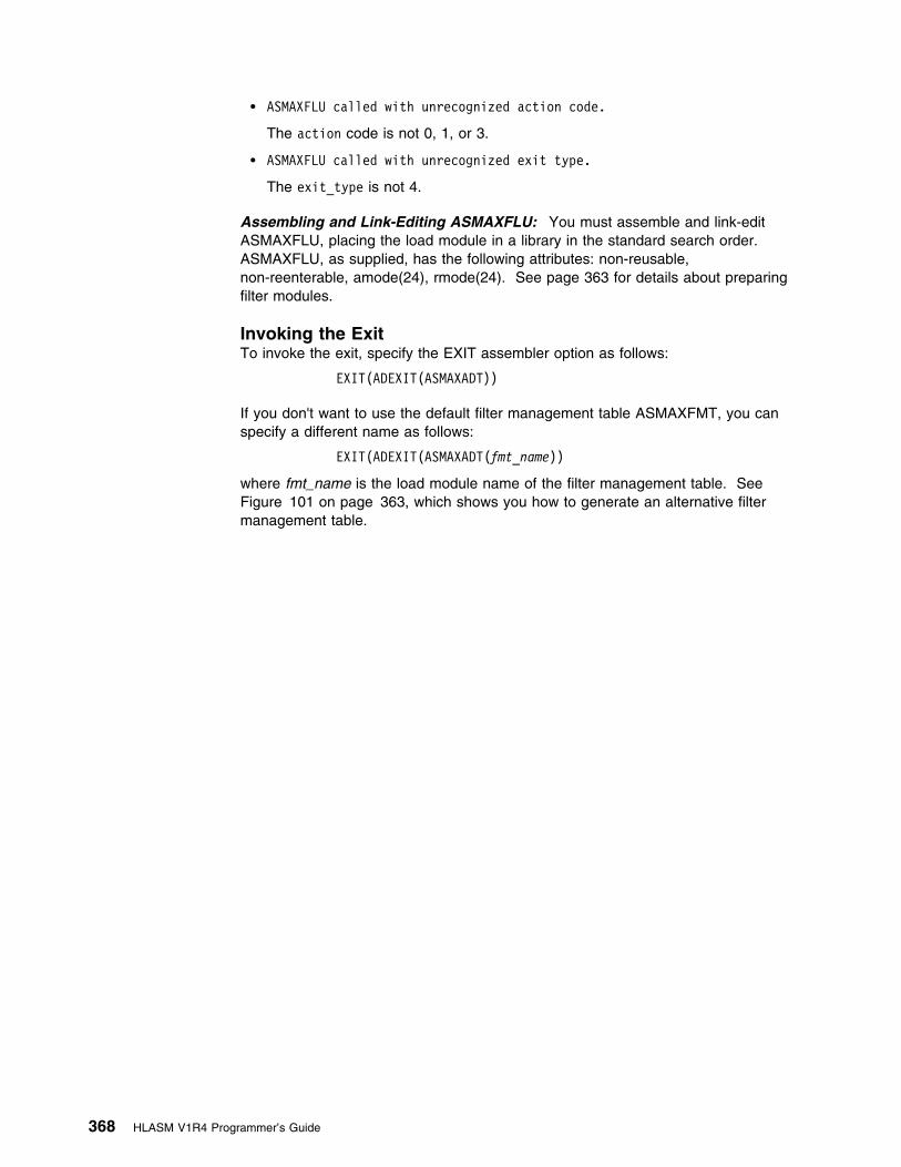
� ASMAXFLU called with unrecognized action code.
The action code is not 0, 1, or 3.
� ASMAXFLU called with unrecognized exit type.
The exit_type is not 4.
Assembling and Link-Editing ASMAXFLU: You must assemble and link-editASMAXFLU, placing the load module in a library in the standard search order.ASMAXFLU, as supplied, has the following attributes: non-reusable,non-reenterable, amode(24), rmode(24). See page 363 for details about preparingfilter modules.
Invoking the ExitTo invoke the exit, specify the EXIT assembler option as follows:
EXIT(ADEXIT(ASMAXADT))
If you don't want to use the default filter management table ASMAXFMT, you canspecify a different name as follows:
EXIT(ADEXIT(ASMAXADT(fmt_name))
where fmt_name is the load module name of the filter management table. SeeFigure 101 on page 363, which shows you how to generate an alternative filtermanagement table.
368 HLASM V1R4 Programmer’s Guide

Appendix J. Sample LISTING User Exit (MVS and CMS)
ASMAXPRT is a sample LISTING exit supplied with High Level Assembler.
FunctionThe sample LISTING exit suppresses printing of the High Level Assembler OptionsSummary, or the Diagnostic Cross Reference and Assembler Summary, or both. Itcan also print the Options Summary page at the end of the listing, instead of itsnormal position at the beginning of the listing.
Preparing the ExitBefore the exit can be used it must be assembled and link-edited, and the loadmodule (phase) placed in a library in the standard search order. ASMAXPRT, assupplied, has the following attributes: reusable, reenterable, amode(31),rmode(any).
Refer to Chapter 4, “Providing User Exits” on page 79 for further information aboutcoding and preparing user exits.
Invoking the ExitTo invoke the exit, specify the EXIT assembler option as follows:
EXIT(PRTEXIT(ASMAXPRT(parameter-string)))
where parameter-string controls what action the exit performs.
Parameter String
┌ ┐─,───────────��─ ──( ───+ ┴┬ ┬─NOOPTION── ) ─�� ├ ┤─NOSUMMARY─ └ ┘─OPTEND────
DefaultNone. At least one keyword is required.
AbbreviationsNOOP, NOSUM
The abbreviations shown here are the minimum number of characters allowed.You can, for example, specify NOOPTI or NOSUMM.
NOOPTIONSuppress the Options Summary
NOSUMMARYSuppress the Diagnostic Cross Reference and Assembler Summary
OPTENDPrint the Options Summary at the end of the assembler listing, instead of at thebeginning.
Copyright IBM Corp. 1982, 2000 369

MessagesASMAXPRT might issue message ASMA701W as follows:
LL ASMA791W LISTING: ASMAXPRT - Invalid Option Specified: xxxxxxxx
This message is issued because the value xxxxxxxx, specified as an exit stringof the EXIT assembler option, is not recognized by ASMAXPRT.
The exit uses the keyword options processed until the error was detected. Anyvalues in the exit string after xxxxxxxx are ignored.
LL ASMA791W LISTING: ASMAXPRT - No options specified
This message is issued because ASMAXPRT expects one or more keywordoptions in the exit string of the EXIT assembler option.
LL ASMA791W LISTING: ASMAXPRT - Exit buffer is full
This message is issued because ASMAXPRT, as supplied, only supports amaximum of 60 lines for the Options Summary page. To increase this value, orchange it to allow an unlimited number of lines, modify the exit source thenassemble and link-edit it.
This error might cause an incomplete Options Summary page.
370 HLASM V1R4 Programmer’s Guide

Appendix K. Sample SOURCE User Exit (MVS and CMS)
ASMAXINV is a sample SOURCE exit supplied with High Level Assembler.
FunctionThe sample SOURCE exit reads variable-length source data sets. Each record thatis read is passed to the assembler as an 80-byte source statement. If any record inthe input data set is longer than 71 characters, the remaining part of the record isconverted into continuation records.
The exit also reads a data set with a fixed record length of 80 bytes.
Preparing the ExitBefore the exit can be used it must be assembled and link-edited, and the loadmodule (phase) placed in a library in the standard search order. ASMAXINV, assupplied, has the following attributes: reusable, reenterable, amode(24), rmode(24).
Refer to Chapter 4, “Providing User Exits” on page 79 for further information aboutcoding and preparing user exits.
Invoking the ExitTo invoke the exit specify the EXIT assembler option as follows:
EXIT(INEXIT(ASMAXINV))
Copyright IBM Corp. 1982, 2000 371

Appendix L. How to Generate a Translation Table
High Level Assembler uses the EBCDIC character set to represent characterscontained in character (C-type) data constants (DCs) and literals. TheTRANSLATE assembler option lets you specify a module containing a translationtable which the assembler uses to convert these characters into another characterset.
High Level Assembler provides an ASCII translation table; however, you can supplyyour own translation table. The translation table module must be namedASMALTxx, where xx is the suffix specified in the TRANSLATE assembler option.See “TRANSLATE” on page 74.
Preparing the Translation Table: The user-supplied translation table must beassembled and link-edited into a library in the standard load module search order.The full name of the translation table load module name must occupy bytes 257 to264 of the module. The first byte of the module must be the first byte of thetranslation table.
A sample translation table to convert a subset of EBCDIC characters into ASCIIcharacters is shown in Figure 105 on page 373. Specify the TRANSLATE(U1)assembler option to use this translation table.
372 Copyright IBM Corp. 1982, 2000
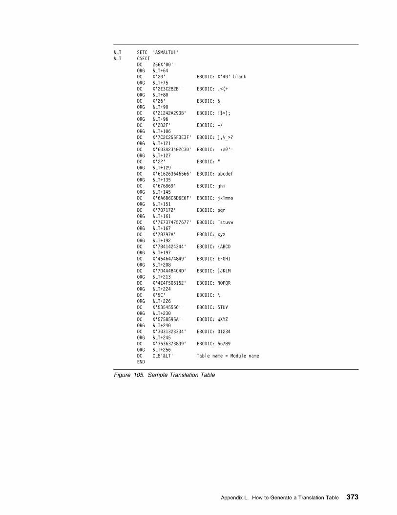
< SETC 'ASMALTU1'< CSECT DC 256X'99' ORG <+64
DC X'29' EBCDIC: X'49' blank ORG <+75 DC X'2E3C282B' EBCDIC: .<(+ ORG <+89 DC X'26' EBCDIC: & ORG <+99
DC X'21242A293B' EBCDIC: !$L); ORG <+96 DC X'2D2F' EBCDIC: -/ ORG <+196 DC X'7C2C255F3E3F' EBCDIC: ],%_>? ORG <+121 DC X'693A23492C3D' EBCDIC: :#@'= ORG <+127 DC X'22' EBCDIC: " ORG <+129 DC X'616263646566' EBCDIC: abcdef ORG <+135 DC X'676869' EBCDIC: ghi ORG <+145 DC X'6A6B6C6D6E6F' EBCDIC: jklmno ORG <+151 DC X'797172' EBCDIC: pqr ORG <+161 DC X'7E7374757677' EBCDIC: ˜stuvw ORG <+167 DC X'78797A' EBCDIC: xyz ORG <+192
DC X'7B41424344' EBCDIC: {ABCD ORG <+197
DC X'4546474849' EBCDIC: EFGHI ORG <+298
DC X'7D4A4B4C4D' EBCDIC: }JKLM ORG <+213
DC X'4E4F595152' EBCDIC: NOPQR ORG <+224 DC X'5C' EBCDIC: \ ORG <+226 DC X'53545556' EBCDIC: STUV ORG <+239 DC X'5758595A' EBCDIC: WXYZ ORG <+249
DC X'3931323334' EBCDIC: 91234 ORG <+245
DC X'3536373839' EBCDIC: 56789 ORG <+256
DC CL8'<' Table name = Module name END
Figure 105. Sample Translation Table
Appendix L. How to Generate a Translation Table 373
| Appendix M. How to Generate a Unicode Translation Table
| High Level Assembler supports the definition of EBCDIC SBCS data constants| which are converted to Unicode data constants. A Unicode character (CU-type)| data constant (DC) is converted to a Unicode DBCS constant using a code page| module. This module is identified using the CODEPAGE assembler option (see| “CODEPAGE” on page 44). The code page module must be named ASMAxxxx,| where xxxx is the value supplied to the CODEPAGE assembler option.
| Preparing the Unicode Translation Table: The user-supplied Unicode translation| table must be assembled and link-edited into a library in the standard load module| search order. The full name of the translation table load module name must occupy| bytes 1 to 8 of the module. The address of the translation table must be in bytes| 65 to 68 of the module. The translation table must begin in byte 133 of the module| and must be 512 bytes in length.
| A sample Unicode translation table is shown in Figure 105 on page 373. Specify| the CODEPAGE(X'FFFF') assembler option to use this translation table.
| The first five DCs in this module are an eye-catcher, which is information that is| easy to read from a dump. The eye-catcher includes useful information such as the| date and time the module was built, and the PTF level.
374 Copyright IBM Corp. 1982, 2000

| ASMAFFFF CSECT| ASMAFFFF AMODE 31| ASMAFFFF RMODE ANY| DC C'ASMAFFFF' Module name| DC CL8'&SYSPARM ' PTF| DC CL8'&SYSDATC' Date| DC CL8'&SYSTIME' Time| DC CL32'Module Description'| DC A(UNICODE) Address of UNICODE translation table| UNICODE DS 9H| DC X'9999' EBCDIC hexadecimal value 99| DC X'9991' EBCDIC hexadecimal value 91| DC X'9992' EBCDIC hexadecimal value 92| DC X'9993' EBCDIC hexadecimal value 93| DC X'999C' EBCDIC hexadecimal value 94| DC X'9999' EBCDIC hexadecimal value 95| DC X'9986' EBCDIC hexadecimal value 96| DC X'997F' EBCDIC hexadecimal value 97| DC X'9997' EBCDIC hexadecimal value 98| DC X'998D' EBCDIC hexadecimal value 99| DC X'998E' EBCDIC hexadecimal value 9A| DC X'999B' EBCDIC hexadecimal value 9B| DC X'999C' EBCDIC hexadecimal value 9C| DC X'999D' EBCDIC hexadecimal value 9D| DC X'999E' EBCDIC hexadecimal value 9E| DC X'999F' EBCDIC hexadecimal value 9F| DC X'9919' EBCDIC hexadecimal value 19| DC X'9911' EBCDIC hexadecimal value 11| DC X'9912' EBCDIC hexadecimal value 12| DC X'9913' EBCDIC hexadecimal value 13| DC X'999D' EBCDIC hexadecimal value 14| DC X'9985' EBCDIC hexadecimal value 15| DC X'9998' EBCDIC hexadecimal value 16| DC X'9987' EBCDIC hexadecimal value 17| DC X'9918' EBCDIC hexadecimal value 18| DC X'9919' EBCDIC hexadecimal value 19| DC X'9992' EBCDIC hexadecimal value 1A| DC X'998F' EBCDIC hexadecimal value 1B| DC X'991C' EBCDIC hexadecimal value 1C| DC X'991D' EBCDIC hexadecimal value 1D| DC X'991E' EBCDIC hexadecimal value 1E| DC X'991F' EBCDIC hexadecimal value 1F| DC X'9989' EBCDIC hexadecimal value 29| DC X'9981' EBCDIC hexadecimal value 21| DC X'9982' EBCDIC hexadecimal value 22| DC X'9983' EBCDIC hexadecimal value 23| DC X'9984' EBCDIC hexadecimal value 24| DC X'999A' EBCDIC hexadecimal value 25| DC X'9917' EBCDIC hexadecimal value 26| DC X'991B' EBCDIC hexadecimal value 27| DC X'9988' EBCDIC hexadecimal value 28| DC X'9989' EBCDIC hexadecimal value 29| DC X'998A' EBCDIC hexadecimal value 2A| DC X'998B' EBCDIC hexadecimal value 2B| DC X'998C' EBCDIC hexadecimal value 2C| DC X'9995' EBCDIC hexadecimal value 2D| DC X'9996' EBCDIC hexadecimal value 2E| DC X'9997' EBCDIC hexadecimal value 2F| DC X'9999' EBCDIC hexadecimal value 39| DC X'9991' EBCDIC hexadecimal value 31| DC X'9916' EBCDIC hexadecimal value 32| DC X'9993' EBCDIC hexadecimal value 33| DC X'9994' EBCDIC hexadecimal value 34| DC X'9995' EBCDIC hexadecimal value 35| DC X'9996' EBCDIC hexadecimal value 36| DC X'9994' EBCDIC hexadecimal value 37| DC X'9998' EBCDIC hexadecimal value 38| DC X'9999' EBCDIC hexadecimal value 39| DC X'999A' EBCDIC hexadecimal value 3A
| Figure 106 (Part 1 of 4). Sample Unicode Translation Table
Appendix M. How to Generate a Unicode Translation Table 375

| DC X'999B' EBCDIC hexadecimal value 3B| DC X'9914' EBCDIC hexadecimal value 3C| DC X'9915' EBCDIC hexadecimal value 3D| DC X'999E' EBCDIC hexadecimal value 3E| DC X'991A' EBCDIC hexadecimal value 3F| DC X'9929' EBCDIC hexadecimal value 49| DC X'99A9' EBCDIC hexadecimal value 41| DC X'99E2' EBCDIC hexadecimal value 42| DC X'99E4' EBCDIC hexadecimal value 43| DC X'99E9' EBCDIC hexadecimal value 44| DC X'99E1' EBCDIC hexadecimal value 45| DC X'99E3' EBCDIC hexadecimal value 46| DC X'99E5' EBCDIC hexadecimal value 47| DC X'99E7' EBCDIC hexadecimal value 48| DC X'99F1' EBCDIC hexadecimal value 49| DC X'995B' EBCDIC hexadecimal value 4A| DC X'992E' EBCDIC hexadecimal value 4B| DC X'993C' EBCDIC hexadecimal value 4C| DC X'9928' EBCDIC hexadecimal value 4D| DC X'992B' EBCDIC hexadecimal value 4E| DC X'9921' EBCDIC hexadecimal value 4F| DC X'9926' EBCDIC hexadecimal value 59| DC X'99E9' EBCDIC hexadecimal value 51| DC X'99EA' EBCDIC hexadecimal value 52| DC X'99EB' EBCDIC hexadecimal value 53| DC X'99E8' EBCDIC hexadecimal value 54| DC X'99ED' EBCDIC hexadecimal value 55| DC X'99EE' EBCDIC hexadecimal value 56| DC X'99EF' EBCDIC hexadecimal value 57| DC X'99EC' EBCDIC hexadecimal value 58| DC X'99DF' EBCDIC hexadecimal value 59| DC X'995D' EBCDIC hexadecimal value 5A| DC X'9924' EBCDIC hexadecimal value 5B| DC X'992A' EBCDIC hexadecimal value 5C| DC X'9929' EBCDIC hexadecimal value 5D| DC X'993B' EBCDIC hexadecimal value 5E| DC X'995E' EBCDIC hexadecimal value 5F| DC X'992D' EBCDIC hexadecimal value 69| DC X'992F' EBCDIC hexadecimal value 61| DC X'99C2' EBCDIC hexadecimal value 62| DC X'99C4' EBCDIC hexadecimal value 63| DC X'99C9' EBCDIC hexadecimal value 64| DC X'99C1' EBCDIC hexadecimal value 65| DC X'99C3' EBCDIC hexadecimal value 66| DC X'99C5' EBCDIC hexadecimal value 67| DC X'99C7' EBCDIC hexadecimal value 68| DC X'99D1' EBCDIC hexadecimal value 69| DC X'99A6' EBCDIC hexadecimal value 6A| DC X'992C' EBCDIC hexadecimal value 6B| DC X'9925' EBCDIC hexadecimal value 6C| DC X'995F' EBCDIC hexadecimal value 6D| DC X'993E' EBCDIC hexadecimal value 6E| DC X'993F' EBCDIC hexadecimal value 6F| DC X'99F8' EBCDIC hexadecimal value 79| DC X'99C9' EBCDIC hexadecimal value 71| DC X'99CA' EBCDIC hexadecimal value 72| DC X'99CB' EBCDIC hexadecimal value 73| DC X'99C8' EBCDIC hexadecimal value 74| DC X'99CD' EBCDIC hexadecimal value 75| DC X'99CE' EBCDIC hexadecimal value 76| DC X'99CF' EBCDIC hexadecimal value 77| DC X'99CC' EBCDIC hexadecimal value 78| DC X'9969' EBCDIC hexadecimal value 79| DC X'993A' EBCDIC hexadecimal value 7A| DC X'9923' EBCDIC hexadecimal value 7B| DC X'9949' EBCDIC hexadecimal value 7C| DC X'9927' EBCDIC hexadecimal value 7D| DC X'993D' EBCDIC hexadecimal value 7E| DC X'9922' EBCDIC hexadecimal value 7F
| Figure 106 (Part 2 of 4). Sample Unicode Translation Table
376 HLASM V1R4 Programmer’s Guide

| DC X'99D8' EBCDIC hexadecimal value 89| DC X'9961' EBCDIC hexadecimal value 81| DC X'9962' EBCDIC hexadecimal value 82| DC X'9963' EBCDIC hexadecimal value 83| DC X'9964' EBCDIC hexadecimal value 84| DC X'9965' EBCDIC hexadecimal value 85| DC X'9966' EBCDIC hexadecimal value 86| DC X'9967' EBCDIC hexadecimal value 87| DC X'9968' EBCDIC hexadecimal value 88| DC X'9969' EBCDIC hexadecimal value 89| DC X'99AB' EBCDIC hexadecimal value 8A| DC X'99BB' EBCDIC hexadecimal value 8B| DC X'99F9' EBCDIC hexadecimal value 8C| DC X'99FD' EBCDIC hexadecimal value 8D| DC X'99FE' EBCDIC hexadecimal value 8E| DC X'99B1' EBCDIC hexadecimal value 8F| DC X'99B9' EBCDIC hexadecimal value 99| DC X'996A' EBCDIC hexadecimal value 91| DC X'996B' EBCDIC hexadecimal value 92| DC X'996C' EBCDIC hexadecimal value 93| DC X'996D' EBCDIC hexadecimal value 94| DC X'996E' EBCDIC hexadecimal value 95| DC X'996F' EBCDIC hexadecimal value 96| DC X'9979' EBCDIC hexadecimal value 97| DC X'9971' EBCDIC hexadecimal value 98| DC X'9972' EBCDIC hexadecimal value 99| DC X'99AA' EBCDIC hexadecimal value 9A| DC X'99BA' EBCDIC hexadecimal value 9B| DC X'99E6' EBCDIC hexadecimal value 9C| DC X'99B8' EBCDIC hexadecimal value 9D| DC X'99C6' EBCDIC hexadecimal value 9E| DC X'29AC' EBCDIC hexadecimal value 9F| DC X'99B5' EBCDIC hexadecimal value A9| DC X'997E' EBCDIC hexadecimal value A1| DC X'9973' EBCDIC hexadecimal value A2| DC X'9974' EBCDIC hexadecimal value A3| DC X'9975' EBCDIC hexadecimal value A4| DC X'9976' EBCDIC hexadecimal value A5| DC X'9977' EBCDIC hexadecimal value A6| DC X'9978' EBCDIC hexadecimal value A7| DC X'9979' EBCDIC hexadecimal value A8| DC X'997A' EBCDIC hexadecimal value A9| DC X'99A1' EBCDIC hexadecimal value AA| DC X'99BF' EBCDIC hexadecimal value AB| DC X'99D9' EBCDIC hexadecimal value AC| DC X'99DD' EBCDIC hexadecimal value AD| DC X'99DE' EBCDIC hexadecimal value AE| DC X'99AE' EBCDIC hexadecimal value AF| DC X'99A2' EBCDIC hexadecimal value B9| DC X'99A3' EBCDIC hexadecimal value B1| DC X'99A5' EBCDIC hexadecimal value B2| DC X'99B7' EBCDIC hexadecimal value B3| DC X'99A9' EBCDIC hexadecimal value B4| DC X'99A7' EBCDIC hexadecimal value B5| DC X'99B6' EBCDIC hexadecimal value B6| DC X'99BC' EBCDIC hexadecimal value B7| DC X'99BD' EBCDIC hexadecimal value B8| DC X'99BE' EBCDIC hexadecimal value B9| DC X'99AC' EBCDIC hexadecimal value BA| DC X'997C' EBCDIC hexadecimal value BB| DC X'99AF' EBCDIC hexadecimal value BC| DC X'99A8' EBCDIC hexadecimal value BD| DC X'99B4' EBCDIC hexadecimal value BE| DC X'99D7' EBCDIC hexadecimal value BF| DC X'997B' EBCDIC hexadecimal value C9| DC X'9941' EBCDIC hexadecimal value C1| DC X'9942' EBCDIC hexadecimal value C2| DC X'9943' EBCDIC hexadecimal value C3| DC X'9944' EBCDIC hexadecimal value C4
| Figure 106 (Part 3 of 4). Sample Unicode Translation Table
Appendix M. How to Generate a Unicode Translation Table 377

| DC X'9945' EBCDIC hexadecimal value C5| DC X'9946' EBCDIC hexadecimal value C6| DC X'9947' EBCDIC hexadecimal value C7| DC X'9948' EBCDIC hexadecimal value C8| DC X'9949' EBCDIC hexadecimal value C9| DC X'99AD' EBCDIC hexadecimal value CA| DC X'99F4' EBCDIC hexadecimal value CB| DC X'99F6' EBCDIC hexadecimal value CC| DC X'99F2' EBCDIC hexadecimal value CD| DC X'99F3' EBCDIC hexadecimal value CE| DC X'99F5' EBCDIC hexadecimal value CF| DC X'997D' EBCDIC hexadecimal value D9| DC X'994A' EBCDIC hexadecimal value D1| DC X'994B' EBCDIC hexadecimal value D2| DC X'994C' EBCDIC hexadecimal value D3| DC X'994D' EBCDIC hexadecimal value D4| DC X'994E' EBCDIC hexadecimal value D5| DC X'994F' EBCDIC hexadecimal value D6| DC X'9959' EBCDIC hexadecimal value D7| DC X'9951' EBCDIC hexadecimal value D8| DC X'9952' EBCDIC hexadecimal value D9| DC X'99B9' EBCDIC hexadecimal value DA| DC X'99FB' EBCDIC hexadecimal value DB| DC X'99FC' EBCDIC hexadecimal value DC| DC X'99F9' EBCDIC hexadecimal value DD| DC X'99FA' EBCDIC hexadecimal value DE| DC X'99FF' EBCDIC hexadecimal value DF| DC X'995C' EBCDIC hexadecimal value E9| DC X'99F7' EBCDIC hexadecimal value E1| DC X'9953' EBCDIC hexadecimal value E2| DC X'9954' EBCDIC hexadecimal value E3| DC X'9955' EBCDIC hexadecimal value E4| DC X'9956' EBCDIC hexadecimal value E5| DC X'9957' EBCDIC hexadecimal value E6| DC X'9958' EBCDIC hexadecimal value E7| DC X'9959' EBCDIC hexadecimal value E8| DC X'995A' EBCDIC hexadecimal value E9| DC X'99B2' EBCDIC hexadecimal value EA| DC X'99D4' EBCDIC hexadecimal value EB| DC X'99D6' EBCDIC hexadecimal value EC| DC X'99D2' EBCDIC hexadecimal value ED| DC X'99D3' EBCDIC hexadecimal value EE| DC X'99D5' EBCDIC hexadecimal value EF| DC X'9939' EBCDIC hexadecimal value F9| DC X'9931' EBCDIC hexadecimal value F1| DC X'9932' EBCDIC hexadecimal value F2| DC X'9933' EBCDIC hexadecimal value F3| DC X'9934' EBCDIC hexadecimal value F4| DC X'9935' EBCDIC hexadecimal value F5| DC X'9936' EBCDIC hexadecimal value F6| DC X'9937' EBCDIC hexadecimal value F7| DC X'9938' EBCDIC hexadecimal value F8| DC X'9939' EBCDIC hexadecimal value F9| DC X'99B3' EBCDIC hexadecimal value FA| DC X'99DB' EBCDIC hexadecimal value FB| DC X'99DC' EBCDIC hexadecimal value FC| DC X'99D9' EBCDIC hexadecimal value FD| DC X'99DA' EBCDIC hexadecimal value FE| DC X'999F' EBCDIC hexadecimal value FF| END
| Figure 106 (Part 4 of 4). Sample Unicode Translation Table
378 HLASM V1R4 Programmer’s Guide

Notices
Notices
This information was developed for products andservices offered in the U.S.A.
IBM may not offer the products, services, or featuresdiscussed in this document in other countries. Consultyour local IBM representative for information on theproducts and services currently available in your area.Any reference to an IBM product, program, or service isnot intended to state or imply that only that IBMproduct, program, or service may be used. Anyfunctionally equivalent product, program, or service thatdoes not infringe any IBM intellectual property right maybe used instead. However, it is the user's responsibilityto evaluate and verify the operation of any non-IBMproduct, program, or service.
IBM may have patents or pending patent applicationscovering subject matter described in this document.The furnishing of this document does not give you anylicense to these patents. You can send licenseinquiries, in writing, to:
IBM Director of Licensing IBM Corporation
North Castle DriveArmonk, NY 10504-1785
U.S.A.
Licensees of this program who wish to have informationabout it for the purpose of enabling: (i) the exchange ofinformation between independently created programsand other programs (including this one) and (ii) themutual use of the information which has beenexchanged, should contact:
IBM CorporationMail Station P300522 South RoadPoughkeepsie New York 12601-5400
U.S.A.
Such information may be available, subject toappropriate terms and conditions, including in somecases, payment of a fee.
The licensed program described in this document andall licensed material available for it are provided by IBM
under terms of the IBM Customer Agreement, IBMInternational Program License Agreement or anyequivalent agreement between us.
For license inquiries regarding double-byte (DBCS)information, contact the IBM Intellectual PropertyDepartment in your country or send inquiries, in writing,to:
IBM World Trade Asia Corporation Licensing
2-31 Roppongi 3-chome, Minato-kuTokyo 106, Japan
The following paragraph does not apply to the UnitedKingdom or any other country where such provisionsare inconsistent with local law: INTERNATIONALBUSINESS MACHINES CORPORATION PROVIDESTHIS PUBLICATION "AS IS" WITHOUT WARRANTYOF ANY KIND, EITHER EXPRESS OR IMPLIED,INCLUDING, BUT NOT LIMITED TO, THE IMPLIEDWARRANTIES OF NON-INFRINGEMENT,MERCHANTABILITY OR FITNESS FOR APARTICULAR PURPOSE. Some states do not allowdisclaimer of express or implied warranties in certaintransactions, therefore, this statement may not apply toyou.
This information could include technical inaccuracies ortypographical errors. Changes are periodically made tothe information herein; these changes will beincorporated in new editions of the publication. IBMmay make improvements and/or changes in theproduct(s) and/or the program(s) described in thispublication at any time without notice.
Any references in this information to non-IBM Web sitesare provided for convenience only and do not in anymanner serve as an endorsement of those Web sites.The materials at those Web sites are not part of thematerials for this IBM product and use of those Websites is at your own risk.
If you are viewing this information softcopy, thephotographs and color illustrations may not appear.
Copyright IBM Corp. 1982, 2000 379

Notices
Trademarks
The following are trademarks of International BusinessMachines Corporation in the United States, or othercountries, or both:
DFSMSDFSMS/MVSEnterprise System/9000Enterprise Systems Architecture/370Enterprise Systems Architecture/390ES/9000ESA/390IBMMVS/DFPMVS/ESAMVS/XAOpenEditionOS/390S/370SPSystem/370System/390VM/ESAVSE/ESA4003090
380 HLASM V1R4 Programmer’s Guide

Glossary
Glossary
This glossary defines terms that are used in the HighLevel Assembler publications. Some of these termsmight not be used in this publication.
This glossary has three main types of definitions thatapply:
� To the assembler language in particular (usuallydistinguished by reference to the words“assembler,” “assembly,” etc.)
� To programming in general
� To data processing as a whole
If you do not understand the meaning of a dataprocessing term used in any of the definitions below,refer to Vocabulary for Data Processing,Telecommunications, and Office Systems, GC20-1699.
IBM is grateful to the American National StandardsInstitute (ANSI) for permission to reprint its definitionsfrom the American National Standard Vocabulary forInformation Processing, which was prepared bySubcommittee X3K5 on Terminology and Glossary ofAmerican National Standards Committee X3. ANSIdefinitions are preceded by an asterisk (*).
absolute expression. An expression is absolute if itsvalue does not change upon program relocation.
absolute value. Is the value of a term when that valuedoes not change upon program relocation.
addressing mode (24-bit). A System/370 addressingmode (AMODE) of the extended architecture that allowsa program to run using 24-bit addresses. Whenoperating in 24-bit mode, S/370 addressing architectureis applied. Other facilities of the extended architecture(see below) may be utilized. Only the low-order 24 bitsof an address are used; the high-order bits are ignored.
addressing mode (31-bit). An extended architectureaddressing mode (AMODE) that allows a program torun using 31-bit addresses, other facilities of theextended architecture, or both. When operating in31-bit mode, extended architecture addressing isapplied, and all but the high-order bit of an address areused to address storage.
assemble. To prepare a machine language programfrom a symbolic language program by substitutingmachine operation codes for symbolic operation codesand absolute or relocatable addresses for symbolicaddresses.
*assembler. A computer program that assembles.
assembler instruction. An assembler languagesource statement that causes the assembler to do aspecific operation. Assembler instructions are nottranslated into machine instructions.
assembler language. A source language that includessymbolic machine language statements in which thereis a one-to-one correspondence with the instructionformats and data formats of the computer. Theassembler language also contains statements thatrepresent assembler instructions and macroinstructions.
automatic library call. The process by which thelinkage editor or binder resolves external references byincluding additional members from the automatic calllibrary.
bimodal program execution. A function of theextended architecture (see “addressing mode (31-bit)”)that allows a program to run in 24-bit or 31-bitaddressing mode. The addressing mode is underprogram control.
binder. The component of DFSMS/MVS which isresponsible for linking and editing programs, to createeither record format load modules or program objects.The DFSMS/MVS binder is a functional replacement forthe MVS/DFP linkage editor.
bracketed DBCS. DBCS characters enclosed with ashift-out (SO) character and a shift-in character (SI) toidentify them from SBCS, and containing no SBCScharacters except SO and SI.
| code page. An assignment of graphic characters and| control function meanings to all code points.
| code point. A 1-byte code representing one of 256| potential characters.
conditional assembly language. A programminglanguage that the assembler processes duringconditional assembly. The conditional assemblylanguage can be used to perform general arithmetic andlogical computations, generate machine and assemblerinstructions from model statements, and providevariable symbols to represent data and vary the contentof model statements during generation. It can be usedin macro definitions, and in open code.
CONTROL PROGRAM.. A program that is designed toschedule and supervise the performance of dataprocessing work by a computing system; an operatingsystem.
Copyright IBM Corp. 1982, 2000 381

Glossary
control section (CSECT). That part of a programspecified by the programmer to be a relocatable unit, allelements of which are to be loaded into adjoining mainstorage locations.
data attributes. Values assigned by the assemblerwhich describe the characteristics of ordinary symbolsand variable symbols that represent data.
*diagnostic. Pertaining to the detection and isolationof a malfunction or mistake.
double-byte character set (DBCS). DBCS is a meansof providing support for Ideographic Languages whichcontain too many symbols to be represented by a singlebyte character set such as EBCDIC. A validdouble-byte character is defined as either DBCS blank(X'4040'), or a pair of bytes, each of which must be inthe range X'41' to X'FE', inclusive.
double-byte data. Double-byte character strings arecommonly referred to as double-byte data.
dummy control section (DSECT). A control sectionthat an assembler can use to map an area of storagewithout producing any object code or data for that area.Synonymous with dummy section.
edited text. Source statements modified by theassembler for internal use. The initial processing of theassembler is referred to as editing.
enterprise systems architecture. A hardwarearchitecture for the IBM 3090 processor. A majorcharacteristic is 31-bit addressing. See also“addressing mode (31-bit).”
*entry point. A location in a module to which controlcan be passed from another module or from the controlprogram.
| extended architecture. A hardware architecture for| systems beginning with the IBM 3081. A major
characteristic is 31-bit addressing. See also“addressing mode (31-bit).”
external symbol dictionary (ESD). Controlinformation associated with an object or load modulewhich identifies the external symbols in the module.
global dictionary. An internal table used by theassembler during macro generation to contain thecurrent values of all unique global SETA, SETB, andSETC variables from all text segments.
global vector table. A table of pointers in the skeletondictionary of each text segment showing where theglobal variables are located in the global dictionary.
hierarchical file system. In MVS/ESA OpenEdition, aHierarchical File System (HFS) is a collection of files
organized in a hierarchy, as in a UNIX system. All filesare members of a directory, and each directory is inturn a member of another directory at a higher level inthe hierarchy. The highest level of the hierarchy is theroot directory. MVS views an entire file hierarchy as acollection of hierarchical file system data sets (HFS datasets). Each HFS data set is a mountable file system.The Hierarchical File System is described in theMVS/ESA OpenEdition MVS User's Guide, SC23-3013.
instruction. *(1) A statement that specifies anoperation and the values and locations of its operands.(2) See also “assembler instruction,” “machineinstruction,” and “macro instruction.”
job control language (JCL). A language used to codejob control statements.
*job control statement. A statement in a job that isused in identifying the job or describing its requirementsto the operating system.
language. A set of representations, conventions, andrules used to convey information.
*language translator. A general term for anyassembler, compiler, or other routine that acceptsstatements in one language and produces equivalentstatements in another language.
library macro definition. A macro definition that isstored in a macro library. The IBM-supplied supervisorand data management macro definitions are examplesof library macro definitions.
linkage editor. A processing program that preparesthe output of language translators to enable it to run. Itcombines separately produced object or load modules;resolves symbolic cross references among them;replaces, deletes, and adds control sections; generatesoverlay structures on request; and produces executablecode (a load module) that is ready to be fetched intomain storage and run.
linker. Used in this publication as collective term forbinder and linkage editor.
load module. The output of a single linkage editor run.A load module is in a format suitable for loading intovirtual storage and running.
loader. A processing program that does the basicediting functions of the linkage editor, and also fetchesand gives control to the processed program. It acceptsobject modules and load modules created by thelinkage editor and generates executable code directly instorage. The loader does not produce load modules forprogram libraries.
local dictionary. An internal table used by theassembler during macro generation to contain the
382 HLASM V1R4 Programmer’s Guide
Glossary
current values of all local SET symbols. There is onelocal dictionary for open code, and one for each macrodefinition.
location counter. A counter whose value indicates theassembled address of a machine instruction or aconstant or the address of an area of reserved storage,relative to the beginning of the control section.
*machine instruction. An instruction that a machinecan recognize and execute.
*machine language. A language that is used directlyby the machine.
macro definition. A set of statements that defines thename of, format of, and conditions for generating asequence of assembler language statements from asingle source statement. This statement is a macroinstruction that calls the definition. (See also “librarymacro definition” and “source macro definition.”)
macro generation (macro expansion). An operationin which the assembler generates a sequence ofassembler language statements from a single macroinstruction, under conditions described by a macrodefinition.
macro instruction (macro call). An assemblerlanguage statement that causes the assembler toprocess a predefined set of statements (called a macrodefinition). The statements normally produced from themacro definition replace the macro instruction in thesource program.
macro library. A library containing macro definitions.The supervisor and data management macro definitionssupplied by IBM (GET, LINK, etc.) are contained in thesystem macro library. Private macro libraries can beconcatenated with the system macro library.
macro prototype statement. An assembler languagestatement that specifies the mnemonic operation codeand the format of all macro instructions that are used tocall a macro definition.
MACRO statement. An assembler language statementthat indicates the beginning of a macro definition. (Alsoknown as a macro definition header).
main storage. All program addressable storage fromwhich instructions may be executed and from whichdata can be loaded directly into registers.
MEND statement. An assembler language statementthat indicates the end of a macro definition. (Also knownas a macro definition trailer).
model statement. A statement from which assemblerlanguage statements are generated during conditionalassembly.
object module. The machine-language output of asingle run of an assembler or a compiler. An objectmodule is used as input to the linkage editor, loader, orbinder.
open code. The portion of a source module that liesoutside of and after any source macro definitions thatmay be specified.
*operating system. Software that controls the runningof computer programs and which may providescheduling, debugging, input/output control, accounting,compilation, storage assignment, data management,and related services. (see “control program.”)
ordinary symbol attribute reference dictionary. Adictionary used by the assembler. The assembler putsan entry in it for each ordinary symbol encountered inthe name field of a statement. The entry contains theattributes (type, length, etc.) of the symbol.
partitioned data set (PDS). A data set on directaccess storage that is divided into partitions, calledmembers, each of which can contain a program, part ofa program, or data.
PDSE (partitioned data set extended). Asystem-managed data set that contains an indexeddirectory and members that are similar to the directoryand members of partitioned data sets.
phase. The output of a single VSE linkage editor run.A phase is in a format suitable for loading into virtualstorage
processing program. (1) A general term for anyprogram that is not a control program. (2) Any programcapable of operating in the problem program state.This includes IBM-distributed language translators,application programs, service programs, anduser-written programs.
program. A general term for any combination ofstatements that can be interpreted by a computer orlanguage translator, and that serves to do a specificfunction.
program fetch. A program that prepares programs forexecution by loading them at specific storage locationsand readjusting each (relocatable) address constant.
program library. A partitioned data set or PDSE(MVS), or Librarian library (VSE), that always containsnamed members.
program management binder. See binder.
program module. Used in this publication ascollective term for load module and program object.
Glossary 383
Glossary
program object. All or part of a computer program ina form suitable for loading into main storage forexecution. Program objects are stored in PDSEprogram libraries, and are produced by the ProgramManagement Binder.
pure DBCS. DBCS characters not delimited by SOand SI. These characters must be known to be DBCSby some other method, such as the position in a record,or a field type descriptor in a database environment.
real storage. The storage of a System/370 computerfrom which the central processing unit can directlyobtain instructions and data, and to which it can directlyreturn results.
read-only control section (RSECT). That part of aprogram specified by the programmer to be a read-onlyexecutable control section. The assembler automaticallychecks the control section for possible coding violationsof program reenterability, regardless of the setting of theRENT assembler option.
reenterable. An attribute that allows a program to beused concurrently by more than one task. This attributeis sometimes called reentrant.
refreshable. An attribute that allows a program to bereplaced with a new copy without affecting its operation.
reusability. An attribute of a program that defines thescope to which it can be reused or shared by multipletasks within an address space.
relocatable expression. An expression is relocatableif its value changes because the control section inwhich it appears is relocated.
relocatable value. Is the value of a term when thatvalue changes because the control section in which itappears is relocated.
*relocation dictionary. The part of an object or loadmodule that identifies all addresses that must beadjusted when a relocation occurs.
residence mode. An extended architecture addressingmode (RMODE) that allows a program to specify theresidence mode (below 16 megabytes or anywhere) tobe associated with a control section.
return code. A value placed in the return code registerat the completion of a program. The value isestablished by the user and may be used to influencethe running of succeeding programs or, in the case ofan abnormal end of task, may simply be printed forprogrammer analysis.
severity code. A code assigned by the assembler toeach error detected in the source code. The highest
code encountered during assembly becomes the returncode of the assembly step.
shift-in (SI). The shift-in (SI) EBCDIC character(X'0F') delimits the end of double-byte data.
shift-out (SO). The shift-out (SO) EBCDIC character(X'0E') delimits the start of double-byte data.
skeleton dictionary. A dictionary built by theassembler for each text segment. It contains the globalvector table, the sequence symbol reference dictionary,and the local dictionary.
source macro definition. A macro definition includedin a source module, either physically or as the result ofa COPY instruction.
source module. The source statements that constitutethe input to a language translator for a particulartranslation.
source statement. A statement written in aprogramming language.
*statement. A meaningful expression or generalizedinstruction in a programming language.
symbol file. A data set used by the assembler forsymbol definitions and references and literals.
symbolic parameter. In assembler programming, avariable symbol declared in the prototype statement of amacro definition.
system macro definition. Loosely, an IBM-suppliedlibrary macro definition which provides access tooperating system facilities.
text segment. The range over which a local dictionaryhas meaning. The source module is divided into textsegments with a segment for open code and one foreach macro definition.
*translate. To transform statements from onelanguage into another without significantly changing themeaning.
| translate table. A table used to replace one or more| characters with alternative characters.
virtual storage. Address space appearing to the useras real storage from which instructions and data aremapped into real storage locations. The size of virtualstorage is limited by the addressing scheme of thecomputing system and by the amount of auxiliarystorage available, rather than by the actual number ofreal storage locations.
ward. A set of DBCS characters which have the samehigh-order byte value. The first byte of a double-byte
384 HLASM V1R4 Programmer’s Guide

Glossary
character is known as the ward byte. A ward contains190 characters. Ward X'42' defines the double-byte
representation of those EBCDIC characters which are inthe range X'41' to X'FE'.
Glossary 385

Bibliography
Bibliography
High Level AssemblerPublications
HLASM General Information, GC26-4943
HLASM Installation and Customization Guide,SC26-3494
HLASM Language Reference, SC26-4940
HLASM Licensed Program Specifications,GC26-4944
HLASM Programmer's Guide, SC26-4941
Toolkit Feature PublicationsHLASM Toolkit Feature User's Guide, GC26-8710
HLASM Toolkit Feature Debug ReferenceSummary, GC26-8712
HLASM Toolkit Feature Interactive Debug FacilityUser's Guide, GC26-8709
HLASM Toolkit Feature Installation Guide,GC26-8711
Related Publications(Architecture)
Enterprise Systems Architecture/390 Principles ofOperation, SA22-7201
Vector Operations, SA22-7207
System/370 Enterprise Systems ArchitecturePrinciples of Operation, SA22-7200
System/370 Principles of Operation, GA22-7000
System/370 Extended Architecture Principles ofOperation, SA22-7085
Related Publications for MVS OS/390 MVS:
OS/390 MVS JCL Reference, GC28-1757
OS/390 MVS JCL User's Guide, GC28-1758
OS/390 MVS Programming: Assembler ServicesGuide, GC28-1757
OS/390 MVS Programming: Assembler ServicesReference, GC28-1910
OS/390 MVS Programming: Authorized AssemblerServices Guide, GC28-1763
OS/390 MVS Programming: Authorized AssemblerServices Reference ALE-DYN, GC28-1764
OS/390 MVS Programming: Authorized AssemblerServices Reference ENF-IXG, GC28-1765
OS/390 MVS Programming: Authorized AssemblerServices Reference LLA-SDU, GC28-1766
OS/390 MVS Programming: Authorized AssemblerServices Reference SET-WTO, GC28-1767
OS/390 MVS System Codes, GC28-1780
OS/390 MVS System Commands, GC28-1781
OS/390 MVS System Messages, Vol 1 (ABA-ASA),GC28-1784
OS/390 MVS System Messages, Vol 2 (ASB-ERB),GC28-1785
OS/390 MVS System Messages, Vol 3 (EWX-IEB),GC28-1786
OS/390 MVS System Messages, Vol 4 (IEC-IFD),GC28-1787
OS/390 MVS System Messages, Vol 5 (IGD-IZP),GC28-1788
MVS/ESA Version 5:
MVS/ESA JCL Reference, GC28-1479
MVS/ESA JCL User's Guide, GC28-1473
MVS/ESA Programming: Assembler ServicesGuide, GC28-1466
MVS/ESA Programming: Assembler ServicesGuide, GC28-1474
MVS/ESA Programming: Authorized AssemblerServices Guide, GC28-1467
MVS/ESA Programming: Authorized AssemblerServices Reference Volumes 1 - 4, GC28-1475,GC28-1476, GC28-1477, GC28-1478
MVS/ESA System Codes, GC28-1486
MVS/ESA System Commands, GC28-1442
MVS/ESA System Messages Volumes 1 - 5 ,GC28-1480, GC28-1481, GC28-1482, GC28-1483,GC28-1484
MVS/ESA OpenEdition:
MVS/ESA OpenEdition MVS User's Guide,SC23-3013
OS/390 OpenEdition:
OS/390 UNIX System Services User's Guide,SC28-1891
MVS/DFP:
386 Copyright IBM Corp. 1982, 2000
Bibliography
MVS/DFP Version 3.3: Utilities, SC26-4559
MVS/DFP Version 3.3: Linkage Editor and Loader,SC26-4564
DFSMS/MVS:
OS/390 DFSMS Program Management, SC27-0806
TSO/E (MVS):
TSO/E Command Reference, SC28-1881
TSO/E (OS/390):
OS/390 TSO/E Command Reference, SC28-1969
MVS SMP/E:
SMP/E Messages and Codes, SC28-1108
SMP/E Reference, SC28-1107
SMP/E Reference Summary, SX22-0006
SMP/E User's Guide, SC28-1302
OS/390 SMP/E:
OS/390 SMP/E Messages and Codes, SC28-1738
OS/390 SMP/E Reference, SC28-1806
OS/390 SMP/E User's Guide, SC28-1740
Related Publications for VMVM/ESA CMS Application Development Guide,SC24-5761
VM/ESA CMS Application Development Guide forAssembler, SC24-5763
VM/ESA CMS Application Development Reference,SC24-5762
VM/ESA CMS Application Development Referencefor Assembler, SC24-5764
VM/ESA CMS User's Guide, SC24-5775
VM/ESA XEDIT Command and Macro Reference,SC24-5780
VM/ESA XEDIT User's Guide, SC24-5779
VM/ESA CP Command and Utility Reference,SC24-5750
VM/ESA Planning and Administration, SC24-5773
VMSES/E Introduction and Reference, SC24-5837
VM/ESA Service Guide, SC24-5838
VM/ESA CMS Command Reference, SC24-5776
VM/ESA CMS File Pool Planning, Administration,and Operation, SC24-5751
VM/ESA System Messages and Codes Reference,SC24-5841
Related Publications for VSEVSE/ESA Administration, SC33-6505
VSE/ESA Guide to System Functions, SC33-6511
VSE/ESA Installation, SC33-6504
VSE/ESA Planning, SC33-6503
VSE/ESA System Control Statements, SC33-6513
General PublicationsBRIEF OS/390 Software Management Cookbook,SG24-4775
Bibliography 387
Index
Index
Special Characters*PROCESS OVERRIDE assembler options 39*PROCESS statements
OVERRIDE 40precedence of assembler options 38
&SYSNDX system variable symbol, controlling its valueusing MHELP 302
Numerics121-character format, source and object listing 15121, LIST assembler suboption 59133-character format, source and object listing 15133, LIST assembler suboption 59370, OPTABLE assembler suboption 62
Aabnormal assembly termination 148ABOVE, suboption of SIZE 69accessing the assembler (CMS) 188ACONTROL statement
COMPAT/NOCOMPAT option 45FLAG option 52LIBMAC/NOLIBMAC option 58RA2/NORA2 option 67
active USINGsin the assembler listing 20UHEAD, PCONTROL assembler suboption 64
ADATA assembler option 42, 255ADATA DC extension record 280ADATA exit processing 111ADATA, GOFF assembler suboption 255adding definitions to a macro Libraryadding macro definitions to libraries 222
CMS 202MVS 173
addressing mode 171ADEXIT installation option 51ALIGN assembler option 43, 211ALIGN, FLAG assembler suboption 52ALIGNWARN installation option 54alternate ddnames 155AMODE
in ESD section of listing 14linker option 169processing option 171
architecture level in ADATA records 262ASA assembler option 43ASA assembler option (CMS) 193ASA assembler option (MVS) 159
ASCII translation table 74ASMAC
cataloged procedure for assembly 152, 174ASMACG
cataloged procedure for assembly and run, using theloader 178
ASMACLcataloged procedure for assembly and link 176
ASMACLGcataloged procedure for assembly, link, and
run 178ASMADATA macro 255, 361ASMAEFNP macro 136, 361ASMAHL command
by FILEDEF for SYSIN 194error messages 357with filename of source 194with the EXIT option 195
ASMAHL command-error messages 309ASMAOPT macro 39ASMAOPT options file/library member 39ASMAPROF, default profile member name 66ASMAXADT (ADATA user exit) 362ASMAXFMB macro 361, 362ASMAXINV (SOURCE user exit) 371ASMAXITP macro 82, 361ASMAXPRT (LISTING user exit) 369assembler
language differences 227sample program 290
assembler cataloged procedures 174assembler data sets (MVS)
characteristics of 158list of 157
assembler diagnosticsabnormal assembly termination 148cross reference 22differences 243error messages 143facilities 143macro trace facility (MHELP) 148MNOTE statements 145National Language Support 57reference information for statements in error 147register cross reference 31suppression of error messages and MNOTE
statements 147assembler files (CMS)
characteristics of 192list of 191
assembler files (VSE)characteristics of 213
388 Copyright IBM Corp. 1982, 2000

Index
assembler files (VSE) (continued)list of 212
Assembler H Version 2 compatibility 6assembler language support 6assembler listing
*PROCESS statements 9121-character format 15133-character format 15CMS options that affect 9diagnostic cross reference and assembler
summary 32differences 241DSECT cross reference 29external symbol dictionary 12general purpose register cross reference 31macro and copy code cross reference 25macro and copy code source summary 25option summary 9options that affect 8parts of 8relocation dictionary 22source and object 15, 16source and object, 121 character format 15source and object, 133 character format 21symbol and literal cross reference 22unreferenced symbols defined in CSECTs 24USING map 30
assembler macroson CMS 202on MVS 173
assembler optionOBJECT 56
assembler options*PROCESS OVERRIDE 39*PROCESS statements 40ADATA 42, 255ALIGN 43, 211ASA 43, 159, 193ASMAOPT 39at invocation 39BATCH 44CODEPAGE 44coding rules 41COMPAT 45conflicting 38DBCS 46DECK 47, 211default 41differences 239DISK (CMS) 66DXREF 47ERASE (CMS) 48ESD 48EXIT 49, 79external source 39external sources 38
assembler options (continued)fixed defaults 39FLAG 52FOLD 55GOFF 55in a parameter list 41INFO 56JCL options 211LANGUAGE 57LIBMAC 58LINECOUNT 58LIST 59, 211MXREF 61NOADATA 42, 255NOALIGN 43, 211NOASA 43, 159, 193NOBATCH 44NOCOMPAT 45NODBCS 46NODECK 47, 211NODXREF 47NOERASE (CMS) 48NOESD 48NOEXIT 49, 79NOFOLD 55NOGOFF 55NOINFO 56NOLIBMAC 58NOLIST 59, 211NOMXREF 61NOOBJECT 62, 211NOPCONTROL 64NOPRINT (CMS) 66NOPROFILE 66NORA2 67NORENT 68NORLD 68, 211NORXREF 68NOSEG 69NOTERM 72, 211NOTEST 73NOTHREAD 73NOTRANSLATE 74NOUSING 75NOXOBJECT 77NOXREF 78, 211OBJECT 62, 211on CMS 190OPTABLE 62override 39OVERRIDE on *PROCESS statement 40overriding 180overriding defaults 41, 180overriding statements in cataloged procedures 180PCONTROL 64PESTOP 66
Index 389

Index
assembler options (continued)precedence 38PRINT (CMS) 66processing 169PROFILE 66RA2 67RENT 68restricted options 40RLD 68, 211RXREF 68sample of use 291SEG 69SIZE 69source 38SYSPARM 71TERM 72, 211TEST 73THREAD 73TRANSLATE 74types of 38USING 75XOBJECT 77XREF 78, 211
assembler statistics 36assembler summary 32assembling your program 206assembly abnormal-termination messages 309assembly and link, JCL for
See ASMACLassembly and run using the loader, JCL for
See ASMACGassembly error diagnostic messages 312assembly error-diagnostic messages 309assembly, JCL for
See ASMACassembly, link, and run, JCL for
See ASMACLGassociated data records
ADATA compilation unit start/end record -X'0002' 265
ADATA identification record - X'0001' 264architecture level 255, 262ASMADATA macro 255common header section 262DC extension record - X'0035' 280DC/DS record - X'0034' 275external symbol dictionary record - X'0020' 271job identification record - X'0000' 264library member and macro cross reference record -
X'0062' 284library record - X'0060' 283machine instruction record - X'0036' 281options file information - X'000B' 268options record - X'0010' 268output file information record - X'000a' 265register cross reference record - X'0045' 283
associated data records (continued)relocation dictionary record - X'0040' 281source analysis record - X'0030' 272statistics record - X'0090' 286symbol cross reference record - X'0044' 282symbol record - X'0042' 281user-supplied information record - X'0070' 285USING map record - X'0080' 285
ATTACH macro instruction, (MVS) 154automatic call library
definition 381secondary data set 167
BBATCH assembler option 44batch assembling 210
CMS 190MVS 156
batch facility on CMS 201binder
generalized object format 77sample JCL 165
BLKSIZE for assembler files 214CMS 193MVS 159
books, High Level Assembler xiv
CC0ATTR instruction
interaction with GOFF 56CALL linker option 169CALL macro instruction 210CALL macro instruction (MVS) 154calling the assembler from a problem program 210calling the assembler from program (MVS) 154CASE, COMPAT assembler suboption 45cataloged procedures
for assembling (ASMAC) 174for assembling and linking (ASMACL) 176for assembling and running using the loader
(ASMACG) 178for assembling, linking, and run (ASMACLG) 178invoking 174overriding 180
CD-ROM publications xvCDLOAD macro instruction 210characteristics of assembler data sets (MVS) 158characteristics of assembler files (CMS) 192characteristics of assembler files (VSE) 213CLOSE calls to user exit 84CMS
ASMAHL command error messages 357assembler macros supported by 202assembling on 189
390 HLASM V1R4 Programmer’s Guide

Index
CMS (continued)batch facility 201diagnostic messages 357logical saved segments 69relationship to assembler 188running on 199
CMS assembler options 190CMS diagnostic messages 197CMSBATCH command 201CODEPAGE assembler option 44codes
See return codescoding rules for assembler options 41COM instruction
interaction with GOFF 56COMPAT assembler option 45compatibility with earlier assemblers 6concatenation of sublibraries 215concatenation of SYSLIB data sets 161, 196COND parameter 162, 180conditional assembly external functions 135CONT, FLAG assembler suboption 52CONTWARN installation option 54create, phase 217cross reference
See also diagnostic cross reference and assemblersummary
binder (MVS) 169data variables (MVS) 169examples 8, 300linkage editor 220linkage editor (MVS) 169
cross reference listDSECT 29
CSECT instructioninteraction with GOFF 56
Customization book xiv
Ddata
variables, cross reference 169data sets, assembler (MVS)
characteristics of 158list of 157
DATA, PCONTROL assembler suboption 64DBCS assembler option 46DD statements, overriding in cataloged
procedures 180ddnamelist 155ddnames
SYSADATA 162, 197SYSIN 160, 195SYSLIB 161, 168, 196SYSLIN 161, 168, 196SYSLMOD 168
ddnames (continued)SYSPRINT 161, 168, 196SYSPUNCH 161, 196SYSTERM 161, 168, 196SYSUT1 168user-specified 168
ddnames alternate 155DE, LANGUAGE assembler suboption 57DECK assembler option 47, 211default options 41default profile member name 66diagnostic cross reference and assembler summary 32diagnostic facilities
See assembler diagnosticsdiagnostic messages written by CMS 197, 357diagnostic messages, assembly error 312DISK assembler option (CMS) 66documentation
High Level Assembler 386related publications 387
documentation, High Level Assembler xivDOS, OPTABLE assembler suboption 62DOS/VSE assembler compatibility 6DSECT cross reference listing format 29DXREF assembler option 47dynamic invocation of assembler 210dynamic invocation of assembler (MVS) 154
EE-Decks, processing 222EN, LANGUAGE assembler suboption 57END Record format 252entry point restatement 185ERASE assembler option (CMS) 48erasing files (CMS) 48error messages
abnormal assembly termination messages 352ASMAHL command error messages (CMS) 357assembly error diagnostic messages 143, 312reference information 147suppression of 52, 147
error, link-edit 220error, linker (MVS) 172ES, LANGUAGE assembler suboption 57ESA
OPTABLE assembler suboption 62ESD assembler option 48ESD Record format 249ESDID, external symbol dictionary ID
in Ordinary Symbol and Literal Cross Reference 23in USING Map 30
examplescataloged procedures coding 180register saving and restoring coding 224register saving and restoring coding (CMS) 203
Index 391

Index
examples (continued)register saving and restoring coding (MVS) 183
EXEC statements, overriding in catalogedprocedures 180
EXIT assembler option 49, 79EXIT option with the ASMAHL command 195exit parameter list 82exit types 79exit-specific information block 92EXITCTL assembler instruction 79exits
user-supplied 79extended architecture instructions 246external functions 135external symbol dictionary (ESD)
entry types 12examples 13, 291listing format 12
FFILEDEF with the ASMAHL command 194filename with ASMAHL command 194files, assembler (CMS)
characteristics of 192list of 191
files, assembler (VSE)characteristics of 213list of 212
files, linkage editorSYSIPT 219SYSLNK 219SYSLOG 219SYSLST 219SYSRDR 219
filter management table (ADATA user exit) 362filter modules (ADATA user exit) 362FIND COPY calls to user exit 84FIND MACRO calls to user exit 84FLAG assembler option 52FOLD assembler option 55format notation, description xv—xviiFULL
MXREF assembler suboption 61XREF assembler suboption 78
function calls, external 135
GGEN, PCONTROL assembler suboption 64General Information book xivgeneral purpose register cross reference 31generalized object format data set 77generate a translation table 372generate a Unicode translation table 374
GENMOD command (CMS) 199GOFF assembler option 55graphic constants 46
Hhardcopy publications xivhierarchical file system
definition 382object data sets 159
High Level Assemblerpublications xiv
High Level Assembler messages 309See also assembler diagnosticsSee also error messages
High Level Assembler option summary 9
II/O Exit Usage Statistics
in the listing 36ICCF, assembling on 208identification-sequence field 18IF statement 216IJSYS01 218IJSYS03 207, 213, 214INCLUDE control statement 168, 219INEXIT installation option 51INFO assembler option 56input, linkage editor 218input, linker (MVS) 166installation and customization
book information xivinvoking cataloged procedures 174invoking the assembler from a problem program 210invoking the assembler from a program (MVS) 154
Jjob control language cataloged procedures
See cataloged proceduresJP, LANGUAGE assembler suboption 57
LLANGUAGE assembler option 57Language Reference xivLET linker option 169LIBEXIT installation option 51LIBMAC assembler option 58Library 213, 215LIBRARY control statement 168LIBRARY exit processing 99license inquiry 379Licensed Program Specifications xvLIMIT installation option 77
392 HLASM V1R4 Programmer’s Guide
Index
LIMIT, USING assembler suboption 75LINECOUNT assembler option 58LINK macro instruction (MVS) 154linkage conventions for external functions 136linkage editor
CMSSee GENMOD command (CMS)
control statements 219errors 220files 218INCLUDE statement 219input 218libraries 219MVS
AMODE option 169call library 167CALL option 169data sets used 168ddnames 167errors 172INCLUDE statement 168input 166LET option 169LIBRARY statement 168LIST option 169MAP option 169output 169primary 167PRINT option 169processing options 169RMODE option 169sample 165secondary 167TSO LINK command 170XREF option 169
on TSO 166output 220sample 217
linkage, object module 184linker
definition 382options (MVS) 169
LIST assembler option 59, 211LIST linker option 169listing control instructions, printing of 18LISTING exit processing 104listing format 13LKED command (CMS) 200LOAD command (CMS) 199load module
on TSO 166sample 165
load module modification 185loader 165loading user exits 81
LOADLIB (CMS) 200logical saved segments (CMS) 69LRECL for assembler files 214
CMS 193MVS 159
LSEGSee logical saved segments (CMS)
Mmachine instructions, publications 386macro and copy code cross reference listing format 25macro and copy code cross reference with LIBMAC
option 26macro and copy code source summary listing
format 25macro definition libraries, additions to 222
CMS 202MVS 173
macro trace facilitySee MHELP
macro-generated statementsformat of 18in diagnostic messages 312
MACROCASE, COMPAT assembler suboption 45macros
ASMADATA 255, 361ASMAEFNP 136, 361ASMAXFMB 361ASMAXITP 82, 361
macros, error messages in 143macros, external function calls 135manuals
High Level Assembler 386related publications 387
manuals, High Level Assembler xivmap
link-edit option 220linker option (MVS) 169load module 169processing option 169
MAP installation option 77MAP, USING assembler suboption 75MAX, LIST assembler suboption 59MCALL, PCONTROL assembler suboption 64message code format 309messages
See assembler diagnosticsMHELP
description 148global suppression—operand=32 301macro AIF dump—operand=4 301macro branch trace—operand=2 301macro call trace—operand=1 301macro entry dump—operand=16 301macro exit dump—operand=8 301
Index 393

Index
MHELP (continued)macro hex dump—operand=64 301MHELP control on &SYSNDX 302MHELP suppression—operand=128 301sample program and listing 301
MHELP instructionformat 148
migration considerations 7migration to High Level Assembler 227MNOTE statements 145MSOURCE, PCONTROL assembler suboption 64MVS/ESA 173
assembler macros supported by 173assembling on 151running 172
MXREF assembler option 61
NNational Language Support 57NLS
See National Language SupportNOADATA assembler option 42, 255NOALIGN assembler option 43, 211NOASA assembler option 43NOASA assembler option (CMS) 193NOASA assembler option (MVS) 159NOBATCH assembler option 44NOCALL link-edit option 169NOCOMPAT assembler option 45NODBCS assembler option 46NODECK assembler option 47, 211NODXREF assembler option 47NOERASE assembler option (CMS) 48NOESD assembler option 48NOEXIT assembler option 49NOFOLD assembler option 55NOGOFF assembler option 55NOINFO assembler option 56NOLET linker option 169NOLIBMAC assembler option 58NOLIST assembler option 59, 211NOMAP linker option 169NOMXREF assembler option 61NOOBJECT assembler option 62, 211NOPCONTROL assembler option 64NOPRINT assembler option (CMS) 66NOPRINT linker option 169NOPROFILE assembler option 66NORA2 assembler option 67NORENT assembler option 68NORLD assembler option 68, 211NORXREF assembler option 68NOSEG assembler option 69notation, description xv—xvii
NOTERM assembler option 72, 211NOTEST assembler option 73NOTHREAD assembler option 73NOTRANSLATE assembler option 74NOUSING assembler option 75NOXOBJECT assembler option 77NOXREF assembler option 78, 211
OOBJECT assembler option 56, 62, 211OBJECT exit processing 108object module linkage 184object modules 168, 218, 219, 246object program migration 7object, extended format 77OBJEXIT installation option 51OFF, PCONTROL assembler suboption 64ON statement 216ON, PCONTROL assembler suboption 64online publications xvOPEN calls to user exit 84OPTABLE assembler option 62option summary listing format 9options
assemblerSee assembler options
linker (MVS) 169options file
overriding *PROCESS OVERRIDE option 39options library member
overriding *PROCESS OVERRIDE option 39ordinary symbol and literal cross reference 22, 78organization of this manual xiOSRUN command (CMS) 200output format listing 13output, linkage editor 169, 220OVERRIDE on *PROCESS statement 40overriding ddname 155overriding default options 41, 180overriding statements in cataloged procedures 180
PPARM field 38partitioned data set definition 383PCONTROL assembler option 64PDSE definition 383PESTOP assembler option 66phase
create 217sample 217
portabilityextended architecture instructions 246object modules 246system macros 246
394 HLASM V1R4 Programmer’s Guide

Index
precedence of assembler options 38primary linker data set 167PRINT assembler option (CMS) 66PRINT linker option 169procedures
See cataloged proceduresPROCESS calls to user exit 84PROCESS COPY calls to user exit 84PROCESS MACRO calls to user exit 84PROCESS statements
See *PROCESS statementsprocessing E-Decks 222processor time for the assembly 36PROFILE assembler option 66PROFMEM, default profile member name 66program execution 172program fetch definition 383program library definition 383program management binder definition 383program module definition 383program module modification 185program object definition 384program termination 224
CMS 203MVS 183
Programmer's Guide xvPRTEXIT installation option 51publications
general 387High Level Assembler xiv, 386HLASM Toolkit 386machine instructions 386MVS 386online (CD-ROM) xv
PUNCH exit processing 108PUSH level
in the assembler listing 20
RRA2 assembler option 67railroad track format, how to read xv—xviirange, in USING Map 30READ calls to user exit 84RECFM for assembler files 214
CMS 193MVS 159
RECORD, FLAG assembler suboption 52RECORDINFO installation option 54reference information for statements in error 147register cross reference 31registers, saving and restoring
CMS 202MVS 182, 185VSE 223
relocation dictionaryexamples 13, 296listing format 22
RENT assembler option 68residency mode 171restoring registers
CMS 202MVS 182VSE 223
return codes 162, 216See also FLAG assembler option
RETURN macro instructionCMS 202MVS 182VSE 223
RLD assembler option 68, 211RLD Record format 251RMODE
in ESD section of listing 14linker option 169processing option 171
RSECT instructioninteraction with GOFF 56
runningCMS 199MVS/ESA 172TSO 172using batch facility 201using LKED and OSRUN commands 200using LOAD and START commands 199using the GENMOD command 199
running programs on CMS 199running your program 221RXREF assembler option 68
Ssample ADATA user exit 362sample LISTING user exit 369sample program to call the assembler dynamically 210
MVS 156sample programs and listings
assembler language features, using 290assembler listing description 9diagnostic error messages 147MHELP 301
sample SOURCE user exit 371SAVE macro instruction
CMS 202MVS 182VSE 223
saving registersCMS 202MVS 182VSE 223
Index 395

Index
SDBSee system-determined blocksize
secondary data set 167SEG assembler option 69sequence number 18severity codes
See FLAG assembler optionSee return codes
SHORT, XREF assembler suboption 78SIZE assembler option 69SIZE installation option 71softcopy publications xvsource and object assembler listing format 15source and object listing 15source and object listing, 121 character format 15source and object listing, 133 character format 21SOURCE exit processing 97source program migration 7SOURCE, MXREF assembler suboption 61stacked items xviSTART command (CMS) 199start time of assembly 36Static Assembler Information Pointer 91statistics, assembler 36stop time of assembly 36STORAGE installation option 71SUBLIB JCL option 215SUBSTR, FLAG assembler suboption 52suppression of error messages and MNOTE
statements 147SYM Record format 252syntax notation, description xv—xviiSYSADAT 213, 216SYSADATA data set 158, 162SYSADATA file 192, 197SYSIN data set 158, 160SYSIN file 192, 195SYSIPT 213, 215, 219SYSLIB data set 158, 161, 168SYSLIB file 192, 196SYSLIN data set 158, 161, 168SYSLIN file 192, 196SYSLIST, COMPAT assembler suboption 45SYSLMOD data set 168SYSLNK 207, 213, 216, 218, 219SYSLOG 213, 215, 219SYSLST 213, 215, 219SYSPARM assembler option 71SYSPCH 213, 216SYSPRINT data set 158, 161, 168SYSPRINT file 192, 196SYSPUNCH data set 158, 161SYSPUNCH file 192, 196SYSRDR 219system macros 246
system variable symbolscomparison with earlier assemblers 230in diagnostic messages 312MHELP numbering system 302setting data set information 94
system-determined blocksize 159SYSTERM data set 158, 161, 168SYSTERM file 192, 196SYSUT1 data set 158, 160, 168SYSUT1 file 192, 193
TTERM assembler option 72, 211TERM exit processing 112termination
abnormal assembly 147, 148program 224
CMS 203MVS 183
TEST assembler option 73THREAD assembler option 73Toolkit Customization book xvToolkit installation and customization
book information xvTRANSLATE assembler option 74translation table generation 372TRMEXIT installation option 51TSO
assembling on 153LINK command 170link-edit options 170running 172
TXT Record format 250
UUE, LANGUAGE assembler suboption 57UHEAD, PCONTROL assembler suboption 64UNI, OPTABLE assembler suboption 62Unicode translation table generation 374unreferenced symbols defined in CSECTs 78unreferenced symbols defined in CSECTs listing
format 24UNREFS, XREF assembler suboption 78user exit
ADATA exit processing 111addressing mode (AMODE) 81ASMAXADT (ADATA user exit) 362ASMAXFMB (ADATA user exit) 362ASMAXFMT (ADATA user exit) 362ASMAXINV (SOURCE user exit) 371ASMAXPRT (LISTING user exit) 369calling 81coding example 115error handling 92
396 HLASM V1R4 Programmer’s Guide
Index
user exit (continued)EXIT assembler option 49exit parameter list 82exit-specific information block 82, 92failure handling 92filter management table (ADATA user exit) 362filter modules (ADATA user exit) 362LIBRARY exit processing 99linkage conventions 81LISTING exit processing 104loading 81locating 81OBJECT exit processing 108PUNCH exit processing 108reason codes 87residency mode (RMODE) 81return codes 86sample ADATA user exit 362sample LISTING user exit 369sample SOURCE user exit 371samples 115SOURCE exit processing 97specifying 80TERM exit processing 112types 79user error handling 92
user-specified data set 168USING assembler option 75USING map listing format 30using the assembler 206
CMS 188MVS 151TSO 153VSE 206
using the assembler (ICCF) 208USINGs, active
in the assembler listing 20UHEAD, PCONTROL assembler suboption 64
utility data set 158utility file 192, 213
Vvariable symbols, system
comparison with earlier assemblers 230VSE 206
relationship to assembler 206VSE/ESA
JCL options 211running your program 221
WWARN installation option 77WARN, USING assembler suboption 75
WRITE calls to user exit 84
XXA, OPTABLE assembler suboption 62XCTL macro instruction (MVS) 154XOBJADATA installation option 77XOBJECT assembler option 77XREF assembler option 78, 211XREF linker option (MVS) 169XREF, MXREF assembler suboption 61
Index 397
We'd Like to Hear from You
High Level Assembler for MVS & VM & VSEProgrammer’s GuideRelease 4
Publication No. SC26-4941-03
Please use one of the following ways to send us your comments about this book:
� Mail—Use the Readers' Comments form on the next page. If you are sending the formfrom a country other than the United States, give it to your local IBM branch office orIBM representative for mailing.
� Fax—Use the Readers' Comments form on the next page and fax it to this U.S. number:800-426-7773.
� Electronic mail—Use one of the following network IDs:
– IBMLink: HLASMPUB at STLVM27 – Internet: [email protected]
Be sure to include the following with your comments:
– Title and publication number of this book– Your name, address, and telephone number if you would like a reply
Your comments should pertain only to the information in this book and the way theinformation is presented. To request additional publications, or to comment on other IBMinformation or the function of IBM products, please give your comments to your IBMrepresentative or to your IBM authorized remarketer.
IBM may use or distribute your comments without obligation.

Readers' Comments
High Level Assembler for MVS & VM & VSEProgrammer’s GuideRelease 4
Publication No. SC26-4941-03
How satisfied are you with the information in this book?
Please tell us how we can improve this book:
May we contact you to discuss your comments? � Yes � No
Name Address
Company or Organization
Phone No.
VerySatisfied Satisfied Neutral Dissatisfied
VeryDissatisfied
Technically accurate � � � � �Complete � � � � �Easy to find � � � � �Easy to understand � � � � �Well organized � � � � �Applicable to your tasks � � � � �Grammatically correct and consistent � � � � �Graphically well designed � � � � �Overall satisfaction � � � � �

Cut or FoldAlong Line
Cut or FoldAlong Line
Readers' CommentsSC26-4941-03 IBM
Fold and Tape Please do not staple Fold and Tape
NO POSTAGENECESSARYIF MAILED IN THEUNITED STATES
BUSINESS REPLY MAILFIRST-CLASS MAIL PERMIT NO. 40 ARMONK, NEW YORK
POSTAGE WILL BE PAID BY ADDRESSEE
Department J58International Business Machines CorporationPO BOX 49023SAN JOSE CA 95161-9945
Fold and Tape Please do not staple Fold and Tape
SC26-4941-03

IBM
Program Number: 5696-234
Printed in the United States of Americaon recycled paper containing 10%recovered post-consumer fiber.
High Level Assembler Publications
SC26-4941 HLASM Programmer's Guide.GC26-4943 HLASM General Information.GC26-4944 HLASM Licensed Program Specifications.SC26-4940 HLASM Language Reference.SC26-3494 HLASM Installation and Customization Guide.
High Level Assembler Toolkit Feature Publications
GC26-8709 HLASM Toolkit Feature Interactive Debug Facility User's Guide.GC26-8710 HLASM Toolkit Feature User's Guide.GC26-8711 HLASM Toolkit Feature Installation Guide.GC26-8712 HLASM Toolkit Feature Debug Reference Summary.
SC26-4941-93

Spine inform
ation:
IBM
HL
ASM
Program
mer’s G
uideR
elease 4