Embed Size (px)
Citation preview
1 | P a g e
ASSAM POWER DISTRIBUTION COMPANY LTD.
BID DOCUMENT FOR
CONSTRUCTION OF 11KV OVERHEAD LINE FROM
(I) BURHAPAHAR RCC BRIDGE TO BURHAPAHAR
TEA ESTATE USING AB CABLE HAVING LINE
LENGTH OF 2.4KM (II)BURHAPAHAR TEA ESTATE TO
KUTHORI HAVING LINE LENGTH OF 11KM BY
USING BARE RACCOON CONDUCTOR IN ORDER TO
DIVERT EXISTING 11KV KUTHORI FEEDER UNDER
NAGAON ELECTRICAL CIRCLE, APDCL
ON
“TURNKEY” MODE
SCHEME: “24x7 Power Supply in Kaziranga, Kamakhya, Sualkuchi,
Tezpur, Manash, Pobitora & Majuli’
NIT NO.CGM (PP&D)/ APDCL/AP 2018-19/24x7 PS/02
2 | P a g e
INDEX
Section – 1 Notice Inviting Tender
Section – 2 Tender Inviting Proposal
Section – 3 BOQ of Packages & Tender Proforma-Part-II (Price Bid)
Section – 4 General Requirements
Section – 5 Forms of Bid
Section – 6 Technical Specifications
Section – 7 Guaranteed Technical Particular
3 | P a g e
SECTION -1 NOTICE INVITING TENDER
4 | P a g e
ASSAM POWER DISTRIBUTION CO. LTD. PROJECT PLANNING & DESIGN
Bijulee Bhawan, Paltanbazar, Guwahati-781001(www.apdcl.gov.in)
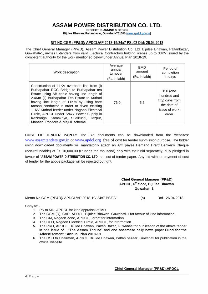
NIT NO.CGM (PP&D)/ APDCL/AP 2018-19/24x7 PS /02 Dtd: 26.04.2018
The Chief General Manager (PP&D), Assam Power Distribution Co. Ltd. Bijulee Bhawan, Paltanbazar, Guwahati-1, invites E-tenders from valid Electrical Contractors holding license up to 33KV issued by the competent authority for the work mentioned below under Annual Plan 2018-19.
Work description
Average annual
turnover
(Rs. in lakh)
EMD amount
(Rs. in lakh)
Period of completion
in days
Construction of 11KV overhead line from (i) Burhapahar RCC Bridge to Burhapahar tea Estate using AB cable having line length of 2.4Km (ii) Burhapahar Tea Estate to Kuthori having line length of 11Km by using bare racoon conductor in order to divert existing 11KV Kuthori feeder under Nagaon Electrical Circle, APDCL under “24x7 Power Supply in Kaziranga, Kamakhya, Sualkuchi, Tezpur, Manash, Pobitora & Majuli’ scheme.
76.0 5.5
150 (one
hundred and
fifty) days from
the date of
issue of work
order
COST OF TENDER PAPER: The Bid documents can be downloaded from the websites:
www.assamtenders.gov.in or www.apdcl.org free of cost for tender submission purpose. The bidder
using downloaded documents will mandatorily attach an A/C payee Demand Draft/ Banker’s Cheque
(non-refundable) of Rs. 10,000.00 (Rupees ten thousand) only with their Bid separately, duly pledged in
favour of “ASSAM POWER DISTRIBUTION CO. LTD. as cost of tender paper. Any bid without payment of cost
of tender for the above package will be rejected outright.
Chief General Manager (PP&D)
APDCL, 6th
floor, Bijulee Bhawan
Guwahati-1
Memo No.CGM (PP&D)/ APDCL/AP 2018-19/ 24x7 PS/02/ (a) Dtd. 26.04.2018 Copy to: -
1. PS to MD, APDCL for kind appraisal of MD 2. The CGM (D), CAR, APDCL, Bijulee Bhawan, Guwahati-1 for favour of kind information. 3. The GM, Nagaon Zone, APDCL, Jorhat for information 4. The CEO, Nagaon Electrical Circle, APDCL, for information 5. The PRO, APDCL, Bijulee Bhawan, Paltan Bazar, Guwahati for publication of the above tender
in one issue of “The Assam Tribune” and one Assamese daily news paper.Fund for the Advertisement : Annual Plan 2018-19
6. The OSD to Chairman, APDCL, Bijulee Bhawan, Paltan bazaar, Guwahati for publication in the official website
Chief General Manager (PP&D),APDCL
5 | P a g e
ASSAM POWER DISTRIBUTION CO. LTD. PROJECT PLANNING & DESIGN
NOTICE INVITING TENDER
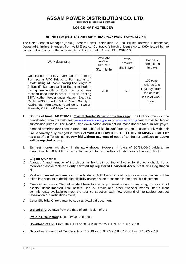
NIT NO.CGM (PP&D)/ APDCL/AP 2018-19/24x7 PS/02 Dtd:26.04.2018
The Chief General Manager (PP&D), Assam Power Distribution Co. Ltd. Bijulee Bhawan, Paltanbazar, Guwahati-1, invites E-tenders from valid Electrical Contractor’s holding license up to 33KV issued by the competent authority for the work mentioned below under Annual Plan 2018-19.
Work description
Average annual
turnover
(Rs. in lakh)
EMD amount
(Rs. in lakh)
Period of completion
In days
Construction of 11KV overhead line from (i) Burhapahar RCC Bridge to Burhapahar tea Estate using AB cable having line length of 2.4Km (ii) Burhapahar Tea Estate to Kuthori having line length of 11Km by using bare raccoon conductor in order to divert existing 11KV Kuthori feeder under Nagaon Electrical Circle, APDCL under “24x7 Power Supply in Kaziranga, Kamakhya, Sualkuchi, Tezpur, Manash, Pobitora & Majuli’ scheme.
76.0 5.5
150 (one
hundred and
fifty) days from
the date of
issue of work
order
1. Source of fund: AP 2018-19; Cost of Tender Paper for the Package: The Bid document can be
downloaded from the websites www.assamtenders.gov.in or www.apdcl.org free of cost for tender
submission purpose. The bidder using downloaded document will mandatorily attach an A/C payee
demand draft/Banker’s cheque (non-refundable) of Rs 10,000/-(Rupees ten thousand) only with their
Bid separately duly pledged in favour of “ASSAM POWER DISTRIBUTION COMPANY LIMITED” as cost of the Tender paper. Any bid without payment of cost of tender for package as above will be rejected outright.
2. Earnest money: As shown in the table above. However, in case of SC/ST/OBC bidders, the amount will be 50% of the shown value subject to the condition of submission of cast certificate. .
3. Eligibility Criteria: a) Average Annual turnover of the bidder for the last three financial years for the work should be as
mentioned above table and duly certified by registered Chartered Accountant with Registration No.
b) Past and present performance of the bidder in ASEB or in any of its successor companies will be taken into account to decide the eligibility as per clause mentioned in the detail bid document.
c) Financial resources: The bidder shall have to specify proposed source of financing, such as liquid assets, unencumbered real assets, line of credit and other financial means, net current commitments, available to meet the total construction cash flow demand of the subject contract (evaluation & qualification criteria).
d) Other Eligibility Criteria may be seen at detail bid document
4. Bid validity: 90 days from the date of submission of Bid 5. Pre-bid Discussion: 13-00 Hrs of 03.05.2018
6. Download of Bid: From 10-00 Hrs of 28.04.2018 to 12-00 Hrs. of 10.05.2018. 7. Date of submission of Tenders: From 10.00Hrs. of 04.05.2018 to 12-00 Hrs. of 10.05.2018
6 | P a g e
8. Date of opening of Bid: a) Techno commercial bids will be opened at 14-00 hrs.of 10.05.2018 b) The price bid on a date to be notified later on.
Note: 1. The work should be carried out as per latest APDCL/REC specification and construction.
2. Bids must be submitted electronically through e-tender portal https://assamtenders.gov.in in two parts
as Techno Commercial bid and Price bid. A copy of the Technical bid has to be submitted in a sealed envelope super scribing (a) Tender No. (b) Name of the bidder with full address.
3. Earnest money as stipulated should be submitted with the Techno Commercial bid in the form of Term Deposit/FD/Bank guarantee from any nationalised or scheduled Bank of India to be issued from banks whose Branches/Regional office is situated within the state of Assam and pledged in favour of “ASSAM POWER DISTRIBUTION CO. LTD”. Any tender without earnest money will be rejected outright.
4. Part-I of the Bid shall consists of information of all Technical Bidding Schedules (GTP), Copy of the Licences, GST registration, certificate of turnover, companies profile, experience certificate etc. Part-II shall consist of Price Bidding Schedules with all quantities and prices filled up as per annexure provided in the detail bid document.
5. The tender should be addressed and submitted in the office of the Chief General Manager (PP&D), APDCL , Bijulee Bhawan, 6th floor, Paltan Bazar, Guwahati-1 and will be opened on the scheduled date & time in presence of the intending bidders.
6. Only those bidders who are found acceptable in Part-I Bid i.e. Techno Commercial bid shall be considered for opening of Price Bid. The date and time of opening of Part-II Bid (Price) shall be communicated to those bidders whose bids are qualified for opening.
7. The Company reserves the right to accept or reject any tender in part or in full or spilt the work of any package without showing any reason thereof.
8. The bidding documents are not transferable and cost of bidding document is not refundable under any circumstances.
Chief General Manager (PP&D)
APDCL, 6th floor, Bijulee Bhawan Paltanbazar, Guwahati-781001
Memo No: CGM (PP&D)/ APDCL/AP 2018-19/24x7 PS/02/ (a) Dated: 26.04.2018 Copy to:-
1. The Managing Director, APDCL Bijulee Bhawan Paltan Bazar for favour of information. 2. The CGM (D), CAR, APDCL Bijulee Bhawan Paltan Bazar for favour of information. 3. The GM, Nagaon Zone, APDCL for information. 4. The CEO, Nagaon Electrical Circle, APDCL- for information 5. To the OSD to the Chairman, APDCL. He is requested to arrange for uploading the above
notice along with Bid document at the official website of APDCL.
Chief General Manager (PP&D), APDCL
7 | P a g e
SECTION 2
TENDER INVITING PROPOSAL
8 | P a g e
ASSAM POWER DISTRIBUTION CO. LTD. PROJECT PLANNING & DESIGN
TENDER INVITING PROPOSALS WITH TERMS & CONDITIONS
1. Name of work: Construction of 11KV overhead line from (i) Burhapahar RCC Bridge to Burhapahar tea Estate using AB cable having line length of 2.4Km (ii) Burhapahar Tea Estate to Kuthori having line length of 11Km by using bare raccoon conductor in order to divert existing 11KV Kuthori feeder under Nagaon Electrical Circle, APDCL under “24x7 Power Supply in Kaziranga, Kamakhya, Soalkuchi, Tezpur, Manash, Pobitora & Majuli’ scheme of AP 2018-19
2. Intent of the Tender Enquiry
The intent of the Tender Enquiry is to invite proposals from the prospective and relevantly
experienced and financially sound contractor(s) (individual or joint venture)/firms to carry out
the works as mentioned above on turnkey mode.
3. Scope of Work
The various activities under the scope of work shall among other related aspects cover the
following.
i. Procurement and supply of all materials required for the work.
ii. Arrange inspection / testing of any/all items ordered at manufacturer’s works for officer deputed by APDCL for such inspection/testing. All cost related to inspection or Test will be borne by the contractor.
iii. Site unloading, storage and handling of all materials supplied including watch and ward for safe custody.
iv. Site fabrication work as per requirement.
v. Submission of implementation schedule from the date of award of contract for: -
Erection, testing and commissioning of all materials/equipment supplied/system installed.
vi. Project management and site organization.
vii. Obtaining clearance from statutory Agencies, Government Departments, Village Panchayats etc. wherever necessary
viii. Submission of technical specification/Test Certificate/Drawings etc. of all materials supplied.
ix. A list of various items normally involved in proposed type of work is provided in this document. This, however, is not to be considered as limiting but only typical. Bidders’ scope will include all other items and materials as may be required to effectively complete the work.
Above all, the scope of work of the bidder/contractor will include all items and facilities as may
be necessary to complete the electrification work on turnkey basis and as binding requirement.
4. Basic specification of the various equipment/ works to be supplied /carried out
i. All equipment supplied shall conform to the requirement of relevant ISS (BIS) as approved by ASEB/Company and that of REC specification and construction standards.
ii. All materials supplied shall be erected, protected as per approved standard practice for proposed type of electrical work so as to supply electricity to the consumers most effectively and in an intrinsically safe manner.
iii. All equipment supplied and installed shall provide easy and effective:
Maintainability
Reliability
Availability
Long life
9 | P a g e
All equipment supplied and installed shall be provided stable and adequate weather protection,
system earthing etc. LA should be earthed separately.
iv. All items, which may require frequent opening up/ dismantling for maintenance, shall be adequately sealed against any tampering/ theft etc.
v. Generally supply and erection of materials and system shall meet the requirement of construction standard being followed in the electrification work.
5. Basic qualifying requirement:
To be qualified for the package the bidder must compulsorily meet the following minimum criteria.
A. Technical.
The prospective bidder must fulfill the following qualifying requirements:
a) The bidder must have valid electrical Contractor’s and Supervisor’s License (HT minimum up to 33 KV) issued by any Licensing Authority of Govt. of Assam. In case, the bidder does not have the licenses from the Licensing Authority of Govt. of Assam but has valid licenses from other Licensing Authority under the Electricity Act 2003, the bidder will have to obtain the same from the Licensing Authority of Govt. of Assam in case of award of contract.
b) The bidder must have the experience of constructing minimum of 2(two) Km of new 11
kV over head line using bare conductor and 1(one) Km of 11KV line using AB cable during last 3(three) years as on the date of bid opening and in satisfactory operation for at least 1(one) year.
c) The bidder shall furnish details of the work / works along with its value already in hand
either of APDCL, or in any other successor companies of ASEB as well as works executed outside the state of Assam along with date of completion as per Letter of Award and likely date of completion duly certified by the competent authority as per format enclosed as Annexure-IA. This shall be treated as one of the major qualifying criteria for technical evaluation of the bid. Any awarded of work if not 100% complete will be treated as work in hand. Submission of false data if found, will be penalized as per rule.
B. Financial a. Average annual turnover of the bidder for the last three consecutive financial years should be as
per NIT and the annual turnover must be certified by a registered Chartered Accountant. This should be supported by the copy of the income tax return submitted by the firm for the last three previous years. In case of joint venture firms, the figures of average annual turnovers for each Joint Venture partners shall be added together to determine the bidder’s compliance with the minimum average turnover requirement for the package. However, the lead partner must meet at least 40% and each of the other partners must meet at least 25% of the minimum average annual turnovers criteria required for each package as per NIT.
b. If the total work in hand against the works of APDCL or its successor companies and other agencies exceed more than 3(three) times the average annual turnover of the bidder, the bid shall be treated as non-responsive.
c. The bidder shall furnish GST registration certificate, Employee Provident fund and valid Labour License (wherever applicable).
d. The bidder shall furnish copy of their Pan Card. The card must be in the name of the firm if the bidder is a firm. If it is a joint venture copy of Pan Card of both the partner/firms must be submitted.
e. Joint venture agreement should be a registered one or certified by Notary. f. Power of attorney should be a registered/ notarized one. g. Formal authority, Registered/Notarized for signing the tender or other documents on behalf of the
firm / individual must be submitted along with the bid. In case of registered company Board’s resolution of the company for authorized signatory should be furnished.
h. Notwithstanding anything stated herein above, APDCL reserves the right to assess the capacity and capability of the bidder to execute the work, should the circumstance warrant such assessment in the overall interest of APDCL.
10 | P a g e
6. Agreement:
The successful bidders shall have to enter in to an agreement with APDCL within 7(seven) days
from the date of issue of detailed work order (LOA).
7. Performance Guarantee:
The successful bidder shall have to deposit performance security deposit in the shape of Bank
Guarantee of nationalized bank or scheduled bank of RBI having their regional office in Assam or
at least a branch office at Guwahati ( in case of those , whose regional office is not located in the
state of Assam) with a certificate from the Bank to the effect that the verification or any confirmation
in regard to the BG issued by the bank can be taken up with the Branch office at Guwahati
pledged in favour of “ASSAM POWER DISTRIBUTION COMPANY LIMITED” as per proforma for
an amount equivalent to 10% (ten percent) of the contract value of the order. The BG should be
furnished to the CGM (PP&D), APDCL along with the acceptance of Letter of Intent (LOI). The
validity of the BG should be for a period of 12 (twelve) months beyond the date of completion of
work as per work order. Further another BG equivalent to 10% of the value of the installed
equipments required to be guaranteed for 60(sixty) months should be submitted on or before expiry
of the earlier BG submitted with LOI to cover the entire warranty period and should be valid for
1(one) month beyond warranty period of 60(sixty) months. The earlier BG will be released on
receipt of 2nd
BG. If supplier fails or neglect to perform any of his obligations under the contract, the
APDCL shall have the right to forfeit in full or in part at its absolute discretion the performance
security deposit furnished by the supplier. No interest shall be payable on such deposits. Detail
order will be issued on receipt of acceptance of LOI and Performance security deposit.
8. Joint Venture Requirement i. In case of successful Bidder, one form of agreement (at annexure) shall be signed by the
both partner so as to be legally binding on both. ii. One of the partners shall be authorized as the lead partner and authorization shall be
evidenced by submitting a Power of Attorney signed by legally authorized signatories of the both the partners. Both the JV partners must have valid electrical Contractor’s License of required level issued by the Licensing Authority.
iii. The lead partner shall be authorized to incur liabilities, receive payments, and receive instructions for and on behalf of any or all partners of the joint venture for entire execution of the contract.
iv. All the partners of the joint venture shall be jointly and severally liable for the execution of the contract in accordance with the contract terms and conditions. A relevant statement to this effect shall be included in the authorization mentioned above as well as in the bid form and the form of agreement (in case of successful bidder).
v. A copy of the joint venture agreement shall be submitted with the bid. vi. The figure of average annual turnovers for the joint venture partners shall be added together
to determine the bidder’s compliance with the minimum average turnover requirement for the
package. However, the lead partner must meet at least 40% and other partner must meet the
at least 25% of the minimum average annual turnover criteria given in the Tender.
vii. Apart from above, the following are the documents that need to be submitted by each
individual partners constituting the Joint Venture-
a. Company/Firm registration no.
b. List of order executed and order in hand
c. Bank solvency certificate
d. Labour license
e. GST registration
f. Providend fund Registration certificate
viii. The Submission of E-tender should be digitally signed by the lead partner of the JV only.
11 | P a g e
9. Other requirements:
The Bidder
i) Should be acquainted himself with relevant conditions of the local geography and socio economic setup of the different location of the State and being capable accordingly to mobilize, organize and expedite the activities.
ii) Should have adequate working personnel comprising of Electrical/ Mechanical engineers, electrical supervisor, skilled and unskilled labour to be deputed to the proposed assignment.
iii) Should be conversant with the code/ standards applicable to proposed type of work. ISS, REC guidelines.
10. Submission of bid
The bidder shall submit the bid/bids in sealed envelope/envelopes as follows:
a. Techno-commercial bid
Techno-commercial bid should be submitted in a sealed envelope, Superscripting “Techno-
commercial bid with EMD” with name of bidder, full address, NIT reference & package no. Under
this, will be included and defined bidders scope of work, responsibilities, guarantees, specification
of equipment, commercial terms and conditions, bidder’s company credentials, experience of
similar assignments, registration details, etc. as per requirement. Tender proforma for techno-
commercial Bid is enclosed as Annexure-I.
b. Earnest Money Deposit (EMD):
The Tender must be accompanied with earnest money as mentioned in the NIT and it is to be
deposited in the form of Bank Call Deposit/NSC/Term Deposit/ BG of nationalized bank or
scheduled bank of RBI having their regional office in Assam or at least a branch office at
Guwahati ( in case of those , whose regional office is not located in the state of Assam) with a
certificate from the Bank to the effect that the verification or any confirmation in regard to the BG
issued by the bank can be taken up with the Branch office at Guwahati pledged in favour of
“ASSAM POWER DISTRIBUTION COMPANY LIMITED”. The EMD should be valid for 6 (six)
months from the date of submission of tender along with Techno- Commercial bid. The earnest
money of the unsuccessful bidders will be released on finalization of the tenders. The EMD to the
successful bidders will be released on submission of 10% Performance Security Deposit to the
undersigned as per clause of the bid document. The EMD of the successful bidder will be forfeited
on non-acceptance of Letter of Intent (LOI) within the stipulated period mentioned in LOI.
c. Submission of documents with technical bids i) Detail list of makes and materials offered with catalogues, technical specification ,type tests
certificate , performance certificate from utilities, authorization letter from manufacturer, customer list etc.
ii) Certificates and testimonials in support of credentials of the bidder’s organization. iii) Details past experience along with present works in hand with awarded amount and progress
report. iv) Brief write-up on methodology to carry out the assignment, if awarded. v) Details of manpower to be engaged for the assignments. vi) Any other information, the bidder may feel facilitative in evaluating the bid. vii) Copies of bidder and supervisor’s license, etc. viii) Certificate from Registered Charted Accountant in support of Annual turn over ix) Solvency certificate from Bank x) Certificate in support of performance of the bidder xi) If the bidder is involved in any litigation with APDCL/ or any successor company of ASEB.
The bidder should furnish the information to that effect. xii) The bidder should submit the list of materials that are to be brought from outside the state xiii) GTP’S of major items as described in BOQ. such as poles, conductors , insulators, surge
arrestor, stay set, earth pipe etc as per bid requirements should invariably be submitted along Price bid should be with the tender otherwise tender is liable to be rejected.
Note:-
12 | P a g e
a. If there is discrepancy between the unit price and the total price that is obtained by multiplying the unit price and quantity, the unit price shall prevail and total price should be corrected. If there is a discrepancy between the words and figures, the amount in word should prevail. If the bidder does not accept the correction of the errors as above, his bid will be rejected and the amount of bid guarantee/security will be forfeited.
b. If the price of any item is kept blank the highest rate quoted among the techno-commercial qualified bidder will be loaded for evaluation purpose. However if the bidder happens to be L-1 then rate against the item which the bidder has kept blank will be awarded as zero i.e. he will have to execute the work without any financial involvement.
c. No separate declaration offering discount on price will be allowed. Offered price in the price schedule will be final.
11. (A) Estimation of material requirement: The total quantity of materials required is indicated in the BOQ. The cost estimate is prepared on the basis of latest Schedule of Rate of APDCL and the same can be collected from the office of CGM (PP&D) if required by the bidder.
(B) Quantity Variation: There may be increase or decrease in quantity of individual item subject to the condition that the corresponding change in total contract value does not increase or decrease by more than 15% keeping the unit rate of individual material and labour unchanged. The variation which may occur must have the approval of CGM (PP&D).
12. Award of work: i) The evaluation of bids will be carried out in two part, technical bid and price bid. The
price bid will be opened and evaluated only of those bidders who qualified in technical bid only.
ii) Company is not bound to accept the lowest quoted rate if the bidder is not responsive as per requirement of APDCL’s T&C.
iii) Work should be started within fifteen (15) days from the date of issue of the work order, failing which order will be cancelled without further correspondence.
iv) The successful bidder must have to complete survey works within1 (one) month from the
date of issue of work order & submit quantity variation within that period.
v) The all materials installed shall be under custody of the contractor till the date of
commissioning and charging. The properties will be taken over by APDCL, only after
satisfactory commissioning and charging.
13. All quoted rate should be inclusive of all taxes as applicable as per prevailing rate.
14. Period of completion: 150 (one hundred fifty) days from the date of issue of work order.
NB: The project being a time bound GOA funded priority scheme the intending bidder
who feel competent enough to complete within the stipulated period should only
participate.
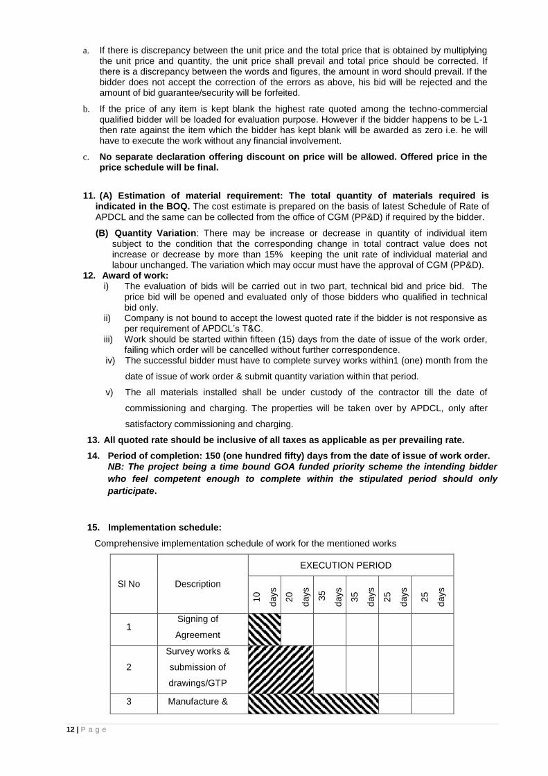
15. Implementation schedule:
Comprehensive implementation schedule of work for the mentioned works
Sl No Description
EXECUTION PERIOD
10
days
20
days
35
days
35
days
25
days
25
days
1 Signing of
Agreement
2
Survey works &
submission of
drawings/GTP
3 Manufacture &

13 | P a g e
supply of
materials
4 Erection of
equipments
5 Testing &
commissioning
16. Termination of work order:
Company reserves the right to terminate the work order at any stage in accordance with
the Company’s General Condition of Supply and Erection in force.
17. Terms of Payment:
a. During the currency of the contract, maximum 2(Two) nos. of progressive bill will be entertained. The progressive bill will be for the actual work done including supply & erection of the materials for which 80% of the billed amount will be paid retaining the balance 20% by APDCL. Final bill will be paid along with the retained amount after satisfactory completion & commissioning of the project subject to validity of performance guarantee submitted as per clause. No mobilization advance will be entertained.
b. All payment shall be made from the office of the CGM (PP&D), APDCL. The bills after due verification by the concerned SDE, passed by the concerned Asstt. General Manager and countersigned by the concerned DGM will be placed to the CGM (PP&D) for payment. Progress report against the work must be enclosed with each bill (format for progress report to be submitted will be supplied along with the work order). Bank Guarantees (BG) submitted along with the bid or to be submitted should be from
any branch of nationalized or scheduled Bank of RBI located in Assam.
c. The right of the contractor/supplier to have payment or reimbursement of any cost for execution of works/supply of materials as the case may be, against this order will be forfeited or deemed to have been relinquished if the claim for it is not preferred to the appropriate authority within 6(Six) months from the date of completion or deemed completion as per clause of Company’s GCSE.
18. Project Management and site Organizations:
In Consideration of the tight schedule of the project, the successful bidder(s) /Contractor(s)
shall exercise systematic closely controlled project management system with the aid of
commonly used soft tools. Following are the major activities/deliverables to be organized
/generated for submission to the Board.
(I) Liaison/Construction offices will be established in each Circle of APDCL: (II) Work Progress Report:
Progress monitoring by the contractor as per implementation schedule and approved milestones.
Fortnightly progress report will be submitted to the concern Deputy General Manager, Senior Manager & Sub-Divisional Engineers. The progress report will highlight the points like, work completion vis-à-vis planned,
plan for next working period, delay analysis vis-à-vis committed schedule with reasons
and remedies, etc.
(III) Site Organization. The bidder at each working site shall establish the following.
Store house
Site fabrication facilities
Construction supervision office.
14 | P a g e
All offices shall be adequately furnished and staffed so as to take all site decisions
independently without frequent references to head Work’s/offices.
19. Guarantees and Penalties:
a) Liquidated Damages (LD) The proposed work is on top priority of Government of Assam and therefore has to be completed within stipulated/agreed schedule. Any delay beyond that will attract penalty as per Company’s General condition of supply and erection.
b) Equipment and system installed (other than APDCL’s supply) shall be guaranteed individually for integrated operations for a period of 18 (Eighteen) months from date of commissioning of a system in general. In case of detection of any defect in individual equipment or system as a whole, the same shall be replaced by the bidder free of cost within 15 days of intimation by the Company’s representative.
c) Warranty from the manufacturer shall be produced along with manufacturer’s test certificate for all equipment/ materials covered under Manufacturer’s warranty.
20. Approvals/Clearances: a) APDCL, concerned DGM shall approve all site and documents prepared by the contractor
for construction of the Line. b) GTP and drawings of all equipment/ materials shall be approved by CGM (PP&D), APDCL. c) The contractor shall obtain all statutory approvals and clearances from the statutory
authorities before charging the system at his/her own cost.
21. Testing & Inspection:
All the equipments / materials to be supplied and erected shall be tested /inspected at
manufacturer’s works by authorized officer/ Engineers of APDCL before dispatching them to
worksite. The contractor shall intimate the CGM (PP&D) sufficiently in advance (at least 15
days) regarding the date of inspection of materials/ equipments at manufacturer’s works. The
materials to be dispatch to site only after receipt of dispatch clearance to be issued by the CGM
(PP&D) after satisfactory testing of the same. The cost of inspection by Company’s officials
has to be borne by the party.
22. Environmental Considerations:
While carrying out the assignment, no damage to environment /forests will be caused by the
contractor. If so done, the contractor will have to compensate the same to the satisfaction of
the licensed Authority.
23. Submission of documents a) With bids. i) Detail list of makes and materials offered with catalogues, technical specification, type test,
performance certificate, customer list etc. ii) Certificates and testimonials in support of credentials of the bidder’s organization. iii) Details past experience along with present works in hand with awarded amount and
progress report. iv) Brief writ-up on methodology to carry out the assignment, if awarded. v) Details of manpower to be engaged for the assignments. vi) Any other information, the bidder may feel facilitative in evaluating the bid. vii) Copies of contractor and supervisor’s license, etc. viii) Certificate from Registered Charted Accountant in support of Annual turn over ix) Solvency certificate from Bank x) Earnest money deposit along with Techno- Commercial bid xi) Certificate in support of performance of the bidder.
b) During project execution
i) All documents for approval shall be submitted in 3 (three) copies. ii) All final documents to be submitted to statutory organizations will be furnished as per
requirement of the authority.

15 | P a g e
24. Funding of the project: The proposed work is funded by the G.O.A. under “AP 2018-19”
25. Ceiling on acceptance of bid value
As a deterrent for cartel formation APDCL at its discretion have the right to scrap the tender if
values quoted by all the bidders is equal to or above 25% of the working estimate. Also the price
bids whose total quoted value is equal to or below 15% of the working estimate, the bid is liable to
reject by APDCL.
26. Termination of contract on Contractor’s default
If the Contractor shall neglect to execute the Works with due diligence and expertise or shall refuse or neglect to comply with any reasonable order given to him, in the Contract by the Engineer in connection with the works or shall contravene the provisions of the Contract, the owner may give notice in writing to the contractor to make good the failure, neglect or contravention complained of. Should the contractor fail to comply with the notice within thirty (30) days from the date of serving the notice, then and in such case the Owner shall be at liberty to employ other workmen and forthwith execute such part of the works as the Contractor, may have neglected to do or if the owner shall think fit, without prejudice to any other right he may have under the Contract to take the work wholly or in part out of the contractor's hands and re-contract with any other person or persons to complete the works or any part thereof and in that event the Owner shall have free use of all Contractor's equipment that may have been at the time on the site in connection with the works without being responsible to the Contractor for fair wear and tear thereof and to the exclusion of any right of the contractor over the same, and the Owner shall be entitled to retain and apply any balance which may otherwise be due on the Contract by him to the contractor, or such part thereof as may be necessary, to the payment of the cost of executing the said part of the work or of completing the Works as the case may be. If the cost of completing of Works or executing a part thereof as aforesaid shall exceed the balance due to the contractor, the contractor shall pay such excess. Such payment of excess amount shall be independent of the liquidated damages for delay which the contractor shall have to pay if the completion of works' is delayed.
In addition, such action by the Owner as aforesaid shall not relieve the Contractor of his liability to
pay liquidated damages for delay in completion of works as defined in clause no.26 of GCSE
Such action by the Owner as aforesaid, the termination of the Contract under this clause shall
neither entitle the contractor to reduce the value of the contract Performance Guarantee nor the
time thereof. The contract Performance Guarantee shall be valid for the full value and for the full
period of the contract including guarantee period.
27. Termination of contract on owners’ initiative
The Owner reserves the right to terminate the Contract either in part or in full due to reasons other
than those mentioned under clause entitled "Contractor's Default." The Owner shall in such an
event give fifteen (15) days notice in writing to the Contractor of his decision to do so.
The Contractor upon receipt of such notice shall discontinue the work on the date and to the
extent specified in the notice, make all reasonable efforts to obtain cancellation of all orders and
contracts to the extent they are related to the work terminated and terms satisfactory to the
Owner, stop all further sub-contracting or purchasing activity related to the work terminated, and
assist the Owner in maintenance, protection, and disposition of the Works acquired under the
Contract by the Owner.
In the event of such a termination, .the Contractor shall be paid compensation, equitable and
reasonable, dictated by the circumstances prevalent at the time of termination.
If the Contractor is an individual or a proprietary concern and the individual or the proprietor dies
and if the contractor is a partnership concern and one of the partners dies then unless the Owner
is satisfied that the legal representatives of the individual contractor or of the proprietor of
propriety concern and in the case of partnership, the surviving partners, are capable of carrying
out and completing the Contract, the Owner shall be entitled to cancel the Contract as to its
uncompleted part without being in any way liable to payment of any compensation to the estate of
deceased Contractor and/or to surviving partners of the contractor's firm on account of the
cancellation of the contract. The decision of the owner that the legal representatives of the
16 | P a g e
deceased contractor or surviving partners of the contractor's firm cannot carry out and complete
the contract shall be final and binding on the parties. In the event of such cancellation, the Owner
shall not hold the estate of the deceased Contractor and/or the surviving partner of the
Contractor's firm liable to damages for not completing the Contract.
28. Frustration of contract
In the event of frustration of the contract of supervening impossibility in items of Section 56 of the
Indian Contract Act, parties shall be absolved of their responsibility to perform the balance portion
of the contract.
In the event of non-availability or suspension of funds for any reasons whatsoever (except for
reason of willful or flagrant breach by the Owner and/or contractor) then the Works under the
contract shall be suspended. Furthermore, if the Owner is unable to make satisfactory alternative
arrangements for financing to the contractor in accordance with the terms of the Contract within
three months of the event, the parties hereto shall be relieved from carrying out further obligations
under the Contract treating it as frustration of the Contract. In the event Performance Bank
Guarantee, the parties shall mutually discuss to arrive at reasonable on all issues including
amounts due to either party for the work already done on "Quantum merit" basis which shall be
determined by mutual agreement between the parties.
29. Disclaimer: While the Company will make every endeavor to extend necessary facilitation in expediting the
work, the contractor shall be responsible to organize and arrange all necessary inputs right from
mobilization activities up to completion of the project. Company will not entertain any failure /
delay on such accounts. Also, Company will not be responsible for any compensation,
replenishment, damage, theft etc. as may be caused due to negligent working, insufficient
coordination with Government / non Government / Local Authority by the contractor and/ or his
personnel deputed for work. The contractor shall take necessary insurance coverage under
LIC/GIC etc. for his working personnel and the goods in store as well as in transit. The contractor
will be deemed to have made him acquainted with the local working conditions at site(s) and fully
provide for into the bid submitted.
30. Before submitting the tender the intending bidders are requested to physically survey/inspect the location/route and the scope of work and have discussion with concerned Sub-divisional Engineer /Asstt. General Manager in this regard in order to minimize issues after awarding the contract. Any additional work/quantity which may be required for renovation of the line but inadvertently left out in the BOQ may perhaps be raised in the pre-bid meeting only against the work.
31. If for any reason the last date of receiving and opening of tender or the date of pre-bid discussion is a declared holiday the next working day will be considered for receiving and opening of bid or pre bid discussion.
32. Terms and conditions, which are not specified, herein above will be governed by the
APDCL’s General Conditions of supply and erection in force.
APDCL’s General Conditions of supply and erection (GCSE) may be seen in our official
website www.apdcl.gov.in-- (Notice part)
17 | P a g e
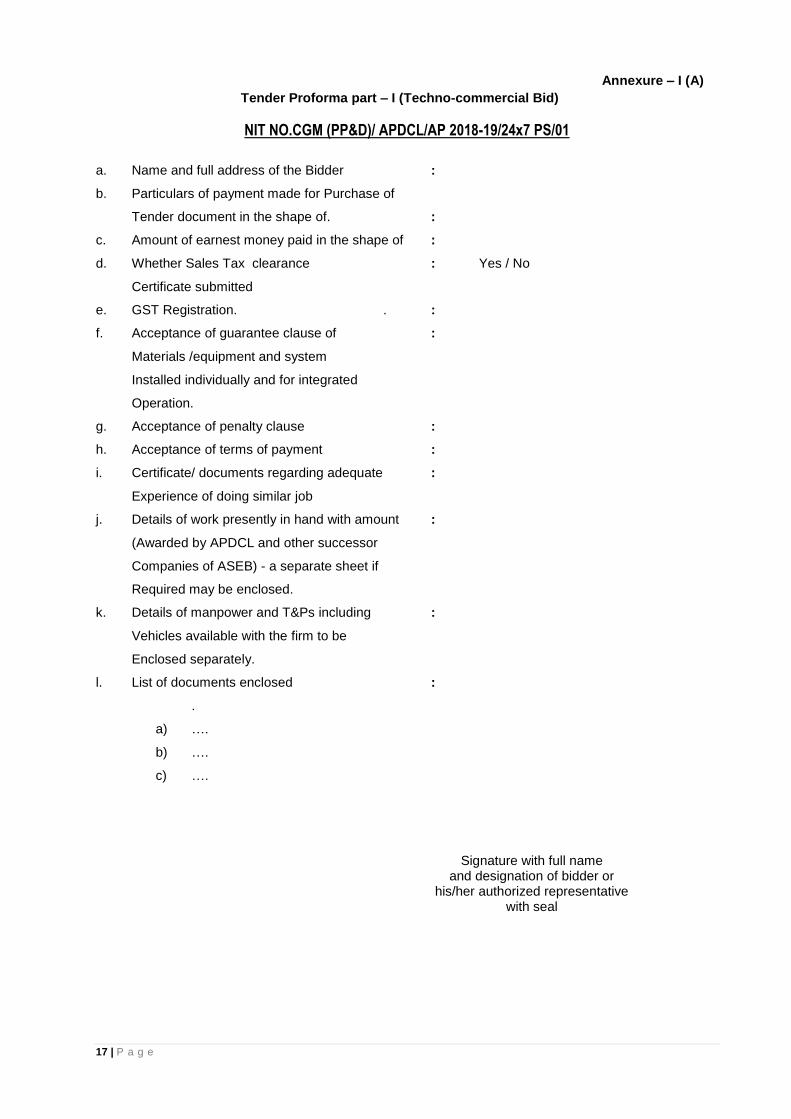
Annexure – I (A)
Tender Proforma part – I (Techno-commercial Bid)
NIT NO.CGM (PP&D)/ APDCL/AP 2018-19/24x7 PS/01
a. Name and full address of the Bidder :
b. Particulars of payment made for Purchase of
Tender document in the shape of. :
c. Amount of earnest money paid in the shape of :
d. Whether Sales Tax clearance : Yes / No
Certificate submitted
e. GST Registration. . :
f. Acceptance of guarantee clause of :
Materials /equipment and system
Installed individually and for integrated
Operation.
g. Acceptance of penalty clause :
h. Acceptance of terms of payment :
i. Certificate/ documents regarding adequate :
Experience of doing similar job
j. Details of work presently in hand with amount :
(Awarded by APDCL and other successor
Companies of ASEB) - a separate sheet if
Required may be enclosed.
k. Details of manpower and T&Ps including :
Vehicles available with the firm to be
Enclosed separately.
l. List of documents enclosed :
.
a) ….
b) ….
c) ….
Signature with full name
and designation of bidder or his/her authorized representative
with seal
18 | P a g e
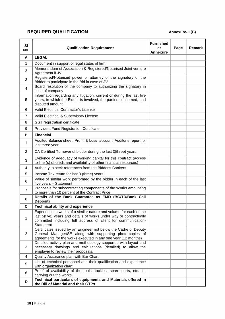
REQUIRED QUALIFICATION Annexure- I (B)
Sl No.
Qualification Requirement Furnished
at Annexure
Page Remark
A LEGAL
1 Document in support of legal status of firm
2 Memorandum of Association & Registered/Notarised Joint venture Agreement if JV
3 Registered/Notarised power of attorney of the signatory of the Bidder to participate in the Bid in case of JV
4 Board resolution of the company to authorizing the signatory in case of company
5 Information regarding any litigation, current or during the last five years, in which the Bidder is involved, the parties concerned, and disputed amount
6 Valid Electrical Contractor's License
7 Valid Electrical & Supervisory License
8 GST registration certificate
9 Provident Fund Registration Certificate
B Financial
1 Audited Balance sheet, Profit & Loss account, Auditor’s report for last three year
2 CA Certified Turnover of bidder during the last 3(three) years.
3 Evidence of adequacy of working capital for this contract (access to line (s) of credit and availability of other financial resources)
4 Authority to seek references from the Bidder's Bankers
5 Income Tax return for last 3 (three) years
6 Value of similar work performed by the bidder in each of the last five years – Statement
7 Proposals for subcontracting components of the Works amounting to more than 10 percent of the Contract Price
8 Details of the Bank Guarantee as EMD (BG/TD/Bank Call Deposit)
C Technical ability and experience
1
Experience in works of a similar nature and volume for each of the last 5(five) years and details of works under way or contractually committed including full address of client for communication- Statement
2 Certificates issued by an Engineer not below the Cadre of Deputy General Manager/SE along with supporting photo-copies of agreements for the works executed in any one year (12 months)
3 Detailed activity plan and methodology supported with layout and necessary drawings and calculations (detailed) to allow the employer to review their proposals.
4 Quality Assurance plan with Bar Chart
5 List of technical personnel and their qualification and experience with organization chart
6 Proof of availability of the tools, tackles, spare parts, etc. for carrying out the works.
D Technical particulars of equipments and Materials offered in the Bill of Material and their GTPs

19 | P a g e
LIST OF ONGOING & COMPLETED PROJECTS: ANNEXURE- I(C)
List of ongoing & completed projects of -
(i) APDCL & Other successor companies of ASEB &
(ii) works executed outside the state of Assam
Sl.No. Name of the work Order No Contract
value Scheme
Stipulated date of
completion
Present Status
1
2
3
BIDDER’S INFORMATION SHEET: Annexure- I (D)
Bidder’s Information
Bidder’s legal name
In case of JV, legal name of each partner
Bidder’s country of constitution
Bidder’s year of constitution
Bidder’s legal address in country of constitution
Bidder’s authorized representative
(name, address, telephone numbers, fax numbers, e-mail address)

20 | P a g e
Attached are copies of the following original documents.
1. In case of single entity, articles of incorporation or constitution of the legal entity named above, in accordance with ITB 4.1 and 4.2.
2. Authorization to represent the firm or JV named in above, in accordance with ITB 22.2.
3. In case of JV, letter of intent to form JV or JV agreement, in accordance with ITB 4.1.
4. In case of a government-owned entity, any additional documents not covered less than 1 above required to comply with ITB 4.5.
FINANCIAL SITUATION (FIN-1)
Each bidders or member of JV must fill in this form
Financial Data for Previous 3 Years [Rs in lakhs]
Year 1: Year 2: Year 3:
Information from Balance Sheet
Total Assets
Total Liabilities
Net Worth
Current Assets
Current Liabilities
Information from Income Statement
Total Revenues
Profits Before Taxes
Profits After Taxes
Attached are copies of financial statements (balance sheets including all related notes, and income statements) for the last three years, as indicated above, complying with the following conditions.
All such documents reflect the financial situation of the Bidder or partner to a JV, and not sister or parent companies.
Historic financial statements must be audited by a certified accountant.
Historic financial statements must be complete, including all notes to the financial statements.
Historic financial statements must correspond to accounting periods already completed and audited (no statements for partial periods shall be requested or accepted).
21 | P a g e
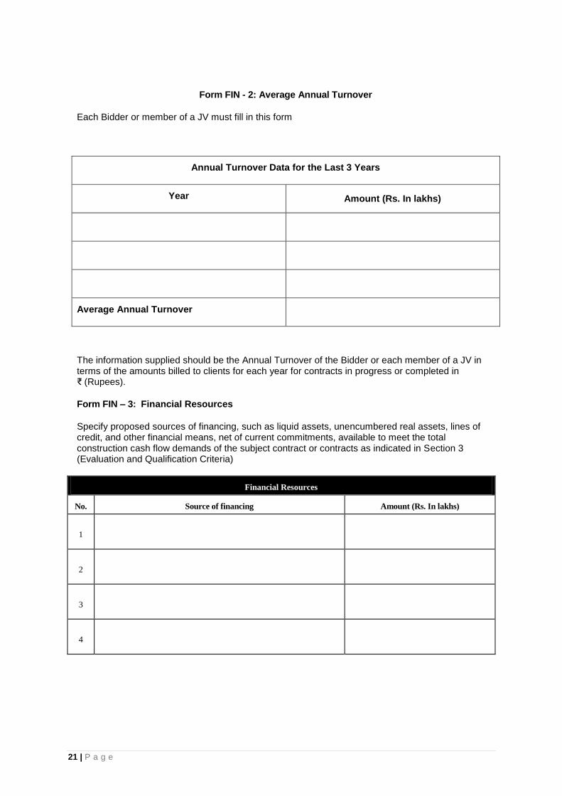
Form FIN - 2: Average Annual Turnover
Each Bidder or member of a JV must fill in this form
Annual Turnover Data for the Last 3 Years
Year Amount (Rs. In lakhs)
Average Annual Turnover
The information supplied should be the Annual Turnover of the Bidder or each member of a JV in terms of the amounts billed to clients for each year for contracts in progress or completed in ₹ (Rupees).
Form FIN – 3: Financial Resources
Specify proposed sources of financing, such as liquid assets, unencumbered real assets, lines of credit, and other financial means, net of current commitments, available to meet the total construction cash flow demands of the subject contract or contracts as indicated in Section 3 (Evaluation and Qualification Criteria)
Financial Resources
No. Source of financing Amount (Rs. In lakhs)
1
2
3
4

22 | P a g e
SECTION 3
BILL OF QUANTITY (BOQ)
23 | P a g e
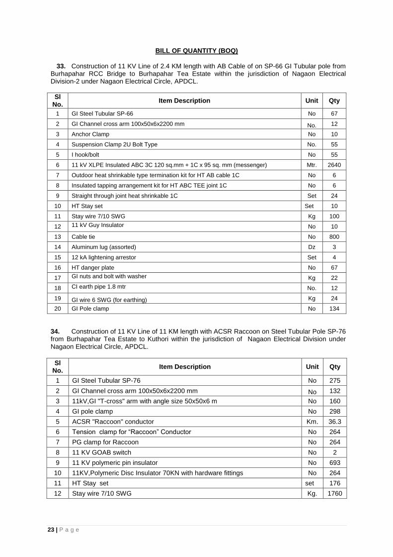
BILL OF QUANTITY (BOQ)
33. Construction of 11 KV Line of 2.4 KM length with AB Cable of on SP-66 GI Tubular pole from Burhapahar RCC Bridge to Burhapahar Tea Estate within the jurisdiction of Nagaon Electrical Division-2 under Nagaon Electrical Circle, APDCL.
Sl No.
Item Description Unit Qty
1 GI Steel Tubular SP-66 No 67
2 GI Channel cross arm 100x50x6x2200 mm No. 12
3 Anchor Clamp No 10
4 Suspension Clamp 2U Bolt Type No. 55
5 I hook/bolt No 55
6 11 kV XLPE Insulated ABC 3C 120 sq.mm + 1C x 95 sq. mm (messenger) Mtr. 2640
7 Outdoor heat shrinkable type termination kit for HT AB cable 1C No 6
8 Insulated tapping arrangement kit for HT ABC TEE joint 1C No 6
9 Straight through joint heat shrinkable 1C Set 24
10 HT Stay set Set 10
11 Stay wire 7/10 SWG Kg 100
12 11 kV Guy Insulator No 10
13 Cable tie No 800
14 Aluminum lug (assorted) Dz 3
15 12 kA lightening arrestor Set 4
16 HT danger plate No 67
17 GI nuts and bolt with washer Kg 22
18 CI earth pipe 1.8 mtr No. 12
19 GI wire 6 SWG (for earthing) Kg 24
20 GI Pole clamp No 134
34. Construction of 11 KV Line of 11 KM length with ACSR Raccoon on Steel Tubular Pole SP-76 from Burhapahar Tea Estate to Kuthori within the jurisdiction of Nagaon Electrical Division under Nagaon Electrical Circle, APDCL.
Sl No.
Item Description Unit Qty
1 GI Steel Tubular SP-76 No 275
2 GI Channel cross arm 100x50x6x2200 mm No 132
3 11kV,GI "T-cross" arm with angle size 50x50x6 m No 160
4 GI pole clamp No 298
5 ACSR "Raccoon" conductor Km. 36.3
6 Tension clamp for “Raccoon” Conductor No 264
7 PG clamp for Raccoon No 264
8 11 KV GOAB switch No 2
9 11 KV polymeric pin insulator No 693
10 11KV,Polymeric Disc Insulator 70KN with hardware fittings No 264
11 HT Stay set set 176
12 Stay wire 7/10 SWG Kg. 1760
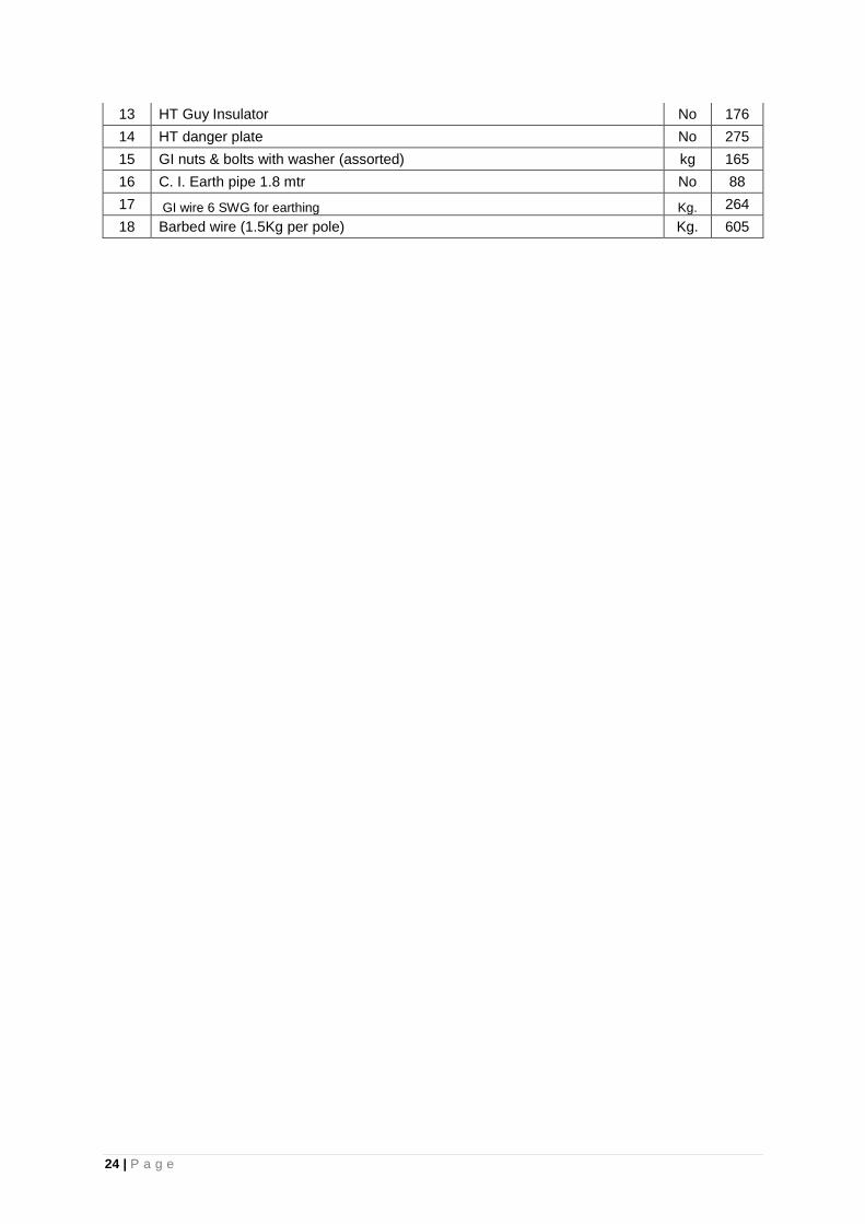
24 | P a g e
13 HT Guy Insulator No 176
14 HT danger plate No 275
15 GI nuts & bolts with washer (assorted) kg 165
16 C. I. Earth pipe 1.8 mtr No 88
17 GI wire 6 SWG for earthing Kg. 264
18 Barbed wire (1.5Kg per pole) Kg. 605
25 | P a g e
ANNEXURE-III PRICE BIDDING SCHEDULE
NIT NO. CGM (PP&D)/ APDCL/AP 2018-19/ 24x7 PS/02/
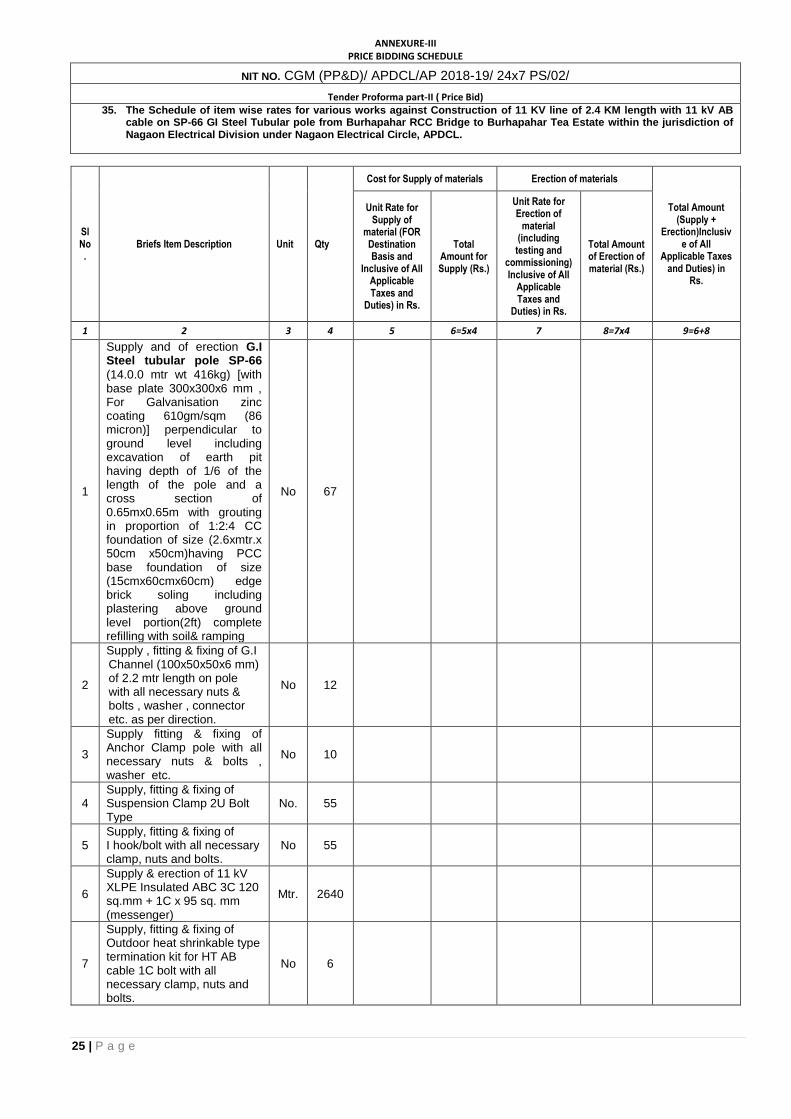
Tender Proforma part-II ( Price Bid) 35. The Schedule of item wise rates for various works against Construction of 11 KV line of 2.4 KM length with 11 kV AB
cable on SP-66 GI Steel Tubular pole from Burhapahar RCC Bridge to Burhapahar Tea Estate within the jurisdiction of Nagaon Electrical Division under Nagaon Electrical Circle, APDCL.
Sl No.
Briefs Item Description Unit Qty
Cost for Supply of materials Erection of materials
Total Amount (Supply +
Erection)Inclusive of All
Applicable Taxes and Duties) in
Rs.
Unit Rate for Supply of
material (FOR Destination Basis and
Inclusive of All Applicable Taxes and
Duties) in Rs.
Total Amount for Supply (Rs.)
Unit Rate for Erection of
material (including testing and
commissioning) Inclusive of All
Applicable Taxes and
Duties) in Rs.
Total Amount of Erection of material (Rs.)
1 2 3 4 5 6=5x4 7 8=7x4 9=6+8
1
Supply and of erection G.I Steel tubular pole SP-66
(14.0.0 mtr wt 416kg) [with base plate 300x300x6 mm , For Galvanisation zinc coating 610gm/sqm (86 micron)] perpendicular to ground level including excavation of earth pit having depth of 1/6 of the length of the pole and a cross section of 0.65mx0.65m with grouting in proportion of 1:2:4 CC foundation of size (2.6xmtr.x 50cm x50cm)having PCC base foundation of size (15cmx60cmx60cm) edge brick soling including plastering above ground level portion(2ft) complete refilling with soil& ramping
No 67
2
Supply , fitting & fixing of G.I Channel (100x50x50x6 mm) of 2.2 mtr length on pole with all necessary nuts & bolts , washer , connector etc. as per direction.
No 12
3
Supply fitting & fixing of Anchor Clamp pole with all necessary nuts & bolts , washer etc.
No 10
4 Supply, fitting & fixing of Suspension Clamp 2U Bolt Type
No. 55
5 Supply, fitting & fixing of I hook/bolt with all necessary clamp, nuts and bolts.
No 55
6
Supply & erection of 11 kV XLPE Insulated ABC 3C 120 sq.mm + 1C x 95 sq. mm (messenger)
Mtr. 2640
7
Supply, fitting & fixing of Outdoor heat shrinkable type termination kit for HT AB cable 1C bolt with all necessary clamp, nuts and bolts.
No 6
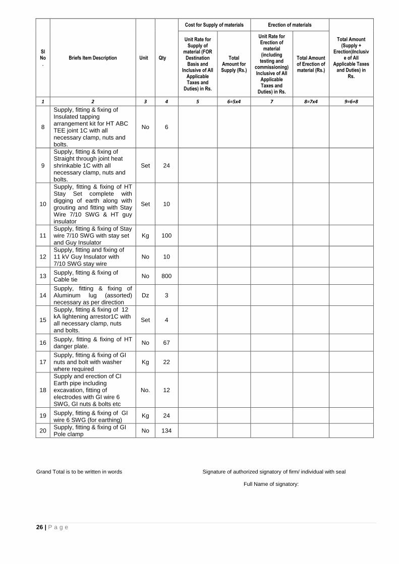
26 | P a g e
Sl No.
Briefs Item Description Unit Qty
Cost for Supply of materials Erection of materials
Total Amount (Supply +
Erection)Inclusive of All
Applicable Taxes and Duties) in
Rs.
Unit Rate for Supply of
material (FOR Destination Basis and
Inclusive of All Applicable Taxes and
Duties) in Rs.
Total Amount for Supply (Rs.)
Unit Rate for Erection of
material (including testing and
commissioning) Inclusive of All
Applicable Taxes and
Duties) in Rs.
Total Amount of Erection of material (Rs.)
1 2 3 4 5 6=5x4 7 8=7x4 9=6+8
8
Supply, fitting & fixing of Insulated tapping arrangement kit for HT ABC TEE joint 1C with all necessary clamp, nuts and bolts.
No 6
9
Supply, fitting & fixing of Straight through joint heat shrinkable 1C with all necessary clamp, nuts and bolts.
Set 24
10
Supply, fitting & fixing of HT Stay Set complete with digging of earth along with grouting and fitting with Stay Wire 7/10 SWG & HT guy insulator
Set 10
11 Supply, fitting & fixing of Stay wire 7/10 SWG with stay set and Guy Insulator
Kg 100
12 Supply, fitting and fixing of 11 kV Guy Insulator with 7/10 SWG stay wire
No 10
13 Supply, fitting & fixing of Cable tie
No 800
14 Supply, fitting & fixing of Aluminum lug (assorted) necessary as per direction
Dz 3
15
Supply, fitting & fixing of 12 kA lightening arrestor1C with all necessary clamp, nuts and bolts.
Set 4
16 Supply, fitting & fixing of HT danger plate.
No 67
17 Supply, fitting & fixing of GI nuts and bolt with washer where required
Kg 22
18
Supply and erection of CI Earth pipe including excavation, fitting of electrodes with GI wire 6 SWG, GI nuts & bolts etc
No. 12
19 Supply, fitting & fixing of GI wire 6 SWG (for earthing)
Kg 24
20 Supply, fitting & fixing of GI Pole clamp
No 134
Grand Total is to be written in words Signature of authorized signatory of firm/ individual with seal Full Name of signatory:
27 | P a g e
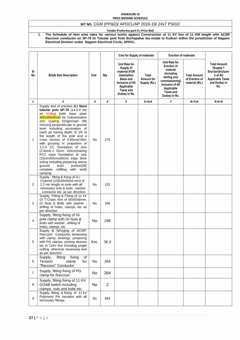
ANNEXURE-III PRICE BIDDING SCHEDULE
NIT NO. CGM (PP&D)/ APDCL/AP 2018-19/ 24x7 PS/02/
Tender Proforma part-II ( Price Bid) 1. The Schedule of item wise rates for various works against Construction of 11 KV line of 11 KM length with ACSR
Raccoon conductor on SP-76 GI Tubular pole from Burhapahar tea estate to Kuthori within the jurisdiction of Nagaon Electrical Division under Nagaon Electrical Circle, APDCL.
Sl No.
Briefs Item Description Unit Qty
Cost for Supply of materials Erection of materials
Total Amount (Supply +
Erection)Inclusive of All
Applicable Taxes and Duties) in
Rs.
Unit Rate for Supply of
material (FOR Destination Basis and
Inclusive of All Applicable Taxes and
Duties) in Rs.
Total Amount for Supply (Rs.)
Unit Rate for Erection of
material (including testing and
commissioning) Inclusive of All
Applicable Taxes and
Duties) in Rs.
Total Amount of Erection of material (Rs.)
1 2 3 4 5 6=5x4 7 8=7x4 9=6+8
1
Supply and of erection G.I Steel tubular pole SP-76 (14.0.0 mtr wt 416kg) [with base plate 300x300x6mm for Galvanisation zinc coating 610gm/sqm (86 micron)] perpendicular to ground level including excavation of earth pit having depth of 1/6 of the length of the pole and a cross section of 0.65mx0.65m with grouting in proportion of 1:2:4 CC foundation of size (2.6xmtr.x 50cm x50cm)having PCC base foundation of size (15cmx60cmx60cm) edge brick soling including plastering above ground level portion(2ft) complete refilling with soil& ramping
No 275
2
Supply , fitting & fixing of G.I Channel (100x50x50x6 mm) of 2.2 mtr length on pole with all necessary nuts & bolts , washer , connector etc. as per direction.
No 132
3
Supply, Fitting & Fixing of 11 kV GI T-Cross Arm of 50x50x6mm, GI Nuts & Bolts with washer , drilling of holes, clamps, etc as per direction
No 160
4
Supply, fitting fixing of GI pole clamp with GI Nuts & Bolts with washer , drilling of holes, clamps, etc
No 298
5
Supply & Stringing of ACSR“ Raccoon” Conductor, tensioning with clamp, bindings, jumpering with PG clamps, jointing sleeves etc in 11kV line including jungle cutting wherever necessary and as per direction .
Km. 36.3
6
Supply, fitting fixing of Tension clamp for “Raccoon” Conductor
No 264
7 Supply, fitting fixing of PG clamp for Raccoon
No 264
8
Supply, fitting fixing of 11 KV GOAB switch including clamps, nuts and bolts etc.
No 2
9
Supply, fitting & fixing of 11 kV Polymeric Pin insulator with all necessary fittings
No 693
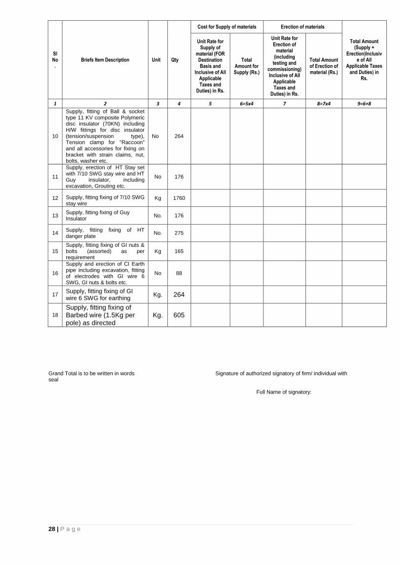
28 | P a g e
Sl No.
Briefs Item Description Unit Qty
Cost for Supply of materials Erection of materials
Total Amount (Supply +
Erection)Inclusive of All
Applicable Taxes and Duties) in
Rs.
Unit Rate for Supply of
material (FOR Destination Basis and
Inclusive of All Applicable Taxes and
Duties) in Rs.
Total Amount for Supply (Rs.)
Unit Rate for Erection of
material (including testing and
commissioning) Inclusive of All
Applicable Taxes and
Duties) in Rs.
Total Amount of Erection of material (Rs.)
1 2 3 4 5 6=5x4 7 8=7x4 9=6+8
10
Supply, fitting of Ball & socket type 11 KV composite Polymeric disc insulator (70KN) including H/W fittings for disc insulator (tension/suspension type), Tension clamp for "Raccoon" and all accessories for fixing on bracket with strain claims, nut, bolts, washer etc.
No 264
11
Supply, erection of HT Stay set with 7/10 SWG stay wire and HT Guy insulator, including excavation, Grouting etc.
No 176
12 Supply, fitting fixing of 7/10 SWG stay wire
Kg 1760
13 Supply, fitting fixing of Guy Insulator
No. 176
14 Supply, fitting fixing of HT danger plate
No. 275
15 Supply, fitting fixing of GI nuts & bolts (assorted) as per requirement
Kg 165
16
Supply and erection of CI Earth pipe including excavation, fitting of electrodes with GI wire 6 SWG, GI nuts & bolts etc.
No 88
17 Supply, fitting fixing of GI wire 6 SWG for earthing
Kg. 264
18
Supply, fitting fixing of Barbed wire (1.5Kg per pole) as directed
Kg. 605
Grand Total is to be written in words Signature of authorized signatory of firm/ individual with seal Full Name of signatory:
29 | P a g e
SECTION -4
GENERAL REQUIREMENTS
30 | P a g e
GENERAL REQUIREMENTS
The bidder shall comply with the following general requirements along with other
specifications.
1.0 QUALITY ASSURANCE PLAN 1.1 The bidder shall invariably furnish the following information along with his offer failing which
the offer shall be liable for rejection. Information shall be separately given for individual type of equipment offered. i) The structure of organization ii) The duties and responsibilities assigned to staff ensuring quality of work iii) The system of purchasing, taking delivery and verification of materials iv) The system for ensuring quality of workmanship v) The quality assurance arrangements shall confirm to the relevant requirement of ISO
9001 on ISO 9002 as applicable. vi) Statement giving list of important raw materials, names of sub-supplies for the raw
materials, list of standards according to which the raw material are tested, list of tests normally carried out on raw material in the presence of suppliers representative, copies of test certificates.
vii) Information and copies of test certificates as on (i) above in respect of bought out items viii) List of manufacturing facilities available ix) Level of automation achieved and list of areas where manual processing exists. x) List of areas in manufacturing process, where stage inspections are normally carried out
for quality control and details of such test and inspection. xi) List of testing equipment available with the bidder for final testing of equipment specified
and test plant limitation, if any vis-à-vis the type. Special acceptance and routine tests specified in the relevant standards. These limitations shall be very clearly brought out in "Schedule of Deviations" from the specified test requirement.
1.2 The contractor shall within 30 days of placement of order, submit the following information to the purchaser. i) List of the raw material as well as bought out accessories and the names of sub-suppliers
selected from those furnished along with the offer. ii) Type test certificated of the raw material and bought out accessories if required by the
purchaser. iii) Quality Assurance Plant (QAP) with hold points for purchaser’s inspection. QAP and
purchasers hold points shall be discussed between the purchaser and contractor before the QAP is finalized.
The contractor shall submit the routine test certificates of bought out accessories and central
excise asses for raw material at the time of routine testing if required by the purchaser and
ensure that the quality assurance requirements of specification are followed by the sub-
contractor.
1.3 The Quality Assurance Programmed shall give a description of the Quality System and Quality Plans with the following details. i) Quality System
The structure of the organization.
The duties and responsibilities assigned to staff ensuring quality of work.
The system of purchasing, taking delivery of verification of materials
The system of ensuring of quality workmanship.
The system of control of documentation.
The system of retention of records.
The arrangement of contractor internal auditing.
A list of administrator and work procedures required to achieve contractor’s quality requirements. These procedures shall be made readily available to the purchaser for inspection on request.
ii) Quality Plans
An outline of the proposed work and program sequence.
The structure of contractor’s organizations for the contract.
The duties and responsibilities ensuring quality of work.
Hold and notification points.
Submission of engineering documents required by this specification.
The inspection of the materials and components on request.
Reference to contractor’s work procedures appropriate to each activity.
31 | P a g e
Inspection during fabrication /construction.
Final inspection and test.
2.0 Inspection 2.1 The Owner's representative or third party nominee shall at all times be entitled to have access
to the works and all places of manufacture, where insulator, and its component parts shall be manufactured and the representatives shall have full facilities for unrestricted inspection of the Contractor's and sub-Contractor's works, raw materials, manufacture of the material and for conducting necessary test as detailed herein.
2.2 The material for final inspection shall be offered by the Contractor only under packed condition as detailed in the specification. The Owner shall select samples at random from the packed lot for carrying out acceptance tests. Insulators shall normally be offered for inspection in lots not exceeding 5000 nos. the lot should be homogeneous and should contain insulators manufactured in the span of not more than 3-4 consecutive weeks.
2.3 The Contractor shall keep the Owner informed in advance of the time of starting and the progress of manufacture of material in their various stages so that arrangements could be made for inspection.
2.4 No material shall be dispatched from its point of manufacture before it has been satisfactorily inspected and tested unless the inspection is waived off by the Owner in writing. In the latter case also the material shall be dispatched only after satisfactory testing for all tests specified herein have been completed.
2.5 The acceptance of any quantity of material shall be no way relieve the Contractor of his responsibility for meeting all the requirements of the specification and shall not prevent subsequent rejection, if such material are later found to be defective.
3.0 Additional Tests 3.1 The Owner reserves the right of having at his own expense any other test(s) of reasonable
nature carried out at Contractor's premises, at site, or in any other place in addition to the type, acceptance and routine tests specified in these bidding documents against any equipments to satisfy himself that the material comply with the Specifications.
3.2 The Owner also reserves the right to conduct all the tests mentioned in this specification at his own expense on the samples drawn from the site at Contractor's premises or at any other test center. In case of evidence of noncompliance, it shall be binding on the part of the Contractor to prove the compliance of the items to the technical specifications by repeat tests or correction of deficiencies, or replacement of defective items, all without any extra cost to the Owner.
4.0 Test Reports 4.1 Copies of type test reports shall be furnished in at least six (6) copies along with one original.
One copy shall be returned duly certified by the Owner only after which the commercial production of the concerned materials shall start.
4.2 Copies of acceptance test reports shall be furnished in at least six (6) copies. One copy shall be returned duly certified by the Owner, only after which the material shall be dispatched.
4.3 Record of routine test reports shall be maintained by the Contractor at his works for periodic inspection by the Owner's representative.
4.4 Test certificates of test during manufacture shall be maintained by the Contractor. These shall be produced for verification as and when desired by the Owner.
5.0 List of Drawings and Documents: 5.1 The bidder shall furnish the following along with bid. i) Two sets of drawings showing clearly the general arrangements, fitting details, electrical
connections etc. ii) Technical leaflets (user’s manual) giving operating instructions. iii) Three copies of dimensional drawings of the box for each quoted item. The manufacturing of the equipment shall be strictly in accordance with the approved
drawings and no deviation shall be permitted without the written approval of the purchaser. All
manufacturing and fabrication work in connection with the equipment prior to the approval of
the drawing shall be at the supplier's risk.
Approval of drawings/work by purchaser shall not relieve the supplier of his responsibility and
liability for ensuring correctness and correct interpretation of the drawings for meeting the
specification.
5.2 The requirements of the latest revision of application standards, rules and codes of practices. The equipment shall conform in all respects to high standards of engineering, design,
32 | P a g e
workmanship and latest revisions of relevant standards at the time of ordering and purchaser shall have the power to reject any work or materials which, in his judgment is not in full accordance therewith.
5.3 The successful Bidder shall within 2 weeks of notification of award of contract submit three sets of final versions of all the drawings as stipulated in the purchase order for purchaser's approval. The purchaser shall communicate his comments/approval on the drawings to the supplier within two weeks. The supplier shall, if necessary, modify the drawings and resubmit three copies of the modified drawings for their approval. The supplier shall within two weeks. Submit 30 prints and two good quality report copies of the approved drawings for purchaser's use.
5.4 Eight sets of operating manuals/technical leaflets shall be supplied to each consignee for the first instance of supply.
5.4.1 One set of routine test certificates shall accompany each dispatch consignment. 5.4.2 The acceptance test certificates in case pre-dispatch inspection or routine test certificates in
cases where inspection is' waived shall be got approved by the purchasers. 6.0 Any Item specification if not available in this document Contractor shall supply and execute the
items meeting the relevant IS specification with the approval of the purchaser.

33 | P a g e
SECTION – 5
FORMS OF BID
34 | P a g e
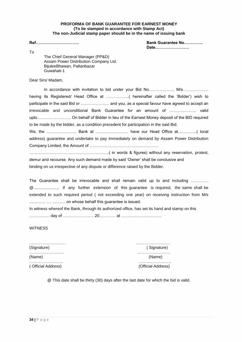
PROFORMA OF BANK GUARANTEE FOR EARNEST MONEY (To be stamped in accordance with Stamp Act)
The non-Judicial stamp paper should be in the name of issuing bank Ref………………………….. Bank Guarantee No…………..
Date……………………. To
The Chief General Manager (PP&D) Assam Power Distribution Company Ltd. BijuleeBhawan, Paltanbazar Guwahati-1
Dear Sirs/ Madam,
In accordance with invitation to bid under your Bid No………………. M/s……………….
having its Registered/ Head Office at ……………..( hereinafter called the ‘Bidder’) wish to
participate in the said Bid or ………………… and you, as a special favour have agreed to accept an
irrevocable and unconditional Bank Guarantee for an amount of ……………….. valid
upto……………………. On behalf of Bidder in lieu of the Earnest Money deposit of the BID required
to be made by the bidder, as a condition precedent for participation in the said Bid.
We, the …………………. Bank at …………………… have our Head Office at…………..( local
address) guarantee and undertake to pay immediately on demand by Assam Power Distribution
Company Limited, the Amount of ……………………………………………
…………………………………………………..( in words & figures) without any reservation, protest,
demur and recourse. Any such demand made by said ‘Owner’ shall be conclusive and
binding on us irrespective of any dispute or difference raised by the Bidder.
The Guarantee shall be irrevocable and shall remain valid up to and including ………….
@....................... if any further extension of this guarantee is required, the same shall be
extended to such required period ( not exceeding one year) on receiving instruction from M/s
………… … ………. on whose behalf this guarantee is issued.
In witness whereof the Bank, through its authorized office, has set its hand and stamp on this
…………… day of ………………….. 20………… at …………………………
WITNESS
……………………… ……………………. (Signature) ( Signature) …………………….. …………………… (Name) (Name) ……………………. …………………… ( Official Address) (Official Address)
@ This date shall be thirty (30) days after the last date for which the bid is valid.
35 | P a g e
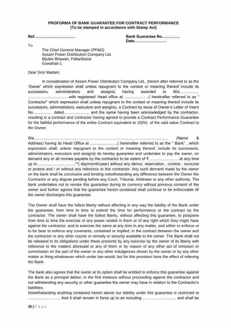
PROFORMA OF BANK GUARANTEE FOR CONTRACT PERFORMANCE (To be stamped in accordance with Stamp Act)
Ref………………………….. Bank Guarantee No…………..
Date……………………. To
The Chief General Manager (PP&D) Assam Power Distribution Company Ltd. Bijulee Bhawan, Paltanbazar Guwahati-1
Dear Sirs/ Madam,
In consideration of Assam Power Distribution Company Ltd., (herein after referred to as the
‘Owner’ which expression shall unless repugnant to the context or meaning thereof include its
successors, administrators and assigns) having awarded to M/s……………
….……………………….with registered/ Head office at ……………….( hereinafter referred to as “
Contractor” which expression shall unless repugnant to the context or meaning thereof include its
successors, administrators, executors and assigns), a Contract by issue of Owner’s Letter of Intent
No…………… dated……………….. and the same having been acknowledged by the contractor,
resulting in a contract and contractor having agreed to provide a Contract Performance Guarantee
for the faithful performance of the entire Contract equivalent to 10(%) of the said value Contract to
the Owner.
We………………………………………………………………………………………….. (Name &
Address) having its Head Office at …………………( hereinafter referred to as the “ Bank” , which
expression shall, unless repugnant to the context or meaning thereof, include its successors,
administrators, executors and assigns) do hereby guarantee and undertake to pay the owner, on
demand any or all monies payable by the contractor to be extent of ₹ …………………. at any time
up to ………………………..**( day/month/year) without any demur, reservation , contest , recourse
or protest and / or without any reference to this contractor. Any such demand made by the owner
on the bank shall be conclusive and binding notwithstanding any difference between the Owner the
Contractor or any dispute pending before any Court, Tribunal, Arbitrator or any other authority. The
bank undertakes not to revoke this guarantee during its currency without previous consent of the
owner and further agrees that the guarantee herein contained shall continue to be enforceable till
the owner discharges this guarantee.
The Owner shall have the fullest liberty without affecting in any way the liability of the Bank under
the guarantee, from time to time to extend the time for performance or the contract by the
contractor. The owner shall have the fullest liberty, without affecting this guarantee, to postpone
from time to time the exercise of any power vested in them or of any right which they might have
against the contractor, and to exercise the same at any time in any matter, and either to enforce or
to for bear to enforce any covenants, contained or implied, in the contract between the owner and
the contractor or any other course or remedy or security available to the owner. The Bank shall not
be released to its obligations under these presents by any exercise by the owner of its liberty with
reference to the matters aforesaid or any of them or by reason of any other act of omission or
commission on the part of the owner or any other indulgences shown by the owner or by any other
matter or thing whatsoever which under law would, but for this provision have the effect of relieving
the Bank.
The bank also agrees that the owner at its option shall be entitled to enforce this guarantee against
the Bank as a principal debtor, in the first instance without proceeding against the contractor and
not withstanding any security or other guarantee the owner may have in relation to the Contractor’s
liabilities.
Notwithstanding anything contained herein above our liability under this guarantee is restricted to
……………………. And it shall remain in force up to an including …………………….. and shall be
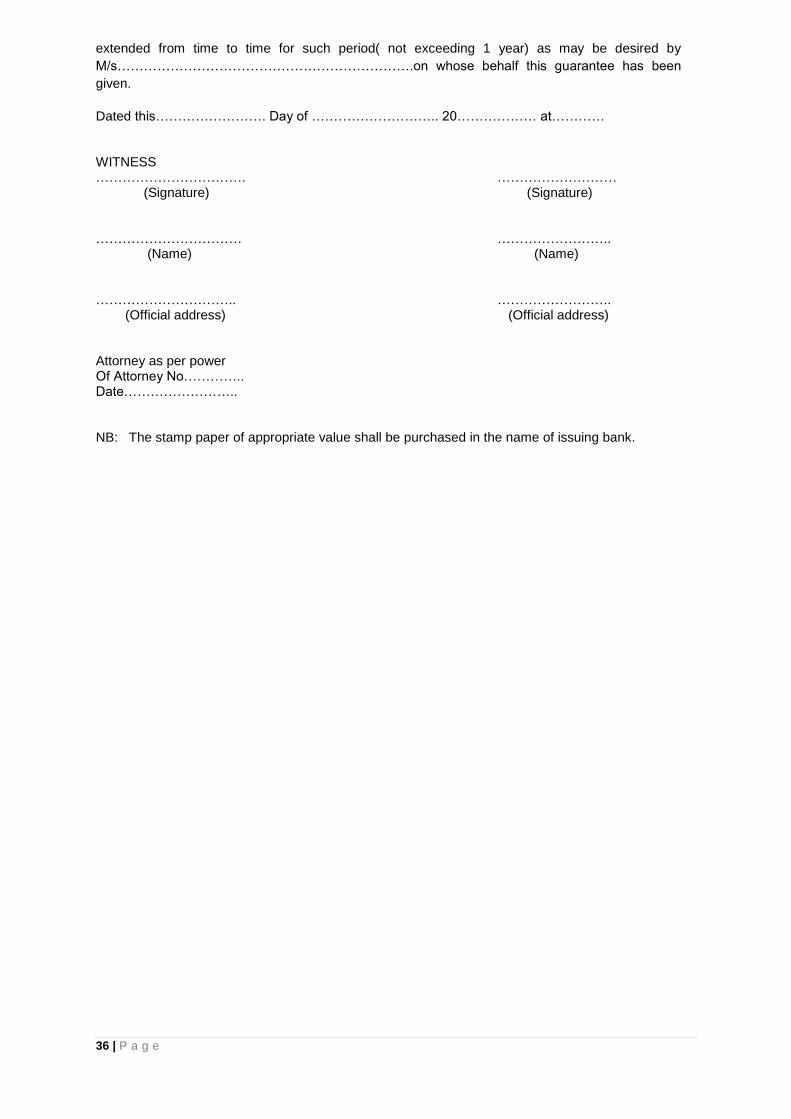
36 | P a g e
extended from time to time for such period( not exceeding 1 year) as may be desired by
M/s………………………………………………………….on whose behalf this guarantee has been
given.
Dated this……………………. Day of ……………………….. 20……………… at………… WITNESS ……………………………. ……………………… (Signature) (Signature) …………………………… …………………….. (Name) (Name) ………………………….. …………………….. (Official address) (Official address) Attorney as per power Of Attorney No………….. Date…………………….. NB: The stamp paper of appropriate value shall be purchased in the name of issuing bank.
37 | P a g e
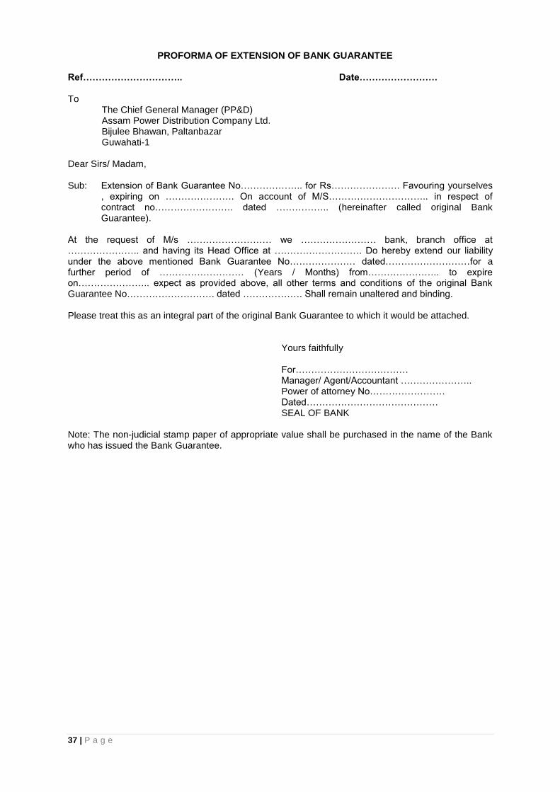
PROFORMA OF EXTENSION OF BANK GUARANTEE Ref………………………….. Date……………………. To
The Chief General Manager (PP&D) Assam Power Distribution Company Ltd. Bijulee Bhawan, Paltanbazar Guwahati-1
Dear Sirs/ Madam, Sub: Extension of Bank Guarantee No……………….. for Rs…………………. Favouring yourselves
, expiring on …………………. On account of M/S………………………….. in respect of contract no……………………. dated …………….. (hereinafter called original Bank Guarantee).
At the request of M/s ……………………… we …………………… bank, branch office at ………………….. and having its Head Office at ………………………. Do hereby extend our liability under the above mentioned Bank Guarantee No………………… dated………………………for a further period of ……………………… (Years / Months) from………………….. to expire on………………….. expect as provided above, all other terms and conditions of the original Bank Guarantee No………………………. dated ………………. Shall remain unaltered and binding. Please treat this as an integral part of the original Bank Guarantee to which it would be attached.
Yours faithfully For……………………………… Manager/ Agent/Accountant ………………….. Power of attorney No…………………… Dated…………………………………… SEAL OF BANK
Note: The non-judicial stamp paper of appropriate value shall be purchased in the name of the Bank who has issued the Bank Guarantee.
38 | P a g e
PROFORMA OF BANK GUARANTEE FOR ADVANCE PAYMENT ( To be stamped in accordance with Stamp Act )
Ref………………………….. Bank guarantee No…………………… Date……………………. To
The Chief General Manager (PP&D) Assam Power Distribution Company Ltd. Bijulee Bhawan, Paltanbazar Guwahati-1
Dear Sirs/ Madam, In consideration of Assam Power Distribution Company Ltd.(hereinafter referred to as the ‘Owner’,
which expressions shall unless repugnant to the context or meaning thereof include its successors,
administrators and assigns) having awarded to M/s…………………………… hereinafter referred to as
the ‘Contractor’ which expression shall unless repugnant to the context or meaning thereof , include
its successors, administrators, executors and assigns), a Contract by issue of Owner’s letter of Award
No…………………… Dated……………………and the same having been acknowledged by the
contractors, resulting in a Contract bearing no…………………. Dated…………………. Valued
(at………………………………( in words and figures). For ………………………….Contract (space of
work)………………………………….. (hereinafter called the ‘Contract’) and the Owner having agreed
to make an advance payment to the Contractor for performance of the above contract amounting
……………………………… (in words and figures) as an advance against Bank Guarantee to be
furnished by the Contractor.
We…………………………..( Name of the Bank) having its Head Office at……………………………… (
hereinafter referred to as the ‘Bank’, which expression shall, unless repugnant to the context or
meaning thereof , include its successors, administrators, executors and assigns) do hereby guarantee
and undertake to pay the owner , immediately on demand any or, all monies payable by the
contractor to the extent of ………………..as aforesaid at any time upto…………………….. (a….)
without any demur, reservation, contest, recourse or protest and/or without any reference to the
contractor. Any such demand made by the Owner on the Bank shall be conclusive and binding
notwithstanding any difference between the Owner and the Contractor or any dispute pending before
any Court, Tribunal, Arbitrator or any other authority. We agree that the guarantee herein contained
shall be irrevocable and shall continue to be enforceable till the owner discharge this guarantee.
The Owner shall have the fullest liberty without affecting in any way the liability of the Bank under this
guarantee, from time to time to vary the advance or to extent the time for performance of the contract
by the Contractor. The Owners shall have the fullest liberty without affecting this guarantee, to
postpone from time to time the exercise of any power vested in them or of any right which they might
have against the Contractor and to exercise the same at any time in any manner, and either to
enforce any covenants, contained or implied, in the contact between the Owner and the Contractor or
any other course or remedy or security available to the Owner. The Bank shall not be released of its
obligations under this presents by any exercise by the owner of its liberty with reference to the matter
aforesaid of any of them or by reason of any other act or forbearance or other acts of omission or
commission on the part of the owner or any other indulgence shown by the owner or by any other
matter or thing whatsoever which under law would be for this provision have the effect of relieving the
Bank.
The Bank also agrees that the Owner at its option shall be entitled to enforce this guarantee against
the Bank as a principal debtor, in the first instance without proceeding against the contractor and not
withstanding any security or other guarantee that the owner may have in relation to the contractors
liabilities.
39 | P a g e
Notwithstanding anything hereinabove our liability under this guarantee is limited to………… and it
shall remain in force upto an including ……………………….( @ and shall be extended from time to
time for such period ( not exceeding 1 year as may be desired by
M/s…………………………………………………………………...dated this ………. Day of
……………….. 20……. At……………………………..
WITNESS…………………………………….. ……………………………… …….……………………….. (Signature) (Signature) ……………………………. ……………………………… (Name) (Name) …………………………..…. (Designation) (Official Address) (With Bank Stamp) Attorney as per Power of attorney No……………………… …. Dated…………………. Strike whichever is not applicable @ The date will be 90(ninety) days after the date of completion of the Contract.
40 | P a g e
PROFORMA OF “AGREEMENT” (To be executed on non-Judicial stamp paper)
This Agreement made this …………….. day of ………… two thousand……………. Between Assam
Power Distribution Company Ltd. having its head office at Bijulee Bhawan, Paltanbazar, Guwahati-1 (
hereinafter referred to as ‘Owner’ or ‘APDCL’, which expression shall include its administrators,
successors and assign on one part and (hereinafter referred to as the ‘Contractors ‘X’ ( Name of the
contracting Co.) which expression shall include its administrators, successors, executors and
permitted assigns) on the other part.
WHEREAS APDCL desirous of …………………….. in ……………. Circle associated with APDCL at ……………….(District) invited Bids for…………………………………………….. ………………………………. (Briefly describe scope of works) for the first state of the project as per its Bid Specification No……………………………… AND WHEREAS……………………….”X” ………………………. Had participated in the above referred Bidding vide their proposal No……………………. dated………………. And awarded the Contract to……………..” X”…………….. on terms and conditions documents referred to therein which have been acknowledged by……………….”X”…………………..resulting into a “Contract”
NOW THEREFORE THIS DEED WITNESS AS UNDER:- 1.0 Article
1.1 Award of Contract
APDCL awarded the contract to……………..”X”……………… for the work of …………… on the terms
and conditions contained in its letter of Award No…….. ………. Dated…………… and the documents
referred to therein. The award has taken effect from aforesaid letter of award. The terms and
expression used in this agreement shall have the same meaning as are assigned to them in the
‘Contract Documents’ referred to in this succeeding Article.
2.0 Documentation
2.1 The contract shall be performed strictly as per the terms and condition stipulated herein and in the
following documents attached herewith( hereinafter referred to as “Contract Documents”.)
i) Section 1-11 of the Bidding Document.
ii) Proposal Sheets, Data Sheets, Drawing work schedule submitted by “X”.
APDCL’s Letter of Award No………….. dated……………….duly acknowledged by “X”.
Quality Plans for manufacturing and field activities entitled as Quality Plan.
All the aforesaid Contract Documents shall form an integral part of this agreement , in so far as the
same or any part conform to the bidding documents and what has been specifically agreed to by the
Owner in its letter of Award. Any matter inconsistent therewith, contrary or repugnant thereto or any
deviations taken by the Contractor in its ‘Proposal’ but not agreed to specially by the Owner in its
Letter of Award shall be deemed to have been withdrawn b y the Contractor. For the sake of brevity,
this agreement along with its aforesaid Contract Documents shall be referred to as the ‘Agreement’.
3.0 Conditions & Covenants
3.1 The scope of Contract, Consideration, Terms of Payment, Price Adjustments, Taxes wherever
applicable, Insurance, Liquidated Damage, Performance Guarantees and all other terms and
conditions are contained in APDCL’s Letter of Award No………........... dated……………… read in
conjunction with other aforesaid contract documents. The contract shall be duly performed by the
Contract Documents, but which are needed for successful, efficient, safe and reliable operation of the
equipment unless otherwise specifically excluded in the specification under ‘exclusion’ or Letter of
Award.
3.2 The scope of work shall also include supply and installation of all such items which are not
specifically mentioned in the contract Documents, but which are needed for successful, efficient, safe

41 | P a g e
and reliable operation of the equipment unless otherwise specifically excluded in the specifications
under ‘exclusions’ or ‘Letter of Award’.
3.3 Time Schedule
3.3.1 Time is the essence of the Contract and schedules shall be strictly adhered to “X” shall perform
the work in accordance with the agreed schedules.
3.4 Quality Plans
3.4.1 The Contractor is responsible for the proper execution of the Quality Plans mentioned in Section
4.8 of GTC. The work beyond the customer’s hold points will progress only with the owners consent.
The Owner will also undertake quality surveillance and quality audit of the Contractor’s /Sub-
contractor’s works, systems and procedures and quality control activities. The Contractor further
agrees that any change in the Quality Plan will be made only with the Owner’s approval. The
contractor shall also perform all quality control activities, inspection and tests agreed with the Owner
to demonstrate full compliance with the contract requirements.
3.4.2 The contractor also agrees to provide the Owner with the necessary facilities for carrying out
inspection, quality audit and quality surveillance of contractors and its Subcontractor’s Quality
Assurance Systems and Manufacturing Activities.
These shall include but not limited to the following:
Relevant plant standards, drawing and procedures;
Detailed Quality Assurance System manuals for manufacturing activities.
Storage procedures and instructions weld, NDT, heat treatment prior to commencement of manufacture;
Complete set of log sheets (blank) mentioned in the Quality Plans. It is expressly agreed to by the contractor that the quality test and inspection by the owner shall not in any way relief the contractor of its responsibilities for quality standards and performance guarantee and their other obligations under the Agreement. 3.4.4 “X’ agrees to submit quality Assurance Documents to APDCL for review and record after completion and within 3 weeks of dispatch of material. The package will include the following :
Factory test result, inspection report for testing required by this contract or applicable codes and standards.
Two copies of inspection reports duly signed by Quality Assurance personnel of both APDCL and “X” for the agreed customer hold points.
Report of the rectification works where and if applicable. 3.5 It is expressly agreed to by the Contractor that notwithstanding the fact that the Contract is termed
as Supply-cum-Erection Contract or indicates the break-up of the Contract consideration, for
convenience of operation and for payment of sale tax on supply portion, it is in fact one composite
Contract on single source responsibility basis and the Contractor is bound to perform the total
Contract in its entirely and non-performance of any part or portion of the Contract shall be deemed to
be breach of the entire Contract.
3.6 The Contractor guarantees that the equipment package under the Contract shall meet the ratings
and performance parameters as stipulated in the technical specifications (Section
10) and in the event of any deficiencies found in the requisite performance figures, the Owner may at
its option reject the equipment package or alternatively accept it on the terms and conditions and
subject to levy of the liquidated damages in terms of Contract documents. The amount of liquidated
damages so leviable shall be in accordance with the contract document and without any limitation.
3.7 It is further agreed by the contractor that the contract performance guarantee shall in no way be
constructed to limit or restrict the owner’s equipment right to recover the damages/compensation due
to shortfall in the equipment performance figures as stated in Para 3.6 above or under any other
clause of the agreement. The amount of damages/compensation shall be recoverable either by way
of deduction from the contract price, contract performance guarantee and or otherwise. The contract
performance guarantee furnished by the contractor is irrevocable and unconditional and the owner
shall have the power to invoke it notwithstanding any dispute or difference between the owner and the
contractor pending before any court tribunal, arbitrator or any other authority.
3.8 This Agreement constitutes full and complete understanding between the parties and terms of the
payment. It shall supersede all prior correspondence terms and conditions contained in the
Agreement. Any modification of the agreement shall be effected only by a written instrument signed
by the authorized representative of both the parties.

42 | P a g e
4.0 SETTLEMENT OF DISPUTES
4.1 It is specifically agreed between parties that all the differences or disputes arising out of the
agreement or touching the subject matter of the agreement shall be decided by process of settlement
and Arbitration as specified in clause 41 of the General Condition of the Contract and provision of the
Indian Arbitration Act, 1996 shall apply. Guwahati Courts alone shall have exclusive jurisdiction over
the same.
4.2 NOTICE OF DEFAULT
Notice of default given by either party to the other under agreement shall be in writing and shall be
deemed to have been duly and properly served upon the parties hereto if delivered against
acknowledgement or by telex or by registered mail with acknowledgements due addressed to the
signatories at the addresses mentioned at Guwahati.
IN WITNESS WHEROF, the parties through their duly authorized representatives have executed
these presents (execution where of has been approved by the competent authorities of both the
parties) on the day, month and year first above mentioned at Guwahati .
WITNESS:
1. ……………………….. (Owner’s signature) ( Printed Name)
2. ……………………… (Designation)( Company’s Stamp)
3. …………………….. (Contractor’s Signature)(Company’s Name)
4. …………………….. (Designation)(Company’s Stamp)
Applicable in case of single award is placed on one party on Supply-cum- Erection basis. In two separate awards are placed on single party/two different parties this clause is to be modified suitably while signing the contract agreement to be signed separately for two awards to incorporate cross fall breach clause.

43 | P a g e
FORM OF POWER OF ATTORNEY FOR JOINT VENTURE
(On Non-judicial Stamp Paper of Appropriate value to be
Purchased in the Name of Joint Venture)
KNOW ALL MEN BY THESE PRESENTS THAT WE, the Partners whose details are given
hereunder……................................................................. have formed a Joint Venture under the laws
of……………………..and having our Registered Office(s)/Head Office(s) at
………………………………………………………………………………………………………….....(herei
n after called the 'Joint Venture' which expression shall unless repugnant to the context or meaning
thereof, include its successors, administrators and assigns) acting thorough M/S………………
………………………………………………………………………….. being the Partner in-charge do
hereby' constitute, nominate and appoint M/S……………………………………
………………………………..a Company incorporated under the laws of arid having its
Registered/Head Office at..as our duly 'constituted lawful Attorney (hereinafter called "Attorney" or"
Authorized Representative" or "Partner In-charge") to exercise all or any of the powers for and on
be.ha1f of, the Joint Venture in regard* to ---------------------(Name of the Package) (Specification No.-
------------------------)of Assam Power Distribution Company Ltd. Bijulee Bhawan, Paltan Bazar,
GUWAHATI (hereinafter called the "Owner"). and the bids for which' have been invited by the
Owner, to undertake the following acts:
i) To submit proposal and participate in the aforesaid Bid Specification of the Owner on behalf
of the “Joint Venture”.
ii) To negotiate with the Owner 'the terms and' conditions for award of the Contract pursuant to
the aforesaid Bid and to sign the Contract with the Owner for and on behalf of the "Joint
Venture'.
iii) To do any other act or submit any document rated to the above.
iv) To receive, accept and execute .the Contract for and on behalf of the "Joint Venture".
It is clearly understood that the Partner In-charge (Lead Partner) shall ensure performance of the
Contract(s) and if one or more Partner fail to perform their respective portion of the Contract(s), the
same shall be deemed to be a default by all the Partners.
It is expressly understood that this Power of Attorney shall remain valid binding and irrevocable till
completion of the Defect Liability Period in terms of the Contract.
The Joint Venture hereby agrees and undertakes to ratify and confirm all the above whatsoever the
said Attorney/ Authorized Representative/Partner In-charge quotes in the bid, negotiates and signs the
Contract with the Owner and/or proposes to act on behalf of the joint Venture by virtue of this Power of
Attorney and the same shall bind the Joint Venture as if done by itself.
* Strike which is not applicable.
IN WITNESS THEREOF the Partners Constituting the Joint Venture as aforesaid have
executed these presents on this …………….. day of ……………....... under the Common
Seal(s) of their Companies.
44 | P a g e
for and on behalf of
the Partners of Joint
Ventures
The Common Seal of the above Partners of the Joint Venture:
The Common Seal has been affixed there unto in the presence of :
WITNESS
1. Signature _________________________
Name___________________________
Designation_______________________
Occupation ________________________
2. Signature _________________________
Name___________________________
Designation_______________________
Occupation ________________________

45 | P a g e
FORM OF JOINT VENTURE AGREEMENT
(ON NON-JUDICIAL STAMP PAPER OF APPROPRIATE VALUE TO BE PURCHASED INTHE
NAME OF JOINT VENTURE)
PROFORMA OF JOINT VENTURE AGREEMENT BETWEEN ______________________
______________________________ AND ____________________________________________
FOR BID SPECIFICATION No_______________________________OF ASSAM POWER
DISTRIBUTION COMPANY LTD.
THIS Joint Venture agreement executed on this _____day of ______________Two thousand eight
and between M/S _________________________________________________ a Company
incorporated under the laws of _______________________________ and having its registered office
at __________________________________ _____________________________ (herein after called
the “Lead Partner” which expression shall include its successors, executors and permitted assigns)
and M/S _______________________________________________ a Company incorporated under
the laws of _______________________________ and having its registered office at
________________________________________________________________ (herein after called
the “Partner” which expression shall include its successors, executors and permitted assigns) for
purpose of making a bid and entering into a contract* (in case of award) for Construction of
_______________________________(name of the package) against the specifications
No._____________________ of APDCL BIJULEE BHAWAN, PALTAN BAZAR, GUWAHATI –
781001, an Electricity Distribution Company registered under Indian Electricity Act, 2003 having its
registered office at BijuleeBhawan, Paltan Bazar, Guwahati – 781001 (herein after called the
“Owner”)
WHEREAS the Owner invited bids as per the above mentioned Specification for the design
manufacture, supply and erection, testing and commissioning of Equipment/Materials stipulated in the
bidding documents under subject Package*
For_________________ (Package Name) (Specification No.:_____________________)
AND WHEREAS Annexure – A (Qualification Requirement of the Bidder). Section-4, forming part of
the bidding documents, stipulates that a Joint Venture of two or more qualified firms as partners,
meeting the requirement of Annexure-A, Section 4 as applicable may bid, provided the .Joint Venture
fulfills all other requirements of Annexure-A, Section 4 and in such a case, the BID shall be signed by
all the partners so as to legally bind all the Partners of the .Joint Venture, who will be jointly and
severally liable to perform the Contract and all obligations hereunder .
* Strike which is not applicable.
The above clause further states that the Joint Venture agreement shall be attached to the bid and the
contract performance guarantee will be as per the format enclosed with the bidding document without
any restriction or liability for either party.
AND 'WHEREAS the bid has been submitted to the Owner vide proposal
No ............................. dated ..................................................... by Lead Partner based on the Joint
Venture agreement between all the Partners under these presents and the bid in accordance with the
requirements of Annexure-A (Qualification Requirements of the Bidders), Section -4 has been signed
by all the partners.
NOW THIS INDENTURE WITNESSETH AS UNDER:
In consideration of the above premises and agreements all the Partners to this ,Joint Venture do
hereby now agree as follows:
1. In consideration of the award of the Contract by the Owner to the Joint Venture partners, we, the Partners to the Joint Venture agreement do hereby agree that M/S__________________ shall
46 | P a g e
act as Lead Partner and further declare and confirm that we shall jointly and severally be bound unto the Owner for the successful performance of the Contract and shall be fully responsible for the design, manufacture, supply, and successful performance of the equipment in accordance with the Contract.
2. In case of any breach of the said Contract by the Lead Partner or other Partner(s) of the Joint Venture agreement, the Partner(s) do hereby agree to be fully responsible for the successful performance of the Contract and to carry out all the obligations and responsibilities under the Contract in accordance with the requirements of the Contract.
3. Further, if the Owner suffers any loss or damage on account of any breach in the Contract or any shortfall in the performance of the equipment in meeting the performance guaranteed as per the specification in terms of the Contract, tile Partner(s) of these presents undertake to promptly make good such loss or damages caused to the Owner, on its demand without any demur. It shall not be necessary or obligatory for the Owner to proceed against Lead Partner to these presents before proceeding against or dealing with the other Partner(s)
4. The financial liability of the Partners of this Joint Venture agreement to the Owner, with respect to any of the claims arising out of the performance of non-performance of the obligations set forth in the said Joint Venture agreement, read in conjunction with the relevant conditions of the Contract shall, however, not be limited in any way so as to restrict or limit the liabilities of any of the Partners of the Joint Venture agreement.
5. It is expressly understood and agreed between the Partners to this Joint Venture agreement that the responsibilities and obligations of each of the Partners shall be as delineated in Appendix-I (*To be incorporated suitably by the Partners) to this agreement. It is further agreed by the Partners that the above sharing of responsibilities and obligations shall not in any way be a limitation of joint and several responsibilities of the Partners under this Contract.
6. This Joint Venture agreement shall be construed and interpreted in accordance with the laws of India and the courts of Delhi shall have the exclusive jurisdiction in all matters arising there under.
7. In case of an award of a Contract, We the Partners to the Joint Venture agreement do hereby agree that we shall be jointly and severally responsible for furnishing a contract performance security from a bank in favour of the Owner in the forms acceptable to purchaser for value of 10% of the Contract Price in the currency/currencies of the Contract.
8. It is further agreed that the Joint Venture agreement shall be irrevocable and shall form an integral part of the Contract, and shall continue to be enforceable till the Owner discharges the same. It shall be effective from the date first mentioned above for all purposes and intents.
IN WITNESS WHEREOF, the Partners to the Joint Venture agreement have through their
authorized representatives executed these presents and affixed Common Seals of their companies,
on the day, month and year first mentioned above.
IN WITNESS WHEREOF, the Partners to the Joint Venture agreement have through their
authorized representatives executed these presents and affixed Common Seals of their companies,
on the day, month and year first mentioned above.
Common Seal of_________________ For Lead Partner
has been affixed in my/our presence
pursuant to the Board of Director's (Signature of authorized
resolution dated________________ representative)
Name
Signature
Designation
47 | P a g e
Name Common Seal of the Company
Designation
Common Seal of_________________ For Other Partner
has been affixed in my/our presence
pursuant to the Board of Director's (Signature of authorized
resolution dated_______________ representative)
Name
Signature
Designation
Name Common Seal of the Company
Designation
WITNESSES
1. Name . (Signature)
(Official address)
2. Name . (Signature)
(Official address)
48 | P a g e
SECTION 6
TECHNICAL SPECIFICATION
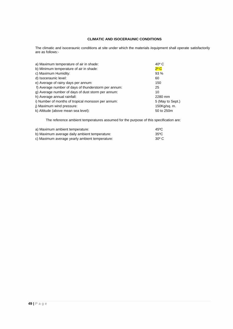
49 | P a g e
CLIMATIC AND ISOCERAUNIC CONDITIONS
The climatic and isoceraunic conditions at site under which the materials /equipment shall operate satisfactorily are as follows:- a) Maximum temperature of air in shade: 40º C
b) Minimum temperature of air in shade: 2º C
c) Maximum Humidity: 93 %
d) Isoceraunic level: 60
e) Average of rainy days per annum: 150
f) Average number of days of thunderstorm per annum: 25
g) Average number of days of dust storm per annum: 10
h) Average annual rainfall: 2280 mm
i) Number of months of tropical monsoon per annum: 5 (May to Sept.)
j) Maximum wind pressure: 150Kg/sq. m.
k) Altitude (above mean sea level): 50 to 250m
The reference ambient temperatures assumed for the purpose of this specification are:
a) Maximum ambient temperature: 45ºC
b) Maximum average daily ambient temperature: 35ºC
c) Maximum average yearly ambient temperature: 30º C

50 | P a g e
TECHNICAL SPECIFICATION FOR EXECUTION OF WORK (FOR 33KV) 1. SCOPE: ERECTION OF 33 KV and 11 KV Line WITH STP: The scope covers the survey of the
proposed route, tree clearance wherever necessary transport of materials to the locations, erection of the line testing of the line and handing over to the APDCL as per specification. Materials such as steel, cement, Steel tubular poles, top cleats, clamps, washers, earth wires, HBG metal, sand, water, cost of bolts and nuts etc., as per requirement are to be procured by the contractor cost of which shall be included in the bid.
2. GENERAL : The Contractor should be well acquainted with the IE Rules 1956 as amended from time
to time and with the Indian Telegraph Act 1889 so that necessary provisions therein may be followed.
3. SURVEY OF THE ROUTE: The Tentative route map of the line to be erected will be furnished by the APDCL to the Contractor along with the copy of the concluded agreement. The Contractor is required to carry out the detailed survey of the route of the line and fix up the locations at the average span indicated in the schedule and mark the locations and submit a detailed route map to the Engineer in charge of the work within 30 days for approval. In the course of surveying by the contractor, any conspicuous variations in the change and physical feature to those indicated in the route map and as actually existing are noticed, the deviations must be brought to the notice of the APDCL Engineer. The APDCL Engineer if considered necessary shall make alterations, which shall be carried out accordingly and the APDCL after inspecting the surveyed route and the revised route map shall be given for final approval in writing. The contractor shall not commence the work until the final approval of the route map is given by the Engineer in charge in writing to the contractor.
4. WAY LEAVES AND TREE CUTTINGS: Proposals for way leaves and right of way shall be submitted by the contractor. Permission will be obtained by the APDCL within reasonable time for which due notice shall be given by the Contractor. The Contractor shall arrange for tree cutting or tree branches cutting also. The widths of tree clearance to be adopted for lines of various voltages are that all growth within 6.096 M (20 ft) from the centre line of support and all trees which may fall and foul the line. The Contractor shall take all possible steps to see that standing crops, etc. are not damaged while attending to tree cutting. When such damage is inevitable the compensation will be borne by the APDCL provided the damage is with the prior concurrence of the Engineer. The Contractor shall bear the compensation for damage caused by the gangs without prior concurrence of the Engineer concerned. No trees shall be cut until the APDCL has made necessary arrangement with the authorities concerned and permission is given to the Contractor to fell such trees. The contractor shall arrange to remove the obstacles as soon as possible. At such times, when it may not possible for APDCL to arrange right-of-way for excavation of pole pits or erecting the poles of stringing the line, then at all such times, the contractor shall shift his gangs to other areas. The rates quoted shall cover all such contingencies and no extra payments shall be claimed for such contingencies.
5. EXCAVATION OF POLE PITS, STAY PITS AND D.P. PITS: After the final survey of the line and after
marking the pole locations with pegs, excavation work has to be commenced in accordance to the approved route map. Excavation is generally done by pick axes, crow V-bars and showers although sometimes earth augers are used. Excavation of pole pits in very hard or rocky soil or in rock beds, may involve blasting with suitable explosives. The pits for the supports are excavated in the direction of the line as this will facilitate the erection of support are excavated in the direction of the line as this will facilitate the erection of support, in addition to giving greater lateral stability, the depth of the foundation to be excavated for poles shall be in accordance with relevant sketch for the erection of pole or stay of D.P. etc.
6. ERECTION OF SUPPORTS: After the excavation of pits is completed the supports to be erected may be brought to the pits location. Then the pole may be erected inside the pit. Wooden support may be utilized to facilitate lifting of the pole at the pit locations. Before the pole is put into pit, RCC padding may be laid below the pole to increase the surface contact between the pole and the soil. The padding will distribute the weight of the pole uniformly on the soil. Having lifted the pole, the same should be kept in a vertical position with the help of manila rope of 25 mm dia using the rope as a temporary anchor. As the poles are being erected say from the pole already erected to the next location where the pole is being erected, the alignment of the poles are to be checked and set right by visual check. The verticality’s of the poles are to be checked with a spirit level on both transverse and longitudinal directions. Having satisfied that the verticality and alignment are all right, earth filling or
51 | P a g e
concreting is to be done. In swampy and special locations, however, before earth filing, the poles are to be concreted up to ground level of the pit. After the poles have been set the temporary anchors are to be removed. The supports shall be buried to a depth as per sketch enclosed.
7. ERECTION OF D.P. STRUCTURES FOR ANGLE LOCATIONS (FOR 33 KV LINE): Generally, for
angles of deviation more than 20° double pole structures of spacing 1.2 mts (4.0 ft) may be erected. The pits are to be excavated as per bisection of the angle of deviation. After the poles are erected, the horizontal / cross bracing should be fitted and the supports held in a vertical position with the help of temporary guys of manila rope of at least 25 mm dia. Ensuring that the poles are held in a vertical position (this can be checked with a spirit level) the concreting of the poles with cement, granite chips of size 20/30 mm mesh and sand in the ratio M400 conforming to ISS is to be done from the bottom of the support to the ground level. Before lifting the pole in the pit, concrete padding of not less than 75 mm thickness may be put for the distribution of the load of the support on the soil. After the concreting is done, the pit may be filled with earth after curing of the concrete is completed. Four stays along the line, two in each direction and two stays along the bisection of angle of deviation are to be provided. Stay concreting may be done with M 400 concrete mixture. The D.P. shall be erected as per the sketch enclosed.
8. ANCHORING AND PROVIDING GUYS FOR SUPPORTS: Guys are to be provided to the supports at
the following places (i) Angle locations, (ii) Dead end locations, (iii) Tee-off points, (iv) Steep gradient locations to avoid uplifted on the poles. The installation of guy will involve the following works:
i. Excavation of pit and fixing of stay rod. ii. Fastening guy wire to the support. iii. Tightening guy wire and fastening to the anchor
The marking of the guy pit for excavation, the excavation of pits and setting of the anchor rod must be carefully carried out. The stay rod should be placed in the position such that the angle of inclination of the rod with the vertical face of the point is 30°/45° as the case may be. The concreting of the stay at the bottom should then be carried out. The back filling and ramming must be well done thereafter, and allowed to set for at least 7 days. The free end of the guy wire is passed through the eye of the anchor rod, bent back parallel to the main portion of the guy and bound after inserting the G.I. Thimble. The loop is protected by the G.I. Thimble, where it bears on the anchor rod. Where the existence of guy wire proves hazardous, it should be protected with suitable asbestos pipe, filled with concrete of about 2 mts length above the ground level, duly painted with white and black stripe so that it may be visible at night. The turn buckle shall be mounted at the pole end of the stay and guy wire so fixed that the eye bolt turn buckle is half way in the working position, thus giving the maximum movement for tightening or loosening. Guy insulators are placed to prevent the lower part of the guy from becoming electrically energized by a contact of the guy when the conductors snap and fall on them of due leakage. No guy insulator shall be located less than 2.6 mts. from the ground. The anchoring and providing guys for supports (Single guy Bow guy fly guy) shall be done as per sketch enclosed. Bow guy and fly guy shall be provided as per field conditions. 9. FIXING OF CROSS ARMS INSULATORS: After the erection of supports and providing guys, the next
step would be to mount the cross arms on the support erected. The lineman should climb the support having requisite tools with him and the cross arm is then tied to a hand line and pulled up by the ground man and should station himself well to one side so that if any material drops from the top of the pole it may not strike him. All the materials required should be lifted or lowered by means of the hand line. In no case, the materials of the tools should be dropped or thrown from the pole top. The fixing of 33 KV, 11 KV and LT Cross arms shall be in accordance to spacing detailed in Sketch. G.I. bolts and nuts and spring washers of good quality only shall be used which will have to be procured by the contractor.
a. Back Clamps; The back clamps for fixing of the seating channels, “V” cross arms, horizontal cross arms and top cleats will have to be procured by the contractor and shall be in accordance with sketch enclosed and the clamp shall be fabricated with 75 X 8 mm G.I. Flat for 33 KV and 50 X 8 mm G.I Flat for 11 KV.
b. Top Cleats The top cleats shall be got fabricated with G.I. Channel of size 100 X 50 mm for 33 KV and 11 KV and shall be in accordance with sketch enclosed.
10. INSULATORS: The pins for insulators shall be fixed in the holes provided in the cross arms and the pole top brackets. The insulators shall be mounted in their places over pins and tightened. In the case of strain or angles supports, where strain fittings are provided for this purpose, one strap of the strain
52 | P a g e
fitting is placed over the cross arm before placing the bolts in the hole of the cross arms. The nut of the strap is so tightened that the strap can move freely in horizontal direction, as this is necessary to fix the strain insulator. The insulator shall be cleaned and examined for defects before fixing, it shall be ensured that all the current carrying parts are smooth and without dirt, cracks or chips.
11. STRINGING OF THE LINE CONDUCTORS For the guidance of the contractor certain do’s and don’ts are given below before the workmen actually commence the stringing work a. Do’s and Don’ts
DO’s i. Use proper equipment for handling aluminum conductors at all times. ii. Use skids, or similar method for lowering reels or coils from transport or ground. iii. Examine reel before unreeling for presence of nails or any other object, which might
damage the conductor. iv. Rotate the reel or coil while unwinding conductor. v. Grip all strands while pulling out the conductor. vi. Control the unreeling speed with suitable braking arrangement. vii. Use wooden guards of suitable braking arrangement. viii. Use long straight, parallel jaw grip with suitable liners when pulling conductor thus
avoiding nicking or kinking of the conductor. ix. Use free running sleeves or blocks with adequate grooves for drawing/paving
conductors. x. Use proper sag charts. xi. Mark conductors with crayons or adhesive tape of such (other) material, which will not
damage the strand. xii. Make all splicing with the proper tools. xiii. Use a twisting wrench for twisting the joints. xiv. Chromite or graphite conducting oxide-inhibiting grease should be used before cleaning
with wire brush. DON’Ts
i. Do not handle conductors without proper tools at any stage. ii. Do not pull conductors without ensuring that there are no obstructions on the ground. iii. Do not pull out excess quantity of conductor than is required. iv. Do not make jumper connections on dirty or weathered conductor. v. Do not handle aluminium conductors in a rough fashion but handle it with care it
deserves. b. CONDUCTOR ERECTIONS: The erection of overhead line conductor is a very important phase in
construction. The erection of conductors can be sub-divided into 4 separate parts as follows: i. Transport of conductors to work site. ii. Paving and stringing of conductors. iii. Tensioning and sagging of conductors. iv. Joining of conductors.
At the important crossing of roads, canals, navigable rivers, railways etc., flagmen should be in attendance to ensure that normal services are not unduly interrupted. These crossing should only be carried out in conjunction with and with the approval of the proper authorities concerned. The conductor drums shall be transported to the tension point without injuring the conductor, if, it is necessary to roll the drum on the ground for a small distance, it should be slowly rolled in the direction of the marked on the drum. The drum should be so supported that it can be rotated freely. For this purpose the drum should either be mounted on the cable drum supports of jacks or hung by means of chain pulley of suitable capacity, suspended from a tripod. In case if it is not possible to raise the conductor drum by any of the above method, a trench of suitable depth slightly bigger than the conductor drum may be dug, so as to facilitate free rotation of the cable drum when it is suspended in the trench by means of M.S. Shaft. While paving, care should be taken to see that conductor does not rub against any metallic fitting of the pole or on the bad/rocky ground. Wooden trusses should be used for this purpose to support the conductor. The conductor should be passed over the poles on wooden or aluminium snatch pulley blocks provided with low friction bearings. While conductor is being paved out slowly, some braking arrangement should be made so that the rotation of the drum may be stopped in emergency. In case the length of one piece of the conductor is less than the length of the section in which conductor paving is being done, it is easy to stretch one length of all phases from one end the remaining length from another end of the section any part
53 | P a g e
of the conductor shall be left at a height of less than that of 5 meters, above the ground by rough sagging.
c. MID SPAN JOINTING OF CONDUCTORS
The mid span jointing of conductors can be carried by twisting the joint at the ends and the wire should project a few centimetre, beyond the end of the sleeves. The projected wires are given a sharp bend to keep them from slipping out of the sleeve. The end of the sleeves are then held tightly by twisting wrenches and then 4 to 5 turns in one direction generally anti-clock wise direction. Crimping Tools are preferably to be used for joints and jumpers.
d. SAGGING AND TENSIONING
On the completion of the paving of the conductors and making mid span joints if any, tensioning operations will commence. Temporary guys will have to be provided for both the anchoring supports in the section where the stringing has to be done. At the tensioning end, one of the conductors is pulled manually up to a certain point and then come along clamp is fixed to the conductor to be tensioned. The grip to the come along clamp is attached to double sleeve pulley block or the pulley lift machine and gradually tensioned. The conductor should then be sagged in accordance with the sag temperature chart for the particular conductor and span. The sag should then be adjusted in the middle span of the section. The sag chart is to be provided. The stretch of the conductor has to be taken out before stringing in order to avoid the gradual increase in sag due to the setting down of the individual wires. There are ways of accomplishing this:
e. PRE-STRESSING In this method the conductor is pulled up to tension considerably above the correct figures, but never exceeding 50% of breaking load for a short period of say twenty minutes. As this method requires more time and involves the use of stronger tackle to secure the higher tension the other method of over tensioning is commonly adopted.
f. OVER-TENSIONING This method consists of pulling up the conductor to a tension a little above the theoretical tension for prevailing temperature and fixed it up at that tension with correspondingly reduced sag. After a certain time the conductor will settle down to the correct sag and tension. A tension of five to eight percent more than the theoretical value has been found to be suitable for the sizes of ACSR and AAAC conductors standardized by REC. The ambient temperature during sagging may be recorded correctly. Conductors can be sagged correctly only when the tension is the same in each span throughout the entire length of section. Use of snatch blocks reduces the friction and chances of inequality of tension in various spans. Sagging can be accomplished by several different methods but most commonly used method is “Slighting”. The slighting sag method of measuring sag is by the use of targets placed on the supports below the cross arms. The targets may be light strip of wood clamped to the pole at a distance equal to the sag below the conductor when the conductor is placed in snatch block. The lineman sees the sag from the next pole. The tension of the conductor is then reduced or increased, until the lowest part of the conductor in the span coincides with the lineman’s line of sight. When sagging is completed, the tension clamps shall be fixed. The clamp can be fitted on the conductor without releasing the tension. A mark is made on the conductor at a distance from the cross-arm equal to the length of complete strain insulator. Before the insulator set is raised to position, all nuts should be free. Come along clamp is placed on the conductor beyond the conductor clamp and attached to the pulling unit. The conductor is pulled in sufficiently to allow the insulator assembly to be fitted to the clamp. After the conductor is clamped to insulator, assembly unit may be released gradually. If the tension is released with a jerk, an abnormal stress may be transferred to conductor and support, which may result in the failure of the cross arm, stay or pole in some cases. After the stringing is completed, all poles, cross arms, insulators, fittings etc. are checked upto ensure that The next step is to place the conductor on the top of the pin insulator from the snatch block and removing snatch blocks. Conductors are then fastened to insulator by the use of aluminium wires. The following points should be observed:
i. Proper size of the tie binding wire which can be readily handled and with adequate strength is to be used.
ii. The length of tie wire should be sufficiently long for making complete tie including the end allowances for gripping with ends.
iii. A good tie should provide a secure binding between the line conductor and insulator and should reinforce the conductor on either side of the insulator.
iv. The use of cutting pliers for binding the tie wire should be avoided.

54 | P a g e
v. The tie wire which has been used previously should be reused Before tying the conductor to the insulator two layers of Aluminium tapes should be wrapped over the conductor in the portion where it touches the insulator. The width and thickness of aluminium tape to be used for a specific size of conductors has been specified in hand books of Aluminium conductor manufacturers and the same be referred to. The Aluminium tapes should also be used at the tension clamp and for proper grip. Normally in straight runs of line, the conductors are run on the top of insulators. When there is small of deviation the conductor is placed inside groove and bound. Accordingly, there are two methods of tying the conductors to insulators. The binding wire/tie wire has to be procured by the contractor and the bid price shall include the cost of this.
g. The contractor shall be entirely responsible for any damage to the supports, other accessories and conductor. He shall also be responsible for proper distribution of the conductor drums to keep number and lengths of cut pieces of the conductor to a minimum.
h. CONDUCTOR DAMAGE AND REPAIR: If the conductor is damaged for whatever reasons, and damage is not repaired by aluminium sleeves, etc., it shall be brought to the notice of the Engineer and shall not be used without his approval. Even repairing of conductor surfaces shall be done only in case of minor damages, scuff marks etc., which are safe from both electrical and mechanical points of view. The final; conductor surface shall be clean, smooth, without any projection sharp points, cut or abrasion etc. giving satisfactory corona and R.I. performance.
i. No joints or splice be made in span’s crossing over main roads, railways, small rivers or intension spans. Not more than one joint per conductor shall be allowed in one span. The strength of the joint shall conform to IE Rule 75.
j. STRINGING. Whatever necessary ground clearances have to be measured to ensure obtaining adequate line clearance as per IE Rule 77 (i)
12. EARTHING
a. Pipe Earthing : At D.P Locations, Pits are to be excavated the steel and metal parts are to be earthed by pipe earthing as per the drawing or sketch enclosed to this specification. Duly filling the pits with finely broken coke having granule sizes not more than 25 mm thick. The coke shall be maintained up to a distance of 300 mm for the pipe on all sides. The top edge of the pipe shall be at least 200 mm below the ground level. The CI strips shall be fixed not less than 300 mm deep from the ground level. The tenders shall quote the charges for earthing inclusive of the cost of coke, excavation and back filling.
b. Pole Earthing: Pole earthing shall be in conformity to I.E. Rules. 13. CONCRETING
a. The cement concrete used for the foundations shall be of M 400 grade. b. The full concreting for the poles if erected in excavated act shall be done so that the
complete block will be of dimensions( 0.6 X 0.6 X 1.6) + 0.2 X 0.2 Mtr. (0.6 X 0.6 X 1/35) + 0.2 X 0.2 X 0.2 Mtrs. so as to maintain as exposed portion for 0.2 Mtrs height above the ground level.
c. If augur is used for making pole pits, ramming shall be done after erection of pole.
14. WORKMANSHIP :The contractor shall entirely be responsible for correct erection of all support as per the approved drawings, and their correct setting and alignment, as approved by the engineer. If the supports and D.P. structures after the erection are found to differ from approved route maps and drawings or to be out of alignment, the contractor shall dismantle and re-erect them correctly at his own cost without extension of time. The supports must be truly vertical and in plumb after erection and no straining will be permitted to bring them to vertical position. Verticality of each support shall be measured by the contractor and furnished to the Engineer.
15. Location numbers for each pole shall be painted on the pole. Anti-climbing devices, and danger boards are to be provided at all railway crossings and road crossings. No extra charges shall be admissible even though separate gangs may have to be sent by the contractor for fitting these accessories and attachments on the support at the appropriate time.
16. FINAL CHECKING, TESTING AND COMMISSIONING :After the completion of the work final patrolling and checking of the line shall be done by the contractor to ensure that all foundations work, pole erection and stringing have been done as approved by the Engineer, and also to ensure that they are completed in all respects. Contractor shall prepare pole schedules and hand it over to the Engineer. All works shall be thoroughly inspected keeping in view of the following main points.
i. Sufficient back filled earth is lying over each foundation pit and it is adequately compacted.
55 | P a g e
ii. Concreting and coping of poles are in good and finally shaped conditions. iii. All the accessories and insulators are strictly as per drawings and are free from any defects or
damages, what-so-ever. iv. All the bolts and nuts should be of G.I material and as per contractual provisions. v. The stringing on the conductor has been done as per approved sag and desired clearances are
available. vi. No damage, minor or major to the conductor, earth wire, accessories and insulator strings still
unattended are noticed. vii. For all points double jumpers shall be provided to each phase. The jumpers provided at the cut
points are connected rigidly to the tension hardware utilizing all the jointing bolts provided for the purpose. The contractor shall submit a report to the above effect to the Engineer. In case, it is noticed later that some or any of the above are not fulfilled the Engineer will get such items rectified through other agencies and recover the cost of such works from the bills payable to the contractor against that contract or any other contract executed by him for APDCL. After final checking, the lines shall be tested for insulation in accordance with tests prescribed by the Engineer. All arrangements for such testing or any other tests desired by the Engineer shall be done by the Contractor and necessary labour, transport and equipment shall be provided by him. Any defects found out as a result of such tests, shall be rectified by the Contractor, forthwith, without any extra charges to APDCL. In addition to the above, the Contractor shall be responsible for testing and ensuring that the total and relative sags of the conductors are within the specified tolerance. Such tests shall be carried out at selected points along the route as required by the Engineer and the Contractor shall provide all necessary equipment and labour to enable the tests to be carried out. The APDCL will arrange statutory inspection of the line and indicate the defects noticed. The Contractor has to rectify all such defects and intimate to APDCL Engineer. After satisfactory tests on the line and an approval by the Engineer the line shall be energized at full operating voltage before handing over.
17. SUPPLY OF CONSTRUCTION MATERIALS BY THE CONTRACTOR The Contractor has to make his own arrangements for procurement, supply and use of construction materials like cement, M.S. rounds, HBG metal and sand.
a. CEMENT :The contractor has to make his own arrangements for the procurement of cement to require required for the work subjected to the follows:
i. The contractor shall procure cement, required for the works only from reputed cement factories (Man producer) acceptable to the Engineer-in-Charge. The contractor shall be required to be furnished to the Engineer-in –Charge bills of payment and test certificates issued by the manufacturers to authenticate procurement of quality cement from the approved cement factory. The contractor shall make his own arrangement for adequate storage of cement.
ii. The contractor shall procure cement in standard packing of all 50 kg per bag from the authorized manufactures. The contactor shall make necessary arrangement at his own cost to the satisfaction of Engineer-in-Charge for actual weighment of random sample from the available stock and shall conform to the specification laid down by the Indian Standard Institution or other standard foreign institutions as the case may be. Cement shall be got tested for all the tests as directed by Engineer-in-Charge at least one month in advance before the use of cement hags brought and kept on site Godown. Cement bags required for testing shall be supplied by the contractor free of cost. However, the testing charges for cement will be borne by the APDCL. If the tests prove unsatisfactorily, then the charges for cement will be borne by the contractor.
iii. The contractor should store the cement of 60 days requirement at least one month in advance to ensure the quality of cement so brought to site and shall not remove the same without the written permission of the Engineer-in-Charge. The contractor shall forthwith remove from the works area any cement that the Engineer-in- Charge may disallow for use, an account of failure to meet with required quality and standard.
iv. The contractor shall further, at all times satisfy the Engineer-in-Charge on demand, by production of records and books or by submission of returns and other proofs as directed, that the cement is being used as rested and approved by Engineer-in-Charge for the purpose and the contractor shall at all times, keep his records upto date to enable the Engineer-in-Charge to apply such checks as he may desire.
56 | P a g e
v. Cement which has been unduly long in storage with the contractor or alternatively has deteriorated due to inadequate storage and thus become unfit for use in the works will be rejected by the department and no claim will be entertained. The contractor shall forthwith remove from the work area, any cement the Engineer-in-Charge may disallow for use on work and replace it by cement complying with the relevant Indian Standards.
b. STEEL The contractor shall procure mild steel reinforcement bars, high yield strength deformed(HYSD) bars, rods and structural steel etc. required for the works only from the main or secondary producers manufacturing steel to the prescribed specifications of Bureau of Indian Standards or equivalent and licensed to affix ISI or other equivalent certification marks and acceptable to the Engineer-in-Charge. Necessary ISI list certificates are to be produced to Engineer-in-Charge before use on works. The unit weight and dimensions shall be as prescribed in the relevant Indian Standard specification for steel.
18. INFORMATION AND DATA a. The information furnished is the best available however, the APDCL does not guarantee the
correctness of interpretations, deductions or conclusions which are given as supplementary information in the Bid Documents or in any reports, maps, drawings, diagrams or in other reference information available to the bidder from APDCL of or otherwise. The information has been produced as found, communicated to ascertained or otherwise/learned by the APDCL.
b. It will be the Bidder’s responsibility to satisfy himself from the “Reference Information” supplied and or inspection of the site that sufficient quantities of construction materials required for the works shall exist in the designated borrow areas or quarry sites. The APDCL does not accept any responsibility either in handing over the quarries or procuring the materials or any other facilities. The Tenderer will not be entitled for any extra rate or claim for the misjudgment on his part for the quantity and quality of materials available in the quarries. Failure by the Bidder to have done all the timings which is in accordance with this condition he is deemed to have done shall not relieve the successful Bidder of the responsibility for satisfactorily completing the work as required at the rates quoted by him.

57 | P a g e
TECHNICAL SPECIFICATION FOR EXECUTION OF WORK (FOR 33KV LINES)
i. SCOPE : ERECTION OF 33 kV LINES on SP 80 GI Steel Tubular POLES
The scope covers the survey of the proposed route, tree clearance wherever necessary transport of materials to the locations, erection of the line testing of the line and handing over to the APDCL, as per specification. Materials such as steel, cement, PSC Poles, top cleats, clamps, washers, earth wires, HBG metal, sand, water, cost of bolts and nuts etc., as given in Annexure-1 are to be procured by the contractor cost of which shall be included in the bid.
1.1 General :
The Contractor should be well acquainted with the IE Rules 1956 as amended from time to time and with the Indian Telegraph Act 1889 so that necessary provisions therein may be followed.
1.2 ELECTRICAL CLEARANCE
As per Indian Electricity Rules ,1956 ( amended version )
Sl. No.
Particulars 33 KV line
1 Minimum height of any conductor of an overhead line across any street
6.4 metres
2 Minimum height of any conductor of an overhead line along any street
6.1 metres
3 Minimum height of any conductor (bare )of an overhead line erected elsewhere
5.2 metres
4 Minimum height of any conductor (insulated )of an overhead line erected elsewhere
4.0 metres
5 Minimum Clearance of an overhead line from building 3.7mtr. (vertical ) 2.0 mtr. ( horizontal)
6 Clearance between over-head line and communication line 2.130 meters
7 Minimum Clearance from another line 0.270 meters
8 Phase to phase clearance ( min) 1370 mm
9 Span 53
1.3 SURVEY OF THE ROUTE
The Tentative route map of the line to be erected will be furnished by the APDCL, to the Contractor along with the copy of the concluded agreement. The Contractor is required to carry out the detailed survey of the route of the line and fix up the locations at the average span indicated in the schedule and mark the locations and submit a detailed route map to the Engineer in charge of the work within 30 days for approval. In the course of surveying by the contractor, any conspicuous variations in the change and physical feature to those indicated in the route map and as actually existing are noticed, the deviations must be brought to the notice of the APDCL Engineer. The APDCL, Engineer if considered necessary shall make alterations, which shall be carried out accordingly and the APDCL, after inspecting the surveyed route and the revised route map shall be given for final approval in writing. The contractor shall not commence the work until the final approval of the route map is given by the Engineer in charge in writing to the contractor.
1.3.1 WAY LEAVES AND TREE CUTTINGS
Proposals for way leaves and right of way shall be submitted by the contractor. Permission will be obtained by the APDCL, within reasonable time for which due notice shall be given by the Contractor. The Contractor shall arrange for tree cutting or tree branches cutting also. The widths of tree clearance to be adopted for lines of various voltages are as detailed below:
1.3.2 33 KV LINE (Trunk Line)
All growth within 6.096 M (20 ft) from the center line of support and all trees which may fall and foul the line.
1.3.3 The Contractor shall take all possible steps to see that standing crops, etc. are not damaged while attending to tree cutting. When such damage is inevitable the compensation will be borne by the APDCL provided the
58 | P a g e
damage is with the prior concurrence of the Engineer. The Contractor shall bear the compensation for damage caused by the gangs without prior concurrence of the Engineer concerned.
1.3.4 No trees shall be cut until the APDCL, has made necessary arrangement with the authorities concerned and permission is given to the Contractor to fell such trees. The contractor shall arrange to remove the obstacles as soon as possible.
1.3.5 At such times, when it may not possible for APDCL, to arrange right-of-way for excavation of pole pits or
erecting the poles of stringing the line, then at all such times, the contractor shall shift his gangs to other areas. The rates quoted shall cover all such contingencies and no extra payments shall be claimed for such contingencies.
1.4 EXCAVATION OF POLE PITS, STAY PITS AND D.P. PITS
1.4.1 After the final survey of the line and after marking the pole locations with pegs, excavation work has to be
commenced in accordance to the approved route map. Excavation is generally done by pick axes, crow V-bars and showers although sometimes earth augers are used. Excavation of pole pits in very hard or rocky soil or in rock beds, may involve blasting with suitable explosives. The pits for the supports are excavated in the direction of the line as this will facilitate the erection of support are excavated in the direction of the line as this will facilitate the erection of support, in addition to giving greater lateral stability, the depth of the foundation to be excavated for poles shall be in accordance with relevant sketch for the erection of pole or stay of D.P. etc.
1.5 ERECTION OF POLES :
1.5.1 PSC POLE :
PSC poles should be erected perpendicular to ground level including excavation of earth pit having depth equal to 1/5th the length of pole and cross-section 75 cm x 50 cm as directed by department including dragging and carrying of pole to site as per soil condition as given below. (i) earth filling with soil at bottom and surrounding with vigorous ramming; (ii) earth filling with soil at bottom and surrounding with vigorous with boulder packing including supply of
boulder by contractor ( size of boulder 150mm x 200mm); (iii) grouting and mufflering in proportion 1:2:4 RCC foundation and filling of cement concrete as per specification including supply of cement , stone chips, shuttering etc. as directed ]
1.5.2 POLE CLAMP:
The pole clamp is to be made of MS flat of size 40 mm x 6 mm with necessary drilling of holes and painting
with primer and anti corrosive paint suitable for different size of steel tubular pole and PSC pole. 1.6 ERECTION OF SUPPORTS
After the excavation of pits is completed the supports to be erected may be brought to the pits location. Then the pole may be erected inside the pit. Wooden support may be utilized to facilitate lifting of the pole at the pit locations. Before the pole is put into pit, RCC padding may be laid below the pole to increase the surface contact between the pole and the soil. The padding will distribute the weight of the pole uniformly on the soil. Having lifted the pole, the same should be kept in a vertical position with the help of manila rope of 25 mm dia using the rope as a temporary anchor. As the poles are being erected say from the pole already erected to the next location where the pole is being erected, the alignment of the poles are to be checked and set right by visual check. The verticality’s of the poles are to be checked with a spirit level on both transverse and longitudinal directions. Having satisfied that the verticality and alignment are all right, earth filling or concreting is to be done. In swampy and special locations, however, before earth filing, the poles are to be concreted up to ground level of the pit. After the poles have been set the temporary anchors are to be removed. The supports shall be buried to a depth as per REC construction standard.

59 | P a g e
TECHNICAL SPECIFICATION FOR G.I STEEL TUBULAR POLES FOR OVERHEAD LINES
1.0 SCOPE:
1.1 This specification covers the general requirements towards design, manufacture, testing at manufacturers works, supply and delivery for tubular steel poles of circular cross section ( swaged type ) for overhead lines.
2.0 STANDARD : 2.1. The tubular steel poles shall conform to the latest edition of Indian Standard specification
IS: 2713 ( Part – I, III ) : 1980 Specification for Steel Tubular poles
The Steel Tubular Poles conforming to other internationally accepted, which ensure equal or higher quality
than the standards, mentioned above also be acceptable. In case the bidder who wish to offer material
conforming to the other standards, salient points of difference between adopted and specific standards
with authentic English Translation shall be furnished.
3.0 Topography and Climatic Condition :
3.1. The materials offered, shall be suitable for operation in tropical climate and will be subjected to the sun and inclement weather and shall be able to withstand wide range of temperature variation. For the purpose of design, average atmospheric temperature may be considered to be 50 °C with humidity nearing saturation.
4.0 Materials :
4.1. The materials used in construction of tubular steel poles shall be of the tested quality of steels of minimum tensile strength 540 MPa (55 Kgf/mm2 ) Or 410MPa (42kgf/sqmm) as the case may be.
4.2. The materials, when analysed in accordance with IS : 228 ( Part-III : 1972 ) and IS : 228 ( Part-IX) shall not show sulpher and phosphorous contents of more than 0.060 percent each.
5.0 Types, Size and construction :
5.1. Tubular Steel Poles shall be swaged type. 5.2. Swaged poles shall be made of seamless or welded tubes of suitable lengths swaged and jointed together.
No circumferential joints shall be permitted in the individual tube lengths of the poles. If welded tubes are used they shall have one longitudinal weld seam only: and the longitudinal welds shall be staggered at each swaged joint.
5.3. Swaging may be done by any mechanical process. The upper edge of each joint shall be chamfered if at an angle of about 45o. The upper edge need not be chamfered if a circumferential weld is to be deposited in accordance with clause No. 5.3 2 of IS: 2713 (Part-I): 1980.
5.4. The length of joints on swaged poles shall be in accordance with clause No. 5.4 of IS: 2713(Par-I): 1980. 5.5. Poles shall be well-finished, clean and free from harmful surface defects. Ends of the poles shall be cut
square. Poles shall be straight, smooth and cylindrical. The weld joints, if any, shall be of good quality, free from scale, surface defects, cracks, etc.
5.6. Tolerances for outside diameter, thickness, length, weight and straightness shall be in accordance with IS: 2713 (Part-I) : 1980.
5.7. The poles shall be coated with black bituminous paint conforming to IS: 158-1968 throughout, internally and externally, upto the level which goes inside the earth. The remaining portion of the exterior shall be painted with one coat of red oxide primer as specified in IS: 2074-1979.
5.8. For galvanized pole shall be galvanised as per IS: 2629/1985 & testing uniformity of coating on zinc should be as per IS:2633/1986 . The quality of zinc used for galvanization shall conform to any of the grade as per IS:209/1992 or IS:13229/1991. The molten metal in galvanisation should contain not less than 98.5 percent by mass of zinc. The mass of zinc coating should not be less than 610g/sqm (Aprox. 86 micron) .
6.0 Joint in Swaged Poles : The lengths of joint on swaged poles shall be as follows:
7.0 Earthing Arrangements :
7.1. For earthing arrangement a through hole of 14mm diameter shall be provided in each pole at a height of 300mm above the planting depth.
Outside Diameter of smaller tube in joints
Length of Joints (J1 or J2
76.1 mm 200 mm
88.9 mm 230mm
114.3 mm 300mm
139.7 mm 350 mm
1651 mm 400 mm
193.7 mm 450mm
60 | P a g e
8.0 PRINCIPAL PARAMETERS
SN ITEM DESCRIPTION PARAMETERS
1. Type of Pole SP-80
2. Overall Length 16.0 M
3. Planting Depth 2.3 M
4. Load Applied from top at a distance of 0.60 M
5. Height above ground 13.7 M
6. Length of sections
a. a Bottom 7.0 M
b. Middle 4.5 M
c. Top 4.5 M
7. Outside Diameter & thickness of
section
A Bottom, MM 219.1 x5.90
B Middle ,MM 193.7 x4.85
C Top, MM 165.1 x 4.5
8. Approx. Wt of pole 416 KG
9. crippling load 611 kgf
10. breaking load 861 kgf
11. Ultimate tensile strength 540 MPa ( 55KGf / mm2 )
12. Joint in poles 400mm & 450 mm
13. Base Plate
A Mild Steel base plate of size 400 mm x 400 mm x 10mm shall be
welded at the bottom of the pole.
14.
Galvanization : as per IS:2629/1985, IS:2633/1986 & IS: 4736/1986 with
amendment
Not less than 610g /sqm (86 micron aprox.)
9.0 Tests and Test Certificates :
9.1. The following tests shall be conducted on finished poles : A. Tensile test and chemical analysis for sulpher and phosphorous : The material when analyzed as
per IS: 228 ( pt.III &Pt. IX) shall not show sulpher& phosphorus content of more than 0.060 percent each., B. Deflection test: The temporary deflection due to the applied load at the point of application of load shall
not exceed 157.5mm C. Permanent set test: The permanent set measured from the zero position after the release of
appropriate applied load, shall not exceed 13 mm D. Drop test.: The pole shall not show any sign of telescoping or loosening of joint
9.2. In addition to above verification of dimensions as per IS: 2713 (Part-III): 1980 shall be carried out during acceptance of lots.
9.3. Number of poles selected for conducting different tests shall be in accordance to clause No.10.1.1 and No. 10.1.12: of IS: 2713 (Part-I) 1980.
9.4. Tests shall be carried out before supply of each consignment at the manufacturers’ woks and test certificates should be submitted to the purchaser for approval prior to delivery.
9.5. Re-tests, if any, shall be made in accordance with IS: 2713 (Part-I) 1980. 9.6. Purchaser reserves the right to inspect during manufacturing and depute his representative to inspect/test
at the works. 9.7. If any extra cost is required for carrying out the above specified tests, the same shall be borne by the
tenderer. 9.8. The inner side and underground portion of the pole is to be painted with black bituminous paint conforming
to IS: 158-1968 throughout, (internally and externally, up to the level which goes inside the earth.) The remaining portion of the exterior shall be galvanized as per the relevant clause.
10.0 Marking :
10.1. The poles shall be marked with designation, manufacturer’s identification, year of manufacture and name of the purchaser: APDCL
10.2. The poles should also be marked with the ISI certification mark.

61 | P a g e
11.0 Performance :-
11.1. The bidder shall furnish a list of the major supplies effected during the last 3 (three) years indicating the volume of supply and actual delivery dates along with the bids.
11.2. Bids may not be considered if the past manufacturing experience is found to be less that 3 (three) years.
12.0 Deviation :-
13.1 Any deviation in technical specification shall be clearly indicated with sufficient reasons thereof. Purchaser shall however reserve the right to accept and/or reject the same without assigning any reasons what-so-ever.
13.0 Guaranteed technical particulars :
13.1. The bidder shall furnish all necessary guaranteed technical particulars in the prescribed proforma enclosed hereinafter.
TECHNICAL SPECIFICATION FOR ACSR CONDUCTORS
A. ACSR CONDUCTOR
1. SCOPE
This section covers design, manufacture, testing before dispatch, packing, supply and delivery for destination
of Kms of "RACOON", “WOLF” ,6/1/4.09 mm, 7/1.57 mm, respectively.
2. STANDARDS
The Conductor shall also comply in all respects with the IS: 398 (Part-II) - 1996 with latest amendments
unless otherwise stipulated in this specification or any other International Standards which ensure equal or
higher quality material.
The ACSR Conductor shall also conform to the following standards :
Offer Conforming to standards other than IS-398 shall be accompanied by the English version of relevant
standards in support of the guaranteed technical particulars to be furnished as per format enclosed.
Sl.
No.
Indian
Standards
Title International
1 IS:209-1979 Specification for Zinc BS-3436-1961
2 IS:398-1996 Specification for Aluminium conductors for overhead
transmission purposes.
Part-II Aluminium conductors IEC-209-1966
Galvanized steel reinforced BS-215(Part-II)
3 IS:1521-1972 Method of Tensile Testing of Steel wire ISO/R89-1959
4 IS:1778-1980 Reels and Drums for Bare conductors BS-1559-1949
5 IS:1841-1978 E.C. Grade Aluminium rod produced by rolling
6 IS:2629-1966 Recommended practice for Hot Dip Galvanizing of iron and
steel
7 IS:2633-1986 Method of testing uniformity of coating of zinc coated
articles.
8 IS:4826-1968 Galvanized coatings on round steel wires. ASTM A472-729
9 IS:5484-1978 E.C. Grade Aluminium rod produced by continuous casting
and rolling.
10 IS:6745-1972 Methods of determination of weight of zinc-coating of zinc
coated iron and steel articles
BS-443-1969

62 | P a g e
3. GENERAL TECHNICAL REQUIREMENTS
The General Technical Requirements are given in Section-II. The Conductor shall conform to these technical
requirements.
The Bidder shall furnish guaranteed technical particulars in Section-III.
3.1. MATERIALS/WORKMANSHIP
3.1.1. The material offered shall be of best quality and workmanship. The steel cored Aluminium conductor strands
shall consist of hard drawn Aluminium wire manufactured from not less than 99.5% pure electrolytic
Aluminium rods of E.C. grade and copper content not exceeding 0.04%. They shall have the same
properties and characteristics as prescribed in IEC: 889-1987. The steel wire shall be made from material
produced either by the acid or basic open hearth process or by electric furnace process or basic oxygen
process. Steel wire drawn from Bessemer process shall not be used.
3.1.2. The steel wires shall be evenly and uniformly coated with electrolytic high grade, 99.95% purity zinc
complying with the latest issue of IS-209 for zinc. The uniformity of zinc coating and the weight of coating
shall be in accordance with Section-II and shall be tested and determined according to the latest IS-2633 or
any other authoritative standard.
3.1.3. The steel strands shall be hot dip galvanized and shall have a minimum zinc coating of 250 gm/sq.m after
stranding. The coating shall be smooth, continuous, and of uniform thickness, free from imperfections and
shall withstand minimum three dips after stranding in standard preece test. The steel strands shall be
preformed and post-formed in order to prevent spreading of strands in the event of cutting of composite
core wire. The properties and characteristics of finished strands and individual wires shall be as prescribed
in IEC: 888-1987.
4. CONDUCTOR PARAMETERS
The Parameters of individual strands and composite steel cored aluminium conductor shall be in
accordance with the values given in Section-II.
Creep in a conductor is attributed partly due to settlement of strands and partly due to non-elastic
elongation of metal when subjected to load. The manufacturer of conductor shall furnish the amount of
creep which will take place in 10, 20, 30, 40 and 50 years along with the supporting calculations. The
calculations should be based on everyday temperature of 32 ºC and everyday tension of 25% of UTS of
conductor of 11/33 KV Lines.
5. TOLERANCES
The tolerances on standard diameter of Aluminium and Steel wires shall be as detailed in specific technical
requirements.
The cross-section of any wire shall not depart from circularity by more than an amount corresponding to
the tolerance on the standard diameter.
The details of diameters, lay ratios of Aluminium and steel wires shall be in accordance with the Section-II
"Technical Requirements".
6. SURFACE CONDITIONS
All Aluminium and steel strands shall be smooth, and free from all imperfections, spills/and splits. The
finished conductor shall be smooth, compact, uniform and free from all imperfections including spills and
splits, die marks, scratches, abrasions, scuff marks, kinks (protrusion of wires), dents, pressmarks, cut
marks, wire cross-over, over-riding looseness, pressure and/or unusual bangle noise on tapping, material
63 | P a g e
inclusions, white rust, powder formation or black spots (on account of reaction with trapped rain water
etc.,), dirt, grit, etc. The surface of conductor shall be free from points, sharp edges, abrasions or other
departures from smoothness or uniformity of surface contour that would increase radio interference and
corona losses. When subjected to tension upto 50% of the ultimate strength of the conductor, the surface
shall not depart from the cylindrical form nor any part of the component parts or strands move relative to
each other in such a way as to get out of place and disturb the longitudinal smoothness of the conductor.
7. JOINTS IN WIRES
7.1. Aluminium wires
During stranding, no Aluminium wire welds shall be made for the purpose of achieving the required
conductor length.
No joint shall be permitted in the individual Aluminium wires in the outer most layer of the finished
Conductor. However, joints in the 12 wire & 18 wire inner layer of the conductor are permitted but these
joints shall be made by the cold pressure butt welding and shall be such that no two such joints shall be
within 15 meters of each other in the complete stranded conductor.
7.2. Steel wires
There shall be no joints in finished steel wires forming the core of the steel reinforced Aluminium
conductor.
8. STRANDING
The wires used in construction of the stranded conductor, shall, before stranding, satisfy all requirements
of IS-398 (Part-II) 1996.
In all constructions, the successive layers shall be stranded in opposite directions. The wires in each layer
shall be evenly and closely stranded round the underlying wire or wires. The outer most layer of wires shall
have a right hand lay. The lay ratio of the different layers shall be within the limits given under Section-II.
9. PACKING
9.1. The conductor shall be supplied in non-returnable strong wooden drums provided with lagging of adequate
strength constructed to protect the conductor against any damage and displacement during transit, storage
and subsequent handling and stringing operations in the field. The drums shall generally conform to IS-
1778-1980 and latest version except as otherwise specified hereinafter. The conductor drums shall be
adequate to wind one standard length of 2500 meters of WEASEL/RABIT/RACOON/DOG/PANTHERACSR
conductor.
9.2. The drums shall be suitable for wheel mounting and for letting off the conductor under a minimum
controlled tension of the order of 5KN. The conductor drums shall be provided with necessary clamping
arrangements so as to be suitable for tension stringing of power conductor.
9.3. The bidders should submit their drawings of the conductor drums along with the bid. After placement of
letter of intent the Manufacturer shall submit four copies of fully dimensioned drawing of the drum for
Employer's approval. After getting approval from the Employer, Manufacturer shall submit 30 more copies of
the approved drawings for further distribution and field use.
9.4. All wooden components shall be manufactured out of seasoned soft wood free from defects that may
materially weaken the component parts of the drums. Preservative treatment for anti-termite/anti fungus
shall be applied to the entire drum with preservatives of a quality which is not harmful to the conductor.
9.5. All flanges shall be 2-ply construction with 64 mm thickness. Each ply shall be nailed and clenched together
at approximately 90 degrees. Nails shall be driven from the inside face of the flange, punched and then

64 | P a g e
clenched on the outer face. Flange boards shall not be less than the nominal thickness by more than 2 mm.
There shall not be less than 2 nails per board in each circle.
9.6. The wooden battens used for making the barrel of the conductor shall be of segmental type. These shall be
nailed to the barrel supports with at least two nails. The battens shall be closely butted and shall provide a
round barrel with smooth external surface. The edges of the battens shall be rounded or chamfered to avoid
damage to the conductor.
9.7. Barrel studs shall be used for construction of drums. The flanges shall be holed and the barrel supports
slotted to receive them. The barrel studs shall be threaded over a length on either end, sufficient to
accommodate washers, spindle plates and nuts for fixing flanges at the required spacing.
9.8. Normally, the nuts on the studs shall stand protruded of the flanges. All the nails used on the inner surface
of the flanges and the drum barrel shall be countersunk. The ends of the barrel shall generally be flushed
with the top of the nuts.
9.9. The inner cheek of the flanges and drum barrel surface shall be painted with bitumen based paint.
9.10. Before reeling, card board or double corrugated or thick bituminized waterproof bamboo paper shall be
secured to the drum barrel and inside of flanges of the drum by means of a suitable commercial adhesive
material. The paper should be dried before use. Medium grade craft paper shall be used in between the
layers of the conductor. After reeling the conductor the exposed surface of the outer layer of conductor shall
be wrapped with thin polythene sheet across the flanges to preserve the conductor from dirt, grit and
damage during transportation and handling and also to prevent ingress of rain water during
storage/transport.
9.11. A minimum space of 75 mm shall be provided between the inner surface of the external protective lagging
and outer layer of the conductor. Outside the protective lagging, there shall be minimum of two binders
consisting of hoop iron/galvanised steel wire. Each protective lagging shall have two recesses to
accommodate the binders.
9.12. Each batten shall be securely nailed across grains as far as possible to the flange edges with at least 2 nails
per end. The length of the nails shall not be less than twice the thickness of the battens. The nail shall not
protrude above the general surface and shall not have exposed sharp edges or allow the battens to be
released due to corrosion.
9.13. The conductor ends shall be properly sealed and secured with the help of U-nails on one side of the flanges.
9.14. Only one standard length of conductor shall be wound on each drum. The method of lagging to be
employed shall be clearly stated in the tender.
9.15. As an alternative to wooden drum Bidder may also supply the conductors in non-returnable painted steel
drums. The painting shall conform to IS:9954-1981,reaffirmed in 1992. Wooden/ steel drum will be treated
at par for evaluation purpose and accordingly the Bidder should quote the package.
10. LABELLING AND MARKING
The drum number shall be branded or gauged or stenciled into the flange. An arrow shall be marked on
the sides of the drum, together with the words "Roll this way". Each drum shall have the following
information provided on the outside of the flange stenciled with indelible ink.
i) Manufacturer's name and address.
ii) Contract/Specification number.
iii) Size and type of conductor.
iv) Net weight of the conductor.
65 | P a g e
v) Gross weight of the conductor and drum.
vi) Length of the conductor.
vii) Position of the conductor end.
viii) Drum and lot number.
ix) Name and address of the consignee.
x) Month and year of manufacture.
xi) The drum may also be marked with standard specification as per which the conductor is
manufactured.
11. STANDARD LENGTHS
11.1. The standard length of the conductor shall be 2500 metres. Bidder shall indicate the standard length of the
conductor to be offered by them. A tolerance of plus or minus 5% on the standard length offered by the
bidder shall be permitted. All lengths outside this limit of tolerance shall be treated as random lengths.
11.2. Random lengths will be accepted provided no length is less than 70% of the standard length and total
quantity of such random length shall not be more than 10% of the total quantity order. When one number
random length has been manufactured at any time, five (5) more individual lengths, each equivalent to the
above random length with a tolerance of +/-5% shall also be manufactured and all above six random
lengths shall be dispatched in the same shipment. At any point, the cumulative quantity supplied including
such random lengths shall not be more than 12.5% of the total cumulative quantity supplied including such
random lengths. However, the last 20% of the quantity ordered shall be supplied only in standard length as
specified.
11.3. Bidder shall also indicate the maximum single length, above the standard length, he can manufacture in the
guaranteed technical particulars of offer. This is required for special stretches like river crossing etc. The
Employer reserves the right to place orders for the above lengths on the same terms and conditions
applicable for the standard lengths during the pendency of the Contract.
12. QUALITY ASSURANCE PLAN
A Quality Assurance Plan including customer hold points covering the manufacturing activities of the
material shall be required to be submitted by the tenderer to the Employer along with the tender. The
Quality Assurance Plan after the same is found acceptable will be approved by the Employer.
The contractor shall follow the approved Quality Assurance Plan in true spirit. If desired by the Employer, he
shall give access to all the documents and materials to satisfy the Employer that the Quality Assurance Plan
is being properly followed.
13. TESTING
13.1. SELECTION OF TEST SAMPLES FOR TYPE TESTS
13.1.1. The samples shall be taken from a continuous length of conductor and subjected to all the tests specified in
clause 14.
13.2. SELECTION OF TEST SAMPLES FOR ACCEPTANCE TESTS
13.2.1. Before dispatch from the works individual wire and finished steel cored Aluminium conductor shall be
subjected to the tests as specified in IS:398 or any other authoritative standard.
13.2.2. Sample for individual wires for test shall be taken before stranding from outer ends of not less than ten per
cent of the spools in the case of Aluminium wire and ten per cent of the wire coils in the case of steel wires.
If samples are taken after stranding, they shall be obtained by cutting 1.2 meters from the outer ends of
the finished conductor from not more than 10 per cent of the finished reels.
66 | P a g e
13.2.3. The routine tests shall be same as acceptance test and shall be carried out on each coil.
14. TESTS
The following tests shall be carried out on sample/samples of conductor :
14.1 Type Tests
(i) Visual examination
(ii) Measurement of diameters of individual Aluminium and steel wires.
(iii) Measurement of lay ratio of each layer
(iv) Breaking load test
(v) Ductility test
(vi) Wrapping test
(vii) Resistance test on Aluminium wires.
(viii) DC resistance Test on Composite Conductor.
(ix) Galvanizing test
(x) Surface condition test
(xi) Stress Strain test
(xii) Procedure qualification test on welded joint of Aluminium Strands.
NOTE:-The type test reports shall not be older than FIVE years and shall be valid up to expiry of
validity of offer.
The above additional lists if not conducted earlier, shall be done under the subject project package at
no extra cost.
14.2 Acceptance tests and Routine tests
(i) Visual and dimensional check on drum.
(ii) Visual examination
(iii) Measurement of diameters of individual Aluminium and steel wires.
(iv) Measurement of lay ratio of each layer
(v) Breaking load test
(vi) Ductility test
(vii) Wrapping test
(viii) Resistance test on Aluminum wires.
(ix) DC resistance Test on Composite Conductor.
(x) Galvanizing test
14.3 Tests During Manufacture
The following tests during manufacture shall be carried out.
(i) Chemical analysis of zinc used for galvanising,
(ii) Chemical analysis of Aluminium used for making Aluminium strands,
(iii) Chemical analysis of steel used for making steel strands,
14.4 Visual examination
The conductor shall be examined visually for good workmanship and general surface finish of the
conductor. The conductor drums shall be rewound in the presence of Inspecting Officer. The Inspector
will initially check for Scratches, Joints etc., and that the conductor shall generally conform to the
requirements of the specifications/IS 398(Part-II)-1996.
67 | P a g e
14.5 Measurement of diameters of individual Aluminium and Steel Wires.
The diameters of individual Aluminum and Steel Wires shall be checked to ensure that they conform to
the requirements of this specification.
14.6 Measurement of lay-ratios
The lay-ratios of each layer of the conductor shall be measured and checked to ensure that they conform
to the requirements of this specification and IS:398 (Part-II)-1996.
14.7 Breaking load test
a) Breaking load test on complete conductor.
Circles perpendicular to the axis of the conductor shall be marked at two places on a sample of
conductor of minimum 5m length between fixing arrangement suitably fixed on a tensile testing
machine. The load shall be increased at a steady rate upto 50% of minimum specified UTS and held for
one minute. The circles drawn shall not be distorted due to relative movement of strands. Thereafter the
load shall be increased at steady rate to 100% of UTS and held for one minute. The Conductor sample
shall not fail during this period. The applied load shall then be increased until the failing load is reached
and the value recorded.
b) Breaking load test on individual Aluminium and Galvanized steel wires.
This test shall be conducted on both Aluminum and Galvanized steel wires. The breaking load of one
specimen cut from each of the samples taken shall be determined by means of suitable tensile testing
machine. The load shall be applied gradually and the rate of separation of the jaws of the testing
machine shall be not less than 25 mm/min. and not greater than 100 mm. / min. The ultimate breaking
load of the specimens shall be not less than the values specified in the Section-II.
14.8 Ductility Test
For the purpose of this test both torsion and elongation tests shall be carried out on galvanized steel
wires only.
14.9 Torsion Test
One specimen cut from each of the samples taken shall be gripped in two vices exactly 15 cms. apart.
One of the vices shall be made to revolve at a speed not exceeding one revolution per second and the
other shall be capable of moving longitudinally to allow for contraction or expansion during testing. A
small tensile load not exceeding 2 (two) percent of the breaking load of the wire shall be applied to the
samples during testing. The test shall be continued until fracture occurs and the fracture shall show a
smooth surface at right angles to the axis of the wire. After fracture, the specimen shall be free from
helical splits. The sample shall withstand a number of twists equivalent to not less than 18 on length
equal to 100 times the diameter. When twisted after stranding the number of complete twists before
fracture occurs shall be not less than 16 on a length equal to 100 times the diameter of the wire. In case
test sample length is less or more than 100 times the stranded diameter of the strand, the minimum
number of twists will be proportioned to the length and if number comes in the fraction then it will be
rounded off to the next higher whole number. The fracture shall show a smooth surface at right angles
to the axis of the wire.
68 | P a g e
14.10 Elongation Test
The elongation of one specimen cut from each of the samples taken shall be determined. The specimen
shall be straightened by hand and an original gauge length of 200 mm. shall be marked on the wire. A
tensile load shall be applied as described in 1.1.4.6.2.1 and the elongation shall be measured after the
fractured ends have been fitted together. If the fracture occurs outside the gauge marks, or within 25
mm. of either mark and the required elongation is not obtained, the test shall be disregarded and
another test conducted. When tested before stranding, the elongation shall be not less than 4 percent
and when tested after stranding, the elongation shall be not less than 3.5 percent.
14.11 Wrapping Test
This test shall be conducted on both Aluminium and Galvanized steel wires.
14.11.1 Aluminium wires
One specimen cut from each of the samples of Aluminium wires shall be wrapped round a wire of its own
diameter to form a close helix of 8 turns. Six turns shall then be unwrapped and closely wrapped in the
same direction as before. The wire shall not break or show any crack.
14.11.2 Galvanized steel wires
One specimen cut from each of the samples of galvanized steel wire taken shall be wrapped round a
mandrel of diameter equal to 4 times the wire diameter to form a close helix of 8 turns. Six turns shall
then be unwrapped and again closely wrapped in the same direction as before. The wire shall not break.
14.12 Resistance Test
This test shall be conducted on Aluminium wires only, conforming to procedure as per IEC:889. The
electrical resistance of one specimen of Aluminium wire cut from each of the samples taken shall be
measured at ambient temperature. The measured resistance shall be corrected to the value
corresponding to 20 degrees C. by means of following formula.
R20 =RT / [1+ alpha x (T-20)]
Where
R20 = Resistance corrected at 20 degrees C.
RT = Resistance measured at T degrees C.
alpha = Constant mass temperature coefficient of resistance 0.004.
T = Ambient temperature during measurement
This resistance calculated to 20 degrees C. shall be not more than the maximum value specified in
section-II.
14.13 Galvanizing Test
This test shall be conducted on galvanized steel wires only. The uniformity of Zinc coating and the
weight of coating shall be in accordance with IS 4826-1979.
14.14 Surface Condition Test
A sample of the finished conductor for use in 11/33 KV system having a minimum length of 5 meters
with compression type dead end clamps compressed on both ends in such manner as to permit the
conductor to take its normal straight line shape, shall be subjected to a tension of 50 percent of the UTS
of the conductor. The surface shall not depart from its cylindrical shape nor shall the strands move
69 | P a g e
relative to each other so as to get out of place or disturb the longitudinal smoothness of conductor. The
measured diameter at any place shall be not less than the sum of the minimum specified diameters of
the individual Aluminium and steel strands as indicated in Section-II.
14.15 Stress-Strain Test
The test is contemplated only to collect the creep data of the conductor from the manufacturer. A
sample of conductor of minimum 10 meters length shall be suitably compressed with dead end clamps.
15. TEST SET-UP
15.1. The test sample shall be supported in a trough over its full length and the trough adjusted so that the
conductor will not be lifted by more than 10mm under tension. This shall be ascertained by actual
measurement.
15.2. The distance between the clamp and the sleeve mouth shall be monitored with callipers during the test to
ensure that, after the test, it does not change by more than 1mm + 0.1mm from the value before the
test.
15.3. The conductor strain shall be evaluated from the measured displacements at the two ends of the gauge
length of the sample. The gauge reference targets shall be attached to the clamps which lock the steel
and Aluminium wires together. Target plates may be used with dial gauges or displacement transducers
and care shall be taken to position the plates perpendicular to the conductor. Twisting the conductor,
lifting it and moving it from side-to-side by the maximum amounts expected during the test should
introduce no more than 0.3mm error in the reading.
16. TEST LOADS FOR COMPLETE CONDUCTOR
The loading conditions for repeated stress-strain tests for complete conductor shall be as follows:
16.1. 1KN load shall be applied initially to straighten the conductor. The load shall be removed after
straightening and then the strain gauges are to be set At zero tension.
16.2. For non-continuous stress-strain data, the strain readings at 1KN intervals at lower tensions and 5 KN
intervals above 30% of UTS shall be recorded.
16.3. The sample shall be reloaded to 30% of UTS and held for 1 hour. Readings are to be noted after 5, 10,
15, 30, 45 and 60 minutes during the hold period. The load shall be released then after the hold period.
16.4. The sample shall be reloaded to 50% of UTS and held for 1 hour. Readings are to be noted after 5, 10,
15, 30, 45 and 60 minutes during the hold period. The load shall be released then after the hold period.
16.5. Reloading upto 70% of UTS shall be done and held for 1 hour. Readings are to be noted after 5, 10, 15,
30, 45 and 60 minutes. The load shall be released.
16.6. Reloading upto 85% of UTS shall be done and held for 1 hour. Readings are to be noted after 5, 10,15,
30, 45 and 60 minutes and the load shall be released then.
16.7. Tension shall be applied again and shall be increased uniformly until the actual breaking strength is
reached. Simultaneous readings of tension and elongation shall be recorded upto 90% of UTS at the
intervals described under Clause 16.6.
17. TEST LOADS FOR STEEL CORE ONLY
The loading conditions for repeated stress-strain tests for the steel core of ACSR shall be as follows:
17.1. The test shall consist of successive applications of load applied in a manner similar to that for the
complete conductor at 30%, 50%, 70% and 85% of UTS.
70 | P a g e
17.2. The steel core shall be loaded until the elongation at the beginning of each hold period corresponds to
that obtained on the complete conductor at 30%, 50%, 70% and 85% of UTS respectively.
18. STRESS-STRAIN CURVES
The design stress-strain curve shall be obtained by drawing a smooth curve through the 0.5 and 1 hour
points at 30%, 50% and 70% of UTS loadings. The presence of any Aluminium slack that can be related
to any observed extrusion entering the span from the compression dead ends shall be removed from the
lower ends of the design curves. Both the laboratory and standard stress-strain curves shall be submitted
to the Employer along with test results. The stress-strain data obtained during the test shall be corrected
to the standard temperature i.e. 20 deg.C.
19. DC RESISTANCE TEST ON COMPOSITE CONDUCTOR
On a conductor sample of minimum 5m length, two contact clamps shall be fixed with a pre-determined
bolt torque. The resistance of the sample shall be measured by a Kelvin double bridge by placing the
clamps initially zero meter and subsequently one meter apart. The test shall be repeated at least five
times and the average value recorded. The value obtained shall be corrected to the value at 20 deg C as
per clause no. 12.8 of IS:398 (Part-II)-1982/1996.The corrected resistance value at 20 deg.C shall
conform to the requirements of this specification.
20. PROCEDURE QUALIFICATION TEST ON WELDED ALUMINIUM STRANDS.
Two Aluminum wires shall be welded as per the approved quality plan and shall be subjected to tensile
load. The breaking strength of the welded joint of the wire shall not be less than the guaranteed
breaking strength of individual strands.
21. CHEMICAL ANALYSIS OF ALUMINIUM AND STEEL
Samples taken from the Aluminum and Steel ingots / coils/ strands shall be chemically/
spectrographically analyzed. The same shall be in conformity with the requirements stated in this
specification.
22. CHEMICAL ANALYSIS OF ZINC
Samples taken from the zinc ingots shall be chemically / spectrographically analyzed. The same shall be
in conformity with the requirements stated in this specification.
23. VISUAL AND DIMENSIONAL CHECK ON DRUMS
The drums shall be visually and dimensionally checked to ensure that they conform to the requirements
of this specification.
24. REJECTION AND RETEST
24.1. In case of failure in any type test, the Manufacturer is either required to manufacture fresh sample lot and
repeat all the tests successfully once or repeat that particular type test three times successfully on the
sample selected from the already manufactured lot at his own expenses. In case a fresh lot is
manufactured for testing then the lot already manufactured shall be rejected.
24.2. If samples are taken for test after stranding and if any selected reel fails in the retest, the manufacturer
may test each and every reel and submit them for further inspection. All rejected material shall be
suitably marked and segregated.
25. CHECKING AND VERIFICATION OF LENGTH OF CONDUCTOR
The contractor should arrange for inspection by the representative of the Employer specially authorized

71 | P a g e
for this purpose. At least 50% of the total number of drums of conductor subject to minimum of two
taken at random should be checked to ascertain the length of conductor. Arrangements should be made
available in the works of the manufacturer for transferring the conductor from one reel to another at the
same time measuring the length of the conductor so transferred by means of a meter.
26. ADDITIONAL TESTS
The Employer reserves the right of having at his own expenses any other test(s) of reasonable nature
carried out at Bidder's premises, at site, or in any other standard Laboratory in addition to the aforesaid
type, acceptance and routine tests to satisfy himself that the materials comply with the specifications.
27. TESTING EXPENSES
27.1. The breakup of the testing charges for the type tests specified shall be indicated separately.
27.2. Bidder shall indicate the laboratories in which they propose to conduct the type test. They shall ensure
that adequate facilities are available in the laboratories and the tests can be completed in these
laboratories within the time schedule guaranteed by them.
27.3. The entire cost of testing for the acceptance and routine tests and tests during manufacture specified
herein shall be treated as included in the quoted unit price of the conductor, except for the expenses of
the inspector/Employer's representative.
27.4. In case of failure in any type test, if repeat type tests are required to be conducted then all the expenses
for deputation of Inspector/Employer's representative shall be deducted from the contract price. Also if on
receipt of the Manufacturer's notice of testing, the Employer's representative does not find 'plant' to be
ready for testing, the expenses incurred by the Employer for redeputation shall be deducted from contract
price.
28. TEST REPORTS
28.1. Copies of type test reports shall be furnished in at least six copies along with one original. One copy will
be returned duly certified by the Employer only after which the commercial production of the material
shall start.
28.2. Record of Routine test reports shall be maintained by the Manufacturer at his works for periodic
inspection by the Employer's representative.
28.3. Test certificates of Tests during manufacture shall be maintained by the Manufacturer. These shall be
produced for verification as and when desired by the Employer.
29. TEST FACILITIES
The following additional test facilities shall be available at the Manufacturer's works:
(i) Calibration of various testing and measuring equipment including tensile testing machine,
resistance measurement facilities, burette, thermometer, barometer, etc.
(ii) Standard resistance for calibration of resistance bridges.
(iii) Finished Conductor shall be checked for length verification and surface finish on separate
rewinding machine at reduced speed(variable from 8 to 16 meters per minute).The rewinding
facilities shall have appropriate clutch system and be free of vibrations, jerks etc with traverse
laying facilities.
30. INSPECTION
30.1. The Employer's representative shall, at all times, be entitled to have access to the works and all places of
72 | P a g e
manufacture where conductor shall be manufactured and the representative shall have full facilities for
unrestricted inspection of the Bidder's works, raw materials and process of manufacture and conducting
necessary tests as detailed herein.
30.2. The Bidder shall keep the Employer informed in advance of the time of starting and of the progress of
manufacture of conductor in its various stages so that arrangements can be made for inspection.
30.3. The contractor will intimate the Employer about carrying out of the tests at least 45 days in advance of
the scheduled date of tests during which the Employer will arrange to depute his representative/s to be
present at the time of carrying out of the tests. Six (6) copies of the test reports shall be submitted. The
contractor has to bear the cost of inspection by APDCL’s officers.
30.4. No material shall be dispatched from its point of manufacture before it has been satisfactorily inspected
and tested, Unless the inspection is waived off by the employer in writing. In the later case also, the
conductor shall be dispatched only after satisfactory testing for all tests specified herein has been
completed and approved by the employer.
30.5. The acceptance of any quantity of material shall in no way relieve the Bidder of any of his responsibilities
for meeting all requirements of the specification, and shall not prevent subsequent rejection if such
material is later found to be defective.
30.6. At least 50% of the total number of drums subject to minimum of two in any lot put up for inspection,
shall be selected at random to ascertain the length of conductor by the following method :
"At the works of the manufacturer of the conductor, the conductor shall be transferred from one drum to
another at the same time measuring its length with the help of a graduated pulley and Cyclometer. The
difference in the average length thus obtained and as declared by the Bidder in the packing list shall be
applied to all the drums if the conductor is found short during checking".
31. SCHEDULE OF DEVIATIONS/VARIATIONS
If the tenderer has any exceptions to any of the clause/s laid down in this specification, these should be
clearly stated in the schedule of deviations / variations.
SECTION - II
SPECIFIC TECHNICAL REQUIREMENTS
1. SCOPE
This section of the specification covers climatic and isoceraunic conditions, specific technical particulars,
schedule of requirements & desired deliveries, for conductor for 11/33 kV lines.
2. CLIMATIC & ISOCERAUNIC CONDITIONS :
2.1 Maximum Temperature
a) Conductor ºC.
2.2Minimum Temperature ºC.
2.3 i)Max. ambient temperature ºC
ii) Mean annual / every day temperature ºC
2.4 Basic wind speed m/s
2.5 Relative humidity
i) i) Maximum %
ii) Minimum %
73 | P a g e
2.8 Average number of thunder storm
2.9 Altitude varying from sea level
2.10Basic horizontal Seismic Co-efficient(horizontal)
Basic vertical Seismic Co-efficient
2.11System Particulars
a) Line Voltage (kV)
b) Highest System Voltage (kV)
c) Number of Circuits
d) Frequency HZ
e) Neutral
f) Short circuit level (KA)
2. SPECIFIC TECHNICAL REQUIREMENTS
CONDUCTOR:
1. Conductor: Rabbit/Raccoon/Dog/Weasel/Panther ACSR
2. IS applicable: IS-398 (part-II) 1996 latest revision
3. Wire Diameter Rabbit Raccoon Wolf Weasel Panther
Aluminium (mm) 6/3.35 6/4.06 6/2.59 6/2.59 30/3.00
Steel(mm) 1/3.35 1/4.09 7/2.59 1/2.59 7/3.00
4. Number of strands:
Steel centre 1 1 1 1
1st steel layer - 6 6
1st Aluminum layer 6 6 6 6 12
2nd Aluminum layer 18
5. Sectional Area of
Aluminum (sq. mm.)
52.88 78.83 158.1 31.61 212.1
6. Total Sectional
Area(sq.mm.)
61.7 91.97 194.9 36.88 261.5
7. Overall diameter(mm) 10.05 12.27 18.13 7.77 21
8. Approximate
weight(Kg./Km.)
10.05 12.27 14.15 7.77 21
9. Calculated D.C
resistance at 20
degrees C., maximum.
(Ohms/Km)
0.552 4.371 0.1828 0.9289 0.139
10. Ultimate tensile
strength (KN)
18.25 26.91 69.2 11.12 89.67
11. Final modulas of
elasticity (GN/sq.m)
79 79 75 79 80
12. Coefficient of linear
expansion x 10-6 per◦C
19.1 19.1 19.8 19.1 17.8
13. Lay ratio Max Min Max Min Max Min Max Min Max Min
Steel core 6 wire layer 28
13
28
13
2.6 Average Rainfall (Max.) mm per annum
2.7a)Rainy months May to Sept.
15 Rainy days in a year (days)
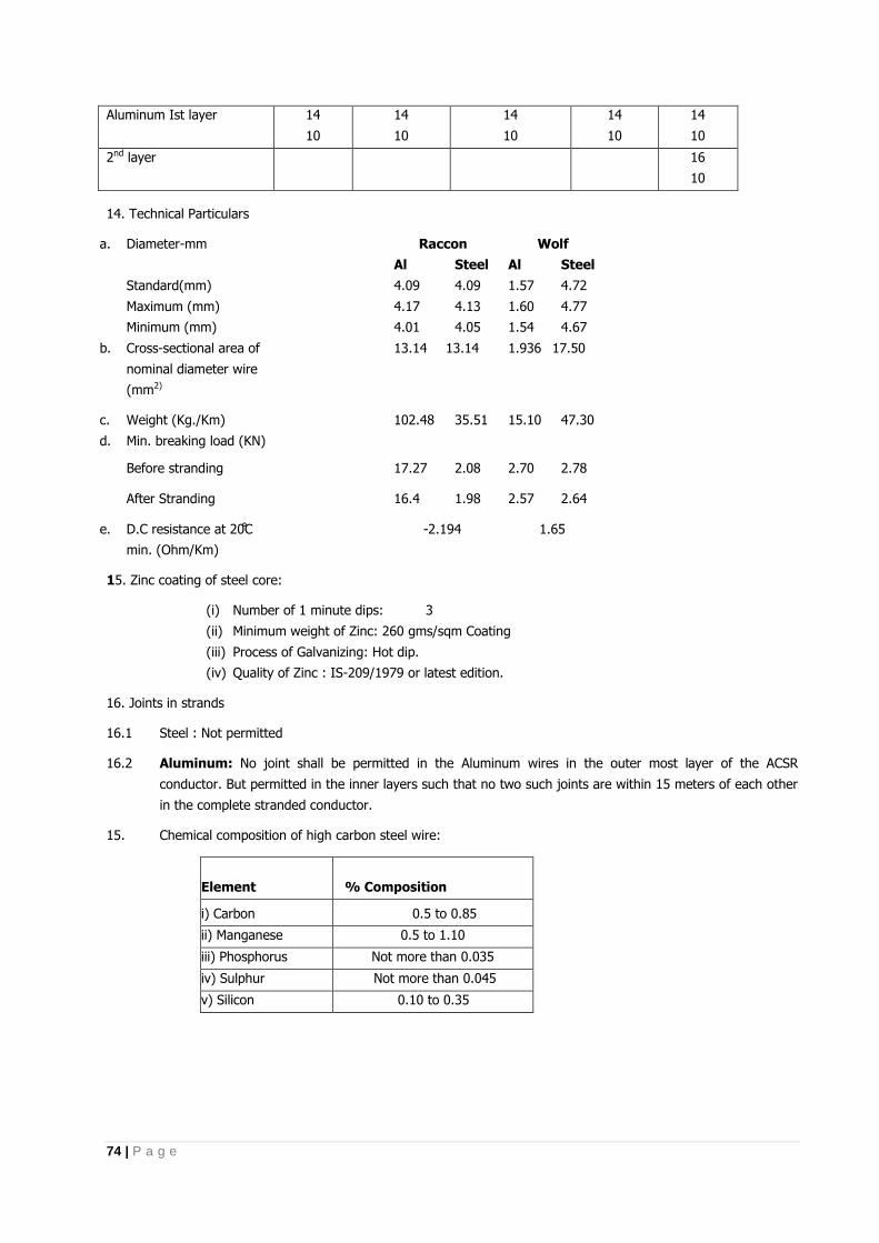
74 | P a g e
Aluminum Ist layer 14
10
14
10
14
10
14
10
14
10
2nd layer
16
10
14. Technical Particulars
a. Diameter-mm
Standard(mm)
Maximum (mm)
Minimum (mm)
Raccon Wolf
Al Steel Al Steel
4.09 4.09 1.57 4.72
4.17 4.13 1.60 4.77
4.01 4.05 1.54 4.67
b. Cross-sectional area of
nominal diameter wire
(mm2)
13.14 13.14 1.936 17.50
c. Weight (Kg./Km) 102.48 35.51 15.10 47.30
d. Min. breaking load (KN)
Before stranding 17.27 2.08 2.70 2.78
After Stranding 16.4 1.98 2.57 2.64
e. D.C resistance at C
min. (Ohm/Km)
-2.194 1.65
15. Zinc coating of steel core:
(i) Number of 1 minute dips: 3
(ii) Minimum weight of Zinc: 260 gms/sqm Coating
(iii) Process of Galvanizing: Hot dip.
(iv) Quality of Zinc : IS-209/1979 or latest edition.
16. Joints in strands
16.1 Steel : Not permitted
16.2 Aluminum: No joint shall be permitted in the Aluminum wires in the outer most layer of the ACSR
conductor. But permitted in the inner layers such that no two such joints are within 15 meters of each other
in the complete stranded conductor.
15. Chemical composition of high carbon steel wire:
Element % Composition
i) Carbon 0.5 to 0.85
ii) Manganese 0.5 to 1.10
iii) Phosphorus Not more than 0.035
iv) Sulphur Not more than 0.045
v) Silicon 0.10 to 0.35
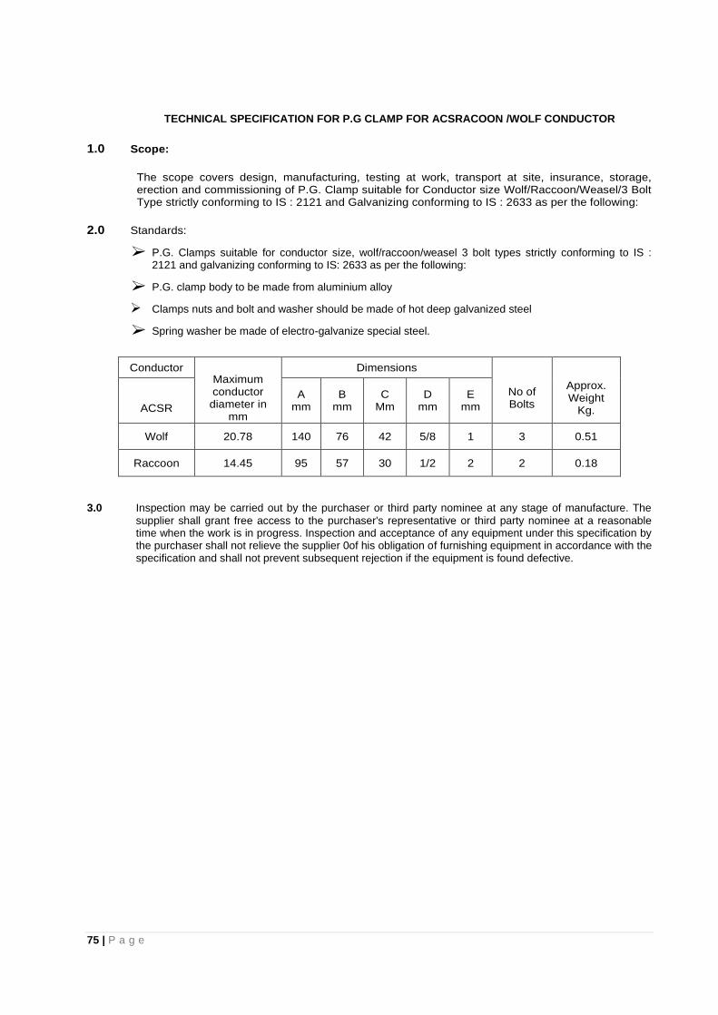
75 | P a g e
TECHNICAL SPECIFICATION FOR P.G CLAMP FOR ACSRACOON /WOLF CONDUCTOR
1.0 Scope:
The scope covers design, manufacturing, testing at work, transport at site, insurance, storage, erection and commissioning of P.G. Clamp suitable for Conductor size Wolf/Raccoon/Weasel/3 Bolt Type strictly conforming to IS : 2121 and Galvanizing conforming to IS : 2633 as per the following:
2.0 Standards:
P.G. Clamps suitable for conductor size, wolf/raccoon/weasel 3 bolt types strictly conforming to IS : 2121 and galvanizing conforming to IS: 2633 as per the following:
P.G. clamp body to be made from aluminium alloy
Clamps nuts and bolt and washer should be made of hot deep galvanized steel
Spring washer be made of electro-galvanize special steel.
Conductor Maximum conductor diameter in
mm
Dimensions
No of Bolts
Approx. Weight
Kg. ACSR
A mm
B mm
C Mm
D mm
E mm
Wolf 20.78 140 76 42 5/8 1 3 0.51
Raccoon 14.45 95 57 30 1/2 2 2 0.18
3.0 Inspection may be carried out by the purchaser or third party nominee at any stage of manufacture. The
supplier shall grant free access to the purchaser's representative or third party nominee at a reasonable time when the work is in progress. Inspection and acceptance of any equipment under this specification by the purchaser shall not relieve the supplier 0of his obligation of furnishing equipment in accordance with the specification and shall not prevent subsequent rejection if the equipment is found defective.

76 | P a g e
TECHNICAL SPECIFICATION FOR COMPOSITE POLYMERIC INSULATORS FOR USE IN 11KV AND 33 KV SYSTEMS
1.0 SCOPE
This section covers the specifications for design, manufacture, shop & laboratory testing, supply before dispatch & supply of Composite polymeric insulator consisting of a load bearing cylindrical insulating solid core consisting of fibers usually glass in a resin based matrix , a housing (outside the insulating core ) made of polymeric material and end fittings permanently attached to the insulating core for A.C system with a nominal voltage greater than 1000 V for overhead lines. The Composite insulator shall be pin insulator for straight line location and Long rod insulator for conductors in tension application at angle/ cut point. The composite tension / suspension insulator shall be of suitable for boll and socket type or tongue & Clevis type fittings.
1. APPLICABLE STANDARD: Following international standard are applicable for composite polymeric
insulation with latest amendment and other relevant national & internal standard also been application with latest amendment. The composite insulators including the end fitting connection shall be of standard design suitable for use with the hardware fittings of any make conforming to relevant IEC/IS standards.
Sl. No.
Indian Standard
Title International Standard
1. IEC
Definition, test method and acceptance criteria for composite insulators for a. c. overhead lines above.
IEC:61109
2. IS:731
Porcelain insulators for overhead power lines with a nominal voltage greater than 1000V
IEC:60383
3. IS:2071 Methods of High voltage testing IEC:60060-1
4.
IS:2486
Specification for insulator fitting for overhead power lines with a nominal voltage greater than 1000V General Requirements and tests Dimensional Requirements locking devices.
IEC:60120 IEC:60372
5.
Thermal mechanical performances test on string insulator units.
IEC:60575
6. IS:13134
Guide for the selection of insulators in respect of polluted conditions.
IEC:60815
7.
Characteristics of string insulator units of the long rod type.
IEC:60433
8. Hydrophobicity classification STRI GUIDE 1.92/1
9.
Radio interference characteristics of overhead power lines and high-voltage equipment
CISPR:18-2 PART2
10. IS:8263 Methods of RI test of HV insulators IEC:60437
11.
Standard for insulators- composite distribution dead end type
ANSI c29.13-2000
12. IS:4759
Hot dip Zinc coatings on structural steel & other allied products.
ISO:1459 ISO:1461
13. IS:2629
Recommendation of weight for hot, dip galvanization for iron and steel
ISO:1461(E)
14. IS:6745
Determination of weight of Zinc coatings on zinc coated iron and steel articles
ISO:1460
15. IS:3203
Method of testing of local thickness of electroplated coating
ISO:2178
16. IS:2633 Testing of uniformity of coating of zinc coated articles
17. Standard specification for glass fiber standards ASTM D 578-05
18.
Standard test method for compositional analysis of thermo gravimetry
ASTME 1131- 03
19. IS:4699 Specification for refined secondary Zinc
2. SERVICE CONDITION
Maximum ambient temperature : *480 C
Minimum ambient temperature : - 50
C Relative humidity : 0 to 100% The size of composite insulator, minimum creepage distance and mechanical strength along with hardware fittings shall be as follows.
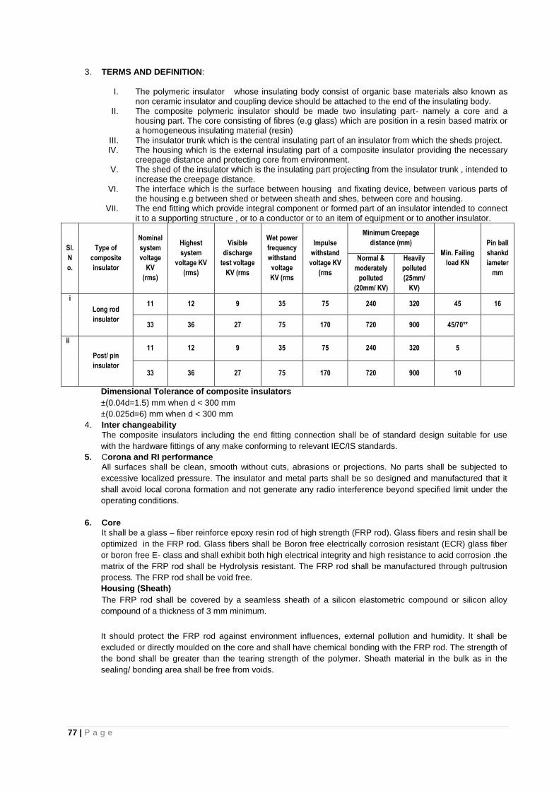
77 | P a g e
3. TERMS AND DEFINITION:
I. The polymeric insulator whose insulating body consist of organic base materials also known as
non ceramic insulator and coupling device should be attached to the end of the insulating body. II. The composite polymeric insulator should be made two insulating part- namely a core and a
housing part. The core consisting of fibres (e.g glass) which are position in a resin based matrix or a homogeneous insulating material (resin)
III. The insulator trunk which is the central insulating part of an insulator from which the sheds project. IV. The housing which is the external insulating part of a composite insulator providing the necessary
creepage distance and protecting core from environment. V. The shed of the insulator which is the insulating part projecting from the insulator trunk , intended to
increase the creepage distance. VI. The interface which is the surface between housing and fixating device, between various parts of
the housing e.g between shed or between sheath and shes, between core and housing. VII. The end fitting which provide integral component or formed part of an insulator intended to connect
it to a supporting structure , or to a conductor or to an item of equipment or to another insulator.
Sl.
N
o.
Type of
composite
insulator
Nominal
system
voltage
KV
(rms)
Highest
system
voltage KV
(rms)
Visible
discharge
test voltage
KV (rms
Wet power
frequency
withstand
voltage
KV (rms
Impulse
withstand
voltage KV
(rms
Minimum Creepage
distance (mm)
Min. Failing
load KN
Pin ball
shankd
iameter
mm
Normal &
moderately
polluted
(20mm/ KV)
Heavily
polluted
(25mm/
KV)
i
Long rod
insulator
11 12 9 35 75 240 320 45 16
33 36 27 75 170 720 900 45/70**
ii
Post/ pin
insulator
11 12 9 35 75 240 320 5
33 36 27 75 170 720 900 10
Dimensional Tolerance of composite insulators
±(0.04d=1.5) mm when d < 300 mm
±(0.025d=6) mm when d < 300 mm
4. Inter changeability
The composite insulators including the end fitting connection shall be of standard design suitable for use
with the hardware fittings of any make conforming to relevant IEC/IS standards.
5. Corona and RI performance
All surfaces shall be clean, smooth without cuts, abrasions or projections. No parts shall be subjected to
excessive localized pressure. The insulator and metal parts shall be so designed and manufactured that it
shall avoid local corona formation and not generate any radio interference beyond specified limit under the
operating conditions.
6. Core
It shall be a glass – fiber reinforce epoxy resin rod of high strength (FRP rod). Glass fibers and resin shall be
optimized in the FRP rod. Glass fibers shall be Boron free electrically corrosion resistant (ECR) glass fiber
or boron free E- class and shall exhibit both high electrical integrity and high resistance to acid corrosion .the
matrix of the FRP rod shall be Hydrolysis resistant. The FRP rod shall be manufactured through pultrusion
process. The FRP rod shall be void free.
Housing (Sheath)
The FRP rod shall be covered by a seamless sheath of a silicon elastometric compound or silicon alloy
compound of a thickness of 3 mm minimum.
It should protect the FRP rod against environment influences, external pollution and humidity. It shall be
excluded or directly moulded on the core and shall have chemical bonding with the FRP rod. The strength of
the bond shall be greater than the tearing strength of the polymer. Sheath material in the bulk as in the
sealing/ bonding area shall be free from voids.
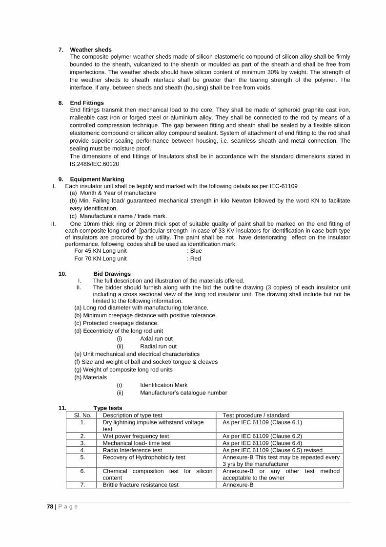
78 | P a g e
7. Weather sheds
The composite polymer weather sheds made of silicon elastomeric compound of silicon alloy shall be firmly
bounded to the sheath, vulcanized to the sheath or moulded as part of the sheath and shall be free from
imperfections. The weather sheds should have silicon content of minimum 30% by weight. The strength of
the weather sheds to sheath interface shall be greater than the tearing strength of the polymer. The
interface, if any, between sheds and sheath (housing) shall be free from voids.
8. End Fittings
End fittings transmit then mechanical load to the core. They shall be made of spheroid graphite cast iron,
malleable cast iron or forged steel or aluminium alloy. They shall be connected to the rod by means of a
controlled compression technique. The gap between fitting and sheath shall be sealed by a flexible silicon
elastomeric compound or silicon alloy compound sealant. System of attachment of end fitting to the rod shall
provide superior sealing performance between housing, i.e. seamless sheath and metal connection. The
sealing must be moisture proof.
The dimensions of end fittings of Insulators shall be in accordance with the standard dimensions stated in
IS:2486/IEC:60120
9. Equipment Marking
I. Each insulator unit shall be legibly and marked with the following details as per IEC-61109 (a) Month & Year of manufacture
(b) Min. Failing load/ guaranteed mechanical strength in kilo Newton followed by the word KN to facilitate
easy identification.
(c) Manufacture’s name / trade mark.
II. One 10mm thick ring or 20mm thick spot of suitable quality of paint shall be marked on the end fitting of each composite long rod of [particular strength in case of 33 KV insulators for identification in case both type of insulators are procured by the utility. The paint shall be not have deteriorating effect on the insulator performance, following codes shall be used as identification mark:
For 45 KN Long unit : Blue
For 70 KN Long unit : Red
10. Bid Drawings
I. The full description and illustration of the materials offered. II. The bidder should furnish along with the bid the outline drawing (3 copies) of each insulator unit
including a cross sectional view of the long rod insulator unit. The drawing shall include but not be limited to the following information.
(a) Long rod diameter with manufacturing tolerance.
(b) Minimum creepage distance with positive tolerance.
(c) Protected creepage distance.
(d) Eccentricity of the long rod unit
(i) Axial run out
(ii) Radial run out
(e) Unit mechanical and electrical characteristics
(f) Size and weight of ball and socket/ tongue & cleaves
(g) Weight of composite long rod units
(h) Materials
(i) Identification Mark
(ii) Manufacturer’s catalogue number
11. Type tests
Sl. No. Description of type test Test procedure / standard
1. Dry lightning impulse withstand voltage test
As per IEC 61109 (Clause 6.1)
2. Wet power frequency test As per IEC 61109 (Clause 6.2)
3. Mechanical load- time test As per IEC 61109 (Clause 6.4)
4. Radio Interference test As per IEC 61109 (Clause 6.5) revised
5. Recovery of Hydrophobicity test Annexure-B This test may be repeated every 3 yrs by the manufacturer
6. Chemical composition test for silicon content
Annexure-B or any other test method acceptable to the owner
7. Brittle fracture resistance test Annexure-B
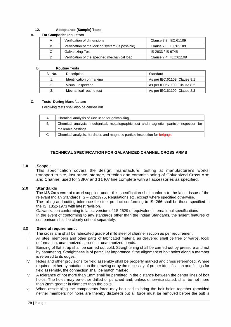
79 | P a g e
12. Acceptance (Sample) Tests
A. For Composite Insulators
A Verification of dimensions Clause 7.2 IEC:61109
B Verification of the locking system ( if possible) Clause 7.3 IEC:61109
C Galvanizing Test IS 2633 / IS 6745
D Verification of the specified mechanical load Clause 7.4 IEC:61109
B. Routine Tests
Sl. No. Description Standard
1. Identification of marking As per IEC:61109 Clause 8.1
2. Visual Inspection As per IEC:61109 Clause 8.2
3. Mechanical routine test As per IEC:61109 Clause 8.3
C. Tests During Manufacture
Following tests shall also be carried our
A Chemical analysis of zinc used for galvanizing
B Chemical analysis, mechanical, metallographic test and magnetic particle inspection for
malleable castings
C Chemical analysis, hardness and magnetic particle inspection for forigngs
TECHNICAL SPECIFICATION FOR GALVANIZED CHANNEL CROSS ARMS
1.0 Scope :
This specification covers the design, manufacture, testing at manufacturer's works, transport to site, insurance, storage, erection and commissioning of Galvanized Cross Arm and Channel used for 33KV and 11 KV line complete with all accessories as specified.
2.0 Standards
The M.S Cross Arm and channel supplied under this specification shall conform to the latest issue of the relevant Indian Standards IS – 226:1975, Regulations etc. except where specified otherwise. The rolling and cutting tolerance for steel product conforming to IS: 266 shall be those specified in the IS: 1852-1973 with latest revision. Galvanization conforming to latest version of 1S:2629 or equivalent international specifications
In the event of conforming to any standards other than the Indian Standards, the salient features of comparison shall be clearly set out separately.
3.0 General requirement :
i. The cross arm shall be fabricated grade of mild steel of channel section as per requirement.
ii. All steel members and other parts of fabricated material as delivered shall be free of warps, local deformation, unauthorized splices, or unauthorized bends.
iii. Bending of flat strap shall be carried out cold. Straightening shall be carried out by pressure and not by hammering. Straightness is of particular importance if the alignment of bolt holes along a member is referred to its edges.
iv. Holes and other provisions for field assembly shall be properly marked and cross referenced. Where required, either by notations on the drawing or by the necessity of proper identification and fittings for field assembly, the connection shall be match marked.
v. A tolerance of not more than 1mm shall be permitted in the distance between the center lines of bolt holes. The holes may be either drilled or punched and, unless otherwise stated, shall be not more than 2mm greater in diameter than the bolts.
vi. When assembling the components force may be used to bring the bolt holes together (provided neither members nor holes are thereby distorted) but all force must be removed before the bolt is
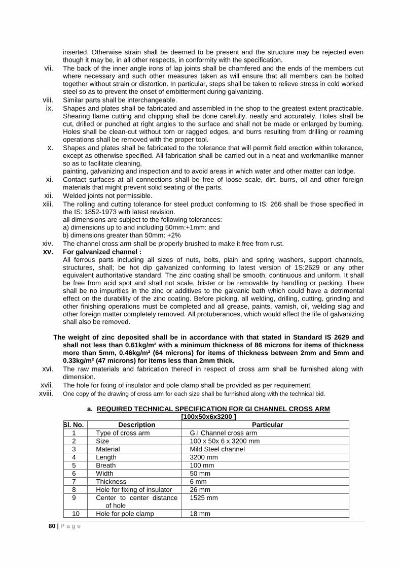
80 | P a g e
inserted. Otherwise strain shall be deemed to be present and the structure may be rejected even though it may be, in all other respects, in conformity with the specification.
vii. The back of the inner angle irons of lap joints shall be chamfered and the ends of the members cut where necessary and such other measures taken as will ensure that all members can be bolted together without strain or distortion. In particular, steps shall be taken to relieve stress in cold worked steel so as to prevent the onset of embitterment during galvanizing.
viii. Similar parts shall be interchangeable.
ix. Shapes and plates shall be fabricated and assembled in the shop to the greatest extent practicable. Shearing flame cutting and chipping shall be done carefully, neatly and accurately. Holes shall be cut, drilled or punched at right angles to the surface and shall not be made or enlarged by burning. Holes shall be clean-cut without torn or ragged edges, and burrs resulting from drilling or reaming operations shall be removed with the proper tool.
x. Shapes and plates shall be fabricated to the tolerance that will permit field erection within tolerance, except as otherwise specified. All fabrication shall be carried out in a neat and workmanlike manner so as to facilitate cleaning, painting, galvanizing and inspection and to avoid areas in which water and other matter can lodge.
xi. Contact surfaces at all connections shall be free of loose scale, dirt, burrs, oil and other foreign materials that might prevent solid seating of the parts.
xii. Welded joints not permissible.
xiii. The rolling and cutting tolerance for steel product conforming to IS: 266 shall be those specified in the IS: 1852-1973 with latest revision.
all dimensions are subject to the following tolerances: a) dimensions up to and including 50mm:+1mm: and b) dimensions greater than 50mm: +2%
xiv. The channel cross arm shall be properly brushed to make it free from rust.
xv. For galvanized channel : All ferrous parts including all sizes of nuts, bolts, plain and spring washers, support channels,
structures, shall; be hot dip galvanized conforming to latest version of 1S:2629 or any other equivalent authoritative standard. The zinc coating shall be smooth, continuous and uniform. It shall be free from acid spot and shall not scale, blister or be removable by handling or packing. There shall be no impurities in the zinc or additives to the galvanic bath which could have a detrimental effect on the durability of the zinc coating. Before picking, all welding, drilling, cutting, grinding and other finishing operations must be completed and all grease, paints, varnish, oil, welding slag and other foreign matter completely removed. All protuberances, which would affect the life of galvanizing shall also be removed.
The weight of zinc deposited shall be in accordance with that stated in Standard IS 2629 and
shall not less than 0.61kg/m² with a minimum thickness of 86 microns for items of thickness more than 5mm, 0.46kg/m² (64 microns) for items of thickness between 2mm and 5mm and 0.33kg/m² (47 microns) for items less than 2mm thick.
xvi. The raw materials and fabrication thereof in respect of cross arm shall be furnished along with dimension.
xvii. The hole for fixing of insulator and pole clamp shall be provided as per requirement.
xviii. One copy of the drawing of cross arm for each size shall be furnished along with the technical bid.
a. REQUIRED TECHNICAL SPECIFICATION FOR GI CHANNEL CROSS ARM
[100x50x6x3200 ]
Sl. No. Description Particular
1 Type of cross arm G.I Channel cross arm
2 Size 100 x 50x 6 x 3200 mm
3 Material Mild Steel channel
4 Length 3200 mm
5 Breath 100 mm
6 Width 50 mm
7 Thickness 6 mm
8 Hole for fixing of insulator 26 mm
9 Center to center distance of hole
1525 mm
10 Hole for pole clamp 18 mm
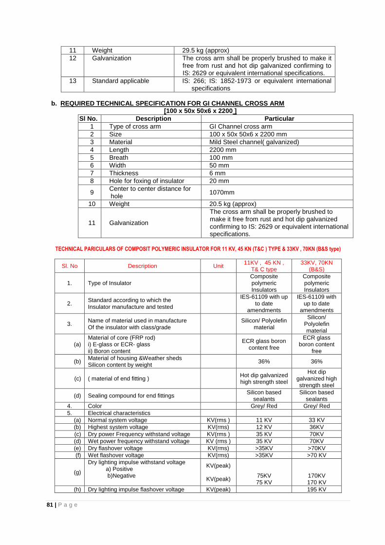
81 | P a g e
11 Weight 29.5 kg (approx)
12 Galvanization The cross arm shall be properly brushed to make it free from rust and hot dip galvanized confirming to IS: 2629 or equivalent international specifications.
13 Standard applicable IS: 266; IS: 1852-1973 or equivalent international specifications
b. REQUIRED TECHNICAL SPECIFICATION FOR GI CHANNEL CROSS ARM
[100 x 50x 50x6 x 2200 ]
Sl No. Description Particular
1 Type of cross arm GI Channel cross arm
2 Size 100 x 50x 50x6 x 2200 mm
3 Material Mild Steel channel( galvanized)
4 Length 2200 mm
5 Breath 100 mm
6 Width 50 mm
7 Thickness 6 mm
8 Hole for foxing of insulator 20 mm
9 Center to center distance for hole
1070mm
10 Weight 20.5 kg (approx)
11 Galvanization
The cross arm shall be properly brushed to make it free from rust and hot dip galvanized confirming to IS: 2629 or equivalent international specifications.
TECHNICAL PARICULARS OF COMPOSIT POLYMERIC INSULATOR FOR 11 KV, 45 KN (T&C ) TYPE & 33KV , 70KN (B&S type)
Sl. No Description Unit 11KV , 45 KN ,
T& C type 33KV, 70KN
(B&S)
1. Type of Insulator Composite polymeric Insulators
Composite polymeric Insulators
2. Standard according to which the Insulator manufacture and tested
IES-61109 with up
to date amendments
IES-61109 with up to date
amendments
3. Name of material used in manufacture Of the insulator with class/grade
Silicon/ Polyolefin
material
Silicon/ Polyolefin material
(a) Material of core (FRP rod) i) E-glass or ECR- glass ii) Boron content
ECR glass boron
content free
ECR glass boron content
free
(b) Material of housing &Weather sheds Silicon content by weight
36% 36%
(c) ( material of end fitting ) Hot dip galvanized high strength steel
Hot dip galvanized high strength steel
(d) Sealing compound for end fittings Silicon based
sealants Silicon based
sealants
4. Color Grey/ Red Grey/ Red
5. Electrical characteristics
(a) Normal system voltage KV(rms ) 11 KV 33 KV
(b) Highest system voltage KV(rms) 12 KV 36KV
(c) Dry power Frequency withstand voltage KV(rms ) 35 KV 70KV
(d) Wet power frequency withstand voltage KV (rms ) 35 KV 70KV
(e) Dry flashover voltage KV(rms) >35KV >70KV
(f) Wet flashover voltage KV(rms) >35KV >70 KV
(g)
Dry lighting impulse withstand voltage a) Positive b)Negative
KV(peak)
KV(peak)
75KV 75 KV
170KV 170 KV
(h) Dry lighting impulse flashover voltage KV(peak) 195 KV
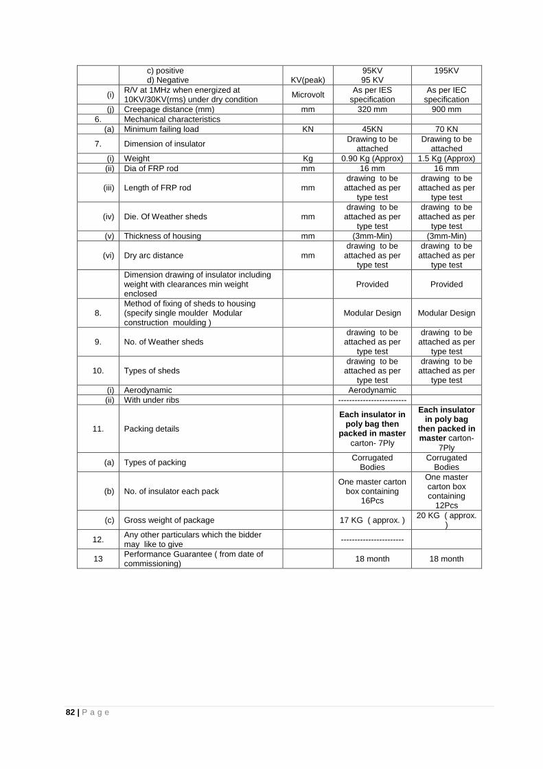
82 | P a g e
c) positive d) Negative
KV(peak)
95KV 95 KV
195KV
(i) R/V at 1MHz when energized at 10KV/30KV(rms) under dry condition
Microvolt As per IES
specification As per IEC
specification
(j) Creepage distance (mm) mm 320 mm 900 mm
6. Mechanical characteristics
(a) Minimum failing load KN 45KN 70 KN
7. Dimension of insulator Drawing to be
attached Drawing to be
attached
(i) Weight Kg 0.90 Kg (Approx) 1.5 Kg (Approx)
(ii) Dia of FRP rod mm 16 mm 16 mm
(iii) Length of FRP rod mm drawing to be
attached as per type test
drawing to be attached as per
type test
(iv) Die. Of Weather sheds mm drawing to be
attached as per type test
drawing to be attached as per
type test
(v) Thickness of housing mm (3mm-Min) (3mm-Min)
(vi) Dry arc distance mm drawing to be
attached as per type test
drawing to be attached as per
type test
Dimension drawing of insulator including weight with clearances min weight enclosed
Provided Provided
8. Method of fixing of sheds to housing (specify single moulder Modular construction moulding )
Modular Design Modular Design
9. No. of Weather sheds drawing to be
attached as per type test
drawing to be attached as per
type test
10. Types of sheds drawing to be
attached as per type test
drawing to be attached as per
type test
(i) Aerodynamic Aerodynamic
(ii) With under ribs -------------------------
11. Packing details
Each insulator in poly bag then
packed in master
carton- 7Ply
Each insulator in poly bag
then packed in master carton-
7Ply
(a) Types of packing Corrugated
Bodies Corrugated
Bodies
(b) No. of insulator each pack One master carton
box containing 16Pcs
One master carton box containing
12Pcs
(c) Gross weight of package 17 KG ( approx. ) 20 KG ( approx.
)
12. Any other particulars which the bidder may like to give
-----------------------
13 Performance Guarantee ( from date of commissioning)
18 month 18 month
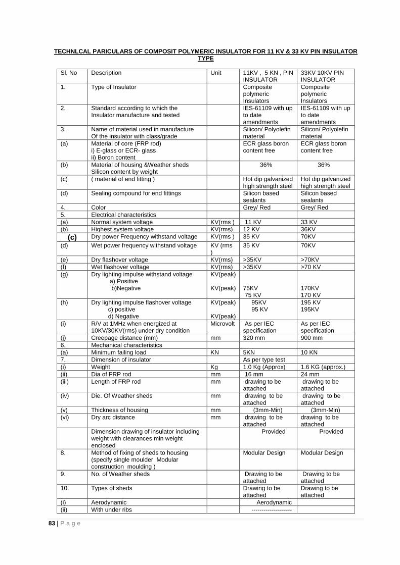
83 | P a g e
TECHNLCAL PARICULARS OF COMPOSIT POLYMERIC INSULATOR FOR 11 KV & 33 KV PIN INSULATOR TYPE
Sl. No Description Unit 11KV , 5 KN , PIN INSULATOR
33KV 10KV PIN INSULATOR
1. Type of Insulator Composite polymeric Insulators
Composite polymeric Insulators
2. Standard according to which the Insulator manufacture and tested
IES-61109 with up to date amendments
IES-61109 with up to date amendments
3. Name of material used in manufacture Of the insulator with class/grade
Silicon/ Polyolefin material
Silicon/ Polyolefin material
(a) Material of core (FRP rod) i) E-glass or ECR- glass ii) Boron content
ECR glass boron content free
ECR glass boron content free
(b) Material of housing &Weather sheds Silicon content by weight
36% 36%
(c) ( material of end fitting ) Hot dip galvanized high strength steel
Hot dip galvanized high strength steel
(d) Sealing compound for end fittings Silicon based sealants
Silicon based sealants
4. Color Grey/ Red Grey/ Red
5. Electrical characteristics
(a) Normal system voltage KV(rms ) 11 KV 33 KV
(b) Highest system voltage KV(rms) 12 KV 36KV
(c) Dry power Frequency withstand voltage KV(rms ) 35 KV 70KV
(d) Wet power frequency withstand voltage KV (rms )
35 KV 70KV
(e) Dry flashover voltage KV(rms) >35KV >70KV
(f) Wet flashover voltage KV(rms) >35KV >70 KV
(g) Dry lighting impulse withstand voltage a) Positive b)Negative
KV(peak) KV(peak)
75KV 75 KV
170KV 170 KV
(h) Dry lighting impulse flashover voltage c) positive d) Negative
KV(peak) KV(peak)
95KV 95 KV
195 KV 195KV
(i) R/V at 1MHz when energized at 10KV/30KV(rms) under dry condition
Microvolt As per IEC specification
As per IEC specification
(j) Creepage distance (mm) mm 320 mm 900 mm
6. Mechanical characteristics
(a) Minimum failing load KN 5KN 10 KN
7. Dimension of insulator As per type test
(i) Weight Kg 1.0 Kg (Approx) 1.6 KG (approx.)
(ii) Dia of FRP rod mm 16 mm 24 mm
(iii) Length of FRP rod mm drawing to be attached
drawing to be attached
(iv) Die. Of Weather sheds mm drawing to be attached
drawing to be attached
(v) Thickness of housing mm (3mm-Min) (3mm-Min)
(vi) Dry arc distance mm drawing to be attached
drawing to be attached
Dimension drawing of insulator including weight with clearances min weight enclosed
Provided Provided
8. Method of fixing of sheds to housing (specify single moulder Modular construction moulding )
Modular Design Modular Design
9. No. of Weather sheds Drawing to be attached
Drawing to be attached
10. Types of sheds Drawing to be attached
Drawing to be attached
(i) Aerodynamic Aerodynamic
(ii) With under ribs --------------------

84 | P a g e
-----
11. Packing details Each insulator in poly bag then packed in master
carton- 7Ply
Each insulator in poly bag then packed in master
carton- 7Ply
(a) Types of packing Corrugated Bodies
Corrugated Bodies
(b) No. of insulator each pack One master carton box containing 16 Pcs
One master carton box containing 16 Pcs
(c) Gross weight of package 16 KG ( approx. )
21 KG ( approx. )
12. Any other particulars which the bidder may like to give
-----------------------
13 Performance Guarantee ( from date of commissioning)
18 month 18 month
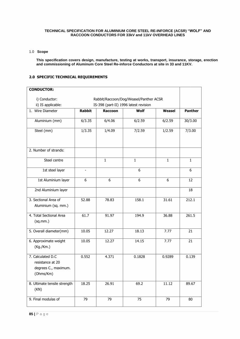
85 | P a g e
TECHNICAL SPECIFICATION FOR ALUMINIUM CORE STEEL RE-INFORCE (ACSR) “WOLF” AND RACCOON CONDUCTORS FOR 33kV and 11kV OVERHEAD LINES
1.0 Scope
This specification covers design, manufacture, testing at works, transport, insurance, storage, erection and commissioning of Aluminum Core Steel Re-inforce Conductors at site in 33 and 11KV.
2.0 SPECIFIC TECHNICAL REQUIREMENTS
CONDUCTOR:
i) Conductor: Rabbit/Raccoon/Dog/Weasel/Panther ACSR
ii) IS applicable: IS-398 (part-II) 1996 latest revision
1. Wire Diameter Rabbit Raccoon Wolf Weasel Panther
Aluminium (mm) 6/3.35 6/4.06 6/2.59 6/2.59 30/3.00
Steel (mm) 1/3.35 1/4.09 7/2.59 1/2.59 7/3.00
2. Number of strands:
Steel centre 1 1 1 1
1st steel layer - 6 6
1st Aluminium layer 6 6 6 6 12
2nd Aluminium layer 18
3. Sectional Area of
Aluminium (sq. mm.)
52.88 78.83 158.1 31.61 212.1
4. Total Sectional Area
(sq.mm.)
61.7 91.97 194.9 36.88 261.5
5. Overall diameter(mm) 10.05 12.27 18.13 7.77 21
6. Approximate weight
(Kg./Km.)
10.05 12.27 14.15 7.77 21
7. Calculated D.C
resistance at 20
degrees C., maximum.
(Ohms/Km)
0.552 4.371 0.1828 0.9289 0.139
8. Ultimate tensile strength
(KN)
18.25 26.91 69.2 11.12 89.67
9. Final modulas of 79 79 75 79 80
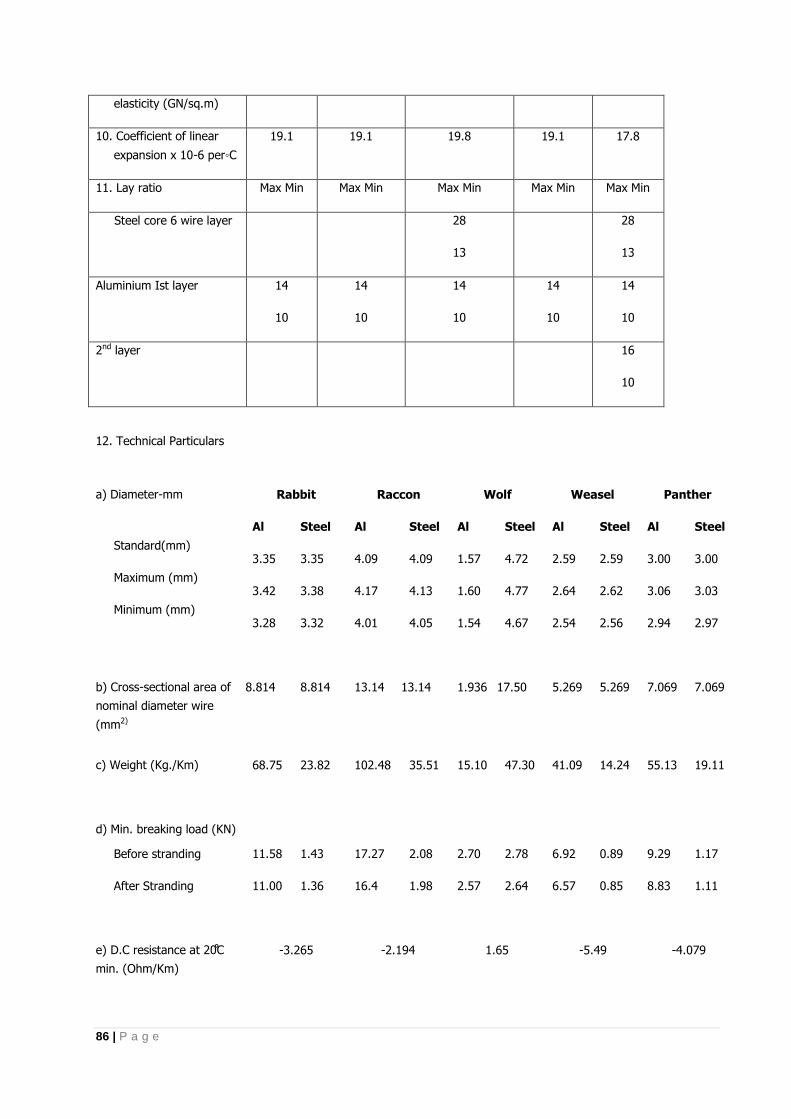
86 | P a g e
elasticity (GN/sq.m)
10. Coefficient of linear
expansion x 10-6 per◦C
19.1 19.1 19.8 19.1 17.8
11. Lay ratio Max Min Max Min Max Min Max Min Max Min
Steel core 6 wire layer 28
13
28
13
Aluminium Ist layer 14
10
14
10
14
10
14
10
14
10
2nd layer
16
10
12. Technical Particulars
a) Diameter-mm
Standard(mm)
Maximum (mm)
Minimum (mm)
Rabbit Raccon Wolf Weasel Panther
Al Steel Al Steel Al Steel Al Steel Al Steel
3.35 3.35 4.09 4.09 1.57 4.72 2.59 2.59 3.00 3.00
3.42 3.38 4.17 4.13 1.60 4.77 2.64 2.62 3.06 3.03
3.28 3.32 4.01 4.05 1.54 4.67 2.54 2.56 2.94 2.97
b) Cross-sectional area of
nominal diameter wire
(mm2)
8.814 8.814 13.14 13.14 1.936 17.50 5.269 5.269 7.069 7.069
c) Weight (Kg./Km) 68.75 23.82 102.48 35.51 15.10 47.30 41.09 14.24 55.13 19.11
d) Min. breaking load (KN)
Before stranding 11.58 1.43 17.27 2.08 2.70 2.78 6.92 0.89 9.29 1.17
After Stranding 11.00 1.36 16.4 1.98 2.57 2.64 6.57 0.85 8.83 1.11
e) D.C resistance at C
min. (Ohm/Km)
-3.265 -2.194 1.65 -5.49 -4.079

87 | P a g e
13. Zinc coating of steel core:
(v) Number of 1 minute dips: 3
(vi) Minimum weight of Zinc: 260 gms/sqm Coating
(vii) Process of Galvanizing: Hot dip.
(viii) Quality of Zinc : IS-209/1979 or latest edition.
14. Joints in strands
14.1 Steel : Not permitted
14.2 Aluminium: No joint shall be permitted in the Aluminium wires in the outer most layer of the ACSR conductor.
But permitted in the inner layers such that no two such joints are within 15 meters of each other in the complete
stranded conductor.
15. Chemical composition of high carbon steel wire:
Element % Composition
i) Carbon 0.5 to 0.85
ii) Manganese 0.5 to 1.10
iii) Phosphorus Not more than 0.035
iv) Sulphur Not more than 0.045
v) Silicon 0.10 to 0.35
16. INSPECTION
All tests and inspection shall be made at the place of manufacture. The manufacturer shall afford the inspection representing the purchaser or third party nominee all reasonable facilities without charge to satisfy him that the material is being furnished in accordance with this specification.
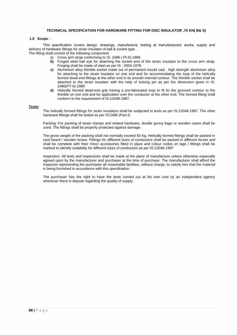
88 | P a g e
TECHNICAL SPECIFICATION FOR HARDWARE FITTING FOR DISC INSULATOR ,70 KN( B& S)
1.0 Scope: -
This specification covers design, drawings, manufacture, testing at manufacturers’ works, supply and delivery of hardware fittings for strain insulator of ball & socket type . The fitting shall consist of the following component:
a) Cross arm strap conforming to IS: 2486 ( Pt-II)-1989. b) Forged steel ball eye for attaching the socket end of the strain insulator to the cross arm strap.
Forging shall be made of steel as per IS : 2004-1978. c) Aluminium alloy thimble socket made out of permanent mould cast , high strength aluminium alloy
for attaching to the strain insulator on one end and for accommodating the loop of the helically formed dead-end fittings at the other end in its smooth internal contour. The thimble socket shall be attached to the strain insulator with the help of locking pin as per the dimension given in IS: 2486(PT-II)-1989
d) Helically formed dead-end grip having a pre-fabricated loop to fit ito the grooved contour to the thimble on one end and for application over the conductor at the other end. The formed fitting shall conform to the requirement of IS:12048-1987.
Tests:
The helically formed fittings for strain insulators shall be subjected to tests as per IS:12048-1987. The other hardware fittings shall be tested as per IS:2486 (Part-I) Packing: For packing of strain clamps and related hardware, double gunny bags or wooden cases shall be used. The fittings shall be properly protected against damage. The gross weight of the packing shall not normally exceed 50 Kg. Helically formed fittings shall be packed in card board / wooden boxes. Fittings for different sizes of conductors shall be packed in different boxes and shall be complete with their minor accessories fitted in place and colour codes on tags / fittings shall be marked to identify suitability for different sizes of conductors as per IS:12048-1987 Inspection: All tests and inspections shall be made at the place of manufacture unless otherwise especially agreed upon by the manufacturer and purchaser at the time of purchase. The manufacturer shall afford the inspector representing the purchaser all reasonable facilities, without charge, to satisfy him that the material is being furnished in accordance with this specification. The purchaser has the right to have the tests carried out at his own cost by an independent agency whenever there is dispute regarding the quality of supply.

89 | P a g e
6.8 HARDWARE FITTINGS INCLUDING SUSPENSION CLAMP ASSEMBLY (Aluminium Alloy) FOR RACCOON AND WOLF CONDUCTOR
Scope: - This specification covers design, drawings, manufacture, testing at manufacturers’ works,
supply and delivery of suspension clamp for use with Raccoon /Wolf conductors within the
state of Assam.
Standard: -The material and process adopted in the manufacture shall conform to the provision of the
following standards amended up-to-date IS: 2486 specification for Insulator fitting for overhead
power lines.
General: -The suspension clamps offered shall be made of die cast high strength aluminium alloy and
shall be suitable for use with “Raccoon and Wolf” conductors together with one set of
preformed armour rods. Suitable sheet metal liner shall be provided.
The clamp shall move easy oscillation around horizontal axis.
The bidder is to quote separately for suspension clamp: i) Envelope type ii)Bottom free centre
type design.
The single suspension clamp shall consist of the following components: -
Description Quantity Material
1. Ball hook without provision for 1 no. Forged Steel
Arching horn
2. Socket type without provision for 1set. MCI
Arching horn
Suspension clamp for AAAC 1 no Alumium alloy
Raccoon /Wolf conductors
The clamp shall be of high corrosion resistant, light in weight, have low effective power loss and small
moment of inertia enabling it to follows freely the movements of the conductor.
The suspension clamp shall also be provided with suitable socket or clevis eye for connecting it to the
insulator string.
The seat and clamping surface should be smooth, without any projections or sharp bends and should be
formed to support the conductor on long, easy curves at the comparatively sharp bends. Minimum failing
load = 70 KN.
The slip strength of suspension clamp shall not exceed 15% of the breaking load of the conductor.
Tests: -The hardware fittings shall be subjected to all the tests in accordance with relevant Indian Standard
Specifications. The purchaser shall have the right to carryout acceptance tests, in the presence of
representatives of the purchaser.
The bidder shall submit type test certificate along with the tenders.
a. The following tests shall be carried out. i. Type Test: -
(a) Slip Strength test for clamp. (b) Mechanical test for clamp & fittings (c) Heating cycle test. (d) Verification of dimensions. (e) Galvanizing / Electroplating test. (f) Visual examination test
ii. Acceptance Test:
a) Dimensional test. b) Galvanizing test. c) Mechanical test for clamp & fittings d) Electrical Resistance Test.
iii. Routine Test:
a) Visual examination test. b) Routine mechanical test.
Guaranteed Technical Particulars (GTP) and drawing specifically showing all dimensions are to
be submitted along with technical bids.
TECHNICAL SPECIFICATION FOR P.G CLAMP FOR AAA WOLF CONDUCTOR
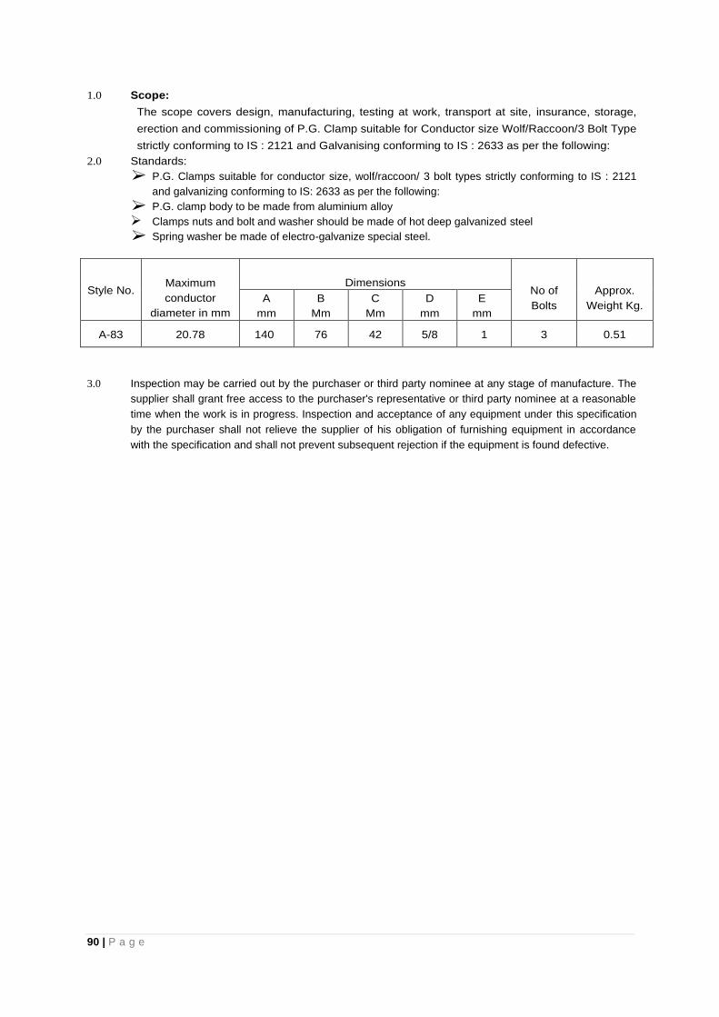
90 | P a g e
1.0 Scope:
The scope covers design, manufacturing, testing at work, transport at site, insurance, storage,
erection and commissioning of P.G. Clamp suitable for Conductor size Wolf/Raccoon/3 Bolt Type
strictly conforming to IS : 2121 and Galvanising conforming to IS : 2633 as per the following:
2.0 Standards:
P.G. Clamps suitable for conductor size, wolf/raccoon/ 3 bolt types strictly conforming to IS : 2121
and galvanizing conforming to IS: 2633 as per the following:
P.G. clamp body to be made from aluminium alloy
Clamps nuts and bolt and washer should be made of hot deep galvanized steel
Spring washer be made of electro-galvanize special steel.
Style No. Maximum
conductor
diameter in mm
Dimensions No of
Bolts
Approx.
Weight Kg. A
mm
B
Mm
C
Mm
D
mm
E
mm
A-83 20.78 140 76 42 5/8 1 3 0.51
3.0 Inspection may be carried out by the purchaser or third party nominee at any stage of manufacture. The
supplier shall grant free access to the purchaser's representative or third party nominee at a reasonable
time when the work is in progress. Inspection and acceptance of any equipment under this specification
by the purchaser shall not relieve the supplier of his obligation of furnishing equipment in accordance
with the specification and shall not prevent subsequent rejection if the equipment is found defective.
91 | P a g e
TECHNICAL SPECIFICATION FOR STAY SET (HT)
1. Scope:
This specification covers the design, manufacture testing at manufacturer's works, transport to site, insurance, storage, erection and commissioning of the Stay Sets (HT) required from the distribution lines at designated locations.
2.0 Standard:
All the materials of stay sets shall comply in all respects with the requirements of the latest edition of the relevant Indian or British Standard specification except in so far as they are modified this specification.
3.0 Design Consideration:
Stay Rods shall be Galvanized and shall be of circular Cross-section with bow, thimble, nuts and bolts. The Rods shall be threaded at one end up to a minimum of 30 cm length and shall be complete with Galvanized M.S. Anchor Plates with all necessary accessories. All parts shall be heavily galvanized.
4.0 Testing:
Type and Routine Tests should be carried on different components of each stay sets as per relevant Indian Standard specification and certified copies of the above should be submitted along with the tender.
5.0 Schedule Requirement:
Stay sets complete with Thimble bow stay Rod/Anchor plate with nuts etc. and made of Rolled mild Steel Rod and plates as per detailed given below:
A) Anchor Plate:
II) Thickness not below 5 mm. III) Size not below 300 mmX300 mm with smooth edges (for HT) IV) Well galvanized V) Materials M.S. Rolled plate VI) About 20 mm square hole at centre for locking the plate with the Anchor Rod (for HT)
A) Anchor Rod:
2.1 Length 1800 mm or above 2.2 Threaded length 30 cm or above 2.3 Diameter 18 mm or above (for HT) 2.4 Anchor plate and head: square size 30mm X 30mm with thickness 25 mm having
matching square size shank for locking the Anchor plate. 2.5 One ratched lock nuts, grooves must match the grooves at bow flange 2.6 One check nut. 2.7 Materials H.S. 2.8 Component well galvanized with extra care for the threaded portion. 2.9 Both lock and check nuts should be matching to the Anchor Rod thread such that
punching of thread after assembly at site safeguards them against removal.
B) Thimble: The match bow diameter and bend should be well galvanized. C) Bow: Rod diameter 12mm/16mm or above overall length 35cm/40cm or above. Flange with well
formed locking grooves matching the locking nut, bow ends will be riveted securely with the flange. All items to be galvanized.
6.0 Inspection:
All tests and inspections shall be carried out at the place of manufacturer unless otherwise agreed by the purchaser and the manufacturers at the time of purchase. A manufacturer shall afford the inspector representing the purchaser or third party nominee, all reasonable facilities, without charge to satisfy that the materials are being purchased as per specification. The purchaser reserves the right to have the test carried out at his cost by an independent agency, whenever there is dispute regarding the quality of the materials supplied.
92 | P a g e
7.0 Marking The equipments shall be marked with name of manufacturer, year and name of project.
TECHNICAL SPECIFICATION FOR G.I. STAY WIRE
1.0 Scope :The specification covers design, manufacturing and testing, transporting to site, insurance, storage, erection and commissioning of G.I. Stay Wire 7/10SWG and 7/14SWG.
2.0 Materials. The wire shall be manufactured from steel, made by any suitable process and shall not
contain sulphur and phosphorus exceeding 0.065 percent each.
The wires shall be coated with Zinc Grade Zn 98 of IS:209-1966 The general requirements for the supply of Galvanized stay strand shall be in accordance with IS:1387-1967
3.0 Construction
3.1 Grades: The wire shall be of Grade-I and tensile strength range 45 up to and including Kg/mm 3.2 The Galvanized stay strand shall be of 7/2 mm and 7/3.15 mm. the lay of the strands shall be of the
length of 7/2 mm and Tables-I of IS: 2141-1963. the wires shall be so stranded together that when and evenly distributed pull is applied at the end of the completed strand each wire will take equal share of the pull.
3.3 The length of the strand which may be supplied without joints in the individual wires comprising it, depend on the length of wire which may be carried by the bobbin in a normal stranding machine. The normal lengths of strand which shall be supplied without joints in the individual wires, excluding welds made in the rod before drawing shall be as given below. The lengths may be exceeded by agreement between the manufacturer and the purchaser.
Diameter of wire in strand Normal length without joints of weld 3.15 mm 1000 M 2.0 mm 3000 M
3.4 In cases where joints are permitted, they shall be made by welding of brazing joints in the same wire shall be separated by a length of not less than that shown in 3.3 and joints in different wires in a strand shall not be less than 20 M apart.
4.0 Freedom from Defects :
4.1 Each coil shall be warranted to contain no weld joint or splice other than in the rod before it is drawn and those permitted in 3.4. The wire shall be circular and shall be free scale, irregularities imperfections flaws splits and other defects. The Zinc coating shall be smooth, even the bright.
5.0 Tests:
5.1 Chemical Analysis: Unless otherwise agreed to between the purchaser and the supplier, the chemical analysis be carried out.
5.2 Tensile Test: The wire when tested in accordance with IS: 1521-1960, on gauge length of 100 mm shall have the minimum tensile strength specified in Tables 1 of IS : 2141/1968 according to the grade of the wire.
5.2.1 The tensile strength of the finalized strand shall be not less than 93% of the aggregate of the single wires.
5.3 Delivery test: The wire shall be subjected to the wrapping test in accordance with IS: 1755/1961. When wrapped eight times round its own diameter and on being subsequently strengthened the wire shall not break or split.
5.3.1 Coating test: The uniformity of Zinc coating shall be tested by the method specified in IS: 2633/1964. The wire shall withstand the number or dips as specified in IS: 4826-1968.
6.0 Marking:
6.1 Each coil shall be provided with a label, fixed firmly on the inner part of the coil, bearing 'the following information.
a. Manufacturer's name or trade mark b. Lot number and coil number c. A brief description and quality of the materials. d. Weight and e. Any other particulars specified by the purchaser f. Name of the project.
6.2 The label may also be marked with the ISI certification mark.
93 | P a g e
7.0 Inspection: The test should be carried out in presence of the inspecting officer deputed by purchaser or third
party nominee and the test should be in conformity with relevant IS .
TECHNICAL SPECIFICATION OF HT GUY INSULATOR
1.0 Scope
This specification covers design, manufacture, testing, transport to site, insurance, storage,
erection and commissioning of the strain type porcelain Guy Insulator used in distribution
overhead power lines.
2.0 Standard
This insulators shall comply with Indian Standard specification IS: 5500/1969 and as amended from time
to time except where they conflict with the requirements in this specification.
Offers conforming to any other internationally accepted standard which ensure equal or higher quality
than the standard mentioned will be acceptable.
3.0 General Requirements
4.0 This porcelain shall be sound, free from defects, thoroughly vitrified and smooth glazed.
The design of the insulator shall be such that stresses to expansion and contraction at any part of the
insulator shall not load to its deterioration.
The glaze, unless otherwise specified, shall be brown in colour. The glaze shall cover the entire
porcelain surface parts except those areas that serves as supports during firing or area otherwise
required to be left unglazed.
5.0 Insulator Characteristics
The Guy Strain Insulators shall have the electrical and mechanical characteristics as shown below:
H.T. Strain Type Porcelain Guy Insulator
1) Length 140 mm
2) Diameter 85 mm
3) Cable hole dia 25 mm + 1.5
4) Minimum failing load 88 KN
5) Creepage distance 48 mm
6) Dry one minute power frequency withstand 27 KV (rms) voltage
7) Wet one minute power frequency withstand 13 KV (rms) voltage
6.0 Test
All insulators shall comply the following test as per IS : 5300
A) Routine test:
The following shall be carried out as., routine test.
a) Visual Examination
Every insulators shall be visually examined. The insulators shall be free from physical distortion of
shape and defects, and thoroughly verified and smoothly glazed. They should be free from cracks or
any other defects likely to be prejudicial to the satisfactory performance in service.
b) Type test:
The following shall constitute the type test and those shall be conducted in the order given below:
i. Visual examination
ii. Verification of dimensions
94 | P a g e
iii. Temperature cycle test
iv. Dry one minute power frequency voltage withstand test
v. Wet one minute power frequency voltage withstand test
vi. Mechanical strength test
vii. Porosity test.
The number of samples for type test are to be agreed to between the purchaser and the supplier.
c) Acceptance Test (to be conducted in the following order)
i. Verification of Dimensions
ii. Temperature cycle test
iii. Mechanical strength test
iv. Porosity test
The number of samples for acceptance test shall be in accordance to IS: 5300.
d) Type test certificate from National Test House/ Govt. recognized institutions/ Govt. recognized
public Testing Laboratories are also to be submitted along with the offer, failing which the offer
is liable for rejection.
7.0 Marking
Each insulator shall be legibly and indelibly marked to shown the following:
a. Name of trade mark of the manufacturer
b. Year of manufacture and name of project
Marking on porcelain shall be printed and shall be applied before firing. Insulators may also be marked
with the ISI certification mark.
8.0 Inspection
All tests and inspections shall be carried out at the place of manufacturer unless otherwise agreed by
the purchaser and the manufacturer at the time of purchase. The manufacturer shall afford the inspector
representing the purchaser or the third party nominee, all reasonable facilities, without charge, to satisfy
that materials are being furnished in accordance with the specification. The purchaser reserves the right
to have the test carried out at his own cost by an independent agency whenever there is dispute
regarding the quality of materials supplied.
9.0 Drawing
Drawing specifically showing all dimensions is to be submitted along with technical bid.
6.9 TECHNICAL SPECIFICATION FOR CAST IRON EARTH PIPE
1.0 Scope
This specification covers design, manufacture, testing, transport to site, insurance, storage, erection and commissioning of the cast iron earth pipe for use on line &substation as earthing pipe
2.0 Standard
The Earth pipe shall comply with the Indian Standard specification IS: 1729/1964 and as amended from time to time except where they conflict with the specific requirements in this specification.
3.0 Manufacture
Metal used for the manufacture of pipes shall be good quality cast iron. Casting shall be stripped with all precautions necessary to avoid wrapping and shrinkage defects. They shall be free from defects which effect the use of castings. By agreement between the purchaser and the manufacturer, minor defects may be rectified. Pipes shall be such that they could be cut, drilled or machines. Bolts, buts &washers shall be made of Steel and well galvanized. The bolts shall be of 200 mm length,
95 | P a g e
16 mm diameter with 2(two) nos. plain washers, one locknut &one check nut. Threaded length of the bolts should be 50 mm.
4.0 Sizes
Dimensions of pipe &socket shall be conform to the sizes shown below and as per drawing enclosed:
Nominal length of the pipe with socket 1800 mm Nominal diameter of pipe 100 mm External diameter of pipe 110 mm Thickness of pipe 5 mm Projection of spigot bead 3 mm Width of spigot bead 15 mm Internal dia of socket 129 mm Thickness of socket 6 mm Internal depth of socket 70 mm Internal Radius of socket 5 mm Width of grooves of socket 10 mm External dia of grooves socket 155 mm Depth of grooves of socket 5 mm Nominal weight of pipe (Exclusive of ear) 21.67 Kg
5.0 Tolerance
The Tolerance of the 100 mm nominal diameter pipe shall be ±3.5 mm The Tolerance of pipe thickness shall be - 15 percent The Tolerance of length of the pipe shall be - ± 20mm The Tolerance of weight of the pipe shall be - 10 Percent
Pipes weighing more than the nominal weight may be accepted provided they comply in every other respect with the requirements of this standard.
6.0 TEST
7.1 Hammer test: Each pipe when tested for soundness by striking with a light hand hammer shall emit a
clear ringing sound.
7.2 Hydraulic test : If so required by the purchaser, pipe shall be tested hydraulically at a pressure of 0.4 kg/cm
2without showing any sign of leakage, sweating or other defect of any kind. The pressure shall be
applied internally and shall be maintained for not less than 15 seconds. The tests shall be conducted before coating of pipe.
8.0 Inspection
All tests and inspection shall be carried out at the place of manufacturers unless otherwise agreed by the purchaser and the manufacturer at the time of purchase. A manufacturer shall afford the inspector representing the purchaser or third party nominee all reasonable facilities without charge to satisfy that the materials are being purchased as per specification. The purchaser reserves the right to have the test carried out at his cost by an independent agency, whenever there is dispute regarding the quality of materials supplied. All incoming consignment shall be checked at stores.
9.0 Coating
Normally pipes, unless specially ordered, shall be supplied free of coating on surfaces.
10.0 Marking
Each pipe shall have the Trade mark of the manufacturer and nominal size suitably marked on it. The pipe marked with the ISI certificate mark, shall be preferred. The equipments shall be marked with name of manufacturer, year and name of project.
96 | P a g e
TECHNICAL SPECIFICATION FOR G.I. WIRE
1.0 Scope This specification covers the manufacturing, testing at works, transport to site, insurance,
storage, erection and commissioning of Galvanized Iron Wire of sizes 4 mm and 5 mm diameter.
2.0 General requirements It relating to the supply of mild steel wire shall be as per IS: 1387/1967 and
the wire shall be drawn from the wire rods conforming to IS: 7887/1975.
The requirements for chemical composition for the wires shall conform to IS:7887/1975.
Mild steel wire for General Engineering purpose shall be of following sizes:
I) 4mm - diameter (8 SWG)
II) 5mm - diameter (6 SWG)
Tolerance permitted on the diameter of wire shall be as per Table -1 of IS:280/1978.
3.0 Climatic Conditions The cross arms should be suitable for the climatic condition mentioned In these
bidding documents:
4.0 Mechanical Properties
4.1 Tensile Test: Tensile strength of wire when tested in accordance with IS:
1521-1972, shall be within the limits given in Table-2 of IS: 280/1978.
4.2 Wrapping Test: Wires shall be subjected wrapping test in accordance with IS: 1755-1961. The wire shall
withstand without breaking or splitting. being wrapped eight times round its own diameter and
subsequently straightened.
Surface finish
a. The wire shall have galvanized finishes. The galvanized coating of steel wire shall conform to the
requirements for anyone of the types of coatings given in IS: 4826-1968 as per agreement with the
purchaser.
b. The coating test for finishes other than galvanized, copper coated or tinned shall be subject to between
the purchaser and the manufacturer.
c. Unless otherwise agreed to the method of drawing representative samples of the material and the criteria
for conforming shall be as prescribed in Appendix (A) of IS: 280/1978.
d. All finished wires shall be well and cleanly drawn to the dimensions specified. The wire shall be sound,
free from splits, surface flaws, rough jagged and imperfect edges and other harmful surface defects.
e. Each coil of wire shall be suitably bound and fastened compactly and shall be protected by suitably
wrapped.
5.0 Marking Each coil of wire shall be marked legibly with the finish size of wire, lot number and trade mark
of the name of the manufacturer. The material may also be marked with the ISI certification mark and
name of the project.
6.0 INSPECTION: Inspection may be carried out by the purchaser or third party nominee at any stage of
manufacture. The supplier shall grant free access to the purchaser's representative or third party nominee
at a reasonable time when the work is in progress. Inspection and acceptance of any equipment under
this specification by the purchaser shall not relieve the supplier of his obligation of furnishing equipment in
accordance with the specification and shall not prevent subsequent rejection if the equipment is found
defective.
97 | P a g e
TECHNICAL SPECIFICATION FOR DANGER NOTICE PLATE 33 kV
1.0 SCOPE:
This specification covers Danger Notice Plates to be displayed in accordance with rule No.35 of Indian Electricity Rules, 1956.
2.0 APPLICABLE STANDARDS.
Unless otherwise modified in this specification, Danger Notice [Plates shall comply with IS:-1982 or the latest version thereof.
3.0 DIMENSIONS.
Size of Danger Notice Plates as follows are recommended For display at 33KV installation - 250 x 200 mm.
The comers of the plate shall be rounded off. The location of fixing holes as shown in Figs. 1 to 4 is provisional and can be modified to suit the requirements at site.
4.0 LETTERINGS
All letterings shall be centrally spaced. The dimensions of the letters, figures and their respective position shall be as shown in figs. 1 to 4. The size of letters in the words in each language and spacing between them shall be so chosen that these are uniformly written in the space earmarked for them.
5.0 LANGUAGES
I. Under Rule No. 35 of Indian Electricity Rules, 1956, the owner of every medium, and extra high voltage installation is required to affix permanently in a conspicuous position a danger notice in Hindi or English and in addition, in local language, with the sign of skull and bones.
II. The type and size of lettering to be done in Hindi is indicated in the specimen danger notice plates shown in fig: 2 and 4 and those in English are shown in fig. 1 and 3.
III. Adequate space has been provided in the specimen danger notice plates for having the letterings in local language for the equivalent of Danger, 33000 ‘Volts’
6.0 MATERIAL AND FINISH
The plate shall be made from mild sheet of at least 1.6 mm thick and vitreous enameled white, with letters, figures and the conventional skull and cross-bones in signal red colour (refer 1S: 5-1978) on the front side. The rear side of the plate shall also be enameled.
7.0 TESTS.
The following tests shall be carried out. i) Visual examination as per 18:2551-1982. ii) Dimensional check as per IS: 2551-1982. iii) Test for weather proofness as per IS: 8709-1977 (or its latest version).
8.0 MARKING.
Maker's name and trade mark and the purchaser's name shall be marked in such a manner and position on the plates that it does not interfere with the other information.
98 | P a g e
SECTION -7
FORM FOR
GUARANTEED TECHNICAL PARTICULARS
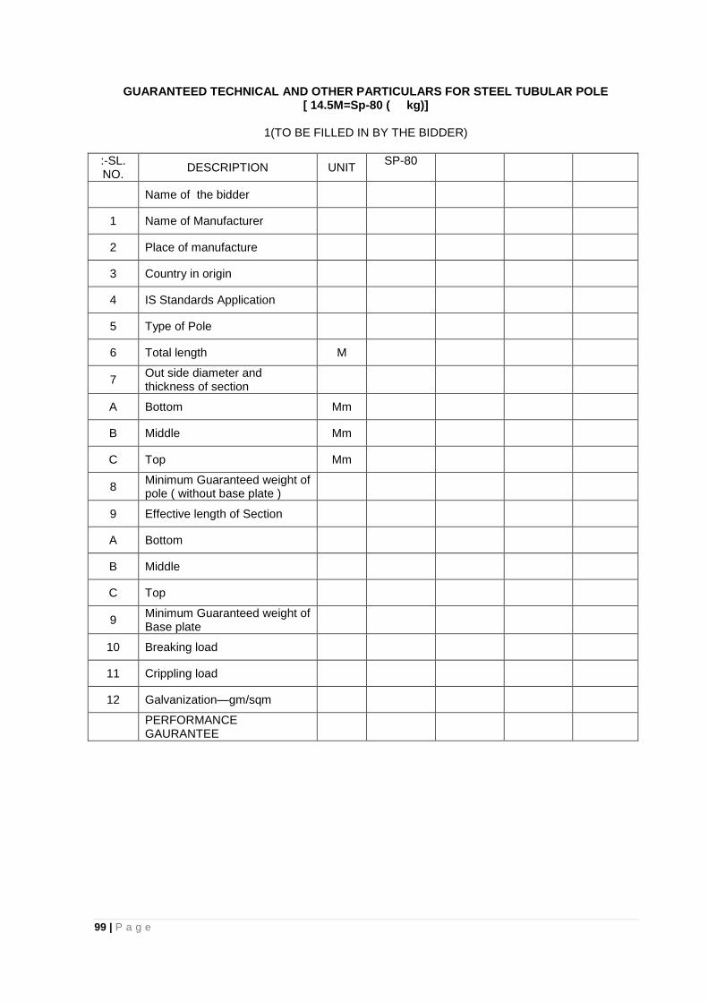
99 | P a g e
GUARANTEED TECHNICAL AND OTHER PARTICULARS FOR STEEL TUBULAR POLE [ 14.5M=Sp-80 ( kg)]
1(TO BE FILLED IN BY THE BIDDER)
:-SL. NO.
DESCRIPTION UNIT SP-80
Name of the bidder
1 Name of Manufacturer
2 Place of manufacture
3 Country in origin
4 IS Standards Application
5 Type of Pole
6 Total length M
7 Out side diameter and thickness of section
A Bottom Mm
B Middle Mm
C Top Mm
8 Minimum Guaranteed weight of pole ( without base plate )
9 Effective length of Section
A Bottom
B Middle
C Top
9 Minimum Guaranteed weight of Base plate
10 Breaking load
11 Crippling load
12 Galvanization—gm/sqm
PERFORMANCE GAURANTEE
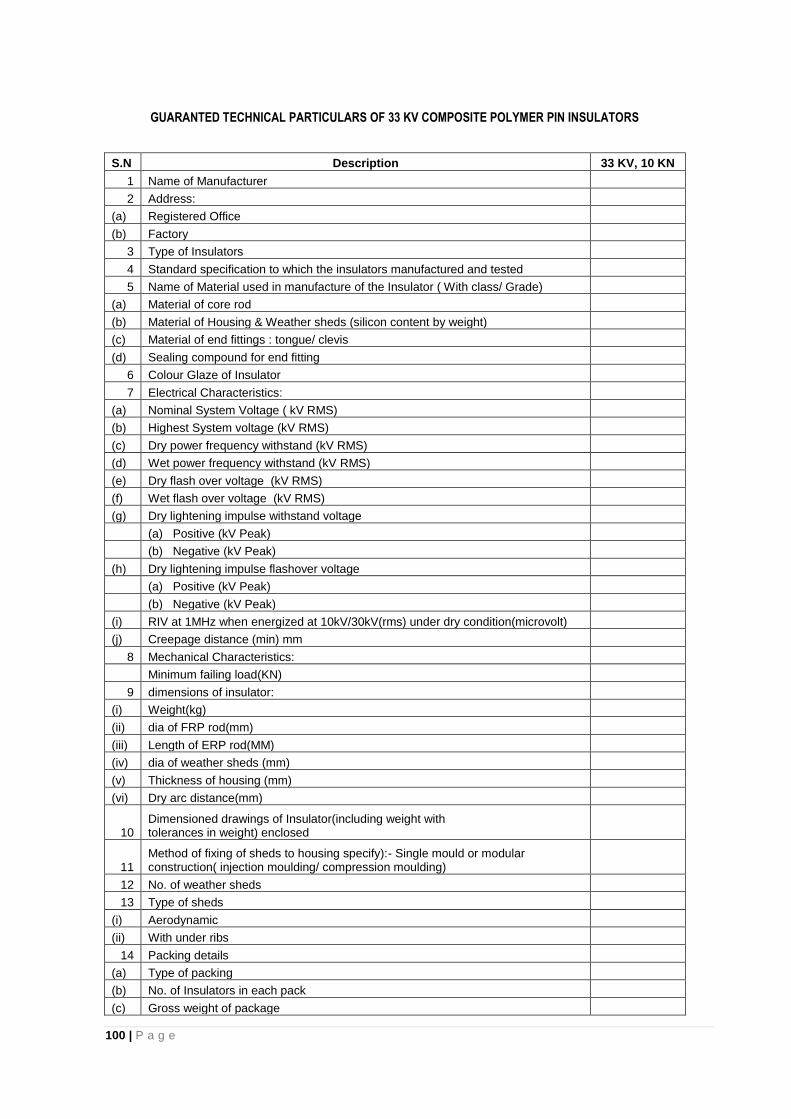
100 | P a g e
GUARANTED TECHNICAL PARTICULARS OF 33 KV COMPOSITE POLYMER PIN INSULATORS
S.N Description 33 KV, 10 KN
1 Name of Manufacturer
2 Address:
(a) Registered Office
(b) Factory
3 Type of Insulators
4 Standard specification to which the insulators manufactured and tested
5 Name of Material used in manufacture of the Insulator ( With class/ Grade)
(a) Material of core rod
(b) Material of Housing & Weather sheds (silicon content by weight)
(c) Material of end fittings : tongue/ clevis
(d) Sealing compound for end fitting
6 Colour Glaze of Insulator
7 Electrical Characteristics:
(a) Nominal System Voltage ( kV RMS)
(b) Highest System voltage (kV RMS)
(c) Dry power frequency withstand (kV RMS)
(d) Wet power frequency withstand (kV RMS)
(e) Dry flash over voltage (kV RMS)
(f) Wet flash over voltage (kV RMS)
(g) Dry lightening impulse withstand voltage
(a) Positive (kV Peak)
(b) Negative (kV Peak)
(h) Dry lightening impulse flashover voltage
(a) Positive (kV Peak)
(b) Negative (kV Peak)
(i) RIV at 1MHz when energized at 10kV/30kV(rms) under dry condition(microvolt)
(j) Creepage distance (min) mm
8 Mechanical Characteristics:
Minimum failing load(KN)
9 dimensions of insulator:
(i) Weight(kg)
(ii) dia of FRP rod(mm)
(iii) Length of ERP rod(MM)
(iv) dia of weather sheds (mm)
(v) Thickness of housing (mm)
(vi) Dry arc distance(mm)
10 Dimensioned drawings of Insulator(including weight with tolerances in weight) enclosed
11 Method of fixing of sheds to housing specify):- Single mould or modular construction( injection moulding/ compression moulding)
12 No. of weather sheds
13 Type of sheds
(i) Aerodynamic
(ii) With under ribs
14 Packing details
(a) Type of packing
(b) No. of Insulators in each pack
(c) Gross weight of package
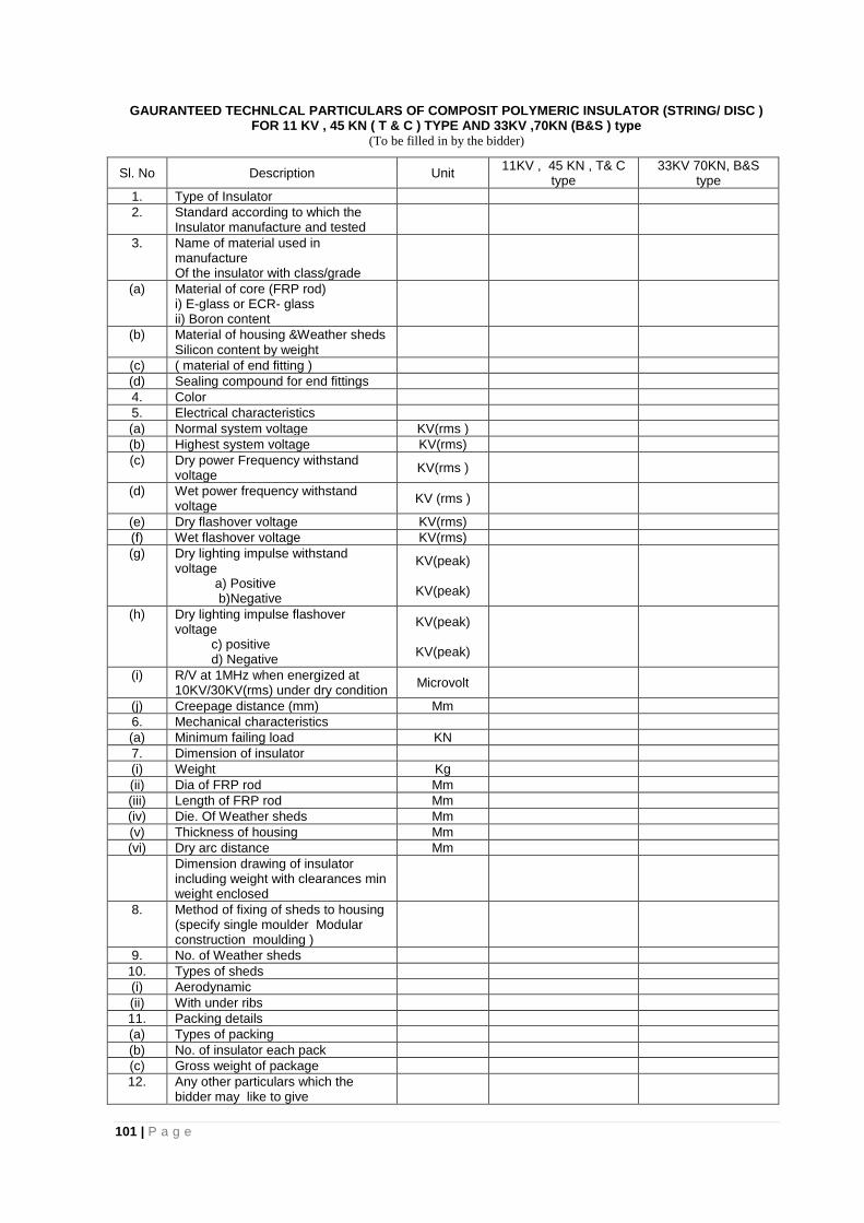
101 | P a g e
GAURANTEED TECHNLCAL PARTICULARS OF COMPOSIT POLYMERIC INSULATOR (STRING/ DISC ) FOR 11 KV , 45 KN ( T & C ) TYPE AND 33KV ,70KN (B&S ) type
(To be filled in by the bidder)
Sl. No Description Unit 11KV , 45 KN , T& C
type 33KV 70KN, B&S
type
1. Type of Insulator
2. Standard according to which the Insulator manufacture and tested
3. Name of material used in manufacture Of the insulator with class/grade
(a) Material of core (FRP rod) i) E-glass or ECR- glass ii) Boron content
(b) Material of housing &Weather sheds Silicon content by weight
(c) ( material of end fitting )
(d) Sealing compound for end fittings
4. Color
5. Electrical characteristics
(a) Normal system voltage KV(rms )
(b) Highest system voltage KV(rms)
(c) Dry power Frequency withstand voltage
KV(rms )
(d) Wet power frequency withstand voltage
KV (rms )
(e) Dry flashover voltage KV(rms)
(f) Wet flashover voltage KV(rms)
(g) Dry lighting impulse withstand voltage a) Positive b)Negative
KV(peak)
KV(peak)
(h) Dry lighting impulse flashover voltage c) positive d) Negative
KV(peak)
KV(peak)
(i) R/V at 1MHz when energized at 10KV/30KV(rms) under dry condition
Microvolt
(j) Creepage distance (mm) Mm
6. Mechanical characteristics
(a) Minimum failing load KN
7. Dimension of insulator
(i) Weight Kg
(ii) Dia of FRP rod Mm
(iii) Length of FRP rod Mm
(iv) Die. Of Weather sheds Mm
(v) Thickness of housing Mm
(vi) Dry arc distance Mm
Dimension drawing of insulator including weight with clearances min weight enclosed
8. Method of fixing of sheds to housing (specify single moulder Modular construction moulding )
9. No. of Weather sheds
10. Types of sheds
(i) Aerodynamic
(ii) With under ribs
11. Packing details
(a) Types of packing
(b) No. of insulator each pack
(c) Gross weight of package
12. Any other particulars which the bidder may like to give
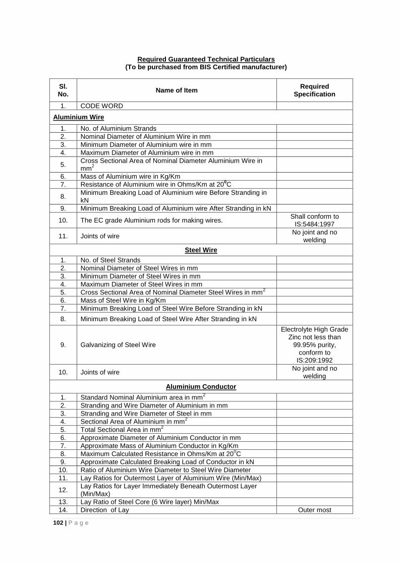
102 | P a g e
Required Guaranteed Technical Particulars
(To be purchased from BIS Certified manufacturer)
Sl. No.
Name of Item Required
Specification
1. CODE WORD
Aluminium Wire
1. No. of Aluminium Strands
2. Nominal Diameter of Aluminium Wire in mm
3. Minimum Diameter of Aluminium wire in mm
4. Maximum Diameter of Aluminium wire in mm
5. Cross Sectional Area of Nominal Diameter Aluminium Wire in mm
2
6. Mass of Aluminium wire in Kg/Km
7. Resistance of Aluminium wire in Ohms/Km at 200C
8. Minimum Breaking Load of Aluminium wire Before Stranding in kN
9. Minimum Breaking Load of Aluminium wire After Stranding in kN
10. The EC grade Aluminium rods for making wires. Shall conform to
IS:5484:1997
11. Joints of wire No joint and no
welding
Steel Wire
1. No. of Steel Strands
2. Nominal Diameter of Steel Wires in mm
3. Minimum Diameter of Steel Wires in mm
4. Maximum Diameter of Steel Wires in mm
5. Cross Sectional Area of Nominal Diameter Steel Wires in mm2
6. Mass of Steel Wire in Kg/Km
7. Minimum Breaking Load of Steel Wire Before Stranding in kN
8. Minimum Breaking Load of Steel Wire After Stranding in kN
9. Galvanizing of Steel Wire
Electrolyte High Grade Zinc not less than
99.95% purity, conform to
IS:209:1992
10. Joints of wire No joint and no
welding
Aluminium Conductor
1. Standard Nominal Aluminium area in mm2
2. Stranding and Wire Diameter of Aluminium in mm
3. Stranding and Wire Diameter of Steel in mm
4. Sectional Area of Aluminium in mm2
5. Total Sectional Area in mm2
6. Approximate Diameter of Aluminium Conductor in mm
7. Approximate Mass of Aluminium Conductor in Kg/Km
8. Maximum Calculated Resistance in Ohms/Km at 200C
9. Approximate Calculated Breaking Load of Conductor in kN
10. Ratio of Aluminium Wire Diameter to Steel Wire Diameter
11. Lay Ratios for Outermost Layer of Aluminium Wire (Min/Max)
12. Lay Ratios for Layer Immediately Beneath Outermost Layer (Min/Max)
13. Lay Ratio of Steel Core (6 Wire layer) Min/Max
14. Direction of Lay Outer most
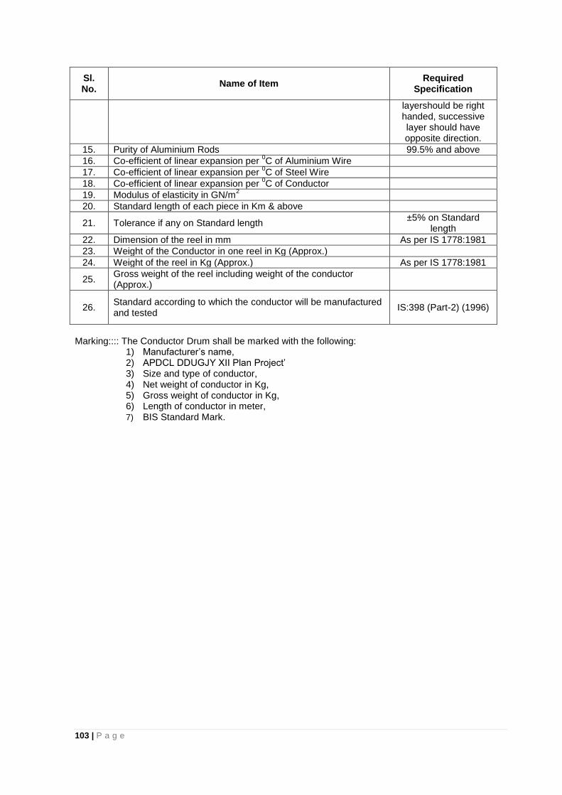
103 | P a g e
Sl. No.
Name of Item Required
Specification
layershould be right handed, successive layer should have opposite direction.
15. Purity of Aluminium Rods 99.5% and above
16. Co-efficient of linear expansion per 0C of Aluminium Wire
17. Co-efficient of linear expansion per 0C of Steel Wire
18. Co-efficient of linear expansion per 0C of Conductor
19. Modulus of elasticity in GN/m2
20. Standard length of each piece in Km & above
21. Tolerance if any on Standard length ±5% on Standard
length
22. Dimension of the reel in mm As per IS 1778:1981
23. Weight of the Conductor in one reel in Kg (Approx.)
24. Weight of the reel in Kg (Approx.) As per IS 1778:1981
25. Gross weight of the reel including weight of the conductor (Approx.)
26. Standard according to which the conductor will be manufactured and tested
IS:398 (Part-2) (1996)
Marking:::: The Conductor Drum shall be marked with the following:
1) Manufacturer’s name, 2) APDCL DDUGJY XII Plan Project’ 3) Size and type of conductor, 4) Net weight of conductor in Kg, 5) Gross weight of conductor in Kg, 6) Length of conductor in meter, 7) BIS Standard Mark.
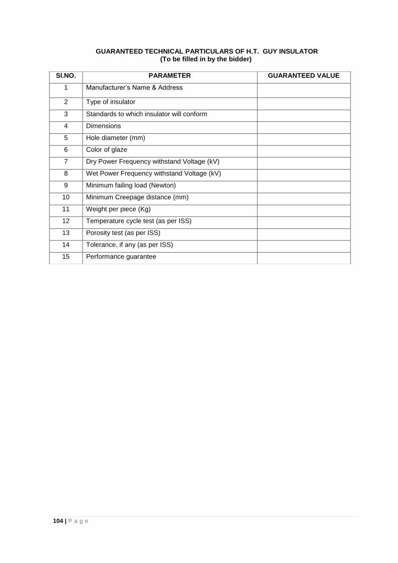
104 | P a g e
GUARANTEED TECHNICAL PARTICULARS OF H.T. GUY INSULATOR (To be filled in by the bidder)
Sl.NO. PARAMETER GUARANTEED VALUE
1 Manufacturer’s Name & Address
2 Type of insulator
3 Standards to which insulator will conform
4 Dimensions
5 Hole diameter (mm)
6 Color of glaze
7 Dry Power Frequency withstand Voltage (kV)
8 Wet Power Frequency withstand Voltage (kV)
9 Minimum failing load (Newton)
10 Minimum Creepage distance (mm)
11 Weight per piece (Kg)
12 Temperature cycle test (as per ISS)
13 Porosity test (as per ISS)
14 Tolerance, if any (as per ISS)
15 Performance guarantee
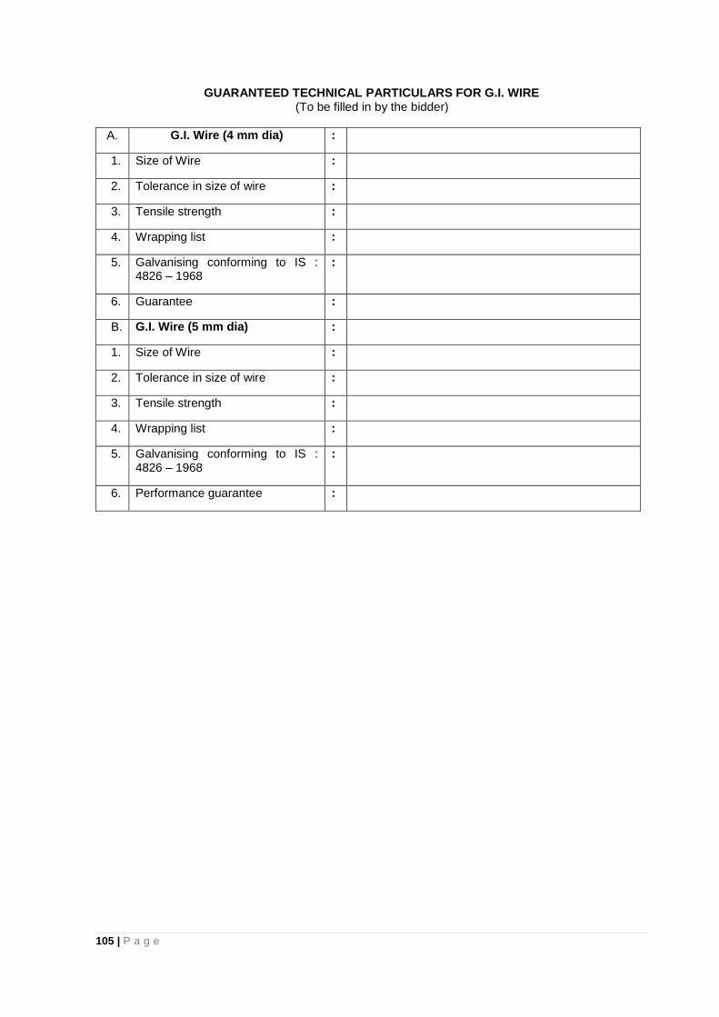
105 | P a g e
GUARANTEED TECHNICAL PARTICULARS FOR G.I. WIRE (To be filled in by the bidder)
A. G.I. Wire (4 mm dia) :
1. Size of Wire :
2. Tolerance in size of wire :
3. Tensile strength :
4. Wrapping list :
5. Galvanising conforming to IS : 4826 – 1968
:
6. Guarantee :
B. G.I. Wire (5 mm dia) :
1. Size of Wire :
2. Tolerance in size of wire :
3. Tensile strength :
4. Wrapping list :
5. Galvanising conforming to IS : 4826 – 1968
:
6. Performance guarantee :
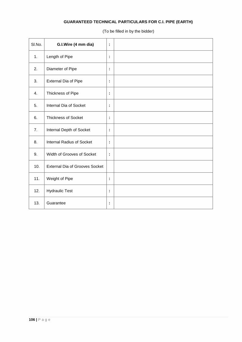
106 | P a g e
GUARANTEED TECHNICAL PARTICULARS FOR C.I. PIPE (EARTH)
(To be filled in by the bidder)
Sl.No. G.I.Wire (4 mm dia) :
1. Length of Pipe :
2. Diameter of Pipe :
3. External Dia of Pipe :
4. Thickness of Pipe :
5. Internal Dia of Socket :
6. Thickness of Socket :
7. Internal Depth of Socket :
8. Internal Radius of Socket :
9. Width of Grooves of Socket :
10. External Dia of Grooves Socket
11. Weight of Pipe :
12. Hydraulic Test :
13. Guarantee :
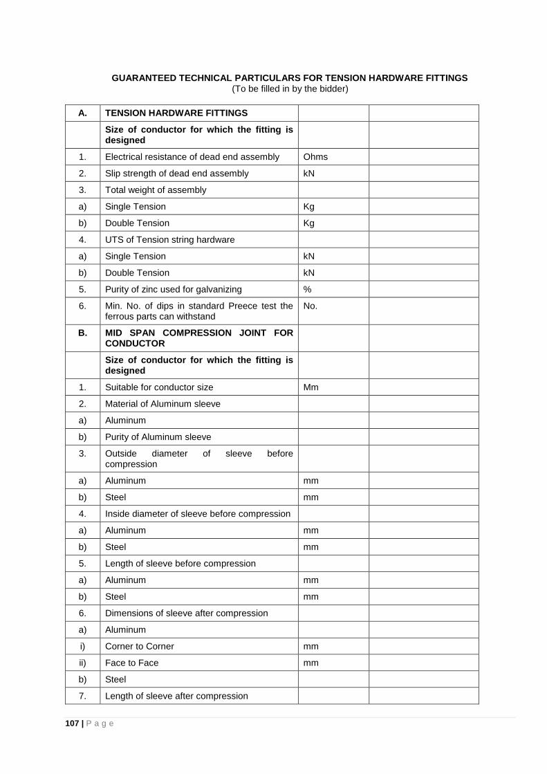
107 | P a g e
GUARANTEED TECHNICAL PARTICULARS FOR TENSION HARDWARE FITTINGS (To be filled in by the bidder)
A. TENSION HARDWARE FITTINGS
Size of conductor for which the fitting is designed
1. Electrical resistance of dead end assembly Ohms
2. Slip strength of dead end assembly kN
3. Total weight of assembly
a) Single Tension Kg
b) Double Tension Kg
4. UTS of Tension string hardware
a) Single Tension kN
b) Double Tension kN
5. Purity of zinc used for galvanizing %
6. Min. No. of dips in standard Preece test the ferrous parts can withstand
No.
B. MID SPAN COMPRESSION JOINT FOR CONDUCTOR
Size of conductor for which the fitting is designed
1. Suitable for conductor size Mm
2. Material of Aluminum sleeve
a) Aluminum
b) Purity of Aluminum sleeve
3. Outside diameter of sleeve before compression
a) Aluminum mm
b) Steel mm
4. Inside diameter of sleeve before compression
a) Aluminum mm
b) Steel mm
5. Length of sleeve before compression
a) Aluminum mm
b) Steel mm
6. Dimensions of sleeve after compression
a) Aluminum
i) Corner to Corner mm
ii) Face to Face mm
b) Steel
7. Length of sleeve after compression
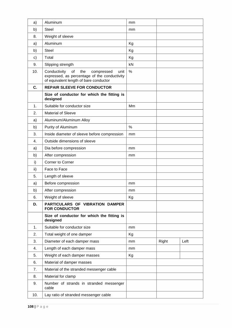
108 | P a g e
a) Aluminum mm
b) Steel mm
8. Weight of sleeve
a) Aluminum Kg
b) Steel Kg
c) Total Kg
9. Slipping strength kN
10. Conductivity of the compressed unit expressed, as percentage of the conductivity of equivalent length of bare conductor
%
C. REPAIR SLEEVE FOR CONDUCTOR
Size of conductor for which the fitting is designed
1. Suitable for conductor size Mm
2. Material of Sleeve
a) Aluminum/Aluminum Alloy
b) Purity of Aluminum %
3. Inside diameter of sleeve before compression mm
4. Outside dimensions of sleeve
a) Dia before compression mm
b) After compression mm
i) Corner to Corner
ii) Face to Face
5. Length of sleeve
a) Before compression mm
b) After compression mm
6. Weight of sleeve Kg
D. PARTICULARS OF VIBRATION DAMPER FOR CONDUCTOR
Size of conductor for which the fitting is designed
1. Suitable for conductor size mm
2. Total weight of one damper Kg
3. Diameter of each damper mass mm Right Left
4. Length of each damper mass mm
5. Weight of each damper masses Kg
6. Material of damper masses
7. Material of the stranded messenger cable
8. Material for clamp
9. Number of strands in stranded messenger cable
10. Lay ratio of stranded messenger cable
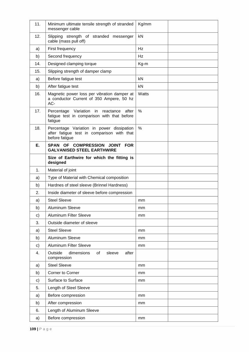
109 | P a g e
11. Minimum ultimate tensile strength of stranded messenger cable
Kg/mm
12. Slipping strength of stranded messenger cable (mass pull off)
kN
a) First frequency Hz
b) Second frequency Hz
14. Designed clamping torque Kg-m
15. Slipping strength of damper clamp
a) Before fatigue test kN
b) After fatigue test kN
16. Magnetic power loss per vibration damper at a conductor Current of 350 Ampere, 50 hz AC-
Watts
17. Percentage Variation in reactance after fatigue test in comparison with that before fatigue
%
18. Percentage Variation in power dissipation after fatigue test in comparison with that before fatigue
%
E. SPAN OF COMPRESSION JOINT FOR GALVANISED STEEL EARTHWIRE
Size of Earthwire for which the fitting is designed
1. Material of joint
a) Type of Material with Chemical composition
b) Hardnes of steel sleeve (Brinnel Hardness)
2. Inside diameter of sleeve before compression
a) Steel Sleeve mm
b) Aluminum Sleeve mm
c) Aluminum Filter Sleeve mm
3. Outside diameter of sleeve
a) Steel Sleeve mm
b) Aluminum Sleeve mm
c) Aluminum Filter Sleeve mm
4. Outside dimensions of sleeve after compression
a) Steel Sleeve mm
b) Corner to Corner mm
c) Surface to Surface mm
5. Length of Steel Sleeve
a) Before compression mm
b) After compression mm
6. Length of Aluminum Sleeve
a) Before compression mm
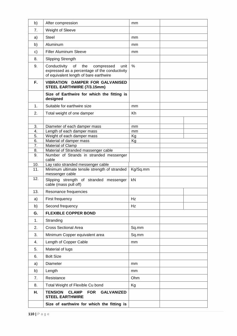
110 | P a g e
b) After compression mm
7. Weight of Sleeve
a) Steel mm
b) Aluminum mm
c) Filler Aluminum Sleeve mm
8. Slipping Strength
9. Conductivity of the compressed unit expressed as a percentage of the conductivity of equivalent length of bare earthwire
%
F. VIBRATION DAMPER FOR GALVANISED STEEL EARTHWIRE (7/3.15mm)
Size of Earthwire for which the fitting is designed
1. Suitable for earthwire size mm
2. Total weight of one damper Kh
3. Diameter of each damper mass mm
4. Length of each damper mass mm
5. Weight of each damper mass Kg
6. Material of damper mass Kg
7. Material of Clamp
8. Material of Stranded massenger cable
9. Number of Strands in stranded messenger cable
10. Lay ratio stranded messenger cable
11. Minimum ultimate tensile strength of stranded messenger cable
Kg/Sq.mm
12. Slipping strength of stranded messenger cable (mass pull off)
kN
13. Resonance frequencies
a) First frequency Hz
b) Second frequency Hz
G. FLEXIBLE COPPER BOND
1. Stranding
2. Cross Sectional Area Sq.mm
3. Minimum Copper equivalent area Sq.mm
4. Length of Copper Cable mm
5. Material of lugs
6. Bolt Size
a) Diameter mm
b) Length mm
7. Resistance Ohm
8. Total Weight of Flexible Cu bond Kg
H. TENSION CLAMP FOR GALVANIZED STEEL EARTHWIRE
Size of earthwire for which the fitting is
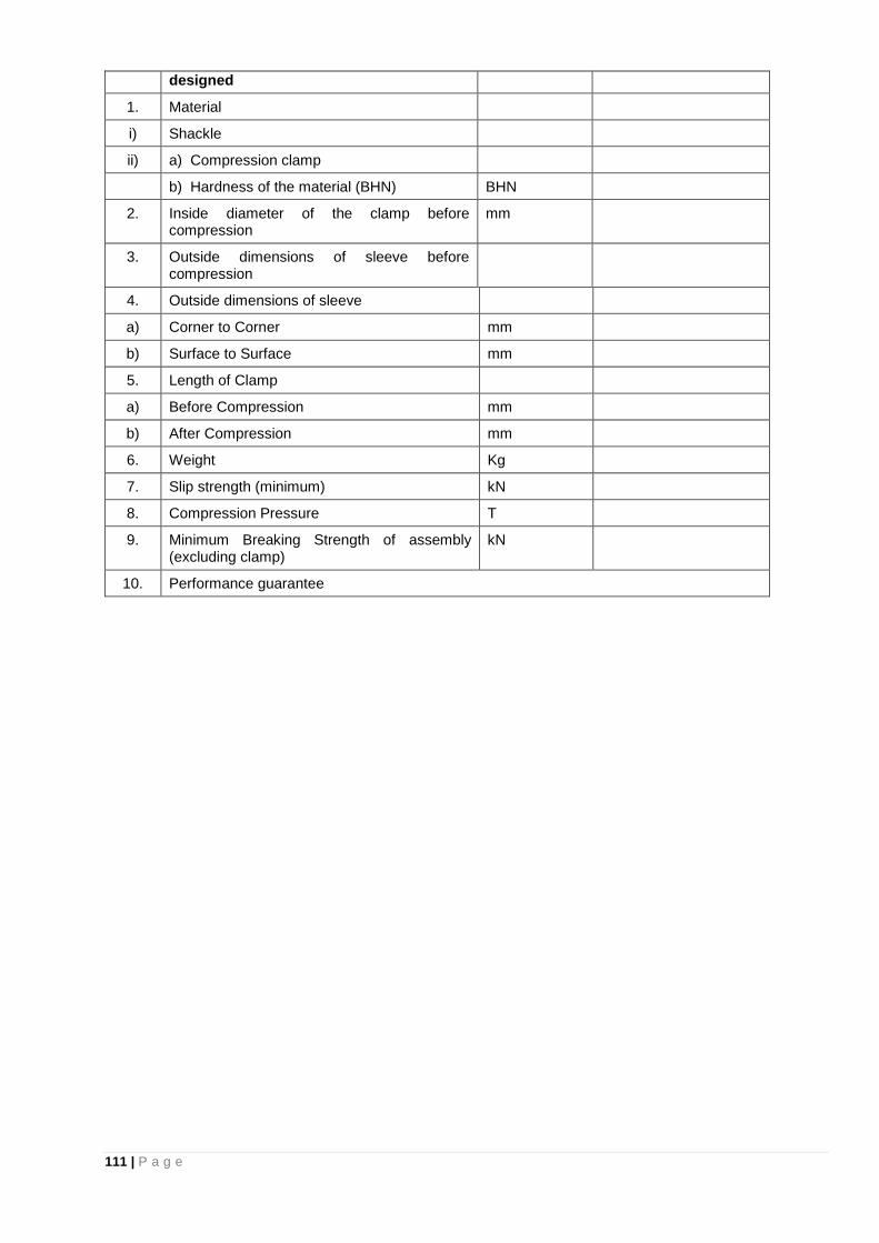
111 | P a g e
designed
1. Material
i) Shackle
ii) a) Compression clamp
b) Hardness of the material (BHN) BHN
2. Inside diameter of the clamp before compression
mm
3. Outside dimensions of sleeve before compression
4. Outside dimensions of sleeve
a) Corner to Corner mm
b) Surface to Surface mm
5. Length of Clamp
a) Before Compression mm
b) After Compression mm
6. Weight Kg
7. Slip strength (minimum) kN
8. Compression Pressure T
9. Minimum Breaking Strength of assembly (excluding clamp)
kN
10. Performance guarantee