Embed Size (px)
Citation preview
Catalog 12 February 2020 ‐ Page i
Catalog 12Index
� 1981, 2019 Fisher Controls International LLC. All rights reserved
ASME/ISA/IEC VALVE SIZINGPart number of complete catalog with binder: D103183X012
Part number of complete catalog without binder: D103182X012
SECTION 1 FLOW COEFFICIENTS(ASME/ISA/IEC)Valve Style Page
Typical Fd Valve Style Modifier Values 1‐1/1‐2. . . . . . . . . . . . . . . . . . . . . . . .
461 Angle 461‐1. . . . . . . . . . . . . . . . . . . . . . . . . . . . . . . . . . . . . . . . . . . . . . .
8532 Butterfly 8532‐1. . . . . . . . . . . . . . . . . . . . . . . . . . . . . . . . . . . . . . . . . .
8560 Butterfly 8560‐1. . . . . . . . . . . . . . . . . . . . . . . . . . . . . . . . . . . . . . . . . .
8580 Butterfly 8580‐1. . . . . . . . . . . . . . . . . . . . . . . . . . . . . . . . . . . . . . . . . .
8590 Butterfly 8590-1. . . . . . . . . . . . . . . . . . . . . . . . . . . . . . . . . . . . . . . . . .
9500 Butterfly 9500‐1. . . . . . . . . . . . . . . . . . . . . . . . . . . . . . . . . . . . . . . . . .
30,000 Butterfly 30,000‐1. . . . . . . . . . . . . . . . . . . . . . . . . . . . . . . . . . . . . .
24000 Baumann� 24000-1. . . . . . . . . . . . . . . . . . . . . . . . . . . . . . . . . . . . . .
24000C Baumann 24000C-1. . . . . . . . . . . . . . . . . . . . . . . . . . . . . . . . . . . . . .
24000CVF/SFV Baumann 24000CVF/SVF-1. . . . . . . . . . . . . . . . . . . . . . . . . .
24000S Baumann 24000S-1. . . . . . . . . . . . . . . . . . . . . . . . . . . . . . . . . . . . . .
24000F Baumann 24000F-1. . . . . . . . . . . . . . . . . . . . . . . . . . . . . . . . . . . . . .
24000SB Baumann 24000SB-1. . . . . . . . . . . . . . . . . . . . . . . . . . . . . . . . . . . .
26000 Baumann 26000-1. . . . . . . . . . . . . . . . . . . . . . . . . . . . . . . . . . . . . . . .
51000 Baumann 51000-1. . . . . . . . . . . . . . . . . . . . . . . . . . . . . . . . . . . . . . . .
81000 Baumann 81000-1. . . . . . . . . . . . . . . . . . . . . . . . . . . . . . . . . . . . . . . .
83000 Baumann 83000-1. . . . . . . . . . . . . . . . . . . . . . . . . . . . . . . . . . . . . . . .
84000 Baumann 84000-1. . . . . . . . . . . . . . . . . . . . . . . . . . . . . . . . . . . . . . . .
87000 Baumann 87000-1. . . . . . . . . . . . . . . . . . . . . . . . . . . . . . . . . . . . . . . .
89000 Baumann 89000-1. . . . . . . . . . . . . . . . . . . . . . . . . . . . . . . . . . . . . . . .
A11 Butterfly A11‐1. . . . . . . . . . . . . . . . . . . . . . . . . . . . . . . . . . . . . . . . . . . .
A31A‐Cryogenic Butterfly A31A‐Cryogenic‐1. . . . . . . . . . . . . . . . . . . . . . .
A31D Butterfly A31D‐1. . . . . . . . . . . . . . . . . . . . . . . . . . . . . . . . . . . . . . . .
Three Way Butterfly Three Way Butterfly‐1. . . . . . . . . . . . . . . . . . . . . . . . . . .
CAV4 Globe, Offset Globe, and Angle CAV4‐1. . . . . . . . . . . . . . . . . . . . . .
CHP Globe CHP-1. . . . . . . . . . . . . . . . . . . . . . . . . . . . . . . . . . . . . . . . . . . . . .
Valve Style Page
Control‐Disk� Butterfly Control‐Disk‐1. . . . . . . . . . . . . . . . . . . . . . . . . . . .
CV500 Ball CV500‐1. . . . . . . . . . . . . . . . . . . . . . . . . . . . . . . . . . . . . . . . . . .
D Globe D‐1. . . . . . . . . . . . . . . . . . . . . . . . . . . . . . . . . . . . . . . . . . . . . . . . . .
DA Angle DA‐1. . . . . . . . . . . . . . . . . . . . . . . . . . . . . . . . . . . . . . . . . . . . . . . . .
D3 Globe D3‐1. . . . . . . . . . . . . . . . . . . . . . . . . . . . . . . . . . . . . . . . . . . . . . . .
D4 Globe D4‐1. . . . . . . . . . . . . . . . . . . . . . . . . . . . . . . . . . . . . . . . . . . . . . . .
EAD Angle EAD‐1. . . . . . . . . . . . . . . . . . . . . . . . . . . . . . . . . . . . . . . . . . . . . . .
EAS Angle EAS‐1. . . . . . . . . . . . . . . . . . . . . . . . . . . . . . . . . . . . . . . . . . . . . . .
EAT Angle EAT‐1/EAT‐2. . . . . . . . . . . . . . . . . . . . . . . . . . . . . . . . . . . . . . . . .
ED Globe ED‐1. . . . . . . . . . . . . . . . . . . . . . . . . . . . . . . . . . . . . . . . . . . . . . . .
Large ED Globe ED-9. . . . . . . . . . . . . . . . . . . . . . . . . . . . . . . . . . . . . . . . . . .
EDR Globe EDR‐1/EDR‐2. . . . . . . . . . . . . . . . . . . . . . . . . . . . . . . . . . . . . . . .
EH Globe EH‐1. . . . . . . . . . . . . . . . . . . . . . . . . . . . . . . . . . . . . . . . . . . . . . . .
ES Globe ES‐1. . . . . . . . . . . . . . . . . . . . . . . . . . . . . . . . . . . . . . . . . . . . . . . .
ET Globe ET‐1. . . . . . . . . . . . . . . . . . . . . . . . . . . . . . . . . . . . . . . . . . . . . . . .
Large ET Globe ET-3. . . . . . . . . . . . . . . . . . . . . . . . . . . . . . . . . . . . . . . . . . .
ET‐C Globe ET‐2. . . . . . . . . . . . . . . . . . . . . . . . . . . . . . . . . . . . . . . . . . . . . .
ETR Globe ET‐3/ET‐4. . . . . . . . . . . . . . . . . . . . . . . . . . . . . . . . . . . . . . . . . . .
EWD Globe EW‐1. . . . . . . . . . . . . . . . . . . . . . . . . . . . . . . . . . . . . . . . . . . . .
EWD‐1 Globe EW‐5. . . . . . . . . . . . . . . . . . . . . . . . . . . . . . . . . . . . . . . . . . .
EWT‐2 Globe EW‐7. . . . . . . . . . . . . . . . . . . . . . . . . . . . . . . . . . . . . . . . . . . .
EWS Globe EW‐26. . . . . . . . . . . . . . . . . . . . . . . . . . . . . . . . . . . . . . . . . . . .
EWT Globe EW‐31. . . . . . . . . . . . . . . . . . . . . . . . . . . . . . . . . . . . . . . . . . . .
EWT‐C Globe EW‐33. . . . . . . . . . . . . . . . . . . . . . . . . . . . . . . . . . . . . . . . . .
EWT‐1 Globe EW‐34. . . . . . . . . . . . . . . . . . . . . . . . . . . . . . . . . . . . . . . . . . .
EWND‐1 Globe EWN‐2. . . . . . . . . . . . . . . . . . . . . . . . . . . . . . . . . . . . . . . . .
Valve Style Page
EWND & EWNT Globe EWN‐1. . . . . . . . . . . . . . . . . . . . . . . . . . . . . . . . . . . .
EWNS Globe EWN‐3. . . . . . . . . . . . . . . . . . . . . . . . . . . . . . . . . . . . . . . . . . .
EWNT‐1 &EWNT‐2 Globe EWN‐4. . . . . . . . . . . . . . . . . . . . . . . . . . . . . . . . . . . . . . . . .
EZ Globe EZ‐1. . . . . . . . . . . . . . . . . . . . . . . . . . . . . . . . . . . . . . . . . . . . . . . .
EZ‐C Globe EZ‐6. . . . . . . . . . . . . . . . . . . . . . . . . . . . . . . . . . . . . . . . . . . . . .
FBD and FBT Globe FB‐1. . . . . . . . . . . . . . . . . . . . . . . . . . . . . . . . . . . . . . . .
GX Globe GX‐1. . . . . . . . . . . . . . . . . . . . . . . . . . . . . . . . . . . . . . . . . . . . . . . .
GX 3-Way 3-Way GX 3-Way-1. . . . . . . . . . . . . . . . . . . . . . . . . . . . . . . . . . . .
HIPPS Ball HIPPS‐1. . . . . . . . . . . . . . . . . . . . . . . . . . . . . . . . . . . . . . . . . . . .
HPAD Angle HP‐1. . . . . . . . . . . . . . . . . . . . . . . . . . . . . . . . . . . . . . . . . . . . . .
HPAS Angle HP‐5. . . . . . . . . . . . . . . . . . . . . . . . . . . . . . . . . . . . . . . . . . . . . . .
HPAT Angle HP‐14. . . . . . . . . . . . . . . . . . . . . . . . . . . . . . . . . . . . . . . . . . . . .
HPD Globe HP‐15. . . . . . . . . . . . . . . . . . . . . . . . . . . . . . . . . . . . . . . . . . . . .
HPS Globe HP‐18. . . . . . . . . . . . . . . . . . . . . . . . . . . . . . . . . . . . . . . . . . . . . .
HPT Globe HP‐22. . . . . . . . . . . . . . . . . . . . . . . . . . . . . . . . . . . . . . . . . . . . . .
HPT-C and HPS-C Globe HP‐24. . . . . . . . . . . . . . . . . . . . . . . . . . . . . . . . . . .
NotchFlo� Globe and Angle NotchFlo‐DST‐1. . . . . . . . . . . . . . . . . . . . . . . .
RSS Globe RSS‐1. . . . . . . . . . . . . . . . . . . . . . . . . . . . . . . . . . . . . . . . . . . . . .
SIS Ball SIS‐1. . . . . . . . . . . . . . . . . . . . . . . . . . . . . . . . . . . . . . . . . . . . . . . . . .
TBX Globe TBX‐1. . . . . . . . . . . . . . . . . . . . . . . . . . . . . . . . . . . . . . . . . . . . . .
Vee‐Ball� Ball V150‐1. . . . . . . . . . . . . . . . . . . . . . . . . . . . . . . . . . . . . . . . . .
V150S Ball V150S‐1. . . . . . . . . . . . . . . . . . . . . . . . . . . . . . . . . . . . . . . . . . . .
V200 Ball V200‐1/V200‐2. . . . . . . . . . . . . . . . . . . . . . . . . . . . . . . . . . . . . . .
V250 Ball V250‐1/V250‐2. . . . . . . . . . . . . . . . . . . . . . . . . . . . . . . . . . . . . . .
V260A Ball V260‐1. . . . . . . . . . . . . . . . . . . . . . . . . . . . . . . . . . . . . . . . . . . .
V260B Ball V260‐3. . . . . . . . . . . . . . . . . . . . . . . . . . . . . . . . . . . . . . . . . . . . .
V260C Ball V260‐4. . . . . . . . . . . . . . . . . . . . . . . . . . . . . . . . . . . . . . . . . . . .
V270 Ball V270‐1/V270‐2. . . . . . . . . . . . . . . . . . . . . . . . . . . . . . . . . . . . . . .
V280 Ball V280-1. . . . . . . . . . . . . . . . . . . . . . . . . . . . . . . . . . . . . . . . . . . . . .
V300 Ball V300‐1/V300‐2. . . . . . . . . . . . . . . . . . . . . . . . . . . . . . . . . . . . . . .
V500 Ball V500‐1. . . . . . . . . . . . . . . . . . . . . . . . . . . . . . . . . . . . . . . . . . . . . .
YD 3‐Way YD‐1. . . . . . . . . . . . . . . . . . . . . . . . . . . . . . . . . . . . . . . . . . . . . . . .
YS 3‐Way YS‐1. . . . . . . . . . . . . . . . . . . . . . . . . . . . . . . . . . . . . . . . . . . . . . . .
Subject Page
Z500 Ball Z500‐1. . . . . . . . . . . . . . . . . . . . . . . . . . . . . . . . . . . . . . . . . . . . . .
SECTION 2 VALVE SIZING PROCEDURE
Introduction 2‐1. . . . . . . . . . . . . . . . . . . . . . . . . . . . . . . . . . . . . . . . . . . . . . . .
Sizing Valves for Liquids 2‐1. . . . . . . . . . . . . . . . . . . . . . . . . . . . . . . . . . . . . .
Liquid Sizing Sample Problems 2‐8. . . . . . . . . . . . . . . . . . . . . . . . . . . . . . . . .
Sizing Valves for Compressible Fluids 2‐12. . . . . . . . . . . . . . . . . . . . . . . . . . .
Compressible Fluid Sizing Sample Problems 2‐14. . . . . . . . . . . . . . . . . . . . .
FSP Vapor Pressure Calculation (V1.4) 2‐17. . . . . . . . . . . . . . . . . . . . . . . . . .
Custom Pv Coefficient Request 2‐18. . . . . . . . . . . . . . . . . . . . . . . . . . . . . . . .
FSP Pulp Stock Sizing Calculations (v1.4) 2‐19. . . . . . . . . . . . . . . . . . . . . . . .
Technical Information 2‐23. . . . . . . . . . . . . . . . . . . . . . . . . . . . . . . . . . . . . .
Leakage Specifications 2‐27. . . . . . . . . . . . . . . . . . . . . . . . . . . . . . . . . . . . . .
Valve Sizing for Cavitating and Flashing Liquids 2‐28. . . . . . . . . . . . . . . . . . .
Valve Sizing for Liquid‐Gas Mixture 2‐29. . . . . . . . . . . . . . . . . . . . . . . . . . . . .
Saturated Steam Pressure and Temperature 2‐32. . . . . . . . . . . . . . . . . . . . .
Saturated and Superheated Steam Density/Temperature Curve 2‐34. . . . .
Velocity Equations 2‐35. . . . . . . . . . . . . . . . . . . . . . . . . . . . . . . . . . . . . . . . . .
SECTION 3 NOISE ABATEMENT
Hydrodynamic Noise (ΔSPLAr Corrections) 3‐1. . . . . . . . . . . . . . . . . . . . . . . .
Sound Characteristics 3‐2. . . . . . . . . . . . . . . . . . . . . . . . . . . . . . . . . . . . . . . .
Hydrodynamic Noise 3‐5. . . . . . . . . . . . . . . . . . . . . . . . . . . . . . . . . . . . . . . . .
Hydrodynamic Noise 3‐5. . . . . . . . . . . . . . . . . . . . . . . . . . . . . . . . . . . . . . . . .
Catalog 12February 2020 ‐ Page ii
Catalog 12Index
� 1981, 2020 Fisher Controls International LLC. All rights reserved
www.Fisher.com
Responsibility for selection, use, and maintenance of any product remains solely with the purchaser and end user. The contents of this publication are forinformational purposes only and are not to be construed as warranties or guarantees, express or implied, regarding the products or services describedtherein. Fisher, Baumann, Control-Disk, NotchFlo, POSI-SEAL, and Vee-Ball are marks owned by one of the companies in the Emerson Automation Solutionsbusiness unit of Emerson Electric Co. Emerson Automation Solutions, Emerson, and the Emerson logo are trademarks and service marks of Emerson ElectricCo. All other marks are the property of their respective owners.
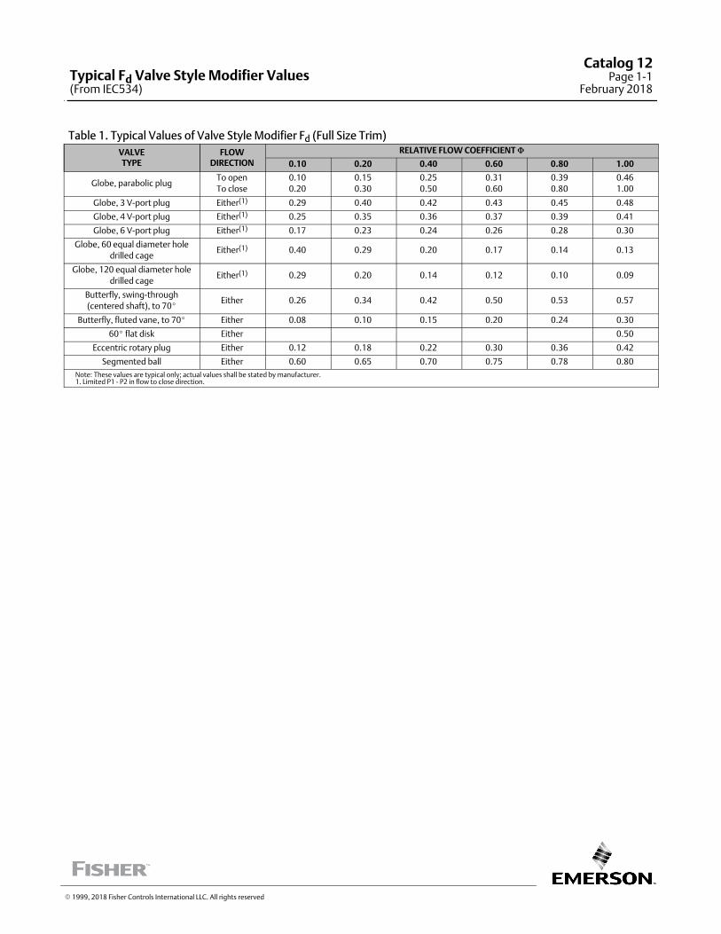
Table 1. Typical Values of Valve Style Modifier Fd (Full Size Trim)
VALVETYPE
FLOWDIRECTION
RELATIVE FLOW COEFFICIENT �
0.10 0.20 0.40 0.60 0.80 1.00
Globe, parabolic plugTo open
To close
0.10
0.20
0.15
0.30
0.25
0.50
0.31
0.60
0.39
0.80
0.46
1.00
Globe, 3 V‐port plug Either(1) 0.29 0.40 0.42 0.43 0.45 0.48
Globe, 4 V‐port plug Either(1) 0.25 0.35 0.36 0.37 0.39 0.41
Globe, 6 V‐port plug Either(1) 0.17 0.23 0.24 0.26 0.28 0.30
Globe, 60 equal diameter hole
drilled cageEither(1) 0.40 0.29 0.20 0.17 0.14 0.13
Globe, 120 equal diameter hole
drilled cageEither(1) 0.29 0.20 0.14 0.12 0.10 0.09
Butterfly, swing‐through
(centered shaft), to 70�Either 0.26 0.34 0.42 0.50 0.53 0.57
Butterfly, fluted vane, to 70� Either 0.08 0.10 0.15 0.20 0.24 0.30
60� flat disk Either 0.50
Eccentric rotary plug Either 0.12 0.18 0.22 0.30 0.36 0.42
Segmented ball Either 0.60 0.65 0.70 0.75 0.78 0.80
Note: These values are typical only; actual values shall be stated by manufacturer.1. Limited P1 - P2 in flow to close direction.
� 1999, 2018 Fisher Controls International LLC. All rights reserved
Typical Fd Valve Style Modifier Values(From IEC534)
Catalog 12Page 1‐1
February 2018

This page intentionally left blank
� 1999, 2018 Fisher Controls International LLC. All rights reserved
www.Fisher.com
Responsibility for selection, use, and maintenance of any product remains solely with the purchaser and end user. The contents of this publication are forinformational purposes only and are not to be construed as warranties or guarantees, express or implied, regarding the products or services describedtherein. Fisher is a mark owned by one of the companies in the Emerson Automation Solutions business unit of Emerson Electric Co. Emerson AutomationSolutions, Emerson, and the Emerson logo are trademarks and service marks of Emerson Electric Co. All other marks are the property of their respectiveowners.
Catalog 12Page 1‐2February 2018
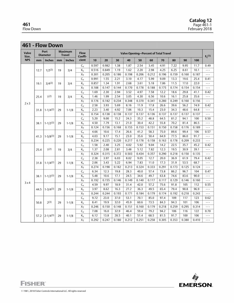
461 ‐ Flow Down
ValveSize,NPS
PortDiameter
MaximumTravel
FlowCoeffi‐cient
Valve Opening—Percent of Total TravelFL
(1)
mm Inches mm Inches 10 20 30 40 50 60 70 80 90 100
2 x 3
12.7 1/2(2) 19 3/4
Cv 0.597 0.982 1.38 1.87 2.54 3.45 4.91 7.22 9.95 11.7 0.49
Kv 0.516 0.849 1.19 1.62 2.20 2.98 4.25 6.25 8.61 10.1 - - -
XT 0.301 0.205 0.186 0.198 0.206 0.212 0.196 0.159 0.160 0.187 - - -
19.1 3/4(2) 19 3/4
Cv 0.991 1.55 2.21 3.10 4.17 5.99 9.09 13.3 19.6 25.4 0.41
Kv 0.857 1.34 1.91 2.68 3.61 5.18 7.86 11.5 17.0 22.0 - - -
XT 0.188 0.147 0.144 0.170 0.178 0.188 0.175 0.174 0.154 0.154 - - -
25.4 1(2) 19 3/4
Cv 1.69 2.30 2.94 3.52 4.97 7.58 12.2 18.6 29.8 41.1 0.42
Kv 1.46 1.99 2.54 3.05 4.30 6.56 10.6 16.1 25.8 35.6 - - -
XT 0.176 0.182 0.234 0.348 0.370 0.341 0.280 0.249 0.160 0.156 - - -
31.8 1-1/4(2) 29 1-1/8
Cv 2.58 3.93 5.69 8.16 11.9 17.8 26.6 39.6 56.2 74.9 0.42
Kv 2.23 3.40 4.92 7.06 10.3 15.4 23.0 34.3 48.6 64.8 - - -
XT 0.154 0.138 0.138 0.137 0.137 0.136 0.137 0.137 0.137 0.137 - - -
38.1 1-1/2(3) 29 1-1/8
Cv 5.20 9.00 15.2 24.3 35.2 48.8 64.5 81.2 94.1 100 0.50
Kv 4.50 7.79 13.1 21.0 30.4 42.2 55.8 70.2 81.4 86.5 - - -
XT 0.124 0.156 0.168 0.155 0.153 0.151 0.150 0.158 0.176 0.189 - - -
41.3 1-5/8(3) 29 1-1/8
Cv 4.66 10.6 17.4 26.6 41.2 58.3 75.0 89.6 99.4 106 0.57
Kv 4.03 9.17 15.1 23.0 35.6 50.4 64.9 77.5 86.0 91.7 - - -
XT 0.234 0.225 0.220 0.217 0.178 0.158 0.163 0.178 0.209 0.233 - - -
3 x 4
25.4 1(2) 19 3/4
Cv 1.58 2.40 3.25 4.02 5.92 9.04 14.2 22.5 35.7 45.2 0.42
Kv 1.37 2.08 2.81 3.48 5.12 7.82 12.3 19.5 30.9 39.1 - - -
XT 0.324 0.315 0.372 0.503 0.434 0.357 0.290 0.218 0.150 0.135 - - -
31.8 1-1/4(2) 29 1-1/8
Cv 2.38 3.97 6.03 8.02 9.05 12.7 20.0 36.9 61.9 79.4 0.42
Kv 2.06 3.43 5.22 6.94 7.83 11.0 17.3 31.9 53.5 68.7 - - -
XT 0.274 0.198 0.182 0.213 0.324 0.333 0.291 0.173 0.125 0.124 - - -
38.1 1-1/2(3) 29 1-1/8
Cv 6.34 12.3 19.8 28.3 40.0 57.4 73.8 86.2 96.7 104 0.47
Kv 5.48 10.6 17.1 24.5 34.6 49.7 63.8 74.6 83.6 90.0 - - -
XT 0.192 0.155 0.146 0.149 0.140 0.117 0.117 0.129 0.146 0.160 - - -
44.5 1-3/4(3) 29 1-1/8
Cv 4.59 9.97 18.9 31.4 42.0 57.2 75.6 91.8 105 112 0.55
Kv 3.97 8.62 16.3 27.2 36.3 49.5 65.4 79.4 90.8 96.9 - - -
XT 0.244 0.244 0.193 0.171 0.184 0.179 0.174 0.192 0.218 0.243 - - -
50.8 2(3) 29 1-1/8
Cv 9.72 23.0 37.0 53.1 70.1 85.0 97.4 109 117 123 0.62
Kv 8.41 19.9 32.0 45.9 60.6 73.5 84.3 94.3 101 106 - - -
XT 0.246 0.150 0.148 0.151 0.160 0.179 0.218 0.259 0.295 0.314 - - -
57.2 2-1/4(3) 29 1-1/8
Cv 7.08 16.0 32.9 46.4 59.4 79.2 94.2 106 116 122 0.70
Kv 6.12 13.8 28.5 40.1 51.4 68.5 81.5 91.7 100 106 - - -
XT 0.292 0.247 0.180 0.212 0.251 0.258 0.305 0.353 0.380 0.410 - - -
� 1981, 2018 Fisher Controls International LLC. All rights reserved
461Flow Down
Catalog 12Page 461-1
February 2018
ValveSize,NPS
PortDiameter
MaximumTravel
FlowCoeffi‐cient
Valve Opening—Percent of Total TravelFL
(1)
mm Inches mm Inches 10 20 30 40 50 60 70 80 90 100
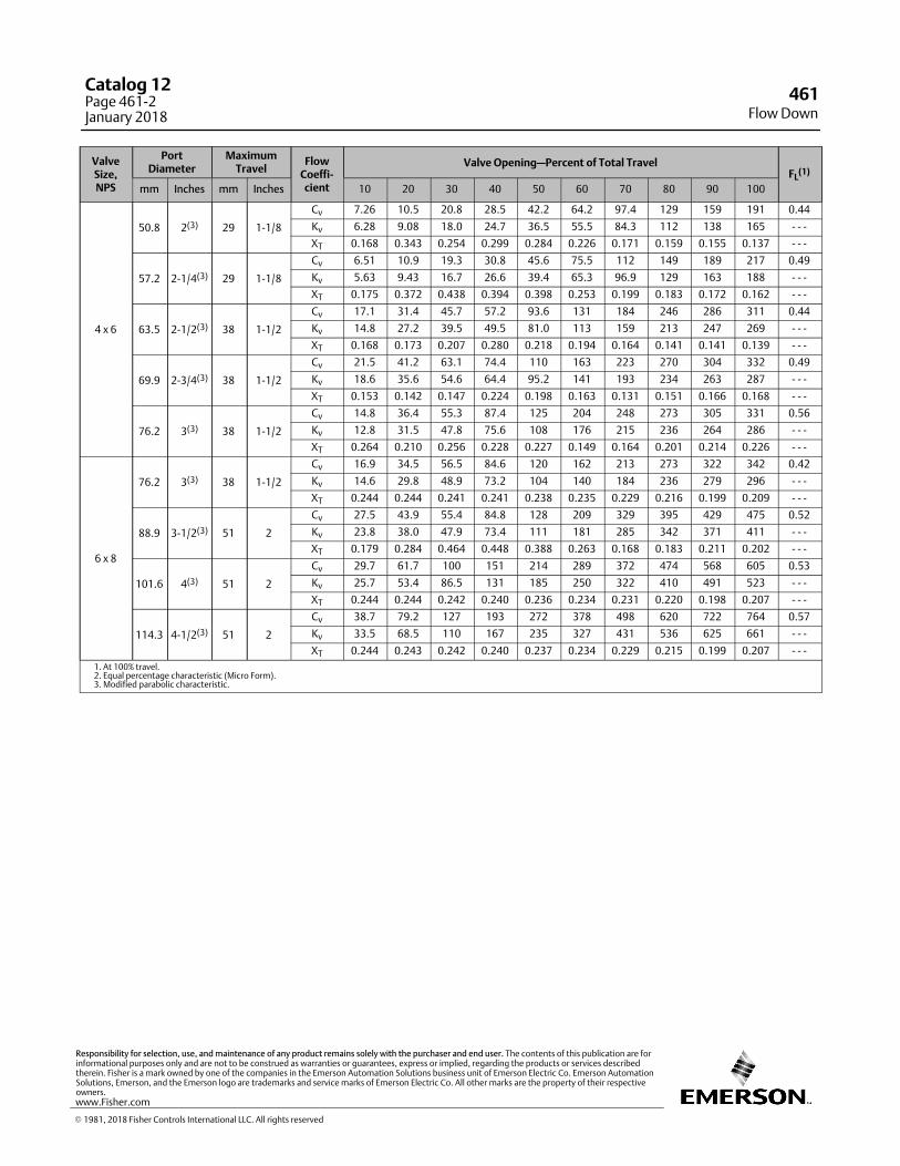
4 x 6
50.8 2(3) 29 1-1/8
Cv 7.26 10.5 20.8 28.5 42.2 64.2 97.4 129 159 191 0.44
Kv 6.28 9.08 18.0 24.7 36.5 55.5 84.3 112 138 165 - - -
XT 0.168 0.343 0.254 0.299 0.284 0.226 0.171 0.159 0.155 0.137 - - -
57.2 2-1/4(3) 29 1-1/8
Cv 6.51 10.9 19.3 30.8 45.6 75.5 112 149 189 217 0.49
Kv 5.63 9.43 16.7 26.6 39.4 65.3 96.9 129 163 188 - - -
XT 0.175 0.372 0.438 0.394 0.398 0.253 0.199 0.183 0.172 0.162 - - -
63.5 2-1/2(3) 38 1-1/2
Cv 17.1 31.4 45.7 57.2 93.6 131 184 246 286 311 0.44
Kv 14.8 27.2 39.5 49.5 81.0 113 159 213 247 269 - - -
XT 0.168 0.173 0.207 0.280 0.218 0.194 0.164 0.141 0.141 0.139 - - -
69.9 2-3/4(3) 38 1-1/2
Cv 21.5 41.2 63.1 74.4 110 163 223 270 304 332 0.49
Kv 18.6 35.6 54.6 64.4 95.2 141 193 234 263 287 - - -
XT 0.153 0.142 0.147 0.224 0.198 0.163 0.131 0.151 0.166 0.168 - - -
76.2 3(3) 38 1-1/2
Cv 14.8 36.4 55.3 87.4 125 204 248 273 305 331 0.56
Kv 12.8 31.5 47.8 75.6 108 176 215 236 264 286 - - -
XT 0.264 0.210 0.256 0.228 0.227 0.149 0.164 0.201 0.214 0.226 - - -
6 x 8
76.2 3(3) 38 1-1/2
Cv 16.9 34.5 56.5 84.6 120 162 213 273 322 342 0.42
Kv 14.6 29.8 48.9 73.2 104 140 184 236 279 296 - - -
XT 0.244 0.244 0.241 0.241 0.238 0.235 0.229 0.216 0.199 0.209 - - -
88.9 3-1/2(3) 51 2
Cv 27.5 43.9 55.4 84.8 128 209 329 395 429 475 0.52
Kv 23.8 38.0 47.9 73.4 111 181 285 342 371 411 - - -
XT 0.179 0.284 0.464 0.448 0.388 0.263 0.168 0.183 0.211 0.202 - - -
101.6 4(3) 51 2
Cv 29.7 61.7 100 151 214 289 372 474 568 605 0.53
Kv 25.7 53.4 86.5 131 185 250 322 410 491 523 - - -
XT 0.244 0.244 0.242 0.240 0.236 0.234 0.231 0.220 0.198 0.207 - - -
114.3 4-1/2(3) 51 2
Cv 38.7 79.2 127 193 272 378 498 620 722 764 0.57
Kv 33.5 68.5 110 167 235 327 431 536 625 661 - - -
XT 0.244 0.243 0.242 0.240 0.237 0.234 0.229 0.215 0.199 0.207 - - -
1. At 100% travel.2. Equal percentage characteristic (Micro Form).3. Modified parabolic characteristic.
Flow Down461
Catalog 12Page 461-2January 2018
� 1981, 2018 Fisher Controls International LLC. All rights reserved
www.Fisher.com
Responsibility for selection, use, and maintenance of any product remains solely with the purchaser and end user. The contents of this publication are forinformational purposes only and are not to be construed as warranties or guarantees, express or implied, regarding the products or services describedtherein. Fisher is a mark owned by one of the companies in the Emerson Automation Solutions business unit of Emerson Electric Co. Emerson AutomationSolutions, Emerson, and the Emerson logo are trademarks and service marks of Emerson Electric Co. All other marks are the property of their respectiveowners.
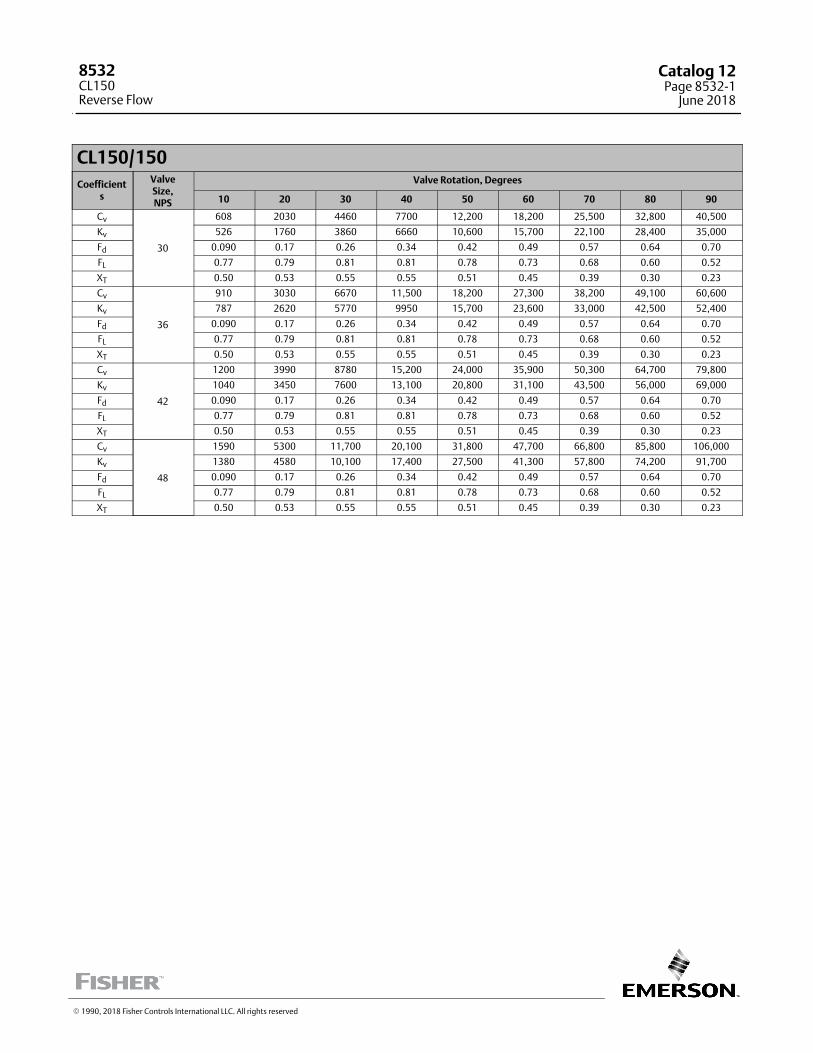
CL150/150
Coefficients
ValveSize,NPS
Valve Rotation, Degrees
10 20 30 40 50 60 70 80 90
Cv
30
608 2030 4460 7700 12,200 18,200 25,500 32,800 40,500
Kv 526 1760 3860 6660 10,600 15,700 22,100 28,400 35,000
Fd 0.090 0.17 0.26 0.34 0.42 0.49 0.57 0.64 0.70
FL 0.77 0.79 0.81 0.81 0.78 0.73 0.68 0.60 0.52
XT 0.50 0.53 0.55 0.55 0.51 0.45 0.39 0.30 0.23
Cv
36
910 3030 6670 11,500 18,200 27,300 38,200 49,100 60,600
Kv 787 2620 5770 9950 15,700 23,600 33,000 42,500 52,400
Fd 0.090 0.17 0.26 0.34 0.42 0.49 0.57 0.64 0.70
FL 0.77 0.79 0.81 0.81 0.78 0.73 0.68 0.60 0.52
XT 0.50 0.53 0.55 0.55 0.51 0.45 0.39 0.30 0.23
Cv
42
1200 3990 8780 15,200 24,000 35,900 50,300 64,700 79,800
Kv 1040 3450 7600 13,100 20,800 31,100 43,500 56,000 69,000
Fd 0.090 0.17 0.26 0.34 0.42 0.49 0.57 0.64 0.70
FL 0.77 0.79 0.81 0.81 0.78 0.73 0.68 0.60 0.52
XT 0.50 0.53 0.55 0.55 0.51 0.45 0.39 0.30 0.23
Cv
48
1590 5300 11,700 20,100 31,800 47,700 66,800 85,800 106,000
Kv 1380 4580 10,100 17,400 27,500 41,300 57,800 74,200 91,700
Fd 0.090 0.17 0.26 0.34 0.42 0.49 0.57 0.64 0.70
FL 0.77 0.79 0.81 0.81 0.78 0.73 0.68 0.60 0.52
XT 0.50 0.53 0.55 0.55 0.51 0.45 0.39 0.30 0.23
� 1990, 2018 Fisher Controls International LLC. All rights reserved
8532CL150Reverse Flow
Catalog 12Page 8532-1
June 2018
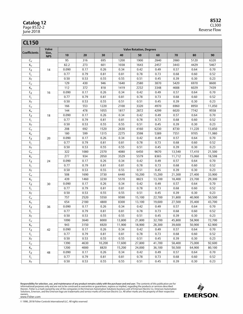
CL150
CoefficientsValveSize,NPS
Valve Rotation, Degrees
10 20 30 40 50 60 70 80 90
Cv
14
95 316 695 1200 1900 2840 3980 5120 6320
Kv 82.2 273 601 1038 1643 2457 3443 4429 5467
Fd 0.090 0.17 0.26 0.34 0.42 0.49 0.57 0.64 0.70
FL 0.77 0.79 0.81 0.81 0.78 0.73 0.68 0.60 0.52
XT 0.50 0.53 0.55 0.55 0.51 0.45 0.39 0.30 0.23
Cv
16
129 430 946 1640 2580 3870 5420 6970 8600
Kv 112 372 818 1419 2232 3348 4688 6029 7439
Fd 0.090 0.17 0.26 0.34 0.42 0.49 0.57 0.64 0.70
FL 0.77 0.79 0.81 0.81 0.78 0.73 0.68 0.60 0.52
XT 0.50 0.53 0.55 0.51 0.51 0.45 0.39 0.30 0.23
Cv
18
166 553 1220 2100 3320 4970 6960 8950 11,050
Kv 144 478 1055 1817 2872 4299 6020 7742 9558
Fd 0.090 0.17 0.26 0.34 0.42 0.49 0.57 0.64 0.70
FL 0.77 0.79 0.81 0.81 0.78 0.73 0.68 0.60 0.52
XT 0.50 0.53 0.55 0.55 0.51 0.45 0.39 0.30 0.23
Cv
20
208 692 1520 2630 4160 6230 8730 11,220 13,850
Kv 180 599 1315 2275 3598 5389 7551 9705 11,980
Fd 0.090 0.17 0.26 0.34 0.42 0.49 0.57 0.64 0.70
FL 0.77 0.79 0.81 0.81 0.78 0.73 0.68 0.60 0.52
XT 0.50 0.53 0.55 0.55 0.51 0.45 0.39 0.30 0.23
Cv
24
322 1080 2370 4080 6450 9670 13,540 17,410 21,500
Kv 277 934 2050 3529 5579 8365 11,712 15,060 18,598
Fd 0.090 0.17 0.26 0.34 0.42 0.49 0.57 0.64 0.70
FL 0.77 0.79 0.81 0.81 0.78 0.73 0.68 0.60 0.52
XT 0.50 0.53 0.55 0.55 0.51 0.45 0.39 0.30 0.23
Cv
30
508 1690 3730 6440 10,200 15,200 21,300 27,400 33,900
Kv 439 1460 3230 5570 8823 13,100 18,400 23,700 29,300
Fd 0.090 0.17 0.26 0.34 0.42 0.49 0.57 0.64 0.70
FL 0.77 0.79 0.81 0.81 0.78 0.73 0.68 0.60 0.52
XT 0.50 0.53 0.55 0.55 0.51 0.45 0.39 0.30 0.23
Cv
36
757 2520 5550 9590 15,100 22,700 31,800 40,900 50,500
Kv 654 2180 4800 8300 13,100 19,600 27,500 35,400 43,700
Fd 0.090 0.17 0.26 0.34 0.42 0.49 0.57 0.64 0.70
FL 0.77 0.79 0.81 0.81 0.78 0.73 0.68 0.60 0.52
XT 0.50 0.53 0.55 0.55 0.51 0.45 0.39 0.30 0.23
Cv
42
1090 3640 8000 13,800 21,800 32,700 45,800 58,900 72,700
Kv 943 3150 6920 11,900 18,900 28,300 39,600 50,900 62,900
Fd 0.090 0.17 0.26 0.34 0.42 0.49 0.57 0.64 0.70
FL 0.77 0.79 0.81 0.81 0.78 0.73 0.68 0.60 0.52
XT 0.50 0.53 0.55 0.55 0.51 0.45 0.39 0.30 0.23
Cv
48
1390 4630 10,200 17,600 27,800 41,700 58,400 75,000 92,600
Kv 1200 4000 8820 15,200 24,000 36,100 50,500 64,900 80,100
Fd 0.090 0.17 0.26 0.34 0.42 0.49 0.57 0.64 0.70
FL 0.77 0.79 0.81 0.81 0.78 0.73 0.68 0.60 0.52
XT 0.50 0.53 0.55 0.55 0.51 0.45 0.39 0.30 0.23
8532CL300
Reverse Flow
Catalog 12Page 8532-2June 2018
� 1990, 2018 Fisher Controls International LLC. All rights reserved
www.Fisher.com
Responsibility for selection, use, and maintenance of any product remains solely with the purchaser and end user. The contents of this publication are forinformational purposes only and are not to be construed as warranties or guarantees, express or implied, regarding the products or services describedtherein. Fisher is a mark owned by one of the companies in the Emerson Automation Solutions business unit of Emerson Electric Co. Emerson AutomationSolutions, Emerson, and the Emerson logo are trademarks and service marks of Emerson Electric Co. All other marks are the property of their respectiveowners.
3
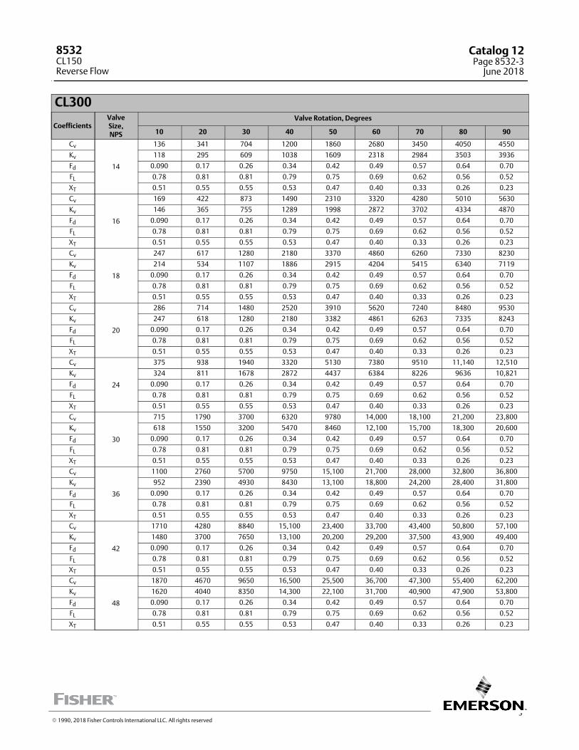
CL300
CoefficientsValveSize,NPS
Valve Rotation, Degrees
10 20 30 40 50 60 70 80 90
Cv
14
136 341 704 1200 1860 2680 3450 4050 4550
Kv 118 295 609 1038 1609 2318 2984 3503 3936
Fd 0.090 0.17 0.26 0.34 0.42 0.49 0.57 0.64 0.70
FL 0.78 0.81 0.81 0.79 0.75 0.69 0.62 0.56 0.52
XT 0.51 0.55 0.55 0.53 0.47 0.40 0.33 0.26 0.23
Cv
16
169 422 873 1490 2310 3320 4280 5010 5630
Kv 146 365 755 1289 1998 2872 3702 4334 4870
Fd 0.090 0.17 0.26 0.34 0.42 0.49 0.57 0.64 0.70
FL 0.78 0.81 0.81 0.79 0.75 0.69 0.62 0.56 0.52
XT 0.51 0.55 0.55 0.53 0.47 0.40 0.33 0.26 0.23
Cv
18
247 617 1280 2180 3370 4860 6260 7330 8230
Kv 214 534 1107 1886 2915 4204 5415 6340 7119
Fd 0.090 0.17 0.26 0.34 0.42 0.49 0.57 0.64 0.70
FL 0.78 0.81 0.81 0.79 0.75 0.69 0.62 0.56 0.52
XT 0.51 0.55 0.55 0.53 0.47 0.40 0.33 0.26 0.23
Cv
20
286 714 1480 2520 3910 5620 7240 8480 9530
Kv 247 618 1280 2180 3382 4861 6263 7335 8243
Fd 0.090 0.17 0.26 0.34 0.42 0.49 0.57 0.64 0.70
FL 0.78 0.81 0.81 0.79 0.75 0.69 0.62 0.56 0.52
XT 0.51 0.55 0.55 0.53 0.47 0.40 0.33 0.26 0.23
Cv
24
375 938 1940 3320 5130 7380 9510 11,140 12,510
Kv 324 811 1678 2872 4437 6384 8226 9636 10,821
Fd 0.090 0.17 0.26 0.34 0.42 0.49 0.57 0.64 0.70
FL 0.78 0.81 0.81 0.79 0.75 0.69 0.62 0.56 0.52
XT 0.51 0.55 0.55 0.53 0.47 0.40 0.33 0.26 0.23
Cv
30
715 1790 3700 6320 9780 14,000 18,100 21,200 23,800
Kv 618 1550 3200 5470 8460 12,100 15,700 18,300 20,600
Fd 0.090 0.17 0.26 0.34 0.42 0.49 0.57 0.64 0.70
FL 0.78 0.81 0.81 0.79 0.75 0.69 0.62 0.56 0.52
XT 0.51 0.55 0.55 0.53 0.47 0.40 0.33 0.26 0.23
Cv
36
1100 2760 5700 9750 15,100 21,700 28,000 32,800 36,800
Kv 952 2390 4930 8430 13,100 18,800 24,200 28,400 31,800
Fd 0.090 0.17 0.26 0.34 0.42 0.49 0.57 0.64 0.70
FL 0.78 0.81 0.81 0.79 0.75 0.69 0.62 0.56 0.52
XT 0.51 0.55 0.55 0.53 0.47 0.40 0.33 0.26 0.23
Cv
42
1710 4280 8840 15,100 23,400 33,700 43,400 50,800 57,100
Kv 1480 3700 7650 13,100 20,200 29,200 37,500 43,900 49,400
Fd 0.090 0.17 0.26 0.34 0.42 0.49 0.57 0.64 0.70
FL 0.78 0.81 0.81 0.79 0.75 0.69 0.62 0.56 0.52
XT 0.51 0.55 0.55 0.53 0.47 0.40 0.33 0.26 0.23
Cv
48
1870 4670 9650 16,500 25,500 36,700 47,300 55,400 62,200
Kv 1620 4040 8350 14,300 22,100 31,700 40,900 47,900 53,800
Fd 0.090 0.17 0.26 0.34 0.42 0.49 0.57 0.64 0.70
FL 0.78 0.81 0.81 0.79 0.75 0.69 0.62 0.56 0.52
XT 0.51 0.55 0.55 0.53 0.47 0.40 0.33 0.26 0.23
� 1990, 2018 Fisher Controls International LLC. All rights reserved
8532CL150Reverse Flow
Catalog 12Page 8532-3
June 2018
This page intentionally left blank
8532CL300
Reverse Flow
Catalog 12Page 8532-4June 2018
� 1990, 2018 Fisher Controls International LLC. All rights reserved
www.Fisher.com
Responsibility for selection, use, and maintenance of any product remains solely with the purchaser and end user. The contents of this publication are forinformational purposes only and are not to be construed as warranties or guarantees, express or implied, regarding the products or services describedtherein. Fisher is a mark owned by one of the companies in the Emerson Automation Solutions business unit of Emerson Electric Co. Emerson AutomationSolutions, Emerson, and the Emerson logo are trademarks and service marks of Emerson Electric Co. All other marks are the property of their respectiveowners.
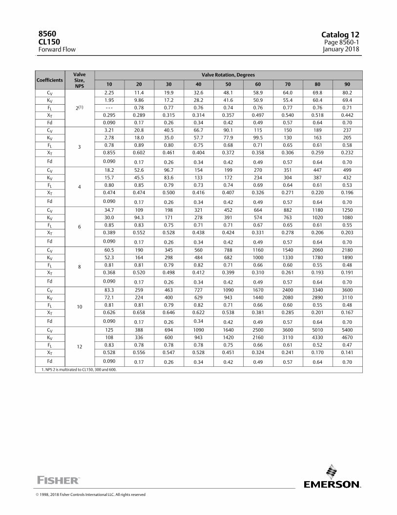
CoefficientsValveSize,NPS
Valve Rotation, Degrees
10 20 30 40 50 60 70 80 90
CV
2(1)
2.25 11.4 19.9 32.6 48.1 58.9 64.0 69.8 80.2
KV 1.95 9.86 17.2 28.2 41.6 50.9 55.4 60.4 69.4
FL ‐ ‐ ‐ 0.78 0.77 0.76 0.74 0.76 0.77 0.76 0.71
XT 0.295 0.289 0.315 0.314 0.357 0.497 0.540 0.518 0.442
Fd 0.090 0.17 0.26 0.34 0.42 0.49 0.57 0.64 0.70
CV
3
3.21 20.8 40.5 66.7 90.1 115 150 189 237
KV 2.78 18.0 35.0 57.7 77.9 99.5 130 163 205
FL 0.78 0.89 0.80 0.75 0.68 0.71 0.65 0.61 0.58
XT 0.855 0.602 0.461 0.404 0.372 0.358 0.306 0.259 0.232
Fd 0.090 0.17 0.26 0.34 0.42 0.49 0.57 0.64 0.70
CV
4
18.2 52.6 96.7 154 199 270 351 447 499
KV 15.7 45.5 83.6 133 172 234 304 387 432
FL 0.80 0.85 0.79 0.73 0.74 0.69 0.64 0.61 0.53
XT 0.474 0.474 0.500 0.416 0.407 0.326 0.271 0.220 0.196
Fd 0.090 0.17 0.26 0.34 0.42 0.49 0.57 0.64 0.70
CV
6
34.7 109 198 321 452 664 882 1180 1250
KV 30.0 94.3 171 278 391 574 763 1020 1080
FL 0.85 0.83 0.75 0.71 0.71 0.67 0.65 0.61 0.55
XT 0.389 0.552 0.528 0.438 0.424 0.331 0.278 0.206 0.203
Fd 0.090 0.17 0.26 0.34 0.42 0.49 0.57 0.64 0.70
CV
8
60.5 190 345 560 788 1160 1540 2060 2180
KV 52.3 164 298 484 682 1000 1330 1780 1890
FL 0.81 0.81 0.79 0.82 0.71 0.66 0.60 0.55 0.48
XT 0.368 0.520 0.498 0.412 0.399 0.310 0.261 0.193 0.191
Fd 0.090 0.17 0.26 0.34 0.42 0.49 0.57 0.64 0.70
CV
10
83.3 259 463 727 1090 1670 2400 3340 3600
KV 72.1 224 400 629 943 1440 2080 2890 3110
FL 0.81 0.81 0.79 0.82 0.71 0.66 0.60 0.55 0.48
XT 0.626 0.658 0.646 0.622 0.538 0.381 0.285 0.201 0.167
Fd 0.090 0.17 0.26 0.34 0.42 0.49 0.57 0.64 0.70
CV
12
125 388 694 1090 1640 2500 3600 5010 5400
KV 108 336 600 943 1420 2160 3110 4330 4670
FL 0.83 0.78 0.78 0.78 0.75 0.66 0.61 0.52 0.47
XT 0.528 0.556 0.547 0.528 0.451 0.324 0.241 0.170 0.141
Fd 0.090 0.17 0.26 0.34 0.42 0.49 0.57 0.64 0.70
1. NPS 2 is multirated to CL150, 300 and 600.
� 1998, 2018 Fisher Controls International LLC. All rights reserved
8560CL150Forward Flow
Catalog 12Page 8560-1
January 2018

CoefficientsValveSize,NPS
Valve Rotation, Degrees
10 20 30 40 50 60 70 80 90
CV
2(1)
2.11 9.96 20.7 34.0 50.5 68.4 81.0 81.0 81.0
KV 1.83 8.62 17.9 29.4 43.7 59.2 70.0 70.0 70.0
FL ‐ ‐ ‐ 0.88 0.84 0.77 0.71 0.69 0.67 0.71 0.69
XT 0.399 0.507 0.354 0.334 0.340 0.342 0.359 0.401 0.401
Fd 0.090 0.17 0.26 .034 0.42 0.49 0.57 0.64 0.70
CV
3
1.79 23.0 37.0 58.8 91.9 139 192 270 259
KV 1.55 19.9 32.0 50.9 79.5 120 166 234 224
FL 0.70 0.81 0.73 0.76 0.75 0.66 0.60 0.50 0.54
XT 0.449 0.455 0.395 0.417 0.423 0.313 0.256 0.188 0.203
Fd 0.090 0.17 0.26 0.34 0.42 0.49 0.57 0.64 0.70
CV
4
17.2 50.2 87.8 146 206 285 365 465 521
KV 14.9 43.4 75.9 126 178 247 316 402 451
FL 0.72 0.84 0.79 0.75 0.71 0.63 0.58 0.53 0.55
XT 0.445 0.471 0.481 0.417 0.370 0.276 0.225 0.191 0.196
Fd 0.090 0.17 0.26 0.34 0.42 0.49 0.57 0.64 0.70
CV
6
30.6 100 173 285 424 640 893 1180 1290
KV 26.5 86.5 150 247 367 554 772 1020 1120
FL 0.83 0.83 0.80 0.78 0.76 0.69 0.59 0.52 0.54
XT 0.444 0.608 0.574 0.485 0.441 0.316 0.227 0.176 0.182
Fd 0.090 0.17 0.26 0.34 0.42 0.49 0.57 0.64 0.70
CV
8
53.6 175 303 499 743 1120 1560 2070 2260
KV 46.4 151 262 432 643 969 1350 1790 1950
FL 0.79 0.83 0.82 0.79 0.73 0.66 0.58 0.51 0.48
XT 0.413 0.567 0.534 0.449 0.409 0.295 0.213 0.164 0.170
Fd 0.090 0.17 0.26 0.34 0.42 0.49 0.57 0.64 0.70
CV
10
84.4 232 423 737 1180 1730 2560 3250 3710
KV 73.0 200 366 638 1020 1500 2210 2810 3210
FL 0.79 0.83 0.82 0.79 0.73 0.66 0.58 0.51 0.48
XT 0.542 0.745 0.673 0.590 0.489 0.380 0.245 0.189 0.156
Fd 0.090 0.17 0.26 0.34 0.42 0.49 0.57 0.64 0.70
CV
12
126 347 631 1100 1760 2590 3820 4850 5540
KV 109 300 546 95.2 1520 2240 3300 4200 4790
FL 0.78 0.87 0.85 0.80 0.75 0.69 0.55 0.51 0.47
XT 0.491 0.671 0.610 0.535 0.443 0.343 0.222 0.171 0.141
Fd 0.090 0.17 0.26 0.34 0.42 0.49 0.57 0.64 0.70
1. NPS 2 is multirated to CL150, 300 and 600.
8560
Reverse FlowCL150
Catalog 12Page 8560-2January 2018
� 1998, 2018 Fisher Controls International LLC. All rights reserved
www.Fisher.com
Responsibility for selection, use, and maintenance of any product remains solely with the purchaser and end user. The contents of this publication are forinformational purposes only and are not to be construed as warranties or guarantees, express or implied, regarding the products or services describedtherein. Fisher is a mark owned by one of the companies in the Emerson Automation Solutions business unit of Emerson Electric Co. Emerson AutomationSolutions, Emerson, and the Emerson logo are trademarks and service marks of Emerson Electric Co. All other marks are the property of their respectiveowners.

3
CoefficientsValveSize,NPS
Valve Rotation, Degrees
10 20 30 40 50 60 70 80 90
CV
2(1)
2.25 11.4 19.9 32.6 48.1 58.9 64.0 69.8 80.2
KV 1.95 9.86 17.2 28.2 41.6 50.9 55.4 60.4 69.4
FL ‐ ‐ ‐ 0.78 0.77 0.75 0.74 0.75 0.77 0.75 0.71
XT 0.299 0.292 0.319 0.318 0.362 0.502 0.546 0.525 0.446
Fd 0.090 0.17 0.26 .034 0.42 0.49 0.57 0.64 0.70
CV
3
3.21 20.8 40.5 66.7 90.1 115 150 189 237
KV 2.78 18.0 35.0 57.7 77.9 99.5 130 163 205
FL 0.78 0.88 0.78 0.77 0.79 0.80 0.72 0.69 0.64
XT 0.370 0.542 0.433 0.411 0.464 0.469 0.397 0.346 0.286
Fd 0.090 0.17 0.26 0.34 0.42 0.49 0.57 0.64 0.70
CV
4
12.9 37.4 72.9 124 174 236 318 420 488
KV 11.2 32.4 63.1 107 151 204 275 363 422
FL 0.81 0.86 0.79 0.73 0.72 0.71 0.65 0.60 0.54
XT 0.455 0.499 0.416 0.395 0.410 0.363 0.292 0.235 0.210
Fd 0.090 0.17 0.26 0.34 0.42 0.49 0.57 0.64 0.70
CV
6
39.6 120 215 340 440 598 777 1050 1100
KV 34.3 104 186 294 381 604 672 908 952
FL 0.80 0.77 0.71 0.68 0.71 0.68 0.62 0.60 0.56
XT 0.420 0.433 0.434 0.369 0.360 0.299 0.282 0.214 0.205
Fd 0.090 0.17 0.26 0.34 0.42 0.49 0.57 0.64 0.70
CV
8
73.9 224 401 634 821 1120 1450 1960 2070
KV 63.9 194 347 548 710 969 1250 1700 1790
FL 0.80 0.79 0.77 0.75 0.71 0.66 0.61 0.55 0.49
XT 0.367 0.380 0.381 0.322 0.314 0.260 0.248 0.187 0.177
Fd 0.090 0.17 0.26 0.34 0.42 0.49 0.57 0.64 0.70
CV
10
64.6 248 453 706 1070 1630 2340 3280 3480
KV 55.9 215 392 611 926 1410 2020 2840 3010
FL 0.80 0.79 0.77 0.75 0.71 0.66 0.61 0.55 0.49
XT 0.464 0.565 0.562 0.544 0.455 0.335 0.255 0.179 0.159
Fd 0.090 0.17 0.26 0.34 0.42 0.49 0.57 0.64 0.70
CV
12
95.2 365 668 1040 1580 2410 3450 4840 5130
KV 82.3 316 578 900 1370 2080 2980 4190 4440
FL 0.86 0.80 0.78 0.79 0.74 0.67 0.59 0.53 0.48
XT 0.422 0.514 0.506 0.492 0.412 0.301 0.231 0.162 0.144
Fd 0.090 0.17 0.26 0.34 0.42 0.49 0.57 0.64 0.70
1. NPS 2 is multirated to CL150, 300 and 600.
8560
Forward FlowCL300
Catalog 12Page 8560-3
January 2018
� 1998, 2018 Fisher Controls International LLC. All rights reserved
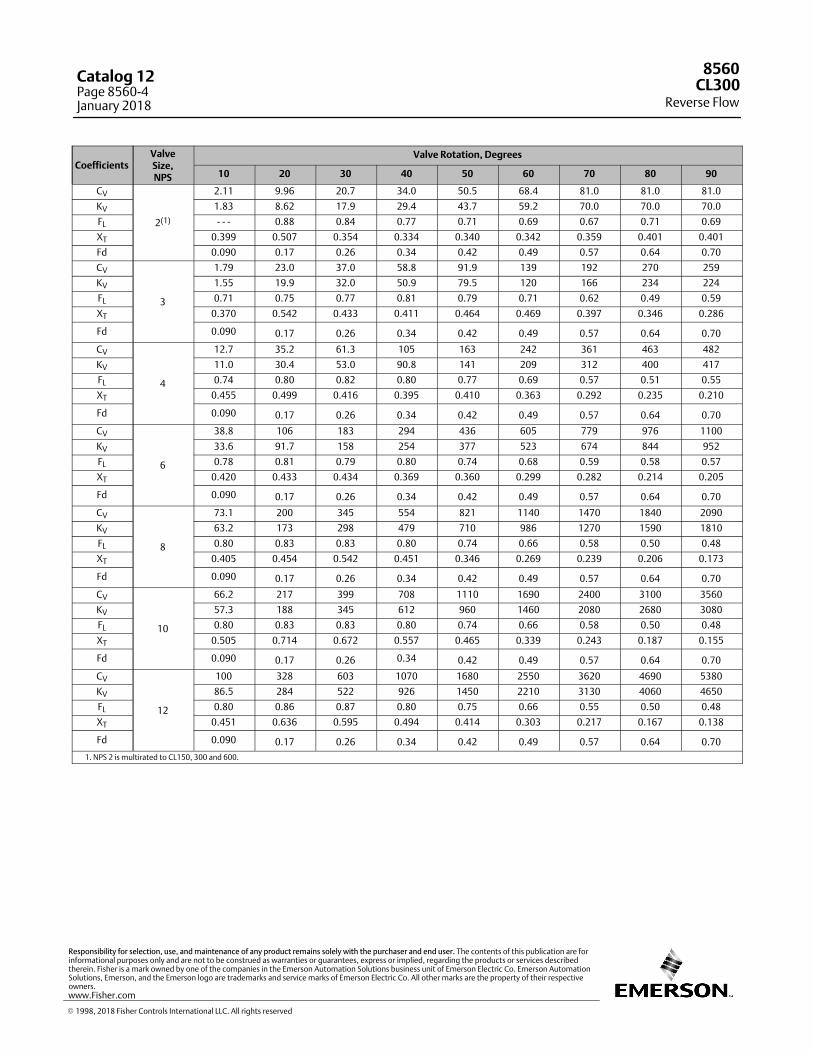
CoefficientsValveSize,NPS
Valve Rotation, Degrees
10 20 30 40 50 60 70 80 90
CV
2(1)
2.11 9.96 20.7 34.0 50.5 68.4 81.0 81.0 81.0
KV 1.83 8.62 17.9 29.4 43.7 59.2 70.0 70.0 70.0
FL ‐ ‐ ‐ 0.88 0.84 0.77 0.71 0.69 0.67 0.71 0.69
XT 0.399 0.507 0.354 0.334 0.340 0.342 0.359 0.401 0.401
Fd 0.090 0.17 0.26 0.34 0.42 0.49 0.57 0.64 0.70
CV
3
1.79 23.0 37.0 58.8 91.9 139 192 270 259
KV 1.55 19.9 32.0 50.9 79.5 120 166 234 224
FL 0.71 0.75 0.77 0.81 0.79 0.71 0.62 0.49 0.59
XT 0.370 0.542 0.433 0.411 0.464 0.469 0.397 0.346 0.286
Fd 0.090 0.17 0.26 0.34 0.42 0.49 0.57 0.64 0.70
CV
4
12.7 35.2 61.3 105 163 242 361 463 482
KV 11.0 30.4 53.0 90.8 141 209 312 400 417
FL 0.74 0.80 0.82 0.80 0.77 0.69 0.57 0.51 0.55
XT 0.455 0.499 0.416 0.395 0.410 0.363 0.292 0.235 0.210
Fd 0.090 0.17 0.26 0.34 0.42 0.49 0.57 0.64 0.70
CV
6
38.8 106 183 294 436 605 779 976 1100
KV 33.6 91.7 158 254 377 523 674 844 952
FL 0.78 0.81 0.79 0.80 0.74 0.68 0.59 0.58 0.57
XT 0.420 0.433 0.434 0.369 0.360 0.299 0.282 0.214 0.205
Fd 0.090 0.17 0.26 0.34 0.42 0.49 0.57 0.64 0.70
CV
8
73.1 200 345 554 821 1140 1470 1840 2090
KV 63.2 173 298 479 710 986 1270 1590 1810
FL 0.80 0.83 0.83 0.80 0.74 0.66 0.58 0.50 0.48
XT 0.405 0.454 0.542 0.451 0.346 0.269 0.239 0.206 0.173
Fd 0.090 0.17 0.26 0.34 0.42 0.49 0.57 0.64 0.70
CV
10
66.2 217 399 708 1110 1690 2400 3100 3560
KV 57.3 188 345 612 960 1460 2080 2680 3080
FL 0.80 0.83 0.83 0.80 0.74 0.66 0.58 0.50 0.48
XT 0.505 0.714 0.672 0.557 0.465 0.339 0.243 0.187 0.155
Fd 0.090 0.17 0.26 0.34 0.42 0.49 0.57 0.64 0.70
CV
12
100 328 603 1070 1680 2550 3620 4690 5380
KV 86.5 284 522 926 1450 2210 3130 4060 4650
FL 0.80 0.86 0.87 0.80 0.75 0.66 0.55 0.50 0.48
XT 0.451 0.636 0.595 0.494 0.414 0.303 0.217 0.167 0.138
Fd 0.090 0.17 0.26 0.34 0.42 0.49 0.57 0.64 0.70
1. NPS 2 is multirated to CL150, 300 and 600.
8560
Reverse FlowCL300
Catalog 12Page 8560-4January 2018
� 1998, 2018 Fisher Controls International LLC. All rights reserved
www.Fisher.com
Responsibility for selection, use, and maintenance of any product remains solely with the purchaser and end user. The contents of this publication are forinformational purposes only and are not to be construed as warranties or guarantees, express or implied, regarding the products or services describedtherein. Fisher is a mark owned by one of the companies in the Emerson Automation Solutions business unit of Emerson Electric Co. Emerson AutomationSolutions, Emerson, and the Emerson logo are trademarks and service marks of Emerson Electric Co. All other marks are the property of their respectiveowners.
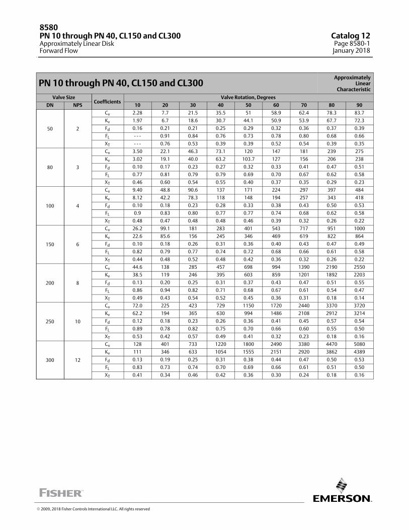
PN 10 through PN 40, CL150 and CL300Approximately
LinearCharacteristic
Valve SizeCoefficients
Valve Rotation, Degrees
DN NPS 10 20 30 40 50 60 70 80 90
50 2
Cv 2.28 7.7 21.5 35.5 51 58.9 62.4 78.3 83.7
Kv 1.97 6.7 18.6 30.7 44.1 50.9 53.9 67.7 72.3
Fd 0.16 0.21 0.21 0.25 0.29 0.32 0.36 0.37 0.39
FL ‐ ‐ ‐ 0.91 0.84 0.76 0.73 0.78 0.80 0.68 0.66
XT ‐ ‐ ‐ 0.76 0.53 0.39 0.39 0.52 0.54 0.39 0.35
80 3
Cv 3.50 22.1 46.3 73.1 120 147 181 239 275
Kv 3.02 19.1 40.0 63.2 103.7 127 156 206 238
Fd 0.10 0.17 0.23 0.27 0.32 0.33 0.41 0.47 0.51
FL 0.77 0.81 0.79 0.79 0.69 0.70 0.67 0.62 0.58
XT 0.46 0.60 0.54 0.55 0.40 0.37 0.35 0.29 0.23
100 4
Cv 9.40 48.8 90.6 137 171 224 297 397 484
Kv 8.12 42.2 78.3 118 148 194 257 343 418
Fd 0.10 0.18 0.23 0.28 0.33 0.38 0.43 0.50 0.53
FL 0.9 0.83 0.80 0.77 0.77 0.74 0.68 0.62 0.58
XT 0.48 0.47 0.48 0.48 0.46 0.39 0.32 0.26 0.22
150 6
Cv 26.2 99.1 181 283 401 543 717 951 1000
Kv 22.6 85.6 156 245 346 469 619 822 864
Fd 0.10 0.18 0.26 0.31 0.36 0.40 0.43 0.47 0.49
FL 0.82 0.79 0.77 0.74 0.72 0.68 0.66 0.61 0.58
XT 0.44 0.48 0.52 0.48 0.42 0.36 0.32 0.26 0.22
200 8
Cv 44.6 138 285 457 698 994 1390 2190 2550
Kv 38.5 119 246 395 603 859 1201 1892 2203
Fd 0.13 0.20 0.25 0.31 0.37 0.43 0.47 0.51 0.55
FL 0.86 0.94 0.82 0.71 0.68 0.67 0.61 0.54 0.47
XT 0.49 0.43 0.54 0.52 0.45 0.36 0.31 0.18 0.14
250 10
Cv 72.0 225 423 729 1150 1720 2440 3370 3720
Kv 62.2 194 365 630 994 1486 2108 2912 3214
Fd 0.12 0.18 0.23 0.26 0.36 0.41 0.45 0.57 0.54
FL 0.89 0.78 0.82 0.75 0.70 0.66 0.60 0.55 0.50
XT 0.53 0.42 0.57 0.49 0.41 0.32 0.23 0.18 0.16
300 12
Cv 128 401 733 1220 1800 2490 3380 4470 5080
Kv 111 346 633 1054 1555 2151 2920 3862 4389
Fd 0.13 0.19 0.25 0.31 0.38 0.44 0.47 0.50 0.53
FL 0.83 0.73 0.74 0.70 0.69 0.66 0.61 0.51 0.50
XT 0.41 0.34 0.46 0.42 0.36 0.30 0.24 0.18 0.16
� 2009, 2018 Fisher Controls International LLC. All rights reserved
8580PN 10 through PN 40, CL150 and CL300Approximately Linear DiskForward Flow
Catalog 12Page 8580-1
January 2018
This page intentionally left blank
8580Catalog 12Page 8580-2January 2018
� 2009, 2018 Fisher Controls International LLC. All rights reserved
www.Fisher.com
Responsibility for selection, use, and maintenance of any product remains solely with the purchaser and end user. The contents of this publication are forinformational purposes only and are not to be construed as warranties or guarantees, express or implied, regarding the products or services describedtherein. Fisher is a mark owned by one of the companies in the Emerson Automation Solutions business unit of Emerson Electric Co. Emerson AutomationSolutions, Emerson, and the Emerson logo are trademarks and service marks of Emerson Electric Co. All other marks are the property of their respectiveowners.
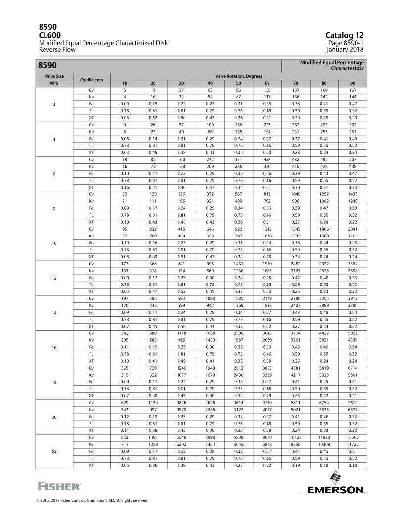
8590 Modified Equal Percentage Characteristic
Valve SizeCoefficients
Valve Rotation, Degrees
NPS 10 20 30 40 50 60 70 80 90
3
Cv 5 18 37 63 95 135 157 164 167
Kv 4 16 32 54 82 117 136 142 144
Fd 0.09 0.15 0.22 0.27 0.31 0.35 0.38 0.41 0.47
FL 0.78 0.81 0.81 0.79 0.73 0.66 0.59 0.55 0.52
XT 0.05 0.52 0.50 0.43 0.36 0.31 0.29 0.29 0.29
4
Cv 9 26 57 100 156 225 267 293 302
Kv 8 22 49 86 135 194 231 253 261
Fd 0.08 0.14 0.21 0.29 0.34 0.37 0.37 0.41 0.49
FL 0.78 0.81 0.81 0.79 0.73 0.66 0.59 0.55 0.52
XT 0.03 0.49 0.48 0.41 0.35 0.30 0.28 0.24 0.24
6
Cv 19 85 160 242 331 428 482 495 507
Kv 16 73 138 209 286 370 416 428 438
Fd 0.10 0.17 0.23 0.29 0.32 0.36 0.39 0.43 0.47
FL 0.78 0.81 0.81 0.79 0.73 0.66 0.59 0.55 0.52
XT 0.16 0.41 0.40 0.37 0.34 0.31 0.30 0.31 0.33
8
Cv 82 129 226 372 567 813 1049 1252 1435
Kv 71 111 195 321 490 702 906 1082 1240
Fd 0.09 0.17 0.24 0.29 0.34 0.36 0.39 0.47 0.50
FL 0.78 0.81 0.81 0.79 0.73 0.66 0.59 0.55 0.52
XT 0.10 0.43 0.48 0.43 0.36 0.31 0.27 0.24 0.22
10
Cv 95 232 415 646 922 1245 1545 1806 2041
Kv 82 200 359 558 797 1076 1335 1560 1763
Fd 0.10 0.16 0.23 0.29 0.31 0.34 0.38 0.44 0.48
FL 0.78 0.81 0.81 0.79 0.73 0.66 0.59 0.55 0.52
XT 0.05 0.49 0.51 0.43 0.34 0.28 0.24 0.24 0.24
12
Cv 177 368 641 995 1431 1950 2462 2922 3354
Kv 153 318 554 860 1236 1685 2127 2525 2898
Fd 0.09 0.17 0.25 0.30 0.34 0.38 0.42 0.48 0.53
FL 0.78 0.81 0.81 0.79 0.73 0.66 0.59 0.55 0.52
XT 0.05 0.47 0.52 0.45 0.37 0.30 0.25 0.23 0.22
14
Cv 197 396 693 1090 1585 2179 2786 3355 3912
Kv 170 342 599 942 1369 1883 2407 2899 3380
Fd 0.09 0.17 0.24 0.29 0.34 0.37 0.43 0.48 0.54
FL 0.78 0.81 0.81 0.79 0.73 0.66 0.59 0.55 0.52
XT 0.07 0.45 0.50 0.44 0.37 0.32 0.27 0.24 0.22
16
Cv 342 680 1118 1658 2300 3043 3774 4422 5022
Kv 295 588 966 1433 1987 2629 3261 3821 4339
Fd 0.11 0.19 0.25 0.30 0.35 0.39 0.43 0.49 0.54
FL 0.78 0.81 0.81 0.79 0.73 0.66 0.59 0.55 0.52
XT 0.10 0.41 0.45 0.41 0.35 0.29 0.26 0.24 0.24
18
Cv 365 720 1246 1943 2812 3853 4881 5819 6714
Kv 315 622 1077 1679 2430 3329 4217 5028 5801
Fd 0.09 0.17 0.24 0.29 0.33 0.37 0.41 0.45 0.51
FL 0.78 0.81 0.81 0.79 0.73 0.66 0.59 0.55 0.52
XT 0.07 0.40 0.45 0.40 0.34 0.29 0.25 0.22 0.21
20
Cv 629 1154 1826 2646 3614 4730 5811 6754 7612
Kv 543 997 1578 2286 3122 4087 5021 5835 6577
Fd 0.12 0.19 0.25 0.29 0.34 0.37 0.41 0.46 0.52
FL 0.78 0.81 0.81 0.79 0.73 0.66 0.59 0.55 0.52
XT 0.11 0.38 0.43 0.39 0.33 0.28 0.24 0.23 0.22
24
Cv 823 1491 2549 3998 5839 8070 10127 11930 13565
Kv 711 1288 2202 3454 5045 6972 8750 10308 11720
Fd 0.09 0.17 0.23 0.28 0.33 0.37 0.41 0.45 0.51
FL 0.78 0.81 0.81 0.79 0.73 0.66 0.59 0.55 0.52
XT 0.06 0.36 0.39 0.33 0.27 0.22 0.19 0.18 0.18
� 2015, 2018 Fisher Controls International LLC. All rights reserved
8590CL600Modified Equal Percentage Characterized DiskReverse Flow
Catalog 12Page 8590-1
January 2018
This page intentionally left blank
8590CL600
Modified Equal Percentage Characterized DiskReverse Flow
Catalog 12Page 8590-2January 2018
� 2015, 2018 Fisher Controls International LLC. All rights reserved
www.Fisher.com
Responsibility for selection, use, and maintenance of any product remains solely with the purchaser and end user. The contents of this publication are forinformational purposes only and are not to be construed as warranties or guarantees, express or implied, regarding the products or services describedtherein. Fisher is a mark owned by one of the companies in the Emerson Automation Solutions business unit of Emerson Electric Co. Emerson AutomationSolutions, Emerson, and the Emerson logo are trademarks and service marks of Emerson Electric Co. All other marks are the property of their respectiveowners.
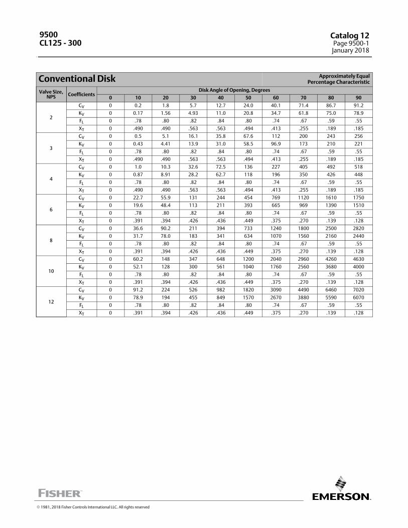
Conventional Disk Approximately EqualPercentage Characteristic
Valve Size,NPS Coefficients
Disk Angle of Opening, Degrees
0 10 20 30 40 50 60 70 80 90
2
CV 0 0.2 1.8 5.7 12.7 24.0 40.1 71.4 86.7 91.2
KV 0 0.17 1.56 4.93 11.0 20.8 34.7 61.8 75.0 78.9
FL 0 .78 .80 .82 .84 .80 .74 .67 .59 .55
XT 0 .490 .490 .563 .563 .494 .413 .255 .189 .185
3
CV 0 0.5 5.1 16.1 35.8 67.6 112 200 243 256
KV 0 0.43 4.41 13.9 31.0 58.5 96.9 173 210 221
FL 0 .78 .80 .82 .84 .80 .74 .67 .59 .55
XT 0 .490 .490 .563 .563 .494 .413 .255 .189 .185
4
CV 0 1.0 10.3 32.6 72.5 136 227 405 492 518
KV 0 0.87 8.91 28.2 62.7 118 196 350 426 448
FL 0 .78 .80 .82 .84 .80 .74 .67 .59 .55
XT 0 .490 .490 .563 .563 .494 .413 .255 .189 .185
6
CV 0 22.7 55.9 131 244 454 769 1120 1610 1750
KV 0 19.6 48.4 113 211 393 665 969 1390 1510
FL 0 .78 .80 .82 .84 .80 .74 .67 .59 .55
XT 0 .391 .394 .426 .436 .449 .375 .270 .139 .128
8
CV 0 36.6 90.2 211 394 733 1240 1800 2500 2820
KV 0 31.7 78.0 183 341 634 1070 1560 2160 2440
FL 0 .78 .80 .82 .84 .80 .74 .67 .59 .55
XT 0 .391 .394 .426 .436 .449 .375 .270 .139 .128
10
CV 0 60.2 148 347 648 1200 2040 2960 4260 4630
KV 0 52.1 128 300 561 1040 1760 2560 3680 4000
FL 0 .78 .80 .82 .84 .80 .74 .67 .59 .55
XT 0 .391 .394 .426 .436 .449 .375 .270 .139 .128
12
CV 0 91.2 224 526 982 1820 3090 4490 6460 7020
KV 0 78.9 194 455 849 1570 2670 3880 5590 6070
FL 0 .78 .80 .82 .84 .80 .74 .67 .59 .55
XT 0 .391 .394 .426 .436 .449 .375 .270 .139 .128
� 1981, 2018 Fisher Controls International LLC. All rights reserved
9500CL125 - 300
Catalog 12Page 9500-1
January 2018
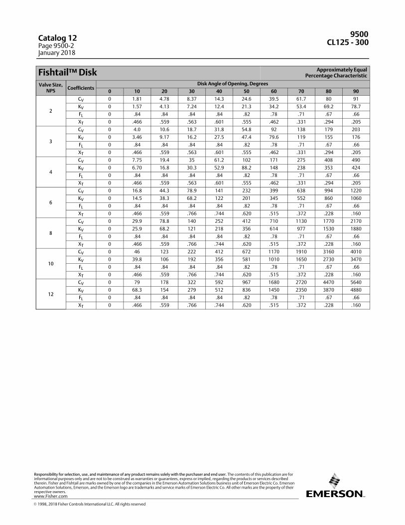
Fishtail™ Disk Approximately EqualPercentage Characteristic
Valve Size,NPS
CoefficientsDisk Angle of Opening, Degrees
0 10 20 30 40 50 60 70 80 90
2
CV 0 1.81 4.78 8.37 14.3 24.6 39.5 61.7 80 91
KV 0 1.57 4.13 7.24 12.4 21.3 34.2 53.4 69.2 78.7
FL 0 .84 .84 .84 .84 .82 .78 .71 .67 .66
XT 0 .466 .559 .563 .601 .555 .462 .331 .294 .205
3
CV 0 4.0 10.6 18.7 31.8 54.8 92 138 179 203
KV 0 3.46 9.17 16.2 27.5 47.4 79.6 119 155 176
FL 0 .84 .84 .84 .84 .82 .78 .71 .67 .66
XT 0 .466 .559 .563 .601 .555 .462 .331 .294 .205
4
CV 0 7.75 19.4 35 61.2 102 171 275 408 490
KV 0 6.70 16.8 30.3 52.9 88.2 148 238 353 424
FL 0 .84 .84 .84 .84 .82 .78 .71 .67 .66
XT 0 .466 .559 .563 .601 .555 .462 .331 .294 .205
6
CV 0 16.8 44.3 78.9 141 232 399 638 994 1220
KV 0 14.5 38.3 68.2 122 201 345 552 860 1060
FL 0 .84 .84 .84 .84 .82 .78 .71 .67 .66
XT 0 .466 .559 .766 .744 .620 .515 .372 .228 .160
8
CV 0 29.9 78.8 140 252 412 710 1130 1770 2170
KV 0 25.9 68.2 121 218 356 614 977 1530 1880
FL 0 .84 .84 .84 .84 .82 .78 .71 .67 .66
XT 0 .466 .559 .766 .744 .620 .515 .372 .228 .160
10
CV 0 46 123 222 412 672 1170 1910 3160 4010
KV 0 39.8 106 192 356 581 1010 1650 2730 3470
FL 0 .84 .84 .84 .84 .82 .78 .71 .67 .66
XT 0 .466 .559 .766 .744 .620 .515 .372 .228 .160
12
CV 0 79 178 322 592 967 1680 2720 4470 5640
KV 0 68.3 154 279 512 836 1450 2350 3870 4880
FL 0 .84 .84 .84 .84 .82 .78 .71 .67 .66
XT 0 .466 .559 .766 .744 .620 .515 .372 .228 .160
9500CL125 ‐ 300
Catalog 12Page 9500-2January 2018
� 1998, 2018 Fisher Controls International LLC. All rights reserved
www.Fisher.com
Responsibility for selection, use, and maintenance of any product remains solely with the purchaser and end user. The contents of this publication are forinformational purposes only and are not to be construed as warranties or guarantees, express or implied, regarding the products or services describedtherein. Fisher and Fishtail are marks owned by one of the companies in the Emerson Automation Solutions business unit of Emerson Electric Co. EmersonAutomation Solutions, Emerson, and the Emerson logo are trademarks and service marks of Emerson Electric Co. All other marks are the property of theirrespective owners.
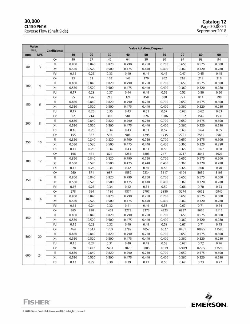
ValveSize, Coefficients
Valve Rotation, Degrees
mm NPS 10 20 30 40 50 60 70 80 90
80 3
Cv 10 27 46 64 80 90 97 98 94
Fl 0.850 0.840 0.820 0.790 0.750 0.700 0.650 0.575 0.600
Xt 0.530 0.520 0.500 0.475 0.440 0.400 0.360 0.320 0.280
Fd 0.15 0.25 0.33 0.40 0.44 0.46 0.47 0.45 0.45
100 4
Cv 23 61 103 143 179 202 216 218 210
Fl 0.850 0.840 0.820 0.790 0.750 0.700 0.650 0.575 0.600
Xt 0.530 0.520 0.500 0.475 0.440 0.400 0.360 0.320 0.280
Fd 0.17 0.28 0.37 0.44 0.49 0.52 0.52 0.50 0.50
150 6
Cv 55 126 213 324 458 600 727 814 790
Fl 0.850 0.840 0.820 0.790 0.750 0.700 0.650 0.575 0.600
Xt 0.530 0.520 0.500 0.475 0.440 0.400 0.360 0.320 0.280
Fd 0.17 0.26 0.35 0.43 0.51 0.57 0.62 0.62 0.63
200 8
Cv 92 214 383 581 826 1086 1362 1545 1530
Fl 0.850 0.840 0.820 0.790 0.750 0.700 0.650 0.575 0.600
Xt 0.530 0.520 0.500 0.475 0.440 0.400 0.360 0.320 0.280
Fd 0.16 0.25 0.34 0.43 0.51 0.57 0.63 0.64 0.65
250 10
Cv 155 337 595 906 1295 1735 2201 2589 2589
Fl 0.850 0.840 0.820 0.790 0.750 0.700 0.650 0.575 0.600
Xt 0.530 0.520 0.500 0.475 0.440 0.400 0.360 0.320 0.280
Fd 0.17 0.25 0.34 0.43 0.51 0.58 0.65 0.67 0.68
300 12
Cv 196 471 824 1255 1805 2471 3217 3845 3923
Fl 0.850 0.840 0.820 0.790 0.750 0.700 0.650 0.575 0.600
Xt 0.530 0.520 0.500 0.475 0.440 0.400 0.360 0.320 0.280
Fd 0.15 0.25 0.34 0.42 0.50 0.58 0.65 0.68 0.70
350 14
Cv 260 571 987 1559 2234 3117 4104 5039 5195
Fl 0.850 0.840 0.820 0.790 0.750 0.700 0.650 0.575 0.600
Xt 0.530 0.520 0.500 0.475 0.440 0.400 0.360 0.320 0.280
Fd 0.16 0.25 0.34 0.42 0.51 0.59 0.66 0.70 0.73
400 16
Cv 278 694 1180 1874 2707 3886 5274 6662 6940
Fl 0.850 0.840 0.820 0.790 0.750 0.700 0.650 0.575 0.600
Xt 0.530 0.520 0.500 0.475 0.440 0.400 0.360 0.320 0.280
Fd 0.15 0.24 0.32 0.41 0.49 0.58 0.67 0.71 0.74
450 18
Cv 365 820 1459 2279 3373 4923 6837 8660 9116
Fl 0.850 0.840 0.820 0.790 0.750 0.700 0.650 0.575 0.600
Xt 0.530 0.520 0.500 0.475 0.440 0.400 0.360 0.320 0.280
Fd 0.15 0.23 0.32 0.40 0.49 0.58 0.67 0.71 0.75
500 20
Cv 464 1043 1739 2782 4057 6027 8461 10895 11590
Fl 0.850 0.840 0.820 0.790 0.750 0.700 0.650 0.575 0.600
Xt 0.530 0.520 0.500 0.475 0.440 0.400 0.360 0.320 0.280
Fd 0.15 0.24 0.31 0.40 0.48 0.58 0.67 0.72 0.76
600 24
Cv 528 1407 2463 3870 5805 8619 12489 16535 17590
Fl 0.850 0.840 0.820 0.790 0.750 0.700 0.650 0.575 0.600
Xt 0.530 0.520 0.500 0.475 0.440 0.400 0.360 0.320 0.280
Fd 0.13 0.22 0.30 0.39 0.47 0.56 0.67 0.73 0.77
� 2018 Fisher Controls International LLC. All rights reserved
30,000CL150 PN16Reverse Flow (Shaft Side)
Catalog 12Page 30,000-1
September 2018

ValveSize,mm
CoefficientsValve Rotation, Degrees
10 20 30 40 50 60 70 80 90
80
Cv 10 27 46 64 80 90 97 98 94
Fl 0.850 0.840 0.820 0.790 0.750 0.700 0.650 0.575 0.600
Xt 0.530 0.520 0.500 0.475 0.440 0.400 0.360 0.320 0.280
Fd 0.15 0.25 0.33 0.40 0.44 0.46 0.47 0.45 0.45
100
Cv 23 61 103 143 179 202 216 218 210
Fl 0.850 0.840 0.820 0.790 0.750 0.700 0.650 0.575 0.600
Xt 0.530 0.520 0.500 0.475 0.440 0.400 0.360 0.320 0.280
Fd 0.17 0.28 0.37 0.44 0.49 0.52 0.52 0.50 0.50
150
Cv 55 126 213 324 458 600 727 814 790
Fl 0.850 0.840 0.820 0.790 0.750 0.700 0.650 0.575 0.600
Xt 0.530 0.520 0.500 0.475 0.440 0.400 0.360 0.320 0.280
Fd 0.17 0.26 0.35 0.43 0.51 0.57 0.62 0.62 0.63
200
Cv 92 214 383 581 826 1086 1362 1545 1530
Fl 0.850 0.840 0.820 0.790 0.750 0.700 0.650 0.575 0.600
Xt 0.530 0.520 0.500 0.475 0.440 0.400 0.360 0.320 0.280
Fd 0.16 0.25 0.34 0.43 0.51 0.57 0.63 0.64 0.65
250
Cv 155 337 595 906 1295 1735 2201 2589 2589
Fl 0.850 0.840 0.820 0.790 0.750 0.700 0.650 0.575 0.600
Xt 0.530 0.520 0.500 0.475 0.440 0.400 0.360 0.320 0.280
Fd 0.17 0.25 0.34 0.43 0.51 0.58 0.65 0.67 0.68
300
Cv 196 471 824 1255 1805 2471 3217 3845 3923
Fl 0.850 0.840 0.820 0.790 0.750 0.700 0.650 0.575 0.600
Xt 0.530 0.520 0.500 0.475 0.440 0.400 0.360 0.320 0.280
Fd 0.15 0.25 0.34 0.42 0.50 0.58 0.65 0.68 0.70
350
Cv 260 571 987 1559 2234 3117 4104 5039 5195
Fl 0.850 0.840 0.820 0.790 0.750 0.700 0.650 0.575 0.600
Xt 0.530 0.520 0.500 0.475 0.440 0.400 0.360 0.320 0.280
Fd 0.16 0.25 0.34 0.42 0.51 0.59 0.66 0.70 0.73
400
Cv 278 694 1180 1874 2707 3886 5274 6662 6940
Fl 0.850 0.840 0.820 0.790 0.750 0.700 0.650 0.575 0.600
Xt 0.530 0.520 0.500 0.475 0.440 0.400 0.360 0.320 0.280
Fd 0.15 0.24 0.32 0.41 0.49 0.58 0.67 0.71 0.74
450
Cv 365 820 1459 2279 3373 4923 6837 8660 9116
Fl 0.850 0.840 0.820 0.790 0.750 0.700 0.650 0.575 0.600
Xt 0.530 0.520 0.500 0.475 0.440 0.400 0.360 0.320 0.280
Fd 0.15 0.23 0.32 0.40 0.49 0.58 0.67 0.71 0.75
500
Cv 464 1043 1739 2782 4057 6027 8461 10895 11590
Fl 0.850 0.840 0.820 0.790 0.750 0.700 0.650 0.575 0.600
Xt 0.530 0.520 0.500 0.475 0.440 0.400 0.360 0.320 0.280
Fd 0.15 0.24 0.31 0.40 0.48 0.58 0.67 0.72 0.76
600
Cv 528 1407 2463 3870 5805 8619 12489 16535 17590
Fl 0.850 0.840 0.820 0.790 0.750 0.700 0.650 0.575 0.600
Xt 0.530 0.520 0.500 0.475 0.440 0.400 0.360 0.320 0.280
Fd 0.13 0.22 0.30 0.39 0.47 0.56 0.67 0.73 0.77
30,000
Reverse Flow (Shaft Side)PN25
Catalog 12Page 30,000-2September 2018
� 2018 Fisher Controls International LLC. All rights reserved
www.Fisher.com
Responsibility for selection, use, and maintenance of any product remains solely with the purchaser and end user. The contents of this publication are forinformational purposes only and are not to be construed as warranties or guarantees, express or implied, regarding the products or services describedtherein. Fisher is a mark owned by one of the companies in the Emerson Automation Solutions business unit of Emerson Electric Co. Emerson AutomationSolutions, Emerson, and the Emerson logo are trademarks and service marks of Emerson Electric Co. All other marks are the property of their respectiveowners.

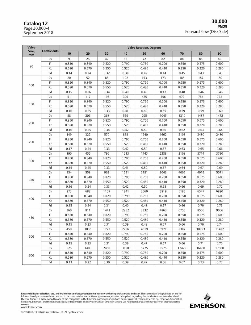
ValveSize, Coefficients
Valve Rotation, Degrees
mm NPS 10 20 30 40 50 60 70 80 90
80 3
Cv 9 25 42 58 72 82 88 88 85
Fl 0.850 0.840 0.820 0.790 0.750 0.700 0.650 0.575 0.600
Xt 0.580 0.570 0.550 0.520 0.480 0.410 0.350 0.320 0.280
Fd 0.14 0.24 0.32 0.38 0.42 0.44 0.45 0.43 0.43
100 4
Cv 20 52 88 122 153 173 185 187 180
Fl 0.850 0.840 0.820 0.790 0.750 0.700 0.650 0.575 0.600
Xt 0.580 0.570 0.550 0.520 0.480 0.410 0.350 0.320 0.280
Fd 0.15 0.26 0.34 0.40 0.45 0.47 0.48 0.46 0.46
150 6
Cv 51 117 198 300 425 556 673 754 732
Fl 0.850 0.840 0.820 0.790 0.750 0.700 0.650 0.575 0.600
Xt 0.580 0.570 0.550 0.520 0.480 0.410 0.350 0.320 0.280
Fd 0.16 0.25 0.33 0.41 0.49 0.55 0.59 0.59 0.60
200 8
Cv 88 206 368 559 795 1045 1310 1487 1472
Fl 0.850 0.840 0.820 0.790 0.750 0.700 0.650 0.575 0.600
Xt 0.580 0.570 0.550 0.520 0.480 0.410 0.350 0.320 0.280
Fd 0.16 0.25 0.34 0.42 0.50 0.56 0.62 0.63 0.64
250 10
Cv 149 322 570 868 1240 1662 2108 2480 2480
Fl 0.850 0.840 0.820 0.790 0.750 0.700 0.650 0.575 0.600
Xt 0.580 0.570 0.550 0.520 0.480 0.410 0.350 0.320 0.280
Fd 0.17 0.24 0.33 0.42 0.50 0.57 0.63 0.65 0.66
300 12
Cv 190 455 796 1213 1743 2388 3108 3714 3790
Fl 0.850 0.840 0.820 0.790 0.750 0.700 0.650 0.575 0.600
Xt 0.580 0.570 0.550 0.520 0.480 0.410 0.350 0.320 0.280
Fd 0.15 0.25 0.33 0.41 0.50 0.57 0.64 0.67 0.69
350 14
Cv 254 558 963 1521 2181 3043 4006 4919 5071
Fl 0.850 0.840 0.820 0.790 0.750 0.700 0.650 0.575 0.600
Xt 0.580 0.570 0.550 0.520 0.480 0.410 0.350 0.320 0.280
Fd 0.16 0.24 0.33 0.42 0.50 0.58 0.66 0.69 0.72
400 16
Cv 273 682 1159 1841 2660 3819 5183 6547 6820
Fl 0.850 0.840 0.820 0.790 0.750 0.700 0.650 0.575 0.600
Xt 0.580 0.570 0.550 0.520 0.480 0.410 0.350 0.320 0.280
Fd 0.15 0.24 0.31 0.40 0.48 0.57 0.66 0.70 0.73
450 18
Cv 360 811 1441 2252 3332 4863 6755 8556 9006
Fl 0.850 0.840 0.820 0.790 0.750 0.700 0.650 0.575 0.600
Xt 0.580 0.570 0.550 0.520 0.480 0.410 0.350 0.320 0.280
Fd 0.15 0.23 0.31 0.39 0.48 0.57 0.66 0.70 0.74
500 20
Cv 459 1033 1722 2756 4019 5971 8382 10793 11482
Fl 0.850 0.840 0.820 0.790 0.750 0.700 0.650 0.575 0.600
Xt 0.580 0.570 0.550 0.520 0.480 0.410 0.350 0.320 0.280
Fd 0.15 0.23 0.31 0.39 0.47 0.57 0.66 0.71 0.75
600 24
Cv 525 1400 2450 3850 5775 8575 12425 16450 17500
Fl 0.850 0.840 0.820 0.790 0.750 0.700 0.650 0.575 0.600
Xt 0.580 0.570 0.550 0.520 0.480 0.410 0.350 0.320 0.280
Fd 0.13 0.22 0.30 0.39 0.47 0.56 0.67 0.73 0.77
30,000
Forward Flow (Disk Side)CL150 PN16
Catalog 12Page 30,000-3
September 2018
� 2018 Fisher Controls International LLC. All rights reserved
ValveSize,mm
CoefficientsValve Rotation, Degrees
10 20 30 40 50 60 70 80 90
80
Cv 9 25 42 58 72 82 88 88 85
Fl 0.850 0.840 0.820 0.790 0.750 0.700 0.650 0.575 0.600
Xt 0.580 0.570 0.550 0.520 0.480 0.410 0.350 0.320 0.280
Fd 0.14 0.24 0.32 0.38 0.42 0.44 0.45 0.43 0.43
100
Cv 20 52 88 122 153 173 185 187 180
Fl 0.850 0.840 0.820 0.790 0.750 0.700 0.650 0.575 0.600
Xt 0.580 0.570 0.550 0.520 0.480 0.410 0.350 0.320 0.280
Fd 0.15 0.26 0.34 0.40 0.45 0.47 0.48 0.46 0.46
150
Cv 51 117 198 300 425 556 673 754 732
Fl 0.850 0.840 0.820 0.790 0.750 0.700 0.650 0.575 0.600
Xt 0.580 0.570 0.550 0.520 0.480 0.410 0.350 0.320 0.280
Fd 0.16 0.25 0.33 0.41 0.49 0.55 0.59 0.59 0.60
200
Cv 88 206 368 559 795 1045 1310 1487 1472
Fl 0.850 0.840 0.820 0.790 0.750 0.700 0.650 0.575 0.600
Xt 0.580 0.570 0.550 0.520 0.480 0.410 0.350 0.320 0.280
Fd 0.16 0.25 0.34 0.42 0.50 0.56 0.62 0.63 0.64
250
Cv 149 322 570 868 1240 1662 2108 2480 2480
Fl 0.850 0.840 0.820 0.790 0.750 0.700 0.650 0.575 0.600
Xt 0.580 0.570 0.550 0.520 0.480 0.410 0.350 0.320 0.280
Fd 0.17 0.24 0.33 0.42 0.50 0.57 0.63 0.65 0.66
300
Cv 190 455 796 1213 1743 2388 3108 3714 3790
Fl 0.850 0.840 0.820 0.790 0.750 0.700 0.650 0.575 0.600
Xt 0.580 0.570 0.550 0.520 0.480 0.410 0.350 0.320 0.280
Fd 0.15 0.25 0.33 0.41 0.50 0.57 0.64 0.67 0.69
350
Cv 254 558 963 1521 2181 3043 4006 4919 5071
Fl 0.850 0.840 0.820 0.790 0.750 0.700 0.650 0.575 0.600
Xt 0.580 0.570 0.550 0.520 0.480 0.410 0.350 0.320 0.280
Fd 0.16 0.24 0.33 0.42 0.50 0.58 0.66 0.69 0.72
400
Cv 273 682 1159 1841 2660 3819 5183 6547 6820
Fl 0.850 0.840 0.820 0.790 0.750 0.700 0.650 0.575 0.600
Xt 0.580 0.570 0.550 0.520 0.480 0.410 0.350 0.320 0.280
Fd 0.15 0.24 0.31 0.40 0.48 0.57 0.66 0.70 0.73
450
Cv 360 811 1441 2252 3332 4863 6755 8556 9006
Fl 0.850 0.840 0.820 0.790 0.750 0.700 0.650 0.575 0.600
Xt 0.580 0.570 0.550 0.520 0.480 0.410 0.350 0.320 0.280
Fd 0.15 0.23 0.31 0.39 0.48 0.57 0.66 0.70 0.74
500
Cv 459 1033 1722 2756 4019 5971 8382 10793 11482
Fl 0.850 0.840 0.820 0.790 0.750 0.700 0.650 0.575 0.600
Xt 0.580 0.570 0.550 0.520 0.480 0.410 0.350 0.320 0.280
Fd 0.15 0.23 0.31 0.39 0.47 0.57 0.66 0.71 0.75
600
Cv 525 1400 2450 3850 5775 8575 12425 16450 17500
Fl 0.850 0.840 0.820 0.790 0.750 0.700 0.650 0.575 0.600
Xt 0.580 0.570 0.550 0.520 0.480 0.410 0.350 0.320 0.280
Fd 0.13 0.22 0.30 0.39 0.47 0.56 0.67 0.73 0.77
30,000
Forward Flow (Disk Side)PN25
Catalog 12Page 30,000-4September 2018
� 2018 Fisher Controls International LLC. All rights reserved
www.Fisher.com
Responsibility for selection, use, and maintenance of any product remains solely with the purchaser and end user. The contents of this publication are forinformational purposes only and are not to be construed as warranties or guarantees, express or implied, regarding the products or services describedtherein. Fisher is a mark owned by one of the companies in the Emerson Automation Solutions business unit of Emerson Electric Co. Emerson AutomationSolutions, Emerson, and the Emerson logo are trademarks and service marks of Emerson Electric Co. All other marks are the property of their respectiveowners.
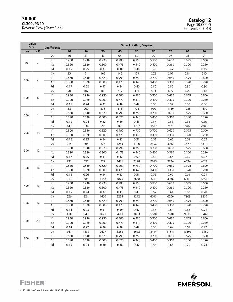
ValveSize, Coefficients
Valve Rotation, Degrees
mm NPS 10 20 30 40 50 60 70 80 90
80 3
Cv 10 27 46 64 80 90 97 98 94
Fl 0.850 0.840 0.820 0.790 0.750 0.700 0.650 0.575 0.600
Xt 0.530 0.520 0.500 0.475 0.440 0.400 0.360 0.320 0.280
Fd 0.15 0.25 0.33 0.40 0.44 0.46 0.47 0.45 0.45
100 4
Cv 23 61 103 143 179 202 216 218 210
Fl 0.850 0.840 0.820 0.790 0.750 0.700 0.650 0.575 0.600
Xt 0.530 0.520 0.500 0.475 0.440 0.400 0.360 0.320 0.280
Fd 0.17 0.28 0.37 0.44 0.49 0.52 0.52 0.50 0.50
150 6
Cv 50 107 183 277 391 504 605 655 630
Fl 0.850 0.840 0.820 0.790 0.750 0.700 0.650 0.575 0.600
Xt 0.530 0.520 0.500 0.475 0.440 0.400 0.360 0.320 0.280
Fd 0.16 0.24 0.32 0.40 0.47 0.53 0.57 0.55 0.56
200 8
Cv 88 200 338 513 725 950 1150 1288 1250
Fl 0.850 0.840 0.820 0.790 0.750 0.700 0.650 0.575 0.600
Xt 0.530 0.520 0.500 0.475 0.440 0.400 0.360 0.320 0.280
Fd 0.16 0.24 0.32 0.40 0.48 0.54 0.58 0.58 0.59
250 10
Cv 143 334 596 906 1287 1692 2121 2407 2383
Fl 0.850 0.840 0.820 0.790 0.750 0.700 0.650 0.575 0.600
Xt 0.530 0.520 0.500 0.475 0.440 0.400 0.360 0.320 0.280
Fd 0.16 0.25 0.34 0.43 0.51 0.57 0.63 0.64 0.65
300 12
Cv 215 465 823 1253 1790 2398 3042 3579 3579
Fl 0.850 0.840 0.820 0.790 0.750 0.700 0.650 0.575 0.600
Xt 0.530 0.520 0.500 0.475 0.440 0.400 0.360 0.320 0.280
Fd 0.17 0.25 0.34 0.42 0.50 0.58 0.64 0.66 0.67
350 14
Cv 231 555 972 1481 2128 2915 3794 4534 4627
Fl 0.850 0.840 0.820 0.790 0.750 0.700 0.650 0.575 0.600
Xt 0.530 0.520 0.500 0.475 0.440 0.400 0.360 0.320 0.280
Fd 0.16 0.26 0.34 0.43 0.51 0.59 0.66 0.69 0.71
400 16
Cv 313 688 1188 1875 2688 3751 4938 6063 6251
Fl 0.850 0.840 0.820 0.790 0.750 0.700 0.650 0.575 0.600
Xt 0.530 0.520 0.500 0.475 0.440 0.400 0.360 0.320 0.280
Fd 0.15 0.24 0.32 0.41 0.49 0.57 0.64 0.67 0.70
450 18
Cv 329 824 1400 2224 3212 4613 6260 7908 8237
Fl 0.850 0.840 0.820 0.790 0.750 0.700 0.650 0.575 0.600
Xt 0.530 0.520 0.500 0.475 0.440 0.400 0.360 0.320 0.280
Fd 0.14 0.23 0.31 0.39 0.47 0.55 0.64 0.68 0.71
500 20
Cv 418 940 1670 2610 3863 5638 7830 9918 10440
Fl 0.850 0.840 0.820 0.790 0.750 0.700 0.650 0.575 0.600
Xt 0.530 0.520 0.500 0.475 0.440 0.400 0.360 0.320 0.280
Fd 0.14 0.22 0.30 0.38 0.47 0.55 0.64 0.68 0.72
600 24
Cv 647 1456 2427 3883 5663 8414 11811 15209 16180
Fl 0.850 0.840 0.820 0.790 0.750 0.700 0.650 0.575 0.600
Xt 0.530 0.520 0.500 0.475 0.440 0.400 0.360 0.320 0.280
Fd 0.15 0.23 0.30 0.38 0.47 0.56 0.65 0.70 0.74
30,000
Reverse Flow (Shaft Side)CL300, PN40
Catalog 12Page 30,000-5
September 2018
� 2018 Fisher Controls International LLC. All rights reserved
ValveSize Coefficients
Valve Rotation, Degrees
mm NPS 10 20 30 40 50 60 70 80 90
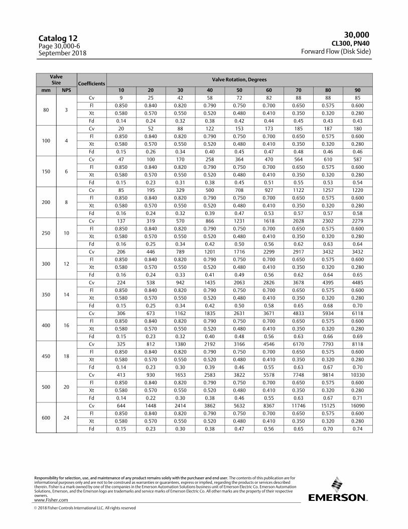
80 3
Cv 9 25 42 58 72 82 88 88 85
Fl 0.850 0.840 0.820 0.790 0.750 0.700 0.650 0.575 0.600
Xt 0.580 0.570 0.550 0.520 0.480 0.410 0.350 0.320 0.280
Fd 0.14 0.24 0.32 0.38 0.42 0.44 0.45 0.43 0.43
100 4
Cv 20 52 88 122 153 173 185 187 180
Fl 0.850 0.840 0.820 0.790 0.750 0.700 0.650 0.575 0.600
Xt 0.580 0.570 0.550 0.520 0.480 0.410 0.350 0.320 0.280
Fd 0.15 0.26 0.34 0.40 0.45 0.47 0.48 0.46 0.46
150 6
Cv 47 100 170 258 364 470 564 610 587
Fl 0.850 0.840 0.820 0.790 0.750 0.700 0.650 0.575 0.600
Xt 0.580 0.570 0.550 0.520 0.480 0.410 0.350 0.320 0.280
Fd 0.15 0.23 0.31 0.38 0.45 0.51 0.55 0.53 0.54
200 8
Cv 85 195 329 500 708 927 1122 1257 1220
Fl 0.850 0.840 0.820 0.790 0.750 0.700 0.650 0.575 0.600
Xt 0.580 0.570 0.550 0.520 0.480 0.410 0.350 0.320 0.280
Fd 0.16 0.24 0.32 0.39 0.47 0.53 0.57 0.57 0.58
250 10
Cv 137 319 570 866 1231 1618 2028 2302 2279
Fl 0.850 0.840 0.820 0.790 0.750 0.700 0.650 0.575 0.600
Xt 0.580 0.570 0.550 0.520 0.480 0.410 0.350 0.320 0.280
Fd 0.16 0.25 0.34 0.42 0.50 0.56 0.62 0.63 0.64
300 12
Cv 206 446 789 1201 1716 2299 2917 3432 3432
Fl 0.850 0.840 0.820 0.790 0.750 0.700 0.650 0.575 0.600
Xt 0.580 0.570 0.550 0.520 0.480 0.410 0.350 0.320 0.280
Fd 0.16 0.24 0.33 0.41 0.49 0.56 0.62 0.64 0.65
350 14
Cv 224 538 942 1435 2063 2826 3678 4395 4485
Fl 0.850 0.840 0.820 0.790 0.750 0.700 0.650 0.575 0.600
Xt 0.580 0.570 0.550 0.520 0.480 0.410 0.350 0.320 0.280
Fd 0.15 0.25 0.34 0.42 0.50 0.58 0.65 0.68 0.70
400 16
Cv 306 673 1162 1835 2631 3671 4833 5934 6118
Fl 0.850 0.840 0.820 0.790 0.750 0.700 0.650 0.575 0.600
Xt 0.580 0.570 0.550 0.520 0.480 0.410 0.350 0.320 0.280
Fd 0.15 0.23 0.32 0.40 0.48 0.56 0.63 0.66 0.69
450 18
Cv 325 812 1380 2192 3166 4546 6170 7793 8118
Fl 0.850 0.840 0.820 0.790 0.750 0.700 0.650 0.575 0.600
Xt 0.580 0.570 0.550 0.520 0.480 0.410 0.350 0.320 0.280
Fd 0.14 0.23 0.30 0.39 0.46 0.55 0.63 0.67 0.70
500 20
Cv 413 930 1653 2583 3822 5578 7748 9814 10330
Fl 0.850 0.840 0.820 0.790 0.750 0.700 0.650 0.575 0.600
Xt 0.580 0.570 0.550 0.520 0.480 0.410 0.350 0.320 0.280
Fd 0.14 0.22 0.30 0.38 0.46 0.55 0.63 0.67 0.71
600 24
Cv 644 1448 2414 3862 5632 8367 11746 15125 16090
Fl 0.850 0.840 0.820 0.790 0.750 0.700 0.650 0.575 0.600
Xt 0.580 0.570 0.550 0.520 0.480 0.410 0.350 0.320 0.280
Fd 0.15 0.23 0.30 0.38 0.47 0.56 0.65 0.70 0.74
30,000
Forward Flow (Disk Side)CL300, PN40
Catalog 12Page 30,000-6September 2018
� 2018 Fisher Controls International LLC. All rights reserved
www.Fisher.com
Responsibility for selection, use, and maintenance of any product remains solely with the purchaser and end user. The contents of this publication are forinformational purposes only and are not to be construed as warranties or guarantees, express or implied, regarding the products or services describedtherein. Fisher is a mark owned by one of the companies in the Emerson Automation Solutions business unit of Emerson Electric Co. Emerson AutomationSolutions, Emerson, and the Emerson logo are trademarks and service marks of Emerson Electric Co. All other marks are the property of their respectiveowners.
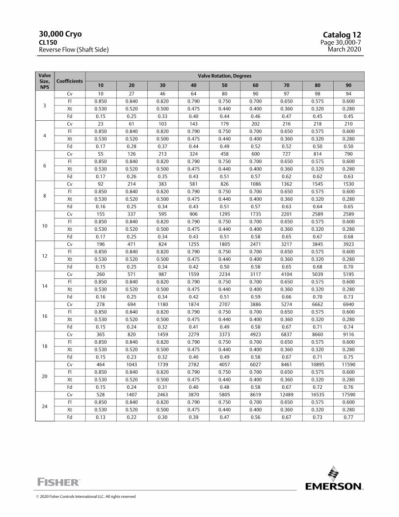
ValveSize,NPS
CoefficientsValve Rotation, Degrees
10 20 30 40 50 60 70 80 90
3
Cv 10 27 46 64 80 90 97 98 94
Fl 0.850 0.840 0.820 0.790 0.750 0.700 0.650 0.575 0.600
Xt 0.530 0.520 0.500 0.475 0.440 0.400 0.360 0.320 0.280
Fd 0.15 0.25 0.33 0.40 0.44 0.46 0.47 0.45 0.45
4
Cv 23 61 103 143 179 202 216 218 210
Fl 0.850 0.840 0.820 0.790 0.750 0.700 0.650 0.575 0.600
Xt 0.530 0.520 0.500 0.475 0.440 0.400 0.360 0.320 0.280
Fd 0.17 0.28 0.37 0.44 0.49 0.52 0.52 0.50 0.50
6
Cv 55 126 213 324 458 600 727 814 790
Fl 0.850 0.840 0.820 0.790 0.750 0.700 0.650 0.575 0.600
Xt 0.530 0.520 0.500 0.475 0.440 0.400 0.360 0.320 0.280
Fd 0.17 0.26 0.35 0.43 0.51 0.57 0.62 0.62 0.63
8
Cv 92 214 383 581 826 1086 1362 1545 1530
Fl 0.850 0.840 0.820 0.790 0.750 0.700 0.650 0.575 0.600
Xt 0.530 0.520 0.500 0.475 0.440 0.400 0.360 0.320 0.280
Fd 0.16 0.25 0.34 0.43 0.51 0.57 0.63 0.64 0.65
10
Cv 155 337 595 906 1295 1735 2201 2589 2589
Fl 0.850 0.840 0.820 0.790 0.750 0.700 0.650 0.575 0.600
Xt 0.530 0.520 0.500 0.475 0.440 0.400 0.360 0.320 0.280
Fd 0.17 0.25 0.34 0.43 0.51 0.58 0.65 0.67 0.68
12
Cv 196 471 824 1255 1805 2471 3217 3845 3923
Fl 0.850 0.840 0.820 0.790 0.750 0.700 0.650 0.575 0.600
Xt 0.530 0.520 0.500 0.475 0.440 0.400 0.360 0.320 0.280
Fd 0.15 0.25 0.34 0.42 0.50 0.58 0.65 0.68 0.70
14
Cv 260 571 987 1559 2234 3117 4104 5039 5195
Fl 0.850 0.840 0.820 0.790 0.750 0.700 0.650 0.575 0.600
Xt 0.530 0.520 0.500 0.475 0.440 0.400 0.360 0.320 0.280
Fd 0.16 0.25 0.34 0.42 0.51 0.59 0.66 0.70 0.73
16
Cv 278 694 1180 1874 2707 3886 5274 6662 6940
Fl 0.850 0.840 0.820 0.790 0.750 0.700 0.650 0.575 0.600
Xt 0.530 0.520 0.500 0.475 0.440 0.400 0.360 0.320 0.280
Fd 0.15 0.24 0.32 0.41 0.49 0.58 0.67 0.71 0.74
18
Cv 365 820 1459 2279 3373 4923 6837 8660 9116
Fl 0.850 0.840 0.820 0.790 0.750 0.700 0.650 0.575 0.600
Xt 0.530 0.520 0.500 0.475 0.440 0.400 0.360 0.320 0.280
Fd 0.15 0.23 0.32 0.40 0.49 0.58 0.67 0.71 0.75
20
Cv 464 1043 1739 2782 4057 6027 8461 10895 11590
Fl 0.850 0.840 0.820 0.790 0.750 0.700 0.650 0.575 0.600
Xt 0.530 0.520 0.500 0.475 0.440 0.400 0.360 0.320 0.280
Fd 0.15 0.24 0.31 0.40 0.48 0.58 0.67 0.72 0.76
24
Cv 528 1407 2463 3870 5805 8619 12489 16535 17590
Fl 0.850 0.840 0.820 0.790 0.750 0.700 0.650 0.575 0.600
Xt 0.530 0.520 0.500 0.475 0.440 0.400 0.360 0.320 0.280
Fd 0.13 0.22 0.30 0.39 0.47 0.56 0.67 0.73 0.77
� 2020 Fisher Controls International LLC. All rights reserved
30,000 CryoCL150Reverse Flow (Shaft Side)
Catalog 12Page 30,000-7
March 2020
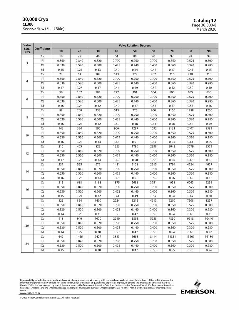
ValveSize,NPS
CoefficientsValve Rotation, Degrees
10 20 30 40 50 60 70 80 90
3
Cv 10 27 46 64 80 90 97 98 94
Fl 0.850 0.840 0.820 0.790 0.750 0.700 0.650 0.575 0.600
Xt 0.530 0.520 0.500 0.475 0.440 0.400 0.360 0.320 0.280
Fd 0.15 0.25 0.33 0.40 0.44 0.46 0.47 0.45 0.45
4
Cv 23 61 103 143 179 202 216 218 210
Fl 0.850 0.840 0.820 0.790 0.750 0.700 0.650 0.575 0.600
Xt 0.530 0.520 0.500 0.475 0.440 0.400 0.360 0.320 0.280
Fd 0.17 0.28 0.37 0.44 0.49 0.52 0.52 0.50 0.50
6
Cv 50 107 183 277 391 504 605 655 630
Fl 0.850 0.840 0.820 0.790 0.750 0.700 0.650 0.575 0.600
Xt 0.530 0.520 0.500 0.475 0.440 0.400 0.360 0.320 0.280
Fd 0.16 0.24 0.32 0.40 0.47 0.53 0.57 0.55 0.56
8
Cv 88 200 338 513 725 950 1150 1288 1250
Fl 0.850 0.840 0.820 0.790 0.750 0.700 0.650 0.575 0.600
Xt 0.530 0.520 0.500 0.475 0.440 0.400 0.360 0.320 0.280
Fd 0.16 0.24 0.32 0.40 0.48 0.54 0.58 0.58 0.59
10
Cv 143 334 596 906 1287 1692 2121 2407 2383
Fl 0.850 0.840 0.820 0.790 0.750 0.700 0.650 0.575 0.600
Xt 0.530 0.520 0.500 0.475 0.440 0.400 0.360 0.320 0.280
Fd 0.16 0.25 0.34 0.43 0.51 0.57 0.63 0.64 0.65
12
Cv 215 465 823 1253 1790 2398 3042 3579 3579
Fl 0.850 0.840 0.820 0.790 0.750 0.700 0.650 0.575 0.600
Xt 0.530 0.520 0.500 0.475 0.440 0.400 0.360 0.320 0.280
Fd 0.17 0.25 0.34 0.42 0.50 0.58 0.64 0.66 0.67
14
Cv 231 555 972 1481 2128 2915 3794 4534 4627
Fl 0.850 0.840 0.820 0.790 0.750 0.700 0.650 0.575 0.600
Xt 0.530 0.520 0.500 0.475 0.440 0.400 0.360 0.320 0.280
Fd 0.16 0.26 0.34 0.43 0.51 0.59 0.66 0.69 0.71
16
Cv 313 688 1188 1875 2688 3751 4938 6063 6251
Fl 0.850 0.840 0.820 0.790 0.750 0.700 0.650 0.575 0.600
Xt 0.530 0.520 0.500 0.475 0.440 0.400 0.360 0.320 0.280
Fd 0.15 0.24 0.32 0.41 0.49 0.57 0.64 0.67 0.70
18
Cv 329 824 1400 2224 3212 4613 6260 7908 8237
Fl 0.850 0.840 0.820 0.790 0.750 0.700 0.650 0.575 0.600
Xt 0.530 0.520 0.500 0.475 0.440 0.400 0.360 0.320 0.280
Fd 0.14 0.23 0.31 0.39 0.47 0.55 0.64 0.68 0.71
20
Cv 418 940 1670 2610 3863 5638 7830 9918 10440
Fl 0.850 0.840 0.820 0.790 0.750 0.700 0.650 0.575 0.600
Xt 0.530 0.520 0.500 0.475 0.440 0.400 0.360 0.320 0.280
Fd 0.14 0.22 0.30 0.38 0.47 0.55 0.64 0.68 0.72
24
Cv 647 1456 2427 3883 5663 8414 11811 15209 16180
Fl 0.850 0.840 0.820 0.790 0.750 0.700 0.650 0.575 0.600
Xt 0.530 0.520 0.500 0.475 0.440 0.400 0.360 0.320 0.280
Fd 0.15 0.23 0.30 0.38 0.47 0.56 0.65 0.70 0.74
30,000 Cryo
Reverse Flow (Shaft Side)CL300
Catalog 12Page 30,000-8
March 2020
� 2020 Fisher Controls International LLC. All rights reserved
www.Fisher.com
Responsibility for selection, use, and maintenance of any product remains solely with the purchaser and end user. The contents of this publication are forinformational purposes only and are not to be construed as warranties or guarantees, express or implied, regarding the products or services describedtherein. Fisher is a mark owned by one of the companies in the Emerson Automation Solutions business unit of Emerson Electric Co. Emerson AutomationSolutions, Emerson, and the Emerson logo are trademarks and service marks of Emerson Electric Co. All other marks are the property of their respectiveowners.
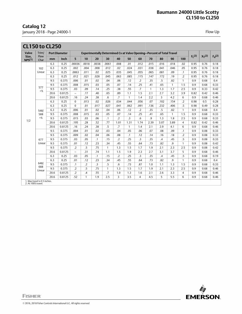
Flow Up
Baumann 24000 Little ScottyCL150 to CL250
Catalog 12 January 2018 ‐ Page 24000‐1
� 2016, 2018 Fisher Controls International LLC. All rights reserved
CL150 to CL250ValveSize,
NPS(1)
Trim/
Flow
Char
Port Diameter Experimentally Determined Cv at Valve Opening—Percent of Total TravelFL
(2) XT(2) Fd
(2)
mm Inch 5 10 20 30 40 50 60 70 80 90 100
1/2
102
Linear
6.3 0.25 .00036 .0018 .0038 .0061 .008 .01 .012 .015 .016 .018 .02 0.95 0.76 0.18
6.3 0.25 .002 .004 .008 .012 .02 .024 .031 .038 .041 .046 .05 0.95 0.76 0.18
6.3 0.25 .0063 .011 .02 .025 .035 .045 .055 .065 .081 .09 .1 0.95 0.76 0.18
6.3 0.25 .012 .021 .028 .045 .063 .085 .115 .147 .172 .19 .2 0.95 0.76 0.18
577
=%
9.5 0.375 .006 .01 .02 .04 .06 .12 .2 .35 .5 .82 1 0.9 0.68 0.4
9.5 0.375 .008 .015 .03 .05 .07 .14 .25 .41 .65 1 1.5 0.9 0.68 0.33
9.5 0.375 .03 .09 .14 .25 .38 .55 .7 1 1.3 1.7 2.5 0.9 0.33 0.42
20.6 0.8125 -- .17 .40 .65 .89 1.1 1.5 2.1 2.7 3.2 3.9 0.82 0.42 0.46
20.6 0.8125 .16 .24 .38 .6 .7 1 1.4 2.2 3 4.2 6 0.9 0.68 0.46
548/
588
=%
6.3 0.25 0 .013 .02 .026 .034 .044 .056 .07 .102 .154 .2 0.98 0.5 0.28
6.3 0.25 0 .01 .017 .027 .041 .062 .091 .136 .232 .406 .5 0.98 0.49 0.28
6.3 0.25 .006 .01 .02 .04 .06 .12 .2 .35 .5 .82 1 0.9 0.68 0.4
9.5 0.375 .008 .015 .03 .05 .07 .14 .25 .41 .65 1 1.5 0.9 0.68 0.33
9.5 0.375 .015 .03 .06 .1 .2 .3 .6 .9 1.3 1.8 2.5 0.9 0.68 0.33
20.6 0.8125 .195 .28 .52 .77 1.01 1.31 1.74 2.39 3.07 3.89 4 0.82 0.42 0.46
20.6 0.8125 .16 .24 .38 .5 .7 1 1.4 2.1 2.9 4.1 6 0.9 0.68 0.46
677
Linear
9.5 0.375 .004 .01 .02 .03 .04 .05 .06 .07 .08 .09 .1 0.9 0.08 0.33
9.5 0.375 .009 .02 .04 .06 .08 .1 .12 .14 .16 .18 .2 0.9 0.08 0.33
9.5 0.375 .03 .05 .1 .15 .2 .25 .3 .35 .4 .45 .5 0.9 0.08 0.33
9.5 0.375 .01 .12 .23 .34 .45 .55 .64 .73 .82 .9 1 0.9 0.08 0.42
9.5 0.375 .2 .5 .75 1 1.3 1.5 1.7 1.9 2.1 2.3 2.5 0.9 0.08 0.42
20.6 0.8125 -- .31 .74 1.1 1.5 1.9 2.3 2.7 3.1 3.7 5 0.9 0.68 0.46
648/
688
Linear
6.3 0.25 .03 .05 .1 .15 .2 .25 .3 .35 .4 .45 .5 0.9 0.68 0.19
6.3 0.25 .01 .12 .23 .34 .45 .55 .64 .73 .82 .9 1 0.9 0.68 0.4
9.5 0.375 .1 .2 .3 .5 .6 .73 .87 1.0 1.1 1.3 1.5 0.9 0.68 0.33
9.5 0.375 .2 .5 .75 1 1.3 1.5 1.7 1.9 2.1 2.3 2.5 0.9 0.68 0.46
20.6 0.8125 .2 .4 .55 .7 1.0 1.3 1.6 2.1 2.6 3.3 4 0.9 0.68 0.46
20.6 0.8125 .52 1 1.9 2.5 3 3.5 4 4.5 5 5.5 6 0.9 0.68 0.46
1. Max travel is 0.5 inches.2. At 100% travel.
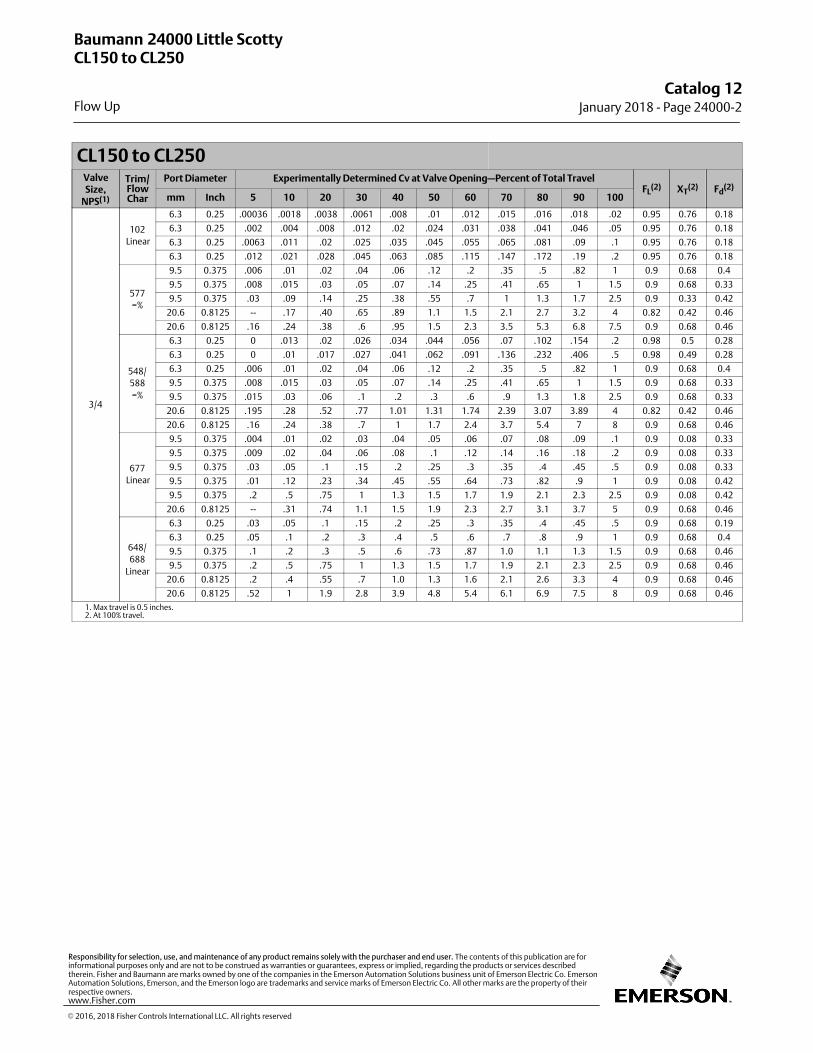
CL150 to CL250ValveSize,
NPS(1)
Trim/FlowChar
Port Diameter Experimentally Determined Cv at Valve Opening—Percent of Total TravelFL
(2) XT(2) Fd
(2)
mm Inch 5 10 20 30 40 50 60 70 80 90 100
3/4
102
Linear
6.3 0.25 .00036 .0018 .0038 .0061 .008 .01 .012 .015 .016 .018 .02 0.95 0.76 0.18
6.3 0.25 .002 .004 .008 .012 .02 .024 .031 .038 .041 .046 .05 0.95 0.76 0.18
6.3 0.25 .0063 .011 .02 .025 .035 .045 .055 .065 .081 .09 .1 0.95 0.76 0.18
6.3 0.25 .012 .021 .028 .045 .063 .085 .115 .147 .172 .19 .2 0.95 0.76 0.18
577
=%
9.5 0.375 .006 .01 .02 .04 .06 .12 .2 .35 .5 .82 1 0.9 0.68 0.4
9.5 0.375 .008 .015 .03 .05 .07 .14 .25 .41 .65 1 1.5 0.9 0.68 0.33
9.5 0.375 .03 .09 .14 .25 .38 .55 .7 1 1.3 1.7 2.5 0.9 0.33 0.42
20.6 0.8125 -- .17 .40 .65 .89 1.1 1.5 2.1 2.7 3.2 4 0.82 0.42 0.46
20.6 0.8125 .16 .24 .38 .6 .95 1.5 2.3 3.5 5.3 6.8 7.5 0.9 0.68 0.46
548/
588
=%
6.3 0.25 0 .013 .02 .026 .034 .044 .056 .07 .102 .154 .2 0.98 0.5 0.28
6.3 0.25 0 .01 .017 .027 .041 .062 .091 .136 .232 .406 .5 0.98 0.49 0.28
6.3 0.25 .006 .01 .02 .04 .06 .12 .2 .35 .5 .82 1 0.9 0.68 0.4
9.5 0.375 .008 .015 .03 .05 .07 .14 .25 .41 .65 1 1.5 0.9 0.68 0.33
9.5 0.375 .015 .03 .06 .1 .2 .3 .6 .9 1.3 1.8 2.5 0.9 0.68 0.33
20.6 0.8125 .195 .28 .52 .77 1.01 1.31 1.74 2.39 3.07 3.89 4 0.82 0.42 0.46
20.6 0.8125 .16 .24 .38 .7 1 1.7 2.4 3.7 5.4 7 8 0.9 0.68 0.46
677
Linear
9.5 0.375 .004 .01 .02 .03 .04 .05 .06 .07 .08 .09 .1 0.9 0.08 0.33
9.5 0.375 .009 .02 .04 .06 .08 .1 .12 .14 .16 .18 .2 0.9 0.08 0.33
9.5 0.375 .03 .05 .1 .15 .2 .25 .3 .35 .4 .45 .5 0.9 0.08 0.33
9.5 0.375 .01 .12 .23 .34 .45 .55 .64 .73 .82 .9 1 0.9 0.08 0.42
9.5 0.375 .2 .5 .75 1 1.3 1.5 1.7 1.9 2.1 2.3 2.5 0.9 0.08 0.42
20.6 0.8125 -- .31 .74 1.1 1.5 1.9 2.3 2.7 3.1 3.7 5 0.9 0.68 0.46
648/
688
Linear
6.3 0.25 .03 .05 .1 .15 .2 .25 .3 .35 .4 .45 .5 0.9 0.68 0.19
6.3 0.25 .05 .1 .2 .3 .4 .5 .6 .7 .8 .9 1 0.9 0.68 0.4
9.5 0.375 .1 .2 .3 .5 .6 .73 .87 1.0 1.1 1.3 1.5 0.9 0.68 0.46
9.5 0.375 .2 .5 .75 1 1.3 1.5 1.7 1.9 2.1 2.3 2.5 0.9 0.68 0.46
20.6 0.8125 .2 .4 .55 .7 1.0 1.3 1.6 2.1 2.6 3.3 4 0.9 0.68 0.46
20.6 0.8125 .52 1 1.9 2.8 3.9 4.8 5.4 6.1 6.9 7.5 8 0.9 0.68 0.46
1. Max travel is 0.5 inches.2. At 100% travel.
Baumann 24000 Little ScottyCL150 to CL250
Flow Up
Catalog 12January 2018 ‐ Page 24000‐2
� 2016, 2018 Fisher Controls International LLC. All rights reserved
www.Fisher.com
Responsibility for selection, use, and maintenance of any product remains solely with the purchaser and end user. The contents of this publication are forinformational purposes only and are not to be construed as warranties or guarantees, express or implied, regarding the products or services describedtherein. Fisher and Baumann are marks owned by one of the companies in the Emerson Automation Solutions business unit of Emerson Electric Co. EmersonAutomation Solutions, Emerson, and the Emerson logo are trademarks and service marks of Emerson Electric Co. All other marks are the property of theirrespective owners.
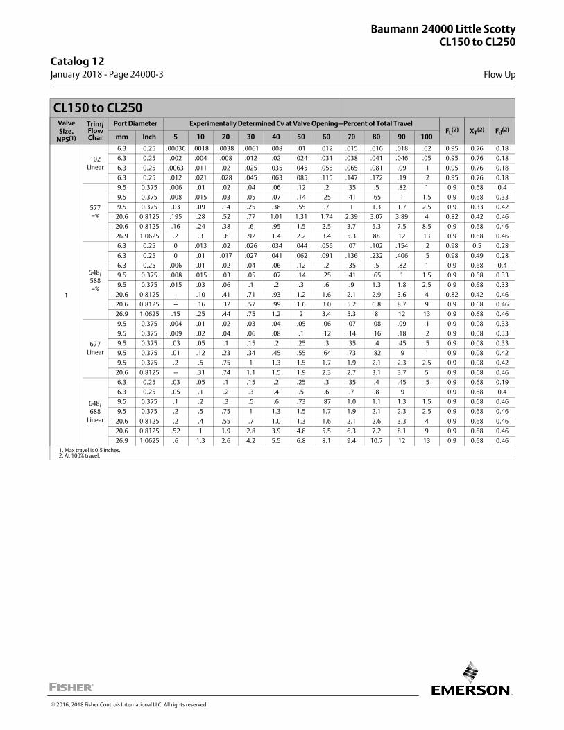
CL150 to CL250ValveSize,
NPS(1)
Trim/FlowChar
Port Diameter Experimentally Determined Cv at Valve Opening—Percent of Total TravelFL
(2) XT(2) Fd
(2)
mm Inch 5 10 20 30 40 50 60 70 80 90 100
1
102
Linear
6.3 0.25 .00036 .0018 .0038 .0061 .008 .01 .012 .015 .016 .018 .02 0.95 0.76 0.18
6.3 0.25 .002 .004 .008 .012 .02 .024 .031 .038 .041 .046 .05 0.95 0.76 0.18
6.3 0.25 .0063 .011 .02 .025 .035 .045 .055 .065 .081 .09 .1 0.95 0.76 0.18
6.3 0.25 .012 .021 .028 .045 .063 .085 .115 .147 .172 .19 .2 0.95 0.76 0.18
577
=%
9.5 0.375 .006 .01 .02 .04 .06 .12 .2 .35 .5 .82 1 0.9 0.68 0.4
9.5 0.375 .008 .015 .03 .05 .07 .14 .25 .41 .65 1 1.5 0.9 0.68 0.33
9.5 0.375 .03 .09 .14 .25 .38 .55 .7 1 1.3 1.7 2.5 0.9 0.33 0.42
20.6 0.8125 .195 .28 .52 .77 1.01 1.31 1.74 2.39 3.07 3.89 4 0.82 0.42 0.46
20.6 0.8125 .16 .24 .38 .6 .95 1.5 2.5 3.7 5.3 7.5 8.5 0.9 0.68 0.46
26.9 1.0625 .2 .3 .6 .92 1.4 2.2 3.4 5.3 88 12 13 0.9 0.68 0.46
548/
588
=%
6.3 0.25 0 .013 .02 .026 .034 .044 .056 .07 .102 .154 .2 0.98 0.5 0.28
6.3 0.25 0 .01 .017 .027 .041 .062 .091 .136 .232 .406 .5 0.98 0.49 0.28
6.3 0.25 .006 .01 .02 .04 .06 .12 .2 .35 .5 .82 1 0.9 0.68 0.4
9.5 0.375 .008 .015 .03 .05 .07 .14 .25 .41 .65 1 1.5 0.9 0.68 0.33
9.5 0.375 .015 .03 .06 .1 .2 .3 .6 .9 1.3 1.8 2.5 0.9 0.68 0.33
20.6 0.8125 -- .10 .41 .71 .93 1.2 1.6 2.1 2.9 3.6 4 0.82 0.42 0.46
20.6 0.8125 -- .16 .32 .57 .99 1.6 3.0 5.2 6.8 8.7 9 0.9 0.68 0.46
26.9 1.0625 .15 .25 .44 .75 1.2 2 3.4 5.3 8 12 13 0.9 0.68 0.46
677
Linear
9.5 0.375 .004 .01 .02 .03 .04 .05 .06 .07 .08 .09 .1 0.9 0.08 0.33
9.5 0.375 .009 .02 .04 .06 .08 .1 .12 .14 .16 .18 .2 0.9 0.08 0.33
9.5 0.375 .03 .05 .1 .15 .2 .25 .3 .35 .4 .45 .5 0.9 0.08 0.33
9.5 0.375 .01 .12 .23 .34 .45 .55 .64 .73 .82 .9 1 0.9 0.08 0.42
9.5 0.375 .2 .5 .75 1 1.3 1.5 1.7 1.9 2.1 2.3 2.5 0.9 0.08 0.42
20.6 0.8125 -- .31 .74 1.1 1.5 1.9 2.3 2.7 3.1 3.7 5 0.9 0.68 0.46
648/
688
Linear
6.3 0.25 .03 .05 .1 .15 .2 .25 .3 .35 .4 .45 .5 0.9 0.68 0.19
6.3 0.25 .05 .1 .2 .3 .4 .5 .6 .7 .8 .9 1 0.9 0.68 0.4
9.5 0.375 .1 .2 .3 .5 .6 .73 .87 1.0 1.1 1.3 1.5 0.9 0.68 0.46
9.5 0.375 .2 .5 .75 1 1.3 1.5 1.7 1.9 2.1 2.3 2.5 0.9 0.68 0.46
20.6 0.8125 .2 .4 .55 .7 1.0 1.3 1.6 2.1 2.6 3.3 4 0.9 0.68 0.46
20.6 0.8125 .52 1 1.9 2.8 3.9 4.8 5.5 6.3 7.2 8.1 9 0.9 0.68 0.46
26.9 1.0625 .6 1.3 2.6 4.2 5.5 6.8 8.1 9.4 10.7 12 13 0.9 0.68 0.46
1. Max travel is 0.5 inches.2. At 100% travel.
Baumann 24000 Little ScottyCL150 to CL250
Flow Up
Catalog 12 January 2018 ‐ Page 24000‐3
� 2016, 2018 Fisher Controls International LLC. All rights reserved
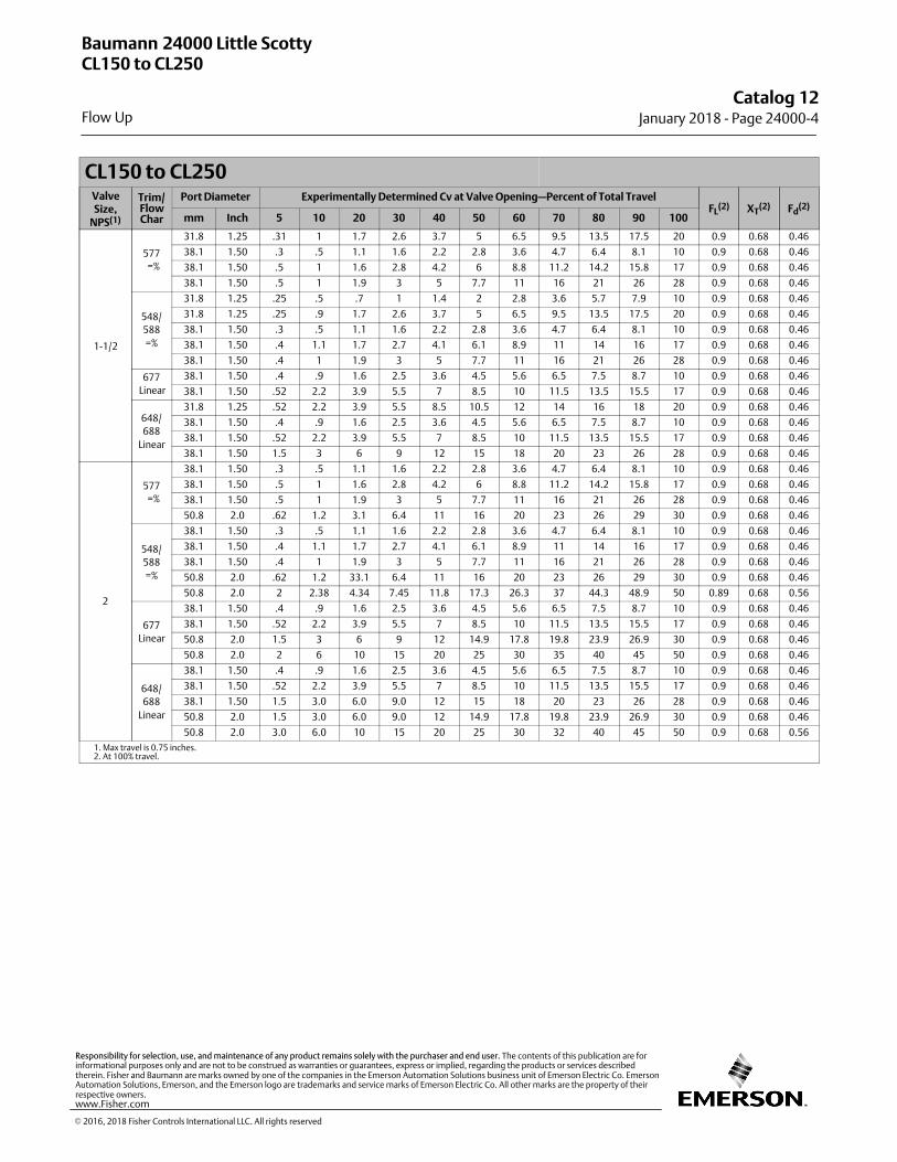
CL150 to CL250ValveSize,
NPS(1)
Trim/FlowChar
Port Diameter Experimentally Determined Cv at Valve Opening—Percent of Total TravelFL
(2) XT(2) Fd
(2)
mm Inch 5 10 20 30 40 50 60 70 80 90 100
1-1/2
577
=%
31.8 1.25 .31 1 1.7 2.6 3.7 5 6.5 9.5 13.5 17.5 20 0.9 0.68 0.46
38.1 1.50 .3 .5 1.1 1.6 2.2 2.8 3.6 4.7 6.4 8.1 10 0.9 0.68 0.46
38.1 1.50 .5 1 1.6 2.8 4.2 6 8.8 11.2 14.2 15.8 17 0.9 0.68 0.46
38.1 1.50 .5 1 1.9 3 5 7.7 11 16 21 26 28 0.9 0.68 0.46
548/
588
=%
31.8 1.25 .25 .5 .7 1 1.4 2 2.8 3.6 5.7 7.9 10 0.9 0.68 0.46
31.8 1.25 .25 .9 1.7 2.6 3.7 5 6.5 9.5 13.5 17.5 20 0.9 0.68 0.46
38.1 1.50 .3 .5 1.1 1.6 2.2 2.8 3.6 4.7 6.4 8.1 10 0.9 0.68 0.46
38.1 1.50 .4 1.1 1.7 2.7 4.1 6.1 8.9 11 14 16 17 0.9 0.68 0.46
38.1 1.50 .4 1 1.9 3 5 7.7 11 16 21 26 28 0.9 0.68 0.46
677
Linear
38.1 1.50 .4 .9 1.6 2.5 3.6 4.5 5.6 6.5 7.5 8.7 10 0.9 0.68 0.46
38.1 1.50 .52 2.2 3.9 5.5 7 8.5 10 11.5 13.5 15.5 17 0.9 0.68 0.46
648/
688
Linear
31.8 1.25 .52 2.2 3.9 5.5 8.5 10.5 12 14 16 18 20 0.9 0.68 0.46
38.1 1.50 .4 .9 1.6 2.5 3.6 4.5 5.6 6.5 7.5 8.7 10 0.9 0.68 0.46
38.1 1.50 .52 2.2 3.9 5.5 7 8.5 10 11.5 13.5 15.5 17 0.9 0.68 0.46
38.1 1.50 1.5 3 6 9 12 15 18 20 23 26 28 0.9 0.68 0.46
2
577
=%
38.1 1.50 .3 .5 1.1 1.6 2.2 2.8 3.6 4.7 6.4 8.1 10 0.9 0.68 0.46
38.1 1.50 .5 1 1.6 2.8 4.2 6 8.8 11.2 14.2 15.8 17 0.9 0.68 0.46
38.1 1.50 .5 1 1.9 3 5 7.7 11 16 21 26 28 0.9 0.68 0.46
50.8 2.0 .62 1.2 3.1 6.4 11 16 20 23 26 29 30 0.9 0.68 0.46
548/
588
=%
38.1 1.50 .3 .5 1.1 1.6 2.2 2.8 3.6 4.7 6.4 8.1 10 0.9 0.68 0.46
38.1 1.50 .4 1.1 1.7 2.7 4.1 6.1 8.9 11 14 16 17 0.9 0.68 0.46
38.1 1.50 .4 1 1.9 3 5 7.7 11 16 21 26 28 0.9 0.68 0.46
50.8 2.0 .62 1.2 33.1 6.4 11 16 20 23 26 29 30 0.9 0.68 0.46
50.8 2.0 2 2.38 4.34 7.45 11.8 17.3 26.3 37 44.3 48.9 50 0.89 0.68 0.56
677
Linear
38.1 1.50 .4 .9 1.6 2.5 3.6 4.5 5.6 6.5 7.5 8.7 10 0.9 0.68 0.46
38.1 1.50 .52 2.2 3.9 5.5 7 8.5 10 11.5 13.5 15.5 17 0.9 0.68 0.46
50.8 2.0 1.5 3 6 9 12 14.9 17.8 19.8 23.9 26.9 30 0.9 0.68 0.46
50.8 2.0 2 6 10 15 20 25 30 35 40 45 50 0.9 0.68 0.46
648/
688
Linear
38.1 1.50 .4 .9 1.6 2.5 3.6 4.5 5.6 6.5 7.5 8.7 10 0.9 0.68 0.46
38.1 1.50 .52 2.2 3.9 5.5 7 8.5 10 11.5 13.5 15.5 17 0.9 0.68 0.46
38.1 1.50 1.5 3.0 6.0 9.0 12 15 18 20 23 26 28 0.9 0.68 0.46
50.8 2.0 1.5 3.0 6.0 9.0 12 14.9 17.8 19.8 23.9 26.9 30 0.9 0.68 0.46
50.8 2.0 3.0 6.0 10 15 20 25 30 32 40 45 50 0.9 0.68 0.56
1. Max travel is 0.75 inches.2. At 100% travel.
Baumann 24000 Little ScottyCL150 to CL250
Flow Up
Catalog 12January 2018 ‐ Page 24000‐4
� 2016, 2018 Fisher Controls International LLC. All rights reserved
www.Fisher.com
Responsibility for selection, use, and maintenance of any product remains solely with the purchaser and end user. The contents of this publication are forinformational purposes only and are not to be construed as warranties or guarantees, express or implied, regarding the products or services describedtherein. Fisher and Baumann are marks owned by one of the companies in the Emerson Automation Solutions business unit of Emerson Electric Co. EmersonAutomation Solutions, Emerson, and the Emerson logo are trademarks and service marks of Emerson Electric Co. All other marks are the property of theirrespective owners.

CL150ValveSize,
NPS(1)
Trim/FlowChar
Port Diameter Experimentally Determined Cv at Valve Opening—Percent of Total TravelFL
(2) XT(2) Fd
(2)
mm Inch 5 10 20 30 40 50 60 70 80 90 100
1/2
102
Linear
6.3 0.25 .00036 .0018 .0038 .0061 .008 .01 .012 .015 .016 .018 .02 0.95 0.76 0.18
6.3 0.25 .002 .004 .008 .012 .02 .024 .031 .038 .041 .046 .05 0.95 0.76 0.18
6.3 0.25 .0063 .011 .02 .025 .035 .045 .055 .065 .081 .09 .1 0.95 0.76 0.18
6.3 0.25 .012 .021 .028 .045 .063 .085 .115 .147 .172 .19 .2 0.95 0.76 0.18
577
=%
9.5 0.375 .006 .01 .02 .04 .06 .12 .2 .35 .5 .82 1 0.9 0.40 0.46
9.5 0.375 .008 .015 .03 .05 .07 .14 .25 .41 .65 1 1.5 0.9 0.33 0.46
9.5 0.375 .03 .09 .14 .25 .38 .55 .7 1 1.3 1.7 2.5 0.9 0.42 0.46
20.6 0.8125 .19 .28 .52 .77 1.0 1.3 1.7 2.3 3.0 3.8 4 0.82 0.68 0.46
20.6 0.8125 .16 .24 .38 .6 .7 1 1.4 2.2 3 4.2 6 0.9 0.68 0.46
548/
588
=%
6.3 0.25 -- .013 .02 .026 .034 .044 .056 .07 .10 .15 .2 0.98 0.50 0.28
6.3 0.25 -- .01 .017 .027 .041 .062 .091 .136 .23 .40 .5 0.98 0.49 0.28
6.3 0.25 .006 .01 .02 .04 .06 .12 .2 .35 .5 .82 1 0.9 0.68 0.40
9.5 0.375 .008 .015 .03 .05 .07 .14 .25 .41 .65 1 1.5 0.9 0.68 0.33
9.5 0.375 .015 .03 .06 .1 .2 .3 .6 .9 1.3 1.8 2.5 0.9 0.68 0.42
20.6 0.8125 .19 .28 .52 .77 1.0 1.3 1.7 2.3 3.0 3.8 4 0.82 0.42 0.46
20.6 0.8125 -- .09 .25 .52 .94 1.5 3.2 5.0 5.9 7.3 7.7 0.91 0.65 0.46
677
Linear
9.5 0.375 .004 .01 .02 .03 .04 .05 .06 .07 .08 .09 .1 0.9 0.68 0.08
9.5 0.375 .009 .02 .04 .06 .08 .1 .12 .14 .16 .18 .2 0.9 0.68 0.12
9.5 0.375 .03 .05 .1 .15 .2 .25 .3 .35 .4 .45 .5 0.9 0.68 0.19
9.5 0.375 .05 .1 .2 .3 .4 .5 .6 .7 .8 .9 1 0.9 0.68 0.27
9.5 0.375 .2 .5 .75 1 1.3 1.5 1.7 1.9 2.1 2.3 2.5 0.9 0.68 0.42
20.6 0.8125 .22 .45 .82 1.3 1.8 2.2 2.6 3.1 3.8 4.5 5 0.9 0.68 0.46
648/
688
Linear
6.3 0.25 .03 .05 .1 .15 .2 .25 .3 .35 .4 .45 .5 0.9 0.68 0.19
6.3 0.25 .06 .12 .23 .34 .45 .55 .64 .73 .82 .9 1 0.9 0.68 0.4
9.5 0.375 .1 .2 .3 .5 .6 .73 .87 1.0 1.1 1.3 1.5 0.9 0.68 0.33
9.5 0.375 .2 .5 .75 1 1.3 1.5 1.7 1.9 2.1 2.3 2.5 0.9 0.68 0.68
20.6 0.8125 .2 .4 .55 .7 1.0 1.3 1.6 2.1 2.6 3.3 4 0.9 0.68 0.46
20.6 0.8125 .52 1 1.9 2.5 3 3.5 4 4.5 5 5.5 6 0.9 0.68 0.46
1. Max travel is 0.5 inches.2. At 100% travel.
Baumann 24000CCL150
Flow Up
Catalog 12 January 2018 ‐ Page 24000C‐1
� 2016, 2018 Fisher Controls International LLC. All rights reserved
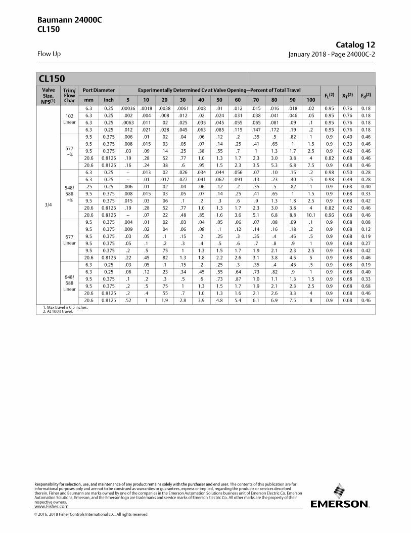
CL150ValveSize,
NPS(1)
Trim/FlowChar
Port Diameter Experimentally Determined Cv at Valve Opening—Percent of Total TravelFL
(2) XT(2) Fd
(2)
mm Inch 5 10 20 30 40 50 60 70 80 90 100
3/4
102
Linear
6.3 0.25 .00036 .0018 .0038 .0061 .008 .01 .012 .015 .016 .018 .02 0.95 0.76 0.18
6.3 0.25 .002 .004 .008 .012 .02 .024 .031 .038 .041 .046 .05 0.95 0.76 0.18
6.3 0.25 .0063 .011 .02 .025 .035 .045 .055 .065 .081 .09 .1 0.95 0.76 0.18
6.3 0.25 .012 .021 .028 .045 .063 .085 .115 .147 .172 .19 .2 0.95 0.76 0.18
577
=%
9.5 0.375 .006 .01 .02 .04 .06 .12 .2 .35 .5 .82 1 0.9 0.40 0.46
9.5 0.375 .008 .015 .03 .05 .07 .14 .25 .41 .65 1 1.5 0.9 0.33 0.46
9.5 0.375 .03 .09 .14 .25 .38 .55 .7 1 1.3 1.7 2.5 0.9 0.42 0.46
20.6 0.8125 .19 .28 .52 .77 1.0 1.3 1.7 2.3 3.0 3.8 4 0.82 0.68 0.46
20.6 0.8125 .16 .24 .38 .6 .95 1.5 2.3 3.5 5.3 6.8 7.5 0.9 0.68 0.46
548/
588
=%
6.3 0.25 -- .013 .02 .026 .034 .044 .056 .07 .10 .15 .2 0.98 0.50 0.28
6.3 0.25 -- .01 .017 .027 .041 .062 .091 .13 .23 .40 .5 0.98 0.49 0.28
.25 0.25 .006 .01 .02 .04 .06 .12 .2 .35 .5 .82 1 0.9 0.68 0.40
9.5 0.375 .008 .015 .03 .05 .07 .14 .25 .41 .65 1 1.5 0.9 0.68 0.33
9.5 0.375 .015 .03 .06 .1 .2 .3 .6 .9 1.3 1.8 2.5 0.9 0.68 0.42
20.6 0.8125 .19 .28 .52 .77 1.0 1.3 1.7 2.3 3.0 3.8 4 0.82 0.42 0.46
20.6 0.8125 -- .07 .22 .48 .85 1.6 3.6 5.1 6.8 8.8 10.1 0.96 0.68 0.46
677
Linear
9.5 0.375 .004 .01 .02 .03 .04 .05 .06 .07 .08 .09 .1 0.9 0.68 0.08
9.5 0.375 .009 .02 .04 .06 .08 .1 .12 .14 .16 .18 .2 0.9 0.68 0.12
9.5 0.375 .03 .05 .1 .15 .2 .25 .3 .35 .4 .45 .5 0.9 0.68 0.19
9.5 0.375 .05 .1 .2 .3 .4 .5 .6 .7 .8 .9 1 0.9 0.68 0.27
9.5 0.375 .2 .5 .75 1 1.3 1.5 1.7 1.9 2.1 2.3 2.5 0.9 0.68 0.42
20.6 0.8125 .22 .45 .82 1.3 1.8 2.2 2.6 3.1 3.8 4.5 5 0.9 0.68 0.46
648/
688
Linear
6.3 0.25 .03 .05 .1 .15 .2 .25 .3 .35 .4 .45 .5 0.9 0.68 0.19
6.3 0.25 .06 .12 .23 .34 .45 .55 .64 .73 .82 .9 1 0.9 0.68 0.40
9.5 0.375 .1 .2 .3 .5 .6 .73 .87 1.0 1.1 1.3 1.5 0.9 0.68 0.33
9.5 0.375 .2 .5 .75 1 1.3 1.5 1.7 1.9 2.1 2.3 2.5 0.9 0.68 0.68
20.6 0.8125 .2 .4 .55 .7 1.0 1.3 1.6 2.1 2.6 3.3 4 0.9 0.68 0.46
20.6 0.8125 .52 1 1.9 2.8 3.9 4.8 5.4 6.1 6.9 7.5 8 0.9 0.68 0.46
1. Max travel is 0.5 inches.2. At 100% travel.
Baumann 24000CCL150
Flow Up
Catalog 12January 2018 ‐ Page 24000C‐2
� 2016, 2018 Fisher Controls International LLC. All rights reserved
www.Fisher.com
Responsibility for selection, use, and maintenance of any product remains solely with the purchaser and end user. The contents of this publication are forinformational purposes only and are not to be construed as warranties or guarantees, express or implied, regarding the products or services describedtherein. Fisher and Baumann are marks owned by one of the companies in the Emerson Automation Solutions business unit of Emerson Electric Co. EmersonAutomation Solutions, Emerson, and the Emerson logo are trademarks and service marks of Emerson Electric Co. All other marks are the property of theirrespective owners.
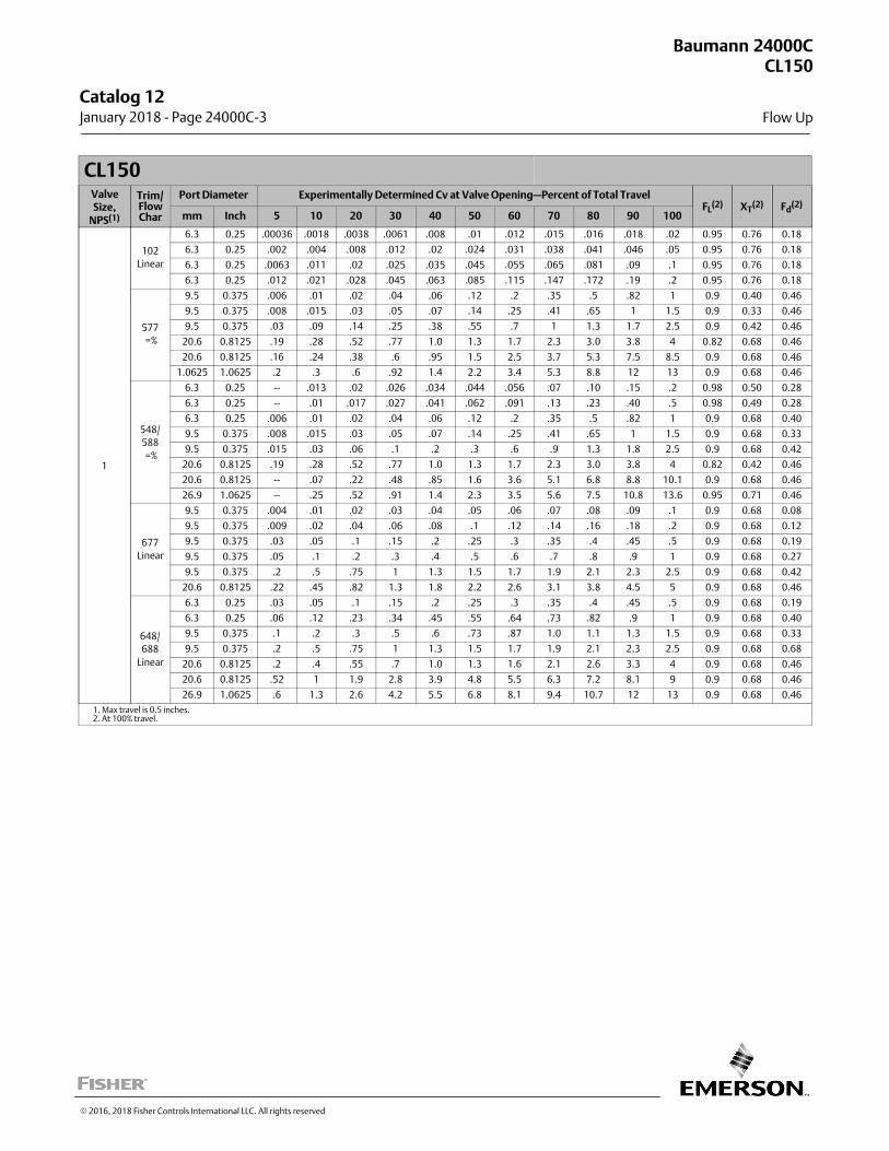
CL150ValveSize,
NPS(1)
Trim/FlowChar
Port Diameter Experimentally Determined Cv at Valve Opening—Percent of Total TravelFL
(2) XT(2) Fd
(2)
mm Inch 5 10 20 30 40 50 60 70 80 90 100
1
102
Linear
6.3 0.25 .00036 .0018 .0038 .0061 .008 .01 .012 .015 .016 .018 .02 0.95 0.76 0.18
6.3 0.25 .002 .004 .008 .012 .02 .024 .031 .038 .041 .046 .05 0.95 0.76 0.18
6.3 0.25 .0063 .011 .02 .025 .035 .045 .055 .065 .081 .09 .1 0.95 0.76 0.18
6.3 0.25 .012 .021 .028 .045 .063 .085 .115 .147 .172 .19 .2 0.95 0.76 0.18
577
=%
9.5 0.375 .006 .01 .02 .04 .06 .12 .2 .35 .5 .82 1 0.9 0.40 0.46
9.5 0.375 .008 .015 .03 .05 .07 .14 .25 .41 .65 1 1.5 0.9 0.33 0.46
9.5 0.375 .03 .09 .14 .25 .38 .55 .7 1 1.3 1.7 2.5 0.9 0.42 0.46
20.6 0.8125 .19 .28 .52 .77 1.0 1.3 1.7 2.3 3.0 3.8 4 0.82 0.68 0.46
20.6 0.8125 .16 .24 .38 .6 .95 1.5 2.5 3.7 5.3 7.5 8.5 0.9 0.68 0.46
1.0625 1.0625 .2 .3 .6 .92 1.4 2.2 3.4 5.3 8.8 12 13 0.9 0.68 0.46
548/
588
=%
6.3 0.25 -- .013 .02 .026 .034 .044 .056 .07 .10 .15 .2 0.98 0.50 0.28
6.3 0.25 -- .01 .017 .027 .041 .062 .091 .13 .23 .40 .5 0.98 0.49 0.28
6.3 0.25 .006 .01 .02 .04 .06 .12 .2 .35 .5 .82 1 0.9 0.68 0.40
9.5 0.375 .008 .015 .03 .05 .07 .14 .25 .41 .65 1 1.5 0.9 0.68 0.33
9.5 0.375 .015 .03 .06 .1 .2 .3 .6 .9 1.3 1.8 2.5 0.9 0.68 0.42
20.6 0.8125 .19 .28 .52 .77 1.0 1.3 1.7 2.3 3.0 3.8 4 0.82 0.42 0.46
20.6 0.8125 -- .07 .22 .48 .85 1.6 3.6 5.1 6.8 8.8 10.1 0.9 0.68 0.46
26.9 1.0625 -- .25 .52 .91 1.4 2.3 3.5 5.6 7.5 10.8 13.6 0.95 0.71 0.46
677
Linear
9.5 0.375 .004 .01 .02 .03 .04 .05 .06 .07 .08 .09 .1 0.9 0.68 0.08
9.5 0.375 .009 .02 .04 .06 .08 .1 .12 .14 .16 .18 .2 0.9 0.68 0.12
9.5 0.375 .03 .05 .1 .15 .2 .25 .3 .35 .4 .45 .5 0.9 0.68 0.19
9.5 0.375 .05 .1 .2 .3 .4 .5 .6 .7 .8 .9 1 0.9 0.68 0.27
9.5 0.375 .2 .5 .75 1 1.3 1.5 1.7 1.9 2.1 2.3 2.5 0.9 0.68 0.42
20.6 0.8125 .22 .45 .82 1.3 1.8 2.2 2.6 3.1 3.8 4.5 5 0.9 0.68 0.46
648/
688
Linear
6.3 0.25 .03 .05 .1 .15 .2 .25 .3 .35 .4 .45 .5 0.9 0.68 0.19
6.3 0.25 .06 .12 .23 .34 .45 .55 .64 .73 .82 .9 1 0.9 0.68 0.40
9.5 0.375 .1 .2 .3 .5 .6 .73 .87 1.0 1.1 1.3 1.5 0.9 0.68 0.33
9.5 0.375 .2 .5 .75 1 1.3 1.5 1.7 1.9 2.1 2.3 2.5 0.9 0.68 0.68
20.6 0.8125 .2 .4 .55 .7 1.0 1.3 1.6 2.1 2.6 3.3 4 0.9 0.68 0.46
20.6 0.8125 .52 1 1.9 2.8 3.9 4.8 5.5 6.3 7.2 8.1 9 0.9 0.68 0.46
26.9 1.0625 .6 1.3 2.6 4.2 5.5 6.8 8.1 9.4 10.7 12 13 0.9 0.68 0.46
1. Max travel is 0.5 inches.2. At 100% travel.
Baumann 24000CCL150
Flow Up
Catalog 12 January 2018 ‐ Page 24000C‐3
� 2016, 2018 Fisher Controls International LLC. All rights reserved
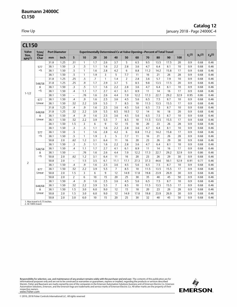
CL150ValveSize,
NPS(1)
Trim/FlowChar
Port Diameter Experimentally Determined Cv at Valve Opening—Percent of Total TravelFL
(2) XT(2) Fd
(2)
mm Inch 5 10 20 30 40 50 60 70 80 90 100
1-1/2
577
=%
31.8 1.25 .31 1 1.7 2.6 3.7 5 6.5 9.5 13.5 17.5 20 0.9 0.68 0.46
38.1 1.50 .3 .5 1.1 1.6 2.2 2.8 3.6 4.7 6.4 8.1 10 0.9 0.68 0.46
38.1 1.50 .5 1 1.6 2.8 4.2 6 8.8 11.2 14.2 15.8 17 0.9 0.68 0.46
38.1 1.50 .5 1 1.9 3 5 7.7 11 16 21 26 28 0.9 0.68 0.46
548/58
8
=%
31.8 1.25 .25 .5 .7 1 1.4 2 2.8 3.6 5.7 7.9 10 0.9 0.68 0.46
31.8 1.25 .25 .9 1.7 2.9 3.7 5 8.5 9.8 13.5 17.5 20 0.9 0.68 0.46
38.1 1.50 .3 .5 1.1 1.6 2.2 2.8 3.6 4.7 6.4 8.1 10 0.9 0.68 0.46
38.1 1.50 .4 1.1 1.7 2.7 4.1 6.1 8.9 11 14 16 17 0.9 0.68 0.46
38.1 1.50 -- .76 1.6 2.6 4.4 7.0 12.2 17.3 22.7 29.2 32.9 0.95 0.86 0.46
677
Linear
38.1 1.50 .4 .9 1.6 2.5 3.6 4.5 5.6 6.5 7.5 8.7 10 0.9 0.68 0.46
38.1 1.50 .52 2.2 3.9 5.5 7 8.5 10 11.5 13.5 15.5 17 0.9 0.68 0.46
648/68
8
Linear
31.8 1.25 .4 .9 1.6 2.5 3.6 4.5 5.6 6.5 7.5 8.7 10 0.9 0.68 0.46
31.8 1.25 .52 2.2 3.9 5.5 8.5 10.5 12 14 16 18 20 0.9 0.68 0.46
38.1 1.50 .4 .9 1.6 2.5 3.6 4.5 5.6 6.5 7.5 8.7 10 0.9 0.68 0.46
38.1 1.50 .52 2.2 3.9 5.5 7 8.5 10 11.5 13.5 15.5 17 0.9 0.68 0.46
38.1 1.50 1.5 3 6 9 12 15 18 20 23 26 28 0.9 0.68 0.46
2
577
=%
38.1 1.50 .3 .5 1.1 1.6 2.2 2.8 3.6 4.7 6.4 8.1 10 0.9 0.68 0.46
38.1 1.50 .5 1 1.6 2.8 4.2 6 8.8 11.2 14.2 15.8 17 0.9 0.68 0.46
38.1 1.50 .5 1 1.9 3 5 7.7 11 16 21 26 28 0.9 0.68 0.46
50.8 2.0 .62 1.2 3.1 6.4 11 16 20 23 26 29 30 0.9 0.68 0.46
548/58
8
=%
38.1 1.50 .3 .5 1.1 1.6 2.2 2.8 3.6 4.7 6.4 8.1 10 0.9 0.68 0.46
38.1 1.50 .4 1.1 1.7 2.7 4.1 6.1 8.9 11 14 16 17 0.9 0.68 0.46
38.1 1.50 -- .76 1.6 2.6 4.4 7.0 12.2 17.3 22.7 29.2 32.9 0.9 0.86 0.46
50.8 2.0 .62 1.2 3.1 6.4 11 16 20 23 26 29 30 0.9 0.68 0.46
50.8 2.0 -- 1.5 3.5 6.1 11.1 17.1 27.3 37.3 44.6 50.1 52.9 0.91 0.77 0.46
677
Linear
38.1 1.50 .4 .9 1.6 2.5 3.6 4.5 5.6 6.5 7.5 8.7 10 0.9 0.68 0.46
38.1 1.50 .52 2.2 3.9 5.5 7 8.5 10 11.5 13.5 15.5 17 0.9 0.68 0.46
50.8 2.0 1.5 3 6 9 12 14.9 17.8 19.8 23.9 26.9 30 0.9 0.68 0.46
50.8 2.0 2 6 10 15 20 25 30 35 40 45 50 0.9 0.68 0.46
648/68
8
Linear
38.1 1.50 .4 .9 1.6 2.5 3.6 4.5 5.6 6.5 7.5 8.7 10 0.9 0.68 0.46
38.1 1.50 .52 2.2 3.9 5.5 7 8.5 10 11.5 13.5 15.5 17 0.9 0.68 0.46
38.1 1.50 1.5 3.0 6.0 9.0 12 15 18 20 23 26 28 0.9 0.68 0.46
50.8 2.0 1.5 3.0 6.0 9.0 12 14.9 17.8 19.8 23.9 26.9 30 0.9 0.68 0.46
50.8 2.0 3.0 6.0 10 15 20 25 30 32 40 45 50 0.9 0.68 0.46
1. Max travel is 0.75 inches.2. At 100% travel.
Baumann 24000CCL150
Flow Up
Catalog 12January 2018 ‐ Page 24000C‐4
� 2016, 2018 Fisher Controls International LLC. All rights reserved
www.Fisher.com
Responsibility for selection, use, and maintenance of any product remains solely with the purchaser and end user. The contents of this publication are forinformational purposes only and are not to be construed as warranties or guarantees, express or implied, regarding the products or services describedtherein. Fisher and Baumann are marks owned by one of the companies in the Emerson Automation Solutions business unit of Emerson Electric Co. EmersonAutomation Solutions, Emerson, and the Emerson logo are trademarks and service marks of Emerson Electric Co. All other marks are the property of theirrespective owners.
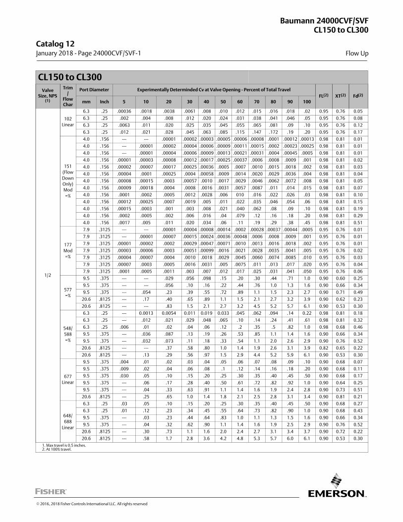
CL150 to CL300
ValveSize, NPS
(1)
Trim/
FlowChar
Port Diameter Experimentally Determinded Cv at Valve Opening - Percent of Total Travel
FL(2) XT(2) Fd(2)
mm Inch 5 10 20 30 40 50 60 70 80 90 100
1/2
102
Linear
6.3 .25 .00036 .0018 .0038 .0061 .008 .010 .012 .015 .016 .018 .02 0.95 0.76 0.05
6.3 .25 .002 .004 .008 .012 .020 .024 .031 .038 .041 .046 .05 0.95 0.76 0.08
6.3 .25 .0063 .011 .020 .025 .035 .045 .055 .065 .081 .09 .10 0.95 0.76 0.12
6.3 .25 .012 .021 .028 .045 .063 .085 .115 .147 .172 .19 .20 0.95 0.76 0.17
151
(Flow
Down
Only)
Mod
=%
4.0 .156 --- --- .00001 .00002 .00003 .00005 .00006 .00008 .0001 .00012 .00013 0.98 0.81 0.01
4.0 .156 --- .00001 .00002 .00004 .00006 .00009 .00011 .00015 .0002 .00023 .00025 0.98 0.81 0.01
4.0 .156 --- .00001 .00004 .00006 .00009 .00013 .00021 .00031 .0004 .00045 .0005 0.98 0.81 0.01
4.0 .156 .00001 .00003 .00008 .00012 .00017 .00025 .00037 .0006 .0008 .0009 .001 0.98 0.81 0.02
4.0 .156 .00002 .00007 .00017 .00025 .00036 .0005 .0007 .0010 .0015 .0018 .002 0.98 0.81 0.03
4.0 .156 .00004 .0001 .00025 .0004 .00058 .0009 .0014 .0020 .0029 .0036 .004 0.98 0.81 0.04
4.0 .156 .00008 .00015 .0003 .00057 .0010 .0017 .0029 .0046 .0062 .0072 .008 0.98 0.81 0.05
4.0 .156 .00009 .00018 .0004 .0008 .0016 .0031 .0057 .0087 .011 .014 .015 0.98 0.81 0.07
4.0 .156 .0001 .0002 .0005 .0012 .0028 .006 010 .016 .022 .026 .03 0.98 0.81 0.10
4.0 .156 .00012 .00025 .0007 .0019 .005 .011 .022 .035 .046 .054 .06 0.98 0.81 0.15
4.0 .156 .00015 .0003 .001 .003 .008 .021 .040 .062 .08 .09 .10 0.98 0.81 0.19
4.0 .156 .0002 .0005 .002 .006 .016 .04 .079 .12 .16 .18 .20 0.98 0.81 0.29
4.0 .156 .0017 .005 .011 .020 .034 .06 .11 .19 .29 .38 .45 0.98 0.81 0.51
177
Mod
=%
7.9 .3125 --- --- .00001 .00004 .00008 .00014 .0002 .00028 .00037 .00044 .0005 0.95 0.76 0.01
7.9 .3125 --- .00001 .00007 .00015 .00024 .00036 .00048 .0006 .0008 .0009 .001 0.95 0.76 0.01
7.9 .3125 .00001 .00002 .0002 .00029 .00047 .00071 .0010 .0013 .0016 .0018 .002 0.95 0.76 0.01
7.9 .3125 .00003 .00006 .0003 .00051 .00099 .0016 .0021 .0028 .0035 .0041 .005 0.95 0.76 0.02
7.9 .3125 .00004 .00007 .0004 .0010 .0018 .0029 .0045 .0060 .0074 .0085 .010 0.95 0.76 0.03
7.9 .3125 .00007 .0003 .0005 .0016 .0031 .005 .0075 .011 .013 .017 .020 0.95 0.76 0.04
7.9 .3125 .0001 .0005 .0011 .003 .007 .012 .017 .025 .031 .041 .050 0.95 0.76 0.06
577
=%
9.5 .375 --- --- .029 .056 .098 .15 .20 .30 .44 .71 1.0 0.90 0.60 0.25
9.5 .375 --- --- .056 .10 .16 .22 .44 .76 1.0 1.3 1.6 0.90 0.66 0.34
9.5 .375 --- .054 .23 .39 .55 .72 .89 1.1 1.5 2.3 2.7 0.90 0.71 0.49
20.6 .8125 --- .17 .40 .65 .89 1.1 1.5 2.1 2.7 3.2 3.9 0.90 0.62 0.23
20.6 .8125 --- --- .83 1.5 2.1 2.7 3.2 4.5 5.2 5.7 6.1 0.90 0.53 0.30
548/
588
=%
6.3 .25 --- 0.0013 0.0054 0.011 0.019 0.033 .045 .062 .094 .14 0.22 0.98 0.81 0.18
6.3 .25 --- .012 .021 .029 .048 .065 .10 .14 .24 .41 .61 0.98 0.81 0.32
6.3 .25 .006 .01 .02 .04 .06 .12 .2 .35 .5 .82 1.0 0.98 0.68 0.46
9.5 .375 --- .036 .087 .13 .19 .26 .53 .85 1.1 1.4 1.6 0.90 0.66 0.34
9.5 .375 --- .032 .073 .11 .18 .33 .54 1.1 2.0 2.6 2.9 0.90 0.76 0.52
20.6 .8125 --- --- .37 .58 .80 1.0 1.4 1.9 2.6 3.1 3.9 0.82 0.65 0.22
20.6 .8125 --- .13 .29 .56 .97 1.5 2.9 4.4 5.2 5.9 6.1 0.90 0.53 0.30
677
Linear
9.5 .375 .004 .01 .02 .03 .04 .05 .06 .07 .08 .09 .10 0.90 0.68 0.07
9.5 .375 .009 .02 .04 .06 .08 .1 .12 .14 .16 .18 .20 0.90 0.68 0.11
9.5 .375 .030 .05 .10 .15 .20 .25 .30 .35 .40 .45 .50 0.90 0.68 0.17
9.5 .375 --- .06 .17 .28 .40 .50 .61 .72 .82 .92 1.0 0.90 0.64 0.25
9.5 .375 --- .04 .33 .63 .91 1.1 1.4 1.6 1.9 2.4 2.8 0.90 0.73 0.51
20.6 .8125 --- .25 .65 1.0 1.4 1.8 2.1 2.5 2.8 3.1 3.4 0.90 0.81 0.21
648/
688
Linear
6.3 .25 .03 .05 .10 .15 .20 .25 .30 .35 .40 .45 .50 0.90 0.68 0.27
6.3 .25 .01 .12 .23 .34 .45 .55 .64 .73 .82 .90 1.0 0.90 0.68 0.43
9.5 .375 --- .03 .23 .44 .64 .83 1.0 1.1 1.3 1.5 1.6 0.90 0.66 0.34
9.5 .375 --- .04 .32 .62 .90 1.1 1.4 1.6 1.9 2.5 2.9 0.90 0.76 0.52
20.6 .8125 --- .30 .73 1.1 1.6 2.0 2.4 2.7 3.1 3.4 3.7 0.90 0.72 0.22
20.6 .8125 --- .58 1.7 2.8 3.6 4.2 4.8 5.3 5.7 6.0 6.1 0.90 0.53 0.30
1. Max travel is 0.5 inches.2. At 100% travel.
Baumann 24000CVF/SVFCL150 to CL300
Flow Up
Catalog 12 January 2018 ‐ Page 24000CVF/SVF‐1
� 2016, 2018 Fisher Controls International LLC. All rights reserved
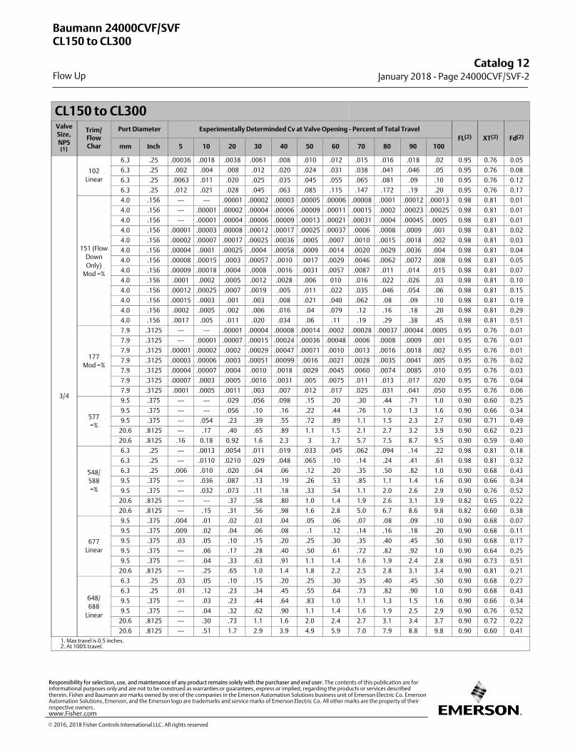
CL150 to CL300ValveSize,NPS
(1)
Trim/FlowChar
Port Diameter Experimentally Determinded Cv at Valve Opening - Percent of Total Travel
FL(2) XT(2) Fd(2)
mm Inch 5 10 20 30 40 50 60 70 80 90 100
3/4
102
Linear
6.3 .25 .00036 .0018 .0038 .0061 .008 .010 .012 .015 .016 .018 .02 0.95 0.76 0.05
6.3 .25 .002 .004 .008 .012 .020 .024 .031 .038 .041 .046 .05 0.95 0.76 0.08
6.3 .25 .0063 .011 .020 .025 .035 .045 .055 .065 .081 .09 .10 0.95 0.76 0.12
6.3 .25 .012 .021 .028 .045 .063 .085 .115 .147 .172 .19 .20 0.95 0.76 0.17
151 (Flow
Down
Only)
Mod =%
4.0 .156 --- --- .00001 .00002 .00003 .00005 .00006 .00008 .0001 .00012 .00013 0.98 0.81 0.01
4.0 .156 --- .00001 .00002 .00004 .00006 .00009 .00011 .00015 .0002 .00023 .00025 0.98 0.81 0.01
4.0 .156 --- .00001 .00004 .00006 .00009 .00013 .00021 .00031 .0004 .00045 .0005 0.98 0.81 0.01
4.0 .156 .00001 .00003 .00008 .00012 .00017 .00025 .00037 .0006 .0008 .0009 .001 0.98 0.81 0.02
4.0 .156 .00002 .00007 .00017 .00025 .00036 .0005 .0007 .0010 .0015 .0018 .002 0.98 0.81 0.03
4.0 .156 .00004 .0001 .00025 .0004 .00058 .0009 .0014 .0020 .0029 .0036 .004 0.98 0.81 0.04
4.0 .156 .00008 .00015 .0003 .00057 .0010 .0017 .0029 .0046 .0062 .0072 .008 0.98 0.81 0.05
4.0 .156 .00009 .00018 .0004 .0008 .0016 .0031 .0057 .0087 .011 .014 .015 0.98 0.81 0.07
4.0 .156 .0001 .0002 .0005 .0012 .0028 .006 010 .016 .022 .026 .03 0.98 0.81 0.10
4.0 .156 .00012 .00025 .0007 .0019 .005 .011 .022 .035 .046 .054 .06 0.98 0.81 0.15
4.0 .156 .00015 .0003 .001 .003 .008 .021 .040 .062 .08 .09 .10 0.98 0.81 0.19
4.0 .156 .0002 .0005 .002 .006 .016 .04 .079 .12 .16 .18 .20 0.98 0.81 0.29
4.0 .156 .0017 .005 .011 .020 .034 .06 .11 .19 .29 .38 .45 0.98 0.81 0.51
177
Mod =%
7.9 .3125 --- --- .00001 .00004 .00008 .00014 .0002 .00028 .00037 .00044 .0005 0.95 0.76 0.01
7.9 .3125 --- .00001 .00007 .00015 .00024 .00036 .00048 .0006 .0008 .0009 .001 0.95 0.76 0.01
7.9 .3125 .00001 .00002 .0002 .00029 .00047 .00071 .0010 .0013 .0016 .0018 .002 0.95 0.76 0.01
7.9 .3125 .00003 .00006 .0003 .00051 .00099 .0016 .0021 .0028 .0035 .0041 .005 0.95 0.76 0.02
7.9 .3125 .00004 .00007 .0004 .0010 .0018 .0029 .0045 .0060 .0074 .0085 .010 0.95 0.76 0.03
7.9 .3125 .00007 .0003 .0005 .0016 .0031 .005 .0075 .011 .013 .017 .020 0.95 0.76 0.04
7.9 .3125 .0001 .0005 .0011 .003 .007 .012 .017 .025 .031 .041 .050 0.95 0.76 0.06
577
=%
9.5 .375 --- --- .029 .056 .098 .15 .20 .30 .44 .71 1.0 0.90 0.60 0.25
9.5 .375 --- --- .056 .10 .16 .22 .44 .76 1.0 1.3 1.6 0.90 0.66 0.34
9.5 .375 --- .054 .23 .39 .55 .72 .89 1.1 1.5 2.3 2.7 0.90 0.71 0.49
20.6 .8125 --- .17 .40 .65 .89 1.1 1.5 2.1 2.7 3.2 3.9 0.90 0.62 0.23
20.6 .8125 .16 0.18 0.92 1.6 2.3 3 3.7 5.7 7.5 8.7 9.5 0.90 0.59 0.40
548/
588
=%
6.3 .25 --- .0013 .0054 .011 .019 .033 .045 .062 .094 .14 .22 0.98 0.81 0.18
6.3 .25 --- .0110 .0210 .029 .048 .065 .10 .14 .24 .41 .61 0.98 0.81 0.32
6.3 .25 .006 .010 .020 .04 .06 .12 .20 .35 .50 .82 1.0 0.90 0.68 0.43
9.5 .375 --- .036 .087 .13 .19 .26 .53 .85 1.1 1.4 1.6 0.90 0.66 0.34
9.5 .375 --- .032 .073 .11 .18 .33 .54 1.1 2.0 2.6 2.9 0.90 0.76 0.52
20.6 .8125 --- --- .37 .58 .80 1.0 1.4 1.9 2.6 3.1 3.9 0.82 0.65 0.22
20.6 .8125 --- .15 .31 .56 .98 1.6 2.8 5.0 6.7 8.6 9.8 0.82 0.60 0.38
677
Linear
9.5 .375 .004 .01 .02 .03 .04 .05 .06 .07 .08 .09 .10 0.90 0.68 0.07
9.5 .375 .009 .02 .04 .06 .08 .1 .12 .14 .16 .18 .20 0.90 0.68 0.11
9.5 .375 .03 .05 .10 .15 .20 .25 .30 .35 .40 .45 .50 0.90 0.68 0.17
9.5 .375 --- .06 .17 .28 .40 .50 .61 .72 .82 .92 1.0 0.90 0.64 0.25
9.5 .375 --- .04 .33 .63 .91 1.1 1.4 1.6 1.9 2.4 2.8 0.90 0.73 0.51
20.6 .8125 --- .25 .65 1.0 1.4 1.8 2.2 2.5 2.8 3.1 3.4 0.90 0.81 0.21
648/
688
Linear
6.3 .25 .03 .05 .10 .15 .20 .25 .30 .35 .40 .45 .50 0.90 0.68 0.27
6.3 .25 .01 .12 .23 .34 .45 .55 .64 .73 .82 .90 1.0 0.90 0.68 0.43
9.5 .375 --- .03 .23 .44 .64 .83 1.0 1.1 1.3 1.5 1.6 0.90 0.66 0.34
9.5 .375 --- .04 .32 .62 .90 1.1 1.4 1.6 1.9 2.5 2.9 0.90 0.76 0.52
20.6 .8125 --- .30 .73 1.1 1.6 2.0 2.4 2.7 3.1 3.4 3.7 0.90 0.72 0.22
20.6 .8125 --- .51 1.7 2.9 3.9 4.9 5.9 7.0 7.9 8.8 9.8 0.90 0.60 0.41
1. Max travel is 0.5 inches.2. At 100% travel.
Baumann 24000CVF/SVFCL150 to CL300
Flow Up
Catalog 12January 2018 ‐ Page 24000CVF/SVF‐2
� 2016, 2018 Fisher Controls International LLC. All rights reserved
www.Fisher.com
Responsibility for selection, use, and maintenance of any product remains solely with the purchaser and end user. The contents of this publication are forinformational purposes only and are not to be construed as warranties or guarantees, express or implied, regarding the products or services describedtherein. Fisher and Baumann are marks owned by one of the companies in the Emerson Automation Solutions business unit of Emerson Electric Co. EmersonAutomation Solutions, Emerson, and the Emerson logo are trademarks and service marks of Emerson Electric Co. All other marks are the property of theirrespective owners.
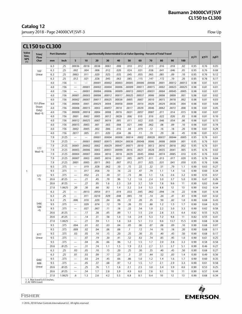
CL150 to CL300ValveSize,NPS
(1)
Trim/FlowChar
Port Diameter Experimentally Determinded Cv at Valve Opening - Percent of Total Travel
FL(2) XT(2) Fd(2)
mm Inch 5 10 20 30 40 50 60 70 80 90 100
1
102
Linear
6.3 .25 .00036 .0018 .0038 .0061 .008 .010 .012 .015 .016 .018 .02 0.95 0.76 0.05
6.3 .25 .002 .004 .008 .012 .020 .024 .031 .038 .041 .046 .05 0.95 0.76 0.08
6.3 .25 .0063 .011 .020 .025 .035 .045 .055 .065 .081 .09 .10 0.95 0.76 0.12
6.3 .25 .012 .021 .028 .045 .063 .085 .115 .147 .172 .19 .20 0.95 0.76 0.17
151 (Flow
Down
Only)
Mod =%
4.0 .156 --- --- .00001 .00002 .00003 .00005 .00006 .00008 .0001 .00012 .00013 0.98 0.81 0.01
4.0 .156 --- .00001 .00002 .00004 .00006 .00009 .00011 .00015 .0002 .00023 .00025 0.98 0.81 0.01
4.0 .156 --- .00001 .00004 .00006 .00009 .00013 .00021 .00031 .0004 .00045 .0005 0.98 0.81 0.01
4.0 .156 .00001 .00003 .00008 .00012 .00017 .00025 .00037 .0006 .0008 .0009 .001 0.98 0.81 0.02
4.0 .156 .00002 .00007 .00017 .00025 .00036 .0005 .0007 .0010 .0015 .0018 .002 0.98 0.81 0.03
4.0 .156 .00004 .0001 .00025 .0004 .00058 .0009 .0014 .0020 .0029 .0036 .004 0.98 0.81 0.04
4.0 .156 .00008 .00015 .0003 .00057 .0010 .0017 .0029 .0046 .0062 .0072 .008 0.98 0.81 0.05
4.0 .156 .00009 .00018 .0004 .0008 .0016 .0031 .0057 .0087 .011 .014 .015 0.98 0.81 0.07
4.0 .156 .0001 .0002 .0005 .0012 .0028 .006 010 .016 .022 .026 .03 0.98 0.81 0.10
4.0 .156 .00012 .00025 .0007 .0019 .005 .011 .022 .035 .046 .054 .06 0.98 0.81 0.15
4.0 .156 .00015 .0003 .001 .003 .008 .021 .040 .062 .08 .09 .10 0.98 0.81 0.19
4.0 .156 .0002 .0005 .002 .006 .016 .04 .079 .12 .16 .18 .20 0.98 0.81 0.29
4.0 .156 .0017 .005 .011 .020 .034 .06 .11 .19 .29 .38 .45 0.98 0.81 0.51
177
Mod =%
7.9 .3125 --- --- .00001 .00004 .00008 .00014 .0002 .00028 .00037 .00044 .0005 0.95 0.76 0.01
7.9 .3125 --- .00001 .00007 .00015 .00024 .00036 .00048 .0006 .0008 .0009 .001 0.95 0.76 0.01
7.9 .3125 .00001 .00002 .0002 .00029 .00047 .00071 .0010 .0013 .0016 .0018 .002 0.95 0.76 0.01
7.9 .3125 .00003 .00006 .0003 .00051 .00099 .0016 .0021 .0028 .0035 .0041 .005 0.95 0.76 0.02
7.9 .3125 .00004 .00007 .0004 .0010 .0018 .0029 .0045 .0060 .0074 .0085 .010 0.95 0.76 0.03
7.9 .3125 .00007 .0003 .0005 .0016 .0031 .005 .0075 .011 .013 .017 .020 0.95 0.76 0.04
7.9 .3125 .0001 .0005 .0011 .003 .007 .012 .017 .025 .031 .041 .050 0.95 0.76 0.06
577
=%
9.5 .375 --- .019 .028 .062 .10 .15 .22 .32 .51 .79 1.1 0.90 0.63 0.27
9.5 .375 --- .017 .056 .10 .16 .22 .47 .79 1.1 1.4 1.6 0.90 0.60 0.34
9.5 .375 --- .052 .23 .39 .57 .73 .90 1.1 1.6 2.6 3.2 0.90 0.55 0.57
20.6 .8125 --- .21 .45 .70 .96 1.2 1.6 2.4 3.0 3.7 5.0 0.90 0.47 0.26
20.6 .8125 --- .27 .95 1.6 2.3 3.0 3.7 5.9 7.8 9.6 11 0.90 0.62 0.44
27.0 1.0625 .20 .30 .60 .92 1.4 2.2 3.4 5.3 8.8 12 13 0.90 0.62 0.34
548/
588
=%
6.3 .25 --- .0013 .0054 .011 .019 .033 .045 .062 .094 .14 .22 0.98 0.81 0.18
6.3 .25 --- .011 .0210 .029 .048 .065 .10 .14 .24 .41 .61 0.98 0.81 0.32
6.3 .25 .006 .010 .020 .04 .06 .12 .20 .35 .50 .82 1.0 0.90 0.68 0.43
9.5 .375 --- .029 .074 .12 .19 .26 .55 .88 1.2 1.5 1.7 0.90 0.64 0.35
9.5 .375 --- .027 .067 .11 .18 .33 .54 1.0 2.2 3.0 3.3 0.90 0.62 0.58
20.6 .8125 --- .17 .38 .65 .89 1.1 1.5 2.0 2.8 3.5 4.4 0.82 0.55 0.23
20.6 .8125 --- .14 .31 .58 1.0 1.6 2.9 5.3 7.2 9.8 11 0.82 0.55 0.41
27.0 1.0625 --- .27 .59 1.1 1.8 3.0 5.1 7.3 9.6 13.7 15.5 0.90 0.68 0.38
677
Linear
9.5 .375 .004 .01 .02 .03 .04 .05 .06 .07 .08 .09 .10 0.90 0.68 0.07
9.5 .375 .009 .02 .04 .06 .08 .1 .12 .14 .16 .18 .20 0.90 0.68 0.11
9.5 .375 .03 .05 .10 .15 .20 .25 .30 .35 .40 .45 .50 0.90 0.68 0.17
9.5 .375 --- .07 .19 .30 .41 .52 .63 .74 .85 .95 1.0 0.90 0.61 0.25
9.5 .375 --- .04 .36 .66 .96 1.2 1.5 1.7 2.0 2.8 3.3 0.90 0.58 0.58
20.6 .8125 --- .31 .74 1.1 1.5 1.9 2.3 2.7 3.1 3.7 5.1 0.90 0.46 0.27
648/
688
Linear
6.3 .25 .03 .05 .10 .15 .20 .25 .30 .35 .40 .45 .50 0.90 0.68 0.27
6.3 .25 .01 .03 .09 .17 .23 .3 .37 .44 .52 .83 1.4 0.90 0.49 0.56
9.5 .375 --- .03 .24 .45 .66 .86 1.0 1.2 1.4 1.6 1.7 0.90 0.60 0.35
9.5 .375 --- .05 .37 .68 .97 1.2 1.5 1.7 2.1 2.9 3.3 0.90 0.61 0.58
20.6 .8125 --- .25 .76 1.1 1.6 2.1 2.5 3.0 3.4 3.9 4.6 0.90 0.53 0.25
20.6 .8125 --- .54 1.7 2.8 3.9 4.9 6.0 7.6 9.1 10 11 0.90 0.57 0.44
27.0 1.0625 .6 1.3 2.6 4.2 5.5 6.8 8.1 9.4 10 12 13 0.90 0.68 0.34
1. 1. Max travel is 0.5 inches.2. At 100% travel.
Baumann 24000CVF/SVFCL150 to CL300
Flow Up
Catalog 12 January 2018 ‐ Page 24000CVF/SVF‐3
� 2016, 2018 Fisher Controls International LLC. All rights reserved
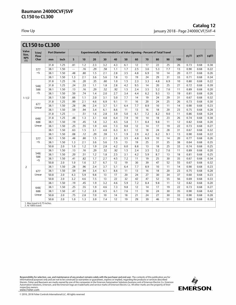
CL150 to CL300ValveSize,NPS
(1)
Trim/FlowChar
Port Diameter Experimentally Determinded Cv at Valve Opening - Percent of Total Travel
FL(2) XT(2) Fd(2)
mm Inch 5 10 20 30 40 50 60 70 80 90 100
1-1/2
577
=%
31.8 1.25 .81 1.2 2.3 3.2 4.3 6.1 12 17 22 25 26 0.73 0.68 0.38
38.1 1.50 --- .16 .29 .58 1.1 1.7 2.5 3.6 5.3 7.7 13 0.90 0.68 0.22
38.1 1.50 .48 .80 1.5 2.1 2.8 3.5 4.8 6.9 10 14 20 0.77 0.68 0.26
38.1 1.50 1.3 2.1 3.6 5.6 7.8 13 19 24 29 31 33 0.71 0.68 0.34
548/
588
=%
31.8 1.25 .16 .20 .35 .60 1.0 1.5 2.3 3.3 4.8 6.9 10 0.80 0.68 0.22
31.8 1.25 .24 .53 1.1 1.8 2.8 4.2 9.5 14 20 25 27 0.72 0.68 0.39
38.1 1.50 .13 .16 .29 .52 .92 1.5 2.4 3.5 5.2 7.6 11 0.89 0.68 0.20
38.1 1.50 .50 .74 1.4 2.0 2.7 3.4 4.4 6.2 9.3 13 19 0.81 0.68 0.26
38.1 1.50 .66 1.1 2.0 3.1 5.0 7.7 14 19 24 29 31 0.67 0.68 0.32
677
Linear
31.8 1.25 .99 2.1 4.6 6.9 9.1 11 16 20 24 25 26 0.73 0.68 0.30
38.1 1.50 .28 .96 2.4 3.7 5.1 6.4 7.7 8.9 10 11 14 0.90 0.68 0.23
38.1 1.50 .59 .94 3.4 6.1 8.6 11 13 16 18 20 23 0.75 0.68 0.28
648/
688
Linear
31.8 1.25 --- .51 1.6 2.8 3.9 5.0 6.1 7.2 8.2 9.0 11 0.86 0.68 0.24
31.8 1.25 .48 1.3 3.1 4.8 6.4 7.9 10 14 18 23 26 0.74 0.68 0.38
38.1 1.50 .19 .45 1.8 3.2 4.5 5.8 7.1 8.4 9.8 11 12 0.82 0.68 0.20
38.1 1.50 .25 .55 1.9 4.6 7.3 9.8 12 14 17 19 22 0.73 0.68 0.27
38.1 1.50 .63 1.5 3.1 4.8 6.3 8.1 12 18 24 28 31 0.67 0.68 0.32
2
577
=%
38.1 1.50 .08 .12 .29 .59 1.1 1.9 2.9 4.2 6.2 9.1 13 0.90 0.68 0.22
38.1 1.50 .48 .80 1.5 2.1 2.8 3.5 4.8 6.9 10 14 20 0.77 0.68 0.26
38.1 1.50 1.3 2.1 3.6 5.6 7.5 13 19 25 31 35 38 0.64 0.68 0.35
50.8 2.0 1.0 1.2 1.9 2.8 4.2 6.0 8.8 13 18 25 33 0.74 0.68 0.25
548/
588
=%
38.1 1.50 .13 .16 .29 .52 .92 1.5 2.4 3.5 5.2 7.6 11 0.89 0.68 0.20
38.1 1.50 .20 .51 1.2 1.8 2.5 3.1 4.2 5.9 8.7 13 18 0.81 0.68 0.25
38.1 1.50 .41 .82 1.7 2.7 4.5 7.2 11 19 25 30 35 0.67 0.68 0.34
50.8 2.0 1.0 1.6 3.7 6.7 12 19 30 39 47 52 55 0.67 0.68 0.32
677
Linear
38.1 1.50 .28 .96 2.4 3.7 5.1 6.4 7.7 8.9 10 11 14 0.90 0.68 0.23
38.1 1.50 .59 .94 3.4 6.1 8.6 11 13 16 18 20 23 0.75 0.68 0.28
50.8 2.0 4.3 5.9 9.8 13 17 20 24 27 30 34 37 0.60 0.68 0.23
50.8 2.0 3.2 4.6 7.5 13 22 32 42 47 52 55 56 0.69 0.68 0.33
648/
688
Linear
38.1 1.50 .19 .45 1.9 3.2 4.6 5.9 7.2 8.4 9.8 11 12 0.82 0.68 0.20
38.1 1.50 .25 .55 1.9 4.6 7.3 9.8 12 14 17 19 22 0.73 0.68 0.27
38.1 1.50 .47 1.2 2.8 4.5 6.1 7.6 11 18 24 30 35 0.90 0.68 0.42
50.8 2.0 .75 2.8 7.0 10 14 18 21 24 27 30 33 0.90 0.68 0.28
50.8 2.0 1.0 1.3 3.9 7.4 12 19 29 39 46 51 55 0.90 0.68 0.38
1. Max travel is 0.75 inches.2. At 100% travel.
Baumann 24000CVF/SVFCL150 to CL300
Flow Up
Catalog 12January 2018 ‐ Page 24000CVF/SVF‐4
� 2016, 2018 Fisher Controls International LLC. All rights reserved
www.Fisher.com
Responsibility for selection, use, and maintenance of any product remains solely with the purchaser and end user. The contents of this publication are forinformational purposes only and are not to be construed as warranties or guarantees, express or implied, regarding the products or services describedtherein. Fisher and Baumann are marks owned by one of the companies in the Emerson Automation Solutions business unit of Emerson Electric Co. EmersonAutomation Solutions, Emerson, and the Emerson logo are trademarks and service marks of Emerson Electric Co. All other marks are the property of theirrespective owners.
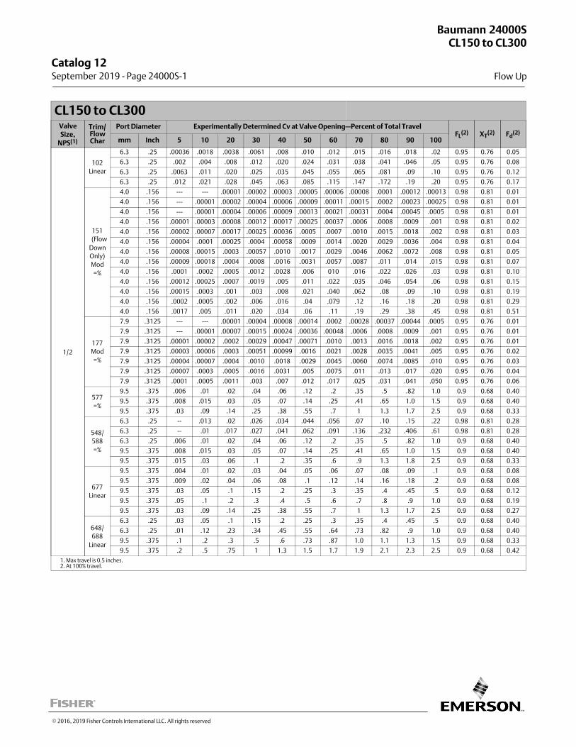
CL150 to CL300ValveSize,
NPS(1)
Trim/FlowChar
Port Diameter Experimentally Determined Cv at Valve Opening—Percent of Total TravelFL
(2) XT(2) Fd
(2)
mm Inch 5 10 20 30 40 50 60 70 80 90 100
1/2
102
Linear
6.3 .25 .00036 .0018 .0038 .0061 .008 .010 .012 .015 .016 .018 .02 0.95 0.76 0.05
6.3 .25 .002 .004 .008 .012 .020 .024 .031 .038 .041 .046 .05 0.95 0.76 0.08
6.3 .25 .0063 .011 .020 .025 .035 .045 .055 .065 .081 .09 .10 0.95 0.76 0.12
6.3 .25 .012 .021 .028 .045 .063 .085 .115 .147 .172 .19 .20 0.95 0.76 0.17
151
(Flow
Down
Only)
Mod
=%
4.0 .156 --- --- .00001 .00002 .00003 .00005 .00006 .00008 .0001 .00012 .00013 0.98 0.81 0.01
4.0 .156 --- .00001 .00002 .00004 .00006 .00009 .00011 .00015 .0002 .00023 .00025 0.98 0.81 0.01
4.0 .156 --- .00001 .00004 .00006 .00009 .00013 .00021 .00031 .0004 .00045 .0005 0.98 0.81 0.01
4.0 .156 .00001 .00003 .00008 .00012 .00017 .00025 .00037 .0006 .0008 .0009 .001 0.98 0.81 0.02
4.0 .156 .00002 .00007 .00017 .00025 .00036 .0005 .0007 .0010 .0015 .0018 .002 0.98 0.81 0.03
4.0 .156 .00004 .0001 .00025 .0004 .00058 .0009 .0014 .0020 .0029 .0036 .004 0.98 0.81 0.04
4.0 .156 .00008 .00015 .0003 .00057 .0010 .0017 .0029 .0046 .0062 .0072 .008 0.98 0.81 0.05
4.0 .156 .00009 .00018 .0004 .0008 .0016 .0031 .0057 .0087 .011 .014 .015 0.98 0.81 0.07
4.0 .156 .0001 .0002 .0005 .0012 .0028 .006 010 .016 .022 .026 .03 0.98 0.81 0.10
4.0 .156 .00012 .00025 .0007 .0019 .005 .011 .022 .035 .046 .054 .06 0.98 0.81 0.15
4.0 .156 .00015 .0003 .001 .003 .008 .021 .040 .062 .08 .09 .10 0.98 0.81 0.19
4.0 .156 .0002 .0005 .002 .006 .016 .04 .079 .12 .16 .18 .20 0.98 0.81 0.29
4.0 .156 .0017 .005 .011 .020 .034 .06 .11 .19 .29 .38 .45 0.98 0.81 0.51
177
Mod
=%
7.9 .3125 --- --- .00001 .00004 .00008 .00014 .0002 .00028 .00037 .00044 .0005 0.95 0.76 0.01
7.9 .3125 --- .00001 .00007 .00015 .00024 .00036 .00048 .0006 .0008 .0009 .001 0.95 0.76 0.01
7.9 .3125 .00001 .00002 .0002 .00029 .00047 .00071 .0010 .0013 .0016 .0018 .002 0.95 0.76 0.01
7.9 .3125 .00003 .00006 .0003 .00051 .00099 .0016 .0021 .0028 .0035 .0041 .005 0.95 0.76 0.02
7.9 .3125 .00004 .00007 .0004 .0010 .0018 .0029 .0045 .0060 .0074 .0085 .010 0.95 0.76 0.03
7.9 .3125 .00007 .0003 .0005 .0016 .0031 .005 .0075 .011 .013 .017 .020 0.95 0.76 0.04
7.9 .3125 .0001 .0005 .0011 .003 .007 .012 .017 .025 .031 .041 .050 0.95 0.76 0.06
577
=%
9.5 .375 .006 .01 .02 .04 .06 .12 .2 .35 .5 .82 1.0 0.9 0.68 0.40
9.5 .375 .008 .015 .03 .05 .07 .14 .25 .41 .65 1.0 1.5 0.9 0.68 0.40
9.5 .375 .03 .09 .14 .25 .38 .55 .7 1 1.3 1.7 2.5 0.9 0.68 0.33
548/
588
=%
6.3 .25 -- .013 .02 .026 .034 .044 .056 .07 .10 .15 .22 0.98 0.81 0.28
6.3 .25 -- .01 .017 .027 .041 .062 .091 .136 .232 .406 .61 0.98 0.81 0.28
6.3 .25 .006 .01 .02 .04 .06 .12 .2 .35 .5 .82 1.0 0.9 0.68 0.40
9.5 .375 .008 .015 .03 .05 .07 .14 .25 .41 .65 1.0 1.5 0.9 0.68 0.40
9.5 .375 .015 .03 .06 .1 .2 .35 .6 .9 1.3 1.8 2.5 0.9 0.68 0.33
677
Linear
9.5 .375 .004 .01 .02 .03 .04 .05 .06 .07 .08 .09 .1 0.9 0.68 0.08
9.5 .375 .009 .02 .04 .06 .08 .1 .12 .14 .16 .18 .2 0.9 0.68 0.08
9.5 .375 .03 .05 .1 .15 .2 .25 .3 .35 .4 .45 .5 0.9 0.68 0.12
9.5 .375 .05 .1 .2 .3 .4 .5 .6 .7 .8 .9 1.0 0.9 0.68 0.19
9.5 .375 .03 .09 .14 .25 .38 .55 .7 1 1.3 1.7 2.5 0.9 0.68 0.27
648/
688
Linear
6.3 .25 .03 .05 .1 .15 .2 .25 .3 .35 .4 .45 .5 0.9 0.68 0.40
6.3 .25 .01 .12 .23 .34 .45 .55 .64 .73 .82 .9 1.0 0.9 0.68 0.40
9.5 .375 .1 .2 .3 .5 .6 .73 .87 1.0 1.1 1.3 1.5 0.9 0.68 0.33
9.5 .375 .2 .5 .75 1 1.3 1.5 1.7 1.9 2.1 2.3 2.5 0.9 0.68 0.42
1. Max travel is 0.5 inches.2. At 100% travel.
Baumann 24000SCL150 to CL300
Flow Up
Catalog 12 September 2019 ‐ Page 24000S‐1
� 2016, 2019 Fisher Controls International LLC. All rights reserved
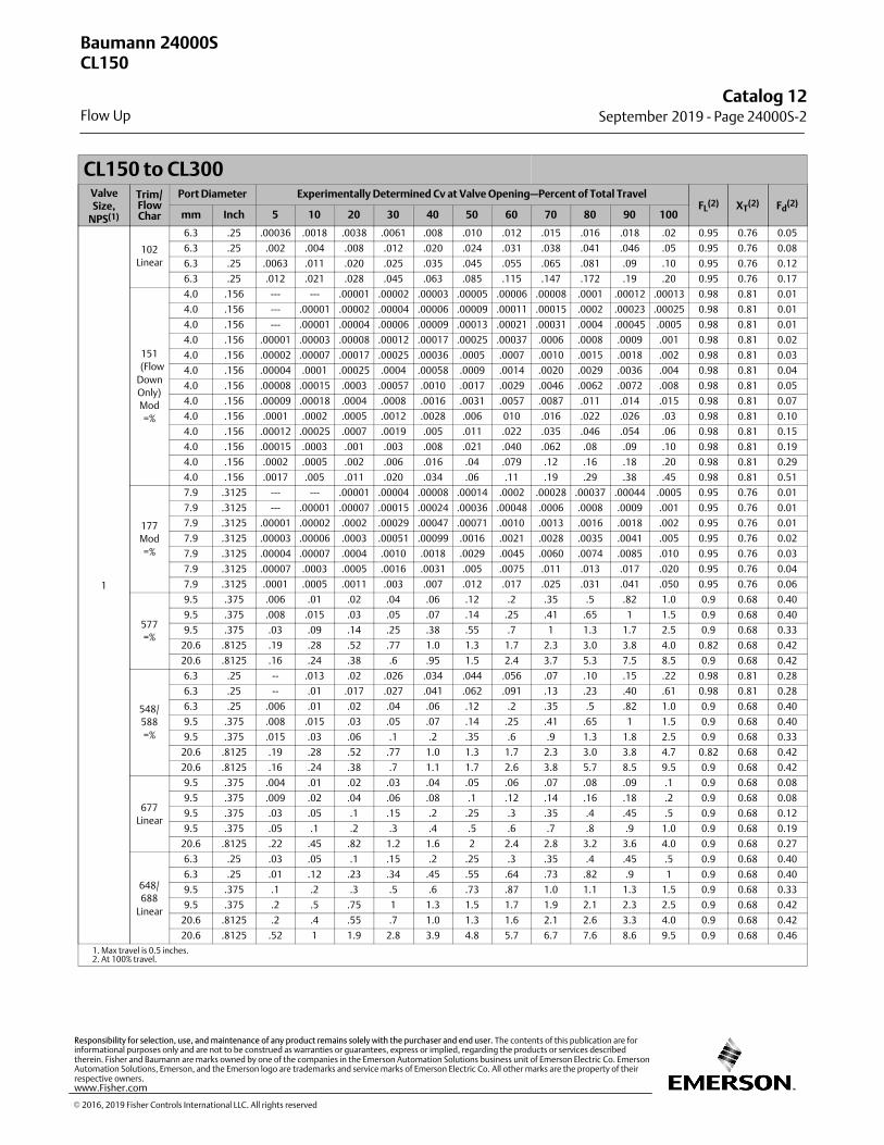
CL150 to CL300ValveSize,
NPS(1)
Trim/FlowChar
Port Diameter Experimentally Determined Cv at Valve Opening—Percent of Total TravelFL
(2) XT(2) Fd
(2)
mm Inch 5 10 20 30 40 50 60 70 80 90 100
1
102
Linear
6.3 .25 .00036 .0018 .0038 .0061 .008 .010 .012 .015 .016 .018 .02 0.95 0.76 0.05
6.3 .25 .002 .004 .008 .012 .020 .024 .031 .038 .041 .046 .05 0.95 0.76 0.08
6.3 .25 .0063 .011 .020 .025 .035 .045 .055 .065 .081 .09 .10 0.95 0.76 0.12
6.3 .25 .012 .021 .028 .045 .063 .085 .115 .147 .172 .19 .20 0.95 0.76 0.17
151
(Flow
Down
Only)
Mod
=%
4.0 .156 --- --- .00001 .00002 .00003 .00005 .00006 .00008 .0001 .00012 .00013 0.98 0.81 0.01
4.0 .156 --- .00001 .00002 .00004 .00006 .00009 .00011 .00015 .0002 .00023 .00025 0.98 0.81 0.01
4.0 .156 --- .00001 .00004 .00006 .00009 .00013 .00021 .00031 .0004 .00045 .0005 0.98 0.81 0.01
4.0 .156 .00001 .00003 .00008 .00012 .00017 .00025 .00037 .0006 .0008 .0009 .001 0.98 0.81 0.02
4.0 .156 .00002 .00007 .00017 .00025 .00036 .0005 .0007 .0010 .0015 .0018 .002 0.98 0.81 0.03
4.0 .156 .00004 .0001 .00025 .0004 .00058 .0009 .0014 .0020 .0029 .0036 .004 0.98 0.81 0.04
4.0 .156 .00008 .00015 .0003 .00057 .0010 .0017 .0029 .0046 .0062 .0072 .008 0.98 0.81 0.05
4.0 .156 .00009 .00018 .0004 .0008 .0016 .0031 .0057 .0087 .011 .014 .015 0.98 0.81 0.07
4.0 .156 .0001 .0002 .0005 .0012 .0028 .006 010 .016 .022 .026 .03 0.98 0.81 0.10
4.0 .156 .00012 .00025 .0007 .0019 .005 .011 .022 .035 .046 .054 .06 0.98 0.81 0.15
4.0 .156 .00015 .0003 .001 .003 .008 .021 .040 .062 .08 .09 .10 0.98 0.81 0.19
4.0 .156 .0002 .0005 .002 .006 .016 .04 .079 .12 .16 .18 .20 0.98 0.81 0.29
4.0 .156 .0017 .005 .011 .020 .034 .06 .11 .19 .29 .38 .45 0.98 0.81 0.51
177
Mod
=%
7.9 .3125 --- --- .00001 .00004 .00008 .00014 .0002 .00028 .00037 .00044 .0005 0.95 0.76 0.01
7.9 .3125 --- .00001 .00007 .00015 .00024 .00036 .00048 .0006 .0008 .0009 .001 0.95 0.76 0.01
7.9 .3125 .00001 .00002 .0002 .00029 .00047 .00071 .0010 .0013 .0016 .0018 .002 0.95 0.76 0.01
7.9 .3125 .00003 .00006 .0003 .00051 .00099 .0016 .0021 .0028 .0035 .0041 .005 0.95 0.76 0.02
7.9 .3125 .00004 .00007 .0004 .0010 .0018 .0029 .0045 .0060 .0074 .0085 .010 0.95 0.76 0.03
7.9 .3125 .00007 .0003 .0005 .0016 .0031 .005 .0075 .011 .013 .017 .020 0.95 0.76 0.04
7.9 .3125 .0001 .0005 .0011 .003 .007 .012 .017 .025 .031 .041 .050 0.95 0.76 0.06
577
=%
9.5 .375 .006 .01 .02 .04 .06 .12 .2 .35 .5 .82 1.0 0.9 0.68 0.40
9.5 .375 .008 .015 .03 .05 .07 .14 .25 .41 .65 1 1.5 0.9 0.68 0.40
9.5 .375 .03 .09 .14 .25 .38 .55 .7 1 1.3 1.7 2.5 0.9 0.68 0.33
20.6 .8125 .19 .28 .52 .77 1.0 1.3 1.7 2.3 3.0 3.8 4.0 0.82 0.68 0.42
20.6 .8125 .16 .24 .38 .6 .95 1.5 2.4 3.7 5.3 7.5 8.5 0.9 0.68 0.42
548/
588
=%
6.3 .25 -- .013 .02 .026 .034 .044 .056 .07 .10 .15 .22 0.98 0.81 0.28
6.3 .25 -- .01 .017 .027 .041 .062 .091 .13 .23 .40 .61 0.98 0.81 0.28
6.3 .25 .006 .01 .02 .04 .06 .12 .2 .35 .5 .82 1.0 0.9 0.68 0.40
9.5 .375 .008 .015 .03 .05 .07 .14 .25 .41 .65 1 1.5 0.9 0.68 0.40
9.5 .375 .015 .03 .06 .1 .2 .35 .6 .9 1.3 1.8 2.5 0.9 0.68 0.33
20.6 .8125 .19 .28 .52 .77 1.0 1.3 1.7 2.3 3.0 3.8 4.7 0.82 0.68 0.42
20.6 .8125 .16 .24 .38 .7 1.1 1.7 2.6 3.8 5.7 8.5 9.5 0.9 0.68 0.42
677
Linear
9.5 .375 .004 .01 .02 .03 .04 .05 .06 .07 .08 .09 .1 0.9 0.68 0.08
9.5 .375 .009 .02 .04 .06 .08 .1 .12 .14 .16 .18 .2 0.9 0.68 0.08
9.5 .375 .03 .05 .1 .15 .2 .25 .3 .35 .4 .45 .5 0.9 0.68 0.12
9.5 .375 .05 .1 .2 .3 .4 .5 .6 .7 .8 .9 1.0 0.9 0.68 0.19
20.6 .8125 .22 .45 .82 1.2 1.6 2 2.4 2.8 3.2 3.6 4.0 0.9 0.68 0.27
648/
688
Linear
6.3 .25 .03 .05 .1 .15 .2 .25 .3 .35 .4 .45 .5 0.9 0.68 0.40
6.3 .25 .01 .12 .23 .34 .45 .55 .64 .73 .82 .9 1 0.9 0.68 0.40
9.5 .375 .1 .2 .3 .5 .6 .73 .87 1.0 1.1 1.3 1.5 0.9 0.68 0.33
9.5 .375 .2 .5 .75 1 1.3 1.5 1.7 1.9 2.1 2.3 2.5 0.9 0.68 0.42
20.6 .8125 .2 .4 .55 .7 1.0 1.3 1.6 2.1 2.6 3.3 4.0 0.9 0.68 0.42
20.6 .8125 .52 1 1.9 2.8 3.9 4.8 5.7 6.7 7.6 8.6 9.5 0.9 0.68 0.46
1. Max travel is 0.5 inches.2. At 100% travel.
Baumann 24000SCL150
Flow Up
Catalog 12September 2019 ‐ Page 24000S‐2
� 2016, 2019 Fisher Controls International LLC. All rights reserved
www.Fisher.com
Responsibility for selection, use, and maintenance of any product remains solely with the purchaser and end user. The contents of this publication are forinformational purposes only and are not to be construed as warranties or guarantees, express or implied, regarding the products or services describedtherein. Fisher and Baumann are marks owned by one of the companies in the Emerson Automation Solutions business unit of Emerson Electric Co. EmersonAutomation Solutions, Emerson, and the Emerson logo are trademarks and service marks of Emerson Electric Co. All other marks are the property of theirrespective owners.

CL150 to CL300ValveSize,
NPS(1)
Trim/FlowChar
Port Diameter Experimentally Determined Cv at Valve Opening—Percent of Total TravelFL
(2) XT(2) Fd
(2)
mm Inch 5 10 20 30 40 50 60 70 80 90 100
1-1/2
577
=%31.8 1.25 .31 1 1.7 2.6 3.7 5.3 7.6 11 13.5 16 17.5 0.9 0.68 0.46
548/
588
=%
31.8 1.25 .25 .5 .7 1 1.4 2 2.8 3.6 5 7 9 0.9 0.68 0.46
31.8 1.25 .25 .9 1.7 2.6 3.7 5.3 7.6 11 13.5 16 17.5 0.9 0.68 0.46
677
Linear31.8 1.25 .31 1 1.7 2.6 3.7 5.3 7.6 11 13.5 16 17.5 0.9 0.68 0.46
648/
688
Linear
31.8 1.25 .52 2.2 3.9 5.5 7 8.5 10 11.5 13.5 15.5 17.5 0.9 0.68 0.46
2
577
=%
38.1 1.50 .3 .5 1.1 1.6 2.2 2.8 3.6 4.7 6.4 8.1 10 0.9 0.68 0.46
38.1 1.50 0.5 1 1.6 2.8 4.2 6 8.8 11.2 14.2 15.8 18 0.9 0.68 0.46
38.1 1.50 0.5 1 1.9 3 5 7.7 11 15 20 24 30.5 0.9 0.68 0.46
548/
588
=%
38.1 1.50 .3 .5 1.1 1.6 2.2 2.8 3.6 4.7 6.4 8.1 10 0.9 0.68 0.46
38.1 1.50 .4 1.1 1.7 2.7 4.1 6.1 8.9 11 14 16 17.5 0.9 0.68 0.46
38.1 1.50 .4 1 1.9 3 5 7.7 11 15 20 24 30.5 0.9 0.68 0.46
677
Linear
38.1 1.50 .3 .5 1.1 1.6 2.2 2.8 3.6 4.7 6.4 8.1 10 0.9 0.68 0.46
38.1 1.50 0.31 1 1.7 2.6 3.7 5.3 7.6 11 13.5 16 17.5 0.9 0.68 0.46
648/
688
Linear
38.1 1.50 .4 .9 1.6 2.5 3.6 4.5 5.6 6.5 7.5 8.7 10 0.9 0.68 0.46
38.1 1.50 .53 2.2 3.9 5.5 7 8.5 10 11.5 13.5 15.5 17.5 0.9 0.68 0.46
38.1 1.50 1.5 3 6 9 12 15 18 21 24 27 30.5 0.9 0.68 0.46
3
577
=%50.8 2.0 0.72 1.4 3.6 7.5 12.8 18.7 23 27 30 33.8 35 0.9 0.68 0.46
548/
588
=%
50.8 2.0 .72 1.4 3.6 7.5 12.8 18.7 23 27 30 33.8 35 0.9 0.68 0.46
50.8 2.0 -- 1.5 3.8 6.4 11.2 18.2 28.5 37.8 45.3 50.3 61 0.9 0.68 0.46
677
Linear
50.8 2.0 0.72 1.4 3.6 7.5 12.8 18.7 23 27 30 33.8 35 0.9 0.68 0.46
50.8 2.0 3.1 6 13 20 26 32 38 44 50 55 61 0.9 0.68 0.46
648/
688
Linear
50.8 2.0 .72 1.4 3.6 7.5 12.8 18.7 23 27 30 33.8 35 0.9 0.68 0.46
50.8 2.0 3 1.57 10 15 20 25 30 36 41 56 61 0.9 0.68 0.46
1. Max travel is 0.75 inches.2. At 100% travel.
Baumann 24000SCL150 to CL300
Flow Up
Catalog 12 January 2018 ‐ Page 24000S‐3
� 2016, 2018 Fisher Controls International LLC. All rights reserved
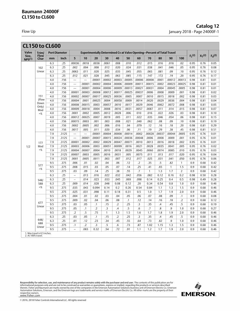
CL150 to CL600ValveSize,
NPS(1)
Trim/FlowChar
Port Diameter Experimentally Determined Cv at Valve Opening—Percent of Total TravelFL
(2) XT(2) Fd
(2)
mm Inch 5 10 20 30 40 50 60 70 80 90 100
1/2
102
Linear
6.3 .25 .00036 .0018 .0038 .0061 .008 .010 .012 .015 .016 .018 .02 0.95 0.76 0.05
6.3 .25 .002 .004 .008 .012 .020 .024 .031 .038 .041 .046 .05 0.95 0.76 0.08
6.3 .25 .0063 .011 .020 .025 .035 .045 .055 .065 .081 .09 .10 0.95 0.76 0.12
6.3 .25 .012 .021 .028 .045 .063 .085 .115 .147 .172 .19 .20 0.95 0.76 0.17
151
(Flow
Down
Only)
Mod
=%
4.0 .156 --- --- .00001 .00002 .00003 .00005 .00006 .00008 .0001 .00012 .00013 0.98 0.81 0.01
4.0 .156 --- .00001 .00002 .00004 .00006 .00009 .00011 .00015 .0002 .00023 .00025 0.98 0.81 0.01
4.0 .156 --- .00001 .00004 .00006 .00009 .00013 .00021 .00031 .0004 .00045 .0005 0.98 0.81 0.01
4.0 .156 .00001 .00003 .00008 .00012 .00017 .00025 .00037 .0006 .0008 .0009 .001 0.98 0.81 0.02
4.0 .156 .00002 .00007 .00017 .00025 .00036 .0005 .0007 .0010 .0015 .0018 .002 0.98 0.81 0.03
4.0 .156 .00004 .0001 .00025 .0004 .00058 .0009 .0014 .0020 .0029 .0036 .004 0.98 0.81 0.04
4.0 .156 .00008 .00015 .0003 .00057 .0010 .0017 .0029 .0046 .0062 .0072 .008 0.98 0.81 0.05
4.0 .156 .00009 .00018 .0004 .0008 .0016 .0031 .0057 .0087 .011 .014 .015 0.98 0.81 0.07
4.0 .156 .0001 .0002 .0005 .0012 .0028 .006 010 .016 .022 .026 .03 0.98 0.81 0.10
4.0 .156 .00012 .00025 .0007 .0019 .005 .011 .022 .035 .046 .054 .06 0.98 0.81 0.15
4.0 .156 .00015 .0003 .001 .003 .008 .021 .040 .062 .08 .09 .10 0.98 0.81 0.19
4.0 .156 .0002 .0005 .002 .006 .016 .04 .079 .12 .16 .18 .20 0.98 0.81 0.29
4.0 .156 .0017 .005 .011 .020 .034 .06 .11 .19 .29 .38 .45 0.98 0.81 0.51
177
Mod
=%
7.9 .3125 --- --- .00001 .00004 .00008 .00014 .0002 .00028 .00037 .00044 .0005 0.95 0.76 0.01
7.9 .3125 --- .00001 .00007 .00015 .00024 .00036 .00048 .0006 .0008 .0009 .001 0.95 0.76 0.01
7.9 .3125 .00001 .00002 .0002 .00029 .00047 .00071 .0010 .0013 .0016 .0018 .002 0.95 0.76 0.01
7.9 .3125 .00003 .00006 .0003 .00051 .00099 .0016 .0021 .0028 .0035 .0041 .005 0.95 0.76 0.02
7.9 .3125 .00004 .00007 .0004 .0010 .0018 .0029 .0045 .0060 .0074 .0085 .010 0.95 0.76 0.03
7.9 .3125 .00007 .0003 .0005 .0016 .0031 .005 .0075 .011 .013 .017 .020 0.95 0.76 0.04
7.9 .3125 .0001 .0005 .0011 .003 .007 .012 .017 .025 .031 .041 .050 0.95 0.76 0.06
577
=%
9.5 .375 .006 .01 .02 .04 .06 .12 .2 .35 .5 .82 1 0.9 0.68 0.42
9.5 .375 .008 .015 .03 .05 .07 .14 .25 .41 .65 1 1.5 0.9 0.68 0.42
9.5 .375 .03 .09 .14 .25 .38 .55 .7 1 1.3 1.7 2 0.9 0.68 0.42
548/
588
=%
6.3 .25 -- .013 .016 .022 .032 .042 .056 .082 0.12 0.16 0.2 0.98 0.50 0.28
6.3 .25 -- .014 .023 .033 .045 .069 .098 0.14 0.25 0.4 0.5 0.98 0.49 0.28
6.3 .25 .009 .014 .028 .048 0.08 0.12 .20 0.34 0.54 0.8 1.0 0.9 0.68 0.46
9.5 .375 .035 .043 0.094 0.14 0.2 0.26 0.54 0.84 1.1 1.3 1.5 0.9 0.68 0.46
9.5 .375 .025 .031 .098 0.11 0.18 0.31 0.5 1.0 1.7 1.9 2.0 0.9 0.68 0.46
677
Linear
9.5 .375 .004 .01 .02 .03 .04 .05 .06 .07 .08 .09 .1 0.9 0.68 0.08
9.5 .375 .009 .02 .04 .06 .08 .1 .12 .14 .16 .18 .2 0.9 0.68 0.12
9.5 .375 .03 .05 .1 .15 .2 .25 .3 .35 .4 .45 .5 0.9 0.68 0.19
9.5 .375 .05 .1 .2 .3 .4 .5 .6 .7 .8 .9 1.0 0.9 0.68 0.27
9.5 .375 .2 .5 .75 1 1.3 1.5 1.6 1.7 1.8 1.9 2.0 0.9 0.68 0.46
648/
688
Linear
6.3 .25 .03 .05 .1 .15 .2 .25 .3 .35 .4 .45 .5 0.9 0.68 0.46
6.3 .25 .01 .12 .23 .34 .45 .55 .64 .73 .82 .9 1.0 0.9 0.68 0.46
9.5 .375 .1 .2 .3 .5 .6 .73 .87 1.02 1.15 1.3 1.5 0.9 0.68 0.46
9.5 .375 -- .083 0.32 .54 .72 .91 1.1 1.2 1.7 1.9 2.0 0.9 0.68 0.46
1. Max travel is 0.5 inches.2. At 100% travel.
Baumann 24000FCL150 to CL600
Flow Up
Catalog 12January 2018 ‐ Page 24000F‐1
� 2016, 2018 Fisher Controls International LLC. All rights reserved
www.Fisher.com
Responsibility for selection, use, and maintenance of any product remains solely with the purchaser and end user. The contents of this publication are forinformational purposes only and are not to be construed as warranties or guarantees, express or implied, regarding the products or services describedtherein. Fisher and Baumann are marks owned by one of the companies in the Emerson Automation Solutions business unit of Emerson Electric Co. EmersonAutomation Solutions, Emerson, and the Emerson logo are trademarks and service marks of Emerson Electric Co. All other marks are the property of theirrespective owners.
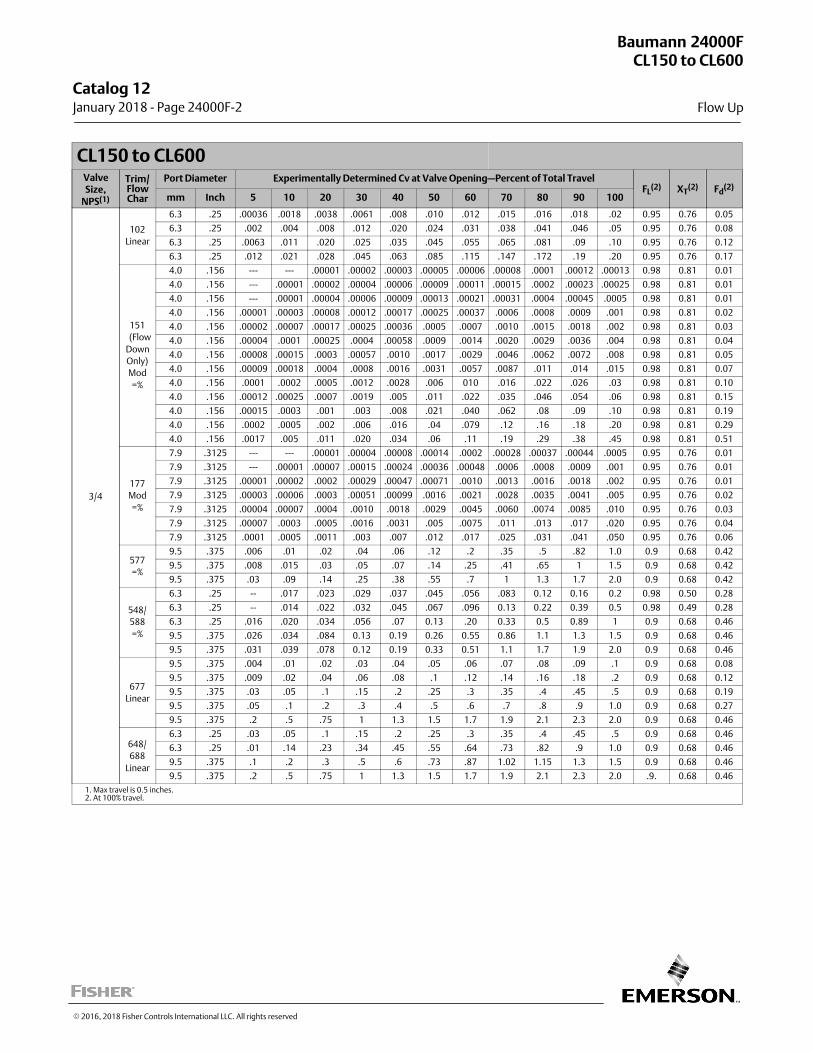
CL150 to CL600ValveSize,
NPS(1)
Trim/FlowChar
Port Diameter Experimentally Determined Cv at Valve Opening—Percent of Total TravelFL
(2) XT(2) Fd
(2)
mm Inch 5 10 20 30 40 50 60 70 80 90 100
3/4
102
Linear
6.3 .25 .00036 .0018 .0038 .0061 .008 .010 .012 .015 .016 .018 .02 0.95 0.76 0.05
6.3 .25 .002 .004 .008 .012 .020 .024 .031 .038 .041 .046 .05 0.95 0.76 0.08
6.3 .25 .0063 .011 .020 .025 .035 .045 .055 .065 .081 .09 .10 0.95 0.76 0.12
6.3 .25 .012 .021 .028 .045 .063 .085 .115 .147 .172 .19 .20 0.95 0.76 0.17
151
(Flow
Down
Only)
Mod
=%
4.0 .156 --- --- .00001 .00002 .00003 .00005 .00006 .00008 .0001 .00012 .00013 0.98 0.81 0.01
4.0 .156 --- .00001 .00002 .00004 .00006 .00009 .00011 .00015 .0002 .00023 .00025 0.98 0.81 0.01
4.0 .156 --- .00001 .00004 .00006 .00009 .00013 .00021 .00031 .0004 .00045 .0005 0.98 0.81 0.01
4.0 .156 .00001 .00003 .00008 .00012 .00017 .00025 .00037 .0006 .0008 .0009 .001 0.98 0.81 0.02
4.0 .156 .00002 .00007 .00017 .00025 .00036 .0005 .0007 .0010 .0015 .0018 .002 0.98 0.81 0.03
4.0 .156 .00004 .0001 .00025 .0004 .00058 .0009 .0014 .0020 .0029 .0036 .004 0.98 0.81 0.04
4.0 .156 .00008 .00015 .0003 .00057 .0010 .0017 .0029 .0046 .0062 .0072 .008 0.98 0.81 0.05
4.0 .156 .00009 .00018 .0004 .0008 .0016 .0031 .0057 .0087 .011 .014 .015 0.98 0.81 0.07
4.0 .156 .0001 .0002 .0005 .0012 .0028 .006 010 .016 .022 .026 .03 0.98 0.81 0.10
4.0 .156 .00012 .00025 .0007 .0019 .005 .011 .022 .035 .046 .054 .06 0.98 0.81 0.15
4.0 .156 .00015 .0003 .001 .003 .008 .021 .040 .062 .08 .09 .10 0.98 0.81 0.19
4.0 .156 .0002 .0005 .002 .006 .016 .04 .079 .12 .16 .18 .20 0.98 0.81 0.29
4.0 .156 .0017 .005 .011 .020 .034 .06 .11 .19 .29 .38 .45 0.98 0.81 0.51
177
Mod
=%
7.9 .3125 --- --- .00001 .00004 .00008 .00014 .0002 .00028 .00037 .00044 .0005 0.95 0.76 0.01
7.9 .3125 --- .00001 .00007 .00015 .00024 .00036 .00048 .0006 .0008 .0009 .001 0.95 0.76 0.01
7.9 .3125 .00001 .00002 .0002 .00029 .00047 .00071 .0010 .0013 .0016 .0018 .002 0.95 0.76 0.01
7.9 .3125 .00003 .00006 .0003 .00051 .00099 .0016 .0021 .0028 .0035 .0041 .005 0.95 0.76 0.02
7.9 .3125 .00004 .00007 .0004 .0010 .0018 .0029 .0045 .0060 .0074 .0085 .010 0.95 0.76 0.03
7.9 .3125 .00007 .0003 .0005 .0016 .0031 .005 .0075 .011 .013 .017 .020 0.95 0.76 0.04
7.9 .3125 .0001 .0005 .0011 .003 .007 .012 .017 .025 .031 .041 .050 0.95 0.76 0.06
577
=%
9.5 .375 .006 .01 .02 .04 .06 .12 .2 .35 .5 .82 1.0 0.9 0.68 0.42
9.5 .375 .008 .015 .03 .05 .07 .14 .25 .41 .65 1 1.5 0.9 0.68 0.42
9.5 .375 .03 .09 .14 .25 .38 .55 .7 1 1.3 1.7 2.0 0.9 0.68 0.42
548/
588
=%
6.3 .25 -- .017 .023 .029 .037 .045 .056 .083 0.12 0.16 0.2 0.98 0.50 0.28
6.3 .25 -- .014 .022 .032 .045 .067 .096 0.13 0.22 0.39 0.5 0.98 0.49 0.28
6.3 .25 .016 .020 .034 .056 .07 0.13 .20 0.33 0.5 0.89 1 0.9 0.68 0.46
9.5 .375 .026 .034 .084 0.13 0.19 0.26 0.55 0.86 1.1 1.3 1.5 0.9 0.68 0.46
9.5 .375 .031 .039 .078 0.12 0.19 0.33 0.51 1.1 1.7 1.9 2.0 0.9 0.68 0.46
677
Linear
9.5 .375 .004 .01 .02 .03 .04 .05 .06 .07 .08 .09 .1 0.9 0.68 0.08
9.5 .375 .009 .02 .04 .06 .08 .1 .12 .14 .16 .18 .2 0.9 0.68 0.12
9.5 .375 .03 .05 .1 .15 .2 .25 .3 .35 .4 .45 .5 0.9 0.68 0.19
9.5 .375 .05 .1 .2 .3 .4 .5 .6 .7 .8 .9 1.0 0.9 0.68 0.27
9.5 .375 .2 .5 .75 1 1.3 1.5 1.7 1.9 2.1 2.3 2.0 0.9 0.68 0.46
648/
688
Linear
6.3 .25 .03 .05 .1 .15 .2 .25 .3 .35 .4 .45 .5 0.9 0.68 0.46
6.3 .25 .01 .14 .23 .34 .45 .55 .64 .73 .82 .9 1.0 0.9 0.68 0.46
9.5 .375 .1 .2 .3 .5 .6 .73 .87 1.02 1.15 1.3 1.5 0.9 0.68 0.46
9.5 .375 .2 .5 .75 1 1.3 1.5 1.7 1.9 2.1 2.3 2.0 .9. 0.68 0.46
1. Max travel is 0.5 inches.2. At 100% travel.
Baumann 24000FCL150 to CL600
Flow Up
Catalog 12 January 2018 ‐ Page 24000F‐2
� 2016, 2018 Fisher Controls International LLC. All rights reserved
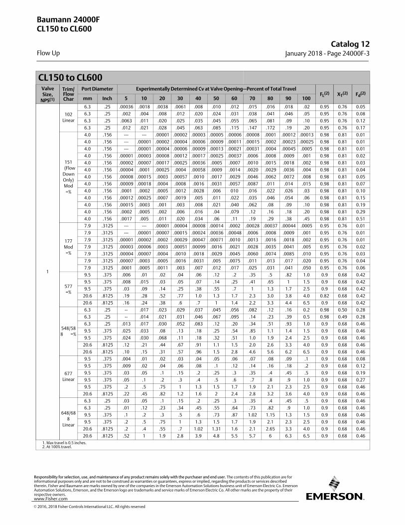
CL150 to CL600ValveSize,
NPS(1)
Trim/FlowChar
Port Diameter Experimentally Determined Cv at Valve Opening—Percent of Total TravelFL
(2) XT(2) Fd
(2)
mm Inch 5 10 20 30 40 50 60 70 80 90 100
1
102
Linear
6.3 .25 .00036 .0018 .0038 .0061 .008 .010 .012 .015 .016 .018 .02 0.95 0.76 0.05
6.3 .25 .002 .004 .008 .012 .020 .024 .031 .038 .041 .046 .05 0.95 0.76 0.08
6.3 .25 .0063 .011 .020 .025 .035 .045 .055 .065 .081 .09 .10 0.95 0.76 0.12
6.3 .25 .012 .021 .028 .045 .063 .085 .115 .147 .172 .19 .20 0.95 0.76 0.17
151
(Flow
Down
Only)
Mod
=%
4.0 .156 --- --- .00001 .00002 .00003 .00005 .00006 .00008 .0001 .00012 .00013 0.98 0.81 0.01
4.0 .156 --- .00001 .00002 .00004 .00006 .00009 .00011 .00015 .0002 .00023 .00025 0.98 0.81 0.01
4.0 .156 --- .00001 .00004 .00006 .00009 .00013 .00021 .00031 .0004 .00045 .0005 0.98 0.81 0.01
4.0 .156 .00001 .00003 .00008 .00012 .00017 .00025 .00037 .0006 .0008 .0009 .001 0.98 0.81 0.02
4.0 .156 .00002 .00007 .00017 .00025 .00036 .0005 .0007 .0010 .0015 .0018 .002 0.98 0.81 0.03
4.0 .156 .00004 .0001 .00025 .0004 .00058 .0009 .0014 .0020 .0029 .0036 .004 0.98 0.81 0.04
4.0 .156 .00008 .00015 .0003 .00057 .0010 .0017 .0029 .0046 .0062 .0072 .008 0.98 0.81 0.05
4.0 .156 .00009 .00018 .0004 .0008 .0016 .0031 .0057 .0087 .011 .014 .015 0.98 0.81 0.07
4.0 .156 .0001 .0002 .0005 .0012 .0028 .006 010 .016 .022 .026 .03 0.98 0.81 0.10
4.0 .156 .00012 .00025 .0007 .0019 .005 .011 .022 .035 .046 .054 .06 0.98 0.81 0.15
4.0 .156 .00015 .0003 .001 .003 .008 .021 .040 .062 .08 .09 .10 0.98 0.81 0.19
4.0 .156 .0002 .0005 .002 .006 .016 .04 .079 .12 .16 .18 .20 0.98 0.81 0.29
4.0 .156 .0017 .005 .011 .020 .034 .06 .11 .19 .29 .38 .45 0.98 0.81 0.51
177
Mod
=%
7.9 .3125 --- --- .00001 .00004 .00008 .00014 .0002 .00028 .00037 .00044 .0005 0.95 0.76 0.01
7.9 .3125 --- .00001 .00007 .00015 .00024 .00036 .00048 .0006 .0008 .0009 .001 0.95 0.76 0.01
7.9 .3125 .00001 .00002 .0002 .00029 .00047 .00071 .0010 .0013 .0016 .0018 .002 0.95 0.76 0.01
7.9 .3125 .00003 .00006 .0003 .00051 .00099 .0016 .0021 .0028 .0035 .0041 .005 0.95 0.76 0.02
7.9 .3125 .00004 .00007 .0004 .0010 .0018 .0029 .0045 .0060 .0074 .0085 .010 0.95 0.76 0.03
7.9 .3125 .00007 .0003 .0005 .0016 .0031 .005 .0075 .011 .013 .017 .020 0.95 0.76 0.04
7.9 .3125 .0001 .0005 .0011 .003 .007 .012 .017 .025 .031 .041 .050 0.95 0.76 0.06
577
=%
9.5 .375 .006 .01 .02 .04 .06 .12 .2 .35 .5 .82 1.0 0.9 0.68 0.42
9.5 .375 .008 .015 .03 .05 .07 .14 .25 .41 .65 1 1.5 0.9 0.68 0.42
9.5 .375 .03 .09 .14 .25 .38 .55 .7 1 1.3 1.7 2.5 0.9 0.68 0.42
20.6 .8125 .19 .28 .52 .77 1.0 1.3 1.7 2.3 3.0 3.8 4.0 0.82 0.68 0.42
20.6 .8125 .16 .24 .38 .6 .7 1 1.4 2.2 3.3 4.4 6.5 0.9 0.68 0.42
548/58
8 =%
6.3 .25 -- .017 .023 .029 .037 .045 .056 .082 .12 .16 0.2 0.98 0.50 0.28
6.3 .25 -- .014 .021 .031 .046 .067 .095 .14 .23 .39 0.5 0.98 0.49 0.28
6.3 .25 .013 .017 .030 .052 .083 .12 .20 .34 .51 .93 1.0 0.9 0.68 0.46
9.5 .375 .025 .033 .08 .13 .18 .25 .54 .85 1.1 1.4 1.5 0.9 0.68 0.46
9.5 .375 .024 .030 .068 .11 .18 .32 .51 1.0 1.9 2.4 2.5 0.9 0.68 0.46
20.6 .8125 .12 .21 .44 .67 .91 1.1 1.5 2.0 2.6 3.3 4.0 0.9 0.68 0.46
20.6 .8125 .10 .15 .31 .57 .96 1.5 2.8 4.6 5.6 6.2 6.5 0.9 0.68 0.46
677
Linear
9.5 .375 .004 .01 .02 .03 .04 .05 .06 .07 .08 .09 .1 0.9 0.68 0.08
9.5 .375 .009 .02 .04 .06 .08 .1 .12 .14 .16 .18 .2 0.9 0.68 0.12
9.5 .375 .03 .05 .1 .15 .2 .25 .3 .35 .4 .45 .5 0.9 0.68 0.19
9.5 .375 .05 .1 .2 .3 .4 .5 .6 .7 .8 .9 1.0 0.9 0.68 0.27
9.5 .375 .2 .5 .75 1 1.3 1.5 1.7 1.9 2.1 2.3 2.5 0.9 0.68 0.46
20.6 .8125 .22 .45 .82 1.2 1.6 2 2.4 2.8 3.2 3.6 4.0 0.9 0.68 0.46
648/68
8
Linear
6.3 .25 .03 .05 .1 .15 .2 .25 .3 .35 .4 .45 .5 0.9 0.68 0.46
6.3 .25 .01 .12 .23 .34 .45 .55 .64 .73 .82 .9 1.0 0.9 0.68 0.46
9.5 .375 .1 .2 .3 .5 .6 .73 .87 1.02 1.15 1.3 1.5 0.9 0.68 0.46
9.5 .375 .2 .5 .75 1 1.3 1.5 1.7 1.9 2.1 2.3 2.5 0.9 0.68 0.46
20.6 .8125 .2 .4 .55 .7 1.02 1.31 1.6 2.1 2.65 3.3 4.0 0.9 0.68 0.46
20.6 .8125 .52 1 1.9 2.8 3.9 4.8 5.5 5.7 6 6.3 6.5 0.9 0.68 0.46
1. Max travel is 0.5 inches.2. At 100% travel.
Baumann 24000FCL150 to CL600
Flow Up
Catalog 12January 2018 ‐ Page 24000F‐3
� 2016, 2018 Fisher Controls International LLC. All rights reserved
www.Fisher.com
Responsibility for selection, use, and maintenance of any product remains solely with the purchaser and end user. The contents of this publication are forinformational purposes only and are not to be construed as warranties or guarantees, express or implied, regarding the products or services describedtherein. Fisher and Baumann are marks owned by one of the companies in the Emerson Automation Solutions business unit of Emerson Electric Co. EmersonAutomation Solutions, Emerson, and the Emerson logo are trademarks and service marks of Emerson Electric Co. All other marks are the property of theirrespective owners.
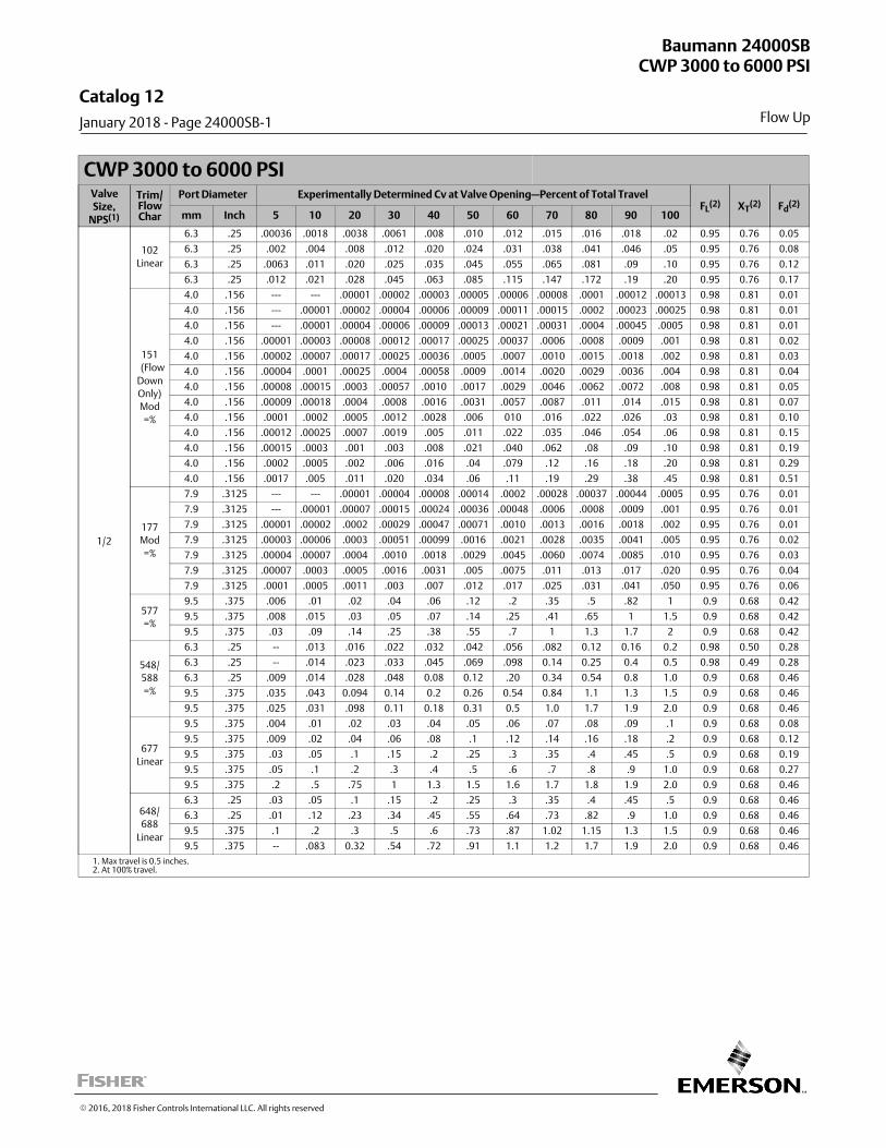
CWP 3000 to 6000 PSIValveSize,
NPS(1)
Trim/FlowChar
Port Diameter Experimentally Determined Cv at Valve Opening—Percent of Total TravelFL
(2) XT(2) Fd
(2)
mm Inch 5 10 20 30 40 50 60 70 80 90 100
1/2
102
Linear
6.3 .25 .00036 .0018 .0038 .0061 .008 .010 .012 .015 .016 .018 .02 0.95 0.76 0.05
6.3 .25 .002 .004 .008 .012 .020 .024 .031 .038 .041 .046 .05 0.95 0.76 0.08
6.3 .25 .0063 .011 .020 .025 .035 .045 .055 .065 .081 .09 .10 0.95 0.76 0.12
6.3 .25 .012 .021 .028 .045 .063 .085 .115 .147 .172 .19 .20 0.95 0.76 0.17
151
(Flow
Down
Only)
Mod
=%
4.0 .156 --- --- .00001 .00002 .00003 .00005 .00006 .00008 .0001 .00012 .00013 0.98 0.81 0.01
4.0 .156 --- .00001 .00002 .00004 .00006 .00009 .00011 .00015 .0002 .00023 .00025 0.98 0.81 0.01
4.0 .156 --- .00001 .00004 .00006 .00009 .00013 .00021 .00031 .0004 .00045 .0005 0.98 0.81 0.01
4.0 .156 .00001 .00003 .00008 .00012 .00017 .00025 .00037 .0006 .0008 .0009 .001 0.98 0.81 0.02
4.0 .156 .00002 .00007 .00017 .00025 .00036 .0005 .0007 .0010 .0015 .0018 .002 0.98 0.81 0.03
4.0 .156 .00004 .0001 .00025 .0004 .00058 .0009 .0014 .0020 .0029 .0036 .004 0.98 0.81 0.04
4.0 .156 .00008 .00015 .0003 .00057 .0010 .0017 .0029 .0046 .0062 .0072 .008 0.98 0.81 0.05
4.0 .156 .00009 .00018 .0004 .0008 .0016 .0031 .0057 .0087 .011 .014 .015 0.98 0.81 0.07
4.0 .156 .0001 .0002 .0005 .0012 .0028 .006 010 .016 .022 .026 .03 0.98 0.81 0.10
4.0 .156 .00012 .00025 .0007 .0019 .005 .011 .022 .035 .046 .054 .06 0.98 0.81 0.15
4.0 .156 .00015 .0003 .001 .003 .008 .021 .040 .062 .08 .09 .10 0.98 0.81 0.19
4.0 .156 .0002 .0005 .002 .006 .016 .04 .079 .12 .16 .18 .20 0.98 0.81 0.29
4.0 .156 .0017 .005 .011 .020 .034 .06 .11 .19 .29 .38 .45 0.98 0.81 0.51
177
Mod
=%
7.9 .3125 --- --- .00001 .00004 .00008 .00014 .0002 .00028 .00037 .00044 .0005 0.95 0.76 0.01
7.9 .3125 --- .00001 .00007 .00015 .00024 .00036 .00048 .0006 .0008 .0009 .001 0.95 0.76 0.01
7.9 .3125 .00001 .00002 .0002 .00029 .00047 .00071 .0010 .0013 .0016 .0018 .002 0.95 0.76 0.01
7.9 .3125 .00003 .00006 .0003 .00051 .00099 .0016 .0021 .0028 .0035 .0041 .005 0.95 0.76 0.02
7.9 .3125 .00004 .00007 .0004 .0010 .0018 .0029 .0045 .0060 .0074 .0085 .010 0.95 0.76 0.03
7.9 .3125 .00007 .0003 .0005 .0016 .0031 .005 .0075 .011 .013 .017 .020 0.95 0.76 0.04
7.9 .3125 .0001 .0005 .0011 .003 .007 .012 .017 .025 .031 .041 .050 0.95 0.76 0.06
577
=%
9.5 .375 .006 .01 .02 .04 .06 .12 .2 .35 .5 .82 1 0.9 0.68 0.42
9.5 .375 .008 .015 .03 .05 .07 .14 .25 .41 .65 1 1.5 0.9 0.68 0.42
9.5 .375 .03 .09 .14 .25 .38 .55 .7 1 1.3 1.7 2 0.9 0.68 0.42
548/
588
=%
6.3 .25 -- .013 .016 .022 .032 .042 .056 .082 0.12 0.16 0.2 0.98 0.50 0.28
6.3 .25 -- .014 .023 .033 .045 .069 .098 0.14 0.25 0.4 0.5 0.98 0.49 0.28
6.3 .25 .009 .014 .028 .048 0.08 0.12 .20 0.34 0.54 0.8 1.0 0.9 0.68 0.46
9.5 .375 .035 .043 0.094 0.14 0.2 0.26 0.54 0.84 1.1 1.3 1.5 0.9 0.68 0.46
9.5 .375 .025 .031 .098 0.11 0.18 0.31 0.5 1.0 1.7 1.9 2.0 0.9 0.68 0.46
677
Linear
9.5 .375 .004 .01 .02 .03 .04 .05 .06 .07 .08 .09 .1 0.9 0.68 0.08
9.5 .375 .009 .02 .04 .06 .08 .1 .12 .14 .16 .18 .2 0.9 0.68 0.12
9.5 .375 .03 .05 .1 .15 .2 .25 .3 .35 .4 .45 .5 0.9 0.68 0.19
9.5 .375 .05 .1 .2 .3 .4 .5 .6 .7 .8 .9 1.0 0.9 0.68 0.27
9.5 .375 .2 .5 .75 1 1.3 1.5 1.6 1.7 1.8 1.9 2.0 0.9 0.68 0.46
648/
688
Linear
6.3 .25 .03 .05 .1 .15 .2 .25 .3 .35 .4 .45 .5 0.9 0.68 0.46
6.3 .25 .01 .12 .23 .34 .45 .55 .64 .73 .82 .9 1.0 0.9 0.68 0.46
9.5 .375 .1 .2 .3 .5 .6 .73 .87 1.02 1.15 1.3 1.5 0.9 0.68 0.46
9.5 .375 -- .083 0.32 .54 .72 .91 1.1 1.2 1.7 1.9 2.0 0.9 0.68 0.46
1. Max travel is 0.5 inches.2. At 100% travel.
Baumann 24000SBCWP 3000 to 6000 PSI
Flow Up
Catalog 12
January 2018 ‐ Page 24000SB‐1
� 2016, 2018 Fisher Controls International LLC. All rights reserved
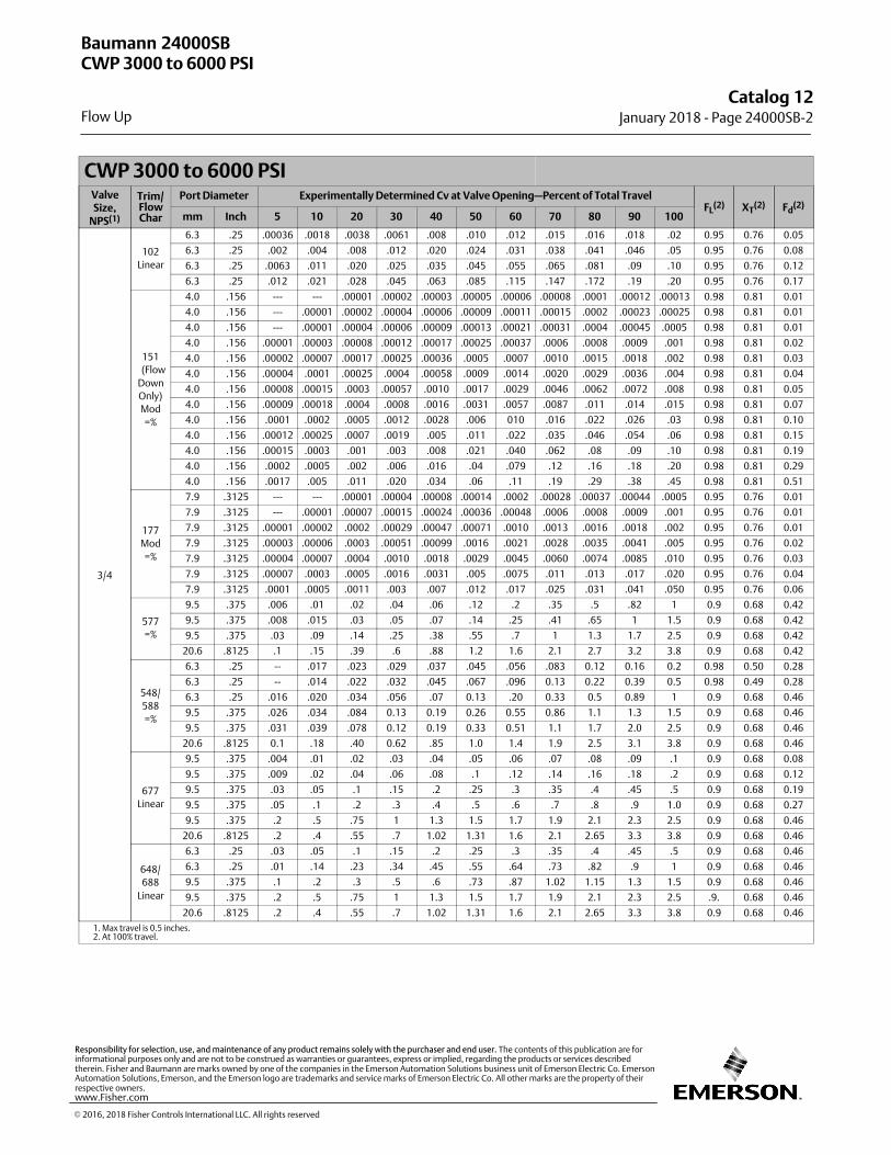
CWP 3000 to 6000 PSIValveSize,
NPS(1)
Trim/FlowChar
Port Diameter Experimentally Determined Cv at Valve Opening—Percent of Total TravelFL
(2) XT(2) Fd
(2)
mm Inch 5 10 20 30 40 50 60 70 80 90 100
3/4
102
Linear
6.3 .25 .00036 .0018 .0038 .0061 .008 .010 .012 .015 .016 .018 .02 0.95 0.76 0.05
6.3 .25 .002 .004 .008 .012 .020 .024 .031 .038 .041 .046 .05 0.95 0.76 0.08
6.3 .25 .0063 .011 .020 .025 .035 .045 .055 .065 .081 .09 .10 0.95 0.76 0.12
6.3 .25 .012 .021 .028 .045 .063 .085 .115 .147 .172 .19 .20 0.95 0.76 0.17
151
(Flow
Down
Only)
Mod
=%
4.0 .156 --- --- .00001 .00002 .00003 .00005 .00006 .00008 .0001 .00012 .00013 0.98 0.81 0.01
4.0 .156 --- .00001 .00002 .00004 .00006 .00009 .00011 .00015 .0002 .00023 .00025 0.98 0.81 0.01
4.0 .156 --- .00001 .00004 .00006 .00009 .00013 .00021 .00031 .0004 .00045 .0005 0.98 0.81 0.01
4.0 .156 .00001 .00003 .00008 .00012 .00017 .00025 .00037 .0006 .0008 .0009 .001 0.98 0.81 0.02
4.0 .156 .00002 .00007 .00017 .00025 .00036 .0005 .0007 .0010 .0015 .0018 .002 0.98 0.81 0.03
4.0 .156 .00004 .0001 .00025 .0004 .00058 .0009 .0014 .0020 .0029 .0036 .004 0.98 0.81 0.04
4.0 .156 .00008 .00015 .0003 .00057 .0010 .0017 .0029 .0046 .0062 .0072 .008 0.98 0.81 0.05
4.0 .156 .00009 .00018 .0004 .0008 .0016 .0031 .0057 .0087 .011 .014 .015 0.98 0.81 0.07
4.0 .156 .0001 .0002 .0005 .0012 .0028 .006 010 .016 .022 .026 .03 0.98 0.81 0.10
4.0 .156 .00012 .00025 .0007 .0019 .005 .011 .022 .035 .046 .054 .06 0.98 0.81 0.15
4.0 .156 .00015 .0003 .001 .003 .008 .021 .040 .062 .08 .09 .10 0.98 0.81 0.19
4.0 .156 .0002 .0005 .002 .006 .016 .04 .079 .12 .16 .18 .20 0.98 0.81 0.29
4.0 .156 .0017 .005 .011 .020 .034 .06 .11 .19 .29 .38 .45 0.98 0.81 0.51
177
Mod
=%
7.9 .3125 --- --- .00001 .00004 .00008 .00014 .0002 .00028 .00037 .00044 .0005 0.95 0.76 0.01
7.9 .3125 --- .00001 .00007 .00015 .00024 .00036 .00048 .0006 .0008 .0009 .001 0.95 0.76 0.01
7.9 .3125 .00001 .00002 .0002 .00029 .00047 .00071 .0010 .0013 .0016 .0018 .002 0.95 0.76 0.01
7.9 .3125 .00003 .00006 .0003 .00051 .00099 .0016 .0021 .0028 .0035 .0041 .005 0.95 0.76 0.02
7.9 .3125 .00004 .00007 .0004 .0010 .0018 .0029 .0045 .0060 .0074 .0085 .010 0.95 0.76 0.03
7.9 .3125 .00007 .0003 .0005 .0016 .0031 .005 .0075 .011 .013 .017 .020 0.95 0.76 0.04
7.9 .3125 .0001 .0005 .0011 .003 .007 .012 .017 .025 .031 .041 .050 0.95 0.76 0.06
577
=%
9.5 .375 .006 .01 .02 .04 .06 .12 .2 .35 .5 .82 1 0.9 0.68 0.42
9.5 .375 .008 .015 .03 .05 .07 .14 .25 .41 .65 1 1.5 0.9 0.68 0.42
9.5 .375 .03 .09 .14 .25 .38 .55 .7 1 1.3 1.7 2.5 0.9 0.68 0.42
20.6 .8125 .1 .15 .39 .6 .88 1.2 1.6 2.1 2.7 3.2 3.8 0.9 0.68 0.42
548/
588
=%
6.3 .25 -- .017 .023 .029 .037 .045 .056 .083 0.12 0.16 0.2 0.98 0.50 0.28
6.3 .25 -- .014 .022 .032 .045 .067 .096 0.13 0.22 0.39 0.5 0.98 0.49 0.28
6.3 .25 .016 .020 .034 .056 .07 0.13 .20 0.33 0.5 0.89 1 0.9 0.68 0.46
9.5 .375 .026 .034 .084 0.13 0.19 0.26 0.55 0.86 1.1 1.3 1.5 0.9 0.68 0.46
9.5 .375 .031 .039 .078 0.12 0.19 0.33 0.51 1.1 1.7 2.0 2.5 0.9 0.68 0.46
20.6 .8125 0.1 .18 .40 0.62 .85 1.0 1.4 1.9 2.5 3.1 3.8 0.9 0.68 0.46
677
Linear
9.5 .375 .004 .01 .02 .03 .04 .05 .06 .07 .08 .09 .1 0.9 0.68 0.08
9.5 .375 .009 .02 .04 .06 .08 .1 .12 .14 .16 .18 .2 0.9 0.68 0.12
9.5 .375 .03 .05 .1 .15 .2 .25 .3 .35 .4 .45 .5 0.9 0.68 0.19
9.5 .375 .05 .1 .2 .3 .4 .5 .6 .7 .8 .9 1.0 0.9 0.68 0.27
9.5 .375 .2 .5 .75 1 1.3 1.5 1.7 1.9 2.1 2.3 2.5 0.9 0.68 0.46
20.6 .8125 .2 .4 .55 .7 1.02 1.31 1.6 2.1 2.65 3.3 3.8 0.9 0.68 0.46
648/
688
Linear
6.3 .25 .03 .05 .1 .15 .2 .25 .3 .35 .4 .45 .5 0.9 0.68 0.46
6.3 .25 .01 .14 .23 .34 .45 .55 .64 .73 .82 .9 1 0.9 0.68 0.46
9.5 .375 .1 .2 .3 .5 .6 .73 .87 1.02 1.15 1.3 1.5 0.9 0.68 0.46
9.5 .375 .2 .5 .75 1 1.3 1.5 1.7 1.9 2.1 2.3 2.5 .9. 0.68 0.46
20.6 .8125 .2 .4 .55 .7 1.02 1.31 1.6 2.1 2.65 3.3 3.8 0.9 0.68 0.46
1. Max travel is 0.5 inches.2. At 100% travel.
Baumann 24000SBCWP 3000 to 6000 PSI
Flow Up
Catalog 12January 2018 ‐ Page 24000SB‐2
� 2016, 2018 Fisher Controls International LLC. All rights reserved
www.Fisher.com
Responsibility for selection, use, and maintenance of any product remains solely with the purchaser and end user. The contents of this publication are forinformational purposes only and are not to be construed as warranties or guarantees, express or implied, regarding the products or services describedtherein. Fisher and Baumann are marks owned by one of the companies in the Emerson Automation Solutions business unit of Emerson Electric Co. EmersonAutomation Solutions, Emerson, and the Emerson logo are trademarks and service marks of Emerson Electric Co. All other marks are the property of theirrespective owners.
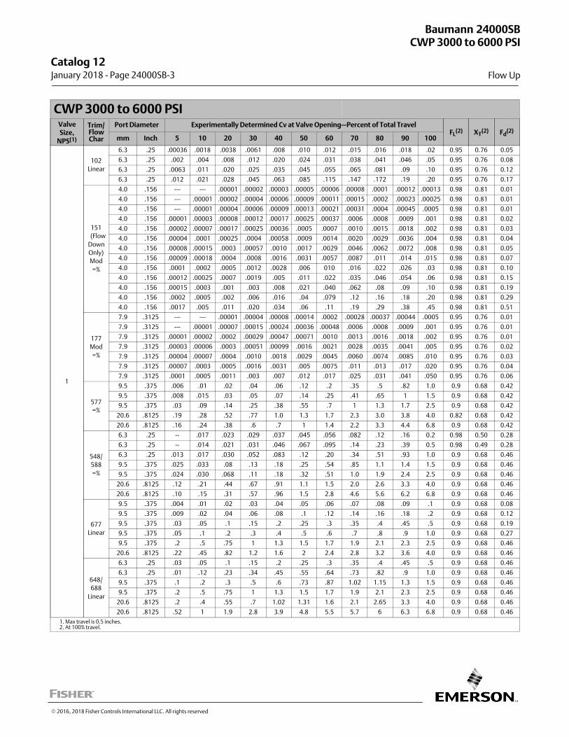
CWP 3000 to 6000 PSIValveSize,
NPS(1)
Trim/FlowChar
Port Diameter Experimentally Determined Cv at Valve Opening—Percent of Total TravelFL
(2) XT(2) Fd
(2)
mm Inch 5 10 20 30 40 50 60 70 80 90 100
1
102
Linear
6.3 .25 .00036 .0018 .0038 .0061 .008 .010 .012 .015 .016 .018 .02 0.95 0.76 0.05
6.3 .25 .002 .004 .008 .012 .020 .024 .031 .038 .041 .046 .05 0.95 0.76 0.08
6.3 .25 .0063 .011 .020 .025 .035 .045 .055 .065 .081 .09 .10 0.95 0.76 0.12
6.3 .25 .012 .021 .028 .045 .063 .085 .115 .147 .172 .19 .20 0.95 0.76 0.17
151
(Flow
Down
Only)
Mod
=%
4.0 .156 --- --- .00001 .00002 .00003 .00005 .00006 .00008 .0001 .00012 .00013 0.98 0.81 0.01
4.0 .156 --- .00001 .00002 .00004 .00006 .00009 .00011 .00015 .0002 .00023 .00025 0.98 0.81 0.01
4.0 .156 --- .00001 .00004 .00006 .00009 .00013 .00021 .00031 .0004 .00045 .0005 0.98 0.81 0.01
4.0 .156 .00001 .00003 .00008 .00012 .00017 .00025 .00037 .0006 .0008 .0009 .001 0.98 0.81 0.02
4.0 .156 .00002 .00007 .00017 .00025 .00036 .0005 .0007 .0010 .0015 .0018 .002 0.98 0.81 0.03
4.0 .156 .00004 .0001 .00025 .0004 .00058 .0009 .0014 .0020 .0029 .0036 .004 0.98 0.81 0.04
4.0 .156 .00008 .00015 .0003 .00057 .0010 .0017 .0029 .0046 .0062 .0072 .008 0.98 0.81 0.05
4.0 .156 .00009 .00018 .0004 .0008 .0016 .0031 .0057 .0087 .011 .014 .015 0.98 0.81 0.07
4.0 .156 .0001 .0002 .0005 .0012 .0028 .006 010 .016 .022 .026 .03 0.98 0.81 0.10
4.0 .156 .00012 .00025 .0007 .0019 .005 .011 .022 .035 .046 .054 .06 0.98 0.81 0.15
4.0 .156 .00015 .0003 .001 .003 .008 .021 .040 .062 .08 .09 .10 0.98 0.81 0.19
4.0 .156 .0002 .0005 .002 .006 .016 .04 .079 .12 .16 .18 .20 0.98 0.81 0.29
4.0 .156 .0017 .005 .011 .020 .034 .06 .11 .19 .29 .38 .45 0.98 0.81 0.51
177
Mod
=%
7.9 .3125 --- --- .00001 .00004 .00008 .00014 .0002 .00028 .00037 .00044 .0005 0.95 0.76 0.01
7.9 .3125 --- .00001 .00007 .00015 .00024 .00036 .00048 .0006 .0008 .0009 .001 0.95 0.76 0.01
7.9 .3125 .00001 .00002 .0002 .00029 .00047 .00071 .0010 .0013 .0016 .0018 .002 0.95 0.76 0.01
7.9 .3125 .00003 .00006 .0003 .00051 .00099 .0016 .0021 .0028 .0035 .0041 .005 0.95 0.76 0.02
7.9 .3125 .00004 .00007 .0004 .0010 .0018 .0029 .0045 .0060 .0074 .0085 .010 0.95 0.76 0.03
7.9 .3125 .00007 .0003 .0005 .0016 .0031 .005 .0075 .011 .013 .017 .020 0.95 0.76 0.04
7.9 .3125 .0001 .0005 .0011 .003 .007 .012 .017 .025 .031 .041 .050 0.95 0.76 0.06
577
=%
9.5 .375 .006 .01 .02 .04 .06 .12 .2 .35 .5 .82 1.0 0.9 0.68 0.42
9.5 .375 .008 .015 .03 .05 .07 .14 .25 .41 .65 1 1.5 0.9 0.68 0.42
9.5 .375 .03 .09 .14 .25 .38 .55 .7 1 1.3 1.7 2.5 0.9 0.68 0.42
20.6 .8125 .19 .28 .52 .77 1.0 1.3 1.7 2.3 3.0 3.8 4.0 0.82 0.68 0.42
20.6 .8125 .16 .24 .38 .6 .7 1 1.4 2.2 3.3 4.4 6.8 0.9 0.68 0.42
548/
588
=%
6.3 .25 -- .017 .023 .029 .037 .045 .056 .082 .12 .16 0.2 0.98 0.50 0.28
6.3 .25 -- .014 .021 .031 .046 .067 .095 .14 .23 .39 0.5 0.98 0.49 0.28
6.3 .25 .013 .017 .030 .052 .083 .12 .20 .34 .51 .93 1.0 0.9 0.68 0.46
9.5 .375 .025 .033 .08 .13 .18 .25 .54 .85 1.1 1.4 1.5 0.9 0.68 0.46
9.5 .375 .024 .030 .068 .11 .18 .32 .51 1.0 1.9 2.4 2.5 0.9 0.68 0.46
20.6 .8125 .12 .21 .44 .67 .91 1.1 1.5 2.0 2.6 3.3 4.0 0.9 0.68 0.46
20.6 .8125 .10 .15 .31 .57 .96 1.5 2.8 4.6 5.6 6.2 6.8 0.9 0.68 0.46
677
Linear
9.5 .375 .004 .01 .02 .03 .04 .05 .06 .07 .08 .09 .1 0.9 0.68 0.08
9.5 .375 .009 .02 .04 .06 .08 .1 .12 .14 .16 .18 .2 0.9 0.68 0.12
9.5 .375 .03 .05 .1 .15 .2 .25 .3 .35 .4 .45 .5 0.9 0.68 0.19
9.5 .375 .05 .1 .2 .3 .4 .5 .6 .7 .8 .9 1.0 0.9 0.68 0.27
9.5 .375 .2 .5 .75 1 1.3 1.5 1.7 1.9 2.1 2.3 2.5 0.9 0.68 0.46
20.6 .8125 .22 .45 .82 1.2 1.6 2 2.4 2.8 3.2 3.6 4.0 0.9 0.68 0.46
648/
688
Linear
6.3 .25 .03 .05 .1 .15 .2 .25 .3 .35 .4 .45 .5 0.9 0.68 0.46
6.3 .25 .01 .12 .23 .34 .45 .55 .64 .73 .82 .9 1.0 0.9 0.68 0.46
9.5 .375 .1 .2 .3 .5 .6 .73 .87 1.02 1.15 1.3 1.5 0.9 0.68 0.46
9.5 .375 .2 .5 .75 1 1.3 1.5 1.7 1.9 2.1 2.3 2.5 0.9 0.68 0.46
20.6 .8125 .2 .4 .55 .7 1.02 1.31 1.6 2.1 2.65 3.3 4.0 0.9 0.68 0.46
20.6 .8125 .52 1 1.9 2.8 3.9 4.8 5.5 5.7 6 6.3 6.8 0.9 0.68 0.46
1. Max travel is 0.5 inches.2. At 100% travel.
Baumann 24000SBCWP 3000 to 6000 PSI
Flow Up
Catalog 12 January 2018 ‐ Page 24000SB‐3
� 2016, 2018 Fisher Controls International LLC. All rights reserved

This page intentionally left blank
Catalog 12January 2018 ‐ Page 24000SB‐4
� 2016, 2018 Fisher Controls International LLC. All rights reserved
www.Fisher.com
Responsibility for selection, use, and maintenance of any product remains solely with the purchaser and end user. The contents of this publication are forinformational purposes only and are not to be construed as warranties or guarantees, express or implied, regarding the products or services describedtherein. Fisher and Baumann are marks owned by one of the companies in the Emerson Automation Solutions business unit of Emerson Electric Co. EmersonAutomation Solutions, Emerson, and the Emerson logo are trademarks and service marks of Emerson Electric Co. All other marks are the property of theirrespective owners.

CWP 150 PSIValveSize,NPS
TrimFlow
Char
Port Diameter Experimentally Determined Cv at Valve Opening—Percent of Total TravelFL
(1)
mm Inch 5 10 20 30 40 50 60 70 80 90 100
1 177 =%8 0.312 ‐ ‐ ‐ 0.00 0.01 0.02 0.04 0.06 0.1 0.1 0.1 0.2 0.2 0.95
13 0.5 0.01 0.03 0.10 0.19 0.45 0.86 1.4 2.1 3.0 4.2 5.4 ‐ ‐ ‐
1. At 100% travel.
CoefficientsValveSize
PortDia.
PlugTvl
CV AT VALVE OPENING - Percent of Plug TravelFd FL XT KC
NPS in. in. 5 10 20 30 40 50 60 70 80 90 100
1
0.312 0.5
0.00002 0.00005 0.00013 0.00024 0.00036 0.00048 0.0006 0.0007 0.0008 0.0009 0.001
0.7
0.98 0.81 0.94
0.00004 0.00015 0.0004 0.0007 0.009 0.0012 0.0018 0.0025 0.0033 0.0041 0.005
0.00007 0.00015 0.0004 0.0008 0.0013 0.002 0.003 0.005 0.007 0.009 0.01
0.0001 0.0002 0.0006 0.0008 0.0017 0.0031 0.0048 0.007 0.01 0.013 0.02
0.0003 0.0005 0.001 0.002 0.004 0.008 0.012 0.017 0.023 0.033 0.05
0.008 0.016 0.034 0.045 0.053 0.061 0.069 0.075 0.081 0.09 0.1
0.02 0.03 0.04 0.06 0.08 0.1 0.12 0.14 0.16 0.18 0.2
0.03 0.04 0.08 0.12 0.16 0.2 0.24 0.28 0.32 0.36 0.4
0.06 0.08 0.16 0.25 0.32 0.41 0.48 0.56 0.64 0.72 0.8 0.42
0.07 0.11 0.2 0.31 0.41 0.52 0.63 0.71 0.82 0.91 1
0.460.375 0.5 0.02 0.042 0.113 0.271 0.541 0.85 1.18 1.72 2.08 2.32 2.5 0.86 0.68 0.73
0.5 0.5 0.04 0.07 0.19 0.46 0.905 1.45 2 2.91 3.52 4 4.2 0.8 0.53 0.51
Baumann 26000
Flow Up
CWP 150 PSI
Catalog 12 January 2018 ‐ Page 26000‐1
� 2014, 2018 Fisher Controls International LLC. All rights reserved

CWP 3000 PSIValveSize,NPS
TrimFlow
Char
Port Diameter Experimentally Determined Cv at Valve Opening—Percent of Total TravelFL
(1)
mm Inch 5 10 20 30 40 50 60 70 80 90 100
1/4
4 =% 4 0.156 ‐ ‐ ‐ 0.00056 0.010 0.016 0.021 0.030 0.055 0.102 0.157 0.265 0.417 0.98
5 =% 4 0.156 ‐ ‐ ‐ 0.00009 0.00065 0.0043 0.011 0.015 0.021 0.043 0.089 0.132 0.152 0.98
6 mod =% 4 0.156 0.00072 0.00180 0.0046 0.0091 0.016 0.033 0.059 0.086 0.095 0.100 0.103 0.98
7 mod =% 4 0.156 ‐ ‐ ‐ 0.00067 0.0033 0.0072 0.013 0.018 0.023 0.031 0.041 0.051 0.065 0.98
8 mod =% 4 0.156 0.00045 0.00114 0.0027 0.0049 0.0077 0.012 0.016 0.021 0.026 0.033 0.041 0.98
9 mod =% 4 0.156 ‐ ‐ ‐ 0.00002 0.00039 0.00101 0.0021 0.0033 0.0047 0.0064 0.0082 0.010 0.014 0.98
10 mod =% 4 0.156 ‐ ‐ ‐ 0.00002 0.00023 0.00060 0.0011 0.0017 0.0026 0.0034 0.0044 0.0054 0.0066 0.98
11 mod =% 4 0.156 0.00003 0.00010 0.00037 0.00065 0.0012 0.0018 0.0026 0.0033 0.0042 0.0050 0.0059 0.98
12 mod =% 4 0.156 ‐ ‐ ‐ ‐ ‐ ‐ 0.00004 0.00020 0.00042 0.00071 0.0011 0.0015 0.0020 0.0025 0.0030 0.98
13 mod =% 4 0.156 ‐ ‐ ‐ ‐ ‐ ‐ 0.00003 0.00011 0.00025 0.00039 0.00057 0.00080 0.0010 0.0013 0.0016 0.98
14 mod =% 4 0.156 ‐ ‐ ‐ ‐ ‐ ‐ 0.00002 0.00006 0.00012 0.00021 0.00030 0.00042 0.00052 0.00065 0.00079 0.98
15 mod =% 4 0.156 0.000002 0.000006 0.00002 0.00004 0.00006 0.00009 0.00011 0.00015 0.0002 0.00023 0.00025 0.98
16 mod =% 4 0.156 0.000001 0.000003 0.00001 0.00002 0.00003 0.00005 0.00006 0.00008 0.0001 0.0012 0.00013 0.98
1. At 100% travel.
Baumann 51000
Flow Up
CWP 3000 PSI
Catalog 12January 2018 ‐ Page 51000‐1
� 2009, 2018 Fisher Controls International LLC. All rights reserved
www.Fisher.com
Responsibility for selection, use, and maintenance of any product remains solely with the purchaser and end user. The contents of this publication are forinformational purposes only and are not to be construed as warranties or guarantees, express or implied, regarding the products or services describedtherein. Fisher and Baumann are marks owned by one of the companies in the Emerson Automation Solutions business unit of Emerson Electric Co. EmersonAutomation Solutions, Emerson, and the Emerson logo are trademarks and service marks of Emerson Electric Co. All other marks are the property of theirrespective owners.
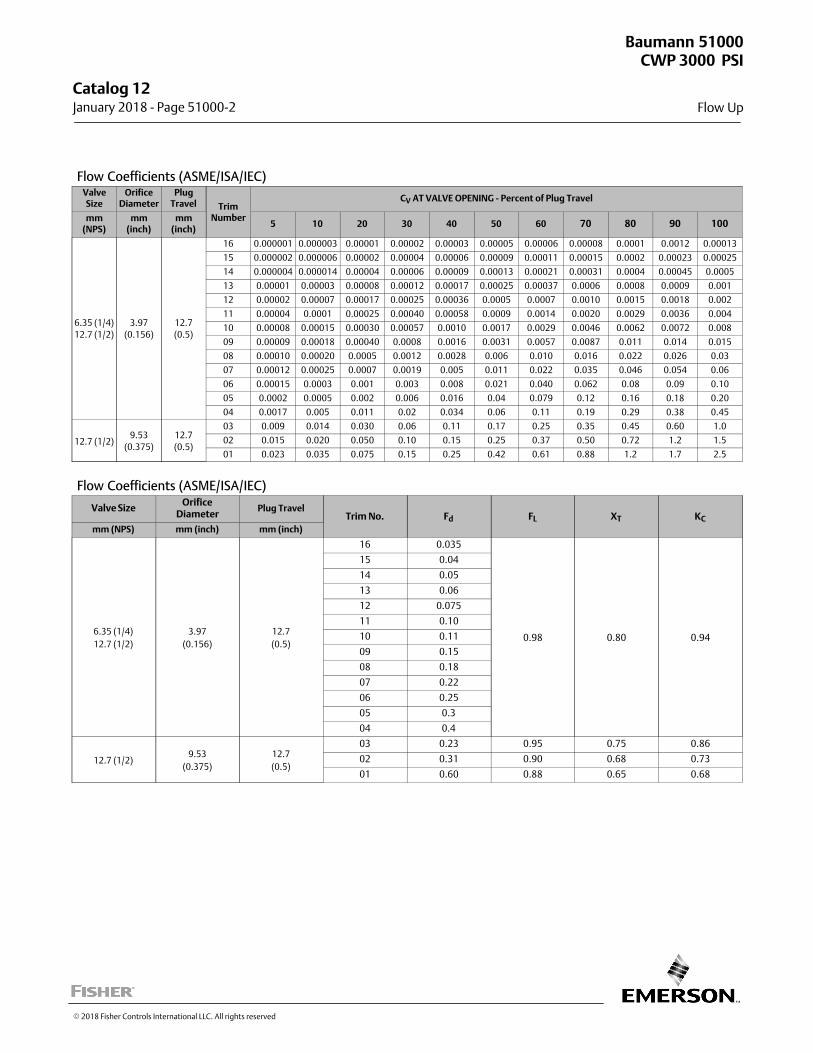
Flow Coefficients (ASME/ISA/IEC)ValveSize
OrificeDiameter
PlugTravel Trim
Number
CV AT VALVE OPENING - Percent of Plug Travel
mm(NPS)
mm(inch)
mm(inch)
5 10 20 30 40 50 60 70 80 90 100
6.35 (1/4)
12.7 (1/2)
3.97
(0.156)
12.7
(0.5)
16 0.000001 0.000003 0.00001 0.00002 0.00003 0.00005 0.00006 0.00008 0.0001 0.0012 0.00013
15 0.000002 0.000006 0.00002 0.00004 0.00006 0.00009 0.00011 0.00015 0.0002 0.00023 0.00025
14 0.000004 0.000014 0.00004 0.00006 0.00009 0.00013 0.00021 0.00031 0.0004 0.00045 0.0005
13 0.00001 0.00003 0.00008 0.00012 0.00017 0.00025 0.00037 0.0006 0.0008 0.0009 0.001
12 0.00002 0.00007 0.00017 0.00025 0.00036 0.0005 0.0007 0.0010 0.0015 0.0018 0.002
11 0.00004 0.0001 0.00025 0.00040 0.00058 0.0009 0.0014 0.0020 0.0029 0.0036 0.004
10 0.00008 0.00015 0.00030 0.00057 0.0010 0.0017 0.0029 0.0046 0.0062 0.0072 0.008
09 0.00009 0.00018 0.00040 0.0008 0.0016 0.0031 0.0057 0.0087 0.011 0.014 0.015
08 0.00010 0.00020 0.0005 0.0012 0.0028 0.006 0.010 0.016 0.022 0.026 0.03
07 0.00012 0.00025 0.0007 0.0019 0.005 0.011 0.022 0.035 0.046 0.054 0.06
06 0.00015 0.0003 0.001 0.003 0.008 0.021 0.040 0.062 0.08 0.09 0.10
05 0.0002 0.0005 0.002 0.006 0.016 0.04 0.079 0.12 0.16 0.18 0.20
04 0.0017 0.005 0.011 0.02 0.034 0.06 0.11 0.19 0.29 0.38 0.45
12.7 (1/2)9.53
(0.375)
12.7
(0.5)
03 0.009 0.014 0.030 0.06 0.11 0.17 0.25 0.35 0.45 0.60 1.0
02 0.015 0.020 0.050 0.10 0.15 0.25 0.37 0.50 0.72 1.2 1.5
01 0.023 0.035 0.075 0.15 0.25 0.42 0.61 0.88 1.2 1.7 2.5
Flow Coefficients (ASME/ISA/IEC)
Valve SizeOrifice
DiameterPlug Travel
Trim No. Fd FL XT KC
mm (NPS) mm (inch) mm (inch)
6.35 (1/4)
12.7 (1/2)
3.97
(0.156)
12.7
(0.5)
16 0.035
0.98 0.80 0.94
15 0.04
14 0.05
13 0.06
12 0.075
11 0.10
10 0.11
09 0.15
08 0.18
07 0.22
06 0.25
05 0.3
04 0.4
12.7 (1/2)9.53
(0.375)
12.7
(0.5)
03 0.23 0.95 0.75 0.86
02 0.31 0.90 0.68 0.73
01 0.60 0.88 0.65 0.68
Baumann 51000
Flow Up
CWP 3000 PSI
Catalog 12 January 2018 ‐ Page 51000‐2
� 2018 Fisher Controls International LLC. All rights reserved
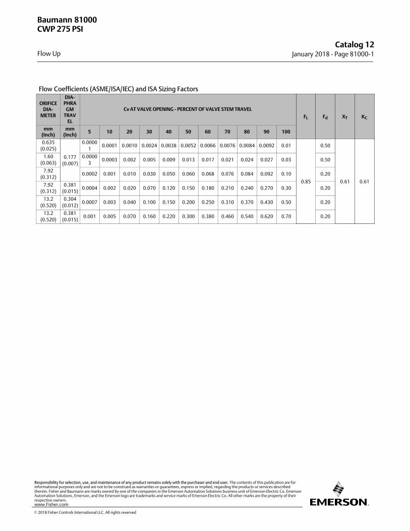
Flow Coefficients (ASME/ISA/IEC) and ISA Sizing Factors
ORIFICEDIA-
METER
DIA-PHRA
GMTRAV
EL
Cv AT VALVE OPENING - PERCENT OF VALVE STEM TRAVEL
FL Fd XT KC
mm(Inch)
mm(Inch)
5 10 20 30 40 50 60 70 80 90 100
0.635
(0.025)
0.177
(0.007)
0.0000
10.0001 0.0010 0.0024 0.0038 0.0052 0.0066 0.0076 0.0084 0.0092 0.01
0.85
0.50
0.61 0.61
1.60
(0.063)
0.0000
30.0003 0.002 0.005 0.009 0.013 0.017 0.021 0.024 0.027 0.03 0.50
7.92
(0.312)0.0002 0.001 0.010 0.030 0.050 0.060 0.068 0.076 0.084 0.092 0.10 0.20
7.92
(0.312)
0.381
(0.015)0.0004 0.002 0.020 0.070 0.120 0.150 0.180 0.210 0.240 0.270 0.30 0.20
13.2
(0.520)
0.304
(0.012)0.0007 0.003 0.040 0.100 0.150 0.200 0.250 0.310 0.370 0.430 0.50 0.20
13.2
(0.520)
0.381
(0.015)0.001 0.005 0.070 0.160 0.220 0.300 0.380 0.460 0.540 0.620 0.70 0.20
Baumann 81000
Flow Up
CWP 275 PSI
Catalog 12January 2018 ‐ Page 81000‐1
� 2018 Fisher Controls International LLC. All rights reserved
www.Fisher.com
Responsibility for selection, use, and maintenance of any product remains solely with the purchaser and end user. The contents of this publication are forinformational purposes only and are not to be construed as warranties or guarantees, express or implied, regarding the products or services describedtherein. Fisher and Baumann are marks owned by one of the companies in the Emerson Automation Solutions business unit of Emerson Electric Co. EmersonAutomation Solutions, Emerson, and the Emerson logo are trademarks and service marks of Emerson Electric Co. All other marks are the property of theirrespective owners.
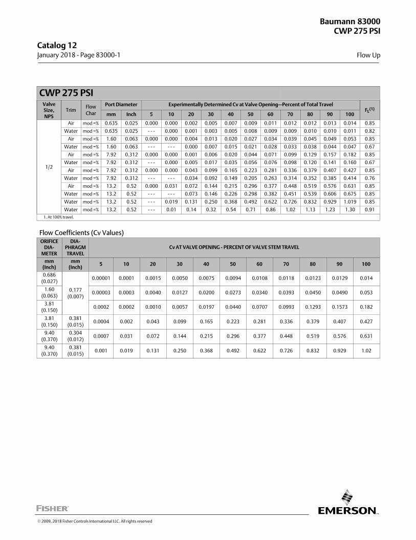
CWP 275 PSIValveSize,NPS
TrimFlow
Char
Port Diameter Experimentally Determined Cv at Valve Opening—Percent of Total TravelFL
(1)
mm Inch 5 10 20 30 40 50 60 70 80 90 100
1/2
Air mod =% 0.635 0.025 0.000 0.000 0.002 0.005 0.007 0.009 0.011 0.012 0.012 0.013 0.014 0.85
Water mod =% 0.635 0.025 - - - 0.000 0.001 0.003 0.005 0.008 0.009 0.009 0.010 0.010 0.011 0.82
Air mod =% 1.60 0.063 0.000 0.000 0.004 0.013 0.020 0.027 0.034 0.039 0.045 0.049 0.053 0.85
Water mod =% 1.60 0.063 - - - - - - 0.000 0.007 0.015 0.021 0.028 0.033 0.038 0.044 0.047 0.67
Air mod =% 7.92 0.312 0.000 0.000 0.001 0.006 0.020 0.044 0.071 0.099 0.129 0.157 0.182 0.85
Water mod =% 7.92 0.312 - - - 0.000 0.005 0.017 0.035 0.056 0.076 0.098 0.120 0.141 0.160 0.67
Air mod =% 7.92 0.312 0.000 0.000 0.043 0.099 0.165 0.223 0.281 0.336 0.379 0.407 0.427 0.85
Water mod =% 7.92 0.312 - - - - - - 0.034 0.092 0.149 0.205 0.263 0.314 0.352 0.385 0.414 0.76
Air mod =% 13.2 0.52 0.000 0.031 0.072 0.144 0.215 0.296 0.377 0.448 0.519 0.576 0.631 0.85
Water mod =% 13.2 0.52 - - - - - - 0.073 0.146 0.226 0.298 0.382 0.451 0.539 0.606 0.675 0.85
Water mod =% 13.2 0.52 - - - 0.019 0.131 0.250 0.368 0.492 0.622 0.726 0.832 0.929 1.019 0.85
Water mod =% 13.2 0.52 - - - 0.01 0.14 0.32 0.54 0.71 0.86 1.02 1.13 1.23 1.30 0.91
1. At 100% travel.
Flow Coefficients (Cv Values)ORIFICE
DIA-METER
DIA-PHRAGMTRAVEL
Cv AT VALVE OPENING - PERCENT OF VALVE STEM TRAVEL
mm(Inch)
mm(Inch)
5 10 20 30 40 50 60 70 80 90 100
0.686
(0.027)
0.177
(0.007)
0.00001 0.0001 0.0015 0.0050 0.0075 0.0094 0.0108 0.0118 0.0123 0.0129 0.014
1.60
(0.063)0.00003 0.0003 0.0040 0.0127 0.0200 0.0273 0.0340 0.0393 0.0450 0.0490 0.053
3.81
(0.150)0.0002 0.0002 0.0010 0.0057 0.0197 0.0440 0.0707 0.0993 0.1293 0.1573 0.182
3.81
(0.150)
0.381
(0.015)0.0004 0.002 0.043 0.099 0.165 0.223 0.281 0.336 0.379 0.407 0.427
9.40
(0.370)
0.304
(0.012)0.0007 0.031 0.072 0.144 0.215 0.296 0.377 0.448 0.519 0.576 0.631
9.40
(0.370)
0.381
(0.015)0.001 0.019 0.131 0.250 0.368 0.492 0.622 0.726 0.832 0.929 1.02
Baumann 83000
Flow Up
CWP 275 PSI
Catalog 12 January 2018 ‐ Page 83000‐1
� 2009, 2018 Fisher Controls International LLC. All rights reserved
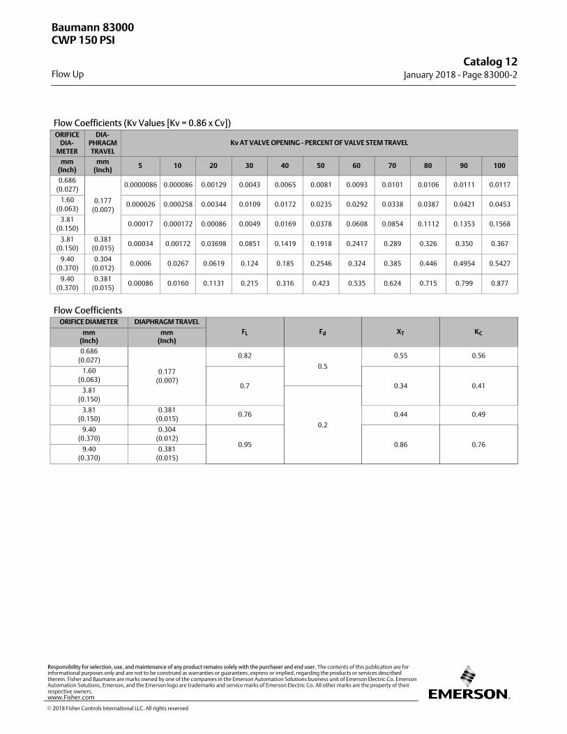
Flow Coefficients (Kv Values [Kv = 0.86 x Cv])ORIFICE
DIA-METER
DIA-PHRAGMTRAVEL
Kv AT VALVE OPENING - PERCENT OF VALVE STEM TRAVEL
mm(Inch)
mm(Inch)
5 10 20 30 40 50 60 70 80 90 100
0.686
(0.027)
0.177
(0.007)
0.0000086 0.000086 0.00129 0.0043 0.0065 0.0081 0.0093 0.0101 0.0106 0.0111 0.0117
1.60
(0.063)0.000026 0.000258 0.00344 0.0109 0.0172 0.0235 0.0292 0.0338 0.0387 0.0421 0.0453
3.81
(0.150)0.00017 0.000172 0.00086 0.0049 0.0169 0.0378 0.0608 0.0854 0.1112 0.1353 0.1568
3.81
(0.150)
0.381
(0.015)0.00034 0.00172 0.03698 0.0851 0.1419 0.1918 0.2417 0.289 0.326 0.350 0.367
9.40
(0.370)
0.304
(0.012)0.0006 0.0267 0.0619 0.124 0.185 0.2546 0.324 0.385 0.446 0.4954 0.5427
9.40
(0.370)
0.381
(0.015)0.00086 0.0160 0.1131 0.215 0.316 0.423 0.535 0.624 0.715 0.799 0.877
Flow CoefficientsORIFICE DIAMETER DIAPHRAGM TRAVEL
FL Fd XT KCmm(Inch)
mm(Inch)
0.686
(0.027)
0.177
(0.007)
0.82
0.5
0.55 0.56
1.60
(0.063)0.7 0.34 0.41
3.81
(0.150)
0.2
3.81
(0.150)
0.381
(0.015)0.76 0.44 0.49
9.40
(0.370)
0.304
(0.012)0.95 0.86 0.76
9.40
(0.370)
0.381
(0.015)
Baumann 83000
Flow Up
CWP 150 PSI
Catalog 12January 2018 ‐ Page 83000‐2
� 2018 Fisher Controls International LLC. All rights reserved
www.Fisher.com
Responsibility for selection, use, and maintenance of any product remains solely with the purchaser and end user. The contents of this publication are forinformational purposes only and are not to be construed as warranties or guarantees, express or implied, regarding the products or services describedtherein. Fisher and Baumann are marks owned by one of the companies in the Emerson Automation Solutions business unit of Emerson Electric Co. EmersonAutomation Solutions, Emerson, and the Emerson logo are trademarks and service marks of Emerson Electric Co. All other marks are the property of theirrespective owners.
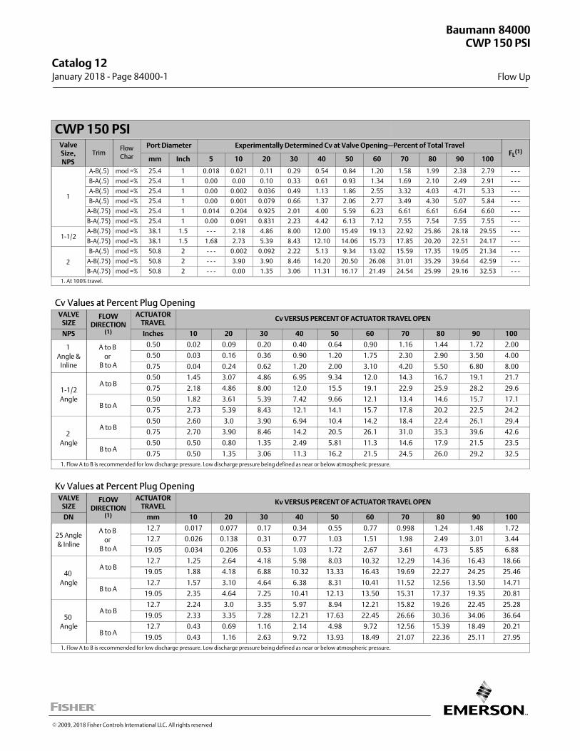
CWP 150 PSIValveSize,NPS
TrimFlow
Char
Port Diameter Experimentally Determined Cv at Valve Opening—Percent of Total TravelFL
(1)
mm Inch 5 10 20 30 40 50 60 70 80 90 100
1
A-B(.5) mod =% 25.4 1 0.018 0.021 0.11 0.29 0.54 0.84 1.20 1.58 1.99 2.38 2.79 ‐ ‐ ‐
B-A(.5) mod =% 25.4 1 0.00 0.00 0.10 0.33 0.61 0.93 1.34 1.69 2.10 2.49 2.91 ‐ ‐ ‐
A-B(.5) mod =% 25.4 1 0.00 0.002 0.036 0.49 1.13 1.86 2.55 3.32 4.03 4.71 5.33 ‐ ‐ ‐
B-A(.5) mod =% 25.4 1 0.00 0.001 0.079 0.66 1.37 2.06 2.77 3.49 4.30 5.07 5.84 ‐ ‐ ‐
A-B(.75) mod =% 25.4 1 0.014 0.204 0.925 2.01 4.00 5.59 6.23 6.61 6.61 6.64 6.60 ‐ ‐ ‐
B-A(.75) mod =% 25.4 1 0.00 0.091 0.831 2.23 4.42 6.13 7.12 7.55 7.54 7.55 7.55 ‐ ‐ ‐
1-1/2A-B(.75) mod =% 38.1 1.5 - - - 2.18 4.86 8.00 12.00 15.49 19.13 22.92 25.86 28.18 29.55 ‐ ‐ ‐
B-A(.75) mod =% 38.1 1.5 1.68 2.73 5.39 8.43 12.10 14.06 15.73 17.85 20.20 22.51 24.17 ‐ ‐ ‐
2
B-A(.5) mod =% 50.8 2 - - - 0.002 0.092 2.22 5.13 9.34 13.02 15.59 17.35 19.05 21.34 ‐ ‐ ‐
A-B(.75) mod =% 50.8 2 - - - 3.90 3.90 8.46 14.20 20.50 26.08 31.01 35.29 39.64 42.59 ‐ ‐ ‐
B-A(.75) mod =% 50.8 2 - - - 0.00 1.35 3.06 11.31 16.17 21.49 24.54 25.99 29.16 32.53 ‐ ‐ ‐
1. At 100% travel.
Cv Values at Percent Plug OpeningVALVE
SIZEFLOW
DIRECTION(1)
ACTUATORTRAVEL
Cv VERSUS PERCENT OF ACTUATOR TRAVEL OPEN
NPS Inches 10 20 30 40 50 60 70 80 90 100
1
Angle &Inline
A to B
or B to A
0.50 0.02 0.09 0.20 0.40 0.64 0.90 1.16 1.44 1.72 2.00
0.50 0.03 0.16 0.36 0.90 1.20 1.75 2.30 2.90 3.50 4.00
0.75 0.04 0.24 0.62 1.20 2.00 3.10 4.20 5.50 6.80 8.00
1-1/2
Angle
A to B0.50 1.45 3.07 4.86 6.95 9.34 12.0 14.3 16.7 19.1 21.7
0.75 2.18 4.86 8.00 12.0 15.5 19.1 22.9 25.9 28.2 29.6
B to A0.50 1.82 3.61 5.39 7.42 9.66 12.1 13.4 14.6 15.7 17.1
0.75 2.73 5.39 8.43 12.1 14.1 15.7 17.8 20.2 22.5 24.2
2
Angle
A to B0.50 2.60 3.0 3.90 6.94 10.4 14.2 18.4 22.4 26.1 29.4
0.75 2.70 3.90 8.46 14.2 20.5 26.1 31.0 35.3 39.6 42.6
B to A0.50 0.50 0.80 1.35 2.49 5.81 11.3 14.6 17.9 21.5 23.5
0.75 0.50 1.35 3.06 11.3 16.2 21.5 24.5 26.0 29.2 32.5
1. Flow A to B is recommended for low discharge pressure. Low discharge pressure being defined as near or below atmospheric pressure.
Kv Values at Percent Plug OpeningVALVE
SIZEFLOW
DIRECTION(1)
ACTUATORTRAVEL
Kv VERSUS PERCENT OF ACTUATOR TRAVEL OPEN
DN mm 10 20 30 40 50 60 70 80 90 100
25 Angle
& Inline
A to B
or B to A
12.7 0.017 0.077 0.17 0.34 0.55 0.77 0.998 1.24 1.48 1.72
12.7 0.026 0.138 0.31 0.77 1.03 1.51 1.98 2.49 3.01 3.44
19.05 0.034 0.206 0.53 1.03 1.72 2.67 3.61 4.73 5.85 6.88
40
Angle
A to B12.7 1.25 2.64 4.18 5.98 8.03 10.32 12.29 14.36 16.43 18.66
19.05 1.88 4.18 6.88 10.32 13.33 16.43 19.69 22.27 24.25 25.46
B to A12.7 1.57 3.10 4.64 6.38 8.31 10.41 11.52 12.56 13.50 14.71
19.05 2.35 4.64 7.25 10.41 12.13 13.50 15.31 17.37 19.35 20.81
50
Angle
A to B12.7 2.24 3.0 3.35 5.97 8.94 12.21 15.82 19.26 22.45 25.28
19.05 2.33 3.35 7.28 12.21 17.63 22.45 26.66 30.36 34.06 36.64
B to A12.7 0.43 0.69 1.16 2.14 4.98 9.72 12.56 15.39 18.49 20.21
19.05 0.43 1.16 2.63 9.72 13.93 18.49 21.07 22.36 25.11 27.95
1. Flow A to B is recommended for low discharge pressure. Low discharge pressure being defined as near or below atmospheric pressure.
Baumann 84000
Flow Up
CWP 150 PSI
Catalog 12 January 2018 ‐ Page 84000‐1
� 2009, 2018 Fisher Controls International LLC. All rights reserved
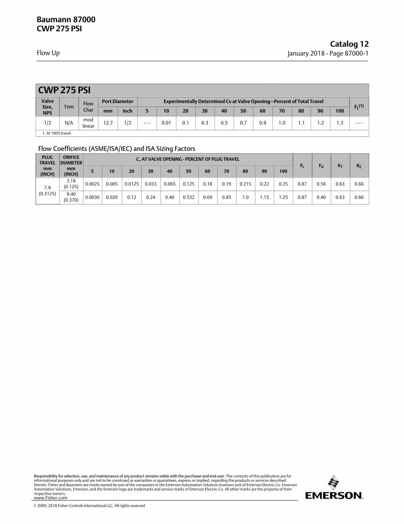
CWP 275 PSIValveSize,NPS
TrimFlow
Char
Port Diameter Experimentally Determined Cv at Valve Opening—Percent of Total TravelFL
(1)
mm Inch 5 10 20 30 40 50 60 70 80 90 100
1/2 N/Amod
linear12.7 1/2 - - - 0.01 0.1 0.3 0.5 0.7 0.9 1.0 1.1 1.2 1.3 ‐ ‐ ‐
1. At 100% travel.
Flow Coefficients (ASME/ISA/IEC) and ISA Sizing FactorsPLUG
TRAVELmm
(INCH)
ORIFICEDIAMETER
mm(INCH)
Cv AT VALVE OPENING - PERCENT OF PLUG TRAVEL
FL Fd XT KC
5 10 20 30 40 50 60 70 80 90 100
7.9
(0.3125)
3.18
(0.125)0.0025 0.005 0.0125 0.033 0.065 0.125 0.18 0.19 0.215 0.22 0.25 0.87 0.56 0.63 0.66
9.40
(0.370)0.0030 0.020 0.12 0.24 0.40 0.532 0.69 0.85 1.0 1.15 1.25 0.87 0.40 0.63 0.66
Baumann 87000
Flow Up
CWP 275 PSI
Catalog 12January 2018 ‐ Page 87000‐1
� 2009, 2018 Fisher Controls International LLC. All rights reserved
www.Fisher.com
Responsibility for selection, use, and maintenance of any product remains solely with the purchaser and end user. The contents of this publication are forinformational purposes only and are not to be construed as warranties or guarantees, express or implied, regarding the products or services describedtherein. Fisher and Baumann are marks owned by one of the companies in the Emerson Automation Solutions business unit of Emerson Electric Co. EmersonAutomation Solutions, Emerson, and the Emerson logo are trademarks and service marks of Emerson Electric Co. All other marks are the property of theirrespective owners.
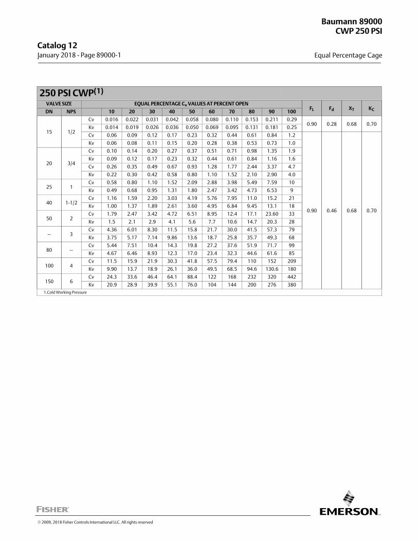
250 PSI CWP(1)
VALVE SIZE EQUAL PERCENTAGE Cv VALUES AT PERCENT OPENFL Fd XT KCDN NPS 10 20 30 40 50 60 70 80 90 100
15 1/2
Cv 0.016 0.022 0.031 0.042 0.058 0.080 0.110 0.153 0.211 0.290.90 0.28 0.68 0.70
Kv 0.014 0.019 0.026 0.036 0.050 0.069 0.095 0.131 0.181 0.25
Cv 0.06 0.09 0.12 0.17 0.23 0.32 0.44 0.61 0.84 1.2
0.90 0.46 0.68 0.70
Kv 0.06 0.08 0.11 0.15 0.20 0.28 0.38 0.53 0.73 1.0
20 3/4
Cv 0.10 0.14 0.20 0.27 0.37 0.51 0.71 0.98 1.35 1.9
Kv 0.09 0.12 0.17 0.23 0.32 0.44 0.61 0.84 1.16 1.6
Cv 0.26 0.35 0.49 0.67 0.93 1.28 1.77 2.44 3.37 4.7
Kv 0.22 0.30 0.42 0.58 0.80 1.10 1.52 2.10 2.90 4.0
25 1Cv 0.58 0.80 1.10 1.52 2.09 2.88 3.98 5.49 7.59 10
Kv 0.49 0.68 0.95 1.31 1.80 2.47 3.42 4.73 6.53 9
40 1-1/2Cv 1.16 1.59 2.20 3.03 4.19 5.76 7.95 11.0 15.2 21
Kv 1.00 1.37 1.89 2.61 3.60 4.95 6.84 9.45 13.1 18
50 2Cv 1.79 2.47 3.42 4.72 6.51 8.95 12.4 17.1 23.60 33
Kv 1.5 2.1 2.9 4.1 5.6 7.7 10.6 14.7 20.3 28
-- 3Cv 4.36 6.01 8.30 11.5 15.8 21.7 30.0 41.5 57.3 79
Kv 3.75 5.17 7.14 9.86 13.6 18.7 25.8 35.7 49.3 68
80 --Cv 5.44 7.51 10.4 14.3 19.8 27.2 37.6 51.9 71.7 99
Kv 4.67 6.46 8.93 12.3 17.0 23.4 32.3 44.6 61.6 85
100 4Cv 11.5 15.9 21.9 30.3 41.8 57.5 79.4 110 152 209
Kv 9.90 13.7 18.9 26.1 36.0 49.5 68.5 94.6 130.6 180
150 6Cv 24.3 33.6 46.4 64.1 88.4 122 168 232 320 442
Kv 20.9 28.9 39.9 55.1 76.0 104 144 200 276 380
1.Cold Working Pressure
Baumann 89000
Equal Percentage Cage
CWP 250 PSI
Catalog 12 January 2018 ‐ Page 89000‐1
� 2009, 2018 Fisher Controls International LLC. All rights reserved

This page intentionally left blank
Catalog 12January 2018 ‐ Page 89000‐2
� 2009, 2018 Fisher Controls International LLC. All rights reserved
www.Fisher.com
Responsibility for selection, use, and maintenance of any product remains solely with the purchaser and end user. The contents of this publication are forinformational purposes only and are not to be construed as warranties or guarantees, express or implied, regarding the products or services describedtherein. Fisher and Baumann are marks owned by one of the companies in the Emerson Automation Solutions business unit of Emerson Electric Co. EmersonAutomation Solutions, Emerson, and the Emerson logo are trademarks and service marks of Emerson Electric Co. All other marks are the property of theirrespective owners.
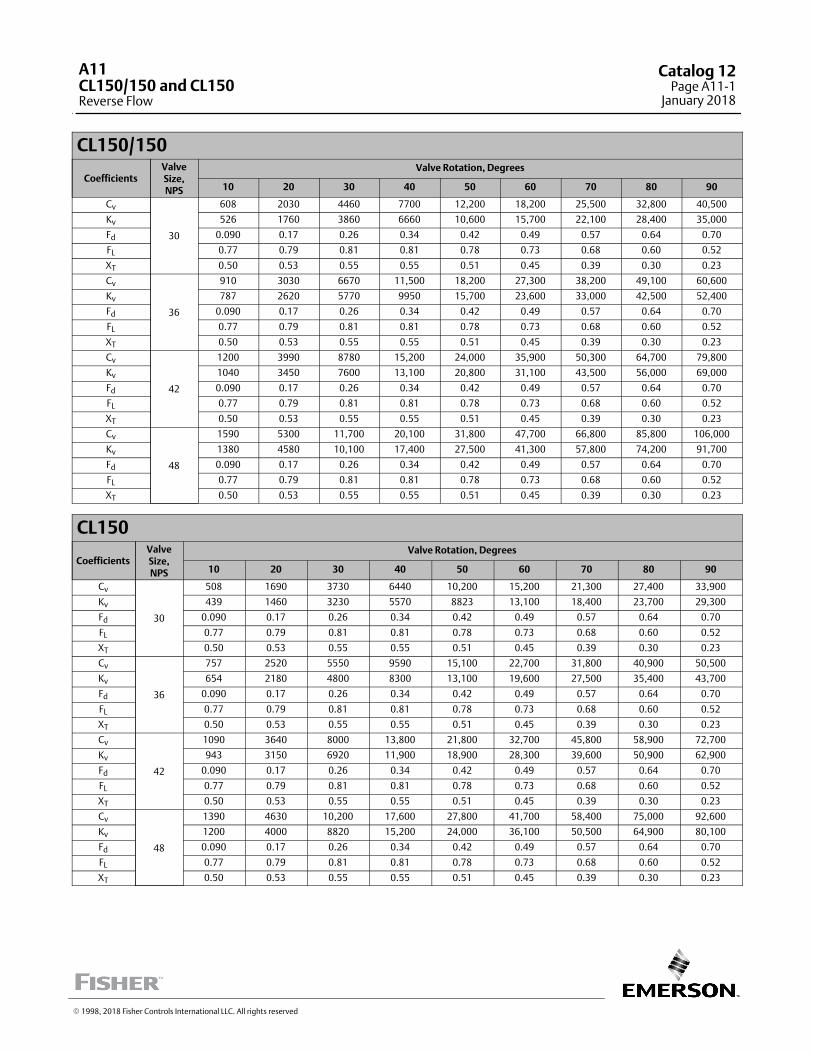
CL150/150
CoefficientsValveSize,NPS
Valve Rotation, Degrees
10 20 30 40 50 60 70 80 90
Cv
30
608 2030 4460 7700 12,200 18,200 25,500 32,800 40,500
Kv 526 1760 3860 6660 10,600 15,700 22,100 28,400 35,000
Fd 0.090 0.17 0.26 0.34 0.42 0.49 0.57 0.64 0.70
FL 0.77 0.79 0.81 0.81 0.78 0.73 0.68 0.60 0.52
XT 0.50 0.53 0.55 0.55 0.51 0.45 0.39 0.30 0.23
Cv
36
910 3030 6670 11,500 18,200 27,300 38,200 49,100 60,600
Kv 787 2620 5770 9950 15,700 23,600 33,000 42,500 52,400
Fd 0.090 0.17 0.26 0.34 0.42 0.49 0.57 0.64 0.70
FL 0.77 0.79 0.81 0.81 0.78 0.73 0.68 0.60 0.52
XT 0.50 0.53 0.55 0.55 0.51 0.45 0.39 0.30 0.23
Cv
42
1200 3990 8780 15,200 24,000 35,900 50,300 64,700 79,800
Kv 1040 3450 7600 13,100 20,800 31,100 43,500 56,000 69,000
Fd 0.090 0.17 0.26 0.34 0.42 0.49 0.57 0.64 0.70
FL 0.77 0.79 0.81 0.81 0.78 0.73 0.68 0.60 0.52
XT 0.50 0.53 0.55 0.55 0.51 0.45 0.39 0.30 0.23
Cv
48
1590 5300 11,700 20,100 31,800 47,700 66,800 85,800 106,000
Kv 1380 4580 10,100 17,400 27,500 41,300 57,800 74,200 91,700
Fd 0.090 0.17 0.26 0.34 0.42 0.49 0.57 0.64 0.70
FL 0.77 0.79 0.81 0.81 0.78 0.73 0.68 0.60 0.52
XT 0.50 0.53 0.55 0.55 0.51 0.45 0.39 0.30 0.23
CL150
CoefficientsValveSize,NPS
Valve Rotation, Degrees
10 20 30 40 50 60 70 80 90
Cv
30
508 1690 3730 6440 10,200 15,200 21,300 27,400 33,900
Kv 439 1460 3230 5570 8823 13,100 18,400 23,700 29,300
Fd 0.090 0.17 0.26 0.34 0.42 0.49 0.57 0.64 0.70
FL 0.77 0.79 0.81 0.81 0.78 0.73 0.68 0.60 0.52
XT 0.50 0.53 0.55 0.55 0.51 0.45 0.39 0.30 0.23
Cv
36
757 2520 5550 9590 15,100 22,700 31,800 40,900 50,500
Kv 654 2180 4800 8300 13,100 19,600 27,500 35,400 43,700
Fd 0.090 0.17 0.26 0.34 0.42 0.49 0.57 0.64 0.70
FL 0.77 0.79 0.81 0.81 0.78 0.73 0.68 0.60 0.52
XT 0.50 0.53 0.55 0.55 0.51 0.45 0.39 0.30 0.23
Cv
42
1090 3640 8000 13,800 21,800 32,700 45,800 58,900 72,700
Kv 943 3150 6920 11,900 18,900 28,300 39,600 50,900 62,900
Fd 0.090 0.17 0.26 0.34 0.42 0.49 0.57 0.64 0.70
FL 0.77 0.79 0.81 0.81 0.78 0.73 0.68 0.60 0.52
XT 0.50 0.53 0.55 0.55 0.51 0.45 0.39 0.30 0.23
Cv
48
1390 4630 10,200 17,600 27,800 41,700 58,400 75,000 92,600
Kv 1200 4000 8820 15,200 24,000 36,100 50,500 64,900 80,100
Fd 0.090 0.17 0.26 0.34 0.42 0.49 0.57 0.64 0.70
FL 0.77 0.79 0.81 0.81 0.78 0.73 0.68 0.60 0.52
XT 0.50 0.53 0.55 0.55 0.51 0.45 0.39 0.30 0.23
� 1998, 2018 Fisher Controls International LLC. All rights reserved
A11CL150/150 and CL150Reverse Flow
Catalog 12Page A11-1
January 2018
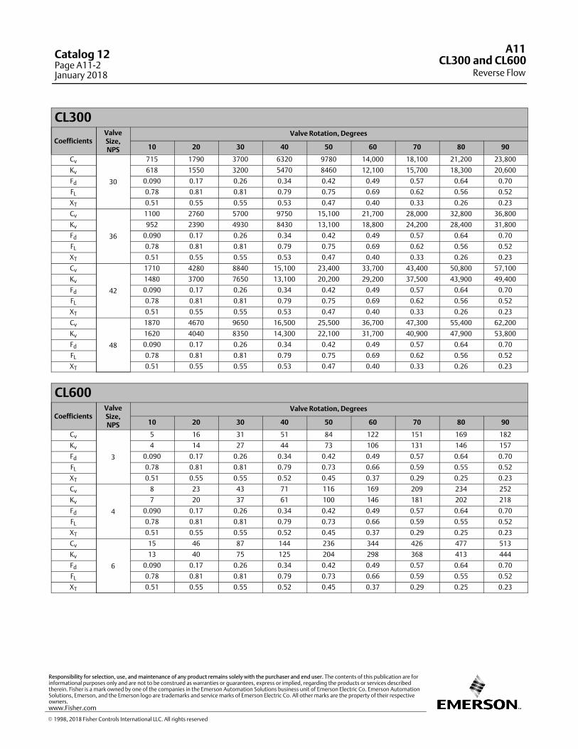
CL300
CoefficientsValveSize,NPS
Valve Rotation, Degrees
10 20 30 40 50 60 70 80 90
Cv
30
715 1790 3700 6320 9780 14,000 18,100 21,200 23,800
Kv 618 1550 3200 5470 8460 12,100 15,700 18,300 20,600
Fd 0.090 0.17 0.26 0.34 0.42 0.49 0.57 0.64 0.70
FL 0.78 0.81 0.81 0.79 0.75 0.69 0.62 0.56 0.52
XT 0.51 0.55 0.55 0.53 0.47 0.40 0.33 0.26 0.23
Cv
36
1100 2760 5700 9750 15,100 21,700 28,000 32,800 36,800
Kv 952 2390 4930 8430 13,100 18,800 24,200 28,400 31,800
Fd 0.090 0.17 0.26 0.34 0.42 0.49 0.57 0.64 0.70
FL 0.78 0.81 0.81 0.79 0.75 0.69 0.62 0.56 0.52
XT 0.51 0.55 0.55 0.53 0.47 0.40 0.33 0.26 0.23
Cv
42
1710 4280 8840 15,100 23,400 33,700 43,400 50,800 57,100
Kv 1480 3700 7650 13,100 20,200 29,200 37,500 43,900 49,400
Fd 0.090 0.17 0.26 0.34 0.42 0.49 0.57 0.64 0.70
FL 0.78 0.81 0.81 0.79 0.75 0.69 0.62 0.56 0.52
XT 0.51 0.55 0.55 0.53 0.47 0.40 0.33 0.26 0.23
Cv
48
1870 4670 9650 16,500 25,500 36,700 47,300 55,400 62,200
Kv 1620 4040 8350 14,300 22,100 31,700 40,900 47,900 53,800
Fd 0.090 0.17 0.26 0.34 0.42 0.49 0.57 0.64 0.70
FL 0.78 0.81 0.81 0.79 0.75 0.69 0.62 0.56 0.52
XT 0.51 0.55 0.55 0.53 0.47 0.40 0.33 0.26 0.23
CL600
CoefficientsValveSize,NPS
Valve Rotation, Degrees
10 20 30 40 50 60 70 80 90
Cv
3
5 16 31 51 84 122 151 169 182
Kv 4 14 27 44 73 106 131 146 157
Fd 0.090 0.17 0.26 0.34 0.42 0.49 0.57 0.64 0.70
FL 0.78 0.81 0.81 0.79 0.73 0.66 0.59 0.55 0.52
XT 0.51 0.55 0.55 0.52 0.45 0.37 0.29 0.25 0.23
Cv
4
8 23 43 71 116 169 209 234 252
Kv 7 20 37 61 100 146 181 202 218
Fd 0.090 0.17 0.26 0.34 0.42 0.49 0.57 0.64 0.70
FL 0.78 0.81 0.81 0.79 0.73 0.66 0.59 0.55 0.52
XT 0.51 0.55 0.55 0.52 0.45 0.37 0.29 0.25 0.23
Cv
6
15 46 87 144 236 344 426 477 513
Kv 13 40 75 125 204 298 368 413 444
Fd 0.090 0.17 0.26 0.34 0.42 0.49 0.57 0.64 0.70
FL 0.78 0.81 0.81 0.79 0.73 0.66 0.59 0.55 0.52
XT 0.51 0.55 0.55 0.52 0.45 0.37 0.29 0.25 0.23
A11
Reverse FlowCL300 and CL600
Catalog 12Page A11-2January 2018
� 1998, 2018 Fisher Controls International LLC. All rights reserved
www.Fisher.com
Responsibility for selection, use, and maintenance of any product remains solely with the purchaser and end user. The contents of this publication are forinformational purposes only and are not to be construed as warranties or guarantees, express or implied, regarding the products or services describedtherein. Fisher is a mark owned by one of the companies in the Emerson Automation Solutions business unit of Emerson Electric Co. Emerson AutomationSolutions, Emerson, and the Emerson logo are trademarks and service marks of Emerson Electric Co. All other marks are the property of their respectiveowners.
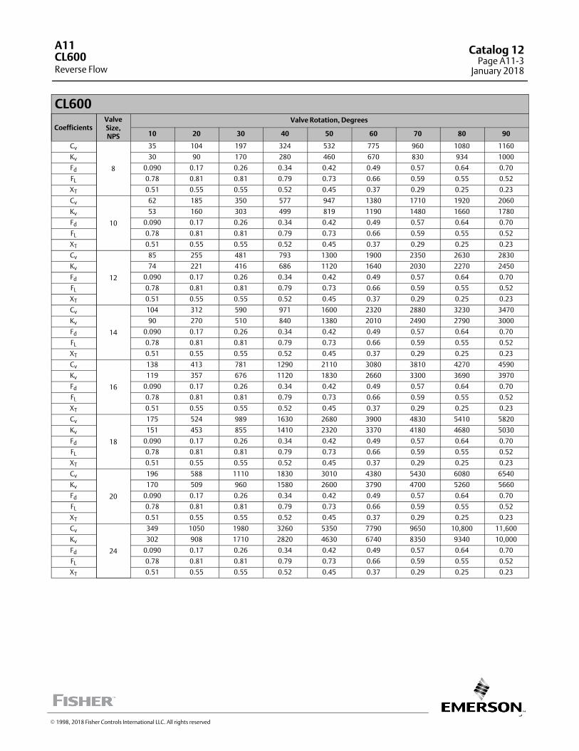
3
CL600
CoefficientsValveSize,NPS
Valve Rotation, Degrees
10 20 30 40 50 60 70 80 90
Cv
8
35 104 197 324 532 775 960 1080 1160
Kv 30 90 170 280 460 670 830 934 1000
Fd 0.090 0.17 0.26 0.34 0.42 0.49 0.57 0.64 0.70
FL 0.78 0.81 0.81 0.79 0.73 0.66 0.59 0.55 0.52
XT 0.51 0.55 0.55 0.52 0.45 0.37 0.29 0.25 0.23
Cv
10
62 185 350 577 947 1380 1710 1920 2060
Kv 53 160 303 499 819 1190 1480 1660 1780
Fd 0.090 0.17 0.26 0.34 0.42 0.49 0.57 0.64 0.70
FL 0.78 0.81 0.81 0.79 0.73 0.66 0.59 0.55 0.52
XT 0.51 0.55 0.55 0.52 0.45 0.37 0.29 0.25 0.23
Cv
12
85 255 481 793 1300 1900 2350 2630 2830
Kv 74 221 416 686 1120 1640 2030 2270 2450
Fd 0.090 0.17 0.26 0.34 0.42 0.49 0.57 0.64 0.70
FL 0.78 0.81 0.81 0.79 0.73 0.66 0.59 0.55 0.52
XT 0.51 0.55 0.55 0.52 0.45 0.37 0.29 0.25 0.23
Cv
14
104 312 590 971 1600 2320 2880 3230 3470
Kv 90 270 510 840 1380 2010 2490 2790 3000
Fd 0.090 0.17 0.26 0.34 0.42 0.49 0.57 0.64 0.70
FL 0.78 0.81 0.81 0.79 0.73 0.66 0.59 0.55 0.52
XT 0.51 0.55 0.55 0.52 0.45 0.37 0.29 0.25 0.23
Cv
16
138 413 781 1290 2110 3080 3810 4270 4590
Kv 119 357 676 1120 1830 2660 3300 3690 3970
Fd 0.090 0.17 0.26 0.34 0.42 0.49 0.57 0.64 0.70
FL 0.78 0.81 0.81 0.79 0.73 0.66 0.59 0.55 0.52
XT 0.51 0.55 0.55 0.52 0.45 0.37 0.29 0.25 0.23
Cv
18
175 524 989 1630 2680 3900 4830 5410 5820
Kv 151 453 855 1410 2320 3370 4180 4680 5030
Fd 0.090 0.17 0.26 0.34 0.42 0.49 0.57 0.64 0.70
FL 0.78 0.81 0.81 0.79 0.73 0.66 0.59 0.55 0.52
XT 0.51 0.55 0.55 0.52 0.45 0.37 0.29 0.25 0.23
Cv
20
196 588 1110 1830 3010 4380 5430 6080 6540
Kv 170 509 960 1580 2600 3790 4700 5260 5660
Fd 0.090 0.17 0.26 0.34 0.42 0.49 0.57 0.64 0.70
FL 0.78 0.81 0.81 0.79 0.73 0.66 0.59 0.55 0.52
XT 0.51 0.55 0.55 0.52 0.45 0.37 0.29 0.25 0.23
Cv
24
349 1050 1980 3260 5350 7790 9650 10,800 11,600
Kv 302 908 1710 2820 4630 6740 8350 9340 10,000
Fd 0.090 0.17 0.26 0.34 0.42 0.49 0.57 0.64 0.70
FL 0.78 0.81 0.81 0.79 0.73 0.66 0.59 0.55 0.52
XT 0.51 0.55 0.55 0.52 0.45 0.37 0.29 0.25 0.23
A11
Reverse FlowCL600
Catalog 12Page A11-3
January 2018
� 1998, 2018 Fisher Controls International LLC. All rights reserved

CL900
CoefficientsValveSize,NPS
Valve Rotation, Degrees
10 20 30 40 50 60 70 80 90
Cv
6
17 52 100 174 265 343 385 417 434
Kv 15 45 87 151 229 297 333 361 375
Fd 0.09 0.17 0.26 0.34 0.42 0.49 0.57 0.64 0.7
FL 0.79 0.81 0.8 0.75 0.69 0.61 0.56 0.53 0.52
XT 0.52 0.55 0.54 0.47 0.39 0.31 0.26 0.24 0.23
Cv
8
30 89 170 296 452 585 659 711 741
Kv 26 77 147 256 391 506 570 615 641
Fd 0.09 0.17 0.26 0.34 0.42 0.49 0.57 0.64 0.7
FL 0.79 0.81 0.8 0.75 0.69 0.61 0.56 0.53 0.52
XT 0.52 0.55 0.54 0.47 0.39 0.31 0.26 0.24 0.23
Cv
10
56 169 324 563 859 1112 1253 1352 1408
Kv 48 146 280 487 743 962 1084 1169 1218
Fd 0.09 0.17 0.26 0.34 0.42 0.49 0.57 0.64 0.7
FL 0.79 0.81 0.8 0.75 0.69 0.61 0.56 0.53 0.52
XT 0.52 0.55 0.54 0.47 0.39 0.31 0.26 0.24 0.23
Cv
12
50 151 290 504 769 995 1121 1210 1260
Kv 43 131 251 436 665 861 970 1047 1090
Fd 0.09 0.17 0.26 0.34 0.42 0.49 0.57 0.64 0.7
FL 0.79 0.81 0.8 0.75 0.69 0.61 0.56 0.53 0.52
XT 0.52 0.55 0.54 0.47 0.39 0.31 0.26 0.24 0.23
Cv
14
111 332 636 1106 1687 2184 2461 2654 2765
Kv 96 287 550 957 1459 1889 2129 2296 2392
Fd 0.09 0.17 0.26 0.34 0.42 0.49 0.57 0.64 0.7
FL 0.79 0.81 0.8 0.75 0.69 0.61 0.56 0.53 0.52
XT 0.52 0.55 0.54 0.47 0.39 0.31 0.26 0.24 0.23
Cv
16
140 421 806 1402 2138 2769 3119 3365 3505
Kv 121 364 697 1213 1849 2395 2698 2911 3032
Fd 0.09 0.17 0.26 0.34 0.42 0.49 0.57 0.64 0.7
FL 0.79 0.81 0.8 0.75 0.69 0.61 0.56 0.53 0.52
XT 0.52 0.55 0.54 0.47 0.39 0.31 0.26 0.24 0.23
Cv
18
182 546 1046 1820 2775 3594 4049 4367 4549
Kv 157 472 905 1574 2400 3109 3502 3777 3935
Fd 0.09 0.17 0.26 0.34 0.42 0.49 0.57 0.64 0.7
FL 0.79 0.81 0.8 0.75 0.69 0.61 0.56 0.53 0.52
XT 0.52 0.55 0.54 0.47 0.39 0.31 0.26 0.24 0.23
Cv
20
214 614 1228 2135 3256 4217 4751 5124 5338
Kv 185 531 1062 1847 2816 3648 4110 4432 4617
Fd 0.09 0.17 0.26 0.34 0.42 0.49 0.57 0.64 0.7
FL 0.79 0.81 0.8 0.75 0.69 0.61 0.56 0.53 0.52
XT 0.52 0.55 0.54 0.47 0.39 0.31 0.26 0.24 0.23
Cv
24
330 989 1895 3296 5029 6509 7333 7909 8239
Kv 285 855 1639 2851 4347 5630 6343 6841 7127
Fd 0.09 0.17 0.26 0.34 0.42 0.49 0.57 0.64 0.7
FL 0.79 0.81 0.8 0.75 0.69 0.61 0.56 0.53 0.52
XT 0.52 0.55 0.54 0.47 0.39 0.31 0.26 0.24 0.23
A11
Reverse FlowCL900
Catalog 12Page A11-4January 2018
� 2008, 2018 Fisher Controls International LLC. All rights reserved
www.Fisher.com
Responsibility for selection, use, and maintenance of any product remains solely with the purchaser and end user. The contents of this publication are forinformational purposes only and are not to be construed as warranties or guarantees, express or implied, regarding the products or services describedtherein. Fisher is a mark owned by one of the companies in the Emerson Automation Solutions business unit of Emerson Electric Co. Emerson AutomationSolutions, Emerson, and the Emerson logo are trademarks and service marks of Emerson Electric Co. All other marks are the property of their respectiveowners.
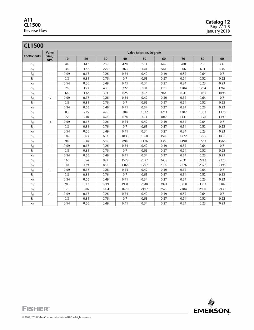
5
CL1500
CoefficientsValveSize,NPS
Valve Rotation, Degrees
10 20 30 40 50 60 70 80 90
Cv
10
44 147 265 420 553 649 700 730 737
Kv 38 127 229 363 478 561 606 631 638
Fd 0.09 0.17 0.26 0.34 0.42 0.49 0.57 0.64 0.7
FL 0.8 0.81 0.76 0.7 0.63 0.57 0.54 0.52 0.52
XT 0.54 0.55 0.49 0.41 0.34 0.27 0.24 0.23 0.23
Cv
12
76 153 456 722 950 1115 1204 1254 1267
Kv 66 132 394 625 822 964 1041 1085 1096
Fd 0.09 0.17 0.26 0.34 0.42 0.49 0.57 0.64 0.7
FL 0.8 0.81 0.76 0.7 0.63 0.57 0.54 0.52 0.52
XT 0.54 0.55 0.49 0.41 0.34 0.27 0.24 0.23 0.23
Cv
14
83 275 495 784 1032 1211 1307 1362 1376
Kv 72 238 428 678 893 1048 1131 1178 1190
Fd 0.09 0.17 0.26 0.34 0.42 0.49 0.57 0.64 0.7
FL 0.8 0.81 0.76 0.7 0.63 0.57 0.54 0.52 0.52
XT 0.54 0.55 0.49 0.41 0.34 0.27 0.24 0.23 0.23
Cv
16
109 363 653 1033 1360 1595 1722 1795 1813
Kv 94 314 565 894 1176 1380 1490 1553 1568
Fd 0.09 0.17 0.26 0.34 0.42 0.49 0.57 0.64 0.7
FL 0.8 0.81 0.76 0.7 0.63 0.57 0.54 0.52 0.52
XT 0.54 0.55 0.49 0.41 0.34 0.27 0.24 0.23 0.23
Cv
18
166 554 997 1579 2077 2438 2631 2742 2770
Kv 144 479 862 1366 1797 2109 2276 2372 2396
Fd 0.09 0.17 0.26 0.34 0.42 0.49 0.57 0.64 0.7
FL 0.8 0.81 0.76 0.7 0.63 0.57 0.54 0.52 0.52
XT 0.54 0.55 0.49 0.41 0.34 0.27 0.24 0.23 0.23
Cv
20
203 677 1219 1931 2540 2981 3218 3353 3387
Kv 176 586 1054 1670 2197 2579 2784 2900 2930
Fd 0.09 0.17 0.26 0.34 0.42 0.49 0.57 0.64 0.7
FL 0.8 0.81 0.76 0.7 0.63 0.57 0.54 0.52 0.52
XT 0.54 0.55 0.49 0.41 0.34 0.27 0.24 0.23 0.23
A11
Reverse FlowCL1500
Catalog 12Page A11-5
January 2018
� 2008, 2018 Fisher Controls International LLC. All rights reserved
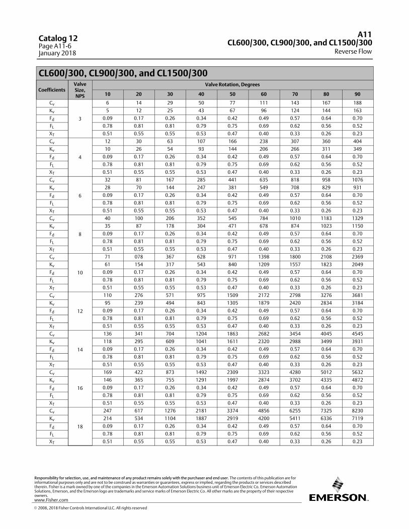
CL600/300, CL900/300, and CL1500/300
CoefficientsValveSize,NPS
Valve Rotation, Degrees
10 20 30 40 50 60 70 80 90
Cv
3
6 14 29 50 77 111 143 167 188
Kv 5 12 25 43 67 96 124 144 163
Fd 0.09 0.17 0.26 0.34 0.42 0.49 0.57 0.64 0.70
FL 0.78 0.81 0.81 0.79 0.75 0.69 0.62 0.56 0.52
XT 0.51 0.55 0.55 0.53 0.47 0.40 0.33 0.26 0.23
Cv
4
12 30 63 107 166 238 307 360 404
Kv 10 26 54 93 144 206 266 311 349
Fd 0.09 0.17 0.26 0.34 0.42 0.49 0.57 0.64 0.70
FL 0.78 0.81 0.81 0.79 0.75 0.69 0.62 0.56 0.52
XT 0.51 0.55 0.55 0.53 0.47 0.40 0.33 0.26 0.23
Cv
6
32 81 167 285 441 635 818 958 1076
Kv 28 70 144 247 381 549 708 829 931
Fd 0.09 0.17 0.26 0.34 0.42 0.49 0.57 0.64 0.70
FL 0.78 0.81 0.81 0.79 0.75 0.69 0.62 0.56 0.52
XT 0.51 0.55 0.55 0.53 0.47 0.40 0.33 0.26 0.23
Cv
8
40 100 206 352 545 784 1010 1183 1329
Kv 35 87 178 304 471 678 874 1023 1150
Fd 0.09 0.17 0.26 0.34 0.42 0.49 0.57 0.64 0.70
FL 0.78 0.81 0.81 0.79 0.75 0.69 0.62 0.56 0.52
XT 0.51 0.55 0.55 0.53 0.47 0.40 0.33 0.26 0.23
Cv
10
71 078 367 628 971 1398 1800 2108 2369
Kv 61 154 317 543 840 1209 1557 1823 2049
Fd 0.09 0.17 0.26 0.34 0.42 0.49 0.57 0.64 0.70
FL 0.78 0.81 0.81 0.79 0.75 0.69 0.62 0.56 0.52
XT 0.51 0.55 0.55 0.53 0.47 0.40 0.33 0.26 0.23
Cv
12
110 276 571 975 1509 2172 2798 3276 3681
Kv 95 239 494 843 1305 1879 2420 2834 3184
Fd 0.09 0.17 0.26 0.34 0.42 0.49 0.57 0.64 0.70
FL 0.78 0.81 0.81 0.79 0.75 0.69 0.62 0.56 0.52
XT 0.51 0.55 0.55 0.53 0.47 0.40 0.33 0.26 0.23
Cv
14
136 341 704 1204 1863 2682 3454 4045 4545
Kv 118 295 609 1041 1611 2320 2988 3499 3931
Fd 0.09 0.17 0.26 0.34 0.42 0.49 0.57 0.64 0.70
FL 0.78 0.81 0.81 0.79 0.75 0.69 0.62 0.56 0.52
XT 0.51 0.55 0.55 0.53 0.47 0.40 0.33 0.26 0.23
Cv
16
169 422 873 1492 2309 3323 4280 5012 5632
Kv 146 365 755 1291 1997 2874 3702 4335 4872
Fd 0.09 0.17 0.26 0.34 0.42 0.49 0.57 0.64 0.70
FL 0.78 0.81 0.81 0.79 0.75 0.69 0.62 0.56 0.52
XT 0.51 0.55 0.55 0.53 0.47 0.40 0.33 0.26 0.23
Cv
18
247 617 1276 2181 3374 4856 6255 7325 8230
Kv 214 534 1104 1887 2919 4200 5411 6336 7119
Fd 0.09 0.17 0.26 0.34 0.42 0.49 0.57 0.64 0.70
FL 0.78 0.81 0.81 0.79 0.75 0.69 0.62 0.56 0.52
XT 0.51 0.55 0.55 0.53 0.47 0.40 0.33 0.26 0.23
A11
Reverse FlowCL600/300, CL900/300, and CL1500/300
Catalog 12Page A11-6January 2018
� 2008, 2018 Fisher Controls International LLC. All rights reserved
www.Fisher.com
Responsibility for selection, use, and maintenance of any product remains solely with the purchaser and end user. The contents of this publication are forinformational purposes only and are not to be construed as warranties or guarantees, express or implied, regarding the products or services describedtherein. Fisher is a mark owned by one of the companies in the Emerson Automation Solutions business unit of Emerson Electric Co. Emerson AutomationSolutions, Emerson, and the Emerson logo are trademarks and service marks of Emerson Electric Co. All other marks are the property of their respectiveowners.
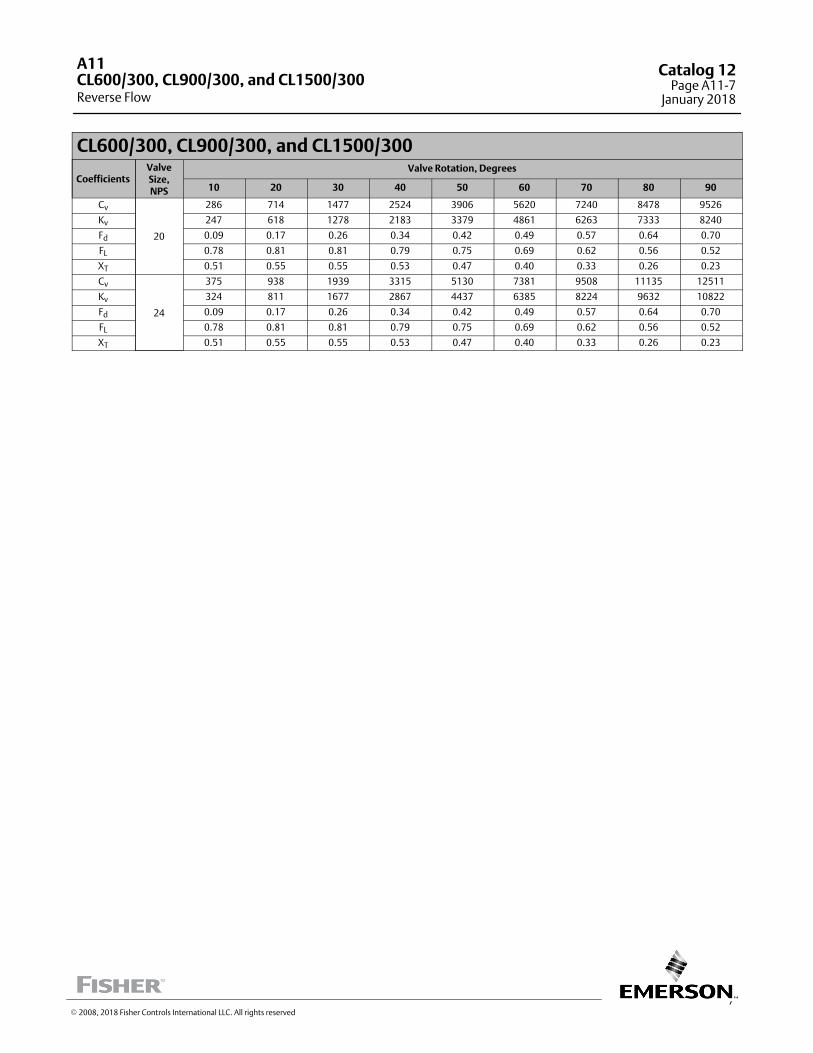
7
CL600/300, CL900/300, and CL1500/300
CoefficientsValveSize,NPS
Valve Rotation, Degrees
10 20 30 40 50 60 70 80 90
Cv
20
286 714 1477 2524 3906 5620 7240 8478 9526
Kv 247 618 1278 2183 3379 4861 6263 7333 8240
Fd 0.09 0.17 0.26 0.34 0.42 0.49 0.57 0.64 0.70
FL 0.78 0.81 0.81 0.79 0.75 0.69 0.62 0.56 0.52
XT 0.51 0.55 0.55 0.53 0.47 0.40 0.33 0.26 0.23
Cv
24
375 938 1939 3315 5130 7381 9508 11135 12511
Kv 324 811 1677 2867 4437 6385 8224 9632 10822
Fd 0.09 0.17 0.26 0.34 0.42 0.49 0.57 0.64 0.70
FL 0.78 0.81 0.81 0.79 0.75 0.69 0.62 0.56 0.52
XT 0.51 0.55 0.55 0.53 0.47 0.40 0.33 0.26 0.23
A11
Reverse FlowCL600/300, CL900/300, and CL1500/300
Catalog 12Page A11-7
January 2018
� 2008, 2018 Fisher Controls International LLC. All rights reserved

This page intentionally left blank
A11Catalog 12Page A11-8January 2018
� 2008, 2018 Fisher Controls International LLC. All rights reserved
www.Fisher.com
Responsibility for selection, use, and maintenance of any product remains solely with the purchaser and end user. The contents of this publication are forinformational purposes only and are not to be construed as warranties or guarantees, express or implied, regarding the products or services describedtherein. Fisher is a mark owned by one of the companies in the Emerson Automation Solutions business unit of Emerson Electric Co. Emerson AutomationSolutions, Emerson, and the Emerson logo are trademarks and service marks of Emerson Electric Co. All other marks are the property of their respectiveowners.
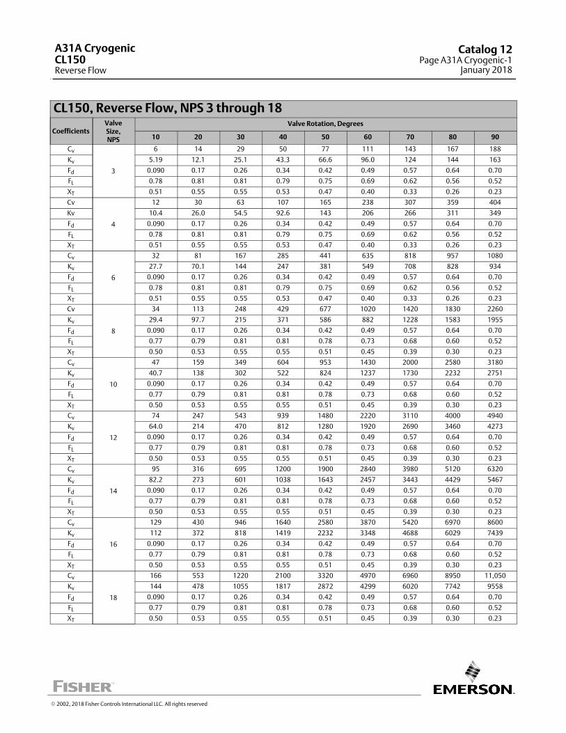
CL150, Reverse Flow, NPS 3 through 18
CoefficientsValveSize,NPS
Valve Rotation, Degrees
10 20 30 40 50 60 70 80 90
Cv
3
6 14 29 50 77 111 143 167 188
Kv 5.19 12.1 25.1 43.3 66.6 96.0 124 144 163
Fd 0.090 0.17 0.26 0.34 0.42 0.49 0.57 0.64 0.70
FL 0.78 0.81 0.81 0.79 0.75 0.69 0.62 0.56 0.52
XT 0.51 0.55 0.55 0.53 0.47 0.40 0.33 0.26 0.23
Cv
4
12 30 63 107 165 238 307 359 404
Kv 10.4 26.0 54.5 92.6 143 206 266 311 349
Fd 0.090 0.17 0.26 0.34 0.42 0.49 0.57 0.64 0.70
FL 0.78 0.81 0.81 0.79 0.75 0.69 0.62 0.56 0.52
XT 0.51 0.55 0.55 0.53 0.47 0.40 0.33 0.26 0.23
Cv
6
32 81 167 285 441 635 818 957 1080
Kv 27.7 70.1 144 247 381 549 708 828 934
Fd 0.090 0.17 0.26 0.34 0.42 0.49 0.57 0.64 0.70
FL 0.78 0.81 0.81 0.79 0.75 0.69 0.62 0.56 0.52
XT 0.51 0.55 0.55 0.53 0.47 0.40 0.33 0.26 0.23
Cv
8
34 113 248 429 677 1020 1420 1830 2260
Kv 29.4 97.7 215 371 586 882 1228 1583 1955
Fd 0.090 0.17 0.26 0.34 0.42 0.49 0.57 0.64 0.70
FL 0.77 0.79 0.81 0.81 0.78 0.73 0.68 0.60 0.52
XT 0.50 0.53 0.55 0.55 0.51 0.45 0.39 0.30 0.23
Cv
10
47 159 349 604 953 1430 2000 2580 3180
Kv 40.7 138 302 522 824 1237 1730 2232 2751
Fd 0.090 0.17 0.26 0.34 0.42 0.49 0.57 0.64 0.70
FL 0.77 0.79 0.81 0.81 0.78 0.73 0.68 0.60 0.52
XT 0.50 0.53 0.55 0.55 0.51 0.45 0.39 0.30 0.23
Cv
12
74 247 543 939 1480 2220 3110 4000 4940
Kv 64.0 214 470 812 1280 1920 2690 3460 4273
Fd 0.090 0.17 0.26 0.34 0.42 0.49 0.57 0.64 0.70
FL 0.77 0.79 0.81 0.81 0.78 0.73 0.68 0.60 0.52
XT 0.50 0.53 0.55 0.55 0.51 0.45 0.39 0.30 0.23
Cv
14
95 316 695 1200 1900 2840 3980 5120 6320
Kv 82.2 273 601 1038 1643 2457 3443 4429 5467
Fd 0.090 0.17 0.26 0.34 0.42 0.49 0.57 0.64 0.70
FL 0.77 0.79 0.81 0.81 0.78 0.73 0.68 0.60 0.52
XT 0.50 0.53 0.55 0.55 0.51 0.45 0.39 0.30 0.23
Cv
16
129 430 946 1640 2580 3870 5420 6970 8600
Kv 112 372 818 1419 2232 3348 4688 6029 7439
Fd 0.090 0.17 0.26 0.34 0.42 0.49 0.57 0.64 0.70
FL 0.77 0.79 0.81 0.81 0.78 0.73 0.68 0.60 0.52
XT 0.50 0.53 0.55 0.55 0.51 0.45 0.39 0.30 0.23
Cv
18
166 553 1220 2100 3320 4970 6960 8950 11,050
Kv 144 478 1055 1817 2872 4299 6020 7742 9558
Fd 0.090 0.17 0.26 0.34 0.42 0.49 0.57 0.64 0.70
FL 0.77 0.79 0.81 0.81 0.78 0.73 0.68 0.60 0.52
XT 0.50 0.53 0.55 0.55 0.51 0.45 0.39 0.30 0.23
� 2002, 2018 Fisher Controls International LLC. All rights reserved
A31A CryogenicCL150Reverse Flow
Catalog 12Page A31A Cryogenic-1
January 2018

CL150, Reverse Flow, NPS 20 and 24
CoefficientsValveSize,NPS
Valve Rotation, Degrees
10 20 30 40 50 60 70 80 90
Cv
20
208 692 1520 2630 4160 6230 8730 11,220 13,850
Kv 180 599 1315 2275 3598 5389 7551 9705 11,980
Fd 0.090 0.17 0.26 0.34 0.42 0.49 0.57 0.64 0.70
FL 0.77 0.79 0.81 0.81 0.78 0.73 0.68 0.60 0.52
XT 0.50 0.53 0.55 0.55 0.51 0.45 0.39 0.30 0.23
Cv
24
322 1080 2370 4080 6450 9670 13,540 17,410 21,500
Kv 277 934 2050 3529 5579 8365 11,712 15,060 18,598
Fd 0.090 0.17 0.26 0.34 0.42 0.49 0.57 0.64 0.70
FL 0.77 0.79 0.81 0.81 0.78 0.73 0.68 0.60 0.52
XT 0.50 0.53 0.55 0.55 0.51 0.45 0.39 0.30 0.23
A31A Cryogenic
Reverse FlowCL150
Catalog 12Page A31A Cryogenic-2January 2018
� 2002, 2018 Fisher Controls International LLC. All rights reserved
www.Fisher.com
Responsibility for selection, use, and maintenance of any product remains solely with the purchaser and end user. The contents of this publication are forinformational purposes only and are not to be construed as warranties or guarantees, express or implied, regarding the products or services describedtherein. Fisher is a mark owned by one of the companies in the Emerson Automation Solutions business unit of Emerson Electric Co. Emerson AutomationSolutions, Emerson, and the Emerson logo are trademarks and service marks of Emerson Electric Co. All other marks are the property of their respectiveowners.
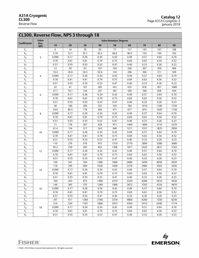
3
CL300, Reverse Flow, NPS 3 through 18
CoefficientsValveSize,NPS
Valve Rotation, Degrees
10 20 30 40 50 60 70 80 90
Cv
3
6 14 29 50 77 111 143 167 188
Kv 5.19 12.1 25.1 43.3 66.6 96.0 124 144 163
Fd 0.090 0.17 0.26 0.34 0.42 0.49 0.57 0.64 0.70
FL 0.78 0.81 0.81 0.79 0.75 0.69 0.62 0.56 0.52
XT 0.51 0.55 0.55 0.53 0.47 0.40 0.33 0.26 0.23
Cv
4
12 30 63 107 165 238 307 359 404
Kv 10.4 26.0 54.5 92.6 143 206 266 311 349
Fd 0.090 0.17 0.26 0.34 0.42 0.49 0.57 0.64 0.70
FL 0.78 0.81 0.81 0.79 0.75 0.69 0.62 0.56 0.52
XT 0.51 0.55 0.55 0.53 0.47 0.40 0.33 0.26 0.23
Cv
6
32 81 167 285 441 635 818 957 1080
Kv 27.7 70.1 144 247 381 549 708 828 934
Fd 0.090 0.17 0.26 0.34 0.42 0.49 0.57 0.64 0.70
FL 0.78 0.81 0.81 0.79 0.75 0.69 0.62 0.56 0.52
XT 0.51 0.55 0.55 0.53 0.47 0.40 0.33 0.26 0.23
Cv
8
40 100 206 352 545 784 1010 1180 1330
Kv 34.6 86.5 178 304 471 677 874 1020 1150
Fd 0.090 0.17 0.26 0.34 0.42 0.49 0.57 0.64 0.70
FL 0.78 0.81 0.81 0.79 0.75 0.69 0.62 0.56 0.52
XT 0.51 0.55 0.55 0.53 0.47 0.40 0.33 0.26 0.23
Cv
10
71 178 367 628 971 1400 1800 2110 2370
Kv 61.4 154 317 543 840 1211 1557 1825 2050
Fd 0.090 0.17 0.26 0.34 0.42 0.49 0.57 0.64 0.70
FL 0.78 0.81 0.81 0.79 0.75 0.69 0.62 0.56 0.52
XT 0.51 0.55 0.55 0.53 0.47 0.40 0.33 0.26 0.23
Cv
12
110 276 570 975 1510 2170 2800 3280 3680
Kv 95.2 239 493 843 1306 1877 2422 2837 3183
Fd 0.090 0.17 0.26 0.34 0.42 0.49 0.57 0.64 0.70
FL 0.78 0.81 0.81 0.79 0.75 0.69 0.62 0.56 0.52
XT 0.51 0.55 0.55 0.53 0.47 0.40 0.33 0.26 0.23
Cv
14
136 341 704 1200 1860 2680 3450 4050 4550
Kv 118 295 609 1038 1609 2318 2984 3503 3936
Fd 0.090 0.17 0.26 0.34 0.42 0.49 0.57 0.64 0.70
FL 0.78 0.81 0.81 0.79 0.75 0.69 0.62 0.56 0.52
XT 0.51 0.55 0.55 0.53 0.47 0.40 0.33 0.26 0.23
Cv
16
169 422 873 1490 2310 3320 4280 5010 5630
Kv 146 365 755 1289 1998 2872 3702 4334 4870
Fd 0.090 0.17 0.26 0.34 0.42 0.49 0.57 0.64 0.70
FL 0.78 0.81 0.81 0.79 0.75 0.69 0.62 0.56 0.52
XT 0.51 0.55 0.55 0.47 0.40 0.33 0.26 0.26 0.23
Cv
18
247 617 1280 2180 3370 4860 6260 7330 8230
Kv 214 534 1107 1886 2915 4204 5415 6340 7119
Fd 0.090 0.17 0.26 0.34 0.42 0.49 0.57 0.64 0.70
FL 0.78 0.81 0.81 0.79 0.75 0.69 0.62 0.56 0.52
XT 0.51 0.55 0.55 0.53 0.47 0.40 0.33 0.26 0.23
A31A Cryogenic
Reverse FlowCL300
Catalog 12Page A31A Cryogenic-3
January 2018
� 2002, 2018 Fisher Controls International LLC. All rights reserved

CL300, Reverse Flow, NPS 20 and 24
CoefficientsValveSize,NPS
Valve Rotation, Degrees
10 20 30 40 50 60 70 80 90
Cv
20
286 714 1480 2520 3910 5620 7240 8480 9530
Kv 247 618 1280 2180 3382 4861 6263 7335 8243
Fd 0.090 0.17 0.26 0.34 0.42 0.49 0.57 0.64 0.70
FL 0.78 0.81 0.81 0.79 0.75 0.69 0.62 0.56 0.52
XT 0.51 0.55 0.55 0.53 0.47 0.40 0.33 0.26 0.23
Cv
24
375 938 1940 3320 5130 7380 9510 11,140 12,500
Kv 324 811 1678 2872 4437 6384 8226 9636 10,821
Fd 0.090 0.17 0.26 0.34 0.42 0.49 0.57 0.64 0.70
FL 0.78 0.81 0.81 0.79 0.75 0.69 0.62 0.56 0.52
XT 0.51 0.55 0.55 0.53 0.47 0.40 0.33 0.26 0.23
A31A Cryogenic
Reverse FlowCL300
Catalog 12Page A31A Cryogenic-4January 2018
� 2002, 2018 Fisher Controls International LLC. All rights reserved
www.Fisher.com
Responsibility for selection, use, and maintenance of any product remains solely with the purchaser and end user. The contents of this publication are forinformational purposes only and are not to be construed as warranties or guarantees, express or implied, regarding the products or services describedtherein. Fisher is a mark owned by one of the companies in the Emerson Automation Solutions business unit of Emerson Electric Co. Emerson AutomationSolutions, Emerson, and the Emerson logo are trademarks and service marks of Emerson Electric Co. All other marks are the property of their respectiveowners.
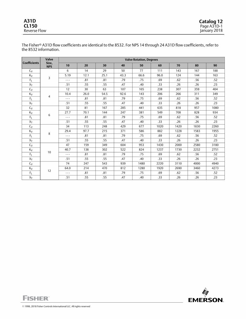
The Fisher� A31D flow coefficients are identical to the 8532. For NPS 14 through 24 A31D flow coefficients, refer tothe 8532 information.
CoefficientsValveSize,NPS
Valve Rotation, Degrees
10 20 30 40 50 60 70 80 90
CV
3
6 14 29 50 77 111 143 167 188
KV 5.19 12.1 25.1 43.3 66.6 96.0 124 144 163
FL ‐ ‐ ‐ .81 .81 .79 .75 .69 .62 .56 .52
XT .51 .55 .55 .47 .40 .33 .26 .26 .23
CV
4
12 30 63 107 165 238 307 359 404
KV 10.4 26.0 54.5 92.6 143 206 266 311 349
FL ‐ ‐ ‐ .81 .81 .79 .75 .69 .62 .56 .52
XT .51 .55 .55 .47 .40 .33 .26 .26 .23
CV
6
32 81 167 285 441 635 818 957 1080
KV 27.7 70.1 144 247 381 549 708 828 934
FL ‐ ‐ ‐ .81 .81 .79 .75 .69 .62 .56 .52
XT .51 .55 .55 .47 .40 .33 .26 .26 .23
CV
8
34 113 248 429 677 1020 1420 1830 2260
KV 29.4 97.7 215 371 586 882 1228 1583 1955
FL ‐ ‐ ‐ .81 .81 .79 .75 .69 .62 .56 .52
XT .51 .55 .55 .47 .40 .33 .26 .26 .23
CV
10
47 159 349 604 953 1430 2000 2580 3180
KV 40.7 138 302 522 824 1237 1730 2232 2751
FL ‐ ‐ ‐ .81 .81 .79 .75 .69 .62 .56 .52
XT .51 .55 .55 .47 .40 .33 .26 .26 .23
CV
12
74 247 543 939 1480 2220 3110 4000 4940
KV 64.0 214 470 812 1280 1920 2690 3460 4273
FL ‐ ‐ ‐ .81 .81 .79 .75 .69 .62 .56 .52
XT .51 .55 .55 .47 .40 .33 .26 .26 .23
� 1998, 2018 Fisher Controls International LLC. All rights reserved
A31DCL150Reverse Flow
Catalog 12Page A31D-1January 2018
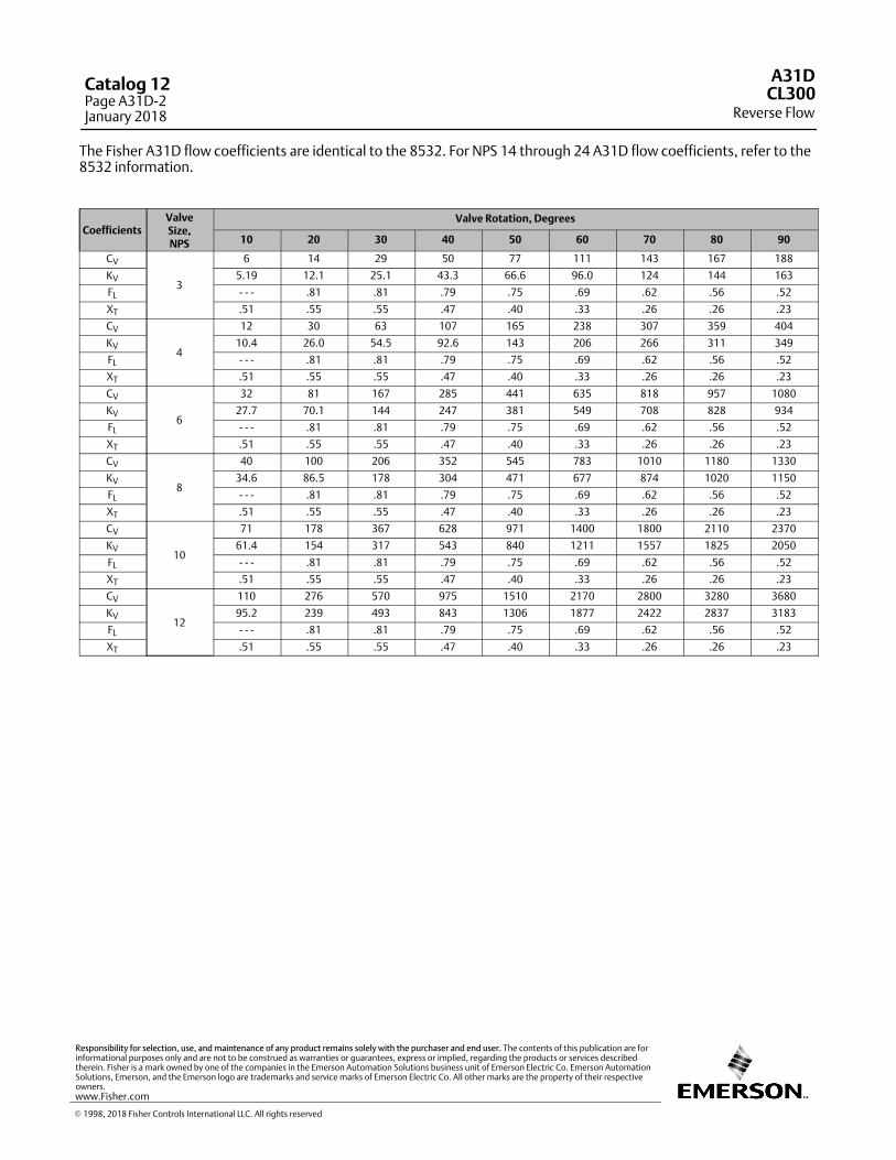
The Fisher A31D flow coefficients are identical to the 8532. For NPS 14 through 24 A31D flow coefficients, refer to the8532 information.
CoefficientsValveSize,NPS
Valve Rotation, Degrees
10 20 30 40 50 60 70 80 90
CV
3
6 14 29 50 77 111 143 167 188
KV 5.19 12.1 25.1 43.3 66.6 96.0 124 144 163
FL ‐ ‐ ‐ .81 .81 .79 .75 .69 .62 .56 .52
XT .51 .55 .55 .47 .40 .33 .26 .26 .23
CV
4
12 30 63 107 165 238 307 359 404
KV 10.4 26.0 54.5 92.6 143 206 266 311 349
FL ‐ ‐ ‐ .81 .81 .79 .75 .69 .62 .56 .52
XT .51 .55 .55 .47 .40 .33 .26 .26 .23
CV
6
32 81 167 285 441 635 818 957 1080
KV 27.7 70.1 144 247 381 549 708 828 934
FL ‐ ‐ ‐ .81 .81 .79 .75 .69 .62 .56 .52
XT .51 .55 .55 .47 .40 .33 .26 .26 .23
CV
8
40 100 206 352 545 783 1010 1180 1330
KV 34.6 86.5 178 304 471 677 874 1020 1150
FL ‐ ‐ ‐ .81 .81 .79 .75 .69 .62 .56 .52
XT .51 .55 .55 .47 .40 .33 .26 .26 .23
CV
10
71 178 367 628 971 1400 1800 2110 2370
KV 61.4 154 317 543 840 1211 1557 1825 2050
FL ‐ ‐ ‐ .81 .81 .79 .75 .69 .62 .56 .52
XT .51 .55 .55 .47 .40 .33 .26 .26 .23
CV
12
110 276 570 975 1510 2170 2800 3280 3680
KV 95.2 239 493 843 1306 1877 2422 2837 3183
FL ‐ ‐ ‐ .81 .81 .79 .75 .69 .62 .56 .52
XT .51 .55 .55 .47 .40 .33 .26 .26 .23
A31D
Reverse FlowCL300
Catalog 12Page A31D-2January 2018
� 1998, 2018 Fisher Controls International LLC. All rights reserved
www.Fisher.com
Responsibility for selection, use, and maintenance of any product remains solely with the purchaser and end user. The contents of this publication are forinformational purposes only and are not to be construed as warranties or guarantees, express or implied, regarding the products or services describedtherein. Fisher is a mark owned by one of the companies in the Emerson Automation Solutions business unit of Emerson Electric Co. Emerson AutomationSolutions, Emerson, and the Emerson logo are trademarks and service marks of Emerson Electric Co. All other marks are the property of their respectiveowners.

A three‐way butterfly valve consists of two standardbutterfly valves mounted on a pipe tee. The valves areoperated by a single actuator through a tandemlinkage. The linkage is normally arranged so that oneof the valves is opening while the other is closing. Foradditional three‐way butterfly valve information, referto Bulletin 51.4:020.
When sizing a three‐way butterfly valve, therelationship between valve disk rotation and flow mustbe kept in mind. With butterfly valves, this relationshipis equal percentage and not linear. Due to thisrelationship, at mid-travel of the valve disk, flowcapacity is less than one‐half total valve capacity. Witha three‐way butterfly valve, one valve is opening whilethe other valve is closing, and both valves are midwaythrough total disk rotation of 60 or 90 degrees whenthe actuator is at mid‐travel. The combined capacity ofthe two valves at mid‐travel is less than wide‐opencapacity of one valve.
Figure 1. Three‐Way Valve Capacity with Single Actuator--60 Degree Maximum Valve Disk Rotation
A1884-1
If each valve is sized to handle maximum pipe tee flowat full disk rotation, combined capacity of the twovalves at mid‐travel will be lower than the flowcapacity of the tee. Although this reduction is presentat all points of travel, it is most significant atmid‐travel. This is illustrated in figures 1 and 2 forconventional disks. For Fishtail™ disks, one‐half oftotal valve capacity is reached at an even larger angleof disk rotation, and the reduction in combinedcapacity at mid‐travel is greater than it is withconventional disks.
For flow‐switching (on/off) applications, this is notserious since the valves will be at mid‐travel onlymomentarily while the valves are being stroked openand closed.
For throttling applications, it is possible that the valveswill remain at mid‐travel for significant periods of time.In these applications, the capacity reduction couldcause system problems such as compressor surging.To avoid these problems, size each valve to carryone‐half of the maximum pipe tee flow at mid‐travel.Then, the combined flow capacity of the two valves atmid‐travel will equal maximum flow.
Figure 2. Three‐Way Valve Capacity with Single Actuator--90 Degree Maximum Valve Disk Rotation
A1885‐1
� 1988, 2018 Fisher Controls International LLC. All rights reserved
Three-Way ButterflyValve Sizing
Catalog 12Page Three-Way Butterfly-1
September 2018
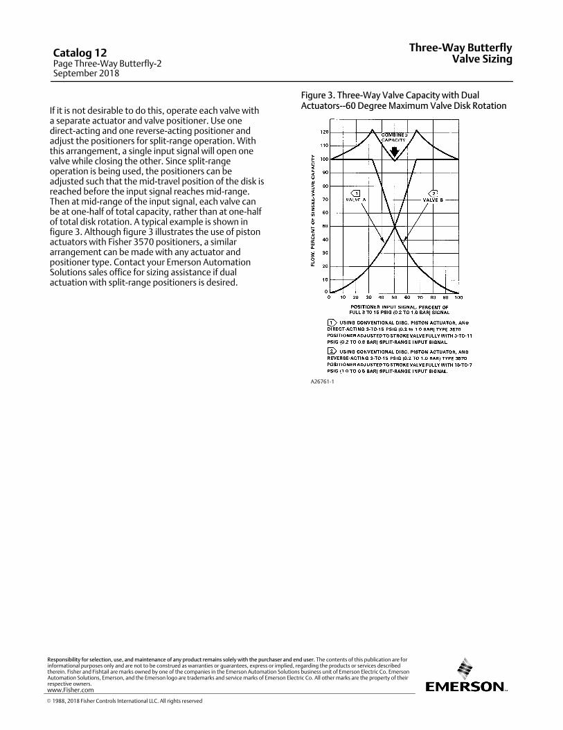
If it is not desirable to do this, operate each valve witha separate actuator and valve positioner. Use onedirect‐acting and one reverse‐acting positioner andadjust the positioners for split‐range operation. Withthis arrangement, a single input signal will open onevalve while closing the other. Since split‐rangeoperation is being used, the positioners can beadjusted such that the mid‐travel position of the disk isreached before the input signal reaches mid‐range.Then at mid‐range of the input signal, each valve canbe at one‐half of total capacity, rather than at one‐halfof total disk rotation. A typical example is shown infigure 3. Although figure 3 illustrates the use of pistonactuators with Fisher 3570 positioners, a similararrangement can be made with any actuator andpositioner type. Contact your Emerson AutomationSolutions sales office for sizing assistance if dualactuation with split‐range positioners is desired.
Figure 3. Three‐Way Valve Capacity with DualActuators--60 Degree Maximum Valve Disk Rotation
A26761‐1
Three-Way ButterflyValve Sizing
Catalog 12Page Three-Way Butterfly-2September 2018
� 1988, 2018 Fisher Controls International LLC. All rights reserved
www.Fisher.com
Responsibility for selection, use, and maintenance of any product remains solely with the purchaser and end user. The contents of this publication are forinformational purposes only and are not to be construed as warranties or guarantees, express or implied, regarding the products or services describedtherein. Fisher and Fishtail are marks owned by one of the companies in the Emerson Automation Solutions business unit of Emerson Electric Co. EmersonAutomation Solutions, Emerson, and the Emerson logo are trademarks and service marks of Emerson Electric Co. All other marks are the property of theirrespective owners.
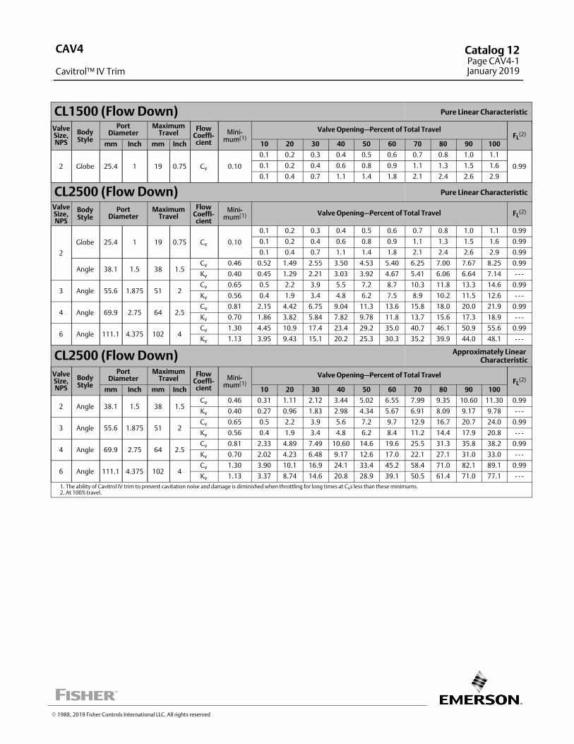
CL1500 (Flow Down) Pure Linear Characteristic
ValveSize,NPS
BodyStyle
PortDiameter
MaximumTravel
FlowCoeffi-cient
Mini-mum(1)
Valve Opening—Percent of Total TravelFL
(2)
mm Inch mm Inch 10 20 30 40 50 60 70 80 90 100
2 Globe 25.4 1 19 0.75 Cv 0.10
0.1 0.2 0.3 0.4 0.5 0.6 0.7 0.8 1.0 1.1
0.990.1 0.2 0.4 0.6 0.8 0.9 1.1 1.3 1.5 1.6
0.1 0.4 0.7 1.1 1.4 1.8 2.1 2.4 2.6 2.9
CL2500 (Flow Down) Pure Linear Characteristic
ValveSize,NPS
BodyStyle
PortDiameter
MaximumTravel
FlowCoeffi-cient
Mini-mum(1) Valve Opening—Percent of Total Travel FL
(2)
2
Globe 25.4 1 19 0.75 Cv 0.10
0.1 0.2 0.3 0.4 0.5 0.6 0.7 0.8 1.0 1.1 0.99
0.1 0.2 0.4 0.6 0.8 0.9 1.1 1.3 1.5 1.6 0.99
0.1 0.4 0.7 1.1 1.4 1.8 2.1 2.4 2.6 2.9 0.99
Angle 38.1 1.5 38 1.5Cv 0.46 0.52 1.49 2.55 3.50 4.53 5.40 6.25 7.00 7.67 8.25 0.99
Kv 0.40 0.45 1.29 2.21 3.03 3.92 4.67 5.41 6.06 6.64 7.14 - - -
3 Angle 55.6 1.875 51 2Cv 0.65 0.5 2.2 3.9 5.5 7.2 8.7 10.3 11.8 13.3 14.6 0.99
Kv 0.56 0.4 1.9 3.4 4.8 6.2 7.5 8.9 10.2 11.5 12.6 - - -
4 Angle 69.9 2.75 64 2.5Cv 0.81 2.15 4.42 6.75 9.04 11.3 13.6 15.8 18.0 20.0 21.9 0.99
Kv 0.70 1.86 3.82 5.84 7.82 9.78 11.8 13.7 15.6 17.3 18.9 - - -
6 Angle 111.1 4.375 102 4Cv 1.30 4.45 10.9 17.4 23.4 29.2 35.0 40.7 46.1 50.9 55.6 0.99
Kv 1.13 3.95 9.43 15.1 20.2 25.3 30.3 35.2 39.9 44.0 48.1 - - -
CL2500 (Flow Down) Approximately Linear Characteristic
ValveSize,NPS
BodyStyle
PortDiameter
MaximumTravel
FlowCoeffi-cient
Mini-mum(1)
Valve Opening—Percent of Total TravelFL
(2)
mm Inch mm Inch 10 20 30 40 50 60 70 80 90 100
2 Angle 38.1 1.5 38 1.5Cv 0.46 0.31 1.11 2.12 3.44 5.02 6.55 7.99 9.35 10.60 11.30 0.99
Kv 0.40 0.27 0.96 1.83 2.98 4.34 5.67 6.91 8.09 9.17 9.78 - - -
3 Angle 55.6 1.875 51 2Cv 0.65 0.5 2.2 3.9 5.6 7.2 9.7 12.9 16.7 20.7 24.0 0.99
Kv 0.56 0.4 1.9 3.4 4.8 6.2 8.4 11.2 14.4 17.9 20.8 - - -
4 Angle 69.9 2.75 64 2.5Cv 0.81 2.33 4.89 7.49 10.60 14.6 19.6 25.5 31.3 35.8 38.2 0.99
Kv 0.70 2.02 4.23 6.48 9.17 12.6 17.0 22.1 27.1 31.0 33.0 - - -
6 Angle 111.1 4.375 102 4Cv 1.30 3.90 10.1 16.9 24.1 33.4 45.2 58.4 71.0 82.1 89.1 0.99
Kv 1.13 3.37 8.74 14.6 20.8 28.9 39.1 50.5 61.4 71.0 77.1 - - -1. The ability of Cavitrol IV trim to prevent cavitation noise and damage is diminished when throttling for long times at Cvs less than these minimums.2. At 100% travel.
� 1988, 2019 Fisher Controls International LLC. All rights reserved
CAV4
Cavitrol™ IV Trim
Catalog 12Page CAV4-1January 2019
This page is intentionally left blank.
CAV4
Cavitrol IV Trim
Catalog 12Page CAV4-2January 2018
� 1988, 2018 Fisher Controls International LLC. All rights reserved
www.Fisher.com
Responsibility for selection, use, and maintenance of any product remains solely with the purchaser and end user. The contents of this publication are forinformational purposes only and are not to be construed as warranties or guarantees, express or implied, regarding the products or services describedtherein. Fisher and Cavitrol are marks owned by one of the companies in the Emerson Automation Solutions business unit of Emerson Electric Co. EmersonAutomation Solutions, Emerson, and the Emerson logo are trademarks and service marks of Emerson Electric Co. All other marks are the property of theirrespective owners.
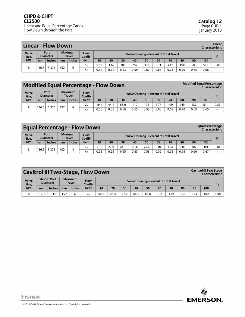
Linear ‐ Flow Down LinearCharacteristic
ValveSize,NPS
PortDiameter
MaximumTravel
FlowCoeffi‐cient
Valve Opening—Percent of Total TravelFL
mm Inches mm Inches 10 20 30 40 50 60 70 80 90 100
8 136.5 5.375 152 6Cv 57.9 134 205 262 308 363 417 458 500 519 0.86
XT 0.54 0.51 0.53 0.59 0.67 0.68 0.73 0.70 0.65 0.66 ‐ ‐ ‐
Modified Equal Percentage ‐ Flow Down Modified Equal PercentageCharacteristic
ValveSize,NPS
PortDiameter
MaximumTravel
FlowCoeffi‐cient
Valve Opening—Percent of Total TravelFL
mm Inches mm Inches 10 20 30 40 50 60 70 80 90 100
8 136.5 5.375 152 6Cv 19.4 44.1 68.0 110 196 307 409 449 487 514 0.86
XT 0.55 0.55 0.56 0.55 0.53 0.60 0.69 0.70 0.68 0.65 ‐ ‐ ‐
Equal Percentage ‐ Flow Down Equal PercentageCharacteristic
ValveSize,NPS
PortDiameter
MaximumTravel
FlowCoeffi‐cient
Valve Opening—Percent of Total TravelFL
mm Inches mm Inches 10 20 30 40 50 60 70 80 90 100
8 136.5 5.375 102 4Cv 11.5 27.9 44.1 60.6 75.4 110 164 236 307 381 0.84
XT 0.53 0.55 0.55 0.55 0.58 0.55 0.52 0.54 0.60 0.67 ‐ ‐ ‐
Cavitrol III Two-Stage, Flow Down Cavitrol III Two StageCharacteristic
ValveSize,NPS
Shutoff PortDiameter
MaximumTravel
FlowCoeffi‐cient
Valve Opening—Percent of Total TravelFL
mm Inches mm Inches 10 20 30 40 50 60 70 80 90 100
8 136.5 5.375 152 6 Cv 9.56 28.4 47.0 65.6 83.8 102 119 136 153 169 0.98
CHPD & CHPTCL2500Linear and Equal Percentage CagesFlow Down through the Port
Catalog 12Page CHP-1
January 2018
� 2016, 2018 Fisher Controls International LLC. All rights reserved
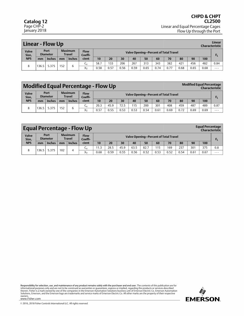
Linear ‐ Flow Up LinearCharacteristic
ValveSize,NPS
PortDiameter
MaximumTravel
FlowCoeffi‐cient
Valve Opening—Percent of Total TravelFL
mm Inches mm Inches 10 20 30 40 50 60 70 80 90 100
8 136.5 5.375 152 6Cv 58.7 133 206 267 313 343 382 421 456 482 0.84
XT 0.58 0.57 0.56 0.59 0.65 0.74 0.77 0.68 0.65 0.68 ‐ ‐ ‐
Modified Equal Percentage ‐ Flow Up Modified Equal PercentageCharacteristic
ValveSize,NPS
PortDiameter
MaximumTravel
FlowCoeffi‐cient
Valve Opening—Percent of Total TravelFL
mm Inches mm Inches 10 20 30 40 50 60 70 80 90 100
8 136.5 5.375 152 6Cv 20.3 45.9 72.5 115 200 301 408 459 487 489 0.87
XT 0.57 0.55 0.53 0.53 0.54 0.61 0.69 0.72 0.69 0.69 ‐ ‐ ‐
Equal Percentage ‐ Flow Up Equal PercentageCharacteristic
ValveSize,NPS
PortDiameter
MaximumTravel
FlowCoeffi‐cient
Valve Opening—Percent of Total TravelFL
mm Inches mm Inches 10 20 30 40 50 60 70 80 90 100
8 136.5 5.375 102 4Cv 11.3 28.5 45.9 63.5 82.7 115 169 237 301 375 0.8
XT 0.68 0.59 0.55 0.56 0.52 0.53 0.52 0.54 0.61 0.67 ‐ ‐ ‐
CHPD & CHPT
Linear and Equal Percentage CagesFlow Up through the Port
CL2500Catalog 12Page CHP-2January 2018
� 2016, 2018 Fisher Controls International LLC. All rights reserved
www.Fisher.com
Responsibility for selection, use, and maintenance of any product remains solely with the purchaser and end user. The contents of this publication are forinformational purposes only and are not to be construed as warranties or guarantees, express or implied, regarding the products or services describedtherein. Fisher is a mark owned by one of the companies in the Emerson Automation Solutions business unit of Emerson Electric Co. Emerson AutomationSolutions, Emerson, and the Emerson logo are trademarks and service marks of Emerson Electric Co. All other marks are the property of their respectiveowners.
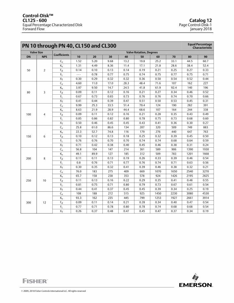
PN 10 through PN 40, CL150 and CL300 Equal PercentageCharacteristic
Valve SizeCoefficients
Valve Rotation, Degrees
DN NPS 10 20 30 40 50 60 70 80 90
50 2
Cv 1.52 5.20 9.68 13.2 19.8 25.2 33.1 44.5 60.7
Kv 1.31 4.49 8.36 11.4 17.1 21.8 28.6 38.4 52.4
Fd 0.14 0.10 0.13 0.14 0.19 0.21 0.25 0.27 0.33
FL ‐ ‐ ‐ 0.78 0.77 0.75 0.74 0.75 0.77 0.75 0.71
XT 0.30 0.29 0.32 0.32 0.36 0.50 0.54 0.52 0.44
80 3
Cv 4.60 11.0 17.0 28.3 48.4 71.6 107 162 227
Kv 3.97 9.50 14.7 24.5 41.8 61.9 92.4 140 196
Fd 0.09 0.11 0.12 0.16 0.21 0.27 0.34 0.46 0.52
FL 0.67 0.73 0.65 0.73 0.76 0.76 0.74 0.70 0.66
XT 0.41 0.44 0.39 0.47 0.51 0.50 0.53 0.45 0.31
100 4
Cv 9.99 25.3 33.5 51.4 79.4 124 190 282 391
Kv 8.63 21.9 28.9 44.4 68.6 107 164 244 338
Fd 0.09 0.11 0.12 0.16 0.21 0.28 0.35 0.43 0.49
FL 0.85 0.86 0.82 0.80 0.78 0.75 0.73 0.68 0.60
XT 0.50 0.46 0.45 0.45 0.43 0.41 0.36 0.30 0.27
150 6
Cv 25.8 61.0 86.6 134 207 320 509 749 883
Kv 22.3 52.7 74.8 116 179 276 440 647 763
Fd 0.10 0.12 0.13 0.18 0.25 0.32 0.39 0.45 0.50
FL 0.76 0.76 0.70 0.70 0.74 0.74 0.68 0.64 0.59
XT 0.71 0.42 0.38 0.40 0.45 0.46 0.38 0.31 0.24
200 8
Cv 56.8 104 147 214 361 589 906 1390 1930
Kv 49.1 89.9 127 185 312 509 783 1201 1668
Fd 0.11 0.11 0.13 0.19 0.26 0.33 0.39 0.46 0.54
FL 0.8 0.76 0.71 0.77 0.76 0.74 0.71 0.63 0.56
XT 0.30 0.35 0.32 0.41 0.39 0.46 0.38 0.32 0.21
250 10
Cv 76.0 183 275 409 669 1070 1650 2540 3270
Kv 65.7 158 238 353 578 924 1426 2195 2825
Fd 0.11 0.13 0.16 0.22 0.29 0.35 0.41 0.48 0.55
FL 0.81 0.75 0.71 0.80 0.79 0.73 0.67 0.61 0.54
XT 0.44 0.41 0.37 0.45 0.45 0.39 0.34 0.25 0.19
300 12
Cv 108 188 272 515 925 1450 2230 3080 4530
Kv 93.3 162 235 445 799 1253 1927 2661 3914
Fd 0.09 0.11 0.14 0.21 0.28 0.34 0.40 0.47 0.54
FL 0.77 0.71 0.78 0.80 0.78 0.74 0.68 0.68 0.54
XT 0.26 0.37 0.48 0.47 0.45 0.47 0.37 0.34 0.19
� 2009, 2018 Fisher Controls International LLC. All rights reserved
Control-Disk™CL125 - 600Equal Percentage Characterized DiskForward Flow
Catalog 12Page Control-Disk-1
January 2018
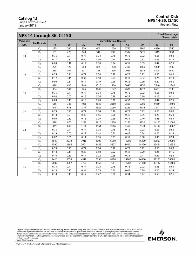
NPS 14 through 36, CL150 Equal PercentageCharacteristic
Valve SizeCoefficients
Valve Rotation, Degrees
NPS 10 20 30 40 50 60 70 80 90
14
Cv 175 260 370 600 1030 1750 2860 4420 6540
Kv 151 225 320 518 890 1512 2471 3819 5651
FL 0.75 0.71 0.77 0.74 0.78 0.75 0.72 0.65 0.60
XT 0.17 0.17 0.40 0.56 0.54 0.43 0.33 0.25 0.19
Fd 0.08 0.10 0.12 0.18 0.24 0.31 0.39 0.47 0.55
16
Cv 275 425 580 875 1430 2380 3860 5990 8900
Kv 238 367 501 756 1236 2056 3335 5175 7690
FL 0.75 0.71 0.77 0.74 0.78 0.75 0.72 0.65 0.60
XT 0.17 0.15 0.33 0.50 0.51 0.41 0.32 0.24 0.18
Fd 0.09 0.11 0.14 0.19 0.25 0.32 0.39 0.47 0.55
18
Cv 410 630 840 1210 1900 3090 4950 7640 11340
Kv 354 544 726 1045 1642 2670 4277 6601 9798
FL 0.75 0.71 0.77 0.74 0.78 0.75 0.72 0.65 0.60
XT 0.08 0.07 0.16 0.26 0.29 0.25 0.19 0.15 0.11
Fd 0.09 0.13 0.15 0.20 0.26 0.32 0.39 0.47 0.55
20
Cv 515 785 1060 1530 2380 3800 6000 9110 13400
Kv 445 678 916 1322 2056 3283 5184 7871 11578
FL 0.75 0.71 0.77 0.74 0.78 0.75 0.72 0.65 0.60
XT 0.18 0.21 0.40 0.56 0.56 0.46 0.35 0.26 0.20
Fd 0.09 0.12 0.15 0.20 0.26 0.33 0.40 0.48 0.55
24
Cv 520 975 1280 1810 2970 5150 8730 14100 21600
Kv 449 842 1106 1564 2566 4450 7543 12182 18662
FL 0.75 0.71 0.77 0.74 0.78 0.75 0.72 0.65 0.60
XT 0.19 0.07 0.22 0.48 0.56 0.46 0.34 0.25 0.18
Fd 0.07 0.09 0.11 0.16 0.23 0.30 0.38 0.46 0.54
30
Cv 1840 2530 3010 4000 6050 10000 16400 26000 39300
Kv 1590 2186 2601 3456 5227 8640 14170 22464 33955
FL 0.75 0.71 0.77 0.74 0.78 0.75 0.72 0.65 0.60
XT 0.14 0.14 0.30 0.50 0.52 0.41 0.29 0.21 0.15
Fd 0.10 0.13 0.17 0.22 0.28 0.34 0.41 0.49 0.56
36
Cv 2410 3550 4310 5750 8890 14800 24500 39100 59500
Kv 2082 3067 3724 4968 7681 12787 21168 33782 51408
FL 0.75 0.71 0.77 0.74 0.78 0.75 0.72 0.65 0.60
XT 0.13 0.15 0.34 0.55 0.56 0.42 0.29 0.20 0.14
Fd 0.10 0.13 0.17 0.22 0.28 0.34 0.42 0.50 0.56
Control-Disk
Reverse FlowNPS 14-36, CL150
Catalog 12Page Control-Disk-2January 2018
� 2013, 2018 Fisher Controls International LLC. All rights reserved
www.Fisher.com
Responsibility for selection, use, and maintenance of any product remains solely with the purchaser and end user. The contents of this publication are forinformational purposes only and are not to be construed as warranties or guarantees, express or implied, regarding the products or services describedtherein. Fisher and Control-Disk are marks owned by one of the companies in the Emerson Automation Solutions business unit of Emerson Electric Co.Emerson Automation Solutions, Emerson, and the Emerson logo are trademarks and service marks of Emerson Electric Co. All other marks are the propertyof their respective owners.

3
NPS 14 through 36, CL300 Equal PercentageCharacteristic
Valve SizeCoefficients
Valve Rotation, Degrees
NPS 10 20 30 40 50 60 70 80 90
14
Cv 140 200 305 500 840 1360 2120 3160 4540
Kv 121 173 264 432 726 1175 1832 2730 3923
FL 0.75 0.71 0.77 0.74 0.78 0.75 0.72 0.65 0.60
XT 0.12 0.15 0.33 0.46 0.47 0.42 0.35 0.29 0.24
Fd 0.08 0.11 0.14 0.17 0.25 0.32 0.40 0.48 0.54
16
Cv 230 365 505 720 1100 1700 2610 3910 5670
Kv 199 315 436 622 950 1469 2255 3378 4899
FL 0.75 0.71 0.77 0.74 0.78 0.75 0.72 0.65 0.60
XT 0.15 0.13 0.26 0.42 0.48 0.44 0.37 0.29 0.23
Fd 0.09 0.13 0.15 0.18 0.26 0.33 0.40 0.48 0.51
18
Cv 300 435 590 880 1420 2340 3750 5770 8510
Kv 259 376 510 760 1227 2022 3240 4985 7353
FL 0.75 0.71 0.77 0.74 0.78 0.75 0.72 0.65 0.60
XT 0.10 0.12 0.29 0.47 0.49 0.41 0.32 0.24 0.19
Fd 0.09 0.11 0.14 0.17 0.25 0.32 0.39 0.47 0.52
20
Cv 535 620 830 1270 2050 3290 5110 7600 10900
Kv 462 536 717 1097 1771 2843 4415 6566 9418
FL 0.75 0.71 0.77 0.74 0.78 0.75 0.72 0.65 0.60
XT 0.14 0.25 0.44 0.53 0.48 0.39 0.30 0.23 0.19
Fd 0.11 0.13 0.16 0.20 0.26 0.33 0.40 0.46 0.53
24
Cv 830 1000 1410 2130 3230 4800 6900 9610 13000
Kv 717 864 1218 1840 2791 4147 5962 8303 11232
FL 0.75 0.71 0.77 0.74 0.78 0.75 0.72 0.65 0.60
XT 0.14 0.29 0.42 0.45 0.42 0.36 0.31 0.27 0.23
Fd 0.12 0.14 0.16 0.20 0.28 0.34 0.41 0.48 0.53
30
Cv 1170 1940 2470 3210 4610 7120 11200 17200 25750
Kv 1011 1676 2134 2773 3983 6152 9677 14861 22248
FL 0.75 0.71 0.77 0.74 0.78 0.75 0.72 0.65 0.60
XT 0.14 0.12 0.25 0.43 0.52 0.47 0.36 0.27 0.20
Fd 0.10 0.13 0.16 0.19 0.25 0.32 0.39 0.46 0.53
36
Cv 1340 1920 2650 4060 6690 11100 17800 27400 40300
Kv 1158 1659 2290 3508 5780 9590 15379 23674 34819
FL 0.75 0.71 0.77 0.74 0.78 0.75 0.72 0.65 0.60
XT 0.15 0.17 0.37 0.53 0.52 0.43 0.33 0.25 0.19
Fd 0.08 0.11 0.14 0.19 0.25 0.32 0.38 0.47 0.54
Control-Disk
Reverse FlowNPS 14-36, CL300
Catalog 12Page Control-Disk-3
January 2018
� 2013, 2018 Fisher Controls International LLC. All rights reserved
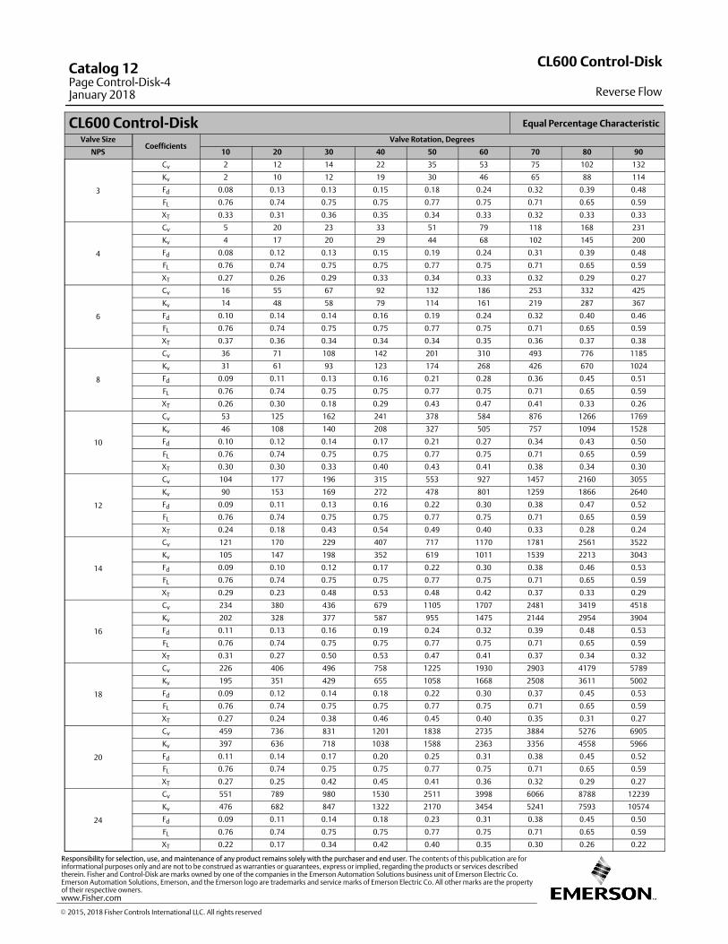
CL600 Control-Disk Equal Percentage Characteristic
Valve SizeCoefficients
Valve Rotation, Degrees
NPS 10 20 30 40 50 60 70 80 90
3
Cv 2 12 14 22 35 53 75 102 132
Kv 2 10 12 19 30 46 65 88 114
Fd 0.08 0.13 0.13 0.15 0.18 0.24 0.32 0.39 0.48
FL 0.76 0.74 0.75 0.75 0.77 0.75 0.71 0.65 0.59
XT 0.33 0.31 0.36 0.35 0.34 0.33 0.32 0.33 0.33
4
Cv 5 20 23 33 51 79 118 168 231
Kv 4 17 20 29 44 68 102 145 200
Fd 0.08 0.12 0.13 0.15 0.19 0.24 0.31 0.39 0.48
FL 0.76 0.74 0.75 0.75 0.77 0.75 0.71 0.65 0.59
XT 0.27 0.26 0.29 0.33 0.34 0.33 0.32 0.29 0.27
6
Cv 16 55 67 92 132 186 253 332 425
Kv 14 48 58 79 114 161 219 287 367
Fd 0.10 0.14 0.14 0.16 0.19 0.24 0.32 0.40 0.46
FL 0.76 0.74 0.75 0.75 0.77 0.75 0.71 0.65 0.59
XT 0.37 0.36 0.34 0.34 0.34 0.35 0.36 0.37 0.38
8
Cv 36 71 108 142 201 310 493 776 1185
Kv 31 61 93 123 174 268 426 670 1024
Fd 0.09 0.11 0.13 0.16 0.21 0.28 0.36 0.45 0.51
FL 0.76 0.74 0.75 0.75 0.77 0.75 0.71 0.65 0.59
XT 0.26 0.30 0.18 0.29 0.43 0.47 0.41 0.33 0.26
10
Cv 53 125 162 241 378 584 876 1266 1769
Kv 46 108 140 208 327 505 757 1094 1528
Fd 0.10 0.12 0.14 0.17 0.21 0.27 0.34 0.43 0.50
FL 0.76 0.74 0.75 0.75 0.77 0.75 0.71 0.65 0.59
XT 0.30 0.30 0.33 0.40 0.43 0.41 0.38 0.34 0.30
12
Cv 104 177 196 315 553 927 1457 2160 3055
Kv 90 153 169 272 478 801 1259 1866 2640
Fd 0.09 0.11 0.13 0.16 0.22 0.30 0.38 0.47 0.52
FL 0.76 0.74 0.75 0.75 0.77 0.75 0.71 0.65 0.59
XT 0.24 0.18 0.43 0.54 0.49 0.40 0.33 0.28 0.24
14
Cv 121 170 229 407 717 1170 1781 2561 3522
Kv 105 147 198 352 619 1011 1539 2213 3043
Fd 0.09 0.10 0.12 0.17 0.22 0.30 0.38 0.46 0.53
FL 0.76 0.74 0.75 0.75 0.77 0.75 0.71 0.65 0.59
XT 0.29 0.23 0.48 0.53 0.48 0.42 0.37 0.33 0.29
16
Cv 234 380 436 679 1105 1707 2481 3419 4518
Kv 202 328 377 587 955 1475 2144 2954 3904
Fd 0.11 0.13 0.16 0.19 0.24 0.32 0.39 0.48 0.53
FL 0.76 0.74 0.75 0.75 0.77 0.75 0.71 0.65 0.59
XT 0.31 0.27 0.50 0.53 0.47 0.41 0.37 0.34 0.32
18
Cv 226 406 496 758 1225 1930 2903 4179 5789
Kv 195 351 429 655 1058 1668 2508 3611 5002
Fd 0.09 0.12 0.14 0.18 0.22 0.30 0.37 0.45 0.53
FL 0.76 0.74 0.75 0.75 0.77 0.75 0.71 0.65 0.59
XT 0.27 0.24 0.38 0.46 0.45 0.40 0.35 0.31 0.27
20
Cv 459 736 831 1201 1838 2735 3884 5276 6905
Kv 397 636 718 1038 1588 2363 3356 4558 5966
Fd 0.11 0.14 0.17 0.20 0.25 0.31 0.38 0.45 0.52
FL 0.76 0.74 0.75 0.75 0.77 0.75 0.71 0.65 0.59
XT 0.27 0.25 0.42 0.45 0.41 0.36 0.32 0.29 0.27
24
Cv 551 789 980 1530 2511 3998 6066 8788 12239
Kv 476 682 847 1322 2170 3454 5241 7593 10574
Fd 0.09 0.11 0.14 0.18 0.23 0.31 0.38 0.45 0.50
FL 0.76 0.74 0.75 0.75 0.77 0.75 0.71 0.65 0.59
XT 0.22 0.17 0.34 0.42 0.40 0.35 0.30 0.26 0.22
CL600 Control-Disk
Reverse Flow
Catalog 12Page Control-Disk-4January 2018
� 2015, 2018 Fisher Controls International LLC. All rights reserved
www.Fisher.com
Responsibility for selection, use, and maintenance of any product remains solely with the purchaser and end user. The contents of this publication are forinformational purposes only and are not to be construed as warranties or guarantees, express or implied, regarding the products or services describedtherein. Fisher and Control-Disk are marks owned by one of the companies in the Emerson Automation Solutions business unit of Emerson Electric Co.Emerson Automation Solutions, Emerson, and the Emerson logo are trademarks and service marks of Emerson Electric Co. All other marks are the propertyof their respective owners.
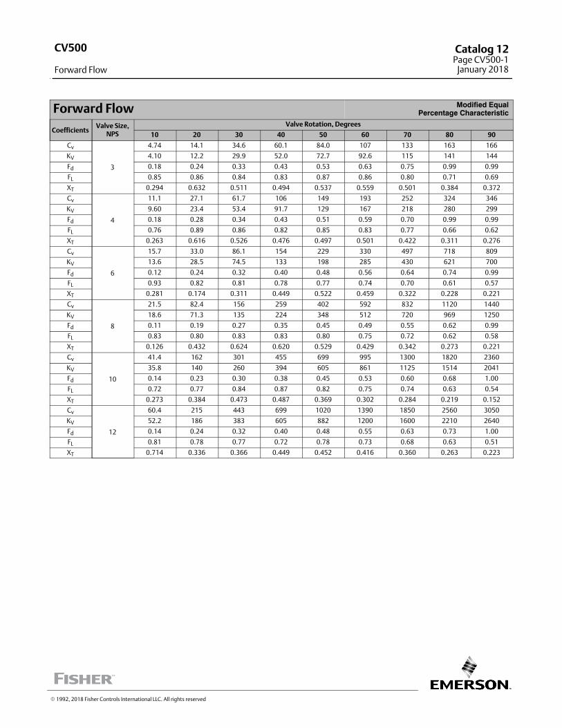
Forward Flow Modified EqualPercentage Characteristic
CoefficientsValve Size,
NPS
Valve Rotation, Degrees
10 20 30 40 50 60 70 80 90
Cv
3
4.74 14.1 34.6 60.1 84.0 107 133 163 166
KV 4.10 12.2 29.9 52.0 72.7 92.6 115 141 144
Fd 0.18 0.24 0.33 0.43 0.53 0.63 0.75 0.99 0.99
FL 0.85 0.86 0.84 0.83 0.87 0.86 0.80 0.71 0.69
XT 0.294 0.632 0.511 0.494 0.537 0.559 0.501 0.384 0.372
Cv
4
11.1 27.1 61.7 106 149 193 252 324 346
KV 9.60 23.4 53.4 91.7 129 167 218 280 299
Fd 0.18 0.28 0.34 0.43 0.51 0.59 0.70 0.99 0.99
FL 0.76 0.89 0.86 0.82 0.85 0.83 0.77 0.66 0.62
XT 0.263 0.616 0.526 0.476 0.497 0.501 0.422 0.311 0.276
Cv
6
15.7 33.0 86.1 154 229 330 497 718 809
KV 13.6 28.5 74.5 133 198 285 430 621 700
Fd 0.12 0.24 0.32 0.40 0.48 0.56 0.64 0.74 0.99
FL 0.93 0.82 0.81 0.78 0.77 0.74 0.70 0.61 0.57
XT 0.281 0.174 0.311 0.449 0.522 0.459 0.322 0.228 0.221
Cv
8
21.5 82.4 156 259 402 592 832 1120 1440
KV 18.6 71.3 135 224 348 512 720 969 1250
Fd 0.11 0.19 0.27 0.35 0.45 0.49 0.55 0.62 0.99
FL 0.83 0.80 0.83 0.83 0.80 0.75 0.72 0.62 0.58
XT 0.126 0.432 0.624 0.620 0.529 0.429 0.342 0.273 0.221
Cv
10
41.4 162 301 455 699 995 1300 1820 2360
KV 35.8 140 260 394 605 861 1125 1514 2041
Fd 0.14 0.23 0.30 0.38 0.45 0.53 0.60 0.68 1.00
FL 0.72 0.77 0.84 0.87 0.82 0.75 0.74 0.63 0.54
XT 0.273 0.384 0.473 0.487 0.369 0.302 0.284 0.219 0.152
Cv
12
60.4 215 443 699 1020 1390 1850 2560 3050
KV 52.2 186 383 605 882 1200 1600 2210 2640
Fd 0.14 0.24 0.32 0.40 0.48 0.55 0.63 0.73 1.00
FL 0.81 0.78 0.77 0.72 0.78 0.73 0.68 0.63 0.51
XT 0.714 0.336 0.366 0.449 0.452 0.416 0.360 0.263 0.223
� 1992, 2018 Fisher Controls International LLC. All rights reserved
CV500
Forward Flow
Catalog 12Page CV500-1
January 2018
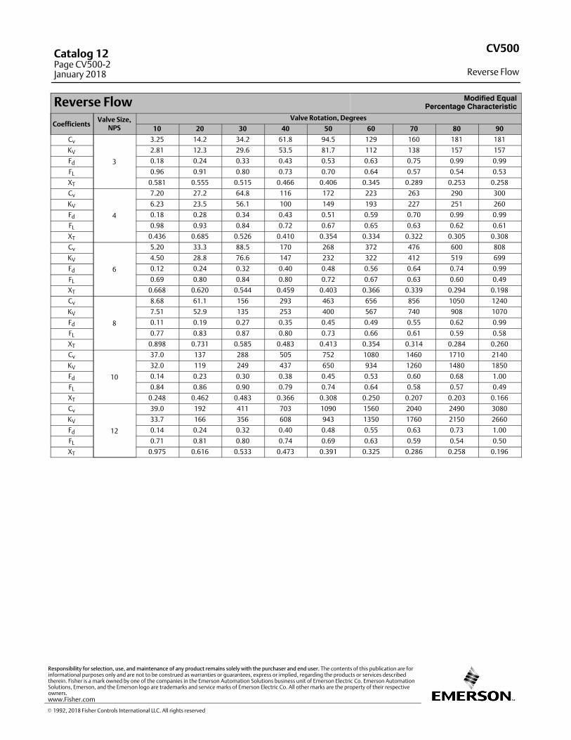
Reverse Flow Modified EqualPercentage Characteristic
CoefficientsValve Size,
NPS
Valve Rotation, Degrees
10 20 30 40 50 60 70 80 90
Cv
3
3.25 14.2 34.2 61.8 94.5 129 160 181 181
KV 2.81 12.3 29.6 53.5 81.7 112 138 157 157
Fd 0.18 0.24 0.33 0.43 0.53 0.63 0.75 0.99 0.99
FL 0.96 0.91 0.80 0.73 0.70 0.64 0.57 0.54 0.53
XT 0.581 0.555 0.515 0.466 0.406 0.345 0.289 0.253 0.258
Cv
4
7.20 27.2 64.8 116 172 223 263 290 300
KV 6.23 23.5 56.1 100 149 193 227 251 260
Fd 0.18 0.28 0.34 0.43 0.51 0.59 0.70 0.99 0.99
FL 0.98 0.93 0.84 0.72 0.67 0.65 0.63 0.62 0.61
XT 0.436 0.685 0.526 0.410 0.354 0.334 0.322 0.305 0.308
Cv
6
5.20 33.3 88.5 170 268 372 476 600 808
KV 4.50 28.8 76.6 147 232 322 412 519 699
Fd 0.12 0.24 0.32 0.40 0.48 0.56 0.64 0.74 0.99
FL 0.69 0.80 0.84 0.80 0.72 0.67 0.63 0.60 0.49
XT 0.668 0.620 0.544 0.459 0.403 0.366 0.339 0.294 0.198
Cv
8
8.68 61.1 156 293 463 656 856 1050 1240
KV 7.51 52.9 135 253 400 567 740 908 1070
Fd 0.11 0.19 0.27 0.35 0.45 0.49 0.55 0.62 0.99
FL 0.77 0.83 0.87 0.80 0.73 0.66 0.61 0.59 0.58
XT 0.898 0.731 0.585 0.483 0.413 0.354 0.314 0.284 0.260
Cv
10
37.0 137 288 505 752 1080 1460 1710 2140
KV 32.0 119 249 437 650 934 1260 1480 1850
Fd 0.14 0.23 0.30 0.38 0.45 0.53 0.60 0.68 1.00
FL 0.84 0.86 0.90 0.79 0.74 0.64 0.58 0.57 0.49
XT 0.248 0.462 0.483 0.366 0.308 0.250 0.207 0.203 0.166
Cv
12
39.0 192 411 703 1090 1560 2040 2490 3080
KV 33.7 166 356 608 943 1350 1760 2150 2660
Fd 0.14 0.24 0.32 0.40 0.48 0.55 0.63 0.73 1.00
FL 0.71 0.81 0.80 0.74 0.69 0.63 0.59 0.54 0.50
XT 0.975 0.616 0.533 0.473 0.391 0.325 0.286 0.258 0.196
CV500
Reverse Flow
Catalog 12Page CV500-2January 2018
� 1992, 2018 Fisher Controls International LLC. All rights reserved
www.Fisher.com
Responsibility for selection, use, and maintenance of any product remains solely with the purchaser and end user. The contents of this publication are forinformational purposes only and are not to be construed as warranties or guarantees, express or implied, regarding the products or services describedtherein. Fisher is a mark owned by one of the companies in the Emerson Automation Solutions business unit of Emerson Electric Co. Emerson AutomationSolutions, Emerson, and the Emerson logo are trademarks and service marks of Emerson Electric Co. All other marks are the property of their respectiveowners.
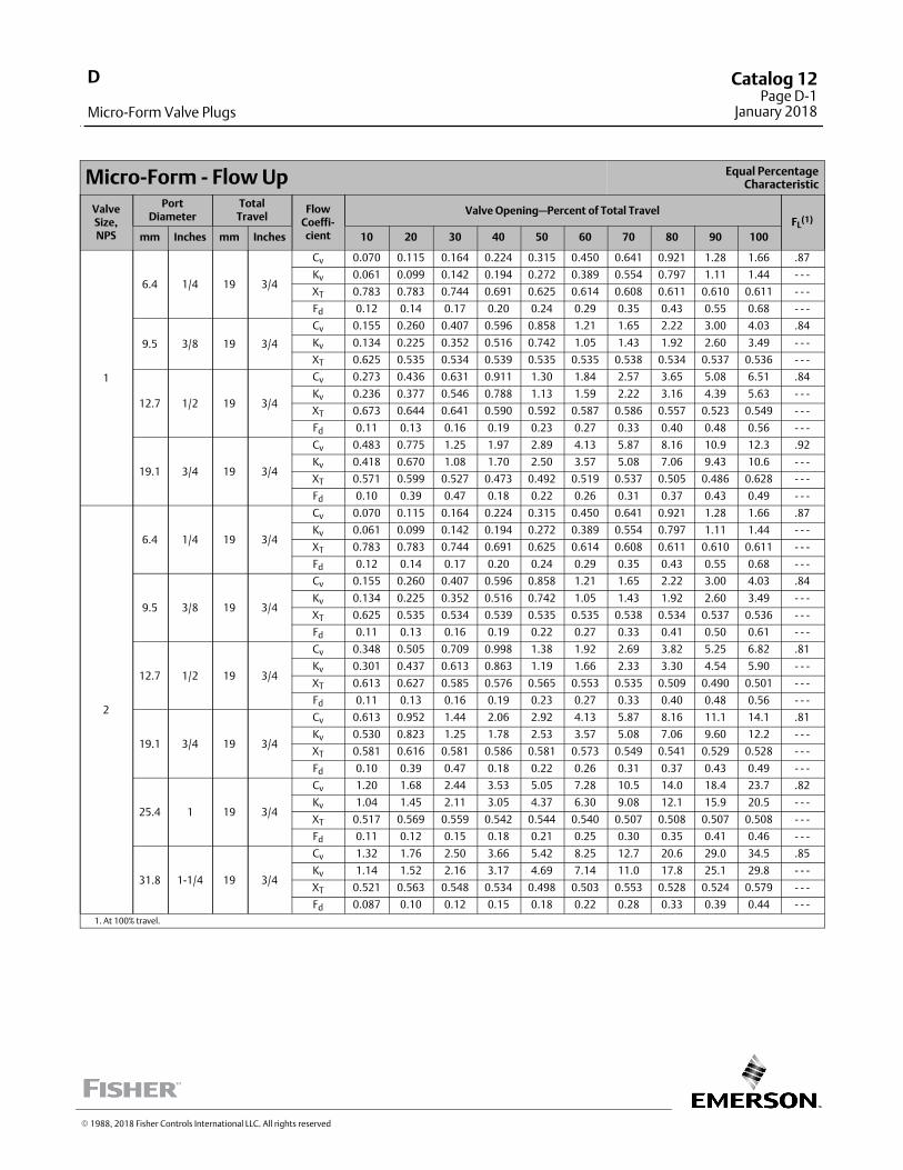
Micro‐Form ‐ Flow Up Equal PercentageCharacteristic
ValveSize,NPS
PortDiameter
TotalTravel
FlowCoeffi‐cient
Valve Opening—Percent of Total TravelFL
(1)
mm Inches mm Inches 10 20 30 40 50 60 70 80 90 100
1
6.4 1/4 19 3/4
Cv 0.070 0.115 0.164 0.224 0.315 0.450 0.641 0.921 1.28 1.66 .87
Kv 0.061 0.099 0.142 0.194 0.272 0.389 0.554 0.797 1.11 1.44 ‐ ‐ ‐
XT 0.783 0.783 0.744 0.691 0.625 0.614 0.608 0.611 0.610 0.611 ‐ ‐ ‐
Fd 0.12 0.14 0.17 0.20 0.24 0.29 0.35 0.43 0.55 0.68 ‐ ‐ ‐
9.5 3/8 19 3/4
Cv 0.155 0.260 0.407 0.596 0.858 1.21 1.65 2.22 3.00 4.03 .84
Kv 0.134 0.225 0.352 0.516 0.742 1.05 1.43 1.92 2.60 3.49 ‐ ‐ ‐
XT 0.625 0.535 0.534 0.539 0.535 0.535 0.538 0.534 0.537 0.536 ‐ ‐ ‐
12.7 1/2 19 3/4
Cv 0.273 0.436 0.631 0.911 1.30 1.84 2.57 3.65 5.08 6.51 .84
Kv 0.236 0.377 0.546 0.788 1.13 1.59 2.22 3.16 4.39 5.63 ‐ ‐ ‐
XT 0.673 0.644 0.641 0.590 0.592 0.587 0.586 0.557 0.523 0.549 ‐ ‐ ‐
Fd 0.11 0.13 0.16 0.19 0.23 0.27 0.33 0.40 0.48 0.56 ‐ ‐ ‐
19.1 3/4 19 3/4
Cv 0.483 0.775 1.25 1.97 2.89 4.13 5.87 8.16 10.9 12.3 .92
Kv 0.418 0.670 1.08 1.70 2.50 3.57 5.08 7.06 9.43 10.6 ‐ ‐ ‐
XT 0.571 0.599 0.527 0.473 0.492 0.519 0.537 0.505 0.486 0.628 ‐ ‐ ‐
Fd 0.10 0.39 0.47 0.18 0.22 0.26 0.31 0.37 0.43 0.49 ‐ ‐ ‐
2
6.4 1/4 19 3/4
Cv 0.070 0.115 0.164 0.224 0.315 0.450 0.641 0.921 1.28 1.66 .87
Kv 0.061 0.099 0.142 0.194 0.272 0.389 0.554 0.797 1.11 1.44 ‐ ‐ ‐
XT 0.783 0.783 0.744 0.691 0.625 0.614 0.608 0.611 0.610 0.611 ‐ ‐ ‐
Fd 0.12 0.14 0.17 0.20 0.24 0.29 0.35 0.43 0.55 0.68 ‐ ‐ ‐
9.5 3/8 19 3/4
Cv 0.155 0.260 0.407 0.596 0.858 1.21 1.65 2.22 3.00 4.03 .84
Kv 0.134 0.225 0.352 0.516 0.742 1.05 1.43 1.92 2.60 3.49 ‐ ‐ ‐
XT 0.625 0.535 0.534 0.539 0.535 0.535 0.538 0.534 0.537 0.536 ‐ ‐ ‐
Fd 0.11 0.13 0.16 0.19 0.22 0.27 0.33 0.41 0.50 0.61 ‐ ‐ ‐
12.7 1/2 19 3/4
Cv 0.348 0.505 0.709 0.998 1.38 1.92 2.69 3.82 5.25 6.82 .81
Kv 0.301 0.437 0.613 0.863 1.19 1.66 2.33 3.30 4.54 5.90 ‐ ‐ ‐
XT 0.613 0.627 0.585 0.576 0.565 0.553 0.535 0.509 0.490 0.501 ‐ ‐ ‐
Fd 0.11 0.13 0.16 0.19 0.23 0.27 0.33 0.40 0.48 0.56 ‐ ‐ ‐
19.1 3/4 19 3/4
Cv 0.613 0.952 1.44 2.06 2.92 4.13 5.87 8.16 11.1 14.1 .81
Kv 0.530 0.823 1.25 1.78 2.53 3.57 5.08 7.06 9.60 12.2 ‐ ‐ ‐
XT 0.581 0.616 0.581 0.586 0.581 0.573 0.549 0.541 0.529 0.528 ‐ ‐ ‐
Fd 0.10 0.39 0.47 0.18 0.22 0.26 0.31 0.37 0.43 0.49 ‐ ‐ ‐
25.4 1 19 3/4
Cv 1.20 1.68 2.44 3.53 5.05 7.28 10.5 14.0 18.4 23.7 .82
Kv 1.04 1.45 2.11 3.05 4.37 6.30 9.08 12.1 15.9 20.5 ‐ ‐ ‐
XT 0.517 0.569 0.559 0.542 0.544 0.540 0.507 0.508 0.507 0.508 ‐ ‐ ‐
Fd 0.11 0.12 0.15 0.18 0.21 0.25 0.30 0.35 0.41 0.46 ‐ ‐ ‐
31.8 1‐1/4 19 3/4
Cv 1.32 1.76 2.50 3.66 5.42 8.25 12.7 20.6 29.0 34.5 .85
Kv 1.14 1.52 2.16 3.17 4.69 7.14 11.0 17.8 25.1 29.8 ‐ ‐ ‐
XT 0.521 0.563 0.548 0.534 0.498 0.503 0.553 0.528 0.524 0.579 ‐ ‐ ‐
Fd 0.087 0.10 0.12 0.15 0.18 0.22 0.28 0.33 0.39 0.44 ‐ ‐ ‐
1. At 100% travel.
� 1988, 2018 Fisher Controls International LLC. All rights reserved
D
Micro-Form Valve Plugs
Catalog 12Page D-1
January 2018
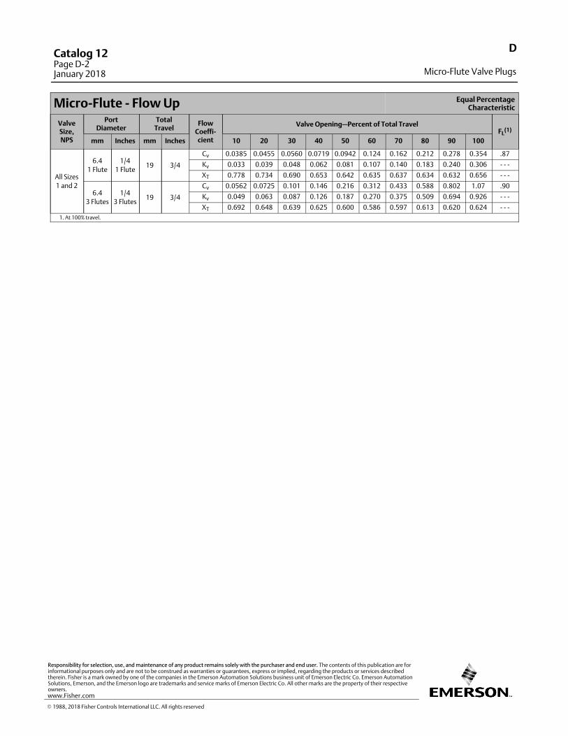
Micro‐Flute ‐ Flow Up Equal PercentageCharacteristic
ValveSize,NPS
PortDiameter
TotalTravel
FlowCoeffi‐cient
Valve Opening—Percent of Total TravelFL
(1)
mm Inches mm Inches 10 20 30 40 50 60 70 80 90 100
All Sizes
1 and 2
6.4
1 Flute
1/4
1 Flute19 3/4
Cv 0.0385 0.0455 0.0560 0.0719 0.0942 0.124 0.162 0.212 0.278 0.354 .87
Kv 0.033 0.039 0.048 0.062 0.081 0.107 0.140 0.183 0.240 0.306 ‐ ‐ ‐
XT 0.778 0.734 0.690 0.653 0.642 0.635 0.637 0.634 0.632 0.656 ‐ ‐ ‐
6.4
3 Flutes
1/4
3 Flutes19 3/4
Cv 0.0562 0.0725 0.101 0.146 0.216 0.312 0.433 0.588 0.802 1.07 .90
Kv 0.049 0.063 0.087 0.126 0.187 0.270 0.375 0.509 0.694 0.926 ‐ ‐ ‐
XT 0.692 0.648 0.639 0.625 0.600 0.586 0.597 0.613 0.620 0.624 ‐ ‐ ‐
1. At 100% travel.
D
Micro-Flute Valve Plugs
Catalog 12Page D-2January 2018
� 1988, 2018 Fisher Controls International LLC. All rights reserved
www.Fisher.com
Responsibility for selection, use, and maintenance of any product remains solely with the purchaser and end user. The contents of this publication are forinformational purposes only and are not to be construed as warranties or guarantees, express or implied, regarding the products or services describedtherein. Fisher is a mark owned by one of the companies in the Emerson Automation Solutions business unit of Emerson Electric Co. Emerson AutomationSolutions, Emerson, and the Emerson logo are trademarks and service marks of Emerson Electric Co. All other marks are the property of their respectiveowners.
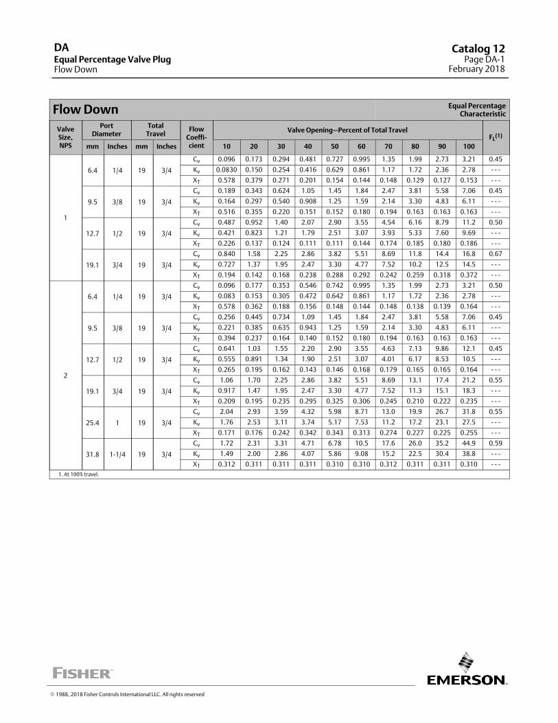
Flow Down Equal PercentageCharacteristic
ValveSize,NPS
PortDiameter
TotalTravel
FlowCoeffi‐cient
Valve Opening—Percent of Total TravelFL
(1)
mm Inches mm Inches 10 20 30 40 50 60 70 80 90 100
1
6.4 1/4 19 3/4
Cv 0.096 0.173 0.294 0.481 0.727 0.995 1.35 1.99 2.73 3.21 0.45
Kv 0.0830 0.150 0.254 0.416 0.629 0.861 1.17 1.72 2.36 2.78 ‐ ‐ ‐
XT 0.578 0.379 0.271 0.201 0.154 0.144 0.148 0.129 0.127 0.153 ‐ ‐ ‐
9.5 3/8 19 3/4
Cv 0.189 0.343 0.624 1.05 1.45 1.84 2.47 3.81 5.58 7.06 0.45
Kv 0.164 0.297 0.540 0.908 1.25 1.59 2.14 3.30 4.83 6.11 ‐ ‐ ‐
XT 0.516 0.355 0.220 0.151 0.152 0.180 0.194 0.163 0.163 0.163 ‐ ‐ ‐
12.7 1/2 19 3/4
Cv 0.487 0.952 1.40 2.07 2.90 3.55 4.54 6.16 8.79 11.2 0.50
Kv 0.421 0.823 1.21 1.79 2.51 3.07 3.93 5.33 7.60 9.69 ‐ ‐ ‐
XT 0.226 0.137 0.124 0.111 0.111 0.144 0.174 0.185 0.180 0.186 ‐ ‐ ‐
19.1 3/4 19 3/4
Cv 0.840 1.58 2.25 2.86 3.82 5.51 8.69 11.8 14.4 16.8 0.67
Kv 0.727 1.37 1.95 2.47 3.30 4.77 7.52 10.2 12.5 14.5 ‐ ‐ ‐
XT 0.194 0.142 0.168 0.238 0.288 0.292 0.242 0.259 0.318 0.372 ‐ ‐ ‐
2
6.4 1/4 19 3/4
Cv 0.096 0.177 0.353 0.546 0.742 0.995 1.35 1.99 2.73 3.21 0.50
Kv 0.083 0.153 0.305 0.472 0.642 0.861 1.17 1.72 2.36 2.78 ‐ ‐ ‐
XT 0.578 0.362 0.188 0.156 0.148 0.144 0.148 0.138 0.139 0.164 ‐ ‐ ‐
9.5 3/8 19 3/4
Cv 0.256 0.445 0.734 1.09 1.45 1.84 2.47 3.81 5.58 7.06 0.45
Kv 0.221 0.385 0.635 0.943 1.25 1.59 2.14 3.30 4.83 6.11 ‐ ‐ ‐
XT 0.394 0.237 0.164 0.140 0.152 0.180 0.194 0.163 0.163 0.163 ‐ ‐ ‐
12.7 1/2 19 3/4
Cv 0.641 1.03 1.55 2.20 2.90 3.55 4.63 7.13 9.86 12.1 0.45
Kv 0.555 0.891 1.34 1.90 2.51 3.07 4.01 6.17 8.53 10.5 ‐ ‐ ‐
XT 0.265 0.195 0.162 0.143 0.146 0.168 0.179 0.165 0.165 0.164 ‐ ‐ ‐
19.1 3/4 19 3/4
Cv 1.06 1.70 2.25 2.86 3.82 5.51 8.69 13.1 17.4 21.2 0.55
Kv 0.917 1.47 1.95 2.47 3.30 4.77 7.52 11.3 15.1 18.3 ‐ ‐ ‐
XT 0.209 0.195 0.235 0.295 0.325 0.306 0.245 0.210 0.222 0.235 ‐ ‐ ‐
25.4 1 19 3/4
Cv 2.04 2.93 3.59 4.32 5.98 8.71 13.0 19.9 26.7 31.8 0.55
Kv 1.76 2.53 3.11 3.74 5.17 7.53 11.2 17.2 23.1 27.5 ‐ ‐ ‐
XT 0.171 0.176 0.242 0.342 0.343 0.313 0.274 0.227 0.225 0.255 ‐ ‐ ‐
31.8 1‐1/4 19 3/4
Cv 1.72 2.31 3.31 4.71 6.78 10.5 17.6 26.0 35.2 44.9 0.59
Kv 1.49 2.00 2.86 4.07 5.86 9.08 15.2 22.5 30.4 38.8 ‐ ‐ ‐
XT 0.312 0.311 0.311 0.311 0.310 0.310 0.312 0.311 0.311 0.310 ‐ ‐ ‐
1. At 100% travel.
� 1988, 2018 Fisher Controls International LLC. All rights reserved
DAEqual Percentage Valve PlugFlow Down
Catalog 12Page DA-1
February 2018
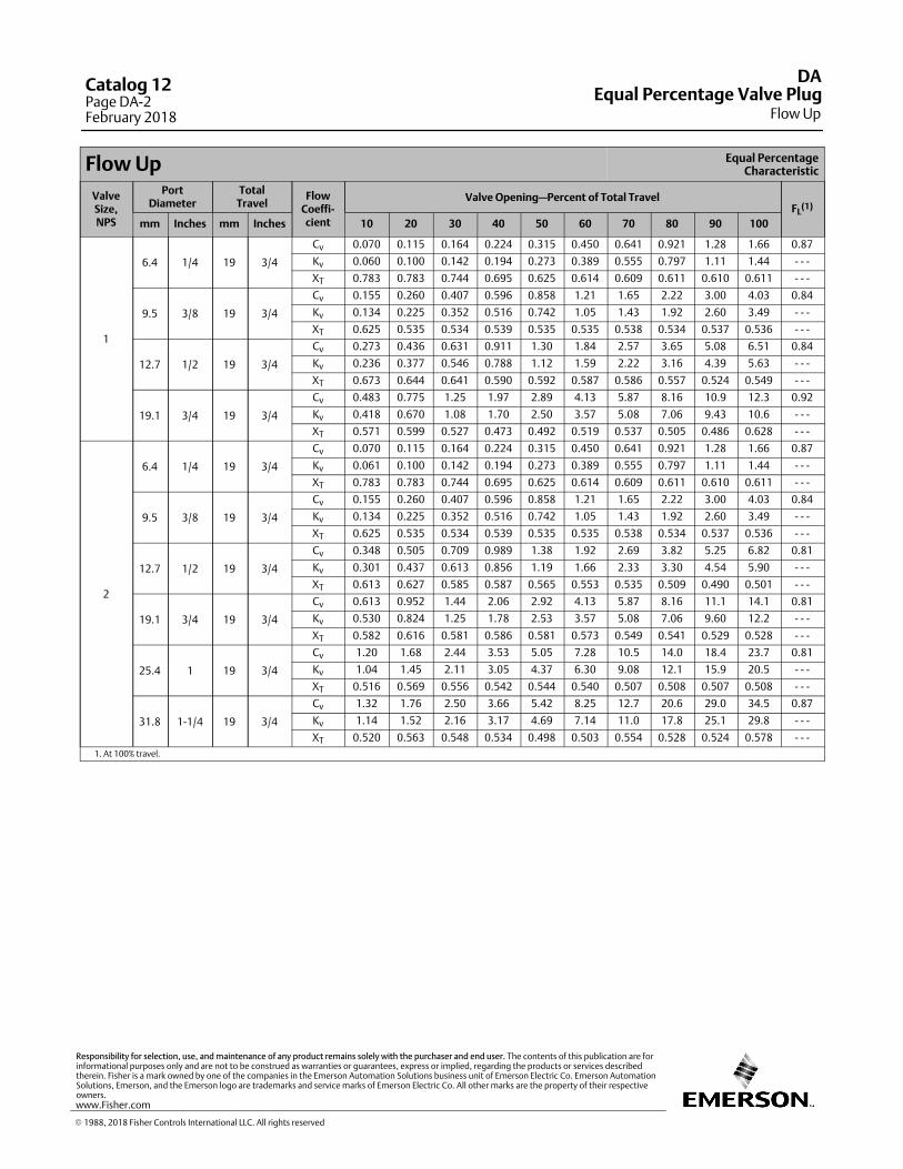
Flow Up Equal PercentageCharacteristic
ValveSize,NPS
PortDiameter
TotalTravel
FlowCoeffi‐cient
Valve Opening—Percent of Total TravelFL
(1)
mm Inches mm Inches 10 20 30 40 50 60 70 80 90 100
1
6.4 1/4 19 3/4
Cv 0.070 0.115 0.164 0.224 0.315 0.450 0.641 0.921 1.28 1.66 0.87
Kv 0.060 0.100 0.142 0.194 0.273 0.389 0.555 0.797 1.11 1.44 ‐ ‐ ‐
XT 0.783 0.783 0.744 0.695 0.625 0.614 0.609 0.611 0.610 0.611 ‐ ‐ ‐
9.5 3/8 19 3/4
Cv 0.155 0.260 0.407 0.596 0.858 1.21 1.65 2.22 3.00 4.03 0.84
Kv 0.134 0.225 0.352 0.516 0.742 1.05 1.43 1.92 2.60 3.49 ‐ ‐ ‐
XT 0.625 0.535 0.534 0.539 0.535 0.535 0.538 0.534 0.537 0.536 ‐ ‐ ‐
12.7 1/2 19 3/4
Cv 0.273 0.436 0.631 0.911 1.30 1.84 2.57 3.65 5.08 6.51 0.84
Kv 0.236 0.377 0.546 0.788 1.12 1.59 2.22 3.16 4.39 5.63 ‐ ‐ ‐
XT 0.673 0.644 0.641 0.590 0.592 0.587 0.586 0.557 0.524 0.549 ‐ ‐ ‐
19.1 3/4 19 3/4
Cv 0.483 0.775 1.25 1.97 2.89 4.13 5.87 8.16 10.9 12.3 0.92
Kv 0.418 0.670 1.08 1.70 2.50 3.57 5.08 7.06 9.43 10.6 ‐ ‐ ‐
XT 0.571 0.599 0.527 0.473 0.492 0.519 0.537 0.505 0.486 0.628 ‐ ‐ ‐
2
6.4 1/4 19 3/4
Cv 0.070 0.115 0.164 0.224 0.315 0.450 0.641 0.921 1.28 1.66 0.87
Kv 0.061 0.100 0.142 0.194 0.273 0.389 0.555 0.797 1.11 1.44 ‐ ‐ ‐
XT 0.783 0.783 0.744 0.695 0.625 0.614 0.609 0.611 0.610 0.611 ‐ ‐ ‐
9.5 3/8 19 3/4
Cv 0.155 0.260 0.407 0.596 0.858 1.21 1.65 2.22 3.00 4.03 0.84
Kv 0.134 0.225 0.352 0.516 0.742 1.05 1.43 1.92 2.60 3.49 ‐ ‐ ‐
XT 0.625 0.535 0.534 0.539 0.535 0.535 0.538 0.534 0.537 0.536 ‐ ‐ ‐
12.7 1/2 19 3/4
Cv 0.348 0.505 0.709 0.989 1.38 1.92 2.69 3.82 5.25 6.82 0.81
Kv 0.301 0.437 0.613 0.856 1.19 1.66 2.33 3.30 4.54 5.90 ‐ ‐ ‐
XT 0.613 0.627 0.585 0.587 0.565 0.553 0.535 0.509 0.490 0.501 ‐ ‐ ‐
19.1 3/4 19 3/4
Cv 0.613 0.952 1.44 2.06 2.92 4.13 5.87 8.16 11.1 14.1 0.81
Kv 0.530 0.824 1.25 1.78 2.53 3.57 5.08 7.06 9.60 12.2 ‐ ‐ ‐
XT 0.582 0.616 0.581 0.586 0.581 0.573 0.549 0.541 0.529 0.528 ‐ ‐ ‐
25.4 1 19 3/4
Cv 1.20 1.68 2.44 3.53 5.05 7.28 10.5 14.0 18.4 23.7 0.81
Kv 1.04 1.45 2.11 3.05 4.37 6.30 9.08 12.1 15.9 20.5 ‐ ‐ ‐
XT 0.516 0.569 0.556 0.542 0.544 0.540 0.507 0.508 0.507 0.508 ‐ ‐ ‐
31.8 1‐1/4 19 3/4
Cv 1.32 1.76 2.50 3.66 5.42 8.25 12.7 20.6 29.0 34.5 0.87
Kv 1.14 1.52 2.16 3.17 4.69 7.14 11.0 17.8 25.1 29.8 ‐ ‐ ‐
XT 0.520 0.563 0.548 0.534 0.498 0.503 0.554 0.528 0.524 0.578 ‐ ‐ ‐
1. At 100% travel.
DA
Flow UpEqual Percentage Valve Plug
Catalog 12Page DA-2February 2018
� 1988, 2018 Fisher Controls International LLC. All rights reserved
www.Fisher.com
Responsibility for selection, use, and maintenance of any product remains solely with the purchaser and end user. The contents of this publication are forinformational purposes only and are not to be construed as warranties or guarantees, express or implied, regarding the products or services describedtherein. Fisher is a mark owned by one of the companies in the Emerson Automation Solutions business unit of Emerson Electric Co. Emerson AutomationSolutions, Emerson, and the Emerson logo are trademarks and service marks of Emerson Electric Co. All other marks are the property of their respectiveowners.
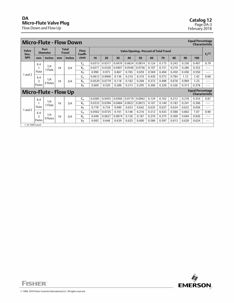
3
Micro‐Flute ‐ Flow Down Equal PercentageCharacteristic
ValveSize,NPS
PortDiameter
TotalTravel
FlowCoeffi‐cient
Valve Opening—Percent of Total TravelFL
(1)
mm Inches mm Inches 10 20 30 40 50 60 70 80 90 100
1 and 2
6.4
1
Flute
1/4
1 Flute19 3/4
Cv 0.0313 0.0377 0.0470 0.0624 0.0874 0.124 0.175 0.243 0.330 0.407 0.79
Kv 0.0271 0.0326 0.0407 0.0540 0.0756 0.107 0.151 0.210 0.286 0.352 ‐ ‐ ‐
XT 0.990 0.975 0.867 0.765 0.659 0.569 0.494 0.450 0.450 0.550 ‐ ‐ ‐
6.4
3
Flutes
1/4
3 Flutes19 3/4
Cv 0.0612 0.0900 0.136 0.210 0.310 0.430 0.573 0.784 1.12 1.42 0.68
Kv 0.0529 0.0779 0.118 0.182 0.268 0.372 0.496 0.678 0.969 1.23 ‐ ‐ ‐
XT 0.669 0.520 0.388 0.313 0.295 0.306 0.326 0.326 0.313 0.378 ‐ ‐ ‐
Micro‐Flute ‐ Flow Up Equal PercentageCharacteristic
1 and 2
6.4
1
Flute
1/4
1 Flute19 3/4
Cv 0.0385 0.0455 0.0560 0.0719 0.0942 0.124 0.162 0.212 0.278 0.354 0.87
Kv 0.0333 0.0394 0.0484 0.0622 0.0815 0.107 0.140 0.183 0.241 0.306 ‐ ‐ ‐
XT 0.778 0.734 0.690 0.653 0.642 0.635 0.637 0.634 0.632 0.656 ‐ ‐ ‐
6.4
3
Flutes
1/4
3 Flutes19 3/4
Cv 0.0562 0.0725 0.101 0.146 0.216 0.312 0.433 0.588 0.802 1.07 0.90
Kv 0.049 0.0627 0.0874 0.126 0.187 0.270 0.375 0.509 0.694 0.926 ‐ ‐ ‐
XT 0.692 0.648 0.639 0.625 0.600 0.586 0.597 0.613 0.620 0.624 ‐ ‐ ‐
1. At 100% travel.
DA
Flow Down and Flow UpMicro-Flute Valve Plug
Catalog 12Page DA-3
February 2018
� 1988, 2018 Fisher Controls International LLC. All rights reserved

This page intentionally left blank
DACatalog 12Page DA-4February 2018
� 2014, 2018 Fisher Controls International LLC. All rights reserved
www.Fisher.com
Responsibility for selection, use, and maintenance of any product remains solely with the purchaser and end user. The contents of this publication are forinformational purposes only and are not to be construed as warranties or guarantees, express or implied, regarding the products or services describedtherein. Fisher is a mark owned by one of the companies in the Emerson Automation Solutions business unit of Emerson Electric Co. Emerson AutomationSolutions, Emerson, and the Emerson logo are trademarks and service marks of Emerson Electric Co. All other marks are the property of their respectiveowners.
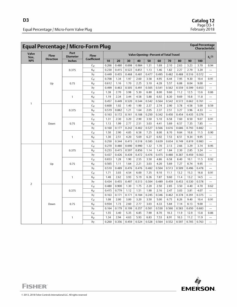
Equal Percentage / Micro-Form Plug Equal PercentageCharacteristic
ValveSize,NPS
FlowDirection
PortDiameter Flow
Coefficient
Valve Opening—Percent of Total TravelFL
(3)
Inches 10 20 30 40 50 60 70 80 90 100
1
Up
0.375
CV 0.266 0.480 0.698 0.984 1.31 1.69 2.10 2.63 3.23 3.70 0.94
KV 0.230 0.415 0.522 0.851 1.13 1.46 1.82 2.27 2.79 3.20 ---
XT 0.449 0.455 0.468 0.481 0.477 0.495 0.482 0.488 0.516 0.572 ---
0.75
CV 0.708 1.34 1.97 2.60 3.58 4.95 6.44 7.95 9.30 10.4 0.91
KV 0.612 1.16 1.70 2.25 3.10 4.28 5.57 6.88 8.04 9.00 ---
XT 0.499 0.463 0.505 0.491 0.505 0.541 0.562 0.559 0.599 0.653 ---
1
CV 1.38 2.70 3.98 5.30 6.80 8.00 9.60 11.2 12.5 13.6 0.86
KV 1.19 2.34 3.44 4.58 5.88 6.92 8.30 9.69 10.8 11.8 ---
XT 0.457 0.449 0.520 0.544 0.542 0.564 0.542 0.572 0.662 0.761 ---
Down
0.375
CV 0.600 1.02 1.40 1.90 2.37 2.74 2.90 3.78 4.58 5.00 0.59
KV 0.519 0.882 1.21 1.64 2.05 2.37 2.51 3.27 3.96 4.33 ---
XT 0.163 0.172 0.161 0.188 0.250 0.342 0.450 0.454 0.435 0.376 ---
0.75
CV 1.31 2.30 3.20 2.90 3.50 5.10 6.58 7.60 8.50 9.07 0.91
KV 1.13 1.99 2.77 2.51 3.03 4.41 5.69 6.57 7.35 7.85 ---
XT 0.160 0.177 0.242 0.402 0.527 0.566 0.616 0.686 0.793 0.882 ---
1
CV 1.50 2.90 4.85 6.58 7.25 8.00 8.70 9.84 10.8 11.5 0.90
KV 1.30 2.51 4.20 5.69 6.27 6.92 7.53 8.51 9.34 9.95 ---
XT 0.250 0.344 0.415 0.518 0.585 0.639 0.654 0.749 0.819 0.983 ---
2
Up
0.375
CV 0.270 0.480 0.690 0.990 1.32 1.70 2.13 2.66 3.29 3.74 0.95
KV 0.233 0.415 0.597 0.856 1.14 1.47 1.84 2.30 2.85 3.24 ---
XT 0.437 0.426 0.439 0.472 0.476 0.475 0.480 0.387 0.459 0.563 ---
0.75
CV 0.653 1.28 1.90 2.55 3.50 4.86 6.58 8.40 10.1 11.5 0.92
KV 0.565 1.11 1.64 2.21 3.03 4.20 5.69 7.27 8.74 9.95 ---
XT 0.510 0.489 0.476 0.476 0.482 0.504 0.513 0.509 0.496 0.478 ---
1
CV 1.71 3.03 4.54 6.00 7.35 9.10 11.1 13.2 15.3 16.8 0.91
KV 1.48 2.62 3.93 5.19 6.36 7.87 9.60 11.4 13.2 14.5 ---
XT 0.434 0.455 0.497 0.513 0.504 0.489 0.459 0.453 0.530 0.578 ---
Down
0.375
CV 0.480 0.900 1.30 1.75 2.20 2.50 2.85 3.50 4.40 4.70 0.62
KV 0.415 0.779 1.12 1.51 1.90 2.16 2.47 3.03 3.81 4.07 ---
XT 0.163 0.171 0.171 0.184 0.245 0.346 0.462 0.378 0.391 0.375 ---
0.75
CV 1.08 2.00 3.00 3.20 3.50 5.00 6.75 8.26 9.40 10.4 0.91
KV 0.934 1.73 2.60 2.77 3.03 4.33 5.84 7.14 8.13 9.00 ---
XT 0.164 0.179 0.199 0.357 0.501 0.530 0.560 0.583 0.650 0.683 ---
1
CV 1.55 3.40 5.35 6.85 7.90 8.70 10.3 11.9 12.9 13.8 0.86
KV 1.34 2.94 4.63 5.93 6.83 7.53 8.91 10.3 11.2 11.9 ---
XT 0.260 0.356 0.459 0.524 0.528 0.564 0.552 0.597 0.705 0.763 ---
� 2013, 2018 Fisher Controls International LLC. All rights reserved
D3
Equal Percentage / Micro-Form Valve Plug
Catalog 12Page D3-1
February 2018
This page is intentionally left blank.
D3Catalog 12Page D3-2February 2018
� 2013, 2018 Fisher Controls International LLC. All rights reserved
www.Fisher.com
Responsibility for selection, use, and maintenance of any product remains solely with the purchaser and end user. The contents of this publication are forinformational purposes only and are not to be construed as warranties or guarantees, express or implied, regarding the products or services describedtherein. Fisher is a mark owned by one of the companies in the Emerson Automation Solutions business unit of Emerson Electric Co. Emerson AutomationSolutions, Emerson, and the Emerson logo are trademarks and service marks of Emerson Electric Co. All other marks are the property of their respectiveowners.
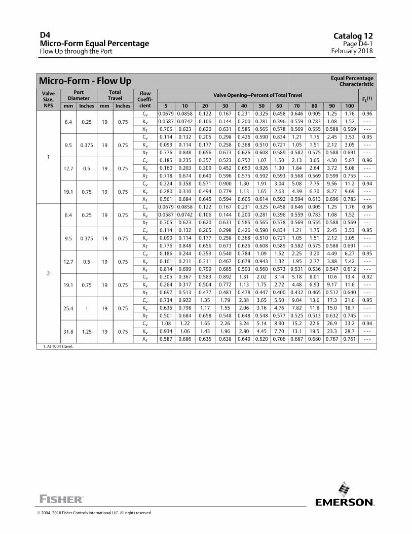
Micro‐Form ‐ Flow Up Equal PercentageCharacteristic
ValveSize,NPS
PortDiameter
TotalTravel
FlowCoeffi‐cient
Valve Opening—Percent of Total TravelFL
(1)
mm Inches mm Inches 5 10 20 30 40 50 60 70 80 90 100
1
6.4 0.25 19 0.75
Cv 0.0679 0.0858 0.122 0.167 0.231 0.325 0.458 0.646 0.905 1.25 1.76 0.96
Kv 0.0587 0.0742 0.106 0.144 0.200 0.281 0.396 0.559 0.783 1.08 1.52 ‐ ‐ ‐
XT 0.705 0.623 0.620 0.631 0.585 0.565 0.578 0.569 0.555 0.588 0.569 ‐ ‐ ‐
9.5 0.375 19 0.75
Cv 0.114 0.132 0.205 0.298 0.426 0.590 0.834 1.21 1.75 2.45 3.53 0.95
Kv 0.099 0.114 0.177 0.258 0.368 0.510 0.721 1.05 1.51 2.12 3.05 ‐ ‐ ‐
XT 0.776 0.848 0.656 0.673 0.626 0.608 0.589 0.582 0.575 0.588 0.691 ‐ ‐ ‐
12.7 0.5 19 0.75
Cv 0.185 0.235 0.357 0.523 0.752 1.07 1.50 2.13 3.05 4.30 5.87 0.96
Kv 0.160 0.203 0.309 0.452 0.650 0.926 1.30 1.84 2.64 3.72 5.08 ‐ ‐ ‐
XT 0.718 0.674 0.640 0.596 0.575 0.592 0.593 0.568 0.569 0.599 0.755 ‐ ‐ ‐
19.1 0.75 19 0.75
Cv 0.324 0.358 0.571 0.900 1.30 1.91 3.04 5.08 7.75 9.56 11.2 0.94
Kv 0.280 0.310 0.494 0.779 1.13 1.65 2.63 4.39 6.70 8.27 9.69 ‐ ‐ ‐
XT 0.561 0.684 0.645 0.594 0.605 0.614 0.592 0.594 0.613 0.696 0.783 ‐ ‐ ‐
2
6.4 0.25 19 0.75
Cv 0.0679 0.0858 0.122 0.167 0.231 0.325 0.458 0.646 0.905 1.25 1.76 0.96
Kv 0.0587 0.0742 0.106 0.144 0.200 0.281 0.396 0.559 0.783 1.08 1.52 ‐ ‐ ‐
XT 0.705 0.623 0.620 0.631 0.585 0.565 0.578 0.569 0.555 0.588 0.569 ‐ ‐ ‐
9.5 0.375 19 0.75
Cv 0.114 0.132 0.205 0.298 0.426 0.590 0.834 1.21 1.75 2.45 3.53 0.95
Kv 0.099 0.114 0.177 0.258 0.368 0.510 0.721 1.05 1.51 2.12 3.05 ‐ ‐ ‐
XT 0.776 0.848 0.656 0.673 0.626 0.608 0.589 0.582 0.575 0.588 0.691 ‐ ‐ ‐
12.7 0.5 19 0.75
Cv 0.186 0.244 0.359 0.540 0.784 1.09 1.52 2.25 3.20 4.49 6.27 0.95
Kv 0.161 0.211 0.311 0.467 0.678 0.943 1.32 1.95 2.77 3.88 5.42 ‐ ‐ ‐
XT 0.814 0.699 0.799 0.685 0.593 0.560 0.573 0.531 0.536 0.547 0.612 ‐ ‐ ‐
19.1 0.75 19 0.75
Cv 0.305 0.367 0.583 0.892 1.31 2.02 3.14 5.18 8.01 10.6 13.4 0.92
Kv 0.264 0.317 0.504 0.772 1.13 1.75 2.72 4.48 6.93 9.17 11.6 ‐ ‐ ‐
XT 0.697 0.513 0.477 0.481 0.478 0.447 0.400 0.432 0.465 0.512 0.640 ‐ ‐ ‐
25.4 1 19 0.75
Cv 0.734 0.922 1.35 1.79 2.38 3.65 5.50 9.04 13.6 17.3 21.6 0.95
Kv 0.635 0.798 1.17 1.55 2.06 3.16 4.76 7.82 11.8 15.0 18.7 ‐ ‐ ‐
XT 0.501 0.684 0.658 0.548 0.648 0.548 0.577 0.525 0.513 0.632 0.745 ‐ ‐ ‐
31.8 1.25 19 0.75
Cv 1.08 1.22 1.65 2.26 3.24 5.14 8.90 15.2 22.6 26.9 33.2 0.94
Kv 0.934 1.06 1.43 1.96 2.80 4.45 7.70 13.1 19.5 23.3 28.7 ‐ ‐ ‐
XT 0.587 0.686 0.636 0.638 0.649 0.520 0.706 0.687 0.680 0.767 0.761 ‐ ‐ ‐
1. At 100% travel.
� 2004, 2018 Fisher Controls International LLC. All rights reserved
D4Micro-Form Equal PercentageFlow Up through the Port
Catalog 12Page D4-1
February 2018

This page is intentionally left blank.
D4Catalog 12Page D4-2February 2018
� 2004, 2018 Fisher Controls International LLC. All rights reserved
www.Fisher.com
Responsibility for selection, use, and maintenance of any product remains solely with the purchaser and end user. The contents of this publication are forinformational purposes only and are not to be construed as warranties or guarantees, express or implied, regarding the products or services describedtherein. Fisher is a mark owned by one of the companies in the Emerson Automation Solutions business unit of Emerson Electric Co. Emerson AutomationSolutions, Emerson, and the Emerson logo are trademarks and service marks of Emerson Electric Co. All other marks are the property of their respectiveowners.
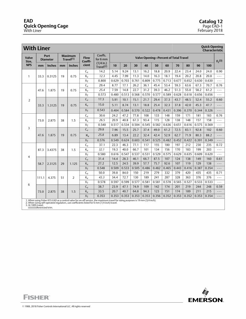
With Liner Quick OpeningCharacteristic
ValveSize,NPS
PortDiameter
MaximumTravel(1) Flow
Coeffi‐cient
Coeffs.
for 6 mm
(1/4 in.)
Travel(2)
Valve Opening—Percent of Total TravelFL
(3)
mm Inches mm Inches 10 20 30 40 50 60 70 80 90 100
1 33.3 0.3125 19 0.75
Cv 14.2 5.14 9.24 13.1 16.2 18.8 20.9 22.4 23.4 24.0 24.0 0.90
Kv 12.3 4.45 7.99 11.3 14.0 16.3 18.1 19.4 20.2 20.8 20.8 ‐ ‐ ‐
XT 0.800 0.629 0.703 0.761 0.809 0.775 0.713 0.677 0.652 0.630 0.630 ‐ ‐ ‐
2
47.6 1.875 19 0.75
Cv 29.4 8.77 17.1 26.2 36.1 45.4 53.4 59.3 63.6 67.3 70.7 0.76
Kv 25.4 7.59 14.8 22.7 31.2 39.3 46.2 51.3 55.0 58.2 61.2 ‐ ‐ ‐
XT 0.573 0.480 0.513 0.568 0.570 0.577 0.589 0.628 0.618 0.656 0.656 ‐ ‐ ‐
33.3 1.3125 19 0.75
Cv 17.3 5.91 10.1 15.1 21.7 29.4 37.3 43.7 48.5 52.4 55.2 0.60
Kv 15.0 5.11 8.74 13.1 18.8 25.4 32.3 37.8 42.0 45.3 47.7 ‐ ‐ ‐
XT 0.543 0.404 0.584 0.570 0.522 0.478 0.431 0.396 0.370 0.344 0.326 ‐ ‐ ‐
3
73.0 2.875 38 1.5
Cv 30.6 24.2 47.2 77.8 108 133 148 159 171 181 183 0.76
Kv 26.5 20.9 40.8 67.3 93.4 115 128 138 148 157 158 ‐ ‐ ‐
XT 0.540 0.517 0.534 0.504 0.545 0.582 0.636 0.651 0.616 0.575 0.569 ‐ ‐ ‐
47.6 1.875 19 0.75
Cv 29.8 7.96 15.5 25.7 37.4 49.0 61.2 72.5 83.1 92.8 102 0.60
Kv 25.8 6.89 13.4 22.2 32.4 42.4 52.9 62.7 71.9 80.3 88.2 ‐ ‐ ‐
XT 0.576 0.549 0.624 0.603 0.541 0.525 0.482 0.452 0.422 0.391 0.349 ‐ ‐ ‐
4
87.3 3.4375 38 1.5
Cv 37.1 22.3 46.3 77.1 117 155 180 197 212 230 235 0.72
Kv 32.1 19.3 40.0 66.7 101 134 156 170 183 199 203 ‐ ‐ ‐
XT 0.580 0.616 0.547 0.537 0.531 0.529 0.575 0.629 0.635 0.609 0.620 ‐ ‐ ‐
58.7 2.3125 29 1.125
Cv 31.4 14.4 28.3 46.1 66.7 87.5 107 124 138 149 160 0.61
Kv 27.2 12.5 24.5 39.9 57.7 75.7 92.6 107 119 129 138 ‐ ‐ ‐
XT 0.548 0.509 0.533 0.505 0.486 0.482 0.465 0.443 0.416 0.387 0.354 ‐ ‐ ‐
6
111.1 4.375 51 2
Cv 50.0 39.8 84.0 150 219 279 332 379 420 435 435 0.71
Kv 43.3 34.4 72.7 130 189 241 287 328 363 376 376 ‐ ‐ ‐
XT 0.578 0.597 0.599 0.577 0.581 0.581 0.578 0.565 0.527 0.533 0.533 ‐ ‐ ‐
73.0 2.875 38 1.5
Cv 38.7 23.9 47.1 74.9 109 142 174 201 219 244 248 0.59
Kv 33.5 20.7 40.7 64.8 94.3 123 151 174 189 211 215 ‐ ‐ ‐
XT 0.353 0.353 0.353 0.353 0.353 0.356 0.352 0.353 0.352 0.353 0.354 ‐ ‐ ‐
1. When using Fisher 655‐EAD as a control valve for on‐off service, the maximum travel for sizing purposes is 19 mm (3/4 inch).2. When sizing self‐operated regulators, use coefficients listed for 6 mm (1/4 inch) travel.3. At 100% travel. Restricted trim.
� 1988, 2018 Fisher Controls International LLC. All rights reserved
EADQuick Opening CageWith Liner
Catalog 12Page EAD-1
February 2018
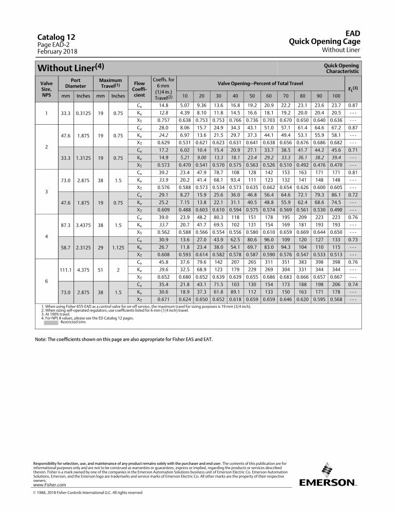
Without Liner(4) Quick OpeningCharacteristic
ValveSize,NPS
PortDiameter
MaximumTravel(1) Flow
Coeffi‐cient
Coeffs. for
6 mm
(1/4 in.)
Travel(2)
Valve Opening—Percent of Total TravelFL
(3)
mm Inches mm Inches 10 20 30 40 50 60 70 80 90 100
1 33.3 0.3125 19 0.75
Cv 14.8 5.07 9.36 13.6 16.8 19.2 20.9 22.2 23.1 23.6 23.7 0.87
Kv 12.8 4.39 8.10 11.8 14.5 16.6 18.1 19.2 20.0 20.4 20.5 ‐ ‐ ‐
XT 0.757 0.638 0.753 0.753 0.766 0.736 0.703 0.670 0.650 0.640 0.636 ‐ ‐ ‐
2
47.6 1.875 19 0.75
Cv 28.0 8.06 15.7 24.9 34.3 43.1 51.0 57.1 61.4 64.6 67.2 0.87
Kv 24.2 6.97 13.6 21.5 29.7 37.3 44.1 49.4 53.1 55.9 58.1 ‐ ‐ ‐
XT 0.629 0.531 0.621 0.623 0.631 0.641 0.638 0.656 0.676 0.686 0.682 ‐ ‐ ‐
33.3 1.3125 19 0.75
Cv 17.2 6.02 10.4 15.4 20.9 27.1 33.7 38.5 41.7 44.2 45.6 0.71
Kv 14.9 5.21 9.00 13.3 18.1 23.4 29.2 33.3 36.1 38.2 39.4 ‐ ‐ ‐
XT 0.573 0.470 0.541 0.570 0.575 0.563 0.526 0.510 0.492 0.476 0.470 ‐ ‐ ‐
3
73.0 2.875 38 1.5
Cv 39.2 23.4 47.9 78.7 108 128 142 153 163 171 171 0.81
Kv 33.9 20.2 41.4 68.1 93.4 111 123 132 141 148 148 ‐ ‐ ‐
XT 0.576 0.588 0.573 0.534 0.573 0.635 0.662 0.654 0.626 0.600 0.605 ‐ ‐ ‐
47.6 1.875 19 0.75
Cv 29.1 8.27 15.9 25.6 36.0 46.8 56.4 64.6 72.1 79.3 86.1 0.72
Kv 25.2 7.15 13.8 22.1 31.1 40.5 48.8 55.9 62.4 68.6 74.5 ‐ ‐ ‐
XT 0.609 0.488 0.603 0.610 0.594 0.575 0.574 0.569 0.561 0.530 0.490 ‐ ‐ ‐
4
87.3 3.4375 38 1.5
Cv 39.0 23.9 48.2 80.3 118 151 178 195 209 223 223 0.76
Kv 33.7 20.7 41.7 69.5 102 131 154 169 181 193 193 ‐ ‐ ‐
XT 0.562 0.588 0.566 0.554 0.556 0.580 0.610 0.659 0.669 0.644 0.650 ‐ ‐ ‐
58.7 2.3125 29 1.125
Cv 30.9 13.6 27.0 43.9 62.5 80.6 96.0 109 120 127 133 0.73
Kv 26.7 11.8 23.4 38.0 54.1 69.7 83.0 94.3 104 110 115 ‐ ‐ ‐
XT 0.608 0.593 0.614 0.582 0.578 0.587 0.590 0.576 0.547 0.533 0.513 ‐ ‐ ‐
6
111.1 4.375 51 2
Cv 45.8 37.6 79.6 142 207 265 311 351 383 398 398 0.76
Kv 39.6 32.5 68.9 123 179 229 269 304 331 344 344 ‐ ‐ ‐
XT 0.652 0.680 0.652 0.639 0.639 0.655 0.686 0.683 0.666 0.657 0.667 ‐ ‐ ‐
73.0 2.875 38 1.5
Cv 35.4 21.8 43.1 71.5 103 130 154 173 188 198 206 0.74
Kv 30.6 18.9 37.3 61.8 89.1 112 133 150 163 171 178 ‐ ‐ ‐
XT 0.671 0.624 0.650 0.652 0.618 0.659 0.659 0.646 0.620 0.595 0.568 ‐ ‐ ‐
1. When using Fisher 655‐EAD as a control valve for on‐off service, the maximum travel for sizing purposes is 19 mm (3/4 inch).2. When sizing self‐operated regulators, use coefficients listed for 6 mm (1/4 inch) travel.3. At 100% travel.4. For NPS 8 values, please see the ED Catalog 12 pages. Restricted trim.
Note: The coefficients shown on this page are also appropriate for Fisher EAS and EAT.
EAD
Without LinerQuick Opening Cage
Catalog 12Page EAD-2February 2018
� 1988, 2018 Fisher Controls International LLC. All rights reserved
www.Fisher.com
Responsibility for selection, use, and maintenance of any product remains solely with the purchaser and end user. The contents of this publication are forinformational purposes only and are not to be construed as warranties or guarantees, express or implied, regarding the products or services describedtherein. Fisher is a mark owned by one of the companies in the Emerson Automation Solutions business unit of Emerson Electric Co. Emerson AutomationSolutions, Emerson, and the Emerson logo are trademarks and service marks of Emerson Electric Co. All other marks are the property of their respectiveowners.
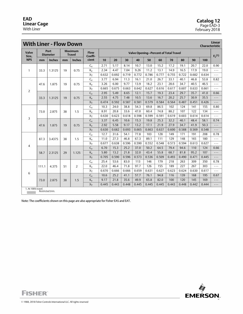
3
With Liner ‐ Flow Down LinearCharacteristic
ValveSize,NPS
PortDiameter
MaximumTravel
FlowCoeffi‐cient
Valve Opening—Percent of Total TravelFL
(1)
mm Inches mm Inches 10 20 30 40 50 60 70 80 90 100
1 33.3 1.3125 19 0.75
Cv 2.71 5.17 8.14 10.7 13.0 15.2 17.2 19.1 20.7 22.0 0.90
Kv 2.34 4.47 7.04 9.26 11.2 13.1 14.9 16.5 17.9 19.0 ‐ ‐ ‐
XT 0.632 0.692 0.719 0.772 0.786 0.777 0.755 0.722 0.682 0.634 ‐ ‐ ‐
2
47.6 1.875 19 0.75
Cv 3.77 6.94 11.3 16.1 21.0 26.7 33.1 40.1 46.8 53.8 0.82
Kv 3.26 6.00 9.77 13.9 18.2 23.1 28.6 34.7 40.5 46.5 ‐ ‐ ‐
XT 0.665 0.675 0.663 0.642 0.627 0.616 0.617 0.607 0.633 0.661 ‐ ‐ ‐
33.3 1.3125 19 0.75
Cv 2.95 5.49 8.65 12.1 15.7 19.3 23.4 29.7 35.7 41.0 0.66
Kv 2.55 4.75 7.48 10.5 13.6 16.7 20.2 25.7 30.9 35.5 ‐ ‐ ‐
XT 0.474 0.592 0.587 0.581 0.579 0.584 0.564 0.487 0.451 0.426 ‐ ‐ ‐
3
73.0 2.875 38 1.5
Cv 10.3 24.0 38.8 54.3 69.8 86.5 102 124 141 155 0.80
Kv 8.91 20.8 33.6 47.0 60.4 74.8 88.2 107 122 134 ‐ ‐ ‐
XT 0.630 0.623 0.618 0.598 0.599 0.591 0.619 0.603 0.614 0.614 ‐ ‐ ‐
47.6 1.875 19 0.75
Cv 3.37 6.45 10.6 15.3 19.8 25.3 32.2 40.1 48.4 58.1 0.74
Kv 2.92 5.58 9.17 13.2 17.1 21.9 27.9 34.7 41.9 50.3 ‐ ‐ ‐
XT 0.630 0.682 0.693 0.665 0.663 0.637 0.600 0.588 0.569 0.548 ‐ ‐ ‐
4
87.3 3.4375 38 1.5
Cv 12.7 31.6 54.1 77.8 103 128 149 171 191 208 0.78
Kv 11.0 27.3 46.8 67.3 89.1 111 129 148 165 180 ‐ ‐ ‐
XT 0.677 0.638 0.596 0.590 0.552 0.548 0.573 0.594 0.613 0.627 ‐ ‐ ‐
58.7 2.3125 29 1.125
Cv 6.70 15.3 25.2 37.0 50.2 64.5 79.4 94.6 110 124 0.66
Kv 5.80 13.2 21.8 32.0 43.4 55.8 68.7 81.8 95.2 107 ‐ ‐ ‐
XT 0.705 0.590 0.596 0.573 0.536 0.509 0.493 0.490 0.471 0.445 ‐ ‐ ‐
6
111.1 4.375 51 2
Cv 25.4 53.6 83.0 113 146 179 218 263 309 350 0.78
Kv 22.0 46.4 71.8 97.7 126 155 189 227 267 303 ‐ ‐ ‐
XT 0.670 0.666 0.666 0.659 0.631 0.627 0.623 0.624 0.630 0.617 ‐ ‐ ‐
73.0 2.875 38 1.5
Cv 10.6 25.2 41.1 57.7 76.1 94.8 116 139 168 195 0.67
Kv 9.17 21.8 35.6 49.9 65.8 82.0 100 120 145 169 ‐ ‐ ‐
XT 0.445 0.443 0.448 0.445 0.445 0.445 0.443 0.448 0.442 0.444 ‐ ‐ ‐
1. At 100% travel. Restricted trim.
Note: The coefficients shown on this page are also appropriate for Fisher EAS and EAT.
EAD
With LinerLinear Cage
Catalog 12Page EAD-3
February 2018
� 1988, 2018 Fisher Controls International LLC. All rights reserved
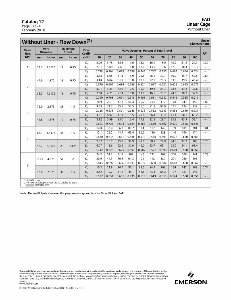
Without Liner ‐ Flow Down(2) LinearCharacteristic
ValveSize,NPS
PortDiameter
MaximumTravel
FlowCoeffi‐cient
Valve Opening—Percent of Total TravelFL
(1)
mm Inches mm Inches 10 20 30 40 50 60 70 80 90 100
1 33.3 1.3125 19 0.75
Cv 2.90 5.78 8.85 11.6 13.9 16.0 18.0 19.7 21.2 22.3 0.89
Kv 2.51 5.00 7.66 10.0 12.0 13.8 15.6 17.0 18.3 19.3 ‐ ‐ ‐
XT 0.778 0.704 0.699 0.736 0.745 0.747 0.730 0.699 0.664 0.624 ‐ ‐ ‐
2
47.6 1.875 19 0.75
Cv 3.68 6.98 11.3 15.9 20.8 26.4 32.7 39.2 45.7 52.5 0.84
Kv 3.18 6.04 9.77 13.8 18.0 22.8 28.3 33.9 39.5 45.4 ‐ ‐ ‐
XT 0.676 0.667 0.684 0.666 0.624 0.627 0.632 0.625 0.655 0.679 ‐ ‐ ‐
33.3 1.3125 19 0.75
Cv 3.01 5.45 8.95 12.5 15.9 19.1 23.3 28.4 33.2 37.6 0.73
Kv 2.60 4.71 7.74 10.8 13.8 16.5 20.2 24.6 28.7 32.5 ‐ ‐ ‐
XT 0.790 0.768 0.661 0.618 0.608 0.611 0.582 0.545 0.535 0.516 ‐ ‐ ‐
3
73.0 2.875 38 1.5
Cv 10.9 25.1 41.3 58.4 75.7 93.9 112 128 143 153 0.83
Kv 9.43 21.7 35.7 50.5 65.5 81.2 96.9 111 124 132 ‐ ‐ ‐
XT 0.736 0.638 0.591 0.548 0.538 0.532 0.543 0.583 0.619 0.631 ‐ ‐ ‐
47.6 1.875 19 0.75
Cv 3.61 6.92 11.1 15.5 20.6 26.4 33.2 41.4 50.1 60.2 0.78
Kv 3.12 5.99 9.60 13.4 17.8 22.8 28.7 35.8 43.3 52.1 ‐ ‐ ‐
XT 0.623 0.721 0.694 0.684 0.663 0.630 0.602 0.570 0.568 0.546 ‐ ‐ ‐
4
87.3 3.4375 38 1.5
Cv 14.0 33.8 56.3 80.2 104 127 148 169 185 201 0.81
Kv 12.1 29.2 48.7 69.4 90.0 110 128 146 160 174 ‐ ‐ ‐
XT 0.640 0.638 0.611 0.588 0.570 0.568 0.593 0.622 0.660 0.664 ‐ ‐ ‐
58.7 2.3125 29 1.125
Cv 7.02 15.7 25.7 36.9 48.6 60.9 72.9 84.6 97.2 108 0.76
Kv 6.07 13.6 22.2 31.9 42.0 52.7 63.1 73.2 84.1 93.4 ‐ ‐ ‐
XT 0.712 0.626 0.625 0.597 0.587 0.577 0.590 0.604 0.580 0.566 ‐ ‐ ‐
6
111.1 4.375 51 2
Cv 24.2 51.2 81.8 109 140 171 208 256 300 341 0.78
Kv 20.9 44.3 70.8 94.3 121 148 180 221 260 295 ‐ ‐ ‐
XT 0.643 0.697 0.666 0.693 0.672 0.668 0.684 0.663 0.668 0.662 ‐ ‐ ‐
73.0 2.875 38 1.5
Cv 10.2 22.8 36.6 52.1 68.0 84.5 102 124 147 168 0.74
Kv 8.82 19.7 31.7 45.1 58.8 73.1 88.2 107 127 145 ‐ ‐ ‐
XT 0.592 0.651 0.661 0.635 0.619 0.619 0.615 0.584 0.568 0.556 ‐ ‐ ‐
1. At 100% travel.2. For NPS 8 values, please see the ED Catalog 12 pages. Restricted trim.
Note: The coefficients shown on this page are also appropriate for Fisher EAS and EAT.
EAD
Without LinerLinear Cage
Catalog 12Page EAD-4February 2018
� 1988, 2018 Fisher Controls International LLC. All rights reserved
www.Fisher.com
Responsibility for selection, use, and maintenance of any product remains solely with the purchaser and end user. The contents of this publication are forinformational purposes only and are not to be construed as warranties or guarantees, express or implied, regarding the products or services describedtherein. Fisher is a mark owned by one of the companies in the Emerson Automation Solutions business unit of Emerson Electric Co. Emerson AutomationSolutions, Emerson, and the Emerson logo are trademarks and service marks of Emerson Electric Co. All other marks are the property of their respectiveowners.
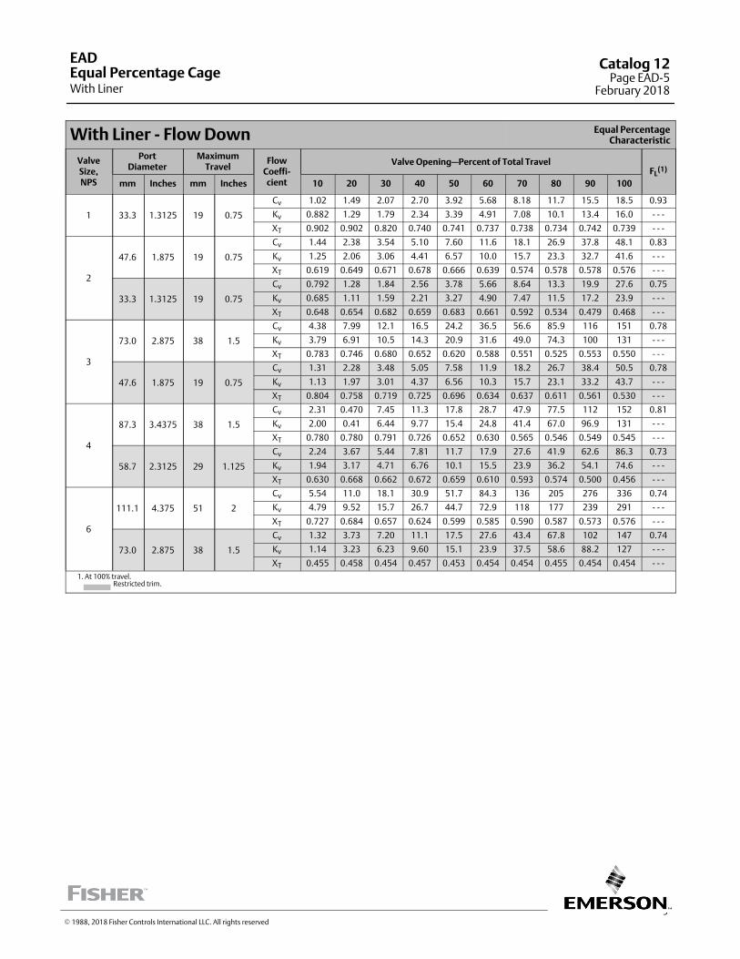
5
With Liner ‐ Flow Down Equal PercentageCharacteristic
ValveSize,NPS
PortDiameter
MaximumTravel
FlowCoeffi‐cient
Valve Opening—Percent of Total TravelFL
(1)
mm Inches mm Inches 10 20 30 40 50 60 70 80 90 100
1 33.3 1.3125 19 0.75
Cv 1.02 1.49 2.07 2.70 3.92 5.68 8.18 11.7 15.5 18.5 0.93
Kv 0.882 1.29 1.79 2.34 3.39 4.91 7.08 10.1 13.4 16.0 ‐ ‐ ‐
XT 0.902 0.902 0.820 0.740 0.741 0.737 0.738 0.734 0.742 0.739 ‐ ‐ ‐
2
47.6 1.875 19 0.75
Cv 1.44 2.38 3.54 5.10 7.60 11.6 18.1 26.9 37.8 48.1 0.83
Kv 1.25 2.06 3.06 4.41 6.57 10.0 15.7 23.3 32.7 41.6 ‐ ‐ ‐
XT 0.619 0.649 0.671 0.678 0.666 0.639 0.574 0.578 0.578 0.576 ‐ ‐ ‐
33.3 1.3125 19 0.75
Cv 0.792 1.28 1.84 2.56 3.78 5.66 8.64 13.3 19.9 27.6 0.75
Kv 0.685 1.11 1.59 2.21 3.27 4.90 7.47 11.5 17.2 23.9 ‐ ‐ ‐
XT 0.648 0.654 0.682 0.659 0.683 0.661 0.592 0.534 0.479 0.468 ‐ ‐ ‐
3
73.0 2.875 38 1.5
Cv 4.38 7.99 12.1 16.5 24.2 36.5 56.6 85.9 116 151 0.78
Kv 3.79 6.91 10.5 14.3 20.9 31.6 49.0 74.3 100 131 ‐ ‐ ‐
XT 0.783 0.746 0.680 0.652 0.620 0.588 0.551 0.525 0.553 0.550 ‐ ‐ ‐
47.6 1.875 19 0.75
Cv 1.31 2.28 3.48 5.05 7.58 11.9 18.2 26.7 38.4 50.5 0.78
Kv 1.13 1.97 3.01 4.37 6.56 10.3 15.7 23.1 33.2 43.7 ‐ ‐ ‐
XT 0.804 0.758 0.719 0.725 0.696 0.634 0.637 0.611 0.561 0.530 ‐ ‐ ‐
4
87.3 3.4375 38 1.5
Cv 2.31 0.470 7.45 11.3 17.8 28.7 47.9 77.5 112 152 0.81
Kv 2.00 0.41 6.44 9.77 15.4 24.8 41.4 67.0 96.9 131 ‐ ‐ ‐
XT 0.780 0.780 0.791 0.726 0.652 0.630 0.565 0.546 0.549 0.545 ‐ ‐ ‐
58.7 2.3125 29 1.125
Cv 2.24 3.67 5.44 7.81 11.7 17.9 27.6 41.9 62.6 86.3 0.73
Kv 1.94 3.17 4.71 6.76 10.1 15.5 23.9 36.2 54.1 74.6 ‐ ‐ ‐
XT 0.630 0.668 0.662 0.672 0.659 0.610 0.593 0.574 0.500 0.456 ‐ ‐ ‐
6
111.1 4.375 51 2
Cv 5.54 11.0 18.1 30.9 51.7 84.3 136 205 276 336 0.74
Kv 4.79 9.52 15.7 26.7 44.7 72.9 118 177 239 291 ‐ ‐ ‐
XT 0.727 0.684 0.657 0.624 0.599 0.585 0.590 0.587 0.573 0.576 ‐ ‐ ‐
73.0 2.875 38 1.5
Cv 1.32 3.73 7.20 11.1 17.5 27.6 43.4 67.8 102 147 0.74
Kv 1.14 3.23 6.23 9.60 15.1 23.9 37.5 58.6 88.2 127 ‐ ‐ ‐
XT 0.455 0.458 0.454 0.457 0.453 0.454 0.454 0.455 0.454 0.454 ‐ ‐ ‐
1. At 100% travel. Restricted trim.
EAD
With LinerEqual Percentage Cage
Catalog 12Page EAD-5
February 2018
� 1988, 2018 Fisher Controls International LLC. All rights reserved
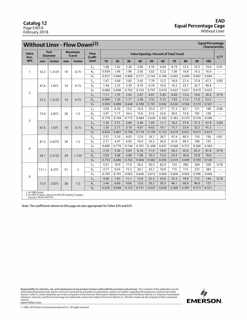
Without Liner ‐ Flow Down(2) Equal PercentageCharacteristic
ValveSize,NPS
PortDiameter
MaximumTravel
FlowCoeffi‐cient
Valve Opening—Percent of Total TravelFL
(1)
mm Inches mm Inches 10 20 30 40 50 60 70 80 90 100
1 33.3 1.3125 19 0.75
Cv 1.08 1.62 2.20 2.96 4.18 6.04 8.74 12.5 16.5 19.0 0.91
Kv 0.934 1.40 1.90 2.56 3.62 5.22 7.56 10.8 14.3 16.4 ‐ ‐ ‐
XT 0.912 0.860 0.808 0.771 0.742 0.706 0.693 0.699 0.697 0.694 ‐ ‐ ‐
2
47.6 1.875 19 0.75
Cv 1.67 2.60 3.82 5.43 7.79 12.2 18.9 27.4 37.8 47.2 0.85
Kv 1.44 2.25 3.30 4.70 6.74 10.6 16.3 23.7 32.7 40.8 ‐ ‐ ‐
XT 0.680 0.690 0.702 0.725 0.707 0.619 0.622 0.621 0.619 0.623 ‐ ‐ ‐
33.3 1.3125 19 0.75
Cv 1.11 1.55 2.05 2.87 4.07 5.95 8.84 13.4 19.6 26.8 0.79
Kv 0.960 1.34 1.77 2.48 3.52 5.15 7.65 11.6 17.0 23.2 ‐ ‐ ‐
XT 0.938 0.899 0.848 0.789 0.761 0.692 0.636 0.568 0.519 0.507 ‐ ‐ ‐
3
73.0 2.875 38 1.5
Cv 4.59 8.29 12.0 16.9 25.0 37.7 57.3 85.1 121 148 0.80
Kv 3.97 7.17 10.4 14.6 21.6 32.6 49.6 73.6 105 128 ‐ ‐ ‐
XT 0.779 0.744 0.715 0.684 0.630 0.582 0.583 0.579 0.578 0.580 ‐ ‐ ‐
47.6 1.875 19 0.75
Cv 1.56 2.51 3.68 5.40 7.65 11.7 18.2 27.0 37.3 47.8 0.84
Kv 1.35 2.17 3.18 4.67 6.62 10.1 15.7 23.4 32.3 41.3 ‐ ‐ ‐
XT 0.834 0.807 0.768 0.718 0.756 0.723 0.679 0.627 0.615 0.615 ‐ ‐ ‐
4
87.3 3.4375 38 1.5
Cv 2.51 5.10 8.03 12.0 18.7 30.7 47.4 80.3 116 156 0.81
Kv 2.17 4.41 6.95 10.4 16.2 26.6 41.0 69.5 100 135 ‐ ‐ ‐
XT 0.890 0.770 0.744 0.701 0..696 0.637 0.668 0.572 0.566 0.565 ‐ ‐ ‐
58.7 2.3125 29 1.125
Cv 2.33 3.56 5.64 8.18 11.9 18.0 28.2 42.6 62.2 81.8 0.79
Kv 2.02 3.08 4.88 7.08 10.3 15.6 24.4 36.8 53.8 70.8 ‐ ‐ ‐
XT 0.753 0.846 0.702 0.666 0.682 0.656 0.619 0.609 0.559 0.530 ‐ ‐ ‐
6
111.1 4.375 51 2
Cv 5.51 10.9 17.9 30.2 50.5 82.0 133 200 269 328 0.78
Kv 4.77 9.43 15.5 26.1 43.7 70.9 115 173 233 284 ‐ ‐ ‐
XT 0.705 0.701 0.663 0.646 0.612 0.604 0.606 0.605 0.596 0.604 ‐ ‐ ‐
73.0 2.875 38 1.5
Cv 4.00 7.63 11.1 15.0 23.3 35.0 53.3 79.6 112 144 0.78
Kv 3.46 6.60 9.60 13.0 20.2 30.3 46.1 68.9 96.9 125 ‐ ‐ ‐
XT 0.670 0.698 0.725 0.731 0.637 0.629 0.599 0.597 0.573 0.571 ‐ ‐ ‐
1. At 100% travel.2. For NPS 8 values, please see the ED Catalog 12 pages. Restricted trim.
Note: The coefficients shown on this page are also appropriate for Fisher EAS and EAT.
EAD
Without LinerEqual Percentage Cage
Catalog 12Page EAD-6February 2018
� 1988, 2018 Fisher Controls International LLC. All rights reserved
www.Fisher.com
Responsibility for selection, use, and maintenance of any product remains solely with the purchaser and end user. The contents of this publication are forinformational purposes only and are not to be construed as warranties or guarantees, express or implied, regarding the products or services describedtherein. Fisher is a mark owned by one of the companies in the Emerson Automation Solutions business unit of Emerson Electric Co. Emerson AutomationSolutions, Emerson, and the Emerson logo are trademarks and service marks of Emerson Electric Co. All other marks are the property of their respectiveowners.
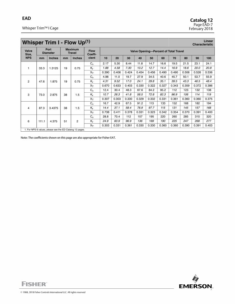
7
Whisper Trim I - Flow Up(1) LinearCharacteristic
ValveSize,NPS
PortDiameter
MaximumTravel
FlowCoeffi-cient
Valve Opening—Percent of Total Travel
mm Inches mm Inches 10 20 30 40 50 60 70 80 90 100
1 33.3 1.3125 19 0.75
Cv 2.17 5.30 8.44 11.8 14.7 16.6 19.5 21.5 23.1 24.1
Kv 1.88 4.58 7.30 10.2 12.7 14.4 16.9 18.6 20.0 20.8
XT 0.390 0.406 0.424 0.454 0.456 0.490 0.490 0.506 0.526 0.536
2 47.6 1.875 19 0.75
Cv 4.98 11.0 19.7 27.9 34.5 40.6 45.7 50.1 53.7 55.9
Kv 4.31 9.52 17.0 24.1 29.8 35.1 39.5 43.3 46.5 48.4
XT 0.670 0.633 0.403 0.330 0.322 0.327 0.343 0.359 0.372 0.386
3 73.0 2.875 38 1.5
Cv 12.4 30.4 48.3 67.6 84.2 95.2 112 123 132 138
Kv 10.7 26.3 41.8 58.5 72.8 82.3 96.9 106 114 119
XT 0.307 0.303 0.330 0.329 0.332 0.331 0.361 0.360 0.360 0.375
4 87.3 3.4375 38 1.5
Cv 16.7 42.9 67.5 91.2 113 133 152 168 182 194
Kv 14.4 37.1 58.4 78.9 97.7 115 131 145 157 168
XT 0.738 0.411 0.378 0.331 0.323 0.342 0.354 0.370 0.391 0.400
6 111.1 4.375 51 2
Cv 28.8 70.4 112 157 195 220 260 285 310 320
Kv 24.9 60.9 96.9 136 169 190 225 247 268 277
XT 0.303 0.331 0.361 0.330 0.330 0.360 0.360 0.390 0.391 0.4031. For NPS 8 values, please see the ED Catalog 12 pages.
Note: The coefficients shown on this page are also appropriate for Fisher EAT.
EAD
Whisper Trim™ I Cage
Catalog 12Page EAD-7
February 2018
� 1988, 2018 Fisher Controls International LLC. All rights reserved

This page is intentionally left blank.
EADCatalog 12Page EAD-8February 2018
� 2010, 2018 Fisher Controls International LLC. All rights reserved
www.Fisher.com
Responsibility for selection, use, and maintenance of any product remains solely with the purchaser and end user. The contents of this publication are forinformational purposes only and are not to be construed as warranties or guarantees, express or implied, regarding the products or services describedtherein. Fisher and Whisper Trim are marks owned by one of the companies in the Emerson Automation Solutions business unit of Emerson Electric Co.Emerson Automation Solutions, Emerson, and the Emerson logo are trademarks and service marks of Emerson Electric Co. All other marks are the propertyof their respective owners.
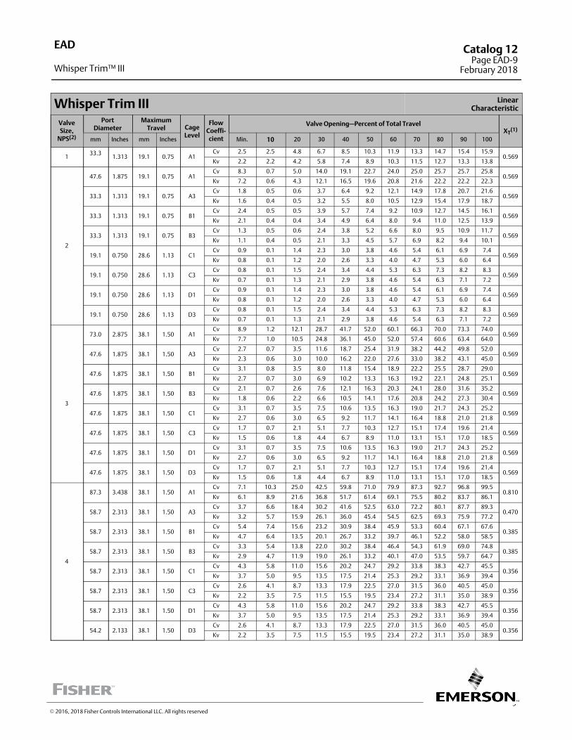
9
Whisper Trim III LinearCharacteristic
ValveSize,
NPS(2)
PortDiameter
MaximumTravel Cage
Level
FlowCoeffi-cient
Valve Opening—Percent of Total TravelXT
(1)
mm Inches mm Inches Min. 10 20 30 40 50 60 70 80 90 100
133.3
1.313 19.1 0.75 A1Cv 2.5 2.5 4.8 6.7 8.5 10.3 11.9 13.3 14.7 15.4 15.9
0.569Kv 2.2 2.2 4.2 5.8 7.4 8.9 10.3 11.5 12.7 13.3 13.8
2
47.6 1.875 19.1 0.75 A1Cv 8.3 0.7 5.0 14.0 19.1 22.7 24.0 25.0 25.7 25.7 25.8
0.569Kv 7.2 0.6 4.3 12.1 16.5 19.6 20.8 21.6 22.2 22.2 22.3
33.3 1.313 19.1 0.75 A3Cv 1.8 0.5 0.6 3.7 6.4 9.2 12.1 14.9 17.8 20.7 21.6
0.569Kv 1.6 0.4 0.5 3.2 5.5 8.0 10.5 12.9 15.4 17.9 18.7
33.3 1.313 19.1 0.75 B1Cv 2.4 0.5 0.5 3.9 5.7 7.4 9.2 10.9 12.7 14.5 16.1
0.569Kv 2.1 0.4 0.4 3.4 4.9 6.4 8.0 9.4 11.0 12.5 13.9
33.3 1.313 19.1 0.75 B3Cv 1.3 0.5 0.6 2.4 3.8 5.2 6.6 8.0 9.5 10.9 11.7
0.569Kv 1.1 0.4 0.5 2.1 3.3 4.5 5.7 6.9 8.2 9.4 10.1
19.1 0.750 28.6 1.13 C1Cv 0.9 0.1 1.4 2.3 3.0 3.8 4.6 5.4 6.1 6.9 7.4
0.569Kv 0.8 0.1 1.2 2.0 2.6 3.3 4.0 4.7 5.3 6.0 6.4
19.1 0.750 28.6 1.13 C3Cv 0.8 0.1 1.5 2.4 3.4 4.4 5.3 6.3 7.3 8.2 8.3
0.569Kv 0.7 0.1 1.3 2.1 2.9 3.8 4.6 5.4 6.3 7.1 7.2
19.1 0.750 28.6 1.13 D1Cv 0.9 0.1 1.4 2.3 3.0 3.8 4.6 5.4 6.1 6.9 7.4
0.569Kv 0.8 0.1 1.2 2.0 2.6 3.3 4.0 4.7 5.3 6.0 6.4
19.1 0.750 28.6 1.13 D3Cv 0.8 0.1 1.5 2.4 3.4 4.4 5.3 6.3 7.3 8.2 8.3
0.569Kv 0.7 0.1 1.3 2.1 2.9 3.8 4.6 5.4 6.3 7.1 7.2
3
73.0 2.875 38.1 1.50 A1Cv 8.9 1.2 12.1 28.7 41.7 52.0 60.1 66.3 70.0 73.3 74.0
0.569Kv 7.7 1.0 10.5 24.8 36.1 45.0 52.0 57.4 60.6 63.4 64.0
47.6 1.875 38.1 1.50 A3Cv 2.7 0.7 3.5 11.6 18.7 25.4 31.9 38.2 44.2 49.8 52.0
0.569Kv 2.3 0.6 3.0 10.0 16.2 22.0 27.6 33.0 38.2 43.1 45.0
47.6 1.875 38.1 1.50 B1Cv 3.1 0.8 3.5 8.0 11.8 15.4 18.9 22.2 25.5 28.7 29.0
0.569Kv 2.7 0.7 3.0 6.9 10.2 13.3 16.3 19.2 22.1 24.8 25.1
47.6 1.875 38.1 1.50 B3Cv 2.1 0.7 2.6 7.6 12.1 16.3 20.3 24.1 28.0 31.6 35.2
0.569Kv 1.8 0.6 2.2 6.6 10.5 14.1 17.6 20.8 24.2 27.3 30.4
47.6 1.875 38.1 1.50 C1Cv 3.1 0.7 3.5 7.5 10.6 13.5 16.3 19.0 21.7 24.3 25.2
0.569Kv 2.7 0.6 3.0 6.5 9.2 11.7 14.1 16.4 18.8 21.0 21.8
47.6 1.875 38.1 1.50 C3Cv 1.7 0.7 2.1 5.1 7.7 10.3 12.7 15.1 17.4 19.6 21.4
0.569Kv 1.5 0.6 1.8 4.4 6.7 8.9 11.0 13.1 15.1 17.0 18.5
47.6 1.875 38.1 1.50 D1Cv 3.1 0.7 3.5 7.5 10.6 13.5 16.3 19.0 21.7 24.3 25.2
0.569Kv 2.7 0.6 3.0 6.5 9.2 11.7 14.1 16.4 18.8 21.0 21.8
47.6 1.875 38.1 1.50 D3Cv 1.7 0.7 2.1 5.1 7.7 10.3 12.7 15.1 17.4 19.6 21.4
0.569Kv 1.5 0.6 1.8 4.4 6.7 8.9 11.0 13.1 15.1 17.0 18.5
4
87.3 3.438 38.1 1.50 A1Cv 7.1 10.3 25.0 42.5 59.8 71.0 79.9 87.3 92.7 96.8 99.5
0.810Kv 6.1 8.9 21.6 36.8 51.7 61.4 69.1 75.5 80.2 83.7 86.1
58.7 2.313 38.1 1.50 A3Cv 3.7 6.6 18.4 30.2 41.6 52.5 63.0 72.2 80.1 87.7 89.3
0.470Kv 3.2 5.7 15.9 26.1 36.0 45.4 54.5 62.5 69.3 75.9 77.2
58.7 2.313 38.1 1.50 B1Cv 5.4 7.4 15.6 23.2 30.9 38.4 45.9 53.3 60.4 67.1 67.6
0.385Kv 4.7 6.4 13.5 20.1 26.7 33.2 39.7 46.1 52.2 58.0 58.5
58.7 2.313 38.1 1.50 B3Cv 3.3 5.4 13.8 22.0 30.2 38.4 46.4 54.3 61.9 69.0 74.8
0.385Kv 2.9 4.7 11.9 19.0 26.1 33.2 40.1 47.0 53.5 59.7 64.7
58.7 2.313 38.1 1.50 C1Cv 4.3 5.8 11.0 15.6 20.2 24.7 29.2 33.8 38.3 42.7 45.5
0.356Kv 3.7 5.0 9.5 13.5 17.5 21.4 25.3 29.2 33.1 36.9 39.4
58.7 2.313 38.1 1.50 C3Cv 2.6 4.1 8.7 13.3 17.9 22.5 27.0 31.5 36.0 40.5 45.0
0.356Kv 2.2 3.5 7.5 11.5 15.5 19.5 23.4 27.2 31.1 35.0 38.9
58.7 2.313 38.1 1.50 D1Cv 4.3 5.8 11.0 15.6 20.2 24.7 29.2 33.8 38.3 42.7 45.5
0.356Kv 3.7 5.0 9.5 13.5 17.5 21.4 25.3 29.2 33.1 36.9 39.4
54.2 2.133 38.1 1.50 D3Cv 2.6 4.1 8.7 13.3 17.9 22.5 27.0 31.5 36.0 40.5 45.0
0.356Kv 2.2 3.5 7.5 11.5 15.5 19.5 23.4 27.2 31.1 35.0 38.9
EAD
Whisper Trim™ III
Catalog 12Page EAD-9
February 2018
� 2016, 2018 Fisher Controls International LLC. All rights reserved
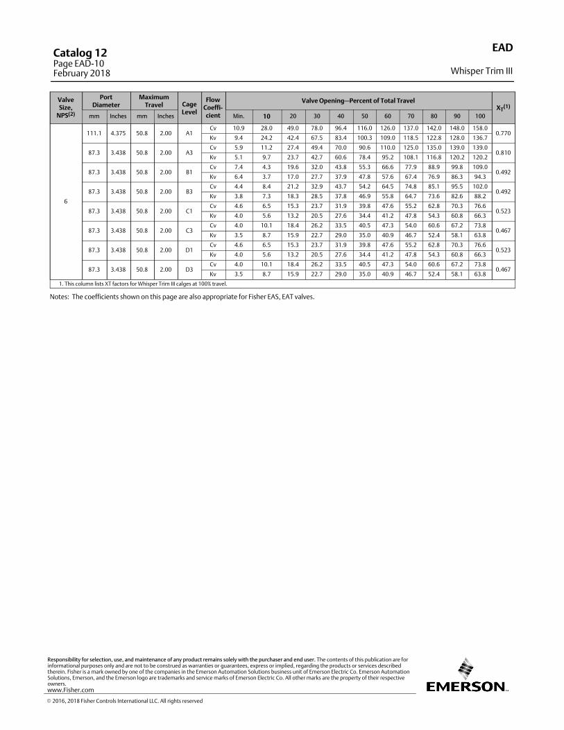
ValveSize,
NPS(2)
PortDiameter
MaximumTravel Cage
Level
FlowCoeffi-cient
Valve Opening—Percent of Total TravelXT
(1)
mm Inches mm Inches Min. 10 20 30 40 50 60 70 80 90 100
6
111.1 4.375 50.8 2.00 A1Cv 10.9 28.0 49.0 78.0 96.4 116.0 126.0 137.0 142.0 148.0 158.0
0.770Kv 9.4 24.2 42.4 67.5 83.4 100.3 109.0 118.5 122.8 128.0 136.7
87.3 3.438 50.8 2.00 A3Cv 5.9 11.2 27.4 49.4 70.0 90.6 110.0 125.0 135.0 139.0 139.0
0.810Kv 5.1 9.7 23.7 42.7 60.6 78.4 95.2 108.1 116.8 120.2 120.2
87.3 3.438 50.8 2.00 B1Cv 7.4 4.3 19.6 32.0 43.8 55.3 66.6 77.9 88.9 99.8 109.0
0.492Kv 6.4 3.7 17.0 27.7 37.9 47.8 57.6 67.4 76.9 86.3 94.3
87.3 3.438 50.8 2.00 B3Cv 4.4 8.4 21.2 32.9 43.7 54.2 64.5 74.8 85.1 95.5 102.0
0.492Kv 3.8 7.3 18.3 28.5 37.8 46.9 55.8 64.7 73.6 82.6 88.2
87.3 3.438 50.8 2.00 C1Cv 4.6 6.5 15.3 23.7 31.9 39.8 47.6 55.2 62.8 70.3 76.6
0.523Kv 4.0 5.6 13.2 20.5 27.6 34.4 41.2 47.8 54.3 60.8 66.3
87.3 3.438 50.8 2.00 C3Cv 4.0 10.1 18.4 26.2 33.5 40.5 47.3 54.0 60.6 67.2 73.8
0.467Kv 3.5 8.7 15.9 22.7 29.0 35.0 40.9 46.7 52.4 58.1 63.8
87.3 3.438 50.8 2.00 D1Cv 4.6 6.5 15.3 23.7 31.9 39.8 47.6 55.2 62.8 70.3 76.6
0.523Kv 4.0 5.6 13.2 20.5 27.6 34.4 41.2 47.8 54.3 60.8 66.3
87.3 3.438 50.8 2.00 D3Cv 4.0 10.1 18.4 26.2 33.5 40.5 47.3 54.0 60.6 67.2 73.8
0.467Kv 3.5 8.7 15.9 22.7 29.0 35.0 40.9 46.7 52.4 58.1 63.8
1. This column lists XT factors for Whisper Trim III calges at 100% travel.
Notes: The coefficients shown on this page are also appropriate for Fisher EAS, EAT valves.
EAD
Whisper Trim III
Catalog 12Page EAD-10February 2018
� 2016, 2018 Fisher Controls International LLC. All rights reserved
www.Fisher.com
Responsibility for selection, use, and maintenance of any product remains solely with the purchaser and end user. The contents of this publication are forinformational purposes only and are not to be construed as warranties or guarantees, express or implied, regarding the products or services describedtherein. Fisher is a mark owned by one of the companies in the Emerson Automation Solutions business unit of Emerson Electric Co. Emerson AutomationSolutions, Emerson, and the Emerson logo are trademarks and service marks of Emerson Electric Co. All other marks are the property of their respectiveowners.
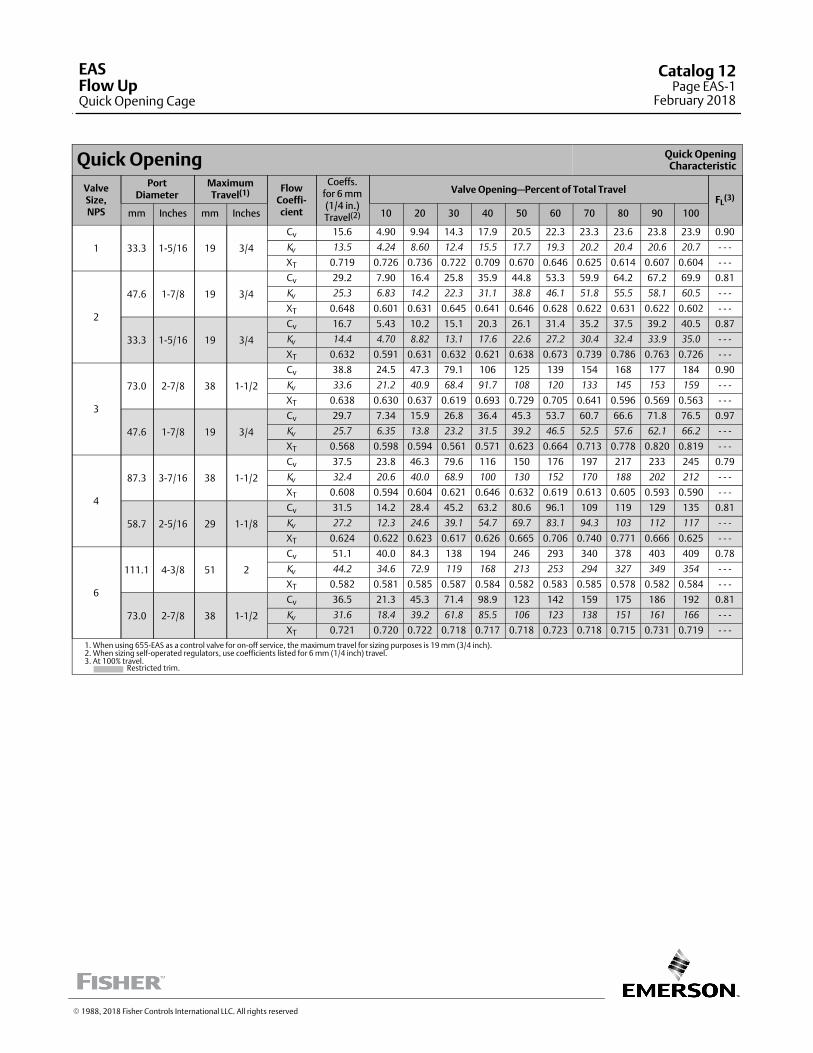
Quick Opening Quick OpeningCharacteristic
ValveSize,NPS
PortDiameter
MaximumTravel(1) Flow
Coeffi‐cient
Coeffs.for 6 mm(1/4 in.)Travel(2)
Valve Opening—Percent of Total TravelFL
(3)
mm Inches mm Inches 10 20 30 40 50 60 70 80 90 100
1 33.3 1‐5/16 19 3/4
Cv 15.6 4.90 9.94 14.3 17.9 20.5 22.3 23.3 23.6 23.8 23.9 0.90
Kv
13.5 4.24 8.60 12.4 15.5 17.7 19.3 20.2 20.4 20.6 20.7 ‐ ‐ ‐
XT 0.719 0.726 0.736 0.722 0.709 0.670 0.646 0.625 0.614 0.607 0.604 ‐ ‐ ‐
2
47.6 1‐7/8 19 3/4
Cv 29.2 7.90 16.4 25.8 35.9 44.8 53.3 59.9 64.2 67.2 69.9 0.81
Kv
25.3 6.83 14.2 22.3 31.1 38.8 46.1 51.8 55.5 58.1 60.5 ‐ ‐ ‐
XT 0.648 0.601 0.631 0.645 0.641 0.646 0.628 0.622 0.631 0.622 0.602 ‐ ‐ ‐
33.3 1‐5/16 19 3/4
Cv 16.7 5.43 10.2 15.1 20.3 26.1 31.4 35.2 37.5 39.2 40.5 0.87
Kv
14.4 4.70 8.82 13.1 17.6 22.6 27.2 30.4 32.4 33.9 35.0 ‐ ‐ ‐
XT 0.632 0.591 0.631 0.632 0.621 0.638 0.673 0.739 0.786 0.763 0.726 ‐ ‐ ‐
3
73.0 2‐7/8 38 1‐1/2
Cv 38.8 24.5 47.3 79.1 106 125 139 154 168 177 184 0.90
Kv
33.6 21.2 40.9 68.4 91.7 108 120 133 145 153 159 ‐ ‐ ‐
XT 0.638 0.630 0.637 0.619 0.693 0.729 0.705 0.641 0.596 0.569 0.563 ‐ ‐ ‐
47.6 1‐7/8 19 3/4
Cv 29.7 7.34 15.9 26.8 36.4 45.3 53.7 60.7 66.6 71.8 76.5 0.97
Kv
25.7 6.35 13.8 23.2 31.5 39.2 46.5 52.5 57.6 62.1 66.2 ‐ ‐ ‐
XT 0.568 0.598 0.594 0.561 0.571 0.623 0.664 0.713 0.778 0.820 0.819 ‐ ‐ ‐
4
87.3 3‐7/16 38 1‐1/2
Cv 37.5 23.8 46.3 79.6 116 150 176 197 217 233 245 0.79
Kv
32.4 20.6 40.0 68.9 100 130 152 170 188 202 212 ‐ ‐ ‐
XT 0.608 0.594 0.604 0.621 0.646 0.632 0.619 0.613 0.605 0.593 0.590 ‐ ‐ ‐
58.7 2‐5/16 29 1‐1/8
Cv 31.5 14.2 28.4 45.2 63.2 80.6 96.1 109 119 129 135 0.81
Kv
27.2 12.3 24.6 39.1 54.7 69.7 83.1 94.3 103 112 117 ‐ ‐ ‐
XT 0.624 0.622 0.623 0.617 0.626 0.665 0.706 0.740 0.771 0.666 0.625 ‐ ‐ ‐
6
111.1 4‐3/8 51 2
Cv 51.1 40.0 84.3 138 194 246 293 340 378 403 409 0.78
Kv
44.2 34.6 72.9 119 168 213 253 294 327 349 354 ‐ ‐ ‐
XT 0.582 0.581 0.585 0.587 0.584 0.582 0.583 0.585 0.578 0.582 0.584 ‐ ‐ ‐
73.0 2‐7/8 38 1‐1/2
Cv 36.5 21.3 45.3 71.4 98.9 123 142 159 175 186 192 0.81
Kv
31.6 18.4 39.2 61.8 85.5 106 123 138 151 161 166 ‐ ‐ ‐
XT 0.721 0.720 0.722 0.718 0.717 0.718 0.723 0.718 0.715 0.731 0.719 ‐ ‐ ‐
1. When using 655‐EAS as a control valve for on‐off service, the maximum travel for sizing purposes is 19 mm (3/4 inch).2. When sizing self‐operated regulators, use coefficients listed for 6 mm (1/4 inch) travel.3. At 100% travel.
Restricted trim.
� 1988, 2018 Fisher Controls International LLC. All rights reserved
EASFlow UpQuick Opening Cage
Catalog 12Page EAS-1
February 2018
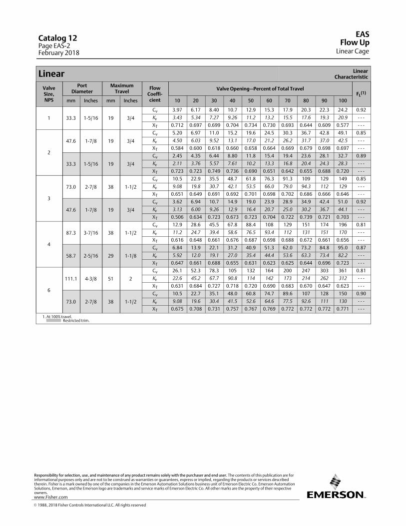
Linear LinearCharacteristic
ValveSize,NPS
PortDiameter
MaximumTravel
FlowCoeffi‐cient
Valve Opening—Percent of Total TravelFL
(1)
mm Inches mm Inches 10 20 30 40 50 60 70 80 90 100
1 33.3 1‐5/16 19 3/4
Cv 3.97 6.17 8.40 10.7 12.9 15.3 17.9 20.3 22.3 24.2 0.92
Kv
3.43 5.34 7.27 9.26 11.2 13.2 15.5 17.6 19.3 20.9 ‐ ‐ ‐
XT 0.712 0.697 0.699 0.704 0.734 0.730 0.693 0.644 0.609 0.577 ‐ ‐ ‐
2
47.6 1‐7/8 19 3/4
Cv 5.20 6.97 11.0 15.2 19.6 24.5 30.3 36.7 42.8 49.1 0.85
Kv
4.50 6.03 9.52 13.1 17.0 21.2 26.2 31.7 37.0 42.5 ‐ ‐ ‐
XT 0.584 0.600 0.618 0.660 0.658 0.664 0.669 0.679 0.698 0.697 ‐ ‐ ‐
33.3 1‐5/16 19 3/4
Cv 2.45 4.35 6.44 8.80 11.8 15.4 19.4 23.6 28.1 32.7 0.89
Kv
2.11 3.76 5.57 7.61 10.2 13.3 16.8 20.4 24.3 28.3 ‐ ‐ ‐
XT 0.723 0.723 0.749 0.736 0.690 0.651 0.642 0.655 0.688 0.720 ‐ ‐ ‐
3
73.0 2‐7/8 38 1‐1/2
Cv 10.5 22.9 35.5 48.7 61.8 76.3 91.3 109 129 149 0.85
Kv
9.08 19.8 30.7 42.1 53.5 66.0 79.0 94.3 112 129 ‐ ‐ ‐
XT 0.651 0.649 0.691 0.692 0.701 0.698 0.702 0.686 0.666 0.646 ‐ ‐ ‐
47.6 1‐7/8 19 3/4
Cv 3.62 6.94 10.7 14.9 19.0 23.9 28.9 34.9 42.4 51.0 0.92
Kv
3.13 6.00 9.26 12.9 16.4 20.7 25.0 30.2 36.7 44.1 ‐ ‐ ‐
XT 0.506 0.634 0.723 0.673 0.723 0.704 0.722 0.739 0.721 0.703 ‐ ‐ ‐
4
87.3 3‐7/16 38 1‐1/2
Cv 12.9 28.6 45.5 67.8 88.4 108 129 151 174 196 0.81
Kv
11.2 24.7 39.4 58.6 76.5 93.4 112 131 151 170 ‐ ‐ ‐
XT 0.616 0.648 0.661 0.676 0.687 0.698 0.688 0.672 0.661 0.656 ‐ ‐ ‐
58.7 2‐5/16 29 1‐1/8
Cv 6.84 13.9 22.1 31.2 40.9 51.3 62.0 73.2 84.8 95.0 0.87
Kv
5.92 12.0 19.1 27.0 35.4 44.4 53.6 63.3 73.4 82.2 ‐ ‐ ‐
XT 0.647 0.661 0.688 0.655 0.631 0.623 0.625 0.644 0.696 0.723 ‐ ‐ ‐
6
111.1 4‐3/8 51 2
Cv 26.1 52.3 78.3 105 132 164 200 247 303 361 0.81
Kv
22.6 45.2 67.7 90.8 114 142 173 214 262 312 ‐ ‐ ‐
XT 0.631 0.684 0.727 0.718 0.720 0.690 0.683 0.670 0.647 0.623 ‐ ‐ ‐
73.0 2‐7/8 38 1‐1/2
Cv 10.5 22.7 35.1 48.0 60.8 74.7 89.6 107 128 150 0.90
Kv
9.08 19.6 30.4 41.5 52.6 64.6 77.5 92.6 111 130 ‐ ‐ ‐
XT 0.675 0.708 0.731 0.757 0.767 0.769 0.772 0.772 0.772 0.771 ‐ ‐ ‐
1. At 100% travel. Restricted trim.
EAS
Linear CageFlow Up
Catalog 12Page EAS-2February 2018
� 1988, 2018 Fisher Controls International LLC. All rights reserved
www.Fisher.com
Responsibility for selection, use, and maintenance of any product remains solely with the purchaser and end user. The contents of this publication are forinformational purposes only and are not to be construed as warranties or guarantees, express or implied, regarding the products or services describedtherein. Fisher is a mark owned by one of the companies in the Emerson Automation Solutions business unit of Emerson Electric Co. Emerson AutomationSolutions, Emerson, and the Emerson logo are trademarks and service marks of Emerson Electric Co. All other marks are the property of their respectiveowners.
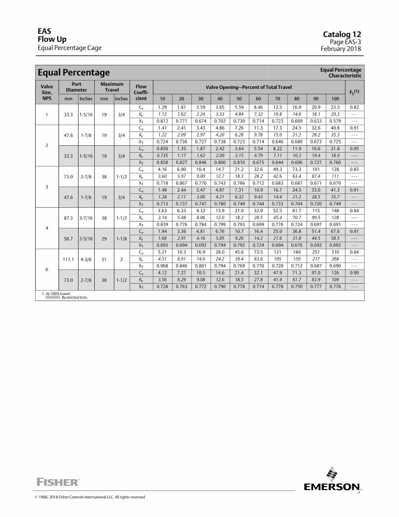
3
Equal Percentage Equal PercentageCharacteristic
ValveSize,NPS
PortDiameter
MaximumTravel
FlowCoeffi‐cient
Valve Opening—Percent of Total TravelFL
(1)
mm Inches mm Inches 10 20 30 40 50 60 70 80 90 100
1 33.3 1‐5/16 19 3/4
Cv 1.29 1.87 2.59 3.85 5.59 8.46 12.5 16.9 20.9 23.5 0.82
Kv
1.12 1.62 2.24 3.33 4.84 7.32 10.8 14.6 18.1 20.3 ‐ ‐ ‐
XT 0.812 0.771 0.674 0.702 0.730 0.714 0.723 0.669 0.633 0.579 ‐ ‐ ‐
2
47.6 1‐7/8 19 3/4
Cv 1.41 2.41 3.43 4.86 7.26 11.3 17.3 24.5 32.6 40.8 0.91
Kv
1.22 2.09 2.97 4.20 6.28 9.78 15.0 21.2 28.2 35.3 ‐ ‐ ‐
XT 0.724 0.736 0.727 0.738 0.723 0.714 0.646 0.680 0.673 0.725 ‐ ‐ ‐
33.3 1‐5/16 19 3/4
Cv 0.850 1.35 1.87 2.42 3.64 5.54 8.22 11.9 16.6 21.8 0.95
Kv
0.735 1.17 1.62 2.09 3.15 4.79 7.11 10.3 14.4 18.9 ‐ ‐ ‐
XT 0.858 0.827 0.846 0.800 0.810 0.675 0.644 0.696 0.727 0.760 ‐ ‐ ‐
3
73.0 2‐7/8 38 1‐1/2
Cv 4.16 6.90 10.4 14.7 21.2 32.6 49.3 73.3 101 128 0.85
Kv
3.60 5.97 9.00 12.7 18.3 28.2 42.6 63.4 87.4 111 ‐ ‐ ‐
XT 0.718 0.867 0.770 0.743 0.766 0.712 0.683 0.687 0.671 0.670 ‐ ‐ ‐
47.6 1‐7/8 19 3/4
Cv 1.48 2.44 3.47 4.87 7.31 10.9 16.7 24.5 33.0 41.3 0.91
Kv
1.28 2.11 3.00 4.21 6.32 9.43 14.4 21.2 28.5 35.7 ‐ ‐ ‐
XT 0.713 0.737 0.747 0.780 0.749 0.744 0.733 0.704 0.720 0.749 ‐ ‐ ‐
4
87.3 3‐7/16 38 1‐1/2
Cv 3.63 6.33 9.32 13.9 21.0 32.9 52.5 81.7 115 148 0.84
Kv
3.14 5.48 8.06 12.0 18.2 28.5 45.4 70.7 99.5 128 ‐ ‐ ‐
XT 0.839 0.776 0.784 0.799 0.793 0.699 0.776 0.724 0.697 0.691 ‐ ‐ ‐
58.7 2‐5/16 29 1‐1/8
Cv 1.94 3.36 4.81 6.76 10.7 16.4 25.0 36.8 51.4 67.6 0.91
Kv
1.68 2.91 4.16 5.85 9.26 14.2 21.6 31.8 44.5 58.5 ‐ ‐ ‐
XT 0.693 0.694 0.692 0.794 0.792 0.724 0.694 0.676 0.692 0.692 ‐ ‐ ‐
6
111.1 4‐3/8 51 2
Cv 5.21 10.3 16.9 28.0 45.6 73.5 121 184 251 310 0.84
Kv
4.51 8.91 14.6 24.2 39.4 63.6 105 159 217 268 ‐ ‐ ‐
XT 0.968 0.846 0.801 0.794 0.769 0.770 0.728 0.712 0.687 0.690 ‐ ‐ ‐
73.0 2‐7/8 38 1‐1/2
Cv 4.12 7.27 10.5 14.6 21.4 32.1 47.9 71.3 97.0 126 0.90
Kv
3.56 6.29 9.08 12.6 18.5 27.8 41.4 61.7 83.9 109 ‐ ‐ ‐
XT 0.728 0.763 0.772 0.790 0.778 0.774 0.778 0.750 0.777 0.776 ‐ ‐ ‐
1. At 100% travel. Restricted trim.
EAS
Equal Percentage CageFlow Up
Catalog 12Page EAS-3
February 2018
� 1988, 2018 Fisher Controls International LLC. All rights reserved
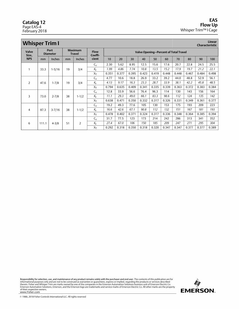
Whisper Trim I LinearCharacteristic
ValveSize,NPS
PortDiameter
MaximumTravel
FlowCoeffi‐cient
Valve Opening—Percent of Total Travel
mm Inches mm Inches 10 20 30 40 50 60 70 80 90 100
1 33.3 1‐5/16 19 3/4
Cv 2.30 5.62 8.95 12.5 15.6 17.6 20.7 22.8 24.5 25.5
Kv
1.99 4.86 7.74 10.8 13.5 15.2 17.9 19.7 21.2 22.1
XT 0.351 0.377 0.395 0.423 0.419 0.448 0.448 0.467 0.484 0.498
2 47.6 1‐7/8 19 3/4
Cv 4.77 10.6 18.8 26.9 33.2 39.2 44.0 48.8 52.9 56.1
Kv
4.13 9.17 16.3 23.3 28.7 33.9 38.1 42.2 45.8 48.5
XT 0.794 0.635 0.409 0.341 0.335 0.339 0.363 0.372 0.383 0.384
3 73.0 2‐7/8 38 1‐1/2
Cv 12.8 33.9 56.6 76.4 96.3 114 130 143 156 164
Kv
11.1 29.3 49.0 66.1 83.3 98.6 112 124 135 142
XT 0.638 0.471 0.350 0.332 0.317 0.326 0.331 0.349 0.361 0.377
4 87.3 3‐7/16 38 1‐1/2
Cv 19.2 49.3 77.6 105 130 153 175 193 209 223
Kv
16.6 42.6 67.1 90.8 112 132 151 167 181 193
XT 0.478 0.402 0.371 0.324 0.317 0.336 0.348 0.364 0.385 0.394
6 111.1 4‐3/8 51 2
Cv 31.7 77.5 123 173 214 242 286 313 341 352
Kv
27.4 67.0 106 150 185 209 247 271 295 304
XT 0.292 0.318 0.350 0.318 0.320 0.347 0.347 0.377 0.377 0.389
EAS
Whisper Trim™ I CageFlow Up
Catalog 12Page EAS-4February 2018
� 1988, 2018 Fisher Controls International LLC. All rights reserved
www.Fisher.com
Responsibility for selection, use, and maintenance of any product remains solely with the purchaser and end user. The contents of this publication are forinformational purposes only and are not to be construed as warranties or guarantees, express or implied, regarding the products or services describedtherein. Fisher and Whisper Trim are marks owned by one of the companies in the Emerson Automation Solutions business unit of Emerson Electric Co.Emerson Automation Solutions, Emerson, and the Emerson logo are trademarks and service marks of Emerson Electric Co. All other marks are the propertyof their respective owners.
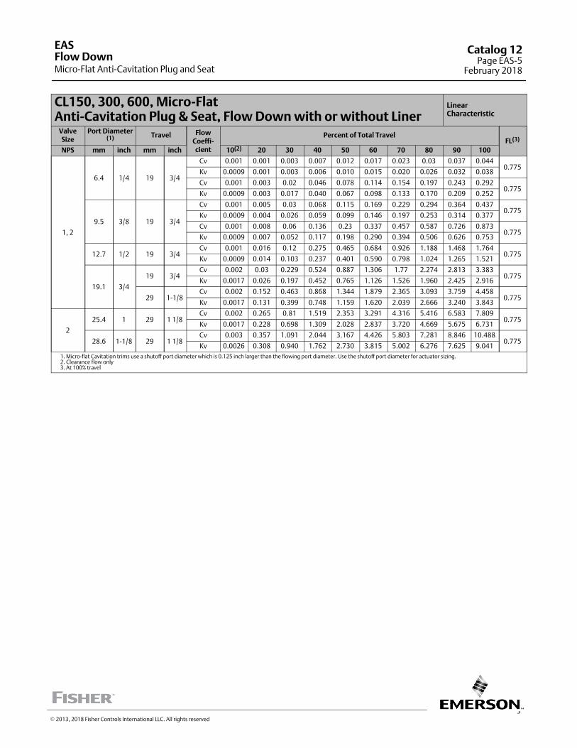
5
CL150, 300, 600, Micro-FlatAnti-Cavitation Plug & Seat, Flow Down with or without Liner
LinearCharacteristic
ValveSize
Port Diameter(1) Travel Flow
Coeffi-cient
Percent of Total TravelFL(3)
NPS mm inch mm inch 10(2) 20 30 40 50 60 70 80 90 100
1, 2
6.4 1/4 19 3/4
Cv 0.001 0.001 0.003 0.007 0.012 0.017 0.023 0.03 0.037 0.0440.775
Kv 0.0009 0.001 0.003 0.006 0.010 0.015 0.020 0.026 0.032 0.038
Cv 0.001 0.003 0.02 0.046 0.078 0.114 0.154 0.197 0.243 0.2920.775
Kv 0.0009 0.003 0.017 0.040 0.067 0.098 0.133 0.170 0.209 0.252
9.5 3/8 19 3/4
Cv 0.001 0.005 0.03 0.068 0.115 0.169 0.229 0.294 0.364 0.4370.775
Kv 0.0009 0.004 0.026 0.059 0.099 0.146 0.197 0.253 0.314 0.377
Cv 0.001 0.008 0.06 0.136 0.23 0.337 0.457 0.587 0.726 0.8730.775
Kv 0.0009 0.007 0.052 0.117 0.198 0.290 0.394 0.506 0.626 0.753
12.7 1/2 19 3/4Cv 0.001 0.016 0.12 0.275 0.465 0.684 0.926 1.188 1.468 1.764
0.775Kv 0.0009 0.014 0.103 0.237 0.401 0.590 0.798 1.024 1.265 1.521
19.1 3/4
19 3/4Cv 0.002 0.03 0.229 0.524 0.887 1.306 1.77 2.274 2.813 3.383
0.775Kv 0.0017 0.026 0.197 0.452 0.765 1.126 1.526 1.960 2.425 2.916
29 1-1/8Cv 0.002 0.152 0.463 0.868 1.344 1.879 2.365 3.093 3.759 4.458
0.775Kv 0.0017 0.131 0.399 0.748 1.159 1.620 2.039 2.666 3.240 3.843
2
25.4 1 29 1 1/8Cv 0.002 0.265 0.81 1.519 2.353 3.291 4.316 5.416 6.583 7.809
0.775Kv 0.0017 0.228 0.698 1.309 2.028 2.837 3.720 4.669 5.675 6.731
28.6 1-1/8 29 1 1/8Cv 0.003 0.357 1.091 2.044 3.167 4.426 5.803 7.281 8.846 10.488
0.775Kv 0.0026 0.308 0.940 1.762 2.730 3.815 5.002 6.276 7.625 9.041
1. Micro-flat Cavitation trims use a shutoff port diameter which is 0.125 inch larger than the flowing port diameter. Use the shutoff port diameter for actuator sizing.2. Clearance flow only3. At 100% travel
EAS
Micro-Flat Anti-Cavitation Plug and SeatFlow Down
Catalog 12Page EAS-5
February 2018
� 2013, 2018 Fisher Controls International LLC. All rights reserved
The EAS valve (Flow Down) has flow coefficients identical to the EAD valve. Refer to the EAD coefficients. For additionalEAS valve body information, refer to Bulletin 51.1:ES.
EASFlow Down
Catalog 12Page EAS-6February 2018
� 1988, 2018 Fisher Controls International LLC. All rights reserved
www.Fisher.com
Responsibility for selection, use, and maintenance of any product remains solely with the purchaser and end user. The contents of this publication are forinformational purposes only and are not to be construed as warranties or guarantees, express or implied, regarding the products or services describedtherein. Fisher is a mark owned by one of the companies in the Emerson Automation Solutions business unit of Emerson Electric Co. Emerson AutomationSolutions, Emerson, and the Emerson logo are trademarks and service marks of Emerson Electric Co. All other marks are the property of their respectiveowners.
The Fisher� EAT valve (“Flow Down”) has flow coefficients identical to the EAD valve. Refer to the EAD coefficients. Foradditional EAT valve body information, refer to Bulletin 51.1:ET.
� 1988, 2018 Fisher Controls International LLC. All rights reserved
EATFlow Down
Catalog 12Page EAT-1
February 2018

This page is intentionally left blank.
EATCatalog 12Page EAT-2February 2018
� 2014, 2018 Fisher Controls International LLC. All rights reserved
www.Fisher.com
Responsibility for selection, use, and maintenance of any product remains solely with the purchaser and end user. The contents of this publication are forinformational purposes only and are not to be construed as warranties or guarantees, express or implied, regarding the products or services describedtherein. Fisher is a mark owned by one of the companies in the Emerson Automation Solutions business unit of Emerson Electric Co. Emerson AutomationSolutions, Emerson, and the Emerson logo are trademarks and service marks of Emerson Electric Co. All other marks are the property of their respectiveowners.
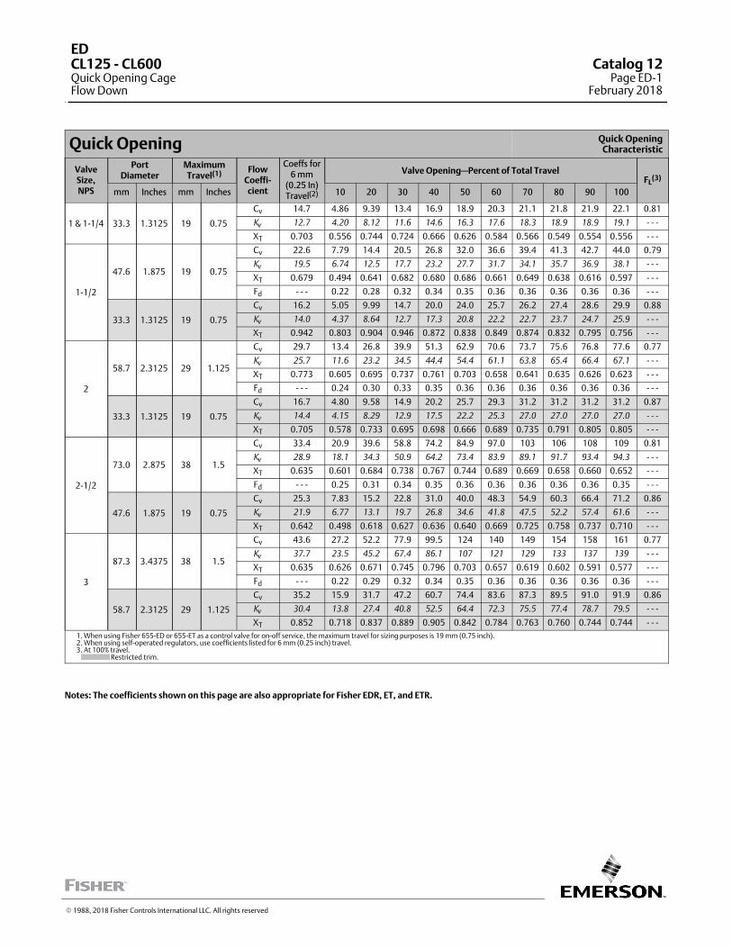
Quick Opening Quick OpeningCharacteristic
ValveSize,NPS
PortDiameter
MaximumTravel(1) Flow
Coeffi‐cient
Coeffs for6 mm
(0.25 In)Travel(2)
Valve Opening—Percent of Total TravelFL
(3)
mm Inches mm Inches 10 20 30 40 50 60 70 80 90 100
1 & 1-1/4 33.3 1.3125 19 0.75
Cv 14.7 4.86 9.39 13.4 16.9 18.9 20.3 21.1 21.8 21.9 22.1 0.81
Kv
12.7 4.20 8.12 11.6 14.6 16.3 17.6 18.3 18.9 18.9 19.1 ‐ ‐ ‐
XT 0.703 0.556 0.744 0.724 0.666 0.626 0.584 0.566 0.549 0.554 0.556 ‐ ‐ ‐
1-1/2
47.6 1.875 19 0.75
Cv 22.6 7.79 14.4 20.5 26.8 32.0 36.6 39.4 41.3 42.7 44.0 0.79
Kv
19.5 6.74 12.5 17.7 23.2 27.7 31.7 34.1 35.7 36.9 38.1 ‐ ‐ ‐
XT 0.679 0.494 0.641 0.682 0.680 0.686 0.661 0.649 0.638 0.616 0.597 ‐ ‐ ‐
Fd ‐ ‐ ‐ 0.22 0.28 0.32 0.34 0.35 0.36 0.36 0.36 0.36 0.36 ‐ ‐ ‐
33.3 1.3125 19 0.75
Cv 16.2 5.05 9.99 14.7 20.0 24.0 25.7 26.2 27.4 28.6 29.9 0.88
Kv
14.0 4.37 8.64 12.7 17.3 20.8 22.2 22.7 23.7 24.7 25.9 ‐ ‐ ‐
XT 0.942 0.803 0.904 0.946 0.872 0.838 0.849 0.874 0.832 0.795 0.756 ‐ ‐ ‐
2
58.7 2.3125 29 1.125
Cv 29.7 13.4 26.8 39.9 51.3 62.9 70.6 73.7 75.6 76.8 77.6 0.77
Kv
25.7 11.6 23.2 34.5 44.4 54.4 61.1 63.8 65.4 66.4 67.1 ‐ ‐ ‐
XT 0.773 0.605 0.695 0.737 0.761 0.703 0.658 0.641 0.635 0.626 0.623 ‐ ‐ ‐
Fd ‐ ‐ ‐ 0.24 0.30 0.33 0.35 0.36 0.36 0.36 0.36 0.36 0.36 ‐ ‐ ‐
33.3 1.3125 19 0.75
Cv 16.7 4.80 9.58 14.9 20.2 25.7 29.3 31.2 31.2 31.2 31.2 0.87
Kv
14.4 4.15 8.29 12.9 17.5 22.2 25.3 27.0 27.0 27.0 27.0 ‐ ‐ ‐
XT 0.705 0.578 0.733 0.695 0.698 0.666 0.689 0.735 0.791 0.805 0.805 ‐ ‐ ‐
2-1/2
73.0 2.875 38 1.5
Cv 33.4 20.9 39.6 58.8 74.2 84.9 97.0 103 106 108 109 0.81
Kv
28.9 18.1 34.3 50.9 64.2 73.4 83.9 89.1 91.7 93.4 94.3 ‐ ‐ ‐
XT 0.635 0.601 0.684 0.738 0.767 0.744 0.689 0.669 0.658 0.660 0.652 ‐ ‐ ‐
Fd ‐ ‐ ‐ 0.25 0.31 0.34 0.35 0.36 0.36 0.36 0.36 0.36 0.35 ‐ ‐ ‐
47.6 1.875 19 0.75
Cv 25.3 7.83 15.2 22.8 31.0 40.0 48.3 54.9 60.3 66.4 71.2 0.86
Kv
21.9 6.77 13.1 19.7 26.8 34.6 41.8 47.5 52.2 57.4 61.6 ‐ ‐ ‐
XT 0.642 0.498 0.618 0.627 0.636 0.640 0.669 0.725 0.758 0.737 0.710 ‐ ‐ ‐
3
87.3 3.4375 38 1.5
Cv 43.6 27.2 52.2 77.9 99.5 124 140 149 154 158 161 0.77
Kv
37.7 23.5 45.2 67.4 86.1 107 121 129 133 137 139 ‐ ‐ ‐
XT 0.635 0.626 0.671 0.745 0.796 0.703 0.657 0.619 0.602 0.591 0.577 ‐ ‐ ‐
Fd ‐ ‐ ‐ 0.22 0.29 0.32 0.34 0.35 0.36 0.36 0.36 0.36 0.36 ‐ ‐ ‐
58.7 2.3125 29 1.125
Cv 35.2 15.9 31.7 47.2 60.7 74.4 83.6 87.3 89.5 91.0 91.9 0.86
Kv
30.4 13.8 27.4 40.8 52.5 64.4 72.3 75.5 77.4 78.7 79.5 ‐ ‐ ‐
XT 0.852 0.718 0.837 0.889 0.905 0.842 0.784 0.763 0.760 0.744 0.744 ‐ ‐ ‐
1. When using Fisher 655‐ED or 655‐ET as a control valve for on‐off service, the maximum travel for sizing purposes is 19 mm (0.75 inch).2. When using self‐operated regulators, use coefficients listed for 6 mm (0.25 inch) travel.3. At 100% travel. Restricted trim.
Notes: The coefficients shown on this page are also appropriate for Fisher EDR, ET, and ETR.
EDCL125 - CL600Quick Opening CageFlow Down
Catalog 12Page ED-1
February 2018
� 1988, 2018 Fisher Controls International LLC. All rights reserved
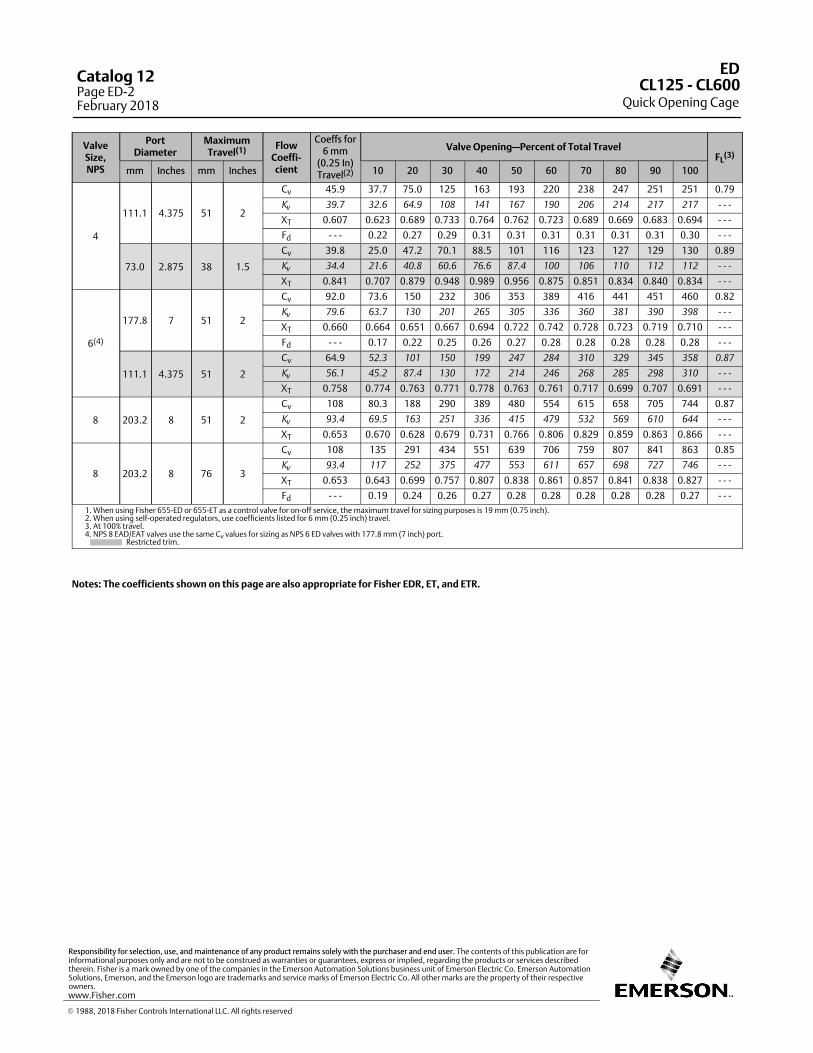
ValveSize,NPS
PortDiameter
MaximumTravel(1) Flow
Coeffi‐cient
Coeffs for6 mm
(0.25 In)Travel(2)
Valve Opening—Percent of Total TravelFL
(3)
mm Inches mm Inches 10 20 30 40 50 60 70 80 90 100
4
111.1 4.375 51 2
Cv 45.9 37.7 75.0 125 163 193 220 238 247 251 251 0.79
Kv
39.7 32.6 64.9 108 141 167 190 206 214 217 217 ‐ ‐ ‐
XT 0.607 0.623 0.689 0.733 0.764 0.762 0.723 0.689 0.669 0.683 0.694 ‐ ‐ ‐
Fd ‐ ‐ ‐ 0.22 0.27 0.29 0.31 0.31 0.31 0.31 0.31 0.31 0.30 ‐ ‐ ‐
73.0 2.875 38 1.5
Cv 39.8 25.0 47.2 70.1 88.5 101 116 123 127 129 130 0.89
Kv
34.4 21.6 40.8 60.6 76.6 87.4 100 106 110 112 112 ‐ ‐ ‐
XT 0.841 0.707 0.879 0.948 0.989 0.956 0.875 0.851 0.834 0.840 0.834 ‐ ‐ ‐
6(4)
177.8 7 51 2
Cv 92.0 73.6 150 232 306 353 389 416 441 451 460 0.82
Kv
79.6 63.7 130 201 265 305 336 360 381 390 398 ‐ ‐ ‐
XT 0.660 0.664 0.651 0.667 0.694 0.722 0.742 0.728 0.723 0.719 0.710 ‐ ‐ ‐
Fd ‐ ‐ ‐ 0.17 0.22 0.25 0.26 0.27 0.28 0.28 0.28 0.28 0.28 ‐ ‐ ‐
111.1 4.375 51 2
Cv 64.9 52.3 101 150 199 247 284 310 329 345 358 0.87
Kv
56.1 45.2 87.4 130 172 214 246 268 285 298 310 ‐ ‐ ‐
XT 0.758 0.774 0.763 0.771 0.778 0.763 0.761 0.717 0.699 0.707 0.691 ‐ ‐ ‐
8 203.2 8 51 2
Cv 108 80.3 188 290 389 480 554 615 658 705 744 0.87
Kv
93.4 69.5 163 251 336 415 479 532 569 610 644 ‐ ‐ ‐
XT 0.653 0.670 0.628 0.679 0.731 0.766 0.806 0.829 0.859 0.863 0.866 ‐ ‐ ‐
8 203.2 8 76 3
Cv 108 135 291 434 551 639 706 759 807 841 863 0.85
Kv
93.4 117 252 375 477 553 611 657 698 727 746 ‐ ‐ ‐
XT 0.653 0.643 0.699 0.757 0.807 0.838 0.861 0.857 0.841 0.838 0.827 ‐ ‐ ‐
Fd ‐ ‐ ‐ 0.19 0.24 0.26 0.27 0.28 0.28 0.28 0.28 0.28 0.27 ‐ ‐ ‐
1. When using Fisher 655‐ED or 655‐ET as a control valve for on‐off service, the maximum travel for sizing purposes is 19 mm (0.75 inch).2. When using self‐operated regulators, use coefficients listed for 6 mm (0.25 inch) travel.3. At 100% travel.4. NPS 8 EAD/EAT valves use the same Cv values for sizing as NPS 6 ED valves with 177.8 mm (7 inch) port. Restricted trim.
Notes: The coefficients shown on this page are also appropriate for Fisher EDR, ET, and ETR.
ED
Quick Opening CageCL125 ‐ CL600
Catalog 12Page ED-2February 2018
� 1988, 2018 Fisher Controls International LLC. All rights reserved
www.Fisher.com
Responsibility for selection, use, and maintenance of any product remains solely with the purchaser and end user. The contents of this publication are forinformational purposes only and are not to be construed as warranties or guarantees, express or implied, regarding the products or services describedtherein. Fisher is a mark owned by one of the companies in the Emerson Automation Solutions business unit of Emerson Electric Co. Emerson AutomationSolutions, Emerson, and the Emerson logo are trademarks and service marks of Emerson Electric Co. All other marks are the property of their respectiveowners.

3
LinearLinear
Characteristic
ValveSize,NPS
PortDiameter
MaximumTravel(2) Flow
Coeffi‐cient
Valve Opening—Percent of Total TravelFL
(1)
mm Inches mm Inches 10 20 30 40 50 60 70 80 90 100
1 & 1-1/4 33.3 1.3125 19 0.75
Cv 3.21 5.50 8.18 10.9 13.2 15.0 16.9 18.6 19.9 20.6 0.84
Kv
2.78 4.76 7.08 9.43 11.4 13.0 14.6 16.1 17.2 17.8 ‐ ‐ ‐
XT 0.340 0.644 0.494 0.509 0.532 0.580 0.610 0.629 0.628 0.636 ‐ ‐ ‐
1-1/2
47.6 1.875 19 0.75
Cv 4.23 7.84 11.8 15.8 20.4 25.3 30.3 34.7 37.2 39.2 0.82
Kv
3.66 6.78 10.2 13.7 17.6 21.9 26.2 30.0 32.2 33.9 ‐ ‐ ‐
XT 0.656 0.709 0.758 0.799 0.738 0.729 0.708 0.686 0.683 0.656 ‐ ‐ ‐
Fd 0.30 0.37 0.41 0.44 0.44 0.41 0.38 0.35 0.34 0.34 ‐ ‐ ‐
33.3 1.3125 19 0.75
Cv 2.92 5.70 9.05 12.5 15.6 18.5 21.1 23.9 26.8 29.2 0.91
Kv
2.53 4.93 7.83 10.8 13.5 16.0 18.3 20.7 23.2 25.3 ‐ ‐ ‐
XT 0.690 0.651 0.633 0.634 0.650 0.666 0.708 0.718 0.737 0.733 ‐ ‐ ‐
2
58.7 2.3125 29 1.125
Cv 7.87 16.0 24.9 33.4 42.1 51.8 62.0 68.1 70.6 72.9 0.77
Kv
6.81 13.8 21.5 28.9 36.4 44.8 53.6 58.9 61.1 63.1 ‐ ‐ ‐
XT 0.641 0.720 0.728 0.767 0.793 0.754 0.683 0.658 0.652 0.638 ‐ ‐ ‐
Fd 0.30 0.35 0.36 0.37 0.37 0.36 0.35 0.35 0.34 0.33 ‐ ‐ ‐
33.3 1.3125 19 0.75
Cv 3.53 6.36 9.92 13.3 16.5 19.7 22.7 25.6 29.3 33.3 0.87
Kv
3.05 5.50 8.58 11.5 14.3 17.0 19.6 22.1 25.3 28.8 ‐ ‐ ‐
XT 0.456 0.529 0.549 0.582 0.611 0.633 0.671 0.723 0.727 0.694 ‐ ‐ ‐
2-1/2
73.0 2.875 38 1.5
Cv 9.34 21.6 35.5 49.5 62.7 74.1 83.6 93.5 102 108 0.81
Kv
8.08 18.7 30.7 42.8 54.2 64.1 72.3 80.9 88.2 93.4 ‐ ‐ ‐
XT 0.680 0.660 0.644 0.669 0.674 0.706 0.716 0.687 0.658 0.641 ‐ ‐ ‐
Fd 0.27 0.33 0.35 0.36 0.35 0.34 0.32 0.29 0.27 0.27 ‐ ‐ ‐
47.6 1.875 19 0.75
Cv 4.10 8.09 12.3 16.7 21.1 26.8 33.7 41.3 49.2 57.0 0.84
Kv
3.55 7.00 10.6 14.4 18.3 23.2 29.2 35.7 42.6 49.3 ‐ ‐ ‐
XT 0.668 0.646 0.684 0.688 0.698 0.694 0.678 0.668 0.669 0.666 ‐ ‐ ‐
3
87.3 3.4375 38 1.5
Cv 14.5 32.9 52.1 70.4 88.5 105 118 133 142 148 0.82
Kv
12.5 28.5 45.1 60.9 76.6 90.8 102 115 123 128 ‐ ‐ ‐
XT 0.671 0.699 0.697 0.720 0.733 0.718 0.707 0.650 0.630 0.620 ‐ ‐ ‐
Fd 0.26 0.32 0.35 0.36 0.36 0.36 0.36 0.28 0.29 0.30 ‐ ‐ ‐
58.7 2.3125 29 1.125
Cv 8.06 16.9 26.7 37.5 49.0 61.4 73.8 85.3 94.7 102 0.85
Kv
6.97 14.6 23.1 32.4 42.4 53.1 63.8 73.8 81.9 88.2 ‐ ‐ ‐
XT 0.592 0.614 0.662 0.672 0.674 0.676 0.694 0.722 0.736 0.732 ‐ ‐ ‐
4
111.1 4.375 51 2
Cv 23.3 50.3 78.1 105 127 152 181 203 223 236 0.82
Kv
20.2 43.5 67.6 90.8 110 131 157 176 193 204 ‐ ‐ ‐
XT 0.691 0.714 0.720 0.731 0.764 0.757 0.748 0.762 0.732 0.688 ‐ ‐ ‐
Fd 0.31 0.36 0.38 0.38 0.37 0.35 0.32 0.30 0.27 0.28 ‐ ‐ ‐
73.0 2.875 38 1.5
Cv 9.77 22.6 37.2 51.8 65.7 77.5 87.5 97.9 107 113 0.84
Kv
8.45 19.5 32.2 44.8 56.8 67.0 75.7 84.7 92.6 97.7 ‐ ‐ ‐
XT 0.926 0.899 0.873 0.904 0.919 0.962 0.972 0.937 0.891 0.872 ‐ ‐ ‐
1. At 100% travel.2. If coefficients listed above for the NPS 8 linear cage with 51 mm (2‐inch) travel are not sufficient for your application, consider using the quick opening cage. The NPS 8 quick opening cagewith 51 mm (2‐inch) travel has approximately a linear characteristic. Restricted trim.
Notes: The coefficients shown on this page are also appropriate for Fisher EDR, ET, and ETR. The full‐size port coefficients for NPS 3 through 8 also apply
to Fisher ET‐C valves.
ED
Linear CageCL125 ‐ CL600
Catalog 12Page ED-3
February 2018
� 1988, 2018 Fisher Controls International LLC. All rights reserved
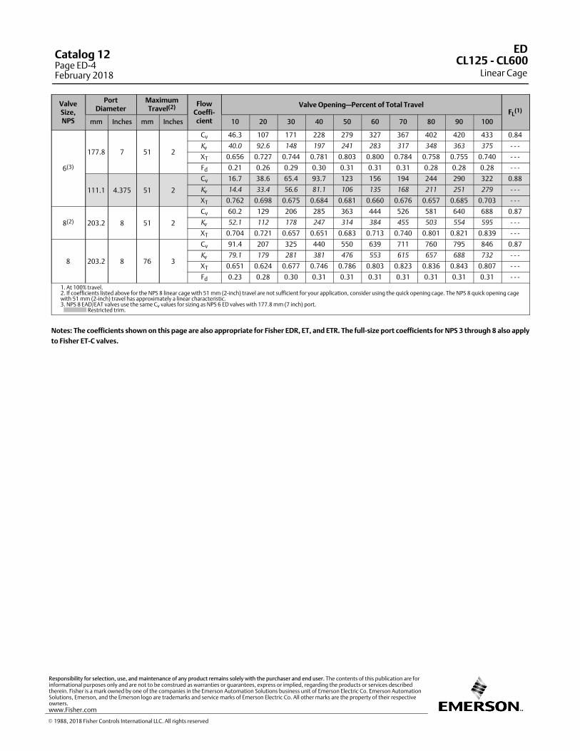
ValveSize,NPS
PortDiameter
MaximumTravel(2) Flow
Coeffi‐cient
Valve Opening—Percent of Total TravelFL
(1)
mm Inches mm Inches 10 20 30 40 50 60 70 80 90 100
6(3)
177.8 7 51 2
Cv 46.3 107 171 228 279 327 367 402 420 433 0.84
Kv
40.0 92.6 148 197 241 283 317 348 363 375 ‐ ‐ ‐
XT 0.656 0.727 0.744 0.781 0.803 0.800 0.784 0.758 0.755 0.740 ‐ ‐ ‐
Fd 0.21 0.26 0.29 0.30 0.31 0.31 0.31 0.28 0.28 0.28 ‐ ‐ ‐
111.1 4.375 51 2
Cv 16.7 38.6 65.4 93.7 123 156 194 244 290 322 0.88
Kv
14.4 33.4 56.6 81.1 106 135 168 211 251 279 ‐ ‐ ‐
XT 0.762 0.698 0.675 0.684 0.681 0.660 0.676 0.657 0.685 0.703 ‐ ‐ ‐
8(2) 203.2 8 51 2
Cv 60.2 129 206 285 363 444 526 581 640 688 0.87
Kv
52.1 112 178 247 314 384 455 503 554 595 ‐ ‐ ‐
XT 0.704 0.721 0.657 0.651 0.683 0.713 0.740 0.801 0.821 0.839 ‐ ‐ ‐
8 203.2 8 76 3
Cv 91.4 207 325 440 550 639 711 760 795 846 0.87
Kv
79.1 179 281 381 476 553 615 657 688 732 ‐ ‐ ‐
XT 0.651 0.624 0.677 0.746 0.786 0.803 0.823 0.836 0.843 0.807 ‐ ‐ ‐
Fd 0.23 0.28 0.30 0.31 0.31 0.31 0.31 0.31 0.31 0.31 ‐ ‐ ‐
1. At 100% travel.2. If coefficients listed above for the NPS 8 linear cage with 51 mm (2‐inch) travel are not sufficient for your application, consider using the quick opening cage. The NPS 8 quick opening cagewith 51 mm (2‐inch) travel has approximately a linear characteristic.3. NPS 8 EAD/EAT valves use the same Cv values for sizing as NPS 6 ED valves with 177.8 mm (7 inch) port. Restricted trim.
Notes: The coefficients shown on this page are also appropriate for Fisher EDR, ET, and ETR. The full‐size port coefficients for NPS 3 through 8 also apply
to Fisher ET‐C valves.
ED
Linear CageCL125 ‐ CL600
Catalog 12Page ED-4February 2018
� 1988, 2018 Fisher Controls International LLC. All rights reserved
www.Fisher.com
Responsibility for selection, use, and maintenance of any product remains solely with the purchaser and end user. The contents of this publication are forinformational purposes only and are not to be construed as warranties or guarantees, express or implied, regarding the products or services describedtherein. Fisher is a mark owned by one of the companies in the Emerson Automation Solutions business unit of Emerson Electric Co. Emerson AutomationSolutions, Emerson, and the Emerson logo are trademarks and service marks of Emerson Electric Co. All other marks are the property of their respectiveowners.
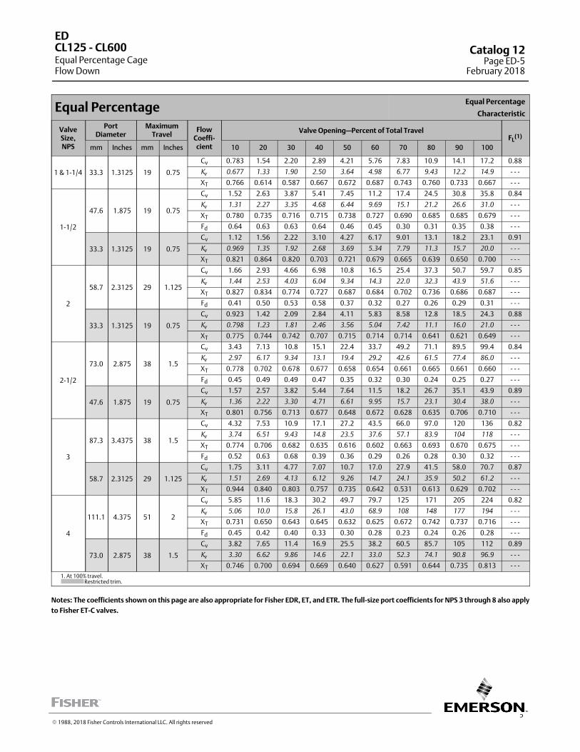
5
Equal PercentageEqual Percentage
Characteristic
ValveSize,NPS
PortDiameter
MaximumTravel
FlowCoeffi‐cient
Valve Opening—Percent of Total TravelFL
(1)
mm Inches mm Inches 10 20 30 40 50 60 70 80 90 100
1 & 1-1/4 33.3 1.3125 19 0.75
Cv 0.783 1.54 2.20 2.89 4.21 5.76 7.83 10.9 14.1 17.2 0.88
Kv
0.677 1.33 1.90 2.50 3.64 4.98 6.77 9.43 12.2 14.9 ‐ ‐ ‐
XT 0.766 0.614 0.587 0.667 0.672 0.687 0.743 0.760 0.733 0.667 ‐ ‐ ‐
1-1/2
47.6 1.875 19 0.75
Cv 1.52 2.63 3.87 5.41 7.45 11.2 17.4 24.5 30.8 35.8 0.84
Kv
1.31 2.27 3.35 4.68 6.44 9.69 15.1 21.2 26.6 31.0 ‐ ‐ ‐
XT 0.780 0.735 0.716 0.715 0.738 0.727 0.690 0.685 0.685 0.679 ‐ ‐ ‐
Fd 0.64 0.63 0.63 0.64 0.46 0.45 0.30 0.31 0.35 0.38 ‐ ‐ ‐
33.3 1.3125 19 0.75
Cv 1.12 1.56 2.22 3.10 4.27 6.17 9.01 13.1 18.2 23.1 0.91
Kv
0.969 1.35 1.92 2.68 3.69 5.34 7.79 11.3 15.7 20.0 ‐ ‐ ‐
XT 0.821 0.864 0.820 0.703 0.721 0.679 0.665 0.639 0.650 0.700 ‐ ‐ ‐
2
58.7 2.3125 29 1.125
Cv 1.66 2.93 4.66 6.98 10.8 16.5 25.4 37.3 50.7 59.7 0.85
Kv
1.44 2.53 4.03 6.04 9.34 14.3 22.0 32.3 43.9 51.6 ‐ ‐ ‐
XT 0.827 0.834 0.774 0.727 0.687 0.684 0.702 0.736 0.686 0.687 ‐ ‐ ‐
Fd 0.41 0.50 0.53 0.58 0.37 0.32 0.27 0.26 0.29 0.31 ‐ ‐ ‐
33.3 1.3125 19 0.75
Cv 0.923 1.42 2.09 2.84 4.11 5.83 8.58 12.8 18.5 24.3 0.88
Kv
0.798 1.23 1.81 2.46 3.56 5.04 7.42 11.1 16.0 21.0 ‐ ‐ ‐
XT 0.775 0.744 0.742 0.707 0.715 0.714 0.714 0.641 0.621 0.649 ‐ ‐ ‐
2-1/2
73.0 2.875 38 1.5
Cv 3.43 7.13 10.8 15.1 22.4 33.7 49.2 71.1 89.5 99.4 0.84
Kv
2.97 6.17 9.34 13.1 19.4 29.2 42.6 61.5 77.4 86.0 ‐ ‐ ‐
XT 0.778 0.702 0.678 0.677 0.658 0.654 0.661 0.665 0.661 0.660 ‐ ‐ ‐
Fd 0.45 0.49 0.49 0.47 0.35 0.32 0.30 0.24 0.25 0.27 ‐ ‐ ‐
47.6 1.875 19 0.75
Cv 1.57 2.57 3.82 5.44 7.64 11.5 18.2 26.7 35.1 43.9 0.89
Kv
1.36 2.22 3.30 4.71 6.61 9.95 15.7 23.1 30.4 38.0 ‐ ‐ ‐
XT 0.801 0.756 0.713 0.677 0.648 0.672 0.628 0.635 0.706 0.710 ‐ ‐ ‐
3
87.3 3.4375 38 1.5
Cv 4.32 7.53 10.9 17.1 27.2 43.5 66.0 97.0 120 136 0.82
Kv
3.74 6.51 9.43 14.8 23.5 37.6 57.1 83.9 104 118 ‐ ‐ ‐
XT 0.774 0.706 0.682 0.635 0.616 0.602 0.663 0.693 0.670 0.675 ‐ ‐ ‐
Fd 0.52 0.63 0.68 0.39 0.36 0.29 0.26 0.28 0.30 0.32 ‐ ‐ ‐
58.7 2.3125 29 1.125
Cv 1.75 3.11 4.77 7.07 10.7 17.0 27.9 41.5 58.0 70.7 0.87
Kv
1.51 2.69 4.13 6.12 9.26 14.7 24.1 35.9 50.2 61.2 ‐ ‐ ‐
XT 0.944 0.840 0.803 0.757 0.735 0.642 0.531 0.613 0.629 0.702 ‐ ‐ ‐
4
111.1 4.375 51 2
Cv 5.85 11.6 18.3 30.2 49.7 79.7 125 171 205 224 0.82
Kv
5.06 10.0 15.8 26.1 43.0 68.9 108 148 177 194 ‐ ‐ ‐
XT 0.731 0.650 0.643 0.645 0.632 0.625 0.672 0.742 0.737 0.716 ‐ ‐ ‐
Fd 0.45 0.42 0.40 0.33 0.30 0.28 0.23 0.24 0.26 0.28 ‐ ‐ ‐
73.0 2.875 38 1.5
Cv 3.82 7.65 11.4 16.9 25.5 38.2 60.5 85.7 105 112 0.89
Kv
3.30 6.62 9.86 14.6 22.1 33.0 52.3 74.1 90.8 96.9 ‐ ‐ ‐
XT 0.746 0.700 0.694 0.669 0.640 0.627 0.591 0.644 0.735 0.813 ‐ ‐ ‐
1. At 100% travel. Restricted trim.
Notes: The coefficients shown on this page are also appropriate for Fisher EDR, ET, and ETR. The full‐size port coefficients for NPS 3 through 8 also apply
to Fisher ET‐C valves.
ED
Equal Percentage CageFlow Down
CL125 ‐ CL600 Catalog 12Page ED-5
February 2018
� 1988, 2018 Fisher Controls International LLC. All rights reserved
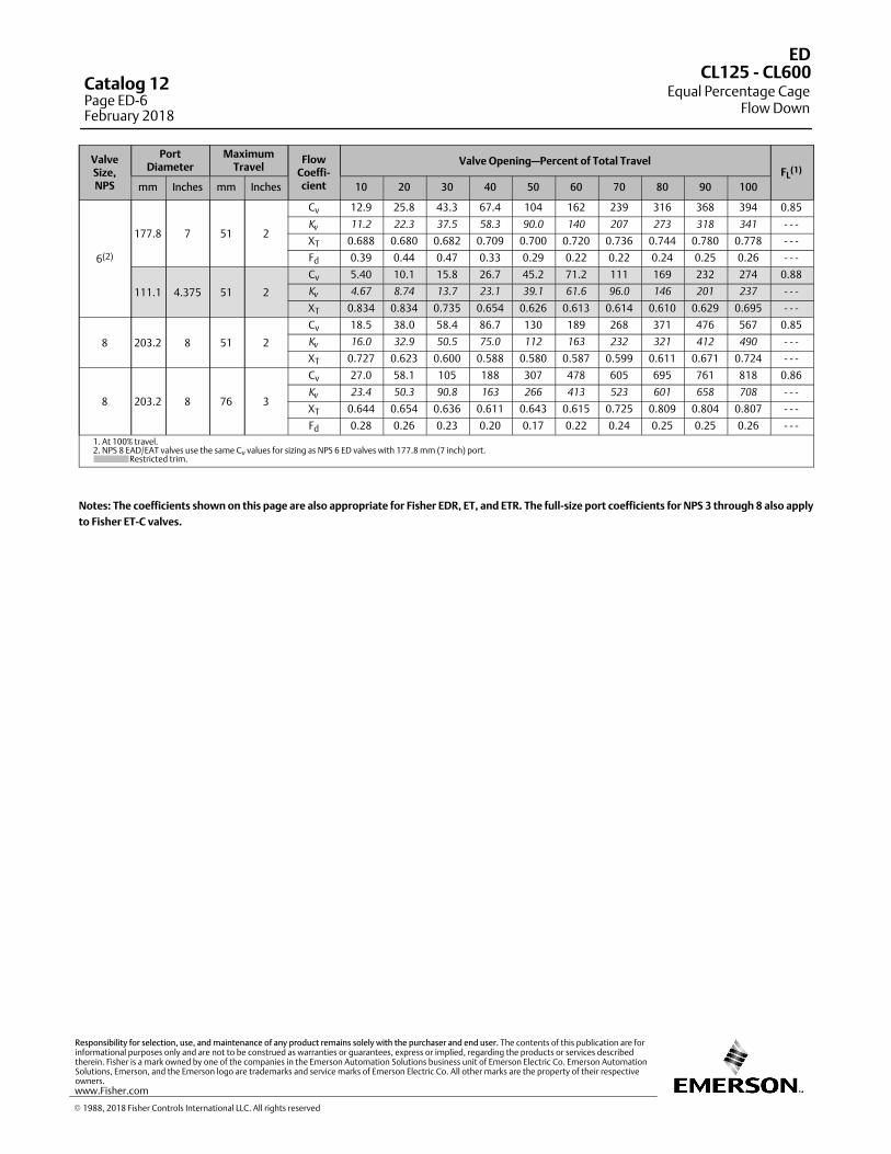
ValveSize,NPS
PortDiameter
MaximumTravel
FlowCoeffi‐cient
Valve Opening—Percent of Total TravelFL
(1)
mm Inches mm Inches 10 20 30 40 50 60 70 80 90 100
6(2)
177.8 7 51 2
Cv 12.9 25.8 43.3 67.4 104 162 239 316 368 394 0.85
Kv
11.2 22.3 37.5 58.3 90.0 140 207 273 318 341 ‐ ‐ ‐
XT 0.688 0.680 0.682 0.709 0.700 0.720 0.736 0.744 0.780 0.778 ‐ ‐ ‐
Fd 0.39 0.44 0.47 0.33 0.29 0.22 0.22 0.24 0.25 0.26 ‐ ‐ ‐
111.1 4.375 51 2
Cv 5.40 10.1 15.8 26.7 45.2 71.2 111 169 232 274 0.88
Kv
4.67 8.74 13.7 23.1 39.1 61.6 96.0 146 201 237 ‐ ‐ ‐
XT 0.834 0.834 0.735 0.654 0.626 0.613 0.614 0.610 0.629 0.695 ‐ ‐ ‐
8 203.2 8 51 2
Cv 18.5 38.0 58.4 86.7 130 189 268 371 476 567 0.85
Kv
16.0 32.9 50.5 75.0 112 163 232 321 412 490 ‐ ‐ ‐
XT 0.727 0.623 0.600 0.588 0.580 0.587 0.599 0.611 0.671 0.724 ‐ ‐ ‐
8 203.2 8 76 3
Cv 27.0 58.1 105 188 307 478 605 695 761 818 0.86
Kv
23.4 50.3 90.8 163 266 413 523 601 658 708 ‐ ‐ ‐
XT 0.644 0.654 0.636 0.611 0.643 0.615 0.725 0.809 0.804 0.807 ‐ ‐ ‐
Fd 0.28 0.26 0.23 0.20 0.17 0.22 0.24 0.25 0.25 0.26 ‐ ‐ ‐
1. At 100% travel.2. NPS 8 EAD/EAT valves use the same Cv values for sizing as NPS 6 ED valves with 177.8 mm (7 inch) port. Restricted trim.
Notes: The coefficients shown on this page are also appropriate for Fisher EDR, ET, and ETR. The full‐size port coefficients for NPS 3 through 8 also apply
to Fisher ET‐C valves.
ED
Equal Percentage CageFlow Down
CL125 ‐ CL600Catalog 12Page ED-6February 2018
� 1988, 2018 Fisher Controls International LLC. All rights reserved
www.Fisher.com
Responsibility for selection, use, and maintenance of any product remains solely with the purchaser and end user. The contents of this publication are forinformational purposes only and are not to be construed as warranties or guarantees, express or implied, regarding the products or services describedtherein. Fisher is a mark owned by one of the companies in the Emerson Automation Solutions business unit of Emerson Electric Co. Emerson AutomationSolutions, Emerson, and the Emerson logo are trademarks and service marks of Emerson Electric Co. All other marks are the property of their respectiveowners.
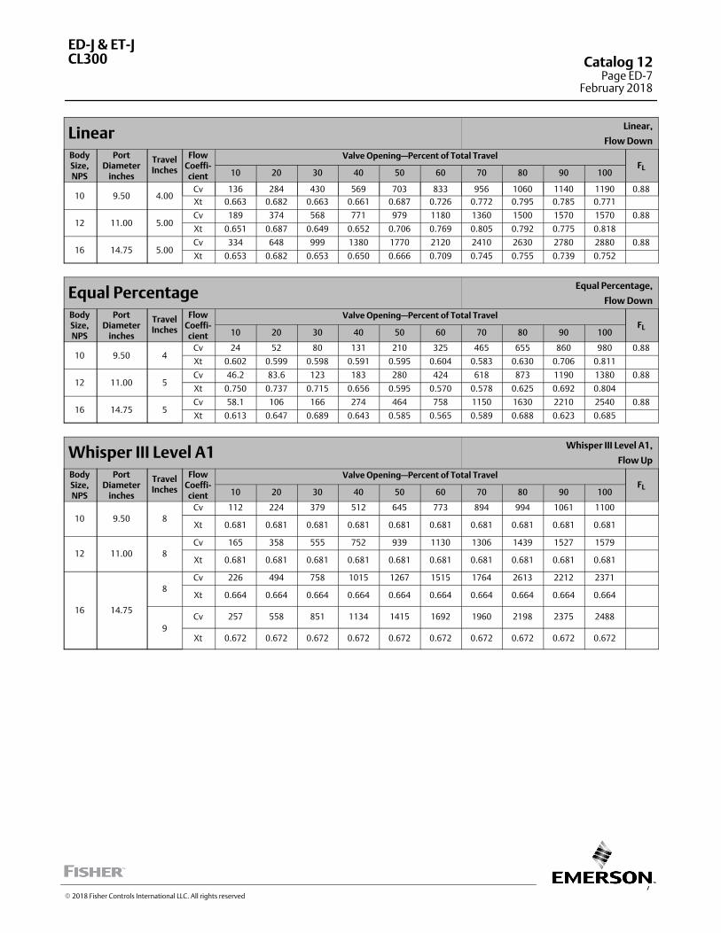
7
LinearLinear,
Flow Down
BodySize,NPS
PortDiameter
inches
TravelInches
FlowCoeffi‐cient
Valve Opening—Percent of Total TravelFL
10 20 30 40 50 60 70 80 90 100
10 9.50 4.00Cv 136 284 430 569 703 833 956 1060 1140 1190 0.88
Xt 0.663 0.682 0.663 0.661 0.687 0.726 0.772 0.795 0.785 0.771
12 11.00 5.00Cv 189 374 568 771 979 1180 1360 1500 1570 1570 0.88
Xt 0.651 0.687 0.649 0.652 0.706 0.769 0.805 0.792 0.775 0.818
16 14.75 5.00Cv 334 648 999 1380 1770 2120 2410 2630 2780 2880 0.88
Xt 0.653 0.682 0.653 0.650 0.666 0.709 0.745 0.755 0.739 0.752
Equal PercentageEqual Percentage,
Flow Down
BodySize,NPS
PortDiameter
inches
TravelInches
FlowCoeffi‐cient
Valve Opening—Percent of Total TravelFL
10 20 30 40 50 60 70 80 90 100
10 9.50 4Cv 24 52 80 131 210 325 465 655 860 980 0.88
Xt 0.602 0.599 0.598 0.591 0.595 0.604 0.583 0.630 0.706 0.811
12 11.00 5Cv 46.2 83.6 123 183 280 424 618 873 1190 1380 0.88
Xt 0.750 0.737 0.715 0.656 0.595 0.570 0.578 0.625 0.692 0.804
16 14.75 5Cv 58.1 106 166 274 464 758 1150 1630 2210 2540 0.88
Xt 0.613 0.647 0.689 0.643 0.585 0.565 0.589 0.688 0.623 0.685
Whisper III Level A1Whisper III Level A1,
Flow Up
BodySize,NPS
PortDiameter
inches
TravelInches
FlowCoeffi‐cient
Valve Opening—Percent of Total TravelFL
10 20 30 40 50 60 70 80 90 100
10 9.50 8
Cv 112 224 379 512 645 773 894 994 1061 1100
Xt 0.681 0.681 0.681 0.681 0.681 0.681 0.681 0.681 0.681 0.681
12 11.00 8
Cv 165 358 555 752 939 1130 1306 1439 1527 1579
Xt 0.681 0.681 0.681 0.681 0.681 0.681 0.681 0.681 0.681 0.681
16 14.75
8
Cv 226 494 758 1015 1267 1515 1764 2613 2212 2371
Xt 0.664 0.664 0.664 0.664 0.664 0.664 0.664 0.664 0.664 0.664
9
Cv 257 558 851 1134 1415 1692 1960 2198 2375 2488
Xt 0.672 0.672 0.672 0.672 0.672 0.672 0.672 0.672 0.672 0.672
ED-J & ET-JCL300 Catalog 12
Page ED-7February 2018
� 2018 Fisher Controls International LLC. All rights reserved
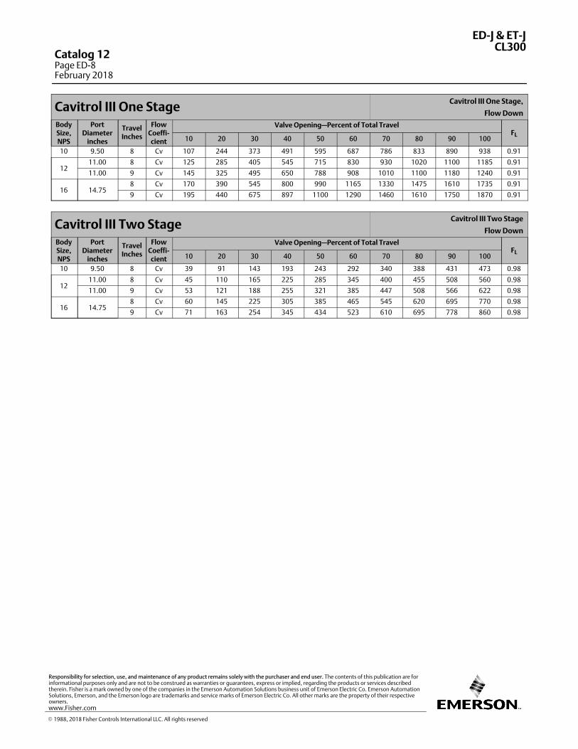
Cavitrol III One StageCavitrol III One Stage,
Flow Down
BodySize,NPS
PortDiameter
inches
TravelInches
FlowCoeffi‐cient
Valve Opening—Percent of Total TravelFL
10 20 30 40 50 60 70 80 90 100
10 9.50 8 Cv 107 244 373 491 595 687 786 833 890 938 0.91
1211.00 8 Cv 125 285 405 545 715 830 930 1020 1100 1185 0.91
11.00 9 Cv 145 325 495 650 788 908 1010 1100 1180 1240 0.91
16 14.758 Cv 170 390 545 800 990 1165 1330 1475 1610 1735 0.91
9 Cv 195 440 675 897 1100 1290 1460 1610 1750 1870 0.91
Cavitrol III Two StageCavitrol III Two Stage
Flow Down
BodySize,NPS
PortDiameter
inches
TravelInches
FlowCoeffi‐cient
Valve Opening—Percent of Total TravelFL
10 20 30 40 50 60 70 80 90 100
10 9.50 8 Cv 39 91 143 193 243 292 340 388 431 473 0.98
1211.00 8 Cv 45 110 165 225 285 345 400 455 508 560 0.98
11.00 9 Cv 53 121 188 255 321 385 447 508 566 622 0.98
16 14.758 Cv 60 145 225 305 385 465 545 620 695 770 0.98
9 Cv 71 163 254 345 434 523 610 695 778 860 0.98
ED-J & ET-JCL300
Catalog 12Page ED-8February 2018
� 1988, 2018 Fisher Controls International LLC. All rights reserved
www.Fisher.com
Responsibility for selection, use, and maintenance of any product remains solely with the purchaser and end user. The contents of this publication are forinformational purposes only and are not to be construed as warranties or guarantees, express or implied, regarding the products or services describedtherein. Fisher is a mark owned by one of the companies in the Emerson Automation Solutions business unit of Emerson Electric Co. Emerson AutomationSolutions, Emerson, and the Emerson logo are trademarks and service marks of Emerson Electric Co. All other marks are the property of their respectiveowners.
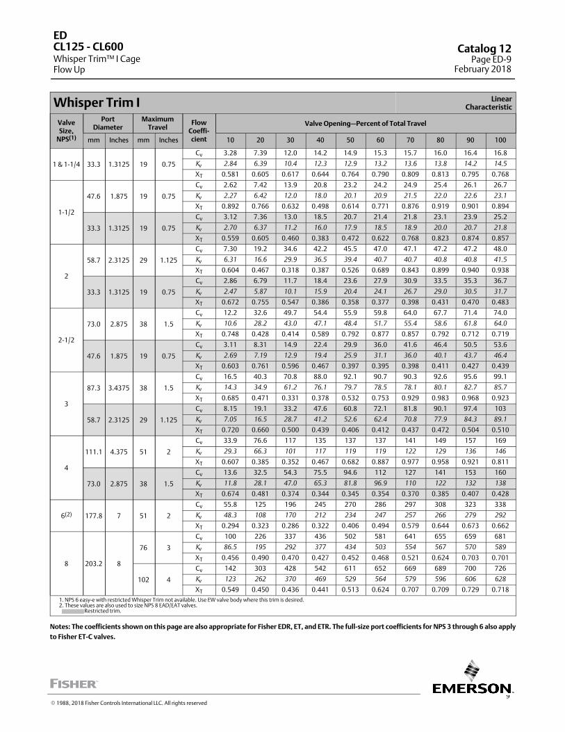
9
Whisper Trim I LinearCharacteristic
ValveSize,
NPS(1)
PortDiameter
MaximumTravel
FlowCoeffi‐cient
Valve Opening—Percent of Total Travel
mm Inches mm Inches 10 20 30 40 50 60 70 80 90 100
1 & 1-1/4 33.3 1.3125 19 0.75
Cv 3.28 7.39 12.0 14.2 14.9 15.3 15.7 16.0 16.4 16.8
Kv
2.84 6.39 10.4 12.3 12.9 13.2 13.6 13.8 14.2 14.5
XT 0.581 0.605 0.617 0.644 0.764 0.790 0.809 0.813 0.795 0.768
1-1/2
47.6 1.875 19 0.75
Cv 2.62 7.42 13.9 20.8 23.2 24.2 24.9 25.4 26.1 26.7
Kv
2.27 6.42 12.0 18.0 20.1 20.9 21.5 22.0 22.6 23.1
XT 0.892 0.766 0.632 0.498 0.614 0.771 0.876 0.919 0.901 0.894
33.3 1.3125 19 0.75
Cv 3.12 7.36 13.0 18.5 20.7 21.4 21.8 23.1 23.9 25.2
Kv
2.70 6.37 11.2 16.0 17.9 18.5 18.9 20.0 20.7 21.8
XT 0.559 0.605 0.460 0.383 0.472 0.622 0.768 0.823 0.874 0.857
2
58.7 2.3125 29 1.125
Cv 7.30 19.2 34.6 42.2 45.5 47.0 47.1 47.2 47.2 48.0
Kv
6.31 16.6 29.9 36.5 39.4 40.7 40.7 40.8 40.8 41.5
XT 0.604 0.467 0.318 0.387 0.526 0.689 0.843 0.899 0.940 0.938
33.3 1.3125 19 0.75
Cv 2.86 6.79 11.7 18.4 23.6 27.9 30.9 33.5 35.3 36.7
Kv
2.47 5.87 10.1 15.9 20.4 24.1 26.7 29.0 30.5 31.7
XT 0.672 0.755 0.547 0.386 0.358 0.377 0.398 0.431 0.470 0.483
2-1/2
73.0 2.875 38 1.5
Cv 12.2 32.6 49.7 54.4 55.9 59.8 64.0 67.7 71.4 74.0
Kv
10.6 28.2 43.0 47.1 48.4 51.7 55.4 58.6 61.8 64.0
XT 0.748 0.428 0.414 0.589 0.792 0.877 0.857 0.792 0.712 0.719
47.6 1.875 19 0.75
Cv 3.11 8.31 14.9 22.4 29.9 36.0 41.6 46.4 50.5 53.6
Kv
2.69 7.19 12.9 19.4 25.9 31.1 36.0 40.1 43.7 46.4
XT 0.603 0.761 0.596 0.467 0.397 0.395 0.398 0.411 0.427 0.439
3
87.3 3.4375 38 1.5
Cv 16.5 40.3 70.8 88.0 92.1 90.7 90.3 92.6 95.6 99.1
Kv
14.3 34.9 61.2 76.1 79.7 78.5 78.1 80.1 82.7 85.7
XT 0.685 0.471 0.331 0.378 0.532 0.753 0.929 0.983 0.968 0.923
58.7 2.3125 29 1.125
Cv 8.15 19.1 33.2 47.6 60.8 72.1 81.8 90.1 97.4 103
Kv
7.05 16.5 28.7 41.2 52.6 62.4 70.8 77.9 84.3 89.1
XT 0.720 0.660 0.500 0.439 0.406 0.412 0.437 0.472 0.504 0.510
4
111.1 4.375 51 2
Cv 33.9 76.6 117 135 137 137 141 149 157 169
Kv
29.3 66.3 101 117 119 119 122 129 136 146
XT 0.607 0.385 0.352 0.467 0.682 0.887 0.977 0.958 0.921 0.811
73.0 2.875 38 1.5
Cv 13.6 32.5 54.3 75.5 94.6 112 127 141 153 160
Kv
11.8 28.1 47.0 65.3 81.8 96.9 110 122 132 138
XT 0.674 0.481 0.374 0.344 0.345 0.354 0.370 0.385 0.407 0.428
6(2) 177.8 7 51 2
Cv 55.8 125 196 245 270 286 297 308 323 338
Kv
48.3 108 170 212 234 247 257 266 279 292
XT 0.294 0.323 0.286 0.322 0.406 0.494 0.579 0.644 0.673 0.662
8 203.2 8
76 3
Cv 100 226 337 436 502 581 641 655 659 681
Kv
86.5 195 292 377 434 503 554 567 570 589
XT 0.456 0.490 0.470 0.427 0.452 0.468 0.521 0.624 0.703 0.701
102 4
Cv 142 303 428 542 611 652 669 689 700 726
Kv
123 262 370 469 529 564 579 596 606 628
XT 0.549 0.450 0.436 0.441 0.513 0.624 0.707 0.709 0.729 0.718
1. NPS 6 easy-e with restricted Whisper Trim not available. Use EW valve body where this trim is desired.2. These values are also used to size NPS 8 EAD/EAT valves. Restricted trim.
Notes: The coefficients shown on this page are also appropriate for Fisher EDR, ET, and ETR. The full‐size port coefficients for NPS 3 through 6 also apply
to Fisher ET‐C valves.
ED
Whisper Trim™ I CageFlow Up
CL125 ‐ CL600 Catalog 12Page ED-9
February 2018
� 1988, 2018 Fisher Controls International LLC. All rights reserved
This page is intentionally left blank.
ED
Whisper Trim I CageFlow Up
CL125 ‐ CL600Catalog 12Page ED-10February 2018
� 2018 Fisher Controls International LLC. All rights reserved
www.Fisher.com
Responsibility for selection, use, and maintenance of any product remains solely with the purchaser and end user. The contents of this publication are forinformational purposes only and are not to be construed as warranties or guarantees, express or implied, regarding the products or services describedtherein. Fisher and Whisper Trim are marks owned by one of the companies in the Emerson Automation Solutions business unit of Emerson Electric Co.Emerson Automation Solutions, Emerson, and the Emerson logo are trademarks and service marks of Emerson Electric Co. All other marks are the propertyof their respective owners.
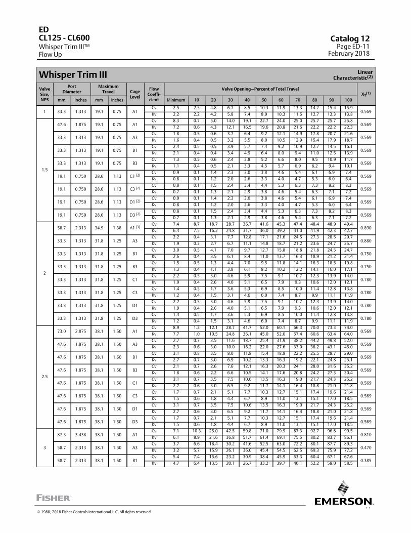
11
Whisper Trim III LinearCharacteristic(2)
ValveSize,NPS
PortDiameter
MaximumTravel Cage
Level
FlowCoeffi‐cient
Valve Opening—Percent of Total TravelXT
(1)
mm Inches mm Inches Minimum 10 20 30 40 50 60 70 80 90 100
1 33.3 1.313 19.1 0.75 A1Cv 2.5 2.5 4.8 6.7 8.5 10.3 11.9 13.3 14.7 15.4 15.9
0.569Kv 2.2 2.2 4.2 5.8 7.4 8.9 10.3 11.5 12.7 13.3 13.8
1.5
47.6 1.875 19.1 0.75 A1Cv 8.3 0.7 5.0 14.0 19.1 22.7 24.0 25.0 25.7 25.7 25.8
0.569Kv 7.2 0.6 4.3 12.1 16.5 19.6 20.8 21.6 22.2 22.2 22.3
33.3 1.313 19.1 0.75 A3Cv 1.8 0.5 0.6 3.7 6.4 9.2 12.1 14.9 17.8 20.7 21.6
0.569Kv 1.6 0.4 0.5 3.2 5.5 8.0 10.5 12.9 15.4 17.9 18.7
33.3 1.313 19.1 0.75 B1Cv 2.4 0.5 0.5 3.9 5.7 7.4 9.2 10.9 12.7 14.5 16.1
0.569Kv 2.1 0.4 0.4 3.4 4.9 6.4 8.0 9.4 11.0 12.5 13.9
33.3 1.313 19.1 0.75 B3Cv 1.3 0.5 0.6 2.4 3.8 5.2 6.6 8.0 9.5 10.9 11.7
0.569Kv 1.1 0.4 0.5 2.1 3.3 4.5 5.7 6.9 8.2 9.4 10.1
19.1 0.750 28.6 1.13 C1 (2)Cv 0.9 0.1 1.4 2.3 3.0 3.8 4.6 5.4 6.1 6.9 7.4
0.569Kv 0.8 0.1 1.2 2.0 2.6 3.3 4.0 4.7 5.3 6.0 6.4
19.1 0.750 28.6 1.13 C3 (2)Cv 0.8 0.1 1.5 2.4 3.4 4.4 5.3 6.3 7.3 8.2 8.3
0.569Kv 0.7 0.1 1.3 2.1 2.9 3.8 4.6 5.4 6.3 7.1 7.2
19.1 0.750 28.6 1.13 D1 (2)Cv 0.9 0.1 1.4 2.3 3.0 3.8 4.6 5.4 6.1 6.9 7.4
0.569Kv 0.8 0.1 1.2 2.0 2.6 3.3 4.0 4.7 5.3 6.0 6.4
19.1 0.750 28.6 1.13 D3 (2)Cv 0.8 0.1 1.5 2.4 3.4 4.4 5.3 6.3 7.3 8.2 8.3
0.569Kv 0.7 0.1 1.3 2.1 2.9 3.8 4.6 5.4 6.3 7.1 7.2
2
58.7 2.313 34.9 1.38 A1 (3)Cv 7.4 8.7 18.7 28.7 36.7 41.6 45.3 47.4 48.4 48.9 49.4
0.890Kv 6.4 7.5 16.2 24.8 31.7 36.0 39.2 41.0 41.9 42.3 42.7
33.3 1.313 31.8 1.25 A3Cv 2.2 0.4 3.1 7.7 12.8 17.1 21.6 24.5 27.3 28.5 29.7
0.880Kv 1.9 0.3 2.7 6.7 11.1 14.8 18.7 21.2 23.6 24.7 25.7
33.3 1.313 31.8 1.25 B1Cv 3.0 0.5 4.1 7.0 9.7 12.7 15.8 18.8 21.8 24.5 24.7
0.750Kv 2.6 0.4 3.5 6.1 8.4 11.0 13.7 16.3 18.9 21.2 21.4
33.3 1.313 31.8 1.25 B3Cv 1.5 0.5 1.3 4.4 7.0 9.5 11.8 14.1 16.3 18.5 19.8
0.750Kv 1.3 0.4 1.1 3.8 6.1 8.2 10.2 12.2 14.1 16.0 17.1
33.3 1.313 31.8 1.25 C1Cv 2.2 0.5 3.0 4.6 5.9 7.5 9.1 10.7 12.3 13.9 14.0
0.780Kv 1.9 0.4 2.6 4.0 5.1 6.5 7.9 9.3 10.6 12.0 12.1
33.3 1.313 31.8 1.25 C3Cv 1.4 0.5 1.7 3.6 5.3 6.9 8.5 10.0 11.4 12.8 13.8
0.780Kv 1.2 0.4 1.5 3.1 4.6 6.0 7.4 8.7 9.9 11.1 11.9
33.3 1.313 31.8 1.25 D1Cv 2.2 0.5 3.0 4.6 5.9 7.5 9.1 10.7 12.3 13.9 14.0
0.780Kv 1.9 0.4 2.6 4.0 5.1 6.5 7.9 9.3 10.6 12.0 12.1
33.3 1.313 31.8 1.25 D3Cv 1.4 0.5 1.7 3.6 5.3 6.9 8.5 10.0 11.4 12.8 13.8
0.780Kv 1.2 0.4 1.5 3.1 4.6 6.0 7.4 8.7 9.9 11.1 11.9
2.5
73.0 2.875 38.1 1.50 A1Cv 8.9 1.2 12.1 28.7 41.7 52.0 60.1 66.3 70.0 73.3 74.0
0.569Kv 7.7 1.0 10.5 24.8 36.1 45.0 52.0 57.4 60.6 63.4 64.0
47.6 1.875 38.1 1.50 A3Cv 2.7 0.7 3.5 11.6 18.7 25.4 31.9 38.2 44.2 49.8 52.0
0.569Kv 2.3 0.6 3.0 10.0 16.2 22.0 27.6 33.0 38.2 43.1 45.0
47.6 1.875 38.1 1.50 B1Cv 3.1 0.8 3.5 8.0 11.8 15.4 18.9 22.2 25.5 28.7 29.0
0.569Kv 2.7 0.7 3.0 6.9 10.2 13.3 16.3 19.2 22.1 24.8 25.1
47.6 1.875 38.1 1.50 B3Cv 2.1 0.7 2.6 7.6 12.1 16.3 20.3 24.1 28.0 31.6 35.2
0.569Kv 1.8 0.6 2.2 6.6 10.5 14.1 17.6 20.8 24.2 27.3 30.4
47.6 1.875 38.1 1.50 C1Cv 3.1 0.7 3.5 7.5 10.6 13.5 16.3 19.0 21.7 24.3 25.2
0.569Kv 2.7 0.6 3.0 6.5 9.2 11.7 14.1 16.4 18.8 21.0 21.8
47.6 1.875 38.1 1.50 C3Cv 1.7 0.7 2.1 5.1 7.7 10.3 12.7 15.1 17.4 19.6 21.4
0.569Kv 1.5 0.6 1.8 4.4 6.7 8.9 11.0 13.1 15.1 17.0 18.5
47.6 1.875 38.1 1.50 D1Cv 3.1 0.7 3.5 7.5 10.6 13.5 16.3 19.0 21.7 24.3 25.2
0.569Kv 2.7 0.6 3.0 6.5 9.2 11.7 14.1 16.4 18.8 21.0 21.8
47.6 1.875 38.1 1.50 D3Cv 1.7 0.7 2.1 5.1 7.7 10.3 12.7 15.1 17.4 19.6 21.4
0.569Kv 1.5 0.6 1.8 4.4 6.7 8.9 11.0 13.1 15.1 17.0 18.5
3
87.3 3.438 38.1 1.50 A1Cv 7.1 10.3 25.0 42.5 59.8 71.0 79.9 87.3 92.7 96.8 99.5
0.810Kv 6.1 8.9 21.6 36.8 51.7 61.4 69.1 75.5 80.2 83.7 86.1
58.7 2.313 38.1 1.50 A3Cv 3.7 6.6 18.4 30.2 41.6 52.5 63.0 72.2 80.1 87.7 89.3
0.470Kv 3.2 5.7 15.9 26.1 36.0 45.4 54.5 62.5 69.3 75.9 77.2
58.7 2.313 38.1 1.50 B1Cv 5.4 7.4 15.6 23.2 30.9 38.4 45.9 53.3 60.4 67.1 67.6
0.385Kv 4.7 6.4 13.5 20.1 26.7 33.2 39.7 46.1 52.2 58.0 58.5
ED
Whisper Trim III™Flow Up
CL125 ‐ CL600 Catalog 12Page ED-11
February 2018
� 1988, 2018 Fisher Controls International LLC. All rights reserved
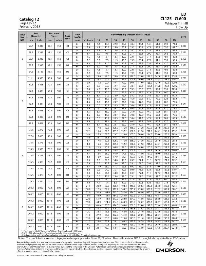
ValveSize,NPS
PortDiameter
MaximumTravel Cage
Level
FlowCoeffi‐cient
Valve Opening—Percent of Total TravelXT
(1)
mm Inches mm Inches Minimum 10 20 30 40 50 60 70 80 90 100
3
58.7 2.313 38.1 1.50 B3Cv 3.3 5.4 13.8 22.0 30.2 38.4 46.4 54.3 61.9 69.0 74.8
0.385Kv 2.9 4.7 11.9 19.0 26.1 33.2 40.1 47.0 53.5 59.7 64.7
58.7 2.313 38.1 1.50 C1Cv 4.3 5.8 11.0 15.6 20.2 24.7 29.2 33.8 38.3 42.7 45.5
0.356Kv 3.7 5.0 9.5 13.5 17.5 21.4 25.3 29.2 33.1 36.9 39.4
58.7 2.313 38.1 1.50 C3Cv 2.6 4.1 8.7 13.3 17.9 22.5 27.0 31.5 36.0 40.5 45.0
0.356Kv 2.2 3.5 7.5 11.5 15.5 19.5 23.4 27.2 31.1 35.0 38.9
58.7 2.313 38.1 1.50 D1Cv 4.3 5.8 11.0 15.6 20.2 24.7 29.2 33.8 38.3 42.7 45.5
0.356Kv 3.7 5.0 9.5 13.5 17.5 21.4 25.3 29.2 33.1 36.9 39.4
54.2 2.133 38.1 1.50 D3Cv 2.6 4.1 8.7 13.3 17.9 22.5 27.0 31.5 36.0 40.5 45.0
0.356Kv 2.2 3.5 7.5 11.5 15.5 19.5 23.4 27.2 31.1 35.0 38.9
4
111.1 4.375 50.8 2.00 A1Cv 10.9 28.0 49.0 78.0 96.4 116.0 126.0 137.0 142.0 148.0 158.0
0.770Kv 9.4 24.2 42.4 67.5 83.4 100.3 109.0 118.5 122.8 128.0 136.7
87.3 3.438 50.8 2.00 A3Cv 5.9 11.2 27.4 49.4 70.0 90.6 110.0 125.0 135.0 139.0 139.0
0.810Kv 5.1 9.7 23.7 42.7 60.6 78.4 95.2 108.1 116.8 120.2 120.2
87.3 3.438 50.8 2.00 B1Cv 7.4 4.3 19.6 32.0 43.8 55.3 66.6 77.9 88.9 99.8 109.0
0.492Kv 6.4 3.7 17.0 27.7 37.9 47.8 57.6 67.4 76.9 86.3 94.3
87.3 3.438 50.8 2.00 B3Cv 4.4 8.4 21.2 32.9 43.7 54.2 64.5 74.8 85.1 95.5 102.0
0.492Kv 3.8 7.3 18.3 28.5 37.8 46.9 55.8 64.7 73.6 82.6 88.2
87.3 3.438 50.8 2.00 C1Cv 4.6 6.5 15.3 23.7 31.9 39.8 47.6 55.2 62.8 70.3 76.6
0.523Kv 4.0 5.6 13.2 20.5 27.6 34.4 41.2 47.8 54.3 60.8 66.3
87.3 3.438 50.8 2.00 C3Cv 4.0 10.1 18.4 26.2 33.5 40.5 47.3 54.0 60.6 67.2 73.8
0.467Kv 3.5 8.7 15.9 22.7 29.0 35.0 40.9 46.7 52.4 58.1 63.8
87.3 3.438 50.8 2.00 D1Cv 4.6 6.5 15.3 23.7 31.9 39.8 47.6 55.2 62.8 70.3 76.6
0.523Kv 4.0 5.6 13.2 20.5 27.6 34.4 41.2 47.8 54.3 60.8 66.3
87.3 3.438 50.8 2.00 D3Cv 4.0 10.1 18.4 26.2 33.5 40.5 47.3 54.0 60.6 67.2 73.8
0.467Kv 3.5 8.7 15.9 22.7 29.0 35.0 40.9 46.7 52.4 58.1 63.8
6
136.5 5.375 76.2 3.00 A1Cv 14.2 17.8 67.6 126.0 176.0 216.0 246.0 267.0 281.0 290.0 294.9
0.563Kv 12.3 15.4 58.5 109.0 152.2 186.9 212.8 231.0 243.1 250.9 255.1
177.8 7.000 50.8 2.00 A1Cv 18.4 25.5 32.5 73.7 120.0 165.0 204.0 234.0 256.0 273.0 285.6
0.563Kv 15.9 22.1 28.1 63.8 103.8 142.7 176.5 202.4 221.5 236.2 247.1
136.5 5.375 76.2 3.00 A3Cv 4.7 17.8 67.6 126.0 176.0 216.0 246.0 267.0 281.0 290.0 295.0
0.563Kv 4.0 15.4 58.5 109.0 152.2 186.9 212.8 231.0 243.1 250.9 255.2
136.5 5.375 76.2 3.00 B1Cv 11.6 21.5 45.2 68.8 92.5 116.2 140.0 163.6 187.3 211.0 231.2
0.563Kv 10.0 18.6 39.1 59.5 80.0 100.5 121.1 141.5 162.0 182.5 200.0
136.5 5.375 76.2 3.00 B3Cv 4.7 12.6 38.2 66.9 94.5 120.0 144.0 167.0 190.0 211.0 228.0
0.563Kv 4.0 10.9 33.0 57.9 81.7 103.8 124.6 144.5 164.4 182.5 197.2
136.5 5.375 76.2 3.00 C1Cv 8.0 6.5 20.6 34.0 48.5 63.7 77.4 91.3 107.2 121.0 129.3
0.563Kv 6.9 5.6 17.8 29.4 42.0 55.1 67.0 79.0 92.7 104.7 111.9
136.5 5.375 76.2 3.00 C3Cv 4.7 11.0 28.0 41.3 55.3 69.3 83.0 97.0 110.0 124.0 138.0
0.563Kv 4.0 9.5 24.2 35.7 47.8 59.9 71.8 83.9 95.2 107.3 119.4
136.5 5.375 76.2 3.00 D1Cv 8.0 6.5 20.6 34.0 48.5 63.7 77.4 91.3 107.2 121.0 129.3
0.563Kv 6.9 5.6 17.8 29.4 42.0 55.1 67.0 79.0 92.7 104.7 111.9
136.5 5.375 76.2 3.00 D3Cv 4.7 5.1 6.7 9.5 19.9 31.4 46.0 61.0 75.7 89.7 104.0
0.563Kv 4.0 4.4 5.8 8.2 17.2 27.2 39.8 52.8 65.5 77.6 90.0
8
203.2 8.000 76.2 3.00 A1Cv 21.5 20.0 77.9 136.1 194.4 249.3 300.3 347.1 384.0 416.0 425.7
0.626Kv 18.6 17.3 67.4 117.7 168.2 215.7 259.8 300.3 332.2 359.9 368.3
203.2 8.000 101.6 4.00 A1Cv 22.0 51.9 144.0 213.0 282.0 374.0 443.0 495.0 558.0 601.0 638.0
0.626Kv 19.0 44.9 124.6 184.3 243.9 323.5 383.2 428.2 482.7 519.9 551.9
203.2 8.000 101.6 4.00 A3Cv 22.0 51.9 144.0 213.0 282.0 374.0 443.0 495.0 558.0 601.0 638.0
0.626Kv 19.0 44.9 124.6 184.3 243.9 323.5 383.2 428.2 482.7 519.9 551.9
203.2 8.000 101.6 4.00 B1Cv 15.0 43.0 85.0 126.0 168.0 209.0 250.0 292.0 333.0 374.0 406.0
0.566Kv 13.0 37.2 73.5 109.0 145.3 180.8 216.3 252.6 288.1 323.5 351.2
203.2 8.000 101.6 4.00 B3Cv 12.7 32.3 75.8 119.0 163.0 206.0 241.0 285.0 328.0 363.0 407.0
0.566Kv 11.0 27.9 65.6 102.9 141.0 178.2 208.5 246.5 283.7 314.0 352.1
203.2 8.000 101.6 4.00 C1Cv 13.0 34.0 61.0 88.0 116.0 143.0 171.0 198.0 226.0 253.0 280.0
0.566Kv 11.2 29.4 52.8 76.1 100.3 123.7 147.9 171.3 195.5 218.9 242.2
203.2 8.000 101.6 4.00 C3Cv 10.2 26.7 47.1 74.4 102.0 129.0 156.0 184.0 204.0 232.0 259.0
0.566Kv 8.8 23.1 40.7 64.4 88.2 111.6 134.9 159.2 176.5 200.7 224.0
1. This column lists XT factors for Whisper Trim III calges at 100% travel.2. NPS 1 1/2 valves with 3/4"port diameter is for ES constructions only3. Not applicable for ET with Spring loaded seal ring or ED with Class IV mulitiple piston rings
Notes: The coefficients shown on this page are also appropriate for Fisher ES, ET valves. The coefficients for NPS 3 through 8 also apply to Fisher ET-C valves.
ED
Whisper Trim IIIFlow Up
CL125 ‐ CL600Catalog 12Page ED-12February 2018
� 1988, 2018 Fisher Controls International LLC. All rights reserved
www.Fisher.com
Responsibility for selection, use, and maintenance of any product remains solely with the purchaser and end user. The contents of this publication are forinformational purposes only and are not to be construed as warranties or guarantees, express or implied, regarding the products or services describedtherein. Fisher and Whisper Trim are marks owned by one of the companies in the Emerson Automation Solutions business unit of Emerson Electric Co.Emerson Automation Solutions, Emerson, and the Emerson logo are trademarks and service marks of Emerson Electric Co. All other marks are the propertyof their respective owners.
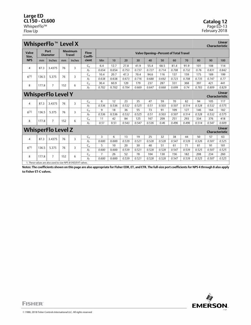
13
WhisperFlo� Level X LinearCharacteristic
ValveSize,NPS
PortDiameter
MaximumTravel
FlowCoeffi‐cient
Valve Opening—Percent of Total Travel
mm Inches mm Inches Min 10 20 30 40 50 60 70 80 90 100
4 87.3 3.4375 76 3Cv 6.4 12.7 27.8 41.9 55.4 68.5 81.4 91.9 101 108 114
XT
0.654 0.654 0.753 0.737 0.727 0.714 0.708 0.732 0.76 0.831 0.842
6(1) 136.5 5.375 76 3Cv 10.4 20.7 47.3 70.4 94.6 116 137 159 175 189 199
XT
0.638 0.638 0.673 0.716 0.688 0.692 0.723 0.708 0.735 0.747 0.77
8 177.8 7 152 6Cv 30.4 60.9 120 179 237 287 331 368 397 421 441
XT
0.702 0.702 0.704 0.669 0.647 0.668 0.699 0.74 0.783 0.809 0.829
WhisperFlo Level Y LinearCharacteristic
4 87.3 3.4375 76 3Cv 6 12 23 35 47 59 70 82 94 105 117
XT
0.536 0.536 0.532 0.525 0.51 0.503 0.507 0.514 0.528 0.532 0.575
6(1) 136.5 5.375 76 3Cv 9 18 36 55 73 91 109 127 146 164 182
XT
0.536 0.536 0.532 0.525 0.51 0.503 0.507 0.514 0.528 0.532 0.575
8 177.8 7 152 6Cv 11 42 84 125 167 209 251 293 334 376 418
XT
0.51 0.51 0.543 0.547 0.536 0.46 0.496 0.496 0.514 0.547 0.609
WhisperFlo Level Z LinearCharacteristic
4 87.3 3.4375 76 3Cv 3 6 13 19 25 32 38 44 50 57 63
XT
0.600 0.600 0.539 0.521 0.528 0.528 0.547 0.539 0.526 0.507 0.525
6(1) 136.5 5.375 76 3Cv 5 10 20 30 40 51 61 71 81 91 101
XT
0.600 0.600 0.539 0.521 0.528 0.528 0.547 0.539 0.525 0.507 0.525
8 177.8 7 152 6Cv 7 26 52 78 104 130 156 182 208 234 260
XT
0.600 0.600 0.539 0.521 0.528 0.528 0.547 0.539 0.525 0.507 0.525
1. These values are also used to size NPS 8 EAD/EAT valves.
Notes: The coefficients shown on this page are also appropriate for Fisher EDR, ET, and ETR. The full‐size port coefficients for NPS 4 through 8 also apply
to Fisher ET‐C valves.
Large ED
WhisperFlo™Flow Up
CL150 ‐ CL600 Catalog 12Page ED-13
February 2018
� 1988, 2018 Fisher Controls International LLC. All rights reserved
This page is intentionally left blank.
ED
WhisperFloFlow Up
CL125 ‐ CL600Catalog 12Page ED-14February 2018
� 2018 Fisher Controls International LLC. All rights reserved
www.Fisher.com
Responsibility for selection, use, and maintenance of any product remains solely with the purchaser and end user. The contents of this publication are forinformational purposes only and are not to be construed as warranties or guarantees, express or implied, regarding the products or services describedtherein. Fisher, Whisper Trim, and WhisperFlo are marks owned by one of the companies in the Emerson Automation Solutions business unit of EmersonElectric Co. Emerson Automation Solutions, Emerson, and the Emerson logo are trademarks and service marks of Emerson Electric Co. All other marks arethe property of their respective owners.
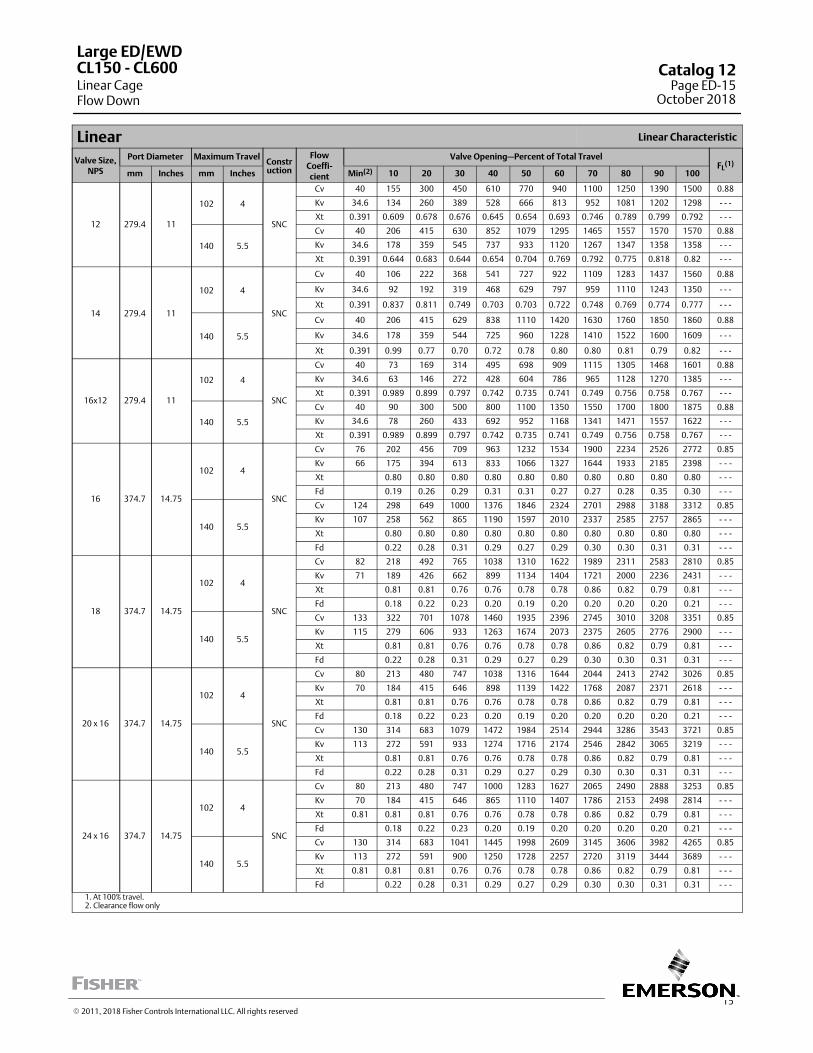
15
Linear Linear Characteristic
Valve Size,NPS
Port Diameter Maximum TravelConstruction
FlowCoeffi‐cient
Valve Opening—Percent of Total TravelFL
(1)
mm Inches mm Inches Min(2) 10 20 30 40 50 60 70 80 90 100
12 279.4 11
102 4
SNC
Cv 40 155 300 450 610 770 940 1100 1250 1390 1500 0.88
Kv 34.6 134 260 389 528 666 813 952 1081 1202 1298 ‐ ‐ ‐
Xt 0.391 0.609 0.678 0.676 0.645 0.654 0.693 0.746 0.789 0.799 0.792 ‐ ‐ ‐
140 5.5
Cv 40 206 415 630 852 1079 1295 1465 1557 1570 1570 0.88
Kv 34.6 178 359 545 737 933 1120 1267 1347 1358 1358 ‐ ‐ ‐
Xt 0.391 0.644 0.683 0.644 0.654 0.704 0.769 0.792 0.775 0.818 0.82 ‐ ‐ ‐
14 279.4 11
102 4
SNC
Cv 40 106 222 368 541 727 922 1109 1283 1437 1560 0.88
Kv 34.6 92 192 319 468 629 797 959 1110 1243 1350 ‐ ‐ ‐
Xt 0.391 0.837 0.811 0.749 0.703 0.703 0.722 0.748 0.769 0.774 0.777 ‐ ‐ ‐
140 5.5
Cv 40 206 415 629 838 1110 1420 1630 1760 1850 1860 0.88
Kv 34.6 178 359 544 725 960 1228 1410 1522 1600 1609 ‐ ‐ ‐
Xt 0.391 0.99 0.77 0.70 0.72 0.78 0.80 0.80 0.81 0.79 0.82 ‐ ‐ ‐
16x12 279.4 11
102 4
SNC
Cv 40 73 169 314 495 698 909 1115 1305 1468 1601 0.88
Kv 34.6 63 146 272 428 604 786 965 1128 1270 1385 ‐ ‐ ‐
Xt 0.391 0.989 0.899 0.797 0.742 0.735 0.741 0.749 0.756 0.758 0.767 ‐ ‐ ‐
140 5.5
Cv 40 90 300 500 800 1100 1350 1550 1700 1800 1875 0.88
Kv 34.6 78 260 433 692 952 1168 1341 1471 1557 1622 ‐ ‐ ‐
Xt 0.391 0.989 0.899 0.797 0.742 0.735 0.741 0.749 0.756 0.758 0.767 ‐ ‐ ‐
16 374.7 14.75
102 4
SNC
Cv 76 202 456 709 963 1232 1534 1900 2234 2526 2772 0.85
Kv 66 175 394 613 833 1066 1327 1644 1933 2185 2398 ‐ ‐ ‐
Xt 0.80 0.80 0.80 0.80 0.80 0.80 0.80 0.80 0.80 0.80 ‐ ‐ ‐
Fd 0.19 0.26 0.29 0.31 0.31 0.27 0.27 0.28 0.35 0.30 ‐ ‐ ‐
140 5.5
Cv 124 298 649 1000 1376 1846 2324 2701 2988 3188 3312 0.85
Kv 107 258 562 865 1190 1597 2010 2337 2585 2757 2865 ‐ ‐ ‐
Xt 0.80 0.80 0.80 0.80 0.80 0.80 0.80 0.80 0.80 0.80 ‐ ‐ ‐
Fd 0.22 0.28 0.31 0.29 0.27 0.29 0.30 0.30 0.31 0.31 ‐ ‐ ‐
18 374.7 14.75
102 4
SNC
Cv 82 218 492 765 1038 1310 1622 1989 2311 2583 2810 0.85
Kv 71 189 426 662 899 1134 1404 1721 2000 2236 2431 ‐ ‐ ‐
Xt 0.81 0.81 0.76 0.76 0.78 0.78 0.86 0.82 0.79 0.81 ‐ ‐ ‐
Fd 0.18 0.22 0.23 0.20 0.19 0.20 0.20 0.20 0.20 0.21 ‐ ‐ ‐
140 5.5
Cv 133 322 701 1078 1460 1935 2396 2745 3010 3208 3351 0.85
Kv 115 279 606 933 1263 1674 2073 2375 2605 2776 2900 ‐ ‐ ‐
Xt 0.81 0.81 0.76 0.76 0.78 0.78 0.86 0.82 0.79 0.81 ‐ ‐ ‐
Fd 0.22 0.28 0.31 0.29 0.27 0.29 0.30 0.30 0.31 0.31 ‐ ‐ ‐
20 x 16 374.7 14.75
102 4
SNC
Cv 80 213 480 747 1038 1316 1644 2044 2413 2742 3026 0.85
Kv 70 184 415 646 898 1139 1422 1768 2087 2371 2618 ‐ ‐ ‐
Xt 0.81 0.81 0.76 0.76 0.78 0.78 0.86 0.82 0.79 0.81 ‐ ‐ ‐
Fd 0.18 0.22 0.23 0.20 0.19 0.20 0.20 0.20 0.20 0.21 ‐ ‐ ‐
140 5.5
Cv 130 314 683 1079 1472 1984 2514 2944 3286 3543 3721 0.85
Kv 113 272 591 933 1274 1716 2174 2546 2842 3065 3219 ‐ ‐ ‐
Xt 0.81 0.81 0.76 0.76 0.78 0.78 0.86 0.82 0.79 0.81 ‐ ‐ ‐
Fd 0.22 0.28 0.31 0.29 0.27 0.29 0.30 0.30 0.31 0.31 ‐ ‐ ‐
24 x 16 374.7 14.75
102 4
SNC
Cv 80 213 480 747 1000 1283 1627 2065 2490 2888 3253 0.85
Kv 70 184 415 646 865 1110 1407 1786 2153 2498 2814 ‐ ‐ ‐
Xt 0.81 0.81 0.81 0.76 0.76 0.78 0.78 0.86 0.82 0.79 0.81 ‐ ‐ ‐
Fd 0.18 0.22 0.23 0.20 0.19 0.20 0.20 0.20 0.20 0.21 ‐ ‐ ‐
140 5.5
Cv 130 314 683 1041 1445 1998 2609 3145 3606 3982 4265 0.85
Kv 113 272 591 900 1250 1728 2257 2720 3119 3444 3689 ‐ ‐ ‐
Xt 0.81 0.81 0.81 0.76 0.76 0.78 0.78 0.86 0.82 0.79 0.81 ‐ ‐ ‐
Fd 0.22 0.28 0.31 0.29 0.27 0.29 0.30 0.30 0.31 0.31 ‐ ‐ ‐
1. At 100% travel.2. Clearance flow only
Large ED/EWD
Linear CageFlow Down
CL150 ‐ CL600 Catalog 12Page ED-15
October 2018
� 2011, 2018 Fisher Controls International LLC. All rights reserved
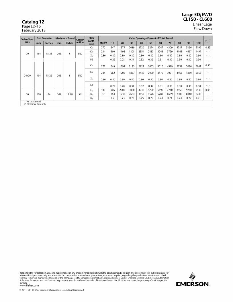
Valve Size,NPS
Port Diameter Maximum TravelConstruction
FlowCoeffi‐cient
Valve Opening—Percent of Total TravelFL
(1)
mm Inches mm Inches Min(2) 10 20 30 40 50 60 70 80 90 100
20 464 18.25 203 8 SNC
Cv 270 647 1377 2089 2720 3274 3747 4309 4787 5196 5196 0.85
Kv 234 560 1192 1808 2354 2833 3243 3729 4143 4497 4497 - - -
Xt 0.80 0.80 0.80 0.80 0.80 0.80 0.80 0.80 0.80 0.80 0.80 - - -
Fd 0.22 0.28 0.31 0.32 0.32 0.31 0.30 0.30 0.30 0.30 - - -
24x20 464 18.25 203 8 SNC
Cv 271 649 1394 2123 2827 3455 4010 4589 5157 5626 5841 0.85
Kv 234 562 1206 1837 2446 2990 3470 3971 4463 4869 5055 - - -
Xt 0.80 0.80 0.80 0.80 0.80 0.80 0.80 0.80 0.80 0.80 0.80 - - -
Fd 0.22 0.28 0.31 0.32 0.32 0.31 0.30 0.30 0.30 0.30 - - -
30 610 24 302 11.88 SN
Cv 100 906 2000 3080 4230 5290 6690 7710 8450 9260 9530 0.99
Kv 87 784 1730 2664 3659 4576 5787 6669 7309 8010 8243 - - -
XT 0.7 0.73 0.72 0.75 0.72 0.74 0.71 0.74 0.72 0.71 - - -1. At 100% travel.2. Clearance flow only
Large ED/EWD
Linear CageFlow Down
CL150 ‐ CL600Catalog 12Page ED-16February 2018
� 2011, 2018 Fisher Controls International LLC. All rights reserved
www.Fisher.com
Responsibility for selection, use, and maintenance of any product remains solely with the purchaser and end user. The contents of this publication are forinformational purposes only and are not to be construed as warranties or guarantees, express or implied, regarding the products or services describedtherein. Fisher is a mark owned by one of the companies in the Emerson Automation Solutions business unit of Emerson Electric Co. Emerson AutomationSolutions, Emerson, and the Emerson logo are trademarks and service marks of Emerson Electric Co. All other marks are the property of their respectiveowners.
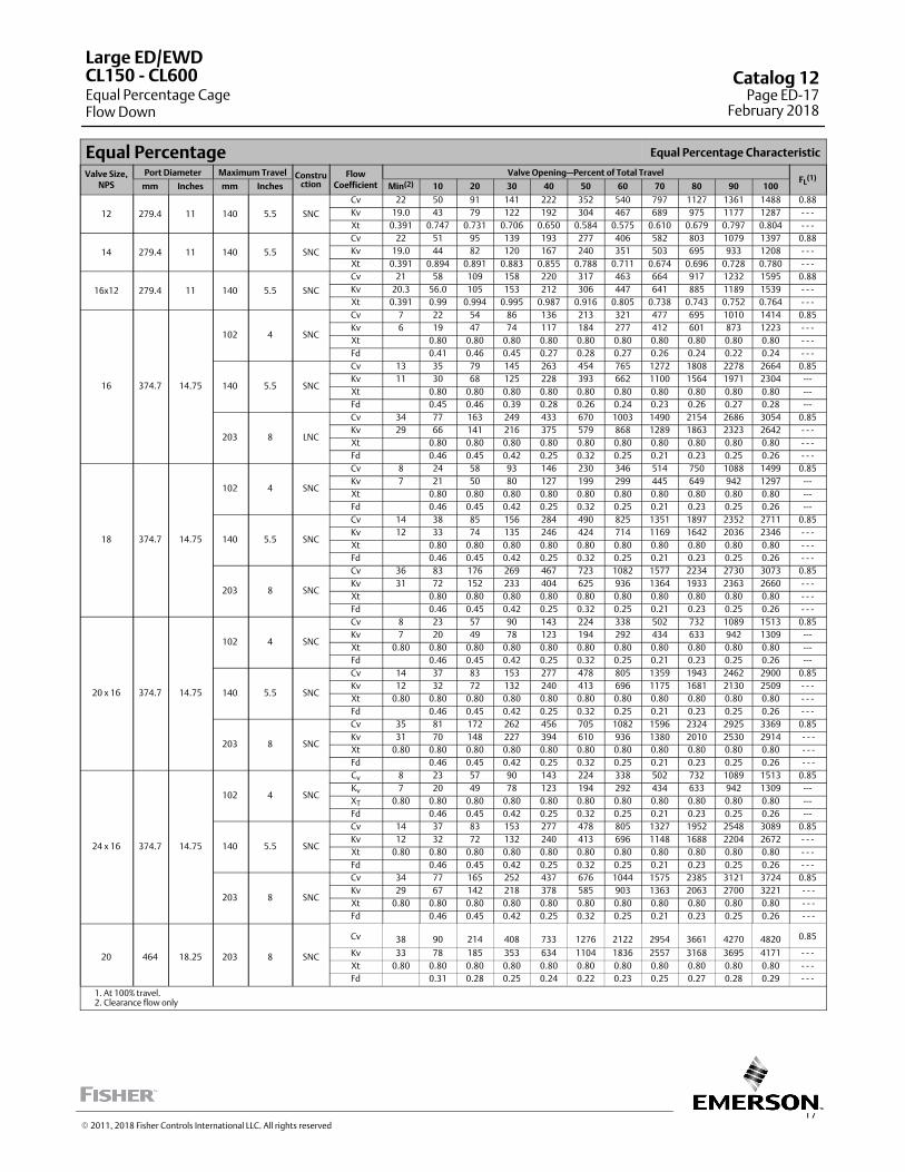
17
Equal Percentage Equal Percentage Characteristic
Valve Size,NPS
Port Diameter Maximum Travel Construction
FlowCoefficient
Valve Opening—Percent of Total TravelFL
(1)mm Inches mm Inches Min(2) 10 20 30 40 50 60 70 80 90 100
12 279.4 11 140 5.5 SNC
Cv 22 50 91 141 222 352 540 797 1127 1361 1488 0.88
Kv 19.0 43 79 122 192 304 467 689 975 1177 1287 ‐ ‐ ‐
Xt 0.391 0.747 0.731 0.706 0.650 0.584 0.575 0.610 0.679 0.797 0.804 ‐ ‐ ‐
14 279.4 11 140 5.5 SNC
Cv 22 51 95 139 193 277 406 582 803 1079 1397 0.88
Kv 19.0 44 82 120 167 240 351 503 695 933 1208 ‐ ‐ ‐
Xt 0.391 0.894 0.891 0.883 0.855 0.788 0.711 0.674 0.696 0.728 0.780 ‐ ‐ ‐
16x12 279.4 11 140 5.5 SNC
Cv 21 58 109 158 220 317 463 664 917 1232 1595 0.88
Kv 20.3 56.0 105 153 212 306 447 641 885 1189 1539 ‐ ‐ ‐
Xt 0.391 0.99 0.994 0.995 0.987 0.916 0.805 0.738 0.743 0.752 0.764 ‐ ‐ ‐
16 374.7 14.75
102 4 SNC
Cv 7 22 54 86 136 213 321 477 695 1010 1414 0.85
Kv 6 19 47 74 117 184 277 412 601 873 1223 ‐ ‐ ‐
Xt 0.80 0.80 0.80 0.80 0.80 0.80 0.80 0.80 0.80 0.80 ‐ ‐ ‐
Fd 0.41 0.46 0.45 0.27 0.28 0.27 0.26 0.24 0.22 0.24 ‐ ‐ ‐
140 5.5 SNC
Cv 13 35 79 145 263 454 765 1272 1808 2278 2664 0.85
Kv 11 30 68 125 228 393 662 1100 1564 1971 2304 ---
Xt 0.80 0.80 0.80 0.80 0.80 0.80 0.80 0.80 0.80 0.80 ---
Fd 0.45 0.46 0.39 0.28 0.26 0.24 0.23 0.26 0.27 0.28 ---
203 8 LNC
Cv 34 77 163 249 433 670 1003 1490 2154 2686 3054 0.85
Kv 29 66 141 216 375 579 868 1289 1863 2323 2642 ‐ ‐ ‐
Xt 0.80 0.80 0.80 0.80 0.80 0.80 0.80 0.80 0.80 0.80 ‐ ‐ ‐
Fd 0.46 0.45 0.42 0.25 0.32 0.25 0.21 0.23 0.25 0.26 ‐ ‐ ‐
18 374.7 14.75
102 4 SNC
Cv 8 24 58 93 146 230 346 514 750 1088 1499 0.85
Kv 7 21 50 80 127 199 299 445 649 942 1297 ---
Xt 0.80 0.80 0.80 0.80 0.80 0.80 0.80 0.80 0.80 0.80 ---
Fd 0.46 0.45 0.42 0.25 0.32 0.25 0.21 0.23 0.25 0.26 ---
140 5.5 SNC
Cv 14 38 85 156 284 490 825 1351 1897 2352 2711 0.85
Kv 12 33 74 135 246 424 714 1169 1642 2036 2346 ‐ ‐ ‐
Xt 0.80 0.80 0.80 0.80 0.80 0.80 0.80 0.80 0.80 0.80 ‐ ‐ ‐
Fd 0.46 0.45 0.42 0.25 0.32 0.25 0.21 0.23 0.25 0.26 ‐ ‐ ‐
203 8 SNC
Cv 36 83 176 269 467 723 1082 1577 2234 2730 3073 0.85
Kv 31 72 152 233 404 625 936 1364 1933 2363 2660 ‐ ‐ ‐
Xt 0.80 0.80 0.80 0.80 0.80 0.80 0.80 0.80 0.80 0.80 ‐ ‐ ‐
Fd 0.46 0.45 0.42 0.25 0.32 0.25 0.21 0.23 0.25 0.26 ‐ ‐ ‐
20 x 16 374.7 14.75
102 4 SNC
Cv 8 23 57 90 143 224 338 502 732 1089 1513 0.85
Kv 7 20 49 78 123 194 292 434 633 942 1309 ---
Xt 0.80 0.80 0.80 0.80 0.80 0.80 0.80 0.80 0.80 0.80 0.80 ---
Fd 0.46 0.45 0.42 0.25 0.32 0.25 0.21 0.23 0.25 0.26 ---
140 5.5 SNC
Cv 14 37 83 153 277 478 805 1359 1943 2462 2900 0.85
Kv 12 32 72 132 240 413 696 1175 1681 2130 2509 ‐ ‐ ‐
Xt 0.80 0.80 0.80 0.80 0.80 0.80 0.80 0.80 0.80 0.80 0.80 ‐ ‐ ‐
Fd 0.46 0.45 0.42 0.25 0.32 0.25 0.21 0.23 0.25 0.26 ‐ ‐ ‐
203 8 SNC
Cv 35 81 172 262 456 705 1082 1596 2324 2925 3369 0.85
Kv 31 70 148 227 394 610 936 1380 2010 2530 2914 - - -
Xt 0.80 0.80 0.80 0.80 0.80 0.80 0.80 0.80 0.80 0.80 0.80 - - -
Fd 0.46 0.45 0.42 0.25 0.32 0.25 0.21 0.23 0.25 0.26 - - -
24 x 16 374.7 14.75
102 4 SNC
Cv 8 23 57 90 143 224 338 502 732 1089 1513 0.85
Kv 7 20 49 78 123 194 292 434 633 942 1309 ---
XT 0.80 0.80 0.80 0.80 0.80 0.80 0.80 0.80 0.80 0.80 0.80 ---
Fd 0.46 0.45 0.42 0.25 0.32 0.25 0.21 0.23 0.25 0.26 ---
140 5.5 SNC
Cv 14 37 83 153 277 478 805 1327 1952 2548 3089 0.85
Kv 12 32 72 132 240 413 696 1148 1688 2204 2672 ‐ ‐ ‐
Xt 0.80 0.80 0.80 0.80 0.80 0.80 0.80 0.80 0.80 0.80 0.80 ‐ ‐ ‐
Fd 0.46 0.45 0.42 0.25 0.32 0.25 0.21 0.23 0.25 0.26 ‐ ‐ ‐
203 8 SNC
Cv 34 77 165 252 437 676 1044 1575 2385 3121 3724 0.85
Kv 29 67 142 218 378 585 903 1363 2063 2700 3221 - - -
Xt 0.80 0.80 0.80 0.80 0.80 0.80 0.80 0.80 0.80 0.80 0.80 - - -
Fd 0.46 0.45 0.42 0.25 0.32 0.25 0.21 0.23 0.25 0.26 - - -
20 464 18.25 203 8 SNC
Cv 38 90 214 408 733 1276 2122 2954 3661 4270 4820 0.85
Kv 33 78 185 353 634 1104 1836 2557 3168 3695 4171 - - -
Xt 0.80 0.80 0.80 0.80 0.80 0.80 0.80 0.80 0.80 0.80 0.80 - - -
Fd 0.31 0.28 0.25 0.24 0.22 0.23 0.25 0.27 0.28 0.29 - - -
1. At 100% travel.2. Clearance flow only
Large ED/EWD
Equal Percentage CageFlow Down
CL150 ‐ CL600 Catalog 12Page ED-17
February 2018
� 2011, 2018 Fisher Controls International LLC. All rights reserved
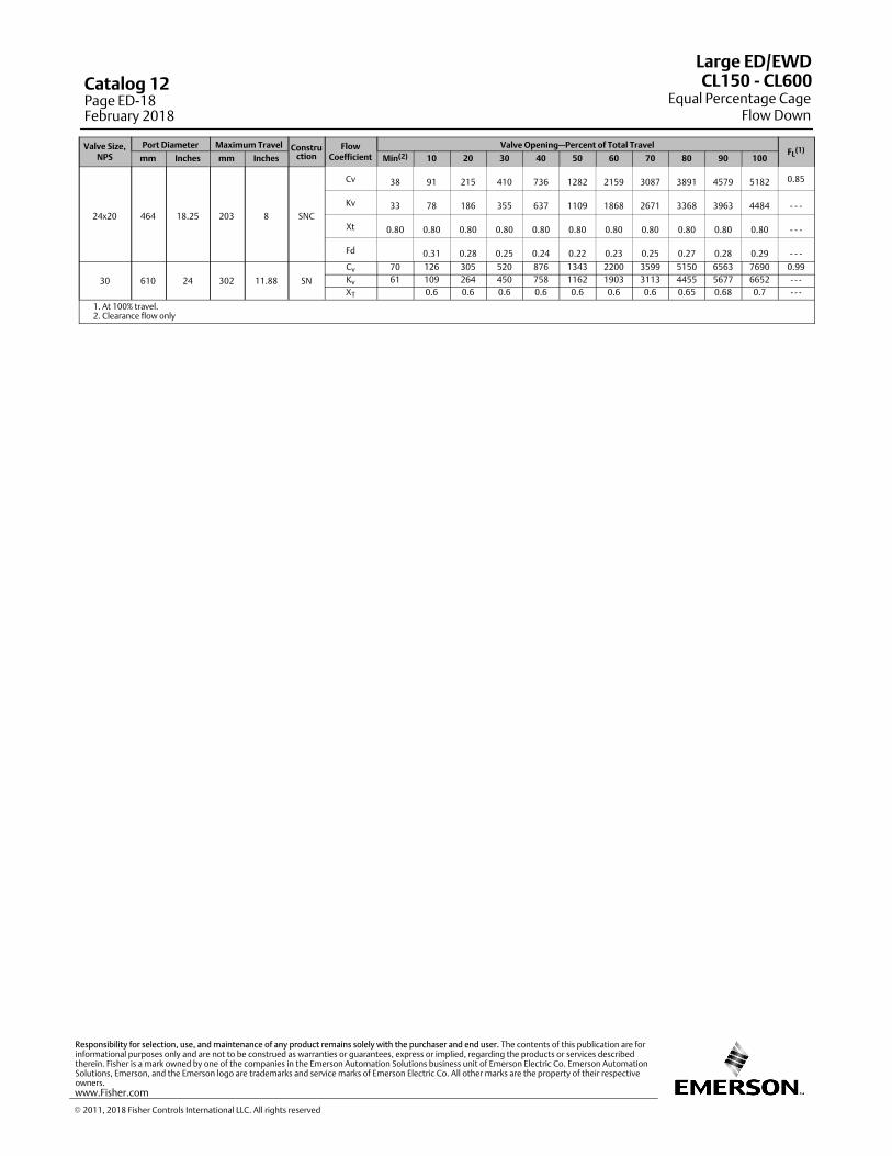
Valve Size,NPS
Port Diameter Maximum Travel Construction
FlowCoefficient
Valve Opening—Percent of Total TravelFL
(1)mm Inches mm Inches Min(2) 10 20 30 40 50 60 70 80 90 100
24x20 464 18.25 203 8 SNC
Cv 38 91 215 410 736 1282 2159 3087 3891 4579 5182 0.85
Kv 33 78 186 355 637 1109 1868 2671 3368 3963 4484 - - -
Xt 0.80 0.80 0.80 0.80 0.80 0.80 0.80 0.80 0.80 0.80 0.80 - - -
Fd 0.31 0.28 0.25 0.24 0.22 0.23 0.25 0.27 0.28 0.29 - - -
30 610 24 302 11.88 SN
Cv 70 126 305 520 876 1343 2200 3599 5150 6563 7690 0.99
Kv 61 109 264 450 758 1162 1903 3113 4455 5677 6652 - - -XT 0.6 0.6 0.6 0.6 0.6 0.6 0.6 0.65 0.68 0.7 - - -
1. At 100% travel.2. Clearance flow only
Large ED/EWD
Equal Percentage CageFlow Down
CL150 ‐ CL600Catalog 12Page ED-18February 2018
� 2011, 2018 Fisher Controls International LLC. All rights reserved
www.Fisher.com
Responsibility for selection, use, and maintenance of any product remains solely with the purchaser and end user. The contents of this publication are forinformational purposes only and are not to be construed as warranties or guarantees, express or implied, regarding the products or services describedtherein. Fisher is a mark owned by one of the companies in the Emerson Automation Solutions business unit of Emerson Electric Co. Emerson AutomationSolutions, Emerson, and the Emerson logo are trademarks and service marks of Emerson Electric Co. All other marks are the property of their respectiveowners.

19
Whisper Trim III - Level A1 - Flow UpLinear
Characteristic
ValveSize,NPS
PortDiameter
MaximumTravel Constr
uction
FlowCoeffi‐cient
Valve Opening—Percent of Total TravelFL
(1)
mm Inches mm Inches Min(2) 10 20 30 40 50 60 70 80 90 100
12 279.4 11
140 5.5 SNC
Cv 25 144 295 441 576 696 803 904 991 1070 1137 0.89
Kv 125 255 381 498 602 695 782 857 926 984 ‐ ‐ ‐
Xt 0.62 0.62 0.62 0.65 0.7 0.75 0.81 0.86 0.86 0.86 ‐ ‐ ‐
203 8 LNC
Cv 25 212 428 622 785 930 1052 1150 1229 1285 1315 0.89
Kv 183 370 538 679 804 910 995 1063 1112 1137 ‐ ‐ ‐
Xt 0.619 0.620 0.665 0.739 0.827 0.856 0.854 0.852 0.849 0.847 ‐ ‐ ‐
14 279.4 11
140 5.5 SNC
Cv 25 144 295 441 584 721 851 981 1104 1225 1318 0.89
Kv 125 255 381 505 623 736 849 955 1059 1140 ‐ ‐ ‐
Xt 0.62 0.62 0.62 0.63 0.65 0.67 0.70 0.72 0.72 0.73 ‐ ‐ ‐
203 8 LNC
Cv 25 212 428 635 828 1016 1194 1332 1420 1482 1515 0.89
Kv 183 370 549 716 879 1033 1153 1229 1282 1310 ‐ ‐ ‐
Xt 0.619 0.620 0.639 0.668 0.703 0.715 0.739 0.800 0.823 0.824 ‐ ‐ ‐
16x12 279.4 11
140 5.5 SNC
Cv 25 144 295 441 589 737 883 1033 1179 1328 1439 0.89
Kv 125 255 381 509 638 764 894 1020 1149 1245 ‐ ‐ ‐
Xt 0.62 0.62 0.62 0.62 0.62 0.62 0.62 0.62 0.62 0.65 ‐ ‐ ‐
203 8 LNC
Cv 25 212 428 644 857 1073 1289 1454 1548 1613 1648 0.89
Kv 183 370 557 741 928 1115 1258 1339 1395 1425 ‐ ‐ ‐
Xt 0.619 0.620 0.621 0.621 0.621 0.621 0.663 0.765 0.805 0.809 ‐ ‐ ‐
16 374.7 14.75 203 8.00 LNC
Cv 38 335 677 1019 1298 1529 1721 1871 1985 2059 2095 089
Kv 290 585 882 1123 1322 1488 1618 1717 1781 1812 - - -
Xt 0.436 0.433 0.432 0.471 0.533 0.589 0.616 0.647 0.686 0.732 - - -
18 374.7 14.75
203 8.00 SNC
Cv 48 233 549 530 1175 1433 1648 1824 1955 2053 2127 0.84
Kv 41 202 475 459 1017 1240 1427 1578 1692 1777 1840 - - -
Xt 0.50 0.52 0.52 0.52 0.52 0.53 0.54 0.56 0.58 0.60 - - -
276 10.88 LNC
Cv 48 343 776 1194 1533 1791 1973 2094 2176 2240 2312 0.84
Kv 41 297 671 1033 1327 1550 1707 1812 1883 1938 2001 - - -
Xt 0.51 0.52 0.52 0.52 0.54 0.57 0.59 0.62 0.63 0.66 - - -
20x16 374.7 14.75
203 8.00 SNC
Cv 38 320 663 1001 1341 1685 1977 2211 2417 2590 2736 0.89
Kv 277 574 865 1160 1457 1710 1912 2090 2241 2367 - - -
XT 0.436 0.433 0.432 0.432 0.432 0.451 0.493 0.541 0.570 0.589 - - -
276 10.88 LNC
Cv 38 443 907 1372 1836 2171 2449 2675 2846 2964 3029 0.89
Kv 383 785 1186 1588 1878 2119 2314 2462 2564 2620 - - -
XT 0.434 0.433 0.432 0.432 0.484 0.549 0.580 0.607 0.639 0.677 - - -
24x16 374.7 14.75
203 8.00 SNC
Cv 38 335 676 1019 1356 1698 1982 2219 2433 2620 2749 0.89
Kv 290 585 881 1173 1469 1714 1919 2105 2266 2378 - - -
XT 0.435 0.433 0.432 0.432 0.432 0.457 0.495 0.539 0.563 0.575 - - -
276 10.88 LNC
Cv 38 461 924 1387 1838 2176 2466 2707 2901 3045 3122 0.89
Kv 399 799 1200 1590 1882 2133 2342 2509 2634 2701 - - -
XT 0.434 0.433 0.432 0.438 0.487 0.546 0.571 0.592 0.616 0.638 - - -
20 464 18.25
276 10.88 SNC
Cv 47 547 1123 1699 2128 2489 2776 2992 3135 3205 3214 0.89
Kv 473 972 1470 1841 2153 2402 2588 2711 2773 2780 - - -
Xt 0.434 0.433 0.432 0.494 0.567 0.604 0.637 0.677 0.726 0.784 - - -
378 14.88 LNC
Cv 77 762 1544 2168 2634 2962 3158 3217 3217 3217 3217 0.89
Kv 659 1335 1876 2278 2562 2731 2783 2783 2783 2783 - - -
Xt 0.43 0.43 0.5 0.59 0.63 0.69 0.76 0.83 0.85 0.85 - - -
1. At 100% travel.2. Clearance flow only
Large ED/EWD
Whisper Trim™ III - Level A1CL150 ‐ CL600
Catalog 12Page ED-19
February 2018
� 2011, 2018 Fisher Controls International LLC. All rights reserved
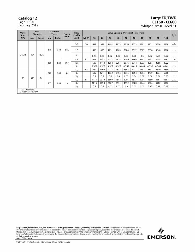
ValveSize,NPS
PortDiameter
MaximumTravel Constr
uction
FlowCoeffi‐cient
Valve Opening—Percent of Total TravelFL
(1)
mm Inches mm Inches Min(2) 10 20 30 40 50 60 70 80 90 100
24x20 464 18.25
276 10.88 SNC
Cv 70 481 987 1492 1923 2316 2673 2991 3271 3514 3720 0.89
Kv 416 853 1291 1663 2004 2312 2587 2830 3040 3218 - - -
Xt 0.53 0.53 0.52 0.57 0.57 0.58 0.6 0.62 0.65 0.67 - - -
378 14.88 LNC
Cv 43 671 1358 2028 2614 3059 3369 3552 3708 3915 4187 0.89
Kv 580 1174 1754 2261 2646 2914 3073 3207 3386 3622 - - -
Xt 0.529 0.528 0.528 0.528 0.552 0.615 0.689 0.736 0.766 0.801 - - -
30 610 24
276 10.88 SN
Cv 55 684 1400 2118 2837 3555 4271 4687 5132 5519 5850 0.99
Kv 592 1211 1832 2454 3075 3694 4054 4439 4774 5060 - - -
XT 0.6 0.6 0.6 0.6 0.57 0.54 0.58 0.59 0.61 0.63 - - -
505 19.88 LN
Cv 55 1173 2370 3569 4544 5286 5873 6294 6559 6661 6661 0.99
Kv 1015 2050 3087 3931 4572 5080 5444 5674 5762 5762 - - -
XT 0.6 0.6 0.57 0.57 0.6 0.63 0.67 0.72 0.78 0.78 - - -
1. At 100% travel.2. Clearance flow only
Large ED/EWD
Whisper Trim III - Level A1CL150 ‐ CL600
Catalog 12Page ED-20February 2018
� 2011, 2018 Fisher Controls International LLC. All rights reserved
www.Fisher.com
Responsibility for selection, use, and maintenance of any product remains solely with the purchaser and end user. The contents of this publication are forinformational purposes only and are not to be construed as warranties or guarantees, express or implied, regarding the products or services describedtherein. Fisher and Whisper Trim are marks owned by one of the companies in the Emerson Automation Solutions business unit of Emerson Electric Co.Emerson Automation Solutions, Emerson, and the Emerson logo are trademarks and service marks of Emerson Electric Co. All other marks are the propertyof their respective owners.

21
Whisper Trim - Level A3 - Flow UpLinear
Characteristic
ValveSize,NPS
PortDiameter
MaximumTravel Constr
uction
FlowCoeffi‐cient
Valve Opening—Percent of Total TravelFL
(1)
mm Inches mm Inches Min(2) 10 20 30 40 50 60 70 80 90 100
12 279.4 11
140 5.5 SNC
Cv 17 123 253 381 508 617 719 813 901 978 1049 0.89
Kv 106 219 330 439 534 622 703 779 846 907 ---
Xt 0.62 0.62 0.62 0.62 0.66 0.71 0.76 0.81 0.86 0.86 ---
203 8 LNC
Cv 17 181 371 550 705 839 960 1063 1149 1219 1272 0.89
Kv 157 321 475 610 726 831 919 994 1055 1100 ---
Xt 0.619 0.620 0.638 0.700 0.769 0.851 0.856 0.854 0.852 0.850 ---
14 279.4 11
140 5.5 SNC
Cv 17 123 253 381 509 630 748 863 978 1086 1192 0.89
Kv 106 219 330 440 545 647 747 846 939 1031 ---
Xt 0.62 0.62 0.62 0.62 0.64 0.66 0.68 0.70 0.72 0.72 ---
203 8 LNC
Cv 17 181 371 554 731 896 1059 1212 1331 1410 1467 0.89
Kv 157 321 479 632 775 916 1048 1152 1219 1269 ---
Xt 0.62 0.62 0.63 0.65 0.68 0.71 0.72 0.74 0.79 0.82 ---
16x12 279.4 11
140 5.5 SNC
Cv 17 123 253 381 510 638 767 897 1029 1158 1287 0.89
Kv 106 219 330 441 552 663 776 890 1002 1113 ---
Xt 0.62 0.62 0.62 0.62 0.62 0.62 0.62 0.62 0.62 0.62 ---
203 8 LNC
Cv 17 181 371 557 748 934 1125 1311 1453 1537 1597 0.89
Kv 157 321 482 647 808 973 1134 1256 1329 1381 ---
Xt 0.619 0.620 0.620 0.621 0.621 0.621 0.621 0.663 0.751 0.805 ---
16 374.7 14.75 203 8.00 LNC
Cv 25 290 593 892 1178 1396 1590 1749 1880 1980 2049 0.89
Kv 251 513 772 1019 1208 1375 1513 1626 1713 1772 - - -
Xt 0.436 0.433 0.433 0.447 0.495 0.554 0.594 0.618 0.646 0.679 - - -
18 374.7 14.75
203 8.00 SNC
Cv 25 197 477 762 1041 1293 1506 1690 1838 1953 2043 0.84
Kv 21 171 413 660 901 1119 1304 1462 1590 1690 1768 - - -
Xt 0.49 0.52 0.52 0.52 0.51 0.52 0.53 0.55 0.56 0.58 - - -
276 10.88 LNC
Cv 25 296 682 1062 1392 1654 1858 2002 2103 2174 2232 0.84
Kv 21 256 590 919 1204 1432 1608 1732 1820 1881 1931 - - -
Xt 0.50 0.52 0.52 0.52 0.53 0.55 0.57 0.60 0.61 0.63 - - -
20x16 374.7 14.75
203 8.00 SNC
Cv 25 290 593 892 1198 1495 1800 2032 2236 2416 2571 0.89
Kv 251 513 772 1036 1293 1557 1758 1934 2089 2224 - - -
XT 0.436 0.433 0.432 0.432 0.432 0.432 0.460 0.498 0.541 0.569 - - -
276 10.88 LNC
Cv 25 400 807 1223 1629 1994 2267 2503 2694 2844 2952 0.89
Kv 346 698 1058 1409 1725 1961 2165 2330 2460 2554 - - -
XT 0.435 0.433 0.432 0.432 0.454 0.504 0.562 0.582 0.607 0.635 - - -
24x16 374.7 14.75
203 8.00 SNC
Cv 18 163 451 735 1025 1307 1597 1861 2075 2270 2425 0.89
Kv 141 390 636 887 1131 1381 1610 1795 1964 2098 - - -
XT 0.440 0.434 0.433 0.432 0.432 0.432 0.441 0.471 0.505 0.537 - - -
276 10.88 LNC
Cv 19 281 688 1103 1509 1895 2188 2449 2666 2849 2918 0.89
Kv 243 595 954 1305 1639 1893 2118 2306 2464 2524 - - -
XT 0.437 0.433 0.432 0.432 0.445 0.489 0.542 0.567 0.585 0.594 - - -
20 464 18.25
276 10.88 SNC
Cv 31 470 976 1471 1912 2259 2555 2795 2980 3112 3189 0.89
Kv 407 844 1272 1654 1954 2210 2418 2578 2692 2758 - - -
Xt 0.435 0.433 0.432 0.461 0.517 0.583 0.607 0.635 0.669 0.710 - - -
378 14.88 LNC
Cv 46 657 1337 1948 2407 2762 3014 3166 3216 3216 3216 0.89
Kv 569 1157 1685 2082 2389 2607 2739 2781 2781 2781 - - -
Xt 0.43 0.43 0.47 0.55 0.6 0.64 0.69 0.76 0.82 0.85 - - -
1. At 100% travel.2. Clearance flow only
Large ED/EWD
Whisper Trim™ III - Level A3CL150 ‐ CL600
Catalog 12Page ED-21
February 2018
� 2011, 2018 Fisher Controls International LLC. All rights reserved
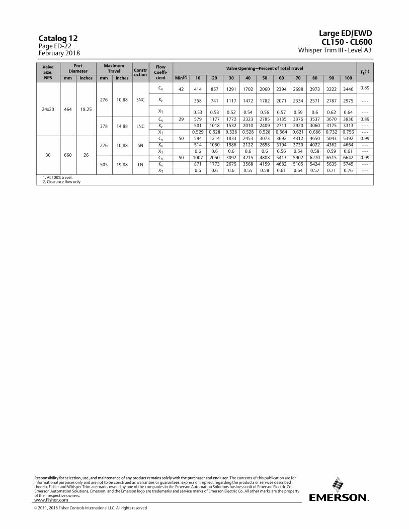
ValveSize,NPS
PortDiameter
MaximumTravel Constr
uction
FlowCoeffi‐cient
Valve Opening—Percent of Total TravelFL
(1)
mm Inches mm Inches Min(2) 10 20 30 40 50 60 70 80 90 100
24x20 464 18.25
276 10.88 SNC
Cv 42 414 857 1291 1702 2060 2394 2698 2973 3222 3440 0.89
Kv 358 741 1117 1472 1782 2071 2334 2571 2787 2975 - - -
XT 0.53 0.53 0.52 0.54 0.56 0.57 0.59 0.6 0.62 0.64 - - -
378 14.88 LNC
Cv 29 579 1177 1772 2323 2785 3135 3376 3537 3670 3830 0.89
Kv
501 1018 1532 2010 2409 2711 2920 3060 3175 3313 - - -
XT 0.529 0.528 0.528 0.528 0.528 0.564 0.621 0.686 0.732 0.756 - - -
30 660 26
276 10.88 SN
Cv 50 594 1214 1833 2453 3073 3692 4312 4650 5043 5392 0.99
Kv 514 1050 1586 2122 2658 3194 3730 4022 4362 4664 - - -XT 0.6 0.6 0.6 0.6 0.6 0.56 0.54 0.58 0.59 0.61 - - -
505 19.88 LN
Cv 50 1007 2050 3092 4215 4808 5413 5902 6270 6515 6642 0.99
Kv 871 1773 2675 3568 4159 4682 5105 5424 5635 5745 - - -XT 0.6 0.6 0.6 0.55 0.58 0.61 0.64 0.57 0.71 0.76 - - -
1. At 100% travel.2. Clearance flow only
Large ED/EWD
Whisper Trim III - Level A3CL150 ‐ CL600Catalog 12
Page ED-22February 2018
� 2011, 2018 Fisher Controls International LLC. All rights reserved
www.Fisher.com
Responsibility for selection, use, and maintenance of any product remains solely with the purchaser and end user. The contents of this publication are forinformational purposes only and are not to be construed as warranties or guarantees, express or implied, regarding the products or services describedtherein. Fisher and Whisper Trim are marks owned by one of the companies in the Emerson Automation Solutions business unit of Emerson Electric Co.Emerson Automation Solutions, Emerson, and the Emerson logo are trademarks and service marks of Emerson Electric Co. All other marks are the propertyof their respective owners.

23
Whisper Trim - Level B1 - Flow UpLinear
Characteristic
ValveSize,NPS
PortDiameter
MaximumTravel Constr
uction
FlowCoeffi‐cient
Valve Opening—Percent of Total TravelFL
(1)
mm Inches mm Inches Min(2) 10 20 30 40 50 60 70 80 90 100
12 279.4 11
140 5.5 SNC
Cv 21 79 157 238 311 384 464 537 597 659 721 0.89
Kv 68 136 206 269 332 401 465 516 570 624 ---
Xt 0.62 0.62 0.62 0.62 0.62 0.62 0.64 0.66 0.68 0.71 ---
203 8 LNC
Cv 21 120 228 337 453 557 646 730 813 889 949 0.89
Kv 104 197 291 392 482 559 631 703 769 821 ---
Xt 0.618 0.619 0.620 0.620 0.641 0.675 0.713 0.756 0.803 0.846 ---
14 279.4 11
140 5.5 SNC
Cv 21 79 157 238 311 384 464 541 607 678 751 0.89
Kv 68 136 206 269 332 401 468 525 586 650 ---
Xt 0.62 0.62 0.62 0.62 0.62 0.62 0.63 0.64 0.64 0.66 ---
203 8 LNC
Cv 21 120 228 337 453 562 663 761 863 962 1044 0.89
Kv 104 197 292 392 486 573 658 747 832 903 ---
Xt 0.62 0.62 0.62 0.62 0.63 0.64 0.66 0.68 0.69 0.71 ---
16x12 279.4 11
140 5.5 SNC
Cv 21 79 157 238 311 384 464 543 614 690 771 0.89
Kv 68 136 206 269 332 401 470 531 597 667 ---
Xt 0.62 0.62 0.62 0.62 0.62 0.62 0.62 0.62 0.62 0.62 ---
203 8 LNC
Cv 21 120 228 337 453 566 674 782 897 1011 1107 0.89
Kv 104 197 291 392 489 583 676 776 875 958 ---
Xt 0.618 0.619 0.620 0.620 0.621 0.621 0.621 0.621 0.621 0.621 ---
16 374.7 14.75 203 8.00 LNC
Cv 32 197 374 554 746 933 1111 1248 1385 1509 1603 0.89
Kv 170 324 479 645 807 961 1080 1198 1305 1387 - - -
Xt 0.438 0.435 0.433 0.433 0.432 0.432 0.461 0.493 0.528 0.56 - - -
18 374.7 14.75
203 8.00 SNC
Cv 36 133 299 470 651 823 990 1150 1304 1441 1559 0.84
Kv 31 115 259 407 564 713 857 995 1128 1247 1349 - - -
Xt 0.48 0.50 0.51 0.52 0.52 0.52 0.52 0.51 0.52 0.52 - - -
276 10.88 LNC
Cv 36 188 432 656 900 1118 1327 1498 1658 1785 1895 0.84
Kv 31 163 374 568 779 968 1149 1297 1435 1545 1640 - - -
Xt 0.49 0.51 0.52 0.52 0.52 0.51 0.52 0.53 0.54 0.55 - - -
20x16 374.7 14.75
203 8.00 SNC
Cv 31 196 374 554 746 933 1111 1290 1480 1669 1827 0.89
Kv 170 324 479 645 807 961 1116 1280 1444 1581 - - -
XT 0.438 0.435 0.433 0.433 0.432 0.432 0.432 0.431 0.431 0.431 - - -
276 10.88 LNC
Cv 31 256 515 756 1016 1256 1517 1757 1974 2141 2307 0.89
Kv 221 445 654 879 1087 1313 1520 1707 1852 1995 - - -
XT 0.437 0.434 0.433 0.432 0.432 0.432 0.432 0.451 0.480 0.514 - - -
24x16 374.7 14.75
203 8.00 SNC
Cv 31 196 374 554 746 933 1111 1290 1480 1669 1818 0.89
Kv 170 324 479 645 807 961 1116 1280 1444 1573 - - -
XT 0.438 0.435 0.433 0.433 0.432 0.432 0.432 0.431 0.431 0.436 - - -
276 10.88 LNC
Cv 31 255 515 755 1016 1255 1516 1756 1964 2137 2290 0.89
Kv 221 445 653 879 1086 1311 1519 1699 1849 1981 - - -
XT 0.437 0.434 0.433 0.432 0.432 0.432 0.432 0.455 0.481 0.509 - - -
20 464 18.25
276 10.88 SNC
Cv 39 314 632 928 1247 1542 1824 2043 2260 2440 2614 0.89
Kv 292 587 862 1159 1432 1724 1937 2151 2331 2508 - - -
Xt 0.437 0.434 0.433 0.432 0.432 0.450 0.481 0.518 0.556 0.588 - - -
378 14.88 LNC
Cv 61 437 855 1271 1688 2009 2298 2548 2756 2922 3051 0.89
Kv 378 739 1100 1460 1738 1988 2204 2384 2528 2639 - - -
Xt 0.43 0.43 0.43 0.43 0.48 0.52 0.58 0.6 0.63 0.65 - - -
24x20 464 18.25
276 10.88 SNC
Cv 56 276 555 815 1095 1354 1635 1835 2063 2262 2467 0.89
Kv 239 480 705 948 1171 1414 1587 1784 1956 2134 - - -
XT 0.53 0.53 0.53 0.52 0.52 0.52 0.56 0.56 0.57 0.57 - - -
378 14.88 LNC
Cv 36 385 754 1121 1486 1844 2191 2508 2783 3011 3196 0.89
Kv
333 652 969 1285 1595 1895 2169 2407 2605 2765 - - -
XT 0.529 0.529 0.528 0.528 0.528 0.528 0.528 0.528 0.545 0.576 - - -
1. At 100% travel.2. Clearance flow only
Large ED/EWD
Whisper Trim™ III - Level B1CL150 ‐ CL600
Catalog 12Page ED-23
February 2018
� 2011, 2018 Fisher Controls International LLC. All rights reserved
This page is intentionally left blank.
Large ED/EWD
Whisper Trim III - Level B1CL150 ‐ CL600Catalog 12
Page ED-24February 2018
� 2018 Fisher Controls International LLC. All rights reserved
www.Fisher.com
Responsibility for selection, use, and maintenance of any product remains solely with the purchaser and end user. The contents of this publication are forinformational purposes only and are not to be construed as warranties or guarantees, express or implied, regarding the products or services describedtherein. Fisher and WhisperFlo are marks owned by one of the companies in the Emerson Automation Solutions business unit of Emerson Electric Co. Emerson Automation Solutions, Emerson, and the Emerson logo are trademarks and service marks of Emerson Electric Co. All other marks are the property oftheir respective owners.
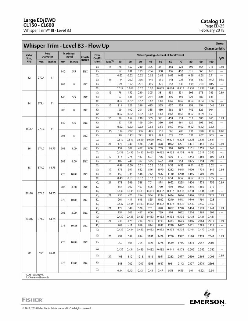
25
Whisper Trim - Level B3 - Flow UpLinear
Characteristic
ValveSize,NPS
PortDiameter
MaximumTravel Constr
uction
FlowCoeffi‐cient
Valve Opening—Percent of Total TravelFL
(1)
mm Inches mm Inches Min(2) 10 20 30 40 50 60 70 80 90 100
12 279.4 11
140 5.5 SNC
Cv 15 78 152 230 305 381 458 528 595 654 716 0.89
Kv 67 131 199 264 330 396 457 515 566 619 ---
Xt 0.62 0.62 0.62 0.62 0.62 0.62 0.63 0.66 0.68 0.71 ---
203 8 LNC
Cv 15 114 222 336 445 550 641 728 808 883 942 0.89
Kv 99 192 291 385 476 554 630 699 764 815 ---
Xt 0.617 0.619 0.62 0.62 0.639 0.674 0.712 0.754 0.799 0.841 ---
14 279.4 11
140 5.5 SNC
Cv 15 78 152 230 305 381 458 531 605 673 745 0.89
Kv 67 131 199 264 330 396 459 523 582 645 ---
Xt 0.62 0.62 0.62 0.62 0.62 0.62 0.62 0.64 0.64 0.66 ---
203 8 LNC
Cv 15 114 222 336 445 555 657 759 858 954 1045 0.89
Kv 99 192 291 385 480 568 657 742 826 904 ---
Xt 0.62 0.62 0.62 0.62 0.63 0.64 0.66 0.67 0.69 0.71 ---
16x12 279.4 11
140 5.5 SNC
Cv 15 78 152 230 305 381 458 533 612 685 765 0.89
Kv 67 131 199 264 330 396 461 529 593 662 ---
Xt 0.62 0.62 0.62 0.62 0.62 0.62 0.62 0.62 0.62 0.62 ---
203 8 LNC
Cv 15 114 222 336 445 558 668 780 891 1002 1114 0.89
Kv 98 192 291 385 483 578 675 771 867 963 ---
Xt 0.617 0.619 0.620 0.620 0.621 0.621 0.621 0.621 0.621 0.621 ---
16 374.7 14.75 203 8.00 LNC
Cv 21 178 349 528 700 878 1052 1201 1331 1451 1555 0.89
Kv 154 302 457 606 759 910 1039 1151 1255 1345 - - -
Xt 0.439 0.435 0.433 0.433 0.432 0.432 0.452 0.48 0.511 0.543 - - -
18 374.7 14.75
203 8.00 SNC
Cv 17 118 278 447 607 776 936 1101 1243 1380 1500 0.84
Kv 15 102 240 387 525 672 810 953 1075 1194 1298 - - -
Xt 0.48 0.50 0.51 0.52 0.52 0.52 0.52 0.51 0.52 0.52 - - -
276 10.88 LNC
Cv 17 173 397 622 846 1070 1282 1445 1600 1734 1846 0.84
Kv 15 150 344 538 732 926 1110 1250 1385 1500 1597 - - -
Xt 0.49 0.51 0.52 0.52 0.52 0.51 0.52 0.52 0.53 0.55 - - -
20x16 374.7 14.75
203 8.00 SNC
Cv 21 178 349 528 701 878 1052 1228 1404 1578 1756 0.89
Kv 154 302 457 606 760 910 1062 1215 1365 1519 - - -
XT 0.439 0.435 0.433 0.433 0.432 0.432 0.432 0.431 0.431 0.431 - - -
276 10.88 LNC
Cv 21 236 475 714 954 1194 1434 1674 1896 2070 2229 0.89
Kv 204 411 618 825 1032 1240 1448 1640 1791 1928 - - -
XT 0.437 0.434 0.433 0.432 0.432 0.432 0.432 0.439 0.467 0.497 - - -
24x16 374.7 14.75
203 8.00 SNC
Cv 21 178 349 528 701 878 1052 1228 1404 1578 1744 0.89
Kv 154 302 457 606 759 910 1062 1214 1365 1509 - - -
XT 0.439 0.435 0.433 0.433 0.432 0.432 0.432 0.431 0.431 0.431 - - -
276 10.88 LNC
Cv 21 236 475 714 953 1193 1433 1673 1886 2064 2217 0.89
Kv 204 411 618 824 1032 1240 1447 1631 1785 1918 - - -
XT 0.437 0.434 0.433 0.432 0.432 0.432 0.432 0.444 0.470 0.495 - - -
20 464 18.25
276 10.88 SNC
Cv 26 292 588 884 1181 1478 1756 1982 2190 2378 2547 0.89
Kv 252 508 765 1021 1278 1519 1715 1894 2057 2203 - - -
Xt 0.437 0.434 0.433 0.432 0.432 0.441 0.471 0.505 0.542 0.582 - - -
378 14.88 LNC
Cv 37 403 812 1213 1616 1951 2232 2477 2690 2866 3003 0.89
Kv 348 702 1049 1398 1687 1931 2142 2327 2479 2598 - - -
Xt 0.44 0.43 0.43 0.43 0.47 0.51 0.56 0.6 0.62 0.64 - - -
1. At 100% travel.2. Clearance flow only
Large ED/EWD
Whisper Trim™ III - Level B3CL150 ‐ CL600
Catalog 12Page ED-25
February 2018
� 2011, 2018 Fisher Controls International LLC. All rights reserved
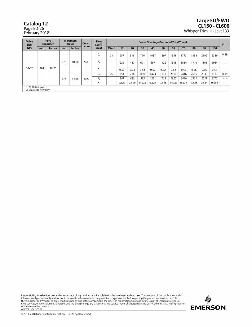
ValveSize,NPS
PortDiameter
MaximumTravel Constr
uction
FlowCoeffi‐cient
Valve Opening—Percent of Total TravelFL
(1)
mm Inches mm Inches Min(2) 10 20 30 40 50 60 70 80 90 100
24x20 464 18.25
276 10.88 SNC
Cv 34 257 516 776 1037 1297 1558 1773 1988 2192 2386 0.89
Kv 222 447 671 897 1122 1348 1534 1719 1896 2064 - - -
XT 0.53 0.53 0.53 0.52 0.52 0.52 0.55 0.56 0.56 0.57 - - -
378 14.88 LNC
Cv 25 354 716 1070 1423 1778 2110 2416 2695 2933 3127 0.89
Kv
307 620 925 1231 1538 1825 2090 2331 2537 2705 - - -
XT 0.529 0.529 0.528 0.528 0.528 0.528 0.528 0.528 0.534 0.562 - - -
1. At 100% travel.2. Clearance flow only
Large ED/EWD
Whisper Trim III - Level B3CL150 ‐ CL600Catalog 12
Page ED-26February 2018
� 2011, 2018 Fisher Controls International LLC. All rights reserved
www.Fisher.com
Responsibility for selection, use, and maintenance of any product remains solely with the purchaser and end user. The contents of this publication are forinformational purposes only and are not to be construed as warranties or guarantees, express or implied, regarding the products or services describedtherein. Fisher and Whisper Trim are marks owned by one of the companies in the Emerson Automation Solutions business unit of Emerson Electric Co.Emerson Automation Solutions, Emerson, and the Emerson logo are trademarks and service marks of Emerson Electric Co. All other marks are the propertyof their respective owners.
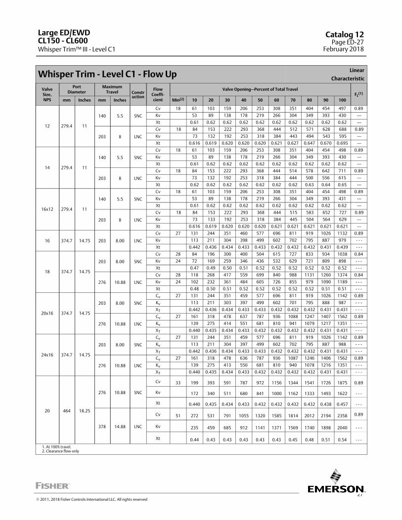
27
Whisper Trim - Level C1 - Flow UpLinear
Characteristic
ValveSize,NPS
PortDiameter
MaximumTravel Constr
uction
FlowCoeffi‐cient
Valve Opening—Percent of Total TravelFL
(1)
mm Inches mm Inches Min(2) 10 20 30 40 50 60 70 80 90 100
12 279.4 11
140 5.5 SNC
Cv 18 61 103 159 206 253 308 351 404 454 497 0.89
Kv 53 89 138 178 219 266 304 349 393 430 ---
Xt 0.61 0.62 0.62 0.62 0.62 0.62 0.62 0.62 0.62 0.62 ---
203 8 LNC
Cv 18 84 153 222 293 368 444 512 571 628 688 0.89
Kv 73 132 192 253 318 384 443 494 543 595 ---
Xt 0.616 0.619 0.620 0.620 0.620 0.621 0.627 0.647 0.670 0.695 ---
14 279.4 11
140 5.5 SNC
Cv 18 61 103 159 206 253 308 351 404 454 498 0.89
Kv 53 89 138 178 219 266 304 349 393 430 ---
Xt 0.61 0.62 0.62 0.62 0.62 0.62 0.62 0.62 0.62 0.62 ---
203 8 LNC
Cv 18 84 153 222 293 368 444 514 578 642 711 0.89
Kv 73 132 192 253 318 384 444 500 556 615 ---
Xt 0.62 0.62 0.62 0.62 0.62 0.62 0.62 0.63 0.64 0.65 ---
16x12 279.4 11
140 5.5 SNC
Cv 18 61 103 159 206 253 308 351 404 454 498 0.89
Kv 53 89 138 178 219 266 304 349 393 431 ---
Xt 0.61 0.62 0.62 0.62 0.62 0.62 0.62 0.62 0.62 0.62 ---
203 8 LNC
Cv 18 84 153 222 293 368 444 515 583 652 727 0.89
Kv 73 133 192 253 318 384 445 504 564 629 ---
Xt 0.616 0.619 0.620 0.620 0.620 0.621 0.621 0.621 0.621 0.621 ---
16 374.7 14.75 203 8.00 LNC
Cv 27 131 244 351 460 577 696 811 919 1026 1132 0.89
Kv 113 211 304 398 499 602 702 795 887 979 - - -
Xt 0.442 0.436 0.434 0.433 0.433 0.432 0.432 0.432 0.431 0.439 - - -
18 374.7 14.75
203 8.00 SNC
Cv 28 84 196 300 400 504 615 727 833 934 1038 0.84
Kv 24 72 169 259 346 436 532 629 721 809 898 - - -
Xt 0.47 0.49 0.50 0.51 0.52 0.52 0.52 0.52 0.52 0.52 - - -
276 10.88 LNC
Cv 28 118 268 417 559 699 840 988 1131 1260 1374 0.84
Kv 24 102 232 361 484 605 726 855 979 1090 1189 - - -
Xt 0.48 0.50 0.51 0.52 0.52 0.52 0.52 0.52 0.51 0.51 - - -
20x16 374.7 14.75
203 8.00 SNC
Cv 27 131 244 351 459 577 696 811 919 1026 1142 0.89
Kv 113 211 303 397 499 602 701 795 888 987 - - -
XT 0.442 0.436 0.434 0.433 0.433 0.432 0.432 0.432 0.431 0.431 - - -
276 10.88 LNC
Cv 27 161 318 478 637 787 936 1088 1247 1407 1562 0.89
Kv 139 275 414 551 681 810 941 1079 1217 1351 - - -
XT 0.440 0.435 0.434 0.433 0.432 0.432 0.432 0.432 0.431 0.431 - - -
24x16 374.7 14.75
203 8.00 SNC
Cv 27 131 244 351 459 577 696 811 919 1026 1142 0.89
Kv 113 211 304 397 499 602 702 795 887 988 - - -
XT 0.442 0.436 0.434 0.433 0.433 0.432 0.432 0.432 0.431 0.431 - - -
276 10.88 LNC
Cv 27 161 318 478 636 787 936 1087 1246 1406 1562 0.89
Kv 139 275 413 550 681 810 940 1078 1216 1351 - - -
XT 0.440 0.435 0.434 0.433 0.432 0.432 0.432 0.432 0.431 0.431 - - -
20 464 18.25
276 10.88 SNC
Cv 33 199 393 591 787 972 1156 1344 1541 1726 1875 0.89
Kv 172 340 511 680 841 1000 1162 1333 1493 1622 - - -
Xt 0.440 0.435 0.434 0.433 0.432 0.432 0.432 0.432 0.438 0.457 - - -
378 14.88 LNC
Cv 51 272 531 791 1055 1320 1585 1814 2012 2194 2358 0.89
Kv 235 459 685 912 1141 1371 1569 1740 1898 2040 - - -
Xt 0.44 0.43 0.43 0.43 0.43 0.43 0.45 0.48 0.51 0.54 - - -
1. At 100% travel.2. Clearance flow only
Large ED/EWD
Whisper Trim™ III - Level C1CL150 ‐ CL600
Catalog 12Page ED-27
February 2018
� 2011, 2018 Fisher Controls International LLC. All rights reserved
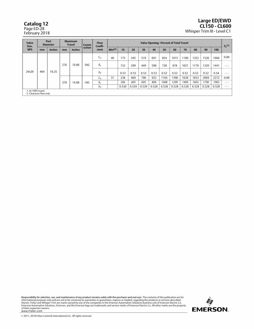
ValveSize,NPS
PortDiameter
MaximumTravel Constr
uction
FlowCoeffi‐cient
Valve Opening—Percent of Total TravelFL
(1)
mm Inches mm Inches Min(2) 10 20 30 40 50 60 70 80 90 100
24x20 464 18.25
276 10.88 SNC
Cv 46 175 345 519 691 854 1015 1180 1353 1526 1666 0.89
Kv 152 299 449 598 738 878 1021 1170 1320 1441 - - -
XT 0.53 0.53 0.53 0.53 0.52 0.52 0.52 0.52 0.52 0.54 - - -
378 14.88 LNC
Cv 31 238 469 700 932 1165 1398 1628 1853 2069 2272 0.89
Kv
206 405 605 806 1008 1209 1409 1603 1790 1965 - - -
XT 0.530 0.529 0.529 0.528 0.528 0.528 0.528 0.528 0.528 0.528 - - -
1. At 100% travel.2. Clearance flow only
Large ED/EWD
Whisper Trim III - Level C1CL150 ‐ CL600Catalog 12
Page ED-28February 2018
� 2011, 2018 Fisher Controls International LLC. All rights reserved
www.Fisher.com
Responsibility for selection, use, and maintenance of any product remains solely with the purchaser and end user. The contents of this publication are forinformational purposes only and are not to be construed as warranties or guarantees, express or implied, regarding the products or services describedtherein. Fisher and Whisper Trim are marks owned by one of the companies in the Emerson Automation Solutions business unit of Emerson Electric Co.Emerson Automation Solutions, Emerson, and the Emerson logo are trademarks and service marks of Emerson Electric Co. All other marks are the propertyof their respective owners.
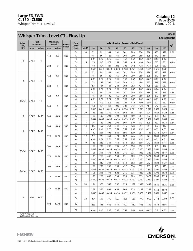
29
Whisper Trim - Level C3 - Flow UpLinear
Characteristic
ValveSize,NPS
PortDiameter
MaximumTravel Constr
uction
FlowCoeffi‐cient
Valve Opening—Percent of Total TravelFL
(1)
mm Inches mm Inches Min(2) 10 20 30 40 50 60 70 80 90 100
12 279.4 11
140 5.5 SNC
Cv 14 52 99 144 191 241 289 334 380 430 479 0.89
Kv 45 86 125 165 208 250 289 329 372 414 ---
Xt 0.61 0.62 0.62 0.62 0.62 0.62 0.62 0.62 0.62 0.62 ---
203 8 LNC
Cv 14 73 143 209 281 349 418 490 548 607 651 0.89
Kv 63 124 181 243 302 362 424 474 525 563 ---
Xt 0.615 0.618 0.619 0.620 0.620 0.621 0.620 0.639 0.662 0.680 ---
14 279.4 11
140 5.5 SNC
Cv 14 52 99 144 191 241 289 334 380 430 479 0.89
Kv 45 86 125 165 208 250 289 329 372 414 ---
Xt 0.61 0.62 0.62 0.62 0.62 0.62 0.62 0.62 0.62 0.62 ---
203 8 LNC
Cv 14 73 143 209 282 349 418 490 553 619 679 0.89
Kv 63 124 181 244 302 362 424 478 535 587 ---
Xt 0.62 0.62 0.62 0.62 0.62 0.62 0.62 0.63 0.64 0.64 ---
16x12 279.4 11
140 5.5 SNC
Cv 14 52 99 144 191 241 289 334 380 430 479 0.89
Kv 45 86 125 165 208 250 289 329 372 414 ---
Xt 0.61 0.62 0.62 0.62 0.62 0.62 0.62 0.62 0.62 0.62 ---
203 8 LNC
Cv 14 73 143 209 282 349 418 490 556 627 697 0.89
Kv 63 124 181 243 302 361 424 481 542 603 ---
Xt 0.615 0.618 0.619 0.620 0.620 0.621 0.621 0.621 0.621 0.621 ---
16 374.7 14.75 203 8.00 LNC
Cv 20 116 226 339 456 564 681 794 904 1023 1120 0.89
Kv 100 195 293 394 488 589 687 782 885 969 - - -
Xt 0.444 0.437 0.435 0.433 0.433 0.432 0.432 0.432 0.431 0.437 - - -
18 374.7 14.75
203 8.00 SNC
Cv 15 76 182 292 394 503 610 713 825 927 1036 0.84
Kv 13 66 157 253 341 435 528 617 714 802 897 - - -
Xt 0.47 0.49 0.50 0.51 0.52 0.52 0.52 0.52 0.52 0.52 - - -
276 10.88 LNC
Cv 14 112 261 405 546 696 839 981 1125 1248 1366 0.84
Kv 12 97 226 351 473 602 726 849 973 1080 1182 - - -
Xt 0.48 0.50 0.51 0.52 0.52 0.52 0.52 0.52 0.51 0.51 - - -
20x16 374.7 14.75
203 8.00 SNC
Cv 19 116 235 344 458 574 682 800 912 1023 1141 0.89
Kv 100 203 298 396 497 590 692 789 885 987 - - -
XT 0.443 0.437 0.434 0.433 0.433 0.432 0.432 0.432 0.431 0.431 - - -
276 10.88 LNC
Cv 19 161 311 471 623 776 935 1085 1240 1398 1547 0.89
Kv 139 269 408 539 671 809 939 1073 1209 1338 - - -
XT 0.440 0.435 0.434 0.433 0.432 0.432 0.432 0.432 0.431 0.431 - - -
24x16 374.7 14.75
203 8.00 SNC
Cv 19 116 235 344 458 574 682 800 912 1023 1127 0.89
Kv 100 203 298 396 497 590 692 789 885 975 - - -
XT 0.443 0.437 0.434 0.433 0.433 0.432 0.432 0.432 0.431 0.431 - - -
276 10.88 LNC
Cv 19 161 311 471 623 775 935 1085 1239 1398 1532 0.89
Kv 139 269 407 539 670 809 939 1072 1209 1325 - - -
XT 0.440 0.435 0.434 0.433 0.432 0.432 0.432 0.432 0.431 0.431 - - -
20 464 18.25
276 10.88 SNC
Cv 24 194 375 568 752 935 1127 1309 1495 1686 1826 0.89
Kv 168 325 491 650 809 975 1132 1293 1458 1579 - - -
Xt 0.440 0.435 0.434 0.433 0.432 0.432 0.432 0.432 0.431 0.450 - - -
378 14.88 LNC
Cv 32 264 518 770 1023 1279 1538 1772 1965 2144 2309 0.89
Kv 229 448 666 885 1107 1330 1533 1700 1854 1997 - - -
Xt 0.44 0.43 0.43 0.43 0.43 0.43 0.44 0.47 0.5 0.53 - - -
1. At 100% travel.2. Clearance flow only
Large ED/EWD
Whisper Trim™ III - Level C3CL150 ‐ CL600
Catalog 12Page ED-29
February 2018
� 2011, 2018 Fisher Controls International LLC. All rights reserved

ValveSize,NPS
PortDiameter
MaximumTravel Constr
uction
FlowCoeffi‐cient
Valve Opening—Percent of Total TravelFL
(1)
mm Inches mm Inches Min(2) 10 20 30 40 50 60 70 80 90 100
24x20 464 18.25
276 10.88 SNC
Cv 30 171 330 499 660 821 990 1149 1313 1480 1638 0.89
Kv 148 285 431 571 710 856 994 1135 1280 1417 - - -
XT 0.53 0.53 0.53 0.53 0.52 0.52 0.52 0.52 0.52 0.52 - - -
378 14.88 LNC
Cv 23 231 458 681 904 1130 1358 1582 1800 2009 2210 0.89
Kv
199 396 589 782 978 1174 1369 1557 1738 1912 - - -
XT 0.530 0.529 0.529 0.528 0.528 0.528 0.528 0.528 0.528 0.528 - - -
1. At 100% travel.2. Clearance flow only
Large ED/EWD
Whisper Trim III - Level C3CL150 ‐ CL600Catalog 12
Page ED-30February 2018
� 2011, 2018 Fisher Controls International LLC. All rights reserved
www.Fisher.com
Responsibility for selection, use, and maintenance of any product remains solely with the purchaser and end user. The contents of this publication are forinformational purposes only and are not to be construed as warranties or guarantees, express or implied, regarding the products or services describedtherein. Fisher and Whisper Trim are marks owned by one of the companies in the Emerson Automation Solutions business unit of Emerson Electric Co.Emerson Automation Solutions, Emerson, and the Emerson logo are trademarks and service marks of Emerson Electric Co. All other marks are the propertyof their respective owners.
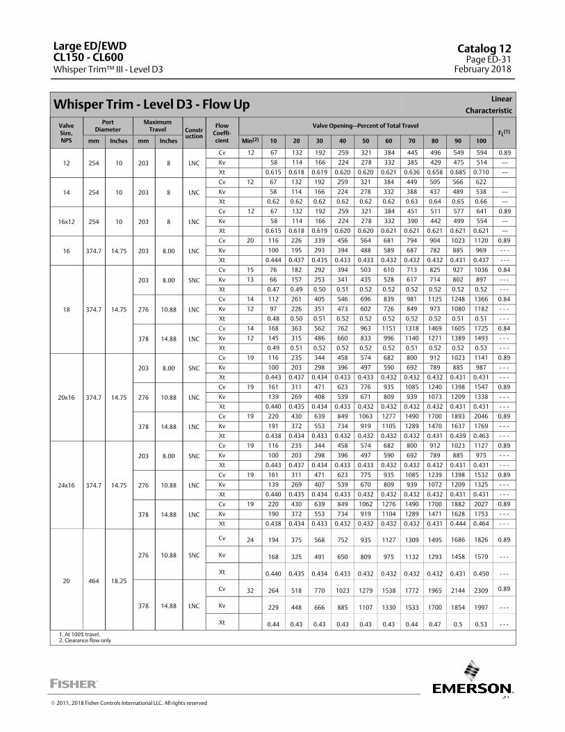
31
Whisper Trim - Level D3 - Flow UpLinear
Characteristic
ValveSize,NPS
PortDiameter
MaximumTravel Constr
uction
FlowCoeffi‐cient
Valve Opening—Percent of Total TravelFL
(1)
mm Inches mm Inches Min(2) 10 20 30 40 50 60 70 80 90 100
12 254 10 203 8 LNC
Cv 12 67 132 192 259 321 384 445 496 549 594 0.89
Kv 58 114 166 224 278 332 385 429 475 514 ---
Xt 0.615 0.618 0.619 0.620 0.620 0.621 0.636 0.658 0.685 0.710 ---
14 254 10 203 8 LNC
Cv 12 67 132 192 259 321 384 449 505 566 622
Kv 58 114 166 224 278 332 388 437 489 538 ---
Xt 0.62 0.62 0.62 0.62 0.62 0.62 0.63 0.64 0.65 0.66 ---
16x12 254 10 203 8 LNC
Cv 12 67 132 192 259 321 384 451 511 577 641 0.89
Kv 58 114 166 224 278 332 390 442 499 554 ---
Xt 0.615 0.618 0.619 0.620 0.620 0.621 0.621 0.621 0.621 0.621 ---
16 374.7 14.75 203 8.00 LNC
Cv 20 116 226 339 456 564 681 794 904 1023 1120 0.89
Kv 100 195 293 394 488 589 687 782 885 969 - - -
Xt 0.444 0.437 0.435 0.433 0.433 0.432 0.432 0.432 0.431 0.437 - - -
18 374.7 14.75
203 8.00 SNC
Cv 15 76 182 292 394 503 610 713 825 927 1036 0.84
Kv 13 66 157 253 341 435 528 617 714 802 897 - - -
Xt 0.47 0.49 0.50 0.51 0.52 0.52 0.52 0.52 0.52 0.52 - - -
276 10.88 LNC
Cv 14 112 261 405 546 696 839 981 1125 1248 1366 0.84
Kv 12 97 226 351 473 602 726 849 973 1080 1182 ‐ ‐ ‐
Xt 0.48 0.50 0.51 0.52 0.52 0.52 0.52 0.52 0.51 0.51 ‐ ‐ ‐
378 14.88 LNC
Cv 14 168 363 562 762 963 1151 1318 1469 1605 1725 0.84
Kv 12 145 315 486 660 833 996 1140 1271 1389 1493 ‐ ‐ ‐
Xt 0.49 0.51 0.52 0.52 0.52 0.52 0.51 0.52 0.52 0.53 ‐ ‐ ‐
20x16 374.7 14.75
203 8.00 SNC
Cv 19 116 235 344 458 574 682 800 912 1023 1141 0.89
Kv 100 203 298 396 497 590 692 789 885 987 - - -
Xt 0.443 0.437 0.434 0.433 0.433 0.432 0.432 0.432 0.431 0.431 - - -
276 10.88 LNC
Cv 19 161 311 471 623 776 935 1085 1240 1398 1547 0.89
Kv 139 269 408 539 671 809 939 1073 1209 1338 - - -
Xt 0.440 0.435 0.434 0.433 0.432 0.432 0.432 0.432 0.431 0.431 - - -
378 14.88 LNC
Cv 19 220 430 639 849 1063 1277 1490 1700 1893 2046 0.89
Kv 191 372 553 734 919 1105 1289 1470 1637 1769 - - -
Xt 0.438 0.434 0.433 0.432 0.432 0.432 0.432 0.431 0.439 0.463 - - -
24x16 374.7 14.75
203 8.00 SNC
Cv 19 116 235 344 458 574 682 800 912 1023 1127 0.89
Kv 100 203 298 396 497 590 692 789 885 975 - - -
Xt 0.443 0.437 0.434 0.433 0.433 0.432 0.432 0.432 0.431 0.431 - - -
276 10.88 LNC
Cv 19 161 311 471 623 775 935 1085 1239 1398 1532 0.89
Kv 139 269 407 539 670 809 939 1072 1209 1325 - - -
Xt 0.440 0.435 0.434 0.433 0.432 0.432 0.432 0.432 0.431 0.431 - - -
378 14.88 LNC
Cv 19 220 430 639 849 1062 1276 1490 1700 1882 2027 0.89
Kv 190 372 553 734 919 1104 1289 1471 1628 1753 - - -
Xt 0.438 0.434 0.433 0.432 0.432 0.432 0.432 0.431 0.444 0.464 - - -
20 464 18.25
276 10.88 SNC
Cv 24 194 375 568 752 935 1127 1309 1495 1686 1826 0.89
Kv 168 325 491 650 809 975 1132 1293 1458 1579 - - -
Xt 0.440 0.435 0.434 0.433 0.432 0.432 0.432 0.432 0.431 0.450 - - -
378 14.88 LNC
Cv 32 264 518 770 1023 1279 1538 1772 1965 2144 2309 0.89
Kv 229 448 666 885 1107 1330 1533 1700 1854 1997 - - -
Xt 0.44 0.43 0.43 0.43 0.43 0.43 0.44 0.47 0.5 0.53 - - -
1. At 100% travel.2. Clearance flow only
Large ED/EWD
Whisper Trim™ III - Level D3CL150 ‐ CL600
Catalog 12Page ED-31
February 2018
� 2011, 2018 Fisher Controls International LLC. All rights reserved
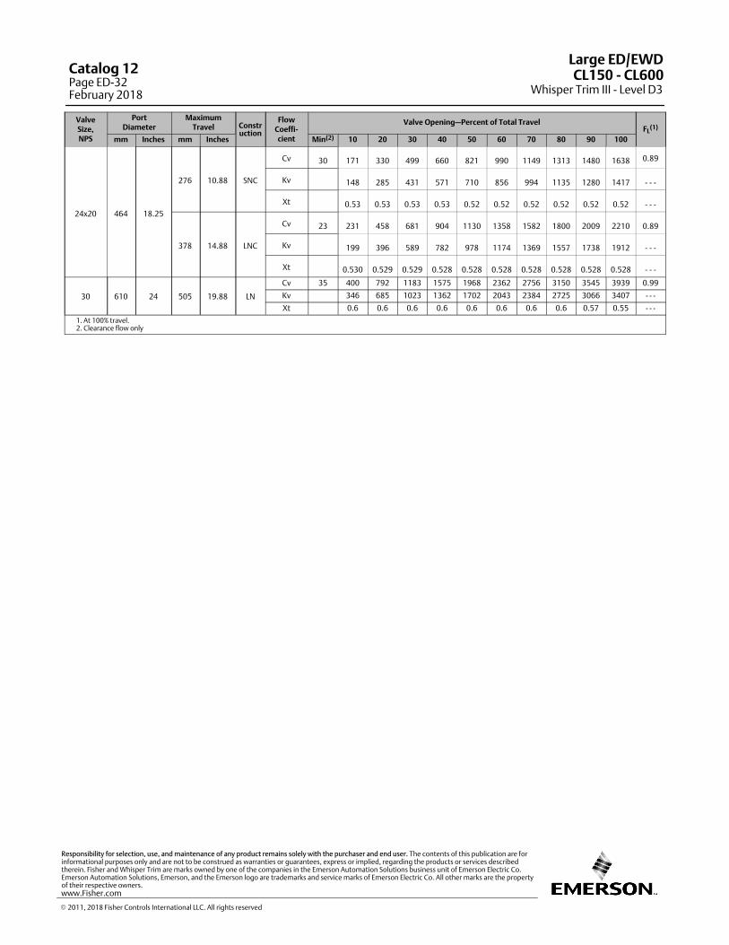
ValveSize,NPS
PortDiameter
MaximumTravel Constr
uction
FlowCoeffi‐cient
Valve Opening—Percent of Total TravelFL
(1)
mm Inches mm Inches Min(2) 10 20 30 40 50 60 70 80 90 100
24x20 464 18.25
276 10.88 SNC
Cv 30 171 330 499 660 821 990 1149 1313 1480 1638 0.89
Kv 148 285 431 571 710 856 994 1135 1280 1417 - - -
Xt 0.53 0.53 0.53 0.53 0.52 0.52 0.52 0.52 0.52 0.52 - - -
378 14.88 LNC
Cv 23 231 458 681 904 1130 1358 1582 1800 2009 2210 0.89
Kv 199 396 589 782 978 1174 1369 1557 1738 1912 - - -
Xt 0.530 0.529 0.529 0.528 0.528 0.528 0.528 0.528 0.528 0.528 - - -
30 610 24 505 19.88 LN
Cv 35 400 792 1183 1575 1968 2362 2756 3150 3545 3939 0.99
Kv 346 685 1023 1362 1702 2043 2384 2725 3066 3407 - - -
Xt 0.6 0.6 0.6 0.6 0.6 0.6 0.6 0.6 0.57 0.55 - - -
1. At 100% travel.2. Clearance flow only
Large ED/EWD
Whisper Trim III - Level D3CL150 ‐ CL600Catalog 12
Page ED-32February 2018
� 2011, 2018 Fisher Controls International LLC. All rights reserved
www.Fisher.com
Responsibility for selection, use, and maintenance of any product remains solely with the purchaser and end user. The contents of this publication are forinformational purposes only and are not to be construed as warranties or guarantees, express or implied, regarding the products or services describedtherein. Fisher and Whisper Trim are marks owned by one of the companies in the Emerson Automation Solutions business unit of Emerson Electric Co.Emerson Automation Solutions, Emerson, and the Emerson logo are trademarks and service marks of Emerson Electric Co. All other marks are the propertyof their respective owners.

33
WhisperFlo Trim - Level X - Flow UpLinear
Characteristic
ValveSize,NPS
PortDiameter
MaximumTravel Constr
uction
FlowCoeffi‐cient
Valve Opening—Percent of Total TravelFL
(1)
mm Inches mm Inches Min(2) 10 20 30 40 50 60 70 80 90 100
12 279.4 11
140 5.5 SNCCv 62.2 92 180 274 366 454 538 616 689 757 820
Xt 0.53 0.71 0.7 0.69 0.68 0.68 0.69 0.69 0.7 0.71 0.73 ---
203 8 LNCCv 62.2 128 257 382 508 633 728 820 901 978 1019 0.89
Xt 0.886 0.886 0.777 0.799 0.737 0.688 0.727 0.776 0.734 0.721 0.758 ---
14 279.4 11
140 5.5 SNCCv 62.2 92 180 276 370 461 549 633 714 791 863
Xt 0.53 0.71 0.70 0.69 0.68 0.67 0.68 0.67 0.68 0.68 0.69 ---
203 8 LNCCv 62.2 126 258 386 517 642 762 866 961 1049 1113
Xt 0.69 0.69 0.66 0.69 0.66 0.65 0.66 0.71 0.70 0.70 0.73 ---
16x12 279.4 11
140 5.5 SNCCv 62.2 92 180 277 372 465 556 645 730 813 892
Xt 0.53 0.71 0.7 0.69 0.68 0.67 0.67 0.66 0.66 0.66 0.66 ---
203 8 LNCCv 62.2 124 258 388 523 648 784 896 1001 1096 1175
Xt 0.556 0.556 0.58 0.614 0.612 0.629 0.615 0.665 0.678 0.691 0.719 ---
16 374.7 14.75 203 8.00 LNCCv 60.2 170 358 541 720 890 1052 1205 1348 1481 1604 ---
Xt 0.534 0.711 0.697 0.688 0.684 0.684 0.687 0.694 0.703 0.715 0.729 ---
18 374.7 14.75
203 8.00 SNCCv 60.2 178 373 550 745 923 1110 1267 1419 1544 1661 ---
Xt 0.66 0.66 0.66 0.66 0.66 0.66 0.66 0.66 0.66 0.66 0.66 ---
276 10.88 LNCCv 60.2 248 513 781 1049 1284 1491 1666 1811 1927 2017 ---
Xt 0.66 0.66 0.66 0.66 0.66 0.66 0.66 0.66 0.66 0.66 0.66 ---
378 14.88 LNCCv 60.2 348 717 1080 1385 1638 1838 1983 2086 2159 2214 ---
Xt 0.66 0.66 0.66 0.66 0.66 0.66 0.66 0.66 0.66 0.66 0.66 ---
20x16 374.7 14.75
203 8.00 SNCCv 60.2 170 359 546 731 912 1089 1260 1427 1587 1741 ---
Xt 0.534 0.713 0.699 0.687 0.677 0.669 0.663 0.659 0.656 0.655 0.654 ---
276 10.88 LNCCv 60.2 238 494 745 990 1226 1452 1667 1870 2061 2240 ---
Xt 0.534 0.708 0.690 0.676 0.666 0.659 0.656 0.654 0.655 0.658 0.662 ---
378 14.88 LNCCv 60.2 332 679 1015 1339 1633 1911 2165 2397 2606 2793 ---
Xt 0.534 0.701 0.679 0.665 0.657 0.654 0.656 0.660 0.667 0.676 0.686 ---
24x16 374.7 14.75
203 8.00 SNCCv 60.2 170 360 548 735 921 1104 1285 1462 1636 1807 ---
Xt 0.534 0.716 0.703 0.692 0.682 0.673 0.665 0.658 0.652 0.647 0.642 ---
276 10.88 LNCCv 60.2 238 495 750 1001 1248 1490 1725 1953 2173 2385 ---
Xt 0.534 0.711 0.695 0.681 0.669 0.659 0.651 0.644 0.639 0.635 0.632 ---
378 14.88 LNCCv 60.2 333 683 1027 1363 1687 1999 2296 2578 2843 3092 ---
Xt 0.534 0.705 0.685 0.668 0.655 0.645 0.638 0.633 0.630 0.628 0.628 ---
20 464 18.25
276 10.88 SNC
Cv 86.5 286 592 891 1179 1453 1712 1954 2179 2386 2576 - - -
Xt 0.534 0.708 0.694 0.685 0.682 0.683 0.688 0.696 0.708 0.722 0.738 - - -
378 14.88 LNC
Cv 86.5 399 813 1208 1577 1917 2223 2497 2740 2954 3141 - - -
Xt 0.534 0.702 0.687 0.682 0.685 0.695 0.711 0.731 0.755 0.781 0.809 - - -
24x20 464 18.25
276 10.88 SNC
Cv 86.5 286 595 900 1200 1493 1779 2056 2322 2578 2823 - - -
Xt 0.534 0.710 0.695 0.683 0.673 0.665 0.659 0.656 0.654 0.653 0.654 - - -
378 14.88 LNC
Cv 86.5 400 820 1231 1630 2012 2376 2720 3043 3343 3622 - - -
Xt 0.534 0.704 0.686 0.672 0.662 0.656 0.653 0.653 0.655 0.659 0.665 - - -
1. At 100% travel.2. Clearance flow only
Large ED/EWD
WhisperFlo™ Trim - Level XCL150 ‐ CL600
Catalog 12Page ED-33
February 2018
� 2011, 2018 Fisher Controls International LLC. All rights reserved
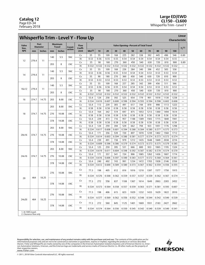
WhisperFlo Trim - Level Y - Flow UpLinear
Characteristic
ValveSize,NPS
PortDiameter
MaximumTravel Constr
uction
FlowCoeffi‐cient
Valve Opening—Percent of Total TravelFL
(1)
mm Inches mm Inches Min(2) 10 20 30 40 50 60 70 80 90 100
12 279.4 11
140 5.5 SNCCv 35 55 109 168 225 282 338 392 445 496 546 0.89
Xt 0.53 0.56 0.55 0.55 0.54 0.54 0.54 0.54 0.54 0.54 0.55 ---
203 8 LNCCv 35 90 180 270 360 450 540 630 720 810 900 0.89
Xt 0.532 0.532 0.532 0.532 0.532 0.532 0.532 0.532 0.532 0.532 0.532 ---
14 279.4 11
140 5.5 SNCCv 35 55 109 168 226 284 340 396 452 505 558
Xt 0.53 0.56 0.56 0.55 0.54 0.54 0.54 0.53 0.53 0.53 0.54 ---
203 8 LNCCv 35 90 180 270 360 450 540 630 720 810 900
Xt 0.53 0.53 0.53 0.53 0.53 0.53 0.53 0.53 0.53 0.53 0.53 ---
16x12 279.4 11
140 5.5 SNCCv 35 55 109 168 227 285 342 399 456 511 566
Xt 0.53 0.56 0.56 0.55 0.54 0.54 0.54 0.53 0.53 0.53 0.53 ---
203 8 LNCCv 35 90 180 270 360 450 540 630 720 810 900
Xt 0.532 0.532 0.532 0.532 0.532 0.532 0.532 0.532 0.532 0.532 0.532 ---
16 374.7 14.75 203 8.00 LNCCv 53.4 124 258 392 525 654 779 901 1018 1130 1238 ---
Xt 0.534 0.616 0.607 0.600 0.596 0.594 0.593 0.594 0.598 0.602 0.608 ---
18 374.7 14.75
203 8.00 SNCCv 53.4 113 239 365 491 617 744 870 998 1113 1223 ---
Xt 0.58 0.58 0.58 0.58 0.58 0.58 0.58 0.58 0.58 0.58 0.58 ---
276 10.88 LNCCv 53.4 164 342 519 697 875 1053 1213 1360 1494 1614 ---
Xt 0.58 0.58 0.58 0.58 0.58 0.58 0.58 0.58 0.58 0.58 0.58 ---
378 14.88 LNCCv 53.4 229 473 716 957 1188 1389 1565 1715 1840 1941 ---
Xt 0.58 0.58 0.58 0.58 0.58 0.58 0.58 0.58 0.58 0.58 0.58 ---
20x16 374.7 14.75
203 8.00 SNCCv 53.4 124 259 394 529 662 794 923 1051 1176 1298 ---
Xt 0.534 0.617 0.608 0.601 0.594 0.588 0.584 0.580 0.577 0.575 0.573 ---
276 10.88 LNCCv 53.4 171 356 539 720 897 1070 1239 1402 1560 1712 ---
Xt 0.534 0.614 0.603 0.594 0.586 0.581 0.577 0.574 0.573 0.573 0.574 ---
378 14.88 LNCCv 53.4 239 491 738 979 1212 1435 1648 1849 2038 2216 ---
Xt 0.534 0.609 0.596 0.586 0.579 0.574 0.573 0.573 0.575 0.579 0.585 ---
24x16 374.7 14.75
203 8.00 SNCCv 53.4 125 259 395 531 666 800 933 1065 1195 1324 ---
Xt 0.534 0.619 0.611 0.604 0.598 0.592 0.587 0.582 0.578 0.574 0.570 ---
276 10.88 LNCCv 53.4 171 357 541 724 906 1085 1262 1436 1607 1774 ---
Xt 0.534 0.616 0.606 0.597 0.590 0.583 0.577 0.572 0.568 0.564 0.561 ---
378 14.88 LNCCv 53.4 240 492 743 991 1234 1472 1703 1928 2146 2356 ---
Xt 0.534 0.612 0.600 0.589 0.580 0.573 0.567 0.562 0.559 0.556 0.555 ---
20 464 18.25
276 10.88 SNC
Cv 77.3 198 405 612 816 1016 1210 1397 1577 1750 1915 - - -
Xt 0.534 0.576 0.568 0.562 0.559 0.557 0.557 0.559 0.562 0.567 0.574 - - -
378 14.88 LNC
Cv 77.3 272 558 837 1108 1367 1614 1849 2063 2265 2452 - - -
Xt 0.534 0.573 0.564 0.558 0.557 0.559 0.563 0.571 0.581 0.593 0.607 - - -
24x20 464 18.25
276 10.88 SNC
Cv 77.3 198 406 615 823 1029 1232 1433 1629 1822 2010 - - -
Xt 0.534 0.577 0.569 0.562 0.556 0.552 0.548 0.544 0.542 0.540 0.539 - - -
378 14.88 LNC
Cv 77.3 272 560 845 1125 1401 1669 1931 2183 2427 2662 - - -
Xt 0.534 0.574 0.564 0.556 0.550 0.545 0.542 0.540 0.539 0.540 0.541 - - -
1. At 100% travel.2. Clearance flow only
Large ED/EWD
WhisperFlo Trim - Level YCL150 ‐ CL600Catalog 12
Page ED-34February 2018
� 2011, 2018 Fisher Controls International LLC. All rights reserved
www.Fisher.com
Responsibility for selection, use, and maintenance of any product remains solely with the purchaser and end user. The contents of this publication are forinformational purposes only and are not to be construed as warranties or guarantees, express or implied, regarding the products or services describedtherein. Fisher and WhisperFlo are marks owned by one of the companies in the Emerson Automation Solutions business unit of Emerson Electric Co. Emerson Automation Solutions, Emerson, and the Emerson logo are trademarks and service marks of Emerson Electric Co. All other marks are the property oftheir respective owners.
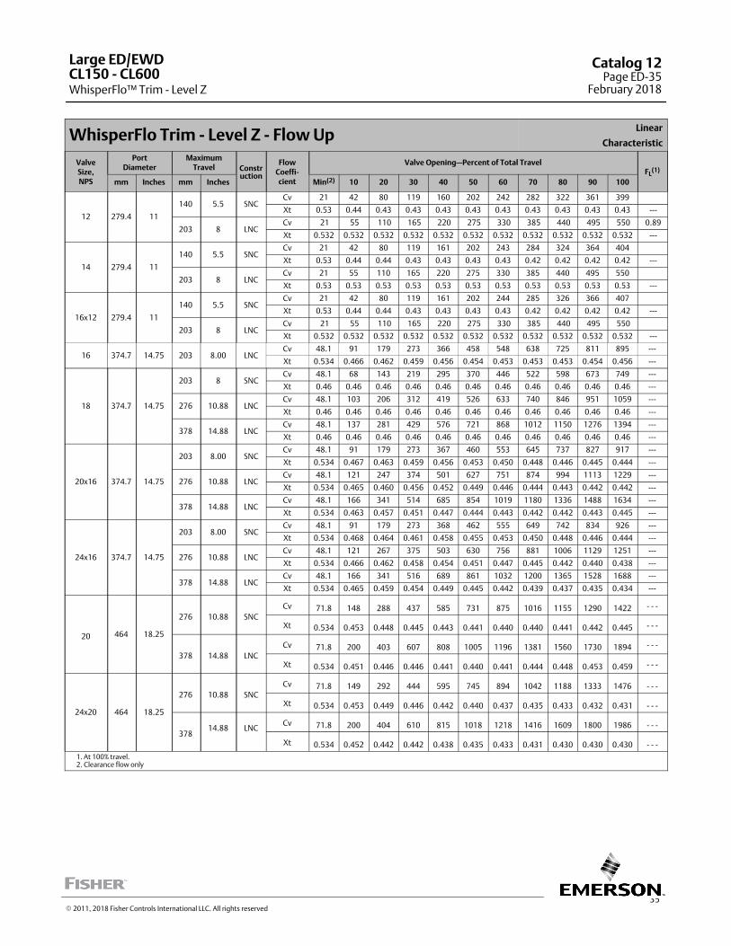
35
WhisperFlo Trim - Level Z - Flow UpLinear
Characteristic
ValveSize,NPS
PortDiameter
MaximumTravel Constr
uction
FlowCoeffi‐cient
Valve Opening—Percent of Total TravelFL
(1)
mm Inches mm Inches Min(2) 10 20 30 40 50 60 70 80 90 100
12 279.4 11
140 5.5 SNCCv 21 42 80 119 160 202 242 282 322 361 399
Xt 0.53 0.44 0.43 0.43 0.43 0.43 0.43 0.43 0.43 0.43 0.43 ---
203 8 LNCCv 21 55 110 165 220 275 330 385 440 495 550 0.89
Xt 0.532 0.532 0.532 0.532 0.532 0.532 0.532 0.532 0.532 0.532 0.532 ---
14 279.4 11
140 5.5 SNCCv 21 42 80 119 161 202 243 284 324 364 404
Xt 0.53 0.44 0.44 0.43 0.43 0.43 0.43 0.42 0.42 0.42 0.42 ---
203 8 LNCCv 21 55 110 165 220 275 330 385 440 495 550
Xt 0.53 0.53 0.53 0.53 0.53 0.53 0.53 0.53 0.53 0.53 0.53 ---
16x12 279.4 11
140 5.5 SNCCv 21 42 80 119 161 202 244 285 326 366 407
Xt 0.53 0.44 0.44 0.43 0.43 0.43 0.43 0.42 0.42 0.42 0.42 ---
203 8 LNCCv 21 55 110 165 220 275 330 385 440 495 550
Xt 0.532 0.532 0.532 0.532 0.532 0.532 0.532 0.532 0.532 0.532 0.532 ---
16 374.7 14.75 203 8.00 LNCCv 48.1 91 179 273 366 458 548 638 725 811 895 ---
Xt 0.534 0.466 0.462 0.459 0.456 0.454 0.453 0.453 0.453 0.454 0.456 ---
18 374.7 14.75
203 8 SNCCv 48.1 68 143 219 295 370 446 522 598 673 749 ---
Xt 0.46 0.46 0.46 0.46 0.46 0.46 0.46 0.46 0.46 0.46 0.46 ---
276 10.88 LNCCv 48.1 103 206 312 419 526 633 740 846 951 1059 ---
Xt 0.46 0.46 0.46 0.46 0.46 0.46 0.46 0.46 0.46 0.46 0.46 ---
378 14.88 LNCCv 48.1 137 281 429 576 721 868 1012 1150 1276 1394 ---
Xt 0.46 0.46 0.46 0.46 0.46 0.46 0.46 0.46 0.46 0.46 0.46 ---
20x16 374.7 14.75
203 8.00 SNCCv 48.1 91 179 273 367 460 553 645 737 827 917 ---
Xt 0.534 0.467 0.463 0.459 0.456 0.453 0.450 0.448 0.446 0.445 0.444 ---
276 10.88 LNCCv 48.1 121 247 374 501 627 751 874 994 1113 1229 ---
Xt 0.534 0.465 0.460 0.456 0.452 0.449 0.446 0.444 0.443 0.442 0.442 ---
378 14.88 LNCCv 48.1 166 341 514 685 854 1019 1180 1336 1488 1634 ---
Xt 0.534 0.463 0.457 0.451 0.447 0.444 0.443 0.442 0.442 0.443 0.445 ---
24x16 374.7 14.75
203 8.00 SNCCv 48.1 91 179 273 368 462 555 649 742 834 926 ---
Xt 0.534 0.468 0.464 0.461 0.458 0.455 0.453 0.450 0.448 0.446 0.444 ---
276 10.88 LNCCv 48.1 121 267 375 503 630 756 881 1006 1129 1251 ---
Xt 0.534 0.466 0.462 0.458 0.454 0.451 0.447 0.445 0.442 0.440 0.438 ---
378 14.88 LNCCv 48.1 166 341 516 689 861 1032 1200 1365 1528 1688 ---
Xt 0.534 0.465 0.459 0.454 0.449 0.445 0.442 0.439 0.437 0.435 0.434 ---
20 464 18.25
276 10.88 SNC
Cv 71.8 148 288 437 585 731 875 1016 1155 1290 1422 - - -
Xt 0.534 0.453 0.448 0.445 0.443 0.441 0.440 0.440 0.441 0.442 0.445 - - -
378 14.88 LNC
Cv 71.8 200 403 607 808 1005 1196 1381 1560 1730 1894 - - -
Xt 0.534 0.451 0.446 0.446 0.441 0.440 0.441 0.444 0.448 0.453 0.459 - - -
24x20 464 18.25
276 10.88 SNC
Cv 71.8 149 292 444 595 745 894 1042 1188 1333 1476 - - -
Xt 0.534 0.453 0.449 0.446 0.442 0.440 0.437 0.435 0.433 0.432 0.431 - - -
37814.88 LNC
Cv 71.8 200 404 610 815 1018 1218 1416 1609 1800 1986 - - -
Xt 0.534 0.452 0.442 0.442 0.438 0.435 0.433 0.431 0.430 0.430 0.430 - - -
1. At 100% travel.2. Clearance flow only
Large ED/EWD
WhisperFlo™ Trim - Level ZCL150 ‐ CL600
Catalog 12Page ED-35
February 2018
� 2011, 2018 Fisher Controls International LLC. All rights reserved

This page is intentionally left blank.
Large ED/EWD
WhisperFlo Trim - Level ZCL150 ‐ CL600Catalog 12
Page ED-36February 2018
� 2018 Fisher Controls International LLC. All rights reserved
www.Fisher.com
Responsibility for selection, use, and maintenance of any product remains solely with the purchaser and end user. The contents of this publication are forinformational purposes only and are not to be construed as warranties or guarantees, express or implied, regarding the products or services describedtherein. Fisher and WhisperFlo are marks owned by one of the companies in the Emerson Automation Solutions business unit of Emerson Electric Co. Emerson Automation Solutions, Emerson, and the Emerson logo are trademarks and service marks of Emerson Electric Co. All other marks are the property oftheir respective owners.
The Fisher� EDR valve has flow coefficients identical to the NPS 1 through 4 CL125 ‐ 600 ED valve. Please refer to thosecoefficients. For additional EDR valve body information, refer to Bulletin 51.1:ED.
� 1988, 2018 Fisher Controls International LLC. All rights reserved
EDR Catalog 12Page EDR-1
February 2018
This page is intentionally left blank.
EDRCatalog 12Page EDR-2February 2018
� 2014, 2018 Fisher Controls International LLC. All rights reserved
www.Fisher.com
Responsibility for selection, use, and maintenance of any product remains solely with the purchaser and end user. The contents of this publication are forinformational purposes only and are not to be construed as warranties or guarantees, express or implied, regarding the products or services describedtherein. Fisher is a mark owned by one of the companies in the Emerson Automation Solutions business unit of Emerson Electric Co. Emerson AutomationSolutions, Emerson, and the Emerson logo are trademarks and service marks of Emerson Electric Co. All other marks are the property of their respectiveowners.
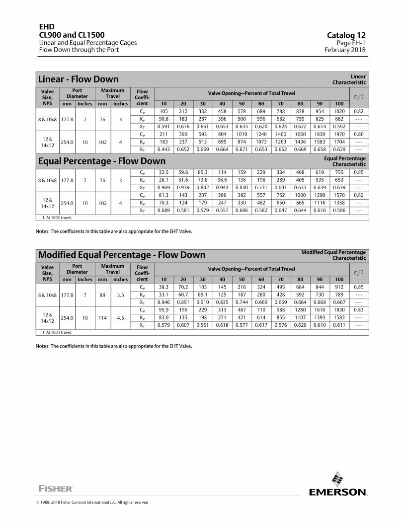
Linear ‐ Flow Down LinearCharacteristic
ValveSize,NPS
PortDiameter
MaximumTravel
FlowCoeffi‐cient
Valve Opening—Percent of Total TravelFL
(1)
mm Inches mm Inches 10 20 30 40 50 60 70 80 90 100
8 & 10x8 177.8 7 76 3
Cv 105 212 332 458 578 689 788 878 954 1020 0.82
Kv 90.8 183 287 396 500 596 682 759 825 882 ‐ ‐ ‐
XT 0.591 0.676 0.661 0.653 0.633 0.620 0.624 0.622 0.614 0.592 ‐ ‐ ‐
12 &
14x12254.0 10 102 4
Cv 211 390 593 804 1010 1240 1460 1660 1830 1970 0.80
Kv 183 337 513 695 874 1073 1263 1436 1583 1704 ‐ ‐ ‐
XT 0.443 0.652 0.669 0.664 0.671 0.653 0.662 0.669 0.658 0.629 ‐ ‐ ‐
Equal Percentage ‐ Flow Down Equal PercentageCharacteristic
8 & 10x8 177.8 7 76 3
Cv 32.5 59.6 85.3 114 159 229 334 468 619 755 0.85
Kv 28.1 51.6 73.8 98.6 138 198 289 405 535 653 ‐ ‐ ‐
XT 0.969 0.939 0.842 0.944 0.840 0.731 0.641 0.633 0.639 0.639 ‐ ‐ ‐
12 &
14x12254.0 10 102 4
Cv 81.3 143 207 286 382 557 752 1000 1290 1570 0.82
Kv 70.3 124 179 247 330 482 650 865 1116 1358 ‐ ‐ ‐
XT 0.689 0.581 0.579 0.557 0.606 0.582 0.647 0.644 0.616 0.596 ‐ ‐ ‐
1. At 100% travel.
Notes: The coefficients in this table are also appropriate for the EHT Valve.
Modified Equal Percentage ‐ Flow Down Modified Equal PercentageCharacteristic
ValveSize,NPS
PortDiameter
MaximumTravel
FlowCoeffi‐cient
Valve Opening—Percent of Total TravelFL
(1)
mm Inches mm Inches 10 20 30 40 50 60 70 80 90 100
8 & 10x8 177.8 7 89 3.5
Cv 38.3 70.2 103 145 216 324 495 684 844 912 0.85
Kv 33.1 60.7 89.1 125 187 280 428 592 730 789 ‐ ‐ ‐
XT 0.946 0.891 0.910 0.835 0.744 0.669 0.669 0.664 0.668 0.667 ‐ ‐ ‐
12 &
14x12254.0 10 114 4.5
Cv 95.9 156 229 313 487 710 988 1280 1610 1830 0.83
Kv 83.0 135 198 271 421 614 855 1107 1393 1583 ‐ ‐ ‐
XT 0.579 0.607 0.561 0.618 0.577 0.617 0.576 0.620 0.610 0.611 ‐ ‐ ‐
1. At 100% travel.
Notes: The coefficients in this table are also appropriate for the EHT Valve.
� 1988, 2018 Fisher Controls International LLC. All rights reserved
EHDCL900 and CL1500Linear and Equal Percentage CagesFlow Down through the Port
Catalog 12Page EH-1
February 2018
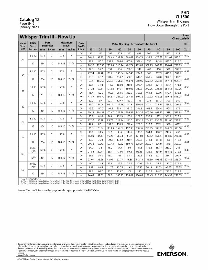
Whisper Trim III ‐ Flow Up LinearCharacteristic
ValveSize,NPS
Body
Size,
Inches
PortDiameter
MaximumTravel
Flow
Coeff-
icient
Valve Opening—Percent of Total Travel Xt(1)
mm Inches mm Inches 10 20 30 40 50 60 70 80 90 100 Xt(1)
A1
8 & 10 177.8 7 177.8 7Cv 31 113 195 275 351 439 500 551 592 617
0.50Kv 26.82 97.75 168.68 237.88 303.62 379.74 432.5 476.62 512.08 533.71
12 254 10 184.15 7-1/4Cv 32.8 147.2 258.8 365.6 465.6 559.4 650 743.8 837.5 915.6
0.65Kv 28.37 127.33 223.86 316.24 402.74 483.88 562.25 643.39 724.44 791.99
A3
8 & 10 177.8 7 177.8 7Cv 32.3 95.7 154 216 280.3 340 400 460 520 586.7
0.57Kv 27.94 82.78 133.21 186.84 242.46 294.1 346 397.9 449.8 507.5
12 254 10 184.15 7-1/4Cv 73.3 191.5 301.5 418.2 530.3 648.5 760.6 878.8 990.9 1112.1
0.69Kv 63.4 165.65 260.8 361.74 458.71 560.95 657.92 760.16 857.13 961.97
B1
8 & 10 177.8 7 177.8 7Cv 36.1 71.8 117.9 168.9 219.6 270.4 321.1 371.4 421.4 471.4
0.50Kv 31.23 62.11 101.98 146.1 189.95 233.9 277.75 321.26 364.51 407.76
12 254 10 184.15 7-1/4Cv 48.4 122.3 190.6 263.5 332.3 393.5 461.3 522.6 577.4 632.3
0.61Kv 41.87 105.79 164.87 227.93 287.44 340.38 399.02 452.05 499.45 546.94
B3
8 & 10 177.8 7 177.8 7Cv 22.2 59 92.7 129.7 163.7 196 234 267.3 300 340
0.57Kv 19.2 51.04 80.19 112.19 141.6 169.54 202.41 231.21 259.5 294.1
12 254 10 184.15 7-1/4Cv 45.3 117.2 191.3 258.1 331.3 396.9 462.5 534.4 600 675
0.65Kv 39.18 101.38 165.47 223.26 286.57 343.32 400.06 462.26 519 583.88
C1
8 & 10 177.8 7 177.8 7Cv 25.8 61.6 96.8 132.3 165.9 202.5 236.9 272 301.8 325.1
0.49Kv 22.32 53.28 83.73 114.44 143.5 175.16 204.92 235.28 261.06 281.21
12 254 10 184.15 7-1/4Cv 42.2 87.1 131.6 176.5 222.4 266.3 312.2 357.1 398 4312
0.55Kv 36.5 75.34 113.83 152.67 192.38 230.35 270.05 308.89 344.27 373.68
C3
8 & 10 177.8 7 177.8 7Cv 18.6 39.5 63.9 88.7 113.7 139.9 164.3 188.7 213.7 232
0.53Kv 16.09 34.17 55.27 76.73 98.35 121.01 142.12 163.23 184.85 200.68
12 254 10 184.15 7-1/4Cv 33.9 76.8 124.2 173.2 219.4 263.9 311.3 354.8 400 416.1
0.61Kv 29.32 66.43 107.43 149.82 189.78 228.27 269.27 306.9 346 359.93
D1
8(2) &
10(2) 177.8 7 177.8 7Cv 24.9 34 45.2 54.4 80 111.5 145.2 183.7 213.7 243
0.46Kv 21.54 29.41 39.1 47.06 69.2 96.45 125.6 158.9 184.85 210.2
12(2) 254 10 184.15 7-1/4Cv 26.6 39.3 49.7 61 83.1 130.3 173.4 223.1 264.1 299.7
0.53Kv 23.01 33.99 42.99 52.77 71.88 112.71 149.99 192.98 228.45 259.24
D3
8(3) &
10(3) 177.8 7 177.8 7Cv 9.7 11.5 13.6 15.9 22.2 42.6 64.9 87.9 111.7 124.1
0.50Kv 8.39 9.95 11.76 13.75 19.2 36.85 56.14 76.03 96.62 107.35
12 254 10 184.15 7-1/4Cv 28.3 60.7 93.3 125.7 158 185 216.7 248.7 281.3 313.7
0.57Kv 24.48 52.51 80.7 108.73 136.67 160.03 187.45 215.13 243.32 271.35
1. At maximum travel.2. These cages are characterized for low flow in the first 40 percent of travel then exhibit in a linear characteristic.3. These cages are characterized for low flow in the first 50 percent of travel then exhibit in a linear characteristic.
Notes: The coefficients on this page are also appropriate for the EHT Valve.
� 2020 Fisher Controls International LLC. All rights reserved
www.Fisher.com
Responsibility for selection, use, and maintenance of any product remains solely with the purchaser and end user. The contents of this publication are forinformational purposes only and are not to be construed as warranties or guarantees, express or implied, regarding the products or services describedtherein. Fisher is a mark owned by one of the companies in the Emerson Process Management business unit of Emerson Electric Co. Emerson Process Management, Emerson, and the Emerson logo are trademarks and service marks of Emerson Electric Co. All other marks are the property of their respectiveowners.
EHD
Whisper Trim III CagesFlow Down through the Port
CL1500Catalog 12Page EH-2January 2020
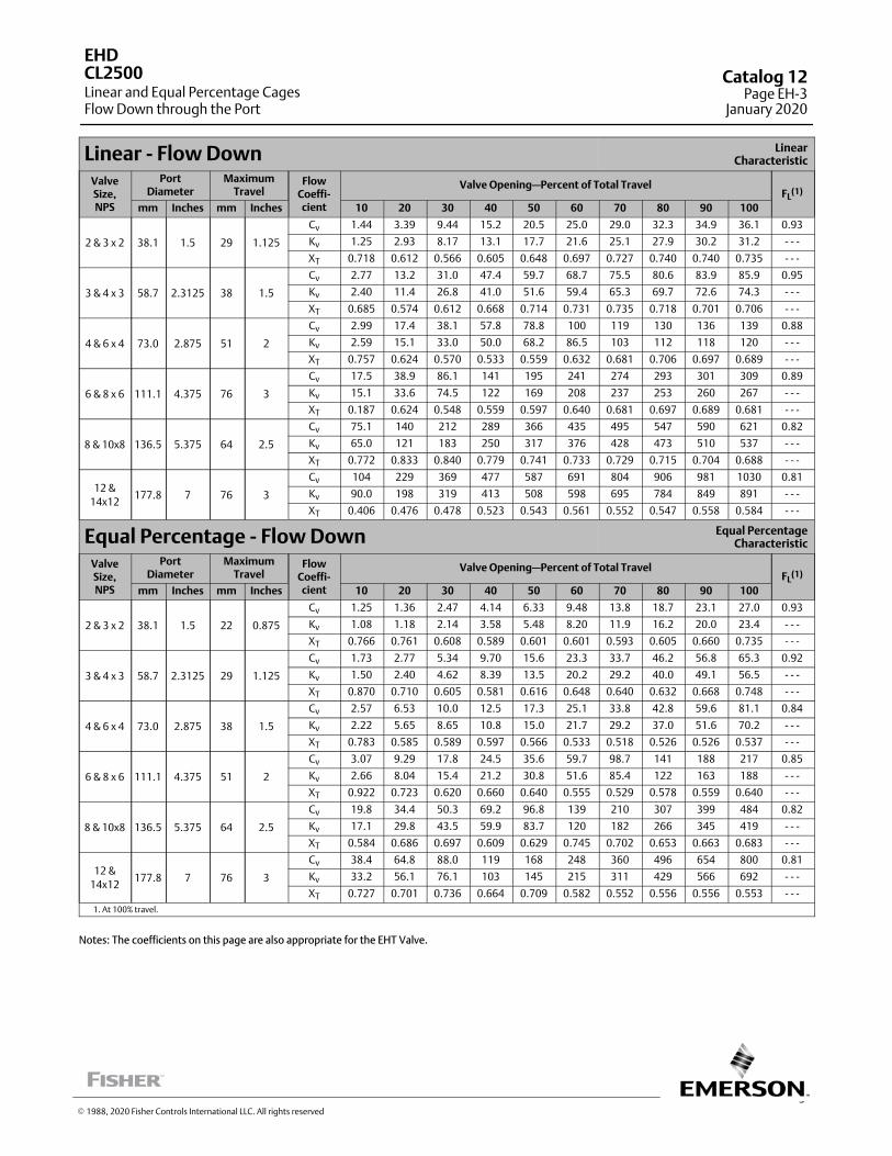
3
Linear ‐ Flow Down LinearCharacteristic
ValveSize,NPS
PortDiameter
MaximumTravel
FlowCoeffi‐cient
Valve Opening—Percent of Total TravelFL
(1)
mm Inches mm Inches 10 20 30 40 50 60 70 80 90 100
2 & 3 x 2 38.1 1.5 29 1.125
Cv 1.44 3.39 9.44 15.2 20.5 25.0 29.0 32.3 34.9 36.1 0.93
Kv 1.25 2.93 8.17 13.1 17.7 21.6 25.1 27.9 30.2 31.2 ‐ ‐ ‐
XT 0.718 0.612 0.566 0.605 0.648 0.697 0.727 0.740 0.740 0.735 ‐ ‐ ‐
3 & 4 x 3 58.7 2.3125 38 1.5
Cv 2.77 13.2 31.0 47.4 59.7 68.7 75.5 80.6 83.9 85.9 0.95
Kv 2.40 11.4 26.8 41.0 51.6 59.4 65.3 69.7 72.6 74.3 ‐ ‐ ‐
XT 0.685 0.574 0.612 0.668 0.714 0.731 0.735 0.718 0.701 0.706 ‐ ‐ ‐
4 & 6 x 4 73.0 2.875 51 2
Cv 2.99 17.4 38.1 57.8 78.8 100 119 130 136 139 0.88
Kv 2.59 15.1 33.0 50.0 68.2 86.5 103 112 118 120 ‐ ‐ ‐
XT 0.757 0.624 0.570 0.533 0.559 0.632 0.681 0.706 0.697 0.689 ‐ ‐ ‐
6 & 8 x 6 111.1 4.375 76 3
Cv 17.5 38.9 86.1 141 195 241 274 293 301 309 0.89
Kv 15.1 33.6 74.5 122 169 208 237 253 260 267 ‐ ‐ ‐
XT 0.187 0.624 0.548 0.559 0.597 0.640 0.681 0.697 0.689 0.681 ‐ ‐ ‐
8 & 10x8 136.5 5.375 64 2.5
Cv 75.1 140 212 289 366 435 495 547 590 621 0.82
Kv 65.0 121 183 250 317 376 428 473 510 537 ‐ ‐ ‐
XT 0.772 0.833 0.840 0.779 0.741 0.733 0.729 0.715 0.704 0.688 ‐ ‐ ‐
12 &
14x12177.8 7 76 3
Cv 104 229 369 477 587 691 804 906 981 1030 0.81
Kv 90.0 198 319 413 508 598 695 784 849 891 ‐ ‐ ‐
XT 0.406 0.476 0.478 0.523 0.543 0.561 0.552 0.547 0.558 0.584 ‐ ‐ ‐
Equal Percentage ‐ Flow Down Equal PercentageCharacteristic
ValveSize,NPS
PortDiameter
MaximumTravel
FlowCoeffi‐cient
Valve Opening—Percent of Total TravelFL
(1)
mm Inches mm Inches 10 20 30 40 50 60 70 80 90 100
2 & 3 x 2 38.1 1.5 22 0.875
Cv 1.25 1.36 2.47 4.14 6.33 9.48 13.8 18.7 23.1 27.0 0.93
Kv 1.08 1.18 2.14 3.58 5.48 8.20 11.9 16.2 20.0 23.4 ‐ ‐ ‐
XT 0.766 0.761 0.608 0.589 0.601 0.601 0.593 0.605 0.660 0.735 ‐ ‐ ‐
3 & 4 x 3 58.7 2.3125 29 1.125
Cv 1.73 2.77 5.34 9.70 15.6 23.3 33.7 46.2 56.8 65.3 0.92
Kv 1.50 2.40 4.62 8.39 13.5 20.2 29.2 40.0 49.1 56.5 ‐ ‐ ‐
XT 0.870 0.710 0.605 0.581 0.616 0.648 0.640 0.632 0.668 0.748 ‐ ‐ ‐
4 & 6 x 4 73.0 2.875 38 1.5
Cv 2.57 6.53 10.0 12.5 17.3 25.1 33.8 42.8 59.6 81.1 0.84
Kv 2.22 5.65 8.65 10.8 15.0 21.7 29.2 37.0 51.6 70.2 ‐ ‐ ‐
XT 0.783 0.585 0.589 0.597 0.566 0.533 0.518 0.526 0.526 0.537 ‐ ‐ ‐
6 & 8 x 6 111.1 4.375 51 2
Cv 3.07 9.29 17.8 24.5 35.6 59.7 98.7 141 188 217 0.85
Kv 2.66 8.04 15.4 21.2 30.8 51.6 85.4 122 163 188 ‐ ‐ ‐
XT 0.922 0.723 0.620 0.660 0.640 0.555 0.529 0.578 0.559 0.640 ‐ ‐ ‐
8 & 10x8 136.5 5.375 64 2.5
Cv 19.8 34.4 50.3 69.2 96.8 139 210 307 399 484 0.82
Kv 17.1 29.8 43.5 59.9 83.7 120 182 266 345 419 ‐ ‐ ‐
XT 0.584 0.686 0.697 0.609 0.629 0.745 0.702 0.653 0.663 0.683 ‐ ‐ ‐
12 &
14x12177.8 7 76 3
Cv 38.4 64.8 88.0 119 168 248 360 496 654 800 0.81
Kv 33.2 56.1 76.1 103 145 215 311 429 566 692 ‐ ‐ ‐
XT 0.727 0.701 0.736 0.664 0.709 0.582 0.552 0.556 0.556 0.553 ‐ ‐ ‐
1. At 100% travel.
Notes: The coefficients on this page are also appropriate for the EHT Valve.
EHD
Linear and Equal Percentage CagesFlow Down through the Port
CL2500 Catalog 12Page EH-3
January 2020
� 1988, 2020 Fisher Controls International LLC. All rights reserved

Modified Equal Percentage ‐ Flow Down Modified Equal PercentageCharacteristic
ValveSize,NPS
PortDiameter
MaximumTravel
FlowCoeffi‐cient
Valve Opening—Percent of Total TravelFL
(1)
mm Inches mm Inches 10 20 30 40 50 60 70 80 90 100
2 & 3 x 2 38.1 1.5 29 1.125
Cv 1.24 1.82 3.91 6.86 11.1 16.9 23.3 28.1 30.4 33.2 0.94
Kv 1.07 1.57 3.38 5.93 9.60 14.6 20.2 24.3 26.3 28.7 ‐ ‐ ‐
XT 0.792 0.681 0.578 0.581 0.605 0.628 0.652 0.693 0.731 0.710 ‐ ‐ ‐
3 & 4 x 3 58.7 2.3125 38 1.5
Cv 1.94 4.28 9.66 18.1 29.9 45.4 60.5 68.9 74.7 80.9 0.96
Kv 1.68 3.70 8.36 15.7 25.9 39.3 52.3 59.6 64.6 70.0 ‐ ‐ ‐
XT 0.805 0.640 0.593 0.624 0.668 0.672 0.677 0.753 0.779 0.710 ‐ ‐ ‐
4 & 6 x 4 73.0 2.875 51 2
Cv 2.99 9.01 12.7 19.6 30.3 44.5 65.8 96.3 114 126 0.90
Kv 2.59 7.79 11.0 17.0 26.2 38.5 56.9 83.3 98.6 109 ‐ ‐ ‐
XT 0.681 0.578 0.593 0.559 0.526 0.518 0.544 0.597 0.693 0.693 ‐ ‐ ‐
6 & 8 x 6 111.1 4.375 76 3
Cv 5.82 16.2 30.6 59.8 115 185 234 254 278 293 0.88
Kv 5.03 14.0 26.5 51.7 99.5 160 202 220 240 253 ‐ ‐ ‐
XT 0.806 0.677 0.624 0.574 0.559 0.597 0.664 0.723 0.706 0.689 ‐ ‐ ‐
8 & 10x8 136.5 5.375 76 3
Cv 22.9 41.9 61.9 86.4 140 225 334 451 537 584 0.85
Kv 19.8 36.2 53.5 74.7 121 195 289 390 465 505 ‐ ‐ ‐
XT 0.563 0.698 0.726 0.739 0.734 0.691 0.666 0.682 0.734 0.740 ‐ ‐ ‐
12 &
14x12177.8 7 89 3.5
Cv 42.4 73.7 104 147 223 351 523 717 899 1010 0.80
Kv 36.7 63.8 90.0 127 193 304 452 620 778 874 ‐ ‐ ‐
XT 0.691 0.679 0.652 0.650 0.598 0.549 0.549 0.552 0.551 0.551 ‐ ‐ ‐
1. At 100% travel.
Notes: The coefficients on this page are also appropriate for the EHT Valve.
EHD
Equal Percentage CagesFlow Down through the Port
CL2500Catalog 12Page EH-4January 2020
� 1990, 2020 Fisher Controls International LLC. All rights reserved
www.Fisher.com
Responsibility for selection, use, and maintenance of any product remains solely with the purchaser and end user. The contents of this publication are forinformational purposes only and are not to be construed as warranties or guarantees, express or implied, regarding the products or services describedtherein. Fisher is a mark owned by one of the companies in the Emerson Process Management business unit of Emerson Electric Co. Emerson Process Management, Emerson, and the Emerson logo are trademarks and service marks of Emerson Electric Co. All other marks are the property of their respectiveowners.
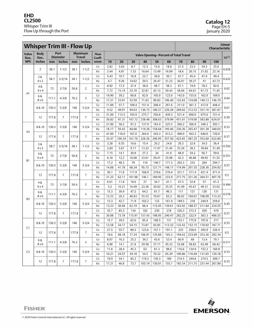
5
Whisper Trim III ‐ Flow Up LinearCharacteristic
ValveSize,NPS
Body
Size,
Inches
PortDiameter
MaximumTravel
Flow
Coeff-
icient
Valve Opening—Percent of Total TravelXt(1)
mm Inches mm Inches 10 20 30 40 50 60 70 80 90 100
A1
2 38.1 1-1/2 38.1 1-1/2Cv 2.82 5.63 8.7 12.3 15.6 18.6 21.5 23.3 24.3 25.6
0.656Kv 2.44 4.87 7.53 10.64 13.49 16.09 18.6 20.15 21.02 22.16
3 &
4 x 358.7 2-5/16 38.1 1-1/2
Cv 5.43 10.7 16.9 23.7 30.6 36.1 41.7 45.4 47.4 49.40.632
Kv 4.7 9.26 14.62 20.5 26.47 31.23 36.07 39.27 41 42.73
4 &
6 x 473 2-7/8 50.8 2
Cv 8.92 17.5 27.4 38.0 48.7 58.3 67.1 74.0 78.3 82.60.62
Kv 7.72 15.14 23.70 32.87 42.13 50.43 58.04 64.01 67.73 71.45
6 &
8 x 6111.1 4-3/8 76.2 3
Cv 19.90 39.2 60.8 82.8 105.0 123.0 142.0 155.0 162.0 169.00.64
Kv 17.21 33.91 52.59 71.62 90.83 106.40 122.83 134.08 140.13 146.19
8 & 10 136.5 5-3/8 146 5-3/4Cv 11.00 57.7 109.4 157.4 208.4 261.6 311.0 361.3 412.9 448.4
0.61Kv 9.52 49.91 94.63 136.15 180.27 226.28 269.02 312.52 357.16 387.87
12 177.8 7 177.8 7Cv 31.00 112.5 193.9 275.7 356.8 439.3 521.4 600.0 675.0 721.4
0.50Kv 26.82 97.31 167.72 238.48 308.63 379.99 451.01 519.00 583.88 624.01
A3
8 & 10 136.5 5-3/8 146 5-3/4Cv 21.00 58.3 97.2 137.9 183.4 225.5 266.2 306.9 348.3 393.1
0.53Kv 18.17 50.43 84.08 119.28 158.64 195.06 230.26 265.47 301.28 340.03
12 177.8 7 177.8 7Cv 41.00 116.0 187.0 264.0 343.3 413.3 490.0 563.3 640.0 720.0
0.57Kv 35.47 100.34 161.76 228.36 296.95 357.50 423.85 487.25 553.60 622.80
B1
3 &
4 x 358.7 2-5/16 38.1 1-1/2
Cv 3.28 6.55 10.6 15.4 20.2 24.8 29.3 32.6 34.5 36.40.593
Kv 2.84 5.67 9.17 13.32 17.47 21.45 25.34 28.2 29.84 31.49
4 &
6 x 473 2-7/8 50.8 2
Cv 7.15 14.1 20.9 27.3 34 41.6 48.9 54.2 56.7 59.60.551
Kv 6.18 12.2 18.08 23.61 29.41 35.98 42.3 46.88 49.05 51.55
8 & 10 136.5 5-3/8 146 5-3/4Cv 17.2 48.3 79 110 140.7 171.3 202.3 233 264 294.7
0.57Kv 14.88 41.78 68.34 95.15 121.71 148.17 174.99 201.55 228.36 254.92
12 177.8 7 177.8 7Cv 36.1 71.8 117.9 168.9 219.6 270.4 321.1 371.4 421.4 471.4
0.5Kv 31.23 62.11 101.98 146.1 189.95 233.9 277.75 321.26 364.51 407.76
B3
4 &
6 x 473 2-7/8 50.4 2
Cv 6.01 11.8 18.6 27 34.7 41.1 47.5 52.8 57 61.30.494
Kv 5.2 10.21 16.09 23.36 30.02 35.55 41.09 45.67 49.31 53.02
6 &
8 x 6111.1 4-3/8 76.2 3
Cv 15.3 30.4 47.2 64.2 81.7 96.3 111 121 126 1310.578
Kv 13.23 26.3 40.83 55.53 70.67 83.3 96.02 104.67 108.99 113.32
8 & 10 136.5 5-3/8 146 5-3/4Cv 15.3 42.7 71.9 102.2 133 161.4 189.5 218 244.9 259.6
0.45Kv 13.23 36.94 62.19 88.4 115.05 139.61 163.92 188.57 211.84 224.55
12 177.8 7 177.8 7Cv 35.7 85.3 134 182 230 278 326.3 373.3 420 470
0.57Kv 30.88 73.78 115.91 157.43 198.95 240.47 282.25 322.9 363.3 406.55
C1
8 & 10 136.5 5-3/8 146 5-3/4Cv 15.7 39.5 62.6 85.4 108.5 131 153.1 175.9 197.6 217
0.55Kv 13.58 34.17 54.15 73.87 93.85 113.32 132.43 152.15 170.92 187.71
12 177.8 7 177.8 7Cv 21.5 55.7 89.3 123.6 157.1 191.1 225 258.6 292.9 326.4
0.5Kv 18.6 48.18 77.24 106.91 135.89 165.3 194.63 223.69 253.36 282.34
C3
6 &
8 x 6111.1 4-3/8 76.2 3
Cv 8.07 16.3 25.2 34.2 43.6 52.4 60.9 68 73.4 79.10.511
Kv 6.98 14.1 21.8 29.58 37.71 45.33 52.68 58.82 63.49 68.42
8 & 10 136.5 5-3/8 146 5-3/4Cv 11.8 28.4 45.3 63 81.3 98.6 116.6 134.9 152.2 160.9
0.53Kv 10.21 24.57 39.18 54.5 70.32 85.29 100.86 116.69 131.65 139.18
12 177.8 7 177.8 7Cv 19.9 54.1 85.2 119.3 150.3 180 214.5 244.8 274.5 309.7
0.53Kv 17.21 46.8 73.7 103.19 130.01 155.7 185.54 211.75 237.44 267.89
EHD
Whisper Trim IIIFlow Up through the Port
CL2500 Catalog 12Page EH-5
January 2020
� 2020 Fisher Controls International LLC. All rights reserved
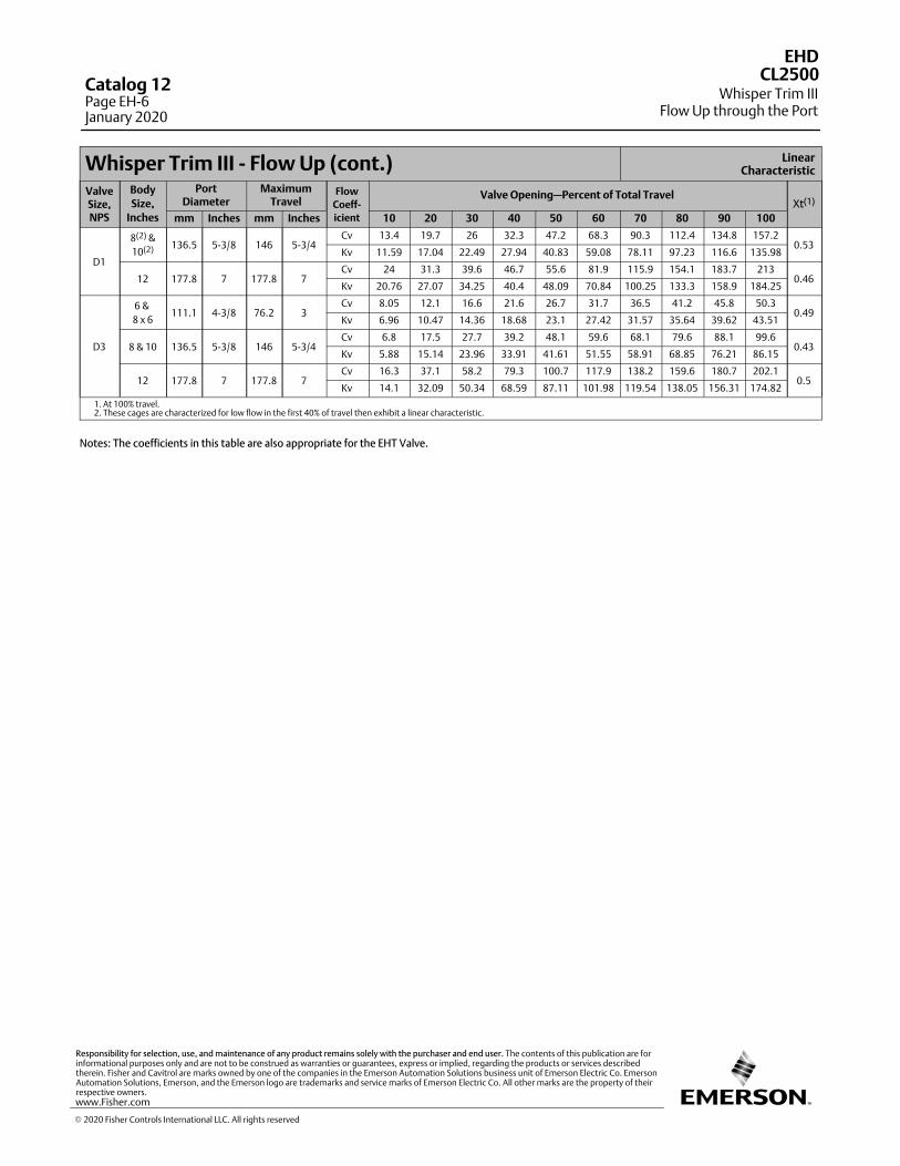
Whisper Trim III ‐ Flow Up (cont.) LinearCharacteristic
ValveSize,NPS
Body
Size,
Inches
PortDiameter
MaximumTravel
Flow
Coeff-
icient
Valve Opening—Percent of Total TravelXt(1)
mm Inches mm Inches 10 20 30 40 50 60 70 80 90 100
D1
8(2) &
10(2) 136.5 5-3/8 146 5-3/4Cv 13.4 19.7 26 32.3 47.2 68.3 90.3 112.4 134.8 157.2
0.53Kv 11.59 17.04 22.49 27.94 40.83 59.08 78.11 97.23 116.6 135.98
12 177.8 7 177.8 7Cv 24 31.3 39.6 46.7 55.6 81.9 115.9 154.1 183.7 213
0.46Kv 20.76 27.07 34.25 40.4 48.09 70.84 100.25 133.3 158.9 184.25
D3
6 &
8 x 6111.1 4-3/8 76.2 3
Cv 8.05 12.1 16.6 21.6 26.7 31.7 36.5 41.2 45.8 50.30.49
Kv 6.96 10.47 14.36 18.68 23.1 27.42 31.57 35.64 39.62 43.51
8 & 10 136.5 5-3/8 146 5-3/4Cv 6.8 17.5 27.7 39.2 48.1 59.6 68.1 79.6 88.1 99.6
0.43Kv 5.88 15.14 23.96 33.91 41.61 51.55 58.91 68.85 76.21 86.15
12 177.8 7 177.8 7Cv 16.3 37.1 58.2 79.3 100.7 117.9 138.2 159.6 180.7 202.1
0.5Kv 14.1 32.09 50.34 68.59 87.11 101.98 119.54 138.05 156.31 174.82
1. At 100% travel.2. These cages are characterized for low flow in the first 40% of travel then exhibit a linear characteristic.
Notes: The coefficients in this table are also appropriate for the EHT Valve.
EHD
Whisper Trim IIIFlow Up through the Port
CL2500Catalog 12Page EH-6January 2020
� 2020 Fisher Controls International LLC. All rights reserved
www.Fisher.com
Responsibility for selection, use, and maintenance of any product remains solely with the purchaser and end user. The contents of this publication are forinformational purposes only and are not to be construed as warranties or guarantees, express or implied, regarding the products or services describedtherein. Fisher and Cavitrol are marks owned by one of the companies in the Emerson Automation Solutions business unit of Emerson Electric Co. EmersonAutomation Solutions, Emerson, and the Emerson logo are trademarks and service marks of Emerson Electric Co. All other marks are the property of theirrespective owners.
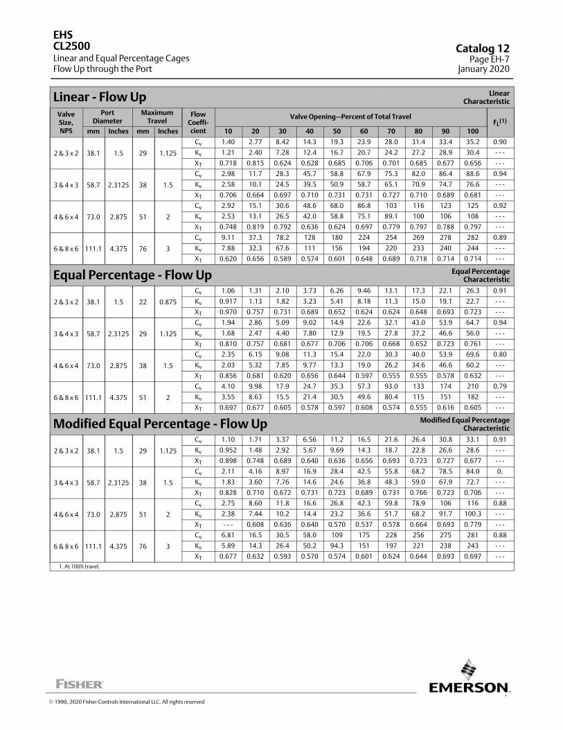
7
Linear ‐ Flow Up LinearCharacteristic
ValveSize,NPS
PortDiameter
MaximumTravel
FlowCoeffi‐cient
Valve Opening—Percent of Total TravelFL
(1)
mm Inches mm Inches 10 20 30 40 50 60 70 80 90 100
2 & 3 x 2 38.1 1.5 29 1.125
Cv 1.40 2.77 8.42 14.3 19.3 23.9 28.0 31.4 33.4 35.2 0.90
Kv 1.21 2.40 7.28 12.4 16.7 20.7 24.2 27.2 28.9 30.4 ‐ ‐ ‐
XT 0.718 0.815 0.624 0.628 0.685 0.706 0.701 0.685 0.677 0.656 ‐ ‐ ‐
3 & 4 x 3 58.7 2.3125 38 1.5
Cv 2.98 11.7 28.3 45.7 58.8 67.9 75.3 82.0 86.4 88.6 0.94
Kv 2.58 10.1 24.5 39.5 50.9 58.7 65.1 70.9 74.7 76.6 ‐ ‐ ‐
XT 0.706 0.664 0.697 0.710 0.731 0.731 0.727 0.710 0.689 0.681 ‐ ‐ ‐
4 & 6 x 4 73.0 2.875 51 2
Cv 2.92 15.1 30.6 48.6 68.0 86.8 103 116 123 125 0.92
Kv 2.53 13.1 26.5 42.0 58.8 75.1 89.1 100 106 108 ‐ ‐ ‐
XT 0.748 0.819 0.792 0.636 0.624 0.697 0.779 0.797 0.788 0.797 ‐ ‐ ‐
6 & 8 x 6 111.1 4.375 76 3
Cv 9.11 37.3 78.2 128 180 224 254 269 278 282 0.89
Kv 7.88 32.3 67.6 111 156 194 220 233 240 244 ‐ ‐ ‐
XT 0.620 0.656 0.589 0.574 0.601 0.648 0.689 0.718 0.714 0.714 ‐ ‐ ‐
Equal Percentage ‐ Flow Up Equal PercentageCharacteristic
2 & 3 x 2 38.1 1.5 22 0.875
Cv 1.06 1.31 2.10 3.73 6.26 9.46 13.1 17.3 22.1 26.3 0.91
Kv 0.917 1.13 1.82 3.23 5.41 8.18 11.3 15.0 19.1 22.7 ‐ ‐ ‐
XT 0.970 0.757 0.731 0.689 0.652 0.624 0.624 0.648 0.693 0.723 ‐ ‐ ‐
3 & 4 x 3 58.7 2.3125 29 1.125
Cv 1.94 2.86 5.09 9.02 14.9 22.6 32.1 43.0 53.9 64.7 0.94
Kv 1.68 2.47 4.40 7.80 12.9 19.5 27.8 37.2 46.6 56.0 ‐ ‐ ‐
XT 0.810 0.757 0.681 0.677 0.706 0.706 0.668 0.652 0.723 0.761 ‐ ‐ ‐
4 & 6 x 4 73.0 2.875 38 1.5
Cv 2.35 6.15 9.08 11.3 15.4 22.0 30.3 40.0 53.9 69.6 0.80
Kv 2.03 5.32 7.85 9.77 13.3 19.0 26.2 34.6 46.6 60.2 ‐ ‐ ‐
XT 0.856 0.681 0.620 0.656 0.644 0.597 0.555 0.555 0.578 0.632 ‐ ‐ ‐
6 & 8 x 6 111.1 4.375 51 2
Cv 4.10 9.98 17.9 24.7 35.3 57.3 93.0 133 174 210 0.79
Kv 3.55 8.63 15.5 21.4 30.5 49.6 80.4 115 151 182 ‐ ‐ ‐
XT 0.697 0.677 0.605 0.578 0.597 0.608 0.574 0.555 0.616 0.605 ‐ ‐ ‐
Modified Equal Percentage ‐ Flow Up Modified Equal PercentageCharacteristic
2 & 3 x 2 38.1 1.5 29 1.125
Cv 1.10 1.71 3.37 6.56 11.2 16.5 21.6 26.4 30.8 33.1 0.91
Kv 0.952 1.48 2.92 5.67 9.69 14.3 18.7 22.8 26.6 28.6 ‐ ‐ ‐
XT 0.898 0.748 0.689 0.640 0.636 0.656 0.693 0.723 0.727 0.677 ‐ ‐ ‐
3 & 4 x 3 58.7 2.3125 38 1.5
Cv 2.11 4.16 8.97 16.9 28.4 42.5 55.8 68.2 78.5 84.0 0.
Kv 1.83 3.60 7.76 14.6 24.6 36.8 48.3 59.0 67.9 72.7 ‐ ‐ ‐
XT 0.828 0.710 0.672 0.731 0.723 0.689 0.731 0.766 0.723 0.706 ‐ ‐ ‐
4 & 6 x 4 73.0 2.875 51 2
Cv 2.75 8.60 11.8 16.6 26.8 42.3 59.8 78.9 106 116 0.88
Kv 2.38 7.44 10.2 14.4 23.2 36.6 51.7 68.2 91.7 100.3 ‐ ‐ ‐
XT ‐ ‐ ‐ 0.608 0.636 0.640 0.570 0.537 0.578 0.664 0.693 0.779 ‐ ‐ ‐
6 & 8 x 6 111.1 4.375 76 3
Cv 6.81 16.5 30.5 58.0 109 175 228 256 275 281 0.88
Kv 5.89 14.3 26.4 50.2 94.3 151 197 221 238 243 ‐ ‐ ‐
XT 0.677 0.632 0.593 0.570 0.574 0.601 0.624 0.644 0.693 0.697 ‐ ‐ ‐
1. At 100% travel.
EHS
Linear and Equal Percentage CagesFlow Up through the Port
CL2500 Catalog 12Page EH-7
January 2020
� 1990, 2020 Fisher Controls International LLC. All rights reserved
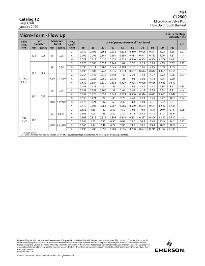
Micro‐Form ‐ Flow Up Equal PercentageCharacteristic
ValveSize,NPS
PortDiameter
MaximumTravel
FlowCoeffi‐cient
Valve Opening—Percent of Total TravelFL
(1)
mm Inches mm Inches 10 20 30 40 50 60 70 80 90 100
1,
1‐1/2 x 1,
& 2 x 1
6.4 0.25 19 0.75
Cv 0.072 0.106 0.163 0.232 0.324 0.449 0.626 0.871 1.22 1.58 0.91
Kv 0.062 0.092 0.141 0.201 0.280 0.388 0.541 0.753 1.06 1.37 ‐ ‐ ‐
XT 0.778 0.717 0.421 0.474 0.513 0.540 0.558 0.566 0.569 0.644 ‐ ‐ ‐
12.7 0.5
19 0.75
Cv 0.220 0.360 0.532 0.746 1.04 1.50 2.15 3.06 4.15 5.37 0.92
Kv 0.190 0.311 0.460 0.645 0.900 1.30 1.86 2.65 3.59 4.65 ‐ ‐ ‐
XT 0.893 0.803 0.748 0.636 0.633 0.637 0.644 0.642 0.661 0.718 ‐ ‐ ‐
22(2) 0.875(2)
Cv 0.254 0.445 0.636 0.890 1.40 2.23 3.50 4.77 5.72 6.36 0.93
Kv 0.220 0.385 0.550 0.770 1.21 1.93 3.03 4.13 4.95 5.50 ‐ ‐ ‐
XT 0.632 0.627 0.630 0.632 0.629 0.628 0.629 0.626 0.633 0.630 ‐ ‐ ‐
19.1 0.75
19 0.75
Cv 0.441 0.681 1.04 1.59 2.36 3.43 4.81 6.43 7.84 8.91 0.88
Kv 0.381 0.589 0.900 1.38 2.04 2.97 4.16 5.56 6.78 7.71 ‐ ‐ ‐
XT 0.782 0.725 0.652 0.548 0.519 0.506 0.514 0.641 0.651 0.648 ‐ ‐ ‐
22(2) 0.875(2)
Cv 0.550 0.721 1.24 1.85 2.78 4.43 6.70 8.45 9.27 10.3 0.84
Kv 0.476 0.624 1.07 1.60 2.40 3.83 5.80 7.31 8.02 8.91 ‐ ‐ ‐
XT 0.516 0.693 0.581 0.587 0.586 0.589 0.585 0.583 0.587 0.585 ‐ ‐ ‐
2 &
3 x 225.4 1
22 0.875
Cv 0.653 1.19 1.89 2.89 4.50 7.08 10.9 15.9 20.0 21.5 0.95
Kv 0.565 1.03 1.63 2.50 3.89 6.12 9.43 13.8 17.3 18.6 ‐ ‐ ‐
XT 0.809 0.812 0.814 0.809 0.810 0.811 0.817 0.806 0.810 0.810 ‐ ‐ ‐
29(2) 1.125(2)
Cv 0.884 1.67 2.86 4.96 9.08 15.6 20.9 23.0 23.9 24.2 0.92
Kv 0.765 1.44 2.47 4.29 7.85 13.5 18.1 19.9 20.7 20.9 ‐ ‐ ‐
XT 0.696 0.700 0.698 0.700 0.696 0.700 0.697 0.745 0.714 0.700 ‐ ‐
1. At 100% travel.2. Travels identified with this superscript are modified equal percentage characteristic. All other travels are equal percentage.
� 1995. 2020 Fisher Controls International LLC. All rights reserved
www.Fisher.com
Responsibility for selection, use, and maintenance of any product remains solely with the purchaser and end user. The contents of this publication are forinformational purposes only and are not to be construed as warranties or guarantees, express or implied, regarding the products or services describedtherein. Fisher and Cavitrol are marks owned by one of the companies in the Emerson Automation Solutions business unit of Emerson Electric Co. EmersonAutomation Solutions, Emerson, and the Emerson logo are trademarks and service marks of Emerson Electric Co. All other marks are the property of theirrespective owners.
EHS
Micro-Form Valve PlugFlow Up through the Port
CL2500Catalog 12Page EH-8January 2020
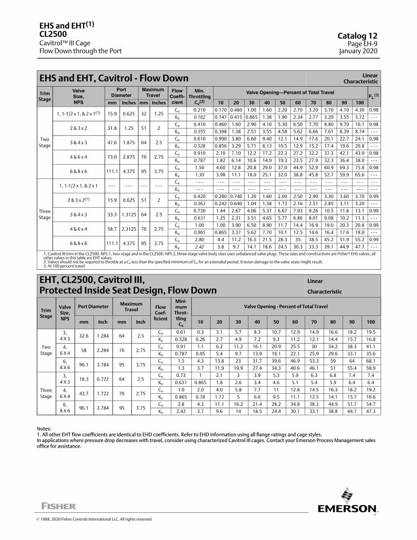
9
EHS and EHT, Cavitrol ‐ Flow Down LinearCharacteristic
TrimStage
ValveSize,NPS
PortDiameter
MaximumTravel
FlowCoeffi-cient
Min.Throttling
Cv(2)
Valve Opening—Percent of Total TravelFL
(3)
mm Inches mm Inches 10 20 30 40 50 60 70 80 90 100
Two
Stage
1, 1‐1/2 x 1, & 2 x 1(1) 15.9 0.625 32 1.25Cv 0.210 0.170 0.480 1.00 1.60 2.20 2.70 3.20 3.70 4.10 4.30 0.98
Kv 0.182 0.147 0.415 0.865 1.38 1.90 2.34 2.77 3.20 3.55 3.72 ‐ ‐ ‐
2 & 3 x 2 31.8 1.25 51 2Cv 0.410 0.460 1.60 2.90 4.10 5.30 6.50 7.70 8.80 9.70 10.1 0.98
Kv 0.355 0.398 1.38 2.51 3.55 4.58 5.62 6.66 7.61 8.39 8.74 ‐ ‐ ‐
3 & 4 x 3 47.6 1.875 64 2.5Cv 0.610 0.990 3.80 6.60 9.40 12.1 14.9 17.6 20.1 22.7 24.1 0.98
Kv 0.528 0.856 3.29 5.71 8.13 10.5 12.9 15.2 17.4 19.6 20.8 ‐ ‐ ‐
4 & 6 x 4 73.0 2.875 70 2.75Cv 0.910 2.10 7.10 12.2 17.2 22.3 27.2 32.2 37.3 42.1 43.9 0.98
Kv 0.787 1.82 6.14 10.6 14.9 19.3 23.5 27.9 32.3 36.4 38.0 ‐ ‐ ‐
6 & 8 x 6 111.1 4.375 95 3.75Cv 1.50 4.60 12.8 20.8 29.0 37.0 44.9 52.9 60.9 69.3 75.8 0.98
Kv 1.30 3.98 11.1 18.0 25.1 32.0 38.8 45.8 52.7 59.9 65.6 ‐ ‐ ‐
Three
Stage
1, 1‐1/2 x 1, & 2 x 1 ‐ ‐ ‐ ‐ ‐ ‐ ‐ ‐ ‐ ‐ ‐ ‐Cv ‐ ‐ ‐ ‐ ‐ ‐ ‐ ‐ ‐ ‐ ‐ ‐ ‐ ‐ ‐ ‐ ‐ ‐ ‐ ‐ ‐ ‐ ‐ ‐ ‐ ‐ ‐ ‐ ‐ ‐ ‐ ‐ ‐ ‐ ‐ ‐
Kv ‐ ‐ ‐ ‐ ‐ ‐ ‐ ‐ ‐ ‐ ‐ ‐ ‐ ‐ ‐ ‐ ‐ ‐ ‐ ‐ ‐ ‐ ‐ ‐ ‐ ‐ ‐ ‐ ‐ ‐ ‐ ‐ ‐ ‐ ‐ ‐
2 & 3 x 2(1) 15.9 0.625 51 2Cv 0.420 0.280 0.740 1.20 1.60 2.00 2.50 2.90 3.30 3.60 3.70 0.99
Kv 0.363 0.242 0.640 1.04 1.38 1.73 2.16 2.51 2.85 3.11 3.20 ‐ ‐ ‐
3 & 4 x 3 33.3 1.3125 64 2.5Cv 0.730 1.44 2.67 4.06 5.37 6.67 7.93 9.26 10.5 11.8 13.1 0.99
Kv 0.631 1.25 2.31 3.51 4.65 5.77 6.86 8.01 9.08 10.2 11.3 ‐ ‐ ‐
4 & 6 x 4 58.7 2.3125 70 2.75Cv 1.00 1.00 3.90 6.50 8.90 11.7 14.4 16.9 19.0 20.3 20.8 0.99
Kv 0.865 0.865 3.37 5.62 7.70 10.1 12.5 14.6 16.4 17.6 18.0 ‐ ‐ ‐
6 & 8 x 6 111.1 4.375 95 3.75Cv 2.80 4.4 11.2 16.3 21.5 28.3 35 38.5 45.2 51.9 55.2 0.99
Kv 2.42 3.8 9.7 14.1 18.6 24.5 30.3 33.3 39.1 44.9 47.7 ‐ ‐ ‐
1. Cavitrol III trim in the CL2500, NPS 1, two‐stage and in the CL2500, NPS 2, three‐stage valve body sizes uses unbalanced valve plugs. These sizes and constructions are Fisher� EHS valves; allother valves in this table are EHT valves.2. Valves should not be required to throttle at a Cv less than the specified minimum of Cv for an extended period. Erosion damage to the valve seats might result.3. At 100 percent travel.
EHT, CL2500, Cavitrol III, Protected Inside Seat Design, Flow Down
Linear
Characteristic
TrimStage
ValveSize,NPS
Port DiameterMaximum
TravelFlowCoef‐
ficient
Mini‐mum
Throt‐tling
Cv
Valve Opening - Percent of Total Travel
mm Inch mm Inch 10 20 30 40 50 60 70 80 90 100
Two
Stage
3,
4 X 332.6 1.284 64 2.5
Cv 0.61 0.3 3.1 5.7 8.3 10.7 12.9 14.9 16.6 18.2 19.5
Kv 0.528 0.26 2.7 4.9 7.2 9.3 11.2 12.1 14.4 15.7 16.8
4,
6 X 458 2.284 70 2.75
Cv 0.91 1.1 6.2 11.2 16.1 20.9 25.5 30 34.2 38.3 41.1
Kv 0.787 0.95 5.4 9.7 13.9 18.1 22.1 25.9 29.6 33.1 35.6
6,
8 X 696.1 3.784 95 3.75
Cv 1.5 4.3 13.8 23 31.7 39.6 46.9 53.3 59 64 68.1
Kv 1.3 3.7 11.9 19.9 27.4 34.3 40.6 46.1 51 55.4 58.9
Three
Stage
3,
4 X 318.3 0.722 64 2.5
Cv 0.73 1 2.1 3 3.9 5.3 5.9 6.3 6.8 7.4 7.4
Kv 0.631 0.865 1.8 2.6 3.4 4.6 5.1 5.4 5.9 6.4 6.4
4,
6 X 443.7 1.722 70 2.75
Cv 1.0 2.0 4.0 5.8 7.7 11 12.8 14.5 16.3 18.2 19.2
Kv 0.865 0.78 1.72 5 6.6 9.5 11.1 12.5 14.1 15.7 16.6
6,
8 X 696.1 3.784 95 3.75
Cv 2.8 4.3 11.1 16.2 21.4 28.2 34.8 38.3 44.9 51.7 54.7
Kv 2.42 3.7 9.6 14 18.5 24.4 30.1 33.1 38.8 44.7 47.3
Notes:1. All other EHT flow coefficients are identical to EHD coefficients. Refer to EHD information using all flange ratings and cage styles.In applications where pressure drop decreases with travel, consider using characterized Cavitrol III cages. Contact your Emerson Process Management salesoffice for assistance.
� 1988, 2020 Fisher Controls International LLC. All rights reserved
EHS and EHT(1)
Cavitrol™ III CageFlow Down through the Port
CL2500 Catalog 12Page EH-9
January 2020
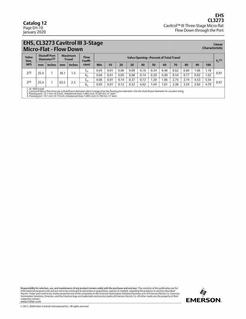
EHS, CL3273 Cavitrol III 3-Stage Micro-Flat ‐ Flow Down
LinearCharacteristic
ValveSize,NPS
Shutoff PortDiameter(2)
MaximumTravel
FlowCoeffi‐cient
Valve Opening—Percent of Total TravelFL
(1)
mm Inches mm Inches Min 10 20 30 40 50 60 70 80 90 100
2(3) 25.4 1 38.1 1.5Cv 0.05 0.01 0.06 0.09 0.16 0.34 0.46 0.62 0.89 1.06 1.18
0.97Kv 0.04 0.01 0.05 0.08 0.14 0.29 0.40 0.54 0.77 0.92 1.02
2(4) 25.4 1 63.5 2.5Cv 0.06 0.01 0.14 0.37 0.72 1.20 1.86 2.75 3.74 4.53 5.54
0.97Kv 0.05 0.01 0.12 0.32 0.62 1.04 1.61 2.38 3.24 3.92 4.79
1. At 100% travel 2. Cavitrol III Micro-Flat trims use a shutoff port diameter which is larger than the flowing port diameter. Use the shutoff port diameter for actuator sizing. 3. Flowing port: 12.7 mm / 0.5 Inch, Unbalanced Area: 5.065 cm2 / 0.785 In2, ¾” stem 4. Flowing port: 19.1 mm / 0.75 Inch, Unbalanced Area: 5.065 cm2 / 0.785 In2, ¾” stem
� 2011, 2020 Fisher Controls International LLC. All rights reserved
www.Fisher.com
Responsibility for selection, use, and maintenance of any product remains solely with the purchaser and end user. The contents of this publication are forinformational purposes only and are not to be construed as warranties or guarantees, express or implied, regarding the products or services describedtherein. Fisher and Cavitrol are marks owned by one of the companies in the Emerson Automation Solutions business unit of Emerson Electric Co. EmersonAutomation Solutions, Emerson, and the Emerson logo are trademarks and service marks of Emerson Electric Co. All other marks are the property of theirrespective owners.
EHS
Cavitrol™ III Three-Stage Micro-flatFlow Down through the Port
CL3273Catalog 12Page EH-10January 2020
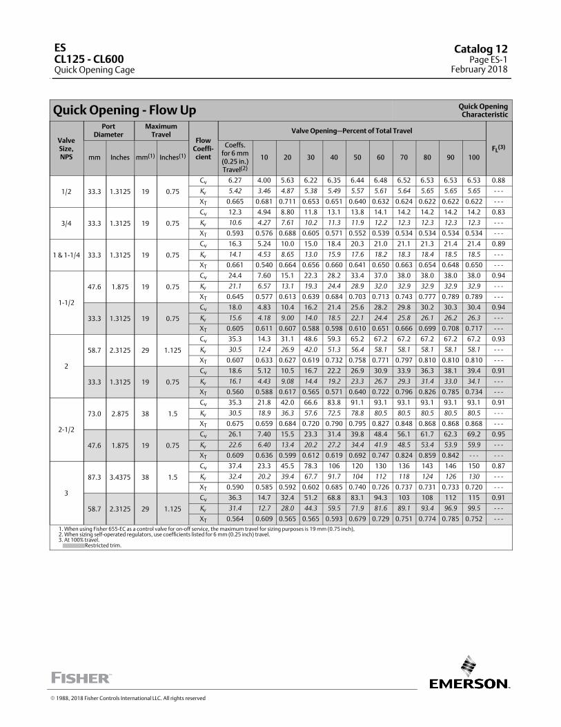
Quick Opening ‐ Flow Up Quick OpeningCharacteristic
ValveSize,NPS
PortDiameter
MaximumTravel
FlowCoeffi‐cient
Valve Opening—Percent of Total Travel
FL(3)
mm Inches mm(1) Inches(1)
Coeffs.for 6 mm(0.25 in.)Travel(2)
10 20 30 40 50 60 70 80 90 100
1/2 33.3 1.3125 19 0.75
Cv 6.27 4.00 5.63 6.22 6.35 6.44 6.48 6.52 6.53 6.53 6.53 0.88
Kv
5.42 3.46 4.87 5.38 5.49 5.57 5.61 5.64 5.65 5.65 5.65 ‐ ‐ ‐
XT 0.665 0.681 0.711 0.653 0.651 0.640 0.632 0.624 0.622 0.622 0.622 ‐ ‐ ‐
3/4 33.3 1.3125 19 0.75
Cv 12.3 4.94 8.80 11.8 13.1 13.8 14.1 14.2 14.2 14.2 14.2 0.83
Kv
10.6 4.27 7.61 10.2 11.3 11.9 12.2 12.3 12.3 12.3 12.3 ‐ ‐ ‐
XT 0.593 0.576 0.688 0.605 0.571 0.552 0.539 0.534 0.534 0.534 0.534 ‐ ‐ ‐
1 & 1‐1/4 33.3 1.3125 19 0.75
Cv 16.3 5.24 10.0 15.0 18.4 20.3 21.0 21.1 21.3 21.4 21.4 0.89
Kv
14.1 4.53 8.65 13.0 15.9 17.6 18.2 18.3 18.4 18.5 18.5 ‐ ‐ ‐
XT 0.661 0.540 0.664 0.656 0.660 0.641 0.650 0.663 0.654 0.648 0.650 ‐ ‐ ‐
1‐1/2
47.6 1.875 19 0.75
Cv 24.4 7.60 15.1 22.3 28.2 33.4 37.0 38.0 38.0 38.0 38.0 0.94
Kv
21.1 6.57 13.1 19.3 24.4 28.9 32.0 32.9 32.9 32.9 32.9 ‐ ‐ ‐
XT 0.645 0.577 0.613 0.639 0.684 0.703 0.713 0.743 0.777 0.789 0.789 ‐ ‐ ‐
33.3 1.3125 19 0.75
Cv 18.0 4.83 10.4 16.2 21.4 25.6 28.2 29.8 30.2 30.3 30.4 0.94
Kv
15.6 4.18 9.00 14.0 18.5 22.1 24.4 25.8 26.1 26.2 26.3 ‐ ‐ ‐
XT 0.605 0.611 0.607 0.588 0.598 0.610 0.651 0.666 0.699 0.708 0.717 ‐ ‐ ‐
2
58.7 2.3125 29 1.125
Cv 35.3 14.3 31.1 48.6 59.3 65.2 67.2 67.2 67.2 67.2 67.2 0.93
Kv
30.5 12.4 26.9 42.0 51.3 56.4 58.1 58.1 58.1 58.1 58.1 ‐ ‐ ‐
XT 0.607 0.633 0.627 0.619 0.732 0.758 0.771 0.797 0.810 0.810 0.810 ‐ ‐ ‐
33.3 1.3125 19 0.75
Cv 18.6 5.12 10.5 16.7 22.2 26.9 30.9 33.9 36.3 38.1 39.4 0.91
Kv
16.1 4.43 9.08 14.4 19.2 23.3 26.7 29.3 31.4 33.0 34.1 ‐ ‐ ‐
XT 0.560 0.588 0.617 0.565 0.571 0.640 0.722 0.796 0.826 0.785 0.734 ‐ ‐ ‐
2‐1/2
73.0 2.875 38 1.5
Cv 35.3 21.8 42.0 66.6 83.8 91.1 93.1 93.1 93.1 93.1 93.1 0.91
Kv
30.5 18.9 36.3 57.6 72.5 78.8 80.5 80.5 80.5 80.5 80.5 ‐ ‐ ‐
XT 0.675 0.659 0.684 0.720 0.790 0.795 0.827 0.848 0.868 0.868 0.868 ‐ ‐ ‐
47.6 1.875 19 0.75
Cv 26.1 7.40 15.5 23.3 31.4 39.8 48.4 56.1 61.7 62.3 69.2 0.95
Kv
22.6 6.40 13.4 20.2 27.2 34.4 41.9 48.5 53.4 53.9 59.9 ‐ ‐ ‐
XT 0.609 0.636 0.599 0.612 0.619 0.692 0.747 0.824 0.859 0.842 ‐ ‐ ‐ ‐ ‐ ‐
3
87.3 3.4375 38 1.5
Cv 37.4 23.3 45.5 78.3 106 120 130 136 143 146 150 0.87
Kv
32.4 20.2 39.4 67.7 91.7 104 112 118 124 126 130 ‐ ‐ ‐
XT 0.590 0.585 0.592 0.602 0.685 0.740 0.726 0.737 0.731 0.733 0.720 ‐ ‐ ‐
58.7 2.3125 29 1.125
Cv 36.3 14.7 32.4 51.2 68.8 83.1 94.3 103 108 112 115 0.91
Kv
31.4 12.7 28.0 44.3 59.5 71.9 81.6 89.1 93.4 96.9 99.5 ‐ ‐ ‐
XT 0.564 0.609 0.565 0.565 0.593 0.679 0.729 0.751 0.774 0.785 0.752 ‐ ‐ ‐
1. When using Fisher 655‐EC as a control valve for on‐off service, the maximum travel for sizing purposes is 19 mm (0.75 inch),2. When sizing self‐operated regulators, use coefficients listed for 6 mm (0.25 inch) travel.3. At 100% travel. Restricted trim.
� 1988, 2018 Fisher Controls International LLC. All rights reserved
ESCL125 - CL600Quick Opening Cage
Catalog 12Page ES-1
February 2018
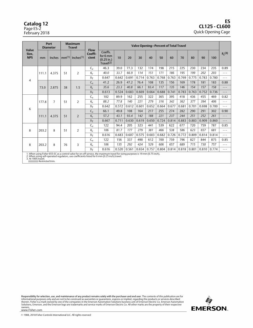
ValveSize,NPS
PortDiameter
MaximumTravel
FlowCoeffi‐cient
Valve Opening—Percent of Total Travel
FL(3)
mm Inches mm(1) Inches(1)
Coeffs.for 6 mm(0.25 in.)Travel(2)
10 20 30 40 50 60 70 80 90 100
4
111.1 4.375 51 2
Cv 46.3 39.0 77.3 132 174 198 215 225 230 234 235 0.89
Kv
40.0 33.7 66.9 114 151 171 186 195 199 202 203 ‐ ‐ ‐
XT 0.647 0.642 0.691 0.714 0.763 0.768 0.763 0.769 0.775 0.783 0.780 ‐ ‐ ‐
73.0 2.875 38 1.5
Cv 41.2 26.9 47.2 76.4 108 135 156 169 178 181 183 0.88
Kv
35.6 23.3 40.8 66.1 93.4 117 135 146 154 157 158 ‐ ‐ ‐
XT 0.613 0.524 0.683 0.669 0.664 0.688 0.741 0.783 0.763 0.752 0.736 ‐ ‐ ‐
6
177.8 7 51 2
Cv 102 89.9 162 255 322 365 395 418 436 455 469 0.82
Kv
88.2 77.8 140 221 279 316 342 362 377 394 406 ‐ ‐ ‐
XT 0.642 0.572 0.612 0.601 0.652 0.664 0.677 0.681 0.701 0.698 0.700 ‐ ‐ ‐
111.1 4.375 51 2
Cv 66.1 49.8 108 164 217 255 274 282 290 291 302 0.90
Kv
57.2 43.1 93.4 142 188 221 237 244 251 252 261 ‐ ‐ ‐
XT 0.667 0.711 0.630 0.619 0.650 0.724 0.814 0.883 0.883 0.909 0.860 ‐ ‐ ‐
8 203.2 8 51 2
Cv 122 94.4 205 323 441 539 622 677 720 759 787 0.85
Kv
106 81.7 177 279 381 466 538 586 623 657 681 ‐ ‐ ‐
XT 0.616 0.683 0.607 0.575 0.603 0.682 0.726 0.772 0.809 0.814 0.814 ‐ ‐ ‐
8 203.2 8 76 3
Cv 122 156 337 490 612 700 759 796 827 844 875 0.85
Kv
106 135 292 424 529 606 657 689 715 730 757 ‐ ‐ ‐
XT 0.616 0.520 0.561 0.654 0.757 0.804 0.814 0.818 0.801 0.810 0.774 ‐ ‐ ‐
1. When using Fisher 655‐EC as a control valve for on‐off service, the maximum travel for sizing purposes is 19 mm (0.75 inch),2. When sizing self‐operated regulators, use coefficients listed for 6 mm (0.25 inch) travel.3. At 100% travel. Restricted trim.
ES
Quick Opening CageCL125 ‐ CL600
Catalog 12Page ES-2February 2018
� 1988, 2018 Fisher Controls International LLC. All rights reserved
www.Fisher.com
Responsibility for selection, use, and maintenance of any product remains solely with the purchaser and end user. The contents of this publication are forinformational purposes only and are not to be construed as warranties or guarantees, express or implied, regarding the products or services describedtherein. Fisher is a mark owned by one of the companies in the Emerson Automation Solutions business unit of Emerson Electric Co. Emerson AutomationSolutions, Emerson, and the Emerson logo are trademarks and service marks of Emerson Electric Co. All other marks are the property of their respectiveowners.
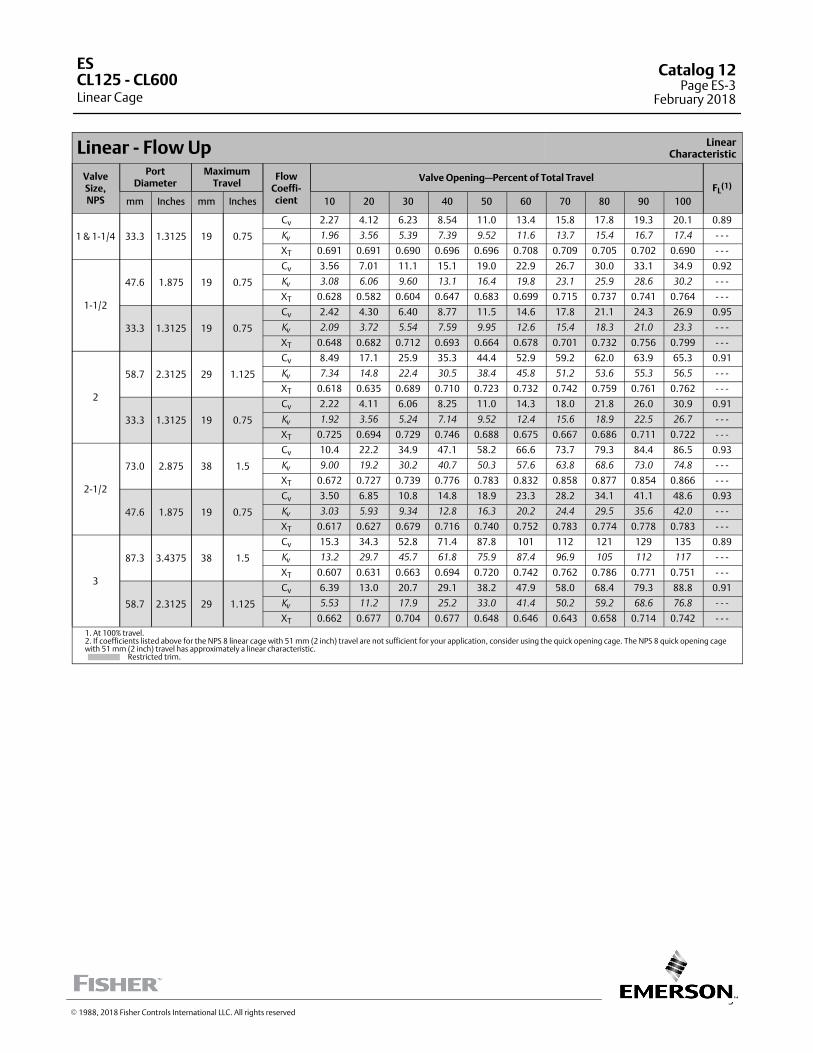
3
Linear ‐ Flow Up LinearCharacteristic
ValveSize,NPS
PortDiameter
MaximumTravel
FlowCoeffi‐cient
Valve Opening—Percent of Total TravelFL
(1)
mm Inches mm Inches 10 20 30 40 50 60 70 80 90 100
1 & 1‐1/4 33.3 1.3125 19 0.75
Cv 2.27 4.12 6.23 8.54 11.0 13.4 15.8 17.8 19.3 20.1 0.89
Kv
1.96 3.56 5.39 7.39 9.52 11.6 13.7 15.4 16.7 17.4 ‐ ‐ ‐
XT 0.691 0.691 0.690 0.696 0.696 0.708 0.709 0.705 0.702 0.690 ‐ ‐ ‐
1‐1/2
47.6 1.875 19 0.75
Cv 3.56 7.01 11.1 15.1 19.0 22.9 26.7 30.0 33.1 34.9 0.92
Kv
3.08 6.06 9.60 13.1 16.4 19.8 23.1 25.9 28.6 30.2 ‐ ‐ ‐
XT 0.628 0.582 0.604 0.647 0.683 0.699 0.715 0.737 0.741 0.764 ‐ ‐ ‐
33.3 1.3125 19 0.75
Cv 2.42 4.30 6.40 8.77 11.5 14.6 17.8 21.1 24.3 26.9 0.95
Kv
2.09 3.72 5.54 7.59 9.95 12.6 15.4 18.3 21.0 23.3 ‐ ‐ ‐
XT 0.648 0.682 0.712 0.693 0.664 0.678 0.701 0.732 0.756 0.799 ‐ ‐ ‐
2
58.7 2.3125 29 1.125
Cv 8.49 17.1 25.9 35.3 44.4 52.9 59.2 62.0 63.9 65.3 0.91
Kv
7.34 14.8 22.4 30.5 38.4 45.8 51.2 53.6 55.3 56.5 ‐ ‐ ‐
XT 0.618 0.635 0.689 0.710 0.723 0.732 0.742 0.759 0.761 0.762 ‐ ‐ ‐
33.3 1.3125 19 0.75
Cv 2.22 4.11 6.06 8.25 11.0 14.3 18.0 21.8 26.0 30.9 0.91
Kv
1.92 3.56 5.24 7.14 9.52 12.4 15.6 18.9 22.5 26.7 ‐ ‐ ‐
XT 0.725 0.694 0.729 0.746 0.688 0.675 0.667 0.686 0.711 0.722 ‐ ‐ ‐
2‐1/2
73.0 2.875 38 1.5
Cv 10.4 22.2 34.9 47.1 58.2 66.6 73.7 79.3 84.4 86.5 0.93
Kv
9.00 19.2 30.2 40.7 50.3 57.6 63.8 68.6 73.0 74.8 ‐ ‐ ‐
XT 0.672 0.727 0.739 0.776 0.783 0.832 0.858 0.877 0.854 0.866 ‐ ‐ ‐
47.6 1.875 19 0.75
Cv 3.50 6.85 10.8 14.8 18.9 23.3 28.2 34.1 41.1 48.6 0.93
Kv
3.03 5.93 9.34 12.8 16.3 20.2 24.4 29.5 35.6 42.0 ‐ ‐ ‐
XT 0.617 0.627 0.679 0.716 0.740 0.752 0.783 0.774 0.778 0.783 ‐ ‐ ‐
3
87.3 3.4375 38 1.5
Cv 15.3 34.3 52.8 71.4 87.8 101 112 121 129 135 0.89
Kv
13.2 29.7 45.7 61.8 75.9 87.4 96.9 105 112 117 ‐ ‐ ‐
XT 0.607 0.631 0.663 0.694 0.720 0.742 0.762 0.786 0.771 0.751 ‐ ‐ ‐
58.7 2.3125 29 1.125
Cv 6.39 13.0 20.7 29.1 38.2 47.9 58.0 68.4 79.3 88.8 0.91
Kv
5.53 11.2 17.9 25.2 33.0 41.4 50.2 59.2 68.6 76.8 ‐ ‐ ‐
XT 0.662 0.677 0.704 0.677 0.648 0.646 0.643 0.658 0.714 0.742 ‐ ‐ ‐
1. At 100% travel.2. If coefficients listed above for the NPS 8 linear cage with 51 mm (2 inch) travel are not sufficient for your application, consider using the quick opening cage. The NPS 8 quick opening cagewith 51 mm (2 inch) travel has approximately a linear characteristic. Restricted trim.
ES
Linear CageCL125 ‐ CL600
Catalog 12Page ES-3
February 2018
� 1988, 2018 Fisher Controls International LLC. All rights reserved
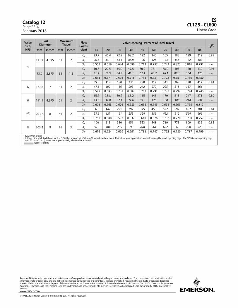
ValveSize,NPS
PortDiameter
MaximumTravel
FlowCoeffi‐cient
Valve Opening—Percent of Total TravelFL
(1)
mm Inches mm Inches 10 20 30 40 50 60 70 80 90 100
4
111.1 4.375 51 2
Cv 23.7 46.4 72.9 98.2 122 145 165 183 199 212 0.89
Kv
20.5 40.1 63.1 84.9 106 125 143 158 172 183 ‐ ‐ ‐
XT 0.553 0.619 0.644 0.680 0.713 0.737 0.743 0.823 0.816 0.791 ‐ ‐ ‐
73.0 2.875 38 1.5
Cv 10.6 22.5 35.0 47.5 60.2 73.1 88.0 103 120 139 0.93
Kv
9.17 19.5 30.3 41.1 52.1 63.2 76.1 89.1 104 120 ‐ ‐ ‐
XT 0.613 0.671 0.698 0.718 0.718 0.731 0.722 0.751 0.769 0.780 ‐ ‐ ‐
6 177.8 7 51 2
Cv 55.0 118 180 235 280 312 341 368 390 417 0.81
Kv
47.6 102 156 203 242 270 295 318 337 361 ‐ ‐ ‐
XT 0.597 0.683 0.701 0.687 0.767 0.791 0.787 0.792 0.794 0.745 ‐ ‐ ‐
6 111.1 4.375 51 2
Cv 15.7 35.8 60.2 86.2 115 146 179 215 247 271 0.89
Kv
13.6 31.0 52.1 74.6 99.5 126 180 186 214 234 ‐ ‐ ‐
XT 0.678 0.668 0.676 0.683 0.668 0.645 0.668 0.695 0.759 0.817 ‐ ‐ ‐
8(2) 203.2 8 51 2
Cv 66.6 147 221 292 375 450 522 592 652 701 0.84
Kv
57.6 127 191 253 324 389 452 512 564 606 ‐ ‐ ‐
XT 0.758 0.588 0.597 0.637 0.640 0.676 0.702 0.720 0.738 0.757 ‐ ‐ ‐
8 203.2 8 76 3
Cv 100 213 330 451 553 648 719 773 809 836 0.85
Kv
86.5 184 285 390 478 561 622 669 700 723 ‐ ‐ ‐
XT 0.616 0.624 0.669 0.691 0.738 0.747 0.762 0.780 0.787 0.799 ‐ ‐ ‐
1. At 100% travel.2. If coefficients listed above for the NPS 8 linear cage with 51 mm (2 inch) travel are not sufficient for your application, consider using the quick opening cage. The NPS 8 quick opening cagewith 51 mm (2 inch) travel has approximately a linear characteristic. Restricted trim.
ES
Linear CageCL125 ‐ CL600
Catalog 12Page ES-4February 2018
� 1988, 2018 Fisher Controls International LLC. All rights reserved
www.Fisher.com
Responsibility for selection, use, and maintenance of any product remains solely with the purchaser and end user. The contents of this publication are forinformational purposes only and are not to be construed as warranties or guarantees, express or implied, regarding the products or services describedtherein. Fisher is a mark owned by one of the companies in the Emerson Automation Solutions business unit of Emerson Electric Co. Emerson AutomationSolutions, Emerson, and the Emerson logo are trademarks and service marks of Emerson Electric Co. All other marks are the property of their respectiveowners.
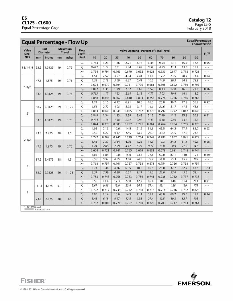
5
Equal Percentage ‐ Flow Up Equal PercentageCharacteristic
ValveSize,NPS
PortDiameter
MaximumTravel
FlowCoeffi‐cient
Valve Opening—Percent of Total TravelFL
(1)
mm Inches mm Inches 10 20 30 40 50 60 70 80 90 100
1 & 1‐1/4 33.3 1.3125 19 0.75
Cv 0.783 1.29 1.86 2.71 4.18 6.44 9.54 13.1 15.7 17.4 0.95
Kv
0.677 1.12 1.61 2.34 3.62 5.57 8.25 11.3 13.6 15.1 ‐ ‐ ‐
XT 0.754 0.794 0.763 0.670 0.652 0.621 0.630 0.677 0.718 0.721 ‐ ‐ ‐
1‐1/2
47.6 1.875 19 0.75
Cv 1.54 2.52 3.57 4.94 7.41 11.6 17.2 23.5 28.7 33.4 0.94
Kv
1.33 2.18 3.09 4.27 6.41 10.0 14.9 20.3 24.8 28.9 ‐ ‐ ‐
XT 0.674 0.670 0.694 0.731 0.706 0.681 0.698 0.692 0.789 0.793 ‐ ‐ ‐
33.3 1.3125 19 0.75
Cv 0.882 1.35 1.89 2.52 3.68 5.52 8.13 12.0 16.6 21.0 0.96
Kv
0.763 1.17 1.63 2.18 3.18 4.77 7.03 10.4 14.4 18.2 ‐ ‐ ‐
XT 0.858 0.845 0.867 0.810 0.833 0.755 0.776 0.766 0.766 0.766 ‐ ‐ ‐
2
58.7 2.3125 29 1.125
Cv 1.74 3.15 4.72 6.91 10.6 16.3 25.0 36.7 47.8 56.2 0.92
Kv
1.51 2.72 4.08 5.98 9.17 14.1 21.6 31.7 41.3 48.6 ‐ ‐ ‐
XT 0.863 0.848 0.849 0.805 0.782 0.778 0.792 0.772 0.847 0.848 ‐ ‐ ‐
33.3 1.3125 19 0.75
Cv 0.849 1.34 1.83 2.39 3.43 5.12 7.49 11.2 15.8 20.8 0.91
Kv
0.734 1.16 1.58 2.07 2.97 4.43 6.48 9.69 13.7 18.0 ‐ ‐ ‐
XT 0.844 0.778 0.803 0.767 0.791 0.764 0.764 0.764 0.755 0.728 ‐ ‐ ‐
2‐1/2
73.0 2.875 38 1.5
Cv 4.05 7.19 10.6 14.5 21.2 31.6 45.5 64.2 77.7 82.7 0.93
Kv
3.50 6.22 9.17 12.5 18.3 27.3 39.4 55.5 67.2 71.5 ‐ ‐ ‐
XT 0.747 0.768 0.745 0.779 0.764 0.744 0.783 0.802 0.841 0.878 ‐ ‐ ‐
47.6 1.875 19 0.75
Cv 1.43 2.37 3.34 4.76 7.25 11.3 17.3 24.2 31.8 40.3 0.95
Kv
1.24 2.05 2.89 4.12 6.27 9.77 15.0 20.9 27.5 34.9 ‐ ‐ ‐
XT 0.664 0.721 0.741 0.765 0.679 0.681 0.678 0.681 0.748 0.744 ‐ ‐ ‐
3
87.3 3.4375 38 1.5
Cv 4.05 6.84 10.0 15.0 23.8 37.8 59.0 87.1 110 121 0.89
Kv
3.50 5.92 8.65 13.0 20.6 32.7 51.0 75.3 95.2 105 ‐ ‐ ‐
XT 0.768 0.757 0.761 0.757 0.758 0.571 0.754 0.756 0.758 0.757 ‐ ‐ ‐
58.7 2.3125 29 1.125
Cv 2.74 3.44 4.86 6.95 10.6 16.5 25.0 37.7 52.7 67.5 0..94
Kv
2.37 2.98 4.20 6.01 9.17 14.3 21.6 32.6 45.6 58.4 ‐ ‐ ‐
XT 0.753 0.748 0.756 0.783 0.786 0.741 0.736 0.732 0.737 0.738 ‐ ‐ ‐
4
111.1 4.375 51 2
Cv 6.56 11.4 17.3 27.0 42.2 66.4 103 146 184 203 0.91
Kv
5.67 9.86 15.0 23.4 36.5 57.4 89.1 126 159 176 ‐ ‐ ‐
XT 0.722 0.717 0.739 0.772 0.738 0.718 0.718 0.736 0.792 0.822 ‐ ‐ ‐
73.0 2.875 38 1.5
Cv 3.96 7.14 10.6 14.5 21.1 31.7 48.0 69.7 95.6 121 0.94
Kv
3.43 6.18 9.17 12.5 18.3 27.4 41.5 60.3 82.7 105 ‐ ‐ ‐
XT 0.792 0.803 0.770 0.767 0.760 0.725 0.703 0.717 0.763 0.764 ‐ ‐ ‐
1. At 100% travel. Restricted trim.
ES
Equal Percentage CageCL125 ‐ CL600
Catalog 12Page ES-5
February 2018
� 1988, 2018 Fisher Controls International LLC. All rights reserved
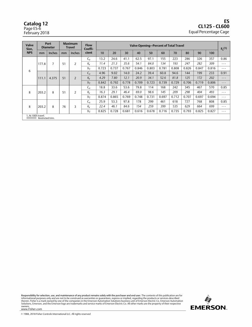
ValveSize,NPS
PortDiameter
MaximumTravel
FlowCoeffi‐cient
Valve Opening—Percent of Total TravelFL
(1)
mm Inches mm Inches 10 20 30 40 50 60 70 80 90 100
6
177.8 7 51 2
Cv 13.2 24.6 41.1 62.5 97.1 155 223 286 326 357 0.86
Kv
11.4 21.3 35.6 54.1 84.0 134 193 247 282 309 ‐ ‐ ‐
XT 0.723 0.737 0.767 0.846 0.803 0.781 0.808 0.826 0.847 0.816 ‐ ‐ ‐
111.1 4.375 51 2
Cv 4.96 9.02 14.0 24.2 39.4 60.8 94.6 144 199 233 0.91
Kv
4.29 7.80 12.1 20.9 34.1 52.6 81.8 125 172 202 ‐ ‐ ‐
XT 0.842 0.792 0.778 0.709 0.723 0.739 0.729 0.706 0.719 0.806 ‐ ‐ ‐
8 203.2 8 51 2
Cv 18.8 33.6 53.6 79.8 114 168 242 345 467 570 0.85
Kv
16.3 29.1 46.4 69.0 98.6 145 209 298 404 493 ‐ ‐ ‐
XT 0.874 0.865 0.769 0.748 0.731 0.697 0.712 0.707 0.697 0.694 ‐ ‐ ‐
8 203.2 8 76 3
Cv 25.9 53.3 97.8 178 299 461 618 727 768 808 0.85
Kv
22.4 46.1 84.6 154 259 399 535 629 664 699 ‐ ‐ ‐
XT 0.825 0.728 0.681 0.616 0.678 0.716 0.735 0.793 0.825 0.827 ‐ ‐ ‐
1. At 100% travel. Restricted trim.
ES
Equal Percentage CageCL125 ‐ CL600
Catalog 12Page ES-6February 2018
� 1988, 2018 Fisher Controls International LLC. All rights reserved
www.Fisher.com
Responsibility for selection, use, and maintenance of any product remains solely with the purchaser and end user. The contents of this publication are forinformational purposes only and are not to be construed as warranties or guarantees, express or implied, regarding the products or services describedtherein. Fisher is a mark owned by one of the companies in the Emerson Automation Solutions business unit of Emerson Electric Co. Emerson AutomationSolutions, Emerson, and the Emerson logo are trademarks and service marks of Emerson Electric Co. All other marks are the property of their respectiveowners.
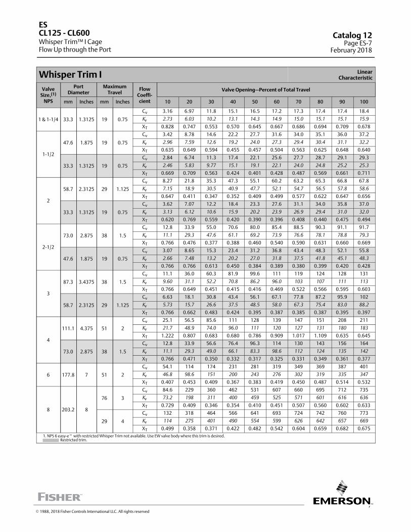
7
Whisper Trim I LinearCharacteristic
ValveSize,(1)
NPS
PortDiameter
MaximumTravel
FlowCoeffi‐cient
Valve Opening—Percent of Total Travel
mm Inches mm Inches 10 20 30 40 50 60 70 80 90 100
1 & 1‐1/4 33.3 1.3125 19 0.75
Cv 3.16 6.97 11.8 15.1 16.5 17.2 17.3 17.4 17.4 18.4
Kv
2.73 6.03 10.2 13.1 14.3 14.9 15.0 15.1 15.1 15.9
XT 0.828 0.747 0.553 0.570 0.645 0.667 0.686 0.694 0.709 0.678
1‐1/2
47.6 1.875 19 0.75
Cv 3.42 8.78 14.6 22.2 27.7 31.6 34.0 35.1 36.0 37.2
Kv
2.96 7.59 12.6 19.2 24.0 27.3 29.4 30.4 31.1 32.2
XT 0.635 0.649 0.594 0.455 0.457 0.504 0.563 0.625 0.648 0.640
33.3 1.3125 19 0.75
Cv 2.84 6.74 11.3 17.4 22.1 25.6 27.7 28.7 29.1 29.3
Kv
2.46 5.83 9.77 15.1 19.1 22.1 24.0 24.8 25.2 25.3
XT 0.669 0.709 0.563 0.424 0.401 0.428 0.487 0.569 0.661 0.711
2
58.7 2.3125 29 1.125
Cv 8.27 21.8 35.3 47.3 55.1 60.2 63.2 65.3 66.8 67.8
Kv
7.15 18.9 30.5 40.9 47.7 52.1 54.7 56.5 57.8 58.6
XT 0.647 0.411 0.347 0.352 0.409 0.499 0.577 0.622 0.647 0.656
33.3 1.3125 19 0.75
Cv 3.62 7.07 12.2 18.4 23.3 27.6 31.1 34.0 35.8 37.0
Kv
3.13 6.12 10.6 15.9 20.2 23.9 26.9 29.4 31.0 32.0
XT 0.620 0.769 0.559 0.420 0.390 0.396 0.408 0.440 0.475 0.494
2‐1/2
73.0 2.875 38 1.5
Cv 12.8 33.9 55.0 70.6 80.0 85.4 88.5 90.3 91.1 91.7
Kv
11.1 29.3 47.6 61.1 69.2 73.9 76.6 78.1 78.8 79.3
XT 0.766 0.476 0.377 0.388 0.460 0.540 0.590 0.631 0.660 0.669
47.6 1.875 19 0.75
Cv 3.07 8.65 15.3 23.4 31.2 36.8 43.4 48.3 52.1 55.8
Kv
2.66 7.48 13.2 20.2 27.0 31.8 37.5 41.8 45.1 48.3
XT 0.766 0.766 0.613 0.450 0.384 0.389 0.380 0.399 0.420 0.428
3
87.3 3.4375 38 1.5
Cv 11.1 36.0 60.3 81.9 99.6 111 119 124 128 131
Kv
9.60 31.1 52.2 70.8 86.2 96.0 103 107 111 113
XT 0.766 0.649 0.451 0.415 0.416 0.469 0.522 0.566 0.595 0.603
58.7 2.3125 29 1.125
Cv 6.63 18.1 30.8 43.4 56.1 67.1 77.8 87.2 95.9 102
Kv
5.73 15.7 26.6 37.5 48.5 58.0 67.3 75.4 83.0 88.2
XT 0.766 0.662 0.483 0.424 0.395 0.387 0.385 0.387 0.395 0.397
4
111.1 4.375 51 2
Cv 25.1 56.5 85.6 111 128 139 147 151 208 211
Kv
21.7 48.9 74.0 96.0 111 120 127 131 180 183
XT 1.222 0.807 0.683 0.680 0.786 0.909 1.017 1.109 0.635 0.645
73.0 2.875 38 1.5
Cv 12.8 33.9 56.6 76.4 96.3 114 130 143 156 164
Kv
11.1 29.3 49.0 66.1 83.3 98.6 112 124 135 142
XT 0.766 0.471 0.350 0.332 0.317 0.325 0.331 0.349 0.361 0.377
6 177.8 7 51 2
Cv 54.1 114 174 231 281 319 349 369 387 401
Kv
46.8 98.6 151 200 243 276 302 319 335 347
XT 0.407 0.453 0.409 0.367 0.383 0.419 0.450 0.487 0.514 0.532
8 203.2 8
76 3
Cv 84.6 229 360 462 531 607 660 695 712 735
Kv
73.2 198 311 400 459 525 571 601 616 636
XT 0.729 0.409 0.346 0.354 0.410 0.451 0.507 0.560 0.602 0.633
29 4
Cv 132 318 464 566 641 693 724 742 760 773
Kv
114 275 401 490 554 599 626 642 657 669
XT 0.499 0.358 0.371 0.422 0.482 0.542 0.604 0.659 0.682 0.675
1. NPS 6 easy-e� with restricted Whisper Trim not available. Use EW valve body where this trim is desired. ‐ Restricted trim.
ES
Whisper Trim™ I CageFlow Up through the Port
CL125 ‐ CL600 Catalog 12Page ES-7
February 2018
� 1988, 2018 Fisher Controls International LLC. All rights reserved
This page is intentionally left blank.
ES
Whisper Trim I CageFlow Up through the Port
CL125 ‐ CL600Catalog 12Page ES-8February 2018
� 1988, 2018 Fisher Controls International LLC. All rights reserved
www.Fisher.com
Responsibility for selection, use, and maintenance of any product remains solely with the purchaser and end user. The contents of this publication are forinformational purposes only and are not to be construed as warranties or guarantees, express or implied, regarding the products or services describedtherein. Fisher, Whisper Trim, and easy-e are marks owned by one of the companies in the Emerson Automation Solutions business unit of Emerson ElectricCo. Emerson Automation Solutions, Emerson, and the Emerson logo are trademarks and service marks of Emerson Electric Co. All other marks are theproperty of their respective owners.
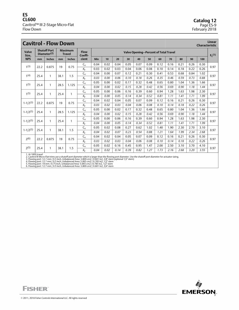
9
Cavitrol ‐ Flow Down LinearCharacteristic
ValveSize,NPS
Shutoff PortDiameter(2)
MaximumTravel
FlowCoeffi‐cient
Valve Opening—Percent of Total TravelFL
(1)
mm Inches mm Inches Min 10 20 30 40 50 60 70 80 90 100
1(3) 22.2 0.875 19 0.75Cv 0.04 0.02 0.04 0.05 0.07 0.09 0.12 0.16 0.21 0.26 0.30
0.97K
v0.03 0.02 0.03 0.04 0.06 0.08 0.10 0.14 0.18 0.22 0.26
1(4) 25.4 1 38.1 1.5Cv 0.04 0.00 0.07 0.12 0.21 0.30 0.41 0.53 0.68 0.84 1.02
0.97K
v0.03 0.00 0.06 0.10 0.18 0.26 0.35 0.46 0.59 0.73 0.88
1(5) 25.4 1 28.5 1.125Cv 0.05 0.00 0.02 0.17 0.32 0.48 0.65 0.80 1.04 1.36 1.66
0.97K
v0.04 0.00 0.02 0.15 0.28 0.42 0.56 0.69 0.90 1.18 1.44
1(5) 25.4 1 25.4 1Cv 0.05 0.00 0.06 0.16 0.39 0.60 0.94 1.28 1.63 1.98 2.30
0.97K
v0.04 0.00 0.05 0.14 0.34 0.52 0.81 1.11 1.41 1.71 1.99
1-1/2(3) 22.2 0.875 19 0.75Cv 0.04 0.02 0.04 0.05 0.07 0.09 0.12 0.16 0.21 0.26 0.30
0.97K
v0.03 0.02 0.03 0.04 0.06 0.08 0.10 0.14 0.18 0.22 0.26
1-1/2(5) 25.4 1 28.5 1.125Cv 0.05 0.00 0.02 0.17 0.32 0.48 0.65 0.80 1.04 1.36 1.66
0.97K
v0.04 0.00 0.02 0.15 0.28 0.42 0.56 0.69 0.90 1.18 1.44
1-1/2(5) 25.4 1 25.4 1Cv 0.05 0.00 0.06 0.16 0.39 0.60 0.94 1.28 1.63 1.98 2.30
0.97K
v0.04 0.00 0.05 0.14 0.34 0.52 0.81 1.11 1.41 1.71 1.99
1-1/2(5) 25.4 1 38.1 1.5Cv 0.05 0.02 0.08 0.27 0.62 1.02 1.40 1.90 2.30 2.70 3.10
0.97K
v0.04 0.02 0.07 0.23 0.54 0.88 1.21 1.64 1.99 2.34 2.68
2(6) 22.2 0.875 19 0.75Cv 0.04 0.02 0.04 0.05 0.07 0.09 0.12 0.16 0.21 0.26 0.30
0.97K
v0.03 0.02 0.03 0.04 0.06 0.08 0.10 0.14 0.18 0.22 0.26
2(5) 25.4 1 38.1 1.5Cv 0.05 0.02 0.16 0.45 0.95 1.47 2.00 2.50 3.10 3.70 4.10
0.97K
v0.04 0.02 0.14 0.39 0.82 1.27 1.73 2.16 2.68 3.20 3.55
1. At 100% travel 2. Cavitrol III Micro-Flat trims use a shutoff port diameter which is larger than the flowing port diameter. Use the shutoff port diameter for actuator sizing. 3. Flowing port: 12.7 mm / 0.5 Inch, Unbalanced Area: 3.869 cm2 / 0.601 In2, 3/8" stem (optional 1/2" stem) 4. Flowing port: 12.7 mm / 0.5 Inch, Unbalanced Area: 5.065 cm2 / 0.785 In2, 1/2" stem 5. Flowing port: 19 mm / 0.75 Inch, Unbalanced Area: 5.065 cm2 / 0.785 In2, 1/2" stem 6. Flowing port: 12.7 mm / 0.5 Inch, Unbalanced Area: 3.869 cm2 / 0.601 In2, 3/4" stem
ES
Cavitrol™ III 2-Stage Micro-FlatFlow Down
CL600 Catalog 12Page ES-9
February 2018
� 2011, 2018 Fisher Controls International LLC. All rights reserved
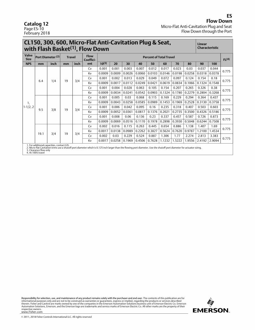
CL150, 300, 600, Micro-Flat Anti-Cavitation Plug & Seat,with Flash Basket(1), Flow Down
LinearCharacteristic
ValveSize
Port Diameter (2) Travel FlowCoeffici-
ent
Percent of Total TravelFL(4)
NPS mm inch mm inch 10(3) 20 30 40 50 60 70 80 90 100
1,
1-1/2, 2
6.4 1/4 19 3/4
Cv 0.001 0.001 0.003 0.007 0.012 0.017 0.023 0.03 0.037 0.0440.775
Kv 0.0009 0.0009 0.0026 0.0060 0.0103 0.0146 0.0198 0.0258 0.0318 0.0378
Cv 0.001 0.002 0.013 0.029 0.049 0.072 0.097 0.124 0.154 0.180.775
Kv 0.0009 0.0017 0.0112 0.0249 0.0421 0.0619 0.0834 0.1066 0.1324 0.1548
Cv 0.001 0.004 0.028 0.063 0.105 0.154 0.207 0.265 0.326 0.380.775
Kv 0.0009 0.0034 0.0241 0.0542 0.0903 0.1324 0.1780 0.2279 0.2804 0.3268
9.5 3/8 19 3/4
Cv 0.001 0.005 0.03 0.068 0.115 0.169 0.229 0.294 0.364 0.4370.775
Kv 0.0009 0.0043 0.0258 0.0585 0.0989 0.1453 0.1969 0.2528 0.3130 0.3758
Cv 0.001 0.006 0.042 0.095 0.16 0.235 0.318 0.407 0.503 0.6030.775
Kv 0.0009 0.0052 0.0361 0.0817 0.1376 0.2021 0.2735 0.3500 0.4326 0.5186
Cv 0.001 0.008 0.06 0.136 0.23 0.337 0.457 0.587 0.726 0.8730.775
Kv 0.0009 0.0069 0.0516 0.1170 0.1978 0.2898 0.3930 0.5048 0.6244 0.7508
19.1 3/4 19 3/4
Cv 0.002 0.016 0.115 0.263 0.445 0.654 0.886 1.138 1.407 1.690.775
Kv 0.0017 0.0138 0.0989 0.2262 0.3827 0.5624 0.7620 0.9787 1.2100 1.4534
Cv 0.002 0.03 0.229 0.524 0.887 1.306 1.77 2.274 2.813 3.3830.775
Kv 0.0017 0.0258 0.1969 0.4506 0.7628 1.1232 1.5222 1.9556 2.4192 2.9094
1. For additional capacities, contact GIS.2. Micro-flat Cavitation trims use a shutoff port diameter which is 0.125 inch larger than the flowing port diameter. Use the shutoff port diameter for actuator sizing.3. Clearance flow only4. At 100% travel
ES
Micro-Flat Anti-Cavitation Plug and SeatFlow Down through the Port
Flow DownCatalog 12Page ES-10February 2018
� 2011, 2018 Fisher Controls International LLC. All rights reserved
www.Fisher.com
Responsibility for selection, use, and maintenance of any product remains solely with the purchaser and end user. The contents of this publication are forinformational purposes only and are not to be construed as warranties or guarantees, express or implied, regarding the products or services describedtherein. Fisher and Cavitrol are marks owned by one of the companies in the Emerson Automation Solutions business unit of Emerson Electric Co. EmersonAutomation Solutions, Emerson, and the Emerson logo are trademarks and service marks of Emerson Electric Co. All other marks are the property of theirrespective owners.
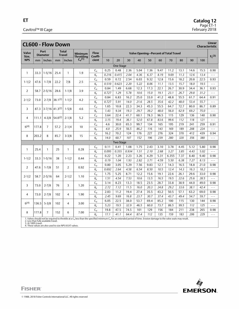
CL600 ‐ Flow Down LinearCharacteristic
ValveSize,NPS
PortDiameter
TotalTravel Minimum
ThrottlingCv
(1)
FlowCoeffi‐cient
Valve Opening—Percent of Total TravelFL
(3)
mm Inches mm Inches 10 20 30 40 50 60 70 80 90 100
One Stage
1 33.3 1‐5/16 25.4 1 1.9Cv 0.25 0.48 2.36 5.04 7.36 9.47 11.2 13.1 14.6 15.5 0.90
Kv
0.216 0.415 2.04 4.36 6.37 8.19 9.69 11.3 12.6 13.4 ‐ ‐ ‐
1‐1/2 47.6 1‐7/8 22.2 7/8 2.5Cv 0.59 0.72 2.54 6.03 9.32 12.8 15.6 18.2 20.8 22.5 0.93
Kv
0.510 0.623 2.20 5.22 8.06 11.1 13.5 15.7 18.0 19.5 ‐ ‐ ‐
2 58.7 2‐5/16 28.6 1‐1/8 3.9Cv 0.84 1.49 6.68 12.3 17.3 22.1 26.7 30.9 34.4 36.1 0.93
Kv
0.727 1.29 5.78 10.6 15.0 19.1 23.1 26.7 29.8 31.2 ‐ ‐ ‐
2‐1/2 73.0 2‐7/8 38.1(2) 1‐1/2 4.2Cv 0.84 6.83 16.2 25.0 33.0 41.2 48.8 55.5 61.7 64.4 0.91
Kv
0.727 5.91 14.0 21.6 28.5 35.6 42.2 48.0 53.4 55.7 ‐ ‐ ‐
3 87.3 3‐7/16 41.3(2) 1‐5/8 4.6Cv 1.65 10.8 22.3 34.3 45.3 55.5 64.7 72.7 80.0 86.7 0.89
Kv
1.43 9.34 19.3 29.7 39.2 48.0 56.0 62.9 69.2 75.0 ‐ ‐ ‐
4 111.1 4‐3/8 54.0(2) 2‐1/8 5.2Cv 3.64 22.4 41.7 60.1 78.3 96.5 115 129 136 140 0.90
Kv
3.15 19.4 36.1 52.0 67.8 83.6 99.6 112 118 121 ‐ ‐ ‐
6(4) 177.8 7 57.2 2‐1/4 10Cv 4.6 30.0 65.3 99.7 134 165 195 219 241 259 0.91
Kv
4.0 25.9 56.5 86.2 116 143 169 189 208 224 ‐ ‐ ‐
8 203.2 8 85.7 3‐3/8 15Cv 16.2 70.2 124 176 227 276 324 370 412 439 0.94
Kv
14.0 60.7 107 152 196 239 280 320 356 380 ‐ ‐ ‐
Two Stage
1 25.4 1 25 1 0.28Cv 0.11 0.41 1.08 1.75 2.43 3.10 3.78 4.45 5.12 5.80 0.98
Kv
0.095 0.355 0.934 1.51 2.10 2.68 3.27 3.85 4.43 5.02 ‐ ‐ ‐
1‐1/2 33.3 1‐5/16 38 1‐1/2 0.44Cv 0.22 1.20 2.23 3.26 4.29 5.31 6.355 7.37 8.40 9.40 0.98
Kv
0.19 1.04 1.93 2.82 3.71 4.59 5.50 6.38 7.27 8.13 ‐ ‐ ‐
2 47.6 1‐7/8 51 2 0.92Cv 0.80 3.05 5.29 7.56 9.83 12.1 14.3 16.5 18.8 21.0 0.98
Kv
0.692 2.64 4.58 6.54 8.50 10.5 12.4 14.3 16.3 18.2 ‐ ‐ ‐
2‐1/2 58.7 2‐5/16 64 2‐1/2 1.10Cv 1.75 5.25 8.71 12.2 15.6 19.1 22.6 26.1 29.6 33.0 0.98
Kv
1.51 4.54 7.53 10.6 13.5 16.5 19.5 22.6 25.6 28.5 ‐ ‐ ‐
3 73.0 2‐7/8 76 3 1.20Cv 3.14 8.23 13.3 18.5 23.5 28.7 33.8 38.9 44.0 49.0 0.98
Kv
2.72 7.12 11.5 16.0 20.3 24.8 29.2 33.6 38.1 42.4 ‐ ‐ ‐
4 73.0 2‐7/8 102 4 1.90Cv 2.83 11.2 19.4 27.4 35.5 43.2 50.5 57.1 63.2 69.0 0.98
Kv
2.45 9.69 16.8 23.7 30.7 37.4 43.7 49.4 54.7 59.7 ‐ ‐ ‐
6(4) 136.5 5‐3/8 102 4 3.00Cv 6.05 22.5 38.0 53.7 69.4 85.2 100 115 130 144 0.98
Kv
5.23 19.5 32.9 46.5 60.0 73.7 86.5 99.5 112 125 ‐ ‐ ‐
8 177.8 7 152 6 7.00Cv 19.8 47.5 74.5 101 129 156 184 211 238 265 0.98
Kv
17.1 41.1 64.4 87.4 112 135 159 183 206 229 ‐ ‐ ‐
1. Valves should not be required to throttle at a Cv less than the specified minimum Cv for an extended period of time. Erosion damage to the valve seats may result.2. Less than fully available travel.3. At 100% travel.4. These values are also used to size NPS 8 EAT valves.
� 1988, 2018 Fisher Controls International LLC. All rights reserved
ET
Cavitrol™ III Cage
Catalog 12Page ET-1
February 2018

This page is intentionally left blank.
ETCatalog 12Page ET-2February 2018
� 2010, 2018 Fisher Controls International LLC. All rights reserved
www.Fisher.com
Responsibility for selection, use, and maintenance of any product remains solely with the purchaser and end user. The contents of this publication are forinformational purposes only and are not to be construed as warranties or guarantees, express or implied, regarding the products or services describedtherein. Fisher is a mark owned by one of the companies in the Emerson Automation Solutions business unit of Emerson Electric Co. Emerson AutomationSolutions, Emerson, and the Emerson logo are trademarks and service marks of Emerson Electric Co. All other marks are the property of their respectiveowners.

3
Linear Linear Characteristic
ValveSize,NPS
Port Diameter Maximum TravelConstruction
FlowCoeffi‐cient
Valve Opening—Percent of Total TravelFL
(1)
mm Inches mm Inches Min(2) 10 20 30 40 50 60 70 80 90 100
12 279.4 11
102 4
SNC
Cv 40 155 300 450 610 770 940 1100 1250 1390 1500 0.88
Kv 34.6 134 260 389 528 666 813 952 1081 1202 1298 ‐ ‐ ‐
Xt 0.391 0.609 0.678 0.676 0.645 0.654 0.693 0.746 0.789 0.799 0.792 ‐ ‐ ‐
140 5.5
Cv 40 206 415 630 852 1079 1295 1465 1557 1570 1570 0.88
Kv 34.6 178 359 545 737 933 1120 1267 1347 1358 1358 ‐ ‐ ‐
Xt 0.391 0.644 0.683 0.644 0.654 0.704 0.769 0.792 0.775 0.818 0.82 ‐ ‐ ‐
14 279.4 11
102 4
SNC
Cv 40 106 222 368 541 727 922 1109 1283 1437 1560 0.88
Kv 34.6 92 192 319 468 629 797 959 1110 1243 1350 ‐ ‐ ‐
Xt 0.391 0.837 0.811 0.749 0.703 0.703 0.722 0.748 0.769 0.774 0.777 ‐ ‐ ‐
140 5.5
Cv 40 206 415 629 838 1110 1420 1630 1760 1850 1860 0.88
Kv 34.6 178 359 544 725 960 1228 1410 1522 1600 1609 ‐ ‐ ‐
Xt 0.391 0.99 0.77 0.70 0.72 0.78 0.80 0.80 0.81 0.79 0.82 ‐ ‐ ‐
16x12 279.4 11
102 4
SNC
Cv 40 73 169 314 495 698 909 1115 1305 1468 1601 0.88
Kv 34.6 63 146 272 428 604 786 965 1128 1270 1385 ‐ ‐ ‐
Xt 0.391 0.989 0.899 0.797 0.742 0.735 0.741 0.749 0.756 0.758 0.767 ‐ ‐ ‐
140 5.5
Cv 40 90 300 500 800 1100 1350 1550 1700 1800 1875 0.88
Kv 34.6 78 260 433 692 952 1168 1341 1471 1557 1622 ‐ ‐ ‐
Xt 0.391 0.989 0.899 0.797 0.742 0.735 0.741 0.749 0.756 0.758 0.767 ‐ ‐ ‐
16 374.7 14.75
102 4
SNC
Cv 76 202 456 709 963 1232 1534 1900 2234 2526 2772 0.85
Kv 66 175 394 613 833 1066 1327 1644 1933 2185 2398 ‐ ‐ ‐
Xt 0.80 0.80 0.80 0.80 0.80 0.80 0.80 0.80 0.80 0.80 ‐ ‐ ‐
Fd 0.19 0.26 0.29 0.31 0.31 0.27 0.27 0.28 0.35 0.30 ‐ ‐ ‐
140 5.5
Cv 124 298 649 1000 1376 1846 2324 2701 2988 3188 3312 0.85
Kv 107 258 562 865 1190 1597 2010 2337 2585 2757 2865 ‐ ‐ ‐
Xt 0.80 0.80 0.80 0.80 0.80 0.80 0.80 0.80 0.80 0.80 ‐ ‐ ‐
Fd 0.22 0.28 0.31 0.29 0.27 0.29 0.30 0.30 0.31 0.31 ‐ ‐ ‐
18 374.7 14.75
102 4
SNC
Cv 82 218 492 765 1038 1310 1622 1989 2311 2583 2810 0.85
Kv 71 189 426 662 899 1134 1404 1721 2000 2236 2431 ‐ ‐ ‐
Xt 0.81 0.81 0.76 0.76 0.78 0.78 0.86 0.82 0.79 0.81 ‐ ‐ ‐
Fd 0.18 0.22 0.23 0.20 0.19 0.20 0.20 0.20 0.20 0.21 ‐ ‐ ‐
140 5.5
Cv 133 322 701 1078 1460 1935 2396 2745 3010 3208 3351 0.85
Kv 115 279 606 933 1263 1674 2073 2375 2605 2776 2900 ‐ ‐ ‐
Xt 0.81 0.81 0.76 0.76 0.78 0.78 0.86 0.82 0.79 0.81 ‐ ‐ ‐
Fd 0.22 0.28 0.31 0.29 0.27 0.29 0.30 0.30 0.31 0.31 ‐ ‐ ‐
20 x 16 374.7 14.75
102 4
SNC
Cv 80 213 480 747 1038 1316 1644 2044 2413 2742 3026 0.85
Kv 70 184 415 646 898 1139 1422 1768 2087 2371 2618 ‐ ‐ ‐
Xt 0.81 0.81 0.76 0.76 0.78 0.78 0.86 0.82 0.79 0.81 ‐ ‐ ‐
Fd 0.18 0.22 0.23 0.20 0.19 0.20 0.20 0.20 0.20 0.21 ‐ ‐ ‐
140 5.5
Cv 130 314 683 1079 1472 1984 2514 2944 3286 3543 3721 0.85
Kv 113 272 591 933 1274 1716 2174 2546 2842 3065 3219 ‐ ‐ ‐
Xt 0.81 0.81 0.76 0.76 0.78 0.78 0.86 0.82 0.79 0.81 ‐ ‐ ‐
Fd 0.22 0.28 0.31 0.29 0.27 0.29 0.30 0.30 0.31 0.31 ‐ ‐ ‐
24 x 16 374.7 14.75
102 4
SNC
Cv 80 213 480 747 1000 1283 1627 2065 2490 2888 3253 0.85
Kv 70 184 415 646 865 1110 1407 1786 2153 2498 2814 ‐ ‐ ‐
Xt 0.81 0.81 0.81 0.76 0.76 0.78 0.78 0.86 0.82 0.79 0.81 ‐ ‐ ‐
Fd 0.18 0.22 0.23 0.20 0.19 0.20 0.20 0.20 0.20 0.21 ‐ ‐ ‐
140 5.5
Cv 130 314 683 1041 1445 1998 2609 3145 3606 3982 4265 0.85
Kv 113 272 591 900 1250 1728 2257 2720 3119 3444 3689 ‐ ‐ ‐
Xt 0.81 0.81 0.81 0.76 0.76 0.78 0.78 0.86 0.82 0.79 0.81 ‐ ‐ ‐
Fd 0.22 0.28 0.31 0.29 0.27 0.29 0.30 0.30 0.31 0.31 ‐ ‐ ‐
1. At 100% travel.2. Clearance flow only
Large ET/EWT
Linear CageFlow Down
CL150 ‐ CL600 Catalog 12Page ET-3
October 2018
� 2011, 2018 Fisher Controls International LLC. All rights reserved
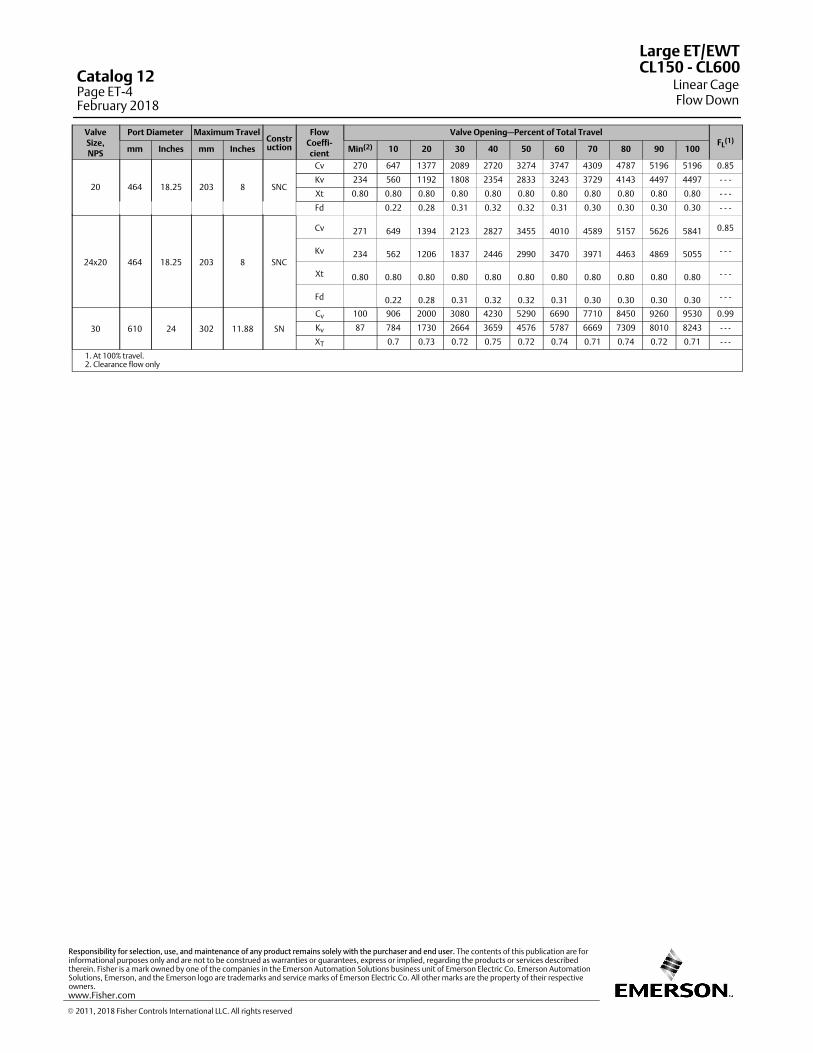
ValveSize,NPS
Port Diameter Maximum TravelConstruction
FlowCoeffi‐cient
Valve Opening—Percent of Total TravelFL
(1)
mm Inches mm Inches Min(2) 10 20 30 40 50 60 70 80 90 100
20 464 18.25 203 8 SNC
Cv 270 647 1377 2089 2720 3274 3747 4309 4787 5196 5196 0.85
Kv 234 560 1192 1808 2354 2833 3243 3729 4143 4497 4497 - - -
Xt 0.80 0.80 0.80 0.80 0.80 0.80 0.80 0.80 0.80 0.80 0.80 - - -
Fd 0.22 0.28 0.31 0.32 0.32 0.31 0.30 0.30 0.30 0.30 - - -
24x20 464 18.25 203 8 SNC
Cv 271 649 1394 2123 2827 3455 4010 4589 5157 5626 5841 0.85
Kv 234 562 1206 1837 2446 2990 3470 3971 4463 4869 5055 - - -
Xt 0.80 0.80 0.80 0.80 0.80 0.80 0.80 0.80 0.80 0.80 0.80 - - -
Fd 0.22 0.28 0.31 0.32 0.32 0.31 0.30 0.30 0.30 0.30 - - -
30 610 24 302 11.88 SN
Cv 100 906 2000 3080 4230 5290 6690 7710 8450 9260 9530 0.99
Kv 87 784 1730 2664 3659 4576 5787 6669 7309 8010 8243 - - -
XT 0.7 0.73 0.72 0.75 0.72 0.74 0.71 0.74 0.72 0.71 - - -
1. At 100% travel.2. Clearance flow only
Large ET/EWT
Linear CageFlow Down
CL150 ‐ CL600Catalog 12Page ET-4February 2018
� 2011, 2018 Fisher Controls International LLC. All rights reserved
www.Fisher.com
Responsibility for selection, use, and maintenance of any product remains solely with the purchaser and end user. The contents of this publication are forinformational purposes only and are not to be construed as warranties or guarantees, express or implied, regarding the products or services describedtherein. Fisher is a mark owned by one of the companies in the Emerson Automation Solutions business unit of Emerson Electric Co. Emerson AutomationSolutions, Emerson, and the Emerson logo are trademarks and service marks of Emerson Electric Co. All other marks are the property of their respectiveowners.

5
Equal Percentage Equal Percentage Characteristic
Valve Size,NPS
Port Diameter Maximum TravelConstruction
FlowCoeffi‐cient
Valve Opening—Percent of Total TravelFL
(1)
mm Inches mm Inches Min(2) 10 20 30 40 50 60 70 80 90 100
12 279.4 11 140 5.5 SNC
Cv 22 50 91 141 222 352 540 797 1127 1361 1488 0.88
Kv 19.0 43 79 122 192 304 467 689 975 1177 1287 ‐ ‐ ‐
Xt 0.391 0.747 0.731 0.706 0.650 0.584 0.575 0.610 0.679 0.797 0.804 ‐ ‐ ‐
14 279.4 11 140 5.5 SNC
Cv 22 51 95 139 193 277 406 582 803 1079 1397 0.88
Kv 19.0 44 82 120 167 240 351 503 695 933 1208 ‐ ‐ ‐
Xt 0.391 0.894 0.891 0.883 0.855 0.788 0.711 0.674 0.696 0.728 0.780 ‐ ‐ ‐
16x12 279.4 11 140 5.5 SNC
Cv 21 58 109 158 220 317 463 664 917 1232 1595 0.88
Kv 20.3 56.0 105 153 212 306 447 641 885 1189 1539 ‐ ‐ ‐
Xt 0.391 0.99 0.994 0.995 0.987 0.916 0.805 0.738 0.743 0.752 0.764 ‐ ‐ ‐
16 374.7 14.75
102 4 SNC
Cv 7 22 54 86 136 213 321 477 695 1010 1414 0.85
Kv 6 19 47 74 117 184 277 412 601 873 1223 ‐ ‐ ‐
Xt 0.80 0.80 0.80 0.80 0.80 0.80 0.80 0.80 0.80 0.80 ‐ ‐ ‐
Fd 0.41 0.46 0.45 0.27 0.28 0.27 0.26 0.24 0.22 0.24 ‐ ‐ ‐
140 5.5 SNC
Cv 13 35 79 145 263 454 765 1272 1808 2278 2664 0.85
Kv 11 30 68 125 228 393 662 1100 1564 1971 2304 ---
Xt 0.80 0.80 0.80 0.80 0.80 0.80 0.80 0.80 0.80 0.80 ---
Fd 0.45 0.46 0.39 0.28 0.26 0.24 0.23 0.26 0.27 0.28 ---
203 8 LNC
Cv 34 77 163 249 433 670 1003 1490 2154 2686 3054 0.85
Kv 29 66 141 216 375 579 868 1289 1863 2323 2642 ‐ ‐ ‐
Xt 0.80 0.80 0.80 0.80 0.80 0.80 0.80 0.80 0.80 0.80 ‐ ‐ ‐
Fd 0.46 0.45 0.42 0.25 0.32 0.25 0.21 0.23 0.25 0.26 ‐ ‐ ‐
18 374.7 14.75
102 4 SNC
Cv 8 24 58 93 146 230 346 514 750 1088 1499 0.85
Kv 7 21 50 80 127 199 299 445 649 942 1297 ---
Xt 0.80 0.80 0.80 0.80 0.80 0.80 0.80 0.80 0.80 0.80 ---
Fd 0.46 0.45 0.42 0.25 0.32 0.25 0.21 0.23 0.25 0.26 ---
140 5.5 SNC
Cv 14 38 85 156 284 490 825 1351 1897 2352 2711 0.85
Kv 12 33 74 135 246 424 714 1169 1642 2036 2346 ‐ ‐ ‐
Xt 0.80 0.80 0.80 0.80 0.80 0.80 0.80 0.80 0.80 0.80 ‐ ‐ ‐
Fd 0.46 0.45 0.42 0.25 0.32 0.25 0.21 0.23 0.25 0.26 ‐ ‐ ‐
203 8 SNC
Cv 36 83 176 269 467 723 1082 1577 2234 2730 3073 0.85
Kv 31 72 152 233 404 625 936 1364 1933 2363 2660 ‐ ‐ ‐
Xt 0.80 0.80 0.80 0.80 0.80 0.80 0.80 0.80 0.80 0.80 ‐ ‐ ‐
Fd 0.46 0.45 0.42 0.25 0.32 0.25 0.21 0.23 0.25 0.26 ‐ ‐ ‐
20 x 16 374.7 14.75
102 4 SNC
Cv 8 23 57 90 143 224 338 502 732 1089 1513 0.85
Kv 7 20 49 78 123 194 292 434 633 942 1309 ---
Xt 0.80 0.80 0.80 0.80 0.80 0.80 0.80 0.80 0.80 0.80 0.80 ---
Fd 0.46 0.45 0.42 0.25 0.32 0.25 0.21 0.23 0.25 0.26 ---
140 5.5 SNC
Cv 14 37 83 153 277 478 805 1359 1943 2462 2900 0.85
Kv 12 32 72 132 240 413 696 1175 1681 2130 2509 ‐ ‐ ‐
Xt 0.80 0.80 0.80 0.80 0.80 0.80 0.80 0.80 0.80 0.80 0.80 ‐ ‐ ‐
Fd 0.46 0.45 0.42 0.25 0.32 0.25 0.21 0.23 0.25 0.26 ‐ ‐ ‐
203 8 SNC
Cv 35 81 172 262 456 705 1082 1596 2324 2925 3369 0.85
Kv 31 70 148 227 394 610 936 1380 2010 2530 2914 - - -
Xt 0.80 0.80 0.80 0.80 0.80 0.80 0.80 0.80 0.80 0.80 0.80 - - -
Fd 0.46 0.45 0.42 0.25 0.32 0.25 0.21 0.23 0.25 0.26 - - -
24 x 16 374.7 14.75
102 4 SNC
Cv 8 23 57 90 143 224 338 502 732 1089 1513 0.85
Kv 7 20 49 78 123 194 292 434 633 942 1309 ---
XT 0.80 0.80 0.80 0.80 0.80 0.80 0.80 0.80 0.80 0.80 0.80 ---
Fd 0.46 0.45 0.42 0.25 0.32 0.25 0.21 0.23 0.25 0.26 ---
140 5.5 SNC
Cv 14 37 83 153 277 478 805 1327 1952 2548 3089 0.85
Kv 12 32 72 132 240 413 696 1148 1688 2204 2672 ‐ ‐ ‐
Xt 0.80 0.80 0.80 0.80 0.80 0.80 0.80 0.80 0.80 0.80 0.80 ‐ ‐ ‐
Fd 0.46 0.45 0.42 0.25 0.32 0.25 0.21 0.23 0.25 0.26 ‐ ‐ ‐
203 8 SNC
Cv 34 77 165 252 437 676 1044 1575 2385 3121 3724 0.85
Kv 29 67 142 218 378 585 903 1363 2063 2700 3221 - - -
Xt 0.80 0.80 0.80 0.80 0.80 0.80 0.80 0.80 0.80 0.80 0.80 - - -
Fd 0.46 0.45 0.42 0.25 0.32 0.25 0.21 0.23 0.25 0.26 - - -
1. At 100% travel.2. Clearance flow only
Large ET/EWT
Equal Percentage CageFlow Down
CL150 ‐ CL600 Catalog 12Page ET-5
February 2018
� 2011, 2018 Fisher Controls International LLC. All rights reserved

Valve Size,NPS
Port Diameter Maximum TravelConstruction
FlowCoeffi‐cient
Valve Opening—Percent of Total TravelFL
(1)
mm Inches mm Inches Min(2) 10 20 30 40 50 60 70 80 90 100
20 464 18.25203
8 SNC
Cv 38 90 214 408 733 1276 2122 2954 3661 4270 4820 0.85
Kv 33 78 185 353 634 1104 1836 2557 3168 3695 4171 - - -
Xt 0.80 0.80 0.80 0.80 0.80 0.80 0.80 0.80 0.80 0.80 0.80 - - -
Fd 0.31 0.28 0.25 0.24 0.22 0.23 0.25 0.27 0.28 0.29 - - -
24x20 464 18.25 203 8 SNC
Cv 38 91 215 410 736 1282 2159 3087 3891 4579 5182 0.85
Kv 33 78 186 355 637 1109 1868 2671 3368 3963 4484 - - -
Xt 0.80 0.80 0.80 0.80 0.80 0.80 0.80 0.80 0.80 0.80 0.80 - - -
Fd 0.31 0.28 0.25 0.24 0.22 0.23 0.25 0.27 0.28 0.29 - - -
30 610 24 276 10.88 SN
Cv 70 126 305 520 876 1343 2200 3599 5150 6563 7690 0.99
Kv 61 109 264 450 758 1162 1903 3113 4455 5677 6652 - - -XT 0.6 0.6 0.6 0.6 0.6 0.6 0.6 0.65 0.68 0.7 - - -
1. At 100% travel.2. Clearance flow only
Large ET/EWT
Equal Percentage CageFlow Down
CL150 ‐ CL600Catalog 12Page ET-6February 2018
� 2011, 2018 Fisher Controls International LLC. All rights reserved
www.Fisher.com
Responsibility for selection, use, and maintenance of any product remains solely with the purchaser and end user. The contents of this publication are forinformational purposes only and are not to be construed as warranties or guarantees, express or implied, regarding the products or services describedtherein. Fisher is a mark owned by one of the companies in the Emerson Automation Solutions business unit of Emerson Electric Co. Emerson AutomationSolutions, Emerson, and the Emerson logo are trademarks and service marks of Emerson Electric Co. All other marks are the property of their respectiveowners.
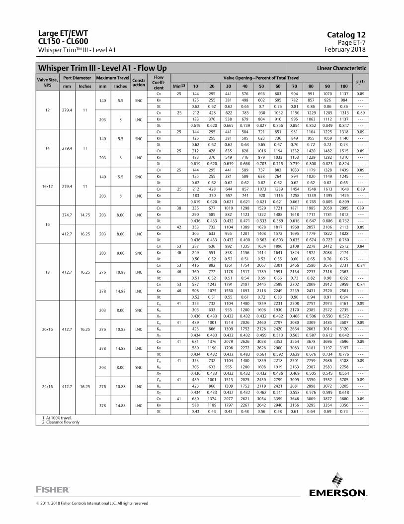
7
Whisper Trim III - Level A1 - Flow Up Linear Characteristic
Valve Size,NPS
Port Diameter Maximum TravelConstruction
FlowCoeffi‐cient
Valve Opening—Percent of Total TravelFL
(1)
mm Inches mm Inches Min(2) 10 20 30 40 50 60 70 80 90 100
12 279.4 11
140 5.5 SNC
Cv 25 144 295 441 576 696 803 904 991 1070 1137 0.89
Kv 125 255 381 498 602 695 782 857 926 984 ‐ ‐ ‐
Xt 0.62 0.62 0.62 0.65 0.7 0.75 0.81 0.86 0.86 0.86 ‐ ‐ ‐
203 8 LNC
Cv 25 212 428 622 785 930 1052 1150 1229 1285 1315 0.89
Kv 183 370 538 679 804 910 995 1063 1112 1137 ‐ ‐ ‐
Xt 0.619 0.620 0.665 0.739 0.827 0.856 0.854 0.852 0.849 0.847 ‐ ‐ ‐
14 279.4 11
140 5.5 SNC
Cv 25 144 295 441 584 721 851 981 1104 1225 1318 0.89
Kv 125 255 381 505 623 736 849 955 1059 1140 ‐ ‐ ‐
Xt 0.62 0.62 0.62 0.63 0.65 0.67 0.70 0.72 0.72 0.73 ‐ ‐ ‐
203 8 LNC
Cv 25 212 428 635 828 1016 1194 1332 1420 1482 1515 0.89
Kv 183 370 549 716 879 1033 1153 1229 1282 1310 ‐ ‐ ‐
Xt 0.619 0.620 0.639 0.668 0.703 0.715 0.739 0.800 0.823 0.824 ‐ ‐ ‐
16x12 279.4 11
140 5.5 SNC
Cv 25 144 295 441 589 737 883 1033 1179 1328 1439 0.89
Kv 125 255 381 509 638 764 894 1020 1149 1245 ‐ ‐ ‐
Xt 0.62 0.62 0.62 0.62 0.62 0.62 0.62 0.62 0.62 0.65 ‐ ‐ ‐
203 8 LNC
Cv 25 212 428 644 857 1073 1289 1454 1548 1613 1648 0.89
Kv 183 370 557 741 928 1115 1258 1339 1395 1425 ‐ ‐ ‐
Xt 0.619 0.620 0.621 0.621 0.621 0.621 0.663 0.765 0.805 0.809 ‐ ‐ ‐
16
374.7 14.75 203 8.00 LNC
Cv 38 335 677 1019 1298 1529 1721 1871 1985 2059 2095 089
Kv 290 585 882 1123 1322 1488 1618 1717 1781 1812 - - -
Xt 0.436 0.433 0.432 0.471 0.533 0.589 0.616 0.647 0.686 0.732 - - -
412.7 16.25 203 8.00 LNC
Cv 42 353 732 1104 1389 1628 1817 1960 2057 2106 2113 0.89
Kv 305 633 955 1201 1408 1572 1695 1779 1822 1828 - - -
Xt 0.436 0.433 0.432 0.490 0.563 0.603 0.635 0.674 0.722 0.780 - - -
18 412.7 16.25
203 8.00 SNC
Cv 53 287 636 992 1335 1634 1896 2108 2278 2412 2512 0.84
Kv 46 249 551 858 1156 1414 1641 1824 1972 2088 2174 ‐ ‐ ‐
Xt 0.50 0.52 0.52 0.51 0.52 0.55 0.60 0.65 0.70 0.76 ‐ ‐ ‐
276 10.88 LNC
Cv 53 416 892 1361 1754 2067 2301 2466 2580 2676 2731 0.84
Kv 46 360 772 1178 1517 1789 1991 2134 2233 2316 2363 ‐ ‐ ‐
Xt 0.51 0.52 0.51 0.54 0.59 0.66 0.73 0.82 0.90 0.92 ‐ ‐ ‐
378 14.88 LNC
Cv 53 587 1243 1791 2187 2445 2599 2702 2809 2912 2959 0.84
Kv 46 508 1075 1550 1893 2116 2249 2339 2431 2520 2561 ‐ ‐ ‐
Xt 0.52 0.51 0.55 0.61 0.72 0.83 0.90 0.94 0.91 0.94 ‐ ‐ ‐
20x16 412.7 16.25
203 8.00 SNC
Cv 41 353 732 1104 1480 1859 2231 2508 2757 2973 3161 0.89
Kv 305 633 955 1280 1608 1930 2170 2385 2572 2735 - - -
XT 0.436 0.433 0.432 0.432 0.432 0.432 0.466 0.506 0.550 0.572 - - -
276 10.88 LNC
Cv 41 489 1001 1514 2026 2460 2797 3080 3309 3485 3607 0.89
Kv 423 866 1309 1752 2128 2420 2664 2863 3014 3120 - - -
XT 0.434 0.433 0.432 0.432 0.459 0.513 0.565 0.587 0.612 0.642 - - -
378 14.88 LNC
Cv 41 681 1376 2079 2626 3038 3353 3564 3678 3696 3696 0.89
Kv 589 1190 1798 2272 2628 2900 3083 3181 3197 3197 - - -
Xt 0.434 0.432 0.432 0.483 0.561 0.592 0.629 0.676 0.734 0.776 - - -
24x16 412.7 16.25
203 8.00 SNC
Cv 41 353 732 1104 1480 1859 2218 2501 2759 2986 3188 0.89
Kv 305 633 955 1280 1608 1919 2163 2387 2583 2758 - - -
XT 0.436 0.433 0.432 0.432 0.432 0.436 0.469 0.505 0.545 0.564 - - -
276 10.88 LNC
Cv 41 489 1001 1513 2025 2450 2799 3099 3350 3552 3705 0.89
Kv 423 866 1309 1752 2119 2421 2681 2898 3072 3205 - - -
XT 0.434 0.433 0.432 0.432 0.462 0.511 0.558 0.576 0.595 0.618 - - -
378 14.88 LNC
Cv 41 680 1374 2077 2621 3054 3399 3648 3809 3877 3880 0.89
Kv 588 1189 1797 2267 2642 2940 3156 3295 3354 3356 - - -
Xt 0.43 0.43 0.43 0.48 0.56 0.58 0.61 0.64 0.69 0.73 - - -
1. At 100% travel.2. Clearance flow only
Large ET/EWT
Whisper Trim™ III - Level A1CL150 ‐ CL600
Catalog 12Page ET-7
February 2018
� 2011, 2018 Fisher Controls International LLC. All rights reserved
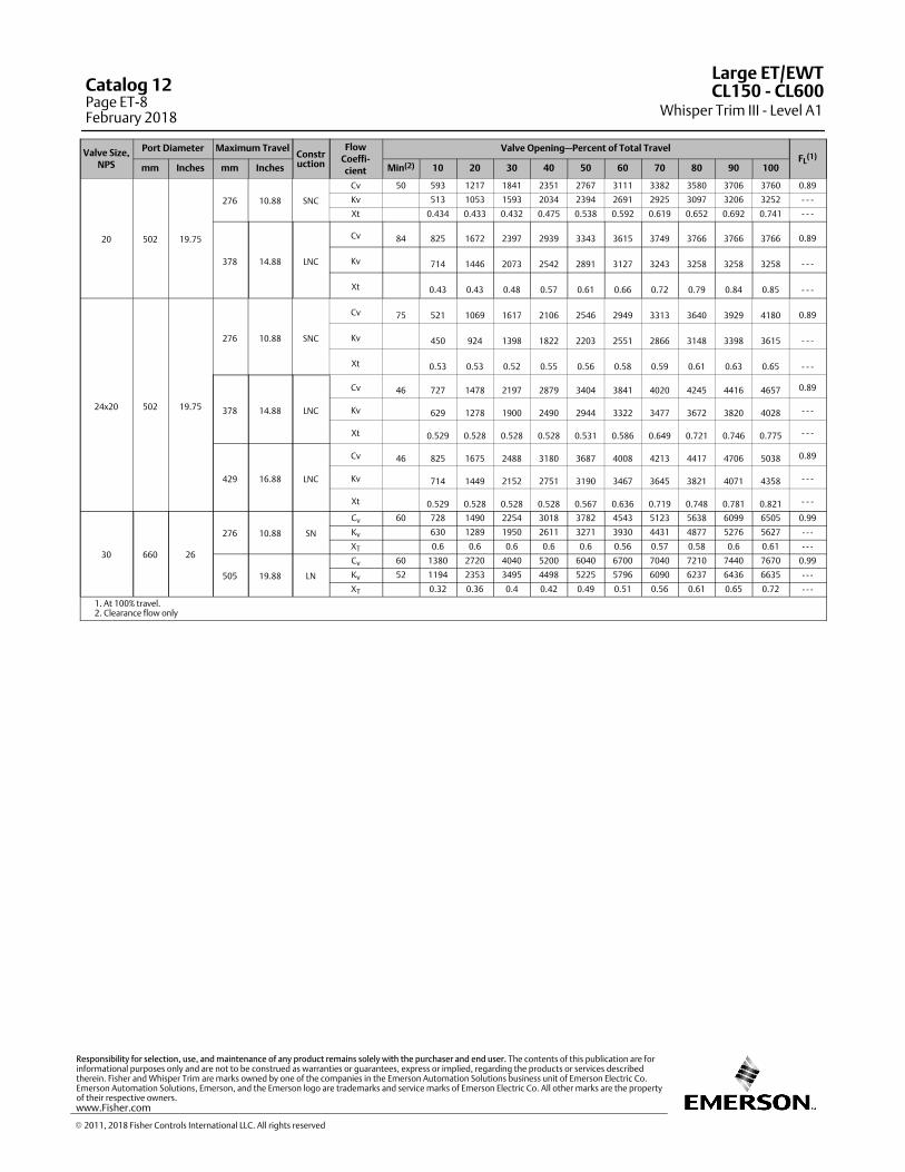
Valve Size,NPS
Port Diameter Maximum TravelConstruction
FlowCoeffi‐cient
Valve Opening—Percent of Total TravelFL
(1)
mm Inches mm Inches Min(2) 10 20 30 40 50 60 70 80 90 100
20 502 19.75
276 10.88 SNC
Cv 50 593 1217 1841 2351 2767 3111 3382 3580 3706 3760 0.89
Kv 513 1053 1593 2034 2394 2691 2925 3097 3206 3252 - - -
Xt 0.434 0.433 0.432 0.475 0.538 0.592 0.619 0.652 0.692 0.741 - - -
378 14.88 LNC
Cv 84 825 1672 2397 2939 3343 3615 3749 3766 3766 3766 0.89
Kv 714 1446 2073 2542 2891 3127 3243 3258 3258 3258 - - -
Xt 0.43 0.43 0.48 0.57 0.61 0.66 0.72 0.79 0.84 0.85 - - -
24x20 502 19.75
276 10.88 SNC
Cv 75 521 1069 1617 2106 2546 2949 3313 3640 3929 4180 0.89
Kv 450 924 1398 1822 2203 2551 2866 3148 3398 3615 - - -
Xt 0.53 0.53 0.52 0.55 0.56 0.58 0.59 0.61 0.63 0.65 - - -
378 14.88 LNC
Cv 46 727 1478 2197 2879 3404 3841 4020 4245 4416 4657 0.89
Kv 629 1278 1900 2490 2944 3322 3477 3672 3820 4028 - - -
Xt 0.529 0.528 0.528 0.528 0.531 0.586 0.649 0.721 0.746 0.775 - - -
429 16.88 LNC
Cv 46 825 1675 2488 3180 3687 4008 4213 4417 4706 5038 0.89
Kv 714 1449 2152 2751 3190 3467 3645 3821 4071 4358 - - -
Xt 0.529 0.528 0.528 0.528 0.567 0.636 0.719 0.748 0.781 0.821 - - -
30 660 26
276 10.88 SN
Cv 60 728 1490 2254 3018 3782 4543 5123 5638 6099 6505 0.99
Kv 630 1289 1950 2611 3271 3930 4431 4877 5276 5627 - - -
XT 0.6 0.6 0.6 0.6 0.6 0.56 0.57 0.58 0.6 0.61 - - -
505 19.88 LN
Cv 60 1380 2720 4040 5200 6040 6700 7040 7210 7440 7670 0.99
Kv 52 1194 2353 3495 4498 5225 5796 6090 6237 6436 6635 - - -
XT 0.32 0.36 0.4 0.42 0.49 0.51 0.56 0.61 0.65 0.72 - - -
1. At 100% travel.2. Clearance flow only
Large ET/EWT
Whisper Trim III - Level A1CL150 ‐ CL600Catalog 12
Page ET-8February 2018
� 2011, 2018 Fisher Controls International LLC. All rights reserved
www.Fisher.com
Responsibility for selection, use, and maintenance of any product remains solely with the purchaser and end user. The contents of this publication are forinformational purposes only and are not to be construed as warranties or guarantees, express or implied, regarding the products or services describedtherein. Fisher and Whisper Trim are marks owned by one of the companies in the Emerson Automation Solutions business unit of Emerson Electric Co.Emerson Automation Solutions, Emerson, and the Emerson logo are trademarks and service marks of Emerson Electric Co. All other marks are the propertyof their respective owners.

9
Whisper Trim - Level A3 - Flow Up Linear Characteristic
Valve Size,NPS
Port Diameter Maximum TravelConstruction
FlowCoeffi‐cient
Valve Opening—Percent of Total TravelFL
(1)
mm Inches mm Inches Min(2) 10 20 30 40 50 60 70 80 90 100
12 279.4 11
140 5.5 SNC
Cv 17 123 253 381 508 617 719 813 901 978 1049 0.89
Kv 106 219 330 439 534 622 703 779 846 907 ---
Xt 0.62 0.62 0.62 0.62 0.66 0.71 0.76 0.81 0.86 0.86 ---
203 8 LNC
Cv 17 181 371 550 705 839 960 1063 1149 1219 1272 0.89
Kv 157 321 475 610 726 831 919 994 1055 1100 ---
Xt 0.619 0.620 0.638 0.700 0.769 0.851 0.856 0.854 0.852 0.850 ---
14 279.4 11
140 5.5 SNC
Cv 17 123 253 381 509 630 748 863 978 1086 1192 0.89
Kv 106 219 330 440 545 647 747 846 939 1031 ---
Xt 0.62 0.62 0.62 0.62 0.64 0.66 0.68 0.70 0.72 0.72 ---
203 8 LNC
Cv 17 181 371 554 731 896 1059 1212 1331 1410 1467 0.89
Kv 157 321 479 632 775 916 1048 1152 1219 1269 ---
Xt 0.62 0.62 0.63 0.65 0.68 0.71 0.72 0.74 0.79 0.82 ---
16x12 279.4 11
140 5.5 SNC
Cv 17 123 253 381 510 638 767 897 1029 1158 1287 0.89
Kv 106 219 330 441 552 663 776 890 1002 1113 ---
Xt 0.62 0.62 0.62 0.62 0.62 0.62 0.62 0.62 0.62 0.62 ---
203 8 LNC
Cv 17 181 371 557 748 934 1125 1311 1453 1537 1597 0.89
Kv 157 321 482 647 808 973 1134 1256 1329 1381 ---
Xt 0.619 0.620 0.620 0.621 0.621 0.621 0.621 0.663 0.751 0.805 ---
16
374.7 14.75 203 8.00 LNC
Cv 25 290 593 892 1178 1396 1590 1749 1880 1980 2049 0.89
Kv 251 513 772 1019 1208 1375 1513 1626 1713 1772 - - -
Xt 0.436 0.433 0.433 0.447 0.495 0.554 0.594 0.618 0.646 0.679 - - -
412.7 16.25 203 8.00 LNC
Cv 28 317 652 979 1270 1497 1693 1849 1970 2054 2100 0.89
Kv 274 564 847 1099 1295 1464 1599 1704 1777 1817 - - -
Xt 0.436 0.433 0.433 0.463 0.520 0.584 0.609 0.638 0.673 0.714 - - -
18 412.7 16.25
203 8.00 SNC
Cv 27 244 554 867 1173 1466 1715 1937 2120 2271 2393 0.84
Kv 23 211 479 751 1015 1269 1484 1676 1835 1965 2071 ‐ ‐ ‐
Xt 0.50 0.52 0.52 0.52 0.52 0.53 0.56 0.60 0.64 0.69 ‐ ‐ ‐
276 10.88 LNC
Cv 27 354 779 1197 1581 1893 2148 2336 2477 2575 2650 0.84
Kv 23 306 674 1036 1368 1638 1858 2022 2143 2229 2293 ‐ ‐ ‐
Xt 0.51 0.52 0.51 0.52 0.55 0.61 0.67 0.74 0.82 0.88 ‐ ‐ ‐
378 14.88 LNC
Cv 27 514 1086 1613 2022 2311 2499 2620 2709 2792 2899 0.84
Kv 23 444 940 1396 1750 2000 2162 2267 2344 2416 2509 ‐ ‐ ‐
Xt 0.52 0.52 0.52 0.58 0.66 0.75 0.86 0.91 0.94 0.94 ‐ ‐ ‐
20x16 412.7 16.25
203 8.00 SNC
Cv 28 317 651 979 1315 1642 1978 2291 2531 2750 2938 0.89
Kv 274 563 847 1138 1420 1711 1981 2189 2379 2541 - - -
Xt 0.436 0.433 0.432 0.432 0.432 0.432 0.438 0.469 0.505 0.542 - - -
276 10.88 LNC
Cv 28 438 886 1343 1790 2245 2569 2857 3099 3302 3461 0.89
Kv 379 767 1161 1548 1942 2222 2472 2680 2856 2993 - - -
Xt 0.435 0.433 0.432 0.432 0.432 0.475 0.525 0.566 0.586 0.608 - - -
378 14.88 LNC
Cv 28 601 1223 1843 2403 2814 3148 3402 3576 3674 3695 0.89
Kv 520 1058 1594 2079 2434 2723 2943 3093 3178 3196 - - -
Xt 0.434 0.432 0.432 0.451 0.516 0.570 0.599 0.632 0.674 0.725 - - -
24x16 412.7 16.25
203 8.00 SNC
Cv 28 304 635 970 1297 1634 1961 2269 2515 2740 2914 0.89
Kv 263 549 839 1122 1413 1696 1963 2175 2370 2521 - - -
Xt 0.436 0.433 0.433 0.432 0.432 0.432 0.442 0.471 0.503 0.532 - - -
276 10.88 LNC
Cv 28 421 877 1324 1781 2216 2557 2852 3114 3334 3519 0.89
Kv 364 759 1145 1541 1917 2212 2467 2694 2884 3044 - - -
Xt 0.435 0.433 0.432 0.432 0.436 0.476 0.520 0.559 0.574 0.592 - - -
378 14.88 LNC
Cv 28 592 1205 1824 2383 2811 3163 3447 3660 3801 3870 0.89
Kv 512 1042 1578 2061 2432 2736 2982 3166 3288 3348 - - -
Xt 0.43 0.43 0.43 0.45 0.51 0.56 0.58 0.61 0.64 0.68 - - -
1. At 100% travel.2. Clearance flow only
Large ET/EWT
Whisper Trim™ III - Level A3CL150 ‐ CL600
Catalog 12Page ET-9
February 2018
� 2011, 2018 Fisher Controls International LLC. All rights reserved
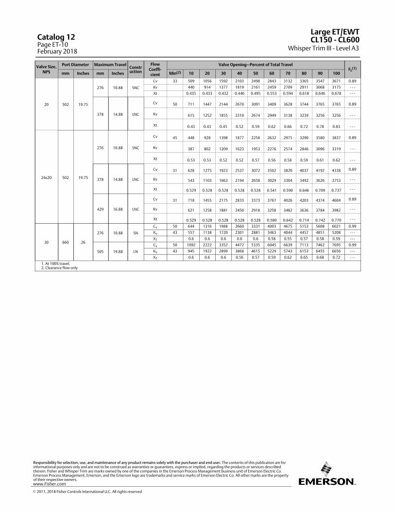
Valve Size,NPS
Port Diameter Maximum TravelConstruction
FlowCoeffi‐cient
Valve Opening—Percent of Total TravelFL
(1)
mm Inches mm Inches Min(2) 10 20 30 40 50 60 70 80 90 100
20 502 19.75
276 10.88 SNC
Cv 33 509 1056 1592 2103 2498 2843 3132 3365 3547 3671 0.89
Kv 440 914 1377 1819 2161 2459 2709 2911 3068 3175 - - -
Xt 0.435 0.433 0.432 0.446 0.495 0.553 0.594 0.618 0.646 0.678 - - -
378 14.88 LNC
Cv 50 711 1447 2144 2670 3091 3409 3628 3744 3765 3765 0.89
Kv 615 1252 1855 2310 2674 2949 3138 3239 3256 3256 - - -
Xt 0.43 0.43 0.45 0.52 0.59 0.62 0.66 0.72 0.78 0.83 - - -
24x20 502 19.75
276 10.88 SNC
Cv 45 448 928 1398 1877 2258 2632 2975 3290 3580 3837 0.89
Kv 387 802 1209 1623 1953 2276 2574 2846 3096 3319 - - -
Xt 0.53 0.53 0.52 0.52 0.57 0.56 0.58 0.59 0.61 0.62 - - -
378 14.88 LNC
Cv 31 628 1275 1923 2537 3072 3502 3820 4037 4192 4338 0.89
Kv 543 1103 1663 2194 2658 3029 3304 3492 3626 3753 - - -
Xt 0.529 0.528 0.528 0.528 0.528 0.541 0.590 0.646 0.709 0.737 - - -
429 16.88 LNC
Cv 31 718 1455 2175 2833 3373 3767 4026 4203 4374 4604 0.89
Kv 621 1258 1881 2450 2918 3258 3482 3636 3784 3982 - - -
Xt 0.529 0.528 0.528 0.528 0.528 0.580 0.642 0.714 0.742 0.770 - - -
30 660 26
276 10.88 SN
Cv 50 644 1316 1988 2660 3331 4003 4675 5153 5608 6021 0.99
Kv 43 557 1138 1720 2301 2881 3463 4044 4457 4851 5208 - - -
XT 0.6 0.6 0.6 0.6 0.6 0.58 0.55 0.57 0.58 0.59 - - -
505 19.88 LN
Cv 50 1092 2222 3352 4472 5335 6045 6639 7113 7462 7695 0.99
Kv 43 945 1922 2899 3868 4615 5229 5743 6153 6455 6656 - - -
XT 0.6 0.6 0.6 0.56 0.57 0.59 0.62 0.65 0.68 0.72 - - -
1. At 100% travel.2. Clearance flow only
Large ET/EWT
Whisper Trim III - Level A3CL150 ‐ CL600Catalog 12
Page ET-10February 2018
� 2011, 2018 Fisher Controls International LLC. All rights reserved
www.Fisher.com
Responsibility for selection, use, and maintenance of any product remains solely with the purchaser and end user. The contents of this publication are forinformational purposes only and are not to be construed as warranties or guarantees, express or implied, regarding the products or services describedtherein. Fisher and Whisper Trim are marks owned by one of the companies in the Emerson Process Management business unit of Emerson Electric Co.Emerson Process Management, Emerson, and the Emerson logo are trademarks and service marks of Emerson Electric Co. All other marks are the propertyof their respective owners.
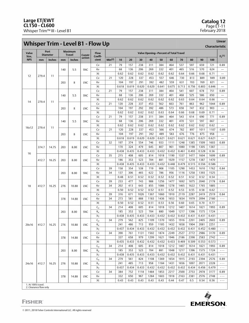
11
Whisper Trim - Level B1 - Flow UpLinear
Characteristic
ValveSize,NPS
PortDiameter
MaximumTravel Constr
uction
FlowCoeffi‐cient
Valve Opening—Percent of Total TravelFL
(1)
mm Inches mm Inches Min(2) 10 20 30 40 50 60 70 80 90 100
12 279.4 11
140 5.5 SNC
Cv 21 79 157 238 311 384 464 537 597 659 721 0.89
Kv 68 136 206 269 332 401 465 516 570 624 ---
Xt 0.62 0.62 0.62 0.62 0.62 0.62 0.64 0.66 0.68 0.71 ---
203 8 LNC
Cv 21 120 228 337 453 557 646 730 813 889 949 0.89
Kv 104 197 291 392 482 559 631 703 769 821 ---
Xt 0.618 0.619 0.620 0.620 0.641 0.675 0.713 0.756 0.803 0.846 ---
14 279.4 11
140 5.5 SNC
Cv 21 79 157 238 311 384 464 541 607 678 751 0.89
Kv 68 136 206 269 332 401 468 525 586 650 ---
Xt 0.62 0.62 0.62 0.62 0.62 0.62 0.63 0.64 0.64 0.66 ---
203 8 LNC
Cv 21 120 228 337 453 562 663 761 863 962 1044 0.89
Kv 104 197 292 392 486 573 658 747 832 903 ---
Xt 0.62 0.62 0.62 0.62 0.63 0.64 0.66 0.68 0.69 0.71 ---
16x12 279.4 11
140 5.5 SNC
Cv 21 79 157 238 311 384 464 543 614 690 771 0.89
Kv 68 136 206 269 332 401 470 531 597 667 ---
Xt 0.62 0.62 0.62 0.62 0.62 0.62 0.62 0.62 0.62 0.62 ---
203 8 LNC
Cv 21 120 228 337 453 566 674 782 897 1011 1107 0.89
Kv 104 197 291 392 489 583 676 776 875 958 ---
Xt 0.618 0.619 0.620 0.620 0.621 0.621 0.621 0.621 0.621 0.621 ---
16
374.7 14.75 203 8.00 LNC
Cv 32 197 374 554 746 933 1111 1248 1385 1509 1603 0.89
Kv 170 324 479 645 807 961 1080 1198 1305 1387 - - -
Xt 0.438 0.435 0.433 0.433 0.432 0.432 0.461 0.493 0.528 0.56 - - -
412.7 16.25 203 8.00 LNC
Cv 35 215 408 605 814 1018 1190 1337 1477 1604 1699 0.89
Kv 186 353 523 704 881 1029 1157 1278 1387 1470 - - -
Xt 0.438 0.435 0.433 0.433 0.432 0.448 0.479 0.515 0.556 0.586 - - -
18 412.7 16.25
203 8.00 SNC
Cv 39 158 354 538 719 908 1105 1290 1453 1610 1762 0.84
Kv 34 137 306 465 622 786 956 1116 1258 1393 1525 ‐ ‐ ‐
Xt 0.48 0.51 0.52 0.52 0.52 0.52 0.51 0.52 0.52 0.54 ‐ ‐ ‐
276 10.88 LNC
Cv 39 233 477 743 988 1256 1477 1692 1875 2040 2178 0.84
Kv 34 202 413 643 855 1086 1278 1465 1622 1765 1885 ‐ ‐ ‐
Xt 0.50 0.52 0.52 0.52 0.51 0.52 0.53 0.55 0.58 0.62 ‐ ‐ ‐
378 14.88 LNC
Cv 39 316 671 1026 1367 1660 1910 2119 2287 2419 2519 0.84
Kv 34 273 581 888 1183 1436 1653 1834 1979 2094 2180 ‐ ‐ ‐
Xt 0.50 0.52 0.52 0.51 0.53 0.56 0.60 0.65 0.70 0.77 ‐ ‐ ‐
20x16 412.7 16.25
203 8.00 SNC
Cv 34 214 408 605 814 1018 1212 1407 1614 1821 1993 0.89
Kv 185 353 523 704 880 1049 1217 1396 1575 1724 - - -
XT 0.438 0.435 0.433 0.433 0.432 0.432 0.432 0.431 0.431 0.431 - - -
276 10.88 LNC
Cv 34 279 562 825 1109 1370 1655 1916 2201 2405 2603 0.89
Kv 241 486 713 959 1185 1432 1658 1904 2081 2251 - - -
XT 0.437 0.434 0.433 0.432 0.432 0.432 0.432 0.431 0.452 0.480 - - -
378 14.88 LNC
Cv 34 390 761 1131 1502 1874 2249 2527 2772 2986 3170 0.89
Kv 337 658 979 1299 1621 1946 2186 2398 2583 2742 - - -
Xt 0.435 0.433 0.432 0.432 0.432 0.433 0.469 0.509 0.553 0.573 - - -
24x16 412.7 16.25
203 8.00 SNC
Cv 34 214 408 605 814 1018 1212 1407 1614 1821 1993 0.89
Kv 185 353 523 704 881 1048 1217 1396 1575 1724 - - -
XT 0.438 0.435 0.433 0.433 0.432 0.432 0.432 0.431 0.431 0.431 - - -
276 10.88 LNC
Cv 34 279 561 824 1108 1369 1654 1915 2193 2394 2576 0.89
Kv 241 485 713 958 1184 1431 1656 1897 2071 2228 - - -
XT 0.437 0.434 0.433 0.432 0.432 0.432 0.432 0.434 0.456 0.479 - - -
378 14.88 LNC
Cv 34 384 752 1118 1484 1853 2217 2500 2753 2978 3177 0.89
Kv 332 650 967 1284 1603 1918 2163 2381 2576 2748 - - -
Xt 0.43 0.43 0.43 0.43 0.43 0.44 0.47 0.5 0.54 0.56 - - -
1. At 100% travel.2. Clearance flow only
Large ET/EWT
Whisper Trim™ III - Level B1CL150 ‐ CL600
Catalog 12Page ET-11
February 2018
� 2011, 2018 Fisher Controls International LLC. All rights reserved
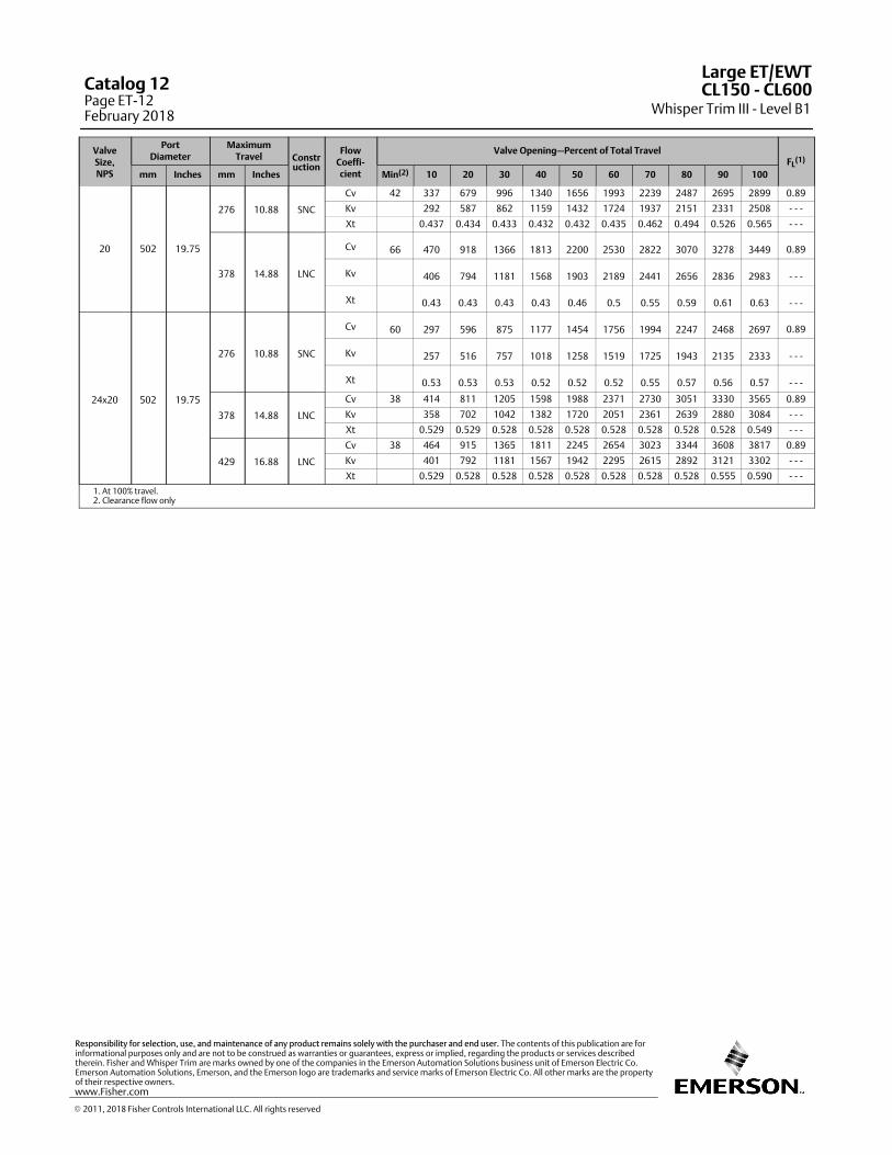
ValveSize,NPS
PortDiameter
MaximumTravel Constr
uction
FlowCoeffi‐cient
Valve Opening—Percent of Total TravelFL
(1)
mm Inches mm Inches Min(2) 10 20 30 40 50 60 70 80 90 100
20 502 19.75
276 10.88 SNC
Cv 42 337 679 996 1340 1656 1993 2239 2487 2695 2899 0.89
Kv 292 587 862 1159 1432 1724 1937 2151 2331 2508 - - -
Xt 0.437 0.434 0.433 0.432 0.432 0.435 0.462 0.494 0.526 0.565 - - -
378 14.88 LNC
Cv 66 470 918 1366 1813 2200 2530 2822 3070 3278 3449 0.89
Kv 406 794 1181 1568 1903 2189 2441 2656 2836 2983 - - -
Xt 0.43 0.43 0.43 0.43 0.46 0.5 0.55 0.59 0.61 0.63 - - -
24x20 502 19.75
276 10.88 SNC
Cv 60 297 596 875 1177 1454 1756 1994 2247 2468 2697 0.89
Kv 257 516 757 1018 1258 1519 1725 1943 2135 2333 - - -
Xt 0.53 0.53 0.53 0.52 0.52 0.52 0.55 0.57 0.56 0.57 - - -
378 14.88 LNC
Cv 38 414 811 1205 1598 1988 2371 2730 3051 3330 3565 0.89
Kv 358 702 1042 1382 1720 2051 2361 2639 2880 3084 - - -
Xt 0.529 0.529 0.528 0.528 0.528 0.528 0.528 0.528 0.528 0.549 - - -
429 16.88 LNC
Cv 38 464 915 1365 1811 2245 2654 3023 3344 3608 3817 0.89
Kv 401 792 1181 1567 1942 2295 2615 2892 3121 3302 - - -
Xt 0.529 0.528 0.528 0.528 0.528 0.528 0.528 0.528 0.555 0.590 - - -
1. At 100% travel.2. Clearance flow only
Large ET/EWT
Whisper Trim III - Level B1CL150 ‐ CL600Catalog 12
Page ET-12February 2018
� 2011, 2018 Fisher Controls International LLC. All rights reserved
www.Fisher.com
Responsibility for selection, use, and maintenance of any product remains solely with the purchaser and end user. The contents of this publication are forinformational purposes only and are not to be construed as warranties or guarantees, express or implied, regarding the products or services describedtherein. Fisher and Whisper Trim are marks owned by one of the companies in the Emerson Automation Solutions business unit of Emerson Electric Co.Emerson Automation Solutions, Emerson, and the Emerson logo are trademarks and service marks of Emerson Electric Co. All other marks are the propertyof their respective owners.
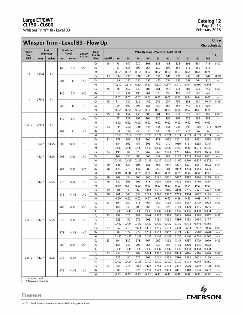
13
Whisper Trim - Level B3 - Flow UpLinear
Characteristic
ValveSize,NPS
PortDiameter
MaximumTravel Constr
uction
FlowCoeffi‐cient
Valve Opening—Percent of Total TravelFL
(1)
mm Inches mm Inches Min(2) 10 20 30 40 50 60 70 80 90 100
12 279.4 11
140 5.5 SNC
Cv 15 78 152 230 305 381 458 528 595 654 716 0.89
Kv 67 131 199 264 330 396 457 515 566 619 ---
Xt 0.62 0.62 0.62 0.62 0.62 0.62 0.63 0.66 0.68 0.71 ---
203 8 LNC
Cv 15 114 222 336 445 550 641 728 808 883 942 0.89
Kv 99 192 291 385 476 554 630 699 764 815 ---
Xt 0.617 0.619 0.62 0.62 0.639 0.674 0.712 0.754 0.799 0.841 ---
14 279.4 11
140 5.5 SNC
Cv 15 78 152 230 305 381 458 531 605 673 745 0.89
Kv 67 131 199 264 330 396 459 523 582 645 ---
Xt 0.62 0.62 0.62 0.62 0.62 0.62 0.62 0.64 0.64 0.66 ---
203 8 LNC
Cv 15 114 222 336 445 555 657 759 858 954 1045 0.89
Kv 99 192 291 385 480 568 657 742 826 904 ---
Xt 0.62 0.62 0.62 0.62 0.63 0.64 0.66 0.67 0.69 0.71 ---
16x12 279.4 11
140 5.5 SNC
Cv 15 78 152 230 305 381 458 533 612 685 765 0.89
Kv 67 131 199 264 330 396 461 529 593 662 ---
Xt 0.62 0.62 0.62 0.62 0.62 0.62 0.62 0.62 0.62 0.62 ---
203 8 LNC
Cv 15 114 222 336 445 558 668 780 891 1002 1114 0.89
Kv 98 192 291 385 483 578 675 771 867 963 ---
Xt 0.617 0.619 0.620 0.620 0.621 0.621 0.621 0.621 0.621 0.621 ---
16
374.7 14.75 203 8.00 LNC
Cv 21 178 349 528 700 878 1052 1201 1331 1451 1555 0.89
Kv 154 302 457 606 759 910 1039 1151 1255 1345 - - -
Xt 0.439 0.435 0.433 0.433 0.432 0.432 0.452 0.48 0.511 0.543 - - -
412.7 16.25 203 8.00 LNC
Cv 24 195 382 578 767 962 1143 1291 1426 1549 1654 0.89
Kv 169 330 500 663 832 989 1117 1233 1340 1431 - - -
Xt 0.439 0.435 0.433 0.433 0.432 0.439 0.469 0.501 0.537 0.575 - - -
18 412.7 16.25
203 8.00 SNC
Cv 19 145 322 506 681 866 1041 1227 1391 1551 1692 0.84
Kv 16 125 278 437 589 750 901 1062 1204 1343 1464 ‐ ‐ ‐
Xt 0.48 0.50 0.52 0.52 0.52 0.52 0.51 0.52 0.52 0.53 ‐ ‐ ‐
276 10.88 LNC
Cv 19 208 454 700 945 1191 1421 1627 1812 1976 2119 0.84
Kv 16 180 393 606 818 1030 1230 1408 1568 1710 1834 ‐ ‐ ‐
Xt 0.49 0.51 0.52 0.52 0.52 0.52 0.52 0.54 0.57 0.60 ‐ ‐ ‐
378 14.88 LNC
Cv 19 301 633 965 1303 1595 1846 2060 2235 2371 2477 0.84
Kv 16 261 548 835 1128 1380 1597 1783 1934 2052 2143 ‐ ‐ ‐
Xt 0.50 0.52 0.52 0.51 0.52 0.55 0.59 0.63 0.68 0.74 ‐ ‐ ‐
20x16 412.7 16.25
203 8.00 SNC
Cv 23 194 382 578 767 962 1152 1345 1537 1729 1922 0.89
Kv 168 330 500 663 832 996 1164 1329 1495 1663 - - -
XT 0.439 0.435 0.433 0.433 0.432 0.432 0.432 0.432 0.431 0.431 - - -
276 10.88 LNC
Cv 23 258 520 782 1044 1307 1570 1833 2096 2328 2517 0.89
Kv 223 450 676 903 1131 1358 1586 1813 2014 2177 - - -
XT 0.437 0.434 0.433 0.432 0.432 0.432 0.432 0.431 0.443 0.468 - - -
378 14.88 LNC
Cv 23 357 719 1074 1431 1795 2153 2438 2683 2902 3086 0.89
Kv 309 622 929 1238 1553 1862 2109 2321 2510 2670 - - -
Xt 0.436 0.433 0.432 0.432 0.432 0.432 0.456 0.493 0.534 0.566 - - -
24x16 412.7 16.25
203 8.00 SNC
Cv 23 194 382 578 767 962 1152 1345 1537 1729 1910 0.89
Kv 168 330 500 663 832 996 1163 1330 1496 1652 - - -
XT 0.439 0.435 0.433 0.433 0.432 0.432 0.432 0.431 0.431 0.431 - - -
276 10.88 LNC
Cv 23 258 520 782 1044 1307 1570 1833 2096 2316 2496 0.89
Kv 223 450 676 903 1131 1358 1586 1813 2003 2159 - - -
XT 0.437 0.434 0.433 0.432 0.432 0.432 0.432 0.431 0.447 0.469 - - -
378 14.88 LNC
Cv 23 354 714 1067 1422 1784 2139 2417 2670 2899 3100 0.89
Kv 306 618 923 1230 1543 1850 2091 2310 2508 2682 - - -
Xt 0.43 0.43 0.43 0.43 0.43 0.43 0.46 0.49 0.53 0.56 - - -
1. At 100% travel.2. Clearance flow only
Large ET/EWT
Whisper Trim™ III - Level B3CL150 ‐ CL600
Catalog 12Page ET-13
February 2018
� 2011, 2018 Fisher Controls International LLC. All rights reserved
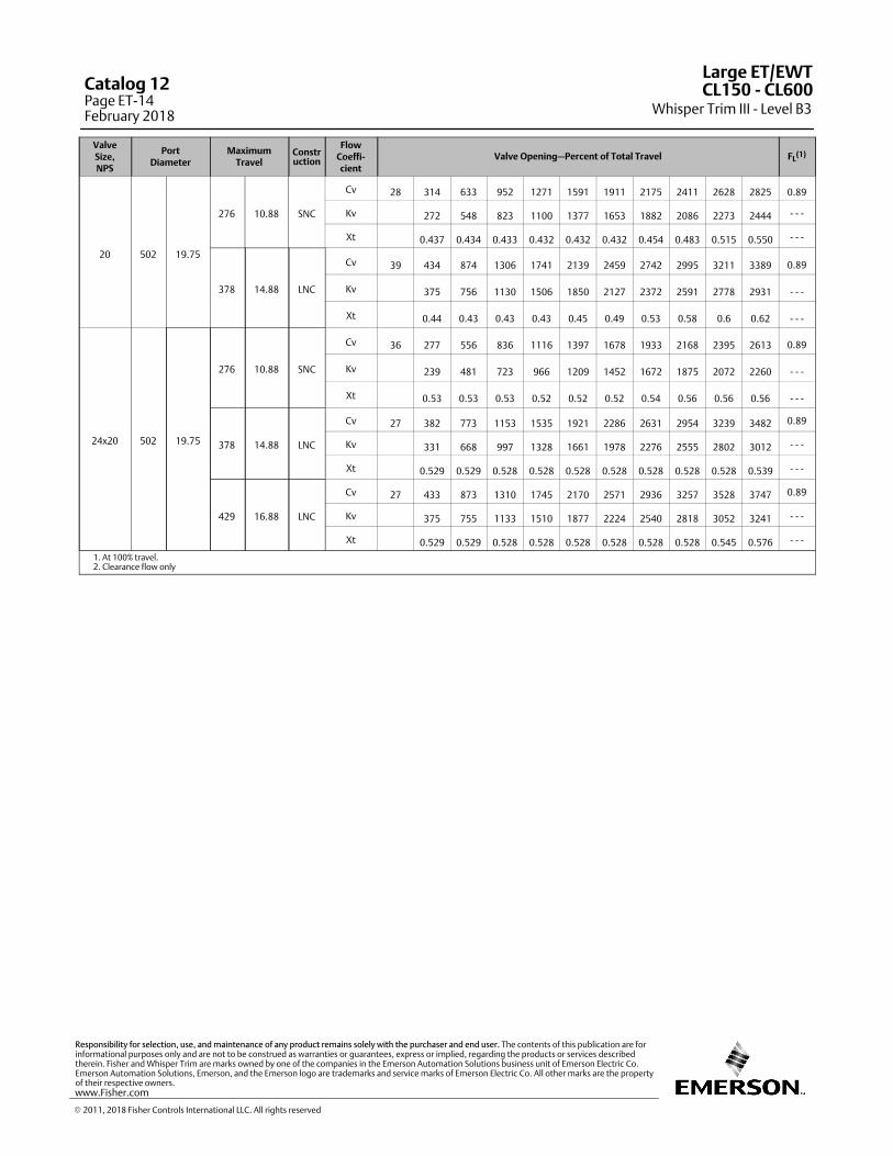
ValveSize,NPS
PortDiameter
MaximumTravel
Construction
FlowCoeffi‐cient
Valve Opening—Percent of Total Travel FL(1)
20 502 19.75
276 10.88 SNC
Cv 28 314 633 952 1271 1591 1911 2175 2411 2628 2825 0.89
Kv 272 548 823 1100 1377 1653 1882 2086 2273 2444 - - -
Xt 0.437 0.434 0.433 0.432 0.432 0.432 0.454 0.483 0.515 0.550 - - -
378 14.88 LNC
Cv 39 434 874 1306 1741 2139 2459 2742 2995 3211 3389 0.89
Kv 375 756 1130 1506 1850 2127 2372 2591 2778 2931 - - -
Xt 0.44 0.43 0.43 0.43 0.45 0.49 0.53 0.58 0.6 0.62 - - -
24x20 502 19.75
276 10.88 SNC
Cv 36 277 556 836 1116 1397 1678 1933 2168 2395 2613 0.89
Kv 239 481 723 966 1209 1452 1672 1875 2072 2260 - - -
Xt 0.53 0.53 0.53 0.52 0.52 0.52 0.54 0.56 0.56 0.56 - - -
378 14.88 LNC
Cv 27 382 773 1153 1535 1921 2286 2631 2954 3239 3482 0.89
Kv 331 668 997 1328 1661 1978 2276 2555 2802 3012 - - -
Xt 0.529 0.529 0.528 0.528 0.528 0.528 0.528 0.528 0.528 0.539 - - -
429 16.88 LNC
Cv 27 433 873 1310 1745 2170 2571 2936 3257 3528 3747 0.89
Kv 375 755 1133 1510 1877 2224 2540 2818 3052 3241 - - -
Xt 0.529 0.529 0.528 0.528 0.528 0.528 0.528 0.528 0.545 0.576 - - -
1. At 100% travel.2. Clearance flow only
Large ET/EWT
Whisper Trim III - Level B3CL150 ‐ CL600Catalog 12
Page ET-14February 2018
� 2011, 2018 Fisher Controls International LLC. All rights reserved
www.Fisher.com
Responsibility for selection, use, and maintenance of any product remains solely with the purchaser and end user. The contents of this publication are forinformational purposes only and are not to be construed as warranties or guarantees, express or implied, regarding the products or services describedtherein. Fisher and Whisper Trim are marks owned by one of the companies in the Emerson Automation Solutions business unit of Emerson Electric Co.Emerson Automation Solutions, Emerson, and the Emerson logo are trademarks and service marks of Emerson Electric Co. All other marks are the propertyof their respective owners.

15
Whisper Trim - Level C1 - Flow UpLinear
Characteristic
ValveSize,NPS
PortDiameter
MaximumTravel Constr
uction
FlowCoeffi‐cient
Valve Opening—Percent of Total TravelFL
(1)
mm Inches mm Inches Min(2) 10 20 30 40 50 60 70 80 90 100
12 279.4 11
140 5.5 SNC
Cv 18 61 103 159 206 253 308 351 404 454 497 0.89
Kv 53 89 138 178 219 266 304 349 393 430 ---
Xt 0.61 0.62 0.62 0.62 0.62 0.62 0.62 0.62 0.62 0.62 ---
203 8 LNC
Cv 18 84 153 222 293 368 444 512 571 628 688 0.89
Kv 73 132 192 253 318 384 443 494 543 595 ---
Xt 0.616 0.619 0.620 0.620 0.620 0.621 0.627 0.647 0.670 0.695 ---
14 279.4 11
140 5.5 SNC
Cv 18 61 103 159 206 253 308 351 404 454 498 0.89
Kv 53 89 138 178 219 266 304 349 393 430 ---
Xt 0.61 0.62 0.62 0.62 0.62 0.62 0.62 0.62 0.62 0.62 ---
203 8 LNC
Cv 18 84 153 222 293 368 444 514 578 642 711 0.89
Kv 73 132 192 253 318 384 444 500 556 615 ---
Xt 0.62 0.62 0.62 0.62 0.62 0.62 0.62 0.63 0.64 0.65 ---
16x12 279.4 11
140 5.5 SNC
Cv 18 61 103 159 206 253 308 351 404 454 498 0.89
Kv 53 89 138 178 219 266 304 349 393 431 ---
Xt 0.61 0.62 0.62 0.62 0.62 0.62 0.62 0.62 0.62 0.62 ---
203 8 LNC
Cv 18 84 153 222 293 368 444 515 583 652 727 0.89
Kv 73 133 192 253 318 384 445 504 564 629 ---
Xt 0.616 0.619 0.620 0.620 0.620 0.621 0.621 0.621 0.621 0.621 ---
16
374.7 14.75 203 8.00 LNC
Cv 27 131 244 351 460 577 696 811 919 1026 1132 0.89
Kv 113 211 304 398 499 602 702 795 887 979 - - -
Xt 0.442 0.436 0.434 0.433 0.433 0.432 0.432 0.432 0.431 0.439 - - -
412.7 16.25 203 8.00 LNC
Cv 30 146 272 392 513 645 778 906 1027 1138 1238 0.89
Kv 126 235 339 444 558 673 784 888 984 1071 - - -
Xt 0.442 0.436 0.434 0.433 0.433 0.432 0.432 0.432 0.438 0.458 - - -
18 412.7 16.25
203 8.00 SNC
Cv 31 99 219 344 468 583 695 812 937 1062 1180 0.84
Kv 27 86 189 297 405 504 602 703 811 919 1021 ‐ ‐ ‐
Xt 0.48 0.49 0.51 0.51 0.52 0.52 0.52 0.52 0.52 0.52 ‐ ‐ ‐
276 10.88 LNC
Cv 31 153 313 469 626 792 959 1125 1281 1423 1560 0.84
Kv 27 132 270 406 542 685 830 973 1109 1231 1350 ‐ ‐ ‐
Xt 0.48 0.50 0.51 0.52 0.52 0.52 0.52 0.51 0.52 0.52 ‐ ‐ ‐
378 14.88 LNC
Cv 31 210 434 656 875 1093 1310 1504 1682 1846 1992 0.84
Kv 27 182 375 568 757 946 1134 1302 1456 1597 1724 ‐ ‐ ‐
Xt 0.49 0.51 0.52 0.52 0.52 0.51 0.52 0.53 0.55 0.57 ‐ ‐ ‐
20x16 412.7 16.25
203 8.00 SNC
Cv 30 146 272 392 513 645 777 906 1027 1147 1276 0.89
Kv 126 235 339 444 558 672 784 888 992 1104 - - -
XT 0.442 0.436 0.434 0.433 0.433 0.432 0.432 0.432 0.431 0.431 - - -
276 10.88 LNC
Cv 30 180 355 534 712 880 1046 1216 1394 1573 1746 0.89
Kv 156 307 462 616 761 905 1052 1206 1361 1510 - - -
XT 0.440 0.435 0.433 0.433 0.432 0.432 0.432 0.432 0.431 0.431 - - -
378 14.88 LNC
Cv 30 247 481 717 956 1195 1435 1675 1913 2150 2347 0.89
Kv 214 416 620 827 1034 1241 1448 1655 1860 2030 - - -
Xt 0.437 0.434 0.433 0.432 0.432 0.432 0.432 0.431 0.431 0.445 - - -
24x16 412.7 16.25
203 8.00 SNC
Cv 21 116 235 343 458 573 681 800 911 1022 1140 0.89
Kv 100 203 297 396 496 589 692 788 884 986 - - -
XT 0.43 0.43 0.43 0.43 0.43 0.43 0.43 0.43 0.43 0.43 - - -
276 10.88 LNC
Cv 21 161 311 470 623 774 934 1085 1238 1397 1547 0.89
Kv 139 269 407 539 670 808 939 1071 1208 1338 - - -
XT 0.43 0.43 0.43 0.43 0.43 0.43 0.43 0.43 0.43 0.43 - - -
378 14.88 LNC
Cv 21 220 430 639 848 1061 1275 1489 1700 1909 2118 0.89
Kv 190 372 553 734 918 1103 1288 1471 1651 1832 - - -
Xt 0.43 0.43 0.43 0.43 0.43 0.43 0.43 0.43 0.43 0.43 - - -
1. At 100% travel.2. Clearance flow only
Large ET/EWT
Whisper Trim™ III - Level C1CL150 ‐ CL600
Catalog 12Page ET-15
February 2018
� 2011, 2018 Fisher Controls International LLC. All rights reserved
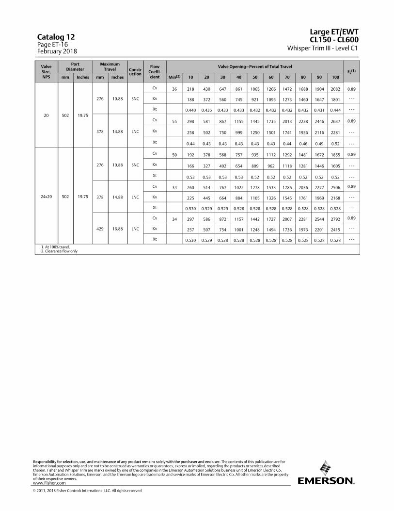
ValveSize,NPS
PortDiameter
MaximumTravel Constr
uction
FlowCoeffi‐cient
Valve Opening—Percent of Total TravelFL
(1)
mm Inches mm Inches Min(2) 10 20 30 40 50 60 70 80 90 100
20 502 19.75
276 10.88 SNC
Cv 36 218 430 647 861 1065 1266 1472 1688 1904 2082 0.89
Kv 188 372 560 745 921 1095 1273 1460 1647 1801 - - -
Xt 0.440 0.435 0.433 0.433 0.432 0.432 0.432 0.432 0.431 0.444 - - -
378 14.88 LNC
Cv 55 298 581 867 1155 1445 1735 2013 2238 2446 2637 0.89
Kv 258 502 750 999 1250 1501 1741 1936 2116 2281 - - -
Xt 0.44 0.43 0.43 0.43 0.43 0.43 0.44 0.46 0.49 0.52 - - -
24x20 502 19.75
276 10.88 SNC
Cv 50 192 378 568 757 935 1112 1292 1481 1672 1855 0.89
Kv 166 327 492 654 809 962 1118 1281 1446 1605 - - -
Xt 0.53 0.53 0.53 0.53 0.52 0.52 0.52 0.52 0.52 0.52 - - -
378 14.88 LNC
Cv 34 260 514 767 1022 1278 1533 1786 2036 2277 2506 0.89
Kv 225 445 664 884 1105 1326 1545 1761 1969 2168 - - -
Xt 0.530 0.529 0.529 0.528 0.528 0.528 0.528 0.528 0.528 0.528 - - -
429 16.88 LNC
Cv 34 297 586 872 1157 1442 1727 2007 2281 2544 2792 0.89
Kv 257 507 754 1001 1248 1494 1736 1973 2201 2415 - - -
Xt 0.530 0.529 0.528 0.528 0.528 0.528 0.528 0.528 0.528 0.528 - - -
1. At 100% travel.2. Clearance flow only
Large ET/EWT
Whisper Trim III - Level C1CL150 ‐ CL600Catalog 12
Page ET-16February 2018
� 2011, 2018 Fisher Controls International LLC. All rights reserved
www.Fisher.com
Responsibility for selection, use, and maintenance of any product remains solely with the purchaser and end user. The contents of this publication are forinformational purposes only and are not to be construed as warranties or guarantees, express or implied, regarding the products or services describedtherein. Fisher and Whisper Trim are marks owned by one of the companies in the Emerson Automation Solutions business unit of Emerson Electric Co.Emerson Automation Solutions, Emerson, and the Emerson logo are trademarks and service marks of Emerson Electric Co. All other marks are the propertyof their respective owners.
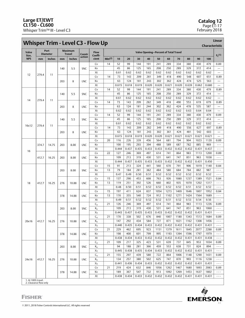
17
Whisper Trim - Level C3 - Flow UpLinear
Characteristic
ValveSize,NPS
PortDiameter
MaximumTravel Constr
uction
FlowCoeffi‐cient
Valve Opening—Percent of Total TravelFL
(1)
mm Inches mm Inches Min(2) 10 20 30 40 50 60 70 80 90 100
12 279.4 11
140 5.5 SNC
Cv 14 52 99 144 191 241 289 334 380 430 479 0.89
Kv 45 86 125 165 208 250 289 329 372 414 ---
Xt 0.61 0.62 0.62 0.62 0.62 0.62 0.62 0.62 0.62 0.62 ---
203 8 LNC
Cv 14 73 143 209 281 349 418 490 548 607 651 0.89
Kv 63 124 181 243 302 362 424 474 525 563 ---
Xt 0.615 0.618 0.619 0.620 0.620 0.621 0.620 0.639 0.662 0.680 ---
14 279.4 11
140 5.5 SNC
Cv 14 52 99 144 191 241 289 334 380 430 479 0.89
Kv 45 86 125 165 208 250 289 329 372 414 ---
Xt 0.61 0.62 0.62 0.62 0.62 0.62 0.62 0.62 0.62 0.62 ---
203 8 LNC
Cv 14 73 143 209 282 349 418 490 553 619 679 0.89
Kv 63 124 181 244 302 362 424 478 535 587 ---
Xt 0.62 0.62 0.62 0.62 0.62 0.62 0.62 0.63 0.64 0.64 ---
16x12 279.4 11
140 5.5 SNC
Cv 14 52 99 144 191 241 289 334 380 430 479 0.89
Kv 45 86 125 165 208 250 289 329 372 414 ---
Xt 0.61 0.62 0.62 0.62 0.62 0.62 0.62 0.62 0.62 0.62 ---
203 8 LNC
Cv 14 73 143 209 282 349 418 490 556 627 697 0.89
Kv 63 124 181 243 302 361 424 481 542 603 ---
Xt 0.615 0.618 0.619 0.620 0.620 0.621 0.621 0.621 0.621 0.621 ---
16
374.7 14.75 203 8.00 LNC
Cv 20 116 226 339 456 564 681 794 904 1023 1120 0.89
Kv 100 195 293 394 488 589 687 782 885 969 - - -
Xt 0.444 0.437 0.435 0.433 0.433 0.432 0.432 0.432 0.431 0.437 - - -
412.7 16.25 203 8.00 LNC
Cv 22 127 246 369 497 614 741 864 983 1113 1200 0.89
Kv 109 213 319 430 531 641 747 851 963 1038 - - -
Xt 0.444 0.437 0.435 0.433 0.433 0.432 0.432 0.432 0.431 0.450 - - -
18 412.7 16.25
203 8.00 SNC
Cv 15 91 213 324 441 560 670 791 906 1019 1140 0.84
Kv 13 79 184 281 382 484 580 684 784 882 987 ‐ ‐ ‐
Xt 0.47 0.49 0.50 0.51 0.52 0.52 0.52 0.52 0.52 0.52 ‐ ‐ ‐
276 10.88 LNC
Cv 15 137 290 453 608 763 926 1080 1237 1389 1521 0.84
Kv 13 119 251 392 526 660 802 935 1070 1202 1317 ‐ ‐ ‐
Xt 0.48 0.50 0.51 0.52 0.52 0.52 0.52 0.51 0.52 0.52 ‐ ‐ ‐
378 14.88 LNC
Cv 15 197 411 624 837 1054 1273 1469 1646 1807 1952 0.84
Kv 13 170 355 540 724 912 1102 1271 1424 1564 1689 ‐ ‐ ‐
Xt 0.49 0.51 0.52 0.52 0.52 0.51 0.52 0.53 0.54 0.56 ‐ ‐ ‐
20x16 412.7 16.25
203 8.00 SNC
Cv 21 126 246 369 497 614 741 864 983 1113 1226 0.89
Kv 109 213 319 430 531 641 747 851 963 1060 - - -
XT 0.443 0.437 0.435 0.433 0.433 0.432 0.432 0.432 0.431 0.431 - - -
276 10.88 LNC
Cv 21 170 338 502 676 840 1007 1180 1343 1513 1684 0.89
Kv 147 292 434 584 727 871 1021 1162 1308 1456 - - -
XT 0.440 0.435 0.434 0.433 0.432 0.432 0.432 0.432 0.431 0.431 - - -
378 14.88 LNC
Cv 21 229 462 695 923 1151 1379 1611 1845 2077 2288 0.89
Kv 198 400 601 799 995 1193 1394 1596 1797 1979 - - -
Xt 0.438 0.434 0.433 0.432 0.432 0.432 0.432 0.431 0.431 0.438 - - -
24x16 412.7 16.25
203 8.00 SNC
Cv 21 109 217 325 423 531 639 737 845 953 1034 0.89
Kv 94 188 281 366 459 553 638 731 824 894 - - -
XT 0.445 0.438 0.435 0.434 0.433 0.432 0.432 0.432 0.431 0.431 - - -
276 10.88 LNC
Cv 21 155 297 439 580 722 864 1006 1148 1290 1431 0.89
Kv 134 257 380 502 625 747 870 993 1116 1238 - - -
XT 0.441 0.436 0.434 0.433 0.432 0.432 0.432 0.432 0.431 0.431 - - -
378 14.88 LNC
Cv 21 219 424 632 846 1056 1262 1467 1680 1893 2083 0.89
Kv 189 367 547 732 913 1092 1269 1453 1637 1802 - - -
Xt 0.438 0.434 0.433 0.432 0.432 0.432 0.432 0.431 0.431 0.431 - - -
1. At 100% travel.2. Clearance flow only
Large ET/EWT
Whisper Trim™ III - Level C3CL150 ‐ CL600
Catalog 12Page ET-17
February 2018
� 2011, 2018 Fisher Controls International LLC. All rights reserved
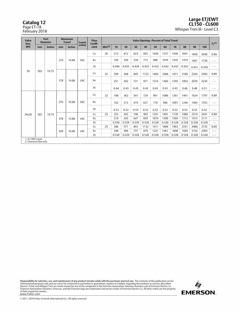
ValveSize,NPS
PortDiameter
MaximumTravel Constr
uction
FlowCoeffi‐cient
Valve Opening—Percent of Total TravelFL
(1)
mm Inches mm Inches Min(2) 10 20 30 40 50 60 70 80 90 100
20 502 19.75
276 10.88 SNC
Cv 26 213 412 623 825 1026 1237 1436 1641 1850 2030 0.89
Kv 184 356 539 713 888 1070 1242 1419 1601 1756 - - -
Xt 0.440 0.435 0.434 0.433 0.432 0.432 0.432 0.432 0.431 0.439 - - -
378 14.88 LNC
Cv 35 290 568 845 1122 1404 1688 1971 2189 2393 2583 0.89
Kv 251 492 731 971 1214 1460 1705 1893 2070 2234 - - -
Xt 0.44 0.43 0.43 0.43 0.43 0.43 0.43 0.46 0.48 0.51 - - -
24x20 502 19.75
276 10.88 SNC
Cv 32 188 362 547 724 901 1086 1261 1441 1624 1797 0.89
Kv 162 313 474 627 779 940 1091 1246 1405 1555 - - -
Xt 0.53 0.53 0.53 0.53 0.52 0.52 0.52 0.52 0.52 0.52 - - -
378 14.88 LNC
Cv 25 253 503 748 993 1241 1491 1739 1980 2214 2441 0.89
Kv 219 435 647 859 1074 1290 1504 1713 1915 2111 - - -
Xt 0.530 0.529 0.529 0.528 0.528 0.528 0.528 0.528 0.528 0.528 - - -
429 16.88 LNC
Cv 25 286 571 853 1132 1411 1689 1963 2231 2488 2733 0.89
Kv 248 494 737 979 1221 1461 1698 1929 2152 2364 - - -
Xt 0.530 0.529 0.528 0.528 0.528 0.528 0.528 0.528 0.528 0.528 - - -
1. At 100% travel.2. Clearance flow only
Large ET/EWT
Whisper Trim III - Level C3CL150 ‐ CL600Catalog 12
Page ET-18February 2018
� 2011, 2018 Fisher Controls International LLC. All rights reserved
www.Fisher.com
Responsibility for selection, use, and maintenance of any product remains solely with the purchaser and end user. The contents of this publication are forinformational purposes only and are not to be construed as warranties or guarantees, express or implied, regarding the products or services describedtherein. Fisher and Whisper Trim are marks owned by one of the companies in the Emerson Automation Solutions business unit of Emerson Electric Co.Emerson Automation Solutions, Emerson, and the Emerson logo are trademarks and service marks of Emerson Electric Co. All other marks are the propertyof their respective owners.
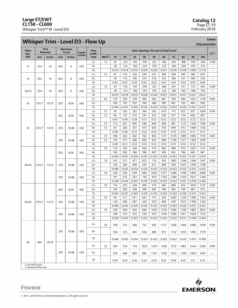
19
Whisper Trim - Level D3 - Flow UpLinear
Characteristic
ValveSize,NPS
PortDiameter
MaximumTravel Constr
uction
FlowCoeffi‐cient
Valve Opening—Percent of Total TravelFL
(1)
mm Inches mm Inches Min(2) 10 20 30 40 50 60 70 80 90 100
12 254 10 203 8 LNC
Cv 12 67 132 192 259 321 384 445 496 549 594 0.89
Kv 58 114 166 224 278 332 385 429 475 514 ---
Xt 0.615 0.618 0.619 0.620 0.620 0.621 0.636 0.658 0.685 0.710 ---
14 254 10 203 8 LNC
Cv 12 67 132 192 259 321 384 449 505 566 622
Kv 58 114 166 224 278 332 388 437 489 538 ---
Xt 0.62 0.62 0.62 0.62 0.62 0.62 0.63 0.64 0.65 0.66 ---
16x12 254 10 203 8 LNC
Cv 12 67 132 192 259 321 384 451 511 577 641 0.89
Kv 58 114 166 224 278 332 390 442 499 554 ---
Xt 0.615 0.618 0.619 0.620 0.620 0.621 0.621 0.621 0.621 0.621 ---
16 374.7 14.75 203 8.00 LNC
Cv 20 116 226 339 456 564 681 794 904 1023 1120 0.89
Kv 100 195 293 394 488 589 687 782 885 969 - - -
Xt 0.444 0.437 0.435 0.433 0.433 0.432 0.432 0.432 0.431 0.437 - - -
18 374.7 14.75
203 8.00 SNC
Cv 15 76 182 292 394 503 610 713 825 927 1036 0.84
Kv 13 66 157 253 341 435 528 617 714 802 897 ‐ ‐ ‐
Xt 0.47 0.49 0.50 0.51 0.52 0.52 0.52 0.52 0.52 0.52 ‐ ‐ ‐
276 10.88 LNC
Cv 14 112 261 405 546 696 839 981 1125 1248 1366 0.84
Kv 12 97 226 351 473 602 726 849 973 1080 1182 ‐ ‐ ‐
Xt 0.48 0.50 0.51 0.52 0.52 0.52 0.52 0.52 0.51 0.51 ‐ ‐ ‐
378 14.88 LNC
Cv 14 168 363 562 762 963 1151 1318 1469 1605 1725 0.84
Kv 12 145 315 486 660 833 996 1140 1271 1389 1493 ‐ ‐ ‐
Xt 0.49 0.51 0.52 0.52 0.52 0.52 0.51 0.52 0.52 0.53 ‐ ‐ ‐
20x16 374.7 14.75
203 8.00 SNC
Cv 19 116 235 344 458 574 682 800 912 1023 1141 0.89
Kv 100 203 298 396 497 590 692 789 885 987 - - -
Xt 0.443 0.437 0.434 0.433 0.433 0.432 0.432 0.432 0.431 0.431 - - -
276 10.88 LNC
Cv 19 161 311 471 623 776 935 1085 1240 1398 1547 0.89
Kv 139 269 408 539 671 809 939 1073 1209 1338 - - -
Xt 0.440 0.435 0.434 0.433 0.432 0.432 0.432 0.432 0.431 0.431 - - -
378 14.88 LNC
Cv 19 220 430 639 849 1063 1277 1490 1700 1893 2046 0.89
Kv 191 372 553 734 919 1105 1289 1470 1637 1769 - - -
Xt 0.438 0.434 0.433 0.432 0.432 0.432 0.432 0.431 0.439 0.463 - - -
24x16 374.7 14.75
203 8.00 SNC
Cv 19 116 235 344 458 574 682 800 912 1023 1127 0.89
Kv 100 203 298 396 497 590 692 789 885 975 - - -
Xt 0.443 0.437 0.434 0.433 0.433 0.432 0.432 0.432 0.431 0.431 - - -
276 10.88 LNC
Cv 19 161 311 471 623 775 935 1085 1239 1398 1532 0.89
Kv 139 269 407 539 670 809 939 1072 1209 1325 - - -
Xt 0.440 0.435 0.434 0.433 0.432 0.432 0.432 0.432 0.431 0.431 - - -
378 14.88 LNC
Cv 19 220 430 639 849 1062 1276 1490 1700 1882 2027 0.89
Kv 190 372 553 734 919 1104 1289 1471 1628 1753 - - -
Xt 0.438 0.434 0.433 0.432 0.432 0.432 0.432 0.431 0.444 0.464 - - -
20 464 18.25
276 10.88 SNC
Cv 24 194 375 568 752 935 1127 1309 1495 1686 1826 0.89
Kv 168 325 491 650 809 975 1132 1293 1458 1579 - - -
Xt 0.440 0.435 0.434 0.433 0.432 0.432 0.432 0.432 0.431 0.450 - - -
378 14.88 LNC
Cv 32 264 518 770 1023 1279 1538 1772 1965 2144 2309 0.89
Kv 229 448 666 885 1107 1330 1533 1700 1854 1997 - - -
Xt 0.44 0.43 0.43 0.43 0.43 0.43 0.44 0.47 0.5 0.53 - - -
1. At 100% travel.2. Clearance flow only
Large ET/EWT
Whisper Trim™ III - Level D3CL150 ‐ CL600
Catalog 12Page ET-19
February 2018
� 2011, 2018 Fisher Controls International LLC. All rights reserved
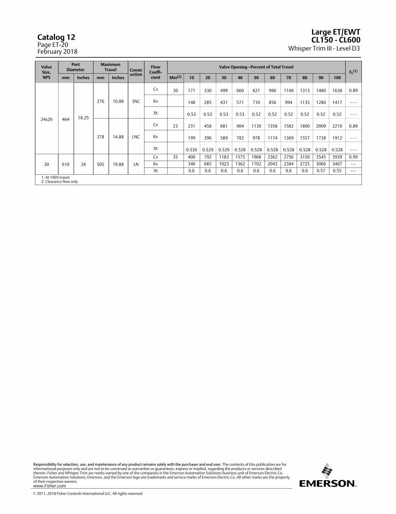
ValveSize,NPS
PortDiameter
MaximumTravel Constr
uction
FlowCoeffi‐cient
Valve Opening—Percent of Total TravelFL
(1)
mm Inches mm Inches Min(2) 10 20 30 40 50 60 70 80 90 100
24x20 464 18.25
276 10.88 SNC
Cv 30 171 330 499 660 821 990 1149 1313 1480 1638 0.89
Kv 148 285 431 571 710 856 994 1135 1280 1417 - - -
Xt 0.53 0.53 0.53 0.53 0.52 0.52 0.52 0.52 0.52 0.52 - - -
378 14.88 LNC
Cv 23 231 458 681 904 1130 1358 1582 1800 2009 2210 0.89
Kv 199 396 589 782 978 1174 1369 1557 1738 1912 - - -
Xt 0.530 0.529 0.529 0.528 0.528 0.528 0.528 0.528 0.528 0.528 - - -
30 610 24 505 19.88 LN
Cv 35 400 792 1183 1575 1968 2362 2756 3150 3545 3939 0.99
Kv 346 685 1023 1362 1702 2043 2384 2725 3066 3407 - - -
Xt 0.6 0.6 0.6 0.6 0.6 0.6 0.6 0.6 0.57 0.55 - - -
1. At 100% travel.2. Clearance flow only
Large ET/EWT
Whisper Trim III - Level D3CL150 ‐ CL600Catalog 12
Page ET-20February 2018
� 2011, 2018 Fisher Controls International LLC. All rights reserved
www.Fisher.com
Responsibility for selection, use, and maintenance of any product remains solely with the purchaser and end user. The contents of this publication are forinformational purposes only and are not to be construed as warranties or guarantees, express or implied, regarding the products or services describedtherein. Fisher and Whisper Trim are marks owned by one of the companies in the Emerson Automation Solutions business unit of Emerson Electric Co.Emerson Automation Solutions, Emerson, and the Emerson logo are trademarks and service marks of Emerson Electric Co. All other marks are the propertyof their respective owners.
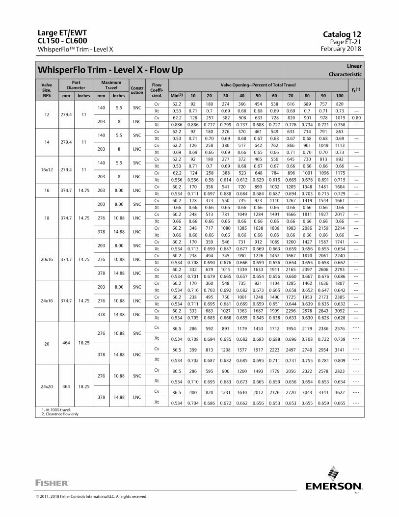
21
WhisperFlo Trim - Level X - Flow UpLinear
Characteristic
ValveSize,NPS
PortDiameter
MaximumTravel Constr
uction
FlowCoeffi‐cient
Valve Opening—Percent of Total TravelFL
(1)
mm Inches mm Inches Min(2) 10 20 30 40 50 60 70 80 90 100
12 279.4 11
140 5.5 SNCCv 62.2 92 180 274 366 454 538 616 689 757 820
Xt 0.53 0.71 0.7 0.69 0.68 0.68 0.69 0.69 0.7 0.71 0.73 ---
203 8 LNCCv 62.2 128 257 382 508 633 728 820 901 978 1019 0.89
Xt 0.886 0.886 0.777 0.799 0.737 0.688 0.727 0.776 0.734 0.721 0.758 ---
14 279.4 11
140 5.5 SNCCv 62.2 92 180 276 370 461 549 633 714 791 863
Xt 0.53 0.71 0.70 0.69 0.68 0.67 0.68 0.67 0.68 0.68 0.69 ---
203 8 LNCCv 62.2 126 258 386 517 642 762 866 961 1049 1113
Xt 0.69 0.69 0.66 0.69 0.66 0.65 0.66 0.71 0.70 0.70 0.73 ---
16x12 279.4 11
140 5.5 SNCCv 62.2 92 180 277 372 465 556 645 730 813 892
Xt 0.53 0.71 0.7 0.69 0.68 0.67 0.67 0.66 0.66 0.66 0.66 ---
203 8 LNCCv 62.2 124 258 388 523 648 784 896 1001 1096 1175
Xt 0.556 0.556 0.58 0.614 0.612 0.629 0.615 0.665 0.678 0.691 0.719 ---
16 374.7 14.75 203 8.00 LNCCv 60.2 170 358 541 720 890 1052 1205 1348 1481 1604 ---
Xt 0.534 0.711 0.697 0.688 0.684 0.684 0.687 0.694 0.703 0.715 0.729 ---
18 374.7 14.75
203 8.00 SNCCv 60.2 178 373 550 745 923 1110 1267 1419 1544 1661 ---
Xt 0.66 0.66 0.66 0.66 0.66 0.66 0.66 0.66 0.66 0.66 0.66 ---
276 10.88 LNCCv 60.2 248 513 781 1049 1284 1491 1666 1811 1927 2017 ---
Xt 0.66 0.66 0.66 0.66 0.66 0.66 0.66 0.66 0.66 0.66 0.66 ---
378 14.88 LNCCv 60.2 348 717 1080 1385 1638 1838 1983 2086 2159 2214 ---
Xt 0.66 0.66 0.66 0.66 0.66 0.66 0.66 0.66 0.66 0.66 0.66 ---
20x16 374.7 14.75
203 8.00 SNCCv 60.2 170 359 546 731 912 1089 1260 1427 1587 1741 ---
Xt 0.534 0.713 0.699 0.687 0.677 0.669 0.663 0.659 0.656 0.655 0.654 ---
276 10.88 LNCCv 60.2 238 494 745 990 1226 1452 1667 1870 2061 2240 ---
Xt 0.534 0.708 0.690 0.676 0.666 0.659 0.656 0.654 0.655 0.658 0.662 ---
378 14.88 LNCCv 60.2 332 679 1015 1339 1633 1911 2165 2397 2606 2793 ---
Xt 0.534 0.701 0.679 0.665 0.657 0.654 0.656 0.660 0.667 0.676 0.686 ---
24x16 374.7 14.75
203 8.00 SNCCv 60.2 170 360 548 735 921 1104 1285 1462 1636 1807 ---
Xt 0.534 0.716 0.703 0.692 0.682 0.673 0.665 0.658 0.652 0.647 0.642 ---
276 10.88 LNCCv 60.2 238 495 750 1001 1248 1490 1725 1953 2173 2385 ---
Xt 0.534 0.711 0.695 0.681 0.669 0.659 0.651 0.644 0.639 0.635 0.632 ---
378 14.88 LNCCv 60.2 333 683 1027 1363 1687 1999 2296 2578 2843 3092 ---
Xt 0.534 0.705 0.685 0.668 0.655 0.645 0.638 0.633 0.630 0.628 0.628 ---
20 464 18.25
276 10.88 SNC
Cv 86.5 286 592 891 1179 1453 1712 1954 2179 2386 2576 - - -
Xt 0.534 0.708 0.694 0.685 0.682 0.683 0.688 0.696 0.708 0.722 0.738 - - -
378 14.88 LNC
Cv 86.5 399 813 1208 1577 1917 2223 2497 2740 2954 3141 - - -
Xt 0.534 0.702 0.687 0.682 0.685 0.695 0.711 0.731 0.755 0.781 0.809 - - -
24x20 464 18.25
276 10.88 SNC
Cv 86.5 286 595 900 1200 1493 1779 2056 2322 2578 2823 - - -
Xt 0.534 0.710 0.695 0.683 0.673 0.665 0.659 0.656 0.654 0.653 0.654 - - -
378 14.88 LNC
Cv 86.5 400 820 1231 1630 2012 2376 2720 3043 3343 3622 - - -
Xt 0.534 0.704 0.686 0.672 0.662 0.656 0.653 0.653 0.655 0.659 0.665 - - -
1. At 100% travel.2. Clearance flow only
Large ET/EWT
WhisperFlo™ Trim - Level XCL150 ‐ CL600
Catalog 12Page ET-21
February 2018
� 2011, 2018 Fisher Controls International LLC. All rights reserved
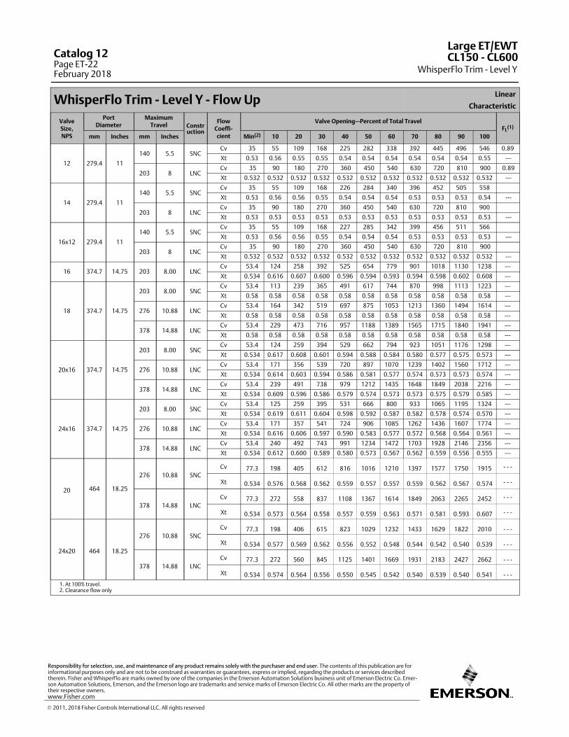
WhisperFlo Trim - Level Y - Flow UpLinear
Characteristic
ValveSize,NPS
PortDiameter
MaximumTravel Constr
uction
FlowCoeffi‐cient
Valve Opening—Percent of Total TravelFL
(1)
mm Inches mm Inches Min(2) 10 20 30 40 50 60 70 80 90 100
12 279.4 11
140 5.5 SNCCv 35 55 109 168 225 282 338 392 445 496 546 0.89
Xt 0.53 0.56 0.55 0.55 0.54 0.54 0.54 0.54 0.54 0.54 0.55 ---
203 8 LNCCv 35 90 180 270 360 450 540 630 720 810 900 0.89
Xt 0.532 0.532 0.532 0.532 0.532 0.532 0.532 0.532 0.532 0.532 0.532 ---
14 279.4 11
140 5.5 SNCCv 35 55 109 168 226 284 340 396 452 505 558
Xt 0.53 0.56 0.56 0.55 0.54 0.54 0.54 0.53 0.53 0.53 0.54 ---
203 8 LNCCv 35 90 180 270 360 450 540 630 720 810 900
Xt 0.53 0.53 0.53 0.53 0.53 0.53 0.53 0.53 0.53 0.53 0.53 ---
16x12 279.4 11
140 5.5 SNCCv 35 55 109 168 227 285 342 399 456 511 566
Xt 0.53 0.56 0.56 0.55 0.54 0.54 0.54 0.53 0.53 0.53 0.53 ---
203 8 LNCCv 35 90 180 270 360 450 540 630 720 810 900
Xt 0.532 0.532 0.532 0.532 0.532 0.532 0.532 0.532 0.532 0.532 0.532 ---
16 374.7 14.75 203 8.00 LNCCv 53.4 124 258 392 525 654 779 901 1018 1130 1238 ---
Xt 0.534 0.616 0.607 0.600 0.596 0.594 0.593 0.594 0.598 0.602 0.608 ---
18 374.7 14.75
203 8.00 SNCCv 53.4 113 239 365 491 617 744 870 998 1113 1223 ---
Xt 0.58 0.58 0.58 0.58 0.58 0.58 0.58 0.58 0.58 0.58 0.58 ---
276 10.88 LNCCv 53.4 164 342 519 697 875 1053 1213 1360 1494 1614 ---
Xt 0.58 0.58 0.58 0.58 0.58 0.58 0.58 0.58 0.58 0.58 0.58 ---
378 14.88 LNCCv 53.4 229 473 716 957 1188 1389 1565 1715 1840 1941 ---
Xt 0.58 0.58 0.58 0.58 0.58 0.58 0.58 0.58 0.58 0.58 0.58 ---
20x16 374.7 14.75
203 8.00 SNCCv 53.4 124 259 394 529 662 794 923 1051 1176 1298 ---
Xt 0.534 0.617 0.608 0.601 0.594 0.588 0.584 0.580 0.577 0.575 0.573 ---
276 10.88 LNCCv 53.4 171 356 539 720 897 1070 1239 1402 1560 1712 ---
Xt 0.534 0.614 0.603 0.594 0.586 0.581 0.577 0.574 0.573 0.573 0.574 ---
378 14.88 LNCCv 53.4 239 491 738 979 1212 1435 1648 1849 2038 2216 ---
Xt 0.534 0.609 0.596 0.586 0.579 0.574 0.573 0.573 0.575 0.579 0.585 ---
24x16 374.7 14.75
203 8.00 SNCCv 53.4 125 259 395 531 666 800 933 1065 1195 1324 ---
Xt 0.534 0.619 0.611 0.604 0.598 0.592 0.587 0.582 0.578 0.574 0.570 ---
276 10.88 LNCCv 53.4 171 357 541 724 906 1085 1262 1436 1607 1774 ---
Xt 0.534 0.616 0.606 0.597 0.590 0.583 0.577 0.572 0.568 0.564 0.561 ---
378 14.88 LNCCv 53.4 240 492 743 991 1234 1472 1703 1928 2146 2356 ---
Xt 0.534 0.612 0.600 0.589 0.580 0.573 0.567 0.562 0.559 0.556 0.555 ---
20 464 18.25
276 10.88 SNC
Cv 77.3 198 405 612 816 1016 1210 1397 1577 1750 1915 - - -
Xt 0.534 0.576 0.568 0.562 0.559 0.557 0.557 0.559 0.562 0.567 0.574 - - -
378 14.88 LNC
Cv 77.3 272 558 837 1108 1367 1614 1849 2063 2265 2452 - - -
Xt 0.534 0.573 0.564 0.558 0.557 0.559 0.563 0.571 0.581 0.593 0.607 - - -
24x20 464 18.25
276 10.88 SNC
Cv 77.3 198 406 615 823 1029 1232 1433 1629 1822 2010 - - -
Xt 0.534 0.577 0.569 0.562 0.556 0.552 0.548 0.544 0.542 0.540 0.539 - - -
378 14.88 LNC
Cv 77.3 272 560 845 1125 1401 1669 1931 2183 2427 2662 - - -
Xt 0.534 0.574 0.564 0.556 0.550 0.545 0.542 0.540 0.539 0.540 0.541 - - -
1. At 100% travel.2. Clearance flow only
Large ET/EWT
WhisperFlo Trim - Level YCL150 ‐ CL600Catalog 12
Page ET-22February 2018
� 2011, 2018 Fisher Controls International LLC. All rights reserved
www.Fisher.com
Responsibility for selection, use, and maintenance of any product remains solely with the purchaser and end user. The contents of this publication are forinformational purposes only and are not to be construed as warranties or guarantees, express or implied, regarding the products or services describedtherein. Fisher and WhisperFlo are marks owned by one of the companies in the Emerson Automation Solutions business unit of Emerson Electric Co. Emerson Automation Solutions, Emerson, and the Emerson logo are trademarks and service marks of Emerson Electric Co. All other marks are the property oftheir respective owners.
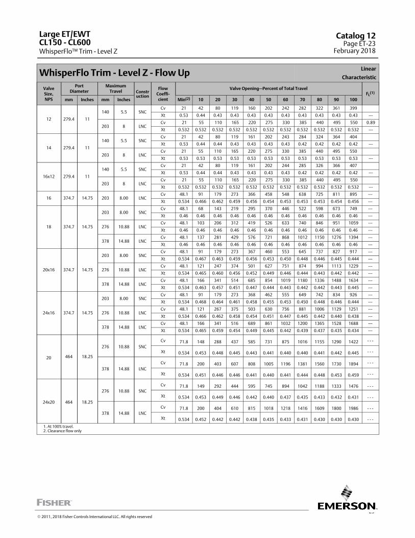
23
WhisperFlo Trim - Level Z - Flow UpLinear
Characteristic
ValveSize,NPS
PortDiameter
MaximumTravel Constr
uction
FlowCoeffi‐cient
Valve Opening—Percent of Total TravelFL
(1)
mm Inches mm Inches Min(2) 10 20 30 40 50 60 70 80 90 100
12 279.4 11
140 5.5 SNCCv 21 42 80 119 160 202 242 282 322 361 399
Xt 0.53 0.44 0.43 0.43 0.43 0.43 0.43 0.43 0.43 0.43 0.43 ---
203 8 LNCCv 21 55 110 165 220 275 330 385 440 495 550 0.89
Xt 0.532 0.532 0.532 0.532 0.532 0.532 0.532 0.532 0.532 0.532 0.532 ---
14 279.4 11
140 5.5 SNCCv 21 42 80 119 161 202 243 284 324 364 404
Xt 0.53 0.44 0.44 0.43 0.43 0.43 0.43 0.42 0.42 0.42 0.42 ---
203 8 LNCCv 21 55 110 165 220 275 330 385 440 495 550
Xt 0.53 0.53 0.53 0.53 0.53 0.53 0.53 0.53 0.53 0.53 0.53 ---
16x12 279.4 11
140 5.5 SNCCv 21 42 80 119 161 202 244 285 326 366 407
Xt 0.53 0.44 0.44 0.43 0.43 0.43 0.43 0.42 0.42 0.42 0.42 ---
203 8 LNCCv 21 55 110 165 220 275 330 385 440 495 550
Xt 0.532 0.532 0.532 0.532 0.532 0.532 0.532 0.532 0.532 0.532 0.532 ---
16 374.7 14.75 203 8.00 LNCCv 48.1 91 179 273 366 458 548 638 725 811 895 ---
Xt 0.534 0.466 0.462 0.459 0.456 0.454 0.453 0.453 0.453 0.454 0.456 ---
18 374.7 14.75
203 8.00 SNCCv 48.1 68 143 219 295 370 446 522 598 673 749 ---
Xt 0.46 0.46 0.46 0.46 0.46 0.46 0.46 0.46 0.46 0.46 0.46 ---
276 10.88 LNCCv 48.1 103 206 312 419 526 633 740 846 951 1059 ---
Xt 0.46 0.46 0.46 0.46 0.46 0.46 0.46 0.46 0.46 0.46 0.46 ---
378 14.88 LNCCv 48.1 137 281 429 576 721 868 1012 1150 1276 1394 ---
Xt 0.46 0.46 0.46 0.46 0.46 0.46 0.46 0.46 0.46 0.46 0.46 ---
20x16 374.7 14.75
203 8.00 SNCCv 48.1 91 179 273 367 460 553 645 737 827 917 ---
Xt 0.534 0.467 0.463 0.459 0.456 0.453 0.450 0.448 0.446 0.445 0.444 ---
276 10.88 LNCCv 48.1 121 247 374 501 627 751 874 994 1113 1229 ---
Xt 0.534 0.465 0.460 0.456 0.452 0.449 0.446 0.444 0.443 0.442 0.442 ---
378 14.88 LNCCv 48.1 166 341 514 685 854 1019 1180 1336 1488 1634 ---
Xt 0.534 0.463 0.457 0.451 0.447 0.444 0.443 0.442 0.442 0.443 0.445 ---
24x16 374.7 14.75
203 8.00 SNCCv 48.1 91 179 273 368 462 555 649 742 834 926 ---
Xt 0.534 0.468 0.464 0.461 0.458 0.455 0.453 0.450 0.448 0.446 0.444 ---
276 10.88 LNCCv 48.1 121 267 375 503 630 756 881 1006 1129 1251 ---
Xt 0.534 0.466 0.462 0.458 0.454 0.451 0.447 0.445 0.442 0.440 0.438 ---
378 14.88 LNCCv 48.1 166 341 516 689 861 1032 1200 1365 1528 1688 ---
Xt 0.534 0.465 0.459 0.454 0.449 0.445 0.442 0.439 0.437 0.435 0.434 ---
20 464 18.25
276 10.88 SNC
Cv 71.8 148 288 437 585 731 875 1016 1155 1290 1422 - - -
Xt 0.534 0.453 0.448 0.445 0.443 0.441 0.440 0.440 0.441 0.442 0.445 - - -
378 14.88 LNC
Cv 71.8 200 403 607 808 1005 1196 1381 1560 1730 1894 - - -
Xt 0.534 0.451 0.446 0.446 0.441 0.440 0.441 0.444 0.448 0.453 0.459 - - -
24x20 464 18.25
276 10.88 SNC
Cv 71.8 149 292 444 595 745 894 1042 1188 1333 1476 - - -
Xt 0.534 0.453 0.449 0.446 0.442 0.440 0.437 0.435 0.433 0.432 0.431 - - -
378 14.88 LNC
Cv 71.8 200 404 610 815 1018 1218 1416 1609 1800 1986 - - -
Xt 0.534 0.452 0.442 0.442 0.438 0.435 0.433 0.431 0.430 0.430 0.430 - - -
1. At 100% travel.2. Clearance flow only
Large ET/EWT
WhisperFlo™ Trim - Level ZCL150 ‐ CL600
Catalog 12Page ET-23
February 2018
� 2011, 2018 Fisher Controls International LLC. All rights reserved
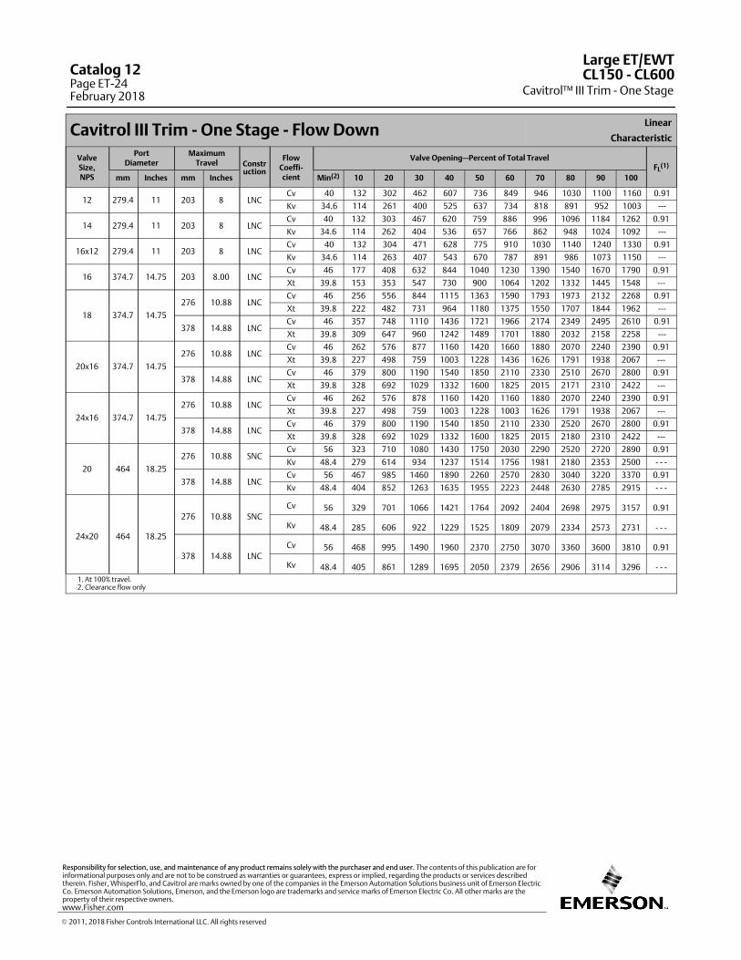
Cavitrol III Trim - One Stage - Flow DownLinear
Characteristic
ValveSize,NPS
PortDiameter
MaximumTravel Constr
uction
FlowCoeffi‐cient
Valve Opening—Percent of Total TravelFL
(1)
mm Inches mm Inches Min(2) 10 20 30 40 50 60 70 80 90 100
12 279.4 11 203 8 LNCCv 40 132 302 462 607 736 849 946 1030 1100 1160 0.91
Kv 34.6 114 261 400 525 637 734 818 891 952 1003 ---
14 279.4 11 203 8 LNCCv 40 132 303 467 620 759 886 996 1096 1184 1262 0.91
Kv 34.6 114 262 404 536 657 766 862 948 1024 1092 ---
16x12 279.4 11 203 8 LNCCv 40 132 304 471 628 775 910 1030 1140 1240 1330 0.91
Kv 34.6 114 263 407 543 670 787 891 986 1073 1150 ---
16 374.7 14.75 203 8.00 LNCCv 46 177 408 632 844 1040 1230 1390 1540 1670 1790 0.91
Xt 39.8 153 353 547 730 900 1064 1202 1332 1445 1548 ---
18 374.7 14.75
276 10.88 LNCCv 46 256 556 844 1115 1363 1590 1793 1973 2132 2268 0.91
Xt 39.8 222 482 731 964 1180 1375 1550 1707 1844 1962 ---
378 14.88 LNCCv 46 357 748 1110 1436 1721 1966 2174 2349 2495 2610 0.91
Xt 39.8 309 647 960 1242 1489 1701 1880 2032 2158 2258 ---
20x16 374.7 14.75
276 10.88 LNCCv 46 262 576 877 1160 1420 1660 1880 2070 2240 2390 0.91
Xt 39.8 227 498 759 1003 1228 1436 1626 1791 1938 2067 ---
378 14.88 LNCCv 46 379 800 1190 1540 1850 2110 2330 2510 2670 2800 0.91
Xt 39.8 328 692 1029 1332 1600 1825 2015 2171 2310 2422 ---
24x16 374.7 14.75
276 10.88 LNCCv 46 262 576 878 1160 1420 1160 1880 2070 2240 2390 0.91
Xt 39.8 227 498 759 1003 1228 1003 1626 1791 1938 2067 ---
378 14.88 LNCCv 46 379 800 1190 1540 1850 2110 2330 2520 2670 2800 0.91
Xt 39.8 328 692 1029 1332 1600 1825 2015 2180 2310 2422 ---
20 464 18.25
276 10.88 SNCCv 56 323 710 1080 1430 1750 2030 2290 2520 2720 2890 0.91
Kv 48.4 279 614 934 1237 1514 1756 1981 2180 2353 2500 - - -
378 14.88 LNCCv 56 467 985 1460 1890 2260 2570 2830 3040 3220 3370 0.91
Kv 48.4 404 852 1263 1635 1955 2223 2448 2630 2785 2915 - - -
24x20 464 18.25
276 10.88 SNC
Cv 56 329 701 1066 1421 1764 2092 2404 2698 2975 3157 0.91
Kv 48.4 285 606 922 1229 1525 1809 2079 2334 2573 2731 - - -
378 14.88 LNC
Cv 56 468 995 1490 1960 2370 2750 3070 3360 3600 3810 0.91
Kv 48.4 405 861 1289 1695 2050 2379 2656 2906 3114 3296 - - -
1. At 100% travel.2. Clearance flow only
Large ET/EWT
Cavitrol™ III Trim - One StageCL150 ‐ CL600Catalog 12
Page ET-24February 2018
� 2011, 2018 Fisher Controls International LLC. All rights reserved
www.Fisher.com
Responsibility for selection, use, and maintenance of any product remains solely with the purchaser and end user. The contents of this publication are forinformational purposes only and are not to be construed as warranties or guarantees, express or implied, regarding the products or services describedtherein. Fisher, WhisperFlo, and Cavitrol are marks owned by one of the companies in the Emerson Automation Solutions business unit of Emerson ElectricCo. Emerson Automation Solutions, Emerson, and the Emerson logo are trademarks and service marks of Emerson Electric Co. All other marks are theproperty of their respective owners.
25
The Fisher Large ET‐C/EWT-C flow coefficients are identical to the FisherLarge ET/EWT and ED/EWD. However, some port diameters are notapplicable to the Fisher Large ET-C/EWT-C. For additional information, refer to Bulletin 51.1:ET/ED (Large).
Large ET-C/EWT-CCL150-CL600
Catalog 12Page ET-25
February 2018
� 2015, 2018 Fisher Controls International LLC. All rights reserved
The Fisher ET‐C valve has flow coefficients identical to the NPS 3 through 8Fisher ED valve with full‐sized port. Please refer to those coefficients. Foradditional ET‐C valve information, refer to Bulletin 51.1:easy‐e� Cryogenic.
� 1995, 2018 Fisher Controls International LLC. All rights reserved
www.Fisher.com
Responsibility for selection, use, and maintenance of any product remains solely with the purchaser and end user. The contents of this publication are forinformational purposes only and are not to be construed as warranties or guarantees, express or implied, regarding the products or services describedtherein. Fisher and easy-e are marks owned by one of the companies in the Emerson Automation Solutions business unit of Emerson Electric Co. EmersonAutomation Solutions, Emerson, and the Emerson logo are trademarks and service marks of Emerson Electric Co. All other marks are the property of theirrespective owners.
ET-CCatalog 12Page ET-26February 2018
27
The Fisher ETR valve has flow coefficients identical to the NPS 1 to 4,CL125‐600 ED valve. Please refer to those coefficients. For additional ETRvalve body information, refer to Bulletin 51.1:ET.
ETR Catalog 12Page ET-27
February 2018
� 1995, 2015 Fisher Controls International LLC. All rights reserved
This page is intentionally left blank.
ETRCatalog 12Page ET-28February 2018
� 2018 Fisher Controls International LLC. All rights reserved
www.Fisher.com
Responsibility for selection, use, and maintenance of any product remains solely with the purchaser and end user. The contents of this publication are forinformational purposes only and are not to be construed as warranties or guarantees, express or implied, regarding the products or services describedtherein. Fisher and easy-e are marks owned by one of the companies in the Emerson Automation Solutions business unit of Emerson Electric Co. EmersonAutomation Solutions, Emerson, and the Emerson logo are trademarks and service marks of Emerson Electric Co. All other marks are the property of theirrespective owners.
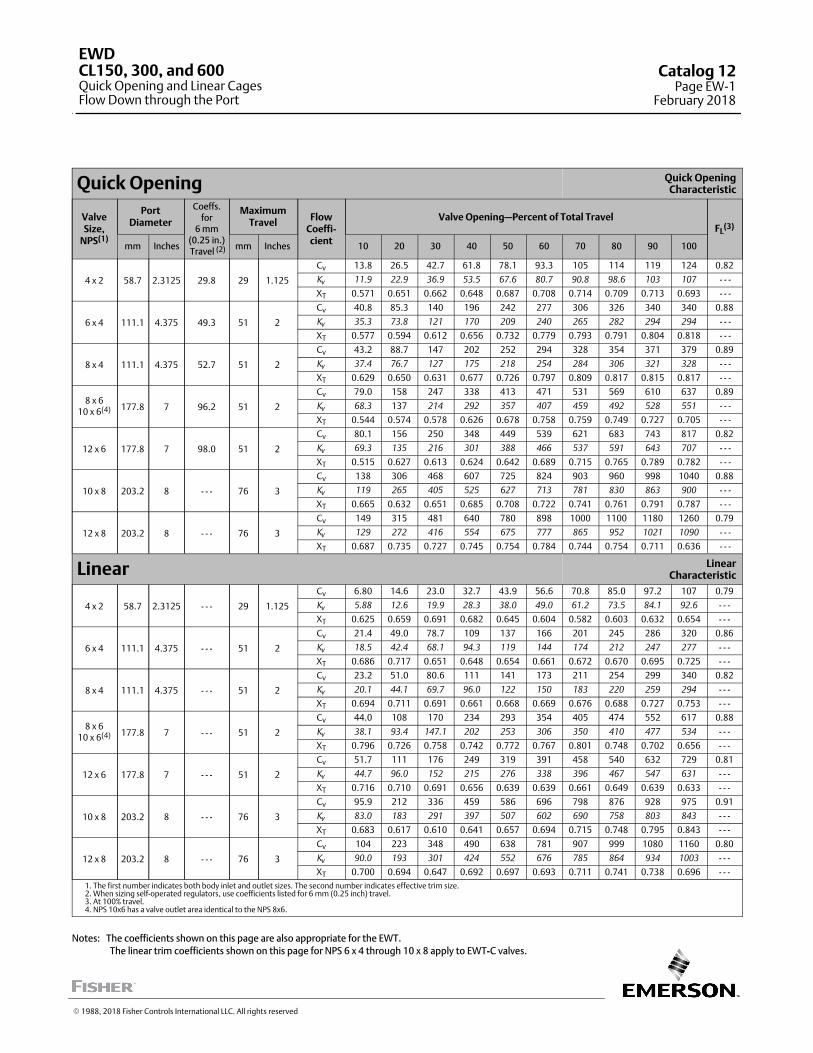
Quick Opening Quick OpeningCharacteristic
ValveSize,
NPS(1)
PortDiameter
Coeffs.for
6 mm(0.25 in.) Travel (2)
MaximumTravel
FlowCoeffi-cient
Valve Opening—Percent of Total TravelFL
(3)
mm Inches mm Inches 10 20 30 40 50 60 70 80 90 100
4 x 2 58.7 2.3125 29.8 29 1.125
Cv 13.8 26.5 42.7 61.8 78.1 93.3 105 114 119 124 0.82
Kv 11.9 22.9 36.9 53.5 67.6 80.7 90.8 98.6 103 107 - - -
XT 0.571 0.651 0.662 0.648 0.687 0.708 0.714 0.709 0.713 0.693 - - -
6 x 4 111.1 4.375 49.3 51 2
Cv 40.8 85.3 140 196 242 277 306 326 340 340 0.88
Kv 35.3 73.8 121 170 209 240 265 282 294 294 - - -
XT 0.577 0.594 0.612 0.656 0.732 0.779 0.793 0.791 0.804 0.818 - - -
8 x 4 111.1 4.375 52.7 51 2
Cv 43.2 88.7 147 202 252 294 328 354 371 379 0.89
Kv 37.4 76.7 127 175 218 254 284 306 321 328 - - -
XT 0.629 0.650 0.631 0.677 0.726 0.797 0.809 0.817 0.815 0.817 - - -
8 x 610 x 6(4) 177.8 7 96.2 51 2
Cv 79.0 158 247 338 413 471 531 569 610 637 0.89
Kv 68.3 137 214 292 357 407 459 492 528 551 - - -
XT 0.544 0.574 0.578 0.626 0.678 0.758 0.759 0.749 0.727 0.705 - - -
12 x 6 177.8 7 98.0 51 2
Cv 80.1 156 250 348 449 539 621 683 743 817 0.82
Kv 69.3 135 216 301 388 466 537 591 643 707 - - -
XT 0.515 0.627 0.613 0.624 0.642 0.689 0.715 0.765 0.789 0.782 - - -
10 x 8 203.2 8 - - - 76 3
Cv 138 306 468 607 725 824 903 960 998 1040 0.88
Kv 119 265 405 525 627 713 781 830 863 900 - - -
XT 0.665 0.632 0.651 0.685 0.708 0.722 0.741 0.761 0.791 0.787 - - -
12 x 8 203.2 8 - - - 76 3
Cv 149 315 481 640 780 898 1000 1100 1180 1260 0.79
Kv 129 272 416 554 675 777 865 952 1021 1090 - - -
XT 0.687 0.735 0.727 0.745 0.754 0.784 0.744 0.754 0.711 0.636 - - -
Linear LinearCharacteristic
4 x 2 58.7 2.3125 - - - 29 1.125
Cv 6.80 14.6 23.0 32.7 43.9 56.6 70.8 85.0 97.2 107 0.79
Kv 5.88 12.6 19.9 28.3 38.0 49.0 61.2 73.5 84.1 92.6 - - -
XT 0.625 0.659 0.691 0.682 0.645 0.604 0.582 0.603 0.632 0.654 - - -
6 x 4 111.1 4.375 - - - 51 2
Cv 21.4 49.0 78.7 109 137 166 201 245 286 320 0.86
Kv 18.5 42.4 68.1 94.3 119 144 174 212 247 277 - - -
XT 0.686 0.717 0.651 0.648 0.654 0.661 0.672 0.670 0.695 0.725 - - -
8 x 4 111.1 4.375 - - - 51 2
Cv 23.2 51.0 80.6 111 141 173 211 254 299 340 0.82
Kv 20.1 44.1 69.7 96.0 122 150 183 220 259 294 - - -
XT 0.694 0.711 0.691 0.661 0.668 0.669 0.676 0.688 0.727 0.753 - - -
8 x 610 x 6(4) 177.8 7 - - - 51 2
Cv 44.0 108 170 234 293 354 405 474 552 617 0.88
Kv 38.1 93.4 147.1 202 253 306 350 410 477 534 - - -
XT 0.796 0.726 0.758 0.742 0.772 0.767 0.801 0.748 0.702 0.656 - - -
12 x 6 177.8 7 - - - 51 2
Cv 51.7 111 176 249 319 391 458 540 632 729 0.81
Kv 44.7 96.0 152 215 276 338 396 467 547 631 - - -
XT 0.716 0.710 0.691 0.656 0.639 0.639 0.661 0.649 0.639 0.633 - - -
10 x 8 203.2 8 - - - 76 3
Cv 95.9 212 336 459 586 696 798 876 928 975 0.91
Kv 83.0 183 291 397 507 602 690 758 803 843 - - -
XT 0.683 0.617 0.610 0.641 0.657 0.694 0.715 0.748 0.795 0.843 - - -
12 x 8 203.2 8 - - - 76 3
Cv 104 223 348 490 638 781 907 999 1080 1160 0.80
Kv 90.0 193 301 424 552 676 785 864 934 1003 - - -
XT 0.700 0.694 0.647 0.692 0.697 0.693 0.711 0.741 0.738 0.696 - - -1. The first number indicates both body inlet and outlet sizes. The second number indicates effective trim size.2. When sizing self-operated regulators, use coefficients listed for 6 mm (0.25 inch) travel.3. At 100% travel.4. NPS 10x6 has a valve outlet area identical to the NPS 8x6.
Notes: The coefficients shown on this page are also appropriate for the EWT.
The linear trim coefficients shown on this page for NPS 6 x 4 through 10 x 8 apply to EWT-C valves.
� 1988, 2018 Fisher Controls International LLC. All rights reserved
EWDCL150, 300, and 600Quick Opening and Linear CagesFlow Down through the Port
Catalog 12Page EW-1
February 2018
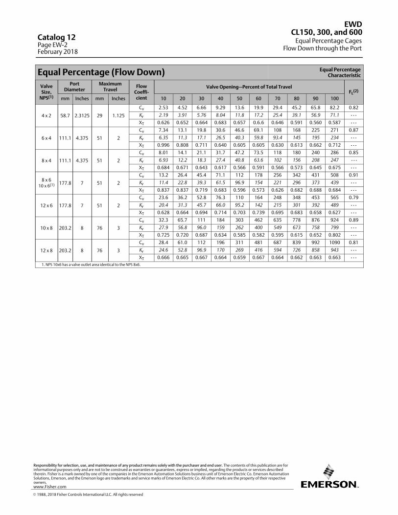
Equal Percentage (Flow Down) Equal PercentageCharacteristic
ValveSize,
NPS(1)
PortDiameter
MaximumTravel
FlowCoeffi-cient
Valve Opening—Percent of Total TravelFL
(2)
mm Inches mm Inches 10 20 30 40 50 60 70 80 90 100
4 x 2 58.7 2.3125 29 1.125
Cv 2.53 4.52 6.66 9.29 13.6 19.9 29.4 45.2 65.8 82.2 0.82
Kv 2.19 3.91 5.76 8.04 11.8 17.2 25.4 39.1 56.9 71.1 - - -
XT 0.626 0.652 0.664 0.683 0.657 0.6.6 0.646 0.591 0.560 0.587 - - -
6 x 4 111.1 4.375 51 2
Cv 7.34 13.1 19.8 30.6 46.6 69.1 108 168 225 271 0.87
Kv 6.35 11.3 17.1 26.5 40.3 59.8 93.4 145 195 234 - - -
XT 0.996 0.808 0.711 0.640 0.605 0.605 0.630 0.613 0.662 0.712 - - -
8 x 4 111.1 4.375 51 2
Cv 8.01 14.1 21.1 31.7 47.2 73.5 118 180 240 286 0.85
Kv 6.93 12.2 18.3 27.4 40.8 63.6 102 156 208 247 - - -
XT 0.684 0.671 0.643 0.617 0.566 0.591 0.566 0.573 0.645 0.675 - - -
8 x 610 x 6(1) 177.8 7 51 2
Cv 13.2 26.4 45.4 71.1 112 178 256 342 431 508 0.91
Kv 11.4 22.8 39.3 61.5 96.9 154 221 296 373 439 - - -
XT 0.837 0.837 0.719 0.683 0.596 0.573 0.626 0.682 0.688 0.684 - - -
12 x 6 177.8 7 51 2
Cv 23.6 36.2 52.8 76.3 110 164 248 348 453 565 0.79
Kv 20.4 31.3 45.7 66.0 95.2 142 215 301 392 489 - - -
XT 0.628 0.664 0.694 0.714 0.703 0.739 0.695 0.683 0.658 0.627 - - -
10 x 8 203.2 8 76 3
Cv 32.3 65.7 111 184 303 462 635 778 876 924 0.89
Kv 27.9 56.8 96.0 159 262 400 549 673 758 799 - - -
XT 0.725 0.720 0.687 0.634 0.585 0.582 0.595 0.615 0.652 0.802 - - -
12 x 8 203.2 8 76 3
Cv 28.4 61.0 112 196 311 481 687 839 992 1090 0.81
Kv 24.6 52.8 96.9 170 269 416 594 726 858 943 - - -
XT 0.666 0.665 0.667 0.664 0.659 0.667 0.664 0.662 0.663 0.663 - - -1. NPS 10x6 has a valve outlet area identical to the NPS 8x6.
EWD
Equal Percentage CagesFlow Down through the Port
CL150, 300, and 600Catalog 12Page EW-2February 2018
� 1988, 2018 Fisher Controls International LLC. All rights reserved
www.Fisher.com
Responsibility for selection, use, and maintenance of any product remains solely with the purchaser and end user. The contents of this publication are forinformational purposes only and are not to be construed as warranties or guarantees, express or implied, regarding the products or services describedtherein. Fisher is a mark owned by one of the companies in the Emerson Automation Solutions business unit of Emerson Electric Co. Emerson AutomationSolutions, Emerson, and the Emerson logo are trademarks and service marks of Emerson Electric Co. All other marks are the property of their respectiveowners.
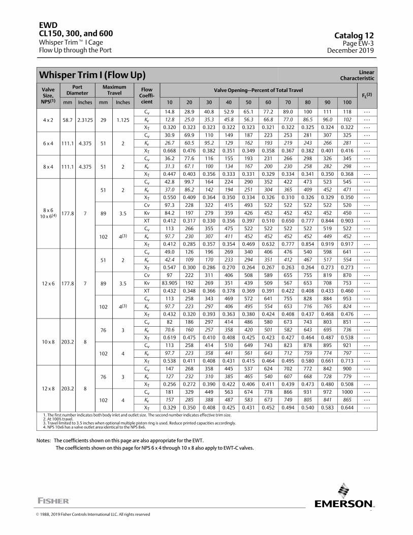
3
Whisper Trim I (Flow Up) LinearCharacteristic
ValveSize,
NPS(1)
PortDiameter
MaximumTravel
FlowCoeffi-cient
Valve Opening—Percent of Total TravelFL
(2)
mm Inches mm Inches 10 20 30 40 50 60 70 80 90 100
4 x 2 58.7 2.3125 29 1.125
Cv 14.8 28.9 40.8 52.9 65.1 77.2 89.0 100 111 118 - - -
Kv 12.8 25.0 35.3 45.8 56.3 66.8 77.0 86.5 96.0 102 - - -
XT 0.320 0.323 0.323 0.322 0.323 0.321 0.322 0.325 0.324 0.322 - - -
6 x 4 111.1 4.375 51 2
Cv 30.9 69.9 110 149 187 223 253 281 307 325 - - -
Kv 26.7 60.5 95.2 129 162 193 219 243 266 281 - - -
XT 0.668 0.476 0.382 0.351 0.349 0.358 0.367 0.382 0.401 0.416 - - -
8 x 4 111.1 4.375 51 2
Cv 36.2 77.6 116 155 193 231 266 298 326 345 - - -
Kv 31.3 67.1 100 134 167 200 230 258 282 298 - - -
XT 0.447 0.403 0.356 0.333 0.331 0.329 0.334 0.341 0.350 0.368 - - -
8 x 610 x 6(4) 177.8 7
51 2
Cv 42.8 99.7 164 224 290 352 422 473 523 545 - - -
Kv 37.0 86.2 142 194 251 304 365 409 452 471 - - -
XT 0.550 0.409 0.364 0.350 0.334 0.326 0.310 0.326 0.329 0.350 - - -
89 3.5
Cv 97.3 228 322 415 493 522 522 522 522 520 - - -
Kv 84.2 197 279 359 426 452 452 452 452 450 - - -
XT 0.412 0.317 0.330 0.356 0.397 0.510 0.650 0.777 0.844 0.903 - - -
102 4(3)
Cv 113 266 355 475 522 522 522 522 519 522 - - -
Kv 97.7 230 307 411 452 452 452 452 449 452 - - -
XT 0.412 0.285 0.357 0.354 0.469 0.632 0.777 0.854 0.919 0.917 - - -
12 x 6 177.8 7
51 2
Cv 49.0 126 196 269 340 406 476 540 598 641 - - -
Kv 42.4 109 170 233 294 351 412 467 517 554 - - -
XT 0.547 0.300 0.286 0.270 0.264 0.267 0.263 0.264 0.273 0.273 - - -
89 3.5
Cv 97 222 311 406 508 589 655 755 819 870 - - -
Kv 83.905 192 269 351 439 509 567 653 708 753 - - -
XT 0.432 0.348 0.366 0.378 0.369 0.391 0.422 0.408 0.433 0.460 - - -
102 4(3)
Cv 113 258 343 469 572 641 755 828 884 953 - - -
Kv 97.7 223 297 406 495 554 653 716 765 824 - - -
XT 0.432 0.320 0.393 0.363 0.380 0.424 0.408 0.437 0.468 0.476 - - -
10 x 8 203.2 8
76 3
Cv 82 186 297 414 486 580 673 743 803 851 - - -
Kv 70.6 160 257 358 420 501 582 643 695 736 - - -
XT 0.619 0.475 0.410 0.408 0.425 0.423 0.427 0.464 0.487 0.538 - - -
102 4
Cv 113 258 414 510 649 743 823 878 895 921 - - -
Kv 97.7 223 358 441 561 643 712 759 774 797 - - -
XT 0.538 0.411 0.408 0.431 0.415 0.464 0.495 0.580 0.661 0.713 - - -
12 x 8 203.2 8
76 3
Cv 147 268 358 445 537 624 702 772 842 900 - - -
Kv 127 232 310 385 465 540 607 668 728 779 - - -
XT 0.256 0.272 0.390 0.422 0.406 0.411 0.439 0.473 0.480 0.508 - - -
102 4
Cv 181 329 449 563 674 778 866 931 972 1000 - - -
Kv 157 285 388 487 583 673 749 805 841 865 - - -
XT 0.329 0.350 0.408 0.425 0.431 0.452 0.494 0.540 0.583 0.644 - - -1. The first number indicates both body inlet and outlet size. The second number indicates effective trim size.2. At 100% travel.3. Travel limited to 3.5 inches when optional multiple piston ring is used. Reduce printed capacities accordingly.4. NPS 10x6 has a valve outlet area identical to the NPS 8x6.
Notes: The coefficients shown on this page are also appropriate for the EWT.
The coefficients shown on this page for NPS 6 x 4 through 10 x 8 also apply to EWT-C valves.
EWD
Whisper Trim� I CageFlow Up through the Port
CL150, 300, and 600 Catalog 12Page EW-3
December 2019
� 1988, 2019 Fisher Controls International LLC. All rights reserved
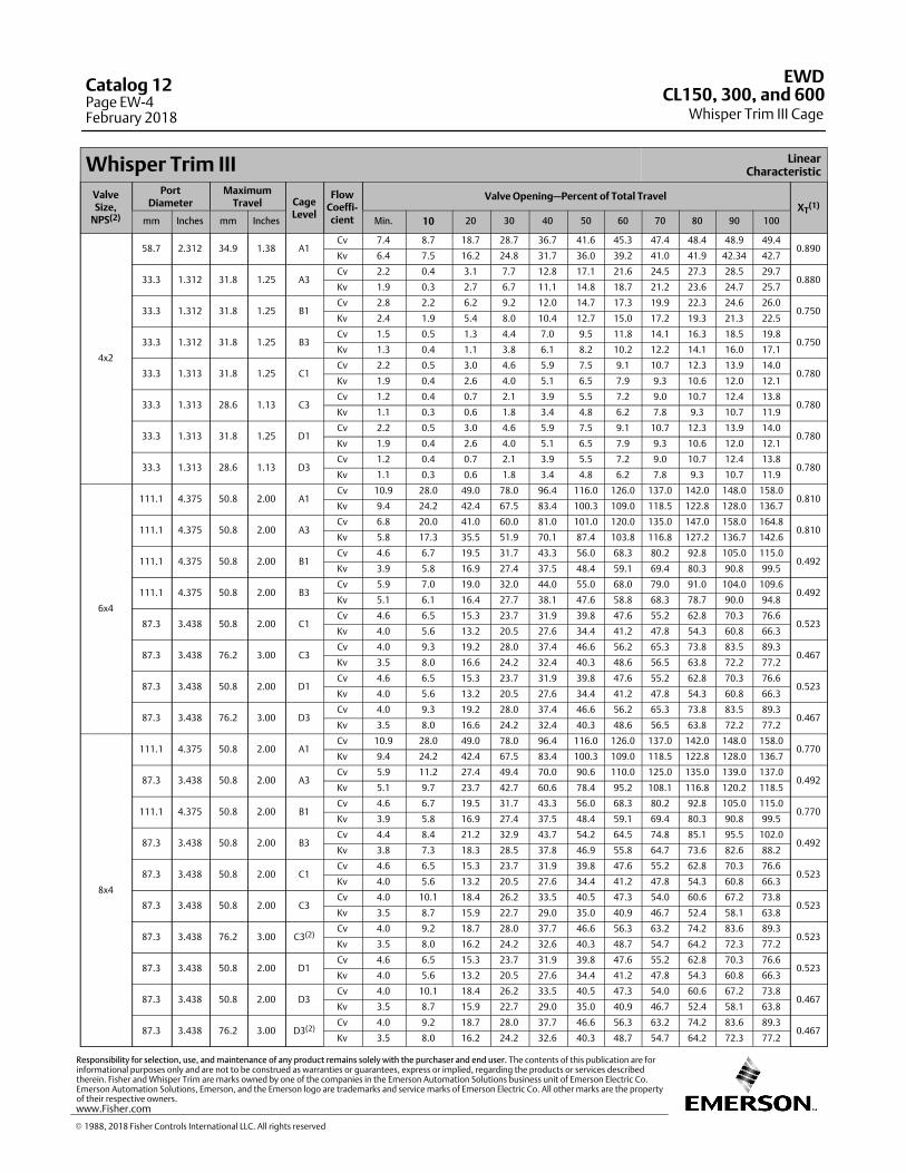
Whisper Trim III LinearCharacteristic
ValveSize,
NPS(2)
PortDiameter
MaximumTravel Cage
Level
FlowCoeffi-cient
Valve Opening—Percent of Total TravelXT
(1)
mm Inches mm Inches Min. 10 20 30 40 50 60 70 80 90 100
4x2
58.7 2.312 34.9 1.38 A1Cv 7.4 8.7 18.7 28.7 36.7 41.6 45.3 47.4 48.4 48.9 49.4
0.890Kv 6.4 7.5 16.2 24.8 31.7 36.0 39.2 41.0 41.9 42.34 42.7
33.3 1.312 31.8 1.25 A3Cv 2.2 0.4 3.1 7.7 12.8 17.1 21.6 24.5 27.3 28.5 29.7
0.880Kv 1.9 0.3 2.7 6.7 11.1 14.8 18.7 21.2 23.6 24.7 25.7
33.3 1.312 31.8 1.25 B1Cv 2.8 2.2 6.2 9.2 12.0 14.7 17.3 19.9 22.3 24.6 26.0
0.750Kv 2.4 1.9 5.4 8.0 10.4 12.7 15.0 17.2 19.3 21.3 22.5
33.3 1.312 31.8 1.25 B3Cv 1.5 0.5 1.3 4.4 7.0 9.5 11.8 14.1 16.3 18.5 19.8
0.750Kv 1.3 0.4 1.1 3.8 6.1 8.2 10.2 12.2 14.1 16.0 17.1
33.3 1.313 31.8 1.25 C1Cv 2.2 0.5 3.0 4.6 5.9 7.5 9.1 10.7 12.3 13.9 14.0
0.780Kv 1.9 0.4 2.6 4.0 5.1 6.5 7.9 9.3 10.6 12.0 12.1
33.3 1.313 28.6 1.13 C3Cv 1.2 0.4 0.7 2.1 3.9 5.5 7.2 9.0 10.7 12.4 13.8
0.780Kv 1.1 0.3 0.6 1.8 3.4 4.8 6.2 7.8 9.3 10.7 11.9
33.3 1.313 31.8 1.25 D1Cv 2.2 0.5 3.0 4.6 5.9 7.5 9.1 10.7 12.3 13.9 14.0
0.780Kv 1.9 0.4 2.6 4.0 5.1 6.5 7.9 9.3 10.6 12.0 12.1
33.3 1.313 28.6 1.13 D3Cv 1.2 0.4 0.7 2.1 3.9 5.5 7.2 9.0 10.7 12.4 13.8
0.780Kv 1.1 0.3 0.6 1.8 3.4 4.8 6.2 7.8 9.3 10.7 11.9
6x4
111.1 4.375 50.8 2.00 A1Cv 10.9 28.0 49.0 78.0 96.4 116.0 126.0 137.0 142.0 148.0 158.0
0.810Kv 9.4 24.2 42.4 67.5 83.4 100.3 109.0 118.5 122.8 128.0 136.7
111.1 4.375 50.8 2.00 A3Cv 6.8 20.0 41.0 60.0 81.0 101.0 120.0 135.0 147.0 158.0 164.8
0.810Kv 5.8 17.3 35.5 51.9 70.1 87.4 103.8 116.8 127.2 136.7 142.6
111.1 4.375 50.8 2.00 B1Cv 4.6 6.7 19.5 31.7 43.3 56.0 68.3 80.2 92.8 105.0 115.0
0.492Kv 3.9 5.8 16.9 27.4 37.5 48.4 59.1 69.4 80.3 90.8 99.5
111.1 4.375 50.8 2.00 B3Cv 5.9 7.0 19.0 32.0 44.0 55.0 68.0 79.0 91.0 104.0 109.6
0.492Kv 5.1 6.1 16.4 27.7 38.1 47.6 58.8 68.3 78.7 90.0 94.8
87.3 3.438 50.8 2.00 C1Cv 4.6 6.5 15.3 23.7 31.9 39.8 47.6 55.2 62.8 70.3 76.6
0.523Kv 4.0 5.6 13.2 20.5 27.6 34.4 41.2 47.8 54.3 60.8 66.3
87.3 3.438 76.2 3.00 C3Cv 4.0 9.3 19.2 28.0 37.4 46.6 56.2 65.3 73.8 83.5 89.3
0.467Kv 3.5 8.0 16.6 24.2 32.4 40.3 48.6 56.5 63.8 72.2 77.2
87.3 3.438 50.8 2.00 D1Cv 4.6 6.5 15.3 23.7 31.9 39.8 47.6 55.2 62.8 70.3 76.6
0.523Kv 4.0 5.6 13.2 20.5 27.6 34.4 41.2 47.8 54.3 60.8 66.3
87.3 3.438 76.2 3.00 D3Cv 4.0 9.3 19.2 28.0 37.4 46.6 56.2 65.3 73.8 83.5 89.3
0.467Kv 3.5 8.0 16.6 24.2 32.4 40.3 48.6 56.5 63.8 72.2 77.2
8x4
111.1 4.375 50.8 2.00 A1Cv 10.9 28.0 49.0 78.0 96.4 116.0 126.0 137.0 142.0 148.0 158.0
0.770Kv 9.4 24.2 42.4 67.5 83.4 100.3 109.0 118.5 122.8 128.0 136.7
87.3 3.438 50.8 2.00 A3Cv 5.9 11.2 27.4 49.4 70.0 90.6 110.0 125.0 135.0 139.0 137.0
0.492Kv 5.1 9.7 23.7 42.7 60.6 78.4 95.2 108.1 116.8 120.2 118.5
111.1 4.375 50.8 2.00 B1Cv 4.6 6.7 19.5 31.7 43.3 56.0 68.3 80.2 92.8 105.0 115.0
0.770Kv 3.9 5.8 16.9 27.4 37.5 48.4 59.1 69.4 80.3 90.8 99.5
87.3 3.438 50.8 2.00 B3Cv 4.4 8.4 21.2 32.9 43.7 54.2 64.5 74.8 85.1 95.5 102.0
0.492Kv 3.8 7.3 18.3 28.5 37.8 46.9 55.8 64.7 73.6 82.6 88.2
87.3 3.438 50.8 2.00 C1Cv 4.6 6.5 15.3 23.7 31.9 39.8 47.6 55.2 62.8 70.3 76.6
0.523Kv 4.0 5.6 13.2 20.5 27.6 34.4 41.2 47.8 54.3 60.8 66.3
87.3 3.438 50.8 2.00 C3Cv 4.0 10.1 18.4 26.2 33.5 40.5 47.3 54.0 60.6 67.2 73.8
0.523Kv 3.5 8.7 15.9 22.7 29.0 35.0 40.9 46.7 52.4 58.1 63.8
87.3 3.438 76.2 3.00 C3(2)Cv 4.0 9.2 18.7 28.0 37.7 46.6 56.3 63.2 74.2 83.6 89.3
0.523Kv 3.5 8.0 16.2 24.2 32.6 40.3 48.7 54.7 64.2 72.3 77.2
87.3 3.438 50.8 2.00 D1Cv 4.6 6.5 15.3 23.7 31.9 39.8 47.6 55.2 62.8 70.3 76.6
0.523Kv 4.0 5.6 13.2 20.5 27.6 34.4 41.2 47.8 54.3 60.8 66.3
87.3 3.438 50.8 2.00 D3Cv 4.0 10.1 18.4 26.2 33.5 40.5 47.3 54.0 60.6 67.2 73.8
0.467Kv 3.5 8.7 15.9 22.7 29.0 35.0 40.9 46.7 52.4 58.1 63.8
87.3 3.438 76.2 3.00 D3(2)Cv 4.0 9.2 18.7 28.0 37.7 46.6 56.3 63.2 74.2 83.6 89.3
0.467Kv 3.5 8.0 16.2 24.2 32.6 40.3 48.7 54.7 64.2 72.3 77.2
EWD
Whisper Trim III CageCL150, 300, and 600
Catalog 12Page EW-4February 2018
� 1988, 2018 Fisher Controls International LLC. All rights reserved
www.Fisher.com
Responsibility for selection, use, and maintenance of any product remains solely with the purchaser and end user. The contents of this publication are forinformational purposes only and are not to be construed as warranties or guarantees, express or implied, regarding the products or services describedtherein. Fisher and Whisper Trim are marks owned by one of the companies in the Emerson Automation Solutions business unit of Emerson Electric Co.Emerson Automation Solutions, Emerson, and the Emerson logo are trademarks and service marks of Emerson Electric Co. All other marks are the propertyof their respective owners.
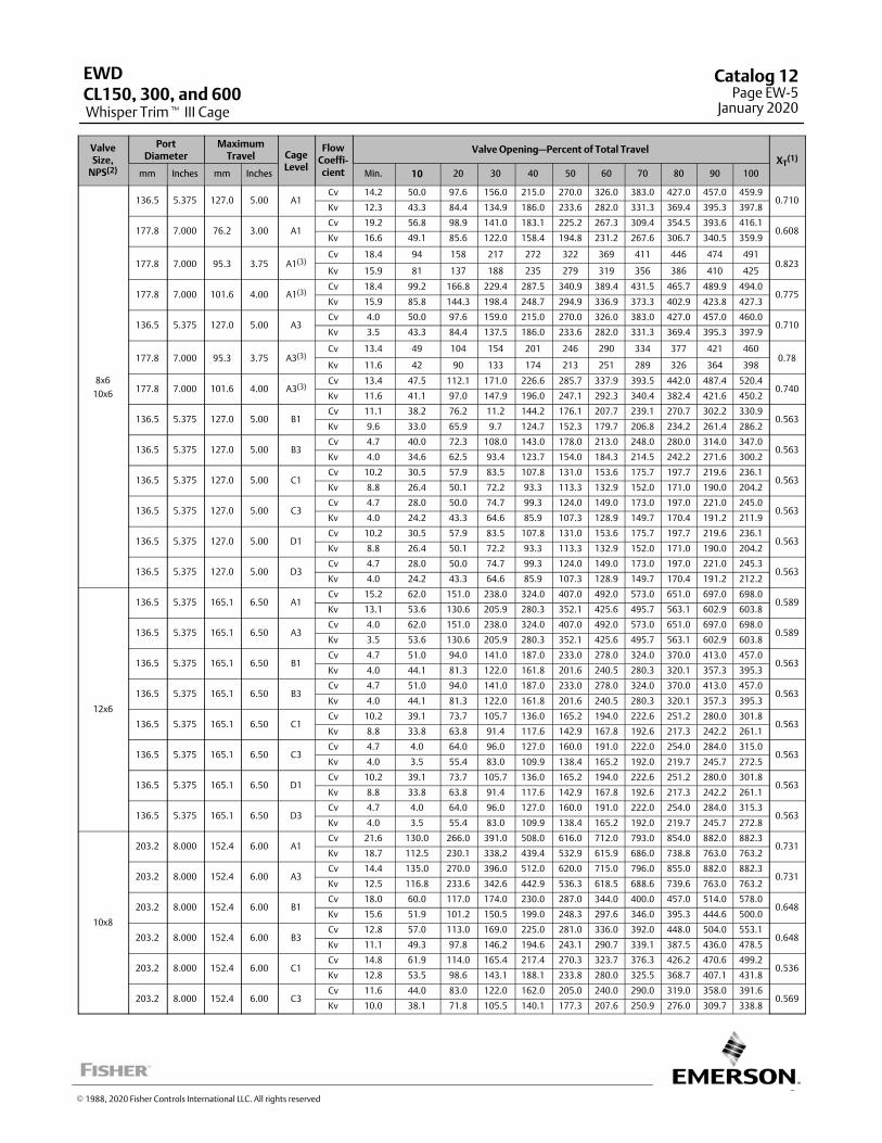
5
ValveSize,
NPS(2)
PortDiameter
MaximumTravel Cage
Level
FlowCoeffi-cient
Valve Opening—Percent of Total TravelXT
(1)
mm Inches mm Inches Min. 10 20 30 40 50 60 70 80 90 100
8x6
10x6
136.5 5.375 127.0 5.00 A1Cv 14.2 50.0 97.6 156.0 215.0 270.0 326.0 383.0 427.0 457.0 459.9
0.710Kv 12.3 43.3 84.4 134.9 186.0 233.6 282.0 331.3 369.4 395.3 397.8
177.8 7.000 76.2 3.00 A1Cv 19.2 56.8 98.9 141.0 183.1 225.2 267.3 309.4 354.5 393.6 416.1
0.608Kv 16.6 49.1 85.6 122.0 158.4 194.8 231.2 267.6 306.7 340.5 359.9
177.8 7.000 95.3 3.75 A1(3)Cv 18.4 94 158 217 272 322 369 411 446 474 491
0.823Kv 15.9 81 137 188 235 279 319 356 386 410 425
177.8 7.000 101.6 4.00 A1(3)Cv 18.4 99.2 166.8 229.4 287.5 340.9 389.4 431.5 465.7 489.9 494.0
0.775Kv 15.9 85.8 144.3 198.4 248.7 294.9 336.9 373.3 402.9 423.8 427.3
136.5 5.375 127.0 5.00 A3Cv 4.0 50.0 97.6 159.0 215.0 270.0 326.0 383.0 427.0 457.0 460.0
0.710Kv 3.5 43.3 84.4 137.5 186.0 233.6 282.0 331.3 369.4 395.3 397.9
177.8 7.000 95.3 3.75 A3(3)Cv 13.4 49 104 154 201 246 290 334 377 421 460
0.78Kv 11.6 42 90 133 174 213 251 289 326 364 398
177.8 7.000 101.6 4.00 A3(3)Cv 13.4 47.5 112.1 171.0 226.6 285.7 337.9 393.5 442.0 487.4 520.4
0.740Kv 11.6 41.1 97.0 147.9 196.0 247.1 292.3 340.4 382.4 421.6 450.2
136.5 5.375 127.0 5.00 B1Cv 11.1 38.2 76.2 11.2 144.2 176.1 207.7 239.1 270.7 302.2 330.9
0.563Kv 9.6 33.0 65.9 9.7 124.7 152.3 179.7 206.8 234.2 261.4 286.2
136.5 5.375 127.0 5.00 B3Cv 4.7 40.0 72.3 108.0 143.0 178.0 213.0 248.0 280.0 314.0 347.0
0.563Kv 4.0 34.6 62.5 93.4 123.7 154.0 184.3 214.5 242.2 271.6 300.2
136.5 5.375 127.0 5.00 C1Cv 10.2 30.5 57.9 83.5 107.8 131.0 153.6 175.7 197.7 219.6 236.1
0.563Kv 8.8 26.4 50.1 72.2 93.3 113.3 132.9 152.0 171.0 190.0 204.2
136.5 5.375 127.0 5.00 C3Cv 4.7 28.0 50.0 74.7 99.3 124.0 149.0 173.0 197.0 221.0 245.0
0.563Kv 4.0 24.2 43.3 64.6 85.9 107.3 128.9 149.7 170.4 191.2 211.9
136.5 5.375 127.0 5.00 D1Cv 10.2 30.5 57.9 83.5 107.8 131.0 153.6 175.7 197.7 219.6 236.1
0.563Kv 8.8 26.4 50.1 72.2 93.3 113.3 132.9 152.0 171.0 190.0 204.2
136.5 5.375 127.0 5.00 D3Cv 4.7 28.0 50.0 74.7 99.3 124.0 149.0 173.0 197.0 221.0 245.3
0.563Kv 4.0 24.2 43.3 64.6 85.9 107.3 128.9 149.7 170.4 191.2 212.2
12x6
136.5 5.375 165.1 6.50 A1Cv 15.2 62.0 151.0 238.0 324.0 407.0 492.0 573.0 651.0 697.0 698.0
0.589Kv 13.1 53.6 130.6 205.9 280.3 352.1 425.6 495.7 563.1 602.9 603.8
136.5 5.375 165.1 6.50 A3Cv 4.0 62.0 151.0 238.0 324.0 407.0 492.0 573.0 651.0 697.0 698.0
0.589Kv 3.5 53.6 130.6 205.9 280.3 352.1 425.6 495.7 563.1 602.9 603.8
136.5 5.375 165.1 6.50 B1Cv 4.7 51.0 94.0 141.0 187.0 233.0 278.0 324.0 370.0 413.0 457.0
0.563Kv 4.0 44.1 81.3 122.0 161.8 201.6 240.5 280.3 320.1 357.3 395.3
136.5 5.375 165.1 6.50 B3Cv 4.7 51.0 94.0 141.0 187.0 233.0 278.0 324.0 370.0 413.0 457.0
0.563Kv 4.0 44.1 81.3 122.0 161.8 201.6 240.5 280.3 320.1 357.3 395.3
136.5 5.375 165.1 6.50 C1Cv 10.2 39.1 73.7 105.7 136.0 165.2 194.0 222.6 251.2 280.0 301.8
0.563Kv 8.8 33.8 63.8 91.4 117.6 142.9 167.8 192.6 217.3 242.2 261.1
136.5 5.375 165.1 6.50 C3Cv 4.7 4.0 64.0 96.0 127.0 160.0 191.0 222.0 254.0 284.0 315.0
0.563Kv 4.0 3.5 55.4 83.0 109.9 138.4 165.2 192.0 219.7 245.7 272.5
136.5 5.375 165.1 6.50 D1Cv 10.2 39.1 73.7 105.7 136.0 165.2 194.0 222.6 251.2 280.0 301.8
0.563Kv 8.8 33.8 63.8 91.4 117.6 142.9 167.8 192.6 217.3 242.2 261.1
136.5 5.375 165.1 6.50 D3Cv 4.7 4.0 64.0 96.0 127.0 160.0 191.0 222.0 254.0 284.0 315.3
0.563Kv 4.0 3.5 55.4 83.0 109.9 138.4 165.2 192.0 219.7 245.7 272.8
10x8
203.2 8.000 152.4 6.00 A1Cv 21.6 130.0 266.0 391.0 508.0 616.0 712.0 793.0 854.0 882.0 882.3
0.731Kv 18.7 112.5 230.1 338.2 439.4 532.9 615.9 686.0 738.8 763.0 763.2
203.2 8.000 152.4 6.00 A3Cv 14.4 135.0 270.0 396.0 512.0 620.0 715.0 796.0 855.0 882.0 882.3
0.731Kv 12.5 116.8 233.6 342.6 442.9 536.3 618.5 688.6 739.6 763.0 763.2
203.2 8.000 152.4 6.00 B1Cv 18.0 60.0 117.0 174.0 230.0 287.0 344.0 400.0 457.0 514.0 578.0
0.648Kv 15.6 51.9 101.2 150.5 199.0 248.3 297.6 346.0 395.3 444.6 500.0
203.2 8.000 152.4 6.00 B3Cv 12.8 57.0 113.0 169.0 225.0 281.0 336.0 392.0 448.0 504.0 553.1
0.648Kv 11.1 49.3 97.8 146.2 194.6 243.1 290.7 339.1 387.5 436.0 478.5
203.2 8.000 152.4 6.00 C1Cv 14.8 61.9 114.0 165.4 217.4 270.3 323.7 376.3 426.2 470.6 499.2
0.536Kv 12.8 53.5 98.6 143.1 188.1 233.8 280.0 325.5 368.7 407.1 431.8
203.2 8.000 152.4 6.00 C3Cv 11.6 44.0 83.0 122.0 162.0 205.0 240.0 290.0 319.0 358.0 391.6
0.569Kv 10.0 38.1 71.8 105.5 140.1 177.3 207.6 250.9 276.0 309.7 338.8
EWD
Whisper Trim� III CageCL150, 300, and 600
Catalog 12Page EW-5
January 2020
� 1988, 2020 Fisher Controls International LLC. All rights reserved
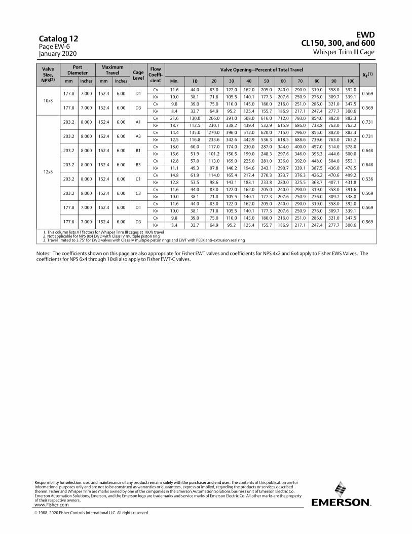
ValveSize,
NPS(2)
PortDiameter
MaximumTravel Cage
Level
FlowCoeffi-cient
Valve Opening—Percent of Total TravelXT
(1)
mm Inches mm Inches Min. 10 20 30 40 50 60 70 80 90 100
10x8
177.8 7.000 152.4 6.00 D1Cv 11.6 44.0 83.0 122.0 162.0 205.0 240.0 290.0 319.0 358.0 392.0
0.569Kv 10.0 38.1 71.8 105.5 140.1 177.3 207.6 250.9 276.0 309.7 339.1
177.8 7.000 152.4 6.00 D3Cv 9.8 39.0 75.0 110.0 145.0 180.0 216.0 251.0 286.0 321.0 347.5
0.569Kv 8.4 33.7 64.9 95.2 125.4 155.7 186.9 217.1 247.4 277.7 300.6
12x8
203.2 8.000 152.4 6.00 A1Cv 21.6 130.0 266.0 391.0 508.0 616.0 712.0 793.0 854.0 882.0 882.3
0.731Kv 18.7 112.5 230.1 338.2 439.4 532.9 615.9 686.0 738.8 763.0 763.2
203.2 8.000 152.4 6.00 A3Cv 14.4 135.0 270.0 396.0 512.0 620.0 715.0 796.0 855.0 882.0 882.3
0.731Kv 12.5 116.8 233.6 342.6 442.9 536.3 618.5 688.6 739.6 763.0 763.2
203.2 8.000 152.4 6.00 B1Cv 18.0 60.0 117.0 174.0 230.0 287.0 344.0 400.0 457.0 514.0 578.0
0.648Kv 15.6 51.9 101.2 150.5 199.0 248.3 297.6 346.0 395.3 444.6 500.0
203.2 8.000 152.4 6.00 B3Cv 12.8 57.0 113.0 169.0 225.0 281.0 336.0 392.0 448.0 504.0 553.1
0.648Kv 11.1 49.3 97.8 146.2 194.6 243.1 290.7 339.1 387.5 436.0 478.5
203.2 8.000 152.4 6.00 C1Cv 14.8 61.9 114.0 165.4 217.4 270.3 323.7 376.3 426.2 470.6 499.2
0.536Kv 12.8 53.5 98.6 143.1 188.1 233.8 280.0 325.5 368.7 407.1 431.8
203.2 8.000 152.4 6.00 C3Cv 11.6 44.0 83.0 122.0 162.0 205.0 240.0 290.0 319.0 358.0 391.6
0.569Kv 10.0 38.1 71.8 105.5 140.1 177.3 207.6 250.9 276.0 309.7 338.8
177.8 7.000 152.4 6.00 D1Cv 11.6 44.0 83.0 122.0 162.0 205.0 240.0 290.0 319.0 358.0 392.0
0.569Kv 10.0 38.1 71.8 105.5 140.1 177.3 207.6 250.9 276.0 309.7 339.1
177.8 7.000 152.4 6.00 D3Cv 9.8 39.0 75.0 110.0 145.0 180.0 216.0 251.0 286.0 321.0 347.5
0.569Kv 8.4 33.7 64.9 95.2 125.4 155.7 186.9 217.1 247.4 277.7 300.6
1. This column lists XT factors for Whisper Trim III cages at 100% travel2. Not applicable for NPS 8x4 EWD with Class IV multiple piston ring3. Travel limited to 3.75" for EWD valves with Class IV multiple piston rings and EWT with PEEK anti-extrusion seal ring
Notes: The coefficients shown on this page are also appropriate for Fisher EWT valves and coefficients for NPS 4x2 and 6x4 apply to Fisher EWS Valves. Thecoefficients for NPS 6x4 through 10x8 also apply to Fisher EWT-C valves.
EWD
Whisper Trim III CageCL150, 300, and 600
Catalog 12Page EW-6January 2020
� 1988, 2020 Fisher Controls International LLC. All rights reserved
www.Fisher.com
Responsibility for selection, use, and maintenance of any product remains solely with the purchaser and end user. The contents of this publication are forinformational purposes only and are not to be construed as warranties or guarantees, express or implied, regarding the products or services describedtherein. Fisher and Whisper Trim are marks owned by one of the companies in the Emerson Automation Solutions business unit of Emerson Electric Co.Emerson Automation Solutions, Emerson, and the Emerson logo are trademarks and service marks of Emerson Electric Co. All other marks are the propertyof their respective owners.
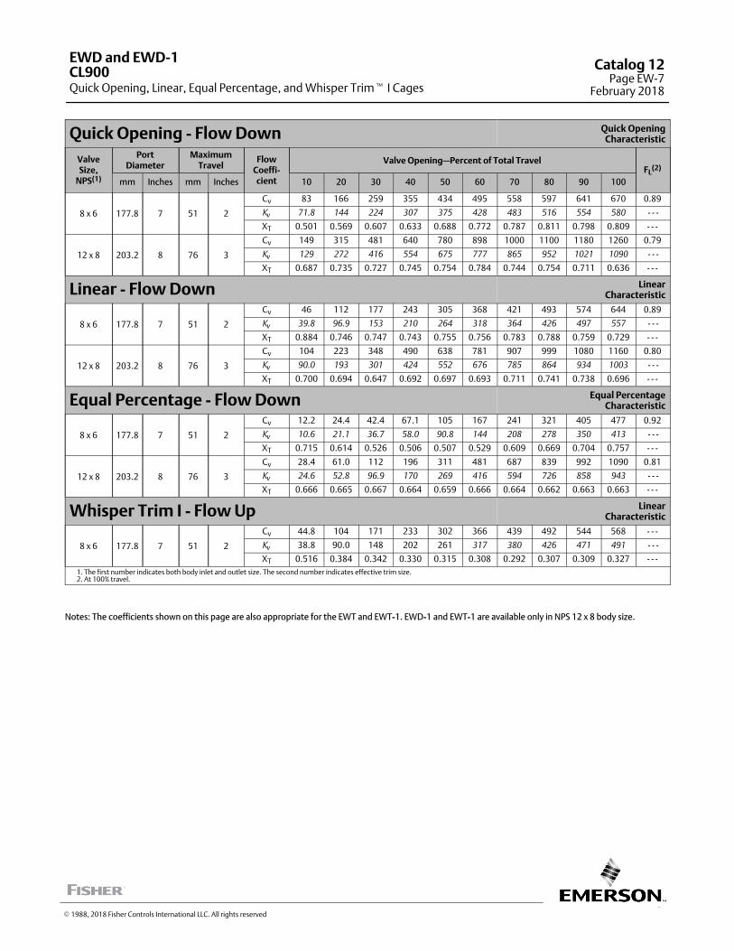
7
Quick Opening - Flow Down Quick OpeningCharacteristic
ValveSize,
NPS(1)
PortDiameter
MaximumTravel
FlowCoeffi-cient
Valve Opening—Percent of Total TravelFL
(2)
mm Inches mm Inches 10 20 30 40 50 60 70 80 90 100
8 x 6 177.8 7 51 2
Cv 83 166 259 355 434 495 558 597 641 670 0.89
Kv 71.8 144 224 307 375 428 483 516 554 580 - - -
XT 0.501 0.569 0.607 0.633 0.688 0.772 0.787 0.811 0.798 0.809 - - -
12 x 8 203.2 8 76 3
Cv 149 315 481 640 780 898 1000 1100 1180 1260 0.79
Kv 129 272 416 554 675 777 865 952 1021 1090 - - -
XT 0.687 0.735 0.727 0.745 0.754 0.784 0.744 0.754 0.711 0.636 - - -
Linear - Flow Down LinearCharacteristic
8 x 6 177.8 7 51 2
Cv 46 112 177 243 305 368 421 493 574 644 0.89
Kv 39.8 96.9 153 210 264 318 364 426 497 557 - - -
XT 0.884 0.746 0.747 0.743 0.755 0.756 0.783 0.788 0.759 0.729 - - -
12 x 8 203.2 8 76 3
Cv 104 223 348 490 638 781 907 999 1080 1160 0.80
Kv 90.0 193 301 424 552 676 785 864 934 1003 - - -
XT 0.700 0.694 0.647 0.692 0.697 0.693 0.711 0.741 0.738 0.696 - - -
Equal Percentage - Flow Down Equal PercentageCharacteristic
8 x 6 177.8 7 51 2
Cv 12.2 24.4 42.4 67.1 105 167 241 321 405 477 0.92
Kv 10.6 21.1 36.7 58.0 90.8 144 208 278 350 413 - - -
XT 0.715 0.614 0.526 0.506 0.507 0.529 0.609 0.669 0.704 0.757 - - -
12 x 8 203.2 8 76 3
Cv 28.4 61.0 112 196 311 481 687 839 992 1090 0.81
Kv 24.6 52.8 96.9 170 269 416 594 726 858 943 - - -
XT 0.666 0.665 0.667 0.664 0.659 0.666 0.664 0.662 0.663 0.663 - - -
Whisper Trim I - Flow Up LinearCharacteristic
8 x 6 177.8 7 51 2
Cv 44.8 104 171 233 302 366 439 492 544 568 - - -
Kv 38.8 90.0 148 202 261 317 380 426 471 491 - - -
XT 0.516 0.384 0.342 0.330 0.315 0.308 0.292 0.307 0.309 0.327 - - -1. The first number indicates both body inlet and outlet size. The second number indicates effective trim size.2. At 100% travel.
Notes: The coefficients shown on this page are also appropriate for the EWT and EWT-1. EWD-1 and EWT-1 are available only in NPS 12 x 8 body size.
EWD and EWD-1
Quick Opening, Linear, Equal Percentage, and Whisper Trim� I CagesCL900
Catalog 12Page EW-7
February 2018
� 1988, 2018 Fisher Controls International LLC. All rights reserved
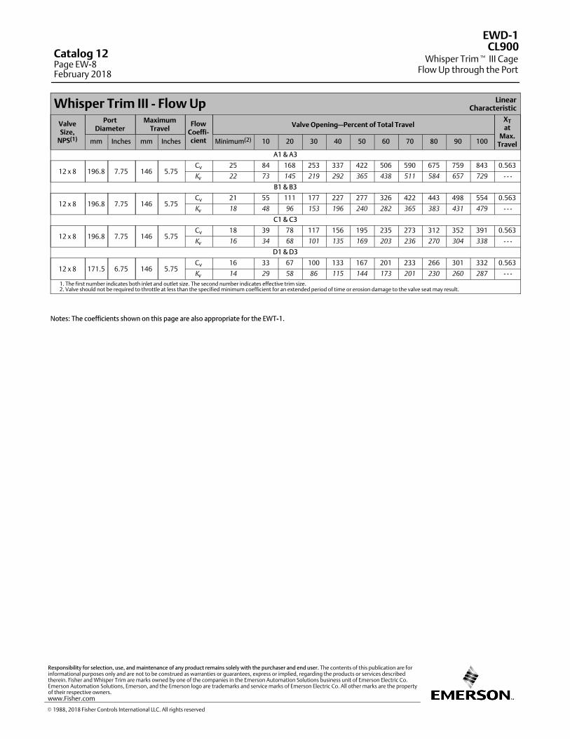
Whisper Trim III - Flow Up LinearCharacteristic
ValveSize,
NPS(1)
PortDiameter
MaximumTravel
FlowCoeffi-cient
Valve Opening—Percent of Total TravelXTat
Max.Travelmm Inches mm Inches Minimum(2) 10 20 30 40 50 60 70 80 90 100
A1 & A3
12 x 8 196.8 7.75 146 5.75Cv 25 84 168 253 337 422 506 590 675 759 843 0.563
Kv 22 73 145 219 292 365 438 511 584 657 729 - - -
B1 & B3
12 x 8 196.8 7.75 146 5.75Cv 21 55 111 177 227 277 326 422 443 498 554 0.563
Kv 18 48 96 153 196 240 282 365 383 431 479 - - -
C1 & C3
12 x 8 196.8 7.75 146 5.75Cv 18 39 78 117 156 195 235 273 312 352 391 0.563
Kv 16 34 68 101 135 169 203 236 270 304 338 - - -
D1 & D3
12 x 8 171.5 6.75 146 5.75Cv 16 33 67 100 133 167 201 233 266 301 332 0.563
Kv 14 29 58 86 115 144 173 201 230 260 287 - - -
1. The first number indicates both inlet and outlet size. The second number indicates effective trim size.2. Valve should not be required to throttle at less than the specified minimum coefficient for an extended period of time or erosion damage to the valve seat may result.
Notes: The coefficients shown on this page are also appropriate for the EWT-1.
EWD-1
Whisper Trim� III CageFlow Up through the Port
CL900Catalog 12Page EW-8February 2018
� 1988, 2018 Fisher Controls International LLC. All rights reserved
www.Fisher.com
Responsibility for selection, use, and maintenance of any product remains solely with the purchaser and end user. The contents of this publication are forinformational purposes only and are not to be construed as warranties or guarantees, express or implied, regarding the products or services describedtherein. Fisher and Whisper Trim are marks owned by one of the companies in the Emerson Automation Solutions business unit of Emerson Electric Co.Emerson Automation Solutions, Emerson, and the Emerson logo are trademarks and service marks of Emerson Electric Co. All other marks are the propertyof their respective owners.
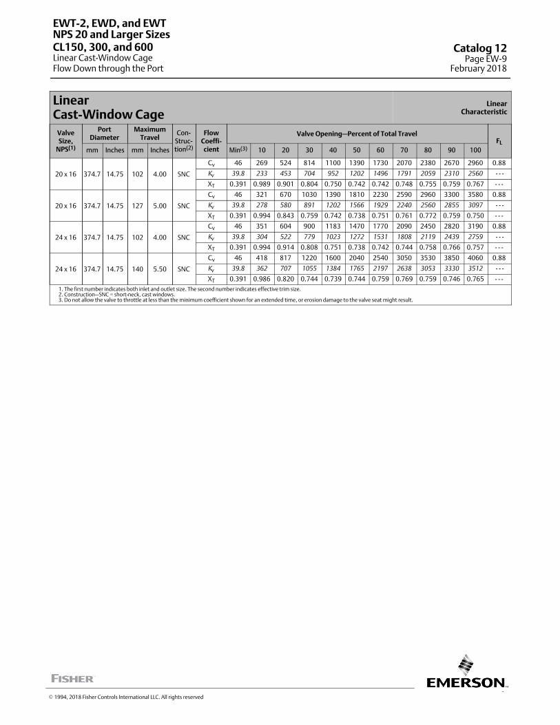
9
LinearCast-Window Cage
LinearCharacteristic
ValveSize,
NPS(1)
PortDiameter
MaximumTravel
Con-Struc-tion(2)
FlowCoeffi-cient
Valve Opening—Percent of Total TravelFL
mm Inches mm Inches Min(3) 10 20 30 40 50 60 70 80 90 100
20 x 16 374.7 14.75 102 4.00 SNC
Cv 46 269 524 814 1100 1390 1730 2070 2380 2670 2960 0.88
Kv 39.8 233 453 704 952 1202 1496 1791 2059 2310 2560 - - -
XT 0.391 0.989 0.901 0.804 0.750 0.742 0.742 0.748 0.755 0.759 0.767 - - -
20 x 16 374.7 14.75 127 5.00 SNC
Cv 46 321 670 1030 1390 1810 2230 2590 2960 3300 3580 0.88
Kv 39.8 278 580 891 1202 1566 1929 2240 2560 2855 3097 - - -
XT 0.391 0.994 0.843 0.759 0.742 0.738 0.751 0.761 0.772 0.759 0.750 - - -
24 x 16 374.7 14.75 102 4.00 SNC
Cv 46 351 604 900 1183 1470 1770 2090 2450 2820 3190 0.88
Kv 39.8 304 522 779 1023 1272 1531 1808 2119 2439 2759 - - -
XT 0.391 0.994 0.914 0.808 0.751 0.738 0.742 0.744 0.758 0.766 0.757 - - -
24 x 16 374.7 14.75 140 5.50 SNC
Cv 46 418 817 1220 1600 2040 2540 3050 3530 3850 4060 0.88
Kv 39.8 362 707 1055 1384 1765 2197 2638 3053 3330 3512 - - -
XT 0.391 0.986 0.820 0.744 0.739 0.744 0.759 0.769 0.759 0.746 0.765 - - -1. The first number indicates both inlet and outlet size. The second number indicates effective trim size.2. Construction—SNC = short-neck, cast windows.3. Do not allow the valve to throttle at less than the minimum coefficient shown for an extended time, or erosion damage to the valve seat might result.
EWT-2, EWD, and EWT
Linear Cast-Window CageFlow Down through the Port
NPS 20 and Larger SizesCL150, 300, and 600 Catalog 12
Page EW-9February 2018
� 1994, 2018 Fisher Controls International LLC. All rights reserved
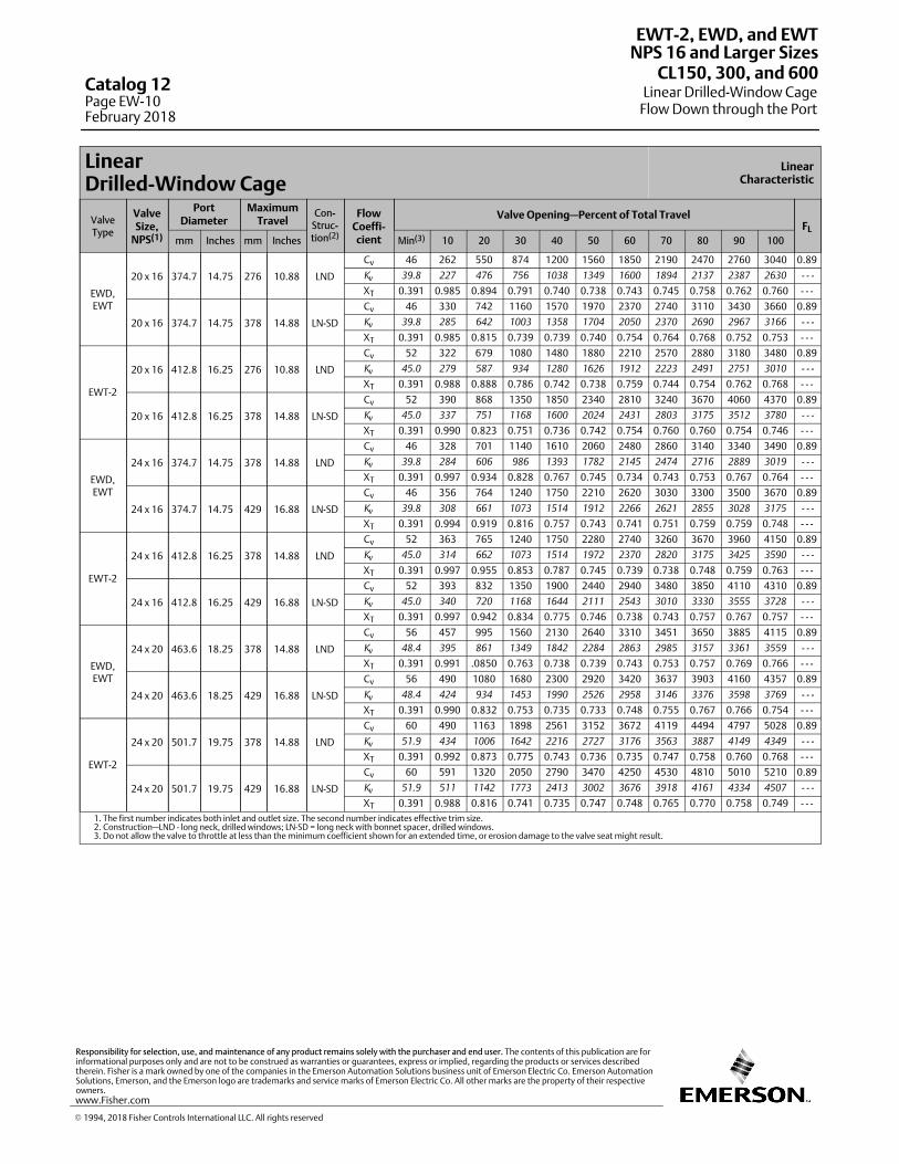
LinearDrilled-Window Cage
LinearCharacteristic
ValveType
ValveSize,
NPS(1)
PortDiameter
MaximumTravel
Con-Struc-tion(2)
FlowCoeffi-cient
Valve Opening—Percent of Total TravelFL
mm Inches mm Inches Min(3) 10 20 30 40 50 60 70 80 90 100
EWD,EWT
20 x 16 374.7 14.75 276 10.88 LND
Cv 46 262 550 874 1200 1560 1850 2190 2470 2760 3040 0.89
Kv 39.8 227 476 756 1038 1349 1600 1894 2137 2387 2630 - - -
XT 0.391 0.985 0.894 0.791 0.740 0.738 0.743 0.745 0.758 0.762 0.760 - - -
20 x 16 374.7 14.75 378 14.88 LN-SD
Cv 46 330 742 1160 1570 1970 2370 2740 3110 3430 3660 0.89
Kv 39.8 285 642 1003 1358 1704 2050 2370 2690 2967 3166 - - -
XT 0.391 0.985 0.815 0.739 0.739 0.740 0.754 0.764 0.768 0.752 0.753 - - -
EWT-2
20 x 16 412.8 16.25 276 10.88 LND
Cv 52 322 679 1080 1480 1880 2210 2570 2880 3180 3480 0.89
Kv 45.0 279 587 934 1280 1626 1912 2223 2491 2751 3010 - - -
XT 0.391 0.988 0.888 0.786 0.742 0.738 0.759 0.744 0.754 0.762 0.768 - - -
20 x 16 412.8 16.25 378 14.88 LN-SD
Cv 52 390 868 1350 1850 2340 2810 3240 3670 4060 4370 0.89
Kv 45.0 337 751 1168 1600 2024 2431 2803 3175 3512 3780 - - -
XT 0.391 0.990 0.823 0.751 0.736 0.742 0.754 0.760 0.760 0.754 0.746 - - -
EWD,EWT
24 x 16 374.7 14.75 378 14.88 LND
Cv 46 328 701 1140 1610 2060 2480 2860 3140 3340 3490 0.89
Kv 39.8 284 606 986 1393 1782 2145 2474 2716 2889 3019 - - -
XT 0.391 0.997 0.934 0.828 0.767 0.745 0.734 0.743 0.753 0.767 0.764 - - -
24 x 16 374.7 14.75 429 16.88 LN-SD
Cv 46 356 764 1240 1750 2210 2620 3030 3300 3500 3670 0.89
Kv 39.8 308 661 1073 1514 1912 2266 2621 2855 3028 3175 - - -
XT 0.391 0.994 0.919 0.816 0.757 0.743 0.741 0.751 0.759 0.759 0.748 - - -
EWT-2
24 x 16 412.8 16.25 378 14.88 LND
Cv 52 363 765 1240 1750 2280 2740 3260 3670 3960 4150 0.89
Kv 45.0 314 662 1073 1514 1972 2370 2820 3175 3425 3590 - - -
XT 0.391 0.997 0.955 0.853 0.787 0.745 0.739 0.738 0.748 0.759 0.763 - - -
24 x 16 412.8 16.25 429 16.88 LN-SD
Cv 52 393 832 1350 1900 2440 2940 3480 3850 4110 4310 0.89
Kv 45.0 340 720 1168 1644 2111 2543 3010 3330 3555 3728 - - -
XT 0.391 0.997 0.942 0.834 0.775 0.746 0.738 0.743 0.757 0.767 0.757 - - -
EWD,EWT
24 x 20 463.6 18.25 378 14.88 LND
Cv 56 457 995 1560 2130 2640 3310 3451 3650 3885 4115 0.89
Kv 48.4 395 861 1349 1842 2284 2863 2985 3157 3361 3559 - - -
XT 0.391 0.991 .0850 0.763 0.738 0.739 0.743 0.753 0.757 0.769 0.766 - - -
24 x 20 463.6 18.25 429 16.88 LN-SD
Cv 56 490 1080 1680 2300 2920 3420 3637 3903 4160 4357 0.89
Kv 48.4 424 934 1453 1990 2526 2958 3146 3376 3598 3769 - - -
XT 0.391 0.990 0.832 0.753 0.735 0.733 0.748 0.755 0.767 0.766 0.754 - - -
EWT-2
24 x 20 501.7 19.75 378 14.88 LND
Cv 60 490 1163 1898 2561 3152 3672 4119 4494 4797 5028 0.89
Kv 51.9 434 1006 1642 2216 2727 3176 3563 3887 4149 4349 - - -
XT 0.391 0.992 0.873 0.775 0.743 0.736 0.735 0.747 0.758 0.760 0.768 - - -
24 x 20 501.7 19.75 429 16.88 LN-SD
Cv 60 591 1320 2050 2790 3470 4250 4530 4810 5010 5210 0.89
Kv 51.9 511 1142 1773 2413 3002 3676 3918 4161 4334 4507 - - -
XT 0.391 0.988 0.816 0.741 0.735 0.747 0.748 0.765 0.770 0.758 0.749 - - -1. The first number indicates both inlet and outlet size. The second number indicates effective trim size.2. Construction—LND - long neck, drilled windows; LN-SD = long neck with bonnet spacer, drilled windows.3. Do not allow the valve to throttle at less than the minimum coefficient shown for an extended time, or erosion damage to the valve seat might result.
EWT-2, EWD, and EWT
Linear Drilled-Window CageFlow Down through the Port
NPS 16 and Larger SizesCL150, 300, and 600
Catalog 12Page EW-10February 2018
� 1994, 2018 Fisher Controls International LLC. All rights reserved
www.Fisher.com
Responsibility for selection, use, and maintenance of any product remains solely with the purchaser and end user. The contents of this publication are forinformational purposes only and are not to be construed as warranties or guarantees, express or implied, regarding the products or services describedtherein. Fisher is a mark owned by one of the companies in the Emerson Automation Solutions business unit of Emerson Electric Co. Emerson AutomationSolutions, Emerson, and the Emerson logo are trademarks and service marks of Emerson Electric Co. All other marks are the property of their respectiveowners.
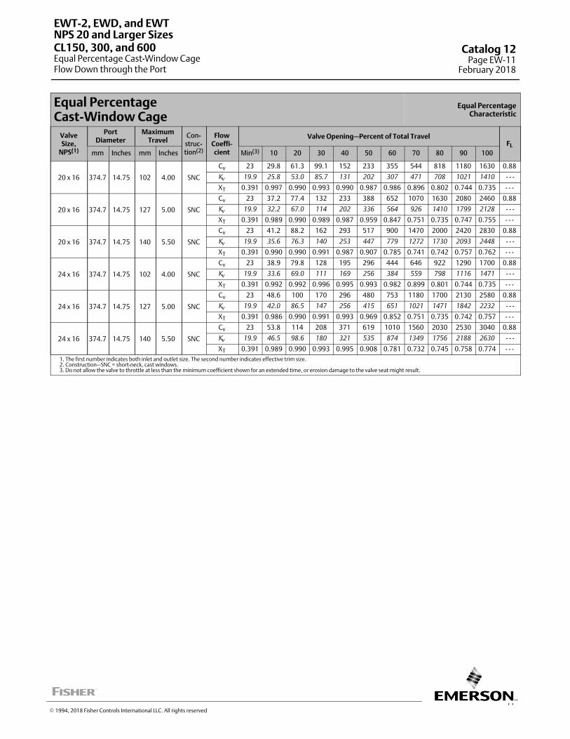
11
Equal PercentageCast-Window Cage
Equal PercentageCharacteristic
ValveSize,
NPS(1)
PortDiameter
MaximumTravel
Con-struc-tion(2)
FlowCoeffi-cient
Valve Opening—Percent of Total TravelFL
mm Inches mm Inches Min(3) 10 20 30 40 50 60 70 80 90 100
20 x 16 374.7 14.75 102 4.00 SNC
Cv 23 29.8 61.3 99.1 152 233 355 544 818 1180 1630 0.88
Kv 19.9 25.8 53.0 85.7 131 202 307 471 708 1021 1410 - - -
XT 0.391 0.997 0.990 0.993 0.990 0.987 0.986 0.896 0.802 0.744 0.735 - - -
20 x 16 374.7 14.75 127 5.00 SNC
Cv 23 37.2 77.4 132 233 388 652 1070 1630 2080 2460 0.88
Kv 19.9 32.2 67.0 114 202 336 564 926 1410 1799 2128 - - -
XT 0.391 0.989 0.990 0.989 0.987 0.959 0.847 0.751 0.735 0.747 0.755 - - -
20 x 16 374.7 14.75 140 5.50 SNC
Cv 23 41.2 88.2 162 293 517 900 1470 2000 2420 2830 0.88
Kv 19.9 35.6 76.3 140 253 447 779 1272 1730 2093 2448 - - -
XT 0.391 0.990 0.990 0.991 0.987 0.907 0.785 0.741 0.742 0.757 0.762 - - -
24 x 16 374.7 14.75 102 4.00 SNC
Cv 23 38.9 79.8 128 195 296 444 646 922 1290 1700 0.88
Kv 19.9 33.6 69.0 111 169 256 384 559 798 1116 1471 - - -
XT 0.391 0.992 0.992 0.996 0.995 0.993 0.982 0.899 0.801 0.744 0.735 - - -
24 x 16 374.7 14.75 127 5.00 SNC
Cv 23 48.6 100 170 296 480 753 1180 1700 2130 2580 0.88
Kv 19.9 42.0 86.5 147 256 415 651 1021 1471 1842 2232 - - -
XT 0.391 0.986 0.990 0.991 0.993 0.969 0.852 0.751 0.735 0.742 0.757 - - -
24 x 16 374.7 14.75 140 5.50 SNC
Cv 23 53.8 114 208 371 619 1010 1560 2030 2530 3040 0.88
Kv 19.9 46.5 98.6 180 321 535 874 1349 1756 2188 2630 - - -
XT 0.391 0.989 0.990 0.993 0.995 0.908 0.781 0.732 0.745 0.758 0.774 - - -1. The first number indicates both inlet and outlet size. The second number indicates effective trim size.2. Construction—SNC = short-neck, cast windows.3. Do not allow the valve to throttle at less than the minimum coefficient shown for an extended time, or erosion damage to the valve seat might result.
EWT-2, EWD, and EWT
Equal Percentage Cast-Window CageFlow Down through the Port
NPS 20 and Larger SizesCL150, 300, and 600 Catalog 12
Page EW-11February 2018
� 1994, 2018 Fisher Controls International LLC. All rights reserved
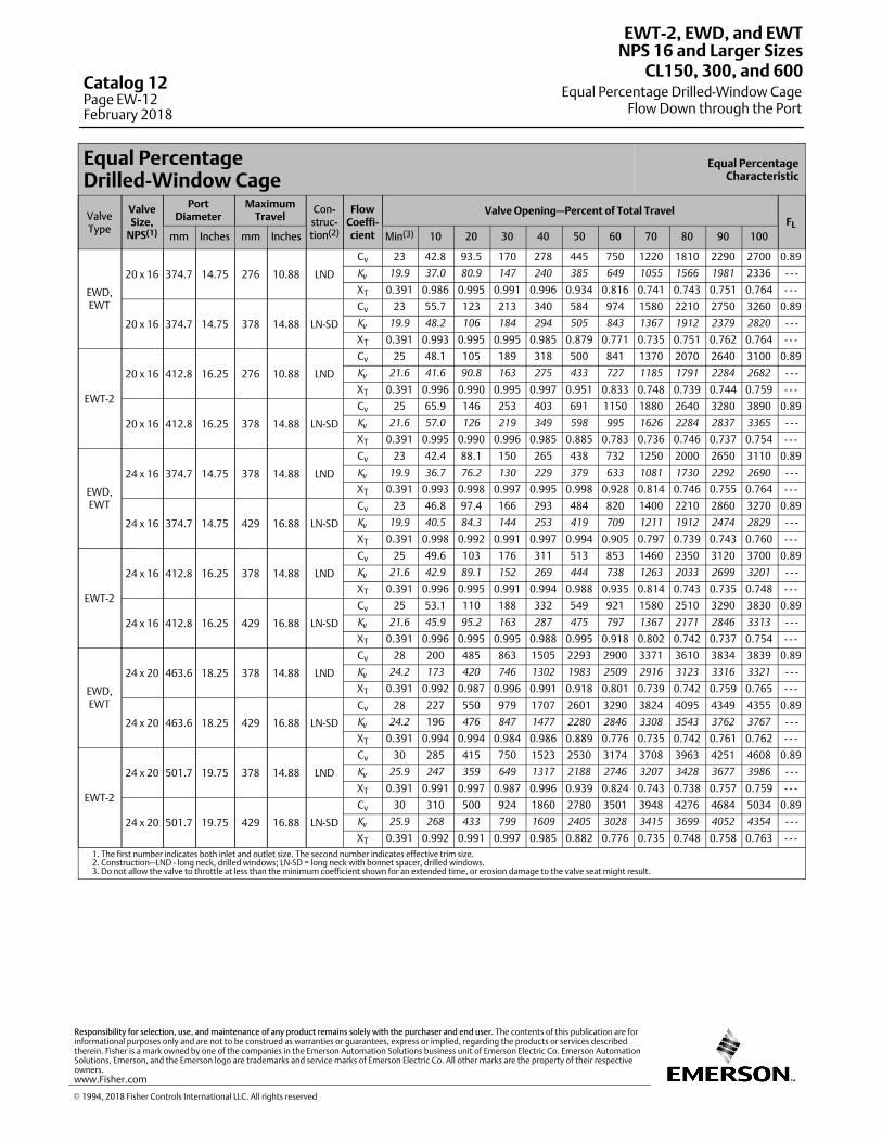
Equal PercentageDrilled-Window Cage
Equal PercentageCharacteristic
ValveType
ValveSize,
NPS(1)
PortDiameter
MaximumTravel
Con-struc-tion(2)
FlowCoeffi-cient
Valve Opening—Percent of Total TravelFL
mm Inches mm Inches Min(3) 10 20 30 40 50 60 70 80 90 100
EWD,EWT
20 x 16 374.7 14.75 276 10.88 LND
Cv 23 42.8 93.5 170 278 445 750 1220 1810 2290 2700 0.89
Kv 19.9 37.0 80.9 147 240 385 649 1055 1566 1981 2336 - - -
XT 0.391 0.986 0.995 0.991 0.996 0.934 0.816 0.741 0.743 0.751 0.764 - - -
20 x 16 374.7 14.75 378 14.88 LN-SD
Cv 23 55.7 123 213 340 584 974 1580 2210 2750 3260 0.89
Kv 19.9 48.2 106 184 294 505 843 1367 1912 2379 2820 - - -
XT 0.391 0.993 0.995 0.995 0.985 0.879 0.771 0.735 0.751 0.762 0.764 - - -
EWT-2
20 x 16 412.8 16.25 276 10.88 LND
Cv 25 48.1 105 189 318 500 841 1370 2070 2640 3100 0.89
Kv 21.6 41.6 90.8 163 275 433 727 1185 1791 2284 2682 - - -
XT 0.391 0.996 0.990 0.995 0.997 0.951 0.833 0.748 0.739 0.744 0.759 - - -
20 x 16 412.8 16.25 378 14.88 LN-SD
Cv 25 65.9 146 253 403 691 1150 1880 2640 3280 3890 0.89
Kv 21.6 57.0 126 219 349 598 995 1626 2284 2837 3365 - - -
XT 0.391 0.995 0.990 0.996 0.985 0.885 0.783 0.736 0.746 0.737 0.754 - - -
EWD,EWT
24 x 16 374.7 14.75 378 14.88 LND
Cv 23 42.4 88.1 150 265 438 732 1250 2000 2650 3110 0.89
Kv 19.9 36.7 76.2 130 229 379 633 1081 1730 2292 2690 - - -
XT 0.391 0.993 0.998 0.997 0.995 0.998 0.928 0.814 0.746 0.755 0.764 - - -
24 x 16 374.7 14.75 429 16.88 LN-SD
Cv 23 46.8 97.4 166 293 484 820 1400 2210 2860 3270 0.89
Kv 19.9 40.5 84.3 144 253 419 709 1211 1912 2474 2829 - - -
XT 0.391 0.998 0.992 0.991 0.997 0.994 0.905 0.797 0.739 0.743 0.760 - - -
EWT-2
24 x 16 412.8 16.25 378 14.88 LND
Cv 25 49.6 103 176 311 513 853 1460 2350 3120 3700 0.89
Kv 21.6 42.9 89.1 152 269 444 738 1263 2033 2699 3201 - - -
XT 0.391 0.996 0.995 0.991 0.994 0.988 0.935 0.814 0.743 0.735 0.748 - - -
24 x 16 412.8 16.25 429 16.88 LN-SD
Cv 25 53.1 110 188 332 549 921 1580 2510 3290 3830 0.89
Kv 21.6 45.9 95.2 163 287 475 797 1367 2171 2846 3313 - - -
XT 0.391 0.996 0.995 0.995 0.988 0.995 0.918 0.802 0.742 0.737 0.754 - - -
EWD,EWT
24 x 20 463.6 18.25 378 14.88 LND
Cv 28 200 485 863 1505 2293 2900 3371 3610 3834 3839 0.89
Kv 24.2 173 420 746 1302 1983 2509 2916 3123 3316 3321 - - -
XT 0.391 0.992 0.987 0.996 0.991 0.918 0.801 0.739 0.742 0.759 0.765 - - -
24 x 20 463.6 18.25 429 16.88 LN-SD
Cv 28 227 550 979 1707 2601 3290 3824 4095 4349 4355 0.89
Kv 24.2 196 476 847 1477 2280 2846 3308 3543 3762 3767 - - -
XT 0.391 0.994 0.994 0.984 0.986 0.889 0.776 0.735 0.742 0.761 0.762 - - -
EWT-2
24 x 20 501.7 19.75 378 14.88 LND
Cv 30 285 415 750 1523 2530 3174 3708 3963 4251 4608 0.89
Kv 25.9 247 359 649 1317 2188 2746 3207 3428 3677 3986 - - -
XT 0.391 0.991 0.997 0.987 0.996 0.939 0.824 0.743 0.738 0.757 0.759 - - -
24 x 20 501.7 19.75 429 16.88 LN-SD
Cv 30 310 500 924 1860 2780 3501 3948 4276 4684 5034 0.89
Kv 25.9 268 433 799 1609 2405 3028 3415 3699 4052 4354 - - -
XT 0.391 0.992 0.991 0.997 0.985 0.882 0.776 0.735 0.748 0.758 0.763 - - -1. The first number indicates both inlet and outlet size. The second number indicates effective trim size.2. Construction—LND - long neck, drilled windows; LN-SD = long neck with bonnet spacer, drilled windows.3. Do not allow the valve to throttle at less than the minimum coefficient shown for an extended time, or erosion damage to the valve seat might result.
EWT-2, EWD, and EWT
Equal Percentage Drilled-Window CageFlow Down through the Port
NPS 16 and Larger SizesCL150, 300, and 600
Catalog 12Page EW-12February 2018
� 1994, 2018 Fisher Controls International LLC. All rights reserved
www.Fisher.com
Responsibility for selection, use, and maintenance of any product remains solely with the purchaser and end user. The contents of this publication are forinformational purposes only and are not to be construed as warranties or guarantees, express or implied, regarding the products or services describedtherein. Fisher is a mark owned by one of the companies in the Emerson Automation Solutions business unit of Emerson Electric Co. Emerson AutomationSolutions, Emerson, and the Emerson logo are trademarks and service marks of Emerson Electric Co. All other marks are the property of their respectiveowners.
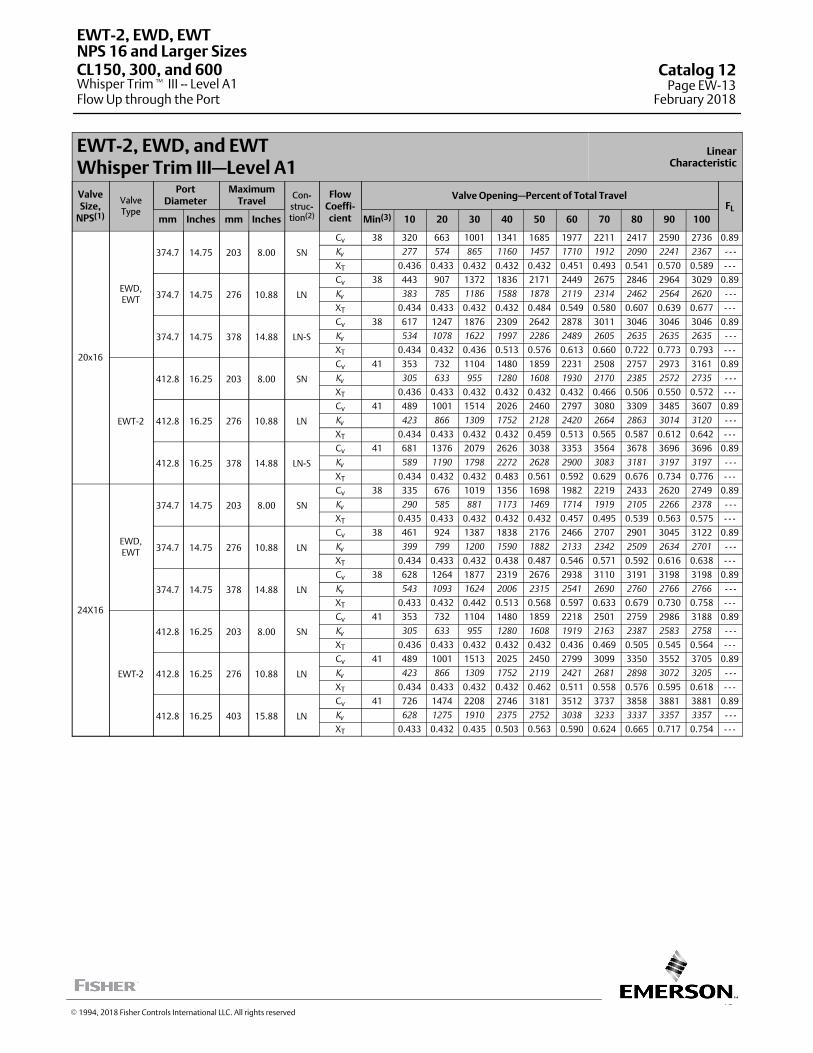
13
EWT-2, EWD, and EWTWhisper Trim III—Level A1
LinearCharacteristic
ValveSize,
NPS(1)
ValveType
PortDiameter
MaximumTravel
Con-struc-tion(2)
FlowCoeffi-cient
Valve Opening—Percent of Total TravelFL
mm Inches mm Inches Min(3) 10 20 30 40 50 60 70 80 90 100
20x16
EWD,EWT
374.7 14.75 203 8.00 SN
Cv 38 320 663 1001 1341 1685 1977 2211 2417 2590 2736 0.89
Kv 277 574 865 1160 1457 1710 1912 2090 2241 2367 - - -
XT 0.436 0.433 0.432 0.432 0.432 0.451 0.493 0.541 0.570 0.589 - - -
374.7 14.75 276 10.88 LN
Cv 38 443 907 1372 1836 2171 2449 2675 2846 2964 3029 0.89
Kv 383 785 1186 1588 1878 2119 2314 2462 2564 2620 - - -
XT 0.434 0.433 0.432 0.432 0.484 0.549 0.580 0.607 0.639 0.677 - - -
374.7 14.75 378 14.88 LN-S
Cv 38 617 1247 1876 2309 2642 2878 3011 3046 3046 3046 0.89
Kv 534 1078 1622 1997 2286 2489 2605 2635 2635 2635 - - -
XT 0.434 0.432 0.436 0.513 0.576 0.613 0.660 0.722 0.773 0.793 - - -
EWT-2
412.8 16.25 203 8.00 SN
Cv 41 353 732 1104 1480 1859 2231 2508 2757 2973 3161 0.89
Kv 305 633 955 1280 1608 1930 2170 2385 2572 2735 - - -
XT 0.436 0.433 0.432 0.432 0.432 0.432 0.466 0.506 0.550 0.572 - - -
412.8 16.25 276 10.88 LN
Cv 41 489 1001 1514 2026 2460 2797 3080 3309 3485 3607 0.89
Kv 423 866 1309 1752 2128 2420 2664 2863 3014 3120 - - -
XT 0.434 0.433 0.432 0.432 0.459 0.513 0.565 0.587 0.612 0.642 - - -
412.8 16.25 378 14.88 LN-S
Cv 41 681 1376 2079 2626 3038 3353 3564 3678 3696 3696 0.89
Kv 589 1190 1798 2272 2628 2900 3083 3181 3197 3197 - - -
XT 0.434 0.432 0.432 0.483 0.561 0.592 0.629 0.676 0.734 0.776 - - -
24X16
EWD,EWT
374.7 14.75 203 8.00 SN
Cv 38 335 676 1019 1356 1698 1982 2219 2433 2620 2749 0.89
Kv 290 585 881 1173 1469 1714 1919 2105 2266 2378 - - -
XT 0.435 0.433 0.432 0.432 0.432 0.457 0.495 0.539 0.563 0.575 - - -
374.7 14.75 276 10.88 LN
Cv 38 461 924 1387 1838 2176 2466 2707 2901 3045 3122 0.89
Kv 399 799 1200 1590 1882 2133 2342 2509 2634 2701 - - -
XT 0.434 0.433 0.432 0.438 0.487 0.546 0.571 0.592 0.616 0.638 - - -
374.7 14.75 378 14.88 LN
Cv 38 628 1264 1877 2319 2676 2938 3110 3191 3198 3198 0.89
Kv 543 1093 1624 2006 2315 2541 2690 2760 2766 2766 - - -
XT 0.433 0.432 0.442 0.513 0.568 0.597 0.633 0.679 0.730 0.758 - - -
EWT-2
412.8 16.25 203 8.00 SN
Cv 41 353 732 1104 1480 1859 2218 2501 2759 2986 3188 0.89
Kv 305 633 955 1280 1608 1919 2163 2387 2583 2758 - - -
XT 0.436 0.433 0.432 0.432 0.432 0.436 0.469 0.505 0.545 0.564 - - -
412.8 16.25 276 10.88 LN
Cv 41 489 1001 1513 2025 2450 2799 3099 3350 3552 3705 0.89
Kv 423 866 1309 1752 2119 2421 2681 2898 3072 3205 - - -
XT 0.434 0.433 0.432 0.432 0.462 0.511 0.558 0.576 0.595 0.618 - - -
412.8 16.25 403 15.88 LN
Cv 41 726 1474 2208 2746 3181 3512 3737 3858 3881 3881 0.89
Kv 628 1275 1910 2375 2752 3038 3233 3337 3357 3357 - - -
XT 0.433 0.432 0.435 0.503 0.563 0.590 0.624 0.665 0.717 0.754 - - -
EWT-2, EWD, EWT
Whisper Trim� III -- Level A1Flow Up through the Port
NPS 16 and Larger SizesCL150, 300, and 600 Catalog 12
Page EW-13February 2018
� 1994, 2018 Fisher Controls International LLC. All rights reserved
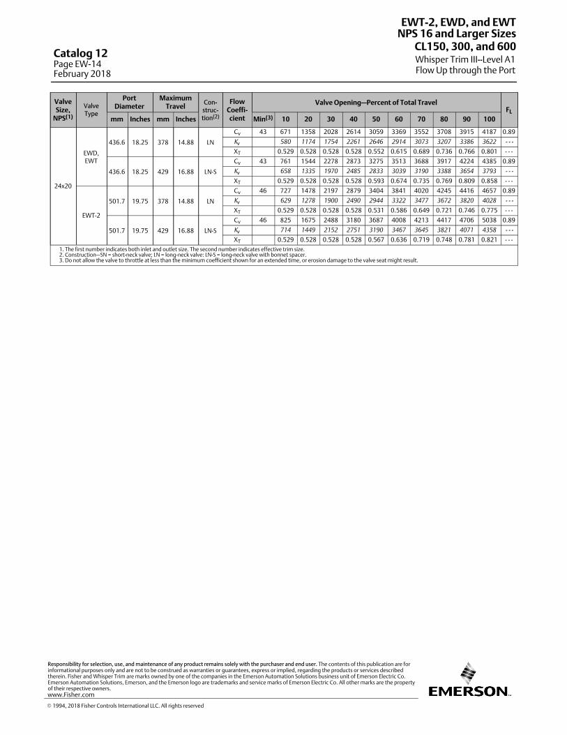
ValveSize,
NPS(1)
ValveType
PortDiameter
MaximumTravel
Con-struc-tion(2)
FlowCoeffi-cient
Valve Opening—Percent of Total TravelFL
mm Inches mm Inches Min(3) 10 20 30 40 50 60 70 80 90 100
24x20
EWD,EWT
436.6 18.25 378 14.88 LN
Cv 43 671 1358 2028 2614 3059 3369 3552 3708 3915 4187 0.89
Kv 580 1174 1754 2261 2646 2914 3073 3207 3386 3622 - - -
XT 0.529 0.528 0.528 0.528 0.552 0.615 0.689 0.736 0.766 0.801 - - -
436.6 18.25 429 16.88 LN-S
Cv 43 761 1544 2278 2873 3275 3513 3688 3917 4224 4385 0.89
Kv 658 1335 1970 2485 2833 3039 3190 3388 3654 3793 - - -
XT 0.529 0.528 0.528 0.528 0.593 0.674 0.735 0.769 0.809 0.858 - - -
EWT-2
501.7 19.75 378 14.88 LN
Cv 46 727 1478 2197 2879 3404 3841 4020 4245 4416 4657 0.89
Kv 629 1278 1900 2490 2944 3322 3477 3672 3820 4028 - - -
XT 0.529 0.528 0.528 0.528 0.531 0.586 0.649 0.721 0.746 0.775 - - -
501.7 19.75 429 16.88 LN-S
Cv 46 825 1675 2488 3180 3687 4008 4213 4417 4706 5038 0.89
Kv 714 1449 2152 2751 3190 3467 3645 3821 4071 4358 - - -
XT 0.529 0.528 0.528 0.528 0.567 0.636 0.719 0.748 0.781 0.821 - - -1. The first number indicates both inlet and outlet size. The second number indicates effective trim size.2. Construction—SN = short-neck valve; LN = long-neck valve: LN-S = long-neck valve with bonnet spacer.3. Do not allow the valve to throttle at less than the minimum coefficient shown for an extended time, or erosion damage to the valve seat might result.
EWT-2, EWD, and EWT
Whisper Trim III--Level A1Flow Up through the Port
NPS 16 and Larger SizesCL150, 300, and 600
Catalog 12Page EW-14February 2018
� 1994, 2018 Fisher Controls International LLC. All rights reserved
www.Fisher.com
Responsibility for selection, use, and maintenance of any product remains solely with the purchaser and end user. The contents of this publication are forinformational purposes only and are not to be construed as warranties or guarantees, express or implied, regarding the products or services describedtherein. Fisher and Whisper Trim are marks owned by one of the companies in the Emerson Automation Solutions business unit of Emerson Electric Co.Emerson Automation Solutions, Emerson, and the Emerson logo are trademarks and service marks of Emerson Electric Co. All other marks are the propertyof their respective owners.
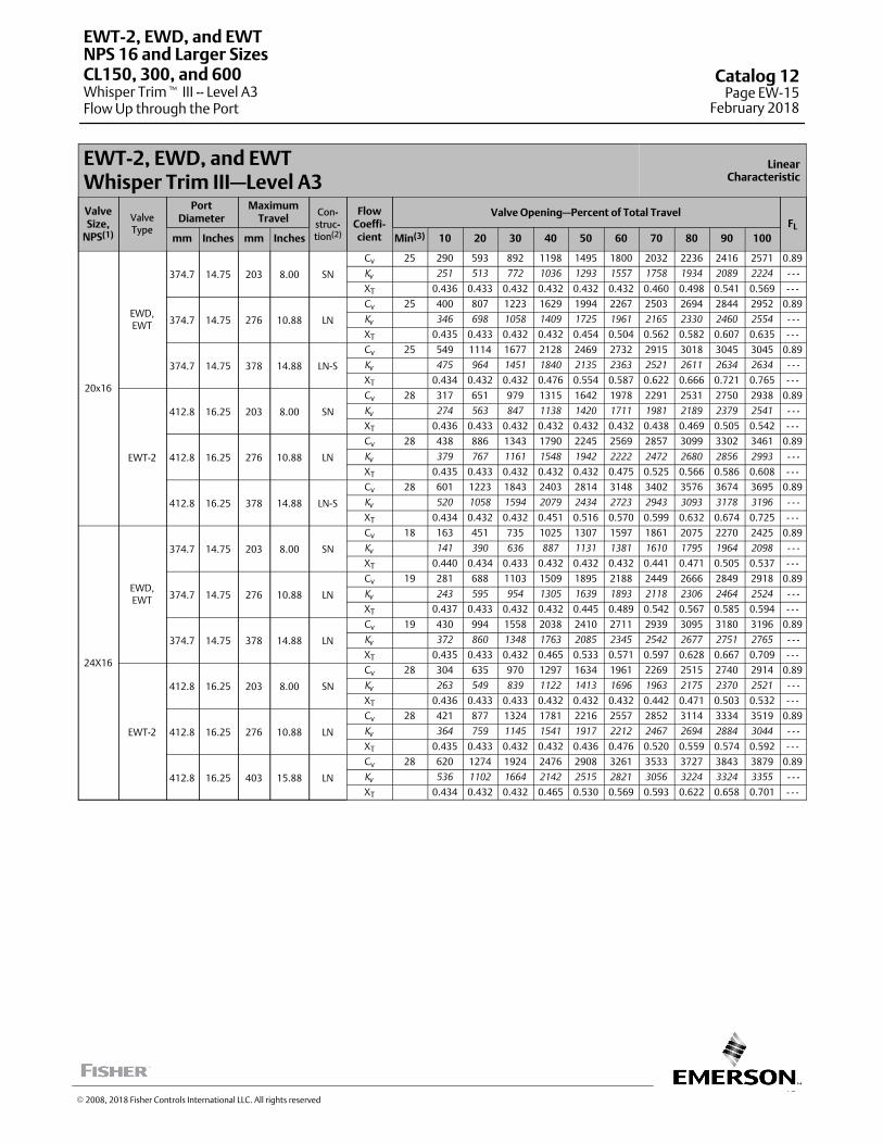
15
EWT-2, EWD, and EWTWhisper Trim III—Level A3
LinearCharacteristic
ValveSize,
NPS(1)
ValveType
PortDiameter
MaximumTravel
Con-struc-tion(2)
FlowCoeffi-cient
Valve Opening—Percent of Total TravelFL
mm Inches mm Inches Min(3) 10 20 30 40 50 60 70 80 90 100
20x16
EWD,EWT
374.7 14.75 203 8.00 SN
Cv 25 290 593 892 1198 1495 1800 2032 2236 2416 2571 0.89
Kv 251 513 772 1036 1293 1557 1758 1934 2089 2224 - - -
XT 0.436 0.433 0.432 0.432 0.432 0.432 0.460 0.498 0.541 0.569 - - -
374.7 14.75 276 10.88 LN
Cv 25 400 807 1223 1629 1994 2267 2503 2694 2844 2952 0.89
Kv 346 698 1058 1409 1725 1961 2165 2330 2460 2554 - - -
XT 0.435 0.433 0.432 0.432 0.454 0.504 0.562 0.582 0.607 0.635 - - -
374.7 14.75 378 14.88 LN-S
Cv 25 549 1114 1677 2128 2469 2732 2915 3018 3045 3045 0.89
Kv 475 964 1451 1840 2135 2363 2521 2611 2634 2634 - - -
XT 0.434 0.432 0.432 0.476 0.554 0.587 0.622 0.666 0.721 0.765 - - -
EWT-2
412.8 16.25 203 8.00 SN
Cv 28 317 651 979 1315 1642 1978 2291 2531 2750 2938 0.89
Kv 274 563 847 1138 1420 1711 1981 2189 2379 2541 - - -
XT 0.436 0.433 0.432 0.432 0.432 0.432 0.438 0.469 0.505 0.542 - - -
412.8 16.25 276 10.88 LN
Cv 28 438 886 1343 1790 2245 2569 2857 3099 3302 3461 0.89
Kv 379 767 1161 1548 1942 2222 2472 2680 2856 2993 - - -
XT 0.435 0.433 0.432 0.432 0.432 0.475 0.525 0.566 0.586 0.608 - - -
412.8 16.25 378 14.88 LN-S
Cv 28 601 1223 1843 2403 2814 3148 3402 3576 3674 3695 0.89
Kv 520 1058 1594 2079 2434 2723 2943 3093 3178 3196 - - -
XT 0.434 0.432 0.432 0.451 0.516 0.570 0.599 0.632 0.674 0.725 - - -
24X16
EWD,EWT
374.7 14.75 203 8.00 SN
Cv 18 163 451 735 1025 1307 1597 1861 2075 2270 2425 0.89
Kv 141 390 636 887 1131 1381 1610 1795 1964 2098 - - -
XT 0.440 0.434 0.433 0.432 0.432 0.432 0.441 0.471 0.505 0.537 - - -
374.7 14.75 276 10.88 LN
Cv 19 281 688 1103 1509 1895 2188 2449 2666 2849 2918 0.89
Kv 243 595 954 1305 1639 1893 2118 2306 2464 2524 - - -
XT 0.437 0.433 0.432 0.432 0.445 0.489 0.542 0.567 0.585 0.594 - - -
374.7 14.75 378 14.88 LN
Cv 19 430 994 1558 2038 2410 2711 2939 3095 3180 3196 0.89
Kv 372 860 1348 1763 2085 2345 2542 2677 2751 2765 - - -
XT 0.435 0.433 0.432 0.465 0.533 0.571 0.597 0.628 0.667 0.709 - - -
EWT-2
412.8 16.25 203 8.00 SN
Cv 28 304 635 970 1297 1634 1961 2269 2515 2740 2914 0.89
Kv 263 549 839 1122 1413 1696 1963 2175 2370 2521 - - -
XT 0.436 0.433 0.433 0.432 0.432 0.432 0.442 0.471 0.503 0.532 - - -
412.8 16.25 276 10.88 LN
Cv 28 421 877 1324 1781 2216 2557 2852 3114 3334 3519 0.89
Kv 364 759 1145 1541 1917 2212 2467 2694 2884 3044 - - -
XT 0.435 0.433 0.432 0.432 0.436 0.476 0.520 0.559 0.574 0.592 - - -
412.8 16.25 403 15.88 LN
Cv 28 620 1274 1924 2476 2908 3261 3533 3727 3843 3879 0.89
Kv 536 1102 1664 2142 2515 2821 3056 3224 3324 3355 - - -
XT 0.434 0.432 0.432 0.465 0.530 0.569 0.593 0.622 0.658 0.701 - - -
EWT-2, EWD, and EWT
Whisper Trim� III -- Level A3Flow Up through the Port
NPS 16 and Larger SizesCL150, 300, and 600 Catalog 12
Page EW-15February 2018
� 2008, 2018 Fisher Controls International LLC. All rights reserved
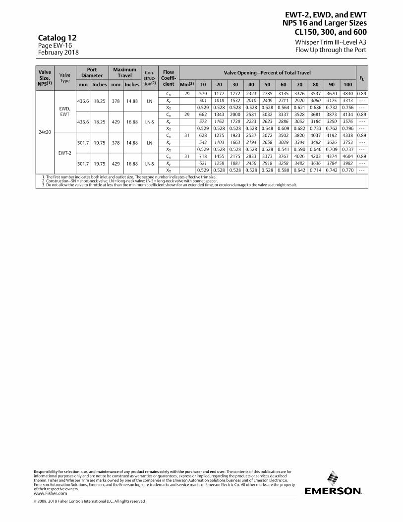
ValveSize,
NPS(1)
ValveType
PortDiameter
MaximumTravel
Con-struc-tion(2)
FlowCoeffi-cient
Valve Opening—Percent of Total TravelFL
mm Inches mm Inches Min(3) 10 20 30 40 50 60 70 80 90 100
24x20
EWD,EWT
436.6 18.25 378 14.88 LN
Cv 29 579 1177 1772 2323 2785 3135 3376 3537 3670 3830 0.89
Kv 501 1018 1532 2010 2409 2711 2920 3060 3175 3313 - - -
XT 0.529 0.528 0.528 0.528 0.528 0.564 0.621 0.686 0.732 0.756 - - -
436.6 18.25 429 16.88 LN-S
Cv 29 662 1343 2000 2581 3032 3337 3528 3681 3873 4134 0.89
Kv 573 1162 1730 2233 2623 2886 3052 3184 3350 3576 - - -
XT 0.529 0.528 0.528 0.528 0.548 0.609 0.682 0.733 0.762 0.796 - - -
EWT-2
501.7 19.75 378 14.88 LN
Cv 31 628 1275 1923 2537 3072 3502 3820 4037 4192 4338 0.89
Kv 543 1103 1663 2194 2658 3029 3304 3492 3626 3753 - - -
XT 0.529 0.528 0.528 0.528 0.528 0.541 0.590 0.646 0.709 0.737 - - -
501.7 19.75 429 16.88 LN-S
Cv 31 718 1455 2175 2833 3373 3767 4026 4203 4374 4604 0.89
Kv 621 1258 1881 2450 2918 3258 3482 3636 3784 3982 - - -
XT 0.529 0.528 0.528 0.528 0.528 0.580 0.642 0.714 0.742 0.770 - - -1. The first number indicates both inlet and outlet size. The second number indicates effective trim size.2. Construction—SN = short-neck valve; LN = long-neck valve: LN-S = long-neck valve with bonnet spacer.3. Do not allow the valve to throttle at less than the minimum coefficient shown for an extended time, or erosion damage to the valve seat might result.
EWT-2, EWD, and EWT
Whisper Trim III--Level A3Flow Up through the Port
NPS 16 and Larger SizesCL150, 300, and 600
Catalog 12Page EW-16February 2018
� 2008, 2018 Fisher Controls International LLC. All rights reserved
www.Fisher.com
Responsibility for selection, use, and maintenance of any product remains solely with the purchaser and end user. The contents of this publication are forinformational purposes only and are not to be construed as warranties or guarantees, express or implied, regarding the products or services describedtherein. Fisher and Whisper Trim are marks owned by one of the companies in the Emerson Automation Solutions business unit of Emerson Electric Co.Emerson Automation Solutions, Emerson, and the Emerson logo are trademarks and service marks of Emerson Electric Co. All other marks are the propertyof their respective owners.
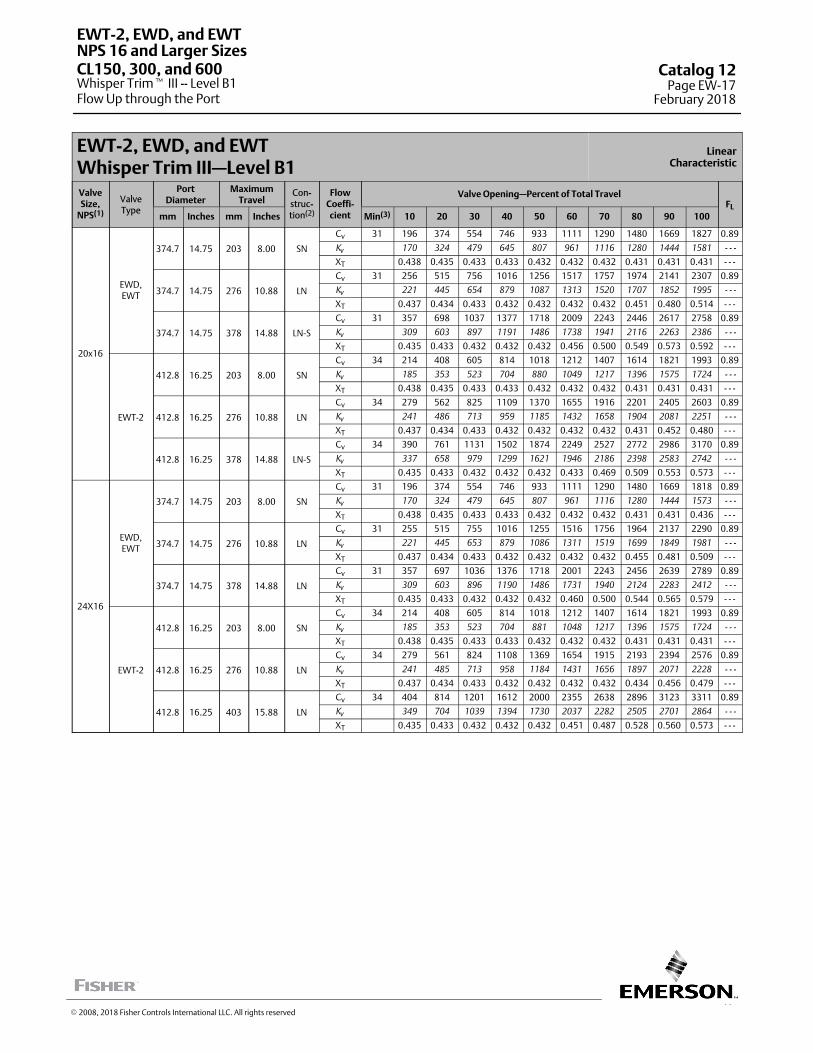
17
EWT-2, EWD, and EWTWhisper Trim III—Level B1
LinearCharacteristic
ValveSize,
NPS(1)
ValveType
PortDiameter
MaximumTravel
Con-struc-tion(2)
FlowCoeffi-cient
Valve Opening—Percent of Total TravelFL
mm Inches mm Inches Min(3) 10 20 30 40 50 60 70 80 90 100
20x16
EWD,EWT
374.7 14.75 203 8.00 SN
Cv 31 196 374 554 746 933 1111 1290 1480 1669 1827 0.89
Kv 170 324 479 645 807 961 1116 1280 1444 1581 - - -
XT 0.438 0.435 0.433 0.433 0.432 0.432 0.432 0.431 0.431 0.431 - - -
374.7 14.75 276 10.88 LN
Cv 31 256 515 756 1016 1256 1517 1757 1974 2141 2307 0.89
Kv 221 445 654 879 1087 1313 1520 1707 1852 1995 - - -
XT 0.437 0.434 0.433 0.432 0.432 0.432 0.432 0.451 0.480 0.514 - - -
374.7 14.75 378 14.88 LN-S
Cv 31 357 698 1037 1377 1718 2009 2243 2446 2617 2758 0.89
Kv 309 603 897 1191 1486 1738 1941 2116 2263 2386 - - -
XT 0.435 0.433 0.432 0.432 0.432 0.456 0.500 0.549 0.573 0.592 - - -
EWT-2
412.8 16.25 203 8.00 SN
Cv 34 214 408 605 814 1018 1212 1407 1614 1821 1993 0.89
Kv 185 353 523 704 880 1049 1217 1396 1575 1724 - - -
XT 0.438 0.435 0.433 0.433 0.432 0.432 0.432 0.431 0.431 0.431 - - -
412.8 16.25 276 10.88 LN
Cv 34 279 562 825 1109 1370 1655 1916 2201 2405 2603 0.89
Kv 241 486 713 959 1185 1432 1658 1904 2081 2251 - - -
XT 0.437 0.434 0.433 0.432 0.432 0.432 0.432 0.431 0.452 0.480 - - -
412.8 16.25 378 14.88 LN-S
Cv 34 390 761 1131 1502 1874 2249 2527 2772 2986 3170 0.89
Kv 337 658 979 1299 1621 1946 2186 2398 2583 2742 - - -
XT 0.435 0.433 0.432 0.432 0.432 0.433 0.469 0.509 0.553 0.573 - - -
24X16
EWD,EWT
374.7 14.75 203 8.00 SN
Cv 31 196 374 554 746 933 1111 1290 1480 1669 1818 0.89
Kv 170 324 479 645 807 961 1116 1280 1444 1573 - - -
XT 0.438 0.435 0.433 0.433 0.432 0.432 0.432 0.431 0.431 0.436 - - -
374.7 14.75 276 10.88 LN
Cv 31 255 515 755 1016 1255 1516 1756 1964 2137 2290 0.89
Kv 221 445 653 879 1086 1311 1519 1699 1849 1981 - - -
XT 0.437 0.434 0.433 0.432 0.432 0.432 0.432 0.455 0.481 0.509 - - -
374.7 14.75 378 14.88 LN
Cv 31 357 697 1036 1376 1718 2001 2243 2456 2639 2789 0.89
Kv 309 603 896 1190 1486 1731 1940 2124 2283 2412 - - -
XT 0.435 0.433 0.432 0.432 0.432 0.460 0.500 0.544 0.565 0.579 - - -
EWT-2
412.8 16.25 203 8.00 SN
Cv 34 214 408 605 814 1018 1212 1407 1614 1821 1993 0.89
Kv 185 353 523 704 881 1048 1217 1396 1575 1724 - - -
XT 0.438 0.435 0.433 0.433 0.432 0.432 0.432 0.431 0.431 0.431 - - -
412.8 16.25 276 10.88 LN
Cv 34 279 561 824 1108 1369 1654 1915 2193 2394 2576 0.89
Kv 241 485 713 958 1184 1431 1656 1897 2071 2228 - - -
XT 0.437 0.434 0.433 0.432 0.432 0.432 0.432 0.434 0.456 0.479 - - -
412.8 16.25 403 15.88 LN
Cv 34 404 814 1201 1612 2000 2355 2638 2896 3123 3311 0.89
Kv 349 704 1039 1394 1730 2037 2282 2505 2701 2864 - - -
XT 0.435 0.433 0.432 0.432 0.432 0.451 0.487 0.528 0.560 0.573 - - -
EWT-2, EWD, and EWT
Whisper Trim� III -- Level B1Flow Up through the Port
NPS 16 and Larger SizesCL150, 300, and 600 Catalog 12
Page EW-17February 2018
� 2008, 2018 Fisher Controls International LLC. All rights reserved

ValveSize,
NPS(1)
ValveType
PortDiameter
MaximumTravel
Con-struc-tion(2)
FlowCoeffi-cient
Valve Opening—Percent of Total TravelFL
mm Inches mm Inches Min(3) 10 20 30 40 50 60 70 80 90 100
24x20
EWD,EWT
436.6 18.25 378 14.88 LN
Cv 36 385 754 1121 1486 1844 2191 2508 2783 3011 3196 0.89
Kv 333 652 969 1285 1595 1895 2169 2407 2605 2765 - - -
XT 0.529 0.529 0.528 0.528 0.528 0.528 0.528 0.528 0.545 0.576 - - -
436.6 18.25 429 16.88 LN-S
Cv 36 431 851 1269 1682 2078 2441 2759 3022 3229 3384 0.89
Kv 373 736 1098 1455 1797 2112 2387 2614 2793 2927 - - -
XT 0.529 0.528 0.528 0.528 0.528 0.528 0.528 0.546 0.583 0.623 - - -
EWT-2
501.7 19.75 378 14.88 LN
Cv 38 414 811 1205 1598 1988 2371 2730 3051 3330 3565 0.89
Kv 358 702 1042 1382 1720 2051 2361 2639 2880 3084 - - -
XT 0.529 0.529 0.528 0.528 0.528 0.528 0.528 0.528 0.528 0.549 - - -
501.7 19.75 429 16.88 LN-S
Cv 38 464 915 1365 1811 2245 2654 3023 3344 3608 3817 0.89
Kv 401 792 1181 1567 1942 2295 2615 2892 3121 3302 - - -
XT 0.529 0.528 0.528 0.528 0.528 0.528 0.528 0.528 0.555 0.590 - - -1. The first number indicates both inlet and outlet size. The second number indicates effective trim size.2. Construction—SN = short-neck valve; LN = long-neck valve: LN-S = long-neck valve with bonnet spacer.3. Do not allow the valve to throttle at less than the minimum coefficient shown for an extended time, or erosion damage to the valve seat might result.
EWT-2, EWD, and EWT
Whisper Trim III--Level B1Flow Up through the Port
NPS 16 and Larger SizesCL150, 300, and 600
Catalog 12Page EW-18February 2018
� 2008, 2018 Fisher Controls International LLC. All rights reserved
www.Fisher.com
Responsibility for selection, use, and maintenance of any product remains solely with the purchaser and end user. The contents of this publication are forinformational purposes only and are not to be construed as warranties or guarantees, express or implied, regarding the products or services describedtherein. Fisher and Whisper Trim are marks owned by one of the companies in the Emerson Automation Solutions business unit of Emerson Electric Co.Emerson Automation Solutions, Emerson, and the Emerson logo are trademarks and service marks of Emerson Electric Co. All other marks are the propertyof their respective owners.

19
EWT-2, EWD, and EWTWhisper Trim III—Level B3
LinearCharacteristic
ValveSize,
NPS(1)
ValveType
PortDiameter
MaximumTravel
Con-struc-tion(2)
FlowCoeffi-cient
Valve Opening—Percent of Total TravelFL
mm Inches mm Inches Min(3) 10 20 30 40 50 60 70 80 90 100
20x16
EWD,EWT
374.7 14.75 203 8.00 SN
Cv 21 178 349 528 701 878 1052 1228 1404 1578 1756 0.89
Kv 154 302 457 606 760 910 1062 1215 1365 1519 - - -
XT 0.439 0.435 0.433 0.433 0.432 0.432 0.432 0.431 0.431 0.431 - - -
374.7 14.75 276 10.88 LN
Cv 21 236 475 714 954 1194 1434 1674 1896 2070 2229 0.89
Kv 204 411 618 825 1032 1240 1448 1640 1791 1928 - - -
XT 0.437 0.434 0.433 0.432 0.432 0.432 0.432 0.439 0.467 0.497 - - -
374.7 14.75 378 14.88 LN-S
Cv 21 326 657 982 1307 1639 1936 2163 2367 2545 2689 0.89
Kv 282 569 849 1130 1418 1675 1871 2047 2201 2326 - - -
XT 0.436 0.433 0.432 0.432 0.432 0.445 0.483 0.528 0.566 0.582 - - -
EWT-2
412.8 16.25 203 8.00 SN
Cv 23 194 382 578 767 962 1152 1345 1537 1729 1922 0.89
Kv 168 330 500 663 832 996 1164 1329 1495 1663 - - -
XT 0.439 0.435 0.433 0.433 0.432 0.432 0.432 0.432 0.431 0.431 - - -
412.8 16.25 276 10.88 LN
Cv 23 258 520 782 1044 1307 1570 1833 2096 2328 2517 0.89
Kv 223 450 676 903 1131 1358 1586 1813 2014 2177 - - -
XT 0.437 0.434 0.433 0.432 0.432 0.432 0.432 0.431 0.443 0.468 - - -
412.8 16.25 378 14.88 LN-S
Cv 23 357 719 1074 1431 1795 2153 2438 2683 2902 3086 0.89
Kv 309 622 929 1238 1553 1862 2109 2321 2510 2670 - - -
XT 0.436 0.433 0.432 0.432 0.432 0.432 0.456 0.493 0.534 0.566 - - -
24X16
EWD,EWT
374.7 14.75 203 8.00 SN
Cv 21 178 349 528 701 878 1052 1228 1404 1578 1744 0.89
Kv 154 302 457 606 759 910 1062 1214 1365 1509 - - -
XT 0.439 0.435 0.433 0.433 0.432 0.432 0.432 0.431 0.431 0.431 - - -
374.7 14.75 276 10.88 LN
Cv 21 236 475 714 953 1193 1433 1673 1886 2064 2217 0.89
Kv 204 411 618 824 1032 1240 1447 1631 1785 1918 - - -
XT 0.437 0.434 0.433 0.432 0.432 0.432 0.432 0.444 0.470 0.495 - - -
374.7 14.75 378 14.88 LN
Cv 21 326 657 981 1306 1639 1926 2159 2373 2561 2711 0.89
Kv 282 568 849 1130 1418 1666 1868 2053 2215 2345 - - -
XT 0.436 0.433 0.432 0.432 0.432 0.449 0.485 0.525 0.559 0.571 - - -
EWT-2
412.8 16.25 203 8.00 SN
Cv 23 194 382 578 767 962 1152 1345 1537 1729 1910 0.89
Kv 168 330 500 663 832 996 1163 1330 1496 1652 - - -
XT 0.439 0.435 0.433 0.433 0.432 0.432 0.432 0.431 0.431 0.431 - - -
412.8 16.25 276 10.88 LN
Cv 23 258 520 782 1044 1307 1570 1833 2096 2316 2496 0.89
Kv 223 450 676 903 1131 1358 1586 1813 2003 2159 - - -
XT 0.437 0.434 0.433 0.432 0.432 0.432 0.432 0.431 0.447 0.469 - - -
412.8 16.25 403 15.88 LN
Cv 23 379 762 1147 1532 1916 2271 2553 2807 3034 3222 0.89
Kv 328 659 992 1325 1657 1964 2208 2428 2624 2787 - - -
XT 0.435 0.433 0.432 0.432 0.432 0.442 0.476 0.513 0.550 0.566 - - -
EWT-2, EWD, and EWT
Whisper Trim� III -- Level B3Flow Up through the Port
NPS 16 and Larger SizesCL150, 300, and 600 Catalog 12
Page EW-19February 2018
� 2008, 2018 Fisher Controls International LLC. All rights reserved

ValveSize,
NPS(1)
ValveType
PortDiameter
MaximumTravel
Con-struc-tion(2)
FlowCoeffi-cient
Valve Opening—Percent of Total TravelFL
mm Inches mm Inches Min(3) 10 20 30 40 50 60 70 80 90 100
24x20
EWD,EWT
436.6 18.25 378 14.88 LN
Cv 25 354 716 1070 1423 1778 2110 2416 2695 2933 3127 0.89
Kv 307 620 925 1231 1538 1825 2090 2331 2537 2705 - - -
XT 0.529 0.529 0.528 0.528 0.528 0.528 0.528 0.528 0.534 0.562 - - -
436.6 18.25 429 16.88 LN-S
Cv 25 402 809 1215 1618 2005 2363 2680 2948 3163 3329 0.89
Kv 348 700 1051 1399 1734 2044 2318 2550 2736 2879 - - -
XT 0.529 0.529 0.528 0.528 0.528 0.528 0.528 0.535 0.569 0.607 - - -
EWT-2
501.7 19.75 378 14.88 LN
Cv 27 382 773 1153 1535 1921 2286 2631 2954 3239 3482 0.89
Kv 331 668 997 1328 1661 1978 2276 2555 2802 3012 - - -
XT 0.529 0.529 0.528 0.528 0.528 0.528 0.528 0.528 0.528 0.539 - - -
501.7 19.75 429 16.88 LN-S
Cv 27 433 873 1310 1745 2170 2571 2936 3257 3528 3747 0.89
Kv 375 755 1133 1510 1877 2224 2540 2818 3052 3241 - - -
XT 0.529 0.529 0.528 0.528 0.528 0.528 0.528 0.528 0.545 0.576 - - -1. The first number indicates both inlet and outlet size. The second number indicates effective trim size.2. Construction—SN = short-neck valve; LN = long-neck valve: LN-S = long-neck valve with bonnet spacer.3. Do not allow the valve to throttle at less than the minimum coefficient shown for an extended time, or erosion damage to the valve seat might result.
EWT-2, EWD, and EWT
Whisper Trim III--Level B3Flow Up through the Port
NPS 16 and Larger SizesCL150, 300, and 600
Catalog 12Page EW-20February 2018
� 2008, 2018 Fisher Controls International LLC. All rights reserved
www.Fisher.com
Responsibility for selection, use, and maintenance of any product remains solely with the purchaser and end user. The contents of this publication are forinformational purposes only and are not to be construed as warranties or guarantees, express or implied, regarding the products or services describedtherein. Fisher and Whisper Trim are marks owned by one of the companies in the Emerson Automation Solutions business unit of Emerson Electric Co.Emerson Automation Solutions, Emerson, and the Emerson logo are trademarks and service marks of Emerson Electric Co. All other marks are the propertyof their respective owners.

21
EWT-2, EWD, and EWTWhisper Trim III—Level C1
LinearCharacteristic
ValveSize,
NPS(1)
ValveType
PortDiameter
MaximumTravel
Con-struc-tion(2)
FlowCoeffi-cient
Valve Opening—Percent of Total TravelFL
mm Inches mm Inches Min(3) 10 20 30 40 50 60 70 80 90 100
20x16
EWD,EWT
374.7 14.75 203 8.00 SN
Cv 27 131 244 351 459 577 696 811 919 1026 1142 0.89
Kv 113 211 303 397 499 602 701 795 888 987 - - -
XT 0.442 0.436 0.434 0.433 0.433 0.432 0.432 0.432 0.431 0.431 - - -
374.7 14.75 276 10.88 LN
Cv 27 161 318 478 637 787 936 1088 1247 1407 1562 0.89
Kv 139 275 414 551 681 810 941 1079 1217 1351 - - -
XT 0.440 0.435 0.434 0.433 0.432 0.432 0.432 0.432 0.431 0.431 - - -
374.7 14.75 276 14.88 LN-S
Cv 27 221 430 642 855 1069 1284 1498 1712 1904 2055 0.89
Kv 191 372 555 740 925 1111 1296 1481 1647 1778 - - -
XT 0.438 0.434 0.433 0.432 0.432 0.432 0.432 0.431 0.440 0.464 - - -
EWT-2
412.8 16.25 203 8.00 SN
Cv 30 146 272 392 513 645 777 906 1027 1147 1276 0.89
Kv 126 235 339 444 558 672 784 888 992 1104 - - -
XT 0.442 0.436 0.434 0.433 0.433 0.432 0.432 0.432 0.431 0.431 - - -
412.8 16.25 276 10.88 LN
Cv 30 180 355 534 712 880 1046 1216 1394 1573 1746 0.89
Kv 156 307 462 616 761 905 1052 1206 1361 1510 - - -
XT 0.440 0.435 0.433 0.433 0.432 0.432 0.432 0.432 0.431 0.431 - - -
412.8 16.25 276 14.88 LN-S
Cv 30 247 481 717 956 1195 1435 1675 1913 2150 2347 0.89
Kv 214 416 620 827 1034 1241 1448 1655 1860 2030 - - -
XT 0.437 0.434 0.433 0.432 0.432 0.432 0.432 0.431 0.431 0.445 - - -
24X16
EWD,EWT
374.7 14.75 203 8.00 SN
Cv 27 131 244 351 459 577 696 811 919 1026 1142 0.89
Kv 113 211 304 397 499 602 702 795 887 988 - - -
XT 0.442 0.436 0.434 0.433 0.433 0.432 0.432 0.432 0.431 0.431 - - -
374.7 14.75 276 10.88 LN
Cv 27 161 318 478 636 787 936 1087 1246 1406 1562 0.89
Kv 139 275 413 550 681 810 940 1078 1216 1351 - - -
XT 0.440 0.435 0.434 0.433 0.432 0.432 0.432 0.432 0.431 0.431 - - -
374.7 14.75 378 14.88 LN
Cv 27 221 430 641 855 1069 1283 1497 1711 1893 2049 0.89
Kv 191 372 554 740 925 1110 1295 1480 1637 1772 - - -
XT 0.438 0.434 0.433 0.432 0.432 0.432 0.432 0.431 0.445 0.467 - - -
EWT-2
412.8 16.25 203 8.00 SN
Cv 30 146 272 392 513 645 777 906 1027 1147 1276 0.89
Kv 126 235 339 444 558 672 784 888 992 1104 - - -
XT 0.442 0.436 0.434 0.433 0.433 0.432 0.432 0.432 0.431 0.431 - - -
412.8 16.25 276 10.88 LN
Cv 30 180 355 534 711 880 1046 1215 1393 1572 1746 0.89
Kv 156 307 462 615 761 905 1051 1205 1360 1510 - - -
XT 0.440 0.435 0.433 0.433 0.432 0.432 0.432 0.432 0.431 0.431 - - -
412.8 16.25 403 15.88 LN
Cv 30 270 514 778 1017 1282 1525 1783 2034 2259 2454 0.89
Kv 234 445 673 880 1109 1319 1542 1759 1954 2123 - - -
XT 0.437 0.434 0.433 0.432 0.432 0.432 0.432 0.431 0.441 0.463 - - -
EWT-2, EWD, and EWT
Whisper Trim� III -- Level C1Flow Up through the Port
NPS 16 and Larger SizesCL150, 300, and 600 Catalog 12
Page EW-21February 2018
� 2008, 2018 Fisher Controls International LLC. All rights reserved

ValveSize,
NPS(1)
ValveType
PortDiameter
MaximumTravel
Con-struc-tion(2)
FlowCoeffi-cient
Valve Opening—Percent of Total TravelFL
mm Inches mm Inches Min(3) 10 20 30 40 50 60 70 80 90 100
24x20
EWD,EWT
436.6 18.25 378 14.88 LN
Cv 31 238 469 700 932 1165 1398 1628 1853 2069 2272 0.89
Kv 206 405 605 806 1008 1209 1409 1603 1790 1965 - - -
XT 0.530 0.529 0.529 0.528 0.528 0.528 0.528 0.528 0.528 0.528 - - -
436.6 18.25 429 16.88 LN-S
Cv 31 271 534 795 1056 1316 1574 1828 2073 2305 2522 0.89
Kv 234 462 688 913 1138 1362 1581 1793 1994 2181 - - -
XT 0.530 0.529 0.528 0.528 0.528 0.528 0.528 0.528 0.528 0.528 - - -
EWT-2
501.7 19.75 378 14.88 LN
Cv 34 260 514 767 1022 1278 1533 1786 2036 2277 2506 0.89
Kv 225 445 664 884 1105 1326 1545 1761 1969 2168 - - -
XT 0.530 0.529 0.529 0.528 0.528 0.528 0.528 0.528 0.528 0.528 - - -
501.7 19.75 429 16.88 LN-S
Cv 34 297 586 872 1157 1442 1727 2007 2281 2544 2792 0.89
Kv 257 507 754 1001 1248 1494 1736 1973 2201 2415 - - -
XT 0.530 0.529 0.528 0.528 0.528 0.528 0.528 0.528 0.528 0.528 - - -1. The first number indicates both inlet and outlet size. The second number indicates effective trim size.2. Construction—SN = short-neck valve; LN = long-neck valve: LN-S = long-neck valve with bonnet spacer.3. Do not allow the valve to throttle at less than the minimum coefficient shown for an extended time, or erosion damage to the valve seat might result.
EWT-2, EWD, and EWT
Whisper Trim III--Level C1Flow Up through the Port
NPS 16 and Larger SizesCL150, 300, and 600
Catalog 12Page EW-22February 2018
� 2008, 2018 Fisher Controls International LLC. All rights reserved
www.Fisher.com
Responsibility for selection, use, and maintenance of any product remains solely with the purchaser and end user. The contents of this publication are forinformational purposes only and are not to be construed as warranties or guarantees, express or implied, regarding the products or services describedtherein. Fisher and Whisper Trim are marks owned by one of the companies in the Emerson Automation Solutions business unit of Emerson Electric Co.Emerson Automation Solutions, Emerson, and the Emerson logo are trademarks and service marks of Emerson Electric Co. All other marks are the propertyof their respective owners.

23
EWT-2, EWD, and EWTWhisper Trim III—Level C3
LinearCharacteristic
ValveSize,
NPS(1)
ValveType
PortDiameter
MaximumTravel
Con-struc-tion(2)
FlowCoeffi-cient
Valve Opening—Percent of Total TravelFL
mm Inches mm Inches Min(3) 10 20 30 40 50 60 70 80 90 100
20x16
EWD,EWT
374.7 14.75 203 8.00 SN
Cv 19 116 235 344 458 574 682 800 912 1023 1141 0.89
Kv 100 203 298 396 497 590 692 789 885 987 - - -
XT 0.443 0.437 0.434 0.433 0.433 0.432 0.432 0.432 0.431 0.431 - - -
374.7 14.75 276 10.88 LN
Cv 19 161 311 471 623 776 935 1085 1240 1398 1547 0.89
Kv 139 269 408 539 671 809 939 1073 1209 1338 - - -
XT 0.440 0.435 0.434 0.433 0.432 0.432 0.432 0.432 0.431 0.431 - - -
374.7 14.75 276 14.88 LN-S
Cv 19 220 430 639 849 1063 1277 1490 1700 1893 2046 0.89
Kv 191 372 553 734 919 1105 1289 1470 1637 1769 - - -
XT 0.438 0.434 0.433 0.432 0.432 0.432 0.432 0.431 0.439 0.463 - - -
EWT-2
412.8 16.25 203 8.00 SN
Cv 21 126 246 369 497 614 741 864 983 1113 1226 0.89
Kv 109 213 319 430 531 641 747 851 963 1060 - - -
XT 0.443 0.437 0.435 0.433 0.433 0.432 0.432 0.432 0.431 0.431 - - -
412.8 16.25 276 10.88 LN
Cv 21 170 338 502 676 840 1007 1180 1343 1513 1684 0.89
Kv 147 292 434 584 727 871 1021 1162 1308 1456 - - -
XT 0.440 0.435 0.434 0.433 0.432 0.432 0.432 0.432 0.431 0.431 - - -
412.8 16.25 276 14.88 LN-S
Cv 21 229 462 695 923 1151 1379 1611 1845 2077 2288 0.89
Kv 198 400 601 799 995 1193 1394 1596 1797 1979 - - -
XT 0.438 0.434 0.433 0.432 0.432 0.432 0.432 0.431 0.431 0.438 - - -
24X16
EWD,EWT
374.7 14.75 203 8.00 SN
Cv 19 116 235 344 458 574 682 800 912 1023 1127 0.89
Kv 100 203 298 396 497 590 692 789 885 975 - - -
XT 0.443 0.437 0.434 0.433 0.433 0.432 0.432 0.432 0.431 0.431 - - -
374.7 14.75 276 10.88 LN
Cv 19 161 311 471 623 775 935 1085 1239 1398 1532 0.89
Kv 139 269 407 539 670 809 939 1072 1209 1325 - - -
XT 0.440 0.435 0.434 0.433 0.432 0.432 0.432 0.432 0.431 0.431 - - -
374.7 14.75 378 14.88 LN
Cv 19 220 430 639 849 1062 1276 1490 1700 1882 2027 0.89
Kv 190 372 553 734 919 1104 1289 1471 1628 1753 - - -
XT 0.438 0.434 0.433 0.432 0.432 0.432 0.432 0.431 0.444 0.464 - - -
EWT-2
412.8 16.25 203 8.00 SN
Cv 21 109 217 325 423 531 639 737 845 953 1034 0.89
Kv 94 188 281 366 459 553 638 731 824 894 - - -
XT 0.445 0.438 0.435 0.434 0.433 0.432 0.432 0.432 0.431 0.431 - - -
412.8 16.25 276 10.88 LN
Cv 21 155 297 439 580 722 864 1006 1148 1290 1431 0.89
Kv 134 257 380 502 625 747 870 993 1116 1238 - - -
XT 0.441 0.436 0.434 0.433 0.432 0.432 0.432 0.432 0.431 0.431 - - -
412.8 16.25 403 15.88 LN
Cv 21 219 424 632 846 1056 1262 1467 1680 1893 2083 0.89
Kv 189 367 547 732 913 1092 1269 1453 1637 1802 - - -
XT 0.438 0.434 0.433 0.432 0.432 0.432 0.432 0.431 0.431 0.431 - - -
EWT-2, EWD, and EWT
Whisper Trim� III -- Level C3Flow Up through the Port
NPS 16 and Larger SizesCL150, 300, and 600 Catalog 12
Page EW-23February 2018
� 2008, 2018 Fisher Controls International LLC. All rights reserved

ValveSize,
NPS(1)
ValveType
PortDiameter
MaximumTravel
Con-struc-tion(2)
FlowCoeffi-cient
Valve Opening—Percent of Total TravelFL
mm Inches mm Inches Min(3) 10 20 30 40 50 60 70 80 90 100
24x20
EWD,EWT
436.6 18.25 378 14.88 LN
Cv 23 231 458 681 904 1130 1358 1582 1800 2009 2210 0.89
Kv 199 396 589 782 978 1174 1369 1557 1738 1912 - - -
XT 0.530 0.529 0.529 0.528 0.528 0.528 0.528 0.528 0.528 0.528 - - -
436.6 18.25 429 16.88 LN-S
Cv 23 260 520 776 1031 1285 1537 1784 2024 2252 2466 0.89
Kv 225 450 671 892 1111 1329 1543 1750 1948 3122 - - -
XT 0.530 0.529 0.528 0.528 0.528 0.528 0.528 0.528 0.528 0.528 - - -
EWT-2
501.7 19.75 378 14.88 LN
Cv 25 253 503 748 993 1241 1491 1739 1980 2214 2441 0.89
Kv 219 435 647 859 1074 1290 1504 1713 1915 2111 - - -
XT 0.530 0.529 0.529 0.528 0.528 0.528 0.528 0.528 0.528 0.528 - - -
501.7 19.75 429 16.88 LN-S
Cv 25 286 571 853 1132 1411 1689 1963 2231 2488 2733 0.89
Kv 248 494 737 979 1221 1461 1698 1929 2152 2364 - - -
XT 0.530 0.529 0.528 0.528 0.528 0.528 0.528 0.528 0.528 0.528 - - -1. The first number indicates both inlet and outlet size. The second number indicates effective trim size.2. Construction—SN = short-neck valve; LN = long-neck valve: LN-S = long-neck valve with bonnet spacer.3. Do not allow the valve to throttle at less than the minimum coefficient shown for an extended time, or erosion damage to the valve seat might result.
EWT-2, EWD, and EWT
Whisper Trim III--Level C3Flow Up through the Port
NPS 16 and Larger SizesCL150, 300, and 600
Catalog 12Page EW-24February 2018
� 2008, 2018 Fisher Controls International LLC. All rights reserved
www.Fisher.com
Responsibility for selection, use, and maintenance of any product remains solely with the purchaser and end user. The contents of this publication are forinformational purposes only and are not to be construed as warranties or guarantees, express or implied, regarding the products or services describedtherein. Fisher and Whisper Trim are marks owned by one of the companies in the Emerson Automation Solutions business unit of Emerson Electric Co.Emerson Automation Solutions, Emerson, and the Emerson logo are trademarks and service marks of Emerson Electric Co. All other marks are the propertyof their respective owners.
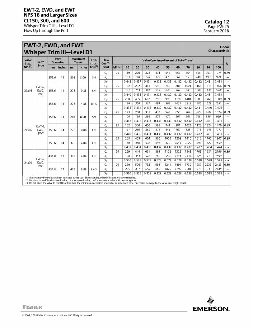
25
EWT-2, EWD, and EWTWhisper Trim III—Level D1
LinearCharacteristic
ValveSize,
NPS(1)
ValveType
PortDiameter
MaximumTravel
Con-struc-tion(2)
FlowCoeffi-cient
Valve Opening—Percent of Total TravelFL
mm Inches mm Inches Min(3) 10 20 30 40 50 60 70 80 90 100
20x16EWT-2,EWD,EWT
355.6 14 203 8.00 SN
Cv 25 119 220 322 431 543 653 754 855 963 1074 0.89
Kv 103 190 278 373 470 564 653 740 833 929 - - -
XT 0.442 0.437 0.434 0.433 0.433 0.432 0.432 0.432 0.431 0.431 - - -
355.6 14 276 10.88 LN
Cv 25 152 292 441 592 740 881 1021 1165 1315 1466 0.89
Kv 131 253 381 512 640 762 883 1008 1138 1268 - - -
XT 0.440 0.435 0.434 0.433 0.432 0.432 0.432 0.432 0.431 0.431 - - -
355.6 14 276 14.88 LN-S
Cv 25 208 405 602 799 998 1199 1401 1603 1768 1909 0.89
Kv 180 350 521 691 863 1037 1212 1386 1529 1651 - - -
XT 0.438 0.434 0.433 0.432 0.432 0.432 0.432 0.431 0.449 0.476 - - -
24x16EWT-2,EWD,EWT
355.6 14 203 8.00 SN
Cv 25 123 230 331 433 543 655 764 865 966 1074 0.89
Kv 106 199 286 375 470 567 661 748 836 929 - - -
XT 0.442 0.436 0.434 0.433 0.433 0.432 0.432 0.432 0.431 0.431 - - -
355.6 14 276 10.88 LN
Cv 25 152 300 450 599 741 881 1023 1173 1324 1470 0.89
Kv 131 260 389 518 641 762 885 1015 1145 1272 - - -
XT 0.440 0.435 0.434 0.433 0.432 0.432 0.432 0.432 0.431 0.431 - - -
355.6 14 378 14.88 LN
Cv 25 208 405 604 805 1006 1208 1410 1610 1765 1907 0.89
Kv 180 350 522 696 870 1045 1220 1393 1527 1650 - - -
XT 0.438 0.434 0.433 0.432 0.432 0.432 0.432 0.432 0.454 0.474 - - -
24x20EWT-2,EWD,EWT
431.8 17 378 14.88 LN
Cv 29 229 444 661 881 1102 1322 1543 1763 1981 2196 0.89
Kv 198 384 572 762 953 1144 1335 1525 1713 1899 - - -
XT 0.530 0.529 0.529 0.528 0.528 0.528 0.528 0.528 0.528 0.528 - - -
431.8 17 429 16.88 LN-S
Cv 29 260 506 752 998 1244 1491 1739 1987 2235 2483 0.89
Kv 225 437 650 863 1076 1290 1504 1719 1933 2148 - - -
XT 0.530 0.529 0.528 0.528 0.528 0.528 0.528 0.528 0.528 0.528 - - -1. The first number indicates both inlet and outlet size. The second number indicates effective trim size.2. Construction—SN = short-neck valve; LN = long-neck valve: LN-S = long-neck valve with bonnet spacer.3. Do not allow the valve to throttle at less than the minimum coefficient shown for an extended time, or erosion damage to the valve seat might result.
EWT-2, EWD, and EWT
Whisper Trim� III -- Level D1Flow Up through the Port
NPS 16 and Larger SizesCL150, 300, and 600 Catalog 12
Page EW-25February 2018
� 2008, 2018 Fisher Controls International LLC. All rights reserved
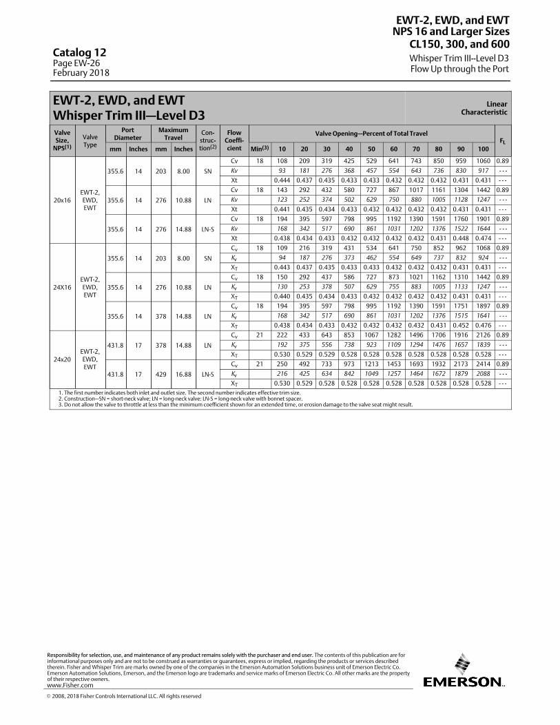
EWT-2, EWD, and EWTWhisper Trim III—Level D3
LinearCharacteristic
ValveSize,
NPS(1)
ValveType
PortDiameter
MaximumTravel
Con-struc-tion(2)
FlowCoeffi-cient
Valve Opening—Percent of Total TravelFL
mm Inches mm Inches Min(3) 10 20 30 40 50 60 70 80 90 100
20x16EWT-2,EWD,EWT
355.6 14 203 8.00 SN
Cv 18 108 209 319 425 529 641 743 850 959 1060 0.89
Kv 93 181 276 368 457 554 643 736 830 917 - - -
Xt 0.444 0.437 0.435 0.433 0.433 0.432 0.432 0.432 0.431 0.431 - - -
355.6 14 276 10.88 LN
Cv 18 143 292 432 580 727 867 1017 1161 1304 1442 0.89
Kv 123 252 374 502 629 750 880 1005 1128 1247 - - -
Xt 0.441 0.435 0.434 0.433 0.432 0.432 0.432 0.432 0.431 0.431 - - -
355.6 14 276 14.88 LN-S
Cv 18 194 395 597 798 995 1192 1390 1591 1760 1901 0.89
Kv 168 342 517 690 861 1031 1202 1376 1522 1644 - - -
Xt 0.438 0.434 0.433 0.432 0.432 0.432 0.432 0.431 0.448 0.474 - - -
24X16EWT-2,EWD,EWT
355.6 14 203 8.00 SN
Cv 18 109 216 319 431 534 641 750 852 962 1068 0.89
Kv 94 187 276 373 462 554 649 737 832 924 - - -
XT 0.443 0.437 0.435 0.433 0.433 0.432 0.432 0.432 0.431 0.431 - - -
355.6 14 276 10.88 LN
Cv 18 150 292 437 586 727 873 1021 1162 1310 1442 0.89
Kv 130 253 378 507 629 755 883 1005 1133 1247 - - -
XT 0.440 0.435 0.434 0.433 0.432 0.432 0.432 0.432 0.431 0.431 - - -
355.6 14 378 14.88 LN
Cv 18 194 395 597 798 995 1192 1390 1591 1751 1897 0.89
Kv 168 342 517 690 861 1031 1202 1376 1515 1641 - - -
XT 0.438 0.434 0.433 0.432 0.432 0.432 0.432 0.431 0.452 0.476 - - -
24x20EWT-2,EWD,EWT
431.8 17 378 14.88 LN
Cv 21 222 433 643 853 1067 1282 1496 1706 1916 2126 0.89
Kv 192 375 556 738 923 1109 1294 1476 1657 1839 - - -
XT 0.530 0.529 0.529 0.528 0.528 0.528 0.528 0.528 0.528 0.528 - - -
431.8 17 429 16.88 LN-S
Cv 21 250 492 733 973 1213 1453 1693 1932 2173 2414 0.89
Kv 216 425 634 842 1049 1257 1464 1672 1879 2088 - - -
XT 0.530 0.529 0.528 0.528 0.528 0.528 0.528 0.528 0.528 0.528 - - -1. The first number indicates both inlet and outlet size. The second number indicates effective trim size.2. Construction—SN = short-neck valve; LN = long-neck valve: LN-S = long-neck valve with bonnet spacer.3. Do not allow the valve to throttle at less than the minimum coefficient shown for an extended time, or erosion damage to the valve seat might result.
EWT-2, EWD, and EWT
Whisper Trim III--Level D3Flow Up through the Port
NPS 16 and Larger SizesCL150, 300, and 600
Catalog 12Page EW-26February 2018
� 2008, 2018 Fisher Controls International LLC. All rights reserved
www.Fisher.com
Responsibility for selection, use, and maintenance of any product remains solely with the purchaser and end user. The contents of this publication are forinformational purposes only and are not to be construed as warranties or guarantees, express or implied, regarding the products or services describedtherein. Fisher and Whisper Trim are marks owned by one of the companies in the Emerson Automation Solutions business unit of Emerson Electric Co.Emerson Automation Solutions, Emerson, and the Emerson logo are trademarks and service marks of Emerson Electric Co. All other marks are the propertyof their respective owners.
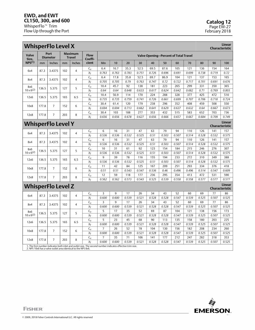
27
WhisperFlo Level X LinearCharacteristic
ValveSize,
NPS(1)
PortDiameter
MaximumTravel
FlowCoeffi‐cient
Valve Opening—Percent of Total Travel
mm Inches mm Inches Min 10 20 30 40 50 60 70 80 90 100
6x4 87.3 3.4375 102 4Cv 6.4 16.7 35.3 52.5 69.5 87.6 105 121 136 154 164
XT 0.763 0.763 0.783 0.751 0.726 0.696 0.691 0.699 0.738 0.719 0.72
8x4 87.3 3.4375 102 4Cv 6.4 17.8 35.8 52.5 69.7 86.9 104 121 137 153 165
XT 0.705 0.705 0.79 0.763 0.747 0.72 0.722 0.717 0.701 0.691 0.676
8x610 x 6(2) 136.5 5.375 127 5
Cv 10.4 45.7 92 138 181 223 265 299 331 350 365
XT 0.64 0.64 0.648 0.633 0.617 0.624 0.642 0.682 0.71 0.769 0.803
12x6 136.5 5.375 165 6.5Cv 10.4 56.9 114 170 224 288 328 377 425 472 510
XT 0.735 0.735 0.759 0.741 0.726 0.661 0.699 0.707 0.706 0.718 0.724
10x8 177.8 7 152 6Cv 30.4 61.4 120 179 238 296 352 408 459 508 550
XT 0.694 0.694 0.713 0.662 0.641 0.629 0.637 0.632 0.64 0.667 0.673
12x8 177.8 7 203 8Cv 30.4 103 188 277 353 432 515 583 652 703 736
XT 0.656 0.656 0.678 0.627 0.656 0.666 0.657 0.667 0.684 0.709 0.749
WhisperFlo Level Y LinearCharacteristic
6x4 87.3 3.4375 102 4Cv 6 16 31 47 63 79 94 110 126 141 157
XT 0.536 0.536 0.532 0.525 0.51 0.503 0.507 0.514 0.528 0.532 0.575
8x4 87.3 3.4375 102 4Cv 6 16 31 47 63 79 94 110 126 141 157
XT 0.536 0.536 0.532 0.525 0.51 0.503 0.507 0.514 0.528 0.532 0.575
8x610 x 6(2) 136.5 5.375 127 5
Cv 10 31 61 92 123 154 184 215 246 276 307
XT 0.536 0.536 0.532 0.525 0.51 0.503 0.507 0.514 0.528 0.532 0.575
12x6 136.5 5.375 165 6.5Cv 9 39 78 116 155 194 233 272 310 349 388
XT 0.536 0.536 0.532 0.525 0.51 0.503 0.507 0.514 0.528 0.532 0.575
10x8 177.8 7 152 6Cv 11 42 84 125 167 209 251 293 334 376 418
XT 0.51 0.51 0.543 0.547 0.536 0.46 0.496 0.496 0.514 0.547 0.609
12x8 177.8 7 203 8Cv 12 59 118 177 236 295 354 413 472 531 590
XT 0.562 0.562 0.573 0.543 0.525 0.539 0.558 0.558 0.577 0.577 0.577
WhisperFlo Level Z LinearCharacteristic
6x4 87.3 3.4375 102 4Cv 3 9 17 26 34 43 52 60 69 77 86
XT 0.600 0.600 0.539 0.521 0.528 0.528 0.547 0.539 0.525 0.507 0.525
8x4 87.3 3.4375 102 4Cv 3 9 17 26 34 43 52 60 69 77 86
XT 0.600 0.600 0.539 0.521 0.528 0.528 0.547 0.539 0.525 0.507 0.525
8x610 x 6(2) 136.5 5.375 127 5
Cv 5 17 35 52 69 87 104 121 138 156 173
XT 0.600 0.600 0.539 0.521 0.528 0.528 0.547 0.539 0.525 0.507 0.525
12x6 136.5 5.375 165 6.5Cv 5 23 45 68 90 113 135 158 180 203 225
XT 0.600 0.600 0.539 0.521 0.528 0.528 0.547 0.539 0.525 0.507 0.525
10x8 177.8 7 152 6Cv 7 26 52 78 104 130 156 182 208 234 260
XT 0.600 0.600 0.539 0.521 0.528 0.528 0.547 0.539 0.525 0.507 0.525
12x8 177.8 7 203 8Cv 7 35 71 106 141 177 212 247 282 318 353
XT 0.600 0.600 0.539 0.521 0.528 0.528 0.547 0.539 0.525 0.507 0.525
1. The first number indicates both inlet and outlet size. The second number indicates effective trim size.2. NPS 10x6 has a valve outlet area identical to the NPS 8x6.
EWD, and EWT
WhisperFlo� TrimFlow Up through the Port
CL150, 300, and 600 Catalog 12Page EW-27
February 2018
� 2009, 2018 Fisher Controls International LLC. All rights reserved
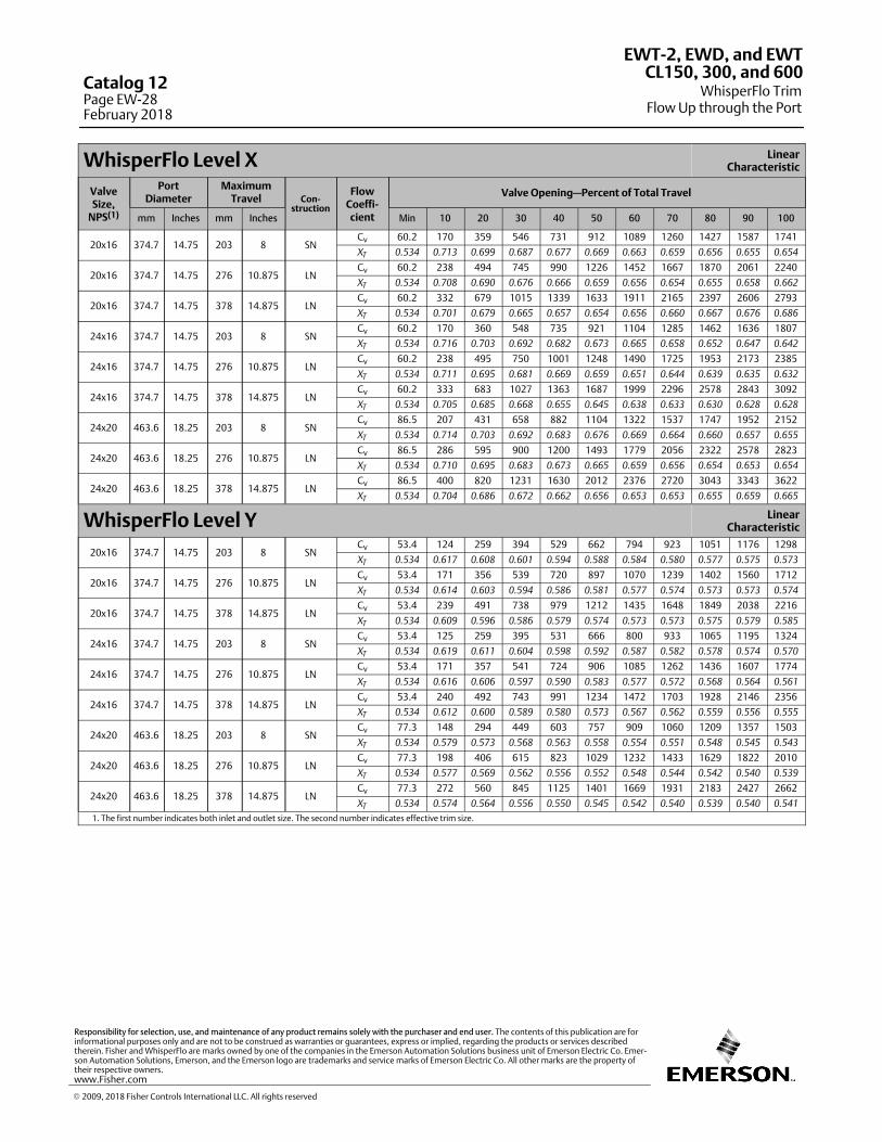
WhisperFlo Level X LinearCharacteristic
ValveSize,
NPS(1)
PortDiameter
MaximumTravel Con-
struction
FlowCoeffi‐cient
Valve Opening—Percent of Total Travel
mm Inches mm Inches Min 10 20 30 40 50 60 70 80 90 100
20x16 374.7 14.75 203 8 SNCv 60.2 170 359 546 731 912 1089 1260 1427 1587 1741
XT 0.534 0.713 0.699 0.687 0.677 0.669 0.663 0.659 0.656 0.655 0.654
20x16 374.7 14.75 276 10.875 LNCv 60.2 238 494 745 990 1226 1452 1667 1870 2061 2240
XT 0.534 0.708 0.690 0.676 0.666 0.659 0.656 0.654 0.655 0.658 0.662
20x16 374.7 14.75 378 14.875 LNCv 60.2 332 679 1015 1339 1633 1911 2165 2397 2606 2793
XT 0.534 0.701 0.679 0.665 0.657 0.654 0.656 0.660 0.667 0.676 0.686
24x16 374.7 14.75 203 8 SNCv 60.2 170 360 548 735 921 1104 1285 1462 1636 1807
XT 0.534 0.716 0.703 0.692 0.682 0.673 0.665 0.658 0.652 0.647 0.642
24x16 374.7 14.75 276 10.875 LNCv 60.2 238 495 750 1001 1248 1490 1725 1953 2173 2385
XT 0.534 0.711 0.695 0.681 0.669 0.659 0.651 0.644 0.639 0.635 0.632
24x16 374.7 14.75 378 14.875 LNCv 60.2 333 683 1027 1363 1687 1999 2296 2578 2843 3092
XT 0.534 0.705 0.685 0.668 0.655 0.645 0.638 0.633 0.630 0.628 0.628
24x20 463.6 18.25 203 8 SNCv 86.5 207 431 658 882 1104 1322 1537 1747 1952 2152
XT 0.534 0.714 0.703 0.692 0.683 0.676 0.669 0.664 0.660 0.657 0.655
24x20 463.6 18.25 276 10.875 LNCv 86.5 286 595 900 1200 1493 1779 2056 2322 2578 2823
XT 0.534 0.710 0.695 0.683 0.673 0.665 0.659 0.656 0.654 0.653 0.654
24x20 463.6 18.25 378 14.875 LNCv 86.5 400 820 1231 1630 2012 2376 2720 3043 3343 3622
XT 0.534 0.704 0.686 0.672 0.662 0.656 0.653 0.653 0.655 0.659 0.665
WhisperFlo Level Y LinearCharacteristic
20x16 374.7 14.75 203 8 SNCv 53.4 124 259 394 529 662 794 923 1051 1176 1298
XT 0.534 0.617 0.608 0.601 0.594 0.588 0.584 0.580 0.577 0.575 0.573
20x16 374.7 14.75 276 10.875 LNCv 53.4 171 356 539 720 897 1070 1239 1402 1560 1712
XT 0.534 0.614 0.603 0.594 0.586 0.581 0.577 0.574 0.573 0.573 0.574
20x16 374.7 14.75 378 14.875 LNCv 53.4 239 491 738 979 1212 1435 1648 1849 2038 2216
XT 0.534 0.609 0.596 0.586 0.579 0.574 0.573 0.573 0.575 0.579 0.585
24x16 374.7 14.75 203 8 SNCv 53.4 125 259 395 531 666 800 933 1065 1195 1324
XT 0.534 0.619 0.611 0.604 0.598 0.592 0.587 0.582 0.578 0.574 0.570
24x16 374.7 14.75 276 10.875 LNCv 53.4 171 357 541 724 906 1085 1262 1436 1607 1774
XT 0.534 0.616 0.606 0.597 0.590 0.583 0.577 0.572 0.568 0.564 0.561
24x16 374.7 14.75 378 14.875 LNCv 53.4 240 492 743 991 1234 1472 1703 1928 2146 2356
XT 0.534 0.612 0.600 0.589 0.580 0.573 0.567 0.562 0.559 0.556 0.555
24x20 463.6 18.25 203 8 SNCv 77.3 148 294 449 603 757 909 1060 1209 1357 1503
XT 0.534 0.579 0.573 0.568 0.563 0.558 0.554 0.551 0.548 0.545 0.543
24x20 463.6 18.25 276 10.875 LNCv 77.3 198 406 615 823 1029 1232 1433 1629 1822 2010
XT 0.534 0.577 0.569 0.562 0.556 0.552 0.548 0.544 0.542 0.540 0.539
24x20 463.6 18.25 378 14.875 LNCv 77.3 272 560 845 1125 1401 1669 1931 2183 2427 2662
XT 0.534 0.574 0.564 0.556 0.550 0.545 0.542 0.540 0.539 0.540 0.541
1. The first number indicates both inlet and outlet size. The second number indicates effective trim size.
EWT-2, EWD, and EWT
WhisperFlo TrimFlow Up through the Port
CL150, 300, and 600Catalog 12Page EW-28February 2018
� 2009, 2018 Fisher Controls International LLC. All rights reserved
www.Fisher.com
Responsibility for selection, use, and maintenance of any product remains solely with the purchaser and end user. The contents of this publication are forinformational purposes only and are not to be construed as warranties or guarantees, express or implied, regarding the products or services describedtherein. Fisher and WhisperFlo are marks owned by one of the companies in the Emerson Automation Solutions business unit of Emerson Electric Co. Emerson Automation Solutions, Emerson, and the Emerson logo are trademarks and service marks of Emerson Electric Co. All other marks are the property oftheir respective owners.
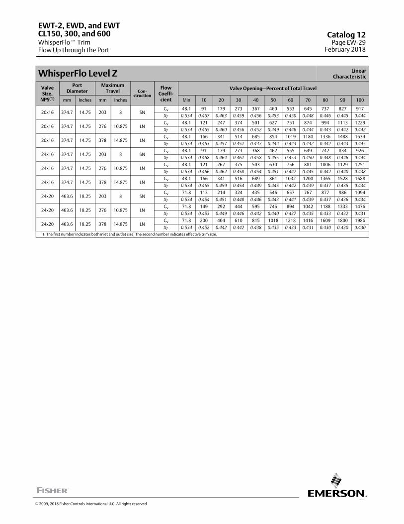
29
WhisperFlo Level Z LinearCharacteristic
ValveSize,
NPS(1)
PortDiameter
MaximumTravel Con-
struction
FlowCoeffi‐cient
Valve Opening—Percent of Total Travel
mm Inches mm Inches Min 10 20 30 40 50 60 70 80 90 100
20x16 374.7 14.75 203 8 SNCv 48.1 91 179 273 367 460 553 645 737 827 917
XT 0.534 0.467 0.463 0.459 0.456 0.453 0.450 0.448 0.446 0.445 0.444
20x16 374.7 14.75 276 10.875 LNCv 48.1 121 247 374 501 627 751 874 994 1113 1229
XT 0.534 0.465 0.460 0.456 0.452 0.449 0.446 0.444 0.443 0.442 0.442
20x16 374.7 14.75 378 14.875 LNCv 48.1 166 341 514 685 854 1019 1180 1336 1488 1634
XT 0.534 0.463 0.457 0.451 0.447 0.444 0.443 0.442 0.442 0.443 0.445
24x16 374.7 14.75 203 8 SNCv 48.1 91 179 273 368 462 555 649 742 834 926
XT 0.534 0.468 0.464 0.461 0.458 0.455 0.453 0.450 0.448 0.446 0.444
24x16 374.7 14.75 276 10.875 LNCv 48.1 121 267 375 503 630 756 881 1006 1129 1251
XT 0.534 0.466 0.462 0.458 0.454 0.451 0.447 0.445 0.442 0.440 0.438
24x16 374.7 14.75 378 14.875 LNCv 48.1 166 341 516 689 861 1032 1200 1365 1528 1688
XT 0.534 0.465 0.459 0.454 0.449 0.445 0.442 0.439 0.437 0.435 0.434
24x20 463.6 18.25 203 8 SNCv 71.8 113 214 324 435 546 657 767 877 986 1094
XT 0.534 0.454 0.451 0.448 0.446 0.443 0.441 0.439 0.437 0.436 0.434
24x20 463.6 18.25 276 10.875 LNCv 71.8 149 292 444 595 745 894 1042 1188 1333 1476
XT 0.534 0.453 0.449 0.446 0.442 0.440 0.437 0.435 0.433 0.432 0.431
24x20 463.6 18.25 378 14.875 LNCv 71.8 200 404 610 815 1018 1218 1416 1609 1800 1986
XT 0.534 0.452 0.442 0.442 0.438 0.435 0.433 0.431 0.430 0.430 0.430
1. The first number indicates both inlet and outlet size. The second number indicates effective trim size.
EWT-2, EWD, and EWT
WhisperFlo� TrimFlow Up through the Port
CL150, 300, and 600 Catalog 12Page EW-29
February 2018
� 2009, 2018 Fisher Controls International LLC. All rights reserved

EWT-2, EWD, and EWTCavitrol III Trim—One Stage
LinearCharacteristic
ValveSize,
NPS(1)
PortDiameter
MaximumTravel
Con-struc-tion(2)
FlowCoeffi-cient
Valve Opening—Percent of Total TravelFL
mm Inches mm Inches Min(3) 10 20 30 40 50 60 70 80 90 100
16 x 12 279.4 11.00 203 8.00 LNDCv 40 132 304 471 628 775 910 1030 1140 1240 1330 0.91
Kv 34.6 114 263 407 543 670 787 891 986 1073 1150 - - -
20 x 16
374.7 14.75 276 10.88 LNDCv 46 262 576 877 1160 1420 1660 1880 2070 2240 2390 0.91
Kv 39.8 227 498 759 1003 1228 1436 1626 1791 1938 2067 - - -
374.7 14.75 378 14.88 LN-SDCv 46 379 800 1190 1540 1850 2110 2330 2510 2670 2800 0.91
Kv 39.8 328 692 1029 1332 1600 1825 2015 2171 2310 2422 - - -
24 x 16
374.7 14.75 276 10.88 LNDCv 46 262 576 878 1160 1420 1160 1880 2070 2240 2390 0.91
Kv 39.8 227 498 759 1003 1228 1003 1626 1791 1938 2067 - - -
374.7 14.75 378 14.88 LNDCv 46 379 800 1190 1540 1850 2110 2330 2520 2670 2800 0.91
Kv 39.8 328 692 1029 1332 1600 1825 2015 2180 2310 2422 - - -
374.7 14.75 429 16.88 LN-SDCv 46 437 909 1340 1710 2030 2290 2510 2680 2830 2940 0.91
Kv 39.8 378 786 1159 1479 1756 1981 2171 2318 2448 2543 - - -
24 x 20
463.6 18.25 378 14.88 LNDCv 56 468 995 1490 1960 2370 2750 3070 3360 3600 3810 0.91
Kv 48.4 405 861 1289 1695 2050 2379 2656 2906 3114 3296 - - -
463.6 18.25 429 16.88 LN-SDCv 56 540 1130 1690 2190 2630 3010 3340 3620 3860 4050 0.91
Kv 48.4 467 977 1462 1894 2275 2604 2889 3131 3339 3503 - - -
1. The first number indicates both inlet and outlet size. The second number indicates effective trim size.2. Construction—SND = short-neck valve, drilled windows; LND - long-neck valve, drilled windows; LN-SD = long-neck valve with bonnet spacer, drilled windows.3. Do not allow the valve to throttle at less than the minimum coefficient shown for an extended time, or erosion damage to the valve seat might occur.
EWT-2, EWD, and EWT
Cavitrol� III -- One StageFlow Down through the Port
NPS 16 and Larger SizesCL150, 300, and 600
Catalog 12Page EW-30February 2018
� 1994, 2018 Fisher Controls International LLC. All rights reserved
www.Fisher.com
Responsibility for selection, use, and maintenance of any product remains solely with the purchaser and end user. The contents of this publication are forinformational purposes only and are not to be construed as warranties or guarantees, express or implied, regarding the products or services describedtherein. Fisher, WhisperFlo, and Cavitrol are marks owned by one of the companies in the Emerson Automation Solutions business unit of Emerson ElectricCo. Emerson Automation Solutions, Emerson, and the Emerson logo are trademarks and service marks of Emerson Electric Co. All other marks are theproperty of their respective owners.
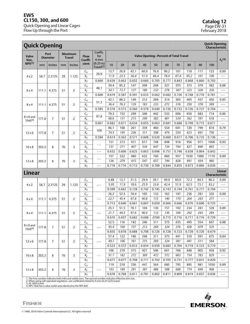
31
Quick Opening Quick OpeningCharacteristic
ValveSize,
NPS(1)
PortDiameter
MaximumTravel Flow
Coeffi-cient
Coeffs.for
6 mm(0.25 in)Travel(2)
Valve Opening—Percent of Total Travel
FL(3)
mm Inches mm Inches 10 20 30 40 50 60 70 80 90 100
4 x 2 58.7 2.3125 29 1.125
Cv29.9
13.7 26.9 42.1 60.0 76.8 90.2 101 110 117 123 0.89
Kv 11.9 23.3 36.4 51.9 66.4 78.0 87.4 95.2 101 106 - - -
XT 0.660 0.639 0.663 0.652 0.660 0.705 0.777 0.843 0.868 0.860 0.793 - - -
6 x 4 111.1 4.375 51 2
Cv48.1
39.4 85.2 147 208 268 321 355 373 379 382 0.88
Kv 34.1 73.7 127 180 232 278 307 323 328 330 - - -
XT 0.600 0.619 0.587 0.591 0.633 0.662 0.682 0.726 0.748 0.770 0.781 - - -
8 x 4 111.1 4.375 51 2
Cv51.3
42.1 88.2 149 212 269 314 365 405 437 450 0.85
Kv 36.4 76.3 129 183 233 272 316 350 378 389 - - -
XT 0.585 0.578 0.573 0.560 0.579 0.640 0.726 0.733 0.726 0.727 0.704 - - -
8 x 6 and
10x6(4) 177.8 7 51 2
Cv97.8
79.3 152 249 346 442 533 606 650 683 714 0.86
Kv 68.6 131 215 299 382 461 524 562 591 618 - - -
XT 0.661 0.682 0.671 0.634 0.655 0.663 0.681 0.688 0.709 0.715 0.671 - - -
12 x 6 177.8 7 51 2
Cv109
86.1 168 261 359 460 554 641 720 799 874 0.79
Kv 74.5 145 226 311 398 479 554 623 691 756 - - -
XT 0.594 0.614 0.563 0.571 0.608 0.630 0.660 0.677 0.706 0.735 0.736 - - -
10 x 8 203.2 8 76 3
Cv- - -
151 313 471 617 748 848 918 956 971 1000 0.93
Kv 131 271 407 534 647 734 794 827 840 865 - - -
XT - - - 0.632 0.606 0.625 0.663 0.698 0.751 0.798 0.838 0.864 0.842 - - -
12 x 8 203.2 8 76 3
Cv- - -
157 322 480 632 760 860 957 1030 1080 1110 0.89
Kv 136 279 415 547 657 744 828 891 934 960 - - -
XT - - - 0.718 0.716 0.712 0.730 0.789 0.844 0.855 0.873 0.866 0.836 - - -
Linear LinearCharacteristic
4 x 2 58.7 2.3125 29 1.125
Cv
- - -
6.88 13.7 21.5 29.9 39.1 49.0 60.0 72.2 84.5 96.2 0.89
Kv 5.95 11.9 18.6 25.9 33.8 42.4 51.9 62.5 73.1 83.2 - - -
XT 0.599 0.662 0.728 0.742 0.745 0.743 0.744 0.761 0.777 0.794 - - -
6 x 4 111.1 4.375 51 2
Cv
- - -
26.2 52.5 78.4 105 133 162 197 236 281 320 0.89
Kv 22.7 45.4 67.8 90.8 115 140 170 204 243 277 - - -
XT 0.713 0.640 0.661 0.667 0.659 0.666 0.666 0.676 0.690 0.725 - - -
8 x 4 111.1 4.375 51 2
Cv
- - -
25.1 51.5 78.1 104 130 157 192 234 281 328 0.89
Kv 21.7 44.5 67.6 90.0 112 136 166 202 243 284 - - -
XT 0.610 0.657 0.682 0.688 .0700 0.715 0.716 0.711 0.716 0.729 - - -
8 x 6 and
10x6(4) 177.8 7 51 2
Cv
- - -
52.5 116 182 246 311 375 435 495 554 607 0.88
Kv 45.4 100 157 213 269 324 376 428 479 525 - - -
XT 0.655 0.678 0.688 0.708 0.726 0.728 0.723 0.729 0.720 0.679 - - -
12 x 6 177.8 7 51 2
Cv
- - -
57.4 122 186 248 311 375 441 510 591 675 0.84
Kv 49.7 106 161 215 269 324 381 441 511 584 - - -
XT 0.523 0.572 0.612 0.654 0.659 0.683 0.704 0.719 0.723 0.719 - - -
10 x 8 203.2 8 76 3
Cv
- - -
106 210 315 427 546 661 766 848 905 958 0.92
Kv 91.7 182 272 369 472 572 663 734 783 829 - - -
XT 0.677 0.677 0.708 0.711 0.702 0.705 0.731 0.777 0.831 0.820 - - -
12 x 8 203.2 8 76 3
Cv
- - -
119 218 336 447 564 680 795 895 981 1050 0.89
Kv 103 189 291 387 488 588 688 774 849 908 - - -
XT 0.678 0.768 0.811 0.791 0.802 0.811 0.809 0.819 0.837 0.836 - - -1. The first number indicates both inlet and outlet sizes. The second number indicates effective trim size.2. When sizing self-operated regulators, use coefficients listed for 6 mm (0.25 inch) travel.3. At 100% travel.4. NPS 10x6 has a valve outlet area identical to the NPS 8x6.
EWS
Quick Opening and Linear CagesFlow Up through the Port
CL150, 300, and 600 Catalog 12Page EW-31
February 2018
� 1988, 2018 Fisher Controls International LLC. All rights reserved
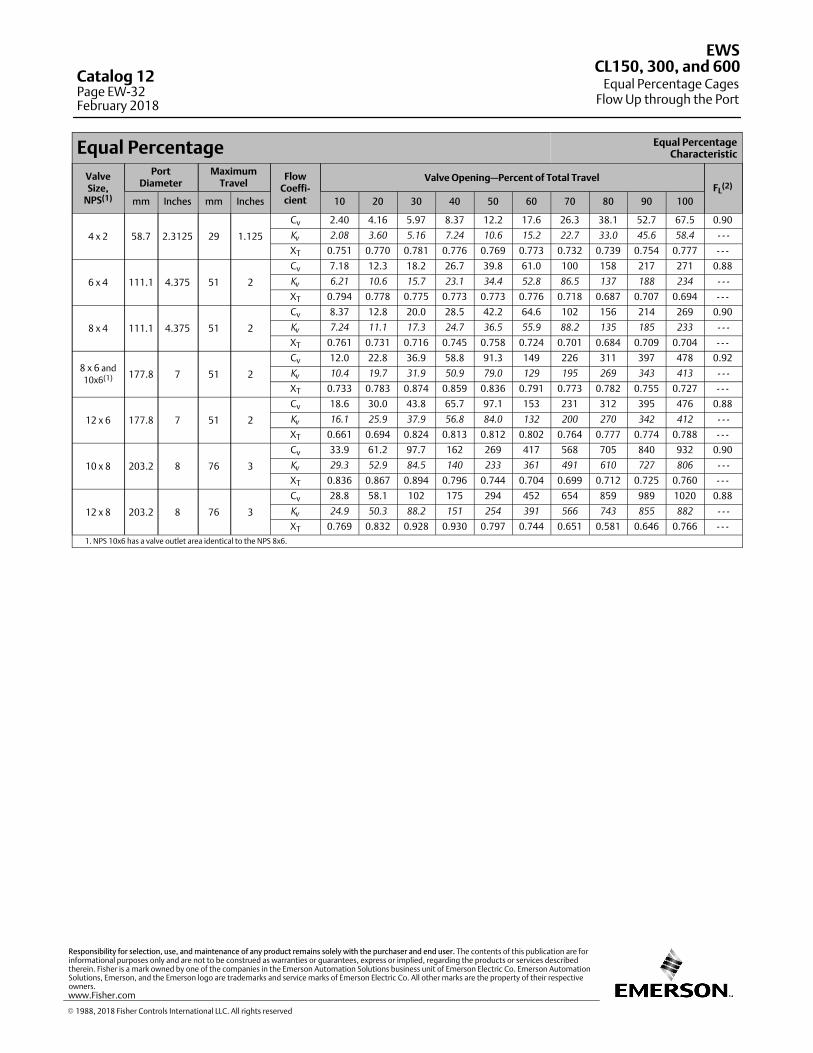
Equal Percentage Equal PercentageCharacteristic
ValveSize,
NPS(1)
PortDiameter
MaximumTravel
FlowCoeffi-cient
Valve Opening—Percent of Total TravelFL
(2)
mm Inches mm Inches 10 20 30 40 50 60 70 80 90 100
4 x 2 58.7 2.3125 29 1.125
Cv 2.40 4.16 5.97 8.37 12.2 17.6 26.3 38.1 52.7 67.5 0.90
Kv 2.08 3.60 5.16 7.24 10.6 15.2 22.7 33.0 45.6 58.4 - - -
XT 0.751 0.770 0.781 0.776 0.769 0.773 0.732 0.739 0.754 0.777 - - -
6 x 4 111.1 4.375 51 2
Cv 7.18 12.3 18.2 26.7 39.8 61.0 100 158 217 271 0.88
Kv 6.21 10.6 15.7 23.1 34.4 52.8 86.5 137 188 234 - - -
XT 0.794 0.778 0.775 0.773 0.773 0.776 0.718 0.687 0.707 0.694 - - -
8 x 4 111.1 4.375 51 2
Cv 8.37 12.8 20.0 28.5 42.2 64.6 102 156 214 269 0.90
Kv 7.24 11.1 17.3 24.7 36.5 55.9 88.2 135 185 233 - - -
XT 0.761 0.731 0.716 0.745 0.758 0.724 0.701 0.684 0.709 0.704 - - -
8 x 6 and
10x6(1) 177.8 7 51 2
Cv 12.0 22.8 36.9 58.8 91.3 149 226 311 397 478 0.92
Kv 10.4 19.7 31.9 50.9 79.0 129 195 269 343 413 - - -
XT 0.733 0.783 0.874 0.859 0.836 0.791 0.773 0.782 0.755 0.727 - - -
12 x 6 177.8 7 51 2
Cv 18.6 30.0 43.8 65.7 97.1 153 231 312 395 476 0.88
Kv 16.1 25.9 37.9 56.8 84.0 132 200 270 342 412 - - -
XT 0.661 0.694 0.824 0.813 0.812 0.802 0.764 0.777 0.774 0.788 - - -
10 x 8 203.2 8 76 3
Cv 33.9 61.2 97.7 162 269 417 568 705 840 932 0.90
Kv 29.3 52.9 84.5 140 233 361 491 610 727 806 - - -
XT 0.836 0.867 0.894 0.796 0.744 0.704 0.699 0.712 0.725 0.760 - - -
12 x 8 203.2 8 76 3
Cv 28.8 58.1 102 175 294 452 654 859 989 1020 0.88
Kv 24.9 50.3 88.2 151 254 391 566 743 855 882 - - -
XT 0.769 0.832 0.928 0.930 0.797 0.744 0.651 0.581 0.646 0.766 - - -1. NPS 10x6 has a valve outlet area identical to the NPS 8x6.
EWS
Equal Percentage CagesFlow Up through the Port
CL150, 300, and 600Catalog 12Page EW-32February 2018
� 1988, 2018 Fisher Controls International LLC. All rights reserved
www.Fisher.com
Responsibility for selection, use, and maintenance of any product remains solely with the purchaser and end user. The contents of this publication are forinformational purposes only and are not to be construed as warranties or guarantees, express or implied, regarding the products or services describedtherein. Fisher is a mark owned by one of the companies in the Emerson Automation Solutions business unit of Emerson Electric Co. Emerson AutomationSolutions, Emerson, and the Emerson logo are trademarks and service marks of Emerson Electric Co. All other marks are the property of their respectiveowners.
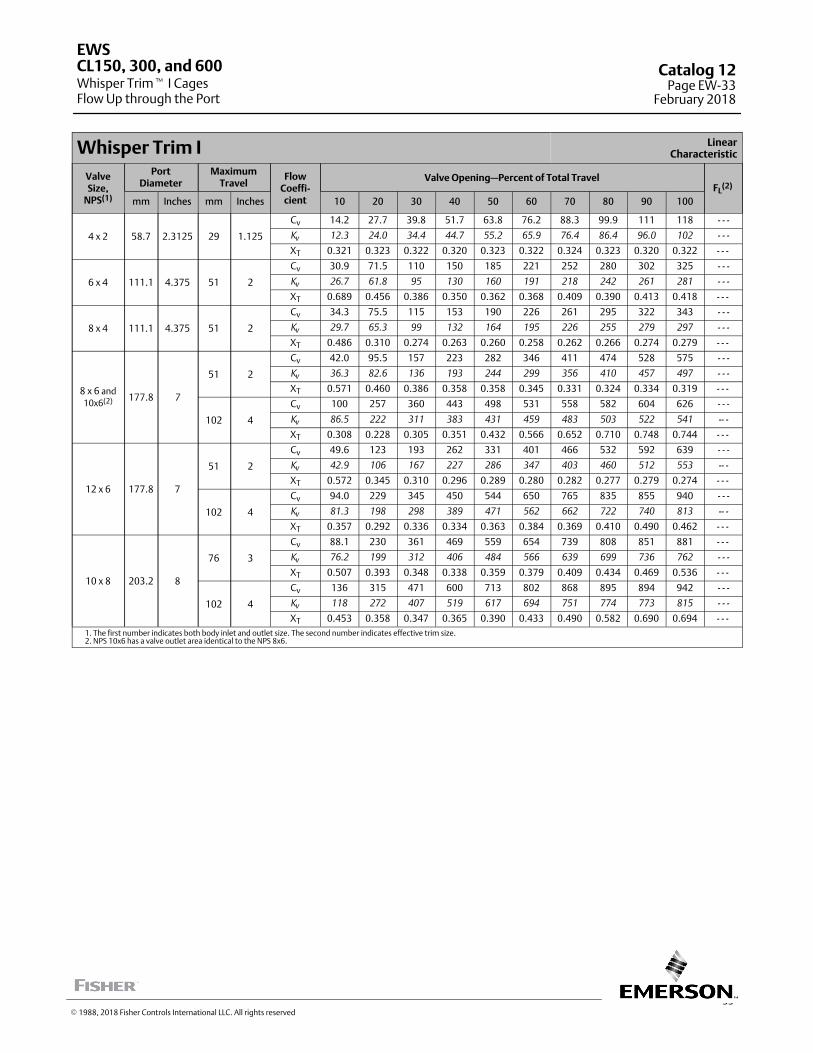
33
Whisper Trim I LinearCharacteristic
ValveSize,
NPS(1)
PortDiameter
MaximumTravel
FlowCoeffi-cient
Valve Opening—Percent of Total TravelFL
(2)
mm Inches mm Inches 10 20 30 40 50 60 70 80 90 100
4 x 2 58.7 2.3125 29 1.125
Cv 14.2 27.7 39.8 51.7 63.8 76.2 88.3 99.9 111 118 - - -
Kv 12.3 24.0 34.4 44.7 55.2 65.9 76.4 86.4 96.0 102 - - -
XT 0.321 0.323 0.322 0.320 0.323 0.322 0.324 0.323 0.320 0.322 - - -
6 x 4 111.1 4.375 51 2
Cv 30.9 71.5 110 150 185 221 252 280 302 325 - - -
Kv 26.7 61.8 95 130 160 191 218 242 261 281 - - -
XT 0.689 0.456 0.386 0.350 0.362 0.368 0.409 0.390 0.413 0.418 - - -
8 x 4 111.1 4.375 51 2
Cv 34.3 75.5 115 153 190 226 261 295 322 343 - - -
Kv 29.7 65.3 99 132 164 195 226 255 279 297 - - -
XT 0.486 0.310 0.274 0.263 0.260 0.258 0.262 0.266 0.274 0.279 - - -
8 x 6 and
10x6(2) 177.8 7
51 2
Cv 42.0 95.5 157 223 282 346 411 474 528 575 - - -
Kv 36.3 82.6 136 193 244 299 356 410 457 497 - - -
XT 0.571 0.460 0.386 0.358 0.358 0.345 0.331 0.324 0.334 0.319 - - -
102 4
Cv 100 257 360 443 498 531 558 582 604 626 - - -
Kv 86.5 222 311 383 431 459 483 503 522 541 -- -
XT 0.308 0.228 0.305 0.351 0.432 0.566 0.652 0.710 0.748 0.744 - - -
12 x 6 177.8 7
51 2
Cv 49.6 123 193 262 331 401 466 532 592 639 - - -
Kv 42.9 106 167 227 286 347 403 460 512 553 -- -
XT 0.572 0.345 0.310 0.296 0.289 0.280 0.282 0.277 0.279 0.274 - - -
102 4
Cv 94.0 229 345 450 544 650 765 835 855 940 - - -
Kv 81.3 198 298 389 471 562 662 722 740 813 -- -
XT 0.357 0.292 0.336 0.334 0.363 0.384 0.369 0.410 0.490 0.462 - - -
10 x 8 203.2 8
76 3
Cv 88.1 230 361 469 559 654 739 808 851 881 - - -
Kv 76.2 199 312 406 484 566 639 699 736 762 - - -
XT 0.507 0.393 0.348 0.338 0.359 0.379 0.409 0.434 0.469 0.536 - - -
102 4
Cv 136 315 471 600 713 802 868 895 894 942 - - -
Kv 118 272 407 519 617 694 751 774 773 815 - - -
XT 0.453 0.358 0.347 0.365 0.390 0.433 0.490 0.582 0.690 0.694 - - -1. The first number indicates both body inlet and outlet size. The second number indicates effective trim size.2. NPS 10x6 has a valve outlet area identical to the NPS 8x6.
EWS
Whisper Trim� I CagesFlow Up through the Port
CL150, 300, and 600 Catalog 12Page EW-33
February 2018
� 1988, 2018 Fisher Controls International LLC. All rights reserved
This page is intentionally left blank.
EWS
Whisper Trim I CagesFlow Up through the Port
CL150, 300, and 600Catalog 12Page EW-34February 2018
� 1988, 2018 Fisher Controls International LLC. All rights reserved
www.Fisher.com
Responsibility for selection, use, and maintenance of any product remains solely with the purchaser and end user. The contents of this publication are forinformational purposes only and are not to be construed as warranties or guarantees, express or implied, regarding the products or services describedtherein. Fisher and Whisper Trim are marks owned by one of the companies in the Emerson Automation Solutions business unit of Emerson Electric Co.Emerson Automation Solutions, Emerson, and the Emerson logo are trademarks and service marks of Emerson Electric Co. All other marks are the propertyof their respective owners.
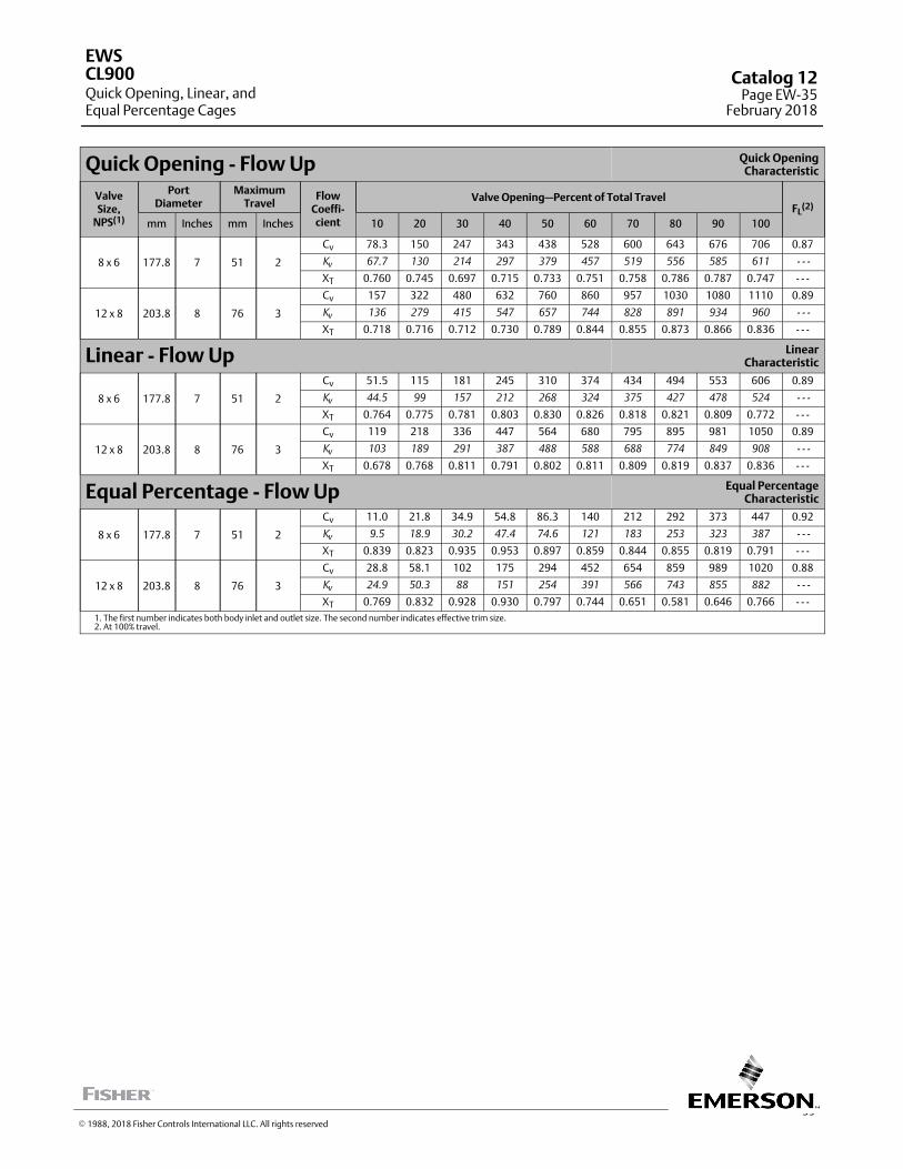
35
Quick Opening - Flow Up Quick OpeningCharacteristic
ValveSize,
NPS(1)
PortDiameter
MaximumTravel
FlowCoeffi-cient
Valve Opening—Percent of Total TravelFL
(2)
mm Inches mm Inches 10 20 30 40 50 60 70 80 90 100
8 x 6 177.8 7 51 2
Cv 78.3 150 247 343 438 528 600 643 676 706 0.87
Kv 67.7 130 214 297 379 457 519 556 585 611 - - -
XT 0.760 0.745 0.697 0.715 0.733 0.751 0.758 0.786 0.787 0.747 - - -
12 x 8 203.8 8 76 3
Cv 157 322 480 632 760 860 957 1030 1080 1110 0.89
Kv 136 279 415 547 657 744 828 891 934 960 - - -
XT 0.718 0.716 0.712 0.730 0.789 0.844 0.855 0.873 0.866 0.836 - - -
Linear - Flow Up LinearCharacteristic
8 x 6 177.8 7 51 2
Cv 51.5 115 181 245 310 374 434 494 553 606 0.89
Kv 44.5 99 157 212 268 324 375 427 478 524 - - -
XT 0.764 0.775 0.781 0.803 0.830 0.826 0.818 0.821 0.809 0.772 - - -
12 x 8 203.8 8 76 3
Cv 119 218 336 447 564 680 795 895 981 1050 0.89
Kv 103 189 291 387 488 588 688 774 849 908 - - -
XT 0.678 0.768 0.811 0.791 0.802 0.811 0.809 0.819 0.837 0.836 - - -
Equal Percentage - Flow Up Equal PercentageCharacteristic
8 x 6 177.8 7 51 2
Cv 11.0 21.8 34.9 54.8 86.3 140 212 292 373 447 0.92
Kv 9.5 18.9 30.2 47.4 74.6 121 183 253 323 387 - - -
XT 0.839 0.823 0.935 0.953 0.897 0.859 0.844 0.855 0.819 0.791 - - -
12 x 8 203.8 8 76 3
Cv 28.8 58.1 102 175 294 452 654 859 989 1020 0.88
Kv 24.9 50.3 88 151 254 391 566 743 855 882 - - -
XT 0.769 0.832 0.928 0.930 0.797 0.744 0.651 0.581 0.646 0.766 - - -1. The first number indicates both body inlet and outlet size. The second number indicates effective trim size.2. At 100% travel.
EWS
Quick Opening, Linear, andEqual Percentage Cages
CL900 Catalog 12Page EW-35
February 2018
� 1988, 2018 Fisher Controls International LLC. All rights reserved
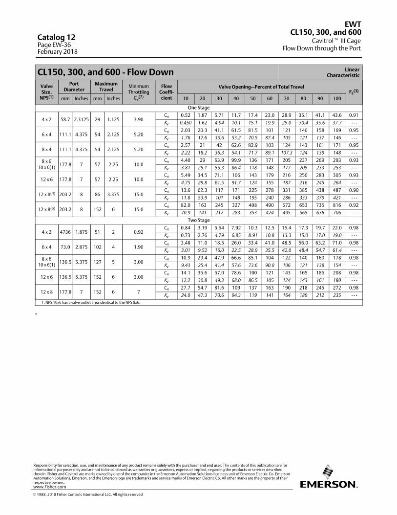
CL150, 300, and 600 - Flow Down LinearCharacteristic
ValveSize,
NPS(1)
PortDiameter
MaximumTravel
MinimumThrottling
Cv(2)
FlowCoeffi-cient
Valve Opening—Percent of Total TravelFL
(3)
mm Inches mm Inches 10 20 30 40 50 60 70 80 90 100
One Stage
4 x 2 58.7 2.3125 29 1.125 3.90Cv 0.52 1.87 5.71 11.7 17.4 23.0 28.9 35.1 41.1 43.6 0.91
Kv 0.450 1.62 4.94 10.1 15.1 19.9 25.0 30.4 35.6 37.7 - - -
6 x 4 111.1 4.375 54 2.125 5.20Cv 2.03 20.3 41.1 61.5 81.5 101 121 140 158 169 0.95
Kv 1.76 17.6 35.6 53.2 70.5 87.4 105 121 137 146 - - -
8 x 4 111.1 4.375 54 2.125 5.20Cv 2.57 21 42 62.6 82.9 103 124 143 161 171 0.95
Kv 2.22 18.2 36.3 54.1 71.7 89.1 107.3 124 139 148 - - -
8 x 610 x 6(1)
177.8 7 57 2.25 10.0Cv 4.40 29 63.9 99.9 136 171 205 237 269 293 0.93
Kv 3.81 25.1 55.3 86.4 118 148 177 205 233 253 - - -
12 x 6 177.8 7 57 2.25 10.0Cv 5.49 34.5 71.1 106 143 179 216 250 283 305 0.93
Kv 4.75 29.8 61.5 91.7 124 155 187 216 245 264 - - -
12 x 8(4) 203.2 8 86 3.375 15.0Cv 13.6 62.3 117 171 225 278 331 385 438 487 0.90
Kv 11.8 53.9 101 148 195 240 286 333 379 421 - - -
12 x 8(5) 203.2 8 152 6 15.0Cv 82.0 163 245 327 408 490 572 653 735 816 0.92
Kv 70.9 141 212 283 353 424 495 565 636 706 - - -
Two Stage
4 x 2 4736 1.875 51 2 0.92Cv 0.84 3.19 5.54 7.92 10.3 12.5 15.4 17.3 19.7 22.0 0.98
Kv 0.73 2.76 4.79 6.85 8.91 10.8 13.3 15.0 17.0 19.0 - - -
6 x 4 73.0 2.875 102 4 1.90Cv 3.48 11.0 18.5 26.0 33.4 41.0 48.5 56.0 63.2 71.0 0.98
Kv 3.01 9.52 16.0 22.5 28.9 35.5 42.0 48.4 54.7 61.4 - - -
8 x 610 x 6(1)
136.5 5.375 127 5 3.00Cv 10.9 29.4 47.9 66.6 85.1 104 122 140 160 178 0.98
Kv 9.43 25.4 41.4 57.6 73.6 90.0 106 121 138 154 - - -
12 x 6 136.5 5.375 152 6 3.00Cv 14.1 35.6 57.0 78.6 100 121 143 165 186 208 0.98
Kv 12.2 30.8 49.3 68.0 86.5 105 124 143 161 180 - - -
12 x 8 177.8 7 152 6 7Cv 27.7 54.7 81.6 109 137 163 190 218 245 272 0.98
Kv 24.0 47.3 70.6 94.3 119 141 164 189 212 235 - - -
1. NPS 10x6 has a valve outlet area identical to the NPS 8x6.
.
EWT
Cavitrol� III CageFlow Down through the Port
CL150, 300, and 600Catalog 12Page EW-36February 2018
� 1988, 2018 Fisher Controls International LLC. All rights reserved
www.Fisher.com
Responsibility for selection, use, and maintenance of any product remains solely with the purchaser and end user. The contents of this publication are forinformational purposes only and are not to be construed as warranties or guarantees, express or implied, regarding the products or services describedtherein. Fisher and Cavitrol are marks owned by one of the companies in the Emerson Automation Solutions business unit of Emerson Electric Co. EmersonAutomation Solutions, Emerson, and the Emerson logo are trademarks and service marks of Emerson Electric Co. All other marks are the property of theirrespective owners.
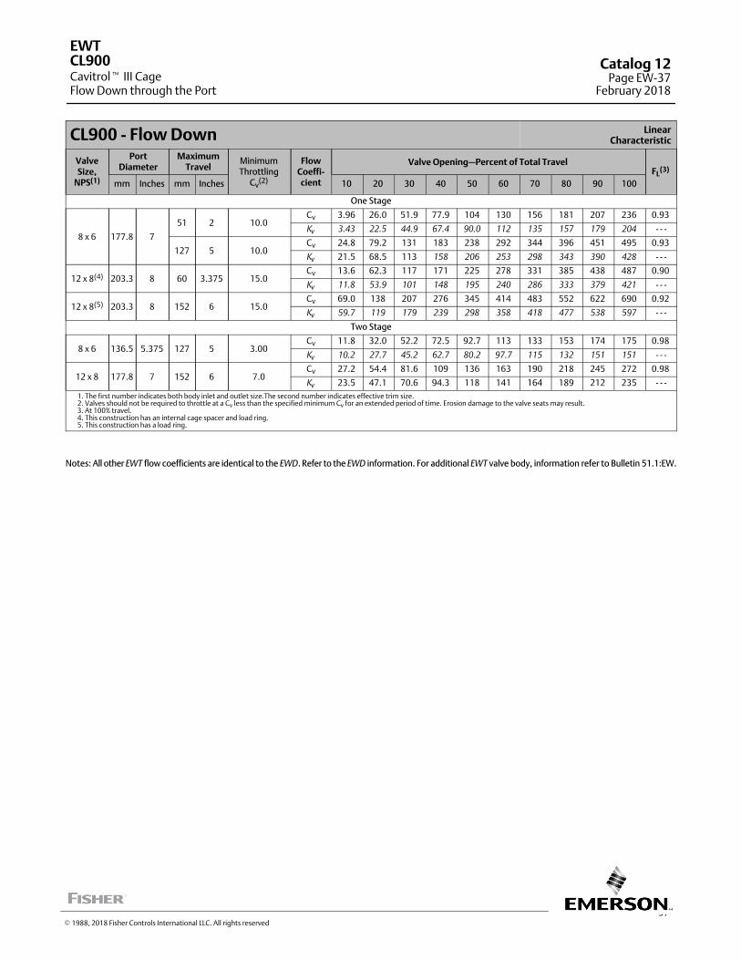
37
CL900 - Flow Down LinearCharacteristic
ValveSize,
NPS(1)
PortDiameter
MaximumTravel
MinimumThrottling
Cv(2)
FlowCoeffi-cient
Valve Opening—Percent of Total TravelFL
(3)
mm Inches mm Inches 10 20 30 40 50 60 70 80 90 100
One Stage
8 x 6 177.8 7
51 2 10.0Cv 3.96 26.0 51.9 77.9 104 130 156 181 207 236 0.93
Kv 3.43 22.5 44.9 67.4 90.0 112 135 157 179 204 - - -
127 5 10.0Cv 24.8 79.2 131 183 238 292 344 396 451 495 0.93
Kv 21.5 68.5 113 158 206 253 298 343 390 428 - - -
12 x 8(4) 203.3 8 60 3.375 15.0Cv 13.6 62.3 117 171 225 278 331 385 438 487 0.90
Kv 11.8 53.9 101 148 195 240 286 333 379 421 - - -
12 x 8(5) 203.3 8 152 6 15.0Cv 69.0 138 207 276 345 414 483 552 622 690 0.92
Kv 59.7 119 179 239 298 358 418 477 538 597 - - -
Two Stage
8 x 6 136.5 5.375 127 5 3.00Cv 11.8 32.0 52.2 72.5 92.7 113 133 153 174 175 0.98
Kv 10.2 27.7 45.2 62.7 80.2 97.7 115 132 151 151 - - -
12 x 8 177.8 7 152 6 7.0Cv 27.2 54.4 81.6 109 136 163 190 218 245 272 0.98
Kv 23.5 47.1 70.6 94.3 118 141 164 189 212 235 - - -
1. The first number indicates both body inlet and outlet size.The second number indicates effective trim size.2. Valves should not be required to throttle at a Cv less than the specified minimum Cv for an extended period of time. Erosion damage to the valve seats may result.3. At 100% travel.4. This construction has an internal cage spacer and load ring.5. This construction has a load ring.
Notes: All other EWT flow coefficients are identical to the EWD. Refer to the EWD information. For additional EWT valve body, information refer to Bulletin 51.1:EW.
EWT
Cavitrol� III CageFlow Down through the Port
CL900 Catalog 12Page EW-37
February 2018
� 1988, 2018 Fisher Controls International LLC. All rights reserved
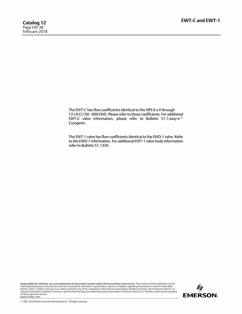
The EWT‐C has flow coefficients identical to the NPS 6 x 4 through 12 x 6 CL150 ‐ 600 EWD. Please refer to those coefficients. For additionalEWT‐C valve information, please refer to Bulletin 51.1:easy‐e�Cryogenic.
The EWT‐1 valve has flow coefficients identical to the EWD‐1 valve. Referto the EWD‐1 information. For additional EWT‐1 valve body informationrefer to Bulletin 51.1:EW.
EWT-C and EWT‐1Catalog 12Page EW-38February 2018
� 1995, 2018 Fisher Controls International LLC. All rights reserved
www.Fisher.com
Responsibility for selection, use, and maintenance of any product remains solely with the purchaser and end user. The contents of this publication are forinformational purposes only and are not to be construed as warranties or guarantees, express or implied, regarding the products or services describedtherein. Fisher, Cavitrol, and easy-e are marks owned by one of the companies in the Emerson Automation Solutions business unit of Emerson Electric Co.Emerson Automation Solutions, Emerson, and the Emerson logo are trademarks and service marks of Emerson Electric Co. All other marks are the propertyof their respective owners.
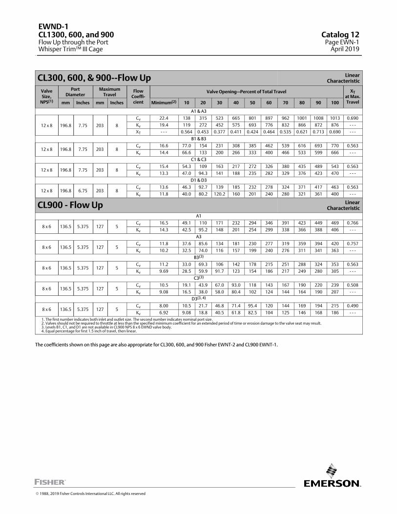
CL300, 600, & 900--Flow Up LinearCharacteristic
ValveSize,
NPS(1)
PortDiameter
MaximumTravel
FlowCoeffi‐cient
Valve Opening—Percent of Total Travel XTat Max.Travelmm Inches mm Inches Minimum(2) 10 20 30 40 50 60 70 80 90 100
A1 & A3
12 x 8 196.8 7.75 203 8
Cv 22.4 138 315 523 665 801 897 962 1001 1008 1013 0.690
Kv 19.4 119 272 452 575 693 776 832 866 872 876 ‐ ‐ ‐
XT ‐ ‐ ‐ 0.564 0.453 0.377 0.411 0.424 0.464 0.535 0.621 0.713 0.690 ‐ ‐ ‐
B1 & B3
12 x 8 196.8 7.75 203 8Cv 16.6 77.0 154 231 308 385 462 539 616 693 770 0.563
Kv 14.4 66.6 133 200 266 333 400 466 533 599 666 ‐ ‐ ‐
C1 & C3
12 x 8 196.8 7.75 203 8Cv 15.4 54.3 109 163 217 272 326 380 435 489 543 0.563
Kv 13.3 47.0 94.3 141 188 235 282 329 376 423 470 ‐ ‐ ‐
D1 & D3
12 x 8 196.8 6.75 203 8Cv 13.6 46.3 92.7 139 185 232 278 324 371 417 463 0.563
Kv 11.8 40.0 80.2 120.2 160 201 240 280 321 361 400 ‐ ‐ ‐
CL900 ‐ Flow Up LinearCharacteristic
A1
8 x 6 136.5 5.375 127 5Cv 16.5 49.1 110 171 232 294 346 391 423 449 469 0.766
Kv 14.3 42.5 95.2 148 201 254 299 338 366 388 406 ‐ ‐ ‐
A3
8 x 6 136.5 5.375 127 5Cv 11.8 37.6 85.6 134 181 230 277 319 359 394 420 0.757
Kv 10.2 32.5 74.0 116 157 199 240 276 311 341 363 ‐ ‐ ‐
B3(3)
8 x 6 136.5 5.375 127 5Cv 11.2 33.0 69.3 106 142 178 215 251 288 324 353 0.563
Kv 9.69 28.5 59.9 91.7 123 154 186 217 249 280 305 ‐ ‐ ‐
C3(3)
8 x 6 136.5 5.375 127 5Cv 10.5 19.1 43.9 67.0 93.0 118 143 167 190 220 239 0.508
Kv 9.08 16.5 38.0 58.0 80.4 102 124 144 164 190 207 ‐ ‐ ‐
D3(3, 4)
8 x 6 136.5 5.375 127 5Cv 8.00 10.5 21.7 46.8 71.4 95.4 120 144 169 194 215 0.490
Kv 6.92 9.08 18.8 40.5 61.8 82.5 104 125 146 168 186 ‐ ‐ ‐
1. The first number indicates both inlet and outlet size. The second number indicates nominal port size.2. Valves should not be required to throttle at less than the specified minimum coefficient for an extended period of time or erosion damage to the valve seat may result.3. Levels B1, C1, and D1 are not available in CL900 NPS 8 x 6 EWND valve body.4. Equal percentage for first 1.5 inch of travel, then linear.
The coefficients shown on this page are also appropriate for CL300, 600, and 900 Fisher EWNT‐2 and CL900 EWNT‐1.
� 1988, 2019 Fisher Controls International LLC. All rights reserved
EWND-1CL1300, 600, and 900Flow Up through the PortWhisper Trim™ III Cage
Catalog 12Page EWN-1
April 2019
This page is intentionally left blank
EWND-1Catalog 12Page EWN-2February 2018
� 1988, 2018 Fisher Controls International LLC. All rights reserved
www.Fisher.com
Responsibility for selection, use, and maintenance of any product remains solely with the purchaser and end user. The contents of this publication are forinformational purposes only and are not to be construed as warranties or guarantees, express or implied, regarding the products or services describedtherein. Fisher and Whisper Trim are marks owned by one of the companies in the Emerson Automation Solutions business unit of Emerson Electric Co.Emerson Automation Solutions, Emerson, and the Emerson logo are trademarks and service marks of Emerson Electric Co. All other marks are the propertyof their respective owners.
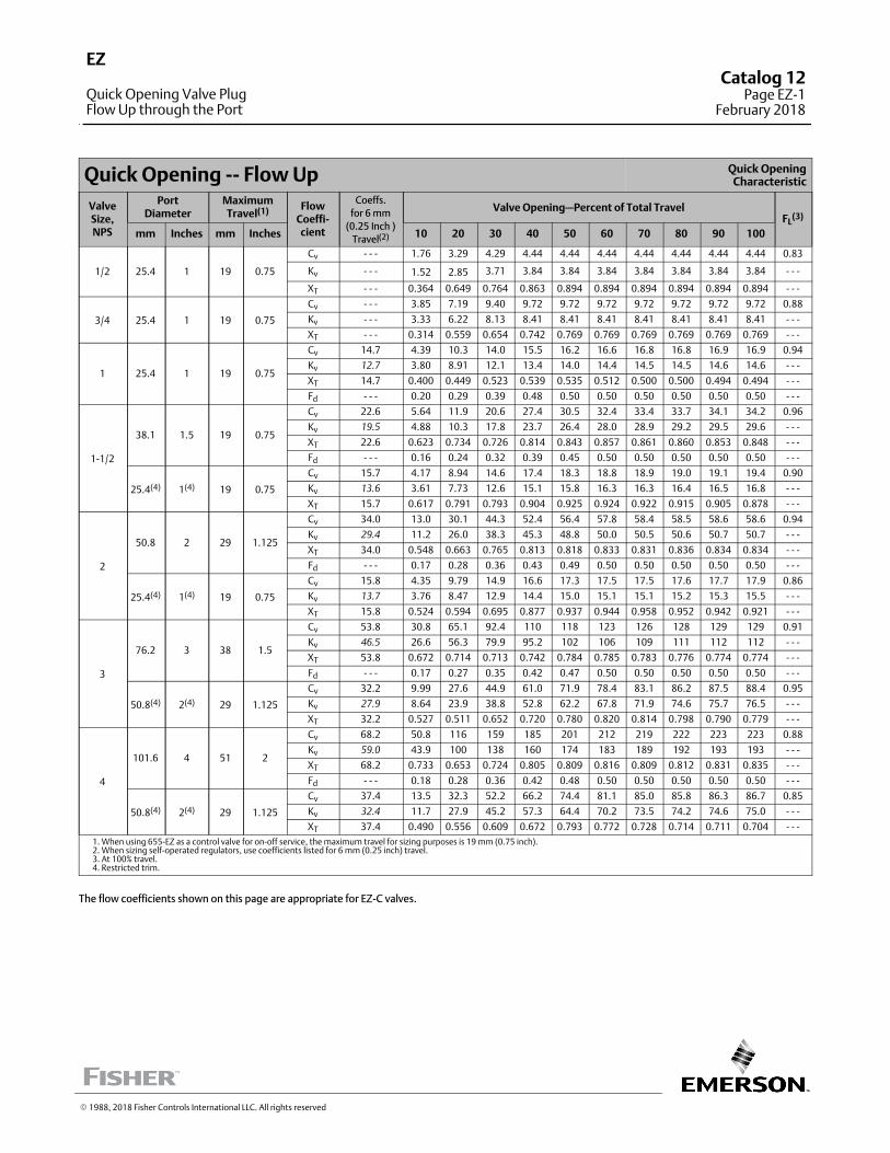
Quick Opening ‐‐ Flow Up Quick OpeningCharacteristic
ValveSize,NPS
PortDiameter
MaximumTravel(1) Flow
Coeffi‐cient
Coeffs.
for 6 mm
(0.25 Inch )
Travel(2)
Valve Opening—Percent of Total TravelFL
(3)
mm Inches mm Inches 10 20 30 40 50 60 70 80 90 100
1/2 25.4 1 19 0.75
Cv ‐ ‐ ‐ 1.76 3.29 4.29 4.44 4.44 4.44 4.44 4.44 4.44 4.44 0.83
Kv ‐ ‐ ‐ 1.52 2.85 3.71 3.84 3.84 3.84 3.84 3.84 3.84 3.84 ‐ ‐ ‐
XT ‐ ‐ ‐ 0.364 0.649 0.764 0.863 0.894 0.894 0.894 0.894 0.894 0.894 ‐ ‐ ‐
3/4 25.4 1 19 0.75
Cv ‐ ‐ ‐ 3.85 7.19 9.40 9.72 9.72 9.72 9.72 9.72 9.72 9.72 0.88
Kv ‐ ‐ ‐ 3.33 6.22 8.13 8.41 8.41 8.41 8.41 8.41 8.41 8.41 ‐ ‐ ‐
XT ‐ ‐ ‐ 0.314 0.559 0.654 0.742 0.769 0.769 0.769 0.769 0.769 0.769 ‐ ‐ ‐
1 25.4 1 19 0.75
Cv 14.7 4.39 10.3 14.0 15.5 16.2 16.6 16.8 16.8 16.9 16.9 0.94
Kv 12.7 3.80 8.91 12.1 13.4 14.0 14.4 14.5 14.5 14.6 14.6 ‐ ‐ ‐
XT 14.7 0.400 0.449 0.523 0.539 0.535 0.512 0.500 0.500 0.494 0.494 ‐ ‐ ‐
Fd ‐ ‐ ‐ 0.20 0.29 0.39 0.48 0.50 0.50 0.50 0.50 0.50 0.50 ‐ ‐ ‐
1‐1/2
38.1 1.5 19 0.75
Cv 22.6 5.64 11.9 20.6 27.4 30.5 32.4 33.4 33.7 34.1 34.2 0.96
Kv 19.5 4.88 10.3 17.8 23.7 26.4 28.0 28.9 29.2 29.5 29.6 ‐ ‐ ‐
XT 22.6 0.623 0.734 0.726 0.814 0.843 0.857 0.861 0.860 0.853 0.848 ‐ ‐ ‐
Fd ‐ ‐ ‐ 0.16 0.24 0.32 0.39 0.45 0.50 0.50 0.50 0.50 0.50 ‐ ‐ ‐
25.4(4) 1(4) 19 0.75
Cv 15.7 4.17 8.94 14.6 17.4 18.3 18.8 18.9 19.0 19.1 19.4 0.90
Kv 13.6 3.61 7.73 12.6 15.1 15.8 16.3 16.3 16.4 16.5 16.8 ‐ ‐ ‐
XT 15.7 0.617 0.791 0.793 0.904 0.925 0.924 0.922 0.915 0.905 0.878 ‐ ‐ ‐
2
50.8 2 29 1.125
Cv 34.0 13.0 30.1 44.3 52.4 56.4 57.8 58.4 58.5 58.6 58.6 0.94
Kv 29.4 11.2 26.0 38.3 45.3 48.8 50.0 50.5 50.6 50.7 50.7 ‐ ‐ ‐
XT 34.0 0.548 0.663 0.765 0.813 0.818 0.833 0.831 0.836 0.834 0.834 ‐ ‐ ‐
Fd ‐ ‐ ‐ 0.17 0.28 0.36 0.43 0.49 0.50 0.50 0.50 0.50 0.50 ‐ ‐ ‐
25.4(4) 1(4) 19 0.75
Cv 15.8 4.35 9.79 14.9 16.6 17.3 17.5 17.5 17.6 17.7 17.9 0.86
Kv 13.7 3.76 8.47 12.9 14.4 15.0 15.1 15.1 15.2 15.3 15.5 ‐ ‐ ‐
XT 15.8 0.524 0.594 0.695 0.877 0.937 0.944 0.958 0.952 0.942 0.921 ‐ ‐ ‐
3
76.2 3 38 1.5
Cv 53.8 30.8 65.1 92.4 110 118 123 126 128 129 129 0.91
Kv 46.5 26.6 56.3 79.9 95.2 102 106 109 111 112 112 ‐ ‐ ‐
XT 53.8 0.672 0.714 0.713 0.742 0.784 0.785 0.783 0.776 0.774 0.774 ‐ ‐ ‐
Fd ‐ ‐ ‐ 0.17 0.27 0.35 0.42 0.47 0.50 0.50 0.50 0.50 0.50 ‐ ‐ ‐
50.8(4) 2(4) 29 1.125
Cv 32.2 9.99 27.6 44.9 61.0 71.9 78.4 83.1 86.2 87.5 88.4 0.95
Kv 27.9 8.64 23.9 38.8 52.8 62.2 67.8 71.9 74.6 75.7 76.5 ‐ ‐ ‐
XT 32.2 0.527 0.511 0.652 0.720 0.780 0.820 0.814 0.798 0.790 0.779 ‐ ‐ ‐
4
101.6 4 51 2
Cv 68.2 50.8 116 159 185 201 212 219 222 223 223 0.88
Kv 59.0 43.9 100 138 160 174 183 189 192 193 193 ‐ ‐ ‐
XT 68.2 0.733 0.653 0.724 0.805 0.809 0.816 0.809 0.812 0.831 0.835 ‐ ‐ ‐
Fd ‐ ‐ ‐ 0.18 0.28 0.36 0.42 0.48 0.50 0.50 0.50 0.50 0.50 ‐ ‐ ‐
50.8(4) 2(4) 29 1.125
Cv 37.4 13.5 32.3 52.2 66.2 74.4 81.1 85.0 85.8 86.3 86.7 0.85
Kv 32.4 11.7 27.9 45.2 57.3 64.4 70.2 73.5 74.2 74.6 75.0 ‐ ‐ ‐
XT 37.4 0.490 0.556 0.609 0.672 0.793 0.772 0.728 0.714 0.711 0.704 ‐ ‐ ‐
1. When using 655‐EZ as a control valve for on‐off service, the maximum travel for sizing purposes is 19 mm (0.75 inch).2. When sizing self‐operated regulators, use coefficients listed for 6 mm (0.25 inch) travel.3. At 100% travel.4. Restricted trim.
The flow coefficients shown on this page are appropriate for EZ‐C valves.
� 1988, 2018 Fisher Controls International LLC. All rights reserved
EZ
Quick Opening Valve PlugFlow Up through the Port
Catalog 12Page EZ-1
February 2018
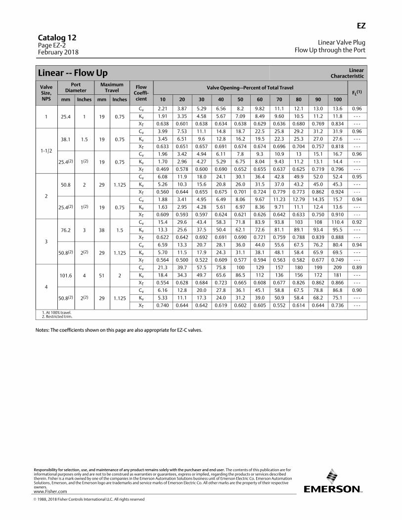
Linear ‐‐ Flow Up LinearCharacteristic
ValveSize,NPS
PortDiameter
MaximumTravel
FlowCoeffi‐cient
Valve Opening—Percent of Total TravelFL
(1)
mm Inches mm Inches 10 20 30 40 50 60 70 80 90 100
1 25.4 1 19 0.75
Cv 2.21 3.87 5.29 6.56 8.2 9.82 11.1 12.1 13.0 13.6 0.96
Kv 1.91 3.35 4.58 5.67 7.09 8.49 9.60 10.5 11.2 11.8 ‐ ‐ ‐
XT 0.638 0.601 0.638 0.634 0.638 0.629 0.636 0.680 0.769 0.834 ‐ ‐ ‐
1‐1/2
38.1 1.5 19 0.75
Cv 3.99 7.53 11.1 14.8 18.7 22.5 25.8 29.2 31.2 31.9 0.96
Kv 3.45 6.51 9.6 12.8 16.2 19.5 22.3 25.3 27.0 27.6 ‐ ‐ ‐
XT 0.633 0.651 0.657 0.691 0.674 0.674 0.696 0.704 0.757 0.818 ‐ ‐ ‐
25.4(2) 1(2) 19 0.75
Cv 1.96 3.42 4.94 6.11 7.8 9.3 10.9 13 15.1 16.7 0.96
Kv 1.70 2.96 4.27 5.29 6.75 8.04 9.43 11.2 13.1 14.4 ‐ ‐ ‐
XT 0.469 0.578 0.600 0.690 0.652 0.655 0.637 0.625 0.719 0.796 ‐ ‐ ‐
2
50.8 2 29 1.125
Cv 6.08 11.9 18.0 24.1 30.1 36.4 42.8 49.9 52.0 52.4 0.95
Kv 5.26 10.3 15.6 20.8 26.0 31.5 37.0 43.2 45.0 45.3 ‐ ‐ ‐
XT 0.560 0.644 0.655 0.675 0.701 0.724 0.779 0.773 0.862 0.924 ‐ ‐ ‐
25.4(2) 1(2) 19 0.75
Cv 1.88 3.41 4.95 6.49 8.06 9.67 11.23 12.79 14.35 15.7 0.94
Kv 1.63 2.95 4.28 5.61 6.97 8.36 9.71 11.1 12.4 13.6 ‐ ‐ ‐
XT 0.609 0.593 0.597 0.624 0.621 0.626 0.642 0.633 0.750 0.910 ‐ ‐ ‐
3
76.2 3 38 1.5
Cv 15.4 29.6 43.4 58.3 71.8 83.9 93.8 103 108 110.4 0.92
Kv 13.3 25.6 37.5 50.4 62.1 72.6 81.1 89.1 93.4 95.5 ‐ ‐ ‐
XT 0.622 0.642 0.692 0.691 0.690 0.721 0.759 0.788 0.839 0.888 ‐ ‐ ‐
50.8(2) 2(2) 29 1.125
Cv 6.59 13.3 20.7 28.1 36.0 44.0 55.6 67.5 76.2 80.4 0.94
Kv 5.70 11.5 17.9 24.3 31.1 38.1 48.1 58.4 65.9 69.5 ‐ ‐ ‐
XT 0.564 0.500 0.522 0.609 0.577 0.594 0.563 0.582 0.677 0.749 ‐ ‐ ‐
4
101.6 4 51 2
Cv 21.3 39.7 57.5 75.8 100 129 157 180 199 209 0.89
Kv 18.4 34.3 49.7 65.6 86.5 112 136 156 172 181 ‐ ‐ ‐
XT 0.554 0.628 0.684 0.723 0.665 0.608 0.677 0.826 0.862 0.866 ‐ ‐ ‐
50.8(2) 2(2) 29 1.125
Cv 6.16 12.8 20.0 27.8 36.1 45.1 58.8 67.5 78.8 86.8 0.90
Kv 5.33 11.1 17.3 24.0 31.2 39.0 50.9 58.4 68.2 75.1 ‐ ‐ ‐
XT 0.740 0.644 0.642 0.619 0.602 0.605 0.552 0.614 0.644 0.736 ‐ ‐ ‐
1. At 100% travel.2. Restricted trim.
Notes: The coefficients shown on this page are also appropriate for EZ‐C valves.
EZ
Linear Valve PlugFlow Up through the Port
Catalog 12Page EZ-2February 2018
� 1988, 2018 Fisher Controls International LLC. All rights reserved
www.Fisher.com
Responsibility for selection, use, and maintenance of any product remains solely with the purchaser and end user. The contents of this publication are forinformational purposes only and are not to be construed as warranties or guarantees, express or implied, regarding the products or services describedtherein. Fisher is a mark owned by one of the companies in the Emerson Automation Solutions business unit of Emerson Electric Co. Emerson AutomationSolutions, Emerson, and the Emerson logo are trademarks and service marks of Emerson Electric Co. All other marks are the property of their respectiveowners.
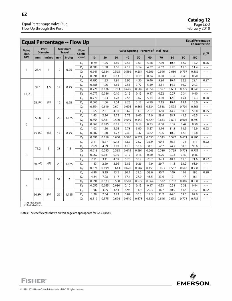
3
Equal Percentage ‐‐ Flow Up Equal PercentageCharacteristic
ValveSize,NPS
PortDiameter
MaximumTravel
FlowCoeffi‐cient
Valve Opening—Percent of Total TravelFL
(1)
mm Inches mm Inches 10 20 30 40 50 60 70 80 90 100
1 25.4 1 19 0.75
Cv 0.79 1.25 1.80 2.53 3.63 5.28 7.59 10.7 12.7 13.2 0.96
Kv 0.683 1.08 1.56 2.19 3.14 4.57 6.57 9.26 11.0 11.4 ‐ ‐ ‐
XT 0.641 0.634 0.598 0.586 0.584 0.596 0.646 0.680 0.757 0.886 ‐ ‐ ‐
Fd 0.091 0.11 0.13 0.16 0.19 0.24 0.30 0.37 0.43 0.50 ‐ ‐ ‐
1‐1/2
38.1 1.5 19 0.75
Cv 0.795 1.23 1.91 2.95 4.30 6.46 9.84 16.4 22.2 28.1 0.97
Kv 0.688 1.06 1.65 2.55 3.72 5.59 8.51 14.2 19.2 24.3 ‐ ‐ ‐
XT 0.726 0.676 0.733 0.645 0.589 0.558 0.597 0.653 0.777 0.840 ‐ ‐ ‐
Fd 0.077 0.086 0.10 0.12 0.15 0.17 0.22 0.27 0.34 0.40 ‐ ‐ ‐
25.4(2) 1(2) 19 0.75
Cv 0.770 1.23 1.78 2.58 3.67 5.54 8.30 12.0 15.1 17.3 0.98
Kv 0.666 1.06 1.54 2.23 3.17 4.79 7.18 10.4 13.1 15.0 ‐ ‐ ‐
XT 0.654 0.619 0.601 0.605 0.561 0.534 0.518 0.575 0.704 0.861 ‐ ‐ ‐
2
50.8 2 29 1.125
Cv 1.65 2.61 4.30 6.62 11.1 20.7 32.8 44.7 50.0 53.8 0.95
Kv 1.43 2.26 3.72 5.73 9.60 17.9 28.4 38.7 43.3 46.5 ‐ ‐ ‐
XT 0.655 0.581 0.520 0.559 0.552 0.529 0.653 0.801 0.903 0.899 ‐ ‐ ‐
Fd 0.069 0.085 0.11 0.13 0.18 0.23 0.30 0.37 0.44 0.50 ‐ ‐ ‐
25.4(2) 1(2) 19 0.75
Cv 1.02 1.50 2.05 2.78 3.90 5.57 8.16 11.8 14.5 15.9 0.92
Kv 0.882 1.30 1.77 2.40 3.37 4.82 7.06 10.2 12.5 13.8 ‐ ‐ ‐
XT 0.596 0.616 0.600 0.580 0.572 0.555 0.523 0.547 0.671 0.905 ‐ ‐ ‐
3
76.2 3 38 1.5
Cv 3.11 5.77 9.12 13.7 21.7 36.0 60.4 86.4 104 114 0.92
Kv 2.69 4.99 7.89 11.9 18.8 31.1 52.2 74.7 90.0 98.6 ‐ ‐ ‐
XT 0.619 0.595 0.598 0.619 0.594 0.563 0.586 0.729 0.778 0.781 ‐ ‐ ‐
Fd 0.062 0.081 0.10 0.12 0.16 0.20 0.26 0.33 0.40 0.46 ‐ ‐ ‐
50.8(2) 2(2) 29 1.125
Cv 2.11 3.11 4.58 6.76 10.7 20.7 34.3 48.3 61.5 71.6 0.92
Kv 1.83 2.69 3.96 5.85 9.26 17.9 29.7 41.8 53.2 61.9 ‐ ‐ ‐
XT 0.874 0.699 0.643 0.626 0.587 0.451 0.493 0.587 0.648 0.734 ‐ ‐ ‐
4
101.6 4 51 2
Cv 4.90 8.19 13.5 20.1 31.2 52.6 96.7 140 170 190 0.90
Kv 4.24 7.08 11.7 17.4 27.0 45.5 83.6 121 147 164 ‐ ‐ ‐
XT 0.594 0.573 0.560 0.568 0.572 0.564 0.532 0.707 0.807 0.834 ‐ ‐ ‐
Fd 0.052 0.065 0.080 0.10 0.13 0.17 0.23 0.31 0.38 0.44 ‐ ‐ ‐
50.8(2) 2(2) 29 1.125
Cv 1.96 3.05 4.43 6.98 11.9 22.3 36.7 50.9 61.8 72.7 0.92
Kv 1.70 2.64 3.83 6.04 10.3 19.3 31.7 44.0 53.5 62.9 ‐ ‐ ‐
XT 0.619 0.575 0.624 0.610 0.678 0.639 0.646 0.673 0.778 0.781 ‐ ‐ ‐
1. At 100% travel.2. Restricted trim.
Notes: The coefficients shown on this page are appropriate for EZ‐C valves.
EZ
Equal Percentage Valve PlugFlow Up through the Port
Catalog 12Page EZ-3
February 2018
� 1988, 2018 Fisher Controls International LLC. All rights reserved
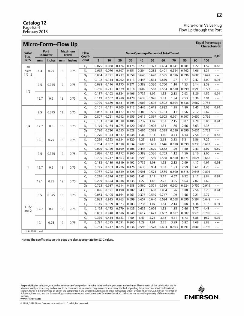
Micro‐Form‐‐Flow Up Equal PercentageCharacteristic
ValveSize,NPS
PortDiameter
MaximumTravel
FlowCoeffi‐cient
Valve Opening—Percent of Total TravelFL
(1)
mm Inches mm Inches 5 10 20 30 40 50 60 70 80 90 100
All
Sizes
1/2 ‐ 26.4 0.25 19 0.75
Cv 0.075 0.088 0.124 0.175 0.236 0.327 0.464 0.641 0.881 1.22 1.52 0.88
Kv 0.065 0.076 0.107 0.151 0.204 0.283 0.401 0.554 0.762 1.06 1.31 ‐ ‐ ‐
XT 0.804 0.771 0.717 0.658 0.645 0.620 0.585 0.596 0.596 0.603 0.647 ‐ ‐ ‐
1/2
9.5 0.375 19 0.75
Cv 0.102 0.134 0.202 0.313 0.448 0.613 0.879 1.27 1.77 2.47 3.00 0.93
Kv 0.088 0.116 0.175 0.271 0.388 0.530 0.760 1.10 1.53 2.14 2.59 ‐ ‐ ‐
XT 0.766 0.711 0.679 0.618 0.602 0.588 0.564 0.580 0.599 0.593 0.723 ‐ ‐ ‐
12.7 0.5 19 0.75
Cv 0.137 0.193 0.324 0.496 0.737 1.07 1.52 2.13 2.93 3.89 4.52 0.94
Kv 0.119 0.167 0.280 0.429 0.638 0.926 1.31 1.84 2.53 3.36 3.91 ‐ ‐ ‐
XT 0.739 0.689 0.631 0.595 0.603 0.602 0.592 0.604 0.636 0.687 0.754 ‐ ‐ ‐
3/4
9.5 0.375 19 0.75
Cv 0.101 0.131 0.205 0.312 0.446 0.618 0.882 1.28 1.80 2.45 3.03 0.93
Kv 0.087 0.113 0.177 0.270 0.386 0.535 0.763 1.11 1.56 2.12 2.62 ‐ ‐ ‐
XT 0.807 0.751 0.642 0.655 0.616 0.597 0.603 0.601 0.607 0.650 0.736 ‐ ‐ ‐
12.7 0.5 19 0.75
Cv 0.133 0.190 0.318 0.486 0.732 1.07 1.52 2.15 3.07 4.20 5.06 0.94
Kv 0.115 0.164 0.275 0.420 0.633 0.926 1.31 1.86 2.66 3.63 4.38 ‐ ‐ ‐
XT 0.780 0.720 0.655 0.628 0.606 0.598 0.598 0.596 0.596 0.636 0.722 ‐ ‐ ‐
19.1 0.75 19 0.75
Cv 0.276 0.373 0.617 0.948 1.44 2.14 3.10 4.43 6.14 7.58 8.35 0.87
Kv 0.239 0.323 0.534 0.820 1.25 1.85 2.68 3.83 5.31 6.56 7.22 ‐ ‐ ‐
XT 0.734 0.702 0.618 0.634 0.605 0.607 0.646 0.670 0.699 0.730 0.693 ‐ ‐ ‐
1
9.5 0.375 19 0.75
Cv 0.099 0.129 0.199 0.308 0.448 0.620 0.882 1.29 1.80 2.43 3.07 0.89
Kv 0.086 0.112 0.172 0.266 0.388 0.536 0.763 1.12 1.56 2.10 2.66 ‐ ‐ ‐
XT 0.795 0.747 0.663 0.641 0.593 0.569 0.568 0.560 0.571 0.624 0.662 ‐ ‐ ‐
12.7 0.5 19 0.75
Cv 0.133 0.189 0.319 0.492 0.735 1.08 1.53 2.12 2.99 4.17 4.91 0.93
Kv 0.115 0.163 0.276 0.426 0.636 0.934 1.32 1.83 2.59 3.61 4.25 ‐ ‐ ‐
XT 0.787 0.728 0.639 0.628 0.591 0.573 0.585 0.600 0.618 0.645 0.803 ‐ ‐ ‐
19.1 0.75 19 0.75
Cv 0.276 0.374 0.622 0.965 1.47 2.17 3.15 4.57 6.52 8.17 8.84 0.97
Kv 0.239 0.324 0.538 0.835 1.27 1.88 2.72 3.95 5.64 7.07 7.65 ‐ ‐ ‐
XT 0.723 0.687 0.614 0.588 0.560 0.571 0.596 0.603 0.624 0.750 0.919 ‐ ‐ ‐
1‐1/2
and 2
9.5 0.375 19 0.75
Cv 0.096 0.121 0.190 0.302 0.435 0.600 0.864 1.26 1.80 2.56 3.20 0.84
Kv 0.083 0.105 0.164 0.261 0.376 0.519 0.747 1.09 1.56 2.21 2.77 ‐ ‐ ‐
XT 0.923 0.915 0.763 0.699 0.657 0.640 0.624 0.608 0.596 0.594 0.648 ‐ ‐ ‐
12.7 0.5 19 0.75
Cv 0.145 0.199 0.323 0.503 0.735 1.07 1.54 2.14 3.08 4.36 5.18 0.91
Kv 0.125 0.172 0.279 0.435 0.636 0.926 1.33 1.85 2.66 3.77 4.48 ‐ ‐ ‐
XT 0.851 0.748 0.686 0.640 0.617 0.627 0.602 0.607 0.607 0.573 0.705 ‐ ‐ ‐
19.1 0.75 19 0.75
Cv 0.336 0.434 0.683 1.00 1.49 2.21 3.18 4.61 6.73 8.88 10.2 0.92
Kv 0.291 0.375 0.591 0.865 1.29 1.91 2.75 3.99 5.82 7.68 8.82 ‐ ‐ ‐
XT 0.784 0.747 0.625 0.636 0.596 0.578 0.603 0.593 0.591 0.680 0.796 ‐ ‐ ‐
1. At 100% travel.
Notes: The coefficients on this page are also appropriate for EZ‐C valves.
EZ
Micro-Form Valve PlugFlow Up through the Port
Catalog 12Page EZ-4February 2018
� 1988, 2018 Fisher Controls International LLC. All rights reserved
www.Fisher.com
Responsibility for selection, use, and maintenance of any product remains solely with the purchaser and end user. The contents of this publication are forinformational purposes only and are not to be construed as warranties or guarantees, express or implied, regarding the products or services describedtherein. Fisher is a mark owned by one of the companies in the Emerson Automation Solutions business unit of Emerson Electric Co. Emerson AutomationSolutions, Emerson, and the Emerson logo are trademarks and service marks of Emerson Electric Co. All other marks are the property of their respectiveowners.
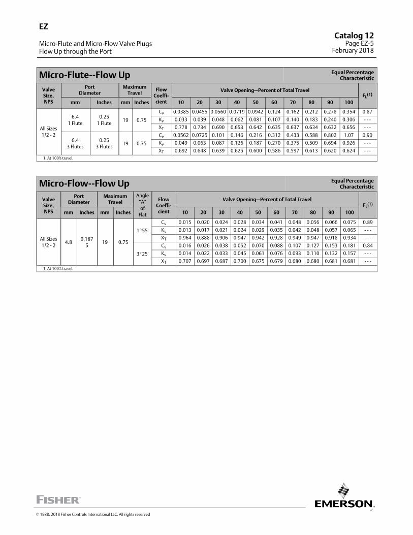
5
Micro‐Flute‐‐Flow Up Equal PercentageCharacteristic
ValveSize,NPS
PortDiameter
MaximumTravel
FlowCoeffi‐cient
Valve Opening—Percent of Total TravelFL
(1)
mm Inches mm Inches 10 20 30 40 50 60 70 80 90 100
All Sizes
1/2 ‐ 2
6.4
1 Flute
0.25
1 Flute19 0.75
Cv 0.0385 0.0455 0.0560 0.0719 0.0942 0.124 0.162 0.212 0.278 0.354 0.87
Kv 0.033 0.039 0.048 0.062 0.081 0.107 0.140 0.183 0.240 0.306 ‐ ‐ ‐
XT 0.778 0.734 0.690 0.653 0.642 0.635 0.637 0.634 0.632 0.656 ‐ ‐ ‐
6.4
3 Flutes
0.25
3 Flutes19 0.75
Cv 0.0562 0.0725 0.101 0.146 0.216 0.312 0.433 0.588 0.802 1.07 0.90
Kv 0.049 0.063 0.087 0.126 0.187 0.270 0.375 0.509 0.694 0.926 ‐ ‐ ‐
XT 0.692 0.648 0.639 0.625 0.600 0.586 0.597 0.613 0.620 0.624 ‐ ‐ ‐
1. At 100% travel.
Micro‐Flow‐‐Flow Up Equal PercentageCharacteristic
ValveSize,NPS
PortDiameter
MaximumTravel
Angle
“A”
of
Flat
FlowCoeffi‐cient
Valve Opening—Percent of Total TravelFL
(1)
mm Inches mm Inches 10 20 30 40 50 60 70 80 90 100
All Sizes
1/2 ‐ 24.8
0.187
519 0.75
1�55'
Cv 0.015 0.020 0.024 0.028 0.034 0.041 0.048 0.056 0.066 0.075 0.89
Kv 0.013 0.017 0.021 0.024 0.029 0.035 0.042 0.048 0.057 0.065 ‐ ‐ ‐
XT 0.964 0.888 0.906 0.947 0.942 0.928 0.949 0.947 0.918 0.934 ‐ ‐ ‐
3�25'
Cv 0.016 0.026 0.038 0.052 0.070 0.088 0.107 0.127 0.153 0.181 0.84
Kv 0.014 0.022 0.033 0.045 0.061 0.076 0.093 0.110 0.132 0.157 ‐ ‐ ‐
XT 0.707 0.697 0.687 0.700 0.675 0.679 0.680 0.680 0.681 0.681 ‐ ‐ ‐
1. At 100% travel.
EZ
Micro-Flute and Micro-Flow Valve PlugsFlow Up through the Port
Catalog 12Page EZ-5
February 2018
� 1988, 2018 Fisher Controls International LLC. All rights reserved
The EZ‐C has flow coefficients identical to the EZ. Please refer to those coefficients. For additional EZ‐C valveinformation, please refer to Bulletin 51.1:easy‐e� Cryogenic.
EZ-CCatalog 12Page EZ-6February 2018
� 1995, 2018 Fisher Controls International LLC. All rights reserved
www.Fisher.com
Responsibility for selection, use, and maintenance of any product remains solely with the purchaser and end user. The contents of this publication are forinformational purposes only and are not to be construed as warranties or guarantees, express or implied, regarding the products or services describedtherein. Fisher and easy-e are marks owned by one of the companies in the Emerson Automation Solutions business unit of Emerson Electric Co. EmersonAutomation Solutions, Emerson, and the Emerson logo are trademarks and service marks of Emerson Electric Co. All other marks are the property of theirrespective owners.
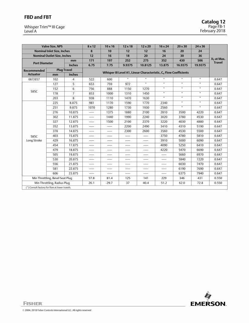
Valve Size, NPS 8 x 12 10 x 16 12 x 18 12 x 20 16 x 24 20 x 30 24 x 36
XT at Max.Travel
Nominal Inlet Size, Inches 8 10 12 12 16 20 24
Nominal Outlet Size, Inches 12 16 18 20 24 30 36
Port Diametermm 171 197 252 275 352 430 506
Inches 6.75 7.75 9.9375 10.8125 13.875 16.9375 19.9375
RecommendedActuator
Plug TravelWhisper III Level A1, Linear Characteristic, Cv Flow Coefficients
mm Inches
667/657 102 4 522 600 * * * * * 0.647
585C
127 5 653 759 972 * * * * 0.647
152 6 756 888 1150 1270 * * * 0.647
178 7 853 1000 1310 1450 * * * 0.647
203 8 938 1110 1470 1630 * * * 0.647
585C
Long Stroke
225 8.875 981 1170 1590 1770 2340 * * 0.647
251 9.875 1070 1280 1730 1930 2560 * * 0.647
276 10.875 ----- 1375 1880 2100 2810 3500 4220 0.647
302 11.875 ----- 1440 1990 2240 3020 3780 4530 0.647
327 12.875 ----- 1500 2100 2370 3220 4030 4880 0.647
352 13.875 ----- ----- 2200 2490 3410 4310 5190 0.647
378 14.875 ----- ----- 2300 2600 3560 4530 5500 0.647
403 15.875 ----- ----- ----- ----- 3750 4780 5810 0.647
429 16.875 ----- ----- ----- ----- 3910 5000 6090 0.647
454 17.875 ----- ----- ----- ----- 4090 5250 6410 0.647
479 18.875 ----- ----- ----- ----- 4220 5470 6690 0.647
505 19.875 ----- ----- ----- ----- ----- 5660 6970 0.647
530 20.875 ----- ----- ----- ----- ----- 5840 7220 0.647
556 21.875 ----- ----- ----- ----- ----- 6030 7470 0.647
581 22.875 ----- ----- ----- ----- ----- 6190 7690 0.647
606 23.875 ----- ----- ----- ----- ----- 6375 7940 0.647
Min Throttling, Bevel Seat Plug 57.8 81.4 125 141 229 346 431 0.550
Min Throttling, Radius Plug 26.1 29.7 37 40.4 51.2 62.0 72.8 0.550
(*) Consult factory for flow at lower travels.
� 2004, 2018 Fisher Controls International LLC. All rights reserved
FBD and FBT
Whisper Trim™ III CageLevel A
Catalog 12Page FB-1
February 2018
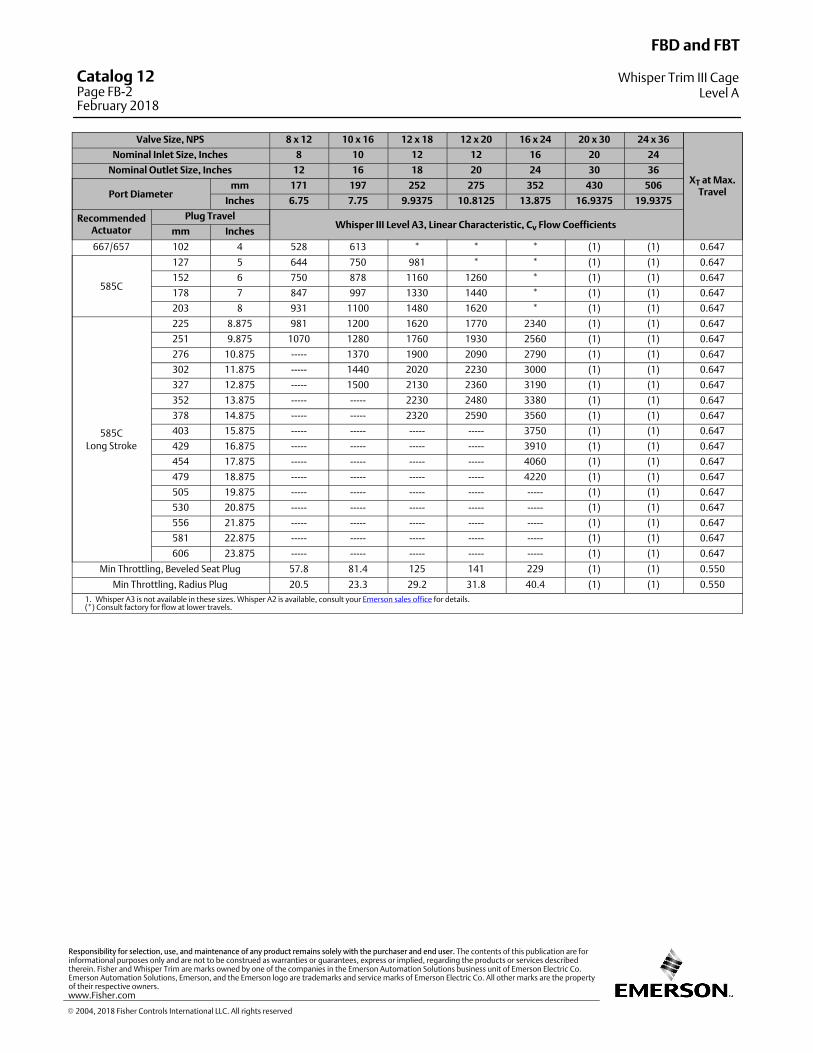
Valve Size, NPS 8 x 12 10 x 16 12 x 18 12 x 20 16 x 24 20 x 30 24 x 36
XT at Max.Travel
Nominal Inlet Size, Inches 8 10 12 12 16 20 24
Nominal Outlet Size, Inches 12 16 18 20 24 30 36
Port Diametermm 171 197 252 275 352 430 506
Inches 6.75 7.75 9.9375 10.8125 13.875 16.9375 19.9375
RecommendedActuator
Plug TravelWhisper III Level A3, Linear Characteristic, Cv Flow Coefficients
mm Inches
667/657 102 4 528 613 * * * (1) (1) 0.647
585C
127 5 644 750 981 * * (1) (1) 0.647
152 6 750 878 1160 1260 * (1) (1) 0.647
178 7 847 997 1330 1440 * (1) (1) 0.647
203 8 931 1100 1480 1620 * (1) (1) 0.647
585C
Long Stroke
225 8.875 981 1200 1620 1770 2340 (1) (1) 0.647
251 9.875 1070 1280 1760 1930 2560 (1) (1) 0.647
276 10.875 ----- 1370 1900 2090 2790 (1) (1) 0.647
302 11.875 ----- 1440 2020 2230 3000 (1) (1) 0.647
327 12.875 ----- 1500 2130 2360 3190 (1) (1) 0.647
352 13.875 ----- ----- 2230 2480 3380 (1) (1) 0.647
378 14.875 ----- ----- 2320 2590 3560 (1) (1) 0.647
403 15.875 ----- ----- ----- ----- 3750 (1) (1) 0.647
429 16.875 ----- ----- ----- ----- 3910 (1) (1) 0.647
454 17.875 ----- ----- ----- ----- 4060 (1) (1) 0.647
479 18.875 ----- ----- ----- ----- 4220 (1) (1) 0.647
505 19.875 ----- ----- ----- ----- ----- (1) (1) 0.647
530 20.875 ----- ----- ----- ----- ----- (1) (1) 0.647
556 21.875 ----- ----- ----- ----- ----- (1) (1) 0.647
581 22.875 ----- ----- ----- ----- ----- (1) (1) 0.647
606 23.875 ----- ----- ----- ----- ----- (1) (1) 0.647
Min Throttling, Beveled Seat Plug 57.8 81.4 125 141 229 (1) (1) 0.550
Min Throttling, Radius Plug 20.5 23.3 29.2 31.8 40.4 (1) (1) 0.550
1. Whisper A3 is not available in these sizes. Whisper A2 is available, consult your Emerson sales office for details.(*) Consult factory for flow at lower travels.
FBD and FBT
Whisper Trim III CageLevel A
Catalog 12Page FB-2February 2018
� 2004, 2018 Fisher Controls International LLC. All rights reserved
www.Fisher.com
Responsibility for selection, use, and maintenance of any product remains solely with the purchaser and end user. The contents of this publication are forinformational purposes only and are not to be construed as warranties or guarantees, express or implied, regarding the products or services describedtherein. Fisher and Whisper Trim are marks owned by one of the companies in the Emerson Automation Solutions business unit of Emerson Electric Co.Emerson Automation Solutions, Emerson, and the Emerson logo are trademarks and service marks of Emerson Electric Co. All other marks are the propertyof their respective owners.

3
Valve Size, NPS 8 x 12 10 x 16 12 x 18 12 x 20 16 x 24 20 x 30 24 x 36
XT at Max.Travel
Nominal Inlet Size, Inches 8 10 12 12 16 20 24
Nominal Outlet Size, Inches 12 16 18 20 24 30 36
Port Diametermm 171 197 252 275 352 430 506
Inches 6.75 7.75 9.9375 10.8125 13.875 16.9375 19.9375
RecommendedActuator
Plug TravelWhisper III Level B1, Linear Characteristic, Cv Flow Coefficients
mm Inches
667/657 102 4 334 366 * * * * * 0.647
585C
127 5 422 463 581 * * * * 0.647
152 6 503 559 703 * * * * 0.647
178 7 578 647 828 * * * * 0.647
203 8 650 731 944 1050 * * * 0.647
585C
Long Stroke
225 8.875 706 897 1030 1150 1410 * * 0.647
251 9.875 769 1000 1140 1270 1575 * * 0.647
276 10.875 ----- 1090 1240 1380 1730 2180 2520 0.647
302 11.875 ----- 1160 1340 1490 1880 2380 2760 0.647
327 12.875 ----- 1230 1430 1600 2030 2580 3000 0.647
352 13.875 ----- ----- 1530 1700 2170 2770 3250 0.647
378 14.875 ----- ----- 1620 1810 2310 2950 3470 0.647
403 15.875 ----- ----- ----- ----- 2440 3120 3690 0.647
429 16.875 ----- ----- ----- ----- 2570 3310 3910 0.647
454 17.875 ----- ----- ----- ----- 2700 3470 4130 0.647
479 18.875 ----- ----- ----- ----- 2830 3660 4340 0.647
505 19.875 ----- ----- ----- ----- ----- 3810 4530 0.647
530 20.875 ----- ----- ----- ----- ----- 3970 4720 0.647
556 21.875 ----- ----- ----- ----- ----- 4090 4910 0.647
581 22.875 ----- ----- ----- ----- ----- 4250 5090 0.647
606 23.875 ----- ----- ----- ----- ----- 4410 5280 0.647
Min Throttling, Bevel Seat Plug 57.8 81.4 125 141 229 346 431 0.550
Min Throttling, Radius Plug 23.1 25.9 32.4 35.6 44.5 50.8 63.8 0.550
(*) Consult factory for flow at lower travels.
FBD and FBT
Whisper Trim™ III CageLevel B
Catalog 12Page FB-3
February 2018
� 2004, 2018 Fisher Controls International LLC. All rights reserved
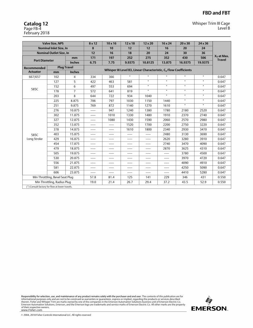
Valve Size, NPS 8 x 12 10 x 16 12 x 18 12 x 20 16 x 24 20 x 30 24 x 36
XT at Max.Travel
Nominal Inlet Size, In 8 10 12 12 16 20 24
Nominal Outlet Size, In 12 16 18 20 24 30 36
Port Diametermm 171 197 252 275 352 430 506
Inches 6.75 7.75 9.9375 10.8125 13.875 16.9375 19.9375
RecommendedActuator
Plug TravelWhisper III Level B3, Linear Characteristic, Cv Flow Coefficients
mm Inches
667/657 102 4 334 366 * * * * * 0.647
585C
127 5 422 463 581 * * * * 0.647
152 6 497 553 694 * * * * 0.647
178 7 572 641 819 * * * * 0.647
203 8 644 722 934 1040 * * * 0.647
585C
Long Stroke
225 8.875 706 797 1030 1150 1440 * * 0.647
251 9.875 769 872 1140 1270 1610 * * 0.647
276 10.875 ----- 947 1240 1380 1780 2180 2520 0.647
302 11.875 ----- 1010 1330 1480 1910 2370 2740 0.647
327 12.875 ----- 1080 1430 1590 2060 2570 2980 0.647
352 13.875 ----- ----- 1520 1700 2200 2750 3220 0.647
378 14.875 ----- ----- 1610 1800 2340 2930 3470 0.647
403 15.875 ----- ----- ----- ----- 2480 3130 3690 0.647
429 16.875 ----- ----- ----- ----- 2620 3280 3910 0.647
454 17.875 ----- ----- ----- ----- 2740 3470 4090 0.647
479 18.875 ----- ----- ----- ----- 2870 3625 4310 0.647
505 19.875 ----- ----- ----- ----- ----- 3780 4500 0.647
530 20.875 ----- ----- ----- ----- ----- 3970 4720 0.647
556 21.875 ----- ----- ----- ----- ----- 4090 4910 0.647
581 22.875 ----- ----- ----- ----- ----- 4250 5090 0.647
606 23.875 ----- ----- ----- ----- ----- 4410 5280 0.647
Min Throttling, Bevel Seat Plug 57.8 81.4 125 141 229 346 431 0.550
Min Throttling, Radius Plug 19.0 21.4 26.7 29.4 37.2 43.5 52.9 0.550
(*) Consult factory for flow at lower travels.
FBD and FBT
Whisper Trim III CageLevel B
Catalog 12Page FB-4February 2018
� 2004, 2018 Fisher Controls International LLC. All rights reserved
www.Fisher.com
Responsibility for selection, use, and maintenance of any product remains solely with the purchaser and end user. The contents of this publication are forinformational purposes only and are not to be construed as warranties or guarantees, express or implied, regarding the products or services describedtherein. Fisher and Whisper Trim are marks owned by one of the companies in the Emerson Automation Solutions business unit of Emerson Electric Co.Emerson Automation Solutions, Emerson, and the Emerson logo are trademarks and service marks of Emerson Electric Co. All other marks are the propertyof their respective owners.

5
Valve Size, NPS 8 x 12 10 x 16 12 x 18 12 x 20 16 x 24 20 x 30 24 x 36
XT at Max.Travel
Nominal Inlet Size, Inches 8 10 12 12 16 20 24
Nominal Outlet Size, Inches 12 16 18 20 24 30 36
Port Diametermm 171 197 252 275 352 430 506
Inches 6.75 7.75 9.9375 10.8125 13.875 16.9375 19.9375
RecommendedActuator
Plug TravelWhisper III Level C1, Linear Characteristic, Cv Flow Coefficients
mm Inches
667/657 102 4 199 224 * * * * * 0.647
585C
127 5 254 286 * * * * * 0.647
152 6 298 334 447 * * * * 0.647
178 7 353 397 531 * * * * 0.647
203 8 409 459 613 663 * * * 0.647
585C
Long Stroke
225 8.875 447 509 678 734 953 * * 0.647
251 9.875 494 569 763 825 1060 * * 0.647
276 10.875 ----- 613 828 897 1170 1460 1680 0.647
302 11.875 ----- 666 906 988 1270 1590 1830 0.647
327 12.875 ----- 716 981 1070 1380 1730 1980 0.647
352 13.875 ----- ----- 1050 1150 1490 1860 2140 0.647
378 14.875 ----- ----- 1120 1230 1590 1990 2290 0.647
403 15.875 ----- ----- ----- ----- 1700 2130 2440 0.647
429 16.875 ----- ----- ----- ----- 1790 2260 2600 0.647
454 17.875 ----- ----- ----- ----- 1890 2390 2750 0.647
479 18.875 ----- ----- ----- ----- 1960 2530 2900 0.647
505 19.875 ----- ----- ----- ----- ----- 2640 3060 0.647
530 20.875 ----- ----- ----- ----- ----- 2760 3210 0.647
556 21.875 ----- ----- ----- ----- ----- 2880 3360 0.647
581 22.875 ----- ----- ----- ----- ----- 3000 3520 0.647
606 23.875 ----- ----- ----- ----- ----- 3080 3610 0.647
Min Throttling, Bevel Seat Plug 57.8 81.4 125 141 229 346 431 0.550
Min Throttling, Radius Plug 20.8 23.7 30.1 32.9 41.5 50.8 59.3 0.550
(*) Consult factory for flow at lower travels.
FBD and FBT
Whisper Trim™ III CageLevel C
Catalog 12Page FB-5
February 2018
� 2004, 2018 Fisher Controls International LLC. All rights reserved

Valve Size, NPS 8 x 12 10 x 16 12 x 18 12 x 20 16 x 24 20 x 30 24 x 36
XT at Max.Travel
Nominal Inlet Size, Inches 8 10 12 12 16 20 24
Nominal Outlet Size, Inches 12 16 18 20 24 30 36
Port Diametermm 171 197 252 275 352 430 506
Inches 6.75 7.75 9.9375 10.8125 13.875 16.9375 19.9375
RecommendedActuator
Plug TravelWhisper III Level C3, Linear Characteristic, Cv Flow Coefficients
mm Inches
667/657 102 4 205 229 * * * * * 0.647
585C
127 5 264 295 * * * * * 0.647
152 6 316 353 447 * * * * 0.647
178 7 375 419 531 * * * * 0.647
203 8 425 478 606 656 * * * 0.647
585C
Long Stroke
225 8.875 466 531 672 728 922 * * 0.647
251 9.875 516 591 753 816 1090 * * 0.647
276 10.875 ----- 647 838 906 1150 1390 1600 0.647
302 11.875 ----- 697 906 988 1250 1520 1750 0.647
327 12.875 ----- 750 981 1070 1370 1660 1910 0.647
352 13.875 ----- ----- 1040 1140 1470 1780 2050 0.647
378 14.875 ----- ----- 1120 1220 1590 1930 2220 0.647
403 15.875 ----- ----- ----- ----- 1700 2060 2370 0.647
429 16.875 ----- ----- ----- ----- 1800 2190 2530 0.647
454 17.875 ----- ----- ----- ----- 1890 2320 2670 0.647
479 18.875 ----- ----- ----- ----- 1990 2460 2830 0.647
505 19.875 ----- ----- ----- ----- ----- 2580 2980 0.647
530 20.875 ----- ----- ----- ----- ----- 2700 3130 0.647
556 21.875 ----- ----- ----- ----- ----- 2820 3280 0.647
581 22.875 ----- ----- ----- ----- ----- 2930 3430 0.647
606 23.875 ----- ----- ----- ----- ----- 3080 3610 0.647
Min Throttling, Bevel Seat Plug 57.8 81.4 125 141 229 346 431 0.550
Min Throttling, Radius Plug 18.0 20.5 25.6 28.1 35.7 43.3 50.7 0.550
(*) Consult factory for flow at lower travels.
FBD and FBT
Whisper Trim III CageLevel C
Catalog 12Page FB-6February 2018
� 2004, 2018 Fisher Controls International LLC. All rights reserved
www.Fisher.com
Responsibility for selection, use, and maintenance of any product remains solely with the purchaser and end user. The contents of this publication are forinformational purposes only and are not to be construed as warranties or guarantees, express or implied, regarding the products or services describedtherein. Fisher and Whisper Trim are marks owned by one of the companies in the Emerson Automation Solutions business unit of Emerson Electric Co.Emerson Automation Solutions, Emerson, and the Emerson logo are trademarks and service marks of Emerson Electric Co. All other marks are the propertyof their respective owners.
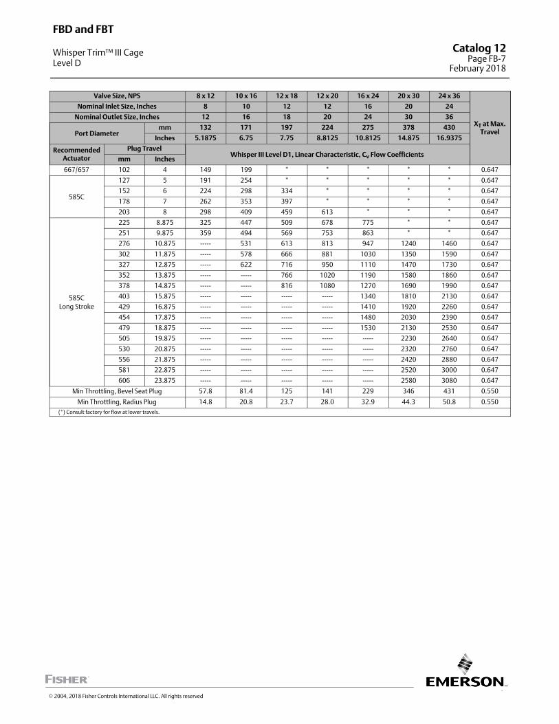
7
Valve Size, NPS 8 x 12 10 x 16 12 x 18 12 x 20 16 x 24 20 x 30 24 x 36
XT at Max.Travel
Nominal Inlet Size, Inches 8 10 12 12 16 20 24
Nominal Outlet Size, Inches 12 16 18 20 24 30 36
Port Diametermm 132 171 197 224 275 378 430
Inches 5.1875 6.75 7.75 8.8125 10.8125 14.875 16.9375
RecommendedActuator
Plug TravelWhisper III Level D1, Linear Characteristic, Cv Flow Coefficients
mm Inches
667/657 102 4 149 199 * * * * * 0.647
585C
127 5 191 254 * * * * * 0.647
152 6 224 298 334 * * * * 0.647
178 7 262 353 397 * * * * 0.647
203 8 298 409 459 613 * * * 0.647
585C
Long Stroke
225 8.875 325 447 509 678 775 * * 0.647
251 9.875 359 494 569 753 863 * * 0.647
276 10.875 ----- 531 613 813 947 1240 1460 0.647
302 11.875 ----- 578 666 881 1030 1350 1590 0.647
327 12.875 ----- 622 716 950 1110 1470 1730 0.647
352 13.875 ----- ----- 766 1020 1190 1580 1860 0.647
378 14.875 ----- ----- 816 1080 1270 1690 1990 0.647
403 15.875 ----- ----- ----- ----- 1340 1810 2130 0.647
429 16.875 ----- ----- ----- ----- 1410 1920 2260 0.647
454 17.875 ----- ----- ----- ----- 1480 2030 2390 0.647
479 18.875 ----- ----- ----- ----- 1530 2130 2530 0.647
505 19.875 ----- ----- ----- ----- ----- 2230 2640 0.647
530 20.875 ----- ----- ----- ----- ----- 2320 2760 0.647
556 21.875 ----- ----- ----- ----- ----- 2420 2880 0.647
581 22.875 ----- ----- ----- ----- ----- 2520 3000 0.647
606 23.875 ----- ----- ----- ----- ----- 2580 3080 0.647
Min Throttling, Bevel Seat Plug 57.8 81.4 125 141 229 346 431 0.550
Min Throttling, Radius Plug 14.8 20.8 23.7 28.0 32.9 44.3 50.8 0.550
(*) Consult factory for flow at lower travels.
FBD and FBT
Whisper Trim™ III CageLevel D
Catalog 12Page FB-7
February 2018
� 2004, 2018 Fisher Controls International LLC. All rights reserved
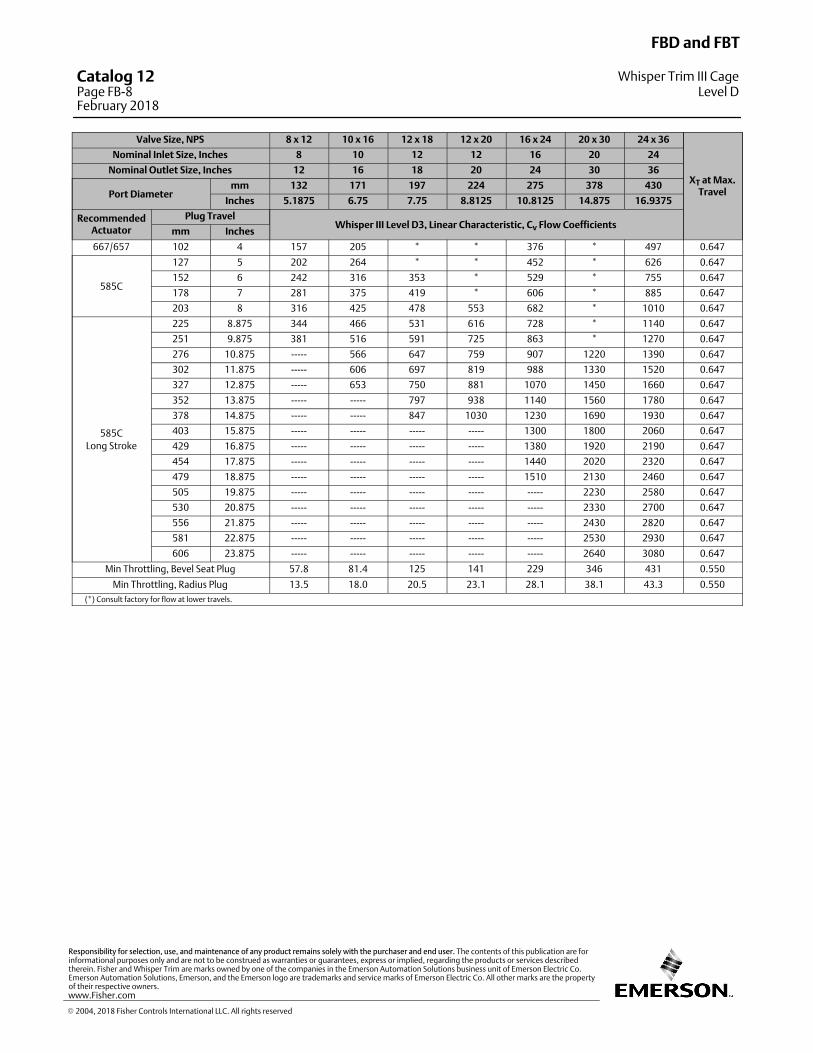
Valve Size, NPS 8 x 12 10 x 16 12 x 18 12 x 20 16 x 24 20 x 30 24 x 36
XT at Max.Travel
Nominal Inlet Size, Inches 8 10 12 12 16 20 24
Nominal Outlet Size, Inches 12 16 18 20 24 30 36
Port Diametermm 132 171 197 224 275 378 430
Inches 5.1875 6.75 7.75 8.8125 10.8125 14.875 16.9375
RecommendedActuator
Plug TravelWhisper III Level D3, Linear Characteristic, Cv Flow Coefficients
mm Inches
667/657 102 4 157 205 * * 376 * 497 0.647
585C
127 5 202 264 * * 452 * 626 0.647
152 6 242 316 353 * 529 * 755 0.647
178 7 281 375 419 * 606 * 885 0.647
203 8 316 425 478 553 682 * 1010 0.647
585C
Long Stroke
225 8.875 344 466 531 616 728 * 1140 0.647
251 9.875 381 516 591 725 863 * 1270 0.647
276 10.875 ----- 566 647 759 907 1220 1390 0.647
302 11.875 ----- 606 697 819 988 1330 1520 0.647
327 12.875 ----- 653 750 881 1070 1450 1660 0.647
352 13.875 ----- ----- 797 938 1140 1560 1780 0.647
378 14.875 ----- ----- 847 1030 1230 1690 1930 0.647
403 15.875 ----- ----- ----- ----- 1300 1800 2060 0.647
429 16.875 ----- ----- ----- ----- 1380 1920 2190 0.647
454 17.875 ----- ----- ----- ----- 1440 2020 2320 0.647
479 18.875 ----- ----- ----- ----- 1510 2130 2460 0.647
505 19.875 ----- ----- ----- ----- ----- 2230 2580 0.647
530 20.875 ----- ----- ----- ----- ----- 2330 2700 0.647
556 21.875 ----- ----- ----- ----- ----- 2430 2820 0.647
581 22.875 ----- ----- ----- ----- ----- 2530 2930 0.647
606 23.875 ----- ----- ----- ----- ----- 2640 3080 0.647
Min Throttling, Bevel Seat Plug 57.8 81.4 125 141 229 346 431 0.550
Min Throttling, Radius Plug 13.5 18.0 20.5 23.1 28.1 38.1 43.3 0.550
(*) Consult factory for flow at lower travels.
FBD and FBT
Whisper Trim III CageLevel D
Catalog 12Page FB-8February 2018
� 2004, 2018 Fisher Controls International LLC. All rights reserved
www.Fisher.com
Responsibility for selection, use, and maintenance of any product remains solely with the purchaser and end user. The contents of this publication are forinformational purposes only and are not to be construed as warranties or guarantees, express or implied, regarding the products or services describedtherein. Fisher and Whisper Trim are marks owned by one of the companies in the Emerson Automation Solutions business unit of Emerson Electric Co.Emerson Automation Solutions, Emerson, and the Emerson logo are trademarks and service marks of Emerson Electric Co. All other marks are the propertyof their respective owners.
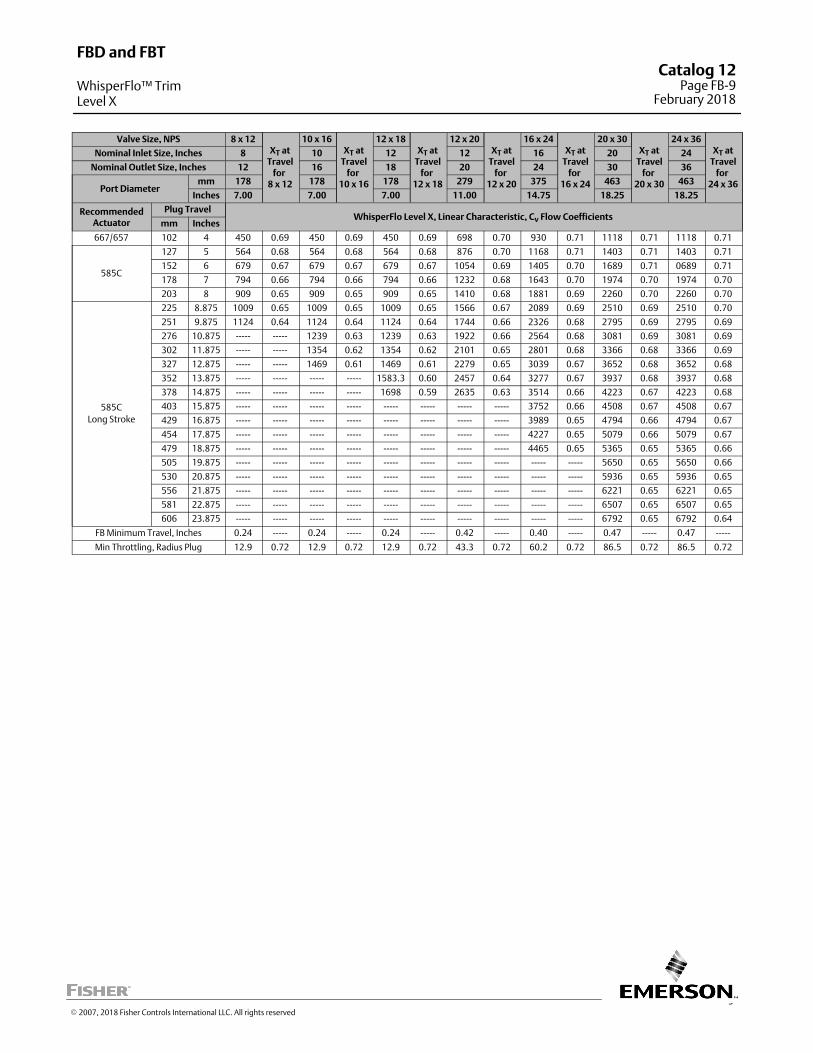
9
Valve Size, NPS 8 x 12XT at
Travelfor
8 x 12
10 x 16XT at
Travelfor
10 x 16
12 x 18XT at
Travelfor
12 x 18
12 x 20XT at
Travelfor
12 x 20
16 x 24XT at
Travelfor
16 x 24
20 x 30XT at
Travelfor
20 x 30
24 x 36XT at
Travelfor
24 x 36
Nominal Inlet Size, Inches 8 10 12 12 16 20 24
Nominal Outlet Size, Inches 12 16 18 20 24 30 36
Port Diametermm 178 178 178 279 375 463 463
Inches 7.00 7.00 7.00 11.00 14.75 18.25 18.25
RecommendedActuator
Plug TravelWhisperFlo Level X, Linear Characteristic, Cv Flow Coefficients
mm Inches
667/657 102 4 450 0.69 450 0.69 450 0.69 698 0.70 930 0.71 1118 0.71 1118 0.71
585C
127 5 564 0.68 564 0.68 564 0.68 876 0.70 1168 0.71 1403 0.71 1403 0.71
152 6 679 0.67 679 0.67 679 0.67 1054 0.69 1405 0.70 1689 0.71 0689 0.71
178 7 794 0.66 794 0.66 794 0.66 1232 0.68 1643 0.70 1974 0.70 1974 0.70
203 8 909 0.65 909 0.65 909 0.65 1410 0.68 1881 0.69 2260 0.70 2260 0.70
585C
Long Stroke
225 8.875 1009 0.65 1009 0.65 1009 0.65 1566 0.67 2089 0.69 2510 0.69 2510 0.70
251 9.875 1124 0.64 1124 0.64 1124 0.64 1744 0.66 2326 0.68 2795 0.69 2795 0.69
276 10.875 ----- ----- 1239 0.63 1239 0.63 1922 0.66 2564 0.68 3081 0.69 3081 0.69
302 11.875 ----- ----- 1354 0.62 1354 0.62 2101 0.65 2801 0.68 3366 0.68 3366 0.69
327 12.875 ----- ----- 1469 0.61 1469 0.61 2279 0.65 3039 0.67 3652 0.68 3652 0.68
352 13.875 ----- ----- ----- ----- 1583.3 0.60 2457 0.64 3277 0.67 3937 0.68 3937 0.68
378 14.875 ----- ----- ----- ----- 1698 0.59 2635 0.63 3514 0.66 4223 0.67 4223 0.68
403 15.875 ----- ----- ----- ----- ----- ----- ----- ----- 3752 0.66 4508 0.67 4508 0.67
429 16.875 ----- ----- ----- ----- ----- ----- ----- ----- 3989 0.65 4794 0.66 4794 0.67
454 17.875 ----- ----- ----- ----- ----- ----- ----- ----- 4227 0.65 5079 0.66 5079 0.67
479 18.875 ----- ----- ----- ----- ----- ----- ----- ----- 4465 0.65 5365 0.65 5365 0.66
505 19.875 ----- ----- ----- ----- ----- ----- ----- ----- ----- ----- 5650 0.65 5650 0.66
530 20.875 ----- ----- ----- ----- ----- ----- ----- ----- ----- ----- 5936 0.65 5936 0.65
556 21.875 ----- ----- ----- ----- ----- ----- ----- ----- ----- ----- 6221 0.65 6221 0.65
581 22.875 ----- ----- ----- ----- ----- ----- ----- ----- ----- ----- 6507 0.65 6507 0.65
606 23.875 ----- ----- ----- ----- ----- ----- ----- ----- ----- ----- 6792 0.65 6792 0.64
FB Minimum Travel, Inches 0.24 ----- 0.24 ----- 0.24 ----- 0.42 ----- 0.40 ----- 0.47 ----- 0.47 -----
Min Throttling, Radius Plug 12.9 0.72 12.9 0.72 12.9 0.72 43.3 0.72 60.2 0.72 86.5 0.72 86.5 0.72
FBD and FBT
WhisperFlo™ TrimLevel X
Catalog 12Page FB-9
February 2018
� 2007, 2018 Fisher Controls International LLC. All rights reserved
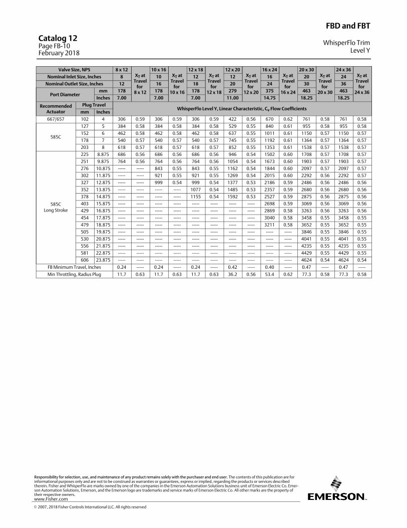
Valve Size, NPS 8 x 12XT at
Travelfor
8 x 12
10 x 16XT at
Travelfor
10 x 16
12 x 18XT at
Travelfor
12 x 18
12 x 20XT at
Travelfor
12 x 20
16 x 24XT at
Travelfor
16 x 24
20 x 30XT at
Travelfor
20 x 30
24 x 36XT at
Travelfor
24 x 36
Nominal Inlet Size, Inches 8 10 12 12 16 20 24
Nominal Outlet Size, Inches 12 16 18 20 24 30 36
Port Diametermm 178 178 178 279 375 463 463
Inches 7.00 7.00 7.00 11.00 14.75 18.25 18.25
RecommendedActuator
Plug TravelWhisperFlo Level Y, Linear Characteristic, Cv Flow Coefficients
mm Inches
667/657 102 4 306 0.59 306 0.59 306 0.59 422 0.56 670 0.62 761 0.58 761 0.58
585C
127 5 384 0.58 384 0.58 384 0.58 529 0.55 840 0.61 955 0.58 955 0.58
152 6 462 0.58 462 0.58 462 0.58 637 0.55 1011 0.61 1150 0.57 1150 0.57
178 7 540 0.57 540 0.57 540 0.57 745 0.55 1192 0.61 1364 0.57 1364 0.57
203 8 618 0.57 618 0.57 618 0.57 852 0.55 1353 0.61 1538 0.57 1538 0.57
585C
Long Stroke
225 8.875 686 0.56 686 0.56 686 0.56 946 0.54 1502 0.60 1708 0.57 1708 0.57
251 9.875 764 0.56 764 0.56 764 0.56 1054 0.54 1673 0.60 1903 0.57 1903 0.57
276 10.875 ----- ----- 843 0.55 843 0.55 1162 0.54 1844 0.60 2097 0.57 2097 0.57
302 11.875 ----- ----- 921 0.55 921 0.55 1269 0.54 2015 0.60 2292 0.56 2292 0.57
327 12.875 ----- ----- 999 0.54 999 0.54 1377 0.53 2186 0.59 2486 0.56 2486 0.56
352 13.875 ----- ----- ----- ----- 1077 0.54 1485 0.53 2357 0.59 2680 0.56 2680 0.56
378 14.875 ----- ----- ----- ----- 1155 0.54 1592 0.53 2527 0.59 2875 0.56 2875 0.56
403 15.875 ----- ----- ----- ----- ----- ----- ----- ----- 2698 0.59 3069 0.56 3069 0.56
429 16.875 ----- ----- ----- ----- ----- ----- ----- ----- 2869 0.58 3263 0.56 3263 0.56
454 17.875 ----- ----- ----- ----- ----- ----- ----- ----- 3040 0.58 3458 0.55 3458 0.55
479 18.875 ----- ----- ----- ----- ----- ----- ----- ----- 3211 0.58 3652 0.55 3652 0.55
505 19.875 ----- ----- ----- ----- ----- ----- ----- ----- ----- ----- 3846 0.55 3846 0.55
530 20.875 ----- ----- ----- ----- ----- ----- ----- ----- ----- ----- 4041 0.55 4041 0.55
556 21.875 ----- ----- ----- ----- ----- ----- ----- ----- ----- ----- 4235 0.55 4235 0.55
581 22.875 ----- ----- ----- ----- ----- ----- ----- ----- ----- ----- 4429 0.55 4429 0.55
606 23.875 ----- ----- ----- ----- ----- ----- ----- ----- ----- ----- 4624 0.54 4624 0.54
FB Minimum Travel, Inches 0.24 ----- 0.24 ----- 0.24 ----- 0.42 ----- 0.40 ----- 0.47 ----- 0.47 -----
Min Throttling, Radius Plug 11.7 0.63 11.7 0.63 11.7 0.63 36.2 0.56 53.4 0.62 77.3 0.58 77.3 0.58
FBD and FBT
WhisperFlo TrimLevel Y
Catalog 12Page FB-10February 2018
� 2007, 2018 Fisher Controls International LLC. All rights reserved
www.Fisher.com
Responsibility for selection, use, and maintenance of any product remains solely with the purchaser and end user. The contents of this publication are forinformational purposes only and are not to be construed as warranties or guarantees, express or implied, regarding the products or services describedtherein. Fisher and WhisperFlo are marks owned by one of the companies in the Emerson Automation Solutions business unit of Emerson Electric Co. Emerson Automation Solutions, Emerson, and the Emerson logo are trademarks and service marks of Emerson Electric Co. All other marks are the property oftheir respective owners.
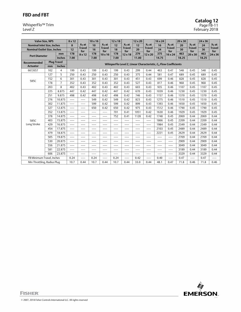
11
Valve Size, NPS 8 x 12XT at
Travelfor
8 x 12
10 x 16XT at
Travelfor
10 x 16
12 x 18XT at
Travelfor
12 x 18
12 x 20XT at
Travelfor
12 x 20
16 x 24XT at
Travelfor
16 x 24
20 x 30XT at
Travelfor
20 x 30
24 x 36XT at
Travelfor
24 x 36
Nominal Inlet Size, Inches 8 10 12 12 16 20 24
Nominal Outlet Size, Inches 12 16 18 20 24 30 36
Port Diametermm 178 178 178 279 375 463 463
Inches 7.00 7.00 7.00 11.00 14.75 18.25 18.25
RecommendedActuator
Plug TravelWhisperFlo Level Z, Linear Characteristic, Cv Flow Coefficients
mm Inches
667/657 102 4 199 0.43 199 0.43 199 0.43 299 0.44 463 0.47 548 0.45 548 0.45
585C
127 5 250 0.43 250 0.43 250 0.43 375 0.44 581 0.47 689 0.45 689 0.45
152 6 301 0.43 301 0.43 301 0.43 451 0.43 699 0.46 828 0.45 828 0.45
178 7 352 0.43 352 0.43 352 0.43 527 0.43 817 0.46 968 0.45 968 0.45
203 8 402 0.43 402 0.43 402 0.43 603 0.43 935 0.46 1107 0.45 1107 0.45
585C
Long Stroke
225 8.875 447 0.42 447 0.42 447 0.42 670 0.43 1039 0.46 1230 0.45 1230 0.45
251 9.875 498 0.42 498 0.42 498 0.42 746 0.43 1157 0.46 1370 0.45 1370 0.45
276 10.875 ----- ----- 549 0.42 549 0.42 823 0.43 1275 0.46 1510 0.45 1510 0.45
302 11.875 ----- ----- 599 0.42 599 0.42 899 0.43 1393 0.46 1650 0.45 1650 0.45
327 12.875 ----- ----- 650 0.42 650 0.42 975 0.43 1512 0.46 1790 0.45 1790 0.45
352 13.875 ----- ----- ----- ----- 701 0.41 1051 0.42 1630 0.46 1929 0.45 1929 0.45
378 14.875 ----- ----- ----- ----- 752 0.41 1128 0.42 1748 0.45 2069 0.44 2069 0.44
403 15.875 ----- ----- ----- ----- ----- ----- ----- ----- 1866 0.45 2209 0.44 2209 0.44
429 16.875 ----- ----- ----- ----- ----- ----- ----- ----- 1984 0.45 2349 0.44 2349 0.44
454 17.875 ----- ----- ----- ----- ----- ----- ----- ----- 2103 0.45 2489 0.44 2489 0.44
479 18.875 ----- ----- ----- ----- ----- ----- ----- ----- 2221 0.45 2629 0.44 2629 0.44
505 19.875 ----- ----- ----- ----- ----- ----- ----- ----- ----- ----- 2769 0.44 2769 0.44
530 20.875 ----- ----- ----- ----- ----- ----- ----- ----- ----- ----- 2909 0.44 2909 0.44
556 21.875 ----- ----- ----- ----- ----- ----- ----- ----- ----- ----- 3049 0.44 3049 0.44
581 22.875 ----- ----- ----- ----- ----- ----- ----- ----- ----- ----- 3189 0.44 3189 0.44
606 23.875 ----- ----- ----- ----- ----- ----- ----- ----- ----- ----- 3329 0.44 3329 0.44
FB Minimum Travel, Inches 0.24 ----- 0.24 ----- 0.24 ----- 0.42 ----- 0.40 ----- 0.47 ----- 0.47 -----
Min Throttling, Radius Plug 10.7 0.44 10.7 0.44 10.7 0.44 33.0 0.44 48.1 0.47 71.8 0.46 71.8 0.46
FBD and FBT
WhisperFlo™ TrimLevel Z
Catalog 12Page FB-11
February 2018
� 2007, 2018 Fisher Controls International LLC. All rights reserved
This page is intentionally left blank
FBD and FBTCatalog 12Page FB-12February 2018
� 2007, 2018 Fisher Controls International LLC. All rights reserved
www.Fisher.com
Responsibility for selection, use, and maintenance of any product remains solely with the purchaser and end user. The contents of this publication are forinformational purposes only and are not to be construed as warranties or guarantees, express or implied, regarding the products or services describedtherein. Fisher and WhisperFlo are marks owned by one of the companies in the Emerson Automation Solutions business unit of Emerson Electric Co. Emerson Automation Solutions, Emerson, and the Emerson logo are trademarks and service marks of Emerson Electric Co. All other marks are the property oftheir respective owners.
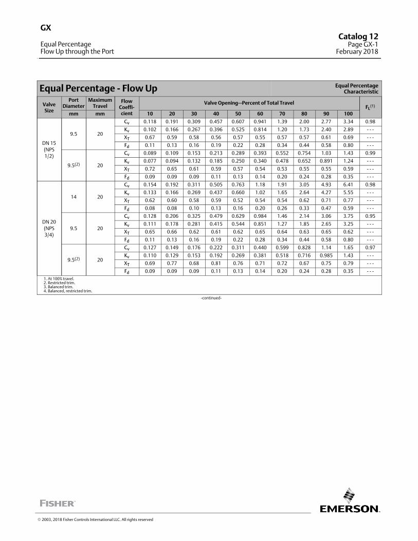
Equal Percentage ‐ Flow Up Equal PercentageCharacteristic
ValveSize
PortDiameter
MaximumTravel
FlowCoeffi‐cient
Valve Opening—Percent of Total TravelFL
(1)
mm mm 10 20 30 40 50 60 70 80 90 100
DN 15
(NPS
1/2)
9.5 20
Cv 0.118 0.191 0.309 0.457 0.607 0.941 1.39 2.00 2.77 3.34 0.98
Kv 0.102 0.166 0.267 0.396 0.525 0.814 1.20 1.73 2.40 2.89 ‐ ‐ ‐
XT 0.67 0.59 0.58 0.56 0.57 0.55 0.57 0.57 0.61 0.69 ‐ ‐ ‐
Fd 0.11 0.13 0.16 0.19 0.22 0.28 0.34 0.44 0.58 0.80 ‐ ‐ ‐
9.5(2) 20
Cv 0.089 0.109 0.153 0.213 0.289 0.393 0.552 0.754 1.03 1.43 0.99
Kv 0.077 0.094 0.132 0.185 0.250 0.340 0.478 0.652 0.891 1.24 ‐ ‐ ‐
XT 0.72 0.65 0.61 0.59 0.57 0.54 0.53 0.55 0.55 0.59 ‐ ‐ ‐
Fd 0.09 0.09 0.09 0.11 0.13 0.14 0.20 0.24 0.28 0.35 ‐ ‐ ‐
DN 20
(NPS
3/4)
14 20
Cv 0.154 0.192 0.311 0.505 0.763 1.18 1.91 3.05 4.93 6.41 0.98
Kv 0.133 0.166 0.269 0.437 0.660 1.02 1.65 2.64 4.27 5.55 ‐ ‐ ‐
XT 0.62 0.60 0.58 0.59 0.52 0.54 0.54 0.62 0.71 0.77 ‐ ‐ ‐
Fd 0.08 0.08 0.10 0.13 0.16 0.20 0.26 0.33 0.47 0.59 ‐ ‐ ‐
9.5 20
Cv 0.128 0.206 0.325 0.479 0.629 0.984 1.46 2.14 3.06 3.75 0.95
Kv 0.111 0.178 0.281 0.415 0.544 0.851 1.27 1.85 2.65 3.25 ‐ ‐ ‐
XT 0.65 0.66 0.62 0.61 0.62 0.65 0.64 0.63 0.65 0.62 ‐ ‐ ‐
Fd 0.11 0.13 0.16 0.19 0.22 0.28 0.34 0.44 0.58 0.80 ‐ ‐ ‐
9.5(2) 20
Cv 0.127 0.149 0.176 0.222 0.311 0.440 0.599 0.828 1.14 1.65 0.97
Kv 0.110 0.129 0.153 0.192 0.269 0.381 0.518 0.716 0.985 1.43 ‐ ‐ ‐
XT 0.69 0.77 0.68 0.81 0.76 0.71 0.72 0.67 0.75 0.79 ‐ ‐ ‐
Fd 0.09 0.09 0.09 0.11 0.13 0.14 0.20 0.24 0.28 0.35 ‐ ‐ ‐
1. At 100% travel.2. Restricted trim.3. Balanced trim.4. Balanced, restricted trim.
‐continued‐
� 2003, 2018 Fisher Controls International LLC. All rights reserved
GX
Equal PercentageFlow Up through the Port
Catalog 12Page GX-1
February 2018
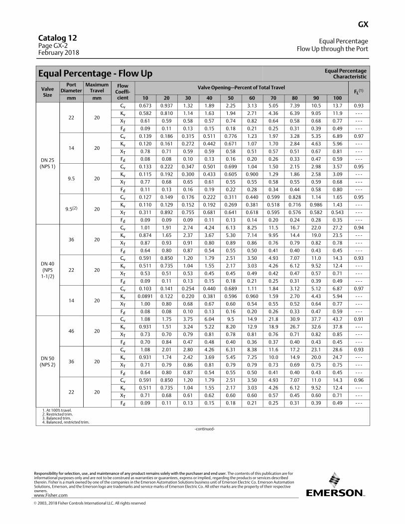
Equal Percentage ‐ Flow Up Equal PercentageCharacteristic
ValveSize
PortDiameter
MaximumTravel
FlowCoeffi‐cient
Valve Opening—Percent of Total TravelFL
(1)
mm mm 10 20 30 40 50 60 70 80 90 100
DN 25
(NPS 1)
22 20
Cv 0.673 0.937 1.32 1.89 2.25 3.13 5.05 7.39 10.5 13.7 0.93
Kv 0.582 0.810 1.14 1.63 1.94 2.71 4.36 6.39 9.05 11.9 ‐ ‐ ‐
XT 0.61 0.59 0.58 0.57 0.74 0.82 0.64 0.58 0.68 0.77 ‐ ‐ ‐
Fd 0.09 0.11 0.13 0.15 0.18 0.21 0.25 0.31 0.39 0.49 ‐ ‐ ‐
14 20
Cv 0.139 0.186 0.315 0.511 0.776 1.23 1.97 3.28 5.35 6.89 0.97
Kv 0.120 0.161 0.272 0.442 0.671 1.07 1.70 2.84 4.63 5.96 ‐ ‐ ‐
XT 0.78 0.71 0.59 0.59 0.58 0.51 0.57 0.51 0.67 0.81 ‐ ‐ ‐
Fd 0.08 0.08 0.10 0.13 0.16 0.20 0.26 0.33 0.47 0.59 ‐ ‐ ‐
9.5 20
Cv 0.133 0.222 0.347 0.501 0.699 1.04 1.50 2.15 2.98 3.57 0.95
Kv 0.115 0.192 0.300 0.433 0.605 0.900 1.29 1.86 2.58 3.09 ‐ ‐ ‐
XT 0.77 0.68 0.65 0.61 0.55 0.55 0.58 0.55 0.59 0.68 ‐ ‐ ‐
Fd 0.11 0.13 0.16 0.19 0.22 0.28 0.34 0.44 0.58 0.80 ‐ ‐ ‐
9.5(2) 20
Cv 0.127 0.149 0.176 0.222 0.311 0.440 0.599 0.828 1.14 1.65 0.95
Kv 0.110 0.129 0.152 0.192 0.269 0.381 0.518 0.716 0.986 1.43 ‐ ‐ ‐
XT 0.311 0.892 0.755 0.681 0.641 0.618 0.595 0.576 0.582 0.543 ‐ ‐ ‐
Fd 0.09 0.09 0.09 0.11 0.13 0.14 0.20 0.24 0.28 0.35 ‐ ‐ ‐
DN 40
(NPS
1‐1/2)
36 20
Cv 1.01 1.91 2.74 4.24 6.13 8.25 11.5 16.7 22.0 27.2 0.94
Kv 0.874 1.65 2.37 3.67 5.30 7.14 9.95 14.4 19.0 23.5 ‐ ‐ ‐
XT 0.87 0.93 0.91 0.80 0.89 0.86 0.76 0.79 0.82 0.78 ‐ ‐ ‐
Fd 0.64 0.80 0.87 0.54 0.55 0.50 0.41 0.40 0.43 0.45 ‐ ‐ ‐
22 20
Cv 0.591 0.850 1.20 1.79 2.51 3.50 4.93 7.07 11.0 14.3 0.93
Kv 0.511 0.735 1.04 1.55 2.17 3.03 4.26 6.12 9.52 12.4 ‐ ‐ ‐
XT 0.53 0.51 0.53 0.45 0.45 0.49 0.42 0.47 0.57 0.71 ‐ ‐ ‐
Fd 0.09 0.11 0.13 0.15 0.18 0.21 0.25 0.31 0.39 0.49 ‐ ‐ ‐
14 20
Cv 0.103 0.141 0.254 0.440 0.689 1.11 1.84 3.12 5.12 6.87 0.97
Kv 0.0891 0.122 0.220 0.381 0.596 0.960 1.59 2.70 4.43 5.94 ‐ ‐ ‐
XT 1.00 0.80 0.68 0.67 0.60 0.54 0.55 0.52 0.64 0.77 ‐ ‐ ‐
Fd 0.08 0.08 0.10 0.13 0.16 0.20 0.26 0.33 0.47 0.59 ‐ ‐ ‐
DN 50
(NPS 2)
46 20
Cv 1.08 1.75 3.75 6.04 9.5 14.9 21.8 30.9 37.7 43.7 0.91
Kv 0.931 1.51 3.24 5.22 8.20 12.9 18.9 26.7 32.6 37.8 ‐ ‐ ‐
XT 0.73 0.70 0.79 0.81 0.78 0.81 0.76 0.71 0.82 0.85 ‐ ‐ ‐
Fd 0.70 0.84 0.47 0.48 0.40 0.36 0.37 0.40 0.43 0.45 ‐ ‐ ‐
36 20
Cv 1.08 2.01 2.80 4.26 6.31 8.38 11.6 17.2 23.1 28.6 0.93
Kv 0.931 1.74 2.42 3.69 5.45 7.25 10.0 14.9 20.0 24.7 ‐ ‐ ‐
XT 0.71 0.79 0.86 0.81 0.79 0.79 0.73 0.69 0.75 0.75 ‐ ‐ ‐
Fd 0.64 0.80 0.87 0.54 0.55 0.50 0.41 0.40 0.43 0.45 ‐ ‐ ‐
22 20
Cv 0.591 0.850 1.20 1.79 2.51 3.50 4.93 7.07 11.0 14.3 0.96
Kv 0.511 0.735 1.04 1.55 2.17 3.03 4.26 6.12 9.52 12.4 ‐ ‐ ‐
XT 0.71 0.68 0.61 0.62 0.60 0.60 0.57 0.45 0.60 0.71 ‐ ‐ ‐
Fd 0.09 0.11 0.13 0.15 0.18 0.21 0.25 0.31 0.39 0.49 ‐ ‐ ‐
1. At 100% travel.2. Restricted trim.3. Balanced trim.4. Balanced, restricted trim.
‐continued‐
GX
Equal PercentageFlow Up through the Port
Catalog 12Page GX-2February 2018
� 2003, 2018 Fisher Controls International LLC. All rights reserved
www.Fisher.com
Responsibility for selection, use, and maintenance of any product remains solely with the purchaser and end user. The contents of this publication are forinformational purposes only and are not to be construed as warranties or guarantees, express or implied, regarding the products or services describedtherein. Fisher is a mark owned by one of the companies in the Emerson Automation Solutions business unit of Emerson Electric Co. Emerson AutomationSolutions, Emerson, and the Emerson logo are trademarks and service marks of Emerson Electric Co. All other marks are the property of their respectiveowners.
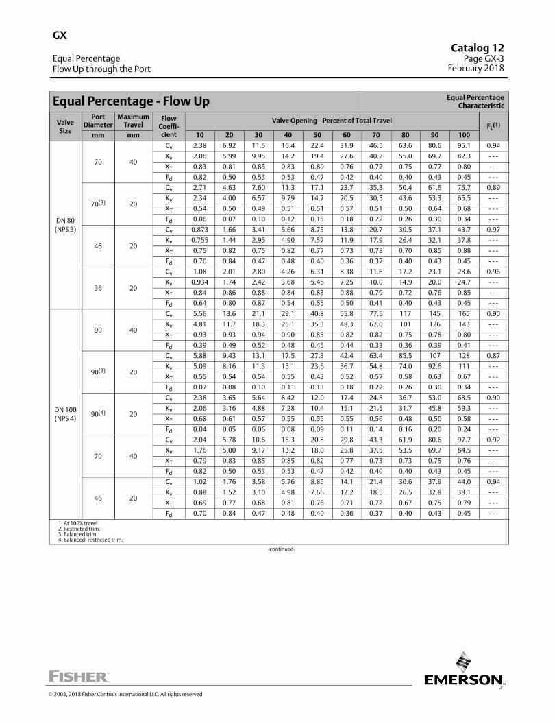
3
Equal Percentage ‐ Flow Up Equal PercentageCharacteristic
ValveSize
PortDiameter
MaximumTravel
FlowCoeffi‐cient
Valve Opening—Percent of Total TravelFL
(1)
mm mm 10 20 30 40 50 60 70 80 90 100
DN 80
(NPS 3)
70 40
Cv 2.38 6.92 11.5 16.4 22.4 31.9 46.5 63.6 80.6 95.1 0.94
Kv 2.06 5.99 9.95 14.2 19.4 27.6 40.2 55.0 69.7 82.3 ‐ ‐ ‐
XT 0.83 0.81 0.85 0.83 0.80 0.76 0.72 0.75 0.77 0.80 ‐ ‐ ‐
Fd 0.82 0.50 0.53 0.53 0.47 0.42 0.40 0.40 0.43 0.45 ‐ ‐ ‐
70(3) 20
Cv 2.71 4.63 7.60 11.3 17.1 23.7 35.3 50.4 61.6 75.7 0.89
Kv 2.34 4.00 6.57 9.79 14.7 20.5 30.5 43.6 53.3 65.5 ‐ ‐ ‐
XT 0.54 0.50 0.49 0.51 0.51 0.57 0.51 0.50 0.64 0.68 ‐ ‐ ‐
Fd 0.06 0.07 0.10 0.12 0.15 0.18 0.22 0.26 0.30 0.34 ‐ ‐ ‐
46 20
Cv 0.873 1.66 3.41 5.66 8.75 13.8 20.7 30.5 37.1 43.7 0.97
Kv 0.755 1.44 2.95 4.90 7.57 11.9 17.9 26.4 32.1 37.8 ‐ ‐ ‐
XT 0.75 0.82 0.75 0.82 0.77 0.73 0.78 0.70 0.85 0.88 ‐ ‐ ‐
Fd 0.70 0.84 0.47 0.48 0.40 0.36 0.37 0.40 0.43 0.45 ‐ ‐ ‐
36 20
Cv 1.08 2.01 2.80 4.26 6.31 8.38 11.6 17.2 23.1 28.6 0.96
Kv 0.934 1.74 2.42 3.68 5.46 7.25 10.0 14.9 20.0 24.7 ‐ ‐ ‐
XT 0.84 0.86 0.88 0.84 0.83 0.88 0.79 0.72 0.76 0.85 ‐ ‐ ‐
Fd 0.64 0.80 0.87 0.54 0.55 0.50 0.41 0.40 0.43 0.45 ‐ ‐ ‐
DN 100
(NPS 4)
90 40
Cv 5.56 13.6 21.1 29.1 40.8 55.8 77.5 117 145 165 0.90
Kv 4.81 11.7 18.3 25.1 35.3 48.3 67.0 101 126 143 ‐ ‐ ‐
XT 0.93 0.93 0.94 0.90 0.85 0.82 0.82 0.75 0.78 0.80 ‐ ‐ ‐
Fd 0.39 0.49 0.52 0.48 0.45 0.44 0.33 0.36 0.39 0.41 ‐ ‐ ‐
90(3) 20
Cv 5.88 9.43 13.1 17.5 27.3 42.4 63.4 85.5 107 128 0.87
Kv 5.09 8.16 11.3 15.1 23.6 36.7 54.8 74.0 92.6 111 ‐ ‐ ‐
XT 0.55 0.54 0.54 0.55 0.43 0.52 0.57 0.58 0.63 0.67 ‐ ‐ ‐
Fd 0.07 0.08 0.10 0.11 0.13 0.18 0.22 0.26 0.30 0.34 ‐ ‐ ‐
90(4) 20
Cv 2.38 3.65 5.64 8.42 12.0 17.4 24.8 36.7 53.0 68.5 0.90
Kv 2.06 3.16 4.88 7.28 10.4 15.1 21.5 31.7 45.8 59.3 ‐ ‐ ‐
XT 0.68 0.61 0.57 0.55 0.55 0.55 0.56 0.48 0.50 0.58 ‐ ‐ ‐
Fd 0.04 0.05 0.06 0.08 0.09 0.11 0.14 0.16 0.20 0.24 ‐ ‐ ‐
70 40
Cv 2.04 5.78 10.6 15.3 20.8 29.8 43.3 61.9 80.6 97.7 0.92
Kv 1.76 5.00 9.17 13.2 18.0 25.8 37.5 53.5 69.7 84.5 ‐ ‐ ‐
XT 0.79 0.83 0.85 0.85 0.82 0.77 0.73 0.73 0.75 0.76 ‐ ‐ ‐
Fd 0.82 0.50 0.53 0.53 0.47 0.42 0.40 0.40 0.43 0.45 ‐ ‐ ‐
46 20
Cv 1.02 1.76 3.58 5.76 8.85 14.1 21.4 30.6 37.9 44.0 0.94
Kv 0.88 1.52 3.10 4.98 7.66 12.2 18.5 26.5 32.8 38.1 ‐ ‐ ‐
XT 0.69 0.77 0.68 0.81 0.76 0.71 0.72 0.67 0.75 0.79 ‐ ‐ ‐
Fd 0.70 0.84 0.47 0.48 0.40 0.36 0.37 0.40 0.43 0.45 ‐ ‐ ‐
1. At 100% travel.2. Restricted trim.3. Balanced trim.4. Balanced, restricted trim.
‐continued‐
GX
Equal PercentageFlow Up through the Port
Catalog 12Page GX-3
February 2018
� 2003, 2018 Fisher Controls International LLC. All rights reserved
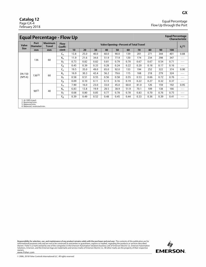
Equal Percentage ‐ Flow Up Equal PercentageCharacteristic
ValveSize
PortDiameter
MaximumTravel
FlowCoeffi‐cient
Valve Opening—Percent of Total TravelFL
(1)
mm mm 10 20 30 40 50 60 70 80 90 100
DN 150
(NPS 6)
136 60
Cv 13.8 25.0 40.0 60.0 90.0 139 201 271 344 401 0.88
Kv 11.9 21.6 34.6 51.9 77.9 120 174 234 298 347 ‐ ‐ ‐
XT 0.73 0.82 0.82 0.81 0.79 0.70 0.67 0.67 0.54 0.71 ‐ ‐ ‐
Fd 0.45 0.39 0.33 0.28 0.24 0.22 0.20 0.18 0.17 0.16 ‐ ‐ ‐
136(3) 60
Cv 19.5 35.0 49.0 65.0 92.0 133 194 252 322 374 0.90
Kv 16.9 30.3 42.4 56.2 79.6 115 168 218 279 324 ‐ ‐ ‐
XT 0.58 0.51 0.55 0.56 0.58 0.55 0.53 0.66 0.72 0.76 ‐ ‐ ‐
Fd 0.09 0.10 0.11 0.13 0.16 0.19 0.22 0.27 0.32 0.37 ‐ ‐ ‐
90(2) 40
Cv 7.90 16.0 23.0 33.0 45.0 60.0 81.0 126 159 192 0.95
Kv 6.83 13.8 19.9 28.5 38.9 51.9 70.1 109 138 166 ‐ ‐ ‐
XT 0.68 0.80 0.85 0.77 0.78 0.78 0.83 0.70 0.76 0.75 ‐ ‐ ‐
Fd 0.39 0.49 0.52 0.48 0.45 0.44 0.33 0.36 0.39 0.41 ‐ ‐ ‐
1. At 100% travel.2. Restricted trim.3. Balanced trim.4. Balanced, restricted trim.
GX
Equal PercentageFlow Up through the Port
Catalog 12Page GX-4February 2018
� 2006, 2018 Fisher Controls International LLC. All rights reserved
www.Fisher.com
Responsibility for selection, use, and maintenance of any product remains solely with the purchaser and end user. The contents of this publication are forinformational purposes only and are not to be construed as warranties or guarantees, express or implied, regarding the products or services describedtherein. Fisher is a mark owned by one of the companies in the Emerson Automation Solutions business unit of Emerson Electric Co. Emerson AutomationSolutions, Emerson, and the Emerson logo are trademarks and service marks of Emerson Electric Co. All other marks are the property of their respectiveowners.
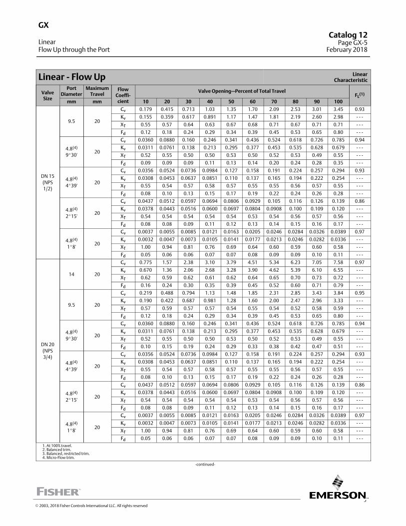
5
Linear ‐ Flow Up LinearCharacteristic
ValveSize
PortDiameter
MaximumTravel
FlowCoeffi‐cient
Valve Opening—Percent of Total TravelFL
(1)
mm mm 10 20 30 40 50 60 70 80 90 100
DN 15
(NPS
1/2)
9.5 20
Cv 0.179 0.415 0.713 1.03 1.35 1.70 2.09 2.53 3.01 3.45 0.93
Kv 0.155 0.359 0.617 0.891 1.17 1.47 1.81 2.19 2.60 2.98 ‐ ‐ ‐
XT 0.55 0.57 0.64 0.63 0.67 0.68 0.71 0.67 0.71 0.71 ‐ ‐ ‐
Fd 0.12 0.18 0.24 0.29 0.34 0.39 0.45 0.53 0.65 0.80 ‐ ‐ ‐
4.8(4)
9�30'20
Cv 0.0360 0.0880 0.160 0.246 0.341 0.436 0.524 0.618 0.726 0.785 0.94
Kv 0.0311 0.0761 0.138 0.213 0.295 0.377 0.453 0.535 0.628 0.679 ‐ ‐ ‐
XT 0.52 0.55 0.50 0.50 0.53 0.50 0.52 0.53 0.49 0.55 ‐ ‐ ‐
Fd 0.09 0.09 0.09 0.11 0.13 0.14 0.20 0.24 0.28 0.35 ‐ ‐ ‐
4.8(4)
4�39'20
Cv 0.0356 0.0524 0.0736 0.0984 0.127 0.158 0.191 0.224 0.257 0.294 0.93
Kv 0.0308 0.0453 0.0637 0.0851 0.110 0.137 0.165 0.194 0.222 0.254 ‐ ‐ ‐
XT 0.55 0.54 0.57 0.58 0.57 0.55 0.55 0.56 0.57 0.55 ‐ ‐ ‐
Fd 0.08 0.10 0.13 0.15 0.17 0.19 0.22 0.24 0.26 0.28 ‐ ‐ ‐
4.8(4)
2�15'20
Cv 0.0437 0.0512 0.0597 0.0694 0.0806 0.0929 0.105 0.116 0.126 0.139 0.86
Kv 0.0378 0.0443 0.0516 0.0600 0.0697 0.0804 0.0908 0.100 0.109 0.120 ‐ ‐ ‐
XT 0.54 0.54 0.54 0.54 0.54 0.53 0.54 0.56 0.57 0.56 ‐ ‐ ‐
Fd 0.08 0.08 0.09 0.11 0.12 0.13 0.14 0.15 0.16 0.17 ‐ ‐ ‐
4.8(4)
1�8'20
Cv 0.0037 0.0055 0.0085 0.0121 0.0163 0.0205 0.0246 0.0284 0.0326 0.0389 0.97
Kv 0.0032 0.0047 0.0073 0.0105 0.0141 0.0177 0.0213 0.0246 0.0282 0.0336 ‐ ‐ ‐
XT 1.00 0.94 0.81 0.76 0.69 0.64 0.60 0.59 0.60 0.58 ‐ ‐ ‐
Fd 0.05 0.06 0.06 0.07 0.07 0.08 0.09 0.09 0.10 0.11 ‐ ‐ ‐
DN 20
(NPS
3/4)
14 20
Cv 0.775 1.57 2.38 3.10 3.79 4.51 5.34 6.23 7.05 7.58 0.97
Kv 0.670 1.36 2.06 2.68 3.28 3.90 4.62 5.39 6.10 6.55 ‐ ‐ ‐
XT 0.62 0.59 0.62 0.61 0.62 0.64 0.65 0.70 0.73 0.72 ‐ ‐ ‐
Fd 0.16 0.24 0.30 0.35 0.39 0.45 0.52 0.60 0.71 0.79 ‐ ‐ ‐
9.5 20
Cv 0.219 0.488 0.794 1.13 1.48 1.85 2.31 2.85 3.43 3.84 0.95
Kv 0.190 0.422 0.687 0.981 1.28 1.60 2.00 2.47 2.96 3.33 ‐ ‐ ‐
XT 0.57 0.59 0.57 0.57 0.54 0.55 0.54 0.52 0.58 0.59 ‐ ‐ ‐
Fd 0.12 0.18 0.24 0.29 0.34 0.39 0.45 0.53 0.65 0.80 ‐ ‐ ‐
4.8(4)
9�30'20
Cv 0.0360 0.0880 0.160 0.246 0.341 0.436 0.524 0.618 0.726 0.785 0.94
Kv 0.0311 0.0761 0.138 0.213 0.295 0.377 0.453 0.535 0.628 0.679 ‐ ‐ ‐
XT 0.52 0.55 0.50 0.50 0.53 0.50 0.52 0.53 0.49 0.55 ‐ ‐ ‐
Fd 0.10 0.15 0.19 0.24 0.29 0.33 0.38 0.42 0.47 0.51 ‐ ‐ ‐
4.8(4)
4�39'20
Cv 0.0356 0.0524 0.0736 0.0984 0.127 0.158 0.191 0.224 0.257 0.294 0.93
Kv 0.0308 0.0453 0.0637 0.0851 0.110 0.137 0.165 0.194 0.222 0.254 ‐ ‐ ‐
XT 0.55 0.54 0.57 0.58 0.57 0.55 0.55 0.56 0.57 0.55 ‐ ‐ ‐
Fd 0.08 0.10 0.13 0.15 0.17 0.19 0.22 0.24 0.26 0.28 ‐ ‐ ‐
4.8(4)
2�15'20
Cv 0.0437 0.0512 0.0597 0.0694 0.0806 0.0929 0.105 0.116 0.126 0.139 0.86
Kv 0.0378 0.0443 0.0516 0.0600 0.0697 0.0804 0.0908 0.100 0.109 0.120 ‐ ‐ ‐
XT 0.54 0.54 0.54 0.54 0.54 0.53 0.54 0.56 0.57 0.56 ‐ ‐ ‐
Fd 0.08 0.08 0.09 0.11 0.12 0.13 0.14 0.15 0.16 0.17 ‐ ‐ ‐
4.8(4)
1�8'20
Cv 0.0037 0.0055 0.0085 0.0121 0.0163 0.0205 0.0246 0.0284 0.0326 0.0389 0.97
Kv 0.0032 0.0047 0.0073 0.0105 0.0141 0.0177 0.0213 0.0246 0.0282 0.0336 ‐ ‐ ‐
XT 1.00 0.94 0.81 0.76 0.69 0.64 0.60 0.59 0.60 0.58 ‐ ‐ ‐
Fd 0.05 0.06 0.06 0.07 0.07 0.08 0.09 0.09 0.10 0.11 ‐ ‐ ‐
1. At 100% travel.2. Balanced trim.3. Balanced, restricted trim.4. Micro‐Flow trim.
‐continued‐
GX
LinearFlow Up through the Port
Catalog 12Page GX-5
February 2018
� 2003, 2018 Fisher Controls International LLC. All rights reserved
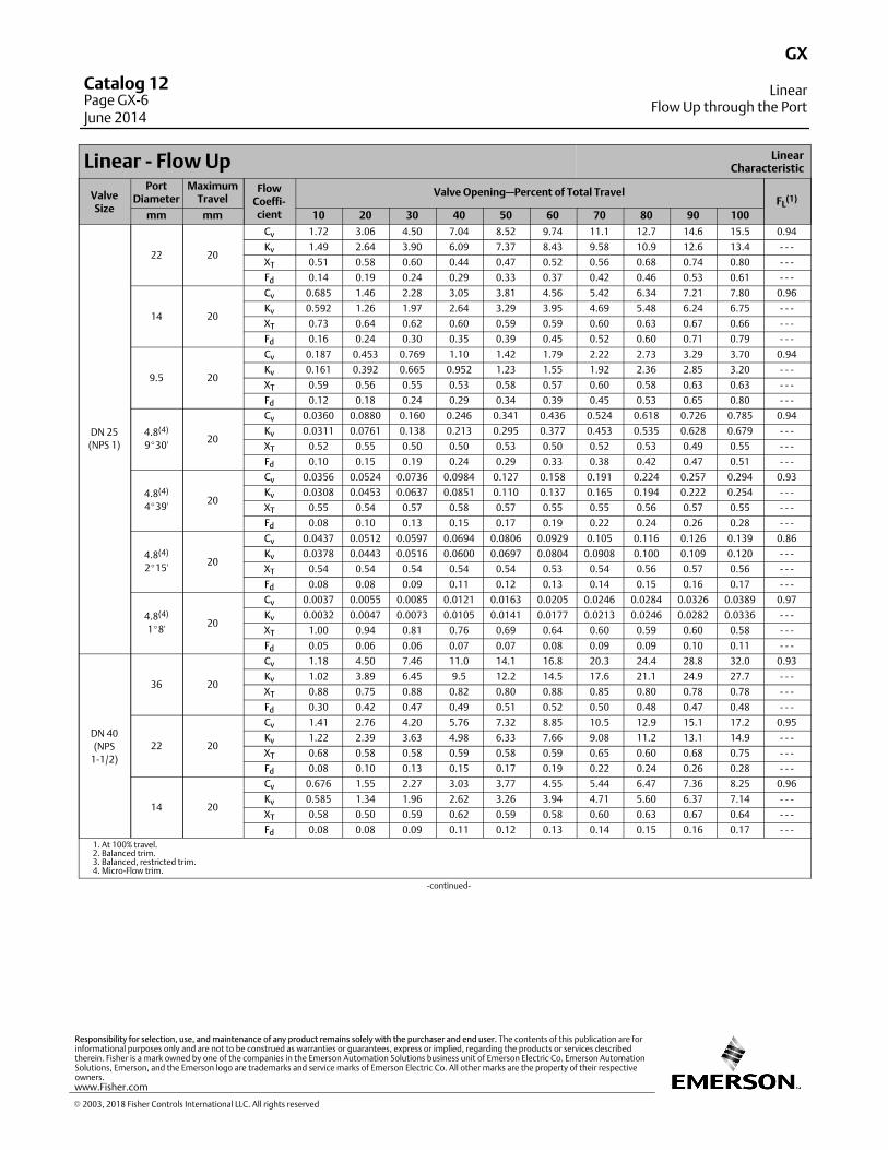
Linear ‐ Flow Up LinearCharacteristic
ValveSize
PortDiameter
MaximumTravel
FlowCoeffi‐cient
Valve Opening—Percent of Total TravelFL
(1)
mm mm 10 20 30 40 50 60 70 80 90 100
DN 25
(NPS 1)
22 20
Cv 1.72 3.06 4.50 7.04 8.52 9.74 11.1 12.7 14.6 15.5 0.94
Kv 1.49 2.64 3.90 6.09 7.37 8.43 9.58 10.9 12.6 13.4 ‐ ‐ ‐
XT 0.51 0.58 0.60 0.44 0.47 0.52 0.56 0.68 0.74 0.80 ‐ ‐ ‐
Fd 0.14 0.19 0.24 0.29 0.33 0.37 0.42 0.46 0.53 0.61 ‐ ‐ ‐
14 20
Cv 0.685 1.46 2.28 3.05 3.81 4.56 5.42 6.34 7.21 7.80 0.96
Kv 0.592 1.26 1.97 2.64 3.29 3.95 4.69 5.48 6.24 6.75 ‐ ‐ ‐
XT 0.73 0.64 0.62 0.60 0.59 0.59 0.60 0.63 0.67 0.66 ‐ ‐ ‐
Fd 0.16 0.24 0.30 0.35 0.39 0.45 0.52 0.60 0.71 0.79 ‐ ‐ ‐
9.5 20
Cv 0.187 0.453 0.769 1.10 1.42 1.79 2.22 2.73 3.29 3.70 0.94
Kv 0.161 0.392 0.665 0.952 1.23 1.55 1.92 2.36 2.85 3.20 ‐ ‐ ‐
XT 0.59 0.56 0.55 0.53 0.58 0.57 0.60 0.58 0.63 0.63 ‐ ‐ ‐
Fd 0.12 0.18 0.24 0.29 0.34 0.39 0.45 0.53 0.65 0.80 ‐ ‐ ‐
4.8(4)
9�30'20
Cv 0.0360 0.0880 0.160 0.246 0.341 0.436 0.524 0.618 0.726 0.785 0.94
Kv 0.0311 0.0761 0.138 0.213 0.295 0.377 0.453 0.535 0.628 0.679 ‐ ‐ ‐
XT 0.52 0.55 0.50 0.50 0.53 0.50 0.52 0.53 0.49 0.55 ‐ ‐ ‐
Fd 0.10 0.15 0.19 0.24 0.29 0.33 0.38 0.42 0.47 0.51 ‐ ‐ ‐
4.8(4)
4�39'20
Cv 0.0356 0.0524 0.0736 0.0984 0.127 0.158 0.191 0.224 0.257 0.294 0.93
Kv 0.0308 0.0453 0.0637 0.0851 0.110 0.137 0.165 0.194 0.222 0.254 ‐ ‐ ‐
XT 0.55 0.54 0.57 0.58 0.57 0.55 0.55 0.56 0.57 0.55 ‐ ‐ ‐
Fd 0.08 0.10 0.13 0.15 0.17 0.19 0.22 0.24 0.26 0.28 ‐ ‐ ‐
4.8(4)
2�15'20
Cv 0.0437 0.0512 0.0597 0.0694 0.0806 0.0929 0.105 0.116 0.126 0.139 0.86
Kv 0.0378 0.0443 0.0516 0.0600 0.0697 0.0804 0.0908 0.100 0.109 0.120 ‐ ‐ ‐
XT 0.54 0.54 0.54 0.54 0.54 0.53 0.54 0.56 0.57 0.56 ‐ ‐ ‐
Fd 0.08 0.08 0.09 0.11 0.12 0.13 0.14 0.15 0.16 0.17 ‐ ‐ ‐
4.8(4)
1�8'20
Cv 0.0037 0.0055 0.0085 0.0121 0.0163 0.0205 0.0246 0.0284 0.0326 0.0389 0.97
Kv 0.0032 0.0047 0.0073 0.0105 0.0141 0.0177 0.0213 0.0246 0.0282 0.0336 ‐ ‐ ‐
XT 1.00 0.94 0.81 0.76 0.69 0.64 0.60 0.59 0.60 0.58 ‐ ‐ ‐
Fd 0.05 0.06 0.06 0.07 0.07 0.08 0.09 0.09 0.10 0.11 ‐ ‐ ‐
DN 40
(NPS
1‐1/2)
36 20
Cv 1.18 4.50 7.46 11.0 14.1 16.8 20.3 24.4 28.8 32.0 0.93
Kv 1.02 3.89 6.45 9.5 12.2 14.5 17.6 21.1 24.9 27.7 ‐ ‐ ‐
XT 0.88 0.75 0.88 0.82 0.80 0.88 0.85 0.80 0.78 0.78 ‐ ‐ ‐
Fd 0.30 0.42 0.47 0.49 0.51 0.52 0.50 0.48 0.47 0.48 ‐ ‐ ‐
22 20
Cv 1.41 2.76 4.20 5.76 7.32 8.85 10.5 12.9 15.1 17.2 0.95
Kv 1.22 2.39 3.63 4.98 6.33 7.66 9.08 11.2 13.1 14.9 ‐ ‐ ‐
XT 0.68 0.58 0.58 0.59 0.58 0.59 0.65 0.60 0.68 0.75 ‐ ‐ ‐
Fd 0.08 0.10 0.13 0.15 0.17 0.19 0.22 0.24 0.26 0.28 ‐ ‐ ‐
14 20
Cv 0.676 1.55 2.27 3.03 3.77 4.55 5.44 6.47 7.36 8.25 0.96
Kv 0.585 1.34 1.96 2.62 3.26 3.94 4.71 5.60 6.37 7.14 ‐ ‐ ‐
XT 0.58 0.50 0.59 0.62 0.59 0.58 0.60 0.63 0.67 0.64 ‐ ‐ ‐
Fd 0.08 0.08 0.09 0.11 0.12 0.13 0.14 0.15 0.16 0.17 ‐ ‐ ‐
1. At 100% travel.2. Balanced trim.3. Balanced, restricted trim.4. Micro‐Flow trim.
‐continued‐
GX
LinearFlow Up through the Port
Catalog 12Page GX-6June 2014
� 2003, 2018 Fisher Controls International LLC. All rights reserved
www.Fisher.com
Responsibility for selection, use, and maintenance of any product remains solely with the purchaser and end user. The contents of this publication are forinformational purposes only and are not to be construed as warranties or guarantees, express or implied, regarding the products or services describedtherein. Fisher is a mark owned by one of the companies in the Emerson Automation Solutions business unit of Emerson Electric Co. Emerson AutomationSolutions, Emerson, and the Emerson logo are trademarks and service marks of Emerson Electric Co. All other marks are the property of their respectiveowners.
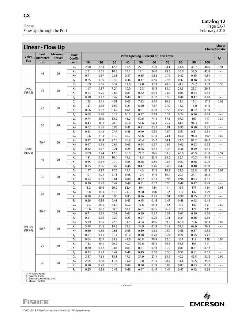
7
Linear ‐ Flow Up LinearCharacteristic
ValveSize
PortDiameter
MaximumTravel
FlowCoeffi‐cient
Valve Opening—Percent of Total TravelFL
(1)
mm mm 10 20 30 40 50 60 70 80 90 100
DN 50
(NPS 2)
46 20
Cv 2.90 7.53 12.6 17.5 22.1 27.8 34.1 41.6 45.7 48.6 0.91
Kv 2.51 6.51 10.9 15.1 19.1 24.0 29.5 36.0 39.5 42.0 ‐ ‐ ‐
XT 0.71 0.87 0.81 0.87 0.85 0.82 0.79 0.82 0.85 0.84 ‐ ‐ ‐
Fd 0.25 0.36 0.42 0.46 0.47 0.46 0.46 0.47 0.48 0.50 ‐ ‐ ‐
36 20
Cv 1.69 5.05 8.37 11.6 14.8 17.9 20.9 24.7 29.2 33.9 0.93
Kv 1.47 4.37 7.24 10.0 12.8 15.5 18.0 21.3 25.3 29.3 ‐ ‐ ‐
XT 0.73 0.76 0.84 0.81 0.82 0.84 0.87 0.85 0.84 0.82 ‐ ‐ ‐
Fd 0.30 0.42 0.47 0.49 0.51 0.52 0.50 0.48 0.47 0.48 ‐ ‐ ‐
22 20
Cv 1.58 3.01 4.51 6.02 7.63 9.10 10.9 13.1 15.1 17.2 0.93
Kv 1.37 2.60 3.90 5.21 6.60 7.87 9.40 11.3 13.0 14.9 ‐ ‐ ‐
XT 0.66 0.62 0.62 0.61 0.61 0.60 0.58 0.55 0.62 0.68 ‐ ‐ ‐
Fd 0.08 0.10 0.13 0.15 0.17 0.19 0.22 0.24 0.26 0.28 ‐ ‐ ‐
DN 80
(NPS 3)
70 40
Cv 9.74 20.9 32.9 46.2 59.6 74.3 87.5 97.2 109 117 0.89
Kv 8.43 18.1 28.5 40.0 51.6 64.3 75.7 84.1 94.3 101 ‐ ‐ ‐
XT 0.62 0.85 0.83 0.81 0.81 0.81 0.81 0.85 0.80 0.77 ‐ ‐ ‐
Fd 0.33 0.43 0.47 0.48 0.49 0.50 0.50 0.51 0.51 0.51 ‐ ‐ ‐
70(2) 20
Cv 10.6 21.3 31.9 42.7 53.6 63.8 74.1 85.0 94.4 102 0.85
Kv 9.17 18.4 27.6 36.9 46.4 55.2 64.1 73.5 81.7 88.2 ‐ ‐ ‐
XT 0.67 0.68 0.66 0.65 0.64 0.67 0.66 0.63 0.63 0.65 ‐ ‐ ‐
Fd 0.12 0.17 0.21 0.25 0.28 0.31 0.34 0.36 0.39 0.41 ‐ ‐ ‐
46 20
Cv 2.09 7.74 12.0 16.5 21.2 26.6 33.0 40.6 46.5 51.8 0.97
Kv 1.81 6.70 10.4 14.3 18.3 23.0 28.5 35.1 40.2 44.8 ‐ ‐ ‐
XT 0.65 0.62 0.79 0.85 0.88 0.85 0.88 0.83 0.88 0.90 ‐ ‐ ‐
Fd 0.25 0.36 0.42 0.46 0.47 0.46 0.46 0.47 0.48 0.50 ‐ ‐ ‐
36 20
Cv 1.17 4.87 7.76 11.1 14.3 17.3 19.3 23.2 27.8 33.3 0.97
Kv 1.01 4.21 6.71 9.58 12.4 14.9 16.7 20.1 24.1 28.8 ‐ ‐ ‐
XT 0.74 0.59 0.81 0.80 0.82 0.83 0.94 0.96 0.93 0.87 ‐ ‐ ‐
Fd 0.30 0.42 0.47 0.49 0.51 0.52 0.50 0.48 0.47 0.48 ‐ ‐ ‐
DN 100
(NPS 4)
90 40
Cv 18.2 39.6 59.0 82.4 104 124 141 156 171 184 0.91
Kv 15.8 34.3 51.0 71.3 90.0 108 122 135 147 159 ‐ ‐ ‐
XT 0.78 0.84 0.90 0.85 0.86 0.91 0.91 0.90 0.85 0.82 ‐ ‐ ‐
Fd 0.26 0.36 0.41 0.43 0.45 0.46 0.47 0.48 0.48 0.48 ‐ ‐ ‐
90(2) 20
Cv 12.3 28.5 44.6 60.2 77.6 95.4 112 130 143 151 0.82
Kv 10.6 24.7 38.6 52.1 67.1 82.5 96.9 112 124 131 ‐ ‐ ‐
XT 0.71 0.65 0.58 0.67 0.59 0.57 0.58 0.61 0.59 0.64 ‐ ‐ ‐
Fd 0.11 0.16 0.20 0.23 0.27 0.29 0.31 0.34 0.36 0.39 ‐ ‐ ‐
90(3) 20
Cv 5.99 13.6 22.3 31.5 40.4 49.6 59.2 69.0 79.6 92.3 0.82
Kv 5.18 11.8 19.3 27.2 34.9 42.9 51.2 59.7 68.9 79.8 ‐ ‐ ‐
XT 0.60 0.59 0.61 0.58 0.59 0.62 0.59 0.58 0.57 0.52 ‐ ‐ ‐
Fd 0.07 0.11 0.14 0.16 0.18 0.20 0.22 0.24 0.25 0.27 ‐ ‐ ‐
70 40
Cv 9.04 22.1 33.8 47.0 60.8 76.9 92.0 107 119 128 0.94
Kv 7.82 19.1 29.2 40.7 52.6 66.5 79.6 92.6 103 111 ‐ ‐ ‐
XT 0.80 0.82 0.84 0.83 0.81 0.80 0.79 0.81 0.81 0.82 ‐ ‐ ‐
Fd 0.33 0.43 0.47 0.48 0.49 0.50 0.50 0.51 0.51 0.51 ‐ ‐ ‐
46 20
Cv 2.37 7.98 13.1 17.3 21.9 27.1 33.2 40.3 46.8 52.2 0.96
Kv 2.05 6.90 11.3 15.0 19.0 23.5 28.7 34.8 40.5 45.2 ‐ ‐ ‐
XT 0.70 0.70 0.78 0.88 0.90 0.88 0.85 0.83 0.83 0.83 ‐ ‐ ‐
Fd 0.25 0.36 0.42 0.46 0.47 0.46 0.46 0.47 0.48 0.50 ‐ ‐ ‐
1. At 100% travel.2. Balanced trim.3. Balanced, restricted trim.4. Micro-Flow trim.
-continued-
GX
LinearFlow Up through the Port
Catalog 12Page GX-7
February 2018
� 2003, 2018 Fisher Controls International LLC. All rights reserved
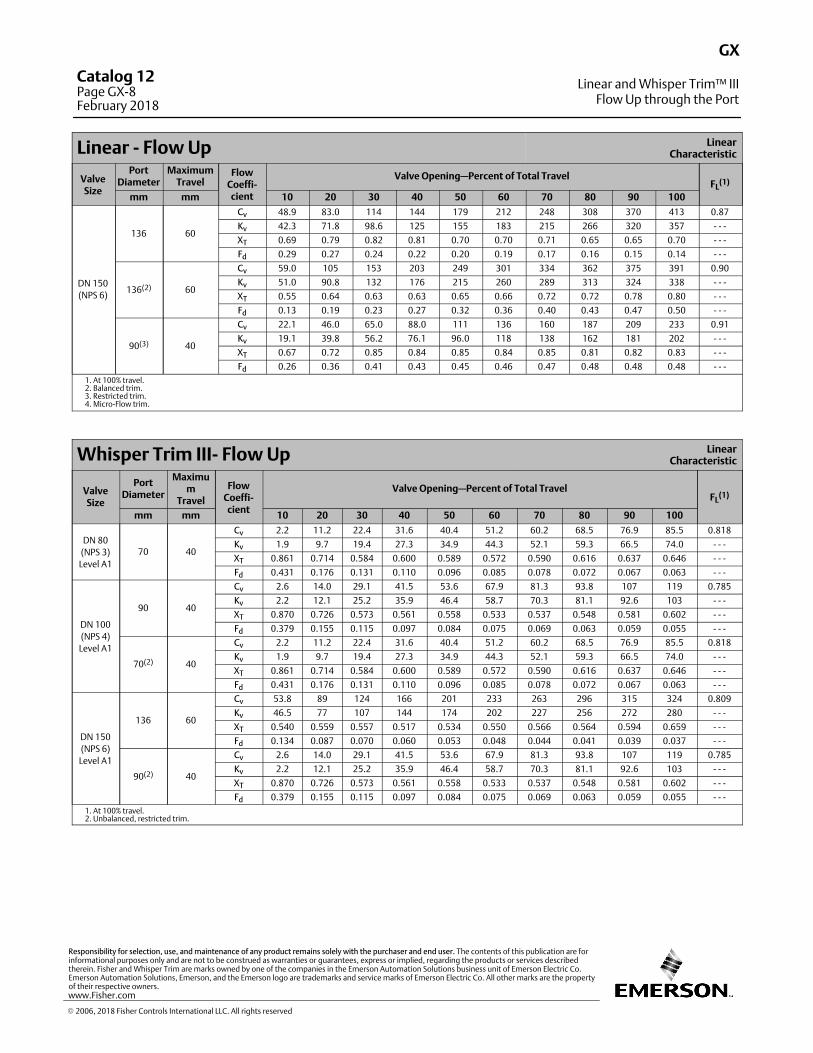
Linear ‐ Flow Up LinearCharacteristic
ValveSize
PortDiameter
MaximumTravel
FlowCoeffi‐cient
Valve Opening—Percent of Total TravelFL
(1)
mm mm 10 20 30 40 50 60 70 80 90 100
DN 150
(NPS 6)
136 60
Cv 48.9 83.0 114 144 179 212 248 308 370 413 0.87
Kv 42.3 71.8 98.6 125 155 183 215 266 320 357 ‐ ‐ ‐
XT 0.69 0.79 0.82 0.81 0.70 0.70 0.71 0.65 0.65 0.70 ‐ ‐ ‐
Fd 0.29 0.27 0.24 0.22 0.20 0.19 0.17 0.16 0.15 0.14 ‐ ‐ ‐
136(2) 60
Cv 59.0 105 153 203 249 301 334 362 375 391 0.90
Kv 51.0 90.8 132 176 215 260 289 313 324 338 ‐ ‐ ‐
XT 0.55 0.64 0.63 0.63 0.65 0.66 0.72 0.72 0.78 0.80 ‐ ‐ ‐
Fd 0.13 0.19 0.23 0.27 0.32 0.36 0.40 0.43 0.47 0.50 ‐ ‐ ‐
90(3) 40
Cv 22.1 46.0 65.0 88.0 111 136 160 187 209 233 0.91
Kv 19.1 39.8 56.2 76.1 96.0 118 138 162 181 202 ‐ ‐ ‐
XT 0.67 0.72 0.85 0.84 0.85 0.84 0.85 0.81 0.82 0.83 ‐ ‐ ‐
Fd 0.26 0.36 0.41 0.43 0.45 0.46 0.47 0.48 0.48 0.48 ‐ ‐ ‐
1. At 100% travel.2. Balanced trim.3. Restricted trim.4. Micro‐Flow trim.
Whisper Trim III‐ Flow Up LinearCharacteristic
ValveSize
PortDiameter
Maximum
Travel
FlowCoeffi‐cient
Valve Opening—Percent of Total TravelFL
(1)
mm mm 10 20 30 40 50 60 70 80 90 100
DN 80
(NPS 3)
Level A1
70 40
Cv 2.2 11.2 22.4 31.6 40.4 51.2 60.2 68.5 76.9 85.5 0.818
Kv 1.9 9.7 19.4 27.3 34.9 44.3 52.1 59.3 66.5 74.0 ‐ ‐ ‐
XT 0.861 0.714 0.584 0.600 0.589 0.572 0.590 0.616 0.637 0.646 ‐ ‐ ‐
Fd 0.431 0.176 0.131 0.110 0.096 0.085 0.078 0.072 0.067 0.063 ‐ ‐ ‐
DN 100
(NPS 4)
Level A1
90 40
Cv 2.6 14.0 29.1 41.5 53.6 67.9 81.3 93.8 107 119 0.785
Kv 2.2 12.1 25.2 35.9 46.4 58.7 70.3 81.1 92.6 103 ‐ ‐ ‐
XT 0.870 0.726 0.573 0.561 0.558 0.533 0.537 0.548 0.581 0.602 ‐ ‐ ‐
Fd 0.379 0.155 0.115 0.097 0.084 0.075 0.069 0.063 0.059 0.055 ‐ ‐ ‐
70(2) 40
Cv 2.2 11.2 22.4 31.6 40.4 51.2 60.2 68.5 76.9 85.5 0.818
Kv 1.9 9.7 19.4 27.3 34.9 44.3 52.1 59.3 66.5 74.0 ‐ ‐ ‐
XT 0.861 0.714 0.584 0.600 0.589 0.572 0.590 0.616 0.637 0.646 ‐ ‐ ‐
Fd 0.431 0.176 0.131 0.110 0.096 0.085 0.078 0.072 0.067 0.063 ‐ ‐ ‐
DN 150
(NPS 6)
Level A1
136 60
Cv 53.8 89 124 166 201 233 263 296 315 324 0.809
Kv 46.5 77 107 144 174 202 227 256 272 280 ‐ ‐ ‐
XT 0.540 0.559 0.557 0.517 0.534 0.550 0.566 0.564 0.594 0.659 ‐ ‐ ‐
Fd 0.134 0.087 0.070 0.060 0.053 0.048 0.044 0.041 0.039 0.037 ‐ ‐ ‐
90(2) 40
Cv 2.6 14.0 29.1 41.5 53.6 67.9 81.3 93.8 107 119 0.785
Kv 2.2 12.1 25.2 35.9 46.4 58.7 70.3 81.1 92.6 103 ‐ ‐ ‐
XT 0.870 0.726 0.573 0.561 0.558 0.533 0.537 0.548 0.581 0.602 ‐ ‐ ‐
Fd 0.379 0.155 0.115 0.097 0.084 0.075 0.069 0.063 0.059 0.055 ‐ ‐ ‐
1. At 100% travel.2. Unbalanced, restricted trim.
GX
Linear and Whisper Trim™ IIIFlow Up through the Port
Catalog 12Page GX-8February 2018
� 2006, 2018 Fisher Controls International LLC. All rights reserved
www.Fisher.com
Responsibility for selection, use, and maintenance of any product remains solely with the purchaser and end user. The contents of this publication are forinformational purposes only and are not to be construed as warranties or guarantees, express or implied, regarding the products or services describedtherein. Fisher and Whisper Trim are marks owned by one of the companies in the Emerson Automation Solutions business unit of Emerson Electric Co.Emerson Automation Solutions, Emerson, and the Emerson logo are trademarks and service marks of Emerson Electric Co. All other marks are the propertyof their respective owners.
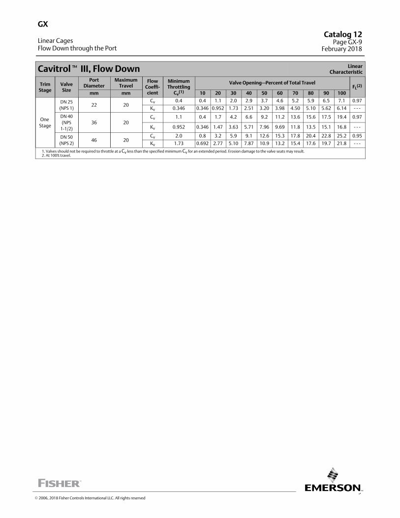
9
Cavitrol� III, Flow Down LinearCharacteristic
TrimStage
ValveSize
PortDiameter
MaximumTravel
FlowCoeffi‐cient
MinimumThrottling
Cv(1)
Valve Opening—Percent of Total TravelFL
(2)
mm mm 10 20 30 40 50 60 70 80 90 100
One
Stage
DN 25
(NPS 1)22 20
Cv 0.4 0.4 1.1 2.0 2.9 3.7 4.6 5.2 5.9 6.5 7.1 0.97
Kv 0.346 0.346 0.952 1.73 2.51 3.20 3.98 4.50 5.10 5.62 6.14 ‐ ‐ ‐
DN 40
(NPS
1‐1/2)
36 20Cv 1.1 0.4 1.7 4.2 6.6 9.2 11.2 13.6 15.6 17.5 19.4 0.97
Kv 0.952 0.346 1.47 3.63 5.71 7.96 9.69 11.8 13.5 15.1 16.8 ‐ ‐ ‐
DN 50
(NPS 2)46 20
Cv 2.0 0.8 3.2 5.9 9.1 12.6 15.3 17.8 20.4 22.8 25.2 0.95
Kv 1.73 0.692 2.77 5.10 7.87 10.9 13.2 15.4 17.6 19.7 21.8 ‐ ‐ ‐
1. Valves should not be required to throttle at a Cv less than the specified minimum Cv for an extended period. Erosion damage to the valve seats may result.2. At 100% travel.
GX
Linear CagesFlow Down through the Port
Catalog 12Page GX-9
February 2018
� 2006, 2018 Fisher Controls International LLC. All rights reserved
This page is intentionally left blank
GXCatalog 12Page GX-10February 2018
� 2008, 2018 Fisher Controls International LLC. All rights reserved
www.Fisher.com
Responsibility for selection, use, and maintenance of any product remains solely with the purchaser and end user. The contents of this publication are forinformational purposes only and are not to be construed as warranties or guarantees, express or implied, regarding the products or services describedtherein. Fisher and Cavitrol are marks owned by one of the companies in the Emerson Automation Solutions business unit of Emerson Electric Co. EmersonAutomation Solutions, Emerson, and the Emerson logo are trademarks and service marks of Emerson Electric Co. All other marks are the property of theirrespective owners.
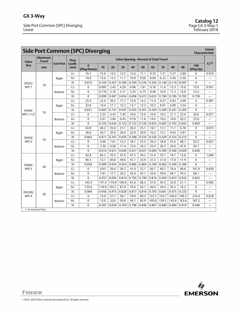
Side Port Common (SPC) Diverging LinearCharacteristic
ValveSize
MaximumTravel
Exit PortFlow
Coeffi‐cient
Valve Opening—Percent of Total Travel
FL(1)
mm0
(Plug Down)10 20 30 40 50 60 70 80 90
100(Plug Up)
DN25/
NPS 119
Right
Cv 16.1 15.0 14.2 13.5 12.6 11.1 9.35 7.21 5.27 2.89 0 0.919
Kv 14.0 13.0 12.3 11.7 10.9 9.56 8.09 6.23 4.56 2.50 0 ---
Xt 0.615 0.543 0.427 0.308 0.250 0.226 0.203 0.148 0.119 0.097 0 ---
Bottom
Cv 0 0.897 2.43 4.29 6.06 7.81 9.78 11.6 13.3 15.0 15.6 0.951
Kv 0 0.776 2.10 3.71 5.25 6.75 8.46 10.0 11.5 13.0 13.5 ---
Xt 0 0.899 0.687 0.654 0.698 0.673 0.622 0.700 0.706 0.702 0.758 ---
DN40/
NPS 1-1/219
Right
Cv 25.4 22.4 20.5 17.7 15.8 14.2 11.9 9.27 6.93 4.09 0 0.991
Kv 22.0 19.4 17.7 15.3 13.7 12.3 10.3 8.01 6.00 3.54 0 ---
Xt 0.831 0.882 0.741 0.697 0.565 0.501 0.450 0.389 0.341 0.285 0 ---
Bottom
Cv 0 2.33 4.45 7.45 10.6 13.6 16.9 19.2 21.7 23.4 26.6 0.877
Kv 0 2.01 3.84 6.45 9.18 11.8 14.6 16.6 18.8 20.2 23.0 ---
Xt 0 0.245 0.636 0.722 0.723 0.720 0.655 0.685 0.705 0.843 0.803 ---
DN50/
NPS 219
Right
Cv 43.9 40.2 35.8 31.1 26.5 23.1 18.7 15.1 11.1 6.78 0 0.973
Kv 38.0 34.7 30.9 26.9 22.9 20.0 16.2 13.1 9.63 5.87 0 ---
Xt 0.864 0.817 0.767 0.656 0.598 0.533 0.536 0.429 0.333 0.215 0 ---
Bottom
Cv 0 2.66 7.61 13.2 18.1 23.5 29.3 34.9 41.6 48.1 52.2 0.831
Kv 0 2.30 6.58 11.4 15.6 20.3 25.4 30.2 36.0 41.6 45.1 ---
Xt 0 0.614 0.651 0.649 0.651 0.627 0.609 0.599 0.588 0.600 0.640 ---
DN80/
NPS 338
Right
Cv 92.8 85.2 70.3 57.6 47.5 39.2 31.6 25.1 19.7 13.8 0 1.000
Kv 80.3 73.7 60.8 49.8 41.1 33.9 27.3 21.8 17.0 11.9 0 ---
Xt 0.858 0.989 0.976 0.934 0.896 0.864 0.789 0.682 0.540 0.306 0 ---
Bottom
Cv 0 9.03 20.4 30.3 41.0 52.1 60.1 69.1 79.4 90.6 101.9 0.839
Kv 0 7.81 17.7 26.2 35.4 45.1 52.0 59.8 68.7 78.3 88.1 ---
Xt 0 0.557 0.695 0.814 0.795 0.790 0.876 0.929 0.937 0.932 0.855 ---
DN100/
NPS 438
Right
Cv 145.4 137.4 119.9 100.6 81.6 68.3 57.6 45.5 33.9 21.1 0 0.942
Kv 125.8 118.9 103.7 87.0 70.6 59.1 49.9 39.4 29.3 18.2 0 ---
Xt 0.984 0.956 0.975 0.828 0.817 0.810 0.705 0.601 0.475 0.322 0 ---
Bottom
Cv 0 15.0 37.7 58.7 79.9 99.3 122.3 143.7 166.0 189.3 216.4 0.818
Kv 0 13.0 32.6 50.8 69.1 85.9 105.8 124.3 143.6 163.8 187.2 ---
Xt 0 0.587 0.659 0.764 0.798 0.840 0.887 0.880 0.869 0.810 0.640 ---
1. At maximum flow.
� 2010, 2018 Fisher Controls International LLC. All rights reserved
GX 3-Way
Side Port Common (SPC) DivergingLinear
Catalog 12Page GX 3-Way-1
February 2018
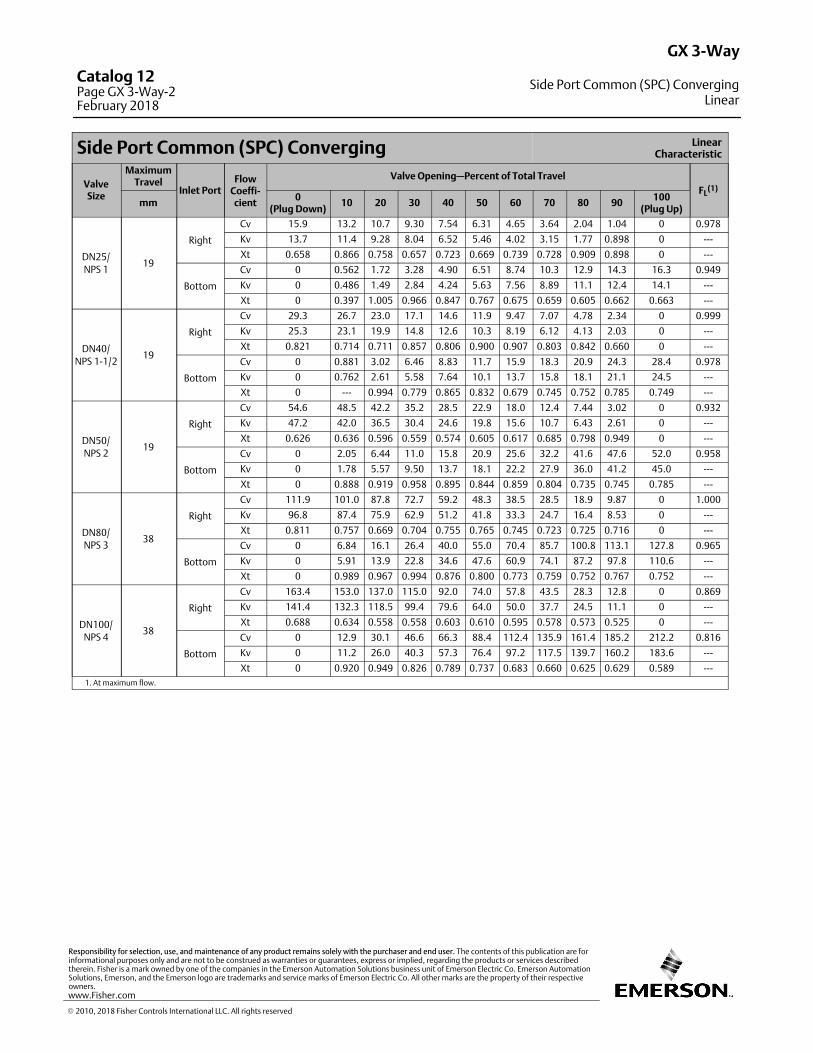
Side Port Common (SPC) Converging LinearCharacteristic
ValveSize
MaximumTravel
Inlet PortFlow
Coeffi‐cient
Valve Opening—Percent of Total Travel
FL(1)
mm0
(Plug Down)10 20 30 40 50 60 70 80 90
100(Plug Up)
DN25/
NPS 119
Right
Cv 15.9 13.2 10.7 9.30 7.54 6.31 4.65 3.64 2.04 1.04 0 0.978
Kv 13.7 11.4 9.28 8.04 6.52 5.46 4.02 3.15 1.77 0.898 0 ---
Xt 0.658 0.866 0.758 0.657 0.723 0.669 0.739 0.728 0.909 0.898 0 ---
Bottom
Cv 0 0.562 1.72 3.28 4.90 6.51 8.74 10.3 12.9 14.3 16.3 0.949
Kv 0 0.486 1.49 2.84 4.24 5.63 7.56 8.89 11.1 12.4 14.1 ---
Xt 0 0.397 1.005 0.966 0.847 0.767 0.675 0.659 0.605 0.662 0.663 ---
DN40/
NPS 1-1/219
Right
Cv 29.3 26.7 23.0 17.1 14.6 11.9 9.47 7.07 4.78 2.34 0 0.999
Kv 25.3 23.1 19.9 14.8 12.6 10.3 8.19 6.12 4.13 2.03 0 ---
Xt 0.821 0.714 0.711 0.857 0.806 0.900 0.907 0.803 0.842 0.660 0 ---
Bottom
Cv 0 0.881 3.02 6.46 8.83 11.7 15.9 18.3 20.9 24.3 28.4 0.978
Kv 0 0.762 2.61 5.58 7.64 10.1 13.7 15.8 18.1 21.1 24.5 ---
Xt 0 --- 0.994 0.779 0.865 0.832 0.679 0.745 0.752 0.785 0.749 ---
DN50/
NPS 219
Right
Cv 54.6 48.5 42.2 35.2 28.5 22.9 18.0 12.4 7.44 3.02 0 0.932
Kv 47.2 42.0 36.5 30.4 24.6 19.8 15.6 10.7 6.43 2.61 0 ---
Xt 0.626 0.636 0.596 0.559 0.574 0.605 0.617 0.685 0.798 0.949 0 ---
Bottom
Cv 0 2.05 6.44 11.0 15.8 20.9 25.6 32.2 41.6 47.6 52.0 0.958
Kv 0 1.78 5.57 9.50 13.7 18.1 22.2 27.9 36.0 41.2 45.0 ---
Xt 0 0.888 0.919 0.958 0.895 0.844 0.859 0.804 0.735 0.745 0.785 ---
DN80/
NPS 338
Right
Cv 111.9 101.0 87.8 72.7 59.2 48.3 38.5 28.5 18.9 9.87 0 1.000
Kv 96.8 87.4 75.9 62.9 51.2 41.8 33.3 24.7 16.4 8.53 0 ---
Xt 0.811 0.757 0.669 0.704 0.755 0.765 0.745 0.723 0.725 0.716 0 ---
Bottom
Cv 0 6.84 16.1 26.4 40.0 55.0 70.4 85.7 100.8 113.1 127.8 0.965
Kv 0 5.91 13.9 22.8 34.6 47.6 60.9 74.1 87.2 97.8 110.6 ---
Xt 0 0.989 0.967 0.994 0.876 0.800 0.773 0.759 0.752 0.767 0.752 ---
DN100/
NPS 438
Right
Cv 163.4 153.0 137.0 115.0 92.0 74.0 57.8 43.5 28.3 12.8 0 0.869
Kv 141.4 132.3 118.5 99.4 79.6 64.0 50.0 37.7 24.5 11.1 0 ---
Xt 0.688 0.634 0.558 0.558 0.603 0.610 0.595 0.578 0.573 0.525 0 ---
Bottom
Cv 0 12.9 30.1 46.6 66.3 88.4 112.4 135.9 161.4 185.2 212.2 0.816
Kv 0 11.2 26.0 40.3 57.3 76.4 97.2 117.5 139.7 160.2 183.6 ---
Xt 0 0.920 0.949 0.826 0.789 0.737 0.683 0.660 0.625 0.629 0.589 ---
1. At maximum flow.
GX 3-Way
Side Port Common (SPC) ConvergingLinear
Catalog 12Page GX 3-Way-2February 2018
� 2010, 2018 Fisher Controls International LLC. All rights reserved
www.Fisher.com
Responsibility for selection, use, and maintenance of any product remains solely with the purchaser and end user. The contents of this publication are forinformational purposes only and are not to be construed as warranties or guarantees, express or implied, regarding the products or services describedtherein. Fisher is a mark owned by one of the companies in the Emerson Automation Solutions business unit of Emerson Electric Co. Emerson AutomationSolutions, Emerson, and the Emerson logo are trademarks and service marks of Emerson Electric Co. All other marks are the property of their respectiveowners.
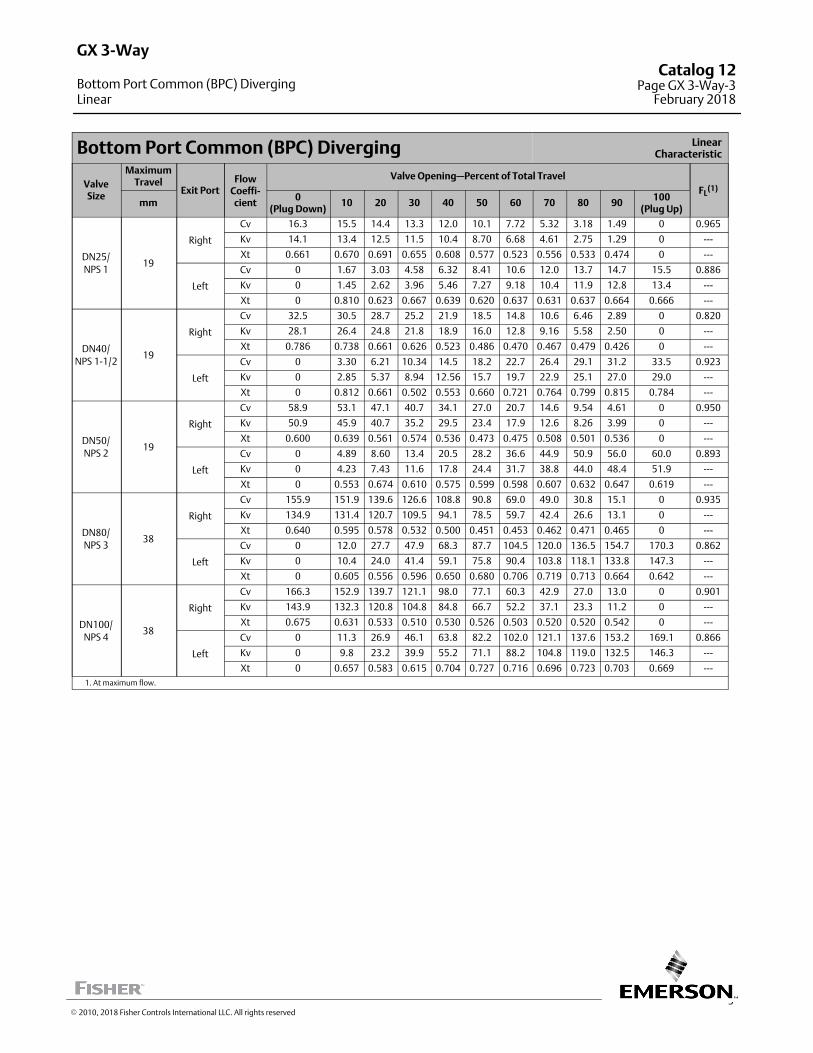
3
Bottom Port Common (BPC) Diverging LinearCharacteristic
ValveSize
MaximumTravel
Exit PortFlow
Coeffi‐cient
Valve Opening—Percent of Total Travel
FL(1)
mm0
(Plug Down)10 20 30 40 50 60 70 80 90
100(Plug Up)
DN25/
NPS 119
Right
Cv 16.3 15.5 14.4 13.3 12.0 10.1 7.72 5.32 3.18 1.49 0 0.965
Kv 14.1 13.4 12.5 11.5 10.4 8.70 6.68 4.61 2.75 1.29 0 ---
Xt 0.661 0.670 0.691 0.655 0.608 0.577 0.523 0.556 0.533 0.474 0 ---
Left
Cv 0 1.67 3.03 4.58 6.32 8.41 10.6 12.0 13.7 14.7 15.5 0.886
Kv 0 1.45 2.62 3.96 5.46 7.27 9.18 10.4 11.9 12.8 13.4 ---
Xt 0 0.810 0.623 0.667 0.639 0.620 0.637 0.631 0.637 0.664 0.666 ---
DN40/
NPS 1-1/219
Right
Cv 32.5 30.5 28.7 25.2 21.9 18.5 14.8 10.6 6.46 2.89 0 0.820
Kv 28.1 26.4 24.8 21.8 18.9 16.0 12.8 9.16 5.58 2.50 0 ---
Xt 0.786 0.738 0.661 0.626 0.523 0.486 0.470 0.467 0.479 0.426 0 ---
Left
Cv 0 3.30 6.21 10.34 14.5 18.2 22.7 26.4 29.1 31.2 33.5 0.923
Kv 0 2.85 5.37 8.94 12.56 15.7 19.7 22.9 25.1 27.0 29.0 ---
Xt 0 0.812 0.661 0.502 0.553 0.660 0.721 0.764 0.799 0.815 0.784 ---
DN50/
NPS 219
Right
Cv 58.9 53.1 47.1 40.7 34.1 27.0 20.7 14.6 9.54 4.61 0 0.950
Kv 50.9 45.9 40.7 35.2 29.5 23.4 17.9 12.6 8.26 3.99 0 ---
Xt 0.600 0.639 0.561 0.574 0.536 0.473 0.475 0.508 0.501 0.536 0 ---
Left
Cv 0 4.89 8.60 13.4 20.5 28.2 36.6 44.9 50.9 56.0 60.0 0.893
Kv 0 4.23 7.43 11.6 17.8 24.4 31.7 38.8 44.0 48.4 51.9 ---
Xt 0 0.553 0.674 0.610 0.575 0.599 0.598 0.607 0.632 0.647 0.619 ---
DN80/
NPS 338
Right
Cv 155.9 151.9 139.6 126.6 108.8 90.8 69.0 49.0 30.8 15.1 0 0.935
Kv 134.9 131.4 120.7 109.5 94.1 78.5 59.7 42.4 26.6 13.1 0 ---
Xt 0.640 0.595 0.578 0.532 0.500 0.451 0.453 0.462 0.471 0.465 0 ---
Left
Cv 0 12.0 27.7 47.9 68.3 87.7 104.5 120.0 136.5 154.7 170.3 0.862
Kv 0 10.4 24.0 41.4 59.1 75.8 90.4 103.8 118.1 133.8 147.3 ---
Xt 0 0.605 0.556 0.596 0.650 0.680 0.706 0.719 0.713 0.664 0.642 ---
DN100/
NPS 438
Right
Cv 166.3 152.9 139.7 121.1 98.0 77.1 60.3 42.9 27.0 13.0 0 0.901
Kv 143.9 132.3 120.8 104.8 84.8 66.7 52.2 37.1 23.3 11.2 0 ---
Xt 0.675 0.631 0.533 0.510 0.530 0.526 0.503 0.520 0.520 0.542 0 ---
Left
Cv 0 11.3 26.9 46.1 63.8 82.2 102.0 121.1 137.6 153.2 169.1 0.866
Kv 0 9.8 23.2 39.9 55.2 71.1 88.2 104.8 119.0 132.5 146.3 ---
Xt 0 0.657 0.583 0.615 0.704 0.727 0.716 0.696 0.723 0.703 0.669 ---
1. At maximum flow.
GX 3-Way
Bottom Port Common (BPC) DivergingLinear
Catalog 12Page GX 3-Way-3
February 2018
� 2010, 2018 Fisher Controls International LLC. All rights reserved

Bottom Port Common (BPC) Converging LinearCharacteristic
ValveSize
MaximumTravel
Inlet PortFlow
Coeffi‐cient
Valve Opening—Percent of Total Travel
FL(1)
mm0
(Plug Down)10 20 30 40 50 60 70 80 90
100(Plug Up)
DN25/
NPS 119
Right
Cv 16.4 14.4 12.8 11.7 10.7 9.64 8.58 6.27 3.80 1.08 0 0.973
Kv 14.2 12.4 11.1 10.1 9.23 8.34 7.42 5.42 3.29 0.93 0 ---
Xt 0.668 0.650 0.691 0.571 0.495 0.397 0.324 0.312 0.291 0.652 0 ---
Left
Cv 0 1.45 2.56 3.93 5.46 7.08 8.83 10.9 13.3 15.3 16.5 0.935
Kv 0 1.25 2.22 3.40 4.73 6.12 7.64 9.39 11.5 13.2 14.3 ---
Xt 0 0.702 0.784 0.725 0.720 0.710 0.722 0.717 0.678 0.609 0.597 ---
DN40/
NPS 1-1/219
Right
Cv 36.8 32.3 25.6 21.3 17.5 12.5 10.3 8.22 4.63 2.34 0 0.804
Kv 31.9 28.0 22.1 18.4 15.1 10.8 8.94 7.11 4.00 2.02 0 ---
Xt 0.540 0.538 0.675 0.661 0.613 0.723 0.690 0.575 0.595 0.634 0 ---
Left
Cv 0 3.36 5.99 9.42 13.3 17.4 22.4 27.4 33.8 37.5 41.5 0.878
Kv 0 2.91 5.18 8.15 11.5 15.0 19.4 23.7 29.2 32.5 35.9 ---
Xt 0 0.625 0.659 0.593 0.598 0.645 0.637 0.695 0.643 0.641 0.603 ---
DN50/
NPS 219
Right
Cv 59.9 50.9 42.8 35.6 29.6 23.1 17.5 13.8 9.75 6.01 0 0.882
Kv 51.8 44.0 37.0 30.8 25.6 20.0 15.2 11.9 8.43 5.20 0 ---
Xt 0.560 0.569 0.609 0.634 0.611 0.613 0.571 0.490 0.387 0.256 0 ---
Left
Cv 0 4.84 8.90 14.2 19.2 25.4 32.8 40.0 47.1 53.4 57.8 0.935
Kv 0 4.19 7.70 12.3 16.6 21.9 28.4 34.6 40.7 46.2 50.0 ---
Xt 0 0.504 0.575 0.549 0.641 0.692 0.696 0.693 0.707 0.722 0.723 ---
DN80/
NPS 338
Right
Cv 158.7 142.5 125.3 102.8 80.3 61.0 45.8 33.1 20.8 10.6 0 0.813
Kv 137.2 123.3 108.4 88.9 69.5 52.8 39.6 28.7 18.0 9.18 0 ---
Xt 0.558 0.578 0.553 0.549 0.600 0.663 0.665 0.653 0.714 0.705 0 ---
Left
Cv 0 12.1 25.7 43.8 63.1 83.1 102.7 120.4 135.7 151.1 164.9 0.931
Kv 0 10.5 22.2 37.9 54.6 71.9 88.9 104.1 117.4 130.7 142.6 ---
Xt 0 0.525 0.579 0.619 0.660 0.658 0.676 0.685 0.701 0.691 0.670 ---
DN100/
NPS 438
Right
Cv 155.9 145.0 127.4 107.6 85.9 66.4 49.4 35.6 23.6 12.2 0 0.810
Kv 134.9 125.4 110.2 93.0 74.3 57.5 42.7 30.8 20.4 10.5 0 ---
Xt 0.564 0.550 0.518 0.504 0.545 0.593 0.628 0.621 0.601 0.553 0 ---
Left
Cv 0 13.5 28.9 48.9 69.5 90.6 111.1 129.2 145.4 159.9 174.4 0.830
Kv 0 11.7 25.0 42.3 60.1 78.4 96.1 111.8 125.8 138.3 150.8 ---
Xt 0 0.427 0.477 0.525 0.553 0.564 0.590 0.637 0.667 0.686 0.676 ---
1. At maximum flow.
GX 3-Way
Bottom Port Common (BPC) ConvergingLinear
Catalog 12Page GX 3-Way-4February 2018
� 2010, 2018 Fisher Controls International LLC. All rights reserved
www.Fisher.com
Responsibility for selection, use, and maintenance of any product remains solely with the purchaser and end user. The contents of this publication are forinformational purposes only and are not to be construed as warranties or guarantees, express or implied, regarding the products or services describedtherein. Fisher is a mark owned by one of the companies in the Emerson Automation Solutions business unit of Emerson Electric Co. Emerson AutomationSolutions, Emerson, and the Emerson logo are trademarks and service marks of Emerson Electric Co. All other marks are the property of their respectiveowners.
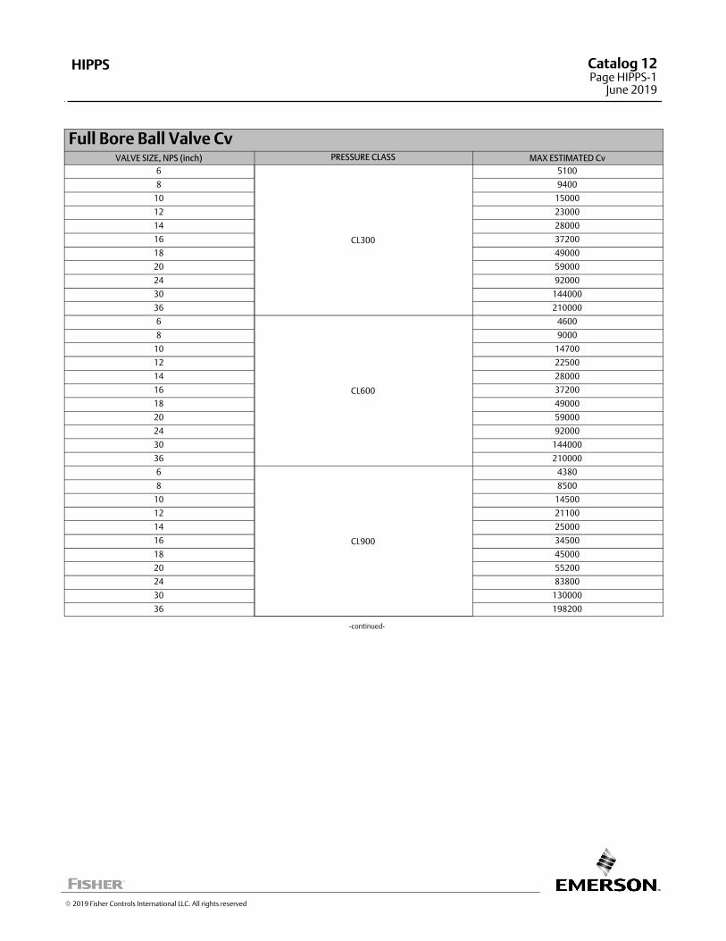
Full Bore Ball Valve CvVALVE SIZE, NPS (inch) PRESSURE CLASS MAX ESTIMATED Cv
6
CL300
5100
8 9400
10 15000
12 23000
14 28000
16 37200
18 49000
20 59000
24 92000
30 144000
36 210000
6
CL600
4600
8 9000
10 14700
12 22500
14 28000
16 37200
18 49000
20 59000
24 92000
30 144000
36 210000
6
CL900
4380
8 8500
10 14500
12 21100
14 25000
16 34500
18 45000
20 55200
24 83800
30 130000
36 198200
‐continued‐
� 2019 Fisher Controls International LLC. All rights reserved
HIPPS Catalog 12Page HIPPS-1
June 2019

Full Bore Ball Valve CvVALVE SIZE, NPS (inch) PRESSURE CLASS MAX ESTIMATED Cv
6
CL1500
3800
8 7400
10 11500
12 18000
14 21000
16 27500
18 37000
20 47800
24 70000
30 112652
36 166073
6
CL2500
2500
8 5300
10 8300
12 13000
14 18275
16 24575
18 31825
20 40025
24 59275
30 95275
HIPPSCatalog 12Page HIPPS-2June 2019
� 2019 Fisher Controls International LLC. All rights reserved
www.Fisher.com
Responsibility for selection, use, and maintenance of any product remains solely with the purchaser and end user. The contents of this publication are forinformational purposes only and are not to be construed as warranties or guarantees, express or implied, regarding the products or services describedtherein. Fisher is a mark owned by Emerson Automation Solutions part of Emerson Electric Co. Emerson Automation Solutions, Emerson, and the Emersonlogo are trademarks and service marks of Emerson Electric Co. All other marks are the property of their respective owners.
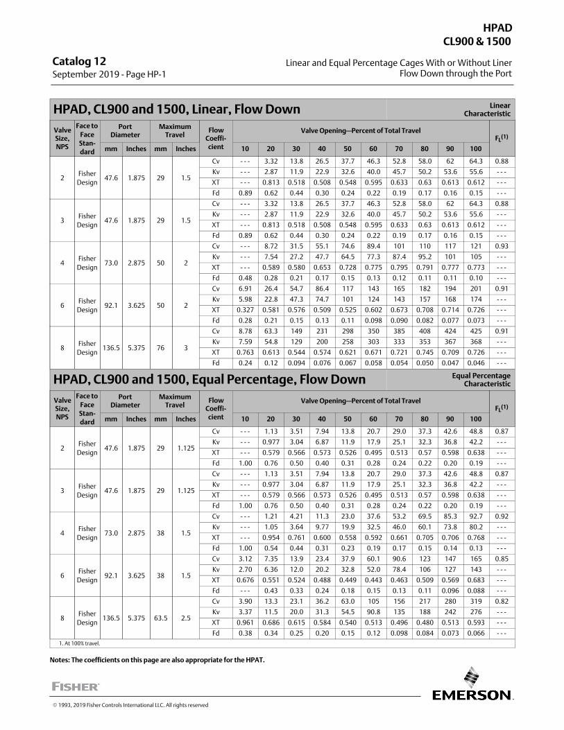
Catalog 12 September 2019 ‐ Page HP-1
Linear and Equal Percentage Cages With or Without LinerFlow Down through the Port
HPADCL900 & 1500
� 1993, 2019 Fisher Controls International LLC. All rights reserved
HPAD, CL900 and 1500, Linear, Flow Down LinearCharacteristic
ValveSize,NPS
Face to
FaceStan-dard
PortDiameter
MaximumTravel
FlowCoeffi‐cient
Valve Opening—Percent of Total TravelFL
(1)
mm Inches mm Inches 10 20 30 40 50 60 70 80 90 100
2Fisher
Design47.6 1.875 29 1.5
Cv - - - 3.32 13.8 26.5 37.7 46.3 52.8 58.0 62 64.3 0.88
Kv - - - 2.87 11.9 22.9 32.6 40.0 45.7 50.2 53.6 55.6 - - -
XT - - - 0.813 0.518 0.508 0.548 0.595 0.633 0.63 0.613 0.612 - - -
Fd 0.89 0.62 0.44 0.30 0.24 0.22 0.19 0.17 0.16 0.15 - - -
3Fisher
Design47.6 1.875 29 1.5
Cv - - - 3.32 13.8 26.5 37.7 46.3 52.8 58.0 62 64.3 0.88
Kv - - - 2.87 11.9 22.9 32.6 40.0 45.7 50.2 53.6 55.6 - - -
XT - - - 0.813 0.518 0.508 0.548 0.595 0.633 0.63 0.613 0.612 - - -
Fd 0.89 0.62 0.44 0.30 0.24 0.22 0.19 0.17 0.16 0.15 - - -
4Fisher
Design73.0 2.875 50 2
Cv - - - 8.72 31.5 55.1 74.6 89.4 101 110 117 121 0.93
Kv - - - 7.54 27.2 47.7 64.5 77.3 87.4 95.2 101 105 - - -
XT - - - 0.589 0.580 0.653 0.728 0.775 0.795 0.791 0.777 0.773 - - -
Fd 0.48 0.28 0.21 0.17 0.15 0.13 0.12 0.11 0.11 0.10 - - -
6Fisher
Design92.1 3.625 50 2
Cv 6.91 26.4 54.7 86.4 117 143 165 182 194 201 0.91
Kv 5.98 22.8 47.3 74.7 101 124 143 157 168 174 - - -
XT 0.327 0.581 0.576 0.509 0.525 0.602 0.673 0.708 0.714 0.726 - - -
Fd 0.28 0.21 0.15 0.13 0.11 0.098 0.090 0.082 0.077 0.073 - - -
8Fisher
Design136.5 5.375 76 3
Cv 8.78 63.3 149 231 298 350 385 408 424 425 0.91
Kv 7.59 54.8 129 200 258 303 333 353 367 368 - - -
XT 0.763 0.613 0.544 0.574 0.621 0.671 0.721 0.745 0.709 0.726 - - -
Fd 0.24 0.12 0.094 0.076 0.067 0.058 0.054 0.050 0.047 0.046 - - -
HPAD, CL900 and 1500, Equal Percentage, Flow Down Equal PercentageCharacteristic
ValveSize,NPS
Face to
FaceStan-dard
PortDiameter
MaximumTravel
FlowCoeffi‐cient
Valve Opening—Percent of Total TravelFL
(1)
mm Inches mm Inches 10 20 30 40 50 60 70 80 90 100
2Fisher
Design47.6 1.875 29 1.125
Cv - - - 1.13 3.51 7.94 13.8 20.7 29.0 37.3 42.6 48.8 0.87
Kv - - - 0.977 3.04 6.87 11.9 17.9 25.1 32.3 36.8 42.2 - - -
XT - - - 0.579 0.566 0.573 0.526 0.495 0.513 0.57 0.598 0.638 - - -
Fd 1.00 0.76 0.50 0.40 0.31 0.28 0.24 0.22 0.20 0.19 - - -
3Fisher
Design47.6 1.875 29 1.125
Cv - - - 1.13 3.51 7.94 13.8 20.7 29.0 37.3 42.6 48.8 0.87
Kv - - - 0.977 3.04 6.87 11.9 17.9 25.1 32.3 36.8 42.2 - - -
XT - - - 0.579 0.566 0.573 0.526 0.495 0.513 0.57 0.598 0.638 - - -
Fd 1.00 0.76 0.50 0.40 0.31 0.28 0.24 0.22 0.20 0.19 - - -
4Fisher
Design73.0 2.875 38 1.5
Cv - - - 1.21 4.21 11.3 23.0 37.6 53.2 69.5 85.3 92.7 0.92
Kv - - - 1.05 3.64 9.77 19.9 32.5 46.0 60.1 73.8 80.2 - - -
XT - - - 0.954 0.761 0.600 0.558 0.592 0.661 0.705 0.706 0.768 - - -
Fd 1.00 0.54 0.44 0.31 0.23 0.19 0.17 0.15 0.14 0.13 - - -
6Fisher
Design92.1 3.625 38 1.5
Cv 3.12 7.35 13.9 23.4 37.9 60.1 90.6 123 147 165 0.85
Kv 2.70 6.36 12.0 20.2 32.8 52.0 78.4 106 127 143 - - -
XT 0.676 0.551 0.524 0.488 0.449 0.443 0.463 0.509 0.569 0.683 - - -
Fd - - - 0.43 0.33 0.24 0.18 0.15 0.13 0.11 0.096 0.088 - - -
8Fisher
Design136.5 5.375 63.5 2.5
Cv 3.90 13.3 23.1 36.2 63.0 105 156 217 280 319 0.82
Kv 3.37 11.5 20.0 31.3 54.5 90.8 135 188 242 276 - - -
XT 0.961 0.686 0.615 0.584 0.540 0.513 0.496 0.480 0.513 0.593 - - -
Fd 0.38 0.34 0.25 0.20 0.15 0.12 0.098 0.084 0.073 0.066 - - -
1. At 100% travel.
Notes: The coefficients on this page are also appropriate for the HPAT.
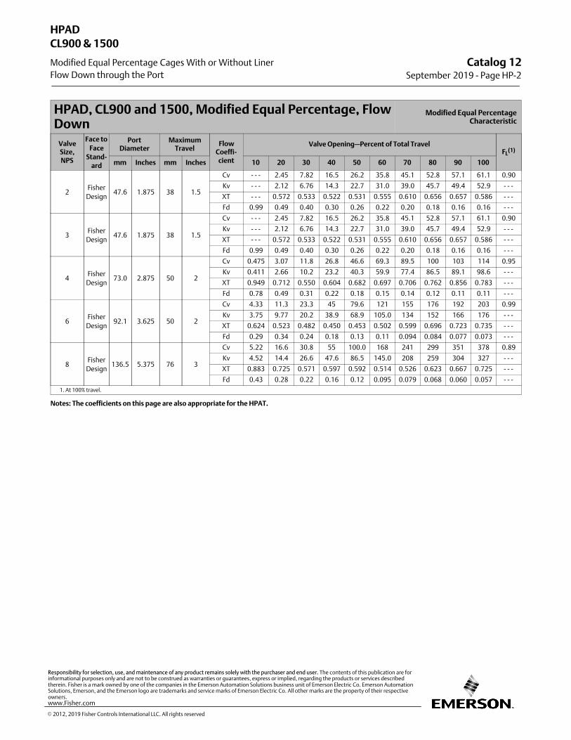
HPAD, CL900 and 1500, Modified Equal Percentage, FlowDown
Modified Equal PercentageCharacteristic
ValveSize,NPS
Face to
FaceStand-
ard
PortDiameter
MaximumTravel
FlowCoeffi‐cient
Valve Opening—Percent of Total TravelFL
(1)
mm Inches mm Inches 10 20 30 40 50 60 70 80 90 100
2Fisher
Design47.6 1.875 38 1.5
Cv - - - 2.45 7.82 16.5 26.2 35.8 45.1 52.8 57.1 61.1 0.90
Kv - - - 2.12 6.76 14.3 22.7 31.0 39.0 45.7 49.4 52.9 - - -
XT - - - 0.572 0.533 0.522 0.531 0.555 0.610 0.656 0.657 0.586 - - -
Fd 0.99 0.49 0.40 0.30 0.26 0.22 0.20 0.18 0.16 0.16 - - -
3Fisher
Design47.6 1.875 38 1.5
Cv - - - 2.45 7.82 16.5 26.2 35.8 45.1 52.8 57.1 61.1 0.90
Kv - - - 2.12 6.76 14.3 22.7 31.0 39.0 45.7 49.4 52.9 - - -
XT - - - 0.572 0.533 0.522 0.531 0.555 0.610 0.656 0.657 0.586 - - -
Fd 0.99 0.49 0.40 0.30 0.26 0.22 0.20 0.18 0.16 0.16 - - -
4Fisher
Design73.0 2.875 50 2
Cv 0.475 3.07 11.8 26.8 46.6 69.3 89.5 100 103 114 0.95
Kv 0.411 2.66 10.2 23.2 40.3 59.9 77.4 86.5 89.1 98.6 - - -
XT 0.949 0.712 0.550 0.604 0.682 0.697 0.706 0.762 0.856 0.783 - - -
Fd 0.78 0.49 0.31 0.22 0.18 0.15 0.14 0.12 0.11 0.11 - - -
6Fisher
Design92.1 3.625 50 2
Cv 4.33 11.3 23.3 45 79.6 121 155 176 192 203 0.99
Kv 3.75 9.77 20.2 38.9 68.9 105.0 134 152 166 176 - - -
XT 0.624 0.523 0.482 0.450 0.453 0.502 0.599 0.696 0.723 0.735 - - -
Fd 0.29 0.34 0.24 0.18 0.13 0.11 0.094 0.084 0.077 0.073 - - -
8Fisher
Design136.5 5.375 76 3
Cv 5.22 16.6 30.8 55 100.0 168 241 299 351 378 0.89
Kv 4.52 14.4 26.6 47.6 86.5 145.0 208 259 304 327 - - -
XT 0.883 0.725 0.571 0.597 0.592 0.514 0.526 0.623 0.667 0.725 - - -
Fd 0.43 0.28 0.22 0.16 0.12 0.095 0.079 0.068 0.060 0.057 - - -
1. At 100% travel.
Notes: The coefficients on this page are also appropriate for the HPAT.
Catalog 12September 2019 ‐ Page HP-2
HPAD
Modified Equal Percentage Cages With or Without Liner
CL900 & 1500
Flow Down through the Port
� 2012, 2019 Fisher Controls International LLC. All rights reserved
www.Fisher.com
Responsibility for selection, use, and maintenance of any product remains solely with the purchaser and end user. The contents of this publication are forinformational purposes only and are not to be construed as warranties or guarantees, express or implied, regarding the products or services describedtherein. Fisher is a mark owned by one of the companies in the Emerson Automation Solutions business unit of Emerson Electric Co. Emerson AutomationSolutions, Emerson, and the Emerson logo are trademarks and service marks of Emerson Electric Co. All other marks are the property of their respectiveowners.
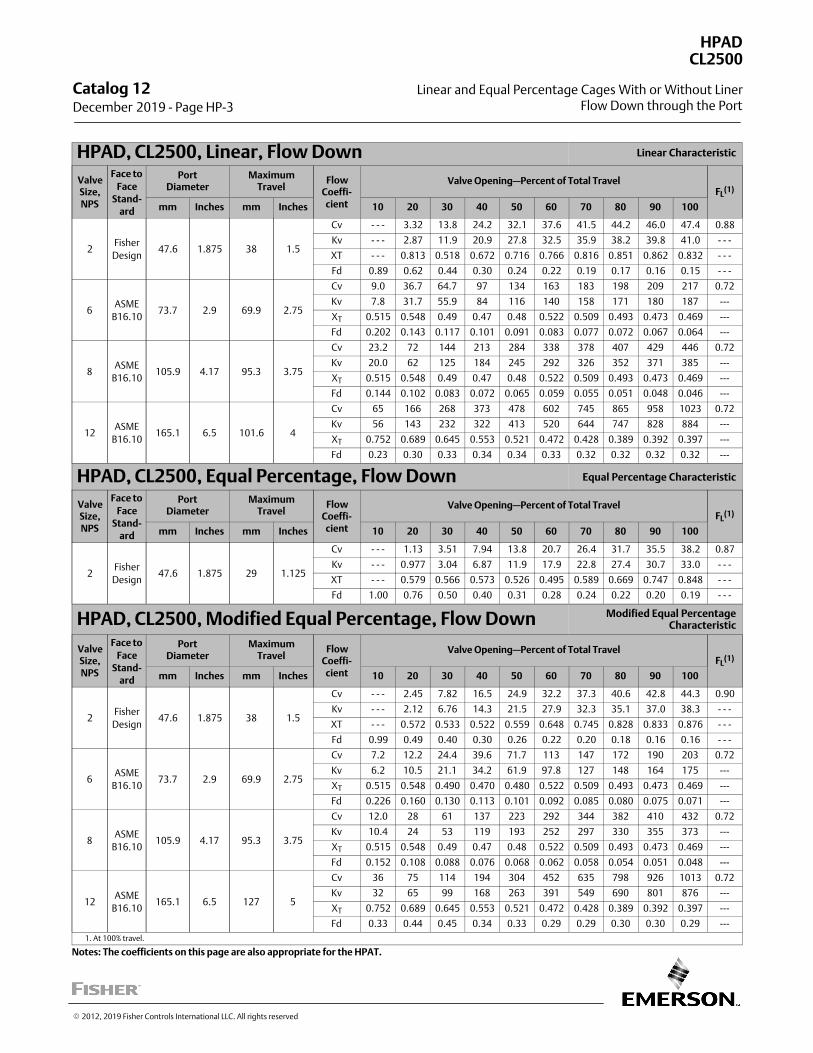
HPAD, CL2500, Linear, Flow Down Linear Characteristic
ValveSize,NPS
Face to
FaceStand-
ard
PortDiameter
MaximumTravel
FlowCoeffi‐cient
Valve Opening—Percent of Total TravelFL
(1)
mm Inches mm Inches 10 20 30 40 50 60 70 80 90 100
2Fisher
Design47.6 1.875 38 1.5
Cv - - - 3.32 13.8 24.2 32.1 37.6 41.5 44.2 46.0 47.4 0.88
Kv - - - 2.87 11.9 20.9 27.8 32.5 35.9 38.2 39.8 41.0 - - -
XT - - - 0.813 0.518 0.672 0.716 0.766 0.816 0.851 0.862 0.832 - - -
Fd 0.89 0.62 0.44 0.30 0.24 0.22 0.19 0.17 0.16 0.15 - - -
6ASME
B16.1073.7 2.9 69.9 2.75
Cv 9.0 36.7 64.7 97 134 163 183 198 209 217 0.72
Kv 7.8 31.7 55.9 84 116 140 158 171 180 187 ---
XT 0.515 0.548 0.49 0.47 0.48 0.522 0.509 0.493 0.473 0.469 ---
Fd 0.202 0.143 0.117 0.101 0.091 0.083 0.077 0.072 0.067 0.064 ---
8ASME
B16.10105.9 4.17 95.3 3.75
Cv 23.2 72 144 213 284 338 378 407 429 446 0.72
Kv 20.0 62 125 184 245 292 326 352 371 385 ---
XT 0.515 0.548 0.49 0.47 0.48 0.522 0.509 0.493 0.473 0.469 ---
Fd 0.144 0.102 0.083 0.072 0.065 0.059 0.055 0.051 0.048 0.046 ---
12ASME
B16.10165.1 6.5 101.6 4
Cv 65 166 268 373 478 602 745 865 958 1023 0.72
Kv 56 143 232 322 413 520 644 747 828 884 ---
XT 0.752 0.689 0.645 0.553 0.521 0.472 0.428 0.389 0.392 0.397 ---
Fd 0.23 0.30 0.33 0.34 0.34 0.33 0.32 0.32 0.32 0.32 ---
HPAD, CL2500, Equal Percentage, Flow Down Equal Percentage Characteristic
ValveSize,NPS
Face to
FaceStand-
ard
PortDiameter
MaximumTravel
FlowCoeffi‐cient
Valve Opening—Percent of Total TravelFL
(1)
mm Inches mm Inches 10 20 30 40 50 60 70 80 90 100
2Fisher
Design47.6 1.875 29 1.125
Cv - - - 1.13 3.51 7.94 13.8 20.7 26.4 31.7 35.5 38.2 0.87
Kv - - - 0.977 3.04 6.87 11.9 17.9 22.8 27.4 30.7 33.0 - - -
XT - - - 0.579 0.566 0.573 0.526 0.495 0.589 0.669 0.747 0.848 - - -
Fd 1.00 0.76 0.50 0.40 0.31 0.28 0.24 0.22 0.20 0.19 - - -
HPAD, CL2500, Modified Equal Percentage, Flow Down Modified Equal PercentageCharacteristic
ValveSize,NPS
Face to
FaceStand-
ard
PortDiameter
MaximumTravel
FlowCoeffi‐cient
Valve Opening—Percent of Total TravelFL
(1)
mm Inches mm Inches 10 20 30 40 50 60 70 80 90 100
2Fisher
Design47.6 1.875 38 1.5
Cv - - - 2.45 7.82 16.5 24.9 32.2 37.3 40.6 42.8 44.3 0.90
Kv - - - 2.12 6.76 14.3 21.5 27.9 32.3 35.1 37.0 38.3 - - -
XT - - - 0.572 0.533 0.522 0.559 0.648 0.745 0.828 0.833 0.876 - - -
Fd 0.99 0.49 0.40 0.30 0.26 0.22 0.20 0.18 0.16 0.16 - - -
6ASME
B16.1073.7 2.9 69.9 2.75
Cv 7.2 12.2 24.4 39.6 71.7 113 147 172 190 203 0.72
Kv 6.2 10.5 21.1 34.2 61.9 97.8 127 148 164 175 ---
XT 0.515 0.548 0.490 0.470 0.480 0.522 0.509 0.493 0.473 0.469 ---
Fd 0.226 0.160 0.130 0.113 0.101 0.092 0.085 0.080 0.075 0.071 ---
8ASME
B16.10105.9 4.17 95.3 3.75
Cv 12.0 28 61 137 223 292 344 382 410 432 0.72
Kv 10.4 24 53 119 193 252 297 330 355 373 ---
XT 0.515 0.548 0.49 0.47 0.48 0.522 0.509 0.493 0.473 0.469 ---
Fd 0.152 0.108 0.088 0.076 0.068 0.062 0.058 0.054 0.051 0.048 ---
12ASME
B16.10165.1 6.5 127 5
Cv 36 75 114 194 304 452 635 798 926 1013 0.72
Kv 32 65 99 168 263 391 549 690 801 876 ---
XT 0.752 0.689 0.645 0.553 0.521 0.472 0.428 0.389 0.392 0.397 ---
Fd 0.33 0.44 0.45 0.34 0.33 0.29 0.29 0.30 0.30 0.29 ---
1. At 100% travel.
Notes: The coefficients on this page are also appropriate for the HPAT.
Catalog 12 December 2019 ‐ Page HP-3
HPAD
Linear and Equal Percentage Cages With or Without Liner
CL2500
Flow Down through the Port
� 2012, 2019 Fisher Controls International LLC. All rights reserved
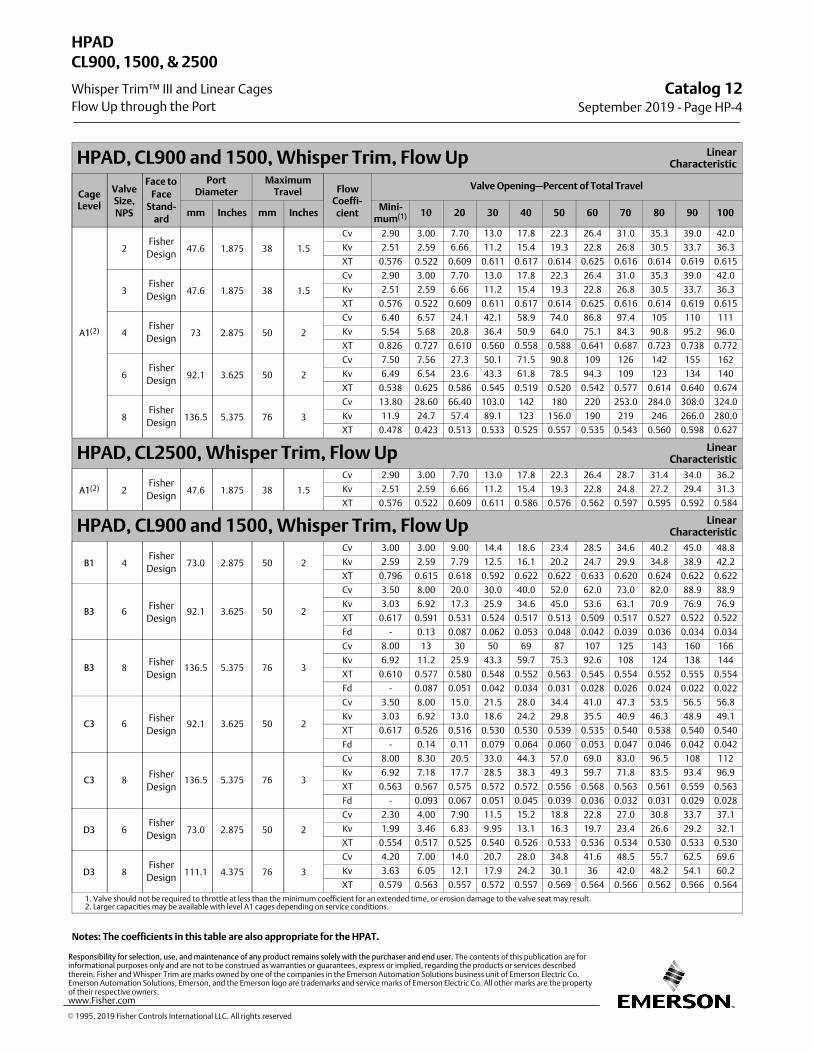
HPAD, CL900 and 1500, Whisper Trim, Flow Up LinearCharacteristic
CageLevel
ValveSize,NPS
Face to
FaceStand-
ard
PortDiameter
MaximumTravel Flow
Coeffi‐cient
Valve Opening—Percent of Total Travel
mm Inches mm InchesMini‐
mum(1) 10 20 30 40 50 60 70 80 90 100
A1(2)
2Fisher
Design47.6 1.875 38 1.5
Cv 2.90 3.00 7.70 13.0 17.8 22.3 26.4 31.0 35.3 39.0 42.0
Kv 2.51 2.59 6.66 11.2 15.4 19.3 22.8 26.8 30.5 33.7 36.3
XT 0.576 0.522 0.609 0.611 0.617 0.614 0.625 0.616 0.614 0.619 0.615
3Fisher
Design47.6 1.875 38 1.5
Cv 2.90 3.00 7.70 13.0 17.8 22.3 26.4 31.0 35.3 39.0 42.0
Kv 2.51 2.59 6.66 11.2 15.4 19.3 22.8 26.8 30.5 33.7 36.3
XT 0.576 0.522 0.609 0.611 0.617 0.614 0.625 0.616 0.614 0.619 0.615
4Fisher
Design73 2.875 50 2
Cv 6.40 6.57 24.1 42.1 58.9 74.0 86.8 97.4 105 110 111
Kv 5.54 5.68 20.8 36.4 50.9 64.0 75.1 84.3 90.8 95.2 96.0
XT 0.826 0.727 0.610 0.560 0.558 0.588 0.641 0.687 0.723 0.738 0.772
6Fisher
Design92.1 3.625 50 2
Cv 7.50 7.56 27.3 50.1 71.5 90.8 109 126 142 155 162
Kv 6.49 6.54 23.6 43.3 61.8 78.5 94.3 109 123 134 140
XT 0.538 0.625 0.586 0.545 0.519 0.520 0.542 0.577 0.614 0.640 0.674
8Fisher
Design136.5 5.375 76 3
Cv 13.80 28.60 66.40 103.0 142 180 220 253.0 284.0 308.0 324.0
Kv 11.9 24.7 57.4 89.1 123 156.0 190 219 246 266.0 280.0
XT 0.478 0.423 0.513 0.533 0.525 0.557 0.535 0.543 0.560 0.598 0.627
HPAD, CL2500, Whisper Trim, Flow Up LinearCharacteristic
A1(2) 2Fisher
Design47.6 1.875 38 1.5
Cv 2.90 3.00 7.70 13.0 17.8 22.3 26.4 28.7 31.4 34.0 36.2
Kv 2.51 2.59 6.66 11.2 15.4 19.3 22.8 24.8 27.2 29.4 31.3
XT 0.576 0.522 0.609 0.611 0.586 0.576 0.562 0.597 0.595 0.592 0.584
HPAD, CL900 and 1500, Whisper Trim, Flow Up LinearCharacteristic
B1 4Fisher
Design73.0 2.875 50 2
Cv 3.00 3.00 9.00 14.4 18.6 23.4 28.5 34.6 40.2 45.0 48.8
Kv 2.59 2.59 7.79 12.5 16.1 20.2 24.7 29.9 34.8 38.9 42.2
XT 0.796 0.615 0.618 0.592 0.622 0.622 0.633 0.620 0.624 0.622 0.622
B3 6Fisher
Design92.1 3.625 50 2
Cv 3.50 8.00 20.0 30.0 40.0 52.0 62.0 73.0 82.0 88.9 88.9
Kv 3.03 6.92 17.3 25.9 34.6 45.0 53.6 63.1 70.9 76.9 76.9
XT 0.617 0.591 0.531 0.524 0.517 0.513 0.509 0.517 0.527 0.522 0.522
Fd ‐ 0.13 0.087 0.062 0.053 0.048 0.042 0.039 0.036 0.034 0.034
B3 8Fisher
Design136.5 5.375 76 3
Cv 8.00 13 30 50 69 87 107 125 143 160 166
Kv 6.92 11.2 25.9 43.3 59.7 75.3 92.6 108 124 138 144
XT 0.610 0.577 0.580 0.548 0.552 0.563 0.545 0.554 0.552 0.555 0.554
Fd ‐ 0.087 0.051 0.042 0.034 0.031 0.028 0.026 0.024 0.022 0.022
C3 6Fisher
Design92.1 3.625 50 2
Cv 3.50 8.00 15.0 21.5 28.0 34.4 41.0 47.3 53.5 56.5 56.8
Kv 3.03 6.92 13.0 18.6 24.2 29.8 35.5 40.9 46.3 48.9 49.1
XT 0.617 0.526 0.516 0.530 0.530 0.539 0.535 0.540 0.538 0.540 0.540
Fd ‐ 0.14 0.11 0.079 0.064 0.060 0.053 0.047 0.046 0.042 0.042
C3 8Fisher
Design136.5 5.375 76 3
Cv 8.00 8.30 20.5 33.0 44.3 57.0 69.0 83.0 96.5 108 112
Kv 6.92 7.18 17.7 28.5 38.3 49.3 59.7 71.8 83.5 93.4 96.9
XT 0.563 0.567 0.575 0.572 0.572 0.556 0.568 0.563 0.561 0.559 0.563
Fd ‐ 0.093 0.067 0.051 0.045 0.039 0.036 0.032 0.031 0.029 0.028
D3 6Fisher
Design73.0 2.875 50 2
Cv 2.30 4.00 7.90 11.5 15.2 18.8 22.8 27.0 30.8 33.7 37.1
Kv 1.99 3.46 6.83 9.95 13.1 16.3 19.7 23.4 26.6 29.2 32.1
XT 0.554 0.517 0.525 0.540 0.526 0.533 0.536 0.534 0.530 0.533 0.530
D3 8Fisher
Design111.1 4.375 76 3
Cv 4.20 7.00 14.0 20.7 28.0 34.8 41.6 48.5 55.7 62.5 69.6
Kv 3.63 6.05 12.1 17.9 24.2 30.1 36 42.0 48.2 54.1 60.2
XT 0.579 0.563 0.557 0.572 0.557 0.569 0.564 0.566 0.562 0.566 0.564
1. Valve should not be required to throttle at less than the minimum coefficient for an extended time, or erosion damage to the valve seat may result.2. Larger capacities may be available with level A1 cages depending on service conditions.
Notes: The coefficients in this table are also appropriate for the HPAT.
Catalog 12September 2019 ‐ Page HP-4
HPAD
Whisper Trim™ III and Linear Cages
CL900, 1500, & 2500
Flow Up through the Port
� 1995, 2019 Fisher Controls International LLC. All rights reserved
www.Fisher.com
Responsibility for selection, use, and maintenance of any product remains solely with the purchaser and end user. The contents of this publication are forinformational purposes only and are not to be construed as warranties or guarantees, express or implied, regarding the products or services describedtherein. Fisher and Whisper Trim are marks owned by one of the companies in the Emerson Automation Solutions business unit of Emerson Electric Co.Emerson Automation Solutions, Emerson, and the Emerson logo are trademarks and service marks of Emerson Electric Co. All other marks are the propertyof their respective owners.
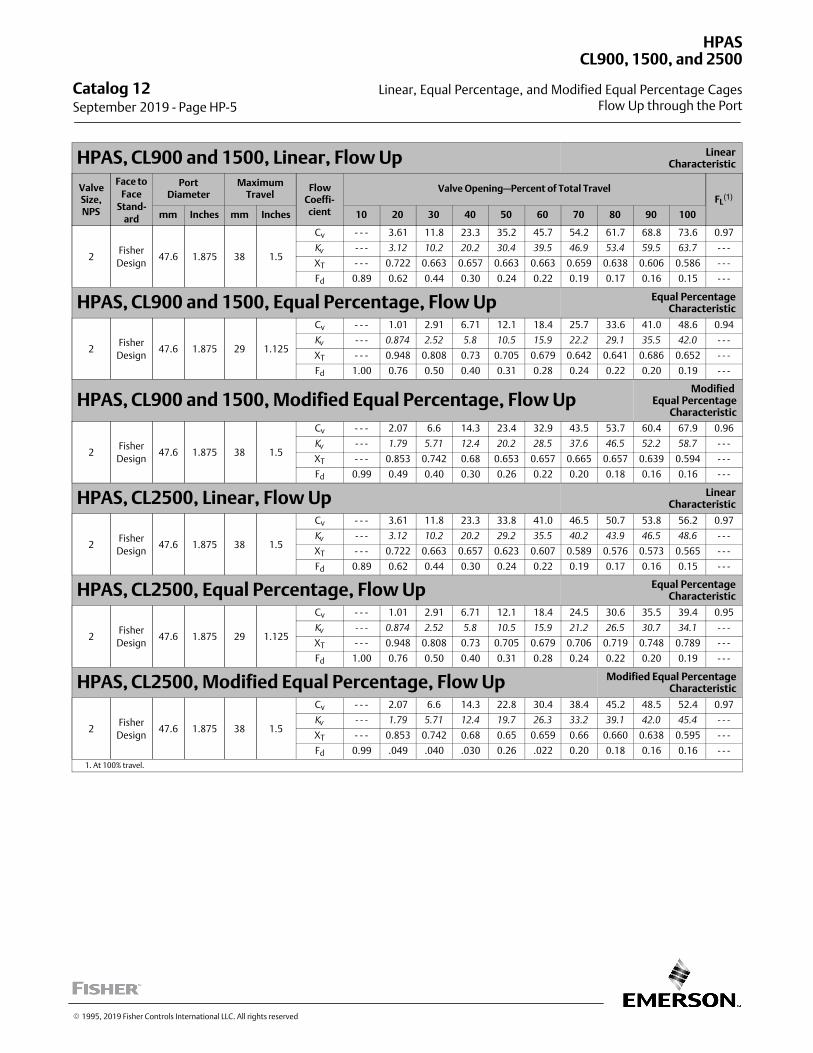
HPAS, CL900 and 1500, Linear, Flow Up LinearCharacteristic
ValveSize,NPS
Face to
FaceStand-
ard
PortDiameter
MaximumTravel
FlowCoeffi‐cient
Valve Opening—Percent of Total TravelFL
(1)
mm Inches mm Inches 10 20 30 40 50 60 70 80 90 100
2Fisher
Design47.6 1.875 38 1.5
Cv ‐ ‐ ‐ 3.61 11.8 23.3 35.2 45.7 54.2 61.7 68.8 73.6 0.97
Kv
‐ ‐ ‐ 3.12 10.2 20.2 30.4 39.5 46.9 53.4 59.5 63.7 ‐ ‐ ‐
XT ‐ ‐ ‐ 0.722 0.663 0.657 0.663 0.663 0.659 0.638 0.606 0.586 ‐ ‐ ‐
Fd 0.89 0.62 0.44 0.30 0.24 0.22 0.19 0.17 0.16 0.15 ‐ ‐ ‐
HPAS, CL900 and 1500, Equal Percentage, Flow Up Equal PercentageCharacteristic
2Fisher
Design47.6 1.875 29 1.125
Cv ‐ ‐ ‐ 1.01 2.91 6.71 12.1 18.4 25.7 33.6 41.0 48.6 0.94
Kv
‐ ‐ ‐ 0.874 2.52 5.8 10.5 15.9 22.2 29.1 35.5 42.0 ‐ ‐ ‐
XT ‐ ‐ ‐ 0.948 0.808 0.73 0.705 0.679 0.642 0.641 0.686 0.652 ‐ ‐ ‐
Fd 1.00 0.76 0.50 0.40 0.31 0.28 0.24 0.22 0.20 0.19 ‐ ‐ ‐
HPAS, CL900 and 1500, Modified Equal Percentage, Flow UpModified
Equal PercentageCharacteristic
2Fisher
Design47.6 1.875 38 1.5
Cv ‐ ‐ ‐ 2.07 6.6 14.3 23.4 32.9 43.5 53.7 60.4 67.9 0.96
Kv
‐ ‐ ‐ 1.79 5.71 12.4 20.2 28.5 37.6 46.5 52.2 58.7 ‐ ‐ ‐
XT ‐ ‐ ‐ 0.853 0.742 0.68 0.653 0.657 0.665 0.657 0.639 0.594 ‐ ‐ ‐
Fd 0.99 0.49 0.40 0.30 0.26 0.22 0.20 0.18 0.16 0.16 ‐ ‐ ‐
HPAS, CL2500, Linear, Flow Up LinearCharacteristic
2Fisher
Design47.6 1.875 38 1.5
Cv ‐ ‐ ‐ 3.61 11.8 23.3 33.8 41.0 46.5 50.7 53.8 56.2 0.97
Kv
‐ ‐ ‐ 3.12 10.2 20.2 29.2 35.5 40.2 43.9 46.5 48.6 ‐ ‐ ‐
XT ‐ ‐ ‐ 0.722 0.663 0.657 0.623 0.607 0.589 0.576 0.573 0.565 ‐ ‐ ‐
Fd 0.89 0.62 0.44 0.30 0.24 0.22 0.19 0.17 0.16 0.15 ‐ ‐ ‐
HPAS, CL2500, Equal Percentage, Flow Up Equal PercentageCharacteristic
2Fisher
Design47.6 1.875 29 1.125
Cv ‐ ‐ ‐ 1.01 2.91 6.71 12.1 18.4 24.5 30.6 35.5 39.4 0.95
Kv
‐ ‐ ‐ 0.874 2.52 5.8 10.5 15.9 21.2 26.5 30.7 34.1 ‐ ‐ ‐
XT ‐ ‐ ‐ 0.948 0.808 0.73 0.705 0.679 0.706 0.719 0.748 0.789 ‐ ‐ ‐
Fd 1.00 0.76 0.50 0.40 0.31 0.28 0.24 0.22 0.20 0.19 ‐ ‐ ‐
HPAS, CL2500, Modified Equal Percentage, Flow Up Modified Equal PercentageCharacteristic
2Fisher
Design47.6 1.875 38 1.5
Cv ‐ ‐ ‐ 2.07 6.6 14.3 22.8 30.4 38.4 45.2 48.5 52.4 0.97
Kv
‐ ‐ ‐ 1.79 5.71 12.4 19.7 26.3 33.2 39.1 42.0 45.4 ‐ ‐ ‐
XT ‐ ‐ ‐ 0.853 0.742 0.68 0.65 0.659 0.66 0.660 0.638 0.595 ‐ ‐ ‐
Fd 0.99 .049 .040 .030 0.26 .022 0.20 0.18 0.16 0.16 ‐ ‐ ‐
1. At 100% travel.
Catalog 12 September 2019 ‐ Page HP-5
HPAS
Linear, Equal Percentage, and Modified Equal Percentage Cages
CL900, 1500, and 2500
Flow Up through the Port
� 1995, 2019 Fisher Controls International LLC. All rights reserved
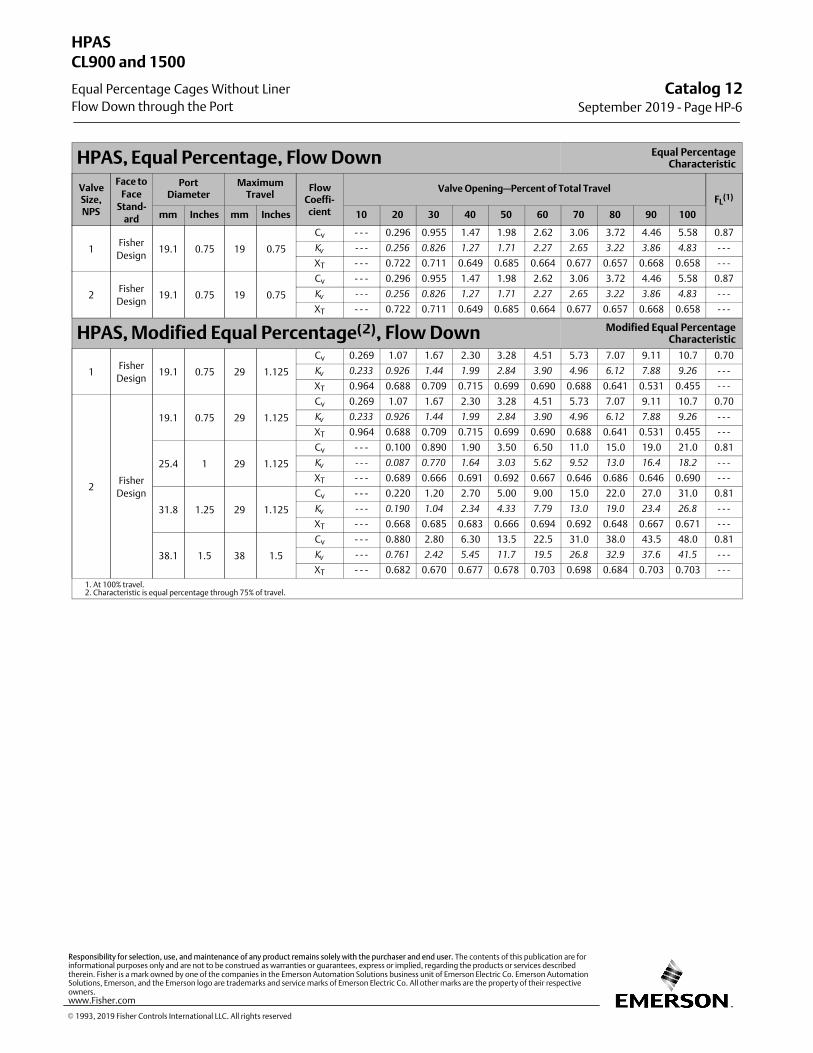
HPAS, Equal Percentage, Flow Down Equal PercentageCharacteristic
ValveSize,NPS
Face to
FaceStand-
ard
PortDiameter
MaximumTravel
FlowCoeffi‐cient
Valve Opening—Percent of Total TravelFL
(1)
mm Inches mm Inches 10 20 30 40 50 60 70 80 90 100
1Fisher
Design19.1 0.75 19 0.75
Cv ‐ ‐ ‐ 0.296 0.955 1.47 1.98 2.62 3.06 3.72 4.46 5.58 0.87
Kv
‐ ‐ ‐ 0.256 0.826 1.27 1.71 2.27 2.65 3.22 3.86 4.83 ‐ ‐ ‐
XT ‐ ‐ ‐ 0.722 0.711 0.649 0.685 0.664 0.677 0.657 0.668 0.658 ‐ ‐ ‐
2Fisher
Design19.1 0.75 19 0.75
Cv ‐ ‐ ‐ 0.296 0.955 1.47 1.98 2.62 3.06 3.72 4.46 5.58 0.87
Kv
‐ ‐ ‐ 0.256 0.826 1.27 1.71 2.27 2.65 3.22 3.86 4.83 ‐ ‐ ‐
XT ‐ ‐ ‐ 0.722 0.711 0.649 0.685 0.664 0.677 0.657 0.668 0.658 ‐ ‐ ‐
HPAS, Modified Equal Percentage(2), Flow Down Modified Equal PercentageCharacteristic
1Fisher
Design19.1 0.75 29 1.125
Cv 0.269 1.07 1.67 2.30 3.28 4.51 5.73 7.07 9.11 10.7 0.70
Kv
0.233 0.926 1.44 1.99 2.84 3.90 4.96 6.12 7.88 9.26 ‐ ‐ ‐
XT 0.964 0.688 0.709 0.715 0.699 0.690 0.688 0.641 0.531 0.455 ‐ ‐ ‐
2Fisher
Design
19.1 0.75 29 1.125
Cv 0.269 1.07 1.67 2.30 3.28 4.51 5.73 7.07 9.11 10.7 0.70
Kv
0.233 0.926 1.44 1.99 2.84 3.90 4.96 6.12 7.88 9.26 ‐ ‐ ‐
XT 0.964 0.688 0.709 0.715 0.699 0.690 0.688 0.641 0.531 0.455 ‐ ‐ ‐
25.4 1 29 1.125
Cv ‐ ‐ ‐ 0.100 0.890 1.90 3.50 6.50 11.0 15.0 19.0 21.0 0.81
Kv
‐ ‐ ‐ 0.087 0.770 1.64 3.03 5.62 9.52 13.0 16.4 18.2 ‐ ‐ ‐
XT ‐ ‐ ‐ 0.689 0.666 0.691 0.692 0.667 0.646 0.686 0.646 0.690 ‐ ‐ ‐
31.8 1.25 29 1.125
Cv ‐ ‐ ‐ 0.220 1.20 2.70 5.00 9.00 15.0 22.0 27.0 31.0 0.81
Kv
‐ ‐ ‐ 0.190 1.04 2.34 4.33 7.79 13.0 19.0 23.4 26.8 ‐ ‐ ‐
XT ‐ ‐ ‐ 0.668 0.685 0.683 0.666 0.694 0.692 0.648 0.667 0.671 ‐ ‐ ‐
38.1 1.5 38 1.5
Cv ‐ ‐ ‐ 0.880 2.80 6.30 13.5 22.5 31.0 38.0 43.5 48.0 0.81
Kv
‐ ‐ ‐ 0.761 2.42 5.45 11.7 19.5 26.8 32.9 37.6 41.5 ‐ ‐ ‐
XT ‐ ‐ ‐ 0.682 0.670 0.677 0.678 0.703 0.698 0.684 0.703 0.703 ‐ ‐ ‐
1. At 100% travel.2. Characteristic is equal percentage through 75% of travel.
Catalog 12September 2019 ‐ Page HP-6
HPAS
Equal Percentage Cages Without Liner
CL900 and 1500
Flow Down through the Port
� 1993, 2019 Fisher Controls International LLC. All rights reserved
www.Fisher.com
Responsibility for selection, use, and maintenance of any product remains solely with the purchaser and end user. The contents of this publication are forinformational purposes only and are not to be construed as warranties or guarantees, express or implied, regarding the products or services describedtherein. Fisher is a mark owned by one of the companies in the Emerson Automation Solutions business unit of Emerson Electric Co. Emerson AutomationSolutions, Emerson, and the Emerson logo are trademarks and service marks of Emerson Electric Co. All other marks are the property of their respectiveowners.
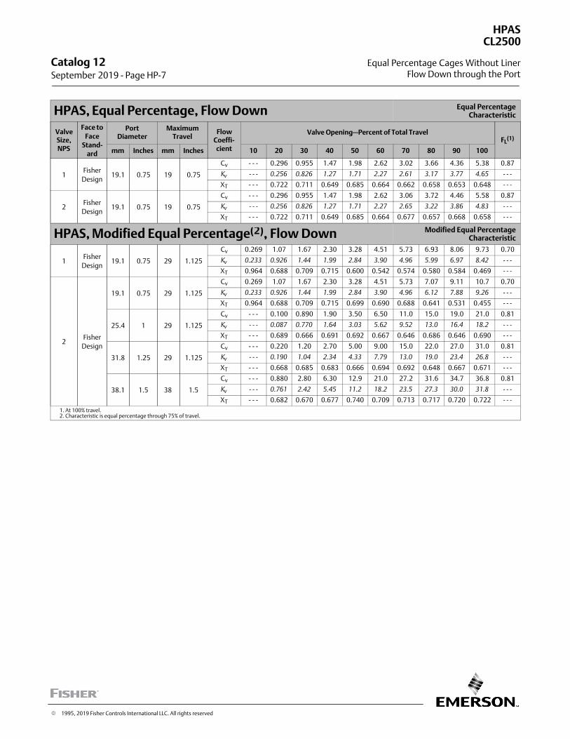
HPAS, Equal Percentage, Flow Down Equal PercentageCharacteristic
ValveSize,NPS
Face to
FaceStand-
ard
PortDiameter
MaximumTravel
FlowCoeffi‐cient
Valve Opening—Percent of Total TravelFL
(1)
mm Inches mm Inches 10 20 30 40 50 60 70 80 90 100
1Fisher
Design19.1 0.75 19 0.75
Cv ‐ ‐ ‐ 0.296 0.955 1.47 1.98 2.62 3.02 3.66 4.36 5.38 0.87
Kv
‐ ‐ ‐ 0.256 0.826 1.27 1.71 2.27 2.61 3.17 3.77 4.65 ‐ ‐ ‐
XT ‐ ‐ ‐ 0.722 0.711 0.649 0.685 0.664 0.662 0.658 0.653 0.648 ‐ ‐ ‐
2Fisher
Design19.1 0.75 19 0.75
Cv ‐ ‐ ‐ 0.296 0.955 1.47 1.98 2.62 3.06 3.72 4.46 5.58 0.87
Kv
‐ ‐ ‐ 0.256 0.826 1.27 1.71 2.27 2.65 3.22 3.86 4.83 ‐ ‐ ‐
XT ‐ ‐ ‐ 0.722 0.711 0.649 0.685 0.664 0.677 0.657 0.668 0.658 ‐ ‐ ‐
HPAS, Modified Equal Percentage(2), Flow Down Modified Equal PercentageCharacteristic
1Fisher
Design19.1 0.75 29 1.125
Cv 0.269 1.07 1.67 2.30 3.28 4.51 5.73 6.93 8.06 9.73 0.70
Kv
0.233 0.926 1.44 1.99 2.84 3.90 4.96 5.99 6.97 8.42 ‐ ‐ ‐
XT 0.964 0.688 0.709 0.715 0.600 0.542 0.574 0.580 0.584 0.469 ‐ ‐ ‐
2Fisher
Design
19.1 0.75 29 1.125
Cv 0.269 1.07 1.67 2.30 3.28 4.51 5.73 7.07 9.11 10.7 0.70
Kv
0.233 0.926 1.44 1.99 2.84 3.90 4.96 6.12 7.88 9.26 ‐ ‐ ‐
XT 0.964 0.688 0.709 0.715 0.699 0.690 0.688 0.641 0.531 0.455 ‐ ‐ ‐
25.4 1 29 1.125
Cv ‐ ‐ ‐ 0.100 0.890 1.90 3.50 6.50 11.0 15.0 19.0 21.0 0.81
Kv
‐ ‐ ‐ 0.087 0.770 1.64 3.03 5.62 9.52 13.0 16.4 18.2 ‐ ‐ ‐
XT ‐ ‐ ‐ 0.689 0.666 0.691 0.692 0.667 0.646 0.686 0.646 0.690 ‐ ‐ ‐
31.8 1.25 29 1.125
Cv ‐ ‐ ‐ 0.220 1.20 2.70 5.00 9.00 15.0 22.0 27.0 31.0 0.81
Kv
‐ ‐ ‐ 0.190 1.04 2.34 4.33 7.79 13.0 19.0 23.4 26.8 ‐ ‐ ‐
XT ‐ ‐ ‐ 0.668 0.685 0.683 0.666 0.694 0.692 0.648 0.667 0.671 ‐ ‐ ‐
38.1 1.5 38 1.5
Cv ‐ ‐ ‐ 0.880 2.80 6.30 12.9 21.0 27.2 31.6 34.7 36.8 0.81
Kv
‐ ‐ ‐ 0.761 2.42 5.45 11.2 18.2 23.5 27.3 30.0 31.8 ‐ ‐ ‐
XT ‐ ‐ ‐ 0.682 0.670 0.677 0.740 0.709 0.713 0.717 0.720 0.722 ‐ ‐ ‐
1. At 100% travel.2. Characteristic is equal percentage through 75% of travel.
Catalog 12 September 2019 ‐ Page HP-7
HPAS
Equal Percentage Cages Without Liner
CL2500
Flow Down through the Port
� 1995, 2019 Fisher Controls International LLC. All rights reserved

HPAS, Equal Percentage, Flow Down Equal PercentageCharacteristic
ValveSize,NPS
Face to
FaceStand-
ard
PortDiameter
MaximumTravel
FlowCoeffi‐cient
Valve Opening—Percent of Total TravelFL
(1)
mm Inches mm Inches 10 20 30 40 50 60 70 80 90 100
1Fisher
Design19.1 0.75 19 0.75
Cv 0.200 0.296 0.955 1.47 1.98 2.62 3.02 3.66 4.36 5.37 0.87
Kv
0.173 0.256 0.826 1.27 1.71 2.27 2.61 3.17 3.77 4.65 ‐ ‐ ‐
XT 0.563 0.714 0.702 0.642 0.677 0.657 0.658 0.650 0.644 0.641 ‐ ‐ ‐
2Fisher
Design19.1 0.75 19 0.75
Cv 0.200 0.296 0.955 1.47 1.98 2.62 3.06 3.72 4.46 5.58 0.87
Kv
0.173 0.256 0.826 1.27 1.71 2.27 2.65 3.22 3.86 4.83 ‐ ‐ ‐
XT 0.563 0.714 0.702 0.642 0.677 0.657 0.669 0.649 0.660 0.651 ‐ ‐ ‐
HPAS, Modified Equal Percentage(2), Flow Down Modified Equal PercentageCharacteristic
1Fisher
Design19.1 0.75 29 1.125
Cv 0.269 1.07 1.67 2.30 3.28 4.51 5.73 6.93 8.06 9.73 0.70
Kv
0.233 0.926 1.44 1.99 2.84 3.90 4.96 5.99 6.97 8.42 ‐ ‐ ‐
XT 0.952 0.680 0.700 0.706 0.593 0.535 0.570 0.574 0.577 0.464 ‐ ‐ ‐
2Fisher
Design
19.1 0.75 29 1.125
Cv 0.269 1.07 1.67 2.30 3.28 4.51 5.73 7.07 9.11 10.7 0.70
Kv
0.233 0.926 1.44 1.99 2.84 3.90 4.96 6.12 7.88 9.26 ‐ ‐ ‐
XT 0.952 0.680 0.700 0.706 0.690 0.682 0.680 0.633 0.525 0.450 ‐ ‐ ‐
25.4 1 29 1.125
Cv ‐ ‐ ‐ 0.100 0.890 1.90 3.50 6.50 11.0 15.0 19.0 20.0 0.81
Kv
‐ ‐ ‐ 0.087 0.770 1.64 3.03 5.62 9.52 13.0 16.4 17.3 ‐ ‐ ‐
XT ‐ ‐ ‐ 0.681 0.658 0.682 0.684 0.659 0.639 0.678 0.638 0.682 ‐ ‐ ‐
31.8 1.25 29 1.125
Cv ‐ ‐ ‐ 0.220 1.20 2.70 5.00 9.00 15.0 22.0 25.7 27.9 0.81
Kv
‐ ‐ ‐ 0.190 1.04 2.34 4.33 7.79 13.0 19.0 22.2 24.1 ‐ ‐ ‐
XT ‐ ‐ ‐ 0.660 0.676 0.675 0.658 0.686 0.684 0.640 0.659 0.663 ‐ ‐ ‐
38.1 1.5 38 1.5
Cv ‐ ‐ ‐ 0.880 2.80 6.30 13.2 21.2 27.6 33.1 37.4 40.8 0.81
Kv
‐ ‐ ‐ 0.761 2.42 5.45 11.4 18.3 23.9 28.6 32.4 35.3 ‐ ‐ ‐
XT ‐ ‐ ‐ 0.674 0.662 0.669 0.670 0.695 0.690 0.691 0.689 0.694 ‐ ‐ ‐
1. At 100% travel.2. Characteristic is equal percentage through 75% of travel.
Catalog 12September 2019 ‐ Page HP-8
HPAS
Equal Percentage Cages With Liner
CL900 and 1500
Flow Down through the Port
� 1995, 2019 Fisher Controls International LLC. All rights reserved
www.Fisher.com
Responsibility for selection, use, and maintenance of any product remains solely with the purchaser and end user. The contents of this publication are forinformational purposes only and are not to be construed as warranties or guarantees, express or implied, regarding the products or services describedtherein. Fisher is a mark owned by one of the companies in the Emerson Automation Solutions business unit of Emerson Electric Co. Emerson AutomationSolutions, Emerson, and the Emerson logo are trademarks and service marks of Emerson Electric Co. All other marks are the property of their respectiveowners.
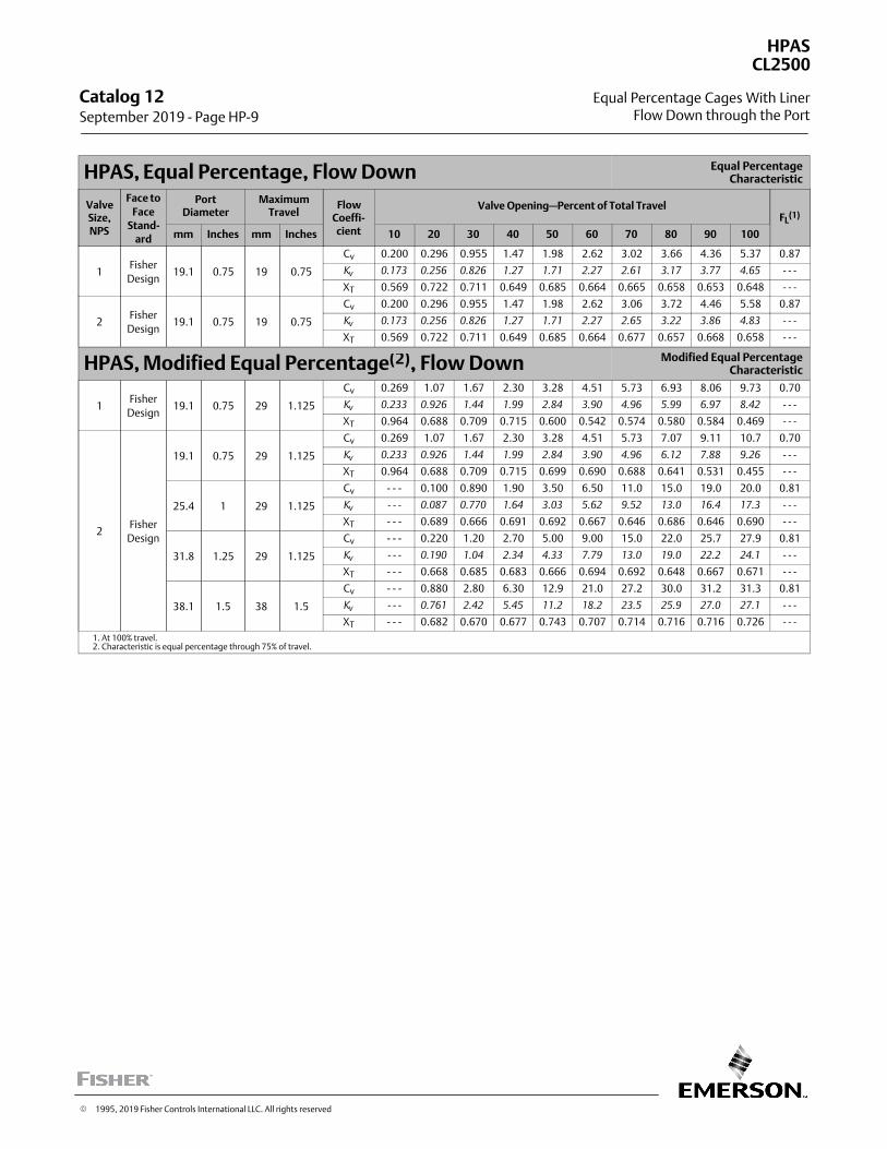
HPAS, Equal Percentage, Flow Down Equal PercentageCharacteristic
ValveSize,NPS
Face to
FaceStand-
ard
PortDiameter
MaximumTravel
FlowCoeffi‐cient
Valve Opening—Percent of Total TravelFL
(1)
mm Inches mm Inches 10 20 30 40 50 60 70 80 90 100
1Fisher
Design19.1 0.75 19 0.75
Cv 0.200 0.296 0.955 1.47 1.98 2.62 3.02 3.66 4.36 5.37 0.87
Kv
0.173 0.256 0.826 1.27 1.71 2.27 2.61 3.17 3.77 4.65 ‐ ‐ ‐
XT 0.569 0.722 0.711 0.649 0.685 0.664 0.665 0.658 0.653 0.648 ‐ ‐ ‐
2Fisher
Design19.1 0.75 19 0.75
Cv 0.200 0.296 0.955 1.47 1.98 2.62 3.06 3.72 4.46 5.58 0.87
Kv
0.173 0.256 0.826 1.27 1.71 2.27 2.65 3.22 3.86 4.83 ‐ ‐ ‐
XT 0.569 0.722 0.711 0.649 0.685 0.664 0.677 0.657 0.668 0.658 ‐ ‐ ‐
HPAS, Modified Equal Percentage(2), Flow Down Modified Equal PercentageCharacteristic
1Fisher
Design19.1 0.75 29 1.125
Cv 0.269 1.07 1.67 2.30 3.28 4.51 5.73 6.93 8.06 9.73 0.70
Kv
0.233 0.926 1.44 1.99 2.84 3.90 4.96 5.99 6.97 8.42 ‐ ‐ ‐
XT 0.964 0.688 0.709 0.715 0.600 0.542 0.574 0.580 0.584 0.469 ‐ ‐ ‐
2Fisher
Design
19.1 0.75 29 1.125
Cv 0.269 1.07 1.67 2.30 3.28 4.51 5.73 7.07 9.11 10.7 0.70
Kv
0.233 0.926 1.44 1.99 2.84 3.90 4.96 6.12 7.88 9.26 ‐ ‐ ‐
XT 0.964 0.688 0.709 0.715 0.699 0.690 0.688 0.641 0.531 0.455 ‐ ‐ ‐
25.4 1 29 1.125
Cv ‐ ‐ ‐ 0.100 0.890 1.90 3.50 6.50 11.0 15.0 19.0 20.0 0.81
Kv
‐ ‐ ‐ 0.087 0.770 1.64 3.03 5.62 9.52 13.0 16.4 17.3 ‐ ‐ ‐
XT ‐ ‐ ‐ 0.689 0.666 0.691 0.692 0.667 0.646 0.686 0.646 0.690 ‐ ‐ ‐
31.8 1.25 29 1.125
Cv ‐ ‐ ‐ 0.220 1.20 2.70 5.00 9.00 15.0 22.0 25.7 27.9 0.81
Kv
‐ ‐ ‐ 0.190 1.04 2.34 4.33 7.79 13.0 19.0 22.2 24.1 ‐ ‐ ‐
XT ‐ ‐ ‐ 0.668 0.685 0.683 0.666 0.694 0.692 0.648 0.667 0.671 ‐ ‐ ‐
38.1 1.5 38 1.5
Cv ‐ ‐ ‐ 0.880 2.80 6.30 12.9 21.0 27.2 30.0 31.2 31.3 0.81
Kv
‐ ‐ ‐ 0.761 2.42 5.45 11.2 18.2 23.5 25.9 27.0 27.1 ‐ ‐ ‐
XT ‐ ‐ ‐ 0.682 0.670 0.677 0.743 0.707 0.714 0.716 0.716 0.726 ‐ ‐ ‐
1. At 100% travel.2. Characteristic is equal percentage through 75% of travel.
Catalog 12 September 2019 ‐ Page HP-9
HPAS
Equal Percentage Cages With Liner
CL2500
Flow Down through the Port
� 1995, 2019 Fisher Controls International LLC. All rights reserved
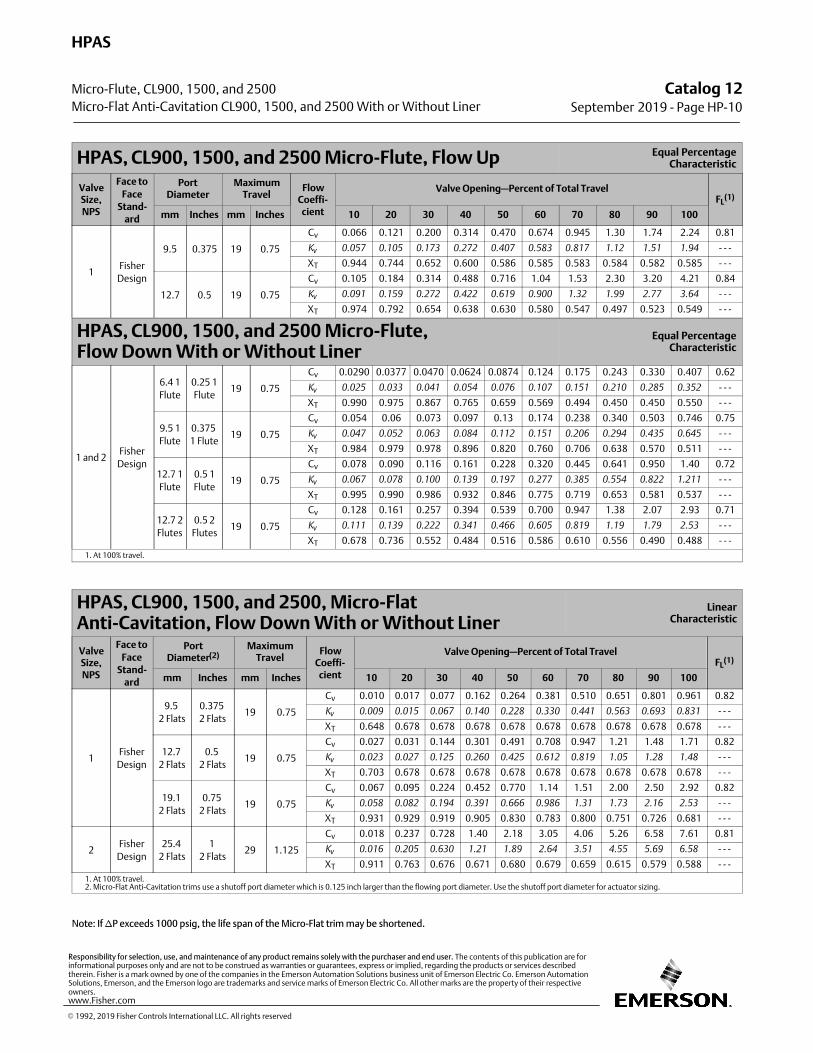
HPAS, CL900, 1500, and 2500 Micro‐Flute, Flow Up Equal PercentageCharacteristic
ValveSize,NPS
Face to
FaceStand-
ard
PortDiameter
MaximumTravel
FlowCoeffi‐cient
Valve Opening—Percent of Total TravelFL
(1)
mm Inches mm Inches 10 20 30 40 50 60 70 80 90 100
1Fisher
Design
9.5 0.375 19 0.75
Cv 0.066 0.121 0.200 0.314 0.470 0.674 0.945 1.30 1.74 2.24 0.81
Kv
0.057 0.105 0.173 0.272 0.407 0.583 0.817 1.12 1.51 1.94 ‐ ‐ ‐
XT 0.944 0.744 0.652 0.600 0.586 0.585 0.583 0.584 0.582 0.585 ‐ ‐ ‐
12.7 0.5 19 0.75
Cv 0.105 0.184 0.314 0.488 0.716 1.04 1.53 2.30 3.20 4.21 0.84
Kv
0.091 0.159 0.272 0.422 0.619 0.900 1.32 1.99 2.77 3.64 ‐ ‐ ‐
XT 0.974 0.792 0.654 0.638 0.630 0.580 0.547 0.497 0.523 0.549 ‐ ‐ ‐
HPAS, CL900, 1500, and 2500 Micro‐Flute, Flow Down With or Without Liner
Equal PercentageCharacteristic
1 and 2Fisher
Design
6.4 1
Flute
0.25 1
Flute19 0.75
Cv 0.0290 0.0377 0.0470 0.0624 0.0874 0.124 0.175 0.243 0.330 0.407 0.62
Kv
0.025 0.033 0.041 0.054 0.076 0.107 0.151 0.210 0.285 0.352 ‐ ‐ ‐
XT 0.990 0.975 0.867 0.765 0.659 0.569 0.494 0.450 0.450 0.550 ‐ ‐ ‐
9.5 1
Flute
0.375
1 Flute19 0.75
Cv 0.054 0.06 0.073 0.097 0.13 0.174 0.238 0.340 0.503 0.746 0.75
Kv
0.047 0.052 0.063 0.084 0.112 0.151 0.206 0.294 0.435 0.645 ‐ ‐ ‐
XT 0.984 0.979 0.978 0.896 0.820 0.760 0.706 0.638 0.570 0.511 ‐ ‐ ‐
12.7 1
Flute
0.5 1
Flute19 0.75
Cv 0.078 0.090 0.116 0.161 0.228 0.320 0.445 0.641 0.950 1.40 0.72
Kv
0.067 0.078 0.100 0.139 0.197 0.277 0.385 0.554 0.822 1.211 ‐ ‐ ‐
XT 0.995 0.990 0.986 0.932 0.846 0.775 0.719 0.653 0.581 0.537 ‐ ‐ ‐
12.7 2
Flutes
0.5 2
Flutes19 0.75
Cv 0.128 0.161 0.257 0.394 0.539 0.700 0.947 1.38 2.07 2.93 0.71
Kv
0.111 0.139 0.222 0.341 0.466 0.605 0.819 1.19 1.79 2.53 ‐ ‐ ‐
XT 0.678 0.736 0.552 0.484 0.516 0.586 0.610 0.556 0.490 0.488 ‐ ‐ ‐
1. At 100% travel.
HPAS, CL900, 1500, and 2500, Micro‐FlatAnti‐Cavitation, Flow Down With or Without Liner
LinearCharacteristic
ValveSize,NPS
Face to
FaceStand-
ard
PortDiameter(2)
MaximumTravel
FlowCoeffi‐cient
Valve Opening—Percent of Total TravelFL
(1)
mm Inches mm Inches 10 20 30 40 50 60 70 80 90 100
1Fisher
Design
9.5
2 Flats
0.375
2 Flats19 0.75
Cv 0.010 0.017 0.077 0.162 0.264 0.381 0.510 0.651 0.801 0.961 0.82
Kv
0.009 0.015 0.067 0.140 0.228 0.330 0.441 0.563 0.693 0.831 ‐ ‐ ‐
XT 0.648 0.678 0.678 0.678 0.678 0.678 0.678 0.678 0.678 0.678 ‐ ‐ ‐
12.7
2 Flats
0.5
2 Flats19 0.75
Cv 0.027 0.031 0.144 0.301 0.491 0.708 0.947 1.21 1.48 1.71 0.82
Kv
0.023 0.027 0.125 0.260 0.425 0.612 0.819 1.05 1.28 1.48 ‐ ‐ ‐
XT 0.703 0.678 0.678 0.678 0.678 0.678 0.678 0.678 0.678 0.678 ‐ ‐ ‐
19.1
2 Flats
0.75
2 Flats19 0.75
Cv 0.067 0.095 0.224 0.452 0.770 1.14 1.51 2.00 2.50 2.92 0.82
Kv
0.058 0.082 0.194 0.391 0.666 0.986 1.31 1.73 2.16 2.53 ‐ ‐ ‐
XT 0.931 0.929 0.919 0.905 0.830 0.783 0.800 0.751 0.726 0.681 ‐ ‐ ‐
2Fisher
Design
25.4
2 Flats
1
2 Flats29 1.125
Cv 0.018 0.237 0.728 1.40 2.18 3.05 4.06 5.26 6.58 7.61 0.81
Kv
0.016 0.205 0.630 1.21 1.89 2.64 3.51 4.55 5.69 6.58 ‐ ‐ ‐
XT 0.911 0.763 0.676 0.671 0.680 0.679 0.659 0.615 0.579 0.588 ‐ ‐ ‐
1. At 100% travel.2. Micro‐Flat Anti‐Cavitation trims use a shutoff port diameter which is 0.125 inch larger than the flowing port diameter. Use the shutoff port diameter for actuator sizing.
Note: If �P exceeds 1000 psig, the life span of the Micro‐Flat trim may be shortened.
Catalog 12September 2019 ‐ Page HP-10
HPAS
Micro-Flute, CL900, 1500, and 2500
Micro-Flat Anti-Cavitation CL900, 1500, and 2500 With or Without Liner
� 1992, 2019 Fisher Controls International LLC. All rights reserved
www.Fisher.com
Responsibility for selection, use, and maintenance of any product remains solely with the purchaser and end user. The contents of this publication are forinformational purposes only and are not to be construed as warranties or guarantees, express or implied, regarding the products or services describedtherein. Fisher is a mark owned by one of the companies in the Emerson Automation Solutions business unit of Emerson Electric Co. Emerson AutomationSolutions, Emerson, and the Emerson logo are trademarks and service marks of Emerson Electric Co. All other marks are the property of their respectiveowners.
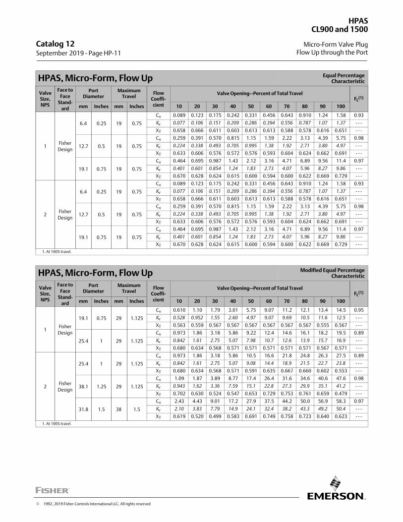
HPAS, Micro‐Form, Flow Up Equal PercentageCharacteristic
ValveSize,NPS
Face to
FaceStand-
ard
PortDiameter
MaximumTravel
FlowCoeffi‐cient
Valve Opening—Percent of Total TravelFL
(1)
mm Inches mm Inches 10 20 30 40 50 60 70 80 90 100
1Fisher
Design
6.4 0.25 19 0.75
Cv 0.089 0.123 0.175 0.242 0.331 0.456 0.643 0.910 1.24 1.58 0.93
Kv
0.077 0.106 0.151 0.209 0.286 0.394 0.556 0.787 1.07 1.37 ‐ ‐ ‐
XT 0.658 0.666 0.611 0.603 0.613 0.613 0.588 0.578 0.616 0.651 ‐ ‐ ‐
12.7 0.5 19 0.75
Cv 0.259 0.391 0.570 0.815 1.15 1.59 2.22 3.13 4.39 5.75 0.98
Kv
0.224 0.338 0.493 0.705 0.995 1.38 1.92 2.71 3.80 4.97 ‐ ‐ ‐
XT 0.633 0.606 0.576 0.572 0.576 0.593 0.604 0.624 0.662 0.691 ‐ ‐ ‐
19.1 0.75 19 0.75
Cv 0.464 0.695 0.987 1.43 2.12 3.16 4.71 6.89 9.56 11.4 0.97
Kv
0.401 0.601 0.854 1.24 1.83 2.73 4.07 5.96 8.27 9.86 ‐ ‐ ‐
XT 0.670 0.628 0.624 0.615 0.600 0.594 0.600 0.622 0.669 0.729 ‐ ‐ ‐
2Fisher
Design
6.4 0.25 19 0.75
Cv 0.089 0.123 0.175 0.242 0.331 0.456 0.643 0.910 1.24 1.58 0.93
Kv
0.077 0.106 0.151 0.209 0.286 0.394 0.556 0.787 1.07 1.37 ‐ ‐ ‐
XT 0.658 0.666 0.611 0.603 0.613 0.613 0.588 0.578 0.616 0.651 ‐ ‐ ‐
12.7 0.5 19 0.75
Cv 0.259 0.391 0.570 0.815 1.15 1.59 2.22 3.13 4.39 5.75 0.98
Kv
0.224 0.338 0.493 0.705 0.995 1.38 1.92 2.71 3.80 4.97 ‐ ‐ ‐
XT 0.633 0.606 0.576 0.572 0.576 0.593 0.604 0.624 0.662 0.691 ‐ ‐ ‐
19.1 0.75 19 0.75
Cv 0.464 0.695 0.987 1.43 2.12 3.16 4.71 6.89 9.56 11.4 0.97
Kv
0.401 0.601 0.854 1.24 1.83 2.73 4.07 5.96 8.27 9.86 ‐ ‐ ‐
XT 0.670 0.628 0.624 0.615 0.600 0.594 0.600 0.622 0.669 0.729 ‐ ‐ ‐
1. At 100% travel.
HPAS, Micro‐Form, Flow Up Modified Equal PercentageCharacteristic
ValveSize,NPS
Face to
FaceStand-
ard
PortDiameter
MaximumTravel
FlowCoeffi‐cient
Valve Opening—Percent of Total TravelFL
(1)
mm Inches mm Inches 10 20 30 40 50 60 70 80 90 100
1Fisher
Design
19.1 0.75 29 1.125
Cv 0.610 1.10 1.79 3.01 5.75 9.07 11.2 12.1 13.4 14.5 0.95
Kv
0.528 0.952 1.55 2.60 4.97 9.07 9.69 10.5 11.6 12.5 ‐ ‐ ‐
XT 0.563 0.559 0.567 0.567 0.567 0.567 0.567 0.567 0.555 0.567 ‐ ‐ ‐
25.4 1 29 1.125
Cv 0.973 1.86 3.18 5.86 9.22 12.4 14.6 16.1 18.2 19.5 0.89
Kv
0.842 1.61 2.75 5.07 7.98 10.7 12.6 13.9 15.7 16.9 ‐ ‐ ‐
XT 0.680 0.634 0.568 0.571 0.571 0.571 0.571 0.571 0.567 0.571 ‐ ‐ ‐
2Fisher
Design
25.4 1 29 1.125
Cv 0.973 1.86 3.18 5.86 10.5 16.6 21.8 24.8 26.3 27.5 0.89
Kv
0.842 1.61 2.75 5.07 9.08 14.4 18.9 21.5 22.7 23.8 ‐ ‐ ‐
XT 0.680 0.634 0.568 0.571 0.591 0.635 0.667 0.660 0.602 0.553 ‐ ‐ ‐
38.1 1.25 29 1.125
Cv 1.09 1.87 3.89 8.77 17.4 26.4 31.6 34.6 40.6 47.6 0.98
Kv
0.943 1.62 3.36 7.59 15.1 22.8 27.3 29.9 35.1 41.2 ‐ ‐ ‐
XT 0.702 0.630 0.524 0.547 0.653 0.729 0.753 0.761 0.659 0.479 ‐ ‐ ‐
31.8 1.5 38 1.5
Cv 2.43 4.43 9.01 17.2 27.9 37.5 44.2 50.0 56.9 58.3 0.97
Kv
2.10 3.83 7.79 14.9 24.1 32.4 38.2 43.3 49.2 50.4 ‐ ‐ ‐
XT 0.619 0.520 0.499 0.583 0.691 0.749 0.758 0.723 0.640 0.623 ‐ ‐ ‐
1. At 100% travel.
Catalog 12 September 2019 ‐ Page HP-11
HPAS
Micro-Form Valve Plug
CL900 and 1500
Flow Up through the Port
� 1992, 2019 Fisher Controls International LLC. All rights reserved
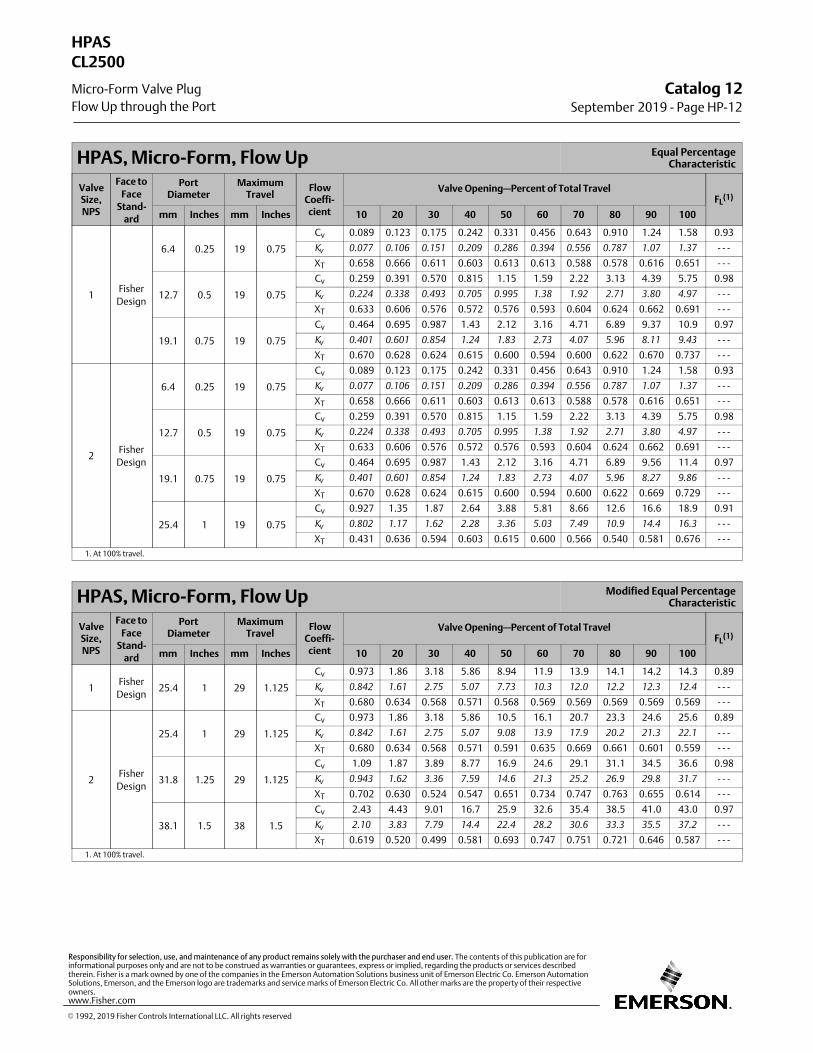
HPAS, Micro‐Form, Flow Up Equal PercentageCharacteristic
ValveSize,NPS
Face to
FaceStand-
ard
PortDiameter
MaximumTravel
FlowCoeffi‐cient
Valve Opening—Percent of Total TravelFL
(1)
mm Inches mm Inches 10 20 30 40 50 60 70 80 90 100
1Fisher
Design
6.4 0.25 19 0.75
Cv 0.089 0.123 0.175 0.242 0.331 0.456 0.643 0.910 1.24 1.58 0.93
Kv
0.077 0.106 0.151 0.209 0.286 0.394 0.556 0.787 1.07 1.37 ‐ ‐ ‐
XT 0.658 0.666 0.611 0.603 0.613 0.613 0.588 0.578 0.616 0.651 ‐ ‐ ‐
12.7 0.5 19 0.75
Cv 0.259 0.391 0.570 0.815 1.15 1.59 2.22 3.13 4.39 5.75 0.98
Kv
0.224 0.338 0.493 0.705 0.995 1.38 1.92 2.71 3.80 4.97 ‐ ‐ ‐
XT 0.633 0.606 0.576 0.572 0.576 0.593 0.604 0.624 0.662 0.691 ‐ ‐ ‐
19.1 0.75 19 0.75
Cv 0.464 0.695 0.987 1.43 2.12 3.16 4.71 6.89 9.37 10.9 0.97
Kv
0.401 0.601 0.854 1.24 1.83 2.73 4.07 5.96 8.11 9.43 ‐ ‐ ‐
XT 0.670 0.628 0.624 0.615 0.600 0.594 0.600 0.622 0.670 0.737 ‐ ‐ ‐
2Fisher
Design
6.4 0.25 19 0.75
Cv 0.089 0.123 0.175 0.242 0.331 0.456 0.643 0.910 1.24 1.58 0.93
Kv
0.077 0.106 0.151 0.209 0.286 0.394 0.556 0.787 1.07 1.37 ‐ ‐ ‐
XT 0.658 0.666 0.611 0.603 0.613 0.613 0.588 0.578 0.616 0.651 ‐ ‐ ‐
12.7 0.5 19 0.75
Cv 0.259 0.391 0.570 0.815 1.15 1.59 2.22 3.13 4.39 5.75 0.98
Kv
0.224 0.338 0.493 0.705 0.995 1.38 1.92 2.71 3.80 4.97 ‐ ‐ ‐
XT 0.633 0.606 0.576 0.572 0.576 0.593 0.604 0.624 0.662 0.691 ‐ ‐ ‐
19.1 0.75 19 0.75
Cv 0.464 0.695 0.987 1.43 2.12 3.16 4.71 6.89 9.56 11.4 0.97
Kv
0.401 0.601 0.854 1.24 1.83 2.73 4.07 5.96 8.27 9.86 ‐ ‐ ‐
XT 0.670 0.628 0.624 0.615 0.600 0.594 0.600 0.622 0.669 0.729 ‐ ‐ ‐
25.4 1 19 0.75
Cv 0.927 1.35 1.87 2.64 3.88 5.81 8.66 12.6 16.6 18.9 0.91
Kv
0.802 1.17 1.62 2.28 3.36 5.03 7.49 10.9 14.4 16.3 ‐ ‐ ‐
XT 0.431 0.636 0.594 0.603 0.615 0.600 0.566 0.540 0.581 0.676 ‐ ‐ ‐
1. At 100% travel.
HPAS, Micro‐Form, Flow Up Modified Equal PercentageCharacteristic
ValveSize,NPS
Face to
FaceStand-
ard
PortDiameter
MaximumTravel
FlowCoeffi‐cient
Valve Opening—Percent of Total TravelFL
(1)
mm Inches mm Inches 10 20 30 40 50 60 70 80 90 100
1Fisher
Design25.4 1 29 1.125
Cv 0.973 1.86 3.18 5.86 8.94 11.9 13.9 14.1 14.2 14.3 0.89
Kv
0.842 1.61 2.75 5.07 7.73 10.3 12.0 12.2 12.3 12.4 ‐ ‐ ‐
XT 0.680 0.634 0.568 0.571 0.568 0.569 0.569 0.569 0.569 0.569 ‐ ‐ ‐
2Fisher
Design
25.4 1 29 1.125
Cv 0.973 1.86 3.18 5.86 10.5 16.1 20.7 23.3 24.6 25.6 0.89
Kv
0.842 1.61 2.75 5.07 9.08 13.9 17.9 20.2 21.3 22.1 ‐ ‐ ‐
XT 0.680 0.634 0.568 0.571 0.591 0.635 0.669 0.661 0.601 0.559 ‐ ‐ ‐
31.8 1.25 29 1.125
Cv 1.09 1.87 3.89 8.77 16.9 24.6 29.1 31.1 34.5 36.6 0.98
Kv
0.943 1.62 3.36 7.59 14.6 21.3 25.2 26.9 29.8 31.7 ‐ ‐ ‐
XT 0.702 0.630 0.524 0.547 0.651 0.734 0.747 0.763 0.655 0.614 ‐ ‐ ‐
38.1 1.5 38 1.5
Cv 2.43 4.43 9.01 16.7 25.9 32.6 35.4 38.5 41.0 43.0 0.97
Kv
2.10 3.83 7.79 14.4 22.4 28.2 30.6 33.3 35.5 37.2 ‐ ‐ ‐
XT 0.619 0.520 0.499 0.581 0.693 0.747 0.751 0.721 0.646 0.587 ‐ ‐ ‐
1. At 100% travel.
Catalog 12September 2019 ‐ Page HP-12
HPAS
Micro-Form Valve Plug
CL2500
Flow Up through the Port
� 1992, 2019 Fisher Controls International LLC. All rights reserved
www.Fisher.com
Responsibility for selection, use, and maintenance of any product remains solely with the purchaser and end user. The contents of this publication are forinformational purposes only and are not to be construed as warranties or guarantees, express or implied, regarding the products or services describedtherein. Fisher is a mark owned by one of the companies in the Emerson Automation Solutions business unit of Emerson Electric Co. Emerson AutomationSolutions, Emerson, and the Emerson logo are trademarks and service marks of Emerson Electric Co. All other marks are the property of their respectiveowners.
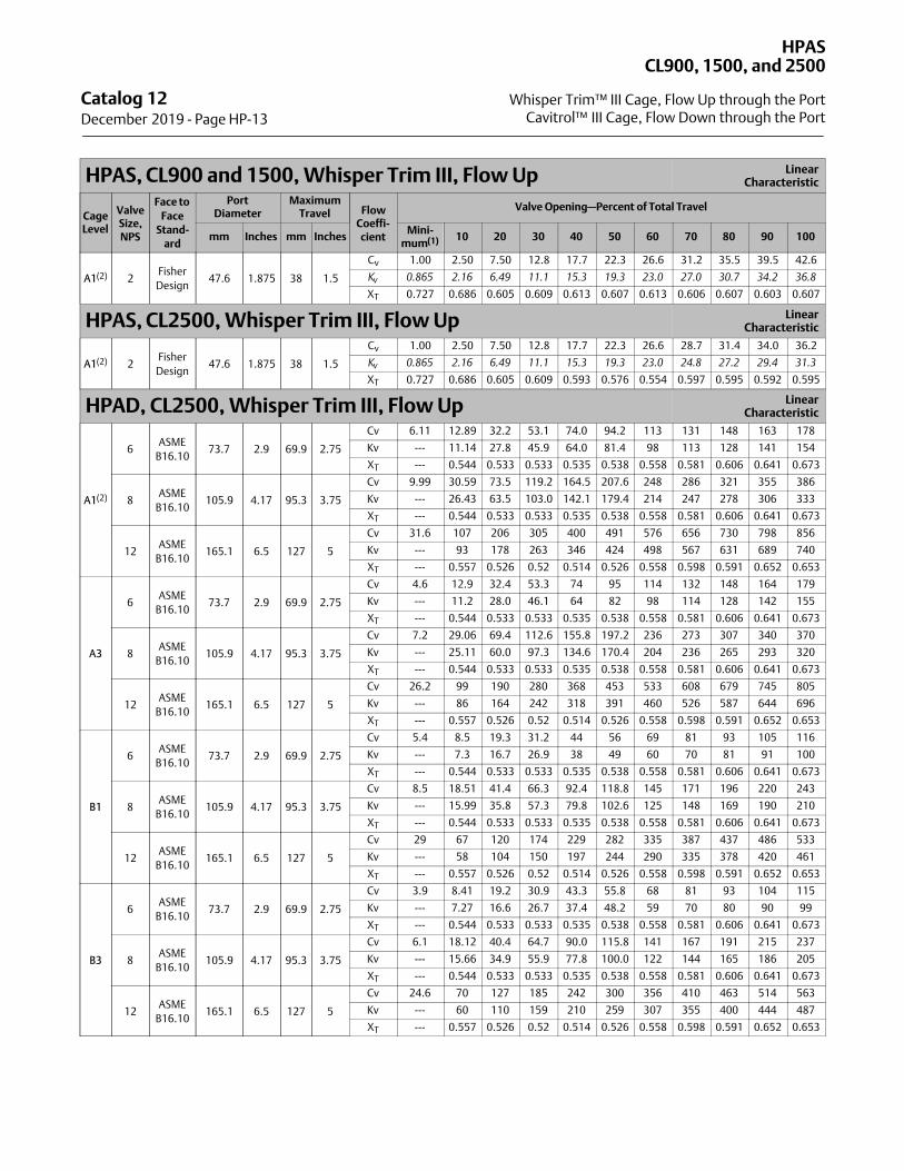
HPAS, CL900 and 1500, Whisper Trim III, Flow Up LinearCharacteristic
CageLevel
ValveSize,NPS
Face to
FaceStand-
ard
PortDiameter
MaximumTravel Flow
Coeffi‐cient
Valve Opening—Percent of Total Travel
mm Inches mm InchesMini‐
mum(1) 10 20 30 40 50 60 70 80 90 100
A1(2) 2Fisher
Design47.6 1.875 38 1.5
Cv 1.00 2.50 7.50 12.8 17.7 22.3 26.6 31.2 35.5 39.5 42.6
Kv
0.865 2.16 6.49 11.1 15.3 19.3 23.0 27.0 30.7 34.2 36.8
XT 0.727 0.686 0.605 0.609 0.613 0.607 0.613 0.606 0.607 0.603 0.607
HPAS, CL2500, Whisper Trim III, Flow Up LinearCharacteristic
A1(2) 2Fisher
Design47.6 1.875 38 1.5
Cv 1.00 2.50 7.50 12.8 17.7 22.3 26.6 28.7 31.4 34.0 36.2
Kv
0.865 2.16 6.49 11.1 15.3 19.3 23.0 24.8 27.2 29.4 31.3
XT 0.727 0.686 0.605 0.609 0.593 0.576 0.554 0.597 0.595 0.592 0.595
HPAD, CL2500, Whisper Trim III, Flow Up LinearCharacteristic
A1(2)
6ASME
B16.1073.7 2.9 69.9 2.75
Cv 6.11 12.89 32.2 53.1 74.0 94.2 113 131 148 163 178
Kv --- 11.14 27.8 45.9 64.0 81.4 98 113 128 141 154
XT --- 0.544 0.533 0.533 0.535 0.538 0.558 0.581 0.606 0.641 0.673
8ASME
B16.10105.9 4.17 95.3 3.75
Cv 9.99 30.59 73.5 119.2 164.5 207.6 248 286 321 355 386
Kv --- 26.43 63.5 103.0 142.1 179.4 214 247 278 306 333
XT --- 0.544 0.533 0.533 0.535 0.538 0.558 0.581 0.606 0.641 0.673
12ASME
B16.10165.1 6.5 127 5
Cv 31.6 107 206 305 400 491 576 656 730 798 856
Kv --- 93 178 263 346 424 498 567 631 689 740
XT --- 0.557 0.526 0.52 0.514 0.526 0.558 0.598 0.591 0.652 0.653
A3
6ASME
B16.1073.7 2.9 69.9 2.75
Cv 4.6 12.9 32.4 53.3 74 95 114 132 148 164 179
Kv --- 11.2 28.0 46.1 64 82 98 114 128 142 155
XT --- 0.544 0.533 0.533 0.535 0.538 0.558 0.581 0.606 0.641 0.673
8ASME
B16.10105.9 4.17 95.3 3.75
Cv 7.2 29.06 69.4 112.6 155.8 197.2 236 273 307 340 370
Kv --- 25.11 60.0 97.3 134.6 170.4 204 236 265 293 320
XT --- 0.544 0.533 0.533 0.535 0.538 0.558 0.581 0.606 0.641 0.673
12ASME
B16.10165.1 6.5 127 5
Cv 26.2 99 190 280 368 453 533 608 679 745 805
Kv --- 86 164 242 318 391 460 526 587 644 696
XT --- 0.557 0.526 0.52 0.514 0.526 0.558 0.598 0.591 0.652 0.653
B1
6ASME
B16.1073.7 2.9 69.9 2.75
Cv 5.4 8.5 19.3 31.2 44 56 69 81 93 105 116
Kv --- 7.3 16.7 26.9 38 49 60 70 81 91 100
XT --- 0.544 0.533 0.533 0.535 0.538 0.558 0.581 0.606 0.641 0.673
8ASME
B16.10105.9 4.17 95.3 3.75
Cv 8.5 18.51 41.4 66.3 92.4 118.8 145 171 196 220 243
Kv --- 15.99 35.8 57.3 79.8 102.6 125 148 169 190 210
XT --- 0.544 0.533 0.533 0.535 0.538 0.558 0.581 0.606 0.641 0.673
12ASME
B16.10165.1 6.5 127 5
Cv 29 67 120 174 229 282 335 387 437 486 533
Kv --- 58 104 150 197 244 290 335 378 420 461
XT --- 0.557 0.526 0.52 0.514 0.526 0.558 0.598 0.591 0.652 0.653
B3
6ASME
B16.1073.7 2.9 69.9 2.75
Cv 3.9 8.41 19.2 30.9 43.3 55.8 68 81 93 104 115
Kv --- 7.27 16.6 26.7 37.4 48.2 59 70 80 90 99
XT --- 0.544 0.533 0.533 0.535 0.538 0.558 0.581 0.606 0.641 0.673
8ASME
B16.10105.9 4.17 95.3 3.75
Cv 6.1 18.12 40.4 64.7 90.0 115.8 141 167 191 215 237
Kv --- 15.66 34.9 55.9 77.8 100.0 122 144 165 186 205
XT --- 0.544 0.533 0.533 0.535 0.538 0.558 0.581 0.606 0.641 0.673
12ASME
B16.10165.1 6.5 127 5
Cv 24.6 70 127 185 242 300 356 410 463 514 563
Kv --- 60 110 159 210 259 307 355 400 444 487
XT --- 0.557 0.526 0.52 0.514 0.526 0.558 0.598 0.591 0.652 0.653
Catalog 12 December 2019 ‐ Page HP-13
HPAS
Whisper Trim™ III Cage, Flow Up through the Port
CL900, 1500, and 2500
Cavitrol™ III Cage, Flow Down through the Port
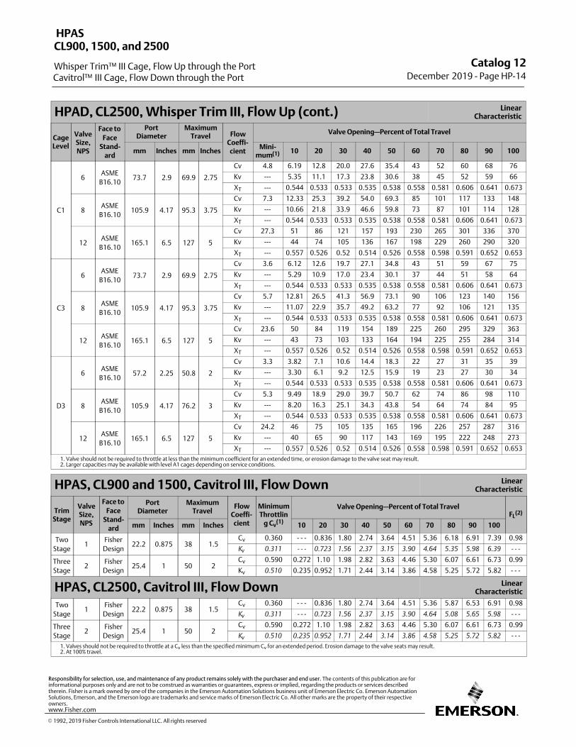
HPAD, CL2500, Whisper Trim III, Flow Up (cont.) LinearCharacteristic
CageLevel
ValveSize,NPS
Face to
FaceStand-
ard
PortDiameter
MaximumTravel Flow
Coeffi‐cient
Valve Opening—Percent of Total Travel
mm Inches mm InchesMini‐
mum(1) 10 20 30 40 50 60 70 80 90 100
C1
6ASME
B16.1073.7 2.9 69.9 2.75
Cv 4.8 6.19 12.8 20.0 27.6 35.4 43 52 60 68 76
Kv --- 5.35 11.1 17.3 23.8 30.6 38 45 52 59 66
XT --- 0.544 0.533 0.533 0.535 0.538 0.558 0.581 0.606 0.641 0.673
8ASME
B16.10105.9 4.17 95.3 3.75
Cv 7.3 12.33 25.3 39.2 54.0 69.3 85 101 117 133 148
Kv --- 10.66 21.8 33.9 46.6 59.8 73 87 101 114 128
XT --- 0.544 0.533 0.533 0.535 0.538 0.558 0.581 0.606 0.641 0.673
12ASME
B16.10165.1 6.5 127 5
Cv 27.3 51 86 121 157 193 230 265 301 336 370
Kv --- 44 74 105 136 167 198 229 260 290 320
XT --- 0.557 0.526 0.52 0.514 0.526 0.558 0.598 0.591 0.652 0.653
C3
6ASME
B16.1073.7 2.9 69.9 2.75
Cv 3.6 6.12 12.6 19.7 27.1 34.8 43 51 59 67 75
Kv --- 5.29 10.9 17.0 23.4 30.1 37 44 51 58 64
XT --- 0.544 0.533 0.533 0.535 0.538 0.558 0.581 0.606 0.641 0.673
8ASME
B16.10105.9 4.17 95.3 3.75
Cv 5.7 12.81 26.5 41.3 56.9 73.1 90 106 123 140 156
Kv --- 11.07 22.9 35.7 49.2 63.2 77 92 106 121 135
XT --- 0.544 0.533 0.533 0.535 0.538 0.558 0.581 0.606 0.641 0.673
12ASME
B16.10165.1 6.5 127 5
Cv 23.6 50 84 119 154 189 225 260 295 329 363
Kv --- 43 73 103 133 164 194 225 255 284 314
XT --- 0.557 0.526 0.52 0.514 0.526 0.558 0.598 0.591 0.652 0.653
D3
6ASME
B16.1057.2 2.25 50.8 2
Cv 3.3 3.82 7.1 10.6 14.4 18.3 22 27 31 35 39
Kv --- 3.30 6.1 9.2 12.5 15.9 19 23 27 30 34
XT --- 0.544 0.533 0.533 0.535 0.538 0.558 0.581 0.606 0.641 0.673
8ASME
B16.10105.9 4.17 76.2 3
Cv 5.3 9.49 18.9 29.0 39.7 50.7 62 74 86 98 110
Kv --- 8.20 16.3 25.1 34.3 43.8 54 64 74 84 95
XT --- 0.544 0.533 0.533 0.535 0.538 0.558 0.581 0.606 0.641 0.673
12ASME
B16.10165.1 6.5 127 5
Cv 24.2 46 75 105 135 165 196 226 257 287 316
Kv --- 40 65 90 117 143 169 195 222 248 273
XT --- 0.557 0.526 0.52 0.514 0.526 0.558 0.598 0.591 0.652 0.653
1. Valve should not be required to throttle at less than the minimum coefficient for an extended time, or erosion damage to the valve seat may result.2. Larger capacities may be available with level A1 cages depending on service conditions.
HPAS, CL900 and 1500, Cavitrol III, Flow Down LinearCharacteristic
TrimStage
ValveSize,NPS
Face to
FaceStand-
ard
PortDiameter
MaximumTravel
FlowCoeffi‐cient
MinimumThrottlin
g Cv(1)
Valve Opening—Percent of Total TravelFL
(2)
mm Inches mm Inches 10 20 30 40 50 60 70 80 90 100
Two
Stage1
Fisher
Design22.2 0.875 38 1.5
Cv 0.360 ‐ ‐ ‐ 0.836 1.80 2.74 3.64 4.51 5.36 6.18 6.91 7.39 0.98
Kv
0.311 ‐ ‐ ‐ 0.723 1.56 2.37 3.15 3.90 4.64 5.35 5.98 6.39 ‐ ‐ ‐
Three
Stage2
Fisher
Design25.4 1 50 2
Cv 0.590 0.272 1.10 1.98 2.82 3.63 4.46 5.30 6.07 6.61 6.73 0.99
Kv 0.510 0.235 0.952 1.71 2.44 3.14 3.86 4.58 5.25 5.72 5.82 ‐ ‐ ‐
HPAS, CL2500, Cavitrol III, Flow Down LinearCharacteristic
Two
Stage1
Fisher
Design22.2 0.875 38 1.5
Cv 0.360 ‐ ‐ ‐ 0.836 1.80 2.74 3.64 4.51 5.36 5.87 6.53 6.91 0.98
Kv
0.311 ‐ ‐ ‐ 0.723 1.56 2.37 3.15 3.90 4.64 5.08 5.65 5.98 ‐ ‐ ‐
Three
Stage2
Fisher
Design25.4 1 50 2
Cv 0.590 0.272 1.10 1.98 2.82 3.63 4.46 5.30 6.07 6.61 6.73 0.99
Kv
0.510 0.235 0.952 1.71 2.44 3.14 3.86 4.58 5.25 5.72 5.82 ‐ ‐ ‐
1. Valves should not be required to throttle at a Cv less than the specified minimum Cv for an extended period. Erosion damage to the valve seats may result.2. At 100% travel.
Catalog 12December 2019 ‐ Page HP-14
HPAS
Whisper Trim™ III Cage, Flow Up through the Port
CL900, 1500, and 2500
Cavitrol™ III Cage, Flow Down through the Port
� 1992, 2019 Fisher Controls International LLC. All rights reserved
www.Fisher.com
Responsibility for selection, use, and maintenance of any product remains solely with the purchaser and end user. The contents of this publication are forinformational purposes only and are not to be construed as warranties or guarantees, express or implied, regarding the products or services describedtherein. Fisher is a mark owned by one of the companies in the Emerson Automation Solutions business unit of Emerson Electric Co. Emerson AutomationSolutions, Emerson, and the Emerson logo are trademarks and service marks of Emerson Electric Co. All other marks are the property of their respectiveowners.
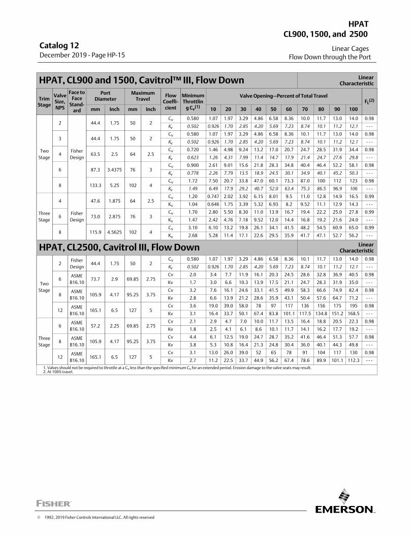
HPAT, CL900 and 1500, Cavitrol™ III, Flow Down LinearCharacteristic
TrimStage
ValveSize,NPS
Face toFace
Stand-ard
PortDiameter
MaximumTravel
FlowCoeffi‐cient
MinimumThrottlin
g Cv(1)
Valve Opening—Percent of Total TravelFL
(2)
mm Inch mm Inch 10 20 30 40 50 60 70 80 90 100
Two
Stage
2
Fisher
Design
44.4 1.75 50 2Cv 0.580 1.07 1.97 3.29 4.86 6.58 8.36 10.0 11.7 13.0 14.0 0.98
Kv
0.502 0.926 1.70 2.85 4.20 5.69 7.23 8.74 10.1 11.2 12.1 ‐ ‐ ‐
3 44.4 1.75 50 2Cv 0.580 1.07 1.97 3.29 4.86 6.58 8.36 10.1 11.7 13.0 14.0 0.98
Kv
0.502 0.926 1.70 2.85 4.20 5.69 7.23 8.74 10.1 11.2 12.1 ‐ ‐ ‐
4 63.5 2.5 64 2.5Cv 0.720 1.46 4.98 9.24 13.2 17.0 20.7 24.7 28.5 31.9 34.4 0.98
Kv
0.623 1.26 4.31 7.99 11.4 14.7 17.9 21.4 24.7 27.6 29.8 ‐ ‐ ‐
6 87.3 3.4375 76 3Cv 0.900 2.61 9.01 15.6 21.8 28.3 34.8 40.4 46.4 52.2 58.1 0.98
Kv
0.778 2.26 7.79 13.5 18.9 24.5 30.1 34.9 40.1 45.2 50.3 ‐ ‐ ‐
8 133.3 5.25 102 4Cv 1.72 7.50 20.7 33.8 47.0 60.1 73.3 87.0 100 112 123 0.98
Kv
1.49 6.49 17.9 29.2 40.7 52.0 63.4 75.3 86.5 96.9 106 ‐ ‐ ‐
Three
Stage
4
Fisher
Design
47.6 1.875 64 2.5Cv 1.20 0.747 2.02 3.92 6.15 8.01 9.5 11.0 12.8 14.9 16.5 0.99
Kv 1.04 0.646 1.75 3.39 5.32 6.93 8.2 9.52 11.1 12.9 14.3 ‐ ‐ ‐
6 73.0 2.875 76 3Cv 1.70 2.80 5.50 8.30 11.0 13.9 16.7 19.4 22.2 25.0 27.8 0.99
Kv 1.47 2.42 4.76 7.18 9.52 12.0 14.4 16.8 19.2 21.6 24.0 ‐ ‐ ‐
8 115.9 4.5625 102 4Cv 3.10 6.10 13.2 19.8 26.1 34.1 41.5 48.2 54.5 60.9 65.0 0.99
Kv 2.68 5.28 11.4 17.1 22.6 29.5 35.9 41.7 47.1 52.7 56.2 ‐ ‐ ‐
HPAT, CL2500, Cavitrol III, Flow Down LinearCharacteristic
Two
Stage
2Fisher
Design44.4 1.75 50 2
Cv 0.580 1.07 1.97 3.29 4.86 6.58 8.36 10.1 11.7 13.0 14.0 0.98
Kv
0.502 0.926 1.70 2.85 4.20 5.69 7.23 8.74 10.1 11.2 12.1 ‐ ‐ ‐
6ASME
B16.1073.7 2.9 69.85 2.75
Cv 2.0 3.4 7.7 11.9 16.1 20.3 24.5 28.6 32.8 36.9 40.5 0.98
Kv 1.7 3.0 6.6 10.3 13.9 17.5 21.1 24.7 28.3 31.9 35.0 ‐ ‐ ‐
8ASME
B16.10105.9 4.17 95.25 3.75
Cv 3.2 7.6 16.1 24.6 33.1 41.5 49.9 58.3 66.6 74.9 82.4 0.98
Kv 2.8 6.6 13.9 21.2 28.6 35.9 43.1 50.4 57.6 64.7 71.2 ‐ ‐ ‐
12ASME
B16.10165.1 6.5 127 5
Cv 3.6 19.0 39.0 58.0 78 97 117 136 156 175 195 0.98
Kv 3.1 16.4 33.7 50.1 67.4 83.8 101.1 117.5 134.8 151.2 168.5 ‐ ‐ ‐
Three
Stage
6ASME
B16.1057.2 2.25 69.85 2.75
Cv 2.1 2.9 4.7 7.0 10.0 11.7 13.5 16.4 18.8 20.5 22.3 0.98
Kv 1.8 2.5 4.1 6.1 8.6 10.1 11.7 14.1 16.2 17.7 19.2 ‐ ‐ ‐
8ASME
B16.10105.9 4.17 95.25 3.75
Cv 4.4 6.1 12.5 19.0 24.7 28.7 35.2 41.6 46.4 51.3 57.7 0.98
Kv 3.8 5.3 10.8 16.4 21.3 24.8 30.4 36.0 40.1 44.3 49.8 ‐ ‐ ‐
12ASME
B16.10165.1 6.5 127 5
Cv 3.1 13.0 26.0 39.0 52 65 78 91 104 117 130 0.98
Kv 2.7 11.2 22.5 33.7 44.9 56.2 67.4 78.6 89.9 101.1 112.3 ‐ ‐ ‐
1. Valves should not be required to throttle at a Cv less than the specified minimum Cv for an extended period. Erosion damage to the valve seats may result.2. At 100% travel.
Catalog 12December 2019 ‐ Page HP-15
HPAT
Linear Cages
CL900, 1500, and 2500
Flow Down through the Port
� 1992, 2019 Fisher Controls International LLC. All rights reserved
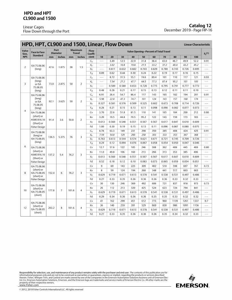
HPD, HPT, CL900 and 1500, Linear, Flow Down Linear Characteristic
ValveSize,NPS
Face to Face
Standard
PortDiameter
MaximumTravel
FlowCoeffi‐cient
Valve Opening—Percent of Total TravelFL
(1)
mm Inches mm Inches 10 20 30 40 50 60 70 80 90 100
2ISA 75.08.06
(long)47.6 1.875 38 1.5
Cv ‐ ‐ ‐ 3.49 12.5 22.9 31.8 38.4 43.0 46.7 49.9 52.2 0.91
Kv
‐ ‐ ‐ 3.02 10.8 19.8 27.5 33.2 37.2 40.4 43.2 45.2 ‐ ‐ ‐
XT ‐ ‐ ‐ 0.811 0.632 0.682 0.743 0.829 0.780 0.743 0.726 0.695 ‐ ‐ ‐
Fd 0.89 0.62 0.44 0.30 0.24 0.22 0.19 0.17 0.16 0.15 ‐ ‐ ‐
3
ISA 75.08.06
(long)
or ISA
75.08.05
(long)
73.0 2.875 50 2
Cv ‐ ‐ ‐ 8.72 31.5 55.1 74.6 89.4 101 110 117 121 0.93
Kv
‐ ‐ ‐ 7.54 27.2 47.7 64.5 77.3 87.4 95.2 101 105 ‐ ‐ ‐
XT ‐ ‐ ‐ 0.589 0.580 0.653 0.728 0.775 0.795 0.791 0.777 0.773 ‐ ‐ ‐
Fd 0.48 0.28 0.21 0.17 0.15 0.13 0.12 0.11 0.11 0.10 ‐ ‐ ‐
4
ISA 75.08.06
(long)
or ISA
75.08.05
(long)
92.1 3.625 50 2
Cv 6.91 26.4 54.7 86.4 117 143 165 182 194 201 0.91
Kv
5.98 22.8 47.3 74.7 101 124 143 157 168 174 ‐ ‐ ‐
XT 0.327 0.581 0.576 0.509 0.525 0.602 0.673 0.708 0.714 0.726 ‐ ‐ ‐
Fd 0.28 0.21 0.15 0.13 0.11 0.098 0.090 0.082 0.077 0.073 ‐ ‐ ‐
ISA-75.08.06
(short) or
ASME B16.10
(Short) or
Fisher Design
91.4 3.6 50.8 2
Cv 3.70 22.6 51.8 81.5 110 141 165 184 200 212 0.80
Kv 3.20 19.5 44.8 70.5 95.2 122 143 159 173 183 ‐ ‐ ‐
XT 0.613 0.560 0.548 0.551 0.567 0.567 0.617 0.647 0.610 0.609 ‐ ‐ ‐
Fd 1.00 0.30 0.19 0.15 0.13 0.11 0.096 0.087 0.080 0.075 ‐ ‐ ‐
6
ISA 75.08.06
(long) or
ISA 75.08.05
(long)
136.5 5.375 76 3
Cv 8.78 63.3 149 231 298 350 385 408 424 425 0.91
Kv
7.59 54.8 129 200 258 303 333 353 367 368 ‐ ‐ ‐
XT 0.763 0.613 0.544 0.574 0.621 0.671 0.721 0.745 0.709 0.726 ‐ ‐ ‐
Fd 0.24 0.12 0.094 0.076 0.067 0.058 0.054 0.050 0.047 0.046 ‐ ‐ ‐
ISA-75.08.06
(short) or
ASME B16.10
(Short) or
Fisher Design
137.2 5.4 76.2 3
Cv 12.7 57.6 122 185 246 308 362 408 445 469 0.80
Kv 11.0 49.8 106 160 213 266 313 353 385 406 ‐ ‐ ‐
XT 0.613 0.560 0.548 0.551 0.567 0.567 0.617 0.647 0.610 0.609 ‐ ‐ ‐
Fd 0.52 0.18 0.12 0.10 0.083 0.073 0.065 0.059 0.054 0.051 ‐ ‐ ‐
8
ISA-75.08.06
(short) or
ISA-75.08.05
(short) or
Fisher Design
152.4 6 76.2 3
Cv 9 69 143 225 309 402 510 598 697 767 0.73
Kv 8 59 124 194 268 348 441 517 603 663 ‐ ‐ ‐
XT 0.629 0.719 0.671 0.613 0.578 0.541 0.538 0.531 0.497 0.486 ‐ ‐ ‐
Fd 0.27 0.33 0.35 0.36 0.36 0.36 0.36 0.33 0.32 0.33 ‐ ‐ ‐
10
ISA-75.08.06
(short) or
ISA-75.08.05
(short)
177.8 7 101.6 4
Cv 30 130 246 369 492 606 721 837 918 973 0.73
Kv 26 112 213 320 425 524 623 724 794 841 ‐ ‐ ‐
XT 0.629 0.719 0.671 0.613 0.578 0.541 0.538 0.531 0.497 0.486 ‐ ‐ ‐
Fd 0.29 0.34 0.36 0.36 0.36 0.35 0.35 0.33 0.32 0.32 ‐ ‐ ‐
12
ISA-75.08.06
(short) or
ISA-75.08.05
(short)
203.2 8 101.6 4
Cv 41 162 299 451 612 773 960 1139 1261 1337 0.7
Kv 36 140 259 391 529 669 830 986 1091 1156 ‐ ‐ ‐
XT 0.629 0.719 0.671 0.613 0.578 0.541 0.538 0.531 0.497 0.486 ‐ ‐ ‐
Fd 0.27 0.33 0.35 0.36 0.36 0.36 0.35 0.34 0.32 0.33 ‐ ‐ ‐
Catalog 12 December 2019 ‐ Page HP-16
HPD and HPT
Linear Cages
CL900 and 1500
Flow Down through the Port
� 2012, 2019 Fisher Controls International LLC. All rights reserved
www.Fisher.com
Responsibility for selection, use, and maintenance of any product remains solely with the purchaser and end user. The contents of this publication are forinformational purposes only and are not to be construed as warranties or guarantees, express or implied, regarding the products or services describedtherein. Fisher, Whisper Trim, and Cavitrol are marks owned by one of the companies in the Emerson Automation Solutions business unit of Emerson Electric Co. Emerson Automation Solutions, Emerson, and the Emerson logo are trademarks and service marks of Emerson Electric Co. All other marks are theproperty of their respective owners.
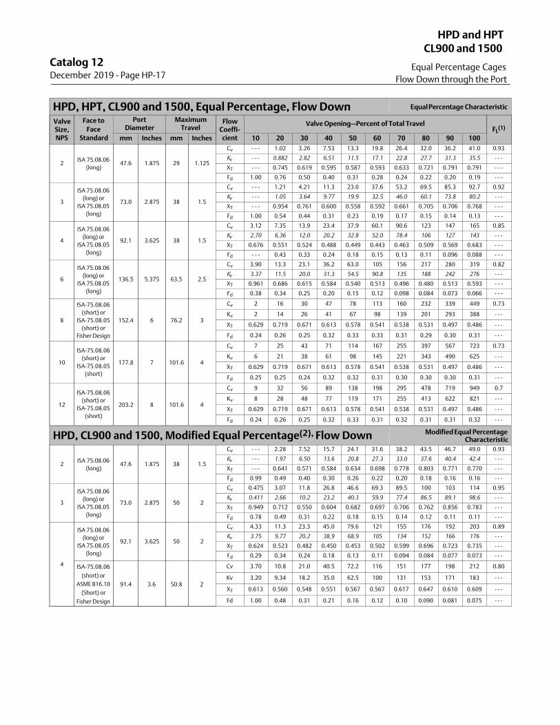
HPD, HPT, CL900 and 1500, Equal Percentage, Flow Down Equal Percentage Characteristic
ValveSize,NPS
Face to
FaceStandard
PortDiameter
MaximumTravel
FlowCoeffi‐cient
Valve Opening—Percent of Total TravelFL
(1)
mm Inches mm Inches 10 20 30 40 50 60 70 80 90 100
2ISA 75.08.06
(long)47.6 1.875 29 1.125
Cv - - - 1.02 3.26 7.53 13.3 19.8 26.4 32.0 36.2 41.0 0.93
Kv
- - - 0.882 2.82 6.51 11.5 17.1 22.8 27.7 31.3 35.5 - - -
XT - - - 0.745 0.619 0.595 0.587 0.593 0.633 0.721 0.791 0.791 - - -
Fd 1.00 0.76 0.50 0.40 0.31 0.28 0.24 0.22 0.20 0.19 - - -
3
ISA 75.08.06
(long) or
ISA 75.08.05
(long)
73.0 2.875 38 1.5
Cv - - - 1.21 4.21 11.3 23.0 37.6 53.2 69.5 85.3 92.7 0.92
Kv
- - - 1.05 3.64 9.77 19.9 32.5 46.0 60.1 73.8 80.2 - - -
XT - - - 0.954 0.761 0.600 0.558 0.592 0.661 0.705 0.706 0.768 - - -
Fd 1.00 0.54 0.44 0.31 0.23 0.19 0.17 0.15 0.14 0.13 - - -
4
ISA 75.08.06
(long) or
ISA 75.08.05
(long)
92.1 3.625 38 1.5
Cv 3.12 7.35 13.9 23.4 37.9 60.1 90.6 123 147 165 0.85
Kv
2.70 6.36 12.0 20.2 32.8 52.0 78.4 106 127 143 - - -
XT 0.676 0.551 0.524 0.488 0.449 0.443 0.463 0.509 0.569 0.683 - - -
Fd - - - 0.43 0.33 0.24 0.18 0.15 0.13 0.11 0.096 0.088 - - -
6
ISA 75.08.06
(long) or
ISA 75.08.05
(long)
136.5 5.375 63.5 2.5
Cv 3.90 13.3 23.1 36.2 63.0 105 156 217 280 319 0.82
Kv
3.37 11.5 20.0 31.3 54.5 90.8 135 188 242 276 - - -
XT 0.961 0.686 0.615 0.584 0.540 0.513 0.496 0.480 0.513 0.593 - - -
Fd 0.38 0.34 0.25 0.20 0.15 0.12 0.098 0.084 0.073 0.066 - - -
8
ISA-75.08.06
(short) or
ISA-75.08.05
(short) or
Fisher Design
152.4 6 76.2 3
Cv 2 16 30 47 78 113 160 232 339 449 0.73
Kv 2 14 26 41 67 98 139 201 293 388 - - -
XT 0.629 0.719 0.671 0.613 0.578 0.541 0.538 0.531 0.497 0.486 - - -
Fd 0.24 0.26 0.25 0.32 0.33 0.33 0.31 0.29 0.30 0.31 - - -
10
ISA-75.08.06
(short) or
ISA-75.08.05
(short)
177.8 7 101.6 4
Cv 7 25 43 71 114 167 255 397 567 723 0.73
Kv 6 21 38 61 98 145 221 343 490 625 - - -
XT 0.629 0.719 0.671 0.613 0.578 0.541 0.538 0.531 0.497 0.486 - - -
Fd 0.25 0.25 0.24 0.32 0.32 0.31 0.30 0.30 0.30 0.31 - - -
12
ISA-75.08.06
(short) or
ISA-75.08.05
(short)
203.2 8 101.6 4
Cv 9 32 56 89 138 198 295 478 719 949 0.7
Kv 8 28 48 77 119 171 255 413 622 821 - - -
XT 0.629 0.719 0.671 0.613 0.578 0.541 0.538 0.531 0.497 0.486 - - -
Fd 0.24 0.26 0.25 0.32 0.33 0.31 0.32 0.31 0.31 0.32 - - -
HPD, CL900 and 1500, Modified Equal Percentage(2), Flow Down Modified Equal PercentageCharacteristic
2ISA 75.08.06
(long)47.6 1.875 38 1.5
Cv ‐ ‐ ‐ 2.28 7.52 15.7 24.1 31.6 38.2 43.5 46.7 49.0 0.93
Kv
‐ ‐ ‐ 1.97 6.50 13.6 20.8 27.3 33.0 37.6 40.4 42.4 ‐ ‐ ‐
XT ‐ ‐ ‐ 0.641 0.571 0.584 0.634 0.698 0.778 0.803 0.771 0.770 ‐ ‐ ‐
Fd 0.99 0.49 0.40 0.30 0.26 0.22 0.20 0.18 0.16 0.16 ‐ ‐ ‐
3
ISA 75.08.06
(long) or
ISA 75.08.05
(long)
73.0 2.875 50 2
Cv 0.475 3.07 11.8 26.8 46.6 69.3 89.5 100 103 114 0.95
Kv
0.411 2.66 10.2 23.2 40.3 59.9 77.4 86.5 89.1 98.6 ‐ ‐ ‐
XT 0.949 0.712 0.550 0.604 0.682 0.697 0.706 0.762 0.856 0.783 ‐ ‐ ‐
Fd 0.78 0.49 0.31 0.22 0.18 0.15 0.14 0.12 0.11 0.11 ‐ ‐ ‐
4
ISA 75.08.06
(long) or
ISA 75.08.05
(long)
92.1 3.625 50 2
Cv 4.33 11.3 23.3 45.0 79.6 121 155 176 192 203 0.89
Kv
3.75 9.77 20.2 38.9 68.9 105 134 152 166 176 ‐ ‐ ‐
XT 0.624 0.523 0.482 0.450 0.453 0.502 0.599 0.696 0.723 0.735 ‐ ‐ ‐
Fd 0.29 0.34 0.24 0.18 0.13 0.11 0.094 0.084 0.077 0.073 ‐ ‐ ‐
ISA-75.08.06
(short) or
ASME B16.10
(Short) or
Fisher Design
91.4 3.6 50.8 2
Cv 3.70 10.8 21.0 40.5 72.2 116 151 177 198 212 0.80
Kv 3.20 9.34 18.2 35.0 62.5 100 131 153 171 183 ‐ ‐ ‐
XT 0.613 0.560 0.548 0.551 0.567 0.567 0.617 0.647 0.610 0.609 ‐ ‐ ‐
Fd 1.00 0.48 0.31 0.21 0.16 0.12 0.10 0.090 0.081 0.075 ‐ ‐ ‐
Catalog 12December 2019 ‐ Page HP-17
HPD and HPT
Equal Percentage Cages
CL900 and 1500
Flow Down through the Port
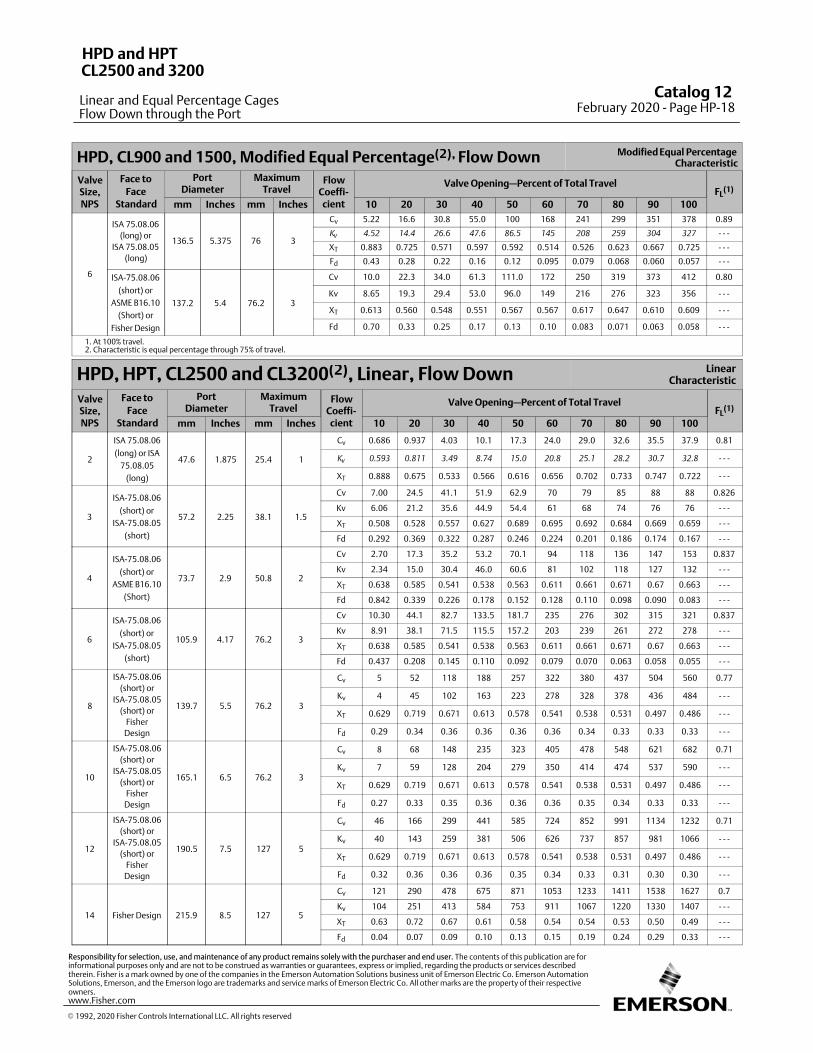
HPD, CL900 and 1500, Modified Equal Percentage(2), Flow Down Modified Equal PercentageCharacteristic
ValveSize,NPS
Face to
FaceStandard
PortDiameter
MaximumTravel
FlowCoeffi‐cient
Valve Opening—Percent of Total TravelFL
(1)
mm Inches mm Inches 10 20 30 40 50 60 70 80 90 100
6
ISA 75.08.06
(long) or
ISA 75.08.05
(long)
136.5 5.375 76 3
Cv 5.22 16.6 30.8 55.0 100 168 241 299 351 378 0.89
Kv
4.52 14.4 26.6 47.6 86.5 145 208 259 304 327 ‐ ‐ ‐
XT 0.883 0.725 0.571 0.597 0.592 0.514 0.526 0.623 0.667 0.725 ‐ ‐ ‐
Fd 0.43 0.28 0.22 0.16 0.12 0.095 0.079 0.068 0.060 0.057 ‐ ‐ ‐
ISA-75.08.06
(short) or
ASME B16.10
(Short) or
Fisher Design
137.2 5.4 76.2 3
Cv 10.0 22.3 34.0 61.3 111.0 172 250 319 373 412 0.80
Kv 8.65 19.3 29.4 53.0 96.0 149 216 276 323 356 ‐ ‐ ‐
XT 0.613 0.560 0.548 0.551 0.567 0.567 0.617 0.647 0.610 0.609 ‐ ‐ ‐
Fd 0.70 0.33 0.25 0.17 0.13 0.10 0.083 0.071 0.063 0.058 ‐ ‐ ‐
1. At 100% travel.2. Characteristic is equal percentage through 75% of travel.
HPD, HPT, CL2500 and CL3200(2), Linear, Flow Down LinearCharacteristic
ValveSize,NPS
Face to
FaceStandard
PortDiameter
MaximumTravel
FlowCoeffi‐cient
Valve Opening—Percent of Total TravelFL
(1)
mm Inches mm Inches 10 20 30 40 50 60 70 80 90 100
2
ISA 75.08.06
(long) or ISA
75.08.05
(long)
47.6 1.875 25.4 1
Cv 0.686 0.937 4.03 10.1 17.3 24.0 29.0 32.6 35.5 37.9 0.81
Kv
0.593 0.811 3.49 8.74 15.0 20.8 25.1 28.2 30.7 32.8 ‐ ‐ ‐
XT 0.888 0.675 0.533 0.566 0.616 0.656 0.702 0.733 0.747 0.722 ‐ ‐ ‐
3
ISA-75.08.06
(short) or
ISA-75.08.05
(short)
57.2 2.25 38.1 1.5
Cv 7.00 24.5 41.1 51.9 62.9 70 79 85 88 88 0.826
Kv 6.06 21.2 35.6 44.9 54.4 61 68 74 76 76 ‐ ‐ ‐
XT 0.508 0.528 0.557 0.627 0.689 0.695 0.692 0.684 0.669 0.659 ‐ ‐ ‐
Fd 0.292 0.369 0.322 0.287 0.246 0.224 0.201 0.186 0.174 0.167 ‐ ‐ ‐
4
ISA-75.08.06
(short) or
ASME B16.10
(Short)
73.7 2.9 50.8 2
Cv 2.70 17.3 35.2 53.2 70.1 94 118 136 147 153 0.837
Kv 2.34 15.0 30.4 46.0 60.6 81 102 118 127 132 ‐ ‐ ‐
XT 0.638 0.585 0.541 0.538 0.563 0.611 0.661 0.671 0.67 0.663 ‐ ‐ ‐
Fd 0.842 0.339 0.226 0.178 0.152 0.128 0.110 0.098 0.090 0.083 ‐ ‐ ‐
6
ISA-75.08.06
(short) or
ISA-75.08.05
(short)
105.9 4.17 76.2 3
Cv 10.30 44.1 82.7 133.5 181.7 235 276 302 315 321 0.837
Kv 8.91 38.1 71.5 115.5 157.2 203 239 261 272 278 ‐ ‐ ‐
XT 0.638 0.585 0.541 0.538 0.563 0.611 0.661 0.671 0.67 0.663 ‐ ‐ ‐
Fd 0.437 0.208 0.145 0.110 0.092 0.079 0.070 0.063 0.058 0.055 ‐ ‐ ‐
8
ISA-75.08.06
(short) or
ISA-75.08.05
(short) or
Fisher
Design
139.7 5.5 76.2 3
Cv 5 52 118 188 257 322 380 437 504 560 0.77
Kv 4 45 102 163 223 278 328 378 436 484 ‐ ‐ ‐
XT 0.629 0.719 0.671 0.613 0.578 0.541 0.538 0.531 0.497 0.486 ‐ ‐ ‐
Fd 0.29 0.34 0.36 0.36 0.36 0.36 0.34 0.33 0.33 0.33 ‐ ‐ ‐
10
ISA-75.08.06
(short) or
ISA-75.08.05
(short) or
Fisher
Design
165.1 6.5 76.2 3
Cv 8 68 148 235 323 405 478 548 621 682 0.71
Kv 7 59 128 204 279 350 414 474 537 590 ‐ ‐ ‐
XT 0.629 0.719 0.671 0.613 0.578 0.541 0.538 0.531 0.497 0.486 ‐ ‐ ‐
Fd 0.27 0.33 0.35 0.36 0.36 0.36 0.35 0.34 0.33 0.33 ‐ ‐ ‐
12
ISA-75.08.06
(short) or
ISA-75.08.05
(short) or
Fisher
Design
190.5 7.5 127 5
Cv 46 166 299 441 585 724 852 991 1134 1232 0.71
Kv 40 143 259 381 506 626 737 857 981 1066 ‐ ‐ ‐
XT 0.629 0.719 0.671 0.613 0.578 0.541 0.538 0.531 0.497 0.486 ‐ ‐ ‐
Fd 0.32 0.36 0.36 0.36 0.35 0.34 0.33 0.31 0.30 0.30 ‐ ‐ ‐
14 Fisher Design 215.9 8.5 127 5
Cv 121 290 478 675 871 1053 1233 1411 1538 1627 0.7
Kv 104 251 413 584 753 911 1067 1220 1330 1407 ‐ ‐ ‐
XT 0.63 0.72 0.67 0.61 0.58 0.54 0.54 0.53 0.50 0.49 ‐ ‐ ‐
Fd 0.04 0.07 0.09 0.10 0.13 0.15 0.19 0.24 0.29 0.33 ‐ ‐ ‐
� 1992, 2020 Fisher Controls International LLC. All rights reserved
www.Fisher.com
Responsibility for selection, use, and maintenance of any product remains solely with the purchaser and end user. The contents of this publication are forinformational purposes only and are not to be construed as warranties or guarantees, express or implied, regarding the products or services describedtherein. Fisher is a mark owned by one of the companies in the Emerson Automation Solutions business unit of Emerson Electric Co. Emerson AutomationSolutions, Emerson, and the Emerson logo are trademarks and service marks of Emerson Electric Co. All other marks are the property of their respectiveowners.
Catalog 12 February 2020 ‐ Page HP-18
HPD and HPT
Linear and Equal Percentage Cages
CL2500 and 3200
Flow Down through the Port
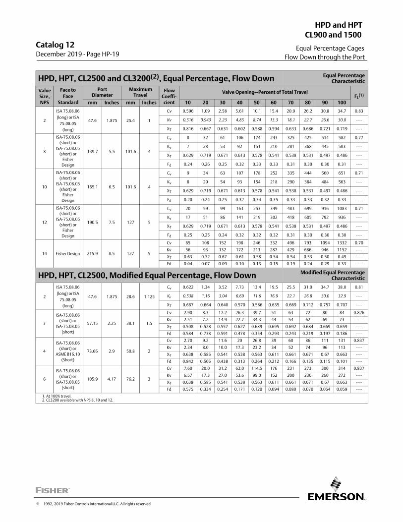
HPD, HPT, CL2500 and CL3200(2), Equal Percentage, Flow Down Equal PercentageCharacteristic
ValveSize,NPS
Face to
FaceStandard
PortDiameter
MaximumTravel
FlowCoeffi‐cient
Valve Opening—Percent of Total TravelFL
(1)
mm Inches mm Inches 10 20 30 40 50 60 70 80 90 100
2
ISA 75.08.06
(long) or ISA
75.08.05
(long)
47.6 1.875 25.4 1
Cv 0.596 1.09 2.58 5.61 10.1 15.4 20.9 26.2 30.8 34.7 0.83
Kv 0.516 0.943 2.23 4.85 8.74 13.3 18.1 22.7 26.6 30.0 - - -
XT 0.816 0.667 0.631 0.602 0.588 0.594 0.633 0.686 0.721 0.719 - - -
8
ISA-75.08.06
(short) or
ISA-75.08.05
(short) or
Fisher
Design
139.7 5.5 101.6 4
Cv 8 32 61 106 174 243 325 425 514 582 0.77
Kv 7 28 53 92 151 210 281 368 445 503 ‐ ‐ ‐
XT 0.629 0.719 0.671 0.613 0.578 0.541 0.538 0.531 0.497 0.486 ‐ ‐ ‐
Fd 0.24 0.26 0.25 0.32 0.33 0.33 0.31 0.30 0.30 0.31 ‐ ‐ ‐
10
ISA-75.08.06
(short) or
ISA-75.08.05
(short) or
Fisher
Design
165.1 6.5 101.6 4
Cv 9 34 63 107 178 252 335 444 560 651 0.71
Kv 8 29 54 93 154 218 290 384 484 563 ‐ ‐ ‐
XT 0.629 0.719 0.671 0.613 0.578 0.541 0.538 0.531 0.497 0.486 ‐ ‐ ‐
Fd 0.20 0.24 0.25 0.32 0.34 0.35 0.33 0.33 0.32 0.33 ‐ ‐ ‐
12
ISA-75.08.06
(short) or
ISA-75.08.05
(short) or
Fisher
Design
190.5 7.5 127 5
Cv 20 59 99 163 253 349 483 699 916 1083 0.71
Kv 17 51 86 141 219 302 418 605 792 936 ‐ ‐ ‐
XT 0.629 0.719 0.671 0.613 0.578 0.541 0.538 0.531 0.497 0.486 ‐ ‐ ‐
Fd 0.25 0.25 0.24 0.32 0.32 0.32 0.31 0.30 0.30 0.30 ‐ ‐ ‐
14 Fisher Design 215.9 8.5 127 5
Cv 65 108 152 198 246 332 496 793 1094 1332 0.70
Kv 56 93 132 172 213 287 429 686 946 1152 ‐ ‐ ‐
XT 0.63 0.72 0.67 0.61 0.58 0.54 0.54 0.53 0.50 0.49 ‐ ‐ ‐
Fd 0.04 0.07 0.09 0.10 0.13 0.15 0.19 0.24 0.29 0.33 ‐ ‐ ‐
HPD, HPT, CL2500, Modified Equal Percentage, Flow Down Modified Equal PercentageCharacteristic
2
ISA 75.08.06
(long) or ISA
75.08.05
(long)
47.6 1.875 28.6 1.125
Cv 0.622 1.34 3.52 7.73 13.4 19.5 25.5 31.0 34.7 38.0 0.81
Kv
0.538 1.16 3.04 6.69 11.6 16.9 22.1 26.8 30.0 32.9 ‐ ‐ ‐
XT 0.667 0.664 0.640 0.570 0.586 0.635 0.669 0.712 0.757 0.707 ‐ ‐ ‐
3
ISA-75.08.06
(short) or
ISA-75.08.05
(short)
57.15 2.25 38.1 1.5
Cv 2.90 8.3 17.2 26.3 39.7 51 63 72 80 84 0.826
Kv 2.51 7.2 14.9 22.7 34.3 44 54 62 69 73 ‐ ‐ ‐
XT 0.508 0.528 0.557 0.627 0.689 0.695 0.692 0.684 0.669 0.659 ‐ ‐ ‐
Fd 0.584 0.738 0.591 0.478 0.354 0.293 0.243 0.219 0.197 0.186 ‐ ‐ ‐
4
ISA-75.08.06
(short) or
ASME B16.10
(Short)
73.66 2.9 50.8 2
Cv 2.70 9.2 11.6 20 26.8 39 60 86 111 131 0.837
Kv 2.34 8.0 10.0 17.3 23.2 34 52 74 96 113 ‐ ‐ ‐
XT 0.638 0.585 0.541 0.538 0.563 0.611 0.661 0.671 0.67 0.663 ‐ ‐ ‐
Fd 0.842 0.505 0.438 0.313 0.264 0.212 0.166 0.135 0.115 0.101 ‐ ‐ ‐
6
ISA-75.08.06
(short) or
ISA-75.08.05
(short)
105.9 4.17 76.2 3
Cv 7.60 20.0 31.2 62.0 114.5 176 231 273 300 314 0.837
Kv 6.57 17.3 27.0 53.6 99.0 152 200 236 260 272 ‐ ‐ ‐
XT 0.638 0.585 0.541 0.538 0.563 0.611 0.661 0.671 0.67 0.663 ‐ ‐ ‐
Fd 0.575 0.334 0.254 0.171 0.120 0.094 0.080 0.070 0.064 0.059 ‐ ‐ ‐
1. At 100% travel.2. CL3200 available with NPS 8, 10 and 12.
Catalog 12December 2019 ‐ Page HP-19
HPD and HPT
Equal Percentage Cages
CL900 and 1500
Flow Down through the Port
� 1992, 2019 Fisher Controls International LLC. All rights reserved
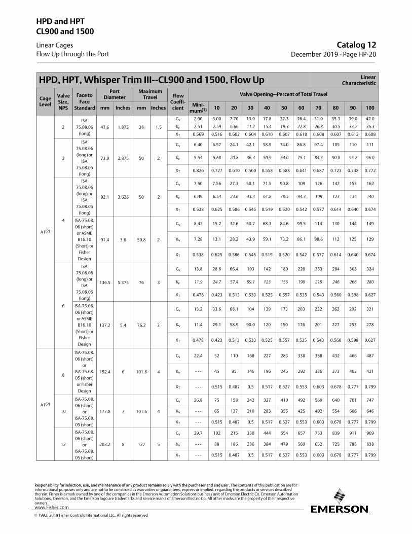
HPD, HPT, Whisper Trim III‐‐CL900 and 1500, Flow Up LinearCharacteristic
CageLevel
ValveSize,NPS
Face to
FaceStandard
PortDiameter
MaximumTravel Flow
Coeffi‐cient
Valve Opening—Percent of Total Travel
mm Inches mm InchesMini‐
mum(1) 10 20 30 40 50 60 70 80 90 100
A1(2)
2
ISA
75.08.06
(long)
47.6 1.875 38 1.5
Cv 2.90 3.00 7.70 13.0 17.8 22.3 26.4 31.0 35.3 39.0 42.0
Kv
2.51 2.59 6.66 11.2 15.4 19.3 22.8 26.8 30.5 33.7 36.3
XT 0.569 0.516 0.602 0.604 0.610 0.607 0.618 0.608 0.607 0.612 0.608
3
ISA
75.08.06
(long) or
ISA
75.08.05
(long)
73.0 2.875 50 2
Cv 6.40 6.57 24.1 42.1 58.9 74.0 86.8 97.4 105 110 111
Kv
5.54 5.68 20.8 36.4 50.9 64.0 75.1 84.3 90.8 95.2 96.0
XT 0.826 0.727 0.610 0.560 0.558 0.588 0.641 0.687 0.723 0.738 0.772
4
ISA
75.08.06
(long) or
ISA
75.08.05
(long)
92.1 3.625 50 2
Cv 7.50 7.56 27.3 50.1 71.5 90.8 109 126 142 155 162
Kv
6.49 6.54 23.6 43.3 61.8 78.5 94.3 109 123 134 140
XT 0.538 0.625 0.586 0.545 0.519 0.520 0.542 0.577 0.614 0.640 0.674
ISA-75.08.
06 (short)
or ASME
B16.10
(Short) or
Fisher
Design
91.4 3.6 50.8 2
Cv 8.42 15.2 32.6 50.7 68.3 84.6 99.5 114 130 144 149
Kv 7.28 13.1 28.2 43.9 59.1 73.2 86.1 98.6 112 125 129
XT 0.538 0.625 0.586 0.545 0.519 0.520 0.542 0.577 0.614 0.640 0.674
6
ISA
75.08.06
(long) or
ISA
75.08.05
(long)
136.5 5.375 76 3
Cv 13.8 28.6 66.4 103 142 180 220 253 284 308 324
Kv
11.9 24.7 57.4 89.1 123 156 190 219 246 266 280
XT 0.478 0.423 0.513 0.533 0.525 0.557 0.535 0.543 0.560 0.598 0.627
ISA-75.08.
06 (short)
or ASME
B16.10
(Short) or
Fisher
Design
137.2 5.4 76.2 3
Cv 13.2 33.6 68.1 104 139 173 203 232 262 292 321
Kv 11.4 29.1 58.9 90.0 120 150 176 201 227 253 278
XT 0.478 0.423 0.513 0.533 0.525 0.557 0.535 0.543 0.560 0.598 0.627
A1(2)
8
ISA-75.08.
06 (short)
or
ISA-75.08.
05 (short)
or Fisher
Design
152.4 6 101.6 4
Cv 22.4 52 110 168 227 283 338 388 432 466 487
Kv ‐ ‐ ‐ 45 95 146 196 245 292 336 373 403 421
XT ‐ ‐ ‐ 0.515 0.487 0.5 0.517 0.527 0.553 0.603 0.678 0.777 0.799
10
ISA-75.08.
06 (short)
or
ISA-75.08.
05 (short)
177.8 7 101.6 4
Cv 26.8 75 158 242 327 410 492 569 640 701 747
Kv ‐ ‐ ‐ 65 137 210 283 355 425 492 554 606 646
XT ‐ ‐ ‐ 0.515 0.487 0.5 0.517 0.527 0.553 0.603 0.678 0.777 0.799
12
ISA-75.08.
06 (short)
or
ISA-75.08.
05 (short)
203.2 8 127 5
Cv 29.7 102 215 330 444 554 657 753 839 911 969
Kv ‐ ‐ ‐ 88 186 286 384 479 569 652 725 788 838
XT ‐ ‐ ‐ 0.515 0.487 0.5 0.517 0.527 0.553 0.603 0.678 0.777 0.799
Catalog 12December 2019 ‐ Page HP-20
HPD and HPT
Linear Cages
CL900 and 1500
Flow Up through the Port
� 1992, 2019 Fisher Controls International LLC. All rights reserved
www.Fisher.com
Responsibility for selection, use, and maintenance of any product remains solely with the purchaser and end user. The contents of this publication are forinformational purposes only and are not to be construed as warranties or guarantees, express or implied, regarding the products or services describedtherein. Fisher is a mark owned by one of the companies in the Emerson Automation Solutions business unit of Emerson Electric Co. Emerson AutomationSolutions, Emerson, and the Emerson logo are trademarks and service marks of Emerson Electric Co. All other marks are the property of their respectiveowners.
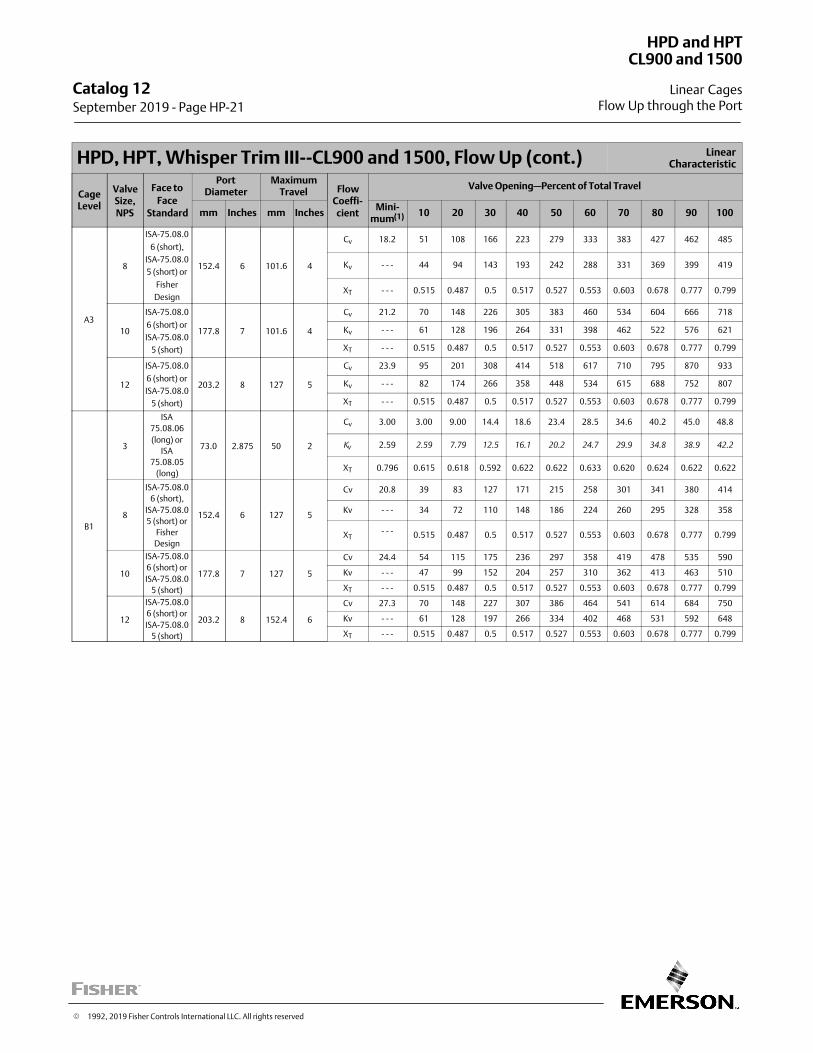
HPD, HPT, Whisper Trim III‐‐CL900 and 1500, Flow Up (cont.) LinearCharacteristic
CageLevel
ValveSize,NPS
Face to
FaceStandard
PortDiameter
MaximumTravel Flow
Coeffi‐cient
Valve Opening—Percent of Total Travel
mm Inches mm InchesMini‐
mum(1) 10 20 30 40 50 60 70 80 90 100
A3
8
ISA-75.08.0
6 (short),
ISA-75.08.0
5 (short) or
Fisher
Design
152.4 6 101.6 4
Cv 18.2 51 108 166 223 279 333 383 427 462 485
Kv ‐ ‐ ‐ 44 94 143 193 242 288 331 369 399 419
XT ‐ ‐ ‐ 0.515 0.487 0.5 0.517 0.527 0.553 0.603 0.678 0.777 0.799
10
ISA-75.08.0
6 (short) or
ISA-75.08.0
5 (short)
177.8 7 101.6 4
Cv 21.2 70 148 226 305 383 460 534 604 666 718
Kv ‐ ‐ ‐ 61 128 196 264 331 398 462 522 576 621
XT ‐ ‐ ‐ 0.515 0.487 0.5 0.517 0.527 0.553 0.603 0.678 0.777 0.799
12
ISA-75.08.0
6 (short) or
ISA-75.08.0
5 (short)
203.2 8 127 5
Cv 23.9 95 201 308 414 518 617 710 795 870 933
Kv ‐ ‐ ‐ 82 174 266 358 448 534 615 688 752 807
XT ‐ ‐ ‐ 0.515 0.487 0.5 0.517 0.527 0.553 0.603 0.678 0.777 0.799
B1
3
ISA
75.08.06
(long) or
ISA
75.08.05
(long)
73.0 2.875 50 2
Cv 3.00 3.00 9.00 14.4 18.6 23.4 28.5 34.6 40.2 45.0 48.8
Kv
2.59 2.59 7.79 12.5 16.1 20.2 24.7 29.9 34.8 38.9 42.2
XT 0.796 0.615 0.618 0.592 0.622 0.622 0.633 0.620 0.624 0.622 0.622
8
ISA-75.08.0
6 (short),
ISA-75.08.0
5 (short) or
Fisher
Design
152.4 6 127 5
Cv 20.8 39 83 127 171 215 258 301 341 380 414
Kv ‐ ‐ ‐ 34 72 110 148 186 224 260 295 328 358
XT‐ ‐ ‐ 0.515 0.487 0.5 0.517 0.527 0.553 0.603 0.678 0.777 0.799
10
ISA-75.08.0
6 (short) or
ISA-75.08.0
5 (short)
177.8 7 127 5
Cv 24.4 54 115 175 236 297 358 419 478 535 590
Kv ‐ ‐ ‐ 47 99 152 204 257 310 362 413 463 510
XT ‐ ‐ ‐ 0.515 0.487 0.5 0.517 0.527 0.553 0.603 0.678 0.777 0.799
12
ISA-75.08.0
6 (short) or
ISA-75.08.0
5 (short)
203.2 8 152.4 6
Cv 27.3 70 148 227 307 386 464 541 614 684 750
Kv ‐ ‐ ‐ 61 128 197 266 334 402 468 531 592 648
XT ‐ ‐ ‐ 0.515 0.487 0.5 0.517 0.527 0.553 0.603 0.678 0.777 0.799
Catalog 12 September 2019 ‐ Page HP-21
HPD and HPT
Linear Cages
CL900 and 1500
Flow Up through the Port
� 1992, 2019 Fisher Controls International LLC. All rights reserved
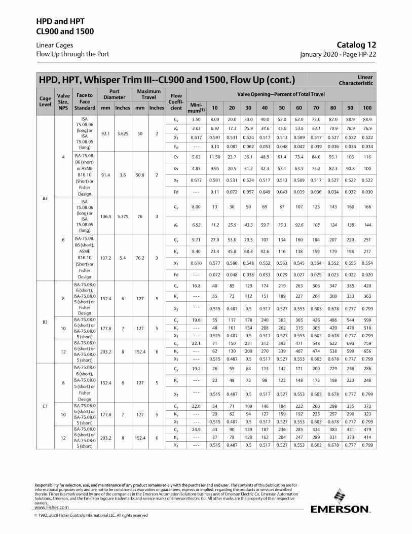
HPD, HPT, Whisper Trim III‐‐CL900 and 1500, Flow Up (cont.) LinearCharacteristic
CageLevel
ValveSize,NPS
Face to
FaceStandard
PortDiameter
MaximumTravel Flow
Coeffi‐cient
Valve Opening—Percent of Total Travel
mm Inches mm InchesMini‐
mum(1) 10 20 30 40 50 60 70 80 90 100
B3
4
ISA
75.08.06
(long) or
ISA
75.08.05
(long)
92.1 3.625 50 2
Cv 3.50 8.00 20.0 30.0 40.0 52.0 62.0 73.0 82.0 88.9 88.9
Kv
3.03 6.92 17.3 25.9 34.6 45.0 53.6 63.1 70.9 76.9 76.9
XT 0.617 0.591 0.531 0.524 0.517 0.513 0.509 0.517 0.527 0.522 0.522
Fd ‐ ‐ ‐ 0.13 0.087 0.062 0.053 0.048 0.042 0.039 0.036 0.034 0.034
ISA-75.08.
06 (short)
or ASME
B16.10
(Short) or
Fisher
Design
91.4 3.6 50.8 2
Cv 5.63 11.50 23.7 36.1 48.9 61.4 73.4 84.6 95.1 105 116
Kv 4.87 9.95 20.5 31.2 42.3 53.1 63.5 73.2 82.3 90.8 100
XT 0.617 0.591 0.531 0.524 0.517 0.513 0.509 0.517 0.527 0.522 0.522
Fd ‐ ‐ ‐ 0.11 0.072 0.057 0.049 0.043 0.039 0.036 0.034 0.032 0.030
6
ISA
75.08.06
(long) or
ISA
75.08.05
(long)
136.5 5.375 76 3
Cv 8.00 13 30 50 69 87 107 125 143 160 166
Kv
6.92 11.2 25.9 43.3 59.7 75.3 92.6 108 124 138 144
ISA-75.08.
06 (short),
ASME
B16.10
(Short) or
Fisher
Design
137.2 5.4 76.2 3
Cv 9.71 27.0 53.0 79.5 107 134 160 184 207 229 251
Kv 8.40 23.4 45.8 68.8 92.6 116 138 159 179 198 217
XT 0.610 0.577 0.580 0.548 0.552 0.563 0.545 0.554 0.552 0.555 0.554
Fd ‐ ‐ ‐ 0.072 0.048 0.038 0.033 0.029 0.027 0.025 0.023 0.022 0.020
B3
8
ISA-75.08.0
6 (short),
ISA-75.08.0
5 (short) or
Fisher
Design
152.4 6 127 5
Cv 16.8 40 85 129 174 219 263 306 347 385 420
Kv ‐ ‐ ‐ 35 73 112 151 189 227 264 300 333 363
XT‐ ‐ ‐ 0.515 0.487 0.5 0.517 0.527 0.553 0.603 0.678 0.777 0.799
10
ISA-75.08.0
6 (short) or
ISA-75.08.0
5 (short)
177.8 7 127 5
Cv 19.6 55 117 178 240 303 365 426 486 544 599
Kv ‐ ‐ ‐ 48 101 154 208 262 315 368 420 470 518
XT ‐ ‐ ‐ 0.515 0.487 0.5 0.517 0.527 0.553 0.603 0.678 0.777 0.799
12
ISA-75.08.0
6 (short) or
ISA-75.08.0
5 (short)
203.2 8 152.4 6
Cv 22.1 71 150 231 312 392 471 548 622 693 759
Kv ‐ ‐ ‐ 62 130 200 270 339 407 474 538 599 656
XT ‐ ‐ ‐ 0.515 0.487 0.5 0.517 0.527 0.553 0.603 0.678 0.777 0.799
C1
8
ISA-75.08.0
6 (short),
ISA-75.08.0
5 (short) or
Fisher
Design
152.4 6 127 5
Cv 19.2 26 55 84 113 142 171 200 229 258 286
Kv ‐ ‐ ‐ 23 48 73 98 123 148 173 198 223 248
XT‐ ‐ ‐ 0.515 0.487 0.5 0.517 0.527 0.553 0.603 0.678 0.777 0.799
10
ISA-75.08.0
6 (short) or
ISA-75.08.0
5 (short)
177.8 7 127 5
Cv 22.0 34 71 109 146 184 222 260 298 335 373
Kv ‐ ‐ ‐ 29 62 94 127 159 192 225 257 290 323
XT ‐ ‐ ‐ 0.515 0.487 0.5 0.517 0.527 0.553 0.603 0.678 0.777 0.799
12
ISA-75.08.0
6 (short) or
ISA-75.08.0
5 (short)
203.2 8 152.4 6
Cv 24.9 43 90 139 187 236 285 334 383 431 479
Kv ‐ ‐ ‐ 37 78 120 162 204 247 289 331 373 414
XT ‐ ‐ ‐ 0.515 0.487 0.5 0.517 0.527 0.553 0.603 0.678 0.777 0.799
Catalog 12January 2020 ‐ Page HP-22
HPD and HPT
Linear Cages
CL900 and 1500
Flow Up through the Port
� 1992, 2020 Fisher Controls International LLC. All rights reserved
www.Fisher.com
Responsibility for selection, use, and maintenance of any product remains solely with the purchaser and end user. The contents of this publication are forinformational purposes only and are not to be construed as warranties or guarantees, express or implied, regarding the products or services describedtherein. Fisher is a mark owned by one of the companies in the Emerson Automation Solutions business unit of Emerson Electric Co. Emerson AutomationSolutions, Emerson, and the Emerson logo are trademarks and service marks of Emerson Electric Co. All other marks are the property of their respectiveowners.
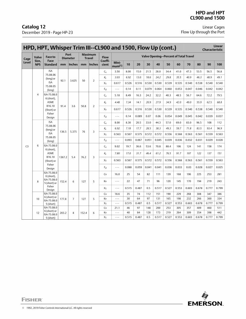
HPD, HPT, Whisper Trim III‐‐CL900 and 1500, Flow Up (cont.) LinearCharacteristic
CageLevel
ValveSize,NPS
Face to
FaceStandard
PortDiameter
MaximumTravel Flow
Coeffi‐cient
Valve Opening—Percent of Total Travel
mm Inches mm InchesMini‐
mum(1) 10 20 30 40 50 60 70 80 90 100
C3
4
ISA
75.08.06
(long) or
ISA
75.08.05
(long)
92.1 3.625 50 2
Cv 3.50 8.00 15.0 21.5 28.0 34.4 41.0 47.3 53.5 56.5 56.8
Kv
3.03 6.92 13.0 18.6 24.2 29.8 35.5 40.9 46.3 48.9 49.1
XT 0.617 0.526 0.516 0.530 0.530 0.539 0.535 0.540 0.538 0.540 0.540
Fd ‐ ‐ ‐ 0.14 0.11 0.079 0.064 0.060 0.053 0.047 0.046 0.042 0.042
ISA-75.08.0
6 (short),
ASME
B16.10
(Short) or
Fisher
Design
91.4 3.6 50.8 2
Cv 5.18 8.49 16.3 24.2 32.2 40.3 48.5 56.7 64.6 72.2 79.5
Kv
4.48 7.34 14.1 20.9 27.9 34.9 42.0 49.0 55.9 62.5 68.8
XT 0.617 0.526 0.516 0.530 0.530 0.539 0.535 0.540 0.538 0.540 0.540
Fd ‐ ‐ ‐ 0.14 0.089 0.07 0.06 0.054 0.049 0.045 0.042 0.039 0.037
6
ISA
75.08.06
(long) or
ISA
75.08.05
(long)
136.5 5.375 76 3
Cv 8.00 8.30 20.5 33.0 44.3 57.0 69.0 83.0 96.5 108 112
Kv
6.92 7.18 17.7 28.5 38.3 49.3 59.7 71.8 83.5 93.4 96.9
XT 0.563 0.567 0.575 0.572 0.572 0.556 0.568 0.563 0.561 0.559 0.563
Fd ‐ ‐ ‐ 0.093 0.067 0.051 0.045 0.039 0.036 0.032 0.031 0.029 0.028
ISA-75.08.0
6 (short),
ASME
B16.10
(Short) or
Fisher
Design
1367.2 5.4 76.2 3
Cv 9.02 19.7 36.6 53.6 70.8 88.4 106 124 141 158 174
Kv
7.80 17.0 31.7 46.4 61.2 76.5 91.7 107 122 137 151
XT 0.563 0.567 0.575 0.572 0.572 0.556 0.568 0.563 0.561 0.559 0.563
Fd ‐ ‐ ‐ 0.088 0.059 0.041 0.041 0.036 0.033 0.03 0.028 0.027 0.025
8
ISA-75.08.0
6 (short),
ISA-75.08.0
5 (short) or
Fisher
Design
152.4 6 127 5
Cv 16.0 25 54 82 111 139 168 196 225 253 281
Kv ‐ ‐ ‐ 22 47 71 96 120 145 170 194 219 243
XT ‐ ‐ ‐ 0.515 0.487 0.5 0.517 0.527 0.553 0.603 0.678 0.777 0.799
10
ISA-75.08.0
6 (short) or
ISA-75.08.0
5 (short)
177.8 7 127 5
Cv 18.6 35 74 112 151 190 229 268 308 347 386
Kv ‐ ‐ ‐ 30 64 97 131 165 198 232 266 300 334
XT ‐ ‐ ‐ 0.515 0.487 0.5 0.517 0.527 0.553 0.603 0.678 0.777 0.799
12
ISA-75.08.0
6 (short) or
ISA-75.08.0
5 (short)
203.2 8 152.4 6
Cv 21.1 46 97 148 200 253 305 357 409 460 511
Kv ‐ ‐ ‐ 40 84 128 173 219 264 309 354 398 442
XT ‐ ‐ ‐ 0.515 0.487 0.5 0.517 0.527 0.553 0.603 0.678 0.777 0.799
Catalog 12 December 2019 ‐ Page HP-23
HPD and HPT
Linear Cages
CL900 and 1500
Flow Up through the Port
� 1992, 2019 Fisher Controls International LLC. All rights reserved
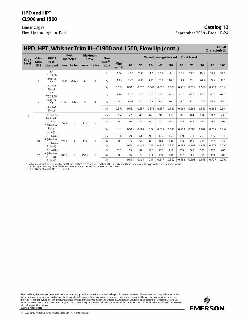
HPD, HPT, Whisper Trim III‐‐CL900 and 1500, Flow Up (cont.) LinearCharacteristic
CageLevel
ValveSize,NPS
Face to
FaceStandard
PortDiameter
MaximumTravel Flow
Coeffi‐cient
Valve Opening—Percent of Total Travel
mm Inches mm InchesMini‐
mum(1) 10 20 30 40 50 60 70 80 90 100
D3
4
ISA
75.08.06
(long) or
ISA
75.08.05
(long)
73.0 2.875 50 2
Cv 2.30 4.00 7.90 11.5 15.2 18.8 22.8 27.0 30.8 33.7 37.1
Kv
1.99 3.46 6.83 9.95 13.1 16.3 19.7 23.4 26.6 29.2 32.1
XT 0.554 0.517 0.525 0.540 0.526 0.533 0.536 0.534 0.530 0.533 0.530
6
ISA
75.08.06
(long) or
ISA
75.08.05
(long)
111.1 4.375 76 3
Cv 4.20 7.00 14.0 20.7 28.0 34.8 41.6 48.5 55.7 62.5 69.6
Kv
3.63 6.05 12.1 17.9 24.2 30.1 36.0 42.0 48.2 54.1 60.2
XT 0.579 0.563 0.557 0.572 0.557 0.569 0.564 0.566 0.562 0.566 0.564
8
ISA-75.08.0
6 (short),
ISA-75.08.0
5 (short) or
Fisher
Design
152.4 6 127 5
Cv 16.4 22 45 69 93 117 141 164 188 212 236
Kv 0 19 39 60 80 101 122 142 163 183 204
XT‐ ‐ ‐ 0.515 0.487 0.5 0.517 0.527 0.553 0.603 0.678 0.777 0.799
10
ISA-75.08.0
6 (short) or
ISA-75.08.0
5 (short)
177.8 7 127 5
Cv 19.0 29 61 93 125 157 189 221 253 285 317
Kv 0 25 53 80 108 136 163 191 219 247 275
XT ‐ ‐ ‐ 0.515 0.487 0.5 0.517 0.527 0.553 0.603 0.678 0.777 0.799
12
ISA-75.08.0
6 (short) or
ISA-75.08.0
5 (short)
203.2 8 152.4 6
Cv 21.7 53 84 128 172 217 263 308 353 397 442
Kv 0 46 72 111 149 188 227 266 305 344 382
XT ‐ ‐ ‐ 0.515 0.487 0.5 0.517 0.527 0.553 0.603 0.678 0.777 0.799
1. Valve should not be required to throttle at less than the minimum coefficient for an extended time, or erosion damage to the valve seat may result.2. Larger capacities may be available with level A1 cages depending on service conditions.3. CL3200 available with NPS 8, 10, and 12.
Catalog 12September 2019 ‐ Page HP-24
HPD and HPT
Linear Cages
CL900 and 1500
Flow Up through the Port
� 1992, 2019 Fisher Controls International LLC. All rights reserved
www.Fisher.com
Responsibility for selection, use, and maintenance of any product remains solely with the purchaser and end user. The contents of this publication are forinformational purposes only and are not to be construed as warranties or guarantees, express or implied, regarding the products or services describedtherein. Fisher and Whisper Trim are marks owned by one of the companies in the Emerson Automation Solutions business unit of Emerson Electric Co.Emerson Automation Solutions, Emerson, and the Emerson logo are trademarks and service marks of Emerson Electric Co. All other marks are the propertyof their respective owners.
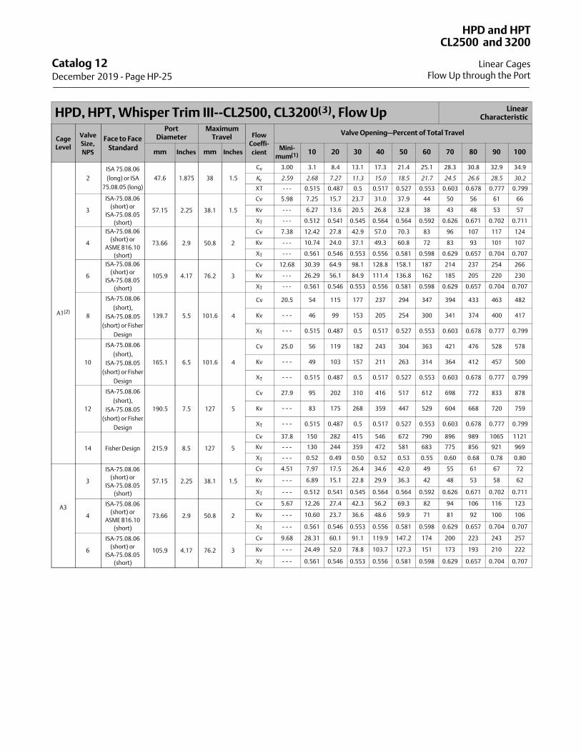
HPD, HPT, Whisper Trim III‐‐CL2500, CL3200(3), Flow Up LinearCharacteristic
Cage
Level
Valve
Size,
NPS
Face to Face
Standard
PortDiameter
MaximumTravel Flow
Coeffi‐
cient
Valve Opening—Percent of Total Travel
mm Inches mm InchesMini‐
mum(1) 10 20 30 40 50 60 70 80 90 100
A1(2)
2
ISA 75.08.06
(long) or ISA
75.08.05 (long)
47.6 1.875 38 1.5
Cv 3.00 3.1 8.4 13.1 17.3 21.4 25.1 28.3 30.8 32.9 34.9
Kv
2.59 2.68 7.27 11.3 15.0 18.5 21.7 24.5 26.6 28.5 30.2
XT - - - 0.515 0.487 0.5 0.517 0.527 0.553 0.603 0.678 0.777 0.799
3
ISA-75.08.06
(short) or
ISA-75.08.05
(short)
57.15 2.25 38.1 1.5
Cv 5.98 7.25 15.7 23.7 31.0 37.9 44 50 56 61 66
Kv - - - 6.27 13.6 20.5 26.8 32.8 38 43 48 53 57
XT - - - 0.512 0.541 0.545 0.564 0.564 0.592 0.626 0.671 0.702 0.711
4
ISA-75.08.06
(short) or
ASME B16.10
(short)
73.66 2.9 50.8 2
Cv 7.38 12.42 27.8 42.9 57.0 70.3 83 96 107 117 124
Kv - - - 10.74 24.0 37.1 49.3 60.8 72 83 93 101 107
XT - - - 0.561 0.546 0.553 0.556 0.581 0.598 0.629 0.657 0.704 0.707
6
ISA-75.08.06
(short) or
ISA-75.08.05
(short)
105.9 4.17 76.2 3
Cv 12.68 30.39 64.9 98.1 128.8 158.1 187 214 237 254 266
Kv - - - 26.29 56.1 84.9 111.4 136.8 162 185 205 220 230
XT - - - 0.561 0.546 0.553 0.556 0.581 0.598 0.629 0.657 0.704 0.707
8
ISA-75.08.06
(short),
ISA-75.08.05
(short) or Fisher
Design
139.7 5.5 101.6 4
Cv 20.5 54 115 177 237 294 347 394 433 463 482
Kv ‐ ‐ ‐ 46 99 153 205 254 300 341 374 400 417
XT ‐ ‐ ‐ 0.515 0.487 0.5 0.517 0.527 0.553 0.603 0.678 0.777 0.799
10
ISA-75.08.06
(short),
ISA-75.08.05
(short) or Fisher
Design
165.1 6.5 101.6 4
Cv 25.0 56 119 182 243 304 363 421 476 528 578
Kv ‐ ‐ ‐ 49 103 157 211 263 314 364 412 457 500
XT ‐ ‐ ‐ 0.515 0.487 0.5 0.517 0.527 0.553 0.603 0.678 0.777 0.799
12
ISA-75.08.06
(short),
ISA-75.08.05
(short) or Fisher
Design
190.5 7.5 127 5
Cv 27.9 95 202 310 416 517 612 698 772 833 878
Kv ‐ ‐ ‐ 83 175 268 359 447 529 604 668 720 759
XT ‐ ‐ ‐ 0.515 0.487 0.5 0.517 0.527 0.553 0.603 0.678 0.777 0.799
14 Fisher Design 215.9 8.5 127 5
Cv 37.8 150 282 415 546 672 790 896 989 1065 1121
Kv ‐ ‐ ‐ 130 244 359 472 581 683 775 856 921 969
XT ‐ ‐ ‐ 0.52 0.49 0.50 0.52 0.53 0.55 0.60 0.68 0.78 0.80
A3
3
ISA-75.08.06
(short) or
ISA-75.08.05
(short)
57.15 2.25 38.1 1.5
Cv 4.51 7.97 17.5 26.4 34.6 42.0 49 55 61 67 72
Kv ‐ ‐ ‐ 6.89 15.1 22.8 29.9 36.3 42 48 53 58 62
XT ‐ ‐ ‐ 0.512 0.541 0.545 0.564 0.564 0.592 0.626 0.671 0.702 0.711
4
ISA-75.08.06
(short) or
ASME B16.10
(short)
73.66 2.9 50.8 2
Cv 5.67 12.26 27.4 42.3 56.2 69.3 82 94 106 116 123
Kv ‐ ‐ ‐ 10.60 23.7 36.6 48.6 59.9 71 81 92 100 106
XT ‐ ‐ ‐ 0.561 0.546 0.553 0.556 0.581 0.598 0.629 0.657 0.704 0.707
6
ISA-75.08.06
(short) or
ISA-75.08.05
(short)
105.9 4.17 76.2 3
Cv 9.68 28.31 60.1 91.1 119.9 147.2 174 200 223 243 257
Kv ‐ ‐ ‐ 24.49 52.0 78.8 103.7 127.3 151 173 193 210 222
XT ‐ ‐ ‐ 0.561 0.546 0.553 0.556 0.581 0.598 0.629 0.657 0.704 0.707
Catalog 12 December 2019 ‐ Page HP-25
HPD and HPT
Linear Cages
CL2500 and 3200
Flow Up through the Port
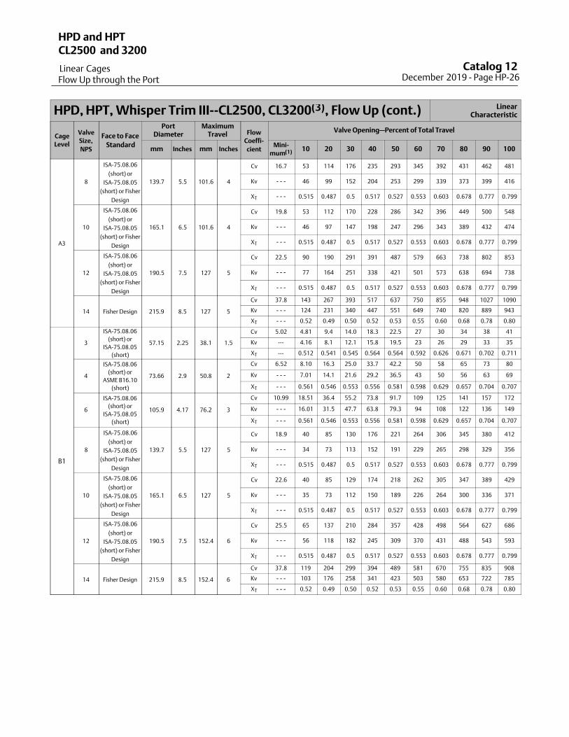
HPD, HPT, Whisper Trim III‐‐CL2500, CL3200(3), Flow Up (cont.) LinearCharacteristic
Cage
Level
Valve
Size,
NPS
Face to Face
Standard
PortDiameter
MaximumTravel Flow
Coeffi‐
cient
Valve Opening—Percent of Total Travel
mm Inches mm InchesMini‐
mum(1) 10 20 30 40 50 60 70 80 90 100
A3
8
ISA-75.08.06
(short) or
ISA-75.08.05
(short) or Fisher
Design
139.7 5.5 101.6 4
Cv 16.7 53 114 176 235 293 345 392 431 462 481
Kv ‐ ‐ ‐ 46 99 152 204 253 299 339 373 399 416
XT ‐ ‐ ‐ 0.515 0.487 0.5 0.517 0.527 0.553 0.603 0.678 0.777 0.799
10
ISA-75.08.06
(short) or
ISA-75.08.05
(short) or Fisher
Design
165.1 6.5 101.6 4
Cv 19.8 53 112 170 228 286 342 396 449 500 548
Kv ‐ ‐ ‐ 46 97 147 198 247 296 343 389 432 474
XT ‐ ‐ ‐ 0.515 0.487 0.5 0.517 0.527 0.553 0.603 0.678 0.777 0.799
12
ISA-75.08.06
(short) or
ISA-75.08.05
(short) or Fisher
Design
190.5 7.5 127 5
Cv 22.5 90 190 291 391 487 579 663 738 802 853
Kv ‐ ‐ ‐ 77 164 251 338 421 501 573 638 694 738
XT ‐ ‐ ‐ 0.515 0.487 0.5 0.517 0.527 0.553 0.603 0.678 0.777 0.799
14 Fisher Design 215.9 8.5 127 5
Cv 37.8 143 267 393 517 637 750 855 948 1027 1090
Kv ‐ ‐ ‐ 124 231 340 447 551 649 740 820 889 943
XT ‐ ‐ ‐ 0.52 0.49 0.50 0.52 0.53 0.55 0.60 0.68 0.78 0.80
B1
3
ISA-75.08.06
(short) or
ISA-75.08.05
(short)
57.15 2.25 38.1 1.5
Cv 5.02 4.81 9.4 14.0 18.3 22.5 27 30 34 38 41
Kv --- 4.16 8.1 12.1 15.8 19.5 23 26 29 33 35
XT --- 0.512 0.541 0.545 0.564 0.564 0.592 0.626 0.671 0.702 0.711
4
ISA-75.08.06
(short) or
ASME B16.10
(short)
73.66 2.9 50.8 2
Cv 6.52 8.10 16.3 25.0 33.7 42.2 50 58 65 73 80
Kv ‐ ‐ ‐ 7.01 14.1 21.6 29.2 36.5 43 50 56 63 69
XT ‐ ‐ ‐ 0.561 0.546 0.553 0.556 0.581 0.598 0.629 0.657 0.704 0.707
6
ISA-75.08.06
(short) or
ISA-75.08.05
(short)
105.9 4.17 76.2 3
Cv 10.99 18.51 36.4 55.2 73.8 91.7 109 125 141 157 172
Kv ‐ ‐ ‐ 16.01 31.5 47.7 63.8 79.3 94 108 122 136 149
XT ‐ ‐ ‐ 0.561 0.546 0.553 0.556 0.581 0.598 0.629 0.657 0.704 0.707
8
ISA-75.08.06
(short) or
ISA-75.08.05
(short) or Fisher
Design
139.7 5.5 127 5
Cv 18.9 40 85 130 176 221 264 306 345 380 412
Kv ‐ ‐ ‐ 34 73 113 152 191 229 265 298 329 356
XT ‐ ‐ ‐ 0.515 0.487 0.5 0.517 0.527 0.553 0.603 0.678 0.777 0.799
10
ISA-75.08.06
(short) or
ISA-75.08.05
(short) or Fisher
Design
165.1 6.5 127 5
Cv 22.6 40 85 129 174 218 262 305 347 389 429
Kv ‐ ‐ ‐ 35 73 112 150 189 226 264 300 336 371
XT ‐ ‐ ‐ 0.515 0.487 0.5 0.517 0.527 0.553 0.603 0.678 0.777 0.799
12
ISA-75.08.06
(short) or
ISA-75.08.05
(short) or Fisher
Design
190.5 7.5 152.4 6
Cv 25.5 65 137 210 284 357 428 498 564 627 686
Kv ‐ ‐ ‐ 56 118 182 245 309 370 431 488 543 593
XT ‐ ‐ ‐ 0.515 0.487 0.5 0.517 0.527 0.553 0.603 0.678 0.777 0.799
14 Fisher Design 215.9 8.5 152.4 6
Cv 37.8 119 204 299 394 489 581 670 755 835 908
Kv ‐ ‐ ‐ 103 176 258 341 423 503 580 653 722 785
XT ‐ ‐ ‐ 0.52 0.49 0.50 0.52 0.53 0.55 0.60 0.68 0.78 0.80
Catalog 12 December 2019 ‐ Page HP-26
HPD and HPT
Linear Cages
CL2500 and 3200
Flow Up through the Port
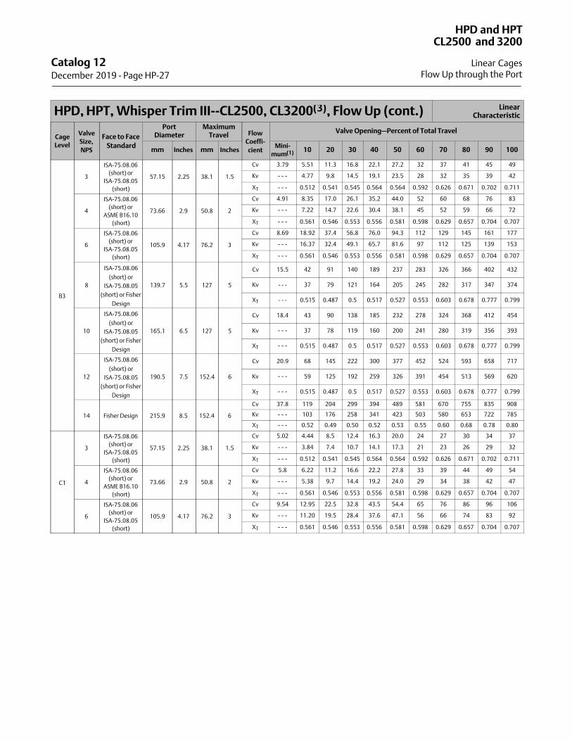
HPD, HPT, Whisper Trim III‐‐CL2500, CL3200(3), Flow Up (cont.) LinearCharacteristic
Cage
Level
Valve
Size,
NPS
Face to Face
Standard
PortDiameter
MaximumTravel Flow
Coeffi‐
cient
Valve Opening—Percent of Total Travel
mm Inches mm InchesMini‐
mum(1) 10 20 30 40 50 60 70 80 90 100
B3
3
ISA-75.08.06
(short) or
ISA-75.08.05
(short)
57.15 2.25 38.1 1.5
Cv 3.79 5.51 11.3 16.8 22.1 27.2 32 37 41 45 49
Kv ‐ ‐ ‐ 4.77 9.8 14.5 19.1 23.5 28 32 35 39 42
XT ‐ ‐ ‐ 0.512 0.541 0.545 0.564 0.564 0.592 0.626 0.671 0.702 0.711
4
ISA-75.08.06
(short) or
ASME B16.10
(short)
73.66 2.9 50.8 2
Cv 4.91 8.35 17.0 26.1 35.2 44.0 52 60 68 76 83
Kv ‐ ‐ ‐ 7.22 14.7 22.6 30.4 38.1 45 52 59 66 72
XT ‐ ‐ ‐ 0.561 0.546 0.553 0.556 0.581 0.598 0.629 0.657 0.704 0.707
6
ISA-75.08.06
(short) or
ISA-75.08.05
(short)
105.9 4.17 76.2 3
Cv 8.69 18.92 37.4 56.8 76.0 94.3 112 129 145 161 177
Kv ‐ ‐ ‐ 16.37 32.4 49.1 65.7 81.6 97 112 125 139 153
XT ‐ ‐ ‐ 0.561 0.546 0.553 0.556 0.581 0.598 0.629 0.657 0.704 0.707
8
ISA-75.08.06
(short) or
ISA-75.08.05
(short) or Fisher
Design
139.7 5.5 127 5
Cv 15.5 42 91 140 189 237 283 326 366 402 432
Kv ‐ ‐ ‐ 37 79 121 164 205 245 282 317 347 374
XT ‐ ‐ ‐ 0.515 0.487 0.5 0.517 0.527 0.553 0.603 0.678 0.777 0.799
10
ISA-75.08.06
(short) or
ISA-75.08.05
(short) or Fisher
Design
165.1 6.5 127 5
Cv 18.4 43 90 138 185 232 278 324 368 412 454
Kv ‐ ‐ ‐ 37 78 119 160 200 241 280 319 356 393
XT ‐ ‐ ‐ 0.515 0.487 0.5 0.517 0.527 0.553 0.603 0.678 0.777 0.799
12
ISA-75.08.06
(short) or
ISA-75.08.05
(short) or Fisher
Design
190.5 7.5 152.4 6
Cv 20.9 68 145 222 300 377 452 524 593 658 717
Kv ‐ ‐ ‐ 59 125 192 259 326 391 454 513 569 620
XT ‐ ‐ ‐ 0.515 0.487 0.5 0.517 0.527 0.553 0.603 0.678 0.777 0.799
14 Fisher Design 215.9 8.5 152.4 6
Cv 37.8 119 204 299 394 489 581 670 755 835 908
Kv ‐ ‐ ‐ 103 176 258 341 423 503 580 653 722 785
XT ‐ ‐ ‐ 0.52 0.49 0.50 0.52 0.53 0.55 0.60 0.68 0.78 0.80
C1
3
ISA-75.08.06
(short) or
ISA-75.08.05
(short)
57.15 2.25 38.1 1.5
Cv 5.02 4.44 8.5 12.4 16.3 20.0 24 27 30 34 37
Kv ‐ ‐ ‐ 3.84 7.4 10.7 14.1 17.3 21 23 26 29 32
XT ‐ ‐ ‐ 0.512 0.541 0.545 0.564 0.564 0.592 0.626 0.671 0.702 0.711
4
ISA-75.08.06
(short) or
ASME B16.10
(short)
73.66 2.9 50.8 2
Cv 5.8 6.22 11.2 16.6 22.2 27.8 33 39 44 49 54
Kv ‐ ‐ ‐ 5.38 9.7 14.4 19.2 24.0 29 34 38 42 47
XT ‐ ‐ ‐ 0.561 0.546 0.553 0.556 0.581 0.598 0.629 0.657 0.704 0.707
6
ISA-75.08.06
(short) or
ISA-75.08.05
(short)
105.9 4.17 76.2 3
Cv 9.54 12.95 22.5 32.8 43.5 54.4 65 76 86 96 106
Kv ‐ ‐ ‐ 11.20 19.5 28.4 37.6 47.1 56 66 74 83 92
XT ‐ ‐ ‐ 0.561 0.546 0.553 0.556 0.581 0.598 0.629 0.657 0.704 0.707
Catalog 12 December 2019 ‐ Page HP-27
HPD and HPT
Linear Cages
CL2500 and 3200
Flow Up through the Port
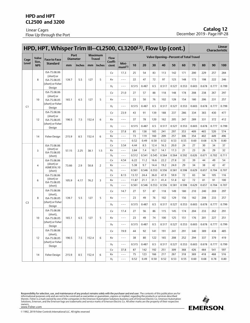
HPD, HPT, Whisper Trim III‐‐CL2500, CL3200(3), Flow Up (cont.) LinearCharacteristic
Cage
Level
Valve
Size,
NPS
Face to Face
Standard
PortDiameter
MaximumTravel Flow
Coeffi‐
cient
Valve Opening—Percent of Total Travel
mm Inches mm InchesMini‐
mum(1) 10 20 30 40 50 60 70 80 90 100
C1
8
ISA-75.08.06
(short) or
ISA-75.08.05
(short) or Fisher
Design
139.7 5.5 127 5
Cv 17.3 25 54 83 113 142 171 200 229 257 284
Kv ‐ ‐ ‐ 22 47 72 97 123 148 173 198 222 246
XT ‐ ‐ ‐ 0.515 0.487 0.5 0.517 0.527 0.553 0.603 0.678 0.777 0.799
10
ISA-75.08.06
(short) or
ISA-75.08.05
(short) or Fisher
Design
165.1 6.5 127 5
Cv 21.0 27 57 88 118 148 178 208 238 267 297
Kv ‐ ‐ ‐ 23 50 76 102 128 154 180 206 231 257
XT ‐ ‐ ‐ 0.515 0.487 0.5 0.517 0.527 0.553 0.603 0.678 0.777 0.799
12
ISA-75.08.06
(short) or
ISA-75.08.05
(short) or Fisher
Design
190.5 7.5 152.4 6
Cv 23.9 43 91 139 188 237 286 334 383 430 477
Kv ‐ ‐ ‐ 37 78 120 162 205 247 289 331 372 412
XT ‐ ‐ ‐ 0.515 0.487 0.5 0.517 0.527 0.553 0.603 0.678 0.777 0.799
14 Fisher Design 215.9 8.5 152.4 6
Cv 37.8 85 138 185 241 297 353 409 465 520 574
Kv ‐ ‐ ‐ 73 119 160 209 257 306 354 402 449 496
XT ‐ ‐ ‐ 0.52 0.49 0.50 0.52 0.53 0.55 0.60 0.68 0.78 0.80
C3
3
ISA-75.08.06
(short) or
ISA-75.08.05
(short)
57.15 2.25 38.1 1.5
Cv 3.54 4.44 8.5 12.4 16.3 20.0 24 27 30 34 37
Kv ‐ ‐ ‐ 3.84 7.4 10.7 14.1 17.3 21 23 26 29 32
XT ‐ ‐ ‐ 0.512 0.541 0.545 0.564 0.564 0.592 0.626 0.671 0.702 0.711
4
ISA-75.08.06
(short) or
ASME B16.10
(short)
73.66 2.9 50.8 2
Cv 4.54 6.22 11.2 16.6 22.2 27.8 33 39 44 49 54
Kv ‐ ‐ ‐ 5.38 9.7 14.4 19.2 24.0 29 34 38 42 47
XT ‐ ‐ ‐ 0.561 0.546 0.553 0.556 0.581 0.598 0.629 0.657 0.704 0.707
6
ISA-75.08.06
(short) or
ISA-75.08.05
(short)
105.9 4.17 76.2 3
Cv 8.13 13.72 24.4 36.0 47.9 59.9 72 83 94 105 116
Kv ‐ ‐ ‐ 11.87 21.1 31.1 41.4 51.8 62 72 81 91 100
XT ‐ ‐ ‐ 0.561 0.546 0.553 0.556 0.581 0.598 0.629 0.657 0.704 0.707
8
ISA-75.08.06
(short),
ISA-75.08.05
(short) or Fisher
Design
139.7 5.5 127 5
Cv 14.7 27 57 87 118 149 180 210 240 269 297
Kv ‐ ‐ ‐ 23 49 76 102 129 156 182 208 233 257
XT ‐ ‐ ‐ 0.515 0.487 0.5 0.517 0.527 0.553 0.603 0.678 0.777 0.799
10
ISA-75.08.06
(short),
ISA-75.08.05
(short) or Fisher
Design
165.1 6.5 127 5
Cv 17.4 27 56 86 115 145 174 204 233 262 291
Kv ‐ ‐ ‐ 23 49 74 100 125 151 176 201 227 251
XT ‐ ‐ ‐ 0.515 0.487 0.5 0.517 0.527 0.553 0.603 0.678 0.777 0.799
12
ISA-75.08.06
(short),
ISA-75.08.05
(short) or Fisher
Design
190.5 7.5 152.4 6
Cv 19.9 44 92 141 191 241 291 340 389 438 485
Kv ‐ ‐ ‐ 38 80 122 165 208 252 294 337 379 419
XT ‐ ‐ ‐ 0.515 0.487 0.5 0.517 0.527 0.553 0.603 0.678 0.777 0.799
14 Fisher Design 215.9 8.5 152.4 6
Cv 37.8 87 142 192 251 309 368 426 484 541 597
Kv ‐ ‐ ‐ 75 123 166 217 267 318 369 418 468 516
XT ‐ ‐ ‐ 0.52 0.49 0.50 0.52 0.53 0.55 0.60 0.68 0.78 0.80
Catalog 12 December 2019 ‐ Page HP-28
HPD and HPT
Linear Cages
CL2500 and 3200
Flow Up through the Port
� 1992, 2019 Fisher Controls International LLC. All rights reserved
www.Fisher.com
Responsibility for selection, use, and maintenance of any product remains solely with the purchaser and end user. The contents of this publication are forinformational purposes only and are not to be construed as warranties or guarantees, express or implied, regarding the products or services describedtherein. Fisher is a mark owned by one of the companies in the Emerson Automation Solutions business unit of Emerson Electric Co. Emerson AutomationSolutions, Emerson, and the Emerson logo are trademarks and service marks of Emerson Electric Co. All other marks are the property of their respectiveowners.
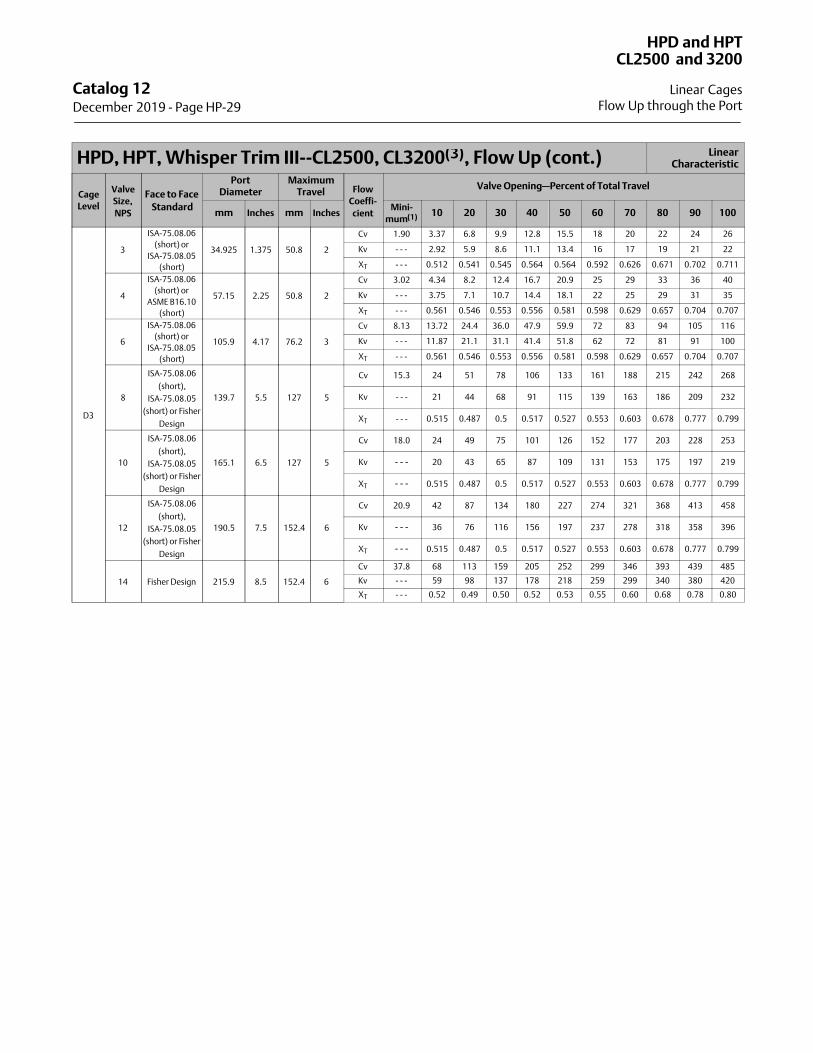
HPD, HPT, Whisper Trim III‐‐CL2500, CL3200(3), Flow Up (cont.) LinearCharacteristic
Cage
Level
Valve
Size,
NPS
Face to Face
Standard
PortDiameter
MaximumTravel Flow
Coeffi‐
cient
Valve Opening—Percent of Total Travel
mm Inches mm InchesMini‐
mum(1) 10 20 30 40 50 60 70 80 90 100
D3
3
ISA-75.08.06
(short) or
ISA-75.08.05
(short)
34.925 1.375 50.8 2
Cv 1.90 3.37 6.8 9.9 12.8 15.5 18 20 22 24 26
Kv ‐ ‐ ‐ 2.92 5.9 8.6 11.1 13.4 16 17 19 21 22
XT ‐ ‐ ‐ 0.512 0.541 0.545 0.564 0.564 0.592 0.626 0.671 0.702 0.711
4
ISA-75.08.06
(short) or
ASME B16.10
(short)
57.15 2.25 50.8 2
Cv 3.02 4.34 8.2 12.4 16.7 20.9 25 29 33 36 40
Kv ‐ ‐ ‐ 3.75 7.1 10.7 14.4 18.1 22 25 29 31 35
XT ‐ ‐ ‐ 0.561 0.546 0.553 0.556 0.581 0.598 0.629 0.657 0.704 0.707
6
ISA-75.08.06
(short) or
ISA-75.08.05
(short)
105.9 4.17 76.2 3
Cv 8.13 13.72 24.4 36.0 47.9 59.9 72 83 94 105 116
Kv ‐ ‐ ‐ 11.87 21.1 31.1 41.4 51.8 62 72 81 91 100
XT ‐ ‐ ‐ 0.561 0.546 0.553 0.556 0.581 0.598 0.629 0.657 0.704 0.707
8
ISA-75.08.06
(short),
ISA-75.08.05
(short) or Fisher
Design
139.7 5.5 127 5
Cv 15.3 24 51 78 106 133 161 188 215 242 268
Kv ‐ ‐ ‐ 21 44 68 91 115 139 163 186 209 232
XT ‐ ‐ ‐ 0.515 0.487 0.5 0.517 0.527 0.553 0.603 0.678 0.777 0.799
10
ISA-75.08.06
(short),
ISA-75.08.05
(short) or Fisher
Design
165.1 6.5 127 5
Cv 18.0 24 49 75 101 126 152 177 203 228 253
Kv ‐ ‐ ‐ 20 43 65 87 109 131 153 175 197 219
XT ‐ ‐ ‐ 0.515 0.487 0.5 0.517 0.527 0.553 0.603 0.678 0.777 0.799
12
ISA-75.08.06
(short),
ISA-75.08.05
(short) or Fisher
Design
190.5 7.5 152.4 6
Cv 20.9 42 87 134 180 227 274 321 368 413 458
Kv ‐ ‐ ‐ 36 76 116 156 197 237 278 318 358 396
XT ‐ ‐ ‐ 0.515 0.487 0.5 0.517 0.527 0.553 0.603 0.678 0.777 0.799
14 Fisher Design 215.9 8.5 152.4 6
Cv 37.8 68 113 159 205 252 299 346 393 439 485
Kv ‐ ‐ ‐ 59 98 137 178 218 259 299 340 380 420
XT ‐ ‐ ‐ 0.52 0.49 0.50 0.52 0.53 0.55 0.60 0.68 0.78 0.80
Catalog 12 December 2019 ‐ Page HP-29
HPD and HPT
Linear Cages
CL2500 and 3200
Flow Up through the Port
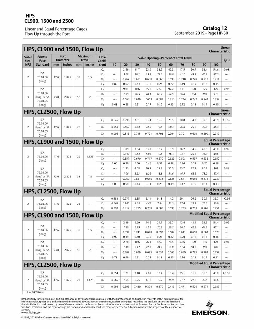
HPS, CL900 and 1500, Flow Up LinearCharacteristic
ValveSize,NPS
Face to
FaceStandard
PortDiameter
MaximumTravel
FlowCoeffi‐cient
Valve Opening—Percent of Total TravelFL
(1)
mm Inches mm Inches 10 20 30 40 50 60 70 80 90 100
2
ISA
75.08.06
(long)
47.6 1.875 38 1.5
Cv ‐ ‐ ‐ 3.56 11.7 23.0 33.9 42.3 47.5 50.7 53.4 54.6 0.98
Kv
‐ ‐ ‐ 3.08 10.1 19.9 29.3 36.6 41.1 43.9 46.2 47.2 ‐ ‐ ‐
XT ‐ ‐ ‐ 0.767 0.681 0.658 0.666 0.693 0.718 0.728 0.719 0.711 ‐ ‐ ‐
Fd 0.89 0.62 0.44 0.30 0.24 0.22 0.19 0.17 0.16 0.15 ‐ ‐ ‐
3
ISA
75.08.06
(long) or ISA
75.08.05
(long)
73.0 2.875 50 2
Cv ‐ ‐ ‐ 9.01 30.6 55.6 78.9 97.7 111 120 125 127 0.96
Kv
‐ ‐ ‐ 7.79 26.5 48.1 68.2 84.5 96.0 104 108 110 ‐ ‐ ‐
XT ‐ ‐ ‐ 0.660 0.636 .0663 0.687 0.713 0.734 0.742 0.742 0.739 ‐ ‐ ‐
Fd 0.48 0.28 0.21 0.17 0.15 0.13 0.12 0.11 0.11 0.10 ‐ ‐ ‐
HPS, CL2500, Flow Up LinearCharacteristic
2
ISA
75.08.06
(long) or ISA
75.08.05
(long)
47.6 1.875 25 1
Cv 0.645 0.996 3.51 8.74 15.9 23.5 30.0 34.3 37.0 40.9 >0.96
Kv
0.558 0.862 3.04 7.56 13.8 20.3 26.0 29.7 32.0 35.4 ‐ ‐ ‐
XT 0.905 0.813 0.715 0.701 0.703 0.704 0.701 0.699 0.699 0.710 ‐ ‐ ‐
HPS, CL900 and 1500, Flow Up Equal PercentageCharacteristic
2
ISA
75.08.06
(long)
47.6 1.875 29 1.125
Cv ‐ ‐ ‐ 1.09 3.04 6.77 12.2 18.9 26.7 34.5 40.5 45.8 0.92
Kv
‐ ‐ ‐ 0.943 2.63 5.86 10.6 16.3 23.1 29.8 35.0 39.6 ‐ ‐ ‐
XT ‐ ‐ ‐ 0.357 0.670 0.717 0.670 0.629 0.598 0.597 0.632 0.652 ‐ ‐ ‐
Fd 1.00 0.76 0.50 0.40 0.31 0.28 0.24 0.22 0.20 0.19 ‐ ‐ ‐
3
ISA
75.08.06
(long) or ISA
75.08.05
(long)
73.0 2.875 38 1.5
Cv ‐ ‐ ‐ 1.23 4.08 10.7 21.7 36.5 53.7 72.2 90.2 101 0.88
Kv
‐ ‐ ‐ 1.06 3.53 9.26 18.8 31.6 46.5 62.5 78.0 87.4 ‐ ‐ ‐
XT ‐ ‐ ‐ 0.967 0.821 0.685 0.634 0.628 0.641 0.659 0.672 0.730 ‐ ‐ ‐
Fd 1.00 0.54 0.44 0.31 0.23 0.19 0.17 0.15 0.14 0.13 ‐ ‐ ‐
HPS, CL2500, Flow Up Equal PercentageCharacteristic
2
ISA
75.08.06
(long)
47.6 1.875 25 1
Cv 0.653 0.977 2.35 5.14 9.18 14.2 20.1 26.2 30.7 35.7 >0.96
Kv
0.565 0.845 2.03 4.45 7.94 12.3 17.4 22.7 26.6 30.9 ‐ ‐ ‐
XT 0.997 0.912 0.785 0.708 0.680 0.690 0.733 0.763 0.768 0.751 ‐ ‐ ‐
HPS, CL900 and 1500, Flow Up Modified Equal PercentageCharacteristic
2
ISA
75.08.06
(long)
47.6 1.875 38 1.5
Cv ‐ ‐ ‐ 2.19 6.69 14.5 24.1 33.7 42.4 48.9 51.9 54.4 0.95
Kv
‐ ‐ ‐ 1.89 5.79 12.5 20.8 29.2 36.7 42.3 44.9 47.1 ‐ ‐ ‐
XT ‐ ‐ ‐ 0.594 0.741 0.648 0.592 0.602 0.641 0.660 0.663 0.670 ‐ ‐ ‐
Fd 0.99 0.49 0.40 0.30 0.26 0.22 0.20 0.18 0.16 0.16 ‐ ‐ ‐
3
ISA
75.08.06
(long) or ISA
75.08.05
(long)
73.0 2.875 50 2
Cv ‐ ‐ ‐ 2.78 10.6 26.3 47.9 71.5 93.6 109 116 124 0.95
Kv
‐ ‐ ‐ 2.40 9.17 22.7 41.4 61.8 81.0 94.3 100 107 ‐ ‐ ‐
XT ‐ ‐ ‐ 0.902 0.690 0.625 0.637 0.666 0.689 0.725 0.783 0.757 ‐ ‐ ‐
Fd 0.78 0.49 0.31 0.22 0.18 0.15 0.14 0.12 0.11 0.11 ‐ ‐ ‐
HPS, CL2500, Flow Up Modified Equal PercentageCharacteristic
2
ISA
75.08.06
(long) or ISA
75.08.05
(long)
47.6 1.875 29 1.125
Cv 0.654 1.21 3.18 7.07 12.4 18.4 25.1 31.5 35.6 40.0 >0.96
Kv
0.566 1.05 2.75 6.12 10.7 15.9 21.7 27.2 30.8 34.6 ‐ ‐ ‐
XT 0.998 0.595 0.430 0.374 0.370 0.413 0.471 0.526 0.571 0.689 ‐ ‐ ‐
1. At 100% travel.
Catalog 12 September 2019 ‐ Page HP-30
HPS
Linear and Equal Percentage Cages
CL900, 1500 and 2500
Flow Up through the Port
� 1992, 2019 Fisher Controls International LLC. All rights reserved
www.Fisher.com
Responsibility for selection, use, and maintenance of any product remains solely with the purchaser and end user. The contents of this publication are forinformational purposes only and are not to be construed as warranties or guarantees, express or implied, regarding the products or services describedtherein. Fisher is a mark owned by one of the companies in the Emerson Automation Solutions business unit of Emerson Electric Co. Emerson AutomationSolutions, Emerson, and the Emerson logo are trademarks and service marks of Emerson Electric Co. All other marks are the property of their respectiveowners.
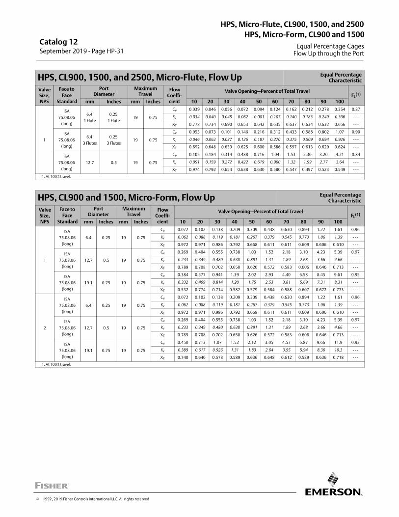
HPS, CL900, 1500, and 2500, Micro‐Flute, Flow Up Equal PercentageCharacteristic
ValveSize,NPS
Face to
FaceStandard
PortDiameter
MaximumTravel
FlowCoeffi‐cient
Valve Opening—Percent of Total TravelFL
(1)
mm Inches mm Inches 10 20 30 40 50 60 70 80 90 100
1
ISA
75.08.06
(long)
6.4
1 Flute
0.25
1 Flute19 0.75
Cv 0.039 0.046 0.056 0.072 0.094 0.124 0.162 0.212 0.278 0.354 0.87
Kv
0.034 0.040 0.048 0.062 0.081 0.107 0.140 0.183 0.240 0.306 ‐ ‐ ‐
XT 0.778 0.734 0.690 0.653 0.642 0.635 0.637 0.634 0.632 0.656 ‐ ‐ ‐
ISA
75.08.06
(long)
6.4
3 Flutes
0.25
3 Flutes19 0.75
Cv 0.053 0.073 0.101 0.146 0.216 0.312 0.433 0.588 0.802 1.07 0.90
Kv
0.046 0.063 0.087 0.126 0.187 0.270 0.375 0.509 0.694 0.926 ‐ ‐ ‐
XT 0.692 0.648 0.639 0.625 0.600 0.586 0.597 0.613 0.620 0.624 ‐ ‐ ‐
ISA
75.08.06
(long)
12.7 0.5 19 0.75
Cv 0.105 0.184 0.314 0.488 0.716 1.04 1.53 2.30 3.20 4.21 0.84
Kv
0.091 0.159 0.272 0.422 0.619 0.900 1.32 1.99 2.77 3.64 ‐ ‐ ‐
XT 0.974 0.792 0.654 0.638 0.630 0.580 0.547 0.497 0.523 0.549 ‐ ‐ ‐
1. At 100% travel.
HPS, CL900 and 1500, Micro‐Form, Flow Up Equal PercentageCharacteristic
ValveSize,NPS
Face to
FaceStandard
PortDiameter
MaximumTravel
FlowCoeffi‐cient
Valve Opening—Percent of Total TravelFL
(1)
mm Inches mm Inches 10 20 30 40 50 60 70 80 90 100
1
ISA
75.08.06
(long)
6.4 0.25 19 0.75
Cv 0.072 0.102 0.138 0.209 0.309 0.438 0.630 0.894 1.22 1.61 0.96
Kv
0.062 0.088 0.119 0.181 0.267 0.379 0.545 0.773 1.06 1.39 ‐ ‐ ‐
XT 0.972 0.971 0.986 0.792 0.668 0.611 0.611 0.609 0.606 0.610 ‐ ‐ ‐
ISA
75.08.06
(long)
12.7 0.5 19 0.75
Cv 0.269 0.404 0.555 0.738 1.03 1.52 2.18 3.10 4.23 5.39 0.97
Kv
0.233 0.349 0.480 0.638 0.891 1.31 1.89 2.68 3.66 4.66 ‐ ‐ ‐
XT 0.789 0.708 0.702 0.650 0.626 0.572 0.583 0.606 0.646 0.713 ‐ ‐ ‐
ISA
75.08.06
(long)
19.1 0.75 19 0.75
Cv 0.384 0.577 0.941 1.39 2.02 2.93 4.40 6.58 8.45 9.61 0.95
Kv
0.332 0.499 0.814 1.20 1.75 2.53 3.81 5.69 7.31 8.31 ‐ ‐ ‐
XT 0.532 0.774 0.714 0.587 0.579 0.584 0.588 0.607 0.672 0.773 ‐ ‐ ‐
2
ISA
75.08.06
(long)
6.4 0.25 19 0.75
Cv 0.072 0.102 0.138 0.209 0.309 0.438 0.630 0.894 1.22 1.61 0.96
Kv
0.062 0.088 0.119 0.181 0.267 0.379 0.545 0.773 1.06 1.39 ‐ ‐ ‐
XT 0.972 0.971 0.986 0.792 0.668 0.611 0.611 0.609 0.606 0.610 ‐ ‐ ‐
ISA
75.08.06
(long)
12.7 0.5 19 0.75
Cv 0.269 0.404 0.555 0.738 1.03 1.52 2.18 3.10 4.23 5.39 0.97
Kv
0.233 0.349 0.480 0.638 0.891 1.31 1.89 2.68 3.66 4.66 ‐ ‐ ‐
XT 0.789 0.708 0.702 0.650 0.626 0.572 0.583 0.606 0.646 0.713 ‐ ‐ ‐
ISA
75.08.06
(long)
19.1 0.75 19 0.75
Cv 0.450 0.713 1.07 1.52 2.12 3.05 4.57 6.87 9.66 11.9 0.93
Kv
0.389 0.617 0.926 1.31 1.83 2.64 3.95 5.94 8.36 10.3 ‐ ‐ ‐
XT 0.740 0.640 0.578 0.589 0.636 0.648 0.612 0.589 0.636 0.718 ‐ ‐ ‐
1. At 100% travel.
Catalog 12September 2019 ‐ Page HP-31
HPS, Micro-Flute, CL900, 1500, and 2500
Equal Percentage Cages
HPS, Micro-Form, CL900 and 1500
Flow Up through the Port
� 1992, 2019 Fisher Controls International LLC. All rights reserved
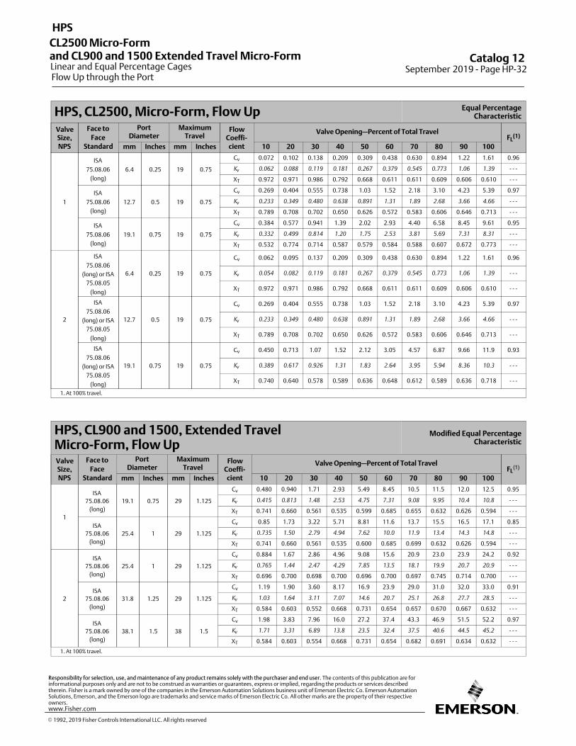
HPS, CL2500, Micro‐Form, Flow Up Equal PercentageCharacteristic
ValveSize,NPS
Face to
FaceStandard
PortDiameter
MaximumTravel
FlowCoeffi‐cient
Valve Opening—Percent of Total TravelFL
(1)
mm Inches mm Inches 10 20 30 40 50 60 70 80 90 100
1
ISA
75.08.06
(long)
6.4 0.25 19 0.75
Cv 0.072 0.102 0.138 0.209 0.309 0.438 0.630 0.894 1.22 1.61 0.96
Kv
0.062 0.088 0.119 0.181 0.267 0.379 0.545 0.773 1.06 1.39 ‐ ‐ ‐
XT 0.972 0.971 0.986 0.792 0.668 0.611 0.611 0.609 0.606 0.610 ‐ ‐ ‐
ISA
75.08.06
(long)
12.7 0.5 19 0.75
Cv 0.269 0.404 0.555 0.738 1.03 1.52 2.18 3.10 4.23 5.39 0.97
Kv
0.233 0.349 0.480 0.638 0.891 1.31 1.89 2.68 3.66 4.66 ‐ ‐ ‐
XT 0.789 0.708 0.702 0.650 0.626 0.572 0.583 0.606 0.646 0.713 ‐ ‐ ‐
ISA
75.08.06
(long)
19.1 0.75 19 0.75
Cv 0.384 0.577 0.941 1.39 2.02 2.93 4.40 6.58 8.45 9.61 0.95
Kv
0.332 0.499 0.814 1.20 1.75 2.53 3.81 5.69 7.31 8.31 ‐ ‐ ‐
XT 0.532 0.774 0.714 0.587 0.579 0.584 0.588 0.607 0.672 0.773 ‐ ‐ ‐
2
ISA
75.08.06
(long) or ISA
75.08.05
(long)
6.4 0.25 19 0.75
Cv 0.062 0.095 0.137 0.209 0.309 0.438 0.630 0.894 1.22 1.61 0.96
Kv
0.054 0.082 0.119 0.181 0.267 0.379 0.545 0.773 1.06 1.39 ‐ ‐ ‐
XT 0.972 0.971 0.986 0.792 0.668 0.611 0.611 0.609 0.606 0.610 ‐ ‐ ‐
ISA
75.08.06
(long) or ISA
75.08.05
(long)
12.7 0.5 19 0.75
Cv 0.269 0.404 0.555 0.738 1.03 1.52 2.18 3.10 4.23 5.39 0.97
Kv
0.233 0.349 0.480 0.638 0.891 1.31 1.89 2.68 3.66 4.66 ‐ ‐ ‐
XT 0.789 0.708 0.702 0.650 0.626 0.572 0.583 0.606 0.646 0.713 ‐ ‐ ‐
ISA
75.08.06
(long) or ISA
75.08.05
(long)
19.1 0.75 19 0.75
Cv 0.450 0.713 1.07 1.52 2.12 3.05 4.57 6.87 9.66 11.9 0.93
Kv
0.389 0.617 0.926 1.31 1.83 2.64 3.95 5.94 8.36 10.3 ‐ ‐ ‐
XT 0.740 0.640 0.578 0.589 0.636 0.648 0.612 0.589 0.636 0.718 ‐ ‐ ‐
1. At 100% travel.
HPS, CL900 and 1500, Extended Travel Micro‐Form, Flow Up
Modified Equal PercentageCharacteristic
ValveSize,NPS
Face to
FaceStandard
PortDiameter
MaximumTravel
FlowCoeffi‐cient
Valve Opening—Percent of Total TravelFL
(1)
mm Inches mm Inches 10 20 30 40 50 60 70 80 90 100
1
ISA
75.08.06
(long)
19.1 0.75 29 1.125
Cv 0.480 0.940 1.71 2.93 5.49 8.45 10.5 11.5 12.0 12.5 0.95
Kv
0.415 0.813 1.48 2.53 4.75 7.31 9.08 9.95 10.4 10.8 ‐ ‐ ‐
XT 0.741 0.660 0.561 0.535 0.599 0.685 0.655 0.632 0.626 0.594 ‐ ‐ ‐
ISA
75.08.06
(long)
25.4 1 29 1.125
Cv 0.85 1.73 3.22 5.71 8.81 11.6 13.7 15.5 16.5 17.1 0.85
Kv
0.735 1.50 2.79 4.94 7.62 10.0 11.9 13.4 14.3 14.8 ‐ ‐ ‐
XT 0.741 0.660 0.561 0.535 0.600 0.685 0.699 0.632 0.626 0.594 ‐ ‐ ‐
2
ISA
75.08.06
(long)
25.4 1 29 1.125
Cv 0.884 1.67 2.86 4.96 9.08 15.6 20.9 23.0 23.9 24.2 0.92
Kv
0.765 1.44 2.47 4.29 7.85 13.5 18.1 19.9 20.7 20.9 ‐ ‐ ‐
XT 0.696 0.700 0.698 0.700 0.696 0.700 0.697 0.745 0.714 0.700 ‐ ‐ ‐
ISA
75.08.06
(long)
31.8 1.25 29 1.125
Cv 1.19 1.90 3.60 8.17 16.9 23.9 29.0 31.0 32.0 33.0 0.91
Kv
1.03 1.64 3.11 7.07 14.6 20.7 25.1 26.8 27.7 28.5 ‐ ‐ ‐
XT 0.584 0.603 0.552 0.668 0.731 0.654 0.657 0.670 0.667 0.632 ‐ ‐ ‐
ISA
75.08.06
(long)
38.1 1.5 38 1.5
Cv 1.98 3.83 7.96 16.0 27.2 37.4 43.3 46.9 51.5 52.2 0.97
Kv
1.71 3.31 6.89 13.8 23.5 32.4 37.5 40.6 44.5 45.2 ‐ ‐ ‐
XT 0.584 0.603 0.554 0.668 0.731 0.654 0.682 0.691 0.634 0.632 ‐ ‐ ‐
1. At 100% travel.
Catalog 12 September 2019 ‐ Page HP-32
HPS
Linear and Equal Percentage Cages
CL2500 Micro-Formand CL900 and 1500 Extended Travel Micro-Form
Flow Up through the Port
� 1992, 2019 Fisher Controls International LLC. All rights reserved
www.Fisher.com
Responsibility for selection, use, and maintenance of any product remains solely with the purchaser and end user. The contents of this publication are forinformational purposes only and are not to be construed as warranties or guarantees, express or implied, regarding the products or services describedtherein. Fisher is a mark owned by one of the companies in the Emerson Automation Solutions business unit of Emerson Electric Co. Emerson AutomationSolutions, Emerson, and the Emerson logo are trademarks and service marks of Emerson Electric Co. All other marks are the property of their respectiveowners.
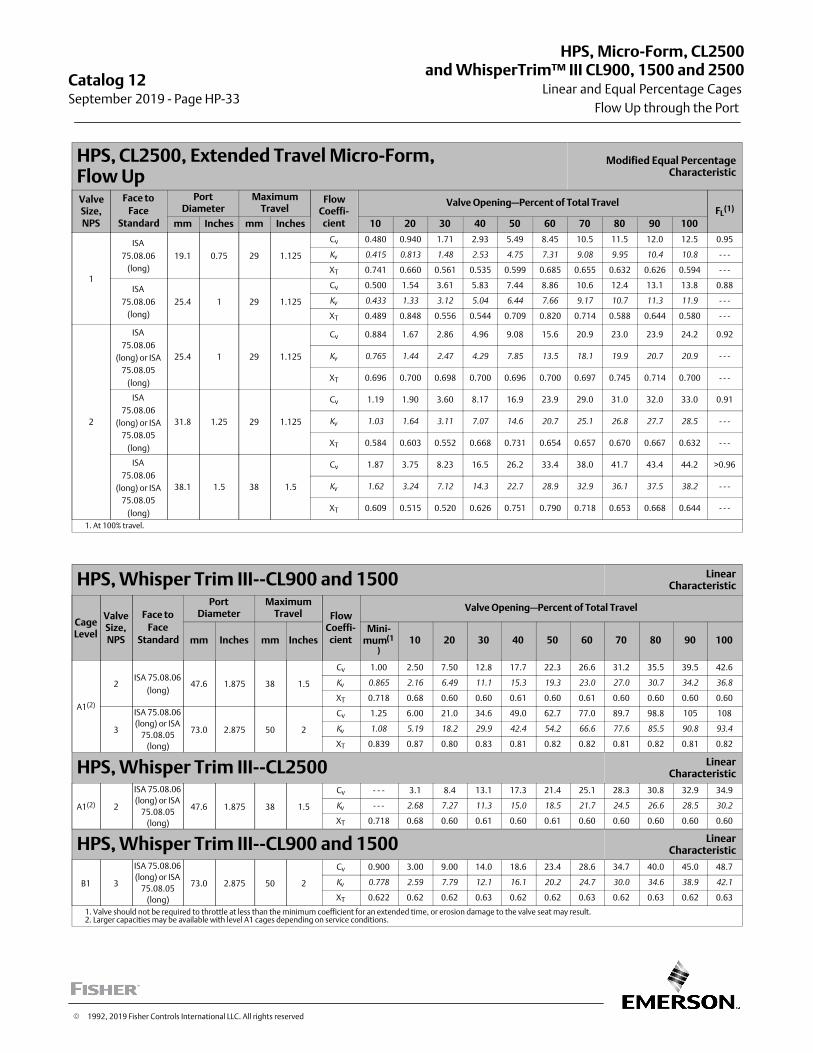
HPS, CL2500, Extended Travel Micro‐Form, Flow Up
Modified Equal PercentageCharacteristic
ValveSize,NPS
Face to
FaceStandard
PortDiameter
MaximumTravel
FlowCoeffi‐cient
Valve Opening—Percent of Total TravelFL
(1)
mm Inches mm Inches 10 20 30 40 50 60 70 80 90 100
1
ISA
75.08.06
(long)
19.1 0.75 29 1.125
Cv 0.480 0.940 1.71 2.93 5.49 8.45 10.5 11.5 12.0 12.5 0.95
Kv
0.415 0.813 1.48 2.53 4.75 7.31 9.08 9.95 10.4 10.8 ‐ ‐ ‐
XT 0.741 0.660 0.561 0.535 0.599 0.685 0.655 0.632 0.626 0.594 ‐ ‐ ‐
ISA
75.08.06
(long)
25.4 1 29 1.125
Cv 0.500 1.54 3.61 5.83 7.44 8.86 10.6 12.4 13.1 13.8 0.88
Kv
0.433 1.33 3.12 5.04 6.44 7.66 9.17 10.7 11.3 11.9 ‐ ‐ ‐
XT 0.489 0.848 0.556 0.544 0.709 0.820 0.714 0.588 0.644 0.580 ‐ ‐ ‐
2
ISA
75.08.06
(long) or ISA
75.08.05
(long)
25.4 1 29 1.125
Cv 0.884 1.67 2.86 4.96 9.08 15.6 20.9 23.0 23.9 24.2 0.92
Kv
0.765 1.44 2.47 4.29 7.85 13.5 18.1 19.9 20.7 20.9 ‐ ‐ ‐
XT 0.696 0.700 0.698 0.700 0.696 0.700 0.697 0.745 0.714 0.700 ‐ ‐ ‐
ISA
75.08.06
(long) or ISA
75.08.05
(long)
31.8 1.25 29 1.125
Cv 1.19 1.90 3.60 8.17 16.9 23.9 29.0 31.0 32.0 33.0 0.91
Kv
1.03 1.64 3.11 7.07 14.6 20.7 25.1 26.8 27.7 28.5 ‐ ‐ ‐
XT 0.584 0.603 0.552 0.668 0.731 0.654 0.657 0.670 0.667 0.632 ‐ ‐ ‐
ISA
75.08.06
(long) or ISA
75.08.05
(long)
38.1 1.5 38 1.5
Cv 1.87 3.75 8.23 16.5 26.2 33.4 38.0 41.7 43.4 44.2 >0.96
Kv
1.62 3.24 7.12 14.3 22.7 28.9 32.9 36.1 37.5 38.2 ‐ ‐ ‐
XT 0.609 0.515 0.520 0.626 0.751 0.790 0.718 0.653 0.668 0.644 ‐ ‐ ‐
1. At 100% travel.
HPS, Whisper Trim III‐‐CL900 and 1500 LinearCharacteristic
CageLevel
ValveSize,NPS
Face to
FaceStandard
PortDiameter
MaximumTravel Flow
Coeffi‐cient
Valve Opening—Percent of Total Travel
mm Inches mm InchesMini‐
mum(1
)10 20 30 40 50 60 70 80 90 100
A1(2)
2ISA 75.08.06
(long)47.6 1.875 38 1.5
Cv 1.00 2.50 7.50 12.8 17.7 22.3 26.6 31.2 35.5 39.5 42.6
Kv
0.865 2.16 6.49 11.1 15.3 19.3 23.0 27.0 30.7 34.2 36.8
XT 0.718 0.68 0.60 0.60 0.61 0.60 0.61 0.60 0.60 0.60 0.60
3
ISA 75.08.06
(long) or ISA
75.08.05
(long)
73.0 2.875 50 2
Cv 1.25 6.00 21.0 34.6 49.0 62.7 77.0 89.7 98.8 105 108
Kv
1.08 5.19 18.2 29.9 42.4 54.2 66.6 77.6 85.5 90.8 93.4
XT 0.839 0.87 0.80 0.83 0.81 0.82 0.82 0.81 0.82 0.81 0.82
HPS, Whisper Trim III‐‐CL2500 LinearCharacteristic
A1(2) 2
ISA 75.08.06
(long) or ISA
75.08.05
(long)
47.6 1.875 38 1.5
Cv ‐ ‐ ‐ 3.1 8.4 13.1 17.3 21.4 25.1 28.3 30.8 32.9 34.9
Kv
‐ ‐ ‐ 2.68 7.27 11.3 15.0 18.5 21.7 24.5 26.6 28.5 30.2
XT 0.718 0.68 0.60 0.61 0.60 0.61 0.60 0.60 0.60 0.60 0.60
HPS, Whisper Trim III‐‐CL900 and 1500 LinearCharacteristic
B1 3
ISA 75.08.06
(long) or ISA
75.08.05
(long)
73.0 2.875 50 2
Cv 0.900 3.00 9.00 14.0 18.6 23.4 28.6 34.7 40.0 45.0 48.7
Kv
0.778 2.59 7.79 12.1 16.1 20.2 24.7 30.0 34.6 38.9 42.1
XT 0.622 0.62 0.62 0.63 0.62 0.62 0.63 0.62 0.63 0.62 0.63
1. Valve should not be required to throttle at less than the minimum coefficient for an extended time, or erosion damage to the valve seat may result.2. Larger capacities may be available with level A1 cages depending on service conditions.
Catalog 12September 2019 ‐ Page HP-33
Linear and Equal Percentage Cages
HPS, Micro-Form, CL2500and WhisperTrim™ III CL900, 1500 and 2500
Flow Up through the Port
� 1992, 2019 Fisher Controls International LLC. All rights reserved
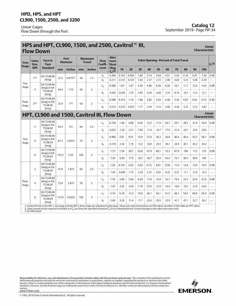
HPS and HPT, CL900, 1500, and 2500, Cavitrol� III, Flow Down
LinearCharacteristic
TrimStage
ValveSize,NPS
Face to
FaceStandard
PortDiameter
MaximumTravel Flow
Coeffi‐cient
MinimumThrottlingCv
(2)
Valve Opening—Percent of Total Travel
FL(3)
mm Inches mm Inches 10 20 30 40 50 60 70 80 90 100
Two
Stage
1(1) ISA 75.08.06
(long)22.2 0.875(1) 38 1.5
Cv 0.360 0.163 0.836 1.80 2.74 3.64 4.51 5.36 6.18 6.91 7.39 0.98
Kv
0.311 0.141 0.723 1.56 2.37 3.15 3.90 4.64 5.35 5.98 6.39 ‐ ‐ ‐
2
ISA 75.08.06
(long) or ISA
75.08.05
(long)
44.4 1.75 50 2
Cv 0.580 1.07 1.97 3.29 4.86 6.58 8.36 10.1 11.7 13.0 14.0 0.98
Kv
0.502 0.926 1.70 2.85 4.20 5.69 7.23 8.74 10.1 11.2 12.1 ‐ ‐ ‐
Three
Stage2(1)
ISA 75.08.06
(long) or ISA
75.08.05
(long)
25.4 1(1) 50 2
Cv 0.590 0.272 1.10 1.98 2.82 3.63 4.46 5.30 6.07 6.61 6.73 0.99
Kv
0.510 0.235 0.952 1.71 2.44 3.14 3.86 4.58 5.25 5.72 5.82 ‐ ‐ ‐
HPT, CL900 and 1500, Cavitrol III, Flow Down LinearCharacteristic
Two
Stage
3
ISA 75.08.06
(long) or ISA
75.08.05
(long)
63.5 2.5 64 2.5
Cv 0.720 1.46 4.98 9.24 13.2 17.0 20.7 24.7 28.5 31.9 34.4 0.98
Kv
0.623 1.26 4.31 7.99 11.4 14.7 17.9 21.4 24.7 27.6 29.8 ‐ ‐ ‐
4
ISA 75.08.06
(long) or ISA
75.08.05
(long)
87.3 3.4375 76 3
Cv 0.900 2.61 9.01 15.6 21.8 28.3 34.8 40.4 46.4 52.2 58.1 0.98
Kv
0.778 2.26 7.79 13.5 18.9 24.5 30.1 34.9 40.1 45.2 50.3 ‐ ‐ ‐
6
ISA 75.08.06
(long) or ISA
75.08.05
(long)
133.3 5.25 102 4
Cv 1.72 7.50 20.7 33.8 47.0 60.1 73.3 87.0 100 112 123 0.98
Kv
1.49 6.49 17.9 29.2 40.7 52.0 63.4 75.3 86.5 96.9 106 ‐ ‐ ‐
Three
Stage
3
ISA 75.08.06
(long) or ISA
75.08.05
(long)
47.6 1.875 64 2.5
Cv 1.20 0.747 2.02 3.92 6.15 8.01 9.50 11.0 12.8 14.9 16.5 0.99
Kv
1.04 0.646 1.75 3.39 5.32 6.93 8.22 9.52 11.1 12.9 14.3 ‐ ‐ ‐
4
ISA 75.08.06
(long) or ISA
75.08.05
(long)
73.0 2.875 76 3
Cv 1.70 2.80 5.50 8.30 11.0 13.9 16.7 19.4 22.2 25.0 27.8 0.99
Kv
1.47 2.42 4.76 7.18 9.52 12.0 14.4 16.8 19.2 21.6 24.0 ‐ ‐ ‐
6
ISA 75.08.06
(long) or ISA
75.08.05
(long)
115.9 4.5625 102 4
Cv 3.10 6.10 13.2 19.8 26.1 34.1 41.5 48.2 54.5 60.9 65.0 0.99
Kv
2.68 5.28 11.4 17.1 22.6 29.5 35.9 41.7 47.1 52.7 56.2 ‐ ‐ ‐
1. Cavitrol III trim in the NPS 1, two stage and the NPS 2, three stage are unbalanced valve plugs. These sizes and constructions are HPS valves; all others in this table are HPT valves.2. Valves should not be required to throttle at a Cv less than the specified minimum Cv for an extended period. Erosion damage to the valve seats may result.3. At 100% travel.
Catalog 12 September 2019 ‐ Page HP-34
HPD, HPS, and HPT
Linear Cages
CL900, 1500, 2500, and 3200
Flow Down through the Port
� 1992, 2019 Fisher Controls International LLC. All rights reserved
www.Fisher.com
Responsibility for selection, use, and maintenance of any product remains solely with the purchaser and end user. The contents of this publication are forinformational purposes only and are not to be construed as warranties or guarantees, express or implied, regarding the products or services describedtherein. Fisher is a mark owned by one of the companies in the Emerson Automation Solutions business unit of Emerson Electric Co. Emerson AutomationSolutions, Emerson, and the Emerson logo are trademarks and service marks of Emerson Electric Co. All other marks are the property of their respectiveowners.
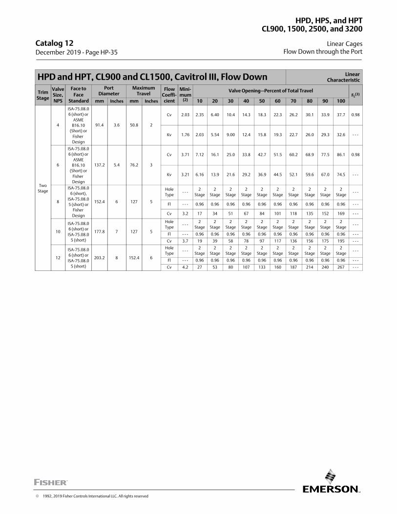
HPD and HPT, CL900 and CL1500, Cavitrol III, Flow Down LinearCharacteristic
TrimStage
ValveSize,NPS
Face to
FaceStandard
PortDiameter
MaximumTravel
FlowCoeffi‐cient
Mini-mum
(2)
Valve Opening—Percent of Total TravelFL
(3)
mm Inches mm Inches 10 20 30 40 50 60 70 80 90 100
Two
Stage
4
ISA-75.08.0
6 (short) or
ASME
B16.10
(Short) or
Fisher
Design
91.4 3.6 50.8 2
Cv 2.03 2.35 6.40 10.4 14.3 18.3 22.3 26.2 30.1 33.9 37.7 0.98
Kv 1.76 2.03 5.54 9.00 12.4 15.8 19.3 22.7 26.0 29.3 32.6 - - -
6
ISA-75.08.0
6 (short) or
ASME
B16.10
(Short) or
Fisher
Design
137.2 5.4 76.2 3
Cv 3.71 7.12 16.1 25.0 33.8 42.7 51.5 60.2 68.9 77.5 86.1 0.98
Kv 3.21 6.16 13.9 21.6 29.2 36.9 44.5 52.1 59.6 67.0 74.5 - - -
8
ISA-75.08.0
6 (short),
ISA-75.08.0
5 (short) or
Fisher
Design
152.4 6 127 5
Hole
Type- - -
2
Stage
2
Stage
2
Stage
2
Stage
2
Stage
2
Stage
2
Stage
2
Stage
2
Stage
2
Stage- - -
Fl - - - 0.96 0.96 0.96 0.96 0.96 0.96 0.96 0.96 0.96 0.96 - - -
Cv 3.2 17 34 51 67 84 101 118 135 152 169 - - -
10
ISA-75.08.0
6 (short) or
ISA-75.08.0
5 (short)
177.8 7 127 5
Hole
Type- - -
2
Stage
2
Stage
2
Stage
2
Stage
2
Stage
2
Stage
2
Stage
2
Stage
2
Stage
2
Stage- - -
Fl - - - 0.96 0.96 0.96 0.96 0.96 0.96 0.96 0.96 0.96 0.96 - - -
Cv 3.7 19 39 58 78 97 117 136 156 175 195 - - -
12
ISA-75.08.0
6 (short) or
ISA-75.08.0
5 (short)
203.2 8 152.4 6
Hole
Type- - -
2
Stage
2
Stage
2
Stage
2
Stage
2
Stage
2
Stage
2
Stage
2
Stage
2
Stage
2
Stage- - -
Fl - - - 0.96 0.96 0.96 0.96 0.96 0.96 0.96 0.96 0.96 0.96 - - -
Cv 4.2 27 53 80 107 133 160 187 214 240 267 - - -
Catalog 12 December 2019 ‐ Page HP-35
HPD, HPS, and HPT
Linear Cages
CL900, 1500, 2500, and 3200
Flow Down through the Port
� 1992, 2019 Fisher Controls International LLC. All rights reserved
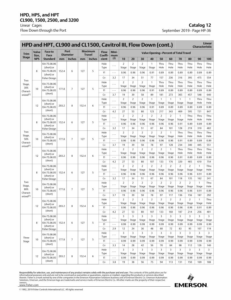
HPD and HPT, CL900 and CL1500, Cavitrol III, Flow Down (cont.) LinearCharacteristic
TrimStage
ValveSize,NPS
Face to
FaceStandard
PortDiameter
MaximumTravel
FlowCoeffi‐cient
Mini-mum
(2)
Valve Opening—Percent of Total Travel
mm Inches mm Inches 10 20 30 40 50 60 70 80 90 100
Two
Stage,
30%
Charact-
erized(1)
8
ISA-75.08.06
(short) or
ISA-75.08.05
(short) or
Fisher Design
152.4 6 127 5
Hole
Type- - -
2
Stage
2
Stage
2
Stage
1
Stage
Thru
Hole
Thru
Hole
Thru
Hole
Thru
Hole
Thru
Hole
Thru
Hole
Fl - - - 0.96 0.96 0.96 0.91 0.89 0.89 0.89 0.89 0.89 0.89
Cv 3.2 17 34 51 77 157 236 316 395 475 554
10
ISA-75.08.06
(short) or
ISA-75.08.05
(short)
177.8 7 127 5
Hole
Type- - -
2
Stage
2
Stage
2
Stage
1
Stage
Thru
Hole
Thru
Hole
Thru
Hole
Thru
Hole
Thru
Hole
Thru
Hole
Fl - - - 0.96 0.96 0.96 0.91 0.89 0.89 0.89 0.89 0.89 0.89
Cv 3.7 19 39 58 89 181 273 365 457 548 640
12
ISA-75.08.06
(short) or
ISA-75.08.05
(short)
203.2 8 152.4 6
Hole
Type- - -
2
Stage
2
Stage
2
Stage
1
Stage
1
Stage
1
Stage
1
Stage
1
Stage
Thru
Hole
Thru
Hole
Fl - - - 0.96 0.96 0.96 0.91 0.89 0.89 0.89 0.89 0.89 0.89
Cv 4.2 27 53 80 123 217 343 469 595 721 847
Two
Stage,
50%
Charact-
erized(1)
8
ISA-75.08.06
(short) or
ISA-75.08.05
(short) or
Fisher Design
152.4 6 127 5
Hole
Type- - -
2
Stage
2
Stage
2
Stage
2
Stage
2
Stage
2
Stage
1
Stage
Thru
Hole
Thru
Hole
Thru
Hole
Fl - - - 0.96 0.96 0.96 0.96 0.96 0.96 0.91 0.89 0.89 0.89
Cv 3.2 17 34 51 67 84 101 128 219 310 402
10
ISA-75.08.06
(short) or
ISA-75.08.05
(short)
177.8 7 127 5
Hole
Type- - -
2
Stage
2
Stage
2
Stage
2
Stage
2
Stage
1
Stage
Thru
Hole
Thru
Hole
Thru
Hole
Thru
Hole
Fl - - - 0.96 0.96 0.96 0.96 0.96 0.96 0.91 0.89 0.89 0.89
Cv 3.7 19 39 58 78 97 128 234 340 445 551
12
ISA-75.08.06
(short) or
ISA-75.08.05
(short)
203.2 8 152.4 6
Hole
Type- - -
2
Stage
2
Stage
2
Stage
2
Stage
2
Stage
1
Stage
Thru
Hole
Thru
Hole
Thru
Hole
Thru
Hole
Fl - - - 0.96 0.96 0.96 0.96 0.96 0.96 0.91 0.89 0.89 0.89
Cv 4.2 27 53 80 107 133 176 320 465 610 754
Two
Stage,
80%
Charact-
erized(1)
8
ISA-75.08.06
(short) or
ISA-75.08.05
(short) or
Fisher Design
152.4 6 127 5
Hole
Type- - -
2
Stage
2
Stage
2
Stage
2
Stage
2
Stage
2
Stage
2
Stage
2
Stage
1
Stage
Thru
Hole
Fl - - - 0.96 0.96 0.96 0.96 0.96 0.96 0.96 0.96 0.91 0.89
Cv 3.2 17 34 51 67 84 101 118 135 162 241
10
ISA-75.08.06
(short) or
ISA-75.08.05
(short)
177.8 7 127 5
Hole
Type- - -
2
Stage
2
Stage
2
Stage
2
Stage
2
Stage
2
Stage
2
Stage
2
Stage
1
Stage
Thru
Hole
Fl - - - 0.96 0.96 0.96 0.96 0.96 0.96 0.96 0.96 0.91 0.89
Cv 3.7 19 39 58 78 97 117 136 156 187 292
12
ISA-75.08.06
(short) or
ISA-75.08.05
(short)
203.2 8 152.4 6
Hole
Type- - -
2
Stage
2
Stage
2
Stage
2
Stage
2
Stage
2
Stage
2
Stage
2
Stage
1
Stage
Thru
Hole
Fl - - - 0.96 0.96 0.96 0.96 0.96 0.96 0.96 0.96 0.91 0.89
Cv 4.2 27 53 80 107 133 160 187 214 256 401
Three
Stage
8
ISA-75.08.06
(short) or
ISA-75.08.05
(short) or
Fisher Design
152.4 6 127 5
Hole
Type- - -
3
Stage
3
Stage
3
Stage
3
Stage
3
Stage
3
Stage
3
Stage
3
Stage
3
Stage
3
Stage
Fl - - - 0.99 0.99 0.99 0.99 0.99 0.99 0.99 0.99 0.99 0.99
Cv 2.9 12 24 36 48 60 72 83 95 107 119
10
ISA-75.08.06
(short) or
ISA-75.08.05
(short)
177.8 7 127 5
Hole
Type- - -
3
Stage
3
Stage
3
Stage
3
Stage
3
Stage
3
Stage
3
Stage
3
Stage
3
Stage
3
Stage
Fl - - - 0.99 0.99 0.99 0.99 0.99 0.99 0.99 0.99 0.99 0.99
Cv 3.3 14 28 42 56 70 84 98 112 126 140
12
ISA-75.08.06
(short) or
ISA-75.08.05
(short)
203.2 8 152.4 6
Hole
Type- - -
3
Stage
3
Stage
3
Stage
3
Stage
3
Stage
3
Stage
3
Stage
3
Stage
3
Stage
3
Stage
Fl - - - 0.99 0.99 0.99 0.99 0.99 0.99 0.99 0.99 0.99 0.99
Cv 3.8 19 38 56 75 94 113 131 150 169 188
Catalog 12September 2019 ‐ Page HP-36
Linear Cages
HPD, HPS, and HPTCL900, 1500, 2500, and 3200
Flow Down through the Port
� 1992, 2019 Fisher Controls International LLC. All rights reserved
www.Fisher.com
Responsibility for selection, use, and maintenance of any product remains solely with the purchaser and end user. The contents of this publication are forinformational purposes only and are not to be construed as warranties or guarantees, express or implied, regarding the products or services describedtherein. Fisher is a mark owned by one of the companies in the Emerson Automation Solutions business unit of Emerson Electric Co. Emerson AutomationSolutions, Emerson, and the Emerson logo are trademarks and service marks of Emerson Electric Co. All other marks are the property of their respectiveowners.
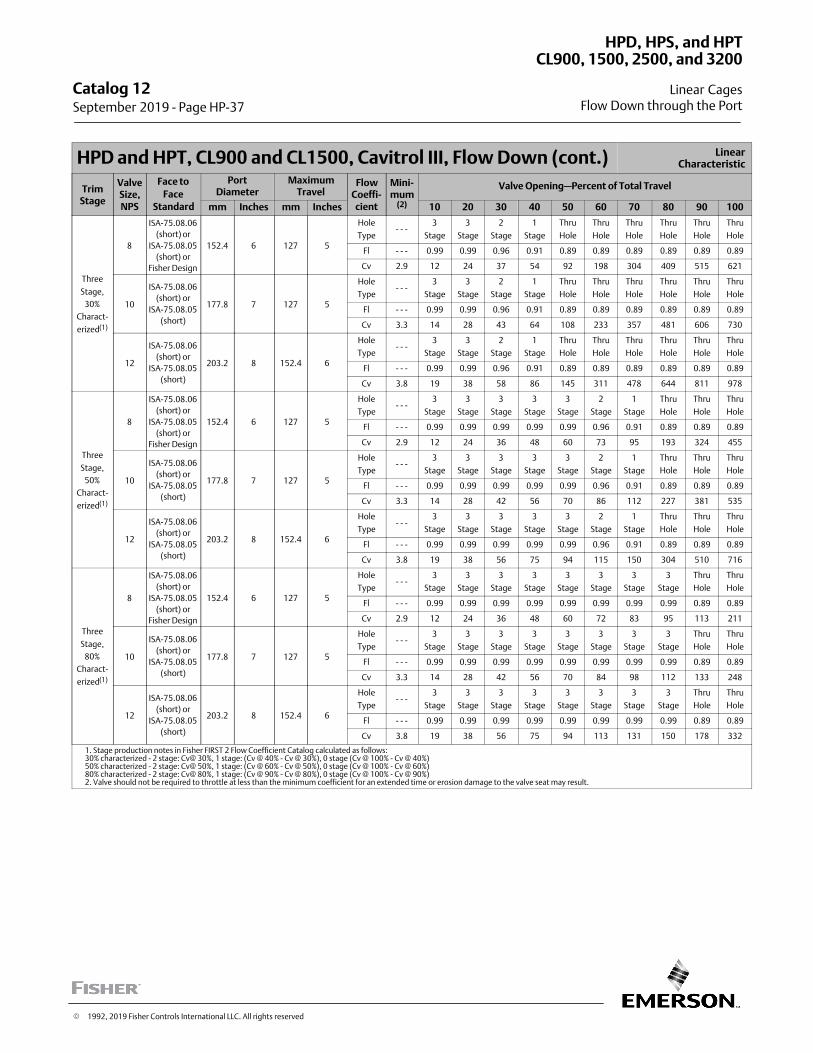
HPD and HPT, CL900 and CL1500, Cavitrol III, Flow Down (cont.) LinearCharacteristic
TrimStage
ValveSize,NPS
Face to
FaceStandard
PortDiameter
MaximumTravel
FlowCoeffi‐cient
Mini-mum
(2)
Valve Opening—Percent of Total Travel
mm Inches mm Inches 10 20 30 40 50 60 70 80 90 100
Three
Stage,
30%
Charact-
erized(1)
8
ISA-75.08.06
(short) or
ISA-75.08.05
(short) or
Fisher Design
152.4 6 127 5
Hole
Type- - -
3
Stage
3
Stage
2
Stage
1
Stage
Thru
Hole
Thru
Hole
Thru
Hole
Thru
Hole
Thru
Hole
Thru
Hole
Fl - - - 0.99 0.99 0.96 0.91 0.89 0.89 0.89 0.89 0.89 0.89
Cv 2.9 12 24 37 54 92 198 304 409 515 621
10
ISA-75.08.06
(short) or
ISA-75.08.05
(short)
177.8 7 127 5
Hole
Type- - -
3
Stage
3
Stage
2
Stage
1
Stage
Thru
Hole
Thru
Hole
Thru
Hole
Thru
Hole
Thru
Hole
Thru
Hole
Fl - - - 0.99 0.99 0.96 0.91 0.89 0.89 0.89 0.89 0.89 0.89
Cv 3.3 14 28 43 64 108 233 357 481 606 730
12
ISA-75.08.06
(short) or
ISA-75.08.05
(short)
203.2 8 152.4 6
Hole
Type- - -
3
Stage
3
Stage
2
Stage
1
Stage
Thru
Hole
Thru
Hole
Thru
Hole
Thru
Hole
Thru
Hole
Thru
Hole
Fl - - - 0.99 0.99 0.96 0.91 0.89 0.89 0.89 0.89 0.89 0.89
Cv 3.8 19 38 58 86 145 311 478 644 811 978
Three
Stage,
50%
Charact-
erized(1)
8
ISA-75.08.06
(short) or
ISA-75.08.05
(short) or
Fisher Design
152.4 6 127 5
Hole
Type- - -
3
Stage
3
Stage
3
Stage
3
Stage
3
Stage
2
Stage
1
Stage
Thru
Hole
Thru
Hole
Thru
Hole
Fl - - - 0.99 0.99 0.99 0.99 0.99 0.96 0.91 0.89 0.89 0.89
Cv 2.9 12 24 36 48 60 73 95 193 324 455
10
ISA-75.08.06
(short) or
ISA-75.08.05
(short)
177.8 7 127 5
Hole
Type- - -
3
Stage
3
Stage
3
Stage
3
Stage
3
Stage
2
Stage
1
Stage
Thru
Hole
Thru
Hole
Thru
Hole
Fl - - - 0.99 0.99 0.99 0.99 0.99 0.96 0.91 0.89 0.89 0.89
Cv 3.3 14 28 42 56 70 86 112 227 381 535
12
ISA-75.08.06
(short) or
ISA-75.08.05
(short)
203.2 8 152.4 6
Hole
Type- - -
3
Stage
3
Stage
3
Stage
3
Stage
3
Stage
2
Stage
1
Stage
Thru
Hole
Thru
Hole
Thru
Hole
Fl - - - 0.99 0.99 0.99 0.99 0.99 0.96 0.91 0.89 0.89 0.89
Cv 3.8 19 38 56 75 94 115 150 304 510 716
Three
Stage,
80%
Charact-
erized(1)
8
ISA-75.08.06
(short) or
ISA-75.08.05
(short) or
Fisher Design
152.4 6 127 5
Hole
Type- - -
3
Stage
3
Stage
3
Stage
3
Stage
3
Stage
3
Stage
3
Stage
3
Stage
Thru
Hole
Thru
Hole
Fl - - - 0.99 0.99 0.99 0.99 0.99 0.99 0.99 0.99 0.89 0.89
Cv 2.9 12 24 36 48 60 72 83 95 113 211
10
ISA-75.08.06
(short) or
ISA-75.08.05
(short)
177.8 7 127 5
Hole
Type- - -
3
Stage
3
Stage
3
Stage
3
Stage
3
Stage
3
Stage
3
Stage
3
Stage
Thru
Hole
Thru
Hole
Fl - - - 0.99 0.99 0.99 0.99 0.99 0.99 0.99 0.99 0.89 0.89
Cv 3.3 14 28 42 56 70 84 98 112 133 248
12
ISA-75.08.06
(short) or
ISA-75.08.05
(short)
203.2 8 152.4 6
Hole
Type- - -
3
Stage
3
Stage
3
Stage
3
Stage
3
Stage
3
Stage
3
Stage
3
Stage
Thru
Hole
Thru
Hole
Fl - - - 0.99 0.99 0.99 0.99 0.99 0.99 0.99 0.99 0.89 0.89
Cv 3.8 19 38 56 75 94 113 131 150 178 332
1. Stage production notes in Fisher FIRST 2 Flow Coefficient Catalog calculated as follows:30% characterized - 2 stage: Cv@ 30%, 1 stage: (Cv @ 40% - Cv @ 30%), 0 stage (Cv @ 100% - Cv @ 40%)50% characterized - 2 stage: Cv@ 50%, 1 stage: (Cv @ 60% - Cv @ 50%), 0 stage (Cv @ 100% - Cv @ 60%)80% characterized - 2 stage: Cv@ 80%, 1 stage: (Cv @ 90% - Cv @ 80%), 0 stage (Cv @ 100% - Cv @ 90%)2. Valve should not be required to throttle at less than the minimum coefficient for an extended time or erosion damage to the valve seat may result.
Catalog 12 September 2019 ‐ Page HP-37
HPD, HPS, and HPT
Linear Cages
CL900, 1500, 2500, and 3200
Flow Down through the Port
� 1992, 2019 Fisher Controls International LLC. All rights reserved
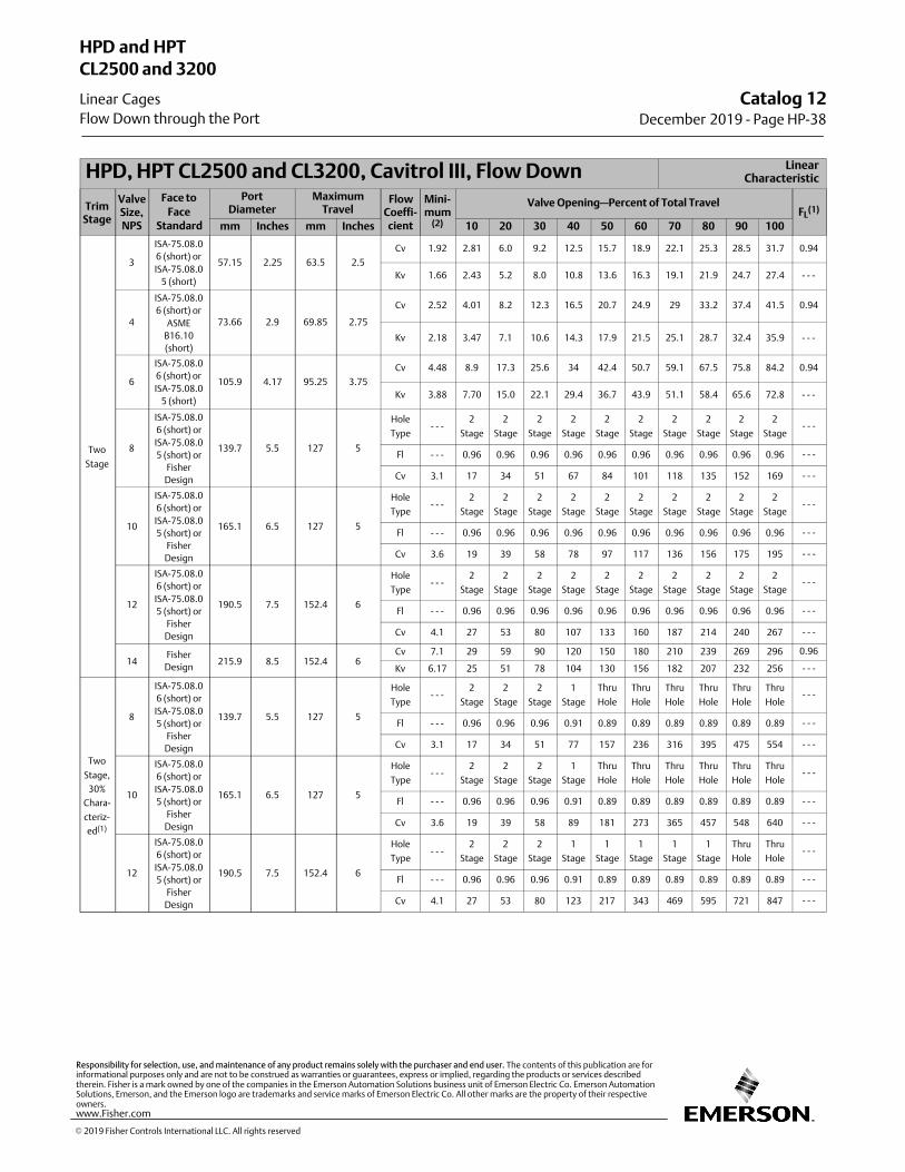
HPD, HPT CL2500 and CL3200, Cavitrol III, Flow Down LinearCharacteristic
TrimStage
ValveSize,NPS
Face to
FaceStandard
PortDiameter
MaximumTravel
FlowCoeffi‐cient
Mini-mum
(2)
Valve Opening—Percent of Total TravelFL
(1)
mm Inches mm Inches 10 20 30 40 50 60 70 80 90 100
Two
Stage
3
ISA-75.08.0
6 (short) or
ISA-75.08.0
5 (short)
57.15 2.25 63.5 2.5
Cv 1.92 2.81 6.0 9.2 12.5 15.7 18.9 22.1 25.3 28.5 31.7 0.94
Kv 1.66 2.43 5.2 8.0 10.8 13.6 16.3 19.1 21.9 24.7 27.4 - - -
4
ISA-75.08.0
6 (short) or
ASME
B16.10
(short)
73.66 2.9 69.85 2.75
Cv 2.52 4.01 8.2 12.3 16.5 20.7 24.9 29 33.2 37.4 41.5 0.94
Kv 2.18 3.47 7.1 10.6 14.3 17.9 21.5 25.1 28.7 32.4 35.9 - - -
6
ISA-75.08.0
6 (short) or
ISA-75.08.0
5 (short)
105.9 4.17 95.25 3.75
Cv 4.48 8.9 17.3 25.6 34 42.4 50.7 59.1 67.5 75.8 84.2 0.94
Kv 3.88 7.70 15.0 22.1 29.4 36.7 43.9 51.1 58.4 65.6 72.8 - - -
8
ISA-75.08.0
6 (short) or
ISA-75.08.0
5 (short) or
Fisher
Design
139.7 5.5 127 5
Hole
Type- - -
2
Stage
2
Stage
2
Stage
2
Stage
2
Stage
2
Stage
2
Stage
2
Stage
2
Stage
2
Stage- - -
Fl - - - 0.96 0.96 0.96 0.96 0.96 0.96 0.96 0.96 0.96 0.96 - - -
Cv 3.1 17 34 51 67 84 101 118 135 152 169 - - -
10
ISA-75.08.0
6 (short) or
ISA-75.08.0
5 (short) or
Fisher
Design
165.1 6.5 127 5
Hole
Type- - -
2
Stage
2
Stage
2
Stage
2
Stage
2
Stage
2
Stage
2
Stage
2
Stage
2
Stage
2
Stage- - -
Fl - - - 0.96 0.96 0.96 0.96 0.96 0.96 0.96 0.96 0.96 0.96 - - -
Cv 3.6 19 39 58 78 97 117 136 156 175 195 - - -
12
ISA-75.08.0
6 (short) or
ISA-75.08.0
5 (short) or
Fisher
Design
190.5 7.5 152.4 6
Hole
Type- - -
2
Stage
2
Stage
2
Stage
2
Stage
2
Stage
2
Stage
2
Stage
2
Stage
2
Stage
2
Stage- - -
Fl - - - 0.96 0.96 0.96 0.96 0.96 0.96 0.96 0.96 0.96 0.96 - - -
Cv 4.1 27 53 80 107 133 160 187 214 240 267 - - -
14Fisher
Design215.9 8.5 152.4 6
Cv 7.1 29 59 90 120 150 180 210 239 269 296 0.96
Kv 6.17 25 51 78 104 130 156 182 207 232 256 - - -
Two
Stage,
30%
Chara-
cteriz-
ed(1)
8
ISA-75.08.0
6 (short) or
ISA-75.08.0
5 (short) or
Fisher
Design
139.7 5.5 127 5
Hole
Type- - -
2
Stage
2
Stage
2
Stage
1
Stage
Thru
Hole
Thru
Hole
Thru
Hole
Thru
Hole
Thru
Hole
Thru
Hole- - -
Fl - - - 0.96 0.96 0.96 0.91 0.89 0.89 0.89 0.89 0.89 0.89 - - -
Cv 3.1 17 34 51 77 157 236 316 395 475 554 - - -
10
ISA-75.08.0
6 (short) or
ISA-75.08.0
5 (short) or
Fisher
Design
165.1 6.5 127 5
Hole
Type- - -
2
Stage
2
Stage
2
Stage
1
Stage
Thru
Hole
Thru
Hole
Thru
Hole
Thru
Hole
Thru
Hole
Thru
Hole- - -
Fl - - - 0.96 0.96 0.96 0.91 0.89 0.89 0.89 0.89 0.89 0.89 - - -
Cv 3.6 19 39 58 89 181 273 365 457 548 640 - - -
12
ISA-75.08.0
6 (short) or
ISA-75.08.0
5 (short) or
Fisher
Design
190.5 7.5 152.4 6
Hole
Type- - -
2
Stage
2
Stage
2
Stage
1
Stage
1
Stage
1
Stage
1
Stage
1
Stage
Thru
Hole
Thru
Hole- - -
Fl - - - 0.96 0.96 0.96 0.91 0.89 0.89 0.89 0.89 0.89 0.89 - - -
Cv 4.1 27 53 80 123 217 343 469 595 721 847 - - -
Catalog 12December 2019 ‐ Page HP-38
HPD and HPT
Linear Cages
CL2500 and 3200
Flow Down through the Port
� 2019 Fisher Controls International LLC. All rights reserved
www.Fisher.com
Responsibility for selection, use, and maintenance of any product remains solely with the purchaser and end user. The contents of this publication are forinformational purposes only and are not to be construed as warranties or guarantees, express or implied, regarding the products or services describedtherein. Fisher is a mark owned by one of the companies in the Emerson Automation Solutions business unit of Emerson Electric Co. Emerson AutomationSolutions, Emerson, and the Emerson logo are trademarks and service marks of Emerson Electric Co. All other marks are the property of their respectiveowners.
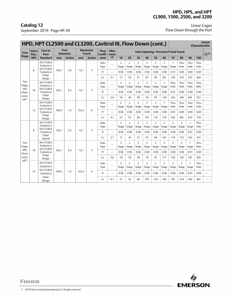
HPD, HPT CL2500 and CL3200, Cavitrol III, Flow Down (cont.) LinearCharacteristic
TrimStage
ValveSize,NPS
Face to
FaceStandard
PortDiameter
MaximumTravel
FlowCoeffi‐cient
Minimum
(2)
Valve Opening—Percent of Total TravelFL
(1)
mm Inches mm Inches 10 20 30 40 50 60 70 80 90 100
Two
Stage,
50%
Chara-
cteriz-
ed(1)
8
ISA-75.08.0
6 (short) or
ISA-75.08.0
5 (short) or
Fisher
Design
139.7 5.5 127 5
Hole
Type- - -
2
Stage
2
Stage
2
Stage
2
Stage
2
Stage
2
Stage
1
Stage
Thru
Hole
Thru
Hole
Thru
Hole- - -
Fl - - - 0.96 0.96 0.96 0.96 0.96 0.96 0.91 0.89 0.89 0.89 - - -
Cv 3.1 17 34 51 67 84 101 128 219 310 402 - - -
10
ISA-75.08.0
6 (short) or
ISA-75.08.0
5 (short) or
Fisher
Design
165.1 6.5 127 5
Hole
Type- - -
2
Stage
2
Stage
2
Stage
2
Stage
2
Stage
1
Stage
Thru
Hole
Thru
Hole
Thru
Hole
Thru
Hole- - -
Fl - - - 0.96 0.96 0.96 0.96 0.96 0.96 0.91 0.89 0.89 0.89 - - -
Cv 3.6 19 39 58 78 97 128 234 340 445 551 - - -
12
ISA-75.08.0
6 (short) or
ISA-75.08.0
5 (short) or
Fisher
Design
190.5 7.5 152.4 6
Hole
Type--
2
Stage
2
Stage
2
Stage
2
Stage
2
Stage
1
Stage
Thru
Hole
Thru
Hole
Thru
Hole
Thru
Hole- - -
Fl -- 0.96 0.96 0.96 0.96 0.96 0.96 0.91 0.89 0.89 0.89 - - -
Cv 4.1 27 53 80 107 133 176 320 465 610 754 - - -
Two
Stage,
80%
Chara-
cteriz-
ed(1)
8
ISA-75.08.0
6 (short) or
ISA-75.08.0
5 (short) or
Fisher
Special
139.7 5.5 127 5
Hole
Type--
2
Stage
2
Stage
2
Stage
2
Stage
2
Stage
2
Stage
2
Stage
2
Stage
1
Stage
Thru
Hole- - -
Fl -- 0.96 0.96 0.96 0.96 0.96 0.96 0.96 0.96 0.91 0.89 - - -
Cv 3.1 17 34 51 67 84 101 118 135 162 241 - - -
10
ISA-75.08.0
6 (short) or
ISA-75.08.0
5 (short) or
Fisher
Design
165.1 6.5 127 5
Hole
Type--
2
Stage
2
Stage
2
Stage
2
Stage
2
Stage
2
Stage
2
Stage
2
Stage
1
Stage
Thru
Hole- - -
Fl -- 0.96 0.96 0.96 0.96 0.96 0.96 0.96 0.96 0.91 0.89 - - -
Cv 3.6 19 39 58 78 97 117 136 156 187 292 - - -
12
ISA-75.08.0
6 (short) or
ISA-75.08.0
5 (short) or
Fisher
Design
190.5 7.5 152.4 6
Hole
Type--
2
Stage
2
Stage
2
Stage
2
Stage
2
Stage
2
Stage
2
Stage
2
Stage
1
Stage
Thru
Hole- - -
Fl -- 0.96 0.96 0.96 0.96 0.96 0.96 0.96 0.96 0.91 0.89 - - -
Cv 4.1 27 53 80 107 133 160 187 214 256 401 - - -
Catalog 12 September 2019 ‐ Page HP-39
HPD, HPS, and HPT
Linear Cages
CL900, 1500, 2500, and 3200
Flow Down through the Port
� 2019 Fisher Controls International LLC. All rights reserved
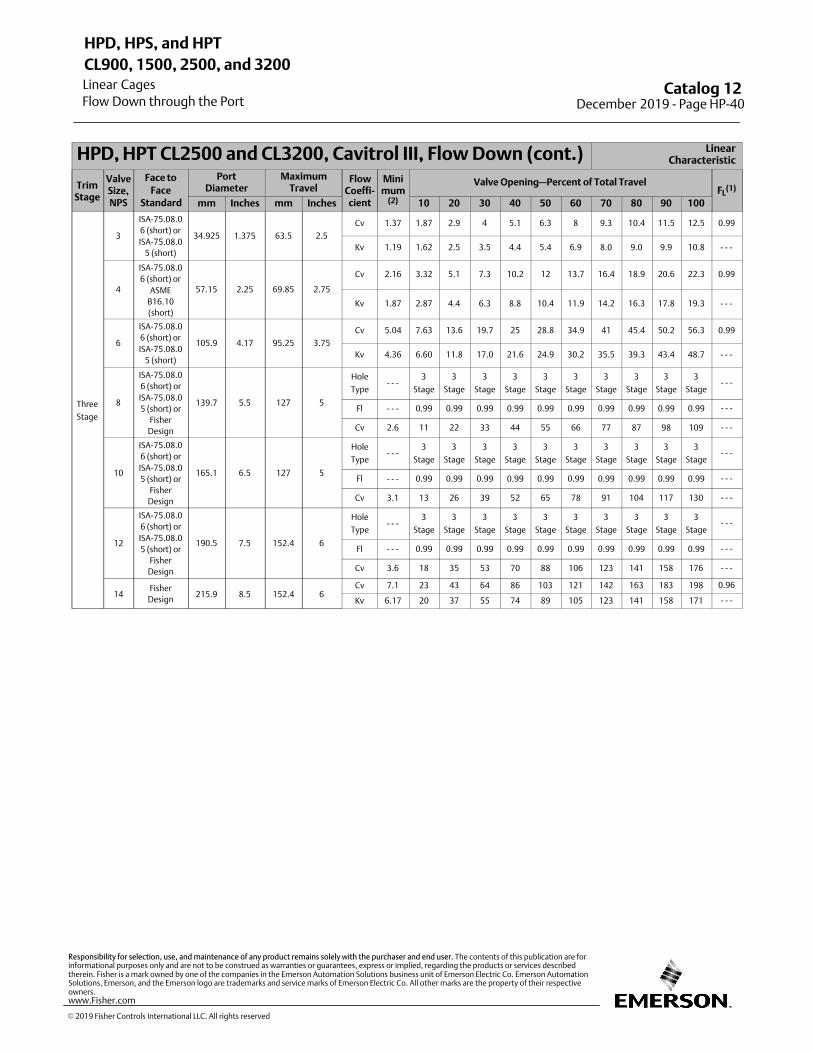
HPD, HPT CL2500 and CL3200, Cavitrol III, Flow Down (cont.) LinearCharacteristic
TrimStage
ValveSize,NPS
Face to
FaceStandard
PortDiameter
MaximumTravel
FlowCoeffi‐cient
Minimum
(2)
Valve Opening—Percent of Total TravelFL
(1)
mm Inches mm Inches 10 20 30 40 50 60 70 80 90 100
Three
Stage
3
ISA-75.08.0
6 (short) or
ISA-75.08.0
5 (short)
34.925 1.375 63.5 2.5
Cv 1.37 1.87 2.9 4 5.1 6.3 8 9.3 10.4 11.5 12.5 0.99
Kv 1.19 1.62 2.5 3.5 4.4 5.4 6.9 8.0 9.0 9.9 10.8 - - -
4
ISA-75.08.0
6 (short) or
ASME
B16.10
(short)
57.15 2.25 69.85 2.75
Cv 2.16 3.32 5.1 7.3 10.2 12 13.7 16.4 18.9 20.6 22.3 0.99
Kv 1.87 2.87 4.4 6.3 8.8 10.4 11.9 14.2 16.3 17.8 19.3 - - -
6
ISA-75.08.0
6 (short) or
ISA-75.08.0
5 (short)
105.9 4.17 95.25 3.75
Cv 5.04 7.63 13.6 19.7 25 28.8 34.9 41 45.4 50.2 56.3 0.99
Kv 4.36 6.60 11.8 17.0 21.6 24.9 30.2 35.5 39.3 43.4 48.7 - - -
8
ISA-75.08.0
6 (short) or
ISA-75.08.0
5 (short) or
Fisher
Design
139.7 5.5 127 5
Hole
Type- - -
3
Stage
3
Stage
3
Stage
3
Stage
3
Stage
3
Stage
3
Stage
3
Stage
3
Stage
3
Stage- - -
Fl - - - 0.99 0.99 0.99 0.99 0.99 0.99 0.99 0.99 0.99 0.99 - - -
Cv 2.6 11 22 33 44 55 66 77 87 98 109 - - -
10
ISA-75.08.0
6 (short) or
ISA-75.08.0
5 (short) or
Fisher
Design
165.1 6.5 127 5
Hole
Type- - -
3
Stage
3
Stage
3
Stage
3
Stage
3
Stage
3
Stage
3
Stage
3
Stage
3
Stage
3
Stage- - -
Fl - - - 0.99 0.99 0.99 0.99 0.99 0.99 0.99 0.99 0.99 0.99 - - -
Cv 3.1 13 26 39 52 65 78 91 104 117 130 - - -
12
ISA-75.08.0
6 (short) or
ISA-75.08.0
5 (short) or
Fisher
Design
190.5 7.5 152.4 6
Hole
Type- - -
3
Stage
3
Stage
3
Stage
3
Stage
3
Stage
3
Stage
3
Stage
3
Stage
3
Stage
3
Stage- - -
Fl - - - 0.99 0.99 0.99 0.99 0.99 0.99 0.99 0.99 0.99 0.99 - - -
Cv 3.6 18 35 53 70 88 106 123 141 158 176 - - -
14Fisher
Design215.9 8.5 152.4 6
Cv 7.1 23 43 64 86 103 121 142 163 183 198 0.96
Kv 6.17 20 37 55 74 89 105 123 141 158 171 - - -
Catalog 12 December 2019 ‐ Page HP-40
HPD, HPS, and HPT
Linear Cages
CL900, 1500, 2500, and 3200
Flow Down through the Port
� 2019 Fisher Controls International LLC. All rights reserved
www.Fisher.com
Responsibility for selection, use, and maintenance of any product remains solely with the purchaser and end user. The contents of this publication are forinformational purposes only and are not to be construed as warranties or guarantees, express or implied, regarding the products or services describedtherein. Fisher is a mark owned by one of the companies in the Emerson Automation Solutions business unit of Emerson Electric Co. Emerson AutomationSolutions, Emerson, and the Emerson logo are trademarks and service marks of Emerson Electric Co. All other marks are the property of their respectiveowners.
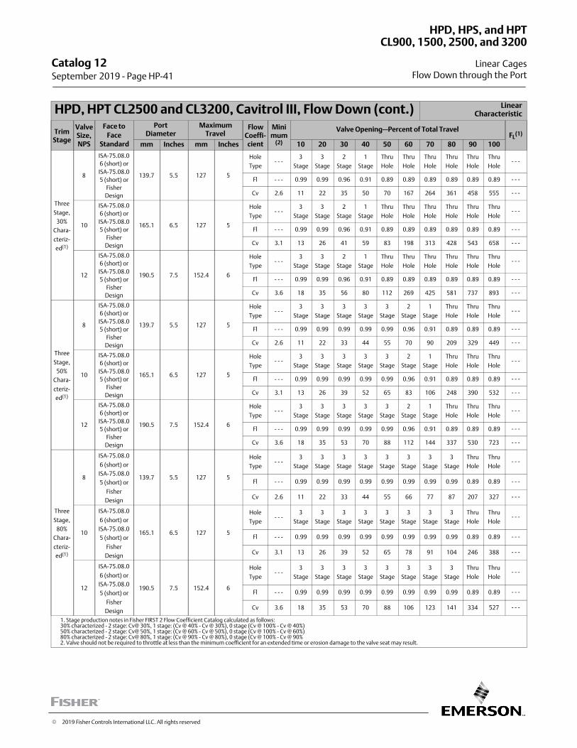
HPD, HPT CL2500 and CL3200, Cavitrol III, Flow Down (cont.) LinearCharacteristic
TrimStage
ValveSize,NPS
Face to
FaceStandard
PortDiameter
MaximumTravel
FlowCoeffi‐cient
Minimum
(2)
Valve Opening—Percent of Total TravelFL
(1)
mm Inches mm Inches 10 20 30 40 50 60 70 80 90 100
Three
Stage,
30%
Chara-
cteriz-
ed(1)
8
ISA-75.08.0
6 (short) or
ISA-75.08.0
5 (short) or
Fisher
Design
139.7 5.5 127 5
Hole
Type- - -
3
Stage
3
Stage
2
Stage
1
Stage
Thru
Hole
Thru
Hole
Thru
Hole
Thru
Hole
Thru
Hole
Thru
Hole- - -
Fl - - - 0.99 0.99 0.96 0.91 0.89 0.89 0.89 0.89 0.89 0.89 - - -
Cv 2.6 11 22 35 50 70 167 264 361 458 555 - - -
10
ISA-75.08.0
6 (short) or
ISA-75.08.0
5 (short) or
Fisher
Design
165.1 6.5 127 5
Hole
Type- - -
3
Stage
3
Stage
2
Stage
1
Stage
Thru
Hole
Thru
Hole
Thru
Hole
Thru
Hole
Thru
Hole
Thru
Hole- - -
Fl - - - 0.99 0.99 0.96 0.91 0.89 0.89 0.89 0.89 0.89 0.89 - - -
Cv 3.1 13 26 41 59 83 198 313 428 543 658 - - -
12
ISA-75.08.0
6 (short) or
ISA-75.08.0
5 (short) or
Fisher
Design
190.5 7.5 152.4 6
Hole
Type- - -
3
Stage
3
Stage
2
Stage
1
Stage
Thru
Hole
Thru
Hole
Thru
Hole
Thru
Hole
Thru
Hole
Thru
Hole- - -
Fl - - - 0.99 0.99 0.96 0.91 0.89 0.89 0.89 0.89 0.89 0.89 - - -
Cv 3.6 18 35 56 80 112 269 425 581 737 893 - - -
Three
Stage,
50%
Chara-
cteriz-
ed(1)
8
ISA-75.08.0
6 (short) or
ISA-75.08.0
5 (short) or
Fisher
Design
139.7 5.5 127 5
Hole
Type- - -
3
Stage
3
Stage
3
Stage
3
Stage
3
Stage
2
Stage
1
Stage
Thru
Hole
Thru
Hole
Thru
Hole- - -
Fl - - - 0.99 0.99 0.99 0.99 0.99 0.96 0.91 0.89 0.89 0.89 - - -
Cv 2.6 11 22 33 44 55 70 90 209 329 449 - - -
10
ISA-75.08.0
6 (short) or
ISA-75.08.0
5 (short) or
Fisher
Design
165.1 6.5 127 5
Hole
Type- - -
3
Stage
3
Stage
3
Stage
3
Stage
3
Stage
2
Stage
1
Stage
Thru
Hole
Thru
Hole
Thru
Hole- - -
Fl - - - 0.99 0.99 0.99 0.99 0.99 0.96 0.91 0.89 0.89 0.89 - - -
Cv 3.1 13 26 39 52 65 83 106 248 390 532 - - -
12
ISA-75.08.0
6 (short) or
ISA-75.08.0
5 (short) or
Fisher
Design
190.5 7.5 152.4 6
Hole
Type- - -
3
Stage
3
Stage
3
Stage
3
Stage
3
Stage
2
Stage
1
Stage
Thru
Hole
Thru
Hole
Thru
Hole- - -
Fl - - - 0.99 0.99 0.99 0.99 0.99 0.96 0.91 0.89 0.89 0.89 - - -
Cv 3.6 18 35 53 70 88 112 144 337 530 723 - - -
Three
Stage,
80%
Chara-
cteriz-
ed(1)
8
ISA-75.08.0
6 (short) or
ISA-75.08.0
5 (short) or
Fisher
Design
139.7 5.5 127 5
Hole
Type- - -
3
Stage
3
Stage
3
Stage
3
Stage
3
Stage
3
Stage
3
Stage
3
Stage
Thru
Hole
Thru
Hole- - -
Fl - - - 0.99 0.99 0.99 0.99 0.99 0.99 0.99 0.99 0.89 0.89 - - -
Cv 2.6 11 22 33 44 55 66 77 87 207 327 - - -
10
ISA-75.08.0
6 (short) or
ISA-75.08.0
5 (short) or
Fisher
Design
165.1 6.5 127 5
Hole
Type- - -
3
Stage
3
Stage
3
Stage
3
Stage
3
Stage
3
Stage
3
Stage
3
Stage
Thru
Hole
Thru
Hole- - -
Fl - - - 0.99 0.99 0.99 0.99 0.99 0.99 0.99 0.99 0.89 0.89 - - -
Cv 3.1 13 26 39 52 65 78 91 104 246 388 - - -
12
ISA-75.08.0
6 (short) or
ISA-75.08.0
5 (short) or
Fisher
Design
190.5 7.5 152.4 6
Hole
Type- - -
3
Stage
3
Stage
3
Stage
3
Stage
3
Stage
3
Stage
3
Stage
3
Stage
Thru
Hole
Thru
Hole- - -
Fl - - - 0.99 0.99 0.99 0.99 0.99 0.99 0.99 0.99 0.89 0.89 - - -
Cv 3.6 18 35 53 70 88 106 123 141 334 527 - - -
1. Stage production notes in Fisher FIRST 2 Flow Coefficient Catalog calculated as follows:30% characterized - 2 stage: Cv@ 30%, 1 stage: (Cv @ 40% - Cv @ 30%), 0 stage (Cv @ 100% - Cv @ 40%)50% characterized - 2 stage: Cv@ 50%, 1 stage: (Cv @ 60% - Cv @ 50%), 0 stage (Cv @ 100% - Cv @ 60%)80% characterized - 2 stage: Cv@ 80%, 1 stage: (Cv @ 90% - Cv @ 80%), 0 stage (Cv @ 100% - Cv @ 90%2. Valve should not be required to throttle at less than the minimum coefficient for an extended time or erosion damage to the valve seat may result.
Catalog 12 September 2019 ‐ Page HP-41
HPD, HPS, and HPT
Linear Cages
CL900, 1500, 2500, and 3200
Flow Down through the Port
� 2019 Fisher Controls International LLC. All rights reserved
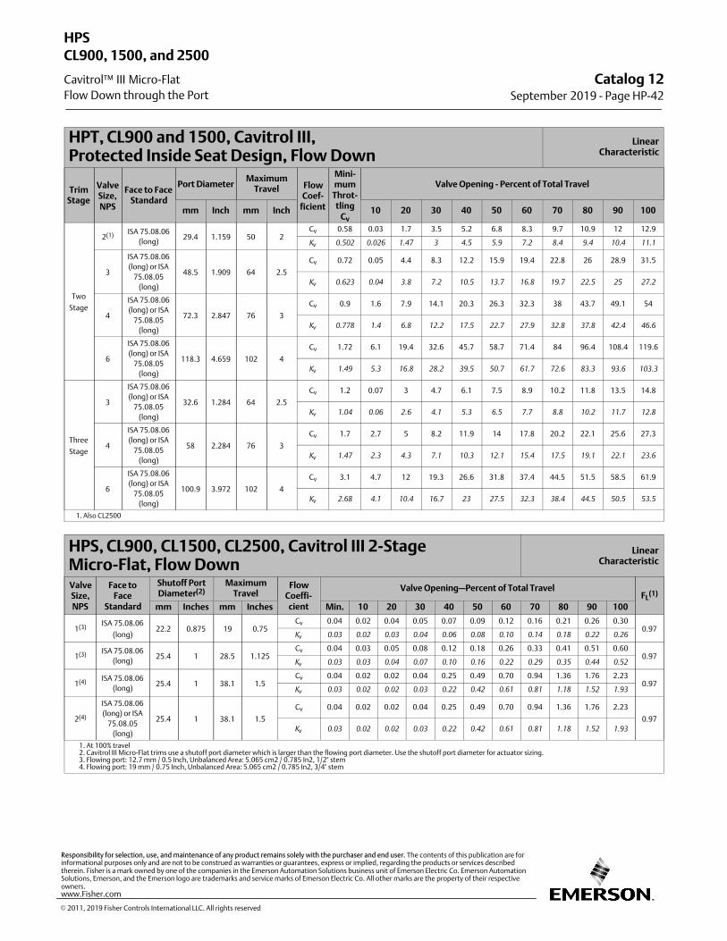
HPT, CL900 and 1500, Cavitrol III, Protected Inside Seat Design, Flow Down
LinearCharacteristic
TrimStage
ValveSize,NPS
Face to FaceStandard
Port DiameterMaximum
Travel FlowCoef‐
ficient
Mini‐mum
Throt‐tling
Cv
Valve Opening - Percent of Total Travel
mm Inch mm Inch 10 20 30 40 50 60 70 80 90 100
Two
Stage
2(1) ISA 75.08.06
(long)29.4 1.159 50 2
Cv 0.58 0.03 1.7 3.5 5.2 6.8 8.3 9.7 10.9 12 12.9
Kv
0.502 0.026 1.47 3 4.5 5.9 7.2 8.4 9.4 10.4 11.1
3
ISA 75.08.06
(long) or ISA
75.08.05
(long)
48.5 1.909 64 2.5
Cv 0.72 0.05 4.4 8.3 12.2 15.9 19.4 22.8 26 28.9 31.5
Kv
0.623 0.04 3.8 7.2 10.5 13.7 16.8 19.7 22.5 25 27.2
4
ISA 75.08.06
(long) or ISA
75.08.05
(long)
72.3 2.847 76 3
Cv 0.9 1.6 7.9 14.1 20.3 26.3 32.3 38 43.7 49.1 54
Kv
0.778 1.4 6.8 12.2 17.5 22.7 27.9 32.8 37.8 42.4 46.6
6
ISA 75.08.06
(long) or ISA
75.08.05
(long)
118.3 4.659 102 4
Cv 1.72 6.1 19.4 32.6 45.7 58.7 71.4 84 96.4 108.4 119.6
Kv
1.49 5.3 16.8 28.2 39.5 50.7 61.7 72.6 83.3 93.6 103.3
Three
Stage
3
ISA 75.08.06
(long) or ISA
75.08.05
(long)
32.6 1.284 64 2.5
Cv 1.2 0.07 3 4.7 6.1 7.5 8.9 10.2 11.8 13.5 14.8
Kv
1.04 0.06 2.6 4.1 5.3 6.5 7.7 8.8 10.2 11.7 12.8
4
ISA 75.08.06
(long) or ISA
75.08.05
(long)
58 2.284 76 3
Cv 1.7 2.7 5 8.2 11.9 14 17.8 20.2 22.1 25.6 27.3
Kv
1.47 2.3 4.3 7.1 10.3 12.1 15.4 17.5 19.1 22.1 23.6
6
ISA 75.08.06
(long) or ISA
75.08.05
(long)
100.9 3.972 102 4
Cv 3.1 4.7 12 19.3 26.6 31.8 37.4 44.5 51.5 58.5 61.9
Kv
2.68 4.1 10.4 16.7 23 27.5 32.3 38.4 44.5 50.5 53.5
1. Also CL2500
HPS, CL900, CL1500, CL2500, Cavitrol III 2-Stage Micro-Flat, Flow Down
LinearCharacteristic
ValveSize,NPS
Face toFace
Standard
Shutoff PortDiameter(2)
MaximumTravel
FlowCoeffi‐cient
Valve Opening—Percent of Total TravelFL
(1)
mm Inches mm Inches Min. 10 20 30 40 50 60 70 80 90 100
1(3)ISA 75.08.06
(long)22.2 0.875 19 0.75
Cv 0.04 0.02 0.04 0.05 0.07 0.09 0.12 0.16 0.21 0.26 0.300.97
Kv
0.03 0.02 0.03 0.04 0.06 0.08 0.10 0.14 0.18 0.22 0.26
1(3) ISA 75.08.06
(long)25.4 1 28.5 1.125
Cv 0.04 0.03 0.05 0.08 0.12 0.18 0.26 0.33 0.41 0.51 0.600.97
Kv
0.03 0.03 0.04 0.07 0.10 0.16 0.22 0.29 0.35 0.44 0.52
1(4) ISA 75.08.06
(long)25.4 1 38.1 1.5
Cv 0.04 0.02 0.02 0.04 0.25 0.49 0.70 0.94 1.36 1.76 2.230.97
Kv
0.03 0.02 0.02 0.03 0.22 0.42 0.61 0.81 1.18 1.52 1.93
2(4)
ISA 75.08.06
(long) or ISA
75.08.05
(long)
25.4 1 38.1 1.5
Cv 0.04 0.02 0.02 0.04 0.25 0.49 0.70 0.94 1.36 1.76 2.23
0.97
Kv
0.03 0.02 0.02 0.03 0.22 0.42 0.61 0.81 1.18 1.52 1.93
1. At 100% travel 2. Cavitrol III Micro-Flat trims use a shutoff port diameter which is larger than the flowing port diameter. Use the shutoff port diameter for actuator sizing. 3. Flowing port: 12.7 mm / 0.5 Inch, Unbalanced Area: 5.065 cm2 / 0.785 In2, 1/2" stem 4. Flowing port: 19 mm / 0.75 Inch, Unbalanced Area: 5.065 cm2 / 0.785 In2, 3/4" stem
Catalog 12September 2019 ‐ Page HP-42
HPS
Cavitrol™ III Micro-Flat
CL900, 1500, and 2500
Flow Down through the Port
� 2011, 2019 Fisher Controls International LLC. All rights reserved
www.Fisher.com
Responsibility for selection, use, and maintenance of any product remains solely with the purchaser and end user. The contents of this publication are forinformational purposes only and are not to be construed as warranties or guarantees, express or implied, regarding the products or services describedtherein. Fisher is a mark owned by one of the companies in the Emerson Automation Solutions business unit of Emerson Electric Co. Emerson AutomationSolutions, Emerson, and the Emerson logo are trademarks and service marks of Emerson Electric Co. All other marks are the property of their respectiveowners.
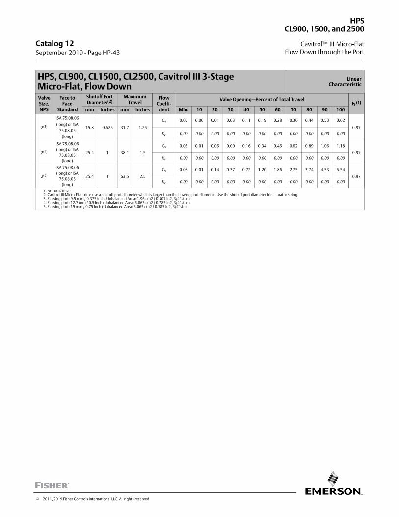
HPS, CL900, CL1500, CL2500, Cavitrol III 3-Stage Micro-Flat, Flow Down
LinearCharacteristic
ValveSize,NPS
Face toFace
Standard
Shutoff PortDiameter(2)
MaximumTravel
FlowCoeffi‐cient
Valve Opening—Percent of Total TravelFL
(1)
mm Inches mm Inches Min. 10 20 30 40 50 60 70 80 90 100
2(3)
ISA 75.08.06
(long) or ISA
75.08.05
(long)
15.8 0.625 31.7 1.25
Cv 0.05 0.00 0.01 0.03 0.11 0.19 0.28 0.36 0.44 0.53 0.62
0.97
Kv
0.00 0.00 0.00 0.00 0.00 0.00 0.00 0.00 0.00 0.00 0.00
2(4)
ISA 75.08.06
(long) or ISA
75.08.05
(long)
25.4 1 38.1 1.5
Cv 0.05 0.01 0.06 0.09 0.16 0.34 0.46 0.62 0.89 1.06 1.18
0.97
Kv
0.00 0.00 0.00 0.00 0.00 0.00 0.00 0.00 0.00 0.00 0.00
2(5)
ISA 75.08.06
(long) or ISA
75.08.05
(long)
25.4 1 63.5 2.5
Cv 0.06 0.01 0.14 0.37 0.72 1.20 1.86 2.75 3.74 4.53 5.54
0.97
Kv
0.00 0.00 0.00 0.00 0.00 0.00 0.00 0.00 0.00 0.00 0.00
1. At 100% travel 2. Cavitrol III Micro-Flat trims use a shutoff port diameter which is larger than the flowing port diameter. Use the shutoff port diameter for actuator sizing. 3. Flowing port: 9.5 mm / 0.375 Inch (Unbalanced Area: 1.96 cm2 / 0.307 In2, 3/4" stem 4. Flowing port: 12.7 mm / 0.5 Inch (Unbalanced Area: 5.065 cm2 / 0.785 In2, 3/4" stem 5. Flowing port: 19 mm / 0.75 Inch (Unbalanced Area: 5.065 cm2 / 0.785 In2, 3/4" stem
Catalog 12 September 2019 ‐ Page HP-43
HPS
Cavitrol™ III Micro-Flat
CL900, 1500, and 2500
Flow Down through the Port
� 2011, 2019 Fisher Controls International LLC. All rights reserved
The Fisher™ HPT-C valve has flow coefficients identical to the NPS 4 and 6 Fisher HPD valve. Please refer to those coefficients. For additional HPT-C valve body information, refer to Bulletin 51.2:HP Cryogenic, D104174X012.
The Fisher HPS-C valve has flow coefficients identical to the NPS 1 through 3 Fisher HPS valve. Please refer to thosecoefficients. For additional HPS-C valve body information, refer to Bulletin 51.2:HP Cryogenic, D104174X012.
Catalog 12September 2019 ‐ Page HP-44
HPT-C and HPS-C
� 2016, 2019 Fisher Controls International LLC. All rights reserved
www.Fisher.com
Responsibility for selection, use, and maintenance of any product remains solely with the purchaser and end user. The contents of this publication are forinformational purposes only and are not to be construed as warranties or guarantees, express or implied, regarding the products or services describedtherein. Fisher is a mark owned by one of the companies in the Emerson Automation Solutions business unit of Emerson Electric Co. Emerson AutomationSolutions, Emerson, and the Emerson logo are trademarks and service marks of Emerson Electric Co. All other marks are the property of their respectiveowners.
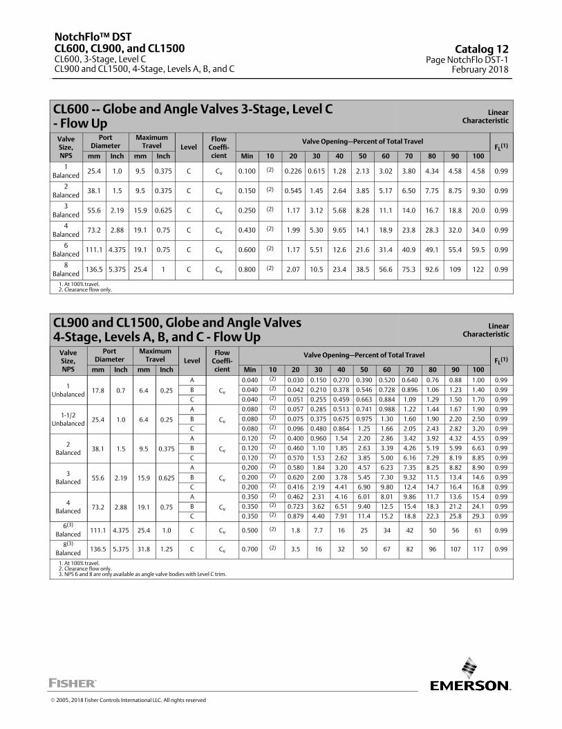
CL600 -- Globe and Angle Valves 3-Stage, Level C - Flow Up
LinearCharacteristic
ValveSize,NPS
PortDiameter
MaximumTravel Level
FlowCoeffi-cient
Valve Opening—Percent of Total TravelFL
(1)
mm Inch mm Inch Min 10 20 30 40 50 60 70 80 90 100
1
Balanced25.4 1.0 9.5 0.375 C Cv 0.100 (2) 0.226 0.615 1.28 2.13 3.02 3.80 4.34 4.58 4.58 0.99
2
Balanced38.1 1.5 9.5 0.375 C Cv 0.150 (2) 0.545 1.45 2.64 3.85 5.17 6.50 7.75 8.75 9.30 0.99
3
Balanced55.6 2.19 15.9 0.625 C Cv 0.250 (2) 1.17 3.12 5.68 8.28 11.1 14.0 16.7 18.8 20.0 0.99
4
Balanced73.2 2.88 19.1 0.75 C Cv 0.430 (2) 1.99 5.30 9.65 14.1 18.9 23.8 28.3 32.0 34.0 0.99
6
Balanced111.1 4.375 19.1 0.75 C Cv 0.600 (2) 1.17 5.51 12.6 21.6 31.4 40.9 49.1 55.4 59.5 0.99
8
Balanced136.5 5.375 25.4 1 C Cv 0.800 (2) 2.07 10.5 23.4 38.5 56.6 75.3 92.6 109 122 0.99
1. At 100% travel.2. Clearance flow only.
CL900 and CL1500, Globe and Angle Valves4-Stage, Levels A, B, and C - Flow Up
LinearCharacteristic
ValveSize,NPS
PortDiameter
MaximumTravel Level
FlowCoeffi-cient
Valve Opening—Percent of Total TravelFL
(1)
mm Inch mm Inch Min 10 20 30 40 50 60 70 80 90 100
1
Unbalanced17.8 0.7 6.4 0.25
A
Cv
0.040 (2) 0.030 0.150 0.270 0.390 0.520 0.640 0.76 0.88 1.00 0.99
B 0.040 (2) 0.042 0.210 0.378 0.546 0.728 0.896 1.06 1.23 1.40 0.99
C 0.040 (2) 0.051 0.255 0.459 0.663 0.884 1.09 1.29 1.50 1.70 0.99
1-1/2
Unbalanced25.4 1.0 6.4 0.25
A
Cv
0.080 (2) 0.057 0.285 0.513 0.741 0.988 1.22 1.44 1.67 1.90 0.99
B 0.080 (2) 0.075 0.375 0.675 0.975 1.30 1.60 1.90 2.20 2.50 0.99
C 0.080 (2) 0.096 0.480 0.864 1.25 1.66 2.05 2.43 2.82 3.20 0.99
2
Balanced38.1 1.5 9.5 0.375
A
Cv
0.120 (2) 0.400 0.960 1.54 2.20 2.86 3.42 3.92 4.32 4.55 0.99
B 0.120 (2) 0.460 1.10 1.85 2.63 3.39 4.26 5.19 5.99 6.63 0.99
C 0.120 (2) 0.570 1.53 2.62 3.85 5.00 6.16 7.29 8.19 8.85 0.99
3
Balanced55.6 2.19 15.9 0.625
A
Cv
0.200 (2) 0.580 1.84 3.20 4.57 6.23 7.35 8.25 8.82 8.90 0.99
B 0.200 (2) 0.620 2.00 3.78 5.45 7.30 9.32 11.5 13.4 14.6 0.99
C 0.200 (2) 0.416 2.19 4.41 6.90 9.80 12.4 14.7 16.4 16.8 0.99
4
Balanced73.2 2.88 19.1 0.75
A
Cv
0.350 (2) 0.462 2.31 4.16 6.01 8.01 9.86 11.7 13.6 15.4 0.99
B 0.350 (2) 0.723 3.62 6.51 9.40 12.5 15.4 18.3 21.2 24.1 0.99
C 0.350 (2) 0.879 4.40 7.91 11.4 15.2 18.8 22.3 25.8 29.3 0.99
6(3)
Balanced111.1 4.375 25.4 1.0 C Cv 0.500 (2) 1.8 7.7 16 25 34 42 50 56 61 0.99
8(3)
Balanced136.5 5.375 31.8 1.25 C Cv 0.700 (2) 3.5 16 32 50 67 82 96 107 117 0.99
1. At 100% travel.2. Clearance flow only.3. NPS 6 and 8 are only available as angle valve bodies with Level C trim.
� 2005, 2018 Fisher Controls International LLC. All rights reserved
NotchFlo™ DSTCL600, CL900, and CL1500CL600, 3-Stage, Level CCL900 and CL1500, 4-Stage, Levels A, B, and C
Catalog 12Page NotchFlo DST-1
February 2018
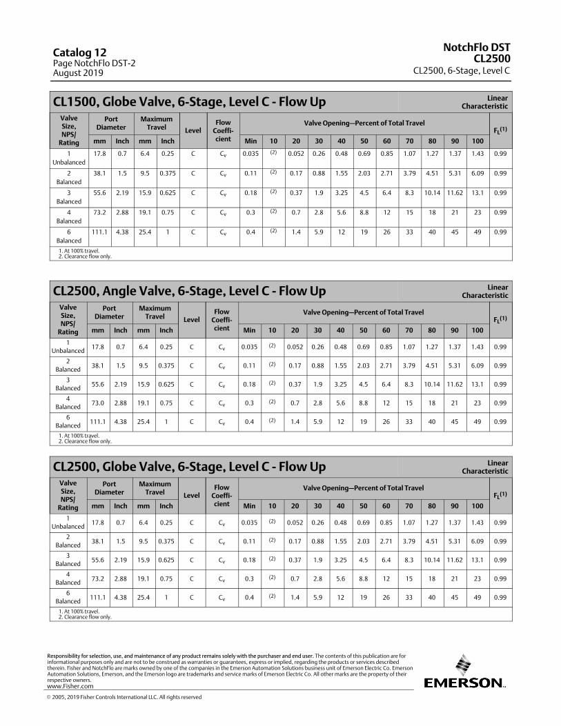
CL1500, Globe Valve, 6-Stage, Level C - Flow Up LinearCharacteristic
ValveSize,NPS/
Rating
PortDiameter
MaximumTravel Level
FlowCoeffi-cient
Valve Opening—Percent of Total TravelFL
(1)
mm Inch mm Inch Min 10 20 30 40 50 60 70 80 90 100
1
Unbalanced
17.8 0.7 6.4 0.25 C Cv 0.035 (2) 0.052 0.26 0.48 0.69 0.85 1.07 1.27 1.37 1.43 0.99
2
Balanced
38.1 1.5 9.5 0.375 C Cv 0.11 (2) 0.17 0.88 1.55 2.03 2.71 3.79 4.51 5.31 6.09 0.99
3
Balanced
55.6 2.19 15.9 0.625 C Cv 0.18 (2) 0.37 1.9 3.25 4.5 6.4 8.3 10.14 11.62 13.1 0.99
4
Balanced
73.2 2.88 19.1 0.75 C Cv 0.3 (2) 0.7 2.8 5.6 8.8 12 15 18 21 23 0.99
6
Balanced
111.1 4.38 25.4 1 C Cv 0.4 (2) 1.4 5.9 12 19 26 33 40 45 49 0.99
1. At 100% travel.2. Clearance flow only.
CL2500, Angle Valve, 6-Stage, Level C - Flow Up LinearCharacteristic
ValveSize,NPS/
Rating
PortDiameter
MaximumTravel Level
FlowCoeffi-cient
Valve Opening—Percent of Total TravelFL
(1)
mm Inch mm Inch Min 10 20 30 40 50 60 70 80 90 100
1
Unbalanced17.8 0.7 6.4 0.25 C Cv 0.035 (2) 0.052 0.26 0.48 0.69 0.85 1.07 1.27 1.37 1.43 0.99
2
Balanced38.1 1.5 9.5 0.375 C Cv 0.11 (2) 0.17 0.88 1.55 2.03 2.71 3.79 4.51 5.31 6.09 0.99
3
Balanced55.6 2.19 15.9 0.625 C Cv 0.18 (2) 0.37 1.9 3.25 4.5 6.4 8.3 10.14 11.62 13.1 0.99
4
Balanced73.0 2.88 19.1 0.75 C Cv 0.3 (2) 0.7 2.8 5.6 8.8 12 15 18 21 23 0.99
6
Balanced111.1 4.38 25.4 1 C Cv 0.4 (2) 1.4 5.9 12 19 26 33 40 45 49 0.99
1. At 100% travel.2. Clearance flow only.
CL2500, Globe Valve, 6-Stage, Level C - Flow Up LinearCharacteristic
ValveSize,NPS/
Rating
PortDiameter
MaximumTravel Level
FlowCoeffi-cient
Valve Opening—Percent of Total TravelFL
(1)
mm Inch mm Inch Min 10 20 30 40 50 60 70 80 90 100
1
Unbalanced17.8 0.7 6.4 0.25 C Cv 0.035 (2) 0.052 0.26 0.48 0.69 0.85 1.07 1.27 1.37 1.43 0.99
2
Balanced38.1 1.5 9.5 0.375 C Cv 0.11 (2) 0.17 0.88 1.55 2.03 2.71 3.79 4.51 5.31 6.09 0.99
3
Balanced55.6 2.19 15.9 0.625 C Cv 0.18 (2) 0.37 1.9 3.25 4.5 6.4 8.3 10.14 11.62 13.1 0.99
4
Balanced73.2 2.88 19.1 0.75 C Cv 0.3 (2) 0.7 2.8 5.6 8.8 12 15 18 21 23 0.99
6
Balanced111.1 4.38 25.4 1 C Cv 0.4 (2) 1.4 5.9 12 19 26 33 40 45 49 0.99
1. At 100% travel.2. Clearance flow only.
NotchFlo DST
CL2500, 6-Stage, Level CCL2500
Catalog 12Page NotchFlo DST-2August 2019
� 2005, 2019 Fisher Controls International LLC. All rights reserved
www.Fisher.com
Responsibility for selection, use, and maintenance of any product remains solely with the purchaser and end user. The contents of this publication are forinformational purposes only and are not to be construed as warranties or guarantees, express or implied, regarding the products or services describedtherein. Fisher and NotchFlo are marks owned by one of the companies in the Emerson Automation Solutions business unit of Emerson Electric Co. EmersonAutomation Solutions, Emerson, and the Emerson logo are trademarks and service marks of Emerson Electric Co. All other marks are the property of theirrespective owners.
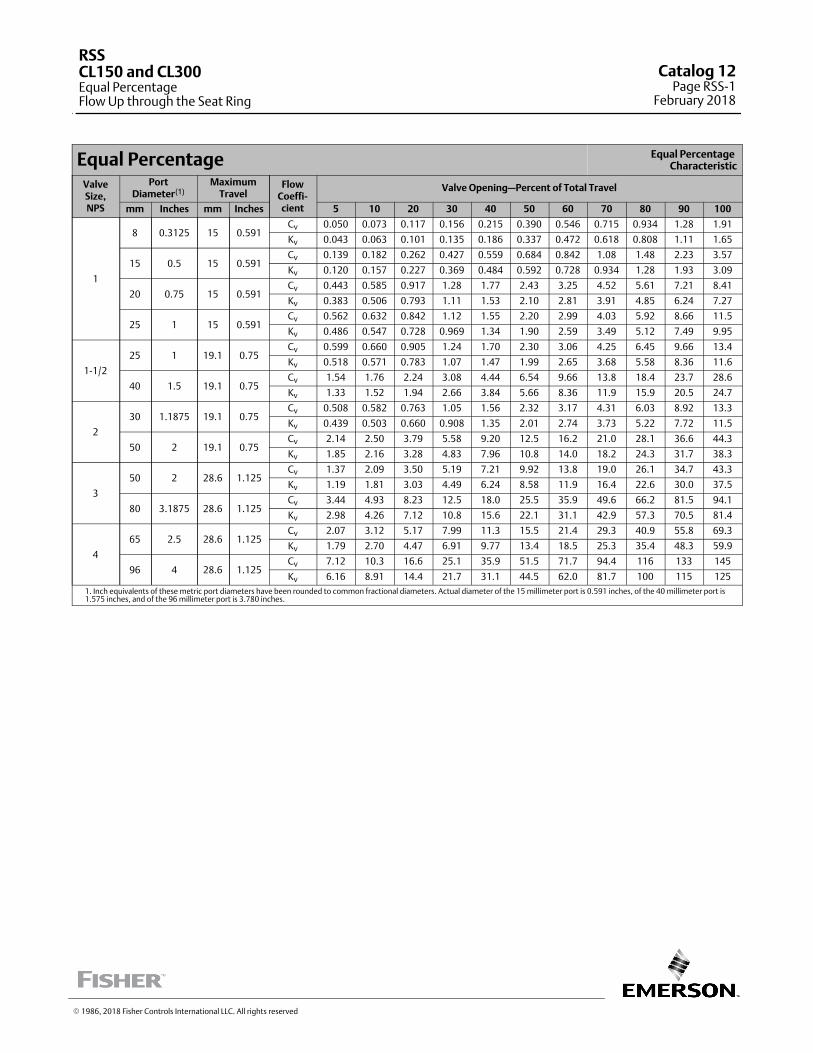
Equal Percentage Equal Percentage Characteristic
ValveSize,NPS
PortDiameter(1)
MaximumTravel
FlowCoeffi‐cient
Valve Opening—Percent of Total Travel
mm Inches mm Inches 5 10 20 30 40 50 60 70 80 90 100
1
8 0.3125 15 0.591Cv 0.050 0.073 0.117 0.156 0.215 0.390 0.546 0.715 0.934 1.28 1.91
Kv 0.043 0.063 0.101 0.135 0.186 0.337 0.472 0.618 0.808 1.11 1.65
15 0.5 15 0.591Cv 0.139 0.182 0.262 0.427 0.559 0.684 0.842 1.08 1.48 2.23 3.57
Kv 0.120 0.157 0.227 0.369 0.484 0.592 0.728 0.934 1.28 1.93 3.09
20 0.75 15 0.591Cv 0.443 0.585 0.917 1.28 1.77 2.43 3.25 4.52 5.61 7.21 8.41
Kv 0.383 0.506 0.793 1.11 1.53 2.10 2.81 3.91 4.85 6.24 7.27
25 1 15 0.591Cv 0.562 0.632 0.842 1.12 1.55 2.20 2.99 4.03 5.92 8.66 11.5
Kv 0.486 0.547 0.728 0.969 1.34 1.90 2.59 3.49 5.12 7.49 9.95
1-1/2
25 1 19.1 0.75Cv 0.599 0.660 0.905 1.24 1.70 2.30 3.06 4.25 6.45 9.66 13.4
Kv 0.518 0.571 0.783 1.07 1.47 1.99 2.65 3.68 5.58 8.36 11.6
40 1.5 19.1 0.75Cv 1.54 1.76 2.24 3.08 4.44 6.54 9.66 13.8 18.4 23.7 28.6
Kv 1.33 1.52 1.94 2.66 3.84 5.66 8.36 11.9 15.9 20.5 24.7
2
30 1.1875 19.1 0.75Cv 0.508 0.582 0.763 1.05 1.56 2.32 3.17 4.31 6.03 8.92 13.3
Kv 0.439 0.503 0.660 0.908 1.35 2.01 2.74 3.73 5.22 7.72 11.5
50 2 19.1 0.75Cv 2.14 2.50 3.79 5.58 9.20 12.5 16.2 21.0 28.1 36.6 44.3
Kv 1.85 2.16 3.28 4.83 7.96 10.8 14.0 18.2 24.3 31.7 38.3
3
50 2 28.6 1.125Cv 1.37 2.09 3.50 5.19 7.21 9.92 13.8 19.0 26.1 34.7 43.3
Kv 1.19 1.81 3.03 4.49 6.24 8.58 11.9 16.4 22.6 30.0 37.5
80 3.1875 28.6 1.125Cv 3.44 4.93 8.23 12.5 18.0 25.5 35.9 49.6 66.2 81.5 94.1
Kv 2.98 4.26 7.12 10.8 15.6 22.1 31.1 42.9 57.3 70.5 81.4
4
65 2.5 28.6 1.125Cv 2.07 3.12 5.17 7.99 11.3 15.5 21.4 29.3 40.9 55.8 69.3
Kv 1.79 2.70 4.47 6.91 9.77 13.4 18.5 25.3 35.4 48.3 59.9
96 4 28.6 1.125Cv 7.12 10.3 16.6 25.1 35.9 51.5 71.7 94.4 116 133 145
Kv 6.16 8.91 14.4 21.7 31.1 44.5 62.0 81.7 100 115 125
1. Inch equivalents of these metric port diameters have been rounded to common fractional diameters. Actual diameter of the 15 millimeter port is 0.591 inches, of the 40 millimeter port is1.575 inches, and of the 96 millimeter port is 3.780 inches.
� 1986, 2018 Fisher Controls International LLC. All rights reserved
RSSCL150 and CL300Equal PercentageFlow Up through the Seat Ring
Catalog 12Page RSS-1
February 2018

This page is intentionally left blank.
RSSCatalog 12Page RSS-2February 2018
� 1986, 2018 Fisher Controls International LLC. All rights reserved
www.Fisher.com
Responsibility for selection, use, and maintenance of any product remains solely with the purchaser and end user. The contents of this publication are forinformational purposes only and are not to be construed as warranties or guarantees, express or implied, regarding the products or services describedtherein. Fisher is a mark owned by one of the companies in the Emerson Automation Solutions business unit of Emerson Electric Co. Emerson AutomationSolutions, Emerson, and the Emerson logo are trademarks and service marks of Emerson Electric Co. All other marks are the property of their respectiveowners.
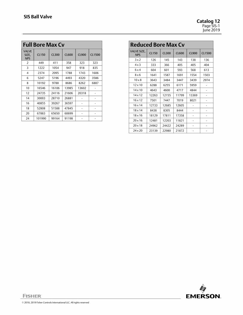
Full Bore Max CvVALVESIZE,NPS
CL150 CL300 CL600 CL900 CL1500
2 449 411 358 323 323
3 1222 1054 947 918 835
4 2374 2095 1788 1743 1606
6 5247 5196 4493 4320 3586
8 10192 9788 8686 8262 6887
10 16546 16106 13985 13602 -
12 24735 24116 21606 20318 -
14 30003 28710 26881 - -
16 40855 39267 36597 - -
18 52808 51588 47845 - -
20 67883 65650 60699 - -
24 101990 99164 91198 - -
Reduced Bore Max CvVALVE SIZE,
NPSCL150 CL300 CL600 CL900 CL1500
3 x 2 126 145 143 138 136
4 x 3 333 366 405 405 404
6 x 4 604 601 593 568 613
8 x 6 1641 1587 1691 1554 1503
10 x 8 3643 3484 3447 3439 2974
12 x 10 6288 6255 6171 5959 -
14 x 10 4643 4600 4717 4844 -
14 x 12 12263 12155 11799 13369 -
16 x 12 7501 7447 7019 8021 -
16 x 14 12733 12685 12605 - -
18 x 14 8438 8305 8444 - -
18 x 16 18129 17811 17358 - -
20 x 16 12481 12203 11821 - -
20 x 18 24962 24422 24289 - -
24 x 20 23139 22980 21872 - -
� 2018, 2019 Fisher Controls International LLC. All rights reserved
SIS Ball ValveCatalog 12
Page SIS-1June 2019
This page is intentionally left blank
SIS Ball ValveCatalog 12Page SIS-2June 2019
� 2018, 2019 Fisher Controls International LLC. All rights reserved
www.Fisher.com
Responsibility for selection, use, and maintenance of any product remains solely with the purchaser and end user. The contents of this publication are forinformational purposes only and are not to be construed as warranties or guarantees, express or implied, regarding the products or services describedtherein. Fisher is a mark owned by Emerson Automation Solutions part of Emerson Electric Co. Emerson Automation Solutions, Emerson, and the Emersonlogo are trademarks and service marks of Emerson Electric Co. All other marks are the property of their respective owners.
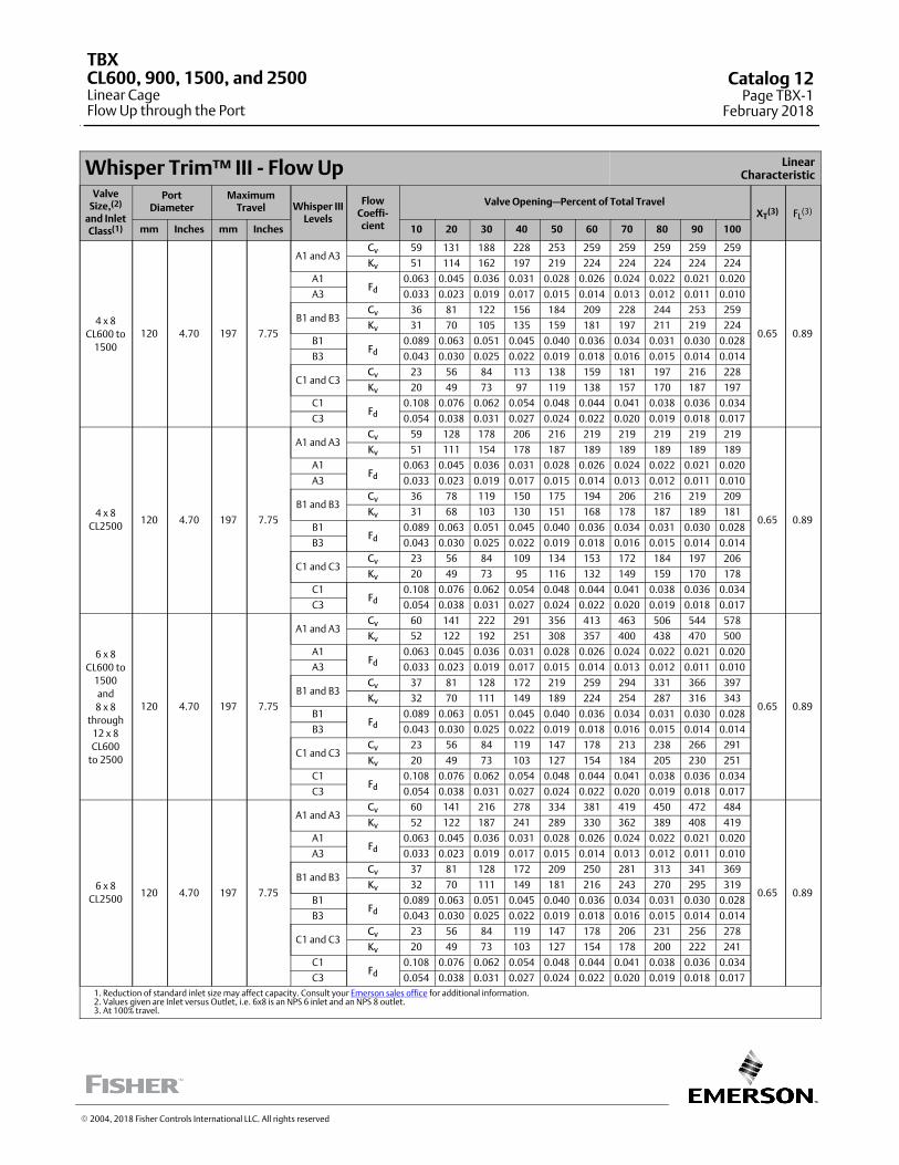
Whisper Trim™ III ‐ Flow Up LinearCharacteristic
ValveSize,(2)
and InletClass(1)
PortDiameter
MaximumTravel Whisper III
Levels
FlowCoeffi‐cient
Valve Opening—Percent of Total TravelXT
(3) FL(3)
mm Inches mm Inches 10 20 30 40 50 60 70 80 90 100
4 x 8
CL600 to
1500
120 4.70 197 7.75
A1 and A3Cv 59 131 188 228 253 259 259 259 259 259
0.65 0.89
Kv 51 114 162 197 219 224 224 224 224 224
A1Fd
0.063 0.045 0.036 0.031 0.028 0.026 0.024 0.022 0.021 0.020
A3 0.033 0.023 0.019 0.017 0.015 0.014 0.013 0.012 0.011 0.010
B1 and B3Cv 36 81 122 156 184 209 228 244 253 259
Kv 31 70 105 135 159 181 197 211 219 224
B1Fd
0.089 0.063 0.051 0.045 0.040 0.036 0.034 0.031 0.030 0.028
B3 0.043 0.030 0.025 0.022 0.019 0.018 0.016 0.015 0.014 0.014
C1 and C3Cv 23 56 84 113 138 159 181 197 216 228
Kv 20 49 73 97 119 138 157 170 187 197
C1Fd
0.108 0.076 0.062 0.054 0.048 0.044 0.041 0.038 0.036 0.034
C3 0.054 0.038 0.031 0.027 0.024 0.022 0.020 0.019 0.018 0.017
4 x 8
CL2500120 4.70 197 7.75
A1 and A3Cv 59 128 178 206 216 219 219 219 219 219
0.65 0.89
Kv 51 111 154 178 187 189 189 189 189 189
A1Fd
0.063 0.045 0.036 0.031 0.028 0.026 0.024 0.022 0.021 0.020
A3 0.033 0.023 0.019 0.017 0.015 0.014 0.013 0.012 0.011 0.010
B1 and B3Cv 36 78 119 150 175 194 206 216 219 209
Kv 31 68 103 130 151 168 178 187 189 181
B1Fd
0.089 0.063 0.051 0.045 0.040 0.036 0.034 0.031 0.030 0.028
B3 0.043 0.030 0.025 0.022 0.019 0.018 0.016 0.015 0.014 0.014
C1 and C3Cv 23 56 84 109 134 153 172 184 197 206
Kv 20 49 73 95 116 132 149 159 170 178
C1Fd
0.108 0.076 0.062 0.054 0.048 0.044 0.041 0.038 0.036 0.034
C3 0.054 0.038 0.031 0.027 0.024 0.022 0.020 0.019 0.018 0.017
6 x 8
CL600 to
1500
and
8 x 8
through
12 x 8
CL600
to 2500
120 4.70 197 7.75
A1 and A3Cv 60 141 222 291 356 413 463 506 544 578
0.65 0.89
Kv 52 122 192 251 308 357 400 438 470 500
A1Fd
0.063 0.045 0.036 0.031 0.028 0.026 0.024 0.022 0.021 0.020
A3 0.033 0.023 0.019 0.017 0.015 0.014 0.013 0.012 0.011 0.010
B1 and B3Cv 37 81 128 172 219 259 294 331 366 397
Kv 32 70 111 149 189 224 254 287 316 343
B1Fd
0.089 0.063 0.051 0.045 0.040 0.036 0.034 0.031 0.030 0.028
B3 0.043 0.030 0.025 0.022 0.019 0.018 0.016 0.015 0.014 0.014
C1 and C3Cv 23 56 84 119 147 178 213 238 266 291
Kv 20 49 73 103 127 154 184 205 230 251
C1Fd
0.108 0.076 0.062 0.054 0.048 0.044 0.041 0.038 0.036 0.034
C3 0.054 0.038 0.031 0.027 0.024 0.022 0.020 0.019 0.018 0.017
6 x 8
CL2500120 4.70 197 7.75
A1 and A3Cv 60 141 216 278 334 381 419 450 472 484
0.65 0.89
Kv 52 122 187 241 289 330 362 389 408 419
A1Fd
0.063 0.045 0.036 0.031 0.028 0.026 0.024 0.022 0.021 0.020
A3 0.033 0.023 0.019 0.017 0.015 0.014 0.013 0.012 0.011 0.010
B1 and B3Cv 37 81 128 172 209 250 281 313 341 369
Kv 32 70 111 149 181 216 243 270 295 319
B1Fd
0.089 0.063 0.051 0.045 0.040 0.036 0.034 0.031 0.030 0.028
B3 0.043 0.030 0.025 0.022 0.019 0.018 0.016 0.015 0.014 0.014
C1 and C3Cv 23 56 84 119 147 178 206 231 256 278
Kv 20 49 73 103 127 154 178 200 222 241
C1Fd
0.108 0.076 0.062 0.054 0.048 0.044 0.041 0.038 0.036 0.034
C3 0.054 0.038 0.031 0.027 0.024 0.022 0.020 0.019 0.018 0.017
1. Reduction of standard inlet size may affect capacity. Consult your Emerson sales office for additional information.2. Values given are Inlet versus Outlet, i.e. 6x8 is an NPS 6 inlet and an NPS 8 outlet.3. At 100% travel.
� 2004, 2018 Fisher Controls International LLC. All rights reserved
TBXCL600, 900, 1500, and 2500Linear CageFlow Up through the Port
Catalog 12Page TBX-1
February 2018
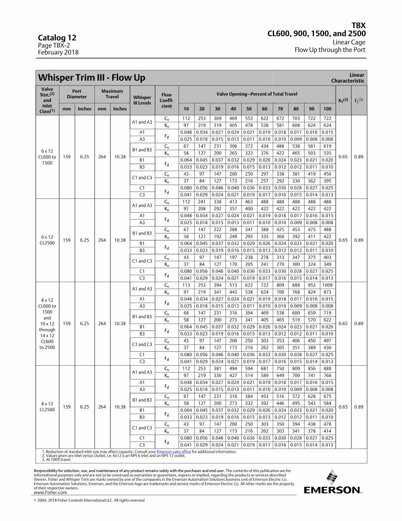
Whisper Trim III ‐ Flow Up LinearCharacteristic
ValveSize,(2)
andInlet
Class(1)
PortDiameter
MaximumTravel Whisper
III Levels
FlowCoeffi‐cient
Valve Opening—Percent of Total Travel
XT(3) FL
(3)
mm Inches mm Inches 10 20 30 40 50 60 70 80 90 100
6 x 12
CL600 to
1500
159 6.25 264 10.38
A1 and A3Cv 112 253 369 469 553 622 672 703 722 722
0.65 0.89
Kv 97 219 319 405 478 538 581 608 624 624
A1Fd
0.048 0.034 0.027 0.024 0.021 0.019 0.018 0.017 0.016 0.015
A3 0.025 0.018 0.015 0.013 0.011 0.010 0.010 0.009 0.008 0.008
B1 and B3Cv 67 147 231 306 372 434 488 538 581 619
Kv 58 127 200 265 322 376 422 465 503 535
B1Fd
0.064 0.045 0.037 0.032 0.029 0.026 0.024 0.023 0.021 0.020
B3 0.033 0.023 0.019 0.016 0.015 0.013 0.012 0.012 0.011 0.010
C1 and C3Cv 43 97 147 200 250 297 338 381 419 456
Kv 37 84 127 173 216 257 292 330 362 395
C1Fd
0.080 0.056 0.046 0.040 0.036 0.033 0.030 0.028 0.027 0.025
C3 0.041 0.029 0.024 0.021 0.019 0.017 0.016 0.015 0.014 0.013
6 x 12
CL2500159 6.25 264 10.38
A1 and A3Cv 112 241 338 413 463 488 488 488 488 488
0.65 0.89
Kv 97 208 292 357 400 422 422 422 422 422
A1Fd
0.048 0.034 0.027 0.024 0.021 0.019 0.018 0.017 0.016 0.015
A3 0.025 0.018 0.015 0.013 0.011 0.010 0.010 0.009 0.008 0.008
B1 and B3Cv 67 147 222 288 341 388 425 453 475 488
Kv 58 127 192 249 295 335 368 392 411 422
B1Fd
0.064 0.045 0.037 0.032 0.029 0.026 0.024 0.023 0.021 0.020
B3 0.033 0.023 0.019 0.016 0.015 0.013 0.012 0.012 0.011 0.010
C1 and C3Cv 43 97 147 197 238 278 313 347 375 403
Kv 37 84 127 170 205 241 270 300 324 349
C1Fd
0.080 0.056 0.046 0.040 0.036 0.033 0.030 0.028 0.027 0.025
C3 0.041 0.029 0.024 0.021 0.019 0.017 0.016 0.015 0.014 0.013
8 x 12
CL600 to
1500
and
10 x 12
through
14 x 12
CL600
to 2500
159 6.25 264 10.38
A1 and A3Cv 113 253 394 513 622 722 809 888 953 1009
0.65 0.89
Kv 97 219 341 443 538 624 700 768 824 873
A1Fd
0.048 0.034 0.027 0.024 0.021 0.019 0.018 0.017 0.016 0.015
A3 0.025 0.018 0.015 0.013 0.011 0.010 0.010 0.009 0.008 0.008
B1 and B3Cv 68 147 231 316 394 469 538 600 659 719
Kv 58 127 200 273 341 405 465 519 570 622
B1Fd
0.064 0.045 0.037 0.032 0.029 0.026 0.024 0.023 0.021 0.020
B3 0.033 0.023 0.019 0.016 0.015 0.013 0.012 0.012 0.011 0.010
C1 and C3Cv 43 97 147 200 250 303 353 406 450 497
Kv 37 84 127 173 216 262 305 351 389 430
C1Fd
0.080 0.056 0.046 0.040 0.036 0.033 0.030 0.028 0.027 0.025
C3 0.041 0.029 0.024 0.021 0.019 0.017 0.016 0.015 0.014 0.013
8 x 12
CL2500159 6.25 264 10.38
A1 and A3Cv 112 253 381 494 594 681 750 809 856 888
0.65 0.89
Kv 97 219 330 427 514 589 649 700 741 768
A1Fd
0.048 0.034 0.027 0.024 0.021 0.019 0.018 0.017 0.016 0.015
A3 0.025 0.018 0.015 0.013 0.011 0.010 0.010 0.009 0.008 0.008
B1 and B3Cv 67 147 231 316 384 453 516 572 628 675
Kv 58 127 200 273 332 392 446 495 543 584
B1Fd
0.064 0.045 0.037 0.032 0.029 0.026 0.024 0.023 0.021 0.020
B3 0.033 0.023 0.019 0.016 0.015 0.013 0.012 0.012 0.011 0.010
C1 and C3Cv 43 97 147 200 250 303 350 394 438 478
Kv 37 84 127 173 216 262 303 341 378 414
C1Fd
0.080 0.056 0.046 0.040 0.036 0.033 0.030 0.028 0.027 0.025
C3 0.041 0.029 0.024 0.021 0.019 0.017 0.016 0.015 0.014 0.013
1. Reduction of standard inlet size may affect capacity. Consult your Emerson sales office for additional information.2. Values given are Inlet versus Outlet, i.e. 6x12 is an NPS 6 inlet and an NPS 12 outlet.3. At 100% travel.
TBX
Linear CageFlow Up through the Port
CL600, 900, 1500, and 2500Catalog 12Page TBX-2February 2018
� 2004, 2018 Fisher Controls International LLC. All rights reserved
www.Fisher.com
Responsibility for selection, use, and maintenance of any product remains solely with the purchaser and end user. The contents of this publication are forinformational purposes only and are not to be construed as warranties or guarantees, express or implied, regarding the products or services describedtherein. Fisher and Whisper Trim are marks owned by one of the companies in the Emerson Automation Solutions business unit of Emerson Electric Co.Emerson Automation Solutions, Emerson, and the Emerson logo are trademarks and service marks of Emerson Electric Co. All other marks are the propertyof their respective owners.
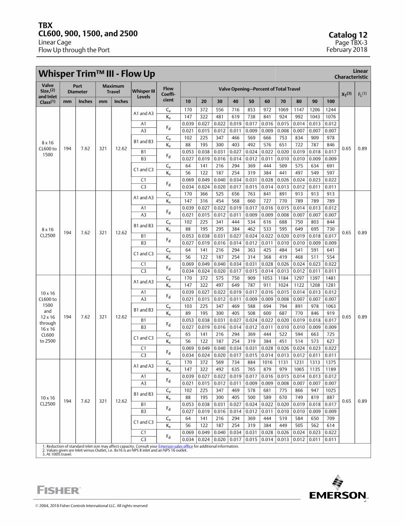
3
Whisper Trim™ III ‐ Flow Up LinearCharacteristic
ValveSize,(2)
and InletClass(1)
PortDiameter
MaximumTravel Whisper III
Levels
FlowCoeffi‐cient
Valve Opening—Percent of Total TravelXT
(3) FL(3)
mm Inches mm Inches 10 20 30 40 50 60 70 80 90 100
8 x 16
CL600 to
1500
194 7.62 321 12.62
A1 and A3Cv 170 372 556 716 853 972 1069 1147 1206 1244
0.65 0.89
Kv 147 322 481 619 738 841 924 992 1043 1076
A1Fd
0.039 0.027 0.022 0.019 0.017 0.016 0.015 0.014 0.013 0.012
A3 0.021 0.015 0.012 0.011 0.009 0.009 0.008 0.007 0.007 0.007
B1 and B3Cv 102 225 347 466 569 666 753 834 909 978
Kv 88 195 300 403 492 576 651 722 787 846
B1Fd
0.053 0.038 0.031 0.027 0.024 0.022 0.020 0.019 0.018 0.017
B3 0.027 0.019 0.016 0.014 0.012 0.011 0.010 0.010 0.009 0.009
C1 and C3Cv 64 141 216 294 369 444 509 575 634 691
Kv 56 122 187 254 319 384 441 497 549 597
C1Fd
0.069 0.049 0.040 0.034 0.031 0.028 0.026 0.024 0.023 0.022
C3 0.034 0.024 0.020 0.017 0.015 0.014 0.013 0.012 0.011 0.011
8 x 16
CL2500194 7.62 321 12.62
A1 and A3Cv 170 366 525 656 763 841 891 913 913 913
0.65 0.89
Kv 147 316 454 568 660 727 770 789 789 789
A1Fd
0.039 0.027 0.022 0.019 0.017 0.016 0.015 0.014 0.013 0.012
A3 0.021 0.015 0.012 0.011 0.009 0.009 0.008 0.007 0.007 0.007
B1 and B3Cv 102 225 341 444 534 616 688 750 803 844
Kv 88 195 295 384 462 533 595 649 695 730
B1Fd
0.053 0.038 0.031 0.027 0.024 0.022 0.020 0.019 0.018 0.017
B3 0.027 0.019 0.016 0.014 0.012 0.011 0.010 0.010 0.009 0.009
C1 and C3Cv 64 141 216 294 363 425 484 541 591 641
Kv 56 122 187 254 314 368 419 468 511 554
C1Fd
0.069 0.049 0.040 0.034 0.031 0.028 0.026 0.024 0.023 0.022
C3 0.034 0.024 0.020 0.017 0.015 0.014 0.013 0.012 0.011 0.011
10 x 16
CL600 to
1500
and
12 x 16
through
16 x 16
CL600
to 2500
194 7.62 321 12.62
A1 and A3Cv 170 372 575 750 909 1053 1184 1297 1397 1481
0.65 0.89
Kv 147 322 497 649 787 911 1024 1122 1208 1281
A1Fd
0.039 0.027 0.022 0.019 0.017 0.016 0.015 0.014 0.013 0.012
A3 0.021 0.015 0.012 0.011 0.009 0.009 0.008 0.007 0.007 0.007
B1 and B3Cv 103 225 347 469 588 694 794 891 978 1063
Kv 89 195 300 405 508 600 687 770 846 919
B1Fd
0.053 0.038 0.031 0.027 0.024 0.022 0.020 0.019 0.018 0.017
B3 0.027 0.019 0.016 0.014 0.012 0.011 0.010 0.010 0.009 0.009
C1 and C3Cv 65 141 216 294 369 444 522 594 663 725
Kv 56 122 187 254 319 384 451 514 573 627
C1Fd
0.069 0.049 0.040 0.034 0.031 0.028 0.026 0.024 0.023 0.022
C3 0.034 0.024 0.020 0.017 0.015 0.014 0.013 0.012 0.011 0.011
10 x 16
CL2500194 7.62 321 12.62
A1 and A3Cv 170 372 569 734 884 1016 1131 1231 1313 1375
0.65 0.89
Kv 147 322 492 635 765 879 979 1065 1135 1189
A1Fd
0.039 0.027 0.022 0.019 0.017 0.016 0.015 0.014 0.013 0.012
A3 0.021 0.015 0.012 0.011 0.009 0.009 0.008 0.007 0.007 0.007
B1 and B3Cv 102 225 347 469 578 681 775 866 947 1025
Kv 88 195 300 405 500 589 670 749 819 887
B1Fd
0.053 0.038 0.031 0.027 0.024 0.022 0.020 0.019 0.018 0.017
B3 0.027 0.019 0.016 0.014 0.012 0.011 0.010 0.010 0.009 0.009
C1 and C3Cv 64 141 216 294 369 444 519 584 650 709
Kv 56 122 187 254 319 384 449 505 562 614
C1Fd
0.069 0.049 0.040 0.034 0.031 0.028 0.026 0.024 0.023 0.022
C3 0.034 0.024 0.020 0.017 0.015 0.014 0.013 0.012 0.011 0.011
1. Reduction of standard inlet size may affect capacity. Consult your Emerson sales office for additional information.2. Values given are Inlet versus Outlet, i.e. 8x16 is an NPS 8 inlet and an NPS 16 outlet.3. At 100% travel.
TBX
Linear CageFlow Up through the Port
CL600, 900, 1500, and 2500 Catalog 12Page TBX-3
February 2018
� 2004, 2018 Fisher Controls International LLC. All rights reserved
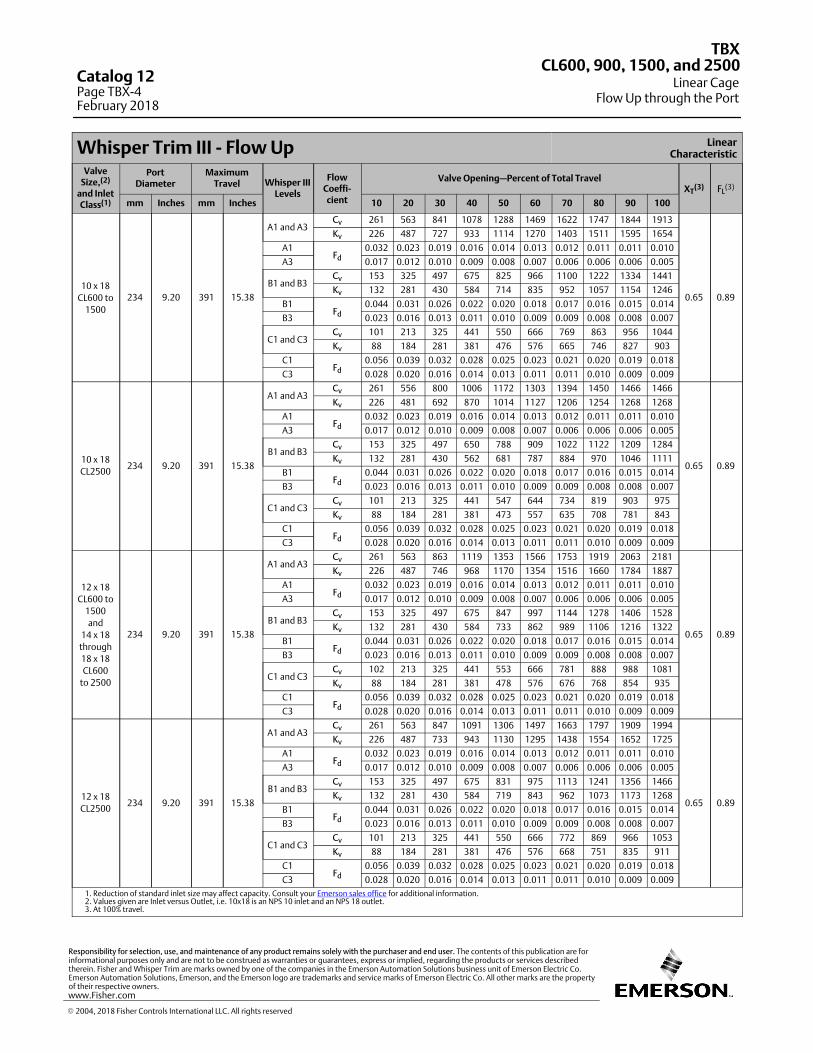
Whisper Trim III ‐ Flow Up LinearCharacteristic
ValveSize,(2)
and InletClass(1)
PortDiameter
MaximumTravel Whisper III
Levels
FlowCoeffi‐cient
Valve Opening—Percent of Total TravelXT
(3) FL(3)
mm Inches mm Inches 10 20 30 40 50 60 70 80 90 100
10 x 18
CL600 to
1500
234 9.20 391 15.38
A1 and A3Cv 261 563 841 1078 1288 1469 1622 1747 1844 1913
0.65 0.89
Kv 226 487 727 933 1114 1270 1403 1511 1595 1654
A1Fd
0.032 0.023 0.019 0.016 0.014 0.013 0.012 0.011 0.011 0.010
A3 0.017 0.012 0.010 0.009 0.008 0.007 0.006 0.006 0.006 0.005
B1 and B3Cv 153 325 497 675 825 966 1100 1222 1334 1441
Kv 132 281 430 584 714 835 952 1057 1154 1246
B1Fd
0.044 0.031 0.026 0.022 0.020 0.018 0.017 0.016 0.015 0.014
B3 0.023 0.016 0.013 0.011 0.010 0.009 0.009 0.008 0.008 0.007
C1 and C3Cv 101 213 325 441 550 666 769 863 956 1044
Kv 88 184 281 381 476 576 665 746 827 903
C1Fd
0.056 0.039 0.032 0.028 0.025 0.023 0.021 0.020 0.019 0.018
C3 0.028 0.020 0.016 0.014 0.013 0.011 0.011 0.010 0.009 0.009
10 x 18
CL2500234 9.20 391 15.38
A1 and A3Cv 261 556 800 1006 1172 1303 1394 1450 1466 1466
0.65 0.89
Kv 226 481 692 870 1014 1127 1206 1254 1268 1268
A1Fd
0.032 0.023 0.019 0.016 0.014 0.013 0.012 0.011 0.011 0.010
A3 0.017 0.012 0.010 0.009 0.008 0.007 0.006 0.006 0.006 0.005
B1 and B3Cv 153 325 497 650 788 909 1022 1122 1209 1284
Kv 132 281 430 562 681 787 884 970 1046 1111
B1Fd
0.044 0.031 0.026 0.022 0.020 0.018 0.017 0.016 0.015 0.014
B3 0.023 0.016 0.013 0.011 0.010 0.009 0.009 0.008 0.008 0.007
C1 and C3Cv 101 213 325 441 547 644 734 819 903 975
Kv 88 184 281 381 473 557 635 708 781 843
C1Fd
0.056 0.039 0.032 0.028 0.025 0.023 0.021 0.020 0.019 0.018
C3 0.028 0.020 0.016 0.014 0.013 0.011 0.011 0.010 0.009 0.009
12 x 18
CL600 to
1500
and
14 x 18
through
18 x 18
CL600
to 2500
234 9.20 391 15.38
A1 and A3Cv 261 563 863 1119 1353 1566 1753 1919 2063 2181
0.65 0.89
Kv 226 487 746 968 1170 1354 1516 1660 1784 1887
A1Fd
0.032 0.023 0.019 0.016 0.014 0.013 0.012 0.011 0.011 0.010
A3 0.017 0.012 0.010 0.009 0.008 0.007 0.006 0.006 0.006 0.005
B1 and B3Cv 153 325 497 675 847 997 1144 1278 1406 1528
Kv 132 281 430 584 733 862 989 1106 1216 1322
B1Fd
0.044 0.031 0.026 0.022 0.020 0.018 0.017 0.016 0.015 0.014
B3 0.023 0.016 0.013 0.011 0.010 0.009 0.009 0.008 0.008 0.007
C1 and C3Cv 102 213 325 441 553 666 781 888 988 1081
Kv 88 184 281 381 478 576 676 768 854 935
C1Fd
0.056 0.039 0.032 0.028 0.025 0.023 0.021 0.020 0.019 0.018
C3 0.028 0.020 0.016 0.014 0.013 0.011 0.011 0.010 0.009 0.009
12 x 18
CL2500234 9.20 391 15.38
A1 and A3Cv 261 563 847 1091 1306 1497 1663 1797 1909 1994
0.65 0.89
Kv 226 487 733 943 1130 1295 1438 1554 1652 1725
A1Fd
0.032 0.023 0.019 0.016 0.014 0.013 0.012 0.011 0.011 0.010
A3 0.017 0.012 0.010 0.009 0.008 0.007 0.006 0.006 0.006 0.005
B1 and B3Cv 153 325 497 675 831 975 1113 1241 1356 1466
Kv 132 281 430 584 719 843 962 1073 1173 1268
B1Fd
0.044 0.031 0.026 0.022 0.020 0.018 0.017 0.016 0.015 0.014
B3 0.023 0.016 0.013 0.011 0.010 0.009 0.009 0.008 0.008 0.007
C1 and C3Cv 101 213 325 441 550 666 772 869 966 1053
Kv 88 184 281 381 476 576 668 751 835 911
C1Fd
0.056 0.039 0.032 0.028 0.025 0.023 0.021 0.020 0.019 0.018
C3 0.028 0.020 0.016 0.014 0.013 0.011 0.011 0.010 0.009 0.009
1. Reduction of standard inlet size may affect capacity. Consult your Emerson sales office for additional information.2. Values given are Inlet versus Outlet, i.e. 10x18 is an NPS 10 inlet and an NPS 18 outlet.3. At 100% travel.
TBX
Linear CageFlow Up through the Port
CL600, 900, 1500, and 2500Catalog 12Page TBX-4February 2018
� 2004, 2018 Fisher Controls International LLC. All rights reserved
www.Fisher.com
Responsibility for selection, use, and maintenance of any product remains solely with the purchaser and end user. The contents of this publication are forinformational purposes only and are not to be construed as warranties or guarantees, express or implied, regarding the products or services describedtherein. Fisher and Whisper Trim are marks owned by one of the companies in the Emerson Automation Solutions business unit of Emerson Electric Co.Emerson Automation Solutions, Emerson, and the Emerson logo are trademarks and service marks of Emerson Electric Co. All other marks are the propertyof their respective owners.
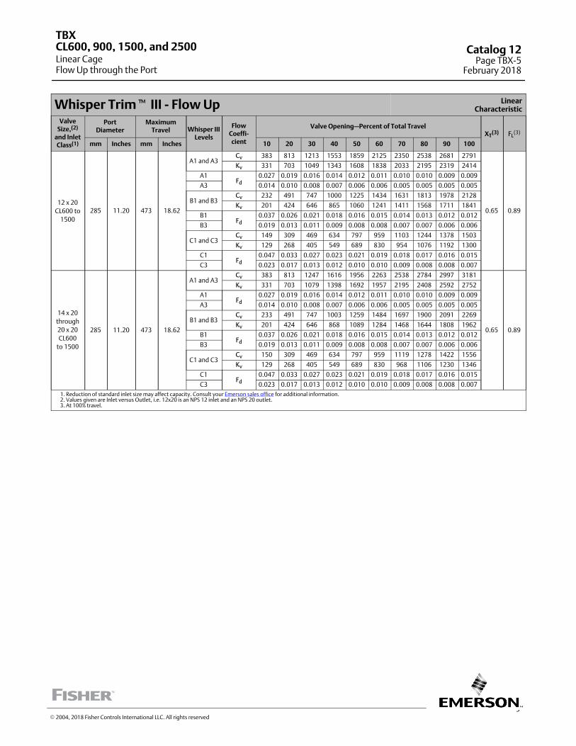
5
Whisper Trim� III ‐ Flow Up LinearCharacteristic
ValveSize,(2)
and InletClass(1)
PortDiameter
MaximumTravel Whisper III
Levels
FlowCoeffi‐cient
Valve Opening—Percent of Total TravelXT
(3) FL(3)
mm Inches mm Inches 10 20 30 40 50 60 70 80 90 100
12 x 20
CL600 to
1500
285 11.20 473 18.62
A1 and A3Cv 383 813 1213 1553 1859 2125 2350 2538 2681 2791
0.65 0.89
Kv 331 703 1049 1343 1608 1838 2033 2195 2319 2414
A1Fd
0.027 0.019 0.016 0.014 0.012 0.011 0.010 0.010 0.009 0.009
A3 0.014 0.010 0.008 0.007 0.006 0.006 0.005 0.005 0.005 0.005
B1 and B3Cv 232 491 747 1000 1225 1434 1631 1813 1978 2128
Kv 201 424 646 865 1060 1241 1411 1568 1711 1841
B1Fd
0.037 0.026 0.021 0.018 0.016 0.015 0.014 0.013 0.012 0.012
B3 0.019 0.013 0.011 0.009 0.008 0.008 0.007 0.007 0.006 0.006
C1 and C3Cv 149 309 469 634 797 959 1103 1244 1378 1503
Kv 129 268 405 549 689 830 954 1076 1192 1300
C1Fd
0.047 0.033 0.027 0.023 0.021 0.019 0.018 0.017 0.016 0.015
C3 0.023 0.017 0.013 0.012 0.010 0.010 0.009 0.008 0.008 0.007
14 x 20
through
20 x 20
CL600
to 1500
285 11.20 473 18.62
A1 and A3Cv 383 813 1247 1616 1956 2263 2538 2784 2997 3181
0.65 0.89
Kv 331 703 1079 1398 1692 1957 2195 2408 2592 2752
A1Fd
0.027 0.019 0.016 0.014 0.012 0.011 0.010 0.010 0.009 0.009
A3 0.014 0.010 0.008 0.007 0.006 0.006 0.005 0.005 0.005 0.005
B1 and B3Cv 233 491 747 1003 1259 1484 1697 1900 2091 2269
Kv 201 424 646 868 1089 1284 1468 1644 1808 1962
B1Fd
0.037 0.026 0.021 0.018 0.016 0.015 0.014 0.013 0.012 0.012
B3 0.019 0.013 0.011 0.009 0.008 0.008 0.007 0.007 0.006 0.006
C1 and C3Cv 150 309 469 634 797 959 1119 1278 1422 1556
Kv 129 268 405 549 689 830 968 1106 1230 1346
C1Fd
0.047 0.033 0.027 0.023 0.021 0.019 0.018 0.017 0.016 0.015
C3 0.023 0.017 0.013 0.012 0.010 0.010 0.009 0.008 0.008 0.007
1. Reduction of standard inlet size may affect capacity. Consult your Emerson sales office for additional information.2. Values given are Inlet versus Outlet, i.e. 12x20 is an NPS 12 inlet and an NPS 20 outlet.3. At 100% travel.
TBX
Linear CageFlow Up through the Port
CL600, 900, 1500, and 2500 Catalog 12Page TBX-5
February 2018
� 2004, 2018 Fisher Controls International LLC. All rights reserved
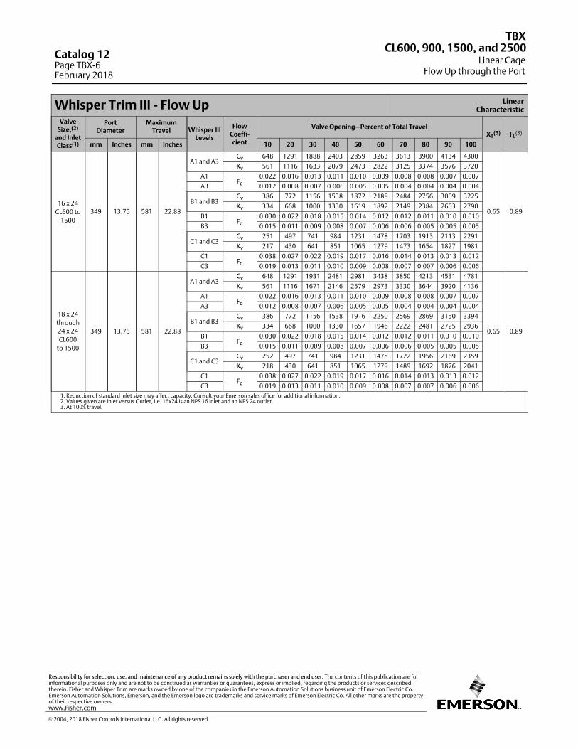
Whisper Trim III ‐ Flow Up LinearCharacteristic
ValveSize,(2)
and InletClass(1)
PortDiameter
MaximumTravel Whisper III
Levels
FlowCoeffi‐cient
Valve Opening—Percent of Total TravelXT
(3) FL(3)
mm Inches mm Inches 10 20 30 40 50 60 70 80 90 100
16 x 24
CL600 to
1500
349 13.75 581 22.88
A1 and A3Cv 648 1291 1888 2403 2859 3263 3613 3900 4134 4300
0.65 0.89
Kv 561 1116 1633 2079 2473 2822 3125 3374 3576 3720
A1Fd
0.022 0.016 0.013 0.011 0.010 0.009 0.008 0.008 0.007 0.007
A3 0.012 0.008 0.007 0.006 0.005 0.005 0.004 0.004 0.004 0.004
B1 and B3Cv 386 772 1156 1538 1872 2188 2484 2756 3009 3225
Kv 334 668 1000 1330 1619 1892 2149 2384 2603 2790
B1Fd
0.030 0.022 0.018 0.015 0.014 0.012 0.012 0.011 0.010 0.010
B3 0.015 0.011 0.009 0.008 0.007 0.006 0.006 0.005 0.005 0.005
C1 and C3Cv 251 497 741 984 1231 1478 1703 1913 2113 2291
Kv 217 430 641 851 1065 1279 1473 1654 1827 1981
C1Fd
0.038 0.027 0.022 0.019 0.017 0.016 0.014 0.013 0.013 0.012
C3 0.019 0.013 0.011 0.010 0.009 0.008 0.007 0.007 0.006 0.006
18 x 24
through
24 x 24
CL600
to 1500
349 13.75 581 22.88
A1 and A3Cv 648 1291 1931 2481 2981 3438 3850 4213 4531 4781
0.65 0.89
Kv 561 1116 1671 2146 2579 2973 3330 3644 3920 4136
A1Fd
0.022 0.016 0.013 0.011 0.010 0.009 0.008 0.008 0.007 0.007
A3 0.012 0.008 0.007 0.006 0.005 0.005 0.004 0.004 0.004 0.004
B1 and B3Cv 386 772 1156 1538 1916 2250 2569 2869 3150 3394
Kv 334 668 1000 1330 1657 1946 2222 2481 2725 2936
B1Fd
0.030 0.022 0.018 0.015 0.014 0.012 0.012 0.011 0.010 0.010
B3 0.015 0.011 0.009 0.008 0.007 0.006 0.006 0.005 0.005 0.005
C1 and C3Cv 252 497 741 984 1231 1478 1722 1956 2169 2359
Kv 218 430 641 851 1065 1279 1489 1692 1876 2041
C1Fd
0.038 0.027 0.022 0.019 0.017 0.016 0.014 0.013 0.013 0.012
C3 0.019 0.013 0.011 0.010 0.009 0.008 0.007 0.007 0.006 0.006
1. Reduction of standard inlet size may affect capacity. Consult your Emerson sales office for additional information.2. Values given are Inlet versus Outlet, i.e. 16x24 is an NPS 16 inlet and an NPS 24 outlet.3. At 100% travel.
TBX
Linear CageFlow Up through the Port
CL600, 900, 1500, and 2500Catalog 12Page TBX-6February 2018
� 2004, 2018 Fisher Controls International LLC. All rights reserved
www.Fisher.com
Responsibility for selection, use, and maintenance of any product remains solely with the purchaser and end user. The contents of this publication are forinformational purposes only and are not to be construed as warranties or guarantees, express or implied, regarding the products or services describedtherein. Fisher and Whisper Trim are marks owned by one of the companies in the Emerson Automation Solutions business unit of Emerson Electric Co.Emerson Automation Solutions, Emerson, and the Emerson logo are trademarks and service marks of Emerson Electric Co. All other marks are the propertyof their respective owners.
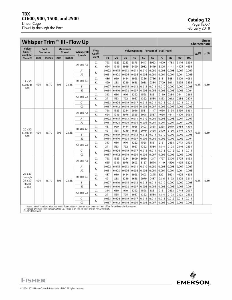
7
Whisper Trim� III ‐ Flow Up LinearCharacteristic
ValveSize,(2)
and InletClass(1)
PortDiameter
MaximumTravel Whisper III
Levels
FlowCoeffi‐cient
Valve Opening—Percent of Total TravelXT
(3) FL(3)
mm Inches mm Inches 10 20 30 40 50 60 70 80 90 100
18 x 30
CL600 to
900
424 16.70 606 23.88
A1 and A3Cv 768 1525 2253 2878 3447 3953 4400 4788 5116 5359
0.65 0.89
Kv 664 1319 1949 2490 2982 3419 3806 4141 4425 4636
A1Fd
0.022 0.015 0.013 0.011 0.010 0.009 0.008 0.008 0.007 0.007
A3 0.011 0.008 0.006 0.005 0.005 0.004 0.004 0.004 0.004 0.003
B1 and B3Cv 486 969 1444 1928 2356 2756 3131 3481 3809 4088
Kv 420 838 1249 1668 2038 2384 2709 3011 3295 3536
B1Fd
0.027 0.019 0.015 0.013 0.012 0.011 0.010 0.009 0.009 0.008
B3 0.014 0.010 0.008 0.007 0.006 0.006 0.005 0.005 0.005 0.004
C1 and C3Cv 313 616 916 1222 1528 1831 2119 2384 2641 2866
Kv 271 533 792 1057 1322 1584 1833 2062 2284 2479
C1Fd
0.033 0.024 0.019 0.017 0.015 0.014 0.013 0.012 0.011 0.011
C3 0.017 0.012 0.010 0.009 0.008 0.007 0.006 0.006 0.006 0.005
20 x 30
CL600 to
900
424 16.70 606 23.88
A1 and A3Cv 768 1525 2284 2966 3581 4147 4666 5134 5556 5891
0.65 0.89
Kv 664 1319 1976 2565 3098 3587 4036 4441 4806 5095
A1Fd
0.022 0.015 0.013 0.011 0.010 0.009 0.008 0.008 0.007 0.007
A3 0.011 0.008 0.006 0.005 0.005 0.004 0.004 0.004 0.004 0.003
B1 and B3Cv 487 969 1444 1928 2403 2838 3238 3619 3984 4300
Kv 421 838 1249 1668 2079 2454 2800 3130 3446 3720
B1Fd
0.027 0.019 0.015 0.013 0.012 0.011 0.010 0.009 0.009 0.008
B3 0.014 0.010 0.008 0.007 0.006 0.006 0.005 0.005 0.005 0.004
C1 and C3Cv 313 616 916 1222 1528 1831 2131 2438 2713 2953
Kv 271 533 792 1057 1322 1584 1844 2108 2346 2554
C1Fd
0.033 0.024 0.019 0.017 0.015 0.014 0.013 0.012 0.011 0.011
C3 0.017 0.012 0.010 0.009 0.008 0.007 0.006 0.006 0.006 0.005
22 x 30
through
24 x 30
CL600
to 900
424 16.70 606 23.88
A1 and A3Cv 768 1525 2284 3009 3650 4247 4797 5306 5775 6153
0.65 0.89
Kv 665 1319 1976 2603 3157 3674 4149 4590 4995 5322
A1Fd
0.022 0.015 0.013 0.011 0.010 0.009 0.008 0.008 0.007 0.007
A3 0.011 0.008 0.006 0.005 0.005 0.004 0.004 0.004 0.004 0.003
B1 and B3Cv 487 969 1444 1928 2403 2875 3291 3691 4075 4406
Kv 421 838 1249 1668 2079 2487 2846 3192 3525 3811
B1Fd
0.027 0.019 0.015 0.013 0.012 0.011 0.010 0.009 0.009 0.008
B3 0.014 0.010 0.008 0.007 0.006 0.006 0.005 0.005 0.005 0.004
C1 and C3Cv 314 619 919 1222 1528 1831 2131 2438 2744 2997
Kv 271 535 795 1057 1322 1584 1844 2108 2373 2592
C1Fd
0.033 0.024 0.019 0.017 0.015 0.014 0.013 0.012 0.011 0.011
C3 0.017 0.012 0.010 0.009 0.008 0.007 0.006 0.006 0.006 0.005
1. Reduction of standard inlet size may affect capacity. Consult your Emerson sales office for additional information.2. Values given are Inlet versus Outlet, i.e. 18x30 is an NPS 18 inlet and an NPS 30 outlet.3. At 100% travel.
TBX
Linear CageFlow Up through the Port
CL600, 900, 1500, and 2500 Catalog 12Page TBX-7
February 2018
� 2004, 2018 Fisher Controls International LLC. All rights reserved
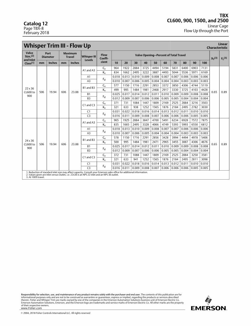
Whisper Trim III ‐ Flow Up LinearCharacteristic
ValveSize,(2)
and InletClass(1)
PortDiameter
MaximumTravel Whisper III
Levels
FlowCoeffi‐cient
Valve Opening—Percent of Total TravelXT
(3) FL(3)
mm Inches mm Inches 10 20 30 40 50 60 70 80 90 100
22 x 36
CL600 to
900
506 19.94 606 23.88
A1 and A3Cv 964 1922 2884 3725 4494 5194 5831 6400 6903 7131
0.65 0.89
Kv 834 1662 2495 3222 3887 4493 5044 5536 5971 6169
A1Fd
0.018 0.013 0.010 0.009 0.008 0.007 0.007 0.006 0.006 0.006
A3 0.010 0.007 0.006 0.005 0.004 0.004 0.004 0.003 0.003 0.003
B1 and B3Cv 577 1150 1716 2291 2853 3372 3850 4306 4744 5119
Kv 499 995 1484 1981 2468 2917 3330 3725 4103 4428
B1Fd
0.025 0.017 0.014 0.012 0.011 0.010 0.009 0.009 0.008 0.008
B3 0.012 0.009 0.007 0.006 0.006 0.005 0.005 0.004 0.004 0.004
C1 and C3Cv 371 731 1084 1447 1809 2169 2525 2884 3216 3503
Kv 321 633 938 1252 1565 1876 2184 2495 2782 3030
C1Fd
0.031 0.022 0.018 0.016 0.014 0.013 0.012 0.011 0.010 0.010
C3 0.016 0.011 0.009 0.008 0.007 0.006 0.006 0.006 0.005 0.005
24 x 36
CL600 to
900
506 19.94 606 23.88
A1 and A3Cv 965 1925 2884 3847 4700 5491 6234 6928 7572 7875
0.65 0.89
Kv 835 1665 2495 3328 4066 4749 5393 5993 6550 6812
A1Fd
0.018 0.013 0.010 0.009 0.008 0.007 0.007 0.006 0.006 0.006
A3 0.010 0.007 0.006 0.005 0.004 0.004 0.004 0.003 0.003 0.003
B1 and B3Cv 578 1150 1716 2291 2856 3428 3994 4494 4978 5406
Kv 500 995 1484 1981 2471 2965 3455 3887 4306 4676
B1Fd
0.025 0.017 0.014 0.012 0.011 0.010 0.009 0.009 0.008 0.008
B3 0.012 0.009 0.007 0.006 0.006 0.005 0.005 0.004 0.004 0.004
C1 and C3Cv 372 731 1088 1447 1809 2169 2525 2884 3250 3581
Kv 321 633 941 1252 1565 1876 2184 2495 2811 3098
C1Fd
0.031 0.022 0.018 0.016 0.014 0.013 0.012 0.011 0.010 0.010
C3 0.016 0.011 0.009 0.008 0.007 0.006 0.006 0.006 0.005 0.005
1. Reduction of standard inlet size may affect capacity. Consult your Emerson sales office for additional information.2. Values given are Inlet versus Outlet, i.e. 22x36 is an NPS 22 inlet and an NPS 36 outlet.3. At 100% travel.
TBX
Linear CageFlow Up through the Port
CL600, 900, 1500, and 2500Catalog 12Page TBX-8February 2018
� 2004, 2018 Fisher Controls International LLC. All rights reserved
www.Fisher.com
Responsibility for selection, use, and maintenance of any product remains solely with the purchaser and end user. The contents of this publication are forinformational purposes only and are not to be construed as warranties or guarantees, express or implied, regarding the products or services describedtherein. Fisher and Whisper Trim are marks owned by one of the companies in the Emerson Automation Solutions business unit of Emerson Electric Co.Emerson Automation Solutions, Emerson, and the Emerson logo are trademarks and service marks of Emerson Electric Co. All other marks are the propertyof their respective owners.
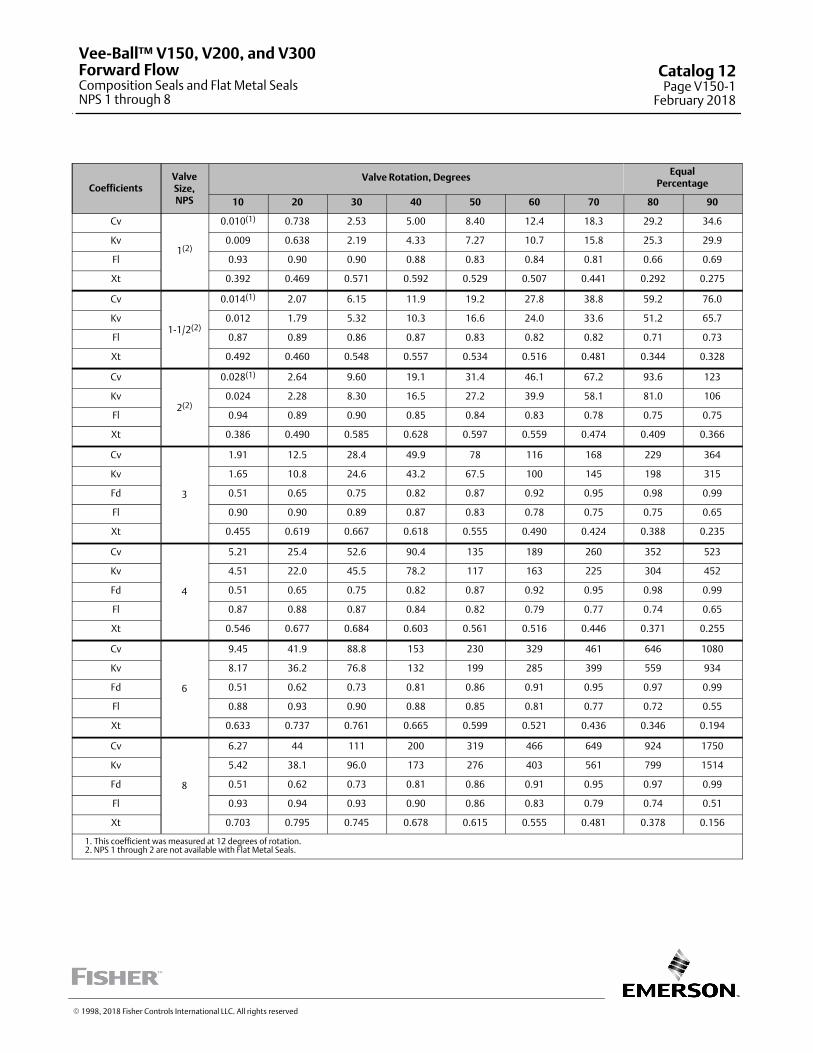
CoefficientsValveSize,NPS
Valve Rotation, DegreesEqual
Percentage
10 20 30 40 50 60 70 80 90
Cv
1(2)
0.010(1) 0.738 2.53 5.00 8.40 12.4 18.3 29.2 34.6
Kv 0.009 0.638 2.19 4.33 7.27 10.7 15.8 25.3 29.9
Fl 0.93 0.90 0.90 0.88 0.83 0.84 0.81 0.66 0.69
Xt 0.392 0.469 0.571 0.592 0.529 0.507 0.441 0.292 0.275
Cv
1-1/2(2)
0.014(1) 2.07 6.15 11.9 19.2 27.8 38.8 59.2 76.0
Kv 0.012 1.79 5.32 10.3 16.6 24.0 33.6 51.2 65.7
Fl 0.87 0.89 0.86 0.87 0.83 0.82 0.82 0.71 0.73
Xt 0.492 0.460 0.548 0.557 0.534 0.516 0.481 0.344 0.328
Cv
2(2)
0.028(1) 2.64 9.60 19.1 31.4 46.1 67.2 93.6 123
Kv 0.024 2.28 8.30 16.5 27.2 39.9 58.1 81.0 106
Fl 0.94 0.89 0.90 0.85 0.84 0.83 0.78 0.75 0.75
Xt 0.386 0.490 0.585 0.628 0.597 0.559 0.474 0.409 0.366
Cv
3
1.91 12.5 28.4 49.9 78 116 168 229 364
Kv 1.65 10.8 24.6 43.2 67.5 100 145 198 315
Fd 0.51 0.65 0.75 0.82 0.87 0.92 0.95 0.98 0.99
Fl 0.90 0.90 0.89 0.87 0.83 0.78 0.75 0.75 0.65
Xt 0.455 0.619 0.667 0.618 0.555 0.490 0.424 0.388 0.235
Cv
4
5.21 25.4 52.6 90.4 135 189 260 352 523
Kv 4.51 22.0 45.5 78.2 117 163 225 304 452
Fd 0.51 0.65 0.75 0.82 0.87 0.92 0.95 0.98 0.99
Fl 0.87 0.88 0.87 0.84 0.82 0.79 0.77 0.74 0.65
Xt 0.546 0.677 0.684 0.603 0.561 0.516 0.446 0.371 0.255
Cv
6
9.45 41.9 88.8 153 230 329 461 646 1080
Kv 8.17 36.2 76.8 132 199 285 399 559 934
Fd 0.51 0.62 0.73 0.81 0.86 0.91 0.95 0.97 0.99
Fl 0.88 0.93 0.90 0.88 0.85 0.81 0.77 0.72 0.55
Xt 0.633 0.737 0.761 0.665 0.599 0.521 0.436 0.346 0.194
Cv
8
6.27 44 111 200 319 466 649 924 1750
Kv 5.42 38.1 96.0 173 276 403 561 799 1514
Fd 0.51 0.62 0.73 0.81 0.86 0.91 0.95 0.97 0.99
Fl 0.93 0.94 0.93 0.90 0.86 0.83 0.79 0.74 0.51
Xt 0.703 0.795 0.745 0.678 0.615 0.555 0.481 0.378 0.156
1. This coefficient was measured at 12 degrees of rotation.2. NPS 1 through 2 are not available with Flat Metal Seals.
� 1998, 2018 Fisher Controls International LLC. All rights reserved
Vee-Ball™ V150, V200, and V300Forward FlowComposition Seals and Flat Metal SealsNPS 1 through 8
Catalog 12Page V150-1
February 2018
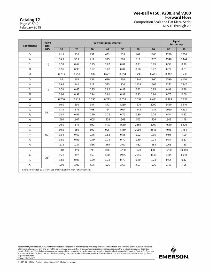
CoefficientsValveSize,NPS
Valve Rotation, DegreesEqual
Percentage
10 20 30 40 50 60 70 80 90
Cv
10
21.8 110 251 433 659 947 1300 1780 2710
Kv 18.9 95.2 217 375 570 819 1125 1540 2344
Fd 0.51 0.64 0.75 0.82 0.87 0.91 0.95 0.98 0.99
Fl 0.95 0.95 0.92 0.87 0.84 0.80 0.77 0.72 0.61
Xt 0.733 0.759 0.697 0.661 0.594 0.499 0.433 0.367 0.233
Cv
12
34 163 359 619 936 1340 1860 2580 4100
Kv 29.4 141 311 535 810 1159 1609 2232 3547
Fd 0.51 0.65 0.75 0.82 0.87 0.92 0.95 0.98 0.99
Fl 0.94 0.98 0.94 0.91 0.88 0.83 0.80 0.75 0.60
Xt 0.766 0.819 0.795 0.723 0.653 0.559 0.471 0.389 0.233
CV
14(1)
60.0 250 541 872 1230 1670 2290 3410 5610
KV 51.9 216 468 754 1064 1445 1981 2950 4853
FL 0.89 0.96 0.79 0.78 0.79 0.80 0.74 0.54 0.37
XT .999 .907 .605 .526 .563 .593 .526 .345 .198
CV
16(1)
70.0 319 692 1150 1630 2380 3290 4680 8270
KV 60.6 280 599 995 1410 2059 2846 4048 7154
FD 0.51 0.67 0.76 0.83 0.88 0.92 0.95 0.98 1.00
FL 0.89 0.96 0.79 0.78 0.79 0.80 0.74 0.54 0.37
XT .273 .731 .566 .469 .469 .452 .384 .265 .133
CV
20(1)
110 459 993 1600 2260 3070 4200 6260 10,300
KV 95.2 397 859 1384 1955 2656 3633 5415 8910
FL 0.89 0.96 0.79 0.78 0.79 0.80 0.74 0.54 0.37
XT .999 .907 .605 .526 .563 .593 .526 .345 .198
1. NPS 14 through 20 V150 valves are not available with Flat Metal seals.
Vee-Ball V150, V200, and V300
Composition Seals and Flat Metal SealsNPS 10 through 20
Forward FlowCatalog 12Page V150-2February 2018
� 1998, 2018 Fisher Controls International LLC. All rights reserved
www.Fisher.com
Responsibility for selection, use, and maintenance of any product remains solely with the purchaser and end user. The contents of this publication are forinformational purposes only and are not to be construed as warranties or guarantees, express or implied, regarding the products or services describedtherein. Fisher and Vee-Ball are marks owned by one of the companies in the Emerson Automation Solutions business unit of Emerson Electric Co. EmersonAutomation Solutions, Emerson, and the Emerson logo are trademarks and service marks of Emerson Electric Co. All other marks are the property of theirrespective owners.
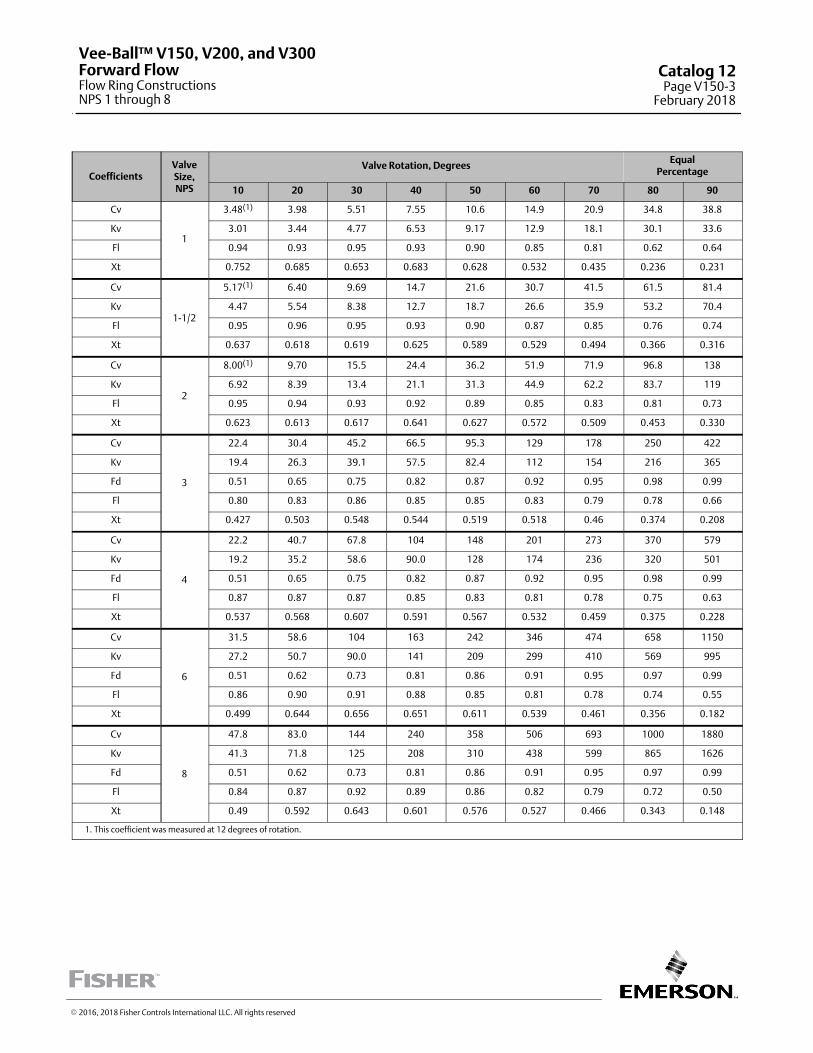
CoefficientsValveSize,NPS
Valve Rotation, DegreesEqual
Percentage
10 20 30 40 50 60 70 80 90
Cv
1
3.48(1) 3.98 5.51 7.55 10.6 14.9 20.9 34.8 38.8
Kv 3.01 3.44 4.77 6.53 9.17 12.9 18.1 30.1 33.6
Fl 0.94 0.93 0.95 0.93 0.90 0.85 0.81 0.62 0.64
Xt 0.752 0.685 0.653 0.683 0.628 0.532 0.435 0.236 0.231
Cv
1-1/2
5.17(1) 6.40 9.69 14.7 21.6 30.7 41.5 61.5 81.4
Kv 4.47 5.54 8.38 12.7 18.7 26.6 35.9 53.2 70.4
Fl 0.95 0.96 0.95 0.93 0.90 0.87 0.85 0.76 0.74
Xt 0.637 0.618 0.619 0.625 0.589 0.529 0.494 0.366 0.316
Cv
2
8.00(1) 9.70 15.5 24.4 36.2 51.9 71.9 96.8 138
Kv 6.92 8.39 13.4 21.1 31.3 44.9 62.2 83.7 119
Fl 0.95 0.94 0.93 0.92 0.89 0.85 0.83 0.81 0.73
Xt 0.623 0.613 0.617 0.641 0.627 0.572 0.509 0.453 0.330
Cv
3
22.4 30.4 45.2 66.5 95.3 129 178 250 422
Kv 19.4 26.3 39.1 57.5 82.4 112 154 216 365
Fd 0.51 0.65 0.75 0.82 0.87 0.92 0.95 0.98 0.99
Fl 0.80 0.83 0.86 0.85 0.85 0.83 0.79 0.78 0.66
Xt 0.427 0.503 0.548 0.544 0.519 0.518 0.46 0.374 0.208
Cv
4
22.2 40.7 67.8 104 148 201 273 370 579
Kv 19.2 35.2 58.6 90.0 128 174 236 320 501
Fd 0.51 0.65 0.75 0.82 0.87 0.92 0.95 0.98 0.99
Fl 0.87 0.87 0.87 0.85 0.83 0.81 0.78 0.75 0.63
Xt 0.537 0.568 0.607 0.591 0.567 0.532 0.459 0.375 0.228
Cv
6
31.5 58.6 104 163 242 346 474 658 1150
Kv 27.2 50.7 90.0 141 209 299 410 569 995
Fd 0.51 0.62 0.73 0.81 0.86 0.91 0.95 0.97 0.99
Fl 0.86 0.90 0.91 0.88 0.85 0.81 0.78 0.74 0.55
Xt 0.499 0.644 0.656 0.651 0.611 0.539 0.461 0.356 0.182
Cv
8
47.8 83.0 144 240 358 506 693 1000 1880
Kv 41.3 71.8 125 208 310 438 599 865 1626
Fd 0.51 0.62 0.73 0.81 0.86 0.91 0.95 0.97 0.99
Fl 0.84 0.87 0.92 0.89 0.86 0.82 0.79 0.72 0.50
Xt 0.49 0.592 0.643 0.601 0.576 0.527 0.466 0.343 0.148
1. This coefficient was measured at 12 degrees of rotation.
Vee-Ball™ V150, V200, and V300Forward FlowFlow Ring ConstructionsNPS 1 through 8
Catalog 12Page V150-3
February 2018
� 2016, 2018 Fisher Controls International LLC. All rights reserved
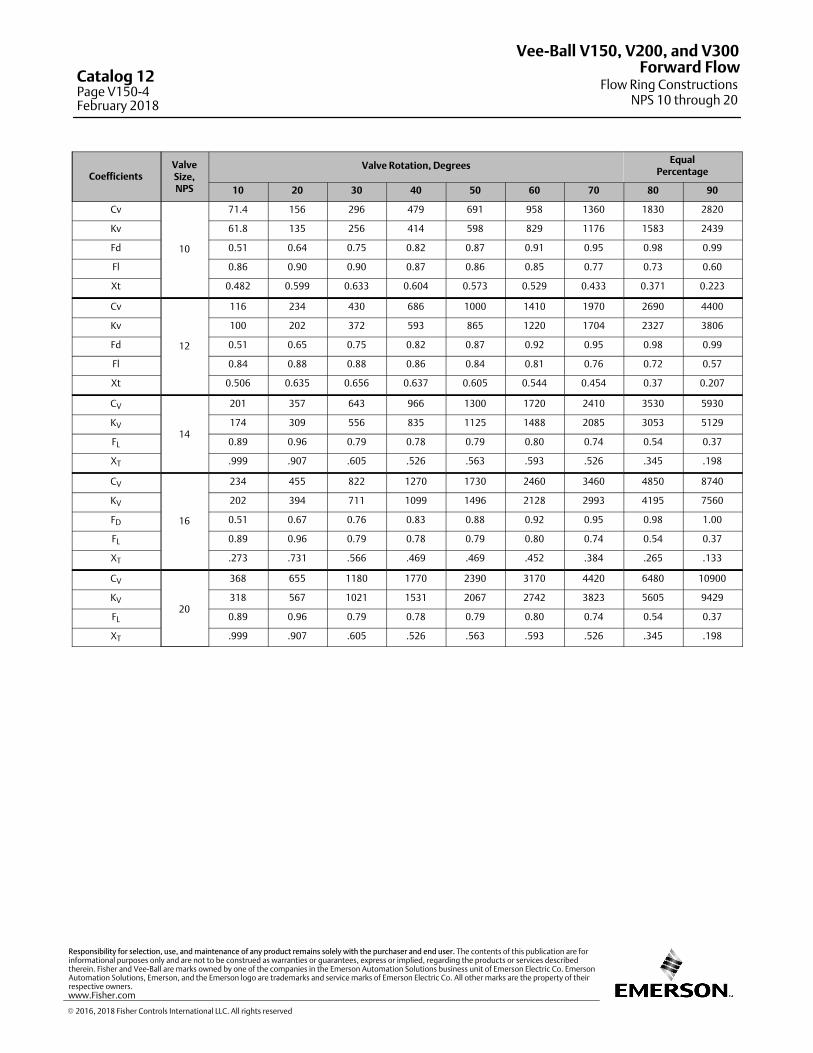
CoefficientsValveSize,NPS
Valve Rotation, DegreesEqual
Percentage
10 20 30 40 50 60 70 80 90
Cv
10
71.4 156 296 479 691 958 1360 1830 2820
Kv 61.8 135 256 414 598 829 1176 1583 2439
Fd 0.51 0.64 0.75 0.82 0.87 0.91 0.95 0.98 0.99
Fl 0.86 0.90 0.90 0.87 0.86 0.85 0.77 0.73 0.60
Xt 0.482 0.599 0.633 0.604 0.573 0.529 0.433 0.371 0.223
Cv
12
116 234 430 686 1000 1410 1970 2690 4400
Kv 100 202 372 593 865 1220 1704 2327 3806
Fd 0.51 0.65 0.75 0.82 0.87 0.92 0.95 0.98 0.99
Fl 0.84 0.88 0.88 0.86 0.84 0.81 0.76 0.72 0.57
Xt 0.506 0.635 0.656 0.637 0.605 0.544 0.454 0.37 0.207
CV
14
201 357 643 966 1300 1720 2410 3530 5930
KV 174 309 556 835 1125 1488 2085 3053 5129
FL 0.89 0.96 0.79 0.78 0.79 0.80 0.74 0.54 0.37
XT .999 .907 .605 .526 .563 .593 .526 .345 .198
CV
16
234 455 822 1270 1730 2460 3460 4850 8740
KV 202 394 711 1099 1496 2128 2993 4195 7560
FD 0.51 0.67 0.76 0.83 0.88 0.92 0.95 0.98 1.00
FL 0.89 0.96 0.79 0.78 0.79 0.80 0.74 0.54 0.37
XT .273 .731 .566 .469 .469 .452 .384 .265 .133
CV
20
368 655 1180 1770 2390 3170 4420 6480 10900
KV 318 567 1021 1531 2067 2742 3823 5605 9429
FL 0.89 0.96 0.79 0.78 0.79 0.80 0.74 0.54 0.37
XT .999 .907 .605 .526 .563 .593 .526 .345 .198
Vee-Ball V150, V200, and V300
Flow Ring ConstructionsNPS 10 through 20
Forward FlowCatalog 12Page V150-4February 2018
� 2016, 2018 Fisher Controls International LLC. All rights reserved
www.Fisher.com
Responsibility for selection, use, and maintenance of any product remains solely with the purchaser and end user. The contents of this publication are forinformational purposes only and are not to be construed as warranties or guarantees, express or implied, regarding the products or services describedtherein. Fisher and Vee-Ball are marks owned by one of the companies in the Emerson Automation Solutions business unit of Emerson Electric Co. EmersonAutomation Solutions, Emerson, and the Emerson logo are trademarks and service marks of Emerson Electric Co. All other marks are the property of theirrespective owners.

CoefficientsValveSize,NPS
Valve Rotation, DegreesEqual
Percentage
10 20 30 40 50 60 70 80 90
Cv
1
2.58(1) 3.16 5.05 8.13 12.4 18.1 25.7 33.4 38.1
Kv 2.23 2.73 4.37 7.03 10.7 15.7 22.2 28.9 33.0
Fl 0.87 0.86 0.81 0.75 0.70 0.65 0.59 0.58 0.59
Xt 0.613 0.521 0.500 0.451 0.383 0.323 0.270 0.249 0.244
Cv
1-1/2
3.80(1) 5.11 8.82 15.1 24.1 35.3 49.9 65.5 79.3
Kv 3.29 4.42 7.63 13.1 20.8 30.5 43.2 56.7 68.6
Fl 0.89 0.89 0.85 0.79 0.74 0.69 0.64 0.60 0.60
Xt 0.641 0.612 0.562 0.503 0.435 0.381 0.319 0.285 0.277
Cv
2
5.55(1) 7.35 13.9 25.2 40.1 59.5 82.4 106 126
Kv 4.80 6.36 12.0 21.8 34.7 51.5 71.3 91.7 109
Fl 0.89 0.88 0.86 0.79 0.76 0.72 0.68 0.65 0.64
Xt 0.643 0.641 0.586 0.524 0.476 0.413 0.365 0.341 0.326
Cv
3
15.3 23.7 38.6 65.2 102 155 228 313 411
Kv 13.2 20.5 33.4 56.4 88.2 134 197 271 356
Fl 0.81 0.83 0.84 0.80 0.74 0.66 0.59 0.54 0.51
Xt 0.516 0.563 0.601 0.504 0.433 0.353 0.271 0.217 0.18
Cv
4
14.8 31.2 59.6 100 157 232 327 441 542
Kv 12.8 27.0 51.6 86.5 136 201 283 381 469
Fl 0.87 0.91 0.88 0.85 0.79 0.72 0.65 0.60 0.58
Xt 0.614 0.676 0.643 0.581 0.492 0.408 0.326 0.258 0.237
Cv
6
19.8 46.3 97 172 275 409 584 764 954
Kv 17.1 40.0 83.9 149 238 354 505 661 825
Fl 0.82 0.90 0.88 0.86 0.81 0.72 0.66 0.62 0.59
Xt 0.638 0.765 0.676 0.558 0.459 0.378 0.309 0.267 0.233
Cv
8
31.2 71.4 149 265 421 625 881 1190 1340
Kv 27.0 61.8 129 229 364 541 762 1029 1159
Fl 0.78 0.85 0.84 0.83 0.78 0.72 0.66 0.60 0.66
Xt 0.641 0.601 0.562 0.493 0.416 0.355 0.304 0.24 0.268
1. This coefficient was measured at 12 degrees of rotation.
Vee-Ball™ V150, V200, and V300Reverse FlowFlow Ring ConstructionsNPS 1 through 8
Catalog 12Page V150-5
February 2018
� 2016, 2018 Fisher Controls International LLC. All rights reserved
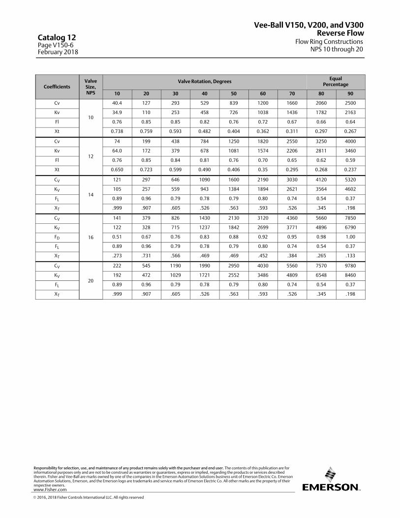
CoefficientsValveSize,NPS
Valve Rotation, DegreesEqual
Percentage
10 20 30 40 50 60 70 80 90
Cv
10
40.4 127 293 529 839 1200 1660 2060 2500
Kv 34.9 110 253 458 726 1038 1436 1782 2163
Fl 0.76 0.85 0.85 0.82 0.76 0.72 0.67 0.66 0.64
Xt 0.738 0.759 0.593 0.482 0.404 0.362 0.311 0.297 0.267
Cv
12
74 199 438 784 1250 1820 2550 3250 4000
Kv 64.0 172 379 678 1081 1574 2206 2811 3460
Fl 0.76 0.85 0.84 0.81 0.76 0.70 0.65 0.62 0.59
Xt 0.650 0.723 0.599 0.490 0.406 0.35 0.295 0.268 0.237
CV
14
121 297 646 1090 1600 2190 3030 4120 5320
KV 105 257 559 943 1384 1894 2621 3564 4602
FL 0.89 0.96 0.79 0.78 0.79 0.80 0.74 0.54 0.37
XT .999 .907 .605 .526 .563 .593 .526 .345 .198
CV
16
141 379 826 1430 2130 3120 4360 5660 7850
KV 122 328 715 1237 1842 2699 3771 4896 6790
FD 0.51 0.67 0.76 0.83 0.88 0.92 0.95 0.98 1.00
FL 0.89 0.96 0.79 0.78 0.79 0.80 0.74 0.54 0.37
XT .273 .731 .566 .469 .469 .452 .384 .265 .133
CV
20
222 545 1190 1990 2950 4030 5560 7570 9780
KV 192 472 1029 1721 2552 3486 4809 6548 8460
FL 0.89 0.96 0.79 0.78 0.79 0.80 0.74 0.54 0.37
XT .999 .907 .605 .526 .563 .593 .526 .345 .198
Vee-Ball V150, V200, and V300
Flow Ring ConstructionsNPS 10 through 20
Reverse FlowCatalog 12Page V150-6February 2018
� 2016, 2018 Fisher Controls International LLC. All rights reserved
www.Fisher.com
Responsibility for selection, use, and maintenance of any product remains solely with the purchaser and end user. The contents of this publication are forinformational purposes only and are not to be construed as warranties or guarantees, express or implied, regarding the products or services describedtherein. Fisher and Vee-Ball are marks owned by one of the companies in the Emerson Automation Solutions business unit of Emerson Electric Co. EmersonAutomation Solutions, Emerson, and the Emerson logo are trademarks and service marks of Emerson Electric Co. All other marks are the property of theirrespective owners.
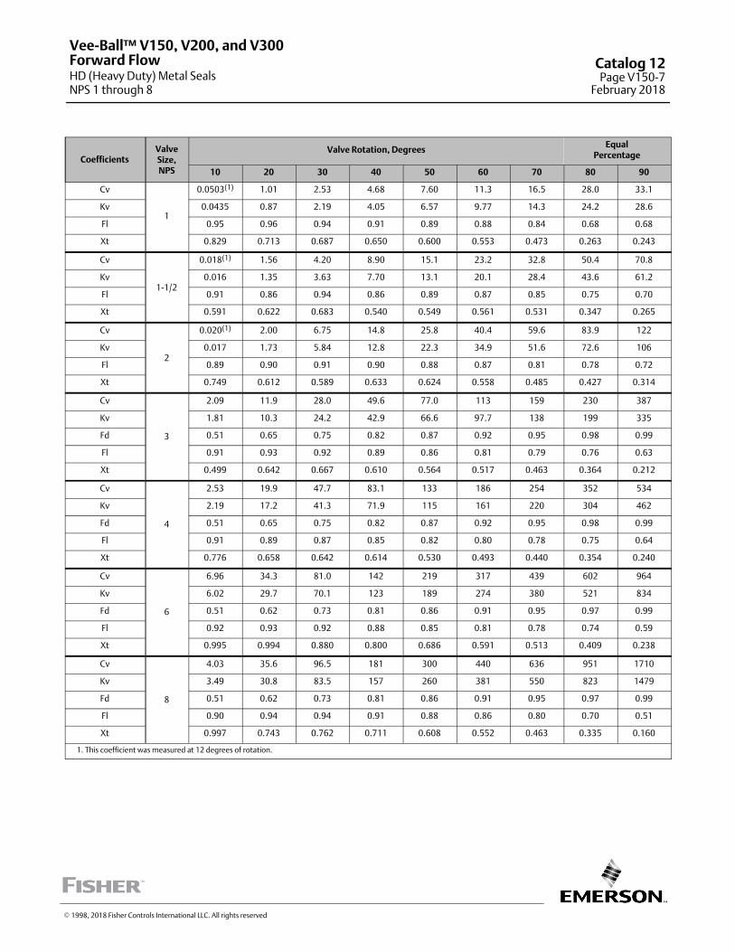
CoefficientsValveSize,NPS
Valve Rotation, DegreesEqual
Percentage
10 20 30 40 50 60 70 80 90
Cv
1
0.0503(1) 1.01 2.53 4.68 7.60 11.3 16.5 28.0 33.1
Kv 0.0435 0.87 2.19 4.05 6.57 9.77 14.3 24.2 28.6
Fl 0.95 0.96 0.94 0.91 0.89 0.88 0.84 0.68 0.68
Xt 0.829 0.713 0.687 0.650 0.600 0.553 0.473 0.263 0.243
Cv
1-1/2
0.018(1) 1.56 4.20 8.90 15.1 23.2 32.8 50.4 70.8
Kv 0.016 1.35 3.63 7.70 13.1 20.1 28.4 43.6 61.2
Fl 0.91 0.86 0.94 0.86 0.89 0.87 0.85 0.75 0.70
Xt 0.591 0.622 0.683 0.540 0.549 0.561 0.531 0.347 0.265
Cv
2
0.020(1) 2.00 6.75 14.8 25.8 40.4 59.6 83.9 122
Kv 0.017 1.73 5.84 12.8 22.3 34.9 51.6 72.6 106
Fl 0.89 0.90 0.91 0.90 0.88 0.87 0.81 0.78 0.72
Xt 0.749 0.612 0.589 0.633 0.624 0.558 0.485 0.427 0.314
Cv
3
2.09 11.9 28.0 49.6 77.0 113 159 230 387
Kv 1.81 10.3 24.2 42.9 66.6 97.7 138 199 335
Fd 0.51 0.65 0.75 0.82 0.87 0.92 0.95 0.98 0.99
Fl 0.91 0.93 0.92 0.89 0.86 0.81 0.79 0.76 0.63
Xt 0.499 0.642 0.667 0.610 0.564 0.517 0.463 0.364 0.212
Cv
4
2.53 19.9 47.7 83.1 133 186 254 352 534
Kv 2.19 17.2 41.3 71.9 115 161 220 304 462
Fd 0.51 0.65 0.75 0.82 0.87 0.92 0.95 0.98 0.99
Fl 0.91 0.89 0.87 0.85 0.82 0.80 0.78 0.75 0.64
Xt 0.776 0.658 0.642 0.614 0.530 0.493 0.440 0.354 0.240
Cv
6
6.96 34.3 81.0 142 219 317 439 602 964
Kv 6.02 29.7 70.1 123 189 274 380 521 834
Fd 0.51 0.62 0.73 0.81 0.86 0.91 0.95 0.97 0.99
Fl 0.92 0.93 0.92 0.88 0.85 0.81 0.78 0.74 0.59
Xt 0.995 0.994 0.880 0.800 0.686 0.591 0.513 0.409 0.238
Cv
8
4.03 35.6 96.5 181 300 440 636 951 1710
Kv 3.49 30.8 83.5 157 260 381 550 823 1479
Fd 0.51 0.62 0.73 0.81 0.86 0.91 0.95 0.97 0.99
Fl 0.90 0.94 0.94 0.91 0.88 0.86 0.80 0.70 0.51
Xt 0.997 0.743 0.762 0.711 0.608 0.552 0.463 0.335 0.160
1. This coefficient was measured at 12 degrees of rotation.
Vee-Ball™ V150, V200, and V300
HD (Heavy Duty) Metal SealsNPS 1 through 8
Forward Flow Catalog 12Page V150-7
February 2018
� 1998, 2018 Fisher Controls International LLC. All rights reserved
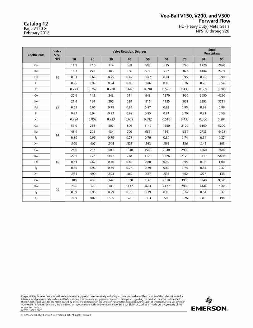
CoefficientsValveSize,NPS
Valve Rotation, DegreesEqual
Percentage
10 20 30 40 50 60 70 80 90
Cv
10
11.9 87.6 214 388 599 875 1240 1720 2820
Kv 10.3 75.8 185 336 518 757 1073 1488 2439
Fd 0.51 0.64 0.75 0.82 0.87 0.91 0.95 0.98 0.99
Fl 0.95 0.97 0.94 0.90 0.86 0.80 0.76 0.70 0.54
Xt 0.773 0.767 0.728 0.646 0.590 0.525 0.437 0.359 0.206
Cv
12
25.0 143 343 611 943 1370 1920 2650 4290
Kv 21.6 124 297 529 816 1185 1661 2292 3711
Fd 0.51 0.65 0.75 0.82 0.87 0.92 0.95 0.98 0.99
Fl 0.93 0.94 0.93 0.89 0.85 0.81 0.76 0.71 0.56
Xt 0.784 0.802 0.733 0.659 0.582 0.510 0.433 0.350 0.204
CV
14
56.0 232 502 809 1140 1550 2120 3160 5200
KV 48.4 201 434 700 986 1341 1834 2733 4498
FL 0.89 0.96 0.79 0.78 0.79 0.80 0.74 0.54 0.37
XT .999 .907 .605 .526 .563 .593 .526 .345 .198
CV
16
26.6 237 600 1040 1500 2040 2900 4560 7840
KV 22.5 177 449 778 1122 1526 2170 3411 5866
Fd 0.51 0.67 0.76 0.83 0.88 0.92 0.95 0.98 1.00
FL 0.89 0.96 0.79 0.78 0.79 0.80 0.74 0.54 0.37
XT .965 .999 .593 .462 .487 .533 .462 .278 .135
CV
20
105 436 942 1520 2140 2910 3990 5940 9770
KV 78.6 326 705 1137 1601 2177 2985 4444 7310
FL 0.89 0.96 0.79 0.78 0.79 0.80 0.74 0.54 0.37
XT .999 .907 .605 .526 .563 .593 .526 .345 .198
Vee-Ball V150, V200, and V300
HD (Heavy Duty) Metal SealsNPS 10 through 20
Forward FlowCatalog 12Page V150-8February 2018
� 1998, 2018 Fisher Controls International LLC. All rights reserved
www.Fisher.com
Responsibility for selection, use, and maintenance of any product remains solely with the purchaser and end user. The contents of this publication are forinformational purposes only and are not to be construed as warranties or guarantees, express or implied, regarding the products or services describedtherein. Fisher and Vee-Ball are marks owned by one of the companies in the Emerson Automation Solutions business unit of Emerson Electric Co. EmersonAutomation Solutions, Emerson, and the Emerson logo are trademarks and service marks of Emerson Electric Co. All other marks are the property of theirrespective owners.
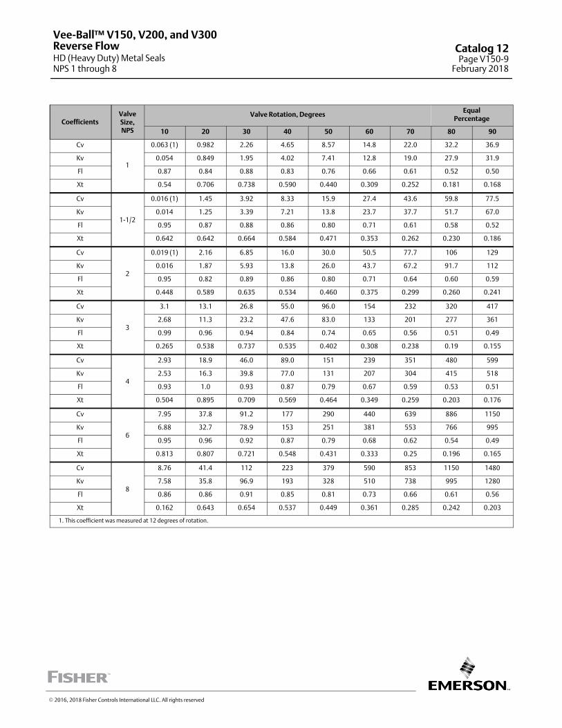
CoefficientsValveSize,NPS
Valve Rotation, DegreesEqual
Percentage
10 20 30 40 50 60 70 80 90
Cv
1
0.063 (1) 0.982 2.26 4.65 8.57 14.8 22.0 32.2 36.9
Kv 0.054 0.849 1.95 4.02 7.41 12.8 19.0 27.9 31.9
Fl 0.87 0.84 0.88 0.83 0.76 0.66 0.61 0.52 0.50
Xt 0.54 0.706 0.738 0.590 0.440 0.309 0.252 0.181 0.168
Cv
1-1/2
0.016 (1) 1.45 3.92 8.33 15.9 27.4 43.6 59.8 77.5
Kv 0.014 1.25 3.39 7.21 13.8 23.7 37.7 51.7 67.0
Fl 0.95 0.87 0.88 0.86 0.80 0.71 0.61 0.58 0.52
Xt 0.642 0.642 0.664 0.584 0.471 0.353 0.262 0.230 0.186
Cv
2
0.019 (1) 2.16 6.85 16.0 30.0 50.5 77.7 106 129
Kv 0.016 1.87 5.93 13.8 26.0 43.7 67.2 91.7 112
Fl 0.95 0.82 0.89 0.86 0.80 0.71 0.64 0.60 0.59
Xt 0.448 0.589 0.635 0.534 0.460 0.375 0.299 0.260 0.241
Cv
3
3.1 13.1 26.8 55.0 96.0 154 232 320 417
Kv 2.68 11.3 23.2 47.6 83.0 133 201 277 361
Fl 0.99 0.96 0.94 0.84 0.74 0.65 0.56 0.51 0.49
Xt 0.265 0.538 0.737 0.535 0.402 0.308 0.238 0.19 0.155
Cv
4
2.93 18.9 46.0 89.0 151 239 351 480 599
Kv 2.53 16.3 39.8 77.0 131 207 304 415 518
Fl 0.93 1.0 0.93 0.87 0.79 0.67 0.59 0.53 0.51
Xt 0.504 0.895 0.709 0.569 0.464 0.349 0.259 0.203 0.176
Cv
6
7.95 37.8 91.2 177 290 440 639 886 1150
Kv 6.88 32.7 78.9 153 251 381 553 766 995
Fl 0.95 0.96 0.92 0.87 0.79 0.68 0.62 0.54 0.49
Xt 0.813 0.807 0.721 0.548 0.431 0.333 0.25 0.196 0.165
Cv
8
8.76 41.4 112 223 379 590 853 1150 1480
Kv 7.58 35.8 96.9 193 328 510 738 995 1280
Fl 0.86 0.86 0.91 0.85 0.81 0.73 0.66 0.61 0.56
Xt 0.162 0.643 0.654 0.537 0.449 0.361 0.285 0.242 0.203
1. This coefficient was measured at 12 degrees of rotation.
Vee-Ball™ V150, V200, and V300
HD (Heavy Duty) Metal SealsNPS 1 through 8
Reverse Flow Catalog 12Page V150-9
February 2018
� 2016, 2018 Fisher Controls International LLC. All rights reserved
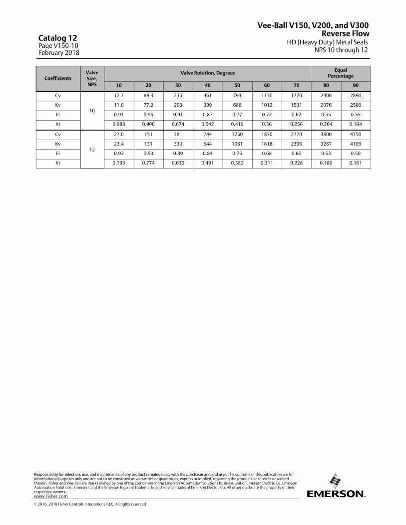
CoefficientsValveSize,NPS
Valve Rotation, DegreesEqual
Percentage
10 20 30 40 50 60 70 80 90
Cv
10
12.7 89.3 235 461 793 1170 1770 2400 2890
Kv 11.0 77.2 203 399 686 1012 1531 2076 2500
Fl 0.91 0.96 0.91 0.87 0.77 0.72 0.62 0.55 0.55
Xt 0.988 0.906 0.674 0.542 0.419 0.36 0.256 0.204 0.194
Cv
12
27.0 151 381 744 1250 1870 2770 3800 4750
Kv 23.4 131 330 644 1081 1618 2396 3287 4109
Fl 0.92 0.93 0.89 0.84 0.76 0.68 0.60 0.53 0.50
Xt 0.795 0.774 0.630 0.491 0.382 0.311 0.228 0.180 0.161
Vee-Ball V150, V200, and V300
HD (Heavy Duty) Metal SealsNPS 10 through 12
Reverse FlowCatalog 12Page V150-10February 2018
� 2016, 2018 Fisher Controls International LLC. All rights reserved
www.Fisher.com
Responsibility for selection, use, and maintenance of any product remains solely with the purchaser and end user. The contents of this publication are forinformational purposes only and are not to be construed as warranties or guarantees, express or implied, regarding the products or services describedtherein. Fisher and Vee-Ball are marks owned by one of the companies in the Emerson Automation Solutions business unit of Emerson Electric Co. EmersonAutomation Solutions, Emerson, and the Emerson logo are trademarks and service marks of Emerson Electric Co. All other marks are the property of theirrespective owners.
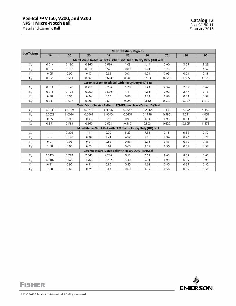
CoefficientsValve Rotation, Degrees
10 20 30 40 50 60 70 80 90
Metal Micro‐Notch Ball with Fisher TCM Plus or Heavy Duty (HD) Seal
CV 0.014 0.130 0.360 0.660 1.03 1.43 2.00 3.25 5.23
KV 0.012 0.112 0.311 0.571 0.89 1.24 1.73 2.81 4.52
FL 0.95 0.90 0.93 0.93 0.91 0.90 0.93 0.93 0.88
XT 0.551 0.581 0.660 0.628 0.589 0.593 0.620 0.605 0.578
Ceramic Micro‐Notch Ball with Heavy Duty (HD) Seal
CV 0.018 0.148 0.415 0.786 1.28 1.78 2.34 2.86 3.64
KV 0.016 0.128 0.359 0.680 1.11 1.54 2.02 2.47 3.15
FL 0.90 0.93 0.94 0.93 0.89 0.90 0.88 0.89 0.92
XT 0.581 0.697 0.693 0.601 0.593 0.612 0.533 0.537 0.612
Metal Micro‐Scratch Ball with TCM Plus or Heavy Duty (HD) Seal
CV 0.0033 0.0109 0.0232 0.0396 0.0542 0.2032 1.136 2.672 5.155
KV 0.0029 0.0094 0.0201 0.0343 0.0469 0.1758 0.983 2.311 4.459
FL 0.95 0.90 0.93 0.93 0.91 0.90 0.93 0.93 0.88
XT 0.551 0.581 0.660 0.628 0.589 0.593 0.620 0.605 0.578
Metal Macro‐Notch Ball with TCM Plus or Heavy Duty (HD) Seal
CV - - - 0.206 1.11 2.79 5.23 7.64 9.18 9.56 9.57
KV - - - 0.178 0.96 2.41 4.52 6.61 7.94 8.27 8.28
FL 0.91 0.95 0.91 0.85 0.85 0.84 0.85 0.85 0.85
XT 1.00 0.65 0.79 0.64 0.60 0.56 0.56 0.56 0.58
Ceramic Macro‐Notch Ball with Heavy Duty (HD) Seal
CV 0.0124 0.782 2.040 4.280 6.13 7.55 8.03 8.03 8.03
KV 0.0107 0.676 1.765 3.702 5.30 6.53 6.95 6.95 6.95
FL 0.91 0.95 0.91 0.85 0.85 0.84 0.85 0.85 0.85
XT 1.00 0.65 0.79 0.64 0.60 0.56 0.56 0.56 0.58
Vee-Ball™ V150, V200, and V300
Metal and Ceramic BallNPS 1 Micro-Notch Ball
Catalog 12Page V150-11February 2018
� 1998, 2018 Fisher Controls International LLC. All rights reserved
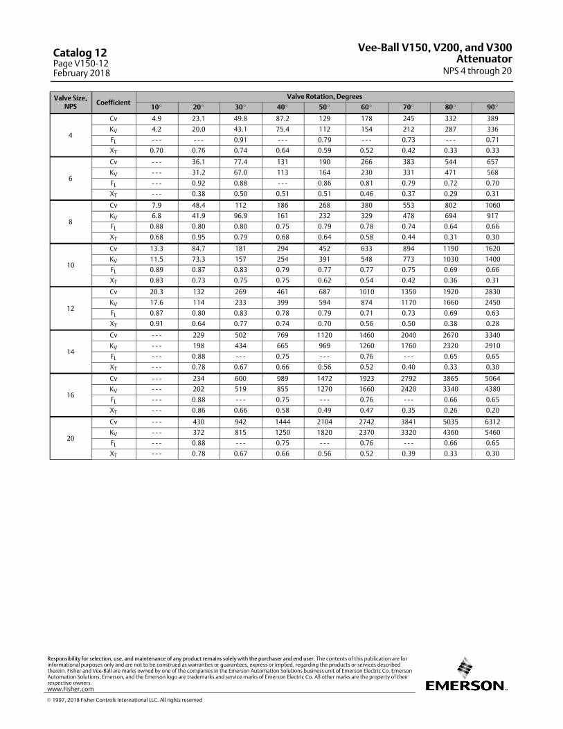
Valve Size,NPS
CoefficientValve Rotation, Degrees
10� 20� 30� 40� 50� 60� 70� 80� 90�
4
Cv 4.9 23.1 49.8 87.2 129 178 245 332 389
KV 4.2 20.0 43.1 75.4 112 154 212 287 336
FL ‐ ‐ ‐ ‐ ‐ ‐ 0.91 ‐ ‐ ‐ 0.79 ‐ ‐ ‐ 0.73 ‐ ‐ ‐ 0.71
XT 0.70 0.76 0.74 0.64 0.59 0.52 0.42 0.33 0.33
6
Cv ‐ ‐ ‐ 36.1 77.4 131 190 266 383 544 657
KV ‐ ‐ ‐ 31.2 67.0 113 164 230 331 471 568
FL ‐ ‐ ‐ 0.92 0.88 ‐ ‐ ‐ 0.86 0.81 0.79 0.72 0.70
XT ‐ ‐ ‐ 0.38 0.50 0.51 0.51 0.46 0.37 0.29 0.31
8
Cv 7.9 48.4 112 186 268 380 553 802 1060
KV 6.8 41.9 96.9 161 232 329 478 694 917
FL 0.88 0.80 0.80 0.75 0.79 0.78 0.74 0.64 0.66
XT 0.68 0.95 0.79 0.68 0.64 0.58 0.44 0.31 0.30
10
Cv 13.3 84.7 181 294 452 633 894 1190 1620
KV 11.5 73.3 157 254 391 548 773 1030 1400
FL 0.89 0.87 0.83 0.79 0.77 0.77 0.75 0.69 0.66
XT 0.83 0.73 0.75 0.75 0.62 0.54 0.42 0.36 0.31
12
Cv 20.3 132 269 461 687 1010 1350 1920 2830
KV 17.6 114 233 399 594 874 1170 1660 2450
FL 0.87 0.80 0.83 0.78 0.79 0.71 0.73 0.69 0.63
XT 0.91 0.64 0.77 0.74 0.70 0.56 0.50 0.38 0.28
14
Cv ‐ ‐ ‐ 229 502 769 1120 1460 2040 2670 3340
KV ‐ ‐ ‐ 198 434 665 969 1260 1760 2320 2910
FL ‐ ‐ ‐ 0.88 ‐ ‐ ‐ 0.75 ‐ ‐ ‐ 0.76 ‐ ‐ ‐ 0.65 0.65
XT ‐ ‐ ‐ 0.78 0.67 0.66 0.56 0.52 0.40 0.33 0.30
16
Cv ‐ ‐ ‐ 234 600 989 1472 1923 2792 3865 5064
KV ‐ ‐ ‐ 202 519 855 1270 1660 2420 3340 4380
FL ‐ ‐ ‐ 0.88 ‐ ‐ ‐ 0.75 ‐ ‐ ‐ 0.76 ‐ ‐ ‐ 0.66 0.65
XT ‐ ‐ ‐ 0.86 0.66 0.58 0.49 0.47 0.35 0.26 0.20
20
Cv ‐ ‐ ‐ 430 942 1444 2104 2742 3841 5035 6312
KV ‐ ‐ ‐ 372 815 1250 1820 2370 3320 4360 5460
FL ‐ ‐ ‐ 0.88 ‐ ‐ ‐ 0.75 ‐ ‐ ‐ 0.76 ‐ ‐ ‐ 0.66 0.65
XT ‐ ‐ ‐ 0.78 0.67 0.66 0.56 0.52 0.39 0.33 0.30
Vee-Ball V150, V200, and V300
NPS 4 through 20Attenuator
Catalog 12Page V150-12February 2018
� 1997, 2018 Fisher Controls International LLC. All rights reserved
www.Fisher.com
Responsibility for selection, use, and maintenance of any product remains solely with the purchaser and end user. The contents of this publication are forinformational purposes only and are not to be construed as warranties or guarantees, express or implied, regarding the products or services describedtherein. Fisher and Vee-Ball are marks owned by one of the companies in the Emerson Automation Solutions business unit of Emerson Electric Co. EmersonAutomation Solutions, Emerson, and the Emerson logo are trademarks and service marks of Emerson Electric Co. All other marks are the property of theirrespective owners.
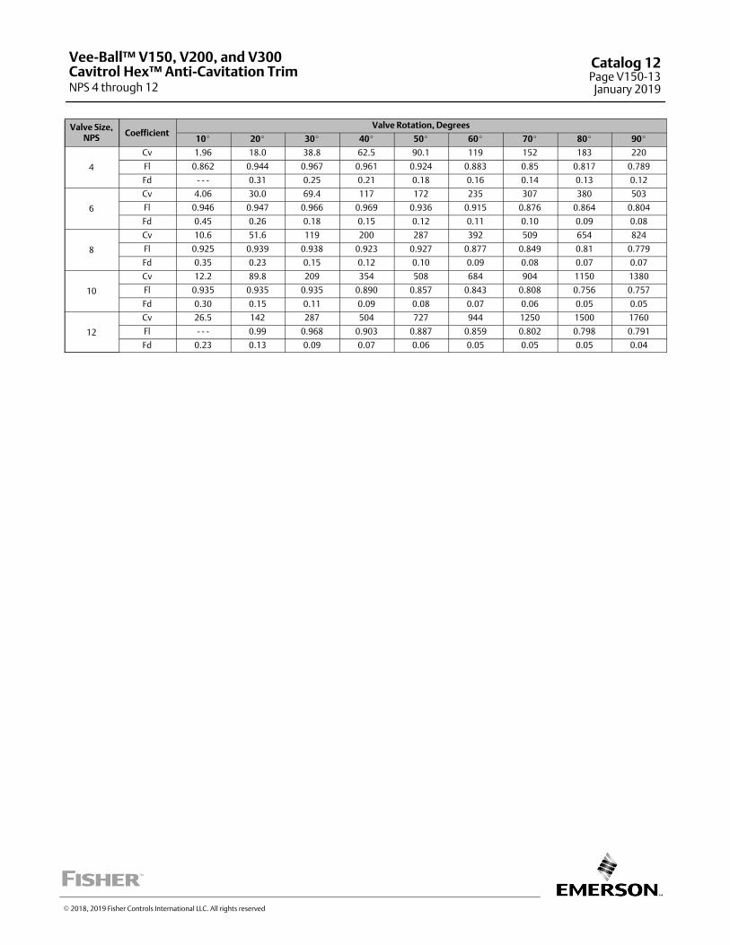
Valve Size,NPS
CoefficientValve Rotation, Degrees
10� 20� 30� 40� 50� 60� 70� 80� 90�
4
Cv 1.96 18.0 38.8 62.5 90.1 119 152 183 220
Fl 0.862 0.944 0.967 0.961 0.924 0.883 0.85 0.817 0.789
Fd ‐ ‐ ‐ 0.31 0.25 0.21 0.18 0.16 0.14 0.13 0.12
6
Cv 4.06 30.0 69.4 117 172 235 307 380 503
Fl 0.946 0.947 0.966 0.969 0.936 0.915 0.876 0.864 0.804
Fd 0.45 0.26 0.18 0.15 0.12 0.11 0.10 0.09 0.08
8
Cv 10.6 51.6 119 200 287 392 509 654 824
Fl 0.925 0.939 0.938 0.923 0.927 0.877 0.849 0.81 0.779
Fd 0.35 0.23 0.15 0.12 0.10 0.09 0.08 0.07 0.07
10
Cv 12.2 89.8 209 354 508 684 904 1150 1380
Fl 0.935 0.935 0.935 0.890 0.857 0.843 0.808 0.756 0.757
Fd 0.30 0.15 0.11 0.09 0.08 0.07 0.06 0.05 0.05
12
Cv 26.5 142 287 504 727 944 1250 1500 1760
Fl ‐ ‐ ‐ 0.99 0.968 0.903 0.887 0.859 0.802 0.798 0.791
Fd 0.23 0.13 0.09 0.07 0.06 0.05 0.05 0.05 0.04
� 2018, 2019 Fisher Controls International LLC. All rights reserved
Vee-Ball™ V150, V200, and V300
NPS 4 through 12Cavitrol Hex™ Anti-Cavitation Trim
Catalog 12Page V150-13
January 2019
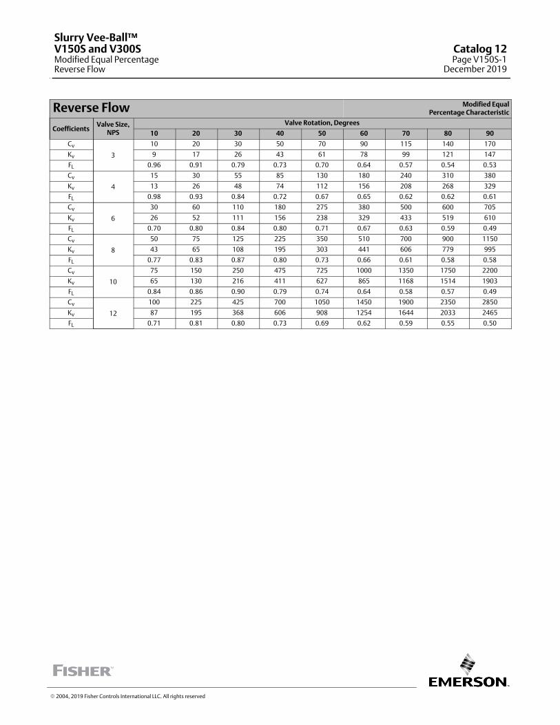
Reverse Flow Modified EqualPercentage Characteristic
CoefficientsValve Size,
NPS
Valve Rotation, Degrees
10 20 30 40 50 60 70 80 90
Cv
3
10 20 30 50 70 90 115 140 170
Kv 9 17 26 43 61 78 99 121 147
FL 0.96 0.91 0.79 0.73 0.70 0.64 0.57 0.54 0.53
Cv
4
15 30 55 85 130 180 240 310 380
Kv 13 26 48 74 112 156 208 268 329
FL 0.98 0.93 0.84 0.72 0.67 0.65 0.62 0.62 0.61
Cv
6
30 60 110 180 275 380 500 600 705
Kv 26 52 111 156 238 329 433 519 610
FL 0.70 0.80 0.84 0.80 0.71 0.67 0.63 0.59 0.49
Cv
8
50 75 125 225 350 510 700 900 1150
Kv 43 65 108 195 303 441 606 779 995
FL 0.77 0.83 0.87 0.80 0.73 0.66 0.61 0.58 0.58
Cv
10
75 150 250 475 725 1000 1350 1750 2200
Kv 65 130 216 411 627 865 1168 1514 1903
FL 0.84 0.86 0.90 0.79 0.74 0.64 0.58 0.57 0.49
Cv
12
100 225 425 700 1050 1450 1900 2350 2850
Kv 87 195 368 606 908 1254 1644 2033 2465
FL 0.71 0.81 0.80 0.73 0.69 0.62 0.59 0.55 0.50
� 2004, 2019 Fisher Controls International LLC. All rights reserved
Slurry Vee-Ball™V150S and V300SModified Equal PercentageReverse Flow
Catalog 12Page V150S-1
December 2019
This page is intentionally left blank.
Slurry Vee-BallV150S and V300S
Catalog 12Page V150S-2December 2019
� 2004, 2019 Fisher Controls International LLC. All rights reserved
www.Fisher.com
Responsibility for selection, use, and maintenance of any product remains solely with the purchaser and end user. The contents of this publication are forinformational purposes only and are not to be construed as warranties or guarantees, express or implied, regarding the products or services describedtherein. Fisher and Vee-Ball are marks owned by one of the companies in the Emerson Automation Solutions business unit of Emerson Electric Co. EmersonAutomation Solutions, Emerson, and the Emerson logo are trademarks and service marks of Emerson Electric Co. All other marks are the property of theirrespective owners.
The Fisher� V200 has flow coefficients identical to the V150. Refer to the V150 information. Reminder: The V200 is available in NPS 1 through 10 only.
� 1998, 2018 Fisher Controls International LLC. All rights reserved
V200
Forward Flow
Catalog 12Page V200-1
February 2018

This page is intentionally left blank.
V200Catalog 12Page V200-2February 2018
� 2014, 2018 Fisher Controls International LLC. All rights reserved
www.Fisher.com
Responsibility for selection, use, and maintenance of any product remains solely with the purchaser and end user. The contents of this publication are forinformational purposes only and are not to be construed as warranties or guarantees, express or implied, regarding the products or services describedtherein. Fisher is a mark owned by one of the companies in the Emerson Automation Solutions business unit of Emerson Electric Co. Emerson AutomationSolutions, Emerson, and the Emerson logo are trademarks and service marks of Emerson Electric Co. All other marks are the property of their respectiveowners.
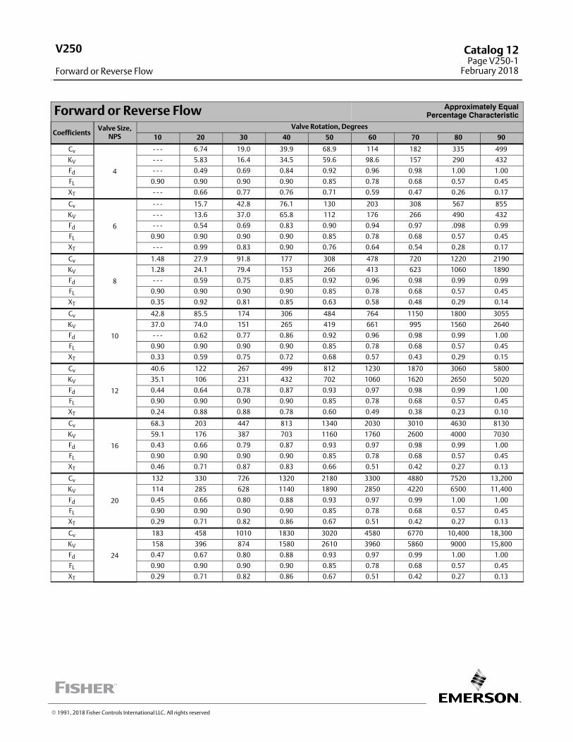
Forward or Reverse Flow Approximately EqualPercentage Characteristic
CoefficientsValve Size,
NPS
Valve Rotation, Degrees
10 20 30 40 50 60 70 80 90
Cv
4
‐ ‐ ‐ 6.74 19.0 39.9 68.9 114 182 335 499
KV ‐ ‐ ‐ 5.83 16.4 34.5 59.6 98.6 157 290 432
Fd ‐ ‐ ‐ 0.49 0.69 0.84 0.92 0.96 0.98 1.00 1.00
FL 0.90 0.90 0.90 0.90 0.85 0.78 0.68 0.57 0.45
XT ‐ ‐ ‐ 0.66 0.77 0.76 0.71 0.59 0.47 0.26 0.17
Cv
6
‐ ‐ ‐ 15.7 42.8 76.1 130 203 308 567 855
KV ‐ ‐ ‐ 13.6 37.0 65.8 112 176 266 490 432
Fd ‐ ‐ ‐ 0.54 0.69 0.83 0.90 0.94 0.97 .098 0.99
FL 0.90 0.90 0.90 0.90 0.85 0.78 0.68 0.57 0.45
XT ‐ ‐ ‐ 0.99 0.83 0.90 0.76 0.64 0.54 0.28 0.17
Cv
8
1.48 27.9 91.8 177 308 478 720 1220 2190
KV 1.28 24.1 79.4 153 266 413 623 1060 1890
Fd ‐ ‐ ‐ 0.59 0.75 0.85 0.92 0.96 0.98 0.99 0.99
FL 0.90 0.90 0.90 0.90 0.85 0.78 0.68 0.57 0.45
XT 0.35 0.92 0.81 0.85 0.63 0.58 0.48 0.29 0.14
Cv
10
42.8 85.5 174 306 484 764 1150 1800 3055
KV 37.0 74.0 151 265 419 661 995 1560 2640
Fd ‐ ‐ ‐ 0.62 0.77 0.86 0.92 0.96 0.98 0.99 1.00
FL 0.90 0.90 0.90 0.90 0.85 0.78 0.68 0.57 0.45
XT 0.33 0.59 0.75 0.72 0.68 0.57 0.43 0.29 0.15
Cv
12
40.6 122 267 499 812 1230 1870 3060 5800
KV 35.1 106 231 432 702 1060 1620 2650 5020
Fd 0.44 0.64 0.78 0.87 0.93 0.97 0.98 0.99 1.00
FL 0.90 0.90 0.90 0.90 0.85 0.78 0.68 0.57 0.45
XT 0.24 0.88 0.88 0.78 0.60 0.49 0.38 0.23 0.10
Cv
16
68.3 203 447 813 1340 2030 3010 4630 8130
KV 59.1 176 387 703 1160 1760 2600 4000 7030
Fd 0.43 0.66 0.79 0.87 0.93 0.97 0.98 0.99 1.00
FL 0.90 0.90 0.90 0.90 0.85 0.78 0.68 0.57 0.45
XT 0.46 0.71 0.87 0.83 0.66 0.51 0.42 0.27 0.13
Cv
20
132 330 726 1320 2180 3300 4880 7520 13,200
KV 114 285 628 1140 1890 2850 4220 6500 11,400
Fd 0.45 0.66 0.80 0.88 0.93 0.97 0.99 1.00 1.00
FL 0.90 0.90 0.90 0.90 0.85 0.78 0.68 0.57 0.45
XT 0.29 0.71 0.82 0.86 0.67 0.51 0.42 0.27 0.13
Cv
24
183 458 1010 1830 3020 4580 6770 10,400 18,300
KV 158 396 874 1580 2610 3960 5860 9000 15,800
Fd 0.47 0.67 0.80 0.88 0.93 0.97 0.99 1.00 1.00
FL 0.90 0.90 0.90 0.90 0.85 0.78 0.68 0.57 0.45
XT 0.29 0.71 0.82 0.86 0.67 0.51 0.42 0.27 0.13
� 1991, 2018 Fisher Controls International LLC. All rights reserved
V250
Forward or Reverse Flow
Catalog 12Page V250-1
February 2018
This page is intentionally left blank.
V250Catalog 12Page V250-2February 2018
� 2014, 2018 Fisher Controls International LLC. All rights reserved
www.Fisher.com
Responsibility for selection, use, and maintenance of any product remains solely with the purchaser and end user. The contents of this publication are forinformational purposes only and are not to be construed as warranties or guarantees, express or implied, regarding the products or services describedtherein. Fisher is a mark owned by one of the companies in the Emerson Automation Solutions business unit of Emerson Electric Co. Emerson AutomationSolutions, Emerson, and the Emerson logo are trademarks and service marks of Emerson Electric Co. All other marks are the property of their respectiveowners.
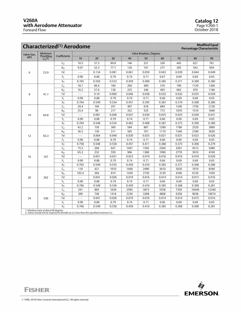
Characterized(1) Aerodome Modified EqualPercentage Characteristic
Valve Size,NPS
MinimumThrottling
CV(2)
CoefficientsValve Rotation, Degrees
10 20 30 40 50 60 70 80 90
6 23.9
CV 10.5 37.3 89.8 146 221 320 445 627 761
KV 9.07 32.3 77.7 126 191 277 385 543 659
Fd ‐ ‐ ‐ 0.134 0.081 0.061 0.050 0.043 0.039 0.044 0.049
FL 0.90 0.88 0.79 0.74 0.71 0.67 0.69 0.69 0.65
XT 0.765 0.550 0.533 0.459 0.409 0.385 0.371 0.309 0.280
8 41.1
Cv 18.7 66.6 160 260 400 570 790 1120 1360
KV 16.2 57.6 138 225 346 493 683 970 1180
Fd ‐ ‐ ‐ 0.10 0.060 0.046 0.038 0.032 0.032 0.035 0.039
FL 0.90 0.88 0.79 0.74 0.71 0.66 0.69 0.69 0.65
XT 0.764 0.549 0.534 0.457 0.395 0.387 0.374 0.308 0.280
10 64.8
Cv 29.4 104 251 407 618 894 1240 1750 2130
KV 25.4 90 217 352 535 773 1070 1510 1840
Fd ‐ ‐ ‐ 0.081 0.048 0.037 0.030 0.025 0.025 0.028 0.031
FL 0.90 0.88 0.79 0.74 0.71 0.66 0.69 0.69 0.65
XT 0.764 0.548 0.534 0.462 0.408 0.387 0.373 0.309 0.280
12 93.3
Cv 42.2 150 360 584 887 1280 1780 2520 3060
KV 36.5 130 311 505 767 1110 1540 2180 2650
Fd ‐ ‐ ‐ 0.064 0.040 0.030 0.025 0.021 0.021 0.023 0.026
FL 0.90 0.88 0.79 0.74 0.71 0.66 0.69 0.69 0.65
XT 0.758 0.548 0.538 0.457 0.411 0.388 0.373 0.308 0.279
16 167
Cv 75.5 268 647 1047 1592 2304 3201 4515 5480
KV 65.3 232 559 906 1380 1990 2770 3910 4740
Fd ‐ ‐ ‐ 0.051 0.031 0.023 0.019 0.016 0.016 0.018 0.020
FL 0.90 0.88 0.79 0.74 0.71 0.66 0.69 0.69 0.65
XT 0.765 0.549 0.535 0.459 0.410 0.385 0.371 0.308 0.280
20 262
Cv 118 421 1010 1640 2490 3610 5020 7070 8590
KV 102.4 364 874 1420 2150 3120 4340 6120 7430
Fd ‐ ‐ ‐ 0.041 0.026 0.019 0.016 0.014 0.014 0.015 0.016
FL 0.90 0.88 0.79 0.74 0.71 0.66 0.69 0.69 0.65
XT 0.766 0.549 0.536 0.459 0.410 0.385 0.368 0.308 0.281
24 536
Cv 241 865 1639 2585 3873 5558 7350 10449 12340
KV 209 748 1418 2236 3308 4808 6358 9038 10674
Fd ‐ ‐ ‐ 0.041 0.026 0.019 0.016 0.014 0.014 0.015 0.016
FL 0.90 0.88 0.79 0.74 0.71 0.66 0.69 0.69 0.65
XT 0.766 0.549 0.536 0.459 0.410 0.385 0.368 0.308 0.281
1. Window starts at about 60 degrees.2. Valves should not be required to throttle at a Cv less than the specified minimum Cv.
� 1998, 2018 Fisher Controls International LLC. All rights reserved
V260Awith Aerodome AttenuatorForward Flow
Catalog 12Page V260-1
October 2018
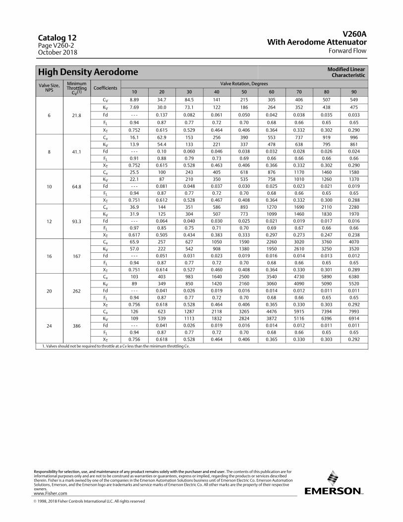
High Density Aerodome Modified LinearCharacteristic
Valve Size,NPS
MinimumThrottling
CV(1)
CoefficientsValve Rotation, Degrees
10 20 30 40 50 60 70 80 90
6 21.8
CV 8.89 34.7 84.5 141 215 305 406 507 549
KV 7.69 30.0 73.1 122 186 264 352 438 475
Fd ‐ ‐ ‐ 0.137 0.082 0.061 0.050 0.042 0.038 0.035 0.033
FL 0.94 0.87 0.77 0.72 0.70 0.68 0.66 0.65 0.65
XT 0.752 0.615 0.529 0.464 0.406 0.364 0.332 0.302 0.290
8 41.1
Cv 16.1 62.9 153 256 390 553 737 919 996
KV 13.9 54.4 133 221 337 478 638 795 861
Fd ‐ ‐ ‐ 0.10 0.060 0.046 0.038 0.032 0.028 0.026 0.024
FL 0.91 0.88 0.79 0.73 0.69 0.66 0.66 0.66 0.66
XT 0.752 0.615 0.528 0.463 0.406 0.366 0.332 0.302 0.290
10 64.8
Cv 25.5 100 243 405 618 876 1170 1460 1580
KV 22.1 87 210 350 535 758 1010 1260 1370
Fd ‐ ‐ ‐ 0.081 0.048 0.037 0.030 0.025 0.023 0.021 0.019
FL 0.94 0.87 0.77 0.72 0.70 0.68 0.66 0.65 0.65
XT 0.751 0.612 0.528 0.467 0.408 0.364 0.332 0.300 0.288
12 93.3
Cv 36.9 144 351 586 893 1270 1690 2110 2280
KV 31.9 125 304 507 773 1099 1460 1830 1970
Fd ‐ ‐ ‐ 0.064 0.040 0.030 0.025 0.021 0.019 0.017 0.016
FL 0.97 0.85 0.75 0.71 0.70 0.69 0.67 0.66 0.66
XT 0.617 0.505 0.434 0.383 0.333 0.297 0.273 0.247 0.238
16 167
Cv 65.9 257 627 1050 1590 2260 3020 3760 4070
KV 57.0 222 542 908 1380 1950 2610 3250 3520
Fd ‐ ‐ ‐ 0.051 0.031 0.023 0.019 0.016 0.014 0.013 0.012
FL 0.94 0.87 0.77 0.72 0.70 0.68 0.66 0.65 0.65
XT 0.751 0.614 0.527 0.460 0.408 0.364 0.330 0.301 0.289
20 262
Cv 103 403 983 1640 2500 3540 4730 5890 6380
KV 89 349 850 1420 2160 3060 4090 5090 5520
Fd ‐ ‐ ‐ 0.041 0.026 0.019 0.016 0.014 0.012 0.011 0.011
FL 0.94 0.87 0.77 0.72 0.70 0.68 0.66 0.65 0.65
XT 0.756 0.618 0.528 0.464 0.406 0.365 0.330 0.303 0.292
24 386
Cv 126 623 1287 2118 3265 4476 5915 7394 7993
KV 109 539 1113 1832 2824 3872 5116 6396 6914
Fd ‐ ‐ ‐ 0.041 0.026 0.019 0.016 0.014 0.012 0.011 0.011
FL 0.94 0.87 0.77 0.72 0.70 0.68 0.66 0.65 0.65
XT 0.756 0.618 0.528 0.464 0.406 0.365 0.330 0.303 0.292
1. Valves should not be required to throttle at a Cv less than the minimum throttling Cv.
V260A
Forward FlowWith Aerodome Attenuator
Catalog 12Page V260-2October 2018
� 1998, 2018 Fisher Controls International LLC. All rights reserved
www.Fisher.com
Responsibility for selection, use, and maintenance of any product remains solely with the purchaser and end user. The contents of this publication are forinformational purposes only and are not to be construed as warranties or guarantees, express or implied, regarding the products or services describedtherein. Fisher is a mark owned by one of the companies in the Emerson Automation Solutions business unit of Emerson Electric Co. Emerson AutomationSolutions, Emerson, and the Emerson logo are trademarks and service marks of Emerson Electric Co. All other marks are the property of their respectiveowners.
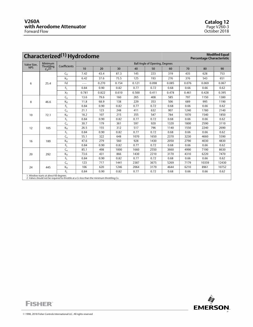
3
Characterized(1) Hydrodome Modified EqualPercentage Characteristic
Valve Size,NPS
MinimumThrottling
CV(2)
CoefficientsBall Angle of Opening, Degrees
10 20 30 40 50 60 70 80 90
6 25.4
CV 7.42 43.4 87.3 145 223 319 435 628 753
KV 6.42 37.6 75.5 125 193 276 376 543 651
Fd ‐ ‐ ‐ 0.270 0.154 0.121 0.098 0.085 0.076 0.069 0.067
FL 0.84 0.90 0.82 0.77 0.72 0.68 0.66 0.66 0.62
XT 0.781 0.822 0.610 0.500 0.411 0.478 0.461 0.428 0.395
8 46.6
Cv 13.6 79.6 160 265 408 585 797 1150 1380
KV 11.8 68.9 138 229 353 506 689 995 1190
FL 0.84 0.90 0.82 0.77 0.72 0.68 0.66 0.66 0.62
10 72.1
Cv 21.1 123 248 411 632 907 1240 1780 2140
KV 18.2 107 215 355 547 784 1070 1540 1850
FL 0.84 0.90 0.82 0.77 0.72 0.68 0.66 0.66 0.62
12 105
Cv 30.7 179 361 597 920 1320 1800 2590 3110
KV 26.5 155 312 517 796 1140 1550 2240 2690
FL 0.84 0.90 0.82 0.77 0.72 0.68 0.66 0.66 0.62
16 189
Cv 55.1 322 648 1070 1650 2370 3230 4660 5590
KV 47.6 279 560 928 1430 2050 2790 4030 4830
FL 0.84 0.90 0.82 0.77 0.72 0.68 0.66 0.66 0.62
20 292
Cv 85.1 498 1000 1660 2550 3660 4990 7190 8630
KV 73.6 431 866 1430 2210 3170 4310 6220 7470
FL 0.84 0.90 0.82 0.77 0.72 0.68 0.66 0.66 0.62
24 445
Cv 123 717 1441 2387 3675 5269 7179 10359 12430
KV 106 620 1246 2064 3179 4644 6210 8961 10752
FL 0.84 0.90 0.82 0.77 0.72 0.68 0.66 0.66 0.62
1. Window starts at about 60 degrees.2. Valves should not be required to throttle at a Cv less than the minimum throttling Cv.
� 1998, 2018 Fisher Controls International LLC. All rights reserved
V260Awith Aerodome AttenuatorForward Flow
Catalog 12Page V260-3
October 2018
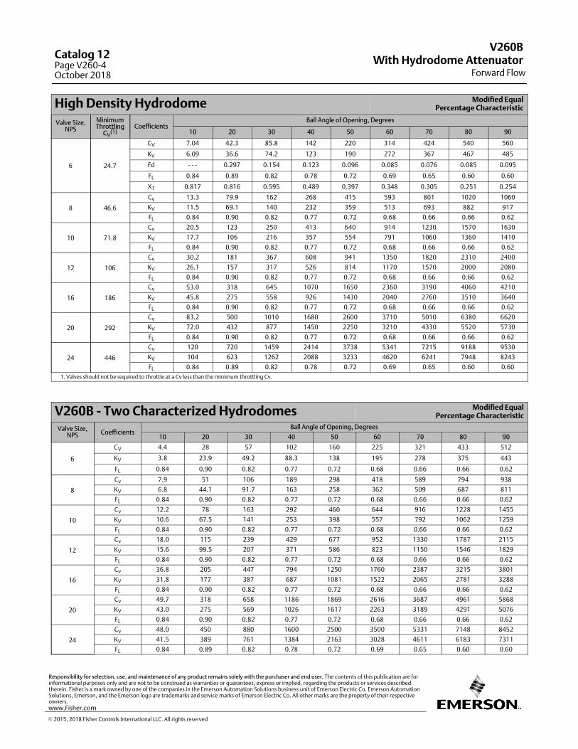
High Density Hydrodome Modified EqualPercentage Characteristic
Valve Size,NPS
MinimumThrottling
CV(1)
CoefficientsBall Angle of Opening, Degrees
10 20 30 40 50 60 70 80 90
6 24.7
CV 7.04 42.3 85.8 142 220 314 424 540 560
KV 6.09 36.6 74.2 123 190 272 367 467 485
Fd ‐ ‐ ‐ 0.297 0.154 0.123 0.096 0.085 0.076 0.085 0.095
FL 0.84 0.89 0.82 0.78 0.72 0.69 0.65 0.60 0.60
XT 0.817 0.816 0.595 0.489 0.397 0.348 0.305 0.251 0.254
8 46.6
Cv 13.3 79.9 162 268 415 593 801 1020 1060
KV 11.5 69.1 140 232 359 513 693 882 917
FL 0.84 0.90 0.82 0.77 0.72 0.68 0.66 0.66 0.62
10 71.8
Cv 20.5 123 250 413 640 914 1230 1570 1630
KV 17.7 106 216 357 554 791 1060 1360 1410
FL 0.84 0.90 0.82 0.77 0.72 0.68 0.66 0.66 0.62
12 106
Cv 30.2 181 367 608 941 1350 1820 2310 2400
KV 26.1 157 317 526 814 1170 1570 2000 2080
FL 0.84 0.90 0.82 0.77 0.72 0.68 0.66 0.66 0.62
16 186
Cv 53.0 318 645 1070 1650 2360 3190 4060 4210
KV 45.8 275 558 926 1430 2040 2760 3510 3640
FL 0.84 0.90 0.82 0.77 0.72 0.68 0.66 0.66 0.62
20 292
Cv 83.2 500 1010 1680 2600 3710 5010 6380 6620
KV 72.0 432 877 1450 2250 3210 4330 5520 5730
FL 0.84 0.90 0.82 0.77 0.72 0.68 0.66 0.66 0.62
24 446
Cv 120 720 1459 2414 3738 5341 7215 9188 9530
KV 104 623 1262 2088 3233 4620 6241 7948 8243
FL 0.84 0.89 0.82 0.78 0.72 0.69 0.65 0.60 0.60
1. Valves should not be required to throttle at a Cv less than the minimum throttling Cv.
V260B - Two Characterized Hydrodomes Modified EqualPercentage Characteristic
Valve Size,NPS Coefficients
Ball Angle of Opening, Degrees
10 20 30 40 50 60 70 80 90
6
CV 4.4 28 57 102 160 225 321 433 512
KV 3.8 23.9 49.2 88.3 138 195 278 375 443
FL 0.84 0.90 0.82 0.77 0.72 0.68 0.66 0.66 0.62
8
Cv 7.9 51 106 189 298 418 589 794 938
KV 6.8 44.1 91.7 163 258 362 509 687 811
FL 0.84 0.90 0.82 0.77 0.72 0.68 0.66 0.66 0.62
10
Cv 12.2 78 163 292 460 644 916 1228 1455
KV 10.6 67.5 141 253 398 557 792 1062 1259
FL 0.84 0.90 0.82 0.77 0.72 0.68 0.66 0.66 0.62
12
Cv 18.0 115 239 429 677 952 1330 1787 2115
KV 15.6 99.5 207 371 586 823 1150 1546 1829
FL 0.84 0.90 0.82 0.77 0.72 0.68 0.66 0.66 0.62
16
Cv 36.8 205 447 794 1250 1760 2387 3215 3801
KV 31.8 177 387 687 1081 1522 2065 2781 3288
FL 0.84 0.90 0.82 0.77 0.72 0.68 0.66 0.66 0.62
20
Cv 49.7 318 658 1186 1869 2616 3687 4961 5868
KV 43.0 275 569 1026 1617 2263 3189 4291 5076
FL 0.84 0.90 0.82 0.77 0.72 0.68 0.66 0.66 0.62
24
Cv 48.0 450 880 1600 2500 3500 5331 7148 8452
KV 41.5 389 761 1384 2163 3028 4611 6183 7311
FL 0.84 0.89 0.82 0.78 0.72 0.69 0.65 0.60 0.60
V260BWith Hydrodome Attenuator
Forward Flow
Catalog 12Page V260-4October 2018
� 2015, 2018 Fisher Controls International LLC. All rights reserved
www.Fisher.com
Responsibility for selection, use, and maintenance of any product remains solely with the purchaser and end user. The contents of this publication are forinformational purposes only and are not to be construed as warranties or guarantees, express or implied, regarding the products or services describedtherein. Fisher is a mark owned by one of the companies in the Emerson Automation Solutions business unit of Emerson Electric Co. Emerson AutomationSolutions, Emerson, and the Emerson logo are trademarks and service marks of Emerson Electric Co. All other marks are the property of their respectiveowners.
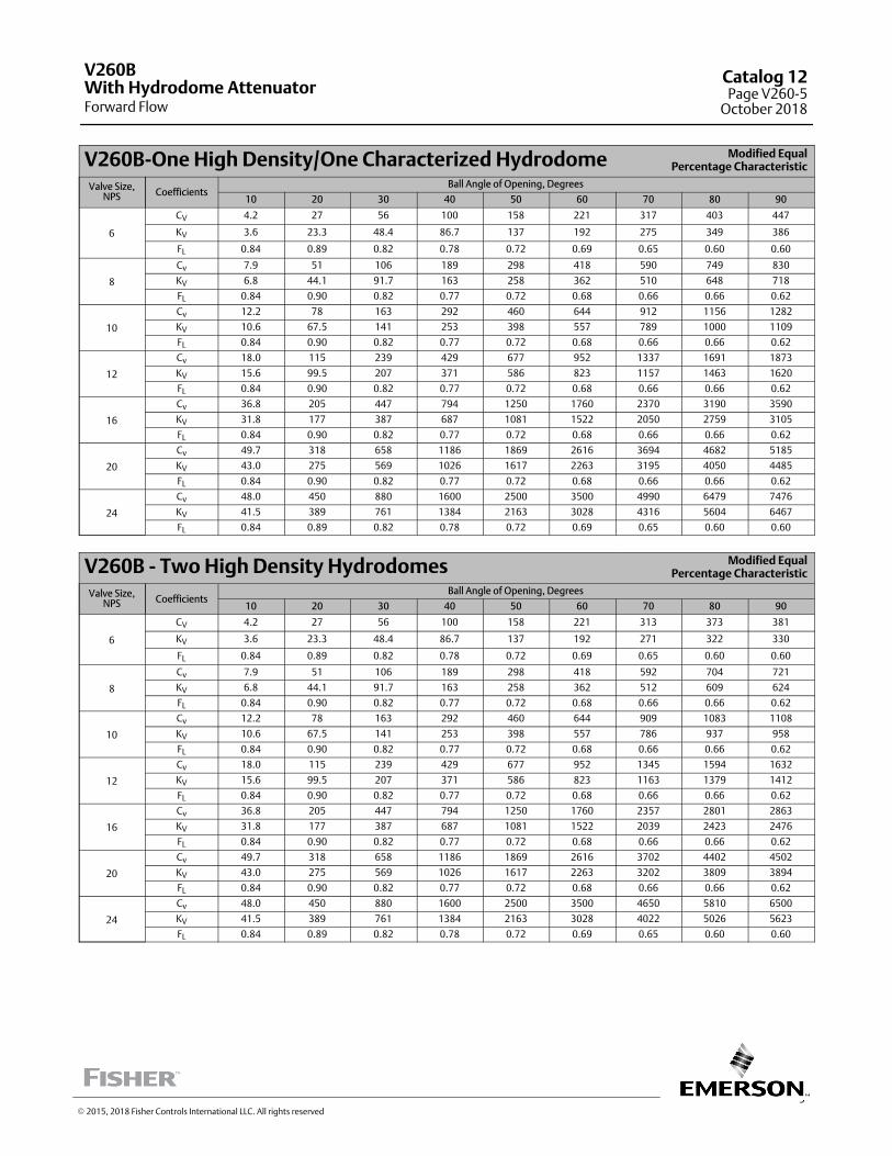
5
V260B-One High Density/One Characterized Hydrodome Modified EqualPercentage Characteristic
Valve Size,NPS Coefficients
Ball Angle of Opening, Degrees
10 20 30 40 50 60 70 80 90
6
CV 4.2 27 56 100 158 221 317 403 447
KV 3.6 23.3 48.4 86.7 137 192 275 349 386
FL 0.84 0.89 0.82 0.78 0.72 0.69 0.65 0.60 0.60
8
Cv 7.9 51 106 189 298 418 590 749 830
KV 6.8 44.1 91.7 163 258 362 510 648 718
FL 0.84 0.90 0.82 0.77 0.72 0.68 0.66 0.66 0.62
10
Cv 12.2 78 163 292 460 644 912 1156 1282
KV 10.6 67.5 141 253 398 557 789 1000 1109
FL 0.84 0.90 0.82 0.77 0.72 0.68 0.66 0.66 0.62
12
Cv 18.0 115 239 429 677 952 1337 1691 1873
KV 15.6 99.5 207 371 586 823 1157 1463 1620
FL 0.84 0.90 0.82 0.77 0.72 0.68 0.66 0.66 0.62
16
Cv 36.8 205 447 794 1250 1760 2370 3190 3590
KV 31.8 177 387 687 1081 1522 2050 2759 3105
FL 0.84 0.90 0.82 0.77 0.72 0.68 0.66 0.66 0.62
20
Cv 49.7 318 658 1186 1869 2616 3694 4682 5185
KV 43.0 275 569 1026 1617 2263 3195 4050 4485
FL 0.84 0.90 0.82 0.77 0.72 0.68 0.66 0.66 0.62
24
Cv 48.0 450 880 1600 2500 3500 4990 6479 7476
KV 41.5 389 761 1384 2163 3028 4316 5604 6467
FL 0.84 0.89 0.82 0.78 0.72 0.69 0.65 0.60 0.60
V260B - Two High Density Hydrodomes Modified EqualPercentage Characteristic
Valve Size,NPS Coefficients
Ball Angle of Opening, Degrees
10 20 30 40 50 60 70 80 90
6
CV 4.2 27 56 100 158 221 313 373 381
KV 3.6 23.3 48.4 86.7 137 192 271 322 330
FL 0.84 0.89 0.82 0.78 0.72 0.69 0.65 0.60 0.60
8
Cv 7.9 51 106 189 298 418 592 704 721
KV 6.8 44.1 91.7 163 258 362 512 609 624
FL 0.84 0.90 0.82 0.77 0.72 0.68 0.66 0.66 0.62
10
Cv 12.2 78 163 292 460 644 909 1083 1108
KV 10.6 67.5 141 253 398 557 786 937 958
FL 0.84 0.90 0.82 0.77 0.72 0.68 0.66 0.66 0.62
12
Cv 18.0 115 239 429 677 952 1345 1594 1632
KV 15.6 99.5 207 371 586 823 1163 1379 1412
FL 0.84 0.90 0.82 0.77 0.72 0.68 0.66 0.66 0.62
16
Cv 36.8 205 447 794 1250 1760 2357 2801 2863
KV 31.8 177 387 687 1081 1522 2039 2423 2476
FL 0.84 0.90 0.82 0.77 0.72 0.68 0.66 0.66 0.62
20
Cv 49.7 318 658 1186 1869 2616 3702 4402 4502
KV 43.0 275 569 1026 1617 2263 3202 3809 3894
FL 0.84 0.90 0.82 0.77 0.72 0.68 0.66 0.66 0.62
24
Cv 48.0 450 880 1600 2500 3500 4650 5810 6500
KV 41.5 389 761 1384 2163 3028 4022 5026 5623
FL 0.84 0.89 0.82 0.78 0.72 0.69 0.65 0.60 0.60
V260B
Forward FlowWith Hydrodome Attenuator
Catalog 12Page V260-5
October 2018
� 2015, 2018 Fisher Controls International LLC. All rights reserved
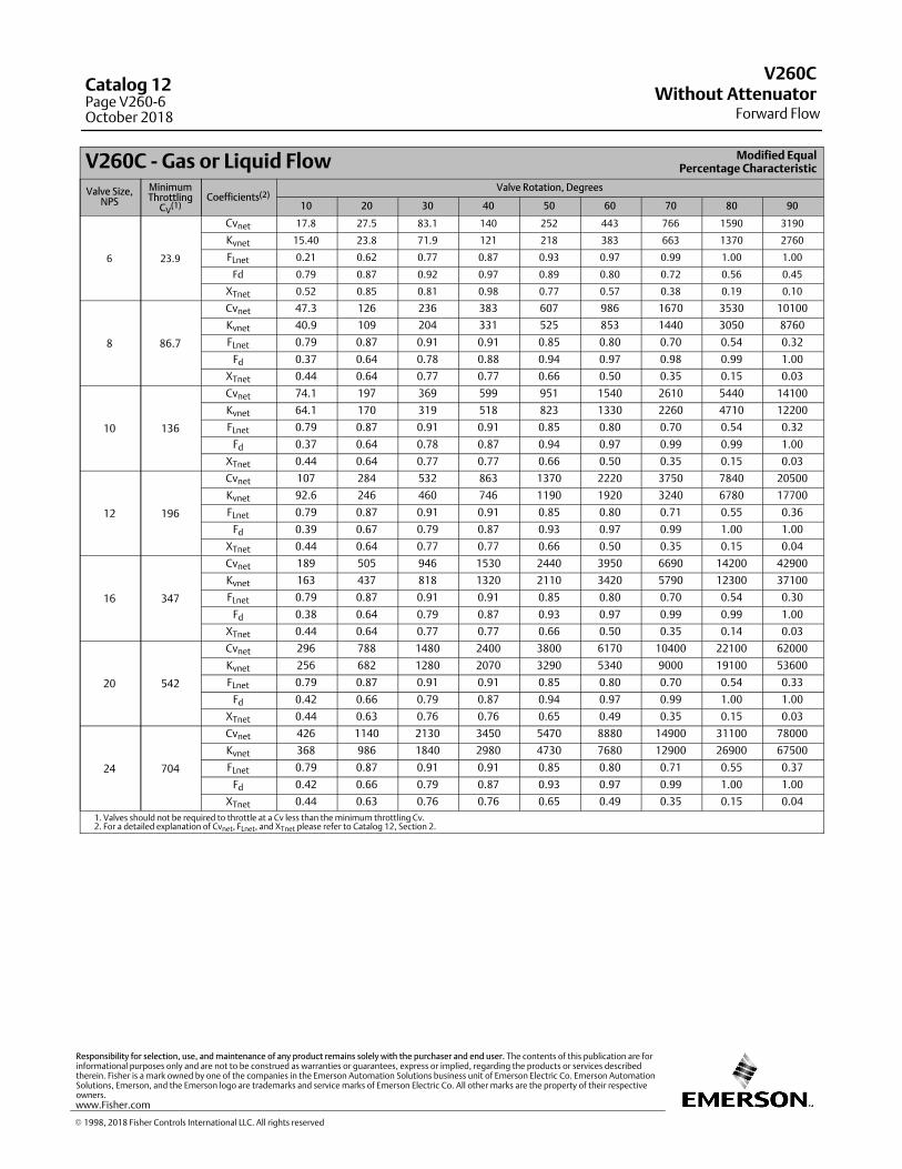
V260C - Gas or Liquid Flow Modified EqualPercentage Characteristic
Valve Size,NPS
MinimumThrottling
CV(1)
Coefficients(2)Valve Rotation, Degrees
10 20 30 40 50 60 70 80 90
6 23.9
Cvnet 17.8 27.5 83.1 140 252 443 766 1590 3190
Kvnet 15.40 23.8 71.9 121 218 383 663 1370 2760
FLnet 0.21 0.62 0.77 0.87 0.93 0.97 0.99 1.00 1.00
Fd 0.79 0.87 0.92 0.97 0.89 0.80 0.72 0.56 0.45
XTnet 0.52 0.85 0.81 0.98 0.77 0.57 0.38 0.19 0.10
8 86.7
Cvnet 47.3 126 236 383 607 986 1670 3530 10100
Kvnet 40.9 109 204 331 525 853 1440 3050 8760
FLnet 0.79 0.87 0.91 0.91 0.85 0.80 0.70 0.54 0.32
Fd 0.37 0.64 0.78 0.88 0.94 0.97 0.98 0.99 1.00
XTnet 0.44 0.64 0.77 0.77 0.66 0.50 0.35 0.15 0.03
10 136
Cvnet 74.1 197 369 599 951 1540 2610 5440 14100
Kvnet 64.1 170 319 518 823 1330 2260 4710 12200
FLnet 0.79 0.87 0.91 0.91 0.85 0.80 0.70 0.54 0.32
Fd 0.37 0.64 0.78 0.87 0.94 0.97 0.99 0.99 1.00
XTnet 0.44 0.64 0.77 0.77 0.66 0.50 0.35 0.15 0.03
12 196
Cvnet 107 284 532 863 1370 2220 3750 7840 20500
Kvnet 92.6 246 460 746 1190 1920 3240 6780 17700
FLnet 0.79 0.87 0.91 0.91 0.85 0.80 0.71 0.55 0.36
Fd 0.39 0.67 0.79 0.87 0.93 0.97 0.99 1.00 1.00
XTnet 0.44 0.64 0.77 0.77 0.66 0.50 0.35 0.15 0.04
16 347
Cvnet 189 505 946 1530 2440 3950 6690 14200 42900
Kvnet 163 437 818 1320 2110 3420 5790 12300 37100
FLnet 0.79 0.87 0.91 0.91 0.85 0.80 0.70 0.54 0.30
Fd 0.38 0.64 0.79 0.87 0.93 0.97 0.99 0.99 1.00
XTnet 0.44 0.64 0.77 0.77 0.66 0.50 0.35 0.14 0.03
20 542
Cvnet 296 788 1480 2400 3800 6170 10400 22100 62000
Kvnet 256 682 1280 2070 3290 5340 9000 19100 53600
FLnet 0.79 0.87 0.91 0.91 0.85 0.80 0.70 0.54 0.33
Fd 0.42 0.66 0.79 0.87 0.94 0.97 0.99 1.00 1.00
XTnet 0.44 0.63 0.76 0.76 0.65 0.49 0.35 0.15 0.03
24 704
Cvnet 426 1140 2130 3450 5470 8880 14900 31100 78000
Kvnet 368 986 1840 2980 4730 7680 12900 26900 67500
FLnet 0.79 0.87 0.91 0.91 0.85 0.80 0.71 0.55 0.37
Fd 0.42 0.66 0.79 0.87 0.93 0.97 0.99 1.00 1.00
XTnet 0.44 0.63 0.76 0.76 0.65 0.49 0.35 0.15 0.04
1. Valves should not be required to throttle at a Cv less than the minimum throttling Cv.2. For a detailed explanation of Cvnet, FLnet, and XTnet please refer to Catalog 12, Section 2.
V260CWithout Attenuator
Forward Flow
Catalog 12Page V260-6October 2018
� 1998, 2018 Fisher Controls International LLC. All rights reserved
www.Fisher.com
Responsibility for selection, use, and maintenance of any product remains solely with the purchaser and end user. The contents of this publication are forinformational purposes only and are not to be construed as warranties or guarantees, express or implied, regarding the products or services describedtherein. Fisher is a mark owned by one of the companies in the Emerson Automation Solutions business unit of Emerson Electric Co. Emerson AutomationSolutions, Emerson, and the Emerson logo are trademarks and service marks of Emerson Electric Co. All other marks are the property of their respectiveowners.
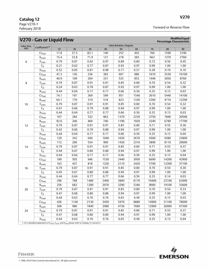
Forward or Reverse Flow
Catalog 12 Page V270‐1
February 2018
V270
V270 - Gas or Liquid Flow Modified EqualPercentage Characteristic
Valve Size,NPS Coefficients(1)
Valve Rotation, Degrees
10 20 30 40 50 60 70 80 90
6
Cvnet 17.8 27.5 83.1 140 252 443 766 1590 3190
Kvnet 15.4 23.8 71.9 121 218 383 663 1370 2760
FLnet 0.79 0.87 0.92 0.97 0.89 0.80 0.72 0.56 0.45
Fd 0.21 0.62 0.77 0.87 0.93 0.97 0.99 1.00 1.00
XTnet 0.52 0.85 0.81 0.98 0.77 0.57 0.38 0.19 0.10
8
Cvnet 47.3 126 236 383 607 986 1670 3530 10100
Kvnet 40.9 109 204 331 525 853 1440 3050 8760
FLnet 0.79 0.87 0.91 0.91 0.85 0.80 0.70 0.54 0.32
Fd 0.24 0.63 0.78 0.87 0.93 0.97 0.99 1.00 1.00
XTnet 0.44 0.64 0.77 0.77 0.66 0.50 0.35 0.15 0.03
10
Cvnet 74.1 197 369 599 951 1540 2610 5440 14100
Kvnet 64.1 170 319 518 823 1330 2260 4710 12200
FLnet 0.79 0.87 0.91 0.91 0.85 0.80 0.70 0.54 0.32
Fd 0.41 0.66 0.79 0.88 0.94 0.97 0.99 1.00 1.00
XTnet 0.44 0.64 0.77 0.77 0.66 0.50 0.35 0.15 0.03
12
Cvnet 107 284 532 863 1370 2220 3750 7840 20500
Kvnet 92.6 246 460 746 1190 1920 3240 6780 17700
FLnet 0.79 0.87 0.91 0.91 0.85 0.80 0.71 0.55 0.36
Fd 0.42 0.66 0.79 0.88 0.94 0.97 0.99 1.00 1.00
XTnet 0.44 0.64 0.77 0.77 0.66 0.50 0.35 0.15 0.04
14
Cvnet 129 342 640 1040 1650 2670 4500 9380 23800
Kvnet 112 296 554 900 1430 2310 3890 8110 20600
FLnet 0.79 0.87 0.91 0.91 0.85 0.80 0.71 0.55 0.37
Fd 0.44 0.67 0.80 0.88 0.94 0.97 0.99 1.00 1.00
XTnet 0.44 0.64 0.77 0.77 0.66 0.50 0.35 0.15 0.04
16
Cvnet 189 505 946 1530 2440 3950 6690 14200 42900
Kvnet 163 437 818 1320 2110 3420 5790 12300 37100
FLnet 0.79 0.87 0.91 0.91 0.85 0.80 0.70 0.54 0.30
Fd 0.45 0.67 0.80 0.88 0.94 0.97 0.99 1.00 1.00
XTnet 0.44 0.64 0.77 0.77 0.66 0.50 0.35 0.14 0.03
20
Cvnet 296 788 1480 2400 3800 6170 10400 22100 62000
Kvnet 256 682 1280 2070 3290 5340 9000 19100 53600
FLnet 0.79 0.87 0.91 0.91 0.85 0.80 0.70 0.54 0.33
Fd 0.47 0.68 0.80 0.88 0.94 0.97 0.99 1.00 1.00
XTnet 0.44 0.63 0.76 0.76 0.65 0.49 0.35 0.15 0.03
24
Cvnet 426 1140 2130 3450 5470 8880 14900 31100 78000
Kvnet 368 986 1840 2980 4730 7680 12900 26900 67500
FLnet 0.79 0.87 0.91 0.91 0.85 0.80 0.71 0.55 0.37
Fd 0.47 0.68 0.80 0.89 0.94 0.97 0.99 1.00 1.00
XTnet 0.44 0.63 0.76 0.76 0.65 0.49 0.35 0.15 0.04
1. For a detailed explanation of Cvnet, FLnet, and XTnet please refer to Catalog 12, Section 2.
� 1988, 2018 Fisher Controls International LLC. All rights reserved
This page is intentionally left blank.
V270
Forward or Reverse Flow
Catalog 12 Page V270‐2
February 2018
� 1988, 2018 Fisher Controls International LLC. All rights reserved
www.Fisher.com
Responsibility for selection, use, and maintenance of any product remains solely with the purchaser and end user. The contents of this publication are forinformational purposes only and are not to be construed as warranties or guarantees, express or implied, regarding the products or services describedtherein. Fisher is a mark owned by one of the companies in the Emerson Automation Solutions business unit of Emerson Electric Co. Emerson AutomationSolutions, Emerson, and the Emerson logo are trademarks and service marks of Emerson Electric Co. All other marks are the property of their respectiveowners.
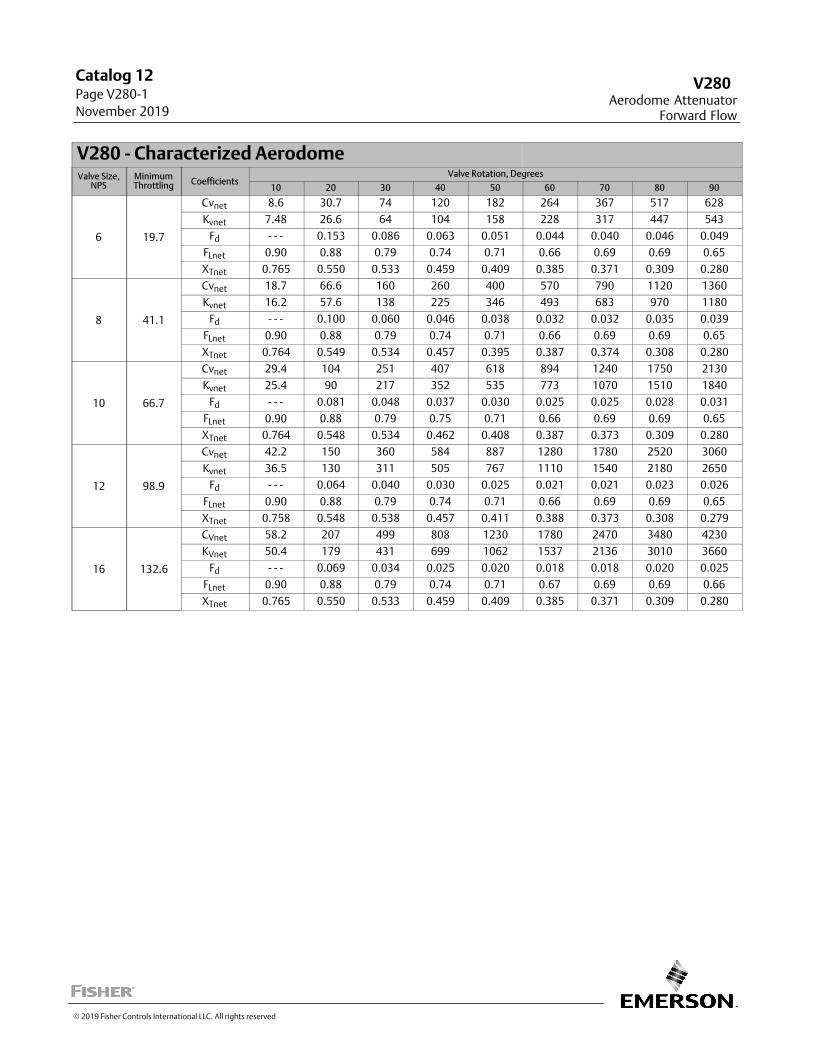
Aerodome AttenuatorForward Flow
Catalog 12 Page V280‐1
November 2019
V280
V280 - Characterized AerodomeValve Size,
NPSMinimumThrottling Coefficients
Valve Rotation, Degrees
10 20 30 40 50 60 70 80 90
6 19.7
Cvnet 8.6 30.7 74 120 182 264 367 517 628
Kvnet 7.48 26.6 64 104 158 228 317 447 543
Fd - - - 0.153 0.086 0.063 0.051 0.044 0.040 0.046 0.049
FLnet 0.90 0.88 0.79 0.74 0.71 0.66 0.69 0.69 0.65
XTnet 0.765 0.550 0.533 0.459 0.409 0.385 0.371 0.309 0.280
8 41.1
Cvnet 18.7 66.6 160 260 400 570 790 1120 1360
Kvnet 16.2 57.6 138 225 346 493 683 970 1180
Fd - - - 0.100 0.060 0.046 0.038 0.032 0.032 0.035 0.039
FLnet 0.90 0.88 0.79 0.74 0.71 0.66 0.69 0.69 0.65
XTnet 0.764 0.549 0.534 0.457 0.395 0.387 0.374 0.308 0.280
10 66.7
Cvnet 29.4 104 251 407 618 894 1240 1750 2130
Kvnet 25.4 90 217 352 535 773 1070 1510 1840
Fd - - - 0.081 0.048 0.037 0.030 0.025 0.025 0.028 0.031
FLnet 0.90 0.88 0.79 0.75 0.71 0.66 0.69 0.69 0.65
XTnet 0.764 0.548 0.534 0.462 0.408 0.387 0.373 0.309 0.280
12 98.9
Cvnet 42.2 150 360 584 887 1280 1780 2520 3060
Kvnet 36.5 130 311 505 767 1110 1540 2180 2650
Fd - - - 0.064 0.040 0.030 0.025 0.021 0.021 0.023 0.026
FLnet 0.90 0.88 0.79 0.74 0.71 0.66 0.69 0.69 0.65
XTnet 0.758 0.548 0.538 0.457 0.411 0.388 0.373 0.308 0.279
16 132.6
CVnet 58.2 207 499 808 1230 1780 2470 3480 4230
KVnet 50.4 179 431 699 1062 1537 2136 3010 3660
Fd - - - 0.069 0.034 0.025 0.020 0.018 0.018 0.020 0.025
FLnet 0.90 0.88 0.79 0.74 0.71 0.67 0.69 0.69 0.66
XTnet 0.765 0.550 0.533 0.459 0.409 0.385 0.371 0.309 0.280
� 2019 Fisher Controls International LLC. All rights reserved
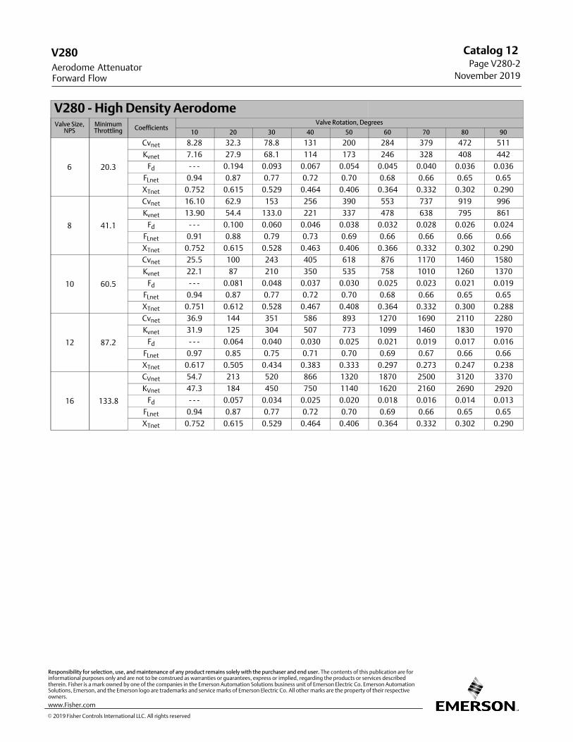
V280 - High Density AerodomeValve Size,
NPSMinimumThrottling Coefficients
Valve Rotation, Degrees
10 20 30 40 50 60 70 80 90
6 20.3
Cvnet 8.28 32.3 78.8 131 200 284 379 472 511
Kvnet 7.16 27.9 68.1 114 173 246 328 408 442
Fd - - - 0.194 0.093 0.067 0.054 0.045 0.040 0.036 0.036
FLnet 0.94 0.87 0.77 0.72 0.70 0.68 0.66 0.65 0.65
XTnet 0.752 0.615 0.529 0.464 0.406 0.364 0.332 0.302 0.290
8 41.1
Cvnet 16.10 62.9 153 256 390 553 737 919 996
Kvnet 13.90 54.4 133.0 221 337 478 638 795 861
Fd - - - 0.100 0.060 0.046 0.038 0.032 0.028 0.026 0.024
FLnet 0.91 0.88 0.79 0.73 0.69 0.66 0.66 0.66 0.66
XTnet 0.752 0.615 0.528 0.463 0.406 0.366 0.332 0.302 0.290
10 60.5
Cvnet 25.5 100 243 405 618 876 1170 1460 1580
Kvnet 22.1 87 210 350 535 758 1010 1260 1370
Fd - - - 0.081 0.048 0.037 0.030 0.025 0.023 0.021 0.019
FLnet 0.94 0.87 0.77 0.72 0.70 0.68 0.66 0.65 0.65
XTnet 0.751 0.612 0.528 0.467 0.408 0.364 0.332 0.300 0.288
12 87.2
Cvnet 36.9 144 351 586 893 1270 1690 2110 2280
Kvnet 31.9 125 304 507 773 1099 1460 1830 1970
Fd - - - 0.064 0.040 0.030 0.025 0.021 0.019 0.017 0.016
FLnet 0.97 0.85 0.75 0.71 0.70 0.69 0.67 0.66 0.66
XTnet 0.617 0.505 0.434 0.383 0.333 0.297 0.273 0.247 0.238
16 133.8
CVnet 54.7 213 520 866 1320 1870 2500 3120 3370
KVnet 47.3 184 450 750 1140 1620 2160 2690 2920
Fd - - - 0.057 0.034 0.025 0.020 0.018 0.016 0.014 0.013
FLnet 0.94 0.87 0.77 0.72 0.70 0.69 0.66 0.65 0.65
XTnet 0.752 0.615 0.529 0.464 0.406 0.364 0.332 0.302 0.290
V280
Forward FlowAerodome Attenuator
Catalog 12 Page V280‐2
November 2019
� 2019 Fisher Controls International LLC. All rights reserved
www.Fisher.com
Responsibility for selection, use, and maintenance of any product remains solely with the purchaser and end user. The contents of this publication are forinformational purposes only and are not to be construed as warranties or guarantees, express or implied, regarding the products or services describedtherein. Fisher is a mark owned by one of the companies in the Emerson Automation Solutions business unit of Emerson Electric Co. Emerson AutomationSolutions, Emerson, and the Emerson logo are trademarks and service marks of Emerson Electric Co. All other marks are the property of their respectiveowners.
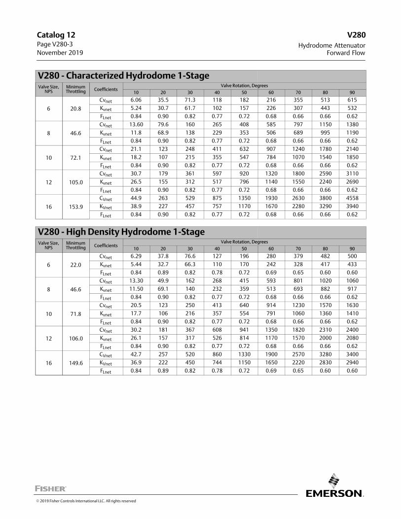
V280 - Characterized Hydrodome 1-StageValve Size,
NPSMinimumThrottling Coefficients
Valve Rotation, Degrees
10 20 30 40 50 60 70 80 90
6 20.8
Cvnet 6.06 35.5 71.3 118 182 216 355 513 615
Kvnet 5.24 30.7 61.7 102 157 226 307 443 532
FLnet 0.84 0.90 0.82 0.77 0.72 0.68 0.66 0.66 0.62
8 46.6
Cvnet 13.60 79.6 160 265 408 585 797 1150 1380
Kvnet 11.8 68.9 138 229 353 506 689 995 1190
FLnet 0.84 0.90 0.82 0.77 0.72 0.68 0.66 0.66 0.62
10 72.1
Cvnet 21.1 123 248 411 632 907 1240 1780 2140
Kvnet 18.2 107 215 355 547 784 1070 1540 1850
FLnet 0.84 0.90 0.82 0.77 0.72 0.68 0.66 0.66 0.62
12 105.0
Cvnet 30.7 179 361 597 920 1320 1800 2590 3110
Kvnet 26.5 155 312 517 796 1140 1550 2240 2690
FLnet 0.84 0.90 0.82 0.77 0.72 0.68 0.66 0.66 0.62
16 153.9
CVnet 44.9 263 529 875 1350 1930 2630 3800 4558
KVnet 38.9 227 457 757 1170 1670 2280 3290 3940
FLnet 0.84 0.90 0.82 0.77 0.72 0.68 0.66 0.66 0.62
V280 - High Density Hydrodome 1-StageValve Size,
NPSMinimumThrottling Coefficients
Valve Rotation, Degrees
10 20 30 40 50 60 70 80 90
6 22.0
Cvnet 6.29 37.8 76.6 127 196 280 379 482 500
Kvnet 5.44 32.7 66.3 110 170 242 328 417 433
FLnet 0.84 0.89 0.82 0.78 0.72 0.69 0.65 0.60 0.60
8 46.6
Cvnet 13.30 49.9 162 268 415 593 801 1020 1060
Kvnet 11.50 69.1 140 232 359 513 693 882 917
FLnet 0.84 0.90 0.82 0.77 0.72 0.68 0.66 0.66 0.62
10 71.8
Cvnet 20.5 123 250 413 640 914 1230 1570 1630
Kvnet 17.7 106 216 357 554 791 1060 1360 1410
FLnet 0.84 0.90 0.82 0.77 0.72 0.68 0.66 0.66 0.62
12 106.0
Cvnet 30.2 181 367 608 941 1350 1820 2310 2400
Kvnet 26.1 157 317 526 814 1170 1570 2000 2080
FLnet 0.84 0.90 0.82 0.77 0.72 0.68 0.66 0.66 0.62
16 149.6
CVnet 42.7 257 520 860 1330 1900 2570 3280 3400
KVnet 36.9 222 450 744 1150 1650 2220 2830 2940
FLnet 0.84 0.89 0.82 0.78 0.72 0.69 0.65 0.60 0.60
� 2019 Fisher Controls International LLC. All rights reserved
V280
Forward FlowHydrodome Attenuator
Catalog 12 Page V280‐3
November 2019
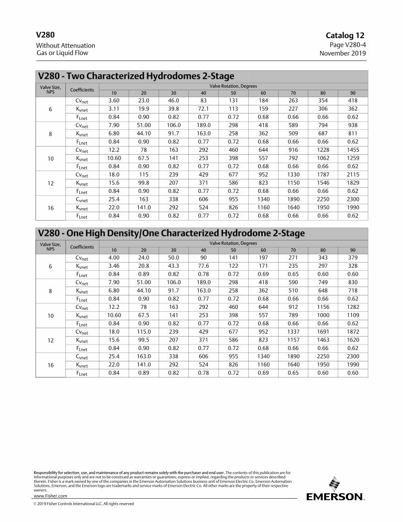
V280 - Two Characterized Hydrodomes 2-StageValve Size,
NPS CoefficientsValve Rotation, Degrees
10 20 30 40 50 60 70 80 90
6
Cvnet 3.60 23.0 46.0 83 131 184 263 354 418
Kvnet 3.11 19.9 39.8 72.1 113 159 227 306 362
FLnet 0.84 0.90 0.82 0.77 0.72 0.68 0.66 0.66 0.62
8
Cvnet 7.90 51.00 106.0 189.0 298 418 589 794 938
Kvnet 6.80 44.10 91.7 163.0 258 362 509 687 811
FLnet 0.84 0.90 0.82 0.77 0.72 0.68 0.66 0.66 0.62
10
Cvnet 12.2 78 163 292 460 644 916 1228 1455
Kvnet 10.60 67.5 141 253 398 557 792 1062 1259
FLnet 0.84 0.90 0.82 0.77 0.72 0.68 0.66 0.66 0.62
12
Cvnet 18.0 115 239 429 677 952 1330 1787 2115
Kvnet 15.6 99.8 207 371 586 823 1150 1546 1829
FLnet 0.84 0.90 0.82 0.77 0.72 0.68 0.66 0.66 0.62
16
Cvnet 25.4 163 338 606 955 1340 1890 2250 2300
Kvnet 22.0 141.0 292 524 826 1160 1640 1950 1990
FLnet 0.84 0.90 0.82 0.77 0.72 0.68 0.66 0.66 0.62
V280 - One High Density/One Characterized Hydrodome 2-StageValve Size,
NPS CoefficientsValve Rotation, Degrees
10 20 30 40 50 60 70 80 90
6
Cvnet 4.00 24.0 50.0 90 141 197 271 343 379
Kvnet 3.46 20.8 43.3 77.6 122 171 235 297 328
FLnet 0.84 0.89 0.82 0.78 0.72 0.69 0.65 0.60 0.60
8
Cvnet 7.90 51.00 106.0 189.0 298 418 590 749 830
Kvnet 6.80 44.10 91.7 163.0 258 362 510 648 718
FLnet 0.84 0.90 0.82 0.77 0.72 0.68 0.66 0.66 0.62
10
Cvnet 12.2 78 163 292 460 644 912 1156 1282
Kvnet 10.60 67.5 141 253 398 557 789 1000 1109
FLnet 0.84 0.90 0.82 0.77 0.72 0.68 0.66 0.66 0.62
12
Cvnet 18.0 115.0 239 429 677 952 1337 1691 1872
Kvnet 15.6 99.5 207 371 586 823 1157 1463 1620
FLnet 0.84 0.90 0.82 0.77 0.72 0.68 0.66 0.66 0.62
16
Cvnet 25.4 163.0 338 606 955 1340 1890 2250 2300
Kvnet 22.0 141.0 292 524 826 1160 1640 1950 1990
FLnet 0.84 0.89 0.82 0.78 0.72 0.69 0.65 0.60 0.60
� 2019 Fisher Controls International LLC. All rights reserved
www.Fisher.com
Responsibility for selection, use, and maintenance of any product remains solely with the purchaser and end user. The contents of this publication are forinformational purposes only and are not to be construed as warranties or guarantees, express or implied, regarding the products or services describedtherein. Fisher is a mark owned by one of the companies in the Emerson Automation Solutions business unit of Emerson Electric Co. Emerson AutomationSolutions, Emerson, and the Emerson logo are trademarks and service marks of Emerson Electric Co. All other marks are the property of their respectiveowners.
V280
Gas or Liquid FlowWithout Attenuation
Catalog 12 Page V280‐4
November 2019
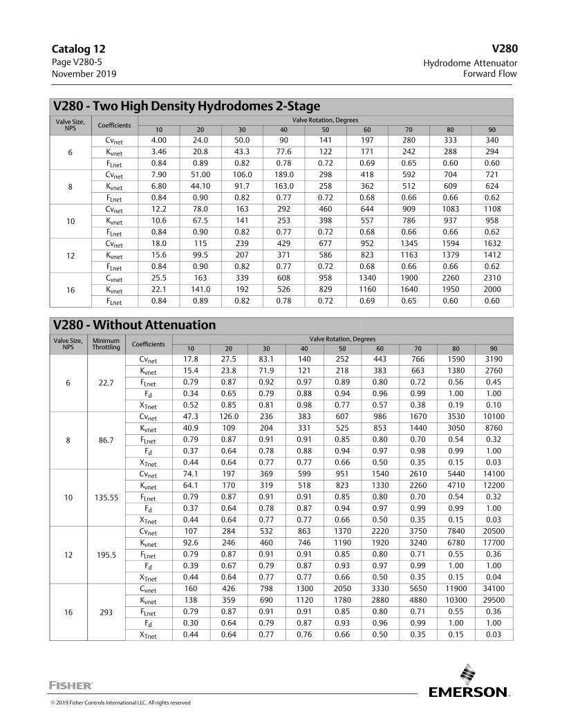
V280 - Two High Density Hydrodomes 2-StageValve Size,
NPS CoefficientsValve Rotation, Degrees
10 20 30 40 50 60 70 80 90
6
Cvnet 4.00 24.0 50.0 90 141 197 280 333 340
Kvnet 3.46 20.8 43.3 77.6 122 171 242 288 294
FLnet 0.84 0.89 0.82 0.78 0.72 0.69 0.65 0.60 0.60
8
Cvnet 7.90 51.00 106.0 189.0 298 418 592 704 721
Kvnet 6.80 44.10 91.7 163.0 258 362 512 609 624
FLnet 0.84 0.90 0.82 0.77 0.72 0.68 0.66 0.66 0.62
10
Cvnet 12.2 78.0 163 292 460 644 909 1083 1108
Kvnet 10.6 67.5 141 253 398 557 786 937 958
FLnet 0.84 0.90 0.82 0.77 0.72 0.68 0.66 0.66 0.62
12
Cvnet 18.0 115 239 429 677 952 1345 1594 1632
Kvnet 15.6 99.5 207 371 586 823 1163 1379 1412
FLnet 0.84 0.90 0.82 0.77 0.72 0.68 0.66 0.66 0.62
16
Cvnet 25.5 163 339 608 958 1340 1900 2260 2310
Kvnet 22.1 141.0 192 526 829 1160 1640 1950 2000
FLnet 0.84 0.89 0.82 0.78 0.72 0.69 0.65 0.60 0.60
V280 - Without AttenuationValve Size,
NPSMinimumThrottling Coefficients
Valve Rotation, Degrees
10 20 30 40 50 60 70 80 90
6 22.7
Cvnet 17.8 27.5 83.1 140 252 443 766 1590 3190
Kvnet 15.4 23.8 71.9 121 218 383 663 1380 2760
FLnet 0.79 0.87 0.92 0.97 0.89 0.80 0.72 0.56 0.45
Fd 0.34 0.65 0.79 0.88 0.94 0.96 0.99 1.00 1.00
XTnet 0.52 0.85 0.81 0.98 0.77 0.57 0.38 0.19 0.10
8 86.7
Cvnet 47.3 126.0 236 383 607 986 1670 3530 10100
Kvnet 40.9 109 204 331 525 853 1440 3050 8760
FLnet 0.79 0.87 0.91 0.91 0.85 0.80 0.70 0.54 0.32
Fd 0.37 0.64 0.78 0.88 0.94 0.97 0.98 0.99 1.00
XTnet 0.44 0.64 0.77 0.77 0.66 0.50 0.35 0.15 0.03
10 135.55
Cvnet 74.1 197 369 599 951 1540 2610 5440 14100
Kvnet 64.1 170 319 518 823 1330 2260 4710 12200
FLnet 0.79 0.87 0.91 0.91 0.85 0.80 0.70 0.54 0.32
Fd 0.37 0.64 0.78 0.87 0.94 0.97 0.99 0.99 1.00
XTnet 0.44 0.64 0.77 0.77 0.66 0.50 0.35 0.15 0.03
12 195.5
Cvnet 107 284 532 863 1370 2220 3750 7840 20500
Kvnet 92.6 246 460 746 1190 1920 3240 6780 17700
FLnet 0.79 0.87 0.91 0.91 0.85 0.80 0.71 0.55 0.36
Fd 0.39 0.67 0.79 0.87 0.93 0.97 0.99 1.00 1.00
XTnet 0.44 0.64 0.77 0.77 0.66 0.50 0.35 0.15 0.04
16 293
Cvnet 160 426 798 1300 2050 3330 5650 11900 34100
Kvnet 138 359 690 1120 1780 2880 4880 10300 29500
FLnet 0.79 0.87 0.91 0.91 0.85 0.80 0.71 0.55 0.36
Fd 0.30 0.64 0.79 0.87 0.93 0.96 0.99 1.00 1.00
XTnet 0.44 0.64 0.77 0.76 0.66 0.50 0.35 0.15 0.03
V280
Forward FlowHydrodome Attenuator
Catalog 12 Page V280‐5
November 2019
� 2019 Fisher Controls International LLC. All rights reserved
The Fisher� V300 has flow coefficients identical to the V150. Refer to the V150 information. Reminder: The V300 is available in NPS 1 through 16 only.Reminder: The V300 NPS 14 and 16 are not available with Flat Metal seals.
� 1998, 2018 Fisher Controls International LLC. All rights reserved
V300
Forward Flow
Catalog 12Page V300-1
February 2018
This page is intentionally left blank.
V300
CL125 ‐ 600
Catalog 12Page V300-2February 2018
� 1998, 2018 Fisher Controls International LLC. All rights reserved
www.Fisher.com
Responsibility for selection, use, and maintenance of any product remains solely with the purchaser and end user. The contents of this publication are forinformational purposes only and are not to be construed as warranties or guarantees, express or implied, regarding the products or services describedtherein. Fisher is a mark owned by one of the companies in the Emerson Automation Solutions business unit of Emerson Electric Co. Emerson AutomationSolutions, Emerson, and the Emerson logo are trademarks and service marks of Emerson Electric Co. All other marks are the property of their respectiveowners.
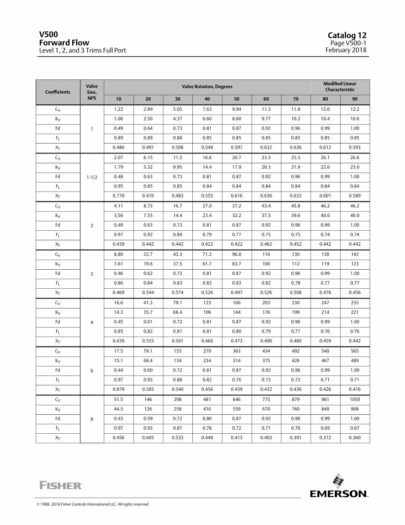
CoefficientsValve
Size,
NPS
Valve Rotation, DegreesModified Linear
Characteristic
10 20 30 40 50 60 70 80 90
CV
1
1.22 2.89 5.05 7.63 9.94 11.3 11.8 12.0 12.2
KV 1.06 2.50 4.37 6.60 8.60 9.77 10.2 10.4 10.6
Fd 0.49 0.64 0.73 0.81 0.87 0.92 0.96 0.99 1.00
FL 0.89 0.89 0.88 0.85 0.85 0.85 0.85 0.85 0.85
XT 0.480 0.497 0.508 0.548 0.597 0.632 0.636 0.612 0.593
CV
1‐1/2
2.07 6.15 11.5 16.6 20.7 23.5 25.3 26.1 26.6
KV 1.79 5.32 9.95 14.4 17.9 20.3 21.9 22.6 23.0
Fd 0.48 0.63 0.73 0.81 0.87 0.92 0.96 0.99 1.00
FL 0.95 0.85 0.85 0.84 0.84 0.84 0.84 0.84 0.84
XT 0.770 0.476 0.483 0.555 0.616 0.636 0.632 0.601 0.589
CV
2
4.11 8.73 16.7 27.0 37.2 43.4 45.8 46.2 46.2
KV 3.56 7.55 14.4 23.4 32.2 37.5 39.6 40.0 40.0
Fd 0.49 0.63 0.73 0.81 0.87 0.92 0.96 0.99 1.00
FL 0.97 0.92 0.84 0.79 0.77 0.75 0.75 0.74 0.74
XT 0.439 0.442 0.442 0.422 0.422 0.462 0.452 0.442 0.442
CV
3
8.80 22.7 43.3 71.3 96.8 116 130 138 142
KV 7.61 19.6 37.5 61.7 83.7 100 112 119 123
Fd 0.46 0.62 0.73 0.81 0.87 0.92 0.96 0.99 1.00
FL 0.86 0.84 0.83 0.83 0.83 0.82 0.78 0.77 0.77
XT 0.469 0.544 0.574 0.526 0.497 0.526 0.508 0.476 0.456
CV
4
16.6 41.3 79.1 123 166 203 230 247 255
KV 14.3 35.7 68.4 106 144 176 199 214 221
Fd 0.45 0.61 0.72 0.81 0.87 0.92 0.96 0.99 1.00
FL 0.85 0.82 0.81 0.81 0.80 0.79 0.77 0.76 0.76
XT 0.439 0.555 0.501 0.466 0.473 0.490 0.480 0.459 0.442
CV
6
17.5 79.1 155 270 363 434 492 540 565
KV 15.1 68.4 134 234 314 375 426 467 489
Fd 0.44 0.60 0.72 0.81 0.87 0.92 0.96 0.99 1.00
FL 0.97 0.93 0.88 0.82 0.76 0.73 0.72 0.71 0.71
XT 0.879 0.585 0.540 0.456 0.439 0.432 0.436 0.426 0.416
CV
8
51.5 146 298 481 646 775 879 981 1050
KV 44.5 126 258 416 559 670 760 849 908
Fd 0.43 0.59 0.72 0.80 0.87 0.92 0.96 0.99 1.00
FL 0.97 0.93 0.87 0.78 0.72 0.71 0.70 0.69 0.67
XT 0.456 0.605 0.533 0.449 0.413 0.403 0.391 0.372 0.360
� 1988, 2018 Fisher Controls International LLC. All rights reserved
V500Forward FlowLevel 1, 2, and 3 Trims Full Port
Catalog 12Page V500-1
February 2018
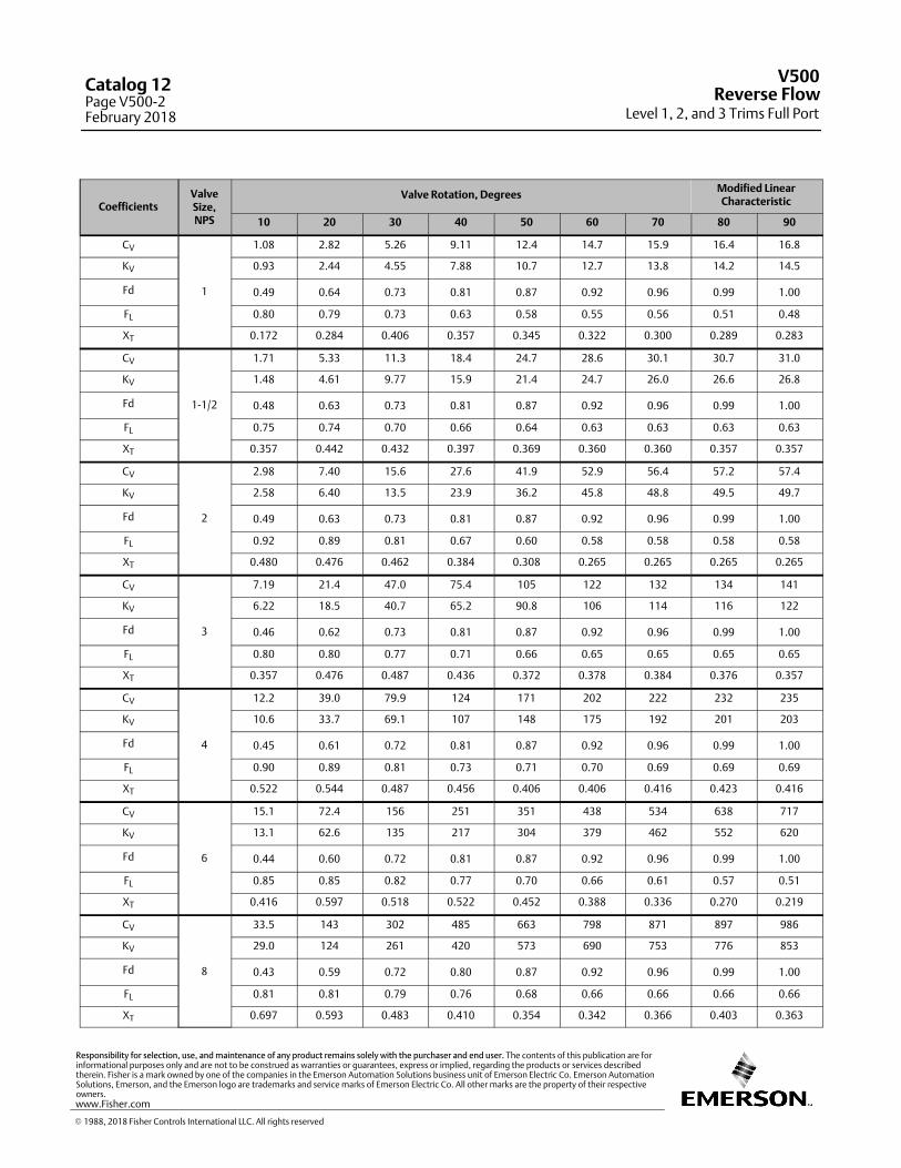
CoefficientsValveSize,NPS
Valve Rotation, DegreesModified LinearCharacteristic
10 20 30 40 50 60 70 80 90
CV
1
1.08 2.82 5.26 9.11 12.4 14.7 15.9 16.4 16.8
KV 0.93 2.44 4.55 7.88 10.7 12.7 13.8 14.2 14.5
Fd 0.49 0.64 0.73 0.81 0.87 0.92 0.96 0.99 1.00
FL 0.80 0.79 0.73 0.63 0.58 0.55 0.56 0.51 0.48
XT 0.172 0.284 0.406 0.357 0.345 0.322 0.300 0.289 0.283
CV
1‐1/2
1.71 5.33 11.3 18.4 24.7 28.6 30.1 30.7 31.0
KV 1.48 4.61 9.77 15.9 21.4 24.7 26.0 26.6 26.8
Fd 0.48 0.63 0.73 0.81 0.87 0.92 0.96 0.99 1.00
FL 0.75 0.74 0.70 0.66 0.64 0.63 0.63 0.63 0.63
XT 0.357 0.442 0.432 0.397 0.369 0.360 0.360 0.357 0.357
CV
2
2.98 7.40 15.6 27.6 41.9 52.9 56.4 57.2 57.4
KV 2.58 6.40 13.5 23.9 36.2 45.8 48.8 49.5 49.7
Fd 0.49 0.63 0.73 0.81 0.87 0.92 0.96 0.99 1.00
FL 0.92 0.89 0.81 0.67 0.60 0.58 0.58 0.58 0.58
XT 0.480 0.476 0.462 0.384 0.308 0.265 0.265 0.265 0.265
CV
3
7.19 21.4 47.0 75.4 105 122 132 134 141
KV 6.22 18.5 40.7 65.2 90.8 106 114 116 122
Fd 0.46 0.62 0.73 0.81 0.87 0.92 0.96 0.99 1.00
FL 0.80 0.80 0.77 0.71 0.66 0.65 0.65 0.65 0.65
XT 0.357 0.476 0.487 0.436 0.372 0.378 0.384 0.376 0.357
CV
4
12.2 39.0 79.9 124 171 202 222 232 235
KV 10.6 33.7 69.1 107 148 175 192 201 203
Fd 0.45 0.61 0.72 0.81 0.87 0.92 0.96 0.99 1.00
FL 0.90 0.89 0.81 0.73 0.71 0.70 0.69 0.69 0.69
XT 0.522 0.544 0.487 0.456 0.406 0.406 0.416 0.423 0.416
CV
6
15.1 72.4 156 251 351 438 534 638 717
KV 13.1 62.6 135 217 304 379 462 552 620
Fd 0.44 0.60 0.72 0.81 0.87 0.92 0.96 0.99 1.00
FL 0.85 0.85 0.82 0.77 0.70 0.66 0.61 0.57 0.51
XT 0.416 0.597 0.518 0.522 0.452 0.388 0.336 0.270 0.219
CV
8
33.5 143 302 485 663 798 871 897 986
KV 29.0 124 261 420 573 690 753 776 853
Fd 0.43 0.59 0.72 0.80 0.87 0.92 0.96 0.99 1.00
FL 0.81 0.81 0.79 0.76 0.68 0.66 0.66 0.66 0.66
XT 0.697 0.593 0.483 0.410 0.354 0.342 0.366 0.403 0.363
V500
Level 1, 2, and 3 Trims Full PortReverse Flow
Catalog 12Page V500-2February 2018
� 1988, 2018 Fisher Controls International LLC. All rights reserved
www.Fisher.com
Responsibility for selection, use, and maintenance of any product remains solely with the purchaser and end user. The contents of this publication are forinformational purposes only and are not to be construed as warranties or guarantees, express or implied, regarding the products or services describedtherein. Fisher is a mark owned by one of the companies in the Emerson Automation Solutions business unit of Emerson Electric Co. Emerson AutomationSolutions, Emerson, and the Emerson logo are trademarks and service marks of Emerson Electric Co. All other marks are the property of their respectiveowners.
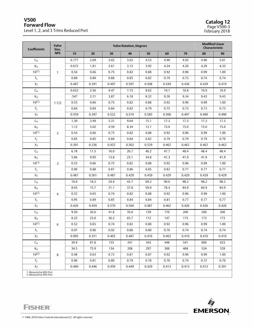
3
CoefficientsValveSize,NPS
Valve Rotation, DegreesModified LinearCharacteristic
10 20 30 40 50 60 70 80 90
CV
1
0.777 2.09 3.02 3.62 4.53 4.90 4.93 4.96 5.01
KV 0.672 1.81 2.61 3.13 3.92 4.24 4.26 4.29 4.33
Fd(1) 0.54 0.66 0.75 0.82 0.88 0.92 0.96 0.99 1.00
FL 0.89 0.89 0.88 0.85 0.82 0.79 0.75 0.74 0.74
XT 0.487 0.391 0.497 0.597 0.508 0.439 0.436 0.429 0.419
CV
1‐1/2
0.632 2.56 4.47 7.15 9.62 10.7 10.8 10.9 10.9
KV .547 2.21 3.87 6.18 8.32 9.26 9.34 9.43 9.43
Fd(1) 0.53 0.66 0.75 0.82 0.88 0.92 0.96 0.99 1.00
FL 0.84 0.84 0.84 0.82 0.79 0.75 0.73 0.73 0.73
XT 0.559 0.397 0.522 0.574 0.585 0.508 0.497 0.490 0.490
CV
2
1.30 3.49 5.31 9.64 15.1 17.3 17.3 17.3 17.3
KV 1.12 3.02 4.59 8.34 13.1 15.0 15.0 15.0 15.0
Fd(1) 0.54 0.66 0.75 0.82 0.88 0.92 0.96 0.99 1.00
FL 0.85 0.85 0.84 0.84 0.82 0.79 0.79 0.79 0.79
XT 0.391 0.336 0.452 0.563 0.529 0.462 0.462 0.462 0.462
CV
3
6.78 11.5 16.0 26.7 40.2 47.7 48.4 48.4 48.4
KV 5.86 9.95 13.8 23.1 34.8 41.3 41.9 41.9 41.9
Fd(1) 0.53 0.66 0.75 0.82 0.88 0.92 0.96 0.99 1.00
FL 0.90 0.88 0.87 0.86 0.85 0.82 0.77 0.77 0.77
XT 0.487 0.501 0.487 0.429 0.459 0.429 0.429 0.429 0.429
CV
4
10.0 18.2 24.4 43.7 69.2 90.6 98.2 98.2 98.2
KV 8.65 15.7 21.1 37.8 59.9 78.4 84.9 84.9 84.9
Fd(1) 0.52 0.65 0.74 0.82 0.88 0.92 0.96 0.99 1.00
FL 0.95 0.89 0.85 0.84 0.84 0.81 0.77 0.77 0.77
XT 0.426 0.459 0.570 0.504 0.487 0.462 0.426 0.426 0.426
CV
6
9.50 26.6 41.8 76.0 129 170 200 200 200
KV 8.22 23.0 36.2 65.7 112 147 173 173 173
Fd(1) 0.52 0.65 0.74 0.82 0.88 0.92 0.96 0.99 1.00
FL 0.97 0.96 0.92 0.86 0.80 0.76 0.74 0.74 0.74
XT 0.995 0.351 0.403 0.487 0.416 0.462 0.410 0.410 0.410
CV
8
39.9 87.8 155 241 343 448 541 606 623
KV 34.5 75.9 134 208 297 388 468 524 539
Fd(2) 0.48 0.63 0.73 0.81 0.87 0.92 0.96 0.99 1.00
FL 0.96 0.81 0.80 0.79 0.78 0.76 0.74 0.72 0.70
XT 0.400 0.446 0.459 0.449 0.429 0.413 0.413 0.413 0.391
1. Measured at 60% Port.2. Measured at 40% Port.
V500
Level 1, 2, and 3 Trims Reduced PortForward Flow
Catalog 12Page V500-3
February 2018
� 1988, 2018 Fisher Controls International LLC. All rights reserved
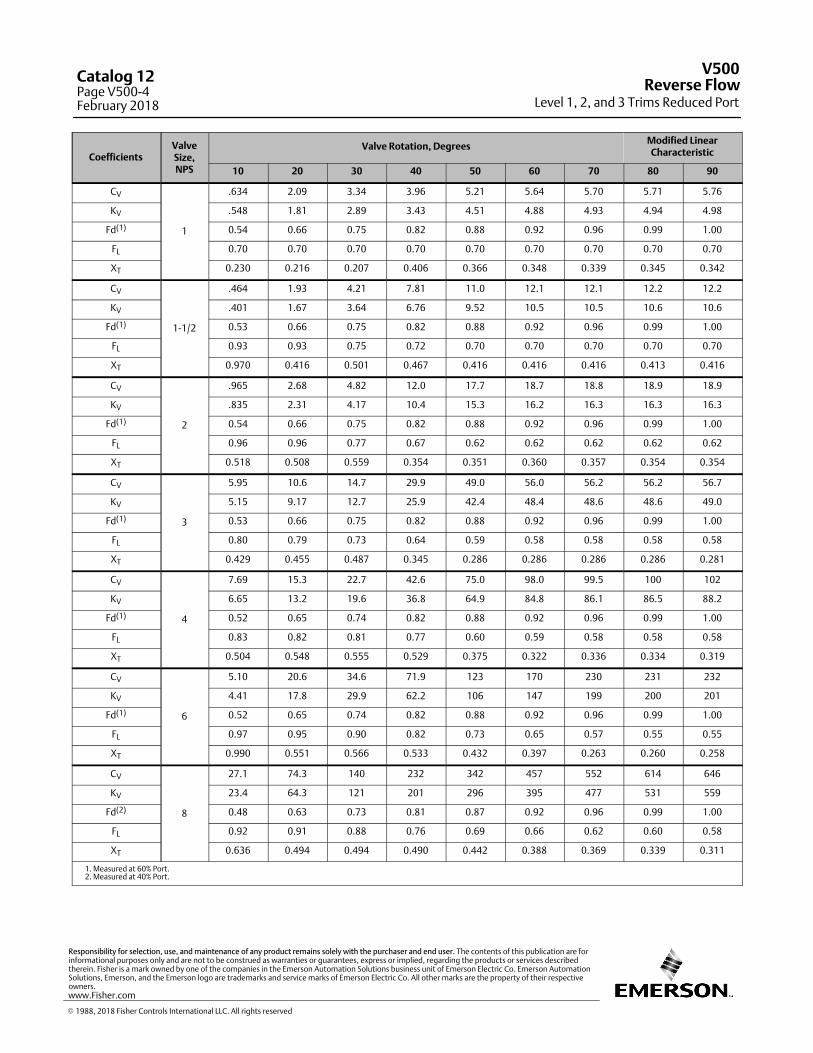
CoefficientsValveSize,NPS
Valve Rotation, DegreesModified LinearCharacteristic
10 20 30 40 50 60 70 80 90
CV
1
.634 2.09 3.34 3.96 5.21 5.64 5.70 5.71 5.76
KV .548 1.81 2.89 3.43 4.51 4.88 4.93 4.94 4.98
Fd(1) 0.54 0.66 0.75 0.82 0.88 0.92 0.96 0.99 1.00
FL 0.70 0.70 0.70 0.70 0.70 0.70 0.70 0.70 0.70
XT 0.230 0.216 0.207 0.406 0.366 0.348 0.339 0.345 0.342
CV
1‐1/2
.464 1.93 4.21 7.81 11.0 12.1 12.1 12.2 12.2
KV .401 1.67 3.64 6.76 9.52 10.5 10.5 10.6 10.6
Fd(1) 0.53 0.66 0.75 0.82 0.88 0.92 0.96 0.99 1.00
FL 0.93 0.93 0.75 0.72 0.70 0.70 0.70 0.70 0.70
XT 0.970 0.416 0.501 0.467 0.416 0.416 0.416 0.413 0.416
CV
2
.965 2.68 4.82 12.0 17.7 18.7 18.8 18.9 18.9
KV .835 2.31 4.17 10.4 15.3 16.2 16.3 16.3 16.3
Fd(1) 0.54 0.66 0.75 0.82 0.88 0.92 0.96 0.99 1.00
FL 0.96 0.96 0.77 0.67 0.62 0.62 0.62 0.62 0.62
XT 0.518 0.508 0.559 0.354 0.351 0.360 0.357 0.354 0.354
CV
3
5.95 10.6 14.7 29.9 49.0 56.0 56.2 56.2 56.7
KV 5.15 9.17 12.7 25.9 42.4 48.4 48.6 48.6 49.0
Fd(1) 0.53 0.66 0.75 0.82 0.88 0.92 0.96 0.99 1.00
FL 0.80 0.79 0.73 0.64 0.59 0.58 0.58 0.58 0.58
XT 0.429 0.455 0.487 0.345 0.286 0.286 0.286 0.286 0.281
CV
4
7.69 15.3 22.7 42.6 75.0 98.0 99.5 100 102
KV 6.65 13.2 19.6 36.8 64.9 84.8 86.1 86.5 88.2
Fd(1) 0.52 0.65 0.74 0.82 0.88 0.92 0.96 0.99 1.00
FL 0.83 0.82 0.81 0.77 0.60 0.59 0.58 0.58 0.58
XT 0.504 0.548 0.555 0.529 0.375 0.322 0.336 0.334 0.319
CV
6
5.10 20.6 34.6 71.9 123 170 230 231 232
KV 4.41 17.8 29.9 62.2 106 147 199 200 201
Fd(1) 0.52 0.65 0.74 0.82 0.88 0.92 0.96 0.99 1.00
FL 0.97 0.95 0.90 0.82 0.73 0.65 0.57 0.55 0.55
XT 0.990 0.551 0.566 0.533 0.432 0.397 0.263 0.260 0.258
CV
8
27.1 74.3 140 232 342 457 552 614 646
KV 23.4 64.3 121 201 296 395 477 531 559
Fd(2) 0.48 0.63 0.73 0.81 0.87 0.92 0.96 0.99 1.00
FL 0.92 0.91 0.88 0.76 0.69 0.66 0.62 0.60 0.58
XT 0.636 0.494 0.494 0.490 0.442 0.388 0.369 0.339 0.311
1. Measured at 60% Port.2. Measured at 40% Port.
V500
Level 1, 2, and 3 Trims Reduced PortReverse Flow
Catalog 12Page V500-4February 2018
� 1988, 2018 Fisher Controls International LLC. All rights reserved
www.Fisher.com
Responsibility for selection, use, and maintenance of any product remains solely with the purchaser and end user. The contents of this publication are forinformational purposes only and are not to be construed as warranties or guarantees, express or implied, regarding the products or services describedtherein. Fisher is a mark owned by one of the companies in the Emerson Automation Solutions business unit of Emerson Electric Co. Emerson AutomationSolutions, Emerson, and the Emerson logo are trademarks and service marks of Emerson Electric Co. All other marks are the property of their respectiveowners.
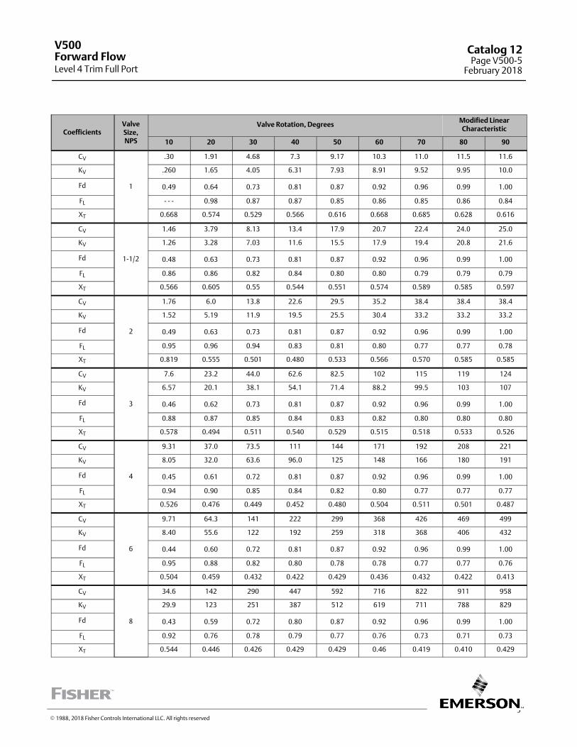
5
CoefficientsValveSize,NPS
Valve Rotation, DegreesModified LinearCharacteristic
10 20 30 40 50 60 70 80 90
CV
1
.30 1.91 4.68 7.3 9.17 10.3 11.0 11.5 11.6
KV .260 1.65 4.05 6.31 7.93 8.91 9.52 9.95 10.0
Fd 0.49 0.64 0.73 0.81 0.87 0.92 0.96 0.99 1.00
FL ‐ ‐ ‐ 0.98 0.87 0.87 0.85 0.86 0.85 0.86 0.84
XT 0.668 0.574 0.529 0.566 0.616 0.668 0.685 0.628 0.616
CV
1‐1/2
1.46 3.79 8.13 13.4 17.9 20.7 22.4 24.0 25.0
KV 1.26 3.28 7.03 11.6 15.5 17.9 19.4 20.8 21.6
Fd 0.48 0.63 0.73 0.81 0.87 0.92 0.96 0.99 1.00
FL 0.86 0.86 0.82 0.84 0.80 0.80 0.79 0.79 0.79
XT 0.566 0.605 0.55 0.544 0.551 0.574 0.589 0.585 0.597
CV
2
1.76 6.0 13.8 22.6 29.5 35.2 38.4 38.4 38.4
KV 1.52 5.19 11.9 19.5 25.5 30.4 33.2 33.2 33.2
Fd 0.49 0.63 0.73 0.81 0.87 0.92 0.96 0.99 1.00
FL 0.95 0.96 0.94 0.83 0.81 0.80 0.77 0.77 0.78
XT 0.819 0.555 0.501 0.480 0.533 0.566 0.570 0.585 0.585
CV
3
7.6 23.2 44.0 62.6 82.5 102 115 119 124
KV 6.57 20.1 38.1 54.1 71.4 88.2 99.5 103 107
Fd 0.46 0.62 0.73 0.81 0.87 0.92 0.96 0.99 1.00
FL 0.88 0.87 0.85 0.84 0.83 0.82 0.80 0.80 0.80
XT 0.578 0.494 0.511 0.540 0.529 0.515 0.518 0.533 0.526
CV
4
9.31 37.0 73.5 111 144 171 192 208 221
KV 8.05 32.0 63.6 96.0 125 148 166 180 191
Fd 0.45 0.61 0.72 0.81 0.87 0.92 0.96 0.99 1.00
FL 0.94 0.90 0.85 0.84 0.82 0.80 0.77 0.77 0.77
XT 0.526 0.476 0.449 0.452 0.480 0.504 0.511 0.501 0.487
CV
6
9.71 64.3 141 222 299 368 426 469 499
KV 8.40 55.6 122 192 259 318 368 406 432
Fd 0.44 0.60 0.72 0.81 0.87 0.92 0.96 0.99 1.00
FL 0.95 0.88 0.82 0.80 0.78 0.78 0.77 0.77 0.76
XT 0.504 0.459 0.432 0.422 0.429 0.436 0.432 0.422 0.413
CV
8
34.6 142 290 447 592 716 822 911 958
KV 29.9 123 251 387 512 619 711 788 829
Fd 0.43 0.59 0.72 0.80 0.87 0.92 0.96 0.99 1.00
FL 0.92 0.76 0.78 0.79 0.77 0.76 0.73 0.71 0.73
XT 0.544 0.446 0.426 0.429 0.429 0.46 0.419 0.410 0.429
V500
Level 4 Trim Full PortForward Flow
Catalog 12Page V500-5
February 2018
� 1988, 2018 Fisher Controls International LLC. All rights reserved
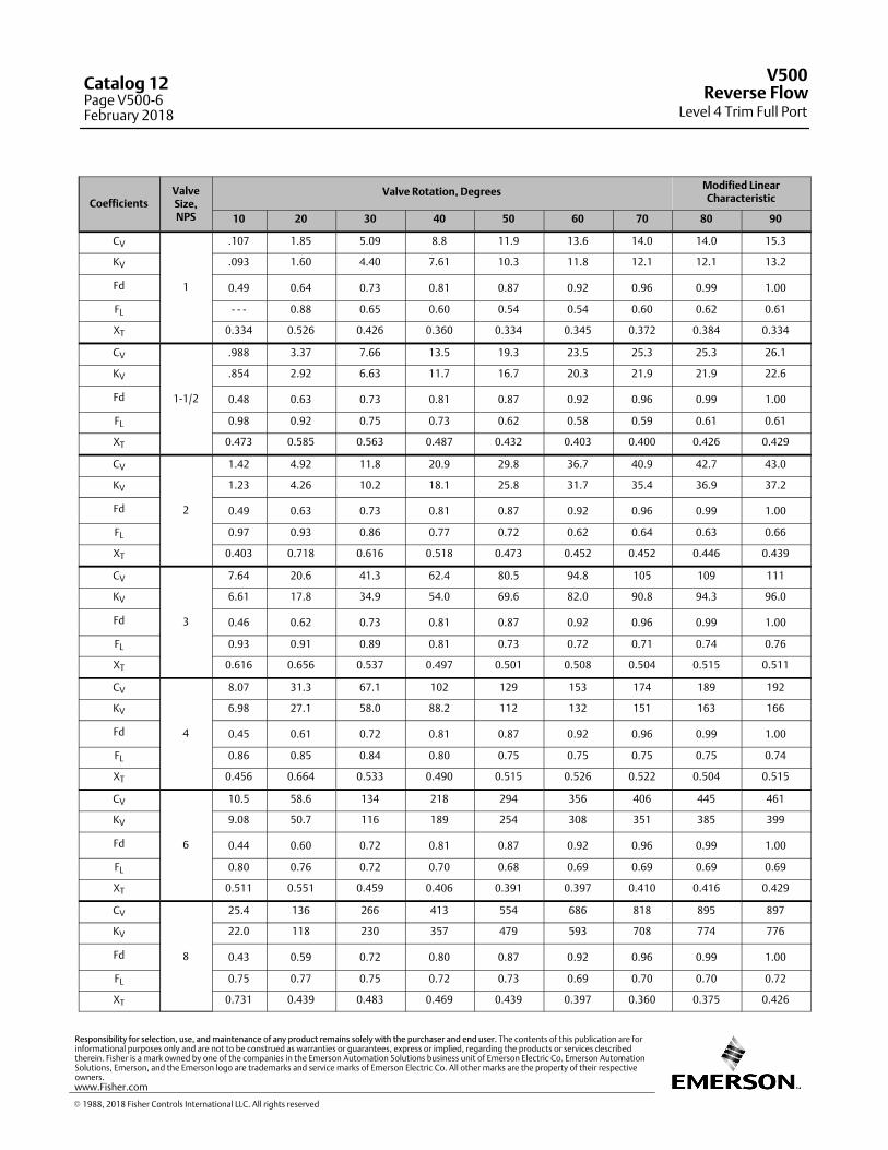
CoefficientsValveSize,NPS
Valve Rotation, DegreesModified LinearCharacteristic
10 20 30 40 50 60 70 80 90
CV
1
.107 1.85 5.09 8.8 11.9 13.6 14.0 14.0 15.3
KV .093 1.60 4.40 7.61 10.3 11.8 12.1 12.1 13.2
Fd 0.49 0.64 0.73 0.81 0.87 0.92 0.96 0.99 1.00
FL ‐ ‐ ‐ 0.88 0.65 0.60 0.54 0.54 0.60 0.62 0.61
XT 0.334 0.526 0.426 0.360 0.334 0.345 0.372 0.384 0.334
CV
1‐1/2
.988 3.37 7.66 13.5 19.3 23.5 25.3 25.3 26.1
KV .854 2.92 6.63 11.7 16.7 20.3 21.9 21.9 22.6
Fd 0.48 0.63 0.73 0.81 0.87 0.92 0.96 0.99 1.00
FL 0.98 0.92 0.75 0.73 0.62 0.58 0.59 0.61 0.61
XT 0.473 0.585 0.563 0.487 0.432 0.403 0.400 0.426 0.429
CV
2
1.42 4.92 11.8 20.9 29.8 36.7 40.9 42.7 43.0
KV 1.23 4.26 10.2 18.1 25.8 31.7 35.4 36.9 37.2
Fd 0.49 0.63 0.73 0.81 0.87 0.92 0.96 0.99 1.00
FL 0.97 0.93 0.86 0.77 0.72 0.62 0.64 0.63 0.66
XT 0.403 0.718 0.616 0.518 0.473 0.452 0.452 0.446 0.439
CV
3
7.64 20.6 41.3 62.4 80.5 94.8 105 109 111
KV 6.61 17.8 34.9 54.0 69.6 82.0 90.8 94.3 96.0
Fd 0.46 0.62 0.73 0.81 0.87 0.92 0.96 0.99 1.00
FL 0.93 0.91 0.89 0.81 0.73 0.72 0.71 0.74 0.76
XT 0.616 0.656 0.537 0.497 0.501 0.508 0.504 0.515 0.511
CV
4
8.07 31.3 67.1 102 129 153 174 189 192
KV 6.98 27.1 58.0 88.2 112 132 151 163 166
Fd 0.45 0.61 0.72 0.81 0.87 0.92 0.96 0.99 1.00
FL 0.86 0.85 0.84 0.80 0.75 0.75 0.75 0.75 0.74
XT 0.456 0.664 0.533 0.490 0.515 0.526 0.522 0.504 0.515
CV
6
10.5 58.6 134 218 294 356 406 445 461
KV 9.08 50.7 116 189 254 308 351 385 399
Fd 0.44 0.60 0.72 0.81 0.87 0.92 0.96 0.99 1.00
FL 0.80 0.76 0.72 0.70 0.68 0.69 0.69 0.69 0.69
XT 0.511 0.551 0.459 0.406 0.391 0.397 0.410 0.416 0.429
CV
8
25.4 136 266 413 554 686 818 895 897
KV 22.0 118 230 357 479 593 708 774 776
Fd 0.43 0.59 0.72 0.80 0.87 0.92 0.96 0.99 1.00
FL 0.75 0.77 0.75 0.72 0.73 0.69 0.70 0.70 0.72
XT 0.731 0.439 0.483 0.469 0.439 0.397 0.360 0.375 0.426
V500
Level 4 Trim Full PortReverse Flow
Catalog 12Page V500-6February 2018
� 1988, 2018 Fisher Controls International LLC. All rights reserved
www.Fisher.com
Responsibility for selection, use, and maintenance of any product remains solely with the purchaser and end user. The contents of this publication are forinformational purposes only and are not to be construed as warranties or guarantees, express or implied, regarding the products or services describedtherein. Fisher is a mark owned by one of the companies in the Emerson Automation Solutions business unit of Emerson Electric Co. Emerson AutomationSolutions, Emerson, and the Emerson logo are trademarks and service marks of Emerson Electric Co. All other marks are the property of their respectiveowners.
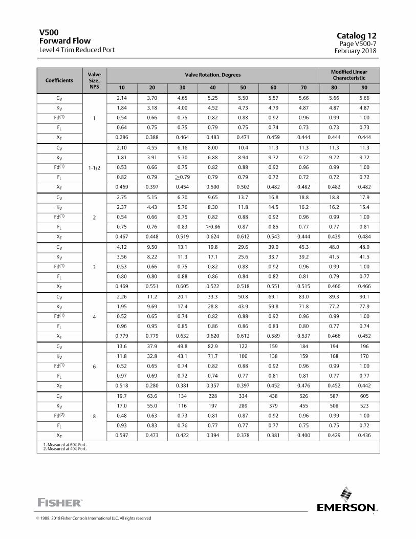
7
CoefficientsValveSize,NPS
Valve Rotation, DegreesModified LinearCharacteristic
10 20 30 40 50 60 70 80 90
CV
1
2.14 3.70 4.65 5.25 5.50 5.57 5.66 5.66 5.66
KV 1.84 3.18 4.00 4.52 4.73 4.79 4.87 4.87 4.87
Fd(1) 0.54 0.66 0.75 0.82 0.88 0.92 0.96 0.99 1.00
FL 0.64 0.75 0.75 0.79 0.75 0.74 0.73 0.73 0.73
XT 0.286 0.388 0.464 0.483 0.471 0.459 0.444 0.444 0.444
CV
1‐1/2
2.10 4.55 6.16 8.00 10.4 11.3 11.3 11.3 11.3
KV 1.81 3.91 5.30 6.88 8.94 9.72 9.72 9.72 9.72
Fd(1) 0.53 0.66 0.75 0.82 0.88 0.92 0.96 0.99 1.00
FL 0.82 0.79 �0.79 0.79 0.79 0.72 0.72 0.72 0.72
XT 0.469 0.397 0.454 0.500 0.502 0.482 0.482 0.482 0.482
CV
2
2.75 5.15 6.70 9.65 13.7 16.8 18.8 18.8 17.9
KV 2.37 4.43 5.76 8.30 11.8 14.5 16.2 16.2 15.4
Fd(1) 0.54 0.66 0.75 0.82 0.88 0.92 0.96 0.99 1.00
FL 0.75 0.76 0.83 �0.86 0.87 0.85 0.77 0.77 0.81
XT 0.467 0.448 0.519 0.624 0.612 0.543 0.444 0.439 0.484
CV
3
4.12 9.50 13.1 19.8 29.6 39.0 45.3 48.0 48.0
KV 3.56 8.22 11.3 17.1 25.6 33.7 39.2 41.5 41.5
Fd(1) 0.53 0.66 0.75 0.82 0.88 0.92 0.96 0.99 1.00
FL 0.80 0.80 0.88 0.86 0.84 0.82 0.81 0.79 0.77
XT 0.469 0.551 0.605 0.522 0.518 0.551 0.515 0.466 0.466
CV
4
2.26 11.2 20.1 33.3 50.8 69.1 83.0 89.3 90.1
KV 1.95 9.69 17.4 28.8 43.9 59.8 71.8 77.2 77.9
Fd(1) 0.52 0.65 0.74 0.82 0.88 0.92 0.96 0.99 1.00
FL 0.96 0.95 0.85 0.86 0.86 0.83 0.80 0.77 0.74
XT 0.779 0.779 0.632 0.620 0.612 0.589 0.537 0.466 0.452
CV
6
13.6 37.9 49.8 82.9 122 159 184 194 196
KV 11.8 32.8 43.1 71.7 106 138 159 168 170
Fd(1) 0.52 0.65 0.74 0.82 0.88 0.92 0.96 0.99 1.00
FL 0.97 0.69 0.72 0.74 0.77 0.81 0.81 0.77 0.77
XT 0.518 0.280 0.381 0.357 0.397 0.452 0.476 0.452 0.442
CV
8
19.7 63.6 134 228 334 438 526 587 605
KV 17.0 55.0 116 197 289 379 455 508 523
Fd(2) 0.48 0.63 0.73 0.81 0.87 0.92 0.96 0.99 1.00
FL 0.93 0.83 0.76 0.77 0.77 0.77 0.75 0.75 0.72
XT 0.597 0.473 0.422 0.394 0.378 0.381 0.400 0.429 0.436
1. Measured at 60% Port.2. Measured at 40% Port.
V500
Level 4 Trim Reduced PortForward Flow
Catalog 12Page V500-7
February 2018
� 1988, 2018 Fisher Controls International LLC. All rights reserved

CoefficientsValveSize,NPS
Valve Rotation, DegreesModified LinearCharacteristic
10 20 30 40 50 60 70 80 90
CV
1
1.90 3.80 4.85 5.82 5.90 5.90 5.90 5.90 5.90
KV 1.63 3.27 4.17 5.01 5.07 5.07 5.07 5.07 5.07
Fd(1) 0.54 0.66 0.75 0.82 0.88 0.92 0.96 0.99 1.00
FL 0.56 0.67 0.68 0.69 0.73 0.75 0.75 0.75 0.75
XT 0.312 0.386 0.427 0.409 0.448 0.448 0.448 0.448 0.448
CV
1‐1/2
1.95 4.45 5.75 7.75 11.4 11.8 11.8 11.8 11.8
KV 1.68 3.83 4.95 6.67 9.80 10.2 10.2 10.2 10.2
Fd(1) 0.53 0.66 0.75 0.82 0.88 0.92 0.96 0.99 1.00
FL 0.83 0.77 0.78 0.76 0.68 0.72 0.73 0.73 0.73
XT 0.395 0.415 0.527 0.519 0.421 0.459 0.459 0.459 0.459
CV
2
2.70 4.65 6.30 11.1 18.3 19.8 20.2 20.4 21.0
KV 2.32 4.00 5.42 9.55 15.7 17.0 17.4 17.5 18.1
Fd(1) 0.54 0.66 0.75 0.82 0.88 0.92 0.96 0.99 1.00
FL 0.91 0.89 0.84 0.71 0.58 0.61 0.62 0.62 0.60
XT 0.459 0.464 0.594 0.453 0.307 0.358 0.366 0.337 0.328
CV
3
4.41 9.60 13.7 19.5 37.3 53.3 56.7 57.9 57.9
KV 3.81 8.30 11.9 16.9 32.3 46.1 49.0 50.1 50.1
Fd(1) 0.53 0.66 0.75 0.82 0.88 0.92 0.96 0.99 1.00
FL 0.96 0.93 0.93 0.87 0.73 0.64 0.62 0.62 0.63
XT 0.469 0.578 0.578 0.537 0.319 0.258 0.265 0.268 0.268
CV
4
9.78 11.1 19.4 32.1 49.7 67.8 80.5 84.6 86.6
KV 8.46 9.60 16.8 27.8 43.0 58.6 69.6 73.2 74.9
Fd(1) 0.52 0.65 0.74 0.82 0.88 0.92 0.96 0.99 1.00
FL 0.93 0.93 0.89 0.84 0.79 0.72 0.64 0.65 0.65
XT 0.620 0.620 0.593 0.605 0.570 0.522 0.476 0.459 0.436
CV
6
10.6 30.0 43.4 77.1 122 168 198 223 226
KV 9.17 26.0 37.5 66.7 106 145 171 193 195
Fd(1) 0.52 0.65 0.74 0.82 0.88 0.92 0.96 0.99 1.00
FL 0.77 0.79 0.77 0.75 0.69 0.64 0.63 0.58 0.58
XT 0.640 0.369 0.476 0.410 0.381 0.357 0.336 0.284 0.278
CV
8
19.8 55.8 125 222 323 413 488 549 569
KV 17.1 48.3 108 192 279 357 422 475 492
Fd(2) 0.48 0.63 0.73 0.81 0.87 0.92 0.96 0.99 1.00
FL 0.75 0.77 0.78 0.75 0.70 0.68 0.70 0.68 0.70
XT 0.459 0.581 0.462 0.394 0.375 0.381 0.391 0.391 0.391
1. Measured at 60% Port.2. Measured at 40% Port.
V500
Level 4 Trim Reduced PortReverse Flow
Catalog 12Page V500-8February 2018
� 1988, 2018 Fisher Controls International LLC. All rights reserved
www.Fisher.com
Responsibility for selection, use, and maintenance of any product remains solely with the purchaser and end user. The contents of this publication are forinformational purposes only and are not to be construed as warranties or guarantees, express or implied, regarding the products or services describedtherein. Fisher is a mark owned by one of the companies in the Emerson Automation Solutions business unit of Emerson Electric Co. Emerson AutomationSolutions, Emerson, and the Emerson logo are trademarks and service marks of Emerson Electric Co. All other marks are the property of their respectiveowners.
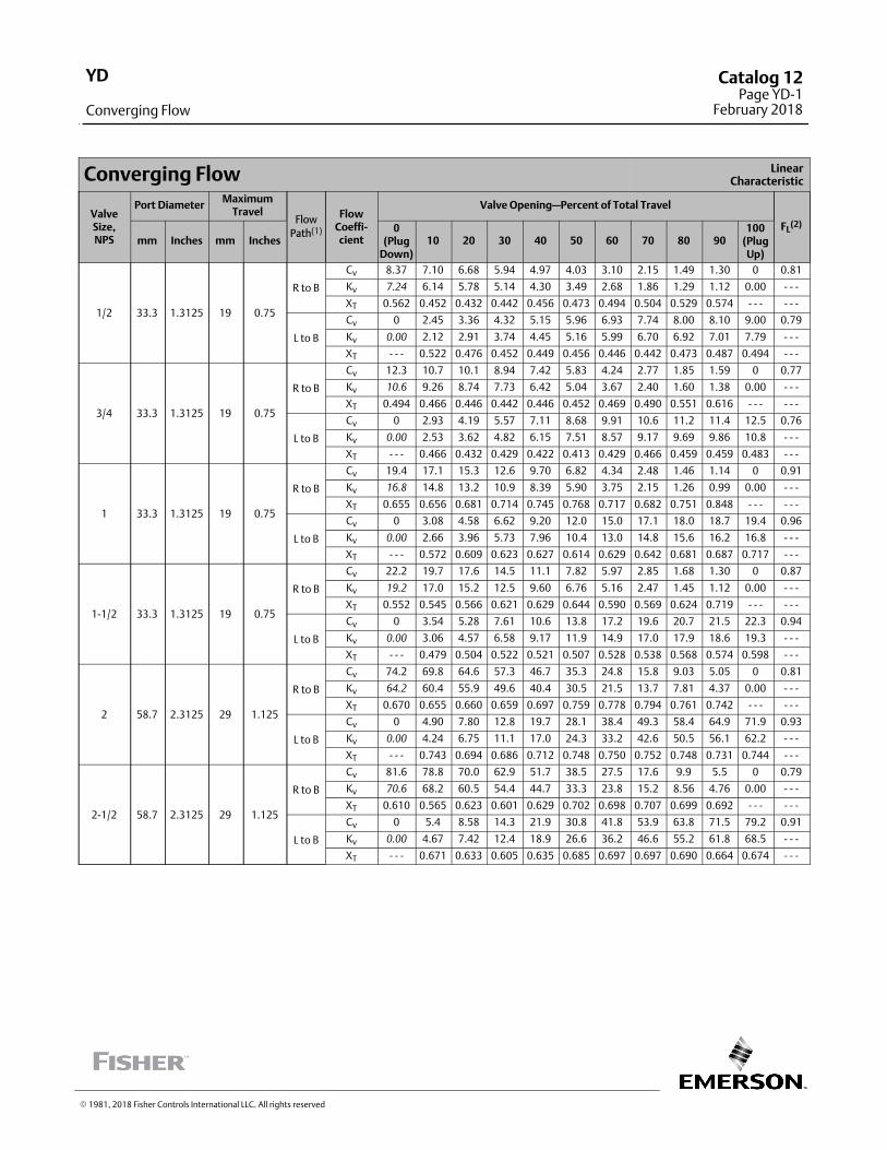
Converging Flow LinearCharacteristic
ValveSize,NPS
Port DiameterMaximum
TravelFlow
Path(1)
FlowCoeffi‐cient
Valve Opening—Percent of Total Travel
FL(2)
mm Inches mm Inches0
(PlugDown)
10 20 30 40 50 60 70 80 90100
(PlugUp)
1/2 33.3 1.3125 19 0.75
R to B
Cv 8.37 7.10 6.68 5.94 4.97 4.03 3.10 2.15 1.49 1.30 0 0.81
Kv 7.24 6.14 5.78 5.14 4.30 3.49 2.68 1.86 1.29 1.12 0.00 ‐ ‐ ‐
XT 0.562 0.452 0.432 0.442 0.456 0.473 0.494 0.504 0.529 0.574 ‐ ‐ ‐ ‐ ‐ ‐
L to B
Cv 0 2.45 3.36 4.32 5.15 5.96 6.93 7.74 8.00 8.10 9.00 0.79
Kv 0.00 2.12 2.91 3.74 4.45 5.16 5.99 6.70 6.92 7.01 7.79 ‐ ‐ ‐
XT ‐ ‐ ‐ 0.522 0.476 0.452 0.449 0.456 0.446 0.442 0.473 0.487 0.494 ‐ ‐ ‐
3/4 33.3 1.3125 19 0.75
R to B
Cv 12.3 10.7 10.1 8.94 7.42 5.83 4.24 2.77 1.85 1.59 0 0.77
Kv 10.6 9.26 8.74 7.73 6.42 5.04 3.67 2.40 1.60 1.38 0.00 ‐ ‐ ‐
XT 0.494 0.466 0.446 0.442 0.446 0.452 0.469 0.490 0.551 0.616 ‐ ‐ ‐ ‐ ‐ ‐
L to B
Cv 0 2.93 4.19 5.57 7.11 8.68 9.91 10.6 11.2 11.4 12.5 0.76
Kv 0.00 2.53 3.62 4.82 6.15 7.51 8.57 9.17 9.69 9.86 10.8 ‐ ‐ ‐
XT ‐ ‐ ‐ 0.466 0.432 0.429 0.422 0.413 0.429 0.466 0.459 0.459 0.483 ‐ ‐ ‐
1 33.3 1.3125 19 0.75
R to B
Cv 19.4 17.1 15.3 12.6 9.70 6.82 4.34 2.48 1.46 1.14 0 0.91
Kv 16.8 14.8 13.2 10.9 8.39 5.90 3.75 2.15 1.26 0.99 0.00 ‐ ‐ ‐
XT 0.655 0.656 0.681 0.714 0.745 0.768 0.717 0.682 0.751 0.848 ‐ ‐ ‐ ‐ ‐ ‐
L to B
Cv 0 3.08 4.58 6.62 9.20 12.0 15.0 17.1 18.0 18.7 19.4 0.96
Kv 0.00 2.66 3.96 5.73 7.96 10.4 13.0 14.8 15.6 16.2 16.8 ‐ ‐ ‐
XT ‐ ‐ ‐ 0.572 0.609 0.623 0.627 0.614 0.629 0.642 0.681 0.687 0.717 ‐ ‐ ‐
1‐1/2 33.3 1.3125 19 0.75
R to B
Cv 22.2 19.7 17.6 14.5 11.1 7.82 5.97 2.85 1.68 1.30 0 0.87
Kv 19.2 17.0 15.2 12.5 9.60 6.76 5.16 2.47 1.45 1.12 0.00 ‐ ‐ ‐
XT 0.552 0.545 0.566 0.621 0.629 0.644 0.590 0.569 0.624 0.719 ‐ ‐ ‐ ‐ ‐ ‐
L to B
Cv 0 3.54 5.28 7.61 10.6 13.8 17.2 19.6 20.7 21.5 22.3 0.94
Kv 0.00 3.06 4.57 6.58 9.17 11.9 14.9 17.0 17.9 18.6 19.3 ‐ ‐ ‐
XT ‐ ‐ ‐ 0.479 0.504 0.522 0.521 0.507 0.528 0.538 0.568 0.574 0.598 ‐ ‐ ‐
2 58.7 2.3125 29 1.125
R to B
Cv 74.2 69.8 64.6 57.3 46.7 35.3 24.8 15.8 9.03 5.05 0 0.81
Kv 64.2 60.4 55.9 49.6 40.4 30.5 21.5 13.7 7.81 4.37 0.00 ‐ ‐ ‐
XT 0.670 0.655 0.660 0.659 0.697 0.759 0.778 0.794 0.761 0.742 ‐ ‐ ‐ ‐ ‐ ‐
L to B
Cv 0 4.90 7.80 12.8 19.7 28.1 38.4 49.3 58.4 64.9 71.9 0.93
Kv 0.00 4.24 6.75 11.1 17.0 24.3 33.2 42.6 50.5 56.1 62.2 ‐ ‐ ‐
XT ‐ ‐ ‐ 0.743 0.694 0.686 0.712 0.748 0.750 0.752 0.748 0.731 0.744 ‐ ‐ ‐
2‐1/2 58.7 2.3125 29 1.125
R to B
Cv 81.6 78.8 70.0 62.9 51.7 38.5 27.5 17.6 9.9 5.5 0 0.79
Kv 70.6 68.2 60.5 54.4 44.7 33.3 23.8 15.2 8.56 4.76 0.00 ‐ ‐ ‐
XT 0.610 0.565 0.623 0.601 0.629 0.702 0.698 0.707 0.699 0.692 ‐ ‐ ‐ ‐ ‐ ‐
L to B
Cv 0 5.4 8.58 14.3 21.9 30.8 41.8 53.9 63.8 71.5 79.2 0.91
Kv 0.00 4.67 7.42 12.4 18.9 26.6 36.2 46.6 55.2 61.8 68.5 ‐ ‐ ‐
XT ‐ ‐ ‐ 0.671 0.633 0.605 0.635 0.685 0.697 0.697 0.690 0.664 0.674 ‐ ‐ ‐
� 1981, 2018 Fisher Controls International LLC. All rights reserved
YD
Converging Flow
Catalog 12Page YD-1
February 2018
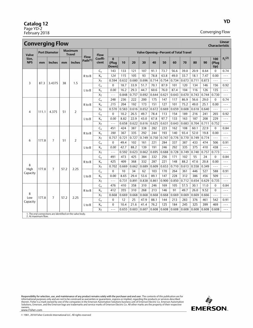
Converging Flow LinearCharacteristic
ValveSize,NPS
Port DiameterMaximum
TravelFlow
Path(1)
FlowCoeffi‐cient
Valve Opening—Percent of Total Travel
FL(2)
mm Inches mm Inches0
(PlugDown)
10 20 30 40 50 60 70 80 90100
(PlugUp)
3 87.3 3.4375 38 1.5
R to B
Cv 143 133 121 107 91.1 73.7 56.6 39.0 20.9 8.64 0 0.74
Kv 124 115 105 93 78.8 63.8 49.0 33.7 18.1 7.47 0.00 ‐ ‐ ‐
XT 0.594 0.632 0.680 0.696 0.714 0.754 0.734 0.673 0.711 0.873 ‐ ‐ ‐ ‐ ‐ ‐
L to B
Cv 0 18.7 33.9 51.7 70.1 87.9 101 120 134 146 156 0.92
Kv 0.00 16.2 29.3 44.7 60.6 76.0 87.4 104 116 126 135 ‐ ‐ ‐
XT ‐ ‐ ‐ 0.848 0.757 0.692 0.644 0.621 0.643 0.670 0.743 0.744 0.730 ‐ ‐ ‐
4 111.1 4.375 51 2
R to B
Cv 248 236 222 200 175 147 117 86.9 56.6 29.0 0 0.74
Kv 215 204 192 173 151 127 101 75.2 49.0 25.1 0.00 ‐ ‐ ‐
XT 0.570 0.583 0.616 0.652 0.672 0.669 0.659 0.608 0.618 0.640 ‐ ‐ ‐ ‐ ‐ ‐
L to B
Cv 0 10.2 26.5 49.7 78.4 113 154 189 216 241 265 0.92
Kv 0.00 8.82 22.9 43.0 67.8 97.7 133 163 187 208 229 ‐ ‐ ‐
XT ‐ ‐ ‐ 0.658 0.622 0.616 0.625 0.631 0.643 0.683 0.704 0.711 0.752 ‐ ‐ ‐
6 177.8 7 51 2
R to B
Cv 451 424 387 338 282 223 162 108 60.1 22.9 0 0.84
Kv 390 367 335 292 244 193 140 93.4 52.0 19.8 0.00 ‐ ‐ ‐
XT 0.757 0.721 0.727 0.749 0.750 0.747 0.776 0.770 0.749 0.774 ‐ ‐ ‐ ‐ ‐ ‐
L to B
Cv 0 49.4 102 161 221 284 337 387 433 474 506 0.91
Kv 0.00 42.7 88.2 139 191 246 292 335 375 410 438 ‐ ‐ ‐
XT ‐ ‐ ‐ 0.592 0.623 0.662 0.695 0.688 0.728 0.749 0.740 0.757 0.773 ‐ ‐ ‐
8
High
Capacity177.8 7 57.2 2.25
R to B
Cv 491 473 425 384 332 256 171 102 55 24 0 0.84
Kv 425 409 368 332 287 221 148 88.2 47.6 20.8 0.00 ‐ ‐ ‐
XT 0.702 0.669 0.662 0.689 0.609 0.653 0.710 0.613 0.558 0.349 ‐ ‐ ‐ ‐ ‐ ‐
L to B
Cv 0 10 34 62 103 170 264 361 446 527 588 0.91
Kv 0.00 8.65 29.4 53.6 89.1 147 228 312 386 456 509 ‐ ‐ ‐
XT ‐ ‐ ‐ 0.731 0.891 0.838 0.861 0.900 0.850 0.712 0.654 0.629 0.735 ‐ ‐ ‐
8
Low
Capacity177.8 7 57.2 2.25
R to B
Cv 476 410 358 310 246 169 105 57.5 30.1 11.0 0 0.84
Kv 412 355 310 268 213 146 91 49.7 26.0 9.52 0 ‐ ‐ ‐
XT 0.668 0.669 0.668 0.668 0.668 0.668 0.669 0.669 0.669 0.666 ‐ ‐ ‐ ‐ ‐ ‐
L to B
Cv 0 12 25 47.9 88.1 144 213 283 376 461 542 0.91
Kv 0 10.4 21.6 41.4 76.2 125 184 245 325 399 469 ‐ ‐ ‐
XT ‐ ‐ ‐ 0.655 0.603 0.607 0.608 0.608 0.608 0.608 0.608 0.608 0.608 ‐ ‐ ‐
1. The end connections are identified on the valve body.2. At maximum flow.
YD
Converging Flow
Catalog 12Page YD-2February 2018
� 1981, 2018 Fisher Controls International LLC. All rights reserved
www.Fisher.com
Responsibility for selection, use, and maintenance of any product remains solely with the purchaser and end user. The contents of this publication are forinformational purposes only and are not to be construed as warranties or guarantees, express or implied, regarding the products or services describedtherein. Fisher is a mark owned by one of the companies in the Emerson Automation Solutions business unit of Emerson Electric Co. Emerson AutomationSolutions, Emerson, and the Emerson logo are trademarks and service marks of Emerson Electric Co. All other marks are the property of their respectiveowners.
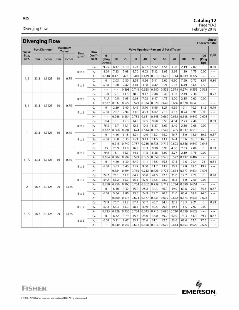
3
Diverging Flow LinearCharacteristic
ValveSize,NPS
Port DiameterMaximum
TravelFlow
Path(1)
FlowCoeffi‐cient
Valve Opening—Percent of Total Travel
FL(2)
mm Inches mm Inches0
(PlugDown)
10 20 30 40 50 60 70 80 90100
(PlugUp)
1/2 33.3 1.3125 19 0.75
B to R
Cv 9.25 8.47 8.19 7.74 6.97 5.92 4.54 3.08 2.19 2.02 0 0.80
Kv 8.00 7.33 7.08 6.70 6.03 5.12 3.93 2.66 1.89 1.75 0.00 ‐ ‐ ‐
XT 0.518 0.473 422 0.410 0.439 0.515 0.620 0.714 0.689 0.727 ‐ ‐ ‐ ‐ ‐ ‐
B to L
Cv 0 2.08 2.80 3.51 4.26 5.11 6.02 6.90 7.50 7.72 8.67 0.80
Kv 0.00 1.80 2.42 3.04 3.68 4.42 5.21 5.97 6.49 6.68 7.50 ‐ ‐ ‐
XT ‐ ‐ ‐ ‐ ‐ ‐ 0.898 0.744 0.628 0.540 0.533 0.578 0.574 0.555 0.563 ‐ ‐ ‐
3/4 33.3 1.3125 19 0.75
B to R
Cv 13.0 12.1 11.5 10.5 9.17 7.48 5.49 3.57 2.49 2.34 0 0.77
Kv 11.2 10.5 9.95 9.08 7.93 6.47 4.75 3.09 2.15 2.02 0.00 ‐ ‐ ‐
XT 0.537 0.537 0.522 0.529 0.574 0.628 0.648 0.636 0.620 0.648 ‐ ‐ ‐ ‐ ‐ ‐
B to L
Cv 0 2.39 3.40 4.46 5.70 6.96 8.21 9.39 10.1 10.3 11.5 0.79
Kv 0.00 2.07 2.94 3.86 4.93 6.02 7.10 8.12 8.74 8.91 9.95 ‐ ‐ ‐
XT ‐ ‐ ‐ 0.946 0.884 0.783 0.681 0.648 0.660 0.668 0.648 0.640 0.608 ‐ ‐ ‐
1 33.3 1.3125 19 0.75
B to R
Cv 19.4 18.1 16.3 14.5 12.5 9.68 6.58 4.04 2.73 2.40 0 0.89
Kv 16.8 15.7 14.1 12.5 10.8 8.37 5.69 3.49 2.36 2.08 0.00 ‐ ‐ ‐
XT 0.632 0.666 0.694 0.674 0.614 0.616 0.549 0.455 0.537 0.515 ‐ ‐ ‐ ‐ ‐ ‐
B to L
Cv 0 4.16 6.18 8.34 10.9 13.3 15.2 16.7 18.0 18.9 19.2 0.87
Kv 0.00 3.60 5.35 7.21 9.43 11.5 13.1 14.4 15.6 16.3 16.6 ‐ ‐ ‐
XT ‐ ‐ ‐ 0.718 0.749 0.787 0.756 0.738 0.712 0.693 0.656 0.640 0.648 ‐ ‐ ‐
1‐1/2 33.3 1.3125 19 0.75
B to R
Cv 23 20.9 18.9 16.8 13.3 9.90 6.90 4.36 2.53 2.06 0 0.89
Kv 19.9 18.1 16.3 14.5 11.5 8.56 5.97 3.77 2.19 1.78 0.00 ‐ ‐ ‐
XT 0.604 0.604 0.599 0.599 0.565 0.559 0.525 0.522 0.492 0.487 ‐ ‐ ‐ ‐ ‐ ‐
B to L
Cv 0 4.20 6.30 8.40 11.1 13.5 15.5 17.5 19.6 21.4 23 0.84
Kv 0.00 3.63 5.45 7.27 9.60 11.7 13.4 15.1 17.0 18.5 19.9 ‐ ‐ ‐
XT ‐ ‐ ‐ 0.684 0.694 0.719 0.732 0.726 0.725 0.674 0.677 0.634 0.596 ‐ ‐ ‐
2 58.7 2.3125 29 1.125
B to R
Cv 74.2 73.1 69.7 64.2 55.0 44.5 32.6 21.0 12.7 8.77 0 0.90
Kv 64.2 63.2 60.3 55.5 47.6 38.5 28.2 18.2 11.0 7.59 0.00 ‐ ‐ ‐
XT 0.750 0.756 0.760 0.754 0.762 0.739 0.712 0.734 0.680 0.651 ‐ ‐ ‐ ‐ ‐ ‐
B to L
Cv 0 6.40 9.32 15.0 28.8 34.3 46.9 59.0 69.8 79.3 85.5 0.87
Kv 0.00 5.54 8.06 13.0 24.9 29.7 40.6 51.0 60.4 68.6 74.0 ‐ ‐ ‐
XT ‐ ‐ ‐ 0.660 0.674 0.624 0.577 0.631 0.639 0.662 0.673 0.636 0.628 ‐ ‐ ‐
2‐1/2 58.7 2.3125 29 1.125
B to R
Cv 77.9 76.7 73.2 67.4 57.7 46.7 34.4 22.1 13.3 9.21 0 0.89
Kv 67.4 66.3 63.3 58.3 49.9 40.4 29.8 19.1 11.5 7.97 0.00 ‐ ‐ ‐
XT 0.723 0.729 0.735 0.734 0.743 0.715 0.680 0.710 0.659 0.628 ‐ ‐ ‐ ‐ ‐ ‐
B to L
Cv 0 6.72 9.79 15.8 25.0 36.0 49.2 62.0 73.3 83.3 89.7 0.87
Kv 0.00 5.81 8.47 13.7 21.6 31.1 42.6 53.6 63.4 72.1 77.6 ‐ ‐ ‐
XT ‐ ‐ ‐ 0.640 0.647 0.601 0.558 0.616 0.620 0.644 0.653 0.623 0.609 ‐ ‐ ‐
YD
Diverging Flow
Catalog 12Page YD-3
February 2018
� 1988, 2018 Fisher Controls International LLC. All rights reserved
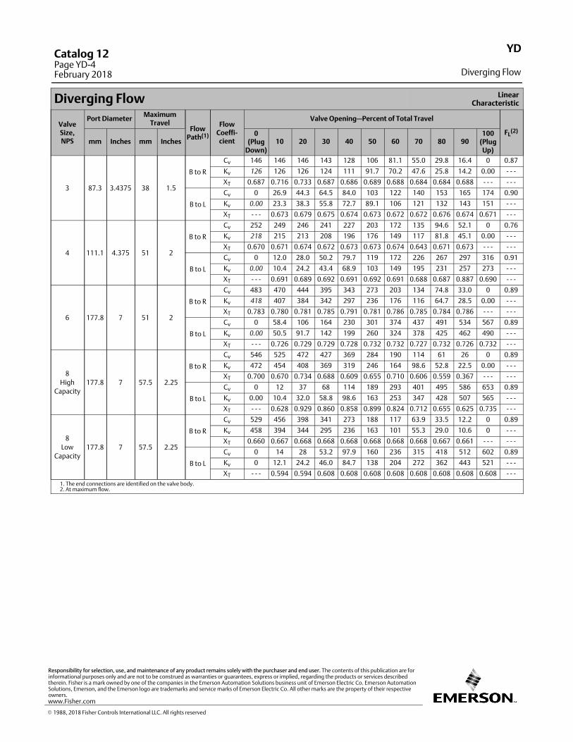
Diverging Flow LinearCharacteristic
ValveSize,NPS
Port DiameterMaximum
TravelFlow
Path(1)
FlowCoeffi‐cient
Valve Opening—Percent of Total Travel
FL(2)
mm Inches mm Inches0
(PlugDown)
10 20 30 40 50 60 70 80 90100
(PlugUp)
3 87.3 3.4375 38 1.5
B to R
Cv 146 146 146 143 128 106 81.1 55.0 29.8 16.4 0 0.87
Kv 126 126 126 124 111 91.7 70.2 47.6 25.8 14.2 0.00 ‐ ‐ ‐
XT 0.687 0.716 0.733 0.687 0.686 0.689 0.688 0.684 0.684 0.688 ‐ ‐ ‐ ‐ ‐ ‐
B to L
Cv 0 26.9 44.3 64.5 84.0 103 122 140 153 165 174 0.90
Kv 0.00 23.3 38.3 55.8 72.7 89.1 106 121 132 143 151 ‐ ‐ ‐
XT ‐ ‐ ‐ 0.673 0.679 0.675 0.674 0.673 0.672 0.672 0.676 0.674 0.671 ‐ ‐ ‐
4 111.1 4.375 51 2
B to R
Cv 252 249 246 241 227 203 172 135 94.6 52.1 0 0.76
Kv 218 215 213 208 196 176 149 117 81.8 45.1 0.00 ‐ ‐ ‐
XT 0.670 0.671 0.674 0.672 0.673 0.673 0.674 0.643 0.671 0.673 ‐ ‐ ‐ ‐ ‐ ‐
B to L
Cv 0 12.0 28.0 50.2 79.7 119 172 226 267 297 316 0.91
Kv 0.00 10.4 24.2 43.4 68.9 103 149 195 231 257 273 ‐ ‐ ‐
XT ‐ ‐ ‐ 0.691 0.689 0.692 0.691 0.692 0.691 0.688 0.687 0.887 0.690 ‐ ‐ ‐
6 177.8 7 51 2
B to R
Cv 483 470 444 395 343 273 203 134 74.8 33.0 0 0.89
Kv 418 407 384 342 297 236 176 116 64.7 28.5 0.00 ‐ ‐ ‐
XT 0.783 0.780 0.781 0.785 0.791 0.781 0.786 0.785 0.784 0.786 ‐ ‐ ‐ ‐ ‐ ‐
B to L
Cv 0 58.4 106 164 230 301 374 437 491 534 567 0.89
Kv 0.00 50.5 91.7 142 199 260 324 378 425 462 490 ‐ ‐ ‐
XT ‐ ‐ ‐ 0.726 0.729 0.729 0.728 0.732 0.732 0.727 0.732 0.726 0.732 ‐ ‐ ‐
8
High
Capacity177.8 7 57.5 2.25
B to R
Cv 546 525 472 427 369 284 190 114 61 26 0 0.89
Kv 472 454 408 369 319 246 164 98.6 52.8 22.5 0.00 ‐ ‐ ‐
XT 0.700 0.670 0.734 0.688 0.609 0.655 0.710 0.606 0.559 0.367 ‐ ‐ ‐ ‐ ‐ ‐
B to L
Cv 0 12 37 68 114 189 293 401 495 586 653 0.89
Kv 0.00 10.4 32.0 58.8 98.6 163 253 347 428 507 565 ‐ ‐ ‐
XT ‐ ‐ ‐ 0.628 0.929 0.860 0.858 0.899 0.824 0.712 0.655 0.625 0.735 ‐ ‐ ‐
8
Low
Capacity177.8 7 57.5 2.25
B to R
Cv 529 456 398 341 273 188 117 63.9 33.5 12.2 0 0.89
Kv 458 394 344 295 236 163 101 55.3 29.0 10.6 0 ‐ ‐ ‐
XT 0.660 0.667 0.668 0.668 0.668 0.668 0.668 0.668 0.667 0.661 ‐ ‐ ‐ ‐ ‐ ‐
B to L
Cv 0 14 28 53.2 97.9 160 236 315 418 512 602 0.89
Kv 0 12.1 24.2 46.0 84.7 138 204 272 362 443 521 ‐ ‐ ‐
XT ‐ ‐ ‐ 0.594 0.594 0.608 0.608 0.608 0.608 0.608 0.608 0.608 0.608 ‐ ‐ ‐
1. The end connections are identified on the valve body.2. At maximum flow.
YD
Diverging Flow
Catalog 12Page YD-4February 2018
� 1988, 2018 Fisher Controls International LLC. All rights reserved
www.Fisher.com
Responsibility for selection, use, and maintenance of any product remains solely with the purchaser and end user. The contents of this publication are forinformational purposes only and are not to be construed as warranties or guarantees, express or implied, regarding the products or services describedtherein. Fisher is a mark owned by one of the companies in the Emerson Automation Solutions business unit of Emerson Electric Co. Emerson AutomationSolutions, Emerson, and the Emerson logo are trademarks and service marks of Emerson Electric Co. All other marks are the property of their respectiveowners.
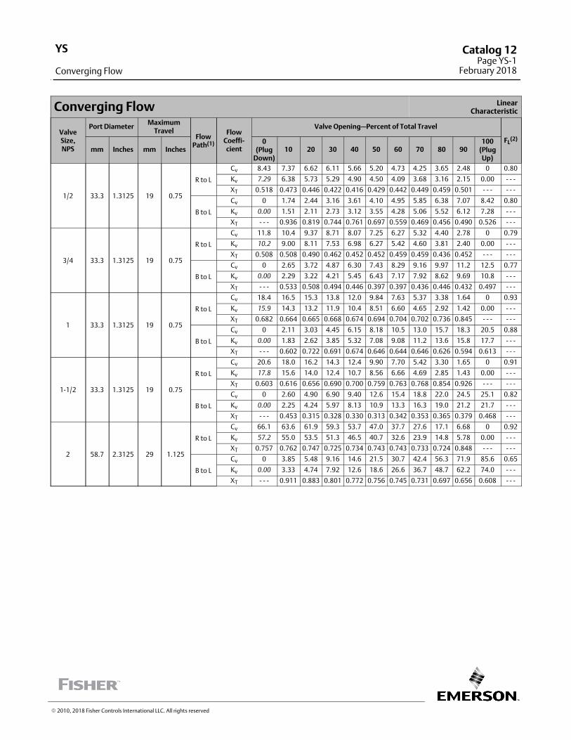
Converging Flow LinearCharacteristic
ValveSize,NPS
Port DiameterMaximum
TravelFlow
Path(1)
FlowCoeffi‐cient
Valve Opening—Percent of Total Travel
FL(2)
mm Inches mm Inches0
(PlugDown)
10 20 30 40 50 60 70 80 90100
(PlugUp)
1/2 33.3 1.3125 19 0.75
R to L
Cv 8.43 7.37 6.62 6.11 5.66 5.20 4.73 4.25 3.65 2.48 0 0.80
Kv 7.29 6.38 5.73 5.29 4.90 4.50 4.09 3.68 3.16 2.15 0.00 ‐ ‐ ‐
XT 0.518 0.473 0.446 0.422 0.416 0.429 0.442 0.449 0.459 0.501 ‐ ‐ ‐ ‐ ‐ ‐
B to L
Cv 0 1.74 2.44 3.16 3.61 4.10 4.95 5.85 6.38 7.07 8.42 0.80
Kv 0.00 1.51 2.11 2.73 3.12 3.55 4.28 5.06 5.52 6.12 7.28 ‐ ‐ ‐
XT ‐ ‐ ‐ 0.936 0.819 0.744 0.761 0.697 0.559 0.469 0.456 0.490 0.526 ‐ ‐ ‐
3/4 33.3 1.3125 19 0.75
R to L
Cv 11.8 10.4 9.37 8.71 8.07 7.25 6.27 5.32 4.40 2.78 0 0.79
Kv 10.2 9.00 8.11 7.53 6.98 6.27 5.42 4.60 3.81 2.40 0.00 ‐ ‐ ‐
XT 0.508 0.508 0.490 0.462 0.452 0.452 0.459 0.459 0.436 0.452 ‐ ‐ ‐ ‐ ‐ ‐
B to L
Cv 0 2.65 3.72 4.87 6.30 7.43 8.29 9.16 9.97 11.2 12.5 0.77
Kv 0.00 2.29 3.22 4.21 5.45 6.43 7.17 7.92 8.62 9.69 10.8 ‐ ‐ ‐
XT ‐ ‐ ‐ 0.533 0.508 0.494 0.446 0.397 0.397 0.436 0.446 0.432 0.497 ‐ ‐ ‐
1 33.3 1.3125 19 0.75
R to L
Cv 18.4 16.5 15.3 13.8 12.0 9.84 7.63 5.37 3.38 1.64 0 0.93
Kv 15.9 14.3 13.2 11.9 10.4 8.51 6.60 4.65 2.92 1.42 0.00 ‐ ‐ ‐
XT 0.682 0.664 0.665 0.668 0.674 0.694 0.704 0.702 0.736 0.845 ‐ ‐ ‐ ‐ ‐ ‐
B to L
Cv 0 2.11 3.03 4.45 6.15 8.18 10.5 13.0 15.7 18.3 20.5 0.88
Kv 0.00 1.83 2.62 3.85 5.32 7.08 9.08 11.2 13.6 15.8 17.7 ‐ ‐ ‐
XT ‐ ‐ ‐ 0.602 0.722 0.691 0.674 0.646 0.644 0.646 0.626 0.594 0.613 ‐ ‐ ‐
1‐1/2 33.3 1.3125 19 0.75
R to L
Cv 20.6 18.0 16.2 14.3 12.4 9.90 7.70 5.42 3.30 1.65 0 0.91
Kv 17.8 15.6 14.0 12.4 10.7 8.56 6.66 4.69 2.85 1.43 0.00 ‐ ‐ ‐
XT 0.603 0.616 0.656 0.690 0.700 0.759 0.763 0.768 0.854 0.926 ‐ ‐ ‐ ‐ ‐ ‐
B to L
Cv 0 2.60 4.90 6.90 9.40 12.6 15.4 18.8 22.0 24.5 25.1 0.82
Kv 0.00 2.25 4.24 5.97 8.13 10.9 13.3 16.3 19.0 21.2 21.7 ‐ ‐ ‐
XT ‐ ‐ ‐ 0.453 0.315 0.328 0.330 0.313 0.342 0.353 0.365 0.379 0.468 ‐ ‐ ‐
2 58.7 2.3125 29 1.125
R to L
Cv 66.1 63.6 61.9 59.3 53.7 47.0 37.7 27.6 17.1 6.68 0 0.92
Kv 57.2 55.0 53.5 51.3 46.5 40.7 32.6 23.9 14.8 5.78 0.00 ‐ ‐ ‐
XT 0.757 0.762 0.747 0.725 0.734 0.743 0.743 0.733 0.724 0.848 ‐ ‐ ‐ ‐ ‐ ‐
B to L
Cv 0 3.85 5.48 9.16 14.6 21.5 30.7 42.4 56.3 71.9 85.6 0.65
Kv 0.00 3.33 4.74 7.92 12.6 18.6 26.6 36.7 48.7 62.2 74.0 ‐ ‐ ‐
XT ‐ ‐ ‐ 0.911 0.883 0.801 0.772 0.756 0.745 0.731 0.697 0.656 0.608 ‐ ‐ ‐
� 2010, 2018 Fisher Controls International LLC. All rights reserved
YS
Converging Flow
Catalog 12Page YS-1
February 2018
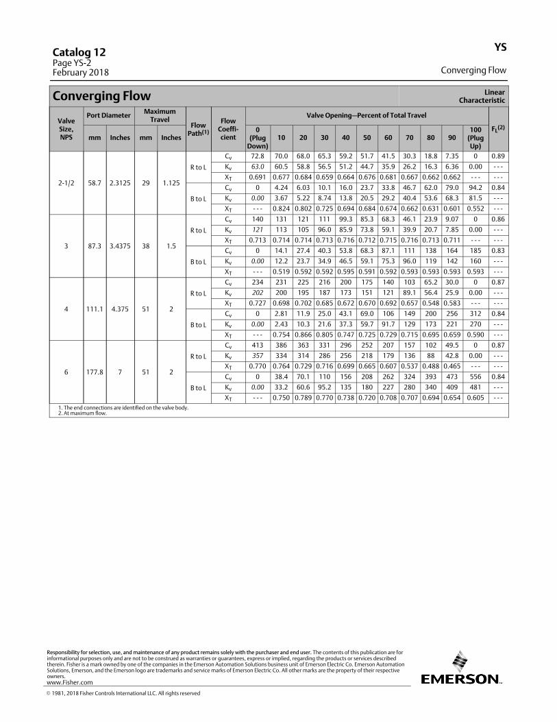
Converging Flow LinearCharacteristic
ValveSize,NPS
Port DiameterMaximum
TravelFlow
Path(1)
FlowCoeffi‐cient
Valve Opening—Percent of Total Travel
FL(2)
mm Inches mm Inches0
(PlugDown)
10 20 30 40 50 60 70 80 90100
(PlugUp)
2‐1/2 58.7 2.3125 29 1.125
R to L
Cv 72.8 70.0 68.0 65.3 59.2 51.7 41.5 30.3 18.8 7.35 0 0.89
Kv 63.0 60.5 58.8 56.5 51.2 44.7 35.9 26.2 16.3 6.36 0.00 ‐ ‐ ‐
XT 0.691 0.677 0.684 0.659 0.664 0.676 0.681 0.667 0.662 0.662 ‐ ‐ ‐ ‐ ‐ ‐
B to L
Cv 0 4.24 6.03 10.1 16.0 23.7 33.8 46.7 62.0 79.0 94.2 0.84
Kv 0.00 3.67 5.22 8.74 13.8 20.5 29.2 40.4 53.6 68.3 81.5 ‐ ‐ ‐
XT ‐ ‐ ‐ 0.824 0.802 0.725 0.694 0.684 0.674 0.662 0.631 0.601 0.552 ‐ ‐ ‐
3 87.3 3.4375 38 1.5
R to L
Cv 140 131 121 111 99.3 85.3 68.3 46.1 23.9 9.07 0 0.86
Kv 121 113 105 96.0 85.9 73.8 59.1 39.9 20.7 7.85 0.00 ‐ ‐ ‐
XT 0.713 0.714 0.714 0.713 0.716 0.712 0.715 0.716 0.713 0.711 ‐ ‐ ‐ ‐ ‐ ‐
B to L
Cv 0 14.1 27.4 40.3 53.8 68.3 87.1 111 138 164 185 0.83
Kv 0.00 12.2 23.7 34.9 46.5 59.1 75.3 96.0 119 142 160 ‐ ‐ ‐
XT ‐ ‐ ‐ 0.519 0.592 0.592 0.595 0.591 0.592 0.593 0.593 0.593 0.593 ‐ ‐ ‐
4 111.1 4.375 51 2
R to L
Cv 234 231 225 216 200 175 140 103 65.2 30.0 0 0.87
Kv 202 200 195 187 173 151 121 89.1 56.4 25.9 0.00 ‐ ‐ ‐
XT 0.727 0.698 0.702 0.685 0.672 0.670 0.692 0.657 0.548 0.583 ‐ ‐ ‐ ‐ ‐ ‐
B to L
Cv 0 2.81 11.9 25.0 43.1 69.0 106 149 200 256 312 0.84
Kv 0.00 2.43 10.3 21.6 37.3 59.7 91.7 129 173 221 270 ‐ ‐ ‐
XT ‐ ‐ ‐ 0.754 0.866 0.805 0.747 0.725 0.729 0.715 0.695 0.659 0.590 ‐ ‐ ‐
6 177.8 7 51 2
R to L
Cv 413 386 363 331 296 252 207 157 102 49.5 0 0.87
Kv 357 334 314 286 256 218 179 136 88 42.8 0.00 ‐ ‐ ‐
XT 0.770 0.764 0.729 0.716 0.699 0.665 0.607 0.537 0.488 0.465 ‐ ‐ ‐ ‐ ‐ ‐
B to L
Cv 0 38.4 70.1 110 156 208 262 324 393 473 556 0.84
Kv 0.00 33.2 60.6 95.2 135 180 227 280 340 409 481 ‐ ‐ ‐
XT ‐ ‐ ‐ 0.750 0.789 0.770 0.738 0.720 0.708 0.707 0.694 0.654 0.605 ‐ ‐ ‐
1. The end connections are identified on the valve body.2. At maximum flow.
YS
Converging Flow
Catalog 12Page YS-2February 2018
� 1981, 2018 Fisher Controls International LLC. All rights reserved
www.Fisher.com
Responsibility for selection, use, and maintenance of any product remains solely with the purchaser and end user. The contents of this publication are forinformational purposes only and are not to be construed as warranties or guarantees, express or implied, regarding the products or services describedtherein. Fisher is a mark owned by one of the companies in the Emerson Automation Solutions business unit of Emerson Electric Co. Emerson AutomationSolutions, Emerson, and the Emerson logo are trademarks and service marks of Emerson Electric Co. All other marks are the property of their respectiveowners.
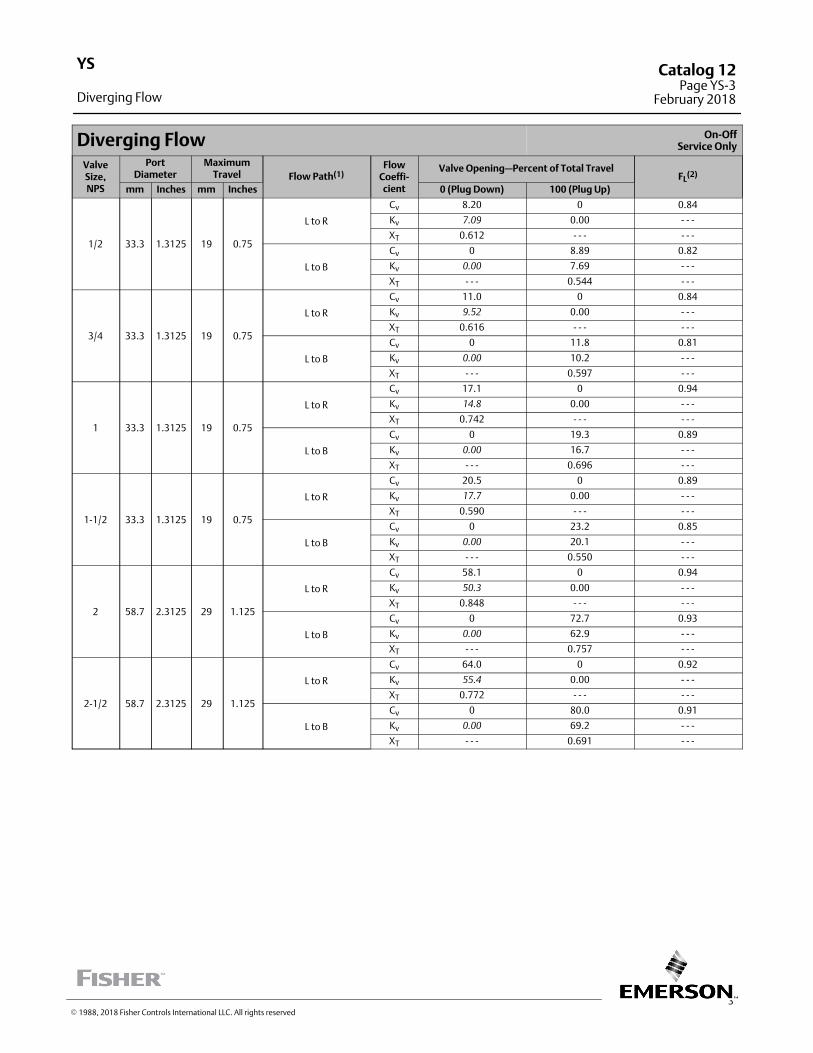
3
Diverging Flow On‐OffService Only
ValveSize,NPS
PortDiameter
MaximumTravel Flow Path(1)
FlowCoeffi‐cient
Valve Opening—Percent of Total TravelFL
(2)
mm Inches mm Inches 0 (Plug Down) 100 (Plug Up)
1/2 33.3 1.3125 19 0.75
L to R
Cv 8.20 0 0.84
Kv 7.09 0.00 ‐ ‐ ‐
XT 0.612 ‐ ‐ ‐ ‐ ‐ ‐
L to B
Cv 0 8.89 0.82
Kv 0.00 7.69 ‐ ‐ ‐
XT ‐ ‐ ‐ 0.544 ‐ ‐ ‐
3/4 33.3 1.3125 19 0.75
L to R
Cv 11.0 0 0.84
Kv 9.52 0.00 ‐ ‐ ‐
XT 0.616 ‐ ‐ ‐ ‐ ‐ ‐
L to B
Cv 0 11.8 0.81
Kv 0.00 10.2 ‐ ‐ ‐
XT ‐ ‐ ‐ 0.597 ‐ ‐ ‐
1 33.3 1.3125 19 0.75
L to R
Cv 17.1 0 0.94
Kv 14.8 0.00 ‐ ‐ ‐
XT 0.742 ‐ ‐ ‐ ‐ ‐ ‐
L to B
Cv 0 19.3 0.89
Kv 0.00 16.7 ‐ ‐ ‐
XT ‐ ‐ ‐ 0.696 ‐ ‐ ‐
1‐1/2 33.3 1.3125 19 0.75
L to R
Cv 20.5 0 0.89
Kv 17.7 0.00 ‐ ‐ ‐
XT 0.590 ‐ ‐ ‐ ‐ ‐ ‐
L to B
Cv 0 23.2 0.85
Kv 0.00 20.1 ‐ ‐ ‐
XT ‐ ‐ ‐ 0.550 ‐ ‐ ‐
2 58.7 2.3125 29 1.125
L to R
Cv 58.1 0 0.94
Kv 50.3 0.00 ‐ ‐ ‐
XT 0.848 ‐ ‐ ‐ ‐ ‐ ‐
L to B
Cv 0 72.7 0.93
Kv 0.00 62.9 ‐ ‐ ‐
XT ‐ ‐ ‐ 0.757 ‐ ‐ ‐
2‐1/2 58.7 2.3125 29 1.125
L to R
Cv 64.0 0 0.92
Kv 55.4 0.00 ‐ ‐ ‐
XT 0.772 ‐ ‐ ‐ ‐ ‐ ‐
L to B
Cv 0 80.0 0.91
Kv 0.00 69.2 ‐ ‐ ‐
XT ‐ ‐ ‐ 0.691 ‐ ‐ ‐
YS
Diverging Flow
Catalog 12Page YS-3
February 2018
� 1988, 2018 Fisher Controls International LLC. All rights reserved
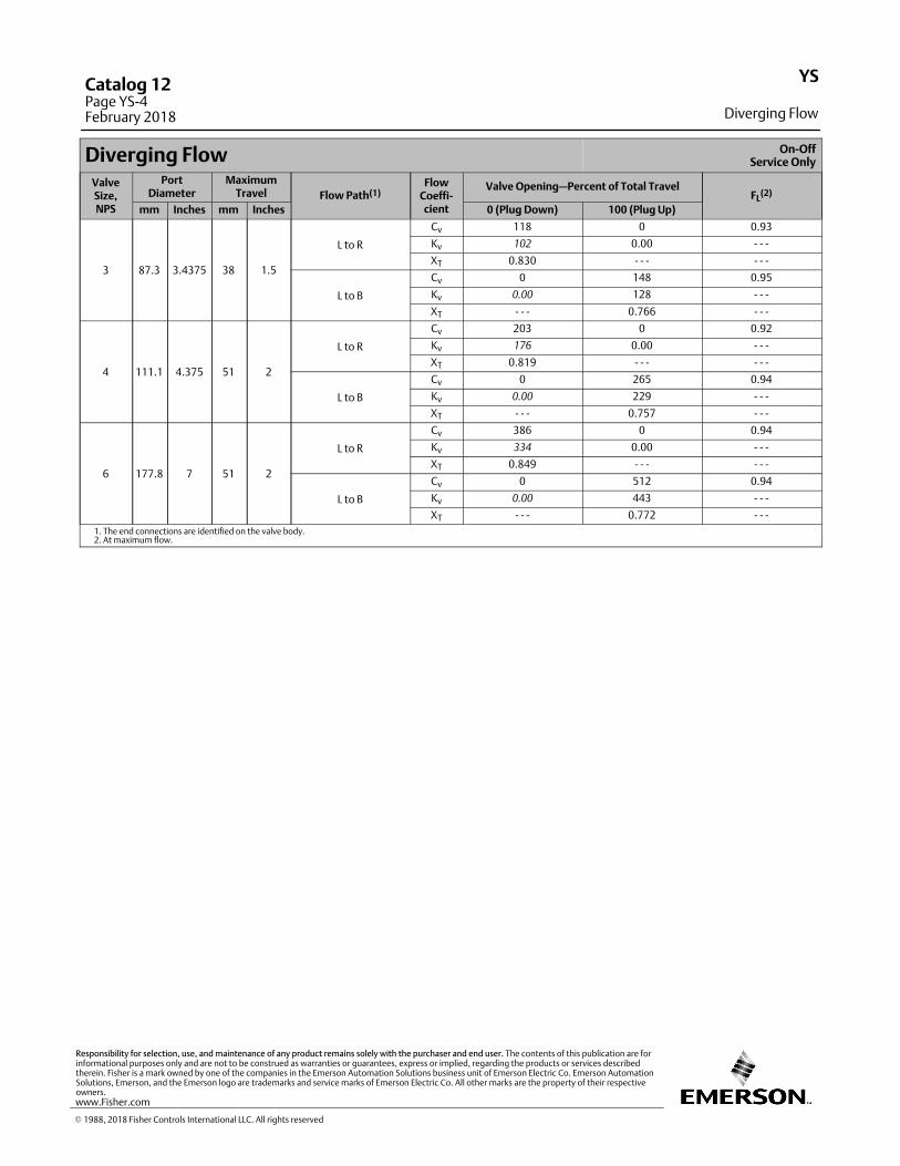
Diverging Flow On‐OffService Only
ValveSize,NPS
PortDiameter
MaximumTravel Flow Path(1)
FlowCoeffi‐cient
Valve Opening—Percent of Total TravelFL
(2)
mm Inches mm Inches 0 (Plug Down) 100 (Plug Up)
3 87.3 3.4375 38 1.5
L to R
Cv 118 0 0.93
Kv 102 0.00 ‐ ‐ ‐
XT 0.830 ‐ ‐ ‐ ‐ ‐ ‐
L to B
Cv 0 148 0.95
Kv 0.00 128 ‐ ‐ ‐
XT ‐ ‐ ‐ 0.766 ‐ ‐ ‐
4 111.1 4.375 51 2
L to R
Cv 203 0 0.92
Kv 176 0.00 ‐ ‐ ‐
XT 0.819 ‐ ‐ ‐ ‐ ‐ ‐
L to B
Cv 0 265 0.94
Kv 0.00 229 ‐ ‐ ‐
XT ‐ ‐ ‐ 0.757 ‐ ‐ ‐
6 177.8 7 51 2
L to R
Cv 386 0 0.94
Kv 334 0.00 ‐ ‐ ‐
XT 0.849 ‐ ‐ ‐ ‐ ‐ ‐
L to B
Cv 0 512 0.94
Kv 0.00 443 ‐ ‐ ‐
XT ‐ ‐ ‐ 0.772 ‐ ‐ ‐
1. The end connections are identified on the valve body.2. At maximum flow.
YS
Diverging Flow
Catalog 12Page YS-4February 2018
� 1988, 2018 Fisher Controls International LLC. All rights reserved
www.Fisher.com
Responsibility for selection, use, and maintenance of any product remains solely with the purchaser and end user. The contents of this publication are forinformational purposes only and are not to be construed as warranties or guarantees, express or implied, regarding the products or services describedtherein. Fisher is a mark owned by one of the companies in the Emerson Automation Solutions business unit of Emerson Electric Co. Emerson AutomationSolutions, Emerson, and the Emerson logo are trademarks and service marks of Emerson Electric Co. All other marks are the property of their respectiveowners.
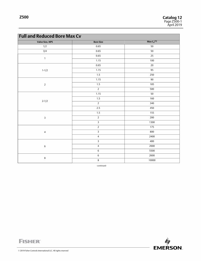
Full and Reduced Bore Max CvValve Size, NPS Bore Size Max Cv
(1)
1/2 0.65 50
3/4 0.65 50
10.65 25
1.15 100
1-1/2
0.65 20
1.15 95
1.5 250
2
1.15 90
1.5 185
2 500
2-1/2
1.15 50
1.5 160
2 340
2.5 450
3
1.5 155
2 200
3 1300
4
2 175
3 800
4 2400
6
3 400
4 2000
6 5500
86 2600
8 10000
‐continued‐
� 2019 Fisher Controls International LLC. All rights reserved
Z500 Catalog 12Page Z500-1
April 2019
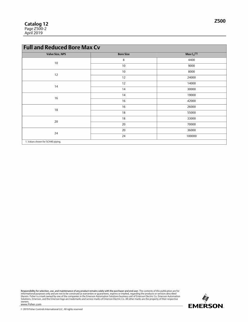
Full and Reduced Bore Max CvValve Size, NPS Bore Size Max Cv
(1)
108 4400
10 9000
1210 8000
12 24000
1412 14000
14 30000
1614 19000
16 42000
1816 26000
18 55000
2018 33000
20 70000
2420 36000
24 100000
1. Values shown for SCH40 piping.
Z500Catalog 12Page Z500-2April 2019
� 2019 Fisher Controls International LLC. All rights reserved
www.Fisher.com
Responsibility for selection, use, and maintenance of any product remains solely with the purchaser and end user. The contents of this publication are forinformational purposes only and are not to be construed as warranties or guarantees, express or implied, regarding the products or services describedtherein. Fisher is a mark owned by one of the companies in the Emerson Automation Solutions business unit of Emerson Electric Co. Emerson AutomationSolutions, Emerson, and the Emerson logo are trademarks and service marks of Emerson Electric Co. All other marks are the property of their respectiveowners.
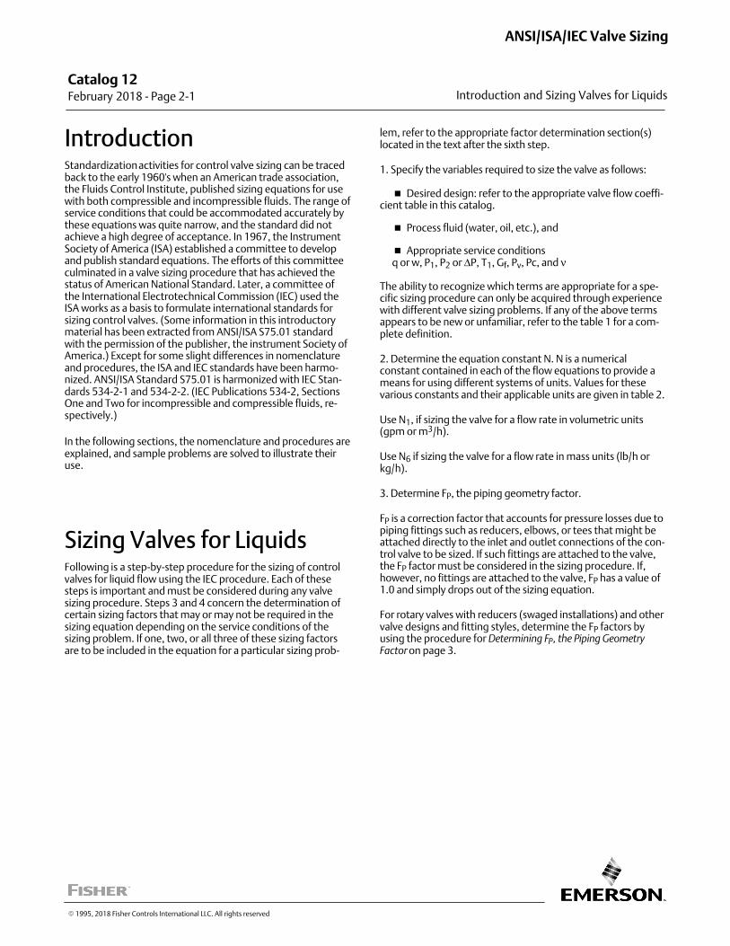
Catalog 12 February 2018 ‐ Page 2‐1 Introduction and Sizing Valves for Liquids
ANSI/ISA/IEC Valve Sizing
� 1995, 2018 Fisher Controls International LLC. All rights reserved
IntroductionStandardization activities for control valve sizing can be tracedback to the early 1960's when an American trade association,the Fluids Control Institute, published sizing equations for usewith both compressible and incompressible fluids. The range ofservice conditions that could be accommodated accurately bythese equations was quite narrow, and the standard did notachieve a high degree of acceptance. In 1967, the InstrumentSociety of America (ISA) established a committee to developand publish standard equations. The efforts of this committeeculminated in a valve sizing procedure that has achieved thestatus of American National Standard. Later, a committee ofthe International Electrotechnical Commission (IEC) used theISA works as a basis to formulate international standards forsizing control valves. (Some information in this introductorymaterial has been extracted from ANSI/ISA S75.01 standardwith the permission of the publisher, the instrument Society ofAmerica.) Except for some slight differences in nomenclatureand procedures, the ISA and IEC standards have been harmonized. ANSI/ISA Standard S75.01 is harmonized with IEC Standards 534‐2‐1 and 534‐2‐2. (IEC Publications 534‐2, SectionsOne and Two for incompressible and compressible fluids, respectively.)
In the following sections, the nomenclature and procedures areexplained, and sample problems are solved to illustrate theiruse.
Sizing Valves for LiquidsFollowing is a step‐by‐step procedure for the sizing of controlvalves for liquid flow using the IEC procedure. Each of thesesteps is important and must be considered during any valvesizing procedure. Steps 3 and 4 concern the determination ofcertain sizing factors that may or may not be required in thesizing equation depending on the service conditions of thesizing problem. If one, two, or all three of these sizing factorsare to be included in the equation for a particular sizing prob
lem, refer to the appropriate factor determination section(s)located in the text after the sixth step.
1. Specify the variables required to size the valve as follows:
� Desired design: refer to the appropriate valve flow coefficient table in this catalog.
� Process fluid (water, oil, etc.), and
� Appropriate service conditions q or w, P1, P2 or ΔP, T1, Gf, Pv, Pc, and ν
The ability to recognize which terms are appropriate for a specific sizing procedure can only be acquired through experiencewith different valve sizing problems. If any of the above termsappears to be new or unfamiliar, refer to the table 1 for a complete definition.
2. Determine the equation constant N. N is a numericalconstant contained in each of the flow equations to provide ameans for using different systems of units. Values for thesevarious constants and their applicable units are given in table 2.
Use N1, if sizing the valve for a flow rate in volumetric units(gpm or m3/h).
Use N6 if sizing the valve for a flow rate in mass units (lb/h orkg/h).
3. Determine FP, the piping geometry factor.
FP is a correction factor that accounts for pressure losses due topiping fittings such as reducers, elbows, or tees that might beattached directly to the inlet and outlet connections of the control valve to be sized. If such fittings are attached to the valve,the FP factor must be considered in the sizing procedure. If,however, no fittings are attached to the valve, FP has a value of1.0 and simply drops out of the sizing equation.
For rotary valves with reducers (swaged installations) and othervalve designs and fitting styles, determine the FP factors byusing the procedure for Determining FP, the Piping Geometry
Factor on page 3.
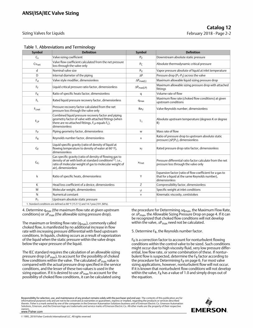
Table 1. Abbreviations and TerminologySymbol Definition Symbol Definition
Cv Valve sizing coefficient P2 Downstream absolute static pressure
CvnetValve flow coefficient calculated from the net pressureloss through the valve only
PC Absolute thermodynamic critical pressure
d Nominal valve size PV Vapor pressure absolute of liquid at inlet temperature
D Internal diameter of the piping ΔP Pressure drop (P1‐P2) across the valve
Fd Valve style modifier, dimensionless ΔPmax(L) Maximum allowable liquid sizing pressure drop
FF Liquid critical pressure ratio factor, dimensionless ΔPmax(LP)Maximum allowable sizing pressure drop with attachedfittings
FK Ratio of specific heats factor, dimensionless q Volume rate of flow
FL Rated liquid pressure recovery factor, dimensionless qmaxMaximum flow rate (choked flow conditions) at givenupstream conditions
FLnetPressure recovery factor calculated from the netpressure loss through the valve only
ReV Valve Reynolds number, dimensionless
FLP
Combined liquid pressure recovery factor and pipinggeometry factor of valve with attached fittings (whenthere are no attached fittings, FLP equals FL),dimensionless
T1Absolute upstream temperature (degrees K or degreeR)
FP Piping geometry factor, dimensionless w Mass rate of flow
FR Reynolds number factor, dimensionless xRatio of pressure drop to upstream absolute staticpressure (ΔP/P1), dimensionless
GF
Liquid specific gravity (ratio of density of liquid atflowing temperature to density of water at 60�F),dimensionless
xT Rated pressure drop ratio factor, dimensionless
GG
Gas specific gravity (ratio of density of flowing gas todensity of air with both at standard conditions(1), i.e.,ratio of molecular weight of gas to molecular weight ofair), dimensionless
xTnetPressure differential ratio factor calculate from the netpressure loss through the valve only
k Ratio of specific heats, dimensionless YExpansion factor (ratio of flow coefficient for a gas tothat for a liquid at the same Reynolds number),dimensionless
K Head loss coefficient of a device, dimensionless Z Compressibility factor, dimensionless
M Molecular weight, dimensionless γ1 Specific weight at inlet conditions
N Numerical constant ν Kinematic viscosity, centistokes
P1 Upstream absolute static pressure
1. Standard conditions are defined as 60�F (15.5�C) and 14.7 psia (101.3kPa).
4. Determine qmax (the maximum flow rate at given upstreamconditions) or ΔPmax (the allowable sizing pressure drop).
The maximum or limiting flow rate (qmax), commonly calledchoked flow, is manifested by no additional increase in flowrate with increasing pressure differential with fixed upstreamconditions. In liquids, choking occurs as a result of vaporizationof the liquid when the static pressure within the valve dropsbelow the vapor pressure of the liquid.
The IEC standard requires the calculation of an allowable sizingpressure drop (ΔPmax), to account for the possibility of chokedflow conditions within the valve. The calculated ΔPmax value iscompared with the actual pressure drop specified in the serviceconditions, and the lesser of these two values is used in thesizing equation. If it is desired to use ΔPmax to account for thepossibility of choked flow conditions, it can be calculated using
the procedure for Determining Δqmax, the Maximum Flow Rate,or ΔPmax, the Allowable Sizing Pressure Drop on page 4. If it canbe recognized that choked flow conditions will not developwithin the valve, ΔPmax need not be calculated.
5. Determine FR, the Reynolds number factor.
FR is a correction factor to account for nonturbulent flowingconditions within the control valve to be sized. Such conditionsmight occur due to high viscosity fluid, very low pressure differential, low flow rate, or some combination of these. If nonturbulent flow is suspected, determine the FR factor according tothe procedure for Determining FR on page 6. For most valvesizing applications, however, nonturbulent flow will not occur.If it is known that nonturbulent flow conditions will not developwithin the valve, FR has a value of 1.0 and simply drops out ofthe equation.
Catalog 12February 2018 ‐ Page 2‐2
ANSI/ISA/IEC Valve Sizing
Sizing Valves for Liquids
� 1995, 2018 Fisher Controls International LLC. All rights reserved
www.Fisher.com
Responsibility for selection, use, and maintenance of any product remains solely with the purchaser and end user. The contents of this publication are forinformational purposes only and are not to be construed as warranties or guarantees, express or implied, regarding the products or services describedtherein. Fisher is a mark owned by one of the companies in the Emerson Automation Solutions business unit of Emerson Electric Co. Emerson AutomationSolutions, Emerson, and the Emerson logo are trademarks and service marks of Emerson Electric Co. All other marks are the property of their respectiveowners.
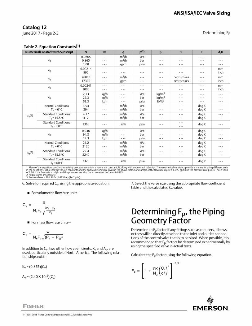
Table 2. Equation Constants(1)
Numerical Constant with Subscript N w q p(2) ρ ν T d,D
N1
0.08650.8651.00
‐ ‐ ‐‐ ‐ ‐‐ ‐ ‐
m3/hm3/hgpm
kPabarpsia
‐ ‐ ‐‐ ‐ ‐‐ ‐ ‐
‐ ‐ ‐‐ ‐ ‐‐ ‐ ‐
‐ ‐ ‐‐ ‐ ‐‐ ‐ ‐
‐ ‐ ‐‐ ‐ ‐‐ ‐ ‐
N20.00214
890‐ ‐ ‐‐ ‐ ‐
‐ ‐ ‐‐ ‐ ‐
‐ ‐ ‐‐ ‐ ‐
‐ ‐ ‐‐ ‐ ‐
‐ ‐ ‐‐ ‐ ‐
‐ ‐ ‐‐ ‐ ‐
mminch
N47600017300
‐ ‐ ‐‐ ‐ ‐
m3/hgpm
‐ ‐ ‐‐ ‐ ‐
‐ ‐ ‐‐ ‐ ‐
centistokescentistokes
‐ ‐ ‐‐ ‐ ‐
mminch
N50.00241
1000‐ ‐ ‐‐ ‐ ‐
‐ ‐ ‐‐ ‐ ‐
‐ ‐ ‐‐ ‐ ‐
‐ ‐ ‐‐ ‐ ‐
‐ ‐ ‐‐ ‐ ‐
‐ ‐ ‐‐ ‐ ‐
mminch
N6
2.7327.363.3
kg/hkg/hlb/h
‐ ‐ ‐‐ ‐ ‐‐ ‐ ‐
kPabarpsia
kg/m3
kg/m3
lb/ft3
‐ ‐ ‐‐ ‐ ‐‐ ‐ ‐
‐ ‐ ‐‐ ‐ ‐‐ ‐ ‐
‐ ‐ ‐‐ ‐ ‐‐ ‐ ‐
N7(3)
Normal ConditionsTN = 0�C
3.94394
‐ ‐ ‐‐ ‐ ‐
m3/hm3/h
kPabar
‐ ‐ ‐‐ ‐ ‐
‐ ‐ ‐‐ ‐ ‐
deg Kdeg K
‐ ‐ ‐‐ ‐ ‐
Standard ConditionsTs = 15.5�C
4.17417
‐ ‐ ‐‐ ‐ ‐
m3/hm3/h
kPabar
‐ ‐ ‐‐ ‐ ‐
‐ ‐ ‐‐ ‐ ‐
deg Kdeg K
‐ ‐ ‐‐ ‐ ‐
Standard ConditionsTs = 60�F
1360 ‐ ‐ ‐ scfh psia ‐ ‐ ‐‐ ‐ ‐‐ ‐ ‐
deg R ‐ ‐ ‐
N8
0.94894.819.3
kg/hkg/hlb/h
‐ ‐ ‐‐ ‐ ‐‐ ‐ ‐
kPabarpsia
‐ ‐ ‐‐ ‐ ‐‐ ‐ ‐
‐ ‐ ‐‐ ‐ ‐‐ ‐ ‐
deg Kdeg Kdeg R
‐ ‐ ‐‐ ‐ ‐‐ ‐ ‐
N9(3)
Normal ConditionsTN = 0�C
21.22120
‐ ‐ ‐‐ ‐ ‐
m3/hm3/h
kPabar
‐ ‐ ‐‐ ‐ ‐
‐ ‐ ‐‐ ‐ ‐
deg Kdeg K
‐ ‐ ‐‐ ‐ ‐
Standard ConditionsTs = 15.5�C
22.42240
‐ ‐ ‐‐ ‐ ‐
m3/hm3/h
kPabar
‐ ‐ ‐‐ ‐ ‐
‐ ‐ ‐‐ ‐ ‐
deg Kdeg K
‐ ‐ ‐‐ ‐ ‐
Standard ConditionsTS = 60�F
7320 ‐ ‐ ‐ scfh psia ‐ ‐ ‐ ‐ ‐ ‐ deg R ‐ ‐ ‐
1. Many of the equations used in these sizing procedures contain a numerical constant, N, along with a numerical subscript. These numerical constants provide a means for using different unitsin the equations. Values for the various constants and the applicable units are given in the above table. For example, if the flow rate is given in U.S. gpm and the pressures are psia, N1 has a valueof 1.00. If the flow rate is m3/hr and the pressures are kPa, the N1 constant becomes 0.0865.2. All pressures are absolute.3. Pressure base is 101.3 kPa (1.013 bar) (14.7 psia).
6. Solve for required Cv, using the appropriate equation:
� For volumetric flow rate units—
Cv �q
N1FpP1�P2
Gf�
� For mass flow rate units—
Cv � wN6Fp (P1 � P2)��
In addition to Cv, two other flow coefficients, Kv and Av, areused, particularly outside of North America. The following relationships exist:
Kv = (0.865)(Cv)
Av = (2.40 X 10‐5)(Cv)
7. Select the valve size using the appropriate flow coefficienttable and the calculated Cv value.
Determining Fp, the PipingGeometry FactorDetermine an Fp factor if any fittings such as reducers, elbows,or tees will be directly attached to the inlet and outlet connections of the control valve that is to be sized. When possible, it isrecommended that Fp factors be determined experimentally byusing the specified valve in actual tests.
Calculate the Fp factor using the following equation.
Fp � �1 � �KN2
�Cv
d2�2�12
Catalog 12 June 2017 ‐ Page 2‐3
ANSI/ISA/IEC Valve Sizing
Determining FP
� 1995, 2018 Fisher Controls International LLC. All rights reserved
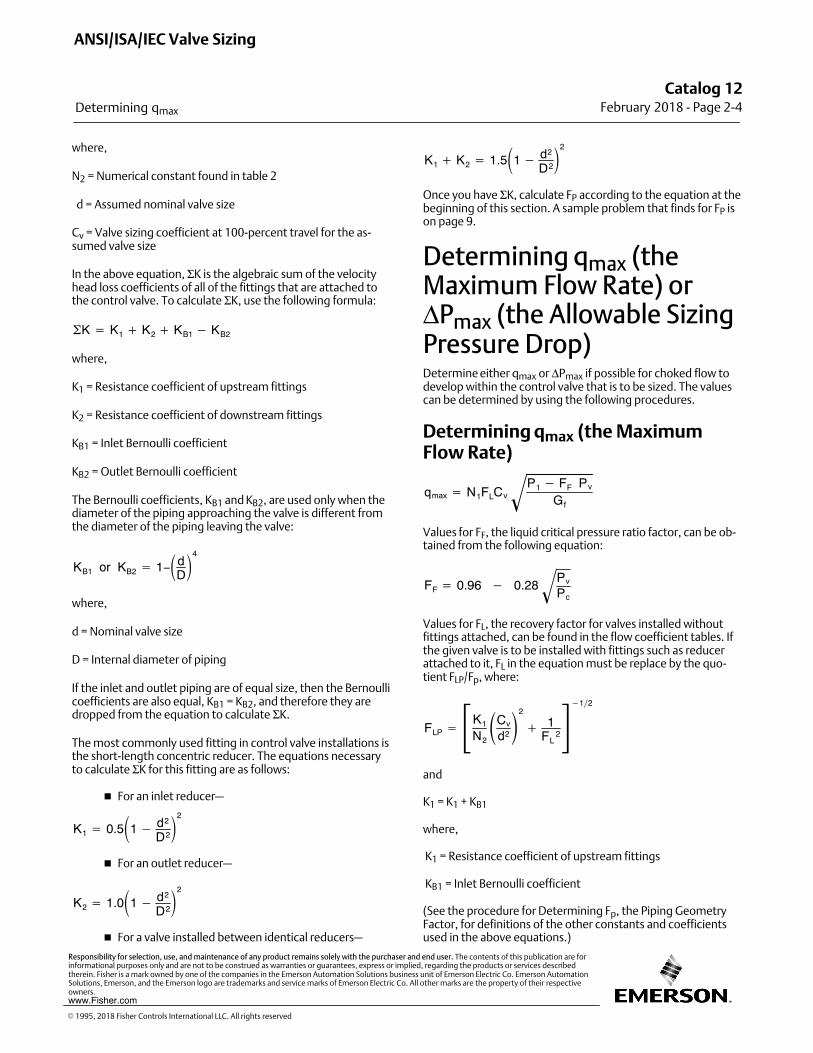
where,
N2 = Numerical constant found in table 2
d = Assumed nominal valve size
Cv = Valve sizing coefficient at 100‐percent travel for the assumed valve size
In the above equation, ΣK is the algebraic sum of the velocityhead loss coefficients of all of the fittings that are attached tothe control valve. To calculate ΣK, use the following formula:
�K � K1 � K2 � KB1 � KB2
where,
K1 = Resistance coefficient of upstream fittings
K2 = Resistance coefficient of downstream fittings
KB1 = Inlet Bernoulli coefficient
KB2 = Outlet Bernoulli coefficient
The Bernoulli coefficients, KB1 and KB2, are used only when thediameter of the piping approaching the valve is different fromthe diameter of the piping leaving the valve:
KB1 or KB2 � 1−�dD�4
where,
d = Nominal valve size
D = Internal diameter of piping
If the inlet and outlet piping are of equal size, then the Bernoullicoefficients are also equal, KB1 = KB2, and therefore they aredropped from the equation to calculate ΣK.
The most commonly used fitting in control valve installations isthe short‐length concentric reducer. The equations necessaryto calculate ΣK for this fitting are as follows:
� For an inlet reducer—
K1 � 0.5�1 � d2
D2�2
� For an outlet reducer—
K2 � 1.0�1 � d2
D2�2
� For a valve installed between identical reducers—
K1 � K2 � 1.5�1 � d2
D2�2
Once you have ΣK, calculate FP according to the equation at thebeginning of this section. A sample problem that finds for FP ison page 9.
Determining qmax (theMaximum Flow Rate) orΔPmax (the Allowable SizingPressure Drop)Determine either qmax or ΔPmax if possible for choked flow todevelop within the control valve that is to be sized. The valuescan be determined by using the following procedures.
Determining qmax (the MaximumFlow Rate)
qmax � N1FLCvP1 � FF Pv
Gf�
Values for FF, the liquid critical pressure ratio factor, can be obtained from the following equation:
FF � 0.96 � 0.28Pv
Pc�
Values for FL, the recovery factor for valves installed withoutfittings attached, can be found in the flow coefficient tables. Ifthe given valve is to be installed with fittings such as reducerattached to it, FL in the equation must be replace by the quotient FLP/Fp, where:
FLP � �K1
N2
�Cv
d2�2
� 1FL
2�12
and
K1 = K1 + KB1
where,
K1 = Resistance coefficient of upstream fittings
KB1 = Inlet Bernoulli coefficient
(See the procedure for Determining Fp, the Piping GeometryFactor, for definitions of the other constants and coefficientsused in the above equations.)
ANSI/ISA/IEC Valve Sizing
Determining qmax
Catalog 12February 2018 ‐ Page 2‐4
� 1995, 2018 Fisher Controls International LLC. All rights reserved
www.Fisher.com
Responsibility for selection, use, and maintenance of any product remains solely with the purchaser and end user. The contents of this publication are forinformational purposes only and are not to be construed as warranties or guarantees, express or implied, regarding the products or services describedtherein. Fisher is a mark owned by one of the companies in the Emerson Automation Solutions business unit of Emerson Electric Co. Emerson AutomationSolutions, Emerson, and the Emerson logo are trademarks and service marks of Emerson Electric Co. All other marks are the property of their respectiveowners.
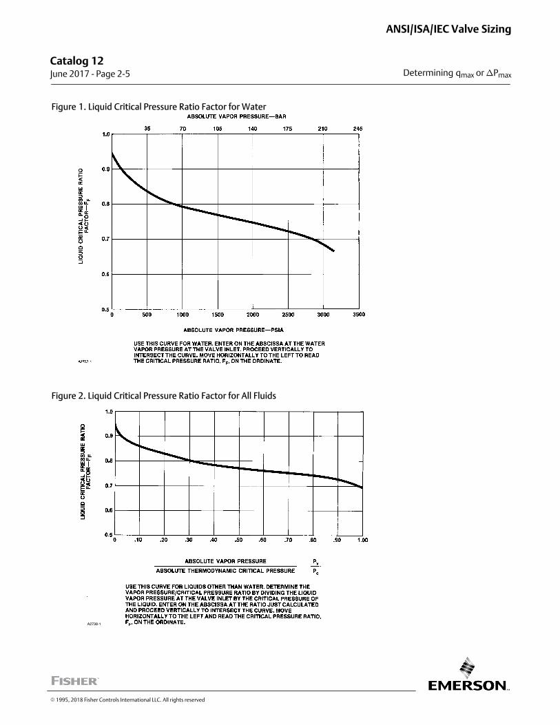
Figure 1. Liquid Critical Pressure Ratio Factor for Water
Figure 2. Liquid Critical Pressure Ratio Factor for All Fluids
A2738-1
Catalog 12 June 2017 ‐ Page 2‐5
ANSI/ISA/IEC Valve Sizing
Determining qmax or �Pmax
� 1995, 2018 Fisher Controls International LLC. All rights reserved
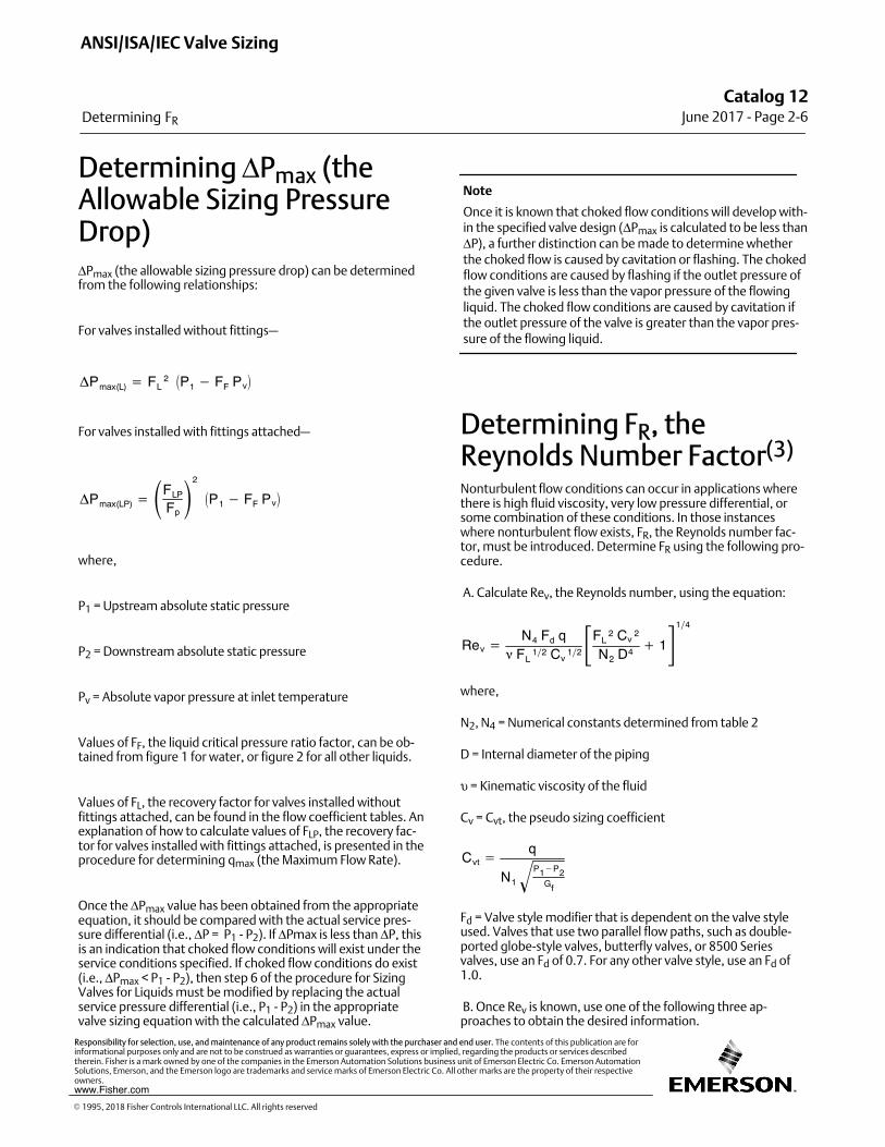
Determining ΔPmax (theAllowable Sizing PressureDrop)ΔPmax (the allowable sizing pressure drop) can be determinedfrom the following relationships:
For valves installed without fittings—
�Pmax(L) � FL2 �P1 � FF Pv�
For valves installed with fittings attached—
�Pmax(LP) � �FLP
Fp�2
�P1 � FF Pv�
where,
P1 = Upstream absolute static pressure
P2 = Downstream absolute static pressure
Pv = Absolute vapor pressure at inlet temperature
Values of FF, the liquid critical pressure ratio factor, can be obtained from figure 1 for water, or figure 2 for all other liquids.
Values of FL, the recovery factor for valves installed withoutfittings attached, can be found in the flow coefficient tables. Anexplanation of how to calculate values of FLP, the recovery factor for valves installed with fittings attached, is presented in theprocedure for determining qmax (the Maximum Flow Rate).
Once the ΔPmax value has been obtained from the appropriateequation, it should be compared with the actual service pressure differential (i.e., ΔP = P1 ‐ P2). If ΔPmax is less than ΔP, thisis an indication that choked flow conditions will exist under theservice conditions specified. If choked flow conditions do exist(i.e., ΔPmax < P1 ‐ P2), then step 6 of the procedure for SizingValves for Liquids must be modified by replacing the actualservice pressure differential (i.e., P1 ‐ P2) in the appropriatevalve sizing equation with the calculated ΔPmax value.
Note
Once it is known that choked flow conditions will develop within the specified valve design (ΔPmax is calculated to be less thanΔP), a further distinction can be made to determine whetherthe choked flow is caused by cavitation or flashing. The chokedflow conditions are caused by flashing if the outlet pressure ofthe given valve is less than the vapor pressure of the flowingliquid. The choked flow conditions are caused by cavitation ifthe outlet pressure of the valve is greater than the vapor pressure of the flowing liquid.
Determining FR, theReynolds Number Factor(3)
Nonturbulent flow conditions can occur in applications wherethere is high fluid viscosity, very low pressure differential, orsome combination of these conditions. In those instanceswhere nonturbulent flow exists, FR, the Reynolds number factor, must be introduced. Determine FR using the following procedure.
A. Calculate Rev, the Reynolds number, using the equation:
Rev �N4 Fd q
� FL12 Cv
12�FL
2 Cv2
N2 D4 � 114
where,
N2, N4 = Numerical constants determined from table 2
D = Internal diameter of the piping
υ = Kinematic viscosity of the fluid
Cv = Cvt, the pseudo sizing coefficient
Cvt �q
N1
P1�P2Gf
�Fd = Valve style modifier that is dependent on the valve styleused. Valves that use two parallel flow paths, such as double‐ported globe‐style valves, butterfly valves, or 8500 Seriesvalves, use an Fd of 0.7. For any other valve style, use an Fd of1.0.
B. Once Rev is known, use one of the following three approaches to obtain the desired information.
ANSI/ISA/IEC Valve Sizing
Determining FR
Catalog 12June 2017 ‐ Page 2‐6
� 1995, 2018 Fisher Controls International LLC. All rights reserved
www.Fisher.com
Responsibility for selection, use, and maintenance of any product remains solely with the purchaser and end user. The contents of this publication are forinformational purposes only and are not to be construed as warranties or guarantees, express or implied, regarding the products or services describedtherein. Fisher is a mark owned by one of the companies in the Emerson Automation Solutions business unit of Emerson Electric Co. Emerson AutomationSolutions, Emerson, and the Emerson logo are trademarks and service marks of Emerson Electric Co. All other marks are the property of their respectiveowners.
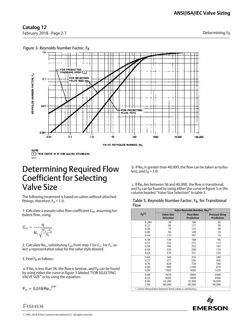
Figure 3. Reynolds Number Factor, FR
Determining Required FlowCoefficient for SelectingValve SizeThe following treatment is based on valves without attachedfittings; therefore, Fp = 1.0.
1. Calculate a pseudo valve flow coefficient Cvt, assuming turbulent flow, using:
Cvt �q
N1
P1�P2Gf
�2. Calculate Rev, substituting Cvt from step 1 for Cv. For FL, select a representative value for the valve style desired.
3. Find FR as follows:
a. If Rev is less than 56, the flow is laminar, and FR can be foundby using either the curve in figure 3 labeled “FOR SELECTINGVALVE SIZE” or by using the equation:
FR � 0.019�Rev�0.67
b. If Rev is greater than 40,000, the flow can be taken as turbulent, and FR = 1.0.
c. If Rev lies between 56 and 40,000, the flow is transitional,and FR can be found by using either the curve in figure 3 or thecolumn headed “Valve Size Selection” in table 3.
Table 3. Reynolds Number Factor, FR, for TransitionalFlow
FR(1)
Valve Reynolds Number, Rev(1)
Valve SizeSelection
Flow RatePrediction
Pressure DropPrediction
0.2840.320.36
0.400.44
566679
94110
106117132
149167
303848
5974
0.480.520.56
0.600.64
130154188
230278
188215253
298351
90113142
179224
0.680.720.76
0.800.84
340471620
9801560
416556720
11001690
280400540
8701430
0.880.920.96
1.00
24704600
10,200
40,000
26604800
10,400
40,000
23004400
10,000
40,000
1. Linear interpolation between listed values is satisfactory.
Catalog 12 February 2018 ‐ Page 2‐7
ANSI/ISA/IEC Valve Sizing
Determining FR
� 1995, 2018 Fisher Controls International LLC. All rights reserved
4. Obtain the required Cv from:
Cv �Cvt
FR
5. After determining Cv, check the FL value for the selectedvalve size and style. If this value is significantly different fromthe value selected in step 2, use the new value, and repeat steps1 through 4.
Predicting Flow Rate
1. Calculate qt, assuming turbulent flow, using:
qt � N1CvP1 � P2
Gf
�2. Calculate Rev, substituting qt for q from step 1.
3. Find FR as follows:
a. If Rev is less than 106, the flow is laminar, and FR can befound by using the curve in figure 3 labeled “FOR PREDICTINGFLOW RATE” or by using the equation:
FR � 0.0027 Rev
b. If Rev is greater than 40,000, the flow can be taken as turbulent, and FR = 1.0.
c. If Rev lies between 106 and 40,000, the flow is transitional,and FR can be found by using either the curve in figure 3 or thecolumn headed “Flow Rate Prediction” in table 3.
4. Obtain the predicted flow rate from:
q � FR qt
Predicting Pressure Drop
1. Calculate Rev.
2. Find FR as follows:
a. If Rev is less than 30, the flow is laminar, and FR can be foundby using the curve in figure 3 labeled “FOR PREDICTING PRESSURE DROP” or by using the equation:
FR � 0.052�Rev�0.5
b. If Rev is greater than 40,000, the flow can be taken as turbulent, and FR = 1.0.
c. If Rev lies between 30 and 40,000, the flow is transitional,and FR can be found by using the curve in figure 3 or the column headed “Pressure Drop Prediction” in table 3.
3. Calculate the predicted pressure drop from:
�p � Gf � qN1 FR Cv
�2
Liquid Sizing SampleProblems
Liquid Sizing Sample Problem No. 1
Assume an installation that, at initial plant start‐up, will not beoperating at maximum design capability. The lines are sized forthe ultimate system capacity, but there is a desire to install acontrol valve now which is sized only for currently anticipatedrequirements. The line size is NPS 8, and a Fisher CL300 ES valvewith an equal percentage cage has been specified. Standardconcentric reducers will be used to install the valve into theline. Determine the appropriate valve size.
1. Specify the necessary variables required to size the valve:
� Desired valve design—CL300 ES valve with equal percentage cage and an assumed valve size of NPS 3.
� Process fluid—liquid propane
� Service conditions—
q = 800 gpm P1 = 300 psig = 314.7 psia P2 = 275 psig = 289.7 psiaΔP = 25 psi T1 = 70�F Gf = 0.50 Pv = 124.3 psia Pv = 616.3 psia
2. Determine an N1 value of 1.0 from table 2.
3. Determine Fp, the piping geometry factor.
Because it is proposed to install an NPS 3 valve in an NPS 8 line,it will be necessary to determine the piping geometry factor,Fp, which corrects for losses caused by fittings attached to thevalve.
Fp � �1 � �KN2
�Cv
d2�2�12
ANSI/ISA/IEC Valve Sizing
Liquid Sizing Sample Problems
Catalog 12February 2018 ‐ Page 2‐8
� 1995, 2018 Fisher Controls International LLC. All rights reserved
www.Fisher.com
Responsibility for selection, use, and maintenance of any product remains solely with the purchaser and end user. The contents of this publication are forinformational purposes only and are not to be construed as warranties or guarantees, express or implied, regarding the products or services describedtherein. Fisher is a mark owned by one of the companies in the Emerson Automation Solutions business unit of Emerson Electric Co. Emerson AutomationSolutions, Emerson, and the Emerson logo are trademarks and service marks of Emerson Electric Co. All other marks are the property of their respectiveowners.
where,
N2 = 890, from table 2 d = 3 in., from step 1 Cv = 121, from the flow coefficient table for a CL300, NPS 3 ESvalve with equal percentage cage
To compute ΣK for a valve installed between identical concentric reducers:
�k � K1 � K2
� 1.5�1 � d2
D2�2
� 1.5�1 �(3)2
(8)2�2
� 1.11
where,
D = NPS 8, the internal diameter of the piping so,
Fp � �1 � 1.11890
�12132�2�12
� 0.90
4. Determine ΔPmax (the Allowable Sizing Pressure Drop).
Based on the small required pressure drop, the flow will not bechoked (i.e., ΔPmax > ΔP).
5. Determine FR, the Reynolds number factor.
Under the specified service conditions, no correction factor willbe required for Rev (i.e., FR = 1.0).
6. Solve for Cv using the appropriate equation.
Cv �q
N1 FpP1�P2
Gf�
� 800�1.0��0.90� 25
0.5�
� 125.7
7. Select the valve size using the flow coefficient table and thecalculated Cv value.
The required Cv of 125.7 exceeds the capacity of the assumedvalve, which has a Cv of 121. Although for this example it maybe obvious that the next larger size (NPS 4) would be the correct valve size, this may not always be true, and a repeat of theabove procedure should be carried out.
Assuming an NPS valve, Cv = 203. This value was determinedfrom the flow coefficient table for a CL300, NPS 4 ES valve withan equal percentage cage.
Recalculate the required Cv using an assumed Cv value of 203 inthe Fp calculation.
where,
�k � K1 � K2
� 1.5�1 � d2
D2�2
� 1.5�1 � 1664�2
� 0.84
and
Fp � �1.0 � �KN2
�Cv
d2
�2�12
� �1.0 � 0.84890
�20342�2�12
� 0.93
and
Cv �q
Nq FpP1�P2
Gf�
� 800�1.0��0.93� 25
0.5�
� 121.7
This solution indicates only that the NPS 4 valve is large enoughto satisfy the service conditions given. There may be cases,however, where a more accurate prediction of the Cv is required. In such cases, the required Cv should be redeterminedusing a new Fp value based on the Cv value obtained above. Inthis example, Cv is 121.7, which leads to the following result:
Catalog 12 February 2018 ‐ Page 2‐9
ANSI/ISA/IEC Valve Sizing
Liquid Sizing Sample Problems
� 1995, 2018 Fisher Controls International LLC. All rights reserved
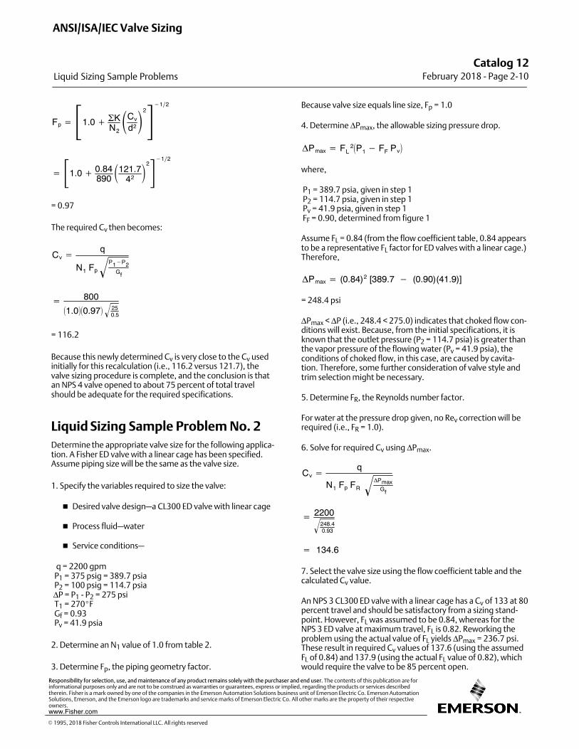
Fp � �1.0 � �KN2
�Cv
d2�2�12
� �1.0 � 0.84890
�121.742�2�12
= 0.97
The required Cv then becomes:
Cv �q
N1 FpP1�P2
Gf�
� 800�1.0��0.97� 25
0.5�
= 116.2
Because this newly determined Cv is very close to the Cv usedinitially for this recalculation (i.e., 116.2 versus 121.7), thevalve sizing procedure is complete, and the conclusion is thatan NPS 4 valve opened to about 75 percent of total travelshould be adequate for the required specifications.
Liquid Sizing Sample Problem No. 2
Determine the appropriate valve size for the following application. A Fisher ED valve with a linear cage has been specified.Assume piping size will be the same as the valve size.
1. Specify the variables required to size the valve:
� Desired valve design—a CL300 ED valve with linear cage
� Process fluid—water
� Service conditions—
q = 2200 gpm P1 = 375 psig = 389.7 psia P2 = 100 psig = 114.7 psia ΔP = P1 ‐ P2 = 275 psi T1 = 270�F Gf = 0.93 Pv = 41.9 psia
2. Determine an N1 value of 1.0 from table 2.
3. Determine Fp, the piping geometry factor.
Because valve size equals line size, Fp = 1.0
4. Determine ΔPmax, the allowable sizing pressure drop.
�Pmax � FL2�P1 � FF Pv�
where,
P1 = 389.7 psia, given in step 1 P2 = 114.7 psia, given in step 1 Pv = 41.9 psia, given in step 1 FF = 0.90, determined from figure 1
Assume FL = 0.84 (from the flow coefficient table, 0.84 appearsto be a representative FL factor for ED valves with a linear cage.)Therefore,
�Pmax � (0.84)2 [389.7 � (0.90)(41.9)]
= 248.4 psi
ΔPmax < ΔP (i.e., 248.4 < 275.0) indicates that choked flow conditions will exist. Because, from the initial specifications, it isknown that the outlet pressure (P2 = 114.7 psia) is greater thanthe vapor pressure of the flowing water (Pv = 41.9 psia), theconditions of choked flow, in this case, are caused by cavitation. Therefore, some further consideration of valve style andtrim selection might be necessary.
5. Determine FR, the Reynolds number factor.
For water at the pressure drop given, no Rev correction will berequired (i.e., FR = 1.0).
6. Solve for required Cv using ΔPmax.
Cv �q
N1 Fp FR�Pmax
Gf�
� 2200248.40.93
�
� 134.6
7. Select the valve size using the flow coefficient table and thecalculated Cv value.
An NPS 3 CL300 ED valve with a linear cage has a Cv of 133 at 80percent travel and should be satisfactory from a sizing standpoint. However, FL was assumed to be 0.84, whereas for theNPS 3 ED valve at maximum travel, FL is 0.82. Reworking theproblem using the actual value of FL yields ΔPmax = 236.7 psi.These result in required Cv values of 137.6 (using the assumedFL of 0.84) and 137.9 (using the actual FL value of 0.82), whichwould require the valve to be 85 percent open.
ANSI/ISA/IEC Valve Sizing
Liquid Sizing Sample Problems
Catalog 12February 2018 ‐ Page 2‐10
� 1995, 2018 Fisher Controls International LLC. All rights reserved
www.Fisher.com
Responsibility for selection, use, and maintenance of any product remains solely with the purchaser and end user. The contents of this publication are forinformational purposes only and are not to be construed as warranties or guarantees, express or implied, regarding the products or services describedtherein. Fisher is a mark owned by one of the companies in the Emerson Automation Solutions business unit of Emerson Electric Co. Emerson AutomationSolutions, Emerson, and the Emerson logo are trademarks and service marks of Emerson Electric Co. All other marks are the property of their respectiveowners.
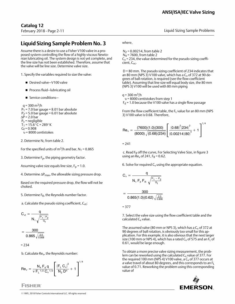
Liquid Sizing Sample Problem No. 3
Assume there is a desire to use a Fisher V100 valve in a proposed system controlling the flow of a highly viscous Newtonian lubricating oil. The system design is not yet complete, andthe line size has not been established. Therefore, assume thatthe valve will be line size. Determine valve size.
1. Specify the variables required to size the valve:
� Desired valve—V100 valve
� Process fluid—lubricating oil
� Service conditions—
q = 300 m3/h P1 = 7.0 bar gauge = 8.01 bar absolute P2 = 5.0 bar gauge = 6.01 bar absoluteΔP = 2.0 bar Pv = negligible T1 = 15.6�C = 289�K Gf = 0.908 υ = 8000 centistokes
2. Determine N1 from table 2.
For the specified units of m3/h and bar, N1 = 0.865
3. Determine Fp, the piping geometry factor.
Assuming valve size equals line size, Fp = 1.0.
4. Determine ΔPmax, the allowable sizing pressure drop.
Based on the required pressure drop, the flow will not bechoked.
5. Determine FR, the Reynolds number factor.
a. Calculate the pseudo sizing coefficient, Cvt:
Cvt �q
N1
P1�P2Gf
�
� 300
0.865 2.00.908�
= 234
b. Calculate Rev, the Reynolds number:
Rev �N4 Fd q
� FL12 Cv
12��FL Cv�2
N2 D4 � 114
where,
N2 = 0.00214, from table 2 N4 = 7600, from table 2Cv = 234, the value determined for the pseudo sizing coefficient, Cvc.
D = 80 mm. The pseudo sizing coefficient of 234 indicates thatan 80 mm (NPS 3) V100 valve, which has a Cv of 372 at 90 degrees of ball rotation, is required (see the flow coefficienttable). Assuming that line size will equal body size, the 80 mm(NPS 3) V100 will be used with 80 mm piping
q = 300 m3/h υ = 8000 centistokes from step 1 Fd = 1.0 because the V100 valve has a single flow passage
From the flow coefficient table, the FL value for an 80 mm (NPS3) V100 valve is 0.68. Therefore,
Rev �(7600)(1.0)(300)
(8000) (0.68)(234)� � �0.68�2�234�
2
�0.00214��80�4 � 114
= 241
c. Read FR off the curve, For Selecting Valve Size, in figure 3using an Rev of 241, FR = 0.62.
6. Solve for required Cv using the appropriate equation.
Cv �q
N1 Fp FR
P1 � P2Gf
�
� 300
0.865(1.0)(0.62) 2.00.908�
= 377
7. Select the valve size using the flow coefficient table and thecalculated Cv value.
The assumed valve (80 mm or NPS 3), which has a Cv of 372 at90 degrees of ball rotation, is obviously too small for this application. For this example, it is also obvious that the next largersize (100 mm or NPS 4), which has a rated Cv of 575 and an FL of0.61, would be large enough.
To obtain a more precise valve sizing measurement, the problem can be reworked using the calculated Cv value of 377. Forthe required 100 mm (NPS 4) V100 valve, a Cv of 377 occurs ata valve travel of about 80 degrees, and this corresponds to an FLvalue of 0.71. Reworking the problem using this correspondingvalue of
Catalog 12 February 2018 ‐ Page 2‐11
ANSI/ISA/IEC Valve Sizing
Liquid Sizing Sample Problems
� 1995, 2018 Fisher Controls International LLC. All rights reserved
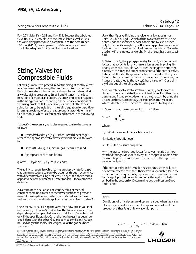
FL = 0.71 yields FR = 0.61 and Cv = 383. Because the tabulatedCv value, 377, is very close to the recalculated Cv value, 383,the valve sizing procedure is complete, and the determined100 mm (NPS 4) valve opened to 80 degrees valve travelshould be adequate for the required specifications.
Sizing Valves forCompressible FluidsFollowing is a six‐step procedure for the sizing of control valvesfor compressible flow using the ISA standardized procedure.Each of these steps is important and must be considered duringany valve sizing procedure. Steps 3 and 4 concern the determination of certain sizing factors that may or may not requiredin the sizing equation depending on the service conditions ofthe sizing problem. If it is necessary for one or both of thesesizing factors to be included in the sizing equation for a particular sizing problem, refer to the appropriate factor determination section(s), which is referenced and located in the followingtext.
1. Specify the necessary variables required to size the valve asfollows:
� Desired valve design (e.g., Fisher ED with linear cage);refer to the appropriate valve flow coefficient table in this catalog
� Process fluid (e.g., air, natural gas, steam, etc.) and
� Appropriate service conditions—
q, or w, P1, P2 or ΔP, T1, Gg, M, k, Z, and γ1
The ability to recognize which terms are appropriate for a specific sizing procedure can only be acquired through experiencewith different valve sizing problems. If any of the above termsappear to be new or unfamiliar, refer to table 1 for a completedefinition.
2. Determine the equation constant, N.N is a numericalconstant contained in each of the flow equations to provide ameans for using different systems of units. values for thesevarious constants and their applicable units are given in table 2.
Use either N7 or N9 if sizing the valve for a flow rate in volumetric units (i.e., scfh or m3/h). Which of the two constants to usedepends upon the specified service conditions. N7 can be usedonly if the specific gravity, Gg, of the flowing gas has been specified along with the other required service conditions. N9 canbe used only if the molecular weight, M, of the gas has beenspecified.
Use either N6 or N8 if sizing the valve for a flow rate in massunits (i.e., lb/h or kg/h). Which of the two constants to use depends upon the specified service conditions. N6 can be usedonly if the specific weight, γ1 of the flowing gas has been specified along with the other required service conditions. N8 can beused only if the molecular weight, M, of the gas has been specified.
3. Determine Fp, the piping geometry factor. Fp is a correctionfactor that accounts for any pressure losses due to piping fittings such as reducers, elbows, or tees that might be attacheddirectly to the inlet and outlet connections of the control valvesto be sized. If such fittings are attached to the valve, the Fp factor must be considered in the sizing procedure. If, however, nofittings are attached to the valve, Fp has a value of 1.0 and simply drops out of the sizing equation.
Also, for rotary valves valves with reducers, Fp factors are included in the appropriate flow coefficient table. For other valvedesigns and fitting styles, determine the Fp factors by using theprocedure for Determining Fp the Piping Geometry Factor,which is located in the section for Sizing Valves for Liquids.
4. Determine Y, the expansion factor, as follows:
Y � 1 � x3 Fk xT
where,
Fk = k/1.4 the ratio of specific heats factor
k = Ratio of specific heats
x = P/P1, the pressure drop ratio
xT = The pressure drop ratio factor for valves installed withoutattached fittings. More definitively, xT is the pressure drop ratiorequired to produce critical, or maximum, flow through thevalve when Fk = 1.0.
If the control valve to be installed has fittings such as reducersor elbows attached to it, then their effect is accounted for in theexpansion factor equation by replacing the xT term with a newfactor xTP. A procedure for determining the xTP factor is described in the section for Determining xTP, the Pressure DropRatio Factor.
Note
Conditions of critical pressure drop are realized when the valueof x become equal to or exceed the appropriate value of theproduct of either Fk xT or Fk xTP at which point:
y � 1 � x3 Fk xT
� 1 � 13 � 0.667
ANSI/ISA/IEC Valve Sizing
Sizing Valve for Compressible Fluids
Catalog 12February 2018 ‐ Page 2‐12
� 1995, 2018 Fisher Controls International LLC. All rights reserved
www.Fisher.com
Responsibility for selection, use, and maintenance of any product remains solely with the purchaser and end user. The contents of this publication are forinformational purposes only and are not to be construed as warranties or guarantees, express or implied, regarding the products or services describedtherein. Fisher is a mark owned by one of the companies in the Emerson Automation Solutions business unit of Emerson Electric Co. Emerson AutomationSolutions, Emerson, and the Emerson logo are trademarks and service marks of Emerson Electric Co. All other marks are the property of their respectiveowners.
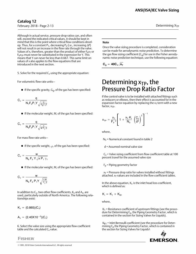
Although in actual service, pressure drop ratios can, and oftenwill, exceed the indicated critical values, it should be kept inmind that this is the point where critical flow conditions develop. Thus, for a constant P1, decreasing P2 (i.e., increasing ΔP)will not result in an increase in the flow rate through the valve.Values of x, therefore, greater than the product of either FkxT orFkxTP must never be substituted in the expression for Y. Thismeans that Y can never be less than 0.667. This same limit onvalues of x also applies to the flow equations that areintroduced in the next section.
5. Solve for the required Cv using the appropriate equation:
For volumetric flow rate units—
� If the specific gravity, Gg, of the gas has been specified:
Cv �q
N7FpP1Yx
GgT1Z�
� If the molecular weight, M, of the gas has been specified:
Cv �q
N9FpP1Yx
M T1 Z�
For mass flow rate units—
� If the specific weight, γ1, of the gas has been specified:
Cv � wN6 Fp Y x P1 �1
�
� If the molecular weight, M, of the gas has been specified:
Cv � w
N8 Fp P1Yx M
T1 Z�
In addition to Cv, two other flow coefficients, Kv and Av, areused, particularly outside of North America. The following relationships exist:
Kv � (0.865)(Cv)
Av � (2.40X10�5)(Cv)
6. Select the valve size using the appropriate flow coefficienttable and the calculated Cv value.
Note
Once the valve sizing procedure is completed, considerationcan be made for aerodynamic noise prediction. To determinethe gas flow sizing coefficient (Cg) for use in the Fisher aerodynamic noise prediction technique, use the following equation:
Cg � 40Cv xT�
Determining xTP, thePressure Drop Ratio FactorIf the control valve is to be installed with attached fittings suchas reducers or elbows, then their effect is accounted for in theexpansion factor equation by replacing the xT term with a newfactor, xTP.
xTP �xT
Fp2�1 �
xT Ki
N5
�Cv
d2�2�1
where,
N5 = Numerical constant found in table 2
d = Assumed nominal valve size
Cv = Valve sizing coefficient from flow coefficient table at 100percent travel for the assumed valve size
Fp = Piping geometry factor
xT = Pressure drop ratio for valves installed without fittingsattached. xT values are included in the flow coefficient tables.
In the above equation, Ki, is the inlet head loss coefficient,which is defined as:
Ki � K1 � KB1
where,
K1 = Resistance coefficient of upstream fittings (see the procedure for Determining Fp, the Piping Geometry Factor, which iscontained in the section for Sizing Valves for Liquids).
KB1 = Inlet Bernoulli coefficient (see the procedure for Determining Fp the Piping Geometry Factor, which is contained inthe section for Sizing Valves for Liquids).
Catalog 12 February 2018 ‐ Page 2‐13
ANSI/ISA/IEC Valve Sizing
Determining XTP
� 1995, 2018 Fisher Controls International LLC. All rights reserved
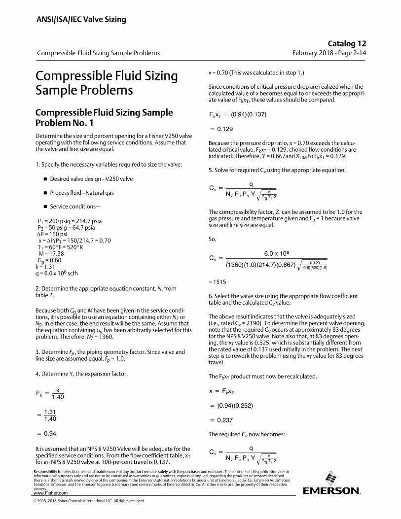
Compressible Fluid SizingSample Problems
Compressible Fluid Sizing SampleProblem No. 1
Determine the size and percent opening for a Fisher V250 valveoperating with the following service conditions. Assume thatthe valve and line size are equal.
1. Specify the necessary variables required to size the valve:
� Desired valve design—V250 valve
� Process fluid—Natural gas
� Service conditions—
P1 = 200 psig = 214.7 psia P2 = 50 psig = 64.7 psia ΔP = 150 psi x = ΔP/P1 = 150/214.7 = 0.70 T1 = 60�F = 520�R M = 17.38 Gg = 0.60k = 1.31q = 6.0 x 10⁶ scfh
2. Determine the appropriate equation constant, N, from table 2.
Because both Gg and M have been given in the service conditions, it is possible to use an equation containing either N7 orN9. In either case, the end result will be the same. Assume thatthe equation containing Gg has been arbitrarily selected for thisproblem. Therefore, N7 = 1360.
3. Determine Fp, the piping geometry factor. Since valve andline size are assumed equal, Fp = 1.0.
4. Determine Y, the expansion factor.
Fk �k
1.40
� 1.311.40
� 0.94
It is assumed that an NPS 8 V250 Valve will be adequate for thespecified service conditions. From the flow coefficient table, xTfor an NPS 8 V250 valve at 100‐percent travel is 0.137.
x = 0.70 (This was calculated in step 1.)
Since conditions of critical pressure drop are realized when thecalculated value of x becomes equal to or exceeds the appropriate value of FkxT, these values should be compared.
FkxT � (0.94)(0.137)
� 0.129
Because the pressure drop ratio, x = 0.70 exceeds the calculated critical value, FkxT = 0.129, choked flow conditions areindicated. Therefore, Y = 0.667and XLIM to FkxT = 0.129.
5. Solve for required Cv using the appropriate equation.
Cv �q
N7 Fp P1 Y xGg T1 Z�
The compressibility factor, Z, can be assumed to be 1.0 for thegas pressure and temperature given and Fp = 1 because valvesize and line size are equal.
So,
Cv �6.0 x 10⁶
(1360)(1.0)(214.7)(0.667) 0.129(0.6)(520)(1.0)
�
= 1515
6. Select the valve size using the appropriate flow coefficienttable and the calculated Cv value.
The above result indicates that the valve is adequately sized(i.e., rated Cv = 2190). To determine the percent valve opening,note that the required Cv occurs at approximately 83 degreesfor the NPS 8 V250 valve. Note also that, at 83 degrees opening, the xT value is 0.525, which is substantially different fromthe rated value of 0.137 used initially in the problem. The nextstep is to rework the problem using the xT value for 83 degreestravel.
The FkxT product must now be recalculated.
x � FkxT
� (0.94)(0.252)
� 0.237
The required Cv now becomes:
Cv �q
N7 Fp P1 Y xGg T1 Z�
ANSI/ISA/IEC Valve Sizing
Compressible Fluid Sizing Sample Problems
Catalog 12February 2018 ‐ Page 2‐14
� 1995, 2018 Fisher Controls International LLC. All rights reserved
www.Fisher.com
Responsibility for selection, use, and maintenance of any product remains solely with the purchaser and end user. The contents of this publication are forinformational purposes only and are not to be construed as warranties or guarantees, express or implied, regarding the products or services describedtherein. Fisher is a mark owned by one of the companies in the Emerson Automation Solutions business unit of Emerson Electric Co. Emerson AutomationSolutions, Emerson, and the Emerson logo are trademarks and service marks of Emerson Electric Co. All other marks are the property of their respectiveowners.
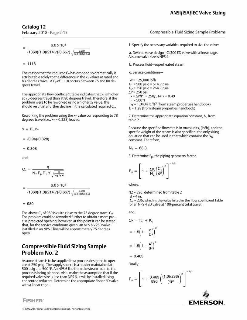
�6.0 x 10⁶
(1360)(1.0)(214.7)(0.667) 0.237(0.6)(520)(1.0)
�
� 1118
The reason that the required Cv has dropped so dramatically isattributable solely to the difference in the xT values at rated and83 degrees travel. A Cv of 1118 occurs between 75 and 80 degrees travel.
The appropriate flow coefficient table indicates that xT is higherat 75 degrees travel than at 80 degrees travel. Therefore, if theproblem were to be reworked using a higher xT value, thisshould result in a further decline in the calculated required Cv.
Reworking the problem using the xT value corresponding to 78degrees travel (i.e., xT = 0.328) leaves:
x � Fk xT
� (0.94)(0.328)
� 0.308
and,
Cv �q
N7 Fp P1 Y xGg T1 Z�
�6.0 x 10⁶
(1360)(1.0)(214.7)(0.667) 0.308(0.6)(520)(1.0)
�
� 980
The above Cv of 980 is quite close to the 75 degree travel Cv.The problem could be reworked further to obtain a more precise predicted opening; however, at this point it can be statedthat, for the service conditions given, an NPS 8 V250 valveinstalled in an NPS 8 line will be approximately 75 degreesopen.
Compressible Fluid Sizing SampleProblem No. 2
Assume steam is to be supplied to a process designed to operate at 250 psig. The supply source is a header maintained at500 psig and 500�F. An NPS 6 line from the steam main to theprocess is being planned. Also, make the assumption that if therequired valve size is less than NPS 6, it will be installed usingconcentric reducers. Determine the appropriate Fisher ED valvewith a linear cage.
1. Specify the necessary variables required to size the valve:
a. Desired valve design—CL300 ED valve with a linear cage.Assume valve size is NPS 4.
b. Process fluid—superheated steam
c. Service conditions—
w = 125,000 lb/h P1 = 500 psig = 514.7 psia P2 = 250 psig = 264.7 psiaΔP = 250 psi x = ΔP/P1 = 250/514.7 = 0.49 T1 = 500�F γ1 = 1.0434 lb/ft3 (from steam properties handbook) k = 1.28 (from steam properties handbook)
2. Determine the appropriate equation constant, N, from table 2.
Because the specified flow rate is in mass units, (lb/h), and thespecific weight of the steam is also specified, the only sizingequation that can be used in that which contains the N6constant. Therefore,
N6 � 63.3
3. Determine Fp, the piping geometry factor.
Fp � �1 � �KN2
�Cv
d2�2�12
where,
N2 = 890, determined from table 2 d = 4 in. Cv = 236, which is the value listed in the flow coefficient tablefor an NPS 4 ED valve at 100‐percent total travel.
and,
�k � K1 � K2
� 1.5�1 � d2
D2�2
� 1.5�1 � 42
62�2
� 0.463
Finally:
Fp � �1 � 0.463890�(1.0)(236)
(4)2�2�12
Catalog 12 February 2018 ‐ Page 2‐15
ANSI/ISA/IEC Valve Sizing
Compressible Fluid Sizing Sample Problems
� 1995, 2017 Fisher Controls International LLC. All rights reserved
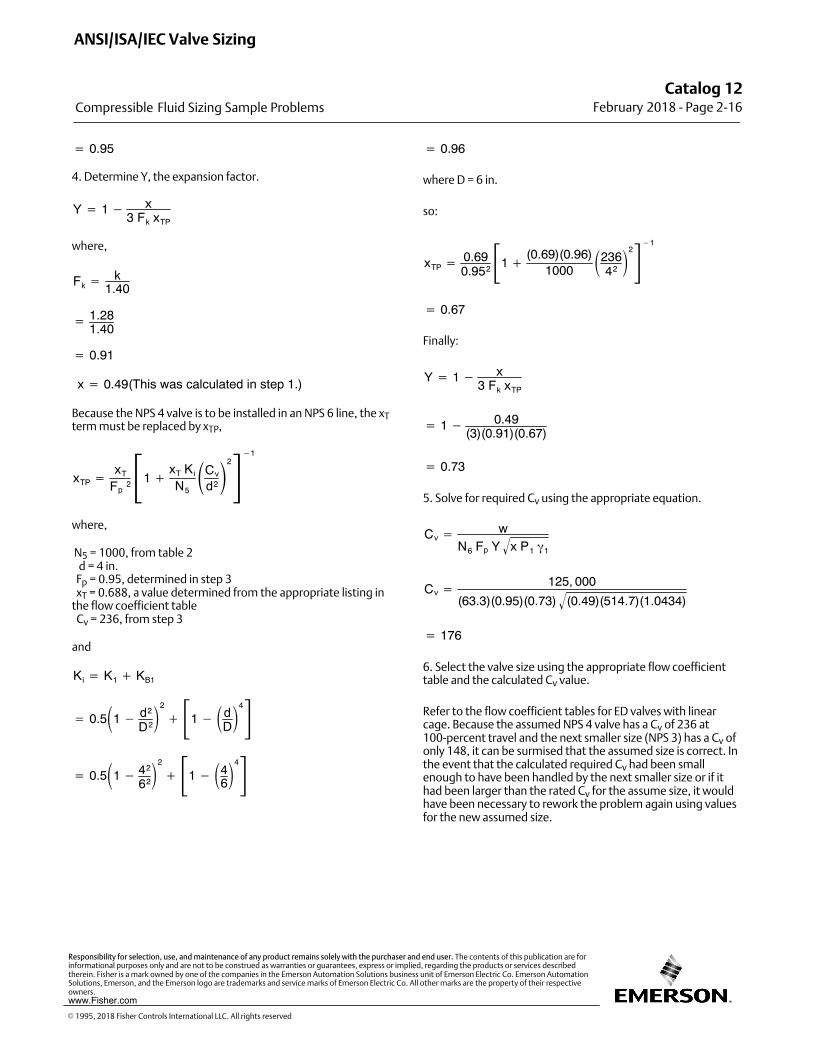
� 0.95
4. Determine Y, the expansion factor.
Y � 1 � x3 Fk xTP
where,
Fk �k
1.40
� 1.281.40
� 0.91
x � 0.49(This was calculated in step 1.)
Because the NPS 4 valve is to be installed in an NPS 6 line, the xTterm must be replaced by xTP,
xTP �xT
Fp2�1 �
xT Ki
N5
�Cv
d2�2�1
where,
N5 = 1000, from table 2 d = 4 in. Fp = 0.95, determined in step 3 xT = 0.688, a value determined from the appropriate listing inthe flow coefficient table Cv = 236, from step 3
and
Ki � K1 � KB1
� 0.5�1 � d2
D2�2
��1 � �dD�4
� 0.5�1 � 42
62�2
��1 � �46�4
� 0.96
where D = 6 in.
so:
xTP � 0.690.952�1 �
(0.69)(0.96)1000
�23642�2�1
� 0.67
Finally:
Y � 1 � x3 Fk xTP
� 1 � 0.49(3)(0.91)(0.67)
� 0.73
5. Solve for required Cv using the appropriate equation.
Cv � wN6 Fp Y x P1 �1
�
Cv �125, 000
(63.3)(0.95)(0.73) (0.49)(514.7)(1.0434)�
� 176
6. Select the valve size using the appropriate flow coefficienttable and the calculated Cv value.
Refer to the flow coefficient tables for ED valves with linearcage. Because the assumed NPS 4 valve has a Cv of 236 at100‐percent travel and the next smaller size (NPS 3) has a Cv ofonly 148, it can be surmised that the assumed size is correct. Inthe event that the calculated required Cv had been smallenough to have been handled by the next smaller size or if ithad been larger than the rated Cv for the assume size, it wouldhave been necessary to rework the problem again using valuesfor the new assumed size.
ANSI/ISA/IEC Valve Sizing
Compressible Fluid Sizing Sample Problems
Catalog 12February 2018 ‐ Page 2‐16
� 1995, 2018 Fisher Controls International LLC. All rights reserved
www.Fisher.com
Responsibility for selection, use, and maintenance of any product remains solely with the purchaser and end user. The contents of this publication are forinformational purposes only and are not to be construed as warranties or guarantees, express or implied, regarding the products or services describedtherein. Fisher is a mark owned by one of the companies in the Emerson Automation Solutions business unit of Emerson Electric Co. Emerson AutomationSolutions, Emerson, and the Emerson logo are trademarks and service marks of Emerson Electric Co. All other marks are the property of their respectiveowners.
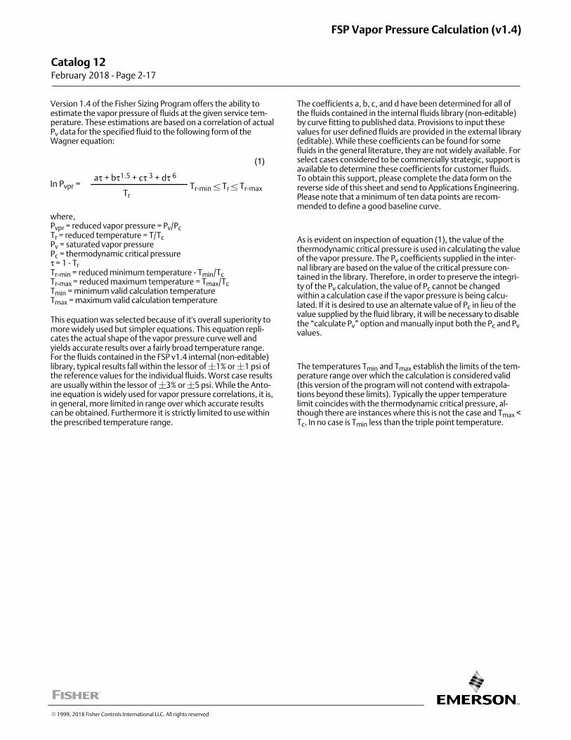
Version 1.4 of the Fisher Sizing Program offers the ability toestimate the vapor pressure of fluids at the given service temperature. These estimations are based on a correlation of actualPv data for the specified fluid to the following form of theWagner equation:
In Pvpr =aτ + bτ1.5 + cτ 3 + dτ 6
TrTr‐min � Tr � Tr‐max
(1)
where,Pvpr = reduced vapor pressure = Pv/PcTr = reduced temperature = T/TcPv = saturated vapor pressurePc = thermodynamic critical pressureτ = 1 ‐ TrTr‐min = reduced minimum temperature - Tmin/TcTr‐max = reduced maximum temperature = Tmax/TcTmin = minimum valid calculation temperatureTmax = maximum valid calculation temperature
This equation was selected because of it's overall superiority tomore widely used but simpler equations. This equation replicates the actual shape of the vapor pressure curve well andyields accurate results over a fairly broad temperature range.For the fluids contained in the FSP v1.4 internal (non‐editable)library, typical results fall within the lessor of �1% or �1 psi ofthe reference values for the individual fluids. Worst case resultsare usually within the lessor of �3% or �5 psi. While the Antoine equation is widely used for vapor pressure correlations, it is,in general, more limited in range over which accurate resultscan be obtained. Furthermore it is strictly limited to use withinthe prescribed temperature range.
The coefficients a, b, c, and d have been determined for all ofthe fluids contained in the internal fluids library (non‐editable)by curve fitting to published data. Provisions to input thesevalues for user defined fluids are provided in the external library(editable). While these coefficients can be found for somefluids in the general literature, they are not widely available. Forselect cases considered to be commercially strategic, support isavailable to determine these coefficients for customer fluids.To obtain this support, please complete the data form on thereverse side of this sheet and send to Applications Engineering.Please note that a minimum of ten data points are recommended to define a good baseline curve.
As is evident on inspection of equation (1), the value of thethermodynamic critical pressure is used in calculating the valueof the vapor pressure. The Pv coefficients supplied in the internal library are based on the value of the critical pressure contained in the library. Therefore, in order to preserve the integrity of the Pv calculation, the value of Pc cannot be changedwithin a calculation case if the vapor pressure is being calculated. If it is desired to use an alternate value of Pc in lieu of thevalue supplied by the fluid library, it will be necessary to disablethe “calculate Pv” option and manually input both the Pc and Pvvalues.
The temperatures Tmin and Tmax establish the limits of the temperature range over which the calculation is considered valid(this version of the program will not contend with extrapolations beyond these limits). Typically the upper temperaturelimit coincides with the thermodynamic critical pressure, although there are instances where this is not the case and Tmax <Tc. In no case is Tmin less than the triple point temperature.
� 1999, 2018 Fisher Controls International LLC. All rights reserved
Catalog 12 February 2018 ‐ Page 2‐17
FSP Vapor Pressure Calculation (v1.4)
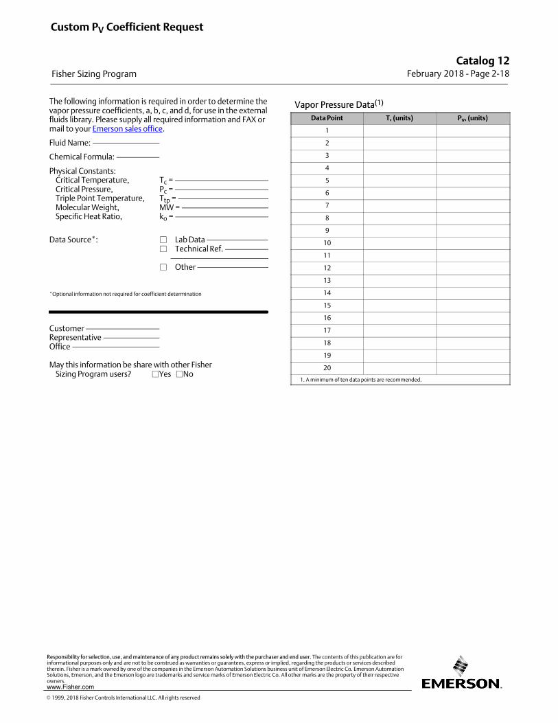
The following information is required in order to determine thevapor pressure coefficients, a, b, c, and d, for use in the externalfluids library. Please supply all required information and FAX ormail to your Emerson sales office.
Fluid Name:
Chemical Formula:
Physical Constants: Critical Temperature, Tc = Critical Pressure, Pc = Triple Point Temperature, Ttp = Molecular Weight, MW = Specific Heat Ratio, ko =
Data Source*: � Lab Data � Technical Ref. � Other
*Optional information not required for coefficient determination
Customer Representative Office
May this information be share with other Fisher Sizing Program users? �Yes �No
Vapor Pressure Data(1)
Data Point T, (units) Pv, (units)
1
2
3
4
5
6
7
8
9
10
11
12
13
14
15
16
17
18
19
20
1. A minimum of ten data points are recommended.
Custom PV Coefficient Request
Fisher Sizing Program
Catalog 12February 2018 ‐ Page 2‐18
� 1999, 2018 Fisher Controls International LLC. All rights reserved
www.Fisher.com
Responsibility for selection, use, and maintenance of any product remains solely with the purchaser and end user. The contents of this publication are forinformational purposes only and are not to be construed as warranties or guarantees, express or implied, regarding the products or services describedtherein. Fisher is a mark owned by one of the companies in the Emerson Automation Solutions business unit of Emerson Electric Co. Emerson AutomationSolutions, Emerson, and the Emerson logo are trademarks and service marks of Emerson Electric Co. All other marks are the property of their respectiveowners.
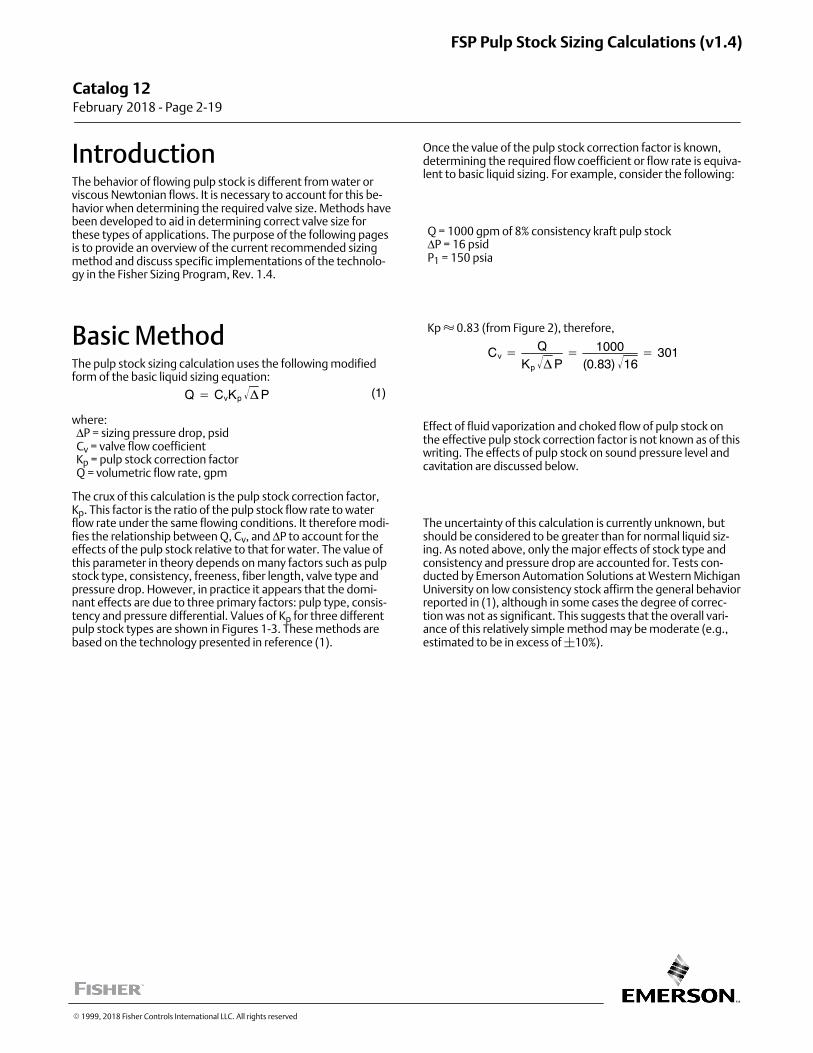
IntroductionThe behavior of flowing pulp stock is different from water orviscous Newtonian flows. It is necessary to account for this behavior when determining the required valve size. Methods havebeen developed to aid in determining correct valve size forthese types of applications. The purpose of the following pagesis to provide an overview of the current recommended sizingmethod and discuss specific implementations of the technology in the Fisher Sizing Program, Rev. 1.4.
Basic MethodThe pulp stock sizing calculation uses the following modifiedform of the basic liquid sizing equation:
Q � CvKp �� P (1)
where: ΔP = sizing pressure drop, psid Cv = valve flow coefficient Kp = pulp stock correction factor Q = volumetric flow rate, gpm
The crux of this calculation is the pulp stock correction factor,Kp. This factor is the ratio of the pulp stock flow rate to waterflow rate under the same flowing conditions. It therefore modifies the relationship between Q, Cv, and ΔP to account for theeffects of the pulp stock relative to that for water. The value ofthis parameter in theory depends on many factors such as pulpstock type, consistency, freeness, fiber length, valve type andpressure drop. However, in practice it appears that the dominant effects are due to three primary factors: pulp type, consistency and pressure differential. Values of Kp for three differentpulp stock types are shown in Figures 1‐3. These methods arebased on the technology presented in reference (1).
Once the value of the pulp stock correction factor is known,determining the required flow coefficient or flow rate is equivalent to basic liquid sizing. For example, consider the following:
Q = 1000 gpm of 8% consistency kraft pulp stock ΔP = 16 psid P1 = 150 psia
Kp � 0.83 (from Figure 2), therefore,
Cv �Q
Kp �� P� 1000
(0.83) 16� � 301
Effect of fluid vaporization and choked flow of pulp stock onthe effective pulp stock correction factor is not known as of thiswriting. The effects of pulp stock on sound pressure level andcavitation are discussed below.
The uncertainty of this calculation is currently unknown, butshould be considered to be greater than for normal liquid sizing. As noted above, only the major effects of stock type andconsistency and pressure drop are accounted for. Tests conducted by Emerson Automation Solutions at Western MichiganUniversity on low consistency stock affirm the general behaviorreported in (1), although in some cases the degree of correction was not as significant. This suggests that the overall variance of this relatively simple method may be moderate (e.g.,estimated to be in excess of �10%).
Catalog 12 February 2018 ‐ Page 2‐19
FSP Pulp Stock Sizing Calculations (v1.4)
� 1999, 2018 Fisher Controls International LLC. All rights reserved
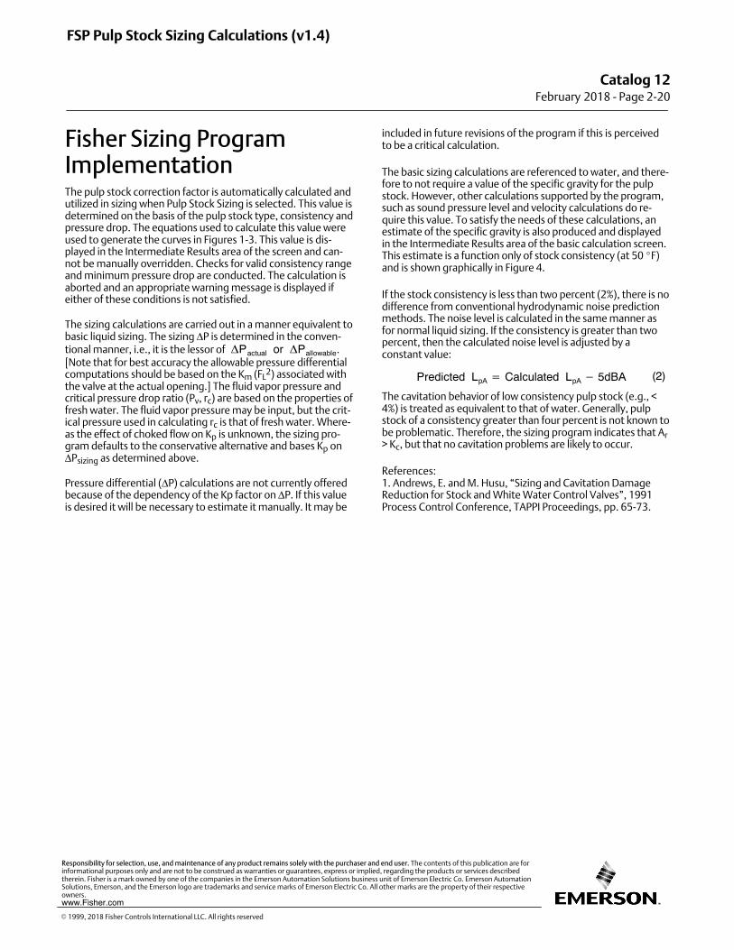
Fisher Sizing ProgramImplementationThe pulp stock correction factor is automatically calculated andutilized in sizing when Pulp Stock Sizing is selected. This value isdetermined on the basis of the pulp stock type, consistency andpressure drop. The equations used to calculate this value wereused to generate the curves in Figures 1‐3. This value is displayed in the Intermediate Results area of the screen and cannot be manually overridden. Checks for valid consistency rangeand minimum pressure drop are conducted. The calculation isaborted and an appropriate warning message is displayed ifeither of these conditions is not satisfied.
The sizing calculations are carried out in a manner equivalent tobasic liquid sizing. The sizing ΔP is determined in the conventional manner, i.e., it is the lessor of �Pactual or �Pallowable.[Note that for best accuracy the allowable pressure differentialcomputations should be based on the Km (FL
2) associated withthe valve at the actual opening.] The fluid vapor pressure andcritical pressure drop ratio (Pv, rc) are based on the properties offresh water. The fluid vapor pressure may be input, but the critical pressure used in calculating rc is that of fresh water. Whereas the effect of choked flow on Kp is unknown, the sizing program defaults to the conservative alternative and bases Kp onΔPsizing as determined above.
Pressure differential (ΔP) calculations are not currently offeredbecause of the dependency of the Kp factor on ΔP. If this valueis desired it will be necessary to estimate it manually. It may be
included in future revisions of the program if this is perceivedto be a critical calculation.
The basic sizing calculations are referenced to water, and therefore to not require a value of the specific gravity for the pulpstock. However, other calculations supported by the program,such as sound pressure level and velocity calculations do require this value. To satisfy the needs of these calculations, anestimate of the specific gravity is also produced and displayedin the Intermediate Results area of the basic calculation screen.This estimate is a function only of stock consistency (at 50 �F)and is shown graphically in Figure 4.
If the stock consistency is less than two percent (2%), there is nodifference from conventional hydrodynamic noise predictionmethods. The noise level is calculated in the same manner asfor normal liquid sizing. If the consistency is greater than twopercent, then the calculated noise level is adjusted by aconstant value:
Predicted LpA � Calculated LpA � 5dBA (2)
The cavitation behavior of low consistency pulp stock (e.g., <4%) is treated as equivalent to that of water. Generally, pulpstock of a consistency greater than four percent is not known tobe problematic. Therefore, the sizing program indicates that Ar> Kc, but that no cavitation problems are likely to occur.
References:1. Andrews, E. and M. Husu, “Sizing and Cavitation DamageReduction for Stock and White Water Control Valves”, 1991Process Control Conference, TAPPI Proceedings, pp. 65‐73.
FSP Pulp Stock Sizing Calculations (v1.4)
Catalog 12February 2018 ‐ Page 2‐20
� 1999, 2018 Fisher Controls International LLC. All rights reserved
www.Fisher.com
Responsibility for selection, use, and maintenance of any product remains solely with the purchaser and end user. The contents of this publication are forinformational purposes only and are not to be construed as warranties or guarantees, express or implied, regarding the products or services describedtherein. Fisher is a mark owned by one of the companies in the Emerson Automation Solutions business unit of Emerson Electric Co. Emerson AutomationSolutions, Emerson, and the Emerson logo are trademarks and service marks of Emerson Electric Co. All other marks are the property of their respectiveowners.
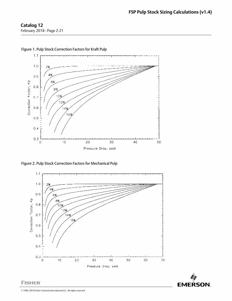
Figure 1. Pulp Stock Correction Factors for Kraft Pulp
Figure 2. Pulp Stock Correction Factors for Mechanical Pulp
Catalog 12 February 2018 ‐ Page 2‐21
FSP Pulp Stock Sizing Calculations (v1.4)
� 1999, 2018 Fisher Controls International LLC. All rights reserved
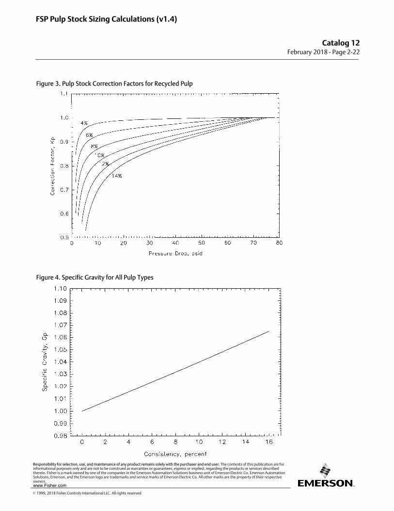
Figure 3. Pulp Stock Correction Factors for Recycled Pulp
Figure 4. Specific Gravity for All Pulp Types
FSP Pulp Stock Sizing Calculations (v1.4)
Catalog 12February 2018 ‐ Page 2‐22
� 1999, 2018 Fisher Controls International LLC. All rights reserved
www.Fisher.com
Responsibility for selection, use, and maintenance of any product remains solely with the purchaser and end user. The contents of this publication are forinformational purposes only and are not to be construed as warranties or guarantees, express or implied, regarding the products or services describedtherein. Fisher is a mark owned by one of the companies in the Emerson Automation Solutions business unit of Emerson Electric Co. Emerson AutomationSolutions, Emerson, and the Emerson logo are trademarks and service marks of Emerson Electric Co. All other marks are the property of their respectiveowners.
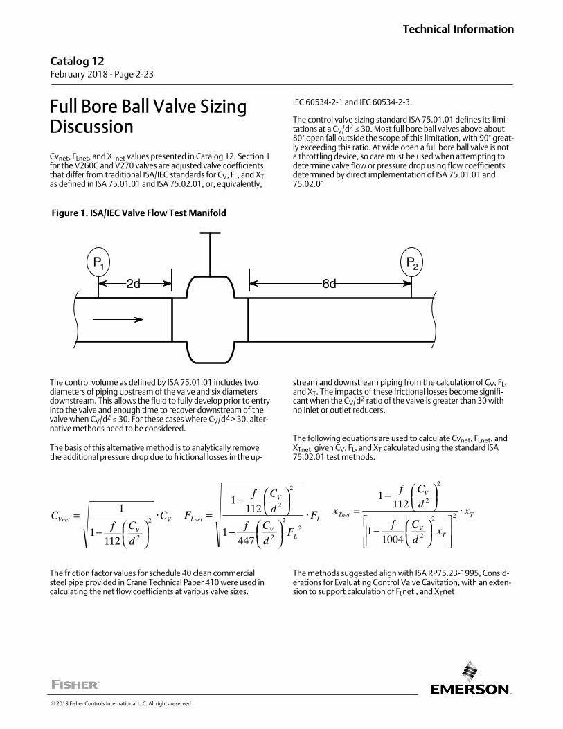
Full Bore Ball Valve SizingDiscussion
Cvnet, FLnet, and XTnet values presented in Catalog 12, Section 1for the V260C and V270 valves are adjusted valve coefficientsthat differ from traditional ISA/IEC standards for CV, FL, and XTas defined in ISA 75.01.01 and ISA 75.02.01, or, equivalently,
IEC 60534-2-1 and IEC 60534-2-3.
The control valve sizing standard ISA 75.01.01 defines its limitations at a CV/d2 ≤ 30. Most full bore ball valves above about80° open fall outside the scope of this limitation, with 90° greatly exceeding this ratio. At wide open a full bore ball valve is nota throttling device, so care must be used when attempting todetermine valve flow or pressure drop using flow coefficientsdetermined by direct implementation of ISA 75.01.01 and75.02.01
Figure 1. ISA/IEC Valve Flow Test Manifold
P1
2d
P2
6d
The control volume as defined by ISA 75.01.01 includes twodiameters of piping upstream of the valve and six diametersdownstream. This allows the fluid to fully develop prior to entryinto the valve and enough time to recover downstream of thevalve when CV/d2 ≤ 30. For these cases where CV/d2 > 30, alternative methods need to be considered.
The basis of this alternative method is to analytically removethe additional pressure drop due to frictional losses in the up
stream and downstream piping from the calculation of CV, FL,and XT. The impacts of these frictional losses become significant when the CV/d2 ratio of the valve is greater than 30 withno inlet or outlet reducers.
The following equations are used to calculate Cvnet, FLnet, andXTnet given CV, FL, and XT calculated using the standard ISA75.02.01 test methods.
V
V
Vnet C
d
CfC �
⎟⎠⎞⎢
⎝⎛−
= 2
21121
1
L
LV
V
Lnet F
Fd
Cf
d
Cf
F �
⎟⎠⎞⎢
⎝⎛−
⎟⎠⎞⎢
⎝⎛−
=2
2
2
2
2
4471
1121
T
TV
V
Tnet x
xd
Cf
d
Cf
x �
⎥⎥⎦
⎤
⎪⎪⎣
⎡⎟⎠⎞⎢
⎝⎛−
⎟⎠⎞
⎢⎝⎛−
= 22
2
2
2
10041
1121
The friction factor values for schedule 40 clean commercialsteel pipe provided in Crane Technical Paper 410 were used incalculating the net flow coefficients at various valve sizes.
The methods suggested align with ISA RP75.23-1995, Considerations for Evaluating Control Valve Cavitation, with an extension to support calculation of FLnet , and XTnet
Catalog 12 February 2018 ‐ Page 2‐23
Technical Information
� 2018 Fisher Controls International LLC. All rights reserved
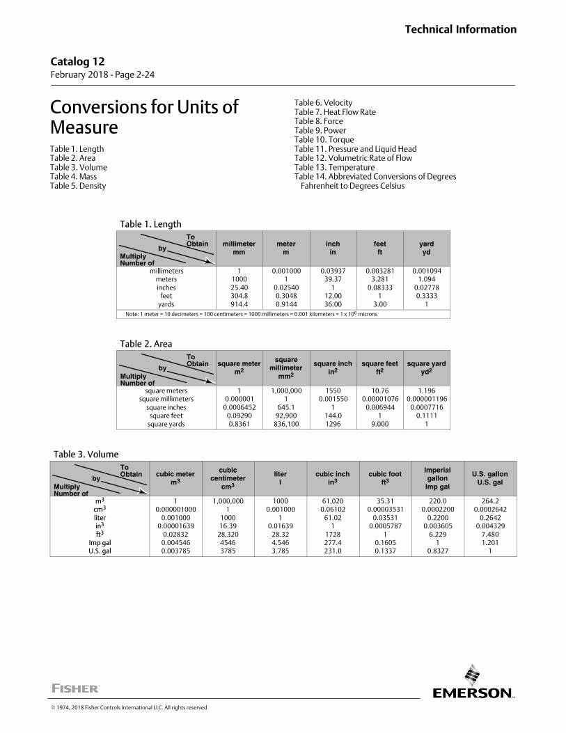
Conversions for Units ofMeasureTable 1. LengthTable 2. AreaTable 3. VolumeTable 4. MassTable 5. Density
Table 6. VelocityTable 7. Heat Flow RateTable 8. ForceTable 9. PowerTable 10. TorqueTable 11. Pressure and Liquid HeadTable 12. Volumetric Rate of FlowTable 13. TemperatureTable 14. Abbreviated Conversions of Degrees Fahrenheit to Degrees Celsius
Table 1. Length
MultiplyNumber of
ToObtain
bymillimeter
mmmeter
minch
infeetft
yardyd
millimetersmetersinches
feetyards
1100025.40304.8914.4
0.0010001
0.025400.30480.9144
0.0393739.37
112.0036.00
0.0032813.281
0.083331
3.00
0.0010941.094
0.027780.3333
1
Note: 1 meter = 10 decimeters = 100 centimeters = 1000 millimeters = 0.001 kilometers = 1 x 10⁶ microns
Table 2. Area
MultiplyNumber of
ToObtain
bysquare meter
m2
squaremillimeter
mm2
square inchin2
square feetft2
square yardyd2
square meterssquare millimeters
square inchessquare feet
square yards
10.000001
0.00064520.092900.8361
1,000,0001
645.192,900
836,100
15500.001550
1144.01296
10.760.00001076
0.0069441
9.000
1.1960.000001196
0.00077160.1111
1
Table 3. Volume
MultiplyNumber of
ToObtain
bycubic meter
m3
cubiccentimeter
cm3
literl
cubic inchin3
cubic footft3
Imperialgallon
Imp gal
U.S. gallonU.S. gal
m3
cm3
literin3
ft3
Imp galU.S. gal
10.000001000
0.0010000.00001639
0.028320.0045460.003785
1,000,0001
100016.39
28,32045463785
10000.001000
10.01639
28.324.5463.785
61,0200.06102
61.021
1728277.4231.0
35.310.00003531
0.035310.0005787
10.16050.1337
220.00.0002200
0.22000.003605
6.2291
0.8327
264.20.0002642
0.26420.004329
7.4801.201
1
Catalog 12 February 2018 ‐ Page 2‐24
Technical Information
� 1974, 2018 Fisher Controls International LLC. All rights reserved
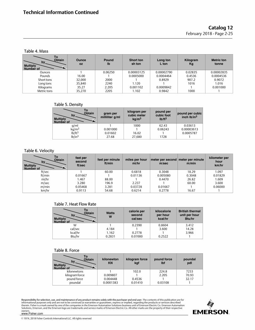
Table 4. Mass
MultiplyNumber of
ToObtain
byOunce
ozPound
lbShort ton
sh tonLong ton
L tonKilogram
KgMetric ton
tonne
OuncesPounds
Short tonsLong tonsKilograms
Metric tons
116.00
32,00035,84035.27
35,270
0.062501
200022402.2052205
0.000031250.0005000
11.120
0.0011021.102
0.000027900.0004464
0.89291
0.00098420.9842
0.028350.4536907.21016
11000
0.000028350.0004536
0.90721.016
0.0010001
Table 5. Density
MultiplyNumber of
ToObtain
by gram permilliliter g/ml
kilogram percubic meter
kg/m3
pound percubic foot
lb/ft3
pound per cubicinch lb/in3
g/mlkg/m3
lb/ft3
lb/in3
10.0010000.01602
27.68
10001
16.0227,680
62.430.06243
11728
0.036130.000036130.0005787
1
Table 6. Velocity
MultiplyNumber of
ToObtain
byfeet persecondft/sec
feet per minuteft/min
miles per hourmi/hr
meter per secondm/sec
meter per minutem/min
kilometer perhourkm/hr
ft/secft/minmi/hrm/secm/minkm/hr
10.01667
1.4673.280
0.054680.9113
60.001
88.00196.93.28154.68
0.68180.01136
12.237
0.037280.6214
0.30480.005080
0.44701
0.016670.2778
18.290.304826.8260.00
116.67
1.0970.01829
1.6093.600
0.060001
Table 7. Heat Flow Rate
MultiplyNumber of
ToObtain
byWatts
W
calorie persecondcal/sec
kilocalorieper hourkcal/hr
British thermalunit per hour
Btu/hr
Wcal/seckcal/hrBtu/hr
14.1841.162
0.2831
0.23901
0.27780.07000
0.86043.600
10.2522
3.41214.283.966
1
Table 8. Force
MultiplyNumber of
ToObtain
bykilonewton
KNkilogram force
kgfpound force
lbfpoundal
pdl
kilonewtonskilogram force
pound forcepoundal
10.0098070.004448
0.0001383
102.01
0.45360.01410
224.82.205
10.03108
723370.9332.17
1
Technical Information Continued
Catalog 12February 2018 ‐ Page 2‐25
� 1974, 2018 Fisher Controls International LLC. All rights reserved
www.Fisher.com
Responsibility for selection, use, and maintenance of any product remains solely with the purchaser and end user. The contents of this publication are forinformational purposes only and are not to be construed as warranties or guarantees, express or implied, regarding the products or services describedtherein. Fisher is a mark owned by one of the companies in the Emerson Automation Solutions business unit of Emerson Electric Co. Emerson AutomationSolutions, Emerson, and the Emerson logo are trademarks and service marks of Emerson Electric Co. All other marks are the property of their respectiveowners.
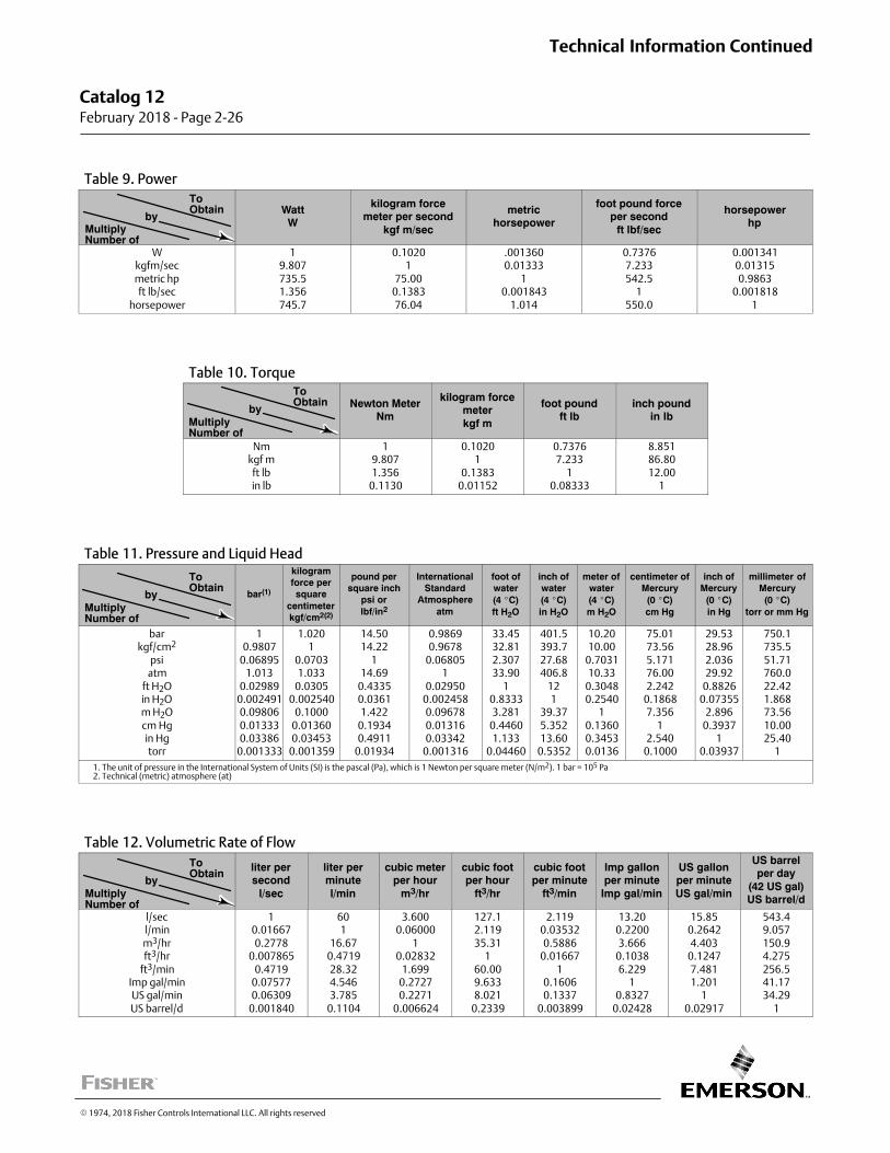
Table 9. Power
MultiplyNumber of
ToObtain
byWatt
W
kilogram forcemeter per second
kgf m/sec
metrichorsepower
foot pound forceper second
ft lbf/sec
horsepowerhp
Wkgfm/secmetric hpft lb/sec
horsepower
19.807735.51.356745.7
0.10201
75.000.138376.04
.0013600.01333
10.001843
1.014
0.73767.233542.5
1550.0
0.0013410.013150.9863
0.0018181
Table 10. Torque
MultiplyNumber of
ToObtain
by Newton MeterNm
kilogram forcemeterkgf m
foot poundft lb
inch poundin lb
Nmkgf mft lbin lb
19.8071.356
0.1130
0.10201
0.13830.01152
0.73767.233
10.08333
8.85186.8012.00
1
Table 11. Pressure and Liquid Head
MultiplyNumber of
ToObtain
by bar(1)
kilogramforce persquare
centimeterkgf/cm2(2)
pound persquare inch
psi orlbf/in2
InternationalStandard
Atmosphereatm
foot ofwater(4 �C)ft H2O
inch ofwater(4 �C)in H2O
meter ofwater(4 �C)m H2O
centimeter ofMercury(0 �C)cm Hg
inch ofMercury
(0 �C)in Hg
millimeter ofMercury(0 �C)
torr or mm Hg
barkgf/cm2
psiatm
ft H2Oin H2Om H2Ocm Hgin Hgtorr
10.9807
0.068951.013
0.029890.0024910.098060.013330.03386
0.001333
1.0201
0.07031.033
0.03050.002540
0.10000.013600.03453
0.001359
14.5014.22
114.69
0.43350.03611.422
0.19340.4911
0.01934
0.98690.9678
0.068051
0.029500.0024580.096780.013160.03342
0.001316
33.4532.812.30733.90
10.83333.281
0.44601.133
0.04460
401.5393.727.68406.8
121
39.375.35213.60
0.5352
10.2010.00
0.703110.33
0.30480.2540
10.13600.34530.0136
75.0173.565.17176.002.242
0.18687.356
12.540
0.1000
29.5328.962.03629.92
0.88260.07355
2.8960.3937
10.03937
750.1735.551.71760.022.421.86873.5610.0025.40
1
1. The unit of pressure in the International System of Units (SI) is the pascal (Pa), which is 1 Newton per square meter (N/m2). 1 bar = 105 Pa2. Technical (metric) atmosphere (at)
Table 12. Volumetric Rate of Flow
MultiplyNumber of
ToObtain
byliter persecond
l/sec
liter perminutel/min
cubic meterper hour
m3/hr
cubic footper hour
ft3/hr
cubic footper minute
ft3/min
Imp gallonper minute
Imp gal/min
US gallonper minuteUS gal/min
US barrelper day
(42 US gal)US barrel/d
l/secl/minm3/hrft3/hr
ft3/minImp gal/minUS gal/minUS barrel/d
10.016670.2778
0.0078650.4719
0.075770.06309
0.001840
601
16.670.471928.324.5463.785
0.1104
3.6000.06000
10.02832
1.6990.27270.2271
0.006624
127.12.11935.31
160.009.6338.021
0.2339
2.1190.035320.5886
0.016671
0.16060.1337
0.003899
13.200.22003.666
0.10386.229
10.8327
0.02428
15.850.26424.403
0.12477.4811.201
10.02917
543.49.057150.94.275256.541.1734.29
1
Catalog 12 February 2018 ‐ Page 2‐26
Technical Information Continued
� 1974, 2018 Fisher Controls International LLC. All rights reserved
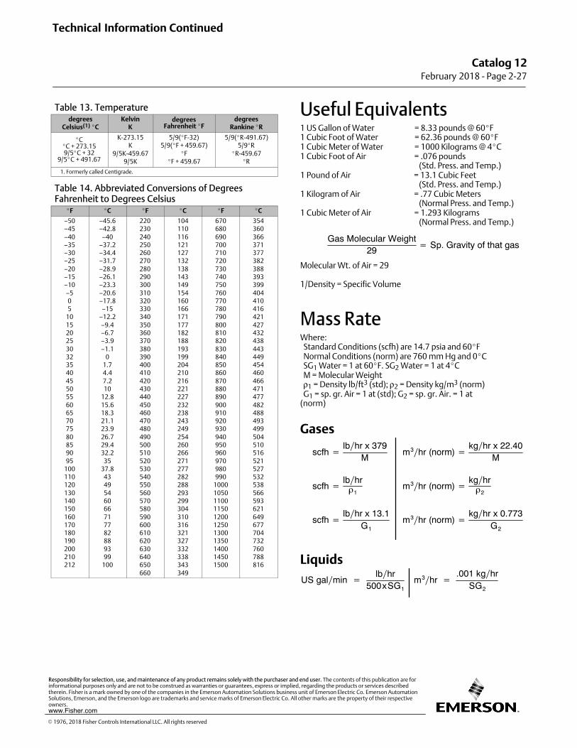
Table 13. Temperaturedegrees
Celsius(1) �CKelvin
Kdegrees
Fahrenheit �Fdegrees
Rankine �R
�C�C + 273.159/5�C + 32
9/5�C + 491.67
K‐273.15K
9/5K‐459.679/5K
5/9(�F‐32)5/9(�F + 459.67)
�F�F + 459.67
5/9(�R‐491.67)5/9�R
�R‐459.67�R
1. Formerly called Centigrade.
Table 14. Abbreviated Conversions of DegreesFahrenheit to Degrees Celsius
�F �C �F �C �F �C
–50–45–40–35–30–25–20–15–10–505
10152025303235404550556065707580859095
100110120130140150160170180190200210212
–45.6–42.8
–40–37.2–34.4–31.7–28.9–26.1–23.3–20.6–17.8
–15–12.2–9.4–6.7–3.9–1.1
01.74.47.210
12.815.618.321.123.926.729.432.2
3537.8
4349546066717782889399
100
220230240250260270280290300310320330340350360370380390400410420430440450460470480490500510520530540550560570580590600610620630640650660
104110116121127132138143149154160166171177182188193199204210216221227232238243249254260266271277282288293299304310316321327332338343349
670680690700710720730740750760770780790800810820830840850860870880890900910920930940950960970980990
10001050110011501200125013001350140014501500
354360366371377382388393399404410416421427432438443449454460466471477482488493499504510516521527532538566593621649677704732760788816
Useful Equivalents1 US Gallon of Water = 8.33 pounds @ 60�F1 Cubic Foot of Water = 62.36 pounds @ 60�F1 Cubic Meter of Water = 1000 Kilograms @ 4�C1 Cubic Foot of Air = .076 pounds
(Std. Press. and Temp.)1 Pound of Air = 13.1 Cubic Feet
(Std. Press. and Temp.)1 Kilogram of Air = .77 Cubic Meters
(Normal Press. and Temp.)1 Cubic Meter of Air = 1.293 Kilograms
(Normal Press. and Temp.)
Gas Molecular Weight29
� Sp. Gravity of that gas
Molecular Wt. of Air = 29
1/Density = Specific Volume
Mass RateWhere: Standard Conditions (scfh) are 14.7 psia and 60�F Normal Conditions (norm) are 760 mm Hg and 0�C SG1 Water = 1 at 60�F. SG2 Water = 1 at 4�C M = Molecular Weight ρ1 = Density lb/ft3 (std); ρ2 = Density kg/m3 (norm) G1 = sp. gr. Air = 1 at (std); G2 = sp. gr. Air. = 1 at(norm)
Gases
scfh �lbhr x 379
M
scfh �lbhr�1
scfh �lbhr x 13.1
G1
m3hr (norm) �kghr x 22.40
M
m3hr (norm) �kghr�2
m3hr (norm) �kghr x 0.773
G2
Liquids
US galmin �lbhr
500xSG1m3hr �
.001 kghrSG2
Technical Information Continued
Catalog 12February 2018 ‐ Page 2‐27
� 1976, 2018 Fisher Controls International LLC. All rights reserved
www.Fisher.com
Responsibility for selection, use, and maintenance of any product remains solely with the purchaser and end user. The contents of this publication are forinformational purposes only and are not to be construed as warranties or guarantees, express or implied, regarding the products or services describedtherein. Fisher is a mark owned by one of the companies in the Emerson Automation Solutions business unit of Emerson Electric Co. Emerson AutomationSolutions, Emerson, and the Emerson logo are trademarks and service marks of Emerson Electric Co. All other marks are the property of their respectiveowners.
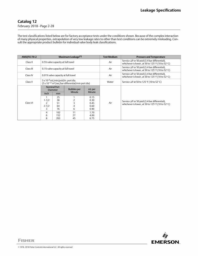
The test classifications listed below are for factory acceptance tests under the conditions shown. Because of the complex interactionof many physical properties, extrapolation of very low leakage rates to other than test conditions can be extremely misleading. Consult the appropriate product bulletin for individual valve body leak classifications.
ANSI/FCI 70‐2 Maximum Leakage(1) Test Medium Pressure and Temperature
Class II 0.5% valve capacity at full travel AirService �P or 50 psid (3.4 bar differential),whichever is lower, at 50 to 125�F (10 to 52�C)
Class III 0.1% valve capacity at full travel AirService �P or 50 psid (3.4 bar differential),whichever is lower, at 50 to 125�F (10 to 52�C)
Class IV 0.01% valve capacity at full travel AirService �P or 50 psid (3.4 bar differential),whichever is lower, at 50 to 125�F (10 to 52�C)
Class V5 x 10-4 mL/min/psid/in. port dia.(5 x 10-12 m3/sec/bar differential/mm port dia)
Water Service �P at 50 to 125�F (10 to 52�C)
Class VI
Nominal PortDiameter Bubbles per
MinutemL perMinute
AirService �P or 50 psid (3.4 bar differential),whichever is lower, at 50 to 125�F (10 to 52�C)
Inch mm
11‐1/2
22‐1/2
3
2538516476
12346
0.150.300.450.600.90
468
102152203
112745
1.704.006.75
Catalog 12 February 2018 ‐ Page 2‐28
Leakage Specifications
� 1978, 2018 Fisher Controls International LLC. All rights reserved
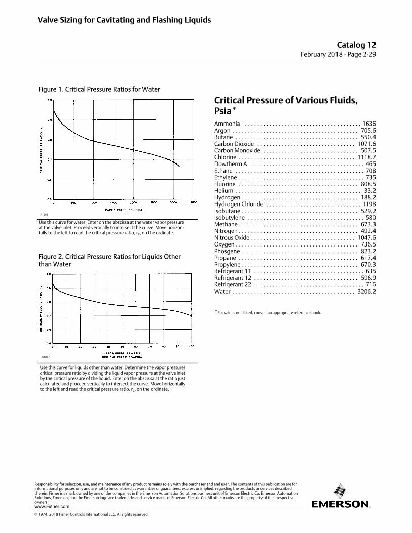
Figure 1. Critical Pressure Ratios for Water
A1256
Use this curve for water. Enter on the abscissa at the water vapor pressureat the valve inlet. Proceed vertically to intersect the curve. Move horizontally to the left to read the critical pressure ratio, rc, on the ordinate.
Figure 2. Critical Pressure Ratios for Liquids Otherthan Water
A1257
Use this curve for liquids other than water. Determine the vapor pressure/critical pressure ratio by dividing the liquid vapor pressure at the valve inletby the critical pressure of the liquid. Enter on the abscissa at the ratio justcalculated and proceed vertically to intersect the curve. Move horizontallyto the left and read the critical pressure ratio, rc, on the ordinate.
Critical Pressure of Various Fluids,Psia*Ammonia 1636. . . . . . . . . . . . . . . . . . . . . . . . . . . . . . . . . . . . . .Argon 705.6. . . . . . . . . . . . . . . . . . . . . . . . . . . . . . . . . . . . . . . . .Butane 550.4. . . . . . . . . . . . . . . . . . . . . . . . . . . . . . . . . . . . . . . .Carbon Dioxide 1071.6. . . . . . . . . . . . . . . . . . . . . . . . . . . . . . . .Carbon Monoxide 507.5. . . . . . . . . . . . . . . . . . . . . . . . . . . . . . .Chlorine 1118.7. . . . . . . . . . . . . . . . . . . . . . . . . . . . . . . . . . . . . .Dowtherm A 465. . . . . . . . . . . . . . . . . . . . . . . . . . . . . . . . . . . . .Ethane 708. . . . . . . . . . . . . . . . . . . . . . . . . . . . . . . . . . . . . . . . . .Ethylene 735. . . . . . . . . . . . . . . . . . . . . . . . . . . . . . . . . . . . . . . . .Fluorine 808.5. . . . . . . . . . . . . . . . . . . . . . . . . . . . . . . . . . . . . . .Helium 33.2. . . . . . . . . . . . . . . . . . . . . . . . . . . . . . . . . . . . . . . . .Hydrogen 188.2. . . . . . . . . . . . . . . . . . . . . . . . . . . . . . . . . . . . . .Hydrogen Chloride 1198. . . . . . . . . . . . . . . . . . . . . . . . . . . . . . .Isobutane 529.2. . . . . . . . . . . . . . . . . . . . . . . . . . . . . . . . . . . . . .Isobutylene 580. . . . . . . . . . . . . . . . . . . . . . . . . . . . . . . . . . . . . .Methane 673.3. . . . . . . . . . . . . . . . . . . . . . . . . . . . . . . . . . . . . . .Nitrogen 492.4. . . . . . . . . . . . . . . . . . . . . . . . . . . . . . . . . . . . . . .Nitrous Oxide 1047.6. . . . . . . . . . . . . . . . . . . . . . . . . . . . . . . . . .Oxygen 736.5. . . . . . . . . . . . . . . . . . . . . . . . . . . . . . . . . . . . . . . .Phosgene 823.2. . . . . . . . . . . . . . . . . . . . . . . . . . . . . . . . . . . . . .Propane 617.4. . . . . . . . . . . . . . . . . . . . . . . . . . . . . . . . . . . . . . .Propylene 670.3. . . . . . . . . . . . . . . . . . . . . . . . . . . . . . . . . . . . . .Refrigerant 11 635. . . . . . . . . . . . . . . . . . . . . . . . . . . . . . . . . . . .Refrigerant 12 596.9. . . . . . . . . . . . . . . . . . . . . . . . . . . . . . . . . .Refrigerant 22 716. . . . . . . . . . . . . . . . . . . . . . . . . . . . . . . . . . . .Water 3206.2. . . . . . . . . . . . . . . . . . . . . . . . . . . . . . . . . . . . . . . .
*For values not listed, consult an appropriate reference book.
Valve Sizing for Cavitating and Flashing Liquids
Catalog 12February 2018 ‐ Page 2‐29
� 1974, 2018 Fisher Controls International LLC. All rights reserved
www.Fisher.com
Responsibility for selection, use, and maintenance of any product remains solely with the purchaser and end user. The contents of this publication are forinformational purposes only and are not to be construed as warranties or guarantees, express or implied, regarding the products or services describedtherein. Fisher is a mark owned by one of the companies in the Emerson Automation Solutions business unit of Emerson Electric Co. Emerson AutomationSolutions, Emerson, and the Emerson logo are trademarks and service marks of Emerson Electric Co. All other marks are the property of their respectiveowners.
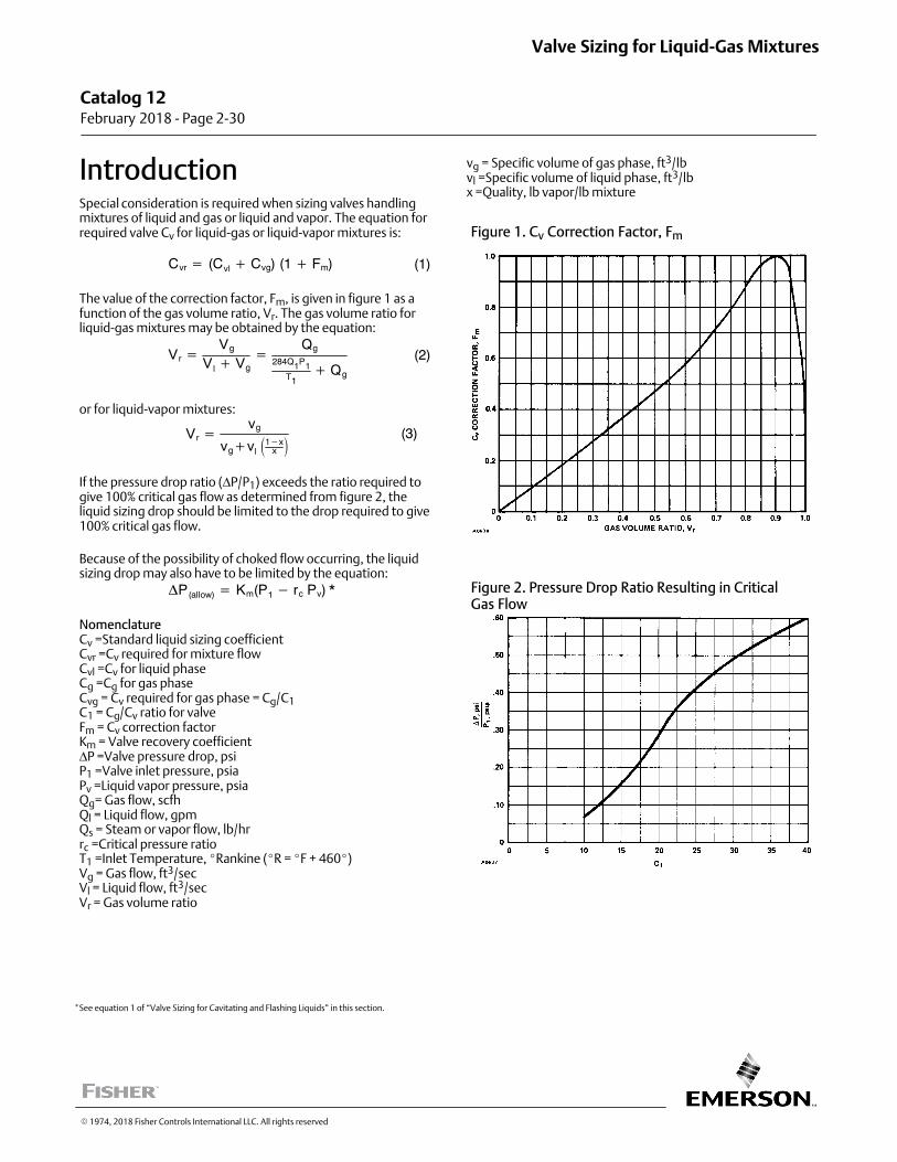
IntroductionSpecial consideration is required when sizing valves handlingmixtures of liquid and gas or liquid and vapor. The equation forrequired valve Cv for liquid‐gas or liquid‐vapor mixtures is:
Cvr � (Cvl � Cvg) (1 � Fm) (1)
The value of the correction factor, Fm, is given in figure 1 as afunction of the gas volume ratio, Vr. The gas volume ratio forliquid‐gas mixtures may be obtained by the equation:
Vr �Vg
Vl � Vg�
Qg
284Q1P1T1
� Qg
(2)
or for liquid‐vapor mixtures:
Vr �vg
vg�vl�1�x
x �(3)
If the pressure drop ratio (ΔP/P1) exceeds the ratio required togive 100% critical gas flow as determined from figure 2, theliquid sizing drop should be limited to the drop required to give100% critical gas flow.
Because of the possibility of choked flow occurring, the liquidsizing drop may also have to be limited by the equation:
�P(allow) � Km(P1 � rc Pv) *
NomenclatureCv =Standard liquid sizing coefficientCvr =Cv required for mixture flowCvl =Cv for liquid phaseCg =Cg for gas phaseCvg = Cv required for gas phase = Cg/C1C1 = Cg/Cv ratio for valveFm = Cv correction factorKm = Valve recovery coefficientΔP =Valve pressure drop, psiP1 =Valve inlet pressure, psiaPv =Liquid vapor pressure, psiaQg= Gas flow, scfhQl = Liquid flow, gpmQs = Steam or vapor flow, lb/hrrc =Critical pressure ratioT1 =Inlet Temperature, �Rankine (�R = �F + 460�)Vg = Gas flow, ft3/secVl = Liquid flow, ft3/secVr = Gas volume ratio
vg = Specific volume of gas phase, ft3/lbvl =Specific volume of liquid phase, ft3/lbx =Quality, lb vapor/lb mixture
Figure 1. Cv Correction Factor, Fm
Figure 2. Pressure Drop Ratio Resulting in CriticalGas Flow
Catalog 12 February 2018 ‐ Page 2‐30
Valve Sizing for Liquid‐Gas Mixtures
� 1974, 2018 Fisher Controls International LLC. All rights reserved
*See equation 1 of “Valve Sizing for Cavitating and Flashing Liquids” in this section.
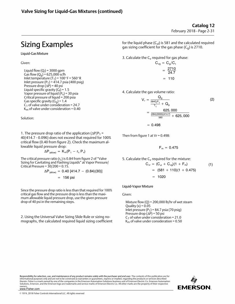
Sizing ExamplesLiquid‐Gas Mixture
Given:
Liquid flow (Qi) = 3000 gpm Gas flow (Qg) = 625,000 scfh Inlet temperature (T1) = 100�F = 560�R Inlet pressure (P1) = 414.7 psia (400 psig) Pressure drop (ΔP) = 40 psi Liquid specific gravity (Gl) = 1.5 Vapor pressure of liquid (Pv) = 30 psia Critical pressure of liquid = 200 psia Gas specific gravity (Gg) = 1.4 C1 of valve under consideration = 24.7 Km of valve under consideration = 0.40
Solution:
1. The pressure drop ratio of the application (ΔP/P1 =40/414.7 - 0.096) does not exceed that required for 100%critical flow (0.40 from figure 2). Check the maximum allowable liquid pressure drop:
�P(allow) � Km(P1 � rc Pv)
The critical pressure ratio (rc) is 0.84 from figure 2 of “ValveSizing for Cavitating and Flashing Liquids” at Vapor Pressure/Critical Pressure = 30/200 = 0.15.
�P(allow) � 0.40 [414.7 � (0.84)(30)]
� 156 psi
Since the pressure drop ratio is less than that required for 100%critical gas flow and the pressure drop is less than the maximum allowable liquid pressure drop, use the given pressuredrop of 40 psi in the remaining steps.
2. Using the Universal Valve Sizing Slide Rule or sizing nomographs, the calculated required liquid sizing coefficient
for the liquid phase (Cvl) is 581 and the calculated requiredgas sizing coefficient for the gas phase (Cg) is 2710.
3. Calculate the Cv required for gas phase:
Cvg � CgC1
� 271024.7
� 110
4. Calculate the gas volume ratio:
Vr �Qg
284QiP1T1
� Qg
(2)
� 625, 000(284)(3000)(414.7)
560 � 625, 000
� 0.498
Then from figure 1 at Vr = 0.498:
Fm � 0.475
5. Calculate the Cv required for the mixture:
Cvr � (Cvl � Cvg)(1 � Fm)
� (581 � 110)(1 � 0.475)
� 1020
(1)
Liquid‐Vapor Mixture
Given:
Mixture flow (Q) = 200,000 lb/hr of wet steam Quality (x) = 0.05 Inlet pressure (P1) = 84.7 psia (70 psig) Pressure drop (ΔP) = 50 psi C1 of valve under consideration = 21.0 Km of valve under consideration = 0.50
Valve Sizing for Liquid‐Gas Mixtures (continued)
Catalog 12February 2018 ‐ Page 2‐31
� 1974, 2018 Fisher Controls International LLC. All rights reserved
www.Fisher.com
Responsibility for selection, use, and maintenance of any product remains solely with the purchaser and end user. The contents of this publication are forinformational purposes only and are not to be construed as warranties or guarantees, express or implied, regarding the products or services describedtherein. Fisher is a mark owned by one of the companies in the Emerson Automation Solutions business unit of Emerson Electric Co. Emerson AutomationSolutions, Emerson, and the Emerson logo are trademarks and service marks of Emerson Electric Co. All other marks are the property of their respectiveowners.
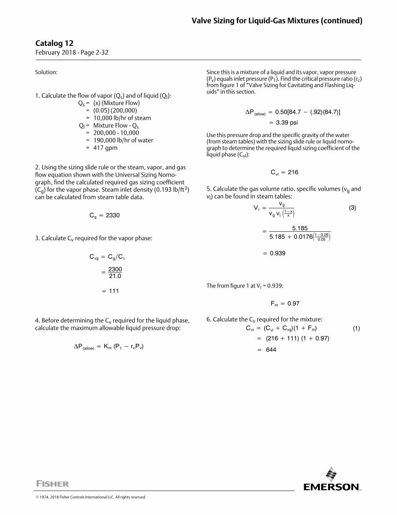
Solution:
1. Calculate the flow of vapor (Qs) and of liquid (Ql):Qs = (x) (Mixture Flow)
= (0.05) (200,000)= 10,000 lb/hr of steam
Ql = Mixture Flow - Qs= 200,000 - 10,000= 190,000 lb/hr of water= 417 gpm
2. Using the sizing slide rule or the steam, vapor, and gasflow equation shown with the Universal Sizing Nomograph, find the calculated required gas sizing coefficient(Cg) for the vapor phase. Steam inlet density (0.193 lb/ft3)can be calculated from steam table data.
Cg � 2330
3. Calculate Cv required for the vapor phase:
Cvg � CgC1
� 230021.0
� 111
4. Before determining the Cv required for the liquid phase,calculate the maximum allowable liquid pressure drop:
�P(allow) � Km (P1 � rcPv)
Since this is a mixture of a liquid and its vapor, vapor pressure(Pv) equals inlet pressure (P1). Find the critical pressure ratio (rc)from figure 1 of “Valve Sizing for Cavitating and Flashing Liquids” in this section.
�P(allow) � 0.50[84.7 � (.92)(84.7)]
� 3.39 psi
Use this pressure drop and the specific gravity of the water(from steam tables) with the sizing slide rule or liquid nomograph to determine the required liquid sizing coefficient of theliquid phase (Cvl):
Cvl � 216
5. Calculate the gas volume ratio. specific volumes (vg andvl) can be found in steam tables:
Vr �vg
vg vl�1�x
x �(3)
� 5.1855.185 � 0.0176�1�0.05
0.05�
� 0.939
The from figure 1 at Vr = 0.939:
Fm � 0.97
6. Calculate the Cv required for the mixture:
Cvr � (Cvl � Cvg)(1 � Fm)
� (216 � 111) (1 � 0.97)
� 644
(1)
Catalog 12 February 2018 ‐ Page 2‐32
Valve Sizing for Liquid‐Gas Mixtures (continued)
� 1974, 2018 Fisher Controls International LLC. All rights reserved
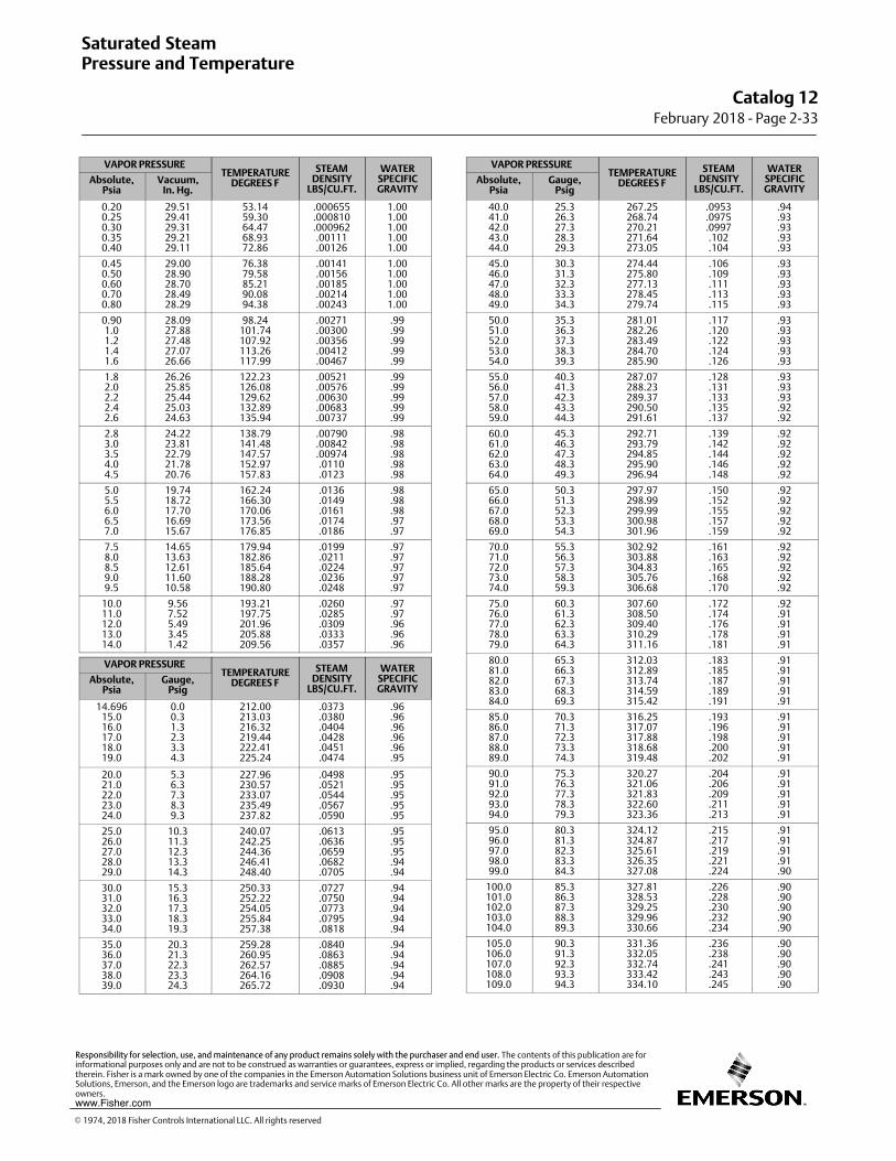
VAPOR PRESSURETEMPERATURE
DEGREES F
STEAMDENSITY
LBS/CU.FT.
WATERSPECIFICGRAVITY
Absolute,Psia
Vacuum,In. Hg.
0.200.250.300.350.40
29.5129.4129.3129.2129.11
53.1459.3064.4768.9372.86
.000655
.000810
.000962.00111.00126
1.001.001.001.001.00
0.450.500.600.700.80
29.0028.9028.7028.4928.29
76.3879.5885.2190.0894.38
.00141
.00156
.00185
.00214
.00243
1.001.001.001.001.00
0.901.01.21.41.6
28.0927.8827.4827.0726.66
98.24101.74107.92113.26117.99
.00271
.00300
.00356
.00412
.00467
.99
.99
.99
.99
.99
1.82.02.22.42.6
26.2625.8525.4425.0324.63
122.23126.08129.62132.89135.94
.00521
.00576
.00630
.00683
.00737
.99
.99
.99
.99
.99
2.83.03.54.04.5
24.2223.8122.7921.7820.76
138.79141.48147.57152.97157.83
.00790
.00842
.00974.0110.0123
.98
.98
.98
.98
.98
5.05.56.06.57.0
19.7418.7217.7016.6915.67
162.24166.30170.06173.56176.85
.0136
.0149
.0161
.0174
.0186
.98
.98
.98
.97
.97
7.58.08.59.09.5
14.6513.6312.6111.6010.58
179.94182.86185.64188.28190.80
.0199
.0211
.0224
.0236
.0248
.97
.97
.97
.97
.97
10.011.012.013.014.0
9.567.525.493.451.42
193.21197.75201.96205.88209.56
.0260
.0285
.0309
.0333
.0357
.97
.97
.96
.96
.96
VAPOR PRESSURETEMPERATURE
DEGREES F
STEAMDENSITY
LBS/CU.FT.
WATERSPECIFICGRAVITY
Absolute,Psia
Gauge,Psig
14.69615.016.017.018.019.0
0.00.31.32.33.34.3
212.00213.03216.32219.44222.41225.24
.0373
.0380
.0404
.0428
.0451
.0474
.96
.96
.96
.96
.96
.95
20.021.022.023.024.0
5.36.37.38.39.3
227.96230.57233.07235.49237.82
.0498
.0521
.0544
.0567
.0590
.95
.95
.95
.95
.95
25.026.027.028.029.0
10.311.312.313.314.3
240.07242.25244.36246.41248.40
.0613
.0636
.0659
.0682
.0705
.95
.95
.95
.94
.94
30.031.032.033.034.0
15.316.317.318.319.3
250.33252.22254.05255.84257.38
.0727
.0750
.0773
.0795
.0818
.94
.94
.94
.94
.94
35.036.037.038.039.0
20.321.322.323.324.3
259.28260.95262.57264.16265.72
.0840
.0863
.0885
.0908
.0930
.94
.94
.94
.94
.94
VAPOR PRESSURETEMPERATURE
DEGREES F
STEAMDENSITY
LBS/CU.FT.
WATERSPECIFICGRAVITY
Absolute,Psia
Gauge,Psig
40.041.042.043.044.0
25.326.327.328.329.3
267.25268.74270.21271.64273.05
.0953
.0975
.0997.102.104
.94
.93
.93
.93
.93
45.046.047.048.049.0
30.331.332.333.334.3
274.44275.80277.13278.45279.74
.106
.109
.111
.113
.115
.93
.93
.93
.93
.93
50.051.052.053.054.0
35.336.337.338.339.3
281.01282.26283.49284.70285.90
.117
.120
.122
.124
.126
.93
.93
.93
.93
.93
55.056.057.058.059.0
40.341.342.343.344.3
287.07288.23289.37290.50291.61
.128
.131
.133
.135
.137
.93
.93
.93
.92
.92
60.061.062.063.064.0
45.346.347.348.349.3
292.71293.79294.85295.90296.94
.139
.142
.144
.146
.148
.92
.92
.92
.92
.92
65.066.067.068.069.0
50.351.352.353.354.3
297.97298.99299.99300.98301.96
.150
.152
.155
.157
.159
.92
.92
.92
.92
.92
70.071.072.073.074.0
55.356.357.358.359.3
302.92303.88304.83305.76306.68
.161
.163
.165
.168
.170
.92
.92
.92
.92
.92
75.076.077.078.079.0
60.361.362.363.364.3
307.60308.50309.40310.29311.16
.172
.174
.176
.178
.181
.92
.91
.91
.91
.91
80.081.082.083.084.0
65.366.367.368.369.3
312.03312.89313.74314.59315.42
.183
.185
.187
.189
.191
.91
.91
.91
.91
.91
85.086.087.088.089.0
70.371.372.373.374.3
316.25317.07317.88318.68319.48
.193
.196
.198
.200
.202
.91
.91
.91
.91
.91
90.091.092.093.094.0
75.376.377.378.379.3
320.27321.06321.83322.60323.36
.204
.206
.209
.211
.213
.91
.91
.91
.91
.91
95.096.097.098.099.0
80.381.382.383.384.3
324.12324.87325.61326.35327.08
.215
.217
.219
.221
.224
.91
.91
.91
.91
.90
100.0101.0102.0103.0104.0
85.386.387.388.389.3
327.81328.53329.25329.96330.66
.226
.228
.230
.232
.234
.90
.90
.90
.90
.90
105.0106.0107.0108.0109.0
90.391.392.393.394.3
331.36332.05332.74333.42334.10
.236
.238
.241
.243
.245
.90
.90
.90
.90
.90
Saturated SteamPressure and Temperature
Catalog 12February 2018 ‐ Page 2‐33
� 1974, 2018 Fisher Controls International LLC. All rights reserved
www.Fisher.com
Responsibility for selection, use, and maintenance of any product remains solely with the purchaser and end user. The contents of this publication are forinformational purposes only and are not to be construed as warranties or guarantees, express or implied, regarding the products or services describedtherein. Fisher is a mark owned by one of the companies in the Emerson Automation Solutions business unit of Emerson Electric Co. Emerson AutomationSolutions, Emerson, and the Emerson logo are trademarks and service marks of Emerson Electric Co. All other marks are the property of their respectiveowners.
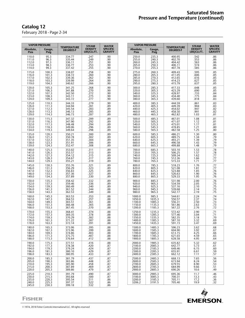
VAPOR PRESSURETEMPERATURE
DEGREES F
STEAMDENSITY
LBS/CU.FT.
WATERSPECIFICGRAVITY
Absolute,Psia
Gauge,Psig
110.0111.0112.0113.0114.0
95.396.397.398.399.3
334.77335.44336.11336.77337.42
.247
.249
.251
.253
.255
.90
.90
.90
.90
.90
115.0116.0117.0118.0119.0
100.3101.3102.3103.3104.3
338.07338.72339.36339.99340.62
.258
.260
.262
.264
.266
.90
.90
.90
.90
.90
120.0121.0122.0123.0124.0
105.3106.3107.3108.3109.3
341.25341.88342.50343.11343.72
.268
.270
.272
.275
.277
.90
.90
.90
.90
.90
125.0126.0127.0128.0129.0
110.3111.3112.3113.3114.3
344.33344.94345.54346.13346.73
.279
.281
.283
.285
.287
.90
.89
.89
.89
.89
130.0131.0132.0133.0134.0
115.3116.3117.3118.3119.3
347.32347.90348.48349.06349.64
.289
.292
.294
.296
.298
.89
.89
.89
.89
.89
135.0136.0137.0138.0139.0
120.3121.3122.3123.3124.3
350.21350.78351.35351.91352.47
.300
.302
.304
.306
.308
.89
.89
.89
.89
.89
140.0141.0142.0143.0144.0
125.3126.3127.3128.3129.3
353.02353.57354.12354.67355.21
.311
.313
.315
.317
.319
.89
.89
.89
.89
.89
145.0146.0147.0148.0149.0
130.3131.3132.3133.3134.3
355.76356.29356.83357.36357.89
.321
.323
.325
.327
.330
.89
.89
.89
.89
.89
150.0152.0154.0156.0158.0
135.3137.3139.3141.3143.3
358.42359.46360.49361.52362.53
.332
.336
.340
.344
.349
.89
.89
.89
.88
.88
160.0162.0164.0166.0168.0
145.3147.3149.3151.3153.3
363.53364.53365.51366.48367.45
.353
.357
.361
.365
.370
.88
.88
.88
.88
.88
170.0172.0174.0176.0178.0
155.3157.3159.3161.3163.3
368.41369.35370.29371.22372.14
.374
.378
.382
.387
.391
.88
.88
.88
.88
.88
180.0182.0184.0186.0188.0
165.3167.3169.3171.3173.3
373.06373.96374.86375.75376.64
.395
.399
.403
.407
.412
.88
.88
.88
.88
.88
190.0192.0194.0196.0198.0
175.3177.3179.3181.3183.3
377.51378.38379.24380.10380.95
.416
.420
.424
.429
.433
.88
.87
.87
.87
.87
200.0205.0210.0215.0220.0
185.3190.3195.3200.3205.3
381.79383.86385.90387.89389.86
.437
.448
.458
.469
.479
.87
.87
.87
.87
.87
225.0230.0235.0240.0245.0
210.3215.3220.3225.3230.3
391.79393.68395.54397.37399.18
.490
.500
.511
.522
.532
.87
.87
.86
.86
.86
VAPOR PRESSURETEMPERATURE
DEGREES F
STEAMDENSITY
LBS/CU.FT.
WATERSPECIFICGRAVITY
Absolute,Psia
Gauge,Psig
250.0255.0260.0265.0270.0
235.3240.3245.3250.3255.3
400.95402.70404.42406.11407.78
.542
.553
.563
.574
.585
.86
.86
.86
.86
.86
275.0280.0285.0290.0295.0
260.3265.3270.3275.3280.3
409.43411.05412.65414.23415.79
.595
.606
.616
.627
.637
.85
.85
.85
.85
.85
300.0320.0340.0360.0380.0
285.3305.3325.3345.3365.3
417.33423.29428.97434.40439.60
.648
.690
.733
.775
.818
.85
.85
.84
.84
.83
400.0420.0440.0460.0480.0
385.3405.3425.3445.3465.3
444.59449.39454.02458.50462.82
.861
.904
.947
.9911.03
.83
.83
.82
.82
.81
500.0520.0540.0560.0580.0
485.3505.3525.3545.3565.3
467.01471.07475.01478.85482.58
1.081.121.171.211.25
.81
.81
.81
.80
.80
600.0620.0640.0660.0680.0
585.3605.3625.3645.3665.3
486.21489.75493.21496.58499.88
1.301.341.391.431.48
.80
.79
.79
.79
.79
700.0720.0740.0760.0780.0
685.3705.3725.3745.3765.3
503.10506.25509.34512.36515.33
1.531.571.621.661.71
.78
.78
.77
.77
.77
800.0820.0840.0860.0880.0
785.3805.3825.3845.3865.3
518.23521.08523.88526.63529.33
1.761.811.851.901.95
.77
.77
.76
.76
.76
900.0920.0940.0960.0980.0
885.3905.3925.3945.3965.3
531.98534.59537.16539.68542.17
2.002.052.102.142.19
.76
.75
.75
.75
.75
1000.01050.01100.01150.01200.0
985.31035.31085.31135.31185.3
544.61550.57556.31561.86567.22
2.242.372.502.632.76
.74
.74
.73
.73
.72
1250.01300.01350.01400.01450.0
1235.31285.31335.31385.31435.3
572.42577.46582.35587.10591.73
2.903.043.183.323.47
.71
.71
.70
.69
.69
1500.01600.01700.01800.01900.0
1485.31585.31685.31785.31885.3
596.23604.90613.15621.03628.58
3.623.924.254.594.95
.68
.67
.66
.65
.64
2000.02100.02200.02300.02400.0
1985.32085.32185.32285.32385.3
635.82642.77649.46655.91662.12
5.325.736.156.617.11
.62
.61
.60
.59
.57
2500.02600.02700.02800.02900.0
2485.32585.32685.32785.32885.3
668.13673.94679.55684.99690.26
7.658.248.909.6610.6
.56
.54
.53
.51
.49
3000.03100.03200.03206.2
2985.33085.33185.33191.5
695.36700.31705.11705.40
11.713.317.219.9
.46
.43
.36
.32
Catalog 12 February 2018 ‐ Page 2‐34
Saturated SteamPressure and Temperature (continued)
� 1974, 2018 Fisher Controls International LLC. All rights reserved
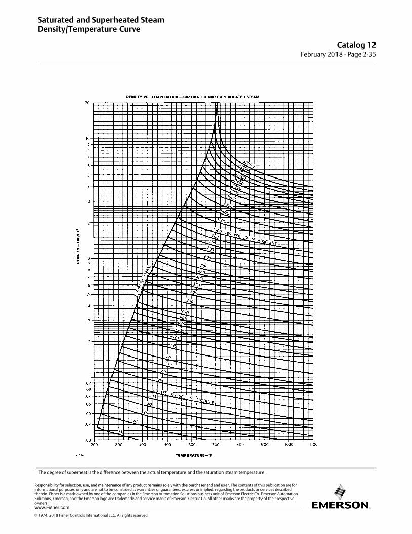
The degree of superheat is the difference between the actual temperature and the saturation steam temperature.
Saturated and Superheated SteamDensity/Temperature Curve
Catalog 12February 2018 ‐ Page 2‐35
� 1974, 2018 Fisher Controls International LLC. All rights reserved
www.Fisher.com
Responsibility for selection, use, and maintenance of any product remains solely with the purchaser and end user. The contents of this publication are forinformational purposes only and are not to be construed as warranties or guarantees, express or implied, regarding the products or services describedtherein. Fisher is a mark owned by one of the companies in the Emerson Automation Solutions business unit of Emerson Electric Co. Emerson AutomationSolutions, Emerson, and the Emerson logo are trademarks and service marks of Emerson Electric Co. All other marks are the property of their respectiveowners.
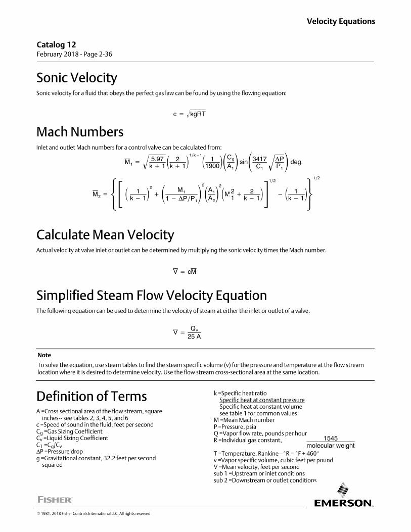
Sonic VelocitySonic velocity for a fluid that obeys the perfect gas law can be found by using the flowing equation:
c � kgRT�
Mach NumbersInlet and outlet Mach numbers for a control valve can be calculated from:
M1 �5.97
k � 1� � 2
k � 1�1k�1� 1
1900��Cg
A1� sin�3417
C1
�PP1
� � deg.
M2 ���
� � 1
k � 1�2
�� M1
1 � �PP1
�2
�A1
A2
�2
�M 21� 2
k � 1�
12
� � 1k � 1
���
�
12
Calculate Mean VelocityActual velocity at valve inlet or outlet can be determined by multiplying the sonic velocity times the Mach number.
V � cM
Simplified Steam Flow Velocity EquationThe following equation can be used to determine the velocity of steam at either the inlet or outlet of a valve.
V � Qv
25 A
Note
To solve the equation, use steam tables to find the steam specific volume (v) for the pressure and temperature at the flow streamlocation where it is desired to determine velocity. Use the flow stream cross‐sectional area at the same location.
Definition of TermsA =Cross sectional area of the flow stream, square inches-- see tables 2, 3, 4, 5, and 6c =Speed of sound in the fluid, feet per secondCg =Gas Sizing CoefficientCv =Liquid Sizing CoefficientC1 =Cg/CvΔP =Pressure dropg =Gravitational constant, 32.2 feet per second squared
k =Specific heat ratio Specific heat at constant pressure Specific heat at constant volume see table 1 for common valuesM =Mean Mach numberP =Pressure, psiaQ =Vapor flow rate, pounds per hourR =Individual gas constant,
T =Temperature, Rankine—�R = �F + 460�v =Vapor specific volume, cubic feet per poundV =Mean velocity, feet per secondsub 1 =Upstream or inlet conditionssub 2 =Downstream or outlet conditions
Catalog 12 February 2018 ‐ Page 2‐36
Velocity Equations
� 1981, 2018 Fisher Controls International LLC. All rights reserved
1545molecular weight
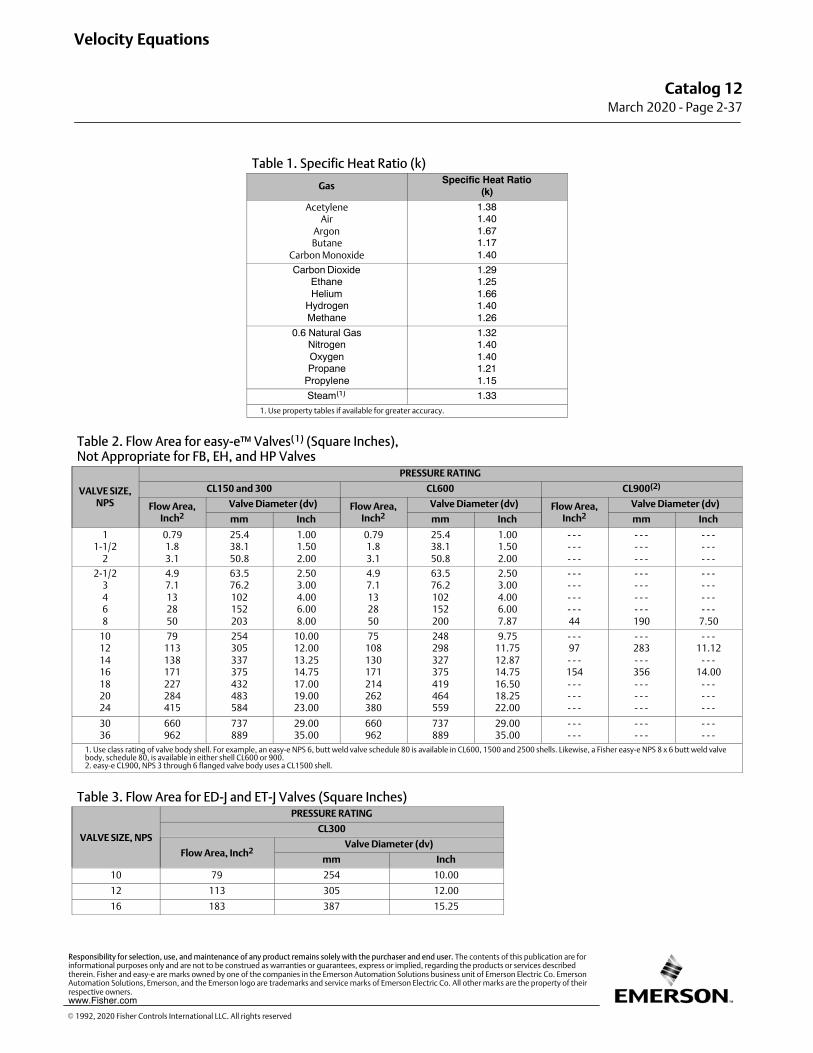
Table 1. Specific Heat Ratio (k)
GasSpecific Heat Ratio
(k)
AcetyleneAir
ArgonButane
Carbon Monoxide
1.381.401.671.171.40
Carbon DioxideEthaneHelium
HydrogenMethane
1.291.251.661.401.26
0.6 Natural GasNitrogenOxygenPropane
Propylene
1.321.401.401.211.15
Steam(1) 1.331. Use property tables if available for greater accuracy.
Table 2. Flow Area for easy-e™ Valves(1) (Square Inches), Not Appropriate for FB, EH, and HP Valves
VALVE SIZE,NPS
PRESSURE RATING
CL150 and 300 CL600 CL900(2)
Flow Area,Inch2
Valve Diameter (dv) Flow Area,Inch2
Valve Diameter (dv) Flow Area,Inch2
Valve Diameter (dv)
mm Inch mm Inch mm Inch
11‐1/2
2
0.791.83.1
25.438.150.8
1.001.502.00
0.791.83.1
25.438.150.8
1.001.502.00
‐ ‐ ‐‐ ‐ ‐‐ ‐ ‐
‐ ‐ ‐‐ ‐ ‐‐ ‐ ‐
‐ ‐ ‐‐ ‐ ‐‐ ‐ ‐
2‐1/23468
4.97.1132850
63.576.2102152203
2.503.004.006.008.00
4.97.1132850
63.576.2102152200
2.503.004.006.007.87
‐ ‐ ‐‐ ‐ ‐‐ ‐ ‐‐ ‐ ‐44
‐ ‐ ‐‐ ‐ ‐‐ ‐ ‐‐ ‐ ‐190
‐ ‐ ‐‐ ‐ ‐‐ ‐ ‐‐ ‐ ‐
7.50
10121416182024
79113138171227284415
254305337375432483584
10.0012.0013.2514.7517.0019.0023.00
75108130171214262380
248298327375419464559
9.7511.7512.8714.7516.5018.2522.00
‐ ‐ ‐97‐ ‐ ‐154‐ ‐ ‐‐ ‐ ‐‐ ‐ ‐
‐ ‐ ‐283‐ ‐ ‐356‐ ‐ ‐‐ ‐ ‐‐ ‐ ‐
‐ ‐ ‐11.12
‐ ‐ ‐14.00
‐ ‐ ‐‐ ‐ ‐‐ ‐ ‐
3036
660962
737889
29.0035.00
660962
737889
29.0035.00
‐ ‐ ‐‐ ‐ ‐
‐ ‐ ‐‐ ‐ ‐
‐ ‐ ‐‐ ‐ ‐
1. Use class rating of valve body shell. For example, an easy-e NPS 6, butt weld valve schedule 80 is available in CL600, 1500 and 2500 shells. Likewise, a Fisher easy-e NPS 8 x 6 butt weld valvebody, schedule 80, is available in either shell CL600 or 900.2. easy-e CL900, NPS 3 through 6 flanged valve body uses a CL1500 shell.
Table 3. Flow Area for ED-J and ET-J Valves (Square Inches)
VALVE SIZE, NPS
PRESSURE RATING
CL300
Flow Area, Inch2Valve Diameter (dv)
mm Inch
10 79 254 10.00
12 113 305 12.00
16 183 387 15.25
Velocity Equations
Catalog 12March 2020 ‐ Page 2‐37
� 1992, 2020 Fisher Controls International LLC. All rights reserved
www.Fisher.com
Responsibility for selection, use, and maintenance of any product remains solely with the purchaser and end user. The contents of this publication are forinformational purposes only and are not to be construed as warranties or guarantees, express or implied, regarding the products or services describedtherein. Fisher and easy-e are marks owned by one of the companies in the Emerson Automation Solutions business unit of Emerson Electric Co. EmersonAutomation Solutions, Emerson, and the Emerson logo are trademarks and service marks of Emerson Electric Co. All other marks are the property of theirrespective owners.
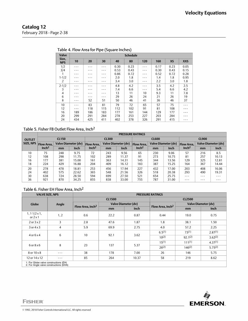
Table 4. Flow Area for Pipe (Square Inches) ValveSize,NPS
Schedule
10 20 30 40 80 120 160 XS XXS
1/23/4
11‐1/2
2
‐ ‐ ‐‐ ‐ ‐‐ ‐ ‐‐ ‐ ‐‐ ‐ ‐
‐ ‐ ‐‐ ‐ ‐‐ ‐ ‐‐ ‐ ‐‐ ‐ ‐
‐ ‐ ‐‐ ‐ ‐‐ ‐ ‐‐ ‐ ‐‐ ‐ ‐
0.300.530.862.03.4
0.230.430.721.83.0
‐ ‐ ‐‐ ‐ ‐‐ ‐ ‐‐ ‐ ‐‐ ‐ ‐
0.170.300.521.42.2
0.230.430.721.83.0
0.050.150.280.951.8
2‐1/23468
‐ ‐ ‐‐ ‐ ‐‐ ‐ ‐‐ ‐ ‐‐ ‐ ‐
‐ ‐ ‐‐ ‐ ‐‐ ‐ ‐‐ ‐ ‐52
‐ ‐ ‐‐ ‐ ‐‐ ‐ ‐‐ ‐ ‐51
4.87.4132950
4.26.6112646
‐ ‐ ‐‐ ‐ ‐102441
3.55.49.32136
4.26.6112646
2.54.27.81937
1012162024
‐ ‐ ‐‐ ‐ ‐189299434
83118186291425
81115183284411
79112177278402
72102161253378
6591
144227326
5781
129203291
75108177284415
‐ ‐ ‐‐ ‐ ‐‐ ‐ ‐‐ ‐ ‐‐ ‐ ‐
Table 5. Fisher FB Outlet Flow Area, Inch2
OUTLETSIZE, NPS
PRESSURE RATINGS
CL150 CL300 CL600 CL900
Flow Area,Inch2
Valve Diameter (dv) Flow Area,Inch2
Valve Diameter (dv) Flow Area,Inch2
Valve Diameter (dv) Flow Area,Inch2
Valve Diameter (dv)
mm Inch mm Inch mm Inch mm Inch
10121618
75108177224
248298381429
9.7511.7515.0016.88
72102161204
243289363409
9.5611.3714.3116.12
6591
145183
230273344387
9.0610.7513.5615.25
5781
129164
216257325367
8.510.1312.8114.44
20243036
278402638921
478575724870
18.8122.6228.5034.25
253365594855
456548699838
17.9421.5627.5033.00
227326521755
432518654787
17.0020.3825.7531.00
203293‐ ‐ ‐‐ ‐ ‐
408490‐ ‐ ‐‐ ‐ ‐
16.0619.31
‐ ‐ ‐‐ ‐ ‐
Table 6. Fisher EH Flow Area, Inch2
VALVE SIZE, NPS PRESSURE RATINGS
Globe Angle
CL1500 CL2500
Flow Area, Inch2Valve Diameter (dv)
Flow Area, Inch2Valve Diameter (dv)
mm Inch mm Inch
1, 1 1/2 x 1, or 2 x 1
1, 2 0.6 22.2 0.87 0.44 19.0 0.75
2 or 3 x 2 3 2.8 47.6 1.87 1.8 38.1 1.50
3 or 4 x 3 4 5.9 69.9 2.75 4.0 57.2 2.25
4 or 6 x 4 6 10 92.1 3.626.5(1) 73(1) 2.87(1)
10(2) 92.1(2) 3.62(2)
6 or 8 x 6 8 23 137 5.3715(1) 111(1) 4.37(1)
26(2) 146(2) 5.75(2)
8 or 10 x 8 ‐ ‐ ‐ 38 178 7.00 26 146 5.75
12 or 14 x 12 ‐ ‐ ‐ 85 264 10.37 58 219 8.62
1. For Globe valve constructions (EH)2. For Angle valve constructions (EHA)
� 1992, 2018 Fisher Controls International LLC. All rights reserved
Catalog 12 February 2018 ‐ Page 2‐38
Velocity Equations
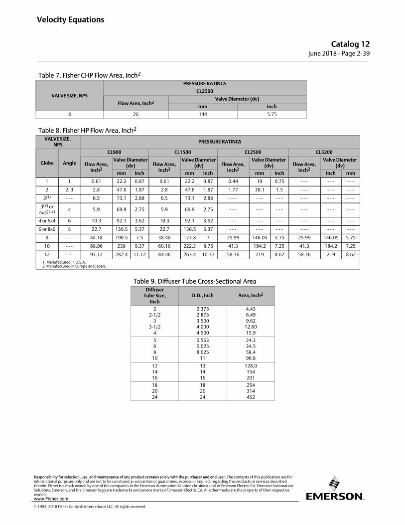
Table 7. Fisher CHP Flow Area, Inch2
VALVE SIZE, NPS
PRESSURE RATINGS
CL2500
Flow Area, Inch2Valve Diameter (dv)
mm Inch
8 26 144 5.75
Table 8. Fisher HP Flow Area, Inch2
VALVE SIZE, NPS
PRESSURE RATINGS
Globe Angle
CL900 CL1500 CL2500 CL3200
Flow Area,Inch2
Valve Diameter(dv) Flow Area,
Inch2
Valve Diameter(dv) Flow Area,
Inch2
Valve Diameter(dv) Flow Area,
Inch2
Valve Diameter(dv)
mm Inch mm Inch mm Inch Inch mm
1 1 0.61 22.2 0.87 0.61 22.2 0.87 0.44 19 0.75 - - - - - - - - -
2 2, 3 2.8 47.6 1.87 2.8 47.6 1.87 1.77 38.1 1.5 - - - - - - - - -
3(1) - - - 6.5 73.1 2.88 6.5 73.1 2.88 - - - - - - - - - - - - - - - - - -
3(2) or4x3(1,2) 4 5.9 69.9 2.75 5.9 69.9 2.75 - - - - - - - - - - - - - - - - - -
4 or 6x4 6 10.3 92.1 3.62 10.3 92.1 3.62 - - - - - - - - - - - - - - - - - -
6 or 8x6 8 22.7 136.5 5.37 22.7 136.5 5.37 - - - - - - - - - - - - - - - - - -
8 - - - 44.18 190.5 7.5 38.48 177.8 7 25.99 146.05 5.75 25.99 146.05 5.75
10 - - - 68.96 238 9.37 60.16 222.3 8.75 41.3 184.2 7.25 41.3 184.2 7.25
12 - - - 97.12 282.4 11.12 84.46 263.4 10.37 58.36 219 8.62 58.36 219 8.62
1. Manufactured in U.S.A.2. Manufactured in Europe and Japan.
Table 9. Diffuser Tube Cross‐Sectional AreaDiffuser
Tube Size,Inch
O.D., Inch Area, Inch2
22‐1/2
33‐1/2
4
2.3752.8753.5004.0004.500
4.436.499.62
12.6015.9
568
10
5.5636.6258.625
11
24.334.558.490.8
121416
131416
128.0154201
182024
182024
254314452
Velocity Equations
Catalog 12June 2018 ‐ Page 2‐39
� 1992, 2018 Fisher Controls International LLC. All rights reserved
www.Fisher.com
Responsibility for selection, use, and maintenance of any product remains solely with the purchaser and end user. The contents of this publication are forinformational purposes only and are not to be construed as warranties or guarantees, express or implied, regarding the products or services describedtherein. Fisher is a mark owned by one of the companies in the Emerson Automation Solutions business unit of Emerson Electric Co. Emerson AutomationSolutions, Emerson, and the Emerson logo are trademarks and service marks of Emerson Electric Co. All other marks are the property of their respectiveowners.
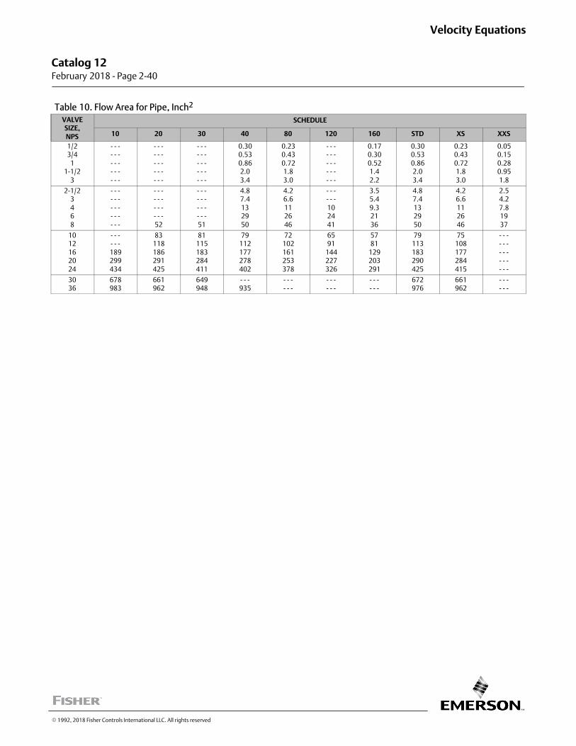
Table 10. Flow Area for Pipe, Inch2
VALVESIZE,NPS
SCHEDULE
10 20 30 40 80 120 160 STD XS XXS
1/23/4
11‐1/2
3
‐ ‐ ‐‐ ‐ ‐‐ ‐ ‐‐ ‐ ‐‐ ‐ ‐
‐ ‐ ‐‐ ‐ ‐‐ ‐ ‐‐ ‐ ‐‐ ‐ ‐
‐ ‐ ‐‐ ‐ ‐‐ ‐ ‐‐ ‐ ‐‐ ‐ ‐
0.300.530.862.03.4
0.230.430.721.83.0
‐ ‐ ‐‐ ‐ ‐‐ ‐ ‐‐ ‐ ‐‐ ‐ ‐
0.170.300.521.42.2
0.300.530.862.03.4
0.230.430.721.83.0
0.050.150.280.951.8
2‐1/23468
‐ ‐ ‐‐ ‐ ‐‐ ‐ ‐‐ ‐ ‐‐ ‐ ‐
‐ ‐ ‐‐ ‐ ‐‐ ‐ ‐‐ ‐ ‐52
‐ ‐ ‐‐ ‐ ‐‐ ‐ ‐‐ ‐ ‐51
4.87.4132950
4.26.6112646
‐ ‐ ‐‐ ‐ ‐102441
3.55.49.32136
4.87.4132950
4.26.6112646
2.54.27.81937
1012162024
‐ ‐ ‐‐ ‐ ‐189299434
83118186291425
81115183284411
79112177278402
72102161253378
6591
144227326
5781
129203291
79113183290425
75108177284415
‐ ‐ ‐‐ ‐ ‐‐ ‐ ‐‐ ‐ ‐‐ ‐ ‐
3036
678983
661962
649948
‐ ‐ ‐935
‐ ‐ ‐‐ ‐ ‐
‐ ‐ ‐‐ ‐ ‐
‐ ‐ ‐‐ ‐ ‐
672976
661962
‐ ‐ ‐‐ ‐ ‐
� 1992, 2018 Fisher Controls International LLC. All rights reserved
Catalog 12 February 2018 ‐ Page 2‐40
Velocity Equations
Velocity Equations
Catalog 12February 2018 ‐ Page 2‐41
� 1992, 2018 Fisher Controls International LLC. All rights reserved
www.Fisher.com
Responsibility for selection, use, and maintenance of any product remains solely with the purchaser and end user. The contents of this publication are forinformational purposes only and are not to be construed as warranties or guarantees, express or implied, regarding the products or services describedtherein. Fisher is a mark owned by one of the companies in the Emerson Automation Solutions business unit of Emerson Electric Co. Emerson AutomationSolutions, Emerson, and the Emerson logo are trademarks and service marks of Emerson Electric Co. All other marks are the property of their respectiveowners.
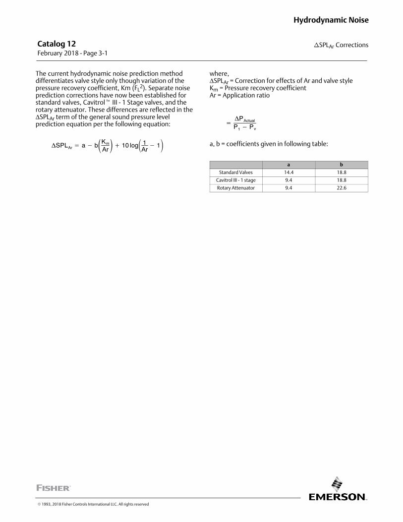
Catalog 12 February 2018 ‐ Page 3‐1
�SPLAr Corrections
Hydrodynamic Noise
� 1993, 2018 Fisher Controls International LLC. All rights reserved
The current hydrodynamic noise prediction methoddifferentiates valve style only though variation of thepressure recovery coefficient, Km (FL
2). Separate noiseprediction corrections have now been established forstandard valves, Cavitrol� III - 1 Stage valves, and therotary attenuator. These differences are reflected in theΔSPLAr term of the general sound pressure levelprediction equation per the following equation:
�SPLAr � a � b�Km
Ar�� 10 log� 1
Ar� 1�
where,ΔSPLAr = Correction for effects of Ar and valve styleKm = Pressure recovery coefficientAr = Application ratio
��PActual
P1 � Pv
a, b = coefficients given in following table:
a b
Standard Valves 14.4 18.8
Cavitrol III - 1 stage 9.4 18.8
Rotary Attenuator 9.4 22.6
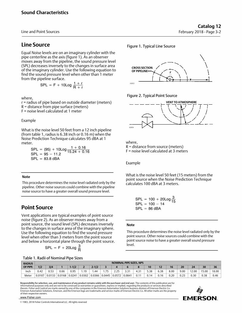
Line Source
Equal Noise levels are on an imaginary cylinder with thepipe centerline as the axis (figure 1). As an observermoves away from the pipeline, the sound pressure level(SPL) decreases inversely to the changes in surface areaof the imaginary cylinder. Use the following equation tofind the sound pressure level when other than 1 meterfrom the pipeline surface.
SPL � F � 10Log 1 � rR � r
where,r = radius of pipe based on outside diameter (meters)R = distance from pipe surface (meters)F = noise level calculated at 1 meter
Example
What is the noise level 50 feet from a 12 inch pipeline(from table 1, radius is 6.38 inch or 0.16 m) when theNoise Prediction Technique calculates 95 dBA at 1meter.
SPL � (95) � 10Log 1 � 0.1615.24 � 0.16
SPL � 95 � 11.2SPL � 83.8 dBA
Note
This procedure determines the noise level radiated only by thepipeline. Other noise sources could combine with the pipelinenoise source to have a greater overall sound pressure level.
Point Source
Vent applications are typical examples of point sourcenoise (figure 2). As an observer moves away from apoint source, the sound level (SPL) decreases inverselyto the changes in surface area of the imaginary sphere.Use the following equation to find the sound pressurelevel when other than 3 meters from the point sourceand below a horizontal plane through the point source.
SPL � F � 20Log 3R
Figure 1. Typical Line Source
CROSS SECTIONOF PIPELINE
A3053
Figure 2. Typical Point Source
A3054
VENT TO ATMOSPHERE
where,R = distance from source (meters)F = noise level calculated at 3 meters
Example
What is the noise level 50 feet (15 meters) from thepoint source when the Noise Prediction Techniquecalculates 100 dBA at 3 meters.
SPL � 100 � 20Log 315
SPL � 100 � 14SPL � 86 dBA
Note
This procedure determines the noise level radiated only by thepoint source. Other noise sources could combine with thepoint source noise to have a greater overall sound pressurelevel.
Table 1. Radii of Nominal Pipe Sizes
RADIUSOF PIPE
NOMINAL PIPE SIZES, NPS
1/2 3/4 1 1‐1/2 2 2‐1/2 3 4 6 8 10 12 16 20 24 30 36
Inch 0.42 0.53 0.66 0.95 1.19 1.44 1.75 2.25 3.31 4.31 5.38 6.38 8.00 9.00 12.00 15.00 18.00
Meter 0.0107 0.0133 0.0168 0.0241 0.0302 0.0366 0.0445 0.0572 0.0841 0.11 0.14 0.16 0.20 0.23 0.30 0.38 0.46
Catalog 12February 2018 ‐ Page 3‐2
Sound Characteristics
Line and Point Sources
� 1983, 2018 Fisher Controls International LLC. All rights reserved
www.Fisher.com
Responsibility for selection, use, and maintenance of any product remains solely with the purchaser and end user. The contents of this publication are forinformational purposes only and are not to be construed as warranties or guarantees, express or implied, regarding the products or services describedtherein. Fisher and Cavitrol are marks owned by one of the companies in the Emerson Automation Solutions business division of Emerson Electric Co.Emerson Automation Solutions, Emerson, and the Emerson logo are trademarks and service marks of Emerson Electric Co. All other marks are the propertyof their respective owners.
Octave Band SoundPressure LevelsAerodynamic noise has an overall sound pressure level(measured one meter downstream of the valve and onemeter away from the pipe‐wall) which does not indicatethe sound pressure level in each frequency band. Usethe information in table 1 to determine octave bandsound pressure levels and to construct a spectrum for aparticular trim type and piping combination.
Example
An NPS 6 valve with Whisper Trim™ III cage has anoverall SPL of 85 dBA. The octave band SPLs are asfollows:SPL at 63 Hz = 85 + (-50) = 35 dBA125 Hz = 85 + (-50) = 35 dBA250 Hz = 85 + (-45) = 40 dBA500 Hz = 85 + (-33) = 52 dBA1000 Hz = 85 + (-21) = 64 dBA2000 Hz = 85 + (-9) = 76 dBA4000 Hz = 85 + (-6) = 79 dBA8000 Hz = 85 + (-3) = 82 dBA
Table 1. Octave Band Sound Pressure Level Corrections
PIPESIZENPS
PIPESCHEDULE
FOR WHISPER TRIM III (OUTLET VELOCITY � 0.3 MACH) FOR ALL OTHERS
Octave Bands, Hz
63 125 250 500 1000 2000 4000 8000 63 125 250 500 1000 2000 4000 8000
1
1‐1/223
4
5S to XXS
5S to XXS5S to XXS5S to XXS
5S to XXS
‐ ‐ ‐
‐ ‐ ‐‐ ‐ ‐‐ ‐ ‐
‐ ‐ ‐
‐ ‐ ‐
‐ ‐ ‐‐ ‐ ‐‐ ‐ ‐
‐ ‐ ‐
‐ ‐ ‐
‐ ‐ ‐‐ ‐ ‐‐ ‐ ‐
‐ ‐ ‐
‐ ‐ ‐
‐ ‐ ‐‐ ‐ ‐‐ ‐ ‐
-45
‐ ‐ ‐
‐ ‐ ‐‐ ‐ ‐‐ ‐ ‐
-33
‐ ‐ ‐
‐ ‐ ‐‐ ‐ ‐‐ ‐ ‐
-21
‐ ‐ ‐
‐ ‐ ‐‐ ‐ ‐‐ ‐ ‐
-9
‐ ‐ ‐
‐ ‐ ‐‐ ‐ ‐‐ ‐ ‐
-6
-50
-50-50-50
-50
-50
-50-50-50
-50
-50
-50-50-50
-50
-39
-39-39-39
-39
-27
-27-27-27
-27
-15
-15-15-15
-15
-6
-6-3-3
-3
-3
-3-6-6
-6
6
81012
14
5S to XXS
5S to 1605S to 1605S to 160
5S to 160
-50
-50-50-50
-50
-50
-50-50-45
-45
-45
-45-45-33
-33
-33
-33-33-21
-21
-21
-21-21-9
-9
-9
-9-9-6
-6
-6
-6-6-3
-3
-3
-3-3-9
-9
-50
-50-50-50
-50
-50
-50-50-39
-39
-39
-29-39-27
-27
-27
-27-27-15
-15
-15
-15-15-3
-3
-3
-3-3-6
-6
-6
-6-6-9
-9
-9
-9-9
-21
-21
16
1820
5S to 160
5S to 1605S to 160
-50
-50-50
-45
-45-45
-33
-33-33
-21
-21-21
-9
-9-9
-6
-6-6
-3
-3-3
-9
-9-9
-50
-50-50
-39
-39-39
-27
-27-27
-15
-15-15
-3
-3-3
-6
-6-6
-9
-9-9
-21
-21-21
245S to 160
120 to 160
-45
-50
-33
-45
-21
-33
-9
-21
-6
-9
-3
-6
-9
-3
-15
-9
-39
-50
-27
-39
-15
-27
-3
-15
-6
-3
-9
-6
-21
-9
-33
-21
30
3642
5S to 30
10 to 4010 to 30
-45
-45-45
-33
-33-33
-21
-21-21
-9
-9-9
-6
-6-6
-3
-3-3
-9
-9-9
-15
-15-15
-39
-39-39
-27
-27-27
-15
-15-15
-3
-3-3
-6
-6-6
-9
-9-9
-21
-21-21
-33
-33-33
Catalog 12 February 2018 ‐ Page 3‐3
Sound Characteristics
Octave Band Sound Pressure Levels
� 1993, 2018 Fisher Controls International LLC. All rights reserved
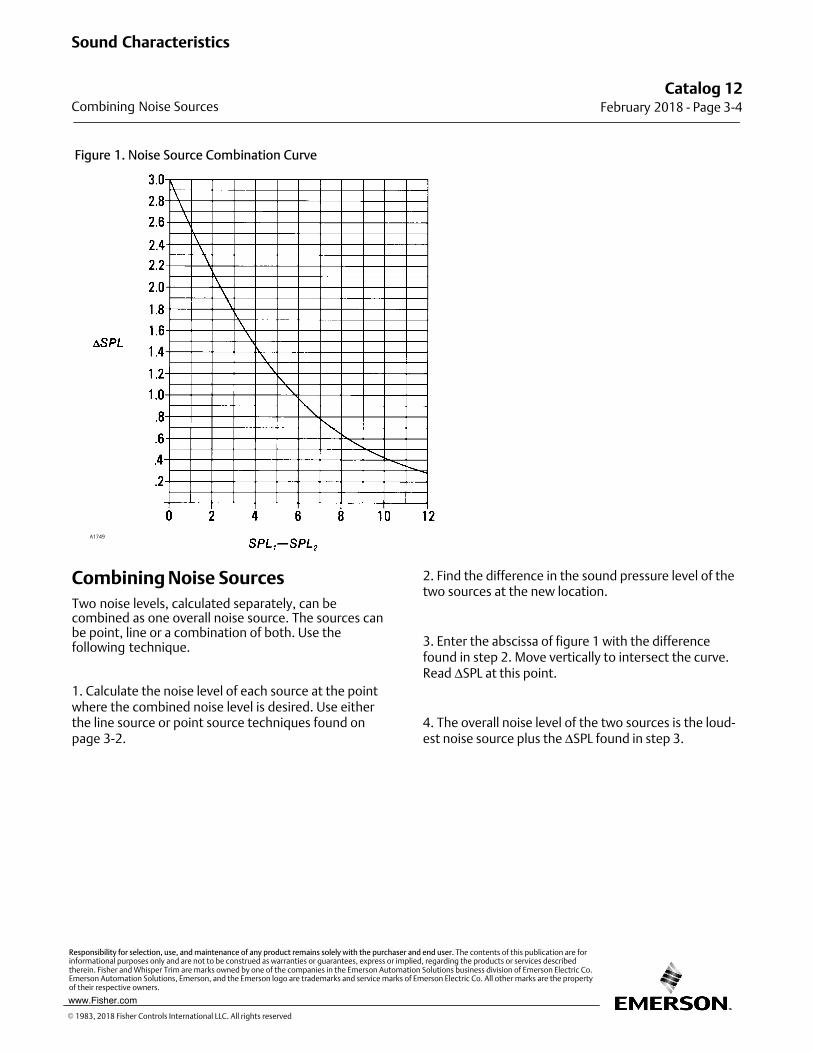
Figure 1. Noise Source Combination Curve
A1749
Combining Noise Sources
Two noise levels, calculated separately, can becombined as one overall noise source. The sources canbe point, line or a combination of both. Use thefollowing technique.
1. Calculate the noise level of each source at the pointwhere the combined noise level is desired. Use eitherthe line source or point source techniques found onpage 3‐2.
2. Find the difference in the sound pressure level of thetwo sources at the new location.
3. Enter the abscissa of figure 1 with the differencefound in step 2. Move vertically to intersect the curve.Read ΔSPL at this point.
4. The overall noise level of the two sources is the loudest noise source plus the ΔSPL found in step 3.
Catalog 12February 2018 ‐ Page 3‐4
Sound Characteristics
Combining Noise Sources
� 1983, 2018 Fisher Controls International LLC. All rights reserved
www.Fisher.com
Responsibility for selection, use, and maintenance of any product remains solely with the purchaser and end user. The contents of this publication are forinformational purposes only and are not to be construed as warranties or guarantees, express or implied, regarding the products or services describedtherein. Fisher and Whisper Trim are marks owned by one of the companies in the Emerson Automation Solutions business division of Emerson Electric Co.Emerson Automation Solutions, Emerson, and the Emerson logo are trademarks and service marks of Emerson Electric Co. All other marks are the propertyof their respective owners.
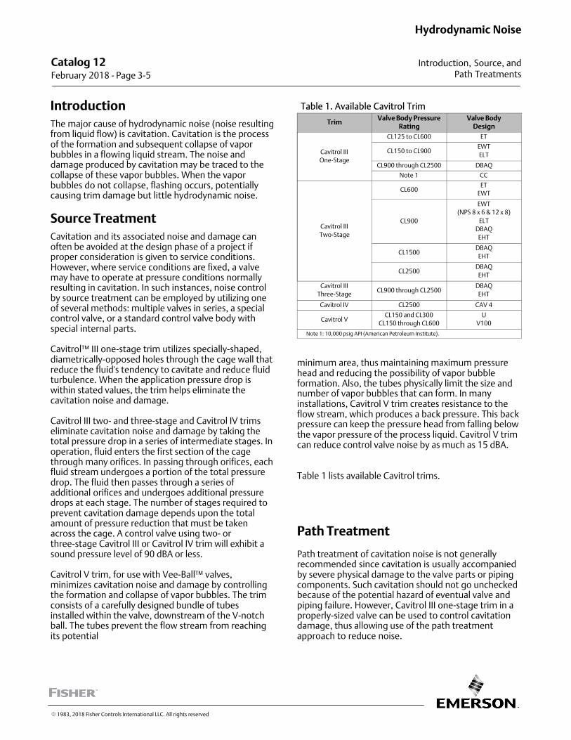
Introduction
The major cause of hydrodynamic noise (noise resultingfrom liquid flow) is cavitation. Cavitation is the processof the formation and subsequent collapse of vaporbubbles in a flowing liquid stream. The noise anddamage produced by cavitation may be traced to thecollapse of these vapor bubbles. When the vaporbubbles do not collapse, flashing occurs, potentiallycausing trim damage but little hydrodynamic noise.
Source Treatment
Cavitation and its associated noise and damage canoften be avoided at the design phase of a project ifproper consideration is given to service conditions.However, where service conditions are fixed, a valvemay have to operate at pressure conditions normallyresulting in cavitation. In such instances, noise controlby source treatment can be employed by utilizing oneof several methods: multiple valves in series, a specialcontrol valve, or a standard control valve body withspecial internal parts.
Cavitrol™ III one‐stage trim utilizes specially‐shaped,diametrically‐opposed holes through the cage wall thatreduce the fluid's tendency to cavitate and reduce fluidturbulence. When the application pressure drop iswithin stated values, the trim helps eliminate thecavitation noise and damage.
Cavitrol III two‐ and three‐stage and Cavitrol IV trimseliminate cavitation noise and damage by taking thetotal pressure drop in a series of intermediate stages. Inoperation, fluid enters the first section of the cagethrough many orifices. In passing through orifices, eachfluid stream undergoes a portion of the total pressuredrop. The fluid then passes through a series ofadditional orifices and undergoes additional pressuredrops at each stage. The number of stages required toprevent cavitation damage depends upon the totalamount of pressure reduction that must be takenacross the cage. A control valve using two‐ orthree‐stage Cavitrol III or Cavitrol IV trim will exhibit asound pressure level of 90 dBA or less.
Cavitrol V trim, for use with Vee‐Ball™�valves,minimizes cavitation noise and damage by controllingthe formation and collapse of vapor bubbles. The trimconsists of a carefully designed bundle of tubesinstalled within the valve, downstream of the V‐notchball. The tubes prevent the flow stream from reachingits potential
Table 1. Available Cavitrol Trim
TrimValve Body Pressure
RatingValve Body
Design
Cavitrol III
One‐Stage
CL125 to CL600 ET
CL150 to CL900EWT
ELT
CL900 through CL2500 DBAQ
Note 1 CC
Cavitrol III
Two‐Stage
CL600ET
EWT
CL900
EWT
(NPS 8 x 6 & 12 x 8)
ELT
DBAQ
EHT
CL1500DBAQ
EHT
CL2500DBAQ
EHT
Cavitrol III
Three‐StageCL900 through CL2500
DBAQ
EHT
Cavitrol IV CL2500 CAV 4
Cavitrol VCL150 and CL300
CL150 through CL600
U
V100
Note 1: 10,000 psig API (American Petroleum Institute).
minimum area, thus maintaining maximum pressurehead and reducing the possibility of vapor bubbleformation. Also, the tubes physically limit the size andnumber of vapor bubbles that can form. In manyinstallations, Cavitrol V trim creates resistance to theflow stream, which produces a back pressure. This backpressure can keep the pressure head from falling belowthe vapor pressure of the process liquid. Cavitrol V trimcan reduce control valve noise by as much as 15 dBA.
Table 1 lists available Cavitrol trims.
Path Treatment
Path treatment of cavitation noise is not generallyrecommended since cavitation is usually accompaniedby severe physical damage to the valve parts or pipingcomponents. Such cavitation should not go uncheckedbecause of the potential hazard of eventual valve andpiping failure. However, Cavitrol III one‐stage trim in aproperly‐sized valve can be used to control cavitationdamage, thus allowing use of the path treatmentapproach to reduce noise.
Catalog 12 February 2018 ‐ Page 3‐5
Hydrodynamic Noise
Introduction, Source, andPath Treatments
� 1983, 2018 Fisher Controls International LLC. All rights reserved
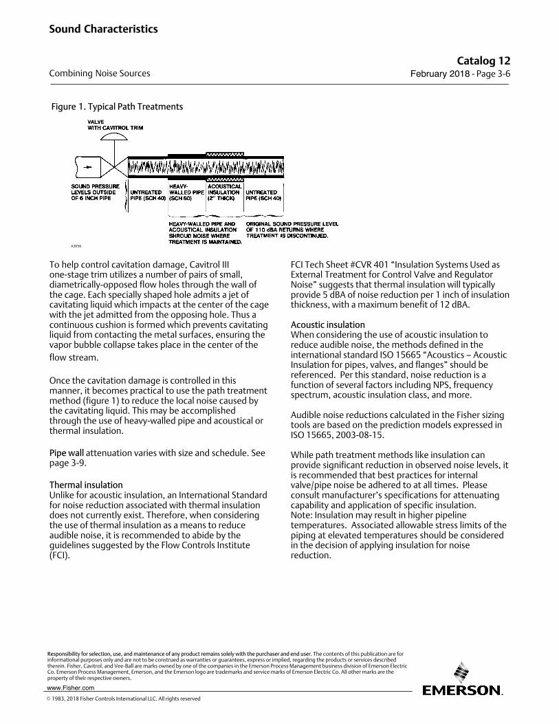
Figure 1. Typical Path Treatments
A3056
To help control cavitation damage, Cavitrol IIIone‐stage trim utilizes a number of pairs of small,diametrically‐opposed flow holes through the wall ofthe cage. Each specially shaped hole admits a jet ofcavitating liquid which impacts at the center of the cagewith the jet admitted from the opposing hole. Thus acontinuous cushion is formed which prevents cavitatingliquid from contacting the metal surfaces, ensuring thevapor bubble collapse takes place in the center of the
flow stream.
Once the cavitation damage is controlled in thismanner, it becomes practical to use the path treatmentmethod (figure 1) to reduce the local noise caused bythe cavitating liquid. This may be accomplishedthrough the use of heavy‐walled pipe and acoustical orthermal insulation.
Pipe wall attenuation varies with size and schedule. Seepage 3‐9.
Thermal insulationUnlike for acoustic insulation, an International Standardfor noise reduction associated with thermal insulationdoes not currently exist. Therefore, when consideringthe use of thermal insulation as a means to reduceaudible noise, it is recommended to abide by theguidelines suggested by the Flow Controls Institute(FCI).
FCI Tech Sheet #CVR 401 “Insulation Systems Used asExternal Treatment for Control Valve and RegulatorNoise” suggests that thermal insulation will typicallyprovide 5 dBA of noise reduction per 1 inch of insulationthickness, with a maximum benefit of 12 dBA.
Acoustic insulation When considering the use of acoustic insulation toreduce audible noise, the methods defined in theinternational standard ISO 15665 “Acoustics – AcousticInsulation for pipes, valves, and flanges” should bereferenced. Per this standard, noise reduction is afunction of several factors including NPS, frequencyspectrum, acoustic insulation class, and more.
Audible noise reductions calculated in the Fisher sizingtools are based on the prediction models expressed inISO 15665, 2003-08-15.
While path treatment methods like insulation canprovide significant reduction in observed noise levels, itis recommended that best practices for internalvalve/pipe noise be adhered to at all times. Pleaseconsult manufacturer’s specifications for attenuatingcapability and application of specific insulation.Note: Insulation may result in higher pipelinetemperatures. Associated allowable stress limits of thepiping at elevated temperatures should be consideredin the decision of applying insulation for noisereduction.
Catalog 12February 2018 ‐ Page 3‐6
Sound Characteristics
Combining Noise Sources
� 1983, 2018 Fisher Controls International LLC. All rights reserved
www.Fisher.com
Responsibility for selection, use, and maintenance of any product remains solely with the purchaser and end user. The contents of this publication are forinformational purposes only and are not to be construed as warranties or guarantees, express or implied, regarding the products or services describedtherein. Fisher, Cavitrol, and Vee-Ball are marks owned by one of the companies in the Emerson Process Management business division of Emerson ElectricCo. Emerson Process Management, Emerson, and the Emerson logo are trademarks and service marks of Emerson Electric Co. All other marks are theproperty of their respective owners.
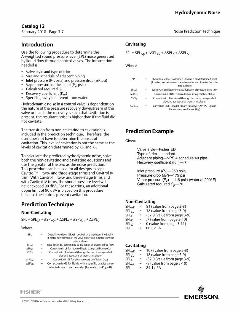
Introduction
Use the following procedure to determine theA‐weighted sound pressure level (SPL) noise generatedby liquid flow through control valves. The informationneeded is:
� Valve style and type of trim� Size and schedule of adjacent piping� Inlet pressure (P1, psia) and pressure drop (�P,psi)� Vapor pressure of the liquid (Pv, psia)� Calculated required Cv
� Recovery coefficient (Km)� Specific gravity if different from water
Hydrodynamic noise in a control valve is dependent onthe nature of the pressure recovery downstream of thevalve orifice. If the recovery is such that cavitation ispresent, the resultant noise is higher than if the fluid didnot cavitate.
The transition from non‐cavitating to cavitating isincluded in the prediction technique. Therefore, theuser does not have to determine the onset ofcavitation. This level of cavitation is not the same as thelevels of cavitation determined by Km and Kc.
To calculate the predicted hydrodynamic noise, solveboth the non‐cavitating and cavitating equations anduse the greater of the two as the noise prediction.This procedure can be used for all designs exceptCavitrol™ III two‐ and three‐stage trims and Cavitrol IVtrim. With Cavitrol III two‐ and three‐stage trims andwith Cavitrol IV trims, the sound pressure level willnever exceed 90 dBA. For these trims, an additionalupper limit of 90 dBA is placed on this procedurebecause these trims prevent cavitation.
Prediction Technique
Non-Cavitating
SPL = SPLΔP + ΔSPLCv + ΔSPLk + ΔSPLkm + ΔSPLg
Where
SPL = Overall noise level (dBA) in decibels at a predetermined point
(1 meter downstream of the valve outlet and 1 meter from the
pipe surface)
SPLΔP = Base SPL in dB, determined as a function of pressure drop (ΔP)
ΔSPLCv = Correction in dB for required liquid sizing coefficient (Cv)
ΔSPLK = Correction in dB achieved through the use of heavy‐walled
pipe and acoustical or thermal insulation
ΔSPLKm = Correction in dB for given recovery coefficient (Km)
ΔSPLG = Correction in dB for fluids with a specific gravity value
which differs from the water (for water, ΔSPLG = 0)
Cavitating
SPL = SPL�p + �SPLCv + �SPLK + �SPLAR
Where
SPL = Overall noise level in decibels (dBA) at a predetermined point
(1 meter downstream of the valve outlet and 1 meter from the
pipe surface)
SPL�P = Base SPL in dB determined as a function of pressure drop (�P)
�SPLCv = Correction in dB for required liquid sizing coefficient (Cv)
�SPLk = Correction in dB achieved through the use of heavy‐walled
pipe and acoustical of thermal insulation
�SPLAR = Correction in dB for applications ratio [AR = �P/(P1-Pv)] and
the recovery coefficient (Km)
Prediction Example
Given:
Valve style—Fisher EDType of trim—standardAdjacent piping—NPS 4 schedule 40 pipeRecovery coefficient (Km)—.7
Inlet pressure (P1 )—250 psiaPressure drop (ΔP)—175 psiVapor pressure(Pv )—11.5 psia (water at 200�F)Calculated required Cg—70
Non‐CavitatingSPL�P = 81 (value from page 3‐8)SPLCv = 18 (value from page 3‐9)SPLK = -32.9 (value from page 3‐9)SPLKm = .7 (value from page 3‐10)SPLG = 0 (value from page 3‐11)SPL = 66.8 dBA
CavitatingSPL�P = 107 (value from page 3‐8)SPLCv = 18 (value from page 3‐9)SPLK = -32.9 (value from page 3‐9)SPLAR = -8 (value from page 3‐10)SPL = 84.1 dBA
Catalog 12 February 2018 ‐ Page 3‐7
Hydrodynamic Noise
Noise Prediction Technique
� 1989, 2018 Fisher Controls International LLC. All rights reserved
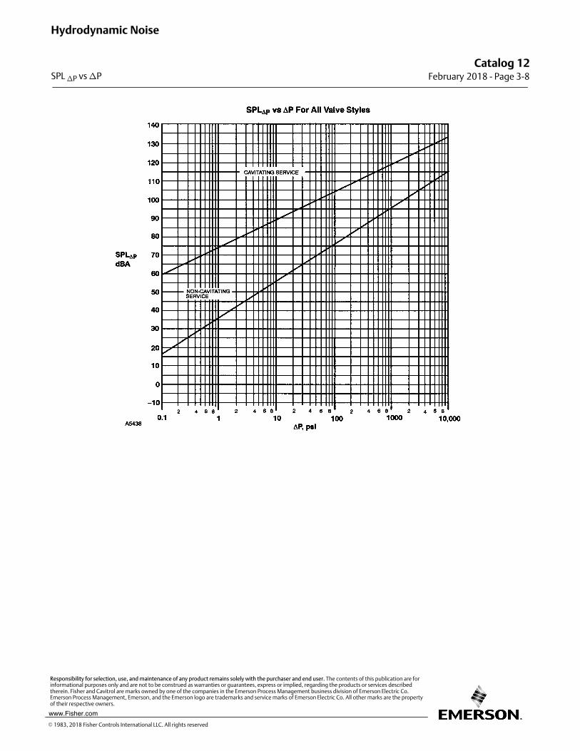
Catalog 12February 2018 ‐ Page 3‐8
Hydrodynamic Noise
SPL �P vs �P
� 1983, 2018 Fisher Controls International LLC. All rights reserved
www.Fisher.com
Responsibility for selection, use, and maintenance of any product remains solely with the purchaser and end user. The contents of this publication are forinformational purposes only and are not to be construed as warranties or guarantees, express or implied, regarding the products or services describedtherein. Fisher and Cavitrol are marks owned by one of the companies in the Emerson Process Management business division of Emerson Electric Co.Emerson Process Management, Emerson, and the Emerson logo are trademarks and service marks of Emerson Electric Co. All other marks are the propertyof their respective owners.
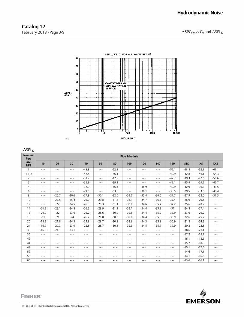
�SPLK
NominalPipeSize,NPS
Pipe Schedule
10 20 30 40 60 80 100 120 140 160 STD XS XXS
1 ‐ ‐ ‐ ‐ ‐ ‐ ‐ ‐ ‐ -48.8 ‐ ‐ ‐ -52.1 ‐ ‐ ‐ ‐ ‐ ‐ ‐ ‐ ‐ -56.1 -48.8 -52.1 -61.1
1‐1/2 ‐ ‐ ‐ ‐ ‐ ‐ ‐ ‐ ‐ -42.8 ‐ ‐ ‐ -46.1 ‐ ‐ ‐ ‐ ‐ ‐ ‐ ‐ ‐ -49.9 -42.8 -46.1 -54.3
2 ‐ ‐ ‐ ‐ ‐ ‐ ‐ ‐ ‐ -38.7 ‐ ‐ ‐ -42.8 ‐ ‐ ‐ ‐ ‐ ‐ ‐ ‐ ‐ -47.7 -39.3 -42.6 -50.6
3 ‐ ‐ ‐ ‐ ‐ ‐ ‐ ‐ ‐ -35.9 ‐ ‐ ‐ -39.2 ‐ ‐ ‐ ‐ ‐ ‐ ‐ ‐ ‐ -43.1 -35.9 -39.2 -46.7
4 ‐ ‐ ‐ ‐ ‐ ‐ ‐ ‐ ‐ -32.9 ‐ ‐ ‐ -36.3 ‐ ‐ ‐ -38.9 ‐ ‐ ‐ -40.9 -32.9 -36.3 -43.5
6 ‐ ‐ ‐ ‐ ‐ ‐ ‐ ‐ ‐ -29.5 ‐ ‐ ‐ -33.5 ‐ ‐ ‐ -36.1 ‐ ‐ ‐ -38.5 -29.5 -33.5 -40.4
8 ‐ ‐ ‐ -25.7 -26.6 -27.9 -30.1 -32.0 -33.6 -35.4 -36.6 -37.7 -27.9 -32.0 -37.3
10 ‐ ‐ ‐ -23.5 -25.4 -26.9 -29.8 -31.4 -33.1 -34.7 -36.3 -37.4 -26.9 -29.8 ‐ ‐ ‐
12 ‐ ‐ ‐ -22 -24.5 -26.3 -29.3 -31.1 -33.0 -34.6 -35.7 -37.2 -25.6 -28.2 ‐ ‐ ‐
14 -21.2 -23.1 -24.8 -26.2 -28.9 -31.1 -33.1 -34.4 -35.9 -37 -24.8 -27.4 ‐ ‐ ‐
16 -20.0 -22 -23.6 -26.2 -28.6 -30.9 -32.8 -34.4 -35.9 -36.9 -23.6 -26.2 ‐ ‐ ‐
18 -19 -21 -24 -26.2 -28.8 -30.9 -32.8 -34.4 -35.6 -36.9 -22.6 -25.2 ‐ ‐ ‐
20 -18.2 -21.8 -24.3 -25.8 -28.7 -30.8 -32.8 -34.3 -35.8 -36.9 -21.8 -24.3 ‐ ‐ ‐
24 -16.7 -20.3 -23.9 -25.8 -28.7 -30.8 -32.9 -34.5 -35.7 -37.0 -20.3 -22.8 ‐ ‐ ‐
30 -16.9 -21.1 -23.1 ‐ ‐ ‐ ‐ ‐ ‐ ‐ ‐ ‐ ‐ ‐ ‐ ‐ ‐ ‐ ‐ ‐ ‐ ‐ ‐ ‐ -18.6 -21.1 ‐ ‐ ‐
36 ‐ ‐ ‐ ‐ ‐ ‐ ‐ ‐ ‐ ‐ ‐ ‐ ‐ ‐ ‐ ‐ ‐ ‐ ‐ ‐ ‐ ‐ ‐ ‐ ‐ ‐ ‐ ‐ ‐ ‐ -17.2 -19.7 ‐ ‐ ‐
42 ‐ ‐ ‐ ‐ ‐ ‐ ‐ ‐ ‐ ‐ ‐ ‐ ‐ ‐ ‐ ‐ ‐ ‐ ‐ ‐ ‐ ‐ ‐ ‐ ‐ ‐ ‐ ‐ ‐ ‐ -16.1 -18.6 ‐ ‐ ‐
44 ‐ ‐ ‐ ‐ ‐ ‐ ‐ ‐ ‐ ‐ ‐ ‐ ‐ ‐ ‐ ‐ ‐ ‐ ‐ ‐ ‐ ‐ ‐ ‐ ‐ ‐ ‐ ‐ ‐ ‐ -15.7 -18.3 ‐ ‐ ‐
48 ‐ ‐ ‐ ‐ ‐ ‐ ‐ ‐ ‐ ‐ ‐ ‐ ‐ ‐ ‐ ‐ ‐ ‐ ‐ ‐ ‐ ‐ ‐ ‐ ‐ ‐ ‐ ‐ ‐ ‐ -15.1 -17.6 ‐ ‐ ‐
52 ‐ ‐ ‐ ‐ ‐ ‐ ‐ ‐ ‐ ‐ ‐ ‐ ‐ ‐ ‐ ‐ ‐ ‐ ‐ ‐ ‐ ‐ ‐ ‐ ‐ ‐ ‐ ‐ ‐ ‐ -14.6 -17.1 ‐ ‐ ‐
56 ‐ ‐ ‐ ‐ ‐ ‐ ‐ ‐ ‐ ‐ ‐ ‐ ‐ ‐ ‐ ‐ ‐ ‐ ‐ ‐ ‐ ‐ ‐ ‐ ‐ ‐ ‐ ‐ ‐ ‐ -14.1 -16.6 ‐ ‐ ‐
60 ‐ ‐ ‐ ‐ ‐ ‐ ‐ ‐ ‐ ‐ ‐ ‐ ‐ ‐ ‐ ‐ ‐ ‐ ‐ ‐ ‐ ‐ ‐ ‐ ‐ ‐ ‐ ‐ ‐ ‐ -13.6 -16.1 ‐ ‐ ‐
Catalog 12 February 2018 ‐ Page 3‐9
Hydrodynamic Noise
�SPCCv vs Cv and �SPLK
� 1983, 2018 Fisher Controls International LLC. All rights reserved
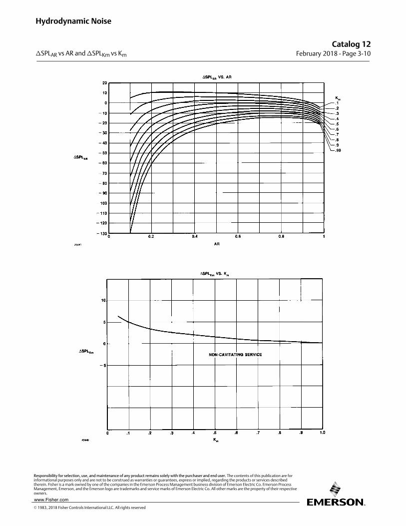
Catalog 12February 2018 ‐ Page 3‐10
Hydrodynamic Noise
�SPLAR vs AR and �SPLKm vs Km
� 1983, 2018 Fisher Controls International LLC. All rights reserved
www.Fisher.com
Responsibility for selection, use, and maintenance of any product remains solely with the purchaser and end user. The contents of this publication are forinformational purposes only and are not to be construed as warranties or guarantees, express or implied, regarding the products or services describedtherein. Fisher is a mark owned by one of the companies in the Emerson Process Management business division of Emerson Electric Co. Emerson ProcessManagement, Emerson, and the Emerson logo are trademarks and service marks of Emerson Electric Co. All other marks are the property of their respectiveowners.
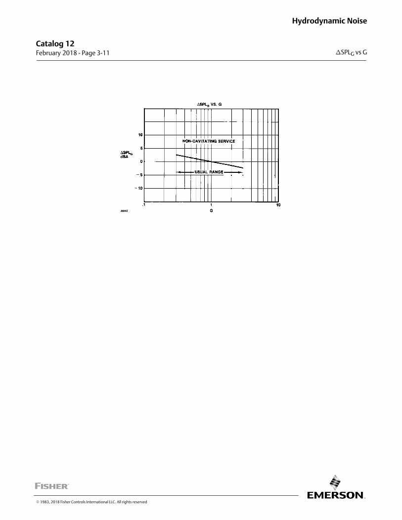
Catalog 12 February 2018 ‐ Page 3‐11
Hydrodynamic Noise
�SPLG vs G
� 1983, 2018 Fisher Controls International LLC. All rights reserved
This page is intentionally left blank
Catalog 12February 2018 ‐ Page 3‐12
Hydrodynamic Noise
� 2018 Fisher Controls International LLC. All rights reserved
www.Fisher.com
Responsibility for selection, use, and maintenance of any product remains solely with the purchaser and end user. The contents of this publication are forinformational purposes only and are not to be construed as warranties or guarantees, express or implied, regarding the products or services describedtherein. Fisher is a mark owned by one of the companies in the Emerson Automation Solutions business division of Emerson Electric Co. EmersonAutomation Solutions, Emerson, and the Emerson logo are trademarks and service marks of Emerson Electric Co. All other marks are the property of theirrespective owners.