Embed Size (px)
Citation preview

1 Copyright © 2013 by ASME
ASME SECTION III STRESS ANALYSIS OF A HEAT EXCHANGER TUBESHEET WITH A MISDRILLED HOLE AND IRREGULAR OR THIN LIGAMENTS
Dr. Enrique Gomez ENSA Engineering Department Avda Juan Carlos I, 8, 39600
Maliano, Cantabria, Spain Tel: +34-942-200166
Email: [email protected]
Mr. Roberto Ruiz ENSA Engineering Department Avda Juan Carlos I, 8, 39600
Maliano, Cantabria, Spain Tel: +34-942-200101
Email: [email protected]
Mr. Robert M. (Con) Wilson Private Consultant
3609 Cherry Hill Drive, Orlando, Florida USA Tel: 407-761-1337
Email: [email protected]
ABSTRACT A stress analysis is described for a nuclear steam
generator tubesheet with a thin or irregular ligament associated with a mis-drilled hole using the rules of ASME B&PV Section III and Non-Mandatory Appendix A, Article A-8000 for Stresses in Perforated Flat Plates. The analysis demonstrates the proper application of the NB-3200 rules for this special application with discussion of the differences between an actual tube hole deviation from what is assumed in ASME Appendix A. This is a companion paper to “Technical Justification Supporting Operation with a Tube Installed in a Mis-Drilled Hole of a Steam Generator Tubesheet”
NOMENCLATURE h = nominal width of ligament at the minimum cross
section, (P – d) (inches) P = nominal distance between hole center lines, pitch
(inches)
t = thickness of plate exclusive of cladding or corrosion allowance (inches)
η = ligament efficiency = h/P ν* = effective Poisson’s ratio for perforated plate (Fig.
A-8131-1) [Ref. 3] E* = effective Young’s modulus for perforated plate
(Fig. A-8131-1) [Ref. 3](ksi) R* = the effective radius of the perforated plate = ro +
1/4 (P - h) (inches) ro = radial distance from center of plate to center of
outermost hole (inches) p1, p2 = pressures acting on surfaces of the plate (ksi) Δp = differential pressure across the plate (ksi) σr* = radial stresses in the equivalent solid plate (ksi) σθ* = tangential stress in the equivalent solid plate (ksi) σa* = axial stress in the equivalent solid plate (ksi)
τra* = radial-axial shear stress in the equivalent solid plate (ksi)
σr = radial stresses in the tubesheet (ksi) σθ = tangential stress in the tubesheet (ksi)
Proceedings of the ASME 2013 Pressure Vessels and Piping Conference PVP2013
July 14-18, 2013, Paris, France
PVP2013-97075

2 Copyright © 2013 by ASME
εr = radial strain in the tubesheet (ksi) εθ = tangential strain in the tubesheet (ksi)
β = biaxiality ratio (σr/σθ or σθ /σr) or (σ1/σ2 or σ2/σ1), where - 1 ≤ β ≤ 1
σ1*, σ2* = principal stress in the plane of the equivalent solid plate (A-8142.2) [Ref. 3] (ksi)
σave* = larger absolute value of σr* or σθ* (A-8142.1(b)) [Ref. 3] (ksi)
σskin = thermal skin stress (ksi) d = diameter of holes in the tubesheet (inches) K = stress multiplier for stresses averaged across the
width of the ligament but not through the tubesheet thickness (Fig. A-8142-1) [Ref. 3]
Y1, Y2 = stress multipliers for peak ligament stresses (Fig. A-8142-3 and A-8142-4) [Ref. 3]
Ymax = stress multipliers given in Fig. A-8142-2 as a function of biaxiality ratio β [Ref. 3]
Km = ratio of total stress in the thin ligament to the total stress in nominal ligament (Fig. A-8143.2-1) [Ref. 3]
Kskin = stress multiplier for thermal skin stress (Fig. A-8153-1) [Ref. 3]
S = stress intensity (A-8142) [Ref. 3] (ksi) v = Poisson’s ratio E = Young’s modulus for tubesheet material (ksi) Et = Young’s modulus for the tube material (ksi)
Tm = mean temperature averaged through the thickness of the tubesheet
Ts = temperature of the secondary surface of the tubesheet
α = coefficient of thermal expansion tt = tube wall thickness (inches) ps = pressure on surface where stress is computed, p1
or p2 (ksi) p1 = pressure in the primary side (ksi) p2 = pressure in the secondary side (ksi) pi = pressure inside tubes (ksi) Pm = primary membrane stress (ksi) Pm+b = primary membrane plus bending stress (ksi) Q = secondary stress (ksi) F = peak stress (ksi) CUF = cumulative usage factors for fatigue
INTRODUCTION Perforated plate stress analysis has been performed for
decades using a methodology that was established in the early 1960s [Ref. 1]. That methodology was introduced to the ASME Boiler and Pressure Vessel Code for Nuclear Components (Section III) in the Summer 1966 Addenda to the 1965 Edition as non-mandatory Appendix I, Article I-9 “Stresses in Ligaments” [Ref. 2]. This same methodology is present, with minor editorial changes, in the current 2011 Addenda of the 2010 Edition of Section III as Appendix A, Article A-8000 [Ref.3]. This methodology allows the tubesheet to be analyzed as if it is a solid plate followed by the application of stress multipliers that were derived from experiments as a function of the tube hole size and pitch. The conversion of a plate with drilled holes to an equivalent solid plate is accomplished by using a modified Young’s modulus
and Poisson’s ratio that is based on tests of plates with various tube hole diameter-to-pitch ratios or ligament efficiencies.
The original methodology also included a procedure for evaluating stresses for a mis-drilled hole with a thinner than nominal ligament. The mis-drilled hole configuration assumed that the hole was out-of-position through the entire thickness of the tubesheet, i.e. parallel to the neighboring holes.
The stress analysis described in this paper is based on the more realistic as-fabricated condition where the mis-drilled hole is not parallel to the neighboring holes. In this case, the drilling of the hole begins at the appropriate position and then drifts away from the intended path, to exit the opposite side of the tubesheet with an out-of-position condition. The limiting location for this condition is at the thinnest ligament location.
The structural analysis of the tubesheet, channel head, lower shell complex involves several simplifications. This paper discusses some of them.
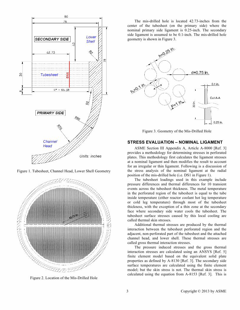
GEOMETRY OF THE TUBESHEET Figure 1 shows the dimensions of an axisymmetric model
of a typical steam generator tubesheet, channel head and lower shell configuration. All parts are constructed using SA-508, Grade 3, Class 2 low alloy steel. The tubesheet that is modeled has 14,440, 0.75-inch diameter holes for 7,220 U-tubes. For simplicity, the tube outer diameter is assumed to be equal to the hole diameter. The distance between holes (the tube pitch) is 1 inch and the holes are arranged in an equilateral triangular pattern. This produces a 0.25-inch nominal, minimum ligament between holes. The ligament efficiency [η = (P-d)/P = h/P] is 0.25. The tubes in the tubesheet holes are Alloy 690 material and have a tt = 0.040-inch wall thickness.
The actual tubesheet has a hot leg side where the heated reactor coolant enters the steam generator tube bundle. The hot leg side has 7,220 holes, each containing the hot leg end of the 7,220 U-bend tubes. The U-bend tubes transfer heat from the reactor coolant to the secondary side fluid to produce steam, and the reactor coolant exits the bundle through the cold leg side of the tubesheet. The hot leg and cold leg sides of the tubesheet are separated by a non-drilled (solid) tubelane that extends across the full diameter of the tubesheet. The steam generator also has a solid divider plate that joins the tubesheet to the channel head and forces the hot reactor coolant to flow through the U-tubes.
It is possible to evaluate the tubesheet stresses using a 3D finite element model that contains the non-perforated tubelane and the divider plate. However, since the original equivalent solid plate methodology is based on an axisymmetric structure, it is acceptable to treat the pressure boundary as being axisymmetric assuming the entire tubesheet to be perforated (neglecting the tubelane and divider plate).
The location of the mis-drilled hole used in this analysis is shown in Figure 2.
3 Copyright © 2013 by ASME
Figure 1. Tubesheet, Channel Head, Lower Shell Geometry
Figure 2. Location of the Mis-Drilled Hole
The mis-drilled hole is located 42.73-inches from the
center of the tubesheet (on the primary side) where the nominal primary side ligament is 0.25-inch. The secondary side ligament is assumed to be 0.1-inch. The mis-drilled hole geometry is shown in Figure 3.
Figure 3. Geometry of the Mis-Drilled Hole
STRESS EVALUATION – NOMINAL LIGAMENT ASME Section III Appendix A, Article A-8000 [Ref. 3]
provides a methodology for determining stresses in perforated plates. This methodology first calculates the ligament stresses at a nominal ligament and then modifies the result to account for an irregular or thin ligament. Following is a discussion of the stress analysis of the nominal ligament at the radial position of the mis-drilled hole (i.e. DS1 in Figure 1).
The tubesheet loadings used in this example include pressure differences and thermal differences for 10 transient events across the tubesheet thickness. The metal temperature in the perforated region of the tubesheet is equal to the tube inside temperature (either reactor coolant hot leg temperature or cold leg temperature) through most of the tubesheet thickness, with the exception of a thin zone at the secondary face where secondary side water cools the tubesheet. The tubesheet surface stresses caused by this local cooling are called thermal skin stresses.
Additional thermal stresses are produced by the thermal interaction between the tubesheet perforated region and the adjacent, non-perforated part of the tubesheet and the attached channel head, and lower shell. These thermal stresses are called gross thermal interaction stresses.
The pressure induced stresses and the gross thermal interaction stresses are calculated using an ANSYS [Ref. 5] finite element model based on the equivalent solid plate properties as defined by A-8130 [Ref. 3]. The secondary side surface temperatures are calculated using the finite element model; but the skin stress is not. The thermal skin stress is calculated using the equation from A-8153 [Ref. 3]. This is

4 Copyright © 2013 by ASME
consistent with the recommendations of Slot and O’Donnell [Ref. 4 and Ref. 1].
The tubesheet stress results at the secondary side location labeled DS1 in Figure 1 are shown in Table 1 for a unit pressure loading (1000 psi).
Table 1. Tubesheet Pressure Stresses due to Unit Loads
Membrane, Pm @ Sec. Side Node
σr* (ksi)
σθ* (ksi)
σa* (ksi)
τra* (ksi)
p1 = 1 ksi 0.281 0.261 -0.511 0.710 p2 = 1 ksi 0.008 -0.011 -0.509 -0.710
Mem+Bend, Pm+b @ Sec. Side Node
σr* (ksi)
σθ* (ksi)
σa* (ksi)
τra* (ksi)
p1 = 1 ksi 1.541 2.424 -0.005 0.710 p2 = 1 ksi -1.389 -2.311 -0.996 -0.710
THERMAL SKIN STRESS EVALUATION The thermal skin stress is calculated using equation (24)
from A-8153 [Ref. 3]; σrskin = σθskin = E α (Tm –Ts) / (1-ν). A-8153 tells the analyst to use equation (23); σskin = Kskin Ymax
(P/h) E α (Tm –Ts) / (1-ν) when equation (24) was intended. The ASME acknowledged this editorial error in response to a 2012 code inquiry [Ref. 6].
The secondary side tubesheet metal surface temperature Ts is calculated by ANSYS for each transient and the tubesheet mean temperature, Tm, is set equal to the average temperature in the tubesheet, which is the reactor coolant hot leg temperature for purposes of this analysis.
The thermal skin stress is not dependent on the ligament efficiency because the skin effect is localized near the surface of a very thick plate. The thick plate constrains the secondary surface so that its in-plane surface strains εr and εθ are zero. This assumption leads to the thermal skin stress equation: σrskin = σθskin = E α (Tm –Ts) / (1-ν). Paragraph A-8153.1 equation (24) [Ref. 3] incorporates a stress reduction factor, Kskin based on the nominal ligament efficiency (η = 0.25) for the purpose of adjusting the thermal skin stress so it can be combined with the stresses from all of the other load cases using the equivalent solid plate method. Table 2 shows the thermal skin stresses for ΔT = (Tm –Ts) = 100ºF. Thermal skin stress is classified as peak stress (F).
Table 2. Thermal Skin Stresses for 100oF ΔT
Thermal Peak, F Sec. Side Node
σr* (ksi)
σθ* (ksi)
σa* (ksi)
τra* (ksi)
ΔT = 100ºF 5.823 5.823 0.0 0.0
TUBE INTERNAL PRESSURE LIGAMENT STRESSES A-8110 (b) [Ref. 3] acknowledges that the tubes stiffen
the tubesheet. Nuclear steam generator tubes are expanded full depth into the tubesheet holes increasing the tubesheet stiffness. This effect is conservatively ignored in this analysis; but could be included if needed to confirm structural acceptability.
The influence of the pressure loading inside the tubes is included because it produces membrane stresses in the tubesheet ligaments. This effect is addressed in equation (13) of A-8132.4 [Ref. 3]. This equation incorporates a stress reduction factor, h/P that adjusts the stresses due to the tube internal pressure so they can be combined with the stresses from the other load cases that are based on the equivalent solid plate properties. The ratio of Young's modulus for the tube (Et) to the Young's modulus of the tubesheet material (E) is included to account for the different properties of the tube and the tubesheet ligament. The ligament stresses due to tube internal pressure are listed in Table 3.
Table 3. Ligament Membrane Stress due to Tube Internal
Pressure (Unit Load Case)
Membrane, Pm Sec. Side Node
σr* (ksi)
σθ* (ksi)
σa* (ksi)
τra* (ksi)
pi = 1 ksi 0.497 0.497 0.0 0.0
PRIMARY STRESS EVALUATION The NB-3221.1 primary membrane stress intensity
requirement [Ref. 7] is to be satisfied based on the stresses due to mechanical and pressure loads. The membrane stress is averaged across the nominal ligament width (0.25-inch) and across the tubesheet thickness as required by A-8142.1 (a) [Ref. 3].
Using the membrane values of Tables 1 and 3, the radial stress, averaged through the depth of the equivalent solid plate for DS1, and the larger value of equation (16) and (17) [Ref. 3] is calculated in Table 4.
Table 4. Primary Membrane Stress
Membrane, Pm @ Sec. Side Node
p1 = pi (ksi)
p2 (ksi)
σr* (ksi)
S (ksi)
Limit (ksi)
Design 2.500 0.900 1.952 12.003 30.000 Level A & B 2.700 0.800 2.107 13.719 33.000 Level C 2.600 0.000 2.023 16.879 48.510 Level D 2.800 0.000 2.178 18.177 63.000 Test 3.100 0.000 2.412 20.125 54.140
The NB-3221.3 primary membrane plus bending stress
intensity requirement [Ref. 7] is to be satisfied based on the stresses due to mechanical and pressure loads. The stresses at the surface of the tubesheet are averaged across the nominal ligament width (0.25-inch) as required by A-8142.1 (b) [Ref. 3].
Using the membrane plus bending values of Table 1 and membrane of Table 3, the radial and hoop stresses for DS1 is calculated in Table 5 according to equation (18) [Ref. 3]:
S = K (P/h) σave* (1)

5 Copyright © 2013 by ASME
Table 5. Primary Membrane plus Bending Stress
Mem+Bend Sec. Side Node
σr* (ksi)
σθ* (ksi) β K S
(ksi) Limit (ksi)
Pm+b Design 3.845 5.223 0.74 1.01 21.099 45.000 Level A & B 4.391 6.038 0.73 1.01 24.393 49.500 Level C 5.299 7.595 0.70 1.01 30.682 72.765 Level D 5.706 8.179 0.70 1.01 33.042 94.500 Test 6.318 9.055 0.70 1.01 36.583 81.210
PRIMARY + SECONDARY STRESS RANGE The NB-3222.2 primary plus secondary stress intensity
range requirement [Ref. 7] is to be satisfied based on the stresses due to mechanical, pressure, and the gross thermal interaction loads. The stresses at the surface of the tubesheet are averaged across the nominal ligament width (0.25-inch) as required by A-8142.2 (a) [Ref. 3].
Using the membrane plus bending values of Table 5 and the gross thermal stresses, the radial and hoop stress for DS1 is calculated in Table 6 according to equation (19) [Ref. 3]:
S = K (P/h) σ1* (2)
Table 6. Primary plus Secondary Stress Range
@ Secondary Side Node
Gross Thermal, Qm+b p1 = pi (ksi)
p2 (ksi)
Pm+b + Qm+b
σr* (ksi)
σθ* (ksi)
σr (ksi)
σθ (ksi)
Transient 1 0.000 0.000 0.000 0.000 0.000 0.000 Transient 2 0.085 0.083 2.224 1.066 12.546 16.461 Transient 3 -0.327 -0.326 2.250 0.796 12.612 17.627 Transient 4 -0.137 -0.137 2.203 0.751 13.235 18.245 Transient 5 1.771 1.753 1.546 1.106 13.538 14.845 Transient 6 1.030 1.009 1.917 0.403 17.507 22.706 Transient 7 2.990 2.962 1.605 0.865 20.236 22.598 Transient 8 -0.108 -0.109 2.227 1.053 11.875 15.855 Transient 9 0.000 0.000 3.100 0.000 25.271 36.220
Transient 10 0.000 0.000 0.000 1.500 -8.334 -13.866
β = 0.67 Max. Range = 33.605 50.086 K = 1.02 Max. Range = 51.088 ksi
PEAK STRESS INTENSITY AND FATIGUE The peak stress intensity due to all loadings is limited by
the NB-3222.4 cyclic fatigue requirement [Ref. 7]. The total stresses at the surface of the tubesheet at the nominal ligament are calculated as required by A-8142.2 (b) or (c) [Ref. 3]. A-8142.2 (b) and (c) both deal with the calculation of the peak stress intensity; but equation (20); S = Ymax (P/h) σ1*+ ps , is only intended for loadings where the maximum stress intensity angular orientation is constant.
In most practical cases (and the example of this paper) the bi-axiality ratio (β) for pressure stresses and thermal stresses are different and vary during the transient history, and the principal stress angular orientations change during the transient history so Equation (21); SΦ = Y1σ1*/η + Y2σ2*/η + ps used.
In 2012 the ASME Section III Code Interpretations Committee ruled that the label “(c)” was an editorial error
[Ref. 6] thus confirming that both equations (20) and (21) [Ref. 3] were intended as alternatives.
The peak stress intensity around the periphery of the hole at location DS1 is provided by Equation (21) of paragraph A-8142.2 (c) [Ref. 3]. The angular orientation of the mis-drilled hole to the tubesheet drilling pattern (angle Φ) must be determined so that the stress multipliers from Figs. A-8142-3 and A-8142-4 can be determined. Following is Equation (21) from Reference 3.
SΦ = Y1σ1*/η + Y2σ2*/η + ps (3)
where:
SΦ = peak stress intensity at the angular orientation Φ Y1, Y2 = stress multipliers in Figs. A-8142-3 and 4. Figures A-8142-3 and A-8142-4 are used because they most closely match the angular orientation of the holes at DS1 (see Figure 4) where the angle is 5.8º from the actual radial orientation (for this location σ2), which is less than the 7.5º value of applicability η = nominal ligament efficiency (0.25) σ1*, σ2* = the principal stresses in the plane of the equivalent solid plate, based on all loadings (except the ligament stresses due to the pressure in the tubes (equation (13)[Ref. 3]). For angles Φ=30º and Φ=90º the ligament stresses due to
the pressure in the tubes have the maximum values per equation (13)[Ref. 3] without any stress concentration factor because it is calculated based on the real geometry (see Figure 5).
Figure 4. Relative Location of the Deviated Hole respect to the
Radial Orientation

6 Copyright © 2013 by ASME
( ) ( )2· · · 2··
2· · · 2· ·
t i ttr i
t tt t
d t p t P h tF pE EA h t t h tE E
θσ σ− − −
= = = =⎛ ⎞ ⎛ ⎞
+ +⎜ ⎟ ⎜ ⎟⎝ ⎠ ⎝ ⎠
(4)
Figure 5. Equation (13) [Ref. 3] to be added to SΦ of Equation
(21) [Ref. 3]
The peak stress intensity is determined for all time steps of all transients for the fatigue evaluation.
The total stress results at location DS1 are listed in Table 7. Table 8 shows the stress intensity calculated using equation (21)[Ref. 3] for two representative angles around the hole, 0º and 90º. Finally, Table 9 shows the factors from Figures A-8142-3 and A-8142-4 [Ref. 3] and the cumulative usage factors for nominal ligament.
Table 7. Total Stresses - Nominal Ligament
Total Stress @ Sec. Side Node
p1 = pi (ksi)
p2 = ps (ksi)
ΔT (oF)
σ2* = σr* (ksi)
σ1* = σθ* (ksi)
(P+Q+F)m+b Transient 1 0.000 0.000 0 0.000 0.000 Transient 2 2.224 1.066 91 7.319 8.297 Transient 3 2.250 0.796 92 7.409 8.663 Transient 4 2.203 0.751 93 7.618 8.870 Transient 5 1.546 1.106 -167 -7.114 -6.787 Transient 6 1.917 0.403 -117 -3.389 -2.089 Transient 7 1.605 0.865 -239 -9.673 -9.082 Transient 8 2.227 1.053 93 7.283 8.278 Transient 9 3.100 0.000 0 4.777 7.514
Transient 10 0.000 1.500 0 -2.084 -3.467
Table 8. Peak Stress Intensity at 0º & 90º, Nominal Ligament
Total Stress @ Sec. Side Node Cycles SΦ=0º
(ksi) SΦ=90º (ksi)
Transient 1 400 0.000 0.000 Transient 2 6,000 22.128 43.850 Transient 3 6,000 20.699 45.370 Transient 4 200 21.411 46.184 Transient 5 10 -26.269 -26.977 Transient 6 50 -18.816 -5.136 Transient 7 15 -37.148 -37.606 Transient 8 1,000,000 21.899 43.759 Transient 9 10 2.416 41.277
Transient 10 10 1.468 -14.723
Table 9. Stress Multipliers and CUF - Nominal Ligament
Angle Y1 Y2 CUF 0º -1.35 2.25 0.0015
10º -1.15 2.15 0.0027 20º -0.6 1.75 0.0055 30º 0.3 0.8 0.0076 40º 1.05 0 0.0065 50º 1.4 -0.4 0.0062 60º 1.3 -0.47 0.0033 70º 1.25 -0.27 0.0055 80º 1.22 -0.15 0.0072 90º 1.2 -0.05 0.0124
STRESS EVALUATION – THIN LIGAMENT Table NB-3217-1 [Ref. 7] classifies the stress intensities
at an isolated or atypical ligament (such as that found next to a mis-drilled hole). It states that membrane stress due to pressure is classified as secondary (Q) and bending is classified as peak (F). This means that the mis-drilled hole does not change the tubesheet primary stress margins for the Design Condition, Service Levels A, B, C and D, and / or the Test Condition for the tubesheet with nominal ligaments. The Triaxial stress requirement is also satisfied because it is based on primary stresses.
The stress limits that must be satisfied at an irregular or thin ligament are found in paragraph A-8143 [Ref. 3]. A-8143 requires evaluation of the Average Stress Intensity at the mid-surface of the tubesheet (A-8143.1) and Peak Stress Intensity (fatigue) (A-8143.2) at the tubesheet surface.
AVERAGE STRESS INTENSITY LIMIT (A-8143.1) Paragraph A-8143.1 limits the average ligament stress
intensity due to pressure plus other mechanical loads to 3.0Sm. The gross thermal discontinuity stresses should also be included (although not mentioned). This is consistent with the original work of O’Donnell [Ref. 1] in his discussion of the thin ligament and is consistent with the definition of secondary stresses. This stress intensity is based on stresses averaged across the thin ligament width and averaged across the tubesheet thickness (thus removing bending). This evaluation is similar to that performed to evaluate primary membrane in A-8142.1 (a) except that the actual width of the thin ligament (ha) is used in place of the nominal width h. The membrane stress components from the equivalent solid plate for the nominal ligament that were multiplied by the P/h ratio are changed using the P/ha ratio for the actual thin ligament.
The A-8143.1 methodology [Ref. 3] is based on the conservative assumption that a mis-drilled hole is parallel to its neighbors and that the actual thin ligament extends through the entire tubesheet thickness. Since actual mis-drilled holes are not typically parallel to the neighboring holes, it is necessary to determine the ligament width at the tubesheet mid-surface, hm and to use it in the A-8143.1 evaluation. A linear variation in the ligament thickness is conservative for typical mis-drilled holes. Using this assumption, the actual mid-surface ligament for use in the A-8143.1 evaluation is hm = (h + ha) / 2. The average stress intensity results for the irregular or thin ligament are shown in Table 10. All values are less than the allowable 3Sm (90 ksi) value.

7 Copyright © 2013 by ASME
Table 10. Primary plus Secondary Stresses - Thin Ligament
Gross Thermal p1 = pi
(ksi) p2
(ksi) σr
(ksi) σθ
(ksi) @ Secondary
Side Node σr* (ksi)
σθ* (ksi)
Qm+b Pm + Qm+b Transient 1 0.000 0.000 0.000 0.000 0.000 0.000 Transient 2 0.085 0.083 2.224 1.066 10.057 9.684 Transient 3 -0.327 -0.326 2.250 0.796 9.572 9.230 Transient 4 -0.137 -0.137 2.203 0.751 9.632 9.299 Transient 5 1.771 1.753 1.546 1.106 9.451 9.129 Transient 6 1.030 1.009 1.917 0.403 10.012 9.719 Transient 7 2.990 2.962 1.605 0.865 11.445 11.127 Transient 8 -0.108 -0.109 2.227 1.053 9.795 9.424 Transient 9 0.000 0.000 3.100 0.000 13.782 13.427
Transient 10 0.000 0.000 0.000 1.500 0.069 -0.094 β = 0.99 Max. Range = 13.713 13.522
K = 1.00 Max. Range = 13.713 ksi
PEAK STRESS INTENSITY LIMIT (A-8143.2) Paragraph A-8143.2 [Ref. 3] describes the method for
obtaining the peak stress intensity for a thin ligament. The thin ligament peak stress intensity is computed by multiplying the nominal peak stress intensity (for the nominal ligament) by the Km value from Figure A-8143.2-1 [Ref. 3]. The Km minimum ligament multiplier and the peak stress intensity are calculated at each transient load step. The stresses from all of the loadings (i.e. pressure, gross thermal stresses, skin stresses) are superimposed at each load step to determine the ratio of the two principal stresses (the bi-axiality ratio, β). Then a value for Km is extracted from Figure A-8143.2-1 [Ref. 3] by linear interpolation between the two nearest plotted β values (either β = -1, 0, or +1).
Paragraph A-8143.2 (a) states that the peak stress intensity in the nominal ligament is calculated as indicated in A-8142.2 (b). As written, this cross-reference could be interpreted to exclude the use of the A-8142.2 (c) to calculate the peak stress intensity, but such an interpretation was not intended. This incomplete cross-reference was not present in the original text of the 1966 Addenda [Ref. 2] when it was first introduced. The ASME Section III Committee for Code Interpretations confirmed that this was an editorial error that will be corrected in a future code edition [Ref. 6].
PEAK STRESS INTENSITY EVALUATION Equation (21) [Ref. 3] is modified to account for the thin
ligament by multiplying the total stress for the nominal thickness ligament by the Km value from Figure A-8143.2-1 [Ref. 3]. Therefore the modified Equation (21) appears as follows:
SΦ-thin = (Y1σ1*/η + Y2σ2*/η)·Km+ ps (5)
The peak stress intensities are calculated for each of the
transient stress states considered in the fatigue evaluation. Special consideration is required for angles Φ=30º and
Φ=90º. In these angles the ligament stresses due to the pressure in the tubes have the maximum values and it is added (equation (13)[Ref. 3]) without any stress concentration factor because it is calculated in the real geometry. For other angle,
this stress can be considered negligible (see Figure 5). Therefore, for the thin ligament:
S Φ-thin(30º&90º) = ( )* *
1 1 2 22· ·
2· ·
t im s
tm t
d t pY YK p
Eh tE
σ ση
−⎛ ⎞++ +⎜ ⎟
⎛ ⎞⎝ ⎠ +⎜ ⎟⎝ ⎠
(6)
Tables 11, 12 and 13 show the result of the process to obtain the Stress Intensity and Cumulative Usage Factors for Fatigue in a thin or irregular ligament.
Table 11. Total Stress - Thin Ligament
Total Stress (P+Q+F)m+b
Sec. Side Node
σ2* = σr* (ksi)
σ1* = σθ* (ksi)
β Km
Transient 1 0.000 0.000 0.00 2.50 Transient 2 7.319 8.297 0.88 2.06 Transient 3 7.409 8.663 0.86 2.07 Transient 4 7.618 8.870 0.86 2.07 Transient 5 -7.114 -6.787 0.95 2.02 Transient 6 -3.389 -2.089 0.62 2.19 Transient 7 -9.673 -9.082 0.94 2.03 Transient 8 7.283 8.278 0.88 2.06 Transient 9 4.777 7.514 0.64 2.18
Transient 10 -2.084 -3.467 0.60 2.20
Table 12. Peak Stress Intensity at 0º and 90º - Thin Ligament
Total Stress @ Sec. Side Node Cycles SΦ-thin=0º
(ksi) SΦ-thin=90º
(ksi) Transient 1 400 0.000 0.000 Transient 2 6,000 44.433 85.736 Transient 3 6,000 42.042 89.648 Transient 4 200 43.530 91.385 Transient 5 10 -54.272 -57.972 Transient 6 50 -41.720 -15.193 Transient 7 15 -76.321 -79.628 Transient 8 1,000,000 43.998 85.601 Transient 9 10 5.272 84.543
Transient 10 10 1.429 -34.181
Table 13. Stress Multipliers and CUF - Thin Ligament
Angle Y1 Y2 CUF 0º -1.35 2.25 0.0226
10º -1.15 2.15 0.0336 20º -0.6 1.75 0.0595 30º 0.3 0.8 0.0767 40º 1.05 0 0.0722 50º 1.4 -0.4 0.0705 60º 1.3 -0.47 0.0413 70º 1.25 -0.27 0.0638 80º 1.22 -0.15 0.0795 90º 1.2 -0.05 0.1088
The results of the analysis for the nominal 0.25” tubesheet
ligament are compared to those of the thin 0.10” ligament in Table 14. This comparison shows that the mis-drilled hole does not impact the primary plus secondary stress intensity range because of the different classification of stresses in a single, thin ligament (per Table NB-3217-1 [Ref. 7]). The

8 Copyright © 2013 by ASME
main influence of the mis-drilled hole is to increase the cumulative fatigue usage factor.
Table 14. Nominal vs. Thin Ligament Results
ASME Section III Code Limit Nominal (0.25 in.) Ligament
Thin (0.10 in.) Ligament
Primary + Secondary Stress Intensity Range 51.088 ksi 13.713 ksi
Cumulative Fatigue Usage Factor, CUF 0.0124 0.1008
CONCLUSIONS The methodology used to evaluate the structural integrity
of a steam generator tubesheet with a mis-drilled hole is described and explained. The non-mandatory rules of ASME Appendix A, Article A-8000 [Ref. 3] contains several ambiguities that are addressed and clarified. The analysis is applied to an actual, non-parallel mis-drilled hole and compared to a parallel mis-drilled hole as is assumed in Appendix A. It is shown that the main influence of a mis-drilled hole is on the cumulative fatigue usage factor.
This method does not account for load redistribution around a thin ligament so the fatigue result is conservative. The presence of mis-drilled holes or locally thin ligaments do not affect the primary stress margin in the tubesheet and do not reduce its overall structural integrity. Therefore, there is no consequence of a fatigue crack at any point within the tubesheet drilling-pattern because it could not propagate beyond the local ligament. Consequently, the presence of mis-drilled holes within the tubesheet drilling pattern, although it may complicate tube installation, is a structurally acceptable condition.
ACKNOWLEDGMENTS The authors would like to acknowledge the contribution
of Equipos Nucleares S.A. (ENSA) and Enrique Casado in the development of this report.
REFERENCES 1. W. J. O’Donnell, B. F. Langer, “Design of Perforated
Plates”, ASME Paper No. 61-WA-115, Journal of Engineering for Industry, Transactions of the ASME, Vol. 84, August 1962
2. ASME Boiler & Pressure Vessel Code, Section III, “Rules for Construction of Nuclear Power Plant Components,” 1965 Edition with Addenda through Summer 1966, Appendix I, Article I-9 “Stresses in Ligaments”, The American Society of Mechanical Engineers, New York, New York
3. ASME Boiler & Pressure Vessel Code, Section III, “Rules for Construction of Nuclear Power Plant Components,” 2010 Edition, 2011 Addenda, Division 1 Appendices, Appendix A, Article A-8000 “Stresses in Perforated Flat Plates”, The American Society of Mechanical Engineers, New York, New York
4. Thomas Slot, “Stress Analysis of Thick Perforated Plates”, Technomic Publishing Co. Inc, Westport, CT 1972
5. ANSYS Computer Program Release 10.0 A1, ANSYS Inc., South Point, 275 Technology Dr., Canonsburg, PA 15317.
6. ASME Code Inquiry File: 12-1333, Letter from Ms. Allyson Byk, Secretary, Section III Standards Committee to inquirer Robert Wilson, August 22, 2012
7. ASME Boiler & Pressure Vessel Code, Section III, “Rules for Construction of Nuclear Power Plant Components,” 2010 Edition, 2011 Addenda, Subsection NB, The American Society of Mechanical Engineers, New York, New York