Embed Size (px)
Citation preview

ASDIP
ASDIP STRUCTURAL SOFTWARE
ASDIP Concrete
User’s Manual
Concrete

ASDIP Structural Software - www.asdipsoft.com Page 1
Table of Contents
Welcome to ASDIP Concrete ..................................................................................................... 3
License Agreement ...................................................................................................................... 3
How to Start a New Project......................................................................................................... 4
How to Open an Existing Project ............................................................................................... 4
How to Save a Project ................................................................................................................. 5
How to Specify the Units for a Project ...................................................................................... 5
How to Enter User and Project Information ............................................................................. 5
How to Set Preferences for a Project ........................................................................................ 6
How to Authenticate the License ............................................................................................... 6
How to Create a Calculation ....................................................................................................... 7
How to Run a Calculation ........................................................................................................... 8
How to Enter the Input Data ....................................................................................................... 8
How to See the Results ............................................................................................................... 9
How to Preview the Report ....................................................................................................... 10
Load Combinations .................................................................................................................... 10
Project Manager Main Window ................................................................................................ 11
Calculation Main Window .......................................................................................................... 12
Concrete Column - Overview ................................................................................................... 13
Concrete Column - Geometry .................................................................................................. 13
Concrete Column - Loads ......................................................................................................... 14
Concrete Column - Materials .................................................................................................... 15
General Tab ................................................................................................................................ 16
Concrete Beam - Overview....................................................................................................... 17
Concrete Beam - Geometry ...................................................................................................... 17
Concrete Beam - Loads ............................................................................................................ 18
Concrete Beam - Materials ....................................................................................................... 19
Concrete Beam - Reinforcement ............................................................................................. 20
Bearing Wall - Overview ............................................................................................................ 21
Bearing Wall - Geometry ........................................................................................................... 21
Bearing Wall - Loads ................................................................................................................. 22
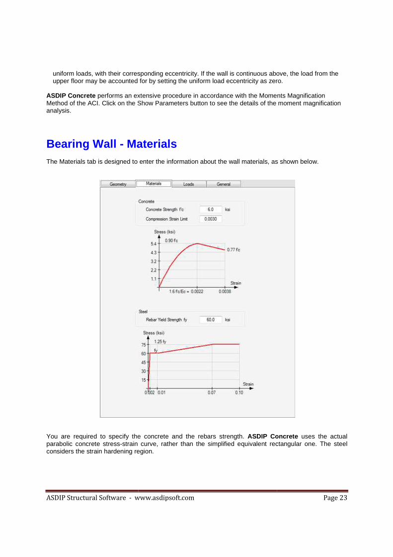
Bearing Wall - Materials ............................................................................................................ 23
File Menu ..................................................................................................................................... 24

ASDIP Structural Software - www.asdipsoft.com Page 2
File | New ................................................................................................................................. 24
File | Open ............................................................................................................................... 24
File | Save ................................................................................................................................ 24
File | Save As .......................................................................................................................... 24
File | Go to Project Manager ................................................................................................. 25
File | Exit ASDIP Concrete .................................................................................................... 25
Settings Menu ............................................................................................................................. 25
Edit Menu..................................................................................................................................... 25
Design Menu ............................................................................................................................... 25
Report Menu ............................................................................................................................... 25
Help Menu ................................................................................................................................... 26

ASDIP Structural Software - www.asdipsoft.com Page 3
Welcome to ASDIP Concrete Frequently the design process involves an iterative procedure of selecting preliminary proportions of structural elements, and then checking the suitability of this solution, otherwise new member properties are used until the algorithm converges in an optimum design. This repetitive and tedious procedure may become time and effort consuming. ASDIP Concrete is a collection of calculation modules that carefully combine the latest building code provisions and proved design and analysis methodologies to perform many of the cumbersome calculations most commonly used in any structural design office. ASDIP Concrete is an integrated system that combines the flexibility of Windows Forms to effortlessly develop either an optimized design or a quick investigation. All the modules have been assembled to help the designer obtain specific results from procedures common to structural concrete design. However, they cannot replace the judgment of an experienced engineer who must select the structural types and appropriate loads, and interpret the results. ASDIP Concrete fully complies with the latest edition of IBC and the ACI 318. The load combinations per the ASCE 7.
License Agreement IMPORTANT - READ BEFORE COPYING, INSTALLING OR USING. Do not copy, install, or use this software until you have carefully read this agreement, which provides the following terms and conditions for its use. Copying, installing, or otherwise using the software indicates that you have read, understand and accept the terms of this Agreement. If you do not accept this Agreement, then return the software and accompanying items to us within 30 days of purchase for a refund. GRANT OF LICENSE The software and data accompanying this License (the "Software") and related documentation are licensed (not sold) to you by ASDIP Structural Software. You own the CD or any other media on which the Software is recorded, but ASDIP Structural Software Concretes full and complete title to the Software and accompanying documentation, and all intellectual property rights therein. Subject to the License Restrictions below, you are granted a personal, non-exclusive license to use one copy of the Software and any updates thereof on a single computer at a time. You may authenticate your license in a second computer, but not in a third, since only two authentications are granted. You may make one archival or backup copy of the software for your own use. However, because the Software is protected by the copyright laws, it is illegal: to make additional copies or otherwise duplicate the Software by any other means (including electronic transmission); to give copies to another person; or, to modify, adapt, translate, rent, sub-license, loan, resell for profit, distribute, create derivative works based upon or network the Software or any part thereof. LICENSE RESTRICTIONS The software contains copyrighted material, trade secrets and other proprietary material protected by United States copyright laws and international treaty provisions. You may not reverse-assemble, reverse-compile, or otherwise reverse-engineer any of the Software components. You will not remove any copyright notices from the Software screens and printouts. ASDIP Structural Software does not grant any express or implied right to you under patents, copyrights, trademarks, or trade secret information.

ASDIP Structural Software - www.asdipsoft.com Page 4
DISCLAIMER OF WARRANTIES The Software is provided "AS IS" without warranty of any kind. If the media on which the Software is furnished are found to be defective in material or workmanship under normal use within a period of thirty (30) days from the date of receipt, ASDIP Structural Software's entire liability and your exclusive remedy shall be the replacement of the media. This offer is void if the media defect results from accident, abuse, or misapplication. To the maximum extent permitted by law, ASDIP Structural Software disclaims all other warranties, either express or implied, including, but not limited to, implied warranties or merchantability and fitness for a particular purpose, with regard to the Software and the accompanying materials. This limited warranty gives you specific legal rights. You may have others that vary from state/jurisdiction to state/jurisdiction. LIMITATION OF LIABILITY To the maximum extent permitted by applicable law, in no event shall ASDIP Structural Software be liable for any damages whatsoever (including, without limitation, damages for loss of business profits, business interruption, loss of business information, or any other loss) arising out of the use of or inability to use this Software. ASDIP Structural Software makes no warranties, either expressed or implied, as to the quality and performance of the Software, that the calculations contained in the Software will meet your requirements, or that the operation of the Software will be uninterrupted or error free. You agree that the Software is intended to aid you in performing engineering-oriented mathematical calculations, and that the results obtained from the Software do not necessarily constitute an acceptable engineering design or analysis. You agree that results of the Software shall be reviewed by persons possessing experience and thorough understanding of the engineering principles that apply or might apply to the usage of and results of the Software. In no event shall ASDIP Structural Software's total liability to you for all damages, losses, and causes of action (whether in contract or otherwise) exceed the amount paid by you for the Software.
How to Start a New Project When you start ASDIP Concrete the Project Manager pops up. From there, you may either create a new project or open an existing one. If you are working in a project and just want to create a new one select File | New from the menu bar. ASDIP Concrete will ask you to confirm, in case that you haven't saved your previous project. The new project will have the calculation tree empty. From there you may start creating calculations.
How to Open an Existing Project ASDIP Concrete projects are saved with the extension .cdp. To open an existing project, in the Project Manager select File | Open from the menu. A new dialog box will pop up to let you specify the location of the requested file. When an existing project is retrieved, all the information and calculations saved with that project will be retrieved as well, so that all the information regarding that specific project is brought up.
ASDIP Structural Software - www.asdipsoft.com Page 5
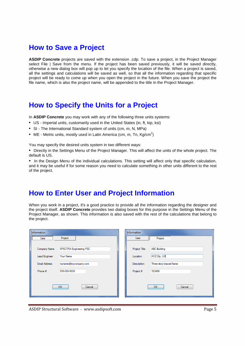
How to Save a Project ASDIP Concrete projects are saved with the extension .cdp. To save a project, in the Project Manager select File | Save from the menu. If the project has been saved previously, it will be saved directly, otherwise a new dialog box will pop up to let you specify the location of the file. When a project is saved, all the settings and calculations will be saved as well, so that all the information regarding that specific project will be ready to come up when you open the project in the future. When you save the project the file name, which is also the project name, will be appended to the title in the Project Manager.
How to Specify the Units for a Project In ASDIP Concrete you may work with any of the following three units systems: • US - Imperial units, customarily used in the United States (in, ft, kip, ksi) • SI - The International Standard system of units (cm, m, N, MPa) • ME - Metric units, mostly used in Latin America (cm, m, Tn, Kg/cm2) You may specify the desired units system in two different ways: • Directly in the Settings Menu of the Project Manager. This will affect the units of the whole project. The default is US. • In the Design Menu of the individual calculations. This setting will affect only that specific calculation, and it may be useful if for some reason you need to calculate something in other units different to the rest of the project.
How to Enter User and Project Information When you work in a project, it's a good practice to provide all the information regarding the designer and the project itself. ASDIP Concrete provides two dialog boxes for this purpose in the Settings Menu of the Project Manager, as shown. This information is also saved with the rest of the calculations that belong to the project.

ASDIP Structural Software - www.asdipsoft.com Page 6
How to Set Preferences for a Project ASDIP Concrete allows you set project preferences in order to customize your program and improve your experience. Although not mandatory, these settings will affect the way the program looks and the way your Reports will be generated. You may set the preferences in the Settings Menu of the Project Manager, and they consist of two dialog boxes, as shown below. One is for the Title Block definition that will be included in the Report and the other is to specify the display screen All this information may be saved as default, so you don't need to enter it again in the future. When you start ASDIP Concrete the Preferences dialog box shows up. You may instruct the program not to show it at startup by checking mark the corresponding check box. The Title Block information is mostly used as a header in the Report. and it consists of basic information about your company or any other text you may want to include in your Report. You may also specify your company logo. The display screen may be either Standard-width or Widescreen display, depending of your monitor. Basically, the Standard-width display fits the screens with a 4:3 ratio such as the common desktop monitors. Widescreen display works better in flat screens with 16:10 ratio such as many laptops and some LCD monitors.
How to Authenticate the License When you download and start using ASDIP Concrete, what you are actually running is an Evaluation version, which is fully functional for 15 days. The only limitation during this period is that you cannot printout your calculations and you cannot save your project, otherwise it is the full version that you will permanently have if you authenticate your license. To do so, you need to order the program by visiting our web site www.asdipsoft.com. Then an email will be sent to you with a license key, which will convert your Evaluation version into the Full version. To install your license either select Settings | License in the Project Manager or select Install License in the Evaluation dialog box at startup. The dialog box shown below will show up.

ASDIP Structural Software - www.asdipsoft.com
In this dialog box you enter your company name and the license key that you just received in your email inbox. When you click the Installlicense for you. Note that you have to have an internet connection to do the authentication. Once the authenticated license is installed on your computer the application can be run without contacting the authentication service. Basically hardware. This will allow you to upgrade your hardware without invalidating your license, provided you keep your computer name. Two authentications are granted with your license, which means that you may authenticate your license in two different computers as a maximum, for example your desktop and your laptop. If you try to authenticate the license in a third computer an error message will show up.
How to Create a Calculation Structural Engineering is all about calculationperform calculations... and manage them. To create a calculation simply click on any of the calculation buttons in the Project Manager. The dialog box shown below will show up.
www.asdipsoft.com
In this dialog box you enter your company name and the license key that you just received in your email Install button the program connects to our web server and authenticates the
Note that you have to have an internet connection to do the authentication. Once the authenticated license is installed on your computer the application can be run without contacting the authentication service. Basically your license will be linked to your computer namehardware. This will allow you to upgrade your hardware without invalidating your license, provided you keep your computer name. Two authentications are granted with your license, which means that you may
se in two different computers as a maximum, for example your desktop and your laptop. If you try to authenticate the license in a third computer an error message will show up.
How to Create a Calculation
Structural Engineering is all about calculations, isn't it? ASDIP Concrete is a software that allows you perform calculations... and manage them. To create a calculation simply click on any of the calculation buttons in the Project Manager. The dialog box shown below will show up.
Page 7
In this dialog box you enter your company name and the license key that you just received in your email button the program connects to our web server and authenticates the
Note that you have to have an internet connection to do the authentication. Once the authenticated license is installed on your computer the application can be run without contacting the
r computer name, not to your hardware. This will allow you to upgrade your hardware without invalidating your license, provided you keep your computer name. Two authentications are granted with your license, which means that you may
se in two different computers as a maximum, for example your desktop and your laptop. If you try to authenticate the license in a third computer an error message will show up.
is a software that allows you perform calculations... and manage them. To create a calculation simply click on any of the calculation

ASDIP Structural Software - www.asdipsoft.com
Enter the calculation name or a short, meaningful description of the calculation. When you click the button the calculation tree at the right half of the Project Manager reflects the change by adding a new node under the corresponding calculation branch. You may cyou may open the calculation that you just created. Think of this as a paper folder on your desk, where you are putting your hand calcs and sketches together. Imagine that you are designing a spread footing by hpages of calcs. If you are a little bit organized, you will put these sheets in a paper folder labeled with the project name. Then imagine that you continue designing by hand another footing of the project, and several more. Add all these paper sheets to your binder. If there are several types of footings in the project, your binder will have to be organized further. ASDIP Concrete organizes the set of calculations for you in an electronic version of the situation described above. The Project Manager will add individual calculations to the project and will organize them in an expandable tree view, similar to the Windows Explorer tree view. You may add as many calculations as you need, and they will be organized
How to Run a Calculation
How to Enter the Input Data When you open a calculation, a predefined module template is retrieveddata and see immediately the results associated with the change that you have just done. All the modules in ASDIP Concrete have two tabbed controls, as shown below. The left tabbed box is dedicated to the input data, whereas the right tabbed box shows the tabs associated with the results. To enter input data simply select the corresponding tab at the left side and use the text boxes and controls designed for that purpose.
www.asdipsoft.com
lculation name or a short, meaningful description of the calculation. When you click the button the calculation tree at the right half of the Project Manager reflects the change by adding a new node under the corresponding calculation branch. You may continue adding calculations to the tree, or you may open the calculation that you just created.
Think of this as a paper folder on your desk, where you are putting your hand calcs and sketches Imagine that you are designing a spread footing by hand and that you ended up with some
pages of calcs. If you are a little bit organized, you will put these sheets in a paper folder labeled with the project name. Then imagine that you continue designing by hand another footing of the project, and
ore. Add all these paper sheets to your binder. If there are several types of footings in the project, your binder will have to be organized further.
organizes the set of calculations for you in an electronic version of the situation bed above. The Project Manager will add individual calculations to the project and will organize
them in an expandable tree view, similar to the Windows Explorer tree view. You may add as many calculations as you need, and they will be organized properly for future reference.
How to Run a Calculation
Once you have created a calculation, you can run it by doubleclicking on the corresponding node at the tree view in the Project Manager. Alternatively, click on the node to highlight it and then click on the Open button. This will retrieve the calculation module. Once there, you may enter the input data and see the results. When you close the calculation sheet, you will be sent back to the Project Manager, which will have the latest information about your calculation, with all the changes that you have just done. If you have multiple calculations in your project, you can jump to any of them and edit it as needed by simply doublecorresponding node in the tree, as explained above. When you saveyour project all the information about all your calculations will be saved as well. The next time that you open that project all the calcs will be there.
How to Enter the Input Data
When you open a calculation, a predefined module template is retrieved, where you may enter your input data and see immediately the results associated with the change that you have just done. All the modules
have two tabbed controls, as shown below. The left tabbed box is dedicated to the s the right tabbed box shows the tabs associated with the results. To enter input data
simply select the corresponding tab at the left side and use the text boxes and controls designed for that
Page 8
lculation name or a short, meaningful description of the calculation. When you click the Add button the calculation tree at the right half of the Project Manager reflects the change by adding a new
ontinue adding calculations to the tree, or
Think of this as a paper folder on your desk, where you are putting your hand calcs and sketches and and that you ended up with some
pages of calcs. If you are a little bit organized, you will put these sheets in a paper folder labeled with the project name. Then imagine that you continue designing by hand another footing of the project, and
ore. Add all these paper sheets to your binder. If there are several types of footings in the
organizes the set of calculations for you in an electronic version of the situation bed above. The Project Manager will add individual calculations to the project and will organize
them in an expandable tree view, similar to the Windows Explorer tree view. You may add as many or future reference.
Once you have created a calculation, you can run it by double-clicking on the corresponding node at the tree view in the Project Manager. Alternatively, click on the node to highlight it and then click
button. This will retrieve the calculation module. Once there, you may enter the input data and see the results. When you close the calculation sheet, you will be sent back to the Project Manager, which will have the latest information about your calculation, with all the changes that you have just done.
If you have multiple calculations in your project, you can jump to any of them and edit it as needed by simply double-clicking the corresponding node in the tree, as explained above. When you save your project all the information about all your calculations will be saved as well. The next time that you open that project all the calcs
, where you may enter your input data and see immediately the results associated with the change that you have just done. All the modules
have two tabbed controls, as shown below. The left tabbed box is dedicated to the s the right tabbed box shows the tabs associated with the results. To enter input data
simply select the corresponding tab at the left side and use the text boxes and controls designed for that

ASDIP Structural Software - www.asdipsoft.com
ASDIP Concrete has been designed with multiple Among the controls provided we have buttons, text boxes, labels, combo boxes, ratio buttons, check boxes, tabs, tree views, dialog boxes, menu bars and tool bars. All these combined elements create rich user interface.
How to See the Results In ASDIP Concrete the results are always current, which means that as soon as you change any of the input data fields the results are updated accordingly. To see the results, simply click on any of the tabs located at the right half of the screen, as shown below.
The three tabs are described as follows:• At a Glance tab - Shows a summary of the results, with the most relevant information that fits in one screen height. No scroll bars. The user can seeyou may prefer to see the Detailed tab.• Detailed tab - Shows a more detailed report of the calculations, with more inintended for a more laborious checking of the steptopic for easier reading, and consist of values and text messages always upshow either OK or NG for pass or fail respectively.
• Graph tab - Shows graphic images related to the diagram. ASDIP Concrete includes graphic views of the soil bearing pressures, the onedirections, the punching shear, the flexural moments, and the construction
www.asdipsoft.com
has been designed with multiple types of controls in order to enter data the easiest way. Among the controls provided we have buttons, text boxes, labels, combo boxes, ratio buttons, check boxes, tabs, tree views, dialog boxes, menu bars and tool bars. All these combined elements create
How to See the Results
the results are always current, which means that as soon as you change any of the input data fields the results are updated accordingly. To see the results, simply click on any of the tabs ocated at the right half of the screen, as shown below.
The three tabs are described as follows: Shows a summary of the results, with the most relevant information that fits in one
screen height. No scroll bars. The user can see "at a glance" if the design passyou may prefer to see the Detailed tab.
Shows a more detailed report of the calculations, with more inintended for a more laborious checking of the step-by-step calculations. The results are organized by topic for easier reading, and consist of values and text messages always up-to
for pass or fail respectively. Shows graphic images related to the calculation, either a plan, elevation, detail, or
includes graphic views of the soil bearing pressures, the onedirections, the punching shear, the flexural moments, and the construction diagram.
Page 9
types of controls in order to enter data the easiest way. Among the controls provided we have buttons, text boxes, labels, combo boxes, ratio buttons, check boxes, tabs, tree views, dialog boxes, menu bars and tool bars. All these combined elements create a
the results are always current, which means that as soon as you change any of the input data fields the results are updated accordingly. To see the results, simply click on any of the tabs
Shows a summary of the results, with the most relevant information that fits in one ses or fails. If necessary,
Shows a more detailed report of the calculations, with more in-depth results. It is step calculations. The results are organized by
to-date. Individual checks
calculation, either a plan, elevation, detail, or includes graphic views of the soil bearing pressures, the one-way shear in both
diagram.

ASDIP Structural Software - www.asdipsoft.com
How to Preview the Report ASDIP Concrete generates a preselect Report | Print Preview from the menu bar. To printout the report, select Report | Print from the menu bar. The preview window provides below.
Load Combinations Structural engineering is all about loads. Loads are typically defined by its source, either dead, live, wind, seismic, etc. The design codes generally group thecase is assigned a load factor. The end result is a series of load combinations, both service and factored. Service load combinations are typically used for bearing calculations, whereas factored load combinations are used for concrete design. ASDIP Concrete lets you specify the Design Code and it internally uses the corresponding load combinations, as shown below:
www.asdipsoft.com
the Report
generates a pre-formatted report that can be printed out. To preview the report simply select Report | Print Preview from the menu bar. To printout the report, select Report | Print from the menu bar. The preview window provides several buttons to multi-page views, zoom and print, as shown
Load Combinations
Structural engineering is all about loads. Loads are typically defined by its source, either dead, live, wind, seismic, etc. The design codes generally group these load cases in load combinations, where each load case is assigned a load factor. The end result is a series of load combinations, both service and factored. Service load combinations are typically used for bearing calculations, whereas factored load
binations are used for concrete design.
lets you specify the Design Code and it internally uses the corresponding load
Page 10
formatted report that can be printed out. To preview the report simply select Report | Print Preview from the menu bar. To printout the report, select Report | Print from the
page views, zoom and print, as shown
Structural engineering is all about loads. Loads are typically defined by its source, either dead, live, wind, se load cases in load combinations, where each load
case is assigned a load factor. The end result is a series of load combinations, both service and factored. Service load combinations are typically used for bearing calculations, whereas factored load
lets you specify the Design Code and it internally uses the corresponding load

ASDIP Structural Software - www.asdipsoft.com
The Load Combinations dialog box may be invoked from the Design Menuyou may specify the Design Code. In addition, for factored loads the live load factor depends whether the load is > 100 psf.
Project Manager Main Window The Project Manager is the central piece of performed, as well as get access to the calculation sheets. In the Project Manager you may create a calculation, save a project, set the units system, enter the information and preferences, and organize your
www.asdipsoft.com
The Load Combinations dialog box may be invoked from the Design Menu. At the top of the you may specify the Design Code. In addition, for factored loads the live load factor depends whether the
Project Manager Main Window
The Project Manager is the central piece of ASDIP Concrete. From there all file activitiesperformed, as well as get access to the calculation sheets. In the Project Manager you may create a calculation, save a project, set the units system, enter the information and preferences, and organize your
Page 11
At the top of the dialog box you may specify the Design Code. In addition, for factored loads the live load factor depends whether the
. From there all file activities may be performed, as well as get access to the calculation sheets. In the Project Manager you may create a calculation, save a project, set the units system, enter the information and preferences, and organize your

ASDIP Structural Software - www.asdipsoft.com
work. Basically the Project Manager is ithe common information updated and active. All basic file operations, such as Start a new project, Open an existing project, and Save a project are only possible in the Project Manager. In aexpandable tree calculation view is a great way to visualize all the calculations in a project.
Calculation Main Window Being ASDIP Concrete a structural design package, the calculation modules are the essence of the software. All the modules have been designed and developed with a deep understanding of the needs of structural engineers. A typical calculation main window is shown below.
A typical calculation main window is basically composed of the menu bar at the top, and immediately below is the tool bar. Below that is the work area, which consists of two tabbed panes: the left pane is designed to enter the input data, and the right pane shows the results of the calculation. The different tabs have a specific purpose, depending of the Concrete includes the following calculation modules: • Concrete Column Design • Concrete Beam Design • Bearing Wall Design
www.asdipsoft.com
Basically the Project Manager is in charge of organizing the calculations in a project, and keeping the common information updated and active. All basic file operations, such as Start a new project, Open an existing project, and Save a project are only possible in the Project Manager. In aexpandable tree calculation view is a great way to visualize all the calculations in a project.
Calculation Main Window
a structural design package, the calculation modules are the essence of the s have been designed and developed with a deep understanding of the needs of
structural engineers. A typical calculation main window is shown below.
A typical calculation main window is basically composed of the menu bar at the top, and immediately elow is the tool bar. Below that is the work area, which consists of two tabbed panes: the left pane is
designed to enter the input data, and the right pane shows the results of the calculation. The different tabs have a specific purpose, depending of the calculation module. The current version of
includes the following calculation modules:
Page 12
n charge of organizing the calculations in a project, and keeping the common information updated and active. All basic file operations, such as Start a new project, Open an existing project, and Save a project are only possible in the Project Manager. In addition, the expandable tree calculation view is a great way to visualize all the calculations in a project.
a structural design package, the calculation modules are the essence of the s have been designed and developed with a deep understanding of the needs of
A typical calculation main window is basically composed of the menu bar at the top, and immediately elow is the tool bar. Below that is the work area, which consists of two tabbed panes: the left pane is
designed to enter the input data, and the right pane shows the results of the calculation. The different calculation module. The current version of ASDIP

ASDIP Structural Software - www.asdipsoft.com
Concrete Column Columns are structural compression members which transmit loads from the upper floors to the lower levels and then to the soil through the foundations. one column in a critical location can cause the progressive collapse of adjoining floors, and in turn, even the collapse of the entire structure. Failure in concrete columns could occur as a result of mateor by loss of lateral structural stability. If a column fails due to material failure, it is classified as a short column, as opposed to the slender column whose failure is by buckling. The program performs the design of a circular or rectangcombination of bending moments and axial loading, based on the latest ACI design criteria and the Ultimate Strength Design Method. It calculates the magnified moments due to slenderness and generates the capacity axial-moment interaction diagram.
Concrete Column Use the Geometry tab to enter the information of the dimensions of the column, as shown below.
www.asdipsoft.com
Concrete Column - Overview Columns are structural compression members which transmit loads from the upper floors to the lower levels and then to the soil through the foundations. Since columns are compression elements, failure of one column in a critical location can cause the progressive collapse of adjoining floors, and in turn, even the collapse of the entire structure. Failure in concrete columns could occur as a result of mateor by loss of lateral structural stability. If a column fails due to material failure, it is classified as a short column, as opposed to the slender column whose failure is by buckling.
The program performs the design of a circular or rectangular concrete column when subjected to a combination of bending moments and axial loading, based on the latest ACI design criteria and the Ultimate Strength Design Method. It calculates the magnified moments due to slenderness and generates
moment interaction diagram.
Concrete Column - Geometry tab to enter the information of the dimensions of the column, as shown below.
Page 13
Columns are structural compression members which transmit loads from the upper floors to the lower Since columns are compression elements, failure of
one column in a critical location can cause the progressive collapse of adjoining floors, and in turn, even the collapse of the entire structure. Failure in concrete columns could occur as a result of material failure or by loss of lateral structural stability. If a column fails due to material failure, it is classified as a short
ular concrete column when subjected to a combination of bending moments and axial loading, based on the latest ACI design criteria and the Ultimate Strength Design Method. It calculates the magnified moments due to slenderness and generates
tab to enter the information of the dimensions of the column, as shown below.

ASDIP Structural Software - www.asdipsoft.com
At the top of the page you may specify the column type, dimensions and reinforcing bars. If circular, the rebars are distributed uniformly along the perimeter. If the column is rectangular the program provides simple and straightforward ways to specify the reinforcement. The slenderness effects are accounted for by specifying the efConcrete internally checks the dimensions and validates the input data.
Concrete Column The Loads tab lets you enter the loads acting on the concrete column, as shown below. Diffacilitate the load data input.
ASDP Concrete allows you specify either a single set of precases to be combined, as briefly described below: • Pre-combined loads - In this case you specify two
This is useful when you have the combined loads and want to either design or verify the footing for those loads.
• Nominal load cases - ASDIP Concretetype of loading, such as Dead, Live, Roof Live, Snow, Wind and Seismiccombine these loads in accordance to the specified Load Combinations.
www.asdipsoft.com
At the top of the page you may specify the column type, dimensions and reinforcing bars. If circular, the rebars are distributed uniformly along the perimeter. If the column is rectangular the program provides simple and straightforward ways to specify the reinforcement. The slenderness effects are accounted for by specifying the effective length factors, and if the column is sway or non
internally checks the dimensions and validates the input data.
Concrete Column - Loads tab lets you enter the loads acting on the concrete column, as shown below. Dif
allows you specify either a single set of pre-combined loads, or a set of nominal load cases to be combined, as briefly described below:
In this case you specify two types of pre-combined loads: Service and Factored. This is useful when you have the combined loads and want to either design or verify the footing for
ASDIP Concrete support a full set of independent load cases, according Dead, Live, Roof Live, Snow, Wind and Seismic. The program internally will
combine these loads in accordance to the specified Load Combinations.
Page 14
At the top of the page you may specify the column type, dimensions and reinforcing bars. If the column is circular, the rebars are distributed uniformly along the perimeter. If the column is rectangular the program provides simple and straightforward ways to specify the reinforcement. The slenderness effects are
fective length factors, and if the column is sway or non-sway. ASDIP
tab lets you enter the loads acting on the concrete column, as shown below. Different sub-tabs
combined loads, or a set of nominal load
combined loads: Service and Factored. This is useful when you have the combined loads and want to either design or verify the footing for
support a full set of independent load cases, according to the . The program internally will

ASDIP Structural Software - www.asdipsoft.com
2nd Order Moments - When the applied loads come from a Second Order Analysis, applied to the column without any further magnification. However, when the loads come from a First Order Analysis, ASDIP ConcreteMoments Magnification Method of the ACIor non-sway, this is, if the column is part of a lateral resisting frame or not. Click on the button to see the details of the magnification analysis.
Concrete Column The Materials tab is designed to enter the information about the column materials, as shown below.
You are required to specify the concrete and the rebars strength. parabolic concrete stress-strain curve, rather than considers the strain hardening region.
www.asdipsoft.com
When the applied loads come from a Second Order Analysis, applied to the column without any further magnification. However, when the loads come from a First
ASDIP Concrete performs an extensive magnification procedure in accordance with the Moments Magnification Method of the ACI. This procedure varies depending whether the column is sway
sway, this is, if the column is part of a lateral resisting frame or not. Click on the to see the details of the magnification analysis.
Concrete Column - Materials tab is designed to enter the information about the column materials, as shown below.
You are required to specify the concrete and the rebars strength. ASDIP Concretestrain curve, rather than the simplified equivalent rectangular one. The steel
considers the strain hardening region.
Page 15
When the applied loads come from a Second Order Analysis, the loads will be applied to the column without any further magnification. However, when the loads come from a First
performs an extensive magnification procedure in accordance with the . This procedure varies depending whether the column is sway
sway, this is, if the column is part of a lateral resisting frame or not. Click on the Show Parameters
tab is designed to enter the information about the column materials, as shown below.
ASDIP Concrete uses the actual the simplified equivalent rectangular one. The steel

ASDIP Structural Software - www.asdipsoft.com Page 16
General Tab The General tab contains information about the calculation that may be of interest to the designer or to someone else who reviews the calculation, as shown below.
Company - The company name was setup when you installed the license and cannot be changed. Project - Since the project name is common for all the calculations of this project, it can only be specified in the Settings | Information menu command of the Project Manager . Engineer - When you create a calculation , the engineer's name is brought from the user information that you entered in the Project Manager . Since two calculations of the same project may be done by two different engineers, this text can be edited in your calculation. Description - By default, this is the calculation name that you entered when you created the calculation . This text, however, can be changed to a more meaningful description if desired. This text will be copied into the report. Notes - This text is intended to provide any information to the reviewer, or a remainder to yourself in the future.

ASDIP Structural Software - www.asdipsoft.com
Concrete Beam - Beams are structural elements that support loads applied transversely, and therefobending moments, as well as shear forces. Concrete beams are usually continuous, this is, they span between several supports. A common example of a Twhere a portion of the slab acts together with the projecting beam web. A beam at the border of the floor is called a spandrel beam. Invertedmembers. The program performs the design of a multiwhen subjected to a combination of bending and shear loading, based on the latest ACI design criteria and the Ultimate Strength Design Method. Multiple options are included to model the beam geometry and loads, as well as the reinforcing steel.
Concrete Beam - Use the Geometry tab to enter the information of the dimensions of the
www.asdipsoft.com
Overview Beams are structural elements that support loads applied transversely, and therefobending moments, as well as shear forces. Concrete beams are usually continuous, this is, they span between several supports. A common example of a T-beam occurs at the interior bay of a building floor,
s together with the projecting beam web. A beam at the border of the floor is called a spandrel beam. Inverted-T and L-beams are commonly used to support prefabricated double
The program performs the design of a multi-span rectangular, T, spandrel, L or invertedwhen subjected to a combination of bending and shear loading, based on the latest ACI design criteria and the Ultimate Strength Design Method. Multiple options are included to model the beam geometry and
the reinforcing steel.
Geometry tab to enter the information of the dimensions of the beam, as shown below.
Page 17
Beams are structural elements that support loads applied transversely, and therefore they mostly resist bending moments, as well as shear forces. Concrete beams are usually continuous, this is, they span
beam occurs at the interior bay of a building floor, s together with the projecting beam web. A beam at the border of the floor
beams are commonly used to support prefabricated double-T
rel, L or inverted-T concrete beam when subjected to a combination of bending and shear loading, based on the latest ACI design criteria and the Ultimate Strength Design Method. Multiple options are included to model the beam geometry and
, as shown below.

ASDIP Structural Software - www.asdipsoft.com
At the top of the page you may specify the beam type, either rectangular, T, spandrel, L, or invertedwell as dimensions of the beam cross section. At the bottom of the page you specify the number of supports. ASDIP Concrete works with a maximum oftwo cantilevers. The end supports may be either pinnedshears and moments accordingly. input data.
Concrete Beam - The Loads tab lets you enter the loads acting on the concrete facilitate the load data input.
ASDP Concrete allows you specify a set of nominal load cases to be combined, as briefly described below: • Nominal load cases - ASDIP Concrete
www.asdipsoft.com
At the top of the page you may specify the beam type, either rectangular, T, spandrel, L, or invertedwell as dimensions of the beam cross section. At the bottom of the page you specify the number of
works with a maximum of six supports, this is, a maximum of five spans plus two cantilevers. The end supports may be either pinned or fixed, and the program calculates the internal shears and moments accordingly. ASDIP Concrete internally checks the dimensions and validates the
Loads tab lets you enter the loads acting on the concrete beam, as shown below. Different sub
allows you specify a set of nominal load cases to be combined, as briefly described
ASDIP Concrete support a full set of independent vertical l
Page 18
At the top of the page you may specify the beam type, either rectangular, T, spandrel, L, or inverted-T, as well as dimensions of the beam cross section. At the bottom of the page you specify the number of
six supports, this is, a maximum of five spans plus or fixed, and the program calculates the internal
internally checks the dimensions and validates the
shown below. Different sub-tabs
allows you specify a set of nominal load cases to be combined, as briefly described
support a full set of independent vertical load cases, according

ASDIP Structural Software - www.asdipsoft.com
to the type of loading, such as loads in accordance to the specified Load Combinations.
ASDIP Concrete accepts up to two sets of uniform loads and up to six sets ospan. The input loads are internally stored along the beam for further calculation. Click on the button to specify the span number.
Concrete Beam - The Materials tab is designed to enter the information about th
You are required to specify the concrete and the rebars strength. parabolic concrete stress-strain curve, rather than the simplified equivalent rectangular one. The steel considers the strain hardening region.
www.asdipsoft.com
to the type of loading, such as Dead, Live, Roof Live, Snow. The program internally will combine these loads in accordance to the specified Load Combinations.
accepts up to two sets of uniform loads and up to six sets of concentrated loads per span. The input loads are internally stored along the beam for further calculation. Click on the button to specify the span number.
Materials tab is designed to enter the information about the beam materials, as shown below.
You are required to specify the concrete and the rebars strength. ASDIP Concretestrain curve, rather than the simplified equivalent rectangular one. The steel
strain hardening region.
Page 19
. The program internally will combine these
f concentrated loads per span. The input loads are internally stored along the beam for further calculation. Click on the Segment
materials, as shown below.
ASDIP Concrete uses the actual strain curve, rather than the simplified equivalent rectangular one. The steel

ASDIP Structural Software - www.asdipsoft.com
Concrete Beam - The Reinforcement tab has been included to enter all the required information to design the rebars for the beam, as shown below.
ASDIP Concrete fully complies with the provisions of the latest eReinforcement tab has been designed to allow the user specify the reinforcing steel of the beam, both for bending and for shear. A number of controls are provided to completely customize and optimize the steel reinforcement. The program calculates the capacity of the reinforced concrete beam and checks the development length of the rebars. All changes are reflected graphically.
www.asdipsoft.com
Reinforcement tab has been included to enter all the required information to design the rebars for the
fully complies with the provisions of the latest edition of the ACI 318. The tab has been designed to allow the user specify the reinforcing steel of the beam, both for
bending and for shear. A number of controls are provided to completely customize and optimize the steel program calculates the capacity of the reinforced concrete beam and checks the
development length of the rebars. All changes are reflected graphically.
Page 20
tab has been included to enter all the required information to design the rebars for the
dition of the ACI 318. The tab has been designed to allow the user specify the reinforcing steel of the beam, both for
bending and for shear. A number of controls are provided to completely customize and optimize the steel program calculates the capacity of the reinforced concrete beam and checks the

ASDIP Structural Software - www.asdipsoft.com
Bearing Wall - Overview
Bearing walls are structural compression members which also may resist outresulting moments are referred to as weakexample of this type of wall. Per ACI, bearing walls may be designed as compression members using the strength design provisions for flexure and axial loads, like columns. Any wall may be designed by this method and no minimum wall thicknesses are prescribed. As with columns, the design of walls is difficult without the use of design aids. Wall design is further complicated by the consideration in practically all cases. The ACI Moment Magnification method is generally used to account for the slenderness effects.
The program performs the design of a concrete bearing wall when subjected to a combination of axis bending moments and axial loading, based on the latest ACI design criteria and the Ultimate Strength Design Method. It calculates the magnified moments due to slenderness and generates the capacity axial-moment interaction diagram. A multi
Bearing Wall - Geometry Use the Geometry tab to enter the information of the dimensions of the
www.asdipsoft.com
Overview
Bearing walls are structural compression members which also may resist out-of-plane lateral loads. The resulting moments are referred to as weak-axis bending. A tilt-up wall panel exposed to wind is an example of this type of wall. Per ACI, bearing walls may be designed as compression members using the
for flexure and axial loads, like columns. Any wall may be designed by this method and no minimum wall thicknesses are prescribed. As with columns, the design of walls is difficult without the use of design aids. Wall design is further complicated by the fact that slenderness is a consideration in practically all cases. The ACI Moment Magnification method is generally used to account
The program performs the design of a concrete bearing wall when subjected to a combination of axis bending moments and axial loading, based on the latest ACI design criteria and the Ultimate Strength Design Method. It calculates the magnified moments due to slenderness and generates the
moment interaction diagram. A multi-story wall may also be modeled.
Geometry tab to enter the information of the dimensions of the wall, as shown below.
Page 21
plane lateral loads. The up wall panel exposed to wind is an
example of this type of wall. Per ACI, bearing walls may be designed as compression members using the for flexure and axial loads, like columns. Any wall may be designed by this
method and no minimum wall thicknesses are prescribed. As with columns, the design of walls is difficult fact that slenderness is a
consideration in practically all cases. The ACI Moment Magnification method is generally used to account
The program performs the design of a concrete bearing wall when subjected to a combination of weak-axis bending moments and axial loading, based on the latest ACI design criteria and the Ultimate Strength Design Method. It calculates the magnified moments due to slenderness and generates the
wall may also be modeled.
, as shown below.
ASDIP Structural Software - www.asdipsoft.com
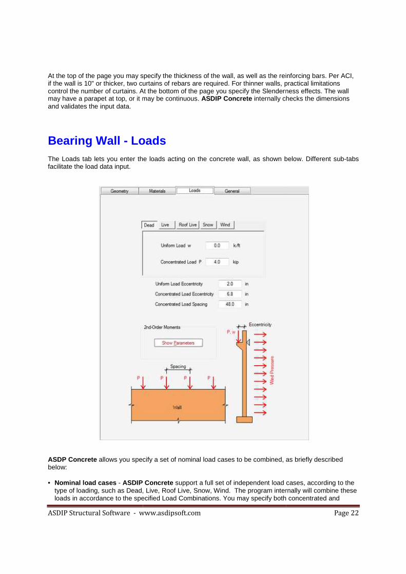
At the top of the page you may specify the thickness of the wall, as well as the reinforcing barif the wall is 10" or thicker, two curtains of rebars are required. For thinner walls, practical limitations control the number of curtains. At the bottom of the page you specify the Slenderness effects. The wall may have a parapet at top, or it may be continuous. and validates the input data.
Bearing Wall - Loads The Loads tab lets you enter the loads acting on the concrete facilitate the load data input.
ASDP Concrete allows you specify a set of nominal load cases to be combined, as briefly described below: • Nominal load cases - ASDIP Concrete
type of loading, such as Dead, Live, Roof Live, Snow, Wind. loads in accordance to the specified Load Combinations. You may specify both concentrated and
www.asdipsoft.com
At the top of the page you may specify the thickness of the wall, as well as the reinforcing barif the wall is 10" or thicker, two curtains of rebars are required. For thinner walls, practical limitations control the number of curtains. At the bottom of the page you specify the Slenderness effects. The wall
t may be continuous. ASDIP Concrete internally checks the dimensions
Loads tab lets you enter the loads acting on the concrete wall, as shown below. Different
allows you specify a set of nominal load cases to be combined, as briefly described
ASDIP Concrete support a full set of independent load cases, according to the Dead, Live, Roof Live, Snow, Wind. The program internally will combine these
loads in accordance to the specified Load Combinations. You may specify both concentrated and
Page 22
At the top of the page you may specify the thickness of the wall, as well as the reinforcing bars. Per ACI, if the wall is 10" or thicker, two curtains of rebars are required. For thinner walls, practical limitations control the number of curtains. At the bottom of the page you specify the Slenderness effects. The wall
internally checks the dimensions
, as shown below. Different sub-tabs
allows you specify a set of nominal load cases to be combined, as briefly described
support a full set of independent load cases, according to the The program internally will combine these
loads in accordance to the specified Load Combinations. You may specify both concentrated and
ASDIP Structural Software - www.asdipsoft.com
uniform loads, with their corresponding eccentricity. If the wall is conupper floor may be accounted for by setting the uniform load eccentricity as zero.
ASDIP Concrete performs an extensive procedure in accordance with the Moments Magnification Method of the ACI. Click on the Show Parametersanalysis.
Bearing Wall - Materials The Materials tab is designed to enter the information about the
You are required to specify the concrete and the rebars strength. parabolic concrete stress-strain curve, rather than the siconsiders the strain hardening region.
www.asdipsoft.com
uniform loads, with their corresponding eccentricity. If the wall is continuous above, the load from the upper floor may be accounted for by setting the uniform load eccentricity as zero.
performs an extensive procedure in accordance with the Moments Magnification Show Parameters button to see the details of the moment magnification
Materials tab is designed to enter the information about the wall materials, as shown below.
You are required to specify the concrete and the rebars strength. ASDIP Concretestrain curve, rather than the simplified equivalent rectangular one. The steel
considers the strain hardening region.
Page 23
tinuous above, the load from the upper floor may be accounted for by setting the uniform load eccentricity as zero.
performs an extensive procedure in accordance with the Moments Magnification to see the details of the moment magnification
materials, as shown below.
ASDIP Concrete uses the actual mplified equivalent rectangular one. The steel

ASDIP Structural Software - www.asdipsoft.com Page 24
File Menu New Open Save Save As Go to Project Manager Exit ASDIP Concrete
File | New This command is only available in the Project Manager and it will clear all the information from previous projects, such as the user and project information and calculations. Remember to save your work before you start a new project, otherwise it will be lost. ASDIP Concrete will ask you to confirm, in case that you haven't saved your previous project.
File | Open This command is only available in the Project Manager and it will retrieve all the information contained in a file previously saved in ASDIP Concrete. The Open Project dialog box will pop up, so that you may specify where the file is located.
File | Save This command is only available in the Project Manager and it will save all the information regarding your project in a file with extension .cdp, which is the default extension for ASDIP Concrete projects. If the project has been saved previously, it will be saved directly, otherwise the Save Project dialog box will pop up, so that you can specify the location of the file.
File | Save As This command is only available in the Project Manager and it will save all the information regarding your project in a file with extension .cdp, which is the default extension for ASDIP Concrete projects. The Save Project dialog box will pop up, so that you can specify the name and location of the file.

ASDIP Structural Software - www.asdipsoft.com Page 25
File | Go to Project Manager This command is only available in the Calculation modules and it will close the current calculation sheet and will take you back to the Project Manager. From there, you may either open another calculation or save your work. It has the same effect as clicking on the X at the upper right corner of the calculation. Note that all your input data and results are not lost, they are still in memory. If you open your calculation again you will see all the information there.
File | Exit ASDIP Concrete This option will close and terminate the application. ASDIP Concrete will ask you to confirm, in case that you haven't saved your project. If you accept, the program will close immediately.
Settings Menu Units – Sets the system of units of the whole project. Information – Enter basic information of both the user and the project. Preferences – Sets different options to customize your experience with ASDIP Concrete. License – Lets you authenticate your license.
Edit Menu Undo - It will reverse the last command Redo - It will reverse the last undo operation Copy - It will store the highlighted text in the clipboard Paste - It will place the clipboard contents in the current position
Design Menu Units – Sets the system of units for the current calculation, otherwise it uses the default . Criteria – Sets the design parameters to be used in the calculation.
Report Menu Print - It will show the Print dialog box Print Preview

ASDIP Structural Software - www.asdipsoft.com Page 26
Help Menu Contents - Shows the Table of Contents of the Help file, where you may select by topic. Index - Shows the Index tab, where you may select by keyword. Search - Shows the Search tab, where you may find a word in the Help file. About - Shows the ASDIP Concrete information dialog.