Embed Size (px)
Citation preview

Arduino Mega 2560
Overview

The Arduino Mega 2560 is a microcontroller board based on the ATmega2560 (datasheet). It has 54 digital input/output
pins (of which 14 can be used as PWM outputs), 16 analog inputs, 4 UARTs (hardware serial ports), a 16 MHz crystal
oscillator, a USB connection, a power jack, an ICSP header, and a reset button. It contains everything needed to support
the microcontroller; simply connect it to a computer with a USB cable or power it with a AC-to-DC adapter or battery to
get started. The Mega is compatible with most shields designed for the Arduino Duemilanove or Diecimila.
Schematic & Reference Design
EAGLE files: arduino-mega2560-reference-design.zip
Schematic: arduino-mega2560-schematic.pdf
Summary
Microcontroller ATmega2560
Operating Voltage 5V
Input Voltage (recommended) 7-12V
Input Voltage (limits) 6-20V
Digital I/O Pins 54 (of which 14 provide PWM output)
Analog Input Pins 16
DC Current per I/O Pin 40 mA
DC Current for 3.3V Pin 50 mA
Flash Memory 256 KB of which 8 KB used by bootloader
SRAM 8 KB
EEPROM 4 KB
Clock Speed 16 MHz
Power
The Arduino Mega can be powered via the USB connection or with an external power supply. The power source is selected
automatically.
External (non-USB) power can come either from an AC-to-DC adapter (wall-wart) or battery. The adapter can be
connected by plugging a 2.1mm center-positive plug into the board's power jack. Leads from a battery can be inserted in
the Gnd and Vin pin headers of the POWER connector.
The board can operate on an external supply of 6 to 20 volts. If supplied with less than 7V, however, the 5V pin may supply
less than five volts and the board may be unstable. If using more than 12V, the voltage regulator may overheat and damage
the board. The recommended range is 7 to 12 volts.
The Mega2560 differs from all preceding boards in that it does not use the FTDI USB-to-serial driver chip. Instead, it
features the Atmega8U2 programmed as a USB-to-serial converter.
The power pins are as follows:
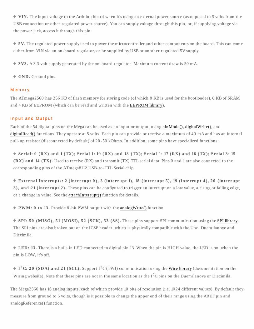
VIN. The input voltage to the Arduino board when it's using an external power source (as opposed to 5 volts from the
USB connection or other regulated power source). You can supply voltage through this pin, or, if supplying voltage via
the power jack, access it through this pin.
5V. The regulated power supply used to power the microcontroller and other components on the board. This can come
either from VIN via an on-board regulator, or be supplied by USB or another regulated 5V supply.
3V3. A 3.3 volt supply generated by the on-board regulator. Maximum current draw is 50 mA.
GND. Ground pins.
Memory
The ATmega2560 has 256 KB of flash memory for storing code (of which 8 KB is used for the bootloader), 8 KB of SRAM
and 4 KB of EEPROM (which can be read and written with the EEPROM library).
Input and Output
Each of the 54 digital pins on the Mega can be used as an input or output, using pinMode(), digitalWrite(), and
digitalRead() functions. They operate at 5 volts. Each pin can provide or receive a maximum of 40 mA and has an internal
pull-up resistor (disconnected by default) of 20-50 kOhms. In addition, some pins have specialized functions:
Serial: 0 (RX) and 1 (TX); Serial 1: 19 (RX) and 18 (TX); Serial 2: 17 (RX) and 16 (TX); Serial 3: 15
(RX) and 14 (TX). Used to receive (RX) and transmit (TX) TTL serial data. Pins 0 and 1 are also connected to the
corresponding pins of the ATmega8U2 USB-to-TTL Serial chip.
External Interrupts: 2 (interrupt 0), 3 (interrupt 1), 18 (interrupt 5), 19 (interrupt 4), 20 (interrupt
3), and 21 (interrupt 2). These pins can be configured to trigger an interrupt on a low value, a rising or falling edge,
or a change in value. See the attachInterrupt() function for details.
PWM: 0 to 13. Provide 8-bit PWM output with the analogWrite() function.
SPI: 50 (MISO), 51 (MOSI), 52 (SCK), 53 (SS). These pins support SPI communication using the SPI library.
The SPI pins are also broken out on the ICSP header, which is physically compatible with the Uno, Duemilanove and
Diecimila.
LED: 13. There is a built-in LED connected to digital pin 13. When the pin is HIGH value, the LED is on, when the
pin is LOW, it's off.
I2C: 20 (SDA) and 21 (SCL). Support I2C (TWI) communication using the Wire library (documentation on the
Wiring website). Note that these pins are not in the same location as the I2C pins on the Duemilanove or Diecimila.
The Mega2560 has 16 analog inputs, each of which provide 10 bits of resolution (i.e. 1024 different values). By default they
measure from ground to 5 volts, though is it possible to change the upper end of their range using the AREF pin and
analogReference() function.
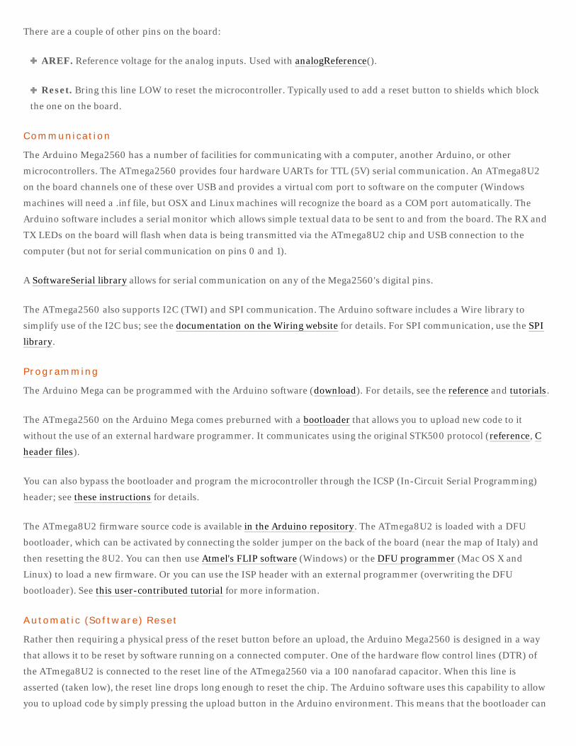
There are a couple of other pins on the board:
AREF. Reference voltage for the analog inputs. Used with analogReference().
Reset. Bring this line LOW to reset the microcontroller. Typically used to add a reset button to shields which block
the one on the board.
Communication
The Arduino Mega2560 has a number of facilities for communicating with a computer, another Arduino, or other
microcontrollers. The ATmega2560 provides four hardware UARTs for TTL (5V) serial communication. An ATmega8U2
on the board channels one of these over USB and provides a virtual com port to software on the computer (Windows
machines will need a .inf file, but OSX and Linux machines will recognize the board as a COM port automatically. The
Arduino software includes a serial monitor which allows simple textual data to be sent to and from the board. The RX and
TX LEDs on the board will flash when data is being transmitted via the ATmega8U2 chip and USB connection to the
computer (but not for serial communication on pins 0 and 1).
A SoftwareSerial library allows for serial communication on any of the Mega2560's digital pins.
The ATmega2560 also supports I2C (TWI) and SPI communication. The Arduino software includes a Wire library to
simplify use of the I2C bus; see the documentation on the Wiring website for details. For SPI communication, use the SPI
library.
Programming
The Arduino Mega can be programmed with the Arduino software (download). For details, see the reference and tutorials.
The ATmega2560 on the Arduino Mega comes preburned with a bootloader that allows you to upload new code to it
without the use of an external hardware programmer. It communicates using the original STK500 protocol (reference, C
header files).
You can also bypass the bootloader and program the microcontroller through the ICSP (In-Circuit Serial Programming)
header; see these instructions for details.
The ATmega8U2 firmware source code is available in the Arduino repository. The ATmega8U2 is loaded with a DFU
bootloader, which can be activated by connecting the solder jumper on the back of the board (near the map of Italy) and
then resetting the 8U2. You can then use Atmel's FLIP software (Windows) or the DFU programmer (Mac OS X and
Linux) to load a new firmware. Or you can use the ISP header with an external programmer (overwriting the DFU
bootloader). See this user-contributed tutorial for more information.
Automatic (Software) Reset
Rather then requiring a physical press of the reset button before an upload, the Arduino Mega2560 is designed in a way
that allows it to be reset by software running on a connected computer. One of the hardware flow control lines (DTR) of
the ATmega8U2 is connected to the reset line of the ATmega2560 via a 100 nanofarad capacitor. When this line is
asserted (taken low), the reset line drops long enough to reset the chip. The Arduino software uses this capability to allow
you to upload code by simply pressing the upload button in the Arduino environment. This means that the bootloader can
have a shorter timeout, as the lowering of DTR can be well-coordinated with the start of the upload.
This setup has other implications. When the Mega2560 is connected to either a computer running Mac OS X or Linux, it
resets each time a connection is made to it from software (via USB). For the following half-second or so, the bootloader is
running on the Mega2560. While it is programmed to ignore malformed data (i.e. anything besides an upload of new
code), it will intercept the first few bytes of data sent to the board after a connection is opened. If a sketch running on the
board receives one-time configuration or other data when it first starts, make sure that the software with which it
communicates waits a second after opening the connection and before sending this data.
The Mega2560 contains a trace that can be cut to disable the auto-reset. The pads on either side of the trace can be
soldered together to re-enable it. It's labeled "RESET-EN". You may also be able to disable the auto-reset by connecting a
110 ohm resistor from 5V to the reset line; see this forum thread for details.
USB Overcurrent Protection
The Arduino Mega2560 has a resettable polyfuse that protects your computer's USB ports from shorts and overcurrent.
Although most computers provide their own internal protection, the fuse provides an extra layer of protection. If more
than 500 mA is applied to the USB port, the fuse will automatically break the connection until the short or overload is
removed.
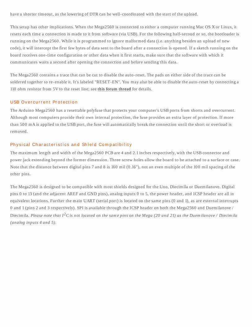
Physical Characteristics and Shield Compatibility
The maximum length and width of the Mega2560 PCB are 4 and 2.1 inches respectively, with the USB connector and
power jack extending beyond the former dimension. Three screw holes allow the board to be attached to a surface or case.
Note that the distance between digital pins 7 and 8 is 160 mil (0.16"), not an even multiple of the 100 mil spacing of the
other pins.
The Mega2560 is designed to be compatible with most shields designed for the Uno, Diecimila or Duemilanove. Digital
pins 0 to 13 (and the adjacent AREF and GND pins), analog inputs 0 to 5, the power header, and ICSP header are all in
equivalent locations. Further the main UART (serial port) is located on the same pins (0 and 1), as are external interrupts
0 and 1 (pins 2 and 3 respectively). SPI is available through the ICSP header on both the Mega2560 and Duemilanove /
Diecimila. Please note that I2C is not located on the same pins on the Mega (20 and 21) as the Duemilanove / Diecimila
(analog inputs 4 and 5).

ICSP
+5V
GND
+5V
GND
GND
+5V
GNDGND
47u 47u
GND GND
GN
D
GND
GREEN
GN
D
+5V
M7
GND
MC33269D-5.0
MC33269ST-5.0T3
100n
GND100n
100n
+3V3
+5V
+5V
ATMEGA1280-16AU
100n100n
22p
+5V
GND
100n
GND
100n
YELLOW
YELLOW
500mA
+5V
100n
GND
YELLOW
GN
D
100n
FDN340P
LM358DLM358D
GND
100n
GND
+5V
100n
+5V
GND
+5V
GND
1u
+5V
ATMEGA8U2-MU
ICSP
+5V
GND
GND
16MHz
GN
D
GND
BLM21
PG
B10
1060
4
PG
B10
1060
4
16MHz
GN
D
1M
1k
1k
1k
1k
10K
10K
10K
10K10
K
10K
10K
10K
1k
1k
1k
1k
22R
22R
22R
22R
GNDTS42
1M
16M
Hz
16M
Hz
22p
22p
22p
22p
GN
D
GN
D
GND
27R
27R
1 23 45 6
ICSP
12345678
PWML
12345678
PWMH
PC1 PC2
OND1
11
22
3 3
VI3
1
VO 2
IC2
ADJ
1
IN3 OUT 42
IC1
123456
POWER
C3
C6
C2
12345678
ADCL
12345678
COMMUNICATION
(A8)PC0 53(A9)PC1 54
(A10)PC2 55(A11)PC3 56(A12)PC4 57(A13)PC5 58(A14)PC6 59(A15)PC7 60
(AD0)PA0 78(AD1)PA1 77(AD2)PA2 76(AD3)PA3 75(AD4)PA4 74(AD5)PA5 73(AD6)PA6 72(AD7)PA7 71
(ADC0)PF0 97(ADC1)PF1 96(ADC2)PF2 95(ADC3)PF3 94
(ADC4/TCK)PF4 93(ADC5/TMS)PF5 92(ADC6/TDO)PF6 91(ADC7/TDI)PF7 90
(ALE)PG2 70
(CLKO/ICP3/INT7)PE7 9
(ICP1)PD4 47
(MISO/PCINT3)PB3 22
(MOSI/PCINT2)PB2 21
(OC0A/OC1C/PCINT7)PB7 26
(OC0B)PG5 1
(OC1A/PCINT5)PB5 24(OC1B/PCINT6)PB6 25
(OC2A/PCINT4)PB4 23
(OC3A/AIN1)PE3 5(OC3B/INT4)PE4 6(OC3C/INT5)PE5 7
(RD)PG1 52
(RXD0/PCIN8)PE0 2
(RXD1/INT2)PD2 45
(SCK/PCINT1)PB1 20
(SCL/INT0)PD0 43(SDA/INT1)PD1 44
(SS/PCINT0)PB0 19
(T0)PD7 50
(T1)PD6 49
(T3/INT6)PE6 8
(TOSC1)PG4 29
(TOSC2)PG3 28
(TXD0)PE1 3
(TXD1/INT3)PD3 46
(WR)PG0 51
(XCK0/AIN0)PE2 4
(XCK1)PD5 48
AGND99
AREF98
AVCC100
GND11326281
PH0(RXD2)12PH1(TXD2)13PH2(XCK2)14PH3(OC4A)15PH4(OC4B)16PH5(OC4C)17PH6(OC2B)18PH7(T4)27
PJ0(RXD3/PCINT9)63PJ1(TXD3/PCINT10)64PJ2(XCK3/PCINT11)65PJ3(PCINT12)66PJ4(PCINT13)67PJ5(PCINT14)68PJ6(PCINT15)69PJ779
PK0(ADC8/PCINT16)89PK1(ADC9/PCINT17)88PK2(ADC10/PCINT18)87PK3(ADC11/PCINT19)86PK4(ADC12/PCINT20)85PK5(ADC13/PCINT21)84PK6(ADC14/PCINT22)83PK7(ADC15/PCINT23)82
PL0(ICP4)35PL1(ICP5)36PL2(T5)37PL3(OC5A)38PL4(OC5B)39PL5(OC5C)40PL641PL742
RESET30
VCC10316180
XTAL134
XTAL233
GNDGNDGND
VCCVCC
VCC
IC3
C5C4
12345678
ADCH
C1
C8
C13
RX
TX
1234P
$1P
$1P
$2P
$2
X2 F1
C9
L
C7
T2
2
31
IC5A
6
57
IC5B
84
C12C11
1 23 45 67 89 10
11 1213 1415 16
XIOH
1 23 45 67 89 10
11 1213 1415 16
XIOL
1 JP1
1 JP2
1 JP3
1 JP4
21
RESET-EN
C10
(PCINT9/OC1B)PC5 25
(PCINT10)PC4 26
(INT4/ICP1/CLK0)PC7 22
(OC1A/PCINT8)PC6 23
(AIN2/PCINT11)PC2 5
(PCINT5)PB5 19
(T1/PCINT4)PB4 18
(PD0/MISO/PCINT3)PB3 17
(PDI/MOSI/PCINT2)PB2 16
(SCLK/PCINT1)PB1 15
(SS/PCINT0)PB0 14
(CTS/HWB/AIN6/TO/INT7)PD7 13
(RTS/AIN5/INT6)PD6 12
(XCK/AIN4/PCINT12)PD5 11
(INT5/AIN3)PD4 10
(TXD1/INT3)PD3 9
(RXD1/AIN1/INT2)PD2 8
(AIN0/INT1)PD1 7
(OC0B/INT0)PD0 6
GND3VCC4
AVCC32
UVCC31
XTAL11
XTAL2(PC0)2
RESET(PC1/DW)24
UGND28
IC4
PADEXP
UCAP27
D-30
D+29
(PCINT6)PB6 20(PCINT7/OC0A/OC1C)PB7 21
1 23 45 6
ICSP1
Y2
21
UB
OO
T
L1
Z1 Z2
21
GROUND
Y1
R1
1 8
RN4A
2 7
RN4B
3 6
RN4C
4 5
RN4D
18
RN
5A
27
RN
5B3
6
RN
5C
4 5
RN5D
18
RN
1A
27
RN
1B
36
RN
1C
4 5
RN1D
1 8
RN3A2 7
RN3B
3 6RN3C
45RN3D
18 RN2A
2 7
RN2B3 6
RN2C
45 RN2D
134 2
RESET
5
R2
21Q1
21Q2
C14
C15
C16
C17
IN1
EN3
NC/FB 4
OUT 5
GND2
R3
R4
+5V
+5V
GNDAREF
AREF
AREF
RESET
RESET
RESET
RESET
RESET
VIN
VIN
VIN
M8RXD
M8RXD
M8TXD
M8TXD
PWRIN
ADC0
ADC2ADC1
ADC3ADC4ADC5ADC6ADC7
+3V3
+3V3+3V3
SDA
SDA
SCL
SCL
ADC9ADC8
ADC10ADC11ADC12ADC13ADC14ADC15
PB3
PB3
PB3
PB2
PB2
PB2
PB1
PB1
PB1
PB5PB4
PE5
PE5PE4
PE4PE3
PE3
PE1 PE1
PE1
PE0 PE0
PE0
DTR
USBVCC
USBVCC
USBVCC
GATE_CMD
CMP
PB6
PH3
PH3
PH4
PH4
PH5
PH5
PH6
PH6
PG5
PG5
RXD1TXD1RXD2
RXD2
RXD3
RXD3
TXD2
TXD2
TXD3
TXD3
PC0
PC0
PC1
PC1
PC2
PC2
PC3
PC3
PC4
PC4
PC5
PC5
PC6
PC6
PC7
PC7
PB0
PB0
PG0
PG0
PG1
PG1
PG2
PG2
PD7
PD7
PA0 PA0PA1
PA1
PA2PA2
PA3
PA3
PA4
PA4
PA5
PA5
PA6
PA6
PA7
PA7
PL0
PL0
PL1
PL1
PL2
PL2PL3
PL3 PL4PL4
PL5
PL5
PL6
PL6
PL7
PL7
PB7
VUCAP
RD-
RD-
RD+
RD+
RESET2
RESET2
MISO2
MISO2
MOSI2
MOSI2
SCK2
SCK2
XVCC
RXLTXL
D-D+
UG
ND
UGND
US
HIE
LD
XTAL2
XTAL2
XTAL1
XTAL1
XT2
XT2
XT1
XT1
XTAL1R
XT1R
+ +
US
B
01234567
8910111213
15161718192021
14
(SCK)(MISO)
(MOSI)
pwmpwmpwmpwm
pwmpwmpwm
pwmpwmpwmpwmpwm
pwmpwmpwm
(TX0)(RX0)
515253
pwmpwm
pwm
pwmpwm
(MISO)
(SCK)(MOSI)
(SS)(MOSI)
(SCK)(MISO)
222324252627282930323436
31333537
494745434139
50484644424038
pwmpwmpwm
pwmpwm
US
B b
oot E
n
Arduino Mega 2560 Reference DesignTM
Reference Designs ARE PROVIDED "AS IS" AND "WITH ALL FAULTS". Arduino DISCLAIMS ALL OTHER WARRANTIES, EXPRESS OR IMPLIED,
Arduino may make changes to specifications and product descriptions at any time, without notice. The Customer must not
REGARDING PRODUCTS, INCLUDING BUT NOT LIMITED TO, ANY IMPLIED WARRANTIES OF MERCHANTABILITY OR FITNESS FOR A PARTICULAR PURPOSE
rely on the absence or characteristics of any features or instructions marked "reserved" or "undefined." Arduino reservesthese for future definition and shall have no responsibility whatsoever for conflicts or incompatibilities arising from future changes to them.The product information on the Web Site or Materials is subject to change without notice. Do not finalize a design with this information.