Embed Size (px)
Citation preview
Buy Download Gett ing Started Learning Reference Hardware FAQ
search
Arduino Mega 2560
O v e r v i e w
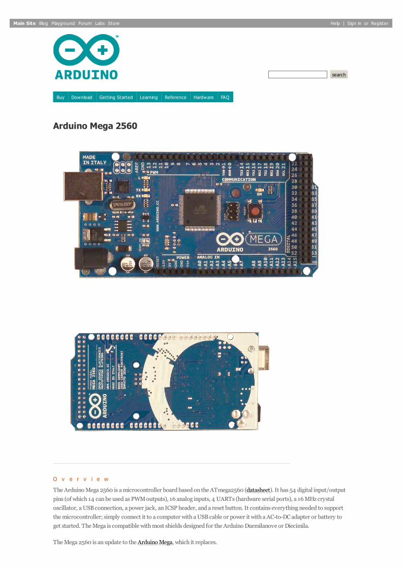
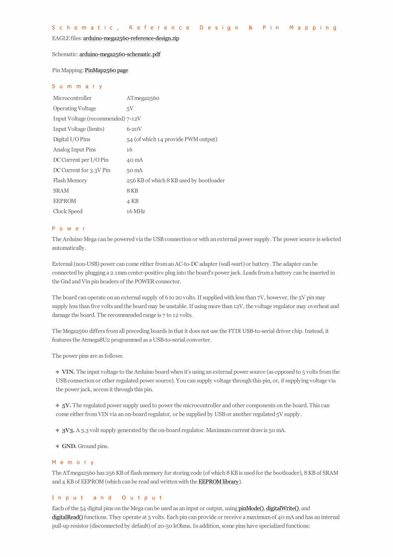
The Arduino Mega 2560 is a microcontroller board based on the ATmega2560 (datasheet). It has 54 digital input/outputpins (of which 14 can be used as PWM outputs), 16 analog inputs, 4 UARTs (hardware serial ports), a 16 MHz crystaloscillator, a USB connection, a power jack, an ICSP header, and a reset button. It contains everything needed to supportthe microcontroller; simply connect it to a computer with a USB cable or power it with a AC-to-DC adapter or battery toget started. The Mega is compatible with most shields designed for the Arduino Duemilanove or Diecimila.
The Mega 2560 is an update to the Arduino Mega, which it replaces.
Main Site Blog Playground Forum Labs Store Help | Sign in or Register
S c h e m a t i c , R e f e r e n c e D e s i g n & P i n M a p p i n g
EAGLE files: arduino-mega2560-reference-design.zip
Schematic: arduino-mega2560-schematic.pdf
Pin Mapping: PinMap2560 page
S u m m a r y
Microcontroller ATmega2560
Operating Voltage 5V
Input Voltage (recommended) 7-12V
Input Voltage (limits) 6-20V
Digital I/O Pins 54 (of which 14 provide PWM output)
Analog Input Pins 16
DC Current per I/O Pin 40 mA
DC Current for 3.3V Pin 50 mA
Flash Memory 256 KB of which 8 KB used by bootloader
SRAM 8 KB
EEPROM 4 KB
Clock Speed 16 MHz
P o w e r
The Arduino Mega can be powered via the USB connection or with an external power supply. The power source is selectedautomatically.
External (non-USB) power can come either from an AC-to-DC adapter (wall-wart) or battery. The adapter can beconnected by plugging a 2.1mm center-positive plug into the board's power jack. Leads from a battery can be inserted inthe Gnd and Vin pin headers of the POWER connector.
The board can operate on an external supply of 6 to 20 volts. If supplied with less than 7V, however, the 5V pin maysupply less than five volts and the board may be unstable. If using more than 12V, the voltage regulator may overheat anddamage the board. The recommended range is 7 to 12 volts.
The Mega2560 differs from all preceding boards in that it does not use the FTDI USB-to-serial driver chip. Instead, itfeatures the Atmega8U2 programmed as a USB-to-serial converter.
The power pins are as follows:
VIN. The input voltage to the Arduino board when it's using an external power source (as opposed to 5 volts from theUSB connection or other regulated power source). You can supply voltage through this pin, or, if supplying voltage viathe power jack, access it through this pin.
5V. The regulated power supply used to power the microcontroller and other components on the board. This cancome either from VIN via an on-board regulator, or be supplied by USB or another regulated 5V supply.
3V3. A 3.3 volt supply generated by the on-board regulator. Maximum current draw is 50 mA.
GND. Ground pins.
M e m o r y
The ATmega2560 has 256 KB of flash memory for storing code (of which 8 KB is used for the bootloader), 8 KB of SRAMand 4 KB of EEPROM (which can be read and written with the EEPROM library).
I n p u t a n d O u t p u t
Each of the 54 digital pins on the Mega can be used as an input or output, using pinMode(), digitalWrite(), anddigitalRead() functions. They operate at 5 volts. Each pin can provide or receive a maximum of 40 mA and has an internalpull-up resistor (disconnected by default) of 20-50 kOhms. In addition, some pins have specialized functions:
Serial: 0 (RX) and 1 (TX); Serial 1: 19 (RX) and 18 (TX); Serial 2: 17 (RX) and 16 (TX); Serial 3: 15(RX) and 14 (TX). Used to receive (RX) and transmit (TX) TTL serial data. Pins 0 and 1 are also connected to thecorresponding pins of the ATmega8U2 USB-to-TTL Serial chip.
External Interrupts: 2 (interrupt 0), 3 (interrupt 1), 18 (interrupt 5), 19 (interrupt 4), 20 (interrupt3), and 21 (interrupt 2). These pins can be configured to trigger an interrupt on a low value, a rising or falling edge,or a change in value. See the attachInterrupt() function for details.
PWM: 0 to 13. Provide 8-bit PWM output with the analogWrite() function.
SPI: 50 (MISO), 51 (MOSI), 52 (SCK), 53 (SS). These pins support SPI communication using the SPI library.The SPI pins are also broken out on the ICSP header, which is physically compatible with the Uno, Duemilanove andDiecimila.
LED: 13. There is a built-in LED connected to digital pin 13. When the pin is HIGH value, the LED is on, when the pinis LOW, it's off.
TWI: 20 (SDA) and 21 (SCL). Support TWI communication using the Wire library. Note that these pins are not inthe same location as the TWI pins on the Duemilanove or Diecimila.
The Mega2560 has 16 analog inputs, each of which provide 10 bits of resolution (i.e. 1024 different values). By defaultthey measure from ground to 5 volts, though is it possible to change the upper end of their range using the AREF pin andanalogReference() function.
There are a couple of other pins on the board:
AREF. Reference voltage for the analog inputs. Used with analogReference().
Reset. Bring this line LOW to reset the microcontroller. Typically used to add a reset button to shields which blockthe one on the board.
C o m m u n i c a t i o n
The Arduino Mega2560 has a number of facilities for communicating with a computer, another Arduino, or othermicrocontrollers. The ATmega2560 provides four hardware UARTs for TTL (5V) serial communication. An ATmega8U2on the board channels one of these over USB and provides a virtual com port to software on the computer (Windowsmachines will need a .inf file, but OSX and Linux machines will recognize the board as a COM port automatically. TheArduino software includes a serial monitor which allows simple textual data to be sent to and from the board. The RX andTX LEDs on the board will flash when data is being transmitted via the ATmega8U2 chip and USB connection to thecomputer (but not for serial communication on pins 0 and 1).
A SoftwareSerial library allows for serial communication on any of the Mega2560's digital pins.
The ATmega2560 also supports TWI and SPI communication. The Arduino software includes a Wire library to simplifyuse of the TWI bus; see the documentation for details. For SPI communication, use the SPI library.
P r o g r a m m i n g
The Arduino Mega can be programmed with the Arduino software (download). For details, see the reference and tutorials.
The ATmega2560 on the Arduino Mega comes preburned with a bootloader that allows you to upload new code to itwithout the use of an external hardware programmer. It communicates using the original STK500 protocol (reference, Cheader files).
You can also bypass the bootloader and program the microcontroller through the ICSP (In-Circuit Serial Programming)header; see these instructions for details.
The ATmega8U2 firmware source code is available in the Arduino repository. The ATmega8U2 is loaded with a DFUbootloader, which can be activated by connecting the solder jumper on the back of the board (near the map of Italy) andthen resetting the 8U2. You can then use Atmel's FLIP software (Windows) or the DFU programmer (Mac OS X and Linux)to load a new firmware. Or you can use the ISP header with an external programmer (overwriting the DFU bootloader).See this user-contributed tutorial for more information.
A u t o m a t i c ( S o f t w a r e ) R e s e t
Share |
Rather then requiring a physical press of the reset button before an upload, the Arduino Mega2560 is designed in a waythat allows it to be reset by software running on a connected computer. One of the hardware flow control lines (DTR) ofthe ATmega8U2 is connected to the reset line of the ATmega2560 via a 100 nanofarad capacitor. When this line isasserted (taken low), the reset line drops long enough to reset the chip. The Arduino software uses this capability to allowyou to upload code by simply pressing the upload button in the Arduino environment. This means that the bootloader canhave a shorter timeout, as the lowering of DTR can be well-coordinated with the start of the upload.
This setup has other implications. When the Mega2560 is connected to either a computer running Mac OS X or Linux, itresets each time a connection is made to it from software (via USB). For the following half-second or so, the bootloader isrunning on the Mega2560. While it is programmed to ignore malformed data (i.e. anything besides an upload of new code),it will intercept the first few bytes of data sent to the board after a connection is opened. If a sketch running on the boardreceives one-time configuration or other data when it first starts, make sure that the software with which it communicateswaits a second after opening the connection and before sending this data.
The Mega2560 contains a trace that can be cut to disable the auto-reset. The pads on either side of the trace can besoldered together to re-enable it. It's labeled "RESET-EN". You may also be able to disable the auto-reset by connecting a110 ohm resistor from 5V to the reset line; see this forum thread for details.
U S B O v e r c u r r e n t P r o t e c t i o n
The Arduino Mega2560 has a resettable polyfuse that protects your computer's USB ports from shorts and overcurrent.Although most computers provide their own internal protection, the fuse provides an extra layer of protection. If morethan 500 mA is applied to the USB port, the fuse will automatically break the connection until the short or overload isremoved.
P h y s i c a l C h a r a c t e r i s t i c s a n d S h i e l d C o m p a t i b i l i t y
The maximum length and width of the Mega2560 PCB are 4 and 2.1 inches respectively, with the USB connector andpower jack extending beyond the former dimension. Three screw holes allow the board to be attached to a surface or case.Note that the distance between digital pins 7 and 8 is 160 mil (0.16"), not an even multiple of the 100 mil spacing of theother pins.
The Mega2560 is designed to be compatible with most shields designed for the Uno, Diecimila or Duemilanove. Digitalpins 0 to 13 (and the adjacent AREF and GND pins), analog inputs 0 to 5, the power header, and ICSP header are all inequivalent locations. Further the main UART (serial port) is located on the same pins (0 and 1), as are external interrupts0 and 1 (pins 2 and 3 respectively). SPI is available through the ICSP header on both the Mega2560 and Duemilanove /
Diecimila. Please note that I2C is not located on the same pins on the Mega (20 and 21) as the Duemilanove / Diecimila(analog inputs 4 and 5).
©Arduino | Edit Page | Page History | Printable View | All Recent Site Changes