Embed Size (px)
Citation preview
[Chourasiya*, 4.(12): December, 2015] ISSN: 2277-9655
(I2OR), Publication Impact Factor: 3.785
http: // www.ijesrt.com © International Journal of Engineering Sciences & Research Technology
[583]
IJESRT INTERNATIONAL JOURNAL OF ENGINEERING SCIENCES & RESEARCH
TECHNOLOGY
SEISMIC ANALYSIS OF MULTI-STOREY R.C. STRUCTURE USING BRACING
SYSTEM AND FLOOR DIAPHRAGM Rahul Chourasiya*, Rashmi Sakalle
* Truba Institute of Engineering and Information Technology.
ABSTRACT Earthquakes are natural hazards which cause disasters are mainly caused by damage too or collapse of buildings and
other manmade structures. Experience has shown that for new constructions, establishing seismic resistant controls
and their implementation is the important safeguard against seismic induced damage. In this study, seismic analysis
of multi storey RC building frames have been carried out considering different types of bracing systems. Bracing
systems are very efficient in resisting lateral forces. STAAD.Pro software has been used for analysis purpose. Analyses
of multi storey RC building frames are carried out in 3 parts I) Building frame without bracing systems diaphragm II)
Building frames with Bracing systems and III) Building frame with floor diaphragm. Three different type of bracing
systems i.e. X Bracing, K Bracing and V Bracing including bracing core and outer pattern have been considered.
Results are collected in terms of maximum moments in beams, axial force, shear force, maximum displacement and
storey displacement which are critically analysed to quantify the effects of various parameters. This approach focuses
on the arrangement of bracing in a structure and their effectiveness in reducing the lateral displacement ultimately to
achieve economy in construction with similar structural frames.
KEYWORDS: Seismic ;Bracing; Maximum moment; Shear Force; Storey displacement; Peak storey displacement;.
INTRODUCTIONSteel braced frame is one of the structural systems used to resist wind loads in multi stories buildings. Many existing
steel buildings need retrofit to overcome deficiencies to resist wind loads. The use of steel bracing systems for
strengthening or retrofitting steel buildings frames is a viable solution for enhancing wind resistance. Steel bracing is
economical, easy to erect, occupies less space and has flexibility to design for meeting the required strength and
stiffness.The lateral stiffness of the building is controlled by different structural systems. These are:
Using unbraced frame with moment-resisting connections.
Using braced frame with moment-resisting connections.
Using braced frame with pin-jointed connections.
Using braced frame with both moment-resisting and pin-jointed connections.
Some of the prominent literature on the topic are as follows -
Kulkarni et.al. (2013) concluded that optimally braced frames are stiff, strong, and an economical structural system.
According to them, a fully braced frame are very stiff and over safe in so far as lateral drift is concerned but
uneconomical and at the contest optimally braced frames have least forces induced in the structure and produce
maximum displacement but within prescribed limit. Kevadkar andKodag (2013) observed that the structuresheavily
susceptible to lateral forces may be concerned to severe damage. In this they found that along with gravity load the
frames are able to withstand to lateral load which can develop high stresses. For this purpose they used shear wall and
steel bracing system to resist such type of loading like earthquake, wind, blast etc. Jesumi, and Rajendran (2013)
studied on the major system providing lateral load resistance in steel lattice towers. They used different types of
bracing systems on towers. The heights of towers varied from 20 to 500 meters. This study has focused on identifying
the economical bracing system for a given range of tower heights. SeyedMehrdadNourbakhsh (2011) studied the
performance of eccentric braces which is to some extent considered as a new subject amongst Civil Engineers. In this
study nine frames were considered which were braced with three different eccentric braces (V, Inverted-V and
Diagonal) in three different heights (4, 8 and 12 story). The frames were assessed by nonlinear static (pushover)
analysis mainly based on FEMA 440. As a result of these frame analysis, it was observed that the plastic hinges firstly

[Chourasiya*, 4.(12): December, 2015] ISSN: 2277-9655
(I2OR), Publication Impact Factor: 3.785
http: // www.ijesrt.com © International Journal of Engineering Sciences & Research Technology
[584]
occur at the fuse section of braces and then at the compressive members of the eccentric braces. But on the other hand
using the eccentric diagonal braces for low and medium rise structures more logical and acceptable from economical
point of view as this type of bracing system absorbs considerably more energy when compared with eccentric V and
Inverted V bracing systems. Gajjar and DhavalP.Advani (2011) focused on the design of multi-storeyed steel buildings
to have good lateral load resisting system along with gravity load system because it also governs the design. This
paper was presented to show the effect of different types of bracing systems in multi storied steel buildings. For this
purpose the 20 stories steel buildings models were used with same configuration and different bracings systems such
as knee brace, X brace and V brace. Salehuddun (2011) focused on nonlinear geometric analysis to be compared with
linear analysis. In this study, a six storey 2-D steel frame structure with 24 m height had been selected to be idealized
as tall building model. The model was analyzed by using SAP2000 structural analysis software with the consideration
of geometric nonlinear effect. This study showed that a steel frame with the consideration of wind load produce greater
sway value as compared to the steel frame without wind load. Jayachandran and vidyanatham (2009) carried out study
to enable optimization of initial structural systems for drift and stresses, based on gravity and lateral load. The design
issues were efficiency of systems, rigidity, member depths, balance between sizes of beam and column, bracings, as
well as spacing of columns, and girders, and areas and inertias of members. Ming Gu(2009) studied wind-resistance
of steel tall buildings and structures. Wind tunnel tests were carried out on 27 typical tall building models by using
wind pressure scanning and HFFB techniques. Interference effects on wind forces and wind pressures among two and
three tall buildings were experimentally investigated with about 10,000 testing cases. Theoretical study on equivalent
static wind loads of tall buildings and structures were then introduced. Especially, a new concept of “mode coupling
factor” and a modified SRSS method for wind response and equivalent static wind load of complicated tall buildings
and structures with consideration of multi-mode contributions and their coupling effects were considered. Ilyas
Yildirim (2009) investigated optimal lateral bracing systems in steel structures under wind. For this purpose evolution
strategies optimization method was used which is a member of the evolutionary algorithms search techniques. First
optimum design of steel frames was introduced then evolution strategies technique was explained. This is followed
by design loads and bracing systems and it is continued by the cost analysis of the models. Optimum designs of three
different structures, comprising twelve different b0racing models were carried out. The calculations were carried out
by a computer program (OPTSTEEL). Bo Dowswell (2000) presented an overview of lateral load resisting systems
and how to implement them. In most commercial buildings, floor and roof diaphragms are used to distribute loads in
the horizontal plane of the structure to the lateral load resisting system. Due to the open nature of most industrial
frames, diaphragms are not present, and horizontal bracing is often used to distribute the loads in the horizontal plane.
Horizontal bracing is also used in heavily-loaded commercial frames, where a diaphragm is not present, or where the
strength or rigidity of the diaphragm is not adequate.
Aim for this study is to understand the effect of seismic in multi storey structure and the remedial measures to control
these effects. To do this, models are generated and analysed with the help of STAAD.Pro software, and the effect of
with and without bracing systems ( X, K and V) including core and outer pattern to resist the seismic forces are
critically analysed.
METHODOLOGY Following steps have been adopted in this study-
Step-1 selection of building geometry, bays and story
Step-2 Selection of bracing model (X bracing frame, V bracing frame, K bracing frame, with core and outer bracing
systems) and diaphragm (Rigid diaphragm, semi-rigid and without diaphragm)
Step-3 selection of 4 seismic zones (II,III,IV and V)
Step-4 Formation of load combination (13 load combinations)
Load case no. Load cases details
1. E.Q. IN X DIR.
2. E.Q. IN Z DIR.
3. DEAD LOAD
4. LIVE LOAD

[Chourasiya*, 4.(12): December, 2015] ISSN: 2277-9655
(I2OR), Publication Impact Factor: 3.785
http: // www.ijesrt.com © International Journal of Engineering Sciences & Research Technology
[585]
5. 1.5 (DL + LL)
6. 1.5 (DL + EQX)
7. 1.5 (DL - EQX)
8. 1.5 (DL + EQZ)
9. 1.5 (DL - EQZ)
10. 1.2 (DL + LL + EQX)
11. 1.2 (DL + LL - EQX)
12. 1.2 (DL + LL + EQZ)
13. 1.2 (DL + LL - EQZ)
Step-5 Modelling of building frames
Step-6 Analysis considering different bracing system, diaphragm models, seismic zones and each load combinations
Step-7 Comparative study of results in terms of maximum moments in columns and beams, base shear, story
displacement, peak story displacement.
STRUCTURAL MODELLING AND ANALYSIS CASE-1: Bare frame without bracing and diaphragm of G+7 storey height.
CASE-2: K bracing at core of G+7 storey height.
CASE-3: K bracing at outer of G+7 storey height.
CASE-4: V bracing at core of G+7 storey height.
CASE-5: V bracing at outer of G+7 storey height.
CASE-6: X bracing at core of G+7 storey height.
CASE-7: X bracing at outer of G+7 storey height.
CASE-8: X bracing at core of G+7 storey height.
CASE-9: X bracing at outer of G+7 storey height.
CASE-10: Building frame with rigid diaphragm of G+7 storey height.
CASE-11: Building frame with semi-rigid diaphragm of G+7 storey height.
STAAD.Pro is used in modelling of building frames. STAAD.Pro is Structural Analysis and Design Program is a
general purpose program for performing the analysis and design of a wide variety of structures. The basic three
activities which are to be carried out to achieve this goal are -
a. Model generation
b. Calculations to obtain the analytical results
c. Result verification- These are allfacilitated by tools contained in the program's graphical environment.
DIAPHRAGMS
According to Paulay and Priestley (1992), the interaction of the lateral load with lateral-force-resisting vertical
elements is achieved by the use of floor systems that generally possess large in-plane stiffness. Thus, the vertical load
resisting elements will contribute to the total lateral load resistance in proportion to their own stiffness. Floors can act
as diaphragm because of its large in-plane stiffness. The main function of the floor diaphragm is to transmit the inertial
forces generated by the ground motion of the floor mass at a given level to the lateral-force-resisting vertical elements
generated by the ground motion. At lower story, significant lateral load need to be transferred from one element to
another element causing significant shear forces and bending moments in the diaphragm.
TYPES OF DIAPHRAGMS
Floor and roof systems act as a diaphragm to transfer the lateral load to the vertical load supporting elements like
beams, columns, walls etc. For the simplicity in the dynamic analysis of building, floors are assumed to be rigid in
their own plane. This concept was developed 40 years ago which assumes that the whole floor moves as the rigid body
motion; two translational and one rotational degree of freedom per each floor. This assumption is valid for many

[Chourasiya*, 4.(12): December, 2015] ISSN: 2277-9655
(I2OR), Publication Impact Factor: 3.785
http: // www.ijesrt.com © International Journal of Engineering Sciences & Research Technology
[586]
buildings but not valid for long, narrow or irregular buildings. Blume et al. conducted forced-vibration tests on several
school buildings and reported long natural periods of roof or floor diaphragms.For the analysis purpose, diaphragm
can be classified as rigid, semi rigid or semi flexible and flexible based on the relative rigidity.
Rigid diaphragm
In the rigid floor diaphragm, the lateral forces are distributed to the vertical load resisting elements (frames, shear
walls) in proportion to their relative stiffnesses. In the rigid diaphragm concept, the in-plane displacement is
considered to be equal along its entire length under lateral load. This rigid diaphragm concept is reasonable for building
nearly square in plan. A case-in-plane concrete floor is an example of rigid diaphragm.
Semi-rigid or semi-flexible diaphragm
In reality, the diaphragm can neither be perfectly rigid nor be perfectly flexible. However, in order to simplify the
analysis with reasonable assumptions, the semi-rigid diaphragm can be made as to a diaphragm's rigidity or flexibility
but in some cases the diaphragm deflection and the vertical lateral load-resisting (VLLR) elements can be of same
magnitude only in semi-rigid diaphragm. The absolute size and stiffness are important in diaphragm but that is not the
final determining factor whether it will behave as rigid, flexible, or semi-rigid. In rigid diaphragm, such as steel deck,
is partly able to distribute the lateral forces into the VLLR elements based on their relative stiffness.
Semi-rigid or semi-flexible diaphragms are those which have significant deflections under load, but which also have
sufficient stiffness to distribute a portion of the load to the vertical elements in proportion to the rigidities of the
vertical resisting elements. The action is analogous to a continuous beam system of appreciable stiffness on yielding
supports. The support reactions are dependent upon the relative stiffness of both diaphragm and the vertical resisting
element.
The rigidity of diaphragm can be ascertained by determining its flexibility factor (F). A slab isconsidered to be rigid
diaphragm if it has a flexibility factor of less than one. A flexibility factorbetween 1 and 10 is considered to represent
a semi-rigid diaphragm, and a factor greater than 10indicate a flexible diaphragm. The flexibility factor for a concrete
diaphragm is defined as:
F = 𝟏𝟎𝟔
𝟖.𝟓 𝒉 𝒘𝒄𝟏.𝟓√𝒇′𝒄
Where,
h = thickness of the slab, (in).
𝑤𝑐= unit weight of the concrete, (pcf)
𝑓′𝑐= compressive strength of the concrete at 28 days, (psi)
Figure 4.1: Isometric view of a basic building structural system comprising horizontal spanning elements
(diaphragms), vertical spanning elements (walls and frames), and foundation

[Chourasiya*, 4.(12): December, 2015] ISSN: 2277-9655
(I2OR), Publication Impact Factor: 3.785
http: // www.ijesrt.com © International Journal of Engineering Sciences & Research Technology
[587]
THE ROLES AND ACTION OF DIAPHRAGMS
A diaphragm is a flat structural unit acting like a deep, thin beam. The term “diaphragm” is usually applied to roofs
and floors. A diaphragm structure results when a series of such vertical and horizontal diaphragms are properly tied
together to form a structural unit.
Diaphragms serve multiple roles to resist gravity and lateral forces in buildings. Figure 4.2 illustrates several of these
roles for a building with a podium level at grade and with below- grade levels. The main roles include:
Resist gravity loads – Most diaphragms are part of the floor and roof framing and therefore support gravity
loads.
Provide lateral support to vertical elements – Diaphragms connect to vertical elements of the seismic force-
resisting system at each floor level, thereby providing lateral support to resist buckling as well as second-
order forces associated with axial forces acting through lateral displacements. Furthermore, by tying together
the vertical elements of the lateral force-resisting system, the diaphragms complete the three-dimensional
framework to resist lateral loads.
Resist out-of-plane forces – Exterior walls and cladding develop out-of-plane lateral inertial forces as a
building responds to an earthquake. Out-of-plane forces also develop due to wind pressure acting on exposed
wall surfaces. The diaphragm-to-wall connections provide resistance to these out-of-plane forces.
Resist thrust from inclined columns – Architectural configurations sometimes require inclined columns,
which can result in large horizontal thrusts, acting within the plane of the diaphragms, due to gravity and
overturning actions. The thrusts can act either in tension or compression, depending on orientation of the
column and whether it isin compression or tension. The diaphragm or components within it need to be
designed to resist these thrusts.
Transfer lateral inertial forces to vertical elements of the seismic force-resisting system – The floor system
commonly comprise most of the mass of the building. Consequently, significant inertial forces can develop
in the plane of the diaphragm. One of the primary roles of the diaphragm in earthquake-resistant buildings is
to transfer these lateral inertial forces, including those due to tributary portions of walls and columns, to the
vertical elements ofthe seismic force-resisting system.
Transfer forces through the diaphragm – As a building responds to earthquake loading, lateral shears often
must be transferred from one vertical element of the seismic force-resisting system to another. The largest
transfers commonly occur at discontinuities in the vertical elements, including in-plane and out-of-plane
offsets in these elements. Figure 4.2 illustrates a common discontinuity at a podium slab. The tendency is for
a majority of the shear in the structural walls above grade to transfer out of those walls, through the podium
slab, and to the basement walls. Large diaphragm transfer forces can occur in this case.
Support soil loads below grade – For buildings with subterranean levels, soil pressure bears against the
basement walls out-of-plane. The basement walls span between diaphragms, producing compressive reaction
forces at the edge of the diaphragms.

[Chourasiya*, 4.(12): December, 2015] ISSN: 2277-9655
(I2OR), Publication Impact Factor: 3.785
http: // www.ijesrt.com © International Journal of Engineering Sciences & Research Technology
[588]
Figure 4.2: Role and action of diaphragm
STRUCTURAL MODELS
Structural models for different cases are shown in Fig. 4.1 to 4.4. No. of beams and columns in each cases are given
in Table 4.1
Figure 4.4: Plan of Bare frame Figure 4.3: Structural model of Bare frame

[Chourasiya*, 4.(12): December, 2015] ISSN: 2277-9655
(I2OR), Publication Impact Factor: 3.785
http: // www.ijesrt.com © International Journal of Engineering Sciences & Research Technology
[589]
Figure 4.5: Structural model of K Bracing at Core Figure 4.7: Structural model of K bracing at outer
Figure 4.9: Structural model of V bracing at core Figure 4.10: Structural model of V bracing at outer

[Chourasiya*, 4.(12): December, 2015] ISSN: 2277-9655
(I2OR), Publication Impact Factor: 3.785
http: // www.ijesrt.com © International Journal of Engineering Sciences & Research Technology
[590]
Structural model of X bracing at core Structural model of X bracing at core
Figure 4.14:A typical isomeric diagram for diaphragm and Figure 4.15:A typical plan diagram for diaphragm
The column size is of 450MM x 450MM, and the beam size is 230MM x 450MM.
MATERIAL AND GEOMERICAL PROPERTIES
Following material properties have been considered in the modelling -
Density of RCC: 25 kN/m3
Density of Masonry: 20 kN/m3 (Assumed)
Young's modulus of concrete: 5000√𝑓𝑐𝑘
Poisson'sratio: 0.17
The foundation depth is considered at 2.0m below ground level and the typical storey height is 3.0 m.

[Chourasiya*, 4.(12): December, 2015] ISSN: 2277-9655
(I2OR), Publication Impact Factor: 3.785
http: // www.ijesrt.com © International Journal of Engineering Sciences & Research Technology
[591]
LOADING CONDITIONS
Following loadings are considered for analysis -
(a) Dead Loads: as per IS: 875 (part-1) 1987
Self wt. of slab considering 150 mm thick. Slab = 0.15 x 25 = 3.75 kN/m2 (slab thick. 150 mm assumed)
Floor Finish load = 1 kN/m2
Water Proofing Load on Roof = 2.5 kN/m2
Masonry Wall Load = 0.25 x 2.55 x 20 = 12.75 kN/m
(b) Live Loads: as per IS: 875 (part-2) 1987
Live Load on typical floors = 2 kN/m2
Live Load on Roof = 1.5 kN/m2
(c) Earth Quake Loads:
All the building frames are analyzed for 4 seismic zones
The earth quake loads are derived for following seismic parameters as per IS: 1893 (2002) [21]
a. Earth Quake Zone-II,III,IV,V (Table - 2)
b. Importance Factor: 1 (Table - 6)
c. Response Reduction Factor: 5 (Table - 7)
d. Damping: 5% (Table - 3)
e. Soil Type: Medium Soil (Assumed)
f. Period in X direction (PX):0.09∗ℎ
√𝑑𝑥seconds Clause 7.6.2 [21]
g. Period in Z direction (PZ):0.09∗ℎ
√𝑑𝑧seconds Clause 7.6.2 [21]
Where h = height of the building
dx= length of building in x direction
dz= length of building in z direction
RESULTS AND DISCUSSION The results are discussed in bracing system and diaphragm system
BRACING MODELS
Results can be described under following heads -
Table 1: Maximum displacement in X direction of bracing system
Max Peak story deflection
Structure type Zone II Zone III Zone IV Zone V
Bare Frame 38.465 61.488 92.186 138.232
X Bracing at Outer 23.555 37.307 55.909 83.812
X Bracing at Core 14.614 23.34 34.974 52.425
V Bracing at outer 35.166 56.207 84.262 128.344
V Bracing at core 34.784 55.492 83.101 124.516
K Bracing at outer 35.675 57.021 85.484 128.177
K Bracing at core 35.366 56.387 84.414 128.456
Fig 1: Maximum displacement in X direction of bracing system
020406080
100120140
Zone II Zone III Zone IV Zone V
In X Direction
Bare Frame
X Bracing at Outer
X Bracing at Core
V Bracing at outer
V Bracing at core
K Bracing at outer
K Bracing at core
[Chourasiya*, 4.(12): December, 2015] ISSN: 2277-9655
(I2OR), Publication Impact Factor: 3.785
http: // www.ijesrt.com © International Journal of Engineering Sciences & Research Technology
[592]
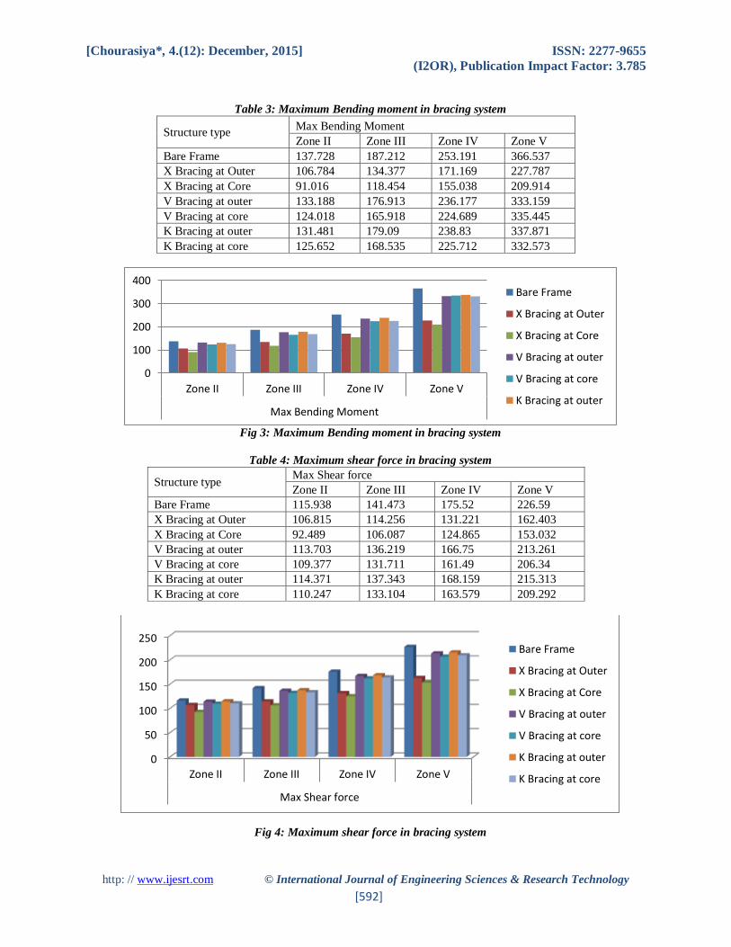
Table 3: Maximum Bending moment in bracing system
Structure type Max Bending Moment
Zone II Zone III Zone IV Zone V
Bare Frame 137.728 187.212 253.191 366.537
X Bracing at Outer 106.784 134.377 171.169 227.787
X Bracing at Core 91.016 118.454 155.038 209.914
V Bracing at outer 133.188 176.913 236.177 333.159
V Bracing at core 124.018 165.918 224.689 335.445
K Bracing at outer 131.481 179.09 238.83 337.871
K Bracing at core 125.652 168.535 225.712 332.573
Fig 3: Maximum Bending moment in bracing system
Table 4: Maximum shear force in bracing system
Structure type Max Shear force
Zone II Zone III Zone IV Zone V
Bare Frame 115.938 141.473 175.52 226.59
X Bracing at Outer 106.815 114.256 131.221 162.403
X Bracing at Core 92.489 106.087 124.865 153.032
V Bracing at outer 113.703 136.219 166.75 213.261
V Bracing at core 109.377 131.711 161.49 206.34
K Bracing at outer 114.371 137.343 168.159 215.313
K Bracing at core 110.247 133.104 163.579 209.292
Fig 4: Maximum shear force in bracing system
0
100
200
300
400
Zone II Zone III Zone IV Zone V
Max Bending Moment
Bare Frame
X Bracing at Outer
X Bracing at Core
V Bracing at outer
V Bracing at core
K Bracing at outer
0
50
100
150
200
250
Zone II Zone III Zone IV Zone V
Max Shear force
Bare Frame
X Bracing at Outer
X Bracing at Core
V Bracing at outer
V Bracing at core
K Bracing at outer
K Bracing at core
[Chourasiya*, 4.(12): December, 2015] ISSN: 2277-9655
(I2OR), Publication Impact Factor: 3.785
http: // www.ijesrt.com © International Journal of Engineering Sciences & Research Technology
[593]
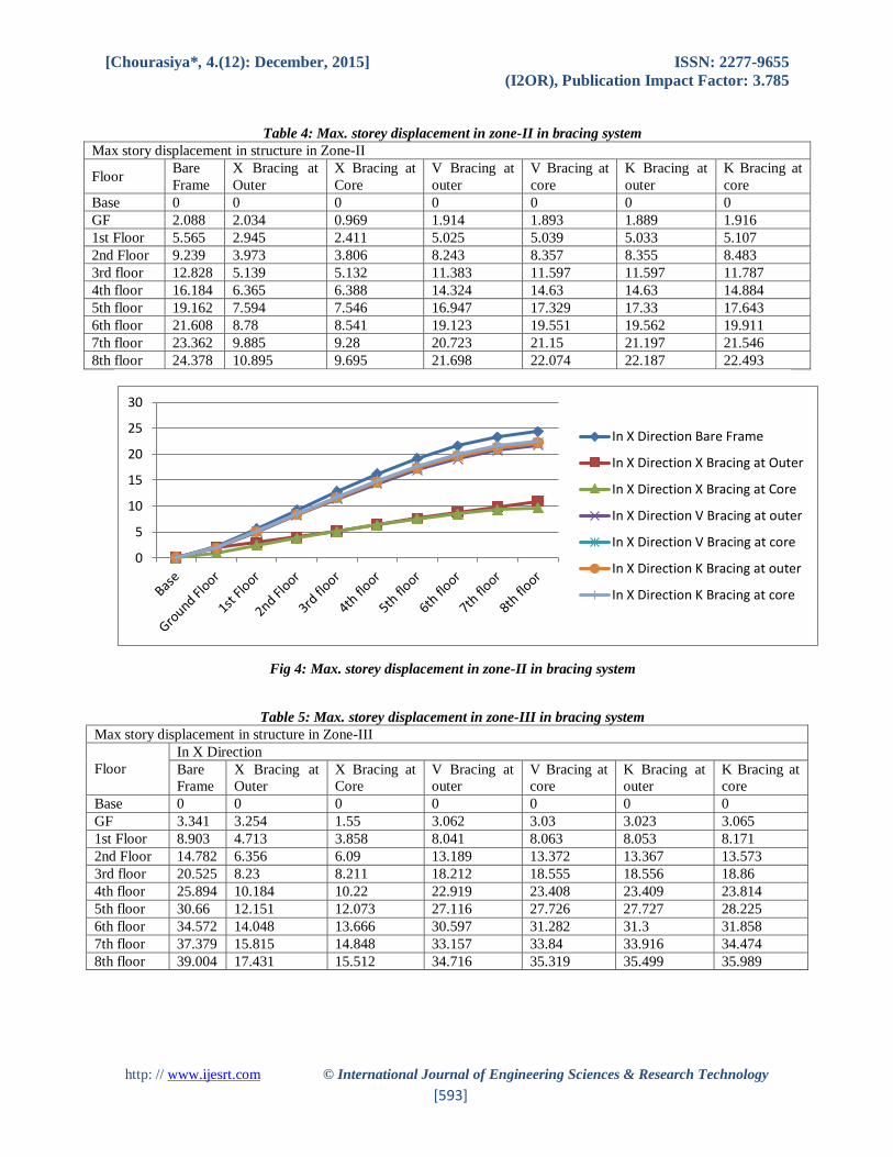
Table 4: Max. storey displacement in zone-II in bracing system
Max story displacement in structure in Zone-II
Floor Bare
Frame
X Bracing at
Outer
X Bracing at
Core
V Bracing at
outer
V Bracing at
core
K Bracing at
outer
K Bracing at
core
Base 0 0 0 0 0 0 0
GF 2.088 2.034 0.969 1.914 1.893 1.889 1.916
1st Floor 5.565 2.945 2.411 5.025 5.039 5.033 5.107
2nd Floor 9.239 3.973 3.806 8.243 8.357 8.355 8.483
3rd floor 12.828 5.139 5.132 11.383 11.597 11.597 11.787
4th floor 16.184 6.365 6.388 14.324 14.63 14.63 14.884
5th floor 19.162 7.594 7.546 16.947 17.329 17.33 17.643
6th floor 21.608 8.78 8.541 19.123 19.551 19.562 19.911
7th floor 23.362 9.885 9.28 20.723 21.15 21.197 21.546
8th floor 24.378 10.895 9.695 21.698 22.074 22.187 22.493
Fig 4: Max. storey displacement in zone-II in bracing system
Table 5: Max. storey displacement in zone-III in bracing system
Max story displacement in structure in Zone-III
Floor
In X Direction
Bare
Frame
X Bracing at
Outer
X Bracing at
Core
V Bracing at
outer
V Bracing at
core
K Bracing at
outer
K Bracing at
core
Base 0 0 0 0 0 0 0
GF 3.341 3.254 1.55 3.062 3.03 3.023 3.065
1st Floor 8.903 4.713 3.858 8.041 8.063 8.053 8.171
2nd Floor 14.782 6.356 6.09 13.189 13.372 13.367 13.573
3rd floor 20.525 8.23 8.211 18.212 18.555 18.556 18.86
4th floor 25.894 10.184 10.22 22.919 23.408 23.409 23.814
5th floor 30.66 12.151 12.073 27.116 27.726 27.727 28.225
6th floor 34.572 14.048 13.666 30.597 31.282 31.3 31.858
7th floor 37.379 15.815 14.848 33.157 33.84 33.916 34.474
8th floor 39.004 17.431 15.512 34.716 35.319 35.499 35.989
0
5
10
15
20
25
30
In X Direction Bare Frame
In X Direction X Bracing at Outer
In X Direction X Bracing at Core
In X Direction V Bracing at outer
In X Direction V Bracing at core
In X Direction K Bracing at outer
In X Direction K Bracing at core
[Chourasiya*, 4.(12): December, 2015] ISSN: 2277-9655
(I2OR), Publication Impact Factor: 3.785
http: // www.ijesrt.com © International Journal of Engineering Sciences & Research Technology
[594]
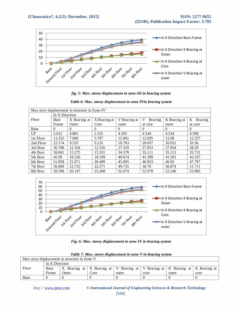
fig. 5: Max. storey displacement in zone-III in bracing system
Table 6: Max. storey displacement in zone-IVin bracing system
Max story displacement in structure in Zone-IV
Floor
In X Direction
Bare
Frame
X Bracing at
Outer
X Bracing at
Core
V Bracing at
outer
V Bracing
at core
K Bracing at
outer
K Bracing
at core
Base 0 0 0 0 0 0 0
GF 5.012 4.881 2.325 4.593 4.544 4.534 4.598
1st Floor 13.355 7.069 5.787 12.061 12.095 12.08 12.257
2nd Floor 22.174 9.535 9.135 19.783 20.057 20.051 20.36
3rd floor 30.788 12.334 12.316 27.319 27.833 27.834 28.29
4th floor 38.841 15.275 15.331 34.378 35.111 35.113 35.721
5th floor 45.99 18.226 18.109 40.674 41.589 41.591 42.337
6th floor 51.858 21.071 20.499 45.895 46.923 46.95 47.787
7th floor 56.069 23.723 22.271 49.735 50.76 50.874 51.711
8th floor 58.508 26.147 23.268 52.074 52.978 53.248 53.983
Fig. 6: Max. storey displacement in zone-IV in bracing system
Table 7: Max. storey displacement in zone-V in bracing system
Max story displacement in structure in Zone-V
Floor
In X Direction
Bare
Frame
X Bracing at
Outer
X Bracing at
Core
V Bracing at
outer
V Bracing at
core
K Bracing at
outer
K Bracing at
core
Base 0 0 0 0 0 0 0
0
10
20
30
40
50In X Direction Bare Frame
In X Direction X Bracing atOuter
In X Direction X Bracing atCore
In X Direction V Bracing atouter
010203040506070
In X Direction Bare Frame
In X Direction X Bracing atOuter
In X Direction X Bracing atCore
In X Direction V Bracing atouter

[Chourasiya*, 4.(12): December, 2015] ISSN: 2277-9655
(I2OR), Publication Impact Factor: 3.785
http: // www.ijesrt.com © International Journal of Engineering Sciences & Research Technology
[595]
GF 7.517 7.321 3.488 6.889 6.817 6.801 6.897
1st Floor 20.033 10.6032 8.68 18.092 18.142 18.12 18.385
2nd Floor 33.26 14.302 13.703 29.675 30.086 30.077 30.54
3rd floor 46.182 18.501 18.474 40.978 41.749 41.757 42.435
4th floor 58.262 22.913 22.996 51.568 52.667 52.67 53.581
5th floor 68.985 27.339 27.164 61.011 62.383 62.387 63.506
6th floor 77.787 31.607 30.748 68.842 70.384 70.424 71.681
7th floor 84.103 35.585 33.407 74.603 76.41 76.31 77.566
8th floor 87.759 39.22 34.902 78.111 79.467 79.873 80.975
Fig. 7: Max. storey displacement in zone-V in bracing system
DIAPHRAGM MODELS
Results can be described under following heads -
Table 8: Maximum displacement in diaphragm system
Maximum displacement
Structure type Zone II Zone III Zone IV Zone V
Bare Frame 38.465 61.488 92.186 138.232
Rigid Diaphragm 11.074 17.718 26.577 39.865
Semi Rigid Diaphragm 37.434 59.894 89.842 134.762
Table 8: Maximum displacement in diaphragm system
0
20
40
60
80
100
In X Direction Bare Frame
In X Direction X Bracing atOuter
In X Direction X Bracing atCore
In X Direction V Bracing atouter
020406080
100120140
Zone II Zone III Zone IV Zone V
In X Direction
Bare Frame
Rigid Dia[hragm
Semi Rigid Diaphragm

[Chourasiya*, 4.(12): December, 2015] ISSN: 2277-9655
(I2OR), Publication Impact Factor: 3.785
http: // www.ijesrt.com © International Journal of Engineering Sciences & Research Technology
[596]
Table 10: Maximum bending moment in diaphragm system
Structure type Max Bending Moment
Zone II Zone III Zone IV Zone V
Bare Frame 137.728 187.212 253.191 366.537
Rigid Diaphragm 65.779 105.246 157.869 236.803
Semi rigid Diaphragm 135.768 184.114 248.575 358.501
Fig. 10: Maximum bending moment in diaphragm system
Table 11: Maximum shear force in diaphragm system
Structure type Max Shear force
Zone II Zone III Zone IV Zone V
Bare Frame 115.938 141.473 175.52 226.59
Rigid Diaphragm 83.587 83.587 104.454 156.682
Semi rigid Diaphragm 114.929 139.875 173.137 223.031
0
50
100
150
200
250
300
350
400
Zone II Zone III Zone IV Zone V
Max Bending Moment
Bare Frame
Rigid Diaphragm
Semi rigid Diaphragm
0
50
100
150
200
250
Zone II Zone III Zone IV Zone V
Max Shear force
Bare Frame
Rigid Diaphragm
Semi rigid Diaphragm

[Chourasiya*, 4.(12): December, 2015] ISSN: 2277-9655
(I2OR), Publication Impact Factor: 3.785
http: // www.ijesrt.com © International Journal of Engineering Sciences & Research Technology
[597]
Fig. 11: Maximum shear force in diaphragm system
Table 12: Max. storey displacement in zone-II in diaphragm system
Max story displacement in structure in zone-II
Floor Bare Frame Rigid Diaphragm Semi rigid Diaphragm
Base 0 0 0
Ground Floor 2.088 0.954 2.13
1st Floor 5.565 1.941 5.667
2nd Floor 9.239 2.944 9.418
3rd floor 12.828 3.937 13.096
4th floor 16.184 4.888 16.546
5th floor 19.162 5.758 19.619
6th floor 21.608 6.5 22.144
7th floor 23.362 7.061 23.945
8th floor 24.378 7.382 24.956
Fig. 12: Max. storey displacement in zone-II in diaphragm system
Table 13: Max. storey displacement in zone-III in diaphragm system
Max story displacement in structure in zone-III
Floor Bare Frame Rigid Diaphragm Semi rigid Diaphragm
Base 0 0 0
GF 3.341 1.527 3.408
1st Floor 8.903 3.106 9.067
2nd Floor 14.782 4.71 15.07
3rd floor 20.525 6.299 20.953
4th floor 25.894 7.821 26.474
5th floor 30.66 9.213 31.391
6th floor 34.572 10.4 35.43
7th floor 37.379 11.298 38.311
8th floor 39.004 11.812 39.93
0
5
10
15
20
25
30
In X Direction Bare Frame
In X Direction RigidDiaphragm
In X Direction Semi rigidDiaphragm
[Chourasiya*, 4.(12): December, 2015] ISSN: 2277-9655
(I2OR), Publication Impact Factor: 3.785
http: // www.ijesrt.com © International Journal of Engineering Sciences & Research Technology
[598]
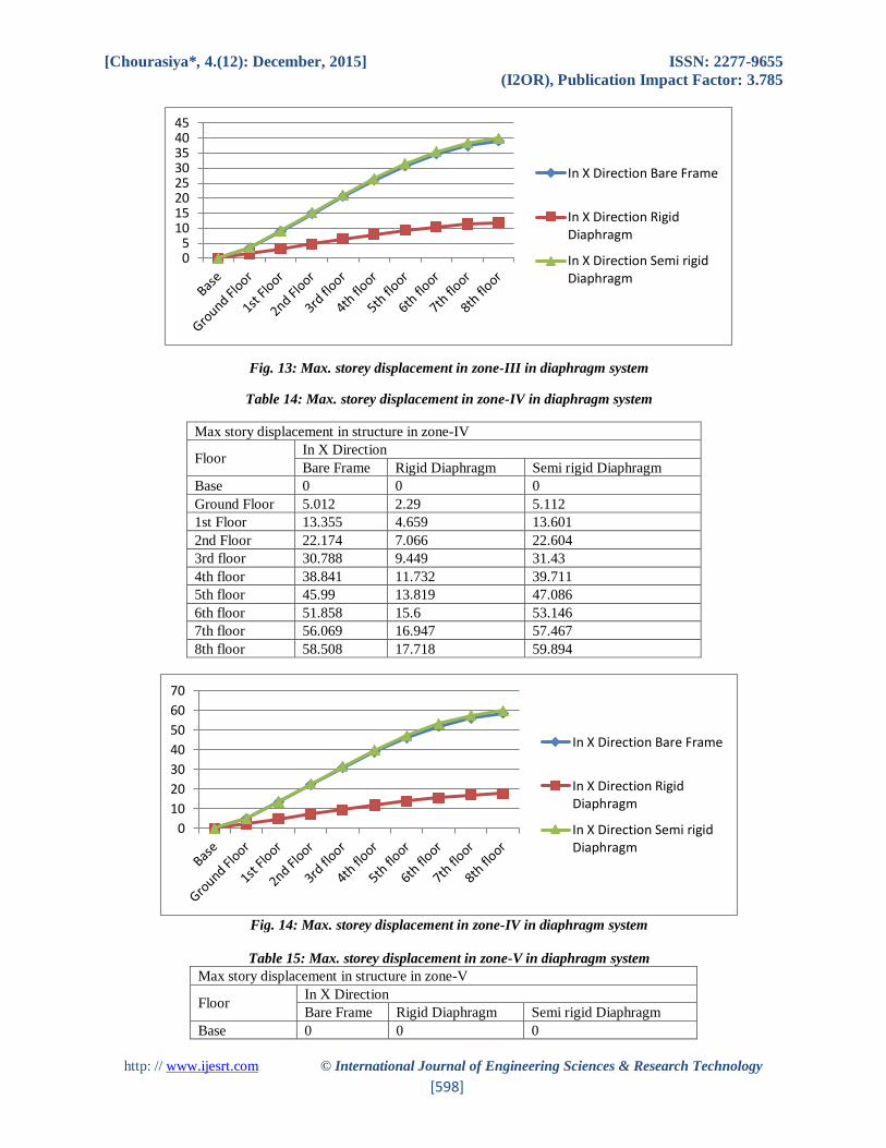
Fig. 13: Max. storey displacement in zone-III in diaphragm system
Table 14: Max. storey displacement in zone-IV in diaphragm system
Max story displacement in structure in zone-IV
Floor In X Direction
Bare Frame Rigid Diaphragm Semi rigid Diaphragm
Base 0 0 0
Ground Floor 5.012 2.29 5.112
1st Floor 13.355 4.659 13.601
2nd Floor 22.174 7.066 22.604
3rd floor 30.788 9.449 31.43
4th floor 38.841 11.732 39.711
5th floor 45.99 13.819 47.086
6th floor 51.858 15.6 53.146
7th floor 56.069 16.947 57.467
8th floor 58.508 17.718 59.894
Fig. 14: Max. storey displacement in zone-IV in diaphragm system
Table 15: Max. storey displacement in zone-V in diaphragm system
Max story displacement in structure in zone-V
Floor In X Direction
Bare Frame Rigid Diaphragm Semi rigid Diaphragm
Base 0 0 0
05
1015202530354045
In X Direction Bare Frame
In X Direction RigidDiaphragm
In X Direction Semi rigidDiaphragm
0
10
20
30
40
50
60
70
In X Direction Bare Frame
In X Direction RigidDiaphragm
In X Direction Semi rigidDiaphragm

[Chourasiya*, 4.(12): December, 2015] ISSN: 2277-9655
(I2OR), Publication Impact Factor: 3.785
http: // www.ijesrt.com © International Journal of Engineering Sciences & Research Technology
[599]
Ground Floor 7.517 3.435 7.669
1st Floor 20.033 6.989 20.402
2nd Floor 33.26 10.598 33.907
3rd floor 46.182 14.173 47.144
4th floor 58.262 17.597 59.567
5th floor 68.985 20.729 70.63
6th floor 77.787 23.4 79.718
7th floor 84.103 25.42 86.201
8th floor 87.759 26.577 89.842
Fig. 15: Max. storey displacement in zone-V in diaphragm system
CONCLUSION Following are the salient conclusions of this study-
From the present study it is seen that rigid diaphragm is much efficient in compared to other diaphragms and bracing
system in reducing moment, storey displacement, peak displacement. The analysis done in the present study clearly
shows that semi-rigid diaphragm and bracing models produce more frame displacement and moments than the rigid
diaphragm models. It has been found from the analysis of various building the rigid diaphragm is more effective than
bracing system. It is concluded that the building with rigid diaphragms will be structurally economic resulting into a
great deal of saving in reinforcement steel.
REFERENCES [1] Bo Dowswell, P.E., Allen Brice, Brain Blain, An overview of lateral load resisting systems and how to
implement them, Morden Steel Construction, July 2010.
[2] Gajjar R.K., DhavalP.Advani, Investigation of efficient bracing system as per IS 800:2007National
Conference on Recent Trends in Engineering & Technology, 13-14 May 2011.
[3] IlyasYildirim, Optimal wind bracing systems for multi-storey steel buildings, Middle East Technical
University, August 2009,Turkey.
[4] IS: 875(part-3), Code of practice for design loads (other than earthquake) for buildings and structures, Part-
3 Wind loads, Bureau of Indian Standards, New Delhi, 1987.
[5] Jesumi A.,RajendranM.G, Optimal bracing system for steel towers, International Journal of Engineering
Research and Applications (IJERA), Vol. 3, Issue 2, March -April 2013, pp.729-732.
0
10
20
30
40
50
60
70
80
90
100
In X Direction BareFrame
In X Direction RigidDiaphragm
In X Direction Semirigid Diaphragm
[Chourasiya*, 4.(12): December, 2015] ISSN: 2277-9655
(I2OR), Publication Impact Factor: 3.785
http: // www.ijesrt.com © International Journal of Engineering Sciences & Research Technology
[600]
[6] Jayachandran, S.A. and Vidyanathan, C.V., Comparative studies on simplified models for the earthquake
analysis of building frames, Proc. Tenth Symp., on Earthquake Engg., November, 2009, Vol. I, pp 371-
380.Roorkee.
[7] Kevadkar M.D., Kodag P.B.,Lateral load analysis of R.C.C. building,International Journal of Modern
Engineering Research, Vol.3, Issue.3, May-June. 2013 pp-1428-1434.
[8] Kulkarni J. G., Kore P. N., Tanawade S. B., Seismic response of reinforced concrete braced frames,
International Journal of Engineering Research and Applications, Vol. 3, Issue 4, Jul-Aug 2013, pp.1047-
1053.
[9] MingGu,Study on wind loads and responses of tall buildings and structures, Seventh Asia-Pacific Conference
on Wind Engineering, November 8-12, 2009, Taipei, Taiwan.
[10] SeyedMehrdadNourbakhsh, Inelastic behavior of eccentric braces in steel structure, Eastern Mediterranean
University, December 2011, Northern Cyprus.
[11] SalehuddinShamshinar,Stability of a six storey steel frame structure, International Journal of Civil &
Environmental Engineering, Vol.13 No.06, 2011.
[12] User Manual STAAD.Pro software, 2013.