Embed Size (px)
DESCRIPTION
AR 15 Lower Receiver Step by Step_Machining
Citation preview

AR Lower Receiver Step-by-Step 1
Machining the AR15Lower Receiver Forging
by
Ray Brandes

AR Lower Receiver Step-by-Step2
Copyright ©2003 Ray-Vin Publishing Co.All rights reserved.
First Edition
Ray-Vin Publishing Co.1844 Mt Cello Rd
Marianna, Florida USA32448-5365
www.ray-vin.com

AR Lower Receiver Step-by-Step 3
This book is dedicated to my best friend and loving wifeVincentine “Ruby” Brandes

AR Lower Receiver Step-by-Step4
I would like to thank the following people for the help they provided inmaking this book possible:
Frank White - Compass Lake EngineeringBruce Funkand all the members of AR15.COM

AR Lower Receiver Step-by-Step 5
Contents
Chapter 1 What you need to knowChapter 2 The First SetupChapter 3 HolesChapter 4 The Passenger SideChapter 5 The Buffer EndChapter 6 Pivot Pin DetailsChapter 7 Finishing the Pistol Grip MountChapter 8 Buffer Retainer HoleChapter 9 The Magazine WellChapter 10 The Hammer & Trigger WellChapter 11 Safety Detent & Trigger GuardChapter 12 Finishing UpAppendix: Tools list and alternate setups

AR Lower Receiver Step-by-Step Chapter 16
In this book I will explain in simple terms just how I go aboutmachining an AR15 lower receiver from a forging. When I first lookedat the blue print for the Colt lower I was overwhelmed by the complex-ity of it all. Now, after successfully machining several, it is nothingmore than the combination of many small, simple operations.
First of all cutting metal is the easy part of being a machinist. Thedifficult part is holding the work and locating the cutting tool relativeto the work. These two things together are called the setup. We will use10 setups to finish our lower.
I use a Bridgport style milling machine with a digital read-out(DRO). With the DRO it is very easy to work using Cartesian coordi-nates. If you don’t have a DRO, you can still do it, but it will take youa little longer and you must guard against positioning errors. Each fullturn of the handle is usually 0.200” and the usual method for movingto a position is to count turns. You won’t make an error of a fewthousands, it will be .200” or one full turn of the handle. Always touchoff your drill and then check with your scale before putting in the hole.When setting your position always come to the mark by turning thehandle clock wise to eliminate backlash errors.
Throughout this book I will maintain certain conventions. When aposition is noted it will always be the X axis first followed by the Yaxis. The X axis runs left to right and is the long axis on your millingtable. For example, if 0,0 is the pivot pin hole location, then the take-down pin hole will be at 6.375~0.00.
There are some special tools you will need to follow my methodof doing this project. A 1-3/16 x 16 tap for the buffer tube is a must.Also a long 3/32 drill and a long 1/8 drill. Also a long 1/4” center drillfor spotting the buffer retainer hole.
Chapter 1What you need to know
X AXIS
Y A
XIS
+X,+Y
+X,-Y-X,-Y
-X,+Y
+
+0,0
-
-

AR Lower Receiver Step-by-Step Chapter 1 7
It is also recommended that you have all the parts for your loweron hand to check for fit and function as the project progresses.
There are some key surfaces on the lower that will be called by
name because we will be referring to them often in the text. The deckis the main flat surface that mates with the upper. The butt face (don’tlaugh) is the face that the buttstock mates against. The left cheek is onthe driver’s side and is the face where the trigger & hammer pin holeswill be. The right cheek is on the opposite side. All forgings are not thesame. Measure across the cheeks and record this dimension. You maywant to take several readings and use the average. I will refer to this asdimension Alpha.
Butt Face
Left Cheek
Right Cheek
Deck
Named Faces
Dimension ALPHA

AR Lower Receiver Step-by-Step Chapter 18
Before you start cutting on your forging, there are a some fixturesyou will need to make. One is a pair of clamping pads to support andhold the forging for several setups. The other is a little drill guide thattakes the heart-burn out of putting in the bolt release pivot pin hole.Drawings for all of these items may be found in the back of the book,figures 1, 2 and 3. Take the time to make them now. You will regret itif you don’t. After you finish the passenger side clamping pad, measureand record dimension Bravo.
Another thing to keep in mind is your serial number. If you aregoing to stamp the number in it is best done while the forging is solidrather than when it is all hollowed out for triggers and magazines. TheBATF does not require a serial number, but they recommend you markthe receiver in such a way that it can be returned to you if lost orstolen. It is better to have a number on the receiver than to try toexplain to the arresting officer that it is legal for you to have a weaponwithout a serial number! The alternative is to take your finished re-ceiver to a trophy shop and have them engrave it to your specifications.
This book is offered for educational use only. It is the usersresponsibility to determine if finishing an AR-15 lower receiver isallowed by law in their state and municipality. The author and pub-lisher assume no liability whatsoever.
Helpful fixtures
DimensionBravo

AR Lower Receiver Step-by-Step Chapter 2 9
Begin by clamping the forging to your milling machine table using thepassenger side clamping pad. Then indicate the forging true to the x axis.
Chapter 2The First Setup
With forgings (as well as castings and weldments) that require finalprecision machining, the big problem is where to start. If you cut too muchoff of one side, there may not be enough material on the other side to cleanup and now you have one expensive piece of scrap. It is like cutting adiamond. You must make the first cut just exactly right in order for every-thing else to fall in place.
This chapter takes youthrough the first setup and the first,and most important, cuts. Whenyou complete this chapter, you willhave five finished surfaces on yourforging.
SURFACES FINISHEDIN THIS CHAPTER
1(DECK)
3
4
(BUTTFACE)5
2
Here is the top view of the setup.

AR Lower Receiver Step-by-Step Chapter 210
Now the forging is parallel and aligned to the table in the x axis.We will now cut the five surfaces. But, first we have to locate the piecein order for our machining to line up with the various features on theforging.
I like to pick up the round boss where the magazine catch will go.This is a good feature to locate on as it will give both x and y. Use acenter and center it on the boss. You can easily get within .005” byeye. Zero you digital read out. For those without DRO’s, it will takeyou longer and you will have to be more careful, but those are youronly handicaps. Move the spindle to the pivot pin hole location andcheck the alignment with the forging. If it looks good make thisposition your absolute zero.
2.109
.563
This is 0,0

AR Lower Receiver Step-by-Step Chapter 2 11
Above are the five surfaces to finish in the first set-up or hold. Iuse a 1” endmill because it makes for easy math. For the 3/4” radius Ix-y it with the 1” endmill in 18 steps (5 degrees each) and it comes outvery smooth.
Nothing more needs be said for experienced machinests. How-ever, I will add somethings for the benifit of the beginners. Since youwill be working close to the table, set your spindle stop to keep thecutter from hitting the table. Don’t try to take off all the metal in onecut. Take rough cuts and leave about .010 for the final cut. A light finalcut will deflect the cutter less and give you a better finish. When youthink you are finished cutting, clean all the chips away and take a lookat your work.
.250
1.575
7.000
7.500
.750 R
Leave this corner sharp!
Above is the tool path for a 1” dia cutter. Onthe right is the table of the 18 steps around the 3/4”radius. The first and last coordinates are the endsof the straight tool paths.
X Y-6.250 -0.750-6.270 -0.750-6.291 -0.753-6.311 -0.757-6.331 -0.763-6.350 -0.771-6.368 -0.780-6.386 -0.790-6.403 -0.802-6.419 -0.816-6.433 -0.830-6.447 -0.846-6.459 -0.863-6.469 -0.881-6.478 -0.899-6.486 -0.918-6.492 -0.938-6.496 -0.958-6.499 -0.979-6.500 -1.000
0.000
0.750
2.075
8.00
0
0.00
0
6.50
0

AR Lower Receiver Step-by-Step Chapter 212
Now that we have established our initial finished surfaces we canhold the forging for the placement of pin holes etc. But before we do,we need to cut a small flat in the bottom of the magazine well to aid inclamping.
Put the lower on a couple of 1-2-3 blocks and clamp as showabove. Using a 1/2” cutter make a flat in the middle of the magazinewell, centered and about 3/4” long. Cut this flat in the material thatwill be removed when we cut the magazine well.
Make sure you have done all the cuts scheduled for this setupbefore you break it down.
BUTTFACE
DECK
TOPFLAT
3/4RADIUS

AR Lower Receiver Step-by-Step Chapter 2 13
Here is an alternate method for cutting the clamp flat. Support thelower on a 1-2-3 blocks and using the passenger side clamp pad, clampit to an angle plate. You can also hold the lower in a vise using thedriver side and passenger side pads.
If you prefer to work in a vise, take the optional cut shown belowacross the bottom of the trigger guard bosses. When claming on thesebosses, be careful not to overtighten and crush your forging.
2.593
AR Lower Receiver Step-by-Step Chapter 314
Location: Pick up the surface just indicated (butt face) with anedge finder and then the face of the forging that is against the angleplate (deck). Move to the location of the pivot pin (7.500X -.250Y)and zero your DRO. Refer to the drawing “DRIVER SIDE” in theappendix for dimensions for this setup.
In this setup you will be putting in the pivot pin hole, take-downpin hole, trigger and hammer holes, safety hole, magazine release hole,bolt release hole and rear trigger guard hole. Also, the safety stops willbe milled along with the magazine release pocket, the bolt releasepocket and one side of the pistol grip mount.
Workholding: Put a sturdy angle plate on the mill table andindicate it true to the x axis. To the plate you will clamp the forging fordrilling pin holes etc. Make sure the surface with the two safety stopbumps is about 1/32 above the top of the angle plate. Using the quill,indicate the machined surface on the end of the forging as show belowand clamp tightly.
Chapter 3Holes
EDGE FINDER
7.500
0.25
0
MAKE THIS POINT 0,0

AR Lower Receiver Step-by-Step Chapter 3 15
Next is the hole for the safetyselector. Drill and ream 0.376 diathrough at 5.572-0.464.
Drill and ream .251 dia. the pivot pin hole through at 0.000-0.000.Now do the same for the take-down pin hole at 6.375-0.000.
0.0
0.0
6.37
5
0.0
0.0
5.57
2
0.464
When doing this kind of work it is a wise move to just touch thework with the center drill and then lay your scale on it just to makesure you are in the right place.

AR Lower Receiver Step-by-Step Chapter 316
That concludes the drilling portion for this setup. Check yourwork against the drawing above and be sure you have all eight holes.
0.0
0.6890.375
0.0
4.44
7
3.60
4
Drill and ream the trigger hole 5/32(0.156) dia. through at 4.447-0.689. Do thesame for the hammer hole at 3.604-0.375.
Next, drill the rear trigger guardhole. It is .125 dia. through at 4.875-2.188. Do not drill the forward triggerguard hole from this side. It is only onthe other side.
0.0
0.0
2.188
4.87
5
0.0
0.0
0.563
3.07
9 Next is the magazine releasehole. Move to 3.079-0.563. Drillthrough with a #5 drill (0.205”diameter).
0.0
0.0
3.07
9
0.194
The next hole does not go through. It isfor the spring that keeps the bolt releasedown. You will probably have to spot facehere to get a flat spot for the drill to start.Drill 5/32 dia. at 3.079-0.194 to 1/32 past thecenterline.
Pivot Pin
Take-down Pin
Safety Selector
Rear Trigger Guard
TriggerHammer
Magazine Release
Bolt Release

AR Lower Receiver Step-by-Step Chapter 3 17
Crank the table down, locate thespindle at 3.079 and mill the bolt releasegrove to 0.279 to the depth set above.
This is why that surface needs to be about 1/32 above the top ofthe angle plate.
Now we will do a little milling. Since we are in the neighborhoodof the bolt release we will mill the side portion of that groove first.Mount up a 5/32 end mill and set it to stop on the safety bump surfaceas show below. This is as far down as you need to cut the groove.
0.0
0.0
3.07
9
0.279
AR Lower Receiver Step-by-Step Chapter 318
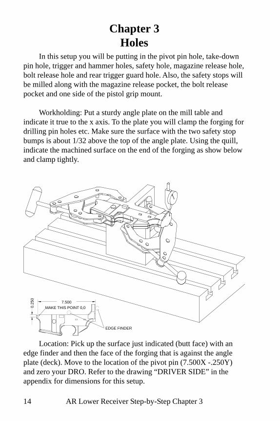
Now we will do the safety stops. Chuck a 1/4 dia. cutter and putthe spindle on the Y axis of the safety hole, 0.464. Using a piece ofplain paper, about .004” thick, for feeler gauge, set the depth of yourcutter to be 0.004” above the surface. On this setting mill off the lowerhalf of the safety bumps.
When you have this done, go ahead and drop the safety in andcheck the fit. You have two minutes to stop smiling and get on to thenext step.
0.0
0.464
0.0

AR Lower Receiver Step-by-Step Chapter 3 19
The magazine release lays in a slot you will mill using the same1/4 inch cutter. The depth of this cut is 5/32 from the surface. Thecoordinates are 1.938-0.563 to 3.197-0.563.
5/32 down from this surface
Go ahead, drop the magazine release in place. It should be closeto flush with the reference surface. When you stop smiling, we can getgoing with the pistol-grip pocket.
0.0
0.563
0.0
3.19
7
1.93
8

AR Lower Receiver Step-by-Step Chapter 320
Chuck a 1/2” dia. cutter and touch off on the reference surface.My forging is 0.864 thick at this point so it will be 0.432 to thecenterline. The face of the grip pad is 3/16 up from the centerline sowe need to subtract .1875 from .432 which gives .244 inches downfrom the reference surface to the bottom of the cut. You will need tomake your own calculations based on the thickness of your particularforging.
You can set your incremental zero at 5.453-1.316 which is thecorner of the pocket. Stay away by five or ten thousandths as yourough down to within 0.005” of the finished depth. Then set yourfinished depth and mill the sides and bottom finished in one pass. Becareful not to run into your clamp!
Reference surface
1.316
0.0
1.066
0.0
5.45
35.
203

AR Lower Receiver Step-by-Step Chapter 3 21
Before breaking the setup, double check that all the opperationsfor this setup have been completed.
A good habit to get into is this. When you think you are finished,clean off the machine of chips and tools etc. instead of rushing toremove your work-piece. This gives you some time to think about it.Nothing is as frustrating as having to re-setup something because youmissed a hole.
PIVOTPIN
BOLTRELEASE
HAMMERHOLE
TRIGGERHOLE
SAFETYSTOPS
MAGAZINERELEASE
TRIGGERGUARD
PISTOLGRIP
SAFETYHOLE
TAKE-DOWNPIN
Check List

AR Lower Receiver Step-by-Step Chapter 422
Chapter 4The Passenger Side
This setup is basically the same as the previous one, except that wewill be putting the passenger side of the reciever up. This chapter deals withspot facing the take down pin hole, milling off the front of the pivot pindetent channel, drilling the vent hole for the pivot pin detent, finishing themagazine release, drilling the front trigger guard hole and milling the otherside of the pistol grip mount.
The SetupWorkholding: As in chapter 3, clamp the forging to the angle plate
(passenger side up) and indicate true the butt face using the quill.Location: Edge find the buttface and the deck. Move 7.500-X and
.250-Y (to the pivot pin location) and set this to zero-zero. Refer to draw-ing “PASSENGER SIDE” in the appendix for this setup.

AR Lower Receiver Step-by-Step Chapter 4 23
First operation is to spot face the take-down pin hole. Chuck a 7/16”dia. endmill and move over the right cheek. Set your elevation wheel at zeroand bottom the cutter on the right cheek for the Z reference. Move to6.375-0.000 and spot face to 0.411” from the centerline.
You can check the fit, but there isn’t much to check for. Just see thatthe spot face is big enough for the pin head.
0.000
0.0
00
6.3
75

AR Lower Receiver Step-by-Step Chapter 424
Now use a 3/8” cutter and move to 0.043 x (to the right of the pivotpin hole and mill off the face at a setting of 0.522 from the centerline. Checkthat the pivot pin fits nicely before moving on.
0.00
0
0.04
3
0.14
5
1.05
5
0.522

AR Lower Receiver Step-by-Step Chapter 4 25
Chuck a 5/16 endmill and prepare to mill the pocket for the magazinerelease button. The drawing calls for this to be 0.318 wide by 0.515 long,centered on the hole at 3.079-0.563. You will mill from roughly 0.663-Y to0.463-Y to a depth of 0.069 past the centerline. Before moving on, checkthe fit with the mag release button. You don’t want this to be tight.
0.000
0.4630.663
0.0
00
3.0
79

AR Lower Receiver Step-by-Step Chapter 426
The magazine release hole needs to be relieved for the spring. Youmay be intimidated by cutting the mag well, but this operation is what scaresme the most!
You have to cut to within 0.054” of the bar slot on the other side andhere is how to do it.
Hold the mag release in the bar slot the wrong way around, measuredown to it from the button surface and record your measurement. It shouldbe close to 15/16” (0.937”). From this value subtract 0.054” and recordthe result.
Now chuck a 5/16” end mill and bring the quill down to the stop.Raise the table until the end mill touches off on the button surface. Set yourelevation dial at zero. Raise the quill and then bring the table up by the resultyou recorded earlier. Position the spindle at 3.079-0.563 and with thespindle off, bring the cutter down until it bottoms on the metal to be cut.Check your quill stop, you should have about 1/4” to go. If you have more,recheck all your measurements!
GOOD!
OOPS!CHECKAGAIN
Button surface
0.0000.563
0.0
00
3.0
79

AR Lower Receiver Step-by-Step Chapter 4 27
The next item in this setup is the forward trigger guard hole. Locate thespindle at 3.031 x 2.188 and drill a 1/8” hole about 1/4” deep. Don’t drill itthrough.
Here is the lower being held by the alternate method in a vise. Afteryou drill this hole, go back in with a #2 center drill and cut a nice chamferon the edge.
One little hole that is easy to overlook is the breather for the take-down pin detent. Locate your spindle at 1.055-0.000 and drill a 5/64(0.078) diameter hole about 1/8” deep. The hole it will be venting isn’t thereyet so don’t go too deep.
1.05
5
0.00
0
1.125
0.000
2.188
0.0
00
3.0
31

AR Lower Receiver Step-by-Step Chapter 428
As in chapter three to cut the passenger side of the pistol grip mountchuck a 1/2” dia. cutter. No need to touch off, just take a light cut thenmeasure the thickness and adjust from there for a finished size of 0.375”.
You can set your incremental zero at 5.453-1.316 which is the cornerof the pocket. Stay away by five or ten thousandths as you rough down towithin 0.005” of the finished depth. Then set your finished depth and mill thesides and bottom finished in one pass. Be careful not to run into your clamp!
If you use the alternate holding method using a vise, be sure to leavethe area to be milled clear of the jaws as shown above, not like on theopposite page.
0.000
1.316
0.0
00
5.2
03
5.4
53
1.066

AR Lower Receiver Step-by-Step Chapter 4 29
Before you break your setup, check your work!
Mill pistolgrip pocket
Drill and millmagazine release
Drill fronttrigger guard
hole
Spot facetake-down pin
hole
Drillpivot pin vent
Mill front of pivot pindetent channel

AR Lower Receiver Step-by-Step Chapter 530
Chapter 5The Buffer End
In this setup we will put in the hole for the bolt release pivot,take-down pin detent hole, the buttstock key hole and bore and threadthe hole for the buffer tube. Also, two more surfaces on the pistol gripmount will get finished.
Work Holding: Once again,clamp the top face of the receiverto the angle plate in the orienta-tion show at the right with thebuffer end of the receiver up.Indicate it true and tighten theclamps.
Locating the spindle: Withyou edge finder, locate the centerof the .375 pistol grip mount. Ifyou prefer, find the center usingthe left and right cheeks. This willbe zero on the X axis. Edge findthe face of the angle plate andmake this surface zero. This willbe your zero on the Y axis.
0.00
0
0.000

AR Lower Receiver Step-by-Step Chapter 5 31
Locate the spindle at 0.625-.188 andchuck that long 3/32 drill. Here is where youwill use that little block I told you to make inchapter one. Hold the block tightly against theangle plate and the forging. The drill shouldline up exactly with the hole in the block.Holding the block tightly, drill the holethrough the lug on the forging. Drilling thishole any other way will drive you nuts!
0.0000.188
0.00
00.
625

AR Lower Receiver Step-by-Step Chapter 532
Next is the hole for the take down pin detent.Locate your spindle at 0.331-0.250 and drill a 3/32”hole down to the take down pin hole.
When drilling deep holes, a poor start will getthe drill walking off right away. Start the hole withthe drill choked up close in the chuck. Once thehole is started, chuck the bit normally and finish thehole.
0.0000.250
0.33
10.
000

AR Lower Receiver Step-by-Step Chapter 5 33
Now for the buffer tube hole.Locate your spindle at 0.000-0.625 andbore a 1.125” hole through the tang.
0.000
0.625
0.00
0
You can put a tool in your boringhead or flycutter to put a nice 45 degreechamfer on the corner.

AR Lower Receiver Step-by-Step Chapter 534
If you have the 1-3/16 - 16 tap go ahead and tap the hole. Put acenter in the spindle to keep the tap aligned and with a light pressureon the down handle turn the tap with a wrench. If you don’t have a tap,you can single-point the thread in a lathe, see the appendix.

AR Lower Receiver Step-by-Step Chapter 5 35
At 0.000-0.375 spot and bore the buttstock anti-rotation hole. Thesize of this hole is 0.499 plus .004 minus nothing. If you drill a pilothole first, your 1/2” drill should not cut oversize. It is important not todrill this hole too deep since the buffer retainer hole will go just on theother side. I like to drill a 1/4” hole 1/4” deep and then go in with a0.500” diameter end mill about .225”.
0.200
0.375
0.00
0
BUFFERRETAINING
HOLE(CHAP 8)
AR Lower Receiver Step-by-Step Chapter 536
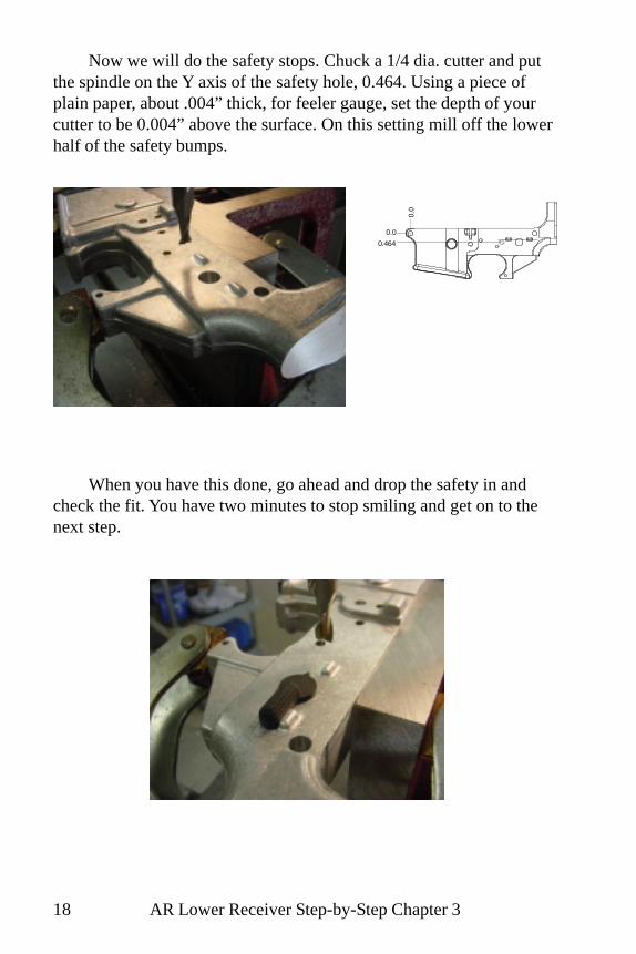
Chuck up a cutter and touch off on the butt face. I use printerpaper that is 0.004” thick and set my dial that amount before the zero.

AR Lower Receiver Step-by-Step Chapter 5 37
The first surface to mill is 1.050” down from the butt face. Milluntil you are flush with the side faces of the pistol grip mount.
Mill flush with thissurface
The next surface should be 1.250” further down and 0.930 awayfrom the surface just milled. Move to your depth slowly and make yourcut flush with the existing surfaces.
Mill flush to thissurface
0.00
0
1.31
6
2.25
0
0.000
1.050
2.300
(0.940)
(1.250)

AR Lower Receiver Step-by-Step Chapter 538
Once again, before moving on, check that all operations arecomplete before breaking this setup.
1-3/16 - 16 TAP THRU
3/32 DRILL THRU
0.188
0.375
0.625
0.250
0.331
0.625
3/32 DRILL THRU TOTAKE-DOWN HOLE
.500 DIA. BORE X.200 DEEP
DECK
Drill boltrelease
pivot hole
Bore &thread buffer
tube holeDrill take-downpin detent hole
Drill stock anti-rotation hole
Mill first pistolgrip flat
Mill secondpistol grip flat

AR Lower Receiver Step-by-Step Chapter 6 39
Chapter 6Pivot Pin Details
In this chapter we will put in the pivot pin detent hole and millout the pivot pin boss where the upper receiver goes in.
Once again we will use our passenger side plate to hold the work.You need to know the exact thickness of the side plate where it con-tacts the cheek of the receiver so if you havn’t miked it yet, do it nowand write the dimension down on the passenger side plate drawing.
Workholding: Clamp the forging to the angle plate using thepassenger side plate. Put the butt face against the table. Indicate thedeck true to the quill.
Location: Edge find the deck and move in 0.250 and set X zero.Edge find the face of the angle plate and move out the thickness of theside plate (that you just recorded) plus half the width of your forging(dim. alpha / 2) and set Y zero.

AR Lower Receiver Step-by-Step Chapter 640
First in will be the pivot pin detent hole. Position your spindle at0.000-0.583 and center drill with a #0 center drill. Choke a 3/32 drilland start the hole. Chuck the bit normally and finish the hole to 1.125”deep from the surface.
1.125
0.583
0.00
0

AR Lower Receiver Step-by-Step Chapter 6 41
For the slot where the upper and lower meet, chuck a 3/8” endmill. Put a pin in the take-down hole and touch off on the top of thepin. From here you will go down 0.385” to the finished surface.
Mill down along the center-line 3/8” past the pin hole until youare within 0.010” of the finished depth. Then widen the slot equally onboth sides to 0.500 +.004 -.000.
To check if you are deep enough, put the pivot pin in the hole andsee that a 1/8” dowl pin fits freely between the pivot-pin and thereceiver. An even better check is to see if your upper fits.
0.375
0.500
0.583

AR Lower Receiver Step-by-Step Chapter 642
Chapter 6 check list. Check that all operations are complete beforemoving on.
Drill pivot-pindetent hole Mill pivot recess
AR Lower Receiver Step-by-Step Chapter 7 43
Chapter 7Finishing the Pistol Grip Mount
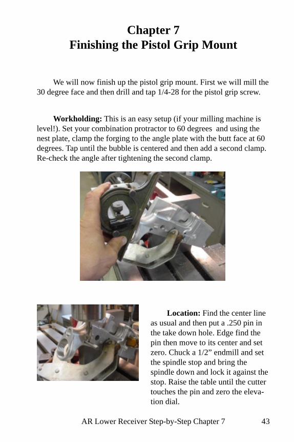
We will now finish up the pistol grip mount. First we will mill the30 degree face and then drill and tap 1/4-28 for the pistol grip screw.
Location: Find the center lineas usual and then put a .250 pin inthe take down hole. Edge find thepin then move to its center and setzero. Chuck a 1/2” endmill and setthe spindle stop and bring thespindle down and lock it against thestop. Raise the table until the cuttertouches the pin and zero the eleva-tion dial.
Workholding: This is an easy setup (if your milling machine islevel!). Set your combination protractor to 60 degrees and using thenest plate, clamp the forging to the angle plate with the butt face at 60degrees. Tap until the bubble is centered and then add a second clamp.Re-check the angle after tightening the second clamp.
AR Lower Receiver Step-by-Step Chapter 744
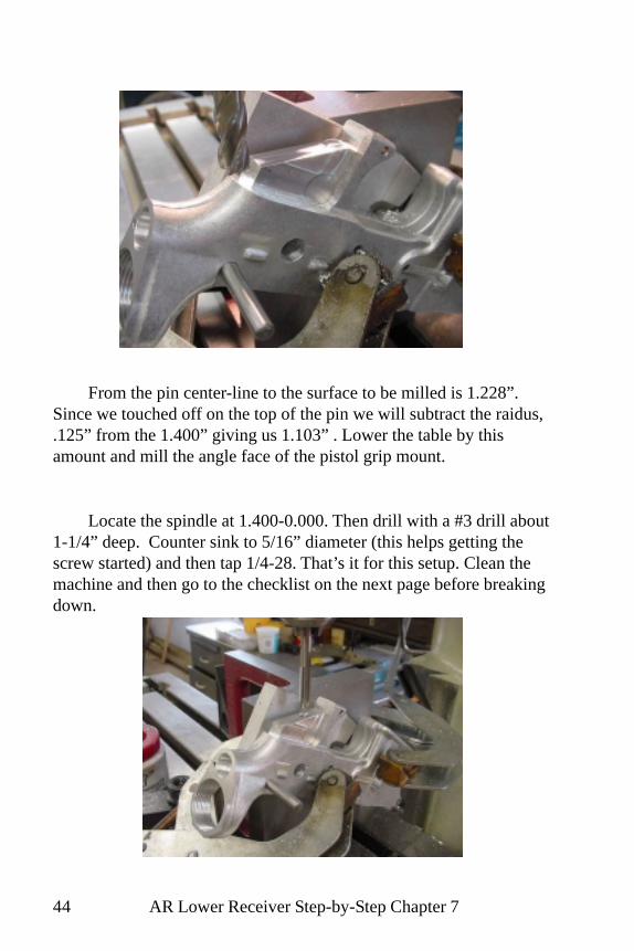
From the pin center-line to the surface to be milled is 1.228”.Since we touched off on the top of the pin we will subtract the raidus,.125” from the 1.400” giving us 1.103” . Lower the table by thisamount and mill the angle face of the pistol grip mount.
Locate the spindle at 1.400-0.000. Then drill with a #3 drill about1-1/4” deep. Counter sink to 5/16” diameter (this helps getting thescrew started) and then tap 1/4-28. That’s it for this setup. Clean themachine and then go to the checklist on the next page before breakingdown.
AR Lower Receiver Step-by-Step Chapter 7 45
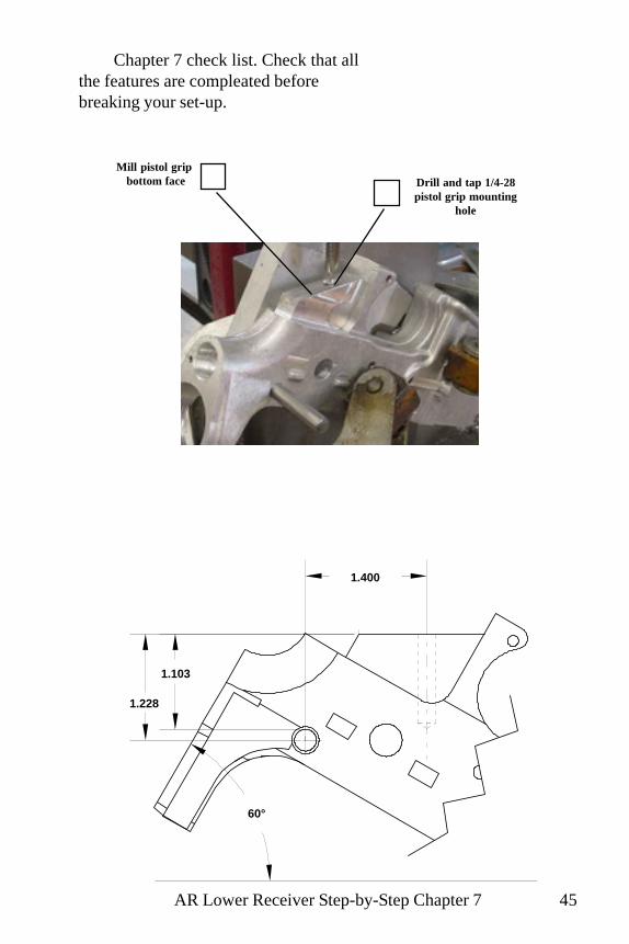
Chapter 7 check list. Check that allthe features are compleated beforebreaking your set-up.
Mill pistol grip bottom face Drill and tap 1/4-28
pistol grip mountinghole
1.400
1.228
60°
1.103

AR Lower Receiver Step-by-Step Chapter 846
Chapter 8Buffer Retainer Hole
In this chapter we will drill the buffer tube retainer hole and in asimilar and closely related setup put a small chamfer on the back of thereceiver. The buffer retainer needs to be in just the right spot. Thebuffer tube itself keeps the retainer in place, but must allow the tip ofthe retainer to extend up to stop the buffer. Thanks again to moderncomputer graphics for helping us locate this hole easily.
Workholding: Set your protractor for 6 degrees and clamp theforging against the angle plate using the clamping pad. Tap the forginguntil the buble is level and add a second clamp. Re-check the angleafter tightening the second clamp.
Locating: Edgefind thecorner at the top of the buttface.Alternatly, you can pick up thecenter of the take-down pin, butsince the detent hold is relativeto the buffer tube, it is best topick up from the surface thebuffer tube shoulders against.

AR Lower Receiver Step-by-Step Chapter 8 47
Since you will be drilling intothe buffer tube threads, the invest-ment in a long #3 center drill iswell worth it. Move to the locationand spot the hole to the full diam-eter (.250) of the center drill.
You don’t want to make amistake here by drilling through byaccident. Double check your depthsetting by moving to X-zero andbring the drill down to the stop andlook in to see; first-that the drill tipwill not break out of the forging atthe bottom and second-that yourdrill chuck will not run into the topof the buffer tube ring.
Put a 0.250 dowel pin in thetake down hole and move thespindle over it with your drill inplace. Bring the quill down to thestop and then bring the table upuntil the drill touches the pin. Apaper shim is always handy andmakes a good feeler. Set yourelevation dial to zero and thencome up 0.639”.

AR Lower Receiver Step-by-Step Chapter 848
Always check for fit with the part before breaking the setup. I hada 1/4” drill that drilled just a half thousandth small and the plungerwouldn’t go in. This is the best time to find out if the hole is tight. Iopened it up with a .251” reamer and the fit was perfect!
6°
0.639
0.595
0.691
(THREADSSIMPLIFIED
FORCLAIRITY)

AR Lower Receiver Step-by-Step Chapter 8 49
Chapter 8-1/2Charging Handle Relief
This was originally another chapter, but I combined it here be-cause the setup is so similar and the location and cut are simple.
Workholding: Clamp the lower at 15 degrees. Use your protrac-tor and clamp it up and tap until the bubble is centered. Then add asecond clamp.
Location: No location required for this setup. Just come downwith your cutter until you touch the corner and then come down an-other .035”. If you scheduled your work right, it might be a good timeto go have a beer!
0.035
15°
0.136

AR Lower Receiver Step-by-Step Chapter 850
Clean your machine and then check your work!
Buf
fer
Ret
aine
r H
ole
Cha
rgin
g H
andl
e R
elie
f

AR Lower Receiver Step-by-Step Chapter 9 51
Chapter 9The Magazine Well
This chapter deals exclusively with the magazine well. I havedone some very minor re-design of the profile here to make it easier tomachine in the home shop. This profile works just fine and saves timeand heartburn as well! Don’t let cutting the mag well freighten you, itis easier than you think! The process is only five steps:
One: Drill 1/8” diameter holes in all the corners. These will createthe corner fillets.
Two: Then we will drill rough holes to remove most of the stockthat is coming out.
Three: Rough out with a 3/4” end mill.Four: Finish with a 3/8” end mill.Five: Clean out the corners.
If you plan to stoke out the corners out using a special tool thanyou will not drill the 1/8” holes, but spot face with a 1/8” endmillinstead.
Workholding: Use both clamp plates and clamp the passengerside against the angle plate and indicate the deck true.
Location: Pick-up the butt face, move 7.500” and set your X axiszero directly above the pivot pin hole. The Y axis zero is the forgingcenterline. Pick up the angle plate surface and move out distanceCharley. This will be Y zero.
0,07.500
Charlie

AR Lower Receiver Step-by-Step Chapter 952
This step creates finished surfaces so drill slowly and carefully.Use cutting fluid and clear the chips often.
For each 1/8” hole: Move the spindle to the location and lock thetable. With a small center drill spot the hole. Put a jobber length drill inthe chuck and choke it up close so only about 1/2” is proturding. Startyou hole with the choked up drill and drill slowly for about 1/4”. Nowchuck a 1/8” parabolic drill and drill the hole through. Check that youare actually through with a mirror. Move to the next location andrepeat the process for all eight 1/8” holes.
If you plan on stroking out the corners, just put a 1/8” dia. spotface by 0.005 deep on these locations as a lay-out for cutting thecorners later.
0.173
0.1730.000
0.387
0.446
0.387
0.00
0
0.40
9
1.92
3
2.28
9
2.68
32.
838
1/8” (0.125”) DIAMETER HOLE LOCATIONS
These 3 holes willbreak out into the
magazine catch slot.
The forging will look like this after the 1/8” holes are drilled.
AR Lower Receiver Step-by-Step Chapter 9 53
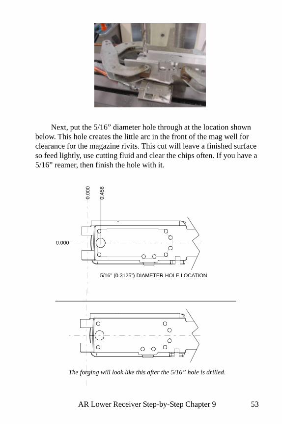
Next, put the 5/16” diameter hole through at the location shownbelow. This hole creates the little arc in the front of the mag well forclearance for the magazine rivits. This cut will leave a finished surfaceso feed lightly, use cutting fluid and clear the chips often. If you have a5/16” reamer, then finish the hole with it.
0.000
0.00
0
0.45
6
5/16” (0.3125”) DIAMETER HOLE LOCATION
The forging will look like this after the 5/16” hole is drilled.

AR Lower Receiver Step-by-Step Chapter 954
Spot and drill the four roughing holes through with a 5/16” or 3/8” drill. Next, drill through 1/2” diameter at the same locations.
Don’t forget to inspect beforemoving on to the next operation.
0.000
0.00
0
0.89
2
1.44
2
1.99
2
2.54
2
1/2” (0.500”) DIAMETER HOLE LOCATION
The forging will look like this after the 1/2” holes are drilled.

AR Lower Receiver Step-by-Step Chapter 9 55
Now with a 3/4” diameter end mill (3” long) rough plunge out thematerial along the centerline. It is best to take out as much as possiblewith a heavy end mill so the smaller one will be under less stress. Thedimensions shown below are the limits for this operation. The plungepositions inbetween are not critical. Take the first plunge on center ofone of the inner 1/2” holes. Then move approximatly .3” for eachsuccessive pluge, but be careful not to exceed the limits.
0.000
0.00
0
0.72
8
2.46
1
3/4” (0.750”) DIAMETERROUGH PLUNGE LIMITS
Here is how the forging will look after the 3/4” rough mill.

AR Lower Receiver Step-by-Step Chapter 956
Your roughed out magazine well should look like this at this point.
Using the same 0.750” diameter mill, follow the limits below fora second roughing pass. The numbers are caculated to leave 0.005” forfinal clean-up.
0.000
0.00
0
0.72
7
2.42
8
0.0690.069
3/4” (0.750”) DIAMETER MILLSECOND ROUGH LIMITS

AR Lower Receiver Step-by-Step Chapter 9 57
Once you have removed asmuch stock as possible with the3/4 end mill switch to a 3/8 endmill. I use a short one and takeout the corners as far down as Ican and then I put in a 2-1/2”long 3/8 mill and plunge out wellto full depth.
Initially, you may want tostay a few thousandths awayfrom the finishe size then take asecond pass with the full lengthendmill to the finished dimen-sions shown below.
Milled out, the magazine well should look like this.
0.279
0.000
0.2620.279
0.066
0.2620.322
0.066
0.00
0
0.53
5
1.98
2
2.21
1
0.73
6
2.35
6
2.71
22.
560
3/8” (0.375”) DIAMETER MILL LIMIT LOCATIONS

AR Lower Receiver Step-by-Step Chapter 958
When you have removed all you can with the 3/8 mill there willonly be some small cusps in the corners that remain to be eliminated.You can do this with a file or if you make a tool you can ‘stroke’ it outusing your milling machine spindle as a verticle shaper.
If you plan to stroke it out, then do not break your setup and turnto page 58.
One last little cut we will make knocks off the corners at the rearof the well. Plunge your 3/8” diameter cutter at the co-ordinatesshown. While it won’t leave the radius that the drawing calls for, it willprovide the clearance needed and is quick and easy to do.
0.121
2.63
1
0.121
0.00
0
0.000
AR Lower Receiver Step-by-Step Chapter 9 59
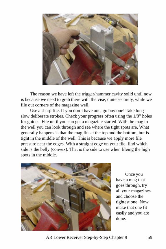
The reason we have left the trigger/hammer cavity solid until nowis because we need to grab there with the vise, quite securely, while wefile out corners of the magazine well.
Use a sharp file. If you don’t have one, go buy one! Take longslow deliberate strokes. Check your progress often using the 1/8” holesfor guides. File until you can get a magazine started. With the mag inthe well you can look through and see where the tight spots are. Whatgenerally happens is that the mag fits at the top and the bottom, but istight in the middle of the well. This is because we apply more filepressure near the edges. With a straight edge on your file, find whichside is the belly (convex). That is the side to use when fileing the highspots in the middle.
Once youhave a mag thatgoes through, tryall your magazinesand choose thetightest one. Nowmake that one fiteasily and you aredone.
AR Lower Receiver Step-by-Step Chapter 960
Stroking out the Corners
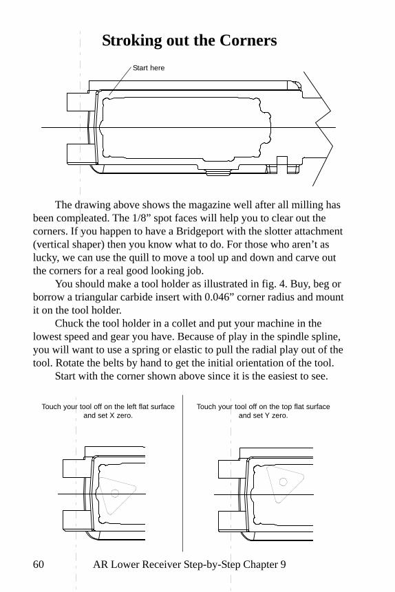
The drawing above shows the magazine well after all milling hasbeen compleated. The 1/8” spot faces will help you to clear out thecorners. If you happen to have a Bridgeport with the slotter attachment(vertical shaper) then you know what to do. For those who aren’t aslucky, we can use the quill to move a tool up and down and carve outthe corners for a real good looking job.
You should make a tool holder as illustrated in fig. 4. Buy, beg orborrow a triangular carbide insert with 0.046” corner radius and mountit on the tool holder.
Chuck the tool holder in a collet and put your machine in thelowest speed and gear you have. Because of play in the spindle spline,you will want to use a spring or elastic to pull the radial play out of thetool. Rotate the belts by hand to get the initial orientation of the tool.
Start with the corner shown above since it is the easiest to see.
Start here
Touch your tool off on the left flat surfaceand set X zero.
Touch your tool off on the top flat surfaceand set Y zero.
AR Lower Receiver Step-by-Step Chapter 9 61
While stroking the quill up and down, move the tool towards thecorner with the table locked at Y zero. Once you see the tool is taking achip you only want to advance the table when the tool is up and out,and then advance no more than 0.005” per stroke. Keep going untilyou reach X 0.017.
Now move to the area where you set X zero and locking the tableat X zero, repeat the operation while moving along the Y axis until youreach Y 0.017.
One last little stroke at X 0.005, Y0.005 and you are finished withthat corner. The opposite front corner is cleaned out in the same fash-ion after re-positioning the tool.
For the four corners at the other end, you will only be able to geta zero for one axis. Move out from that zero 0.017” and then procedetowards the corner along the zeroed axis. Stop when you just cuttangent in the 1/8” spot face and set this point zero for the other axis.Then complete the corner as you did with the first two.
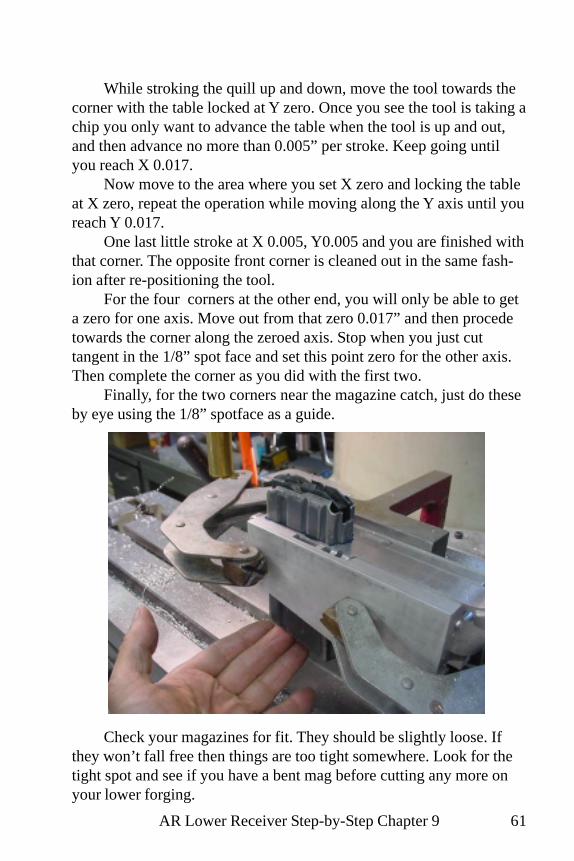
Finally, for the two corners near the magazine catch, just do theseby eye using the 1/8” spotface as a guide.
Check your magazines for fit. They should be slightly loose. Ifthey won’t fall free then things are too tight somewhere. Look for thetight spot and see if you have a bent mag before cutting any more onyour lower forging.

AR Lower Receiver Step-by-Step Chapter 1062
Chapter 10Hammer & Trigger Cavity
Workholding: Clamp up the forging and indicate it as in chapternine. Position one clamp just behind and below the safety hole and theother clamp with a plate to protect the work just on otp of the maga-zine release hole. Shown above is an alternate method using a machinevise. Clamp lightly and indicate the deck true then tighten the vise.
Location: Pickup the butt face with your edge finder and move7.5” to the pivot pin and set your X axis zero. The Y axis zero is theforging center line.
In this chapter we will finish the bolt release pocket and finish thehammer/trigger cavity.

AR Lower Receiver Step-by-Step Chapter 10 63
It is easy to forget to finish the bolt release slot so we will do thatfirst and get it out of the way. Put a 1/8” or 5/32” diameter end mill inthe spindle and move to 3.079 X. Set your endmill to stop on the deck.You will be cutting a total depth of 0.335” to 0.250” past the centerline. Match the sides of your slot with the alredy milled surfaces fromchapter three.
3.079
0.316
0.335

AR Lower Receiver Step-by-Step Chapter 1064
Once again we need to remove a lot of metal and the best way todo it is with drills. Drills are inexpensive and rugged. With someplanning we can take out lots of stock before we have to put our endmills to work. Once the hole locations are spotted with a center drill,chuck up a 1/2” drill. Touch off on the deck surface and set for a depthof cut of 1.240” to leave some metal on the bottom for clean-up. DrillThe four 1/2” holes and the one 3/8” hole in the trigger/hammerpocket. Then set the depth of cut to 0.615” and drill the rear two 3/8”holes in the take down pin area.
Take-down cavity 0.630 deepTrigger hole goes through
Hammer-Trigger cavity 1.250 deep
0.00
0
3.54
0
4.06
5
4.59
0
5.11
5
5.60
8
6.07
2
6.51
4
0.000
1/2” DRILL X 1.250 DEEP(4 PLACES)
0.031
3/8” DRILL X1.250 DEEP
3/8” DRILL X 0.630DEEP (2 PLACES)

AR Lower Receiver Step-by-Step Chapter 10 65
0.000
0.127
0.127
0.031
0.0310.
000
3.48
3
5.12
7
5.91
6
6.55
8
5.60
8
MILL THIS AREA TO 1.250 DEPTHMILL THIS AREA TO
0.630 DEPTH
The cavity will be milled out using a 7/16” (0.4375”) end mill.This will leave the proper radii in the corners. Refer to the diagramabove for the travel limits. It is best to rough it out first leaving about0.005” per side and on the bottom for finishing. Plunging works wellfor roughing. Blow the chips out often to avoid binding the cutter.

AR Lower Receiver Step-by-Step Chapter 1066
The last operation will be cutting the slot for the trigger. Drill two1/4” holes through as shown. Then chuck a 5/16 end mill and mill theslot through using the same center locations.
0.000
0.00
0
4.08
34.
451
Clean your machine and then check your work before breakingthe setup.
Boltrelease slot
HammerTriggerCavity
Triggerslot
Take-downcavity

AR Lower Receiver Step-by-Step Chapter 11 67
Chapter 11Safety Detent & Trigger Guard
This is the next to last setup. Becarefull now not to rush and makea mistake. Errors are very common near the end of the trail when onebegins thinking about the next phase instead of focusing on the task athand.
Workholding: Support your lower (it is more than 80% completenow so it is no longer a ‘forging’) on a couple of 1-2-3 blocks andclamp against the angel plate with one clamp at the magazine end. Usesomething between the clamp and the lower to help distribute thepressure.
Location: Edge find the butt face and then add a second clamponce you have your spindle located. Move 7.500” and set your X axiszero over the pivot pin hole. Y axis zero should be the same as the lastsetup.

AR Lower Receiver Step-by-Step Chapter 1168
The first thing to do in this setup is the is the safety detent hole.Move back to 5.572” and off the center line by 0.295” and spot the loca-tion with a 3/16 center drill. Eyeball it with the safety hole as a doublecheck before you drill 1/8” through. This detent is the headed variety andyou must now drill a larger diameter for the head. Use a 5/32 drill, but becareful to only go 0.188” deep or you will be in bad shape.
0.295
5.57
2
0.00
0
0.000
Drill 1/8” (0.125)through and then
drill 5/32” (0.156) x3/16” (0.188) deep.

AR Lower Receiver Step-by-Step Chapter 11 69
The trigger guard slots are 7/16” wide, but I like to use a 3/8”cutter. While on the centerline, cut down until you are flush with theflat surface of the pistol grip mount and stop there. Now take passesevenly on each side until you have the 7/16” wide slot.
Always check yourparts with the feature thatis to receive them. I don’thave to tell you it is a loteasier now to widen atight slot than to find outlater after you haveanodized you work andthe trigger guard won’tfit!

AR Lower Receiver Step-by-Step Chapter 1170
Trigger Guard
Safety Detent

AR Lower Receiver Step-by-Step Chapter 12 71
Chapter 12Finishing Up
Now that you have a working lower receiver, you will want to dosome final finishing. Removing forging seams and smoothing sharpedges will take your lower from “home-job” to “nice job!”
You will want to file and sand smooth the forging seams insidethe trigger area, front of the mag well and on the curve between thepistol grip and the buttstock.
Hold your lower in a bench viseusing a rag to prevent the vise jawsfrom marring the surfaces. Be carefulnot to overtighten!
A half-round bastard fileworks well for taking down theforging seams.
Finish with 240 grit emory paperon the file to take out scratches andfile marks.
Rough trigger area
Trigger area filed
Trigger area polished

AR Lower Receiver Step-by-Step Chapter 1272
Rough Finished
Rough Finished
Rough Finished
A carbide burr in a hand grinder is very useful for putting a lead-in on the bottom of the magazine well. The lead-in makes it easier toget the magazine into the rifle. When using power hand tools, grindcarefully to avoid cutting to deep. Smooth and finish with a file andsand paper.

AR Lower Receiver Step-by-Step Chapter 12 73
Although it is not required by law, it is strongly suggested you putsome kind of ‘serial’ number on the lower. The BATF recomends somekind of identification so the weapon can be returned to you in case it islost or stolen. I use my old NRA number with a dash one, dash two etc.If you don’t number your lower you may spend a night in jail becausesomeone is not all that familare with the laws and wonders why youhave an un-serilaized weapon...
I am blessed with a loving wife who lets me buy just about anymachine if I ding-dong long enough. I use a panto-mill to engrave mymarkings on the lower. If you are using stamps you should havestamped the forging before you did any machining as I mentioned inchapter one. Another option is to take it to your nearest trophy shopand have them laser or diamond engrave it. Have this done after thelower is anodized.
Pick a number, any number!

AR Lower Receiver Step-by-Step Chapter 1274
Anodizing is Easy!
You need a battery charger, lye, battery acid and distilled water,baking soda and dye.
I was pleasantly suprised by how easy it was to get a great anodiz-ing job at home. It is a four step process and if you succeded in ma-chining a lower, anodizing will be a walk in the park. The four anodiz-ing steps are: clean, anodize, dye, seal.
I am not going to detail the anodizing process in this book. Youcan learn all you need to know from this web-site:
http://www.focuser.com/atm/anodize/anodize99.html

AR Lower Receiver Step-by-Step Appendix 75
Appendix
Tools the author used (in addition to machine clamps and stan-dard number, fraction and letter drills) in order of appearance:
test indicator1” end mill1-2-3 blocks1/2” end mill4 x 6 angle plate6” Kant Twist clampsedge finder0.251” reamer0.376” reamer5/32 reamer5/32 end mill1/4 end mill3/8 end mill5/16 end milllong 3/32 drillboring head1-3/16 x 16 tap1/4-28 taplong #3 center drilllong 1/8 drill3/4 end mill x 3” long3/8 end mill x 3” long7/16 end mill x 1-1/4”

AR Lower Receiver Step-by-Step Appendix76
If you don’t want to spring for the 1-3/16 x 16 tap for the buffertube you can use the alternate method of cutting the thread by singlepointing it in a lathe.
I recomend you bore the 1.125 hole in the mill per page 32 inchapter 5. If you don’t have a boring head, drill and ream a hole onlocation. This hole will be used to locate the lower true to the lathespindle axis.
If your lathe isn’t big enough to swing stout clamps, you maywant to drill and tap two mounting holes in the mag well and triggerwell areas. Use these holes to screw the lower to your lathe bar.
Get a sturdy bar, at least 1” square or better and chuck it in a 4-jaw chuck. Then clamp or screw the deck to one side of the bar. Next,turn the chuck so the forging is horizontal and indicate a cheek to get itparallel to the spindle. Finally, adjust the chuck jaws so your pilot holeis running true.
Now finish boring to 1.125” diameter and single point the internalthread. Use your buffer tube as a gauge.

AR Lower Receiver Step-by-Step Appendix 77
1”
1”
Clearance for 5/16screw
0.500
2.750
8”
4.250
1.500
2.750
5/16-18 TAPX 3/4 DEEP(2 PLACES)
Pivot PinCenter Line