Embed Size (px)
Citation preview

AQUAMASTER®
INSTALLATION GUIDE
Geosynthetic MaterialsAssociation
PROUD MEMBER
Industrial FabricsAssociation International
PROUD MEMBER
TABLE OF CONTENTS 1. GENERAL..............................................................................................................1
1.1. Scope..........................................................................................................1 1.2. Applications................................................................................................1 1.3. References..................................................................................................2
2. PRODUCTS AND WARRANTIES...........................................................................3 3. QUALITY CONTROL AND QUALIFICATIONS........................................................3
3.1. IPG Goal......................................................................................................3 3.2. Qualification Minimums.............................................................................3
4. SUBMITTALS........................................................................................................4 4.1. Documentation...........................................................................................4
5. STORAGE AND HANDLING OF PRODUCTS..........................................................4 5.1. Storage........................................................................................................4 5.2. Handling......................................................................................................5
6. INSTALLATION.....................................................................................................5 6.1. Subgrade Preparation.................................................................................5 6.2. Unfolding and Deploying Aquamaster Products......................................6 6.3. Field Seaming.............................................................................................7 6.4. Field Seam Testing......................................................................................9 6.5. Evaluation of Defects................................................................................11 6.6. Anchoring and Concrete Attachments.....................................................12 6.7. Pipe Penetrations.....................................................................................13 6.8. Inspection and Installation Approval........................................................14 6.9. Covering the Geomembrane....................................................................14
7. ARMORPAD.....................................................................................................18 7.1. Hot Melt Adhesive....................................................................................18 7.2. Placement of Concrete.............................................................................18 7.3. Placement in a Channel of Canal..............................................................18
8. FIELD ACCEPTANCE...........................................................................................19
1
1. General
1.1. SCOPE The following information is a general installation guideline for Intertape Polymer Group’s (IPG) AquaMaster® geomembranes. This guideline is consistent with industry accepted standards. This manual will help AquaMaster® geomembrane installers achieve a durable liner installation. Whenever a geomembrane installation is conducted under detailed engineering specifications, those specifications should take precedence over this installation guideline and the project should be performed in strict accordance with those specifications. For information related to a specific project, please contact our technical department at the number below:
Intertape Polymer Group 50 Abbey Avenue
TRURO, NS, B2N 6W4, CANADA Tel: 800-565-2000
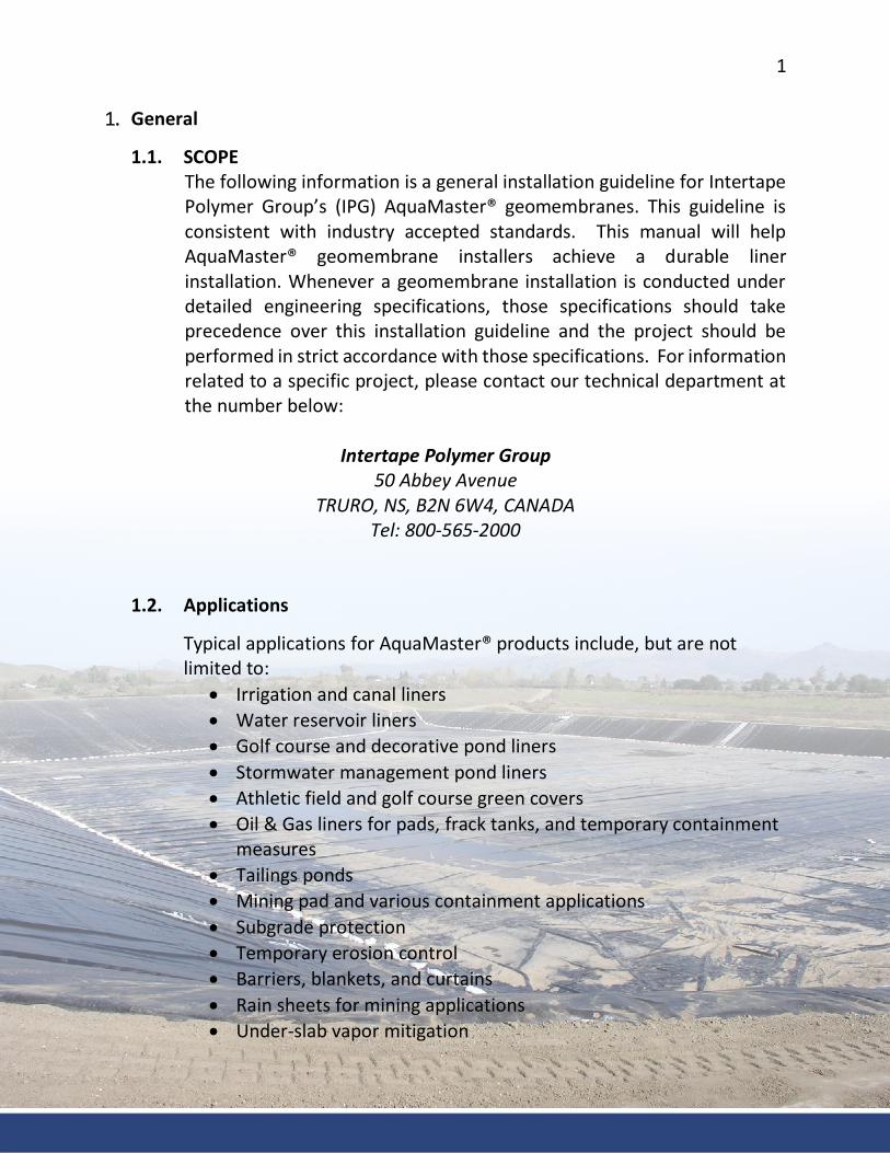
1.2. Applications
Typical applications for AquaMaster® products include, but are not limited to:
• Irrigation and canal liners • Water reservoir liners • Golf course and decorative pond liners • Stormwater management pond liners • Athletic field and golf course green covers • Oil & Gas liners for pads, frack tanks, and temporary containment
measures • Tailings ponds • Mining pad and various containment applications • Subgrade protection • Temporary erosion control • Barriers, blankets, and curtains • Rain sheets for mining applications • Under-slab vapor mitigation
2
1.3. References
ASTM – American Society for Testing and Materials 1.3.1 ASTM D1238-13 Standard Test Method for Melt Flow Rates of
Thermoplastics by Extrusion Plastometer 1.3.2 ASTM D3218-07, Standard Specification for Polyolefin Monofilaments 1.3.3 ASTM D2646-11, Standard Test Methods for Backing Fabric
Characteristics of Pile Yarn Floor Coverings 1.3.4 ASTM D751-06, Standard Test Methods for Coated Fabrics 1.3.5 ASTM D1777-96, Standard Test Method for Thickness of Textile Materials 1.3.6 ASTM D7003-03, Standard Test Method for Strip Tensile Properties of
Reinforced Geomembranes 1.3.7 ASTM D7004-03, Standard Test Method for Grab Tensile Properties of
Reinforced Geomembranes 1.3.8 ASTM D4533-15, Standard Test Method for Trapezoid Tearing Strength of
Geotextiles 1.3.9 ASTM D5884-04, Standard Test Method for Determining Tearing Strength
of Internally Reinforced Geomembranes 1.3.10 ASTM D4833-07, Standard Test Method for Index Puncture Resistance of
Geomembranes and Related Products 1.3.11 ASTM D6636-01, Standard Test Method for Determination of Ply
Adhesion Strength of Reinforced Geomembranes 1.3.12 ASTM D7272-06, Standard Test Method for Determining the Integrity of
Seams Used in Joining Geomembranes by Pre-Manufactured Taped Methods
1.3.13 ASTM D4437-08, Standard Practice for Non-destructive Testing (NDT) for Determining the Integrity of Seams Used in Joining Flexible Polymeric Sheet Geomembranes
1.3.14 ASTM D5641-94, Standard Practice for Geomembrane Seam Evaluation by Vacuum Chamber
1.3.15 ASTM D7747-11 Standard Test Method for Determining Integrity of Seams Produced Using Thermo-Fusion Methods for Reinforced Geomembranes by the Strip Tensile Method
Other References 1.3.16 USEPA. (1991). Inspection Techniques for The Fabrication Of
Geomembrane Field Seams. Cincinnati, Ohio 45268: U.S. Environmental Protection Agency.
1.3.17 Koerner, R. M. (2005). Designing with Geosynthetics (5 ed.). Upper Saddle River, NJ 07458: Pearson Education, Inc.
3
1.3.18 Geosynthetic Research Institute (2012). "Standard Specification for Test Methods, Required Properties and Testing Frequencies for Scrim Reinforced Polyethylene Geomembranes Used in Exposed Temporary Applications" GRI GM 22, Geosynthetic Institute, Folsom, PA.
2. Products and Warranties
2.1 AquaMaster® products have warranties. Each project and product selection will typically have a warranty between 2 and 25 years. Please contact an IPG specialist to discuss the warranty for your specific project.
2.2 This includes all products sold under the AquaMaster® label including, NovaLiner™, ArmorLiner™, ArmorPad®, ArmorGrip™, and NovaGrip™.
3. Quality Control and Qualifications
3.1 Intertape Polymer Group (IPG) is committed to providing products that consistently meet or exceed customer and regulatory requirements. IPG has established a Quality Management System which is certified to ISO 9001:2008 standards. It is IPG’s goal to continue meeting and exceeding industry standards and providing our customers with world class products.
3.2 Qualification Minimums 3.2.1 Manufacturer: IPG has more than 20-years of experience
manufacturing the above-mentioned products. Additionally, IPG has manufactured more than the minimum industry standard of >2,000,000 m2 (21,527,820 ft2) through the last 5 years.
3.2.2 Fabricator: The fabricator of the geomembrane shall have fabricated a minimum of 500,000 m2/year (5,381,955 ft2/year) of the specified type or similar geomembranes.
3.2.3 Installer: The installer shall be the fabricator or approved fabricators installer, or an installer/contractor approved by the owner’s representative. The geomembrane installer shall have installed at least 10 projects involving a total of 500,000 m2 (5,381,955 ft2) using the specified geomembrane.

4
4. Submittals 4.1. Documentation
4.1.1. AquaMaster® sample material warranty. 4.1.2. Sample of AquaMaster® Product(s) to be installed, including any technical data
on the product. 4.1.3. Reports on the results of examinations and testing shall be prepared and
submitted to the Owner's Representative. 4.1.4. Shop drawings/panel layout for Geomembranes with panel numbers, field
seam locations and details, corresponding to shipping labels. 4.1.5. Submit resumes or qualifications of the installation supervisor and certified
welding technicians. 4.1.6. Documentation of manufacturer’s and installer’s qualifications. It is
recommended that the welding technicians hold an International Association of Geosynthetic Installers (IAGI) Certified Welding Technician (CWT) certification in reinforced geomembranes.
4.1.7. The documentation to be submitted by the Fabricator to the Owner varies depending on the Owner’s requirements. Documentation may include copies of tested seam results, certifications, or any other document related to the quality of the geomembranes and their installation.
5. Storage and Handling of Products
5.1. Storage: Both fabricated panels and rolled goods of AquaMaster® products shall be stored and handled in a proper manner, and in accordance with industry and project specific standards. Leave the panels and rolls packaged in UV protected wrap until the time of installation. If extremely hot or cold temperatures are present, keep the product(s) inside at a moderate temperature. This reduces the force required to unfold the panels. Fabricated panels, when possible, should be stored on pallets off the ground. The storage area should be dry, level, and with a firm base to facilitate lifting so the panels are not damaged, do not become dirty, and remain dry. Pallets should not be stacked as it increases the chance to damage the panels.
5
5.2. Handling Special care should always be taken to reduce the chance of damage to rolls and fabricated panels of AquaMaster®. When unloading AquaMaster® products at a site the following steps should be followed.
1) Inspect product prior to unloading from vehicle, take inventory of roll/panel numbers, and make notes of any observed damage prior to removing from vehicle. If there is damage, make claims with carrier prior to unloading or shortly after unloading.
2) Material unloading at site should be completed using the proper equipment for the weight of the rolls/panels. It is recommended to have a storage/movement plan in place for material on site as to reduce the number of times material will need to be moved prior to installation, as each time it is moved the chance for damage to the product increases significantly.
6. Installation
6.1. Subgrade Preparation 6.1.1. A pre-installation meeting/inspection shall be completed by all
interested parties, ie. owner, engineer, installer, contractors, governmental agencies and any other representatives that have a vested interest in the project. Any parties not present for the pre-installation inspection should provide written notification of their subgrade approval.
6.1.2. Subgrade surfaces shall be clear of all angular debris, including: rocks, sticks, metal objects, and any debris larger than 0.4 inches (>10mm). The surface shall be smooth, flat and stable. No standing water, mud, snow, or excessive moisture should be allowed underneath AquaMaster® products.
6.1.3. Vegetation shall be removed during subgrade preparation to avoid puncturing the geomembrane and ensure no long-term root damage will occur.
6.1.4. Wildlife can puncture geomembranes. While many of the AquaMaster® products are suitable for long term exposure if they are placed in a high animal traffic area, a layer of material
6
(approximately 3 to 6 inches (7.5 to 15 cm) over the geomembrane will greatly reduce the chance of damage. For more information on this subject, please contact your IPG technical representative.
6.1.5. All pipes, drains, fittings, etc., which are to be installed underneath the geomembrane, should be in place, backfilled, and ready to be covered with the geomembrane prior to deployment.
6.1.6. Anchor trenches, should be completed prior to deployment of the geomembrane. After deployment of the geomembrane, anchor trenches should be filled and compacted using standard compaction practices.
6.2. Unfolding and Deploying AquaMaster® products
Typically, AquaMaster® products are supplied as panels to most projects. However, the same process is usually used for rolled goods. Factory fabricated panels is an optimum choice and greatly reduces the installation time and amount of field seaming and testing which needs to be completed.
6.2.1. Fabricated geomembrane panels are normally placed at a starting point on one corner of the area to be lined. The deployment markings on the packaging or label indicate which direction the panel will unfold. Note, accordion-folded and rolled panels will unroll in only one principal direction while double accordion-folded panels may unfold in either principal direction.
6.2.2. Prior to installation, verify there is enough material and the installer is prepared to provide slack for the geomembrane on the project. Slack shall not be confused with unintentional wrinkles or folds, and is to be approximately 5% in hot climates. The exact amount of slack can be determined from the engineer of record. Please do not hesitate to contact your IPG technical representative to discuss.
7
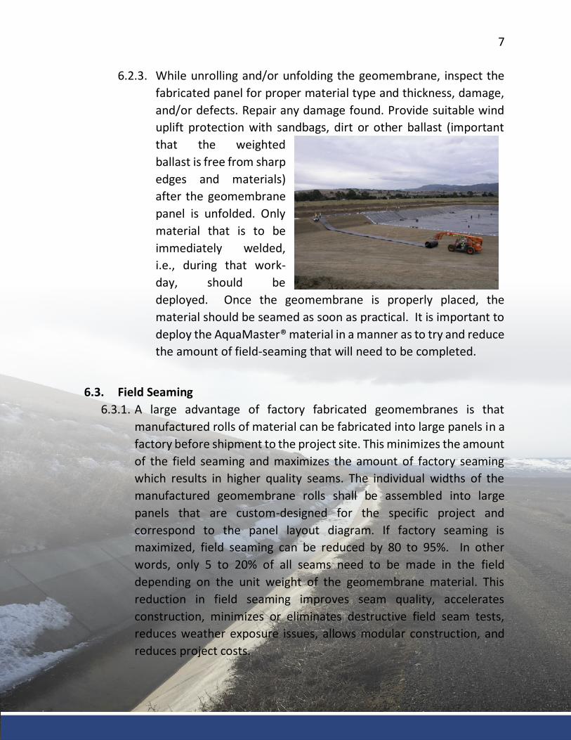
6.2.3. While unrolling and/or unfolding the geomembrane, inspect the fabricated panel for proper material type and thickness, damage, and/or defects. Repair any damage found. Provide suitable wind uplift protection with sandbags, dirt or other ballast (important that the weighted ballast is free from sharp edges and materials) after the geomembrane panel is unfolded. Only material that is to be immediately welded, i.e., during that work-day, should be deployed. Once the geomembrane is properly placed, the material should be seamed as soon as practical. It is important to deploy the AquaMaster® material in a manner as to try and reduce the amount of field-seaming that will need to be completed.
6.3. Field Seaming
6.3.1. A large advantage of factory fabricated geomembranes is that manufactured rolls of material can be fabricated into large panels in a factory before shipment to the project site. This minimizes the amount of the field seaming and maximizes the amount of factory seaming which results in higher quality seams. The individual widths of the manufactured geomembrane rolls shall be assembled into large panels that are custom-designed for the specific project and correspond to the panel layout diagram. If factory seaming is maximized, field seaming can be reduced by 80 to 95%. In other words, only 5 to 20% of all seams need to be made in the field depending on the unit weight of the geomembrane material. This reduction in field seaming improves seam quality, accelerates construction, minimizes or eliminates destructive field seam tests, reduces weather exposure issues, allows modular construction, and reduces project costs.
8
6.3.2. Cleaning of Seaming Surfaces
It is important to try and protect the welding edges during installation. A minimum overlap of 4 to 6 inches (10 to 15 cm) of wrinkle free and “fish-mouth” free area, must be cleaned of all dirt, dust, water and any foreign debris within 30 minutes of the seaming operation. Verification of the contact surfaces being cleaned should be the responsibility of the certified welding technician.
6.3.3. All seaming shall be done with thermal heat-sealing equipment or with an adhesive. (The adhesive seaming method for ArmorPad® is discussed in Section 7.1). Heat sealing with automated wedge welding equipment is the preferred method whenever possible. Wedge welders for field seaming shall be qualified before field seaming of panels begins. A test section shall be completed to determine the proper operating temperature and speed of the welder. A minimum 6 foot (2 meter) sample field seam shall be completed for all AquaMaster® products.
6.3.4. Wedge welding is performed with a hot wedge welding machine, which uses a heated element to melt the geomembranes to be welded and then presses the two melted sheets together to form the bond. When performed properly, wedge welders produce high quality and consistent seams. The wedge in a hot wedge welder can be heated with hot air (hot air method), or with electric resistance heating (hot wedge method). All wedge welders employ a set point controller to accurately maintain the welding temperature within the most efficient welding temperature for the material. The pressure wheels should be adjustable to allow for good material bonding after heating. Only single or solid wedge arrangement is recommended for factory and field welding of AquaMaster® reinforced geomembranes. The single (or solid) wedge arrangement produces a continuous bonded weld not less than 1 inch (25.4 mm) wide.
6.3.5. Field Tape Seaming
AquaMaster® geomembranes should be field seamed by heat welding, sewing, or adhesive in the case of ArmorPad®. If necessary, they can be seamed using field tape seaming methods, but due to many variables, tape seaming is never guaranteed. Tape seaming is usually
9
limited to products less than 30-mil in thickness. Immediately after creating a tape seam, it should be loaded or secured to facilitate bonding. The preferred method for securing prepared tape joints is to backfill the geomembrane with a suitable soil cover so tensile stresses do not develop. The backfill creates a pressure seal between the geomembrane panels and tape which is usually effective. An alternative method of creating strength in a tape seam is to sew the seam first and then use prepared tapes to waterproof the joint. Even with a sewn seam, the recommended practice is to backfill the geomembrane to prevent shifting of the seam and to help adhere or bond the tapes.
To create a tape seam, place one or two continuous lines of double sided tape between the sheet overlap. Apply a minimum 4 inch (10 cm) wide single sided heavy-duty tape over the flap area. Press the sheet materials together to compress the tape using a rubber, nylon, or steel hand roller or similar tool. In areas where wrinkles cannot be removed, use tapes on all sides of the wrinkle to form a waterproof seal. Visually inspect the completed seam to ensure intimate contact between the tapes and the upper and lower sheet surfaces. Repair discontinuities by placing a patch over the damaged area with a prepared tape seal around the perimeter. The patch must be circular, oval, or contain rounded corners and extend 6-inches around the defect. Supervise the backfilling of the seam area to prevent the seam from being placed in tension and pulled apart. Backfill should proceed in a direction that does not tend to pull the seams apart or create a shear or tensile stress in the seam.
6.4. Field Seam Testing
6.4.1. Trial Seams
Test seams shall be prepared and tested by the Geomembrane Installer to verify that the seaming parameters meet accepted seam values at the start of each welding session or at the beginning of each working day. Test seams also may be made whenever personnel or equipment are changed, and when climatic conditions reflect wide changes in geomembrane temperature, or other conditions that could affect seam quality. A minimum of one test strip per seaming
10
apparatus shall be conducted at the start of each welding session during a day and at least every 4 hours or 3000 lineal feet (914 meters) of field seam per machine, whichever is more frequent. Field test seams shall be made using “scrap” material from the same lot as the geomembrane being welded in the field. This requirement is necessary to ensure that the installed geomembrane panels are not damaged prior to the onset of the field welding process because no destructive seam tests shall be conducted on factory fabricated seams to preserve integrity of the fabricated panels. Test seaming shall be conducted under ambient conditions and with the same equipment, geomembrane, and operator as field seaming on the fabricated panels. The test seams shall be at least 6-feet long for all types of field seams. If there is no area or equipment on site to provide for these seam requirements, seam strength can be verified for production using trial welds sent to an independent testing laboratory to verify quality. If a test seam fails, an additional test seam shall be immediately completed. If the additional test seam fails, the seaming apparatus shall be rejected and not used until the deficiencies are corrected and a successful full test seam is produced. Each test seam shall be labeled with date, geomembrane temperature, weather conditions, number of seaming unit, panel identification, seam number or test location, technician performing the test seam, and a pass or fail description. Pre-qualification seams for tape seams shall be in accordance with ASTM D7272.
6.4.2. Non-Destructive Seam Testing (NDT)
When required, field seams can be non-destructively tested by the geomembrane installer over the full length of the seams before the seam is covered. When seam NDT is part of the requirements, each seam shall be numbered or otherwise designated. The location, date, test unit, name of the technician, name of QC person, and outcome of all NDT shall be recorded and submitted to the Owner’s Representative. Testing should be performed as the seaming progresses; not at the completion of all field seaming, unless agreed to in advance by the Owner’s Representative. All defects found should
11
be repaired, re-tested, and remarked to indicate acceptable completion of repair. NDT of field seams shall be performed using one or more of the following methods. Air Lance testing method is preferred whenever possible. 6.4.2.1. Air Lance Method (ASTM D4437)
If required by the contract documents, air lance testing can be accomplished to provide a good source of non-destructive testing. The Geomembrane Installer shall provide an air compressor, air hose, and air lance wand with a pressure gauge capable of measuring air flow to the tip. The testing shall be performed by experienced technicians familiar with this testing procedure. This non-destructive test involves placing the air lance wand approximately ¼ to ½ inch (6 mm to 12 mm) from the edge of a completed seam (not more than 2 inches (51 mm)) and closely monitoring the backside of the sheet for any air penetration through the seam, loose edges, riffles, and/or noise. If air penetrates the seam area, the technician will either see this visibly or hear it audibly and the area shall be marked for repair.
6.4.2.2. Mechanical Point Stress or "Pick" Test (ASTM D4437)
This NDT uses a dull tool (such as a blunt screwdriver) under the top edge of a field seam. With care, an installer can detect an un-bonded area, which is easier to separate than a properly bonded area. This method must be used with extreme care so as not to damage the parent geomembrane and bonded area, and is to be used only if other NDT methods are not available.
6.5. Evaluation of Defects
Each suspect location (both in geomembrane seam and non-seam areas) shall be non-destructively tested. Each location which fails non-destructive testing shall be marked, numbered, measured, and posted on the daily installation drawings and subsequently repaired. Defective seams, tears or holes shall be repaired by capping or cutting out the defective seam and re-seaming.
12
Single seams more than 20% of their length requiring repair should be entirely removed and re-welded. Each patch or capping shall extend a minimum of 6 inches in all directions beyond the defect. All repairs shall be located, measured, non-destructively tested, and recorded.
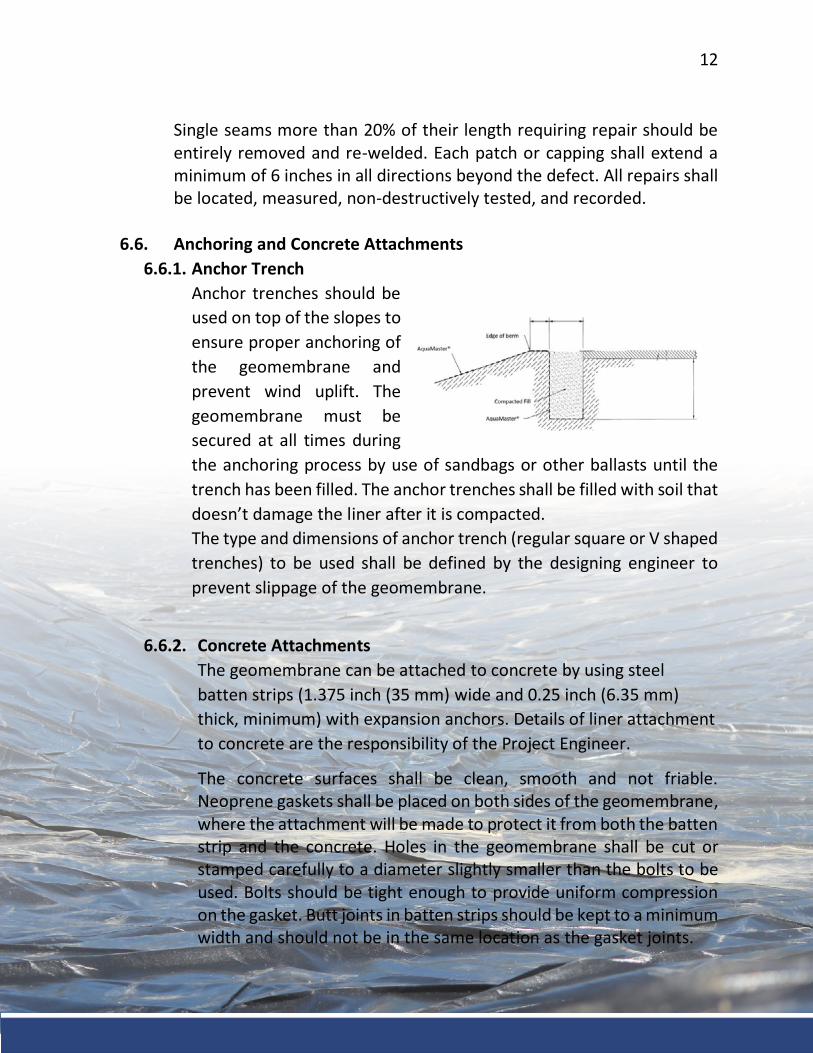
6.6. Anchoring and Concrete Attachments 6.6.1. Anchor Trench
Anchor trenches should be used on top of the slopes to ensure proper anchoring of the geomembrane and prevent wind uplift. The geomembrane must be secured at all times during the anchoring process by use of sandbags or other ballasts until the trench has been filled. The anchor trenches shall be filled with soil that doesn’t damage the liner after it is compacted. The type and dimensions of anchor trench (regular square or V shaped trenches) to be used shall be defined by the designing engineer to prevent slippage of the geomembrane.
6.6.2. Concrete Attachments
The geomembrane can be attached to concrete by using steel batten strips (1.375 inch (35 mm) wide and 0.25 inch (6.35 mm) thick, minimum) with expansion anchors. Details of liner attachment to concrete are the responsibility of the Project Engineer.
The concrete surfaces shall be clean, smooth and not friable. Neoprene gaskets shall be placed on both sides of the geomembrane, where the attachment will be made to protect it from both the batten strip and the concrete. Holes in the geomembrane shall be cut or stamped carefully to a diameter slightly smaller than the bolts to be used. Bolts should be tight enough to provide uniform compression on the gasket. Butt joints in batten strips should be kept to a minimum width and should not be in the same location as the gasket joints.
13
Once batten strip installation is complete, it should be inspected for loose bolts and visible defects. The geomembrane fixed to a concrete structure must be on firm soil subgrade that will not deform and stretch the geomembrane. Compacting of the soil subgrade around such structures must be performed with particular care so excessive differential movement between the concrete and soil subgrade does not occur.
6.7. Pipe Penetrations
Whenever possible, avoid slitting geomembrane panels for piping details until a pre-fabricated pipe boot is ready for immediate installation. Cuts made in the geomembrane for clearance over penetrations should always be made as small as possible to minimize patch work. Generally, it is preferred to let the geomembrane straddle a relatively small protrusion (for later detail work) provided a rag or towel is taped over the pipe to avoid damage to the geomembrane. Whenever there is a pipe penetration into the geomembrane, pipe boots should be prepared with excess material to fit the pipe tightly but not require excessive force to pull over the pipe. The number of welds made to fabricate a boot shall be minimized. The boot shall be fabricated such that when installed, it is fully supported by the pipe and the surrounding subgrade. If a pipe boot feels overly snug but workable, try applying either talc powder or using compressed air with a nozzle to float the boot sleeve over and along the pipe. Pipe boots should never be used if the force required to install them stresses or weakens the boot. When properly installed, the pipe boot will lay flat against grade surrounding pipe without leaving pockets that may become stressed during or after placement of backfill. The pipe boot sleeve should be attached to the pipe using butyl tape between the pipe and boot and two stainless steel clamps. Proper leak-proof sealing of pipe boots should be verified by using the air lance test method described above in section 6.4.2.1.
14
When cover materials are not used, splash pads or additional geomembrane layers shall be used for all inflow pipes to prevent long term wear and damage to the geomembrane caused by the direct impact of the inflow on the geomembrane panels. The pads should be welded on top of the geomembrane panels and tested using the same air lance method. Common splash panel sizes are 4 to 6 feet in all directions. However, larger sizes may be required depending on the amount of inflow pipes and the height of the discharge point.
6.8. Inspection and Installation Approval
Geomembrane installation should be approved by all interested parties prior to covering it or filling the canal or reservoir. If installation is deemed not acceptable, it should be corrected before covering it. A walkover of the complete site with all interested parties shall be done in order to verify that liner installation is acceptable. Owner, contractor and geomembrane installer, or their representative, shall all approve in writing installation acceptance before moving on with the next step of the project.
6.9. Covering the Geomembrane
When covering or initially placing fill material over the liner, it is important not to lock the liner into the perimeter anchor trench prior to covering. This can cause undue stress and tension on the liner slopes during the covering process. The anchor trench or perimeter shelf area should be the last area covered to complete the cover process. Under all operating conditions, protection of the geomembrane will be required. Care should be taken when covering the geomembrane to prevent any damage. At no time will construction equipment be allowed to operate or drive directly on the geomembranes. Access roads for clean soil cover should be maintained to provide 0.45 m (18 inch) minimum and for heavier equipment on haul roads a minimum of 0.90 m (36 inch) preferable between the excavation equipment and the geomembrane at all times. Cover soil requirements should be
15
verified before placement with the Design Professional and geomembrane installer. Additionally, a protection geotextile layer may be needed in rougher soil conditions between the geomembrane and the cover materials. The use of a protection layer should be verified with the Design Professional and Geomembrane Fabricator. Cover material shall consist of less than 12 mm (0.5 inch) minus particles, clean rounded soils free of sharp edges, sticks, metal, rubbish, and debris or foreign materials. Site specific materials or sizes may be acceptable. It is recommended that the contractor receive prior written approval of acceptance of the cover materials from a Geomembrane Representative and/or Design Professional before covering the geomembrane.
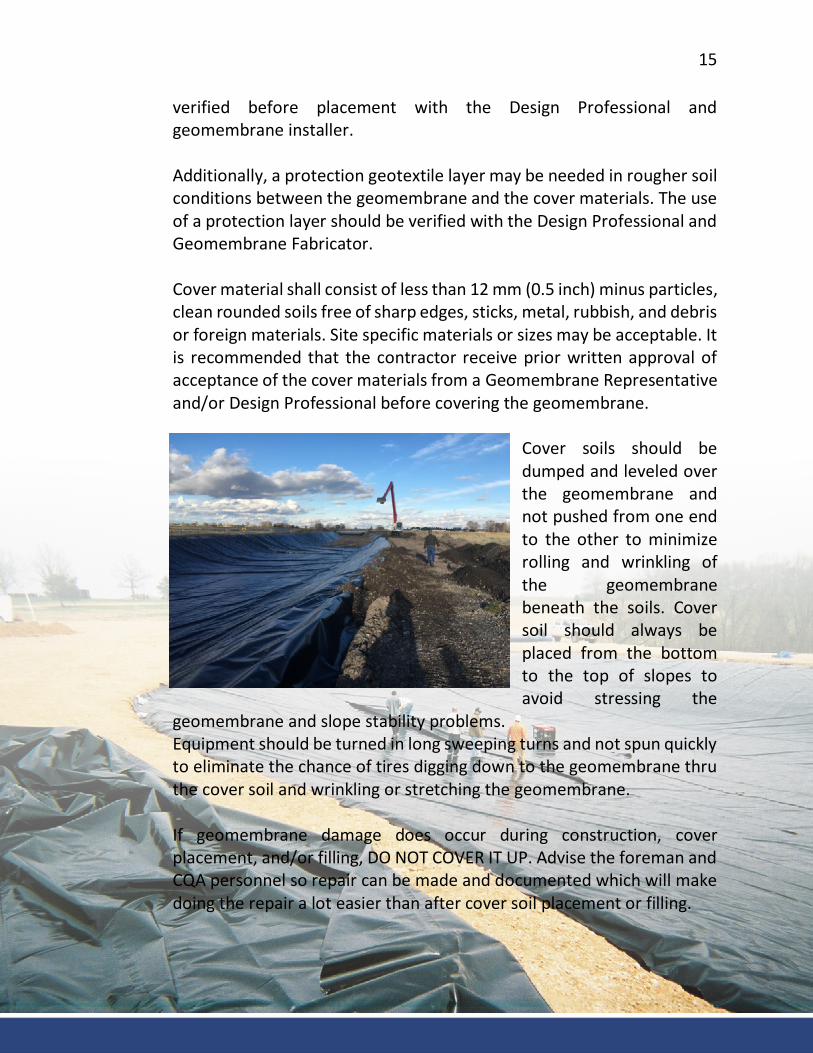
Cover soils should be dumped and leveled over the geomembrane and not pushed from one end to the other to minimize rolling and wrinkling of the geomembrane beneath the soils. Cover soil should always be placed from the bottom to the top of slopes to avoid stressing the
geomembrane and slope stability problems. Equipment should be turned in long sweeping turns and not spun quickly to eliminate the chance of tires digging down to the geomembrane thru the cover soil and wrinkling or stretching the geomembrane. If geomembrane damage does occur during construction, cover placement, and/or filling, DO NOT COVER IT UP. Advise the foreman and CQA personnel so repair can be made and documented which will make doing the repair a lot easier than after cover soil placement or filling.
16
7. ArmorPad®
ArmorPad® is a unique geomembrane product manufactured by IPG. It incorporates a non-woven geotextile laminated to one or both sides of the standard reinforced geomembrane. Installation of AquaMaster® ArmorPad® typically follows all the above-mentioned procedures, however, there are a couple of differences when placing the product into a canal or channel. Panels of ArmorPad® can be seamed together by standard methods or use of a hot-melt adhesive.
7.1. Hot Melt Adhesive
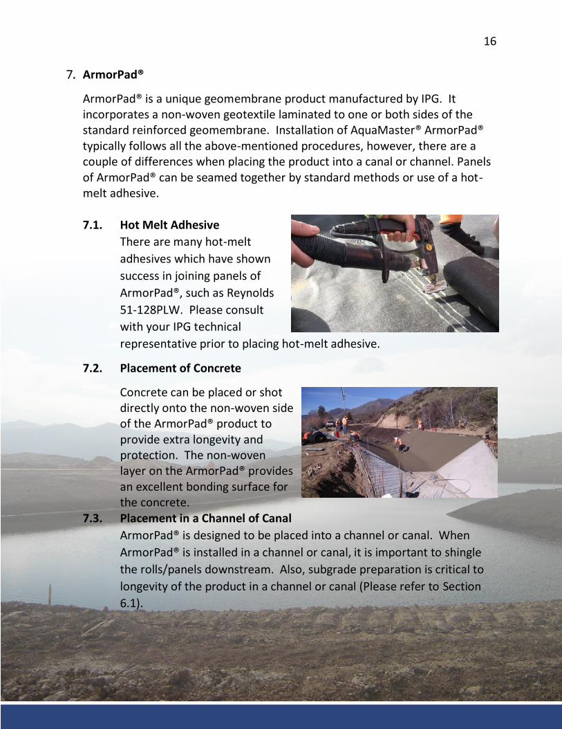
There are many hot-melt adhesives which have shown success in joining panels of ArmorPad®, such as Reynolds 51-128PLW. Please consult with your IPG technical representative prior to placing hot-melt adhesive.
7.2. Placement of Concrete
Concrete can be placed or shot directly onto the non-woven side of the ArmorPad® product to provide extra longevity and protection. The non-woven layer on the ArmorPad® provides an excellent bonding surface for the concrete.
7.3. Placement in a Channel of Canal ArmorPad® is designed to be placed into a channel or canal. When ArmorPad® is installed in a channel or canal, it is important to shingle the rolls/panels downstream. Also, subgrade preparation is critical to longevity of the product in a channel or canal (Please refer to Section 6.1).
17
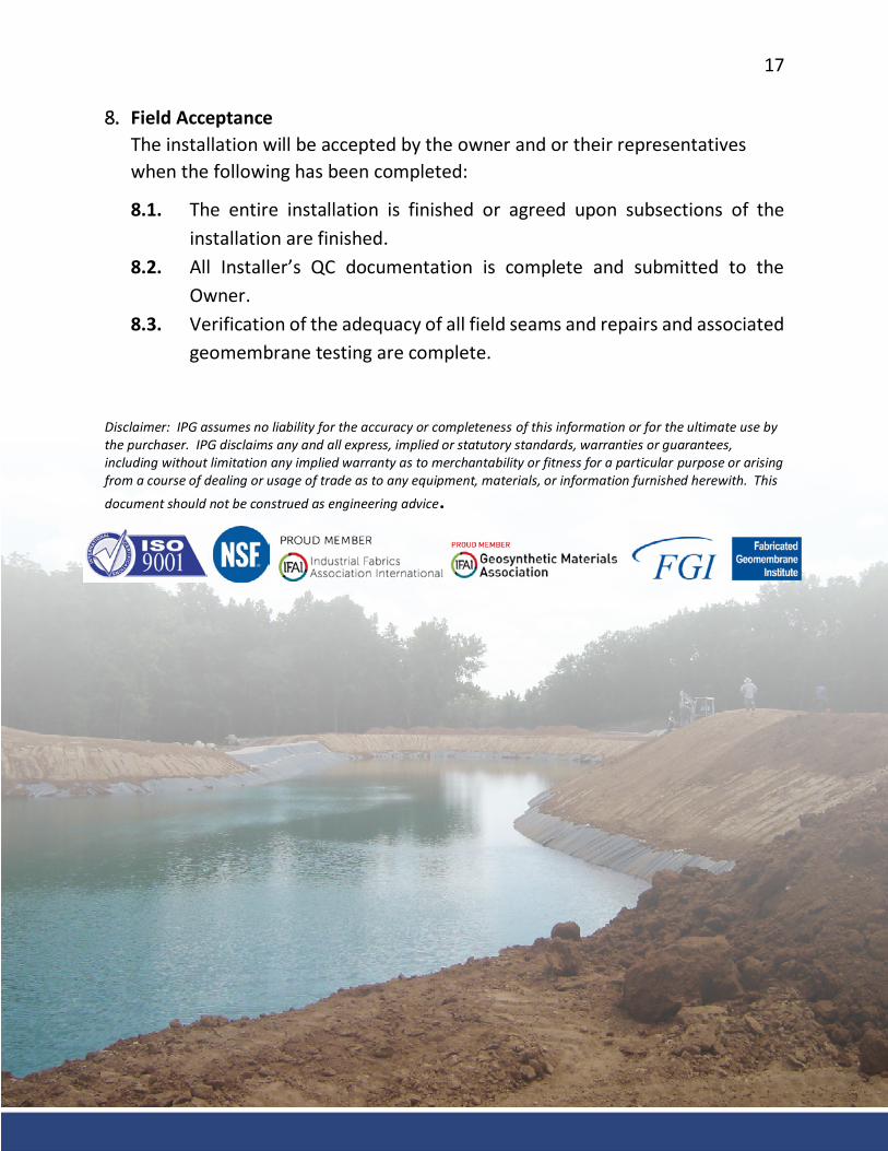
8. Field Acceptance The installation will be accepted by the owner and or their representatives when the following has been completed:
8.1. The entire installation is finished or agreed upon subsections of the installation are finished.
8.2. All Installer’s QC documentation is complete and submitted to the Owner.
8.3. Verification of the adequacy of all field seams and repairs and associated geomembrane testing are complete.
Disclaimer: IPG assumes no liability for the accuracy or completeness of this information or for the ultimate use by the purchaser. IPG disclaims any and all express, implied or statutory standards, warranties or guarantees, including without limitation any implied warranty as to merchantability or fitness for a particular purpose or arising from a course of dealing or usage of trade as to any equipment, materials, or information furnished herewith. This document should not be construed as engineering advice.