Embed Size (px)
Citation preview

Appendix-I: Water Heating System Sizing Verification Record
Work Sheet “A” – Storage Tank Type Water Heating Systems & Work Sheet “B” – Tankless or On-Demand Water Heating Systems
** To be completed by the Planner and verified by the Health Authority**
Environmental Health Section
(404) 657-6534 www.georgiaeh.us
This verification document contains two work sheets, “A” and “B” which are to be utilized in verifying the proper sizing of a
food service establishment’s water heating system as required by DPH Rule 511-6-1-.06(1)(g)2.
When assessing the capacity of water heating systems, the Designer and the Health Authority are both advised to consult with
DPH Chapter 511-6-1 and its Manual for Design, Installation and Construction, as referenced in DPH Rule 511-6-1-.02(8).
Additionally, Work Sheet “A” entitled, “Storage Tank Type Water Heating Systems” and Work Sheet “B” entitled, “Tankless
or On-Demand Water Heating Systems” must be completed and retained within the proposed food service establishment’s
inspection record file. See the following guide document, “Steps in Assessing Hot Water Generating Systems for completing
Work Sheet “A” and Work Sheet “B”.
Assessment records, Work Sheets “A” and “B”, are to be maintained by the local Health Authority in the county in which the
proposed food service establishment is to be constructed. They will remain as part of the proposed food service
establishment’s inspection record until they are replaced by a new assessment due to a change in the permit holder or a major
remodel of the establishment.
For more information, see Section K entitled, “Hot Water Supply Requirements”, located in Part-I of the plan review guidance
manual entitled, “Food Service Establishment Manual for Design, Installation and Construction” as referenced in DPH Rule
511-6-1-.02(8). A copy of this Manual may be accessed on the Department’s environmental health webpage at
www.georgiaeh.us under the Food Service heading.
Page 2 of 22
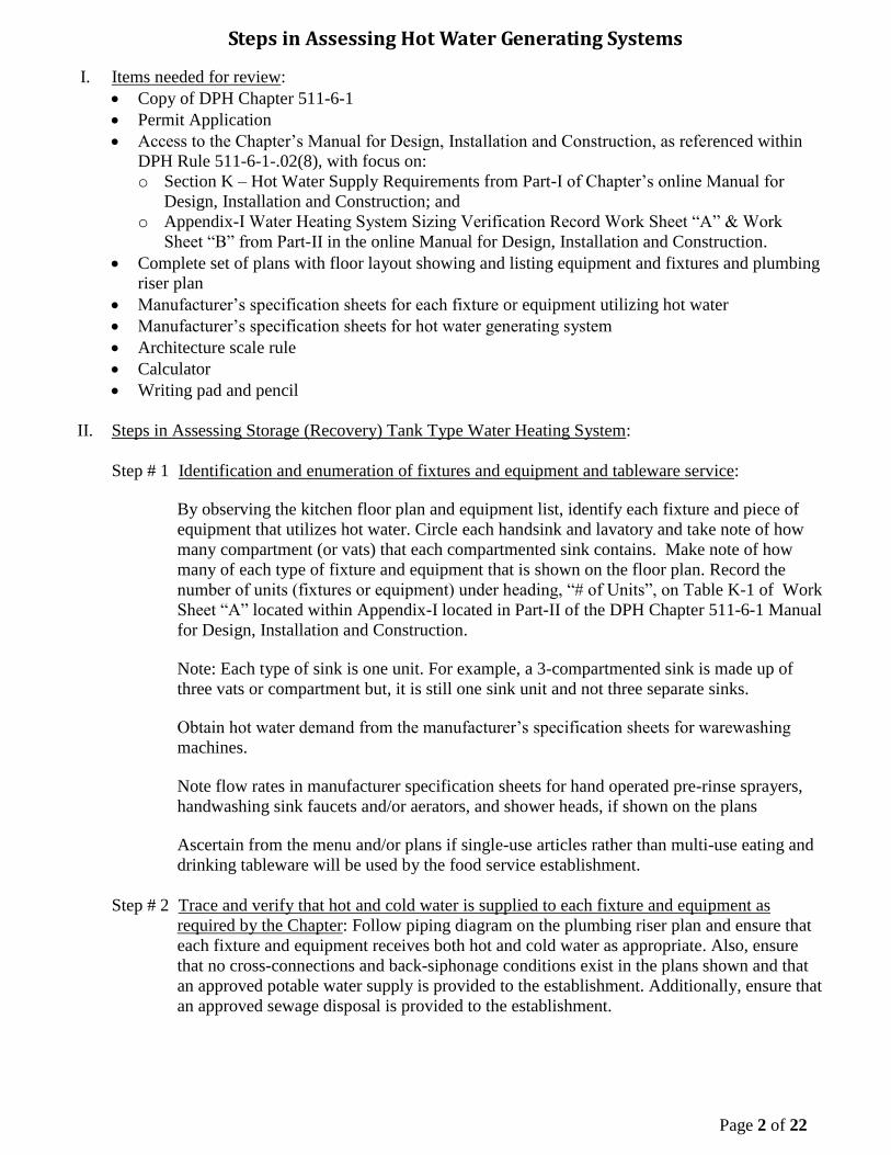
Steps in Assessing Hot Water Generating Systems
I. Items needed for review:
Copy of DPH Chapter 511-6-1
Permit Application
Access to the Chapter’s Manual for Design, Installation and Construction, as referenced within
DPH Rule 511-6-1-.02(8), with focus on:
o Section K – Hot Water Supply Requirements from Part-I of Chapter’s online Manual for
Design, Installation and Construction; and
o Appendix-I Water Heating System Sizing Verification Record Work Sheet “A” & Work
Sheet “B” from Part-II in the online Manual for Design, Installation and Construction.
Complete set of plans with floor layout showing and listing equipment and fixtures and plumbing
riser plan
Manufacturer’s specification sheets for each fixture or equipment utilizing hot water
Manufacturer’s specification sheets for hot water generating system
Architecture scale rule
Calculator
Writing pad and pencil
II. Steps in Assessing Storage (Recovery) Tank Type Water Heating System:
Step # 1 Identification and enumeration of fixtures and equipment and tableware service:
By observing the kitchen floor plan and equipment list, identify each fixture and piece of
equipment that utilizes hot water. Circle each handsink and lavatory and take note of how
many compartment (or vats) that each compartmented sink contains. Make note of how
many of each type of fixture and equipment that is shown on the floor plan. Record the
number of units (fixtures or equipment) under heading, “# of Units”, on Table K-1 of Work
Sheet “A” located within Appendix-I located in Part-II of the DPH Chapter 511-6-1 Manual
for Design, Installation and Construction.
Note: Each type of sink is one unit. For example, a 3-compartmented sink is made up of
three vats or compartment but, it is still one sink unit and not three separate sinks.
Obtain hot water demand from the manufacturer’s specification sheets for warewashing
machines.
Note flow rates in manufacturer specification sheets for hand operated pre-rinse sprayers,
handwashing sink faucets and/or aerators, and shower heads, if shown on the plans
Ascertain from the menu and/or plans if single-use articles rather than multi-use eating and
drinking tableware will be used by the food service establishment.
Step # 2 Trace and verify that hot and cold water is supplied to each fixture and equipment as
required by the Chapter: Follow piping diagram on the plumbing riser plan and ensure that
each fixture and equipment receives both hot and cold water as appropriate. Also, ensure
that no cross-connections and back-siphonage conditions exist in the plans shown and that
an approved potable water supply is provided to the establishment. Additionally, ensure that
an approved sewage disposal is provided to the establishment.
Page 3 of 22
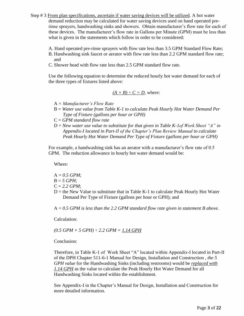
Step # 3 From plan specifications, ascertain if water saving devices will be utilized. A hot water
demand reduction may be calculated for water saving devices used on hand operated pre-
rinse sprayers, handwashing sinks and showers. Obtain manufacturer’s flow rate for each of
these devices. The manufacturer’s flow rate in Gallons per Minute (GPM) must be less than
what is given in the statements which follow in order to be considered:
A. Hand operated pre-rinse sprayers with flow rate less than 3.5 GPM Standard Flow Rate;
B. Handwashing sink faucet or aerator with flow rate less than 2.2 GPM standard flow rate;
and
C. Shower head with flow rate less than 2.5 GPM standard flow rate.
Use the following equation to determine the reduced hourly hot water demand for each of
the three types of fixtures listed above:
(A × B) ÷ C = D, where:
A = Manufacturer’s Flow Rate
B = Water use value from Table K-1 to calculate Peak Hourly Hot Water Demand Per
Type of Fixture (gallons per hour or GPH)
C = GPM standard flow rate
D = New water use value to substitute for that given in Table K-1of Work Sheet “A” in
Appendix-I located in Part-II of the Chapter’s Plan Review Manual to calculate
Peak Hourly Hot Water Demand Per Type of Fixture (gallons per hour or GPH)
For example, a handwashing sink has an aerator with a manufacturer’s flow rate of 0.5
GPM. The reduction allowance in hourly hot water demand would be:
Where:
A = 0.5 GPM;
B = 5 GPH;
C = 2.2 GPM;
D = the New Value to substitute that in Table K-1 to calculate Peak Hourly Hot Water
Demand Per Type of Fixture (gallons per hour or GPH); and
A = 0.5 GPM is less than the 2.2 GPM standard flow rate given in statement B above.
Calculation:
(0.5 GPM × 5 GPH) ÷ 2.2 GPM = 1.14 GPH
Conclusion:
Therefore, in Table K-1 of Work Sheet “A” located within Appendix-I located in Part-II
of the DPH Chapter 511-6-1 Manual for Design, Installation and Construction , the 5
GPH value for the Handwashing Sinks (including restrooms) would be replaced with
1.14 GPH as the value to calculate the Peak Hourly Hot Water Demand for all
Handwashing Sinks located within the establishment.
See Appendix-I in the Chapter’s Manual for Design, Installation and Construction for
more detailed information.
Page 4 of 22
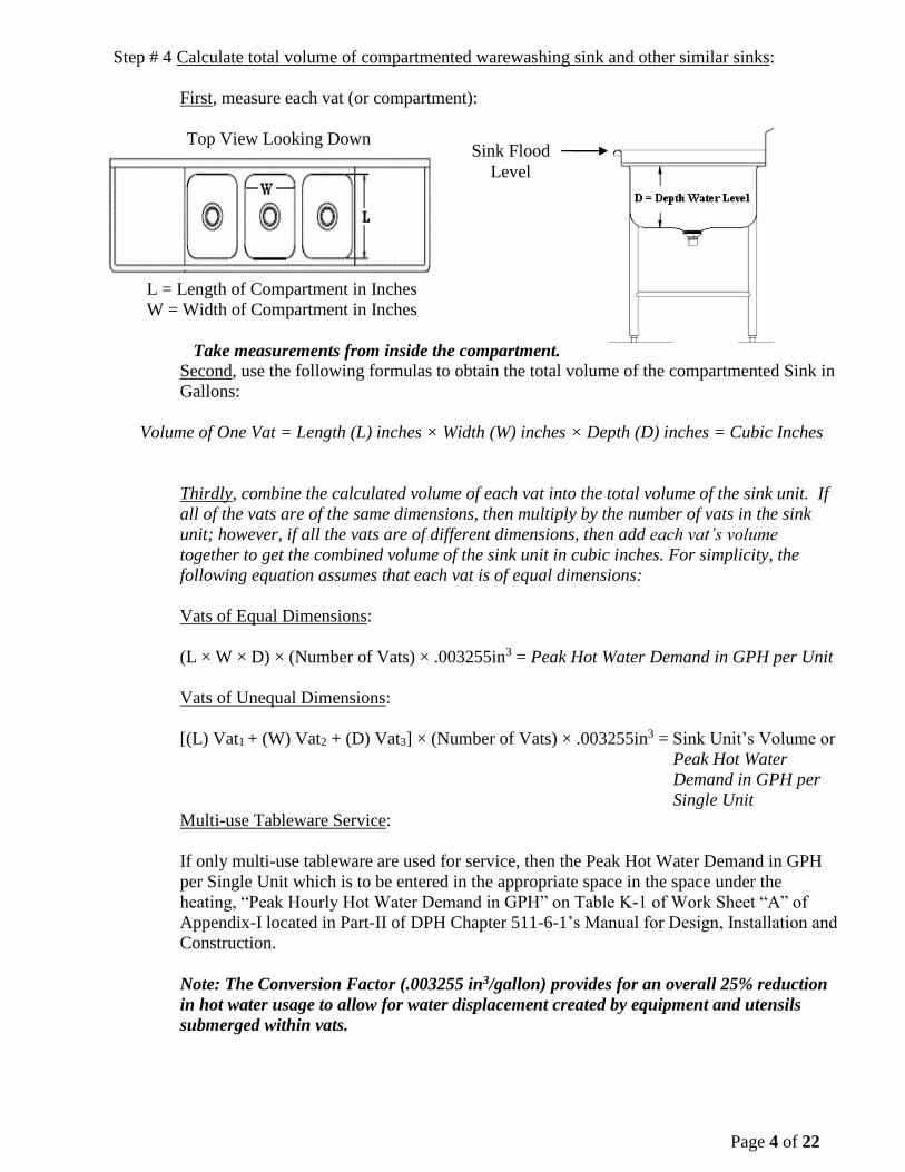
Step # 4 Calculate total volume of compartmented warewashing sink and other similar sinks:
First, measure each vat (or compartment):
Top View Looking Down
L = Length of Compartment in Inches
W = Width of Compartment in Inches
Take measurements from inside the compartment.
Second, use the following formulas to obtain the total volume of the compartmented Sink in
Gallons:
Volume of One Vat = Length (L) inches × Width (W) inches × Depth (D) inches = Cubic Inches
Thirdly, combine the calculated volume of each vat into the total volume of the sink unit. If
all of the vats are of the same dimensions, then multiply by the number of vats in the sink
unit; however, if all the vats are of different dimensions, then add each vat’s volume
together to get the combined volume of the sink unit in cubic inches. For simplicity, the
following equation assumes that each vat is of equal dimensions:
Vats of Equal Dimensions:
(L × W × D) × (Number of Vats) × .003255in3 = Peak Hot Water Demand in GPH per Unit
Vats of Unequal Dimensions:
[(L) Vat1 + (W) Vat2 + (D) Vat3] × (Number of Vats) × .003255in3 = Sink Unit’s Volume or
Peak Hot Water
Demand in GPH per
Single Unit
Multi-use Tableware Service:
If only multi-use tableware are used for service, then the Peak Hot Water Demand in GPH
per Single Unit which is to be entered in the appropriate space in the space under the
heating, “Peak Hourly Hot Water Demand in GPH” on Table K-1 of Work Sheet “A” of
Appendix-I located in Part-II of DPH Chapter 511-6-1’s Manual for Design, Installation and
Construction.
Note: The Conversion Factor (.003255 in3/gallon) provides for an overall 25% reduction
in hot water usage to allow for water displacement created by equipment and utensils
submerged within vats.
Sink Flood
Level
Page 5 of 22
Single-use articles Used for Tableware Service:
If single-service articles are used instead of multi-use tableware for service, then calculate
the reduced hot water demand by using the following formula:
Peak Hot Water Demand in GPH per Single Unit × 80% (or .80) = Final Sink Volume or
Peak Hot Water Demand in GPH per Single Unit of which is to be entered in the
appropriate space in the space under the heating, “Peak Hourly Hot Water Demand in GPH”
on Table K-1 of Work Sheet “A” of Appendix-I located in Part-II of DPH Chapter 511-6-
1’s Manual for Design, Installation and Construction.
Peak Hot Water Demand in GPH per Single Unit × 80% (or .80) = 20% Reduction in
Peak Hot Water Demand in GPH per Unit Allowance when Single-Use Articles are used
instead of Multi-Use Tableware
Fourthly, determine the maximum hourly hot water demand per type of fixture in GPH or
MHHWDPTF-GPH. Do the following:
Multiply the Peak Hourly Hot Water Demand in GPH for compartmented sink unit on Table
K-1 of Work Sheet “A” of Appendix-I located in Part-II of DPH Chapter 511-6-1’s Manual
for Design, Installation and Construction by the number of units recorded under column
heading, “# of Units”. Enter this value under the column heading, “MHHWDTF-GPH”, for
each fixture and equipment listed in Table K-1.
Step #5 Determine the Peak Hourly Hot Water Demand for warewashing machine:
Look at the manufacturer’s specification sheets for the specified warewashing machine and
record the final rinse cycle hot water demand which should be listed in GPH. Use the
following formula to get the Peak Hourly Hot Water Demand:
GPH = gal/hr Final Rinse (from manufacturer cut sheets) X 70% (or .70)
For example, a warewashing machine specification indicated a final rinse of 130 GPH hot
water demand. Since no warewashing machine will be used 100% of the time but instead,
only 70 % of the time, the Peak Hourly Hot Water Demand would be calculated:
GPH = 130 GPH × .70 = 91 GPH
91 GPH would then be entered in the appropriate space in the space under the heating,
“Peak Hourly Hot Water Demand in GPH” on Table K-1 of Work Sheet “A” of Appendix-I
located in Part-II of DPH Chapter 511-6-1’s Manual for Design, Installation and
Construction. Record the number of this type of warewashing machines on the same form
under the column heading, “# of Units”.
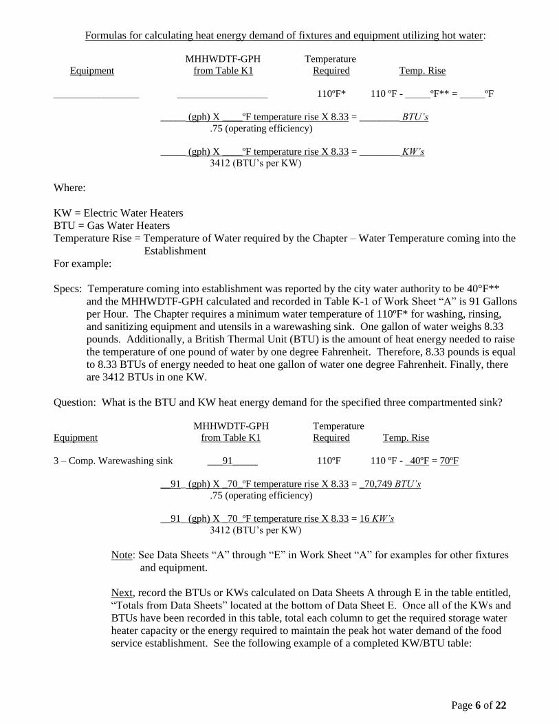
Step #6 Determine the MHHWDTF-GPH for each piece of fixture and equipment listed on Chart K-
1 in Work Sheet “A” by multiplying the # of Units by the Peak Hourly Hot Water Demand
in GPH.
First, convert MHHWDTF-GPH calculated and listed in Table K-1 into the energy demand
for each fixture and piece of equipment utilizing hot water as specified by the permit
applicant to be installed according to the submitted plans and specifications. To accomplish
this step, use Data Sheets A through E to calculate and record the KW (Kilowatts) or BTU
(British Thermal Units) required heat energy demand. See the following formulas to
calculate KW and BTU to be used based upon the type of energy supplied to the water
heating unit:
Page 6 of 22
Formulas for calculating heat energy demand of fixtures and equipment utilizing hot water:
MHHWDTF-GPH Temperature
Equipment from Table K1 Required Temp. Rise
_________________ __________________ 110ºF* 110 ºF - _____ºF** = _____ºF
_____ (gph) X ____ºF temperature rise X 8.33 = ________ BTU’s
.75 (operating efficiency)
_____ (gph) X ____ºF temperature rise X 8.33 = ________ KW’s
3412 (BTU’s per KW)
Where:
KW = Electric Water Heaters
BTU = Gas Water Heaters
Temperature Rise = Temperature of Water required by the Chapter – Water Temperature coming into the
Establishment
For example:
Specs: Temperature coming into establishment was reported by the city water authority to be 40°F**
and the MHHWDTF-GPH calculated and recorded in Table K-1 of Work Sheet “A” is 91 Gallons
per Hour. The Chapter requires a minimum water temperature of 110ºF* for washing, rinsing,
and sanitizing equipment and utensils in a warewashing sink. One gallon of water weighs 8.33
pounds. Additionally, a British Thermal Unit (BTU) is the amount of heat energy needed to raise
the temperature of one pound of water by one degree Fahrenheit. Therefore, 8.33 pounds is equal
to 8.33 BTUs of energy needed to heat one gallon of water one degree Fahrenheit. Finally, there
are 3412 BTUs in one KW.
Question: What is the BTU and KW heat energy demand for the specified three compartmented sink?
MHHWDTF-GPH Temperature
Equipment from Table K1 Required Temp. Rise
3 – Comp. Warewashing sink ___91_____ 110ºF 110 ºF - _40ºF = 70ºF
__91_ (gph) X _70_ºF temperature rise X 8.33 = _70,749 BTU’s
.75 (operating efficiency)
__91_ (gph) X _70_ºF temperature rise X 8.33 = 16 KW’s
3412 (BTU’s per KW)
Note: See Data Sheets “A” through “E” in Work Sheet “A” for examples for other fixtures
and equipment.
Next, record the BTUs or KWs calculated on Data Sheets A through E in the table entitled,
“Totals from Data Sheets” located at the bottom of Data Sheet E. Once all of the KWs and
BTUs have been recorded in this table, total each column to get the required storage water
heater capacity or the energy required to maintain the peak hot water demand of the food
service establishment. See the following example of a completed KW/BTU table:
Page 7 of 22
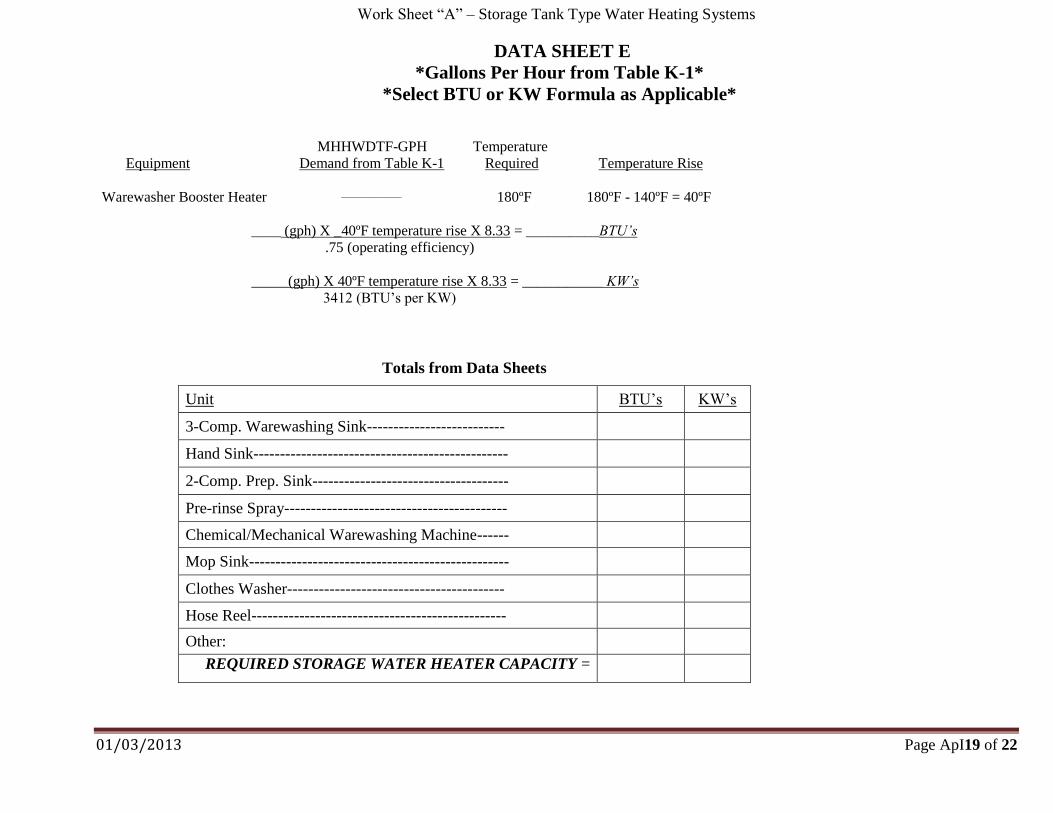
Totals from Data Sheets
Unit BTU’s KW’s
3-Comp. Warewashing Sink-------------------------- 61,420 14.00
Hand Sink------------------------------------------------ 16,660 4.00
2-Comp. Prep. Sink------------------------------------- 15,549 3.42
Pre-rinse Spray------------------------------------------ 34,986 8.00
Chemical/Mechanical Warewashing Machine------ 70,749 16.00
Mop Sink------------------------------------------------- 7,774 2.00
Clothes Washer----------------------------------------- 11,662 3.00
Hose Reel------------------------------------------------ 15,549 3.42
REQUIRED WATER HEATER CAPACITY = 234,349 53.84
Step #7 Conclusions:
First, compare the REQUIRED WATER HEATER CAPACITY to the water heater
specified within submitted plans in order to determine if the specified water heater will be
capable to maintain the proposed food service establishment’s peak hot water demand as
exactly what is specified within DPH Rule 511-6-1-.06 (1) (g) 2. For example:
From totals calculated in the Chart above, a water heater with the BTU rating (or capacity)
of 234,349 BTU’s, if gas fired, or one with a KW rating (or capacity) of 53.34 KW’s, if
electric, will be required in order to meet the peek hot water demand of the proposed food
service establishment.
Next, if the warewashing machine uses a hot water final sanitizing rinse cycle, a booster
heater for the hot water sanitizing final rinse must be provided and sized to supply an
additional 40,428 BTU’s or 9 KW’s. The booster heater is necessary in order to boost the
required gallons per hour demand an additional 40ºF to attain the required minimum 180ºF
final rinse temperature. See the following example to calculate the KW or BTU energy
demand for the external booster heater:
Formulas for calculating heat energy demand for external booster heater:
MHHWDTF-GPH Temperature
Equipment from Chart K-1 Required Temperature. Rise
Booster Heater 91 180ºF 180ºF - 140ºF = 40ºF
91 (GPH) X 40ºF temperature rise X 8.33 = 40,428.266 ~ 40,428 BTU’s
.75 (operating efficiency)
91 (GPH) X 40ºF temperature rise X 8.33 = 8.886~ 9 KW’s
3412 (BTU’s per KW)
Where:
Degree Rise = 40ºF, since the water temperature at the booster heater must be at least 140ºF
in order for the booster heater to raise this 140ºF incoming water another 40ºF to the
minimum hot water sanitizing, fresh rinse temperature of at least 180ºF.
Page 8 of 22
MHHWDTF-GPH = Maximum Hourly Hot Water Demand per Type of Fixture in Gallons
per Hour
8.33 is the weight of one gallon of water in pounds. A British Thermal Unit (BTU) is the
amount of heat energy needed to raise the temperature of one pound of water by one degree
F. Therefore, 8.33 is equal to 8.33 BTUs of energy needed to heat one gallon of water one
degree Fahrenheit. This is the standard measurement used to state the amount of energy that
a fuel has as well as the amount of output of any heat generating device.
Step #8 Comparison:
Compare the energy demand (KW or BTU) listed in the table, “Totals from Data Sheets”, in
Step #8 above to the energy rating of the specified water heater noted within the submitted
plans. If the water heater is at least equal to the energy values listed within the table, then
the unit is sized to meet the hot water demand of the proposed food service establishment.
If not, then the water heating system needs to be redesigned with a larger capacity.
III. Steps in Assessing Tankless or On-Demand Hot Water Heating Systems:
Step # 1 Identification and enumeration of fixtures and equipment and tableware service:
Just as in Step #1 of Part-II, identify each fixture and piece of equipment that utilizes hot
water by observing the kitchen floor plan and equipment list. Circle each handsink and
lavatory. Make note of how many of each type of fixture and equipment that is shown on
the floor plan. Record the number of units (fixtures or equipment) under heading, “Number
of Units”, on Table K-2 of Work Sheet “B” located within Appendix-I located in Part-II of
the DPH Chapter 511-6-1 Manual for Design, Installation and Construction.
Each type of sink is one unit. For example, a 3-compartmented sink is made up of three
vats or compartment but, it is still one sink unit and not three separate sinks. However, the
focus in not on the vat volumes but instead, it is on the flow rate of the faucets that fill the
vats.
Obtain hot flow rates in gallons per minute (GPM) from the manufacturer’s specification
sheets for warewashing machines. Also, note flow rates in manufacturer specification
sheets for other fixtures and equipment utilizing hot water as well.
Because tankless or on-demand water heating systems do not recover and maintain a
volume of hot water, consideration for reduction in use of Single-use articles for eating and
drinking tableware does not apply when sizing and assessing these types of systems.
Instead, the flow rate of fixtures and equipment must be the governing factor.
A flow rate reduction may be used for low flow water faucets installed on 3-compartment
sinks, hand operated pre-rinse sprayers, food preparation sinks, handwashing sinks and
shower heads by entering the manufacturer’s flow rate listed for the faucet or faucet’s
aerator. Flow rate reductions may be applied if manufacturer’s flow rates are less than
those shown within Table K-2 of Work Sheet “B”. If true, these manufacture flow rates
may be substituted for Hot Water Usage GPM figures given in Table K-2. Use
manufacturer’s flow rate in GPM for specific make and model of warewashing machines
and inter them within the appropriate space under Hot Water Usage GPM heading as well.
Page 9 of 22
Step # 2 Calculate the total hot water demand flow rate in Gallons Per Minute (GPM) using Table K-2
located within Work Sheet “B” of Appendix-I in Part-II of the Chapter’s Manual for Design,
Installation and Construction. Please take not that if the heater manufacturer has sizing,
installation and system design criteria, then their criteria may be used as long as they have
been previously submitted and approved by the local Health Authority with consultation with
Department ‘s Environmental Health Branch Office representatives. Otherwise, use the
Work Sheet “B” to calculate hot water demand.
Step # 3 Multiply the Hot Water Usage GPM by the number of fixtures to obtain the Hot Water
Demand Flow Rate in GPM for each listed fixture and equipment utilizing hot water. Enter
this value under the column heating “Hot Water Demand Flow Rate in Gallons per Minute”
of Table K-2 for each listed fixture and piece of equipment utilizing hot water.
Step # 4 Calculate the maximum hot water flow rate for the establishment:
The thermal efficiency of the water heating unit must be adjusted for altitude. The altitude
adjustment is 4% per 1000 feet of elevation above sea level, or 20% at 5000 feet above sea
level. The designer of the on-demand water heating system will need to provide the altitude
data for the site of the proposed food service establishment to be used in the following
calculations:
1. Use the following equation to determine the establishment’s maximum flow rate in
GPM:
(0.04 × _________________ ÷ 1000) + 1 = ____________________
Elevation of facility adjustment factor
___________________ × _____________________ = ___________________
Adjustment factor total hot water demand maximum GPM
flow rate calculated in hot water flow usage
Table K-2
Use calculated maximum GPM hot water flow usage value in this equation to
determine the minimum number of heating units that will be required as determined
from the equation in Step #5 below.
Step #5 Determine the number of heating units that will be needed to meet the required maximum
hot water flow rate demand for the establishment. Use the following formula to calculate
the needed number of tankless or on-demand water heating units:
____________________ ÷ _____________________ = __(__________________)_
Maximum GPM hot water manufacturer’s flow rate number of heating
flow usage calculated in in GPM @100°F or 80°F units required*
“1” above rise**
*Multiple units must be installed and plumbed to operate in a parallel configuration. **
If there are no high temperature dishwashing machine or other fixtures requiring input
water temperatures of 140°F (100°F rise) or more, then 80°F rise can be used.
Page 10 of 22
Step #6 Determine if an on-demand water heating system will need a storage tank to compensate
for the lag in availability of hot water at warewashing machine startup. On-demand water
heating systems must include a storage tank to eliminate lag in availability of hot water at
the start-up of a warewashing machine. If not provided, the effects of water temperature
lag between start-up time of the unit and the point when hot water is received at the
warewashing machine will cause warewashing machines to operate outside of their
designed operating parameters. As a result, eating and drinking utensils and equipment
placed within them will not be properly cleaned and sanitized as required by DPH Rule
511-6-1-.05. Therefore, a storage tank must be provided within the system and it must
have a volume of at least 25 gallons or at least 25% of the gallons per hour (GPH) demand
of the warewashing machine. The larger these two values is the required storage tank size.
Use the following equations to calculate on-demand water heating system storage tanks:
Dishwashing Machine*
Manufacturer: _________________ Model Number: ______________
Gallons per Hour Water Consumption: ________ × 0.25 = ___________________
Storage tank capacity in gallons
Calculated Storage Tank Capacity: ___________ vs. 25 Gallon Storage Tank
Enter the larger of the two: ______________ Required Storage Tank Capacity** *
High temperature, heat sanitizing warewashing machines must be provided with a
separate booster heater. Use of an instantaneous unit is not allowed for use as a booster
heater. Step #8 within Part-II entitled, “Steps in Assessing Storage (Recovery) Tank
Type Water Heating System” for booster heater calculation examples. ** The storage tank must be installed in the hot water supply line located between the
heater unit(s) and the hot water distribution line. A recirculation line and aquastat
(water thermostat) must be installed at the storage tank to assure the water in the tank
remains at the appropriate temperature (120°F to 140°F). The recirculation line must be
connected between the storage tank and the cold water supply line at the heater unit(s).
Step #7 Compare the number of units calculated in Step #5 in Part-III to that specified within the
submitted plans. If the number of units specified within the submitted plans is at least
equal to that calculated in Step #5, then the specified unit(s) are sized to meet the hot water
demand of the proposed food service establishment. If not, then the water heating system
needs to be redesigned with a larger BTU and flow capacity. Additionally, if a
warewashing machine is proposed, a storage take with a capacity of 25 gallons must be
include within the installation of the on-demand water heating system in order to eliminate
the lag in availability of hot water at warewasher startup.
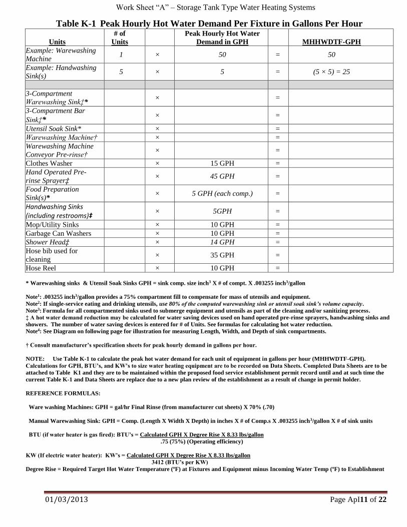
Work Sheet “A” – Storage Tank Type Water Heating Systems
01/03/2013 Page ApI11 of 22
Table K-1 Peak Hourly Hot Water Demand Per Fixture in Gallons Per Hour
Units
# of
Units Peak Hourly Hot Water
Demand in GPH MHHWDTF-GPH
Example: Warewashing
Machine 1 × 50 = 50
Example: Handwashing
Sink(s) 5 × 5 = (5 × 5) = 25
3-Compartment
Warewashing Sink‡* × =
3-Compartment Bar
Sink‡* × =
Utensil Soak Sink* × =
Warewashing Machine† × =
Warewashing Machine
Conveyor Pre-rinse† × =
Clothes Washer × 15 GPH =
Hand Operated Pre-
rinse Sprayer‡ × 45 GPH =
Food Preparation
Sink(s)* × 5 GPH (each comp.) =
Handwashing Sinks (including restrooms)‡ × 5GPH =
Mop/Utility Sinks × 10 GPH =
Garbage Can Washers × 10 GPH =
Shower Head‡ × 14 GPH =
Hose bib used for
cleaning × 35 GPH =
Hose Reel × 10 GPH =
* Warewashing sinks & Utensil Soak Sinks GPH = sink comp. size inch3 X # of compt. X .003255 inch3/gallon
Note1: .003255 inch3/gallon provides a 75% compartment fill to compensate for mass of utensils and equipment.
Note2: If single-service eating and drinking utensils, use 80% of the computed warewashing sink or utensil soak sink’s volume capacity.
Note3: Formula for all compartmented sinks used to submerge equipment and utensils as part of the cleaning and/or sanitizing process.
‡ A hot water demand reduction may be calculated for water saving devices used on hand operated pre-rinse sprayers, handwashing sinks and
showers. The number of water saving devices is entered for # of Units. See formulas for calculating hot water reduction.
Note4: See Diagram on following page for illustration for measuring Length, Width, and Depth of sink compartments.
† Consult manufacturer’s specification sheets for peak hourly demand in gallons per hour.
NOTE: Use Table K-1 to calculate the peak hot water demand for each unit of equipment in gallons per hour (MHHWDTF-GPH).
Calculations for GPH, BTU’s, and KW’s to size water heating equipment are to be recorded on Data Sheets. Completed Data Sheets are to be
attached to Table K1 and they are to be maintained within the proposed food service establishment permit record until and at such time the
current Table K-1 and Data Sheets are replace due to a new plan review of the establishment as a result of change in permit holder.
REFERENCE FORMULAS:
Ware washing Machines: GPH = gal/hr Final Rinse (from manufacturer cut sheets) X 70% (.70)
Manual Warewashing Sink: GPH = Comp. (Length X Width X Depth) in inches X # of Comp.s X .003255 inch3/gallon X # of sink units
BTU (if water heater is gas fired): BTU’s = Calculated GPH X Degree Rise X 8.33 lbs/gallon
.75 (75%) (Operating efficiency)
KW (If electric water heater): KW’s = Calculated GPH X Degree Rise X 8.33 lbs/gallon
3412 (BTU’s per KW)
Degree Rise = Required Target Hot Water Temperature (ºF) at Fixtures and Equipment minus Incoming Water Temp (ºF) to Establishment
Work Sheet “A” – Storage Tank Type Water Heating Systems
01/03/2013 Page ApI12 of 22
Determining the Volume of a Compartmented Sink
First, measure each vat (or compartment):
Top View Looking Down
L = Length of Compartment in Inches
W = Width of Compartment in Inches
Note: Take measurements from inside the compartment.
Second, use the following formulas to obtain the total volume of the compartmented Sink in Gallons:
Volume of One Vat = Length (L) inches × Width (W) inches × Depth (D) inches = Cubic Inches
Thirdly, combine the calculated volume of each vat into the total volume of the sink unit. If all of the vats
are of the same dimensions, then multiply by the number of vats in the sink unit; however, if all the vats
are of different dimensions, then added each vat’s volume together to get the combined volume of the sink
unit in cubic inches. For simplicity, the following equation assumes that each vat is of equal dimensions:
Vats of Equal Dimensions:
(L × W × D) × (Number of Vats) × .003255in3 = Peak Hot Water Demand in GPH per Unit
Vats of Unequal Dimensions:
[(L) Vat1 + (W) Vat2 + (D) Vat3] × (Number of Vats) × .003255in3 = Sink Unit’s Volume or Peak Hot
Water Demand in GPH per Single Unit
Multi-use Tableware Service:
If only multi-use tableware are used for service, then the Peak Hot Water Demand in GPH per Single Unit
which is to be entered in the appropriate space in the space under the heating, “Peak Hourly Hot Water
Demand in GPH” on Table K-1 of Work Sheet “A” of Appendix-I located in Part-II of DPH Chapter 511-
6-1’s Manual for Design, Installation and Construction.
Note: The Conversion Factor (.003255 in3/gallon) provides for an overall 25% reduction in hot water
usage to allow for water displacement created by equipment and utensils submerged within vats.
Sink Flood
Level
Work Sheet “A” – Storage Tank Type Water Heating Systems
01/03/2013 Page ApI13 of 22
Single-use articles Used for Tableware Service:
Finally, if single-service articles are used instead of multi-use tableware for service, then calculate the
reduced hot water demand by using the following formula:
Peak Hot Water Demand in GPH per Single Unit × 80% (or .80) = Final Sink Volume or Peak Hot Water
Demand in GPH per Single Unit of which is to be entered in the appropriate space in the space under the
heating, “Peak Hourly Hot Water Demand in GPH” on Table K-1 of Work Sheet “A” of Appendix-I
located in Part-II of DPH Chapter 511-6-1’s Manual for Design, Installation and Construction.
Peak Hot Water Demand in GPH per Single Unit × 80% (or .80) = 20% Reduction in Peak Hot Water
Demand in GPH per Unit Allowance when Single-Use Articles are used instead of Multi-Use
Tableware
*If applicable* - Hot Water Demand Reduction – Water Saving Devices
I. Obtain manufacturer’s flow rate for each device. The manufacturer’s flow rate must be less than what
is listed below to be considered:
1. Hand operated pre-rinse sprayers with flow rate less than 3.5 GPM standard flow rate.
Manufacturer: ___________________; Model #: ______________________
Manufacturer’s Flow Rating: _______________ GPH
2. Handwashing sink faucet or aerator with flow rate less than 2.2 GPM standard flow rate.
Manufacturer: ___________________; Model #: ______________________
Manufacturer’s Flow Rating: _______________ GPH
3. Shower head with flow rate less than 2.5 GPM standard flow rate.
Manufacturer: ___________________; Model #: ______________________
Manufacturer’s Flow Rating: _______________ GPH
II. Using the following equation, the reduction in the hourly hot water demand for each of the three
types of fixtures listed above is determined by the following calculations:
(A × B) ÷ C = D, where:
A = Manufacturer’s Flow Rate
B = Water use value from Table K-1 to calculate Peak Hourly Hot Water Demand Per
Type of Fixture (gallons per hour or GPH)
C = GPM standard flow rate (SFR)
D = New water use value to substitute for that given in Table K-1 to calculate Peak
Hourly Hot Water Demand Per Type of Fixture (gallons per hour or GPH)
Work Sheet “A” – Storage Tank Type Water Heating Systems
01/03/2013 Page ApI14 of 22
1. Hand operated pre-rinse sprayers:
(____________ × __________) ÷ _____________ = ______________ GPH
A B C D
2. Handwashing sink:
(____________ × __________) ÷_____________ = ______________ GPH
A B C D
3. Shower head:
(____________ × __________) ÷ _____________ = ______________ GPH
A B C D
Note: Substitute “D” value for existing “Peak Hourly Hot Water Demand” value in Table K-1.
Work Sheet “A” – Storage Tank Type Water Heating Systems
01/03/2013 Page ApI15 of 22
DATA SHEET A
*Gallons Per Hour from Table K-1*
*Select BTU or KW Formula as Applicable*
MHHWDTF-GPH Temperature
Equipment Demand from Table K-1 Required Temperature Rise
3 – Comp. Warewashing sink ________ 110ºF 110ºF - _____ºF = _____ºF
_____(gph) X ____ºF temperature rise X 8.33 = ________ BTU’s
.75 (operating efficiency)
_____(gph) X ____ºF temperature rise X 8.33 = ________ KW’s
3412 (BTU’s per KW)
*******************************************************************************************************************
MHHWDTF-GPH Temperature
Equipment Demand from Table K-1 Required Temperature Rise
Hand sink ________ 100ºF 100ºF - ____ºF = ____ºF
____ (gph) X ____ºF temperature rise X 8.33 = ________ BTU’s
.75 (operating efficiency)
_____(gph) X ____ºF temperature rise X 8.33 = ________ KW’s
3412 (BTU’s per KW)
Work Sheet “A” – Storage Tank Type Water Heating Systems
01/03/2013 Page ApI16 of 22
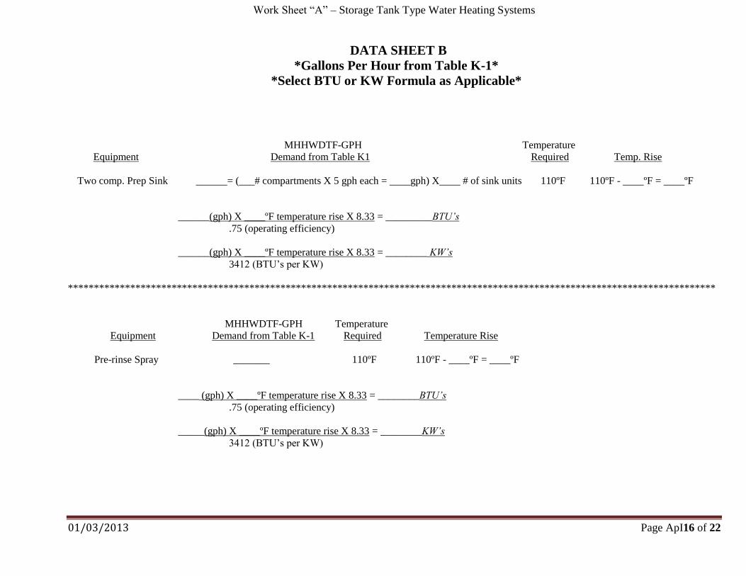
DATA SHEET B
*Gallons Per Hour from Table K-1*
*Select BTU or KW Formula as Applicable*
MHHWDTF-GPH Temperature
Equipment Demand from Table K1 Required Temp. Rise
Two comp. Prep Sink ______= (___# compartments X 5 gph each = ____gph) X____ # of sink units 110ºF 110ºF - ____ºF = ____ºF
______(gph) X ____ºF temperature rise X 8.33 = _________BTU’s
.75 (operating efficiency)
______(gph) X ____ºF temperature rise X 8.33 = ________ KW’s
3412 (BTU’s per KW)
*****************************************************************************************************************************
MHHWDTF-GPH Temperature
Equipment Demand from Table K-1 Required Temperature Rise
Pre-rinse Spray _______ 110ºF 110ºF - ____ºF = ____ºF
____ (gph) X ____ºF temperature rise X 8.33 = ________BTU’s
.75 (operating efficiency)
_____(gph) X ____ºF temperature rise X 8.33 = ________KW’s
3412 (BTU’s per KW)
Work Sheet “A” – Storage Tank Type Water Heating Systems
01/03/2013 Page ApI17 of 22
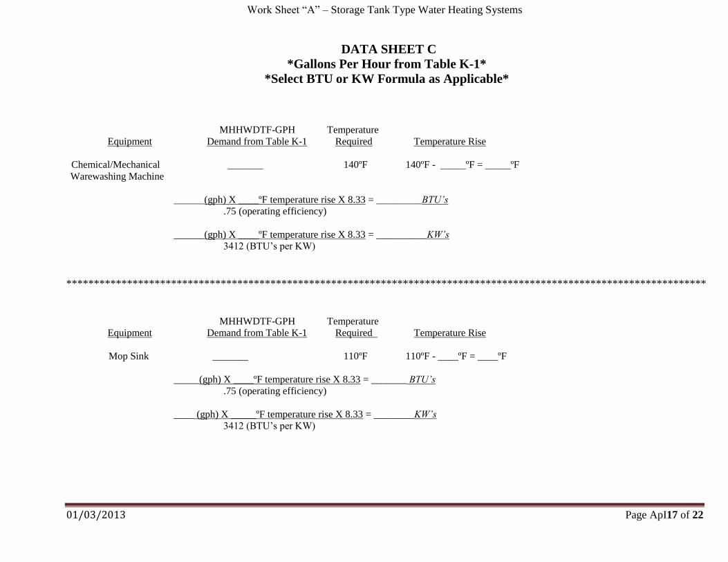
DATA SHEET C
*Gallons Per Hour from Table K-1*
*Select BTU or KW Formula as Applicable*
MHHWDTF-GPH Temperature
Equipment Demand from Table K-1 Required Temperature Rise
Chemical/Mechanical _______ 140ºF 140ºF - _____ºF = _____ºF
Warewashing Machine
______(gph) X ____ºF temperature rise X 8.33 = _________BTU’s
.75 (operating efficiency)
______(gph) X ____ºF temperature rise X 8.33 = __________KW’s
3412 (BTU’s per KW)
********************************************************************************************************************
MHHWDTF-GPH Temperature
Equipment Demand from Table K-1 Required Temperature Rise
Mop Sink _______ 110ºF 110ºF - ____ºF = ____ºF
_____(gph) X ____ºF temperature rise X 8.33 = _______ BTU’s
.75 (operating efficiency)
____ (gph) X _____ºF temperature rise X 8.33 = ________KW’s
3412 (BTU’s per KW)
Work Sheet “A” – Storage Tank Type Water Heating Systems
01/03/2013 Page ApI18 of 22
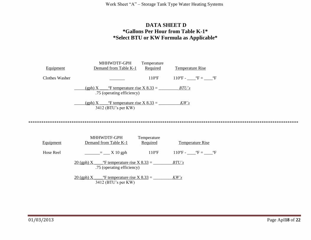
DATA SHEET D
*Gallons Per Hour from Table K-1*
*Select BTU or KW Formula as Applicable*
MHHWDTF-GPH Temperature
Equipment Demand from Table K-1 Required Temperature Rise
Clothes Washer _______ 110ºF 110ºF - ____ºF = ____ºF
_____(gph) X ____ºF temperature rise X 8.33 = _________ BTU’s
.75 (operating efficiency)
_____(gph) X ____ºF temperature rise X 8.33 = __________KW’s
3412 (BTU’s per KW)
*****************************************************************************************************************************
MHHWDTF-GPH Temperature
Equipment Demand from Table K-1 Required Temperature Rise
Hose Reel _______= ___ X 10 gph 110ºF 110ºF - ____ºF = ____ºF
20 (gph) X ____ºF temperature rise X 8.33 = _________BTU’s
.75 (operating efficiency)
20 (gph) X ____ºF temperature rise X 8.33 = _________KW’s
3412 (BTU’s per KW)
Work Sheet “A” – Storage Tank Type Water Heating Systems
01/03/2013 Page ApI19 of 22
DATA SHEET E
*Gallons Per Hour from Table K-1*
*Select BTU or KW Formula as Applicable*
MHHWDTF-GPH Temperature
Equipment Demand from Table K-1 Required Temperature Rise
Warewasher Booster Heater _____________ 180ºF 180ºF - 140ºF = 40ºF
____ (gph) X _40ºF temperature rise X 8.33 = __________BTU’s
.75 (operating efficiency)
_____(gph) X 40ºF temperature rise X 8.33 = ___________ KW’s
3412 (BTU’s per KW)
Totals from Data Sheets
Unit BTU’s KW’s
3-Comp. Warewashing Sink--------------------------
Hand Sink------------------------------------------------
2-Comp. Prep. Sink-------------------------------------
Pre-rinse Spray------------------------------------------
Chemical/Mechanical Warewashing Machine------
Mop Sink-------------------------------------------------
Clothes Washer-----------------------------------------
Hose Reel------------------------------------------------
Other:
REQUIRED STORAGE WATER HEATER CAPACITY =
Work Sheet “B” – Tankless or On-Demand Water Heating Systems
01/03/2013 Page ApI20 of 22
I. Calculate the total hot water demand flow rate in Gallons Per Minute (GPM) using Table K-2. If the
heater manufacturer has sizing, installation and system design criteria, then their criteria may be used as
long as they have been previously submitted and approved by the local Health Authority with
consultation with Department representatives. Otherwise, use the following Work Sheet “B” to calculate
hot water demand:
Table K-2 Total Hot Water Demand Flow Rate
Plumbing Fixture Hot Water Usage
(gallons per
minute)
Number
of
Fixtures
Hot Water Demand
Flow Rate in
Gallons Per Minute
Example: Warewashing Machine
†Hobart AM14 8.0 1 (8.0 × 1) = 8.0
Example: Handsink(s) 0.5 4 (0.5 × 4) = 2.0
3-Compartment Warewashing Sink* 2.0 for each faucet
3-Compartment Bar Sink* 2.0 for each faucet
Utensil Soak Sink 1.0
Warewashing Machine†
Warewashing Machine
Conveyor Pre-rinse†
Clothes Washer 2.0
Hand Operated Pre-rinse Sprayer* 2.0
Food Preparation Sink(s)* 1.0
Handwashing Sinks
(including restrooms)* 0.5
Mop/Utility Sinks 2.0
Garbage Can Washers 1.0
Shower Head* 1.0
Hose Bibb used for cleaning 5.0
Total Hot Water Demand Flow Rate (GPM) Required:
* A flow rate reduction may be used for low flow water faucets installed on 3-compartment
sinks, hand operated pre-rinse sprayers, food preparation sinks, handwashing sinks and
shower heads by entering the manufacturer’s flow rate listed for the faucet or faucet’s
aerator. Flow rate reductions may be applied if manufacturer’s flow rates are less than
those shown above.
† Use manufacturer’s flow rate in GPM for specific make and model of warewashing
machine.
Work Sheet “B” – Tankless or On-Demand Water Heating Systems
01/03/2013 Page ApI21 of 22
II. Calculate the maximum hot water flow rate for the establishment: The thermal efficiency of the water
heating unit must be adjusted for altitude. The altitude adjustment is 4% per 1000 feet of elevation above
sea level, or 20% at 5000 feet above sea level. The designer of the on-demand water heating system will
need to provide the altitude data for the site of the proposed food service establishment to be used in the
following calculations:
1. Use the following equation to determine the establishment’s maximum flow rate in GPM:
(0.04 × _________________ ÷ 1000) + 1 = ____________________
Elevation of facility adjustment factor
___________________ × _____________________ = ___________________
adjustment factor total hot water demand maximum GPM
flow rate calculated in hot water flow usage
Table K-2
Use calculated maximum GPM hot water flow usage value in this equation to determine the
minimum number of heating units that will be required as determined from the equation in “2”
below.
2. Determine the number of heating units that will be needed to meet the required maximum hot
water flow rate for the establishment:
______________________ ÷ _____________________ = __(__________________)_
maximum GPM hot water manufacturer’s flow rate number of heating
flow usage calculated in in GPM @100°F or 80°F units required*
“1” above rise**
*Multiple units must be installed and plumbed to operate in a parallel configuration. **
If there are no high temperature dishwashing machine or other fixtures requiring input water
temperatures of 140°F (100°F rise) or more, then 80°F rise can be used.
3. Storage Tank Sizing: IF A WAREWASHING MACHINE(S) IS TO BE INSTALLED, the on-
demand water heating system must include a storage tank to eliminate lag in availability of hot
water at the warewashing machine. If not, the effects of water temperature lag between start-up
time of the unit and the point when hot water is received at the warewashing machine will cause
warewashing machines to operate outside of their designed operating parameters. As a result,
eating and drinking utensils and equipment placed within them will not be properly cleaned and
sanitized as required by DPH Rule 511-6-1-.05. Therefore, the storage tank must be at least 25
gallons or at least 25% of the gallons per hour (GPH) demand of the warewashing machine(s).
The larger value of the two is the required storage tank size. Use the following equations to
calculate on-demand water heating system storage tanks:
Work Sheet “B” – Tankless or On-Demand Water Heating Systems
01/03/2013 Page ApI22 of 22
Storage Tank Sizing: (Continued)
Dishwashing Machine*
Manufacturer: _________________ Model Number: ______________
Gallons Per Hour Water Consumption: ________ × 0.25 = ___________________
Storage tank capacity in gallons
Calculated Storage Tank Capacity: ___________ vs. 25 Gallon Storage Tank
Enter the larger of the two: ______________ Required Storage Tank Capacity**
*
High temperature, heat sanitizing warewashing machines must be provided with a separate booster
heater. Use of an instantaneous unit is not allowed for use as a booster heater.
** The storage tank must be installed in the hot water supply line located between the heater unit(s)
and the hot water distribution line. A recirculation line and aquastat (water thermostat) must be
installed at the storage tank to assure the water in the tank remains at the appropriate temperature
(120°F to 140°F). The recirculation line must be connected between the storage tank and the cold
water supply line at the heater unit(s).