Embed Size (px)
DESCRIPTION
API 682
Citation preview

API 682
API 682 Short GuideMost common plans and operational information.

2
API 682 has emerged to become a worldwide accepted standard in today`s refinery and hydrocarbon related applications. EagleBurgmann offers a wide range of high quality mechanical seals and supply systems which fully comply with this standard.
From expert consulting and engineering up to modular TotalSealCare® service solutions for entire plants – EagleBurgmann is your reliable partner for sealing technology.
Please ask also for our API poster, our detailed brochure 58E and the API 682 seal selection software on CD.
Find your nearest contact at www.eagleburgmann.com/world.
Important NoteOperating manuals and plant guidelines must be strictly observed and are always to be followed prior to the information given in this short guide. Before carrying out any regular inspection or repair work, shut down system and make sure the system is completely pressureless! Do not touch hot surfaces! Use adequate temperature measuring device. Strictly follow safety regulations!
Terms used in this short guideStart-up procedures: assume that pump is reinstalled and put into operation after overhaul. Shut-down procedures: assume a stopping of the pump and keeping the pump in standby mode. Regular inspections are conducted on the normal operator tours. Trouble-shooting describes the most common failures at mechanical seals and supply systems and how to cure them. Other causes, not mentioned in this guide, may be present – however these must be evaluated by consulting EagleBurgmann. Subject to change.

3
Connection codes on seal gland acc. to API 682, 3rd edition F = FlushFI = Flush IN (only plan 23)FO = Flush OUT (only plan 23)D = DrainQ = QuenchV = VentBI = Buffer/Barrier INBO = Buffer/Barrier OUTLBI = Liquid Buffer/Barrier INLBO = Liquid Buffer/Barrier OUTGBI = Gas Buffer/Barrier INGBO = Gas Buffer/Barrier OUTCSD = Containment Seal DrainCSV = Containment Seal Vent
Most common PID codes for supply system instrumentationPI = Pressure IndicatorTI = Temperature IndicatorLS = Level SwitchPS = Pressure SwitchLG = Level GaugePT/PIT = Pressure Transmitter/ Pressure Indicator TransmitterTT = Temperature TransmitterPCV = Pressure Control ValvePSV = Pressure Safety Valve
= Valve normally open (NO) = Valve normally closed (NC) = Orifice = Strainer

4
Media characteristics Clean media is pumped at
high temperature.Flushing is not desired or necessary.
Start-up procedure No special procedures need
to be followed.
Shut-down procedure No special procedures need
to be followed.
Regular inspection No special procedures need
to be followed.
Seal chamber cooling or heating and neck bush are
necessary, unless otherwise specified. Dead end seal
chamber with no circulation. Plugged
connections for possible future circulation and
quench.
Plan 02

5
02
Troubleshooting No special procedures need
to be followed.
Plan 02

6
Media characteristics For any moderatly clean and
warm media.
Start-up procedureThe seal chamber must be filled with pumped media. If the seal
chamber is not self-venting chambers, trapped gas must be removed by venting. Check that
piping and the appropriate orifice is installed correctly. If valves are
installed in the flush piping, they must be open at all times and false
operation (e.g. accidental closing) must be excluded.
Shut-down procedureNo special procedures need
to be followed.
Regular inspectionCheck for any leakage and
abnormal temperature gradient on the flush line (e.g. a healthy flow
will display nearly equal temperature distribution on the
total piping).
For general applications. Product pumped clean,
good lubricating properties and heat removal from the
mechanical seal. Recirculation from pump
discharge through flow control orifice to the seal.
Plan 11

7
11
Troubleshootingn Problem: Abnormal temperature
gradient on the flush piping. Cause: Interrupted flow of flush
stream (valve is closed or piping/orifice is clogged).
Solution: Open valves and secure against accidental closing. Shut down pump and check piping/orifice for clogging.
Plan 11

8
Media characteristics For any moderatly clean and
warm media.
Start-up procedureThe seal chamber must be filled
with pumped media. Trapped gas must be removed by thoroughly
venting the seal housing. On vertical pumps a vent connection shall be
supplied at the highest point of the seal chamber or seal housing.
Check that piping and the appropriate orifice is installed
correctly. If valves are installed in the flush piping, they must be open
at all times and false operation (e.g. accidental closing)
must be excluded.
Shut-down procedureNo special procedures need
to be followed.
Regular inspectionCheck for any leakage and
abnormal temperature gradient on the flush line (e.g. a healthy flow
will display nearly equal temperature distribution on the
total piping).
Used where the seal chamber pressure is at
discharge pressure (mainly vertical pumps).
Recirculation from pump seal chamber through a flow control orifice and
back to the seal.
Plan 13

9
13
Troubleshootingn Problem: Abnormal temperature
gradient on the flush piping. Cause: Interrupted flow of flush
stream (valve is closed or piping/orifice is clogged or gas is trapped in the seal chamber of vertical pumps).
Solution: Open valves and secure against accidental closing. Shut down pump, remove clogging from piping or orifice. Vent seal chamber thoroughly in vertical pumps.
Plan 13

10
Plan 21 = without strainer, Plan 22 = with strainer.
Media characteristicsThe media is near to its vapourisation point.
Media is pumped at high temperature.
Start-up procedureThe seal chamber must be filled with pumped media.
Trapped gas must be removed by thoroughly venting the seal housing. Check that piping and the appropriate
orifice is installed correctly. The strainer must be clean (plan 22). If valves are installed in the flush piping, they
must be open at all times and false operation (e.g. accidental closing) must be excluded. The cooling
water supply must be connected, thoroughly vented and operative.
Shut-down procedure Keep cooling water supply open at high temperatures.
Regular inspectionCheck for any leakage and abnormal temperature gradient on the flush line (e.g. a healthy flow will
display nearly equal temperature distribution on the total piping). Check cooling water temperature. Clean
strainer (plan 22) at regular intervals.
Used for hot applications or where the temperature and
pressure in the seal chamber is close to the vapour curve of the product. Recirculation
from pump discharge through a flow control orifice and
cooler into the seal chamber.
Plan 21 (22)

11
21, 2
2
Troubleshootingn Problem: Abnormal temperature gradient on
the flush piping. Cause: Interrupted flow of flush stream.
The valve is closed or piping/orifice is clogged. The strainer is loaded with deposits.
Solution: Open valves and secure against accidental closing. Shut down pump, remove clogging from piping or orifice. Clean strainer.
n Problem: Abnormal temperature rise in the cooling water supply.
Cause: Cooling water stream is interrupted. Solution: Open cooling water supply. Check if cooling
water piping is clogged, remove clogging. Consider changing to plan 23 if possible.
Plan 21 (22)

12
Media characteristicsThe media is near to its vapourisation point.
Media is pumped at high temperature.
Start-up procedureThe seal chamber must be filled with pumped media.
Trapped gas must be removed by thoroughly venting the seal housing. Piping shall be inclining upward and self
venting (no gas traps). Piping shall be arranged to provide lowest possible flow resistance (direct lines,
avoid bends if possible, required bends with large radius) If valves are installed in the flush piping, they
must be open at all times and false operation (e.g. accidental closing) must be excluded.
The cooling water supply must be connected, thoroughly vented and operative.
Shut-down procedureKeep cooling water supply open
at high temperatures.
Regular inspectionCheck for any leakage and abnormal temperature gradient on the flush line (e.g. a healthy flow will
display nearly equal temperature distribution on the total piping). Check cooling water temperature.
Used for hot liquid applications or where the temperature and pressure
in the seal chamber is close to the vapour curve of
the product. Recirculation by means of a pumping ring
in seal chamber through a cooler and back to seal
chamber.
Plan 23

13
23
Troubleshootingn Problem: Abnormal temperature gradient on the
flush piping. Cause: Interrupted flow of flush stream.
The valve is closed or piping is clogged. Solution: Open valves and secure against accidental
closing. Shut down pump, remove clogging from piping. If pumped media is heavily loaded with solids, consider using alternative API plan.
n Problem: Abnormal temperature rise in the cooling water supply.
Cause: Cooling water stream is interrupted. Solution: Open cooling water supply. Check if cooling
water piping is clogged, remove clogging.
Plan 23

14
Media characteristicsMedia contains suspended solids.
For optimum performance, the density of solid particle shall be more than twice that of the liquid.
Start-up procedureThe seal chamber must be filled with pumped media.
Trapped gas must be removed by thoroughly venting the seal housing. Check that piping and the cyclone
separator is installed correctly. If valves are installed in the flush piping, they must be open at all times and
false operation (e.g. accidental closing) must be excluded. Eventual orifices or obstacles in any of the
flow lines shall be removed as solid particle will accumulate here or reduce the efficiency of the
cyclone separator.
Shut-down procedureNo special procedures need
to be followed.
Regular inspectionCheck for any leakage and abnormal temperature
gradient on the flush line (e.g. a healthy flow will display nearly equal temperature distribution
on the total piping).
Used in applications with suspended solids where the
SG of the particles are 2x that of the liquid.
Recirculation from pump discharge through a
cyclone separator, clean fluid to seal chamber, contaminated fluid to
suction.
Plan 31

15
31
Troubleshootingn Problem: Abnormal temperature gradient on the
flush piping. Cause: Interrupted flow of flush stream. The valve is
closed, piping or cyclone separator is clogged. Solution: Open valves and secure against accidental
closing. Shut down pump, remove clogging from piping or cyclone separator. If an orifice is in the line it is highly recommended to remove it. If the particle density is less than twice that of the liquid or if the piping gets clogged repeatedly, consider using an alternative API plan.
Plan 31

16
Media characteristicsMedia contains suspended solids. Media has poor
lubricity. Media is pumped at high temperature. Media is hazardous and/or harmful. Direct contact of the
media with the seal is not desired.
Start-up procedureCheck that piping, instrumentation and strainer or
orifice (if installed) is installed correctly. If installed, the strainer or orifice must be clean. Open main valve for
external source of flushing liquid. The seal chamber must be filled with flushing liquid. Adjust flow rate by means of flow indicator and flow control valve as per instructions. Secure main valve and flow control valve
from false operation (e.g. accidental closing).
Shut-down procedureShut down pump. Close main valve only after pump has
completely stopped, keep flow control valve open.
Regular inspectionCheck for any visible leakage.
Check for temperature rise in the flush line at point of entry into the seal.
Clean strainer when pump is shut-down.
Used when the product being pumped does not
have good lubrication properties, is dirty or
hazardous. Flush injection of clean fluid into the seal chamber from an external
source.
Plan 32

17
32
Troubleshootingn Problem: Temperature rise in the flush line near seal. Cause: The flush stream is interrupted, heat
generated by the seal radiates into the flush line. Solution: Open main valve, check flow rate indicator,
adjust flow rate with flow control valve. If this does not cure the problem shut down pump and check flush line for clogging. Clean strainer or orifice.
Plan 32

18
Media characteristicsMedia is pumped at high temperature.
Media is hazardous and/or harmful. Media may not be contaminated with barrier fluid.
Media may not contain suspended solids and should have good lubricating properties.
Start-up procedureCheck that piping and the appropriate instrumentation is installed correctly. Piping shall be inclining upward
and self venting (no gas traps). The TS vessel must be at highest point. Piping shall be arranged to provide
lowest possible flow resistance (direct lines, avoid bends if possible, required bends with large radius). Fill
the TS Vessel with fresh buffer fluid to be above MIN, but well below MAX mark. Type and quality of the
buffer fluid shall be in accordance to the operation manual. Trapped gas must be removed by thoroughly
venting the seal housing. Valves in the piping must be open at all times and false operation (e.g. accidental closing) must be excluded. Valve to flare or safe vent
line must be open. Do not pressurise the system.
Shut-down procedureNo special procedures need to be followed.
Keep cooling water supply open at high temperature.
Regular inspectionCheck the correct fill level of the TS vessel (between
MIN and MAX mark). Exchange the buffer fluid at regular intervals, as indicated in operation manual. A
change of buffer fluid colour is normal and does not in itself indicate a seal failure. Check for any visible
leakage and abnormal temperature rise. The TI shall display the specified temperature range. The PI shall
display a pressureless condition.
Used where the pumped product is harmful /
hazardous and / or buffer fluid may not contaminate
the product. External reservoir at pressure below
seal chamber pressure providing buffer liquid
forced circulation.
Plan 52

19
52
Troubleshootingn Problem: Abnormal rise of fluid level and increase
of pressure in TS Vessel. Cause: The product side seal is having an increased
leakage. Solution: Shut-down pump and have mechanical seal
inspected.
n Problem: Abnormal fall of fluid level in TS Vessel. Cause: The atmospheric side seal is having an
increased leakage. Solution: Shut down pump and have mechanical seal
inspected.
n Problem: The temperature indicator shows abnormal rise of temperature in the buffer system.
Cause 1: The seal is overheating due to dry running or increased friction.
Solution: Shut down pump and have mechanical seal inspected. Make sure seal is lubricated sufficiently by pump media. If this cannot be assured, consider changing to a system with pressurised barrier fluid.
Cause 2: Insufficient cooling by the water cooler in the TS vessel.
Solution: Check cooling water supply.
n Problem: Temperature rise between buffer fluid out at TS vessel and buffer fluid in at seal gland connection.
Cause: Circulation of buffer fluid is interrupted, heat generated by seal radiates into buffer fluid line.
Solution: Vent the buffer fluid system acc. to instructions. Check circulation of buffer fluid.
Plan 52

20
Media characteristicsMedia contains suspended solids. Media has poor lubricity.
Media is pumped at high temperature. Media is hazardous and/or harmful. Leakage of media to atmospheric side is not desired. The media is near to its
vapourisation point.
Start-up procedureFill the TS Vessel with fresh barrier fluid up to max. fill level
mark. The barrier fluid shall be in accordance to the operation manual. Trapped gas must be removed by thoroughly venting
the seal housing. Check that piping and the appropriate instrumentation is installed correctly. Piping shall be installed
in an upward inclined way, and self venting. Piping shall be arranged to provide lowest possible flow resistance (direct lines, avoid bends as far as possible, required bends with
large radius). Valves in the piping must be open at all times and false operation
(e.g. accidental closing) must be excluded. Apply barrier pressure at the specified value (usually 2 bar or min 10%
above stuffing box pressure). Start-up pump.
Shut-down procedureShut off pump. Keep TS vessel pressurised. Keep cooling
water supply open at high temperatures.
Regular inspectionCheck the correct fill level of the TS vessel (between MIN and
MAX mark). Check correct barrier pressure. The PI shall display the specified value. Check for any leakage and abnormal
temperature rise. The TI shall display the specified value. Check for abnormal temperature gradient in circulation line.
Used for hot applications or where products have low
pressure and are harmful/hazardous. External
reservoir pressurized above seal chamber pressure
providing barrier fluid to mechanical seals. Forced
circulation.
Plan 53A

21
53A
Troubleshootingn Problem: Abnormal fall of fluid level in TS Vessel. Cause: Either the product side or the atmospheric side seal
is having an increased leakage. Solution: Shut-down pump and have mechanical seal
inspected.
n Problem: The temperature indicator shows abnormal rise of temperature in the barrier system.
Cause 1: The seal is generating excessive heat due to dry running or increased friction.
Solution: Shut-down pump and have mechanical seal inspected. Make sure seal is lubricated sufficiently by barrier fluid.
Cause 2: Insufficient cooling of the TS vessel. Improve cooling capacity, or ensure cooling water circulation.
Solution: Check cooling water supply.
n Problem: Temperature rise between barrier out at TS vessel and barrier in at seal gland connection.
Cause: Circulation of barrier fluid is interrupted, heat generated by seal radiates into barrier line.
Solution: Vent the barrier fluid system acc. to instructions. Check circulation of barrier fluid.
n Problem: Rise of barrier fluid level and simultaneous drop of indicated pressure.
Cause: The barrier pressure has broken down. Solution: Check barrier pressure supply line. Ensure supply
of sufficient barrier pressure.
Plan 53A A
N2A

22
Media characteristicsMedia contains suspended solids. Media has poor lubricity. Media is pumped at high temperature. Media is hazardous
and/or harmful. Leakage of media to atmospheric side is not desired. The media is near to its vapourisation point.
Start-up procedurePre charge accumulator to the specified pressure. Fill up
circulation line acc. to instructions until barrier fluid exits at the vent. Trapped gas must be removed from the system by
venting at highest point of the system. Check that piping and the appropriate instrumentation is installed correctly. Piping
shall be installed in an upward inclined way. Cooler must be higher than seal. Piping shall be arranged to provide lowest possible flow resistance (direct lines, avoid bends as far as
possible, required bends with large radius). Valves in the piping must be open at all times and false operation (e.g.
accidental closing) must be excluded. Open valve of accumulator to apply barrier pressure. Start-up pump.
Shut-down procedureShut off pump. No special procedures need to be followed.
Regular inspectionCheck correct barrier pressure. The PI shall be within the
specified value. Check for any leakage and abnormal temperature rise or gradient. The TI shall be within the
specified value. If low pressure is indicated, refill system acc. to instructions.
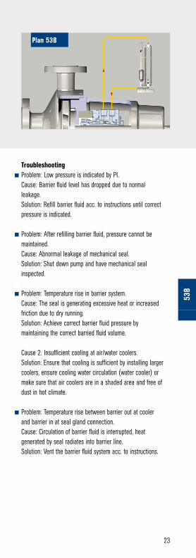
Used for applications where products have high
pressure and are harmful/hazardous. Pre-pressurized
bladder accumulator provides pressure to
circulation system. Heat removed by air/water heat
exchanger. Forced circulation.
Plan 53B
23
53B
Troubleshootingn Problem: Low pressure is indicated by PI. Cause: Barrier fluid level has dropped due to normal
leakage. Solution: Refill barrier fluid acc. to instructions until correct
pressure is indicated.
n Problem: After refilling barrier fluid, pressure cannot be maintained.
Cause: Abnormal leakage of mechanical seal. Solution: Shut down pump and have mechanical seal
inspected.
n Problem: Temperature rise in barrier system. Cause: The seal is generating excessive heat or increased
friction due to dry running. Solution: Achieve correct barrier fluid pressure by
maintaining the correct barried fluid volume.
Cause 2: Insufficient cooling at air/water coolers. Solution: Ensure that cooling is sufficient by installing larger
coolers, ensure cooling water circulation (water cooler) or make sure that air coolers are in a shaded area and free of dust in hot climate.
n Problem: Temperature rise between barrier out at cooler and barrier in at seal gland connection.
Cause: Circulation of barrier fluid is interrupted, heat generated by seal radiates into barrier line.
Solution: Vent the barrier fluid system acc. to instructions.
Plan 53B

24
Media characteristicsMedia has poor lubricity. Media is pumped at high temperature. Media is hazardous and/or harmful.
Leakage of media to atmospheric side is not desired. The media is near to its vapourisation point.
Start-up procedureFill up piston transmitter with fresh barrier fluid so that fill
indicator is between specified MIN and MAX marks. Important: piston may not be below MAX mark (“on block”) to
avoid excessive pressure build-up. Trapped gas must be removed by venting at highest point of the system. Check that
piping and the appropriate instrumentation is installed correctly. Piping shall be installed in an upward inclined way. Cooler must be higher than seal. Piping shall be arranged to
provide lowest possible flow resistance (direct lines, avoid bends as far as possible, required bends with large radius).
Valves in the piping must be open at all times and false operation (e.g. accidental closing) must be excluded. Start-up
pump. The reference line from the seal chamber will be self-filling after start-up. Remaining air bubbles can be
tolerated.
Shut-down procedureShut off pump. No special procedures need to be followed.
When water cooler is used, keep cooling water supply open at high temperatures.
Regular inspectionCheck correct fill level of the barrier fluid. If piston reaches the TOP mark, then fill level is LOW and vice versa. Check for any
leakage and abnormal temperature rise or gradient. The TI shall be within the specified value. If a strainer is installed in
the reference line, keep clean.
Used for applications where products have high
pressure and are harmful/hazardous. Pressurization
by reference line from seal chamber to a piston
pressure booster provides pressurized barrier fluid to circulation system. Forced
circulation.
Plan 53C

25
53C
Troubleshootingn Problem: The sight gauge shows that the piston is at top position. Cause: Barrier fluid level is low, allowing the reference pressure
to move the piston upward. Solution: Refill barrier fluid acc. to instructions until piston is
between MIN and MAX mark.
n Problem: Sudden rise of the piston over MIN mark. After refilling, the level cannot be maintained, piston rises again.
Cause: Abnormal leakage of mechanical seal. Solution: Shut off pump and have mechanical seal inspected.
Refill barrier fluid.
n Problem: Piston is below MAX mark and is pressed “on block”. Cause: After long pressureless standstill period, the piston may
drop due to gravity. The piston transmitter has been overfilled with barrier fluid.
Caution: This is a critical operation condition! Pressure is trapped! Due to thermal expansion critical pressures can be reached causing seal and/or supply system destruction.
Solution: Open vent valve at supply system and allow pressure/barrier fluid to escape. Piston will rise to a normal value. Take caution when opening vent valve and observe safety instructions!
n Problem: Abnormal temperature rise in barrier system. Cause: Insufficient cooling at air fin/water coolers. Solution: Ensure that cooling is sufficient by installing larger
coolers, ensure cooling water circulation (water cooler) or make sure that air fin coolers are free of dust and are installed in a shaded area and in hot climate regions.
n Problem: Temperature rise between barrier out at cooler and barrier in at seal gland connection, while the cooler itself is cool.
Cause: Circulation of barrier fluid is interrupted, heat generated by seal radiates into barrier line.
Solution: Vent the barrier fluid system acc. to instructions or check barrier fluid piping for clogging.
Plan 53C

26
Media characteristicsMedia contains suspended solids. Media has poor lubricity. Media is pumped at high temperature. Media is hazardous
and/or harmful. The media is near to its vapourisation point. Leakage of media to atmospheric side is not desired.
Start-up procedureFill up barrier fluid tank with fresh barrier fluid acc. to
instructions. Check that piping and the appropriate instrumentation is installed correctly. Piping shall be installed
in an upward inclined way. Piping shall be arranged to provide lowest possible flow resistance (direct lines, avoid bends as far as possible, required bends with large radius). Valves in
the piping must be open at all times and false operation (e.g. accidental closing) must be excluded. Start-up barrier
fluid system and adjust barrier pressure acc. to instructions. Start-up pump.
Shut-down procedureShut off pump.
Regular inspectionCorrect fill level of the barrier fluid is surveyed by alarm protection. Check filters and strainers at the barrier fluid
system acc. to instruction. Check bladder accumulator acc. to instructions. Check for any leakage and abnormal temperature
rise or gradient. The TI shall be within the specified value.
Used in harmful/hazardous applications. Pressurized
clean barrier fluid from an external system. Fluid
circulation by an external pump or pressure system.
Plan 54

27
54
Troubleshootingn Problem: Barrier fluid level is at MIN value. Cause: Barrier fluid level is low. Solution: Refill barrier fluid acc. to instructions.
n Problem: After refilling, the level cannot be maintained. Barrier fluid level drops rapidly.
Cause: Abnormal leakage of mechanical seal. Solution: Shut off pump and have mechanical seal
inspected. Refill barrier fluid.
n Problem: Abnormal temperature rise at seal. Cause: Circulation of barrier fluid is interrupted, heat
generated by seal radiates into barrier line. Solution: Ensure that barrier fluid can circulated. Inspect
strainers and filters at barrier fluid system.
Plan 54

28
Media characteristicsMedia is pumped at high
temperature. Leakage of media on atmospheric side may form
deposits, crystallise or oxidize.
Start-up procedureOpen valves for the nitrogen, steam, water or whatever quench media is
used. If valves are installed in the quench piping, they must be open at
all times and false operation (e.g. accidental closing) must be
excluded. Adjust the desired flow of quench media (hint: usually low
flow rates are sufficient).
Shut-down procedureNo special procedures need to
be followed.
Regular inspectionCheck for abnormal leakage on
atmospheric side of seal.
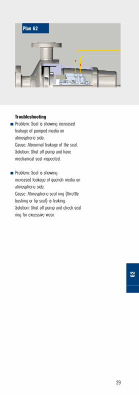
Used to keep atmospheric side of seal clean. External
source providing a flow-through quench to
atmospheric side.
Plan 62
29
62
Troubleshootingn Problem: Seal is showing increased
leakage of pumped media on atmospheric side.
Cause: Abnormal leakage of the seal. Solution: Shut off pump and have
mechanical seal inspected.
n Problem: Seal is showing increased leakage of quench media on atmospheric side.
Cause: Atmospheric seal ring (throttle bushing or lip seal) is leaking.
Solution: Shut off pump and check seal ring for excessive wear.
Plan 62

30
Media characteristicsCan be used with any media which form a liquid leakage
(non-evaporating).
Start-up procedureIf valves are installed in the piping,
they must be open at all times and false operation (e.g. accidental
closing) must be excluded.
Shut-down procedureNo special procedures need
to be followed.
Regular inspectionNo special procedures need
to be followed.
Used for leakage detection on single seal. Atmospheric side leakage collection and
monitoring in external vessel.
Plan 65

31
65
Troubleshootingn Problem: Level-high alarm has
been activated. Cause: Abnormal leakage of the
mechanical seal. Solution: Shut off pump and have
mechanical seal inspected.
n Problem: Level-high alarm has been activated but seal is o.k.
Cause: The drain pipe of the system is clogged or drain valve closed.
Solution: Remove clogging from piping, clean orifice or open drain valve.
Device to be located below pump shaftA
Plan 65A
to drain

32
Media characteristicsMedia vapors are hazardous and/or harmful. Media
vapors are purged to avoid combustable mixtures.
Start-up procedureIf specified, leakage collection systems plan 75 or 76 may be installed in connection with plan 72. If valves
are installed in the piping, they must be open at all times and false operation (e.g. accidental closing) must be excluded. Check that piping and electrical equipment
of the gas panel is installed correctly. Make sure that rotation direction of pump corresponds to rotation
direction of gas seal (at unidirectional gas seal). Open main valve of buffer gas line. Adjust gas flow acc. to instructions. Check pressure indicator: pressure shall
remain near 0 bar [g] if pressure builds up, a valve is still closed. Start-up pump.
Shut-down procedureShut off pump.
Gas buffer supply may be shut off, if required.
Regular inspectionCheck for abnormal gas consumption: flow indicator
shall display specified value. Check buffer gas pressure: it should be near 0 bar [g]. Check filter and replace
filter elements at regular intervals (acc. to instructions).
Applicable with hydrocarbons, normally
used in conjunction with plan 75 or plan 76.
Externally supplied gas buffer (pressure lower than seal pressure). Buffer gas
used to dilute seal leakage.
Plan 72

33
72
Troubleshootingn Problem: High level alarm of leakage
collection system plan 75. Cause: High liquid leakage of product side
mechanical seal. Solution: Shut off pump and have
mechanical seal inspected.
n Problem: High pressure alarm of vapour recovery system plan 76.
Cause: High gas leakage on product side mechanical seal.
Solution: Shut off pump and have mechanical seal inspected.
n Problem: After start-up the pump runs in reverse mode.
Cause: After installation, the pump has been connected in reversed polarity.
Solution: Connect pump in correct polarity. In case of unidirectional seal, have seal inspected for damage.
n Problem: Pressure indicator in gas supply system shows pressure increase.
Cause: The valve to the flare line is closed or orifice is clogged.
Solution: Open valve to flare line, make sure the orifice is clean.
Plan 72A B
C
connect to plan 75A connect to plan 76B N2C

34
Media characteristicsMedia has poor lubricity. The media is near to its
vapourisation point. Media is hazardous and/or harmful. Media shall be free of solids.
Start-up procedureIf valves are installed in the piping, they must be open
at all times and false operation (e.g. accidental closing) must be excluded. Check that piping and electrical
equipment of the gas panel is installed correctly. Make sure that rotation direction of pump corresponds to rotation direction of gas seal (at unidirectional gas
seal). Open main valve of barrier gas line. Set optimum barrier pressure to be above product pressure acc. to
instructions. Adjust the set points of instruments acc. to instructions. Start-up pump.
Shut-down procedureShut off pump. Keep barrier gas supply open.
Regular inspectionCheck for any abnormal gas leakage in piping (use adequate gas leak detecting device such as bubble
spray etc.). Check for abnormal gas consumption: flow indicator shall display specified value. Check barrier
pressure: PI shall display specified value. Check filter and replace filter elements at regular intervals (acc. to
instructions).
Used in applications where the product is harmful/
hazardous. Externally supplied barrier gas used to
positively prevent process fluid from leaking to
atmosphere.
Plan 74

35
74
Troubleshootingn Problem: Abnormally high gas consumption. Cause: High leakage of mechanical seal or
leaking piping. Solution: Shut off pump and inspect the seal,
check piping.
n Problem: Abnormally low gas consumption. Cause 1: Barrier gas supply is insufficient. Solution: Check barrier gas supply source. Ensure
all valves are fully open. Check filter and replace filter element if necessary.
Cause 2: Seal faces are running in contact. Solution: Have gas seal inspected.
n Problem: After start-up the pump runs in reverse mode. Cause: After installation, the pump has been connected
in reversed polarity. Solution: Connect pump in correct polarity. In case of
unidirectional seal, have seal inspected for damage.
N2A
Plan 74
A

36
Media characteristicsMedia is hazardous and/or harmful. Media leakage of product side seal
is liquid.
Start-up procedureThe plan 75 is commonly used in
connection with plan 72, where leakage of the seal is liquid. Check
that piping is installed correctly. Open valve of the flare line. Close
valve of the liquid drain line. Start-up pump.
Shut-down procedureShut off pump. Keep flare line open
and drain line closed.
Regular inspectionCheck liquid level through sight
glass or level indicator. The level shall be between MIN and MAX mark. Check position of valves.
Flare line must be open, liquid drain must be closed. If high level alarm
is triggered, drain the system by opening liquid drain line. Close valve
afterwards.
Application when pump fluid condenses at ambient temperatures. Containment
seal chamber drain for condensing leakage.
Plan 75

37
75
Troubleshootingn Problem: After drain, the liquid
leakage collection system refills quickly. Alarm is triggered after a short interval.
Cause: Abnormal leakage of mechanical seal
Solution: Shut off pump and inspect the seal.
n Problem: Liquid leakage at atmospheric side containment seal.
Cause 1: Both valves to flare and drain are closed. Liquid leakage has filled entire seal and leakage collection system.
Cause 2: The product side seal has increased leakage.
Solution: Have mechanical seal inspected, make sure valves are in correct position.
Device to be located below pump shaftA
Plan 75
A
to drain
to flare

38
Media characteristicsMedia is hazardous and/or harmful. Media leakage of product side seal
is evaporated.
Start-up procedureThe plan 76 is commonly used in
connection with plan 72, where leakage of the seal is vapour. Check
that piping is installed correctly. Open valve of the flare line.
Start-up pump.
Shut-down procedureShut off pump.
Keep flare line open if possible.
Regular inspectionThe drain valve of the leakage
collection system can be opened occasionally to check for any liquid
condensate. The system does not require regular maintenance.
Application where pump fluid does not condense at
ambient temperature. Containment seal chamber
drain for non-condensing leakage.
Plan 76

39 76
Troubleshootingn Problem: The high pressure alarm
is triggered. Cause: Abnormal leakage of
mechanical seal. Solution: Shut off pump and have
mechanical seal inspected.
to flarePlan 76

EagleBurgmann GermanyGmbH & Co. KGAeussere Sauerlacher Str. 6-10D-82515 WolfratshausenPhone +49(0)8171 / 23-0Telefax +49(0)8171 / 23-1246www.eagleburgmann.com
APIS
GE /
E7 /
3.00
0 / 0
3.11
/ 9.7.
1 ©
Eag
leBur
gman
n Gro
up M
arke
ting,
Germ
any
API 682