Embed Size (px)
Citation preview

Apertures for Coulter CountersH. E. Kubitschek Citation: Review of Scientific Instruments 35, 1598 (1964); doi: 10.1063/1.1719219 View online: http://dx.doi.org/10.1063/1.1719219 View Table of Contents: http://scitation.aip.org/content/aip/journal/rsi/35/11?ver=pdfcov Published by the AIP Publishing Articles you may be interested in High-bandwidth radio frequency Coulter counter Appl. Phys. Lett. 87, 184106 (2005); 10.1063/1.2125111 Proper Analysis of Coulter Counter Data Rev. Sci. Instrum. 36, 868 (1965); 10.1063/1.1719742 Loss of Resolution in Coulter Counters Rev. Sci. Instrum. 33, 576 (1962); 10.1063/1.1717939 Coincidence in Coulter Counters Rev. Sci. Instrum. 33, 575 (1962); 10.1063/1.1717938 Theory of Coincidence in Coulter Particle Counters Rev. Sci. Instrum. 32, 1132 (1961); 10.1063/1.1717181
This article is copyrighted as indicated in the article. Reuse of AIP content is subject to the terms at: http://scitationnew.aip.org/termsconditions. Downloaded to IP:
140.254.87.149 On: Sat, 20 Dec 2014 09:23:59
THE REVIEW OF SCIENTIFIC INSTRUMENTS
Notes
BRIEF contributions in any field of instrumentation or technique within the scope of the Journal can be accorded earlier publication iJ submitted for this section. Contributions should in general not exceed 500 words.
Apertures for Coulter Counters*
H. E. KUBITSCHEK
Division of Biological and Medical Research, Argonne National Laboratory, Argonne, Illinois
(Received 26 June 1964; and in final form, 29 July 1964)
MOST apertures presently available for Coulter counters appear to be designed for rapidity of count
ing and reduction of coincidence counts, rather than for precision of sizing. In independent tests of several different commercial instruments at Argonne National Laboratory inaccurate distributions of red blood cell volumes were obtained, primarily because the apertures supplied with these instruments were too short to permit all electronic pulses generated by these particles to reach their maximum amplitudes. The distributions that were obtained were skewed and of poorer resolution than those taken with apertures designed for more accurate sizing. With an improved aperture the resolution (width at half-maximum amplitude) was increased by about 20% and the coefficient of variation (standard deviation/mean) was decreased by about 50%. This note discusses the construction of apertures to give accurate distributions of particle size.
The requirement for accurate sizing, that every particle must produce a pulse which reaches its maximum (or plateau) value, has been discussed in a previous note.1
For particles suspended in saline or in 0.1N HCI, this requirement is met in the instruments we have tested when the length of the aperture is about 2 to 3 times its diameter, or greater, for aperture diameters from 10 to 100 J.L. The inaccurate distributions obtained for red blood cells were due, principally, to the fact that the commercial apertures were only about as long as their diameters.
Apertures with bore diameters of 25 J.L and greater are most easily constructed from precision bore capillary tubing (available from Fischer and Porter Company, Hatborro, Pennsylvania and from Wilmad Glass Company, Landesville, New Jersey). Capillary tubing can be cut into lengths of about 0.2 to 0.3 mm with a silicon wafering machine. (This service is available in many optical shops or through companies manufacturing transistors.) For bore diameters of 75 to 125 J.L, these wafers _may be used as aperture disks without further polishing.
1598
VOLUME 35, NUMBER 11 NOVEMBER 1964-
An alternative procedure is one which we have developed for smaller apertures. Capillary tubing is heated, pulled to the desired diameter, and after cooling, cut into segments about 4 to 6 mm in length. As many as 30 to 50 of these segments are placed on end on a glass fiat and embedded in an epoxy resin, presenting a single rough surface to be ground and polished. To prevent accumulation of abrasives in the capillaries during grinding, these are also filled with the resin. Of several resins we have used, "Scotchcast" brand resin No.2 (Minnesota Mining and Manufacturing Company, St. Paul, Minnesota) has been most successful because its hardness was most similar to that of glass. After polishing with rouge, the pieces of capillary tubing are freed from the fiat by heating over-night in an annealing oven at 550°C, which completely removes the resin. Upon cooling, the pieces are embedded upon an optical fiat with their polished ends in contact with the fiat, ground to the desired thickness, polished, and again freed at the annealing temperature. With this technique we have made apertures with diameters as small as 2 J.L and lengths as short as 20 J.L.
A third procedure has been successfully used with resins commonly used for embedding biological specimens for electron microscopy. Copper or aluminum wire of the desired diameter is embedded in the resin, for example methylmethacrylate. After polymerization, the hardened block is then sectioned on a microtome to sheets of the desired thickness, and the wire remnants are dissolved away with a dilute acid, such as nitric acid.
To cement an aperture to an aperture tube it may be necessary first to remove old adhesive. This is accomplished, as before, by placing the aperture tube at annealing temperature overnight, a method superior to the use of most solvents. The aperture disk may be cemented to the the tube with anyone of a variety of adhesives. We find that a good grade of marine spar varnish is easy to apply and long lasting. Using a thin glass point, a ring of varnish is drawn about the hole in the aperture tube and the aperture disk is dropped into place and baked for 1 h at about 150°C.
Small apertures frequently become blocked during use, even through counting solutions are routinely filtered through 0.45-J.L filters (Millipore Filter Corporation, Bedford, Massachusetts). This frequent blocking, which increases as aperture diameters are decreased, makes it convenient to provide a means for reversing the pressure across the aperture, which is usually sufficient to clear it. If these minute apertures are allowed to remain clogged, it becomes increasingly difficult, or impossible, to free them by pressure reversal alone. In some cases the aperture may be opened by washing with acetone or nitric acid. Also it is frequently possible to clean apertures ultrasonically (D. Glaser, private communication). Again, in ex-
This article is copyrighted as indicated in the article. Reuse of AIP content is subject to the terms at: http://scitationnew.aip.org/termsconditions. Downloaded to IP:
140.254.87.149 On: Sat, 20 Dec 2014 09:23:59
NOTES 1599
treme cases the aperture can often be recovered by heating at 550°C.
The techniques described in this note were developed with the skillful collaboration of the members of the glass shop in the Division of Biological and Medical Research and the Laboratory optical shop, who have been responsible for the fabrication of minute apertures.
* Work supported by the U. S. Atomic Energy Commission. 1 H. E. Kubitschek, Rev. Sci. Instr. 33, 576 (1962).
Method to Increase the Pressure Drop Across a Differentially Pumped Gas Canal*
H. WINKLERt
California Institute of Technology, Pasadena, California
(Received 23 July 1964)
T HIS note describes a simple arrangement to increase the pressure drop across a differentially pumped
canal, as used in open gas targets for nuclear spectroscopy. The maximum pressure which can be obtained in such differentially pumped gas targets is determined by: (1) the dimensions of the beam entrance canal, (2) the nature of the gas, and (3) the pumping speed and maximum tolerable pressure at the low pressure end of the canal. In order to get the beam into the gas target with a minimum of energy loss and scattering, the pressure at the low pressure end of the canal is usually so low that it does not affect the amount of gas flowing through the canal.
By using the momentum of the mass flow of the gas feed into the gas target to build up an additional pressure difference on the high pressure side of the canal, the apparent conductance of the canal can be decreased. Then, for equal mass flow through the canal, a higher target pressure can be obtained.
Figure 1 shows the apparatus used to check this proposal. The low pressure side of the canal was pumped by
FIG. 1. Experimental set-up.
DETAIL A
IOmm
150,----,----,-----,-----,---.--------,
" I
E E
>--~ roo 0:
" >--<J)
" '" ~ 50
'" 0: ::> <J)
~ 0: a.
100 200 300 400 500
PRESSURE AT ROOTS PUMP INTAKE (I'Hgl
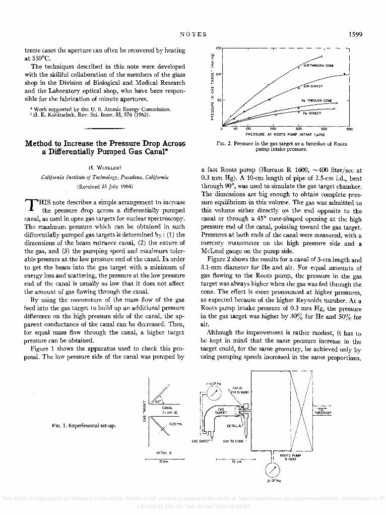
FIG. 2. Pressure in the gas target as a function of Roots pump intake pressure.
a fast Roots pump (Hereaus R 1600, ",400 liter/sec at 0.3 rum Hg). A lO-cm length of pipe of 2.5-cm i.d., bent through 90°, was used to simulate the gas target chamber. The dimensions are big enough to obtain complete pressure equilibrium in this volume. The gas was admitted to this volume either directly on the end opposite to the canal or through a 45° cone-shaped opening at the high pressure end of the canal, pointing toward the gas target. Pressures at both ends of the canal were measured, with a mercury manometer on the high pressure side and a McLeod gauge on the pump side.
Figure 2 shows the results for a canal of 3-cm length and 3.1-mm diameter for He and air. For equal amounts of gas flowing to the Roots pump, the pressure in the gas target was always higher when the gas was fed through the cone. The effect is more pronounced at higher pressures, as expected because of the higher Reynolds number. At a Roots pump intake pressure of 0.3 rum Hg, the pressure in the gas target was higher by 30% for He and 50% for air.
Although the improvement is rather modest, it has to be kept in mind that the same pressure increase in the target could, for the same geometry, be achieved only by using pumping speeds increased in the same proportions.
mmOf Hg
GAS TO CONE I
10 em
jL OF Hg
Til FOREPUMP
This article is copyrighted as indicated in the article. Reuse of AIP content is subject to the terms at: http://scitationnew.aip.org/termsconditions. Downloaded to IP:
140.254.87.149 On: Sat, 20 Dec 2014 09:23:59