Embed Size (px)
Citation preview

June 2006
Angle Encoders
with Integral Bearing
2
Information onAngle encoders without integral bearingRotary encodersEncoders for servo drivesExposed linear encodersLinear encoders for numerically controlled machine toolsInterface electronicsHEIDENHAIN controls
is available on request as well as on the Internet at www.heidenhain.de.
•••••
••
This catalog supersedes all previous editions, which thereby become invalid.The basis for ordering from HEIDENHAIN is always the catalog edition valid when the contract is made.
Standards (ISO, EN, etc.) apply only where explicitly stated in the catalog.
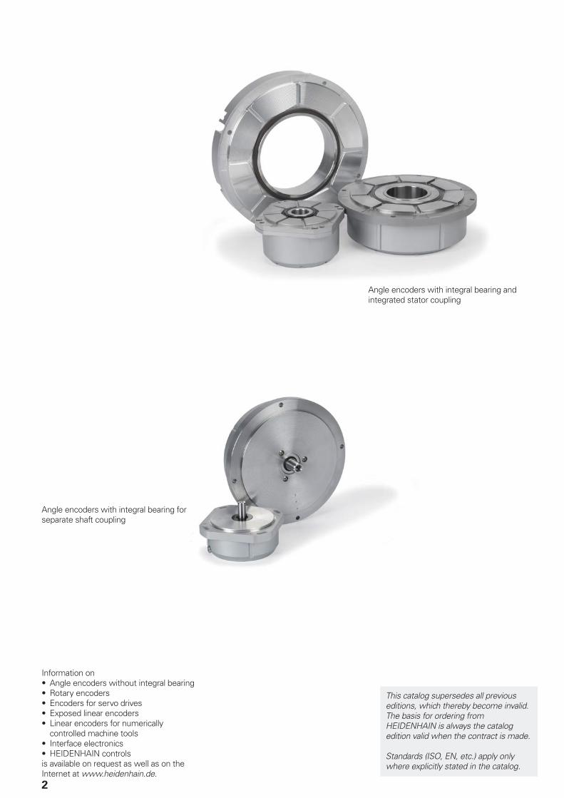
Angle encoders with integral bearing and integrated stator coupling
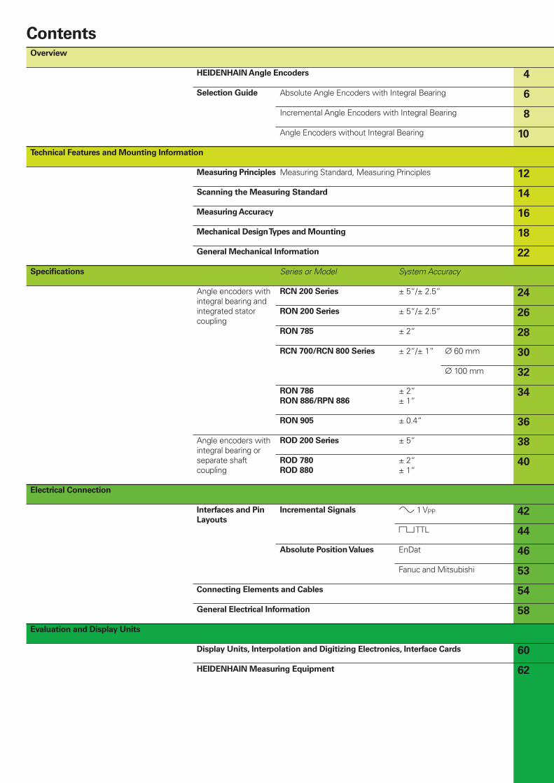
Angle encoders with integral bearing for separate shaft coupling
Overview
HEIDENHAIN Angle Encoders 4
Selection Guide Absolute Angle Encoders with Integral Bearing 6
Incremental Angle Encoders with Integral Bearing 8
Angle Encoders without Integral Bearing 10
Technical Features and Mounting Information
Measuring Principles Measuring Standard, Measuring Principles 12
Scanning the Measuring Standard 14
Measuring Accuracy 16
Mechanical Design Types and Mounting 18
General Mechanical Information 22
Specifi cations Series or Model System Accuracy
Angle encoders with integral bearing and integrated stator coupling
RCN 200 Series ± 5“/± 2.5“ 24
RON 200 Series ± 5“/± 2.5“ 26
RON 785 ± 2“ 28
RCN 700/RCN 800 Series ± 2“/± 1“ ¬ 60 mm 30
¬ 100 mm 32
RON 786
RON 886/RPN 886
± 2“± 1“
34
RON 905 ± 0.4“ 36
Angle encoders with integral bearing or separate shaft coupling
ROD 200 Series ± 5“ 38
ROD 780
ROD 880
± 2“± 1“
40
Electrical Connection
Interfaces and Pin
Layouts
Incremental Signals » 1 VPP 42
« TTL 44
Absolute Position Values EnDat 46
Fanuc and Mitsubishi 53
Connecting Elements and Cables 54
General Electrical Information 58
Evaluation and Display Units
Display Units, Interpolation and Digitizing Electronics, Interface Cards 60
HEIDENHAIN Measuring Equipment 62
Contents
4
HEIDENHAIN Angle Encoders
The term angle encoder is typically used to describe encoders that have an accuracy of better than ± 5“ and a line count above 10000. In contrast, rotary encoders are encoders that typically have an accuracy of more than ± 10“.Angle encoders are found in applications requiring precision angular measurement to accuracies within several arc seconds.
Examples:Rotary tables on machine toolsSwivel heads on machine toolsC-axes of lathesMeasuring machines for gearsPrinting units of printing machinesSpectrometersTelescopes
etc.
The tables on the following pages list different types of angle encoders to suit the various applications and meet different requirements.
•••••••
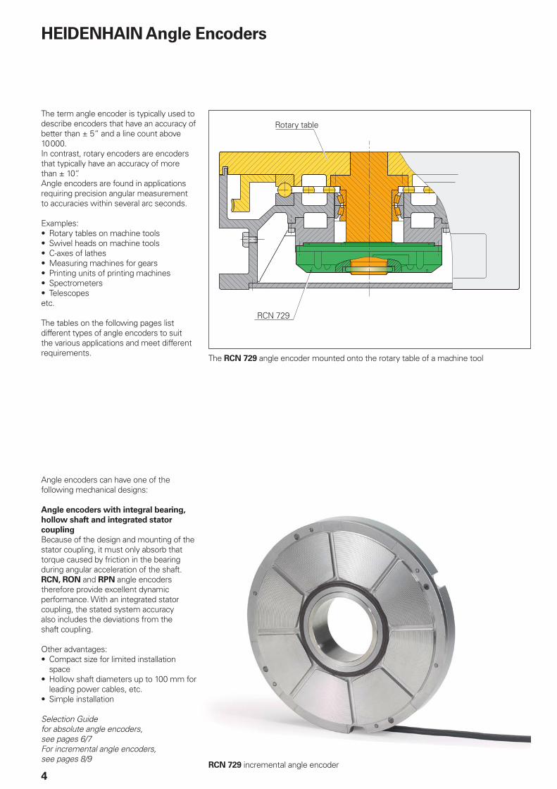
The RCN 729 angle encoder mounted onto the rotary table of a machine tool
RCN 729 incremental angle encoder
Rotary table
RCN 729
Angle encoders can have one of the following mechanical designs:
Angle encoders with integral bearing,
hollow shaft and integrated stator
coupling
Because of the design and mounting of the stator coupling, it must only absorb that torque caused by friction in the bearing during angular acceleration of the shaft. RCN, RON and RPN angle encoders therefore provide excellent dynamic performance. With an integrated stator coupling, the stated system accuracy also includes the deviations from the shaft coupling.
Other advantages:Compact size for limited installation spaceHollow shaft diameters up to 100 mm for leading power cables, etc.Simple installation
Selection Guide for absolute angle encoders, see pages 6/7For incremental angle encoders, see pages 8/9
•
•
•
5
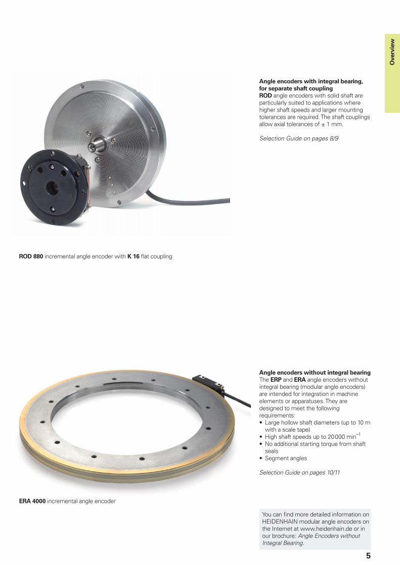
Angle encoders with integral bearing,
for separate shaft coupling
ROD angle encoders with solid shaft are particularly suited to applications where higher shaft speeds and larger mounting tolerances are required. The shaft couplings allow axial tolerances of ± 1 mm.
Selection Guide on pages 8/9
Angle encoders without integral bearing
The ERP and ERA angle encoders without integral bearing (modular angle encoders) are intended for integration in machine elements or apparatuses. They are designed to meet the following requirements:
Large hollow shaft diameters (up to 10 m with a scale tape)High shaft speeds up to 20000 min–1
No additional starting torque from shaft sealsSegment angles
Selection Guide on pages 10/11
•
••
•
ROD 880 incremental angle encoder with K 16 fl at coupling
ERA 4000 incremental angle encoder
Overv
iew
You can fi nd more detailed information on HEIDENHAIN modular angle encoders on the Internet at www.heidenhain.de or in our brochure: Angle Encoders without Integral Bearing.
6
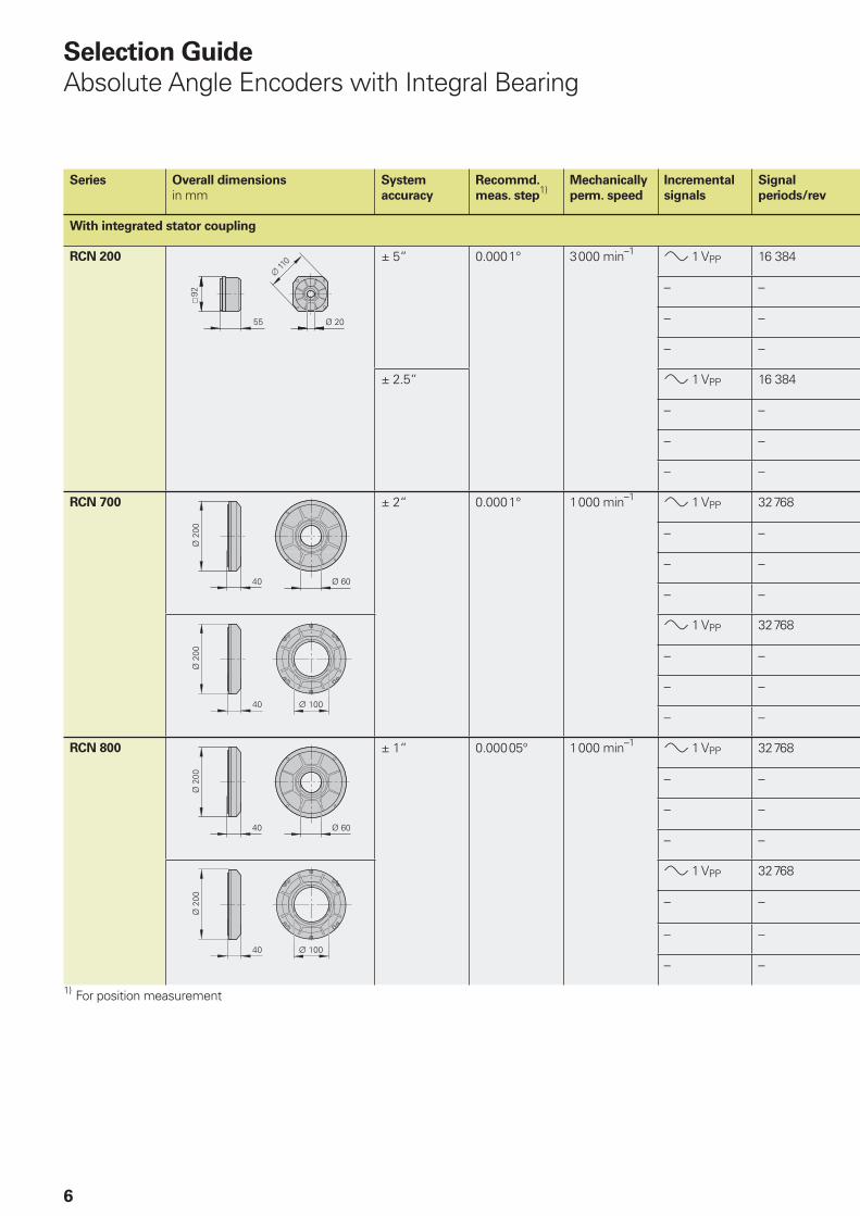
Selection Guide
Absolute Angle Encoders with Integral Bearing
Series Overall dimensions
in mmSystem
accuracy
Recommd.
meas. step1)
Mechanically
perm. speed
Incremental
signals
Signal
periods/rev
With integrated stator coupling
RCN 200 ± 5“ 0.0001° 3000 min–1 » 1 VPP 16 384
– –
– –
– –
± 2.5“ » 1 VPP 16 384
– –
– –
– –
RCN 700 ± 2“ 0.0001° 1000 min–1 » 1 VPP 32768
– –
– –
– –
» 1 VPP 32768
– –
– –
– –
RCN 800 ± 1“ 0.00005° 1000 min–1 » 1 VPP 32768
– –
– –
– –
» 1 VPP 32768
– –
– –
– –
1) For position measurement
RCN 200
RCN 700
¬ 60 mm
RCN 800
¬ 100 mm
7
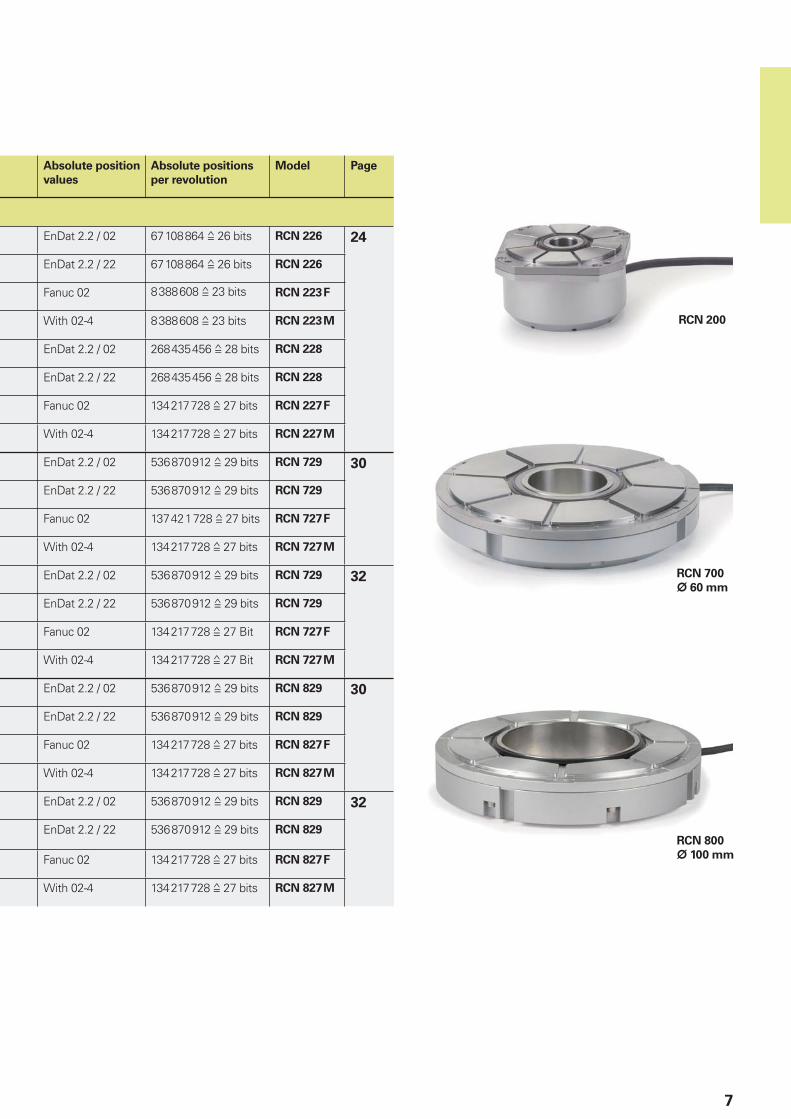
Absolute position
values
Absolute positions
per revolution
Model Page
EnDat 2.2 / 02 67108864 ƒ 26 bits RCN 226 24
EnDat 2.2 / 22 67108864 ƒ 26 bits RCN 226
Fanuc 02 8388608 ƒ 23 bits RCN 223F
With 02-4 8388608 ƒ 23 bits RCN 223M
EnDat 2.2 / 02 268435456 ƒ 28 bits RCN 228
EnDat 2.2 / 22 268435456 ƒ 28 bits RCN 228
Fanuc 02 134217728 ƒ 27 bits RCN 227F
With 02-4 134217728 ƒ 27 bits RCN 227M
EnDat 2.2 / 02 536870912 ƒ 29 bits RCN 729 30
EnDat 2.2 / 22 536870912 ƒ 29 bits RCN 729
Fanuc 02 137421728 ƒ 27 bits RCN 727F
With 02-4 134217728 ƒ 27 bits RCN 727M
EnDat 2.2 / 02 536870912 ƒ 29 bits RCN 729 32
EnDat 2.2 / 22 536870912 ƒ 29 bits RCN 729
Fanuc 02 134217728 ƒ 27 Bit RCN 727F
With 02-4 134217728 ƒ 27 Bit RCN 727M
EnDat 2.2 / 02 536870912 ƒ 29 bits RCN 829 30
EnDat 2.2 / 22 536870912 ƒ 29 bits RCN 829
Fanuc 02 134217728 ƒ 27 bits RCN 827F
With 02-4 134217728 ƒ 27 bits RCN 827M
EnDat 2.2 / 02 536870912 ƒ 29 bits RCN 829 32
EnDat 2.2 / 22 536870912 ƒ 29 bits RCN 829
Fanuc 02 134217728 ƒ 27 bits RCN 827F
With 02-4 134217728 ƒ 27 bits RCN 827M
8
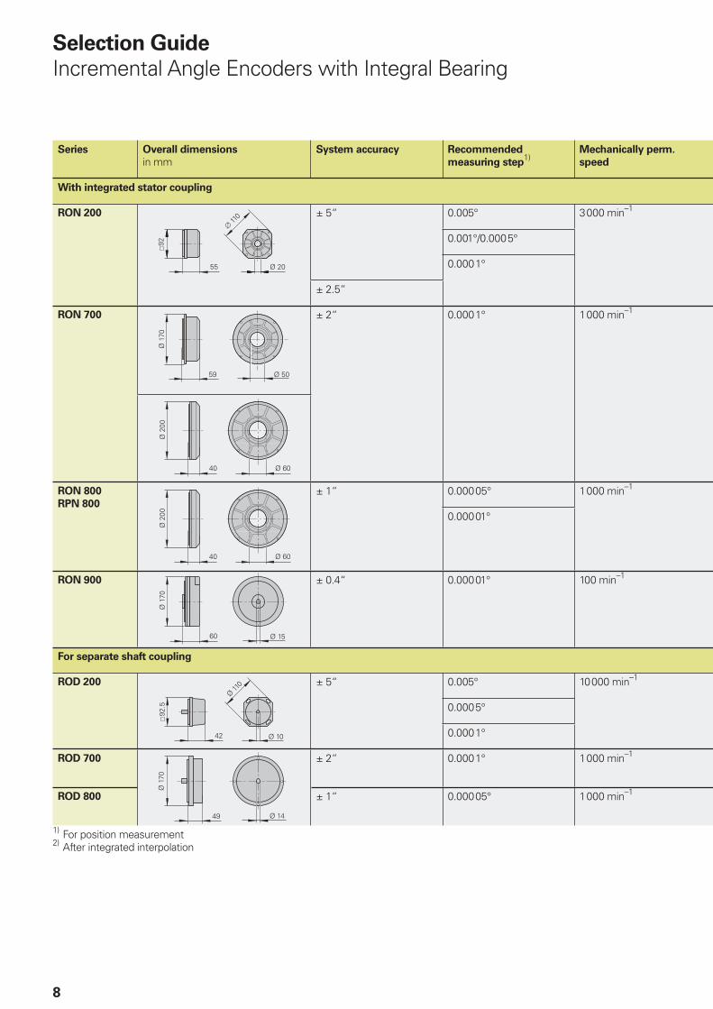
Selection Guide
Incremental Angle Encoders with Integral Bearing
Series Overall dimensions
in mmSystem accuracy Recommended
measuring step1)
Mechanically perm.
speed
With integrated stator coupling
RON 200 ± 5“ 0.005° 3000 min–1
0.001°/0.0005°
0.0001°
± 2.5“
RON 700 ± 2“ 0.0001° 1000 min–1
RON 800
RPN 800
± 1“ 0.00005° 1000 min–1
0.00001°
RON 900 ± 0.4“ 0.00001° 100 min–1
For separate shaft coupling
ROD 200 ± 5“ 0.005° 10000 min–1
0.0005°
0.0001°
ROD 700 ± 2“ 0.0001° 1000 min–1
ROD 800 ± 1“ 0.00005° 1000 min–1
1) For position measurement2) After integrated interpolation
ROD 780
RON 285
RON 786
RON 905
ROD 280
9
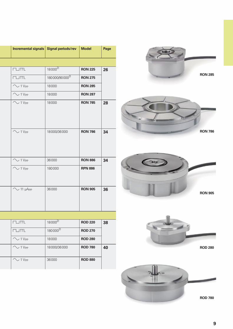
Incremental signals Signal periods/rev Model Page
« TTL 180002)RON 225 26
« TTL 180000/900002)RON 275
» 1 VPP 18000 RON 285
» 1 VPP 18000 RON 287
» 1 VPP 18000 RON 785 28
» 1 VPP 18000/36000 RON 786 34
» 1 VPP 36000 RON 886 34
» 1 VPP 180000 RPN 886
» 11 µAPP 36000 RON 905 36
« TTL 180002)ROD 220 38
« TTL 1800002)ROD 270
» 1 VPP 18000 ROD 280
» 1 VPP 18000/36000 ROD 780 40
» 1 VPP 36000 ROD 880
10
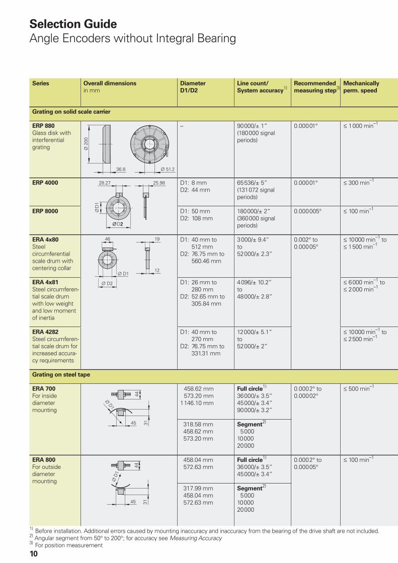
Series Overall dimensions
in mmDiameter
D1/D2
Line count/
System accuracy1)
Recommended
measuring step3)
Mechanically
perm. speed
Grating on solid scale carrier
ERP 880
Glass disk with interferential grating
– 90 000/± 1“(180 000 signal periods)
0.000 01° † 1000 min–1
ERP 4000 D1: 8 mmD2: 44 mm
65 536/± 5”(131 072 signal periods)
0.000 01° † 300 min–1
ERP 8000 D1: 50 mmD2: 108 mm
180 000/± 2“(360 000 signal periods)
0.000 005° † 100 min–1
ERA 4x80
Steel circumferential scale drum with centering collar
D1: 40 mm to 512 mmD2: 76.75 mm to 560.46 mm
3000/± 9.4“to52 000/± 2.3“
0.002° to0.000 05°
† 10 000 min–1 to† 1500 min–1
ERA 4x81
Steel circumferen-tial scale drum with low weight and low moment of inertia
D1: 26 mm to 280 mmD2: 52.65 mm to 305.84 mm
4096/± 10.2“to48 000/± 2.8“
† 6000 min–1 to† 2000 min–1
ERA 4282
Steel circumferen-tial scale drum for increased accura-cy requirements
D1: 40 mm to 270 mmD2: 76.75 mm to 331.31 mm
12 000/± 5.1“to52 000/± 2“
† 10 000 min–1 to† 2500 min–1
Grating on steel tape
ERA 700
For inside diameter mounting
458.62 mm 573.20 mm1146.10 mm
Full circle1)
36 000/± 3.5“45 000/± 3.4“90 000/± 3.2”
0.000 2° to0.000 02°
† 500 min–1
318.58 mm 458.62 mm 573.20 mm
Segment2)
5 00010 00020 000
ERA 800
For outside diameter mounting
458.04 mm 572.63 mm
Full circle1)
36 000/± 3.5“45 000/± 3.4“
0.000 2° to0.000 05°
† 100 min–1
317.99 mm 458.04 mm 572.63 mm
Segment2)
5 00010 00020 000
1) Before installation. Additional errors caused by mounting inaccuracy and inaccuracy from the bearing of the drive shaft are not included.2) Angular segment from 50° to 200°; for accuracy see Measuring Accuracy3) For position measurement
Selection Guide
Angle Encoders without Integral Bearing
���� �����
�� ����
ERP 880
ERA 880
ERA 780
ERA 4000
ERP 4080
11
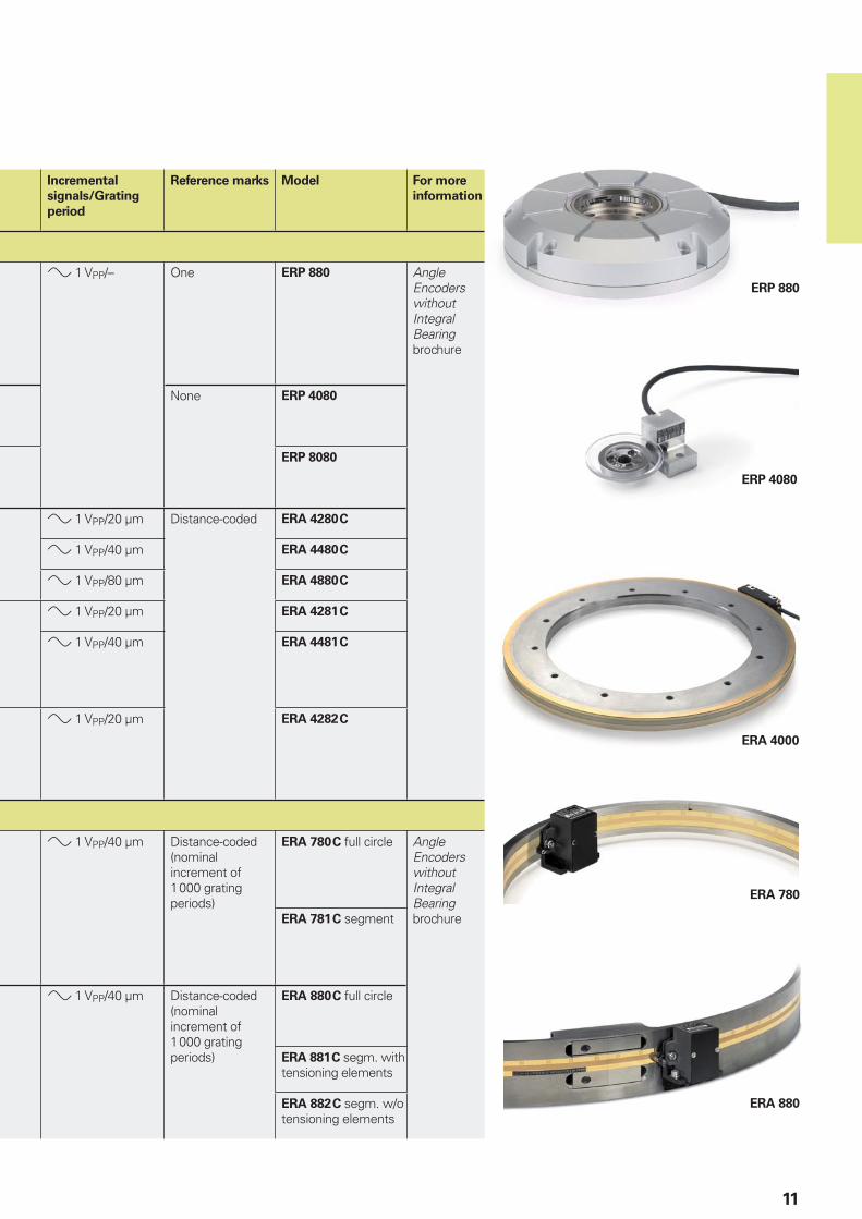
Incremental
signals/Grating
period
Reference marks Model For more
information
» 1 VPP/– One ERP 880 Angle Encoders without Integral Bearing brochure
None ERP 4080
ERP 8080
» 1 VPP/20 µm Distance-coded ERA 4280 C
» 1 VPP/40 µm ERA 4480 C
» 1 VPP/80 µm ERA 4880 C
» 1 VPP/20 µm ERA 4281 C
» 1 VPP/40 µm ERA 4481 C
» 1 VPP/20 µm ERA 4282 C
» 1 VPP/40 µm Distance-coded (nominal increment of 1000 grating periods)
ERA 780 C full circle Angle Encoders without Integral Bearing brochureERA 781 C segment
» 1 VPP/40 µm Distance-coded (nominal increment of 1000 grating periods)
ERA 880 C full circle
ERA 881 C segm. with tensioning elements
ERA 882 C segm. w/o tensioning elements
12
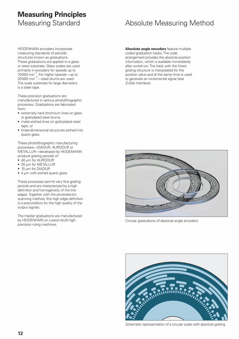
Measuring Principles
Measuring Standard Absolute Measuring Method
Absolute angle encoders feature multiple coded graduation tracks. The code arrangement provides the absolute position information, which is available immediately after switch-on. The track with the fi nest grating structure is interpolated for the position value and at the same time is used to generate an incremental signal (see EnDat Interface).
Circular graduations of absolute angle encoders
Schematic representation of a circular scale with absolute grating
HEIDENHAIN encoders incorporate measuring standards of periodic structures known as graduations.These graduations are applied to a glass or steel substrate. Glass scales are used primarily in encoders for speeds up to 10 000 min–1. For higher speeds—up to 20 000 min–1—steel drums are used. The scale substrate for large diameters is a steel tape.
These precision graduations are manufactured in various photolithographic processes. Graduations are fabricated from:
extremely hard chromium lines on glass or gold-plated steel drums,matte-etched lines on gold-plated steel tape, orthree-dimensional structures etched into quartz glass.
These photolithographic manufacturing processes—DIADUR, AURODUR or METALLUR—developed by HEIDENHAIN produce grating periods of:
40 µm for AURODUR20 µm for METALLUR10 µm for DIADUR4 µm with etched quartz glass
These processes permit very fi ne grating periods and are characterized by a high defi nition and homogeneity of the line edges. Together with the photoelectric scanning method, this high edge defi nition is a precondition for the high quality of the output signals.
The master graduations are manufactured by HEIDENHAIN on custom-built high-precision ruling machines.
•
•
•
••••
13
Þ1 = (abs A–sgn A–1) x I + (sgn A–sgn D) x abs MRR
where:
A = 2 x abs MRR–I
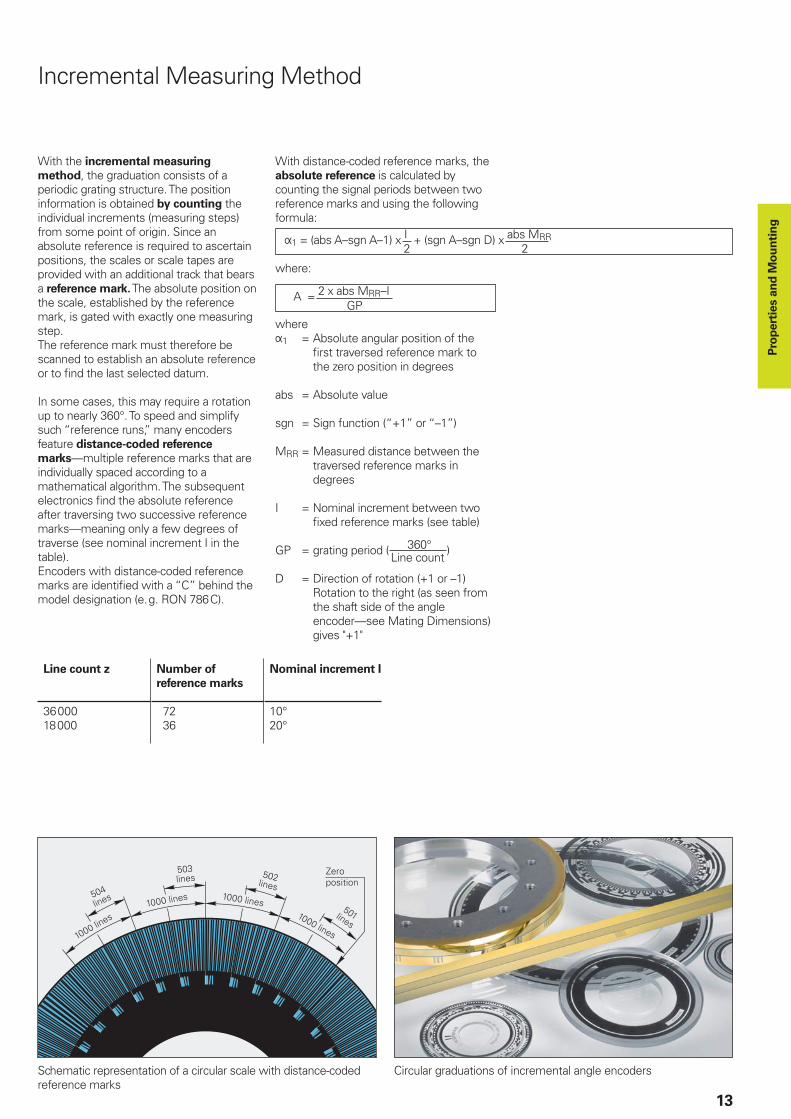
Incremental Measuring Method
With the incremental measuring
method, the graduation consists of a periodic grating structure. The position information is obtained by counting the individual increments (measuring steps) from some point of origin. Since an absolute reference is required to ascertain positions, the scales or scale tapes are provided with an additional track that bears a reference mark. The absolute position on the scale, established by the reference mark, is gated with exactly one measuring step.The reference mark must therefore be scanned to establish an absolute reference or to fi nd the last selected datum.
In some cases, this may require a rotation up to nearly 360°. To speed and simplify such “reference runs,” many encoders feature distance-coded reference
marks—multiple reference marks that are individually spaced according to a mathematical algorithm. The subsequent electronics fi nd the absolute reference after traversing two successive reference marks—meaning only a few degrees of traverse (see nominal increment I in the table). Encoders with distance-coded reference marks are identifi ed with a “C” behind the model designation (e.g. RON 786C).
With distance-coded reference marks, the absolute reference is calculated by counting the signal periods between two reference marks and using the following formula:
2 2
whereÞ1 = Absolute angular position of the
fi rst traversed reference mark to the zero position in degrees
abs = Absolute value
sgn = Sign function (“+1” or “–1”)
MRR = Measured distance between the traversed reference marks in degrees
I = Nominal increment between two fi xed reference marks (see table)
GP = grating period ( 360° )
D = Direction of rotation (+1 or –1) Rotation to the right (as seen from the shaft side of the angle encoder—see Mating Dimensions) gives "+1"
Line count
Line count z Number of
reference marks
Nominal increment I
3600018000
72 36
10°20°
Schematic representation of a circular scale with distance-coded reference marks
Circular graduations of incremental angle encoders
GP
Pro
pert
ies a
nd
Mo
un
tin
g
14
Most HEIDENHAIN encoders operate using the principle of photoelectric scanning. Photoelectric scanning of a measuring standard is contact-free, and as such free of wear. This method detects even very fi ne lines, no more than a few microns wide, and generates output signals with very small signal periods.
The fi ner the grating period of a measuring standard is, the greater the effect of diffraction on photoelectric scanning. HEIDENHAIN uses two scanning principles with angle encoders:
The imaging scanning principle for grating periods from 10 µm to approx. 70 µm.The interferential scanning principle for very fi ne graduations with grating periods of 4 µm.
•
•
Scanning the Measuring Standard
Photoelectric Scanning
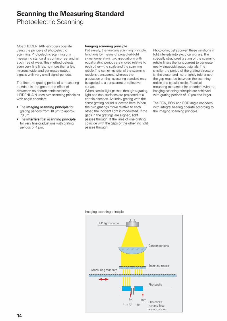
Imaging scanning principle
Put simply, the imaging scanning principle functions by means of projected-light signal generation: two graduations with equal grating periods are moved relative to each other—the scale and the scanning reticle. The carrier material of the scanning reticle is transparent, whereas the graduation on the measuring standard may be applied to a transparent or refl ective surface. When parallel light passes through a grating, light and dark surfaces are projected at a certain distance. An index grating with the same grating period is located here. When the two gratings move relative to each other, the incident light is modulated. If the gaps in the gratings are aligned, light passes through. If the lines of one grating coincide with the gaps of the other, no light passes through.
Photovoltaic cells convert these variations in light intensity into electrical signals. The specially structured grating of the scanning reticle fi lters the light current to generate nearly sinusoidal output signals. The smaller the period of the grating structure is, the closer and more tightly toleranced the gap must be between the scanning reticle and circular scale. Practical mounting tolerances for encoders with the imaging scanning principle are achieved with grating periods of 10 µm and larger.
The RCN, RON and ROD angle encoders with integral bearing operate according to the imaging scanning principle.
Imaging scanning principle
LED light source
Condenser lens
Measuring standardScanning reticle
Photocells
PhotocellsI90° and I270°are not shown
15
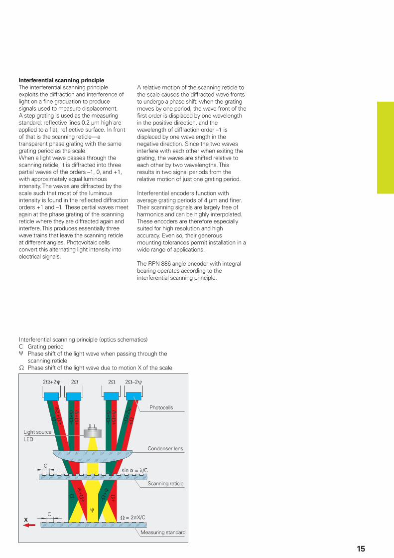
Interferential scanning principle
The interferential scanning principle exploits the diffraction and interference of light on a fi ne graduation to produce signals used to measure displacement.A step grating is used as the measuring standard: refl ective lines 0.2 µm high are applied to a fl at, refl ective surface. In front of that is the scanning reticle—a transparent phase grating with the same grating period as the scale.When a light wave passes through the scanning reticle, it is diffracted into three partial waves of the orders –1, 0, and +1, with approximately equal luminous intensity. The waves are diffracted by the scale such that most of the luminous intensity is found in the refl ected diffraction orders +1 and –1. These partial waves meet again at the phase grating of the scanning reticle where they are diffracted again and interfere. This produces essentially three wave trains that leave the scanning reticle at different angles. Photovoltaic cells convert this alternating light intensity into electrical signals.
A relative motion of the scanning reticle to the scale causes the diffracted wave fronts to undergo a phase shift: when the grating moves by one period, the wave front of the fi rst order is displaced by one wavelength in the positive direction, and the wavelength of diffraction order –1 is displaced by one wavelength in the negative direction. Since the two waves interfere with each other when exiting the grating, the waves are shifted relative to each other by two wavelengths. This results in two signal periods from the relative motion of just one grating period.
Interferential encoders function with average grating periods of 4 µm and fi ner. Their scanning signals are largely free of harmonics and can be highly interpolated. These encoders are therefore especially suited for high resolution and high accuracy. Even so, their generous mounting tolerances permit installation in a wide range of applications.
The RPN 886 angle encoder with integral bearing operates according to the interferential scanning principle.
Interferential scanning principle (optics schematics)C Grating periodψ Phase shift of the light wave when passing through the
scanning reticle− Phase shift of the light wave due to motion X of the scale
Light sourceLED
Photocells
Condenser lens
Scanning reticle
Measuring standard
16
Measuring Accuracy
The accuracy of angular measurement is mainly determined by:1. The quality of the graduation2. The quality of the scanning process3. The quality of the signal processing
electronics4. Eccentricity of the graduation to the
bearing5. Radial runout of the bearing6. Elasticity of the encoder shaft and its
coupling with the drive shaft7. The elasticity of the stator coupling
(RCN, RON, RPN) or shaft coupling (ROD)
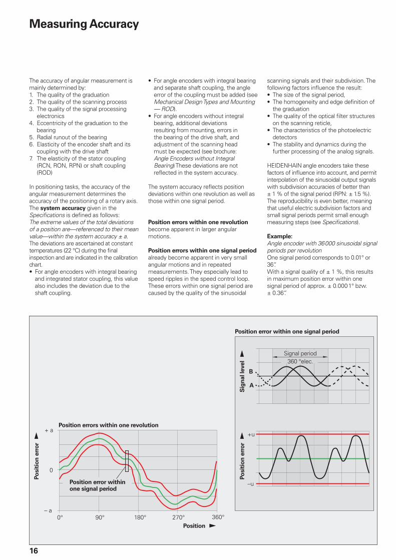
In positioning tasks, the accuracy of the angular measurement determines the accuracy of the positioning of a rotary axis. The system accuracy given in the Specifi cations is defi ned as follows:The extreme values of the total deviations of a position are—referenced to their mean value—within the system accuracy ± a.The deviations are ascertained at constant temperatures (22 °C) during the fi nal inspection and are indicated in the calibration chart.
For angle encoders with integral bearing and integrated stator coupling, this value also includes the deviation due to the shaft coupling.
•
For angle encoders with integral bearing and separate shaft coupling, the angle error of the coupling must be added (see Mechanical Design Types and Mounting — ROD).For angle encoders without integral bearing, additional deviations resulting from mounting, errors in the bearing of the drive shaft, and adjustment of the scanning head must be expected (see brochure: Angle Encoders without Integral Bearing) These deviations are not refl ected in the system accuracy.
The system accuracy refl ects position deviations within one revolution as well as those within one signal period.
Position errors within one revolution become apparent in larger angular motions.
Position errors within one signal period already become apparent in very small angular motions and in repeated measurements. They especially lead to speed ripples in the speed control loop. These errors within one signal period are caused by the quality of the sinusoidal
•
•
scanning signals and their subdivision. The following factors infl uence the result:
The size of the signal period,The homogeneity and edge defi nition of the graduationThe quality of the optical fi lter structures on the scanning reticle,The characteristics of the photoelectric detectorsThe stability and dynamics during the further processing of the analog signals.
HEIDENHAIN angle encoders take these factors of infl uence into account, and permit interpolation of the sinusoidal output signals with subdivision accuracies of better than ± 1 % of the signal period (RPN: ± 1.5 %). The reproducibility is even better, meaning that useful electric subdivision factors and small signal periods permit small enough measuring steps (see Specifi cations).
Example:
Angle encoder with 36000 sinusoidal signal periods per revolution One signal period corresponds to 0.01° or 36“.With a signal quality of ± 1 %, this results in maximum position error within one signal period of approx. ± 0.0001° bzw. ± 0.36“.
••
•
•
•
Position errors within one revolution
Position error within one signal period
Position !
Position error within one signal period
Po
sit
ion
err
or !
Po
sit
ion
err
or !
Sig
nal le
vel !
Signal period360 °elec.
1
2
17
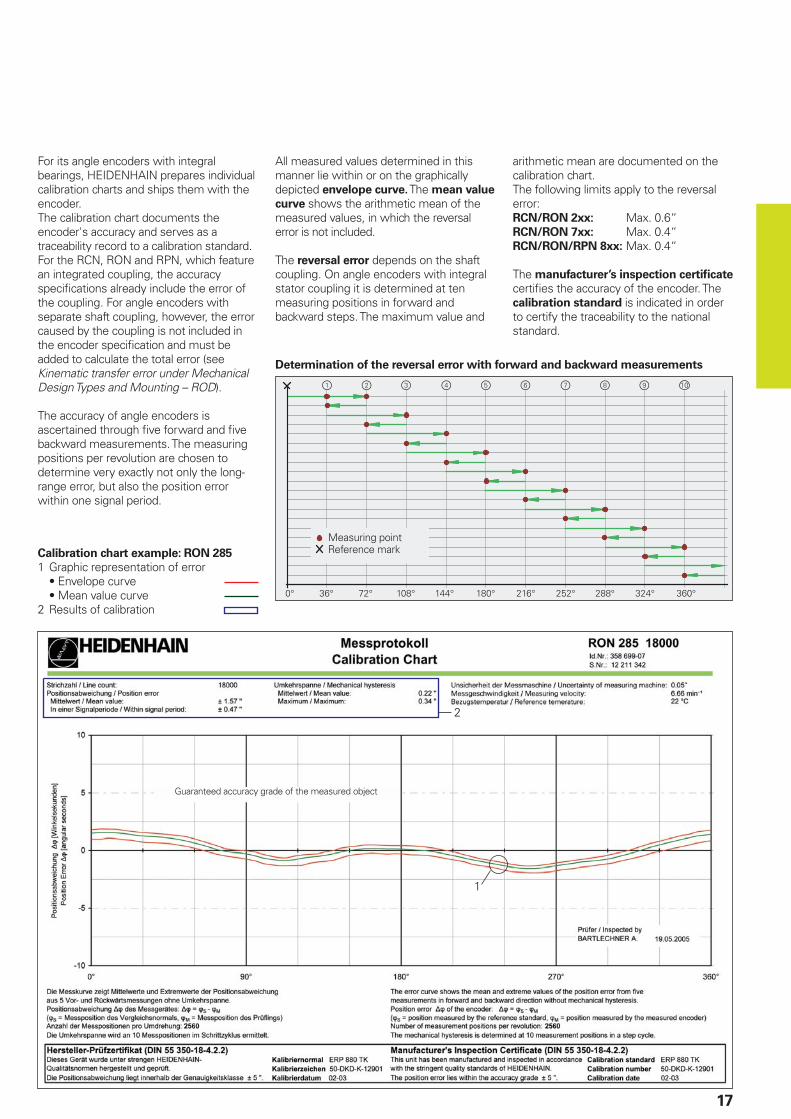
For its angle encoders with integral bearings, HEIDENHAIN prepares individual calibration charts and ships them with the encoder.The calibration chart documents the encoder's accuracy and serves as a traceability record to a calibration standard. For the RCN, RON and RPN, which feature an integrated coupling, the accuracy specifi cations already include the error of the coupling. For angle encoders with separate shaft coupling, however, the error caused by the coupling is not included in the encoder specifi cation and must be added to calculate the total error (see Kinematic transfer error under Mechanical Design Types and Mounting – ROD).
The accuracy of angle encoders is ascertained through fi ve forward and fi ve backward measurements. The measuring positions per revolution are chosen to determine very exactly not only the long-range error, but also the position error within one signal period.
All measured values determined in this manner lie within or on the graphically depicted envelope curve. The mean value
curve shows the arithmetic mean of the measured values, in which the reversal error is not included.
The reversal error depends on the shaft coupling. On angle encoders with integral stator coupling it is determined at ten measuring positions in forward and backward steps. The maximum value and
arithmetic mean are documented on the calibration chart.The following limits apply to the reversal error:RCN/RON 2xx: Max. 0.6“RCN/RON 7xx: Max. 0.4“RCN/RON/RPN 8xx: Max. 0.4“
The manufacturer’s inspection certifi cate certifi es the accuracy of the encoder. The calibration standard is indicated in order to certify the traceability to the national standard.
Calibration chart example: RON 285
1 Graphic representation of error • Envelope curve • Mean value curve2 Results of calibration
Determination of the reversal error with forward and backward measurements
Measuring pointReference mark
Guaranteed accuracy grade of the measured object

18
Mechanical Design Types and Mounting
RCN, RON, RPN
RCN, RON and RPN angle encoders have an integral bearing, hollow shaft and integrated stator coupling. The measured shaft is directly connected with the shaft of the angle encoder. The reference mark can be assigned to a desired angular position of the measured shaft from the rear of the encoder during mounting.The graduated disk is rigidly affi xed to the hollow shaft. The scanning unit rides on the shaft on ball bearings and is connected to the housing with a coupling on the stator side. During angular acceleration of the shaft, the coupling must absorb only that torque caused by friction in the bearing. Angle encoders with integrated stator coupling therefore provide excellent dynamic performance.
Mounting
The housing of the RCN, RON and RPN is fi rmly connected to the stationary machine part with an integral mounting fl ange and a centering collar. Liquids can easily fl ow away through drainage channels on the fl ange.
Shaft coupling with ring nut
The RCN, RON and RPN series have a hollow through shaft. For installation, the hollow through shaft of the angle encoder is placed over the machine shaft and is fi xed with a ring nut from the front of the encoder. The ring nut can easily be tightened with the mounting tool.
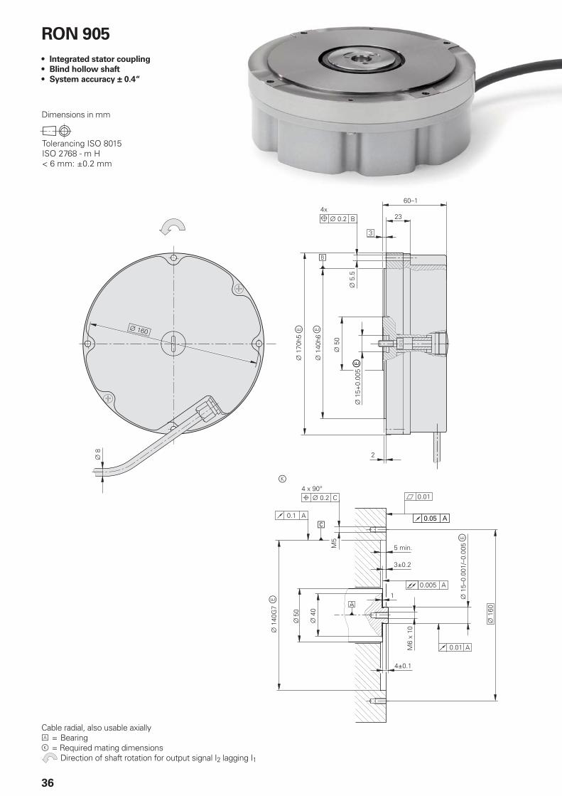
RON 905 shaft coupling
The RON 905 has a bottomed hollow shaft. The shaft connection is made via an axial central screw.
Front end shaft coupling
It is often advantageous, especially with rotary tables, to integrate the angle encoder in the table so that it is freely accessible when the rotor is lifted. This installation from above reduces mounting times, increases the ease for servicing, and improves the accuracy, since the encoder is located nearer to the rotary table bearing and the measuring or machining plane. The hollow shaft is attached with the threaded holes on the face, using special mounting elements fi tted to the individual design (not included in delivery).To comply with radial and axial runout specifi cations, the internal bore 1 and the shoulder surface 2 are to be used as mounting surfaces for shaft coupling at the face of the encoder.
Mounting an angle encoder with hollow through shaft
Integrated coupling
Photocells
DIADUR graduated disk
Light source (LED) with condenser lens
Hollow shaft
Cross section of the RON 886 angle encoder
Front end shaft coupling with RCN 729
Provided by customer
Rotor
RCN 729
Stator
Mounting aid
Ring nut
���
��
19
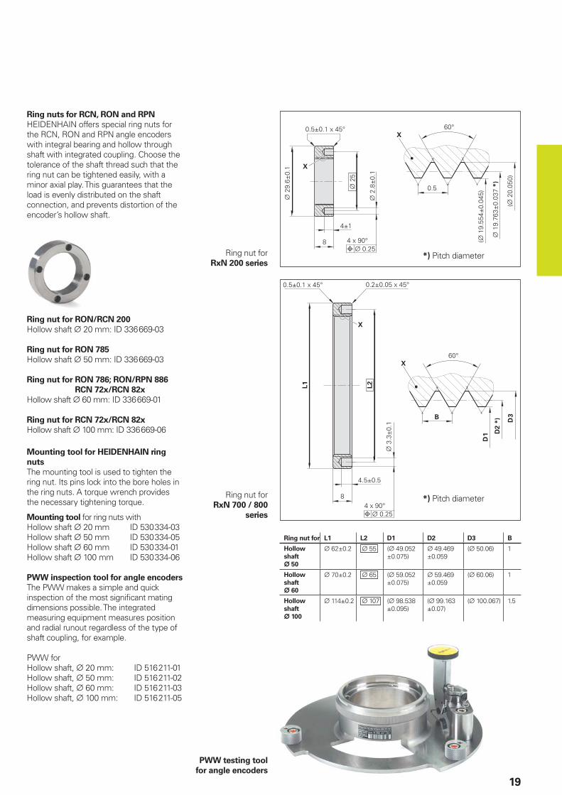
Ring nut for L1 L2 D1 D2 D3 B
Hollow
shaft
¬ 50
¬ 62±0.2 ¬ 55 (¬ 49.052±0.075)
¬ 49.469±0.059
(¬ 50.06) 1
Hollow
shaft
¬ 60
¬ 70±0.2 ¬ 65 (¬ 59.052±0.075)
¬ 59.469±0.059
(¬ 60.06) 1
Hollow
shaft
¬ 100
¬ 114±0.2 ¬ 107 (¬ 98.538±0.095)
(¬ 99.163±0.07)
(¬ 100.067) 1.5
Ring nuts for RCN, RON and RPN
HEIDENHAIN offers special ring nuts for the RCN, RON and RPN angle encoders with integral bearing and hollow through shaft with integrated coupling. Choose the tolerance of the shaft thread such that the ring nut can be tightened easily, with a minor axial play. This guarantees that the load is evenly distributed on the shaft connection, and prevents distortion of the encoder’s hollow shaft.
Ring nut for RON/RCN 200
Hollow shaft ¬ 20 mm: ID 336 669-03
Ring nut for RON 785
Hollow shaft ¬ 50 mm: ID 336 669-03
Ring nut for RON 786; RON/RPN 886
RCN 72x/RCN 82x
Hollow shaft ¬ 60 mm: ID 336 669-01
Ring nut for RCN 72x/RCN 82x
Hollow shaft ¬ 100 mm: ID 336 669-06
*) Pitch diameter
Ring nut forRxN 200 series
*) Pitch diameter
Mounting tool for HEIDENHAIN ring
nuts
The mounting tool is used to tighten the ring nut. Its pins lock into the bore holes in the ring nuts. A torque wrench provides the necessary tightening torque.
Mounting tool for ring nuts withHollow shaft ¬ 20 mm ID 530 334-03Hollow shaft ¬ 50 mm ID 530 334-05Hollow shaft ¬ 60 mm ID 530 334-01Hollow shaft ¬ 100 mm ID 530 334-06
PWW inspection tool for angle encoders
The PWW makes a simple and quick inspection of the most signifi cant mating dimensions possible. The integrated measuring equipment measures position and radial runout regardless of the type of shaft coupling, for example.
PWW for Hollow shaft, ¬ 20 mm: ID 516 211-01Hollow shaft, ¬ 50 mm: ID 516 211-02Hollow shaft, ¬ 60 mm: ID 516 211-03Hollow shaft, ¬ 100 mm: ID 516 211-05
Ring nut forRxN 700 / 800
series
PWW testing tool
for angle encoders
20
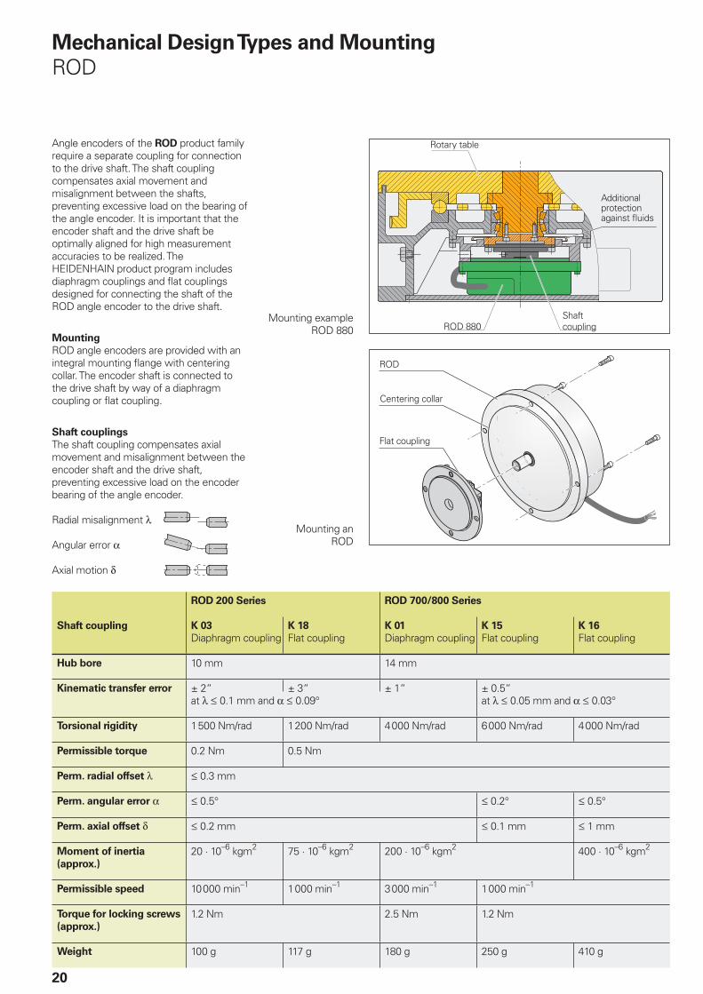
Angle encoders of the ROD product family require a separate coupling for connection to the drive shaft. The shaft coupling compensates axial movement and misalignment between the shafts, preventing excessive load on the bearing of the angle encoder. It is important that the encoder shaft and the drive shaft be optimally aligned for high measurement accuracies to be realized. The HEIDENHAIN product program includes diaphragm couplings and fl at couplings designed for connecting the shaft of the ROD angle encoder to the drive shaft.
Mounting
ROD angle encoders are provided with an integral mounting fl ange with centering collar. The encoder shaft is connected to the drive shaft by way of a diaphragm coupling or fl at coupling.
Shaft couplings
The shaft coupling compensates axial movement and misalignment between the encoder shaft and the drive shaft, preventing excessive load on the encoder bearing of the angle encoder.
Radial misalignment λ
Angular error α
Axial motion δ
Mechanical Design Types and Mounting
ROD
Mounting example ROD 880
Mounting anROD
Rotary table
ROD 880
Additional protection against fl uids
Shaft coupling
ROD
Centering collar
Flat coupling
ROD 200 Series ROD 700/800 Series
Shaft coupling K 03
Diaphragm couplingK 18
Flat couplingK 01
Diaphragm couplingK 15
Flat couplingK 16
Flat coupling
Hub bore 10 mm 14 mm
Kinematic transfer error ± 2“ ± 3“ ± 1“ ± 0.5“at λ † 0.1 mm and α † 0.09° at λ † 0.05 mm and α † 0.03°
Torsional rigidity 1500 Nm/rad 1200 Nm/rad 4000 Nm/rad 6000 Nm/rad 4000 Nm/rad
Permissible torque 0.2 Nm 0.5 Nm
Perm. radial offset λ † 0.3 mm
Perm. angular error α † 0.5° † 0.2° † 0.5°
Perm. axial offset δ † 0.2 mm † 0.1 mm † 1 mm
Moment of inertia
(approx.)
20 · 10–6 kgm2 75 · 10–6 kgm2 200 · 10–6 kgm2 400 · 10–6 kgm2
Permissible speed 10000 min–1 1000 min–1 3000 min–1 1000 min–1
Torque for locking screws
(approx.)
1.2 Nm 2.5 Nm 1.2 Nm
Weight 100 g 117 g 180 g 250 g 410 g
21
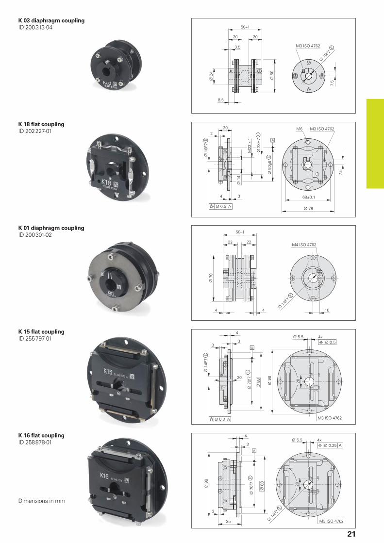
K 03 diaphragm coupling
ID 200313-04
K 18 fl at coupling
ID 202227-01
K 01 diaphragm coupling
ID 200301-02
K 15 fl at coupling
ID 255797-01
K 16 fl at coupling
ID 258878-01
Dimensions in mm
DA 300
22
Protection
Unless otherwise indicated, all RCN, RON, RPN and ROD angle encoders meet protection standard IP 67 according to IEC 60529 (EN 60529). This includes housings and cable outlets.The shaft inlet provides protection to IP 64.
Splash water should not contain any substances that would have harmful effects on the encoder parts. If protection to IP 64 of the shaft inlet is not suffi cient (such as when the angle encoder is mounted vertically), additional labyrinth seals should be provided.
RCN, RON, RPN and ROD angle encoders are equipped with a compressed air inlet. Connection to a source of compressed
air slightly above atmospheric pressure provides additional protection against contamination.
The compressed air introduced directly onto the encoders must be cleaned by a microfi lter, and must comply with the following quality classes as per ISO 8573-1
(2001 edition):Solid contaminants: Class 1(max. particle size 0.1 µm and max. particle density 0.1 mg/m3 at 1 · 105 Pa)Total oil content: Class 1(max. oil concentration 0.01 mg/m3 at 1 · 105 Pa)Maximum pressure dew point: Class 4, but with reference conditions of +3 °C at 2 · 105 Pa
•
•
•
General Mechanical Information
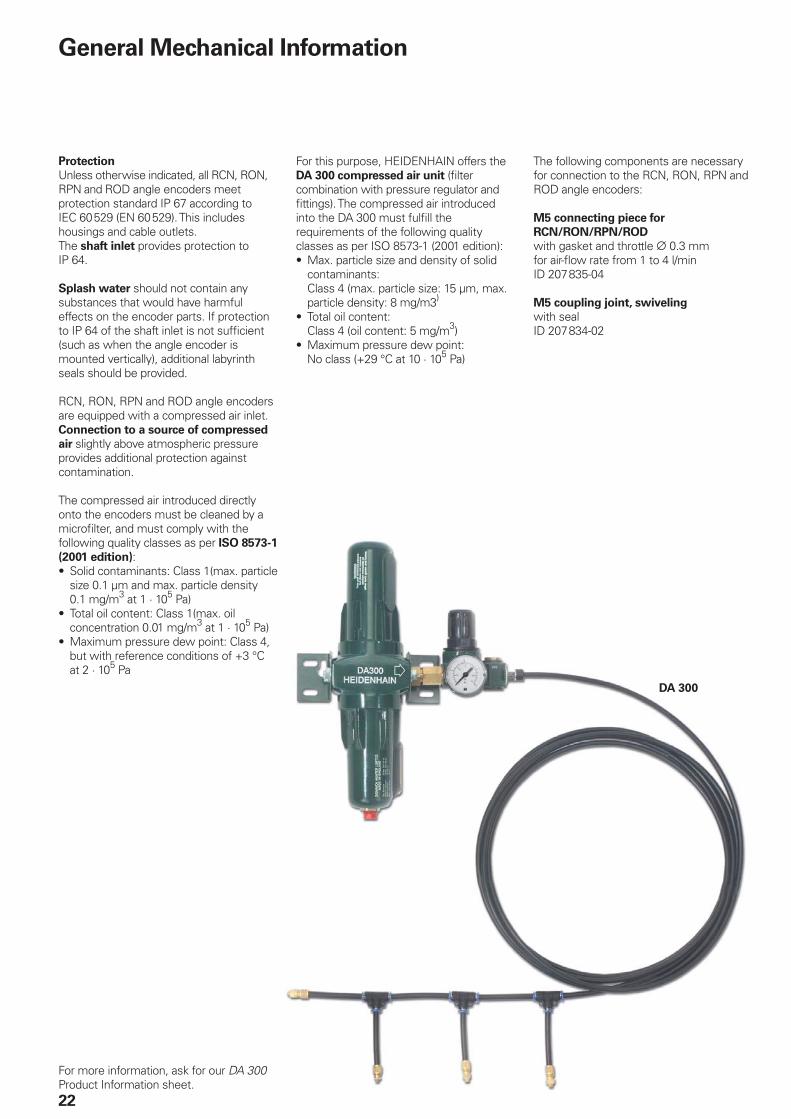
For this purpose, HEIDENHAIN offers the DA 300 compressed air unit (fi lter combination with pressure regulator and fi ttings). The compressed air introduced into the DA 300 must fulfi ll the requirements of the following quality classes as per ISO 8573-1 (2001 edition):
Max. particle size and density of solid contaminants: Class 4 (max. particle size: 15 µm, max. particle density: 8 mg/m3)
Total oil content: Class 4 (oil content: 5 mg/m3)Maximum pressure dew point: No class (+29 °C at 10 · 105 Pa)
•
•
•
The following components are necessary for connection to the RCN, RON, RPN and ROD angle encoders:
M5 connecting piece for
RCN/RON/RPN/ROD
with gasket and throttle ¬ 0.3 mmfor air-fl ow rate from 1 to 4 l/minID 207835-04
M5 coupling joint, swiveling
with sealID 207834-02
For more information, ask for our DA 300 Product Information sheet.
23
Temperature range
The angle encoders are inspected at a reference temperature of 22 °C. The system accuracy given in the calibration chart applies at this temperature.The operating temperature indicates the ambient temperature limits between which the angle encoders will function properly.The storage temperature range of –30 °C to 80 °C is valid when the unit remains in its packaging. The storage temperature for the RPN 886 may not exceed -10 °C to +50 °C.
Protection against contact
After encoder installation, all rotating parts (coupling on ROD, locking ring on RCN, RON and RPN) must be protected against accidental contact during operation.
Acceleration
Angle encoders are subject to various types of acceleration during operation and mounting.
The permissible angular acceleration for all RCN, RON, RPN and ROD angle encoders is over 105 rad/s2.The indicated maximum values for vibration are valid according to IEC 6068-2-6.The maximum permissible acceleration values (semi-sinusoidal shock) for shock
and impact are valid for 6 ms (IEC 60068-2-27). Under no circumstances should a hammer or similar implement be used to adjust or position the encoder.
•
•
•
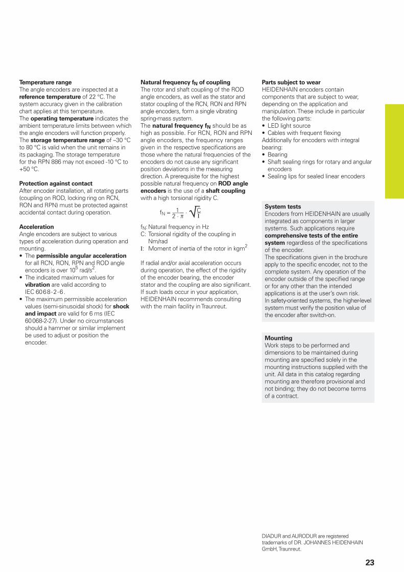
Natural frequency fN of coupling
The rotor and shaft coupling of the ROD angle encoders, as well as the stator and stator coupling of the RCN, RON and RPN angle encoders, form a single vibrating spring-mass system.The natural frequency fN should be as high as possible. For RCN, RON and RPN angle encoders, the frequency ranges given in the respective specifi cations are those where the natural frequencies of the encoders do not cause any signifi cant position deviations in the measuring direction. A prerequisite for the highest possible natural frequency on ROD angle
encoders is the use of a shaft coupling
with a high torsional rigidity C.
fN = 2 · þ
· ¹C
fN: Natural frequency in HzC: Torsional rigidity of the coupling in
Nm/radI: Moment of inertia of the rotor in kgm2
If radial and/or axial acceleration occurs during operation, the effect of the rigidity of the encoder bearing, the encoder stator and the coupling are also signifi cant. If such loads occur in your application, HEIDENHAIN recommends consulting with the main facility in Traunreut.
Parts subject to wear
HEIDENHAIN encoders contain components that are subject to wear, depending on the application and manipulation. These include in particular the following parts:
LED light sourceCables with frequent fl exing
Additionally for encoders with integral bearing:
BearingShaft sealing rings for rotary and angular encodersSealing lips for sealed linear encoders
••
••
•
System tests
Encoders from HEIDENHAIN are usually integrated as components in larger systems. Such applications require comprehensive tests of the entire
system regardless of the specifi cations of the encoder.The specifi cations given in the brochure apply to the specifi c encoder, not to the complete system. Any operation of the encoder outside of the specifi ed range or for any other than the intended applications is at the user’s own risk.In safety-oriented systems, the higher-level system must verify the position value of the encoder after switch-on.
Mounting
Work steps to be performed and dimensions to be maintained during mounting are specifi ed solely in the mounting instructions supplied with the unit. All data in this catalog regarding mounting are therefore provisional and not binding; they do not become terms of a contract.
DIADUR and AURODUR are registered trademarks of DR. JOHANNES HEIDENHAIN GmbH, Traunreut.
1I
� ��������������������������������������������
���� ��
�����������!�
24
Dimensions in mm
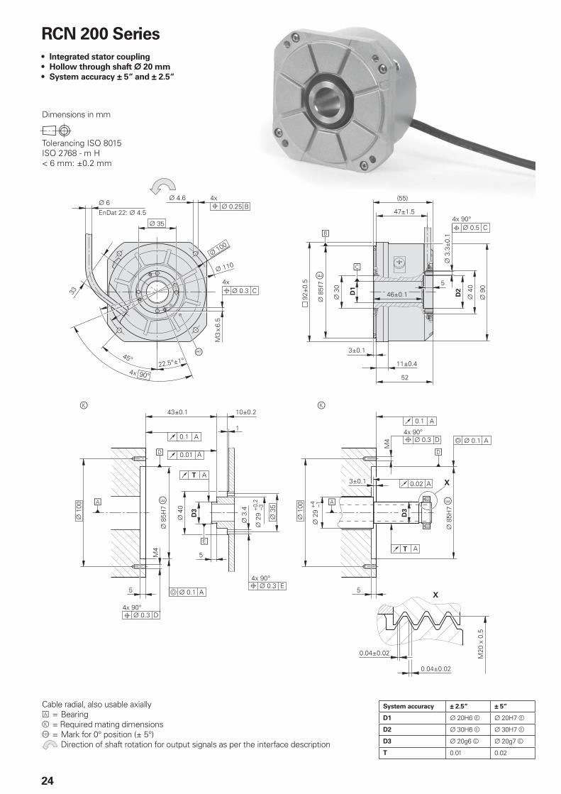
RCN 200 Series
Integrated stator coupling
Hollow through shaft ¬ 20 mm
System accuracy ± 5“ and ± 2.5“
•
•
•
System accuracy ± 2.5“ ± 5“
D1 ¬ 20H6 e ¬ 20H7 e
D2 ¬ 30H6 e ¬ 30H7 e
D3 ¬ 20g6 e ¬ 20g7 e
T 0.01 0.02
Cable radial, also usable axiallyA = Bearingk = Required mating dimensionsÀ = Mark for 0° position (± 5°) Direction of shaft rotation for output signals as per the interface description
25
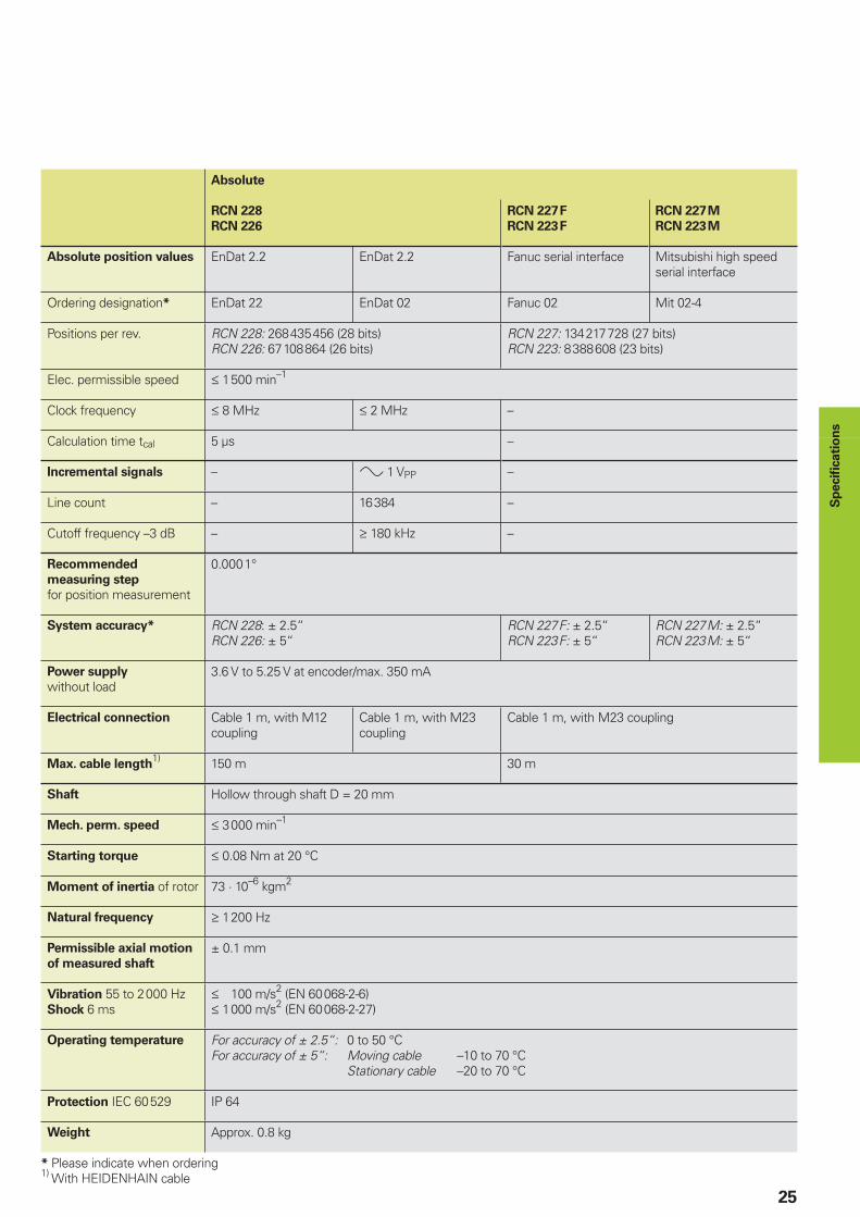
Absolute
RCN 228
RCN 226
RCN 227F
RCN 223F
RCN 227M
RCN 223M
Absolute position values EnDat 2.2 EnDat 2.2 Fanuc serial interface Mitsubishi high speed serial interface
Ordering designation* EnDat 22 EnDat 02 Fanuc 02 Mit 02-4
Positions per rev. RCN 228: 268435456 (28 bits)RCN 226: 67108864 (26 bits)
RCN 227: 134217728 (27 bits)RCN 223: 8388608 (23 bits)
Elec. permissible speed † 1500 min–1
Clock frequency † 8 MHz † 2 MHz –
Calculation time tcal 5 µs –
Incremental signals – » 1 VPP –
Line count – 16384 –
Cutoff frequency –3 dB – ‡ 180 kHz –
Recommended
measuring step
for position measurement
0.0001°
System accuracy* RCN 228: ± 2.5“RCN 226: ± 5“
RCN 227F: ± 2.5“RCN 223F: ± 5“
RCN 227M: ± 2.5“RCN 223M: ± 5“
Power supply
without load3.6 V to 5.25 V at encoder/max. 350 mA
Electrical connection Cable 1 m, with M12 coupling
Cable 1 m, with M23 coupling
Cable 1 m, with M23 coupling
Max. cable length1) 150 m 30 m
Shaft Hollow through shaft D = 20 mm
Mech. perm. speed † 3000 min–1
Starting torque † 0.08 Nm at 20 °C
Moment of inertia of rotor 73 · 10–6 kgm2
Natural frequency ‡ 1200 Hz
Permissible axial motion
of measured shaft
± 0.1 mm
Vibration 55 to 2000 HzShock 6 ms
† 100 m/s2 (EN 60068-2-6)† 1000 m/s2 (EN 60068-2-27)
Operating temperature For accuracy of ± 2.5“: 0 to 50 °CFor accuracy of ± 5“: Moving cable –10 to 70 °C Stationary cable –20 to 70 °C
Protection IEC 60529 IP 64
Weight Approx. 0.8 kg
* Please indicate when ordering1) With HEIDENHAIN cable
Sp
ecifi c
ati
on
s
���� ��
�����������!�
� ��������������������������������������������
26
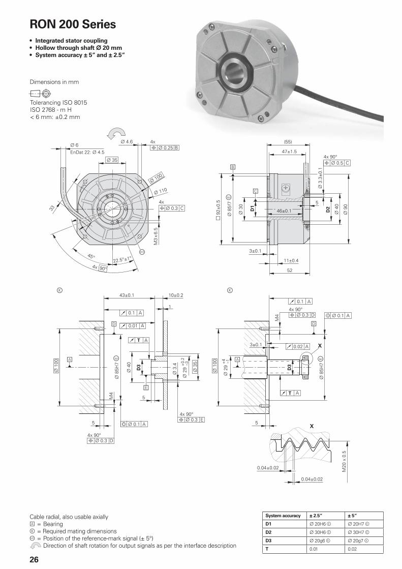
RON 200 Series
Integrated stator coupling
Hollow through shaft ¬ 20 mm
System accuracy ± 5“ and ± 2.5“
•
•
•
Dimensions in mm
System accuracy ± 2.5“ ± 5“
D1 ¬ 20H6 e ¬ 20H7 e
D2 ¬ 30H6 e ¬ 30H7 e
D3 ¬ 20g6 e ¬ 20g7 e
T 0.01 0.02
Cable radial, also usable axiallyA = Bearingk = Required mating dimensionsÀ = Position of the reference-mark signal (± 5°) Direction of shaft rotation for output signals as per the interface description
27
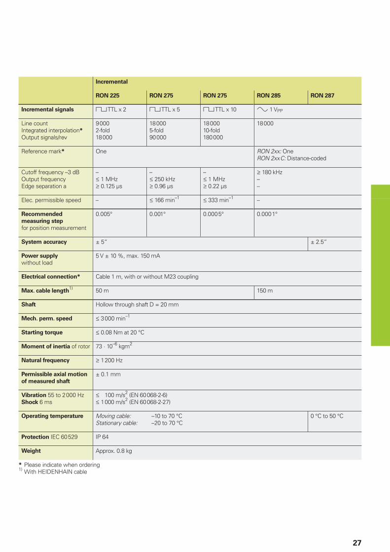
Incremental
RON 225 RON 275 RON 275 RON 285 RON 287
Incremental signals « TTL x 2 « TTL x 5 « TTL x 10 » 1 VPP
Line countIntegrated interpolation*
Output signals/rev
90002-fold18000
180005-fold90000
1800010-fold180000
18000
Reference mark* One RON 2xx: OneRON 2xxC: Distance-coded
Cutoff frequency –3 dBOutput frequencyEdge separation a
–† 1 MHz‡ 0.125 µs
–† 250 kHz‡ 0.96 µs
–† 1 MHz‡ 0.22 µs
‡ 180 kHz––
Elec. permissible speed – † 166 min–1 † 333 min–1 –
Recommended
measuring step
for position measurement
0.005° 0.001° 0.0005° 0.0001°
System accuracy ± 5“ ± 2.5“
Power supply
without load5 V ± 10 %, max. 150 mA
Electrical connection* Cable 1 m, with or without M23 coupling
Max. cable length1) 50 m 150 m
Shaft Hollow through shaft D = 20 mm
Mech. perm. speed † 3000 min–1
Starting torque † 0.08 Nm at 20 °C
Moment of inertia of rotor 73 · 10–6 kgm2
Natural frequency ‡ 1200 Hz
Permissible axial motion
of measured shaft
± 0.1 mm
Vibration 55 to 2000 HzShock 6 ms
† 100 m/s2 (EN 60068-2-6)† 1000 m/s2 (EN 60068-2-27)
Operating temperature Moving cable: –10 to 70 °CStationary cable: –20 to 70 °C
0 °C to 50 °C
Protection IEC 60529 IP 64
Weight Approx. 0.8 kg
* Please indicate when ordering1) With HEIDENHAIN cable
� ��
������"
�����#
�
�
�
� ��������������������������������������������
28
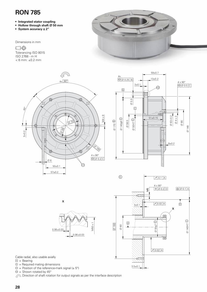
RON 785
Integrated stator coupling
Hollow through shaft ¬ 50 mm
System accuracy ± 2“
•
•
•
Dimensions in mm
Cable radial, also usable axiallyA = Bearingk = Required mating dimensionsÀ = Position of the reference-mark signal (± 5°)Á = Shown rotated by 45° Direction of shaft rotation for output signals as per the interface description
29
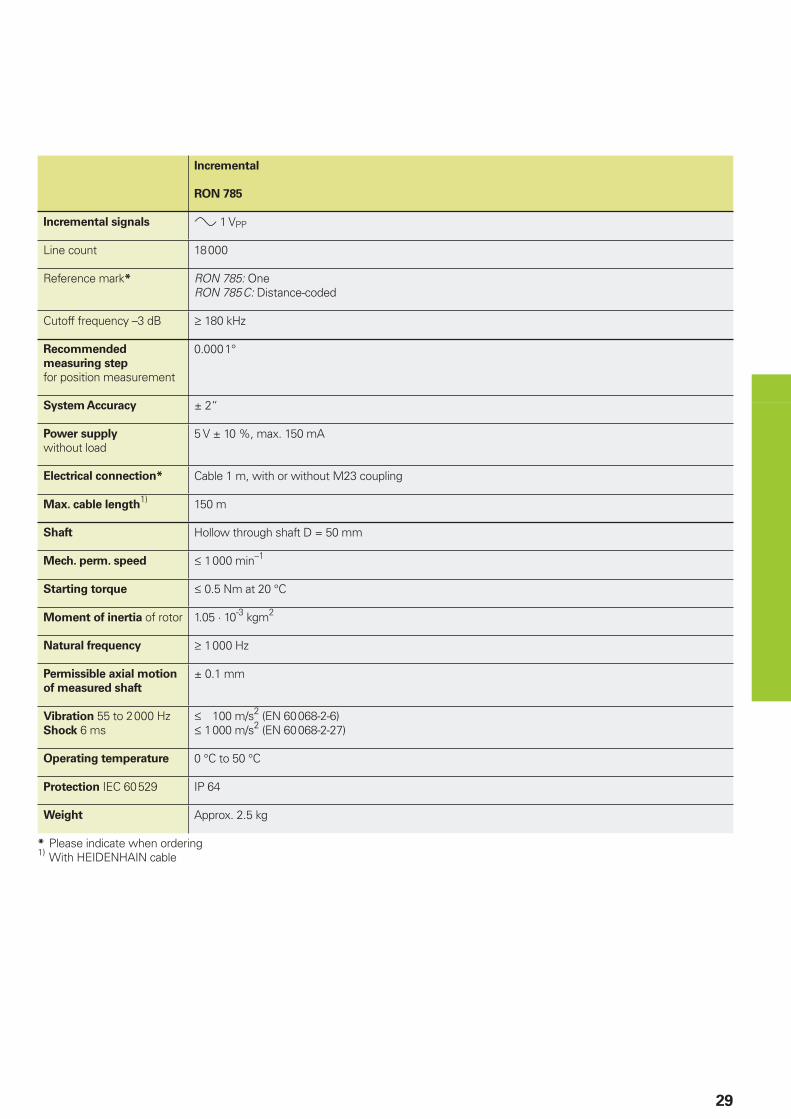
Incremental
RON 785
Incremental signals » 1 VPP
Line count 18000
Reference mark* RON 785: OneRON 785C: Distance-coded
Cutoff frequency –3 dB ‡ 180 kHz
Recommended
measuring step
for position measurement
0.0001°
System Accuracy ± 2“
Power supply
without load5 V ± 10 %, max. 150 mA
Electrical connection* Cable 1 m, with or without M23 coupling
Max. cable length1) 150 m
Shaft Hollow through shaft D = 50 mm
Mech. perm. speed † 1000 min–1
Starting torque † 0.5 Nm at 20 °C
Moment of inertia of rotor 1.05 · 10-3 kgm2
Natural frequency ‡ 1000 Hz
Permissible axial motion
of measured shaft
± 0.1 mm
Vibration 55 to 2000 HzShock 6 ms
† 100 m/s2 (EN 60068-2-6)† 1000 m/s2 (EN 60068-2-27)
Operating temperature 0 °C to 50 °C
Protection IEC 60529 IP 64
Weight Approx. 2.5 kg
* Please indicate when ordering1) With HEIDENHAIN cable
�
�
� �
� ��������������������������������������������
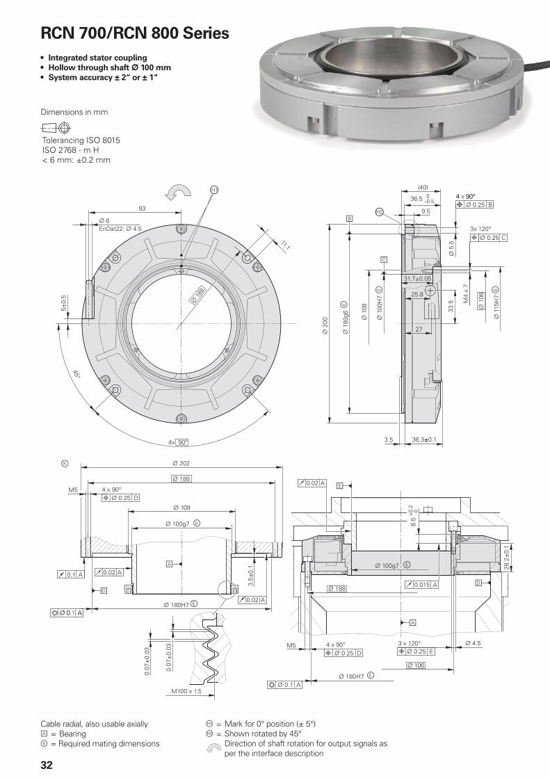
30
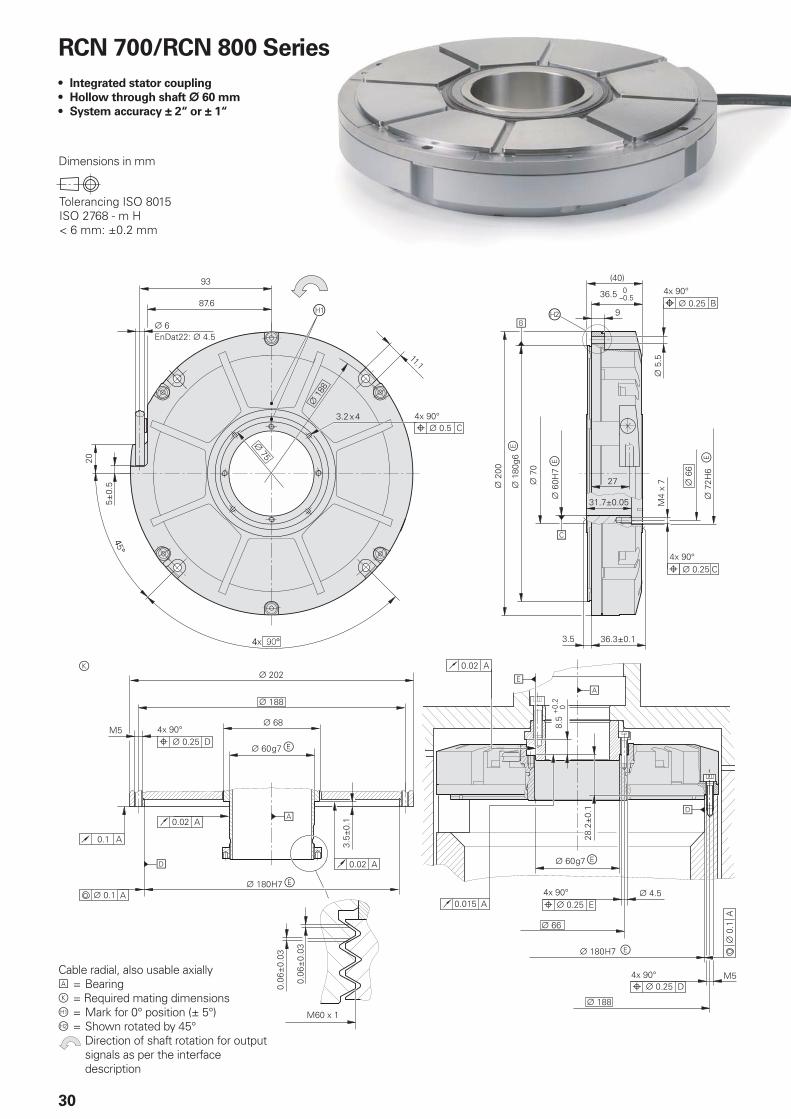
RCN 700/RCN 800 Series
Integrated stator coupling
Hollow through shaft ¬ 60 mm
System accuracy ± 2“ or ± 1“
•
•
•
Dimensions in mm
Cable radial, also usable axiallyA = Bearingk = Required mating dimensionsÀ = Mark for 0° position (± 5°)Á = Shown rotated by 45° Direction of shaft rotation for output
signals as per the interface description

31
Absolute
RCN 729
RCN 829
RCN 729
RCN 829
RCN 727F
RCN 827F
RCN 727M
RCN 827M
Absolute position values EnDat 2.2 EnDat 2.2 Fanuc 02 serial interface Mitsubishi high speed serial interface
Ordering designation* EnDat 22 EnDat 02 Fanuc 02 Mit 02-4
Positions per rev. 536870912 (29 bits) 134217728 (27 bits)
Elec. permissible speed † 300 min–1 (for continuous position value)
Clock frequency † 8 MHz † 2 MHz –
Calculation time tcal 5 µs –
Incremental signals – » 1 VPP –
Line count* – 32768 –
Cutoff frequency –3 dB – ‡ 180 kHz –
Recommended
measuring step
for position measurement
RCN 72x: 0.0001°RCN 82x: 0.00005°
System accuracy RCN 72x: ± 2“RCN 82x: ± 1“
Power supply
without load3.6 to 5.25 V, max. 350 mA
Electrical connection* Cable 1 m, with M12 coupling
Cable 1 m, with M23 coupling
Max. cable length1) 150 m 30 m
Shaft Hollow through shaft D = 60 mm
Mech. perm. speed † 1000 min–1
Starting torque † 0.5 Nm at 20 °C
Moment of inertia of rotor 1.3 · 10-3 kgm2
Natural frequency ‡ 1000 Hz
Permissible axial motion
of measured shaft
† ± 0.1 mm
Vibration 55 to 2000 HzShock 6 ms
† 100 m/s2 (EN 60068-2-6)† 1000 m/s2 (EN 60068-2-27)
Operating temperature 0 °C to 50 °C
Protection IEC 60529 IP 64
Weight Approx. 2.8 kg
* Please indicate when ordering1) With HEIDENHAIN cable
�
�
� ��������������������������������������������
32
RCN 700/RCN 800 Series
Integrated stator coupling
Hollow through shaft ¬ 100 mm
System accuracy ± 2“ or ± 1“
•
•
•
Dimensions in mm
Cable radial, also usable axiallyA = Bearingk = Required mating dimensions
À = Mark for 0° position (± 5°)Á = Shown rotated by 45° Direction of shaft rotation for output signals as
per the interface description
33
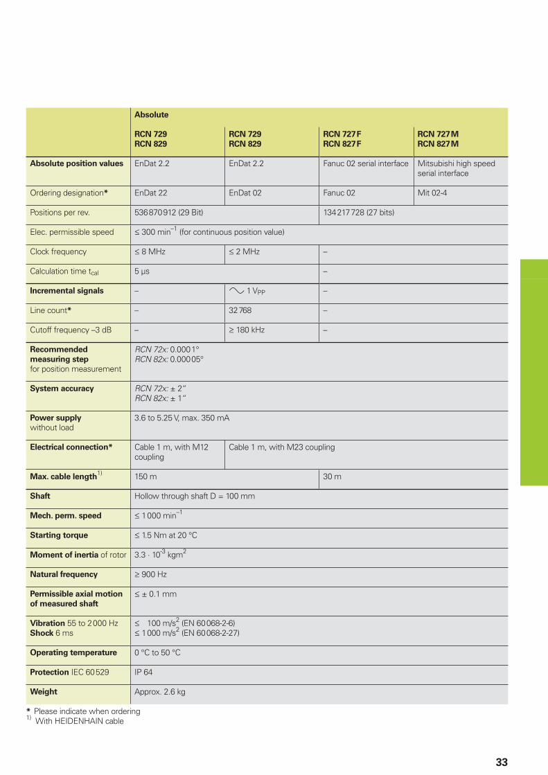
Absolute
RCN 729
RCN 829
RCN 729
RCN 829
RCN 727F
RCN 827F
RCN 727M
RCN 827M
Absolute position values EnDat 2.2 EnDat 2.2 Fanuc 02 serial interface Mitsubishi high speed serial interface
Ordering designation* EnDat 22 EnDat 02 Fanuc 02 Mit 02-4
Positions per rev. 536870912 (29 Bit) 134217728 (27 bits)
Elec. permissible speed † 300 min–1 (for continuous position value)
Clock frequency † 8 MHz † 2 MHz –
Calculation time tcal 5 µs –
Incremental signals – » 1 VPP –
Line count* – 32768 –
Cutoff frequency –3 dB – ‡ 180 kHz –
Recommended
measuring step
for position measurement
RCN 72x: 0.0001°RCN 82x: 0.00005°
System accuracy RCN 72x: ± 2“RCN 82x: ± 1“
Power supply
without load3.6 to 5.25 V, max. 350 mA
Electrical connection* Cable 1 m, with M12 coupling
Cable 1 m, with M23 coupling
Max. cable length1) 150 m 30 m
Shaft Hollow through shaft D = 100 mm
Mech. perm. speed † 1000 min–1
Starting torque † 1.5 Nm at 20 °C
Moment of inertia of rotor 3.3 · 10-3 kgm2
Natural frequency ‡ 900 Hz
Permissible axial motion
of measured shaft
† ± 0.1 mm
Vibration 55 to 2000 HzShock 6 ms
† 100 m/s2 (EN 60068-2-6)† 1000 m/s2 (EN 60068-2-27)
Operating temperature 0 °C to 50 °C
Protection IEC 60529 IP 64
Weight Approx. 2.6 kg
* Please indicate when ordering1) With HEIDENHAIN cable
�
�
� �
� ��������������������������������������������
34
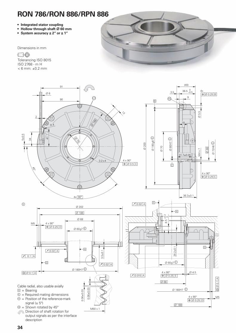
RON 786/RON 886/RPN 886
Integrated stator coupling
Hollow through shaft ¬ 60 mm
System accuracy ± 2“ or ± 1“
•
•
•
Dimensions in mm
Cable radial, also usable axiallyA = Bearingk = Required mating dimensionsÀ = Position of the reference-mark
signal (± 5°) Á = Shown rotated by 45° Direction of shaft rotation for
output signals as per the interface description
35
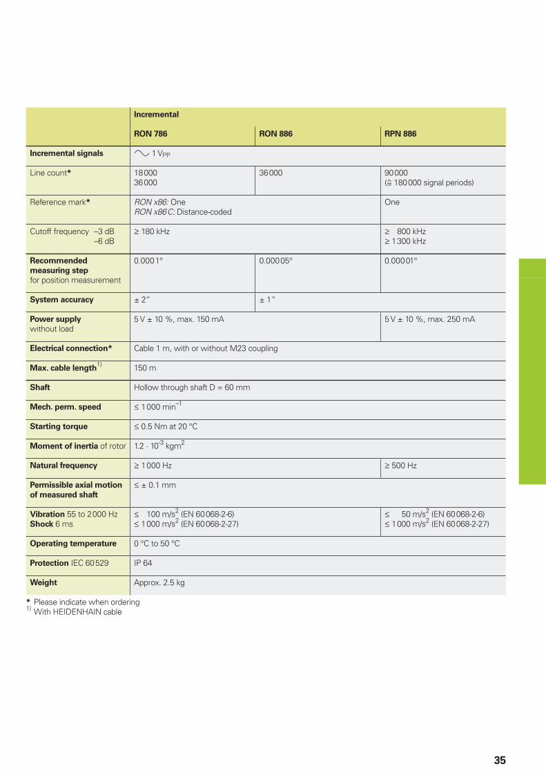
Incremental
RON 786 RON 886 RPN 886
Incremental signals » 1 VPP
Line count* 1800036000
36000 90000(ƒ 180000 signal periods)
Reference mark* RON x86: OneRON x86C: Distance-coded
One
Cutoff frequency –3 dB –6 dB
‡ 180 kHz ‡ 800 kHz‡ 1300 kHz
Recommended
measuring step
for position measurement
0.0001° 0.00005° 0.00001°
System accuracy ± 2“ ± 1“
Power supply
without load5 V ± 10 %, max. 150 mA 5 V ± 10 %, max. 250 mA
Electrical connection* Cable 1 m, with or without M23 coupling
Max. cable length1) 150 m
Shaft Hollow through shaft D = 60 mm
Mech. perm. speed † 1000 min–1
Starting torque † 0.5 Nm at 20 °C
Moment of inertia of rotor 1.2 · 10-3 kgm2
Natural frequency ‡ 1000 Hz ‡ 500 Hz
Permissible axial motion
of measured shaft
† ± 0.1 mm
Vibration 55 to 2000 HzShock 6 ms
† 100 m/s2 (EN 60068-2-6)† 1000 m/s2 (EN 60068-2-27)
† 50 m/s2 (EN 60068-2-6)† 1000 m/s2 (EN 60068-2-27)
Operating temperature 0 °C to 50 °C
Protection IEC 60529 IP 64
Weight Approx. 2.5 kg
* Please indicate when ordering1) With HEIDENHAIN cable
������$
� ��������������������������������������������
36
RON 905
Integrated stator coupling
Blind hollow shaft
System accuracy ± 0.4“
•
•
•
Dimensions in mm
Cable radial, also usable axiallyA = Bearingk = Required mating dimensions Direction of shaft rotation for output signal I2 lagging I1
37
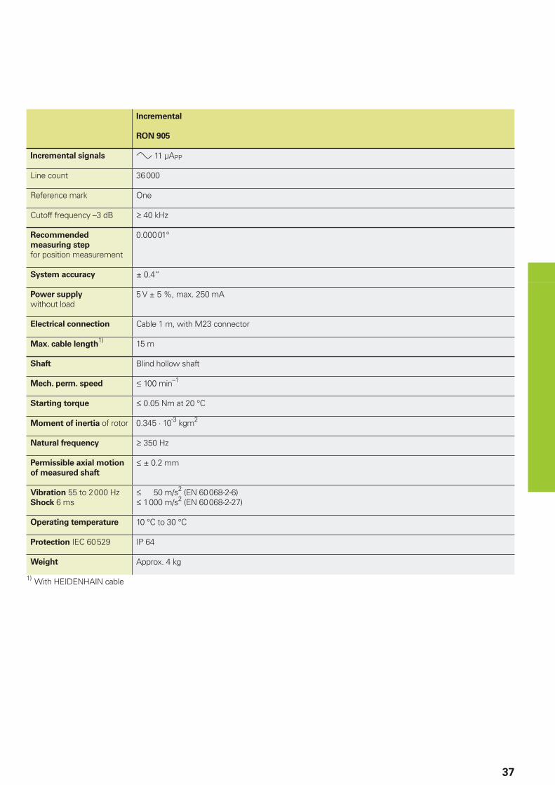
Incremental
RON 905
Incremental signals » 11 µAPP
Line count 36000
Reference mark One
Cutoff frequency –3 dB ‡ 40 kHz
Recommended
measuring step
for position measurement
0.00001°
System accuracy ± 0.4“
Power supply
without load5 V ± 5 %, max. 250 mA
Electrical connection Cable 1 m, with M23 connector
Max. cable length1) 15 m
Shaft Blind hollow shaft
Mech. perm. speed † 100 min–1
Starting torque † 0.05 Nm at 20 °C
Moment of inertia of rotor 0.345 · 10-3 kgm2
Natural frequency ‡ 350 Hz
Permissible axial motion
of measured shaft
† ± 0.2 mm
Vibration 55 to 2000 HzShock 6 ms
† 50 m/s2 (EN 60068-2-6)† 1000 m/s2 (EN 60068-2-27)
Operating temperature 10 °C to 30 °C
Protection IEC 60529 IP 64
Weight Approx. 4 kg
1) With HEIDENHAIN cable
�
� ��������������������������������������������
38
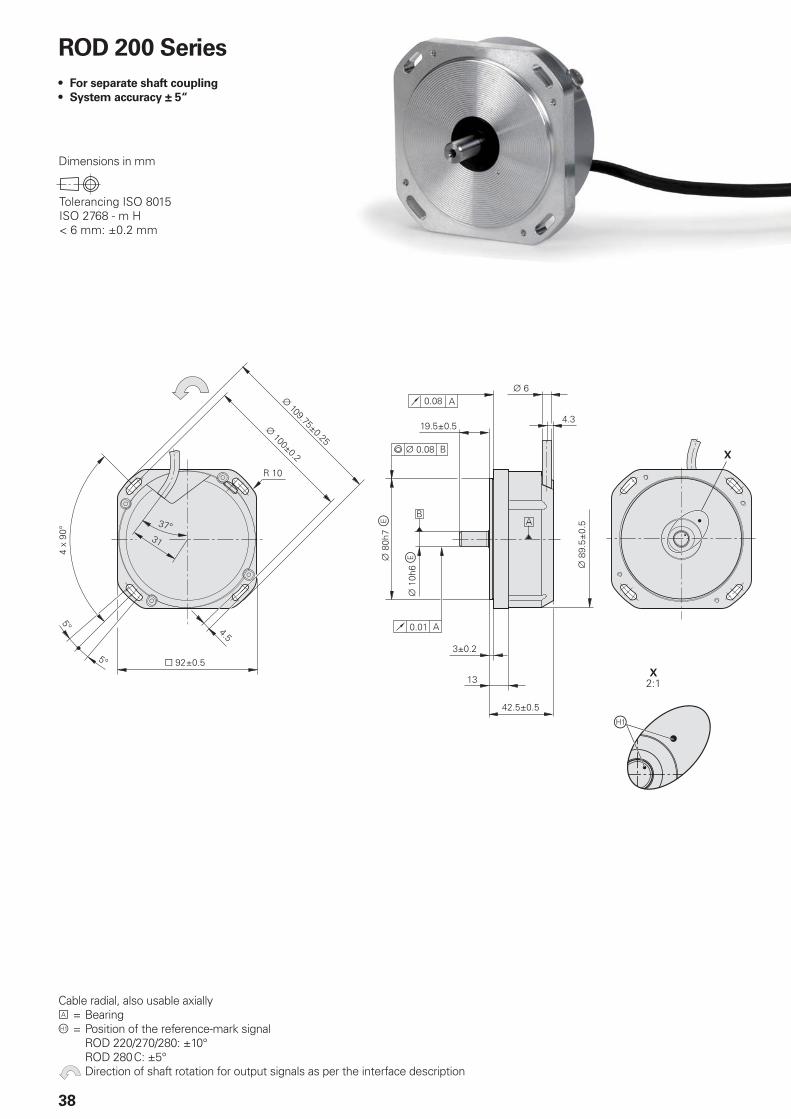
ROD 200 Series
For separate shaft coupling
System accuracy ± 5“
•
•
Dimensions in mm
Cable radial, also usable axiallyA = BearingÀ = Position of the reference-mark signal ROD 220/270/280: ±10° ROD 280C: ±5° Direction of shaft rotation for output signals as per the interface description
39
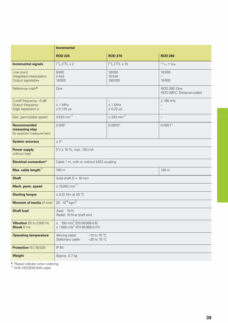
Incremental
ROD 220 ROD 270 ROD 280
Incremental signals « TTL x 2 « TTL x 10 » 1 VPP
Line countIntegrated interpolationOutput signals/rev
90002-fold18000
1800010-fold180000
18000–18000
Reference mark* One ROD 280: OneROD 280C: Distance-coded
Cutoff frequency –3 dBOutput frequencyEdge separation a
–† 1 MHz‡ 0.125 µs
–† 1 MHz‡ 0.22 µs
‡ 180 kHz––
Elec. permissible speed 3333 min–1 † 333 min–1 –
Recommended
measuring step
for position measurement
0.005° 0.0005° 0.0001°
System accuracy ± 5“
Power supply
without load5 V ± 10 %, max. 150 mA
Electrical connection* Cable 1 m, with or without M23 coupling
Max. cable length1) 100 m 150 m
Shaft Solid shaft D = 10 mm
Mech. perm. speed † 10000 min–1
Starting torque † 0.01 Nm at 20 °C
Moment of inertia of rotor 20 · 10-6 kgm2
Shaft load Axial: 10 NRadial: 10 N at shaft end
Vibration 55 to 2000 HzShock 6 ms
† 100 m/s2 (EN 60068-2-6)† 1000 m/s2 (EN 60068-2-27)
Operating temperature Moving cable: –10 to 70 °CStationary cable: –20 to 70 °C
Protection IEC 60529 IP 64
Weight Approx. 0.7 kg
* Please indicate when ordering1) With HEIDENHAIN cable
� ��������������������������������������������
40
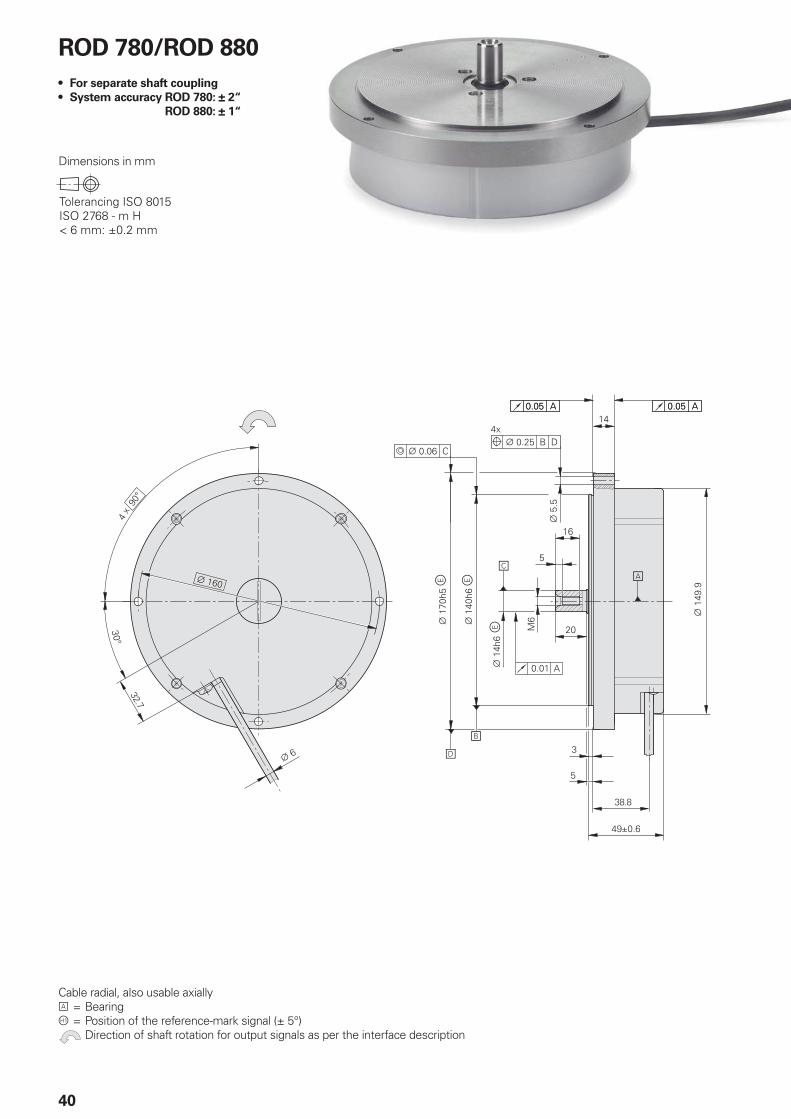
ROD 780/ROD 880
For separate shaft coupling
System accuracy ROD 780: ± 2“
ROD 880: ± 1“
•
•
Dimensions in mm
Cable radial, also usable axiallyA = BearingÀ = Position of the reference-mark signal (± 5°) Direction of shaft rotation for output signals as per the interface description
41
Incremental
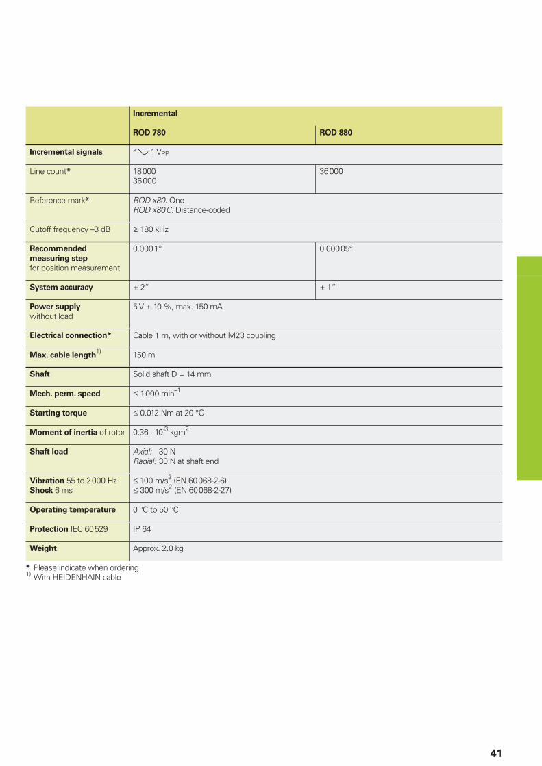
ROD 780 ROD 880
Incremental signals » 1 VPP
Line count* 1800036000
36000
Reference mark* ROD x80: OneROD x80C: Distance-coded
Cutoff frequency –3 dB ‡ 180 kHz
Recommended
measuring step
for position measurement
0.0001° 0.00005°
System accuracy ± 2“ ± 1“
Power supply
without load5 V ± 10 %, max. 150 mA
Electrical connection* Cable 1 m, with or without M23 coupling
Max. cable length1) 150 m
Shaft Solid shaft D = 14 mm
Mech. perm. speed † 1000 min–1
Starting torque † 0.012 Nm at 20 °C
Moment of inertia of rotor 0.36 · 10-3 kgm2
Shaft load Axial: 30 NRadial: 30 N at shaft end
Vibration 55 to 2000 HzShock 6 ms
† 100 m/s2 (EN 60068-2-6)† 300 m/s2 (EN 60068-2-27)
Operating temperature 0 °C to 50 °C
Protection IEC 60529 IP 64
Weight Approx. 2.0 kg
* Please indicate when ordering1) With HEIDENHAIN cable
42
Signal period360° elec.
(Rated value)
A, B, R measured with oscilloscope in differential mode
Sig
nal am
plitu
de [
%]!
Scanning frequency [kHz]!–3 dB cutoff frequency–6 dB cutoff frequency
Interfaces
Incremental Signals » 1 VPP
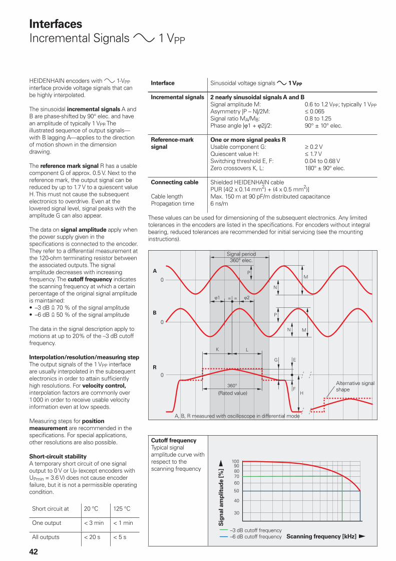
HEIDENHAIN encoders with » 1-VPP interface provide voltage signals that can be highly interpolated.
The sinusoidal incremental signals A and B are phase-shifted by 90° elec. and have an amplitude of typically 1 VPP. The illustrated sequence of output signals—with B lagging A—applies to the direction of motion shown in the dimension drawing.
The reference mark signal R has a usable component G of approx. 0.5 V. Next to the reference mark, the output signal can be reduced by up to 1.7 V to a quiescent value H. This must not cause the subsequent electronics to overdrive. Even at the lowered signal level, signal peaks with the amplitude G can also appear.
The data on signal amplitude apply when the power supply given in the specifi cations is connected to the encoder. They refer to a differential measurement at the 120-ohm terminating resistor between the associated outputs. The signal amplitude decreases with increasing frequency. The cutoff frequency indicates the scanning frequency at which a certain percentage of the original signal amplitude is maintained:
–3 dB ƒ 70 % of the signal amplitude–6 dB ƒ 50 % of the signal amplitude
The data in the signal description apply to motions at up to 20% of the –3 dB cutoff frequency.
Interpolation/resolution/measuring step
The output signals of the 1 VPP interface are usually interpolated in the subsequent electronics in order to attain suffi ciently high resolutions. For velocity control, interpolation factors are commonly over 1000 in order to receive usable velocity information even at low speeds.
Measuring steps for position
measurement are recommended in the specifi cations. For special applications, other resolutions are also possible.
Short-circuit stability
A temporary short circuit of one signal output to 0 V or UP (except encoders with UPmin = 3.6 V) does not cause encoder failure, but it is not a permissible operating condition.
Short circuit at 20 °C 125 °C
One output < 3 min < 1 min
All outputs < 20 s < 5 s
••
Interface Sinusoidal voltage signals » 1 VPP
Incremental signals 2 nearly sinusoidal signals A and B
Signal amplitude M: 0.6 to 1.2 VPP; typically 1 VPPAsymmetry |P – N|/2M: † 0.065Signal ratio MA/MB: 0.8 to 1.25Phase angle |ϕ1 + ϕ2|/2: 90° ± 10° elec.
Reference-mark
signal
One or more signal peaks R
Usable component G: ‡ 0.2 VQuiescent value H: † 1.7 VSwitching threshold E, F: 0.04 to 0.68 VZero crossovers K, L: 180° ± 90° elec.
Connecting cable
Cable lengthPropagation time
Shielded HEIDENHAIN cablePUR [4(2 x 0.14 mm2) + (4 x 0.5 mm2)]Max. 150 m at 90 pF/m distributed capacitance6 ns/m
These values can be used for dimensioning of the subsequent electronics. Any limited tolerances in the encoders are listed in the specifi cations. For encoders without integral bearing, reduced tolerances are recommended for initial servicing (see the mounting instructions).
Alternative signal shape
Cutoff frequency
Typical signal amplitude curve with respect to the scanning frequency
43
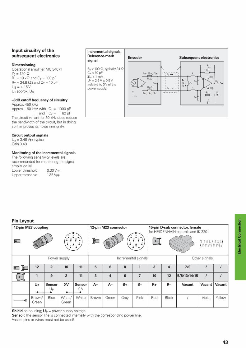
Pin Layout
12-pin M23 coupling 12-pin M23 connector 15-pin D-sub connector, female
for HEIDENHAIN controls and IK 220
Power supply Incremental signals Other signals
12 2 10 11 5 6 8 1 3 4 7/9 / /
1 9 2 11 3 4 6 7 10 12 5/8/13/14/15 / /
UP Sensor
UP
0 V Sensor
0 VA+ A– B+ B– R+ R– Vacant Vacant Vacant
Brown/Green
Blue White/Green
White Brown Green Gray Pink Red Black / Violet Yellow
Shield on housing; UP = power supply voltageSensor: The sensor line is connected internally with the corresponding power line.Vacant pins or wires must not be used!
Ele
ctr
ical C
on
necti
on
Input circuitry of the
subsequent electronics
Dimensioning
Operational amplifi er MC 34074Z0 = 120 −R1 = 10 k− and C1 = 100 pFR2 = 34.8 k− and C2 = 10 pFUB = ± 15 VU1 approx. U0
–3dB cutoff frequency of circuitry
Approx. 450 kHzApprox. 50 kHz with C1 = 1000 pF and C2 = 82 pFThe circuit variant for 50 kHz does reduce the bandwidth of the circuit, but in doing so it improves its noise immunity.
Circuit output signals
Ua = 3.48 VPP typicalGain 3.48
Monitoring of the incremental signals
The following sensitivity levels are recommended for monitoring the signal amplitude M: Lower threshold: 0.30 VPPUpper threshold: 1.35 VPP
Encoder Subsequent electronics
Incremental signals
Reference-mark
signal
Ra < 100 −, typically 24 −Ca < 50 pFΣIa < 1 mAU0 = 2.5 V ± 0.5 V(relative to 0 V of the power supply)
���
%�
�� ��� ��� ��& ��� �� ���
�
��
�
���
�
����
44
Interfaces
Incremental signals « TTL
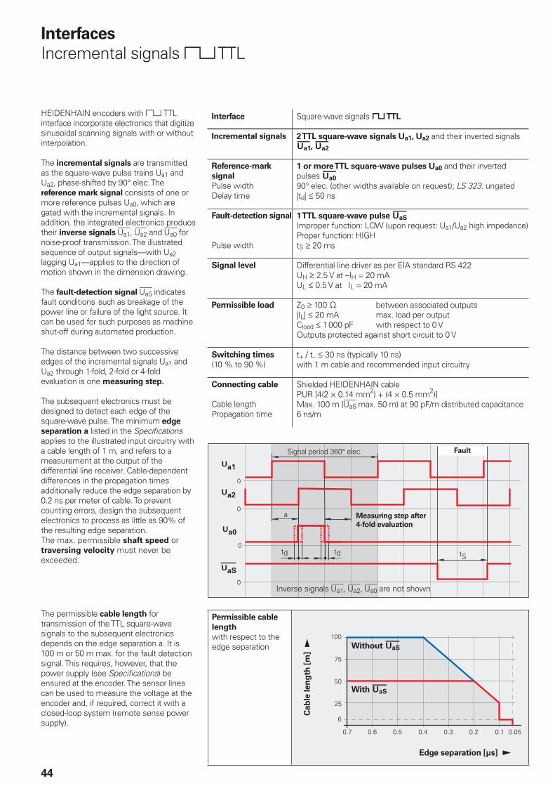
HEIDENHAIN encoders with « TTL interface incorporate electronics that digitize sinusoidal scanning signals with or without interpolation.
The incremental signals are transmitted as the square-wave pulse trains Ua1 and Ua2, phase-shifted by 90° elec. The reference mark signal consists of one or more reference pulses Ua0, which are gated with the incremental signals. In addition, the integrated electronics produce their inverse signals 4, £ and ¤ for noise-proof transmission. The illustrated sequence of output signals—with Ua2 lagging Ua1—applies to the direction of motion shown in the dimension drawing.
The fault-detection signal ¥ indicates fault conditions such as breakage of the power line or failure of the light source. It can be used for such purposes as machine shut-off during automated production.
The distance between two successive edges of the incremental signals Ua1 and Ua2 through 1-fold, 2-fold or 4-fold evaluation is one measuring step.
The subsequent electronics must be designed to detect each edge of the square-wave pulse. The minimum edge
separation a listed in the Specifi cations applies to the illustrated input circuitry with a cable length of 1 m, and refers to a measurement at the output of the differential line receiver. Cable-dependent differences in the propagation times additionally reduce the edge separation by 0.2 ns per meter of cable. To prevent counting errors, design the subsequent electronics to process as little as 90% of the resulting edge separation.The max. permissible shaft speed or traversing velocity must never be exceeded.
The permissible cable length for transmission of the TTL square-wave signals to the subsequent electronics depends on the edge separation a. It is 100 m or 50 m max. for the fault detection signal. This requires, however, that the power supply (see Specifi cations) be ensured at the encoder. The sensor lines can be used to measure the voltage at the encoder and, if required, correct it with a closed-loop system (remote sense power supply).
Interface Square-wave signals « TTL
Incremental signals 2 TTL square-wave signals Ua1, Ua2 and their inverted signals $, £
Reference-mark
signal
Pulse widthDelay time
1 or more TTL square-wave pulses Ua0 and their inverted pulses ¤ 90° elec. (other widths available on request); LS 323: ungated|td| † 50 ns
Fault-detection signal
Pulse width
1 TTL square-wave pulse ¥ Improper function: LOW (upon request: Ua1/Ua2 high impedance)Proper function: HIGHtS ‡ 20 ms
Signal level Differential line driver as per EIA standard RS 422UH ‡ 2.5 V at –IH = 20 mAUL † 0.5 V at IL = 20 mA
Permissible load Z0 ‡ 100 − between associated outputs|IL| † 20 mA max. load per outputCload † 1000 pF with respect to 0 VOutputs protected against short circuit to 0 V
Switching times
(10 % to 90 %)t+ / t– † 30 ns (typically 10 ns)with 1 m cable and recommended input circuitry
Connecting cable
Cable lengthPropagation time
Shielded HEIDENHAIN cablePUR [4(2 × 0.14 mm2) + (4 × 0.5 mm2)]Max. 100 m (¥ max. 50 m) at 90 pF/m distributed capacitance6 ns/m
Signal period 360° elec. Fault
Measuring step after
4-fold evaluation
Inverse signals 4, £, ¤ are not shown
Permissible cable
length
with respect to the edge separation
Cab
le len
gth
[m
] !
Edge separation [µs] !
Without ¥
With ¥
45
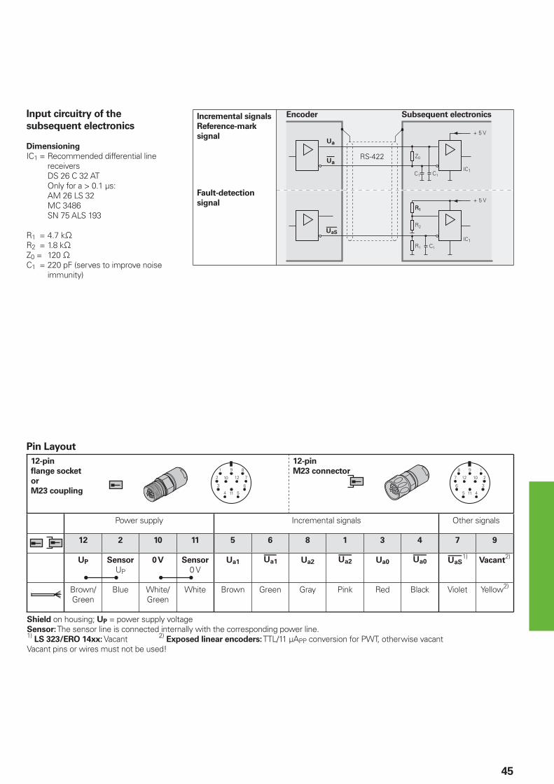
Pin Layout
12-pin
fl ange socket
or
M23 coupling
12-pin
M23 connector
Power supply Incremental signals Other signals
12 2 10 11 5 6 8 1 3 4 7 9
UP Sensor
UP
0 V Sensor
0 VUa1 $ Ua2 £ Ua0 ¤ ¥1)
Vacant2)
Brown/Green
Blue White/Green
White Brown Green Gray Pink Red Black Violet Yellow2)
Shield on housing; UP = power supply voltageSensor: The sensor line is connected internally with the corresponding power line.1) LS 323/ERO 14xx: Vacant 2) Exposed linear encoders: TTL/11 µAPP conversion for PWT, otherwise vacantVacant pins or wires must not be used!
Input circuitry of the
subsequent electronics
Dimensioning
IC1 = Recommended differential line receivers
DS 26 C 32 AT Only for a > 0.1 µs: AM 26 LS 32 MC 3486 SN 75 ALS 193
R1 = 4.7 k−R2 = 1.8 k−Z0 = 120 −C1 = 220 pF (serves to improve noise
immunity)
Incremental signals
Reference-mark
signal
Fault-detection
signal
Encoder Subsequent electronics
������&����������� ����� �����
46
Interfaces
Absolute Position Values
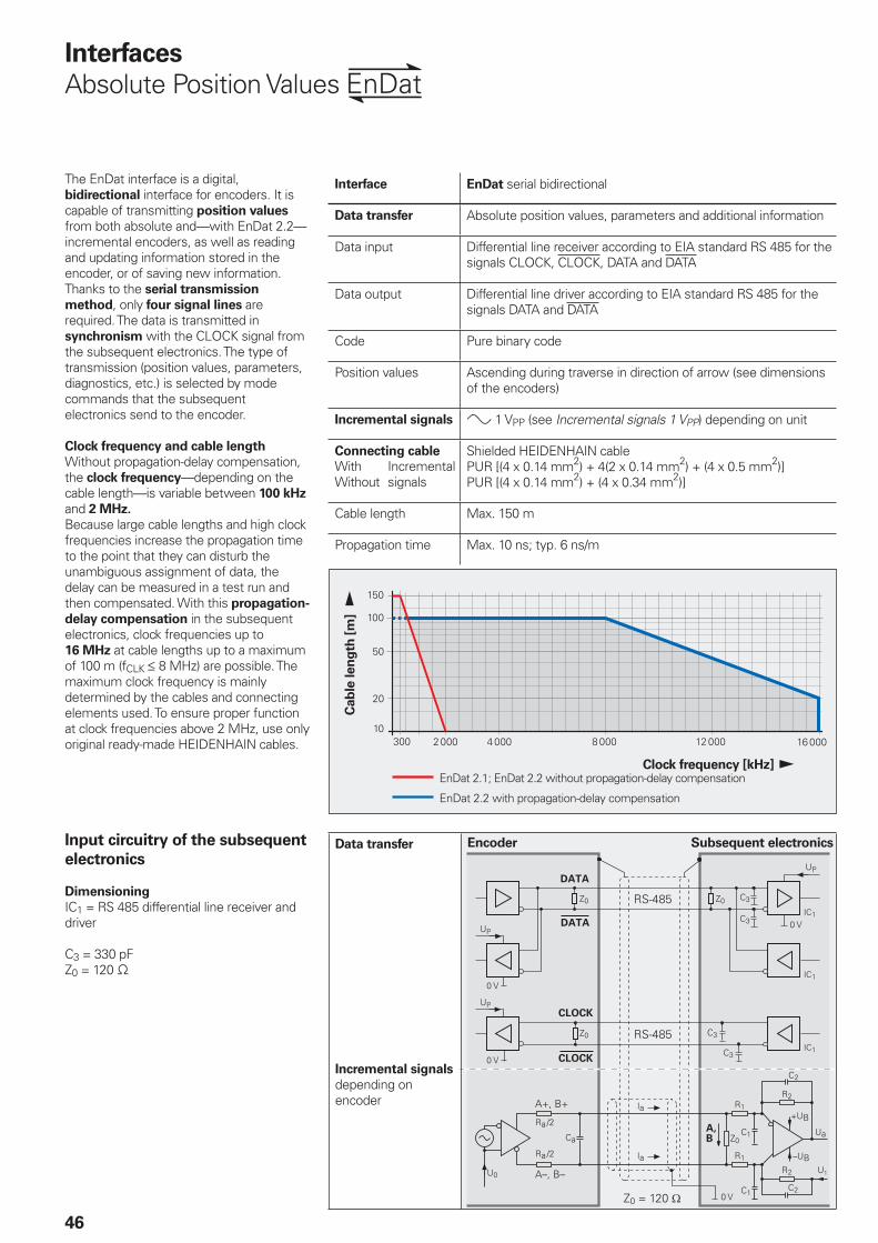
The EnDat interface is a digital, bidirectional interface for encoders. It is capable of transmitting position values from both absolute and—with EnDat 2.2—incremental encoders, as well as reading and updating information stored in the encoder, or of saving new information. Thanks to the serial transmission
method, only four signal lines are required. The data is transmitted in synchronism with the CLOCK signal from the subsequent electronics. The type of transmission (position values, parameters, diagnostics, etc.) is selected by mode commands that the subsequent electronics send to the encoder.
Clock frequency and cable length
Without propagation-delay compensation, the clock frequency—depending on the cable length—is variable between 100 kHz and 2 MHz.
Because large cable lengths and high clock frequencies increase the propagation time to the point that they can disturb the unambiguous assignment of data, the delay can be measured in a test run and then compensated. With this propagation-
delay compensation in the subsequent electronics, clock frequencies up to 16 MHz at cable lengths up to a maximum of 100 m (fCLK † 8 MHz) are possible. The maximum clock frequency is mainly determined by the cables and connecting elements used. To ensure proper function at clock frequencies above 2 MHz, use only original ready-made HEIDENHAIN cables.
Interface EnDat serial bidirectional
Data transfer Absolute position values, parameters and additional information
Data input Differential line receiver according to EIA standard RS 485 for the signals CLOCK, CLOCK, DATA and DATA
Data output Differential line driver according to EIA standard RS 485 for the signals DATA and DATA
Code Pure binary code
Position values Ascending during traverse in direction of arrow (see dimensions of the encoders)
Incremental signals » 1 VPP (see Incremental signals 1 VPP) depending on unit
Connecting cable Shielded HEIDENHAIN cablePUR [(4 x 0.14 mm2) + 4(2 x 0.14 mm2) + (4 x 0.5 mm2)]PUR [(4 x 0.14 mm2) + (4 x 0.34 mm2)]
WithWithout
Incremental signals
Cable length Max. 150 m
Propagation time Max. 10 ns; typ. 6 ns/m
Input circuitry of the subsequent
electronics
Dimensioning
IC1 = RS 485 differential line receiver and driver
C3 = 330 pFZ0 = 120 −
Encoder Subsequent electronics
Cab
le len
gth
[m
] !
Clock frequency [kHz]!EnDat 2.1; EnDat 2.2 without propagation-delay compensation
EnDat 2.2 with propagation-delay compensation
Data transfer
Incremental signals
depending on encoder

47
VersionsThe extended EnDat interface version 2.2 is compatible in its communication, command set and time conditions with version 2.1, but also offers signifi cant advantages. It makes it possible, for example, to transfer additional information with the position value without sending a separate request for it. The interface protocol was expanded and the time conditions (clock frequency, processing time, recovery time) were optimized.
Ordering designation
Indicated on the ID label and can be read out via parameter.
Command set
The command set is the sum of all available mode commands. (See “Selecting the transmission type“). The EnDat 2.2 command set includes EnDat 2.1 mode commands. When a mode command from the EnDat 2.2 command set is transmitted to EnDat-01 subsequent electronics, the encoder or the subsequent electronics may generate an error message.
Incremental signals
EnDat 2.1 and EnDat 2.2 are both available with or without incremental signals. EnDat 2.2 encoders feature a high internal resolution. Therefore, depending on the control technology being used, interrogation of the incremental signals is not necessary. To increase the resolution of EnDat 2.1 encoders, the incremental signals are interpolated and evaluated in the subsequent electronics.
Power supply
Encoders with ordering designations EnDat 02 and EnDat 22 have an extended power supply range.
Ordering
designation
Command set Incremental
signals
Clock
frequency
Power supply
EnDat 01 EnDat 2.1or EnDat 2.2
With † 2 MHz See specifi cations of the encoder
EnDat 21 Without
EnDat 02 EnDat 2.2 With † 2 MHz Extended range3.6 to 5.25 V or 14 VEnDat 22 EnDat 2.2 Without † 16 MHz
Specifi cation of the EnDat interface (bold print indicates standard versions)
Benefi ts of the EnDat InterfaceAutomatic self-confi guration: All information required by the subsequent electronics is already stored in the encoder. High system security through alarms and messages for monitoring and diagnosis.High transmission reliability through cyclic redundancy checks.Datum shift for faster commissioning.
Other benefi ts of EnDat 2.2
A single interface for all absolute and incremental encoders.Additional information (limit switch, temperature, acceleration)Quality improvement: Position value calculation in the encoder permits shorter sampling intervals (25 µs).Online diagnostics through valuation numbers that indicate the encoder’s current functional reserves and make it easier to plan the machine servicing.Safety concept for designing safety-oriented control systems consisting of safe controls and safe encoders based on the DIN EN ISO 13 849-1 and IEC 61 508 standards.
Advantages of purely serial
transmission
specifi cally for EnDat 2.2 encodersCost optimization through simple
subsequent electronics with EnDat receiver component and simple
connection technology: Standard connecting element (M12; 8-pin), single-shielded standard cables and low wiring cost.Minimized transmission times through high clock frequencies up to 16 MHz. Position values available in the subsequent electronics after only approx. 10 µs.Support for state-of-the-art machine
designs e.g. direct drive technology
•
•
•
•
•
•
•
•
•
•
•
•
FunctionsThe EnDat interface transmits absolute position values or additional physical quantities (only EnDat 2.2) in an unambiguous time sequence and serves to read from and write to the encoder’s internal memory. Some functions are available only with EnDat 2.2 mode commands.
Position values can be transmitted with or without additional information. The additional information types are selectable via the Memory Range Select (MRS) code. Other functions such as Read parameter and Write parameter can also be called after the memory area and address have been selected. Through simultaneous transmission with the position value, additional information can also be requested of axes in the feedback loop, and functions executed with them.
Parameter reading and writing is possible both as a separate function and in connection with the position value. Parameters can be read or written after the memory area and address is selected.
Reset functions serve to reset the encoder in case of malfunction. Reset is possible instead of or during position value transmission.
Servicing diagnostics make it possible to inspect the position value even at a standstill. A test command has the encoder transmit the required test values.
You can fi nd more information in the EnDat 2.2 Technical Information document or on the Internet at www.endat.de.
48
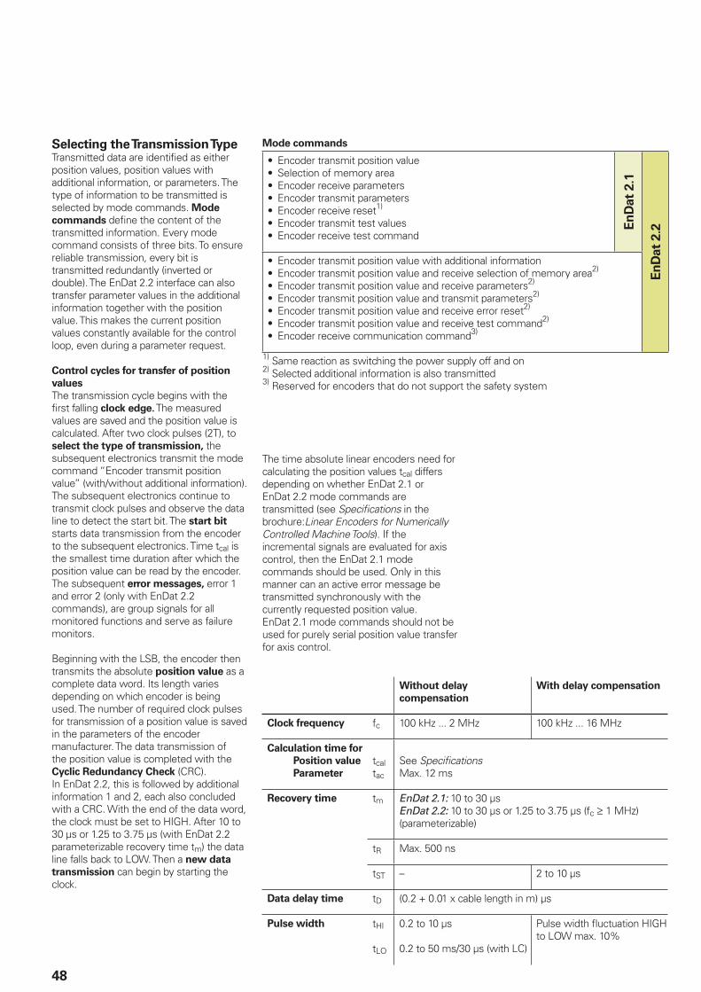
Selecting the Transmission TypeTransmitted data are identifi ed as either position values, position values with additional information, or parameters. The type of information to be transmitted is selected by mode commands. Mode
commands defi ne the content of the transmitted information. Every mode command consists of three bits. To ensure reliable transmission, every bit is transmitted redundantly (inverted or double). The EnDat 2.2 interface can also transfer parameter values in the additional information together with the position value. This makes the current position values constantly available for the control loop, even during a parameter request.
Control cycles for transfer of position
values
The transmission cycle begins with the fi rst falling clock edge. The measured values are saved and the position value is calculated. After two clock pulses (2T), to select the type of transmission, the subsequent electronics transmit the mode command “Encoder transmit position value” (with/without additional information).The subsequent electronics continue to transmit clock pulses and observe the data line to detect the start bit. The start bit starts data transmission from the encoder to the subsequent electronics. Time tcal is the smallest time duration after which the position value can be read by the encoder. The subsequent error messages, error 1 and error 2 (only with EnDat 2.2 commands), are group signals for all monitored functions and serve as failure monitors.
Beginning with the LSB, the encoder then transmits the absolute position value as a complete data word. Its length varies depending on which encoder is being used. The number of required clock pulses for transmission of a position value is saved in the parameters of the encoder manufacturer. The data transmission of the position value is completed with the Cyclic Redundancy Check (CRC).In EnDat 2.2, this is followed by additional information 1 and 2, each also concluded with a CRC. With the end of the data word, the clock must be set to HIGH. After 10 to 30 µs or 1.25 to 3.75 µs (with EnDat 2.2 parameterizable recovery time tm) the data line falls back to LOW. Then a new data
transmission can begin by starting the clock.
Without delay
compensation
With delay compensation
Clock frequency fc 100 kHz ... 2 MHz 100 kHz ... 16 MHz
Calculation time for
Position value
Parameter
tcaltac
See Specifi cationsMax. 12 ms
Recovery time tm EnDat 2.1: 10 to 30 µsEnDat 2.2: 10 to 30 µs or 1.25 to 3.75 µs (fc ‡ 1 MHz) (parameterizable)
tR Max. 500 ns
tST – 2 to 10 µs
Data delay time tD (0.2 + 0.01 x cable length in m) µs
Pulse width tHI
tLO
0.2 to 10 µs
0.2 to 50 ms/30 µs (with LC)
Pulse width fl uctuation HIGH to LOW max. 10%
Mode commands
Encoder transmit position valueSelection of memory areaEncoder receive parametersEncoder transmit parametersEncoder receive reset1)
Encoder transmit test valuesEncoder receive test command
•••••••
En
Dat
2.1
En
Dat
2.2
Encoder transmit position value with additional informationEncoder transmit position value and receive selection of memory area2)
Encoder transmit position value and receive parameters2)
Encoder transmit position value and transmit parameters2)
Encoder transmit position value and receive error reset2)
Encoder transmit position value and receive test command2)
Encoder receive communication command3)
•••••••
1) Same reaction as switching the power supply off and on2) Selected additional information is also transmitted3) Reserved for encoders that do not support the safety system
The time absolute linear encoders need for calculating the position values tcal differs depending on whether EnDat 2.1 or EnDat 2.2 mode commands are transmitted (see Specifi cations in the brochure:Linear Encoders for Numerically Controlled Machine Tools). If the incremental signals are evaluated for axis control, then the EnDat 2.1 mode commands should be used. Only in this manner can an active error message be transmitted synchronously with the currently requested position value. EnDat 2.1 mode commands should not be used for purely serial position value transfer for axis control.
%���
� �
%��
� �� �
%� %'
%��� %�
� �
%��
%'
� �� �
()*+',-'.
49
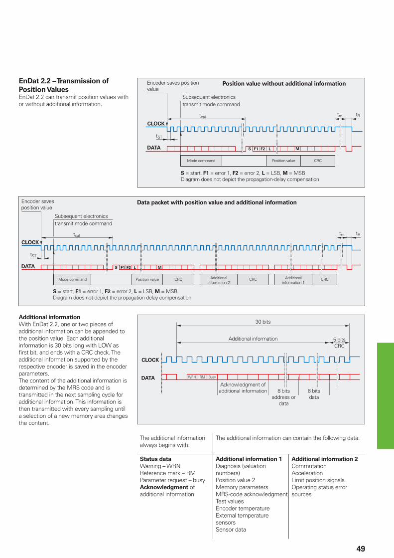
Encoder saves position value
Subsequent electronics transmit mode command
Mode command Position value CRC
S = start, F1 = error 1, F2 = error 2, L = LSB, M = MSBDiagram does not depict the propagation-delay compensation
Position value without additional informationEnDat 2.2 – Transmission of
Position ValuesEnDat 2.2 can transmit position values with or without additional information.
Additional information
With EnDat 2.2, one or two pieces of additional information can be appended to the position value. Each additional information is 30 bits long with LOW as fi rst bit, and ends with a CRC check. The additional information supported by the respective encoder is saved in the encoder parameters.The content of the additional information is determined by the MRS code and is transmitted in the next sampling cycle for additional information. This information is then transmitted with every sampling until a selection of a new memory area changes the content.
The additional information always begins with:
The additional information can contain the following data:
Status data
Warning – WRNReference mark – RMParameter request – busyAcknowledgment of additional information
Additional information 1
Diagnosis (valuation numbers)Position value 2Memory parametersMRS-code acknowledgmentTest valuesEncoder temperatureExternal temperature sensorsSensor data
Additional information 2
CommutationAccelerationLimit position signalsOperating status error sources
30 bits
Additional information 5 bitsCRC
Acknowledgment of additional information 8 bits
address or data
8 bitsdata
Encoder saves position value
Subsequent electronics transmit mode command
Mode command Position value CRC Additional information 2
CRC Additional information 1
CRC
S = start, F1 = error 1, F2 = error 2, L = LSB, M = MSBDiagram does not depict the propagation-delay compensation
Data packet with position value and additional information
50
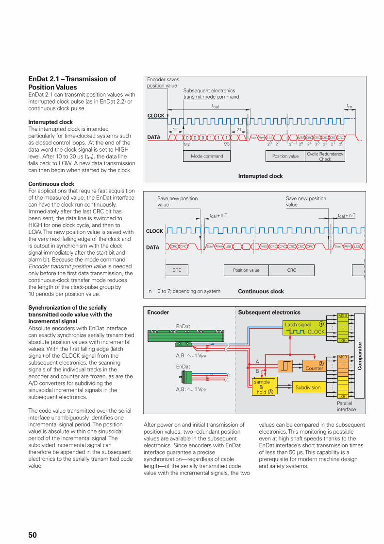
EnDat 2.1 – Transmission of
Position ValuesEnDat 2.1 can transmit position values with interrupted clock pulse (as in EnDat 2.2) or continuous clock pulse.
Interrupted clock
The interrupted clock is intended particularly for time-clocked systems such as closed control loops. At the end of the data word the clock signal is set to HIGH level. After 10 to 30 µs (tm), the data line falls back to LOW. A new data transmission can then begin when started by the clock.
Continuous clock
For applications that require fast acquisition of the measured value, the EnDat interface can have the clock run continuously. Immediately after the last CRC bit has been sent, the data line is switched to HIGH for one clock cycle, and then to LOW. The new position value is saved with the very next falling edge of the clock and is output in synchronism with the clock signal immediately after the start bit and alarm bit. Because the mode command Encoder transmit position value is needed only before the fi rst data transmission, the continuous-clock transfer mode reduces the length of the clock-pulse group by 10 periods per position value.
Synchronization of the serially
transmitted code value with the
incremental signal
Absolute encoders with EnDat interface can exactly synchronize serially transmitted absolute position values with incremental values. With the fi rst falling edge (latch signal) of the CLOCK signal from the subsequent electronics, the scanning signals of the individual tracks in the encoder and counter are frozen, as are the A/D converters for subdividing the sinusoidal incremental signals in the subsequent electronics.
The code value transmitted over the serial interface unambiguously identifi es one incremental signal period. The position value is absolute within one sinusoidal period of the incremental signal. The subdivided incremental signal can therefore be appended in the subsequent electronics to the serially transmitted code value.
Encoder Subsequent electronics
Latch signal
Subdivision
Counter Co
mp
ara
tor
Parallel interface
1 VPP
1 VPP
After power on and initial transmission of position values, two redundant position values are available in the subsequent electronics. Since encoders with EnDat interface guarantee a precise synchronization—regardless of cable length—of the serially transmitted code value with the incremental signals, the two
Position value CRCCRC
Save new position value
Save new position value
n = 0 to 7; depending on system Continuous clock
values can be compared in the subsequent electronics. This monitoring is possible even at high shaft speeds thanks to the EnDat interface’s short transmission times of less than 50 µs. This capability is a prerequisite for modern machine design and safety systems.
Encoder saves position value
Subsequent electronics transmit mode command
Mode command Position value Cyclic Redundancy Check
Interrupted clock
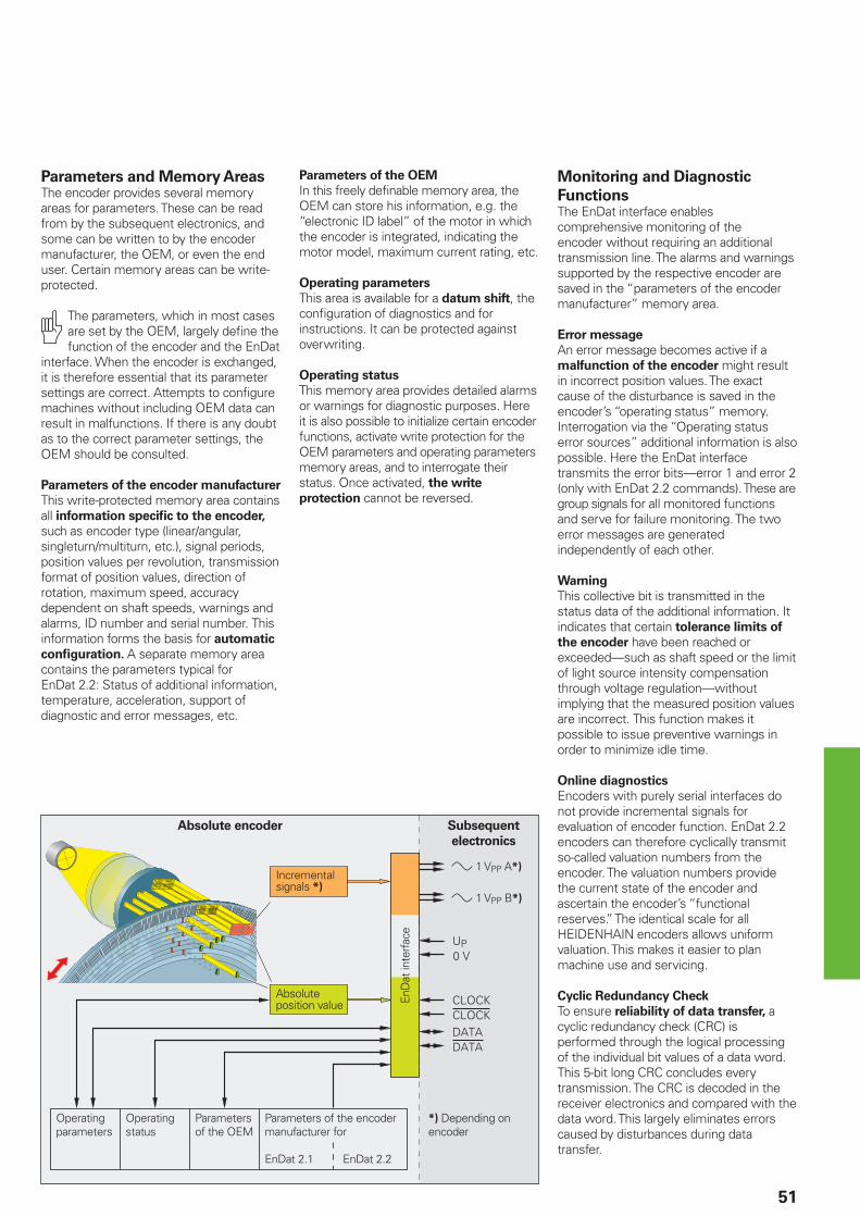
51
Parameters and Memory AreasThe encoder provides several memory areas for parameters. These can be read from by the subsequent electronics, and some can be written to by the encoder manufacturer, the OEM, or even the end user. Certain memory areas can be write-protected.
The parameters, which in most cases are set by the OEM, largely defi ne the function of the encoder and the EnDat
interface. When the encoder is exchanged, it is therefore essential that its parameter settings are correct. Attempts to confi gure machines without including OEM data can result in malfunctions. If there is any doubt as to the correct parameter settings, the OEM should be consulted.
Parameters of the encoder manufacturer
This write-protected memory area contains all information specifi c to the encoder, such as encoder type (linear/angular, singleturn/multiturn, etc.), signal periods, position values per revolution, transmission format of position values, direction of rotation, maximum speed, accuracy dependent on shaft speeds, warnings and alarms, ID number and serial number. This information forms the basis for automatic
confi guration. A separate memory area contains the parameters typical for EnDat 2.2: Status of additional information, temperature, acceleration, support of diagnostic and error messages, etc.
Absolute encoder Subsequent
electronics
Absolute position value
Operating parameters
Operating status
Parameters of the OEM
Parameters of the encoder manufacturer for
EnDat 2.1 EnDat 2.2
EnD
at in
terf
ace
Monitoring and Diagnostic
FunctionsThe EnDat interface enables comprehensive monitoring of the encoder without requiring an additional transmission line. The alarms and warnings supported by the respective encoder are saved in the “parameters of the encoder manufacturer” memory area.
Error message
An error message becomes active if a malfunction of the encoder might result in incorrect position values. The exact cause of the disturbance is saved in the encoder’s “operating status” memory.Interrogation via the “Operating status error sources” additional information is also possible. Here the EnDat interface transmits the error bits—error 1 and error 2 (only with EnDat 2.2 commands). These are group signals for all monitored functions and serve for failure monitoring. The two error messages are generated independently of each other.
Warning
This collective bit is transmitted in the status data of the additional information. It indicates that certain tolerance limits of
the encoder have been reached or exceeded—such as shaft speed or the limit of light source intensity compensation through voltage regulation—without implying that the measured position values are incorrect. This function makes it possible to issue preventive warnings in order to minimize idle time.
Online diagnostics
Encoders with purely serial interfaces do not provide incremental signals for evaluation of encoder function. EnDat 2.2 encoders can therefore cyclically transmit so-called valuation numbers from the encoder. The valuation numbers provide the current state of the encoder and ascertain the encoder’s “functional reserves.” The identical scale for all HEIDENHAIN encoders allows uniform valuation. This makes it easier to plan machine use and servicing.
Cyclic Redundancy Check
To ensure reliability of data transfer, a cyclic redundancy check (CRC) is performed through the logical processing of the individual bit values of a data word. This 5-bit long CRC concludes every transmission. The CRC is decoded in the receiver electronics and compared with the data word. This largely eliminates errors caused by disturbances during data transfer.
Incremental signals *)
*) Depending on encoder
» 1 VPP A*)
» 1 VPP B*)
Parameters of the OEM
In this freely defi nable memory area, the OEM can store his information, e.g. the “electronic ID label” of the motor in which the encoder is integrated, indicating the motor model, maximum current rating, etc.
Operating parameters
This area is available for a datum shift, the confi guration of diagnostics and for instructions. It can be protected against overwriting.
Operating status
This memory area provides detailed alarms or warnings for diagnostic purposes. Here it is also possible to initialize certain encoder functions, activate write protection for the OEM parameters and operating parameters memory areas, and to interrogate their status. Once activated, the write
protection cannot be reversed.
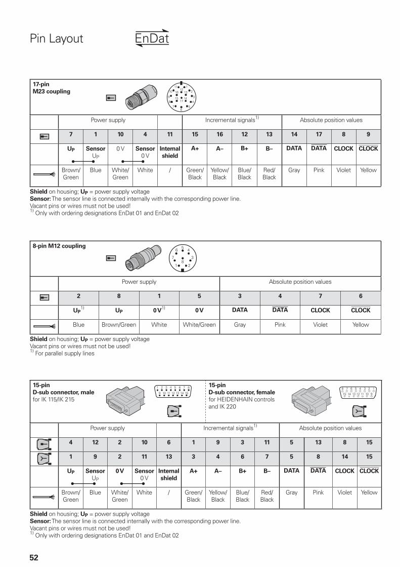
&
�
�
�
�
�
52
Pin Layout
17-pin
M23 coupling
Power supply Incremental signals1) Absolute position values
7 1 10 4 11 15 16 12 13 14 17 8 9
UP Sensor
UP
0 V Sensor
0 VInternal
shield
A+ A– B+ B– DATA DATA CLOCK CLOCK
Brown/Green
Blue White/Green
White / Green/Black
Yellow/Black
Blue/Black
Red/Black
Gray Pink Violet Yellow
Shield on housing; UP = power supply voltageSensor: The sensor line is connected internally with the corresponding power line.Vacant pins or wires must not be used!1) Only with ordering designations EnDat 01 and EnDat 02
15-pin
D-sub connector, male
for IK 115/IK 215
15-pin
D-sub connector, female
for HEIDENHAIN controlsand IK 220
Power supply Incremental signals1) Absolute position values
4 12 2 10 6 1 9 3 11 5 13 8 15
1 9 2 11 13 3 4 6 7 5 8 14 15
UP Sensor
UP
0 V Sensor
0 VInternal
shield
A+ A– B+ B– DATA DATA CLOCK CLOCK
Brown/Green
Blue White/Green
White / Green/Black
Yellow/Black
Blue/Black
Red/Black
Gray Pink Violet Yellow
Shield on housing; UP = power supply voltageSensor: The sensor line is connected internally with the corresponding power line.Vacant pins or wires must not be used!1) Only with ordering designations EnDat 01 and EnDat 02
8-pin M12 coupling
Power supply Absolute position values
2 8 1 5 3 4 7 6
UP1)
UP 0 V1)
0 V DATA DATA CLOCK CLOCK
Blue Brown/Green White White/Green Gray Pink Violet Yellow
Shield on housing; UP = power supply voltageVacant pins or wires must not be used!1) For parallel supply lines
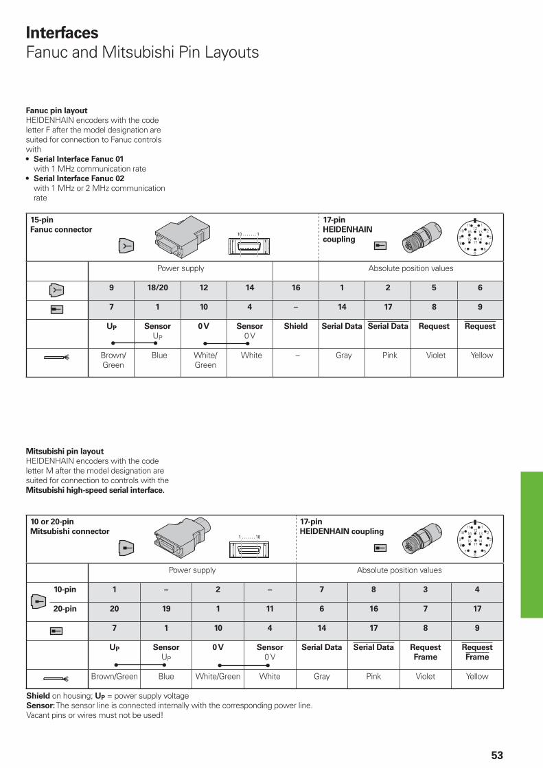
������������������
������������������
53
15-pin
Fanuc connector
17-pin
HEIDENHAIN
coupling
Power supply Absolute position values
9 18/20 12 14 16 1 2 5 6
7 1 10 4 – 14 17 8 9
UP Sensor
UP
0 V Sensor
0 VShield Serial Data Serial Data Request Request
Brown/Green
Blue White/Green
White – Gray Pink Violet Yellow
Interfaces
Fanuc and Mitsubishi Pin Layouts
Fanuc pin layout
HEIDENHAIN encoders with the code letter F after the model designation are suited for connection to Fanuc controls with
Serial Interface Fanuc 01
with 1 MHz communication rate
Serial Interface Fanuc 02
with 1 MHz or 2 MHz communication rate
•
•
Mitsubishi pin layout
HEIDENHAIN encoders with the code letter M after the model designation are suited for connection to controls with the Mitsubishi high-speed serial interface.
10 or 20-pin
Mitsubishi connector
17-pin
HEIDENHAIN coupling
Power supply Absolute position values
10-pin 1 – 2 – 7 8 3 4
20-pin 20 19 1 11 6 16 7 17
7 1 10 4 14 17 8 9
UP Sensor
UP
0 V Sensor
0 VSerial Data Serial Data Request
Frame
Request
Frame
Brown/Green Blue White/Green White Gray Pink Violet Yellow
Shield on housing; UP = power supply voltageSensor: The sensor line is connected internally with the corresponding power line.Vacant pins or wires must not be used!
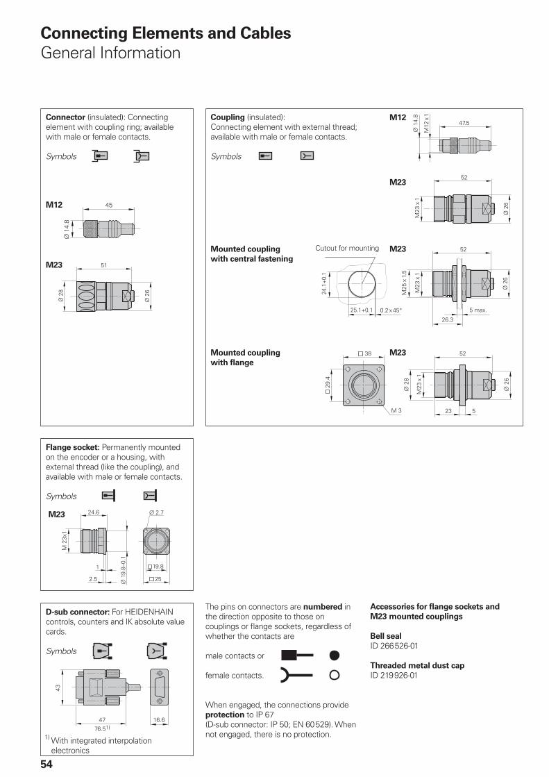
M23
M23
M23
M23
M12
M23
M12
54
The pins on connectors are numbered in the direction opposite to those on couplings or fl ange sockets, regardless of whether the contacts are
male contacts or
female contacts.
When engaged, the connections provide protection to IP 67 (D-sub connector: IP 50; EN 60529). When not engaged, there is no protection.
Connecting Elements and Cables
General Information
Connector (insulated): Connecting element with coupling ring; available with male or female contacts.
Symbols
Coupling (insulated):Connecting element with external thread; available with male or female contacts.
Symbols
D-sub connector: For HEIDENHAIN controls, counters and IK absolute value cards.
Symbols
Accessories for fl ange sockets and
M23 mounted couplings
Bell seal
ID 266526-01
Threaded metal dust cap
ID 219926-01
Flange socket: Permanently mounted on the encoder or a housing, with external thread (like the coupling), and available with male or female contacts.
Symbols
Mounted coupling
with central fastening
Mounted coupling
with fl ange
Cutout for mounting
1) With integrated interpolation electronics
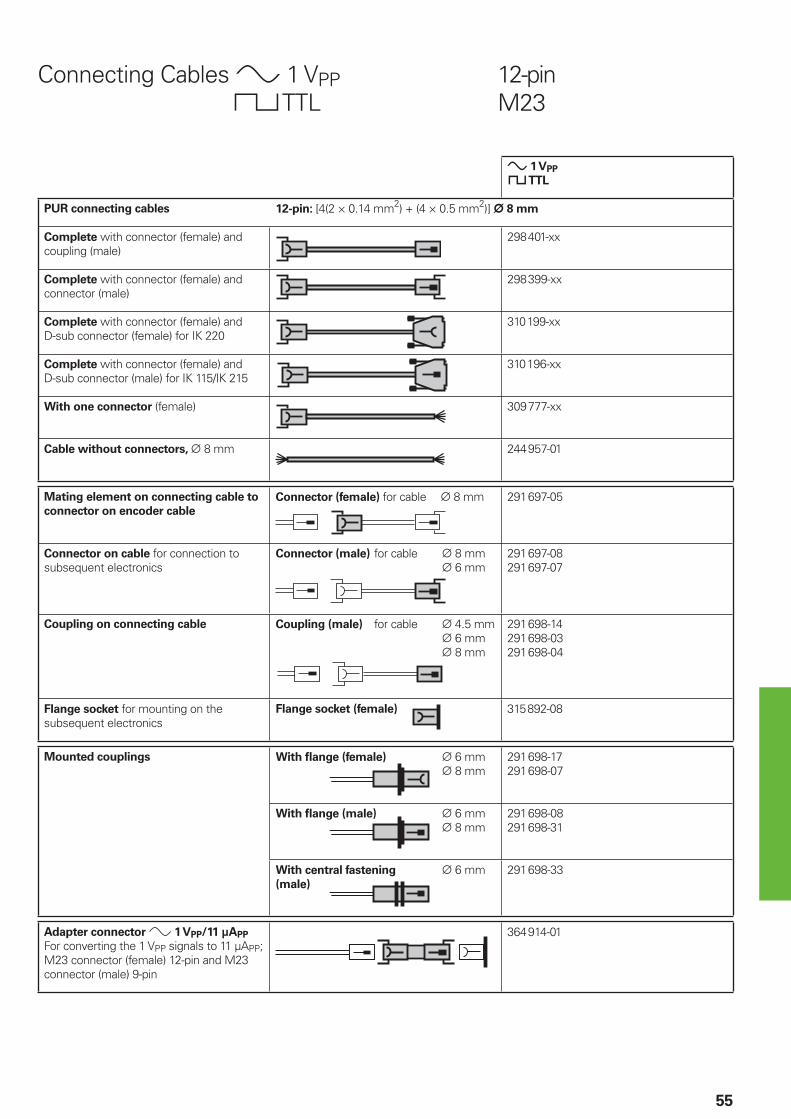
55
Connecting Cables » 1 VPP 12-pin « TTL M23
» 1 VPP
« TTL
PUR connecting cables 12-pin: [4(2 × 0.14 mm2) + (4 × 0.5 mm2)] ¬ 8 mm
Complete with connector (female) and coupling (male)
298401-xx
Complete with connector (female) and connector (male)
298399-xx
Complete with connector (female) and D-sub connector (female) for IK 220
310199-xx
Complete with connector (female) and D-sub connector (male) for IK 115/IK 215
310196-xx
With one connector (female) 309777-xx
Cable without connectors, ¬ 8 mm 244957-01
Mating element on connecting cable to
connector on encoder cable
Connector (female) for cable ¬ 8 mm
291697-05
Connector on cable for connection to subsequent electronics
Connector (male) for cable ¬ 8 mm ¬ 6 mm
291697-08291697-07
Coupling on connecting cable Coupling (male) for cable ¬ 4.5 mm ¬ 6 mm ¬ 8 mm
291698-14291698-03291698-04
Flange socket for mounting on the subsequent electronics
Flange socket (female)
315892-08
Mounted couplings With fl ange (female) ¬ 6 mm
¬ 8 mm
291698-17291698-07
With fl ange (male) ¬ 6 mm ¬ 8 mm
291698-08291698-31
With central fastening ¬ 6 mm(male)
291698-33
Adapter connector » 1 VPP/11 µAPP
For converting the 1 VPP signals to 11 µAPP; M23 connector (female) 12-pin and M23 connector (male) 9-pin
364914-01
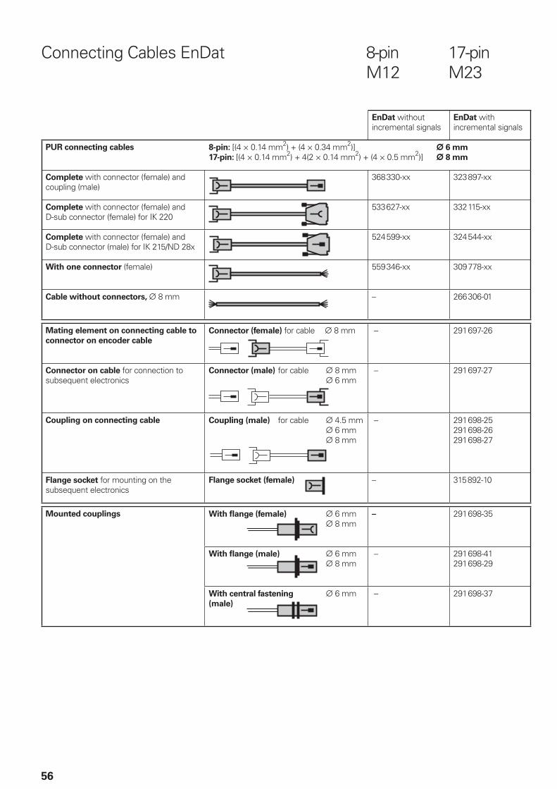
56
Connecting Cables EnDat 8-pin 17-pin M12 M23
EnDat without incremental signals
EnDat with incremental signals
PUR connecting cables 8-pin: [(4 × 0.14 mm2) + (4 × 0.34 mm2)] ¬ 6 mm
17-pin: [(4 × 0.14 mm2) + 4(2 × 0.14 mm2) + (4 × 0.5 mm2)] ¬ 8 mm
Complete with connector (female) and coupling (male)
368330-xx 323897-xx
Complete with connector (female) and D-sub connector (female) for IK 220
533 627-xx 332115-xx
Complete with connector (female) and D-sub connector (male) for IK 215/ND 28x
524599-xx 324544-xx
With one connector (female) 559346-xx 309778-xx
Cable without connectors, ¬ 8 mm – 266306-01
Mating element on connecting cable to
connector on encoder cable
Connector (female) for cable ¬ 8 mm
– 291697-26
Connector on cable for connection to subsequent electronics
Connector (male) for cable ¬ 8 mm
¬ 6 mm
– 291697-27
Coupling on connecting cable Coupling (male) for cable ¬ 4.5 mm ¬ 6 mm ¬ 8 mm
– 291698-25291698-26291698-27
Flange socket for mounting on the subsequent electronics
Flange socket (female)
– 315892-10
Mounted couplings
With fl ange (female) ¬ 6 mm ¬ 8 mm
– 291698-35
With fl ange (male) ¬ 6 mm ¬ 8 mm
– 291698-41291698-29
With central fastening ¬ 6 mm(male)
– 291698-37
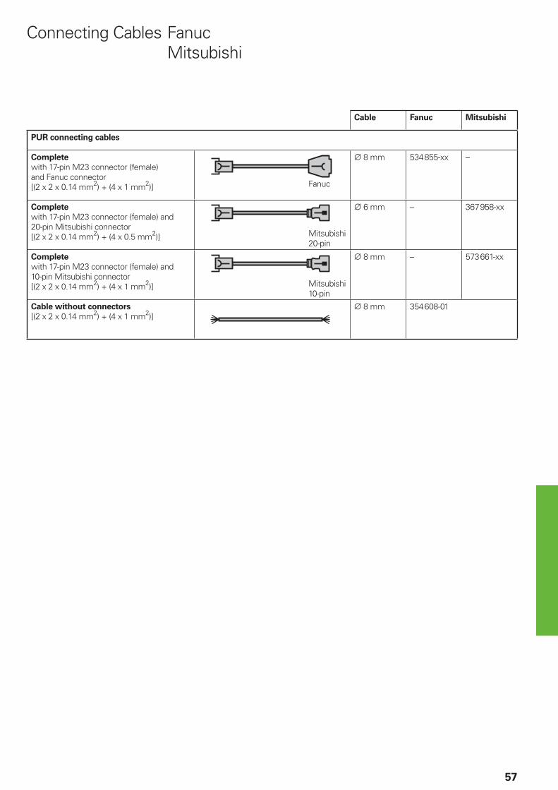
57
Cable Fanuc Mitsubishi
PUR connecting cables
Complete
with 17-pin M23 connector (female)and Fanuc connector[(2 x 2 x 0.14 mm2) + (4 x 1 mm2)]
¬ 8 mm 534855-xx –
Complete
with 17-pin M23 connector (female) and20-pin Mitsubishi connector[(2 x 2 x 0.14 mm2) + (4 x 0.5 mm2)]
¬ 6 mm – 367958-xx
Complete
with 17-pin M23 connector (female) and10-pin Mitsubishi connector[(2 x 2 x 0.14 mm2) + (4 x 1 mm2)]
¬ 8 mm – 573661-xx
Cable without connectors
[(2 x 2 x 0.14 mm2) + (4 x 1 mm2)]¬ 8 mm 354608-01
Connecting Cables Fanuc Mitsubishi
Fanuc
Mitsubishi20-pin
Mitsubishi10-pin
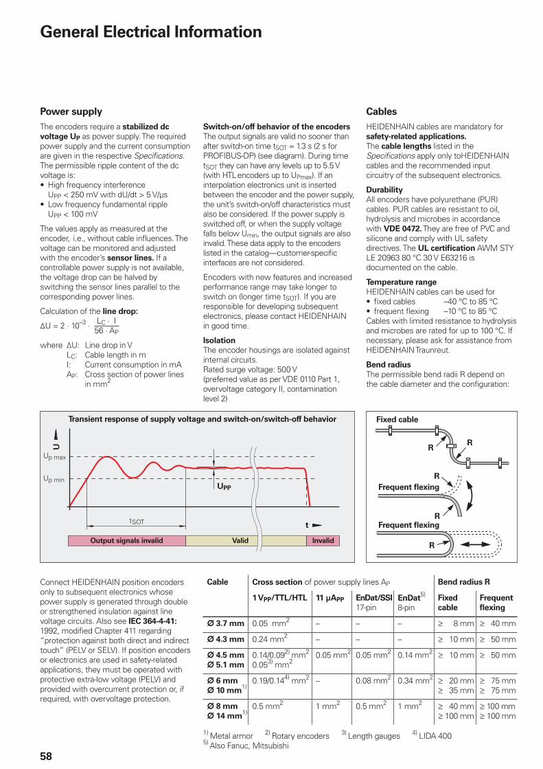
/0���1
/0����
%����
�
58
General Electrical Information
Power supply
The encoders require a stabilized dc
voltage UP as power supply. The required power supply and the current consumption are given in the respective Specifi cations. The permissible ripple content of the dc voltage is:
High frequency interference UPP < 250 mV with dU/dt > 5 V/µsLow frequency fundamental ripple UPP < 100 mV
The values apply as measured at the encoder, i.e., without cable infl uences. The voltage can be monitored and adjusted with the encoder’s sensor lines. If a controllable power supply is not available, the voltage drop can be halved by switching the sensor lines parallel to the corresponding power lines.
Calculation of the line drop:
¹U = 2 · 10–3 ·
where ¹U: Line drop in V LC: Cable length in m I: Current consumption in mA AP: Cross section of power lines
in mm2
•
•
LC · I56 · AP
Fixed cable
Frequent fl exing
Frequent fl exing
Cables
HEIDENHAIN cables are mandatory for safety-related applications.
The cable lengths listed in the Specifi cations apply only toHEIDENHAIN cables and the recommended input circuitry of the subsequent electronics.
Durability
All encoders have polyurethane (PUR) cables. PUR cables are resistant to oil, hydrolysis and microbes in accordance with VDE 0472. They are free of PVC and silicone and comply with UL safety directives. The UL certifi cation AWM STYLE 20963 80 °C 30 V E63216 is documented on the cable.
Temperature range
HEIDENHAIN cables can be used forfi xed cables –40 °C to 85 °Cfrequent fl exing –10 °C to 85 °C
Cables with limited resistance to hydrolysis and microbes are rated for up to 100 °C. If necessary, please ask for assistance from HEIDENHAIN Traunreut.
Bend radius
The permissible bend radii R depend on the cable diameter and the confi guration:
••
Transient response of supply voltage and switch-on/switch-off behavior
Switch-on/off behavior of the encoders
The output signals are valid no sooner than after switch-on time tSOT = 1.3 s (2 s for PROFIBUS-DP) (see diagram). During time tSOT they can have any levels up to 5.5 V (with HTL encoders up to UPmax). If an interpolation electronics unit is inserted between the encoder and the power supply, the unit’s switch-on/off characteristics must also be considered. If the power supply is switched off, or when the supply voltage falls below Umin, the output signals are also invalid. These data apply to the encoders listed in the catalog—customer-specifi c interfaces are not considered.
Encoders with new features and increased performance range may take longer to switch on (longer time tSOT). If you are responsible for developing subsequent electronics, please contact HEIDENHAIN in good time.
Isolation
The encoder housings are isolated against internal circuits.Rated surge voltage: 500 V(preferred value as per VDE 0110 Part 1, overvoltage category II, contamination level 2)
Output signals invalid InvalidValid
UPP
Cable Cross section of power supply lines AP Bend radius R
1 VPP/TTL/HTL 11 µAPP EnDat/SSI
17-pinEnDat
5)
8-pinFixed
cable
Frequent
fl exing
¬ 3.7 mm 0.05 mm2 – – – ‡ 8 mm ‡ 40 mm
¬ 4.3 mm 0.24 mm2 – – – ‡ 10 mm ‡ 50 mm
¬ 4.5 mm
¬ 5.1 mm
0.14/0.092) mm2
0.053) mm20.05 mm2 0.05 mm2 0.14 mm2 ‡ 10 mm ‡ 50 mm
¬ 6 mm
¬ 10 mm1)
0.19/0.144) mm2 – 0.08 mm2 0.34 mm2 ‡ 20 mm‡ 35 mm
‡ 75 mm‡ 75 mm
¬ 8 mm
¬ 14 mm1)
0.5 mm2 1 mm2 0.5 mm2 1 mm2 ‡ 40 mm‡ 100 mm
‡ 100 mm‡ 100 mm
1) Metal armor 2) Rotary encoders 3) Length gauges 4) LIDA 4005) Also Fanuc, Mitsubishi
Connect HEIDENHAIN position encoders only to subsequent electronics whose power supply is generated through double or strengthened insulation against line voltage circuits. Also see IEC 364-4-41: 1992, modifi ed Chapter 411 regarding “protection against both direct and indirect touch” (PELV or SELV). If position encoders or electronics are used in safety-related applications, they must be operated with protective extra-low voltage (PELV) and provided with overcurrent protection or, if required, with overvoltage protection.
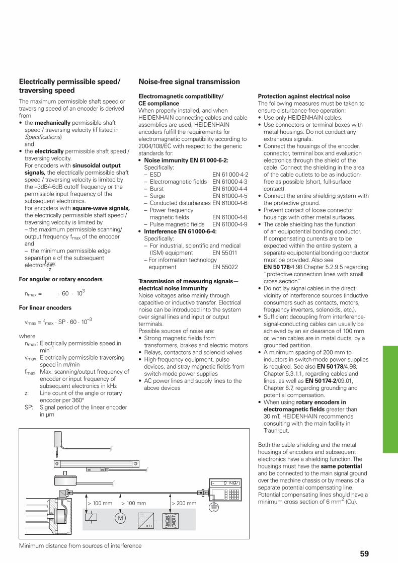
59Minimum distance from sources of interference
Electrically permissible speed/
traversing speed
The maximum permissible shaft speed or traversing speed of an encoder is derived from
the mechanically permissible shaft speed / traversing velocity (if listed in Specifi cations) and the electrically permissible shaft speed / traversing velocity. For encoders with sinusoidal output
signals, the electrically permissible shaft speed / traversing velocity is limited by the –3dB/–6dB cutoff frequency or the permissible input frequency of the subsequent electronics.For encoders with square-wave signals, the electrically permissible shaft speed / traversing velocity is limited by– the maximum permissible scanning/output frequency fmax of the encoder and– the minimum permissible edge separation a of the subsequent electronics.
For angular or rotary encoders
nmax = · 60 · 103
For linear encoders
vmax = fmax · SP · 60 · 10–3
where nmax: Electrically permissible speed in
min–1
vmax: Electrically permissible traversing speed in m/min
fmax: Max. scanning/output frequency of encoder or input frequency of subsequent electronics in kHz
z: Line count of the angle or rotary encoder per 360°
SP: Signal period of the linear encoder in µm
•
•
fmaxz
Noise-free signal transmission
Electromagnetic compatibility/
CE compliance
When properly installed, and when HEIDENHAIN connecting cables and cable assemblies are used, HEIDENHAIN encoders fulfi ll the requirements for electromagnetic compatibility according to 2004/108/EC with respect to the generic standards for:
Noise immunity EN 61 000-6-2:
Specifi cally: – ESD EN 61 000-4-2 – Electromagnetic fi elds EN 61000-4-3 – Burst EN 61000-4-4 – Surge EN 61000-4-5 – Conducted disturbances EN 61000-4-6 – Power frequency
magnetic fi elds EN 61000-4-8 – Pulse magnetic fi elds EN 61000-4-9
Interference EN 61 000-6-4: Specifi cally:
– For industrial, scientifi c and medical (ISM) equipment EN 55 011
– For information technology equipment EN 55022
Transmission of measuring signals—
electrical noise immunity
Noise voltages arise mainly through capacitive or inductive transfer. Electrical noise can be introduced into the system over signal lines and input or output terminals.Possible sources of noise are:
Strong magnetic fi elds from transformers, brakes and electric motorsRelays, contactors and solenoid valvesHigh-frequency equipment, pulse devices, and stray magnetic fi elds from switch-mode power suppliesAC power lines and supply lines to the above devices
•
•
•
••
•
Protection against electrical noise
The following measures must be taken to ensure disturbance-free operation:
Use only HEIDENHAIN cables.Use connectors or terminal boxes with metal housings. Do not conduct any extraneous signals.Connect the housings of the encoder, connector, terminal box and evaluation electronics through the shield of the cable. Connect the shielding in the area of the cable outlets to be as induction-free as possible (short, full-surface contact).Connect the entire shielding system with the protective ground.Prevent contact of loose connector housings with other metal surfaces.The cable shielding has the function of an equipotential bonding conductor. If compensating currents are to be expected within the entire system, a separate equipotential bonding conductor must be provided. Also see EN 50 178/4.98 Chapter 5.2.9.5 regarding “protective connection lines with small cross section.”Do not lay signal cables in the direct vicinity of interference sources (inductive consumers such as contacts, motors, frequency inverters, solenoids, etc.).Suffi cient decoupling from interference-signal-conducting cables can usually be achieved by an air clearance of 100 mm or, when cables are in metal ducts, by a grounded partition.A minimum spacing of 200 mm to inductors in switch-mode power supplies is required. See also EN 50 178/4.98, Chapter 5.3.1.1, regarding cables and lines, as well as EN 50 174-2/09.01, Chapter 6.7, regarding grounding and potential compensation.When using rotary encoders in
electromagnetic fi elds greater than 30 mT, HEIDENHAIN recommends consulting with the main facility in Traunreut.
Both the cable shielding and the metal housings of encoders and subsequent electronics have a shielding function. The housings must have the same potential
and be connected to the main signal ground over the machine chassis or by means of a separate potential compensating line. Potential compensating lines should have a minimum cross section of 6 mm2 (Cu).
••
•
•
•
•
•
•
•
•
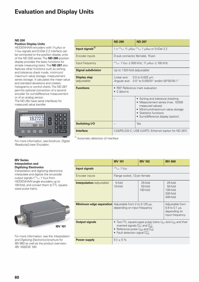
IBV 101
60
Evaluation and Display Units
IBV Series
Interpolation and
Digitizing Electronics
Interpolation and digitizing electronics interpolate and digitize the sinusoidal output signals (» 1 VPP) from HEIDENHAIN angle encoders up to 100-fold, and convert them to TTL square-wave pulse trains.
For more information, see the Interpolation and Digitizing Electronics brochure for IBV 660 as well as the product overview:IBV 100/EXE 100.
IBV 101 IBV 102 IBV 660
Input signals » 1 VPP
Encoder inputs Flange socket, 12-pin female
Interpolation (adjustable) 5-fold10-fold
25-fold 50-fold100-fold
25-fold 50-fold100-fold200-fold400-fold
Minimum edge separation Adjustable from 2 to 0.125 µs, depending on input frequency
Adjustable from 0.8 to 0.1 µs, depending on input frequency
Output signals Two TTL square-wave pulse trains Ua1 and Ua2 and their inverted signals 4 and £Reference pulse Ua0 and ¤Fault detection signal ¥
•
••
Power supply 5 V ± 5 %
ND 200
Position Display Units
HEIDENHAIN encoders with 11-µAPP or 1-VPP signals and EnDat 2.2 interface can be connected to the position display units of the ND 200 series. The ND 280 position display provides the basic functions for simple measuring tasks. The ND 287 also features other functions such as sorting and tolerance check mode, minimum/maximum value storage, measurement series storage. It calculates the mean value and standard deviations and creates histograms or control charts. The ND 287 permits optional connection of a second encoder for sum/difference measurement or of an analog sensor.The ND 28x have serial interfaces for measured value transfer.
For more information, see brochure: Digital Readouts/Linear Encoders.
ND 280 ND 287
Input signals1) 1 x » 11 µAPP, » 1 µAPP or EnDat 2.2
Encoder inputs D-sub connector (female), 15-pin
Input frequency » 1 VPP: † 500 kHz; 11 µAPP: † 100 kHz
Signal subdivision Up to 1 024-fold (adjustable)
Display step
(adjustable)Linear axis: 0.5 to 0.002 µmAngular axis: 0.5° to 0.000 01° and/or 00°00‘00.1”
Functions REF Reference mark evaluation2 datums
••
– Sorting and tolerance checkingMeasurement series (max. 10 000 measured values)Minimum/maximum value storageStatistics functionsSum/difference display (option)
••
•••
Switching I/O – Yes
Interface V.24/RS-232-C; USB (UART); Ethernet (option for ND 287)
1) Automatic detection of interface
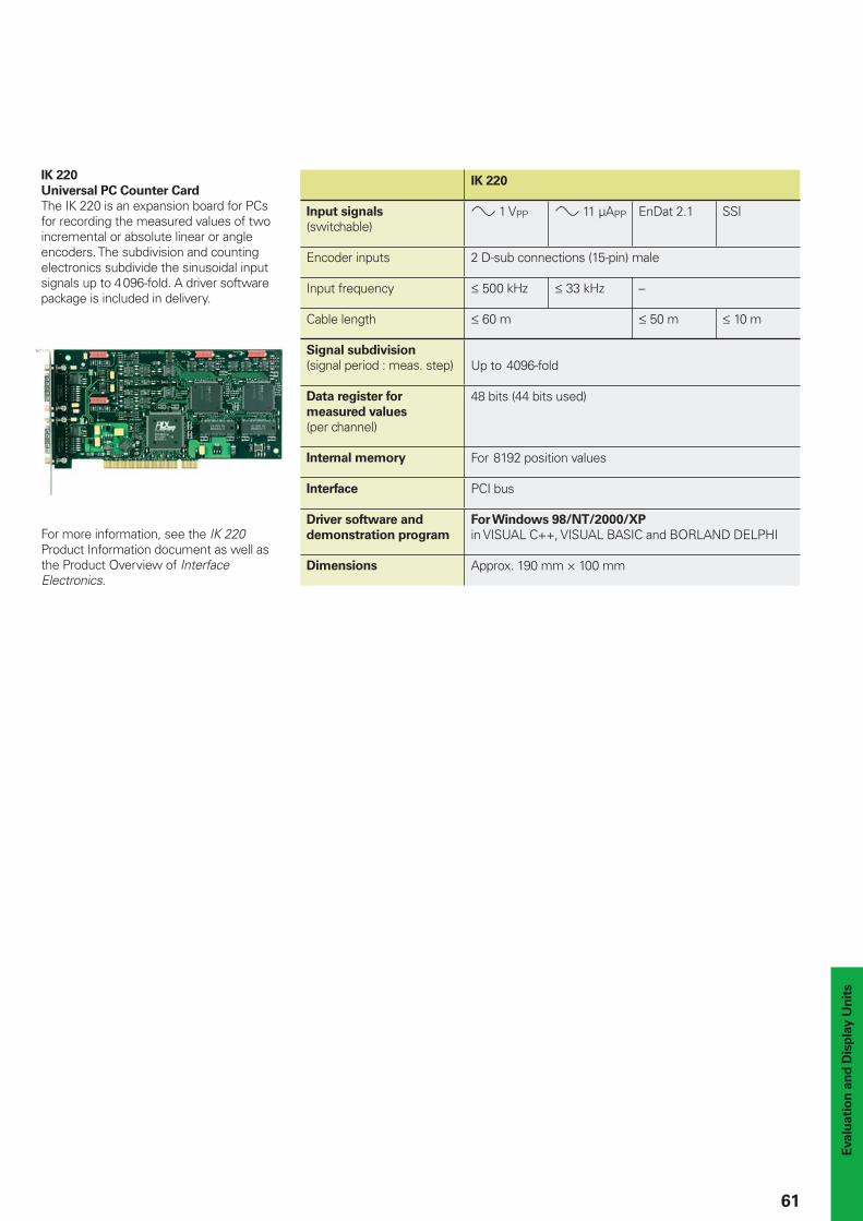
Evalu
ati
on
an
d D
isp
lay U
nit
s
61
IK 220
Universal PC Counter Card
The IK 220 is an expansion board for PCs for recording the measured values of two incremental or absolute linear or angle encoders. The subdivision and counting electronics subdivide the sinusoidal input signals up to 4096-fold. A driver software package is included in delivery.
For more information, see the IK 220 Product Information document as well as the Product Overview of Interface Electronics.
IK 220
Input signals
(switchable)» 1 VPP » 11 µAPP EnDat 2.1 SSI
Encoder inputs 2 D-sub connections (15-pin) male
Input frequency † 500 kHz † 33 kHz –
Cable length † 60 m † 50 m † 10 m
Signal subdivision
(signal period : meas. step) Up to 4096-fold
Data register for
measured values (per channel)
48 bits (44 bits used)
Internal memory For 8192 position values
Interface PCI bus
Driver software and
demonstration program
For Windows 98/NT/2000/XP
in VISUAL C++, VISUAL BASIC and BORLAND DELPHI
Dimensions Approx. 190 mm × 100 mm
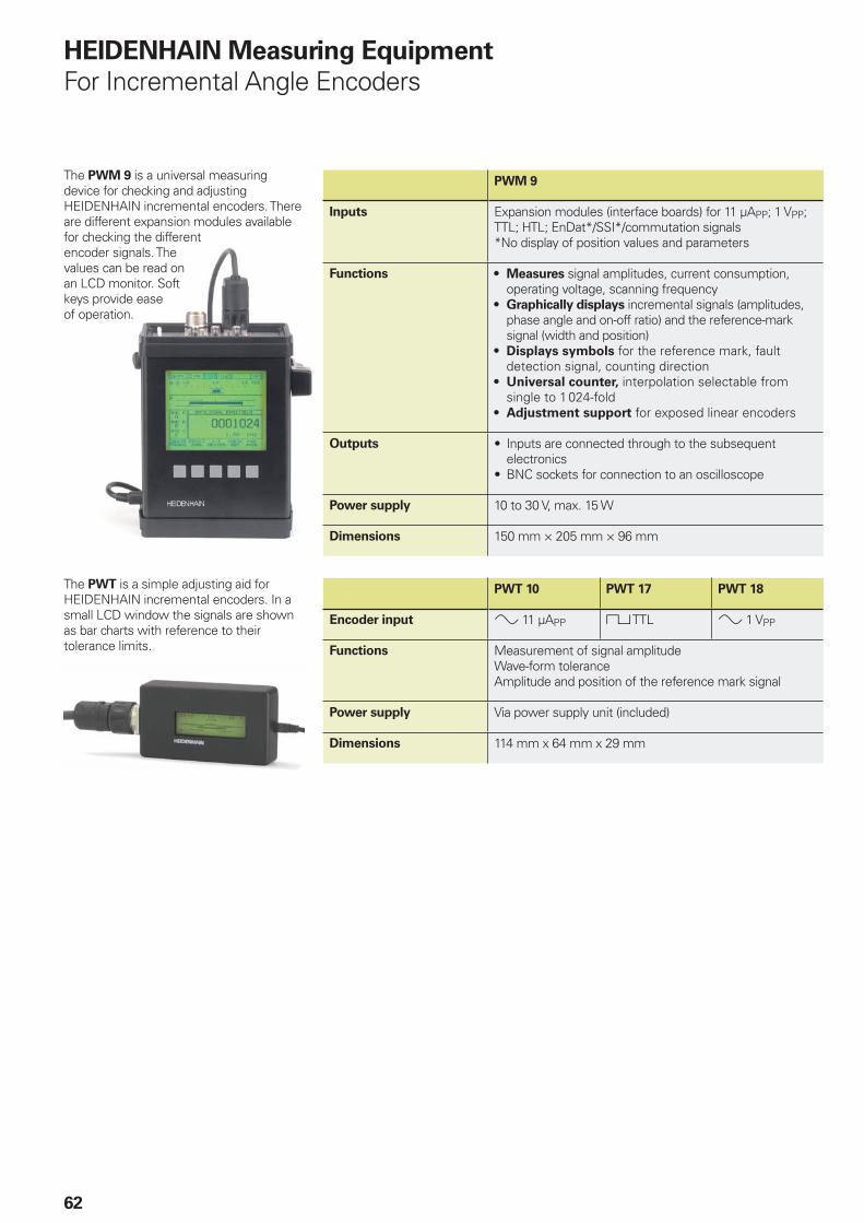
62
HEIDENHAIN Measuring Equipment
For Incremental Angle Encoders
The PWT is a simple adjusting aid for HEIDENHAIN incremental encoders. In a small LCD window the signals are shown as bar charts with reference to their tolerance limits.
PWT 10 PWT 17 PWT 18
Encoder input » 11 µAPP « TTL » 1 VPP
Functions Measurement of signal amplitudeWave-form toleranceAmplitude and position of the reference mark signal
Power supply Via power supply unit (included)
Dimensions 114 mm x 64 mm x 29 mm
The PWM 9 is a universal measuring device for checking and adjusting HEIDENHAIN incremental encoders. There are different expansion modules available for checking the different encoder signals. The values can be read on an LCD monitor. Soft keys provide ease of operation.
PWM 9
Inputs Expansion modules (interface boards) for 11 µAPP; 1 VPP; TTL; HTL; EnDat*/SSI*/commutation signals *No display of position values and parameters
Functions Measures signal amplitudes, current consumption, operating voltage, scanning frequencyGraphically displays incremental signals (amplitudes, phase angle and on-off ratio) and the reference-mark signal (width and position)Displays symbols for the reference mark, fault detection signal, counting directionUniversal counter, interpolation selectable from single to 1024-foldAdjustment support for exposed linear encoders
•
•
•
•
•
Outputs Inputs are connected through to the subsequent electronicsBNC sockets for connection to an oscilloscope
•
•
Power supply 10 to 30 V, max. 15 W
Dimensions 150 mm × 205 mm × 96 mm
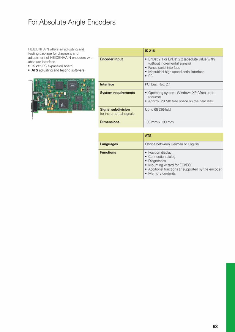
63
HEIDENHAIN offers an adjusting and testing package for diagnosis and adjustment of HEIDENHAIN encoders with absolute interface.
IK 215 PC expansion boardATS adjusting and testing software
•
•
IK 215
Encoder input EnDat 2.1 or EnDat 2.2 (absolute value with/without incremental signals)Fanuc serial interfaceMitsubishi high speed serial interfaceSSI
•
•••
Interface PCI bus, Rev. 2.1
System requirements Operating system: Windows XP (Vista upon request)Approx. 20 MB free space on the hard disk
•
•
Signal subdivision
for incremental signalsUp to 65 536-fold
Dimensions 100 mm x 190 mm
ATS
Languages Choice between German or English
Functions Position displayConnection dialogDiagnosticsMounting wizard for ECI/EQIAdditional functions (if supported by the encoder)Memory contents
••••••
For Absolute Angle Encoders
NL HEIDENHAIN NEDERLAND B.V. 6716 BM Ede, Netherlands { +31 (318) 581800 E-Mail: [email protected]
NO HEIDENHAIN Scandinavia AB 7300 Orkanger, Norway { +47 72480048 E-Mail: [email protected]
PH Machinebanks` Corporation Quezon City, Philippines 1113 { +63 (2) 7113751 E-Mail: [email protected]
PL APS 02-489 Warszawa, Poland { +48 228639737 E-Mail: [email protected]
PT FARRESA ELECTRÓNICA, LDA. 4470 - 177 Maia, Portugal { +351 229478140 E-Mail: [email protected]
RO Romania − HU
RU OOO HEIDENHAIN 125315 Moscow, Russia { +7 (495) 931-9646 E-Mail: [email protected]
SE HEIDENHAIN Scandinavia AB 12739 Skärholmen, Sweden { +46 (8) 53193350 E-Mail: [email protected]
SG HEIDENHAIN PACIFIC PTE LTD. Singapore 408593, { +65 6749-3238 E-Mail: [email protected]
SK Slovakia − CZ
SL Posredništvo HEIDENHAIN SAŠO HÜBL s.p. 2000 Maribor, Slovenia { +386 (2) 4297216 E-Mail: [email protected]
TH HEIDENHAIN (THAILAND) LTD Bangkok 10250, Thailand { +66 (2) 398-4147-8 E-Mail: [email protected]
TR T&M Mühendislik San. ve Tic. LTD. ŞTİ. 34738 Erenköy-Istanbul, Turkey { +90 (216) 3022345 E-Mail: [email protected]
TW HEIDENHAIN Co., Ltd. Taichung 407, Taiwan { +886 (4) 23588977 E-Mail: [email protected]
UA Ukraine − RU
US HEIDENHAIN CORPORATION Schaumburg, IL 60173-5337, USA { +1 (847) 490-1191 E-Mail: [email protected]
VE Maquinaria Diekmann S.A. Caracas, 1040-A, Venezuela { +58 (212) 6325410 E-Mail: [email protected]
VN AMS Advanced Manufacturing Solutions Pte Ltd HCM City, Viêt Nam { +84 (8) 9123658 - 8352490 E-Mail: [email protected]
ZA MAFEMA SALES SERVICES C.C. Midrand 1685, South Africa { +27 (11) 3144416 E-Mail: [email protected]
CZ HEIDENHAIN s.r.o. 106 00 Praha 10, Czech Republic { +420 272658131 E-Mail: [email protected]
DK TP TEKNIK A/S 2670 Greve, Denmark { +45 (70) 100966 E-Mail: [email protected]
ES FARRESA ELECTRONICA S.A. 08028 Barcelona, Spain { +34 934092491 E-Mail: [email protected]
FI HEIDENHAIN Scandinavia AB 02770 Espoo, Finland { +358 (9) 8676476 E-Mail: [email protected]
FR HEIDENHAIN FRANCE sarl 92310 Sèvres, France { +33 0141143000 E-Mail: [email protected]
GB HEIDENHAIN (G.B.) Limited Burgess Hill RH15 9RD, United Kingdom { +44 (1444) 247711 E-Mail: [email protected]
GR MB Milionis Vassilis 17341 Athens, Greece { +30 (210) 9336607 E-Mail: [email protected]
HK HEIDENHAIN LTD Kowloon, Hong Kong { +852 27591920 E-Mail: [email protected]
HR Croatia − SL
HU HEIDENHAIN Kereskedelmi Képviselet 1239 Budapest, Hungary { +36 (1) 4210952 E-Mail: [email protected]
ID PT Servitama Era Toolsindo Jakarta 13930, Indonesia { +62 (21) 46834111 E-Mail: [email protected]
IL NEUMO VARGUS MARKETING LTD. Tel Aviv 61570, Israel { +972 (3) 5373275 E-Mail: [email protected]
IN ASHOK & LAL Chennai – 600 030, India { +91 (44) 26151289 E-Mail: [email protected]
IT HEIDENHAIN ITALIANA S.r.l. 20128 Milano, Italy { +39 02270751 E-Mail: [email protected]
JP HEIDENHAIN K.K. Tokyo 102-0073, Japan { +81 (3) 3234-7781 E-Mail: [email protected]
KR HEIDENHAIN LTD. Gasan-Dong, Seoul, Korea 153-782 { +82 (2) 2028-7430 E-Mail: [email protected]
MK Macedonia − BG
MX HEIDENHAIN CORPORATION MEXICO 20235 Aguascalientes, Ags., Mexico { +52 (449) 9130870 E-Mail: [email protected]
MY ISOSERVE Sdn. Bhd 56100 Kuala Lumpur, Malaysia { +60 (3) 91320685 E-Mail: [email protected]
AR NAKASE SRL. B1653AOX Villa Ballester, Argentina { +54 (11) 47684242 E-Mail: [email protected]
AT HEIDENHAIN Techn. Büro Österreich 83301 Traunreut, Germany { +49 (8669) 31-1337 E-Mail: [email protected]
AU FCR Motion Technology Pty. Ltd Laverton North 3026, Australia { +61 (3) 93626800 E-Mail: [email protected]
BE HEIDENHAIN NV/SA 1760 Roosdaal, Belgium { +32 (54) 343158 E-Mail: [email protected]
BG ESD Bulgaria Ltd. Sofi a 1172, Bulgaria { +359 (2) 9632949 E-Mail: [email protected]
BR DIADUR Indústria e Comércio Ltda. 04763-070 – São Paulo – SP, Brazil { +55 (11) 5696-6777 E-Mail: [email protected]
BY Belarus − RU
CA HEIDENHAIN CORPORATION Mississauga, Ontario L5T2N2, Canada { +1 (905) 670-8900 E-Mail: [email protected]
CH HEIDENHAIN (SCHWEIZ) AG 8603 Schwerzenbach, Switzerland { +41 (44) 8062727 E-Mail: [email protected]
CN DR. JOHANNES HEIDENHAIN (CHINA) Co., Ltd. Beijing 101312, China { +86 10-80420000 E-Mail: [email protected]
CS Serbia and Montenegro − BG
DE HEIDENHAIN Technisches Büro Nord 12681 Berlin, Deutschland { (030) 54705-240 E-Mail: [email protected]
HEIDENHAIN Technisches Büro Mitte 08468 Heinsdorfergrund, Deutschland { (03765) 69544 E-Mail: [email protected]
HEIDENHAIN Technisches Büro West 44379 Dortmund, Deutschland { (0231) 618083-0 E-Mail: [email protected]
HEIDENHAIN Technisches Büro Südwest 70771 Leinfelden-Echterdingen, Deutschland { (0711) 993395-0 E-Mail: [email protected]
HEIDENHAIN Technisches Büro Südost 83301 Traunreut, Deutschland { (08669) 31-1345 E-Mail: [email protected]
Vollständige Adressen siehe www.heidenhain.deFor complete addresses see www.heidenhain.de
Zu
m A
bh
eft
en
hie
r fa
lzen
! /
Fo
ld h
ere
fo
r fi
lin
g!
������������ ��� ��������������� ��������������������������������������� ���������������� ����������������� �!"��#�$����������
������ !���� ��!�
591 109-21 · 40 · 6/2008 · H · Printed in Germany · Subject to change without notice