Embed Size (px)
Citation preview
Features• Provides a safe, efficient method of
switching from an active pressure reliefdevice to a standby, maintaining systemoverpressure protection regardless ofSafety Selector Valve position.
• Provides high Cv values, resulting in lessthan 3% pressure drop to the active PRVinlet, when used with the largest APIorifice available in a given valve size, inaccordance with the recommendations ofAPI RP520 Part II and ASME Section VIII,Division 1, Appendix M, thereby greatlyreducing the possibility of destructivechatter of the PRV.
• Requires only one minimally sizedpenetration into the vessel or pipe, reducing costs.
• Greatly reduces field installation costsand space requirements throughpreassembled and compact design.
• Provides process isolation of standbypressure relief device.
• Allows pressure relief device maintenancewithout process shutdown.
• A bleed valve is provided under eachsafety relief device as an effective andsafe means of venting entrapped processunder an isolated pressure relief valveprior to removal for maintenance.
• Bright red indicator for positive indicationof active pressure relief device.
• Meets all mandatory requirements ofASME Section VIII, Division 1, UG-135 (b).
• Foolproof provisions for dual padlocking ineither pressure relief valve position, inaccordance with the recommendations ofASME Section VIII.
• Packing design has been tested to ASTME427, Method A halogen leak test,reducing probability of fugitive emissions.
• No seat lapping required for maintenance.Only recommended spare parts are softgoods which reduces cost of ownership.
• Meets standard temperature applicationsfrom cryogenic to +800°F [427°C].
• Offers materials of constructioncompatible with pressure relief devices.Duplex and 6MO material available.
• Provides reduced number of leak points toatmosphere, reducing probability offugitive emissions.
• Isolates a standby pressure relief valve inaccordance with joint recommendation ofAPI Subcommittee on Pressure RelievingSystems and Subcommittee on RefineryInspection.
• Type approval by Det Norske Veritas(DNV).
• Manufactured by an ISO 9001 certifiedfacility.
• Simplicity of operation with built-in seatequalization and no special toolsminimizes total time to operate valve.
Recommended SpecificationsChangeover device inlet connection is to bethe same size and rating as the pressurerelief valve inlets.
• Pressure drop through the changeoverdevice’s active side cannot exceed 3%with pressure relief valve fully open.
• Changeover device is to have externalindicator, showing which side is active.
• Provisions for double padlocking in either position are required.
• A valve bleed port must be located under each pressure relief valveconnection for pressure venting under the inactive pressure relief valve.
Anderson Greenwood Safety Selector ValveDual Pressure Relief Device System
Copyright © 2005 Tyco Flow Control. All rights reserved. ANGMC-0241-US-0510Total Flow Control Solutions™
Flow Control
The Safety Selector Valve is designed specifically tofunction as an effective ‘switchover’ device.ANDERSON
GREENWOOD
Anderson Greenwood is either a trademark or registered trademark of Tyco International Services AGor its affiliates in the United States and/or other countries. All other brand names, product names, ortrademarks belong to their respective holders.
Anderson Greenwood Safety Selector ValveDual Pressure Relief Device System
Copyright © 2005 Tyco Flow Control. All rights reserved. ANGMC-02412
Applications
Section I Steam ServiceSafety Selector Valves can be utilized forcertain Section I Boiler applications.
Per ASME Section I Boiler and PressureVessel Code Case 2254, a switchover valvesuch as the Safety Selector Valve can beinstalled to provide a back-up safety valve forboilers with a maximum allowable workingpressure (MAWP) of 800 psig or less.
The code case requires that the followingcriteria be met by the switchover device:
Positive locking YesExternal bleed valves YesCertified Cv values Yes
The Safety Selector Valve will provide thehighest flow efficiency (Cv) of any otherswitchover device in the same nominal pipesize. These Cv values allow the SafetySelector Valve to be used with mostmanufacturers’ flanged Section I Boiler valvesand meet the code case requirements. Pleaseprovide us with the model number and setpressure of the safety valves to be used toinsure complete compliance with the codecase.
Operation
Dual Pressure Relief DeviceSystemsAnderson Greenwood developed the SafetySelector Valve in response to the growingdemand for cost-effective, dual pressure reliefvalve and/or rupture disc installations intoday’s process industries. The SafetySelector Valve is designed specifically tofunction as an effective ‘switchover’ devicethat permits routine or emergency servicingof redundant pressure relief devices with noprocess interruption, thus providingcontinuous system overpressure protection.Until recently, bulky and expensive pipingfabrications or total shutdown were the onlymethods for safely servicing the pressurerelief devices. These systems required eithertwo separate vessel penetrations withmechanically linked block valves or a 3-wayblock valve that commonly resulted in highinlet pressure loss, excessive turbulence tothe active pressure relief device and multipleleak points. The Anderson Greenwood SafetySelector Valve solves these problems. It iseasy to install, requiring only one vesselpenetration in the same size as the pressurerelief valve inlet. The unique design providesless than 3% pressure drop to the activepressure relief valve inlet when used with thelargest API orifice available in a given valvesize, in accordance with API RP520, Part IIand ASME Section VIII guidelines.
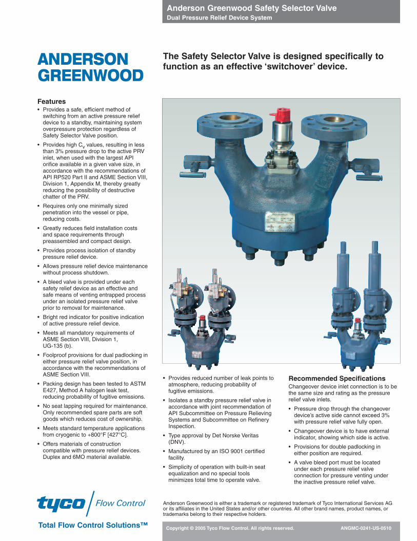
Interlocking BlockValve with Two Vessel
Penetrations
3-Way Block Valve with Pipe Elbows
(see Pressure Drop Comparison Below)
Interlocking BlockValve with Pipe Tee
and Elbows
Traditional Dual Pressure Relief Device Systems
Using API Standard 526 direct acting spring loaded valves, the comparative pressure dropthrough the Safety Selector Valve versus the same size 3-way ball valve is as follows:
2” 3” 4” 6” 8”2J3 3L4 4P6 6R8 8T10
SSV 1.50% 0.86% 1.42% 1.37% 1.31%
3-Way Ball 6.36% 5.65% 9.30% 10.6% 8.69%
Liquid/Two Phase ServiceSafety selector valves can be used inGas/Vapor, Steam, or Liquid service. Safetyselector valves can also be used in two phaseservice. The picture on the left is of anAnderson Greenwood Series 400 pilot valverelieving on liquid only. The picture on theright shows the same valve transitioning totwo phase flow as gas is becoming entrainedin the relief stream.
Anderson Greenwood Safety Selector ValveDual Pressure Relief Device System
Copyright © 2005 Tyco Flow Control. All rights reserved. ANGMC-02413
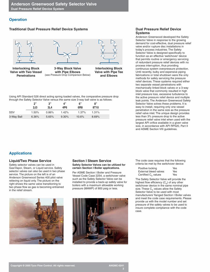
11/2-inch – 10-inch Sizes
Process ConnectionIntegral Cast Inlet Flange(ANSI Raised Face)
Bleed Port forStandby PRD
2
7
8
3
12
4
1
10
PRDConnection
6
115
Flow
9
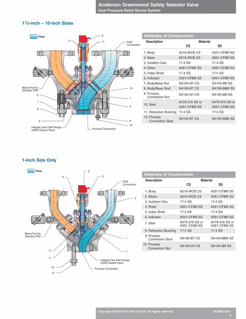
Bleed Port forStandby PRD
3
10 Process Connection
Integral Cast Inlet Flange(ANSI Raised Face)
1
2
PRDConnection
6
8 5
7
4
9
Flow
Materials of ConstructionDescription Material
CS SS
Materials of ConstructionDescription Material
CS SS
1. Body A216-WCB CS A351-CF8M SS
2. Elbow A216-WCB CS A351-CF8M SS
3. Isolation Disc 17-4 SS 17-4 SS
4. Rotor A351-CF8M SS A351-CF8M SS
5. Index Shaft 17-4 SS 17-4 SS
6. Indicator A351-CF8M SS A351-CF8M SS
A479-316 SS or A479-316 SS or7. SeatA351-CF8M SS A351-CF8M SS
8. Retraction Bushing 17-4 SS 17-4 SS
9. Process SA193-B7 CS SA193-B8M SSConnection Stud
10. Process Connection Nut
SA194-2H CS SA194-8M SS
1. Body A216-WCB CS A351-CF8M SS
2. Base A216-WCB CS A351-CF8M SS
3. Isolation Disc 17-4 SS 17-4 SS
4. Rotor A351-CF8M SS A351-CF8M SS
5. Index Shaft 17-4 SS 17-4 SS
6. Indicator A351-CF8M SS A351-CF8M SS
7. Body/Base Nut SA194-2H CS SA194-8M SS
8. Body/Base Stud SA193-B7 CS SA193-B8M SS
9. Process Connection Nut
SA194-2H CS SA194-8M SS
A479-316 SS or A479-316 SS or10. Seat
A351-CF8M SS A351-CF8M SS
11. Retraction Bushing 17-4 SS 17-4 SS
12. Process Connection Stud
SA193-B7 CS SA193-B8M SS
1-inch Size Only
Anderson Greenwood Safety Selector ValveDual Pressure Relief Device System
Copyright © 2005 Tyco Flow Control. All rights reserved. ANGMC-02414
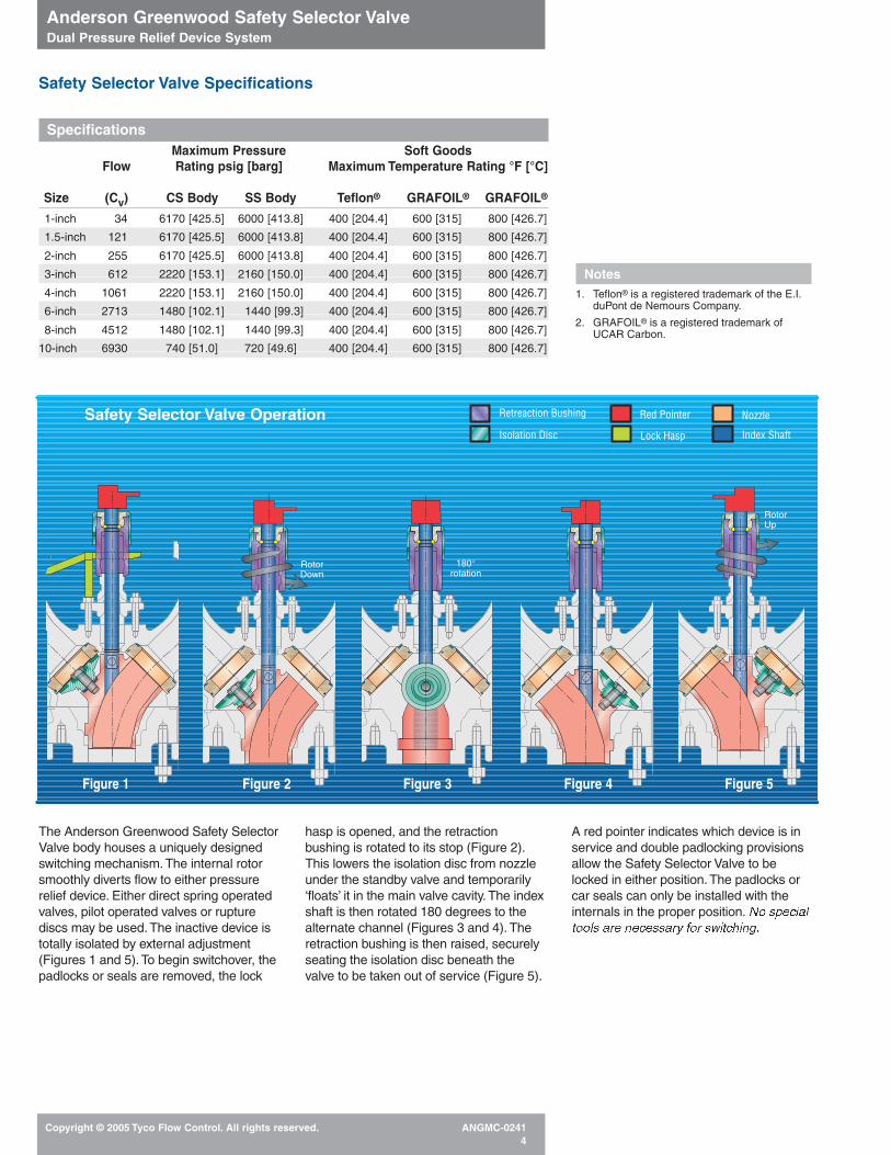
Safety Selector Valve Specifications
Safety Selector Valve Operation
SpecificationsMaximum Pressure Soft Goods
Flow Rating psig [barg] Maximum Temperature Rating °F [°C]Efficiency (@ 100°F) [37.8°C] PEEK/
Size (Cv) CS Body SS Body Teflon® GRAFOIL® GRAFOIL®
1-inch 34 6170 [425.5] 6000 [413.8] 400 [204.4] 600 [315] 800 [426.7]
1.5-inch 121 6170 [425.5] 6000 [413.8] 400 [204.4] 600 [315] 800 [426.7]
2-inch 255 6170 [425.5] 6000 [413.8] 400 [204.4] 600 [315] 800 [426.7]
3-inch 612 2220 [153.1] 2160 [150.0] 400 [204.4] 600 [315] 800 [426.7]
4-inch 1061 2220 [153.1] 2160 [150.0] 400 [204.4] 600 [315] 800 [426.7]
6-inch 2713 1480 [102.1] 1440 [99.3] 400 [204.4] 600 [315] 800 [426.7]
8-inch 4512 1480 [102.1] 1440 [99.3] 400 [204.4] 600 [315] 800 [426.7]
10-inch 6930 740 [51.0] 720 [49.6] 400 [204.4] 600 [315] 800 [426.7]
RotorDown
180°rotation
RotorUp
Figure 1 Figure 2 Figure 3 Figure 4 Figure 5
Notes1. Teflon® is a registered trademark of the E.I.
duPont de Nemours Company.
2. GRAFOIL® is a registered trademark ofUCAR Carbon.
The Anderson Greenwood Safety SelectorValve body houses a uniquely designedswitching mechanism. The internal rotorsmoothly diverts flow to either pressurerelief device. Either direct spring operatedvalves, pilot operated valves or rupturediscs may be used. The inactive device istotally isolated by external adjustment(Figures 1 and 5). To begin switchover, thepadlocks or seals are removed, the lock
hasp is opened, and the retractionbushing is rotated to its stop (Figure 2).This lowers the isolation disc from nozzleunder the standby valve and temporarily‘floats’ it in the main valve cavity. The indexshaft is then rotated 180 degrees to thealternate channel (Figures 3 and 4). Theretraction bushing is then raised, securelyseating the isolation disc beneath thevalve to be taken out of service (Figure 5).
A red pointer indicates which device is inservice and double padlocking provisionsallow the Safety Selector Valve to belocked in either position. The padlocks orcar seals can only be installed with theinternals in the proper position. No specialtools are necessary for switching.
Retreaction Bushing Red Pointer Nozzle
Isolation Disc Lock Hasp Index Shaft
Anderson Greenwood Safety Selector ValveDual Pressure Relief Device System
Copyright © 2005 Tyco Flow Control. All rights reserved. ANGMC-02415
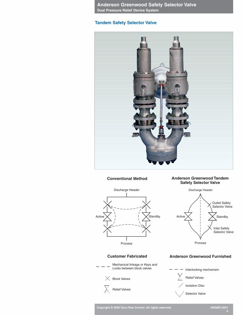
Conventional Method Anderson Greenwood TandemSafety Selector Valve
Customer Fabricated
Mechanical linkage or Keys andLocks between block valves
Block Valves
Relief Valves
Anderson Greenwood Furnished
Interlocking mechanism
Relief Valves
Isolation Disc
Selector Valve
Discharge Header Discharge Header
Process Process
Outlet SafetySelector Valve
Inlet SafetySelector Valve
Active ActiveStandby Standby
Tandem Safety Selector Valve
Anderson Greenwood Safety Selector ValveDual Pressure Relief Device System
Copyright © 2005 Tyco Flow Control. All rights reserved. ANGMC-02416
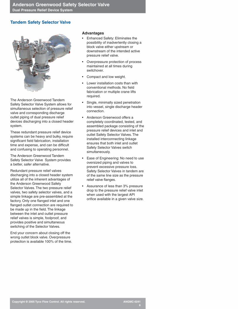
Advantages• Enhanced Safety: Eliminates the
possibility of inadvertently closing ablock valve either upstream ordownstream of the intended activepressure relief valve.
• Overpressure protection of processmaintained at all times duringswitchover.
• Compact and low weight.
• Lower installation costs than withconventional methods. No fieldfabrication or multiple crane liftsrequired.
• Single, minimally sized penetrationinto vessel, single discharge headerconnection.
• Anderson Greenwood offers acompletely coordinated, tested, andassembled package consisting of thepressure relief devices and inlet andoutlet Safety Selector Valves. The installed interconnecting linkageensures that both inlet and outletSafety Selector Valves switchsimultaneously.
• Ease of Engineering: No need to useoversized piping and valves toprevent excessive pressure loss.Safety Selector Valves in tandem areof the same line size as the pressurerelief valve flanges.
• Assurance of less than 3% pressuredrop to the pressure relief valve inletwhen used with the largest APIorifice available in a given valve size.
Tandem Safety Selector Valve
The Anderson Greenwood TandemSafety Selector Valve System allows forsimultaneous selection of pressure reliefvalve and corresponding dischargeoutlet piping of dual pressure reliefdevices discharging into a closed headersystem.
These redundant pressure relief device systems can be heavy and bulky, requiresignificant field fabrication, installationtime and expense, and can be difficultand confusing to operating personnel.
The Anderson Greenwood TandemSafety Selector Valve System providesa better, safer alternative.
Redundant pressure relief valvesdischarging into a closed header systemutilize all of the inherent advantages ofthe Anderson Greenwood SafetySelector Valves. The two pressure reliefvalves, two safety selector valves, and asimple linkage are pre-assembled at thefactory. Only one flanged inlet and oneflanged outlet connection are required tobe made up in the field. The linkagebetween the inlet and outlet pressurerelief valves is simple, foolproof, andprovides positive and simultaneousswitching of the Selector Valves.
End your concern about closing off thewrong outlet block valve. Overpressure protection is available 100% of the time.
Anderson Greenwood Safety Selector ValveDual Pressure Relief Device System
Copyright © 2005 Tyco Flow Control. All rights reserved. ANGMC-02417
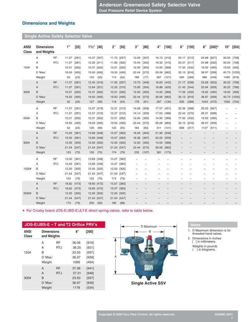
Dimensions and Weights
A RF 11.07 [281] 12.07 [307] 11.70 [297] 13.26 [337] 16.13 [410] 20.17 [512] 24.69 [627] 30.25 [768]
A RTJ 11.07 [281] 12.26 [311] 11.89 [302] 13.45 [342] 16.32 [415] 20.37 [517] 24.88 [632] 30.25 [768]
150# B 10.31 [262] 10.31 [262] 10.31 [262] 12.00 [305] 14.50 [368] 17.00 [432] 19.50 [495] 19.50 [495]
D ‘Max.’ 19.50 [495] 19.50 [495] 19.50 [495] 22.44 [570] 26.06 [662] 32.13 [816] 36.97 [939] 40.75 [1035]
Weight 52 (24) 122 (55) 115 (52) 169 (77) 267 (121) 594 (269) 989 (449) 1490 (676)
A RF 11.07 [281] 12.45 [316] 11.95 [297] 13.70 [348] 16.63 [442] 21.17 [538] 25.69 [653] 30.25 [768]
A RTJ 11.07 [281] 12.64 [321] 12.20 [310] 13.95 [354] 16.88 [429] 21.43 [544] 25.94 [659] 30.25 [768]
300# B 10.31 [262] 10.31 [262] 10.31 [262] 12.00 [305] 14.50 [368] 17.00 [432] 19.50 [495] 19.50 [495]
D ‘Max.’ 19.50 [495] 19.50 [495] 19.50 [495] 22.44 [570] 26.06 [662] 32.13 [816] 36.97 [939] 40.75 [1035]
Weight 52 (24) 127 (58) 118 (54) 178 (81) 287 (130) 635 (288) 1043 (473) 1550 (703)
A RF 11.07 [281] 12.57 [319] 12.21 [310] 14.08 [358] 17.57 [451] 22.36 [568] 26.25 [667] – –
A RTJ 11.07 [281] 12.57 [319] 12.27 [312] 14.14 [359] 17.63 [488] 22.43 [570] 26.31 [668] – –
600# B 10.31 [262] 10.31 [262] 10.31 [262] 12.00 [305] 14.50 [368] 17.00 [432] 19.50 [495] – –
D ‘Max.’ 19.50 [495] 19.50 [495] 19.50 [495] 22.44 [570] 26.06 [662] 32.13 [816] 36.97 [939] – –
Weight 52 (24) 129 (59) 122 (55) 184 (83) 311 (141) 699 (317) 1127 (511) – –
A RF 15.00 [381] 13.69 [348] 15.07 [383] 18.26 [464] 21.90 [556] – – – – – –
A RTJ 15.00 [381] 13.69 [348] 15.07 [383] 18.38 [467] 22.02 [559] – – – – – –
900# B 12.00 [305] 12.00 [305] 12.00 [305] 12.00 [305] 14.50 [368] – – – – – –
D ‘Max.’ 21.54 [547] 21.54 [547] 21.54 [547] 22.44 [570] 26.06 [662] – – – – – –
Weight 153 (70) 155 (70) 174 (79) 235 (107) 381 (173) – – – – – –
A RF 15.00 [381] 13.69 [348] 15.07 [383] – – – – – – – – – –
A RTJ 15.00 [381] 13.69 [348] 15.07 [383] – – – – – – – – – –
1500# B 12.00 [305] 12.00 [305] 12.00 [305] – – – – – – – – – –
D ‘Max.’ 21.54 [547] 21.54 [547] 21.54 [547] – – – – – – – – – –
Weight 153 (70) 155 (70) 174 (79) – – – – – – – – – –
A RF 18.62 [473] 18.60 [472] 15.07 [383] – – – – – – – – – –
A RTJ 18.62 [473] 18.60 [472] 15.07 [383] – – – – – – – – – –
2500# B 12.00 [305] 12.00 [305] 12.00 [305] – – – – – – – – – –
D ‘Max.’ 21.54 [547] 21.54 [547] 21.54 [547] – – – – – – – – – –
Weight 173 (79) 205 (93) 195 (89) – – – – – – – – – –
* For Crosby brand JOS-E/JBS-E/JLT-E direct spring valves, refer to table below.
JOS-E/JBS-E – T and T2 Orifice PRV’s
Single Active SSV
D Maximum
B
A
Notes1. D Maximum dimension is for
threaded hand valves.
2. Dimensions in inches[ ] in millimeters.
Weights in pounds( ) in kilograms.
Single Active Safety Selector Valve
ANSI Dimensions 1” [25] 11/2” [40] 2” [50] 3” [80] 4” [100] 6” [150] 8” [200]* 10” [254]Class and Weights
ANSI Dimensions 8” [200]Class and Weights
A RF 36.06 [916]
A RTJ 36.25 [921]
150# B 23.50 [597]
D ‘Max.’ 36.97 [939]
Weight 1089 (494)
A RF 37.06 [941]
A RTJ 37.31 [948]
300# B 23.50 [597]
D ‘Max.’ 36.97 [939]
Weight 1178 (534)
Anderson Greenwood Safety Selector ValveDual Pressure Relief Device System
Copyright © 2005 Tyco Flow Control. All rights reserved. ANGMC-02418
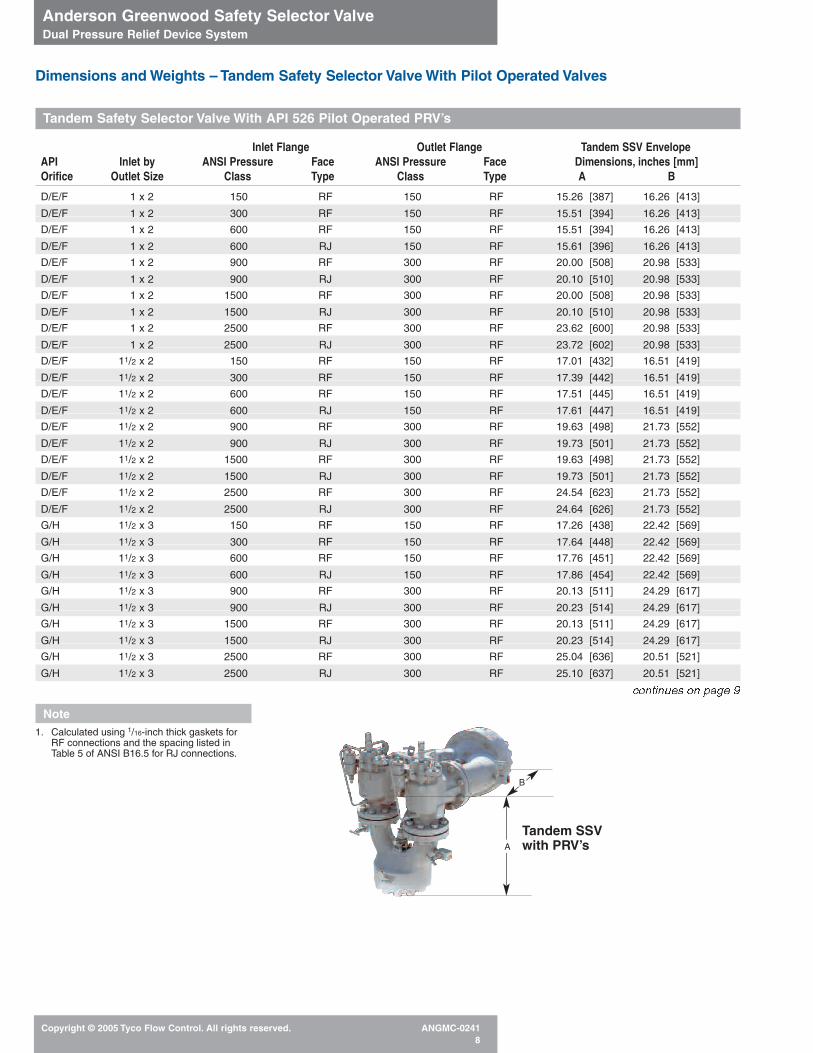
Dimensions and Weights – Tandem Safety Selector Valve With Pilot Operated Valves
Tandem Safety Selector Valve With API 526 Pilot Operated PRV’s
D/E/F 1 x 2 150 RF 150 RF 15.26 [387] 16.26 [413]
D/E/F 1 x 2 300 RF 150 RF 15.51 [394] 16.26 [413]
D/E/F 1 x 2 600 RF 150 RF 15.51 [394] 16.26 [413]
D/E/F 1 x 2 600 RJ 150 RF 15.61 [396] 16.26 [413]
D/E/F 1 x 2 900 RF 300 RF 20.00 [508] 20.98 [533]
D/E/F 1 x 2 900 RJ 300 RF 20.10 [510] 20.98 [533]
D/E/F 1 x 2 1500 RF 300 RF 20.00 [508] 20.98 [533]
D/E/F 1 x 2 1500 RJ 300 RF 20.10 [510] 20.98 [533]
D/E/F 1 x 2 2500 RF 300 RF 23.62 [600] 20.98 [533]
D/E/F 1 x 2 2500 RJ 300 RF 23.72 [602] 20.98 [533]
D/E/F 11/2 x 2 150 RF 150 RF 17.01 [432] 16.51 [419]
D/E/F 11/2 x 2 300 RF 150 RF 17.39 [442] 16.51 [419]
D/E/F 11/2 x 2 600 RF 150 RF 17.51 [445] 16.51 [419]
D/E/F 11/2 x 2 600 RJ 150 RF 17.61 [447] 16.51 [419]
D/E/F 11/2 x 2 900 RF 300 RF 19.63 [498] 21.73 [552]
D/E/F 11/2 x 2 900 RJ 300 RF 19.73 [501] 21.73 [552]
D/E/F 11/2 x 2 1500 RF 300 RF 19.63 [498] 21.73 [552]
D/E/F 11/2 x 2 1500 RJ 300 RF 19.73 [501] 21.73 [552]
D/E/F 11/2 x 2 2500 RF 300 RF 24.54 [623] 21.73 [552]
D/E/F 11/2 x 2 2500 RJ 300 RF 24.64 [626] 21.73 [552]
G/H 11/2 x 3 150 RF 150 RF 17.26 [438] 22.42 [569]
G/H 11/2 x 3 300 RF 150 RF 17.64 [448] 22.42 [569]
G/H 11/2 x 3 600 RF 150 RF 17.76 [451] 22.42 [569]
G/H 11/2 x 3 600 RJ 150 RF 17.86 [454] 22.42 [569]
G/H 11/2 x 3 900 RF 300 RF 20.13 [511] 24.29 [617]
G/H 11/2 x 3 900 RJ 300 RF 20.23 [514] 24.29 [617]
G/H 11/2 x 3 1500 RF 300 RF 20.13 [511] 24.29 [617]
G/H 11/2 x 3 1500 RJ 300 RF 20.23 [514] 24.29 [617]
G/H 11/2 x 3 2500 RF 300 RF 25.04 [636] 20.51 [521]
G/H 11/2 x 3 2500 RJ 300 RF 25.10 [637] 20.51 [521]
continues on page 9
Inlet Flange Outlet Flange Tandem SSV Envelope API Inlet by ANSI Pressure Face ANSI Pressure Face Dimensions, inches [mm]Orifice Outlet Size Class Type Class Type A B
Note1. Calculated using 1/16-inch thick gaskets for
RF connections and the spacing listed inTable 5 of ANSI B16.5 for RJ connections.
Tandem SSVwith PRV’sA
B
Anderson Greenwood Safety Selector ValveDual Pressure Relief Device System
Copyright © 2005 Tyco Flow Control. All rights reserved. ANGMC-02419
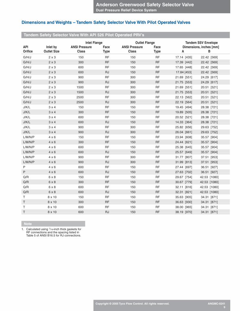
Tandem Safety Selector Valve With API 526 Pilot Operated PRV’s
Dimensions and Weights – Tandem Safety Selector Valve With Pilot Operated Valves
G/H/J 2 x 3 150 RF 150 RF 17.14 [435] 22.42 [569]
G/H/J 2 x 3 300 RF 150 RF 17.39 [442] 22.42 [569]
G/H/J 2 x 3 600 RF 150 RF 17.65 [448] 22.42 [569]
G/H/J 2 x 3 600 RJ 150 RF 17.84 [453] 22.42 [569]
G/H/J 2 x 3 900 RF 300 RF 21.69 [551] 24.29 [617]
G/H/J 2 x 3 900 RJ 300 RF 21.75 [553] 24.29 [617]
G/H/J 2 x 3 1500 RF 300 RF 21.69 [551] 20.51 [521]
G/H/J 2 x 3 1500 RJ 300 RF 21.75 [553] 20.51 [521]
G/H/J 2 x 3 2500 RF 300 RF 22.13 [562] 20.51 [521]
G/H/J 2 x 3 2500 RJ 300 RF 22.19 [564] 20.51 [521]
J/K/L 3 x 4 150 RF 150 RF 19.45 [494] 28.38 [721]
J/K/L 3 x 4 300 RF 150 RF 19.89 [505] 28.38 [721]
J/K/L 3 x 4 600 RF 150 RF 20.52 [521] 28.38 [721]
J/K/L 3 x 4 600 RJ 150 RF 14.33 [364] 28.38 [721]
J/K/L 3 x 4 900 RF 300 RF 25.82 [656] 29.63 [752]
J/K/L 3 x 4 900 RJ 300 RF 26.04 [661] 29.63 [752]
L/M/N/P 4 x 6 150 RF 150 RF 23.94 [608] 35.57 [904]
L/M/N/P 4 x 6 300 RF 150 RF 24.44 [621] 35.57 [904]
L/M/N/P 4 x 6 600 RF 150 RF 25.38 [645] 35.57 [904]
L/M/N/P 4 x 6 600 RJ 150 RF 25.57 [649] 35.57 [904]
L/M/N/P 4 x 6 900 RF 300 RF 31.77 [807] 37.51 [953]
L/M/N/P 4 x 6 900 RJ 300 RF 31.99 [813] 37.51 [953]
P 4 x 6 600 RF 150 RF 27.44 [697] 36.51 [927]
P 4 x 6 600 RJ 150 RF 27.63 [702] 36.51 [927]
Q/R 6 x 8 150 RF 150 RF 29.67 [754] 42.53 [1080]
Q/R 6 x 8 300 RF 150 RF 30.67 [779] 42.53 [1080]
Q/R 6 x 8 600 RF 150 RF 32.11 [816] 42.53 [1080]
Q/R 6 x 8 600 RJ 150 RF 32.31 [821] 42.53 [1080]
T 8 x 10 150 RF 150 RF 35.63 [905] 34.31 [871]
T 8 x 10 300 RF 150 RF 36.63 [930] 34.31 [871]
T 8 x 10 600 RF 150 RF 38.00 [965] 34.31 [871]
T 8 x 10 600 RJ 150 RF 38.19 [970] 34.31 [871]
Inlet Flange Outlet Flange Tandem SSV Envelope API Inlet by ANSI Pressure Face ANSI Pressure Face Dimensions, inches [mm]Orifice Outlet Size Class Type Class Type A B
Note1. Calculated using 1/16-inch thick gaskets for
RF connections and the spacing listed inTable 5 of ANSI B16.5 for RJ connections.
Anderson Greenwood Safety Selector ValveDual Pressure Relief Device System
Copyright © 2005 Tyco Flow Control. All rights reserved. ANGMC-024110
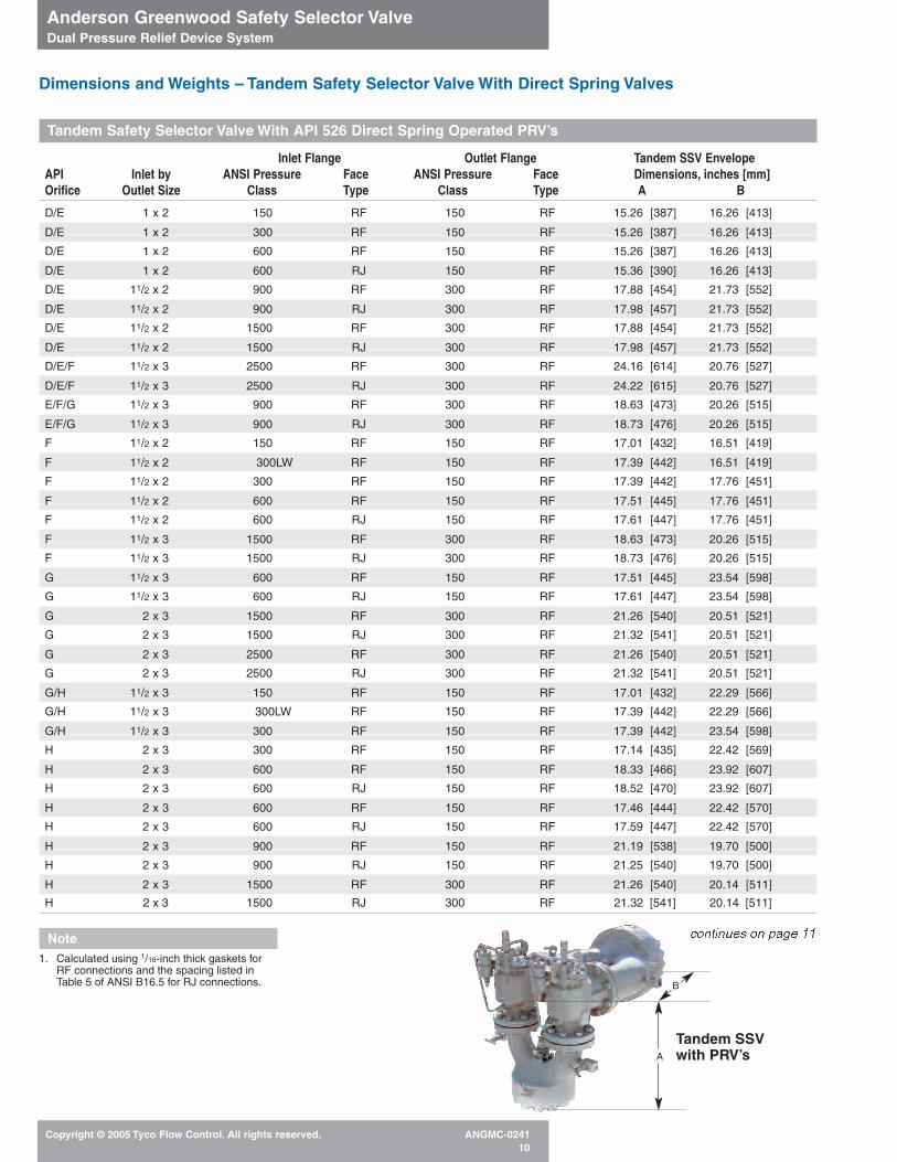
Dimensions and Weights – Tandem Safety Selector Valve With Direct Spring Valves
Tandem Safety Selector Valve With API 526 Direct Spring Operated PRV’s
Note1. Calculated using 1/16-inch thick gaskets for
RF connections and the spacing listed inTable 5 of ANSI B16.5 for RJ connections.
D/E 1 x 2 150 RF 150 RF 15.26 [387] 16.26 [413]
D/E 1 x 2 300 RF 150 RF 15.26 [387] 16.26 [413]
D/E 1 x 2 600 RF 150 RF 15.26 [387] 16.26 [413]
D/E 1 x 2 600 RJ 150 RF 15.36 [390] 16.26 [413]
D/E 11/2 x 2 900 RF 300 RF 17.88 [454] 21.73 [552]
D/E 11/2 x 2 900 RJ 300 RF 17.98 [457] 21.73 [552]
D/E 11/2 x 2 1500 RF 300 RF 17.88 [454] 21.73 [552]
D/E 11/2 x 2 1500 RJ 300 RF 17.98 [457] 21.73 [552]
D/E/F 11/2 x 3 2500 RF 300 RF 24.16 [614] 20.76 [527]
D/E/F 11/2 x 3 2500 RJ 300 RF 24.22 [615] 20.76 [527]
E/F/G 11/2 x 3 900 RF 300 RF 18.63 [473] 20.26 [515]
E/F/G 11/2 x 3 900 RJ 300 RF 18.73 [476] 20.26 [515]
F 11/2 x 2 150 RF 150 RF 17.01 [432] 16.51 [419]
F 11/2 x 2 300LW RF 150 RF 17.39 [442] 16.51 [419]
F 11/2 x 2 300 RF 150 RF 17.39 [442] 17.76 [451]
F 11/2 x 2 600 RF 150 RF 17.51 [445] 17.76 [451]
F 11/2 x 2 600 RJ 150 RF 17.61 [447] 17.76 [451]
F 11/2 x 3 1500 RF 300 RF 18.63 [473] 20.26 [515]
F 11/2 x 3 1500 RJ 300 RF 18.73 [476] 20.26 [515]
G 11/2 x 3 600 RF 150 RF 17.51 [445] 23.54 [598]
G 11/2 x 3 600 RJ 150 RF 17.61 [447] 23.54 [598]
G 2 x 3 1500 RF 300 RF 21.26 [540] 20.51 [521]
G 2 x 3 1500 RJ 300 RF 21.32 [541] 20.51 [521]
G 2 x 3 2500 RF 300 RF 21.26 [540] 20.51 [521]
G 2 x 3 2500 RJ 300 RF 21.32 [541] 20.51 [521]
G/H 11/2 x 3 150 RF 150 RF 17.01 [432] 22.29 [566]
G/H 11/2 x 3 300LW RF 150 RF 17.39 [442] 22.29 [566]
G/H 11/2 x 3 300 RF 150 RF 17.39 [442] 23.54 [598]
H 2 x 3 300 RF 150 RF 17.14 [435] 22.42 [569]
H 2 x 3 600 RF 150 RF 18.33 [466] 23.92 [607]
H 2 x 3 600 RJ 150 RF 18.52 [470] 23.92 [607]
H 2 x 3 600 RF 150 RF 17.46 [444] 22.42 [570]
H 2 x 3 600 RJ 150 RF 17.59 [447] 22.42 [570]
H 2 x 3 900 RF 150 RF 21.19 [538] 19.70 [500]
H 2 x 3 900 RJ 150 RF 21.25 [540] 19.70 [500]
H 2 x 3 1500 RF 300 RF 21.26 [540] 20.14 [511]
H 2 x 3 1500 RJ 300 RF 21.32 [541] 20.14 [511]
continues on page 11
Inlet Flange Outlet Flange Tandem SSV Envelope API Inlet by ANSI Pressure Face ANSI Pressure Face Dimensions, inches [mm]Orifice Outlet Size Class Type Class Type A B
Tandem SSVwith PRV’sA
B
Anderson Greenwood Safety Selector ValveDual Pressure Relief Device System
Copyright © 2005 Tyco Flow Control. All rights reserved. ANGMC-024111
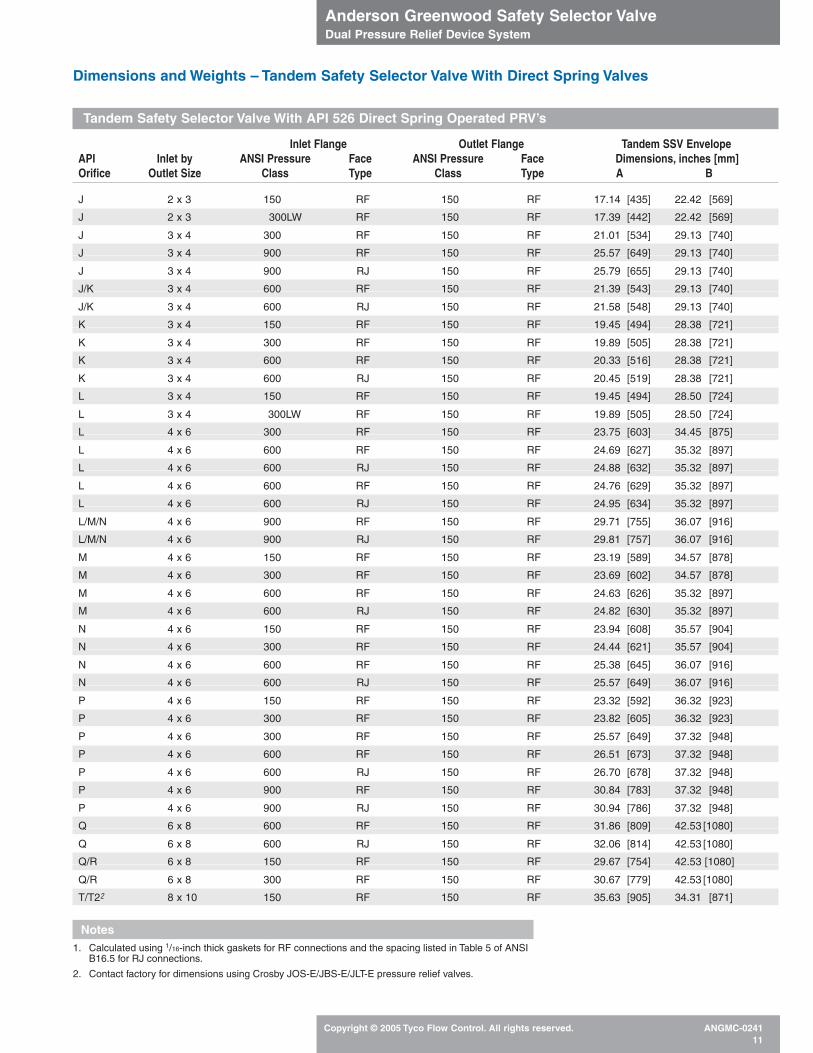
Dimensions and Weights – Tandem Safety Selector Valve With Direct Spring Valves
Tandem Safety Selector Valve With API 526 Direct Spring Operated PRV’s
Notes1. Calculated using 1/16-inch thick gaskets for RF connections and the spacing listed in Table 5 of ANSI
B16.5 for RJ connections.
2. Contact factory for dimensions using Crosby JOS-E/JBS-E/JLT-E pressure relief valves.
Inlet Flange Outlet Flange Tandem SSV Envelope API Inlet by ANSI Pressure Face ANSI Pressure Face Dimensions, inches [mm]Orifice Outlet Size Class Type Class Type A B
J 2 x 3 150 RF 150 RF 17.14 [435] 22.42 [569]
J 2 x 3 300LW RF 150 RF 17.39 [442] 22.42 [569]
J 3 x 4 300 RF 150 RF 21.01 [534] 29.13 [740]
J 3 x 4 900 RF 150 RF 25.57 [649] 29.13 [740]
J 3 x 4 900 RJ 150 RF 25.79 [655] 29.13 [740]
J/K 3 x 4 600 RF 150 RF 21.39 [543] 29.13 [740]
J/K 3 x 4 600 RJ 150 RF 21.58 [548] 29.13 [740]
K 3 x 4 150 RF 150 RF 19.45 [494] 28.38 [721]
K 3 x 4 300 RF 150 RF 19.89 [505] 28.38 [721]
K 3 x 4 600 RF 150 RF 20.33 [516] 28.38 [721]
K 3 x 4 600 RJ 150 RF 20.45 [519] 28.38 [721]
L 3 x 4 150 RF 150 RF 19.45 [494] 28.50 [724]
L 3 x 4 300LW RF 150 RF 19.89 [505] 28.50 [724]
L 4 x 6 300 RF 150 RF 23.75 [603] 34.45 [875]
L 4 x 6 600 RF 150 RF 24.69 [627] 35.32 [897]
L 4 x 6 600 RJ 150 RF 24.88 [632] 35.32 [897]
L 4 x 6 600 RF 150 RF 24.76 [629] 35.32 [897]
L 4 x 6 600 RJ 150 RF 24.95 [634] 35.32 [897]
L/M/N 4 x 6 900 RF 150 RF 29.71 [755] 36.07 [916]
L/M/N 4 x 6 900 RJ 150 RF 29.81 [757] 36.07 [916]
M 4 x 6 150 RF 150 RF 23.19 [589] 34.57 [878]
M 4 x 6 300 RF 150 RF 23.69 [602] 34.57 [878]
M 4 x 6 600 RF 150 RF 24.63 [626] 35.32 [897]
M 4 x 6 600 RJ 150 RF 24.82 [630] 35.32 [897]
N 4 x 6 150 RF 150 RF 23.94 [608] 35.57 [904]
N 4 x 6 300 RF 150 RF 24.44 [621] 35.57 [904]
N 4 x 6 600 RF 150 RF 25.38 [645] 36.07 [916]
N 4 x 6 600 RJ 150 RF 25.57 [649] 36.07 [916]
P 4 x 6 150 RF 150 RF 23.32 [592] 36.32 [923]
P 4 x 6 300 RF 150 RF 23.82 [605] 36.32 [923]
P 4 x 6 300 RF 150 RF 25.57 [649] 37.32 [948]
P 4 x 6 600 RF 150 RF 26.51 [673] 37.32 [948]
P 4 x 6 600 RJ 150 RF 26.70 [678] 37.32 [948]
P 4 x 6 900 RF 150 RF 30.84 [783] 37.32 [948]
P 4 x 6 900 RJ 150 RF 30.94 [786] 37.32 [948]
Q 6 x 8 600 RF 150 RF 31.86 [809] 42.53 [1080]
Q 6 x 8 600 RJ 150 RF 32.06 [814] 42.53 [1080]
Q/R 6 x 8 150 RF 150 RF 29.67 [754] 42.53 [1080]
Q/R 6 x 8 300 RF 150 RF 30.67 [779] 42.53 [1080]
T/T22 8 x 10 150 RF 150 RF 35.63 [905] 34.31 [871]
Anderson Greenwood Safety Selector ValveDual Pressure Relief Device System
Copyright © 2005 Tyco Flow Control. All rights reserved. ANGMC-024112
Tyco Flow Control (TFC) provides the information herein in good faith but makes no representation as to its comprehensiveness or accuracy. This data sheet is intended only as a guide to TFC products and services.Individuals using this data sheet must exercise their independent judgment in evaluating product selection and determining product appropriateness for their particular purpose and system requirements. TFCMAKES NO REPRESENTATIONS OR WARRANTIES, EITHER EXPRESS OR IMPLIED, INCLUDING WITHOUT LIMITATION ANY WARRANTIES OF MERCHANTABILITY OR FITNESS FOR A PARTICULAR PURPOSEWITH RESPECT TO THE INFORMATION SET FORTH HEREIN OR THE PRODUCT(S) TO WHICH THE INFORMATION REFERS. ACCORDINGLY, TFC WILL NOT BE RESPONSIBLE FOR DAMAGES (OF ANY KIND ORNATURE, INCLUDING INCIDENTAL, INDIRECT, OR CONSEQUENTIAL DAMAGES) RESULTING FROM THE USE OF OR RELIANCE UPON THIS INFORMATION. Patents and Patents Pending in the U.S. and foreign countries. Tyco reserves the right to change product designs and specifications without notice.
www.tycovalves.com
Tyco Valves & Controls
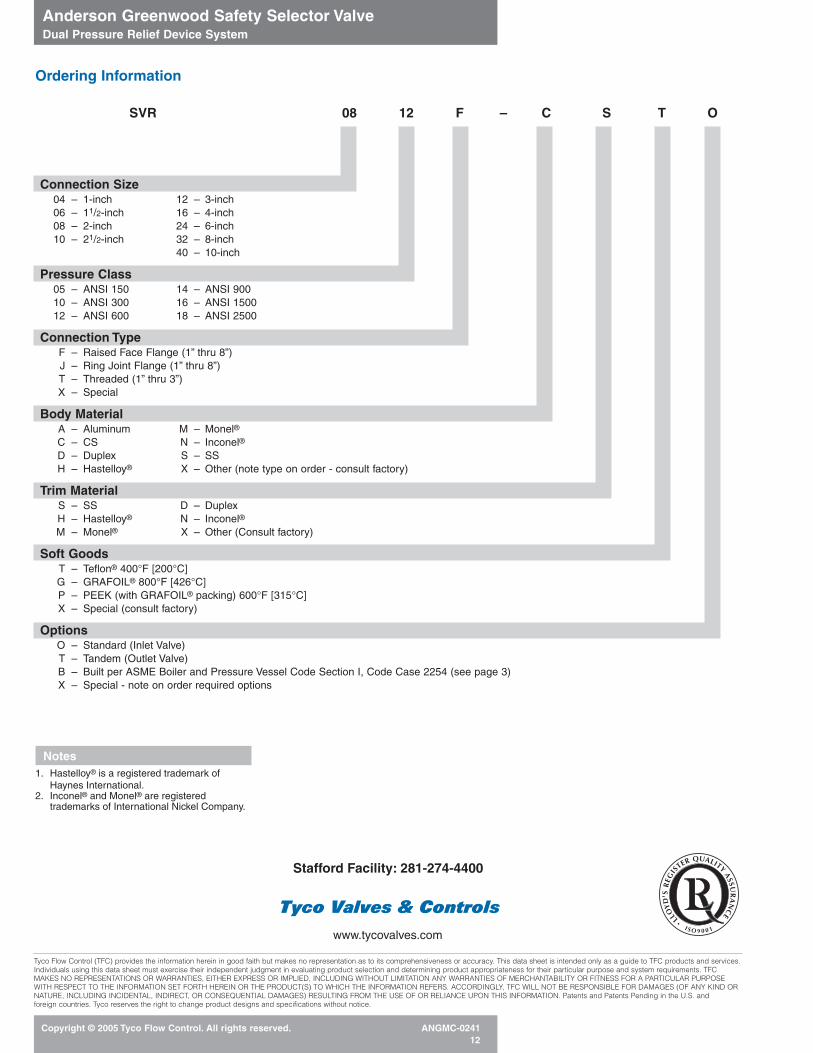
SVR 08 12 F – C S T O
Connection Size04 – 1-inch 12 – 3-inch06 – 11/2-inch 16 – 4-inch08 – 2-inch 24 – 6-inch10 – 21/2-inch 32 – 8-inch
40 – 10-inch
Pressure Class05 – ANSI 150 14 – ANSI 90010 – ANSI 300 16 – ANSI 150012 – ANSI 600 18 – ANSI 2500
Connection TypeF – Raised Face Flange (1” thru 8”)J – Ring Joint Flange (1” thru 8”)T – Threaded (1” thru 3”)X – Special
Body MaterialA – Aluminum M – Monel®
C – CS N – Inconel®
D – Duplex S – SSH – Hastelloy® X – Other (note type on order - consult factory)
Trim MaterialS – SS D – DuplexH – Hastelloy® N – Inconel®
M – Monel® X – Other (Consult factory)
Soft GoodsT – Teflon® 400°F [200°C]G – GRAFOIL® 800°F [426°C]P – PEEK (with GRAFOIL® packing) 600°F [315°C]X – Special (consult factory)
OptionsO – Standard (Inlet Valve)T – Tandem (Outlet Valve)B – Built per ASME Boiler and Pressure Vessel Code Section I, Code Case 2254 (see page 3)X – Special - note on order required options
Ordering Information
Notes1. Hastelloy® is a registered trademark of
Haynes International.2. Inconel® and Monel® are registered
trademarks of International Nickel Company.
Stafford Facility: 281-274-4400