Embed Size (px)
Citation preview
© Copyright Sierra Gear & Axle 2015
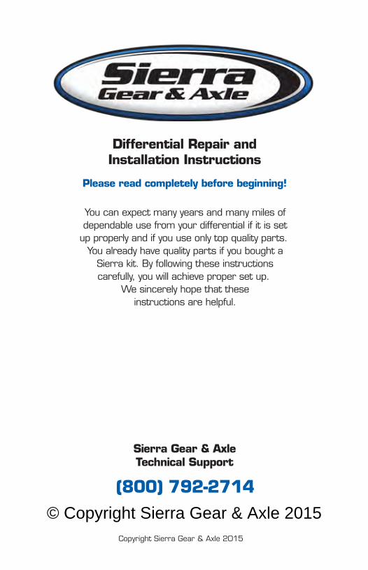
DIFFERENTIAL REPAIR
AND
INSTALLATIONINSTRUCTIONS
© Copyright Sierra Gear & Axle 2015
Differential Repair andInstallation Instructions
Please read completely before beginning!
You can expect many years and many miles ofdependable use from your differential if it is set
up properly and if you use only top quality parts. You already have quality parts if you bought a
Sierra kit. By following these instructionscarefully, you will achieve proper set up.
We sincerely hope that theseinstructions are helpful.
Sierra Gear & AxleTechnical Support
(800) 792-2714
Copyright Sierra Gear & Axle 2015
© Copyright Sierra Gear & Axle 2015
TABLE OF CONTENTS
Parts Identification.........................................4
Tool List...................................................5
Disassembly / Inspection..................................6
Adjustments...............................................7
Parts Preparation......................................... 7
Initial Assembly............................................7
Component Clearancing....................................8
Assembly - Pinion..........................................9
Assembly - Carrier........................................10
Checking the Pattern.....................................11
Gear Tooth Nomenclature.................................12
Patterns - Acceptable.....................................13
Patterns - Pinion Too Shallow..............................14
Patterns - Pinion Too Deep................................15
Setup Specifications....................................16-17
Gear Oil..................................................17
Additives.................................................17
Break-In Procedure.......................................17
Shim Combination Worksheet.............................18
Warranty Information..............................Back Cover
© Copyright Sierra Gear & Axle 20154
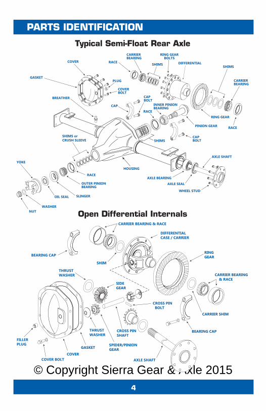
PARTS IDENTIFICATION
COVER
PINION GEAR
GASKET
BREATHER
RACE
RACE
SLINGEROIL SEAL
WASHERNUT
YOKE
CAPBOLT
CAPBOLT
PLUG
COVERBOLT
OUTER PINIONBEARING
INNER PINIONBEARING
SHIMSSHIMS orCRUSH SLEEVE
HOUSING
AXLE BEARINGAXLE SEAL
AXLE SHAFT
WHEEL STUD
CAP
RACE
RACE
RING GEAR
CARRIERBEARING
CARRIERBEARING
SHIMSSHIMS
RING GEARBOLTS
DIFFERENTIAL
FILLERPLUG
SIDEGEAR
RINGGEAR
THRUSTWASHER
THRUSTWASHER
CROSS PINSHAFT
CARRIER BEARING & RACE
CARRIER BEARING & RACE
CROSS PIN BOLT
BEARING CAP
AXLE SHAFT
BEARING CAP
SPIDER/PINIONGEAR
CARRIER SHIM
DIFFERENTIALCASE / CARRIER
COVER
SHIM
COVER BOLT
GASKET
Open Differential Internals
Typical Semi-Float Rear Axle
© Copyright Sierra Gear & Axle 20155
TOOL LIST
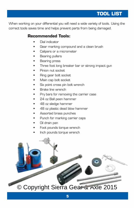
When working on your differential you will need a wide variety of tools. Using thecorrect tools saves time and helps prevent parts from being damaged.
• Dial indicator• Gear marking compound and a clean brush• Calipers or a micrometer• Bearing pullers• Bearing press• Three foot long breaker bar or strong impact gun• Pinion nut socket• Ring gear bolt socket• Main cap bolt socket• Six point cross pin bolt wrench• Brake line wrench• Pry bars for removing the carrier case• 24 oz Ball peen hammer• 48 oz sledge hammer• 48 oz plastic dead blow hammer• Assorted brass punches• Punch for marking carrier caps• Oil drain pan• Foot pounds torque wrench• Inch pounds torque wrench
Recommended Tools:
© Copyright Sierra Gear & Axle 20156
DISASSEMBLY
Inspection
Make sure that you have all the parts and tools you will need. The extent ofdisassembly depends on the job being done and the inspection findings. Lift the vehicle using an appropriate lift or a jack and safe jack stands.Always make certain that the vehicle is safely supported before workingunderneath. Unbolt the driveshaft from the yoke. Remove the differentialcover or unbolt the third member. Let the oil drian into a suitable container.Please recycle your waste oil. Remove c-clip axles by removing thedifferential cross pin bolt and cross pin shaft, pushing the axles in andpulling the c-clips. Full float axles are unbolted at the hubs. Punch bothcarrier caps with identification marks so that you will be able to re-installthem on the same side and in the same direction. Most carriers can bepulled out of the housing with a pry bar. Further disassembly depends onthe job being done. If you’re changing the ring and pinion or the pinionbearings, remove the pinion nut with an air gun while holding the yoke, oruse a long breaker bar and brace the yoke (bolt it to a long board) so that itcan’t move. Knock the pinion gear out to the rear with a brass punch takingcare not to damage the threads. Keep track of the positions of all of theoriginal shims. Pinion bearings must be pressed off. Carrier bearings canbe pulled using a bearing puller. Internal parts (inside the carrier) can bemoved as necessary.
Inspect all bearings and races for pitting or uneven wear. The inner carrierbearing races should not spin on the carrier journals. The carrier racesshould have a snug fit in the housing. Inspect the carrier race bores forgrooves from spinning races. “Spun” carriers and housings can bemachined to accept slightly larger races and bearings. The side gear boresinside the carrier should not have any abnormal wear. All gear teeth shouldbe smooth but not excessively shiny. Inspect gear teeth for pitting, chips,breaks, and for signs of uneven wear and overheating. Inspect positractionclutches for scoring and wear. Inspect the axles for pitted, grooved, or dulland rough bearing surfaces. Check for worn axle splines. All questionableparts should be replaced.
Preparation
© Copyright Sierra Gear & Axle 20157
ASSEMBLY
The four essential differential adjustments are pinion depth, pinion bearingpreload, backlash and carrier bearing preload. The tables on page 18can be used to write down shim combinations and results.
Clean all new and used parts with clean solvent. Dry the parts. De-burr theback of the ring gear and carrier mounting surface with a file or wet stone.Wash out the housing with solvent and check all of the oil passages to makecertain that there are NO metal particles or dirt that can lead to early wear.Many housings have oil passages to the pinion and grooves just outside ofthe carrier bearings. Push rags through the axle tubes using solvent orbrake cleaner until they are clean. Polish all seal surfaces with light emerycloth or fine sandpaper and then wipe them with a clean rag and clean oilor solvent to remove metal particles. Use a moderate coat of gear oil (notgrease!) on all bearings and grease on all seals and seal surfaces just priorto installation.
We have successfully set up thousands of differentials without using a piniondepth setting tool. Pinion depth shims either go under the rear pinion raceor on the pinion shaft under the rear pinion bearing. The diameter of yourshims will determine where they go. Try using the original shim depth foryour first attempt. The rear pinion bearing must be pressed on the pinionshaft and the pinion races must be tapped into the housing with a largepunch so that they seat evenly. Install the front bearing and carefully tap thepinion seal in place with an old race. Ford 8” and 9”, and GM 10.5” andHO72 use a pilot bearing which must be tapped in, with a retainer for theFords. Mount the ring gear to the carrier with a drop of red Loctite on eachbolt. Carrier bearings are pressed on the carrier and secured with greenLoctite. Note that in Dana Spicer differentials the carrier shims go betweenthe carrier and carrier bearings.
Again, try using the original shim configuration.
Differential Adjustments
Preparing Parts
Initial Assembly
© Copyright Sierra Gear & Axle 20158
COMMON ISSUES
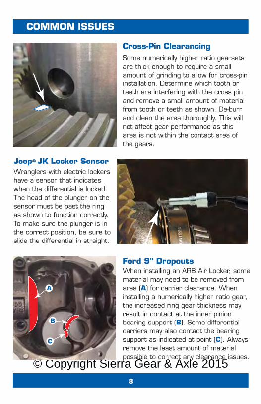
Cross-Pin Clearancing
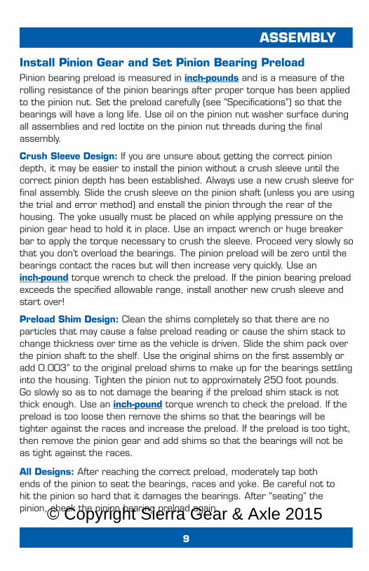
Jeep® JK Locker Sensor
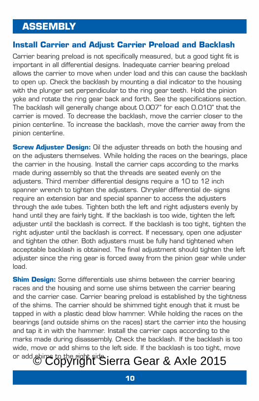
Ford 9” Dropouts
Some numerically higher ratio gearsetsare thick enough to require a smallamount of grinding to allow for cross-pininstallation. Determine which tooth orteeth are interfering with the cross pinand remove a small amount of materialfrom tooth or teeth as shown. De-burrand clean the area thoroughly. This willnot affect gear performance as thisarea is not within the contact area ofthe gears.
Wranglers with electric lockershave a sensor that indicateswhen the differential is locked.The head of the plunger on thesensor must be past the ringas shown to function correctly.To make sure the plunger is inthe correct position, be sure toslide the differential in straight.
When installing an ARB Air Locker, somematerial may need to be removed fromarea (A) for carrier clearance. Wheninstalling a numerically higher ratio gear,the increased ring gear thickness mayresult in contact at the inner pinionbearing support (B). Some differentialcarriers may also contact the bearingsupport as indicated at point (C). Alwaysremove the least amount of materialpossible to correct any clearance issues.
A
B
C
© Copyright Sierra Gear & Axle 20159
ASSEMBLY
Install Pinion Gear and Set Pinion Bearing Preload
Crush Sleeve Design: If you are unsure about getting the correct piniondepth, it may be easier to install the pinion without a crush sleeve until thecorrect pinion depth has been established. Always use a new crush sleeve forfinal assembly. Slide the crush sleeve on the pinion shaft (unless you are usingthe trial and error method) and enstall the pinion through the rear of thehousing. The yoke usually must be placed on while applying pressure on thepinion gear head to hold it in place. Use an impact wrench or huge breakerbar to apply the torque necessary to crush the sleeve. Proceed very slowly sothat you don’t overload the bearings. The pinion preload will be zero until thebearings contact the races but will then increase very quickly. Use aninch-pound torque wrench to check the preload. If the pinion bearing preloadexceeds the specified allowable range, install another new crush sleeve andstart over!
Pinion bearing preload is measured in inch-pounds and is a measure of therolling resistance of the pinion bearings after proper torque has been appliedto the pinion nut. Set the preload carefully (see “Specifications”) so that thebearings will have a long life. Use oil on the pinion nut washer surface duringall assemblies and red loctite on the pinion nut threads during the finalassembly.
Preload Shim Design: Clean the shims completely so that there are noparticles that may cause a false preload reading or cause the shim stack tochange thickness over time as the vehicle is driven. Slide the shim pack overthe pinion shaft to the shelf. Use the original shims on the first assembly oradd 0.003” to the original preload shims to make up for the bearings settlinginto the housing. Tighten the pinion nut to approximately 250 foot pounds.Go slowly so as to not damage the bearing if the preload shim stack is notthick enough. Use an inch-pound torque wrench to check the preload. If thepreload is too loose then remove the shims so that the bearings will betighter against the races and increase the preload. If the preload is too tight,then remove the pinion gear and add shims so that the bearings will not beas tight against the races.
All Designs: After reaching the correct preload, moderately tap bothends of the pinion to seat the bearings, races and yoke. Be careful not tohit the pinion so hard that it damages the bearings. After “seating” the pinion, check the pinion bearing preload again.
© Copyright Sierra Gear & Axle 201510
ASSEMBLY
Install Carrier and Adjust Carrier Preload and BacklashCarrier bearing preload is not specifically measured, but a good tight fit isimportant in all differential designs. Inadequate carrier bearing preloadallows the carrier to move when under load and this can cause the backlashto open up. Check the backlash by mounting a dial indicator to the housingwith the plunger set perpendicular to the ring gear teeth. Hold the pinionyoke and rotate the ring gear back and forth. See the specifications section.The backlash will generally change about 0.007” for each 0.010” that thecarrier is moved. To decrease the backlash, move the carrier closer to thepinion centerline. To increase the backlash, move the carrier away from thepinion centerline.
Shim Design: Some differentials use shims between the carrier bearingraces and the housing and some use shims between the carrier bearingand the carrier case. Carrier bearing preload is established by the tightnessof the shims. The carrier should be shimmed tight enough that it must betapped in with a plastic dead blow hammer. While holding the races on thebearings (and outside shims on the races) start the carrier into the housingand tap it in with the hammer. Install the carrier caps according to themarks made during disassembly. Check the backlash. If the backlash is toowide, move or add shims to the left side. If the backlash is too tight, moveor add shims to the right side.
Screw Adjuster Design: Oil the adjuster threads on both the housing andon the adjusters themselves. While holding the races on the bearings, placethe carrier in the housing. Install the carrier caps according to the marksmade during assembly so that the threads are seated evenly on theadjusters. Third member differential designs require a 10 to 12 inchspanner wrench to tighten the adjusters. Chrysler differential de- signsrequire an extension bar and special spanner to access the adjustersthrough the axle tubes. Tighten both the left and right adjusters evenly byhand until they are fairly tight. If the backlash is too wide, tighten the leftadjuster until the backlash is correct. If the backlash is too tight, tighten theright adjuster until the backlash is correct. If necessary, open one adjusterand tighten the other. Both adjusters must be fully hand tightened whenacceptable backlash is obtained. The final adjustment should tighten the leftadjuster since the ring gear is forced away from the pinion gear while underload.
© Copyright Sierra Gear & Axle 201511
CONTACT PATTERN
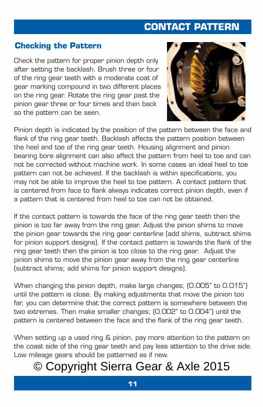
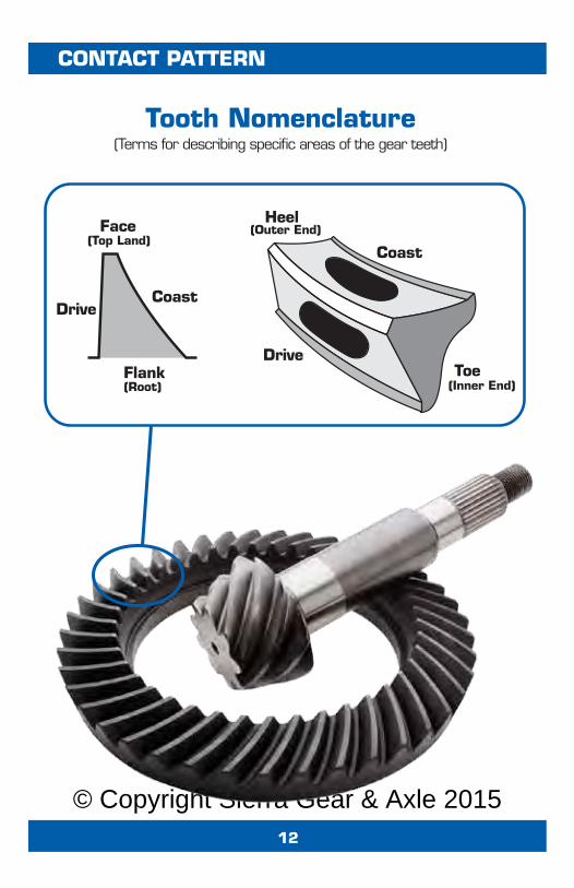
Check the pattern for proper pinion depth onlyafter setting the backlash. Brush three or fourof the ring gear teeth with a moderate coat ofgear marking compound in two different placeson the ring gear. Rotate the ring gear past thepinion gear three or four times and then backso the pattern can be seen.
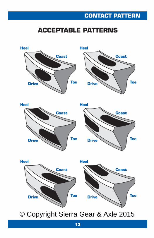
Pinion depth is indicated by the position of the pattern between the face andflank of the ring gear teeth. Backlash affects the pattern position betweenthe heel and toe of the ring gear teeth. Housing alignment and pinionbearing bore alignment can also affect the pattern from heel to toe and cannot be corrected without machine work. In some cases an ideal heel to toepattern can not be achieved. If the backlash is within specifications, youmay not be able to improve the heel to toe pattern. A contact pattern thatis centered from face to flank always indicates correct pinion depth, even ifa pattern that is centered from heel to toe can not be obtained.
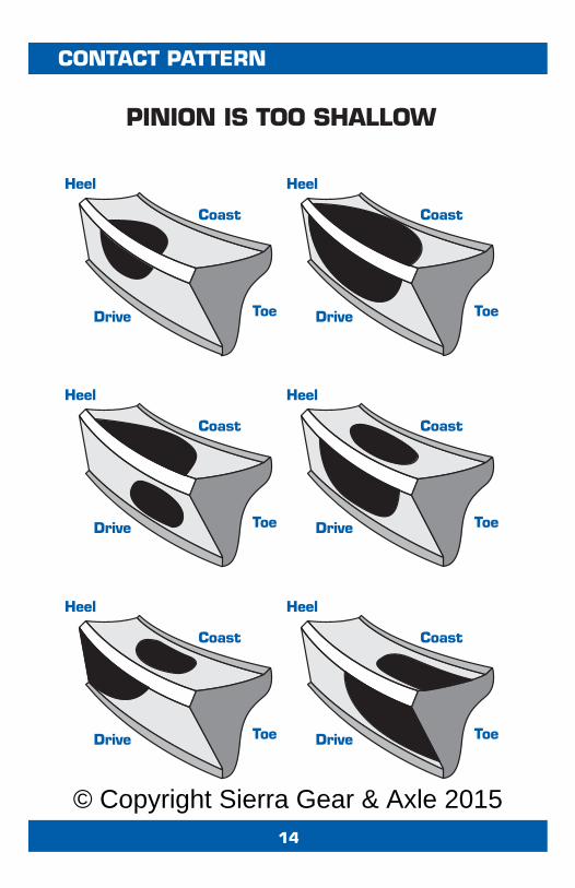
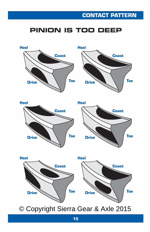
If the contact pattern is towards the face of the ring gear teeth then thepinion is too far away from the ring gear. Adjust the pinion shims to movethe pinion gear towards the ring gear centerline (add shims, subtract shimsfor pinion support designs). If the contact pattern is towards the flank of thering gear teeth then the pinion is too close to the ring gear. Adjust thepinion shims to move the pinion gear away from the ring gear centerline(subtract shims; add shims for pinion support designs).
When changing the pinion depth, make large changes; (0.005” to 0.015”)until the pattern is close. By making adjustments that move the pinion toofar, you can determine that the correct pattern is somewhere between thetwo extremes. Then make smaller changes; (0.002” to 0.004”) until thepattern is centered between the face and the flank of the ring gear teeth.
When setting up a used ring & pinion, pay more attention to the pattern onthe coast side of the ring gear teeth and pay less attention to the drive side.Low mileage gears should be patterned as if new.
Checking the Pattern
© Copyright Sierra Gear & Axle 201512
CONTACT PATTERN
Heel
Coast
ToeDrive
Face
CoastDrive
Flank(Inner End)
(Outer End)(Top Land)
(Root)
Tooth Nomenclature(Terms for describing specific areas of the gear teeth)
© Copyright Sierra Gear & Axle 201513
CONTACT PATTERN
Heel
Coast
ToeDrive
Heel
Coast
ToeDrive
Heel
Coast
ToeDrive
Heel
Coast
ToeDrive
Heel
Coast
ToeDrive
Heel
Coast
ToeDrive
ACCEPTABLE PATTERNS
© Copyright Sierra Gear & Axle 201514
CONTACT PATTERN
Heel
Coast
ToeDrive
Heel
Coast
ToeDrive
Heel
Coast
ToeDrive
Heel
Coast
ToeDrive
Heel
Coast
ToeDrive
Heel
Coast
ToeDrive
PINION IS TOO SHALLOW
© Copyright Sierra Gear & Axle 201515
CONTACT PATTERN
Heel
Coast
ToeDrive
Heel
Coast
ToeDrive
Heel
Coast
ToeDrive
Heel
Coast
ToeDrive
Heel
Coast
ToeDrive
Heel
Coast
ToeDrive
PINION IS TOO DEEP
© Copyright Sierra Gear & Axle 2015
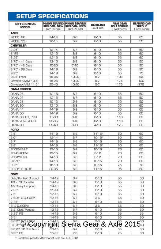
* Backlash Specs for Aftermarket Sets are .006-.012
SETUP SPECIFICATIONSDIFFERENTIAL
MODEL
GMC
AMC
CHRYSLER
DANA SPICER
FORD
MODEL 20
Olds/Pontiac Dropout‘63 - ’79 Corvette‘55 Chevy Dropout7.25”7.5”
7.75”
8.2” Olds/Pontiac8.25” IFS8.5”
14-1914-19
14-1912-15
6-86-7
6-106-10
6555
6555
14-1811-1412-15
12-15
12-1514-1914-19
6-76-86-86-76-7
6-7
6-76-86-8
6-106-106-106-106-10
6-10
6-106-106-10
5555555565
65
556565
6060606060
7.625” 2-Cut OEM 12-15 6-7 3-6 65 60
8.625” 2-Cut OEM 14-19 6-8 3-6 65 60
8.875” 12 Bolt Truck 13-15 6-7 6-10 55 608.875” 12-Bolt Car 14-19 6-8 6-10 55 60
9.25” IFS 15-22 7-9 6-10 75 80
608” 2-Cut OEM 12-15 6-7 3-6 65 60
605560
7.25”
8.25”8.75” - 41 Case8.75” - 42 Case8.75” - 89 Case9.25”
12-14
12-1513-1515-2514-1914-19
6-7
6-86-87-106-96-9
6-10
6-106-106-106-106-10
55
5555555565
508” IFS 12-15 6-8 6-10 55 60
6090909075
Chrysler/AAM 10.5” 15-25 10-20 5-7 175 1209.25” Front 15-35 10-20 5-7 103 63
Chrysler/AAM 11.5” 25-45 10-20 5-7 175 175
DANA 25DANA 27DANA 28DANA 30DANA 44DANA 50DANA 60, 61, 70UDANA 70 & 70HDDANA 80
12-1512-1510-1312-1514-1914-1917-3020-3525-40
6-76-75-66-86-96-98-108-109-11
6-106-106-106-106-106-106-106-104-10
555555555565110110175
505050606060808080
7.5”8.0”8.7”8.8”9” OEM R&P9” NON-OEM9” DAYTONA9-3/8”9.75”
14-1912-1414-1914-1913-1513-1514-1614-1615-19
6-86-76-86-86-76-76-86-86-8
11-16* 10-15*10-15
11-16*10-166-126-1210-1510-15
6060606070
7075
6060606060
70 6070 60
6070
10.25” & 10.5” 20-35 6-8 11-16 95 80
MODEL 35
PINION BEARINGPRELOAD - NEW
(Inch Pounds)
PINION BEARINGPRELOAD - USED
(Inch Pounds)
BEARING CAPTORQUE
(Foot Pounds)
RING GEARBOLT TORQUE(Foot Pounds)
BACKLASH(.001 inch)
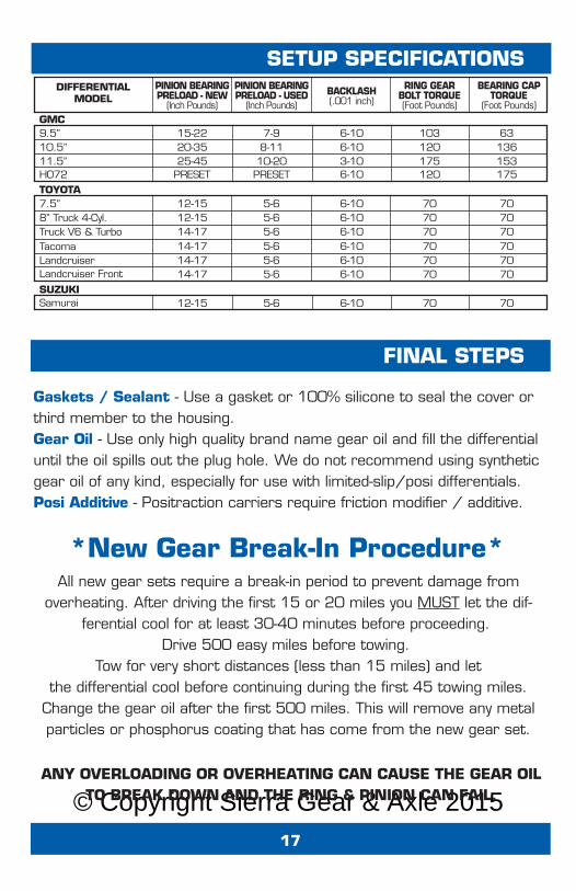
© Copyright Sierra Gear & Axle 201517
FINAL STEPS
Gaskets / Sealant - Use a gasket or 100% silicone to seal the cover orthird member to the housing.Gear Oil - Use only high quality brand name gear oil and fill the differentialuntil the oil spills out the plug hole. We do not recommend using syntheticgear oil of any kind, especially for use with limited-slip/posi differentials. Posi Additive - Positraction carriers require friction modifier / additive.
ANY OVERLOADING OR OVERHEATING CAN CAUSE THE GEAR OILTO BREAK DOWN AND THE RING & PINION CAN FAIL.
*New Gear Break-In Procedure*All new gear sets require a break-in period to prevent damage from
overheating. After driving the first 15 or 20 miles you MUST let the dif-ferential cool for at least 30-40 minutes before proceeding.
Drive 500 easy miles before towing. Tow for very short distances (less than 15 miles) and let
the differential cool before continuing during the first 45 towing miles.Change the gear oil after the first 500 miles. This will remove any metalparticles or phosphorus coating that has come from the new gear set.
SETUP SPECIFICATIONSDIFFERENTIAL
MODELPINION BEARINGPRELOAD - NEW
(Inch Pounds)
PINION BEARINGPRELOAD - USED
(Inch Pounds)
BEARING CAPTORQUE
(Foot Pounds)
RING GEARBOLT TORQUE(Foot Pounds)
BACKLASH(.001 inch)
GMC
SUZUKI
TOYOTA
9.5”10.5”11.5”HO72
15-2220-3525-45
PRESETPRESET
7-98-1110-20
6-106-103-106-10
103120175120
63136153175
7.5”8” Truck 4-Cyl.
Samurai 12-15 5-6 6-10 70 70
Landcruiser FrontLandcruiserTacomaTruck V6 & Turbo
14-1714-1714-17
5-65-65-6
6-106-106-10
707070
707070
12-1512-1514-17
5-65-65-6
6-106-106-10
707070
707070
© Copyright Sierra Gear & Axle 201518
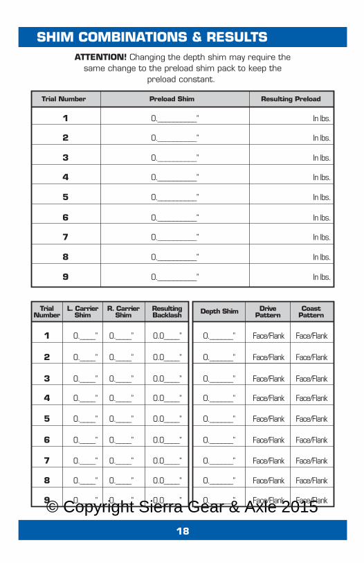
SHIM COMBINATIONS & RESULTSATTENTION! Changing the depth shim may require the
same change to the preload shim pack to keep thepreload constant.
Trial Number
TrialNumber
L. CarrierShim
R. CarrierShim
CoastPattern
DrivePattern
ResultingBacklash Depth Shim
Preload Shim Resulting Preload
1 0.__________” In lbs.
2 0.__________” In lbs.
3 0.__________” In lbs.
4 0.__________” In lbs.
5 0.__________” In lbs.
6 0.__________” In lbs.
7 0.__________” In lbs.
8 0.__________” In lbs.
9 0.__________” In lbs.
1 0.____” 0.____” 0.0____” 0.______” Face/Flank Face/Flank
2 0.____” 0.____” 0.0____” 0.______” Face/Flank Face/Flank
3 0.____” 0.____” 0.0____” 0.______” Face/Flank Face/Flank
4 0.____” 0.____” 0.0____” 0.______” Face/Flank Face/Flank
5 0.____” 0.____” 0.0____” 0.______” Face/Flank Face/Flank
6 0.____” 0.____” 0.0____” 0.______” Face/Flank Face/Flank
7 0.____” 0.____” 0.0____” 0.______” Face/Flank Face/Flank
8 0.____” 0.____” 0.0____” 0.______” Face/Flank Face/Flank
9 0.____” 0.____” 0.0____” 0.______” Face/Flank Face/Flank
© Copyright Sierra Gear & Axle 201519
NOTES
© Copyright Sierra Gear & Axle 2015Online at: www.sierragear.com
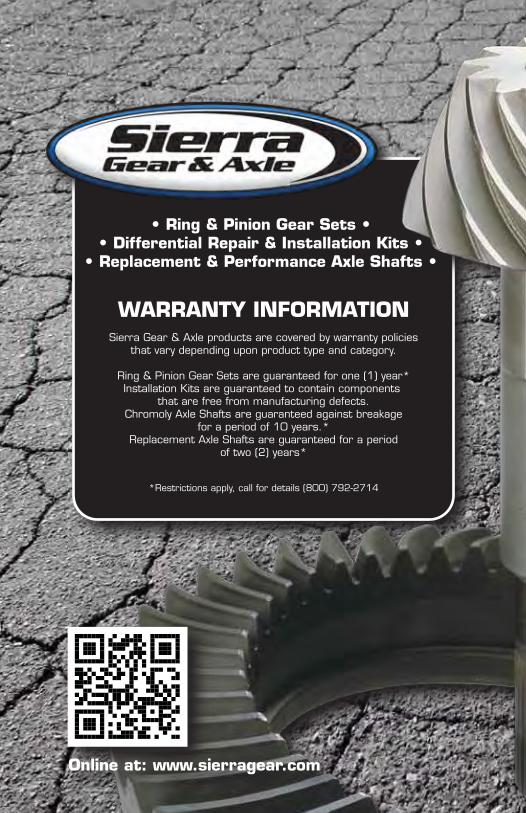
WARRANTY INFORMATION
• Ring & Pinion Gear Sets • • Differential Repair & Installation Kits •
• Replacement & Performance Axle Shafts •
Sierra Gear & Axle products are covered by warranty policiesthat vary depending upon product type and category.
Ring & Pinion Gear Sets are guaranteed for one (1) year*Installation Kits are guaranteed to contain components
that are free from manufacturing defects.Chromoly Axle Shafts are guaranteed against breakage
for a period of 10 years.*Replacement Axle Shafts are guaranteed for a period
of two (2) years*
*Restrictions apply, call for details (800) 792-2714