Embed Size (px)
Citation preview

ANCHORED INTERPLANETARY MONITORING PLATFORM
A M P (D 8i E) i '
E. T. R. OPERATIONS CHECK-OFF LIST
U C C E S S I O N 6 24929 NUMBER) -- ITHRU)
? GODDARD SPACE FLIGHT CENTER GREENBELT, MARYLAND
I - # I
I - trd copy (HC) ,c: 88
https://ntrs.nasa.gov/search.jsp?R=19660015640 2020-01-28T23:30:20+00:00Z

X-723-66-215
ANCHORED INTERPLANETARY MONITORING PLATFORM
AIMP (D & E)
E. T. R. OPERATIONS CHECK-OFF LIST
E. W. Trav i s D. K. McCarthy R. L. Courtney
D. L. Mil ler
May 1966
Goddard Space Flight Center Greenbelt, Maryland

.
TABLE OF CONTENTS
Page
. I
I . Introduction . . . . . . . . . . . . . . . . . . . . . . . . . . . . . . . 1
Field Operations . . . . . . . . . . . . . . . . . . . . . . . . . 2 I11 . Fastening Procedure Instructions . . . . . . . . . . . . . . . . 3 IV . Fourth (4th) Stage Motor ...................... 4 V . Fluxgate Boom Assembly ...................... 5
V I . Center Tube . . . . . . . . . . . . . . . . . . . . . . . . . . . . . . . 7 VII . Assembly Above Platform P r i o r to Top Cover
Installation . . . . . . . . . . . . . . . . . . . . . . . . . . . . 10 VI11 . Below Pla t form P r i o r t o Lower Cone Installation . . . . . . 13
IX . Lower Cone Installation . . . . . . . . . . . . . . . . . . . . . . . 15 X . De-Spinsystem . . . . . . . . . . . . . . . . . . . . . . . . . . . . 16
XI . Top Cover Installation ........................ 20 XI1 . Balance Operations (Prototype) . . . . . . . . . . . . . . . . . . 22
XIII . Balance Operations (Flight Unit) . . . . . . . . . . . . . . . . . 23 XIV . F-2 . . . . . . . . . . . . . . . . . . . . . . . . . . . . . . . . . . . . 32 xv . F-! . . . . . . . . . . . . . . . . . . . . . . . . . . . . . . . . . . . . 3 3
XVI . F-0 . . . . . . . . . . . . . . . . . . . . . . . . . . . . . . . . . . . . 36 XVII . Alignment and Data Recordings (PMF) . . . . . . . . . . . . . 37
XVIII . Inventory . . . . . . . . . . . . . . . . . . . . . . . . . . . . . . . . . 41 XIX . Spacecraft Inertia Data Sheet . . . . . . . . . . . . . . . . . . . 44 XX . Spacecraft and FW -4D Data .................... 45
XXII . AIMP-D Paddle A r m Assembly Orientations . . . . . . . . . 51 XXIU . Screw Torque Values . . . . . . . . . . . . . . . . . . . . . . . . . 52 XXIV . YO-YO De-Spin Calculation Sheet . . . . . . . . . . . . . . . . . 53 XXV . Satellite Checkout Change Sheet . . . . . . . . . . . . . . . . . 58
XXVI . Solar Paddle Weights and C.G's . . . . . . . . . . . . . . . . . 61
XXVIII . A M P - D Operations Schedule a t E.T.R. . . . . . . . . . . . . 64 M(IX . Spacecraft Drawings ......................... 7 7
11 . Spacecraft Mechanical Personnel on AIMP-D & E
XXI . Sequence of Events .......................... 48
XXVII . Spin Rate Calculations . . . . . . . . . . . . . . . . . . . . . . . . 62
Appendix A . Retromotor X-ray Procedure . . . . . . . . . . . . . . B . Radiographic Acceptance Cr i te r ia . . . . . . . . . . . C . Igniter and Guillotine Resistance Measurements . . D . Magnetic Mapping and Deperming of the Retromotor E . Igniter Installation and Leak Check . . . . . . . . . . . F -No voltage check of Pyrotechnic Circui t ry F-2 Day G - N o voltage check of Pyrotechnic Circui t ry F-1 Day €3 . No voltage check and Final Arming F-0 Day . . . . .
I 1
1 1
1 1
1 1
I 1
I 1
1 1
A-1 B-1 c - 1 D- 1 E- 1 F-1 G-1 H-1

8
w Y
I

I *
ANCHORED INTERPLANETARY MONITORING PLATFORM
AIMP (D & E)
E.T.R. OPERATIONS CHECK-OFF LIST
I. INTRODUCTION
The function of this check-off l ist is to insure that a l l mechanical s y s tcms (including experiments fas teners , s c rews despin sys terns, ctc.) a r e properly and permanently inserted to insure a successful mis- sion of the AIMP-D Interplanctary Monitoring Platform. The spacecraft will not be considered ready for flight until it has thoroughly been checkcd and doublechecked by the cognizant Pro jec t Engineer o r his designated alternate. Any defect noted, no mat te r how insignificant, should be brought to the attention of the Project Engineer immediately.
.
1

11. SPACECRAFT MECHANICAL PERSONNEL ON AIMP- D & E
Motel
FIELD OPERATIONS
(a ) MECHANICAL SYSTEMS BRANCH PERSONNEL
Motel
E. W. T rav i s Pro jec t Engineer
D. K. McCarthy Asst . Pro jec t Engineer
R. C. Courtney Resea rch Engineer
F. N. LeDoux Head, S t ruc tura l & Mechanic a1 Applic a- tions Section
A. J. P i e r r o Lead Technician
P. McConnell Technician
L. Paul Technician
(b) W ESTINGHOUSE PERSONNEL
Phone
Phone
D. Miller Pro j e c t Engine e r B ,
D. Brust Technician
J. Rauser Technician
2

111. FASTENING PROCEDURE INSTRUCTIONS
Long-Lok screws shall be used wherever possible with Nylok screws second and blue Lock-tite on s tandard screws third. * T o indi- cate that the screws a r e properly installed and a r e to remain in the spacecraf t permanently, the head of every screw will be painted with a white dot partly on the head of the sc rew and partly on the adjoining surface, a f t e r which the Spacecraft technician shall initial the appro- priate item in the f i r s t column with the Project Engineer 's ( o r a l te r - nate) in the second column. affords an immediate visual indication that the screws a r e locked and ready for flight.
This operation is necessary in that it
If the occasion a r i s e s to remove a screw, the sc rew will be dis- carded, paint removed f rom the adjoining surface and a new sc rew used and repainted as indicated previously. removal of marked screws and state the reason.
Fil l in the comment colurnn for
Change and removal sheets (blank) a r e provided herein and any defects o r changes in procedure a r e to be recorded.
One m a s t e r check-off list shall be recorded for the Spacecraft that is launched and one mas te r maintained on the spa re Spacecraft. copies shall be maintained for reference use - only by the MSB and Westinghouse personnel.
Ext ra
3

IV. 4th STAGE MOTOR
1
2
3 .
4.
5.
6 .
Observe shipping containers for any damage incurred during shipment.
Observe inspection of the motor , nozzle, nozzle r a t plug, spacecraf t a t tach holes, etc.
Observe igniter inspection - shorting plug, body, exit port , etc.
X-ray the motor per the procedure outlined in Appendix A.
Pe r fo rm igniter res i s tance mea s u r ements per the procedure outlined in Appendix C.
Magnetically map and depe rm if neces- s a r y the igni ters and re t romotor per the procedure in Appendix D.
4
I

.
. V. FLUXGATE BOOM ASSEMBLY
Check the following:
1. Movement of secondary hinge
(a) hinge pin loaded 1/4 tu rn 2 nuts - 17 in. lb.
(b) Lock-in of secondary hinge
2. C rush pads (4) on main hinges (Z)-Teflon 4 scr.-1 in. lb.
3 . Leaf spr ings ( 2 ) on main hinges ( 2 ) 2 scr.-1 in. lb.
4. GSFC and Ames Housings
(a)
(b) housing and s leeve (#2-56)
( c ) housing and connector plate
(d)
( e )
( f )
housing connected to F / G Boom 4 scr.-2.5 in. lb.
4 scr.-1 in. lb.
4 scr.-2.5 in. lb. connectors (2 each) and connector plate 4 scr.-2.5 in. lb. connectors ( 2 each) and sensor ( senso r side) 4 scr.-2.5 in. lb. pin between housing and boom
5

5. GSFC Housing
Confirm the proper orientation of the sensor inside the cannister by hand rotating the sensor and observing the cable c learance through the cannis ter cutout.
Sensor connector (Continental)
Fibe rgla s s cannis ter
Fiberglass fan
2 s c r .
8 scr.-2.5 in. lb. 3 scr.-1 in. lb.
6. Ames Housing
Connection between adapter and housing
Connection between adapter and sensor 6 s c r . & nuts-2.5 in. lb.
6 s c r . & nuts-2.5 in. lb.
Sensor cannister 12 scr.-1.5 in. lb.
The word "Top" is engraved on the top (external) surface of the adapter flange which mounts to the sensor package.
Confirm proper orientation - the sensor package is not symmetr ical in that one mounting hole and sc rew over the single-axis sensor i s omitted f r o m the inner c i rc le of mounting screws (upper left side, viewed f rom spacecraf t )
7. Check f o r proper alignment of GSFC senso r in cannister by rotating sensor approximately 30 O by hand.
6

VI. CENTER TUBE AND MOTOR ADAPTER
Check the following:
1. Screws in Bat tery Cover 21 scr.-1 in. lb.
2. Screws between Battery connector bracket and center tube 2 scr.-1.5 in. lb.
3 . Screws between Bat tery connector and bracket 2 scr.-2.5 in. lb.
4. Screws in Bat te ry connectors on Bat te ry 4 scr.-2.5 in. lb.
5. Shorting Connector in Bat tery Test Connector 2 scr.-2.5 in. lb.
6. Bat tery bolts 4 bolts-17 in. lb.
7. Third (3 rd ) stage Micro-Switch Assembly 8 scr.-1 in. lb.
8. Spring Seat Ring 8 scr.-3 in. lb.
9. D.A.C. Connector R-F cap 4 scr.-2.5 in. lb.
10. D.A.C. Connector 4 scr.- Diallyl thialate mater ia l down to separat ion
) - GSFC side. to03 -000
plane ( .175
7

11.
12.
13.
14.
15.
16.
17.
18.
19.
20.
21.
22.
23.
Use fixture provided by GSFC to verify cor rec t alignment of D.A.C. connector on GSFC side.
Spring Seat Disc 8 scr.-2.5 in. lb.
Screws in 4th Stage Separation Spring Housings (4) 8 scr.-4 in. lb.
Screws holding separation springs in housings (4) 4 scr.-2.5 in. lb.
Screws in Micro-Switch brackets (4th stage) 6 scr.-2.5 in. lb.
Screws through Mic ro-Switches (4th stage) 6 s c r . & nuts-2 in. lb.
Screws through Flyaway Connectors into center tube 8 scr.-3 in. lb.
Tabs on Flyaway Connector boxes
Spring Seats (4) on Motor Adapter 8 scr.-3 in. lb.
Screws through Flyaway Connectors (motor adapter) 8 scr.-3 in. lb.
Screws (3) and pins (3) through Micro- Switch actuators 3 scr.-3 in. lb.
Screws for support rod of thermal shield 2 scr.-2.5 in. lb.
Thermal Shield Screw 1 scr.-1 in. lb.
8

24. Resistance of re t romotor thermis te rs through motor adapter flyaway connector. Low tempera ture the rmis t e r 10,000 ohms a t room temperature . High temperature the rmis t e r 1200 ohms a t Room Temperature.
Low Temperature :
High Temperature:
9
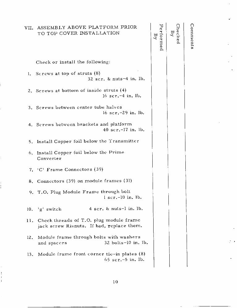
VII. ASSEMBLY ABOVE PLATFORM PRIOR TO TOP COVER INSTALLATION
Check or install the following:
1. Screws a t top of s t ru ts (8) 32 scr . & nuts-4 in. lb.
2. Screws a t bottom of inside s t ru ts (4) 16 scr.-4 in. lb.
3. Screws between center tube halves 16 scr.-29 in. lb.
4. Screws between brackets and platform 40 scr.-17 in. lb.
5. Install Copper foil below the Transmi t te r
6. Install Copper foil below the P r i m e Convert e r
7. ' C ' F rame Connectors (39)
8 . Connectors (39) on module f r ames (31)
9. T.O. Plug Module F r a m e through bolt 1 scr.-10 in. lb.
10. ' g ' switch 4 s c r . & nuts-1 in. lb.
11. Check threads of T.O. plug module f r a m e jack screw Rivnuts. If bad, replace them.
12. Module f r ame through bolts with washe r s and spacers 32 bolts-10 in. lb.
13. Module f rame front corner tie-in plates (8) 65 scr.-5 in. lb.
10

14. Screws on front of module f rames ( tes t conn. etc.)
15. Secure a l l Coax connectors - use thick Glyptol and Nylon pliers. a. b. c.
Antenna Hybrid - 5 coax Antennae Cups (4) - 10 coax Range and Range Rate red line coax connectors (11)
16. F / G Connectors (2) 4 nuts-5 in. lb.
17. Antenna Hybrid Board a. 4 screws (nylon) b. Check insulation f r o m module f rame
19. F I G Micro-switches 4 scr.-1.5 in. lb.
2 0 . F / G Micro-switch plungers ( 2 ) and pins ( 2 )
21. Record a l l c a r d se r i a l numbers on page 41.
22. Lower Harness disconnect brackets
a. Face t D IC' F r a m e - 3 brackets -
b. Facet H IC' F r a m e - 1 bracket - 6 scr.-2.5 in. lb.
2 scr.-2.5 in. lb.
2 3 . Screws between lower harness disconnect connectors a. Face t D - 6 scr.-2.5 in. lb. b. Facet H - 2 scr.-2.5 in. lb.
cd (D Y
< U Y
(D a 3
11

24. Cable c lamps - sc rews and lacing (visual inspection)
25. Antenna Cup Clamps 12 scr.-4 nuts
26. De-Spin Disconnect Brackets ( 2 ) 8 scr.-3 in. lb.
12

I - ~
VIII. BELOW PLATFORM BEFORE LOWER CONE INSTALLATION
Check the following:
1 . Balance weights
2. Screws at bottom of ou-side s-ruts (4) 16 scr.-4 in. lb.
3 . Transmi t t e r heat sink sc rews (copper) 3 scr.-2 in. lb.
4. P r i m e Converter heat sink screws (copper) 5 scr.-2 in. lb.
5. Screws (8) between platform and front co rne r tie-in plate
8 scr.-5 in. lb.
6. Paddle A r m res i s to r s (8) 32 scr.-1 in. lb.
7. Paddle A r m Trans i s to r s (8)
8. Paddle A r m Hinge to Bracket Bolts, with F iberg lass insulators
16 bolts-50 in. lb.
9. Paddle A r m to hinge bolt t CIBA epoxy 4 bolts & nuts
10. Paddle A r m lock-in bolt t CIBA epoxy 4 bolts & nuts
11. Secondary hinge spring housing (4) 8 scr.-2.5 in. lb.
12. Paddle A r m micro-switches (4) 8 scr.-1 in. lb.
1 3

13. Filter-con brackets 6 scr.-2.5 in. lb.
14. Filter-cons (5) 10 scr.-2.5 in. lb.
15. Third (3rd) stage m,:ro switch A s s ' y
a. check E-rings with epoxy b. check movement of plunger c. d.
check closure of switches (8) check height of plunger to c lose switches with stop nut
16. Cable c lamps, sc rews and lacing (visual inspection)
17. Umbilical Bracket 2 scr.-4 in. lb.
18. Umbilical Connector 4 sc r . & nuts
19. Umbilical Diode 1 sc r . (nylon)
20. Lower Harness Diode Box 4 nuts-17 in. lb.
14

IX. LOWER CONE INSTALLATION
Check the following:
Between lower cone ring and platform 1. 2 4 sc r . & 8 nuts
2. Top of cone a t center tube 9 s c r . & washers-3 in. lb.
Base of cone, at Lower Cone Support Ring 9 s c r . & washers-8 in. lb.
3 .
4. Cone split (2) 12 sc r . & washers-8 in. lb.
15

X. DE-SPIN SYSTEM
1.
2.
3 .
4.
5.
6.
7.
Check bridgewire res is tance using Alinco Model 101-5BFM of 4 prepotted and insulated Dimple Motors. Dimple Motor #1A= Dimple Motor #2A= Dimple Motor #1B= Dimple Motor #2B=
ohms Face t C-Bottom ohms Face t C-Top ohms Face t G-Bottorr ohms Face t G-Top
Resistance readings of individual Dimple Motor should be between 1.4 and 2.6 ohms. Otherwise, re jec t the Dimple Motor.
Install appropriate dimple motors into Facet C and G. schematic).
(See enclosed pictor ia l
Check Dimple Motors for proper f i t and sh im if necessary.
Solder Dimple Motors per schematic using a heat sink attached to de-spin f e edthr oughs . Check feedthroughs on the inside of Top Cover for damage due to soldering Dimple Motors.
Check total res is tance at top cover con- nector using Alinco Model 101-5BFM squib checker. (See enclosed pictor ia l schematic). Dimple Motor #1A- ohms Face t C-Botton Dimple Motor #2A= ohms Face t C-Top Dimple Motor # l B = ohms Face t G-Botton Dimple Motor #2B= ohms Face t G-Top
16

8.
9.
10.
11.
12.
13.
14.
15.
16.
Resis tance readings through top cover connector should be between 1.6 & 3.0 ohms. Otherwise reject and install new dimple motors.
Brush coat exposed te rmina ls with Epon 828 and allow t ime to dry.
Install R-F cover shields ( 2 ) over each te rmina l system. 6 scr.-2.5 in. lb.
Weigh and record each end mass - inner weight, outer weight, 4 #0-SO screws, and 2 nuts. Weight #1= g r a m s Weight # 2 = g r a m s
The same weights must agree with final value recorded on de-spin calculation sheet - page 54.
Assemble weights to cables and wrap clockwise.
Attach each weight to inner weight 8 scr.-1 in. lb.
Adjust tension in cable and lock-tite end-fitting nuts with - red lock-tite ( 4 nuts).
Visually inspect complete assembly.
(-I
0
m R
17

XXII. DESPIN DIMPLE MOTOR WIRING DIAGRAM
Note: Return Leads Go To Terminals Closer To Squibs
E! 3 z 3 0, 4 n n 3 n
ID
VI
O
1A
v, U
I I I
I Filter 86
Note: A l l Wire
Q T w P T w
L
F 3 2 1 IS15-P6
Filter #4
I IS15-S6
l l
28 Rei
28
- - - - h)h)h )h ) I Connector @ Payload -
I ' D . P C D W p p m m I 3rd Stage Interface P P ,isted Quad I x1 io
isted Pair ! S S ? ? L -________---- .A
DAC Attach Fitting
18

17. Record bridgewire res is tance of dimple motors through spacecraf t s ide of D.A.C. flyaway connector: Dimple Motor #lA= Dimple Motor #ZA= Dimple Motor # 1 B= Dimple Motor #2B= (See enclosed pictorial schematic)
ohms Facet C-Bottom ohms Facet C-Top ohms Facet G-Bottom ohms Facet G -Top
18. If cover is ever removed f rom spacecraft repeat items #16 & 17.
19. Record bridgewire res i s tance of dimple moto r s a t D.A.C. timer terminals after spacecraf t is mated to the third s tage during balance operations: Dimple Motor #lA= Dimple Motor #ZA= Dimple Motor #1B= Dimple Motor #2B=
ohms Facet C-Bottom ohms Facet C-Top ohms Facet G-Bottom ohms Facet G-Top
20. I f spacecraf t is ever removed f rom the th i rd s tage repeat items #17 & 19.
21. Record bridgewire res is tance of dimple moto r s at D.A.C. t imer terminals at F-1. Dimple Motor #1A= Dimple Motor #ZA= Dimple Motor #1B= Dimple Motor #ZB=
ohms Facet C-Bottom ohms Facet C-Top ohms Facet G-Bottom ohms Facet G-Top
19

XI. T O P COVER INSTALLATION
Check o r install the following:
1. I & E Experiment thermal cover 9 scr.-3 in. lb.
2. Solar Cell Damage Experiment 8 scr.-5 in. lb.
3. Screws in balance weights (inside cover)
4. California dome 6 scr.-1 in. lb.
5. Thermistor access cover 6 scr.-1 in. lb.
6. De-Spin Flyaway connector Brackets ( 2 ) 8 scr.-3 in. lb.
7. Cable clamps and lacing (visual inspection)
8. Feedthroughs for damage due to soldering of Dimple Motors.
9. Screws between top cover and center tube 8 scr.-8 in. lb.
10. Screws between top cover and platform 15 scr.-8 in. lb.
11. Antennae Cups (4) 24 scr.-1 in. lb.
12. Solar-Cell Damage Connector 2 scr.-2.5 in. lb.
13. Optical Aspect Sensor 3 scr.-2.5 in. lb.
td 0 Y
d e 4 0
Y
0 a 3
20

14. R-F Covers: GSFC F / G Electronics (1) M.I.T. ( 3 ) T.O. P lug (1) Ames (1) California (1) University of Iowa (1)
21

XU. BALANCE OPERATIONS PROTOTYPE)
1. Mount Prototype spacecraf t and ine r t 4th s tage retromotor on FW-4D.
2. Observe D.A.C. installing 3rd s tage c lamp band.
3. Check compatibility of de-spin connector.
4. Check clearance of separation switch plungers.
5. Install F / G booms and Paddles.
6. Observe D.A.C. aligning and bonding the paddle and boom cradles and standoffs.
7. Observe D.A.C.'s compatibility check of Umbilical cord and Fair ing and a c c e s s doors (2 )
8. Observe disconnect of umbilical and c lamp band by D.A.C.
9. Remove Prototype Spacecraft and ine r t 4th stage retromotor f r o m FW-4D.
22

XIII. BALANCE OPERATIONS (FLIGHT UNIT)
1.
2 .
3 .
4.
5.
6.
7.
8.
9.
10.
Personnel will wear flame retardant coveralls and legstats.
Remove Retromotor shipping container case using a i r hoist and hydroset (Ground Straps between a i r hoist , shipping container and Building Grounding System).
Remove Retromotor using a i r hoist and hydroset (Ground Straps between a i r hoist, lifting rig and Building Grounding System).
Weigh TE-M-458 retromotor and record on page 46.
Weigh AIMP-D Spacecraft, Booms, and p2&ncs and rcc=rd =;I 7.7”- A L y-5- TU.
Place S /C on Precis ion Measuring Facility (PMF) and measu re the two precisely machined sur faces of the center tube for T.I.R. Record on page 37.
Measure f la tness of center tube a t 4th stage interface. Record on page 37.
Remove Flyaway Connector covers and install F iberg lass Motor Adapter with the 4th stage m a r m a n clamp.
Check alignment of a l l 24 flyaway connector pins.
Align the S / C keyway with the adapter keyway.
23

11. Put 75 lbs. symmetr ical ly on top of the adapter.
12. Position the marmon clamp, aligning i ts key with the S / C and adapter keyways.
13. Install 4th Stage Bolt Cut ters (with shorting connector attached) into bracket. Record s e r i a l N o ' s . under Inventory, page 41.
14. Snug up the two ( 2 ) marmon clamp bolts.
15. Position the segments in each half of the clamp band:
( a ) the center segment in center of i t s floating position.
(b) the other segments pushed a s fa r a s possible toward their respective ends of the clamp band.
16. Tap the clamp band with a rubber tipped hammer above and below the r ivets so the bolt: a r e tightened simultaneously .
17. Torque the bolts to 10 in.-lbs. af ter they have been snugged up equally on both s ides .
18. Proceed to tighten the two ( 2 ) bolts one-quarte (1 /4) turn alternately.
t 5 -0 19. Final torque 35 in. lbs.
20. Tighten Bracket with sc rew and nut. 2 scr.-2 nuts
24

21.
22.
23.
24.
25.
26 .
2 7.
28 .
29 .
30.
Remove the 75 lb. load.
Install Protect ive Housing with teflon in se r t over bolt head ( 9 0 in. lb.).
Safety wi re two ( 2 ) bolt cu t te rs to bolt cu t te r bracket.
Measure f la tness of F iberg lass Motor Adapter , and r eco rd on page 37.
Instal l lower the rma l blanket with Kapton tape and 8 scr.-2.5 in. lb.
Check continuity between lower thermal blanket & Motor Adapter.
Instal l ground line f r o m the long t he rma l blanket s c r e w to the motor mounting hole. Check continuity with the spacecraft ground using an Alinco t e s t e r .
P l ace re t romotor on S / C while on PMF. Align re t romotor in pre-selected position (one of the 8 possible positions) with dial indicator to minimize T.I.R. between S /C and Retromotor. (Maximum allowable runout i s .002 T.I.R.) Record T.I.R. on page 37.
Instal l Retromotor hold-down bolts with ground lug under one bolt. (titanium)
8 bolts-90 in. lb.
Ins ta l l lanyards ( 2 ) between 4th stage Marman Clamp and 4th Stage Retromotor Bolts.
25

31. Bond two ( 2 ) The rmis to r s to motor case using DC 90-006 p r imer and aerospace sealant. Allow to cu re 12 hours @ room temperature.
32. Inser t dummy ( iner t loaded) igniters into Retromotor.
33. Lace Igniter and thermis tor harness to Re t r omoto r .
34. Check FW-4D attach fixture and payload interface for nicks, sc ra tches , b u r r s , etc.
35. Check D.A.C. side of de-spin connector - using Alignment Tool No. GE-IMP(D) 3239. See data sheet, page 31.
36. Use fixture to verify co r rec t alignment of de-spin connector on spacecraft side.
37. Ground spacecraft to the building via Ground Strap.
. 38. Mount Spacecraft/Retromotor on FW-4D.
39. Use Key in S/C keyway to eliminate rotation a s S /C is lowered on FW-4D.
40. Remove Key.
41. Observe D.A.C. installing Clamp Band
t o r que) t5 (30 in. lbs. -0
42. Check clearance of separation switch plungers ( 2 ) .
26

43.
44.
45.
46.
47.
48.
49.
50.
51.
52.
53.
Continuity check made f r o m D.A.C. attach fitting side through de-spin Dimple Motors using Alinco t e s t e r Model 101-5BFM. Record on pp. 19, i t em #19.
Observe S /C runout measurements and record on page 37.
Instal l t he rma l blanket using two (2) grounding clips. 16 s c r s . at base
(SST) 8 in. lb.
Tape and sea l at base.
Ground blanket to the building via Ground Straps.
Observe D.A.C. t ransfer of Retromotor/ Spacecraft/FW-4D to balance fixture.
Install F / G booms ( 2 ) main hinge pin + CIBA epoxy - 2 bolts and 4 nuts -
17 in. lb.
Install tors ion springs (2) in b ras s r e t a ine r s (2).
Instal l fluxgate connectors t o Spacecraft AMES 2 scr.-2.5 in. lb. GSFC 2 scr.-2.5 in. lb.
Check movement of main hinge and insure lock-in. AMES , GSFC
Remove protective covers f rom AMES , GSFC
2 7

54.
55.
56.
5 7.
58.
59.
60.
61.
62.
63.
64.
65.
Remove secondary hinge pin locks. AMES , GSFC
Observe D.A.C. installat 'on of fluxgate tie-down cord (35 lbs. -0).
t k
Instal l safety cord around booms.
Bond Teflon c r u s h pads using Epon 828.
Install Flight paddles (4) a t pre-selected positions.
Record positions on page 51.
Torque of Secondary Hinge Pin Bolts (4) 17 in. lb.
Check a. Movement of secondary hinges (4) b. Proper seating of c r u s h pads (4)
Record secondary plunger spr ings used on page 51.
Remove spring-plunger se t s c r e w s (4) .
Observe D.A.C. installation of paddle tie-down cord.
a. Tension 40 lbs. (-o). t 5
b. Location 2-3/8 inches f r o m tip of paddle.
Install safety cord around bottom of appendages.
28

66.
6 7.
68.
69.
70.
. 71.
72.
73.
74.
75.
76.
7 7.
Remove a l l sensor covers.
Ins ta l l antennae (4)
Check Continuity.
50 in. lbs. - 4 Lock- screws - 1 in. lb.
Observe D.A.C. balance operations.
Observe D.A.C. install final balance weights
Record D.A.C. balance weights on page 47.
Remove flight so la r paddles (4).
Remove the spacecraf t antennae.
Replace a l l sensor covers.
Replace conductive aseps is bag over spacecraft .
Observe D.A.C. cleaning of t ransport container with isopropanol alcohol pr ior to assembly over re t romotor/spacecraf t / FW-4D spin table assembly.
Observe assembly of t ranspor t container.
After container assembly, observe D.A.C. at tach d ry nitrogen purge system to con- ta iner and activate. tinuously purged until assembly a r r i v e s at gantry).
(Container is con-
29

78.
79.
80.
81.
82.
Observe shipment t o launch pad and attach- men t to second stage.
Observe removal of t ranspor t container by D.A.C.
Observe placement of D.A.C. Air-conditioning Bag over S / C by D.A.C.
Remove a seps i s bag f r o m S/C.
Attach shor t bag to Retromotor.
30

1 . With tcol on DAC adapter record center displacement and then push the connector in the d i rec- tions shown and record feeler gauge readings per the chart above.
t
Position t
Gauge Reading
Center
Between pins 1 - 8
Between pins 4 - 5
Between pins 2 - 3
Between pins 6 - 7
31

XIV. F-2
1 . Perform No Voltage check per procedure in Appendix F, during vehicle s t ray voltage test.
Pe r fo rm Igniter Installation and Leak Check pe procedure in Appendix E.
3 . Remove s t r i p coating f rom spacecraft .
2.
(save for weight measurement)
4. Take biological samples, using distilled water
32

XV. F-1
1.
2.
3.
4.
5.
6 .
7.
8 .
9.
Decontaminate spacecraf t with s ter i le swabs. a ) F o r Black paint, buffed aluminum
surfaces , evaporated aluminum surfaces: Acetone - general cleaning Ethyl Alcohol - fingerprints loo/, Acetic Acid, 90% tr iple distilled
water - b) F o r white paint no cleaning.
Install O.A. fluted covers ( 2 ) - 4 scr.-2.5 in. lb.
Install a l l R-F t e s t connector covers on s ides of S / C Top Cover.
Re-check tension in F IC tie-down cord (35 lbs. -o). Adjust if necessary.
+5
Lock-tite se t sc rews in F / G tie-down cord adjustment mechanism.
Remove protective bags f rom F / G Sensor cannis ters . Remove 3rd stage separation switch safety lock sys tem (2). 4 sc r .
Open each paddle a r m to insure that the la tch locks properly and proper c losure of m i c ro-switches. A r m N o . 1 A r m N o . 2 A r m N o . 3 A r m N o . 4
ci
(D a 3
33

10. Install Flight Solar Paddles a t pre- selected positions. Record on page 51.
11.
12.
13.
14.
15.
16.
17.
18.
19.
20.
Install Solar Paddle secondary hinge pins (4) 17 in. lb.
Install Solar Paddle connectors (4) 9 scr.-2.5 in. lb.
Inspect paddle a r m wiring for nicks, cuts. etc.
Check movement of secondary hinge, proper seating of c rush pad, remove set sc rews (4) in spring plunger.
Record spring no. and c rush pad length on page 51.
Observe D.A.C. installation of Solar Paddle tie-down cord.
t 5 tension - 40 lbs. -0 a.
b. location 2-3/8 in. up f r o m tip of paddle.
Adjust tension with mechanism in two opposing paddles . Inspect D.A.C. tie-down system.
Put Glyptol in paddle cord tie-down mechanism.
Remove separation spring (4th stage) hold-down pins (4).
TJ (D Y
' T Y
CD a 3
3 4

21.
22.
23.
24.
25.
26.
2 7.
28.
29.
30.
31.
32.
33.
34.
35.
36.
Verify that all R-F sys tems a r e ' O F F ' .
Verify that both Ordnance Safing Plugs a r e in s t a1 1 ed.
Observe NO-VOLTAGE check of ha rness pr ior to connection of ha rness to Igniters and Bolt Cut te rs per the procedure in Appendix G.
Remove Igniter Shorting Plugs and connect spacecraf t igniter ha rness to the Igni ters and Bolt Cut ters .
Complete installation of thermal blanket about the nozzle with tape.
Take biological samples .
Remove the shor t dust bag f rom the Ret r omoto r.
Remove protective covers f rom experiments: a. I. & E. b. Solar Cel l Damage c. California - two ( 2 ) Teflon plugs d. M.I.T. e. University of Lowa - four (4) f. O.A. Sensor - two (2) (Visually inspect the
absence of any tape on the O.A. Sensor)
Instal l Antennae (4) 50 in. lbs. Four (4) lock screws 1 in. lb.
Check continuity.
Lock-tite all R-F Doors shut.
P u t Conductive Asepsis Bag over spacecraft .
Observe D.A.C. install one-half of Fairing.
Remove Conductive Asepsis Bag f r o m Spacecraf t .
Ob s e r ve D .A. C . Fairing ins t a1 lat ion.
Observe Umbilical connection.

XVI. F-0
1. P e r f o r m NO-VOLTAGE check & Fina l Arming per the procedure in Appendix H.
2. Take final biological samples .
3 .
4.
Observe D.A.C. s ea l Fair ing a c c e s s ports .
Confirm removal of all tools, etc., taken up to the gantry.
36

XVII. ALIGNMENT RECORDINGS (PMF)
1.
2.
3.
4.
5.
6.
7.
Measure and r eco rd the following:
T.I.R. @ 3rd stage interface. (A Diameter)
T.I.R. of center tube @ 4th stage interface. ( B Diameter)
Flatness of center tube @ 4th stage interface ( C Surface)
Flatness of f iberglass 4th stage motor adapter ( D Surface)
T.I.R. of Retromotor mounting flange af ter being minimized (.002 T.I.R. max.) ( E Diameter)
Final optimized position of motor (Posit ion of Igniters with reference to 3rd Keyway).
T .I.R. of FW-4D/ spacec raf t / re t romotor measured a t
Note: angle. a s viewed f r o m the top of the spacecraft.
3 rd stage Keyway is zero reference Angles increase in clockwise direction
37

Motor 4dapter
ALIGNMENT DATA SHEET #1
1. Angle Between Motor Scribeline and 3rd Stage Keyway measured clockwise
2. Shim Size & Location
Hole No.
3rd Stage Keyway
Shim size
38

ALIGNMENT DATA SHEET # 1 (cont'd)
3 . Calculated Motor Thrus t Alignment
Throat Center ~
1 Exi t Cone Center I
u -
4. Moment A r m Calculations:
180
0
39

.
Angle
0 10 20 30 40 50 60 70 80 90
100 110 120 130 140 150 160 170 180 190 200 210 2 20 2 30 240 250 260 270 280 290 300 310 320 3 30 340 350 36 0
A 6
A
ALIGNMENT D A T A SHEET #2
B c I
b Ref
C L
D F
t
40

.
XVIII. INVENTORY
Face t A
Ion & Electron Exp. GSFC Fluxgate Electronics GSFC Fluxgate A / D Electronics
Face t B
Prime Converter O.A. Converter O.A. Sensor O.A. Amplifier O.A. Computer
Face t C
P r o g r a m m e r No. 3 (F l ipper Control)
Solar A r r a y Regulator Pe r fo rmance P a r a m e t e r s P r o g r a m m e r No. 1
(undervoltage) M.I.T. Logic C a r d No. 2 M.I.T. Logic Card No. 3
Face t D
M.I.T. Plasma Probe Sensor
F a c e t E
Te leme t ry Encoder Enc oder C onve rt e r Antenna Hybrid
VI 5 : . w.'.
K
ES 1 EG 3 EG2
P4 [P5 LA1 L42 L43
[G 3 [P2 [D2
[G 1 EM2 EM3
EM1
[D 1 [P6 [T 8
41
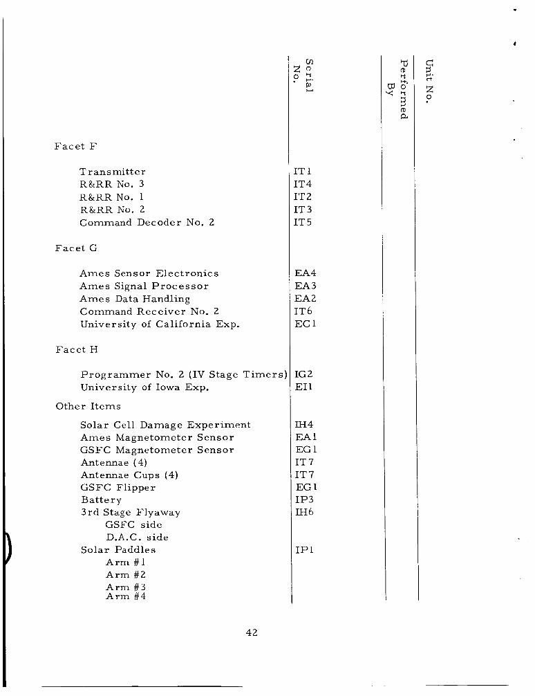
Face t F
Transmi t te r R&RRNo. 3 R&RRNo. 1 R&RRNo. 2 Command Decoder NO. 2
Face t G
Ames Sensor Electronics Ames Signal P r o c e s s o r Ames Data Handling Command Receiver No. 2 University of California Exp.
Face t H
Programmer No. 2 (IV Stage T i m e r s ’ University of Iowa Exp.
Other I tems
Solar Cell Damage Experiment Ames Magnetometer Sensor GSFC Magnetometer Sensor Antennae (4) Antennae Cups (4) GSFC Flipper Bat tery 3rd Stage Flyaway
GSFC side D.A.C. side
Arm # 1 Arm # 2 Arm # 3 Arm # 4
Solar Paddles
cn z m 2.
r”,
[T 1 [T4 [T 2 [T 3 [T 5
EA4 EA3 EA2 [T 6 EC 1
IG 2 E1 1
1h4 EA 1 EG 1 IT 7 IT 7 EG 1 1p3
IH 6
IP 1
42

Bolt cu t te rs # 1 #2
Platinum Wire Thermis te r Ret r omot o r Igniter s
# 1 #2
4 3

c
c
a e, $. 0
PI d
; 0
I 0
3.1
3.1 -
a P) c, u P) k w
% m e,
a d
a e, c, u e, k w z 0 0 a
44

XX. SPACECRAFT AND FW-4D DATA
A. FW-4D Moto r Alonc
(Loaded) roll
roll
I
(Expendcd) 1
Wcsight (Loaded)
Weight (Expcndcd)
1 (Loaded) t ransvcr s e max.
(Expcndcd) t ransver s e I
max.
- - slug-ft 2
- slug-ft2
- lbs.
- lbs.
- - slug-ft2
- - slug-ft2
-
-
-
B. Attach fitting (c lamp band, spring, t imer s , etc., except t uni b 1 c r o c k c t s )
I
Weight
t ransverse max.
C . Tumble Rockets (.6KSS)
I (own axis)
I
roll
rol l (about spin axis)
t ransverse 1
Weight max.
- slug - f t * - - - lbs .
- - slug-ft2
s lug -ft 2
- slug -f t2
- -
-
- - lbs.
45

D. Aluminum Foil ( - Layer s - Mil.)
- - slug - f t
r 011 I
I
W cf ight
t ransverse max.
- - slug-ft2
- - lbs.
E. Cradles (6 ) , Cords ( 2 ) , Pyrotechnics
- - s lug-ft 2 ro l l I
t ransverse I
Weight max.
- - slug - f t 2
- - lbs.
F. AIMP-D Spacccraft/Retromotor
Moment of Inertia Data on page 44. Weight - - lbs. (includes
s t r ipcoa t) - Weight - lbs. (s t r ipcoat)
Weight - - lbs. ( spacec ra f t /
re t romotor
G. Folded Spacecraft/Retromotor on FW-4D
- - s lug-f t2 ro l l I
- - s lug -f t2 t ransverse I
C.G. separation plane lbs. - Weight -
H. Weight of:
Spin table - - lbs.
46
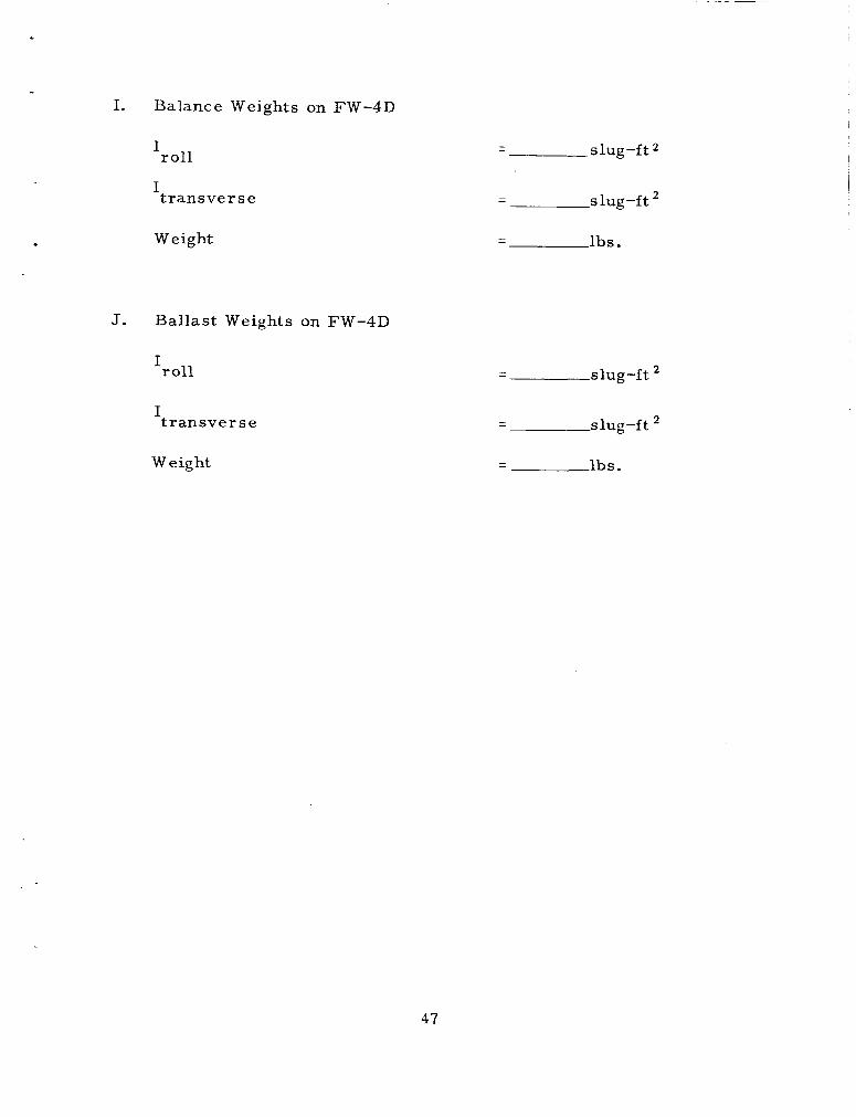
I. Balance Weights on FW-4D
roll
transverse
I
I
Weight
J. Ballast Weights on FW-4D
rol l I
t ransve r s e I
Weight
slug-ft2 - -
slug-ft - -
lbs. - -
slug-ft
slug-ft
- -
- -
lbs. - -
47

XXI. SEQUENCE O F EVENTS
The following table lists the significant engineering events which occur f r o m l i f toff to third-stage separation of the Delta Vehicle. All event t imes a r e l is ted in seconds-after-liftoff. In addition, a l l second- stage and subsequent events a r e re ferenced to the s t a r t of the second- stage program t imer a t the time of main engine cutoff (MECO).
First Stage
Time Event Initiated By
TtO (1) Liftoff Uncage Stage I Gyros
Tt2.0 Start Roll P rogram Tt4.0 (1) S t a r t F i r s t Stage Pitch P rogram
Tt9.67 Stop First Pitch Rate TtlO.0 Start Second Pitch Rate Tt39.67 Stop Second Pitch Rate Tt40.0 (1) S ta r t Third Pitch Rate
T t70.0
Tt79.67 Stop Third Pitch Rate Tt80.0 (1) S ta r t Fourth Pitch Rate
Tt90.0 (1) Pitch & Yaw Control System
(2 ) S t a r t s Stage I P rogrammer
( 2 ) S t a r t First Stage Yaw P r o g r a m
(2) A r m Solid Motor Separation Solid Motor Separation Pitch, Yaw and Roll Control System Gain Change
( 2 ) Enable BTL
Gain Change (2) Yaw Vernier Engine Unlock ( 3 ) Star t Stage 1 Guidance
Tt114.0 Enable Stage 11 Ignition Power Tt130.0 Stop Pitch P r o g r a m Rate Tt139.0 (1) Stop BTL Guidance
(2 ) Enable MECO Circui t ry ( 3 ) Second Stage Roll Gyro Uncage
Tt148.0 MECO (M)
L.O. Switch L.O. Switch Stage 1 P rogrammer Stage 1 P r o g r a m m e r Stage 1 P rogrammer Stage 1 P rogrammer Stage 1 P rogrammer Stage 1 P rogrammer Stage 1 P rogrammer Stage 1 P rogrammer Solid, separation timer Stage 1 P rogrammer Stage 1 P rogrammer Stage 1 P r o g r a m m e r Stage 1 P rogrammer
Stage 1 P rogrammer BTL ground station 5G switch Stage 1 P r o g r a m m e r Stage 1 Programmer Stage 1 P r o g r a m m e r Stage 1 P r o g r a m m e r FIP Switch
48

Second and Third Stages
Time Event
MtO (1) S ta r t Stage 11 Programmer (MEC 0)
M t 4
Mt10
Mt20 M t 1 8
M+200 Mt205
Mt2lO Mt215 M t 2 18
Mt400
M t 4 0 3
M+420 Mt425 M+450
(2) F i r e Blast Band Bolts ( 1 ) (2) Uncage Roll Gyro (Backup) (3) (4) Transfer Guidance Reference
(5) Start Stage I1 Engine (6) S ta r t Stage I1 First Pitch Rate Stop Stage I1 F i r s t Pitch Rate ( 1 ) Start Stage I1 Second Pitch Rate (2) S t a r t Stage I1 Closed Loop
Guidance (3) Jet t ison Fairing Stop Stage I1 Second Pitch Rate Stop Stage II Second Pitch Rate
(Backup) Stop Stage I1 Closed Loop Guidance Initiate VCS (1) Initiate VCS (Backup) (2) Turn off BTL (1)
F i r e Stage II/I Separation Bolts
Uncage Pitch and Yaw Gyros
Power
Enable Stage 11 Roll Control
Stage I1 Engine Cutoff Command
(2) (3) Turn off BTL (Backup) (4) Turn off Hydraulics SECO (Stage I1 Cutoff) (1) A r m oxidizer Probes (2) A r m TPS Star t Coast Phase Pitch Prog. Stop Coast Phase Pitch Prog. S ta r t Coast Phase Yaw Program
Switch to Coast Phase Control
Mt460 Stop Coast Phase Yaw Program
Initiated By
MECO Relay
MECO Relay Stage I1 Prog. (Seq. 1) Stage I1 Prog. (Seq. 1) Stage I1 Prog. (Seq. 1)
Stage I1 Prog. (Seq. 1) Stage I1 Prog. (Seq. 1) Stage I1 Prog. (Seq. 1) Stage I1 Prog. Stage I1 Prog. Stage 11 Prog.
BTL Stage I1 Prog. (Seq. 2) BTL
Stage 11 Prog. BTL BTL Stage I1 Prog. (Seq. 3 ) Stage I1 Prog. (Seq. 3) VCS relay DV set for f t /sec. VCS relay VCS relay VCS relay
Stage 11 Prog. (Seq. 4) Stage I1 Prog. (Seq. 4) Stage I1 Prog. Stage II Prog. Stage I1 Prog. Stage 11 Prog.
49

t
Second and Thi rd Stages (Cont'd)
T i m e Event Initiated By
Mt1073
Mt1074 Mt1075
Mt1077
Mt1121 Mt1089
M t l l 4 8 Mt1163 Mt1173 Mt1203
Mt1206
(1) F i r e Spin Rockets Stage II Prog. (Seq. 5) ( 2 ) S t a r t Pyrotechnic TDR for Seq. 6
Backup Stage II Prog. (Seq. 5) ( 3 ) Start Stage 111 Sequence T imer Stage I1 Prog. (Seq. 5) (4) Sta r t Stage 111 Ignition T ime Stage II Prog. (Seq. 5)
Delay ( 5 ) S t a r t Ignition Wire Cutter TDR Stage I1 Prog. (Seq. 5) F i r e Stage I11 Ignition Wire Cut te rs Ign. w i re cut ter TDR (1) Blow Stage III/II Separation Bolts Stage I1 Prog. (Seq. 6) ( 2 ) Fire Ret ros Sequence 6 Backup Pyrotechnic TDR Stage 111 Engine Ignition Stage 111 Burnout Depletion De-spin DAC t i m e r Solar Paddle Erect ion DAC t i m e r F / G Boom Erect ion DAC t i m e r Retromotor Spacecraft/Stage I11 Separation DAC t i m e r Tumble Stage 111 DAC t i m e r
Pyrotechnic t ime delay
50

XXII AIMP-D PADDLE ARM ASSEMBLY ORIENTATIONS
D E C A Y SPRING PADDLE NO. ARM POSITION R A T E NO.
1
2
3
4
AIMP-D PADDLE ARM ASSEMBLY ORIENTATIONS
CRUSH PAD L.
IIAII FLUX G A T V ’
BOOM /’ /
P
di”
5 1

XXIII. SCREW TORQUE VALUES
In-lb.
Bolt Size
Alumi- Mag- Toler- ance
18-8 and 300 S e r i e s B r a s s Phosphor num ne s ium
s St. Bronze 2024-T4 ZK60-T5
t 0.5 - 2-56 2.0 1.5 1.8 0.9 0.5
4-40 4.7 3.8 4.3 2.4 1.4 t 0.5 - ~~
5-40 7 5 6 3 2 t 1 -
6-32 8 7 8 4 3
8-32 18 14 16 9 5
t 2
t 2
- 10-24 21 16 19 12 7
10-32 30 24 27 17 11 -
t 5
t 5
- 1 /4-20 70 55 60 40 25
1 /4-28 90 70 80 50 30 -
5/16-18 120 100 110 70 45 - t 10
5/16-24 130 105 120 75 45
3/8-16 2 10 170 200 120 75 -
t 10
t 2 0
t2 0
-
- 3 /8-24 240 190 220 130 85
How to Use: Choose the sma l l e r torque value f o r any combination of bolt and in se r t / f a s t ene r . (helicoils, etc.), compare s c r e w and in se r t materials.
#4-40 Al.screw in Phos. Bronze helicoil = 2.4 in-lb. #4-40 s c r e w (18-8 SST) in tappedMagnesium = 1.4 in-lb. #4-40 s c r e w (18-8 SST) in Phs. Bronze Helicoil in
F o r threaded in se r t s
Examples:
Magnesium = 4.3 in-lb.
52

XXIV. YO-YO DESPIN CALCULATION SHEET
1 . Definition of Symbols and Units
I - moment of inertia about spin ax is - slug f t 2
a - radius of satell i te - ft
L - length of one yo-yo wi re - f t
m - total mass of both spin weights t 1 / 3 mass of both wi re s - slugs
- maximum tension in wi re - lbs max F
- initial spin r a t e - R.P.M. 0
W
- final spin r a t e - R.P.M. Wf
r - f inal spin r a t e divided by initial spin r a t e
g - gravitational constant - f t / s e c
2 . To calculate the total m a s s (weight) of spin weights and wi re (m):
Record
I = s lug -f t
a = f t
L = ft
w = R. P.M.
R. P.M. 0
-
wf -
Calculate
Go to char t with this value of r and r ead off I / m ( L t a ) 2 . Call th i s value B. Then calculate the following:
53

YO-YO DESPIN CALCULATION SHEET (Continued)
l t r - B =- - 1 - r
Subtract 1 / 3 m a s s of w i re
- 113 -
( W - 1 / 3 m a s s wire) - GRAMS -
2 EACH Each despin weight =
NOTE: Above weight consis ts of 2 nuts , end fitting, weight block and weight
3 . To calculate maximum tension in one wire:
Calculate
o r A = ft
a l so w: = I s e c
4. Check of underlying assumption of the equations:
Calculate G
- - - - (1-r) I ma G =
If G > 100 and L / a > 2 n , answers a r e accu ra t e to about 1-1/2?0 of theoretically c o r r e c t value.
-
54

ANCHORED INTERPLANETARY MONITORING
PLATFORM AlMP (D & E)
MECHANICAL DATA SHEET
55

I 0
56

I .
ASSEMBLY (TITLE)
Dimple Motor DM29AO
Hercules Powder Co. Dag. HD-920
DRAWING NO.
ANCHORED INTERPLANETARY MONITORING
SUBSYSTEM
Despin System
PLATFORM AIMP (D & E)
MECHANICAL DATA SHEET
I.
11.
Physical Data
Body size - .293" dia. , .51" long Wire leads - #24 AWG, copper, solid Seal - Phenolic Bridge resistance - 1.4 - 2.6 ohms, wire type Ignition - Lead styphnate Main charge - LMNR/Black powder type
Performance Data
Test current (maximum) - 10 MA. Max. nonfire (MNFC) - 0.25 amp, one 30 sec. pulse Min fire (HFC) (Borderline, not recommended) - 0.45 Am. Recommended (a11 fire) (RFC) - 1-3 AMP6 Ignition time:
Milliseconds - 4.0, 3.5 3,O 2.7 High temperature - Functions after 3 hours at 25OoF Low temperature - Functions at -65 F Reliability - 99.9%
Amps - ,l.O, 2.0 3.0 5.0
57

SATELLITE CHECKOUT CHANGE SHEET
I
Action and Comment
58

SATELLITE CHECKOUT CHANGE SHEET
Action and Comment
59

SATELLITE CHECKOUT CHANGE SHEET
Action and Comment

XXVI. SOLAR
+Y
X (inches)
PADDLE WEIGHTS
Y (inc he s)
AND C.G.'s.
TYPICAL PADDLE f
l - I I .
I - Y TOP VIEW
C.G.
61

XXVII. SPLN RATE CALCULATIONS
A. SYMBOLS
= spin ra te af ter yo-yo despin
= Stage I11 spin up r a t e ( rpm)
= total impulse of each rocket (1b.-sec.)
= duration of decay t ime (sec) schedule: Rocket t ime (sec.) Decay
NOTE: F o r combinations use the .3KS 40 1.5 Minimum Decay time. .6KS40 1.2
1 KS40 0.72
= perpendicular distance f rom stage 111 spin axis to each pet rocket thrust vector ( f t . )
= spin iner t ia of full stage 111, attachments, and spacecraf t folded (slug ft 2,
= spin iner t ia of expended stage 111, attachments, and space- c raf t folded (slug f t 2 )
= spin iner t ia of expended stage 111, attachments, and space- craf t with paddles extended (slug-ft 2,
= spin iner t ia of expended stage 111, attachments, and space- craf t with paddles and booms extended (slug-ft 2,
= despin ratio due to yo-yo deployment
S P I N UP
42.7 A t
8.88 wo - - -
I f f
NOTE : 'This equation assumes 93% efficiency for pet rocket operations.
62

SPIN RATE CALCULATIONS (Continued)
C. SPIN RATE AFTER YO-YO DESPIN, LC.
- w 1 - R w ,
D. SPIN RATE, PADDLE EXTENDED ( u p )
E. FINAL SPIN RATE, PADDLES AND BOOMS EXTENDED ( w p b )
6 3

XXVIII
(d Rl a1 0
+ 4
cr 3 0 k
6
6 v1 b (d a m r? I
6(
E 0 k U
v) 4: m Id c, rcc 0 Q)
3 a Q) c V
v3
4
64

a,
21
65

a, a b 0 c,
c, 0 k a
b cd
W N r n
* N I cr
0 N
I cr
66
c, W Id k V a, V rd a m 2 M
.r( A
r4
i, W rd k V a, V
m a, P > 0 0
c,
c,
a"
c, 3 0 3 V a, s V
c c,
E" .d k P) a X 0)
E-c H
2
c, W
44
I 0 A V a, A V c, F: a,
E
$
.d k a, a
; 0
W
k
$ 3 ld
h m
k a,
.c,
. I 4 3 . 5
b 9 I d
$ 3 bT:
r-l 0 D N N 4
I I I 6( r4 r4
I k a,
G
F: 0
c,
.d
.d c,
w ;
$ 0 a I a,
a -4 c)
5 m
W w 0 -0 c rd c, m a,
67

t + IT & c a c
; r/:
s b
t
.I- 7
G
c, w Id k V a, 0 Id P VI a, P + 0 0
c,
c,
2
a,
$/
4 a,
m e, d
? cd m
t-i
Id U
M 0 0
P a,
.d
d
.d
9
I d
6(
68

2
0" 4 E"
0
Id k a,
.rl c,
W
Id k M 0 k P( Q-4 0
3 0 3 V a, s u
c,
.rl E
2 ;
b d
cd
a, c, m h in Id c,
a"
F 2
a c Id
V (d k b
LJ
c,
. m m a ,
- (d
. . d(v
2 a L n m d a ,
I Er
0 . .
. . " ( v
" I 6(
69

c, w rd
G 0
a, M k 9 a 5 M 0 k c, .rl
c h a k
L)
c, 3 0 4: 0 a,
m iz 3cd r d k
+ + 0 F c
c a
2 U
s t
+
.r 7
G
c, w Id k V a, V rd P cn a, P * 0
0
c,
c,
E
k k
. ( d . . 4 U N r n
. . 2 4 N a,
c, (d k 0 c, u a, k
2
. . . +NCr,
E'
2
0 0 k
a, 0
0
4
c,
a 9 &
P a 9 ? 3;
k d E-l . . .
.-cNrr)
O h a,
61 0
I 4
cr r- I c.1
00 I c.1
70

I .
a a, G cd a,
I 0 k b a 0 m
24 V a, c V
a, M rd
w
c,
M CI k 0 c, .r(
d 0
.rl
E 4
cd V
M 0
.I+
a . . . F : 4 N r n cd . O h .
4 v " N
; P a 3 c, ul
h P a 3 c, ul
a 3 ;;
4 4 4
2 a
N I cr *
I Gc
cc) I bl
71

+ + 0 b I P I n c U
J t
+
r
G
+ W id k 0 a, u (d a v) aJ P $. 0
0
c,
c,
2
a, d
72

c, w rd k V a, V ld a m a, a s’ c, 0 c, 0 k
pc
73


i
I 4-
x x x X
w en w a Ja U
75

f X
76

ATLANTIC
BANANA RIVER
CAPE KENNEDY 0 1 2 3 4 5 6 7 8 9101112
SCALE IN THOUSANDS OF FEET
- 77

78

79

3 Lu I > e 0 c c LL
4 a V
V Ly
a
n e z a
e v)
I
I
8 0

W
W
4
-
II
W W
2 0
L u L
i $ N -
I!
81


s w - > w
v)
I- LL
n
a
a
n e r a
-
& v v w
e v)
I
-
83

84

Thrust Vector Mi sal ignrnent
DTEY-458
'.3 /
11.900
- 19 900 REF
85

APPENDIX A
AIMP RETROMOTOR X-RAY PROCEDURES
APRIL 1966
E. W. Travis D. L. Mi l l e r
A- 1

RETROMOTOR
The purpose of this operation is to x-ray the motor , without igni ters , to insure that no separations o r c racks a r e evident in the grain config- uration o r that any discrepancies can be detected in the motor case.
The x-rays a r e taken in the Solid Propellants Area and consist of
Motor handling for these checks is under the nine views to duplicate the x-rays taken pr ior to shipment f r o m the Thiokol Elkton Division. supervision of a GSFC Mechanical Engineer.
Personnel Required:
GSFC Mechanical Engineer GSFC Mechanical Technicians
Equipment Required:
T E -M -4 5 8 Re t r omotor A s s embly Retromotor Handling Dolly and lifting r i g Conductive Mat attached to building ground sys tem Conductive Shoe legstats for personnel Conductive s t r ap to be connected between Motor
X-ray equipment a s required fo r the views noted in
Two ( 2 ) wooden x-ray pallets
AFT closure bolt and building ground sys t em
Figures 2 and 3
Operational P r oc edur e
1. Secure permission f rom the a r e a Supervisor to remove the motor f r o m storage and /o r move it to the designated facility for x-ray checks.
2. Move the Motor Shipping Container into the designated a r e a a s close to the work a r e a a s practicable.
A-2

3.
4.
5.
6.
7.
8.
9 .
10.
P lace a Conductive Mat in the work a r e a and connect the mat to the building ground system
Verify that personnel who handle the motor a r e wearing legstats. Personnel shall a lso wear their GSFC Radiation Badge.
Remove the shipping container cover and l i f t the cover s t ra ight up.
The re t romotor and igniters a r e grounded to the shipping container a s shown in F igure 1. The motor is covered with a velostat protec- tive bag.
Attach a conductive s t r a p between an aft-clo- siirs 5s?t azc! t h e huildk-g groiind system. Disconnect the shipping ground s t r aps at points A & B (See Figure 1).
Locate the motor handling dolly o r plywood holding board within the field of view of the X-ray device. Attach a ground s t r a p between the motor lifting cradle and the motor ground strap.
Lift the motor f rom the shipping container, and set it in an upright position on the wooden pallet. The motor may be lif ted by hand o r c rane by using the lifting cradle s tored in the motor container.
Remove the motor lifting cradle and pull the velostat bag down flush with the aft mounting ring .
I
A-3

11.
12.
13.
14.
15.
16.
17.
18.
19.
Reassemble the lifting c rad le around the mo- tor and lift the motor off the pallet by hand o r c rane and pull the velostat bag f r o m under motor.
Set the motor back on the wooden pallet and remove the lifting cradle.
X-ray the retromotor taking the views speci- fied in Figures 2 and 3. The machine sett ings, film data, etc. included in the block on F i g - u r e s 2 and 3 a r e the sett ings used for the machine a t Thiokol-Elkton and a r e included for reference only.
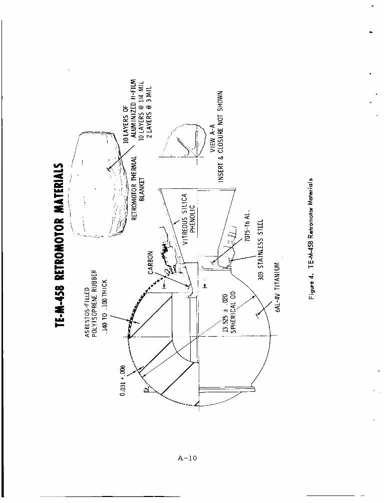
Cri ter ia for flight acceptance of a re t romotor is contained in the Thiokol specification num- ber P 20025 ( see Appendix B). cross-section is shown in Figure 4.
The motor
Attach a ground s t r a p between the motor l i f t - ing cradle and the motor ground strap. Attach the lifting cradle around the motor.
Lay the velostatbag a c r o s s the second wooden motor pallet and set the motor onto the velo- stat.
Remove lifting cradle and pull velostat bag up over the motor.
Reassemble the lifting c rad le around the motor.
Transport the motor to the shipping container and set the lifting cradle with the re t romotor into the shipping container.
A-4
x (D LL

20. Attach the shipping container ground s t r aps to points A & B (See Figure 1).
21. Remove the ground s t r a p running f rom the aft c losure bolt to building ground.
22. Close and secure the container.
A-5

N
0 ..- c
C
/ I
\
P
A-6
8 C 0 C 0
.- c
V
2 3 Is,
U .-
I

.
N
0 cy
L
A-7

VIEWS 4 b a - STAR POIt” A
SECTION A-A
1. Star points to be numbered 1 thru 4
2. Views 1 thru 4 will Concentrate on per the above sketch.
the popellmt load. 3. Views 5 thru 6 will concentrute on
the popeilant - motor case inter- face at the si& opposite the ma- chine.
VALLEY
ViEWS 3 b 7
VIEWS 2 b 6
THIOKOL X-RAY DATA FORREFERENCEONLY
KV 380 MAM 52 FFD_lOO” FOCfiL SPOT 5nm FILM TYPE Kodoh AA/Ansco B FILMSIZE MclL ~
REQ‘D SENSITIVITY LEAD SCREENS TOP ,oOr--
I
. o z e - INTENSIFY AA BOTTOK .OIO
e Tubepp- ~
M A S K I N G I K ~ ~
FILTER .020 Pb/.010 Cu.
PENETRAMETER NO. 1 1
Figure 2
A-8

1. No. 1 valley (see Figure 2) to be marked with a lead wrow or marker.
THIOKOL X-RAY DATA FOR REFERENCE ONLY
KV 38. MAM--% FFD 100" F K A L S P O T S n FILM TYPE Kodok AA/Ansco B FILM SIZE 14 I 17 REQ'D SENSITIVITY 1 % LEAD SCREENS TOP .OM
BOTTOM .010 FILTER .020 Pb/.010 Cu. i;
Tube MASKING N/A PENETRAMETER NO. 11
Figure 3
A-9
k
A-10
ti

APPENDIX B
RADIOGRAPHIC ACCEPTANCE CRITERIA
APRIL 1966
E. W. Travis D. L. Mil ler
B-1

# P 2 002 5
1
1.
2
2.1
3
3.1
3.1.1
3.2
3.2.1
3.2.2
3.3
3.3.1
3.4
3.4.1
3.4.2
RADIOGRAPHIC ACCEPTANCE CRITERLA,
TE-M-458 LOADED CASE
SCOPE
This specification establishes the acceptance c r i t e r i a for TE- M-458 loaded cases submitted to radiographic inspection. (See 4.1).
APPLICABLE DOCUMENTS
There a r e no applicable documents.
REQUIREMENTS
Surface Area
Total surface a r e a of a l l voids shall not exceed 12 square inches.
Voids
The propellant shall be f r e e f r o m voids, o r combinations of voids, that would decrease the normal minimum burning dis- tance to any point on the case wall ( insulated o r uninsulated) by more than 1 /2 inch.
The number of voids is controlled by surface a r e a c r i te r ia .
Cracks
Cracks shall not be permitted.
Separation.
There shall be no separation between the propellant and l iner , between the l iner and insulation and between the l iner and case .
There shall be no separation between the insulation and the case within 1 /2 inch of any edge of the insulation.
B-2

3.4.3
3.5
3.6
4
4.1
4.2
4.2.1
4.2.2
Total a r e a of separat ion between the insulation and the case shall not exceed 28 square inches.
Inclusions. The loaded case shall be f r ee f r o m foreign mater ia l .
Disposition. Fa i lure of loaded cases to meet the requirements specified herein shall be cause for rejection or fur ther review by MRB, depending on the nature of the discrepancy.
NOTES
This specification shall not be used unless referenced on an eng ine e r ing drawing.
Definitions.
Crack. A c rack is a break in mater ia l continuity with o r with- out separat ion into parts.
Separation. Separation is a condition wherein there is lack of physical contact between adjacent mater ia l s .
B-3

APPENDIX C
RETROMOTOR IGNITER AND BOLT GUILLOTINE RESISTANCE MEASUREMENTS
I
E. W. Travis D. L. Miller
c- 1

IGNITER AND GUILLOTINE RESISTANCE MEASUREMENTS AND MOTOR ADAPTER CONTINUITY TEST
This procedure descr ibes the s teps necessary to measu re the bridgewire res is tances of the ret romotor igni ters and the bolt guillo- t ines both by themselves and with these i tems physically connected to the spacecraft re t romotor adapter harness . in the Pan American Solid Propellant Elec t r ic Tes t Area.
This t e s t will be conducted
P e r s onne 1 Requi r ed:
GSFC Mechanical Engineer GSFC Electr ical Engineer GSFC Mechanical Technician
Equipment Re qui r e d:
Four (4) Igniter Assemblies TCC #17466-01 Spacecraft Flight Motor Adapter Test Cable
Operational Procedure
1.
2.
3 .
Request the supervisor of the Pan American Solid Propellants Area to have the four flight igniter assemblies and four bolt guillotines delivered to the tes t area.
The jumper cable required to e lectr ical ly connect the ret romotor igniters to the t e s t cell is a l ready available a t the cell. This cable is marked "McDonnell Gemini." this cable. See cable "C" in Figure 1.
Locate
Give the guillotine tes t cables and the fly- away connector tes t cables to the Pan Amer i - can test conductor so that he can have his connectors attached to the open ends of these cables. See Figure 1.
c-2

1 .. Locate the guillotine, igni ters and motor adapter in the t e s t area.
The igniter bridgewire will be measu red first. Connect the Igniter connector jumper (Cable C in F igure 1) to the cell.
Pan American will m e a s u r e tes t cable r e s i s - tance with the pins shorted.
Remove the shorting plug f rom the igniter and connect the jumper cable to the igniter.
Pan American will t es t for bridgewire re - sistance. Record this on the Resis tance Sum- m a r y Sheet a t the end of this procedure.
Disconnect the jumper cable and replace the shorting plug on the igniter.
Repeat s teps 7 thru 9 for each igniter.
Disconnect jumper cable "C" f r o m the cell.
Connect 2 type "A" jumper cables to the spacecraft motor adapter t o connectors S2 & S4. See F igure 2.
Connect both the "A" jumper cables to the cell.
Pan American will measure the tes t cable res is tance with the leads shorted.
Remove the shorting connectors f rom the two igniters to be used with the flight motor.
4.
5.
6.
7.
8.
9.
10.
11.
12.
13.
14.
15.
I
c -3

16.
17.
18.
19.
20.
21.
22.
23.
24.
25.
26.
Connect the motor adapter harness to these igniters . Locate the motor adapter in the cel l in a man. ner such that it would be protected in the event of accidental ignition.
Pan American will t es t the resis tance of thest circuits. tance summary sheet.
Record these values on the res i s -
Disconnect each of the igniters f rom the adapter harness .
Replace the shorting connectors onto both igniters.
Repeat s teps 14 thru 2 0 for the igniters to be used f o r the flight backup motor.
Disconnect both "A" jumper cables f r o m con- nectors S 2 & S4 on the motor adapter and reconnect these to S1 & S3.
Pan American will measure the res i s tance o the tes t cable with the pins shorted.
Select the two bolt guillotines to be used for flight.
Remove the shorting connectors f r o m these guillotines.
Connect each guillotine to the motor adapter harness .
I
c -4

2 7.
28.
29.
30.
31.
32.
33.
34.
35.
3 6 .
3 7.
38.
Locate the motor adapter in the cel l in a man. n e r such that it would be protected in the event of accidental ignition.
Pan American will measu re the res i s tance of these circui ts . Record these values on the resis tance summary sheet.
Disconnect the two guillotines f rom the adap- t e r harne s s . Reconnect the shorting plugs onto the guillo- tines.
Repeat s teps 25 thru 30 for the flight backup guillotines.
Disconnect the "A" style jumper cables f rom the motor adapter.
Res tore the motor adapter to i t s protective container . Disconnect the "A" style jumper cable f r o m the cell.
Connect two TIBIT style jumper cables to the cell.
Pan American will measure the tes t cable r e s is tance with the pins shorted.
Remove the shorting connector f rom the two flight guillotines.
Connect these guillotines to the "B" jumper cables.
c -5

39.
40.
41.
42.
43.
44.
P a n American will measu re the bridgewire res is tances in these guillotines. values on the Resistance Summary Sheet.
Disconnect the two guillotines f r o m the "B" jumper cables.
Reconnect the shorting plugs onto the guillo- tines.
Repeat s teps 37 th ru 41 for the flight backup guillotines.
Disconnect the "B" jumper cables f r o m the cell.
Return the igniters and bolt guillotine to their proper s torage a rea .
Record these I
I
C -6

Green F ly-Away Spacecraft Connector
/z/ Pan American Cell Connector
PT 0 6 p - a - 4 ~
2 Required GSFC Supplied Except For
Pan Amer. Connector
Pan American Ce l l Connector
MG 0 6 p - a - x (less Keyways # 2 & 3)
2 Required GSFC Supplied Except For
Pan Amer. Connector
Pan American & c e l l Connector
Cable C- Pan American Supplied, 1 Required
Figure 1. Jumper Cables
c-7

RESISTANCE SUMMARY SHEET
t .2 -.O
A. Igniters (Nominal Res i s t an te = 1.0 ohms B.W. only)
Bridgewire Bridgewire t Motor Resis tance Only Adapter Cabling Resis tance - S /N
--
B. - Bolt Guillotines . - - . - - (Nominal Resis tance = 1.1 5 0.1 ohms B.W. only)
Bridgewir e Bridgewire t Motor Adapter Cabling Resis tance
.~ Resis tance Only S/N
-.. _- ___ - ___ A-D _______. - -
A-D . . - . ....... -
............ - A-D ___ . . . . . . . -
c -8

APPENDIX D
AIMP RETROMOTOR AND IGNITERS MAGNETIC MEASUREMENTS AND
DEPERMING PROCEDURE
APRIL 1966
E. W. Travis D. L. Miller
D- 1

AIMP RETROMOTOR AND IGNITER MAGNETIC MAPPING AND DEPERMING
The procedure outlines the method for magnetically mapping and deperming the AIMP Retromotor Assembly and live igni ters . be done separately.
Each will
P e r s onne 1 Re qui r e d :
Solid Propel lants Area GSFC Mechanical Engineer GSFC Mechanical Technicians ( 2 ) GSFC Magnetic P rope r t i e s Engineer GSFC Magnetic P rope r t i e s Technician
Equipment Required:
TE -M -45 8 Re tr omotor As s embly 2 Igniter Assembl ies TCC #E17466-01 Wooden Pal le t Retromotor Lifting Sling Retromotor Deperm Adapter GSFC Deperm Coil and Dolly Variac, Type WSOHM DC Power Supply, Har r i son Labs #808A, P 5 Retromotor Mounting Bolts - 8 # 1 / 4 - 28 x 7/16 long, Ti tanium Third Stage Clamp Band - Aluminum G round St rap , Non-magnetic Conductive Mat connected to Building Ground Sys tem Conductive Legstats for Pe r sonne l F o r s t e r /Hoover Magnetometer, #MF-55-33 1-1 OX Safety Wire - .032 Diameter , Aluminum Safety Wire P l i e r s
Ope ration Procedure
1. Secure permiss ion f r o m a r e a superv isor to conduct magnetic deperming on motor in a designated a r e a within the Solid Propel lan ts facility.
D-2

I .
Connect a non-magnetic conductive s t rap , tied to the building ground system, to the motor c a s e on an aft c losure bolt.
Disconnect the shipping ground s t r aps a t points A and B. See Figure 1.
I - -
I
2.
3.
4.
5.
6.
7.
8.
9.
10.
11.
12.
P e r f o r m a functional checkout on the sensor and deperming equipment.
Move the motor in its shipping container into the designated a rea . Locate the Motor Ship- ping Container a s c lose to the work a r e a as practicable.
Locate a conductive mat connected to the building ground sys t em in the motor work a rea . Connect a non-magnetic conductive ground s t r a p f r o m the deperm dolly to the building ground system.
Verify that personnel who work on the motor a r e wearing legstats.
Clear the a r e a of a l l unnecessary personnel.
Remove the lifting cradle.
D-3

13.
14.
15.
16.
17.
18.
19.
Pee l the velostat bag f r o m around the motor down to the mounting ring.
Reassemble the lifting c rad le to the motor.
Assemble the deperm adapter to the deperm dolly.
Place motor mounting bolts (8 #1 /4 - 28 x 7/16 hex head) on the deperm dolly.
Connect a ground s t r ap f rom the motor lifting cradle to the motor ground strap. motor f r o m the wooden pallet using the cradle sling and a crane.
Lower the retromotor onto the deperm dolly.
Mount the motor to the dolly using the 8 bolts provided.
Lift the
20. Remove the motor lifting c rad le and sling.
2 1. P e r f o r m magnetic measurements and deperm ing as required. urement motor s / n 9
Record the magnetic meas-
Magnetic Measurements: a ) Gamma @ inches Initial b)---Gamma @---inches a f te r deperm
ing
22. Attach a ground s t r ap f r o m the motor lifting cradle to the motor ground s t rap. motor lifting cradle to the motor and attach the sling to a crane.
Attach
D -4
i - 23.
24.
25.
26.
2 7.
28.
29.
30.
31.
32.
33.
34.
35.
36.
Remove the eight mounting bolts.
Lift the motor f r o m the dolly using the crane. 1
I
I
Place the velostat bag a c r o s s the wooden pallet.
Lower the motor onto the pallet .
Remove the lifting cradle and sling.
Pull velostat bag up over the motor.
Attach the lifting cradle ground s t r a p to the motor ground strap. Reassemble the lifting c rad le to the motor.
Lift the motor by hand and set it inot the shipping container.
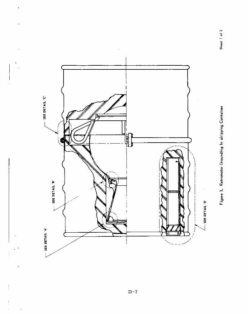
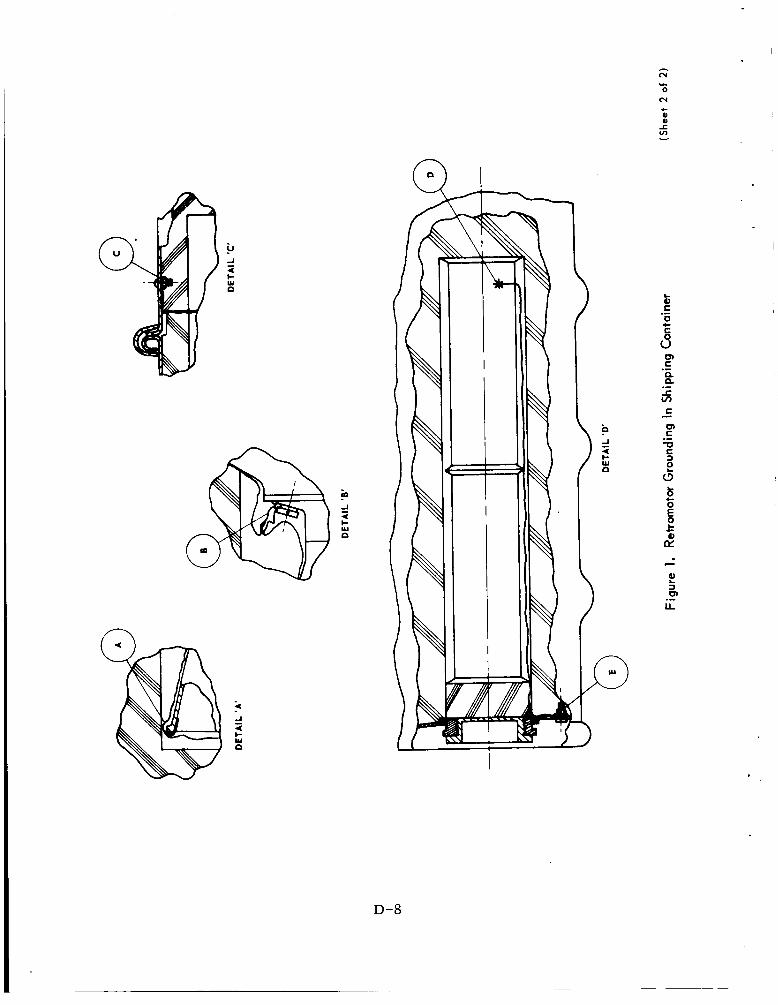
Connect the shipping container ground s t r aps a t points A and B. See Figure 1.
Disconnect the ground s t r a p connected to the building ground.
Pull velostat bag up over the nozzle.
Put the shipping container top back in place and bolt closed.
Remove both igniter containers from their storage cavity in the shipping container.
Connect a non-magnetic conductive s t rap, tied to the building ground system, to each igniter.
3 CD a
I ~
! I
I
i
I
!
5
,
I
CD Q
I
I
D-5

3 7.
38.
39.
40.
41.
42.
43.
44.
45.
46.
47.
Disconnect the shipping container ground s t rap f r o m the igniters.
Remove the RED warning tag f r o m the short- ing connector by cutting the safety wire.
NOTE: DO NOT REMOVE THE IGNITER SHORTING CONNECT ORS
Reassemble the warning t a g to the shorting connector using aluminum safety wire.
Magnetically m a p and deperm the igniter assemblies a s required.
Record the magnetic propert ies of the ignit- e r s : s /n Y
a) Gamma @ -inches Initial b) Gamma @ inches a f te r deperm,
in g
Reconnect the shipping container ground strap.
Disconnect the ground s t r a p to building ground.
Put the igniters in their containers.
Place the containers in their cavity in the motor shipping container.
Relock wi re the cap on the shipping container
Repeat the process for the flight backup mo- tor using the second copy of this document.
D-6
i .
0
D-7
3 i
n
4 c W
a i
n
4 c W
I
D-8

APPENDIX E
AIMP RETROMOTOR IGNITER INSTALLATION AND LEAK TEST
APRIL 1966
E. W. T rav i s D. L. Mil ler
E-1

IGNITER INSTALLATION AND LEAK TEST
This procedure desc r ibes the installation of the igni ters into the motor fo r flight and the method fo r conduction of a leak t e s t to verify the p r e s s u r e integrity of the motor assembly with igni ters installed.
Personnel Required:
GSFC Mechanical Engineers ( 2 ) GSFC Mechanical Technician
Equipment Re qui re d:
Two ( 2 ) , Igniter Assemblies TCC #E17466-01
Igniter 0-Rings MS 28775-012 0-Ring Lubricant Dow Corning #55M Deep Well Socket Wrench Torque Wrench ( 6 0 in-lb) Safety Wire - .032 Diameter , Stainless
Safety Wire P l i e r s Leak Tes t Suitcase
Steel
Acetone Kimwipes Cotton Swabs Watch 1 Container o
minimum) Liquic
Ins pe c t ion M i r r o r Approved Flashlight
Operational Procedure ___ ~-
Nitrogen ( 3 gallons
'd (D Y
.yF ii (D Q
I 1. Secure permiss ion f r o m the a r e a supe rv i so r 1
to remove the two ( 2 ) igniter a s sembl i e s f r o m the storage a r e a .
I I
0 0 3 3 5, (D
cn
E-2

l -
2.
3 .
4.
5.
6 .
7.
8.
9.
10.
11.
12.
Open the cap on the top of the shipping con- tainer and remove the ground s t r a p f rom each igniter . 1
I 1
Transpor t the igniter assemblies in their I c annis te rs to the gantry via an approved I ve hic le. i
The Vacsorb pumps shall be filled approxi- mately 1 / 2 hour pr ior to the est imated t ime f o r ascending the gantry to perform igniter installation. t ime f r o m the Blockhouse.
Secure est imate for this start ing
Close valves A , B, and C on the leak check gear . See F igure 1. Do not a t tach hose to quick disconnect a t this time.
Fill both the LN2 containers in the leak check suitcase.
i Replace the cover on the leak check suitcase. ~
Verify that the automatic relief valve has been' removed f r o m the suitcase.
! I
I I
Upon being notified that the tes t can begin, re-' move the sui tcase cover and refi l l the Vac- j so rb pumps with LN2.
Replace the sui tcase cover.
Notify the blockhouse that the igniter installa- tion and leak check a r e commencing.
C a r r y the igniters and equipment required t o the 9 level of the gantry. I
E-3

13.
14.
15.
16.
17.
18.
19.
20.
21.
22.
Position the leak tes t sui tcase approximately 8 feet f r o m the vehicle centerline. Check to insure that the suitcase is close enough to al- low the plug to be placed into the motor noz- zle.
Unpack the igniters record igniter s e r i a l num be r s on this page.
Lo c a t ion S / N Igniter A Igniter B
cd (D Y
4 mz
NOTE: DO NOT REMOVE SHORTING PLUGS I
Secure 0-Rings for each igniter f r o m the en- velopes inside the igniter cannis ter and inspect for damage.
Remove the bag covering the retromotor .
Remove the dummy igni ters f rom the re t ro- motor.
'
I
I I
I
i
Inspect the igniter ports in the aft c losure and clean, using cotton swabs and alcohol, if necessary.
1 ~
1
Lightly g rease the 0-Rings with the Dow Corning #55M lubricant. I
Slip the 0-Rings in place on the igniters. ,
Cut the lockwire holding the WARNING tag to the shorting plug and remove the WARNING tag.
Install both igni ters , finger tight, locating igniters A-B recorded in s tep #14.
,
r .
0 a
E -4

.
23.
24.
25.
26.
2 7.
28.
29.
30.
3 1.
32.
33.
34.
Torque each igniter to 60 in-lbs. using the deep well socket and torque wrench.
Lockwire the igniter base to the aft c losure bolt. Recheck igniter torque.
Replace the WARNING t a g onto the shorting plugs using the SST lockwire.
I Lightly g r e a s e the 0-Ring on the leak tes t I motor plug using Dow Corning #55M 1ubricant.l
I
Remove sui tcase cover and attach hose to vacsorb pumps with the quick disconnect fi t t ing.
Open valve "C", near the gauge.
With a finger res t ing lightly over the hole in the motor plug, open valve "A" slightly to verify suction. aft e r v e r i f i c at ion.
Close valve "A" immediately
Manually remove the aft c losure r a t plug f r o m the nozzle.
Inser t the motor plug into the nozzle.
Open valve "A" slightly and close valve "A" when the vacuum reaches 27 f 1 inches of Mercury. Record pressure .
P = -inches of Mercury.
Close valve "C" .
Disconnect hose f r o m the pump at the quick disconnect .
cd
' c w
(D Y
m ' d 3 (0 a.
I
j
j I
I
i
! !
!
I
I
I
E-5

35.
36.
3 7.
38.
39.
40.
41.
42.
43.
44.
45.
Close the cover on the suitcase and check automatic valve operation.
Should vacsorb "A" be inoperative o r incap- able of pumping to the required level, close valve "A" and use vacsorb I 'Brt by opening valve "B".
Wait five (5) minutes for the sys tem to stabil- ize, Vacuum must be 27 k 1 inches of Mercury. Record gauge reading.
P = inches of Mercury.
Wait for ten minutes. The vacuum p r e s s u r e shall not have reduced m o r e than 1 /2 inch of Mercury f rom the valve recorded in s tep #37. record the reading.
P = inches of Mercury.
Holding onto the pipe attached to the motor plug, open valve "C" to vent the motor .
When the motor i s vented, remove the motor plug and s tore it in the suitcase.
Inspect motor r a t plug for damage and wipe the top and bottom aluminum foil with acet- one.
Press the r a t plug into the nozzle until it s ea t fully.
Replace the dust bag over the re t romotor .
Notify the blockhouse that the igniter instal- lation and leak check a r e complete.
Remove leak check gea r , and other equipmen f rom the gantry.
CAUTION: BE CAREFUL NOT TO SPILL THE LN2 IN THE LEAK CHECK SUITCASE.
1
9 (D cl
0 cl
3 (D Q
id a
E -6

W 0
3 0
a
’ __.-__ ,
I- LL /
E-7

APPENDIX F
NO VOLTAGE CHECK OF PYROTECHNIC CIRCUITRY
APRIL 1966
E. W. Travis D. L. M i l l e r
F- 1

1.
2.
3 .
4.
5.
6.
7.
8.
9.
F-2 DAY NO VOLTAGE CHECK
NOTE: This t e s t will be conducted during the vehicle s t r ay voltage test .
Request permission f r o m test conductor to commence spacecraf t no voltage tes t .
Verify that the turn-on plug (ei ther live o r GSE) is installed. (See Figure 1)
Verify that the umbilical plug is connected to the spacecraft.
Request the electr ical integration engineer to verify that the blockhouse panel is functioning properly.
Verify that no plug is installed in the ordnance connector. plug to the electr ical integration engineer and request permission to remove this plug.
If a plug is installed, identify the
Turn the S-1 switch on the pyrotechnic test box to OFF.
-
Plug the Spacecraft End of the Pyrotechnic Tes t Cable into the spacecraf t ordnance t e s t connector. See Figure 1. Remove the sa fe tes t ordnance connector.
Turn the S-2 switch to the ON position. places the voltmeter a c r o s s the circui ts .
This __
Request permission f r o m the spacecraf t electrical engineer to commence testing. Verify that the spacecraft ha rness is not connected to the igniters o r bolt guillotines.
F-2

I -
10. Switch the S-1 switch thru each of the pyro- technic positions and r eco rd below the voltage for each.
NOTE: Each position has a maximum allow- able voltage reading. Should any reading exceed that value, r eco rd the value, turn the S-1 switch to O F F anc notify the blockhouse engineer.
Maximum Switch Allowable
Posit ion Voltage Reading
Shield 1GN 1 RLY 1GN 2 RLY S E P A RLY S E P B RLY IGN 1 SQUIB IGN 2 SQUIB S E P A SQUIB S E P B SQUIB MID-QUAD QUAD-OUTPUT
- - (Millivolts)
50 5 0 50 50
200 200 200 200 50 50
11. Turn the S-1 switch to OFF.
12. Place the LIVE ordnance plug (green) into the ordnance connector.
13. Switch the S-1 switch thru each of the pyro- technic positions and record below the voltagc for each.
NOTE: Each position has a maximum allow- able voltage reading. Should any
F-3

14.
15.
16.
17.
reading exceed that value, r eco rd the value, t u rn the S-1 switch to OFFand notify the blockhouse engineer.
Switch P o sit ion
Shield 1GN 1 RLY 1GN 2 RLY S E P A RLY S E P B RLY 1GN 1 SQUIB 1GN 2 SQUIB S E P A SQUIB S E P B SQUIB MID-QUAD QUAD OUTPUT
Maximum Allowable
(Millivolts) Voltage Reading
Turn the S-1 switch to OFF.
Remove the LIVE ordnance plug.
Install the SAFE ordnance plug ( r e d ) into the ordnance connector.
Switch the S-1 switch thru each of the pyro- technic positions and r eco rd below the voltagc for each.
NOTE: Each position has a maximum allow- able voltage reading. Should any reading exceed that value, r e c o r d thc value, tu rn the S-1 switch to OFFanc notify the blockhouse engineer.
F -4

18.
19.
20.
21.
22.
23.
24.
Switch Po sit ion
Shield 1GN 1 RLY 1GN 2 RLY S E P A RLY S E P B RLY 1GN 1 SQUIB 1GN 2 SQUIB S E P A SQUIB SEP B SQUIB MID-QUAD QUAD OUTPUT
Maximum Allowable
(Millivolts) Voltage Reading
50 50 50 50 50 50 50 - 50 50 50 ~ - -
Turn the S-1 switch to OFF.
Notify the t e s t conductor that the "Spacecraft - ON" portion of the spacecraft no voltage check i s complete.
Request permission f r o m the t e s t conductor tc turn the spacecraf t O F F for the "Spacecraft- OFF" portion of the spacecraft no voltage tes t
Request the spacecraf t electrical engineer to switch the spacecraf t OFF and reduce the power supply to zero amps.
Request verification f rom the spacecraf t e lectr ical engineer that the spacecraft i s OFF
Remove the SAFE ordnance plug.
Switch the S-1 switch thru each of the pyro- technic positions and record below the voltage for each.
F-5

NOTE: Each position has a maximum allow- able voltage reading. Should any reading exceed that value, r eco rd the value, tu rn the S-1 switch to OFFanC notify the blockhouse engineer.
Switch Position
Shield ~. _-
1GN 1 RLY 1GN 2 RLY S E P A RLY S E P B RLY 1GN 1 SQUIB 1GN 2 SQUIB S E P A SQUIB S E P B SQUIB MID-QUAD QUAD OUTPUT
Maximum Allowable Voltage Reading __ - - __ . . -
(Millivolts)
25. Turn the S-1 switch to OFF.
2 6 . Install the LIVE ordnance plug (green) into tl ordnance connector.
27. Switch the S-1 switch th ru each of the pyro- technic positions and r e c o r d below the voltag for each.
NOTE: Each position has a maximum allow- able voltage reading. Should any reading exceed that value, r e c o r d the value, tu rn the S-1 switch to O F F a n d notify the blockhouse engineer.
F-6

28.
29.
30.
31.
Maximum Switch Allowable
Reading I Voltage - P o sit ion
Shield
-- - (UiiiivoltsJ
1GN 1 RLY 1GN 2 RLY S E P A RLY SEP B RLY IGN 1 SQUIB IGN 2 SQUIB S E P A SQUIB SEP B SQUIB MID-QUAD QUAD OUTPUT
50 50 50 50 50 50 50 50 50 5 0
Turn the S-1 switch to OFF. 4
Remove the LIVE ordnance plug. - - Install the SAFE ordnance plug ( red) into the ordnance connector . -- - -
Switch the S-1 switch thru each of the pyro- technic positions and record below the vol- tages fo r each.
NOTE: Each position has a maximum allow- able voltage reading. Should any reading exceed that value, record the value, tu rn the S-1 switch to O F F a n d notify the blockhouse engineer.
1 I I
F-7

Switch Position
Shield ___
1GN 1 RLY 1GN 2 RLY SEP A RLY S E P B RLY 1GN 1 SQUIB 1GN 2 SQUIB SEP A SQUIB SEP B SQUIB MID-QUAD QUAD OUTPUT
Maximum Allowable
Voltage (Millivolts)
50 50 50 50 50 50 50 50
.50 50
32. Turn the S-1 switch to OFF.
33. Disconnect the ordnance t e s t cable at the spacecraft.
34. Replace the SAFE ordnance test plug.
35. Notify the spacecraf t e lec t r ica l engineer that the no voltage check is complete.
36. Notify the t e s t conductor that the spacecraf t no voltage t e s t is complete.
I I
i !
.
I i I I ! I I
F -8

ORDNANCE CONNECTOR
FACET C
Figure 1. Spacecraft Connector Locations
F-9

APPENDIX G
NO VOLTAGE CHECK O F PYROTECHNIC CIRCUITRY
F-1 DAY
APRIL 1966
c E. W. Travis D. L. Mi l le r
G-1

F-1 DAY N O VOLTAGE CHECK
NOTE: This t e s t will be conducted p r io r to connecting the spacecraf t ha rness to the re t romotor igni- t e r s and bolt guillotines, during sun gun checks.
r, p 1 - 7
0 ! 3 1 Q l 5
1. Request permiss ion f rom tes t conductor to 1 , a rn m
--i 'I--+ ; commence spacecraf t no voltage tes t with the spacecraf t on.
Verify that the turn-on plug (e i ther live o r GSE) is installed.
2. I I I---- ( s e e Figure 1) 1 ,
I I 3 . Verify that the umbilical plug is connected to 1 I I
the spacecraft . 1- +- - - -
verify that the blockhouse panel i s functioning 1 I 1
4. Request the e lec t r ica l integration engineer to ' I I 1
properly. Verify that the spacecraf t ha rness is not connected to the igni ters & guillotines. - -- ! t I-- 4
' 1 7. Remove the SAFE ordnance t e s t plug and plug i i I
L-1- - _I 1
L 4 -
5. Remove the SAFE ordnance plug.
6. Turn the S--.- switch on the pyrotechnic t e s t box to OFF. - 4
I the - Spacecraft - - - End - of the pyrotechnic t e s t
nector. ( s e e Figure 1)
I I cable into the spacecraf t ordnance t e s t con-
1 I
8. Turn the S-2 - switch to the ON position. places the voltmeter a c r o s s the c i rcu i t s .
Request permiss ion f r o m the spacecraf t e lectr ical engineer to commence testing.
Switch the S-1 switch th ru each of the pyro- technic positions and r eco rd below the vol tage ' for each.
This 7
tj- I 9.
I I
10. I
I
I I I
G -2

.
.
11.
12.
13.
' -
NOTE: Each position has a maximum allow- I able voltage reading. Should any reading exceed that value, record the I value, tu rn the S-1 switch to O F F and ' notify the blockhouse engineer. !
Maximum Switch Allowable
P o sition Voltage (Millivolts)
Shield 1GN 1 RLY 1GN 2 RLY SEP A RLY S E P B RLY 1GN 1 SQUIB 1GN 2 SQUIB S E P A SQUIB S E P B SQUIB MID-QUAD QUAD OUTPUT
5 0 50 5 0 50
200 2 00 200 200
5 0 50
Turn the S-1 switch to OFF.
Place the LIVE ordnance plug (green) into the o r dnanc e connect or.
Switch the S-1 switch thru each of the pyro- I
technic positions and record below the voltage, for each.
NOTE: Each position has a maximum al low-,
reading exceed that value, record the1 value, tu rn the S-1 switch to OFFandi notify the blockhouse engineer.
able voltage reading. Should any I
I
G-3

c
Switch Posi t ion
Shield ~-
1GN 1 RLY 1GN 2 RLY SEP A RLY S E P B RLY 1GN 1 SQUIB 1GN 2 SQUIB SEP A SQUIB SEP B SQUIB MID-QUAD QUAD OUTPUT
Maximum Allowable
Voltage (Millivolts) ____-- .. _. -
5 0 5 0 5 0 5 0 50 50 50 50 50 50
Reading , .-
co p.
__I.-
-. -
I
! i ~
I
I
14. Turn the S-1 switch to OFF. 2 I i --4
I I
I
I 15.
16.
Remove the LIVE ordnance plug.
I Install the SAFE ordnance plug ( r e d ) into the o rdnanc e connect or . . --+
, 1
!
I I I I I I
17. Switch the S-1 switch th ru each of the pyro- technic positions and r eco rd below the voltage
,
for each.
NOTE: Each position has a maximum allow- ,
able voltage reading. Should any reading exceed that value, r e c o r d the value, tu rn the S-1 switch to O F F and ; notify the blockhouse engineer.
I !
1
, I
, I I j
, I I
(D 5 it m
I I I
G -4

Maximum Switch
Position Allowable
Reading f I
Voltage (Millivolts) Shield
1GN 1 RLY 1GN 2 RLY S E P A RLY S E P B RLY 1Gn 1 SQUIB 1GN 2 SQUIB SEP A SQUIB SEP B SQUIB MID-QUAD QUAD OUTPUT
50 50 50 50 50 5 0 50 5 0 50 5 0
I
i I--?--- - - - 18. Turn the S-1 switch to OFF. i
19. Notify the tes t conductor that the "Spacecraft- ~ j I
ON" portion of the spacecraft no voltage check; I - is complete. I----+ I
20 . Request Permiss ion f rom the t e s t conductor to turn the spacecraf t O F F f o r the "Space- craft-OFF" portion of the spacecraft no-vol- tage tes t .
i I
I -4-- 4 I
I
I
1
power supply to zero amperes. I I
I
21. Request the spacecraft electrical engineer to j I i
, - switch the spacecraft OFF and reduce the i
22. Request verification f rom the spacecraft I
electr ical engineer that the spacecraft is OFF.] , - 2 3 . Remove the SAFE ordnance plug.
24. Switch the S-1 switch thru each of the pyro- '
technic positions and record below the voltage for each. I I i
G-5

NOTE: Each position has a maximum allow- able voltage.reading. Should any reading exceed that value, r eco rd the value, tu rn the S-1 switch to OFFanC notify the blockhouse engineer.
Minimum Switch Allowable
Position V o It Re a ding ' - age- - (Millivolts) I
Shield 1GN 1 RLY 1GN 2 RLY S E P A RLY SEP B RLY 1GN 1 S Q U I B 1GN 2 SQUIB S E P A S Q U I B S E P B S Q U I B MID -QUAD QUAD O U T P U T
50 50 50 50
2 00 200 2 0 0 200 50 50
9 (D Y
I __- I
i 25. Turn the S-1 switch to OFF.
26.
I
'r- Install the L I V E ordnance plug (g reen ) into the/ ordnance connector.
27. Switch the S-1 switch th ru each of the pyro- technic positions and r eco rd below the voltage for each.
N O T E : Each position has a maximum allow- able voltage reading. Should any reading exceed that value, r eco rd the value, tu rn the S-1 switch t o OFFand notify the blockhouse engineer.
,
G-6

.
28.
29 .
30.
31.
Maximum Switch Allowable
Pos i t ion Voltage Re ad in. (Millivolts)
Shield 1GN 1 RLY 50
-- 1GN 2 RLY 50 S E P A RLY 50 ____ I
S E P B RLY 50 ___--
1GN 1 SQUIB 50 1GN 2 SQUIB 50 ~- -
S E P A SQUIB 50 -- S E P B SQUIB 50 ~-
MID-QUAD 50 QUAD OUTPUT 50 .-
Turn the S-1 switch to OFF.
Remove the LIVE ordnance.
Install the SAFE ordnance plug ( r ed ) into the ordnance connector.
Switch the S-1 switch thru each of the pyro- technic positions and record below the voltage for each.
NOTE: Each position has a maximum allow- 1 able voltage reading. Should any 1 reading exceed that value, record the! value, turn the S-1 switch to OFFand ' notify the blockhouse engineer.
I
I
I
i
G-7

32
Maximum Switch Allowable
Position
Shield
___._ -
1GN 1 RLY 1GN 2 RLY S E P A RLY S E P B RLY 1GN 1 SQUIB 1GN 2 SQUIB SEP A SQUIB SEP B SQUIB MID-QUAD QUAD OUTPUT
Vo It age - (Millivolts)
50 50 50 50 50 50 50 50 50 50
____.
Turn the S-1 switch to OFF_.
I 33. Disconnect the ordnance t e s t cable a t the spacecraft .
Replace the SAFE ordnance t e s t connector. +-I- I
34. I
35. Notify the spacecraf t e lec t r ica l engineer that ' I 1
I the no voltage check is complete. I
I
36. Notify the tes t conductor that the spacecraf t I I
I no voltage tes t is complete.
I !
1
! I
,
I
0 0 3 3 3 (D
rn
G-8

I TURN-ON CONNECTOR
TURN-ON CONNECTOR 1 1
/ ORDNANCE CONN ECTOR
FACET C
Figure 1. Spacecraft Connector Locations
G-9

APPENDUC H
NO VOLTAGE CHECK AND FINAL ARMING
F-U DAY
APRIL 1966
E. W. Travis D. L. Miller
H- 1

F-O DAY NO VOLTAGE CHECK AND FINAL ARMING
This check will be conducted on F-0 day p r io r to final sealing of the fairing a c c e s s par t s .
(I Y
a 1. Request permiss ion f r o m t e s t conductor to
commence spacecraf t no voltage tes t . . ---
2. Verify that the live turn-on plug i s installed. ( s e e Figure 1 ) ___*- -
3 . Verify that the umbilical plug i s connected to the spacecraft . ____ _-- -- +
4. Request the e lec t r ica l integration engineer to verify that (a) blockhouse panel is functioning properly, (b) the spacecraf t is O F F and (c ) the power supply is reduced to zero amperes . __ - -
5. Remove the SAFE ordnance tes t plug. D o & remove the SAFE ordnance plug. 1
6. Turn the - S-1 switch on the pyrotechnic t e s t box to 0 2 . - -
7. Plug the Spacecraft ~ - End of the pyrotechnic I
t es t cable into the spacecraf t ordnance t e s t connector. ( s e e Figure 1) l ~ . ~ _ _ -
8. Turn theS-2 -_ switch to the ON position. This places the voltmeter a c r o s s the c i rcu i t s . ~ _ _ - .+ . - --
9. Request permiss ion f r o m the spacec ra f t e lectr ical engineer to commence testing. ,--._- ---
I
10. Switch the S-1 switch thru each of the pyro- technic positions and r eco rd below the voltage for each.
I I I
H -2

NOTE: Each position has a maximum allow- able voltage reading. Should any reading exceed that value, r eco rd the value, tu rn the S-1 switch to O F F a n d notify the blockhouse engineer.
I 1 : 12. Disconnect the ordnance tes t cable at the 1
Switch Posit ion
1
Shield 1GN 1 RLY 1GN 2 RLY S E P A RLY S E P B RLY 1GN 1 SQUIB 1GN 2. SQUIB S E P A SQUIB S E P B SQUIB MID-QUAD QUAD OUTPUT
Maximum Allowable
(Millivolts)
5 0 5 0 50 ___-
5 0 - 50 50 -- 50 5 0 50 __-- 5 0 ____
Voltage R e a ding
spacecraft . I
i I i
14. Notify the spacecraf t electrical engineer that 1
the no voltage check is complete.
15. Notify the tes t conductor that the spacecraft no voltage tes t is complete, and request per- mission to proceed with the final arming.
Remove the SAFE ordnance plug. 16. I I
n
H-3

17.
18.
19.
20.
21.
Install the LIVE ordnance plug, using yellow locktite.
Remove the SAFE ordnance t e s t plug.
THE SPACECRAFT IS NOW ARMED.
Install the LIVE ordnance tes t plug, using yellow locktite.
Secure the "Turn-On Plug Door" with yellow locktite.
Notify the tes t conductor that the spacecraf t arming has been completed.
H -4
- .

TURN -ON CONNECTOR \
TURN -ON CONNECTOR
ORDNANCE CONNECTOR
FACET C
Figure 1. Spacecraft Connector Locations
H-5


![Programmable Interplanetary Networks - UvA · recent tests such as the Interplanetary Internet[3], showing the rst approaches to a so called InterPlanetary Network (IPN). With the](https://img.dokumen.tips/doc/110x75/5f0461a37e708231d40db1e7/programmable-interplanetary-networks-uva-recent-tests-such-as-the-interplanetary.jpg)