Embed Size (px)
Citation preview
Hindawi Publishing CorporationAdvances in Power ElectronicsVolume 2012, Article ID 208231, 18 pagesdoi:10.1155/2012/208231
Research Article
Analysis of a Microgrid under Transient ConditionsUsing Voltage and Frequency Controller
Monika Jain,1 Sushma Gupta,1 Deepika Masand,2 and Gayatri Agnihotri1
1 Electrical Engineering Department, Maulana Azad National Institute (M.A.N.I.T), Deemed University,Bhopal (M.P.) 462052, India
2 Electrical and Electronic Department of Engineering, Oriental college of science and technology (O.I.S.T),R.G.P.V University, Bhopal (M.P.) 462021, India
Correspondence should be addressed to Monika Jain, [email protected]
Received 24 May 2012; Revised 21 September 2012; Accepted 5 October 2012
Academic Editor: Pavol Bauer
Copyright © 2012 Monika Jain et al. This is an open access article distributed under the Creative Commons Attribution License,which permits unrestricted use, distribution, and reproduction in any medium, provided the original work is properly cited.
This paper presents an investigation of voltage-and-frequency-(VF-) based battery energy storage system (BESS) controller usedin micro grid for analyzing the optimum capability of plant. Microgrid is formed by using three hydropower plants feeding three-phase four-wire load. The proposed controller is used for load balancing, harmonic elimination, load leveling, and neutral currentcompensation. The proposed BESS controller permits the selection of an optimum voltage level of battery and allows independentcurrent control of each phase. The main emphasis is given on maintaining constant voltage and frequency within the micro gridduring transient conditions. Micro grid with power plant and its controller is modeled in MATLAB/Simulink using Power SystemBlockset (PSB) toolboxes.
1. Introduction
Existing and new generating plants cause depletion of fossilfuels, global warming, and pollution. This diverts research-ers’ attention towards renewable energy resources. Therenewable energy sources such as wind, small-hydro,biomass, geothermal are inexhaustible in nature and easilyavailable in our country. Also remotely located villages,islands, hills, military equipment, and so forth are some ofthe areas which are mainly isolated from the power systemgrid and in these areas wind and hydro-energy are availableabundantly. Thus for supplying energy in such areas, iso-lated system, micro-or minigrid system, is an emerging con-cept and draws the attention of many researchers. Micro-grid is the small scale energy system equipped with distri-buted energy resources, electronic equipments, loads, ancil-lary facilities, and so forth. In micro grid system, micro-generators are operated parallel to the loads, usually throughsome voltage-source-inverter-(VSI-) based or current-source-inverter-based system that can operate in control-lable systems. The concept of micro grid was first introducedin 2001 by Lasseter [1]. A number of new technologies and
innovative ideas are proposed [2–10] till now. Uno et al. [2]describe the supply and demand stability in micro grid fordifferent connections. Later on the scheme based on powerelectronics devices with distributed generation (DG) is usedto form micro grid [3]. The micro grid thus formed canwork in grid connected mode as well as in islanded modewith the help of power electronic converter. A new con-cept was introduced in which two inverters are used, one inshunt and another in series with individual DG formsingmicro grid [4]. The former is used for balancing the volt-age and the latter is used for balanced the line current. Small-signal stability for conventional power systems is well estab-lished, but for inverter-based micro grids there is need toanalysis, how the circuit and control features give rise toparticular oscillatory modes and which of them have poordamping. Thus the author develops the state-space model-ing for such inverters based micro-grid [5]. Moving furthermicro grid not only deals with power sharing or transientstability problems but also deals with over voltage, undervoltage, oscillations, offset voltage, and so on. Hence Wuet al. describe the existing problems and the possible solu-tion in micro grid [6]. When micro grid is working in
2 Advances in Power Electronics
islanded mode proper synchronization between generators isrequired, if not so large transient current will flow. A conceptof soft connection scheme based on classical zero crossingdetector was introduced for synchronization of generatorsforming micro grid [7]. In spite of synchronization thereis another problem of proper load sharing in autonomousmicro grid. Thus a new concept was developed by Majumderet al. [8], in which high gain angle droop control scheme isused for proper load sharing in micro grid. A supplementaryloop is proposed for each DG to stabilize the system usinghigh angle droop gain. Further a mathematical model thatpredicts the effect of voltage offset on reactive power sharingbetween inverters in micro grid was introduced [9]. Activesynchronizing control scheme was introduced by author,which is required when micro grid consists of multiple DGs.Further the author concluded that the scheme is useful forislanded and reconnected mode [10].
Past research indicates that a self excited inductiongenerator (SEIG) has emerged as a suitable candidate forisolated system [11–14] because of its many advantages suchas its small size and weight, robust construction, reducedunit size and maintenance cost, brushless rotor construction,absence of a separate excitation source, and self protectionagainst severe over loads and short circuits. In order to utilizethe full potential of the energy source, several such generatorsmay have to be operated in parallel. There is no problem ofsynchronization and hunting in SEIG thus here it is used asgenerator in forming micro grid.
In this paper micro grid is formed using hydro powerplants located at some distance far from each power plant.Hydro-electric plants can provide cheap, clean, and reliableelectricity for villages. Power generated by these plants isalmost constant for 24 h a day. If light load condition arisesthe extra power will be stored in battery and if load increasesthen deficit power will be supplied by the battery. Hydro-electric plants convert the kinetic energy of a waterfall intoelectric energy [15]. In this paper main emphasis is given onthe transient condition within the micro grid and optimumutilization of BESS controller during this condition.
Focus of the Paper. So many authors work on the powersharing between generators during grid connected modeand islanded mode. In case of grid connected mode, thegenerators of micro grid are connected to the load as wellas to the main grid. The loads are shared by the maingrid and generator of micro grid. Hence the generators ofmicro grid are not fully loaded. Now if a fault occurs inthe main grid it gets isolated from the rest of the system(forming micro grid), this mode is known as islanded mode.The generators of micro grid (which are not fully loaded)now shared power within themselves and maintain constantvoltage and frequency at load ends.
But this paper deals with islanded mode only and thegenerators which are forming micro grid are fully loadedduring healthy condition. If the fault occurs in any of thegenerator and it gets isolated then also the load of the faultygenerator is shared by the rest of the generators in microgrid and thus maintains voltage and frequency constant atthe load ends.
In addition, this paper also describes the concept ofmicro grid in which SEIGs are connected in parallel formingmicro grid with their individual load. The hydroturbines areused as prime mover for SEIGs which are used to deliverpower. The system consists of squirrel cage induction gener-ator with capacitor bank. The capacitor bank is used to caterreactive power requirement. A controller is connected in par-allel to the load to improve the stability of the system undertransients. In spite of the above advantage SEIG is superiorcompared to other electric generator because there is noneed of synchronization between two asynchronous generat-ors.
2. System Description and Working
The schematic diagram of micro grid is shown in Figure 1.The system consists of three small hydro-turbines which areused as prime movers for SEIGs. Single hydro power plantconsists of asynchronous generator (SEIG) with the excita-tion capacitor, consumer load and a voltage source converterwith a battery energy storage system (BESS) based voltageand frequency controller. The self-excited induction genera-tor has been found to be an attractive competitor to the syn-chronous generator due to several advantages as discussed inabove section. A major drawback of SEIG’s is their poor volt-age regulation under varying load conditions even for fixedprime movers speeds. The star connected 3-phase capacitorbank is used for generator excitation and value of excitationcapacitor is selected to generate the rated voltage at no loadcondition while additional demand of power during full loadand faulty condition is met by controller because of havingcapability of bidirectional flow of active and reactive power.
The reactive power requirement can be compensated byconverter based compensators like DSTATCOM and DVR.This paper deals with BESS as a controller. The BESScontroller consists of DSTATCOM and a battery connectedparallel to DC link of DSTATCOM. Basic principle of activeand reactive power sharing starts with the active and reactivepower flows between two ac sources through line impedanceZ(= R + jX) as shown in Figure 2. The active power P andreactive power Q are given by:
P = V1
(R2 + X2)[R(V1 −V2 cos δ) + V2 sin δ],
Q = V1
(R2 + X2)[−RV2 sin δ + X(V1 −V2 cos δ)].
(1)
If the line is mainly inductive, where the resistance can beneglected, the typical phase angle between two voltages is
P = V1V2
X(sin δ),
Q = V1
X(V1 −V2).
(2)
These equations imply that the active power is proportionalto phase angle and reactive power is proportional to voltagedifferences between the two systems, respectively. For this

Advances in Power Electronics 3
Main grid Transformer CB
CB Tx
CB
CB Tx
Tx
Load
Load
MS
MS
Load
MS
grid transformer
CB: circuit breaker
Main grid Micro grid
Storagedevice
MS: micro sourceTx: transmission line
Storagedevice
Storagedevice
6 kV main 6 kV/415 V distribution
Figure 1: The micro grid with micro source, load, and controller.
V1 V2
R + jX
Z
V1 V2
δ
Figure 2: Two generators connected by line impedance.
reason, in BESS controller two PI controllers are there tocontrol active and reactive powers by varying its outputfrequency (that generates the phase-angle difference as aresult) and voltage levels. As a result, the P-F and Q-V droopstrategies provide a stable active and reactive power sharingbetween the generators. Thus constant power requirementof SEIGs and load is met by IGBT based current controlledvoltage source converter (CC-VSC) along with batteryenergy storage system (BESS) at its DC link. The output ofVSC is connected through the AC filtering inductor at thepoint of common coupling between every micro source andload.
The basic principle of regulating the frequency by thecontroller is that it maintains the constant output power atthe generator terminal voltage because input power from theturbine is constant so the frequency at the terminal remainsconstant [11]. In given configuration if no load condition
arises the extra power is used to charge the battery and duringheavy load condition CC-VSC is able to regulate the reactivepower and frequency. If one of the SEIG is shut down due tofaulty condition, the terminal voltage and frequency are stillregulated.
3. Control Strategy
The proposed system consists of three hydro power plantswhich are operating parallel forming micro grid. Each plantconsists of self excited induction generator, with load andits controller. The control strategy for the other two plantsis also the same. Figure 3 shows the control strategy ofthe proposed voltage and frequency controller which isbased on the generation of reference source currents [13–15]. Three-phase reference source currents are having twocomponents, one is in-phase component or active power

4 Advances in Power Electronics
Quadraturecomponent reference
current
AC voltagePI
controller
In phasecomponent
reference current
Compensation ofamplitude of activepower component
of current
FrequencyPI controller
Frequencymeasurement
Unit voltagetemplate generator
Quadrature voltagetemplete generator
0
Hysteresis current
Battery
Va Vb Vc
Vt
+−
++
+−
−+
Ua Ub Uc
Vrated Prated
Vabc
Freff
Vtreff
Wa Wb Wc
I∗saip
I ∗sbip
I∗scip
I∗smip
I∗amipI∗saiq
I∗sbiq
I∗sciqI∗smiq
I∗ I∗ I∗ I∗
controller
S1 S3 S5 S7
S4 S6 S8 S2
a
bc
n
Rb
Ro
Vo
Cbat
−+
−+
IcaIcb
Icc
Icn
L f ,Rf
L f ,Rf
L f ,Rf
L f ,Rf
Igene
IsaIsbIsc
sa sb sc sn
Vdc
Cdc
Figure 3: Schematic diagram of control scheme for SEIG –STATCOM system.
component (i∗saip, i∗sbip, i∗scip) while the other one is in-quad-rature component or reactive components (i∗saiq, i∗sbiq, i∗sciq).
In-phase component of reference source current isestimated by taking the difference of amplitude of rated gen-erated current (Igene) and output of frequency PI controller(Ismip) [13].
The amplitude of rated current of the generator is cal-culated as
Igene =√
2(Prated)√3(Vrated)
, (3)
where Prated is the rated generated power (Pgene) and Vrated isrms voltage of the asynchronous generator.
The frequency error is given as
ferror(q) = freff(q) − f(q), (4)
where freff is reference frequency (50 Hz in present system)and f is the frequency of the voltage of an asynchronousgenerator. The instantaneous value of f is estimated usingphase locked loop (PLL).
At the qth sampling instant, the output of PI frequencycontroller (Pc) is as:
Pc(q) = Pc(q−1) + Kp f
{ferror(q) − ferror(q−1)
}+ Ki f ferror(q),
(5)
where Kp f and Ki f are the proportional and integral gains offrequency PI controller.
From (1) and (2) at the qth sampling instant, the ampli-tude of active component of current is
I∗smip = Igene(q) − Ismip(q). (6)
The instantaneous values of in-phase components of refer-ence source currents are estimated as
i∗saip = I∗smip Ua; i∗sbip = I∗smipUb; i∗scip = I∗smipUc.(7)
Multiplication of I∗smip with in-phase unit amplitude tem-plates (Ua,Ub,Uc) yields the in-phase component of refer-ence source currents. These templates are three-phase sinu-soidal functions which are derived by dividing the ac voltages

Advances in Power Electronics 5
Va,Vb, and Vc by their amplitude Vt. The instantaneous linevoltages at the IAGs terminals (Va, Vb, and Vc) are con-sidered close to sinusoidal and their amplitude is computedas
Vt ={(
23
)(Va
2 + Vb2 + Vc
2)}1/2
. (8)
The unity amplitude templates having instantaneous value inphase with instantaneous voltage (Va, Vb, and Vc), which arederived as [3, 8, 9]:
Ua = Va
Vt; Ub = Vb
Vt; Uc = Vc
Vt. (9)
To generate the quadrature component of reference sourcecurrent, another set of sinusoidal quadrature unity ampli-tude templates (Wa, Wb, Wc) is obtained from in-phase unitvectors (Ua, Ub and Uc). The multiplication of these com-ponents with output of PI terminal voltage controller (I∗smiq)gives the quadrature or reactive component of referencesource currents.
The ac voltage error Verror at the qth sampling instant is
Verror(q) = Vtreff(q) −Vt(q), (10)
where Vtreff(q) is the amplitude of reference ac terminal volt-age and Vt(q) is the amplitude of the sensed three-phase acvoltage at the IAG terminals at qth instant.
The output of the PI controller (I∗smiq(q)) for maintainingconstant ac terminal voltage at the qth sampling instant isexpressed as
I∗smiq(q) = I∗
smiq(q−1)
+ Kpa
{Verror(q) −Verror(q−1)
}+ KiaVerror(q),
(11)
where Kpa and Kia are the proportional and integral gainconstants of the proportional integral (PI) controller. Verror(q)
and Verror(q−1) are the voltage errors in qth and (q − 1)thinstant. The output of PI controller (I∗smiq(q−1)) is consideredthe amplitude of quadrature component of the referencesource current at (q − 1)th instant.
The instantaneous quadrature components of the refer-ence source currents are estimated as
i∗saiq = I∗smiq Wa; i∗sbiq = I∗smiq Wb; i∗sciq = I∗smiq Wc,(12)
where Wa, Wb and Wc are another set of unit vectors havinga phase shift of 90◦ leading with respect to the correspondingunit vectors Ua, Ub, and Uc which are estimated as
Wa = −Ub√3
+Uc√
3,
Wb =(√
3Ua)
√2
+(Ub −Uc)
2√
3,
Wc = −(√3Ua)
√2
+(Ub −Uc)
2√
3.
(13)
The total reference source currents are the sum of in-phaseand quadrature components of the reference source currentas:
i∗sa = i∗saiq + i∗saip,
i∗sb = i∗sbiq + i∗sbip,
i∗sc = i∗sciq + i∗scip.
(14)
The reference source currents (i∗sa, i∗sb, and i∗sc) are comparedwith the sensed source currents (isa, isb, and isc). The currenterrors are computed as
isa error = i∗sa − isa,
isb error = i∗sb − isb,
isc error = i∗sc − isc.
(15)
These error signals are then given to ON/OFF switching pat-terns of the gate drive (IGBT) signals to generated pulse fromthe hysteresis current controller.
3.1. Design of BESS Controller. Battery Energy Storage Sys-tem (BESS) consist of lead-acid batteries, power conversionunit, and control system. The latter two are already discussedin the above section. The batteries are mainly used bypower generating utilities, power distribution utilities, andpower consumers. Main economic benefits of using BESSby power distributor and consumers is its ability to shavepeak demands of loads by mean of discharging stored batteryenergy.
Lead-acid batteries are electrochemical devices that canbe charge and discharge many times. Each cell of this batteryconsists of two electrodes. The positive electrode is of leadoxide (PbO2) and negative electrode is of sponge lead (Pb)[16]. When these electrodes are immersed in sulfuric acidelectrolyte, a nominal open-circuit potential of 2V/cell iscreated. When circuit between two electrodes is closed,battery discharges its stored energy.
Thevenin equivalent circuit of the battery-based model[17, 18] is shown in Figure 4.
The terminal voltage of the equivalent battery is obtainedas
Vbattery =(
2√
2√3
)V , (16)
where V is the line rms voltage (V = 415 V).At no load, voltage across the terminals of SEIG is rated
voltage of 415 V. The battery voltage must be more than thepeak of line voltage for satisfactory operation of Hysteresiscontroller. A slightly higher round-off value of 750 V isconsidered.
Since the battery is an energy storage unit, its energyis represented in kWh when a battery is used to model the

6 Advances in Power Electronics
+
−Vo
Ro
R1
Cbat
Figure 4: Thevenin equivalent circuit of battery model.
Powergui
Discrete,Ts = 2e−005 s.
Scope 9
Vc1
v+−
v+−v+−
v+−
Load 3
Vc3
i +−
i +−a b c
a
bc
Hydro plant 3
Neutral
a 1
a
bc
A
BC
a
b
c
Hydro plant 2
Neutral
a
b
c
Hydro plant 1
Neutral
a
c
b
a
c
b
a
c
A
B
C
b
a b c
a 1
a b c
a 1Load 2
Load 1
Vc2
ABC
ABC
A B C
A B C A B C
A B C
A
B
C
A
B
C
Figure 5: MATLAB/Simulink model of microgrid.
battery unit, the equivalent capacitance can be determinedfrom:
Cbat =(kwh∗ 3600∗ 103 )
0.5(V 2
ocmax −V 2ocmax
) , (17)
Cbat =(6∗ 4∗ 3600∗ 103)
0.5[(
7602)− (7402)] ,
Cbat = 5760F.
(18)
In the given Thevenins equivalent model Ro is the equiva-lent resistance (external + internal) of a parallel/series com-bination of the battery, which is usually a small value. Theparallel circuit of Rb and Cbat is used to describe the energyand voltage during charging or discharging. Rb in parallelwith Cbat represents self discharging of the battery, sincethe self discharging current of a battery is small, the valueof resistance Rb is large. From these equations, differentparameters of a battery (Rb, Cbat) are selected and given inthe appendix. Here it is considered that the battery is having
energy storage of 6 kW for 4 h peaking capacity, and itsvariation in voltage of 740–760 V.
The greatest potential for BES is in multifunction appli-cations. These include
(i) Peak shaving of customer load.
(ii) Load leveling—also benefits the electric utility.
(iii) Energy/power for uninterruptable loads.
(iv) Generation reserve requirement.
(v) Automatic generation control (area control error(ACE) requirement).
(vi) Deferment of new transmission construction.
(vii) Reduction of magnetic field effects.
4. MATlAB Simulink Model
Figure 5 shows the MATLAB/Simulink based model of microgrid in which micro sources connected in parallel operatealong its controller, respectively. Each micro source has its

Advances in Power Electronics 7
Scope 13
Genvolt
Goto 9
Vc
v+−
Vb
Va
v+−
v+−
Capneutral
Induction generator
Neutralism
Goto 8
i+−
Scope 9
i +−
i +−
i +−
a b c
1
23
a
b
c
4
Neutral
a
b
c
STATCOM
To load
Va
Vb
Vc
Ia
Ib
Ic
Isn
A B C
A
B
C
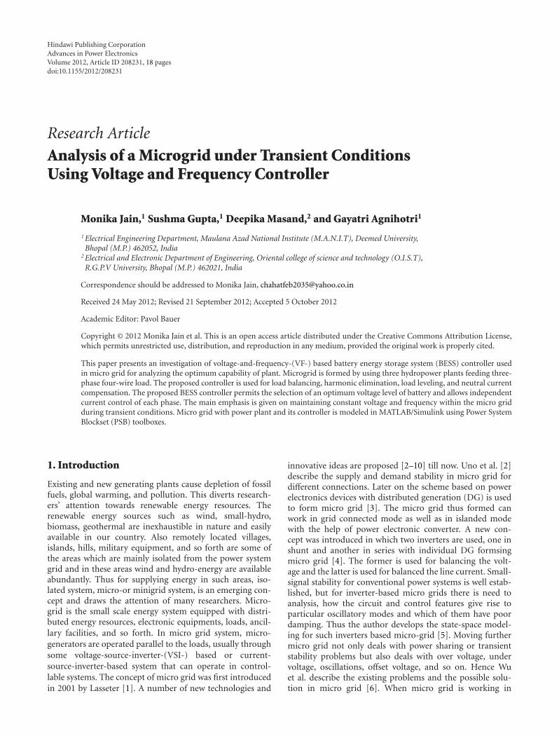
Figure 6: Sub system of MATLAB/Simulink model of hydropower plant using VF based BESS Controller.
own load and is connected to the other micro source throughshort transmission line. Line resistance and reactance is alsoconsidered. The model consists of three hydro power plantseach having induction generator with its prime movers,each of 7.5 kW, 415 V, 50 Hz, 4-pole and each having starconnected capacitor bank to provide reactive power at noload condition. The additional requirement of power duringtransient condition is provided by voltage frequency basedBESS controller. The sub models of DSTATCOM controllersare shown in Figures 6 and 7 which are formed by all equa-tions which are describe in Section 3. The proposed systemis modeled using simulink and PSB toolboxes in MATLABversion of 7.8, in discrete mode at 5e-6 sec step size withode 23tb (stiff/TR-BDF-2) solver along with the saturationcharacteristics of the machine as determined by synchronousspeed test. Available universal bridge is used to model theVSC. Thevenin’s equivalent battery energy storage system ismodeled as in [13, 14, 16, 18] using passive components and
a dc battery. The resistive/inductive balanced/unbalancedload is considered as linear load.
5. Results and Discussion
The performance of the proposed controller in micro gridis demonstrated with balanced/unbalanced linear, nonlinearand dynamic loads. Simulation waveforms for the entirethree micro sources are presented in Figures 8–11. The sub-script 1, 2, 3 are used for plant 1, plant 2, and plant 3. All thewaveforms are represented using these subscripts for all typeof loads. The waveforms consist of generator voltage (Vgabc),generator current (Igabc), load current (ILabc), controller cur-rent (Icabc), load neutral current (ILn), load neutral currentcontroller (ILncc), neutral current (In), terminal voltage (Vt),frequency ( f ), and battery current (Ibat) with respect to time(sec.), presented in the figures. Generator “3” is disconnectedat 2.7 sec and reconnected at 2.9 sec. The voltage and current
8 Advances in Power Electronics
Isn
To Load
+
−
9
7
4Neutral current cont
1 2
3
Contoller
a b
c
In1
In2
In3
Pulse
Hystresis cont
Isaeit
Isbeit
Isceit
Ia
Ib
Ic
Error generator
Vt1 PID [Iq1]
600
4
5
6
Ia
Ib
Ic
[B1]
[C1]
A1
Ub
Uc
Ua
Wa
Wb
Wc
Wa1
[Wb1]
[Wc1]Quadrature comp
1
2
3
Va
Vb
Vb
Vc
Vc
1/Vt1
Ref freq
Ua Ub Uc
In phase comp
Va
Pgen
Freq
Vabc(pu)wt
sin cos
3-phase PLL
-C-
X
PID
[p121]
Freq1
i+−+
−
+
i+
−
i+
−i+
−
+−
+
+
−
− IsnIgen
To Load
A
B
C
Figure 7: Sub system of MATLAB/Simulink model of hydropower plant using VF-based BESS Controller.
of the disconnected generator remain same after connectionto the micro grid. In this paper the following four cases arediscussed.
5.1. Performance of Microgrid with BESS Feeding Bal-anced/Unbalanced Resistive Load. The performance of BESSbased VF controller for micro grid with balanced/unbalancedresistive load is shown in Figures 8(a) and 8(b). Before theapplication of consumer load, the battery consumes all thegenerated active power. Star connected three single phaseload each of 2.5 KW is applied at 2.2 sec. At 2.3 sec onephase is open and later on at 2.4 sec another phase is openhence load becomes unbalanced. Results include chargingand discharging of battery and maintaining load balancing.Later on one by one phases are reconnected to the system.Hence the balanced, unbalanced, and no load conditionvoltage and frequency of the system remain constant.
5.2. Performance of Microgrid with BESS Controller afterRemoving One Micro-Source. The performance of BESSbased VF controller is shown in Figures 8(a) and 8(b). At2.6 sec balanced resistive loads is applied to the system andat 2.7 sec fault is occur between hydro plant “3” and its load“3” so it get disconnected from the rest of the micro source.The plant remains disconnected from “2.7 to 2.9 sec” andagain it is connected to the system at “2.9 sec.” During thedisconnected interval 2.7 sec to 2.9 sec there is dischargingof battery “1” and “2” as they have to share the extra load ofmicro source “3.” As is seen in waveform of Figure 8, terminal
voltage and frequency of the system remain constant evenafter removal of one micro source.
5.3. Performance of Microgrid with BESS Feeding Bal-anced/Unbalanced Reactive Load and Removal of One Micro-Source. Similarly, the performance of BESS based VF con-troller for micro grid with balanced/unbalanced reactive loadis shown in Figures 9(a) and 9(b). Star connected threesingle phase load of each 2.5 KW and 1.87 KVAR is appliedat 2.2 sec. At 2.3 sec one phase is open and later on at 2.4 secanother phase is open hence load becomes unbalanced andresults in charging and discharging of battery, which showsload balancing of BESS fed VF controller. Again at 2.6 secbalanced load is applied to the system. Now at 2.7 sec a3-phase fault occurs between load and hydroplant “3” sothis plant is out of order and unable to support its loadfrom 2.7 sec to 2.9 sec. It is seen from the waveform evenif one plant is off the BESS based VF controller works andsupplies the power during faulty condition. In this way, BESSkeeps the overall generated power constant at the generatorterminal which in turn regulates the system frequency.
5.4. Performance of Microgrid with BESS Feeding Bal-anced/Unbalanced Nonlinear Load and Removal off One MicroSource. Similarly, the performance of BESS based VF con-troller for micro grid with balanced/unbalanced non-linearload is shown in Figures 10(a) and 10(b). Star connectedthree single phase diode rectifier based non-linear load isapplied at 2.2 sec. At 2.3 sec one phase is open and later on

Advances in Power Electronics 9
0500
Generator voltage 1
0500
Generator voltage 2
0500
Generator voltage 3
020
Generator current 1
020
Generator current 2
020
Generator current 3
0
20Load current 1
0
20Load current 2
0
20Load current 3
500550600
Terminal voltage 1
500
550
600Terminal voltage 2
500
550
600Terminal voltage 3
45
50
55Frequency (Hz) 1
45
50
55Frequency (Hz) 2
2.1 2.2 2.3 2.4 2.5 2.6 2.7 2.8 2.9 345
50
55
Generator voltage 2
Generator voltage 3
Generator current 1
Generator current 2
Generator current 3
Load current 1
Load current 2
Load current 3
Terminal voltage 1
Terminal voltage 2
Terminal voltage 3
Frequency (Hz) 1
Frequency (Hz) 2
Frequency (Hz) 3
−500
−500
−20
−20
−20
−20
−20
−20
−500
Time (s)
Vgabc
1Vgabc
2Vgabc
3I gabc1
I gabc2
I gabc3
I Labc1
I Labc2
I Labc3
Vt1
Vt2
Vt3
f 1f 2
f 3
(a)
Figure 8: Continued.

10 Advances in Power Electronics
020
Controller current 1
020
Controller current 2
020
Controller current 3
020
Load neutral current 1
020
Load neutral current 2
0
20Load neutral current 3
0
20Load neutral current controller 1
0
20Load neutral current controller 2
0
20Load neutral current controller 3
024
Neutral current 1
Neutral current 2
Neutral current 3
0
20
40Battery current 1
Battery current 2
Controller current 2
Controller current 3
Load neutral current 1
Load neutral current 2
Load neutral current 3
Load neutral current controller 1
Load neutral current controller 2
Load neutral current controller 3
Neutral current 1
Neutral current 2
Neutral current 3
Battery current 1
Battery current 2
Time (s)
Battery current 3
−20
−20
−20
−20
−20
−20
−20
−20
−20
−2−4
024
−2−4
024
−2−4
−20
−40
0
20
40
−20
−40
0
20
40
−20
−40
2.1 2.2 2.3 2.4 2.5 2.6 2.7 2.8 2.9 3
I cabc1
I cabc2
I cabc3
I Ln
1I L
n2
I Ln
3I L
ncc
1I L
ncc
2I L
ncc
3I n
1I n
2I n
3I b
at1
I bat
2I b
at3
(b)
Figure 8: (a) Transient waveform of microgrid with BESS based VFC feeding balanced/unbalanced resistive load and shunting of one plant.(b) Transient waveform of microgrid with BESS based VFC feeding balanced/unbalanced resistive load and shunting of one plant.

Advances in Power Electronics 11
Generator voltage 1
Generator voltage 2
Generator voltage 3
Generator current 1
Generator current 2
Generator current 3
Load current 1
Load current 2
Load current 3
Terminal voltage 1
Terminal voltage 2
Terminal voltage 3
Frequency (Hz) 1
Frequency (Hz) 2
Generator voltage 2
Generator voltage 3
Generator current 1
Generator current 2
Generator current 3
Load current 1
Load current 2
Load current 3
Terminal voltage 1
Terminal voltage 2
Terminal voltage 3
Frequency (Hz) 1
Frequency (Hz) 2
Frequency (Hz) 3
0500
500
550
600
500
550
600
500550600
45
50
55
45
50
55
2.1 2.2 2.3 2.4 2.5 2.6 2.7 2.8 2.9 345
50
55
−500
Time (s)
0500
−500
0500
−500
020
020
020
020
020
020
−20
−20
−20
−20
−20
−20
Vgabc
1Vgabc
2Vgabc
3I gabc1
I gabc2
I gabc3
I Labc1
I Labc2
I Labc3
Vt1
Vt2
Vt3
f 1f 2
f 3
(a)
Figure 9: Continued.

12 Advances in Power Electronics
020
Controller current 1
020
Controller current 2
020
Controller current 3
0
20
020
0
20
020
0
20
020
024
0
20
40Battery current 1
Battery current 2
Time (s)
Battery current 3
−20
−20
−20
−20
−20
−20
−20
−20
−20
−2−4
024
−2−4
024
−2−4
−20
−40
0
20
40
−20
−40
0
20
40
−20
−40
2.1 2.2 2.3 2.4 2.5 2.6 2.7 2.8 2.9 3
I cabc1
I cabc2
I cabc3
I Ln
1I L
n2
I Ln
3I L
ncc
1I L
ncc
2I L
ncc
3I n
1I n
2I n
3I b
at1
I bat
2I b
at3
Load neutral current 1
Load neutral current 2
Load neutral current 3
Load neutral current controller 1
Load neutral current controller 2
Load neutral current controller 3
Neutral current 1
Neutral current 2
Neutral current 3
(b)
Figure 9: (a) Transient waveform of microgrid with BESS based VFC feeding balanced/unbalanced reactive load and removal of one plant.(b) Transient waveform of microgrid with BESS based VFC feeding balanced/unbalanced reactive load and removal of one plant.

Advances in Power Electronics 13
Generator voltage 1
Generator voltage 2
Generator voltage 3
Generator current 1
Generator current 2
Generator current 3
Load current 1
Load current 2
Load current 3
Terminal voltage 1
Terminal voltage 2
Terminal voltage 3
Frequency (Hz) 1
Frequency (Hz) 2
Frequency (Hz) 3
0500
500
550
600
500
550
600
500
550
600
45
50
55
45
50
55
2.1 2.2 2.3 2.4 2.5 2.6 2.7 2.8 2.9 345
50
55
−500
Time (s)
0500
−500
0500
−500
020
−20
02040
−20−40
02040
−20−40
02040
−20−40
02040
−20−40
02040
−20−40
Vgabc
1Vgabc
2Vgabc
3I gabc1
I gabc2
I gabc3
I Labc1
I Labc2
I Labc3
Vt1
Vt2
Vt3
f 1f 2
f 3
(a)
Figure 10: Continued.

14 Advances in Power Electronics
Controller current 1
Controller current 2
Controller current 3
024
0
20
40Battery current 1
Battery current 2
Time (s)
Battery current 3
−2−4
024
−20
−40
0
50
−50
2.1 2.2 2.3 2.4 2.5 2.6 2.7 2.8 2.9 3
−2−4
024
−2−4
02040
−20−40
02040
−20−40
02040
−20−40
02040
−20−40
02040
−20−40
02040
−20−40
02040
−20−40
02040
−20−40
02040
−20−40
0
50
−50
I cabc1
I cabc2
I cabc3
I Ln
1I L
n2
I Ln
3I L
ncc
1I L
ncc
2I L
ncc
3I n
1I n
2I n
3I b
at1
I bat
2I b
at3
Load neutral current 1
Load neutral current 2
Load neutral current 3
Load neutral current controller 1
Load neutral current controller 2
Load neutral current controller 3
Neutral current 1
Neutral current 2
Neutral current 3
(b)
Figure 10: (a) Transient waveform of microgrid with BESS based VFC feeding balanced/unbalanced nonlinear load and removal of oneplant. (b) Transient waveform of microgrid with BESS based VFC feeding balanced/unbalanced nonlinear load and removal of one plant.

Advances in Power Electronics 15
Generator voltage 1
Generator voltage 2
Generator voltage 3
Generator current 1
Generator current 2
Generator current 3
Load current 1
Load current 2
Load current 3
Terminal voltage 1
Terminal voltage 2
Terminal voltage 3
Frequency (Hz) 1
Frequency (Hz) 2
Frequency (Hz) 3
0500
500
550
600
500
550
600
500
550
600
45
50
55
45
50
55
2.1 2.2 2.3 2.4 2.5 2.6 2.7 2.8 2.9 345
50
55
−500
Time (s)
0500
−500
0500
−500
0
20
0
20
0
20
−20
−20
−20
02040
−20−40
02040
−20−40
02040
−20−40
Vgabc
1Vgabc
2Vgabc
3I gabc1
I gabc2
I gabc3
I Labc1
I Labc2
I Labc3
Vt1
Vt2
Vt3
f 1f 2
f 3
(a)
Figure 11: Continued.
16 Advances in Power Electronics
Controller current 1
Controller current 2
Controller current 3
Load torque 1
Load torque 2
Load torque 3
Battery current 1
Battery current 2
Time (s)
Battery current 3
2.1 2.2 2.3 2.4 2.5 2.6 2.7 2.8 2.9 3
1000
−100
1000
−100
200
0−200
200100
0
200100
0
200100
0
100
50
0
−50
−100
100
0
−100
200
0
−200
TL1
TL2
TL3
I cabc1
I cabc2
I cabc3
I bat
1I b
at2
I bat
3
(b)
Figure 11: (a) Transient waveform of microgrid with BESS based VFC feeding balanced dynamic load and removal of one plant. (b) Transientwaveform of microgrid with BESS based VFC feeding balanced dynamic load and removal of one plant.
at 2.4 sec another phase is open hence load becomes unbal-anced and results in charging and discharging of battery,which shows load balancing of BESS fed VF controller. Againat 2.6 sec balanced load is applied to the system. Now at2.7 sec a 3-phase fault occurs between load and hydroplant“3” so this plant is out of order and unable to support its loadfrom 2.7 sec to 2.9 sec. As is seen from the waveform evenif one plant is off the BESS based VF controller works andsupplies the power during faulty condition. In this way, BESSkeeps the overall generated power constant at the generatorterminal which in turn regulates the system frequency.
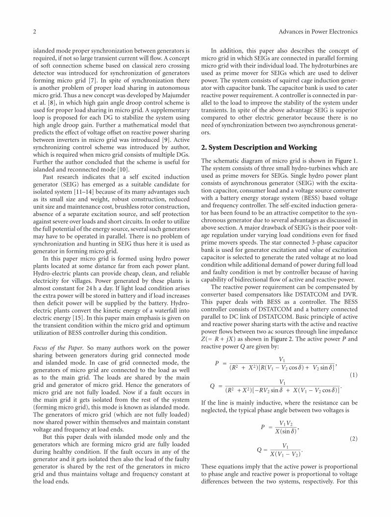
5.5. Performance of Microgrid with BESS Feeding BalanceDynamic Load and Removal of One Micro-Source. Theperformance of BESS controller for micro grid with balanced
dynamic load is shown in Figures 11(a) and 11(b). At2.2 sec direct on line starting of induction motor of 2 kW,50 Hz asynchronous motor is applied and sudden changesare observed in load current, due to high starting current.A minor discharge of battery is observed to regulate thefrequency but after 4-5 cycles when sudden starting currentis controlled, voltage and current at the generator terminalremain constant. At 2.4 sec load torque is 75 Nm and at 2.4it is increased to 157 Nm; if it is applied on the motor shaftthen the motor load current is increased but the controllerperformance is desirable. Now at 2.7 sec a 3-phase faultoccurs between load and hydro plant “3” so this plant is outof order and unable to support its load from 2.7 sec to 2.9 sec.As is seen from the waveform even if one plant is off the BESSbased VF controller works and supplies the power to load

Advances in Power Electronics 17
during faulty condition. In this way, BESS keeps the overallgenerated power constant at the generator terminal which inturn regulates the system frequency.
6. Conclusion
A detailed analysis of a micro grid with three micro sourcesunder different load conditions is dealt with in this paper.The proposed BESS controller based voltage and frequencywith each micro source regulates the terminal voltage andfrequency of the source and hence stabilizes the micro grid.The mathematical model for BESS controller is analyzed fortransient and dynamic condition. The controller providesdesirable feature of synchronous condenser operating incapacitive and inductive modes. The capability of BESSbased VF controller is demonstrated for load balancing, loadleveling, and harmonic eliminations in linear, nonlinear, anddynamic loads. The BESS controller also works satisfactorilyduring removal of one micro source but as the whole systemis connected in parallel other controller shares the load ofthat removed power generating plant and hence maintainsthe voltage and frequency of the whole system constant.Though due to battery energy storage system the size andthe cost of the controller is increased but reliability ofsystem with its VF control, outweighs this added cost. Theimplementation of this technology reinforces the use of suchsystem where the grid connection has not reached yet andalso in remote areas where renewable sources are available inabundance.
Appendix
(I) Machine parameters: 7.5 kW, 415 V, 50 Hz, Y-con-nected, 4-pole, Rs = 1Ω, Rr = 0.77Ω, Xlr = Xls =1.5Ω, J = 0.1384 kg-m2.
(II) Controller parameters:
Kpf = 2, Kif = 10,
Kpd = 0.02, Kid = 0.0025.
(I) Battery parameters:
L f = 4 mH, Rf = 0.1Ω and Cdc = 4000μf, R1 =10 K,
Ro = 0.01Ω, Cbat = 5760 F.
(IV) Consumer Loads
(a) Resistive load = 2.5 kW single phase loads.
(b) Reactive load = 2.5 kW, 1.875 KVAR 0.8 PFlagging single phase loads.
(c) Nonlinear load = 2.5 kW with 100 μF capacitorand 8 mH inductor at DC end of single phasediode rectifier.
(d) Dynamic load = induction motor 2 kW, 50 Hz,4 pole, 415 V.
References
[1] B. Lasseter, “Microgrids (distributed power generation),” inProceedings of IEEE Power Engineering Society Winter Meeting,vol. 1, pp. 146–149, Columbus, Ohio, USA, February 2001.
[2] Y. Uno, G. Fujita, R. Yokoyama, M. Matubara, T. Toyoshima,and T. Tsukui, “Evaluation of micro-grid supply and demandstability for different interconnections,” in Proceedings of theIEEE International Power and Energy Conference (PECon ’06),pp. 612–617, November 2006.
[3] F. Katiraei, M. R. Iravani, and P. W. Lehn, “Micro-grid auto-nomous operation during and subsequent to islanding pro-cess,” IEEE Transactions on Power Delivery, vol. 20, no. 1, pp.248–257, 2005.
[4] Y. Wei Li, D. M. Vilathgamuwa, and P. Chiang Loh, “A grid-interfacing power quality compensator for three-phase three-wire microgrid applications,” IEEE Transactions on Power Elec-tronics, vol. 21, no. 4, pp. 1021–1031, 2006.
[5] N. Pogaku, M. Prodanovic, and T. C. Green, “Modeling, ana-lysis and testing of autonomous operation of an inverter-basedmicrogrid,” IEEE Transactions on Power Electronics, vol. 22, no.2, pp. 613–625, 2007.
[6] C. X. Wu, F. S. Wen, and Y. L. Lou, “The existed problems andpossible solutions of micro-grid based on distributed genera-tion,” in Proceedings of the 3rd International Conference onDeregulation and Restructuring and Power Technologies (DRPT’08), pp. 2763–2768, April 2008.
[7] B. Adhikary, B. Ghimire, and P. Karki, “Interconnection oftwo micro hydro units forming a mini-grid system usingsoft connection,” in Proceedings of IEEE Region 10 Conference(TENCON ’09), November 2009.
[8] R. Majumder, B. Chaudhuri, A. Ghosh, R. Majumder, G.Ledwich, and F. Zare, “Improvement of stability and load shar-ing in an autonomous microgrid using supplementary droopcontrol loop,” IEEE Transactions on Power Systems, vol. 25, no.2, pp. 796–808, 2010.
[9] S. V. Iyer, M. N. Belur, and M. C. Chandorkar, “Analysis andmitigation of voltage offsets in multi-inverter microgrids,”IEEE Transactions on Energy Conversion, vol. 26, no. 1, pp.354–363, 2011.
[10] C. Cho, J.-H. Jeon, J-Y. Kim, S. Kwon, K. Park, and S. Kim,“Active synchronizing control of a microgrid,” IEEE Transac-tions on Power Electronics, vol. 26, no. 12, pp. 3707–3719, 2011.
[11] C. V. Nayar, J. Perahia, F. Thomas, S. J. Phillips, T. Pryor, andW. L. James, “Investigation of capacitor-excited induction gen-erators and permanent magnet alternators for small scale windpower generation,” Renewable Energy, vol. 1, no. 3-4, pp. 381–388, 1991.
[12] A. Chandra, B. Singh, B. N. Singh, and K. A. Haddad, “Animproved control algorithm of shunt active filter for voltageregulation, harmonic elimination, power-factor correction,and balancing of nonlinear loads,” IEEE Transactions on PowerElectronics, vol. 15, no. 3, pp. 495–507, 2000.
[13] B. Singh, G. Kasal, A. Chandra, and K. Haddad, “Battery basedvoltage and frequency controller for parallel operated isolatedasynchronous generators,” in Proceedings of IEEE InternationalSymposium on Industrial Electronics (ISIE ’07), pp. 883–888,June 2007.
[14] B. Singh and G. K. Kasal, “Voltage and frequency controller fora three-phase four-wire autonomous wind energy conversionsystem,” IEEE Transactions on Energy Conversion, vol. 23, no.2, pp. 509–518, 2008.
[15] P. K. Goel, B. Singh, S. S. Murthy, and N. Kishore, “Isolatedwind-hydro hybrid system using cage generators and battery

18 Advances in Power Electronics
storage,” IEEE Transactions on Industrial Electronics, vol. 58,no. 4, pp. 1141–1153, 2011.
[16] M. D. Aderson and D. S. Carr, “Battery energy storage techno-logy,” Proceedings of the IEEE, vol. 18, no. 3, pp. 475–479, 1993.
[17] M. Ceraolo, “New dynamical models of lead-acid batteries,”IEEE Transactions on Power Systems, vol. 15, no. 4, pp. 1184–1190, 2000.
[18] N. Jantharamin and L. Zhang, “A new dynamic model for lead-acid batteries,” in Proceedings of the 4th IET International Con-ference on Power Electronics, Machines and Drives (PEMD ’08),pp. 86–90, April 2008.

International Journal of
AerospaceEngineeringHindawi Publishing Corporationhttp://www.hindawi.com Volume 2010
RoboticsJournal of
Hindawi Publishing Corporationhttp://www.hindawi.com Volume 2014
Hindawi Publishing Corporationhttp://www.hindawi.com Volume 2014
Active and Passive Electronic Components
Control Scienceand Engineering
Journal of
Hindawi Publishing Corporationhttp://www.hindawi.com Volume 2014
International Journal of
RotatingMachinery
Hindawi Publishing Corporationhttp://www.hindawi.com Volume 2014
Hindawi Publishing Corporation http://www.hindawi.com
Journal ofEngineeringVolume 2014
Submit your manuscripts athttp://www.hindawi.com
VLSI Design
Hindawi Publishing Corporationhttp://www.hindawi.com Volume 2014
Hindawi Publishing Corporationhttp://www.hindawi.com Volume 2014
Shock and Vibration
Hindawi Publishing Corporationhttp://www.hindawi.com Volume 2014
Civil EngineeringAdvances in
Acoustics and VibrationAdvances in
Hindawi Publishing Corporationhttp://www.hindawi.com Volume 2014
Hindawi Publishing Corporationhttp://www.hindawi.com Volume 2014
Electrical and Computer Engineering
Journal of
Advances inOptoElectronics
Hindawi Publishing Corporation http://www.hindawi.com
Volume 2014
The Scientific World JournalHindawi Publishing Corporation http://www.hindawi.com Volume 2014
SensorsJournal of
Hindawi Publishing Corporationhttp://www.hindawi.com Volume 2014
Modelling & Simulation in EngineeringHindawi Publishing Corporation http://www.hindawi.com Volume 2014
Hindawi Publishing Corporationhttp://www.hindawi.com Volume 2014
Chemical EngineeringInternational Journal of Antennas and
Propagation
International Journal of
Hindawi Publishing Corporationhttp://www.hindawi.com Volume 2014
Hindawi Publishing Corporationhttp://www.hindawi.com Volume 2014
Navigation and Observation
International Journal of
Hindawi Publishing Corporationhttp://www.hindawi.com Volume 2014
DistributedSensor Networks
International Journal of