Embed Size (px)
Citation preview

Abstract—The aim of this paper is the analysis of the aero
dynamical behavior of some improvements designed for heavy vehicle semi-trailer tankers. These improvements reduce the drag coefficient and then the vehicle use less fuel (a 11% less)
In this process the vehicle has been analyzed without aerodynamic improvements to detect the zones that have a higher vorticity and the highest flux detachment to act in these zones and with two different vehicle tanker configurations.
There have been analyzed three different types of aerodynamic configurations: a nose cone, a underskirt and a boat tail; they have been analyzed separately and together; this allows to obtain separately the contribution of each improvement and finally it has been obtained a 23% of drag reduction.
For each case it has been obtained the flux shape, the particle velocity, the turbulence,… using the most accuracy fluid mechanical model.
Index Terms— tanker, aerodynamic, improvements, heavy vehicle.
I. INTRODUCTION
HE aerodynamic has been a field of study tied since its beginnings to the aerospace engineering; nowadays
some aspects like the increase in the price of the fuels, the greenhouse effect, etc. have reverberated in the car industry promoting the production of the least pollutant and more energetically efficient vehicles. This has forced to modify some designs criterions of the vehicles, forcing to develop and apply new design technologies between which one it is the aerodynamics. For higher dimension vehicles, there has not been such a significant development of their aerodynamics being this one a fundamental aspect to development more ecological vehicles in the future, with consumption a 15% smaller (1). It is necessary to take in mind that, the aerodynamic improvements allow to in addition the stability of the vehicles, to reduce the effect of the aerodynamics on other vehicles in the road, the splashes, to improve the vehicle lateral wind behavior, etc. These aspects have been considered to be fundamental to realize an aerodynamic analysis of the tanker and to develop some improvements that will increase the aerodynamics of the vehicle.
II. MAIN SEMITRAILER AERODINAMIC IMPROVEMENTS
The main aerodynamic improvements that exist now are
Manuscript received March 04, 2012; revised April 10, 2012. R. Miralbes: Author is a professor with the Design and Manufacturing
Department of the University of Zaragoza (Spain) (corresponding author to provide phone: +34/976761907; e-mail: [email protected]).
applied in square-box semi-trailers, so they will have to be adapted for the use with tankers. Of them, we will study the boat tails, the aerodynamic skirts and the noses cones.
A. The Boat Tails
These elements act avoiding the detachment of the limit layer in the later zone of the box avoiding the pressure gradient that would generate vorticity and re-leading the flow to prevent it from becoming detached. Several configurations exist: later sheets (up to 4 % of improvement) and rounded profiles (up to 5 %)
Fig. 1 – Boat tails
B. Nose Cones
They are aerodynamic elements that are placed in the front top zone of the semi-trailer, and they re-direct the air and prevent it from getting inside the King-Pin gap. They allow an aerodynamic improvement higher than a 3 %.
Fig. 2 – Nose cone
C. Undercarriadge Skirt
They are some parts that prevent the air to go inside the lower zone of the vehicle. So the air flow diminishes for the
Analysis of Some Aerodynamic Improvements for Semi-trailer Tankers
R. Miralbes
T
Proceedings of the World Congress on Engineering 2012 Vol III WCE 2012, July 4 - 6, 2012, London, U.K.
ISBN: 978-988-19252-2-0 ISSN: 2078-0958 (Print); ISSN: 2078-0966 (Online)
WCE 2012
above mentioned zone, which would generate due to the wheels and due to the diverse pieces of the low zone of the vehicle a turbulent flow that it affects negatively to the vehicle aerodynamic. It is obtained up to a 7 % improvement.
Fig. 3 – Undercarriadge Skirt
III. CFD AERODYNAMIC CALCULUS
METHODOLOGY
For the CFD aerodynamic analysis of the vehicle and of his possible modifications, a commercial CFD program has been used. With regard to the method followed for the modeling, discretization and calculus of the vehicle has used the following methodology:
A. CAD model
The first step to do the analysis is to obtain the CAD shaped of the exterior zone of the vehicle, eliminated and simplifying certain elements like the rear-view mirrors of the vehicle, the indicators, muffs and other auxiliary elements because their modeling would be implied by an excessively refined finite element model[2,3]. For this case it has been made a CADE model with their main dimensions obtained from a tanker vehicle of the company CRYO-ENERGY S.A., and it has been added an average range tractor cap.
B. Volumetric finite elements discretization
To make the volumetric FE model it has been used the CAD geometry of the vehicle and it has been located inside a volume that simulates the air outside the vehicle. For it depending on the recommendations of some authors (2,3) and the program ones (4), in the air volume there must be a distance between the frontal of the vehicle and the air inlet of 2.000 mm and between the end of the vehicle and the air outlet of 10.000 mm in order to gather perfectly the stele that generates the vehicle. About the lateral and upper distance it must be at least 4.000 mm from the exterior tangent surface.
C. Aerodynamic analysis
To make the aerodynamic calculation it is necessary to realize some tasks before proceeding with the calculation and before the solution model. There has been chosen a “segregated” model solution that allows to reduce the computational needs and that it is recommended for this type of calculations, using a calculation with double precision (5), for a stationary model based on calculation in nodes, which it is recommended by the program to obtain better results. There has used a turbulence model based on the equations RANS of type k-ε Realizable (5). With regard to the walls it has been used a “Non Equilibrated Wall” model.
About the contour conditions, because there are some zones, each one has different contour conditions. On the one hand for the inlet surface, an air flow with constant speed (30 m/s) in tangential direction, with a very small turbulence (0.1 %) has been used. With regard to the top, lateral and button zones, they have been simulated like opened outside with a pressure of 1 atm. and with an air flow of 30 m/s in the corresponding direction. The ground has been modeled as a smooth surface that moves with the same speed that the fluid (30 m/s). (6). The wheels have been considered to be smooth and mobile surfaces, that they force a draft in his coherent center with the speed of the vehicle. The other surfaces of the vehicle have been considered to be fixed and smooth walls and it has been used a symmetry condition to reduce the computational cost of the model. It has been chosen an algorithm of resolution of type Simple-C (4), to solve the fields of pressure - speed that is the scheme of resolution indicated for discretizations with elements not aligned with the flow; in addition being in use schemes of the discretization standard for the resolution of the pressures and of the second order for the calculations at the moment and of turbulence. These parameters are the recommended ones for the program.
IV. ADJUSTMENT OF THE AERODYNAMIC IMPROVEMENTS TO
THE TANKERS
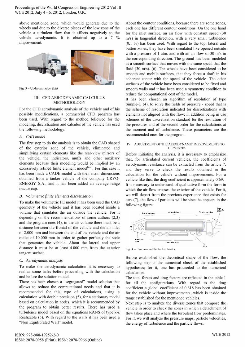
Before initiating the analysis, it is necessary to emphasize that, for articulated current vehicles, the coefficients of aerodynamic resistance can be extracted from the article 7, and they serve to check the results obtained in the calculation for the vehicle without improvements. For a vehicle like this, the drag coefficient is approximately 0.69. It is necessary to understand of qualitative form the form in which the air flow crosses the exterior of the vehicle. For it, we will depart from the previous experience that exists for cars (7), the flow of particles will be since he appears in the following figure.
Fig. 4 – Flux around the tanker trailer
Before established the theoretical shape of the flow, the following step is the numerical check of the established hypotheses; for it, one has proceeded to the numerical calculation. The total forces and drag factors are reflected in the table 1 for all the configurations. With regard to the drag coefficient a global coefficient of 0.618 has been obtained for the vehicle without improvements, which is inside the range established for the mentioned vehicles. Next step is to analyze the diverse zones that compose the vehicle in order to check the zones in which a detachment of flow takes place and where the turbulent flow predominates. For it, we will analyze the pressure maps, particle velocities, the energy of turbulence and the particle flows.
Proceedings of the World Congress on Engineering 2012 Vol III WCE 2012, July 4 - 6, 2012, London, U.K.
ISBN: 978-988-19252-2-0 ISSN: 2078-0958 (Print); ISSN: 2078-0966 (Online)
WCE 2012

Fig. 5 – Longitudinal velocity in the symmetry plane for the vehicle without improvements.
It is possible to observe in the figure 5, the low velocity zones, that are the low zone of the vehicle, the zone of the king-pin gap and the stele of the tanker, like it was predicted previously and that they will be the zones in which higher turbulence exists. Also a zone of low velocity is observed in the frontal zone, the detachment of the limit layer on the cabin, in the back part of the vehicle and in the lower zone of tractor and the "hooking" of the flow in the top part of the cistern. On the other hand, they are observed in the edges of the road tractor high speeds of the fluid.
Fig. 6 – K turbulence parameter for the configuration without improvements in the symmetry plane
Also it is necessary to highlight the analysis of the zone of wheels that is a zone in the one where predominates the turbulent flow, as the figure 7 testifies. In addition a detachment of the cap can observe limit in the zones near to the wheels and in the low part of the vehicle; it finalizes this one is due to the discontinuity between the tractor and the semi-trailer.
Fig. 7 – K turbulence parameter for the configuration without improvements in a horizontal plane at the wheel height.
After realizing this analysis, it has concluded that the hypotheses of flow established previously are correct, for what it would be necessary to act on the zones of the gap of the king-pin and of the wheels to reduce the aerodynamic losses of the vehicle. With regard to the zone of the stele of the vehicle, no initial action will be realized, since he presents a correct streamline; for the configuration with box
in the later zone, it presents a major detachment of flow and a major turbulence, which should be avoided. The aerodynamic elements that will be studied especially will be the aerodynamic skirts. Also there will be designed for the configuration of vehicle by posterior box an aerodynamic modification, based on the boat tail which is going to be named " aerodynamic adapter for the rear box"; on the other hand, an aerodynamic improvement will be designed for the front zone of the vehicle that avoids the vorticity and the detachment of the cap borders, based on the aerodynamic noses and that we will name a "aerodynamic forehead".
A. The underskirt
Nowadays all the new construction semi-trailers must introduce measures for lateral protection that they find in agreement with the board 98/297/CEE. These elements of protection present an aerodynamic penalty since the detachment of flow due to the discontinuities. In addition, the existence of gaps in the zone of the wheels, allows the air introduction in these zones, and therefore, an aerodynamic penalty; it is for it that will be tried by means of the aerodynamic skirts, to reduce the air flow in the zone. For it, it has proposed the following aerodynamic improvement:
Fig. 8 – Aerodynamic skirt for the configuration with box in the lower zone
It has been proposed a skirt with a constant surface from the front zone of the semi-trailer to the button zone of the same one, formed by three clearly differentiated zones. On having analyzed the obtained results is observed that it decreases the K turbulence parameter in the lower zone of the vehicle (see figures 7 and 9). This indicates a decreasing of the turbulence in the zone, and so a decreasing of the aerodynamic losses.
Fig. 9 – K turbulence parameter in the zone of the aerodynamic skirt
Proceedings of the World Congress on Engineering 2012 Vol III WCE 2012, July 4 - 6, 2012, London, U.K.
ISBN: 978-988-19252-2-0 ISSN: 2078-0958 (Print); ISSN: 2078-0966 (Online)
WCE 2012
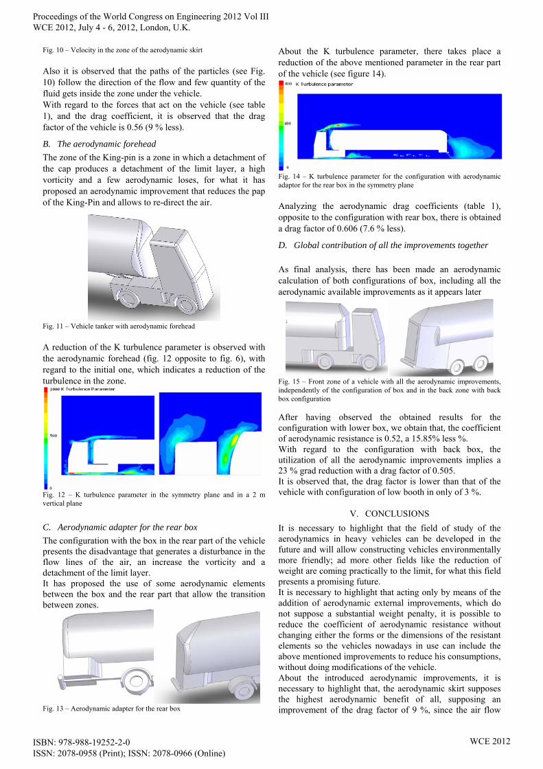
Fig. 10 – Velocity in the zone of the aerodynamic skirt
Also it is observed that the paths of the particles (see Fig. 10) follow the direction of the flow and few quantity of the fluid gets inside the zone under the vehicle. With regard to the forces that act on the vehicle (see table 1), and the drag coefficient, it is observed that the drag factor of the vehicle is 0.56 (9 % less).
B. The aerodynamic forehead
The zone of the King-pin is a zone in which a detachment of the cap produces a detachment of the limit layer, a high vorticity and a few aerodynamic loses, for what it has proposed an aerodynamic improvement that reduces the pap of the King-Pin and allows to re-direct the air.
Fig. 11 – Vehicle tanker with aerodynamic forehead
A reduction of the K turbulence parameter is observed with the aerodynamic forehead (fig. 12 opposite to fig. 6), with regard to the initial one, which indicates a reduction of the turbulence in the zone.
Fig. 12 – K turbulence parameter in the symmetry plane and in a 2 m vertical plane
C. Aerodynamic adapter for the rear box
The configuration with the box in the rear part of the vehicle presents the disadvantage that generates a disturbance in the flow lines of the air, an increase the vorticity and a detachment of the limit layer. It has proposed the use of some aerodynamic elements between the box and the rear part that allow the transition between zones.
Fig. 13 – Aerodynamic adapter for the rear box
About the K turbulence parameter, there takes place a reduction of the above mentioned parameter in the rear part of the vehicle (see figure 14).
Fig. 14 – K turbulence parameter for the configuration with aerodynamic adaptor for the rear box in the symmetry plane
Analyzing the aerodynamic drag coefficients (table 1), opposite to the configuration with rear box, there is obtained a drag factor of 0.606 (7.6 % less).
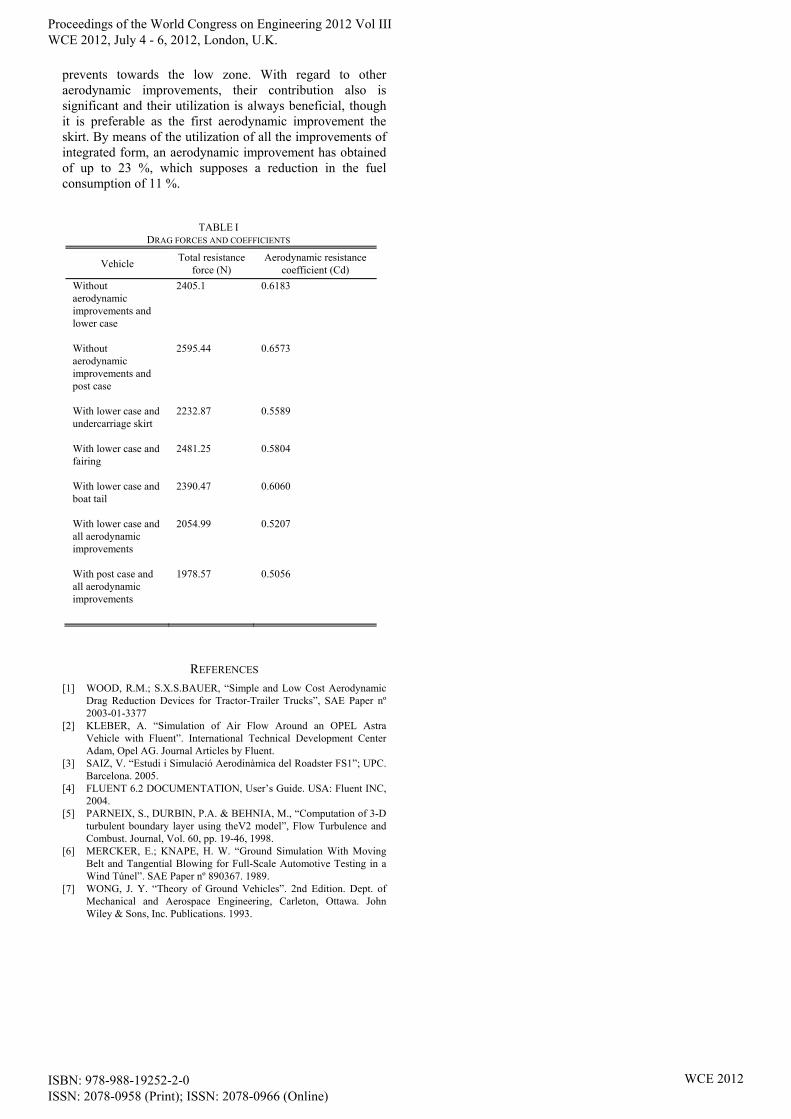
D. Global contribution of all the improvements together
As final analysis, there has been made an aerodynamic calculation of both configurations of box, including all the aerodynamic available improvements as it appears later
Fig. 15 – Front zone of a vehicle with all the aerodynamic improvements, independently of the configuration of box and in the back zone with back box configuration
After having observed the obtained results for the configuration with lower box, we obtain that, the coefficient of aerodynamic resistance is 0.52, a 15.85% less %. With regard to the configuration with back box, the utilization of all the aerodynamic improvements implies a 23 % grad reduction with a drag factor of 0.505. It is observed that, the drag factor is lower than that of the vehicle with configuration of low booth in only of 3 %.
V. CONCLUSIONS
It is necessary to highlight that the field of study of the aerodynamics in heavy vehicles can be developed in the future and will allow constructing vehicles environmentally more friendly; ad more other fields like the reduction of weight are coming practically to the limit, for what this field presents a promising future. It is necessary to highlight that acting only by means of the addition of aerodynamic external improvements, which do not suppose a substantial weight penalty, it is possible to reduce the coefficient of aerodynamic resistance without changing either the forms or the dimensions of the resistant elements so the vehicles nowadays in use can include the above mentioned improvements to reduce his consumptions, without doing modifications of the vehicle. About the introduced aerodynamic improvements, it is necessary to highlight that, the aerodynamic skirt supposes the highest aerodynamic benefit of all, supposing an improvement of the drag factor of 9 %, since the air flow
Proceedings of the World Congress on Engineering 2012 Vol III WCE 2012, July 4 - 6, 2012, London, U.K.
ISBN: 978-988-19252-2-0 ISSN: 2078-0958 (Print); ISSN: 2078-0966 (Online)
WCE 2012
prevents towards the low zone. With regard to other aerodynamic improvements, their contribution also is significant and their utilization is always beneficial, though it is preferable as the first aerodynamic improvement the skirt. By means of the utilization of all the improvements of integrated form, an aerodynamic improvement has obtained of up to 23 %, which supposes a reduction in the fuel consumption of 11 %.
REFERENCES [1] WOOD, R.M.; S.X.S.BAUER, “Simple and Low Cost Aerodynamic
Drag Reduction Devices for Tractor-Trailer Trucks”, SAE Paper nº 2003-01-3377
[2] KLEBER, A. “Simulation of Air Flow Around an OPEL Astra Vehicle with Fluent”. International Technical Development Center Adam, Opel AG. Journal Articles by Fluent.
[3] SAIZ, V. “Estudi i Simulació Aerodinàmica del Roadster FS1”; UPC. Barcelona. 2005.
[4] FLUENT 6.2 DOCUMENTATION, User’s Guide. USA: Fluent INC, 2004.
[5] PARNEIX, S., DURBIN, P.A. & BEHNIA, M., “Computation of 3-D turbulent boundary layer using theV2 model”, Flow Turbulence and Combust. Journal, Vol. 60, pp. 19-46, 1998.
[6] MERCKER, E.; KNAPE, H. W. “Ground Simulation With Moving Belt and Tangential Blowing for Full-Scale Automotive Testing in a Wind Túnel”. SAE Paper nº 890367. 1989.
[7] WONG, J. Y. “Theory of Ground Vehicles”. 2nd Edition. Dept. of Mechanical and Aerospace Engineering, Carleton, Ottawa. John Wiley & Sons, Inc. Publications. 1993.
TABLE I DRAG FORCES AND COEFFICIENTS
Vehicle Total resistance
force (N) Aerodynamic resistance
coefficient (Cd)
Without aerodynamic improvements and lower case
2405.1 0.6183
Without aerodynamic improvements and post case
2595.44 0.6573
With lower case and undercarriage skirt
2232.87 0.5589
With lower case and fairing
2481.25 0.5804
With lower case and boat tail
2390.47 0.6060
With lower case and all aerodynamic improvements
2054.99 0.5207
With post case and all aerodynamic improvements
1978.57 0.5056
Proceedings of the World Congress on Engineering 2012 Vol III WCE 2012, July 4 - 6, 2012, London, U.K.
ISBN: 978-988-19252-2-0 ISSN: 2078-0958 (Print); ISSN: 2078-0966 (Online)
WCE 2012