Embed Size (px)
Citation preview
Analysis of Interacting Cracks Using the Generalized Finite Element
Method with Global-Local Enrichment Functions∗
Dae-Jin Kim, Carlos Armando Duarte,† and Jeronymo Peixoto Pereira
Department of Civil and Environmental Engr.,
University of Illinois at Urbana-Champaign, Newmark Laboratory,
205 North Mathews Avenue, Urbana, Illinois 61801, USA
(Dated: January 9, 2008)
Abstract
This paper presents an analysis of interacting cracks usinga generalized finite element method (GFEM)
enriched with so-called global-local functions. In this approach, solutions of local boundary value problems
computed in a global-local analysis are used to enrich the global approximation space through the partition
of unity framework used in the GFEM. This approach is relatedto the global-local procedure in the FEM,
which is broadly used in industry to analyze fracture mechanics problems in complex three-dimensional
geometries. In this paper, we compare the effectiveness of the global-local FEM with the GFEM with
global-local enrichment functions. Numerical experiments demonstrate that the latter is much more robust
than the former. In particular, the GFEM is less sensitive tothe quality of boundary conditions applied
to the local problems than the global-local FEM. Stress intensity factors computed with the conventional
global-local approach showed errors of up to one order of magnitude larger than in the case of the GFEM.
The numerical experiments also demonstrate that the GFEM can account for interactions among cracks
with different scale sizes, even when not all cracks are modeled in the global domain.
∗Dedicated to Professor Fazil Erdogan for his seminal contributions to the analysis of fracture mechanics problems.†Corresponding author.; e-mail:[email protected]
1

I. INTRODUCTION
Three-dimensional interacting cracks appear in many practical engineering problems. Exam-
ples include corrosion-assisted cracks, multi-site damage analysis of lap joints and thermal fatigue
cracks in cooling systems of nuclear power plants [1–4]. This class of problems is difficult to an-
alyze due to the singularities at crack fronts and the complex stress distribution caused by the
interaction of many cracks. The situation gets even more challenging when cracks with different
scale sizes are involved, like in the case of macrocracks interacting with many microcracks. Small
microcracks cannot be modeled by a global mesh designed to capture macrocracks. To handle this
problem, the finite element method (FEM) requires extreme local refinements around the front of
macrocracks and in regions where microcracks are located, leading to a high computational cost,
especially in the three-dimensional case.
The global-local or sub-modeling procedure in the FEM [5–7]is an alternative to analyze
interacting cracks. However, this approach is known to be sensitive to the quality of boundary
conditions used in the local domains (sub-models) [7]. Accurate local solutions require the use of
sufficiently large local domains and, in some cases, modeling of interacting features, like cracks,
in the global problem. This leads to a large number of degreesof freedom in both global and local
domains, and offsets some of the advantages of the procedure.
In this paper, we demonstrate that interacting cracks can beefficiently analyzed using the so-
called generalized finite element method (GFEM) with global-local enrichment functions [8, 9].
In this procedure, local solutions computed in a global-local analysis are used to enrich the global
solution space through the partition of unity framework used in the GFEM. The local solution
enrichments are hierarchical and used only at a few nodes in the coarse global mesh. As a result,
the enriched global problem can be solved at a low computational cost [9]. We also show that
interactions among several cracks with different scale sizes can be accurately captured using the
GFEM with global-local enrichment functions. The quality of the numerical solutions is measured
using analytical solutions derived by Civelek and Erdogan [10] for the problem of an infinite strip
containing multiple cracks.
The outline of this paper is as follows. The global-local FEMis briefly reviewed in Section
II. The GFEM with global-local enrichment functions is summarized in Section III. Numerical
JAM-07-1228 2 Duarte
experiments comparing the global-local FEM and the GFEM with global-local enrichments are
presented in Section IV. Section V draws the main conclusions from this investigation.
II. THE GLOBAL-LOCAL APPROACH IN THE FINITE ELEMENT METHOD
The global-local approach in the finite element method has a long history whose origin can be
traced to the 1960’s. It has also been calledzooming techniqueor sub-modeling[5, 6]. This tech-
nique has been extensively used in industry although it is rarely mentioned in academic textbooks
[5]. More recently, this approach has begun to be incorporated into parallel processing algorithms
[11].
As an example to illustrate the approach, let us consider a structural part with a planar crack
surface shown in Figure 1. The boundary conditions and geometric description of the crack sur-
face are represented in Figure 1(a). The global-local FEM procedure involves two steps [5, 6].
First, the solution of the problem is computed on a coarse, global, quasi-uniform mesh like that
shown in Figure 1(a). No mesh refinement around local features, like crack surfaces, is usually
performed. Next, small sub-domains containing local features are extracted from the global do-
main and analyzed using the global solution as boundary conditions [5, 6]. Local domains are
typically analyzed using very refined meshes like the one shown in Figure 1(b). The use of the
crude global solution as boundary conditions for local problems is a key point in the procedure.
Either displacement (Dirichlet) or traction (Neumann) boundary conditions can be used [5].
The computational cost of factorizing a matrix grows fasterthan linearly with respect to prob-
lem size. Therefore, by solving the global problem on a coarse mesh, and local problems on
fine meshes, instead of refining the global mesh, the global-local FEM can significantly reduce
computational costs when applied to large practical engineering problems.
In the procedure described above, the crack was discretizedin the (coarse) global mesh. This
may be difficult when the geometry of the domain is complex, when the crack is small, or when
the analysis of several crack locations and configurations is required. Therefore, in engineering
applications of the global-local FEM, local features like cracks are often not discretized in the
global mesh and the global problem is solved as if there were no cracks in the domain. The cracks
are modeledonly in the local domains [5, 7]. This significantly reduces mesh generation efforts
JAM-07-1228 3 Duarte
(a)Global analysis with a coarse mesh to provide boundary conditions for the
extracted local domain.
(b)Refined local problem and its solution.
FIG. 1: Global-local analysis for a structural component with a planar crack surface.
and enables the use of a single global solution for the analysis of any configuration of cracks in
the domain. However, as demonstrated later in Section IV A 2,this approach may lead to large
errors in the solution of the local problems.
An important issue for the global-local FEM is the size of local domains. The basic assump-
tion of this approach is that the global solution is sufficiently accurate at the boundary of a local
domain, or that the local domain is large enough such that a crude boundary condition does not
affect the quality of the local solution. It is not always easy to comply with this assumption since
JAM-07-1228 4 Duarte

local problems are modeled in the neighborhood of local features such as cracks and cutouts where
the solution exhibits strong gradients or singularities. In addition, the well known pollution effect
may cause the propagation ofdiscretizationerrors over large distance in a domain [12]. For crack
problems, it is usually recommended that the size of a sub-domain be at least 2.5 to 3 times larger
than the length of the crack [7]. This may require, for example, the inclusion of more than one
crack in a local domain leading to large local problems and todifficulties in generating appropriate
meshes in the local domains.
III. THE GENERALIZED FINITE ELEMENT METHOD WITH GLOBAL-LOCAL ENRICH-
MENT FUNCTIONS
This section describes the basic concepts of the generalized finite element method (GFEM) and
the construction of enrichment functions using a proceduresimilar to that employed in the global-
local FEM. The main features of these so-called global-local enrichment functions are discussed.
We also compare the global-local FEM with the GFEM enriched with global-local functions.
A. The Generalized Finite Element Method
The construction of generalized finite element approximations is briefly reviewed in this sec-
tion. Further details can be found in, for example, [13–17].
A shape functions,φα i , in the GFEM is built from the product of a linear finite element shape
function,ϕα , and an enrichment function,Lα i ,
φα i(xxx) = ϕα(xxx)Lα i(xxx) (no summation onα) (1)
whereα is a node in the finite element mesh. Figure 2 illustrates the construction of GFEM
shape functions. The linear finite element shape functionsϕα , α = 1, . . . ,N, in a finite element
mesh withN nodes constitute a partition of unity, i.e.,∑Nα=1 ϕα(xxx) = 1 for all xxx in a domainΩ
covered by the finite element mesh. This is a key property usedin partition of unity methods like
the GFEM. Linear combination of the GFEM shape functionsφα i , α = 1, . . . ,N, can represent
exactlyany enrichment functionLα i .
JAM-07-1228 5 Duarte

(a) (b)
FIG. 2: Construction of a generalized FEM shape function using a polynomial (a) and a non-polynomial
enrichment (b). Here,ϕα are the functions at the top, the enrichment functions,Lα i , are the functions in the
middle, and the generalized FE shape functions,φα i , are the resulting bottom functions.
Several enrichment functions can be hierarchically added to any nodeα in a finite element
mesh. Thus, ifm(α) is the number of enrichment functions at nodeα , the GFEM approximation,
uhp, of a functionu can be written as
uhp(xxx) =N
∑α=1
m(α)
∑i=1
aα iφα i(xxx) =N
∑α=1
m(α)
∑i=1
aα iϕα(xxx)Lα i(xxx)
The main strength of the generalized FEM is its ability to usenon-polynomial enrichment
functions as illustrated in Figure 2(b). Expansions of the elasticity solution in the neighborhood
of a crack (Westergaard functions) can be taken as enrichment functions at nodes near a crack
front [14, 18–22]. Discontinuities in a displacement field can be approximated independently of
the underlying finite element mesh if Heaviside functions are used as enrichment functions [21–
25]. Custom-built enrichment functions that are solutionsof local boundary value problems can
be used as well [8, 9, 26]. These so-called global-local enrichment functions are described in
detail in Section III B.
JAM-07-1228 6 Duarte
B. A Global-Local Approach to Build Enrichment Functions
In this section, we review a global-local approach to build enrichment functions for the gen-
eralized FEM. Additional details can be found in [8, 9]. We focus on three-dimensional linear
elasticity problems. The formulation is, however, applicable to other classes of problems as well.
1. Formulation of Global Problem
Consider the domainΩG = ΩG∪∂ΩG ⊂ IR3 illustrated in Figure 3(a). The boundary is decom-
posed as∂ΩG = ∂ΩuG∪∂Ωσ
G with ∂ΩuG∩∂Ωσ
G = /0.
The strong form of the equilibrium and constitutive equations is given by
∇ ·σσσ = 000 σσσ = CCC : εεε in ΩG, (2)
whereCCC is Hooke’s tensor. The following boundary conditions are prescribed on∂ΩG
uuu = uuu on ∂ΩuG σσσ ·nnn = ttt on ∂Ωσ
G, (3)
wherennn is the outward unit normal vector to∂ΩσG, and ttt and uuu are prescribed tractions and
displacements, respectively.
Let uuu0G denote a generalized FEM approximation of the solutionuuu of problem (2), (3). The
approximationuuu0G is the solution of the following problem:
Finduuu0G ∈ XXXhp
G (ΩG) ⊂ H1(ΩG) such that∀ vvv0G ∈ XXXhp
G (ΩG)
∫ΩG
σσσ(uuu0G) : εεε(vvv0
G)dxxx+η∫
∂ ΩuG
uuu0G ·vvv0
Gdsss=∫
∂ ΩσG
ttt ·vvv0Gdsss+η
∫∂ Ωu
G
uuu ·vvv0Gdsss (4)
whereXXXhpG (ΩG) is a discretization of the Hilbert spaceH1(ΩG) built with generalized FEM shape
functions, andη is a penalty parameter. Problem (4) leads to a system of linear equations for
the unknown degrees of freedom ofuuu0G. The mesh used to solve problem (4) is typically a coarse
quasi-uniform mesh. This problem is analogous to the first step of the global-local FEM presented
in Figure 1(a) and denoted hereafter asinitial global problem.
JAM-07-1228 7 Duarte
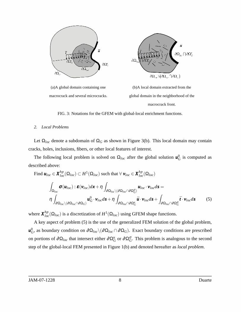
(a)A global domain containing one
macrocrack and several microcracks.
(b)A local domain extracted from the
global domain in the neighborhood of the
macrocrack front.
FIG. 3: Notations for the GFEM with global-local enrichmentfunctions.
2. Local Problems
Let Ωloc denote a subdomain ofΩG as shown in Figure 3(b). This local domain may contain
cracks, holes, inclusions, fibers, or other local features of interest.
The following local problem is solved onΩloc after the global solutionuuu0G is computed as
described above:
Finduuuloc ∈ XXXhploc(Ωloc) ⊂ H1(Ωloc) such that∀ vvvloc ∈ XXXhp
loc(Ωloc)
∫Ωloc
σσσ(uuuloc) : εεε(vvvloc)dxxx+η∫
∂ Ωloc\(∂ Ωloc∩∂ ΩσG)
uuuloc ·vvvlocdsss=
η∫
∂ Ωloc\(∂ Ωloc∩∂ ΩG)uuu0
G ·vvvlocdsss+η∫
∂ Ωloc∩∂ ΩuG
uuu·vvvlocdsss+∫
∂ Ωloc∩∂ ΩσG
ttt ·vvvlocdsss (5)
whereXXXhploc(Ωloc) is a discretization ofH1(Ωloc) using GFEM shape functions.
A key aspect of problem (5) is the use of the generalized FEM solution of the global problem,
uuu0G, as boundary condition on∂Ωloc\(∂Ωloc∩ ∂ΩG). Exact boundary conditions are prescribed
on portions of∂Ωloc that intersect either∂ΩuG or ∂Ωσ
G. This problem is analogous to the second
step of the global-local FEM presented in Figure 1(b) and denoted hereafter aslocal problem.
JAM-07-1228 8 Duarte

3. Global-Local Enrichment Functions
The error in the local solutionuuuloc depends not only on the discretization used in the lo-
cal domainΩloc, but, more importantly, also on the quality of boundary conditions used on
∂Ωloc\(∂Ωloc∩∂ΩG), i.e. uuu0G. In the GFEM proposed in [8, 9], this issue is addressed by going
one step further in a global-local analysis;the local solution uuuloc is used as an enrichment function
for the global problem.The local solution is called aglobal-local enrichment functionand is used
to define the following vector-valued global shape function
φφφ α = ϕαuuuloc (6)
whereϕα denotes a partition of unity function defined in the coarseglobalmesh used to solve the
global problem presented in Section III B 1. This function isused at nodesxxxα of the global mesh
whose support,ωα , is contained in the local domainΩloc. In our implementation, we enrich each
component of the displacement vector with the corresponding component of the local solution
uuuloc. Thus, a global-local enrichment adds three degrees of freedom to a node when solving a
three-dimensional elasticity problem. The global problemdefined in Section III B 1 is then solved
again using these global functions. The solution of this enriched global problem is denoted byuuuEG.
This problem is denoted hereafter asenriched global problem. In [9], we demonstrated how this
problem can be efficiently solved using the solution of the initial global problem.
The GFEM with global-local enrichment functions can account for possible interactions of
local (near crack, for example) and global (structural) behavior. This procedure also addresses the
loss of accuracy in the local solution caused by the crude boundary conditions used in the local
domain. Roughly speaking, this can be explained by the fact that the global partition of unity
ϕα , and thereforeφφφ α , are zero at the boundary of local domainΩloc, where the accuracy ofuuuloc
is more severely affected by the boundary conditions applied at ∂Ωloc. The enrichment of the
global mesh with the local solution is illustrated in Figure4 using the same example introduced
in Section II. Hereafter,GFEMg-l denotes the GFEM with global-local enrichment functions.
JAM-07-1228 9 Duarte

FIG. 4: Enrichment of the coarse global mesh with a local solution.
IV. NUMERICAL EXPERIMENTS
In this section, we analyze the performance of theGFEMg-l in the analysis of interacting cracks.
We compare the quality of stress intensity factors extracted from the solution of the enriched global
problem,uuuEG, with those extracted from the local solution,uuuloc.
The local solutionuuuloc is computed using the generalized finite element method described
in Section III A. This enables us to solve the local problems using meshes that do not fit the
crack surfaces, as required in the FEM. Therefore, strictlyspeaking,uuuloc is computed using a
global-local GFEM and not a global-local FEM. However, these methods suffer from the same
limitations, and it is reasonable to assume that the conclusions drawn here are also valid for the
global-local FEM. Hereafter, the procedure used to computeuuuloc is denoted byGL-FEM.
The numerical examples presented below include an analysisof interacting cracks, an inclined
crack and cracks with different scale sizes. The main focus of the numerical experiments is on
how the quality of boundary conditions for the local problems affects that of the stress intensity
factors extracted fromGFEMg-l andGL-FEM solutions. The numerical experiments show that
theGFEMg-l is much less sensitive to the quality of local boundary conditions and provides more
accurate stress intensity factors than theGL-FEM.
JAM-07-1228 10 Duarte

FIG. 5: Description of a problem with two interacting cracksin an infinite strip.
A. Analysis of Two Interacting Macrocracks
An example with two interacting cracks in an infinite strip isconsidered in this section. The
problem is illustrated in Figure 5. The general plane elastic problem of an infinite strip containing
multiple cracks perpendicular to its boundary was analysized by Civelek and Erdogan [10]. They
showed that for the configuration shown in Figure 5, the interaction between the cracks produces
a nonzero mode-two stress intensity factor,KII . This leads to the propagation of the cracks away
from each other. This effect becomes more significant as the distance between the cracks decreases
[10]. In this section, we investigate how well theGFEMg-l and theGL-FEM can captute the
interaction between the two cracks asB/H goes to zero (Cf. Figure 5). The stress intensity factors
are extracted fromuuuEG anduuuloc, respectively, as discussed above.
Three-dimensional tetrahedron elements are used in our computations. The Poisson’s ratio is
set to zero in order to minimize three-dimensional effects in the computed solution. This enables
us to use Civelek and Erdogan’s solution presented in [10] asa reference. The other parameters
JAM-07-1228 11 Duarte

assumed in our computations are as follows: Young’s modulusE = 200,000; in-plane dimensions
H = 10.0, 2l = 4.0, V = 200.0; domain thicknesst = 1.0; vertical tractionty = 100.0. Since the
vertical dimension is twenty times larger than the horizontal dimension, we can assume that the
solution on this finite domain is very close to the case of an infinite strip.
The SIFs are extracted using the cut-off function method [27–29] and normalized as in [10]
using
kI (II ) =KI (II )
ty√
π l(7)
wherekI (II ) denotes the normalized mode I (II) SIF,KI (II ) denotes the original mode I (II) SIF,ty
is the traction applied aty = ±V/2, and 2l is the crack length.
1. Analysis with Cracks Discretized in the Global Domain
The discretizations shown in Figure 6 are used in the analysis presented in this section. The
global mesh is quite coarse, as shown in Figure 6(a), and has only one layer of elements in the out-
of-plane direction. Heaviside enrichment functions are used to represent the cracks. This enables
the cracks to cut elements in the mesh, as described in Section III A.
Four local problems are created, one for each crack front as illustrated in Figure 6(a). The
local meshes are strongly refined in the neighborhood of the crack fronts. Westergaard functions
are used in the elements intersecting the crack front. In thecase of theGL-FEM, stress intensity
factors are extracted from solutions computed in these local domains.
The local solutions are used to enrich nodes in the global mesh, as illustred in Figure 6(c). Only
four nodes per crack front are enriched with these functions(two nodes atz= 0 and two atz= t).
As a result, the enriched global problem has almost the same number of degrees of freedom as
the initial global problem (Cf. Table I). In the case of theGFEMg-l, stress intensity factors are
extracted from the solution computed in this enriched global problem.
The polynomial order of the shape functions used in the initial and enriched global problems
is p = 1, whereas cubic polynomial shape functions (p = 3) are used in the local problems. It
should be emphasized that the interacting cracksare discretizedin the global domain. This is in
contrast to the analysis presented in Section IV A 2 where thecracks are not discretized in the
global domain.
JAM-07-1228 12 Duarte

(a)Discretization of cracks in the initial global
problem. The shaded areas represent the local
domains extracted from the coarse global
mesh.
(b)Graded meshes used in the
discretization of local problems.
(c)Enrichment of global discretization with
local solutions. Global nodes enriched with
local solutions are represented with squares.
FIG. 6: Discretization of a problem with two interacting cracks using tetrahedral elements. Front view of
the strip shown in Figure 5 for the caseB/H = 2. Note that the cracks are discretized in the global domain
and a three-dimensional discretization is used.
JAM-07-1228 13 Duarte
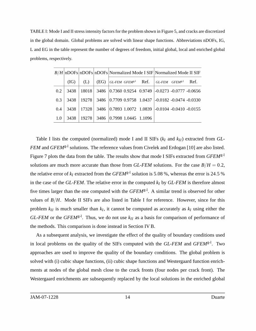
TABLE I: Mode I and II stress intensity factors for the problem shown in Figure 5, and cracks are discretized
in the global domain. Global problems are solved with linearshape functions. Abbreviations nDOFs, IG,
L and EG in the table represent the number of degrees of freedom, initial global, local and enriched global
problems, respectively.
B/H nDOFsnDOFsnDOFsNormalized Mode I SIFNormalized Mode II SIF
(IG) (L) (EG) GL-FEM GFEMg-l Ref. GL-FEM GFEMg-l Ref.
0.2 3438 18018 3486 0.7360 0.9254 0.9749-0.0273 -0.0777 -0.0656
0.3 3438 19278 3486 0.7709 0.9758 1.0437-0.0182 -0.0474 -0.0330
0.4 3438 17328 3486 0.7893 1.0072 1.0839-0.0104 -0.0410 -0.0155
1.0 3438 19278 3486 0.7998 1.0445 1.1096
Table I lists the computed (normalized) mode I and II SIFs (kI andkII ) extracted fromGL-
FEM andGFEMg-l solutions. The reference values from Civelek and Erdogan [10] are also listed.
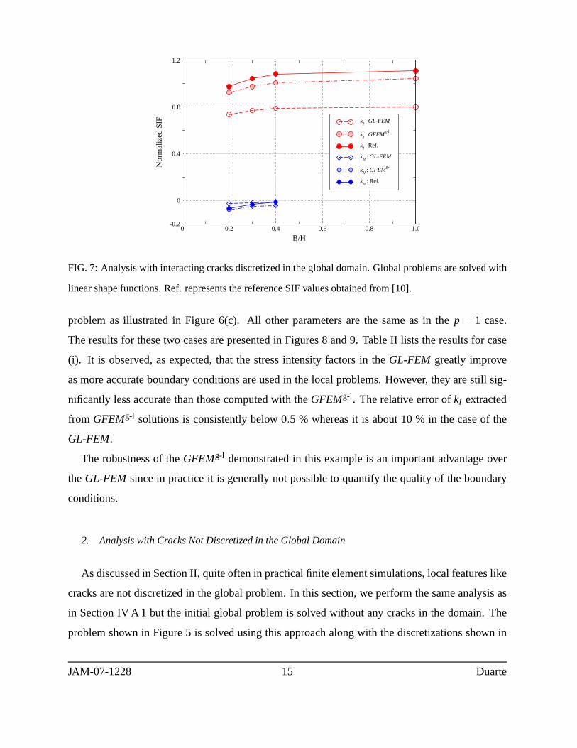
Figure 7 plots the data from the table. The results show that mode I SIFs extracted fromGFEMg-l
solutions are much more accurate than those fromGL-FEM solutions. For the caseB/H = 0.2,
the relative error ofkI extracted from theGFEMg-l solution is 5.08 %, whereas the error is 24.5 %
in the case of theGL-FEM. The relative error in the computedkI by GL-FEM is therefore almost
five times larger than the one computed with theGFEMg-l. A similar trend is observed for other
values ofB/H. Mode II SIFs are also listed in Table I for reference. However, since for this
problemkII is much smaller thankI , it cannot be computed as accurately askI using either the
GL-FEM or theGFEMg-l. Thus, we do not usekII as a basis for comparison of performance of
the methods. This comparison is done instead in Section IV B.
As a subsequent analysis, we investigate the effect of the quality of boundary conditions used
in local problems on the quality of the SIFs computed with theGL-FEM andGFEMg-l. Two
approaches are used to improve the quality of the boundary conditions. The global problem is
solved with (i) cubic shape functions, (ii) cubic shape functions and Westergaard function enrich-
ments at nodes of the global mesh close to the crack fronts (four nodes per crack front). The
Westergaard enrichments are subsequently replaced by the local solutions in the enriched global
JAM-07-1228 14 Duarte
0 0.2 0.4 0.6 0.8 1.0
B/H
-0.2
0
0.4
0.8
1.2
Nor
mal
ized
SIF k
I : GL-FEM
kI : GFEM
g-l
kI : Ref.
kII
: GL-FEM
kII
: GFEMg-l
kII
: Ref.
FIG. 7: Analysis with interacting cracks discretized in theglobal domain. Global problems are solved with
linear shape functions. Ref. represents the reference SIF values obtained from [10].
problem as illustrated in Figure 6(c). All other parametersare the same as in thep = 1 case.
The results for these two cases are presented in Figures 8 and9. Table II lists the results for case
(i). It is observed, as expected, that the stress intensity factors in theGL-FEM greatly improve
as more accurate boundary conditions are used in the local problems. However, they are still sig-
nificantly less accurate than those computed with theGFEMg-l. The relative error ofkI extracted
from GFEMg-l solutions is consistently below 0.5 % whereas it is about 10 % in the case of the
GL-FEM.
The robustness of theGFEMg-l demonstrated in this example is an important advantage over
theGL-FEM since in practice it is generally not possible to quantify the quality of the boundary
conditions.
2. Analysis with Cracks Not Discretized in the Global Domain
As discussed in Section II, quite often in practical finite element simulations, local features like
cracks are not discretized in the global problem. In this section, we perform the same analysis as
in Section IV A 1 but the initial global problem is solved without any cracks in the domain. The
problem shown in Figure 5 is solved using this approach alongwith the discretizations shown in
JAM-07-1228 15 Duarte

TABLE II: Mode I and II stress intensity factors for the problem shown in Figure 5, and cracks are dis-
cretized in the global domain. Global problems are solved with cubic shape functions.
B/H nDOFsnDOFsnDOFs Mode I SIF Mode II SIF
(IG) (L) (EG) GL-FEM GFEMg-l Ref. GL-FEM GFEMg-l Ref.
0.2 34380 18018 34428 0.8908 0.9771 0.9749-0.0578 -0.0693 -0.0656
0.3 34380 19278 34428 0.9446 1.0436 1.0437-0.0338 -0.0375 -0.0330
0.4 34380 17328 34428 0.9767 1.0803 1.0839-0.0186 -0.0169 -0.0155
1.0 34380 19278 34428 1.0005 1.1135 1.1096
0 0.2 0.4 0.6 0.8 1.0
B/H
-0.2
0
0.4
0.8
1.2
Nor
mal
ized
SIF k
I : GL-FEM
kI : GFEM
g-l
kI : Ref.
kII
: GL-FEM
kII
: GFEMg-l
kII
: Ref.
FIG. 8: Analysis with interacting cracks discretized in theglobal domain. Global problems are solved with
cubic shape functions.
Figure 10. Only two local problems are created in this case, and each local problem includes the
entire crack as illustrated in Figure 10(b). The cracks are described only in the local problems
using Heaviside and Westergaard enrichment functions. Therefinement level at the crack fronts
is the same as in Section IV A 1. The local solutions are used toenrich nodes in the global mesh
as illustrated in 10(c). Twenty nodes per crack are enrichedin this case. It should be emphasized
that the interacting cracksare not discretizedin the global domain in contrast with the example
JAM-07-1228 16 Duarte

0 0.2 0.4 0.6 0.8 1.0
B/H
-0.2
0
0.4
0.8
1.2
Nor
mal
ized
SIF k
I : GL-FEM
kI : GFEM
g-l
kI : Ref.
kII
: GL-FEM
kII
: GFEMg-l
kII
: Ref.
FIG. 9: Analysis with interacting cracks discretized in theglobal domain. Global problems are solved with
cubic shape functions and Westergaard function enrichments.
analyzed in Section IV A 1.
The polynomial order of shape functions used in the initial and enriched global problems is set
to p = 1, whereas cubic polynomial shape functions (p = 3) are used in the local problems. Table
III lists the results for this case. Figure 11 plots the data from the table. The difference in quality of
SIFs extracted fromGFEMg-l andGL-FEM is even more significant than in the previous section.
For example, the relative error in mode I SIF forB/H = 0.2 computed by theGFEMg-l is 4.05 %,
whereas in the case of theGL-FEM it is 52.64 %. We can observe that the error inkI computed
with theGL-FEM is about twice as large as in the case reported in Table I. In contrast, the error
in the case of theGFEMg-l is about the same as in Table I, in spite of the fact that the cracks were
not modeled in the initial global problem.
As in the analysis presented in Section IV A 1, we investigatethe effect of using cubic shape
functions in the global problem. All other parameters are kept unchanged. The results for this
choice of shape functions are presented in Figure 12 and in Table IV. Westergaard enrichments
are not used in the global domain since in this domain the cracks are not discretized. It can be
observed from Figure 12 and Table IV that the mode I SIFs computed with theGL-FEM do not
improve in this case. This shows that if the cracks are not discretized in the global problem, the
quality of boundary conditions used in the local problems may not improve even if higher order
JAM-07-1228 17 Duarte

(a)The shaded areas represent the local
domains extracted from the coarse global
mesh.
(b)Graded meshes used in the
discretization of local problems.
(c)Enrichment of global discretization with
local solutions. Global nodes enriched with
local solutions are represented with squares.
FIG. 10: Discretization of a problem with two interacting cracks. Front view for the caseB/H = 2. The
cracks arenot discretized in the global domain.
elements or finer meshes are used in the global problem. The mode I SIFs in theGFEMg-l have
an error of less than 1 % while in the case of theGL-FEM the error is about five times larger
than those reported in Table II. This, again, shows that theGFEMg-l is more robust and can
provide more accurate solutions than theGL-FEM, even in such an extreme situation where no
JAM-07-1228 18 Duarte

TABLE III: Mode I and II stress intensity factors for the problem shown in Figure 5. Cracks are not
discretized in the global domain, and linear shape functions are used in the global domain.
B/H nDOFsnDOFsnDOFsNormalized Mode I SIFNormalized Mode II SIF
(IG) (L) (EG) GL-FEM GFEMg-l Ref. GL-FEM GFEMg-l Ref.
0.2 3366 36708 3486 0.4617 0.9354 0.9749-0.0270 -0.0906 -0.0656
0.3 3366 39228 3486 0.4625 0.9834 1.0437-0.0162 -0.0537 -0.0330
0.4 3366 35328 3486 0.4630 0.9987 1.0839-0.0043 -0.0103 -0.0155
1.0 3366 39228 3486 0.4604 1.0425 1.1096
0 0.2 0.4 0.6 0.8 1.0
B/H
-0.2
0
0.4
0.8
1.2
Nor
mal
ized
SIF k
I : GL-FEM
kI : GFEM
g-l
kI : Ref.
kII
: GL-FEM
kII
: GFEMg-l
kII
: Ref.
FIG. 11: Analysis with interacting cracks not discretized in the global domain. Global problems are solved
with linear shape functions.
local features are represented in the global domain.
B. Analysis of an Inclined Crack
As a second example, we analyze the mixed-mode fracture problem shown in Figure 13. In
contrast with the problem analyzed in Section IV A, here modeI and II stress intensity factors are
of the same order magnitude. Thus, they can be extracted withthe same level of accuracy. We
JAM-07-1228 19 Duarte

TABLE IV: Mode I and II stress intensity factors for the problem shown in Figure 5. Cracks are not
discretized in the global domain and cubic shape functions are used in the global domain.
B/H nDOFsnDOFsnDOFs Mode I SIF Mode II SIF
(IG) (L) (EG) GL-FEM GFEMg-l Ref. GL-FEM GFEMg-l Ref.
0.2 33660 36708 33780 0.4617 0.9807 0.9749-0.0270 -0.0720 -0.0656
0.3 33660 39228 33780 0.4625 1.0517 1.0437-0.0162 -0.0459 -0.0330
0.4 33660 35328 33780 0.4630 1.0902 1.0839-0.0043 -0.0186 -0.0155
1.0 33660 39228 33780 0.4604 1.1125 1.1096
0 0.2 0.4 0.6 0.8 1.0
B/H
0
0.4
0.8
1.2
Nor
mal
ized
SIF k
I : GL-FEM
kI : GFEM
g-l
kI : Ref.
kII
: GL-FEM
kII
: GFEMg-l
kII
: Ref.
FIG. 12: Analysis with interacting cracks not discretized in the global domain. Global problems are solved
with cubic shape functions.
compare SIFs extracted fromGL-FEM andGFEMg-l solutions with reference values computed
by Szabo and Babuska [27] using thep version of the finite element method withp = 8.
Three-dimensional tetrahedron elements are used in our computations as in Section IV A. The
Poisson’s ratio is set to zero to compare our results with thereference values computed assuming
plane stress condition. The following parameters are also adopted in our simulation: Young’s
modulusE = 1.0; in-plane dimensionsw = 1.0; domain thicknesst = 1.0; vertical tractionty =
1.0.
JAM-07-1228 20 Duarte
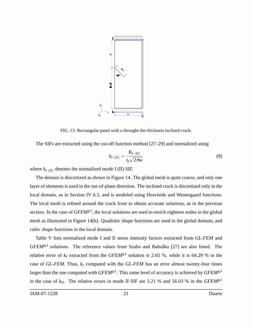
FIG. 13: Rectangular panel with a throught-the-thickness inclined crack.
The SIFs are extracted using the cut-off function method [27–29] and normalized using
kI (II ) =KI (II )
ty√
2πw(8)
wherekI (II ) denotes the normalized mode I (II) SIF.
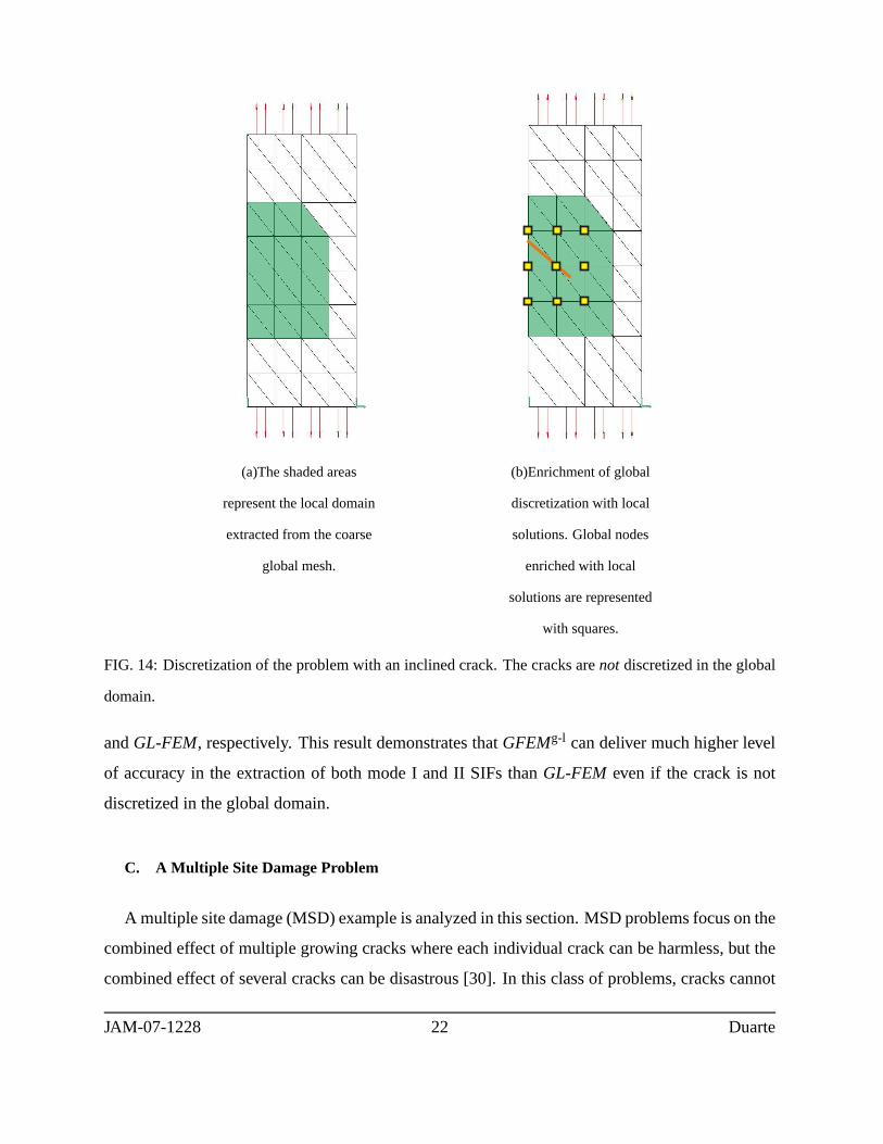
The domain is discretized as shown in Figure 14. The global mesh is quite coarse, and only one
layer of elements is used in the out-of-plane direction. Theinclined crack is discretized only in the
local domain, as in Section IV A 2, and is modeled using Heaviside and Westergaard functions.
The local mesh is refined around the crack front to obtain accurate solutions, as in the previous
section. In the case ofGFEMg-l, the local solutions are used to enrich eighteen nodes in theglobal
mesh as illustrated in Figure 14(b). Quadratic shape functions are used in the global domain, and
cubic shape functions in the local domain.
Table V lists normalized mode I and II stress intensity factors extracted fromGL-FEM and
GFEMg-l solutions. The reference values from Szabo and Babuska [27] are also listed. The
relative error ofkI extracted from theGFEMg-l solution is 2.65 %, while it is 64.29 % in the
case ofGL-FEM. Thus,kI computed with theGL-FEM has an error almost twenty-four times
larger than the one computed withGFEMg-l. This same level of accuracy is achieved byGFEMg-l
in the case ofkII . The relative errors in mode II SIF are 3.21 % and 56.03 % in theGFEMg-l
JAM-07-1228 21 Duarte
(a)The shaded areas
represent the local domain
extracted from the coarse
global mesh.
(b)Enrichment of global
discretization with local
solutions. Global nodes
enriched with local
solutions are represented
with squares.
FIG. 14: Discretization of the problem with an inclined crack. The cracks arenot discretized in the global
domain.
andGL-FEM, respectively. This result demonstrates thatGFEMg-l can deliver much higher level
of accuracy in the extraction of both mode I and II SIFs thanGL-FEM even if the crack is not
discretized in the global domain.
C. A Multiple Site Damage Problem
A multiple site damage (MSD) example is analyzed in this section. MSD problems focus on the
combined effect of multiple growing cracks where each individual crack can be harmless, but the
combined effect of several cracks can be disastrous [30]. Inthis class of problems, cracks cannot
JAM-07-1228 22 Duarte
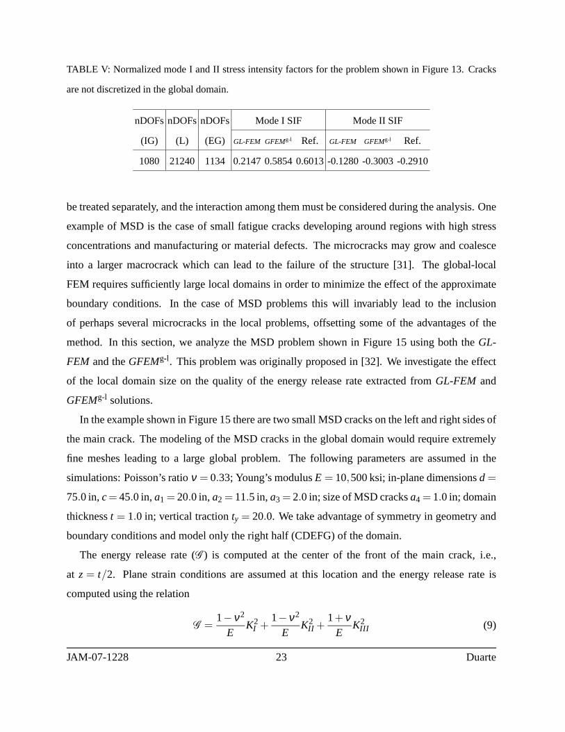
TABLE V: Normalized mode I and II stress intensity factors for the problem shown in Figure 13. Cracks
are not discretized in the global domain.
nDOFsnDOFsnDOFs Mode I SIF Mode II SIF
(IG) (L) (EG) GL-FEM GFEMg-l Ref. GL-FEM GFEMg-l Ref.
1080 21240 1134 0.2147 0.5854 0.6013-0.1280 -0.3003 -0.2910
be treated separately, and the interaction among them must be considered during the analysis. One
example of MSD is the case of small fatigue cracks developingaround regions with high stress
concentrations and manufacturing or material defects. Themicrocracks may grow and coalesce
into a larger macrocrack which can lead to the failure of the structure [31]. The global-local
FEM requires sufficiently large local domains in order to minimize the effect of the approximate
boundary conditions. In the case of MSD problems this will invariably lead to the inclusion
of perhaps several microcracks in the local problems, offsetting some of the advantages of the
method. In this section, we analyze the MSD problem shown in Figure 15 using both theGL-
FEM and theGFEMg-l. This problem was originally proposed in [32]. We investigate the effect
of the local domain size on the quality of the energy release rate extracted fromGL-FEM and
GFEMg-l solutions.
In the example shown in Figure 15 there are two small MSD cracks on the left and right sides of
the main crack. The modeling of the MSD cracks in the global domain would require extremely
fine meshes leading to a large global problem. The following parameters are assumed in the
simulations: Poisson’s ratioν = 0.33; Young’s modulusE = 10,500 ksi; in-plane dimensionsd =
75.0 in,c= 45.0 in,a1 = 20.0 in,a2 = 11.5 in,a3 = 2.0 in; size of MSD cracksa4 = 1.0 in; domain
thicknesst = 1.0 in; vertical tractionty = 20.0. We take advantage of symmetry in geometry and
boundary conditions and model only the right half (CDEFG) ofthe domain.
The energy release rate (G ) is computed at the center of the front of the main crack, i.e.,
at z = t/2. Plane strain conditions are assumed at this location and the energy release rate is
computed using the relation
G =1−ν2
EK2
I +1−ν2
EK2
II +1+ν
EK2
III (9)
JAM-07-1228 23 Duarte

FIG. 15: Description of a multisite damage problem.
whereν is Poisson’s ratio, andE is Young’s modulus. The stress intensity factorsKI , KII and
KIII are extracted using the contour integral method [27–29, 33,34]. The reference value for the
G is taken as 2.5609. This value was computed using a very refined mesh and high order shape
functions (p = 4) with all cracks modeled in the global problem. This reference discretization has
a total of 365,538 degrees of freedom. We checked the convergence of the computed reference
value forG by solving the problem using a smaller model, with 311,742 degrees of freedom. The
difference in the energy release rates between these two models was less than 0.01 %.
The discretizations shown in Figure 16 are used in the analysis presented below. Local domains
of different sizes are used as illustrated in Figure 16(a). Only the main crack is discretized in
the global problem. The neighborhood of the main crack frontand the entire MSD cracks are
modeled in the local domains (Cf. Figures 16(a) and 16(b)). Not modeling the MSD cracks in the
global domain considerably reduces the computational costand also facilitates the creation of the
macroscale discretization. In the case of theGFEMg-l, the local solutions are used to enrich the
global nodes illustrated in Figure 16(c). The same set of 12 nodes is enriched, regardless of the
JAM-07-1228 24 Duarte
(a)Discretization of cracks in the initial global
problem. Solid, dashed and long dash-double dotted
lines represent the boundaries of local domains with
three different sizes used in this analysis.
(b)Graded mesh used in the
discretization of the local problem
represented by a dashed line in Figure
16(a)
(c)Enrichment of global discretization with the local
solution in Figure 16(b). Global nodes enriched with
the local solution are represented by squares.
FIG. 16: Discretization of the MSD problem (front view).Only the main crack is discretized in the global
domainwhile both the main and MSD cracks are discretized in the local domains.
size of local domain.
The local meshes are strongly refined in the neighborhood of the crack fronts. Singular West-
ergaard functions are used in local elements intersecting acrack front. Cubic shape functions are
used in the initial and enriched global problems and in the local problems as well.
Table VI lists the energy release rate (G ) extracted fromGL-FEM andGFEMg-l solutions for
varying sizes of local domains. In the table, the three different sizes of local domains illustrated
JAM-07-1228 25 Duarte
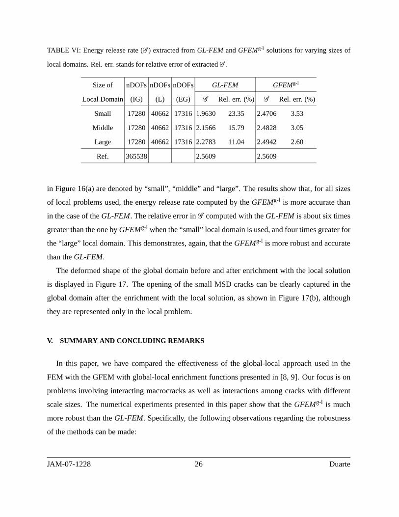
TABLE VI: Energy release rate (G ) extracted fromGL-FEM andGFEMg-l solutions for varying sizes of
local domains. Rel. err. stands for relative error of extractedG .
Size of nDOFs nDOFsnDOFs GL-FEM GFEMg-l
Local Domain (IG) (L) (EG) G Rel. err. (%) G Rel. err. (%)
Small 17280 40662 17316 1.9630 23.35 2.4706 3.53
Middle 17280 40662 17316 2.1566 15.79 2.4828 3.05
Large 17280 40662 17316 2.2783 11.04 2.4942 2.60
Ref. 365538 2.5609 2.5609
in Figure 16(a) are denoted by “small”, “middle” and “large”. The results show that, for all sizes
of local problems used, the energy release rate computed by theGFEMg-l is more accurate than
in the case of theGL-FEM. The relative error inG computed with theGL-FEM is about six times
greater than the one byGFEMg-l when the “small” local domain is used, and four times greaterfor
the “large” local domain. This demonstrates, again, that theGFEMg-l is more robust and accurate
than theGL-FEM.
The deformed shape of the global domain before and after enrichment with the local solution
is displayed in Figure 17. The opening of the small MSD crackscan be clearly captured in the
global domain after the enrichment with the local solution,as shown in Figure 17(b), although
they are represented only in the local problem.
V. SUMMARY AND CONCLUDING REMARKS
In this paper, we have compared the effectiveness of the global-local approach used in the
FEM with the GFEM with global-local enrichment functions presented in [8, 9]. Our focus is on
problems involving interacting macrocracks as well as interactions among cracks with different
scale sizes. The numerical experiments presented in this paper show that theGFEMg-l is much
more robust than theGL-FEM. Specifically, the following observations regarding the robustness
of the methods can be made:
JAM-07-1228 26 Duarte

(a)Deformed shape of the global domain before
enrichment with a local solution.
(b)Deformed shape of the global domain after
enrichment with a local solution.
FIG. 17: Deformed shape of the global domain in the MSD problem before and after enrichment with a
local solution. The elements of the local problem nested in the global mesh are visualized in Figure 17(b).
• The numerical examples presented in Section IV A show that the GFEMg-l is less sensitive
to the quality of boundary conditions applied to the local problems than theGL-FEM. Ac-
curate SIFs could be extracted fromGFEMg-l solutions even when cracks were not modeled
in the global problem. The SIFs extracted fromGL-FEM solutions showed an error of up
to one order of magnitude larger than in the case of theGFEMg-l.
• When cracks were modeled in the initial global problems, thequality of SIFs extracted from
GL-FEM solutions improved significantly with the accuracy of the initial global problem.
However, increasing the polynomial order used in the initial global problem didnot im-
prove the performance of theGL-FEM much when cracks were not modeled in the global
problem.
• Energy release rates extracted fromGFEMg-l solutions of an MSD problem consistently
exhibited higher accuracy than in the case of theGL-FEM for all sizes of local domains
considered in the numerical experiments.
• The GFEMg-l can account for interactions among cracks with the same or different scale
sizes, even when not all cracks are modeled in the initial global problem. This makes
JAM-07-1228 27 Duarte
theGFEMg-l an appealing method to analyze problems with phenomena spanning multiple
spatial scales.
Our work in [9] also shows that theGFEMg-l is computationally very efficient. The cost of the
method when analyzing stationary cracks, like in this paper, is very close to theGL-FEM, since
the cost of solving the enriched global problem is small whencompared with the cost for the initial
global problem [9]. The cost analysis presented in [9] was done on a single processor machine
for the case of a single local problem defined per crack in the domain. Our on-going research
shows, however, that the method is also highly scalable and can be parallelized without difficulty.
The robustness and computational efficiency of theGFEMg-l makes it suited to the analysis of
practical fracture mechanics engineering problems.
Acknowledgments
The partial support of this work by the National Center for Supercomputing Applications and
the University of Illinois at Urbana-Champaign, under the auspices of the NCSA/UIUC Faculty
Fellows Program, and by the National Science Foundation under grant DMS-0611094 is gratefully
acknowledged.
[1] M. Kayama and N. Totsuka. Influence of interaction between multiple cracks on stress corrosion
crack propagation.Corrosion Science, 44:2333–2352, 2002.
[2] M. Kayama and T. Kitamura. A simulation on growth of multiple small cracks under stress corrosion.
International Journal of Fracture, 130:787–801, 2004.
[3] H. Kebir, J. M. Roelandt, and Chambon L. Dual boundary element method modelling of aircraft
structural joints with multiple site damage.Engineering Fracture Mechanics, 73:418–434, 2006.
[4] M. Seyedi, S. Taheri, and F. Hild. Numerical modeling of crack propagation and shielding effects in
a striping network.Nuclear engineering and design, 236:954–964, 2006.
JAM-07-1228 28 Duarte
[5] C. A. Felippa. Introduction to finite element methods., 2004. Course Notes. Depart-
ment of Aerospace Engineeing Sciences, University of Colorado at Boulder. Available at
http://www.colorado.edu/engineering/Aerospace/CAS/courses.d/IFEM.d/.
[6] A. K. Noor. Global-local methodologies and their applications to nonlinear analysis.Finite Elements
in Analysis and Design, 2:333–346, 1986.
[7] A.Th. Diamantoudis and G.N. Labeas. Stress intensity factors of semi-elliptical surface cracks in pres-
sure vessels by global-local finite element methodology.Engineering Fracture Mechanics, 72:1299–
1312, 2005.
[8] C.A. Duarte, D.-J. Kim, and I. Babuska. Chapter: A global-local approach for the constructionof
enrichment functions for the generalized fem and its application to three-dimensional cracks. In
V.M.A. Leitao, C.J.S. Alves, and C.A. Duarte, editors,Advances in Meshfree Techniques, volume 5
of Computational Methods in Applied Sciences, The Netherlands, 2007. Springer. ISBN 978-1-4020-
6094-6.
[9] C.A. Duarte and D.-J. Kim. Analysis and applications of ageneralized finite element method with
global-local enrichment functions.Computer Methods in Applied Mechanics and Engineering, 2007.
Accepted for publication. http://dx.doi.org/10.1016/j.cma.2007.08.017.
[10] M. B. Civelek and F. Erdogan. Crack problems for a rectangular plate and an infinite strip.Interna-
tional Journal of Fracture, 19:139–159, 1982.
[11] C. T. Sun and K. M. Mao. A global-local finite element method suitable for parallel computations.
Computers and Structures, 29:309–315, 1988.
[12] I. Babuska and T. Strouboulis.The Finite Element Method and its Reliability. Numerical Mathematics
and Scientific Computation. Oxford Science Publications, New York, USA, 2001.
[13] I. Babuska and J. M. Melenk. The partition of unity finite element method. International Journal for
Numerical Methods in Engineering, 40:727–758, 1997.
[14] C.A. Duarte, I. Babuska, and J.T. Oden. Generalized finite element methods for three dimensional
structural mechanics problems.Computers and Structures, 77:215–232, 2000.
[15] J.T. Oden, C.A. Duarte, and O.C. Zienkiewicz. A new cloud-basedhp finite element method.Com-
puter Methods in Applied Mechanics and Engineering, 153:117–126, 1998.
[16] T. Strouboulis, K. Copps, and I. Babuska. The generalized finite element method.Computer Methods
JAM-07-1228 29 Duarte
in Applied Mechanics and Engineering, 190:4081–4193, 2001.
[17] C.A. Duarte, D.-J. Kim, and D.M. Quaresma. Arbitrarilysmooth generalized finite element
approximations. Computer Methods in Applied Mechanics and Engineering, 196:33–56, 2006.
http://dx.doi.org/10.1016/j.cma.2005.12.016.
[18] J.T. Oden and C.A. Duarte. Chapter: Clouds, Cracks and FEM’s. In B.D. Reddy, editor,Recent
Developments in Computational and Applied Mechanics, pages 302–321, Barcelona, Spain, 1997.
International Center for Numerical Methods in Engineering, CIMNE.
[19] J.T. Oden and C.A.M. Duarte. Chapter: Solution of singular problems usinghp clouds. In J.R.
Whiteman, editor,The Mathematics of Finite Elements and Applications– Highlights 1996, pages
35–54, New York, NY, 1997. John Wiley & Sons.
[20] C.A. Duarte, O.N. Hamzeh, T.J. Liszka, and W.W. Tworzydlo. A generalized finite element method for
the simulation of three-dimensional dynamic crack propagation. Computer Methods in Applied Me-
chanics and Engineering, 190:2227–2262, 2001. http://dx.doi.org/10.1016/S0045-7825(00)00233-4.
[21] N. Moes, J. Dolbow, and T. Belytschko. A finite element method for crack growth without remeshing.
International Journal for Numerical Methods in Engineering, 46:131–150, 1999.
[22] N. Sukumar, N. Moes, B. Moran, and T. Belytschko. Extended finite element method for
three-dimensional crack modelling.International Journal for Numerical Methods in Engineering,
48(11):1549–1570, 2000.
[23] G. N. Wells and L. J. Sluys. A new method for modeling cohesive cracks using finite elements.
International Journal for Numerical Methods in Engineering, 50:2667–2682, 2001.
[24] A. Simone. Partition of unity-based discontinuous elements for interface phenomena: Computational
issues.Communications in Numerical Methods in Engineering, 20:465–478, 2004.
[25] C.A. Duarte, L.G. Reno, and A. Simone. A high-order generalized FEM for through-the-thickness
branched cracks.International Journal for Numerical Methods in Engineering, 72(3):325–351, 2007.
http://dx.doi.org/10.1002/nme.2012.
[26] T. Strouboulis, L. Zhang, and I. Babuska. Generalized finite element method using mesh-based hand-
books: Application to problems in domains with many voids.Computer Methods in Applied Mechan-
ics and Engineering, 192:3109–3161, 2003.
[27] B. A. Szabo and I. Babuska. Computation of the amplitude of stress singular terms for cracks and
JAM-07-1228 30 Duarte

reentrant corners. In T. A. Cruse, editor,Fracture Mechanics: Nineteenth Symposium, ASTM STP
969, pages 101–124, 1988.
[28] J.P. Pereira and C.A. Duarte. Extraction of stress intensity factors from generalized finite element
solutions.Engineering Analysis with Boundary Elements, 29:397–413, 2005.
[29] J.P. Pereira and C.A. Duarte. Computation of stress intensity factors for pressurized cracks using
the generalized finite element method and superconvergent extraction techniques. In P.R.M. Lyra,
S.M.B.A. da Silva, F.S. Magnani, L.J. do N. Guimaraes, L.M. da Costa, and E. Parente Junior, editors,
XXV Iberian Latin-American Congress on Computational Methods in Engineering, Recife, PE, Brazil,
November 2004. 15 pages. ISBN Proceedings CD: 857 409 869-8.
[30] I. Babuska and B. Andersson. The splitting method as a tool for multiple damage analysis.SIAM
journal on scientific computing, 26:1114–1145, 2005.
[31] A. Yohannes, D. J. Cartwright, and R. A. Collins. Application of a discontinuous strip yield model
to multiple site damage in stiffened sheets. InThe 1996 4th International Conference on Computer-
Aided Assesment and Control, pages 565–572, Fukuoka; Japan, 1996.
[32] L. Wang, F. W. Brust, and S. N. Atluri. The elastic-plastic finite element alternating
method(EPFEAM) and the prediction of fracture under WFD conditions in aircraft structures.Com-
putational Mechanics, 19:356–369, 1997.
[33] M. Stern, E. B. Becker, and R. S. Dunham. A contour integral computation of mixed-mode stress
intensity factors.International Journal of Fracture, 12:359–368, 1976.
[34] J.P. Pereira and C.A. Duarte. The contour integral method for loaded cracks.Communications in
Numerical Methods in Engineering, 22(5):421–432, 2006. http://dx.doi.org/10.1002/cnm.824.
JAM-07-1228 31 Duarte
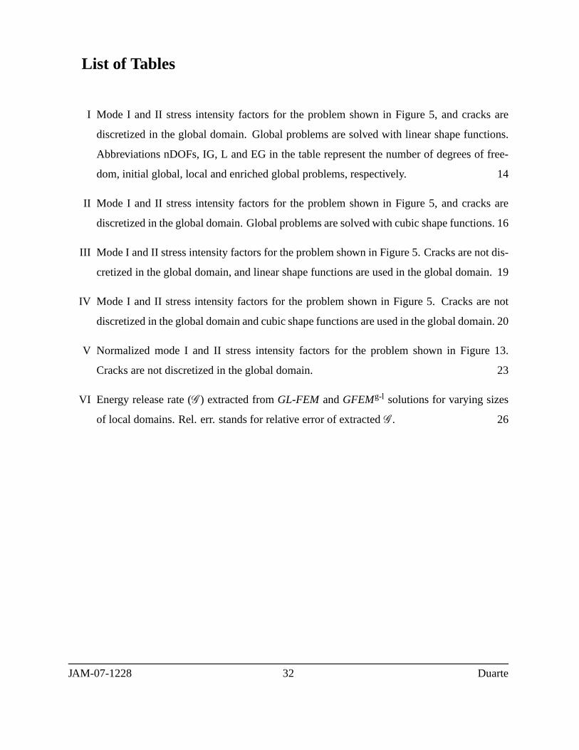
List of Tables
I Mode I and II stress intensity factors for the problem shownin Figure 5, and cracks are
discretized in the global domain. Global problems are solved with linear shape functions.
Abbreviations nDOFs, IG, L and EG in the table represent the number of degrees of free-
dom, initial global, local and enriched global problems, respectively. 14
II Mode I and II stress intensity factors for the problem shown in Figure 5, and cracks are
discretized in the global domain. Global problems are solved with cubic shape functions. 16
III Mode I and II stress intensity factors for the problem shown in Figure 5. Cracks are not dis-
cretized in the global domain, and linear shape functions are used in the global domain. 19
IV Mode I and II stress intensity factors for the problem shown in Figure 5. Cracks are not
discretized in the global domain and cubic shape functions are used in the global domain. 20
V Normalized mode I and II stress intensity factors for the problem shown in Figure 13.
Cracks are not discretized in the global domain. 23
VI Energy release rate (G ) extracted fromGL-FEM andGFEMg-l solutions for varying sizes
of local domains. Rel. err. stands for relative error of extractedG . 26
JAM-07-1228 32 Duarte

List of Figures
1 Global-local analysis for a structural component with a planar crack surface. 4
(a) Global analysis with a coarse mesh to provide boundary conditions for the extracted
local domain.
(b) Refined local problem and its solution.
2 Construction of a generalized FEM shape function using a polynomial (a) and a non-
polynomial enrichment (b). Here,ϕα are the functions at the top, the enrichment functions,
Lα i , are the functions in the middle, and the generalized FE shape functions,φα i , are the
resulting bottom functions. 6
(a)
(b)
3 Notations for the GFEM with global-local enrichment functions. 8
(a) A global domain containing one macrocrack and several microcracks.
(b) A local domain extracted from the global domain in the neighborhood of the macroc-
rack front.
4 Enrichment of the coarse global mesh with a local solution. 10
5 Description of a problem with two interacting cracks in an infinite strip. 11
6 Discretization of a problem with two interacting cracks using tetrahedral elements. Front
view of the strip shown in Figure 5 for the caseB/H = 2. Note that the cracks are discretized
in the global domain and a three-dimensional discretization is used. 13
(a) Discretization of cracks in the initial global problem.The shaded areas represent the
local domains extracted from the coarse global mesh.
(b) Graded meshes used in the discretization of local problems.
JAM-07-1228 33 Duarte
(c) Enrichment of global discretization with local solutions. Global nodes enriched with
local solutions are represented with squares.
7 Analysis with interacting cracks discretized in the global domain. Global problems are
solved with linear shape functions. Ref. represents the reference SIF values obtained from
[10]. 15
8 Analysis with interacting cracks discretized in the global domain. Global problems are
solved with cubic shape functions. 16
9 Analysis with interacting cracks discretized in the global domain. Global problems are
solved with cubic shape functions and Westergaard functionenrichments. Global problems
are solved with cubic shape functions. 17
10 Discretization of a problem with two interacting cracks.Front view for the caseB/H = 2.
The cracks arenot discretized in the global domain. 18
(a) The shaded areas represent the local domains extracted from the coarse global mesh.
(b) Graded meshes used in the discretization of local problems.
(c) Enrichment of global discretization with local solutions. Global nodes enriched with
local solutions are represented with squares.
11 Analysis with interacting cracks not discretized in the global domain. Global problems are
solved with linear shape functions. 19
12 Analysis with interacting cracks not discretized in the global domain. Global problems are
solved with cubic shape functions. 20
13 Rectangular panel with a throught-the-thickness inclined crack. 21
14 Discretization of the problem with an inclined crack. Thecracks arenot discretized in the
global domain. 22
(a) The shaded areas represent the local domain extracted from the coarse global mesh.
JAM-07-1228 34 Duarte
(b) Enrichment of global discretization with local solutions. Global nodes enriched with
local solutions are represented with squares.
15 Description of a multisite damage problem. 24
16 Discretization of the MSD problem (front view).Only the main crack is discretized in the
global domainwhile both the main and MSD cracks are discretized in the local domains.
25
(a) Discretization of cracks in the initial global problem.Solid, dashed and long dash-
double dotted lines represent the boundaries of local domains with three different sizes
used in this analysis.
(b) Graded mesh used in the discretization of the local problem represented by a dashed
line in Figure 16(a)
(c) Enrichment of global discretization with the local solution in Figure 16(b). Global
nodes enriched with the local solution are represented by squares.
17 Deformed shape of the global domain in the MSD problem before and after enrichment with
a local solution. The elements of the local problem nested inthe global mesh are visualized
in Figure 17(b). 27
(a) Deformed shape of the global domain before enrichment with a local solution.
(b) Deformed shape of the global domain after enrichment with a local solution.
JAM-07-1228 35 Duarte