Embed Size (px)
Citation preview

ANALYSIS OF FORGING FOR THREE DIFFERENT ALLOY STEELS
A THESIS SUBMITTED TO
THE GRADUATE SCHOOL OF NATURAL AND APPLIED SCIENCES
OF
THE MIDDLE EAST TECHNICAL UNIVERSITY
BY
BARIŞ CİVELEKOĞLU
IN PARTIAL FULFILLMENT OF THE REQUIREMENTS FOR THE DEGREE
OF MASTER OF SCIENCE
IN
THE DEPARTMENT OF MECHANICAL ENGINEERING
DECEMBER 2003

Approval of the Graduate School of Natural and Applied Sciences.
Prof. Dr. Canan ÖZGEN Director
I certify that this thesis satisfies all the requirements as a thesis for the
degree of Master of Science.
Prof. Dr. Kemal İDER Head of the Department
This is to certify that we have read this thesis and that in our opinion it
is fully adequate, in scope and quality, as a thesis for the degree of
Master of Science.
Prof. Dr. Mustafa İlhan GÖKLER Prof. Dr. Haluk DARENDELİLER Co-Supervisor Supervisor
Examining Committee Members:
Prof. Dr. Ömer Gündüz BİLİR
Prof. Dr. Haluk DARENDELİLER
Prof. Dr. Mustafa İlhan GÖKLER
Prof. Dr. Kemal İDER
Prof. Dr. Bilgehan ÖGEL

iii
ABSTRACT
ANALYSIS OF FORGING FOR THREE DIFFERENT ALLOY STEELS
CİVELEKOĞLU, Barış
M. Sc., Department of Mechanical Engineering
Supervisor: Prof. Dr. Haluk DARENDELİLER
Co-Supervisor: Prof. Dr. Mustafa İlhan GÖKLER
December 2003, 77 pages
Forging is a manufacturing process which is preferred among
the others in that, the final product shows more enhanced properties.
The properties of the final product are directly related with the material
used in the forging process. Main parameters such as forging
temperature, number of stages, preform design, dimensions of the
billet, etc. may be affected by the forging material.
Alloys are one of the main areas of interest in the forging
industry. The use of alloy steels may bring superior properties,
especially in terms of strength and forgeability.
In this study, three different alloy steels, which are hot forged in
industry have been examined. The flow of the material, stress
distribution, die filling and the effects of the process parameters on the
forging have been investigated. Three industrial forging parts; M20 and
M30 eye bolts and a runner block have been studied. Finite Volume
Analysis of the forging process has been performed for carbon steels;

iv
C45 and C60 and alloy steels; a stainless steel X20Cr13, a heat-
treatable alloy steel, 42CrMo4 and a bearing steel, 100Cr6. The results
of the simulations have been compared with the findings of the
experiments carried out in a forging company. It has been observed
that numerical and experimental results are in good agreement.
Keywords: Alloy Forging, Hot Forging, Forging Parameters, Closed-Die
Forging, Finite Volume Analysis.

v
ÖZ
ÜÇ FARKLI ALAŞIMLI ÇELİK İÇİN DÖVME ANALİZİ
CİVELEKOĞLU, Barış
Yüksek Lisans, Makina Mühendisliği Bölümü
Tez Yöneticisi: Prof. Dr. Haluk DARENDELİLER
Ortak Tez Yöneticisi: Prof. Dr. Mustafa İlhan GÖKLER
Aralık 2003, 77 sayfa
Dövme, ürünün daha üstün özellikler göstermesi bakımından,
diğerlerine göre tercih edilen bir üretim metodudur. Ürünün özellikleri,
dövme işleminde kullanılan malzemeyle doğrudan ilişkilidir. Dövme
sıcaklığı, işlem sayısı, ön form tasarımı, başlangıç malzemesinin
boyutları vb. gibi ana değişkenler, kullanılacak malzemeden
etkilenebilir.
Alaşımlar, son yıllarda dövme endüstrisinin en çok uğraştığı
alanlardan biri olmuştur. Alaşımlı çelik kullanımı, özellikle mukavemet
ve dövülebilirlik bakımından daha üstün özellikler getirebilir.
Bu çalışmada, endüstride sıcak olarak dövülen üç farklı alaşımlı
çelik incelenmiştir. Malzemenin akışı, gerilme dağılımı, kalıpların
malzeme ile dolması ve işlem parametrelerinin dövme üzerine etkileri
araştırılmıştır. Üç endüstriyel dövme parçası; M20 ve M30 gözlü
civatalar ve bir bilyalı yatak üzerinde çalışılmıştır. Karbon çelikleri; C45
ve C60, paslanmaz bir alaşımlı çelik; X20Cr13, bir ıslah çeliği;

vi
42CrMo4 ve bir rulman çeliği; 100Cr6 için dövme işleminin Sonlu
Hacim Analizi yapılmıştır. Sayısal analiz sonuçları, bir dövme
firmasında yapılan deneylerin bulgularıyla karşılaştırılmıştır. Sayısal ve
deneysel sonuçların uyum içinde olduğu gözlemlenmiştir.
Anahtar Kelimeler: Alaşımlı Çelik, Sıcak Dövme, Dövme Parametreleri,
Kapalı Kalıpta Dövme, Sonlu Hacim Analizi.

vii
ACKNOWLEDGEMENTS
I express sincere appreciation to Prof. Dr. Haluk Darendeliler
and Prof. Dr. Mustafa İlhan Gökler for their guidance and insight
throughout the study.
I would like to thank to Prof. Dr. Bilgehan Ögel for his support
during the study and METU CAD/CAM/Robotics Research and
Application Center for the facilities provided to me throughout this
research.
Thanks go to Mr. Cevat Kömürcü, Mrs. Tülay Kömürcü from
AKSAN Steel Forging Company. Their technical assistance and
providing the facilities of the forging plant in my service is highly
appreciated.
To my parents, Müjgan and Seyfettin Civelekoğlu, and to my
sister Bilge, I offer sincere thanks for their unshakable faith in me and
for their encouragement.
Special thanks go to my colleagues, Erkin Kutlu, Ernur Kazancı,
Barış Karagözler, Mehmet Tunç, Sertan Gülbahar, Ender Cengiz,
Özkan İlkgün, for their valuable supports.
viii
TABLE OF CONTENTS
ABSTRACT .................................................................................... iii
ÖZ................................................................................................... v
ACKNOWLEDGEMENTS .............................................................. vii
TABLE OF CONTENTS ................................................................. viii
LIST OF TABLES........................................................................... xi
LIST OF FIGURES......................................................................... xii
CHAPTERS
1 – INTRODUCTION...................................................................... 1
1.1 Forging ............................................................................. 1
1.1.1 Types of Forging Operations .................................... 3
1.1.2 Forging Design Parameters ...................................... 5
1.1.3 Forging Defects......................................................... 7
1.1.4 Forging Design Optimization..................................... 10
1.2 Forging Materials ............................................................. 11
1.2.1 Steels ........................................................................ 12
1.2.1.1 Carbon Steels ................................................ 13

ix
1.2.1.2 Alloy Steels .................................................... 14
1.2.2 Material Selection ..................................................... 14
1.3 Simulation of Forging ....................................................... 16
1.4 Previous Studies .............................................................. 19
1.5 Scope of the Thesis ......................................................... 21
3 - ALLOY STEELS....................................................................... 23
2.1 Introduction ...................................................................... 23
2.2 Effect of Alloying Elements .............................................. 24
2.3 Classification of Alloy Steels ............................................ 29
2.4 Strengthening Mechanisms in Alloy Steels ..................... 30
2.5 Material Selection in Forging ........................................... 31
3 - FORGING DESIGN CONSIDERATIONS................................ 33
3.1 Introduction ...................................................................... 33
3.2 Forgeability....................................................................... 33
3.3 Grain Size......................................................................... 35
3.4 Preforming........................................................................ 37
3.5 Parting Plane.................................................................... 37
3.6 Draft.................................................................................. 38
3.7 Flash................................................................................. 39
3.8 Temperature..................................................................... 41

x
4 - CASE STUDY ON EYE BOLTS................................................ 43
4.1 Introduction ...................................................................... 43
4.2 Forging Practice for Eye Bolts ......................................... 44
4.3 Forging Simulation of M20 Eye Bolt ................................ 46
4.4 Experimental Study of M20 Eye Bolt ............................... 49
4.5 Forging Simulation of M20 Eye Bolt Using the Test Data ..................................................................................
52
4.6 Forging Simulation of M30 Eye Bolt ................................ 56
5 - CASE STUDY ON RUNNER BLOCKS .................................... 60
5.1 Introduction ....................................................................... 60
5.2 Company’s Practice for Roller Bearings........................... 61
5.3 Simulation of Runner Blocks............................................. 63
6 – CONCLUSION ......................................................................... 68
6.1 Conclusion ....................................................................... 68
6.2 Recommendations for Future Work................................. 70
REFERENCES............................................................................... 72
APPENDIX
INSPECTION OF M20 EYE BOLT................................................. 76
xi
LIST OF TABLES
Table
1.1 Common Applications for Forgings ............................. 2
1.2 Homologous Temperature Ranges for Various
Processes .................................................................... 3
3.1 Recommendation of NADF for Flash Mass per Unit
Length of the Parting Line ...........................................
40
4.1 The Process Sheet of Forging M20 Eye Bolt .............. 45
4.2 Maximum Die Loads in Forging Various Steels at
Different Temperatures................................................
49
4.3 Temperature ranges for selected materials in
AKSAN.........................................................................
50
4.4 Simulation Results using the Test Data ...................... 52
4.5 Maximum Die Loads for M30 Eye Bolt ........................ 58
5.1 The Process Sheet of the Process .............................. 63
5.2 The Maximum Die Loads and the Maximum
Effective Stresses ........................................................
67
xii
LIST OF FIGURES
Figure
1.1 Schematic Illustration of Various Types of Presses
Used in Forging...........................................................................
5
1.2 Internal Defects Because of an Oversized Billet in
Forging ............................................................................
7
1.3 Effect of Fillet Radius on Defect Formation in
Forging. On The Right Side of Drawings Small Fillets
are Shown Causing Defects ...........................................
8
1.4 Mechanical Properties of Five Tensile Test
Specimen Taken at Various Locations and Directions
in an AZ61 Magnesium Alloy Forging.............................
9
1.5 Room Temperature Strength-Density Ratios of
Aerospace Materials .......................................................
15
2.1 Hardening Effects of Alloying Elements in Solid
Solution After Nitriding ....................................................
26
2.2 Classification of Ferrous Alloys....................................... 29
3.1 Influence of Forgeability and Flow Strength on Die
Filling...............................................................................
35
3.2 A Planar Parting Plane ................................................... 37
3.3 Addition of the Features to a Forging Model for Ease
of Removal and Not to Harm the Part ............................
38
3.4 Types of Draft.................................................................. 39
4.1 Forging Model of a High Tensile Eye Bolt ...................... 43

xiii
4.2 A Lifting Eye Bolt with Two Loading Configurations....... 44
4.3 (a) Finish Die Used for the Forging of M20 Eye Bolt
and (b) the Final Product ................................................
46
4.4 Input Parameters for the 10 MN (1000 tonf)
Mechanical Press............................................................
47
4.5 Upsetting and Flattening Stages of M20 Forging. .......... 47
4.6 The Final Forging Stage of the Operation ...................... 48
4.7 The Steps of the Forging Process of M20 Eye Bolt
with Different Materials (a) C45 (b) C60 (c) X20Cr13
(d) 42CrMo4 (e) 100Cr6 .................................................
51
4.8 Die Load vs. Time Graph of C45 at 1100 ºC .................. 53
4.9 Die Load vs. Time Graph of C60 at 1150 ºC ................... 53
4.10 Die Load vs. Time Graph of C60 at 1100 ºC .................. 54
4.11 Die Load vs. Time Graph of X20Cr13 at 1180 ºC .......... 54
4.12 Die Load vs. Time Graph of 42CrMo4 at 1150 ºC.......... 55
4.13 Die Load vs. Time Graph of 100Cr6 at 1150 ºC............. 55
4.14 Die Load vs. Time Graph of 100Cr6 at 1100 ºC............. 56
4.15 The Proposed Geometry of the Preform of M30 Eye
Bolt ..................................................................................
57
4.16 Process Simulation of Forging M30 Eye Bolt ................. 57
4.17 Final Product in Forging M30 Showing (a) Filled and
(b) Unfilled Regions ........................................................
59
5.1 Models of Various Runner Blocks Used in Industry ....... 60
5.2 Ball Rail System.............................................................. 61
5.3 The Process Sequence of Forging a Runner Block ....... 62

xiv
5.4 (a) The Final Product, (b) The Upper Die, (c) The
Lower Die ........................................................................
64
5.5 Simulation of the Forging Sequence .............................. 64
5.6 Die Loads in the Final Stage of Process for the
Bearing Steel, 100Cr6 ....................................................
65
5.7 Die Loads in the Final Stage of Process for the
Carbon Steel, C45 ..........................................................
65
5.8 Effective Stress Distributions for Carbon Steel at
80 % of the Final Stroke .................................................
66
5.9 Effective Stress Distributions for Bearing Steel at
90 % of the Final Stroke .................................................
66
6.1 Flash Distribution in forging of (a) 100Cr6, (b) C45 ....... 68
A.1 A C45 Sample Taken out from the Symmetry Plane...... 76

1
CHAPTER 1
INTRODUCTION 1.1 Forging
Forging is a process in which a piece of metal is shaped to the
desired form by plastic deformation of a simple starting form such as
bar, billet, or ingot. In metal forming industry, forging has a special
place in that, it reduces the required machining operations, gives the
opportunity to produce complex parts with the desired directional
strength, refining the grain structure and developing the optimum grain
flow, which imparts desirable directional properties such as tensile
strength, ductility, impact toughness, fracture toughness and fatigue
strength. The final product has structural integrity meaning that it has
no internal voids and porosity, having uniform mechanical properties
and predictable response to heat treatment [1].
Forging has advantages over machining and casting in terms of
the material properties resulting from the orientation of grains in the
finished product. In forging, directional alignment is oriented in the
maximum strength direction which also yields ductility and impact and
fatigue resistance. In machining, end grains are exposed, leaving the
part more liable to fatigue and more sensitive to stress corrosion
cracking. In casting, grain flow and directional strength are not
observed as a characteristic of the operation.
2
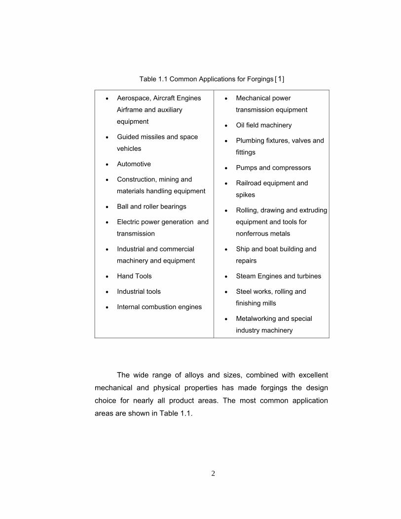
Table 1.1 Common Applications for Forgings [1]
• Aerospace, Aircraft Engines
Airframe and auxiliary
equipment
• Guided missiles and space
vehicles
• Automotive
• Construction, mining and
materials handling equipment
• Ball and roller bearings
• Electric power generation and
transmission
• Industrial and commercial
machinery and equipment
• Hand Tools
• Industrial tools
• Internal combustion engines
• Mechanical power
transmission equipment
• Oil field machinery
• Plumbing fixtures, valves and
fittings
• Pumps and compressors
• Railroad equipment and
spikes
• Rolling, drawing and extruding
equipment and tools for
nonferrous metals
• Ship and boat building and
repairs
• Steam Engines and turbines
• Steel works, rolling and
finishing mills
• Metalworking and special
industry machinery
The wide range of alloys and sizes, combined with excellent
mechanical and physical properties has made forgings the design
choice for nearly all product areas. The most common application
areas are shown in Table 1.1.

3
1.1.1 Types of Forging Operations
Forging can be carried out at room temperature, called cold, or
at elevated temperatures, called warm or hot forging, depending on the
temperature. The temperature ranges are given in Table 1.2 in terms of
the homologous temperature, which is the ratio of the testing
temperature to the melting point temperature, T/Tm, where Tm is the
melting point of the workpiece material and both are expressed in
degrees Kelvin. The homologous recrystallization temperature for
metals is about 0.5 [2].
Table 1.2 Homologous Temperature Ranges for Various Processes
There are mainly two types of forging operations called open
and closed die forging according to the type of the die set. Forging may
be performed by placing a workpiece between two flat or curved
plates, which is called open-die forging. Full control of the geometry of
the forging is not satisfied and in general, large forgings are produced
with this kind of operation. The initial shape of a forging in a forging
PROCESS T / Tm
Cold Working < 0.3
Warm Working 0.3 to 0.5
Hot Working > 0.5

4
sequence is also given between open dies so as to prepare the part for
a preforming or a final step.
In impression or closed-die forging, while the workpiece is being
upset between the closing dies, it acquires the shape of the die
cavities. In most hot forging operations, the temperature of the
workpiece materials is higher than that of the dies. The main objective
of the closed die forging is to ensure adequate flow of the metal in the
dies in order to obtain the desired finished part geometry without any
defects and with prescribed properties.
There are several types of forging machines that may be used
for the open die, impression die and cold forging processes. Some of
the forging presses are shown in Figure 1.1. They vary in factors such
as the rate at which energy is applied to the workpiece, and the
capability to control the energy. Each type has distinct advantages and
disadvantages, depending on the number of forgings to be produced,
dimensional precision, and the alloy being forged.
Hydraulic presses have a constant low speed and are load
limited. Large amounts of energy can be transmitted to the workpiece
by a constant load available throughout the stroke.
Mechanical presses are stroke limited and they are basically
crank or eccentric types, with the speeds varying from a maximum at
the center of the stroke to zero at the bottom. The force available
depends on the stroke position and becomes extremely large at the
bottom dead center.
Hammers derive their energy from the potential energy of the
ram, which is then converted to kinetic energy; thus they are energy
limited. The speed are high, therefore the low forming times minimize
cooling of the hot forging, allowing the forging of complex shapes, with
thin and deep recesses.

5
Figure 1.1 Schematic Illustration of Various Types of Presses Used in
Forging [2]
Screw presses derive their energy from a flywheel. The forging
load is transmitted through a vertical screw. These presses are energy
limited and can be used for many forging operations.
The choice of the forging process, for any product, depends on
many factors, in terms of material and weight of the workpiece, the
size, quality, and quantity of the forging required.
1.1.2 Forging Design Parameters
In a general bulk forming process, the key areas of interest
should include [3],
6
• workpiece material : shape and size, chemical composition and
microstructure, flow properties under processing conditions,
thermal and physical properties
• dies or tools : geometry, surface conditions, material and
hardness, surface coating, temperature, stiffness and accuracy
• interface conditions : surface finish, lubrication, friction, heat
transfer.
• work zone : mechanics of plastic deformation, material flow,
stresses, velocities, temperatures.
• equipment used : speed, production rate, force and energy
capabilities, rigidity and accuracy.
The control of the above parameters helps the manufacturer to
predict the characteristics of the final product.
Forging process has several design parameters which are
specific to itself in terms of; the selection of presses, forging and die
materials, temperature, forging sequence, preforms that help the final
product to have the desired material properties and geometrical shape,
the parting plane, dimensions of dies such as gutter and flash
clearances, and the location of impressions. As it is in nearly all bulk
forming operations, cost is also a very important factor that influences
the selection of the above parameters. One has to predict several
factors to optimize a forging operation.
One very practical method by which a scientific approach to
improving forging technology can be applied is to maintain accurate
and detailed records of forging variables. This kind of information then
can be used to select forging practices for alloys and parts to be forged
in the future.

7
1.1.3 Forging Defects
Defects in forgings can be caused by excess material, thick
webs, small radii, grain flow pattern and the anisotropy of the forged
part.
Excess material in the web of a forging may buckle during
forging and develop laps. If the web is thick, the excess material flows
past the already forged portions and develops internal cracks,
indicating the importance of properly distributing material and
controlling the flow in the die cavity. Also, as a result of oversized
stock, the material at the center of the part flows past the filled regions
as the deformation continues as seen in Figure 1.2 [2].
Figure 1.2 Internal Defects Because of an Oversized Billet in Forging
The various radii in the die cavity can significantly affect
formation of defects. In Figure 1.3, the material follows a large corner
radius better than a small radius. With small radii, the material can fold
over itself and produce a lap, called cold shut.
Although it may not be considered a flaw, another important
aspect of quality in a forging is the grain flow pattern. At times the grain
flow lines reach a surface perpendicularly, exposing the grain
boundaries directly to the environment. They are known as end grains.

8
Figure 1.3 Effect of Fillet Radius on Defect Formation in Forging. On The
Right Side of Drawings Small Fillets are Shown Causing Defects [2]
In service, they can be attacked by the environment and develop a
rough surface and act as stress raisers. For critical components, end
grains in forgings can be avoided by proper selection of the original
workpiece orientation in the die cavity and by control of material flow.
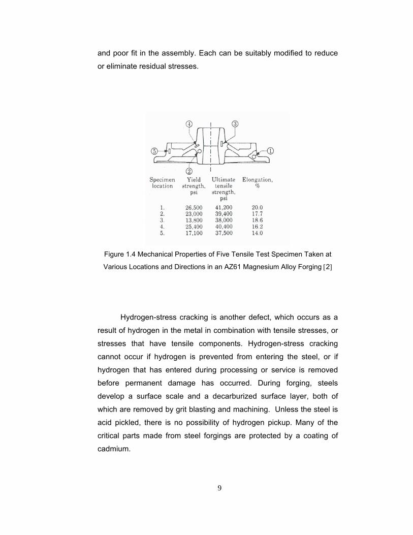
Because the metal flows in various directions in a forging, and
because of temperature variations, the properties of a forging are
generally anisotropic. As Figure 1.4 shows, strength and ductility vary
significantly in test specimens taken from different location and
orientations in a forged part.
Residual stresses should also be considered in the design
stage. The sustained tensile stress at the surface of a forging that
contributes to stress corrosion cracking is the total of applied and
residual stresses. When the residual stress constitutes a significant
percentage of the total stress, it should be reduced or eliminated.
Common sources of residual stresses include quenching, machining,
9
and poor fit in the assembly. Each can be suitably modified to reduce
or eliminate residual stresses.
Figure 1.4 Mechanical Properties of Five Tensile Test Specimen Taken at
Various Locations and Directions in an AZ61 Magnesium Alloy Forging [2]
Hydrogen-stress cracking is another defect, which occurs as a
result of hydrogen in the metal in combination with tensile stresses, or
stresses that have tensile components. Hydrogen-stress cracking
cannot occur if hydrogen is prevented from entering the steel, or if
hydrogen that has entered during processing or service is removed
before permanent damage has occurred. During forging, steels
develop a surface scale and a decarburized surface layer, both of
which are removed by grit blasting and machining. Unless the steel is
acid pickled, there is no possibility of hydrogen pickup. Many of the
critical parts made from steel forgings are protected by a coating of
cadmium.

10
1.1.4 Forging Design Optimization
In order to optimize forging parameters, process should be
simulated to assure filling of dies and to avoid flow induced defects
such as laps and shuts, process temperature should be predicted to
control mechanical properties of the forging part together with friction
conditions and die life, and also grain flow and microstructure should
be predicted. For the prediction of these parameters several methods
are being used in the industry, one of which is to establish a
preliminary die design and select process parameters by using
experience based knowledge.
In hot-forging dies, thermomechanical loading is large enough to
produce stresses beyond the yielding point, especially at critical
regions of stress concentration, such as geometrical irregularities of
the surface. Another reason for a non-homogeneous distribution of
stress and its rise beyond the yielding point is a non-optimal design of
preform for the final forge. This causes the accumulation of plastic
strain and, therefore, accumulation of damage in the critical areas of
the die. The investigation of hot ductility for die steel makes possible
the application of damage mechanics to the die fracture, and
calculation of the level of damage introduced into the die after every
forging cycle. By changing the preform design, the level of damage can
be minimized, and an optimal preform shape that gives the longest die
life can be found.
The most important design consideration in a forging sequence
is therefore the preform design. With the correct selection of number
and shape of the preforms, die life should be improved, material should
be flown through the intended direction, required load should be
reduced and the process time should be decreased.
Lapovok et al. described the steps of preform optimization
including the following sequence [4];
11
• Choose the main geometrical parameters defining the form of
the preform, and plan the mathematical experiment by
prescribing the variation of these parameters.
• Determine the form of preforms according to every set of
selected geometrical parameters in the plan of the mathematical
experiment.
• Choose the criteria for preform optimization (e.g. die life).
• Solve the plasticity boundary problem for every set of selected
geometrical parameters in the plan of the mathematical
experiment.
• Define the discriminating function which depends on the main
geometrical parameters (e.g. the die life as a function of the
geometrical parameters of the preform), and investigate its
extremum to determine the optimal parameters
1.2 Forging Materials
Virtually all metals have alloys that are forgeable, giving the
designer the full spectrum of mechanical and physical properties of
ferrous and non-ferrous alloys. The most common forging alloys
include:
• Carbon, microalloy and alloy steel forgings account for the
greatest volume of forgings for a very wide range of
applications.
• Stainless steels are widely used where resistance to heat and
corrosion are required
12
• Aluminum forgings are used in applications where temperatures
do not exceed 150oC, and where weight of the component is an
issue.
• Copper, brass and bronze forgings offer excellent corrosion
resistance with high thermal and electrical conductivity.
• Iron, nickel and cobalt high temperature alloy forgings are
preeminent for applications of cyclical and sustained loads at
high temperatures.
• Titanium forgings are used where high strength, low weight and
excellent corrosion resistance, combined with moderate heat
resistance, are required.
• Magnesium forgings offer the lowest density of any commercial
structural metal, at operating temperatures similar to aluminum.
In this study, several alloy steels will be investigated. Special
emphasis will be given on types of steels on the following pages.
1.2.1 Steels
Steel may be defined as iron in a modified form, artificially
produced, containing a certain amount of carbon and other
constituents and possessing a hardness, strength, elasticity, etc.,
which vary with chemical composition and thermal treatment.
Steels can be classified by a variety of different systems such as:
• The composition, such as carbon, low-alloy or stainless steel,
• The manufacturing methods, such as open hearth, basic oxygen
process, or electric furnace methods,
• The finishing method, such as hot rolling or cold rolling,

13
• The product form, such as bar plate, sheet, strip, tubing or
structural shape,
• The deoxidation practice, such as killed, semi-killed, capped or
rimmed steel,
• The microstructure, such as ferritic, pearlitic and martensitic,
• The required strength level, as specified in ASTM standards,
• The heat treatment, such as annealing, quenching and
tempering, and thermomechanical processing,
• Quality descriptors, such as forging or commercial quality.
There are hundreds of steels that range in carbon content from
approximately 0.06% to 1.5%. Many contain metallic alloying elements,
such as manganese, chromium and molybdenum, ranging from trace
amounts to approximately 9%. Virtually all can be readily forged. There
are two groups within the general classification of steels: carbon steels,
and alloy steels.
1.2.1.1 Carbon Steels
As defined in ASTM standards, carbon steel is a steel that
conforms to a specification that prescribes a maximum limit, in mass
percent, of not more than: 2.00 for carbon and 1.65 for manganese,
but does not prescribe a minimum limit for aluminum, boron, chromium,
cobalt, columbium, molybdenum, nickel, tungsten, vanadium, or
zirconium. Popular carbon grades include DIN C15, C45, and C60.
Carbon grades are used extensively in applications which require
machining, welding, forging or induction hardening.
14
1.2.1.2 Alloy Steels
In general, alloy steel is used when more strength, ductility or
toughness is required than can be obtained in a carbon grade. In
addition, alloy grades should be used where properties such as
corrosion resistance, heat resistance and low-temperature impact
values are required. Microalloyed steels, which are carbon products
with very low ranges of elements (such as vanadium, niobium and/or
titanium), and stainless steels may be classified as alloy steels.
Detailed information about alloy steels will be given in Chapter 2.
1.2.2 Material Selection
The selection of material for a forging part requires a balance
between factors such as strength versus toughness, stress-corrosion
resistance versus weight, manufacturing cost versus useful load-
carrying capacity, maintenance cost versus production cost, heat
treatment versus using special alloys. An efficient design aims to
produce a part from the minimum amount of material with the lowest
loads on dies. The material is first examined for toughness and
strength, then qualified for stability to temperature and environment.
Selected materials are then analyzed for producibility and economy at
the last step. To obtain data for material properties, failure analyses
offer useful data. Failure of a component can occur during operation
within the design stress range. Lack of proper orientation of a critical
design stress with the preferred grain flow may cause failure.
Failure may also occur because of deterioration of material
properties with time and service conditions. Failure analyses may help
to understand the causes of unexpected failure, such as grain growth,
inclusions of nonmetallic impurities, grain flow folding from improper
forging practice, lack of a wrought metallurgical structure and from the

15
unintentional production of stress raisers by machining to a very sharp
fillet or by poor fit in assembly [5].
The strength to density ratio is one of the most important
parameters in material selection. It resembles the strength per unit
weight of parts, which are used mostly in aerospace applications where
low weight and high strength is a major requirement. In Figure 1.5, strength-density ratios of several aerospace-forging alloys tested at
room temperature are shown.
Figure 1.5 Room Temperature Strength-Density Ratios of Aerospace
Materials [5]
In order to select the most appropriate material, one has to have
information on the material and the process specifications. Material
specifications define material properties or requirements. However,

16
they often include one or more sections on processing such as heat
treatment, forging operations, and inspection. Processing
specifications may include sections on materials. As a result, material
and process specifications are closely related. The tests contained in
the material specifications are intended to provide correlation with the
behavior material in real life use. Room temperature laboratory fatigue
and fracture-toughness testing does not reflect the effects of operating
conditions of environment and temperature on the reliability and life
expectancy of forged components. Most test data have been of limited
usefulness because of a lack of direct correlation with service
conditions.
1.3 Simulation of Forging
In the design of forging operations, information is necessary
such as material flow in the dies, level of die fill, defects, strain, stress,
temperature distribution in the work pieces and the dies, and working
force. In the subsequent heat treatment operations, information on
combination of microstructure, residual stresses and dimensional
accuracy in the final product are also very important. Such information
may be obtained by numerical simulation [6].
On the other hand, the information obtained from the simulation
of forging is also very important for the subsequent heat treatment
process because the residual stress from the forging process does
influence the results of heat treatment.
Many approaches have been developed in the field of closed-
die forging to integrate the use of numerical simulation techniques and
CAD programs based on empirical rules in the form of expert systems
or intelligent knowledge-based systems. One of these approaches was
adopted at the University of Birmingham in developing an expert

17
system for upset forging die design which combined the results of
many years research into the design based on empirical guidelines
and finite element metal forming simulation [7].
Various CAD/CAE packages are being used in the industry and
for the academic studies so as to obtain the necessary information
stated above. Some of these packages are briefly introduced below:
FORGE2 and FORGE3 are software packages developed
through a joint research program, involving major companies such as
Snecma, Peugeot, Pechiney, Safe Ascometal and the Ecole des Mines
de Paris, a leading French university. FORGE2 is dedicated to the
simulation of hot, warm and cold forging of axisymmetric parts and
parts with high length-to-width ratios such as cylinders, impacts,
extrusions, axles, shafts, gear blanks, rings, fasteners and wire
drawing, aircraft disks, blades, wheels, bearing cages, and railway
wheels. FORGE3 examples of fully three-dimensional parts include
steering knuckles, crankshafts, twin connection rods, lower arms,
constant velocity joints, bevel gears, aircraft landing gears, fan blades,
engine mountings, and wing components.
QFORM3D is used for the simulation of hot, warm and cold
forming processes. The software predicts material flow defects,
identifies the temperature distribution, assesses the load and
consumption of energy for the deformation. It features a direct interface
to Pro/Engineer (PTC), Solid Works (Solid Works Corp.), TFlex CAD
(Top Systems), Solid Edge (Unigraphics) and Mechanical Desktop
(AutoDesk), speeding up the operation considerably. The software
generates a finite element mesh on the die and workpiece surface and
inside automatically, restructuring it in the solution process, as
required.
DEFORM™-3D is a process simulation system designed to
analyze the three-dimensional flow of complex metal forming

18
processes. Based on the finite element method, DEFORM™ has
proven to be accurate and robust in industrial applications. The
simulation engine is capable of predicting large deformation material
flow and thermal behavior with precision. The software simulates
material flow, die fill, forming load, tool stress and defect formation in
cold, warm and hot forming processes.
MSC. Patran is an open-architecture, general software, 3-D
mechanical computer aided engineering software package with
interactive graphics providing a complete CAE environment. It enables
direct access to geometry from many CAD systems for creating finite
element models. MSC.Patran finite element system permits the user to
directly access model geometry and to quickly develop finite element
meshes. It can perform thermal, fatigue, and composite laminate
analyses.
MSC.Superform is a simulation tool for the simulation of bulk
forging processes and manufacturing tools. MSC.SuperForm features
integrated 2-D and 3-D thermally coupled analysis, damage analysis,
simulation of forming tools, integrated material database, and press
kinematics. MSC.SuperForm's graphical user interface is designed
specifically to meet the demands of the bulk forging industry. The
simulation software uses a fully automated remeshing technology
based on material deformation and die geometry. Using the improved
meshing technology, MSC.SuperForm can simulate various machining
operations.
MSC.SuperForge is a new software application for the computer
simulation of industrial forging processes. It combines a Windows
graphical user interface with a robust solution procedure to provide
unprecedented accuracy and speed in forging simulations. It is the first
"meshless" forging simulation tool available on the market, and is
utilized by leading forging companies and suppliers around the world to

19
simulate the forging of a wide variety of practical industrial parts.
MSC.SuperForge provides forging process engineers with detailed
insight into the forging process, including material flow, die fill, flash
regions, laps/folds and die loads. Unlike a traditional finite element
mesh, which distorts while attempting to follow the deformation of
material, the finite volume mesh in MSC.SuperForge defines a fixed
frame of reference through which the workpiece material simply flows.
1.4 Previous Studies
In a study, a bevel gear forging preform design is altered to
improve the product quality and to secure the effective material flow. In
this study, it has been shown how an improvement can be made
through an improved design using finite element simulation [8].
Caporalli, Gileno and Button studied on an expert system for hot
forging design. A software interfacing MS Visual Basic v.5.0 and
SolidEdge v.3.0 was used to design flashless hot forged parts. The
dimensions of the billet were calculated from the volume of the final
forging. The best shape and dimensions of the preform were defined
from the results of simulations with FEM program ANSYS [9].
In his paper, Lapovok described an approach to improve hot-
forging die life by minimization of damage accumulation and
optimization of preform design. He observed an improvement in the die
life of a gear-annulus forging, using simulations as a tool and
distribution of equivalent plastic strain as an objective function. He
used a damage accumulation formula and optimized the geometrical
parameters of the forged part [4].
Matlock, Krauss and Speer considered the processing
approaches for the production of direct-cooled forging steels with

20
emphasizing features that control strength and toughness. They stated
that medium-carbon, direct-cooled microalloyed forging steels replace
the quenched-and-tempered steels to realize cost savings associated
with controlled cooling after forging instead of conventional quenching
and tempering heat treatment of low alloy steels [10].
The microstructure of a medium carbon microalloyed steel and
the influence of thermomechanical treatment conditions on the final
austenite grain size have been studied. It was found that the strain rate
can be as important as the strain to influence the final microstructure
and therefore the mechanical properties of the final product [11].
A system for quantifying and comparing the sensitivity of a
thermomechanical finite element analysis of forging to variations in
different input parameters is reported by Snape et al. Since the number
of parameters makes it impractical to investigate all of them, they have
restricted the investigations to the parameters that define the flow
stress of the forged steel, heat transfer and friction at the die-workpiece
interface. They investigated the response of five results which are
maximum generalized strain, maximum load, forging work, final die fill
and the complexity factor, to input variations [12].
Zhao et al. developed a finite element based sensitivity analysis
method for preform die shape design in forging, by controlling the
deformation uniformity. In the optimization problem, it is considered to
minimize the effective strain variation within the final forging through
optimizing the preform die shape, so as to obtain a more uniform
deformation within the final forging. The sensitivity of the objective
function is calculated by the accumulated sensitivities of the nodal
coordinates and the elemental effective strain to design variables
throughout an entire simulation [13].
A sensitivity analysis based preform die shape design for
flashless forging operations was proposed by Guoqun Zhao, Ed Wright
21
and Ramana V. Grandhi [14]. They represented the preform die
shapes by cubic B-spline curves. They studied on an optimization
problem in which they tried to minimize the zone where the realized
and desired final forging shapes do not coincide. They concentrated on
two-dimensional problems and left the determination of the initial size
of the stock as a future work.
Taylan Altan has proposed a computer aided sequence design
system consisting of a computer program, a CAD program and a
commercial Finite Element program. The aim of the study was not to
develop a computer system to automate a forming sequence design,
but to develop computer aided tools to assist the designers. They built
a sequence library using the reference works and the industrial
practices. Finite element simulations were used to optimize the
process variables and die design to reduce the process development
effort and cost [15].
Altan et. al. [16], summarized the flow stress data from the
literature and showed that forging stresses vary considerably among
materials and with temperature and strain rate.
1.5 Scope of the Thesis
Forgeability and strength are important material properties in
forging. Poor forgeability may cause rupture before the die has been
filled. High flow stress may result in underfilling of the die. Each
material has different flow and forgeability characteristics. However,
sufficient number of comparative studies have not been encountered in
the literature.
This study aims investigating forging of specific alloys. The
forging sequence will be investigated and the effects of material

22
selection on the processes will be observed. Pro/ENGINEER is used
for 3D modeling of the parts and simulations are performed by using
MSC.Superforge. Case studies will be performed by using the parts
made of different alloy and carbon steels. The results of the forging
experiments, which have been carried out in the forging company, will
be compared with the computer simulations.
In Chapter 2, characteristics of alloy steels are provided. In
Chapter 3, the design considerations in forging process are given. In
Chapter 4 and 5, case studies realized for industrial forgings are
presented. Finally, conclusions and suggestions for future works are
discussed in Chapter 6.
23
CHAPTER 2
ALLOY STEELS
2.1 Introduction
Alloy steel is defined in ASTM standards as a material that
conforms to a specification that requires one or more of the following
elements, by mass percent, to have a minimum content equal to or
greater than: 0.30 for aluminum; 0.0008 for boron; 0.30 for chromium;
0.30 for cobalt; 0.06 for columbium (niobium); 0.40 for copper; 0.40 for
lead; 1.65 for manganese; 0.08 for molybdenum; 0.30 for nickel; 0.60
for silicon; 0.05 for titanium; 0.30 for tungsten (wolfram); 0.10 for
vanadium; 0.05 for zirconium; or 0.10 for any other alloying element,
except sulphur, phosphorus, carbon, and nitrogen.
Engineers have demanded steels with higher and higher tensile
strength, together with adequate ductility. This has been particularly so
where lightness is desirable, as in the automobile and aircraft
industries. An increase in carbon content met this demand in a limited
way, but even in the heat-treated condition the maximum strength is
about 700 MPa above which value a rapid fall in ductility and impact
strength occurs and mass effects limit the permissible section.
Heat-treated alloy steels provide high strength, high yield point,
combined with appreciable ductility even in large sections. The use of
plain carbon steels frequently necessitates water quenching

24
accompanied by the danger of distortion and cracking, and even so
only thin sections can be hardened throughout. For resisting corrosion
and oxidation at elevated temperatures, alloy steels are essential.
With the exception of the high-alloy maraging steels, all the
commercially significant alloy steels are strengthened by conventional
quench hardening. Alloying elements are added to prevent or retard
the formation of nonmartensitic microconstitutents during quenching.
The maximum attainable strength level is determined by the carbon
content. In order to improve the ductility and toughness of hardened
steel, it is reheated (tempered) for a relatively short time at a moderate
temperature.
Steels containing alloying elements in high amounts can be
transformation hardened by air-cooling instead of liquid quenching.
The standard alloy steel grades are found in the AISI and SAE
1300 through 9800 series. They are listed in many AISI publications
and in the ASM and SAE Handbooks [1]. Modifications of these types
are also used in special applications. As a rule, these standard grades
are specified when more strength, ductility and impact toughness are
required than can be attained in carbon steels. They are also specified
when specific properties such as wear resistance, corrosion resistance,
heat resistance and special low temperature impact properties are
required. Some alloy steels are formulated for special treatments such
as carburizing or carbo-nitriding.
2.2 Effect of Alloying Elements
The principal alloying elements added to steel in widely varying
amounts either singly or in complex mixtures are manganese, nickel,

25
chromium, molybdenum, vanadium, tungsten, silicon, copper, cobalt
and boron.
The effect of the alloying element in the steel may be one or
more of the following:
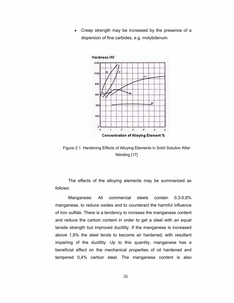
• The alloying element may go into solid solution in the
iron, enhancing the strength. Effect of alloying element
additions on hardness after nitriding with a base
composition of; 0,25% C, 0,30% Si, 0,70% Mn is shown
in Figure 2.1.
• Hard carbides associated with Fe, C may be formed.
• It may form intermediate compounds with iron, e.g. FeCr
(sigma phase), Fe, W.
• It may influence the critical temperature range.
• It may alter the carbon content of the eutectoid.
• It may alter the “critical cooling velocity”.
• Combinations of elements can be chosen so that the
volume change and the risk of quench cracking is
reduced.
• It may have a chemical effect on the impurities.
• It may render the alloy sluggish to thermal changes,
increasing the stability of the hardened condition and so
producing tool steels which are capable of being used up
to 550°C without softening and in certain cases may
exhibit an increase in hardness.
• Certain elements such as chromium, Aluminum, silicon
and copper tend to produce adherent oxide films on the
surface of the steel, which increase its resistance to
corrosion and oxidation at elevated temperatures.
26
• Creep strength may be increased by the presence of a
dispersion of fine carbides, e.g. molybdenum.
Figure 2.1 Hardening Effects of Alloying Elements in Solid Solution After
Nitriding [17]
The effects of the alloying elements may be summarized as
follows:
Manganese: All commercial steels contain 0,3-0,8%
manganese, to reduce oxides and to counteract the harmful influence
of iron sulfide. There is a tendency to increase the manganese content
and reduce the carbon content in order to get a steel with an equal
tensile strength but improved ductility. If the manganese is increased
above 1,8% the steel tends to become air hardened, with resultant
impairing of the ductility. Up to this quantity, manganese has a
beneficial effect on the mechanical properties of oil hardened and
tempered 0,4% carbon steel. The manganese content is also

27
increased in certain alloy steels, with a reduction or elimination of
expensive nickel, in order to reduce costs. Manganese increases
hardenability by lowering transformation points and causing
transformations to be sluggish.
Nickel: The addition of nickel acts similarly to increasing the rate
of cooling of a carbon steel. Steels with 0,5% nickel are similar to
carbon steel, but are stronger, on account of the finer pearlite formed
and the presence of nickel in solution in the ferrite. When 10% nickel is
exceeded the steels have a high tensile strength, great hardness,
corrosion resistance, but are brittle.
Chromium: Chromium steels are easier to machine than nickel
steels of similar tensile strength. The steels of higher chromium
contents are susceptible to temper brittleness if slowly cooled from the
tempering temperature through the range 550/450°C. These steels are
also liable to form surface markings, generally referred to as "chrome
lines".
Molybdenum: Additions of 0,5% molybdenum have been made
to plain carbon steels to give increased strength at boiler temperatures
of 400°C, but the element is mainly used in combination with other
alloying elements. Molybdenum is also a constituent in some high-
speed steels, magnet alloys, heat-resisting and corrosion-resisting
steels. It may inhibit the grain growth.
Vanadium: It has a beneficial effect on the mechanical
properties of heat-treated steels, especially in the presence of other
elements. Chromium-vanadium (0,15%) steels are used for automobile
axles, coil springs, torsion bars and creep resistance. Vanadium
increases strength while retaining ductility, and promotes fine grain
structure.
Tungsten: Tungsten raises the critical points in steel and the
carbides dissolve slowly over a range of temperature. When

28
completely dissolved, the tungsten renders transformation sluggish,
especially to tempering, and use is made of this in most hot-working
tool ("high speed") and die steels. Tungsten refines the grain size and
produces less tendency to decarburization during working. Tungsten is
also used in magnet, corrosion- and heat-resisting steels.
Silicon: Only three types of silicon steel are in common use-one
in conjunction with manganese for springs; the second for electrical
purposes, used in sheet form for the construction of transformer cores,
and poles of dynamos and motors, that demand high magnetic
permeability and electrical resistance; and the third is used for
automobile valves. It contributes oxidation resistance in heat-resisting
steels and is a general purpose deoxidizer.
Copper: It lowers the critical points, but insufficiently to produce
martensite by air cooling. The resistance to atmospheric corrosion is
improved and copper steels can be temper hardened.
Cobalt: It decreases hardenability but sustains hardness during
tempering. It is used in gas turbine steel, magnets and as a bond in
hard metal.
Boron: Boron is added to previously fully killed, fine-grain steel
to increase the hardenability of the steel. The yield ratio and impact are
definitely improved, provided advantage is taken of the increased
hardenability obtained and the steel is fully hardened before tempering.
In conjunction with molybdenum boron forms a useful group of high
tensile bainitic steels. Boron is used in some hard facing alloys and for
nuclear control rods.
Classification of alloying metals according to their effect in the
steel is difficult, because the influence varies so widely with each
addition depending on the quantity used and other elements present. A
useful grouping, however, is based upon the effect of the element on
the stability of the carbides, and the stability of the austenite.

29
2.3 Classification of Alloy Steels
Figure 2.2 Classification of Ferrous Alloys [17]
Steels can be categorized by composition, strength, formability,
hardenability, weldability, corrosion or oxidation resistance etc. A
general classification is given in Figure 2.2.
There are two general categories of alloy steels: the high-
strength-low-alloy (HSLA) types, which rely largely on chemical
composition to develop the desired mechanical properties in the as-

30
rolled or normalized condition, and the constructional alloy steels, in
which the desired properties are developed by thermal treatment [18].
Stainless steels may also be classed as alloy steel, the main
alloying elements being Nickel and Chromium. According to
applications, alloy steels may be divided into four classes:
(1) Structural steels, which are subjected to stresses in machine parts.
(2) Tool and die steels.
(3) Magnetic alloys.
(4) Stainless and heat-resisting steels.
2.4 Strengthening Mechanisms in Alloy Steels
There are some alternative procedures for improving the
strength of alloy steels by influencing the microstructure:
(1) Grain refinement, which increases strength and ductility. This
can be developed by severely reducing the time after the finishing of
forging at some low temperature of austenite stability or by rapid
heating, coupled with a short austenitising period. Fine grain is
produced in 9% Ni steel by tempering fine lath martensite.
(2) Precipitation hardening by carbide, nitride or intermetallic
compounds.
(a) By secondary hardening, e.g. 12% Cr steel with additions.
(b) Age hardening a low carbon Fe-Ni lath martensite
supersaturated with substitutional elements, e.g. maraging.
(c) Age hardening of austenite, e.g. stainless steels.
Phosphorus and titanium are common additions. Stacking
faults are often associated with fine carbide precipitates, and
31
strength can be raised by increasing the number of stacking
faults (i.e. lower fault energy.
(d) Controlled transformation 18/8 austenite steels in which
transformation to martensite is induced by refrigeration or by
strain.
(3) Thermomechanical treatments, such as deformation of
austenite prior to or during the transformation, and deformation
after the transformation of austenite.
2.5 Material Selection in Forging
In selecting the optimum alloy, first of all, the alloy must have
the ability to be forged; that is, it must be sufficiently forgeable so that
the product can be manufactured. Some alloys are relatively easy to
forge and may be used to make components with very intricate
features. Grades that are more difficult to forge require distinct design
approaches.
On the other hand, the alloy must be able to achieve the
required properties so that the product can meet service requirements.
The forging process, particularly development of grain flow,
produces significant effects on material properties. In addition, there is
a wide range of available heat treatments, particularly for steel alloys.
Arriving at the optimum material, processing and heat treatment from
the available matrix requires a balance of product design, forging and
materials expertise.
Carbon steels are selected in nearly all manufacturing areas.
Microalloyed steels serve as an alternative for their high strength and
uniform hardness without heat treatment. Alloy steels have improved
mechanical properties versus carbon steels. Stainless steels are less

32
forgeable than alloy and carbon steels and they are used in areas
where high temperature properties and corrosion resistance are
required. There are ferritic, austenitic and martensitic stainless steel
types having different characteristics; ferritic stainless steels have
excellent corrosion resistance, good ductility, and they can be worked
cold or hot. Austenitic stainless steels are highly resistant to acids and
they have good toughness at cryogenic temperatures. Martensitic
stainless steels are magnetic and they can be hardened and tempered.
Other than steels, there are various alloys in terms of aluminum,
copper base, titanium, magnesium and high temperature alloys.
Aluminum alloys can be very easily forged into precise, complex
shapes. They have low density and good corrosion resistance. They
are used mostly in aerospace, automotive, defense industries and
sporting accessories. Copper base alloys have excellent corrosion
resistance and forgeability. They are used in leak proof fittings,
plumbing fixtures, gears, bearings, pumps, value bodies, and non-
sparking applications. Titanium is a high strength alloy having a low
weight, high service temperatures and excellent corrosion resistance.
Aerospace, chemical processing and prosthetics are some of the areas
of use. Magnesium has a low density and low modulus of elasticity. It is
used where minimum weight is required at relatively low service
temperatures. High temperature alloys have good corrosion and
oxidation resistance. They are used in gas turbine components.

33
CHAPTER 3
FORGING DESIGN CONSIDERATIONS
3.1 Introduction
The applications of alloy steels in forging require several design
considerations affecting the number of stages, forging temperature,
preform design, dimensions of dies and billet, etc. Alloy steels have a
wide area of use in forging industry since they bring superior properties
to the final product. Strength and forgeability are the main parameters
of the forging materials that affect the process.
3.2 Forgeability
Forgeability is defined as the tolerance of a metal or alloy for
deformation without failure, regardless of forging-pressure
requirements. Forgeability evaluations at a particular temperature do
not necessarily define the ease with which a metal can be forged in
impression dies under process conditions. In forging operations,
temperatures of the workpiece usually differ as a result of die chilling
and because of energy absorption causing heating. A metal having a
wider forging temperature range may be easier to forge than the one,
which withstands equal amounts of deformation without rupture [19].
34
Forgeability of a metal can be determined by several tests in
terms of hot-twist, upset, notched-bar upset, hot impact tensile, tension
and compression tests [19]. Compression tests are expected to provide
values more useful for estimating forging pressures. Based on known
correlations of test values with forging performance, the hot-twist test is
particularly useful for evaluating the forgeability of carbon, low-alloy,
and stainless steel. Tension tests provide data on ductility, which agree
to some extent with the forgeability of metals at cold-working
temperatures.
The most important metallurgical variables influencing
forgeability are the composition and purity with the grain size of the
material and number of phases present. In general, the forgeabilities of
metals and alloys increase with increasing temperature. However,
there are various distinct behaviors exhibited by different alloy
systems. Improving the forgeability of an alloy by increasing the forging
temperature may lead to reduced forgeability because of grain growth
and the accompanying brittle grain boundary condition. Besides these
metallurgical factors there are some mechanical factors that influence
forgeability such as strain rate and stress distribution. Carbon and low-
alloy steels are forged better at higher deformation rates. In general,
metals exhibiting low ductility at cold-working temperatures show
reduced forgeability at increasing strain rates, and metals exhibiting
high ductility at cold-working temperatures are not affected by
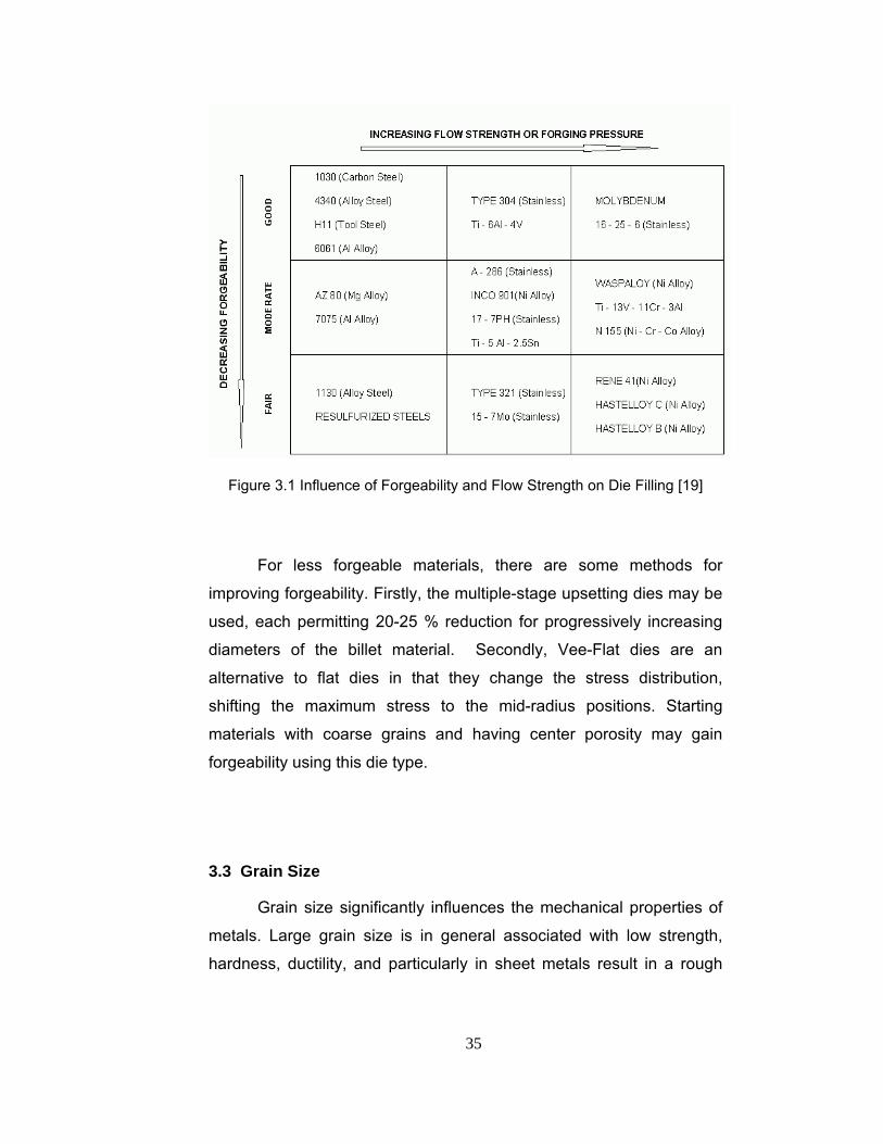
increasing strain rates as much. In Figure 3.1, the influence of
forgeability and flow strength on die filling is shown.
Types of stresses applied to the metal during deformation
contribute to the variations in forgeability. The workpiece is exposed to
a combination of compressive, tensile, and shear stresses. Tensile and
shear stresses cause ruptures in general. It is necessary to provide
compressive support to those portions of a less forgeable metal that
are normally exposed to the tensile and shear stresses.
35
Figure 3.1 Influence of Forgeability and Flow Strength on Die Filling [19]
For less forgeable materials, there are some methods for
improving forgeability. Firstly, the multiple-stage upsetting dies may be
used, each permitting 20-25 % reduction for progressively increasing
diameters of the billet material. Secondly, Vee-Flat dies are an
alternative to flat dies in that they change the stress distribution,
shifting the maximum stress to the mid-radius positions. Starting
materials with coarse grains and having center porosity may gain
forgeability using this die type.
3.3 Grain Size
Grain size significantly influences the mechanical properties of
metals. Large grain size is in general associated with low strength,
hardness, ductility, and particularly in sheet metals result in a rough
36
surface appearance after being stretched. Grain size may be
measured by counting the number of grains in a given area or the
number of grains that intersect a given length of a line randomly drawn
on an enlarged photograph of the grains taken under a microscope on
a polished and etched specimen.
Strain, strain rate and temperature are assumed as important
technological parameters influencing the grain size. The optimal
trajectories of thermomechanical parameters can be defined by using
an appropriate optimal control algorithm based on a grain size
evolution model and stable regions of thermomechanical parameters to
ensure consistency in the properties and microstructures of forgings of
difficult-to-deform materials [20].
There are several variables influencing the microstructure
development. Shape design variables are one of the most important
parameters as investigated by Gao and Grandhi [21]. The shape of
initial billet affects the forming processes, such as influencing the
distribution of strain, strain rate and temperature, then further
influencing the microstructural behavior. In theory, it is best to obtain a
uniform/fine grain size and a large recrystallized volume fraction. They
concluded that; for Waspaloy, the recrystallization occurs in a small
temperature range and a complete recrystallization does not happen in
most areas during non-isothermal forging process.
Since forging is a multistage operation with a strong relationship
between the stages, theoretical prediction of microstructure evolution
and mechanical properties of the final product is difficult. In order to
gain a full understanding, one has to combine experimental results with
the thermal–mechanical–microstructural model of a forging sequence.

37
3.4 Preforming
Decision on the preform shape is the most important step in a
forging when less forgeable materials are used and a high quality in
both the dimensions and the properties is required. In forging of carbon
or low-alloy steel, the preform should not have any flash. In addition to
this, for any type of material, the preforms should be deformed without
flash, since the formed flash before the final forging cannot be used in
the filling of the dies, and considered as scrap.
There are many studies on the determination of the optimum die
profile in the literature using computer aided design and analysis
techniques [14], [15], [22], [23].
3.5 Parting Plane
Parting plane is the plane having the maximum cross-sectional
area along the forging direction. Parting plane placement determines
whether the grain flow that is required and specified for the forging will
be obtained. After locating the parting plane, the depth and position of
the impressions in the dies are fixed. The principal grain flow direction
within the forging will be parallel to the principal direction of service
loading provided that the parting plane is placed properly. A planar
parting plane is given in Figure 3.2.
Parting Plane
Figure 3.2 A Planar Parting Plane

38
3.6 Draft
Draft refers to the angle or taper on the sides of a forging that is
necessary for releasing the forging from the dies. The location of draft
is determined by the location of the parting line. The forging has its
maximum spread at the parting plane regardless of whether the draft is
intentionally applied or is normally part of the design. Ideally, drafted
forgings should remove from dies in the first instant of separation at the
interface.
Workpieces are to be designed with no taper on vertical sides
with respect to the forging direction meaning zero draft. This requires
special forceful means for ejection from die cavities. Workpiece is then
removed from the die by mechanical means, by “strippers” that pull and
“knockout pins” that push. In such situations several features are
added to the forging in order not to harm the piece as in Figure 3.3.
Figure 3.3 Addition of the Features to a Forging Model for Ease of Removal
and not to Harm the Part

39
Zero-draft has the advantage of eliminating the machining
operations after forging. However, the more common practice with
forgings of steel, heat resisting alloys, and titanium is to finish machine
for improved surface, and the forgings are designed with draft. The
significance of cut grain and any end-grain exposure is up to what
quality is required in the forging [5].
In Figure 3.4, types of draft are shown. In steel forgings, inside
draft is generally greater than the outside draft, because the outside
surface shrinks away from the die during cooling and permit removal of
the forging.
Figure 3.4 Types of Draft [5]
3.7 Flash Some of the material flows radially outward and forms a flash.
Because of its high length-to-thickness ratio, the flash is subjected to
high pressure. The pressure in turn means high frictional resistance to
material flow in the radial direction in the flash gap. Since high friction
40
encourages the filling of the die cavities, the flash has a significant role
in the flow of material in impression-die forging. Furthermore, when the
operation is performed at elevated temperatures, the flash cools faster
than the bulk of the workpiece because of its high surface-to-thickness
ratio. Thus the flash resists deformation more than the bulk does and
helps fill the die cavities.
For the parts having holes, the design should include webs in
order not to give damage to dies. The web of a forging is relatively thin,
plate-like element placed in the hole and can be considered as an
inner flash. The remaining web section of the part can be removed
after the forging by trimming it on a press or by machining.
Recommended values for these features can be found in the related
DIN standard [24].
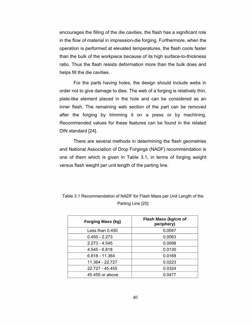
There are several methods in determining the flash geometries
and National Association of Drop Forgings (NADF) recommendation is
one of them which is given in Table 3.1, in terms of forging weight
versus flash weight per unit length of the parting line.
Table 3.1 Recommendation of NADF for Flash Mass per Unit Length of the
Parting Line [25]
Forging Mass (kg) Flash Mass (kg/cm of periphery)
Less than 0.450 0.0047 0.450 - 2.273 0.0063 2.273 - 4.545 0.0098 4.545 - 6.818 0.0130 6.818 - 11.364 0.0168 11.364 - 22.727 0.0223 22.727 - 45.455 0.0324 45.455 or above 0.0477

41
Forging is referred as flashless forging when the space between
dies is filled with no flash. The design of flashless forging processes is
more complex than the design of conventional closed die forging with
flash. Therefore, in order to accelerate the development of the
manufacturing process as well as to reduce the development costs,
new design methods must be developed and applied [26]. Flashless
forging shows much less forging load than that for conventional
forging. Trimming process is also eliminated. However a major
advantage of the closed-die forging with flash is that the volume of the
preform can vary within a wider range than for flashless forging, which
makes it easier to continuously manufacture products with the same
quality.
3.8 Temperature
In hot forging operations, temperature is a very important design
consideration in that; it directly affects the properties of the materials.
Temperature variations are influenced by the surface area of contact
between dies and forging, the part thickness or volume, die
temperature, the amount of heat generated by deformation and friction,
and the contact time under pressure. In the hot-working temperature
range, deformation occurs by breakdown of grain into subgrains
through dislocation movement, grain-boundary shearing and migration,
and fine slip [27].
Changes in temperature during closed-die forging can have
quite different effects in load requirements and in metal flow for
different materials. The forging temperatures and reductions must be
controlled to prevent grain growth. The amount of reduction is
important, because deformation heating of the workpiece influences
the effective temperature. The temperatures should be low enough to

42
prevent recrystallization during working; short periods above the
recrystallization temperature (on the order of 10 minutes) can usually
be tolerated [27].
For alloys that need control of forging temperature within a
narrow range in order to develop desirable microstructures and
properties, isothermal forging may be a good solution. The process is
named isothermal, because the tools and the stock are at the same
temperature at the beginning of forging and the low strain rates and
long dwell times minimize temperature changes. Isothermal forging is
advantageous in that, chilling, which limits permissible reductions is
eliminated. Also, heat is distributed or extracted uniformly from all
locations of a forging, which helps to stay in the required temperature
range. While it is always desirable to keep the temperature difference
between the dies and the workpiece as small as possible, it must be
considered that, the dies cannot be heated higher than the tempering
temperature of the die material, because exceeding the tempering
temperature causes the die to become softer. As a result, dies may fail.

43
CHAPTER 4
CASE STUDY ON EYE BOLTS
4.1 Introduction
In this study, metric 20 and 30 eye bolts, which are forged from
alloy steels and titanium in industry, have been investigated. A forging
model of the eye bolt is given in Figure 4.1.
Figure 4.1 Forging Model of a High Tensile Eye Bolt
These types of eye bolts are used for lifting purposes. They
have a short threaded shaft and are ideal for through-bolting fiberglass
or metal.
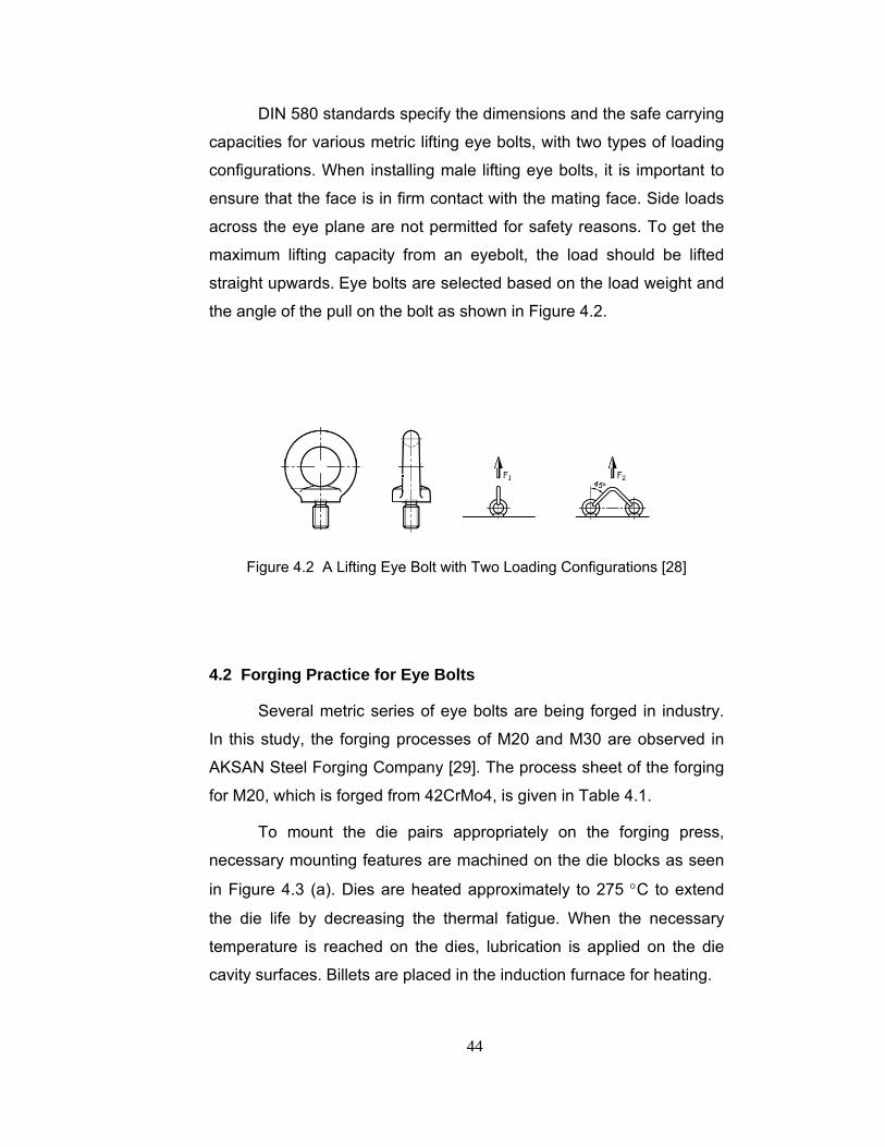
44
DIN 580 standards specify the dimensions and the safe carrying
capacities for various metric lifting eye bolts, with two types of loading
configurations. When installing male lifting eye bolts, it is important to
ensure that the face is in firm contact with the mating face. Side loads
across the eye plane are not permitted for safety reasons. To get the
maximum lifting capacity from an eyebolt, the load should be lifted
straight upwards. Eye bolts are selected based on the load weight and
the angle of the pull on the bolt as shown in Figure 4.2.
Figure 4.2 A Lifting Eye Bolt with Two Loading Configurations [28]
4.2 Forging Practice for Eye Bolts
Several metric series of eye bolts are being forged in industry.
In this study, the forging processes of M20 and M30 are observed in
AKSAN Steel Forging Company [29]. The process sheet of the forging
for M20, which is forged from 42CrMo4, is given in Table 4.1.
To mount the die pairs appropriately on the forging press,
necessary mounting features are machined on the die blocks as seen
in Figure 4.3 (a). Dies are heated approximately to 275 °C to extend
the die life by decreasing the thermal fatigue. When the necessary
temperature is reached on the dies, lubrication is applied on the die
cavity surfaces. Billets are placed in the induction furnace for heating.

45
Table 4.1 The Process Sheet of Forging M20 Eye Bolt [29]
Op #
Operation Equipment
1 Crop the bar to length of 80 - 81 mm with the
stock diameter of 40 mm Cropping Tool
2 Heat the stock up to 1100oC 100 KW Induction
Heater
3 Check the temperature Optical Pyrometer
4 First Preform: Upset the stock. After the
upsetting operation, the height should be 30-
32 mm and diameter should be 67-69 mm
10 MN Mechanical
Forging Press
5
Second Preform: Place the stock to the die
and lengthen the stock. After the operation
length should be 95-98 mm, depth should be
30-32 mm, width should be 45-46 mm
10 MN Mechanical
Forging Press
6 Final Forging: Adjust the dies such that the
flash thickness is 3.5 mm and web thickness
is 5 mm
10 MN Mechanical
Forging Press
7 Place the forged product on the hole trimmer
and trim the hole
1 MN Mechanical
Trimming Press
8 Place the finished part on the trimmer and
trim the flash 1 MN Mechanical
Trimming Press
After the billet is taken out from the furnace, the heated billet is placed
between the first pair of dies and the other stages of process are
subsequently applied to forge and trim the part in the test run. The
upper and lower dies are adjusted to obtain the required geometry and
a more uniform flash distribution and prevent misalignment.

46
(a) (b)
Figure 4.3 (a) Finish Die Used for the Forging of M20 Eye Bolt and (b) The
Final Product
4.3 Forging Simulation of M20 Eye Bolt
Simulations are performed by using MSC.Superforge, which is a
commercial finite volume analysis package. Five different materials are
used in the simulations which are a heat-treatable steel: 42CrMo4,
carbon steels C60 and C45, a stainless steel: X20Cr13 and a bearing
steel: 100Cr6. Material properties are taken from the MSC.Superforge
database. The die material is also selected from the database as H-13,
which is the commonly used die material. The open dies are used in
the simulations of the upsetting and the flattening operations and the
closed die is used in the final stage. Plastic shear friction model is used
with 0.3 as the interface friction factor [12]. The element size used in
the modeling of the workpiece is taken as 2 mm.
10 MN mechanical press is used in the numerical analysis as
used in the particular forging company. In the program, the press is
represented as given in Figure 4.4 with crank radius, (R) of 125 mm,
rod length (L) of 665 mm and rotational speed (ω) of 90 rpm.

47
Figure 4.4 Input Parameters for the 10 MN (1000 tonf) Mechanical Press
In the first step, the stock with the length of 81 mm and the
diameter of 40 mm is deformed between flat dies so that the height is
reduced to 31 mm. As a result of the simulation, the diameter of the
deformed shape becomes about 66 mm. In the second step, the upset
part is rotated 90º and it is flattened between flat dies. At the end of
this step, the parts dimensions become approximately 87 x 31 x 46
mm. The geometries of the part at the subsequent stages are given in
Figure 4.5.
Figure 4.5 Upsetting and Flattening Stages of M20 Forging

48
The part is then placed between the final forging dies. The
thicknesses of the flash and the web are 3.5 and 5 mm respectively.
The geometries of the part, before and after the final stage are
presented in Figure 4.6.
Figure 4.6 The Final Forging Stage of the Operation
The first set of simulations has been performed for three
different materials with different initial workpiece temperatures. Die
loads and die fill are examined in each simulation sequence.
The temperature of the dies are taken as 275 °C, which is the
intended value of AKSAN forging company and the ambient
temperature is assumed to be 25 °C. A carbon steel C45, a stainless
steel X20Cr13 and a heat-treatable steel 42CrMo4 are used as the
materials to be forged. In Superforge, the dies are taken as rigid and
heat transfer is allowed between dies and the workpiece. The
maximum die loads are given in Table 4.2.
It is observed that, the die loads decrease as the temperature
increases, as expected. At different temperatures, the minimum die
loads are obtained for different materials. For example, while at 800
ºC, X20Cr13 has the lowest die load, at 900 ºC and 1000 ºC, C45 and
at 1100 ºC, 42CrMo4 are most forgeable as seen in Table 4.2.

49
Table 4.2 Maximum Die Loads in Forging Various Steels at Different
Temperatures
Material
Temperature °C
Carbon SteelC 45
(DIN 1.0503)
Stainless SteelX20Cr13
(DIN 1.4021)
Heat-Treatable Steel
42CrMo4 (DIN 1.7225)
1100 7,135 x 106 N 7,208 x 106 N 6,370 x 106 N
1000 7,200 x 106 N 7,319 x 106 N 7,405 x 106 N
900 7.825 x 10⁶ N 8,109 x 106 N 8,338 x 106 N
800 8.513 x 10⁶ N 8,220 x 106 N 8,662 x 106 N
For the three steels, a sharp increase is observed at die loads
as temperature increases. The workpiece should be heated above this
critical temperature. For instance, for the stainless steel, X20Cr13, the
forging temperature should be higher than 900 ºC, looking at the die
load results.
4.4 Experimental Study of M20 Eye Bolt Five different materials have been forged for the testing
purposes. These materials are C45, C60, X20Cr13, 42CrMo4 and
100Cr6. Practically, forming temperature ranges of the selected
materials proposed by AKSAN company and the average test
temperatures measured by using a portable pyrometer are as given in
Table 4.3 [29]. Die surface temperature for the die set was measured
as 130 ºC. Although the preheat surface temperature of the dies has
been planned as 275 ºC, unfortunately the die surface temperatures
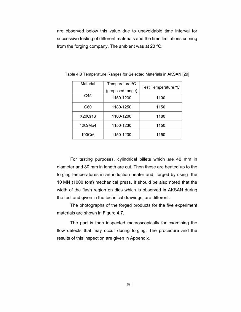
50
are observed below this value due to unavoidable time interval for
successive testing of different materials and the time limitations coming
from the forging company. The ambient was at 20 ºC.
Table 4.3 Temperature Ranges for Selected Materials in AKSAN [29]
Material Temperature ºC
(proposed range) Test Temperature ºC
C45 1150-1230 1100
C60 1180-1250 1150
X20Cr13 1100-1200 1180
42CrMo4 1150-1230 1150
100Cr6 1150-1230 1150
For testing purposes, cylindrical billets which are 40 mm in
diameter and 80 mm in length are cut. Then these are heated up to the
forging temperatures in an induction heater and forged by using the
10 MN (1000 tonf) mechanical press. It should be also noted that the
width of the flash region on dies which is observed in AKSAN during
the test and given in the technical drawings, are different.
The photographs of the forged products for the five experiment
materials are shown in Figure 4.7.
The part is then inspected macroscopically for examining the
flow defects that may occur during forging. The procedure and the
results of this inspection are given in Appendix.
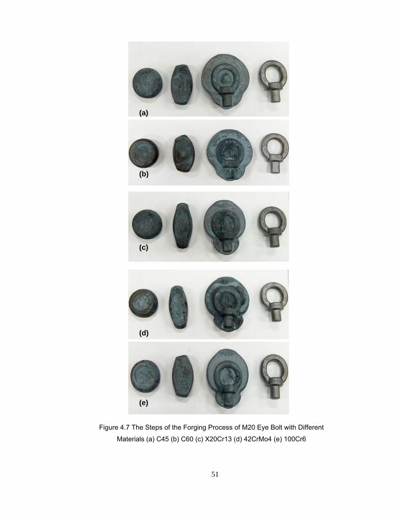
51
(a)
(b)
(c)
(d)
(e)
Figure 4.7 The Steps of the Forging Process of M20 Eye Bolt with Different
Materials (a) C45 (b) C60 (c) X20Cr13 (d) 42CrMo4 (e) 100Cr6

52
4.5 Forging Simulation of M20 Eye Bolt Using the Test Data
In the second set of simulations, the measured values of the
temperatures in the testing of M20 eye bolt in the company have been
entered in the simulations. For comparison with C45, the simulations of
C60 and 100Cr6 have also been performed with 1100 ºC as the initial
billet temperature. The results for the die loads are obtained as given
in Table 4.4. In Figures 4.8 through 4.14 die load versus time graphs
of the simulations of C45, C60, X20Cr13, 42CrMo4 and 100Cr6 are
presented respectively.
Table 4.4 Simulation Results using the Test Data
Material Temperature
ºC
Max.Die Load
(x106 N)
C45* 1100 6.808 C60* 1150 6,424 C60** 1100 6,505
X20Cr13* 1180 6,895 42CrMo4* 1150 5,748 100Cr6* 1150 5,657 100Cr6** 1100 5,713
* temperature value input for the test data
* * temperature value input for comparison purpose When the maximum die loads of C45 in the first set are
compared with the second set results, it is seen that loads are higher in
the first one. The reason of this difference is due to the flash region,
which is wider in the second case.

53
Figure 4.8 Die Load vs. Time Graph of C45 at 1100 ºC
Figure 4.9 Die Load vs. Time Graph of C60 at 1150 ºC

54
Figure 4.10 Die Load vs. Time Graph of C60 at 1100 ºC
Figure 4.11 Die Load vs. Time Graph of X20Cr13 at 1180 ºC
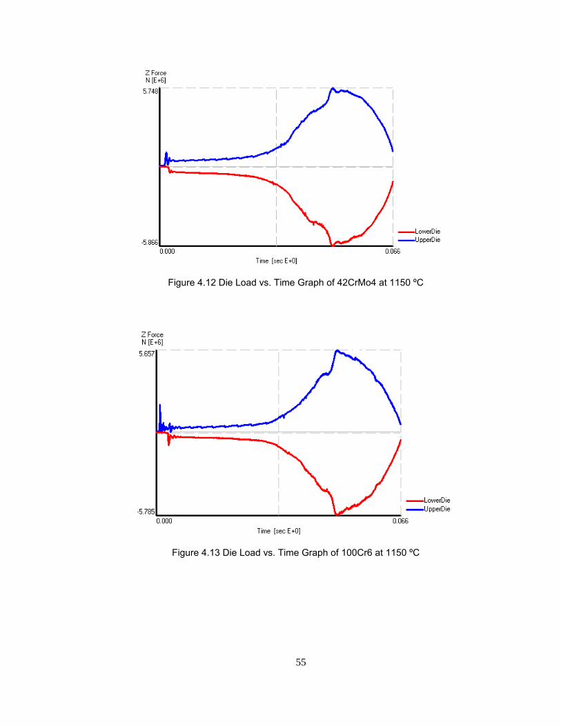
55
Figure 4.12 Die Load vs. Time Graph of 42CrMo4 at 1150 ºC
Figure 4.13 Die Load vs. Time Graph of 100Cr6 at 1150 ºC
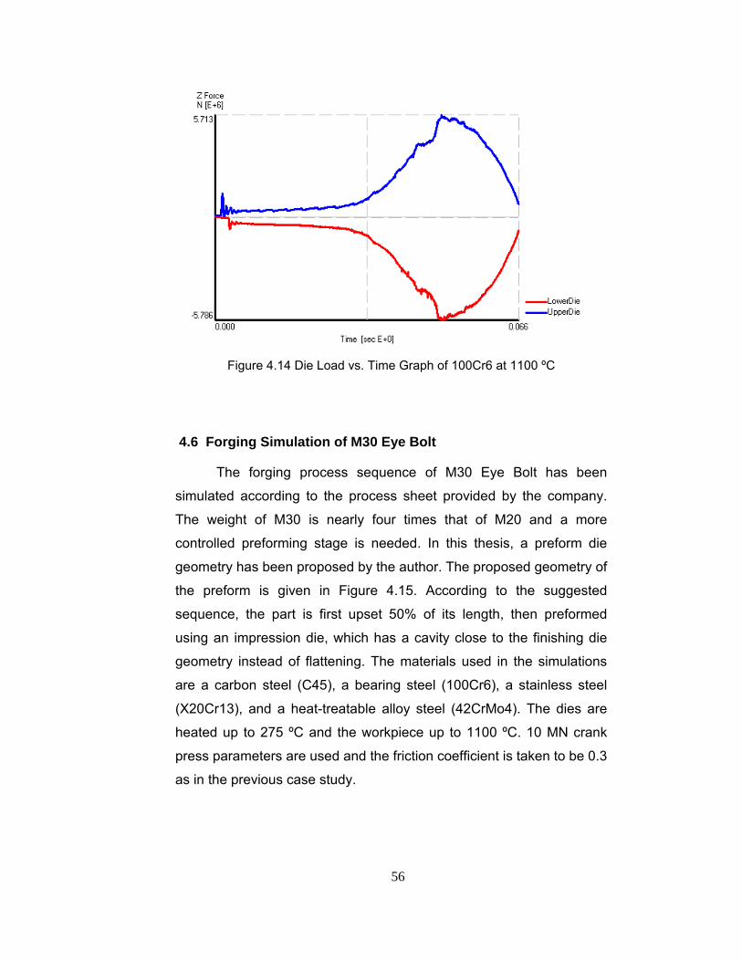
56
Figure 4.14 Die Load vs. Time Graph of 100Cr6 at 1100 ºC
4.6 Forging Simulation of M30 Eye Bolt
The forging process sequence of M30 Eye Bolt has been
simulated according to the process sheet provided by the company.
The weight of M30 is nearly four times that of M20 and a more
controlled preforming stage is needed. In this thesis, a preform die
geometry has been proposed by the author. The proposed geometry of
the preform is given in Figure 4.15. According to the suggested
sequence, the part is first upset 50% of its length, then preformed
using an impression die, which has a cavity close to the finishing die
geometry instead of flattening. The materials used in the simulations
are a carbon steel (C45), a bearing steel (100Cr6), a stainless steel
(X20Cr13), and a heat-treatable alloy steel (42CrMo4). The dies are
heated up to 275 ºC and the workpiece up to 1100 ºC. 10 MN crank
press parameters are used and the friction coefficient is taken to be 0.3
as in the previous case study.

57
Figure 4.15 The Proposed Geometry of the Preform of M30 Eye Bolt
The flash thickness and billet size are also determined in this
case study. The billet dimensions are determined by adding flash
according to the recommendations of NADF, to the original part with
the flash thickness of 4.5 mm. According to NADF, since the weight of
the forging is 1.90 kg, the coefficient is taken from Table 3.1 as 0.0063
kg/cm and using the peripheral length of 447.71 cm the flash weight is
calculated as 0.282 kg.
Simulations are initiated with a stock material having 30 mm
diameter and height of 101 mm to satisfy the volume of the final forging
including flash. The flash width is approximated to be 15 mm by using
the NADF recommendation. In the preforming stage, the dies are
closed until the distance between them is 20 mm to allow the material
to deform in the upsetting direction in the final forging step. Process
sequence is given in Figure 4.16.
Figure 4.16 Process Simulation of Forging M30 Eye Bolt
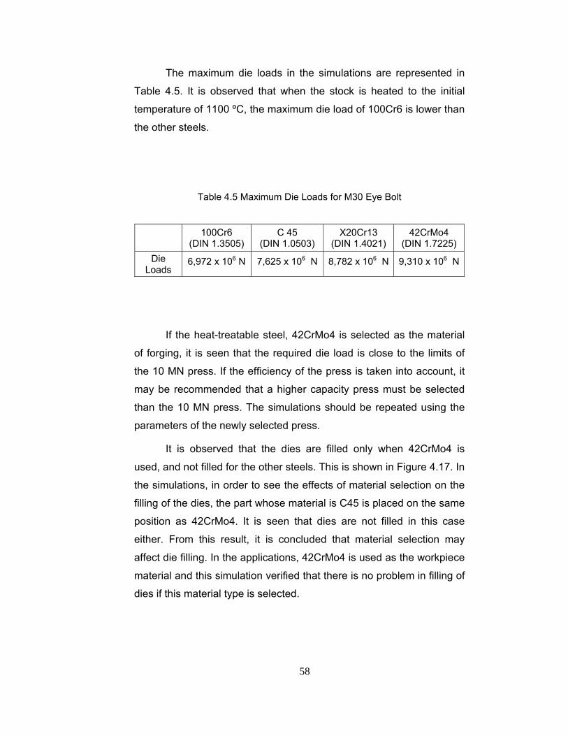
58
The maximum die loads in the simulations are represented in
Table 4.5. It is observed that when the stock is heated to the initial
temperature of 1100 ºC, the maximum die load of 100Cr6 is lower than
the other steels.
Table 4.5 Maximum Die Loads for M30 Eye Bolt
100Cr6 (DIN 1.3505)
C 45 (DIN 1.0503)
X20Cr13 (DIN 1.4021)
42CrMo4 (DIN 1.7225)
Die Loads
6,972 x 106 N 7,625 x 106 N 8,782 x 106 N 9,310 x 106 N
If the heat-treatable steel, 42CrMo4 is selected as the material
of forging, it is seen that the required die load is close to the limits of
the 10 MN press. If the efficiency of the press is taken into account, it
may be recommended that a higher capacity press must be selected
than the 10 MN press. The simulations should be repeated using the
parameters of the newly selected press.
It is observed that the dies are filled only when 42CrMo4 is
used, and not filled for the other steels. This is shown in Figure 4.17. In
the simulations, in order to see the effects of material selection on the
filling of the dies, the part whose material is C45 is placed on the same
position as 42CrMo4. It is seen that dies are not filled in this case
either. From this result, it is concluded that material selection may
affect die filling. In the applications, 42CrMo4 is used as the workpiece
material and this simulation verified that there is no problem in filling of
dies if this material type is selected.

59
(a) (b)
Figure 4.17 Final Product in Forging M30 Showing (a) Filled and (b) Unfilled
Regions

60
CHAPTER 5
CASE STUDY ON RUNNER BLOCKS 5.1 Introduction
Runner blocks, which are shown in Figure 5.1, are used in
machinery and equipment in rail systems for linear motion purposes,
and in material handling. They must be manufactured to a high degree
of precision and corrosion resistance is very important. The product
group which is analyzed in the study includes runner blocks, which are
used in ball rail systems. A runner block assembled on a ball rail
system is shown in Figure 5.2. A ball rail system consists of a guide rail
with all surfaces ground and ball track zones hardened, and a steel
runner block with bearing steel balls, integral all-round sealing of
tracks, hardened and ground steel load bearing plates with ball tracks,
and cage designed for optimum ball recirculation.
Figure 5.1 Models of Various Runner Blocks Used in Industry [29]

61
Figure 5.2 Ball Rail System [30]
In this chapter, the production of runner blocks has been
presented and simulations are performed to compare the results with
the simulations in Chapter 4 and the real-life application.
5.2 Company’s Practice for Roller Bearings
In this process, three preforming stages are applied as a
necessity which comes from the size and the weight of the product. For
lubrication, a mixture of 1 liter graphite-base oil and 15 liters of water is
used. Parting line is planar. It is very important that the part is handled
carefully using a forging tong during the hot forming and after the
trimming. Before trimming, the part is left for cooling for approximately
2 minutes and the temperature of the part decreases to about 900 ºC.
100Cr6 is used which is a ball and roller bearing steel as the material.
The process sequence is shown in Figure 5.3 and the procedure
applied by the forging company is given in Table 5.1.

62
1. Upsetting 2. Flattening
3. Preforming 4. Final Forging
5. Part Left for Cooling 6. Trimming
Products of the forging sequence
Figure 5.3 The Process Sequence of Forging a Runner Block

63
Table 5.1 The Process Sheet of the Process
Op # Operation Tool
1 Crop the square cross-section bar to a length of
185-186 mm with the side length of 90 mm Cropping Tool
2 Heat the stock up to 1100oC 970 KW Induction
Heater
3 Check the temperature Optical Pyrometer
4 First Preform: Upset the stock. After the
upsetting operation, the dimensions should be
147-151 mm in height
40 MN
Mech. Press
5
Second Preform: Place the stock to the die and
lengthen the stock. After the operation the
height should be 168-171 mm and the cross
section should be 79 x 125 mm
40 MN
Mech. Press
6 Third Preform: Place the stock to the die such
that the height of the part becomes 66 - 67 mm
40 MN
Mech. Press
7 Final Forging: Adjust the dies such that the
flash thickness is 7-7.5 mm 40 MN
Mech. Press
8 Place the finished part on the trimmer and trim
the flash 40 MN
Mech. Press
5.3 Simulation of Runner Blocks
Runner blocks have been analyzed using MSC.Superforge. In
the simulation of runner blocks, two materials are compared in terms of
a carbon steel, C45, and a bearing steel, 100Cr6. 10 MN press
parameters are used with shear friction coefficient of 0.3. In Figure 5.4,
computer models of the dies and the final product are given.
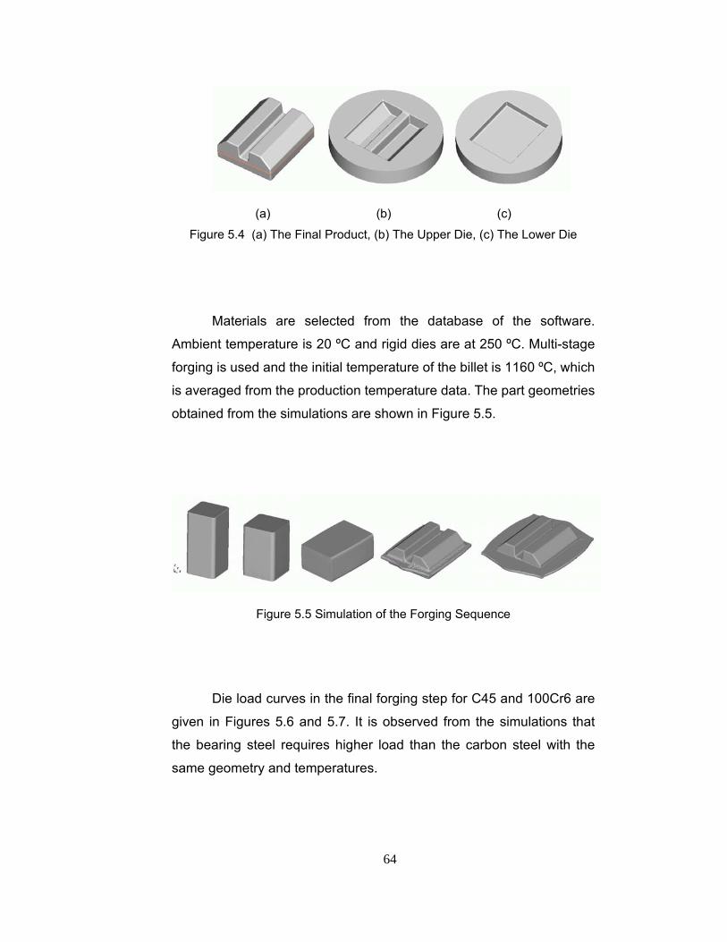
64
(a) (b) (c)
Figure 5.4 (a) The Final Product, (b) The Upper Die, (c) The Lower Die
Materials are selected from the database of the software.
Ambient temperature is 20 ºC and rigid dies are at 250 ºC. Multi-stage
forging is used and the initial temperature of the billet is 1160 ºC, which
is averaged from the production temperature data. The part geometries
obtained from the simulations are shown in Figure 5.5.
Figure 5.5 Simulation of the Forging Sequence
Die load curves in the final forging step for C45 and 100Cr6 are
given in Figures 5.6 and 5.7. It is observed from the simulations that
the bearing steel requires higher load than the carbon steel with the
same geometry and temperatures.
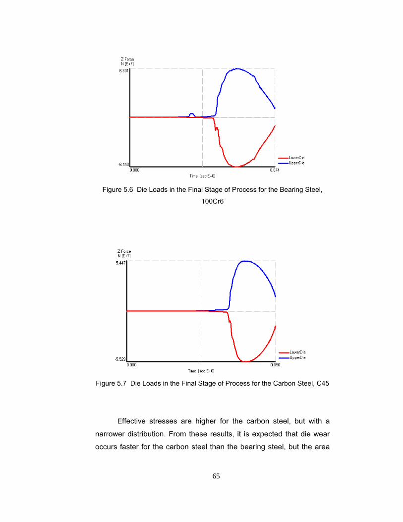
65
Figure 5.6 Die Loads in the Final Stage of Process for the Bearing Steel,
100Cr6
Figure 5.7 Die Loads in the Final Stage of Process for the Carbon Steel, C45
Effective stresses are higher for the carbon steel, but with a
narrower distribution. From these results, it is expected that die wear
occurs faster for the carbon steel than the bearing steel, but the area

66
which is prone to wear is wider for the bearing steel. Effective stresses
are represented in Figures 5.8 and 5.9.
Figure 5.8 Effective Stress Distributions for Carbon Steel at 80 % of the Final
Stroke
Figure 5.9 Effective Stress Distributions for Bearing Steel at 90 % of the Final
Stroke

67
The stage of the final impression at which the effective stress is
maximum, is different for the two steels. The occurrence of the
maximum effective stress is at an earlier stage for the carbon steel.
When the material effects are compared, it is seen that in the
simulation of M20 and M30 eye bolt, die loads are higher for the
carbon steel than the bearing steel. This shows the effect of part
geometry on the final loading.
In the simulations of both C45 and 100Cr6, dies are filled as in
the real-life application. The maximum die loads and the maximum
effective stresses are given in Table 5.2.
Table 5.2 The Maximum Die Loads and the Maximum Effective Stresses
Material Result
C45 100Cr6
Maximum Die Load (N) 5.447 x 10⁷ 6.301 x 10⁷
Maximum Effective Stress (MPa) 172.3 96.28

68
CHAPTER 6
CONCLUSION 6.1 Conclusion
In this study, the hot forging process of two groups; eye bolts
and runner blocks which are manufactured from alloy steels have been
examined. Simulations of M20 eye bolts are compared with the forging
experiments. Results have been discussed by considering die-fill,
effective stress distributions and temperature effects.
It has been observed that similar flash distributions are
observed in the simulations for the selected materials. In the practice,
the distributions follow similar contours; however for the carbon steel,
the flashes distribution is more uniform than the bearing steel. This is
seen in Figure 6.1.
(a) (b)
Figure 6.1 Flash Distribution of (a) 100Cr6, (b) C45

69
It is clear from Figure 6.1 that 100Cr6 has a higher resistance to
deformation than the carbon steel; C45, meaning that the material flow
is different for the two steels. Therefore during preform design,
simulations for the difficult-to-form materials may be helpful in
determining the preform shapes, number of preforms and the optimum
flash thicknesses.
In simulations of M20 eye bolt, it has been observed that, the
most appropriate forging temperature may be selected for different
materials. Die load results can be used for the selection of forging
press. The efficiency of the press should also be taken into
consideration in selecting the most appropriate temperature. In
mechanical presses, efficiency is not taken into consideration in the
calculations; however the maximum load that the press exerts is in
general lower than its capacity.
It can be concluded that, flow stresses of the material strongly
effects the material flow and die fill, which in turn may effect billet
dimensions in the forging operations.
In both the experiments and the simulations of M20 eye bolt,
dies are filled. However, there occurred some mismatch between the
flash distribution in simulations and during the test. The reason for this
is mostly related with the friction conditions at the workpiece-die
interface. The friction at the upper die and at the lower dies is taken
equal in the simulations, but this is not the case in the experiments.
The geometry complexity, pressure at various points on the die cavity,
lubrication are the factors that change the friction coefficient in real-life
environment.
Heat transfer coefficient is also an important parameter in
forging simulations. Kutlu [25] has simulated with different heat transfer
coefficients, he found out that changing the heat transfer coefficient
parameter is not so effective in the simulation software. The flash

70
formed at the end of the process acts as a seal that plugs the gap
between the dies. The strength of this seal, which was a function of the
flow stress of the steel in the flash, is the primary factor affecting the
maximum forging load. The most important determinant of the steel’s
flow stress is its temperature, which in the flash region, was primarily
controlled by the die heat transfer coefficient. The die heat transfer
coefficient significantly affects the flash temperature, which significantly
affects the forging load. Increasing the temperature of the dies may be
a solution for decreasing the die loads.
During the experiments, it has been observed that the
temperature of the heated billet is not constant over the entire length
changing from 1080 ºC to 1280 ºC. Moreover, scale formation on steel
during the heating, makes it difficult to measure the exact temperature
of the billet. These incorrect readings and inhomogeneous temperature
distributions are one of the reasons of the difference between the
simulations and the experiments.
The cooling of the billet and dies due to delays of the operator
and the positioning of the workpiece play a very important role on the
final shape and properties, since the temperature decreases very
rapidly as the heated billet is transferred from the induction heater to
the forging die.
6.2 Recommendations for Future Work
In this study, the main control parameter is the high temperature
material data, since the forging process in performed above the
recrystallization temperature. These parameters are directly taken from
the MSC.Superforge database. It should be valuable that these values
are determined experimentally and entered into the software.

71
Also, the temperature values during the experiment are read
using a portable optical pyrometer. The readings sometimes give
incorrect values due to the scale on the workpiece. A static pyrometer
may be used in the experiments so as to read a specific point on the
part for each forging sequence.
In order to improve the mechanical properties of the final
product, it is necessary to understand the relationship between the
development of the microstructure and the thermomechanical
variables. An analysis software can be developed in order to predict
the microstructure evolution in hot forging applications using the results
of the MSC.Superforge simulation package.
Die loads of the simulations may be compared with die loads in
the experiments using special equipment.
In the simulation software, the initial temperature of the billet is
taken constant throughout the entire volume. A computer program can
be developed in order to approximate the temperature distribution in
the billets at the beginning of the metal deformation in press.
The results of the MSC.Superforge which is a finite volume
solver may be compared with finite element programs such as
MSC.Superform, FORGE3, QFORM3D, DEFORM™-3D, MSC. Patran,
etc.
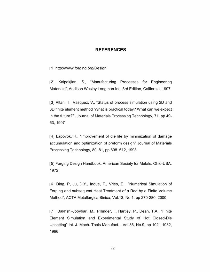
72
REFERENCES [1] http://www.forging.org/Design
[2] Kalpakjian, S., “Manufacturing Processes for Engineering
Materials”, Addison Wesley Longman Inc, 3rd Edition, California, 1997
[3] Altan, T., Vasquez, V., “Status of process simulation using 2D and
3D finite element method ‘What is practical today? What can we expect
in the future?’”, Journal of Materials Processing Technology, 71, pp 49-
63, 1997
[4] Lapovok, R., “Improvement of die life by minimization of damage
accumulation and optimization of preform design” Journal of Materials
Processing Technology, 80–81, pp 608–612, 1998
[5] Forging Design Handbook, American Society for Metals, Ohio-USA,
1972
[6] Ding, P, Ju, D.Y., Inoue, T., Vries, E. “Numerical Simulation of
Forging and subsequent Heat Treatment of a Rod by a Finite Volume
Method”, ACTA Metallurgica Sinica, Vol.13, No.1, pp 270-280, 2000
[7] Bakhshi-Jooybari, M., Pillinger, I., Hartley, P., Dean, T.A., “Finite
Element Simulation and Experimental Study of Hot Closed-Die
Upsetting” Int. J. Mach. Tools Manufact. , Vol.36, No.9, pp 1021-1032,
1996

73
[8] Lee, Y.K. Lee, S.R., Lee, C.H., Yang, D.Y., “Process modification
of bevel gear forging using 3-D finite element analysis” Journal of
Materials Processing Technology, Vol.113, pp 59-63, 2001
[9] Caporalli, A. , Gileno, L.A., Button, S.T., “Expert system for hot
forging design”, Journal of Materials Processing Technology, Vol. 80–
81, pp 131–135, 1998
[10] Matlock, D.K., Krauss, G., Speer, J.G., “Microstructures and
properties of direct-cooled microalloy forging steels", Journal of
Materials Processing Technology, 117, pp 324-328, 2001
[11] Carsi, M., Penalba, F., Larrea, M.T., Ruano, O.A., “Influence of
strain rate on the microstructure of a thermo-mechanically processed
medium carbon microalloyed steel”, Materials Science and
Engineering, A234-236, pp 703-706, 1997
[12] Snape, G., Clift, S., Bramley, A., “Parametric sensitivity analyses
for FEA of hot steel forging", Journal of Materials Processing
Technology, 5930, pp 1–8, 2002
[13] Zhao, X., Zhao, G., Wang, G., Wang, T., “Preform die shape
design for uniformity of deformation in forging based on preform
sensitivity analysis”, Journal of Materials Processing Technology,
5682, pp 1–8, 2002
[14] Zhao, G., Wright, E., Grandhi, R.V., “Sensitivity analysis based
preform die shape design for net-shape forging”, Int. J. Mach. Tools
Manufact., Vol.37, No.9, pp 1251-1271, 1997
74
[15] Kim, H., Altan, T., “Cold forging of steel- practical examples of
computerized part and process design”, Journal of Materials
Processing Technology, 59, pp 122-131, 1996
[16] Altan, T., Nichols, D. E., Boulger, F. W., “Flow Stresses of Metals
in Forging”, Contrct No. DAAG 46-71-C-0095, Battelle’sColumbus
Laboratories, First Interim Topical Report, June 22, 1971.
[17] http://www.key-to-steel.com/
[18] DeGarmo, E. P.; Black, J. T.; Kohser, R.A., “Materials and
Processes in Manufacturing”, Macmillan Publishing Company, New
York, 1988
[19] Sabroff, A.M., Boulger, F.W., Henning, H.J., “Forging Materials
and Practices”, Reinhold Book Corporation, New York, 1968
[20] Feng, J.P., Luo, Z.J. “A method for the optimal control of forging
process variables using the finite element method and control theory”,
Journal of Materials Processing Technology, 108 pp 40-4, 2000
[21] Gao, Z., Grandhi, R.V. “Microstructure optimization in design of
forging processes”, International Journal of Machine Tools &
Manufacture, 40 pp 691-711, 2000
[22] Doege, E., Stockter, R., Muckelbauer, M., “Computer Aided
Design of Forging Tools”, Int. Conference on Design and Production of
Dies and Molds, pp. 271- 276, Turkey, 1997
[23] Mynors, D.J., Bramley, A.N., Allen, M., “An examination of Manual
Design Procedures as a Precursor to the Application of Simulation”,

75
Int. Conference on Design and Production of Dies and Molds, pp. 283-
290, Turkey, 1997
[24] DIN Standard 7523 – “Design of Drop and Press Forgings”,
September 1986, Part 2
[25] Kutlu, A. E., “Analysis and Design of Preforms for Non-
Axisymmetric Press Forgings”, M. Sc. Thesis, Middle East Technical
University, Ankara, Turkey, 2001.
[26] Vazquez, V., Altan, T. “Die design for flashless forging of complex
parts”, Journal of Materials Processing Technology, 98, pp 81-89, 2000
[27] Altan, T, Boulger, F.W., Becker, J.R., Akgerman, N., Henning,
H.J., “Forging Equipment, Materials, and Practices”, Batelle Columbus
Labarotories Metalworking Division, Ohio, 1973
[28] http://www.ganter-griff.de
[29] Private Communication with AKSAN Steel Forging Industry,
Ankara, TURKEY.
[30] http://www.boschrexroth.com

76
APPENDIX
INSPECTION OF M20 EYE BOLT
After the forging experiment of M20 eye bolt, a section is cut out
from a C45 sample product including the web section, but without flash
to investigate its interior structure. The section in on the symmetry
plane of the part. To prepare the sample, first the part is cut using a
band saw, and then the surface to be examined is improved on a
manual milling machine. Further improvement on the surface is
obtained on a grinding machine and after this operation; sand paper is
applied on the surface. The surface is then etched for macro
inspection.
Figure A.1 A C45 Sample Taken out from the Symmetry Plane

77
As seen in Figure A.1, material distribution is homogeneous due
to hot working. Segregation, flow, fold or laps have not been observed
on the sample piece.