Embed Size (px)
Citation preview
ANALYSIS OF 2D TRUSSES
BY STIFFNESS METHOD
1
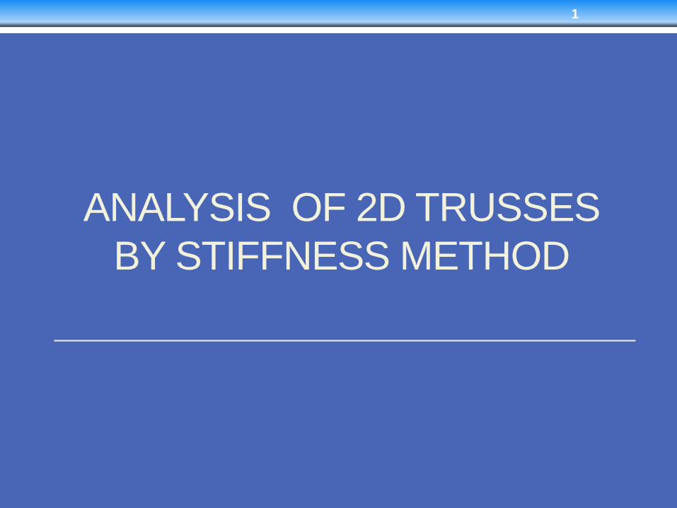
Procedure for Truss Analysis
• Step 1: Notation
• Establish the x, y global coordinate system. You may take
any joint as an origin
• Identify each joint and element numerically and specify
near and far ends of each member.
• Specify the two code numbers at each joint, using the
lowest numbers to identify degree of freedoms, followed
by the highest degree of freedom to identify constrains.
• From the problem establish Dk and Qk.
2
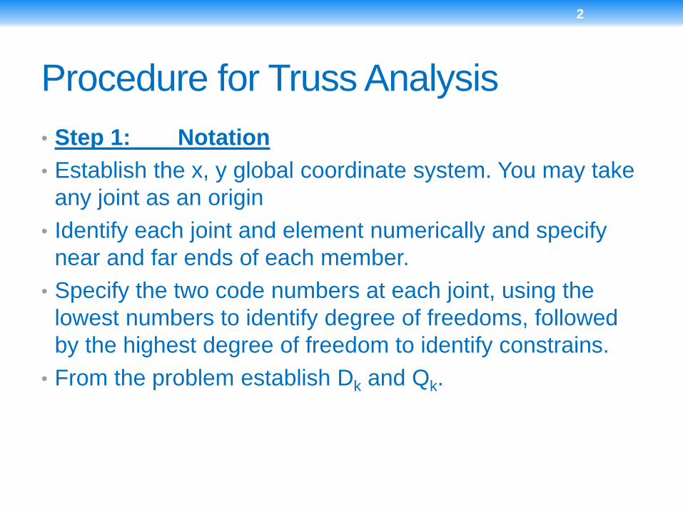
• Step 2: Structure Stiffness Matrix
• For each member of the truss determine ּגx and ּגy and
the member stiffness matrix using the following general
matrix
3
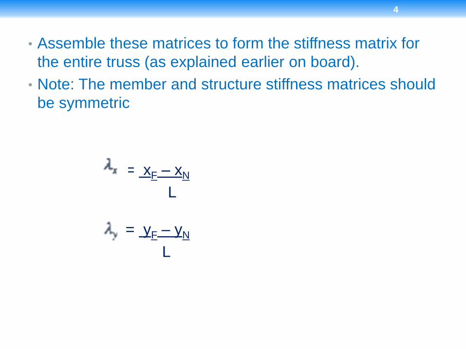
• Assemble these matrices to form the stiffness matrix for
the entire truss (as explained earlier on board).
• Note: The member and structure stiffness matrices should
be symmetric
= xF – xN
L
= yF – yN
L
4
• Step 3: Displacement and Loads
• Partition the structure stiffness matrix for easier
calculations
• Determine the unknown joint displacement Dx, the support
reactions Qx.
• Using all the unknowns the member forces in each truss
element using basic rules of truss analysis
5
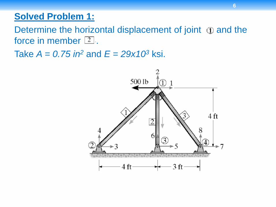
Solved Problem 1:
Determine the horizontal displacement of joint and the
force in member .
Take A = 0.75 in2 and E = 29x103 ksi.
6
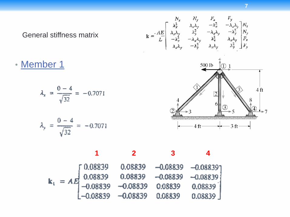
• Member 1
General stiffness matrix
7
1 2 3 4
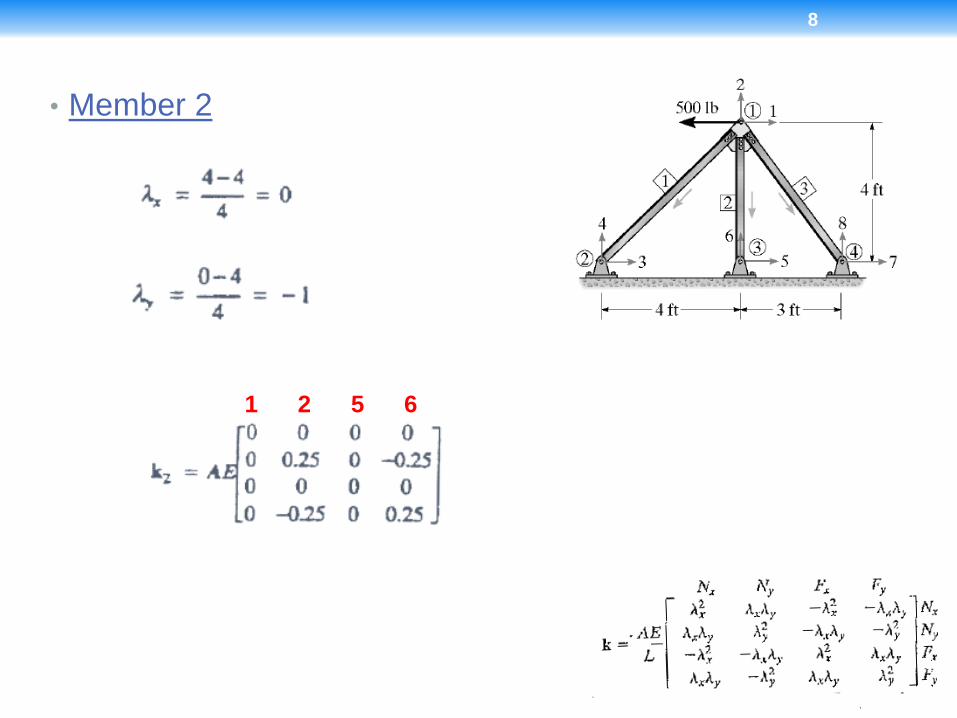
• Member 2
8
1 2 5 6
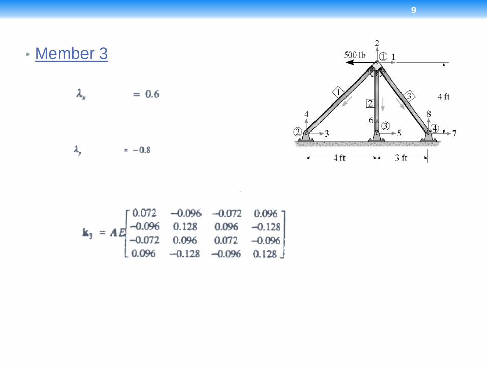
• Member 3
9
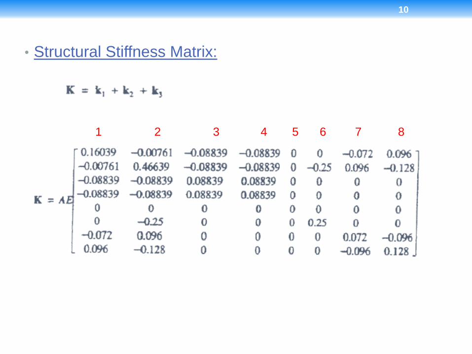
• Structural Stiffness Matrix:
1 2 3 4 5 6 7 8
10
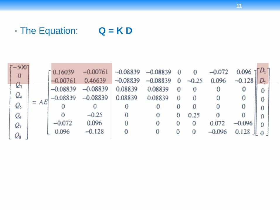
• The Equation: Q = K D
11
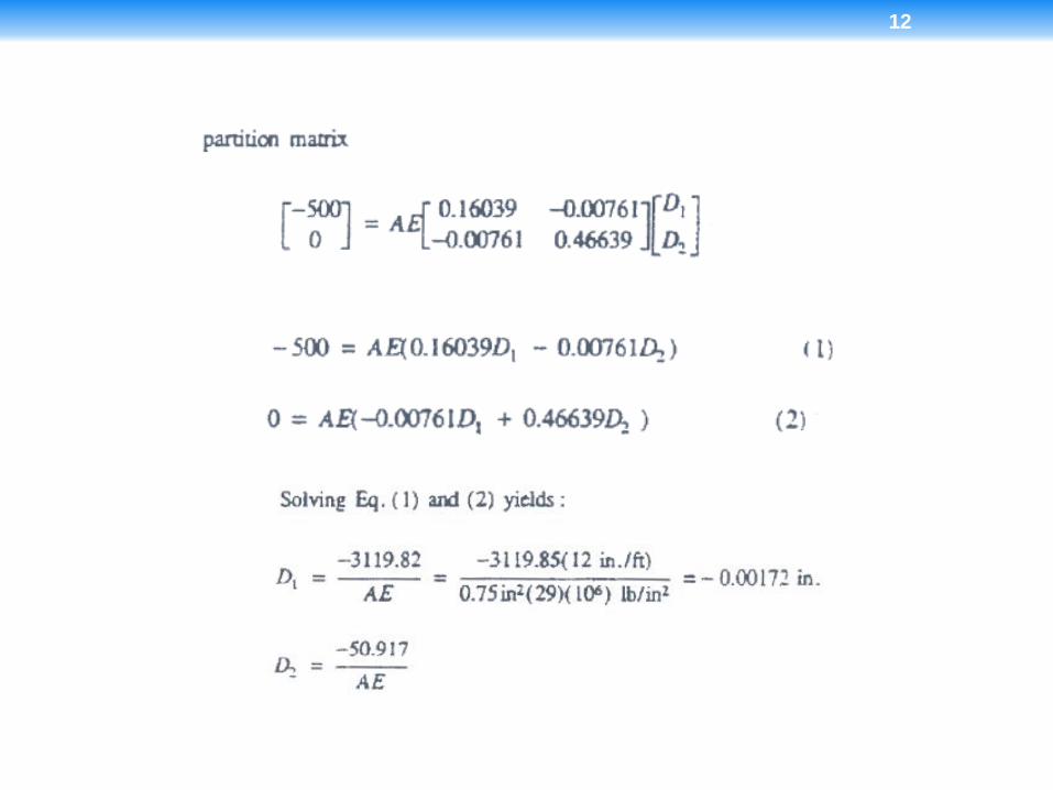
12
• Find out the values of Q3, Q4, Q5, Q6, Q7 and Q8.
• Then find out forces in member no. 2 using method of
joints.
13
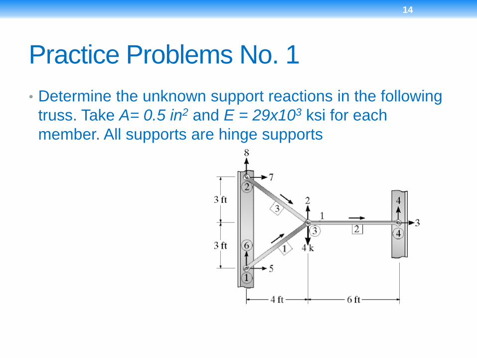
Practice Problems No. 1
• Determine the unknown support reactions in the following
truss. Take A= 0.5 in2 and E = 29x103 ksi for each
member. All supports are hinge supports
14
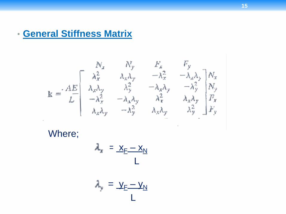
• General Stiffness Matrix
15
Where;
= xF – xN
L
= yF – yN
L
15

SOLUTION HINT
16