Embed Size (px)
Citation preview
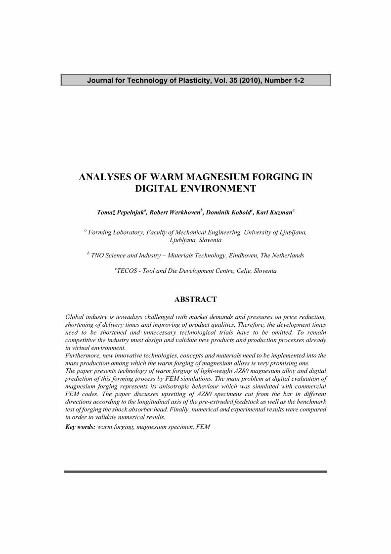
Journal for Technology of Plasticity, Vol. 35 (2010), Number 1-2
ANALYSES OF WARM MAGNESIUM FORGING IN DIGITAL ENVIRONMENT
Tomaž Pepelnjaka, Robert Werkhovenb, Dominik Koboldc, Karl Kuzmana
a Forming Laboratory, Faculty of Mechanical Engineering, University of Ljubljana,
Ljubljana, Slovenia
b TNO Science and Industry – Materials Technology, Eindhoven, The Netherlands
cTECOS - Tool and Die Development Centre, Celje, Slovenia
ABSTRACT
Global industry is nowadays challenged with market demands and pressures on price reduction, shortening of delivery times and improving of product qualities. Therefore, the development times need to be shortened and unnecessary technological trials have to be omitted. To remain competitive the industry must design and validate new products and production processes already in virtual environment. Furthermore, new innovative technologies, concepts and materials need to be implemented into the mass production among which the warm forging of magnesium alloys is very promising one. The paper presents technology of warm forging of light-weight AZ80 magnesium alloy and digital prediction of this forming process by FEM simulations. The main problem at digital evaluation of magnesium forging represents its anisotropic behaviour which was simulated with commercial FEM codes. The paper discusses upsetting of AZ80 specimens cut from the bar in different directions according to the longitudinal axis of the pre-extruded feedstock as well as the benchmark test of forging the shock absorber head. Finally, numerical and experimental results were compared in order to validate numerical results.
Key words: warm forging, magnesium specimen, FEM
14
Journal for Technology of Plasticity, Vol. 35 (2010), Number 1-2
1. INTRODUCTION
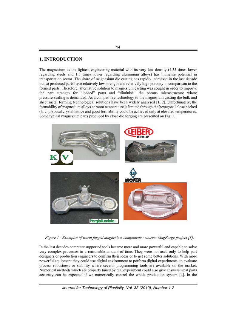
The magnesium as the lightest engineering material with its very low density (4.35 times lower regarding steels and 1.5 times lower regarding aluminium alloys) has immense potential in transportation sector. The share of magnesium die casting has rapidly increased in the last decade but so produced parts have relatively low strength and relatively high porosity in comparison to the formed parts. Therefore, alternative solution to magnesium casting was sought in order to improve the part strength for “loaded” parts and “diminish” the porous microstructure where pressure-sealing is demanded. As a competitive technology to the magnesium casting the bulk and sheet metal forming technological solutions have been widely analysed [1, 2]. Unfortunately, the formability of magnesium alloys at room temperature is limited through the hexagonal close packed (h. c. p.) basal crystal lattice and good formability could be achieved only at elevated temperatures. Some typical magnesium parts produced by close die forging are presented on Fig. 1.
Figure 1 - Examples of warm forged magnesium components; source: MagForge project [3].
In the last decades computer supported tools became more and more powerful and capable to solve very complex processes in a reasonable amount of time. They were not used only to help part designers or production engineers to confirm their ideas or to get some better solutions. With more powerful equipment they could use digital environment to perform digital experiments, to evaluate process robustness or stability where several programming tools are available on the market. Numerical methods which are properly tuned by real experiment could also give answers what parts accuracy can be expected if we numerically control the whole production system [4]. In the
15
Journal for Technology of Plasticity, Vol. 35 (2010), Number 1-2
MagForge project several commercial simulation softwares applicable for forging simulations were comparative analysed. However, at the time of the benchmark test only Deform 3D and ABAQUS were able to handle the anisotropic material behaviour. 2. PROCESS CHARACTERISTICS OF WARM FORGING OF Mg-
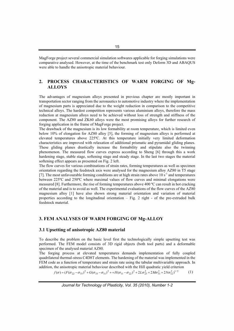
ALLOYS The advantages of magnesium alloys presented in previous chapter are mostly important in transportation sector ranging from the aeronautics to automotive industry where the implementation of magnesium parts is appreciated due to the weight reduction in comparison to the competitive technical alloys. The hardest competition represents various aluminium alloys, therefore the mass reduction at magnesium alloys need to be achieved without loss of strength and stiffness of the component. The AZ80 and ZK60 alloys were the most promising alloys for further research of forging application in the frame of MagForge project. The drawback of the magnesium is its low formability at room temperature, which is limited even below 10% of elongation for AZ80 alloy [5], the forming of magnesium alloys is performed at elevated temperatures above 225ºC. At this temperature initially very limited deformation characteristics are improved with relaxation of additional prismatic and pyramidal gliding planes. These gliding planes drastically increase the formability and stipulate also the twinning phenomenon. The measured flow curves express according to Sheng [6] through this a work hardening stage, stable stage, softening stage and steady stage. In the last two stages the material softening effect appears as presented on Fig. 2 left. The flow curves for various combinations of strain rates, forming temperatures as well as specimen orientation regarding the feedstock axis were analysed for the magnesium alloy AZ80 in T5 stage [7]. The most unfavourable forming conditions are at high strain rates above 10 s-1 and temperatures between 225ºC and 250ºC where maximal values of flow curves and minimal elongations were measured [8]. Furthermore, the rise of forming temperatures above 400 ºC can result in hot cracking of the material and is to avoid as well. The experimental evaluations of the flow curves of the AZ80 magnesium alloy [1] have also shown strong material orientation and variation of material properties according to the longitudinal orientation – Fig. 2 right - of the pre-extruded bulk feedstock material.
3. FEM ANALYSES OF WARM FORGING OF Mg-ALLOY 3.1 Upsetting of anisotropic AZ80 material
To describe the problem on the basic level first the technologically simple upsetting test was performed. The FEM model consists of 3D rigid objects (both tool parts) and a deformable specimen of the analysed material AZ80. The forging process at elevated temperatures demands implementation of fully coupled quadrilateral thermal-stress C4D8T elements. The hardening of the material was implemented in the FEM code as a function of temperature and strain rate using the tabular multivariable approach. In addition, the anisotropic material behaviour described with the Hill quadratic yield criterion
2/1212
231
223
22211
21133
23322 )222)()()(()( NMLHGFf (1)
16
Journal for Technology of Plasticity, Vol. 35 (2010), Number 1-2
was taking into account. The Hill factors F, G, H and N were conducted from the compression tests in longitudinal and transverse directions as well as under 45 degrees according to the extrusion direction. The only currently not exact determined factors are the factors of shear stresses L and M since the shear tests for bulk material are rarely to find in the literature. Therefore, the shear stresses were currently only estimated values aimed for the verification of the Hill’s flow model itself. Determination of the modification of the shear test based on the hat test [10] is in progress and will be implemented in the simulation model in the near future.
Figure 2 - Flow curve of Magnesium alloy according to Sheng (left) [5] and case of the measured
flow curve for the extruded AZ80 bar (right) [7].
The rigid tool surfaces are described with discrete rigid elements on which initial temperature was set as a boundary condition. The thermo-mechanical properties necessary for FEM analysis are as follows:
elastic properties: Poisson’s ratio , E modulus, plastic properties: yield point Rp and flow curve as a function of temperature and strain
rate, thermal properties: thermal conductivity, specific heat, thermal expansion …
Contact interactions on the surfaces of both tool parts and the specimen in the FEM model are defined with the slave-master surface contact considering the Coulomb friction law. Friction
17
Journal for Technology of Plasticity, Vol. 35 (2010), Number 1-2
coefficient between punch and specimen was assumed to be 0.06, what corresponds to the oil
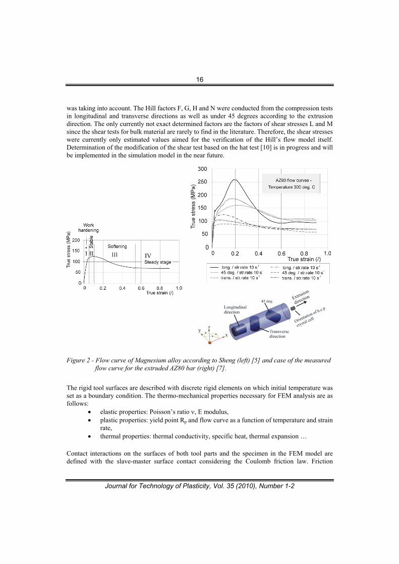
base carbon emulsion Thermex R7-271-03 which was used at experimental work [11]. The specimens having 16 mm in diameter and 20 mm in height were selected for the simulations. Initial tool and workpiece temperature of 300 ºC was selected. The specimen was compressed with a ram speed of 20 mm/s corresponding to the selection of the hydraulic press at the experimental work. The average strain rate was 1.6 s-1. During the FEM simulation the temperature field is continuously calculated according to the deformation work and thermal conductivity of the contacts.
Figure 3 - Stress distribution in upset specimens in various orientations according to the feedstock axis – longitudinal (top left), at 45 degrees (top right) and transverse (bottom).
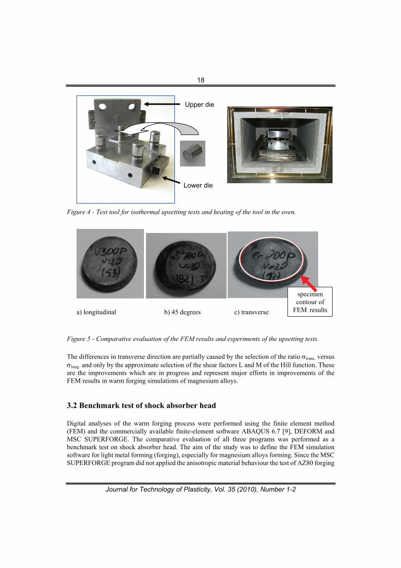
As it is evident from the Fig. 3 the orientation of the specimen according to the extrusion direction determine the shape of the specimen. While the longitudinal extruded specimen does not express anisotropic behaviour over its cross section the transverse testing direction express strong anisotropic behaviour which is determined with anisotropic factors of the flow curve. The influence of the anisotropic material in longitudinal and transverse behaviour can be conducted also as a ratio between flow stresses in both directions trans. versus long. However this ratio varies with the strain rate, temperature and equivalent strain. Therefore, the further research work is oriented into determination of the most important influential parameter. The results of the numerical simulations were compared with experiments performed in the Forming Laboratory on a test tool for warm forging – Fig. 4. To assure the proper initial forging conditions the test tool was heated together with the specimen in a laboratory oven having the same temperature at the beginning of the forging operation [12]. Comparative evaluations of the footprints of the formed specimens and FEM results have shown good correlation in particular in longitudinal direction – Fig. 5. There were slight differences at specimens machined at 45 degrees according to the extrusion direction while the transverse machined specimens have shown differences which are to improve in further research work.
18
Journal for Technology of Plasticity, Vol. 35 (2010), Number 1-2
Figure 4 - Test tool for isothermal upsetting tests and heating of the tool in the oven.
a) longitudinal b) 45 degrees c) transverse
Figure 5 - Comparative evaluation of the FEM results and experiments of the upsetting tests.
The differences in transverse direction are partially caused by the selection of the ratio trans. versus long. and only by the approximate selection of the shear factors L and M of the Hill function. These are the improvements which are in progress and represent major efforts in improvements of the FEM results in warm forging simulations of magnesium alloys.
3.2 Benchmark test of shock absorber head
Digital analyses of the warm forging process were performed using the finite element method (FEM) and the commercially available finite-element software ABAQUS 6.7 [9], DEFORM and MSC SUPERFORGE. The comparative evaluation of all three programs was performed as a benchmark test on shock absorber head. The aim of the study was to define the FEM simulation software for light metal forming (forging), especially for magnesium alloys forming. Since the MSC SUPERFORGE program did not applied the anisotropic material behaviour the test of AZ80 forging
Upper die
Lower die
specimen contour of
FEM results
19
Journal for Technology of Plasticity, Vol. 35 (2010), Number 1-2
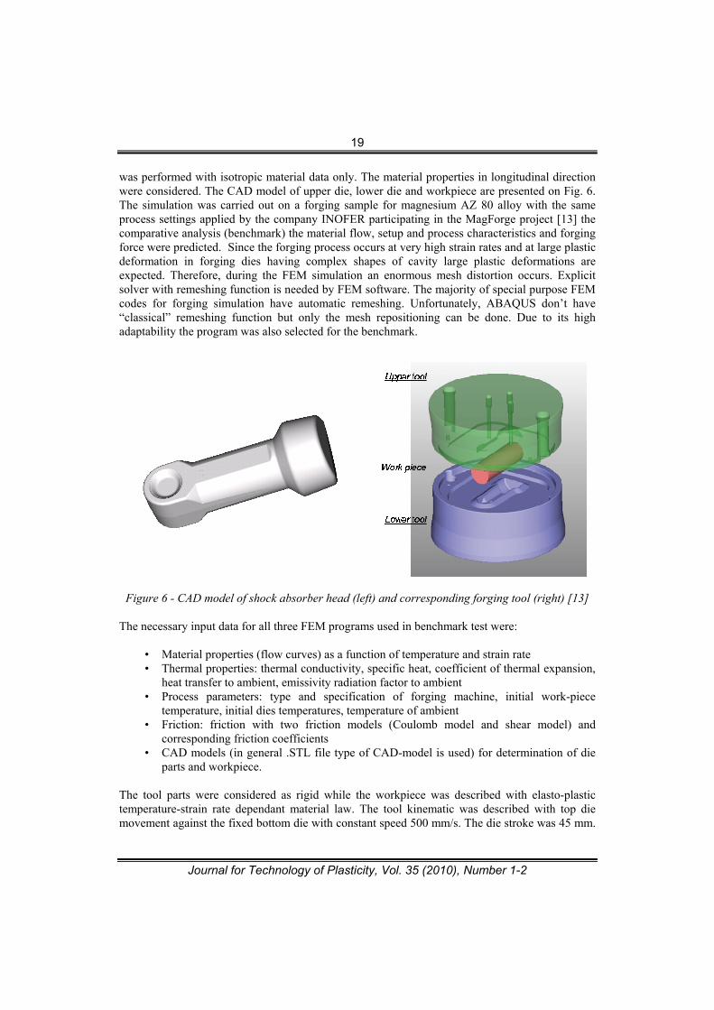
was performed with isotropic material data only. The material properties in longitudinal direction were considered. The CAD model of upper die, lower die and workpiece are presented on Fig. 6. The simulation was carried out on a forging sample for magnesium AZ 80 alloy with the same process settings applied by the company INOFER participating in the MagForge project [13] the comparative analysis (benchmark) the material flow, setup and process characteristics and forging force were predicted. Since the forging process occurs at very high strain rates and at large plastic deformation in forging dies having complex shapes of cavity large plastic deformations are expected. Therefore, during the FEM simulation an enormous mesh distortion occurs. Explicit solver with remeshing function is needed by FEM software. The majority of special purpose FEM codes for forging simulation have automatic remeshing. Unfortunately, ABAQUS don’t have “classical” remeshing function but only the mesh repositioning can be done. Due to its high adaptability the program was also selected for the benchmark.
Figure 6 - CAD model of shock absorber head (left) and corresponding forging tool (right) [13]
The necessary input data for all three FEM programs used in benchmark test were:
• Material properties (flow curves) as a function of temperature and strain rate • Thermal properties: thermal conductivity, specific heat, coefficient of thermal expansion,
heat transfer to ambient, emissivity radiation factor to ambient • Process parameters: type and specification of forging machine, initial work-piece
temperature, initial dies temperatures, temperature of ambient • Friction: friction with two friction models (Coulomb model and shear model) and
corresponding friction coefficients • CAD models (in general .STL file type of CAD-model is used) for determination of die
parts and workpiece.
The tool parts were considered as rigid while the workpiece was described with elasto-plastic temperature-strain rate dependant material law. The tool kinematic was described with top die movement against the fixed bottom die with constant speed 500 mm/s. The die stroke was 45 mm.
20
Journal for Technology of Plasticity, Vol. 35 (2010), Number 1-2
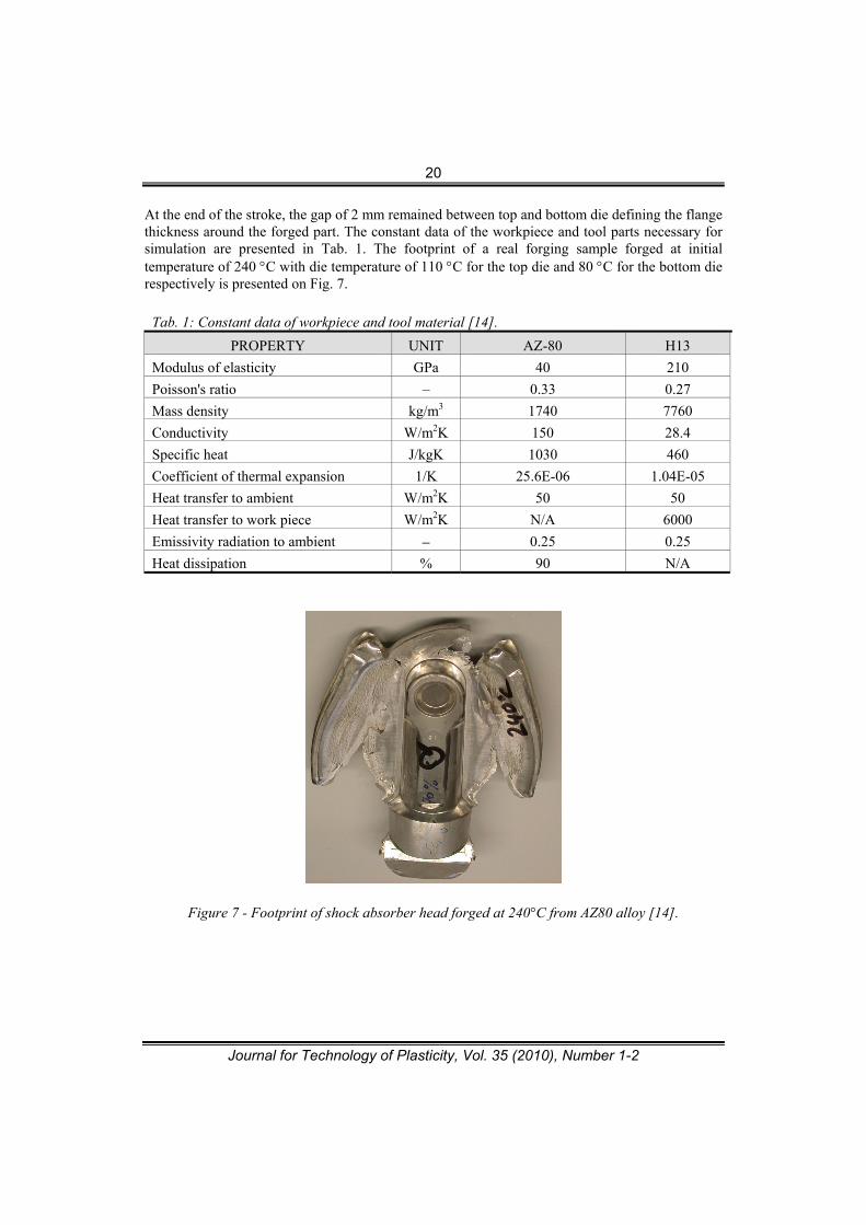
At the end of the stroke, the gap of 2 mm remained between top and bottom die defining the flange thickness around the forged part. The constant data of the workpiece and tool parts necessary for simulation are presented in Tab. 1. The footprint of a real forging sample forged at initial temperature of 240 C with die temperature of 110 C for the top die and 80 C for the bottom die respectively is presented on Fig. 7.
Tab. 1: Constant data of workpiece and tool material [14].
PROPERTY UNIT AZ-80 H13
Modulus of elasticity GPa 40 210
Poisson's ratio – 0.33 0.27
Mass density kg/m3 1740 7760
Conductivity W/m2K 150 28.4
Specific heat J/kgK 1030 460
Coefficient of thermal expansion 1/K 25.6E-06 1.04E-05
Heat transfer to ambient W/m2K 50 50
Heat transfer to work piece W/m2K N/A 6000
Emissivity radiation to ambient – 0.25 0.25
Heat dissipation % 90 N/A
Figure 7 - Footprint of shock absorber head forged at 240°C from AZ80 alloy [14].
21
Journal for Technology of Plasticity, Vol. 35 (2010), Number 1-2
MSC SUPERFORGE DEFORM ABAQUS
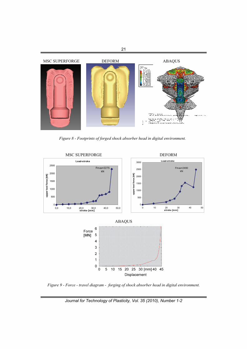
Figure 8 - Footprints of forged shock absorber head in digital environment.
MSC SUPERFORGE DEFORM
ABAQUS
Figure 9 - Force - travel diagram - forging of shock absorber head in digital environment.
Load-stroke
Fmax=2490 kN
0
500
1000
1500
2000
2500
3000
0 10 20 30 40 50stroke [mm]
up
per
to
ol f
orc
e [k
N]
Load-stroke
Fmax=2275 kN
0
500
1000
1500
2000
2500
0,0 10,0 20,0 30,0 40,0 50,0stroke [mm]
up
per
to
ol f
orc
e [k
N]
22
Journal for Technology of Plasticity, Vol. 35 (2010), Number 1-2
From Fig. 9 it is evident that DEFORM and MSC SUPERFORGE delivers comparable results of forming force while ABAQUS 2.5-times higher forces needed for forging of shock absorber head. This can be a result of enormous deformations of forged flange at ABAQUS simulation caused by non-adaptable FEM mesh. The drop of forging force at DEFORM simulations appeared through split of the simulation into two parts caused by excessive file size. This error can be corrected with smaller file size performed in one-step simulation only. Furthermore, the simulated footprint of forged shock absorber head is most comparable to the experimental one at DEFORM simulation while the flange shape is too narrow at MSC SUPERFORGE analysis and extremely large due to non-adaptable FEM mesh at ABAQUS simulation. For further research work it is advisable to use ABAQUS simulations for geometrically simple shapes where large deformations don’t take place while the industrial cases should be analysed with DEFORM simulations. Both programs also enable an anisotropic material flow which will be implemented in further research works. 4. CONCLUSIONS The implementation of magnesium alloys is very promising solution in wide range of transportation sector. Since the forging process has to be performed at elevated temperatures due to better formability it depends from several process variables. Determination of flow curves as a function of strain rate, temperature and specimen orientation regarding the feedstock axis represents the most demanding input data for numerical simulations. Unfortunately, no specialised commercial software with full anisotropic material behaviour for bulk metal forming is currently attainable. Therefore, description of proper anisotropic material behaviour and determination of shear stresses of the analysed material are here to analyse more into the detail in further research work. First digital analyses based on simple warm forging simulations with ABAQUS have shown promising results despite some simplifications at determination of anisotropic material. Similar results cab be obtained by DEFORM program which is on the other hand less appropriate for user adaptations of flow laws, user-programming etc. The benchmark test of shock absorber head with isotropic AZ80 material properties has shown various footprints of forged part. The most promising footprint has delivered DEFORM program. Two programs (MSC SUPERFORGE and DEFORM) have shown similar forming forces which unfortunately could not be compared with real forming forces due to the lack of experimental data. Programs DEFORM and ABAQUS enable also the anisotropic material behaviour – first should be used for industrial application while the second one should be used for geometrically simple case studies for development of new material models, improved anisotropic material flow etc. However, extensive further research work is necessary to obtain reliable results for forging applications of complex industrial parts.
Acknowledgments: The represented research work was performed in a frame of a Collective Research Project MagForge – Magnesium Forged Components for Structural Lightweight Transport Applications with Contract no.: COLL-CT-2006-030208 founded by EC within 6th Frame Project as well as Timminco Corporation (currently Applied Magnesium International) for the provision of commercial-grade AZ80 magnesium feedstock. Authors are grateful for their support.
23
Journal for Technology of Plasticity, Vol. 35 (2010), Number 1-2
REFERENCES [1] Collective Research Project MagForge – Magnesium Forged Components for Structural
Lightweight Transport Applications, Cont. no.: COLL-CT-2006-030208, www.magforge.eu
[2] A.-W. El-Morsy, K.-I. Manabe: Finite element analysis of magnesium AZ31 alloy sheet in
warm deep-drawing process considering heat transfer effect, Materials Letters, Vol. 60,
Issue 15, July 2006, pp. 1866-1870.
[3] Bădoi, W.H. Sillekens: Deliverable 5.1.4 Forging Practice of Magnesium Alloys, Collective
Research Project MagForge, Cont. no.: COLL-CT-2006-030208, 2010, 45 p.
[4] K. Kuzman: Some Research and Development Efforts in Cold Forging, Umformtechnik Plus,
Meisenbach Verlag, Bamberg 1999, pp. 199-206.
[5] D.M. Constantinescu, P. Moldovan, W. Sillekens, M. Sandu, G. Popescu, F. Baciu: Fatigue
Life Particularities of AZ80 Allows used in Automotive Industry, 2nd Fatigue symposium,
Leoben 2008, pp. 117-127.
[6] Z.Q. Sheng, R. Shivpuri: Modeling flow stress of magnesium alloys at elevated temperature,
Materials Science and Engineering: A, Vol.419, Issues 1-2, 2006, pp. 202-208.
[7] D. Kobold, T. Pepelnjak, G. Gantar, K. Kuzman: Analyses of Material Properties of
Magnesium Alloys on Warm Forging Processes, Proc. of Magnesium 2009 Conference,
Weimar, 26.-29. Oct. 2009, Germany, 6 p.
[8] T. Pepelnjak, M. Erjavec, G. Popescu: Deliverable 2.2.1: Constitutive relationships and
physical property data for state-of-art feedstock, Collective Research Project MagForge,
Cont. no.: COLL-CT-2006-030208, 2010, 74 p.
[9] ABAQUS Theory Manual, ABAQUS, Inc., version 6.7, 2007
[10] E. El-Magd, M. Abouridouane: Characterization, modeling and simulation of deformation
and fracture behavior of the light-weight wrought alloys under high strain rate loading,
International Journal of Impact Engineering 32 (2006) pp. 741–758.
[11] W.H.Sillekens: Forging of magnesium alloys: current status and prospects for development
(keynote paper); 1st Congress Materials Science and Engineering (MSE 08); September 1–4,
2008, DGM; Nürnberg, 43 p.
[12] Petek, T. Pepelnjak, K. Kuzman: Analysis of innovative forming processes in digital
environment, 7th Int. Conf. on Industrial Tools and Material Processing Technologies,
Ljubljana, Slovenia, October 4th-7th 2009, pp. 315-320.
[13] Pepelnjak T., Werkhoven R., Sillekens, W.H.: Deliverable 5.1.3: FEM process simulation
models for magnesium forging, Collective Research Project MagForge, Cont. no.:
COLL-CT-2006-030208, 2010, 16 p.
[14] Pepelnjak T., Werkhoven R., Bădoi, I.: Deliverable 5.1.1 (#6) Process modelling and
optimisation, Collective Research Project MagForge, Cont. no.: COLL-CT-2006-030208,
2010, 11 p.
24
Journal for Technology of Plasticity, Vol. 35 (2010), Number 1-2
ANALIZA TOPLOG KOVANJA MAGNEZIJUMA U DIGITALNOM OKRUŽENJU
Tomaž Pepelnjaka, Robert Werkhovenb, Dominik Koboldc, Karl Kuzmana
a Forming Laboratory, Faculty of Mechanical Engineering, University of Ljubljana,
Ljubljana, Slovenia
b TNO Science and Industry – Materials Technology, Eindhoven, The Netherlands
cTECOS - Tool and Die Development Centre, Celje, Slovenia
REZIME
Globalna industrija u savremenim uslovima suočena je sa sve strožijim zahtevima tržišta, kako u smislu kvaliteta proizvoda tako i sa stanovišta cene. Zbog toga je neophodno da se vreme za razvoj proizvoda skrati i izbegnu nepotrebne eksperimentalne probe odnosno tkz. ’’trial-and-error’’ postupci. Jedan od načina za povećanje konkurentnosti proizvoda i ispunjenje zahteva tržišta je razvoj proizvoda u digitalnom okruženju. Pored toga, u redovan proizvodni proces potrebno je u što većoj meri implementirati nove tehnologije, materijale i koncepte proizvodnje. Jedna od tehnologija koja po tom pitanju pokazuje veliki potencijal je toplo kovanje magnezijumovih legura. U ovom radu prikazana je tehnologija toplog kovanja lake magnezijumove legure AZ80. Pomoću MKE simuliran je proces toplog kovanja, pri čemu je jedan od osnovnih problema bila anizotropija materijala koja je morala biti definisana standardnim kodom. U radu se analizira sabijanje pripremaka isečenih iz prethodno istisnute šipke, pri čemu se isecanje vršilo u različitim pravcima u odnosu na aksijalnu osu šipke. Pored toga, izvršen je i benchmark test kovanja glave absorbera. U cilju verifikacije numeričkog modela dobijeni rezultati upoređeni su sa rezultatima eksperimentalnih istraživanja. Ključne reči: Toplo kovanje magnezijuma, FEM