Embed Size (px)
Citation preview
AAPG Bulletin, v. 85, no. 2 (February 2001), pp. 233–260 233
Analog models of restrainingstepovers in strike-slipfault systemsKen McClay and Massimo Bonora
ABSTRACT
Scaled sandbox models have successfully simulated the geometriesand progressive evolution of antiformal pop-up structures devel-oped in a weak sedimentary cover above restraining stepovers inoffset sinistral strike-slip fault systems in rigid basement. Modelswere run both with and without synkinematic sedimentation,which was added incrementally to cover the growing antiformalstructures. Vertical and horizontal sections of the completed mod-els permit the full three-dimensional (3-D) structure of the pop-ups to be analyzed in detail. Three representative end-member ex-periments are described: 30� underlapping restraining stepovers;90� neutral restraining stepovers; and 150� overlapping restrainingstepovers.
The experimental pop-ups are typically sigmoidal to lozenge-shaped, antiformal structures having geometries that are dependenton both the stepover angle and stepover width in the underlyingbasement faults. Underlapping restraining stepovers typically formelongate lozenge-shaped pop-ups; 90� neutral restraining stepoversproduce shorter, squat rhomboidal pop-ups; and overlapping re-straining stepovers produce sigmoidal antiformal pop-ups. Transpop-up cross fault systems are characteristic at large displacementson the basement fault system. Above the offset principal displace-ment zones, the pop-ups are commonly small, narrow, positiveflower structures, whereas in the stepover region, they widen outand become markedly asymmetric. This pop-up asymmetryswitches across the center of the stepover, where the pop-ups arelargely symmetical. Maximum rotations measured within the cen-tral highly uplifted region of the pop-ups increase from 7� counter-clockwise for the underlapping (30�) stepovers, to 14� counter-clockwise for the neutral (90�) stepovers, to 16� counterclockwisefor the overlapping (150�) stepovers.
In models where no synkinematic sediments were added duringdeformation, the pop-up structures are bound by convex, flatten-ing-upward, oblique-slip reverse fault systems that link downwardto the offsets in the basement fault system. In contrast, in the
Copyright �2001. The American Association of Petroleum Geologists. All rights reserved.
Manuscript received November 18, 1997; revised manuscript received March 24, 2000; final acceptanceJune 30, 2000.
AUTHORS
Ken McClay � Fault Dynamics ResearchGroup, Geology Department, Royal HollowayUniversity of London, Egham, Surrey TW20OEX, United Kingdom; [email protected]
Ken McClay comes from Adelaide, Australia.He has a B.Sc. (honors) degree from AdelaideUniversity and an M.Sc. degree and Ph.D. instructural geology from Imperial College,London. He lectured at Goldsmiths Collegeand is now at Royal Holloway University ofLondon. He has been professor of structuralgeology since 1991 and is director of the FaultDynamics Research Group. He was AAPGdistinguished lecturer in North America 1994–1995 and AAPG International distinguishedlecturer 1998–1999. His research involvesextension, thrust, strike-slip, and inversionterranes and their applications to hydrocarbonexploration. He publishes widely, consults, andgives short courses to industry.
Massimo Bonora � Midland Valley, 14Park Circus, Glasgow, G3 6AX, Scotland,United Kingdom
Massimo Bonora comes from Ferrara, Italy.He received his degree in geological sciencesfrom Ferrara University and his M.Sc. degreein basin evolution and dynamics from RoyalHolloway University of London. Between 1995and 1998 Massimo worked as a researchassistant in the Fault Dynamics ResearchGroup at Royal Holloway. Massimo is nowworking as a structural geologist within theLatin America team at Midland Valley Ltd. inGlasgow, Scotland.
ACKNOWLEDGEMENTS
The research for this article has been sup-ported by the Fault Dynamics Project (spon-sored by ARCO British Limited, Petrobras U.K.Ltd., BP Exploration, Conoco (U.K.) Limited,Mobil North Sea Limited, and Sun Oil Britain).Ken McClay also gratefully acknowledgesfunding from ARCO British Limited and BP Ex-ploration. We thank J. Reijs for the data forFigure 21. Critical reviews by A. Sylvester, D.Stone, and J. Sheridan were greatly appreci-ated. We thank Tim Dooley for many fruitfuldiscussions and assistance with drafting dia-grams. Howard Moore constructed the defor-mation apparatus. Fault Dynamics PublicationNo. 74.
234 Analog Models of Restraining Strike-Slip Faults
experiments where synkinematic sediments wereadded incrementally during deformation, the pop-upsare formed by oblique-slip reverse faults that steepenupward into the synkinematic strata with the forma-tion of fault-propagation growth folds.
The analog models are compared with natural ex-amples of pop-up structures and show strong similar-ities in structural geometries and stratal architectures.These models may provide structural templates forseismic interpretation of complex contractional struc-tures in offset strike-slip fault systems.
INTRODUCTION
Interpretation and analysis of complex three-dimen-sional (3-D) structures in the subsurface is one of themajor challenges in hydrocarbon exploration. Seismicimaging of strike-slip structures is commonly very poorbecause of the steep stratal and fault dips as well assignificant along-strike variations in structural geome-tries (cf. Harding, 1990; Sylvester, 1988). Scaled ana-log modeling has proved to be a powerful tool in de-veloping an understanding of the geometries andkinematics of complex 3-D structures in sedimentarybasins (e.g., extension structures: Withjack and Jami-son, 1986; Serra and Nelson, 1989; McClay, 1990;Withjack et al., 1990; Tron and Brun, 1991; Vende-ville, 1991; McClay, 1995a, b; McClay and White,1995; contractional structures: Lallemand et al., 1992;Calassou et al., 1993; Malavieille et al., 1993; andstrike-slip structures: Naylor et al., 1986;Mandl, 1988;Richard et al., 1989, 1991, 1995; Richard and Cob-bold, 1990; Richard, 1991; Schreurs, 1994; McClayand Dooley, 1995; Dooley and McClay, 1997).
This article summarizes the results of a compre-hensive suite of experiments designed to simulate thegeometric and kinematic evolution of structuressqueezed up at restraining bends and stepovers instrike-slip fault systems; in this article these structuresare termed “pop-ups” (cf. Stone, 1995). In particularthe models have incorporated syntectonic sedimenta-tion during the deformation. This research is part of anongoing program designed to develop an understand-ing of the four-dimensional (4-D) evolution of com-plex structures in sedimentary basins and follows anearlier article on the modeling of strike-slip pull-apartbasins (Dooley and McClay, 1997). The experimentalresults provide templates for seismic interpretation ofstrike-slip pop-ups and insights into their kinematicevolution. The results of the analog models are com-
pared and contrasted with natural examples of struc-tures developed in sedimetary strata above restrainingbends or stepovers in basement strike-slip faultsystems.
Pop-ups and transpressional uplifts are an integralpart of intraplate and interplate strike-slip fault zones(Sylvester and Smith, 1976; Christie-Blick and Biddle,1985; Sylvester, 1988; Zolnai, 1991) and form at re-straining bends or stepovers (e.g., Harding, 1974,1990; Christie-Blick and Biddle, 1985; Harding et al.,1985; Lowell, 1985). They typically form anticlinaluplifts, commonly with doubly plunging arrangementsof folds, and are of limited strike extent. In plan viewthey are broadly lozenge-shaped to rhomboidal inform, whereas in cross section they commonlybounded convex-up faults that flatten upward towardthe surface forming positive flower or palm tree struc-tures (e.g., Sylvester and Smith, 1987; Sylvester,1988). In this article we use the general term “pop-up”to describe a domal uplift (cf. Stone, 1995) that hasboth positive structural and topographic relief. Manylarge intraplate strike-slip systems, for example, alongthe San Andreas fault system (Harding, 1976; Sylvesterand Smith, 1976; Sylvester, 1988; Brown and Sibson,1989; Jones et al., 1994; Powell et al., 1993) or alongthe Altai fault system in Mongolia (Cunningham et al.,1996) commonly have large-scale pop-ups associatedwith restraining bends and stepovers.
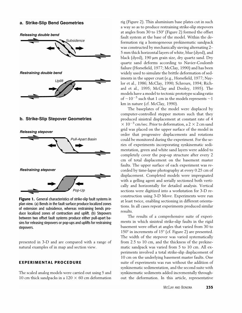
Bends and stepovers (jogs or offsets) in the prin-cipal displacement zones (PDZs) (e.g., Christie-Blickand Biddle, 1985) of a strike-slip fault system generallyproduce either zones of extension (pull-apart or step-over basins) at releasing bends or stepovers (Figure 1a)or regions of compression, uplifts, or pop-up structures(including positive flower–palm tree structures) at re-straining bends or restraining stepovers (Figure 1b).The latter characteristically produce anticlinal upliftsin the overlying sedimentary section with older strataor basement exposed in the core (e.g., Crowell, 1974;Sylvester and Smith, 1976; Mann et al., 1983; Aydinand Nur, 1985; Christie-Blick and Biddle, 1985; Syl-vester, 1988). Previous analog model studies of pop-ups have not fully addressed their progressive evolu-tion, their 3-D structure, and in particular, theirinteraction with syntectonic sedimentation (cf. sand-box models in Horsefield, 1977, 1980; Naylor et al.,1986; Mandl, 1988; Richard and Cobbold, 1990; Rich-ard, 1991; Richard et al., 1991; Schreurs, 1994; andRichard et al., 1995; and clay models in Wilcox et al.,1973; Keller et al., 1997). Here the results of a system-atic series of restraining stepover analog models are
McClay and Bonora 235
Releasing double bend
Restraining double bend
Releasing stepover
Restraining stepover
a. Strike-Slip Bend Geometries
b. Strike-Slip Stepover Geometries
Subsidence
Uplift
Pull-Apart Basin
Pop-Up
Figure 1. General characteristics of strike-slip fault systems inplan view. (a) Bends in the fault surface produce localized zonesof extension and subsidence, whereas restraining bends pro-duce localized zones of contraction and uplift. (b) Stepoversbetween two offset fault systems produce either pull-apart ba-sins for releasing stepovers or pop-ups and uplifts for restrainingstepovers.
presented in 3-D and are compared with a range ofnatural examples of in map and section view.
EXPERIMENTAL PROCEDURE
The scaled analog models were carried out using 5 and10 cm thick sandpacks in a 120 � 60 cm deformation
rig (Figure 2). Thin aluminium base plates cut in sucha way so as to produce restraining strike-slip stepoversat angles from 30 to 150� (Figure 2) formed the offsetfault system at the base of the model. Within the de-formation rig a homogeneous prekinematic sandpackwas constructed by mechanically sieving alternating 2–5 mm thick horizontal layers of white, blue (dyed), andblack (dyed), 190 lm grain size, dry quartz sand. Dryquartz sand deforms according to Navier-Coulombfailure (Horsefield, 1977; McClay, 1990) and has beenwidely used to simulate the brittle deformation of sed-iments in the upper crust (e.g., Horsefield, 1977; Nay-lor et al., 1986; McClay, 1990; Schreurs, 1994; Rich-ard et al., 1995; McClay and Dooley, 1995). Themodels have a model to tectonic prototype scaling ratioof �10�5 such that 1 cm in the models represents �1km in nature (cf. McClay, 1990).
The baseplates of the model were displaced bycomputer-controlled stepper motors such that theyproduced sinistral displacement at constant rate of 4� 10�3 cm/sec. Prior to deformation, a 2 � 2 cm sandgrid was placed on the upper surface of the model inorder that progressive displacements and rotationscould be monitored during the experiment. For the se-ries of experiments incorporating synkinematic sedi-mentation, green and white sand layers were added tocompletely cover the pop-up structure after every 2cm of total displacement on the basement masterfaults. The upper surface of each experiment was re-corded by time-lapse photography at every 0.25 cm ofdisplacement. Completed models were impregnatedwith a gelling agent and serially sectioned both verti-cally and horizontally for detailed analysis. Verticalsections were digitized into a workstation for 3-D re-construction using 3-D Move. Experiments were runat least twice, enabling sectioning in different orienta-tions. In all cases repeat experiments produced similarresults.
The results of a comprehensive suite of experi-ments in which sinistral strike-slip faults in the rigidbasement were offset at angles that varied from 30 to150� in increments of 15� (cf. Figure 2) are presented.The width of the stepover was varied systematicallyfrom 2.5 to 10 cm, and the thickness of the prekine-matic sandpack was varied from 5 to 10 cm. All ex-periments involved a total strike-slip displacement of10 cm on the underlying basement master faults. Onesuite of experiments was run without the addition ofsynkinematic sedimentation, and the second suite withsynkinematic sediments added incrementally through-out the deformation. In this article, representative
236 Analog Models of Restraining Strike-Slip Faults
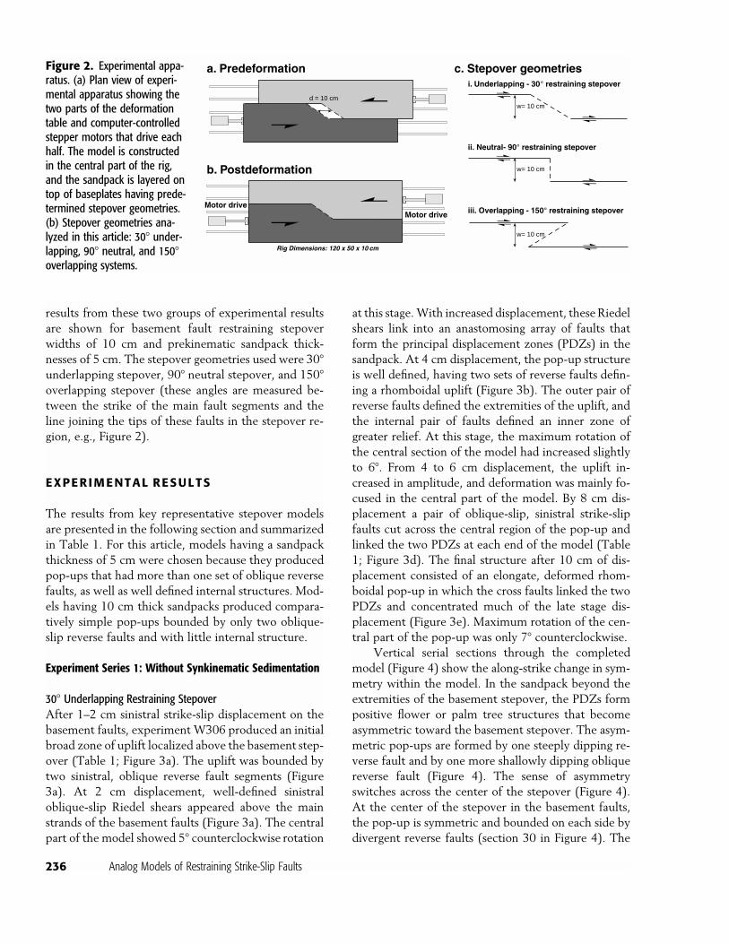
Figure 2. Experimental appa-ratus. (a) Plan view of experi-mental apparatus showing thetwo parts of the deformationtable and computer-controlledstepper motors that drive eachhalf. The model is constructedin the central part of the rig,and the sandpack is layered ontop of baseplates having prede-termined stepover geometries.(b) Stepover geometries ana-lyzed in this article: 30� under-lapping, 90� neutral, and 150�overlapping systems.
a. Predeformation
b. Postdeformation
i. Underlapping - 30° restraining stepover
ii. Neutral- 90° restraining stepover
iii. Overlapping - 150° restraining stepover
c. Stepover geometries
w= 10 cm
w= 10 cm
w= 10 cm
Motor driveMotor drive
Rig Dimensions: 120 x 50 x 10 cm
d = 10 cm
results from these two groups of experimental resultsare shown for basement fault restraining stepoverwidths of 10 cm and prekinematic sandpack thick-nesses of 5 cm. The stepover geometries used were 30�underlapping stepover, 90� neutral stepover, and 150�overlapping stepover (these angles are measured be-tween the strike of the main fault segments and theline joining the tips of these faults in the stepover re-gion, e.g., Figure 2).
EXPERIMENTAL RESULTS
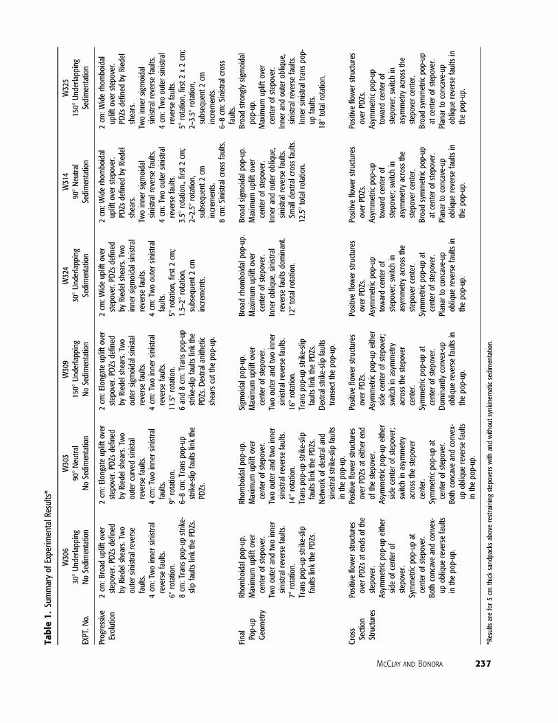
The results from key representative stepover modelsare presented in the following section and summarizedin Table 1. For this article, models having a sandpackthickness of 5 cm were chosen because they producedpop-ups that had more than one set of oblique reversefaults, as well as well defined internal structures. Mod-els having 10 cm thick sandpacks produced compara-tively simple pop-ups bounded by only two oblique-slip reverse faults and with little internal structure.
Experiment Series 1: Without Synkinematic Sedimentation
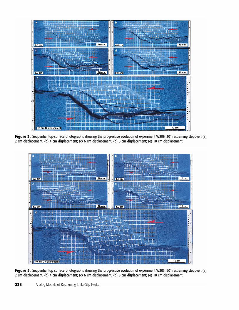
30� Underlapping Restraining StepoverAfter 1–2 cm sinistral strike-slip displacement on thebasement faults, experiment W306 produced an initialbroad zone of uplift localized above the basement step-over (Table 1; Figure 3a). The uplift was bounded bytwo sinistral, oblique reverse fault segments (Figure3a). At 2 cm displacement, well-defined sinistraloblique-slip Riedel shears appeared above the mainstrands of the basement faults (Figure 3a). The centralpart of the model showed 5� counterclockwise rotation
at this stage.With increased displacement, theseRiedelshears link into an anastomosing array of faults thatform the principal displacement zones (PDZs) in thesandpack. At 4 cm displacement, the pop-up structureis well defined, having two sets of reverse faults defin-ing a rhomboidal uplift (Figure 3b). The outer pair ofreverse faults defined the extremities of the uplift, andthe internal pair of faults defined an inner zone ofgreater relief. At this stage, the maximum rotation ofthe central section of the model had increased slightlyto 6�. From 4 to 6 cm displacement, the uplift in-creased in amplitude, and deformation was mainly fo-cused in the central part of the model. By 8 cm dis-placement a pair of oblique-slip, sinistral strike-slipfaults cut across the central region of the pop-up andlinked the two PDZs at each end of the model (Table1; Figure 3d). The final structure after 10 cm of dis-placement consisted of an elongate, deformed rhom-boidal pop-up in which the cross faults linked the twoPDZs and concentrated much of the late stage dis-placement (Figure 3e). Maximum rotation of the cen-tral part of the pop-up was only 7� counterclockwise.
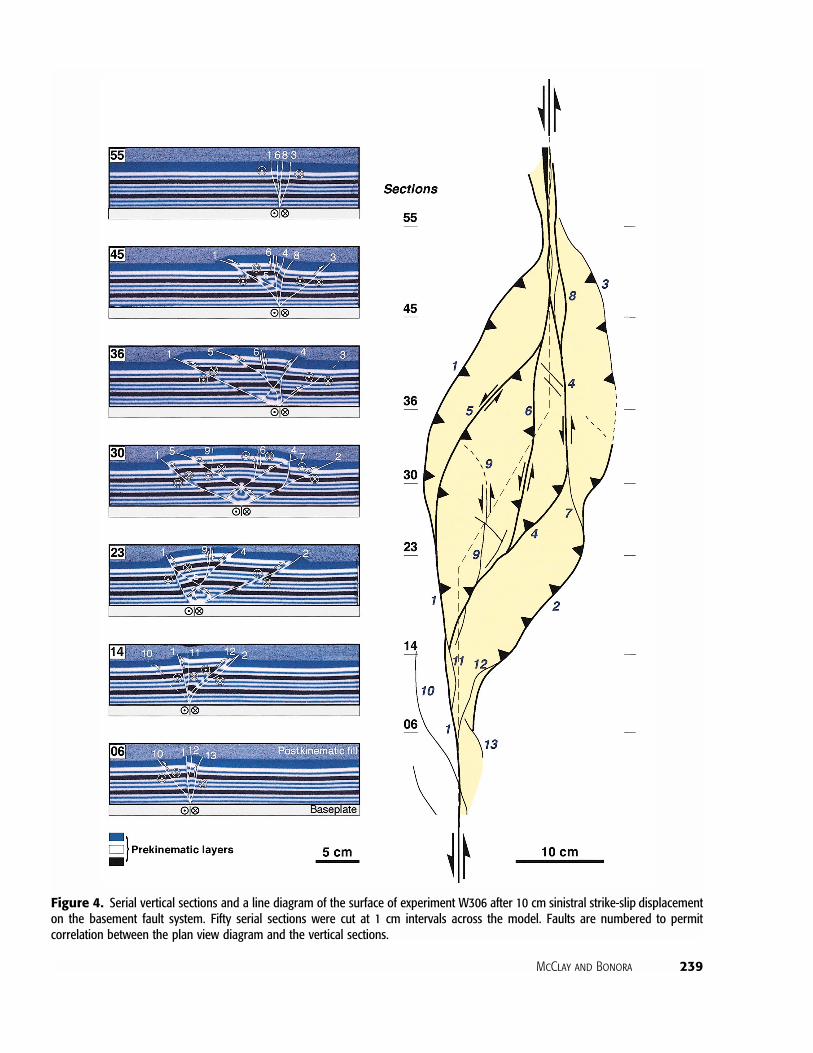
Vertical serial sections through the completedmodel (Figure 4) show the along-strike change in sym-metry within the model. In the sandpack beyond theextremities of the basement stepover, the PDZs formpositive flower or palm tree structures that becomeasymmetric toward the basement stepover. The asym-metric pop-ups are formed by one steeply dipping re-verse fault and by one more shallowly dipping obliquereverse fault (Figure 4). The sense of asymmetryswitches across the center of the stepover (Figure 4).At the center of the stepover in the basement faults,the pop-up is symmetric and bounded on each side bydivergent reverse faults (section 30 in Figure 4). The
McClay and Bonora 237
Table1.
SummaryofExperim
entalResults*
EXPT.No.
W306
30�Underlapping
NoSedimentation
W303
90�Neutral
NoSedimentation
W309
150�Underlapping
NoSedimentation
W324
30�Underlapping
Sedimentation
W314
90�Neutral
Sedimentation
W325
150�Underlapping
Sedimentation
Progressive
Evolution
2cm:Broad
upliftover
stepover.PDZsdefined
byRiedelshears.Two
outersinistralreverse
faults.
4cm:Twoinnersinistral
reversefaults.
6�rotation.
8cm:Transpop-up
strike-
slipfaultslinkthePDZs.
2cm:Elongateupliftover
stepover.PDZsdefined
byRiedelshears.Two
outercurved
sinistal
reversefaults.
4cm:Twoinnersinistral
faults.
9�rotation.
6–8cm:Transpop-up
strike-slipfaultslinkthe
PDZs.
2cm:Elongateupliftover
stepover.PDZsdefined
byRiedelshears.Two
outersigmoidalsinistal
reversefaults.
4cm:Twoinnersinistral
reversefaults.
11.5
�rotation.
6and8cm:Transpop-up
strike-slipfaultslinkthe
PDZs.Dextralanithetic
shearscutthe
pop-up.
2cm:W
ideupliftover
stepover.PDZsdefined
byRiedelshears.Two
innersigmoidalsinistral
reversefaults.
4cm:Twooutersinistral
faults.
5�rotation,first2cm;
1.5–2�rotation,
subsequent2cm
increments.
2cm:W
iderhom
boidal
upliftoverstepover.
PDZsdefined
byRiedel
shears.
Twoinnersigmoidal
sinistralreversefaults.
4cm:Twooutersinistral
reversefaults.
3.5�rotation.,first2
cm;
2–2.5�rotation,
subsequent2cm
increments.
8cm:Sinistralcrossfaults.
2cm:W
iderhom
boidal
upliftoverstepover.
PDZsdefined
byRiedel
shears.
Twoinnersigmoidal
sinistralreversefaults.
4cm:Twooutersinistral
reversefaults.
5�rotation,first2x2cm;
2–3.5�rotation,
subsequent2cm
increments.
6–8cm:Sinistralcross
faults.
Final
Pop-up
Geom
etry
Rhom
boidalpop-up.
Maximum
upliftover
centerofstepover.
Twoouterandtwoinner
sinistralreversefaults.
7�rotation.
Transpop-up
strike-slip
faultslinkthePDZs.
Rhom
boidalpop-up.
Maximum
upliftover
centerofstepover.
Twoouterandtwoinner
sinistralreversefaults.
14�rotation.
Transpop-up
strike-slip
faultslinkthePDZs.
Networkofdextraland
sinistralstrike-slip
faults
inthepop-up.
Sigmoidalpop-up.
Maximum
upliftover
centerofstepover.
Twoouterandtwoinner
sinistralreversefaults.
16�rotation.
Transpop-up
strike-slip
faultslinkthePDZs.
Dextralstrike-slip
faults
transectthe
pop-up.
Broadrhom
boidalpop-up.
Maximum
upliftover
centerofstepover.
Inneroblique,sinistral
reversefaultsdominant.
12�totalrotation.
Broadsigmoidalpop-up.
Maximum
upliftover
centerofstepover.
Innerandouteroblique,
sinistralreversefaults.
Smalldextralcrossfaults.
12.5
�totalrotation.
Broadstronglysigmoidal
pop-up.
Maximum
upliftover
centerofstepover.
Innerandouteroblique,
sinistralreversefaults.
Innersinistraltranspop-
upfaults.
18�totalrotation.
Cross
Section
Structures
Positiveflowerstructures
overPDZsatendsofthe
stepover.
Asymmetric
pop-up
either
sideofcenterof
stepover.
Symmetric
pop-up
atcenterofstepover.
Bothconcaveandconvex-
upoblique
reversefaults
inthepop-up.
Positiveflowerstructures
overPDZsateitherend
ofthestepover.
Asymmetric
pop-up
either
sidecenterofstepover;
switchinasymmetry
acrossthestepover
center.
Symmetric
pop-up
atcenterofstepover.
Bothconcaveandconvex-
upoblique
reversefaults
inthepop-up.
Positiveflowerstructures
overPDZs.
Asymmetric
pop-up
either
sidecenterofstepover;
switchinasymmetry
acrossthestepover
center.
Symmetric
pop-up
atcenterofstepover.
Dominantlyconvex-up
oblique
reversefaultsin
thepop-up.
Positiveflowerstructures
overPDZs.
Asymmetric
pop-up
towardcenterof
stepover;switchin
asymmetryacrossthe
stepovercenter.
Symmetric
pop-up
atcenterofstepover.
Planartoconcave-up
oblique
reversefaultsin
thepop-up.
Positiveflowerstructures
overPDZs.
Asymmetric
pop-up
towardcenterof
stepover;switchin
asymmetryacrossthe
stepovercenter.
Broadsymmetric
pop-up
atcenterofstepover.
Planartoconcave-up
oblique
reversefaultsin
thepop-up.
Positiveflowerstructures
overPDZs.
Asymmetric
pop-up
towardcenterof
stepover;switchin
asymmetryacrossthe
stepovercenter.
Broadsymmetric
pop-up
atcenterofstepover.
Planartoconcave-up
oblique
reversefaultsin
thepop-up.
*Resultsarefor5cm
thick
sandpacksaboverestrainingstepoverswith
andwithoutsynkinematicsedimentation.
238 Analog Models of Restraining Strike-Slip Faults
Figure 3. Sequential top-surface photographs showing the progressive evolution of experiment W306, 30� restraining stepover. (a)2 cm displacement; (b) 4 cm displacement; (c) 6 cm displacement; (d) 8 cm displacement; (e) 10 cm displacement.
Figure 5. Sequential top surface photographs showing the progressive evolution of experiment W303, 90� restraining stepover. (a)2 cm displacement; (b) 4 cm displacement; (c) 6 cm displacement; (d) 8 cm displacement; (e) 10 cm displacement.
McClay and Bonora 239
Figure 4. Serial vertical sections and a line diagram of the surface of experiment W306 after 10 cm sinistral strike-slip displacementon the basement fault system. Fifty serial sections were cut at 1 cm intervals across the model. Faults are numbered to permitcorrelation between the plan view diagram and the vertical sections.
240 Analog Models of Restraining Strike-Slip Faults
opposing asymmetries of the pop-ups at either end ofthe stepover reflect the decrease in along-strike dis-placement on the outer oblique reverse faults (Figure4). The steep crosscutting strike-slip faults that link thePDZs appear to cut the earlier formed lower angleconvex-up reverse faults that define the dominantasymmetric positive flower structure of the pop-up(Figure 4).
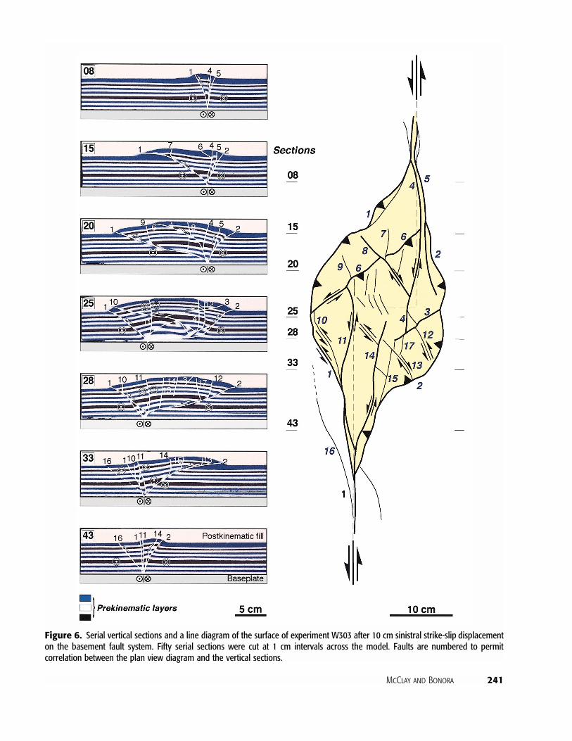
90� Neutral Restraining StepoverExperiment W303, a 90� neutral restraining stepover,displayed a similar evolution to the 30� model de-scribed previously. A rhomboidal to slightly sigmoidalpop-up structure bounded by curved, oblique-slip re-verse faults formed above the basement stepover (Ta-ble 1; Figure 5). The main differences in the evolutionof this model were the shorter pop-up and the in-creased rotation and the development of small dis-placement antithetic, dextral shears in the central re-gion of the pop-up (Table 1; Figure 5). In cross sectionthe pop-up shows a distinct asymmetry, the sense ofwhich switches across the center of the basement step-over (Figure 6).
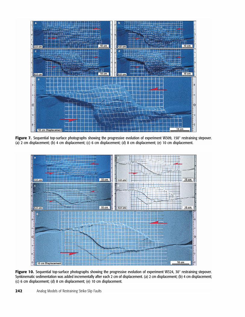
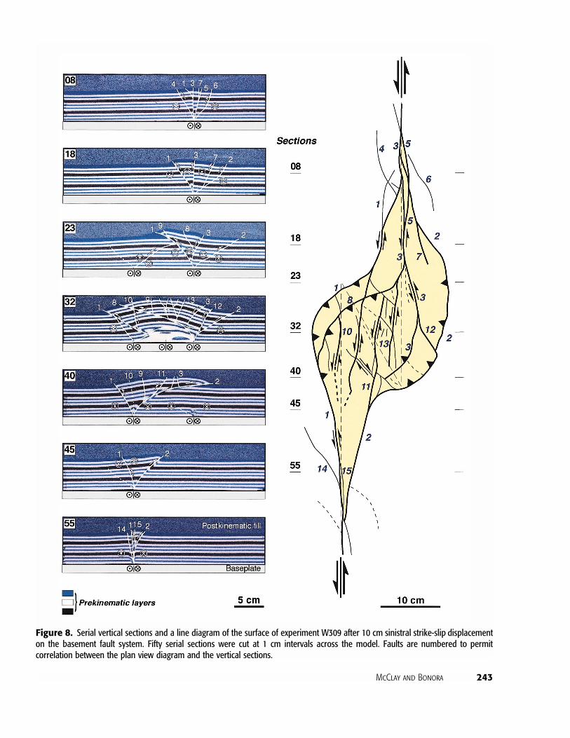
150� Overlapping Restraining StepoverExperiment W309, a 150� overlapping restrainingstepover, displayed a similar evolution to the modelspreviously described but developed a strongly sigmoi-dal pop-up structure bounded by curved, oblique-slipreverse faults above the basement stepover (Table 1;Figure 7). This model also displayed increased rotation(16� after 10 cm of displacement) (Table 1) and thedevelopment of small displacement dextral and sinis-tral shears in the central region of the pop-up (Table1; Figure 7). As in the other models described previ-ously, the cross sections of the pop-up show a distinctasymmetry, which switches across the center of thebasement stepover (Figure 8).
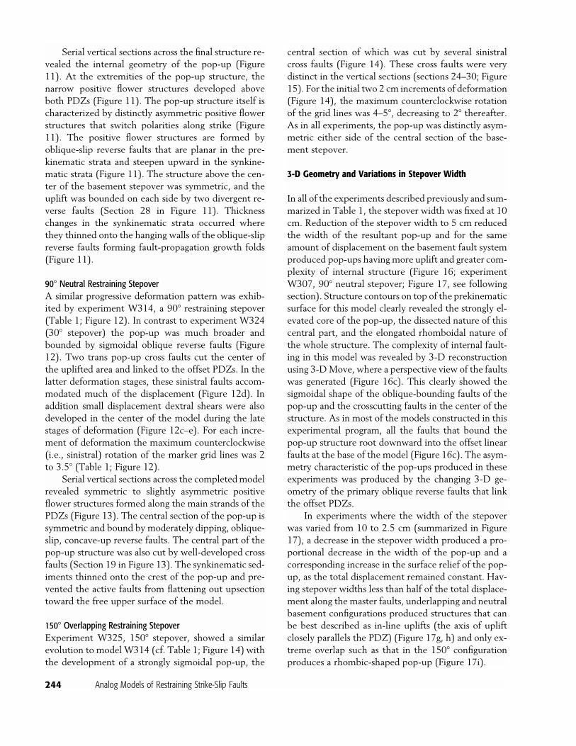
Horizontal SectionsIn addition to vertical serial sections, some modelswere sectioned horizontally to analyze the geometry atdepth. Figure 9 shows the top-surface geometry and ahorizontal section, at 2.5 cm below the crest of thepop-up, through experiment W305, a 90� neutral re-straining stepover. The rhomboidal shape is clearly de-lineated together with the two pairs of sigmoidal,oblique-slip reverse faults that bound the inner andouter parts of the uplifted area. Note also the doublyplunging anticlinal nature of the pop-up with the mainanticlinal axis that strikes counter to the overall sinis-
tral shear displacement of the main fault systems (Fig-ure 9c). The inner set of reverse faults defines a zoneof greater uplift. The cross pop-up strike-slip faults thatare seen on the upper surface of the model (Figure 9a)have sigmoidal traces in the horizontal section (Figure9b) and link to the main PDZs at either end of thestepover structure. The synthetic and antithetic Riedelshears that are observed on the surface of the model(Figure 9a) are not found in the horizontal section, in-dicating their limited slip and relatively late stage ofdevelopment.
Experiment Series 2: With Synkinematic Sedimentation
In this series of experiments, synkinematic sedimen-tation was added at the end of each increment of de-formation burying the pop-ups and preventing the de-velopment of steep surface scarps above emergent faultsurfaces. The photographs of the top surfaces of themodels at each stage of the deformation therefore showthe effects of the last deformation increment in thesynkinematic layer.
30� Underlapping Restraining StepoverAfter 1–2 cm of sinistral strike-slip displacement on thebasement faults, synthetic Riedel shears formed abovethe offset segments of these faults together with a widezone of gentle uplift above the basement stepover (Fig-ure 10a). This uplift zone was bound by two weaklydeveloped oblique-slip reverse faults, which with in-creased displacement, propagated along strike andformed sigmoidal linkages to the main PDZs (Figure10b). At 4 cm of displacement a second set of sinistral,oblique-slip reverse faults formed at the extremities ofthe uplifted area. At this stage (Figure 10b), the inter-nal pair of reverse faults defined an inner zone ofgreater relief, similar to that in themodels without syn-kinematic sedimentation (cf. Figure 3). After 6 cm dis-placement (Figure 10c), activity on the inner right-hand oblique reverse fault ceased, and much of thelate-stage displacement focused on the remainingfaults (Figure 10d), forming an elongate deformedrhomboidal pop-up. This was also the geometry of thefinal structure after 10 cm displacement (Figure 10e).Trans pop-up oblique sinistral strike-slip faults do notappear to cut the structure. The rotations of themarkergrid on the upper surface of the model are only verysmall (Figure 10), decreasing from 5� counterclockwiserotation at 2 cm displacement to only 1.5 to 2� rotationfor each 2 cm deformation increment thereafter(Table 1).
McClay and Bonora 241
Figure 6. Serial vertical sections and a line diagram of the surface of experiment W303 after 10 cm sinistral strike-slip displacementon the basement fault system. Fifty serial sections were cut at 1 cm intervals across the model. Faults are numbered to permitcorrelation between the plan view diagram and the vertical sections.
242 Analog Models of Restraining Strike-Slip Faults
Figure 7. Sequential top-surface photographs showing the progressive evolution of experiment W309, 150� restraining stepover.(a) 2 cm displacement; (b) 4 cm displacement; (c) 6 cm displacement; (d) 8 cm displacement; (e) 10 cm displacement.
Figure 10. Sequential top-surface photographs showing the progressive evolution of experiment W324, 30� restraining stepover.Synkinematic sedimentation was added incrementally after each 2 cm of displacement. (a) 2 cm displacement; (b) 4 cm displacement;(c) 6 cm displacement; (d) 8 cm displacement; (e) 10 cm displacement.
McClay and Bonora 243
Figure 8. Serial vertical sections and a line diagram of the surface of experiment W309 after 10 cm sinistral strike-slip displacementon the basement fault system. Fifty serial sections were cut at 1 cm intervals across the model. Faults are numbered to permitcorrelation between the plan view diagram and the vertical sections.
244 Analog Models of Restraining Strike-Slip Faults
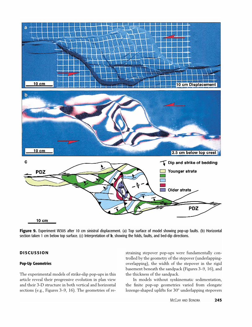
Serial vertical sections across the final structure re-vealed the internal geometry of the pop-up (Figure11). At the extremities of the pop-up structure, thenarrow positive flower structures developed aboveboth PDZs (Figure 11). The pop-up structure itself ischaracterized by distinctly asymmetric positive flowerstructures that switch polarities along strike (Figure11). The positive flower structures are formed byoblique-slip reverse faults that are planar in the pre-kinematic strata and steepen upward in the synkine-matic strata (Figure 11). The structure above the cen-ter of the basement stepover was symmetric, and theuplift was bounded on each side by two divergent re-verse faults (Section 28 in Figure 11). Thicknesschanges in the synkinematic strata occurred wherethey thinned onto the hanging walls of the oblique-slipreverse faults forming fault-propagation growth folds(Figure 11).
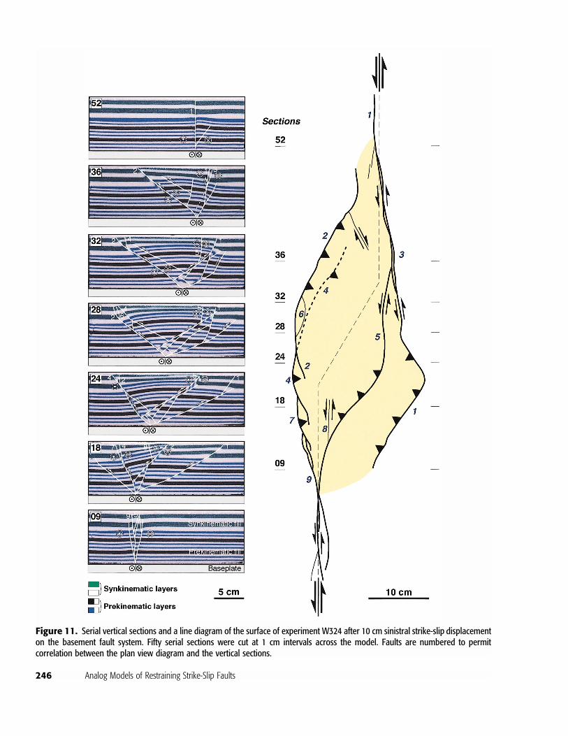
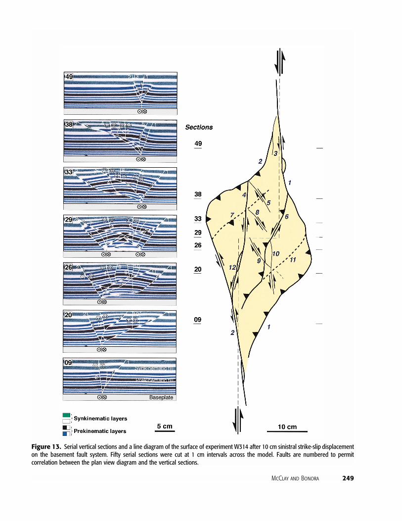
90� Neutral Restraining StepoverA similar progressive deformation pattern was exhib-ited by experiment W314, a 90� restraining stepover(Table 1; Figure 12). In contrast to experiment W324(30� stepover) the pop-up was much broader andbounded by sigmoidal oblique reverse faults (Figure12). Two trans pop-up cross faults cut the center ofthe uplifted area and linked to the offset PDZs. In thelatter deformation stages, these sinistral faults accom-modated much of the displacement (Figure 12d). Inaddition small displacement dextral shears were alsodeveloped in the center of the model during the latestages of deformation (Figure 12c–e). For each incre-ment of deformation the maximum counterclockwise(i.e., sinistral) rotation of the marker grid lines was 2to 3.5� (Table 1; Figure 12).
Serial vertical sections across the completedmodelrevealed symmetric to slightly asymmetric positiveflower structures formed along the main strands of thePDZs (Figure 13). The central section of the pop-up issymmetric and bound by moderately dipping, oblique-slip, concave-up reverse faults. The central part of thepop-up structure was also cut by well-developed crossfaults (Section 19 in Figure 13). The synkinematic sed-iments thinned onto the crest of the pop-up and pre-vented the active faults from flattening out upsectiontoward the free upper surface of the model.
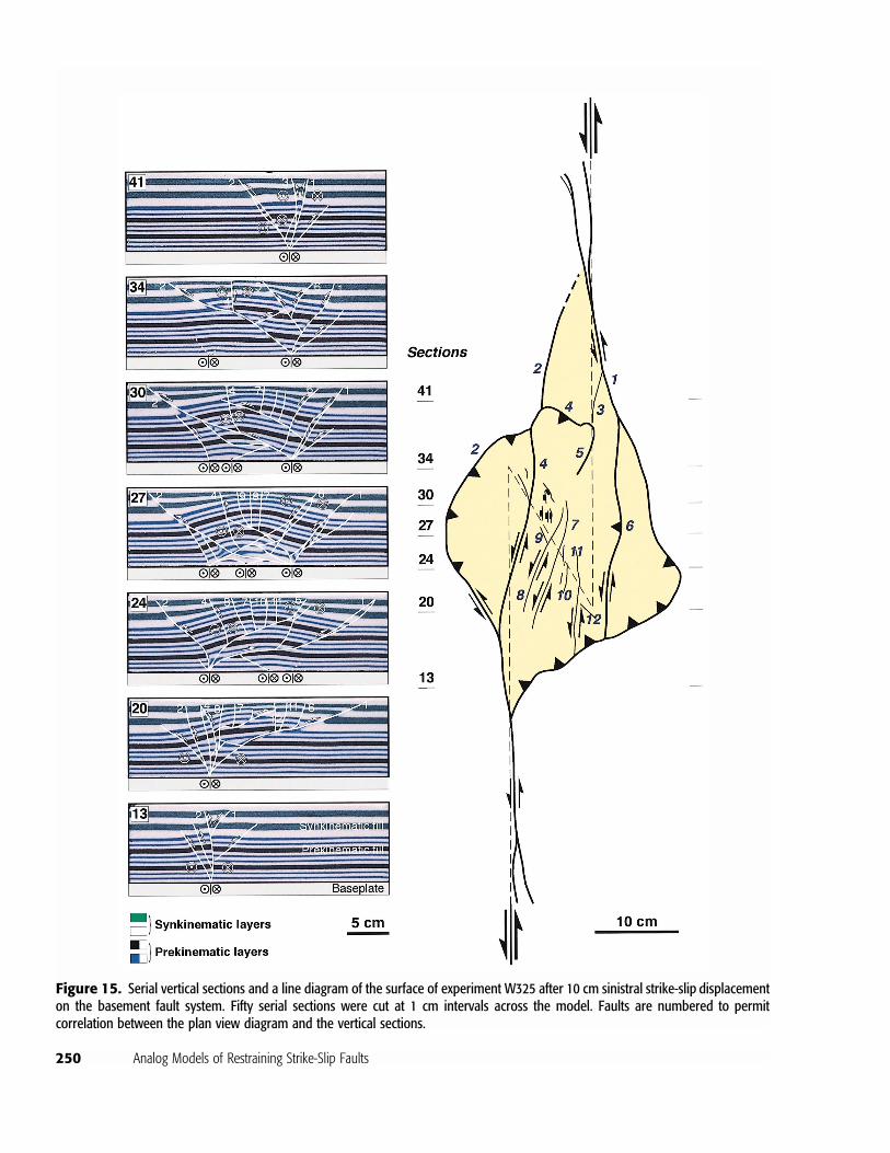
150� Overlapping Restraining StepoverExperiment W325, 150� stepover, showed a similarevolution to model W314 (cf. Table 1; Figure 14) withthe development of a strongly sigmoidal pop-up, the
central section of which was cut by several sinistralcross faults (Figure 14). These cross faults were verydistinct in the vertical sections (sections 24–30; Figure15). For the initial two 2 cm increments of deformation(Figure 14), the maximum counterclockwise rotationof the grid lines was 4–5�, decreasing to 2� thereafter.As in all experiments, the pop-up was distinctly asym-metric either side of the central section of the base-ment stepover.
3-D Geometry and Variations in Stepover Width
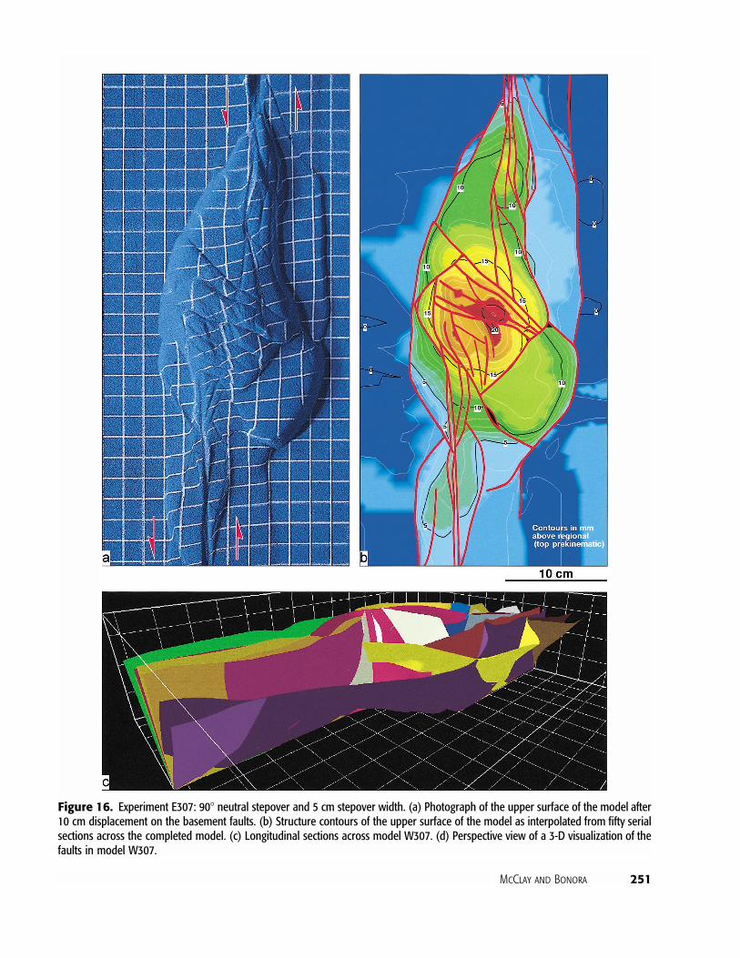
In all of the experiments described previously and sum-marized in Table 1, the stepover width was fixed at 10cm. Reduction of the stepover width to 5 cm reducedthe width of the resultant pop-up and for the sameamount of displacement on the basement fault systemproduced pop-ups having more uplift and greater com-plexity of internal structure (Figure 16; experimentW307, 90� neutral stepover; Figure 17, see followingsection). Structure contours on top of the prekinematicsurface for this model clearly revealed the strongly el-evated core of the pop-up, the dissected nature of thiscentral part, and the elongated rhomboidal nature ofthe whole structure. The complexity of internal fault-ing in this model was revealed by 3-D reconstructionusing 3-DMove, where a perspective view of the faultswas generated (Figure 16c). This clearly showed thesigmoidal shape of the oblique-bounding faults of thepop-up and the crosscutting faults in the center of thestructure. As in most of the models constructed in thisexperimental program, all the faults that bound thepop-up structure root downward into the offset linearfaults at the base of the model (Figure 16c). The asym-metry characteristic of the pop-ups produced in theseexperiments was produced by the changing 3-D ge-ometry of the primary oblique reverse faults that linkthe offset PDZs.
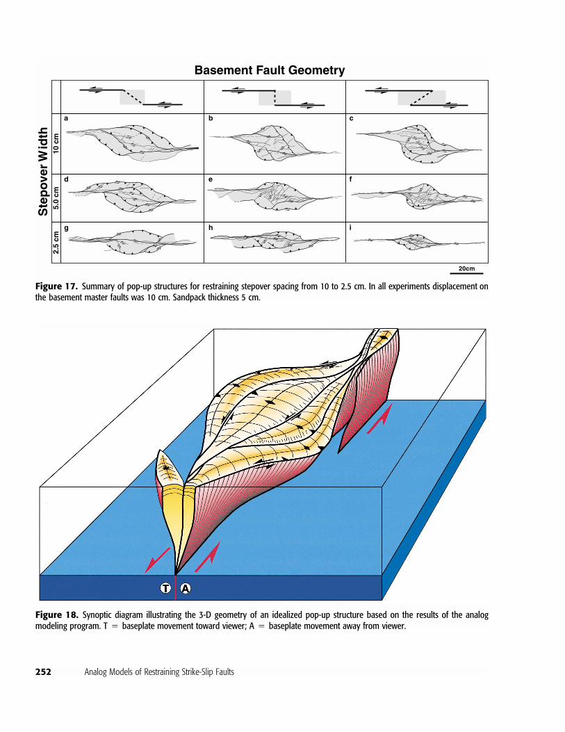
In experiments where the width of the stepoverwas varied from 10 to 2.5 cm (summarized in Figure17), a decrease in the stepover width produced a pro-portional decrease in the width of the pop-up and acorresponding increase in the surface relief of the pop-up, as the total displacement remained constant. Hav-ing stepover widths less than half of the total displace-ment along the master faults, underlapping and neutralbasement configurations produced structures that canbe best described as in-line uplifts (the axis of upliftclosely parallels the PDZ) (Figure 17g, h) and only ex-treme overlap such as that in the 150� configurationproduces a rhombic-shaped pop-up (Figure 17i).
McClay and Bonora 245
Figure 9. Experiment W305 after 10 cm sinistral displacement. (a) Top surface of model showing pop-up faults. (b) Horizontalsection taken 1 cm below top surface. (c) Interpretation of b, showing the folds, faults, and bed-dip directions.
DISCUSSION
Pop-Up Geometries
The experimental models of strike-slip pop-ups in thisarticle reveal their progressive evolution in plan viewand their 3-D structure in both vertical and horizontalsections (e.g., Figures 3–9, 16). The geometries of re-
straining stepover pop-ups were fundamentally con-trolled by the geometry of the stepover (underlapping-overlapping), the width of the stepover in the rigidbasement beneath the sandpack (Figures 3–9, 16), andthe thickness of the sandpack.
In models without synkinematic sedimentation,the finite pop-up geometries varied from elongatelozenge-shaped uplifts for 30� underlapping stepovers
246 Analog Models of Restraining Strike-Slip Faults
Figure 11. Serial vertical sections and a line diagram of the surface of experiment W324 after 10 cm sinistral strike-slip displacementon the basement fault system. Fifty serial sections were cut at 1 cm intervals across the model. Faults are numbered to permitcorrelation between the plan view diagram and the vertical sections.
McClay and Bonora 247
Figure 12. Sequential top-surface photographs showing the progressive evolution of experiment W314, 90� restraining stepover.Synkinematic sedimentation was added incrementally after each 2 cm of displacement. (a) 2 cm displacement; (b) 4 cm displacement;(c) 6 cm displacement; (d) 8 cm displacement; (e) 10 cm displacement.
Figure 14. Sequential top-surface photographs showing the progressive evolution of experiment W325, 150� restraining stepover.Synkinematic sedimentation was added incrementally after each 2 cm of displacement. (a) 2 cm displacement; (b) 4 cm displacement;(c) 6 cm displacement; (d) 8 cm displacement; (e) 10 cm displacement.
248 Analog Models of Restraining Strike-Slip Faults
(Figures 3, 16), to broad rhomboidal shapes for 90�stepovers (Figures 5, 9, 13), to sigmoidal shapes for150� overlapping stepovers (Figures 7, 15). All pop-ups are characterized by doubly plunging anticlinesthat produce four-way dip closures above the restrain-ing stepover (Figures 9, 16). Having an increase in theamount of stepover, the pop-ups became wider, moresigmoidal, and developed crosscutting faults thatlinked the offset PDZs (Figures 5, 7, 9). In some mod-els, small, antithetic (dextral) shears also cut the crestsof the pop-ups. The addition of synkinematic sedimen-tation produced broader structures (Figures 10, 12, 14)as the sidewall bounding faults to the pop-up propa-gated upward through the synkinematic layers ratherthan flattening at the surface as in the models that hadno synkinematic sedimentation. A decrease in thewidth of the stepover produced narrower pop-ups(Figure 17), but they had more complex internal struc-tures (Figure 16). As in all sand analog models, thefault density decreases as sandpack thickness increases,such that 10 cm sandpacks generated relatively simplebroad pop-up. Models run that had stepover widths ofless than 50% total displacement produced narrow, in-line uplifts for underlapping to neutral baseplateconfigurations.
In vertical sections (cf. Figures 4, 6, 8), the PDZsat the extremities of the models were characterized bynarrow positive flower structures. Deformation in thestepover consisted of strongly asymmetric pop-ups, ex-cept in their very centers, where broad symmetric pop-ups were formed. Inmost models, two pairs of oblique-slip reverse sidewall faults bound the pop-up. Theinner fault pair produced a central zone of greater up-lift and surface relief (Figures 3e, 5e, 7e). For modelswithout synkinematic sedimentation, the boundingfaults to the pop-ups are very steep, having dips �75�in the basal parts of the model and flatten upward to-ward the free upper surface, giving a general convex-up fault profile. Models having synkinematic sedimen-tation typically produced pop-up faults that weregently concave upward (Figures 11, 13, 15) in crosssection as a result of propagation through the synki-nematic layers producing fault-propagation growthfolds. The synkinematic strata thinned onto the crestof the pop-up anticlines and thickened away fromthem (Figures 11, 13, 15).
The upper surfaces of the pop-ups showed coun-terclockwise (sinistral) rotation indicated by the defor-mation of the grid lines on the surface of the models.The maximum rotation, after 10 cm displacement onthe basement fault system, increased from only 7–7.5�
counterclockwise for the 30� underlapping stepover(Figure 3), to 12–14� for the 90� neutral stepover (Fig-ure 5); to 16� for the 150� overlapping stepover (Figure7). The same pattern of increased rotation was ob-served for strike-slip pull-apart models (Dooley andMcClay, 1997) and reflect the increasing difficulty ofdisplacement transfer across the stepover with in-creased amount of stepover ( i.e., 30 to 90� to 150�).These rotations, however, are relatively small com-pared with those that might be expected in block-faultrotational strike-slip models (cf. McKenzie and Jack-son, 1986) and those that are observed in complex re-straining stepover systems along the San Andreas faultsystem in southern California (cf. 37 to 85�) (Dickin-son, 1996; Sylvester, 1988). This most likely reflectsthe isotropic nature of the sandpack in the models, andlarger rotations might be expected if competency con-trasts and anisotropies were introduced into themodels.
Figure 18 is a 3-D synoptic model of the funda-mental pop-up architecture as seen in the analog mod-els. This illustrates the curved nature of the primarysidewall reverse faults and the change in their geome-tries along strike. The pop-up asymmetry is generatedas the bounding faults change from strike-slip tooblique reverse-slip along strike and as they link to thePDZs at the ends of the stepovers.
Comparisons with Natural Examples of Pop-Up Structures
Many strike-slip fault systems are strongly segmented(e.g., the San Andreas system) (Jones et al., 1994; Pe-ters et al., 1994; Zolnai, 1991; Sylvester, 1988; Powellet al., 1993), having thrust faults and anticlinal upliftsformed in regions of restraining stepovers in the faultsystem. Well-described natural examples of pop-upsare uncommon, probably because of the complex 3-Dgeometries of the fault systems and also because theyare regions of uplift and, once formed, rapidly becomeeroded. Sylvester and Smith (1976) described complexpalm tree structures: pop-up features having flatteningupward reverse faults from the Mecca Hills region ofthe San Andreas fault system, southern California.Cunningham et al. (1996) interpreted several short,elevated mountain ranges along the North Gobi–Altaifault zone to have formed above restraining bends andstepovers in this sinistral strike-slip fault system. Thesemountain ranges have broad, doubly plunging antifor-mal shapes and are bounded by steep reverse faults.Their general form and topographic morphology aresimilar to that produced in the analogmodels described
McClay and Bonora 249
Figure 13. Serial vertical sections and a line diagram of the surface of experiment W314 after 10 cm sinistral strike-slip displacementon the basement fault system. Fifty serial sections were cut at 1 cm intervals across the model. Faults are numbered to permitcorrelation between the plan view diagram and the vertical sections.
250 Analog Models of Restraining Strike-Slip Faults
Figure 15. Serial vertical sections and a line diagram of the surface of experiment W325 after 10 cm sinistral strike-slip displacementon the basement fault system. Fifty serial sections were cut at 1 cm intervals across the model. Faults are numbered to permitcorrelation between the plan view diagram and the vertical sections.
McClay and Bonora 251
Figure 16. Experiment E307: 90� neutral stepover and 5 cm stepover width. (a) Photograph of the upper surface of the model after10 cm displacement on the basement faults. (b) Structure contours of the upper surface of the model as interpolated from fifty serialsections across the completed model. (c) Longitudinal sections across model W307. (d) Perspective view of a 3-D visualization of thefaults in model W307.
252 Analog Models of Restraining Strike-Slip Faults
a
d
g
b
e
h
c
f
i
Basement Fault Geometry
Ste
pov
er W
idth
20cm
5.0
cm2.
5 cm
10 c
m
Figure 17. Summary of pop-up structures for restraining stepover spacing from 10 to 2.5 cm. In all experiments displacement onthe basement master faults was 10 cm. Sandpack thickness 5 cm.
Figure 18. Synoptic diagram illustrating the 3-D geometry of an idealized pop-up structure based on the results of the analogmodeling program. T � baseplate movement toward viewer; A � baseplate movement away from viewer.

McClay and Bonora 253
Nevada
LMFSLVSZ
Bitter Spring ValleyFault Zone
Bitter Spring ValleyFault Zone
Limit of Uplift
Folded Cenozoic Thrust
LakeMead
20 km
MuddyMts
LasVegas
VirginMts
GoldButte
N
N
1 km
D
UD
UD
U
U
D
Figure 19. Map of the Echo Hills restraining stepover, south-eastern Nevada (modified from Campagna and Aydin, 1991). LVSZ �Las Vegas shear zone; LMFS � Lake Mead fault system.
D
U
North OwlCreek Fault
Shotgun Butte Thrust
109°
43°30’
N
20 km
Figure 20. Simplified map ofthe Owl Creek pop-up struc-ture, Wyoming (modified fromPaylor and Yin, 1993).
in this article. Natural pop-ups that show similar mor-phologies and structures to the analog models arebriefly discussed in the following section.
Example 1: Echo Hills, Southeastern NevadaThe Echo Hills formed in a restraining stepover in theBitter Spring Valley fault zone, north of Lake Mead,
254 Analog Models of Restraining Strike-Slip Faults
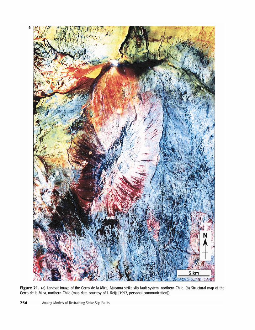
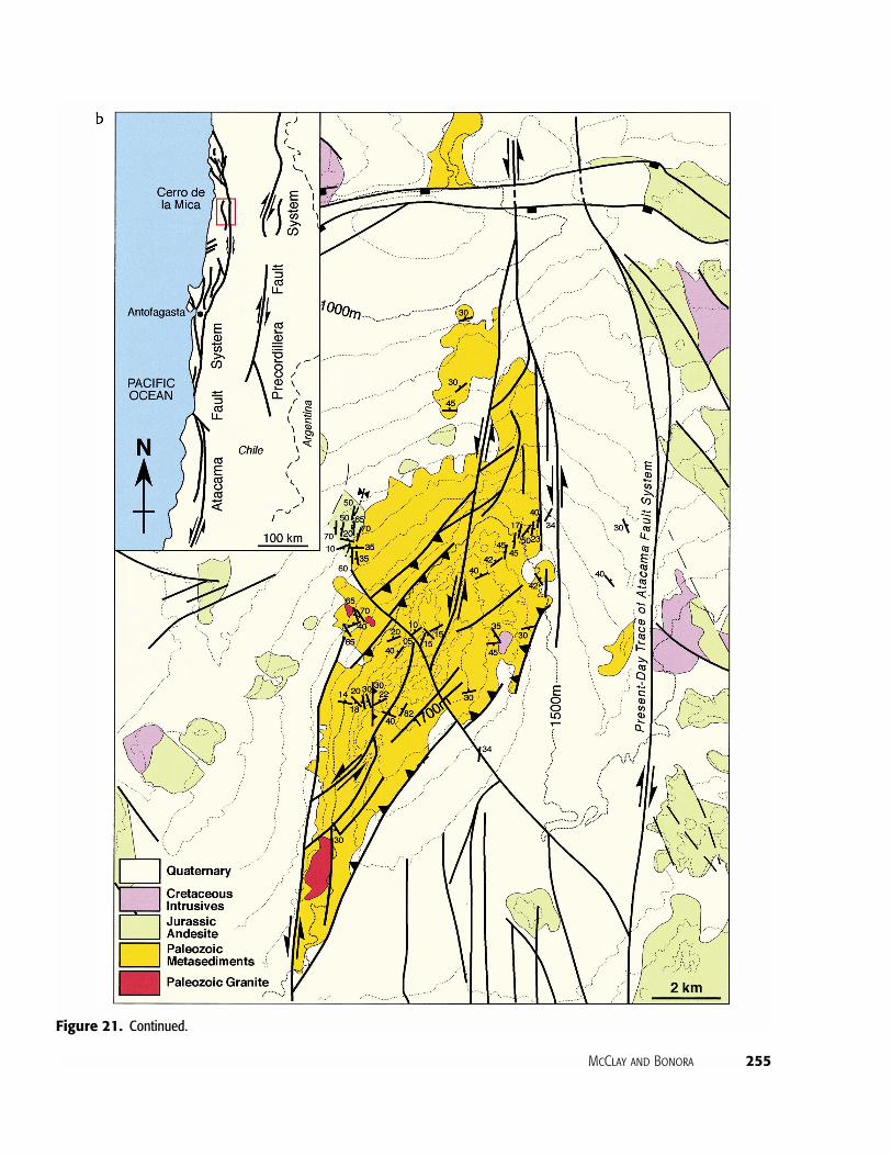
Figure 21. (a) Landsat image of the Cerro de la Mica, Atacama strike-slip fault system, northern Chile. (b) Structural map of theCerro de la Mica, northern Chile (map data courtesy of J. Reijs [1997, personal communication]).
McClay and Bonora 255
Figure 21. Continued.
256 Analog Models of Restraining Strike-Slip Faults
Nevada. The topography and fault patterns (Figure19) as mapped by Campagna and Aydin (1991) showa rhomboidal zone of uplift that is bounded by steepreverse faults. The center of the uplifted block is cutby sinistral strike-slip faults that link the two PDZs(Figure 19). The structure of this pop-up is similar tothe analog models and the map is most comparableto the surface views of the 30� restraining stepovermodels (cf. Figures 3, 4, 10).
Example 2: Owl Creek Mountains, Central WyomingThe Owl Creek pop-up, central Wyoming (Paylor andYin, 1993), formed in the stepover between thesteeply dipping North Owl Creek fault in the north-west and the Shotgun Butte thrust system in thesoutheast (Figure 20). The Owl Creek structure con-sists of three dominant northwest-southeast–trendinganticlines involving Precambrian through Permianrocks (Paylor and Yin, 1993) forming a complex pop-up structure. Its lozenge shape and map expression issimilar to the patterns produced by the underlappingrestraining stepover models (Figures 3, 4, 10).
Example 3: Cerro de la Mica, Atacama Fault System,Northern ChileCerro de la Mica, is a short, isolated range of upliftedPaleozoic volcanic and sedimentary rocks along thenorthern Atacama fault zone (Figure 21). Cerro de laMica occurs at the stepover between two segments ofthe Jurassic–Cretaceous sinistral northern Atacamafault zone. The range is 800 m above base level, elon-gate, and bounded by steep reverse faults on each side.The internal structure is complex and has steeply dip-ping Paleozoic volcanic and sedimentary rocks (Figure21b). The morphology and fault architecture of theCerro del Mica is comparable to our experimentalmodels where the restraining stepover was oriented at30� (e.g., Figures 3, 4, 10).
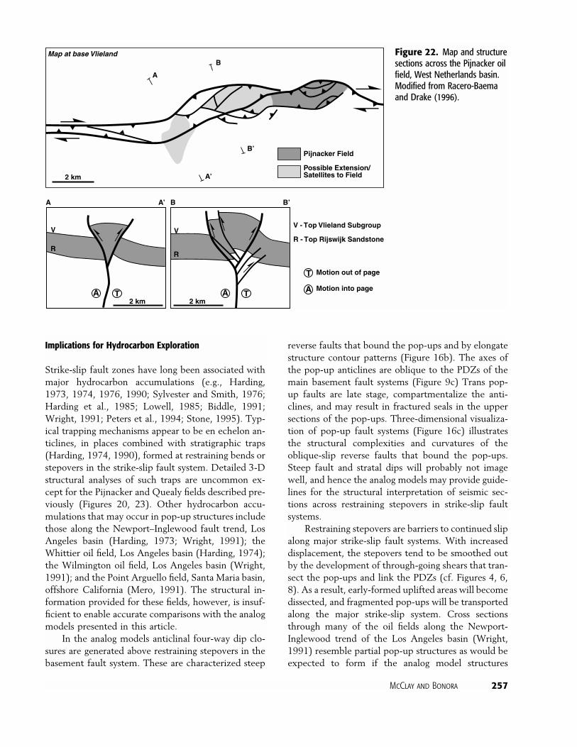
Example 4: Pijnacker Field, West NetherlandsThe Pijnacker field (Figure 22) is located at a right-stepping, restraining offset in a northwest-southeast–trending dextral strike-slip fault system (Racero-Baema and Drake, 1996). The field is located in anelongate lozenge-shaped pop-up that formed by in-version of an older rhomboidal pull-apart as a resultof early Tertiary reversal of slip on the northwest-southeast boundary faults. The pop-up is bounded byconcave-up reverse faults that produce an elongate S-shaped anticlinal structure (Figure 22). In this case theplan geometry of the pop-up indicates that the con-
trolling faults were offset in an underlapping stepovergeometry (cf. Figures 3, 5). The reservoir unit in thisoil field is the Rijswijk sandstone (Racero-Baema andDrake, 1996).
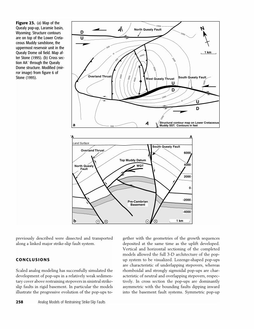
Example 5: Quealy Dome, WyomingThe Quealy dome (Figure 23) is formed between twonortheast-trending, basement-involved, sinistralstrike-slip faults in the Laramie basin, Wyoming(Stone, 1995). The pop-up formed between theNorth Quealy and South Quealy fault systems, 3.2km apart (Figure 23a), and is characterized by anasymmetric dome bounded by gently concave-upthrust faults (Overland thrust and West Quealythrust) (Figure 23). The map and cross sectional ge-ometry of the Quealy pop-up closely matches thearchitecture of the 90� neutral stepover models (Fig-ures 5, 6) and, in particular, the map pattern is verysimilar to the horizontal section of model W305 (Fig-ure 9b).
Limitations of the Analog Models
The geometries and kinematics of pop-up structuresdeveloped at retraining bends and stepovers in strike-slip fault systems can be successfully simulated usinganalog models as described previously. Important lim-itations to sandbox modeling, however, must alwaysbe considered when applying the results to studies ofnatural fault systems. Sandbox models cannot accu-rately simulate the thermal, flexural, and isostatic ef-fects generated by, or associated with, faulting in theupper crust, nor do they consider the effects of pore-fluid pressures and compaction. Pure sand models,such as those described in this article, are isotropic,whereas in natural systems, the upper crustal stratawould be expected to exhibit competency contrastsand anisotropies that would affect the fault geometriesand in particular the development of folds and rigidblock rotations. Natural pop-ups such as the OwlCreek (Figure 20) and the Ocotillo Badlands struc-tures (Brown and Sibson, 1989) are strongly folded asa result of anisotropic layers in the stepover structure.In particular the models presented in this article donot incorporate plastic or ductile layers designed tosimulate weak rocks such as salt or overpressuredshale. Nevertheless, the usefulness of the analog mod-els in understanding the progressive evolution ofstrike-slip pop-ups is demonstrated by the strong geo-metric similarities between the models and the naturalexamples described previously.
McClay and Bonora 257
Possible Extension/Satellites to Field
A
A’
B
B’
V - Top Vlieland Subgroup
R - Top Rijswijk Sandstone
Map at base Vlieland
2 km
A A’
2 km
B B’
Pijnacker Field
A T A TMotion into pageA
Motion out of pageT
2 km
V
R
V
R
Figure 22. Map and structuresections across the Pijnacker oilfield, West Netherlands basin.Modified from Racero-Baemaand Drake (1996).
Implications for Hydrocarbon Exploration
Strike-slip fault zones have long been associated withmajor hydrocarbon accumulations (e.g., Harding,1973, 1974, 1976, 1990; Sylvester and Smith, 1976;Harding et al., 1985; Lowell, 1985; Biddle, 1991;Wright, 1991; Peters et al., 1994; Stone, 1995). Typ-ical trapping mechanisms appear to be en echelon an-ticlines, in places combined with stratigraphic traps(Harding, 1974, 1990), formed at restraining bends orstepovers in the strike-slip fault system. Detailed 3-Dstructural analyses of such traps are uncommon ex-cept for the Pijnacker and Quealy fields described pre-viously (Figures 20, 23). Other hydrocarbon accu-mulations that may occur in pop-up structures includethose along the Newport–Inglewood fault trend, LosAngeles basin (Harding, 1973; Wright, 1991); theWhittier oil field, Los Angeles basin (Harding, 1974);the Wilmington oil field, Los Angeles basin (Wright,1991); and the Point Arguello field, Santa Maria basin,offshore California (Mero, 1991). The structural in-formation provided for these fields, however, is insuf-ficient to enable accurate comparisons with the analogmodels presented in this article.
In the analog models anticlinal four-way dip clo-sures are generated above restraining stepovers in thebasement fault system. These are characterized steep
reverse faults that bound the pop-ups and by elongatestructure contour patterns (Figure 16b). The axes ofthe pop-up anticlines are oblique to the PDZs of themain basement fault systems (Figure 9c) Trans pop-up faults are late stage, compartmentalize the anti-clines, and may result in fractured seals in the uppersections of the pop-ups. Three-dimensional visualiza-tion of pop-up fault systems (Figure 16c) illustratesthe structural complexities and curvatures of theoblique-slip reverse faults that bound the pop-ups.Steep fault and stratal dips will probably not imagewell, and hence the analog models may provide guide-lines for the structural interpretation of seismic sec-tions across restraining stepovers in strike-slip faultsystems.
Restraining stepovers are barriers to continued slipalong major strike-slip fault systems. With increaseddisplacement, the stepovers tend to be smoothed outby the development of through-going shears that tran-sect the pop-ups and link the PDZs (cf. Figures 4, 6,8). As a result, early-formed uplifted areas will becomedissected, and fragmented pop-ups will be transportedalong the major strike-slip system. Cross sectionsthrough many of the oil fields along the Newport-Inglewood trend of the Los Angeles basin (Wright,1991) resemble partial pop-up structures as would beexpected to form if the analog model structures
258 Analog Models of Restraining Strike-Slip Faults
Figure 23. (a) Map of theQuealy pop-up, Laramie basin,Wyoming. Structure contoursare on top of the Lower Creta-ceous Muddy sandstone, theuppermost reservoir unit in theQuealy Dome oil field. Map af-ter Stone (1995). (b) Cross sec-tion AA� through the QuealyDome structure. Modified (mir-ror image) from figure 6 ofStone (1995).
1 km
A'
A
1 km
N
AA'
-4000
-2000
0
2000
4000
6000
Land Surface
300020
00
4000
3000
2000
3000
1000
1000
1000
sl
-100
0
-500
-500
sl
-500
-1500
North QuealyFault
South Quealy FaultOverland Thrust
WQT
South Quealy Fault
North Quealy Fault
Overland ThrustWest Quealy Thrust
Structural contour map on Lower CretaceousMuddy SST. Contours in feet
Top Muddy Datum
DU
U
D
U
D
Pre-CambrianBasement
a
b
previously described were dissected and transportedalong a linked major strike-slip fault system.
CONCLUSIONS
Scaled analog modeling has successfully simulated thedevelopment of pop-ups in a relatively weak sedimen-tary cover above restraining stepovers in sinistral strike-slip faults in rigid basement. In particular the modelsillustrate the progressive evolution of the pop-ups to-
gether with the geometries of the growth sequencesdeposited at the same time as the uplift developed.Vertical and horizontal sectioning of the completedmodels allowed the full 3-D architecture of the pop-up system to be visualized. Lozenge-shaped pop-upsare characteristic of underlapping stepovers, whereasrhomboidal and strongly sigmoidal pop-ups are char-acteristic of neutral and overlapping stepovers, respec-tively. In cross section the pop-ups are dominantlyasymmetric with the bounding faults dipping inwardinto the basement fault systems. Symmetric pop-up
McClay and Bonora 259
geometries are only found above the central sectionsof the basement stepovers. All pop-ups produced inthe modeling program were doubly plunging anticlinesthat produced four-way dip closures. With increasedstepover angle (neutral to overlapping) and increaseddisplacement on the basement fault systems, crosscut-ting faults transect the central sections of the modelpop-ups.
Natural examples of pop-ups from various strike-slip terranes show comparable morphologies and struc-tures to the analog models. Many pop-ups, however,are eroded, and their full 3-D fault architecture is notdiscernible. The analog models described in this articlemay provide guidelines for the interpretation of seis-mic sections across restraining stepovers in strike-slipsystems. Additional, well-imaged, 3-D seismic exam-ples of contractional structures at strike-slip restrainingbends and stepovers are needed, however, to fully testthe applicability of these analog models to naturalstrike-slip systems.
REFERENCES CITED
Aydin, A. A., and A. Nur, 1985, The types and roles of stepovers instrike-slip tectonics, in K. T. Biddle and N. Christie-Blick, eds.,Strike-slip deformation, basin formation, and sedimentation:SEPM Special Publication 37, p. 35–45.
Biddle, K., ed., 1991, Active margin basins: AAPG Memoir 51,324 p.
Brown, N. H., and R. H. Sibson, 1989, Structural geology of theOcotillo Badlands antidilational fault jog, southern California,in D. P. Schwartz and R. H. Sibson, eds., Fault segmentationand controls of rupture initiation and termination: U.S. Geo-logical Survey Open File Report 89-315, p. 94–110.
Calassou, S., C. Larroque, and J. Malavieille, 1993, Transfer zonesof deformation in thrust wedges: an experimental study: Tec-tonophysics, v. 221, p. 325–344.
Campagna, D. J., and A. Aydin, 1991, Tertiary uplift and shorteningin the Basin and Range: the Echo Hills, southeastern Nevada:Geology, v. 19, p. 485–488.
Christie-Blick, N., and K. T. Biddle, 1985, Deformation and basinformation along strike-slip faults, in K. T. Biddle and N. Chris-tie-Blick, eds., Strike-slip deformation, basin formation, andsedimentation: SEPM Special Publication 37, p. 1–35.
Crowell, J. C., 1974, Origin of late Cenozoic basins in southernCali-fornia, inR. H. Dott and R. H. Shaver, eds.,Modern and ancientgeosynclinal sedimentation: SEPM Special Publication 19, p.292–303.
Cunningham,W. D., B. F.Windley, D.Dorjnamjaa,G. Badamgarov,and M. Saandar, 1996, A structural transect across the Mon-golian western Altai: active transpressional mountain buildingin central Asia: Tectonics, v. 15, p. 142–156.
Dickinson, W. R., 1996, Kinematics of transrotational tectonism inthe California Transverse Ranges and its contribution to cu-mulative slip along the San Andreas transform fault system:Geological Society of America Special Paper 305, 46 p.
Dooley, T., and K. R. McClay, 1997, Analog modelling of strike-slippull-apart basins: AAPG Bulletin, v. 81, p. 804–826.
Harding, T. P., 1973, Newport-Inglewood trend, California—an ex-ample of wrenching style of deformation: AAPG Bulletin, v.57, p. 97–116.
Harding, T. P., 1974, Petroleum traps associated with wrench faults:AAPG Bulletin, v. 58, p. 1290–1304.
Harding, T. P., 1976, Tectonic significance andhydrocarbontrappingconsequences of sequential folding synchronous with San An-dreas faulting, San Joaquin Valley, California: AAPG Bulletin,v. 60, p. 356–378.
Harding, T. P., 1990, Identification of wrench faults using subsurfacestructural data: criteria and pitfalls: AAPG Bulletin, v. 74, p.1590–1609.
Harding, T. P., R. C. Vierbuchen, andN. Christie-Blick, 1985,Struc-tural styles, plate-tectonic settings, and hydrocarbon traps ofdivergent (transtensional) wrench faults, in K. T. Biddle and N.Christie-Blick, eds., Strike-slip deformation, basin formation,and sedimentation: SEPM Special Publication 37, p. 51–78.
Horsfield, W. T., 1977, An experimental approach to basement-controlled faulting: Geologae en Mijnbouw, v. 56, p. 363–370.
Horsfield, W. T., 1980, Contemporaneous movement along crossingconjugate normal faults: Journal of Structural Geology, v. 2, p.305–310.
Jones, D. L., R. Graymer, C. Wang, T. V. McEvilly, and A. Lomax,1994, Neogene transpressive evolution of the California CoastRanges: Tectonics, v. 13, p. 561–574.
Keller, J. V. A., S. H. Hall, and K. R. McClay, 1997, Shear fracturepattern and microstructural evolution in transpressional faultzones from field and laboratory studies: Journal of StructuralGeology, v. 19, p. 1173–1187.
Lallemand, S., J. Malavieille, and S. Calassou, 1992, Effects of oce-anic ridge subduction on accretionary wedges: Tectonics, v 11,p. 1301–1313.
Lowell, J. D., 1985, Structural styles in petroleum exploration:Tulsa, Oil and Gas Consultants International, 460 p.
Malavieille, J., S. Calassou, and C. Larroque, 1993, Modelisationexperimentale des relations tectonique sedimentation entrebassin avant-arc et prisme d’accretion: Compte Rendu Acada-mie des Sciences, v. 316, p. 1131–1137.
Mandl, G., 1988, Mechanics of tectonic faulting: Netherlands, El-sevier, 407 p.
Mann, P., P. R. Hempton, D. C. Bradley, and K. Burke, 1983, De-velopment of pull-aparts: Journal of Geology, v. 91, p. 529–554.
McClay, K. R., 1990, Deformation mechanics in analogue models ofextensional fault systems, in E. H. Rutter and R. J. Knipe, eds.,Deformation mechanisms, rheology and tectonics: GeologicalSociety Special Publication 54, p. 445–454.
McClay, K. R., 1995a, The geometries and kinematics of invertedfault systems: a review of analogue model studies, in J. G. Bu-chanan and P. G. Buchanan, eds., Inversion tectonics: Geolog-ical Society Special Publication 88, p. 97–118.
McClay, K. R., 1995b, 2-D and 3-D analogue modelling of exten-sional fault structures: templates for seismic interpretation: Pe-troleum Geoscience, v. 1, p. 163–178.
McClay, K., and T. Dooley, 1995, Analog models of pull-aparts:Geology, v. 23, p. 711–714.
McClay, K. R., and M. J. White, 1995, Analogue modelling of or-thogonal and oblique rifting: Marine and Petroleum Geology,v. 12, p. 137–151.
McKenzie, D., and J. Jackson, 1986, A block model of distributeddeformation by block faulting: Journal of theGeological Societyof London, v. 143, p. 349–353.
Mero, W. E., 1991: Point Arguello field—USA Santa Maria Basin,offshore California, in N. H. Foster and E. A. Beaumont, eds.,Structural traps V.: AAPG Treatise of Petroleum Geology—Atlas of Oil and Gas Fields, p. 27–57.
260 Analog Models of Restraining Strike-Slip Faults
Naylor, M. A., G. Mandl, and C. H. K. Sijpesteijn, 1986, Fault ge-ometries in basement-induced wrench faulting under differentinitial stress states: Journal of Structural Geology, v. 8, p. 737–752.
Paylor II, E. D., and A. Yin, 1993, Left-slip evolution of the NorthOwl Creek fault system, Wyoming, during Laramide shorten-ing, in C. J. Scmidt, R. B. Chase, and E. A. Erslev, eds., Lar-amide basement deformation in the Rocky Mountain forelandof the western United States: Geological Society of AmericaSpecial Paper 280, p. 229–242.
Peters, K. E., T. D. Elam, M. H. Pytte, and P. Sundararaman, 1994,Identification of petroleum systems adjacent to the SanAndreasfault, California, USA, in L. B. Magoon and W. G. Dow, eds.,The petroleum system—from source to trap: AAPG Memoir60, p. 423–436.
Powell, R. E., R. J. Weldon, and J. C. Matti, 1993, The San Andreasfault system: displacement, palinspastic reconstruction andgeo-logic evolution: Geological Society of America Memoir 178,332 p.
Racero-Baema, A., and S. J. Drake, 1996, Structural style and res-ervoir development in the West Netherlands oil province, inH. E. Rondeel, D. A. J. Batjes, and W. H. Niewenhuis, eds.,Geology of gas and oil under theNetherlands: Amsterdam,Klu-wer, p. 211–227.
Richard, P. D., 1991. Experiments on faulting in a two layer coversequence overlying a reactivated basement fault with oblique(normal-wrench or reverse-wrench) slip: Journal of StructuralGeology, v. 13, p. 459–469.
Richard, P. D., and P. R. Cobbold, 1990, Experimental insights intopartitioning of fault motions in continental convergent wrenchzones: Annales Tectonicae, v. 4, p. 35–44.
Richard, P. D., J. F. Ballard, B. Colletta, and P. R. Cobbold, 1989,Fault initiation and development above a basement strike-slipfault: analogue modelling and tomography: Compte RenduAcadamie des Sciences, v. 309, no. 2, p. 2111–2118.
Richard, P. D., B. Moquet, and P. R. Cobbold, 1991, Experimentson simultaneous faulting and folding above a basement wrenchfault: Tectonophysics, v. 188, p. 133–141.
Richard, P. D., M. A. Naylor, and A. Koopman, 1995, Experimental
models of strike-slip tectonics: Petroleum Geoscience, v. 1, p.71–80.
Schreurs, G., 1994, Experiments on strike-slip faulting and blockrotation: Geology, v. 22, p. 567–570.
Serra, S., and R. A. Nelson, 1989, Clay modelling of rift asymmetryand associated structures: Tectonophysics, v. 153, p. 307–312.
Stone, D. S., 1995, Structure and kinematic genesis of the Quealywrench duplex: transpressional reactivation of the PrecambrianCheyenne belt in the Laramie basin,Wyoming: AAPGBulletin,v. 79, p. 1349–1376.
Sylvester, A. G., 1988, Strike-slip faults: Geological Society ofAmerica Bulletin, v. 100, p. 1666–1703.
Sylvester, A. G., and R. R. Smith, 1976, Tectonic transpression andbasement-controlled deformation in the San Andreas faultzone, Salton trough, California: AAPG Bulletin, v. 60, p. 74–96.
Sylvester, A. G., and R. R. Smith, 1987, Structure section in PaintedCanyon, Mecca Hills, southern California, in M. L. Hill, ed.,Centennial field guide volume 1: Cordilleran Section Geologi-cal Society of America, p. 103–108.
Tron, V., and J-P. Brun, 1991, Experiments on oblique rifting inbrittle-ductile systems: Tectonophysics, v. 188, p. 71–84.
Vendeville, B., 1991,Mechanisms generating normal fault curvature:a review illustrated by physical models, in A. M. Roberts, G.Yielding, and B. Freeman, eds., The geometry of normal faults:Geological Society Special Publication 56, p. 241–250.
Wilcox, R. E., T. P. Harding, and D. R. Seely, 1973, Basin wrenchtectonics: AAPG Bulletin, v. 57, p. 74–96.
Withjack, M. O., and W. R. Jamison, 1986, Deformation producedby oblique rifting: Tectonophysics, v. 126, p. 99–124.
Withjack, M. O., J. Olson, and E. Peterson, 1990, Experimentalmodels of extensional forced folds: AAPG Bulletin, v. 74, p.1038–1045.
Wright, T. L., 1991, Structural geology and tectonic evolution of theLos Angeles basin, California, in K. T. Biddle, ed., Active mar-gin basins: AAPG Memoir 52, p. 35–130.
Zolnai, G., 1991, Continental wrench-tectonics and hydrocarbonhabitat, 2d ed.: AAPG Continuing Education Course Notes 30,unpaginated.