Embed Size (px)
Citation preview

Struttura del corsoStruttura del corso
VERIFICA FINALELezione 11Ottimo progettuale
Lezione 10Carico limite di piastre su pali
Giovedì06.03.08
Esercitazione 3Piastre su pali in condizioni di esercizio
Lezione 9Criteri innovativi di progettazione
Lezione 8Comportamento di pali in gruppo
Giovedì28.02.08
Esercitazione 2Pali soggetti a carichi trasversali
Lezione 7Sperimentazione su pali (2)
Lezione 6Sperimentazione su pali (1)
Giovedì21.02.08
Esercitazione 1Fondazioni soggette a carichi verticali
Lezione 5Pali soggetti a carico assiale
Lezione 4Fondazioni superficiali (2)
Giovedì14.02.08
Lezione 3Fondazioni superficiali (1)
Lezione 2Quadro normativo di riferimento
Lezione 1Criteri generali di progettazione
Giovedì07.02.08
15.00 – 17.3012.30 – 13.3010.30 – 12.00
ANALISI E PROGETTAZIONE DELLE FONDAZIONIANALISI E PROGETTAZIONE DELLE FONDAZIONI
Università degli Studi di Napoli Federico IISeconda Università degli Studi di NapoliUniversità degli Studi di SalernoUniversità degli Studi di Napoli ParthenopeUniversità degli Studi del Sannio
Università degli Studi Roma La Sapienza
Dottorato di Ricerca in Ingegneria Geotecnica

In fact, the designof piles is a rathercomplex matter….
State of the ArtReport
Analisi e progettazione delle fondazioniAversa, febbraio-marzo 2008
Alessandro MandoliniSeconda Università di Napoli

In fact, the design of piles is a rather complex matter,..
As all “complex” things, it should be composedby a real part and an imaginary part
The real part may be the experimental evidence
The imaginary (imaginative?) partthe models and methods of analysis
Analisi e progettazione delle fondazioniAversa, febbraio-marzo 2008
Alessandro MandoliniSeconda Università di Napoli

Selected topics in the field of pile foundations are addressed
State of the ArtReport
Analisi e progettazione delle fondazioniAversa, febbraio-marzo 2008
Alessandro MandoliniSeconda Università di Napoli

All engineering design involves the choice of a solution to a particular problem which is EFFECTIVE, PRACTICAL and ECONOMIC.
These objectives apply to piling as to any other item.
• ENGINEERING REQUIREMENTS
• CONVENIENCE
• SPEED OF ACTION
WHY PILES SHOULD BE CHOSEN FOR A PARTICULAR CASE ?
Analisi e progettazione delle fondazioniAversa, febbraio-marzo 2008
Alessandro MandoliniSeconda Università di Napoli

OBJECTIVES
• EFFECTIVE
• PRACTICAL
• ECONOMIC
To be effective, piles must carry the loads which the supported structure imparts to them, together with any additional forces which may result from deformations of the soil mass in which they are embedded (consolidation, earthquake, movements induced by nearbystructures, ……).
Analisi e progettazione delle fondazioniAversa, febbraio-marzo 2008
Alessandro MandoliniSeconda Università di Napoli

OBJECTIVES
• EFFECTIVE
• PRACTICAL
• ECONOMIC
To be practical, piles must be of a such type as will permit access for piling equipment to the locations where they are required. The design must recognize the limits of what is possible in current practice in terms of the equipment available and the method of construction must recognize and seek to minimize the difficulties related to ground conditions which could impede proper construction.
Analisi e progettazione delle fondazioniAversa, febbraio-marzo 2008
Alessandro MandoliniSeconda Università di Napoli

OBJECTIVES
• EFFECTIVE
• PRACTICAL
• ECONOMIC
To be economic, the design must be such as to maximize the bearing capacity of each pile while at the same time providing an adequate margin of safety against failure or excessive deformation of either individual piles or pile group.
Analisi e progettazione delle fondazioniAversa, febbraio-marzo 2008
Alessandro MandoliniSeconda Università di Napoli

WHY PILES SHOULD BE CHOSEN FOR A PARTICULAR CASE ?
• ENGINEERING REQUIREMENTS
• CONVENIENCE
• SPEED OF ACTION
OBJECTIVES
• EFFECTIVE
• PRACTICAL
• ECONOMIC
Analisi e progettazione delle fondazioniAversa, febbraio-marzo 2008
Alessandro MandoliniSeconda Università di Napoli

A pile foundation is a system acting as a composite constructionconsisting of three elements: footing, piles and subsoil
QTOTQTOT QTOT PS
n
1ii,pSTOT QQQQQ +=∑+=
=
load sharing coefficient, αpr
TOT
PG
TOT
n
1ii,pile
pr QQ
Q
Q=
∑=α =
αpr = 0 1 ]0,1[
S PG C

1
10
100
1 3 5FS,UR [-]
w [
cm]
B = Bopt
Not realistic Shallow foundations(pads, beams, rafts, …)
Deep foundations (piles)
FSUR > FSminwUR > wadm
SBD
FSUR < FSminwUR > wadm
CSBD
Analisi e progettazione delle fondazioniAversa, febbraio-marzo 2008
Alessandro MandoliniSeconda Università di Napoli

Whatever the case, the design process of a pile foundation always contains the following steps:
• Assessment of the behaviour of single pile, taking in a due account technological factors
• Evaluation of the interaction effects among piles (group effects), either when assessing displacement behaviour under working loads or when evaluating bearing capacity
• Consideration of the contribution of the pile cap (if the case)
Analisi e progettazione delle fondazioniAversa, febbraio-marzo 2008
Alessandro MandoliniSeconda Università di Napoli

PILE CLASSIFICATION
DISPLACEMENT PILESDISPLACEMENT PILES
NON DISPLACEMENT PILESNON DISPLACEMENT PILES
LARGE DISPLACEMENT SMALL DISPLACEMENT
BORED
CFA
INSTALLATION METHODINSTALLATION METHOD
OTHERS (barrette, micropiles)
Analisi e progettazione delle fondazioniAversa, febbraio-marzo 2008
Alessandro MandoliniSeconda Università di Napoli

0 0.4 0.8 1.2β = τslim/σ'v
Bored piles in sandD = 0.914 m L = 10 m
bentonite cake < 1 mm
polymer no cake
bentonite cake ≈ 10 mm
Ata e O’Neill (1997)
Installation effect on shaft resistance
Analisi e progettazione delle fondazioniAversa, febbraio-marzo 2008
Alessandro MandoliniSeconda Università di Napoli

Installation effect on shaft resistance
0 0.2 0.4 0.6 0.8 1α = τslim/Cu
Beaumont clay - OCR = 4÷10 - IP = 25÷55%D = 0.273÷0.914 m L = 7÷24 m
Bored - polymer
Bored - bentonite
Bored - dry
Closed-end steel pile
O’Neill (1999)
Analisi e progettazione delle fondazioniAversa, febbraio-marzo 2008
Alessandro MandoliniSeconda Università di Napoli

Poulos et al., 2001
It is very difficult to recommend any single approach as being the more appropriate for estimating axial bearing capacity of a single pile.
Analisi e progettazione delle fondazioniAversa, febbraio-marzo 2008
Alessandro MandoliniSeconda Università di Napoli

Mandolini et al., 2005
The most reasonable approach seems to be that of developing regional design methods (L5) combining the local experiences of both piling contractors and designers.The reliability of such methods depends on the quantity and quality of available evidence, particularly:
- detailed installation parameters- well-conducted and well-interpreted load tests
Analisi e progettazione delle fondazioniAversa, febbraio-marzo 2008
Alessandro MandoliniSeconda Università di Napoli

NON DISPLACEMENT PILESNON DISPLACEMENT PILES
CONTINUOUS FLIGTH AUGER, CFA
Developed in The Netherlands, ’60sLarge use in Europe, not appreciated in USA (forbidden by FHWA)
0
20
40
60
80
100
1984 1985 1986 1987 1988 1989 1990 1991 1992
% of
pile
typ
e
non displ. pilesauger pilesdispl. piles
0
20
40
60
80
100
2000 2001 2002 2003 2004
Trevisani, 1992 Mandolini, 2004
Analisi e progettazione delle fondazioniAversa, febbraio-marzo 2008
Alessandro MandoliniSeconda Università di Napoli

ConcretePump
NON DISPLACEMENT PILESNON DISPLACEMENT PILES
CONTINUOUS FLIGTH AUGER, CFA
Analisi e progettazione delle fondazioniAversa, febbraio-marzo 2008
Alessandro MandoliniSeconda Università di Napoli

ConcretePump
PENETRATION STAGE
Rate of penetration, vPRate of revolution, ωP
Viggiani (1989, 1993)
Kinematic analysis: in order not to decompress surrounding soils:
VP > VP,CR = ωP⋅λ⋅[1-(d0/dN)2]
λ = pitch of the screwd0 = outer diameter of the central hollow stemdN = overall diameter of the auger
Mt
λ
d0
dNON DISPLACEMENT PILESNON DISPLACEMENT PILES
CONTINUOUS FLIGTH AUGER, CFA
Analisi e progettazione delle fondazioniAversa, febbraio-marzo 2008
Alessandro MandoliniSeconda Università di Napoli

ConcretePump
0.0
0.2
0.4
0.6
0.8
1.0
0.0 0.2 0.4 0.6 0.8 1.0
do / d
vp /
(p
x )
terreno dislocato:vP > ωP x λ
terreno asportato:vP < ωP x λ
NON DISPLACEMENT PILESNON DISPLACEMENT PILES
CONTINUOUS FLIGTH AUGER, CFA
displaced soil:vP > ω x λ
removed soil:vP < ω x λ
Analisi e progettazione delle fondazioniAversa, febbraio-marzo 2008
Alessandro MandoliniSeconda Università di Napoli

ConcretePump
RETRIEVAL STAGE
Retrieval rate, vRωR = 0
Mandolini (2002)
In a given time ∆T:
VC = QC x ∆T∆s = VR x ∆T
Avg. pile diameter over ∆s:
d =VC/∆s = 1,13x(QC/VR)0,5
NON DISPLACEMENT PILESNON DISPLACEMENT PILES
CONTINUOUS FLIGTH AUGER, CFA
Analisi e progettazione delle fondazioniAversa, febbraio-marzo 2008
Alessandro MandoliniSeconda Università di Napoli

ConcretePump
NON DISPLACEMENT PILESNON DISPLACEMENT PILES
CONTINUOUS FLIGTH AUGER, CFA
Analisi e progettazione delle fondazioniAversa, febbraio-marzo 2008
Alessandro MandoliniSeconda Università di Napoli

The bearing capacity and settlement behaviour of CFA piles is toa large extent influenced by the equipment used and theexperience of the operator.
The significance of these two aspects is often underestimate oroverlooked at the design stage, but plays an important role forthe performance of CFA piles.
The use of a reliable system to monitor and record the wholeprocess of construction (auger depth z, , revolution w, penetrationrate VP, uplift rate VR, concrete supply QC, injection pressure PC)of this type of pile is therefore highly recommended.
Analisi e progettazione delle fondazioniAversa, febbraio-marzo 2008
Alessandro MandoliniSeconda Università di Napoli

two rectangularrafts
eight circularrafts
twobuildings
minorstructures
≈ 1500CFA piles
≈ 1300CFA piles
≈ 200CFA piles
≈ 300CFA piles
≈ 3300 piles (60% dN = 0,8 m; 40% dN = 0,6 m), L = 24 m
TOTAL LENGTH TOTAL LENGTH ≈≈ 80 km, TOTAL VOLUME 80 km, TOTAL VOLUME ≈≈ 33.000 m33.000 m33
Need of an accurate control during executionNeed of an accurate control during execution
The huge treatment plans in the plan of Sarno River
Analisi e progettazione delle fondazioniAversa, febbraio-marzo 2008
Alessandro MandoliniSeconda Università di Napoli

0
5
10
15
20
25
30
0.0 0.5 1.0CC [-]
dept
h [m
]
0
5
10
15
20
25
30
10 20 30 40ϕ [ ° ]
0
5
10
15
20
25
30
0 10 20 30qC [MPa]
Top soil
alluvialsoils
baseformation
Experimental site (Mandolini et al., 2002)
GWL
Subsoil investigations over an area of about 10000 m2:
• 7 bore-holes up to 50 m• 17 Cone Penetration Tests (CPT)• 7 Piezocone Tests (CPTU)• 4 Seismic Piezocone Tests (SCPTU)• 30 undisturbed samples for lab tests
Analisi e progettazione delle fondazioniAversa, febbraio-marzo 2008
Alessandro MandoliniSeconda Università di Napoli

STAGE I STAGE I -- Check of the monitoring systemCheck of the monitoring system
10 piles of reduced lengthwere installed, then extractedin order to measure overalllength and true diameter(step 0,5 m)
Analisi e progettazione delle fondazioniAversa, febbraio-marzo 2008
Alessandro MandoliniSeconda Università di Napoli

STAGE II STAGE II -- SLT on instrumented trial CFA pilesSLT on instrumented trial CFA piles
3 trial piles ( 2 piles dN = 0,8 m and 1 piles dN = 0,6 m) wereinstalled and instrumented alongthe shaft with the LCPCretrievable extensometer, thenloaded up to QMAX = 3 - 4 timesthe working load QW
Analisi e progettazione delle fondazioniAversa, febbraio-marzo 2008
Alessandro MandoliniSeconda Università di Napoli

STAGE III STAGE III -- Construction of the piled foundationsConstruction of the piled foundations
- For all the constructed piles,installation parameters havebeen recorded
- 9 proof tests on d = 0,8 mpiles have been performed
- 300 non destructive tests(20% of the number of piles)
CASAGRANDE C600
Analisi e progettazione delle fondazioniAversa, febbraio-marzo 2008
Alessandro MandoliniSeconda Università di Napoli

d = 0,8 mL = 24 m
d = 0,6 mL = 22,5 m
d = 0,8 mL = 24,1 m
Analisi e progettazione delle fondazioniAversa, febbraio-marzo 2008
Alessandro MandoliniSeconda Università di Napoli

Analisi e progettazione delle fondazioniAversa, febbraio-marzo 2008
Alessandro MandoliniSeconda Università di Napoli

0.0
1.0
2.0
3.0
4.0
5.0
0 20 40 60 80
settlement, w [mm]
load
[MN
]Results of loading tests on Results of loading tests on ddNN = 0,8 m CFA piles= 0,8 m CFA piles
0.0
1.0
2.0
3.0
4.0
5.0
0 20 40 60 80
settlement, w [mm]
load
[MN
]
total loadshaft loadbase load
@1 - L = 24,0 m @3 - L = 24,1 m
QMAX = 4,08 MNSMAX = 2,81 MNPMAX = 1,55 MNwMAX = 75,6 mm
QMAX = 5,30 MNSMAX = 3,94 MNPMAX = 1,36 MNwMAX = 22,8 mm
Analisi e progettazione delle fondazioniAversa, febbraio-marzo 2008
Alessandro MandoliniSeconda Università di Napoli

Viggiani (1989): insertion of the auger
- in order not to decompress the surrounding soil:
VP > VP,CR = ω ⋅ λ ⋅ [1 - (d0 / dN)2]
ω = rate of revolutionλ = pitch of the screw (0,5 m and 0,6 m)d0 = outer diameter of the central hollow stem (0,18 m)dN = overall diameter of the auger (0,6 m and 0,8 m)
dN = 0,8 m ⇒ VP,CR (m/h) = 34,2 ⋅ ω (r.p.m.)
dN = 0,6 m ⇒ VP,CR (m/h) = 27,3 ⋅ ω (r.p.m.)
Analisi e progettazione delle fondazioniAversa, febbraio-marzo 2008
Alessandro MandoliniSeconda Università di Napoli

0 10 20
ω [r .p.m .]
0 250
500
V P [m /h]
0 10 20ω [r .p.m .]
0 250
500
V P [m /h]
0
10
20
30
0 10 20 30
q c [M Pa]d
ep
th [
m]
0
10
20
30
0 10 20 30
q c [M Pa]
de
pth
[m
]Pile @1
VP < VP,CRITalong all the shaft
“BORED” - ND PILES
Pile @3
VP ≈ VP,CRITalong almost all the shaft
“DRIVEN” - D PILES
Analisi e progettazione delle fondazioniAversa, febbraio-marzo 2008
Alessandro MandoliniSeconda Università di Napoli
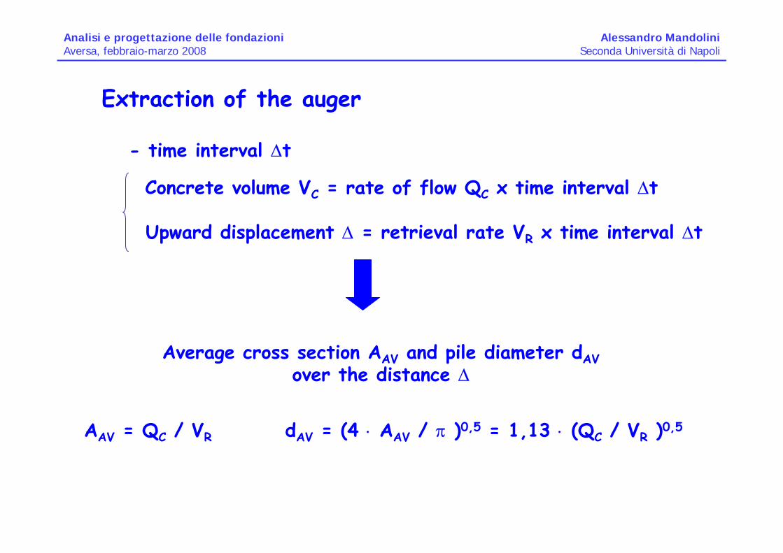
Extraction of the auger
- time interval ∆t
Concrete volume VC = rate of flow QC x time interval ∆t
Upward displacement ∆ = retrieval rate VR x time interval ∆t
Average cross section AAV and pile diameter dAVover the distance ∆
AAV = QC / VR dAV = (4 ⋅ AAV / π )0,5 = 1,13 ⋅ (QC / VR )0,5
Analisi e progettazione delle fondazioniAversa, febbraio-marzo 2008
Alessandro MandoliniSeconda Università di Napoli

0
10
20
30
0 50 100
150
QC [m 3/h]d
ep
th [
m]
50 150
250
350
V R [m /h]
0.75
0.85
0.95
d [m ]
0
10
20
30
0 50 100
150
QC [m 3/h]
de
pth
[m
]
50 150
250
350
V R [m /h]0.
75
0.85
0.95
d [m ]
Pile @1dAV > dN
along the entire shaft
dS = 0,82 m; dB = 0,84 m
Pile @3dAV > dN
along the entire shaft
dS = 0,85 m; dB = 0,94 m
Analisi e progettazione delle fondazioniAversa, febbraio-marzo 2008
Alessandro MandoliniSeconda Università di Napoli

pile n° 2
pile n° 1pile n° 3
0,0
1,0
2,0
3,0
0 20 40 60 80
settlement, w [mm]
base
pre
ssur
e, p
[MPa
]
_____ corrected-------- uncorrected
pile n° 2
pile n° 1
pile n° 3
0
20
40
60
80
0 20 40 60 80
avg.
she
ar s
tress
, s [k
Pa]
_____ corrected-------- uncorrected
Analisi e progettazione delle fondazioniAversa, febbraio-marzo 2008
Alessandro MandoliniSeconda Università di Napoli

BackBack--Analysis: Design Parameters for StrengthAnalysis: Design Parameters for StrengthsMAX = k ⋅ µ ⋅ σ′V pMAX = Nq ⋅ σ′VL
orsMAX = αS ⋅ qC,S pMAX = αB ⋅ qC,B
µ = tan(Φ)qC,S = average value of qC up to L - 4 ⋅ dNqC,B = average value of qC between the depths ( L - 4 ⋅ dN) and ( L + dN)
Analisi e progettazione delle fondazioniAversa, febbraio-marzo 2008
Alessandro MandoliniSeconda Università di Napoli

sMAX = αS ⋅ qC,S
pMAX = αB ⋅ qC,B
0.02
0.03
0.04
0.0 1.0 2.0VP/VP,CR
α S
0.15
0.20
0.25
0.0 1.0 2.0VP/VP,CR
α B
αS = 0,026 x (VP/VP,CR) + 0,004 αB = 0,115 x (VP/VP,CR) + 0,153
BackBack--Analysis: Design Parameters for StrengthAnalysis: Design Parameters for Strength

BackBack--Analysis: Design Parameters for StiffnessAnalysis: Design Parameters for Stiffness
Randolph & Wroth (1978): Q/(w⋅r0⋅GL) = f (η, ξ, ζ, ρ, EP, L/r0)
From SCPTU: G [MPa] = 10 + 4⋅z [m]; GB = 330 MPa
G* = modified values atpile-soil interface
Assuming G*B/GB = aB
G*B/GB G*S/GS
@1 shaft base 0.180
0.320
@2 shaft base 0.246
0.420
@3 shaft base 0.184
0.420
Pile
0.20
0.40
0.60
0.0 1.0 2.0VP/VP,CR
G* S
/GS
G*S /GS = 0,274 x (VP/VP,CR) + 0,144
Analisi e progettazione delle fondazioniAversa, febbraio-marzo 2008
Alessandro MandoliniSeconda Università di Napoli

Procedure for the selection of piles to be testedProcedure for the selection of piles to be tested
0
5
10
15
20
25
30
0 10 20ω [r.p.m.]
dept
h [m
]
0
5
10
15
20
25
30
0 500
vP [m/h]
dept
h [m
] (VP / VP,CR ) ⇒ αS, G*S
0
5
10
15
20
25
30
0.7 0.8 0.9 1.0
d [m]
dept
h [m
]
SLIM = [π ⋅ dS ⋅ (L - 4 dS)] ⋅αS ⋅ qCS
PLIM = [0,25 ⋅π ⋅ dB2] ⋅ αB ⋅ qCB
(VP / VP,CR ) ⇒ αB, G*B
⇒ QLIM
(Randolph & Wroth, ‘78) ⇓
[QLIM /FS] /w = QW /w
Analisi e progettazione delle fondazioniAversa, febbraio-marzo 2008
Alessandro MandoliniSeconda Università di Napoli

Results of 9 proof loading tests on piles Results of 9 proof loading tests on piles belonging to foundationsbelonging to foundations
+ 40%
- 25%
0
200
400
600
800
1000
0 200 400 600 800 1000QW /w [kN/mm], measured
QW
/w [k
N/m
m],
pred
icte
d
Analisi e progettazione delle fondazioniAversa, febbraio-marzo 2008
Alessandro MandoliniSeconda Università di Napoli

@ Experimental findings have confirmed that the behaviour ofCFA piles is intermediate between that of D and ND piles
@ Such behaviour is strongly influenced by the installationprocedures, not only during the penetration stage but also during the extraction of the auger
@ Proper graduation of concrete pumping rates couldcompensate possible soil loosening in the penetration stage,improving the performance of the piles
@ A preliminary procedure has been proposed, with the aim of making available a rational approach to the selection of thepiles to be tested
Further systematic experiments are neededFurther systematic experiments are needed
COMMENTSCOMMENTS
Analisi e progettazione delle fondazioniAversa, febbraio-marzo 2008
Alessandro MandoliniSeconda Università di Napoli

SUN won a national competition for a research funding by ItalianGovernment (about 900.000 €)
Partner: Società Italiana Fondazioni S.p.A.
4 experimental sites (n.c. and o.c clayey; loose and dense sandy soils)
For each experimental site: detailed geotechnical investigations
5 load tests at failure on fully instrumented trial piles installed with a different set of installation parameters
different concrete mix
Analisi e progettazione delle fondazioniAversa, febbraio-marzo 2008
Alessandro MandoliniSeconda Università di Napoli

U
L
Due to hydration phenomenon of the concrete embedded in a “dry” ambient, the upper part of the pile will tend to shrink with respect to the soil. The latter will react with upward forces
Due to hydration phenomenon of the concrete embedded in a “wet” ambient, the lower part of the pile will tend to swell with respect to the soil. The latter will react with downward forces
Falconio & Mandolini (2003)
Analisi e progettazione delle fondazioniAversa, febbraio-marzo 2008
Alessandro MandoliniSeconda Università di Napoli

U
LB
AKi
Ki
-10
-5
0
5
10-0.02 -0.01 0.00 0.01 0.02
w
A
load
Analisi e progettazione delle fondazioniAversa, febbraio-marzo 2008
Alessandro MandoliniSeconda Università di Napoli

U
LB
AKi
Ki
-10
-5
0
5
10-0.02 -0.01 0.00 0.01 0.02
w
A
τlim,measured < τlim,true
Analisi e progettazione delle fondazioniAversa, febbraio-marzo 2008
Alessandro MandoliniSeconda Università di Napoli

U
LB
AKi
Ki
-10
-5
0
5
10-0.02 -0.01 0.00 0.01 0.02
w
A
B
Analisi e progettazione delle fondazioniAversa, febbraio-marzo 2008
Alessandro MandoliniSeconda Università di Napoli

U
LB
AKi
Ki
-10
-5
0
5
10-0.02 -0.01 0.00 0.01 0.02
w
A
B
τlim,measured > τlim,true
Analisi e progettazione delle fondazioniAversa, febbraio-marzo 2008
Alessandro MandoliniSeconda Università di Napoli

Influence of residual stresses locked into piles
-3 m
-10 m
-20 m-35 m
-300
-200
-100
0
100
200
300
0 10 20 30 40 50 60 70 80 90 100time after casting [days]
µε
Experimental data fromEastern Napoli’s area (CDN)
Instrumented pile sectionsbelow water level
Analisi e progettazione delle fondazioniAversa, febbraio-marzo 2008
Alessandro MandoliniSeconda Università di Napoli

37
55
55
55
d
Sec. 2
Sec. 1
Sec. 3
Sec. 4
Sec. 5
Sec. 6
Sec. 7
Sec. 842
102
139
p.l.f.
γsat=1,1 - 1,4 t/mc; qc=2,5 MPa
γsat=1,6 - 1,8 t/mc; qc=15 MPa
qc=5 MPa
γsat=1,5 - 1,6 t/mc; qc=10 MPac'=0; φ=36°-40°
γsat=1,5 - 1,6 t/mc; qc=20 MPac'=1 -2 kg/cmq; φ=28°-32°
Sand
Loose pozzolana
Weakly cemented pozzolana
Peat
Riporto
d
Piles A - C d=1,5mPiles B - D d=2,00
0,0
5,0
10,0
15,0
20,0
25,0
30,0
35,0
40,0
-150 50 250µε
z [m
]
SRM
(a)
Experimental data from Eastern Napoli’s area (CDN)
Analisi e progettazione delle fondazioniAversa, febbraio-marzo 2008
Alessandro MandoliniSeconda Università di Napoli

EXPERIMENTAL DATA FOR CAST IN SITU BORED PILES
Analisi e progettazione delle fondazioniAversa, febbraio-marzo 2008
Alessandro MandoliniSeconda Università di Napoli

Two additional possible explanations:
a) Influence of soil stress history at small depths
b) Influence of dilatancy
Analisi e progettazione delle fondazioniAversa, febbraio-marzo 2008
Alessandro MandoliniSeconda Università di Napoli

COMMENTSCOMMENTS-Similarly to what happens for different phenomena like downdrag, the initial distribution of residual stresses along the pile affects the distribution of the shaft friction at the end of the load test;
-Being the load resultant at the beginning of the test equal to zero (no load at the pile head), no appreciable differences have to be expected in terms of ultimate capacity;
-Numerical studies and available case histories highlight the errors commonly made when interpreting the results of loading tests on instrumented piles assuming a stress-free pile;
-As for driven piles, it is not rational to neglect residual stresses when dealing with cast in situ bored piles;
-Part of the large scattering of experimental β values have to be attributed to these effects.
Analisi e progettazione delle fondazioniAversa, febbraio-marzo 2008
Alessandro MandoliniSeconda Università di Napoli

Mandolini et al., 2005
The most reasonable approach seems to be that of developing regional design methods (L5) combining the local experiences of both piling contractors and designers.The reliability of such methods depends on the quantity and quality of available evidence, particularly:
- detailed installation parameters- well-conducted and well-interpreted load tests
Analisi e progettazione delle fondazioniAversa, febbraio-marzo 2008
Alessandro MandoliniSeconda Università di Napoli

Type of load tests
Poulos, 2000; Randolph, 2003
Analisi e progettazione delle fondazioniAversa, febbraio-marzo 2008
Alessandro MandoliniSeconda Università di Napoli

test pile
a) ideal test
fixed point
level
load
An ideal load test on pile is that applying to the ground a load system with non-zero resultant
Analisi e progettazione delle fondazioniAversa, febbraio-marzo 2008
Alessandro MandoliniSeconda Università di Napoli

Kentledge
Before the start of the load test, the weight of the kentledgeis transmitted to the supporting soil at the surface.It follows that the state of stress into the soil will be altered, then allowing for a different response of the embedded pile.
Tension piles or anchors
During the loading stages, reaction piles will be loaded in opposite direction, altering the shear stresses at soil-pile interface.
Analisi e progettazione delle fondazioniAversa, febbraio-marzo 2008
Alessandro MandoliniSeconda Università di Napoli

Tension piles or anchors
Q -Q/2-Q/2Simplified formula (Fleming et al., 1992):
αij = 1 – ln(sij/ro)/ζ; ζ = ln(rm/ro)
Analisi e progettazione delle fondazioniAversa, febbraio-marzo 2008
Alessandro MandoliniSeconda Università di Napoli

0.0
0.2
0.4
0.6
0.8
1.0
0 10 20 30 40si,j/r0 [-]
inte
ract
ion
fact
or, α
i,j [-
] GL/GB=1GL/GB=1/3
Homogeneous soil
ρ=GL/2/GL=0,67; νs=0,5L/ro=50, λ=EP/GL=1000
Tension piles or anchors
Q -Q/2-Q/2
Analisi e progettazione delle fondazioniAversa, febbraio-marzo 2008
Alessandro MandoliniSeconda Università di Napoli

0.0
0.2
0.4
0.6
0.8
1.0
0 10 20 30 40si,j/r0 [-]
inte
ract
ion
fact
or, α
i,j [-
] GL/GB=1GL/GB=1/3
6 < s/ro < 14GL/GB = 1/3 → 0,15 < αij < 0,42GL/GB = 1 → 0,29 < αij < 0,52
Tension piles or anchors
Q -Q/2-Q/2
Analisi e progettazione delle fondazioniAversa, febbraio-marzo 2008
Alessandro MandoliniSeconda Università di Napoli

0.0
0.2
0.4
0.6
0.8
1.0
0 10 20 30 40si,j/r0 [-]
inte
ract
ion
fact
or, α
i,j [-
] GL/GB=1GL/GB=1/3
GL/GB = 1/3 → w = (0,58-0,85)w↓
GL/GB = 1 → w = (0,48-0,71)w↓
Tension piles or anchors
Q -Q/2-Q/2
( )α−=×α−=+= ↓↑↓ 1w2QI2QIwww ww
Analisi e progettazione delle fondazioniAversa, febbraio-marzo 2008
Alessandro MandoliniSeconda Università di Napoli

TP
ILTww
EE =
wILT = settlement during ILTwTP = settlement during TP
End-bearing piles (GL/GB = 1/3)at large distance (s/ro = 14)
Floating piles (GL/GB = 1)at small distance (s/ro = 6)
1,18 ≤ EE ≤ 2,08
Tension piles or anchors
Q -Q/2-Q/2
Analisi e progettazione delle fondazioniAversa, febbraio-marzo 2008
Alessandro MandoliniSeconda Università di Napoli

Osterberg Cell
Advantages
- More similar to ILT- No need for reaction system
Disadvantages
- Different loading condition (loaded at depth and down-top)- Interpretation depending on the hypotheses
Analisi e progettazione delle fondazioniAversa, febbraio-marzo 2008
Alessandro MandoliniSeconda Università di Napoli

Osterberg Cell
Supper
Slower
B
The O-Cell should be placed along the pile shaft at a depth for which the upper shaft load (Supper) is similar to the sum of the lower shaft load and of the base (Slower + B):
Qupper = Supper; Qlower = Slower + B
Analisi e progettazione delle fondazioniAversa, febbraio-marzo 2008
Alessandro MandoliniSeconda Università di Napoli

Osterberg Cell
Supper
Slower
B
If failure occurs for an upward movement of the pile head:
Qult > 2 x Qupper = 2 x Supper
If failure occurs for a downward movement of the lower part of the pile:
Qult > 2 x Qlower = 2 x (Slower + B)
If O-cell is placed at the base, Slower = 0 ⇒ Qupper = S; Qlower = BIt follows that two separate curves (shaft and base) can be obtained
Analisi e progettazione delle fondazioniAversa, febbraio-marzo 2008
Alessandro MandoliniSeconda Università di Napoli

Osterberg Cell
Supper
Slower
B
In the figure, B < S ⇒ Qult > 2 x B
Analisi e progettazione delle fondazioniAversa, febbraio-marzo 2008
Alessandro MandoliniSeconda Università di Napoli

Osterberg Cell
Supper
Slower
B
Hypotheses
a) The pile is rigid
b) The load-settlement relationship for shaft resistance is independent of the direction of the relative soil-pile movement
c) The stress and strain fields at the pile base and along the pile shaft are independent each other and the load-settlement relationships of the base and the shaft can be considered separately
Analisi e progettazione delle fondazioniAversa, febbraio-marzo 2008
Alessandro MandoliniSeconda Università di Napoli

Osterberg CellKentledge Tension piles or anchors
COMMENT
Whatever the type, load test setup affects the measured results !!
Analisi e progettazione delle fondazioniAversa, febbraio-marzo 2008
Alessandro MandoliniSeconda Università di Napoli

Numerical analysis by ABAQUS 6.2 for different load test setup(Recinto, 2004; Mandolini et al., 2005)
kentledge
jack
jack
spreader beam
Osterberg load cell
support
test pile
test pile
test pile
test pile
reactionpile
a) ideal test
c) reaction piles ground anchors
c)Osterberg cell
anchor
fixed point
level
test piletell
tales
load
b) test with kentledge
d) Osterberg ll
jack
Analisi e progettazione delle fondazioniAversa, febbraio-marzo 2008
Alessandro MandoliniSeconda Università di Napoli

= 3
1°
= 2
3°
= 2
7°
= 3
5°
0
20
40
60
80
100
0 2000 4000 6000 8000Q [kN]
w [
mm
] ILT
COLTtp
ILT
L/d = 20
s/d = 6
Tension piles Kentledge Osterberg
The ultimate load is not influenced by the load test setup
=31°
=23°
=27°
=35°
0
20
40
60
80
100
0 2000 4000 6000 8000Q [kN]
w [
mm
]
ILT
L/d = 20
= 3
1°
= 2
3°
= 2
7°
= 3
5°
0
20
40
60
80
100
0 2000 4000 6000Q [kN]
w [
mm
] ILT
L/d = 20
Numerical analysis by ABAQUS 6.2 for different load test setup(Recinto, 2004; Mandolini et al., 2005)
Analisi e progettazione delle fondazioniAversa, febbraio-marzo 2008
Alessandro MandoliniSeconda Università di Napoli

= 3
1°
= 2
3°
= 2
7°
= 3
5°
0
20
40
60
80
100
0 2000 4000 6000 8000Q [kN]
w [
mm
] ILT
COLTtp
ILT
L/d = 20
s/d = 6
=31°
=23°
=27°
=35°
0
20
40
60
80
100
0 2000 4000 6000 8000Q [kN]
w [
mm
]
ILT
L/d = 20
= 3
1°
= 2
3°
= 2
7°
= 3
5°
0
20
40
60
80
100
0 2000 4000 6000Q [kN]
w [
mm
] ILT
L/d = 20
Tension piles Kentledge Osterberg
The axial stiffness is strongly influenced by the load test setup
Numerical analysis by ABAQUS 6.2 for different load test setup(Recinto, 2004; Mandolini et al., 2005)
Analisi e progettazione delle fondazioniAversa, febbraio-marzo 2008
Alessandro MandoliniSeconda Università di Napoli

tension piles
kentledge
OCT
0
50
100
150
200
0 10 20 30 40 50L/d
k (%
)
f rictional material
tension piles
kentledge
OCT
0
50
100
150
200
0 10 20 30 40 50L/d
k (%
)
cohesive material
( )ILT
ILTK
KKk −=
Numerical analysis by ABAQUS 6.2 for different load test setup(Recinto, 2004; Mandolini et al., 2005)
Substantial overestimation of the axial stiffnessThe key factor is the pile slenderness L/d
Analisi e progettazione delle fondazioniAversa, febbraio-marzo 2008
Alessandro MandoliniSeconda Università di Napoli

Commercial Centre in Napoli – Bored pile d = 0,9 m; L = 22 m
Case history by Mandolini & Ramondini, 1998
Analisi e progettazione delle fondazioniAversa, febbraio-marzo 2008
Alessandro MandoliniSeconda Università di Napoli

Commercial Centre in Napoli – Bored pile d = 0,9 m; L = 22 m
Case history by Mandolini & Ramondini, 1998
Analisi e progettazione delle fondazioniAversa, febbraio-marzo 2008
Alessandro MandoliniSeconda Università di Napoli

STAGE IPreparation of the kentledge Q ∼ 11,5 MN
Average settlement of the kentledge 6,6 mm
Settlement of the unloaded pile 1,55 mm
INTERACTION EXISTS !!
zavorra
palo
0
2
4
6
8
10
12
14
0 2 4 6 8 10 12
load on the foundation of the kentledge [MN]
disp
lace
men
t [m
m]
Commercial Centre in Napoli – Bored pile d = 0,9 m; L = 22 m
Case history by Mandolini & Ramondini, 1998
pile
kentledge
Analisi e progettazione delle fondazioniAversa, febbraio-marzo 2008
Alessandro MandoliniSeconda Università di Napoli

STAGE IILoading on pile up to Q ∼ 10 MN and unloading
Pile head settlement 9,8 mm (at the end of the test, residual 1,4 mm)
Upward movements of kentledge 1,9 mm (at the end of the test, residual 0,1 mm)
palo
zavorra
-4
-2
0
2
4
6
8
10
12
14
0 2 4 6 8 10 12
load [MN]
disp
lace
men
t [m
m]
Commercial Centre in Napoli – Bored pile d = 0,9 m; L = 22 m
Case history by Mandolini & Ramondini, 1998
pile
kentledge
Analisi e progettazione delle fondazioniAversa, febbraio-marzo 2008
Alessandro MandoliniSeconda Università di Napoli

zavorra
palo
0
2
4
6
8
10
12
14
0 2 4 6 8 10 12
load on the foundation of the kentledge [MN]
disp
lace
men
t [m
m]
Interpretation neglecting interaction
K0 = [dQ/dw]0 = 1,28 MN/mm
Interpretation considering interaction
K0 = [dQ/dw]0 = 1,06 MN/mm
“SOFTER” PILE (≈ 20%)
Commercial Centre in Napoli – Bored pile d = 0,9 m; L = 22 m
Case history by Mandolini & Ramondini, 1998
pile
kentledge
Analisi e progettazione delle fondazioniAversa, febbraio-marzo 2008
Alessandro MandoliniSeconda Università di Napoli

COMMENTSCOMMENTS
- Load test to failure is the most reliable design method of a pile
- Whatever the load test type adopted, the results must be interpreted looking at the entire system as made by elements interacting each other
- Although new load test setups have been recently proposed (OC),static load tests with kentledge or reaction piles give less affected results
- Due to increasing use of design methods based on stiffness consideration rather than capacity demand, a correct evaluation of the results of load tests is becoming increasingly crucial
Analisi e progettazione delle fondazioniAversa, febbraio-marzo 2008
Alessandro MandoliniSeconda Università di Napoli

Struttura del corsoStruttura del corso
VERIFICA FINALELezione 11Ottimo progettuale
Lezione 10Carico limite di piastre su pali
Giovedì06.03.08
Esercitazione 3Piastre su pali in condizioni di esercizio
Lezione 9Criteri innovativi di progettazione
Lezione 8Comportamento di pali in gruppo
Giovedì28.02.08
Esercitazione 2Pali soggetti a carichi trasversali
Lezione 7Sperimentazione su pali (2)
Lezione 6Sperimentazione su pali (1)
Giovedì21.02.08
Esercitazione 1Fondazioni soggette a carichi verticali
Lezione 5Pali soggetti a carico assiale
Lezione 4Fondazioni superficiali (2)
Giovedì14.02.08
Lezione 3Fondazioni superficiali (1)
Lezione 2Quadro normativo di riferimento
Lezione 1Criteri generali di progettazione
Giovedì07.02.08
15.00 – 17.3012.30 – 13.3010.30 – 12.00
ANALISI E PROGETTAZIONE DELLE FONDAZIONIANALISI E PROGETTAZIONE DELLE FONDAZIONI
Università degli Studi di Napoli Federico IISeconda Università degli Studi di NapoliUniversità degli Studi di SalernoUniversità degli Studi di Napoli ParthenopeUniversità degli Studi del Sannio
Università degli Studi Roma La Sapienza
Dottorato di Ricerca in Ingegneria Geotecnica