Embed Size (px)
Citation preview
AN972: EFR32 RF Evaluation Guide
This evaluation guide provides an easy way to evaluate the performance of the Wire-less Gecko EFR32 devices using the Silicon Labs Radio Abstraction Interface Layer(RAIL). RAILtest is a standalone test application, which is used for testing radio func-tionality, as well as peripherals, deep sleep states, and so on. Basic transmit and re-ceive commands allow customers to fully evaluate the receiving and transmitting per-formance and to test RF functionality of development kit hardware or customer hard-ware. Note that some of the lab testes require RF test equipment, such as a spectrumanalyzer and RF signal generator. It is a useful test application to be used for basictesting of your custom EFR32 design and characterization.The test can be used in thelaboratory to measure the basic RF parameters of the radio (output power, sensitivity,and so on).
The two tables below illustrate which RAILtest feature is suitable for which RF evalua-tion test.
KEY POINTS
• How to evaluate the performances of theWireless Gecko EFR32 devices
• RAILtest is a standalone test applicationused for testing radio functionality
• RAILtest can be used in the laboratory tomeasure the basic RF parameters of theradio
Reception Test
PER BER
Rx sensitivity triggered andnon-triggered x
Selectivity x x
Blocking x x
Intermodulation x x
Maximum input Power x x
Transmission Test
CW modePN9
modePacketmode
Tx Power x ─ ─
Power Spectral Density Mask ─ x ─
Phase Noise x ─ ─
Spurious Emission x ─ ─
Transient Power ─ ─ x
Proprietary is supported on all EFR32FG devices. For others, check the device's data sheet under Ordering Information > ProtocolStack to see if Proprietary is supported. In Proprietary SDK version 2.7.n, Connect is not supported on EFR32xG22.
silabs.com | Building a more connected world. Rev. 0.5

1. Running Simplicity Studio
For more information on Simplicity Studio and the Flex SDK, refer to QSG138: Getting Started with the Silicon Labs Flex Software De-velopment Kit for the Wireless Gecko (EFR32™) Portfolio.
Before running RAILtest, the platform must be configured according to the following instructions:
To start, you need to set up an EFR32 development kit radio board with a mainboard for Wireless Starter Kits (WSTK). Once you haveinstalled all the required software you can connect your EFR32 development kit hardware to your PC using a mini USB cable. Makesure the 3-way power switch in the bottom left is set to AEM.
If you want to connect to your WSTK over Ethernet, you should also plug in an Ethernet cable at this time. The IP address will be prin-ted to the LCD screen during startup of the WSTK but may be lost when the app starts. To see this again, reboot the WSTK and pressthe reset button for several seconds to prevent the EFR32 from loading its application.
AN972: EFR32 RF Evaluation GuideRunning Simplicity Studio
silabs.com | Building a more connected world. Rev. 0.5 | 2

1.1 Select RAILtest application
1. Once Simplicity Studio is running, under the Devices tab select the S/N (device serial number) of your device. There should be onlyone if you have connected only one EFR32 development kit. (After connecting the WSTK to the PC, the first screen on the LCD ofthe mainboard is the Start Screen, which shows the Serial Number of your device.)
2. In the Launcher (default) perspective, if it is not already selected, click the Getting Started tab.3. Click [New Project].
Figure 1.1. Simplicity Studio's Launcher Perspective
AN972: EFR32 RF Evaluation GuideRunning Simplicity Studio
silabs.com | Building a more connected world. Rev. 0.5 | 3
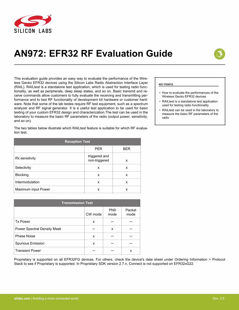
4. Select Silicon Labs Flex SDK as the application type.
Figure 1.2. Application Type Selection Dialog
5. Click [Next] .6. Select the Flex SDK version you would like to use (preferably the latest one).
Figure 1.3. Stack Selection Dialog
7. Click [Next].
AN972: EFR32 RF Evaluation GuideRunning Simplicity Studio
silabs.com | Building a more connected world. Rev. 0.5 | 4
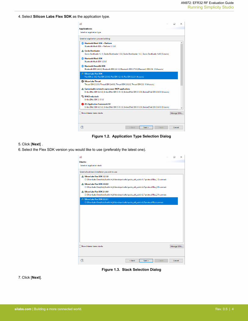
8. Select the RAIL: RAILTEST application.
Figure 1.4. Select Application Dialog
9. Click [Next].10. In the Project Configuration dialog, specify a location for your application.
Note: the location must be on the same Windows partition as the stack.
Figure 1.5. Project Configuration Dialog
11. Specify a name for your application.12. Click [Next].
AN972: EFR32 RF Evaluation GuideRunning Simplicity Studio
silabs.com | Building a more connected world. Rev. 0.5 | 5
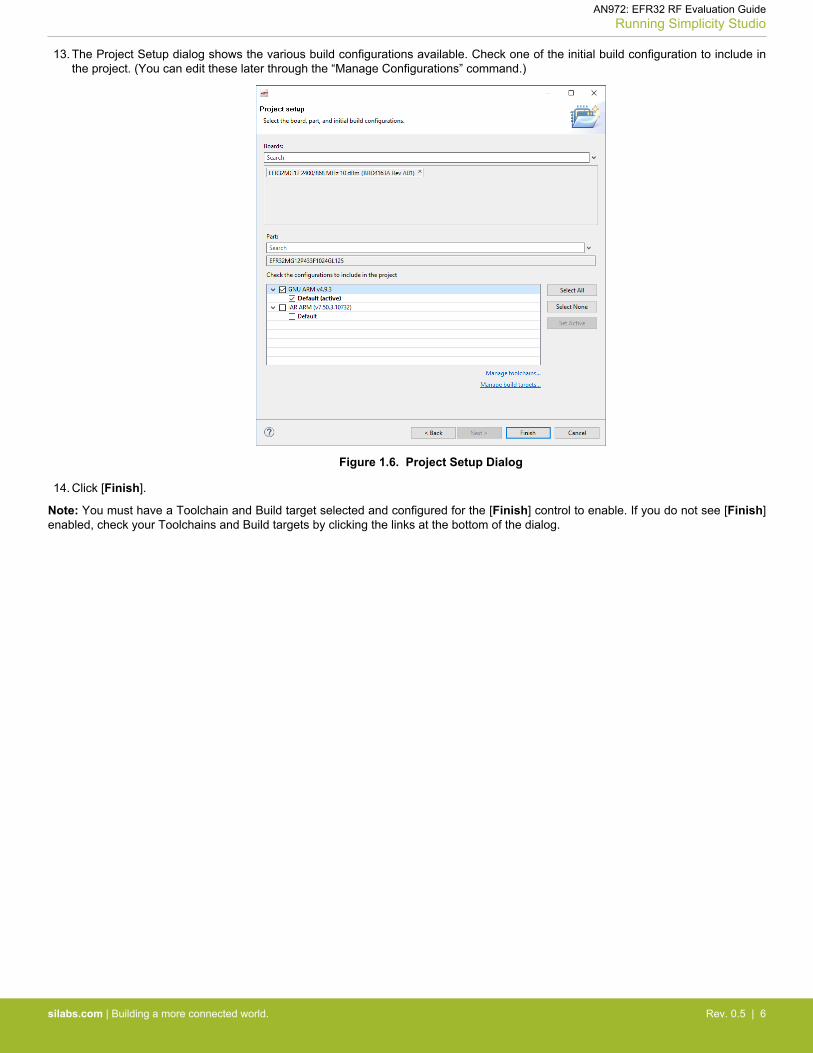
13. The Project Setup dialog shows the various build configurations available. Check one of the initial build configuration to include inthe project. (You can edit these later through the “Manage Configurations” command.)
Figure 1.6. Project Setup Dialog
14. Click [Finish].
Note: You must have a Toolchain and Build target selected and configured for the [Finish] control to enable. If you do not see [Finish]enabled, check your Toolchains and Build targets by clicking the links at the bottom of the dialog.
AN972: EFR32 RF Evaluation GuideRunning Simplicity Studio
silabs.com | Building a more connected world. Rev. 0.5 | 6
1.2 Generate the Application
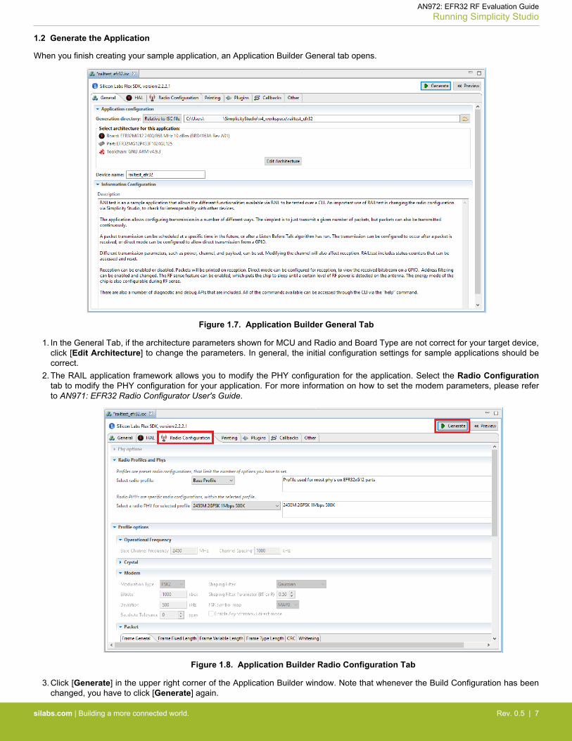
When you finish creating your sample application, an Application Builder General tab opens.
Figure 1.7. Application Builder General Tab
1. In the General Tab, if the architecture parameters shown for MCU and Radio and Board Type are not correct for your target device,click [Edit Architecture] to change the parameters. In general, the initial configuration settings for sample applications should becorrect.
2. The RAIL application framework allows you to modify the PHY configuration for the application. Select the Radio Configurationtab to modify the PHY configuration for your application. For more information on how to set the modem parameters, please referto AN971: EFR32 Radio Configurator User's Guide.
Figure 1.8. Application Builder Radio Configuration Tab
3. Click [Generate] in the upper right corner of the Application Builder window. Note that whenever the Build Configuration has beenchanged, you have to click [Generate] again.
AN972: EFR32 RF Evaluation GuideRunning Simplicity Studio
silabs.com | Building a more connected world. Rev. 0.5 | 7

4. Select if you want to overwrite any of the existing files. Click [OK].
Figure 1.9. Generation Validation Dialog
5. The next dialog shows the generated files. Click [OK] to continue.
Figure 1.10. Generation Successful Dialog
AN972: EFR32 RF Evaluation GuideRunning Simplicity Studio
silabs.com | Building a more connected world. Rev. 0.5 | 8
1.3 Build the Application
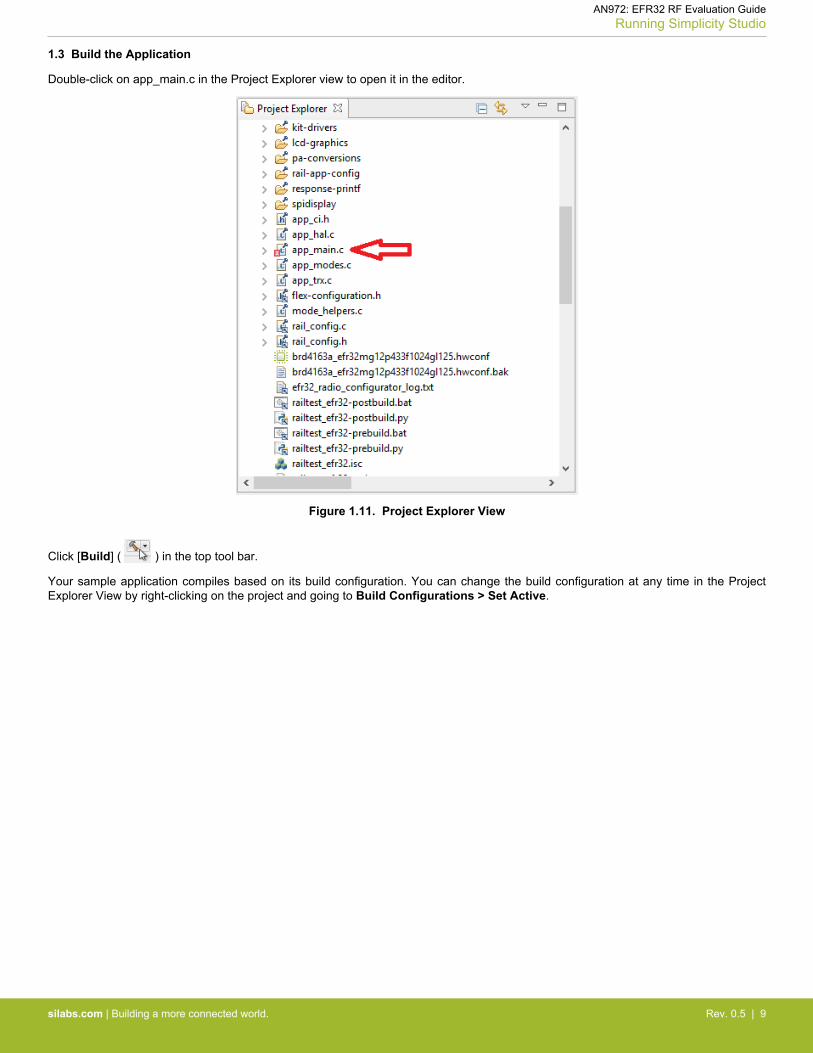
Double-click on app_main.c in the Project Explorer view to open it in the editor.
Figure 1.11. Project Explorer View
Click [Build] ( ) in the top tool bar.
Your sample application compiles based on its build configuration. You can change the build configuration at any time in the ProjectExplorer View by right-clicking on the project and going to Build Configurations > Set Active.
AN972: EFR32 RF Evaluation GuideRunning Simplicity Studio
silabs.com | Building a more connected world. Rev. 0.5 | 9

1.4 Load the Binary onto your Device/Flash Programming
If a full erase is not necessary, click [Debug] ( ) in the Developer Perspective. This flashes the project into the board if it wassuccessfully built. This will only update the program memory.
Once the project is flashed, the board can be started by clicking [Resume] ( ).
Alternatively:1. In the Simplicity Studio Launcher window, select your target device.2. With the device selected, select the [Flash Programmer] tile under the Compatible Tools menu:
Figure 1.12. Flash Programmer Tile
3. The Flash Programmer opens. In this window, you can choose your file type and browse your file.
AN972: EFR32 RF Evaluation GuideRunning Simplicity Studio
silabs.com | Building a more connected world. Rev. 0.5 | 10
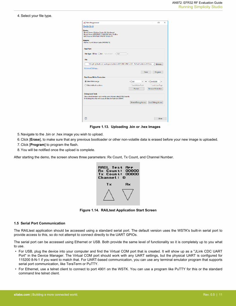
4. Select your file type.
Figure 1.13. Uploading .bin or .hex Images
5. Navigate to the .bin or .hex image you wish to upload.6. Click [Erase], to make sure that any previous bootloader or other non-volatile data is erased before your new image is uploaded.7. Click [Program] to program the flash.8. You will be notified once the upload is complete.
After starting the demo, the screen shows three parameters: Rx Count, Tx Count, and Channel Number.
Figure 1.14. RAILtest Application Start Screen
1.5 Serial Port Communication
The RAILtest application should be accessed using a standard serial port. The default version uses the WSTK's built-in serial port toprovide access to this, so do not attempt to connect directly to the UART GPIOs.
The serial port can be accessed using Ethernet or USB. Both provide the same level of functionality so it is completely up to you whatto use.• For USB, plug the device into your computer and find the Virtual COM port that is created. It will show up as a "JLink CDC UART
Port" in the Device Manager. The Virtual COM port should work with any UART settings, but the physical UART is configured for115200 8-N-1 if you want to match that. For UART-based communication, you can use any terminal emulator program that supportsserial port communication, like TeraTerm or PuTTY.
• For Ethernet, use a telnet client to connect to port 4901 on the WSTK. You can use a program like PuTTY for this or the standardcommand line telnet client.
AN972: EFR32 RF Evaluation GuideRunning Simplicity Studio
silabs.com | Building a more connected world. Rev. 0.5 | 11

1.6 Console View
Once the RAILtest application is loaded onto the EFR32 you can interact with the RAILtest application using the Command Line Inter-face. The Console View will give you a CLI interface in Simplicity Studio’s Network Analyzer Perspective so that you can interact direct-ly with the RAILtest application.
1. Right-click your device in the Devices View. (You can reach the Devices View by going back to the Simplicity Launcher Perspec-tive, Compatible Tools tab, and selecting Network Analyzer.)
Figure 1.15. Network Analyzer Tile
2. Select Connect (if you are not already connected) and then Launch Console. To get a prompt on the Console Serial 1 tab, press[Enter].
Figure 1.16. Launch Console
AN972: EFR32 RF Evaluation GuideRunning Simplicity Studio
silabs.com | Building a more connected world. Rev. 0.5 | 12
2. Basics of the RAILtest Application
The RAILtest application provides you with a simple tool for testing out the radio and the functionality of the RAIL library. For any ad-vanced usage you will have to write your own software against the RAIL library and create a custom radio configuration.
Note: If you are going to use the WSTK as a mobile device to run the RAILtest application, it is recommended that you connect anexternal AA battery pack or a USB power bank to the WSTK board. The coin cell battery will not have enough power to do long-termtesting using sample applications like RAILtest.
2.1 CLI
The most powerful way to interact with the sample application is using the provided command line interface. The setup instructions insection 1.6 Console View describes how to connect to this interface.
2.2 Command Input
The syntax for this interface is the standard command [arg0, arg1, ...] syntax, where the number and type of arguments depend on thespecific command. Numeric values can be prefixed with 0x to indicate hexadecimal values. Note that the maximum number of argu-ments to any command is 9 and the maximum length of a command line is 255 characters.
Use the help command to see a full listing of available command options.
2.3 Command Output
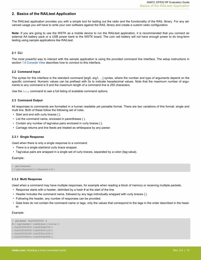
All responses to commands are formatted in a human readable yet parsable format. There are two variations of this format: single andmulti line. Both of these follow the following set of rules.• Start and end with curly braces { }.• List the command name, enclosed in parentheses ( ).• Contain any number of tag/value pairs enclosed in curly braces { }.• Carriage returns and line feeds are treated as whitespace by any parser.
2.3.1 Single Response
Used when there is only a single response to a command.• There is a single start/end curly brace wrapper.• Tag/value pairs are wrapped in a single set of curly braces, separated by a colon {tag:value}.
Example:
> getchannel{{(getchannel)}{channel:4}}
2.3.2 Multi Response
Used when a command may have multiple responses, for example when reading a block of memory or receiving multiple packets.• Response starts with a header, delimited by a hash # at the start of the line.• Header includes the command name, followed by any tags individually wrapped with curly braces { }.• Following the header, any number of responses can be provided.• Data lines do not contain the command name or tags, only the values that correspond to the tags in the order described in the head-
er.
Example:
> getmemw 0x20000000 4#{{(getmemw)}{address}{value}}{{0x20000000}{0x0000e530}}{{0x20000004}{0x000051c6}}{{0x20000008}{0x0000c939}}{{0x2000000c}{0x0000e090}}
AN972: EFR32 RF Evaluation GuideBasics of the RAILtest Application
silabs.com | Building a more connected world. Rev. 0.5 | 13

3. Transmission Test
3.1 Output a Continuous Unmodulated Tone for Testing Tx Power, Phase Noise and Spurious Emission
CW mode is used to test the output power of the test card and obverse the unmodulated carrier spectrum. In this mode, only the fre-quency and the output power are configurable parameters.
Enable the CW mode:
setTxTone [enable] Enable(1) or Disable(0) a tone from the radio
The setPower command can be used to change the output power; enter the desired power in deci dBm.
Note: The radio state must be IDLE. Call "rx 0" first.
setPower s [power] Set the current transmit power in deci dBm
To modify your frequency to a value not defined in the channel list, you will need to set the application into the FREQUENCY_OVER-RIDE debug mode via debugMode, which tells the application to ignore the current channel selection. Once in the FREQUENCY_OVER-RIDE debug mode, you can use the freqOverride command to switch to another center frequency.
Note: The freqOverride command requires you to be in FREQUENCY_OVERRIDE debug mode.
Note: The radio state must be IDLE in order for the channel to be changed or the frequency to be modified. Call rx 0 first.
Example:
rx 0 [enable] Enable(1) or Disable(0) receive modesetDebugMode 1 [mode] 1 = Frequency Override. 0 = Disable debug modefreqOverride 2404000000 [freq] Change to freq specified in Hz. Requires debug mode to be enabled.
Another way to change the frequency is to change the channel. The specific channel configuration depends on the PHY configurationyou have chosen for your test app. To switch between channels, use the setChannel [num] command. In addition, you can use buttonPB1 to cycle between channels. (The channel spacing value is used for relative frequency configuration where one would like to config-ure a frequency so many channel spacing away from the base channel frequency.)
To get the current radio channel, use this command:
getchannel Get the current radio channel
To set another radio channel, use this command:
rx 0 [enable] Enable(1) or Disable(0) receive modesetchannel u [channel] Set the current radio channel
Note: The radio state must be IDLE in order for the channel to be changed or the frequency to be modified. Call rx 0 first.
AN972: EFR32 RF Evaluation GuideTransmission Test
silabs.com | Building a more connected world. Rev. 0.5 | 14

A spectrum analyzer is used to measure the transmit performances of the radio and must be connected through a proper RF cable tothe RF connector of the radio board.
Figure 3.1. Unmodulated CW Signal Measured with Spectrum Analyzer
CW mode can also be used to test Phase Noise and Spurious Emission.
AN972: EFR32 RF Evaluation GuideTransmission Test
silabs.com | Building a more connected world. Rev. 0.5 | 15
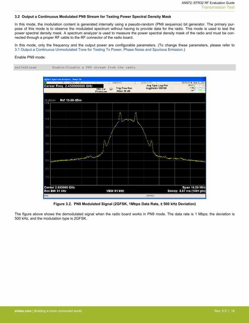
3.2 Output a Continuous Modulated PN9 Stream for Testing Power Spectral Density Mask
In this mode, the modulation content is generated internally using a pseudo-random (PN9 sequence) bit generator. The primary pur-pose of this mode is to observe the modulated spectrum without having to provide data for the radio. This mode is used to test thepower spectral density mask. A spectrum analyzer is used to measure the power spectral density mask of the radio and must be con-nected through a proper RF cable to the RF connector of the radio board.
In this mode, only the frequency and the output power are configurable parameters. (To change these parameters, please refer to3.1 Output a Continuous Unmodulated Tone for Testing Tx Power, Phase Noise and Spurious Emission.)
Enable PN9 mode:
setTxStream Enable/Disable a PN9 stream from the radio
Figure 3.2. PN9 Modulated Signal (2GFSK, 1Mbps Data Rate, ± 500 kHz Deviation)
The figure above shows the demodulated signal when the radio board works in PN9 mode. The data rate is 1 Mbps; the deviation is500 kHz, and the modulation type is 2GFSK.
AN972: EFR32 RF Evaluation GuideTransmission Test
silabs.com | Building a more connected world. Rev. 0.5 | 16

3.3 Enable Direct Mode
In direct mode, the radio will still attempt to decode received packets, but the data bit streams are input to and output from the chip inreal-time on a physical I/O pin. This is often useful in legacy systems that do not use a conventional packet structure, or when the hostMCU must perform customized packet handling or processing. In TX Direct mode, the TX modulation data is applied to an input pin ofthe chip and processed in “real time” (that is, not stored in a register for transmission at a later time).
The GPIOs for direct mode are fixed for now to the following pins.
DIN - EFR32_PC10 -> EXP_HEADER15/WSTK_P12DOUT - EFR32_PC11 -> EXP_HEADER16/WSTK_P13
The data on these pins is asynchronous and can be connected directly to a UART. To enter direct mode issue the directMode 1command after starting the app. To leave direct mode use directMode 0. If you want to transmit you must enable the transmitter byissuing directTx 1 and later stop it with directTx 0. Receive is controlled using the standard rx 1/0 command, but is enabled bydefault when not transmitting.
In this mode, only the frequency and the output power are configurable parameters. (To change these parameters, please refer to3.1 Output a Continuous Unmodulated Tone for Testing Tx Power, Phase Noise and Spurious Emission.)
AN972: EFR32 RF Evaluation GuideTransmission Test
silabs.com | Building a more connected world. Rev. 0.5 | 17

3.4 Enable Packet Mode
The application starts in packet mode with the receiver enabled. In this mode we receive and transmit packets using the radio's framecontroller hardware.
To transmit a specified number of packets, use this command:
tx w [n] Transmit n packets. If n is 0 transmit infinitely
Or press button PB0. If you hold PB0 for a couple of seconds or run the tx 0 command you can toggle the continuous transmit mode.
In this mode, the frequency, the output power, delay in between each transmitted packet, the length, and the value of the bytes to sendare configurable parameters. (To change the frequency and the output power parameters, please refer to 3.1 Output a Continuous Un-modulated Tone for Testing Tx Power, Phase Noise and Spurious Emission.)
When transmitting multiple packets or infinite packets there is a configurable delay in between each transmit. By default this is 250 ms,but it can be set with the following command:
setTxDelay w [delay] Set the inter-packet delay in milliseconds for repeated Tx
Get the inter-packet delay in milliseconds for repeated Tx, use the getTxDelay command.
If the desired delay is lower than 15 ms, all the peripherals need to be disabled.
setPeripheralEnable u [enable] Turn LEDs and LCD on/off
The application by default sends a fixed packet, but it is possible to override the values via setTxPayload. The command allows you tomodify the values of the payload at specific offsets. For instance to modify the first 4 bytes sent in the packet to be 0x01 0x02 0x030x04, this is the command:
setTxPayload 0 0x01 0x02 0x03 0x04
Note: To view the currently configured TX Packet information, use the following command:
printTxPacket Print the current Tx data and length
A byte in the payload holds the length of the packet for variable length schemes. The length byte in IEEE 802.15.4 is the first byte; thisis what you can set using the setTxPayload command. The length byte also covers the CRC length of the packet, and the length pa-rameter covers the length byte; this is what you can set using the setTxLength command.
All in all, here is an example to set 3-byte payload to 0x01 0x02 0x03, while using IEEE 802.15.4 configuration:
setTxLength 4 setTxPayload 0 0x05 0x01 0x02 0x03
A spectrum analyzer is used to view the over the air sent packets of the radio. It must be connected through a proper RF cable to theRF connector of the radio board..
AN972: EFR32 RF Evaluation GuideTransmission Test
silabs.com | Building a more connected world. Rev. 0.5 | 18
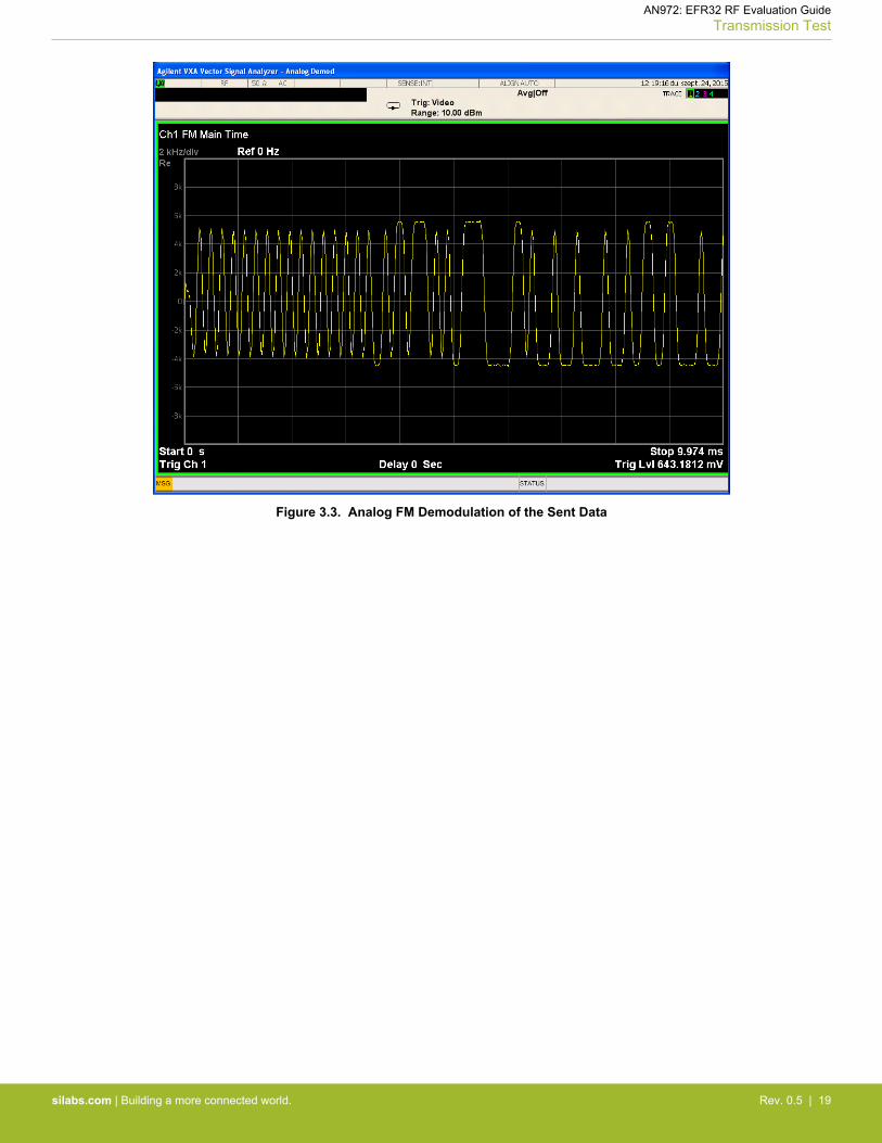
Figure 3.3. Analog FM Demodulation of the Sent Data
AN972: EFR32 RF Evaluation GuideTransmission Test
silabs.com | Building a more connected world. Rev. 0.5 | 19
4. Reception Test
4.1 Running Bit Error Test from the CLI to Measure RX Sensitivity, Selectivity Testing (co, adjacent, alternate, image), Block-ing, Intermodulation, Maximum Input Power
The sensitivity of the radio can be measured with a continuously-looped PN sequence (x^9 + x^5 + 1). This mode is called bit error rate(BER). The EFR32 hardware has the ability to enter BER receive mode for diagnostic purposes. The radio is set into continuous re-ceive mode. The RF data needs to be fed to the RX SMA of the test card or radio board. By adjusting the output power of the signalgenerator or an EFR32, the sensitivity of the radio can be measured (it is typically measured for 10^-3 BER).
4.1.1 BER Measurement Procedure
To run the BER test successfully, a radio configuration specific to BER mode must be generated by the radio configurator. Reconfigurefor BER testing needs to be checked on the Radio Configuration tab in Simplicity Studio.
Figure 4.1. Enable BER Testing in Simplicity Studio
The setBerConfig command allows you to specify how many bytes to receive in BER receive mode. The maximum number of bytesyou can designate to receive is 536870911. Specifying a number of 0 or a number greater than the maximum possible value will auto-matically configure the BER test to receive the maximum number of bytes for testing.
The berRx command allows you to enter and exit BER receive mode. If the test is allowed to run to completion, there is no need to exitBER receive mode.
The berStatus command allows the user to query for test statistics during or after a test. The statistics are reset when setBerConfigis run or when berRx 1 is run. The statistics include BitsToTest (total bits to be tested), BitsTested (the number of bits already receivedand tested), PercentDone (percentage of how many configured bytes have been received), RSSI (an instantaneous RSSI value corre-sponding to the last byte received), BitErrors (the number of received bits determined to be in error), and PercentBitError (percentage ofbit errors to bits tested).
Example:
> setberconfig 100000
> berrx 1
> berstatus{{(berStatus)}{BitsToTest:800000}{BitsTested:0}{PercentDone:0.00}{RSSI:0}{BitErrors:0}{PercentBitError:0.00}}
// PN9 transmission enabled here
> berstatus{{(berStatus)}{BitsToTest:800000}{BitsTested:121312}{PercentDone:15.16}{RSSI:-23}{BitErrors:0}{PercentBitError:0.00}}
> setberconfig 1000000
> berrx 1
> berstatus{{(berStatus)}{BitsToTest:8000000}{BitsTested:4418528}{PercentDone:55.23}{RSSI:-96}{BitErrors:960478}{PercentBitError:21.74}}
> berstatus{{(berStatus)}{BitsToTest:8000000}{BitsTested:8000000}{PercentDone:100.00}{RSSI:-97}{BitErrors:2752908}{PercentBitError:34.41}}
4.2 Running a Packet Error Test from the CLI
PER mode can be used to test RX sensitivity (triggered and non-triggered PER), Selectivity (co, adjacent, alternate, image), Blocking,Intermodulation, and Maximum input power.
AN972: EFR32 RF Evaluation GuideReception Test
silabs.com | Building a more connected world. Rev. 0.5 | 20
4.2.1 Basics of the Packet Error Rate
Packet error rate can be calculated with the following equation:
Packet Error Rate(PER) % =(PTx - PRx)
PTx*100
where PTX is the number of sent packets and PRX is the number of received packets.
4.2.2 Non-Triggered PER
By default the application starts in packet mode with the receiver enabled. In this mode we receive and transmit packets using the ra-dio's frame controller hardware. If a packet is received, the payload content and length, the RSSI, the CRC status, and the time can beread from the receiver response.
Example:
{{(rx)}{len:24}{timeUs:265911670}{crc:Pass}{rssi:0xcf}{payload: 0x0f 0x160x11 0x22 0x33 0x44 0x55 0x66 0x77 0x88 0x99 0xaa 0xbb 0xcc 0xdd 0xee 0xff0x00 0x11 0x22 0x33 0x44 0x55 0x66}}
The sensitivity of the radio can be also measured by receiving packets. This test also involves an RF signal generator, which can trans-mit predefined packets. In this mode, the radio is set to receive and the generator must send packets. If the radio does not receive thepacket, there is no RX response. To view the number of received packets, CRC errors, and sync detect errors, use the status com-mand.
Example:
status {{(status)}{TxCount:0}{RxCount:9}{SyncDetect:9}{InvalidCrc:0}{RxOverflow:0}{AddrFilt:0}{TxAbort:0}{TxChannelBusy:0}{Channel:0}{TxMode:Off}{RxMode:Enabled}}
By adjusting the output power of the generator, the sensitivity of the radio can be determined. It is usually defined for a 1% or 20%packet error rate.
To reset all the counters use:
resetCounters Resets the Tx and Rx counters
If a long and fast test needs to be run, it is better to disable the Rx responses, to make the communication and the test faster.
setRxNotification u [enable] Enable/Disable LED toggle and status print for every receive packet
PER Measurement Procedure Using Link Test
1. Load the RAILtest application on two EFR32 nodes.2. Set both nodes to the same channel with the setchannel n command, where "n" is the channel number.
To view the currently configured TX Packet information, use printTxPacket.3. Issue the rx 1 command on the first node.4. Issue the tx n [dec value] command on the second node. This command transmits n packets of the form required for PER analy-
sis. (For actual PER analysis, send 1000 or more packets.)
Another way to send packets is to press button PB0. If you hold PB0 for a couple of seconds you can toggle continuous tx modewhere a packet is sent every 250 ms.
5. To view the number of received packets, CRC errors and sync detect errors, use the status command.
AN972: EFR32 RF Evaluation GuideReception Test
silabs.com | Building a more connected world. Rev. 0.5 | 21
4.2.3 Triggered PER
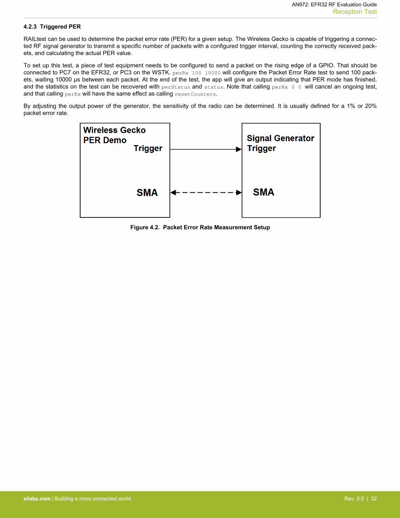
RAILtest can be used to determine the packet error rate (PER) for a given setup. The Wireless Gecko is capable of triggering a connec-ted RF signal generator to transmit a specific number of packets with a configured trigger interval, counting the correctly received pack-ets, and calculating the actual PER value.
To set up this test, a piece of test equipment needs to be configured to send a packet on the rising edge of a GPIO. That should beconnected to PC7 on the EFR32, or PC3 on the WSTK. perRx 100 10000 will configure the Packet Error Rate test to send 100 pack-ets, waiting 10000 μs between each packet. At the end of the test, the app will give an output indicating that PER mode has finished,and the statistics on the test can be recovered with perStatus and status. Note that calling perRx 0 0 will cancel an ongoing test,and that calling perRx will have the same effect as calling resetCounters.
By adjusting the output power of the generator, the sensitivity of the radio can be determined. It is usually defined for a 1% or 20%packet error rate.
Figure 4.2. Packet Error Rate Measurement Setup
AN972: EFR32 RF Evaluation GuideReception Test
silabs.com | Building a more connected world. Rev. 0.5 | 22
4.3 RSSI Curve
Received signal strength indicator (RSSI) is an estimate of the signal strength in the channel to which the receiver is tuned. The RSSIvalue can be read with 0.25 dB resolution per bit. The RSSI may be read at any time while the radio is in Receive mode. The RSSI isnot latched, but continuously updated while in Receive mode.
To read the RSSI value, use the following command:
getRssi Get RSSI in dBm if the receiver is turned on.
Example:
> getRssigetRssi{{(getRssi)}{rssi:-94}}
> >
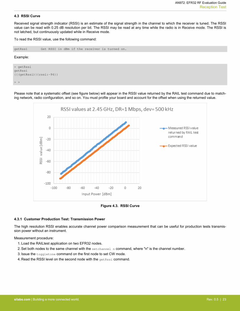
Please note that a systematic offset (see figure below) will appear in the RSSI value returned by the RAIL test command due to match-ing network, radio configuration, and so on. You must profile your board and account for the offset when using the returned value.
Figure 4.3. RSSI Curve
4.3.1 Customer Production Test: Transmission Power
The high resolution RSSI enables accurate channel power comparison measurement that can be useful for production tests transmis-sion power without an instrument.
Measurement procedure:1. Load the RAILtest application on two EFR32 nodes.2. Set both nodes to the same channel with the setchannel n command, where "n" is the channel number.3. Issue the toggletone command on the first node to set CW mode.4. Read the RSSI level on the second node with the getRssi command.
AN972: EFR32 RF Evaluation GuideReception Test
silabs.com | Building a more connected world. Rev. 0.5 | 23
5. Current Consumption Test
Current consumption measurement procedure:1. Load the RAILtest application on an EFR32 RF radio board.2. Issue the appropriate command/commands to set the device in the required mode (for example: Tx), which current consumption
has to be measured.3. In Simplicity Studio's Launcher Perspective, select the target device.4. With the device selected, select the Energy Profiler tile under the Compatible Tools tab.
Figure 5.1. Energy Profiler Tile
5. After the Energy Profiler Perspective opens click the down-arrow next to Quick Access. Click Start Energy Capture.
Figure 5.2. Starting Energy Capture
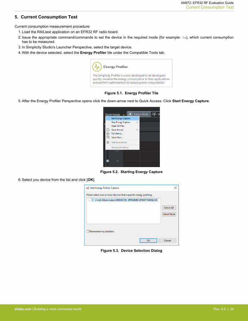
6. Select you device from the list and click [OK].
Figure 5.3. Device Selection Dialog
AN972: EFR32 RF Evaluation GuideCurrent Consumption Test
silabs.com | Building a more connected world. Rev. 0.5 | 24
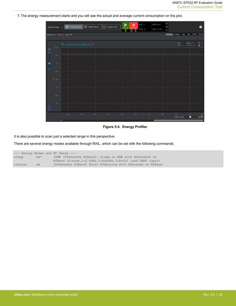
7. The energy measurement starts and you will see the actual and average current consumption on the plot.
Figure 5.4. Energy Profiler
It is also possible to scan just a selected range in this perspective.
There are several energy modes available through RAIL, which can be set with the following commands.
--- Energy Modes and RF Sense ---sleep bw* [EM# [RfSenseUs RfBand]] Sleep in EM# with RFSenseUs on RfBand (0=none,1=2.4GHz,2=SubGHz,3=both) (and UART input)rfsense ww [RfSenseUs RfBand] Start RfSensing with RSenseUs on RfBand
AN972: EFR32 RF Evaluation GuideCurrent Consumption Test
silabs.com | Building a more connected world. Rev. 0.5 | 25

Simplicity StudioOne-click access to MCU and wireless tools, documentation, software, source code libraries & more. Available for Windows, Mac and Linux!
IoT Portfoliowww.silabs.com/IoT
SW/HWwww.silabs.com/simplicity
Qualitywww.silabs.com/quality
Support and Communitycommunity.silabs.com
http://www.silabs.com
Silicon Laboratories Inc.400 West Cesar ChavezAustin, TX 78701USA
DisclaimerSilicon Labs intends to provide customers with the latest, accurate, and in-depth documentation of all peripherals and modules available for system and software implementers using or intending to use the Silicon Labs products. Characterization data, available modules and peripherals, memory sizes and memory addresses refer to each specific device, and "Typical" parameters provided can and do vary in different applications. Application examples described herein are for illustrative purposes only. Silicon Labs reserves the right to make changes without further notice to the product information, specifications, and descriptions herein, and does not give warranties as to the accuracy or completeness of the included information. Without prior notification, Silicon Labs may update product firmware during the manufacturing process for security or reliability reasons. Such changes will not alter the specifications or the performance of the product. Silicon Labs shall have no liability for the consequences of use of the information supplied in this document. This document does not imply or expressly grant any license to design or fabricate any integrated circuits. The products are not designed or authorized to be used within any FDA Class III devices, applications for which FDA premarket approval is required, or Life Support Systems without the specific written consent of Silicon Labs. A "Life Support System" is any product or system intended to support or sustain life and/or health, which, if it fails, can be reasonably expected to result in significant personal injury or death. Silicon Labs products are not designed or authorized for military applications. Silicon Labs products shall under no circumstances be used in weapons of mass destruction including (but not limited to) nuclear, biological or chemical weapons, or missiles capable of delivering such weapons. Silicon Labs disclaims all express and implied warranties and shall not be responsible or liable for any injuries or damages related to use of a Silicon Labs product in such unauthorized applications.
Trademark InformationSilicon Laboratories Inc.®, Silicon Laboratories®, Silicon Labs®, SiLabs® and the Silicon Labs logo®, Bluegiga®, Bluegiga Logo®, ClockBuilder®, CMEMS®, DSPLL®, EFM®, EFM32®, EFR, Ember®, Energy Micro, Energy Micro logo and combinations thereof, "the world’s most energy friendly microcontrollers", Ember®, EZLink®, EZRadio®, EZRadioPRO®, Gecko®, Gecko OS, Gecko OS Studio, ISOmodem®, Precision32®, ProSLIC®, Simplicity Studio®, SiPHY®, Telegesis, the Telegesis Logo®, USBXpress® , Zentri, the Zentri logo and Zentri DMS, Z-Wave®, and others are trademarks or registered trademarks of Silicon Labs. ARM, CORTEX, Cortex-M3 and THUMB are trademarks or registered trademarks of ARM Holdings. Keil is a registered trademark of ARM Limited. Wi-Fi is a registered trademark of the Wi-Fi Alliance. All other products or brand names mentioned herein are trademarks of their respective holders.


![G0 - RF Safety G0 – ELECTRICAL AND RF SAFETY [2 Exam Questions - 2 groups] G0A - RF safety principles, rules and guidelines; routine station evaluation](https://img.dokumen.tips/doc/110x75/56649e2b5503460f94b1925a/g0-rf-safety-g0-electrical-and-rf-safety-2-exam-questions-2-groups.jpg)