Embed Size (px)
Citation preview
August 2016 DocID028052 Rev 2 1/29
1
AN4736Application note
How to calibrate STM32L4 Series microcontrollers internal RC oscillator
Introduction
The STM32L4 Series microcontrollers have two internal RC oscillators that can be selected as the system clock source. These are known as the HSI16 (high-speed internal) and MSI (multi-speed internal) oscillators. The HSI16 oscillator has a typical frequency of 16 MHz. The MSI oscillator is a multispeed, low-power clock source.
The STM32L4 Series microcontrollers have two secondary internal clock sources:
• LSI: 32 kHz (low-speed internal)
• HSI48: 48MHz (high-speed internal) that can be used directly for USB, for RNG (random number generator) and for SDMMC (SD/SDIO MMC card host interface).
The operating temperature has an impact on the accuracy of the RC oscillators. At 30 °C, the HSI16 oscillator has an accuracy of ± 0.5 %, the MSI oscillator has an accuracy of ± 0.6 % and the HSI48 oscillator has an accuracy of ±4%. But in the temperature range of -40 °C to 105 °C, the accuracy decreases. To compensate for the influence of temperature on internal RC oscillators accuracy, the STM32L4 Series microcontrollers have built-in features allowing to calibrate the HSI16, MSI and HSI48 oscillators and measure the LSI (low-speed internal) oscillator frequency.
When a low-speed external (LSE) clock source at 32.768 kHz is available in the system, the MSI frequency can be automatically trimmed by hardware to reach an accuracy better than ±0.25 %. This hardware auto-calibration with LSE is called PLL (phase-locked loop) mode. This application note does not use this mode and focuses only on the user trimming.
This application note also focuses on how to calibrate below internal RC oscillators: HSI16, MSI and HSI48. Three methods are presented: the first method is based on finding the frequency with the minimum error, the second one consists in finding the maximum allowed frequency error and the third one implements a table of premeasured values and then searches in it for the appropriate change. All three are implemented by providing an accurate reference signal.
The measurement of the LSI oscillator is performed by connecting the oscillator to a timer input capture.
The X-CUBE-RC-CALIB embedded software package is delivered with this application note, containing the source code to perform those internal oscillators calibrations and all the embedded software modules required to run the examples.
Note: All the information related to HSI48 is only applicable to the following product families: STM32L43x, STM32L44x, STM32L45x, STM32L46x, STM32L496 and STM32L4A6.
www.st.com
Contents AN4736
2/29 DocID028052 Rev 2
Contents
1 STM32L4 Series system clock . . . . . . . . . . . . . . . . . . . . . . . . . . . . . . . . . 5
2 Internal RC oscillator calibration . . . . . . . . . . . . . . . . . . . . . . . . . . . . . . . 7
2.1 Calibration principle . . . . . . . . . . . . . . . . . . . . . . . . . . . . . . . . . . . . . . . . . 10
2.2 Hardware implementation . . . . . . . . . . . . . . . . . . . . . . . . . . . . . . . . . . . . .11
2.2.1 Case where LSE is used as the reference frequency . . . . . . . . . . . . . . 11
2.2.2 Case where another source is used as the reference frequency . . . . . 12
2.3 Description of the internal oscillator calibration firmware . . . . . . . . . . . . . 13
2.3.1 HSI16/MSI calibration with minimum error . . . . . . . . . . . . . . . . . . . . . . 13
2.3.2 HSI16 calibration with fixed error . . . . . . . . . . . . . . . . . . . . . . . . . . . . . . 15
2.3.3 MSI calibration with fixed error . . . . . . . . . . . . . . . . . . . . . . . . . . . . . . . 16
2.3.4 HSI48 calibration using CRS . . . . . . . . . . . . . . . . . . . . . . . . . . . . . . . . . 18
2.3.5 HSI16/MSI frequency measurement . . . . . . . . . . . . . . . . . . . . . . . . . . . 18
2.3.6 HSI16/MSI calibration using calibration curve . . . . . . . . . . . . . . . . . . . . 21
2.4 Recommendations on the use of the calibration library . . . . . . . . . . . . . . 21
2.5 Calibration process performance . . . . . . . . . . . . . . . . . . . . . . . . . . . . . . . 22
2.5.1 Duration of the calibration process . . . . . . . . . . . . . . . . . . . . . . . . . . . . 22
3 Internal oscillator measurement . . . . . . . . . . . . . . . . . . . . . . . . . . . . . . 23
3.1 Measurement principle . . . . . . . . . . . . . . . . . . . . . . . . . . . . . . . . . . . . . . . 23
3.2 Description of the internal oscillator measurement firmware . . . . . . . . . . 25
3.3 Internal oscillator calibration/measurement demo description . . . . . . . . . 25
4 Conclusion . . . . . . . . . . . . . . . . . . . . . . . . . . . . . . . . . . . . . . . . . . . . . . . . 27
5 Revision history . . . . . . . . . . . . . . . . . . . . . . . . . . . . . . . . . . . . . . . . . . . 28
DocID028052 Rev 2 3/29
AN4736 List of tables
3
List of tables
Table 1. Document revision history . . . . . . . . . . . . . . . . . . . . . . . . . . . . . . . . . . . . . . . . . . . . . . . . . 28
List of figures AN4736
4/29 DocID028052 Rev 2
List of figures
Figure 1. Simplified clock tree . . . . . . . . . . . . . . . . . . . . . . . . . . . . . . . . . . . . . . . . . . . . . . . . . . . . . . . 5Figure 2. HSI16 oscillator trimming characteristics . . . . . . . . . . . . . . . . . . . . . . . . . . . . . . . . . . . . . . . 7Figure 3. MSI trimming behavior . . . . . . . . . . . . . . . . . . . . . . . . . . . . . . . . . . . . . . . . . . . . . . . . . . . . . 9Figure 4. TRIM monotonicity . . . . . . . . . . . . . . . . . . . . . . . . . . . . . . . . . . . . . . . . . . . . . . . . . . . . . . . . 9Figure 5. Timing diagram of internal oscillator calibration . . . . . . . . . . . . . . . . . . . . . . . . . . . . . . . . . 10Figure 6. Hardware connection using LSE as the reference frequency. . . . . . . . . . . . . . . . . . . . . . . 11Figure 7. Hardware connection using external reference frequency . . . . . . . . . . . . . . . . . . . . . . . . . 12Figure 8. Internal oscillator calibration: finding the minimum frequency . . . . . . . . . . . . . . . . . . . . . . 14Figure 9. “Spring loop” . . . . . . . . . . . . . . . . . . . . . . . . . . . . . . . . . . . . . . . . . . . . . . . . . . . . . . . . . . . . 15Figure 10. HSI16 calibration flowchart: maximum allowed frequency error . . . . . . . . . . . . . . . . . . . . . 16Figure 11. MSI calibration flowchart: maximum allowed frequency error. . . . . . . . . . . . . . . . . . . . . . . 17Figure 12. HSI48 trimming algorithm . . . . . . . . . . . . . . . . . . . . . . . . . . . . . . . . . . . . . . . . . . . . . . . . . . 18Figure 13. HSI16/MSI oscillator frequency measurement flowchart . . . . . . . . . . . . . . . . . . . . . . . . . . 20Figure 14. MSI measurement configuration. . . . . . . . . . . . . . . . . . . . . . . . . . . . . . . . . . . . . . . . . . . . . 23Figure 15. LSI measurement configuration . . . . . . . . . . . . . . . . . . . . . . . . . . . . . . . . . . . . . . . . . . . . . 24Figure 16. Timing diagram of an internal RC oscillator measurement . . . . . . . . . . . . . . . . . . . . . . . . . 24Figure 17. Internal RC oscillator calibration and measurement . . . . . . . . . . . . . . . . . . . . . . . . . . . . . . 26
DocID028052 Rev 2 5/29
AN4736 STM32L4 Series system clock
28
1 STM32L4 Series system clock
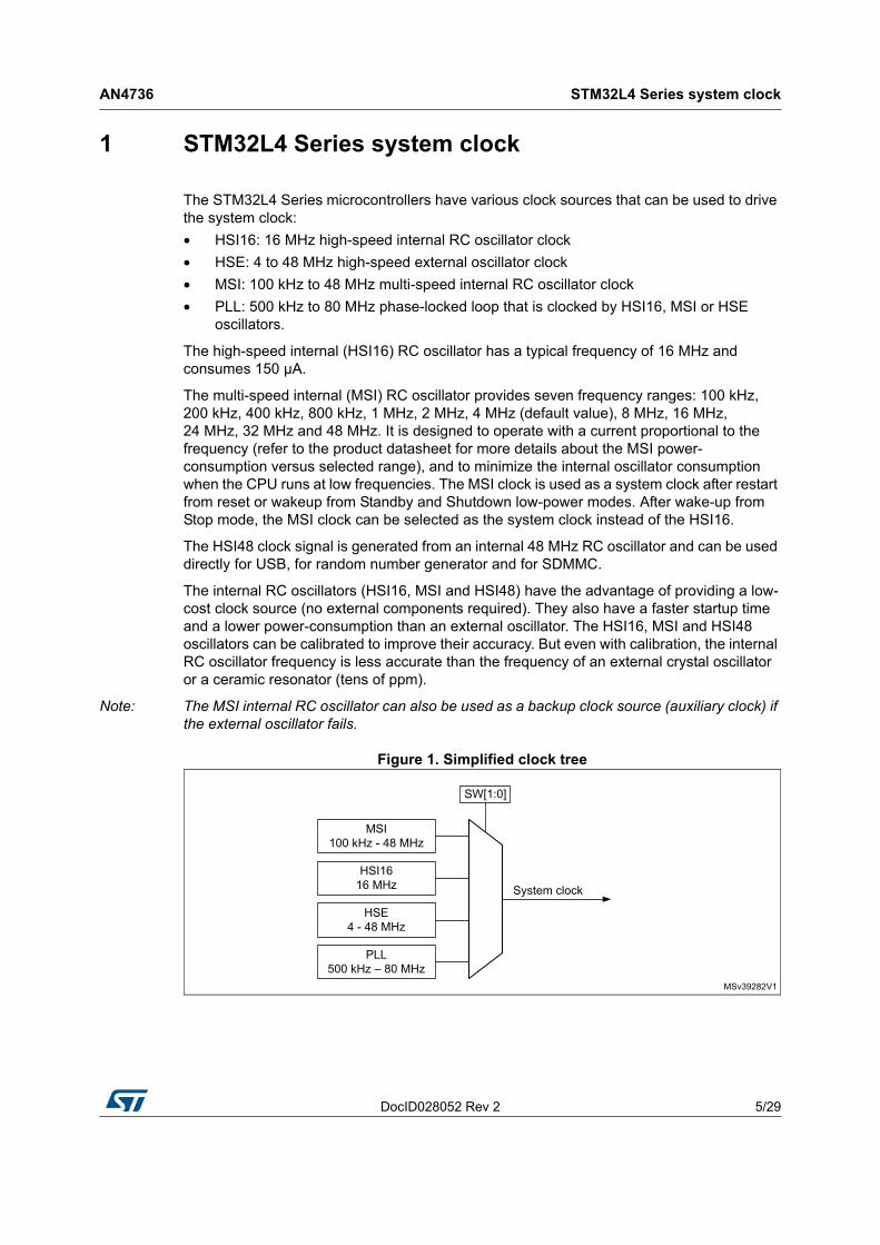
The STM32L4 Series microcontrollers have various clock sources that can be used to drive the system clock:
• HSI16: 16 MHz high-speed internal RC oscillator clock
• HSE: 4 to 48 MHz high-speed external oscillator clock
• MSI: 100 kHz to 48 MHz multi-speed internal RC oscillator clock
• PLL: 500 kHz to 80 MHz phase-locked loop that is clocked by HSI16, MSI or HSE oscillators.
The high-speed internal (HSI16) RC oscillator has a typical frequency of 16 MHz and consumes 150 µA.
The multi-speed internal (MSI) RC oscillator provides seven frequency ranges: 100 kHz, 200 kHz, 400 kHz, 800 kHz, 1 MHz, 2 MHz, 4 MHz (default value), 8 MHz, 16 MHz, 24 MHz, 32 MHz and 48 MHz. It is designed to operate with a current proportional to the frequency (refer to the product datasheet for more details about the MSI power-consumption versus selected range), and to minimize the internal oscillator consumption when the CPU runs at low frequencies. The MSI clock is used as a system clock after restart from reset or wakeup from Standby and Shutdown low-power modes. After wake-up from Stop mode, the MSI clock can be selected as the system clock instead of the HSI16.
The HSI48 clock signal is generated from an internal 48 MHz RC oscillator and can be used directly for USB, for random number generator and for SDMMC.
The internal RC oscillators (HSI16, MSI and HSI48) have the advantage of providing a low-cost clock source (no external components required). They also have a faster startup time and a lower power-consumption than an external oscillator. The HSI16, MSI and HSI48 oscillators can be calibrated to improve their accuracy. But even with calibration, the internal RC oscillator frequency is less accurate than the frequency of an external crystal oscillator or a ceramic resonator (tens of ppm).
Note: The MSI internal RC oscillator can also be used as a backup clock source (auxiliary clock) if the external oscillator fails.
Figure 1. Simplified clock tree
STM32L4 Series system clock AN4736
6/29 DocID028052 Rev 2
The STM32L4 Series devices also have three secondary clock sources (that cannot be used as system clock sources):
• LSI: 32 kHz low-speed internal RC that can be kept running in Stop and Standby modes for the independent watchdog (IWDG), the RTC and the LCD. The LSI oscillator cannot be calibrated, but it can be measured to evaluate any frequency deviations (due to temperature and voltage changes)
• LSE crystal: 32.768 kHz low-speed external crystal RC which optionally drives the real time clock (RTC)
• HSI48: 48 MHz high-speed internal RC which is designed to provide a high precision clock to the USB peripheral by means of a special clock recovery system (CRS) circuitry.
DocID028052 Rev 2 7/29
AN4736 Internal RC oscillator calibration
28
2 Internal RC oscillator calibration
The frequency of the internal RC oscillators may vary from one device to another due to manufacturing process variations. For this reason, the MSI and the HSI16 RC oscillators are factory-calibrated by ST to have an accuracy of [min -0.75 %, max 0.5 %] at TA = 30 °C. After reset, the factory calibration value is automatically loaded in the internal calibration bits.
The frequency of the internal RC oscillators can be fine-tuned to achieve better accuracy with wider temperature and supply voltage ranges. The trimming bits are used for this purpose.
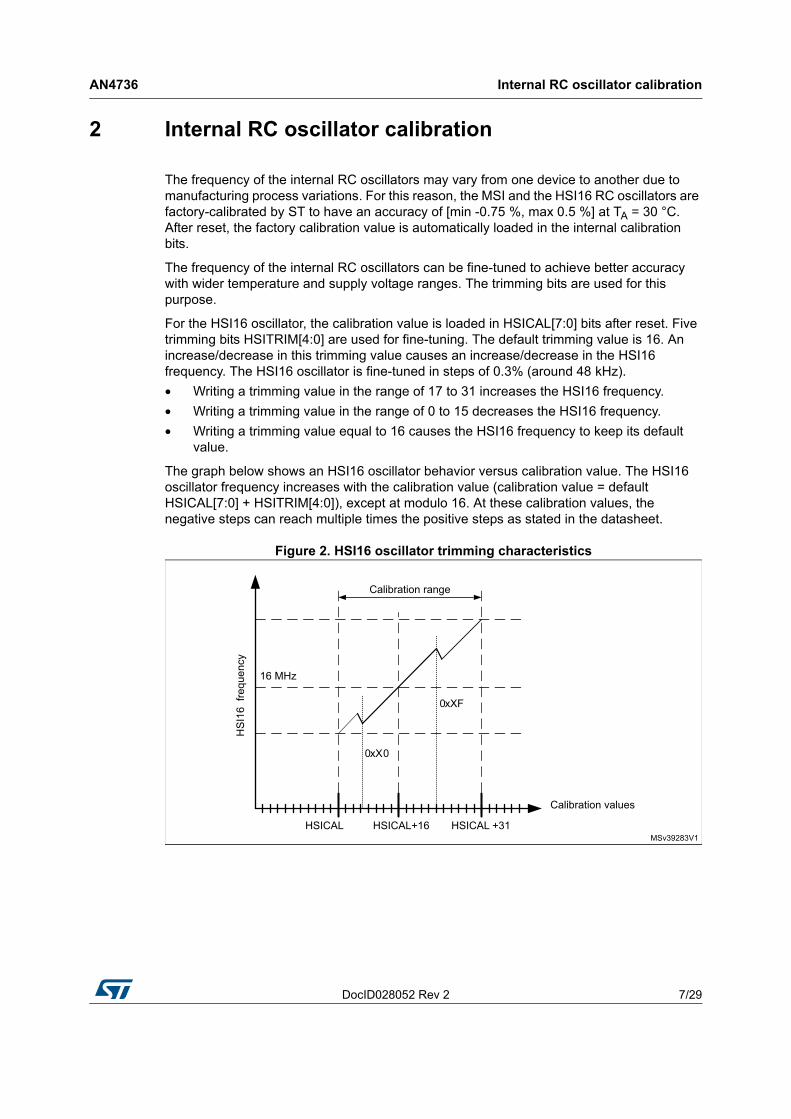
For the HSI16 oscillator, the calibration value is loaded in HSICAL[7:0] bits after reset. Five trimming bits HSITRIM[4:0] are used for fine-tuning. The default trimming value is 16. An increase/decrease in this trimming value causes an increase/decrease in the HSI16 frequency. The HSI16 oscillator is fine-tuned in steps of 0.3% (around 48 kHz).
• Writing a trimming value in the range of 17 to 31 increases the HSI16 frequency.
• Writing a trimming value in the range of 0 to 15 decreases the HSI16 frequency.
• Writing a trimming value equal to 16 causes the HSI16 frequency to keep its default value.
The graph below shows an HSI16 oscillator behavior versus calibration value. The HSI16 oscillator frequency increases with the calibration value (calibration value = default HSICAL[7:0] + HSITRIM[4:0]), except at modulo 16. At these calibration values, the negative steps can reach multiple times the positive steps as stated in the datasheet.
Figure 2. HSI16 oscillator trimming characteristics
Internal RC oscillator calibration AN4736
8/29 DocID028052 Rev 2
For the MSI oscillator, the calibration value is loaded in the MSICAL[7:0] bits after reset. Eight trimming bits MSITRIM[7:0] are used giving a wide tuning range. The calibration is based on adding the default MSICAL[7:0] bits (reset value) to the MSITRIM[7:0] bits.
The result is stored in MSICAL[7:0]:
MSICAL[7:0] = default MSICAL[7:0] + MSITRIM[7:0]
Example:
Assuming the default MSI calibration value MSICAL[7:0] is 0x80.
1. Writing a value between 0x01 and 0x7F in MSITRIM[7:0] leads to a calibration value MSICAL[7:0] in the range of:
MSICAL[7:0] = 0x80 + 0x01 = 0x81
and MSICAL[7:0] = 0x80 + 0x7F = 0xFF
These results are greater than 0x80 (default MSI[7:0] value) and consequently the MSI frequency is increased by 1 step (0x81 - 0x80) to 127 steps (0xFF - 0x80).
2. Writing a value between 0x81 and 0xFF in MSITRIM[7:0] leads to calibration value MSICAL[7:0] in the range of:
MSICAL[7:0] = 0x80 + 0x81 = 0x01
and MSICAL[7:0] = 0x80 + 0xFF = 0x7F
These results are lower than 0x80 (default MSI[7:0] value) and consequently the MSI frequency is decreased by 1 step (0x01) to 127 steps (0x7F).
3. Writing the default calibration value (0x80) in MSITRIM[7:0] leads to a calibration value MSICAL[7:0] equal to MSICAL[7:0] = 0x80 + 0x80 = 0x00 and consequently the MSI frequency is decreased by 128 steps (minimum frequency).
DocID028052 Rev 2 9/29
AN4736 Internal RC oscillator calibration
28
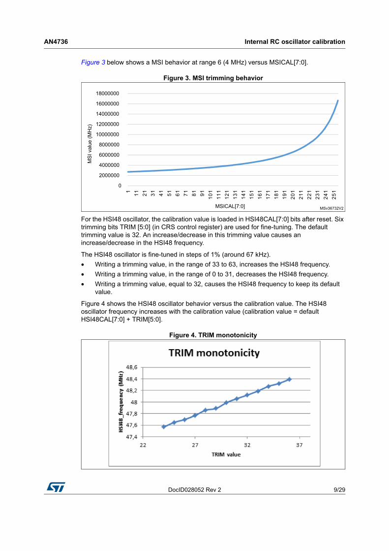
Figure 3 below shows a MSI behavior at range 6 (4 MHz) versus MSICAL[7:0].
Figure 3. MSI trimming behavior
For the HSI48 oscillator, the calibration value is loaded in HSI48CAL[7:0] bits after reset. Six trimming bits TRIM [5:0] (in CRS control register) are used for fine-tuning. The default trimming value is 32. An increase/decrease in this trimming value causes an increase/decrease in the HSI48 frequency.
The HSI48 oscillator is fine-tuned in steps of 1% (around 67 kHz).
• Writing a trimming value, in the range of 33 to 63, increases the HSI48 frequency.
• Writing a trimming value, in the range of 0 to 31, decreases the HSI48 frequency.
• Writing a trimming value, equal to 32, causes the HSI48 frequency to keep its default value.
Figure 4 shows the HSI48 oscillator behavior versus the calibration value. The HSI48 oscillator frequency increases with the calibration value (calibration value = default HSI48CAL[7:0] + TRIM[5:0].
Figure 4. TRIM monotonicity
Internal RC oscillator calibration AN4736
10/29 DocID028052 Rev 2
2.1 Calibration principle
The calibration principle consists in:
1. Setting the internal RC oscillator (that needs to be calibrated) as system clock,
2. Measuring the internal RC oscillator (HSI16 or MSI) frequency for each trimming value,
3. Computing the frequency error for each trimming value,
4. Finally, setting the trimming bits with the optimum value (corresponding to the lowest frequency error).
The internal oscillator frequency is not measured directly but is computed from the number of clock pulses counted using a timer compared with the typical value. To do this, a very accurate reference frequency must be available such as the LSE frequency provided by the external 32.768 kHz crystal or the 50 Hz/60 Hz of the mains (refer to Section 2.2.2: Case where another source is used as the reference frequency).
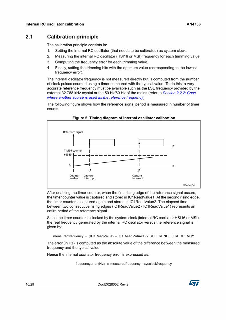
The following figure shows how the reference signal period is measured in number of timer counts.
Figure 5. Timing diagram of internal oscillator calibration
After enabling the timer counter, when the first rising edge of the reference signal occurs, the timer counter value is captured and stored in IC1ReadValue1. At the second rising edge, the timer counter is captured again and stored in IC1ReadValue2. The elapsed time between two consecutive rising edges (IC1ReadValue2 - IC1ReadValue1) represents an entire period of the reference signal.
Since the timer counter is clocked by the system clock (internal RC oscillator HSI16 or MSI), the real frequency generated by the internal RC oscillator versus the reference signal is given by:
The error (in Hz) is computed as the absolute value of the difference between the measured frequency and the typical value.
Hence the internal oscillator frequency error is expressed as:
measuredfrequency IC1ReadValue2 IC1ReadValue1–( ) REFERENCE_FREQUENCY×=
frequencyerror Hz( ) measuredfrequency sysclockfrequency–=
DocID028052 Rev 2 11/29
AN4736 Internal RC oscillator calibration
28
After calculating the error for each trimming value, the algorithm determines the optimum trimming value (that corresponds to the nearest frequency to typical value) to be programmed in the trimming bits (refer to Section 2.3: Description of the internal oscillator calibration firmware for more details).
2.2 Hardware implementation
2.2.1 Case where LSE is used as the reference frequency
The STM32L4 Series offer a useful feature: the ability to connect internally the low-speed external (LSE) oscillator to timer 16 channel 1. Thus, the LSE clock can be used as the reference signal for internal oscillator calibration and no additional hardware connections are required. Only the LSE oscillator should be connected to OSC32_IN and OSC32_OUT.
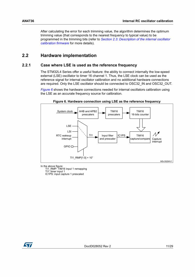
Figure 6 shows the hardware connections needed for internal oscillators calibration using the LSE as an accurate frequency source for calibration.
Figure 6. Hardware connection using LSE as the reference frequency
In the above figure: TI1_RMP: TIM16 input 1 remapping TI1: timer input 1 IC1PS: input capture 1 prescaled
Internal RC oscillator calibration AN4736
12/29 DocID028052 Rev 2
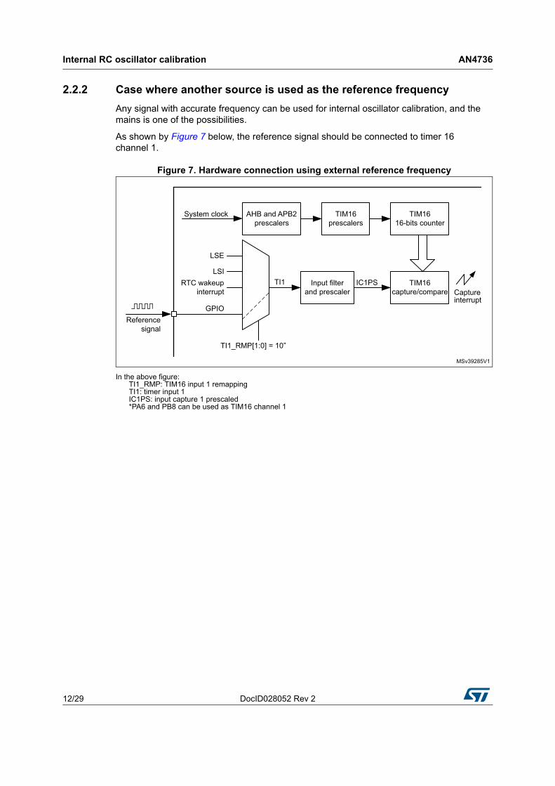
2.2.2 Case where another source is used as the reference frequency
Any signal with accurate frequency can be used for internal oscillator calibration, and the mains is one of the possibilities.
As shown by Figure 7 below, the reference signal should be connected to timer 16 channel 1.
Figure 7. Hardware connection using external reference frequency
In the above figure: TI1_RMP: TIM16 input 1 remapping TI1: timer input 1 IC1PS: input capture 1 prescaled *PA6 and PB8 can be used as TIM16 channel 1
DocID028052 Rev 2 13/29
AN4736 Internal RC oscillator calibration
28
2.3 Description of the internal oscillator calibration firmware
The internal RC oscillator calibration firmware provided with this application note includes three major functions, listed below:
• uint32_t HSI16_CalibrateMinError(void)
• ErrorStatus HSI16_CalibrateFixedError(uint32_t MaxAllowedError, uint32_t* Freq)
• ErrorStatus HSI16_CalibrateCurve(uint32_t* Freq)
• uint32_t MSI_CalibrateMinError(void)
• ErrorStatus MSI_CalibrateFixedError(uint32_t MaxAllowedError, uint32_t* Freq)
• ErrorStatus MSI_CalibrateCurve(uint32_t* Freq)
• void HSI16_GetCurve( void );
• void MSI_GetCurve(void);
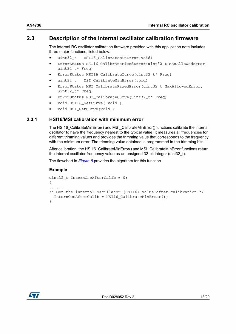
2.3.1 HSI16/MSI calibration with minimum error
The HSI16_CalibrateMinError() and MSI_CalibrateMinError() functions calibrate the internal oscillator to have the frequency nearest to the typical value. It measures all frequencies for different trimming values and provides the trimming value that corresponds to the frequency with the minimum error. The trimming value obtained is programmed in the trimming bits.
After calibration, the HSI16_CalibrateMinError() and MSI_CalibrateMinError functions return the internal oscillator frequency value as an unsigned 32-bit integer (uint32_t).
The flowchart in Figure 8 provides the algorithm for this function.
Example
uint32_t InternOscAfterCalib = 0;{....../* Get the internal oscillator (HSI16) value after calibration */ InternOscAfterCalib = HSI16_CalibrateMinError();}
Internal RC oscillator calibration AN4736
14/29 DocID028052 Rev 2
Figure 8. Internal oscillator calibration: finding the minimum frequency
1. If the system clock source is HSI16, the trimming bits have a 5-bit length and the number of steps is 32. If the system clock source is MSI, the trimming bits have an 8-bit length and the number of steps is 256.
2. Frequency measurement is detailed in Section 2.3.5.
DocID028052 Rev 2 15/29
AN4736 Internal RC oscillator calibration
28
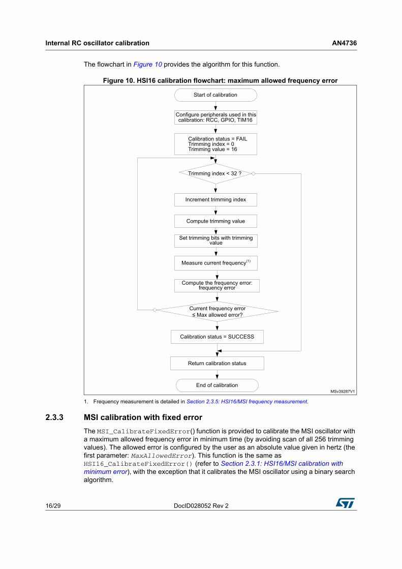
2.3.2 HSI16 calibration with fixed error
The HSI16_CalibrateFixedError() function is provided to calibrate the HSI16 oscillator with a maximum allowed frequency error. It is configured by the user as an absolute value given in hertz (the first parameter: MaxAllowedError). This function is the same as HSI16_CalibrateMinError() (refer to Section 2.3.1: HSI16/MSI calibration with minimum error), but it searches for the frequency that has an error (in absolute value) lower than or equal to MaxAllowedError.
• If it finds this frequency, it stops searching and configures the trimming bits HSI16TRIM[4:0] according to this frequency and returns SUCCESS, meaning that the calibration operation has succeeded.
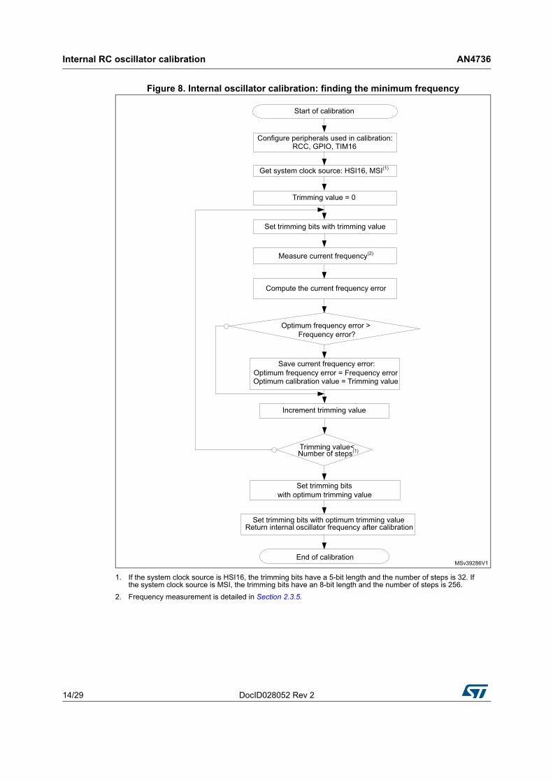
• Otherwise, it continues searching for it until the HSI16TRIM bits = 31 (32nd frequency). It then sets the trimming bits HSI16TRIM[4:0] to the default calibration value and returns ERROR, meaning that the calibration has failed and did not find any frequency with an error lower than or equal to MaxAllowedError. The frequency measurement starts with HSI16TRIM = 16. The HSI16TRIM value is computed in loops to find the next value. That is, the HSI16TRIM value starts from 16, then goes to the next value to the left, then to the next to the right, then to the second to the left and so on until it reaches 31, forming a “spring loop” (as shown in Figure 9).
This algorithm is based on the fact that the probability of finding the frequency that has the minimum error increases when the HSI16TRIM[4:0] value tends to 16. This algorithm is implemented so as to minimize the time consumed by the calibration process.
Figure 9. “Spring loop”
The second parameter is used to get the frequency (in hertz) after calibration in the form of an unsigned 32-bit integer (unit32_t).
Internal RC oscillator calibration AN4736
16/29 DocID028052 Rev 2
The flowchart in Figure 10 provides the algorithm for this function.
Figure 10. HSI16 calibration flowchart: maximum allowed frequency error
1. Frequency measurement is detailed in Section 2.3.5: HSI16/MSI frequency measurement.
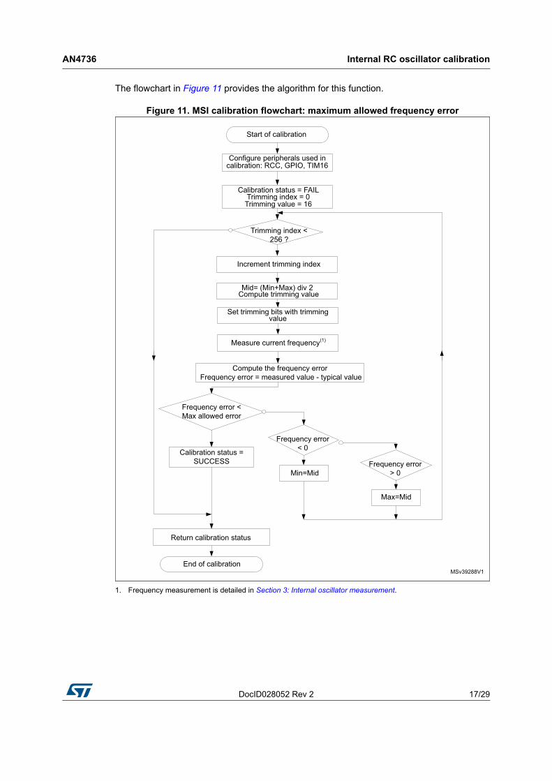
2.3.3 MSI calibration with fixed error
The MSI_CalibrateFixedError() function is provided to calibrate the MSI oscillator with a maximum allowed frequency error in minimum time (by avoiding scan of all 256 trimming values). The allowed error is configured by the user as an absolute value given in hertz (the first parameter: MaxAllowedError). This function is the same as HSI16_CalibrateFixedError() (refer to Section 2.3.1: HSI16/MSI calibration with minimum error), with the exception that it calibrates the MSI oscillator using a binary search algorithm.
DocID028052 Rev 2 17/29
AN4736 Internal RC oscillator calibration
28
The flowchart in Figure 11 provides the algorithm for this function.
Figure 11. MSI calibration flowchart: maximum allowed frequency error
1. Frequency measurement is detailed in Section 3: Internal oscillator measurement.
Internal RC oscillator calibration AN4736
18/29 DocID028052 Rev 2
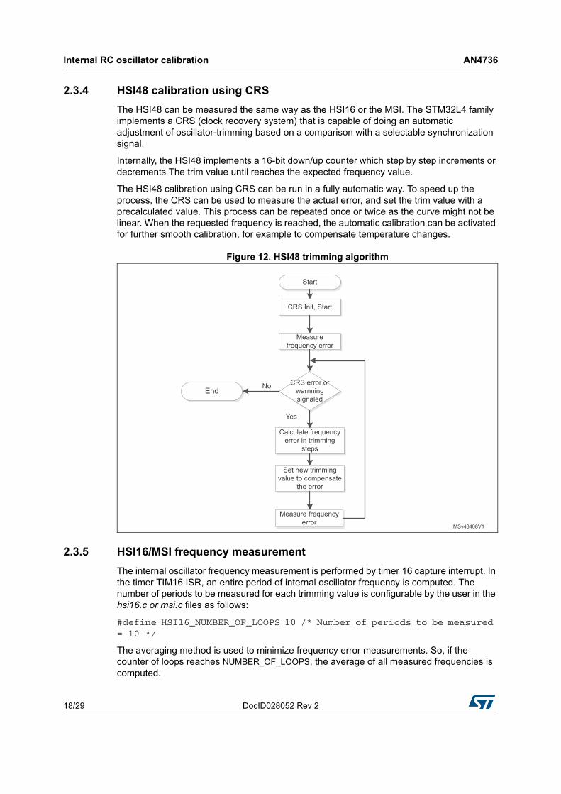
2.3.4 HSI48 calibration using CRS
The HSI48 can be measured the same way as the HSI16 or the MSI. The STM32L4 family implements a CRS (clock recovery system) that is capable of doing an automatic adjustment of oscillator-trimming based on a comparison with a selectable synchronization signal.
Internally, the HSI48 implements a 16-bit down/up counter which step by step increments or decrements The trim value until reaches the expected frequency value.
The HSI48 calibration using CRS can be run in a fully automatic way. To speed up the process, the CRS can be used to measure the actual error, and set the trim value with a precalculated value. This process can be repeated once or twice as the curve might not be linear. When the requested frequency is reached, the automatic calibration can be activated for further smooth calibration, for example to compensate temperature changes.
Figure 12. HSI48 trimming algorithm
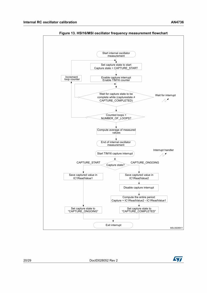
2.3.5 HSI16/MSI frequency measurement
The internal oscillator frequency measurement is performed by timer 16 capture interrupt. In the timer TIM16 ISR, an entire period of internal oscillator frequency is computed. The number of periods to be measured for each trimming value is configurable by the user in the hsi16.c or msi.c files as follows:
#define HSI16_NUMBER_OF_LOOPS 10 /* Number of periods to be measured = 10 */
The averaging method is used to minimize frequency error measurements. So, if the counter of loops reaches NUMBER_OF_LOOPS, the average of all measured frequencies is computed.
DocID028052 Rev 2 19/29
AN4736 Internal RC oscillator calibration
28
The user can easily configure the frequency of the reference source. It is defined in the header file hsi16.c or msi.c as follows:
• If the LSE clock is used as the reference frequency, uncomment the line below to make sure the LSE is configured and internally connected to timer 16 channel 1:
#define USE_REFERENCE_LSE
• If the reference frequency is a mains source frequency equal to 50 Hz, then comment the line above and define the reference frequency as shown below:
#define REFERENCE_FREQUENCY (uint32_t)50 /* The reference frequency value in Hz */
The computation of the frequency measurements does not depend on the duty cycle of the source reference signal. It depends on its frequency since the capture 1 interrupt is configured to occur on every rising edge of the reference signal (refer to Figure 5).
Note: Figure 13 provides the frequency measurement algorithm.
Internal RC oscillator calibration AN4736
20/29 DocID028052 Rev 2
Figure 13. HSI16/MSI oscillator frequency measurement flowchart
DocID028052 Rev 2 21/29
AN4736 Internal RC oscillator calibration
28
2.3.6 HSI16/MSI calibration using calibration curve
Both previous methods (minimal and fixed error) can take a long team because many measurements need to be run (for example, 32 measurements for HSI16 when the minimal error method used). First, for all trimming values, the difference between the corresponding and the requested frequency is measured and stored in a table. It uses the same principle as minimal error method. When it is necessary to calibrate the internal oscillator function HSI16_CalibrateCurve(), it measures the actual frequency only once and searches in the table the appropriate value to compensate the difference.
In the case of an MSI calibration, the MSI_GetCurve() and MSI_CalibrateCurve() functions should be used instead of HSI16_GetCurve() and HSI16_calibrateCurve().
2.4 Recommendations on the use of the calibration library
1. If the external signal frequency is lower than the system clock/65535, the TIM16 counter prescaler should be used to support the low frequencies.
2. If the external signal frequency is higher than system clock/100, the TIM16 input capture prescaler (divider) should be used to support the high frequencies.
3. It is recommended to stop all the application’s activities before the calibration process, and to restart them after calling the calibration functions.
4. The application therefore has to stop communications, ADC measurements and other processes (except when using the ADC for calibration, refer to Step 7. below).
5. These processes normally use clock configurations that are different from those used in the calibration process. Otherwise, errors might be introduced in the application: errors while reading/sending frames, ADC reading errors since the sampling time has changed, and so on.
6. The internal RC oscillator calibration firmware uses the following peripherals: the reset and clock control (for trimming internal RC oscillators) and the timer 16 (for measuring internal RC oscillators). Therefore, it is recommended to reconfigure these peripherals (if used in the application) after running the calibration routine.
7. A real-time calibration versus temperature can be used when the ambient temperature changes noticeably while the application is running. The internal temperature sensor can be used with the ADC watchdog with two thresholds. Each time an ADC watchdog interrupt occurs, a new calibration process has to be performed and the two thresholds are updated according to the current temperature (this feature is not implemented in the firmware provided with this application note):
8. Threshold_High = CurrentTemperatureValue + TemperatureOffset
9. Threshold_Low = CurrentTemperatureValue – TemperatureOffset
10. It might happen that with a change of operating conditions (for example the surrounding temperature) the calibration curve can change. From this reason it is recommended to measure again from time to time (or when the conditions change) in order to keep working with correct values.
Internal RC oscillator calibration AN4736
22/29 DocID028052 Rev 2
2.5 Calibration process performance
2.5.1 Duration of the calibration process
The duration of the calibration process depends on:
1. the frequency of the reference signal (prescaled value) “REFERENCE_FREQUENCY”,
2. the number of measured periods per trimming value “NUMBER_OF_LOOPS”,
3. the number of measured frequencies during the calibration process “number of steps”.
Once the peripherals are configured and ready (mainly the LSE oscillator), the duration of the calibration process is approximated by:
duration = (2 x (NUMBER_OF_LOOPS + 1) x number of steps) / REFERENCE_FREQUENCY
If the calibration process is run with a minimum frequency error for the HSI16 oscillator (HSI16_CalibrateMinError()), the number of steps is equal to 32. If the LSE oscillator is used as the reference frequency (REFERENCE_FREQUENCY = LSE value / input capture prescaler = 32768/8 = 4096 Hz) and the selected number of measured periods is 10, the calibration consumes approximately:
duration = (2 x 11 x 32) / 4096 = 172 ms
When running the calibration process for the MSI oscillator, the number of steps is equal to 256. If the LSE oscillator is used as the reference frequency (REFERENCE_FREQUENCY = LSE value / input capture prescaler = 32768/8 = 4096 Hz) and the selected number of measured periods is 10, the calibration consumes approximately:
duration = (2 x 11 x 256) / 4096 = 1.4 s
The duration of the calibration process with a maximum allowed error is lower than or equal to the duration of calibration when using the minimum frequency error process.
Note: Multiplying by 2 in the duration formula above is due to the fact that there is no synchronization between the reference signal and the start of counting by the timer.
DocID028052 Rev 2 23/29
AN4736 Internal oscillator measurement
28
3 Internal oscillator measurement
The internal MSI and LSI RC oscillators are both low-power and low-cost clock sources. In the STM32L4 Series microcontroller family, an internal connection is provided between the internal RC oscillators (MSI and LSI) and the embedded timer (TIM16) to facilitate the measurement procedure.
3.1 Measurement principle
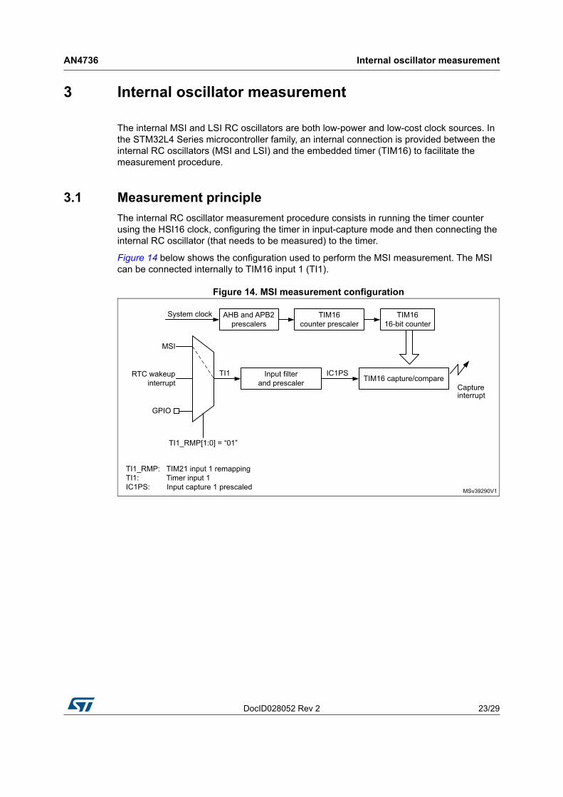
The internal RC oscillator measurement procedure consists in running the timer counter using the HSI16 clock, configuring the timer in input-capture mode and then connecting the internal RC oscillator (that needs to be measured) to the timer.
Figure 14 below shows the configuration used to perform the MSI measurement. The MSI can be connected internally to TIM16 input 1 (TI1).
Figure 14. MSI measurement configuration
Internal oscillator measurement AN4736
24/29 DocID028052 Rev 2
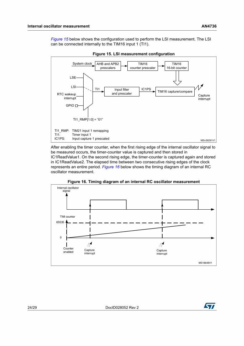
Figure 15 below shows the configuration used to perform the LSI measurement. The LSI can be connected internally to the TIM16 input 1 (TI1).
Figure 15. LSI measurement configuration
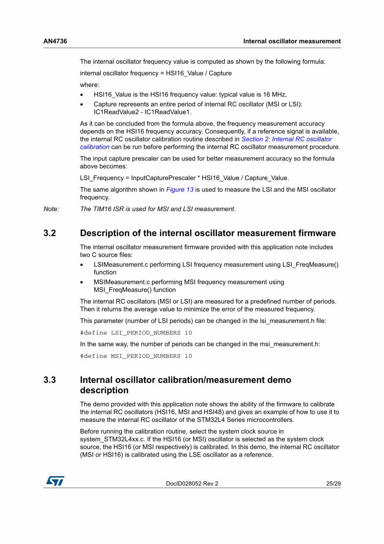
After enabling the timer counter, when the first rising edge of the internal oscillator signal to be measured occurs, the timer-counter value is captured and then stored in IC1ReadValue1. On the second rising edge, the timer-counter is captured again and stored in IC1ReadValue2. The elapsed time between two consecutive rising edges of the clock represents an entire period. Figure 16 below shows the timing diagram of an internal RC oscillator measurement.
Figure 16. Timing diagram of an internal RC oscillator measurement
DocID028052 Rev 2 25/29
AN4736 Internal oscillator measurement
28
The internal oscillator frequency value is computed as shown by the following formula:
internal oscillator frequency = HSI16_Value / Capture
where:
• HSI16_Value is the HSI16 frequency value: typical value is 16 MHz,
• Capture represents an entire period of internal RC oscillator (MSI or LSI): IC1ReadValue2 - IC1ReadValue1.
As it can be concluded from the formula above, the frequency measurement accuracy depends on the HSI16 frequency accuracy. Consequently, if a reference signal is available, the internal RC oscillator calibration routine described in Section 2: Internal RC oscillator calibration can be run before performing the internal RC oscillator measurement procedure.
The input capture prescaler can be used for better measurement accuracy so the formula above becomes:
LSI_Frequency = InputCapturePrescaler * HSI16_Value / Capture_Value.
The same algorithm shown in Figure 13 is used to measure the LSI and the MSI oscillator frequency.
Note: The TIM16 ISR is used for MSI and LSI measurement.
3.2 Description of the internal oscillator measurement firmware
The internal oscillator measurement firmware provided with this application note includes two C source files:
• LSIMeasurement.c performing LSI frequency measurement using LSI_FreqMeasure() function
• MSIMeasurement.c performing MSI frequency measurement using MSI_FreqMeasure() function
The internal RC oscillators (MSI or LSI) are measured for a predefined number of periods. Then it returns the average value to minimize the error of the measured frequency.
This parameter (number of LSI periods) can be changed in the lsi_measurement.h file:
#define LSI_PERIOD_NUMBERS 10
In the same way, the number of periods can be changed in the msi_measurement.h:
#define MSI_PERIOD_NUMBERS 10
3.3 Internal oscillator calibration/measurement demo description
The demo provided with this application note shows the ability of the firmware to calibrate the internal RC oscillators (HSI16, MSI and HSI48) and gives an example of how to use it to measure the internal RC oscillator of the STM32L4 Series microcontrollers.
Before running the calibration routine, select the system clock source in system_STM32L4xx.c. If the HSI16 (or MSI) oscillator is selected as the system clock source, the HSI16 (or MSI respectively) is calibrated. In this demo, the internal RC oscillator (MSI or HSI16) is calibrated using the LSE oscillator as a reference.
Internal oscillator measurement AN4736
26/29 DocID028052 Rev 2
By default, the demo uses the minimum error method to calibrate the oscillators.
To run the calibration process that provides the frequency with fixed error or calibration curve, the user has to leave uncommented the line with requested method in the main.c file.
#define CALIBRATION_MIN_ERROR
#define FIXED_ERROR
#define ERROR_CURVE
For the HSI48 oscillators, a CRS is used both for measurements and for calibration. To run the CRS, three sources of references can be chosen:
• a USB SOF (start of frame), which is the default source of reference
• a signal provided via GPIO
• an LSE oscillator (non applicable for STM32L4 Nucleo-32 board).
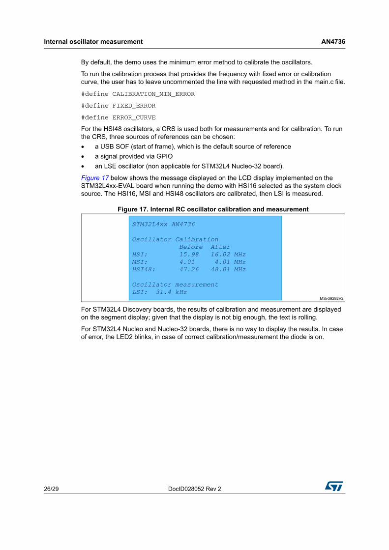
Figure 17 below shows the message displayed on the LCD display implemented on the STM32L4xx-EVAL board when running the demo with HSI16 selected as the system clock source. The HSI16, MSI and HSI48 oscillators are calibrated, then LSI is measured.
Figure 17. Internal RC oscillator calibration and measurement
For STM32L4 Discovery boards, the results of calibration and measurement are displayed on the segment display; given that the display is not big enough, the text is rolling.
For STM32L4 Nucleo and Nucleo-32 boards, there is no way to display the results. In case of error, the LED2 blinks, in case of correct calibration/measurement the diode is on.
DocID028052 Rev 2 27/29
AN4736 Conclusion
28
4 Conclusion
Even if the internal RC oscillators are factory-calibrated, the user should calibrate them in the operating environment if a high-accuracy clock is required in the application.
This application note provides two routines:
• Multi and high-speed internal oscillator calibration: how to fine-tune the oscillator to the typical value
• Multi and low-speed internal oscillator measurement: how to get the “exact” LSI/MSI frequency value
Several frequency sources can be used to calibrate the internal RC oscillators (HSI16, HSI48 and MSI) such as LSE crystal or AC line among others. Regardless of the reference frequency source, the internal oscillator calibration principle is the same: a reference signal must be provided to be measured by a timer. The higher the accuracy of the reference signal frequency, the better the accuracy of the internal oscillator frequency measurement.
The error is computed as the absolute value of the typical frequency value and the measured one for each trimming value. After this, the calibration value is calculated and then programmed in the trimming bits.
The second section of this application note presented the measurement of the LSI and the MSI oscillators. The internal connection between internal oscillators and embedded timers in the STM32L4 Series microcontroller family is used for this purpose. The timer is clocked using the system clock source and configured in input capture mode. The captured time between two consecutive rising edges of internal oscillator represents an entire period.
Revision history AN4736
28/29 DocID028052 Rev 2
5 Revision history
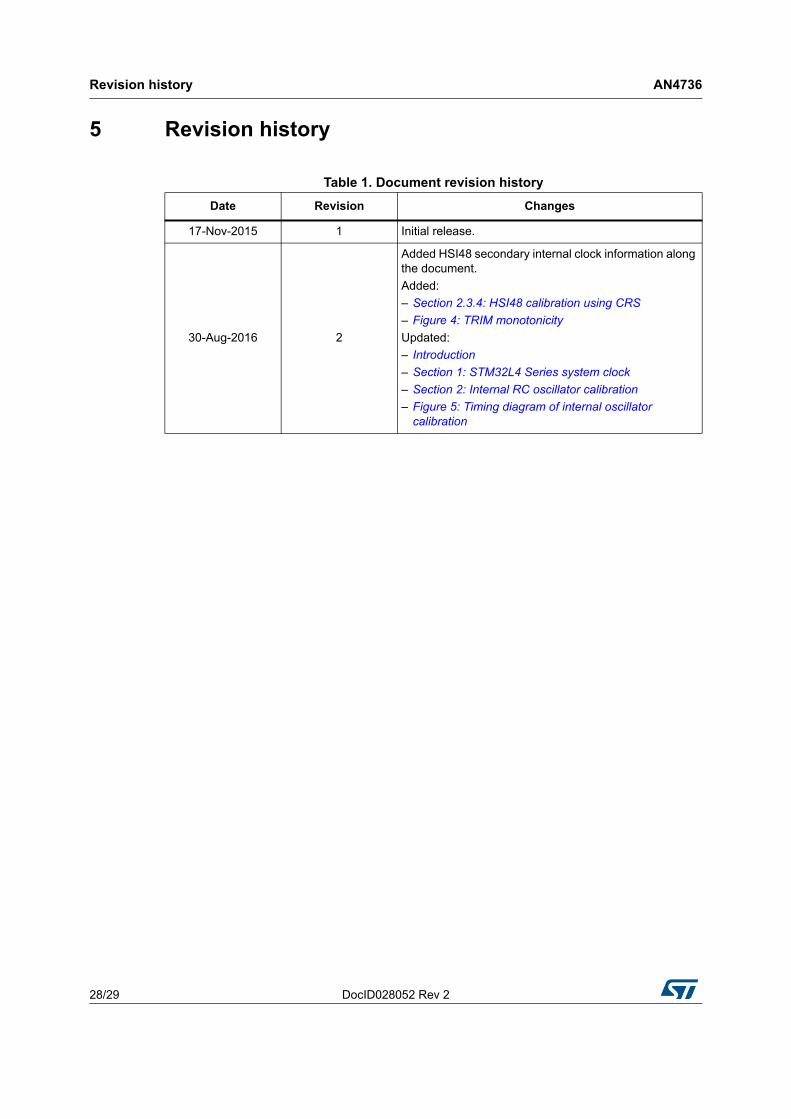
Table 1. Document revision history
Date Revision Changes
17-Nov-2015 1 Initial release.
30-Aug-2016 2
Added HSI48 secondary internal clock information along the document.
Added:
– Section 2.3.4: HSI48 calibration using CRS
– Figure 4: TRIM monotonicity
Updated:
– Introduction
– Section 1: STM32L4 Series system clock
– Section 2: Internal RC oscillator calibration
– Figure 5: Timing diagram of internal oscillator calibration
DocID028052 Rev 2 29/29
AN4736
29
IMPORTANT NOTICE – PLEASE READ CAREFULLY
STMicroelectronics NV and its subsidiaries (“ST”) reserve the right to make changes, corrections, enhancements, modifications, and improvements to ST products and/or to this document at any time without notice. Purchasers should obtain the latest relevant information on ST products before placing orders. ST products are sold pursuant to ST’s terms and conditions of sale in place at the time of order acknowledgement.
Purchasers are solely responsible for the choice, selection, and use of ST products and ST assumes no liability for application assistance or the design of Purchasers’ products.
No license, express or implied, to any intellectual property right is granted by ST herein.
Resale of ST products with provisions different from the information set forth herein shall void any warranty granted by ST for such product.
ST and the ST logo are trademarks of ST. All other product or service names are the property of their respective owners.
Information in this document supersedes and replaces information previously supplied in any prior versions of this document.
© 2016 STMicroelectronics – All rights reserved