Embed Size (px)
Citation preview
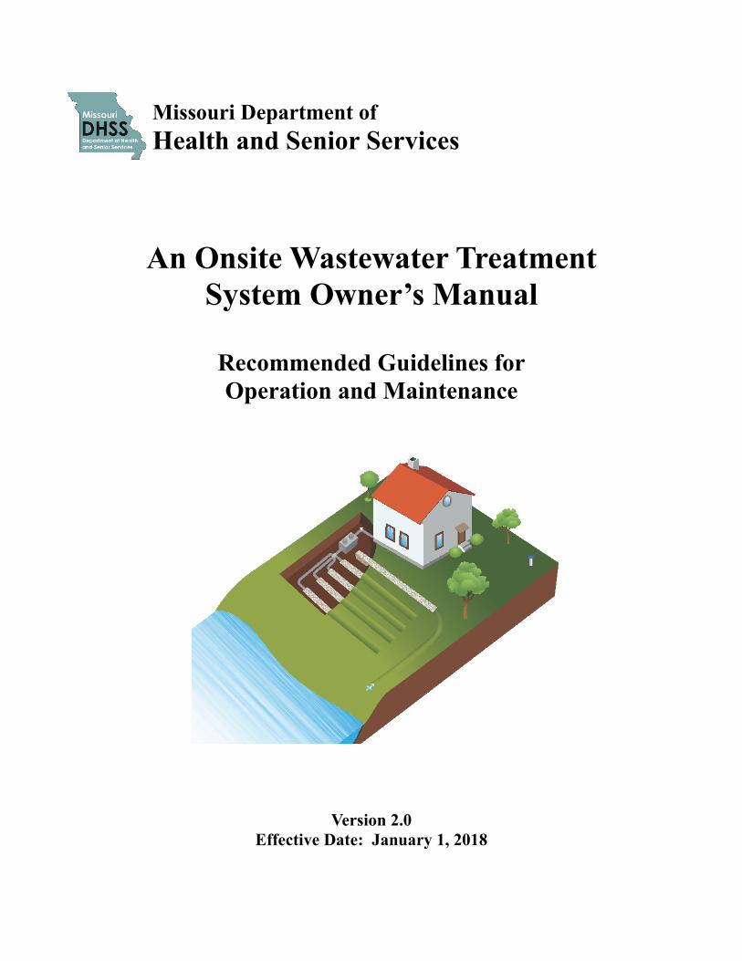
Missouri Department of
Health and Senior Services
An Onsite Wastewater Treatment
System Owner’s Manual
Recommended Guidelines for
Operation and Maintenance
Version 2.0
Effective Date: January 1, 2018

Purpose, Scope, and Applicability
Introduction and How to Use the Guidelines
Reasons for Maintaining Your System
Chapter 1: Septic Tanks
Chapter 2: Aeration Treatment Units (ATU’s)
Chapter 3: Bio-filters
Chapter 4: Wetlands
Chapter 5: Lagoons
Chapter 6: Pumps and Pump Tanks
Chapter 7: Effluent Screens
Chapter 8: Gravity Distribution and Soil Dispersal Trenches
Chapter 9: Pressure Distribution
Chapter 10: Drip Dispersal
Chapter 11: Curtain Drains
Chapter 12: Holding Tanks
Chapter 13: Cluster Systems
Chapter 14: Soils Component
Table of Contents
Table of Contents
Page 1 of 2 Table of Contents
Troubleshooting System Problems
Management Models
Remediation
Glossary
Diagram of System
Record Keeping Document
Resources
Acknowledgments
Table of Contents
Table of Contents, continued
Page 2 of 2
Table of Contents
Purpose
Scope
The following guidance document was developed to provide a comprehensive overview of the mechanics, design, OPERATION, and MAINTENANCE of common ONSITE WASTEWATER TREATMENT SYSTEM components utilized in Missouri. The technical standards for the OPERATION and MAINTENANCE of the various pretreatment components as well as the soil treatment systems found throughout these guidelines are highly recommended, however, they are not enforceable unless adopted by rule or local ordinance. Omission of or reference to a particular product, service, or manufacturer within these guidelines does not imply any denial or endorsement by the Missouri Department of Health and Senior Services.
Applicability
The following guidelines apply to any OWNER or user of an ONSITE WASTEWATER TREATMENT SYSTEM, REGISTERED ONSITE WASTEWATER TREATMENT SYSTEM PROFESSIONALS, qualified SERVICE PROVIDERS, and RESPONSIBLE MANAGEMENT ENTITIES (RME). The guidelines apply to the OPERATION and MAINTENANCE of ONSITE WASTEWATER TREATMENT SYSTEMS receiving a maximum flow of three thousand (3,000) gallons per day or less of DOMESTIC SEWAGE to include single-family residential lagoons. ONSITE WASTEWATER TREATMENT SYSTEM (OWTS) or decentralized wastewater treatment system means a managed wastewater treatment system used to collect, treat, and disperse or reclaim WASTEWATER from individual homes, clusters of homes, establishments, or isolated communities at or near the point of waste generation.
Individual wastewater treatment system means a system relying on natural processes and/or mechanical components to collect, treat, and disperse or reclaim WASTEWATER from a single dwelling or building.
Cluster wastewater treatment system means a WASTEWATER collection and treatment system under some form of common ownership which collects WASTEWATER from two or more dwellings or buildings with multiple OWNERS and conveys it to a treatment and dispersal system located on a suitable site near the dwellings or buildings.
The purpose of these guidelines is to establish OPERATION and MAINTENANCE standards and to promote the effective management of decentralized (individual and cluster) wastewater treatment systems for the life of the systems. Effective management will ensure the level of treatment necessary to adequately protect public health and surface and groundwater quality.
Page 1 of 1 Purpose, Scope, and Applicability
Introduction
The performance of onsite and clustered wastewater treatment systems is a local, state, and national issue and a great concern to the Missouri Department of Health and Senior Services. Decentralized systems are used by an estimated twenty-five percent of homeowners in Missouri and are permanent components of our state’s WASTEWATER infrastructure. Decentralized systems, defined for the purposes of these guidelines, shall mean managed individual onsite, or clustered, wastewater treatment systems (commonly referred to as ONSITE WASTEWATER TREATMENT SYSTEMS) used to collect, treat, and disperse WASTEWATER from individual dwellings, businesses, or small communities . Unfortunately, many of the systems in use are improperly managed and do not provide the level of treatment necessary to adequately protect public health and groundwater and
surface water quality. Proper management of decentralized systems involves a comprehensive set of measures that encompass several elements in addition to proper OPERATION and MAINTENANCE. The U.S. Environmental Protection Agency’s Voluntary National Guidel ines for Management of Onsite and Clustered Wastewater Treatment Systems provides five management models for decentralized systems that address education, performance, evaluation, design, construction, OPERATION and M A I N T E N A N C E , a n d c o r r e c t i v e actions essential for a more complete MANAGEMENT PROGRAM. For more information see MANAGEMENT MODEL I, II, III, IV or V at Voluntary National Guidelines for Management of Onsite and Clustered Wastewater Treatment Systems.
How to Use the Guidelines
Every wastewater system requires care and oversight. ONSITE WASTEWATER TREATMENT SYSTEMS do not last forever, however, following the recommendations within these guidelines can significantly extend the life of your onsite or cluster system. The guidelines consist of various sections to assist in your understanding of the OPERATION and MAINTENANCE of an ONSITE WASTEWATER TREATMENT SYSTEM. Each chapter focuses on one component within the most common ONSITE WASTEWATER TREATMENT SYSTEMS. This was done so that a homeowner, REGISTERED ONSITE WASTEWATER TREATMENT SYSTEM PROFESSSIONAL, or qualified SERVICE PROVIDER can custom design a user’s manual specifically for your system.
For example, if you have a septic tank with an EFFLUENT screen and gravity dispersal trenches, you should use Chapters 1, 7 and 8 of these guidelines
to gain an understanding of your system’s OPERATION and MAINTENANCE requirements. In addition, defined terms are formatted in ALL CAPS. The glossary, a diagram of a system, a record keeping log, and resources are located at the end of these guidelines for additional information.
Wastewater Treatment System Owners and Users
To achieve the best performance from your system, it is essential to know what type of ONSITE WASTEWATER TREATMENT SYSTEM you have, where it is located, and its basic OPERATION and MAINTENANCE requirements. Upon installing the system, a REGISTERED ONSITE WASTEWATER TREATMENT SYSTEM PROFESSIONAL may have provided an owner’s manual tailored to your system that answers these questions and provides a specific service schedule. If no information about your system
Page 1 of 2 Introduction
How to Use the Guidelines, continued
is available, a Diagram of System page is located at the end of these guidelines to sketch the location of any visible or known parts of your system. To assist your search, look for inspection ports, tank or valve access, and control/alarm panels. A good place to start is down slope from the house; however, if there is a pump in the system, some components may be up slope. It may be necessary to seek the expertise of a REGISTERED ONSITE WASTEWATER TREATMENT SYSTEM PROFESSIONAL to locate and identify the components of your system. Use the information in the following chapters to help determine which components make up your system. Once you know what type of system you have, review the information in the appropriate chapters. Note the Do’s and Don’ts and the
Warning Signs. Use the MAINTENANCE section(s) to schedule or contract with a wastewater professional to perform regular INSPECTIONS and service as needed. Always keep records of routine service and repairs. Remember to check with the local onsite WASTEWATER ADMINISTRATIVE AUTHORITY about whether a permit is necessary for any system repair.
Wastewater System Professionals
You should give system OWNERS a detailed ‘as-built’ drawing of their wastewater system and any manufacturer provided owner’s manual or other OPERATION and MAINTENANCE information. In addition, the appropriate sections of these guidelines should be used to support or supplement OPERATION and MAINTENANCE information for the OWNER’S specific system.
Homeowner Responsibilities
The OPERATION and MAINTENANCE of an ONSITE WASTEWATER TREATMENT SYSTEM is the responsibility of the OWNER and user of the system.
A permit is usually needed before a system is installed or repaired on your property. Applications are available from your local public health agency or other local onsite WASTEWATER ADMINISTRATIVE AUTHORITY.
All ONSITE WASTEWATER TREATMENT SYSTEMS must be installed and OPERATED in accordance with the requirements specified in 19 CSR 20-3.060, Minimum Construction Standards for On-Site Wastewater Treatment Systems, and 19 CSR 20-3.015, Operation of Onsite Wastewater Treatment Systems, the manufacturer’s specifications, and the designer’s OPERATION and MAINTENANCE manual.
In accordance with Missouri law, ONSITE WASTEWATER TREATMENT SYSTEMS must be OPERATED and MAINTAINED to prevent the production of odors, the creation of a habitat for insect breeding, contamination of surface water or groundwater, or creation of a nuisance or health hazard.
In accordance with Missouri law, MALFUNCTIONING ONSITE WASTEWATER TREATMENT SYSTEMS must be remediated, repaired, and/or replaced in accordance with the requirements specified in 19 CSR 20-3.060 Minimum Construction Standards for On-Site Wastewater Treatment Systems.
Page 2 of 2 How to Use Guidelines

Reasons for Maintaining Your System
For many homeowners their ONSITE WASTEWATER TREATMENT SYSTEM may easily be the most overlooked and undervalued utility in the home. If you are like many homeowners, not much thought is given to what happens to the waste that goes down the drain. Yet if you rely on an onsite system to treat and disperse your household WASTEWATER, proper OPERATION and MAINTENANCE of your system can have a significant impact on how well it works and how long it lasts. There are three main reasons why ONSITE WASTEWATER TREATMENT SYSTEM MAINTENANCE is so important-
The first reason is protecting your HEALTH, the health of your family, and the environment. Household WASTEWATER is loaded with disease-causing bacteria and viruses, as well as, high levels of nitrogen and phosphorus. When onsite systems fail, inadequately treated household WASTEWATER is released into the environment and can contaminate nearby wells, groundwater, and surface waters. Any contact with untreated human waste can pose a significant health risk.
The second reason is MONEY. MALFUNCTIONING onsite systems are expensive to repair or replace, and neglected MAINTENANCE by homeowners is a common cause of early system failure. The minimal amount of preventative MAINTENANCE that onsite systems require costs very little in comparison to the cost of a new system. For example, it can easily cost more than $10,000 to replace a failing onsite system, compared to $200 - $500 average per year costs to have a system routinely inspected, serviced or pumped.
The third reason is to protect your PROPERTY VALUE. An unusable onsite wastewater treatment system or one in disrepair can cause property values to decline. It can also make it difficult to sell the property; in cases when a property transfer INSPECTION is mandated, the property sale may be delayed if the ONSITE WASTEWATER TREATMENT SYSTEM is not operating properly. In addition, building or occupancy permits may be denied for these properties. MALFUNCTIONING onsite systems can reduce property values in the area if they contribute to the pollution of local rivers and lakes that your community uses for commercial or recreational activities.
Page 1 of 1 Maintaining Your System
Homes not served by public sewers rely on individual onsite or cluster wastewater treatment systems to treat and disperse household WASTEWATER. Household WASTEWATER includes both GRAYWATER and BLACKWATER. GRAYWATER is defined as water captured from nonfood preparation sinks, showers, baths, and clothes washing machines while BLACKWATER is that portion of WASTEWATER that originates from toilet fixtures, dishwashers, and food preparation sinks. Household WASTEWATER contains human waste, dirt, food, toilet paper, soap, detergents, and cleaning products; which i n c l u d e s d i s s o l v e d n u t r i e n t s , microorganisms, and solid particles. Improperly maintained wastewater treatment
systems can allow these substances to contaminate groundwater and/or surface water and pose a health hazard.
A typical ONSITE WASTEWATER TREATMENT SYSTEM has four main components: a sewer line from the house, a septic tank, a soil treatment system, and the soil under and around the treatment system. The septic tank is a buried, watertight tank designed and constructed to receive all household WASTEWATER and provide primary treatment. After receiving limited treatment in the septic tank, WASTEWATER is distributed and dispersed into the soil for final treatment. Then clean water, filtered by the soil, recharges streams, lakes, and groundwater in the area.
How a Septic Tank Works
Primary treatment means the septic tank provides short-term storage and time for the WASTEWATER to separate into layers. Tees, or baffles, provided at the septic tank’s inlet and outlet are essential to the function of the tank. When raw WASTEWATER enters the tank the inlet tee slows the incoming waste, reducing turbulence so that heavier solids can settle to the bottom of the tank and form a SLUDGE layer. Lighter solids, such as grease and paper, float to the surface and form a SCUM layer. The outlet tee keeps the SLUDGE and SCUM in the tank. During this storage period bacteria digest organic material in the WASTEWATER and reduce the volume of solids that are present.
Chapter 1: Septic Tanks A Pretreatment Component
What’s Ahead...
How a Septic
Tank Works
Design and
Construction
Maintenance
Warning Signs
Do’s and Don’ts Glossary Resources
Chapter 1
Page 1 of 7 Chapter 1: Septic Tanks
As new WASTEWATER enters the tank through the inlet tee, an equal amount of clarified WASTEWATER is pushed out of the tank through the outlet tee. The WASTEWATER that leaves the tank has been partially treated but still contains disease causing bacteria and other pollutants and receives further treatment in the soil treatment area. The SCUM and SLUDGE layers retained and stored in the tank accumulate over time and eventually must be pumped out. Septic tanks provide reliable, but limited treatment of WASTEWATER. The United States Environmental Protection Agency has established five management models with progressively increasing management controls as sensitivity of the environment and/or treatment system complexity increases. MANAGEMENT MODEL I specifies appropriate program elements and activities where treatment systems are owned and operated by individual PROPERTY OWNERS in
areas of low environmental sensitivity. The objective of this model is to ensure that-
Conventional systems are designed and i n s t a l l e d i n a c c o r d a n c e w i t h appropriate state and local regulations;
Homeowners are knowledgeable of their particular system and provide routine MAINTENANCE (INSPECTIONS and pumping) necessary for the system to operate properly, and, if needed;
Homeowners ensure a MALFUNCTIONING system is repaired in accordance with Missouri law.
This model is generally appropriate for septic tank systems. In some sensitive environments, septic tanks can also be used as a component of a more advanced system for which MANAGEMENT MODELS II, III, or IV may be recommended.
Raw
Wastewater Pretreated
Wastewater
Bedding
Page 2 of 7 Chapter 1: Septic Tanks
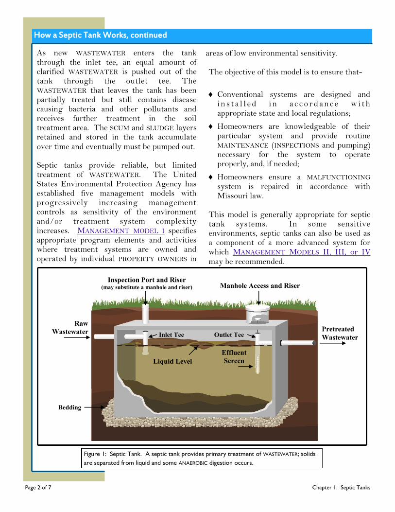
Figure 1: Septic Tank. A septic tank provides primary treatment of WASTEWATER; solids
are separated from liquid and some ANAEROBIC digestion occurs.
Inspection Port and Riser (may substitute a manhole and riser) Manhole Access and Riser
Inlet Tee Outlet Tee
Effluent
Screen Liquid Level
How a Septic Tank Works, continued
Design and Construction
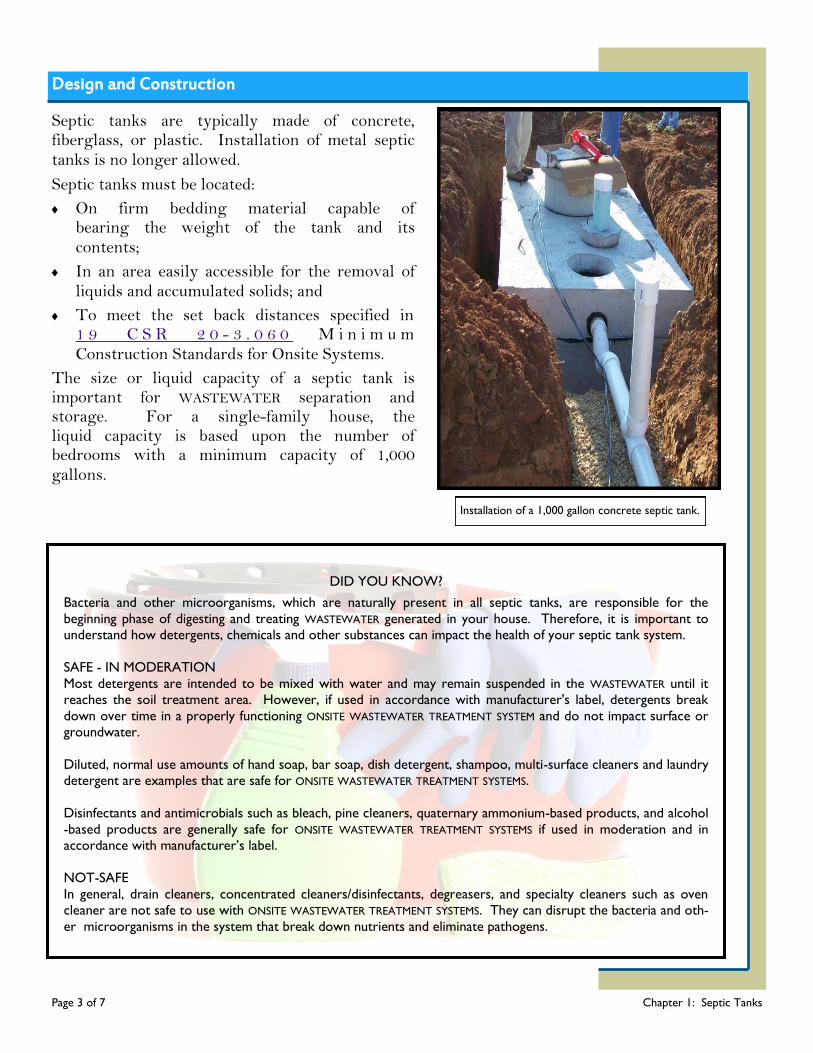
Septic tanks are typically made of concrete, fiberglass, or plastic. Installation of metal septic tanks is no longer allowed.
Septic tanks must be located:
On firm bedding material capable of bearing the weight of the tank and its contents;
In an area easily accessible for the removal of liquids and accumulated solids; and
To meet the set back distances specified in 1 9 C S R 2 0 - 3 . 0 6 0 M i n i m u m Construction Standards for Onsite Systems.
The size or liquid capacity of a septic tank is important for WASTEWATER separation and storage. For a single-family house, the liquid capacity is based upon the number of bedrooms with a minimum capacity of 1,000 gallons.
DID YOU KNOW?
Bacteria and other microorganisms, which are naturally present in all septic tanks, are responsible for the
beginning phase of digesting and treating WASTEWATER generated in your house. Therefore, it is important to understand how detergents, chemicals and other substances can impact the health of your septic tank system.
SAFE - IN MODERATION
Most detergents are intended to be mixed with water and may remain suspended in the WASTEWATER until it reaches the soil treatment area. However, if used in accordance with manufacturer's label, detergents break
down over time in a properly functioning ONSITE WASTEWATER TREATMENT SYSTEM and do not impact surface or groundwater.
Diluted, normal use amounts of hand soap, bar soap, dish detergent, shampoo, multi-surface cleaners and laundry detergent are examples that are safe for ONSITE WASTEWATER TREATMENT SYSTEMS.
Disinfectants and antimicrobials such as bleach, pine cleaners, quaternary ammonium-based products, and alcohol
-based products are generally safe for ONSITE WASTEWATER TREATMENT SYSTEMS if used in moderation and in accordance with manufacturer’s label.
NOT-SAFE
In general, drain cleaners, concentrated cleaners/disinfectants, degreasers, and specialty cleaners such as oven cleaner are not safe to use with ONSITE WASTEWATER TREATMENT SYSTEMS. They can disrupt the bacteria and oth-
er microorganisms in the system that break down nutrients and eliminate pathogens.
Page 3 of 7 Chapter 1: Septic Tanks
Installation of a 1,000 gallon concrete septic tank.
Maintenance - Inspections
Regular MAINTENANCE is essential for getting the best performance from your septic tank system. If too much SLUDGE and SCUM are allowed to accumulate in the tank, the incoming WASTEWATER does not have adequate time to settle, causing solids to flow into the soil treatment system and clog dispersal trenches. If clogging occurs, WASTEWATER can overflow onto the ground surface or backup into the house, where it exposes people and animals to disease-causing organisms. To prevent this from happening, it is important to inspect your tank regularly and have it serviced when needed. Septic tanks should have INSPECTION access over the inlet and outlet tees/baffles. All tanks have manholes for inspecting and pumping; minor excavation work may be needed to uncover the manhole.
Inspections
Septic tanks must be inspected at least every two years. If the system has an EFFLUENT screen or the system serves a non-residential establishment, the tank should initially be inspected at least annually. The INSPECTION may be conducted by the homeowner, a REGISTERED ONSITE WASTEWATER TREATMENT SYSTEM PROFESSIONAL, or other qualified SERVICE PROVIDER. The INSPECTION should include assuring:
The septic tank is structurally sound with no corrosion, cracking, or missing parts;
There are no signs of water intrusion;
The septic tank, risers, manhole, access ports, lids, and covers are watertight;
Lids and covers are locked or otherwise secured to prevent accidental entry;
The inlet and outlet tees or baffles are in good condition and functioning properly;
If present, EFFLUENT screens are in good condition and not clogged; and
The SCUM and SLUDGE layers are at an acceptable thickness.
DID YOU KNOW? In order to ensure individuals are properly trained, the Missouri Department of Health and
Senior Services registers several types of ONSITE WASTEWATER TREATMENT SYSTEM PROFESSIONALS.
For more information about installers, onsite soil evaluators, onsite system inspectors/evaluators,
and percolation testers please go to Wastewater Professionals at http://health.mo.gov/living/
environment/onsite/professionals.php
.
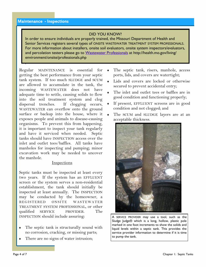
A SERVICE PROVIDER may use a tool, such as the
Sludge Judge® which is a long, hollow, plastic pole
marked in one foot increments to show the solids and
liquid levels within a septic tank. This provides the
service provider information to determine if it is time
to pump the tank.
Page 4 of 7 Chapter 1: Septic Tanks

Maintenance - Pumping
Figure 2: Septic Tank. Contract for removal of solids from the septic tank when SLUDGE is 12 inches
or less from bottom of outlet [A] or when SCUM is 3 inches or less from bottom of outlet [B].
Correctly sized septic tanks are designed to accumulate solids for several years under normal conditions. As solids fill up the tank, WASTEWATER has less time to separate properly and solid particles could flow out of the tank in-to the dispersal trenches. If the tank is not peri-odically pumped out, these solids will enter the soil treatment system; clogging the system to a point that a new soil treatment area may be needed. It is the responsibility of the homeowner or user of the septic tank system to contract with a R E G I S T E R E D O N S I T E W A S T E W A T E R TREATMENT SYSTEM PROFESSIONAL or other qualified SERVICE PROVIDER for the removal of the septic tank contents when needed. There are three main factors which determine the frequency at which a septic tank must be pumped:
The liquid capacity of the tank;
How much water flows through the system, usually related to the number of people in the household; and
The vo lume o f so l ids in the WASTEWATER, usually related to the use of a garbage disposal.
A septic tank must be pumped when the top of the SLUDGE layer is no closer than twelve inches below the bottom of the outlet tee or when the bottom of the SCUM layer is no closer than three inches above the bottom of the outlet tee. A typ-ical 1,000 gallon septic tank serving a three bed-room home may need to be pumped roughly eve-ry two to five years; if the home has a garbage disposal, the tank generally needs to be pumped twice as often. A REGISTERED ONSITE WASTEWATER TREATMENT SYSTEM PROFESSIONAL or other qualified SERVICE PROVIDER is responsible for the proper treatment and disposal of all hauled WASTEWATER by transporting to a municipal sewage treatment plant capable of receiving the waste; transporting to a sludge handling facility which possesses a current and valid permit issued for such activity; or land applying under a current and valid permit for such activity.
Page 5 of 7 Chapter 1: Septic Tanks
Raw
Wastewater Pretreated
Wastewater
[B]
[A]
Sludge
Liquid
SCUM
Warning Signs of System Malfunctioning
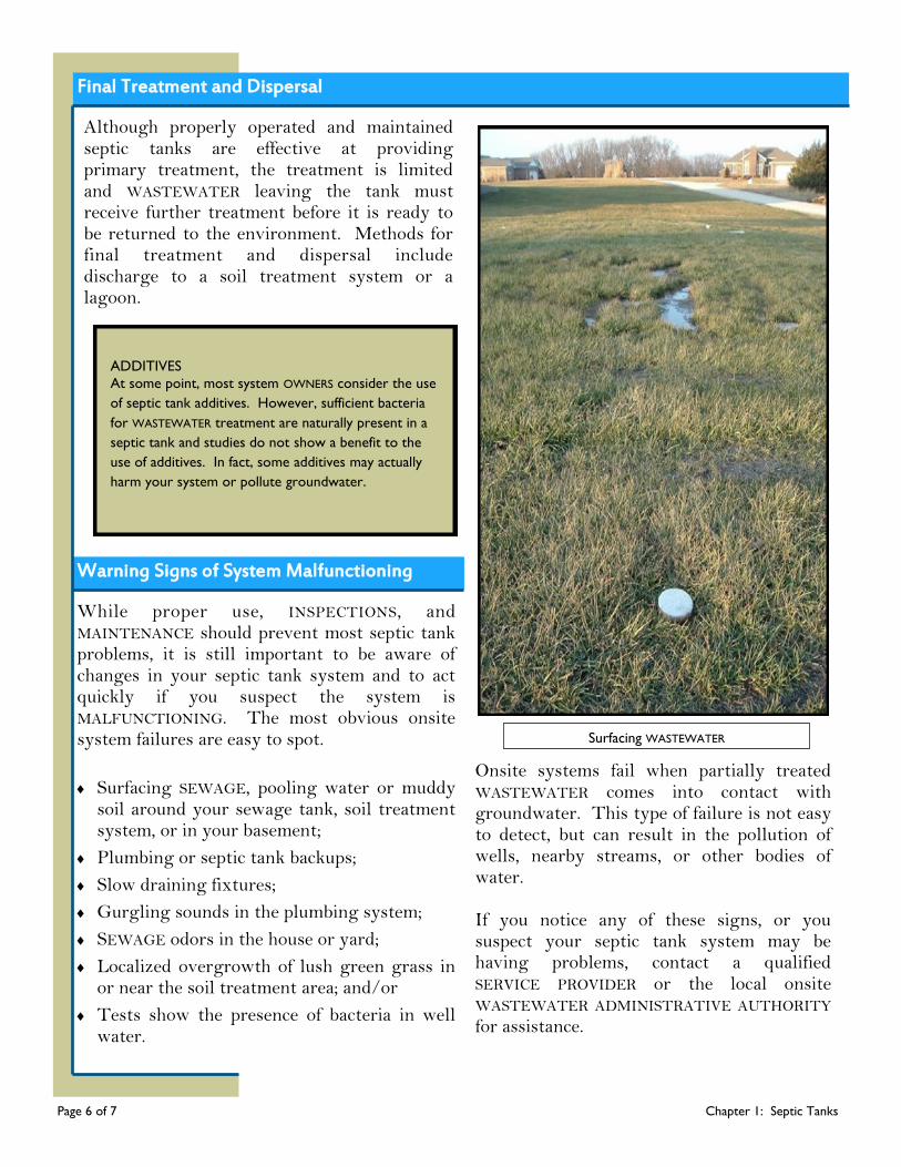
Surfacing WASTEWATER
While proper use, INSPECTIONS, and MAINTENANCE should prevent most septic tank problems, it is still important to be aware of changes in your septic tank system and to act quickly if you suspect the system is MALFUNCTIONING. The most obvious onsite system failures are easy to spot.
Surfacing SEWAGE, pooling water or muddy soil around your sewage tank, soil treatment system, or in your basement;
Plumbing or septic tank backups;
Slow draining fixtures;
Gurgling sounds in the plumbing system;
SEWAGE odors in the house or yard;
Localized overgrowth of lush green grass in or near the soil treatment area; and/or
Tests show the presence of bacteria in well water.
Onsite systems fail when partially treated WASTEWATER comes into contact with groundwater. This type of failure is not easy to detect, but can result in the pollution of wells, nearby streams, or other bodies of water. If you notice any of these signs, or you suspect your septic tank system may be having problems, contact a qualified SERVICE PROVIDER or the local onsite WASTEWATER ADMINISTRATIVE AUTHORITY for assistance.
Although properly operated and maintained septic tanks are effective at providing primary treatment, the treatment is limited and WASTEWATER leaving the tank must receive further treatment before it is ready to be returned to the environment. Methods for final treatment and dispersal include discharge to a soil treatment system or a lagoon.
ADDITIVES
At some point, most system OWNERS consider the use
of septic tank additives. However, sufficient bacteria
for WASTEWATER treatment are naturally present in a
septic tank and studies do not show a benefit to the
use of additives. In fact, some additives may actually
harm your system or pollute groundwater.
Final Treatment and Dispersal
Page 6 of 7 Chapter 1: Septic Tanks
Proper OPERATION and MAINTENANCE of an onsite system can prevent costly repairs or replacement and can protect your property value. Observing the following recommendations will help to keep your system operating properly.
Septic Tank Do’s and Don’ts
Do’s
Obtain the necessary permits from the appropriate ADMINISTRATIVE AUTHORITY before making any repairs.
Use REGISTERED ONSITE WASTEWATER TREATMENT SYSTEM PROFESSIONALS and qualified SERVICE PROVIDERS.
Conserve water to avoid overloading the onsite system, use high-efficiency fixtures and promptly repair any leaky faucets or toilets.
Have your septic tank inspected annually if it has an EFFLUENT screen or every two years if it does not.
Have your septic tank pumped routinely. Pumping your septic tank when needed may be the single most important thing you can do to protect your soil treatment system and your investment.
Contact a qualified SERVICE PROVIDER if you experience problems with your system, such as surfacing WASTEWATER in your yard or other warning signs the system may be MALFUNCTIONING.
Keep detailed records regarding the system, its location, make/model, contract service agreement, service visits, and MAINTENANCE performed.
Use commercial bathroom cleaners and laundry detergents in moderation and only according to manufacturer’s directions.
Keep your septic tank accessible for INSPECTIONS and pumping; yet locked or otherwise secured to prevent accidental entry.
Have your private water well tested periodically or if you experience any warning signs of the system MALFUNCTIONING (contact your local public health agency).
Don’t enter a septic tank. Poisonous gasses or a lack of oxygen can be fatal.
Your septic tank system is not a trash can. Don’t put dental floss, feminine hygiene products, flushable wipes, condoms, diapers, cotton swabs, cigarette butts, coffee grounds, cat litter, paper towels, paint, pesticides, or other hazardous chemicals into your system.
Don’t use caustic drain openers for a clogged drain. Instead, use boiling water or a drain snake to open clogs.
Don’t drive or park vehicles or allow livestock on any part of your septic tank system. Doing so can compact the soil in your soil treatment area or damage the pipes, tank, or other onsite system components.
Don’t build over any part of your septic tank system; this includes patios, carports, and other structures.
Don’t attempt to pump your own septic tank; use the services of a qualified SERVICE PROVIDER.
Septic Tank Do’s and Don’ts
Don’ts
Page 7 of 7 Chapter 1: Septic Tanks
Homes not served by public sewers rely on individual or small cluster wastewater treatment systems to treat and disperse household WASTEWATER. Household WASTEWATER includes both GRAYWATER and BLACKWATER. GRAYWATER is defined as water captured from nonfood preparation sinks, showers, baths, and clothes washing machines while BLACKWATER is that portion of WASTEWATER that originates from toilet fixtures, dishwashers, and food preparation sinks. Household WASTEWATER contains human waste, dirt, food, toiler paper, soap, detergents, and cleaning products; which includes dissolved nutrients, microorganisms, and solid particles. Improperly maintained wastewater treatment systems can allow these substances
to
contaminate groundwater and/or surface water and pose a health hazard. A septic tank followed by gravity dispersal trenches is the most common ONSITE WASTEWATER TREATMENT SYSTEM used in rural areas. However, there are many households for which the typical septic tank system is not the best WASTEWATER treatment option. For example, septic tank systems are not suitable for lots with limited land area, poor soil conditions, or where the water table is too high to allow the soil adequate time to treat the WASTEWATER before it reaches groundwater. In these cases, an aeration treatment unit may be a good option. Aeration treatment units (ATUs) are similar to septic tanks in that they both use natural processes to treat WASTEWATER. But unlike septic tanks that rely on ANAEROBIC treatment, ATUs use AEROBIC treatment processes that require oxygen. Oxygen is added using a mechanism to inject and circulate air inside the treatment tank; electricity is needed for this operation. For this reason, ATUs cost more to operate and need more frequent routine MAINTENANCE than most septic tank systems. However, when properly OPERATED and MAINTAINED, ATUs provide a high-quality wastewater treatment alternative.
Chapter 2
Chapter 2: Aeration Treatment Units A Pretreatment Component
What’s Ahead...
How an Aeration Treatment Unit
Works
Design and Construction
Maintenance
Warning Signs
Do’s and Don’ts Glossary Resources
Page 1 of 8 Chapter 2: ATUs

How an Aeration Treatment Unit Works
The main function of the aeration treatment unit is to collect and treat household WASTEWATER. ATUs themselves come in many sizes and shapes. ATUs include a main compartment called an aeration chamber in which air is mixed with the WASTEWATER. Some models include a primary settling compartment or an additional tank to reduce the amount of solids in the WASTEWATER entering into the aeration chamber. Because most individual household and other small ATUs are buried underground like septic tanks, air must be forced into the aeration chamber by an air blower, pump, compressor or by a motor and aspirator. The forced air mixes with WASTEWATER in the aeration chamber and the oxygen supports
the growth of AEROBIC bacteria that digest the organic material in the WASTEWATER. This mixture of WASTEWATER, bacteria, and air is called MIXED LIQUOR. The treatment occurring in the MIXED LIQUOR is referred to as suspended growth because the bacteria grow and die as they are suspended in the liquid, unattached to any surface. The bacteria cannot digest all of the solids in the mixed liquor and the growth and die-off of bacteria create more solids; these solids accumulate as SLUDGE and eventually overload the clarifier or filter if not pumped out. Some ATUs have a fixed medium, typically a prefabricated plastic, which provides surface area for attached growth. Attached growth technologies work on the principle that microorganisms remove organic matter from
Raw
Wastewater Pretreated
Wastewater
Primary Treatment
Scum
Liquid
Sludge
Aeration Chamber Clarifier
Clarified
Liquid
Sludge Mixed Liquor
Figure 1: Aeration Treatment Unit (ATU). An ATU uses air to promote the growth of bacteria that use oxygen to help treat
the WASTEWATER. In the aeration chamber air is mixed with WASTEWATER and bacteria. Some models include a chamber or
separate tank for primary treatment. Various ATU models use different methods to introduce air and retain solids.
Page 2 of 8 Chapter 2: ATUs
How an Aeration Treatment Unit Works, continued
WASTEWATER while growing on the filter media, essentially recycling the dissolved organic material into a film that develops on the media. As the attached growth builds up and sloughs off, SLUDGE accumulates at the bottom of the tank. Many AEROBIC units include a final settling chamber or clarifier where solids and bacteria can settle and return to the aeration chamber.
Other designs use a screen to retain solids in the ATU. When the amount of solids in the MIXED LIQUOR reaches a certain point, the clarifier cannot retain the solids or the filter/screen can clog and restrict WASTEWATER flow. Suspended growth solids in the MIXED LIQUOR or SLUDGE buildup will need to be pumped out periodically so that solids don’t discharge to the soil treatment system or clog the ATU.
[A] [C]
[B]
[D]
[E]
[A]
[B]
[D]
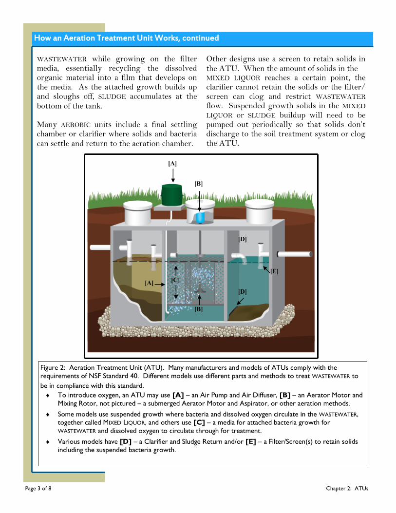
Figure 2: Aeration Treatment Unit (ATU). Many manufacturers and models of ATUs comply with the
requirements of NSF Standard 40. Different models use different parts and methods to treat WASTEWATER to
be in compliance with this standard.
To introduce oxygen, an ATU may use [A] – an Air Pump and Air Diffuser, [B] – an Aerator Motor and
Mixing Rotor, not pictured – a submerged Aerator Motor and Aspirator, or other aeration methods.
Some models use suspended growth where bacteria and dissolved oxygen circulate in the WASTEWATER,
together called MIXED LIQUOR, and others use [C] – a media for attached bacteria growth for
WASTEWATER and dissolved oxygen to circulate through for treatment.
Various models have [D] – a Clarifier and Sludge Return and/or [E] – a Filter/Screen(s) to retain solids
including the suspended bacteria growth.
Page 3 of 8 Chapter 2: ATUs
ATUs provide a higher level of WASTEWATER treatment than septic tanks. However, proper OPERATION and MAINTENANCE is essential. The United States Environmental Protection Agency has established five management models with progressively increasing management controls as sensitivity of the environment and/or treatment system complexity increases. MANAGEMENT MODEL II specifies program elements and activities where more complex designs are employed to enhance the capacity of conventional systems to accept and treat WASTEWATER. Because of treatment complexity, contracts with qualified SERVICE PROVIDERS are needed to ensure proper and timely MAINTENANCE.
The objective of this model is to ensure that-
Advanced systems are designed and installed in accordance with appropriate state and local regulations;
Homeowners are knowledgeable of their particular system and maintain a contractual agreement with a qualified SERVICE PROVIDER to provide routine MAINTENANCE (INSPECTIONS and pumping) necessary for the system to operate properly, and, if needed;
Homeowners ensure a MALFUNCTIONING system is repaired in accordance with Missouri law.
This model is generally most appropriate for aeration treatment units. In some sensitive environments, MANAGEMENT MODELS III or IV may be recommended.
Design and Construction
ATU tanks are typically made of concrete, fiberglass, or plastic.
ATUs must meet NSF Standard 40.
ATUs must be located:
On firm, bedding material capable of bearing the weight of the tank and its contents;
In an area easily accessible for the removal of liquids and accumulated solids; and
To meet the set back distances specified in 19 CSR 20-3.060 Minimum Construction Standards for Onsite Systems.
The capacity of an ATU is based on the volume of WASTEWATER that can be treated in one day. For a single-family house, the treatment capacity is based upon the number of bedrooms with a minimum required capacity of 120 gallons per day per bedroom or 500 gallons per day, whichever is greater.
How an Aeration Treatment Unit Works, continued
Page 4 of 8 Chapter 2: ATUs
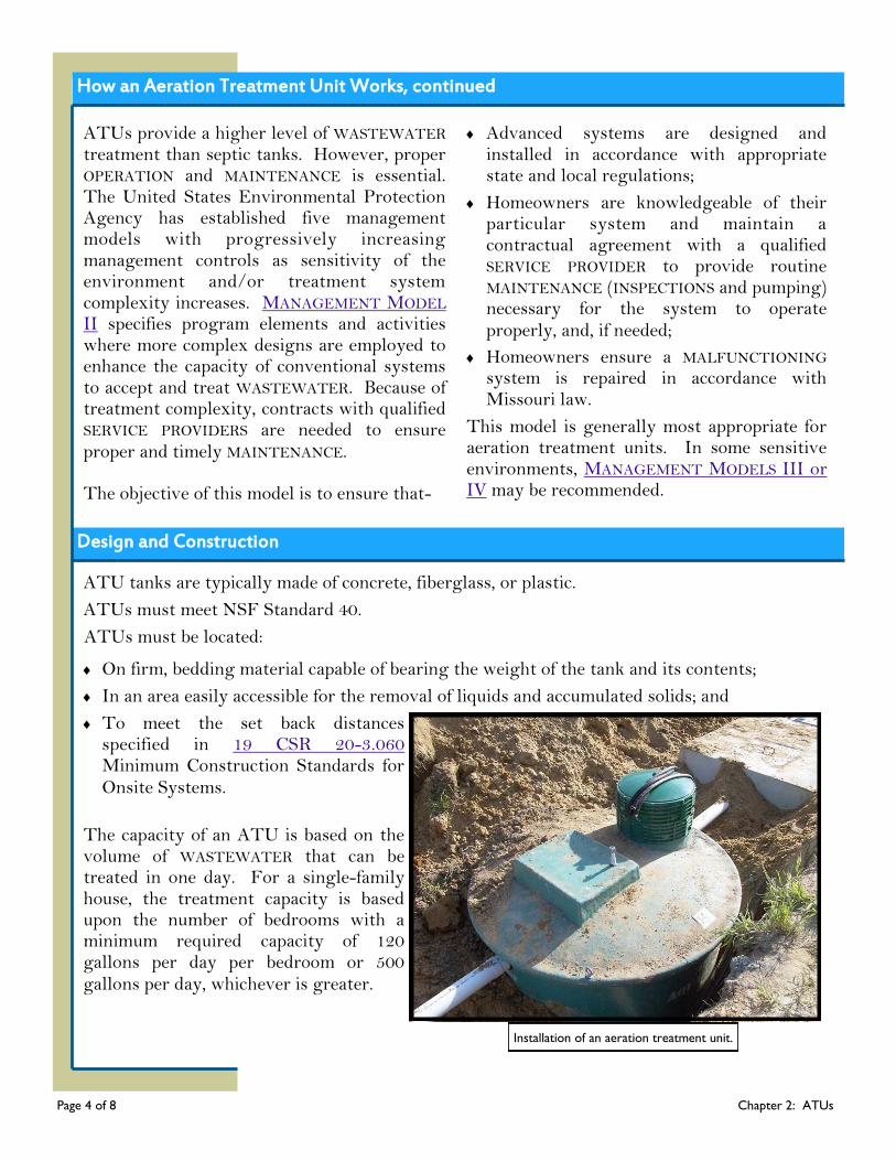
Installation of an aeration treatment unit.
Regular MAINTENANCE is essential for getting the best performance from your onsite system. It is important that mechanical components in AEROBIC systems receive regular INSPECTION and MAINTENANCE. Most homeowners do not have the expertise to inspect, maintain, and repair their own systems. If your unit carries the NSF International certification, it will include the first two years of service visits and an option to renew the service contract.
Inspections ATUs must be inspected at least every six months according to NSF certification requirements and as recommended by the manufacturer. The INSPECTION should be conducted by a maintenance provider certified by the ATU manufacturer. The INSPECTION should include assuring:
The tank is structurally sound with no corrosion, cracking, or missing parts;
If applicable, the primary treatment chamber or tank shows no signs of water intrusion;
The tank, risers, service access, access ports, lids, and covers are in good condition and watertight;
The aeration chamber has a functioning aeration system that introduces air into the chamber and mixes WASTEWATER according to the manufacturer’s specifications;
If applicable, the clarification chamber, and/or screens are not overloaded and solids are retained in the treatment unit;
Vents and aeration access ports are free of blockages and cleaned as needed;
Lids and covers are locked or otherwise secured to prevent accidental entry;
Alarms function properly;
There are no signs of corrosion on the wiring; and
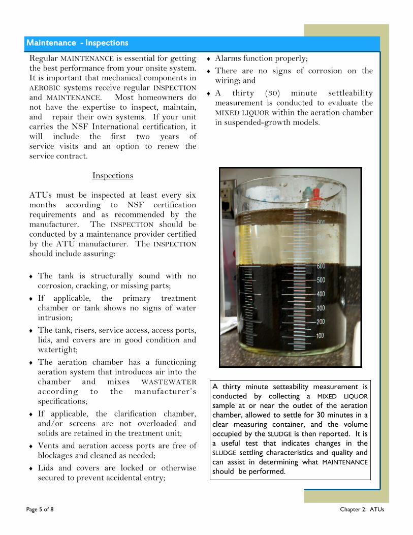
A thirty (30) minute settleability measurement is conducted to evaluate the MIXED LIQUOR within the aeration chamber in suspended-growth models.
Maintenance - Inspections
Page 5 of 8 Chapter 2: ATUs
A thirty minute setteability measurement is
conducted by collecting a MIXED LIQUOR
sample at or near the outlet of the aeration
chamber, allowed to settle for 30 minutes in a
clear measuring container, and the volume
occupied by the SLUDGE is then reported. It is
a useful test that indicates changes in the
SLUDGE settling characteristics and quality and
can assist in determining what MAINTENANCE
should be performed.
It is the responsibility of the homeowner or user of the ATU to contract with a maintenance provider certified by the ATU manufacturer or other qualified SERVICE PROVIDER for the periodic removal and treatment of the contents of the unit. The OWNER or user of the system must schedule for the removal and sanitary disposal of WASTEWATER from all chambers when:
Any other tank in the system needs pumped;
If applicable, the top of the SLUDGE layer is no closer than twelve inches below the outlet of the primary chamber or tank;
The MIXED LIQUOR settleable solids in the aeration chamber measure greater than fif-ty percent (50%);
If applicable, the SLUDGE layer fills more than two thirds of the volume below the attached growth media; or
As recommended by the manufacturer.
The maintenance provider certified by the ATU manufacturer or other qualified SERVICE PROVIDER is responsible for the proper treatment and disposal of all hauled WASTEWATER by transporting to a municipal sewage treatment plant capable of receiving the waste; transporting to a SLUDGE handling facility which possesses a current and valid permit issued for such activity; or land applying under a current and valid permit for such activity.
Maintenance - Pumping
Page 6 of 8 Chapter 2: ATUs
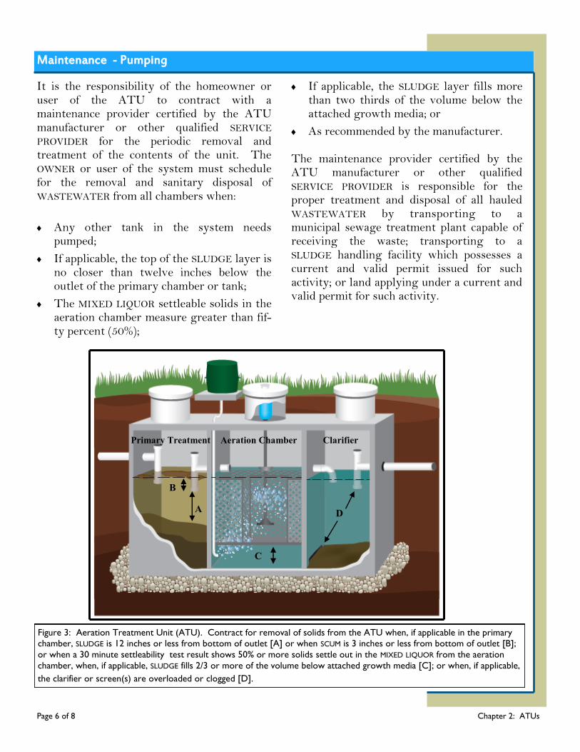
Primary Treatment Aeration Chamber Clarifier
B
A
C
D
Figure 3: Aeration Treatment Unit (ATU). Contract for removal of solids from the ATU when, if applicable in the primary
chamber, SLUDGE is 12 inches or less from bottom of outlet [A] or when SCUM is 3 inches or less from bottom of outlet [B];
or when a 30 minute settleability test result shows 50% or more solids settle out in the MIXED LIQUOR from the aeration
chamber, when, if applicable, SLUDGE fills 2/3 or more of the volume below attached growth media [C]; or when, if applicable,
the clarifier or screen(s) are overloaded or clogged [D].

While proper use, INSPECTIONS, and MAINTENANCE should prevent most ATU problems, it is still important to be aware of changes in your system and to act quickly if you suspect the system is MALFUNCTIONING. The most obvious onsite system failures are easy to spot.
Alarms or lights activated;
Any change in the system’s normal operating sound;
Any changes in the normal color of the WASTEWATER in the aeration chamber;
Excessive solids, foam, or SCUM in the unit;
Plumbing backups;
SEWAGE odors in the house or yard; and/or
Tests show the presence of bacteria in well water.
Onsite systems fail when partially treated WASTEWATER comes into contact with groundwater. This type of failure is not easy to detect, but can result in the pollution of wells, nearby streams, or other bodies of water. If you notice any of these signs or you suspect your system may be having problems, contact a qualified SERVICE PROVIDER or the local onsite WASTEWATER ADMINISTRATIVE AUTHORITY for assistance.
Page 7 of 8 Chapter 2: ATUs
Warning Signs of System Malfunctioning
Final Treatment and Dispersal
Although properly OPERATED and MAINTAINED AEROBIC units reduce the pollutants in WASTEWATER compared to septic tanks, the WASTEWATER leaving the unit must receive further treatment before it is ready to be returned to the environment. Methods for final treatment and dispersal include discharge to a soil treatment system or lagoon.
DID YOU KNOW?
In order to ensure individuals are properly
trained, the Missouri Department of Health and
Senior Services registers several types of
ONSITE WASTEWATER TREATMENT SYSTEM
PROFESSIONALS. For more information about
installers, onsite soil evaluators, onsite
system inspectors/evaluators, and percolation
testers please go to Wastewater Professionals
or http://health.mo.gov/living/environment/
onsite/professionals.php
Surfacing WASTEWATER
ATU Do’s and Don’ts
Proper OPERATION and MAINTENANCE of an onsite system can prevent costly repairs or replacement and can protect your property value. Observing the following recommendations will help to keep your system operating properly.
Do’s
Don’ts
Obtain the necessary permits from the appropriate ADMINISTRATIVE AUTHORITY before making any repairs.
Use a maintenance provider certified by the ATU manufacturer or other qualified SERVICE PROVIDERS for routine INSPECTIONS, MAINTENANCE, and pumping; and if you experience problems with the system, such as the alarm is activated or other warning signs the system may be MALFUNCTIONING.
Renew and maintain the contract service arrangement offered by the manufacturer after the initial two-year period has expired.
Have the system maintained regularly in accordance with the manufacturer’s recommendations.
Keep the system accessible for INSPECTIONS and pumping; yet locked or otherwise secured to prevent accidental entry.
Keep detailed records regarding the system, its location, make/model, contract service agreement, service visits, and MAINTENANCE performed.
Conserve water to avoid overloading the onsite system, use high-efficiency fixtures and promptly repair any leaky faucets or toilets.
Have your private water well tested periodically or if you experience any warning signs of the system MALFUNCTIONING (contact your local public health agency).
Don’t enter a sewage tank. Poisonous gasses or a lack of oxygen can be fatal.
Your sewage system is not a trash can. Don’t put dental floss, feminine hygiene products, flushable wipes, condoms, diapers, cotton swabs, cigarette butts, coffee grounds, cat litter, paper towels, paint, pesticides, or other hazardous chemicals into your system.
Don’t use caustic drain openers for a clogged drain. Instead, use boiling water or a drain snake to open clogs.
Don’t drive or park vehicles or allow livestock on any part of your ONSITE WASTEWATER TREATMENT SYSTEM. Doing so can compact the soil in your soil treatment area or damage the pipes, tank, or other onsite system components.
Don’t build over any part of your system; this includes patios, carports, and other structures.
Don’t attempt to clean or perform MAINTENANCE on any sealed AEROBIC unit components.
Don’t attempt to perform any MAINTENANCE prior to shutting off all electricity to the system.
If lights or alarms are activated, don't turn alarm off prior to assuring the system is not MALFUNCTIONING.
Page 8 of 8 Chapter 2: ATUs
Chapter 3: Bio-filters A Pretreatment Component
Chapter 3
A septic tank followed by gravity dispersal trenches is the most common ONSITE WASTEWATER TREATMENT SYSTEM used in rural areas. However, there are many households for which the typical septic tank system is not the best wastewater treatment option. For example, septic tank systems are not suitable for lots with limited land area, poor soil conditions, or where the water table is too high to allow the soil adequate time to treat the WASTEWATER before it reaches groundwater. In these cases, a bio-filter treatment system may be a good option. Bio-filters, or media filters, use ATTACHED GROWTH PROCESSES to treat WASTEWATER in an unsaturated environment. Attached growth is the process of flowing WASTEWATER through a natural or manufactured material for biological treatment. In contrast to the treatment processes where waste consuming bacteria grow suspended in sewage tanks, the
active treatment bacteria in ATTACHED GROWTH PROCESSES grow on a filter media, such as gravel, sand, peat, textile, or foam. The bacteria are primarily AEROBIC, meaning they require oxygen to live and essentially recycle the organic material in the WASTEWATER into a film that develops on the media. To avoid plugging the bio-filter, WASTEWATER must first be treated to remove larger solids. This is accomplished by using a septic tank or an aeration treatment unit to treat the WASTEWATER prior to moving it through the attached growth bio-filter media. Generally these processes are low MAINTENANCE, have low energy requirements, and are robust and stable; making them a good advanced wastewater treatment technology for individual homes, as well as, small communities.
How a Bio-filter Treatment System Works What’s Ahead...
How a Bio-filter
Works
Design and
Construction
Maintenance
Warning Signs
Do’s and Don’ts Glossary Resources
Bio-filters make effective attached growth systems using natural filter media such as sand or peat, or manufactured media such as textile and foam. They can be designed as single-pass filters or recirculating filters. Recirculating filters cycle WASTEWATER through the media more than one time. Regardless of the media, the process is generally the same - WASTEWATER from a septic tank is applied to a bed of media, treatment occurs as WASTEWATER flow by bacteria growing on the media, the filtrate is collected in a drain underneath the media and may be recirculated or sent on to a soil treatment system for final treatment and dispersal.
Page 1 of 7 Chapter 3: Bio-filters
Page 24 How a Bio-filter Treatment System Works, continued
A bio-filter treatment system provides a higher level of WASTEWATER treatment than septic tanks. However, proper OPERATION and MAINTENANCE is essential. The US Environmental Protection Agency has established five management models with progressively increasing management controls as sensitivity of the environment and/or treatment system complexity increases. MANAGEMENT MODEL II specifies program elements and activities where more complex designs are employed to enhance the capacity of conventional systems to accept and treat WASTEWATER. Because of treatment complexity, contracts with qualified SERVICE PROVIDERS are needed to ensure proper and timely MAINTENANCE. The objective of this model is to ensure that-
Advanced systems are designed and installed in accordance with appropriate state and local regulations;
Homeowners are knowledgeable of their particular system and maintain a contractual agreement with a qualified SERVICE PROVIDER to provide routine MAINTENANCE (INSPECTIONS and pumping) necessary for the system to operate properly, and, if needed;
Homeowners ensure a MALFUNCTIONING system is repaired in accordance with Missouri law.
This model is generally most appropriate for bio-filter treatment systems. However, in some sensitive environments, MANAGEMENT MODELS III or IV may be recommended.
Page 2 of 7 Chapter 3: Bio-filters
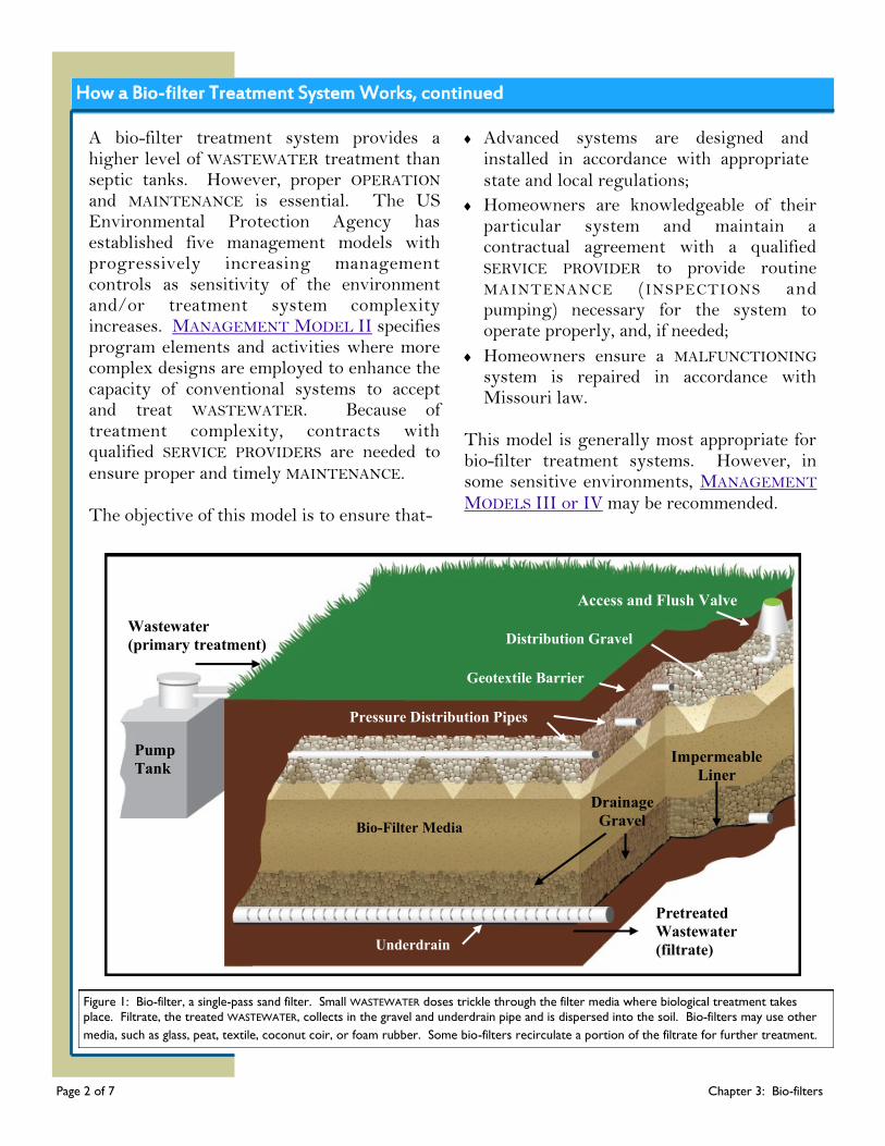
Figure 1: Bio-filter, a single-pass sand filter. Small WASTEWATER doses trickle through the filter media where biological treatment takes
place. Filtrate, the treated WASTEWATER, collects in the gravel and underdrain pipe and is dispersed into the soil. Bio-filters may use other
media, such as glass, peat, textile, coconut coir, or foam rubber. Some bio-filters recirculate a portion of the filtrate for further treatment.
Pump
Tank
Wastewater
(primary treatment)
Pressure Distribution Pipes
Geotextile Barrier
Distribution Gravel
Access and Flush Valve
Bio-Filter Media
Underdrain
Impermeable
Liner
Drainage
Gravel
Pretreated
Wastewater
(filtrate)
Chapter 3 Sand Filters
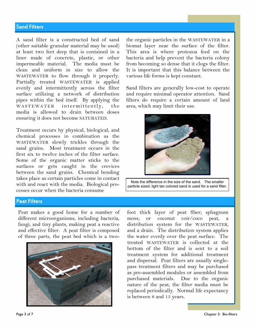
A sand filter is a constructed bed of sand (other suitable granular material may be used) at least two feet deep that is contained in a liner made of concrete, plastic, or other impermeable material. The media must be clean and uniform in size to allow the WASTEWATER to flow through it properly. Partially treated WASTEWATER is applied evenly and intermittently across the filter surface utilizing a network of distribution pipes within the bed itself. By applying the W A S T E W A T E R i ntermi t tent ly , the media is allowed to drain between doses ensuring it does not become SATURATED. Treatment occurs by physical, biological, and chemical processes in combination as the WASTEWATER slowly trickles through the sand grains. Most treatment occurs in the first six to twelve inches of the filter surface. Some of the organic matter sticks to the surfaces or gets caught in the crevices between the sand grains. Chemical bonding takes place as certain particles come in contact with and react with the media. Biological pro-cesses occur when the bacteria consume
the organic particles in the WASTEWATER in a biomat layer near the surface of the filter. This area is where protozoa feed on the bacteria and help prevent the bacteria colony from becoming so dense that it clogs the filter. It is important that this balance between the various life forms is kept constant. Sand filters are generally low-cost to operate and require minimal operator attention. Sand filters do require a certain amount of land area, which may limit their use.
Note the difference in the size of the sand. The smaller particle sized, light tan colored sand is used for a sand filter.
Peat Filters
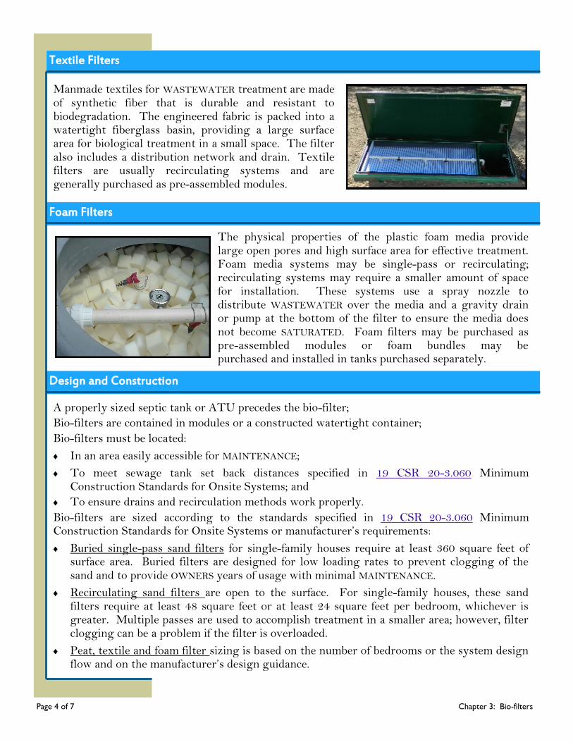
Peat makes a good home for a number of different microorganisms, including bacteria, fungi, and tiny plants, making peat a reactive and effective filter. A peat filter is composed of three parts, the peat bed which is a two-
foot thick layer of peat fiber; sphagnum moss; or coconut coir/coco peat, a distribution system for the WASTEWATER, and a drain. The distribution system applies the water evenly over the peat surface. The treated WASTEWATER is collected at the bottom of the filter and is sent to a soil treatment system for additional treatment and dispersal. Peat filters are usually single-pass treatment filters and may be purchased as pre-assembled modules or assembled from purchased materials. Due to the organic nature of the peat, the filter media must be replaced periodically. Normal life expectancy is between 8 and 15 years.
Page 3 of 7 Chapter 3: Bio-filters
Textile Filters
Manmade textiles for WASTEWATER treatment are made of synthetic fiber that is durable and resistant to biodegradation. The engineered fabric is packed into a watertight fiberglass basin, providing a large surface area for biological treatment in a small space. The filter also includes a distribution network and drain. Textile filters are usually recirculating systems and are generally purchased as pre-assembled modules.
Foam Filters
The physical properties of the plastic foam media provide large open pores and high surface area for effective treatment. Foam media systems may be single-pass or recirculating; recirculating systems may require a smaller amount of space for installation. These systems use a spray nozzle to distribute WASTEWATER over the media and a gravity drain or pump at the bottom of the filter to ensure the media does not become SATURATED. Foam filters may be purchased as pre-assembled modules or foam bundles may be purchased and installed in tanks purchased separately.
Design and Construction
A properly sized septic tank or ATU precedes the bio-filter;
Bio-filters are contained in modules or a constructed watertight container;
Bio-filters must be located:
In an area easily accessible for MAINTENANCE;
To meet sewage tank set back distances specified in 19 CSR 20-3.060 Minimum Construction Standards for Onsite Systems; and
To ensure drains and recirculation methods work properly.
Bio-filters are sized according to the standards specified in 19 CSR 20-3.060 Minimum Construction Standards for Onsite Systems or manufacturer’s requirements:
Buried single-pass sand filters for single-family houses require at least 360 square feet of surface area. Buried filters are designed for low loading rates to prevent clogging of the sand and to provide OWNERS years of usage with minimal MAINTENANCE.
Recirculating sand filters are open to the surface. For single-family houses, these sand filters require at least 48 square feet or at least 24 square feet per bedroom, whichever is greater. Multiple passes are used to accomplish treatment in a smaller area; however, filter clogging can be a problem if the filter is overloaded.
Peat, textile and foam filter sizing is based on the number of bedrooms or the system design flow and on the manufacturer’s design guidance.
Page 4 of 7 Chapter 3: Bio-filters
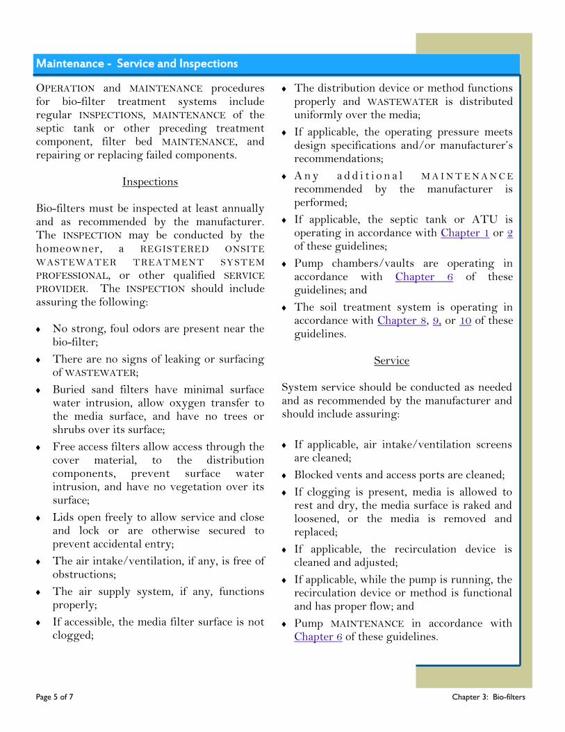
Maintenance - Service and Inspections
OPERATION and MAINTENANCE procedures for bio-filter treatment systems include regular INSPECTIONS, MAINTENANCE of the septic tank or other preceding treatment component, filter bed MAINTENANCE, and repairing or replacing failed components.
Inspections Bio-filters must be inspected at least annually and as recommended by the manufacturer. The INSPECTION may be conducted by the homeowner, a REGISTERED ONSITE WASTEWATER TREATMENT SYSTEM PROFESSIONAL, or other qualified SERVICE PROVIDER. The INSPECTION should include assuring the following: No strong, foul odors are present near the
bio-filter;
There are no signs of leaking or surfacing of WASTEWATER;
Buried sand filters have minimal surface water intrusion, allow oxygen transfer to the media surface, and have no trees or shrubs over its surface;
Free access filters allow access through the cover material, to the distribution components, prevent surface water intrusion, and have no vegetation over its surface;
Lids open freely to allow service and close and lock or are otherwise secured to prevent accidental entry;
The air intake/ventilation, if any, is free of obstructions;
The air supply system, if any, functions properly;
If accessible, the media filter surface is not clogged;
The distribution device or method functions properly and WASTEWATER is distributed uniformly over the media;
If applicable, the operating pressure meets design specifications and/or manufacturer’s recommendations;
A n y a d d i t i o n a l M A I N T E N A N C E recommended by the manufacturer is performed;
If applicable, the septic tank or ATU is operating in accordance with Chapter 1 or 2 of these guidelines;
Pump chambers/vaults are operating in accordance with Chapter 6 of these guidelines; and
The soil treatment system is operating in accordance with Chapter 8, 9, or 10 of these guidelines.
Service
System service should be conducted as needed and as recommended by the manufacturer and should include assuring:
If applicable, air intake/ventilation screens are cleaned;
Blocked vents and access ports are cleaned;
If clogging is present, media is allowed to rest and dry, the media surface is raked and loosened, or the media is removed and replaced;
If applicable, the recirculation device is cleaned and adjusted;
If applicable, while the pump is running, the recirculation device or method is functional and has proper flow; and
Pump MAINTENANCE in accordance with Chapter 6 of these guidelines.
Page 5 of 7 Chapter 3: Bio-filters
Maintenance - Pumping
If applicable, it is the responsibility of the homeowner or user of the system to contract with a REGISTERED ONSITE WASTEWATER TREATMENT SYSTEM PROFESSIONAL or other qualified SERVICE PROVIDER for the removal and sanitary disposal of solids from the recirculation tank when any other tank or compartment is pumped or the SLUDGE level is no more than two thirds of the volume below the pump intake.
The REGISTERED ONSITE WASTEWATER TREATMENT SYSTEM PROFESSIONAL or other qualified SERVICE PROVIDER is responsible for the proper treatment and disposal of all hauled WASTEWATER by transporting to a municipal SEWAGE treatment plant capable of receiving the waste; transporting to a SLUDGE handling facility which possesses a current and valid permit issued for such activity; or land applying under a current and valid permit for such activity.
Final Treatment and Dispersal
Although properly operated and maintained bio-filters can produce a highly treated WASTEWATER, it must receive further treatment before it is ready to be returned to the environment. Final treatment and dispersal options include gravity or pressure distribution soil treatment systems.
Warning Signs of System Malfunctioning
While proper use, INSPECTIONS, and MAINTENANCE should prevent most onsite system problems, it is still important to be aware of changes in your sewage system and to act quickly if you suspect the system is MALFUNCTIONING. The most obvious onsite system failures are easy to spot.
Alarms or lights activated;
Any changes in the normal appearance of the WASTEWATER in the pump tank or chamber;
Water pooling on the filter surface or near the filter;
Plumbing backups;
SEWAGE odors in the house, the filter area, or soil treatment area; and/or
Tests show the presence of bacteria in well water.
Onsite systems fail when partially treated WASTEWATER comes into contact with groundwater. This type of failure is not easy to detect, but can result in the pollution of wells, nearby streams, or other bodies of water. If you notice any of these signs, or you suspect your system may be having problems, contact a qualified SERVICE PROVIDER or local onsite WASTEWATER ADMINISTRATIVE AUTHORITY for assistance.
Page 6 of 7 Chapter 3: Bio-filters
DID YOU KNOW?
Studies have shown that many biofilters are
effective in reducing bacteria and nutrients in
WASTEWATER by 90% or more when compared to
septic tanks alone.

Proper OPERATION and MAINTENANCE of your onsite system can prevent costly repairs or replacement and can protect your property value. Observing the following recommendations will help to keep your system operating properly.
Obtain the necessary permits from the appropriate ADMINISTRATIVE AUTHORITY before making
any repairs.
Use a maintenance provider certified by the ATU manufacturer or other qualified SERVICE
PROVIDERS for routine INSPECTIONS, MAINTENANCE, and pumping; and if you experience
problems with the system, such as the alarm is activated or other warning signs the system may
be MALFUNCTIONING.
Maintain a service contract if available.
Have the system maintained regularly in accordance with the manufacturer’s or system
designer’s recommendations.
Keep the system accessible for INSPECTIONS and pumping; yet locked or otherwise secured to
prevent accidental entry.
Keep detailed records regarding the system, its location; make/model; contract service
agreement; service visits; and MAINTENANCE performed.
Have your private water well tested periodically or if you experience any warning signs of the
system MALFUNCTIONING (contact your local public health agency).
Don’t enter a sewage tank or filter container. Poisonous gasses or a lack of oxygen can be fatal.
Your onsite system is not a trash can. Don’t put dental floss, feminine hygiene products, flushable wipes, condoms, diapers, cotton swabs, cigarette butts, coffee grounds, cat litter, paper towels, paint, pesticides, or other hazardous chemicals into your system.
Don’t use caustic drain openers for a clogged drain. Instead, use boiling water or a drain snake to open clogs.
Don’t drive or park vehicles or allow livestock on any part of your onsite system. Doing so can compact the soil in your soil treatment area or damage the pipes, tank, or other onsite system components.
Don’t build over any part of your system; this includes patios, carports, and other structures.
Page 7 of 7 Chapter 3: Bio-filters
Bio-filter Do’s and Don’ts
Do’s
Don’ts

Chapter 4: Wetlands A Pretreatment Component
Chapter 4
The most common type of ONSITE WASTEWATER TREATMENT SYSTEM, a conventional septic tank and gravity dispersal trenches, is not suited for all soil conditions. For sites with limited land area, poor soil conditions, or where the water table is too high to allow the soil adequate time to treat the WASTEWATER before it reaches groundwater, additional treatment can be provided by constructed wetlands systems, also called vegetated submerged beds. Subsurface flow constructed wetlands are designed to use natural processes to
remove impurities from WASTEWATER through a combination of physical, biological and chemical processes. Free water surface wetlands are not allowed for onsite wastewater treatment because people and animals would be exposed to WASTEWATER at the wetlands surface. Wetlands systems are usually passive and require no energy, however, some effort will be needed to ensure a wetlands wastewater treatment system fits with your landscaping.
How a Wetlands Works
Natural wetlands, marshes, swamps, and bogs play an important role in protecting water quality. Constructed or artificial wetland systems mimic the treatment that occurs in natural wetlands by relying on plants and a combination of naturally occurring biological, chemical and physical processes to remove pollutants from the water. Because constructed wetland systems are designed specifically for WASTEWATER treatment, they typically work more efficiently than natural wetlands and can serve as an alternative when conventional systems are not suitable.
A wetlands may be designed to contain two cells or zones. They are constructed by excavating shallow earthen ponds, which may be lined, and are filled with up to 18 inches of river rock or other granular media and planted with aquatic vegetation. A septic tank or other pretreatment component precedes the wetlands to keep grease and larger solids from clogging the wetlands. WASTEWATER from the septic tank enters the front end of the wetlands and is spread out across the width of the bed through a perforated pipe. WASTEWATER flows through the media and plant roots where it is treated by attached bacteria and other microorganisms. At the back, or outfall, of the wetlands is another perforated pipe that collects the treated water. An adjustable device controls the water level and allows treated WASTEWATER to flow into a second cell, to a soil treatment system, or lagoon for further treatment.
What’s Ahead...
How a Wetlands
Works
Design and
Construction
Maintenance
Warning Signs
Do’s and Don’ts Glossary Resources
Page 1 of 5 Chapter 4: Wetlands

How a Wetlands Works, continued
The quality or level of treatment is determined by how long the WASTEWATER takes to pass through the media. During the growing season, plants use more water and increase the retention time; although roots still filter WASTEWATER when plants are dormant, retention time and water treatment is decreased. Wetlands provide reliable and passive treatment of WASTEWATER. The US Environmental Protection Agency has established five management models with progressively increasing management controls as sensitivity of the environment and/or treatment system complexity increases. MANAGEMENT MODEL I specifies appropriate program elements and activities where treatment systems are owned and operated by individual PROPERTY OWNERS in areas of low
environmental sensitivity.
The objective of this model is to ensure that-
Systems are designed and installed in accordance with appropriate state and local regulations;
Homeowners are knowledgeable of their particular system and provide routine MAINTENANCE (INSPECTIONS and pumping) necessary for the system to operate properly, and, if needed;
Homeowners ensure a MALFUNCTIONING system is repaired in accordance with Missouri law.
This model is generally appropriate for wetlands systems. However, in some sensitive environments, MANAGEMENT MODELS II, III, or IV may be recommended.
Page 2 of 5 Chapter 4: Wetlands
Wetland Plants
and Roots
Gravel Treatment Zone
Berm
Berm
Impermeable Liner
Outlet Gravel and
Collection Pipe
Adjustable
Height Outlet
Pretreated
Wastewater Wastewater
(Primary
Treatment )
Inlet Distribution -
Pipe and Gravel
Figure 1: Wetlands. A wetlands further treats wastewater from a septic tank before it is dispersed into the soil or discharged to a
single-family lagoon.
Design and Construction
Wetlands may be constructed with one or two zones or cells; the first cell must be sealed or lined to hold water and the second cell may be unlined to allow for some percolation of water.
Wetlands must be located:
In an area easily accessible for MAINTENANCE;
To meet sewage tank set back distances specified in 19 CSR 20-3.060 Minimum Construction Standards for Onsite Systems;
To ensure drains and dispersal methods work properly.
Wetlands sizing is based in part on winter temperatures; in mid-Missouri a typical wetlands’ surface area would be 330 square feet per bedroom.
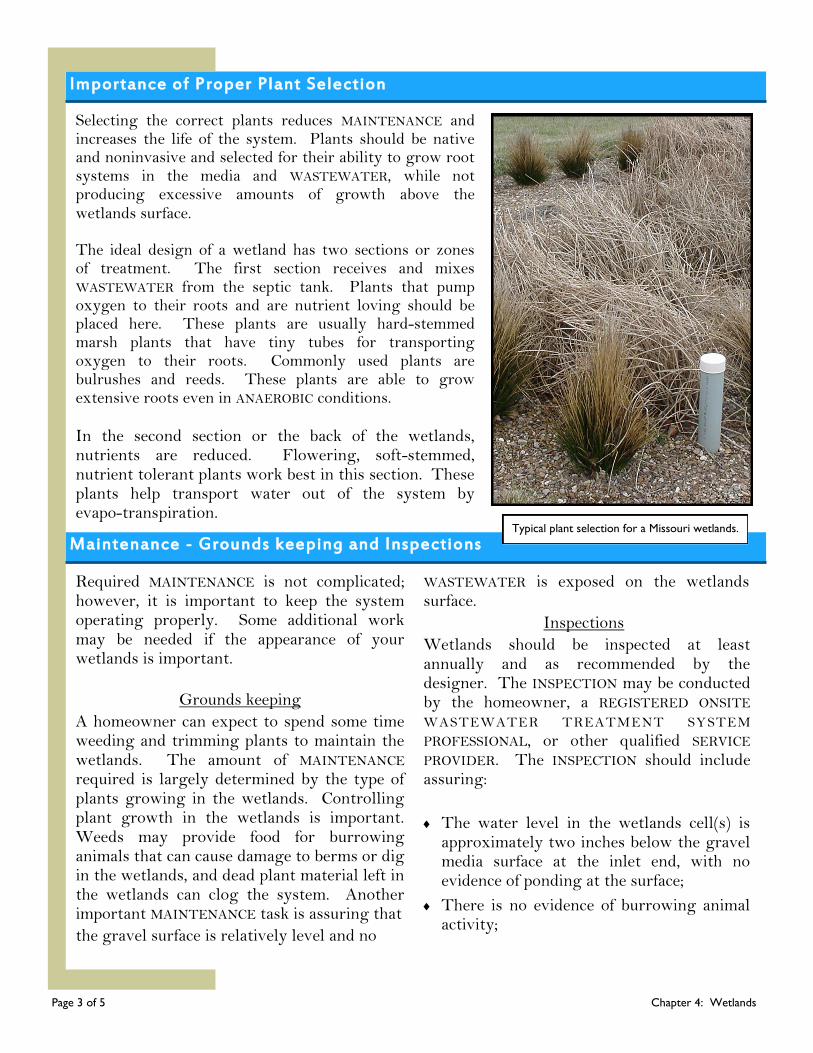
Importance of Proper Plant Selection
Selecting the correct plants reduces MAINTENANCE and increases the life of the system. Plants should be native and noninvasive and selected for their ability to grow root systems in the media and WASTEWATER, while not producing excessive amounts of growth above the wetlands surface. The ideal design of a wetland has two sections or zones of treatment. The first section receives and mixes WASTEWATER from the septic tank. Plants that pump oxygen to their roots and are nutrient loving should be placed here. These plants are usually hard-stemmed marsh plants that have tiny tubes for transporting oxygen to their roots. Commonly used plants are bulrushes and reeds. These plants are able to grow extensive roots even in ANAEROBIC conditions. In the second section or the back of the wetlands, nutrients are reduced. Flowering, soft-stemmed, nutrient tolerant plants work best in this section. These plants help transport water out of the system by evapo-transpiration.
Required MAINTENANCE is not complicated; however, it is important to keep the system operating properly. Some additional work may be needed if the appearance of your wetlands is important.
Grounds keeping
A homeowner can expect to spend some time weeding and trimming plants to maintain the wetlands. The amount of MAINTENANCE required is largely determined by the type of plants growing in the wetlands. Controlling plant growth in the wetlands is important. Weeds may provide food for burrowing animals that can cause damage to berms or dig in the wetlands, and dead plant material left in the wetlands can clog the system. Another important MAINTENANCE task is assuring that
the gravel surface is relatively level and no
WASTEWATER is exposed on the wetlands surface.
Inspections
Wetlands should be inspected at least annually and as recommended by the designer. The INSPECTION may be conducted by the homeowner, a REGISTERED ONSITE WASTEWATER TREATMENT SYSTEM PROFESSIONAL, or other qualified SERVICE PROVIDER. The INSPECTION should include assuring:
The water level in the wetlands cell(s) is approximately two inches below the gravel media surface at the inlet end, with no evidence of ponding at the surface;
There is no evidence of burrowing animal activity;
Maintenance - Grounds keeping and Inspections
Page 3 of 5 Chapter 4: Wetlands
Typical plant selection for a Missouri wetlands.
Maintenance - Inspections and Service
Inspections, continued
The berm and liner are in good condition, free
from evidence of leakage, erosion, or animal
burrows;
The water level control structure and lid/cover
is watertight;
Lids and covers are locked or otherwise
secured to prevent accidental entry;
A minimum freeboard distance of six inches is
maintained between the surface of the media
and the top of the berm;
No solids have collected in the inlet pipe;
Vegetation is maintained, with no trees or
shrubs near the cells;
The pretreatment component, such as a septic
tank or ATU, is operated and maintained in
accordance with Chapter 1 or 2 of these
guidelines;
If applicable, pump(s) function in accordance
with Chapter 6 of these guidelines; and
The soil treatment system is maintained in
accordance with Chapter 8, 9, or 10 of these
guidelines.
Service
The following MAINTENANCE items should be
routinely conducted to assure a properly
functioning wetlands:
Repair any leaks;
Manage water level to promote vegetation
growth and minimize freezing;
Remove brown or dormant vegetation during
winter months;
Level the gravel/media surface;
Check water level in cleanouts on the inlet
distribution pipe;
If applicable, clean the distribution pipe and
tees; and
Repair any erosion on berms.
Final Treatment and Dispersal
Although properly operated and maintained wetlands can produce cleaner EFFLUENT than a septic tank alone, the WASTEWATER leaving the wetlands must receive further treatment before it is ready to be returned to the environment. Final treatment and dispersal options include gravity or pressure distribution soil treatment systems or a lagoon system. Rainfall onto the wetlands surface area should be considered when designing a soil treatment system.
Warning Signs of System Malfunctioning
While proper use, INSPECTIONS, and MAINTENANCE should prevent most onsite system problems, it is still important to be aware of changes in your system and to act quickly if you suspect the system is MALFUNCTIONING. The most obvious onsite system failures are easy to spot.
Surfacing SEWAGE, pooling water or soggy soil around your wetlands;
Plumbing or septic tank backups;
SEWAGE odors in the house or yard;
Plants displaying signs of stress, such as, wilting or refusal to bloom; and/or
Tests show the presence of bacteria in well water.
Onsite systems fail when partially treated WASTEWATER comes into contact with groundwater. This type of failure is not easy to detect, but can result in the pollution of wells, nearby streams, or other bodies of water.
If you notice any of these signs or you suspect your onsite system may be having problems, contact a qualified SERVICE PROVIDER or the local onsite WASTEWATER ADMINISTRATIVE AUTHORITY for assistance.
Page 4 of 5 Chapter 4: Wetlands
Wetlands Do’s and Don’ts
Proper OPERATION and MAINTENANCE of an onsite system can prevent costly repairs or replacement and can protect your property value. Observing the following recommendations will help to keep your system operating properly.
Obtain the necessary permits from the appropriate ADMINISTRATIVE AUTHORITY before making any repairs.
Use REGISTERED ONSITE WASTEWATER SYSTEM PROFESSIONALS and qualified SERVICE PROVIDERS for routine INSPECTIONS, MAINTENANCE, and pumping; and if you experience problems or observe any warning signs that the system may be MALFUNCTIONING.
Conserve water to avoid overloading the onsite system, use high-efficiency fixtures and promptly repair any leaky faucets or toilets.
Have your system inspected annually and as recommended by the designer.
Have your septic tank pumped routinely. Pumping your septic tank when needed may be the single most important thing you can do to protect your wetlands system and your investment.
Landscape the system with appropriate aquatic vegetation; routinely check for signs of diseases and/or stress.
Replace dead plants as needed and remove “volunteer” weeds, trees, and shrubs from the wetland.
Use commercial bathroom cleaners and laundry detergents in moderation and only according to manufacturer’s directions.
Keep detailed records regarding the system, its location, make/model, contract service agreement, service visits, and MAINTENANCE performed.
Have your private water well tested periodically or if you experience any warning signs of the system MALFUNCTIONING (contact your local public health agency).
Don’t enter a sewage tank. Poisonous gasses or lack of oxygen can be fatal.
Your sewage system is not a trash can. Don’t put dental floss, feminine hygiene products, condoms, flushable wipes, diapers, cotton swabs, cigarette butts, coffee grounds, cat litter, paper towels, paint, pesticides, or other hazardous chemicals into your system.
Don’t use caustic drain openers for a clogged drain. Instead, use boiling water or a drain snake to open clogs.
Don’t drive or park vehicles or allow livestock on any part of your system. Doing so can compact the soil in your soil treatment area or damage the pipes, tank, wetlands, or other onsite system components.
Don’t apply herbicides or pesticides on or near the system.
Don’t plant a garden in your wetland. You risk the possibility of food contamination.
Don’t allow children or pets to play in the wetlands; they could come into contact with WASTEWATER that could make them sick.
Do’s
Don’ts
Page 5 of 5 Chapter 4: Wetlands

Chapter 5: Lagoons A Pretreatment Component
Chapter 5
Although a septic tank system is more commonly used, a wastewater lagoon system may be an option for single-family residences with slowly percolating, high clay content soils that are not steeply sloped. Lagoon systems include one or more pond-like bodies of water designed with long retention times to receive and treat WASTEWATER. While in the lagoon, WASTEWATER receives treatment through a combination of physical, biological, and chemical processes. A lagoon system must fit its specific site and use.
Designs are based on such factors as the type of soil, the amount of land area available, the slope, the climate, and the amount of sunlight and wind in the area. The most common type of wastewater treatment lagoon used by individual households is the FACULTATIVE lagoon, which are also called stabilization ponds, oxidation ponds, and photosynthetic ponds. They can be adapted for use in most climates, require no machinery, and treat WASTEWATER naturally, using both AEROBIC and ANAEROBIC processes.
How a Lagoon Works
Physical, biological, and chemical processes take place throughout a lagoon to treat WASTEWATER. In FACULTATIVE lagoons, WASTEWATER naturally settles into three fairly distinct layers or zones. Different conditions exist in each layer and treatment takes place in all three.
The top layer is an AEROBIC zone where wind and sunlight play important roles. The WASTEWATER in this part of the lagoon receives oxygen from air, surface agitation caused by wind and rain, and produced by algae. This oxygen makes conditions favorable for AEROBIC bacteria and other organisms living in this zone to treat WASTEWATER. This zone also serves as a barrier for the odors from gases produced by treatment processes occurring in the lower layers. Names for the middle layer include the facultative, intermediate, or AEROBIC-ANAEROBIC zone. Both AEROBIC and ANAEROBIC conditions exist in this layer in varying degrees. Depending on the specific conditions in any given part of this zone, different types of bacteria and other organisms contribute to WASTEWATER treatment.
What’s Ahead...
How a Lagoon
Works
Design and
Construction
Maintenance
Warning Signs
Do’s and Don’ts
Glossary
Resources
Page 1 of 7 Chapter 5: Lagoons
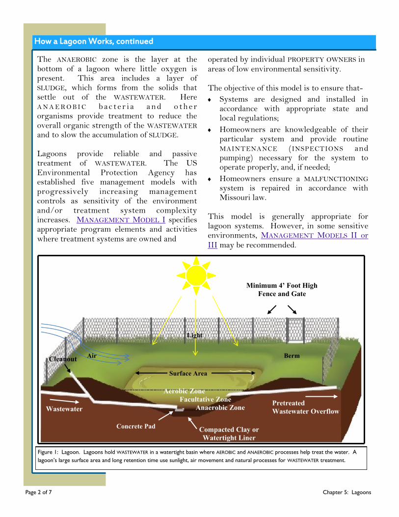
How a Lagoon Works, continued
The ANAEROBIC zone is the layer at the bottom of a lagoon where little oxygen is present. This area includes a layer of SLUDGE, which forms from the solids that settle out of the WASTEWATER. Here A N A E R O B I C b a c t e r i a a n d o t h e r organisms provide treatment to reduce the overall organic strength of the WASTEWATER and to slow the accumulation of SLUDGE. Lagoons provide reliable and passive treatment of WASTEWATER. The US Environmental Protection Agency has established five management models with progressively increasing management controls as sensitivity of the environment and/or treatment system complexity increases. MANAGEMENT MODEL I specifies appropriate program elements and activities where treatment systems are owned and
operated by individual PROPERTY OWNERS in areas of low environmental sensitivity. The objective of this model is to ensure that-
Systems are designed and installed in accordance with appropriate state and local regulations;
Homeowners are knowledgeable of their particular system and provide routine MAINTENANCE (INSPECTIONS and pumping) necessary for the system to operate properly, and, if needed;
Homeowners ensure a MALFUNCTIONING system is repaired in accordance with Missouri law.
This model is generally appropriate for lagoon systems. However, in some sensitive environments, MANAGEMENT MODELS II or III may be recommended.
Page 2 of 7 Chapter 5: Lagoons
Minimum 4’ Foot High
Fence and Gate
Light
Wastewater
Berm
Concrete Pad
Aerobic Zone
Facultative Zone
Anaerobic Zone Pretreated
Wastewater Overflow
Compacted Clay or
Watertight Liner
Air Cleanout
Figure 1: Lagoon. Lagoons hold WASTEWATER in a watertight basin where AEROBIC and ANAEROBIC processes help treat the water. A
lagoon’s large surface area and long retention time use sunlight, air movement and natural processes for WASTEWATER treatment.
Surface Area
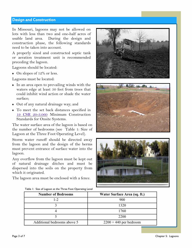
Design and Construction
In Missouri, lagoons may not be allowed on lots with less than two and one-half acres of usable land area. During the design and construction phase, the following standards need to be taken into account.
A properly sized and constructed septic tank or aeration treatment unit is recommended preceding the lagoon.
Lagoons should be located:
On slopes of 12% or less.
Lagoons must be located:
In an area open to prevailing winds with the waters edge at least 50 feet from trees that could inhibit wind action or shade the water surface;
Out of any natural drainage way; and
To meet the set back distances specified in 19 CSR 20-3.060 Minimum Construction Standards for Onsite Systems.
The water surface area of the lagoon is based on the number of bedrooms (see Table 1: Size of Lagoon at the Three Foot Operating Level).
Storm water runoff should be directed away from the lagoon and the design of the berms must prevent entrance of surface water into the lagoon.
Any overflow from the lagoon must be kept out of natural drainage ditches and must be dispersed into the soils on the property from which it originated.
The lagoon area must be enclosed with a fence.
Number of Bedrooms Water Surface Area (sq. ft.)
1-2 900
3 1320
4 1760
5 2200
Additional bedrooms above 5 2200 + 440 per bedroom
Page 3 of 7 Chapter 5: Lagoons
Table 1: Size of Lagoon at the Three Foot Operating Level
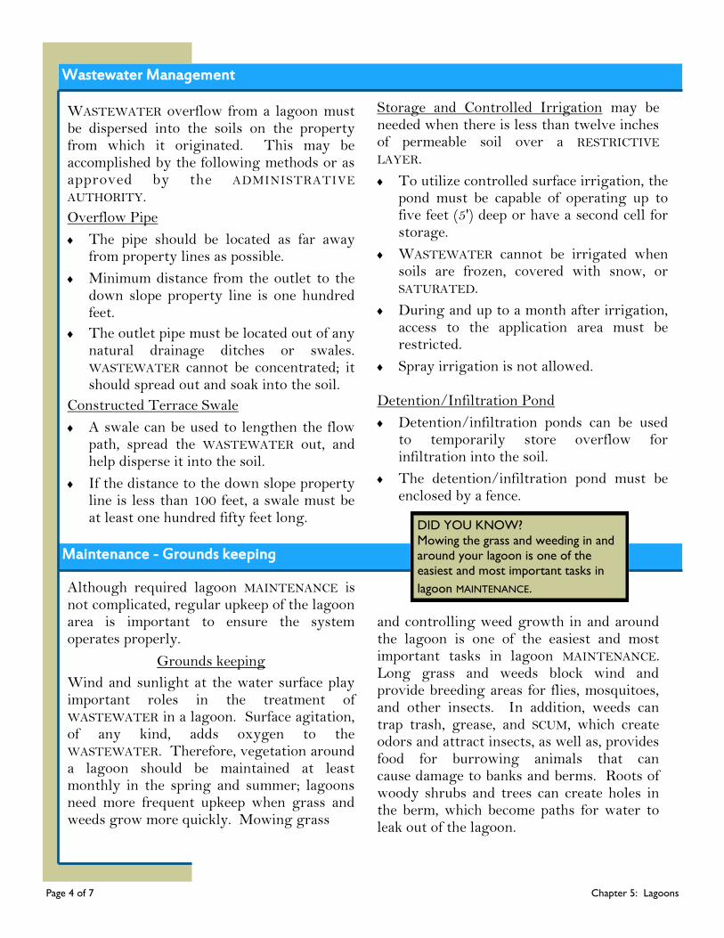
Wastewater Management
WASTEWATER overflow from a lagoon must be dispersed into the soils on the property from which it originated. This may be accomplished by the following methods or as approved by the ADMINISTRATIVE AUTHORITY.
Overflow Pipe
The pipe should be located as far away from property lines as possible.
Minimum distance from the outlet to the down slope property line is one hundred feet.
The outlet pipe must be located out of any natural drainage ditches or swales. WASTEWATER cannot be concentrated; it should spread out and soak into the soil.
Constructed Terrace Swale
A swale can be used to lengthen the flow path, spread the WASTEWATER out, and help disperse it into the soil.
If the distance to the down slope property line is less than 100 feet, a swale must be at least one hundred fifty feet long.
Storage and Controlled Irrigation may be needed when there is less than twelve inches of permeable soil over a RESTRICTIVE LAYER.
To utilize controlled surface irrigation, the pond must be capable of operating up to five feet (5') deep or have a second cell for storage.
WASTEWATER cannot be irrigated when soils are frozen, covered with snow, or SATURATED.
During and up to a month after irrigation, access to the application area must be restricted.
Spray irrigation is not allowed.
Detention/Infiltration Pond
Detention/infiltration ponds can be used to temporarily store overflow for infiltration into the soil.
The detention/infiltration pond must be enclosed by a fence.
Maintenance - Grounds keeping
Although required lagoon MAINTENANCE is not complicated, regular upkeep of the lagoon area is important to ensure the system operates properly.
Grounds keeping
Wind and sunlight at the water surface play important roles in the treatment of WASTEWATER in a lagoon. Surface agitation, of any kind, adds oxygen to the WASTEWATER. Therefore, vegetation around a lagoon should be maintained at least monthly in the spring and summer; lagoons need more frequent upkeep when grass and weeds grow more quickly. Mowing grass
and controlling weed growth in and around the lagoon is one of the easiest and most important tasks in lagoon MAINTENANCE. Long grass and weeds block wind and provide breeding areas for flies, mosquitoes, and other insects. In addition, weeds can trap trash, grease, and SCUM, which create odors and attract insects, as well as, provides food for burrowing animals that can cause damage to banks and berms. Roots of woody shrubs and trees can create holes in the berm, which become paths for water to leak out of the lagoon.
DID YOU KNOW?
Mowing the grass and weeding in and
around your lagoon is one of the
easiest and most important tasks in
lagoon MAINTENANCE.
Page 4 of 7 Chapter 5: Lagoons
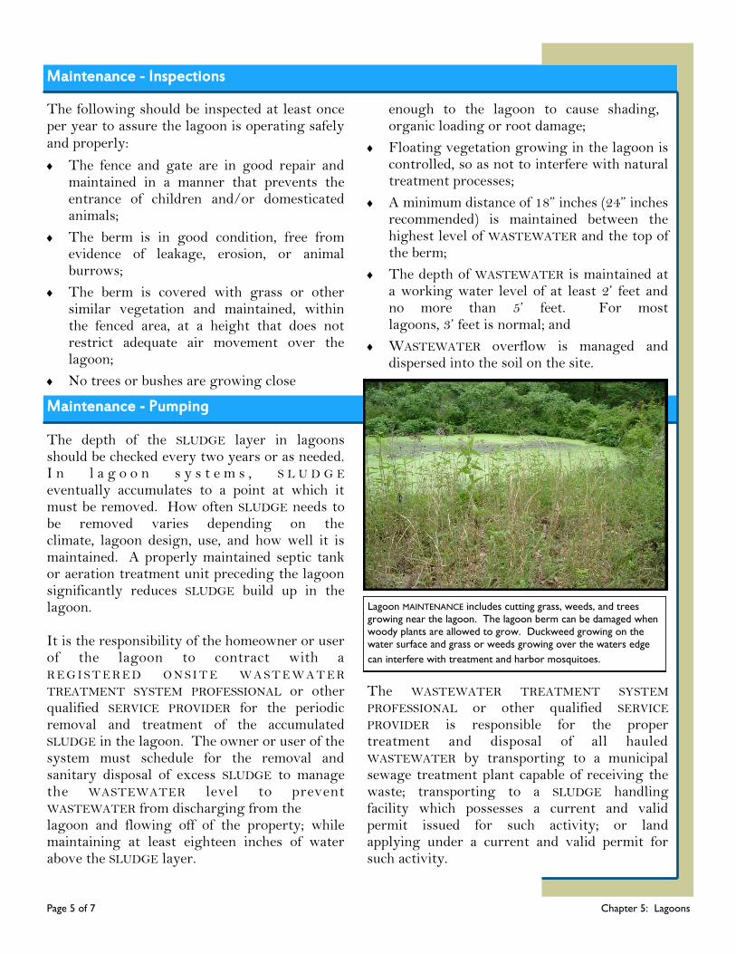
Maintenance - Inspections
The following should be inspected at least once per year to assure the lagoon is operating safely and properly:
The fence and gate are in good repair and maintained in a manner that prevents the entrance of children and/or domesticated animals;
The berm is in good condition, free from evidence of leakage, erosion, or animal burrows;
The berm is covered with grass or other similar vegetation and maintained, within the fenced area, at a height that does not restrict adequate air movement over the lagoon;
No trees or bushes are growing close
enough to the lagoon to cause shading, organic loading or root damage;
Floating vegetation growing in the lagoon is controlled, so as not to interfere with natural treatment processes;
A minimum distance of 18” inches (24” inches recommended) is maintained between the highest level of WASTEWATER and the top of the berm;
The depth of WASTEWATER is maintained at a working water level of at least 2’ feet and no more than 5’ feet. For most lagoons, 3’ feet is normal; and
WASTEWATER overflow is managed and dispersed into the soil on the site.
The depth of the SLUDGE layer in lagoons should be checked every two years or as needed. I n l a g o o n s y s t e m s , S L U D G E eventually accumulates to a point at which it must be removed. How often SLUDGE needs to be removed varies depending on the climate, lagoon design, use, and how well it is maintained. A properly maintained septic tank or aeration treatment unit preceding the lagoon significantly reduces SLUDGE build up in the lagoon. It is the responsibility of the homeowner or user of the lagoon to contract with a R E G I S T E R E D O N S I T E W A S T E W A T E R TREATMENT SYSTEM PROFESSIONAL or other qualified SERVICE PROVIDER for the periodic removal and treatment of the accumulated SLUDGE in the lagoon. The owner or user of the system must schedule for the removal and sanitary disposal of excess SLUDGE to manage the WASTEWATER level to prevent WASTEWATER from discharging from the lagoon and flowing off of the property; while maintaining at least eighteen inches of water above the SLUDGE layer.
The WASTEWATER TREATMENT SYSTEM PROFESSIONAL or other qualified SERVICE PROVIDER is responsible for the proper treatment and disposal of all hauled WASTEWATER by transporting to a municipal sewage treatment plant capable of receiving the waste; transporting to a SLUDGE handling facility which possesses a current and valid permit issued for such activity; or land applying under a current and valid permit for such activity.
Maintenance - Pumping
Page 5 of 7 Chapter 5: Lagoons
Lagoon MAINTENANCE includes cutting grass, weeds, and trees
growing near the lagoon. The lagoon berm can be damaged when
woody plants are allowed to grow. Duckweed growing on the
water surface and grass or weeds growing over the waters edge
can interfere with treatment and harbor mosquitoes.

Warning Signs of System Malfunctioning
While proper use, INSPECTIONS, and MAINTENANCE should prevent most lagoon problems, it is still important to be aware of changes in your system and to act quickly if you suspect the system is MALFUNCTIONING. The most obvious lagoon issues are easy to spot.
The presence of weeds and long grass along the berm. The berm must to be mowed and weeded regularly;
The presence of duckweed, watermeal, or hyacinth growing on water surface. These plants should be physically removed;
The presence of blue-green algae. This algae is stringy and can clump and block sunlight; it can dominate lagoons when conditions are poor, when pH is low, or when protozoa eat all of the green algae. Blue-green algae can be physically removed like duckweed;
The presence of an algal bloom. This may occur after periods of cloudy weather or abrupt temperature changes. Matted algae on the surface can block sunlight and cause foul odors and should be broken up and dispersed;
The presence of odors. Lagoons may occasionally have odors from algal blooms, ANAEROBIC conditions, SCUM, and turnover of the lagoon contents in spring or by temporary overloading, ice cover, or atmospheric conditions. These odors may be controlled by broadcasting sodium or ammonium nitrate over the surface of the pond. In general, the amount of sodium or ammonium nitrate should not exceed two pounds per day until the odor dissipates;
The observation of short circuiting, or dead spots in the flow pattern, due to obstructions in the lagoon or to wind on the surface. This can cause WASTEWATER
to leave the lagoon too quickly, resulting in inadequate treatment of the WASTEWATER;
The presence of erosion. Controlling burrowing animals around the lagoon can help prevent erosion of berms;
The presence of burrowing animals; muskrats and other burrowing animals can be discouraged by weeding and mowing the lagoon berms;
The change of water color. Bright rich green color indicates good conditions; dull green or yellowish color can indicate an undesirable type of algae is becoming dominant in the lagoon; gray or black col-or can indicate ANAEROBIC conditions; and tan, brown or red color can indicate either soil in the water from berm erosion or the presence of algae with different pigmentation; and
The presence of SLUDGE accumulation. SLUDGE in the bottom of lagoons should be measured at least once per year and removed as needed.
Onsite systems fail when partially treated WASTEWATER comes into contact with groundwater. This type of failure is not easy to detect, but can result in the pollution of wells, nearby streams, or other bodies of water. If you notice any of these signs or you suspect your system may be having problems, contact a qualified SERVICE PROVIDER or the local onsite WASTEWATER ADMINISTRATIVE AUTHORITY for assistance.
Page 6 of 7 Chapter 5: Lagoons
Lagoon Do’s and Don’ts
Proper OPERATION and MAINTENANCE of your onsite system can prevent costly repairs or replacement and can protect your property value. Observing the following recommendations will help to keep your system operating properly.
Do’s
Obtain the necessary permits from the appropriate ADMINISTRATIVE AUTHORITY before making any repairs.
Use REGISTERED ONSITE WASTEWATER TREATMENT SYSTEM PROFESSIONALS and qualified SERVICE PROVIDERS.
Keep the system accessible for INSPECTIONS and pumping; yet locked or otherwise secured to prevent accidental entry.
Have your septic tank inspected annually if it has an EFFLUENT screen or every two years if it does not.
Have your septic tank pumped routinely. Pumping your septic tank when needed may be the single most important thing you can do to protect your soil treatment system and your investment.
Keep detailed records regarding the system, its location, contract service agreement, service visits, and MAINTENANCE performed.
Conserve water to avoid overloading the onsite system, use high-efficiency fixtures and promptly repair any leaky faucets or toilets.
Divert other sources of water, like roof drains, house footing drains, and sump pumps away from the soil treatment area.
Have your private water well tested periodically or if you experience any warning signs of the system MALFUNCTIONING (contact your local public health agency).
Don’ts
Don’t enter a sewage tank. Poisonous gasses or a lack of oxygen can be fatal.
Don’t allow the overflow from the lagoon to leave your property, even during wet weather.
Don’t plant a garden, trees, or shrubbery near the lagoon. This could cause shading, SLUDGE build-up, and increase odor levels.
Your sewage system is not a trash can. Don’t put dental floss, feminine hygiene products, flushable wipes, condoms, diapers, cotton swabs, cigarette butts, coffee grounds, cat litter, paper towels, paint, pesticides, or other hazardous chemicals into your system.
Don’t allow children or pets to play in the lagoon; they could come into contact with WASTEWATER that could make them sick.
Don’t drive or park vehicles or allow livestock on any part of your sewage tank system. Doing so can compact the soil or damage the pipes, tank, or other onsite system components.
Don’t build over any part of your system; this includes patios, carports, and other structures.
Page 7 of 7 Chapter 5: Lagoons
Chapter 6: Pumps and Pump Tanks
Pumps are used to move WASTEWATER to other parts of an ONSITE WASTEWATER TREATMENT SYSTEM. A pumping system consists of three key parts – the pump tank, the pump, and the controls. How the onsite system is designed to move WASTEWATER determines where the pump is located; and the location of the pump often impacts the sizing and appearance of the three components. Pump tanks are used in several types of ONSITE WASTEWATER TREATMENT SYSTEMS, including dose to gravity, low-pressure distribution,
subsurface drip distribution, and bio-filter systems. Each of these systems includes a pretreatment component, a pump tank, and soil treatment system. Dosing is the intermittent application of a set volume of WASTEWATER to the next component of the onsite system. Dosing to a gravity dispersal system or the use of pressure distribution help to spread WASTEWATER more evenly in the soil treatment area and promote better treatment. Dosing a bio-filter or other pretreatment component can achieve a high level of WASTEWATER treatment.
Chapter 6
A pump tank collects and stores WASTEWATER from the septic tank or other pretreatment component which is then dosed to the next component in the ONSITE WASTEWATER TREATMENT SYSTEM. It can be an individual tank or a separate compartment within a septic tank. The tank must be large enough to store the volume of WASTEWATER pumped during dosing, plus the minimum level of WASTEWATER needed for the pump to operate properly and a reserve capacity
to allow time for a service call if the pump MALFUNCTIONS. Small pump basins are sometimes used; however, they have very limited emergency reserve capacity. To minimize the amount of solids pumped to the next system component, the system must have some type of filter or screen. Options include an EFFLUENT screen in the sewage tank outlet, a filtered pump vault or screen basket to contain the pump, and/or a screen or disc filter in the pressure line. A pump system can be dosed either on demand or by a timer. Demand dosing is a common method used for delivering WASTEWATER to soil
How a Pump and Pump Tank Works
What’s Ahead...
How a Pump and
Pump Tank Works
Design and
Construction
Maintenance
Warning Signs
Do’s and Don’ts Glossary Resources
Page 1 of 5 Chapter 6: Pumps and Pump Tanks
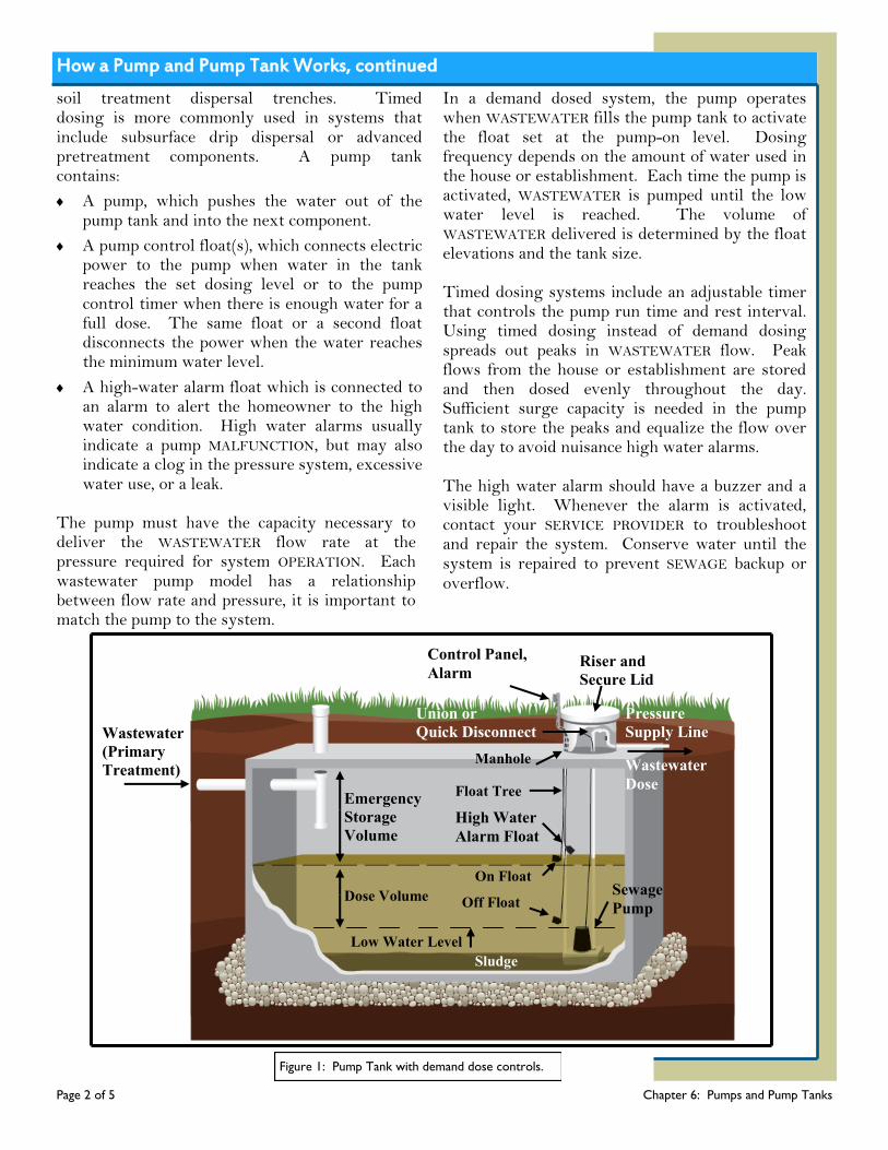
How a Pump and Pump Tank Works, continued
soil treatment dispersal trenches. Timed dosing is more commonly used in systems that include subsurface drip dispersal or advanced pretreatment components. A pump tank contains:
A pump, which pushes the water out of the pump tank and into the next component.
A pump control float(s), which connects electric power to the pump when water in the tank reaches the set dosing level or to the pump control timer when there is enough water for a full dose. The same float or a second float disconnects the power when the water reaches the minimum water level.
A high-water alarm float which is connected to an alarm to alert the homeowner to the high water condition. High water alarms usually indicate a pump MALFUNCTION, but may also indicate a clog in the pressure system, excessive water use, or a leak.
The pump must have the capacity necessary to deliver the WASTEWATER flow rate at the pressure required for system OPERATION. Each wastewater pump model has a relationship between flow rate and pressure, it is important to match the pump to the system.
In a demand dosed system, the pump operates when WASTEWATER fills the pump tank to activate the float set at the pump-on level. Dosing frequency depends on the amount of water used in the house or establishment. Each time the pump is activated, WASTEWATER is pumped until the low water level is reached. The volume of WASTEWATER delivered is determined by the float elevations and the tank size. Timed dosing systems include an adjustable timer that controls the pump run time and rest interval. Using timed dosing instead of demand dosing spreads out peaks in WASTEWATER flow. Peak flows from the house or establishment are stored and then dosed evenly throughout the day. Sufficient surge capacity is needed in the pump tank to store the peaks and equalize the flow over the day to avoid nuisance high water alarms. The high water alarm should have a buzzer and a visible light. Whenever the alarm is activated, contact your SERVICE PROVIDER to troubleshoot and repair the system. Conserve water until the system is repaired to prevent SEWAGE backup or overflow.
Page 2 of 5 Chapter 6: Pumps and Pump Tanks
Off Float
On Float
Wastewater
(Primary
Treatment)
Emergency
Storage
Volume
Dose Volume
Low Water Level
Sludge
Pressure
Supply Line
Wastewater
Dose
Sewage
Pump
High Water
Alarm Float
Float Tree
Manhole
Control Panel,
Alarm
Union or
Quick Disconnect
Riser and
Secure Lid
Figure 1: Pump Tank with demand dose controls.
On Float
Off Float
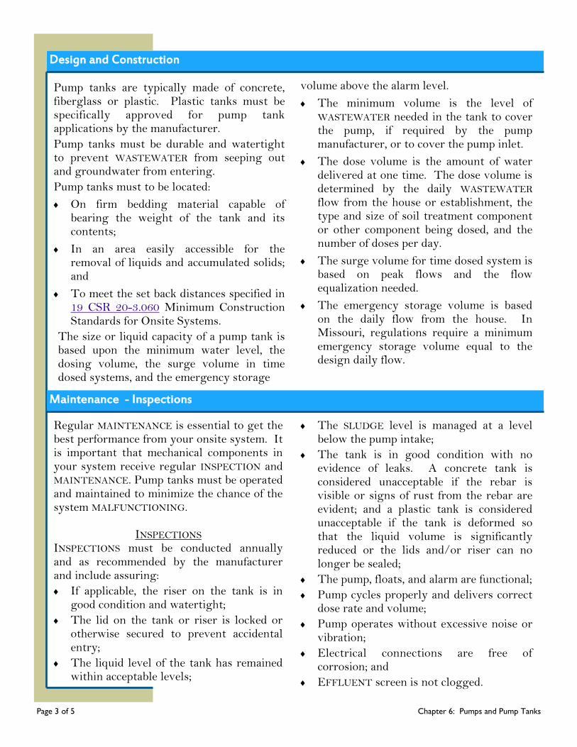
Design and Construction
Pump tanks are typically made of concrete, fiberglass or plastic. Plastic tanks must be specifically approved for pump tank applications by the manufacturer.
Pump tanks must be durable and watertight to prevent WASTEWATER from seeping out and groundwater from entering.
Pump tanks must to be located:
On firm bedding material capable of bearing the weight of the tank and its contents;
In an area easily accessible for the removal of liquids and accumulated solids; and
To meet the set back distances specified in 19 CSR 20-3.060 Minimum Construction Standards for Onsite Systems.
The size or liquid capacity of a pump tank is based upon the minimum water level, the dosing volume, the surge volume in time dosed systems, and the emergency storage
volume above the alarm level.
The minimum volume is the level of WASTEWATER needed in the tank to cover the pump, if required by the pump manufacturer, or to cover the pump inlet.
The dose volume is the amount of water delivered at one time. The dose volume is determined by the daily WASTEWATER flow from the house or establishment, the type and size of soil treatment component or other component being dosed, and the number of doses per day.
The surge volume for time dosed system is based on peak flows and the flow equalization needed.
The emergency storage volume is based on the daily flow from the house. In Missouri, regulations require a minimum emergency storage volume equal to the design daily flow.
Maintenance - Inspections
Regular MAINTENANCE is essential to get the best performance from your onsite system. It is important that mechanical components in your system receive regular INSPECTION and MAINTENANCE. Pump tanks must be operated and maintained to minimize the chance of the system MALFUNCTIONING.
INSPECTIONS INSPECTIONS must be conducted annually and as recommended by the manufacturer and include assuring:
If applicable, the riser on the tank is in good condition and watertight;
The lid on the tank or riser is locked or otherwise secured to prevent accidental entry;
The liquid level of the tank has remained within acceptable levels;
The SLUDGE level is managed at a level below the pump intake;
The tank is in good condition with no evidence of leaks. A concrete tank is considered unacceptable if the rebar is visible or signs of rust from the rebar are evident; and a plastic tank is considered unacceptable if the tank is deformed so that the liquid volume is significantly reduced or the lids and/or riser can no longer be sealed;
The pump, floats, and alarm are functional;
Pump cycles properly and delivers correct dose rate and volume;
Pump operates without excessive noise or vibration;
Electrical connections are free of corrosion; and
EFFLUENT screen is not clogged.
Page 3 of 5 Chapter 6: Pumps and Pump Tanks
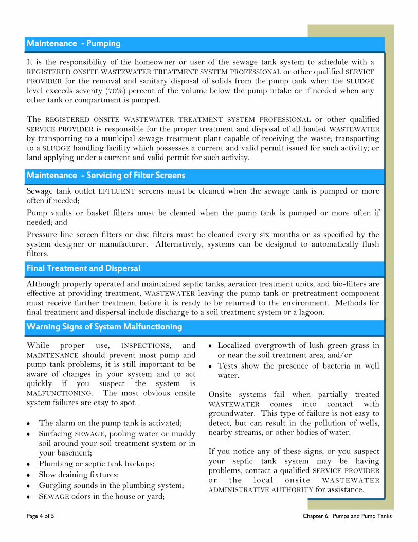
Maintenance - Pumping
It is the responsibility of the homeowner or user of the sewage tank system to schedule with a REGISTERED ONSITE WASTEWATER TREATMENT SYSTEM PROFESSIONAL or other qualified SERVICE PROVIDER for the removal and sanitary disposal of solids from the pump tank when the SLUDGE level exceeds seventy (70%) percent of the volume below the pump intake or if needed when any other tank or compartment is pumped.
The REGISTERED ONSITE WASTEWATER TREATMENT SYSTEM PROFESSIONAL or other qualified SERVICE PROVIDER is responsible for the proper treatment and disposal of all hauled WASTEWATER by transporting to a municipal sewage treatment plant capable of receiving the waste; transporting to a SLUDGE handling facility which possesses a current and valid permit issued for such activity; or land applying under a current and valid permit for such activity.
Maintenance - Servicing of Filter Screens
Sewage tank outlet EFFLUENT screens must be cleaned when the sewage tank is pumped or more often if needed;
Pump vaults or basket filters must be cleaned when the pump tank is pumped or more often if needed; and
Pressure line screen filters or disc filters must be cleaned every six months or as specified by the system designer or manufacturer. Alternatively, systems can be designed to automatically flush filters.
Although properly operated and maintained septic tanks, aeration treatment units, and bio-filters are effective at providing treatment, WASTEWATER leaving the pump tank or pretreatment component must receive further treatment before it is ready to be returned to the environment. Methods for final treatment and dispersal include discharge to a soil treatment system or a lagoon.
Final Treatment and Dispersal
Warning Signs of System Malfunctioning
While proper use, INSPECTIONS, and MAINTENANCE should prevent most pump and pump tank problems, it is still important to be aware of changes in your system and to act quickly if you suspect the system is MALFUNCTIONING. The most obvious onsite system failures are easy to spot.
The alarm on the pump tank is activated;
Surfacing SEWAGE, pooling water or muddy soil around your soil treatment system or in your basement;
Plumbing or septic tank backups;
Slow draining fixtures;
Gurgling sounds in the plumbing system;
SEWAGE odors in the house or yard;
Localized overgrowth of lush green grass in or near the soil treatment area; and/or
Tests show the presence of bacteria in well water.
Onsite systems fail when partially treated WASTEWATER comes into contact with groundwater. This type of failure is not easy to detect, but can result in the pollution of wells, nearby streams, or other bodies of water. If you notice any of these signs, or you suspect your septic tank system may be having problems, contact a qualified SERVICE PROVIDER or the local onsite WASTEWATER ADMINISTRATIVE AUTHORITY for assistance.
Page 4 of 5 Chapter 6: Pumps and Pump Tanks

Pump Tank Do’s and Don’ts
Proper OPERATION and MAINTENANCE of an onsite system can prevent costly repairs or replacement and can protect your property value. Observing the following recommendations will help to keep your system operating properly.
Do’s
Obtain the necessary permits from the appropriate ADMINISTRATIVE AUTHORITY before making any repairs.
Use REGISTERED ONSITE WASTEWATER TREATMENT SYSTEM PROFESSIONALS and qualified SERVICE PROVIDERS.
Conserve water to avoid overloading the onsite system, use high-efficiency fixtures and promptly repair any leaky faucets or toilets.
Pump your pump tank at the same frequency as your septic tank or other pretreatment component. This may be the single most important thing you can do to protect your soil treatment system and your investment.
Divert other sources of water, like roof drains, house footing drains, and sump pumps away from the soil treatment area.
Landscape the system properly. Plant grass over and near the soil treatment system; roots from nearby trees or shrubs might clog and damage the system.
Contact a qualified SERVICE PROVIDER if you experience problems with your system, such as surfacing WASTEWATER in your yard or other warning signs the system may be MALFUNCTIONING.
Keep detailed records regarding the system, its location, make/model, contract service agreement, service visits, and MAINTENANCE performed.
Use commercial bathroom cleaners and laundry detergents in moderation and only according to manufacturer’s directions.
Keep your pump tank accessible for INSPECTIONS and pumping; yet locked or otherwise secured to prevent accidental entry.
Have your private water well tested periodically or if you experience any warning signs of the system MALFUNCTIONING (contact your local public health agency).
If your pump tank alarm is activated – contact your SERVICE PROVIDER promptly to repair the system and minimize your water usage in the interim.
Don’t enter a pump tank or septic tank. Poisonous gasses or a lack of oxygen can be fatal. Your septic tank system is not a trash can. Don’t put dental floss, feminine hygiene products,
flushable wipes, condoms, diapers, cotton swabs, cigarette butts, coffee grounds, cat litter, paper towels, paint, pesticides, or other hazardous chemicals into your system.
Don’t use caustic drain openers for a clogged drain. Instead, use boiling water or a drain snake to open clogs.
Don’t drive or park vehicles or allow livestock on any part of your septic tank system. Doing so can compact the soil in your soil treatment area or damage the pipes, tanks, or other onsite system components.
Don’t build over any part of your septic tank system; this includes patios, carports, and other structures.
Don’t attempt to pump your own pump tank or septic tank; use the services of a qualified SERVICE PROVIDER.
Don’ts
Page 5 of 5 Chapter 6: Pumps and Pump Tanks
Chapter 7
Chapter 7: Effluent Screens
Page 1 of 5 Chapter 7: Effluent Screens
What’s Ahead...
How an Effluent
Screen Work
Design and
Construction
Maintenance
Do’s and Don’ts Glossary Resources
A septic tank with soil dispersal trenches is a common wastewater treatment system that uses an underground tank designed to collect and pre-treat WASTEWATER from your home or establishment. As WASTEWATER flows into the tank, heavier materials settle to the bottom and form a SLUDGE layer, while lighter greases and fats float to the top, forming a SCUM layer. Clarified EFFLUENT is discharged from the center layer of the tank into a soil treatment system where it is dispersed into the surrounding soils. However, if solids leave the tank, the soil at the bottom of the dispersal trenches can clog. When clogging occurs, WASTEWATER is not dispersed or treated effectively, which can cause WASTEWATER to backup into the building or come to the ground surface. It can potentially lead to expensive repairs or replacement of the soil treatment system.
The use of EFFLUENT screens is becoming more common. Usually, an EFFLUENT screen is placed in the outlet tee of the septic tank to enhance solids retention in the tank; helping to prevent blockages and clogging that can damage the soil treatment system. Screens come in a variety of shapes and sizes and can often be retrofitted into existing septic tanks or can be installed in a separate basin following the septic tank.
DID YOU KNOW? EFFLUENT screens may sometimes be referred to as
EFFLUENT filters. EFFLUENT screens can be located in places other than a septic tank outlet. For example,
wastewater treatment systems that have a pump often use screens instead of, or in addition to, an
EFFLUENT screen located in the septic tank outlet. Also, some aeration treatment units have an EFFLUENT screen
or filter. Other types of screens include screened pump baskets, screened pump vaults, fabric filters, and screens
or disc filters designed to be installed in the pressure
line.
How an Effluent Screen Works
The simplest EFFLUENT screens are slotted cartridges that are inserted in the septic tank’s outlet tee with seals so that WASTEWATER must pass through the slots to leave the tank. Any solids that are larger than the slots will be retained in the tank. Over time, retained solids collect on the screen and clog the slots. Although this indicates the screen is working, screens must be cleaned periodically to avoid sluggish drains, SEWAGE backups, or sewage tank overflows.
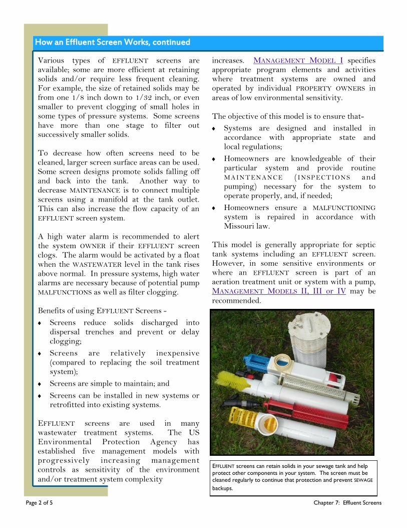
How an Effluent Screen Works, continued
Page 2 of 5 Chapter 7: Effluent Screens
Various types of EFFLUENT screens are available; some are more efficient at retaining solids and/or require less frequent cleaning. For example, the size of retained solids may be from one 1/8 inch down to 1/32 inch, or even smaller to prevent clogging of small holes in some types of pressure systems. Some screens have more than one stage to filter out successively smaller solids. To decrease how often screens need to be cleaned, larger screen surface areas can be used. Some screen designs promote solids falling off and back into the tank. Another way to decrease MAINTENANCE is to connect multiple screens using a manifold at the tank outlet. This can also increase the flow capacity of an EFFLUENT screen system. A high water alarm is recommended to alert the system OWNER if their EFFLUENT screen clogs. The alarm would be activated by a float when the WASTEWATER level in the tank rises above normal. In pressure systems, high water alarms are necessary because of potential pump MALFUNCTIONS as well as filter clogging. Benefits of using EFFLUENT Screens -
Screens reduce solids discharged into dispersal trenches and prevent or delay clogging;
Screens are relatively inexpensive (compared to replacing the soil treatment system);
Screens are simple to maintain; and
Screens can be installed in new systems or retrofitted into existing systems.
EFFLUENT screens are used in many wastewater treatment systems. The US Environmental Protection Agency has established five management models with progressively increasing management controls as sensitivity of the environment and/or treatment system complexity
increases. MANAGEMENT MODEL I specifies appropriate program elements and activities where treatment systems are owned and operated by individual PROPERTY OWNERS in areas of low environmental sensitivity.
The objective of this model is to ensure that-
Systems are designed and installed in accordance with appropriate state and local regulations;
Homeowners are knowledgeable of their particular system and provide routine MAINT EN ANC E ( I NSP ECTION S and pumping) necessary for the system to operate properly, and, if needed;
Homeowners ensure a MALFUNCTIONING system is repaired in accordance with Missouri law.
This model is generally appropriate for septic tank systems including an EFFLUENT screen. However, in some sensitive environments or where an EFFLUENT screen is part of an aeration treatment unit or system with a pump, MANAGEMENT MODELS II, III or IV may be recommended.
EFFLUENT screens can retain solids in your sewage tank and help
protect other components in your system. The screen must be
cleaned regularly to continue that protection and prevent SEWAGE
backups.
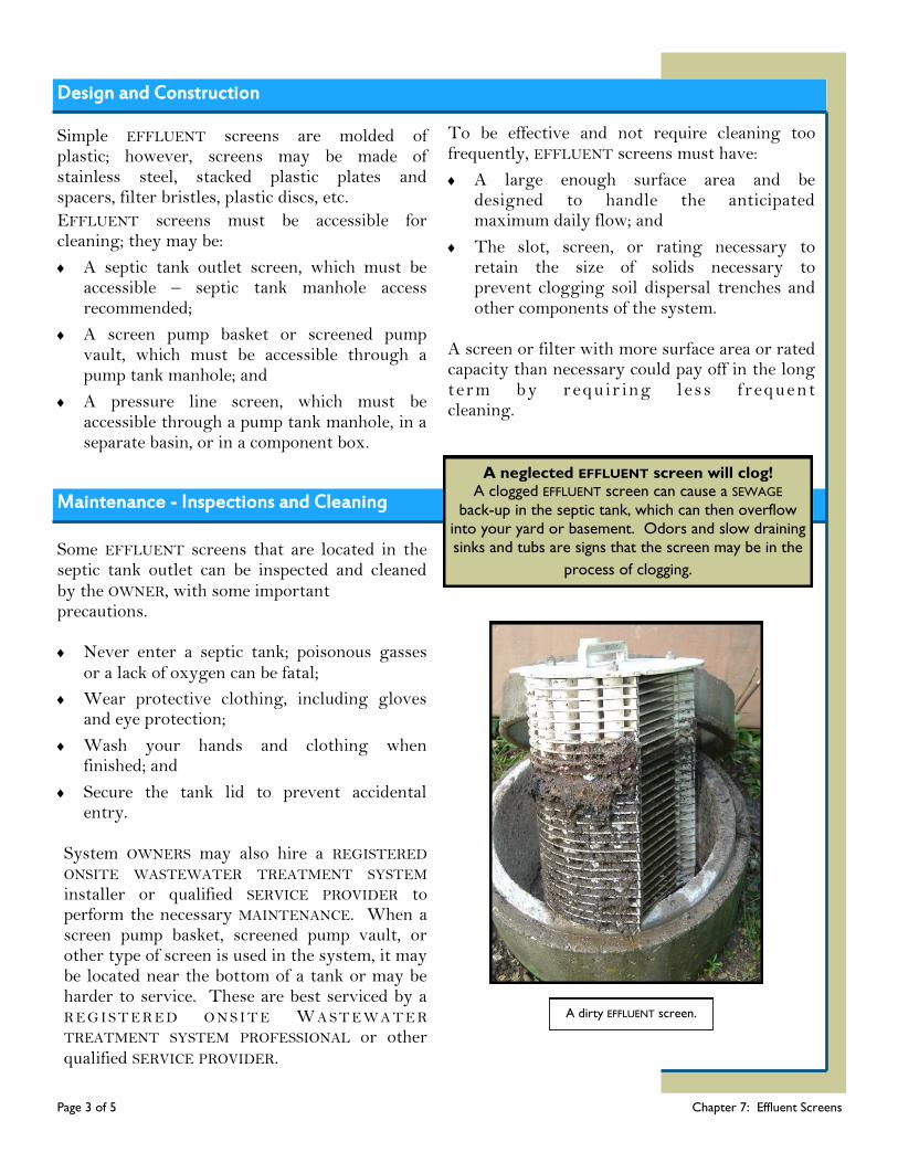
Design and Construction
Page 3 of 5 Chapter 7: Effluent Screens
Simple EFFLUENT screens are molded of plastic; however, screens may be made of stainless steel, stacked plastic plates and spacers, filter bristles, plastic discs, etc.
EFFLUENT screens must be accessible for cleaning; they may be:
A septic tank outlet screen, which must be accessible – septic tank manhole access recommended;
A screen pump basket or screened pump vault, which must be accessible through a pump tank manhole; and
A pressure line screen, which must be accessible through a pump tank manhole, in a separate basin, or in a component box.
To be effective and not require cleaning too frequently, EFFLUENT screens must have:
A large enough surface area and be designed to handle the anticipated maximum daily flow; and
The slot, screen, or rating necessary to retain the size of solids necessary to prevent clogging soil dispersal trenches and other components of the system.
A screen or filter with more surface area or rated capacity than necessary could pay off in the long term by r equ ir ing l ess f requent cleaning.
Maintenance - Inspections and Cleaning
Some EFFLUENT screens that are located in the septic tank outlet can be inspected and cleaned by the OWNER, with some important precautions. Never enter a septic tank; poisonous gasses
or a lack of oxygen can be fatal;
Wear protective clothing, including gloves and eye protection;
Wash your hands and clothing when finished; and
Secure the tank lid to prevent accidental entry.
System OWNERS may also hire a REGISTERED ONSITE WASTEWATER TREATMENT SYSTEM installer or qualified SERVICE PROVIDER to perform the necessary MAINTENANCE. When a screen pump basket, screened pump vault, or other type of screen is used in the system, it may be located near the bottom of a tank or may be harder to service. These are best serviced by a R E G I S T E R E D O N S I T E W A S T E W A T E R TREATMENT SYSTEM PROFESSIONAL or other qualified SERVICE PROVIDER.
A neglected EFFLUENT screen will clog! A clogged EFFLUENT screen can cause a SEWAGE
back-up in the septic tank, which can then overflow
into your yard or basement. Odors and slow draining
sinks and tubs are signs that the screen may be in the
process of clogging.
A dirty EFFLUENT screen.

Maintenance - Inspections and Cleaning, continued
Page 4 of 5 Chapter 7: Effluent Screens
EFFLUENT screen in septic tank outlet:
Remove the access cover over the tank outlet;
Observe the WASTEWATER level in the tank in relation to the outlet level;
If the WASTEWATER level is high, it must be lowered before inspecting and cleaning the filter. Lower the level by allowing WASTEWATER to drain while using no water in the house or establishment or by contracting for the removal and sanitary disposal of WASTEWATER and SLUDGE from the tank;
If the WASTEWATER level is at the bottom of the outlet pipe, remove the screen;
Follow manufacturer’s recommendations. Clean the screen over the tank inlet manhole using water spray and direct the solids and spray into the tank;
Replace the screen; and
Secure the tank access cover(s).
EFFLUENT screens in other locations:
Remove access cover(s);
If necessary, pump out WASTEWATER to the next system component or with a vacuum truck;
Disable the pump;
If possible, close valves to isolate screen(s);
Remove and inspect the condition of screen;
F o l l o w t h e m a n u f a c t u r e r ’ s recommendations. Spray the screen to clean it over a tank access and direct the solids and spray into the tank, or alternatively, replace with clean screen and take the clogged screen off site for cleaning;
Replace the screen, open valves, and enable the pump;
Check for WASTEWATER leaks; and
Secure all access covers.
A dirty EFFLUENT screen. This screen is located in the outlet
baffle of a septic tank.
Properly cleaning a dirty EFFLUENT screen.

Page 5 of 5 Chapter 7: Effluent Screens
DO NOT ENTER a septic tank for any reason! Noxious gasses that are in septic tanks can cause serious injury or death.
Wear waterproof, disposable gloves and safety glasses. Remove the septic tank manhole cover where the screen is located and note the liquid level in the tank. The liquid level should be at the bottom of the outlet pipe. If the liquid level is above the outlet pipe or the EFFLUENT screen do not remove the screen. This is a sign of problems somewhere in the system; a clogged screen, pump failure, clogged soil treatment system, etc. Call a REGISTERED ONSITE WASTEWATER TREATMENT SYSTEM PROFESSIONAL and have the tank’s contents pumped before removing the screen.
If the liquid level is at the bottom of the outlet pipe, remove the screen from its casing. Note the condition of the screen and the extent of build-up to help determine when to clean the screen. Using a garden hose,
spray off the screen over the first manhole (closest to inlet pipe). Be careful to prevent splashing onto your body or clothes or into the yard. Do not clean the EFFLUENT screen in the grass next to the septic tank; SEWAGE in your yard is a public health risk.
Return the screen to its casing once it has been cleaned.
Secure the manhole cover once you are finished. The solids from the screen cleaning will settle and get removed the next time the tank is pumped during routine MAINTENANCE. Make sure the screen is reinstalled correctly to ensure proper OPERATION.
Once the job is complete, dispose of the gloves and wash your hands thoroughly with soap and warm water. If your clothes were contaminated, remove immediately and launder in hot water and dry on high heat.
Do’s a
Effluent Screen Do’s and Don’ts
Do’s
Don’ts
Large volumes of WASTEWATER generated in a short period of time can result in turbulence in your
septic tank and reduce retention time, which can lead to solids clogging the EFFLUENT screen.
Limit the use of water-using fixtures to one at a time.
Disconnect water treatment devices such as water softeners from your sewage tank.
Do laundry throughout the week, rather than doing it all in one day.
Add a lint filter to the outlet hose of your washing machine.
Avoid or limit the use of garbage disposal and scrape all dishes well before placing in a dishwasher. Dispose of food waste by composting or in the trash.
Replace filter if found in disrepair.
If your septic alarm signals, don’t ignore it!
Your sewage system is not a trash can. Don’t put dental floss, feminine hygiene products, flushable wipes, condoms, diapers, cotton swabs, cigarette butts, coffee grounds, cat litter, paper towels, paint, pesticides, or other hazardous chemicals into your system.
Reduce the amount of strong cleaning chemicals and antibacterial soaps used in the home. These can interfere with treatment in the septic tank or aeration treatment unit.
Do not flush unused or expired medications; take to a prescription drug collection site.
HOMEOWNER’S INSTRUCTIONS
Chapter 8: Gravity Distribution Methods and Soil Dispersal Trenches
Chapter 8
A gravity ONSITE WASTEWATER TREATMENT SYSTEM, also called a standard or conventional system, is the most commonly used system for treating WASTEWATER. These systems consist of a septic tank or other pretreatment component, a distribution system, and a soil treatment system. The distribution system is a network of pipes carrying WASTEWATER from the pretreatment component to the soil treatment system. Except for lagoon systems, WASTEWATER from the pretreatment component must be dispersed below the soil surface for final treatment. There are several methods for distributing pretreated WASTEWATER to the soil treatment system for the final step in the treatment process. Distribution methods include gravity, dose-to-gravity, and pressure distribution. The best method for a particular site will
depend on the slope, available area, and soil properties. Gravity distribution is defined as using the force of gravity to convey WASTEWATER to one or more components or devices. Dose-to-gravity distribution is defined as using a pump or siphon to convey WASTEWATER, in discreet amounts over a definite time period, to one or more components or devices. Pressure distribution is defined as using a pump or siphon to convey WASTEWATER under pressure to one or more components or devices. The soil provides wastewater treatment by acting as a filter and a biological and chemical treatment media. When the system is operating properly, clean water is recycled into streams, lakes, and groundwater in the area.
How Gravity Soil Dispersal Trenches Work What’s Ahead...
How Gravity Soil
Dispersal
Trenches Work
Design and
Construction
Maintenance
Warning Signs
Do’s and Don’ts Glossary Resources
A standard soil treatment system consists of a series of dispersal trench-es; gravity dispersal trenches work by letting gravity convey WASTEWATER from the septic tank into the soil treatment system. For this to occur, the soil treatment area must be below the outlet level of the septic tank. Dispersal trenches are usually 18 inches, up to 30 inches, deep; can be up to 100’ feet long; and are traditionally gravel-filled with a 4” inch diameter perforated pipe running the length of the trench. Trenches
Page 1 of 8 Chapter 8: Gravity Distribution Methods and Soil Dispersal Trenches
Chapter 8

How Gravity Soil Dispersal Trenches Work, continued
may also be constructed using gravelless products, such as open bottom plastic chambers, large diameter filter wrapped pipe, or bundles of expanded polystyrene aggregate. The gravel or gravelless products used in gravity dispersal trenches have void space that p r o v i d e s s h o r t - t e r m s t o r a g e f o r WASTEWATER, especially for occasional periods of higher than normal water use. However, storage is not the main function of dispersal trenches. The most important purpose of dispersal trenches is to allow pretreated WASTEWATER to come into contact with enough soil area – the trench bottoms and s i d e w a l l s – t o e n s u r e t h a t WASTEWATER can receive satisfactory final treatment. Dispersal trenches rely on the surrounding soil and the development of a bio-mat for final
treatment. When WASTEWATER is introduced into the dispersal trench, a bio-mat begins to form. Bio-mat is a layer of WASTEWATER solids, organic matter, and microorganisms. It acts as a filter providing some treatment. And, as the bio-mat develops, it slows the rate that WASTEWATER moves into the soil, which helps force WASTEWATER to flow farther along the trench bottom. By slowing WASTEWATER flow into the soil, the bio-mat helps to prevent SATURATED soil conditions under the dispersal trench. Unsaturated soil, which holds oxygen in the larger pores, is essential for effective treatment of the WASTEWATER. As WASTEWATER moves slowly through unsaturated soil, more filtering of fine solids takes place and the AEROBIC bacteria and organisms in the soil consume disease causing bacteria and viruses.
Page 2 of 8 Chapter 8: Gravity Distribution Methods and Soil Dispersal Trenches
Inspection Port
Barrier Material
4 - inch
Perforated Pipe
Clean Gravel
Chamber System
Filter wrapped 10 - inch
Perforated Corrugated Pipe
4 - inch Perforated Flexible Pipe
Expanded Polystyrene Bundles
Minimum Separation to bed-
rock, water table,
or RESTRICTIVE LAYER
Mounded Soil Backfill
to settle naturally and
shed water
Watertight
Pipe to Each
Trench
Septic
Tank
Distribution Box
Gravity Distribution and Dispersal Trenches. Four dispersal trench options are shown including perforated pipe and gravel and three
gravelless trench products - chambers, filter wrapped large diameter pipe, and expanded polystyrene bundles (EPS).
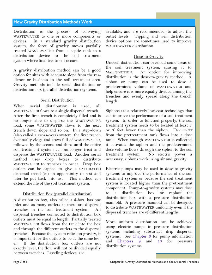
Page 3 of 8 Chapter 8: Gravity Distribution Methods and Soil Dispersal Trenches
How Gravity Distribution Methods Work
Distribution is the process of conveying WASTEWATER to one or more components or devices. In a standard gravity distribution system, the force of gravity moves partially treated WASTEWATER from a septic tank to a distribution device to the soil treatment system where final treatment occurs. A gravity distribution method can be a good option for sites with adequate slope from the res-idence or business to the soil treatment area. Gravity methods include serial distribution or distribution box (parallel distribution) systems.
Serial Distribution
When serial distribution is used, all WASTEWATER flows to a single dispersal trench. After the first trench is completely filled and is no longer able to disperse the WASTEWATER load, some WASTEWATER flows to the next trench down slope and so on. In a step-down (also called a cross-over) system, the first trench eventually clogs and stays full of WASTEWATER, followed by the second and third until the entire soil treatment system can no longer treat and disperse the WASTEWATER load. Another serial method uses drop boxes to distribute WASTEWATER to trenches in order. Drop box outlets can be capped to give a SATURATED dispersal trench(es) an opportunity to rest and later be put back into use. This method can extend the life of the soil treatment system.
Distribution Box (parallel distribution)
A distribution box, also called a d-box, has one inlet and as many outlets as there are dispersal trenches in the soil treatment system. All dispersal trenches connected to distribution box outlets must be equal in length. Partially treated WASTEWATER flows from the tank into the box and through the different outlets to the dispersal trenches. Because the system relies on gravity, it is important for the outlets to be at the same lev-el. If the distribution box outlets are not exactly level, the flow will not be divided equally between trenches. Leveling devices are
available, and are recommended, to adjust the outlet levels. Tipping and weir distribution device options are sometimes used to improve WASTEWATER distribution.
Dose-to-Gravity
Uneven distribution can overload some areas of the soil treatment system, causing it to MALFUNCTION. An option for improving distribution is the dose-to-gravity method. A siphon or pump can be used to dose a predetermined volume of WASTEWATER and help ensure it is more equally divided among the trenches and evenly spread along the trench length. Siphons are a relatively low-cost technology that can improve the performance of a soil treatment system. In order to function properly, the soil treatment system needs to be located at least 2’ or 3’ feet lower than the siphon. EFFLUENT from the pretreatment tank flows into a dose tank. When enough WASTEWATER is collected, it activates the siphon and the predetermined dose volume flows through the siphon to the soil treatment system. No electric power is necessary; siphons work using air and gravity. Electric pumps may be used in dose-to-gravity systems to improve the performance of the soil treatment system or because the soil treatment system is located higher than the pretreatment component. Pump-to-gravity systems may dose to a distribution box or replace the distribution box with a pressure distribution manifold. A pressure manifold can be designed to distribute WASTEWATER uniformly even if the dispersal trenches are of different lengths. More uniform distribution can be achieved using electric pumps in pressure distribution systems including subsurface drip dispersal systems. See Chapter 6 for pump information and Chapters 9 and 10 for pressure distribution systems.
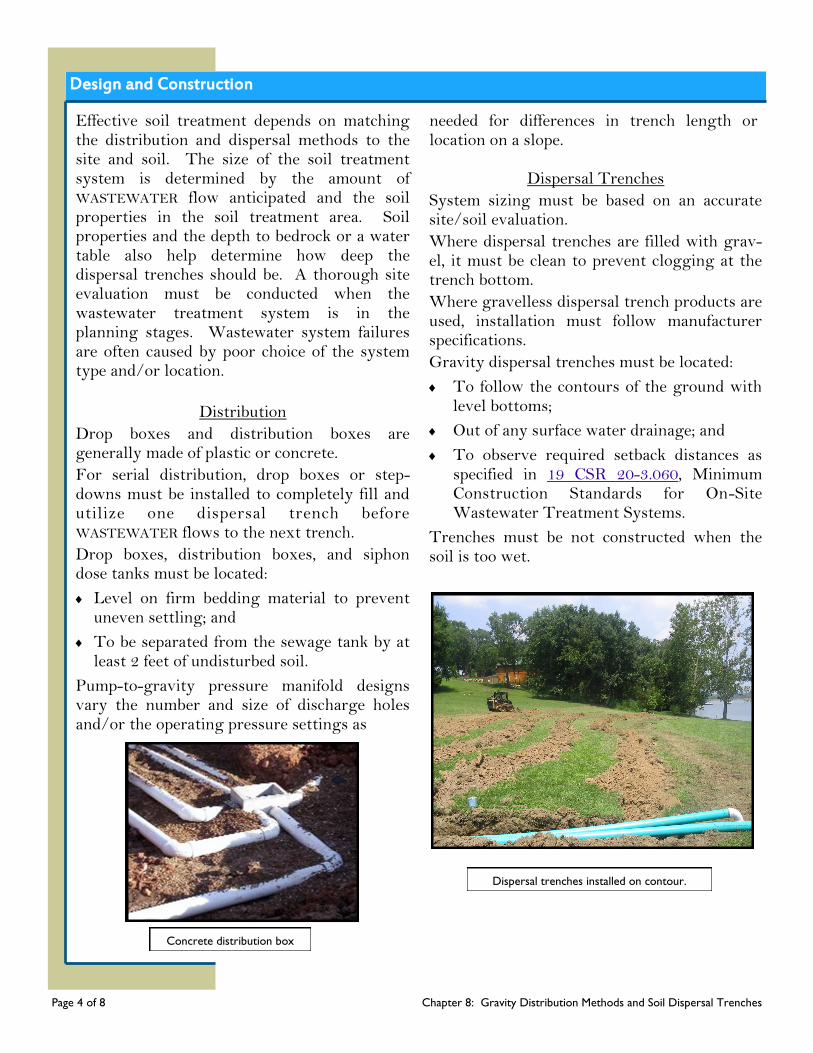
Design and Construction
Effective soil treatment depends on matching the distribution and dispersal methods to the site and soil. The size of the soil treatment system is determined by the amount of WASTEWATER flow anticipated and the soil properties in the soil treatment area. Soil properties and the depth to bedrock or a water table also help determine how deep the dispersal trenches should be. A thorough site evaluation must be conducted when the wastewater treatment system is in the planning stages. Wastewater system failures are often caused by poor choice of the system type and/or location.
Distribution
Drop boxes and distribution boxes are generally made of plastic or concrete.
For serial distribution, drop boxes or step-downs must be installed to completely fill and utilize one dispersal trench before WASTEWATER flows to the next trench.
Drop boxes, distribution boxes, and siphon dose tanks must be located:
Level on firm bedding material to prevent uneven settling; and
To be separated from the sewage tank by at least 2 feet of undisturbed soil.
Pump-to-gravity pressure manifold designs vary the number and size of discharge holes and/or the operating pressure settings as
needed for differences in trench length or location on a slope.
Dispersal Trenches
System sizing must be based on an accurate site/soil evaluation.
Where dispersal trenches are filled with grav-el, it must be clean to prevent clogging at the trench bottom.
Where gravelless dispersal trench products are used, installation must follow manufacturer specifications.
Gravity dispersal trenches must be located:
To follow the contours of the ground with level bottoms;
Out of any surface water drainage; and
To observe required setback distances as specified in 19 CSR 20-3.060, Minimum Construction Standards for On-Site Wastewater Treatment Systems.
Trenches must be not constructed when the soil is too wet.
Concrete distribution box
Page 4 of 8 Chapter 8: Gravity Distribution Methods and Soil Dispersal Trenches
Dispersal trenches installed on contour.
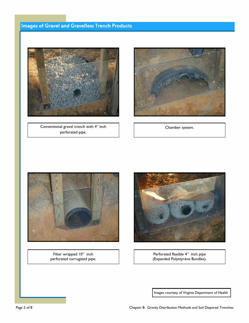
Images of Gravel and Gravelless Trench Products
Conventional gravel trench with 4” inch
perforated pipe.
Chamber system.
Filter wrapped 10” inch
perforated corrugated pipe.
Perforated flexible 4” inch pipe
(Expanded Polystyrene Bundles).
Images courtesy of Virginia Department of Health
Page 5 of 8 Chapter 8: Gravity Distribution Methods and Soil Dispersal Trenches
Maintenance - Inspections
Gravity distribution devices are relatively uncomplicated and easy to operate. With a little regular MAINTENANCE and management, many problems can be avoided and the useful life of the soil treatment system extended. Siphon systems are simple to operate. Regular INSPECTIONS are needed to catch and correct problems, such as when a siphon fails to cycle properly and the advantages of dosing are lost. The advantages of a pressure manifold can also be lost if MAINTENANCE is neglected. Readily available, and yet secure, access to distribution devices will save MAINTENANCE time and money. INSPECTION access to the dispersal trenches, in addition to the distribution devices, allows the system to be managed. Needed adjustments or repairs can be made before a small problem becomes a costly system failure.
Inspections
To assure gravity, or dose-to-gravity, distribution is operating properly, the distribution device must be inspected at least every two years and any time a pretreatment component, such as the septic tank or aeration treatment unit, is inspected and/or pumped. See Chapter 6 for pumps. As applicable, INSPECTIONS must include assuring:
The distribution device is structurally sound with no corrosion, cracking, or missing parts;
All access ports, lids, covers, and pipe connections are watertight;
Lids and covers are locked or otherwise se-cured to prevent accidental entry;
The distribution device or siphon dose tank is free of accumulated solids;
The distribution device is level and/or adjusted to distribute WASTEWATER to the dispersal trenches as designed; and
If applicable, siphon cycles properly and is not just trickling.
To assure the soil treatment system is operating properly, INSPECTIONS must be conducted at least every two years and any time a pretreatment component, such as the septic tank or aeration treatment unit, is inspected and/or pumped. INSPECTIONS must include assuring the following:
There are no signs of surfacing EFFLUENT;
No strong, foul odors are present near the soil treatment area;
Vegetation is maintained on and around the soil treatment area;
The surface of the soil treatment area has no areas of depression for surface water to collect;
No visible damage to the dispersal trench-es;
When inspection ports are available, observe the presence and depth of ponding within each dispersal trench and any root intrusion or obstruction to the system;
The soil treatment area is not subject to traffic, heavy equipment, or used as pasture for domesticated animals; and
The soil treatment area is not used for outbuildings and/or structures, such as pa-tios or above-ground swimming pools.
Page 6 of 8 Chapter 8: Gravity Distribution Methods and Soil Dispersal Trenches
DID YOU KNOW?
WASTEWATER contains bacteria and viruses
that cause illness. Contact with untreated
WASTEWATER can make people and family
pets sick, as well as contaminate nearby wells,
groundwater, and drinking water sources.
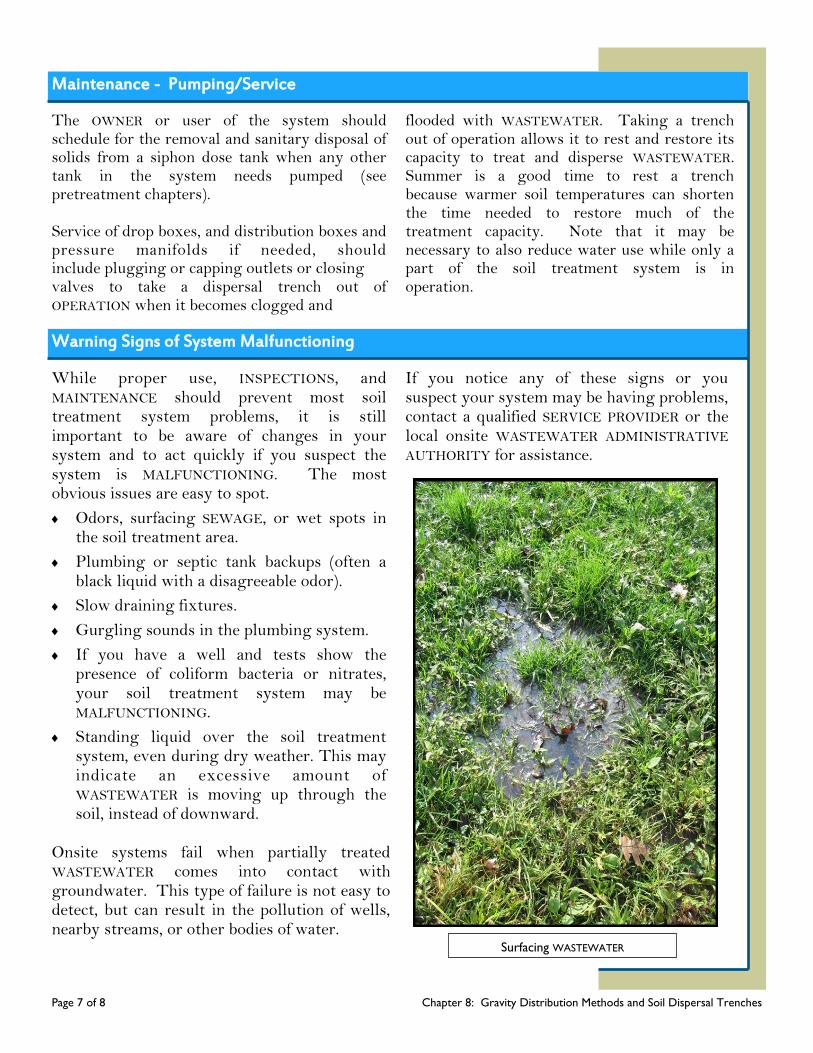
Maintenance - Pumping/Service
The OWNER or user of the system should schedule for the removal and sanitary disposal of solids from a siphon dose tank when any other tank in the system needs pumped (see pretreatment chapters). Service of drop boxes, and distribution boxes and pressure manifolds if needed, should include plugging or capping outlets or closing valves to take a dispersal trench out of OPERATION when it becomes clogged and
flooded with WASTEWATER. Taking a trench out of operation allows it to rest and restore its capacity to treat and disperse WASTEWATER. Summer is a good time to rest a trench because warmer soil temperatures can shorten the time needed to restore much of the treatment capacity. Note that it may be necessary to also reduce water use while only a part of the soil treatment system is in operation.
Warning Signs of System Malfunctioning
While proper use, INSPECTIONS, and MAINTENANCE should prevent most soil treatment system problems, it is still important to be aware of changes in your system and to act quickly if you suspect the system is MALFUNCTIONING. The most obvious issues are easy to spot.
Odors, surfacing SEWAGE, or wet spots in the soil treatment area.
Plumbing or septic tank backups (often a black liquid with a disagreeable odor).
Slow draining fixtures.
Gurgling sounds in the plumbing system.
If you have a well and tests show the presence of coliform bacteria or nitrates, your soil treatment system may be MALFUNCTIONING.
Standing liquid over the soil treatment system, even during dry weather. This may indicate an excessive amount of WASTEWATER is moving up through the soil, instead of downward.
Onsite systems fail when partially treated WASTEWATER comes into contact with groundwater. This type of failure is not easy to detect, but can result in the pollution of wells, nearby streams, or other bodies of water.
If you notice any of these signs or you suspect your system may be having problems, contact a qualified SERVICE PROVIDER or the local onsite WASTEWATER ADMINISTRATIVE AUTHORITY for assistance.
Surfacing WASTEWATER
Page 7 of 8 Chapter 8: Gravity Distribution Methods and Soil Dispersal Trenches
Gravity Distribution Do’s and Don’ts
Proper OPERATION and MAINTENANCE of your onsite system can prevent costly repairs or replacement and can protect your property value. Observing the following recommendations will help to keep your system operating properly.
Do’s
Obtain the necessary permits from the appropriate ADMINISTRATIVE AUTHORITY before making any repairs.
Use REGISTERED ONSITE WASTEWATER TREATMENT SYSTEM PROFESSIONALS and qualified SERVICE PROVIDERS.
Know where the soil treatment system and replacement area are located. It is easier to protect the system when you know where the components are.
Conserve water to avoid overloading the soil treatment system, use high-efficiency fixtures and promptly repair any leaky faucets or toilets. Soil treatment systems do not have an unlimited capacity to disperse WASTEWATER.
Keep heavy equipment off the soil treatment area, cars and equipment must not be driven or parked over the soil treatment system.
Divert other sources of water, like roof drains, house footing drains, and sump pumps away from the soil treatment system.
Keep detailed records regarding the system, its location, make/model, contract service agreement, service visits, and MAINTENANCE performed.
Landscape the system properly. Plant grass over and near the soil treatment system to prevent soil erosion; roots from nearby trees or shrubs might clog and damage the system.
Contact a qualified SERVICE PROVIDER if you experience problems with your system, such as surfacing WASTEWATER in your yard or other warning signs the system may be MALFUNCTIONING.
Plan ahead--soil treatment systems do not last forever. If you have additional space, consider reserving some area from development so that it can be used for a replacement soil treatment system when needed.
Don’ts
Don’t build over the soil treatment system; this includes patios, carports, and other structures.
Don’t pave or use landscaping plastic over the soil treatment system; bacteria in the soil need oxygen to properly treat WASTEWATER.
Don’t allow large animals and livestock to roam over the soil treatment system. Soil compaction prevents oxygen from getting into the soil and prevents water from flowing away from the soil treatment system.
Don’t dig in the soil treatment area, as damage to the pipes may occur.
Don’t plant more trees and shrubs in or near the soil treatment area.
Don’t plant a garden over the soil treatment system. You risk the possibility of food contamination.
Don’t install an irrigation system in the soil treatment area or allow the irrigation water run towards the soil treatment system.
Page 8 of 8 Chapter 8: Gravity Distribution Methods and Soil Dispersal Trenches

Chapter 9: Pressure Distribution
Chapter 9
Page 1 of 7 Chapter 9: Pressure Distribution
A gravity ONSITE WASTEWATER TREATMENT SYSTEM, also called a standard or conventional system, is the most commonly used system for treating WASTEWATER. These systems consist of a septic tank or other pretreatment component, a distribution system, and a soil treatment system. After receiving limited treatment in the septic tank, WASTEWATER is distributed and dispersed into the soil for final treatment. A subsurface soil treatment system serves two purposes: 1) keep untreated WASTEWATER below the soil surface, and 2) purify the WASTEWATER before it reaches ground or surface water. Unfortunately, not all soil and site conditions are well suited for these conventional systems. To protect public health and water quality, alternative systems are often
used in areas where conventional systems cannot assure adequate WASTEWATER treatment. Although not the answer for all unsuitable soils, pressure distribution can assist the soils where conventional gravity distribution systems would fail. One specific type of pressure distribution system is the low-pressure pipe (LPP) system. LPP systems were developed as an alternative to conventional soil treatment systems to overcome some problems such as shallow bedrock or water table and to reduce localized overloading common in gravity distribution systems. Drip irrigation, another type of pressure distribution is discussed in Chapter 10 of these guidelines.
How Pressure Distribution Works
At a minimum, primary treatment by a septic tank with an EFFLUENT screen is required before a pressure distribution system. An aeration treatment unit (ATU) or alternative treatment component, such as a bio-filter or wetlands can also be used. Pressure distribution should be used following ATUs or alternative treatment systems because WASTEWATER from these systems does not promote the development of a bio-mat on which gravity distribution depends. Pretreated WASTEWATER collects in a separate compartment or pump tank. When WASTEWATER reaches a certain level, or based on timer control settings, the pump is activated and screened EFFLUENT is dosed to a network of distribution pipes. WASTEWATER is distributed evenly over the soil treatment area through evenly spaced small holes drilled in the distribution pipes. Some soil treatment areas are split into smaller zones and dosing alternates between zones.
What’s Ahead...
How Pressure
Distribution
Works
Design and
Construction
Maintenance
Warning Signs
Do’s and Don’ts Glossary Resources

How Pressure Distribution Works, continued
Page 2 of 7 Chapter 9: Pressure Distribution
Compared to a conventional gravity trench system, LPP dispersal trenches are shallower and narrower. An LPP system may need less area than a gravity system. Benefits of pressure distribution include:
Allows placement of the soil treatment system in the best area even if it is upslope from the residence or establishment;
Improved distribution over the entire area helps prevent localized overloading and too rapid WASTEWATER percolation with little time for treatment;
Dosing and resting cycles that promote aerated soil conditions; and
Spread out peak flows over time, which helps improve soil treatment compared to gravity distribution systems.
Additional benefits of LPP distribution potentially include:
Shallow, narrow trenches use the best soil layers for WASTEWATER treatment;
Treatment may be possible in a smaller area;
Less trench material may be needed, which can reduce site disturbance and soil compaction; and
Systems might better fit uneven sloping terrain that would be unsuitable for gravity flow systems.
Pressure Distribution Systems use a network of pipes to distribute WASTEWATER equally in dispersal trenches. Low-
Pressure Pipe is an engineered type of pressure distribution system using shallow, narrow dispersal trenches.
Pump
Tank
Land Block
Pressure Manifold
Access for
cleanout and
setting
pressure
Geotextile Barrier
Backfill Mounded
to settle naturally
and shed rainwater
Dispersal Trenches
Distribution Pipe with Drilled Holes
Valve Access
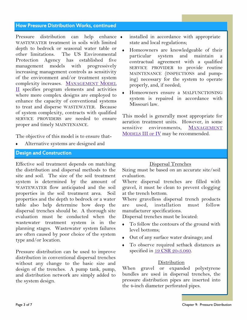
Design and Construction
Page 3 of 7 Chapter 9: Pressure Distribution
Effective soil treatment depends on matching the distribution and dispersal methods to the site and soil. The size of the soil treatment system is determined by the amount of WASTEWATER flow anticipated and the soil properties in the soil treatment area. Soil properties and the depth to bedrock or a water table also help determine how deep the dispersal trenches should be. A thorough site evaluation must be conducted when the wastewater treatment system is in the planning stages. Wastewater system failures are often caused by poor choice of the system type and/or location. Pressure distribution can be used to improve distribution in conventional dispersal trenches without any change to the basic size and design of the trenches. A pump tank, pump, and distribution network are simply added to the system design.
Dispersal Trenches Sizing must be based on an accurate site/soil evaluation. Where dispersal trenches are filled with gravel, it must be clean to prevent clogging at the trench bottom. Where gravelless dispersal trench products are used, installation must follow manufacturer specifications. Dispersal trenches must be located:
To follow the contours of the ground with level bottoms;
Out of any surface water drainage; and
To observe required setback distances as specified in 19 CSR 20-3.060.
Distribution
When gravel or expanded polystyrene bundles are used in dispersal trenches, the pressure distribution pipes are inserted into the 4-inch diameter perforated pipes.
How Pressure Distribution Works, continued
Pressure distribution can help enhance WASTEWATER treatment in soils with limited depth to bedrock or seasonal water table or other limitations. The US Environmental Protection Agency has established five management models with progressively increasing management controls as sensitivity of the environment and/or treatment system complexity increases. MANAGEMENT MODEL II specifies program elements and activities where more complex designs are employed to enhance the capacity of conventional systems to treat and disperse WASTEWATER. Because of system complexity, contracts with qualified SERVICE PROVIDERS are needed to ensure proper and timely MAINTENANCE. The objective of this model is to ensure that-
Alternative systems are designed and
installed in accordance with appropriate state and local regulations;
Homeowners are knowledgeable of their particular system and maintain a contractual agreement with a qualified SERVICE PROVIDER to provide routine MAINTENANCE (INSPECTIONS and pump-ing) necessary for the system to operate properly, and, if needed;
Homeowners ensure a MALFUNCTIONING system is repaired in accordance with Missouri law.
This model is generally most appropriate for aeration treatment units. However, in some sensitive environments, MANAGEMENT MODELS III or IV may be recommended.
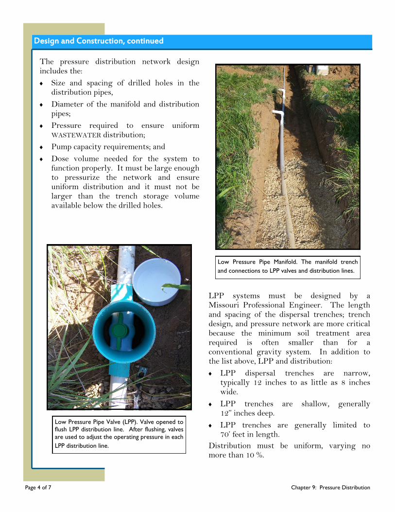
Page 4 of 7 Chapter 9: Pressure Distribution
Design and Construction, continued
The pressure distribution network design includes the:
Size and spacing of drilled holes in the distribution pipes,
Diameter of the manifold and distribution pipes;
Pressure required to ensure uniform WASTEWATER distribution;
Pump capacity requirements; and
Dose volume needed for the system to function properly. It must be large enough to pressurize the network and ensure uniform distribution and it must not be larger than the trench storage volume available below the drilled holes.
LPP systems must be designed by a Missouri Professional Engineer. The length and spacing of the dispersal trenches; trench design, and pressure network are more critical because the minimum soil treatment area required is often smaller than for a conventional gravity system. In addition to the list above, LPP and distribution:
LPP dispersal trenches are narrow, typically 12 inches to as little as 8 inches wide.
LPP trenches are shallow, generally 12” inches deep.
LPP trenches are generally limited to 70’ feet in length.
Distribution must be uniform, varying no more than 10 %.
Low Pressure Pipe Valve (LPP). Valve opened to
flush LPP distribution line. After flushing, valves
are used to adjust the operating pressure in each
LPP distribution line.
Low Pressure Pipe Manifold. The manifold trench
and connections to LPP valves and distribution lines.
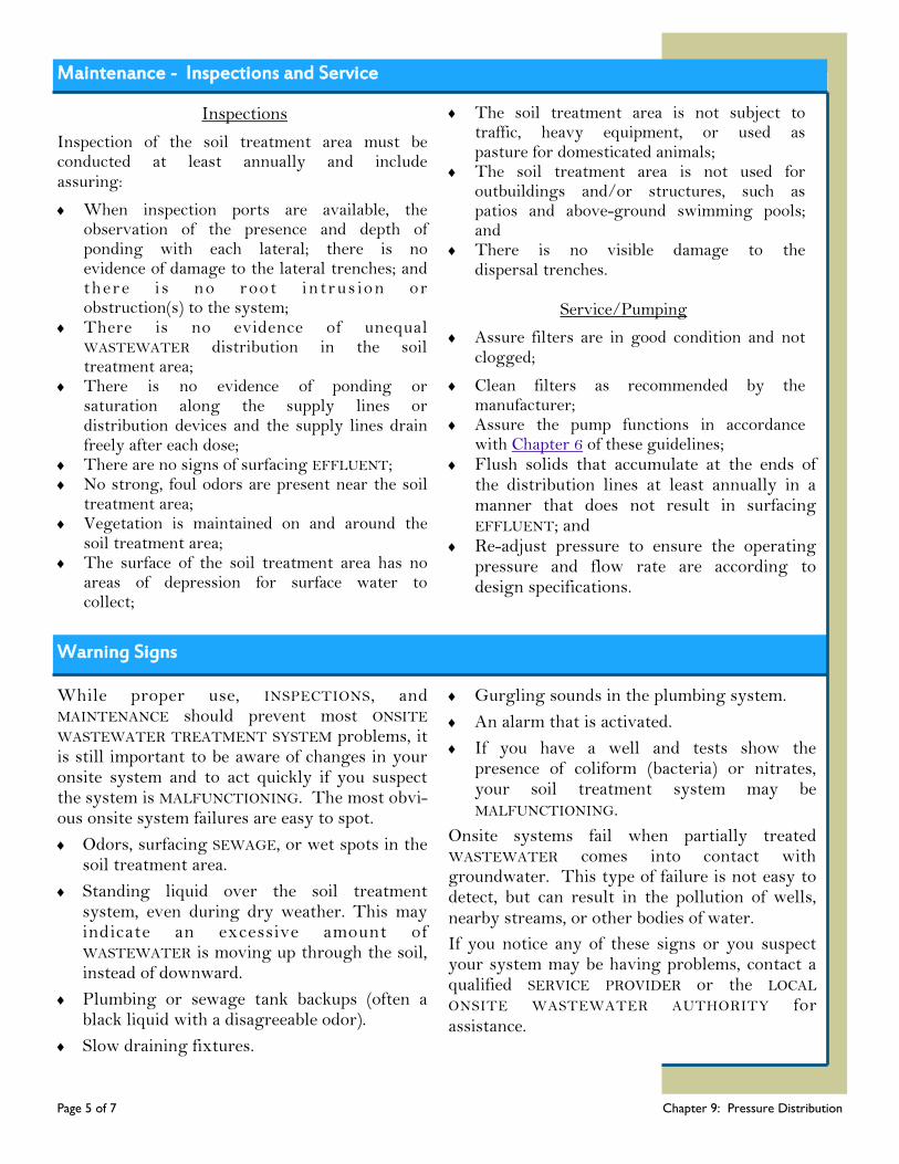
Page 5 of 7 Chapter 9: Pressure Distribution
Warning Signs
While proper use, INSPECTIONS, and MAINTENANCE should prevent most ONSITE WASTEWATER TREATMENT SYSTEM problems, it is still important to be aware of changes in your onsite system and to act quickly if you suspect the system is MALFUNCTIONING. The most obvi-ous onsite system failures are easy to spot.
Odors, surfacing SEWAGE, or wet spots in the soil treatment area.
Standing liquid over the soil treatment system, even during dry weather. This may indicate an excessive amount of WASTEWATER is moving up through the soil, instead of downward.
Plumbing or sewage tank backups (often a black liquid with a disagreeable odor).
Slow draining fixtures.
Gurgling sounds in the plumbing system.
An alarm that is activated.
If you have a well and tests show the presence of coliform (bacteria) or nitrates, your soil treatment system may be MALFUNCTIONING.
Onsite systems fail when partially treated WASTEWATER comes into contact with groundwater. This type of failure is not easy to detect, but can result in the pollution of wells, nearby streams, or other bodies of water.
If you notice any of these signs or you suspect your system may be having problems, contact a qualified SERVICE PROVIDER or the LOCAL ONSITE WASTEWATER AUTHORITY for assistance.
Maintenance - Inspections and Service
Inspections
Inspection of the soil treatment area must be conducted at least annually and include assuring:
When inspection ports are available, the observation of the presence and depth of ponding with each lateral; there is no evidence of damage to the lateral trenches; and there i s no root in trus ion or obstruction(s) to the system;
There is no evidence of unequal WASTEWATER distribution in the soil treatment area;
There is no evidence of ponding or saturation along the supply lines or distribution devices and the supply lines drain freely after each dose;
There are no signs of surfacing EFFLUENT; No strong, foul odors are present near the soil
treatment area; Vegetation is maintained on and around the
soil treatment area; The surface of the soil treatment area has no
areas of depression for surface water to collect;
The soil treatment area is not subject to traffic, heavy equipment, or used as pasture for domesticated animals;
The soil treatment area is not used for outbuildings and/or structures, such as patios and above-ground swimming pools; and
There is no visible damage to the dispersal trenches.
Service/Pumping
Assure filters are in good condition and not clogged;
Clean filters as recommended by the manufacturer;
Assure the pump functions in accordance with Chapter 6 of these guidelines;
Flush solids that accumulate at the ends of the distribution lines at least annually in a manner that does not result in surfacing EFFLUENT; and
Re-adjust pressure to ensure the operating pressure and flow rate are according to design specifications.

Do’s
Page 6 of 7 Chapter 9: Pressure Distribution
Pressure Distribution Do’s and Don’ts
Proper OPERATION and MAINTENANCE of your onsite system can prevent costly repairs or replacement and can protect your property value. Observing the following recommendations will help to keep your system operating properly.
Obtain the necessary permits from the appropriate ADMINISTRATIVE AUTHORITY before making any repairs.
Use REGISTERED ONSITE WASTEWATER TREATMENT SYSTEM PROFESSIONALS and qualified SERVICE PROVIDERS.
Conserve water to avoid overloading the onsite system, use high-efficiency fixtures and promptly repair any leaky faucets or toilets. Soil treatment systems do not have an unlimited capacity to disperse WASTEWATER.
Divert other sources of water, like roof drains, house footing drains, and sump pumps away from the soil treatment area.
Keep your sewage tank(s) accessible for INSPECTIONS and pumping; yet locked or otherwise secured to prevent accidental entry.
Have your septic tank, ATU, or other pretreatment component inspected and pumped according to the guidelines for that component.
Have your pump tank inspected at the same frequency as your septic tank or other pretreatment component and pumped if needed.
If your pump tank alarm is activated – contact your SERVICE PROVIDER promptly to repair the system and minimize your water usage in the interim.
Plan ahead--soil treatment systems do not last forever. If you have additional space, consider reserving some area from development so that it can be used for a replacement soil treatment system when needed.
Know where the soil treatment system and replacement area are located. It is easier to protect the system when you know where the components are.
Landscape the system properly. Plant and maintain grass over the soil treatment system to prevent soil erosion.
Keep heavy equipment off the soil treatment area, cars and equipment must not be driven or parked over the soil treatment system.
Contact a qualified SERVICE PROVIDER if you experience problems with your system, such as surfacing WASTEWATER in your yard or other warning signs the system may be MALFUNCTIONING.
Keep detailed records regarding the system, its location, make/model, contract service agreement, service visits, and MAINTENANCE performed.
Use commercial bathroom cleaners and laundry detergents in moderation and only according to manufacturer’s directions.
Have your private water well tested periodically or if you experience any warning signs of the system MALFUNCTIONING (contact your local public health agency).
Don’ts
Don’t enter a septic tank, pump tank or any sewage tank. Poisonous gasses or a lack of oxygen can be fatal.
Your septic tank system is not a trash can. Don’t put dental floss, feminine hygiene products, condoms, flushable wipes, diapers, cotton swabs, cigarette butts, coffee grounds, cat litter, paper towels, paint, pesticides, or other hazardous chemicals into your system.
Don’t use caustic drain openers for a clogged drain. Instead, use boiling water or a drain snake to open clogs.
Don’t drive or park vehicles on any part of your ONSITE WASTEWATER TREATMENT SYSTEM. Doing so can compact the soil in your soil treatment area or damage the pipes, tanks, or other system components.
Don’t allow large animals and livestock to roam over the soil treatment system. Soil compaction prevents oxygen from getting into the soil and prevents water from flowing away from the soil treatment system.
Don’t build over any part of your ONSITE WASTEWATER TREATMENT SYSTEM; this includes patios, carports, and other structures.
Don’t pave or use landscaping plastic over the soil treatment system; bacteria in the soil need oxygen to properly treat WASTEWATER.
Don’t dig in the soil treatment area, as damage to the pipes may occur.
Don’t plant a garden over the soil treatment system. You risk the possibility of food contamination.
Don’t plant more trees and shrubs in or near the soil treatment area.
Don’t install an irrigation system in the soil treatment area or allow the irrigation water run towards the soil treatment system.
Don’t attempt to pump your own sewage tank; use the services of a qualified SERVICE PROVIDER.
Page 7 of 7 Chapter 9: Pressure Distribution

Chapter 10: Subsurface Drip Dispersal Chapter 10
Subsurface Drip Dispersal Systems use shallow flexible drip lines with emitters spaced two feet apart to distribute
WASTEWATER evenly over the area.
Page 1 of 7 Chapter 10: Drip Dispersal
Pretreatment Pump
Tank
Access for
effluent screen on
Supply Manifold
Flush Valve
on Return
Manifold
Drip Line Emitters
Looped
Ends
Return Manifold
Supply Manifold
Soil Treatment Area
Access for Air Release
Vacuum Break Valve
The simplest ONSITE WASTEWATER TREATMENT SYSTEM, a septic tank and a gravity dispersal trench system, will not work on every site. Even a pressure distribution network installed in dispersal trenches cannot be expected to treat and disperse WASTEWATER adequately in some soils. Subsurface drip dispersal, also called drip irrigation, systems use small flexible drip lines with emitters to spread WASTEWATER uniformly in the soil treatment area. Drip lines are installed so that there is an emitter for every four square feet, which means more uniform dispersal than is possible with a trench system. Because drip systems can spread small doses of wastewater evenly over large areas, they can be used on many difficult sites.
What’s Ahead...
How Drip Dispersal Works
Design and Construction
Maintenance
Warning Signs
Do’s and Don’ts Glossary Resources
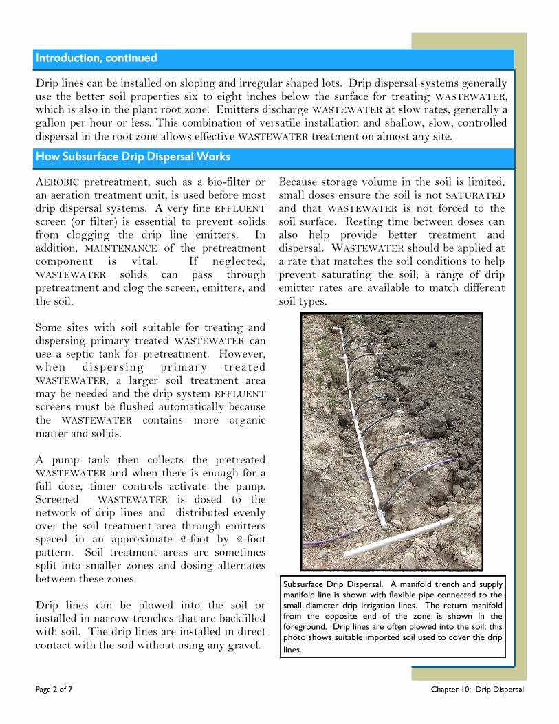
Introduction, continued
Page 2 of 7 Chapter 10: Drip Dispersal
Drip lines can be installed on sloping and irregular shaped lots. Drip dispersal systems generally use the better soil properties six to eight inches below the surface for treating WASTEWATER, which is also in the plant root zone. Emitters discharge WASTEWATER at slow rates, generally a gallon per hour or less. This combination of versatile installation and shallow, slow, controlled dispersal in the root zone allows effective WASTEWATER treatment on almost any site.
How Subsurface Drip Dispersal Works
AEROBIC pretreatment, such as a bio-filter or an aeration treatment unit, is used before most drip dispersal systems. A very fine EFFLUENT screen (or filter) is essential to prevent solids from clogging the drip line emitters. In addition, MAINTENANCE of the pretreatment component is vital. If neglected, WASTEWATER solids can pass through pretreatment and clog the screen, emitters, and the soil. Some sites with soil suitable for treating and dispersing primary treated WASTEWATER can use a septic tank for pretreatment. However, when dispers ing pr imary treated WASTEWATER, a larger soil treatment area may be needed and the drip system EFFLUENT screens must be flushed automatically because the WASTEWATER contains more organic matter and solids. A pump tank then collects the pretreated WASTEWATER and when there is enough for a full dose, timer controls activate the pump. Screened WASTEWATER is dosed to the network of drip lines and distributed evenly over the soil treatment area through emitters spaced in an approximate 2-foot by 2-foot pattern. Soil treatment areas are sometimes split into smaller zones and dosing alternates between these zones. Drip lines can be plowed into the soil or installed in narrow trenches that are backfilled with soil. The drip lines are installed in direct contact with the soil without using any gravel.
Because storage volume in the soil is limited, small doses ensure the soil is not SATURATED and that WASTEWATER is not forced to the soil surface. Resting time between doses can also help provide better treatment and dispersal. WASTEWATER should be applied at a rate that matches the soil conditions to help prevent saturating the soil; a range of drip emitter rates are available to match different soil types.
Subsurface Drip Dispersal. A manifold trench and supply
manifold line is shown with flexible pipe connected to the
small diameter drip irrigation lines. The return manifold
from the opposite end of the zone is shown in the
foreground. Drip lines are often plowed into the soil; this
photo shows suitable imported soil used to cover the drip
lines.
How Subsurface Drip Dispersal Works, continued
Page 3 of 7 Chapter 10: Drip Dispersal
Benefits of drip dispersal include:
Small flexible drip lines have the ability to fit to site contours and irregular shaped areas;
Narrow trenches or plowed in drip lines create less site disturbance;
Shallow drip line installation uses the surface soil layers that are usually best for wastewater treatment;
Shallow drip lines in the root zone promotes water reuse through plant evapo-transpiration; and
Matching slow emitter rates and dose sizes to the soils improves wastewater treatment.
In limiting soil conditions, subsurface drip systems can disperse pretreated WASTEWATER uniformly and enhance the soils ability to provide final treatment and recycle the WASTEWATER. The US Environmental Protection Agency has established five management models with progressively increasing management controls as sensitivity of the environment and/or treatment system complexity increases. MANAGEMENT MODEL II specifies program elements and activities
where more complex designs are employed to enhance the capacity of conventional systems to treat and disperse WASTEWATER. Because of system complexity, contracts with qualified SERVICE PROVIDERS are needed to ensure prop-er and timely MAINTENANCE. The objective of this model is to ensure that-
Alternative systems are designed and installed in accordance with appropriate state and local regulations;
Homeowners are knowledgeable of their particular system and maintain a contractual agreement with a qualified SERVICE PROVIDER to provide routine MAINTENANCE (INSPECTIONS, flushing, and pumping) necessary for the system to operate properly, and, if needed;
H o m e o w n e r s e n s u r e a MALFUNCTIONING system is repaired in accordance with Missouri law.
This model is generally most appropriate for subsurface drip dispersal systems. However, in some sensitive environments, MANAGEMENT MODELS III or IV may be recommended.
Design and Construction
Effective soil treatment depends on matching the distribution and dispersal methods to the site and soil. The size of the soil treatment system is determined by the amount of WASTEWATER flow anticipated and the soil properties in the soil treatment area. Soil properties and the depth to bedrock or a water table also help determine the depth of the dispersal system. Drip dispersal can often be installed shallower than other distribution systems. A thorough site evaluation must be c o n d u c t e d w h e n t h e w a s t e w a t e r treatment system is in the planning stages. Wastewater system failures are often caused by the improper choice of the system type and/or location. Subsurface drip dispersal systems must be designed by a Missouri Professional Engineer.
Drip Dispersal
Minimum treatment area must be based on an accurate site/soil evaluation;
Minimum drip line length is based on 2-foot spacing;
A drip emitter can be considered to cover at most four (4) square feet;
Drip lines must be located:
To follow the contours of the ground and be installed level;
Out of any surface water drainage;
To allow drip lines and manifolds to drain back to sewage tanks to reduce the potential for freezing; and
To observe required setback distances as specified in 19 CSR 20-3.060.
Design and Construction, continued
Page 4 of 7 Chapter 10: Drip Dispersal
Distribution A drip dispersal pressure distribution network design includes the:
Drip line model and drip emitter rate in gallons per hour;
Maximum length of drip lines;
Zoning requirements if applicable;
Diameter of the supply and return manifolds;
Air release/vacuum breaker valves and locations;
EFFLUENT screen or disc filter model to protect drip emitters from clogging;
Flow and pressure required for dosing to ensure uniform WASTEWATER distribution;
Flow and pressure necessary to effectively flush the drip lines and manifolds to prevent buildup of slime or solids;
Pump capacity requirements;
Dose volume needed for the system to function properly. It must be large enough to include the volume to fill and pressurize the drip lines and ensure uniform distribution, and it must not be so large that WASTEWATER is forced to the ground surface; and
Timer dose control settings.
The importance of proper design, installation, MAINTENANCE, and monitoring of drip systems including the pretreatment component can not be overstated. If a design focuses on the long term performance of the system, some of the OPERATION and MAINTENANCE requirements for drip systems can be automated. Programmable timers can adjust dose volumes to accommodate daily flows from the typical water use up to the maximum design flow. Valves and controllers are available to alternately dose different zones and automatically flush EFFLUENT screens and the drip lines. Options are available to remotely monitor alarms or to monitor and even control system performance.
Inspection
An onsite INSPECTION of drip dispersal soil treatment systems must be conducted at least every six months and must include assuring:
The pretreatment component(s) is operating properly (see Chapters 1, 2, 3, and 4 of these guidelines);
The pump and controls functions according to design (see Chapter 6 of these guidelines);
Air release/vacuum relief valves at high points of system/zones function properly;
EFFLUENT screens (or disc filters) are in good condition and not clogged;
If applicable, automatic flushing of screens and/or drip lines functions properly;
There are no signs of surfacing WASTEWATER;
There is no evidence of unequal WASTEWATER distribution in the soil treatment area;
No strong, foul odors are present near the soil treatment area;
Vegetation is maintained on and around the soil treatment area;
The surface of the soil treatment area has no areas of depression for surface water to collect;
The soil treatment area is not subject to traffic, heavy equipment, or used as pasture for domesticated animals;
The soil treatment area is not used for outbuildings and/or structures, such as patios and above-ground swimming pools;
There is no visible damage to the drip dispersal lines; and
There is no evidence of ponding or saturation along the supply or return lines and the lines drain freely after each dose.
Maintenance - Inspection
Maintenance - Service/Pumping
Page 5 of 7 Chapter 10: Drip Dispersal
Service the pretreatment component as needed and recommended by the manufacturer;
Service the pump in accordance with Chapter 6 of these guidelines;
Contract with a REGISTERED ONSITE WASTEWATER TREATMENT SYSTEM PROFESSIONAL or other qualified SERVICE PROVIDER for the removal and treatment of the contents of the pretreatment component and pump tank in accordance with Chapter 1 or 2 of these guidelines;
Manually flush or replace EFFLUENT screens (or disc filters) as needed and recommended by the manufacturer;
Manually flush solids that may accumulate in the drip lines and manifold lines (return flow to the system) at least every six (6) months;
Check operating pressure and flow rate while the pump is running to ensure they meet design specifications; and
Perform any additional MAINTENANCE recommended by the manufacturer.
Warning Signs
While proper use, INSPECTIONS, and MAINTENANCE should prevent most ONSITE WASTEWATER TREATMENT SYSTEM problems, it is still important to be aware of changes in your onsite system and to act quickly if you suspect the system is MALFUNCTIONING. The most obvious onsite system failures are easy to spot. Odors, surfacing WASTEWATER, or wet
spots in the soil treatment area.
Standing liquid over the soil treatment system, even during dry weather. This may indicate an excessive amount of WASTEWATER is moving up through the soil, instead of downward.
Plumbing or sewage tank backups (often a black liquid with a disagreeable odor).
Slow draining fixtures.
Gurgling sounds in the plumbing system.
An alarm that is activated.
If you have a well and tests show the presence of coliform (bacteria) or nitrates, your soil treatment system may be MALFUNCTIONING.
Onsite systems fail when partially treated WASTEWATER comes into contact with groundwater. This type of failure is not easy to detect, but can result in the pollution of wells, nearby streams, or other bodies of water. If you notice any of these signs or you suspect your system may be having problems, contact a qualified SERVICE PROVIDER or the local onsite WASTEWATER ADMINISTRATIVE AUTHORITY for assistance.
DID YOU KNOW?
If you have a power failure or if the
alarm on the pump tank is
activated, the tank can hold only
the WASTEWATER that can fit in its
emergency storage volume. If you
use more water than the emergency
volume, WASTEWATER can back up
in your home plumbing.
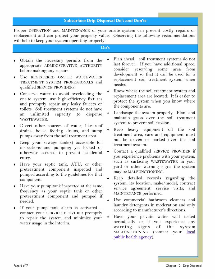
Subsurface Drip Dispersal Do’s and Don’ts
Page 6 of 7 Chapter 10: Drip Dispersal
Proper OPERATION and MAINTENANCE of your onsite system can prevent costly repairs or replacement and can protect your property value. Observing the following recommendations will help to keep your system operating properly.
Do’s
Obtain the necessary permits from the appropriate ADMINISTRATIVE AUTHORITY before making any repairs.
Use REGISTERED ONSITE WASTEWATER TREATMENT SYSTEM PROFESSIONALS and qualified SERVICE PROVIDERS.
Conserve water to avoid overloading the onsite system, use high-efficiency fixtures and promptly repair any leaky faucets or toilets. Soil treatment systems do not have an unlimited capacity to disperse WASTEWATER.
Divert other sources of water, like roof drains, house footing drains, and sump pumps away from the soil treatment area.
Keep your sewage tank(s) accessible for inspections and pumping; yet locked or otherwise secured to prevent accidental entry.
Have your septic tank, ATU, or other pretreatment component inspected and pumped according to the guidelines for that component.
Have your pump tank inspected at the same frequency as your septic tank or other pretreatment component and pumped if needed.
If your pump tank alarm is activated – contact your SERVICE PROVIDER promptly to repair the system and minimize your water usage in the interim.
Plan ahead—soil treatment systems do not last forever. If you have additional space, consider reserving some area from development so that it can be used for a replacement soil treatment system when needed.
Know where the soil treatment system and replacement area are located. It is easier to protect the system when you know where the components are.
Landscape the system properly. Plant and maintain grass over the soil treatment system to prevent soil erosion.
Keep heavy equipment off the soil treatment area, cars and equipment must not be driven or parked over the soil treatment system.
Contact a qualified SERVICE PROVIDER if you experience problems with your system, such as surfacing WASTEWATER in your yard or other warning signs the system may be MALFUNCTIONING.
Keep detailed records regarding the system, its location, make/model, contract service agreement, service visits, and MAINTENANCE performed.
Use commercial bathroom cleaners and laundry detergents in moderation and only according to manufacturer’s directions.
Have your private water well tested periodically or if you experience any warning signs of the system MALFUNCTIONING (contact your local public health agency).

Don’ts
Page 7 of 7 Chapter 10: Drip Dispersal
Don’t enter a septic tank, pump tank or any sewage tank. Poisonous gasses or a lack of oxygen can be fatal.
Your septic tank system is not a trash can. Don’t put dental floss, feminine hygiene products, flushable wipes, condoms, diapers, cotton swabs, cigarette butts, coffee grounds, cat litter, paper towels, paint, pesticides, or other hazardous chem-icals into your system.
Don’t use caustic drain openers for a clogged drain. Instead, use boiling water or a drain snake to open clogs.
Don’t drive or park vehicles on any part of your onsite wastewater system. Doing so can compact the soil in your soil treatment area or damage the pipes, tanks, or other system components.
Don’t allow large animals and livestock to roam over the soil treatment system. Soil compaction prevents oxygen from getting into the soil and prevents water from flowing away from the soil treatment system.
Don’t build over any part of your onsite wastewater system; this includes patios, carports, and other structures.
Don’t pave or use landscaping plastic over the soil treatment system; bacteria in the soil need oxygen to properly treat WASTEWATER.
Don’t dig in the soil treatment area, as damage to the pipes may occur.
Don’t plant a garden over the soil treatment system. You risk the possibility of food contamination.
Don’t plant more trees and shrubs in or near the soil treatment area.
Don’t attempt to pump your own sewage tank; use the services of a qualified SERVICE PROVIDER.

Chapter 11
Chapter 11: Curtain Drains
Page 1 of 3 Chapter 11: Curtain Drains
10’ foot setback (minimum)
Dispersal Trenches
Perforated pipe
sloped to outlet
Direction
of
ground
water
flow
Perched Water Table
RESTRICTIVE LAYER
Outlet located
away from soil
treatment area
Slope
watertight
pipe to outlet
Construct with gravel to the soil surface or construct
surface water diversion
Figure 1: Curtain Drain. Curtain Drains are used to intercept groundwater and surface water moving towards a
soil treatment area on sloping sites. Water is diverted away from the soil treatment system to reduce
SATURATION and enhance wastewater treatment.
Wastewater treatment in the soil depends on unsaturated conditions. During rainfall, some water moves along the top of the ground while some of the water soaks into the soil. When water moving downward in the soil encounters a less permeable or RESTRICTIVE LAYER of soil, water movement slows and soil above the RESTRICTIVE LAYER can become SATURATED. Over a period of time this can create a perched water table. The perched water then moves down slope through the soil above the RESTRICTIVE LAYER. On sloping sites, a curtain drain (also called
interceptor drains) can enhance the soil’s ability to treat and disperse wastewater by intercepting both surface water runoff and groundwater moving towards a soil treatment area.
What’s Ahead...
How a Curtain Drain
Works
Design and Construction
Maintenance
Glossary Resources
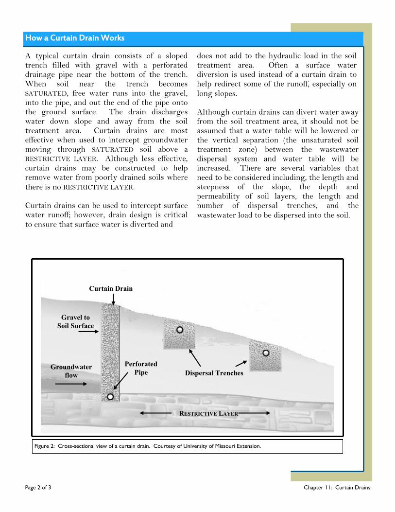
How a Curtain Drain Works
Page 2 of 3 Chapter 11: Curtain Drains
A typical curtain drain consists of a sloped trench filled with gravel with a perforated drainage pipe near the bottom of the trench. When soil near the trench becomes SATURATED, free water runs into the gravel, into the pipe, and out the end of the pipe onto the ground surface. The drain discharges water down slope and away from the soil treatment area. Curtain drains are most effective when used to intercept groundwater moving through SATURATED soil above a RESTRICTIVE LAYER. Although less effective, curtain drains may be constructed to help remove water from poorly drained soils where there is no RESTRICTIVE LAYER. Curtain drains can be used to intercept surface water runoff; however, drain design is critical to ensure that surface water is diverted and
does not add to the hydraulic load in the soil treatment area. Often a surface water diversion is used instead of a curtain drain to help redirect some of the runoff, especially on long slopes. Although curtain drains can divert water away from the soil treatment area, it should not be assumed that a water table will be lowered or the vertical separation (the unsaturated soil treatment zone) between the wastewater dispersal system and water table will be increased. There are several variables that need to be considered including, the length and steepness of the slope, the depth and permeability of soil layers, the length and number of dispersal trenches, and the wastewater load to be dispersed into the soil.
Dispersal Trenches
RESTRICTIVE LAYER
Curtain Drain
Groundwater
flow
Gravel to
Soil Surface
Perforated
Pipe
Figure 2: Cross-sectional view of a curtain drain. Courtesy of University of Missouri Extension.
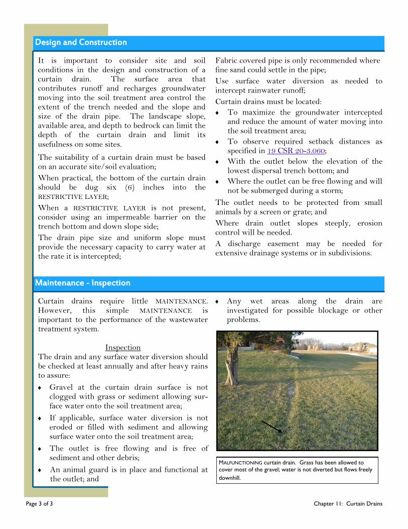
Design and Construction
Page 3 of 3 Chapter 11: Curtain Drains
Maintenance - Inspection
It is important to consider site and soil conditions in the design and construction of a curtain drain. The surface area that contributes runoff and recharges groundwater moving into the soil treatment area control the extent of the trench needed and the slope and size of the drain pipe. The landscape slope, available area, and depth to bedrock can limit the depth of the curtain drain and limit its usefulness on some sites.
The suitability of a curtain drain must be based on an accurate site/soil evaluation;
When practical, the bottom of the curtain drain should be dug six (6) inches into the RESTRICTIVE LAYER;
When a RESTRICTIVE LAYER is not present, consider using an impermeable barrier on the trench bottom and down slope side;
The drain pipe size and uniform slope must provide the necessary capacity to carry water at the rate it is intercepted;
Fabric covered pipe is only recommended where fine sand could settle in the pipe;
Use surface water diversion as needed to intercept rainwater runoff;
Curtain drains must be located:
To maximize the groundwater intercepted and reduce the amount of water moving into the soil treatment area;
To observe required setback distances as specified in 19 CSR 20-3.060;
With the outlet below the elevation of the lowest dispersal trench bottom; and
Where the outlet can be free flowing and will not be submerged during a storm;
The outlet needs to be protected from small animals by a screen or grate; and
Where drain outlet slopes steeply, erosion control will be needed.
A discharge easement may be needed for extensive drainage systems or in subdivisions.
Curtain drains require little MAINTENANCE. However, this simple MAINTENANCE is important to the performance of the wastewater treatment system.
Inspection
The drain and any surface water diversion should be checked at least annually and after heavy rains to assure:
Gravel at the curtain drain surface is not clogged with grass or sediment allowing sur-face water onto the soil treatment area;
If applicable, surface water diversion is not eroded or filled with sediment and allowing surface water onto the soil treatment area;
The outlet is free flowing and is free of sediment and other debris;
An animal guard is in place and functional at the outlet; and
Any wet areas along the drain are investigated for possible blockage or other problems.
MALFUNCTIONING curtain drain. Grass has been allowed to
cover most of the gravel; water is not diverted but flows freely
downhill.
Chapter 12
Chapter 12: Holding Tanks
Page 1 of 6 Chapter 12: Holding Tanks
In Missouri, HOLDING TANKS are only used when the soil and site conditions do not permit the installation of ONSITE WASTEWATER TREATMENT SYSTEMS and a public sewer is not available. HOLDING TANKS are only allowed in two types of situations: 1) when the use of a HOLDING TANK will be temporary, usually less than a year, until connection to a sewer collection system is possible or until construction of an ONSITE WASTEWATER TREATMENT SYSTEM can be completed, or 2) where no other wastewater treatment option is available to
prevent a health hazard, nuisance or contamination of groundwater or surface waters. In these situations, HOLDING TANKS may only be used when a MANAGEMENT program is in place and specific approval has been given. The use of HOLDING TANKS is generally discouraged because there is no WASTEWATER treatment and hauling WASTEWATER becomes costly. Illegal discharges may occur due to neglect or intentionally when pumping costs add up.
How a Holding Tank Works
It is important to know that a HOLDING TANK is not a wastewater treatment system. HOLDING TANKS are large watertight containers that receive and temporarily store limited quantities of domestic WASTEWATER. The tanks are similar to septic tanks in construction; however, they
have no outlet piping and there is no soil dispersal and treatment component. When a HOLDING TANK is nearly full, the OWNER must use the services of a REGISTERED WASTEWATER TREATMENT SYSTEM PROFESSIONAL or other qualified SERVICE PROVIDER to remove and transport the tank’s contents off site to a wastewater treatment facility. HOLDING TANKS can collect the entire WASTEWATER flow from a residence or establishment. Or, depending on the conditions on a site, a tank may collect just the BLACKWATER and a reduced size ONSITE WASTEWATER TREATMENT SYSTEM could safely treat and disperse the GRAYWATER, or a tank may collect just the GRAYWATER if a compost toilet is used for toilet wastes.
What’s Ahead...
How a Holding
Tank Works
Design and
Construction
Maintenance
Warning Signs
Do’s and Don’ts Glossary Resources
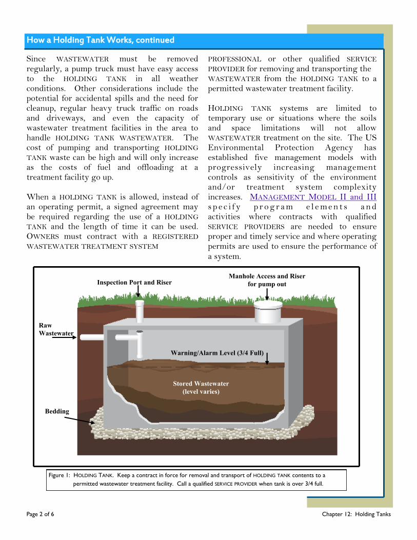
How a Holding Tank Works, continued
Page 2 of 6 Chapter 12: Holding Tanks
Since WASTEWATER must be removed regularly, a pump truck must have easy access to the HOLDING TANK in all weather conditions. Other considerations include the potential for accidental spills and the need for cleanup, regular heavy truck traffic on roads and driveways, and even the capacity of wastewater treatment facilities in the area to handle HOLDING TANK WASTEWATER. The cost of pumping and transporting HOLDING TANK waste can be high and will only increase as the costs of fuel and offloading at a treatment facility go up. When a HOLDING TANK is allowed, instead of an operating permit, a signed agreement may be required regarding the use of a HOLDING TANK and the length of time it can be used. OWNERS must contract with a REGISTERED WASTEWATER TREATMENT SYSTEM
PROFESSIONAL or other qualified SERVICE PROVIDER for removing and transporting the WASTEWATER from the HOLDING TANK to a permitted wastewater treatment facility.
HOLDING TANK systems are limited to temporary use or situations where the soils and space limitations will not allow WASTEWATER treatment on the site. The US Environmental Protection Agency has established five management models with progressively increasing management controls as sensitivity of the environment and/or treatment system complexity increases. MANAGEMENT MODEL II and III s p e c i f y p r o g r a m e l e m e n t s a n d activities where contracts with qualified SERVICE PROVIDERS are needed to ensure proper and timely service and where operating permits are used to ensure the performance of a system.
Figure 1: HOLDING TANK. Keep a contract in force for removal and transport of HOLDING TANK contents to a
permitted wastewater treatment facility. Call a qualified SERVICE PROVIDER when tank is over 3/4 full.
Inspection Port and Riser Manhole Access and Riser
for pump out
Warning/Alarm Level (3/4 Full)
Stored Wastewater
(level varies)
Raw
Wastewater
Bedding
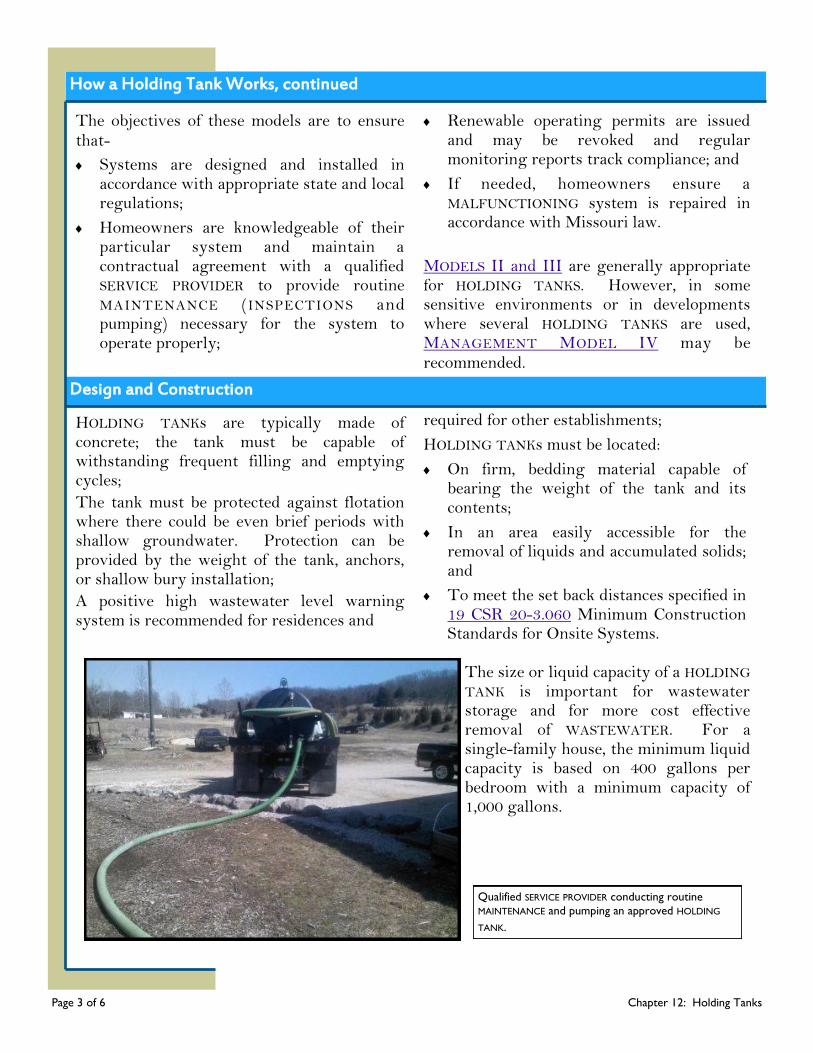
How a Holding Tank Works, continued
Page 3 of 6 Chapter 12: Holding Tanks
The objectives of these models are to ensure that-
Systems are designed and installed in accordance with appropriate state and local regulations;
Homeowners are knowledgeable of their particular system and maintain a contractual agreement with a qualified SERVICE PROVIDER to provide routine MAINTENANCE (INSPECTIONS and pumping) necessary for the system to operate properly;
Renewable operating permits are issued and may be revoked and regular monitoring reports track compliance; and
If needed, homeowners ensure a MALFUNCTIONING system is repaired in accordance with Missouri law.
MODELS II and III are generally appropriate for HOLDING TANKS. However, in some sensitive environments or in developments where several HOLDING TANKS are used, MANAGEMENT MODEL IV may be recommended.
HOLDING TANKs are typically made of concrete; the tank must be capable of withstanding frequent filling and emptying cycles;
The tank must be protected against flotation where there could be even brief periods with shallow groundwater. Protection can be provided by the weight of the tank, anchors, or shallow bury installation;
A positive high wastewater level warning system is recommended for residences and
required for other establishments;
HOLDING TANKs must be located:
On firm, bedding material capable of bearing the weight of the tank and its contents;
In an area easily accessible for the removal of liquids and accumulated solids; and
To meet the set back distances specified in 19 CSR 20-3.060 Minimum Construction Standards for Onsite Systems.
The size or liquid capacity of a HOLDING TANK is important for wastewater storage and for more cost effective removal of WASTEWATER. For a single-family house, the minimum liquid capacity is based on 400 gallons per bedroom with a minimum capacity of 1,000 gallons.
Design and Construction
Qualified SERVICE PROVIDER conducting routine
MAINTENANCE and pumping an approved HOLDING
TANK.
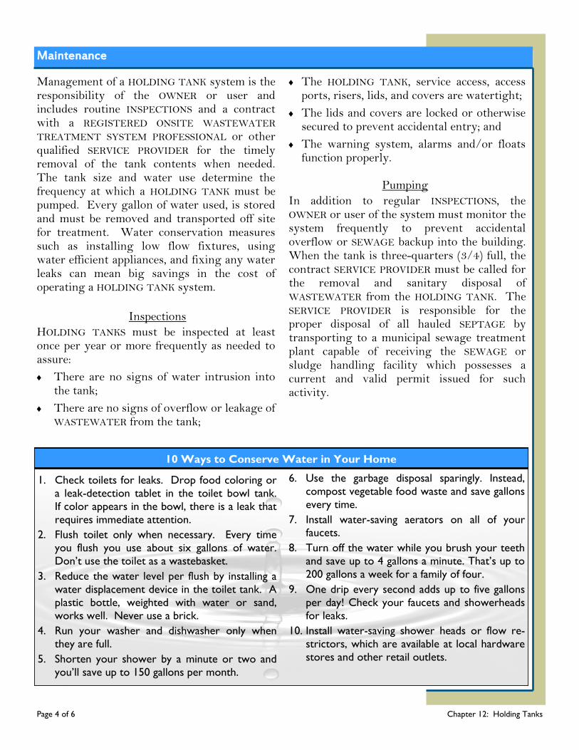
Maintenance
Page 4 of 6 Chapter 12: Holding Tanks
Management of a HOLDING TANK system is the responsibility of the OWNER or user and includes routine INSPECTIONS and a contract with a REGISTERED ONSITE WASTEWATER TREATMENT SYSTEM PROFESSIONAL or other qualified SERVICE PROVIDER for the timely removal of the tank contents when needed. The tank size and water use determine the frequency at which a HOLDING TANK must be pumped. Every gallon of water used, is stored and must be removed and transported off site for treatment. Water conservation measures such as installing low flow fixtures, using water efficient appliances, and fixing any water leaks can mean big savings in the cost of operating a HOLDING TANK system.
Inspections
HOLDING TANKS must be inspected at least once per year or more frequently as needed to assure:
There are no signs of water intrusion into the tank;
There are no signs of overflow or leakage of WASTEWATER from the tank;
The HOLDING TANK, service access, access ports, risers, lids, and covers are watertight;
The lids and covers are locked or otherwise secured to prevent accidental entry; and
The warning system, alarms and/or floats function properly.
Pumping
In addition to regular INSPECTIONS, the OWNER or user of the system must monitor the system frequently to prevent accidental overflow or SEWAGE backup into the building. When the tank is three-quarters (3/4) full, the contract SERVICE PROVIDER must be called for the removal and sanitary disposal of WASTEWATER from the HOLDING TANK. The SERVICE PROVIDER is responsible for the proper disposal of all hauled SEPTAGE by transporting to a municipal sewage treatment plant capable of receiving the SEWAGE or sludge handling facility which possesses a current and valid permit issued for such activity.
10 Ways to Conserve Water in Your Home
1. Check toilets for leaks. Drop food coloring or
a leak-detection tablet in the toilet bowl tank.
If color appears in the bowl, there is a leak that
requires immediate attention.
2. Flush toilet only when necessary. Every time
you flush you use about six gallons of water.
Don’t use the toilet as a wastebasket.
3. Reduce the water level per flush by installing a
water displacement device in the toilet tank. A
plastic bottle, weighted with water or sand,
works well. Never use a brick.
4. Run your washer and dishwasher only when
they are full.
5. Shorten your shower by a minute or two and
you’ll save up to 150 gallons per month.
6. Use the garbage disposal sparingly. Instead,
compost vegetable food waste and save gallons
every time.
7. Install water-saving aerators on all of your faucets.
8. Turn off the water while you brush your teeth
and save up to 4 gallons a minute. That’s up to
200 gallons a week for a family of four.
9. One drip every second adds up to five gallons
per day! Check your faucets and showerheads
for leaks.
10. Install water-saving shower heads or flow re-
strictors, which are available at local hardware
stores and other retail outlets.
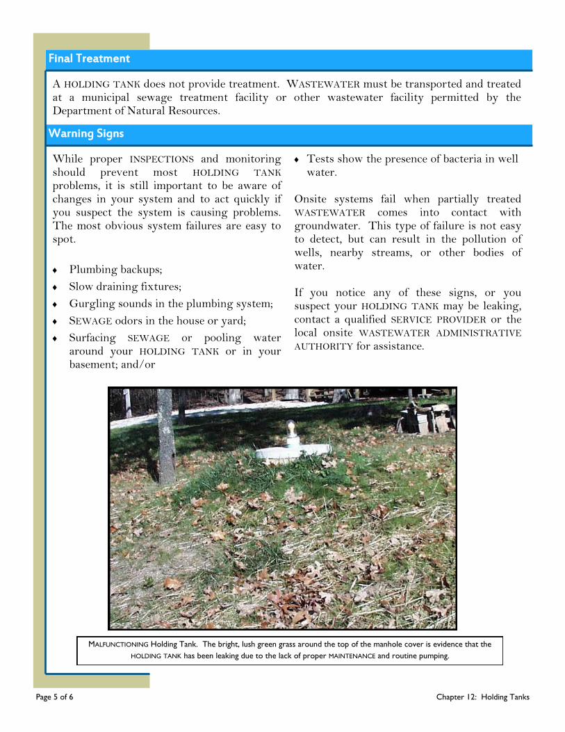
Final Treatment
A HOLDING TANK does not provide treatment. WASTEWATER must be transported and treated at a municipal sewage treatment facility or other wastewater facility permitted by the Department of Natural Resources.
Warning Signs
While proper INSPECTIONS and monitoring should prevent most HOLDING TANK problems, it is still important to be aware of changes in your system and to act quickly if you suspect the system is causing problems. The most obvious system failures are easy to spot.
Plumbing backups;
Slow draining fixtures;
Gurgling sounds in the plumbing system;
SEWAGE odors in the house or yard;
Surfacing SEWAGE or pooling water around your HOLDING TANK or in your basement; and/or
Tests show the presence of bacteria in well water.
Onsite systems fail when partially treated WASTEWATER comes into contact with groundwater. This type of failure is not easy to detect, but can result in the pollution of wells, nearby streams, or other bodies of water. If you notice any of these signs, or you suspect your HOLDING TANK may be leaking, contact a qualified SERVICE PROVIDER or the local onsite WASTEWATER ADMINISTRATIVE AUTHORITY for assistance.
MALFUNCTIONING Holding Tank. The bright, lush green grass around the top of the manhole cover is evidence that the
HOLDING TANK has been leaking due to the lack of proper MAINTENANCE and routine pumping.
Page 5 of 6 Chapter 12: Holding Tanks
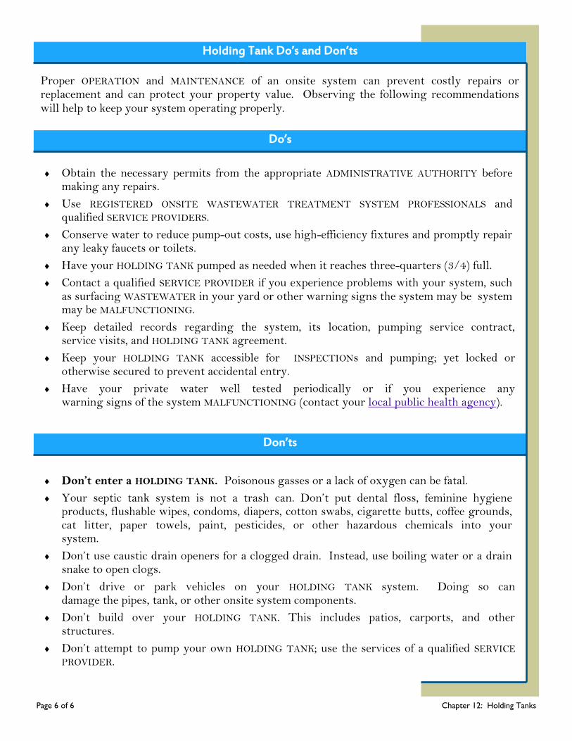
Holding Tank Do’s and Don’ts
Page 6 of 6 Chapter 12: Holding Tanks
Proper OPERATION and MAINTENANCE of an onsite system can prevent costly repairs or replacement and can protect your property value. Observing the following recommendations will help to keep your system operating properly.
Do’s
Obtain the necessary permits from the appropriate ADMINISTRATIVE AUTHORITY before making any repairs.
Use REGISTERED ONSITE WASTEWATER TREATMENT SYSTEM PROFESSIONALS and qualified SERVICE PROVIDERS.
Conserve water to reduce pump-out costs, use high-efficiency fixtures and promptly repair any leaky faucets or toilets.
Have your HOLDING TANK pumped as needed when it reaches three-quarters (3/4) full.
Contact a qualified SERVICE PROVIDER if you experience problems with your system, such as surfacing WASTEWATER in your yard or other warning signs the system may be system may be MALFUNCTIONING.
Keep detailed records regarding the system, its location, pumping service contract, service visits, and HOLDING TANK agreement.
Keep your HOLDING TANK accessible for INSPECTIONs and pumping; yet locked or otherwise secured to prevent accidental entry.
Have your private water well tested periodically or if you experience any warning signs of the system MALFUNCTIONING (contact your local public health agency).
Don’ts
Don’t enter a HOLDING TANK. Poisonous gasses or a lack of oxygen can be fatal.
Your septic tank system is not a trash can. Don’t put dental floss, feminine hygiene products, flushable wipes, condoms, diapers, cotton swabs, cigarette butts, coffee grounds, cat litter, paper towels, paint, pesticides, or other hazardous chemicals into your system.
Don’t use caustic drain openers for a clogged drain. Instead, use boiling water or a drain snake to open clogs.
Don’t drive or park vehicles on your HOLDING TANK system. Doing so can damage the pipes, tank, or other onsite system components.
Don’t build over your HOLDING TANK. This includes patios, carports, and other structures.
Don’t attempt to pump your own HOLDING TANK; use the services of a qualified SERVICE PROVIDER.
Chapter 13
Chapter 13: Cluster Systems
Page 1 of 6 Chapter 13: Cluster Systems
Over the past few decades Missouri and the nation have made significant strides in addressing WASTEWATER treatment needs in communities. However, WASTEWATER treatment needs still remain, especially in small, rural communities and developments. Many of these older developments were not planned with sewage treatment in mind; in fact, several have direct SEWAGE discharges or connections to common drains due to a lack of such planning. These communities often cannot solve their sewage treatment problems using individual onsite systems due to small lot size or poor soil conditions. A centralized wastewater system may not be
a good solution due to limited operation expertise and funding. Cluster systems can bridge the gap in small communities and developments where neither individual ONSITE WASTEWATER TREATMENT SYSTEMS nor centralized wastewater systems are feasible. Cluster systems are an important option for wastewater management in situations where onsite systems are impractical or where connecting to centralized wastewater systems is not financially or technically feasible. Cluster systems can also be used to address capacity issues with large centralized wastewater systems.
How a Cluster System Works
There are three general types of wastewater systems: individual onsite, centralized, and cluster. Each type of system can consist of various combinations of wastewater collection, treatment, and dispersal technologies. While individual onsite systems serve one household or property and centralized systems serve large, high-density communities, cluster systems serve an intermediate number of residences or establishments. Cluster systems collect and treat wastewater from at least two residences or establishments, but less than the whole community. A typical cluster system serves 2 to 10 residences.
What’s Ahead...
How a Cluster
System Works
Design and
Construction
Maintenance
Warning Signs
Do’s and Don’ts Glossary Resources

How a Cluster System Works, continued
Page 2 of 6 Chapter 13: Cluster Systems
The difference between the three types are:
Individual Onsite Wastewater Systems:
Onsite systems collect, treat, and disperse wastewater on an individual property. Onsite systems are associated with low-density communities and developments and generally consist of a treatment device and a subsurface dispersal system.
Centralized Wastewater Systems:
Centralized systems are associated with high-density communities and developments such as cities and commercial areas. They generally consist of a collection system that gathers and transports WASTEWATER to large centralized treatment facilities where it is usually returned to surface waters.
Cluster Wastewater Systems:
Cluster systems can serve a small to large number of connections. Smaller cluster systems serving a few buildings resemble onsite systems, while large cluster systems serving hundreds of structures are similar to centralized systems. Small cluster systems generally disperse WASTEWATER in subsurface dispersal systems.
This chapter focuses on cluster systems that disperse treated WASTEWATER into subsurface soil treatment systems. Cluster systems may include any of the technologies that are discussed in the component chapters of this manual except for lagoons and HOLDING TANKS.
Cluster systems may collect and transport all of the raw SEWAGE from individual structures to a single location for treatment and dispersal. Alternatively, treatment may begin with a sewage tank located at each residence or establishment; and then only EFFLUENT is collected and transported for further treatment and dispersal.
Other than the more extensive sewage collection network, various wastewater treatment components work essentially the same in a cluster system as in an individual system. Please refer to the appropriate chapter of this manual for more component details.
How a Cluster System Works, continued
Cluster systems can provide effective treatment of wastewater. The United States Environmental Protection Agency (US EPA) has established five management models with progressively increasing management controls as sensitivity of the environment and/or treatment system complexity increases. Management model V specifies appropriate program elements and activit ies where a RESPONSIBLE MANAGEMENT ENTITY (RME) owns and
manages individual and clustered systems. This model is generally appropriate for cluster systems. However, Management model IV may be considered if residence or establishment OWNERS would own the pretreatment components located at individual buildings. A further discussion of cluster system management is included later in this chapter.
Page 3 of 6 Chapter 13: Cluster Systems
Design and Construction
Cluster system design and construction may differ from individual system component design and construction. Some differences are related to increased complexity of larger systems. However, some relate to the flexibility, controls, and improved treatment options that can be more cost effective at a somewhat larger scale. As the number of cluster system connections and the flows increase, the effect of individual flow variability has less of an impact than on individual systems. Collection System One major difference between cluster wastewater treatment systems and individual onsite systems is the more extensive collection network needed for a cluster system. Collection may use either a system of 4-inch diameter or larger conventional gravity sewers or smaller alternative sewers. To assure proper function of a cluster treatment system, it is essential to assure that the collection system is watertight to exclude all groundwater and surface water. Gravity sewers must be sized and sloped correctly to handle the flows based on the anticipated number of connections. Access and cleanouts must be installed as needed for
untreated wastewater or for EFFLUENT.
Alternative collection systems include EFFLUENT sewers and pressure sewers, which may use smaller diameter pipes and shallower installation to simplify construction and potentially reduce costs. Cleanouts, isolation valves, air releases, and vacuum relief valves must be used as needed to allow service and assure system function. Pretreatment Component(s) When primary treatment is accomplished at each building, septic tank and EFFLUENT screen components are similar to those of an individual system. Collection of flows from multiple buildings often helps even out variable flows, which can improve the performance of pretreatment components. The use of timers and controls for flow equalization, recirculation, and other design options can further improve performance and may be more cost effective for cluster systems than for individual systems. However, any pretreatment components must be sized correctly based on the maximum daily flows received.
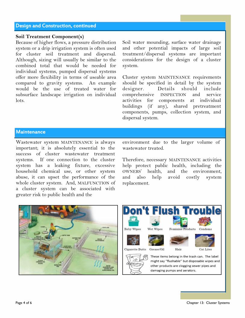
Design and Construction, continued
Soil Treatment Component(s) Because of higher flows, a pressure distribution system or a drip irrigation system is often used for cluster soil treatment and dispersal. Although, sizing will usually be similar to the combined total that would be needed for individual systems, pumped dispersal systems offer more flexibility in terms of useable area compared to gravity systems. An example would be the use of treated water for subsurface landscape irrigation on individual lots.
Soil water mounding, surface water drainage and other potential impacts of large soil treatment/dispersal systems are important considerations for the design of a cluster system. Cluster system MAINTENANCE requirements should be specified in detail by the system designer. Details should include comprehensive INSPECTION and service activities for components at individual buildings (if any), shared pretreatment components, pumps, collection system, and dispersal system.
Page 4 of 6 Chapter 13: Cluster Systems
Maintenance
Wastewater system MAINTENANCE is always important; it is absolutely essential to the success of cluster wastewater treatment systems. If one connection to the cluster system has a leaking fixture, excessive household chemical use, or other system abuse, it can upset the performance of the whole cluster system. And, MALFUNCTION of a cluster system can be associated with greater risk to public health and the
environment due to the larger volume of wastewater treated.
Therefore, necessary MAINTENANCE activities help protect public health, including the OWNERS’ health, and the environment, and also help avoid costly system replacement.
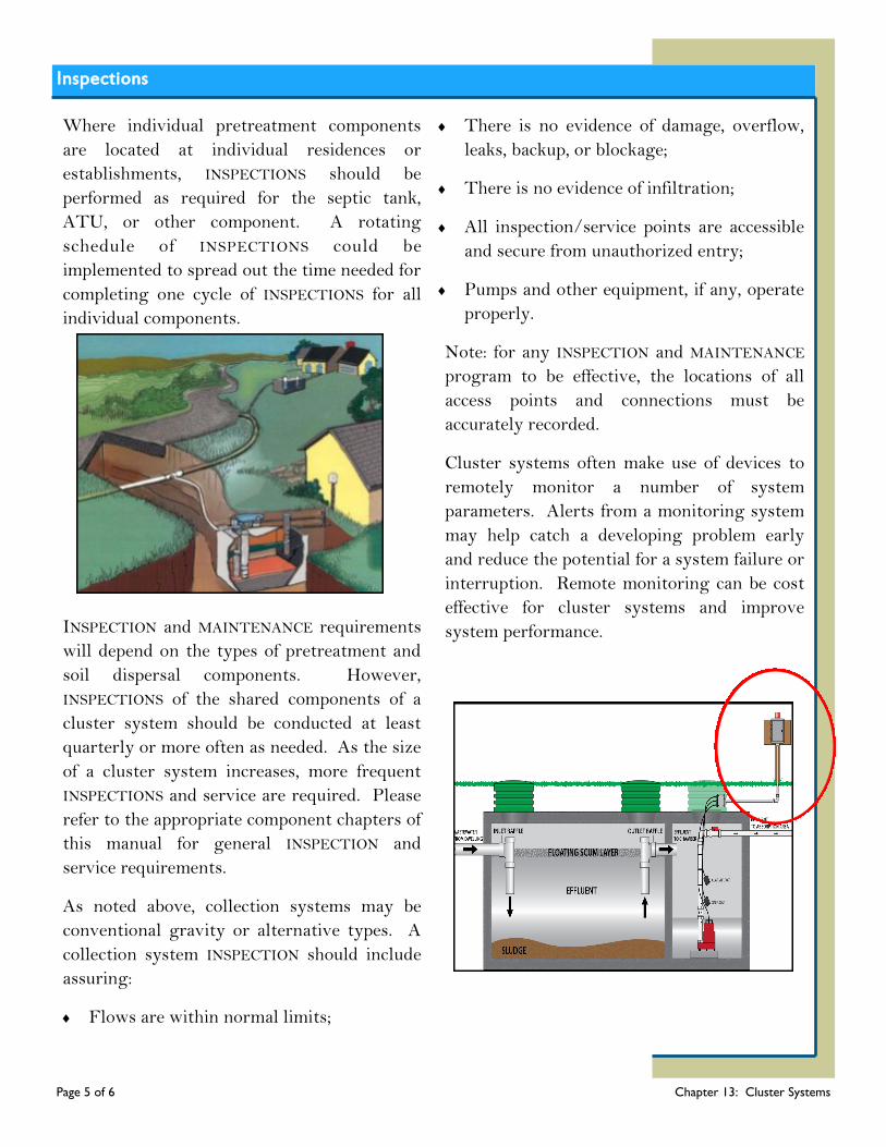
Inspections
Page 5 of 6 Chapter 13: Cluster Systems
Where individual pretreatment components
are located at individual residences or
establishments, INSPECTIONS should be
performed as required for the septic tank,
ATU, or other component. A rotating
schedule of INSPECTIONS could be
implemented to spread out the time needed for
completing one cycle of INSPECTIONS for all
individual components.
INSPECTION and MAINTENANCE requirements
will depend on the types of pretreatment and
soil dispersal components. However,
INSPECTIONS of the shared components of a
cluster system should be conducted at least
quarterly or more often as needed. As the size
of a cluster system increases, more frequent
INSPECTIONS and service are required. Please
refer to the appropriate component chapters of
this manual for general INSPECTION and
service requirements.
As noted above, collection systems may be
conventional gravity or alternative types. A
collection system INSPECTION should include
assuring:
Flows are within normal limits;
There is no evidence of damage, overflow,
leaks, backup, or blockage;
There is no evidence of infiltration;
All inspection/service points are accessible
and secure from unauthorized entry;
Pumps and other equipment, if any, operate
properly.
Note: for any INSPECTION and MAINTENANCE
program to be effective, the locations of all
access points and connections must be
accurately recorded.
Cluster systems often make use of devices to
remotely monitor a number of system
parameters. Alerts from a monitoring system
may help catch a developing problem early
and reduce the potential for a system failure or
interruption. Remote monitoring can be cost
effective for cluster systems and improve
system performance.
Cluster System Management
The actual MAINTENANCE and service activities for cluster systems may be easier than the management structure required. Cluster system management needs to be more thoughtfully organized than the simpler management allowed for individual systems. For comparison, an individual onsite system OWNER is generally responsible for the system OPERATION and MAINTENANCE, including any repair or replacement that may become necessary. Because a cluster system may serve any number of individual residences or establishments, it would be difficult, if not impossible, for one or more OWNERS acting individually to successfully manage a cluster system. A form of legal and financial organization is needed to handle necessary management activities. The entity would be considered a RESPONSIBLE MANAGEMENT ENTITY (RME). An RME may manage one or more cluster and/or individual wastewater treatment systems. RME’s may include various private, public, or non-profit entities. Regardless of the type of entity, the legal and financial organization must provide for OWNERS to fairly share the cost of MAINTENANCE and funds for major repairs.
Failure to properly organize management could result in unacceptable system MALFUNCTION and risks to public health and the environment. The US EPA established five management models for onsite and cluster wastewater systems; see a summary in the Management Models section of this manual. Model V, RME ownership is recommended for cluster systems. Model IV or a combination of the two models could be used where an RME manages individual systems or components that are owned and located on the individual OWNER’S property. The activities of an RME under Model V include: Participate in system selection, planning,
and design; Inform system OWNER/users of proper
system use and prohibited uses; Employ or contract with registered/
qualified service professionals; Operate, maintain, and repair system to
assure required performance; Retain system INSPECTION and service
records.
Do’s and Don’ts
In addition to the Dos and Don’ts noted in the various component chapters, for cluster systems there is one important OWNER/user requirement:
Follow any and all RME recommendations or requirements regarding the
care and use of a cluster system.
Page 6 of 6 Chapter 13: Cluster Systems

Chapter 14: Soils Component Chapter 14
Homes not served by public sewers rely on individual onsite or cluster wastewater treatment systems to treat and disperse domestic WA STEWATER . Household WASTEWATER contains human waste, dirt, food, toilet paper, soap, detergents, and cleaning products; which includes dissolved nutrients, microorganisms, pathogens (disease causing organisms) and solid particles. Improperly maintained wastewater treatment systems can allow these substances to become a health hazard by contaminating groundwater and/or bodies of surface water.
ONSITE WASTEWATER TREATMENT SYSTEMS (OWTSs) may have a variety of component types; however, soil is one component that all onsite systems have in common. Except HOLDING TANK systems do not use the soil
onsite, but instead store SEWAGE until it is hauled off site for treatment. Wastewater treatment by the soil is the final layer of protection for p u b l i c h e a l t h , groundwater, and surface waters. After this final treatment step, treated water is safely recycled back into the hydrologic cycle.
Soils are not all the same. Therefore, it is
important to understand the soil’s properties
and limitations for treating and recycling water.
The best choice of system components and the
proper design and installation of an OWTS
requires an accurate evaluation of the site and
soil properties. Soil properties can best be
determined by a soil morphology evaluation
although a percolation test may be accepted in
some areas (contact your onsite wastewater
ADMINISTRATIVE AUTHORITY for details).
Page 1 of 8 Chapter 14: Soils Component
What’s Ahead...
How Soil Works
to Treat
Wastewater
Soil Properties
Design &
Construction
Maintenance
Remediation
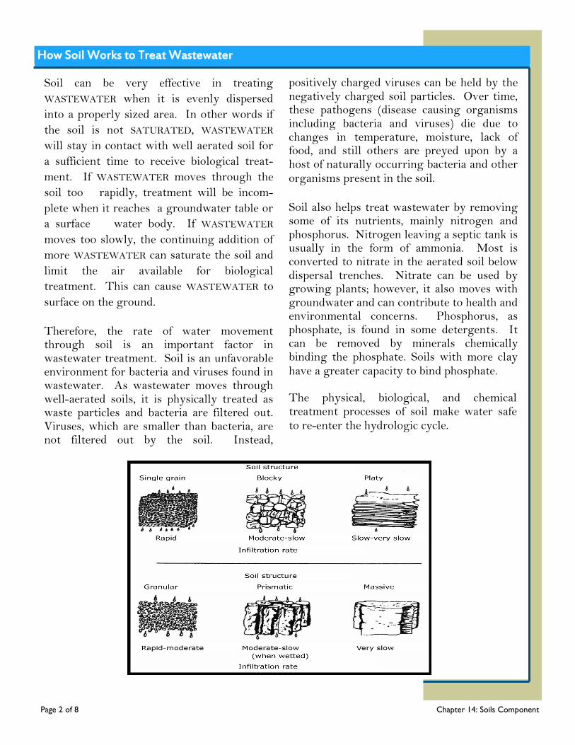
Soil can be very effective in treating
WASTEWATER when it is evenly dispersed
into a properly sized area. In other words if
the soil is not SATURATED, WASTEWATER
will stay in contact with well aerated soil for
a sufficient time to receive biological treat-
ment. If WASTEWATER moves through the
soil too rapidly, treatment will be incom-
plete when it reaches a groundwater table or
a surface water body. If WASTEWATER
moves too slowly, the continuing addition of
more WASTEWATER can saturate the soil and
limit the air available for biological
treatment. This can cause WASTEWATER to
surface on the ground.
Therefore, the rate of water movement through soil is an important factor in wastewater treatment. Soil is an unfavorable environment for bacteria and viruses found in wastewater. As wastewater moves through well-aerated soils, it is physically treated as waste particles and bacteria are filtered out. Viruses, which are smaller than bacteria, are not filtered out by the soil. Instead,
positively charged viruses can be held by the negatively charged soil particles. Over time, these pathogens (disease causing organisms including bacteria and viruses) die due to changes in temperature, moisture, lack of food, and still others are preyed upon by a host of naturally occurring bacteria and other organisms present in the soil.
Soil also helps treat wastewater by removing some of its nutrients, mainly nitrogen and phosphorus. Nitrogen leaving a septic tank is usually in the form of ammonia. Most is converted to nitrate in the aerated soil below dispersal trenches. Nitrate can be used by growing plants; however, it also moves with groundwater and can contribute to health and environmental concerns. Phosphorus, as phosphate, is found in some detergents. It can be removed by minerals chemically binding the phosphate. Soils with more clay have a greater capacity to bind phosphate. The physical, biological, and chemical treatment processes of soil make water safe to re-enter the hydrologic cycle.
How Soil Works to Treat Wastewater
Page 2 of 8 Chapter 14: Soils Component
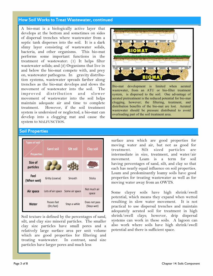
How Soil Works to Treat Wastewater, continued
A bio-mat is a biologically active layer that develops at the bottom and sometimes on sides of dispersal trenches where wastewater from a septic tank disperses into the soil. It is a dark slimy layer consisting of wastewater solids, bacteria, and other organisms. This bio-mat performs some important functions in the treatment of wastewater: (1) It helps filter wastewater solids; and (2) Organisms that live in and below the bio-mat compete with, and prey on, wastewater pathogens. In gravity distribu-tion systems, wastewater spreads farther along trenches as the bio-mat develops and slows the movement of wastewater into the soil. The improved d is tr ibut ion and s lower movement of wastewater into the soil helps maintain adequate air and time to complete treatment. However, if the soil treatment system is undersized or neglected, a bio-mat can develop into a clogging mat and cause the system to MALFUNCTION.
Soil texture is defined by the percentages of sand, silt, and clay size mineral particles. The smaller clay size particles have small pores and a relatively large surface area per unit volume which are good properties for filtering and treating wastewater. In contrast, sand size particles have larger pores and much less
surface area which are good properties for moving water and air, but not as good for treatment. Silt sized particles are intermediate in size, treatment, and water/air movement. Loam is a term for soil having percentages of sand, silt, and clay so that each has nearly equal influence on soil properties. Loam and predominantly loamy soils have good properties for treating wastewater as well as for moving water away from an OWTS.
Some clayey soils have high shrink/swell potential, which means they expand when wetted resulting in slow water movement. It is not practical to use dispersal trenches and maintain adequately aerated soil for treatment in high shrink/swell clays; however, drip dispersal systems can work in these soils. A lagoon can also work where soils have high shrink/swell potential and there is sufficient space.
Bio-mat development is limited when aerated
wastewater, from an ATU or bio-filter treatment
system, is dispersed to the soil. One advantage of
aerated pretreatment is the reduced potential for bio-mat
clogging, however; the filtering, treatment, and
distribution benefits of the bio-mat are lost. Aerated
wastewater should be pressure distributed to avoid
overloading part of the soil treatment area.
Soil Properties
Page 3 of 8 Chapter 14: Soils Component
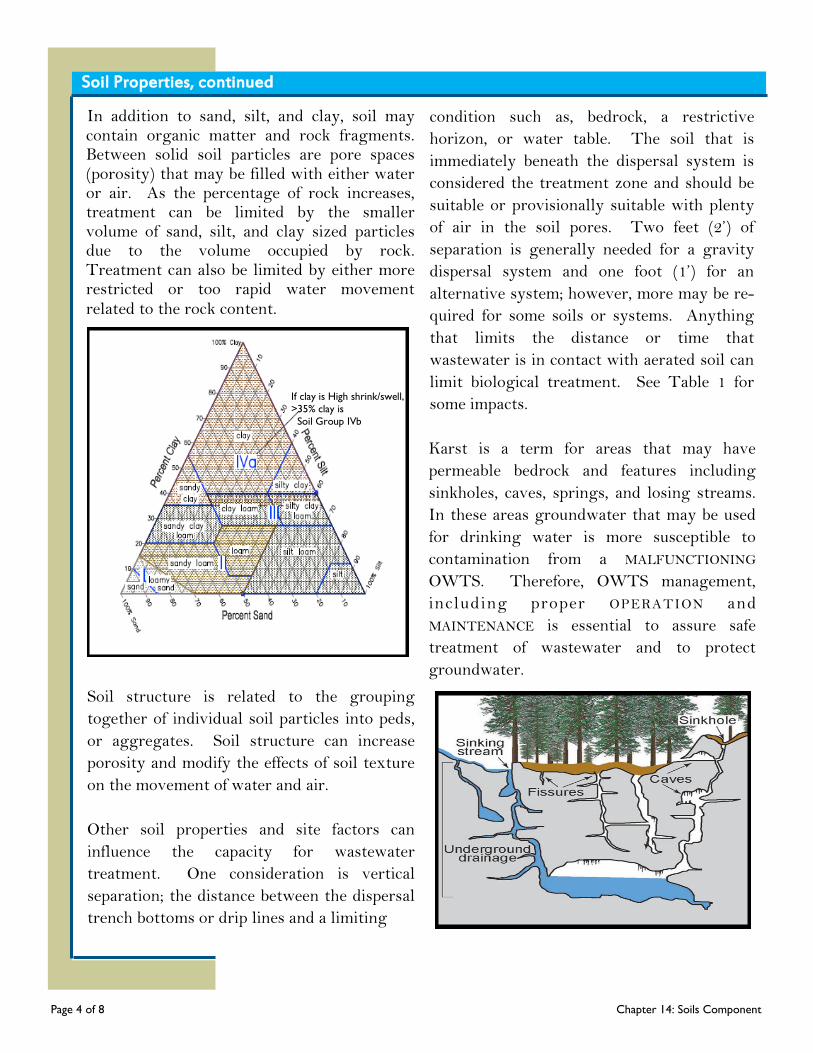
In addition to sand, silt, and clay, soil may contain organic matter and rock fragments. Between solid soil particles are pore spaces (porosity) that may be filled with either water or air. As the percentage of rock increases, treatment can be limited by the smaller volume of sand, silt, and clay sized particles due to the volume occupied by rock. Treatment can also be limited by either more restricted or too rapid water movement related to the rock content.
Soil structure is related to the grouping
together of individual soil particles into peds,
or aggregates. Soil structure can increase
porosity and modify the effects of soil texture
on the movement of water and air.
Other soil properties and site factors can
influence the capacity for wastewater
treatment. One consideration is vertical
separation; the distance between the dispersal
trench bottoms or drip lines and a limiting
condition such as, bedrock, a restrictive
horizon, or water table. The soil that is
immediately beneath the dispersal system is
considered the treatment zone and should be
suitable or provisionally suitable with plenty
of air in the soil pores. Two feet (2’) of
separation is generally needed for a gravity
dispersal system and one foot (1’) for an
alternative system; however, more may be re-
quired for some soils or systems. Anything
that limits the distance or time that
wastewater is in contact with aerated soil can
limit biological treatment. See Table 1 for
some impacts.
Karst is a term for areas that may have
permeable bedrock and features including
sinkholes, caves, springs, and losing streams.
In these areas groundwater that may be used
for drinking water is more susceptible to
contamination from a MALFUNCTIONING
OWTS. Therefore, OWTS management,
including proper OPERATION and
MAINTENANCE is essential to assure safe
treatment of wastewater and to protect
groundwater.
Soil Properties, continued
Page 4 of 8 Chapter 14: Soils Component
If clay is High shrink/swell,
>35% clay is
Soil Group IVb
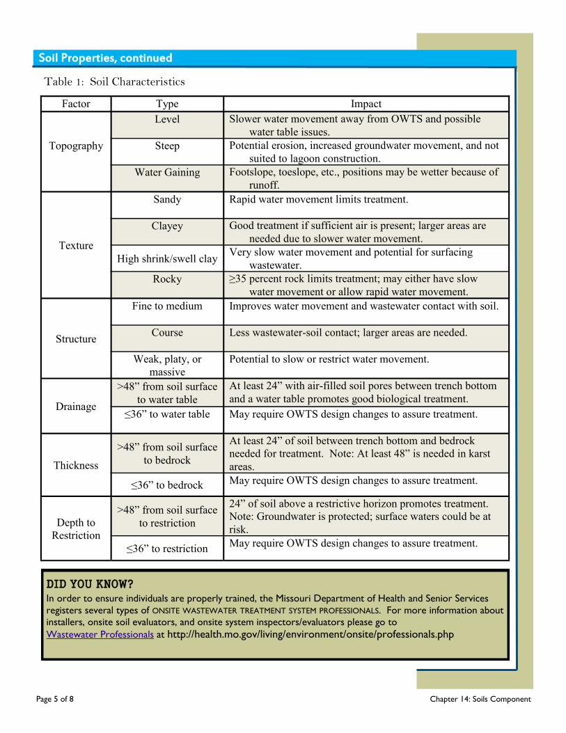
Table 1: Soil Characteristics
Soil Properties, continued
Factor Type Impact
Topography
Level
Slower water movement away from OWTS and possible
water table issues.
Steep
Potential erosion, increased groundwater movement, and not
suited to lagoon construction.
Water Gaining
Footslope, toeslope, etc., positions may be wetter because of
runoff.
Texture
Sandy
Rapid water movement limits treatment.
Clayey
Good treatment if sufficient air is present; larger areas are
needed due to slower water movement.
High shrink/swell clay Very slow water movement and potential for surfacing
wastewater.
Rocky
≥35 percent rock limits treatment; may either have slow
water movement or allow rapid water movement.
Structure
Fine to medium
Improves water movement and wastewater contact with soil.
Course
Less wastewater-soil contact; larger areas are needed.
Weak, platy, or
massive
Potential to slow or restrict water movement.
Drainage
>48” from soil surface
to water table
At least 24” with air-filled soil pores between trench bottom
and a water table promotes good biological treatment.
≤36” to water table
May require OWTS design changes to assure treatment.
Thickness
>48” from soil surface
to bedrock
At least 24” of soil between trench bottom and bedrock
needed for treatment. Note: At least 48” is needed in karst
areas.
≤36” to bedrock May require OWTS design changes to assure treatment.
Depth to
Restriction
>48” from soil surface
to restriction
24” of soil above a restrictive horizon promotes treatment.
Note: Groundwater is protected; surface waters could be at
risk.
≤36” to restriction May require OWTS design changes to assure treatment.
DID YOU KNOW? In order to ensure individuals are properly trained, the Missouri Department of Health and Senior Services
registers several types of ONSITE WASTEWATER TREATMENT SYSTEM PROFESSIONALS. For more information about
installers, onsite soil evaluators, and onsite system inspectors/evaluators please go to
Wastewater Professionals at http://health.mo.gov/living/environment/onsite/professionals.php
Page 5 of 8 Chapter 14: Soils Component
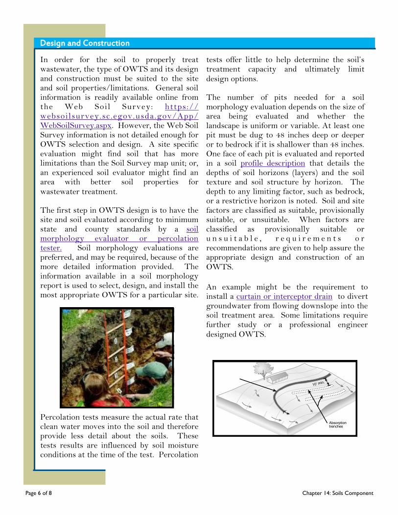
In order for the soil to properly treat wastewater, the type of OWTS and its design and construction must be suited to the site and soil properties/limitations. General soil information is readily available online from the Web Soi l Survey: https://websoi lsurvey.sc.egov.usda.gov/App/WebSoilSurvey.aspx. However, the Web Soil Survey information is not detailed enough for OWTS selection and design. A site specific evaluation might find soil that has more limitations than the Soil Survey map unit; or, an experienced soil evaluator might find an area with better soil properties for wastewater treatment. The first step in OWTS design is to have the site and soil evaluated according to minimum state and county standards by a soil morphology evaluator or percolation tester. Soil morphology evaluations are preferred, and may be required, because of the more detailed information provided. The information available in a soil morphology report is used to select, design, and install the most appropriate OWTS for a particular site.
Percolation tests measure the actual rate that clean water moves into the soil and therefore provide less detail about the soils. These tests results are influenced by soil moisture conditions at the time of the test. Percolation
tests offer little to help determine the soil’s treatment capacity and ultimately limit design options. The number of pits needed for a soil morphology evaluation depends on the size of area being evaluated and whether the landscape is uniform or variable. At least one pit must be dug to 48 inches deep or deeper or to bedrock if it is shallower than 48 inches. One face of each pit is evaluated and reported in a soil profile description that details the depths of soil horizons (layers) and the soil texture and soil structure by horizon. The depth to any limiting factor, such as bedrock, or a restrictive horizon is noted. Soil and site factors are classified as suitable, provisionally suitable, or unsuitable. When factors are classified as provisionally suitable or u n s u i t a b l e , r e q u i r e m e n t s o r recommendations are given to help assure the appropriate design and construction of an OWTS.
An example might be the requirement to install a curtain or interceptor drain to divert groundwater from flowing downslope into the soil treatment area. Some limitations require further study or a professional engineer designed OWTS.
Design and Construction
Page 6 of 8 Chapter 14: Soils Component
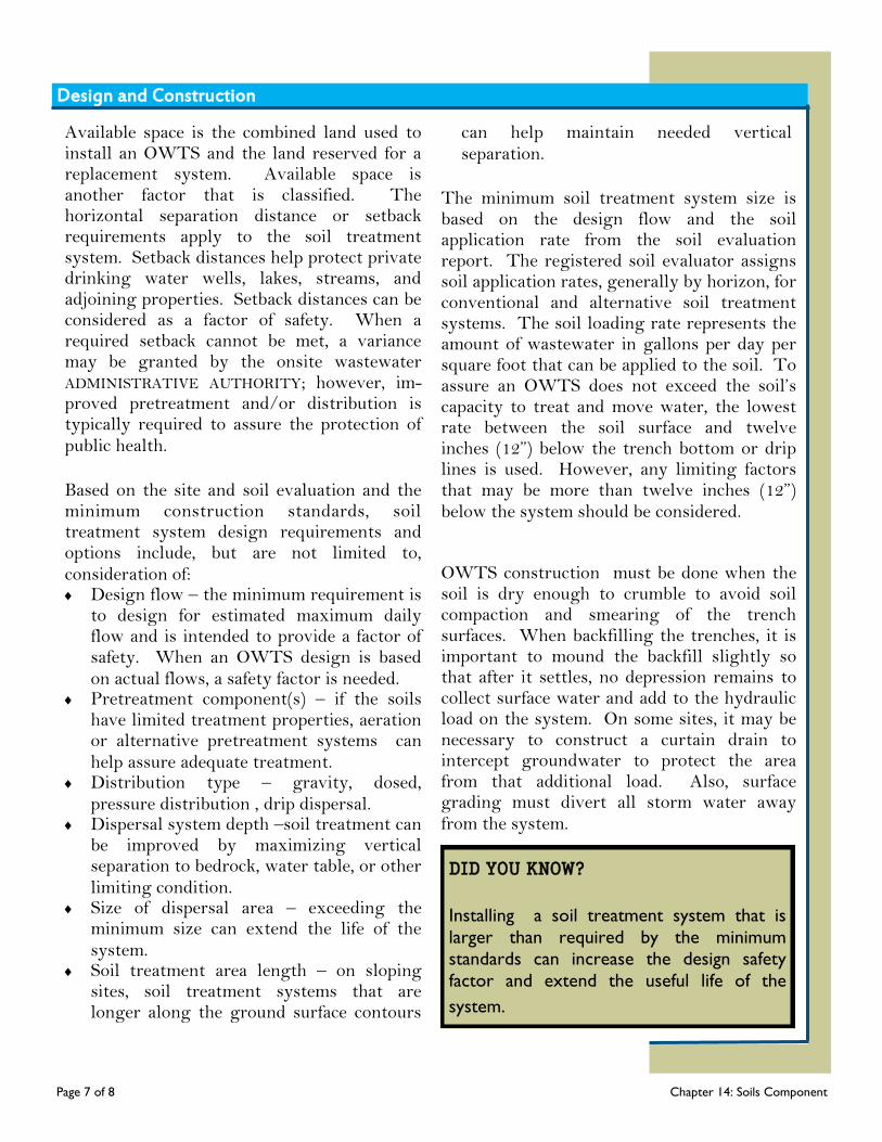
Available space is the combined land used to install an OWTS and the land reserved for a replacement system. Available space is another factor that is classified. The horizontal separation distance or setback requirements apply to the soil treatment system. Setback distances help protect private drinking water wells, lakes, streams, and adjoining properties. Setback distances can be considered as a factor of safety. When a required setback cannot be met, a variance may be granted by the onsite wastewater ADMINISTRATIVE AUTHORITY; however, im-proved pretreatment and/or distribution is typically required to assure the protection of public health.
Based on the site and soil evaluation and the minimum construction standards, soil treatment system design requirements and options include, but are not limited to, consideration of: Design flow – the minimum requirement is
to design for estimated maximum daily flow and is intended to provide a factor of safety. When an OWTS design is based on actual flows, a safety factor is needed.
Pretreatment component(s) – if the soils have limited treatment properties, aeration or alternative pretreatment systems can help assure adequate treatment.
Distribution type – gravity, dosed, pressure distribution , drip dispersal.
Dispersal system depth –soil treatment can be improved by maximizing vertical separation to bedrock, water table, or other limiting condition.
Size of dispersal area – exceeding the minimum size can extend the life of the system.
Soil treatment area length – on sloping sites, soil treatment systems that are longer along the ground surface contours
can help maintain needed vertical separation.
The minimum soil treatment system size is based on the design flow and the soil application rate from the soil evaluation report. The registered soil evaluator assigns soil application rates, generally by horizon, for conventional and alternative soil treatment systems. The soil loading rate represents the amount of wastewater in gallons per day per square foot that can be applied to the soil. To assure an OWTS does not exceed the soil’s capacity to treat and move water, the lowest rate between the soil surface and twelve inches (12”) below the trench bottom or drip lines is used. However, any limiting factors that may be more than twelve inches (12”) below the system should be considered.
OWTS construction must be done when the soil is dry enough to crumble to avoid soil compaction and smearing of the trench surfaces. When backfilling the trenches, it is important to mound the backfill slightly so that after it settles, no depression remains to collect surface water and add to the hydraulic load on the system. On some sites, it may be necessary to construct a curtain drain to intercept groundwater to protect the area from that additional load. Also, surface grading must divert all storm water away from the system.
Design and Construction
DID YOU KNOW?
Installing a soil treatment system that is
larger than required by the minimum
standards can increase the design safety
factor and extend the useful life of the
system.
Page 7 of 8 Chapter 14: Soils Component
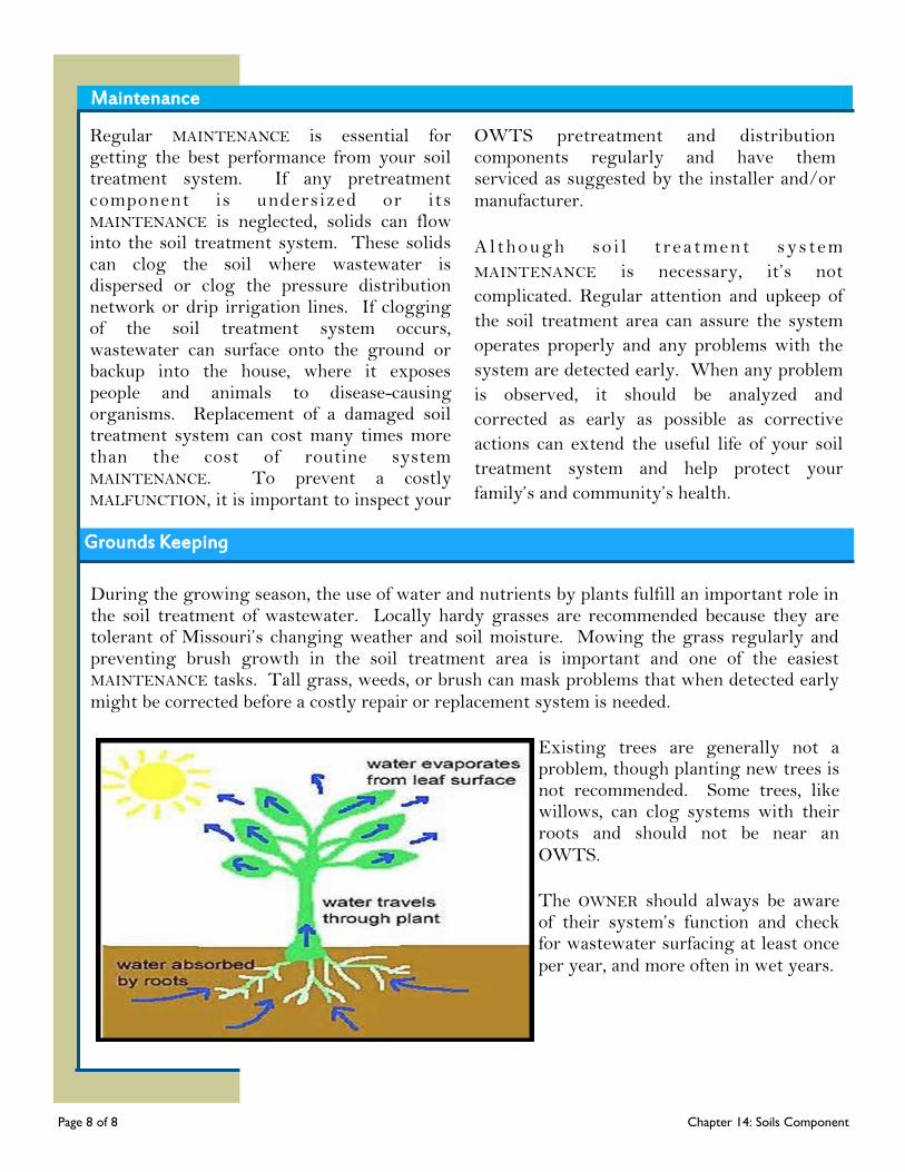
Regular MAINTENANCE is essential for getting the best performance from your soil treatment system. If any pretreatment component is undersized or its MAINTENANCE is neglected, solids can flow into the soil treatment system. These solids can clog the soil where wastewater is dispersed or clog the pressure distribution network or drip irrigation lines. If clogging of the soil treatment system occurs, wastewater can surface onto the ground or backup into the house, where it exposes people and animals to disease-causing organisms. Replacement of a damaged soil treatment system can cost many times more than the cost of routine system MAINTENANCE. To prevent a costly MALFUNCTION, it is important to inspect your
OWTS pretreatment and distribution components regularly and have them serviced as suggested by the installer and/or manufacturer.
A lthough so i l t rea tment sys tem
MAINTENANCE is necessary, it’s not
complicated. Regular attention and upkeep of
the soil treatment area can assure the system
operates properly and any problems with the
system are detected early. When any problem
is observed, it should be analyzed and
corrected as early as possible as corrective
actions can extend the useful life of your soil
treatment system and help protect your
family’s and community’s health.
During the growing season, the use of water and nutrients by plants fulfill an important role in the soil treatment of wastewater. Locally hardy grasses are recommended because they are tolerant of Missouri’s changing weather and soil moisture. Mowing the grass regularly and preventing brush growth in the soil treatment area is important and one of the easiest MAINTENANCE tasks. Tall grass, weeds, or brush can mask problems that when detected early might be corrected before a costly repair or replacement system is needed.
Existing trees are generally not a problem, though planting new trees is not recommended. Some trees, like willows, can clog systems with their roots and should not be near an OWTS.
The OWNER should always be aware of their system’s function and check for wastewater surfacing at least once per year, and more often in wet years.
Maintenance
Grounds Keeping
Page 8 of 8 Chapter 14: Soils Component
Troubleshooting System Problems Common Problems
Existing ONSITE WASTEWATER TREATMENT SYSTEMS or cluster systems can MALFUNCTION for a number of reasons; the most common causes include excessive water use, improper or lack of MAINTENANCE, or the system is inadequately designed or improperly installed. Regular MAINTENANCE by a qualified professional is the best way to avoid problems with your system. In addition, if you see or smell signs of trouble, don’t ignore them. Prompt action at the first warning signs can prevent a problem from becoming worse. Some common signs of trouble include sewer odors, slow drains, SEWAGE backup, and soggy soil or WASTEWATER surfacing in the yard. Determining the specific causes of the problem can be difficult for the homeowner and often requires the expertise of a SERVICE PROVIDER. In diagnosing the problem, it is important to observe whether the problem developed gradually or suddenly; whether it might be related to weather conditions; washing clothes; an increase in the number of people residing in the household; plumbing additions or leaks, or some other pattern or cause. Once you and/or your SERVICE PROVIDER have identified the cause of the problem; a solution must be devised. If the solution involves a major modification or repair of the wastewater treatment system, contact your
local onsite WASTEWATER ADMINISTRATIVE AUTHORITY and ask about permit requirements in your area. At all times, observe safety precautions!
Never enter a sewage tank.
Avoid coming into contact with WASTEWATER. WASTEWATER contains disease-causing viruses and bacteria. People and their pets that come into contact with WASTEWATER may become sick.
Use eye and face protection and rubber gloves when working around a wastewater treatment system.
Afterwards, clean and sanitize your hands, clothes, and areas of any splatter or spill, as well as, secure the lid and openings to
prevent someone from accidentally falling into the tank.
Page 1 of 5 Troubleshooting System Problems

Finding an Existing System
Although it may not be easy, it is important to know where the different parts of your ONSITE WASTEWATER TREATMENT SYSTEM are located for proper MAINTENANCE and troubleshooting problems. Some counties and cities with onsite wastewater permit and INSPECTION programs may have system records and information on file. If no plans exist with the ADMINISTRATIVE AUTHORITY, basement or crawlspace plumbing, cleanouts, sewage tank inspection ports, and dispersal system service access can be clues to the system’s location. Once the system layout is determined, diagram or map out the system for your records.
Wastewater Odors - Indoors
Dry trap, typically a floor drained or unused plumbing fixture/drain
Johnny ring at toilet
Plugged sewer vent or vents are not installed properly
Freezing can temporarily clog the vent
Unsealed electrical conduit from pump tank allows sewer gas indoors
Fill the trap with water periodically
Replace the Johnny ring
Contact qualified plumber to evaluate the plumbing and make necessary corrections
Seal conduit
Problem Potential Causes Potential Solutions
Wastewater Odors - Outdoors
Sewer vents too close to the ground or incorrect vents
Temporary weather conditions with little air movement
Sewer blockage
Heavy use of system
Loose lid on sewer tank
Wastewater and/or solids surfacing at tank
Wastewater surfacing in yard
Contact qualified plumber to evaluate the plumbing and make necessary corrections
Wait and watch as weath-er conditions change
Contact qualified SERVICE PROVIDER to evaluate the sewage tank and take necessary MAINTENANCE or repair actions
Reduce water usage, repair leaking plumbing fixtures; install water saving fixtures and appliances
Secure sewage tank lid Note: Urgent, take
action promptly
Page 2 of 5 Troubleshooting System Problems
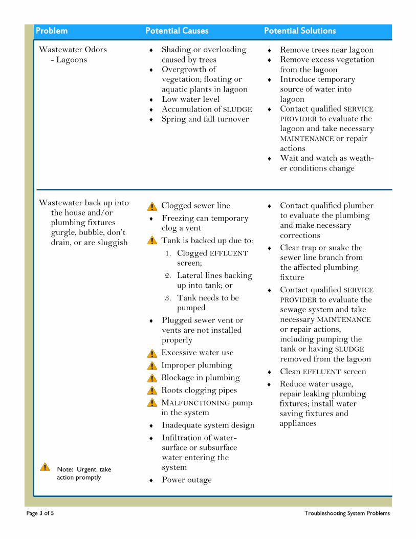
Problem Potential Causes Potential Solutions
Wastewater Odors - Lagoons
Shading or overloading caused by trees
Overgrowth of vegetation; floating or aquatic plants in lagoon
Low water level Accumulation of SLUDGE Spring and fall turnover
Remove trees near lagoon Remove excess vegetation
from the lagoon Introduce temporary
source of water into lagoon
Contact qualified SERVICE PROVIDER to evaluate the lagoon and take necessary MAINTENANCE or repair actions
Wait and watch as weath-er conditions change
Wastewater back up into the house and/or plumbing fixtures gurgle, bubble, don’t drain, or are sluggish
Clogged sewer line
Freezing can temporary clog a vent
Tank is backed up due to:
1. Clogged EFFLUENT screen;
2. Lateral lines backing up into tank; or
3. Tank needs to be pumped
Plugged sewer vent or vents are not installed properly
Excessive water use
Improper plumbing
Blockage in plumbing
Roots clogging pipes
MALFUNCTIONING pump in the system
Inadequate system design
Infiltration of water- surface or subsurface water entering the system
Power outage
Contact qualified plumber to evaluate the plumbing and make necessary corrections
Clear trap or snake the sewer line branch from the affected plumbing fixture
Contact qualified SERVICE PROVIDER to evaluate the sewage system and take necessary MAINTENANCE or repair actions, including pumping the tank or having SLUDGE removed from the lagoon
Clean EFFLUENT screen
Reduce water usage, repair leaking plumbing fixtures; install water saving fixtures and appliances
Note: Urgent, take
action promptly
Page 3 of 5 Troubleshooting System Problems
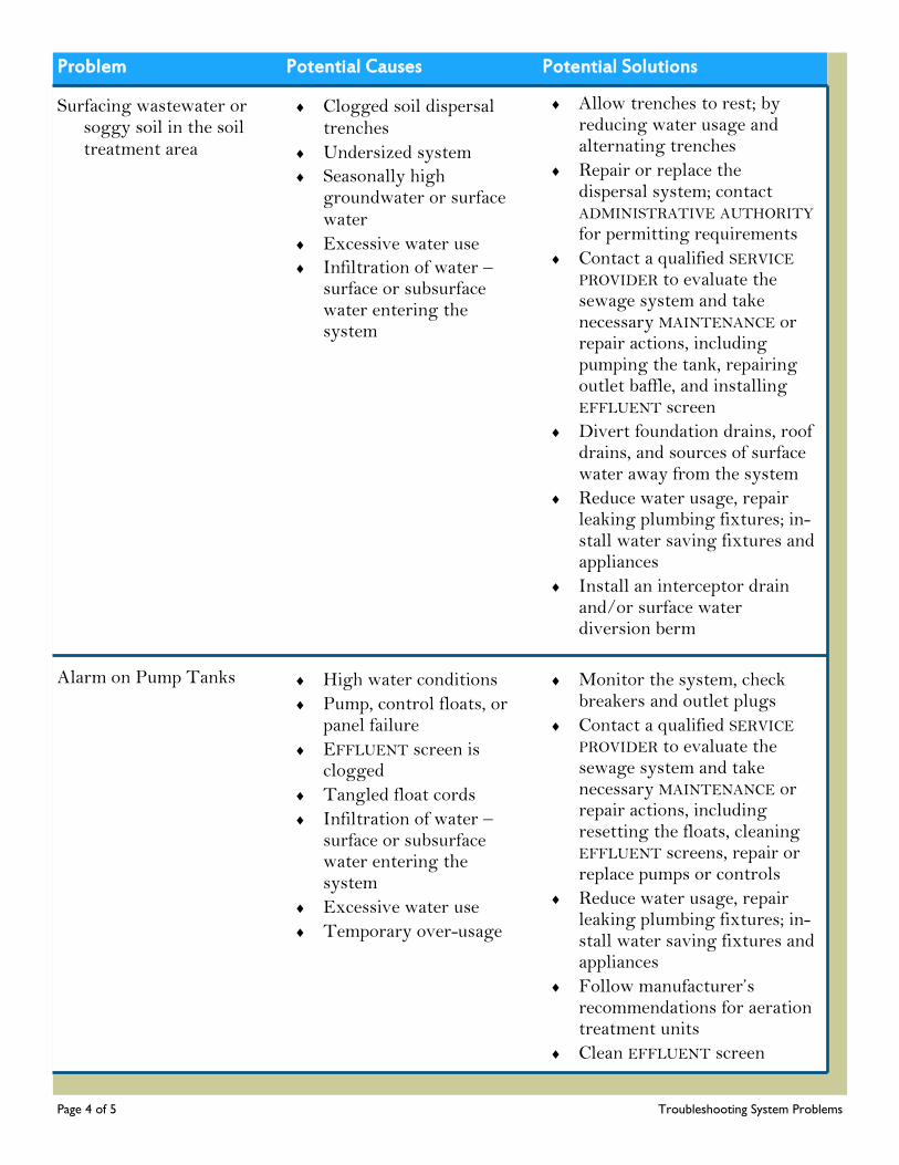
Problem Potential Causes Potential Solutions
Surfacing wastewater or soggy soil in the soil treatment area
Clogged soil dispersal trenches
Undersized system
Seasonally high groundwater or surface water
Excessive water use
Infiltration of water – surface or subsurface water entering the system
Allow trenches to rest; by reducing water usage and alternating trenches
Repair or replace the dispersal system; contact ADMINISTRATIVE AUTHORITY for permitting requirements
Contact a qualified SERVICE PROVIDER to evaluate the sewage system and take necessary MAINTENANCE or repair actions, including pumping the tank, repairing outlet baffle, and installing EFFLUENT screen
Divert foundation drains, roof drains, and sources of surface water away from the system
Reduce water usage, repair leaking plumbing fixtures; in-stall water saving fixtures and appliances
Install an interceptor drain and/or surface water diversion berm
Alarm on Pump Tanks High water conditions
Pump, control floats, or panel failure
EFFLUENT screen is clogged
Tangled float cords
Infiltration of water – surface or subsurface water entering the system
Excessive water use
Temporary over-usage
Monitor the system, check breakers and outlet plugs
Contact a qualified SERVICE PROVIDER to evaluate the sewage system and take necessary MAINTENANCE or repair actions, including resetting the floats, cleaning EFFLUENT screens, repair or replace pumps or controls
Reduce water usage, repair leaking plumbing fixtures; in-stall water saving fixtures and appliances
Follow manufacturer’s recommendations for aeration treatment units
Clean EFFLUENT screen
Page 4 of 5 Troubleshooting System Problems
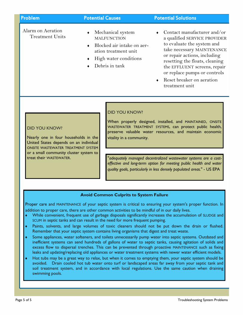
Problem Potential Causes Potential Solutions
Alarm on Aeration Treatment Units
Mechanical system MALFUNCTION
Blocked air intake on aer-ation treatment unit
High water conditions
Debris in tank
Contact manufacturer and/or a qualified SERVICE PROVIDER to evaluate the system and take necessary MAINTENANCE or repair actions, including resetting the floats, cleaning the EFFLUENT screens, repair or replace pumps or controls
Reset breaker on aeration treatment unit
Page 5 of 5 Troubleshooting System Problems
DID YOU KNOW?
Nearly one in four households in the
United States depends on an individual
ONSITE WASTEWATER TREATMENT SYSTEM
or a small community cluster system to
treat their WASTEWATER.
DID YOU KNOW?
When properly designed, installed, and MAINTAINED, ONSITE
WASTEWATER TREATMENT SYSTEMS, can protect public health,
preserve valuable water resources, and maintain economic
vitality in a community.
Avoid Common Culprits to System Failure
Proper care and MAINTENANCE of your septic system is critical to ensuring your system's proper function. In
addition to proper care, there are other common activities to be mindful of in our daily lives. While convenient, frequent use of garbage disposals significantly increases the accumulation of SLUDGE and
SCUM in septic tanks and can result in the need for more frequent pumping.
Paints, solvents, and large volumes of toxic cleaners should not be put down the drain or flushed.
Remember that your septic system contains living organisms that digest and treat waste.
Some appliances, water softeners, and toilets unnecessarily pump water into septic systems. Outdated and
inefficient systems can send hundreds of gallons of water to septic tanks, causing agitation of solids and
excess flow to dispersal trenches. This can be prevented through proactive MAINTENANCE such as fixing
leaks and updating/replacing old appliances or water treatment systems with newer water efficient models.
Hot tubs may be a great way to relax, but when it comes to emptying them, your septic system should be
avoided. Drain cooled hot tub water onto turf or landscaped areas far away from your septic tank and
soil treatment system, and in accordance with local regulations. Use the same caution when draining
swimming pools.
"adequately managed decentralized wastewater systems are a cost-
effective and long-term option for meeting public health and water
quality goals, particularly in less densely populated areas." - US EPA

Remediation
Remediation
When there are indications of a soil treatment system MALFUNCTION, it is important to analyze and correct the problems as early as possible. A few things can be relatively simple to correct, such as a leaking fixture. They should be fixed immediately and normal water use reduced as much as practical. Another corrective action would be to divert any surface water that may be running onto the soil treatment area. If there is a distribution box, check or have a wastewater professional check that trenches are receiving relatively equal volumes of wastewater and make adjustments as needed.
If these actions do not correct the problem, a R EGI STER ED ONSITE W AST EWATER TREATMENT SYSTEM PROFESSIONAL or other qualified SERVICE PROVIDER should be contacted to pump out the sewage tank. The SERVICE PROVIDER is responsible for the proper treatment and disposal of all hauled wastewater by transporting to a municipal sewage treatment plant capable of receiving the waste; transporting to a sludge handling facility which possesses a current and valid permit issued for such activity; or land applying under a current and valid permit for such activity. While pumping out the tank, the SERVICE PROVIDER should be able to verify the size of the tank and whether it leaks. The professional may observe WASTEWATER returning to the tank from the dispersal
system, an indication of possible overloaded system, SATURATED soil or bio-mat clogging. Further investigation may be needed.
More extensive corrective options may include expansion, repair, replacement, or remediation. Expanding the OWTS would be applicable when building an addition to the home, there is an increase in the number of occupants, or if the system was originally undersized but meets other construction standards. Repairs are usually only acceptable when a trench or pipe has been damaged, for example by a heavy vehicle or during the installation of another underground utility. Replacement of the soil treatment system may be necessary if the type of system, the design, or the installation was not correct based on the soil properties. Older systems could have appeared to function while putting groundwater at risk. When a problem is observed, a replacement soil treatment system may be needed to protect public health, groundwater, and surface waters.
Page 1 of 2 Management Models
INSPECTIONS:
Refer to the appropriate chapters of this
manual – Gravity Distribution and Soil
Dispersal Trenches, Pressure Distribution, or
Drip Dispersal for INSPECTION criteria,
Warning Signs and Dos and Don’ts.
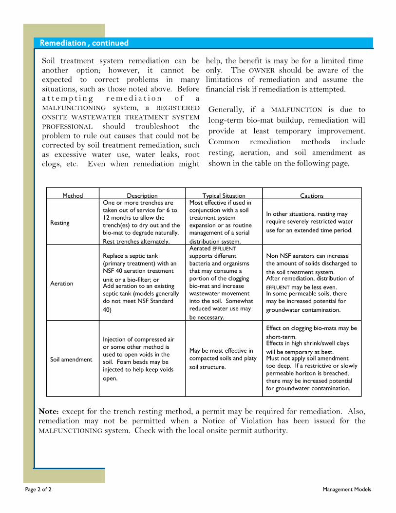
Note: except for the trench resting method, a permit may be required for remediation. Also, remediation may not be permitted when a Notice of Violation has been issued for the MALFUNCTIONING system. Check with the local onsite permit authority.
Remediation , continued
Method Description Typical Situation Cautions
Resting
One or more trenches are
taken out of service for 6 to
12 months to allow the
trench(es) to dry out and the
bio-mat to degrade naturally.
Rest trenches alternately.
Most effective if used in
conjunction with a soil
treatment system
expansion or as routine
management of a serial
distribution system.
In other situations, resting may
require severely restricted water
use for an extended time period.
Aeration
Replace a septic tank
(primary treatment) with an
NSF 40 aeration treatment
unit or a bio-filter; or Add aeration to an existing
septic tank (models generally
do not meet NSF Standard
40)
Aerated EFFLUENT
supports different
bacteria and organisms
that may consume a
portion of the clogging
bio-mat and increase
wastewater movement
into the soil. Somewhat
reduced water use may
be necessary.
Non NSF aerators can increase
the amount of solids discharged to
the soil treatment system. After remediation, distribution of
EFFLUENT may be less even. In some permeable soils, there
may be increased potential for
groundwater contamination.
Soil amendment
Injection of compressed air
or some other method is
used to open voids in the
soil. Foam beads may be
injected to help keep voids
open.
May be most effective in
compacted soils and platy
soil structure.
Effect on clogging bio-mats may be
short-term. Effects in high shrink/swell clays
will be temporary at best. Must not apply soil amendment
too deep. If a restrictive or slowly
permeable horizon is breached,
there may be increased potential
for groundwater contamination.
Soil treatment system remediation can be another option; however, it cannot be expected to correct problems in many situations, such as those noted above. Before a t t e m p t i n g r e m e d i a t i o n o f a MALFUNCTIONING system, a REGISTERED ONSITE WASTEWATER TREATMENT SYSTEM PROFESSIONAL should troubleshoot the problem to rule out causes that could not be corrected by soil treatment remediation, such as excessive water use, water leaks, root clogs, etc. Even when remediation might
help, the benefit is may be for a limited time only. The OWNER should be aware of the limitations of remediation and assume the financial risk if remediation is attempted.
Generally, if a MALFUNCTION is due to
long-term bio-mat buildup, remediation will
provide at least temporary improvement.
Common remediation methods include
resting, aeration, and soil amendment as
shown in the table on the following page.
Page 2 of 2 Management Models

Management Models
Management Model 1 - Homeowner Aware
This model covers appropriate management practices where treatment systems are owned and operated by an individual PROPERTY OWNER in areas of low environmental sensitivity and less dense development. This model is applicable where treatment technologies are limited to standard systems, which are passive and robust. Standard systems can provide acceptable treatment under suitable site and soil conditions with limited attention by the system OWNER. System MALFUNCTIONS that might occur and continue undetected for a time will pose a
relatively low level of risk to public health and water resources. The objectives of this management model are to ensure that all systems are sited, designed, and constructed in compliance with minimum construction standards and that system OWNERS are informed of the MAINTENANCE needs of their systems. The model is intended to raise homeowner’s awareness of basic system MAINTENANCE requirements and to better ensure that the homeowners attend to those deficiencies that threaten public health or water resources.
Program Element Activity
Public Education and Participation
ADMINISTRATIVE AUTHORITY educates OWNER/user on purpose, use, and care of decentralized wastewater treatment system.
OWNER and SERVICE PROVIDER are informed of purpose, use, and care of decentralized wastewater treatment system.
OWNER and SERVICE PROVIDER are informed of existing regulations.
Training SERVICE PROVIDERS obtain training from manufacturer regarding
OPERATION and MAINTENANCE procedures of any proprietary equipment. SERVICE PROVIDERS comply with applicable state and local regulations.
SERVICE PROVIDERS obtain appropriate continuing education.
OWNERS using services, contract with only trained and qualified providers.
OPERATION and MAINTENANCE
Designer, installer, SERVICE PROVIDER, and/or the ADMINISTRATIVE AUTHORITY provide OWNER/user with educational materials regarding system use and care.
OWNER/user performs recommended routine MAINTENANCE or hires a SERVICE PROVIDER to perform MAINTENANCE.
Hire a SERVICE PROVIDER to inspect, service, and remove SEPTAGE for proper treatment and offsite disposal.
SERVICE PROVIDER inspects and services system as necessary. User follows recommendations provided by ADMINISTRATIVE
AUTHORITY, SERVICE PROVIDERS, and OWNER to ensure that undesirable or prohibited materials are not discharged into the system.
Page 1 of 4 Management Models
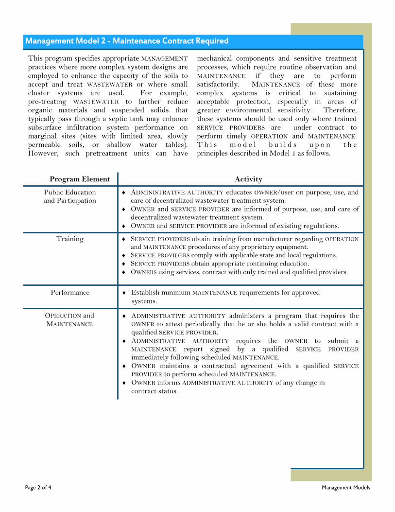
Management Model 2 - Maintenance Contract Required
This program specifies appropriate MANAGEMENT practices where more complex system designs are employed to enhance the capacity of the soils to accept and treat WASTEWATER or where small cluster systems are used. For example, pre-treating WASTEWATER to further reduce organic materials and suspended solids that typically pass through a septic tank may enhance subsurface infiltration system performance on marginal sites (sites with limited area, slowly permeable soils, or shallow water tables). However, such pretreatment units can have
mechanical components and sensitive treatment processes, which require routine observation and MAINTENANCE if they are to perform satisfactorily. MAINTENANCE of these more complex systems is critical to sustaining acceptable protection, especially in areas of greater environmental sensitivity. Therefore, these systems should be used only where trained SERVICE PROVIDERS are under contract to perform timely OPERATION and MAINTENANCE. T h i s m o d e l b u i l d s u p o n t h e principles described in Model 1 as follows.
Program Element Activity
Public Education and Participation
ADMINISTRATIVE AUTHORITY educates OWNER/user on purpose, use, and care of decentralized wastewater treatment system.
OWNER and SERVICE PROVIDER are informed of purpose, use, and care of decentralized wastewater treatment system.
OWNER and SERVICE PROVIDER are informed of existing regulations.
Training SERVICE PROVIDERS obtain training from manufacturer regarding OPERATION and MAINTENANCE procedures of any proprietary equipment.
SERVICE PROVIDERS comply with applicable state and local regulations.
SERVICE PROVIDERS obtain appropriate continuing education.
OWNERS using services, contract with only trained and qualified providers.
OPERATION and MAINTENANCE
ADMINISTRATIVE AUTHORITY administers a program that requires the OWNER to attest periodically that he or she holds a valid contract with a qualified SERVICE PROVIDER.
ADMINISTRATIVE AUTHORITY requires the OWNER to submit a MAINTENANCE report signed by a qualified SERVICE PROVIDER immediately following scheduled MAINTENANCE.
OWNER maintains a contractual agreement with a qualified SERVICE PROVIDER to perform scheduled MAINTENANCE.
OWNER informs ADMINISTRATIVE AUTHORITY of any change in contract status.
Performance Establish minimum MAINTENANCE requirements for approved systems.
Page 2 of 4 Management Models
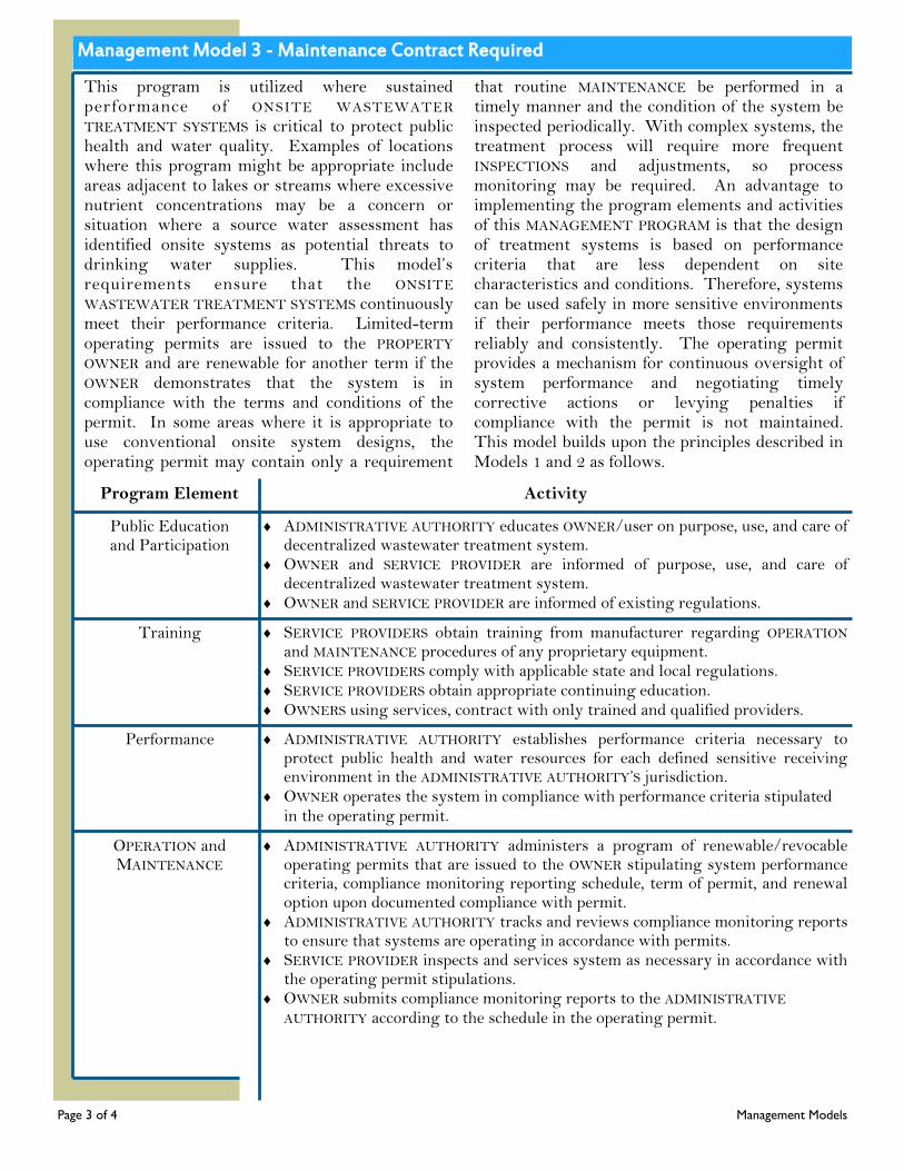
Management Model 3 - Maintenance Contract Required
This program is utilized where sustained performance of ONSITE WASTEWATER TREATMENT SYSTEMS is critical to protect public health and water quality. Examples of locations where this program might be appropriate include areas adjacent to lakes or streams where excessive nutrient concentrations may be a concern or situation where a source water assessment has identified onsite systems as potential threats to drinking water supplies. This model’s requirements ensure that the ONSITE WASTEWATER TREATMENT SYSTEMS continuously meet their performance criteria. Limited-term operating permits are issued to the PROPERTY OWNER and are renewable for another term if the OWNER demonstrates that the system is in compliance with the terms and conditions of the permit. In some areas where it is appropriate to use conventional onsite system designs, the operating permit may contain only a requirement
that routine MAINTENANCE be performed in a timely manner and the condition of the system be inspected periodically. With complex systems, the treatment process will require more frequent INSPECTIONS and adjustments, so process monitoring may be required. An advantage to implementing the program elements and activities of this MANAGEMENT PROGRAM is that the design of treatment systems is based on performance criteria that are less dependent on site characteristics and conditions. Therefore, systems can be used safely in more sensitive environments if their performance meets those requirements reliably and consistently. The operating permit provides a mechanism for continuous oversight of system performance and negotiating timely corrective actions or levying penalties if compliance with the permit is not maintained. This model builds upon the principles described in Models 1 and 2 as follows.
Program Element Activity
Public Education and Participation
ADMINISTRATIVE AUTHORITY educates OWNER/user on purpose, use, and care of decentralized wastewater treatment system.
OWNER and SERVICE PROVIDER are informed of purpose, use, and care of decentralized wastewater treatment system.
OWNER and SERVICE PROVIDER are informed of existing regulations.
Training SERVICE PROVIDERS obtain training from manufacturer regarding OPERATION and MAINTENANCE procedures of any proprietary equipment.
SERVICE PROVIDERS comply with applicable state and local regulations. SERVICE PROVIDERS obtain appropriate continuing education. OWNERS using services, contract with only trained and qualified providers.
OPERATION and MAINTENANCE
ADMINISTRATIVE AUTHORITY administers a program of renewable/revocable operating permits that are issued to the OWNER stipulating system performance criteria, compliance monitoring reporting schedule, term of permit, and renewal option upon documented compliance with permit.
ADMINISTRATIVE AUTHORITY tracks and reviews compliance monitoring reports to ensure that systems are operating in accordance with permits.
SERVICE PROVIDER inspects and services system as necessary in accordance with the operating permit stipulations.
OWNER submits compliance monitoring reports to the ADMINISTRATIVE AUTHORITY according to the schedule in the operating permit.
Performance ADMINISTRATIVE AUTHORITY establishes performance criteria necessary to protect public health and water resources for each defined sensitive receiving environment in the ADMINISTRATIVE AUTHORITY’S jurisdiction.
OWNER operates the system in compliance with performance criteria stipulated in the operating permit.
Page 3 of 4 Management Models
Management Models 4 and 5 - Responsible Management Entity
The RESPONSIBLE MANAGEMENT ENTITY (RME) models focus on large numbers of onsite and cluster systems that must meet specific water quality requirements because the density of the systems or the sensitivity of the environment is high. Frequent and highly reliable OPERATION and MAINTENANCE is required to ensure water resource protection. Issuing the operating permit to an RME instead of the PROPERTY OWNER provides greater assurance of control over performance compliance. This allows the use of performance based systems in more sensitive environments than Model 3. For a service fee, an
RME takes responsibility for the OPERATION and MAINTENANCE of the system. In the RME ownership model, they can provide a higher level of control because the RME directs planning and management as well as OPERATION and MAINTENANCE. These approaches can reduce the number of permits and the administration functions performed by the ADMINISTRATIVE AUTHORITY. System failures are also reduced as a result of routine and preventive MAINTENANCE. The operating permit system is similar to that of Model 3 except that the permittee is a public or private RME.
Page 4 of 4 Management Models
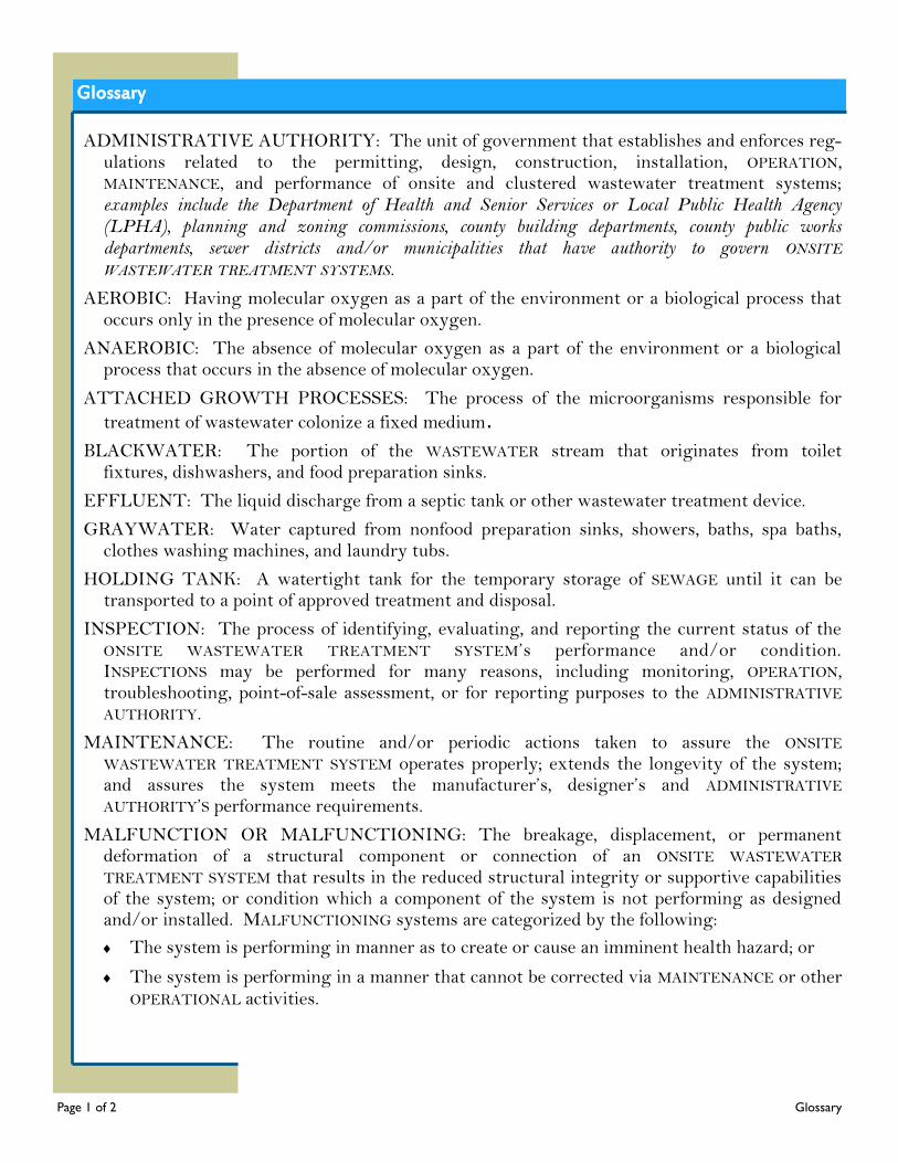
Glossary
ADMINISTRATIVE AUTHORITY: The unit of government that establishes and enforces reg-ulations related to the permitting, design, construction, installation, OPERATION, MAINTENANCE, and performance of onsite and clustered wastewater treatment systems; examples include the Department of Health and Senior Services or Local Public Health Agency (LPHA), planning and zoning commissions, county building departments, county public works departments, sewer districts and/or municipalities that have authority to govern ONSITE WASTEWATER TREATMENT SYSTEMS.
AEROBIC: Having molecular oxygen as a part of the environment or a biological process that occurs only in the presence of molecular oxygen.
ANAEROBIC: The absence of molecular oxygen as a part of the environment or a biological process that occurs in the absence of molecular oxygen.
ATTACHED GROWTH PROCESSES: The process of the microorganisms responsible for
treatment of wastewater colonize a fixed medium.
BLACKWATER: The portion of the WASTEWATER stream that originates from toilet fixtures, dishwashers, and food preparation sinks.
EFFLUENT: The liquid discharge from a septic tank or other wastewater treatment device.
GRAYWATER: Water captured from nonfood preparation sinks, showers, baths, spa baths, clothes washing machines, and laundry tubs.
HOLDING TANK: A watertight tank for the temporary storage of SEWAGE until it can be transported to a point of approved treatment and disposal.
INSPECTION: The process of identifying, evaluating, and reporting the current status of the ONSITE WASTEWATER TREATMENT SYSTEM’s performance and/or condition. INSPECTIONS may be performed for many reasons, including monitoring, OPERATION, troubleshooting, point-of-sale assessment, or for reporting purposes to the ADMINISTRATIVE AUTHORITY.
MAINTENANCE: The routine and/or periodic actions taken to assure the ONSITE WASTEWATER TREATMENT SYSTEM operates properly; extends the longevity of the system; and assures the system meets the manufacturer’s, designer’s and ADMINISTRATIVE AUTHORITY’S performance requirements.
MALFUNCTION OR MALFUNCTIONING: The breakage, displacement, or permanent deformation of a structural component or connection of an ONSITE WASTEWATER TREATMENT SYSTEM that results in the reduced structural integrity or supportive capabilities of the system; or condition which a component of the system is not performing as designed and/or installed. MALFUNCTIONING systems are categorized by the following:
The system is performing in manner as to create or cause an imminent health hazard; or
The system is performing in a manner that cannot be corrected via MAINTENANCE or other OPERATIONAL activities.
Page 1 of 2 Glossary
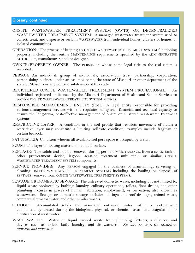
Glossary, continued
ONSITE WASTEWATER TREATMENT SYSTEM (OWTS) OR DECENTRALIZED WASTEWATER TREATMENT SYSTEM: A managed wastewater treatment system used to collect, treat, and disperse or reclaim WASTEWATER from individual homes, clusters of homes, or isolated communities.
OPERATION: The process of keeping an ONSITE WASTEWATER TREATMENT SYSTEM functioning properly, including the routine MAINTENANCE requirements specified by the ADMINISTRATIVE AUTHORITY, manufacturer, and/or designer.
OWNER/PROPERTY OWNER: The PERSON in whose name legal title to the real estate is recorded.
PERSON: An individual, group of individuals, association, trust, partnership, corporation, person doing business under an assumed name, the state of Missouri or other department of the state of Missouri or any political subdivision of this state.
REGISTERED ONSITE WASTEWATER TREATMENT SYSTEM PROFESSIONAL: An individual registered or licensed by the Missouri Department of Health and Senior Services to provide ONSITE WASTEWATER TREATMENT SYSTEM services.
RESPONSIBLE MANAGEMENT ENTITY (RME): A legal entity responsible for providing various management services with the requisite managerial, financial, and technical capacity to ensure the long-term, cost-effective management of onsite or clustered wastewater treatment systems.
RESTRICTIVE LAYER: A condition in the soil profile that restricts movement of fluids; a restrictive layer may constitute a limiting soil/site condition; examples include fragipan or certain bedrock.
SATURATED: Condition wherein all available soil pore space is occupied by water.
SCUM: The layer of floating material on a liquid surface.
SEPTAGE: The solids and liquids removed, during periodic MAINTENANCE, from a septic tank or other pretreatment device, lagoon, aeration treatment unit tank, or similar ONSITE WASTEWATER TREATMENT SYSTEM components.
SERVICE PROVIDER: Any PERSON engaged in the business of maintaining, servicing or cleaning ONSITE WASTEWATER TREATMENT SYSTEMS including the hauling or disposal of SEPTAGE removed from ONSITE WASTEWATER TREATMENT SYSTEMS.
SEWAGE OR DOMESTIC SEWAGE: The untreated domestic waste, including but not limited to, liquid waste produced by bathing, laundry, culinary operations, toilets, floor drains, and other plumbing fixtures in places of human habitation, employment, or recreation; also known as wastewater. Sewage or domestic sewage excludes footings and roof drainage, animal waste, commercial process water, and other similar wastes.
SLUDGE: Accumulated solids and associated entrained water within a pretreatment component, generated during the biological, physical, or chemical treatment, coagulation, or clarification of wastewater.
WASTEWATER: Water or liquid carried waste from plumbing fixtures, appliances, and devices such as toilets, bath, laundry, and dishwashers. See also SEWAGE OR DOMESTIC SEWAGE and SEPTAGE.
Page 2 of 2 Glossary
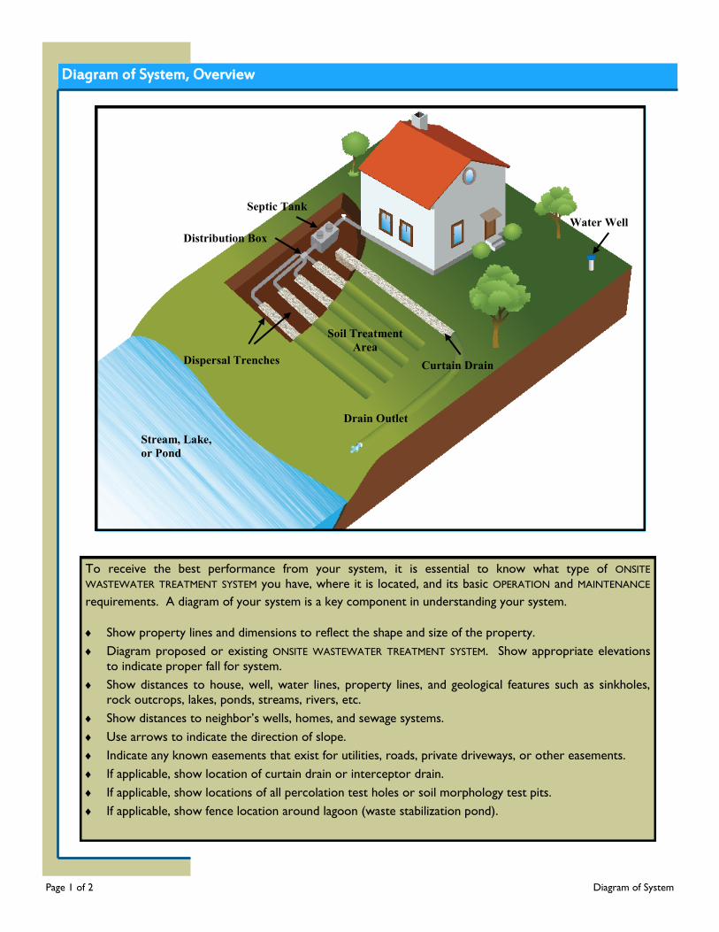
Diagram of System, Overview
Page 1 of 2 Diagram of System
Water Well
Curtain Drain
Soil Treatment
Area
Drain Outlet
Stream, Lake,
or Pond
Dispersal Trenches
Distribution Box
Septic Tank
To receive the best performance from your system, it is essential to know what type of ONSITE
WASTEWATER TREATMENT SYSTEM you have, where it is located, and its basic OPERATION and MAINTENANCE
requirements. A diagram of your system is a key component in understanding your system.
Show property lines and dimensions to reflect the shape and size of the property.
Diagram proposed or existing ONSITE WASTEWATER TREATMENT SYSTEM. Show appropriate elevations
to indicate proper fall for system.
Show distances to house, well, water lines, property lines, and geological features such as sinkholes,
rock outcrops, lakes, ponds, streams, rivers, etc.
Show distances to neighbor’s wells, homes, and sewage systems.
Use arrows to indicate the direction of slope.
Indicate any known easements that exist for utilities, roads, private driveways, or other easements.
If applicable, show location of curtain drain or interceptor drain.
If applicable, show locations of all percolation test holes or soil morphology test pits.
If applicable, show fence location around lagoon (waste stabilization pond).
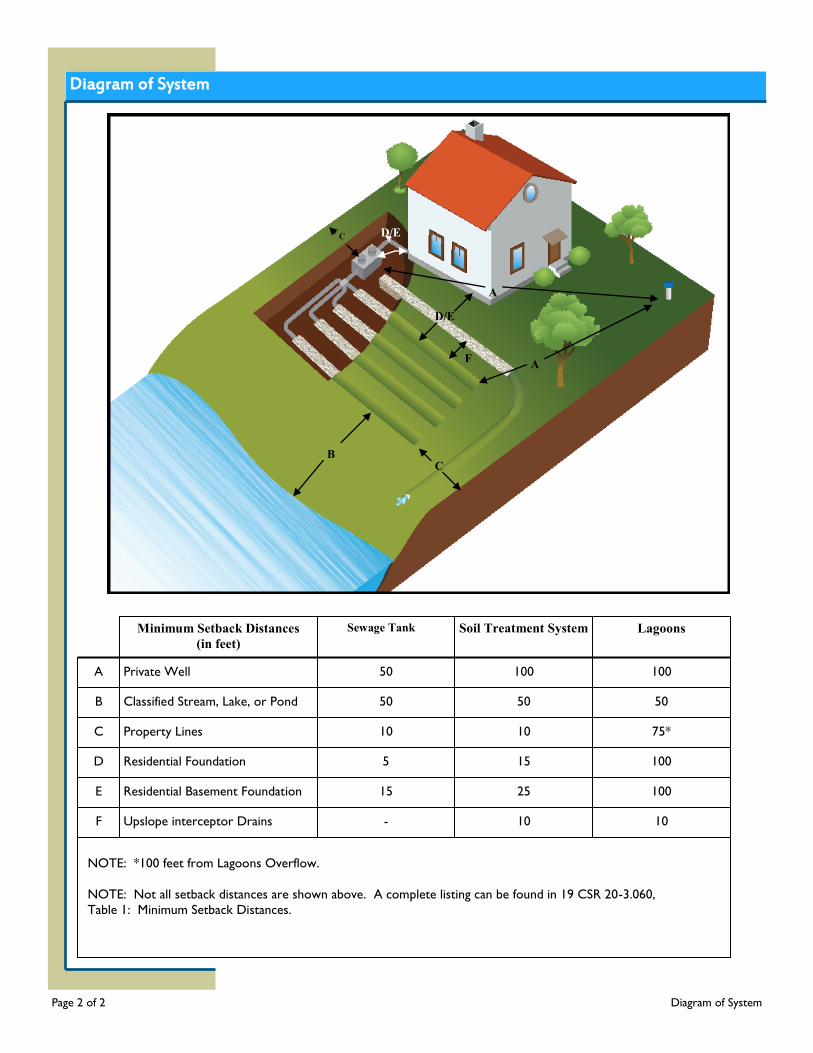
Diagram of System
Page 2 of 2 Diagram of System
A
B
F
E
D
C Property Lines
Residential Foundation
Residential Basement Foundation
Upslope interceptor Drains
Private Well
Classified Stream, Lake, or Pond
Minimum Setback Distances
(in feet)
Sewage Tank Soil Treatment System
Lagoons
-
15
5
10
50
50
100 15
100 25
10 10
100
50
10 75*
50
100
A
B C
D/E
D/E C
A F
NOTE: *100 feet from Lagoons Overflow.
NOTE: Not all setback distances are shown above. A complete listing can be found in 19 CSR 20-3.060,
Table 1: Minimum Setback Distances.
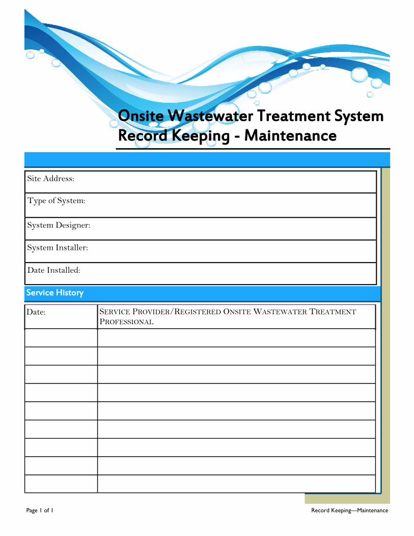
Onsite Wastewater Treatment System Record Keeping - Maintenance
Service History
Date: SERVICE PROVIDER/REGISTERED ONSITE WASTEWATER TREATMENT PROFESSIONAL
Site Address:
Type of System:
System Designer:
System Installer:
Date Installed:
Page 1 of 1 Record Keeping—Maintenance
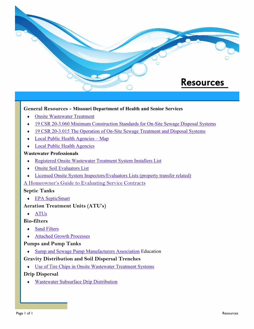
Resources
General Resources - Missouri Department of Health and Senior Services
Onsite Wastewater Treatment
19 CSR 20-3.060 Minimum Construction Standards for On-Site Sewage Disposal Systems
19 CSR 20-3.015 The Operation of On-Site Sewage Treatment and Disposal Systems
Local Public Health Agencies – Map
Local Public Health Agencies
Wastewater Professionals
Registered Onsite Wastewater Treatment System Installers List
Onsite Soil Evaluators List
Licensed Onsite System Inspectors/Evaluators Lists (property transfer related)
A Homeowner’s Guide to Evaluating Service Contracts
Septic Tanks
EPA SepticSmart
Aeration Treatment Units (ATU’s)
ATUs
Bio-filters
Sand Filters
Attached Growth Processes
Pumps and Pump Tanks
Sump and Sewage Pump Manufacturers Association Education
Gravity Distribution and Soil Dispersal Trenches
Use of Tire Chips in Onsite Wastewater Treatment Systems
Drip Dispersal
Wastewater Subsurface Drip Distribution
Page 1 of 1 Resources
Acknowledgments
Page 1 of 1 Acknowledgements
The Department of Health and Senior Services would like to take this opportunity to express their gratitude to the members of the Stakeholders Workgroup for the technical discussions and time devoted to these guidelines. In addition, the Department would like to thank Firehouse Designs for the graphics used throughout these guidelines.
The Department would like to extend a sincere thank you to the following organizations and groups for their literature contributions, photographs, and resources - the Consortium of Institutes for Decentralized Wastewater Treatment, National Environmental Services Center (NESC), University of Missouri Extension, US Environmental Protection Agency (EPA), University of Minnesota, and the Virginia Department of Health.