Embed Size (px)
Citation preview

An MDE Modeling Framework forMeasurable Goal-Oriented RequirementsFernando Molina,1,∗ Jesus Pardillo,2,† Cristina Cachero,2,‡ Ambrosio Toval1,§1Software Engineering Research Group, Department of Informatics andSystems, University of Murcia, Facultad de Informatica, Campus de Espinardo,30100 Murcia, Spain2Department of Informatics and Systems, University of Alicante, Spain
It is a proved fact that the appropriate management of requirements is one of the most influentialfactors in the success of software development projects. With the advent of the model-drivenengineering (MDE) development paradigm, the need for formal gathering mechanisms, whichprovide the necessary degree of nonambiguity and detail, has led to the proposal of a myriad ofrequirements metamodels. However, a great disparity exists, both in the concepts/relationshipsand in the underlying semantics involved in each metamodel. Moreover, most existing proposalslack backward (e.g., alignment with business goals) or forward (e.g., connection with validationmethods) traceability. In view of this situation, this article proposes a “measurable requirementsmetamodel” that offers support to the elicitation of measurable requirements. This support isbased on the explicit connection of goals, requirements, and measures, thus fostering a goal-drivenmeasurable requirements engineering (RE) perspective. Additionally, since it is well known thatmetamodels only reflect the abstract syntax of the modeling language, the proposed metamodelalso includes a notation (concrete syntax) which, for reasons of understandability, is based onthe goal-oriented requirements language (GRL) notation. This notation is supported by a unifiedmodeling language (UML) profile that facilitates its adoption by RE analysts in the context ofany UML-based software engineering process. To support this proposal, an Eclipse tool has beendeveloped. This tool permits the integration of measurable requirements as a driving force in thecontext of a given MDE development process. C© 2010 Wiley Periodicals, Inc.
1. INTRODUCTION
Goal orientation is a recognized paradigm through which to elaborate, struc-ture, and analyze software requirements.1−3 Goals are prescriptive statements ofintent whose satisfaction requires the cooperation of agents in the software and itsenvironment. They may refer to functional or nonfunctional concerns and range
∗Author to whom all correspondence should be addressed: e-mail: [email protected].†e-mail: [email protected].‡e-mail: [email protected].§e-mail: [email protected].
INTERNATIONAL JOURNAL OF INTELLIGENT SYSTEMS, VOL. 25, 757–783 (2010)C© 2010 Wiley Periodicals, Inc. Published online in Wiley InterScience(www.interscience.wiley.com). • DOI 10.1002/int.20430

758 MOLINA ET AL.
from high-level strategic concerns to those that are low-level and technical. Unlikeother requirements engineering (RE) paradigms, goal orientation and its associatedgoal modeling languages (GMLs) and elaboration methods, such as knowledge ac-quisition in automated specification (KAOS)4 or nonfunctional requirement (NFR),5
promote the use of visual models rather than textual descriptions to reason about thesystem. For the construction of these models, it is common to distinguish betweenearly requirements (organizational goals) and late requirements (system propertiesand service capabilities), depending upon whether the focus is on the business goalsor on the requirements of the system-to-be.6
On the other hand, software metrics are known to be of paramount importancein increasing the level of objectivity with which software products are evaluated andcompared.7 They are not only a cornerstone piece to help assess and institutionalizesoftware process improvement practices (e.g., ISO/IEC 155048 or CMMI9), but theyare also useful instruments to validate requirements, usually in the context of qualityscenarios.10
Finally, but of no less importance, the model-driven engineering (MDE)paradigm11 is increasingly drawing practitioners’ attention as an emerging approachfor cost-effective, reliable, and rapid application development.12 MDE advocates vi-sual models, which are formally described by means of metamodels, as key engineer-ing artifacts throughout the engineering life cycle. A metamodel offers numerousadvantages.13 First, the metamodel defines both the elements that participate inthe requirements management process and the relationships between them in anunambiguous manner. Moreover, it offers a formal basis upon which tools for themanagement of the metamodel elements and the definition of transformation rulesfrom requirements to other elements can be constructed. MDE technologies makeuse of these advantages and combine (1) domain specific languages, whose typesystems formalize the application structure, behavior, and requirements within par-ticular domains, and (2) transformation engines and compilers that analyze modelsand synthesize various types of artifacts (e.g., models with a lower abstraction levelor source code).
The integration of goal-driven requirements models, software measures, andMDE processes with automation capabilities provides clear benefits:
• Goal-oriented RE (GORE)+Measures: The inclusion of well-defined and unambiguousmeasures in association with requirements increases the accuracy and repeatability of therequirements validation process.
• Measures+MDE: The definition of measures as models that can be integrated into MDEapproaches permits the measurement task to be automated, thus speeding up the require-ments validation process. More importantly, MDE approaches provide early models onwhich to carry out measurements, thus permitting an early detection and correction ofproblems, which drastically decreases the project costs.14
• MDE+GORE: In the context of MDE approaches, goal-driven requirements metamodelsand models provide a widely used vocabulary and notation for, respectively, visuallyrepresenting both early and late requirements models that are aligned with stakeholders’objectives.
However, to the best of our knowledge, the integration of these three elementshas not yet been considered. Our work aims to fill this gap by providing an integration
International Journal of Intelligent Systems DOI 10.1002/int

MDE MODELING FRAMEWORK FOR GOAL-ORIENTED REQUIREMENTS 759
of goals, late requirements and measures through the definition of the metamodelsnecessary to support measurable requirements. Specifically, and in addition to thisintegration, the main contributions of this article are
• The definiton of a late requirements metamodel that connects late requirements withgoals, thus fostering the traceability between these two concepts. This goal-oriented laterequirements metamodel is called unified late requirements (ULR) metamodel and wasdesigned after a systematic review of the existing approaches for requirements metamod-eling, contributing to the completeness of our approach.
• The combination of the new ULR with an adapted measurement metamodel, called“software measurement metamodel” (SMM), to create a new “measurable requirementsmetamodel” (MRM). The MRM provides users with the abstract syntax (semantics) forthe specification of measurable requirements and converts our proposal, to the best ofour knowledge, into the first metamodel to provide support for goal-driven measurablerequirements.
• The definition of a UML profile15 that facilitates the inclusion of these new goal-orientedmeasurable requirements models in existing MDE approaches, which in turn facilitatesthe early validation of requirements over the MDE-modeling artifacts. This profile pro-vides the concrete syntax (notation) that serves to visually represent the metamodelconcepts. The use of a profiling mechanism facilitates its adoption by practitioners, who,according to a recent study, are already accustomed to using unified modeling language(UML) models.16 Furthermore, this profile is based on goal-oriented requirement lan-guage (GRL),17 a standard goal modeling language based on i∗, which facilitates itsadoption by the RE community, who will not need to learn “yet another notation.” Theprofile simultaneously allows the use of the well-known i∗ notation to express a concernthat is not present in i∗, which is that of measurable requirements.
The remainder of this article is organized as follows. In Section 2, the back-ground for this work is provided. In Section 3, the summary of a systematic reviewof the requirements metamodeling field and the ULR metamodel are presented.Section 4 outlines the SMM– metamodel and explains how both metamodels havebeen merged into the MRM. Section 5 provides an in-depth explanation of theUML profile that has been united with MRM. To further clarify the approach, Sec-tion 6 presents an example that illustrates the application of the proposed modelingframework. This framework is supported by a computer-aided software engineering(CASE) tool that is presented in Section 7. Finally, in Section 8, the main conclusionsare drawn and further lines of research are outlined.
2. BACKGROUND
The tasks related to requirements are among those that are most influential inthe success of a software development project. Just as an inadequate management ofrequirements has been the proven cause of the failure of numerous software projects,their appropriate management helps to improve the quality of the software prod-ucts and the productivity of their development processes.18 Throughout its history,therefore, the RE discipline has developed a wide number of approaches that stemfrom different paradigms, such as goal-driven requirements engineering (GDRE),3
aspect-driven,19 viewpoints-driven20 paradigms, or those based on requirementstemplates,21 to name but a few. Of these, GDRE approaches have been gaining
International Journal of Intelligent Systems DOI 10.1002/int

760 MOLINA ET AL.
momentum for a number of reasons, including their capability to reason aboutrequirements at different levels of abstraction. As was mentioned previously, theysupport the definition of early requirements models that represent an organizationaldomain and serve to analyze it in terms of the business actors and their intentions.They also serve to define late requirements models, in which the software system isrepresented within its operational environment along with its expected functionalityand relevant characteristics.6
These goal-driven requirements models are supplanting traditional modelingartifacts such as UML use cases or requirements templates.22 However, this goal-driven perspective has not yet reached the MDE community. Within this paradigm,where models need to act as blueprints of the system, requirements models havetraditionally been limited to extended UML use-case diagrams, in which only func-tional (late) requirements are considered. In these proposals, the limited scope(functionality) and the high level at which such requirements have been describedhave caused them to influence the MDE transformation process in a solely tangen-tial manner. This has also motivated the definition of requirements metamodels.However, the existing proposals for this aim have certain problems. For example,in some approaches such as in Refs. 23 and 24 their high coupling with specific do-mains have caused their usefulness as general purpose communication artifacts to behampered. A further important concern is that the traceability between the detailedrequirements and the underlying early requirements (business goals) is missing inall these approaches. One noteworthy exception to this is the proposal of Bolchiniand Paolini,25 in which a goal-oriented requirements metamodel that describes howthe resulting models can be used to partially derive and validate the quality of othermodels is presented. However, the proposal is specific to the Web domain, and theusability validation process is not automatable.
On the other hand, workflows and notations to construct organizational (early)requirements models are an extensive area of work in GDRE, usually included ingeneral GDRE methodologies such as Tropos,26 KAOS,4 goal-based requirementsanalysis method (GBRAM),27 NFR5 or goal-oriented adaptive requirements engi-neering (GARE),17 to name but a few. Various GMLs associated with these proposalshave been proposed. Of these, GRL,17 which is associated with the GARE approach,stands out due to its inclusion in the user requirements notation (URN) standard.28
Most proposals also include support for late requirements views, and even imple-mentation technique catalogs that help to achieve certain requirements (see, e.g.,NFR). The means to address the transformation between organizational models andlate requirements models varies. In Ref. 6, it is achieved through the use of patterns.TROPOS defines a bridge between organizational stakeholders and goals, and thecandidate software architectures supporting the requirements. In KAOS, the changefrom early to late requirements is achieved through the operationalization of goals,in which responsibilities for their fulfillment are assigned to agents. In GBRAM,the definition of late requirements from organizational goals is based on scenariotechniques. However, contrary to our approach, the complexity of the resulting re-quirements models in all the aforementioned approaches is unsustainable for mostMDE processes, which are usually adopted in cases where baselines need to begenerated very quickly, and requirements techniques therefore need to be extremely
International Journal of Intelligent Systems DOI 10.1002/int

MDE MODELING FRAMEWORK FOR GOAL-ORIENTED REQUIREMENTS 761
lightweight, intuitive, and usable by software analysts and project stakeholders, whooften have little or no technical background.25
We claim that, to palliate these shortcomings, MDE approaches require the in-clusion of a requirements metamodel that borrows the explicit consideration of thecomplementary GDRE concerns (early requirements and late requirements) as partof any requirements metamodel included in an MDE process. This notwithstanding,this metamodel should be simple, signifying that only the core concepts should bepresent. We claim that this simplicity means to centering them on late requirements,which are those that make a direct impact on the modeling artifacts, and simply pro-vide a link to early requirements, which can be worked on outside the MDE process.Furthermore, we are of the opinion that it is of the uttermost importance that thismetamodel additionally supports the link between late requirements and measures,to support their early validation over the MDE modeling artifacts. Furthermore,to define a sound late requirements metamodel that can be derived from GDREapproaches and is simultaneously simple enough to be adopted by MDE practition-ers, we claim that other concerns need to be addressed: requirements metamodelsfor MDE should strive toward reuse, and include traceability among early and laterequirements. However, detailed reasoning mechanisms to solve aspects such asconflicting requirements, given their complexity, should be left aside, assuming thatthey can be solved in a previous step, namely during the transformation from theorganizational model into this late requirements model.
Our approach covers all these aspects. Furthermore, and given the existingdisparity with regard to the semantics of the RE concepts included in the differentGDRE metamodels,29 our proposal is based on a systematic review in which themost common acceptations for concepts have been incorporated. Finally, but ofno less importance, our approach establishes the role that this late requirementsmetamodel should play in the MDE transformation process, that is, to serve to drivethe automatic validation of requirements over other MDE artifacts.
3. THE UNIFIED LATE REQUIREMENTS METAMODEL
3.1. Introduction
As we have previously mentioned, the different existing requirements meta-modeling proposals present a great disparity in their level of abstraction, number ofconcerns addressed, and semantics. In view of this situation, and given the fact thatlate requirements metamodels are those that provide the most useful informationfrom an MDE perspective, the following section presents a summary of a systematicreview carried out to identify the most relevant late requirements metamodels (bethey GDRE proposals or otherwise). This review has permitted us to identify theircore concepts.
3.2. A Summary of a Requirements Metamodels Systematic Review
The aforementioned literature review was carried out by following the guide-lines proposed by Kitchenham,30 which establish a set of stages with this aim, whichare (i) question formularization, to clearly define the research objectives; (ii) source
International Journal of Intelligent Systems DOI 10.1002/int

762 MOLINA ET AL.
Table I. Late requirements metamodels’ concepts comparison.
Bolchini25 COMET32 Fernandez33 Goknil34 REMM35 SME36
Additional Desc./Use case � � �catalog �Functional requirement � � �Glossary � �Goal � � �Non-functional requirement � �Requirement � � � � � �Scenario � �Source �Stakeholder � � � � � �
(Actor)Term � � �Test case � � �Trace � �×
selection, in which the sources for the searches will be selected; (iii) studies selec-tion process, which describes the process and the criteria for studies selection andevaluation; (iv) information extraction, which defines the extraction criteria; and (v)extraction execution, which presents the data resulting from the selected studies.
In our case, the main aim of the review was to identify what the existingproposals for requirements metamodeling were, and what concepts they covered.A set of sources (namely IEEE Computer Society, ACM Digital Library, GoogleScholar, Citeseer, and ScienceDirect) that contain the work published in journalsand conferences of recognized quality within the research community was analyzed.These sources were subjected to various search string criteria. That which retrievedthe highest number of useful results was: (“requirements” AND (“metamodeling”OR “metamodelling” OR “metamodel”)) OR (“metamodel of requirements”). Asa result, six proposals for requirements metamodeling were identified. The result oftheir comparison can be seen in Table I and more details of the systematic reviewcan be found in Ref. 31.
As Table I shows, the number and type of concepts included in the differ-ent metamodels vary greatly, the requirement concept being the only one which isuniversally present. Unfortunately, we have been unable to assess whether the un-derlying semantics are the same in all the approaches, since none of them providesformal definitions of the included concepts. Furthermore, there is no consensus withregard to whether or not requirements should be subcategorized, the most commonclassification—when present—being that of functional versus non-functional.
From the six metamodels identified, three of them25,32,33 (i.e., 50%) includeas a cornerstone the goal concept, which permits late requirements models to beconnected with organizational models elaborated in previous steps in any GDREprocess. However, as the reader may have already observed in Table I, there is littleelse in common among these goal-aware metamodels.
Another concern that appears in some metamodels35 is that of the reuse ofrequirements, which is tackled by including a catalog concept. This concept serves
International Journal of Intelligent Systems DOI 10.1002/int

MDE MODELING FRAMEWORK FOR GOAL-ORIENTED REQUIREMENTS 763
to gather a set of requirements extracted from one or more sources (i.e., a law, anorganizational policy, a particular domain, a set of guidelines, etc.) which can bereused in all the projects in which these sources are applicable.37
Yet another concern is that of vocabulary disambiguation. Since requirementsare usually described by using natural language, which may be imprecise andambiguous, some metamodels33−35 have considered the possibility of describingrequirements through the use of a set of well-defined terms collected in a glossary.
Also detected in various metamodels32−34 is the concept additional descrip-tion. On many occasions, a simple textual description is not sufficient to make arequirement understandable. Some metamodels therefore introduce this concept toprovide more detailed information about the requirement, using text or some kindof artifact that is appropriate for this aim, such as UML use cases.
Two34,35 out of the six metamodels include a tracing concern, which is under-stood to be a relationship that exists among two or more requirements and which isreflected in the trace concept. These traces can be classified according to the kindof relationship: refinement, conflict, etc.
It is worth noting that some proposals34−36 have taken into consideration therequirements validation concern, that is, the need to check that the system or soft-ware implemented fulfills a predefined requirement. To address this concern, suchmetamodels include the concept of a test case. However, no guidelines are providedregarding how such a validation should be defined in order for it to be repeatable,systematic and, if possible, automated.
Finally, but of no less importance, our comparison reveals that only some ofthe metamodels (e.g., Ref. 35) offer some kind of automatic support to deal with theconcepts proposed by the metamodel, and only a subset of them offers a concretesyntax (notation) to deal with the concepts that make up the metamodel.
During the comparison, we discovered some concepts that are particular toindividual metamodels, such as tasks, features, viewpoints, or design constraints.These concepts usually relate to the specific domain for which the metamodelwas designed, and they have been left out of Table I for reasons of space. Basedon this systematic review, the following subsection shows our proposal for a laterequirements metamodel for MDE.
3.3. ULR: A Unified Late Requirements Metamodel for MDE
Given the lack of agreement on the core concepts for a late requirementsmetamodel, we have based our proposal on the following set of concerns andconstraints. On the one hand, the set of concerns was defined by using the bestpractices that were detected during our review of late requirements metamodels,and included: (1) support for requirements reuse, (2) support for backward andforward traceability, (3) support for validation, and (4) support for both functionaland NFRs. On the other hand, the set of constraints was determined both based onthe late-nature of the model (signifying that it had to be focused on the requirementsof the system-to-be, regardless of the means by which those requirements wereobtained) and on the need for it to be unambiguous and specific enough to allow it
International Journal of Intelligent Systems DOI 10.1002/int

764 MOLINA ET AL.
Figure 1. ULR: The unified late requirements metamodel.
be integrated with MDE practices and agile methodologies. It also had to be keptsimple, to facilitate both its quick instantiation and its easy manipulation in MDEtransformations.
Figure 1 shows our ULR proposal. As occurred with all the late requirementsmetamodels studied, the key element in ULR is that of requirement which can bedescribed by using a set of attributes (hidden in the figure) such as an identifier,its type, its priority, and its textual description. Requirements can be classified aseither functional requirements (FRs) (what the system must do) or NFRs (howthe system must do it). This classification is useful because, while FRs usuallyrely on test cases for their validation, NFRs are related to quality scenarios thatquantify and contextualize a given quality concern.10 More complex requirementsclassifications have been avoided for the sake of simplicity. Requirements that areorganized into tree-like structures (see, e.g., quality models such as the ISO 912638),along with relationships between FRs and NFRs, are captured by means of the unaryrelationship decomposed into, which is defined over the requirement concept. Onoccasions, catalogs originating from certain sources are useful resources from whichto pick up requirements, thus speeding up the metamodel instantiation process.
Because of the need for traceability with business objectives, which are gatheredtogether in organizational models, each requirement is connected through the binaryrelationship satisfiedBy to the set of goals it contributes to satisfying. Each goal canbe decomposedInto other goals, and captures a high-level objective of one or morestakeholders that propose it.
Moreover, in order to, as far as possible, avoid the ambiguity inherent in naturallanguage, and to help developers understand the requirements (often expressed in
International Journal of Intelligent Systems DOI 10.1002/int

MDE MODELING FRAMEWORK FOR GOAL-ORIENTED REQUIREMENTS 765
terms that are only familiar to domain experts), the description of requirements maybe accompanied by terms included in a glossary.
Now that this metamodel has been defined, the following section explainshow it can be connected with a measurement metamodel to offer support to theconcept of “measurable requirement,” and thus promote the forward traceability ofrequirements.
4. THE MEASURABLE REQUIREMENTS METAMODEL
The explicit definition of both organizational and late requirements modelsand GDRE methodologies, although necessary, may not be sufficient to guaranteethe quality of the resulting application.39 Indeed, the explicit alignment of businessgoals with software requirements could lead to good products. However, many otherfactors may influence the quality of the products (e.g., human decisions). It is thusnecessary to complete methodologies with techniques for product quality assess-ment. This quality assessment is considered to be so critical that specific conceptsfor its management have been included in a proposal for a core (and thus minimal)requirements ontology.29 This ontology clearly states that any “functional goal”and any “quality constraint” should be verifiable, in the respect that the softwareengineer should be able to check, at any time, whether the system satisfies them.This same need for validation instruments is stressed in Ref. 40. While FRs are usu-ally easily validated (in the sense that the software engineer can determine whetherwhat is functionally required is indeed delivered by the system), NFRs require awell-defined, objective, quality space that is shared among the stakeholders. If suchobjective quality space is missing, we risk biased, subjective quality assessment.29
To achieve this objectivity, requirements need to be quantifiable. One widespreadmethod for quantifying NFRs consists of defining associated measures which makethem measurable.41 This practice has been included in many software developmentprocesses (see, e.g., Ref. 10), in which it has been proved to contribute to the successof projects. In order for these measures to be supported by an MDE process, it isnecessary for its definition to be supported by metamodels. However, this aspecthas, to the best of our knowledge, been systematically neglected in late requirementmetamodels (see Section 3).
To overcome this shortcoming, and to pave the way for an automation of thewhole measurement process, we need a metamodel that supports the systematicdefinition of measures, and a link between this metamodel and the requirementsthey are bound to quantify.42 Our proposal to meet these needs is denominated asSMM– (see Figure 2), which permits measures to be defined in a systematic andunambiguous manner. Its name is derived from the fact that its construction is asimplification of the well-known SMM,43 which was created based on a softwaremeasure ontology (SMO). This ontology provides a certain degree of harmonizationto the different software measurement standards and research proposals, along witha common conceptualization of software measurement, in which objects, concepts,entities, and their relationships are explicitly represented in an unambiguous andexplicit manner. The rationale behind the necessity for this simplified view over the
International Journal of Intelligent Systems DOI 10.1002/int

766 MOLINA ET AL.
Figure 2. SMM–: A simplified software measurement metamodel (SMM).
original SMM metamodel is twofold; on the one hand, some of the concepts in theoriginal SMM were defined at different levels of abstraction, which were not suitablefor our purpose: e.g., in the original SMM, Entity is an instance of Entity Class.Therefore, only Entity Class remains in our metamodel. On the other hand, someSMM concepts simply overlapped with the concepts in ULR: the SMM InformationNeed is, from our point of view, an oversimplification of a whole requirementsmodel, such as our ULR model. Another overlapping occurs with the SMM qualitymodel and measurable concept terms. In our approach, the quality model is implicitlydefined by the set of NFRs included in the ULR model. These requirements needan associated Validation Method, which can be linked with a measure. In ourapproach, the SMM Measurable Concept has therefore been decomposed into aULR requirement that is associated with an SMM– measure.
In the SMM– metamodel, we can observe that everything is organized aroundthe measure concept. Measures can be subdivided into base measures (directly cal-culated by means of a measurement method), derived measures (based on one ormore base measures, and calculated by means of a measurement function) or indi-cators. Indicators, calculated by means of analysis models, can be made up of bothbase and derived measures, and have certain decision criteria associated. Generallyspeaking, the decision criterion translates measurement results into answers to acertain information need. In other words, in our framework, indicators serve to val-idate NFRs. To fully specify a measure, the scale, the unit of measurement, and thetype of scale must be provided. Moreover, measures are applied over a certain entitytype, which, in our case, corresponds with any kind of model included in the MDEprocess. Models have certain attributes (namely size, complexity, length, coupling,and cohesion44), and measures can be formally related to any of these attributes.
International Journal of Intelligent Systems DOI 10.1002/int

MDE MODELING FRAMEWORK FOR GOAL-ORIENTED REQUIREMENTS 767
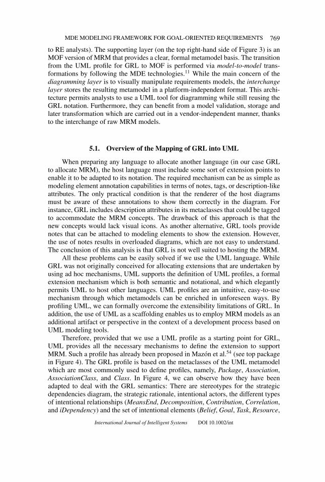
Figure 3. Measurable requirements metamodel (MRM) modeling architecture for model-drivenengineering (MDE) and goal-driven requirements engineering (GDRE).
To link the ULR and the SMM– (see Figures 1 and 2), it is necessary toprovide a relationship between (i) the Validation Method metaclass of ULR on theone hand, and (ii) certain Measures of SMM– on the other. Since Indicator is theonly measure type that provides a means to translate the measurement result into avalidation criteria (through the decision criteria metaclass), we have merged bothmetamodels together with the addition of a Measured Through link between theValidation Method and the Indicator metaclasses. The metamodel resulting fromthis integration (see the central part of Figure 3) is what is actually called MRM.
It is important to note how the resulting MRM supersedes not only ULR,which can now define measurable requirements but also the original SMM itselfwhich, with the linking to RE concepts, can now soundly express not only themeasures but also the context and purpose of the measures in a systematic manner.In MRM, this context involves not only specific goals or specific requirements butalso specific quality scenarios with specific conditions under which the measuresare to be applied. All this information is of paramount importance in the definitionof measures, as they affect the acceptability of the measure result. For example, theapplication of a performance measure with a system load of 10 simultaneous users(quality scenario 1) is different to the application of the same measure with 5000simultaneous users (quality scenario 2).
To summarize this, Figure 3 shows our metamodeling architecture. In thisfigure, we can observe how the MRM imports the ULR and the SMM– metamodels.
International Journal of Intelligent Systems DOI 10.1002/int

768 MOLINA ET AL.
The figure also includes a MeasuredThrough element that provides the hook betweenthese two metamodels, by means of a link between the Validation Method concept(defined as part of the ULR) and the Indicator concept (defined as part of the SMM–).
Although the resulting MRM can be used by directly instantiating the meta-classes to specify measurable requirements, experience has demonstrated that objectmodels do not scale well.45 The following section, therefore, presents a visual nota-tion that provides MRM with a concrete syntax and helps modelers to deal with theMRM instantiation.
5. A VISUAL NOTATION FOR MRM: THE MRM PROFILE
If we look back at Figure 3, we can observe that the metamodels shown inFigures 1 and 2 have been represented by means of meta-object facility (MOF),46
a widely used standard for metamodeling that provides useful primitive types suchas classes, properties, and associations. Despite the fact that MOF has been rec-ommended by the object management group (OMG)47 for general metamodelingin MDE projects, its lack of visual notation makes it an unsuitable candidate forpractical modeling. In fact, just as a proper requirements metamodel is necessary toimprove software analysts’ communicational capabilities, the provision of a propervisualization for the corresponding requirements model is necessary to improve itsusability as an analysis artifact.48 We therefore advocate not only formally specify-ing requirements based on metamodeling, but also diagramming these models in amanner that will improve their cognitive effectiveness.
To achieve its maximum potential, MRM visual models should be aware of theprinciples that empower the human’s visual and cognitive capabilities involved inunderstanding the models.45,49 The raw definition of object diagrams that representmetaclass instances (classes, relationships, and properties) with a neutral notation(InstanceSpecification, Link, and Slot, respectively, see Figure 9a), is not, therefore,sufficient.50 An additional rendering layer for the MRM that provides it with a nota-tion that takes into account recent research on cognitive complexity management45
is thus necessary.For the definition of this notation, and given the many syntactic variations
in the existing GMLs,51 we have opted to base our modelling framework on theURN standard,52 which adopts one of the aforementioned proposals for GMLs,denominated as GRL, for the definition of business goals, NFRs, alternatives andrationales. However, since GRL does not provide the concepts needed to deal withmeasurable requirements, the MRM modeling framework includes a notationalextension of GRL. For this extension, and given that the notation should preferablybe modular,53 we have decided to use the well-known profiling mechanism providedby UML. The result is an MRM profile, which is based on a pre-existing GRL profile,and which extends it with measurement concepts.
MRM can therefore be seen as a two-layered modeling framework (seeFigure 3): a diagramming layer (based on a UML profile for GRL) and an in-terchange layer (based on MOF, i.e., raw metamodeling). The former (see the topleft-hand side of Figure 3) deals with an extended version of GRL diagrams (familiar
International Journal of Intelligent Systems DOI 10.1002/int
MDE MODELING FRAMEWORK FOR GOAL-ORIENTED REQUIREMENTS 769
to RE analysts). The supporting layer (on the top right-hand side of Figure 3) is anMOF version of MRM that provides a clear, formal metamodel basis. The transitionfrom the UML profile for GRL to MOF is performed via model-to-model trans-formations by following the MDE technologies.11 While the main concern of thediagramming layer is to visually manipulate requirements models, the interchangelayer stores the resulting metamodel in a platform-independent format. This archi-tecture permits analysts to use a UML tool for diagramming while still reusing theGRL notation. Furthermore, they can benefit from a model validation, storage andlater transformation which are carried out in a vendor-independent manner, thanksto the interchange of raw MRM models.
5.1. Overview of the Mapping of GRL into UML
When preparing any language to allocate another language (in our case GRLto allocate MRM), the host language must include some sort of extension points toenable it to be adapted to its notation. The required mechanism can be as simple asmodeling element annotation capabilities in terms of notes, tags, or description-likeattributes. The only practical condition is that the renderer of the host diagramsmust be aware of these annotations to show them correctly in the diagram. Forinstance, GRL includes description attributes in its metaclasses that could be taggedto accommodate the MRM concepts. The drawback of this approach is that thenew concepts would lack visual icons. As another alternative, GRL tools providenotes that can be attached to modeling elements to show the extension. However,the use of notes results in overloaded diagrams, which are not easy to understand.The conclusion of this analysis is that GRL is not well suited to hosting the MRM.
All these problems can be easily solved if we use the UML language. WhileGRL was not originally conceived for allocating extensions that are undertaken byusing ad hoc mechanisms, UML supports the definition of UML profiles, a formalextension mechanism which is both semantic and notational, and which elegantlypermits UML to host other languages. UML profiles are an intuitive, easy-to-usemechanism through which metamodels can be enriched in unforeseen ways. Byprofiling UML, we can formally overcome the extensibility limitations of GRL. Inaddition, the use of UML as a scaffolding enables us to employ MRM models as anadditional artifact or perspective in the context of a development process based onUML modeling tools.
Therefore, provided that we use a UML profile as a starting point for GRL,UML provides all the necessary mechanisms to define the extension to supportMRM. Such a profile has already been proposed in Mazon et al.54 (see top packagein Figure 4). The GRL profile is based on the metaclasses of the UML metamodelwhich are most commonly used to define profiles, namely, Package, Association,AssociationClass, and Class. In Figure 4, we can observe how they have beenadapted to deal with the GRL semantics: There are stereotypes for the strategicdependencies diagram, the strategic rationale, intentional actors, the different typesof intentional relationships (MeansEnd, Decomposition, Contribution, Correlation,and iDependency) and the set of intentional elements (Belief, Goal, Task, Resource,
International Journal of Intelligent Systems DOI 10.1002/int

770 MOLINA ET AL.
Figure 4. Unified modeling language (UML) profiling architecture for diagramming measurablerequirements metamodel (MRM) models.
and Softgoal). It is important to note how this profile provides modelers with boththe semantics of GRL elements and their notation in UML.
5.2. A UML Profile for Rendering MRM
The GRL profile provides the basis for the definition of the new MRM profile,by means of the UML specialization mechanism. Table II shows the new MRMstereotypes, defined based on the names of the MRM metaclasses together with the
International Journal of Intelligent Systems DOI 10.1002/int

MDE MODELING FRAMEWORK FOR GOAL-ORIENTED REQUIREMENTS 771
Table II. Representing measurable requirements metamodel (MRM) metaclasses by means ofgoal-oriented requirements language (GRL).
GRL Element Notation Equivalence in MRM
Actor Stakeholder
Goal Goal, Indicator, Base Measure, Derived Measure
Softgoal Non Functional RequirementTask Functional Requirement, Analysis Model, Measurement
Function, Measurement Method
Resource Attribute, Entity Class, Decision Criteria
Task Dependency Test Case
Resource Dependency Quality Scenario, Measurement Result
intentional element of the GRL profile that serves as a basis for the extension (seebottom package in Figure 4). This specialization contrasts with the UML Extensionrelationship that was used between metaclasses and stereotypes in the original GRLprofile (see top package in Figure 4). The reason for this is that, while in the GRLprofile the elements extended were UML metaclasses, for the MRM profile weare extending stereotypes, to adapt an existing profile to accommodate the newMRM elements. This adaptation is achieved through the definition of inheritancehierarchies between UML classifiers, by means of Generalization relationships.
5.2.1. Metaclasses Mapping
The MRM extension presented in Figure 4 is derived from the notationalmapping presented in Table II. In this table, the selection of the notation has beencarried out by following a sound set of diagramming principles that foster cognitiveeffectiveness,45 since it is well known that this effectiveness is primarily determinedby the perceptual characteristics of the diagram. As stated in Ref. 55 even slightchanges in graphical representation may make a dramatic impact on understandingand problem solving performance. These principles are, namely
Perceptual discrimination: In our proposed notation, different shapes are associated with dif-ferent concepts, to foster their recognition (compare the diagrams depicted in Figures 9aand 9b).
Perceptual configuration: Our notation proposal is based on icons; icons make diagramsmore visually appealing, speed up recognition and recall, and improve intelligibility tonovice users. Furthermore, the inclusion of some objects inside others (by means of actorboundaries) creates perceptual grouping, which expands the number of elements thatcan be shown in each diagram without exceeding cognitive limits. This mechanism iscomplemented by the use of packages, which are provided by the UML scaffolding andcontribute to improving the end user’s understanding and the verification accuracy bymore than 50%.53
Perceptual precedence: In our notation proposal not all the metamodel concepts have anassociated icon. Given the fact that the human working memory is very limited, themind needs to establish the order in which elements are dealt with; the definition of
International Journal of Intelligent Systems DOI 10.1002/int

772 MOLINA ET AL.
Table III. Tag definitions involved in the measurable requirements metamodel (MRM) profile.
Stereotype Tag Data Type Semantics From MRM
for all id String core facilitydescription String core facility
FR, NFR catalog String Catalogsource String Source
Measure base Boolean Base Measurederived Boolean Derived Measureunit String Unit of Measurementscale String Scaletype of Scale Enumeration Type of Scale
some concepts by means of tags rather than stereotypes helps the user to choose whichelements to pay attention to first. For example, if we look at the Measure stereotype,it maps two MRM metaclasses (Base Measure and Derived Measure); the representedelements are discriminated by means of tagged values associated with the stereotype.Other metaclasses have been similarly notationally translated into tag definitions (seeTable III). Moreover, the Glossary and Term MRM metaclasses have not been providedwith a modeling mechanism, since their textual nature makes them poor candidates fordiagrams.
Perceptual directness (notational knowledge): The fact that our proposed notation usesGRL icons (shared by most i∗ proposals), and even reuses GRL concepts (and not onlynotation) when possible (see, e.g., the goal element), facilitates its recognition by analystswho are familiar with the GRL notation. What is more, the use of stereotypes providesa standardized element labeling. This has been shown to be essential in diminishing thecognitive overload that hampers the understanding of diagrams.
5.2.2. Metarelationships Mapping
As the reader may have already noticed, in our profile only interactor relation-ships have been stereotyped. The task dependency metarelationship represents testcases that connect FRs (represented as tasks) with indicators (represented as goals).The resource dependency metarelationship is used to represent either (i) qualityscenarios, which link NFRs (represented as softgoals) and indicators (representedas goals) or (ii) measurement results, which link requirements with indicators.
With regard to the relationships between the MRM metaclasses, the designedprofile does not contain stereotypes for adapting the GRL relationship notation (seeFigure 4). This is due to the fact that every MRM metarelationship between eachpair of MRM metaclasses is mapped into just one single intentional relationship inGRL. Therefore, by attending the source and end metaclasses, both modelers andmodel-management tools are able to trace the source MRM metarelationship. Toillustrate this, Figure 5 shows the mapping of some SMM– metarelationships. Thisfigure allows us to observe how indicators (mapped into goals) and analysis models(tasks) are related through a means-end relationship. The same relationship appearsbetween derived measures (goals) and their corresponding measurement functions(tasks) and base measures (goals) and their corresponding measurement methods(tasks). A further relevant intentional relationship is that of task decomposition,
International Journal of Intelligent Systems DOI 10.1002/int

MDE MODELING FRAMEWORK FOR GOAL-ORIENTED REQUIREMENTS 773
Figure 5. Goal-oriented requirements language (GRL) notation for measurable requirementsmetamodel (MRM) measurement concepts.
which appears between analysis models (tasks) and their related measures (goals) ordecision criteria (resources), and also between measurement functions (tasks) andthe associated measures (goals), or between measurement methods (tasks) and theassociated entity classes (resources). Finally, a contribution relationship providesthe attribute (belief) that permits the connection between measurement methods(tasks) and entity classes (resources).
5.2.3. Metaproperties Mapping
The metaproperties involved in MRM are shown in Table III. These metaproper-ties are mapped into the corresponding tag definitions (i.e., metaproperties profilingimplementation), which are associated with the stereotypes shown in Figure 4.
Typically, most stereotypes in a UML profile are complemented with severalconstraints, usually defined in formal languages such as object constraint language(OCL),56 that assure the consistency of the model. For example, in MRM models,the mutual exclusion between the Boolean conditions associated with the base andderived tags must be assured; moreover, the metarelationship mappings presentedin Figure 5 must be preserved.
However, the MRM architecture (see Figure 3), and the fact that MRM istargeted toward providing a notational rather than a semantic extension of GRL,makes the definition of these constraints at profile level unnecessary. Instead, MRMmodels are validated by the MRM semantics constraints in the storing layer, basedon MOF. For this validation MRM models need to be transformed into MOF models.We thus avoid OCL expressions that are expensive to codify and prone to failure
International Journal of Intelligent Systems DOI 10.1002/int

774 MOLINA ET AL.
Figure 6. Three alternative ways to represent stereotype icons in the unified modeling language(UML).
owing to the lack of formal or automatic methods to guide the constraints mappinginvolved in the profiled metamodels. What is more, we allow for the reuse of themodel checking capabilities independently of particular modeling tools.
5.3. The MRM Rendering Notation
The MRM rendering notation associated with the MRM profile is presented asfollows. Given that the MRM profile is defined in terms of the GRL profile, to showthe MRM notational changes it is necessary to understand how the GRL profilealters the UML notation.
5.3.1. Metaclasses Visualization
With regard to the UML profile for GRL,54 but also applicable to any UMLprofile, there are mainly three alternative notational variations for the iconographyintroduced by the profile’s stereotypes (shown in Figure 6). The first and most classicvariation is the simple decoration of the extended metaclass (see the Class UMLmetaclass extended to represent a GRL Task in Figure 6). The metaclass thereforeretains its original notation. The second variation is another UML standard notationmechanism that can be applied when “boxes-like” metaclasses (such as Class)are rendered without their properties. The third notational variation is used whenstraightforward visual metaphors are needed to represent the concept and this implieshiding the underlying UML notation completely. This kind is the most powerful,but it is necessary for the modeling tools to be able to interpret, or at least emulate,the specific non-normative extensions out of default notational extensions providedby UML modeling tools with strict profiling capabilities.
5.3.2. Metarelationships Visualization
With regard to the MRM metarelationships supported by the metaclasses map-ping (Section), the stereotyping of intentional relationships is not actually requiredand the current GRL notation thus works well in this case. Note that, from a prac-tical point of view, the mappings involved between MRM and GRL assure thatMRM relationships will be univocally discriminated from the rendering intentionalrelationship of the GRL profile for MRM.
International Journal of Intelligent Systems DOI 10.1002/int

MDE MODELING FRAMEWORK FOR GOAL-ORIENTED REQUIREMENTS 775
Figure 7. Goal-oriented requirements language (GRL) notation decoration for rendering mea-surable requirements metamodel (MRM) metaclasses.
5.3.3. Metaproperties Visualization
Figure 7 also shows the decoration of the GRL notation for the MRM metaprop-erties. As occurs with the metaclasses, metaproperties are contained in a lower com-partment of the corresponding node-like rendering (note that the relationships aredefined in such a way that they do not have properties), in contrast to the notingmechanism initially provided by GRL (e.g., Dealership’s id in Figure 7).
To illustrate this, we shall now present an example of the use of MRM. Forthe sake of conciseness, in this example we will use the third of the notationalalternatives presented in Figure 6.
6. EXAMPLE
The application example chosen to illustrate our approach deals with a re-quirements elicitation scenario for a simplified online ticket sales system. Botha description of the MRM instantiation and the presentation of the MRM profilenotation are discussed.
6.1. Description
For the sake of simplicity, let us assume that the sales manager of a certaincinema chain wishes to increase the sales profit of the company. Let us also supposethat this goal is to be achieved through two different subgoals; on the one hand,the company wishes to increase the sales net profit by implementing a Web-basedonline ticket sales system that decreases the costs associated with the sales process.On the other hand, the company also wishes to increase the number of sales byobtaining a wider range of customers. The sales manager believes that offering thetickets through the Internet may positively influence both subgoals, so s/he has takenon a Web ticket sales system development process.
The Web customer who will interact with the application has as his/her main FRthat of buying ticket. This requirement can be decomposed into two FRs: browse filmsand purchase ticket. In addition, several NFRs have been identified. The buy ticketfunctionality should follow accessibility guidelines to allow Web customers with
International Journal of Intelligent Systems DOI 10.1002/int

776 MOLINA ET AL.
Figure 8. Ticket Sales System: Stakeholder’s goals and requirements.
disabilities to access the system. Additionally, the system should provide informationaccuracy while browsing through the films: synopsis, sessions, prices and so forthshould be reliable. Also, the application’s learnability should be high, that is, theapplication should be simple enough for novice users to learn its operation easily.Finally, the purchase process should be performed while assuring the security of thecustomer data.
6.2. Instantiating the MRM Metamodel
If we first check the involved ULR metaclasses (see Figures 1 and 9a), we canobserve that (i) the sales manager and Web customer both instantiate the Stakeholdermetaclass, (ii) all goals related to increasing sales profit instantiate the Goal meta-class, (iii) buy tickets, browse films, purchase tickets are all FR occurrences, and (iv)accessibility, learnability, security and information accuracy are all NFR instances.Also, note how the GRL notation (Figure 8) improves the understandability of thisMRM model rendered as an object diagram (Figure 9a).
Let us now focus on the learnability with which the Web customer is able tobrowse the films we are offering on our site, and let us convert this into a measurablerequirement. For this purpose, let us assume that we have defined a quality scenario—(instantiated from the Quality Scenario metaclass, see Figure 1) which states that itis necessary to check whether a novice user is able to find the link s/he expected tofind based on his/her mental model of the domain.
If we now check the SMM– (see Figure 2), we can observe how the first stepin making a requirement measurable is that of defining an Indicator occurrence thatwe have denominated as “navigability level.” Indicators are made up of measures.In our example, let us imagine there is a single Derived Measure instance thatcontributes to the indicator, which is called “domain coverage navigation measure.”(DCNM). This measure is based on two base measure occurrences: the “number ofrelevant relationships” (NRR) and the “number of navigated domain relationships”(NNDR). In short, the DCNM calculates how many of the domain relationships thatmay be relevant in fulfilling the requirement are actually navigation links which areavailable through the application interface. Let us also imagine that, in this context,
International Journal of Intelligent Systems DOI 10.1002/int

MDE MODELING FRAMEWORK FOR GOAL-ORIENTED REQUIREMENTS 777
Figure 9. (a) Object diagram corresponding to the instantiation of measurable requirementsmetamodel (MRM) for the Ticket Sales System (b) Equivalent model using the MRM notation.
the Decision Criteria and the Analysis Model associated with the indicator establishthat a DCNM > 0.80 makes the Web design acceptable with regard to its learnability.Both the NRR and the NNDR are measures that can be calculated automatically if theWeb development process includes conceptual domain and navigation models suchas the ones managed in the context of Web Engineering methodologies. Assuming
International Journal of Intelligent Systems DOI 10.1002/int

778 MOLINA ET AL.
that the system is being deployed with one of these Web engineering proposals,namely OO-H,57 the DCNM measure can be calculated early in the lifecycle, basedon the Entity Class “Web conceptual model” (an abstract model that represents anentire Web application). More specifically, the NRR is calculated over the “domainmodel” Entity Class, while the NNDR is calculated over the “navigational model”Entity Class. Both measures are related to the structural complexity Attribute of theassociated models. The measurement function that serves to calculate the DCNMuses the two base measures to calculate the measurement result. The higher thisvalue is, the more domain relationships are covered in the application interface bymeans of links.
Figure 9a shows the objects diagram that represents the instantiation of MRMfor this example. This model can be used in the context of model-driven method-ologies to automate the measurement process at every stage of development, andeven to automatically evolve the models based on measurement results. Readersinterested in the whole approach are referred to Ref. 42.
As the reader may note, despite the low complexity of the example, the size ofthe obtained diagram is quite large, while its understandability is low. The provisionof the visual notation improves the conciseness of the diagram (see Figure 9b), whilesimultaneously improving its readability.
7. TOOL SUPPORT FOR THE MANAGEMENT OF MRM MODELS
Given the increasing complexity of the systems being developed, modelingframeworks are currently of little use if they are not supported by CASE tools thathelp to manage them. Thus, this section presents how the MRM framework has beenintegrated into an MDE environment.
In the case of MRM, and given the fact that it was created with the aim of itsbeing integrated into MDE approaches, our modeling framework is accompaniedby a tool that includes a model-to-model transformation architecture for articulatingboth the visual representation and the storage of MRM models. Certain considera-tions have been taken into account in the selection of the technological environmentin which to implement this tool. First, it was necessary to use an environmentthat would facilitate the definition of metamodels. Moreover, as we wished variousstakeholders (and not only designers) to use MRM, it was necessary to offer thema graphical tool with a usable and comfortable interface that would allow them tocreate and manipulate models compliant with the metamodel. It was also necessaryto consider the capacities offered by the technological environment to extend thetool with new functionalities or to integrate it with other pre-existing tools.
Given these premises, the ECLIPSE development platform58 and, in particular,the ECLIPSE modeling framework (EMF) was selected to implement the tool. BothECLIPSE and EMF have certain suitable features that make them of interest to usin our approach. On the one hand, EMF offers support to deal with MOF. EMF istherefore useful both to describe MRM and for the creation and manipulation ofmodels and metamodels. On the other hand, ECLIPSE is an open source platform-independent project and has an architecture based on plug-ins. One of these plug-ins
International Journal of Intelligent Systems DOI 10.1002/int

MDE MODELING FRAMEWORK FOR GOAL-ORIENTED REQUIREMENTS 779
Figure 10. Measurable requirements metamodel (MRM) modeling framework supported by theECLIPSE development platform.
is the UML2Tools plug-in, which supports the formal definition of UML profiles.Figure 10 shows how UML2Tools has been adapted by customizing the stereotypevisualization, thus enabling it to conform to the non-normative notational extension(Section 5.3), menus and palette tools.
The implementation of the application example (see Section 6) in the designedplatform is also shown in Figure 10. The left-hand side of the figure represents theTicket Sale System MRM diagram, modeled with the GRL profile for MRM, togetherwith the palette tool for creating the modeling elements following the proposed nota-tion. The center of this same figure shows the model-to-model transformations thatjoin the diagramming and interchange layers (Section 5). These transformationshave been specified in query/view/transformation (QVT) language,59 and then cod-ified through atlas transformation language (ATL)60. In the center of the figure thereis also a tab that shows the actual (i.e., raw) implementation of MRM with EMF, inwhich we can observe the metaclasses used to represent the model itself (Model),its modeling elements (Element), and a particular element, which in this case cor-responds to the link between the requirements and measurement subparts of MRM(MeasuredThrough). On the right-hand side of Figure 10, we can observe the textualmodel corresponding to the Ticket Sale System (see Section 6). For reasons of legi-bility, this textual MRM model has been divided into three parts: the requirementssubmodel is presented in the top window, while the requirements-measurement link-age is depicted in the middle window and the measurement submodel is shown in thebottom window. EMF directly supports this tree-like textual representation, whichcorresponds to the object diagram shown in Figure 9a. Modeling elements and someuseful properties such as containment relationships, data types, or generalizations,
International Journal of Intelligent Systems DOI 10.1002/int

780 MOLINA ET AL.
are shown in this view. To complete the models specification, ECLIPSE also providesa properties view (in the lower part of the figure), which shows the properties of theselected classes.
It is important to note how the modeling architecture that implements ECLIPSE
preserves the two-layer separation of our approach (see Figure 3) by providing twodifferent kinds of metadata: on the one hand, the diagramming layer (based on UMLprofiles) is kept in XML metadata interchange (XMI) files, which store visualizationinformation (e.g., nodes, arcs, and 2D positions) together with the references to therendered modeling elements. On the other hand, the actual model data (i.e., thedata obtained from the direct instantiation of the concepts defined in the raw MRM)is stored in XMI files that support EMF-based model persistence, which enablesmodelers to share MRM models among different types of model management tools(e.g., diagramming tools, checking & validation tools, transformation engines, andmodel repositories), through our interchange layer.
8. CONCLUSIONS AND FURTHER WORK
The lack of consensus with regard to the use of late requirements metamod-els in MDE proposals, together with the absence of mechanisms for specifyingthe requirements validation over other early development artifacts, is a reality thatis hampering the alignment of MDE-based development projects with regard tostakeholders’ needs. To alleviate this situation, we have proposed a MRM, whichwill assist MDE developers in the systematic elicitation of requirements, while si-multaneously contributing toward obtaining the benefits of an early requirementsevaluation. The support that MRM offers for the explicit linkage of goals, require-ments and measures, helps to achieve both the backward and forward traceability ofrequirements. Moreover, in view of the fact that sound model rendering mechanismsare crucial for the success of a modeling framework, we have presented an asso-ciated UML profile, based on GRL and some well-known diagramming principlesthat simplify the task of modeling. The UML scaffolding provides MRM modelswith a degree of scalability (mainly based on the concept of package) that is missingin some well-known GMLs, including GRL. This task is further simplified by anECLIPSE-based tool that supports the MRM framework. Furthermore, the Eclipseenvironment allows MRM models to be integrated with MDE transformations thatautomate the measurement activities, thus speeding up the requirements validationprocess.
The definition of visual notations for modeling languages by profiling UMLraises interesting research questions such as the usability evaluation of the softwareartifacts designed.50 A significant challenge will therefore be the provision of a soundempirical evaluation that proves the suitability of the designed MRM diagrams forrequirements elicitation and validation. In fact, despite its popularity, one of themain risks in the success of this evaluation is the aforementioned complexity ofGMLs. Visual enhancements for MRM diagrams have been envisaged (such as theabstraction achieved by collapsing stakeholders’ rationales), but the evaluation ofsuch techniques requires further work.
International Journal of Intelligent Systems DOI 10.1002/int

MDE MODELING FRAMEWORK FOR GOAL-ORIENTED REQUIREMENTS 781
Acknowledgments
This work has been partially supported by the projects DEDALO (TIN2006-15175-C05-03)and PANGEA (TIN2009-13718-C02-02) from the Spanish Ministry of Science and Technol-ogy, MELISA-GREIS (PAC08-0142-335), ESPIA (TIN2007-67078), QUASIMODO (PAC08–0157-0668) and DEMETER (GVPRE/2008/063). Fernando Molina and Jesus Pardillo are par-tially funded by the Fundacion Seneca (Region de Murcia) and the FPU grant AP2006-00332,respectively.
LIST OF ACRONYMS
EMF Eclipse Modeling Framework58
FR Functional RequirementGDRE Goal-Driven Requirements EngineeringGML Goal Modeling LanguageGORE Goal-Oriented Requirements EngineeringGRL Goal-oriented Requirements Language17
MD{A,E} Model-Driven Architecture13/Engineering11
MM Measurement MetamodelMRM Measurable Requirements Metamodel (see Section 4)MOF Meta-Object Facility46
NFR Non-Functional RequirementOCL Object Constraint Language61
OMG Object Management Group47
QVT Query/View/Transformation language59
RE Requirements EngineeringRM Requirements MetamodelSM{M,O} Software Measurement Metamodel/Ontology43
ULR Unified Late-Requirements metamodel (see Section 3)UML Unified Modeling Language15
URN User Requirements Notation52
References
1. Yamamoto S, Kaiya H, Cox K, Bleistein SJ. Goal oriented requirements engineering: trendsand issues. IEICE Trans 2006;89-D:2701–2711.
2. Lapouchnian A. Goal-oriented requirements engineering: An overview of the current re-search. Technical report, University of Toronto, 2005.
3. van Lamsweerde A. Goal-oriented requirements engineering: From system objectives toUML models to precise software specifications. In: ICSE 2003. pp 744–745.
4. Dardenne A, van Lamsweerde A, Fickas S. Goal-directed requirements acquisition. SciComput Program 1993;20:3–50.
5. Mylopoulos J, Yu E, Nixon BA, Chung L. Non-functional requirements in software engi-neering. The Kluwer International Series in Software Engineering. Boston MA: Kluwer;2000.
6. Martınez A, Pastor O, Mylopoulos J, Giorgini P. From early to late requirements: A goal-based approach. In: AOIS 2006. pp 123–142.
7. Fenton NE, Pfleeger SL. Software metrics: A rigorous and practical approach. Boston, MA:PWS Publishing; 1998.
8. ISO. SPICE (Software Process Improvement and Capability dEtermination); 2004.9. Chrissis MB, Konrad M, Shrum S. CMMI: Guidelines for process integration and product
improvement. Boston, MA: Addison-Wesley; 2006.10. Larman C. Applying UML and patterns. Prentice Hall PTR, Upper Saddle River, NJ, USA;
2005.
International Journal of Intelligent Systems DOI 10.1002/int

782 MOLINA ET AL.
11. Schmidt D. Guest editor’s introduction: Model-driven engineering. IEEE Comput2006;39:25–31.
12. Selic B. MDA manifestations. Eur J Inform Prof 2008;IX(2);12–16.13. Kleppe A, Warmer J, Bast W. MDA Explained: The model driven architecture: Practice and
promise. Boston, MA: Addison-Wesley; 2003.14. Briand L, Morasca S, Basili V. Defining and validating measures for object-based high-level
design. IEEE Trans Softw Eng 1999;25:722–743.15. Object Management Group: Unified Modeling Language (UML), version 2.1.1., 2007.
Available online at http://www.omg.org/technology/documents/formal/uml.htm. AccessedMay 2010.
16. Lange C, Chaudron M, Muskens J. In practice: UML software architecture and designdescription. IEEE Softw 2006;23:40–46.
17. University of Toronto: Goal-Oriented Requirement Engineering Methodology Using GRL.Available online at http://www.cs.toronto.edu/km/GRL, accessed May 2010.
18. Damian D, Chisan J. An empirical study of the complex relationships between requirementsengineering processes and other processes that lead to payoffs in productivity, quality, andrisk management. IEEE Trans Softw Eng 2006;32:433–453.
19. Rashid A, Moreira AM, Tekinerdogan B. Special issue on early aspects: aspect-oriented requirements engineering and architecture design. IEE Proc–Softw 2004;151:153–156.
20. Kotonya G, Sommerville I. Requirements engineering with viewpoints. Softw Eng J1996;11:5–18.
21. Robertson S, Robertson J. Mastering the requirement process. Boston, MA: Addison-Wesley; 1999.
22. Cockburn A. Writing effective use cases. Boston, MA: Addison-Wesley; 2001.23. Escalona MJ, Aragon G. Ndt. a model-driven approach for web requirements. IEEE Trans
Softw Eng 2008;34:377–390.24. Koch N, Zhang G, Escalona MJ. Model transformations from requirements to web system
design. In: ICWE, 2006. pp 281–288.25. Bolchini D, Paolini P. Goal-driven requirements analysis for hypermedia-intensive web
applications. Requir Eng J 2004;9:85–103.26. Bresciani P, Perini A, Giorgini P, Giunchiglia F, Mylopoulos J. Tropos: An agent-
oriented software development methodology. Auton Agents Multi-Agent Syst 2004;8:203–236.
27. Potts C, Takahashi K, Anton AI. Inquiry-based requirements analysis. IEEE Softw1994;11:21–32.
28. International Telecommunications Union’s Telecommunication Standardization Sector(ITU-T): User Requirements Notation (URN)/Z.151 metamodel. Available online at http://jucmnav.softwareengineering.ca/ucm/bin/view/UCM/DraftZ151Metamodel, accessed May2010.
29. Jureta I, Mylopoulos J, Faulkner S. Revisiting the core ontology and problem in requirementsengineering. In: RE 2008. pp 71–80
30. Kitchenham B. Guidelines for performing systematic literature reviews in software engi-neering. EBSE Technical Report EBSE-2007–01, Software Engineering Group, School ofComputer Science and Mathematics, Keele University, UK and Departament of ComputerScience, University of Durham, Durham, UK, 2007.
31. Molina F, Pardillo J, Cachero C, Toval A. A systematic review of require-ments metamodels. Technical report, University of Murcia, 2008. Available online athttp://www.lucentia.es/index.php/MRM.
32. Berre AJ. Comet (component and model based development methodology), 2006. Availableonline at http://modelbased.net/comet/, accessed May 2010.
33. Fernandez JL, Monzon A. A metamodel and a tool for software requirements management.In: Reliable Software Technologies. Ada-Europe. Berlin, Germany, 2000.
34. Goknil A, Kurtev I, van den Berg K. A metamodeling approach for reasoning about require-ments. In: ECMDA-FA 2008. pp 310–325.
International Journal of Intelligent Systems DOI 10.1002/int

MDE MODELING FRAMEWORK FOR GOAL-ORIENTED REQUIREMENTS 783
35. Vicente-Chicote C, Moros B, Toval A. REMM-studio: an integrated model-driven environ-ment for requirements specification, validation and formatting. J Obj Technol, Special IssueTOOLS EUROPE 2007 2007;6:437–454.
36. Vogel R, Mantell K. MDA adoption for a SME: evolution, not revolution – phase II. In: 2ndWorkshop From code centric to model centric software engineering: Practices, Implicationsand ROI. In conjunction with ECMDA 2006. (2006)
37. Toval A, Moros B, Nicolas J, Lasheras J. Eight key issues for an effective reuse. Int J ComputSyst Sci 2008;23.
38. ISO: /ISO/IEC 9126–1. Softw. eng.-product quality – part 1: Quality model,2000.39. Serrano MA, Calero C, Sahraoui HA, Piattini M. Empirical studies to assess the understand-
ability of data warehouse schemas using structural metrics. Softw Qual J 2008;16:79–106.40. Blaine JD, Cleland-Huang J. Software quality requirements: how to balance competing
priorities. IEEE Softw 2008;25:22–24.41. Glinz M. A risk-based, value-oriented approach to quality requirements. IEEE Softw
2008;25:34–41.42. Cachero C, Melia S, Genero M, Poels G, Calero C. Towards improving the navigability of
web applications: a model-driven approach. Eur J Inf Syst 2007;16:420–447.43. Garcıa F, Bertoa MF, Calero C, Vallecillo A, Ruiz F, Piattini M, Genero M. Towards a
consistent terminology for software measurement. Inf Softw Technol 2006;48:631–644.44. Briand L, Morasca S, Basili V. Property-based software engineering measurement. IEEE
Trans Softw Eng 1996;22:68–86.45. Moody D. What makes a good diagram? improving the cognitive effectiveness of diagrams
in is development. In: Advances in Information Systems Development. Springer, SpringStreet, NY, USA; 2006:481–492.
46. Object Management Group: Meta Object Facility (MOF) version 2.0., Available online athttp://www.omg.org/mof/, accessed May 2010.
47. OMG: Object management group, 2009. Available online at http://www.omg.org/48. Whitley KN. Visual programming languages and the empirical evidence for and against. J
Vis Lang Comput 1997;8:109–142.49. Shneiderman B, Card S, Mackinlay J. Readings in Information Visualization: Using Vision
to Think. San Fransisco, CA: Morgan Kaufmann; 1999.50. Green T, Petre M. Usability analysis of visual programming environments: a cognitive
dimensions framework. J Vis Lang Comput 1996;7:131–174.51. Horkoff J, Elahi G, Abdulhadi S, Yu E. Reflective analysis of the syntax and semantics of
the i* framework. In: ER Workshops2008. pp 249–260.52. Amyot D. Mussbacher G. URN: Towards a new standard for the visual description of
requirements. In: SAM 2002. pp 21–37.53. Moody D. Comparative evaluation of large data model representation methods: The analyst’s
perspective. In: ER 2002. pp 214–231.54. Mazon JN, Pardillo J, Trujillo J. A model-driven goal-oriented requirement engineering
approach for data warehouses. In: ER Workshops 2007. pp 255–264.55. Larkin JH, Simon HA. Why a diagram is (sometimes) worth ten thousand words. Cogn Sci
1987;11:65–100.56. Warmer J, Kleppe A. The object constraint language: Getting your models ready for MDA.
Boston, MA: Addison-Wesley; 2003.57. Gomez J, Cachero C, Pastor O. Conceptual modeling of device-independent web applica-
tions: towards a web engineering approach. IEEE Multimedia 2001;8:26–39.58. Eclipse. Eclipse modeling framework project (EMF), 2008. Available online at
http://www.eclipse.org/modeling/emf/59. Object Management Group. MOF QVT standard specification, 2005. Available online at
http://www.omg.org/ docs/ptc/05–11-01.pdf.60. Team A. Atlas transformation language (ATL). Available online at http://www.eclipse.org/
gmt/atl/, accessed May 2010.61. Object Management Group: object constraint language (OCL), version 2.0., Available online
at http://www.omg.org/technology/documents/formal/ocl.htm, accessed May 2010.
International Journal of Intelligent Systems DOI 10.1002/int