Embed Size (px)
Citation preview

CIRP Journal of Manufacturing Science and Technology 6 (2013) 181–186
An integrated approach to support the joint design of machine toolsand process planning
M. Leonesio, L. Molinari Tosatti, S. Pellegrinelli, A. Valente *
Institute of Industrial Technologies and Automation (ITIA), National Research Council of Italy (CNR), Via Bassini 15, 20133 Milano, Italy
A R T I C L E I N F O
Article history:
Available online 9 April 2013
Keywords:
Process planning
Machine tool kinematics and dynamics
Machine design
STEP-NC
A B S T R A C T
The configuration of machine tools and process planning problem are traditionally managed as
independent stages, where the process plan is designed by considering a number of machine tool
solutions available from catalogue. This strategy presents a number of disadvantages in terms of process
results and machine capabilities fully exploitation. The current paper proposes an integrated approach
for jointly configuring machine tools and process planning. The approach is structured in 4 major
recursive steps that eventually ensure the accomplishment of the best trade-off between the machine
tool static and dynamic behaviour, the process quality and the resulting economic efficiency. The
benefits of the approach have been evaluated for a test case application in the railway and automotive
sectors.
� 2013 CIRP.
Contents lists available at SciVerse ScienceDirect
CIRP Journal of Manufacturing Science and Technology
jou r nal h o mep age: w ww.els evier . co m/lo c ate /c i rp j
1. Introduction
The design and configuration of machine tools is instrumentalfor European manufacturing competitiveness [1]. Coherently withthe mass customization principles and the traditional Europeanknow how in the field of instrumental goods production, machinetools should result from a configuration process tightly related tothe analysis of the families of products and process qualityrequirements rather than being a standard and rigid catalogueequipment. This makes the machine configuration and the processplanning as two steps of the same problem where the machine toolgeometric and kinematics features influence the accessibility tothe workpiece operations along with the fixturing systemconfiguration and the machine dynamic impacts on the finalquality and costs of the workpiece.
The relationships between machine tool configuration andprocess planning have been widely investigated by the scientificliterature with reference to the following topics: the evaluation ofmachine capabilities to statically realize a process plan [2], theexecution of a process plan across several resources [3], the energyefficient process planning [4–7] and, finally, evaluation of theimpact of machine tool dynamic behaviour on the process planningdefinition [8]. However, the interest of these works is mostlyfocused on the impact of a specific machine tool architecture andperformance on the process planning problem.
* Corresponding author. Tel.: +39 0223699917; fax: +39 0223699941.
E-mail address: [email protected] (A. Valente).
1755-5817/$ – see front matter � 2013 CIRP.
http://dx.doi.org/10.1016/j.cirpj.2013.03.002
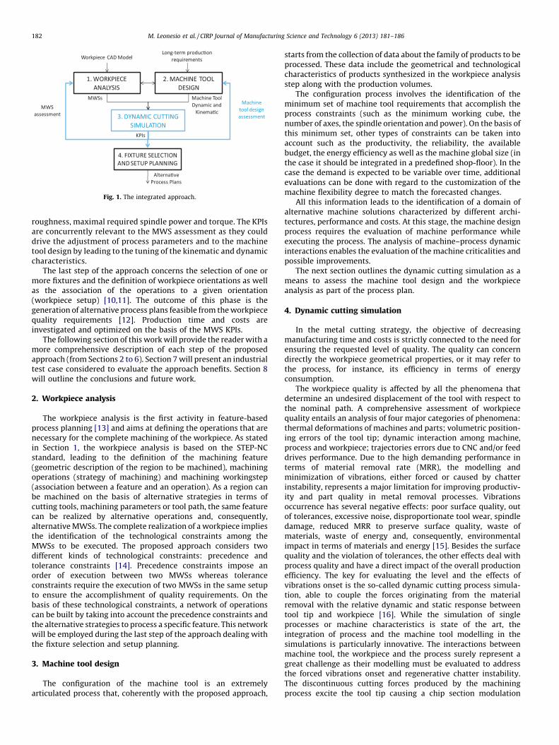
The current paper presents an integrated approach to supportthe joint design of machine tools and process planning. Theproposed approach is structured in four major steps as illustratedin Fig. 1.
The first step consists in the analysis of the workpiece CADmodel. The workpiece is analysed according to the STEP standard[9] through the identification of machining feature (geometricaldescription of the region of the workpiece to be machined),machining operations (selection of cutting tools, machiningparameters and strategies) and machining workingsteps (MWS– association between a machining feature and a machiningoperation). On the basis of a number of alternative MWSs, Step 1identifies the MWSs that globally better match the productionrequirements and machine behaviour.
The geometric and technological information related to thefamily of products together with the data about the productiondemand and the forecasts about possible product evolutions areutilized in Step 2 related to the machine tool design. The outcomeof this step is a domain of general-purpose machine tools that fitthe production requirements from both the dynamic and staticpoint of view Steps 1 and 2 are traditionally handled asindependent phases as general-purpose machine tools arenormally configured with no knowledge of the actual productsto machine and the process planning is usually developed startingfrom an existing machine catalogue.
Step 3 regards the dynamic simulation of the machine toolsolutions resulting from Step 2 while executing the MWSsidentified in Step 1. The dynamic behaviour of machine tools isevaluated against a number of Key Performance Indicators (KPIs)dealing with the energy consumption, tool wear, surface
1. WORKPIE CE ANALYSIS
2. MACHINE TOOL DESIGN
3. DYNAMIC CUTT ING SIMULATION
Workpiece CAD Model
MWSs Machine Too l Dynamic and
Kinema�c
4. FIXTURE SELECTION AND SETUP PLANN ING
KPIs
Machine too l design ass ess ment
MWS ass ess ment
Alterna�ve Process Plans
Long-term produc�on requ irements
Fig. 1. The integrated approach.
M. Leonesio et al. / CIRP Journal of Manufacturing Science and Technology 6 (2013) 181–186182
roughness, maximal required spindle power and torque. The KPIsare concurrently relevant to the MWS assessment as they coulddrive the adjustment of process parameters and to the machinetool design by leading to the tuning of the kinematic and dynamiccharacteristics.
The last step of the approach concerns the selection of one ormore fixtures and the definition of workpiece orientations as wellas the association of the operations to a given orientation(workpiece setup) [10,11]. The outcome of this phase is thegeneration of alternative process plans feasible from the workpiecequality requirements [12]. Production time and costs areinvestigated and optimized on the basis of the MWS KPIs.
The following section of this work will provide the reader with amore comprehensive description of each step of the proposedapproach (from Sections 2 to 6). Section 7 will present an industrialtest case considered to evaluate the approach benefits. Section 8will outline the conclusions and future work.
2. Workpiece analysis
The workpiece analysis is the first activity in feature-basedprocess planning [13] and aims at defining the operations that arenecessary for the complete machining of the workpiece. As statedin Section 1, the workpiece analysis is based on the STEP-NCstandard, leading to the definition of the machining feature(geometric description of the region to be machined), machiningoperations (strategy of machining) and machining workingstep(association between a feature and an operation). As a region canbe machined on the basis of alternative strategies in terms ofcutting tools, machining parameters or tool path, the same featurecan be realized by alternative operations and, consequently,alternative MWSs. The complete realization of a workpiece impliesthe identification of the technological constraints among theMWSs to be executed. The proposed approach considers twodifferent kinds of technological constraints: precedence andtolerance constraints [14]. Precedence constraints impose anorder of execution between two MWSs whereas toleranceconstraints require the execution of two MWSs in the same setupto ensure the accomplishment of quality requirements. On thebasis of these technological constraints, a network of operationscan be built by taking into account the precedence constraints andthe alternative strategies to process a specific feature. This networkwill be employed during the last step of the approach dealing withthe fixture selection and setup planning.
3. Machine tool design
The configuration of the machine tool is an extremelyarticulated process that, coherently with the proposed approach,
starts from the collection of data about the family of products to beprocessed. These data include the geometrical and technologicalcharacteristics of products synthesized in the workpiece analysisstep along with the production volumes.
The configuration process involves the identification of theminimum set of machine tool requirements that accomplish theprocess constraints (such as the minimum working cube, thenumber of axes, the spindle orientation and power). On the basis ofthis minimum set, other types of constraints can be taken intoaccount such as the productivity, the reliability, the availablebudget, the energy efficiency as well as the machine global size (inthe case it should be integrated in a predefined shop-floor). In thecase the demand is expected to be variable over time, additionalevaluations can be done with regard to the customization of themachine flexibility degree to match the forecasted changes.
All this information leads to the identification of a domain ofalternative machine solutions characterized by different archi-tectures, performance and costs. At this stage, the machine designprocess requires the evaluation of machine performance whileexecuting the process. The analysis of machine–process dynamicinteractions enables the evaluation of the machine criticalities andpossible improvements.
The next section outlines the dynamic cutting simulation as ameans to assess the machine tool design and the workpieceanalysis as part of the process plan.
4. Dynamic cutting simulation
In the metal cutting strategy, the objective of decreasingmanufacturing time and costs is strictly connected to the need forensuring the requested level of quality. The quality can concerndirectly the workpiece geometrical properties, or it may refer tothe process, for instance, its efficiency in terms of energyconsumption.
The workpiece quality is affected by all the phenomena thatdetermine an undesired displacement of the tool with respect tothe nominal path. A comprehensive assessment of workpiecequality entails an analysis of four major categories of phenomena:thermal deformations of machines and parts; volumetric position-ing errors of the tool tip; dynamic interaction among machine,process and workpiece; trajectories errors due to CNC and/or feeddrives performance. Due to the high demanding performance interms of material removal rate (MRR), the modelling andminimization of vibrations, either forced or caused by chatterinstability, represents a major limitation for improving productiv-ity and part quality in metal removal processes. Vibrationsoccurrence has several negative effects: poor surface quality, outof tolerances, excessive noise, disproportionate tool wear, spindledamage, reduced MRR to preserve surface quality, waste ofmaterials, waste of energy and, consequently, environmentalimpact in terms of materials and energy [15]. Besides the surfacequality and the violation of tolerances, the other effects deal withprocess quality and have a direct impact of the overall productionefficiency. The key for evaluating the level and the effects ofvibrations onset is the so-called dynamic cutting process simula-tion, able to couple the forces originating from the materialremoval with the relative dynamic and static response betweentool tip and workpiece [16]. While the simulation of singleprocesses or machine characteristics is state of the art, theintegration of process and the machine tool modelling in thesimulations is particularly innovative. The interactions betweenmachine tool, the workpiece and the process surely represent agreat challenge as their modelling must be evaluated to addressthe forced vibrations onset and regenerative chatter instability.The discontinuous cutting forces produced by the machiningprocess excite the tool tip causing a chip section modulation

M. Leonesio et al. / CIRP Journal of Manufacturing Science and Technology 6 (2013) 181–186 183
influencing the cutting force itself. In order to incorporate thedescribed effects, the architecture of the dynamic cuttingsimulation approach should integrate the following functionalmodules:
� A part program interpreter able to provide the tool path with therelated velocity law, together with the cutting parametersdefining the operation (for instance, spindle speed and feed rate);� A ‘‘geometric engine’’ for computing the workpiece-tool engage-
ment and the chip geometry computation;� A force model relating the chip geometry with the cutting forces
expressed by each engaged cutter and their summation;� A representation of the tool tip and workpiece relative dynamics;� A time-domain integrator for the overall dynamic simulation.
In most of existing commercial applications, the dynamic loopbetween machine and process is not closed, as cutting forcesdisturbances are supposed to not affect tool position andconsequently chip section. Actually, the complexity of the modelseverely reduces the existing commercial applications: the uniquecommercial application realizing a proper ‘‘Virtual Machining’’taking into account dynamic cutting is MachProTM by MALINC.
The dynamic simulation results contribute in evaluating thequality of the machining process. This means to identify a numberof KPIs to be measured and tracked over time.
4.1. Key Performance Indicators (KPI)
The KPIs considered in the proposed approach are interpretedas a measure of the machine tool dynamics with respect to therequired machining operations. On the basis of the value of theseindicators some instrumental choices can be realized withreference to the machine structure and control system. In thefollowing part of the current section, the most importantconsidered KPIs are briefly introduced.
4.1.1. Energy consumption
The mechanical energy necessary to perform the machiningoperation can be obtained by computing the integral of themechanical power over machining time, namely:
Etot ¼ Es pindle þ Eaxes
¼Z TMWS
0Vs pindleTs pindleðtÞdt þ
Z TMWS
0v*
feedðtÞ � ~FcðtÞdt (1)
where Vspindle is the spindle velocity, Tspindle is the spindle torque,~v feed is the instantaneous feed velocity, ~Fc is the cutting force andTMWS is the MWS duration.
The computation of electrical energy consumption can be moreprecisely computed by keeping separated axes and spindlemechanical power since the efficiency of the corresponding drives(whose estimation is out of scope) is usually different. Moreover, inorder to compare the copper losses in spindle winding for differentMWSs, the Root Mean Squared value (RMS) of spindle torque canbe computed as well, starting from torque time history.
In literature, cutting energy consumption is commonlyestimated by a constant volumetric specific energy associated tothe material type: this approximated approach conflicts with theexperimental data, whereas the specific energy changes with tool,process parameters and machines [17]. The specific spindle powerconsumption (SSPC) is inversely related to cutting speed, feed pertooth, depth of cut and width of cut. The situation can be different ifthe process becomes unstable (chatter occurrence): as the spindlecopper losses are proportional to the RMS of the torque, thepresence of a dynamic component in cutting force may cause anincrease of SSPC.
All the above-mentioned considerations are automaticallytaken into account by the developed SW module.
4.1.2. Spindle bearings load
Spindle bearings usually face a progressive wear duringmachining and most of the spindle maintenance time is devotedto bearings substitution. The bearing catalogues report a stan-dardized formula to compute bearing life by referring to the‘‘dynamic equivalent load’’, able to synthesize in a single numberthe effort requested to a bearing during a complex load history.Assuming that spindle bearings load is proportional to the spindleshaft bending moment, the ‘‘dynamic equivalent load’’ can becomputed for each MWS, and used to compare the induced bearingstress. In formula:
BL ¼ Ltool �Z TMWS
0
ffiffiffiffiffiffiffiffiffiffiffiffiffiffiffiffiffiF3
xyðtÞTMWS
dt3
s(2)
where Ltool is the tool length and Fxy is the cutting force resultant inthe milling plane (xy).
4.1.3. Roughness
Surface roughness depends on several factors related to cuttingkinematic and vibration onset. In the proposed approach, the toolvibrations and deflection are directly addressed as a surfaceroughness indicator. They are crucial in determining an acceptablelevel of surface roughness and comparing the influence of differentdynamic responses on this parameter. Thus, the indicatorbecomes:
R ¼ maxTMWS
~xtoolðtÞk kð Þ (3)
where ~xtoolðtÞ is the tool tip displacement over time.
4.1.4. Tool cutter load
Tool chipping occurs when the shear pressure on the cuttingedge overcomes the mechanical resistance of the material. Theshear stress is proportional to the cutting force expressed by thesingle cutter Fcutter normalized with respect to the cutting edgeengagement (b). Therefore, the corresponding indicator is:
Cl ¼ 1
bmaxTMWS
ðFcutterðtÞÞ (4)
The other KPIs consist in an estimation of the tool wear exploitingby Taylor formula, the maximum spindle power and maximumspindle torque requested to cut the material, as well as themaximum load requested by machine tool axes to provide feedmovement. They are directly available from simulation andrepresent constraints that the machine tool must respect to beable to perform a given operation.
5. Machine tool design and MWS assessment
Coherently with the proposed approach, the interpretation ofKPIs can drive the improvement choices both for the processplanning and the machine tools.
Based upon the KPIs values, a number of MWSs can be updatedto obtain a more performing and feasible process. For example, incase the KPI expressing the surface roughness indicates that theprocess is not compliant to the workpiece quality constraints,some MWS such as feed rate or spindle speed can be adjusted;similarly, according to maximum spindle power, feed rate, spindlespeed or cut of depth can be modified in order to reduce the costassociated to the manufacturing process.
The impact of KPIs on the machine tool choices is morecomplex to be addressed. The KPIs expressing the required
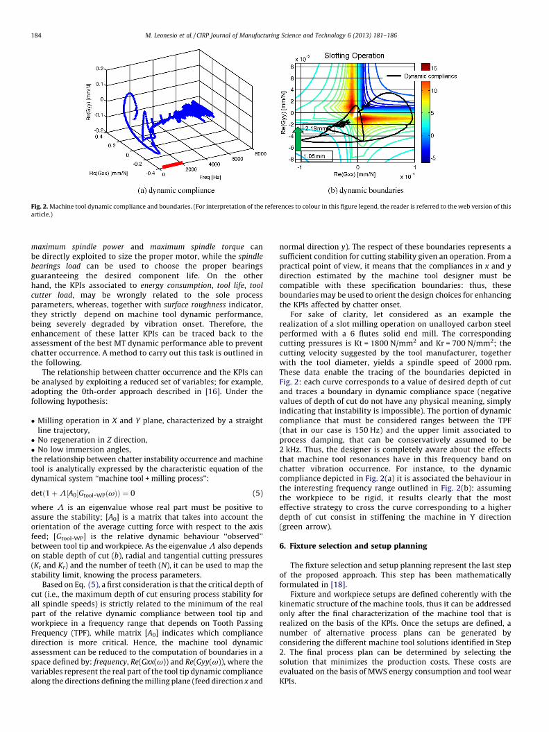
Fig. 2. Machine tool dynamic compliance and boundaries. (For interpretation of the references to colour in this figure legend, the reader is referred to the web version of this
article.)
M. Leonesio et al. / CIRP Journal of Manufacturing Science and Technology 6 (2013) 181–186184
maximum spindle power and maximum spindle torque canbe directly exploited to size the proper motor, while the spindle
bearings load can be used to choose the proper bearingsguaranteeing the desired component life. On the otherhand, the KPIs associated to energy consumption, tool life, tool
cutter load, may be wrongly related to the sole processparameters, whereas, together with surface roughness indicator,they strictly depend on machine tool dynamic performance,being severely degraded by vibration onset. Therefore, theenhancement of these latter KPIs can be traced back to theassessment of the best MT dynamic performance able to preventchatter occurrence. A method to carry out this task is outlined inthe following.
The relationship between chatter occurrence and the KPIs canbe analysed by exploiting a reduced set of variables; for example,adopting the 0th-order approach described in [16]. Under thefollowing hypothesis:
� Milling operation in X and Y plane, characterized by a straightline trajectory,� No regeneration in Z direction,� No low immersion angles,the relationship between chatter instability occurrence and machinetool is analytically expressed by the characteristic equation of thedynamical system ‘‘machine tool + milling process’’:
detð1 þ L½A0�Gtool-WPðvÞÞ ¼ 0 (5)
where L is an eigenvalue whose real part must be positive toassure the stability; [A0] is a matrix that takes into account theorientation of the average cutting force with respect to the axisfeed; [Gtool-WP] is the relative dynamic behaviour ‘‘observed’’between tool tip and workpiece. As the eigenvalue L also dependson stable depth of cut (b), radial and tangential cutting pressures(Kt and Kr) and the number of teeth (N), it can be used to map thestability limit, knowing the process parameters.
Based on Eq. (5), a first consideration is that the critical depth ofcut (i.e., the maximum depth of cut ensuring process stability forall spindle speeds) is strictly related to the minimum of the realpart of the relative dynamic compliance between tool tip andworkpiece in a frequency range that depends on Tooth PassingFrequency (TPF), while matrix [A0] indicates which compliancedirection is more critical. Hence, the machine tool dynamicassessment can be reduced to the computation of boundaries in aspace defined by: frequency, Re(Gxx(v)) and Re(Gyy(v)), where thevariables represent the real part of the tool tip dynamic compliancealong the directions defining the milling plane (feed direction x and
normal direction y). The respect of these boundaries represents asufficient condition for cutting stability given an operation. From apractical point of view, it means that the compliances in x and y
direction estimated by the machine tool designer must becompatible with these specification boundaries: thus, theseboundaries may be used to orient the design choices for enhancingthe KPIs affected by chatter onset.
For sake of clarity, let considered as an example therealization of a slot milling operation on unalloyed carbon steelperformed with a 6 flutes solid end mill. The correspondingcutting pressures is Kt = 1800 N/mm2 and Kr = 700 N/mm2; thecutting velocity suggested by the tool manufacturer, togetherwith the tool diameter, yields a spindle speed of 2000 rpm.These data enable the tracing of the boundaries depicted inFig. 2: each curve corresponds to a value of desired depth of cutand traces a boundary in dynamic compliance space (negativevalues of depth of cut do not have any physical meaning, simplyindicating that instability is impossible). The portion of dynamiccompliance that must be considered ranges between the TPF(that in our case is 150 Hz) and the upper limit associated toprocess damping, that can be conservatively assumed to be2 kHz. Thus, the designer is completely aware about the effectsthat machine tool resonances have in this frequency band onchatter vibration occurrence. For instance, to the dynamiccompliance depicted in Fig. 2(a) it is associated the behaviour inthe interesting frequency range outlined in Fig. 2(b): assumingthe workpiece to be rigid, it results clearly that the mosteffective strategy to cross the curve corresponding to a higherdepth of cut consist in stiffening the machine in Y direction(green arrow).
6. Fixture selection and setup planning
The fixture selection and setup planning represent the last stepof the proposed approach. This step has been mathematicallyformulated in [18].
Fixture and workpiece setups are defined coherently with thekinematic structure of the machine tools, thus it can be addressedonly after the final characterization of the machine tool that isrealized on the basis of the KPIs. Once the setups are defined, anumber of alternative process plans can be generated byconsidering the different machine tool solutions identified in Step2. The final process plan can be determined by selecting thesolution that minimizes the production costs. These costs areevaluated on the basis of MWS energy consumption and tool wearKPIs.
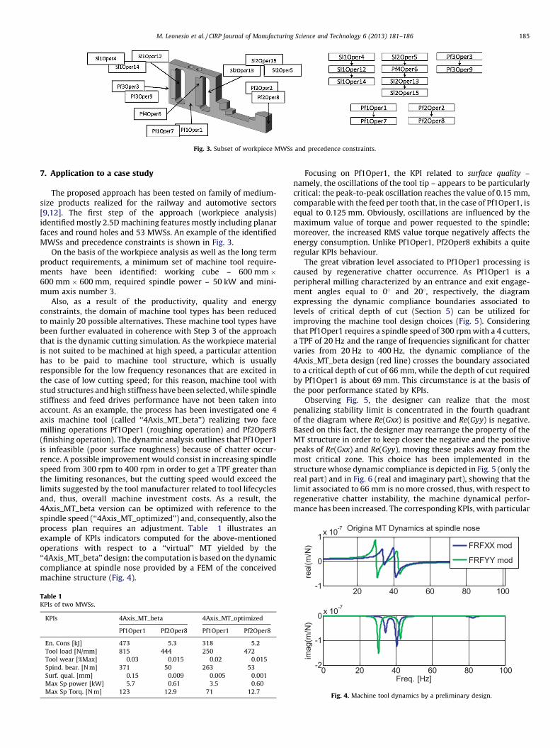
Fig. 3. Subset of workpiece MWSs and precedence constraints.
0
1x 10
-7
real(m
/N)
Origina MT Dynamics at spindle nose
FRFXX mod
FRFYY mod
M. Leonesio et al. / CIRP Journal of Manufacturing Science and Technology 6 (2013) 181–186 185
7. Application to a case study
The proposed approach has been tested on family of medium-size products realized for the railway and automotive sectors[9,12]. The first step of the approach (workpiece analysis)identified mostly 2.5D machining features mostly including planarfaces and round holes and 53 MWSs. An example of the identifiedMWSs and precedence constraints is shown in Fig. 3.
On the basis of the workpiece analysis as well as the long termproduct requirements, a minimum set of machine tool require-ments have been identified: working cube – 600 mm �600 mm � 600 mm, required spindle power – 50 kW and mini-mum axis number 3.
Also, as a result of the productivity, quality and energyconstraints, the domain of machine tool types has been reducedto mainly 20 possible alternatives. These machine tool types havebeen further evaluated in coherence with Step 3 of the approachthat is the dynamic cutting simulation. As the workpiece materialis not suited to be machined at high speed, a particular attentionhas to be paid to machine tool structure, which is usuallyresponsible for the low frequency resonances that are excited inthe case of low cutting speed; for this reason, machine tool withstud structures and high stiffness have been selected, while spindlestiffness and feed drives performance have not been taken intoaccount. As an example, the process has been investigated one 4axis machine tool (called ‘‘4Axis_MT_beta’’) realizing two facemilling operations Pf1Oper1 (roughing operation) and Pf2Oper8(finishing operation). The dynamic analysis outlines that Pf1Oper1is infeasible (poor surface roughness) because of chatter occur-rence. A possible improvement would consist in increasing spindlespeed from 300 rpm to 400 rpm in order to get a TPF greater thanthe limiting resonances, but the cutting speed would exceed thelimits suggested by the tool manufacturer related to tool lifecyclesand, thus, overall machine investment costs. As a result, the4Axis_MT_beta version can be optimized with reference to thespindle speed (‘‘4Axis_MT_optimized’’) and, consequently, also theprocess plan requires an adjustment. Table 1 illustrates anexample of KPIs indicators computed for the above-mentionedoperations with respect to a ‘‘virtual’’ MT yielded by the‘‘4Axis_MT_beta’’ design: the computation is based on the dynamiccompliance at spindle nose provided by a FEM of the conceivedmachine structure (Fig. 4).
Table 1KPIs of two MWSs.
KPIs 4Axis_MT_beta 4Axis_MT_optimized
Pf1Oper1 Pf2Oper8 Pf1Oper1 Pf2Oper8
En. Cons [kJ] 473 5.3 318 5.2
Tool load [N/mm] 815 444 250 472
Tool wear [%Max] 0.03 0.015 0.02 0.015
Spind. bear. [N m] 371 50 263 53
Surf. qual. [mm] 0.15 0.009 0.005 0.001
Max Sp power [kW] 5.7 0.61 3.5 0.60
Max Sp Torq. [N m] 123 12.9 71 12.7
Focusing on Pf1Oper1, the KPI related to surface quality –namely, the oscillations of the tool tip – appears to be particularlycritical: the peak-to-peak oscillation reaches the value of 0.15 mm,comparable with the feed per tooth that, in the case of Pf1Oper1, isequal to 0.125 mm. Obviously, oscillations are influenced by themaximum value of torque and power requested to the spindle;moreover, the increased RMS value torque negatively affects theenergy consumption. Unlike Pf1Oper1, Pf2Oper8 exhibits a quiteregular KPIs behaviour.
The great vibration level associated to Pf1Oper1 processing iscaused by regenerative chatter occurrence. As Pf1Oper1 is aperipheral milling characterized by an entrance and exit engage-ment angles equal to 08 and 208, respectively, the diagramexpressing the dynamic compliance boundaries associated tolevels of critical depth of cut (Section 5) can be utilized forimproving the machine tool design choices (Fig. 5). Consideringthat Pf1Oper1 requires a spindle speed of 300 rpm with a 4 cutters,a TPF of 20 Hz and the range of frequencies significant for chattervaries from 20 Hz to 400 Hz, the dynamic compliance of the4Axis_MT_beta design (red line) crosses the boundary associatedto a critical depth of cut of 66 mm, while the depth of cut requiredby Pf1Oper1 is about 69 mm. This circumstance is at the basis ofthe poor performance stated by KPIs.
Observing Fig. 5, the designer can realize that the mostpenalizing stability limit is concentrated in the fourth quadrantof the diagram where Re(Gxx) is positive and Re(Gyy) is negative.Based on this fact, the designer may rearrange the property of theMT structure in order to keep closer the negative and the positivepeaks of Re(Gxx) and Re(Gyy), moving these peaks away from themost critical zone. This choice has been implemented in thestructure whose dynamic compliance is depicted in Fig. 5 (only thereal part) and in Fig. 6 (real and imaginary part), showing that thelimit associated to 66 mm is no more crossed, thus, with respect toregenerative chatter instability, the machine dynamical perfor-mance has been increased. The corresponding KPIs, with particular
20 40 60 80 10 0-1
0 20 40 60 80 10 0-2
-1
0x 10
-7
imag(m
/N)
Freq. [ Hz]
Fig. 4. Machine tool dynamics by a preliminary design.
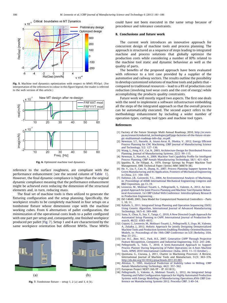
Fig. 5. Machine tool dynamics optimization with respect to MWS Pf1Op1. (For
interpretation of the references to colour in this figure legend, the reader is referred
to the web version of this article.)
10 20 30 40 50 60-1
0
1x 10
-7
real(m
/N)
New MT design aft er re-design
10 20 30 40 50 60-2
-1
0x 10
-7
imag(m
/N)
Freq. [ Hz]
FRFXX T mod
FRFYY T mod
Fig. 6. Optimized machine tool dynamics.
M. Leonesio et al. / CIRP Journal of Manufacturing Science and Technology 6 (2013) 181–186186
reference to the surface roughness, are compliant with theperformance enhancement (see the second column of Table 1).However, the final dynamic compliance is higher than the originaldynamic compliance meaning that the performance enhancementmight be achieved even reducing the dimension of the structuralelements and, in turn, reducing mass.
The final set of machine tools is then utilized to generate thefixturing configuration and the setup planning. Specifically, theworkpiece results to be completely machined in four setups on atombstone fixture whose dimensions cope with the machineworking cubes. From 6 alternatives of pallet configuration, theminimization of the operational costs leads to a pallet configuredwith one part per setup and, consequently, one finished workpieceproduced per pallet (Fig. 7). Setup 1 and 4 are characterized by thesame workpiece orientation but different MWSs. These MWSs
Fig. 7. Tombstone fixture – setup 1, 2 (a) and 3, 4 (b).
could have not been executed in the same setup because ofprecedence and tolerance constraints.
8. Conclusions and future work
The current work introduces an innovative approach forconcurrent design of machine tools and process planning. Theapproach is structured as a sequence of steps leading to integratedmachine and process solutions that globally optimize theproduction costs while considering a number of KPIs related tothe machine tool static and dynamic behaviour as well as thequality of parts.
The benefits of the proposed approach have been evaluatedwith reference to a test case provided by a supplier of theautomotive and railway sectors. The results outline the possibilityto develop customized solutions of machine tools and pallets that –compared to traditional resources – lead to a 8% of production costreduction (involving tool wear costs and the cost of energy) whileaccomplishing the products quality constraints.
Future work will mostly regard two aspects. The first one dealswith the need to implement a software infrastructure embeddingall the steps of the integrated approach so that the overall processcan be automatically executed. The second aspect refers to themethodology enhancement by including a wider number ofoperation types, cutting tool types and machine tool types.
References
[1] Factory of the Future Strategic Multi Annual Roadmap, 2010, http://ec.euro-pa.eu/research/industrial_technologies/pdf/ppp-factories-of-the-future-strate-gic-multiannual-roadmap-info-day_en.pdf.
[2] Newman, S.T., Nassehi, A., Imani-Asrai, R., Dhokia, V., 2012, Energy EfficientProcess Planning for CNC Machining, CIRP Journal of Manufacturing Scienceand Technology, 5/2: 127–136.
[3] Wang, L., Feng, H.Y., Cai, N., 2003, Architecture Design for Distributed ProcessPlanning, Journal of Manufacturing Systems, 22/2: 99–115.
[4] Newman, S., Nassehi, A., 2009, Machine Tool Capability Profile for IntelligentProcess Planning, CIRP Annals Manufacturing Technology, 58/1: 421–424.
[5] Ippolito, R., De Fillippi, A., 1979, Energy Savings by Proper Machine ToolManagement, SME Technical Paper (Series) MM (MM79-38).
[6] He, Y., Liu, F., Cao, H., Zhang, H., 2007, Process Planning Support System forGreen Manufacturing and Its Application, Frontiers of Mechanical Engineeringin China, 2/1: 104–109.
[7] Dahmus, J.B., Gutowski, T.G., 2004, An Environmental Analysis of Machining,in: Proceedings of ASME International Mechanical Engineering Congress andR&D Exposition, pp.13–19.
[8] Leonesio, M., Molinari Tosatti, L., Pellegrinelli, S., Valente, A., 2012, An Inte-grated Approach for Joint Process Planning and Machine Tool Dynamic Behav-ioral Assessment, 1st CIRP Global Web Conference: Interdisciplinary Researchin Production Engineering, .
[9] ISO 14649, 2003, Data Model for Computerized Numerical Controllers – Parts1, 10, 11.
[10] Kafashi, S., 2011, Integrated Setup Planning and Operation Sequencing (ISOS)Using Genetic Algorithm, International Journal of Advanced ManufacturingTechnology, 56/5–8: 589–600.
[11] Suna, X., Chua, X., Sua, Y., Tanga, C., 2010, A New Directed Graph Approach forAutomated Setup Planning in CAPP, International Journal of Production Re-search, 48/22: 6583–6612.
[12] Copani, G., Leonesio, M., Molinari-Tosatti, L., Pellegrinelli, S., Urgo, M., Valente,A., Zulaika, J., 2012, Holistic Approach for Jointly Designing DematerializedMachine Tools and Production Systems Enabling Flexibility-Oriented BusinessModels, in: Proceedings of the 19th CIRP Conference on LCE (Berkeley, USA,May 23–25), .
[13] Lee, H.C., Jhee, W.C., Park, H.S., 2007, Generative CAPP Through ProjectiveFeature Recognition, Computers and Industrial Engineering, 53/2: 241–246.
[14] Pellegrinelli, S., Tolio, T., 2010, A Semi-Automated Approach to SupportProcess Planner During Sequencing of Pallet Operations on 4-Axes MachineTools, APMS 2010 International Conference (Italia, 2010, 11–13 October), .
[15] Quintana, G., Ciurana, J., 2011, Chatter in Machining Processes: A Review,International Journal of Machine Tools and Manufacture, 51/5: 363–376.http://dx.doi.org/10.1016/j.ijmachtools.2011.01.001.
[16] Altintas, Y., 1995, Analytical Prediction of Stability Lobes in Milling, CIRPAnnals Manufacturing Technology, 44/2: 357–362.
[17] European Project NEXT (6th FP – IP: 011815).[18] Pellegrinelli, S., Valente, A., Molinari Tosatti, L., 2012, An Integrated Setup
Planning and Pallet Configuration Approach for Highly Automated ProductionSystems with Energy Modelling of Manufacturing Operations,45th CIRP Con-ference on Manufacturing Systems 2012. Procedia CIRP, 3:49–54.