Embed Size (px)
Citation preview
BICSI Region Meeting
Phoenix
An Inside Look
atOutside Plant
BICSI Region Meeting2007
Presented byDavid M. RichardsRCDD/NTS/OSP SpecialistPCC Network SolutionsVP Technical TrainingBICSI® Certified [email protected]
Agenda
• What is CO-OSP?• A close look at the 758-A
standard• Available Resources
What is CO-OSP?
• Customer Owned Outside Plant• “Telecommunications infrastructure
designed for installation exterior to buildings” ANSI/TIA/EIA-758-A terminology
CO-OSP Standard
• ANSI/TIA/EIA-758-A (2004) Customer-Owned Outside Plant Telecommunications Infrastructure Standard.
This standard replaces the ANSI/TIA/EIA-758 and 758-1documents. (1999)
Why do I have to know these standards?
You have to know these standards if:
• You do work on customer ownedproperty
• You’d like to give your customer a system that will work regardless of the electronics they choose
LET’S TAKE A LOOK INSIDETHE CO-OSP STANDARD
ANSI/TIA/EIA-758-A
Customer-owned Outside PlantTelecommunicationsInfrastructure Standard
Discussion of the contents !
• Introduction and Scope• Definitions, Acronyms, Weights,
and Symbols• Cabling Infrastructure• Pathways and Spaces• Cabling Hardware• Annexes
INTRODUCTION
• Customer owned campus facilities are typically termed “outside plant”
• In this standard they’re called “Customer-owned OSP”
INTRODUCTION
• Two categories of criteria are specified:Mandatory and Advisory Terms
Mandatory word is “SHALL”
Advisory words are “SHOULD”, “MAY”, and “DESIRABLE”
INTRODUCTION
• Mandatory criterion applies to performance and compatibility requirements
• Advisory criterion is “above minimum” goals.
Introduction
• Metric dimensions are “soft” conversions of US units(100mm soft converts to 4 inches)
• Conduit dimensions are listed as follows: 21 (3/4) trade size conduitThat’s 21mm and/or 3/4”(You won’t see the mm or in)
INTRODUCTION
• The standard is a “living document” which means it can be revised or updated due to advances in construction techniques or technology.
SCOPE-Applicability
• The standard specifies minimumrequirements for CO-OSP
• Specifies cabling and the pathways and spaces to support it
• Useful life of OSP Pathways and Spaces is 40 years
• Useful life of OSP Cabling is 30 years
Scope - Applicability
Now isn’t that convenient !
The useful life of pathways is 40 yearsThe useful life of the OSP cable is 30 yearsThe useful life of an OSP engineer is 29 years 364 days
SCOPE-Pathways and Spaces
• There are two basic types of cable pathway systems:
Underground and Aerial
SCOPE
• Underground Pathways andSpaces
Direct BuriedBuried Duct/ConduitMaintenance Holes, HandholesShared Spaces (utility tunnels)
SCOPE-Pathways and Spaces
• Aerial Pathways and Spaces
PolesMessenger Wire or StrandAnchoring Guy WiresAnchors
SCOPE-Customer Owned OSP Cabling
• Consists of recognized cable• Conforming connecting
hardware• Protective Devices which….
Can be located on the exterior or interior of a building or in an outdoor pedestal or cabinet
SCOPE-Customer Owned OSP Cabling
• Can have intermediate splices• Fiber Optic Cabling may pass
through a building entrance facility as part of the cable route
• Star topology recommended
Normative References
• The standard references 54 other standards and codes which, by reference, constitute part of the standard
TERMS AND DEFINITIONS
The CO-OSP standard contains:
• 77 definitions• 49 acronyms• 14 weights and measures• 59 symbols
TERMS AND DEFINITIONSLet’s look at one definition
Entrance facility(telecommunications):An entrance to a building for both public and private network service cables, (including wireless), including the entrance point of the building and continuing to the entrance room or space.
Terms and Definitions
• For most service providers (SP) or access providers (AP), that represents a change to the ways we learned.
• The entrance facility was the place in the building we stopped our cable and terminated it.
CABLING INFRASTRUCTURETopology
• Recommended topology is a star• Large Campuses use a hierarchical
star• Stars offer centralized
management and administration• Distance limitations may prohibit
the use of a star topology
CABLING INFRASTRUCTURERecognized Cables
• 50/125 optical fiber cable• 62.5/125 optical fiber cable• Singlemode optical fiber cable• 100 ohm Twisted Pair Cable• 75 ohm Coaxial Cable
CABLING INFRASTRUCTUREMedia Selection
• Choose the cable considering:Characteristics of the applicationsDistancesFuture growth (population)Customer preferenceRequired useful lifeFlexibility with respect to supported services
CABLING INFRASTRUCTUREBonding and Grounding
• A critical component of design• Protects people and property• Improper bonding and grounding can
affect other telecomm circuits• Comply with ANSI-J-STD-607-A, The
National Electrical Safety Code®
(NESC®) and National Electrical Code (NEC®)
CABLING INFRASTRUCTUREBonding and Grounding
POOR or incomplete Bonding and Grounding can create:
• Equipment malfunction or failure• Insurance issues you don’t want• Injury or death to personnel• Noise on voice circuits• Loss of manufacturer’s warranty
PATHWAYS AND SPACES
Pathways may be aerial,direct buried, or underground.
Underground or direct buried is preferred over aerial
Underground is preferred over direct buried
PATHWAYS AND SPACESSubsurface Pathways
• Design should consider:
Excavation -Clearances and separations,Depth, Backfill, and Restoration,Trenching, Boring, Plowing.Street Crossings, Casings.
PATHWAYS AND SPACESConduit/Duct
• EB Type - Encasement in concrete• DB Type - Direct Buried or encased• Rigid Non-Metallic Sched. 40 or 80• MPD- Multiple Plastic Duct• Rigid Metallic Conduit• IMC- Intermediate Metallic Conduit• Fiberglass Duct - DB or encased• Inner duct - PE or PVCNote- The NEC says “metal” not
“metallic”
PATHWAYS AND SPACESConduit/Duct
• Encase bends (non-metallic)• 600 ft max. between pulling points• No more then (2) 90’s or a total of
180 degrees• Drain slope should be is 1/8” per
foot:Exiting or entering a building orfrom the middle of a conduit span(each way)
PATHWAYS AND SPACES
• Innerduct may be placed within a duct to facilitate initial and subsequent placement of multiple cables in a single duct.
Note- Innerduct can be plastic or fabric textile duct
PATHWAYS AND SPACESSubsurface Considerations
• Duct plugs on ALL conduits• Axial Movement- Bridge Crossing• Tunnel Requirements
OSHASheath properties and clearances
PATHWAYS AND SPACESAerial Construction
Consider:• Pole class, length, type, depth.• All loading factors• Grounding, clearances, separation• Anchors/guys, riser protection• Span lengths, slack spans, etc.• Lashing, strand tension, sag.
AERIAL CONSTRUCTION
• Poles commonly used in the telecommunications world are:Height- 30’, 35’, 40’ or 45’Class- 9 classes – 1 thru 10
(Class 8 was eliminated) Most common - 3, 4, 5, 6, 7
PATHWAYS AND SPACESMaintenance Holes
• Location considerations:Terrain (Topography)Soil ConditionsSurrounding StructuresPersonnel AccessPlacing and Splicing Ease
PATHWAYS AND SPACESMaintenance Holes
• Maximum distance shall not exceed 600 feet
• Not within 50’ of curb radius at an intersection
• In the right of way but outside the traveled portion(if placed within the traveled portion then 5 feet from the curb)
PATHWAYS AND SPACESMaintenance Holes
• Concrete, steel, or cast iron• Must have proper load ratings• Can be pre-cast or site poured• May have multiple openings
PATHWAYS AND SPACESMaintenance Holes
• Maintenance holes shall be equipped with:Corrosion resistant pulling ironsCorrosion resistant cable racksSump for drainage and………..
PATHWAYS AND SPACESMaintenance Holes
SHALL NOT BE SHAREDWITH ELECTRICALINSTALLATIONS
(other than those needed for telecommunications equipment)
PATHWAYS AND SPACESMaintenance Holes
• TYPESA - end wall entrance onlyB - handholeJ - end and sidewall entranceV - one end wall and two side
walls
PATHWAYS AND SPACESMaintenance Holes
• “Covers shall meet the environmental conditions”Heavy Vehicle TrafficLighter LoadsSidewalk
PATHWAYS AND SPACESHandholes (Advanced Warning)
The slide you are about to see may cause nausea, disbelief, glazed vision, or create some serious doubt about your presenter’s credibility.
PATHWAYS AND SPACESHandholes
• Shall not be used in place of a MH• Shall not to be used for splicing• Shall not be shared with electrical• Shall not exceed a 4’ X 4’ X 4’• Should not be used in runs of more
than (3) 4” conduits• Should align conduits on opposite
walls at the same elevation
PATHWAYS AND SPACESPedestals and Cabinets
• Should accommodate 4 cables• Cable bend radii not less then 15
times the diameter of the cable• Corrosion Resistance• Customer Preferences• Meet ASTM requirements
PATHWAYS AND SPACESPedestals and Cabinets
• Resistant to rodent and insects• Secure - Locks, special bolts, etc.• Chemically resistant• Grounding and bonding to Codes
PATHWAYS AND SPACESOther Spaces
• Vaults:
Are open or closed bottom housings which provide grade level or below grade level environmental protection, access, and security to splices, cable, and distribution equipment.
PATHWAYS AND SPACESVault Selection Concerns
• Cable bend radii (15x cable)• Accommodate four cables• Accommodate both inline and
butt splices• Secure with locks, bolts, etc• Provisions to relocate if needed• Resistant to rodents/insects
PATHWAYS AND SPACESTraffic Loadings
• Maintenance Holes and Vaultshave three basic load ratingsH-5 Sidewalk applications
(11K lbs..)H-10 Driveways/Parking Area (22K)H-20 Heavy Traffic (40K)
CABLING Twisted Pair Cable
• 19, 22, 24, or 26 AWG• Meet all ANSI/ICEA requirements• Recommended applications for
Filled and Air Core cables (R,S,N)• Meet AHJ and applicable codes
CABLINGTwisted Pair Specifications
• Filled cable is recommended (R) for aerial, direct buried, and UG.
• Air Core is suitable (S) for aerial and UG and not recommended (N) for direct buried.
CABLING Connecting Hardware
• Withstand temperature range of -40 degrees F to 158 degrees F
• Can be plastic or metal• Must meet requirements of
ANSI/TIA/EIA 568-B• Terminal blocks must allow access to
test points without disconnecting the service drop or puncturing the insulation
CABLINGTermination Blocks
• Provide a means to connect the service wire to the distribution cable
• Typically available in 5-6 pair increments, and from 5 to 50 pairs
• Shall be compatible for all gauges26, 24, 22, 19, and 18 1/2
CABLINGCross Connects
• Cross Connection Blocks are used to connect feeder pair to distribution pair. Terminals SHALL have:Tip on the left, ring on the right orTip above and ring below andRemovable red markers for special circuit ID
CABLINGBuilding Entrance Terminals
• Available in 2, 4, 6, and multiples of 10 and 25 pairs.
• Protected and Non-protected(Protected type must meet UL 497)
• Can be equipped with various protective modules (carbon, gas tube, solid state, etc.)
CABLING Splicing
• Single Wire Connectors are also known as “discrete” connectors
• Multiple Pair Connectors (modules)• Splicing Connectors have 10
separate tests performed on them in order to meet requirements
CABLING8 Primary Tests
• DC Loop Resistance• Wire Map• Continuity• Shorts• Crosses• Reversals• Splits• Any other mis-wiring
CABLINGCoaxial Cable
• 75 ohm cable semi-rigid• Trunk, feeder, and distribution• N type connecting hardware• Meet requirements of SCTE
Society of Cable Television Engineers (Doc. IPS-SP-100)
CABLINGFiber Optic Cable
• Singlemode, multimode, or a combination of these types
• Non-conductive and conductive• Armored and Non-Armored• Indoor/Outdoor (50 foot rule)
CABLINGFiber Optic Cable Types
• Generally non-armored is referred to as duct cable
• All dielectric have no metallic components
CABLINGFiber Optic Cable Types
Armored cables• Similar to duct cable in design• Steel Armor under outer sheath• Rodent resistant• Added protection in rocky soil
CABLINGFiber Optic Cable Types
Aerial Cables• Same construction as duct cables• All dielectric recommended• Not as susceptible to lightning
(if they’re all dielectric)
CABLINGFiber Optic Cable Types
Self Supporting• Designed to be installed without
the need for a pre-installed messenger.
• Can be installed quicker than duct type construction
CABLINGFiber Optic Cable Types
All dielectric, self supporting cable or ADSS cables
Duct cables that contain a layer of strength members that allows installation without a messengerbut have length limits
CABLINGFiber Optic Cable Types
Indoor/Outdoor Cables
• Should be water blocked and be UV Resistant
• Must pass NEC flame test andcarry a flame rating (e.g. OFNR)
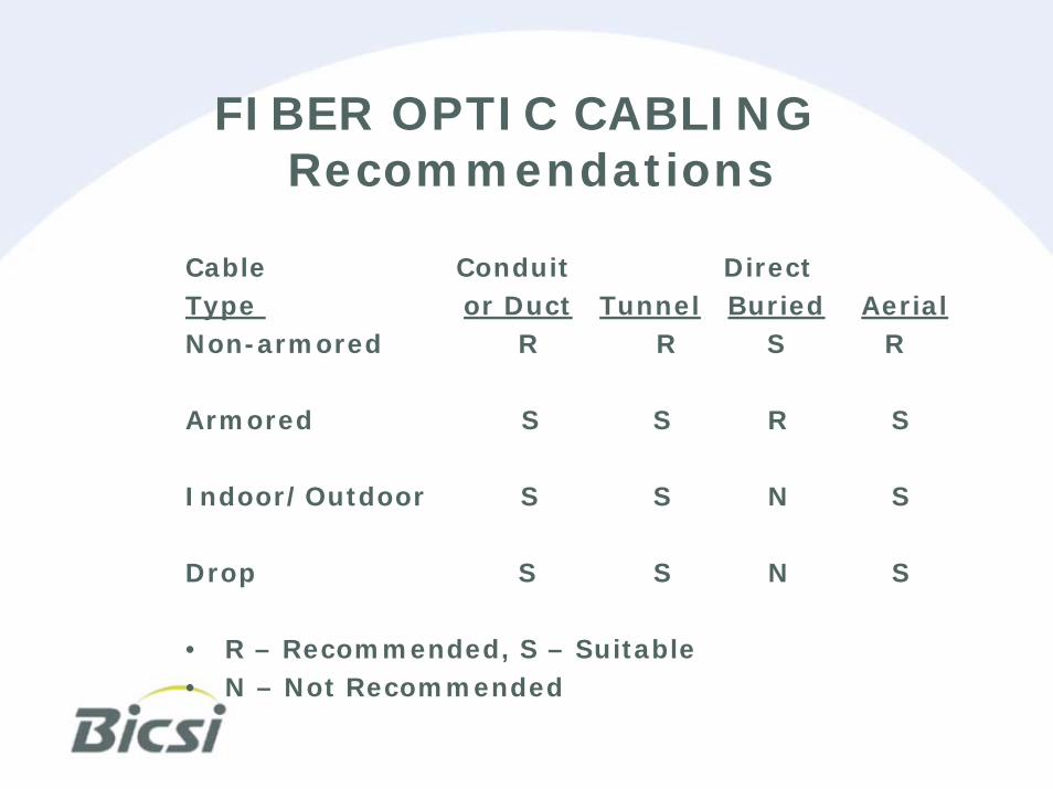
FIBER OPTIC CABLINGRecommendations
Cable Conduit Direct Type or Duct Tunnel Buried AerialNon-armored R R S R
Armored S S R S
Indoor/Outdoor S S N S
Drop S S N S
• R – Recommended, S – Suitable• N – Not Recommended
CABLINGFiber Optic Cable
• Fusion and Mechanical Splices(fusion is recommended for OSP)
• Splice Attenuation (Insertion Loss) should not exceed .1dB mean or .3dB maximum
• Provide Mechanical Protection
FIBER OPTIC CABLESplicing/Terminating
Mechanical protection
• Each splice shall be protected in a splice tray
• Stripped fibers shall be protected with a shrink sleeve or silicon adhesive
• Prevents exposure to moisture
FIBER OPTIC CABLEInstallation
Bonding and Grounding
• All metallic components shall be bonded to each other and grounded.
• Metallic components include armor, central strength members and closures.
CABLING Fiber Optic Cable
• Bend radius shall be no less then 20 times the cable diameter during install and 15 times after install
• Field Test per ANSI/TIA/EIA 568-B
CABLING Air Pressurization
• Air core cable installed in subsurface pathways shall be pressurized
• Aerial air-core should be vented• Pressure should be a minimum of
1.5PSI plus .43PSI per foot of hydrostatic head
• Static, Single and Dual Feed Systems. (Dual Feed suggested)
CABLINGAir Pressurization
Where dry air pressure systems are deployed consider:
• Compressor Size• Dryer• Manifolds, flow meters, cut-offs• Pneumatic resistance of the cable• Alarms and air plugs• Location of air feeds and air pipes
ANNEXES A, B, C and D What they address
• A- OSP Symbols• B- Typical OSP Lengths for
Specific Applications• C- OSP Optical fiber cabling
practices• D- Bibliography and References
Annexes
• Annex A is normative and considered as requirements of the CO-OSP Standard
• Annex B, C, and D are informative and not considered as requirements.
ResourcesOSP READING MATERIAL
• ANSI Standards, especially TIA758-A• Trade Journals (i.e OSP Magazine)• GTEPs, BSPs, Telecordia and AT&T
OSP Engineering Manuals• BICSI CO-OSP Manual• BICSI OSP Training courses
WHAT DOES THE CUSTOMER EXPECT?
SIMPLE !!!!!
They want the job done right, in compliance with the codes and standards, and on time.
(and free of change orders would be nice too.)
SOME SCARY THOUGHTS
• What happens when the AHJ starts to check all your jobs?
• What happens if the customer hires a third party to do a quality check?
• What happens when your design or placing techniques injure or kill?
• Would you be happy if you were paying for the work you’re doing?

BE CAREFUL !!!!!!
OUTSIDE PLANT
IS INHERENTLYDANGEROUS