Embed Size (px)
Citation preview

147
An FPGA-Based Transceiver Module
John B. Stephensen, KD6OZH3064 E. Brown Ave., Fresno, CA [email protected]
Traditionally, hams have wired together multiple standard integrated circuits to constructradios, TNCs and other devices. However, modern devices manufactured in high volumeintegrate most functionality on one chip that is customized for the purpose. Feature sizes inintegrated circuits have now become so small that field programmable gate arrays (FPGAs)can be used to achieve what once required a custom chip. Since the logic in the FPGA can beused in parallel rather than sequentially, it is a much more powerful tool than a microprocessor.Recent FPGAs also contain larger amounts of dedicated memory, making it possible toincorporate microprocessors within the FPGA.
My goal was to make a small high-speed digital signal processor that can be embedded inamateur radio devices. The original hardware platform was developed while I was a member ofthe ARRL high-speed multimedia (HSMM) working group and was described in QEX1.However, the combination of an FPGA and an external microcontroller was costly and inter-chip communication imposes design restrictions and a speed penalty. Therefore, I developed asoft processor that was recently described in PSR2. However, this CPU comprises only 8% ofthe logic required to implement an OFDM modem. This document describes the specializedsignal processing modules that accompany the CPU. Each implements a specific algorithm,but can be customized by loading new parameters. The result is a device that looks like acustom integrated circuit that can have software downloaded to program it for specificapplications.
1. Overview
The hardware platform is a 2.5” x 2.4” PCB with a Xilinx XC3S500E FPGA surrounded by an80 Msps analog to digital converter (ADC), 80 Msps digital to analog converter (DAC), 100Mbps Ethernet physical layer interface (PHY) and 4-megabits of flash memory. There is also aJTAG port, a low-speed DAC and an RS-485 port for debugging and control. The 10-pinheader connects directly to 5 FPGA I/O pins that may be used for debugging, controllinganalog circuitry and/or attaching an audio CODEC. The schematic diagrams are in appendix A.
The ADC analog input and DAC analog output are provided directly on 2-pin connectors andanalog filtering takes place externally. This allows the use double-sided boards or evencopper-clad perforated board for analog circuitry. The FPGA configuration is automaticallyloaded from the flash memory when power is applied. It contains three main sections – thetuner, the modem and the CPU.

148
Figure 1 – DCP-3 PCB
The tuner section, shown in figure 2, interfaces to the ADC and DAC and provides digitalupconversion, downconversion, filtering and signal level control. Some functions operate attwice the sampling rate in order to share resources. The single lines in the block diagram arepaths where the in-phase (I) and quadrature (Q) samples are processed sequentially at 160MHz. The double lines are paths where I and Q samples are processed in parallel at 80 MHz.
The signal processing hardware starts with the direct digital synthesizer (DDS) whosefrequency may be set with a resolution of 0.02 Hz. During reception, the input from the ADC issequentially multiplied by the cosine and sine outputs of the DDS to generate baseband I andQ outputs. One cascaded integrator comb (CIC) filter and two finite impulse response (FIR)filters provide downsampling and establish the receiver bandwidth. A noise blanker is locatedbetween the FIR filters. The AGC levels the signals and converts from two 20-bit to two 16-bitsamples. Optionally, the received signal may pass through the resampling filter to beconverted to a rate that is not an integer fraction of the ADC sampling rate.
When transmitting, the resampler can convert the baseband signal to a rate compatible withthe DAC. The signal may then be compressed or clipped to reduce the peak to average powerratio (PAPR) and passed on to the filter chain. The order of the filters is reversed fortransmission with the two FIR filters first and the CIC filter last. Upsampled I and Q basebandsignals are mixed with the cosine and sine DDS outputs and added together to produce thefinal output to the DAC.

149
Figure 2 –Tuning, Filtering and Level Control Circuitry
The modem section, shown in figure 3, uses CORDIC (coordinate rotation digital computer) tomodulate or demodulate the signal when a single carrier is used. This is an algorithm thatperforms trigonometric functions using only adds and shifts. For amplitude modulation (AM)and phase modulation (PM), it can rotate the input signal to alter its phase or measure thephase and magnitude of the input. For frequency modulation (FM), the input is integrated orthe output is differentiated. SSB reception and transmission use a 16-bit accumulator thatcontinuously rotates the phase. It functions as the BFO and provides 0.12 Hz resolution at 8ksps. The CPU accesses the modem via a 15-word FIFO with two 16-bit entries containingeither magnitude and phase or I and Q information.
Figure 3 – Modulation and Demodulation Circuitry

150
The timing recovery unit generates error signals for use in optimizing the sampling of FSK andPSK waveforms. The null detector and phase correlator provide timing recovery for OFDMreception. Both are described in more detail later in this document.
A fast Fourier transform (FFT) is provided for OFDM or MFSK modems. It moves databetween two RAMs while converting between time and frequency domains. The time domainbuffer connects directly to the tuner and the frequency domain buffer is read or written by theCPU. When receiving, I and Q samples of the input signal accumulate in one RAM, theprocessing module then calculates the FFT and places the phase and magnitude for eachdemodulated subcarrier in the second RAM. When transmitting, the CPU places data in thesubcarrier RAM and this is converted to a series of samples in the I/Q RAM.
An 80 MHz 16-bit CPU controls the tuner and modem. It has a RISC instruction set thatincludes bit manipulation for protocol processing and hardware multiply, multiply-accumulateand divide for signal processing. It also allows addition, subtraction, loading or comparison of8-bit constants in one instruction or the same operations with 16-bit constants using a prefixinstruction. In addition, memory read and memory write instructions support indirect addresseswith offsets while input and output instructions use direct addressing. This produces fastcompact code. The complete instruction set is described in appendix B.
Figure 4 – CPU and Peripherals
The CPU has 8 kB of dedicated instruction and data memory that is accessed simultaneouslyvia two ports. It is augmented by a number of modules that provide I/O and speed up commonalgorithms for digital communication and digital signal processing such as filtering and errordetection and correction. These are accessed via I/O ports and two-port buffer memory asshown in figure 4. An advantage of this architecture is that the CPU can start multipleoperations that proceed in parallel.

151
2. Tuner
The heart of the DDS is a phase accumulator that increments by the value in the centerfrequency register on alternate cycles of the 160 MHz clock. The upper 10 bits of the phaseoutput address a dual-port 1024 x 18 ROM sine look up table. Adding a 90-degree offset onalternate clock cycles generates cosine and sine outputs. The ROM address inputs selectadjacent entries and linear interpolation is used to smooth the output. The difference betweenadjacent entries is multiplied by bits 4-21 of the phase accumulator and then added to the firstentry. Extensive pipelining is used with delays inserted between stages to align results. Theshift registers provided in the Xilinx architecture minimize the amount of resources used as oneFPGA logic cell can provide a 1 to 16 stage shift register. 8 clock cycles are used to generateeach output. The algorithm was originally described in a Motorola application note3 and spursshould be below –112 dBc.
Figure 5 – DDS VFO
The CIC filter, shown in figure 6, can downsample or upsample by an integer value between10 and 640, converting between 80 Msps and 8000-125 ksps. A CIC filter is used as it canprovide large decimation and interpolation ratios while using only addition and subtraction. It isessentially a moving average filter that has been optimized to use less hardware. Instead ofsumming a fixed number of samples in each pass, the process has been simplified to summingall samples in an accumulator (integration) and then calculating the difference betweenaccumulator states at two different times – the first and last taps of the moving average. Thefrequency response of the differentiator is a comb shape so that portion is called a comb filter.The accumulator can overflow as long as there are enough bits to cover the time span overwhich the filter averages. Cascading multiple filters improves the frequency response and theintegrators and differentiators can be grouped together. This simplifies downsampling asintervening samples can be ignored. The differentiators need only have one delay register aslong as they are enabled only for each output sample. The accumulators must process all inputsamples. When upsampling the differentiators precede the integrators.
The CIC circuitry contains four 56-bit integrators and four 28-bit differentiators for eachchannel. The integrators are split in two and the carry between the two 28-bit halves isbuffered to minimize propagation delays. The CIC filter has an inherent gain that varies withthe interpolation or decimation factor so this is offset by setting a gain factor that controls a

152
shifter and multiplier. The CIC gain is the third power of the interpolation factor or the fourthpower of the decimation factor.
When receiving, the minimum CIC gain is 104 and the maximum gain is about 1.68 x 10¹¹. Thereceived data input (RDI) is multiplied by 0-1024 and shifted by 0-15 bits by two 4-inputmultiplexers before being applied to the first integrator. The shifter provides a 43-bit output so itis expanded to 56 bits by adding 13 sign bits. This gives a gain range of 225 or about 3.3 x 10⁷.The top 28 bits of the last integrator are then fed to the first differentiator and the received dataoutput (RDO) is obtained from the top 18 bits of the last differentiator. Thus, the input signal isexpected to grow by 38 bits (2.75 x 10¹¹) by the time that it reaches the output. When theminimum decimation factor of 10 is used, the gain compensation can be set to 2.75 x 10⁷.When the maximum decimation factor of 640 is used, the gain compensation can be set to1.63 x 100.
Figure 6 – CIC Filter
The transmit data input (TDI) is multiplied by 0-8 before being applied to the bottom 21 bits offirst differentiator. The upper 7 bits are copies of the sign bits. This is necessary as therequired resolution grows by at least 1 bit per state. The full 28-bit differentiator output is thenshifted by 0-15 bits and applied to the first integrator. This gives a gain adjustment range of 218
or about 2.6 x 10⁵. The minimum CIC gain is 103 and the maximum gain is about 2.6 x 10⁸.The total gain can be kept at about 2.6 x 10⁸, so the 18-bit input grows to 46 bits.Consequently the transmit data output (TDO) is tapped down on the last integrator and the top10 bits are ignored.
Two FIR filters follow the CIC filter. The first is used for downsampling by a factor of 2-50 andthe second is used to establish the shape of the final passband. It may also downsample or

153
upsample by a factor of up to 20 depending on the steepness of the filter skirts. The first FIRfilter outputs 18-bit results and the second FIR filter outputs 20 bit results. A CIC filter isessentially a FIR filter with all coefficients equal to one and has a fixed frequency response ofwhich only a fraction of the center portion is flat. FIR filters operate by multiplying a set ofsignal samples (data) by a set of positive and negative coefficients and summing the products.They consume more resources than the CIC but this allows tailoring the frequency response tospecific requirements. Both FIR filters use 24-bit coefficients to reduce the level of spuriousresponses. Spurs are down 4-5 dB per coefficient bit depending on the filter shape factor andthe amount of downsampling or upsampling.
Figure 7 – FIR Filter
Figure 7 shows the common architecture of the two FIR filters. Each uses two dual-port 18kblock RAMs. One port of the data RAM is used to store samples as they arrive. The samplecounter determines the address used and it always incremented after each write. When thefilter starts the contents of the sample counter are saved and used as the base address for theother port which is used to retrieve samples for processing by the filter. I and Q samples arestored serially in the RAM and are accessed on opposite phases of the 80 MHz master clock.The filter runs on a double-rate clock at 160 MHz.
The second block RAM stores instructions consisting of a 9-bit index, a 24-bit coefficient, awrite enable bit and an end of filter bit. The CPU may load instructions via a 9-bit wide port.Instructions addressed by the program counter are retrieved over two clock cycles and areused to process I samples on one clock cycle and Q samples on the next clock cycle. Data isread from the data RAM at the address obtained by subtracting the index from the baseaddress register. It is then multiplied by the coefficient using two dedicated 18x18 multipliersand two adders to sum the partial products. This creates a 42-bit product that is summedalternately in two 42-bit accumulators. The accumulators are split into three 14-bit sections toreduce carry propagation delays and addition occurs over 3 clock cycles. Each section

154
contains an adder and a multiplexer. This provides a 2-clock delay so two channels aresupported. The multiplexers have one port tied to zero so that they can be used to switchbetween loading and accumulating by the signals Z3, Z4 and Z5. The final sum of products isthen rounded to either 18 or 20 bits.
Figure 8 – Noise Blanker
The noise blanker is shown in figure 8. It generates the absolute value of I samples and Qsamples by complementing negative values. These are compared to a limit and if it isexceeded in either axis the output is set to zero. Two registers clocked on opposite edges ofthe single-rate clock (sclk) align the comparitor output with the two related samples. The signalis delayed in three registers and the fourth register is reset as the offending samples pass by.This logic is placed between the FIR filters so that blanking occurs prior to the steep-skirtedfinal filter. This minimizes stretching of noise pulses.
Figure 9 – Tuner Configuration Registers
The tuner is configured via the 8 registers shown in figure 9. The center frequency is a 32-bitword, loaded LSW first in two 16-bit segments. The FIR instructions are loaded into the filter

155
selected by the FIR bit in 9-bit segments, LSW first. The RST bit resets the FIR addresscounter and inhibits filter operation during loading. The two FIR decimation values initializecounters that delay the start of the FIR filters until a specified number of new samples havebeen accumulated in data memory. Interpolation is handled by putting multiple writeinstructions in the filtering programs.
The status register contains overflow flags that are set when an overflow occurs and resetwhen read. The ADC overflow comes from the overflow output on the ADC. The MIX and DACflags signal overflow in the quadrature mixer and adder, respectively. FL1 and FL2 areoverflow flags from the two FIR filters.
3. AGC, Resampler and Clipper/Compressor
The AGC module levels the output and reduces the word size to 16 bits. It implements acomplete hang AGC system in hardware. The desired AGC output level, attack time, releasetime, hang threshold and hang time are all programmable by the CPU. The AGC gain mayvary between 0 and 96 dB and the CPU may read the current value.
Figure 10 - Automatic Gain Control
The AGC logic is shown in figure 10 and makes extensive use of serial arithmetic to reduceresources and power requirements. This is possible because the signal has been fully filteredand down-sampled to 2.5 Msps or less. The circuit operates at 80 MHz so 32 clock cycles areavailable for each sample. I and Q samples are loaded into two shift registers and then shiftedleft for a number of clock cycles determined by the counter. The counter is loaded with the gain

156
exponent at the same time that data is loaded. It then counts down to zero and stops theshifting, multiplying the data by the binary exponent. Not shown is logic that detects and flagsoverflows. The gain mantissa is used in two serial multipliers to multiply by a factor of 1 to 2. Itis loaded into another shift register and the bits are shifted out MSB first. If a bit is one theshifted signal samples are added to the shifted contents of another register. The accumulatedsum shifts left on each clock cycle. After 13 cycles, the results are available at the output.
The AGC gain is set by the top 16 bits of a 24-bit accumulator that integrates the differencebetween the magnitude of the output signal and the AGC setpoint. The magnitudedetermination logic is described further in the compressor/clipper section of this document.Loop gain is controlled by a serial multiplier created by shifting the output of the setpointsubtracter. It multiplies by a power of two that is determined by a time delay in a shift register.Xilinx logic elements may be configured as a 16-bit shift register with an output multiplexer.That multiplexer determines the number of stages used, the time delay and the gain. There arethree possibilities for gain. If the output signal is higher than the setpoint, the attack gain isselected. If the signal is below the setpoint but above the hang threshold, the release gain isused. If the signal is below the hang threshold and the hang timer has not expired, the loopgain is set to the minimum. This allows the AGC gain to be held constant for a period after thesignal disappears and then be rapidly reduced after that period. This mechanism reduces AGCpumping on CW and SSB signals4. It is also useful for OFDM signals that use null symbols asdelimiters.
Figure 11 - Resampling Filter
A resampling filter may be switched in for applications using baud rates that are not an integerfraction of the ADC and DAC sampling rates. The output sample rate (OSR) may be increasedor decreased as specified by a 4-bit integer and a 24-bit fraction that determine the time

157
between output samples. The output sample rate is the input sample rate divided by this 28-bitnumber and may be set to an accuracy of 0.06 PPM.
The phase accumulator controls the resampling filter. It is incremented by the OSR before thestart of each filtering cycle. If a new input sample is needed the integer portion of the outputwill be non-zero. New samples are requested by decrementing the sample counter by thatvalue. The sample counter will go negative if the required samples are not present and theprocessing pipeline will stall. It will then continue when new samples arrive and the samplecounter output goes positive. The integer portion of the phase accumulator output is treated asoverflow and does not accumulate between cycles.
The upper 12 bits of the fractional portion of the phase accumulator are added to the phaseoffset from the offset shift register. The lower 12 bits of the result are used to select thecoefficients to be used in the filtering process. The upper 4 bits are added to the data indexfrom the tap counter so the sequence of data samples to be processed to be shiftedbackwards in time. The resampling filter implements a 16-tap filter with 64 possible coefficientsfor each tap. The tap counter increments from 0 to 15, 31, 47 or 63 depending on whetherthere are 1, 2, 3 or 4 outputs to be generated per filtering cycle. The bottom 4 bits select datasamples and coefficients and the upper 2 bits are used to select the phase offsets stored in a4-entry shift register.
The coefficients are stored in a 1024x18 dual-port ROM and provide a flat passband to 0.4times the input sample rate. Coefficients are linearly interpolated in the same manner as theDDS when the desired output sample falls between ROM entries. Incoming data is stored intwo 32-entry shift registers as it arrives. Multiplexers embedded in the shift register select therequired samples. As new samples arrive, the sample counter is incremented and added to thedata index to compensate for shifts that occur during computation. Both channels aremultiplied by the same coefficient and the results accumulated. The distortion introduced bythe resampling process should be less than -96 dBc and is less than –85 dBc on a spectrumanalyzer. A more thorough description of the arbitrary resampling process can be found inchapter 7 of reference 5.
When transmitting, a RF compressor is available to reduce the peak to average power ratio(PAPR) of SSB and OFDM signals. It consists of two multipliers and a memory containing 64coefficients that are selected by the magnitude of the incoming signal. The gain profile may beadjusted for clipping, compression or bypass. Figure 12 shows the logic used.
The magnitude of the input is estimated by the formula 7*(max + min/2)/8. Since compressiononly occurs at high signal levels only the upper 8 bits of the input are examined. Gaincoefficients are stored in a shift register and the upper 6 bits of the magnitude select theappropriate entry. Each 8-bit entry consists of a 4-bit integer and a 4-bit fraction. Low signalslevels may be boosted by up to 24 dB while high signal levels can be left unchanged or evenattenuated. The look-up table and multipliers ensure that the clipping level or compressionprofile is independent of signal phase. Processing the I and Q channels independently wouldhave resulted in a 3 dB increase in output level when the phase is 45, 135, 225 or 315degrees. It would also have altered the phase of the output.

158
Figure 12 - Compressor/Clipper
The resampler, AGC and compressor are configured via the 8 registers shown in figure 13.The output sample rate is loaded in two 16-bit segments with the lower bits saved in atemporary register until the upper bits are loaded. The output phases are loaded in reverseorder and the first N are used as determined by the INT bits.
Figure 13 – AGC, Resampler and Compressor Configuration Registers
4. Single-Carrier Modem
The CORDIC logic is shown in figure 14. There are three stages – coarse rotation, fine rotationand output correction. The coarse rotation logic rotates the inputs by 90� or 180� so thatcalculations can be done in the first quadrant. It can negate the X and/or Y inputs and maythen swap the inputs. This is determined by looking at the signs of the X and Y inputs or thequadrant of the angle Z. The fine rotation engine consists of the three multiplexers, two 0-15-bit shifters and three 22-bit adder-subtractors in the center of the diagram. The six extra bitsensure the accuracy of the computations. Two extra MSBs allow for magnitude growth duringcomputation. Four extra LSBs limit the loss of resolution as X and Y shift right. 16 fine rotationsare performed by adding or subtracting fractions of X from Y and fractions of Y from X. At the

159
same time, the arctangent is subtracted from or added to Z. In the first rotation the multiplexerslet in the coarsely rotated data. In the next 15 rotations, the output is fed back to the input andthe shift value is incremented.
Figure 14 - CORDIC
At each step, the rotation may be clockwise or counter-clockwise as determined by the signalsubxz. In the rotate mode Z is driven towards zero by a series of rotations by 45�, 22.5� andever-smaller increments. In the vector mode, Y is driven towards zero. The length of the signalvector increases by a known value with each rotation. Correction logic multiplies the final Xand Y outputs by a constant so that the magnitude remains in the �1 range. It also alters the Zoutput to correct for the coarse rotation. The accuracy of the algorithm is 15 bits with fullmagnitude data and decreases as the magnitude decreases. The AGC system keeps inputlevels near the maximum to minimize errors. For a full description of the CORDIC algorithmand its computational accuracy, see chapter 25 of reference 6.
The resampling filter may be configured to generate more than one output with a fixed delaybetween samples. The timing recovery module then processes the phase or frequency foreach sample. Early, nominal and late samples are used to measure the slope of the signalprior to and after the sampled data as shown in figure 15. Samples are present when IV is trueand the last sample is indicated by setting the final flag. Adjacent samples are stored inregisters and subtracted. When the final sample arrives, the clock enable signal goes true fortwo cycles. This enables the adder/subtracter and the nominal-early and late-nominal signalsare accumulated. Subtraction is performed when the difference is negative so the magnitude of

160
the error is recorded. The register following the adder/subtracter stored the first result as thesecond is being processed. The accumulator, shift register and subtracter form a movingaverage filter that averages the two error signals over 8 sample periods. The CPU can use thisinformation to alter the time delay and optimize the sampling point for PSK and FSK modems.
Figure 15 – Timing Recovery
OFDM requires a different type of timing recovery. The null detector, shown in figure 16, is avariable-length moving average filter for the signal magnitude plus additional logic and is usedto accurately detect the end of the null symbol. The input is the signal magnitude from theCORDIC module and is added to a 24-bit accumulator. The contents of the RAM are then readand subtracted from the top 18 bits of the accumulator to provide a received signal strengthindication (RSSI). Simultaneously, the accumulator value is written into the RAM. The addresscounter is incremented after each write and is reset to zero when the symbol length is reached.The RAM thus acts as a variable-length time delay.
The RSSI is applied to three comparators and two registers. If the RSSI is greater than theprevious maximum, the new maximum is stored in a register and used to set a low signalthreshold. While the RSSI is less than this threshold, the minimum signal level register isupdated whenever RSSI is less its current value. Each update also loads a counter with a timedelay. When the minimum signal level has passed, the count will proceed to zero and thecounter will stop. A flip-flop and gate detect this transition and issue a start of frame (SOF)pulse. The FFT may be configured to start automatically when SOF occurs or manually bysoftware intervention. The time delay is usually set to be the cyclic prefix interval.

161
Figure 16 – Null Detector
The phase correlator, shown in figure 17, compares the cyclic prefix of each received symbolwith the end of the symbol from which it was copied. The input is the top 8-bit of the phaseoutput of the CORDIC module. As each sample arrives, the 1024 x 8 RAM is read andsubtracted from the input. At the same time, it is written to the RAM and the address counter isincremented. The RAM acts as a variable-length shift register with the length determined byresetting the counter when the FFT size is reached. The phase difference is added to a 12-bitvalue when positive or subtracted from that value when negative and the magnitude of thephase difference is accumulated. This is applied to a variable-length shift register whoseoutput is subtracted from the current accumulated value to give the average phase error overthat time interval. When the average phase error is less than 90� (¼ full scale), the minimumvalue of the phase error is tracked by updating the minimum value register whenever it isgreater than the current average. An update also loads a down counter with a time delay.Once the minimum phase error has passed the counter proceeds to zero, stops counting and async pulse is emitted. The FFT module uses the sync pulse to save the current sample counterand this information may be used to monitor the placement of the OFDM sampling window.

162
Figure 17 – Phase Correlator
Eight registers, shown in figure 18, configure the modem. The first two registers are used toload baseband data, with the X register loaded first and the 2 samples placed in the FIFOwhen the Y register is written. There are also 4 status registers. The X and Y registers shouldbe read in sequence and the FIFO entry will be updated after the Y input is read. The E and Fbits indicate that the FIFO is empty or full. RSSI is updated after every sample is processed,but is not buffered as it changes slowly.
Figure 18 – Modem I/O Registers
The FM bit enables phase accumulation on transmit and phase differentiation on receive. TheFM delay determines the number of samples over which differentiation is done. There isalways one output per sample. The SSB bit enables the BFO for receive and transmit.

163
An additional FIR filter is provided that may be used for audio filtering, sideband separation,pilot carrier tracking or FSK waveform shaping. It may be configured to implement 2 to 16filters of 31-255 taps and may downsample by any integer factor and upsample by a factor of 1to 7. The CPU writes data to the filter, initiates a convolution and then reads the result(s). Thefiltering occurs at a rate of one tap per clock cycle and in parallel with any program that theCPU is executing.
Figure 19 – FIR Filter
A single 1024-word dual-port RAM is used to store 16-bit data and 18-bit coefficients.Coefficients are initialized using two output ports. The most significant 2 bits are stored in atemporary register at one port and then combined with the least significant 16 bits written tothe second port. All coefficients for all filters must be written in sequence and the addresscounter (actr) increments on the LSW write. Data is written to another output port and is storedat an address supplied by one of 16 address counters (dctr) that are implemented with a 16 x 8RAM. The counter used is selected by the base address register. The base address iscombined with the counter (actr or dctr) in a 4:1 multiplexer. The length configuration registerdetermines which RAM address bits are obtained from the counters and the base addressregister. This allows the creation of 32, 64, 128 or 256-word data buffers. The base addressused must be on a 32, 64, 128 or 256-word boundary, respectively.
The filtering process starts by writing the base address of the coefficient set to a special outputport. This address loaded into the coefficient address counter (caddr) where it is incrementedas coefficients are retrieved. The base address of the current data buffer is decremented and
164
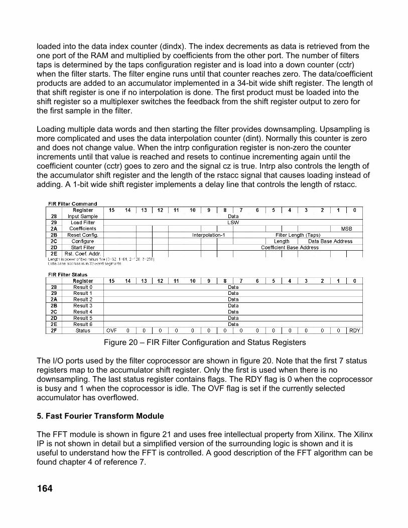
loaded into the data index counter (dindx). The index decrements as data is retrieved from theone port of the RAM and multiplied by coefficients from the other port. The number of filterstaps is determined by the taps configuration register and is load into a down counter (cctr)when the filter starts. The filter engine runs until that counter reaches zero. The data/coefficientproducts are added to an accumulator implemented in a 34-bit wide shift register. The length ofthat shift register is one if no interpolation is done. The first product must be loaded into theshift register so a multiplexer switches the feedback from the shift register output to zero forthe first sample in the filter.
Loading multiple data words and then starting the filter provides downsampling. Upsampling ismore complicated and uses the data interpolation counter (dint). Normally this counter is zeroand does not change value. When the intrp configuration register is non-zero the counterincrements until that value is reached and resets to continue incrementing again until thecoefficient counter (cctr) goes to zero and the signal cz is true. Intrp also controls the length ofthe accumulator shift register and the length of the rstacc signal that causes loading instead ofadding. A 1-bit wide shift register implements a delay line that controls the length of rstacc.
Figure 20 – FIR Filter Configuration and Status Registers
The I/O ports used by the filter coprocessor are shown in figure 20. Note that the first 7 statusregisters map to the accumulator shift register. Only the first is used when there is nodownsampling. The last status register contains flags. The RDY flag is 0 when the coprocessoris busy and 1 when the coprocessor is idle. The OVF flag is set if the currently selectedaccumulator has overflowed.
5. Fast Fourier Transform Module
The FFT module is shown in figure 21 and uses free intellectual property from Xilinx. The XilinxIP is not shown in detail but a simplified version of the surrounding logic is shown and it isuseful to understand how the FFT is controlled. A good description of the FFT algorithm can befound chapter 4 of reference 7.

165
The leftmost dual-port RAM is 512 entries by 32-bits and is split in half with one half containingthe data in the process of being received or transmitted and the other half containing the databeing loaded or unloaded by the FFT. The swap bit is inverted to switch halves when a newsample period starts. The counter (sctr) on the left-hand side of the diagram controls sampling.It is reset when not receiving or transmitting and enabled when transmission starts or when theSOF (start of frame) input is pulsed. It counts when RIV is true (reception) or TOE is true(transmission). The output is the address for reading data from (TDO) or writing data to (RDI)the RAM and counts up until the number of samples in the FFT (fftlen) is reached. At that pointit is loaded with the inverted cyclic prefix length (cplen) and counts up from that negativenumber. Writing to the RAM is inhibited during the cyclic prefix. The upper 1, 2 or 3 bits of theRAM address are removed by the mask logic for 128, 64 and 32-point FFTs, respectively.During reception, the FFT starts when the data carrier detect (DCD) input is true and thecounter is loaded with cplen. During transmission, DCD is ignored.
Figure 21 – FFT and Buffer Memory
The Xilinx FFT module provides 5-8-bit addresses when reading data into the N input or writingdata from the X output. These addresses are multiplexed into the port B RAM address port fortime-oriented data. Three clock cycles are provided for reading data so there is a 2-clock delayin the data path from the leftmost RAM. The rightmost RAM stores data ordered by frequencyand is connected directly to the CPU on the port A side. The other side is accessed by the FFTvia logic that converts between rectangular and polar coordinate systems. Conversion to polarcoordinates (phase and magnitude) takes time so there are six pipeline registers in theaddress path. The address is modified by a 4-input multiplexer to center the zero-frequencysample in each buffer with positive and negative frequency samples on either side. The RAMis 1024x16-bits but is divided into four 256-sample by 16-bit buffers. The upper 2 address bitsare provided by a base address counter which is incremented when the FFT is complete

166
(receive) or the FFT is started (transmit). This value is incremented or decremented by oneand provided as status to the CPU.
The other status port is the sample phase register that saves the sample counter value whenSYNC pulses are received. When the ensof configuration bit is true these pulses will also resetthe sample counter. There are four other status bits that are not shown in the logic diagram butare shown in the I/O port diagram, below.
Figure 22 – Polar to Rectangular Conversion
The input to the IFFT consists of a 4-bit phase and a 4-bit magnitude. These are converted toCartesian coordinates by the circuit in figure 21. Two 16 entry by 6-bit ROMs contain sine andcosine look-up tables. The outputs can be increased by approximately 3 dB by multiplying by1.5. 6 dB steps are obtained by using two 8-input multiplexers as shifters. One multiplexerinput is zero to allow disabling the subcarrier. This gives a 39-dB range.
Figure 23 – Rectangular to Polar Conversion
The output of the FFT is converted from 16 x 16-bit Cartesian coordinates to 5 x 7-bit polarcoordinates by the circuit in figure 23. CORDIC is not used as it would require more resourcesgiven such limited precision. The inputs are first converted to a floating-point format with a 4-bitexponent, two sign bits and two 4-bit fractions. One X/Y pair is converted per clock cycle by

167
using four 2-input multiplexers and making a decision at each stage to shift by 8, 4, 2 or 1 bitpositions as the samples travel through the circuit. The 5 x 5-bit output is then rotated into thefirst quadrant by taking the absolute value and swapping X and Y when necessary. Thearctangent is obtained from a 256x4 ROM and the output is adjusted back to the correctquadrant by an adder. This process reduces the size of the ROM by a factor of 4. The output is5 bits of phase that is suitable for soft-decision Viterbi decoding of 8PSK. The logarithm of themagnitude is obtained from the 64x3 ROM and added to the exponent. This gives a 7-bitlogarithmic magnitude output.
Figure 24 – FFT Configuration and Status Registers
The FFT module is configured via the 5 registers shown in figure 24. The FFT should be resetbefore changing other parameters. The current address register contains the address of the256-word buffer to be used to prepare the next symbol to be transmitted or the location of thebuffer with the last received symbol. The INT bit is set when the buffer address changes. TheSOF and EOF bits can be used to determine the start and end of the frame. SOF is set when anull symbol is detected and EOF is set when RSSI drops by 6 or 12 dB depending on thesetting of the H bit in the modem configuration.
6. Error Control Logic
Many communications protocols use cyclic redundancy checks (CRCs) for error detection.Calculations on a general-purpose processor are time consuming, as it requires bitmanipulation. The CRC hardware shown in figure 25 provides a means to generate and checkthe two most commonly used CRCs quickly. The CPU writes bytes or words in parallel to the

168
two shift registers. This sets a counter to the number of dibits to be processed and enables theCRC-16 and CRC-32 logic. The shift register outputs are multiplexed at twice the CPU clockrate so the CRC logic operates at 160 Mbps. Thus a word can be processed in 8 clock cyclesor a byte in 4 clock cycles.
CRCs can be computed in parallel with data copying by the CPU. The block copy routine ismodified to output a word between the memory read and memory write. After the transfer iscomplete, the CPU inputs one of the accumulated CRCs and appends it to the data. CRC-32 isthe algorithm used by Ethernet and CRC-16 is the algorithm used by HDLC and AX.25.
Figure 25 – Cyclic Redundancy Check Logic
Figure 26 – CRC Configuration and Status Registers
CRCs only allow error detection, but convolutional codes, including trellis-coded modulation,allow error correction. They may be implemented using the programmable convolutionalencoder and Viterbi decoder modules.
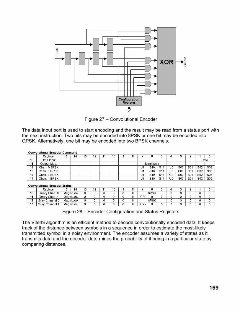
The encoder exclusive-ORs delayed versions of the uncoded data bits to generate codedoutputs. Configuration registers select the bits to be used. Figure 27 shows the logic forencoding one bit. The configuration register, AND gates and exclusive-OR gate are replicated4 times. Two to four outputs may be generated for each input so that BPSK, QPSK and 8PSKcan be accommodated. Either natural or gray coding may be selected.
169
Figure 27 – Convolutional Encoder
The data input port is used to start encoding and the result may be read from a status port withthe next instruction. Two bits may be encoded into 8PSK or one bit may be encoded intoQPSK. Alternatively, one bit may be encoded into two BPSK channels.
Figure 28 – Encoder Configuration and Status Registers
The Viterbi algorithm is an efficient method to decode convolutionally encoded data. It keepstrack of the distance between symbols in a sequence in order to estimate the most-likelytransmitted symbol in a noisy environment. The encoder assumes a variety of states as ittransmits data and the decoder determines the probability of it being in a particular state bycomparing distances.

170
Figure 29 – Viterbi Decoder
Received symbols are written to a 16-entry FIFO in the Viterbi decoder. As symbols areextracted from the FIFO, they are processed once for each possible new state of thetransmitting convolutional coder. The received symbol is compared to the expected symbol fora particular previous state and the phase error is converted to a distance. This new distance isadded to the cumulative distance to the previous state retrieved from the 32-entry dual-portmetrics RAM and compared to the current minimum distance. If it is less than the minimum itreplaces the minimum and the previous state is saved. This process generates a set of metricsmeasuring the probability that each input symbol matches each possible transmitted symbol.The likely previous state for each possible new state is stored in a dual-port block RAM.
The block RAM can store path information for up to 256 symbols. After all symbols have beenprocessed, the contents of the ROM are scanned in reverse order, tracing back over the mostlikely path that the transmitting encoder took. The traceback logic requires that the last state bezero. As traceback occurs, the states are looked up in a bit map and the decoded data bits areshifted into an eight-dibit register. The bit values corresponding to each state are loaded inreverse order via the bit decoding configuration register. The traceback process stops on everyeight symbol and the OV bit is set to allow the CPU to read the decoded byte or word via thefirst two status registers. The number of symbols remaining is contained in the lower 8 bits ofthe third status register.

171
Figure 30 – Viterbi Decoder Configuration and Status Registers
The states and symbols assumed in the decoding process are stored as a program in a 64-entry by 11-bit shift register. The decoder can be programmed for any forward error-correctingcode with less than 16 states using 2, 4 or 8-level signaling. Instructions are loaded via thepath list input register shown in figure 30. The number of paths to evaluate is also specifiedand determines the number of clock cycles required for decoding. Each path requires 4 clocksand 4 additional clocks are required for pipeline delays.
Figure 31 – BCH Encoder/Decoder
A Bose Chaudhuri Hocquenghem (BCH) CODEC module supports block codes with 8-247data bits and 3-8 parity bits. It may be configured for specific codes by specifying the length ofthe shift register and placement of the feedback taps (G1-7). The word width (N) is variable sothat encoding or decoding of 1 to 16 data bits may occur in parallel at one clock cycle per bit.

172
The BCH algorithm is executes simultaneously on multiple bit streams where each bit in aword is part of an independent stream. When transmitting, the CPU writes data to an outputport with ACC set to 1. This loads the shift register and on each of the following clock cyclesone data bit passes through the exclusive-OR on the extreme right side of the diagram where itis combined with the currently selected bit in each shift register. On each clock cycle, all shiftregisters advance and the next bit is processed. Setting ACC to 0 causes the written data to beignored but the next accumulated parity bits are moved into the shift register where they canbe accessed at an input port and transmitted serially. When receiving, ACC is set to 1 and bothdata and parity words are written to the output port. The accumulated syndrome for each bitcan be read by setting the width register to the bit number. The CPU then uses any non-zerosyndrome for error correction.
Figure 32 – BCH Configuration and Status Registers
7. I/O Ports
Several methods are provided for the DCP-3 to communicate digitally with other devices. Theinternal circuitry is not described in this document, as it concentrates on the signal-processinghardware.
Figure 33 - Ethernet Configuration and Status Registers
The Ethernet port uses a single transmit buffer and double-buffered receive. 2 kB of dual-portRAM is provided to store the frame to be transmitted and 4 kB of dual-port RAM is provided tobuffer received frames. The CPU may access one received frame at the same time another isbeing received. The hardware supports only full-duplex operation at 100 Mbps at this time.Transmission is accomplished by writing a frame and its preamble to the transmit buffer andthen outputting the length to port 1 as shown in figure 33. The CPU then checks the TXE bit inthe status register for completion of transmission before writing another frame. The CPU mayalso check the RXR bit for received frames and obtain the length of the received frame. It then

173
accesses the receiver buffer memory to retrieve the frame. One half of the buffer is visiblewhich contains the first frame received. When the CPU signals done by writing to port 0, thenext frame is presented.
A universal asynchronous receiver/transmitter (UART) is provided for low-speedcommunication. It is used by the loader firmware for downloading software and may be usedfor other purposes, such as implementing a TNC. Signaling rates between 110 and 460,800baud are supported. The baud rate divisor is set to generate the appropriate clock at 16 timesthe symbol rate. 15-byte receive and transmit FIFOs are provided and may be read and writtenvia port 20. Status flags indicate when the transmit FIFO is empty (TXE), the transmit FIFO isready for data (TXR), the receive FIFO is full (RXF) and received data is available (RXR). Thereceive FIFO has a framing error bit for each entry. The UART supports only 8-bit characterswithout parity.
Figure 34 - UART Configuration and Status Registers
Note that the Ethernet interface and UART do not implement CRC generation and checking.This may be done by using the CRC hardware described previously.
There are two SPI ports. One is used to operate the low-speed DAC and the other isconnected to the onboard serial flash memory. Writing a byte to the SPI transmit data portsends a command to the flash memory. Simultaneously, data is transmitted from the flashmemory and appears in the received data port. The data transmission rate is fixed at 20 Mbpsand the CPU must wait 32 clock cycles for operations to complete. Ports A and B control theslave select line, which must be active when sending commands to the flash memory.
Figure 35 - SPI Configuration and Status Registers
The lower portion of the serial flash memory contains the FPGA configuration that is loadedautomatically when power is applied so it must not be disturbed. However, the upper portionmay be used for data and program storage.

174
The DAC port is 16-bits wide and is write-only. The lower 12 bits control the DAC and theupper 4 bits must be set to zero. 64 clock cycles are required after the write for data to betransferred to the DAC.
Figure 36 – Low-Speed DAC Output Register
An I2S port is provided to attach an external 1 or 2-channel 16-24-bit audio CODEC operatingat 32 ksps. Data for the left and right channels is written to separate pairs of output ports. Theleast significant byte (LSB) is written first and is zeroed after every write to the most significantword (MSW). The MSW write causes data to be transmitted. Use of the left and right channelsmust be alternated for stereo CODECs. Left and right channel data is read from a commonpair of input ports and the “Left” status flag indicates the active channel. Both ports have a 15-entry FIFO. Status flags indicate FIFO status and input sample source (left or right channel).
Figure 37 - I2S Configuration and Status Registers
8. Conclusion
The combination of a fixed hardware configuration stored in flash memory plus downloadablesoftware has proven to be very flexible. Much development time was spent optimizing the useof FPGA resources. For example, dedicated multipliers are used in the FIR filters where highspeed is necessary and serial multipliers are used in the AGC logic after the sample rate hasbeen reduced. Logic such as the CORDIC module was designed for reuse when switchingfrom transmit to receive so little standard IP was used other than the FFT module. Thathardware can now be leveraged for multiple applications by changing the software. Thecurrent program implements a transceiver for AM, FM and SSB plus a high-speed OFDMmodem. The resampler and timing recovery hardware should allow implementation of a high-speed AX.25 TNC in the future.
Several PC-based programs were developed for use with the DCP-3, including an assemblerfor the CPU and utilities to format configuration information for loading into flash memory.These programs and the complete Verilog source code for the FPGA are available on theTAPR web site. The source code and it derivatives are provided for personal non-profiteducational use in the Amateur Radio Service and are not licensed for redistribution.

175
Since the hardware is defined in Verilog it can be ported to newer and denser FPGAs. TheXC3S500 was first shipped in 2006. An XC3S1400A FPGA can now provide more than twicethe logic and 60% more memory for little additional cost. This would allow use of ADCs andDACs up to 160 Msps, faster filters and more complex signal constellations for higher data rateOFDM modems. At a somewhat higher price, Spartan-6 series FPGAs can eventually provideeven more memory and logic. I plan to make a new version of the board in the near future. Inthe mean time, I’ll be using this one on the air.
9. References
1. John B. Stephensen, “Software Defined Radios for Digital Communications”,November/December 2004 QEX.
2. John B. Stephensen, “A Soft Processor for DSP”, Winter 2009 Packet Status Register.
3. Andreas Chrysafis, “Digital Sine-Wave Synthesis using the DSP56001/2”, Motorola SignalProcessing Division, 1988.
4. William Sabin, “Automatic Gain Control for CW Reception”, QST, July 1963.
5. Fredric J. Harris, “Multirate Signal Processing for Communication Systems”, ISBN 0-13-146511-2, Prentice-Hall, 2004.
6. Scott Hauck, Andre DeHon, “Reconfigurable Computing – The Theory and Practice ofFPGA-Based Computation”, ISBN 978-0-12-370522-8, Elsevier, Inc., 2008.
7. Richard G. Lyons, “Understanding Digital Signal Processing”, ISBN 0-201-63467-8,Addison-Wesley, 1997.

176
Appendix A – DCP-3 Schematic Diagram
The following 6 pages contain the schematic diagram of the DCP-3 digital signalprocessing PCB:
1. Ethernet Interface2. High-speed Analog to Digital Converter3. Serial Flash Memory and Low-speed DAC4. High-speed Digital to Analog Converter5. Voltage Regulator and JTAG Interface6. Clock Oscillators
The schematic shows a Xilinx XC3S250E FPGA but the XC3S500E has thesame pin configuration in the 100-pin TQFP package.

177

178

179

180

181

182

183
CPU16B Instruction Set Page 1 of 14
05/29/10
Appendix B - CPU16B instruction Set
B1. Introduction
The CPU16B is a 16-bit Von Neuman architecture processor with a single address spaceshared between data and instructions. The dual-port memory provided by FPGAs allowssimultaneous instruction fetches and data manipulation giving the performance of a Harvardarchitecture machine. The instruction set uses 5 basic formats as shown in figure 1.
15 14 13 12 11 10 9 8 7 6 5 4 3 2 1 0CALL Type Absolute Address
JMP/LOOP/RET Type Op. Condition Relative AddressImmediate Data Type Op. Constant A
I/O Type Operation Port AALU Type Operation Modifier B/C A
Figure 1 – Basic Instruction Format
Program-control instructions use two address formats. Call instructions use a 14-bit absoluteaddress and can access 16,384 words of program memory. Jump instructions use a 9-bitrelative address and can access the previous 255 or next 256 instruction locations. The jumpis taken if the condition specified by a 3-bit field is satisfied. Otherwise instruction executioncontinues in sequence. The full program address space can be accessed by loop instructionsthat use a 14-bit absolute addresses stored by the mark instruction. This allows backwardjumps to any location.
ALU instructions may operate on 16-bit words, the lower 4 or 8-bits of a word or any single bit.Most use register A as the source for one operand and the destination for the result. Thesecond operand may be register B or a signed 8 or 16-bit constant.
I/O instructions use a 7-bit direct address to identify up to 128 16-bit wide I/O ports. Memoryaccess instructions use 14-bit indirect addresses stored in register B plus an offset from themodifier field. Register A contains the data to be written to memory and is the repository forany data read from memory.
Assembler syntax uses 3 fields. The label field contains either blank space or an alphanumericname followed by a colon. The operation field contains a 2-4-character instruction name. Theoperand field contains nothing, a single parameter or two to three parameters separated bycommas.
Label: OP Rd,Rs,mod ; comments
Operands may be register names (SP and R1-R15), address labels or constants in binary,decimal, hexadecimal or alphanumeric format. A binary number starts with “#”, a hexadecimalnumber starts with “$” and a 1 or 2 character string is delimited by single quotes (‘).

184
CPU16B Instruction Set Page 2 of 14
05/29/10
B2. Program Flow Control
The program control instructions are listed in figure 2. Calls are unconditional and the call usesabsolute addresses. The jump, loop and return instructions may be conditional orunconditional. Jump instructions use addresses that are relative to the program counter.
15 14 13 12 11 10 9 8 7 6 5 4 3 2 1 0CALL 00 Absolute AddressJMP 01 00 Condition Relative AddressRET 01 01 Condition 0
LOOP 01 01 Condition 1MARK 01 10 0 0STRA 01 10 0 1REP 01 10 1 000 Count
Figure 2 – Program Control Instructions
Three condition flags may be tested as shown in figure 3. The C, V and Z bits are the carry,overflow and zero flags for comparison operations and for 16-bit arithmetic operations,including add, subtract, increment and decrement. The C bit is also altered by bit test andshifting operations. The Z bit is necessary for loop control and the C bit is necessary for multi-word shifts and software multiplication and division routines.
Condition Description000 Always001 Never (NOP)010 V set by previous arithmetic or comparison instruction011 V reset by previous arithmetic or comparison instruction100 Z set by previous arithmetic or comparison instruction101 Z reset by previous arithmetic or comparison instruction110 C set by previous arithmetic, comparison, shift or bit test instruction111 C reset by previous arithmetic, comparison, shift or bit test instruction
Figure 3 – Jump Conditions
The assembly language representation is an instruction name that specifies any conditioncode followed by an operand specifying the absolute address for calls or the relative addressfor jumps. Mark, return and loop instructions have no operand. Repeat has a single numericoperand.
JMP loads the program counter (PC) with the specified address and continues programexecution from that location. JV, JNV, JZ, JNZ, JC and JNC jump if the V bit is true, the V bit isfalse, the Z bit is set, the Z bit is reset, the C bit is set or the C bit is reset. Otherwise,execution continues with the next instruction in sequence. The operand may be a label or anumeric value.

185
CPU16B Instruction Set Page 3 of 14
05/29/10
Here: JMP $0JNZ there
CALL pushes the next instruction address onto the return address stack and then jumps to thespecified address. The address is stored temporarily in a register while the stack pointer isincremented and then written into the dedicated RAM holding the return address stack. Itcontains up to 16 return addresses to allow subroutine nesting up to 16 levels. There is nooverflow or underflow indication. . The operand may be a label or a numeric value.
Here: CALL $0CALL There
The RET (return) instruction restores the address in the address stack to the program counterand continues execution from that location. RV, RNV, RZ, RNZ, RC and RNC return if the V bitis true, the V bit is false, the Z bit is set, the Z bit is reset, the C bit is set or the C bit is reset.The stack pointer is decremented after the address is read. There are no operands.
There:RET
The MARK instruction pushes the next instruction address onto the return address stackwithout jumping. It is used with the LOOP instructions for long backward jumps.
The STRA instruction pushes the contents of the selected register onto the return addressstack. It is used with the RET instruction for indirect jumps.
STRA R15
The LOOP instruction restores the address in the return address stack to the program counterand continues execution from that location. LV, LNV, LZ, LNZ, LC and LNC loop if the L bit istrue, the V bit is false, the Z bit is set, the Z bit is reset, the C bit is set or the C bit is reset. Thestack pointer is decremented if the loop is exited.
LDL R1,256MARKNOP ; do this 256 timesDEC R1LNZ
The REP (repeat) instruction causes the next instruction to execute count + 2 times. It inhibitsincrementing the program counter so the same instruction is issued multiple times with noadditional overhead. The assembler calculates the correct value for the count field given thenumber of times to repeat the next instruction.
REP 256NOP ; do this 256 times

186
CPU16B Instruction Set Page 4 of 14
05/29/10
B3. Memory Access and I/O
Figure 4 shows the format of the immediate data, I/O and memory access instructions. Theydo not alter any flags.
15 14 13 12 11 10 9 8 7 6 5 4 3 2 1 0MVI 01 11 Data ALDH 10 101 101 DataWR 10 110 000 B A
WRO 10 110 Offset B AOUT 10 111 Port AIN 11 000 Port ARD 11 001 000 B A
RDO 11 001 Offset B A
Figure 4 – I/O and Memory Access Instructions
The MVI instruction replaces the lower 8 bits of register A with immediate data and the sign isextended to the upper 8 bits. This can be modified by the LDH instruction that loads 8 bits ofdata into a special register. Those 8 bits replace the MSB in any MVI, ADI or CPI instructionthat follows. The MVIW and LOAD pseudo-operations generate one LDH and one MVIinstruction to load a 16-bit constant into a register. The LDA pseudo-operation does the samefor loading a 14-bit address into a register.
MVI #01111110MVIW $3AB4LDA label
Output instructions use direct addressing to access up to 128 ports up to 16 bits wide. OUTcopies the contents of register A to the selected port by placing the port address on IOADDR,the data on DOUT and asserting IOWR. Input instructions use direct addressing to access upto 128 ports up to 16 bits wide. IN copies the contents of the selected port from the DIN bus toregister A and asserts IORD. IN takes 2 clock cycles to allow for propagation delays.
OUT R1,48 ; numeric port numberIN R1,data ; port number defined by EQU
Memory access instructions use register indirect addressing of up to 65,536 words of memory.Writes complete in one clock cycle and reads take two cycles. Write with offset (WRO) copiesthe contents of register A to the memory location at the address in register B plus a 3-bit offsetcontained in the instruction. Read with offset (RDO) copies the contents of the memorylocation at the address in register B plus a 3-bit offset contained in the instruction to register A.The write (WR) and read (RD) instructions are the same but with a fixed offset of zero.
RDO R2,R1,0 ; contents of memory at address in R1 copied to R2RD R2,R1 ; contents of memory at address in R1 copied to R2WR R3,R2 ; contents of R3 copied to memory at address in R2

187
CPU16B Instruction Set Page 5 of 14
05/29/10
B4. Arithmetic Operations
The 4, 8 and 16-bit arithmetic instructions are encoded as shown in figure 5. The carry,overflow and zero flags are updated for 16-bit arithmetic operations but not for 4-bit or 8-bitoperations.
15 14 13 12 11 10 9 8 7 6 5 4 3 2 1 0ADI 10 00 C AINC 10 00 00000000 ASBI 10 00 -C ADEC 10 00 11111111 ACPI 10 01 C ACPZ 10 01 00000000 ACMP 10 101 011 B ACLC 10 101 110 0000 0000STC 10 101 110 0001 0000
CMPC 10 101 111 B AMOV 11 010 000 B AMVN 11 010 001 B ANEG 11 010 001 A AADD 11 010 010 B ASUB 11 010 011 B A
MOVC 11 010 100 B AMVNC 11 010 101 B ANEGC 11 010 101 A AADC 11 010 110 B ASBC 11 010 111 B A
MOV8 11 011 000 B AMVN8 11 011 001 B AADD8 11 011 010 B ASUB8 11 011 011 B AMOV4 11 011 000 B AMVN4 11 011 001 B AADD4 11 011 010 B ASUB4 11 011 011 B A
Figure 5 –Arithmetic Instructions
ADI adds an 8-bit signed constant to register A (A=A+C). SBI generates the same instructionbut negates the constant to subtract from register A (A=A-C). INC and DEC provide analternate way of specifying ADI RA, 1 and SBI RA, 1. ADIW and SBIW prefix an LDH instructionfor 16-bit operations.
ADI R2,1 ; 2 ways to increment R2 by 1INC R2

188
CPU16B Instruction Set Page 6 of 14
05/29/10
CPI subtracts and 8-bit signed constant from register A and sets the zero and carry flags. Noregister is modified. CPZ provides a shorthand way of specifying CPI RA, 0. CPIW generatesan LDH followed by a CPI for 16-bit comparisons.
CPI R1,0 ; 2 ways to compare R1 to zeroCPZ R1CPIW R2,3456
STC and CLC set and clear the carry flag, respectively.
STC ; set carryCLC ; clear carry
CMP subtracts register B from register A and sets the zero and carry flags. No register ismodified. CMPC is the same, but propagates the carry bit for larger comparisons.
CMP R2,R1 ; compare R2 to R1
MOV copies register B to register A. MVN copies the two’s complement of register B to registerA. MOVC and MVNC perform the same operations but propagate the carry bit. NEG andNEGC provide an alternate way to specify MVN RN,RN and MVNC RN,RN.
MOV R2,R1 ; copy R1 to R2 and set flagsNEG R2 ; negate R2MVN R2,R1 ; copy negative of R1 to R2
ADD adds register B to register A and leaves the result in register A (A=A+B). SUB subtractsregister B from register A and leaves the result in register A (A=A-B). ADC and SBC are thesame, but propagate the carry bit for larger arithmetic operations.
ADD R1,R3 ; 32-bit add (R2,R1 + R4,R3)ADC R2,R4
MOV8 copies the contents of register B into the lower byte of register A. MVN8 negates thebyte being copied. NEG8 provides an alternate way to specify MVN8 RN,RN.
MOV8 R2,R1 ; copy LSB of R1 to R2 without affecting flagsMVN8 R2,R1 ; same, but resultant byte is negated
ADD8 and SUB8 add or subtract the lower byte in B from the lower byte in A without affectingthe upper byte (A7-0 = A7-0 � B7-0 and A15-8 = A15-8).
ADD8 R2,R1SUB8 R2,R1
MOV4, MVN4, NEG4, ADD4 and SUB4 perform the same operations on the lower 4 bitswithout affecting the upper 12 bits.

189
CPU16B Instruction Set Page 7 of 14
05/29/10
B5. Logical Operations
The logic unit operates on two 16-bit inputs (A and B) or on one bit from input A. The encodingis shown in figure 6.
15 14 13 12 11 10 9 8 7 6 5 4 3 2 1 0NOT 11 100 000 B AAND 11 100 001 B AOR 11 100 010 B A
XOR 11 100 011 B AMASK 11 100 100 C ARST 11 100 101 C ASET 11 100 110 C AINV 11 100 111 C A
Figure 6 – Logical Instructions
Four instructions perform logical operations between register A and register B and fourinstructions perform logical operations on bits in register A.
NOT copies the one’s complement of register B to register A. OR sets bits in register A wheneither of the corresponding bits in register A or register B are 1. XOR sets bits if only one of thetwo corresponding bits is 1. AND sets bits in register A if the corresponding bits in register Aand register B are both 1.
NOT R1,R1 ; R1 <- ~R1OR R2,R1 ; R2 <- R2 | R1XOR R3,R1 ; R3 <- R3 ^ R1AND R4,R1 ; R4 <- R4 & R1
MASK selects the lower 0-15 bits of register A by zeroing the upper bits.
MASK R6,8 ; zero upper byte of R0
The bit manipulation instructions modify register A. RST and SET change the value of the bitselected by C to 0 and 1, respectively. INV complements the value of the selected bit.
RST R7,1 ; clear bit 0SET R7,15 ; set bit 15INV R7,7 ; invert bit 7
190
CPU16B Instruction Set Page 8 of 14
05/29/10
B6. Shift, Rotate and Sign Extension Operations
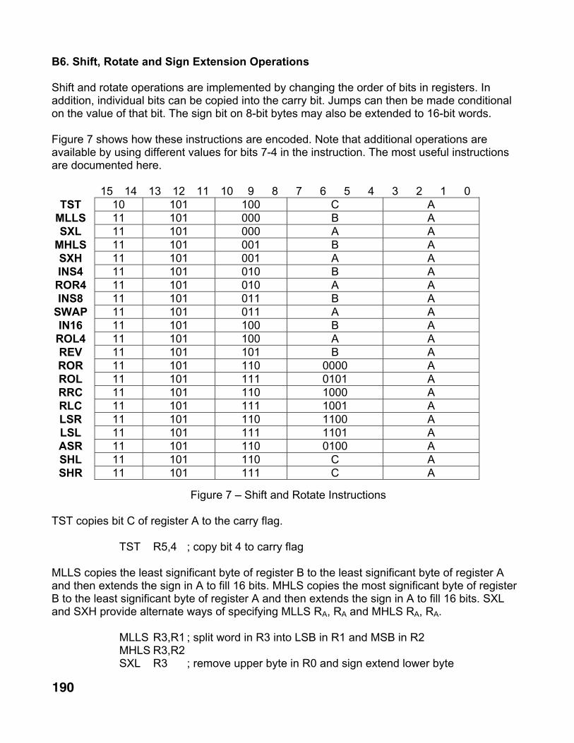
Shift and rotate operations are implemented by changing the order of bits in registers. Inaddition, individual bits can be copied into the carry bit. Jumps can then be made conditionalon the value of that bit. The sign bit on 8-bit bytes may also be extended to 16-bit words.
Figure 7 shows how these instructions are encoded. Note that additional operations areavailable by using different values for bits 7-4 in the instruction. The most useful instructionsare documented here.
15 14 13 12 11 10 9 8 7 6 5 4 3 2 1 0TST 10 101 100 C A
MLLS 11 101 000 B ASXL 11 101 000 A A
MHLS 11 101 001 B ASXH 11 101 001 A AINS4 11 101 010 B AROR4 11 101 010 A AINS8 11 101 011 B A
SWAP 11 101 011 A AIN16 11 101 100 B AROL4 11 101 100 A AREV 11 101 101 B AROR 11 101 110 0000 AROL 11 101 111 0101 ARRC 11 101 110 1000 ARLC 11 101 111 1001 ALSR 11 101 110 1100 ALSL 11 101 111 1101 AASR 11 101 110 0100 ASHL 11 101 110 C ASHR 11 101 111 C A
Figure 7 – Shift and Rotate Instructions
TST copies bit C of register A to the carry flag.
TST R5,4 ; copy bit 4 to carry flag
MLLS copies the least significant byte of register B to the least significant byte of register Aand then extends the sign in A to fill 16 bits. MHLS copies the most significant byte of registerB to the least significant byte of register A and then extends the sign in A to fill 16 bits. SXLand SXH provide alternate ways of specifying MLLS RA, RA and MHLS RA, RA.
MLLS R3,R1 ; split word in R3 into LSB in R1 and MSB in R2MHLS R3,R2SXL R3 ; remove upper byte in R0 and sign extend lower byte

191
CPU16B Instruction Set Page 9 of 14
05/29/10
INS4 copies the lower 4 bits of register B to the upper 4 bits of register A after shifting theupper 12 bits of register A to the right. INS8 copies the lower 8 bits of register B to the upper 8bits of register A after shifting the upper 8 bits of register A to the right. INS4 copies the lower12 bits of register B to the upper 12 bits of register A after shifting the upper 4 bits of register Ato the right. ROR4, SWAP and ROL4 provide alternate ways of specifying INS4 RA, RA, INS8RA, RA and IN12 RA, RA.
INS4 R1,R2 ; copy LS 4 bits of R2 to bits 15-12 of R1 and shift bits 15-4 to 11-0ROR4 R1 ; rotate R0 right by 4 bits
REV reverses the order of the bits while copying from register B to register A. Bits 15 and 0 areswapped, bits 14 and 1 are swapped, etc.
LDL R1,$57REV R1,R1 ; 01010111 -> 11101010
ROL and ROR rotate the contents of register A left or right by one bit with bit 15 replacing bit 0or bit 0 replacing bit 15, respectively. RLC and RRC rotate the contents of register A left orright by one bit with the carry bit replacing bit 0 or bit 15, respectively. The carry bit containsthe previous value of bit 15 after ROL or RLC and bit 0 after ROR or RRC.
LOAD R1,$F0 ; R1=11110000ROR R1 ; R1=01111000, C=0ROL R1 ; R1=11110000, C=0RLC R1 ; R1=11100000, C=1RRC R1 ; R1=11110000, C=0
LSL shifts the contents of register A left by one bit and clears bit 0 while setting the carry bit tothe previous value of bit 15. LSR shifts the contents of register A right by one bit and clears bit15 while setting the carry bit to the previous value of bit 0.
LOAD R2,$FF ; R2=11111111LSL R2 ; R2=11111110, C=1LSR R2 ; R2=01111111, C=0
ASR shifts the contents of register A right by one bit without affecting bit 15. The carry registercontains the previous value of bit 0.
LOAD R1,-2 ; R1=11111110ASR R1 ; R1=11111111 (-1), C=0

192
CPU16B Instruction Set Page 10 of 14
05/29/10
The SHL and SHR instructions provide a means to generate additional types of 1-bit shifts asshown below:
C Carry Flag LSB or MSB00x0 Bit 0 Bit 000x1 Bit 15 Bit 001x0 Bit 0 Bit 1501x1 Bit 15 Bit 1510x0 Bit 0 Carry flag10x1 Bit 15 Carry flag1100 Bit 0 01101 Bit 15 01110 Bit 0 11111 Bit 15 1
Figure 8 – SHL and SHR Modifier Field Encoding
The value of the bit shifted into the LSB during a left shift (SHL) or into the MSB during a rightshift (SHR) may be obtained from the carry flag or fixed at 0 or 1. Either the most or leastsignificant bit can be copied to the carry flag.

193
CPU16B Instruction Set Page 11 of 14
05/29/10
B7. Optional Multiply-Accumulate Instructions
There are 10 multiply-accumulate instructions, as listed in figure 9. Type 2 instructions areused to start multiplication with options selected by the modifier field. The instructionscomplete in 1 cycle but results require 2 instruction cycles to become available. Type 3instructions are used to copy the results into general-purpose registers.
15 14 13 12 11 10 9 8 7 6 5 4 3 2 1 0UMUL 10 100 000 B AUMLN 10 100 001 B AUMAC 10 100 010 B AUMSB 10 100 011 B AMUL 10 100 100 B A
MULN 10 100 101 B AMAC 10 100 110 B A
MSUB 10 100 111 B ALPL 11 110 000 0000 ALPH 11 110 001 0000 A
Figure 9 – Multiply Instructions
MUL performs a 16-bit by 16-bit signed multiply and leaves the result in a 32-bit accumulator.UMUL performs an unsigned multiply. MULN and UMLN perform signed and unsignedmultiplies and negate the result.
MAC and UMAC perform signed and unsigned multiplies and add the result to the existingaccumulator contents. MSUB and UMSB perform signed and unsigned multiplication andsubtract the result from the accumulator. Operands may be introduced at a rate of one pair perinstruction cycle and the results will be available on the next instruction cycle after the finaloperands are loaded.
LPH provides the upper 16-bits of the accumulator and LPL provides the lower 16 bits of theaccumulator.
The MAC unit is useful for complex multiplies. CI = AIBI - AJBJ can be implemented with a MULinstruction followed by MSUB, LPH and LPL instructions. CJ = AIBJ + AJBI can be implementedwith a MUL instruction followed by MAC, LPH and LPL instructions. The following codefragment performs a complex multiply on R1/R2 and R3/R4 and returns the result in R5-R8.
MUL R1,R3 ; AIBI
MSUB R2,R4 ; AIBI - AJBJ
LPL R5LPH R6MUL R1,R4 ; AIBJ
MAC R2,R3 ; AIBJ + AJBI
LPL R7LPH R8

194
CPU16B Instruction Set Page 12 of 14
05/29/10
B8. Optional Division Instructions
There are 4 division-related instructions that are formatted as shown in figure 10. The divisionoperations consume many clock cycles, but may occur in parallel with other operations. Theprogrammer must insure that a new division operation is not issued until the previous one hasbeen completed.
15 14 13 12 11 10 9 8 7 6 5 4 3 2 1 0FDIV 10 101 000 0000 0000IDIV 10 101 001 B ALQ 11 110 010 0000 ALR 11 110 011 0000 A
Figure 10 – Division Instructions
IDIV performs a 16-bit by 16-bit unsigned integer division leaving a 16-bit quotient and 16-bitremainder. A is divided by B and the result is left in the quotient and remainder registers after17 clock cycles.
FDIV continues the calculation in order to generate the fractional portion of the quotient in Qafter 17 more clock cycles.
The LQ and LR instructions read the quotient and remainder registers. The upper bit of R maybe monitored to determine when the calculation is complete. It is 1 during computation.
LOAD R2,255LOAD R1,4IDIV R2,R1 ; 255 � 4REP 17NOPLQ R1 ; 63LR R2 ; 3FDIV ; 3 � 4REP 16NOPLQ R3 ; R3 = 1100000000000000 = ¾

195
CPU16B Instruction Set Page 13 of 14
05/29/10
B9. Stack Operations
The register R0 may be specified by SP and is commonly used as a stack pointer for datastorage. The assembler will generate 2-instruction sequences for PUSH and POP as follows:
DEC SP ; PUSH RN
WR RN,SP
RD RN,SP ; POP RN
INC SP
By default, the use of R0 is suppressed to minimize register allocation errors.
B10. Pseudo-Instructions
The PRAM instruction is used to accommodate different types and amounts of programmemory. UCF files are used to initialize program memory when the FPGA is configured.Hexadecimal format files may be downloaded after FPGA configuration.
Modifier Result0 Generate hex file (any length)1 UCF file for one 1k x 16 RAM2 UCF file for two 2k x 8 RAMs4 UCF file for four 4k x 4 RAMs
Figure 11 – PRAM Instruction
REG assigns a label to the specified register and EQU assigns a label to the specified numericconstant.
Label REG R7one EQU 1
DW and DB initialize the value of a word or the 2 bytes within a single word, respectively.
DW 28DB 37,48
DS assigns a label to the current address and increments the data address by the specifiednumber of words.
long: DW 2
The ORG pseudo-instruction is used to set the program address to the specified value. Theprogram address defaults to zero.
ORG 0

196
CPU16B Instruction Set Page 14 of 14
05/29/10
B11. Summary
Figure 12 shows how instructions are allocated within the space provided by the type,operation and modifier fields. All instructions are 16 bits and all except IN, RD, IDIV and FDIVexecute in one clock cycle.
Figure 12 – Operation Code Matrix
JBS