Embed Size (px)
Citation preview
US Amy CrpsLVALUA I IUN VKUWUH1 liJK I1 MONWHLUWi CONCRETE BOX CULVERTS UNDER AIRFIELD
PAVEMENTS
by
David M. Coleman, James A. Harrison
' FILE COP -Y Geotechnical Laboratory
and
Stanley C. Woodson
Structures Laboratory
DEPARTMENT OF THE ARMYWaterways Experiment Station, Corps of Engineers
.. .3909 Halls Ferry Road, Vicksburg, Mississippi 39180-6199
.DTICELECTE
900lOT.3 IlI0
September 1990Final Report
Approved for Public Release; Distribution Unlimited
Prepared for DEPARTMENT OF THE ARMYUS Army Corps of Engineers
Washington, DC 20314-1000and
DEPARTMENT OF THE AIR FORCELABO Engineering and Services Center
RY Tyndall Air Force Base, Florida 32403-6001
1
Destroy this report when no longer needed. Do not returnit to the originator.
The findings in this report are not to be construed as an officialDepartment of the Army position unless so designated
by other authorized documents.
The contents of this report are not to be used foradvertising, publication, or promotional purposes.
Citation of trade names does not constitute anofficial endorsement or approval of the use of
such commercial produ.zts.
UnclassifiedSECURITY CLASSIFICATION OF THIS PAGE
REPORT DOCUMENTATION PAGE N0
la. REPORT SECURITY CLASSIFICATION lb. RESTRICTIVE MARKINGSUnclassified
2a. SECURITY CLASSIFICATION AUTHORITY 3 DISTRIBUTION IAVAILABILITY OF REPORTApproved for public release; distribution
2b. DECLASSIFICATION IDOWNGRADING SCHEDULE unlimited.
4. PERFORMING ORGANIZATION REPORT NUMBER(S) 5, MONITORING ORGANIZATION REPORT NUMBER(S)
Technical Report GL-90-25
68. NAME OF PERFORMING ORGANIZATION 6b. OFFICE SYMBOL 7a. NAME OF MONITORING ORGANIZATION(f applicable)
See reverse see reverse
6c. ADDRESS (City, State, and ZIP Code) 7b. ADDRESS (City, State, and ZIP Code)
3909 Halls Ferry RoadVicksburg, MS 39180-6199
8. NAME OF FUNDING/SPONSORING 8b. OFFICE SYMBOL 9. PROCUREMENT INSTRUMENT IDENTIFICATION NUMBERORGANIZATION (If applicable)See reverse AFESC-DEMP
8c. ADDRESS (City, State, and ZIP Code) 10. SOURCE OF FUNDING NUMBERSWashington, DC 20314-1000 PROGRAM PROJECT TASK IWORK UNIT
AFESC-DEMP ELEMENT NO. NO. NO. ACCESSION NO.
Tyndall Air Force Base, FL 32403-6001 I11. TITLE (Include Security Classifiation)
Evaluation Procedure for Reinforced Concrete Box Culverts under Airfield Pavements
12. PERSONAL AUTHOR(S)
Coleman David M ' Hrrlcnn Tamrni A • Unndnnr, Rtn1 y f,13a. TYPE OF REPORT 13b. TIME COVERED 14. DATE OF REPORT (Year, Month,8Dy) 15. PAGE COUNT
Final report FROM.Tn A _TO SD September 1990 8616. SUPPLEMENTARY NOTATIONAvailable from National Technical Information Service, 5285 Port Royal Road, Springfield,VA 22161.
17. COSATI CODES 18. SUBJ.CT TERMS-(Cct',J. on reverse if necessary and identify by block number)FIELD GROUP SUB.GROUP Airfield drainage Culvert evaluation
Airfield pavements Structural analysisI Box culverts
19. ABSTRACT (Continue on reverse if necessary and identify by block number)
"-----9'While most airfield pavements are periodically evaluated to determine theirstructural capacity, often little thought is given to the structural capacity of theculverts and other drainage structures beneath the pavement. The Department ofDefense has never had a standard means of evaluating box culverts under airfields orlanding strips. This capacity has been needed on several occasions, particularlyoverseas where landing strips are sometimes built into the local highway system.
The research reported herein evaluated several different methods for perform-ing the structural evaluation of reinforced concrete box culverts under aircraftloads, selected two computer programs (CANDE-1980 and CORTCUL) for detailed testing,and then d.;veloped a culvert evaluation methodology based on the CORTCUL program.
(Continued)
20. D;STRIBUTION/AVAILABILITY O ABSTRACT 21 ABSTRACT SECURITY CLASSIFICATION-UNCASSIFIEDUNLIMITED 191 SAME AS RPT 0 DTIC USERS Unclassified
22a. NAME C RESPONSIBLE INDIVIDUAL 22b, TELEPHONE (Include Area Code) I22c. OFFICE SYMBOL
DO Form 1473, JUN 86 Previouseditionsareobsolete, SECURITY CLASSIFICATION OF THI; PAGEUnclassified
UnclassifiedSECURITY CLASSIFICATION OF TIS PAGE
6a. NAME OF PERFORMING ORGANIZATION (Continued).
USAEWESGeotechnical LaboratoryStructures Laboratory
6b. OFFICE SYMBOL (Continued).
CEWES-GP-NCE1WES-SS-R
8a. NAME OF NDING/SPONSORING ORGANIZATION (Continued).
US Army Corps of E inee7US Air F6--"Engineer a Services Center
1.9. ABSTRACT (Continue ).
To assist in deter ining the aircraft loads, an additional computer program
was developed. This program, CULVERT, uses elastic layer theory and predefined
aircraft data to calculat&\the vertical stress acting on the top of the culvert due
to the aircraft and also p;vides output and plotting capabilities. Stress is then
applied to the culvert model along with the member loads, soil loads, and other /loads such as internal water. The CORTCUL program evaluates the culvert based on/i
the requirements of ACI 318, 'uilding Code Requirements for Reinforced Concrete./
Unclassified
SECURITY CLASSIFICATION OF THIS PAGE
PREFACE
The initial research reported herein was conducted for the Headquarters,
US Army Corps of Engineers under an O&M,A project entitled "Development of an
Evaluation Procedure for Reinforced Concrete Culverts under Airfield Pave-
ments." The Technical Monitor at Headquarters was Mr. S. S. Gillespie.
Follow-on work was conducted and this report prepared and published under the
sponsorship of the US Air Force Engineering and Services Center (AFESC).
Technical Monitor at AFESC was Mr. J. L. Greene.
The research effort reported herein was conducted from January 1983 to
March 1990 by Messrs. D. M. Coleman, J. A. Harrison, and Dr. R. S. Rollings,
Pavement Systems Division (PSD), Geotechnical Laboratory (GL), US Army Engi-
neer Waterways Experiment Station (WES). Other WES personnel who assisted in
the study that led to the preparation of this report were Messrs. D. M. Ladd
and H. H. Ulery, PSD, and Dr. R. Mosher, Ms. V. Knowles, and Mr. W. H. Jones,
Information Technology Laboratory (ITL), and Mr. S. C. Woodson, Structures
Laboratory. Non-government personnel assisting in this study under contract
to PSD were Drs. G. C. Feng, Choctaw Engineering Company, Houston, TX, and
C. H. Juang, Associate Professor of Civil Engineering, Clemson University.
This report was prepared by Messrs. Coleman, Harrison, and Woodson under the
general supervision of Mr. H. H. Ulery, Chief, PSD, and Dr. W. F.
Marcuson III, Chief, GL. This report was edited by Ms. Odell F. Allen, Visual
Production Center, ITL.
The Commander and Director of WES during the conduct of this study and
the preparation of this report was COL Larry B. Fulton, EN. Technical
Director was Dr. Robert W. Whalin.Aooession For
NTIS GRA&IDTIC TAB 0Unannounced QJustificatio
By
Availabil~ity 00osAvail anid/or,
1it SP06
CONTENTS
Page
PREFACE .................................................................. I
CONVERSION FACTORS, NON-SI TO SI (METRIC)UNITS OF MEASUREMENT ................................................. 4
PART I: INTRODUCTION ................................................. 5
Background ........................................................ 5Purpose .......................................................... 6Scope ............................................................. 6
PART II: REVIEW OF DESIGN AND EVALUATION PROCEDURES .................... 7
Army and Air Force ............................................... 7Navy ............................................................. 7Federal Aviation Administration .................................. 7International Civil Aviation Organization ........................ 8
PART III: SELECTION OF EVALUATION MODEL ................................ 10
CANDE-1980 ....................................................... 10CORTCUL .......................................................... 11Comparison of Programs ........................................... 12Selection of Program ............................................. 14
PART IV: DEVELOPMENT OF EVALUATION PROCEDURE .......................... 17
Introduction to CORTCUL .......................................... 17Application of Loads ............................................. 19Determination of Aircraft Live Loads ............................. 27Verification of Aircraft Loading Methods ......................... 28Parameter Studies Performed ...................................... 28
PART V: PROCEDURE FOR EVALUATING REINFORCED CONCRETEBOX CULVERTS UNDER AIRCRAFT LOADS ............................ 32
General .......................................................... 32Field Inspection of Culverts ..................................... 32Tools and Equipment .............................................. 33Inspection of Reinforced Concrete Box Culverts ................... 33Evaluation of Reinforced Concrete Box Culverts ................... 35Data Input ....................................................... 35Data Output ...................................................... 38Analysis of Output ............................................... 41Example Problem .................................................. 41
PART VI: SUMMARY, CONCLUSIONS, AND RECOMMENDATIONS .................... 43
Summary .......................................................... 43Conclusions ...................................................... 43Recommendations .................................................. 43
REFERENCES ............................................................. 45
APPENDIX A: USER'S GUIDE FOR CULVERT: EVALUATION PACKAGE FOR THEEVALUATION OF REINFORCED CONCRETE BOX CULVERTS UNDERAIRCRAFT LOADS ............................................ Al
2
Paze
APPENDIX B: RESULTS OF CORTCUL PARAMETER STUDIES ....................... Bl
APPENDIX C: EXAMPLE PROBLEM ........................................... Cl
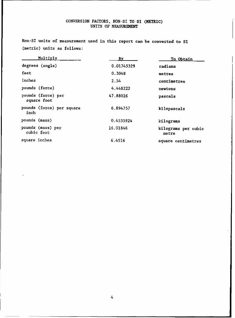
CONVERSION FACTORS, NON-SI TO SI (METRIC)UNITS OF MEASUREMENT
Non-SI units of measurement used in this report can be converted to SI
(metric) units as follows:
Multiply By To Obtain
degrees (angle) 0.01745329 radians
feet 0.3048 metres
inches 2.54 centimetres
pounds (force) 4.448222 newtons
pounds (force) per 47.88026 pascalssquare foot
pounds (force) per square 6.894757 kilopascalsinch
pounds (mass) 0.4535924 kilograms
pounds (mass) per 16.01846 kilograms per cubiccubic foot metre
square inches 6.4516 square centimetres
4
EVALUATION PROCEDURE FOR REINFORCED CONCRETE
BOX CULVERTS UNDER AIRFIELD PAVEMENTS
PART I: INTRODUCTION
Background
1. Most airfield pavements are periodically evaluated to determine the
structural capacity of the pavement system and to determine if strengthening
is required to meet anticipated future traffic needs. Most of these pavement
evaluations consider only the pavement structure itself with little consider-
ation given to other facilities such as drainage structures. Although it is
usually assumed that the drainage structures under airfield pavements have
been designed to support both the dead (earth) and live (aircraft) loads
imposed on them, this assumption may not be true in all cases. The technical
manual covering airfield drainage structures is Army and Air Force TM 5-820-3/
AFM 88-5, Chap. 3 entitled "Drainage and Erosion-Control Structures for Air-
fields and Heliports" (Headquarters, Departments of the Army and the Air Force
1978). This manual contains tables giving the minimum cover requirements for
several different types and numerous sizes of circular pipes; however, rein-
forced concrete box culverts are not mentioned. The lack of any data on rein-
forced concrete box culverts or presentation of a means for evaluating these
structures in the airfield drainage manual could present problems for
personnel designing or evaluating airfields.
2. The problem of not having a standard procedure for evaluating rein-
forced concrete box culverts became readily apparent during an overseas air-
field evaluation program in 1982. As part of an overseas airfield evaluation
program, the US Army Engineer Waterways Experiment Station (WES) was tasked
with evaluating the structural capacity of several emergency landing strips
built into the host nation's expressway system. Included in this pavement
evaluation was the evaluation of drainage structures under the pavement. The
drainage structures included both circular pipes and reinforced concrete box
culverts. While evaluating the circular pipes could be accomplished rapidly
with information presented in current technical manuals, an evaluation method
for the reinforced concrete box culverts had to be developed. Due to time and
5
funding restrictions that existed on the pavement evaluation project, an
existing Corps of Engineers computer program was used to model each of the
subject culverts on a site-specific basis. That exercise in evaluating
approximately 30 concrete box culverts indicated the need for a standard
method of evaluating reinforced concrete box culverts under aircraft loads.
Purpose
3. The purpose of this research project was to develop a standard pro-
cedure for determining the structural capacity of reinforced concrete box
culverts (hereafter called box culverts) under aircraft loads. Specific
objectives were to investigate the various methods available for rapidly eval-
uating the structural capacity of box culverts, select one of these methods
for use, and develop a rational method of evaluating culverts under aircraft
loadings using the selected method.
Scope
4. This report describes the development of a procedure for determining
the structural capacity of reinforced concrete box culverts under aircraft
loads. The evaluation procedure is described in detail along with the inputs
required in the culvert evaluation computer program. A computer program to
assist in determining the stresses on the culvert due to the aircraft loads
was developed and is also presented in this report. Appendix A provides the
Users Guide for this program. Appendix B gives the results of parameter stud-
ies. Appendix C presents a complete example problem to demonstrate the evalu-
ation procedure. A floppy disk containing all of the computer programs
discussed herein is available from the authors.
6
PART II: REVIEW OF DESIGN AND EVALUATION PROCEDURES
Army and Air Force
5. Technical Manuals TM 5-820-1/AFM 88-5, Chap. 1, TM 5-820-2/AFM 88-5,
Chap. 2, TM 5-820-3/AFM 88-5, Chap. 3, and TM 5-820-4/AFM 88-5, Chap. 4 (Head-
quarters, Departments of the Army and Air Force 1983, 1979, 1978, and 1977)
provide guidance of the design of drainage facilities for the Army and Air
Force. While emphasizing the use of circular conduits, none of these tech-
nical manuals mention box culverts except for TM 5-820-4/AFM 88-5, Chap. 4.
This technical manual gives capacity curves for several different sizes of box
culverts but does not provide information on designing the culvert structure
or minimum required cover depths. Technical Manual TM 5-330/AFM 86-3, Vol II
(Headquarters, Departments of the Army and Air Force 1968) gives no informa-
tion on box culverts under airfields. From this review, it is apparent that
the design and evaluation of reinforced concrete box culverts have been given
only limited consideration in the Army and Air Force technical manuals.
6. Airfield drainage is discussed in Section 6 of NAVFAC Design Manual
DM-21 (Naval Facilities Engineering Command 1973). This design manual refers
to the Army and Air Force technical manuals listed in paragraph 5 for "design
procedures and criteria" related to "drainage and erosion control structures."
Federal Aviation Administration
7. Federal Aviation Administration (FAA) criteria for airfield drainage
are given in FAA Advisory Circular 150/5320-5B (Federal Aviation Administra-
tion 1970). Section 15 of Chapter 4 in Advisory Circular 150/5320-5B
addresses the loads on drainage structures such as box culverts. The design
live load recommendations given in this Advisory Circular are:
a. For spans 2 ft or less in the least direction, a uniform liveload of 250 psi.
b. For spans between 2 and 10 ft in the least direction, a uniformlive load varying between 50 and 250 psi in direct proportion tothe span length.
7
c. For spans of 10 ft or greater in the least direction, the designshould be based on the most critical loading condition appliedby the various aircraft gear configurations.
While the design and installation of circular conduits and the design loads
for box culverts are discussed, the advisory circular does not address the
evaluation of existing in situ drainage structures.
International Civil Aviation Organization
8. The International Civil Aviation Organization (ICAO) Aerodrome
Design Manual (1983) contains a chapter entitled "Structural Concerns for
Culverts and Bridges" in which a large part of the chapter is devoted to the
evaluation of subsurface structures. The Aerodrome Design Manual states that
every subsurface structure beneath a pavement must be considered in connection
with the evaluation of the pavement. This manual also states that the likli-
hood of a particular structure would prove more critical than the pavement in
limiting the aircraft loads on the type, size, and location of the structure.
9. The Aerodrome Design Manual suggests some general guidance to assist
in determining which structures can be considered not limiting and which
structures are marginal or limiting thereby needing careful study and analy-
sis. This general guidance is presented in Table 1 which is Table 7-1 in the
Aerodrome Design Manual. This table indicates the thickness of protective
cover of soil and pavement structure above drainage structures which will
spread the load sufficiently, considering combining effects from adjacent
wheels to reduce the pressure induced on the structure by the aircraft (live)
load to less than 10 percent of the earth (dead) load. The guidance is based
on aircraft wheel loads of 200 kN (approximately 44,866 lb) or less, and the
premise that the live load on deeply buried structures tends to be only a
small portion of the dead load so that small and medium size pipes or culverts
will not accumulate a large share of the live load and limit surface loadings.
Pipes or culverts with diameters or spans up to about one-third the listed
depth of cover and at depths equal to or greater than that listed should not
require a separate load limitation. Structures at depths shallower than those
in Table 1 would require a more detailed analysis, and possibly would require
a load limitation depending on the rigidity of the culvert, the bedding and
backfill conditions, the existing pavement structure, and the amount of con-
servatism in the original design. The Aerodrome Design Manual recommends that
8
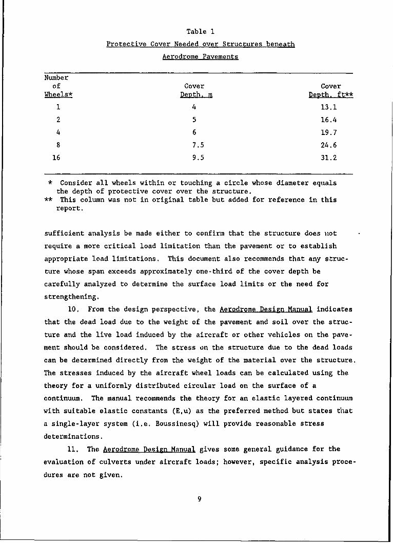
Table 1
Protective Cover Needed over Structures beneath
Aerodrome Pavements
Numberof Cover Cover
Wheels* Depth, m Depth, ft**
1 4 13.1
2 5 16.4
4 6 19.7
8 7.5 24.6
16 9.5 31.2
* Consider all wheels within or touching a circle whose diameter equals
the depth of protective cover over the structure.** This column was not in original table but added for reference in this
report.
sufficient analysis be made either to confirm that the structure does uot
require a more critical load limitation than the pavement or to establish
appropriate load limitations. This document also recommends that any struc-
ture whose span exceeds approximately one-third of the cover depth be
carefully analyzed to determine the surface load limits or the need for
strengthening.
10. From the design perspective, the Aerodrome Design Manual indicates
that the dead load due to the weight of the pavement and soil over the struc-
ture and the live load induced by the aircraft or other vehicles on the pave-
ment should be considered. The stress on the structure due to the dead loads
can be determined directly from the weight of the material over the structure.
The stresses induced by the aircraft wheel loads can be calculated using the
theory for a uniformly distributed circular load on the surface of a
continuum. The manual recommends the theory for an elastic layered continuum
with suitable elastic constants (E,u) as the preferred method but states that
a single-layer system (i.e. Boussinesq) will provide reasonable stress
determinations.
11. The Aerodrome Design Manual gives some general guidance for the
evaluation of culverts under aircraft loads; however, specific analysis proce-
dures are not given.
9
PART III: SELECTION OF EVALUATION MODEL
12. In the initial stages of this study a literature review was per-
formed to determine if computer codes were available that would allow rapid
analysis of box culverts under aircraft loadings. Based on this review two
programs were chosen for detailed evaluation. The two programs selected were
the Federal Highway Administration's CANDE-1980 program and the US Army Corps
of Engineers CORTCUL program.
CANDE-1980
13. The CANDE (Culvert ANalysis and DEsign) computer program is a
finite element computer program for the structural analysis and design of
buried culverts. After its introduction in 1976 additional refinements and
modifications were made and incorporated into the program which was renamed
"CANDE-1980." The major capabilities of the CANDE-1980 program listed in the
program documentation are:
a. Automated finite element analysis of precast culverts withsimplified input of embankment and trench installations isavailable. This is the so-called Level 2 solution. Two othersolution levels are available in the program. They areLevel 1, which is a closed form solution applicable only tocircular conduits, and Level 3, which is a full finite elementmodel requiring definition of the finite element grid and theculvert.
b. Soil-structure interaction techniques are used for solutions.
c. The Duncan nonlinear soil model option employing hyperbolicfunctions of the soils elastic and bulk moduli is available foruse.
d. Standard soil model parameters are stored in the program,thereby simplifying input requirements.
a. Simplified data input options for the overburden dependent soilmodel are available.
f. Iterative redistribution of stresses due to concrete crackingis modeled.
g. Trilinear compression stress-strain concrete model with elasticunloading is available.
h. Incremental load application is provided so that steel andconcrete stress-strain relations are incremented tangent rela-tions iteratively derived.
10
i. Fourteen beam-rod elements are available for modeling a halfcell or 28 beam-rod elements are available for modeling a wholecell.
j. There is good correlation with out-of-ground tests includingprediction of mode of failure either in flexure or diagonalcracking.
k. There is good agreement between predictions of soil pressuresat intermediate and final burial depths and measured values ona full scale installation.
14. Additional details on the CANDE-1980 program can be found in the
program documentation which consists of four reports. These reports are
CANDE-1980: Box Culverts and Soil Models (Katona et al. 1981); CANDE - A:
Modern Approach for the Structural Design and Analysis of Buried Culverts
(Katona et al. 1976); CANDE User Manual (Katona et al. 1976); and CANDE System
Manual (Katone et al. 1976).
CORTCUL
15. The CORTCUL program can be used for the design or analysis of
orthogonal, reinforced concrete culverts by either the working stress design
(WSD) or the strength design (SD) procedures. The CORTCUL program follows as
a minimum the procedures outlined in Engineer Manual EM 1110-2-2902
(Headquarters, Department of the Army 1969) dated March 1969 and is based on
ACI 318-89 (American Concrete Institute 1989). The program models the culvert
as a two-dimensional, linearly elastic, plane frame. The matrix stiffness
method, modified to account for conditions at the member intersections is used
to analyze the frame structure. Major features of the CORTCUL program are:
a. It can be used in either the design or analysis mode.
b. Design or analysis can be performed using either the workingstress design or strength design procedures.
g. The program determines the required thicknesses and reinforce-
ment areas in the design mode.
d. The program determines stresses and factors of safety in theanalysis mode.
e. The program provides single or multicell capability up to ninecells.
f. The program allows a different value of concrete cover at fourdifferent locations in the culvert cross-section (e.g. exteriorface of exterior members, interior face of roof and exteriorwalls, interior face of base slab, and tension face of interiorwalls).
11
g. The program allows iLiclusion of the effects of the ground waterlevel and internal water at various depths within one or morecells.
h. The program allows up to eight special load types to be used inthe analysis mode.
16. Additional details on the CORTCUL can be found in Users Guide:
Computer Program For Design Or Investigation Of Orthogonal Culverts (CORTCUL)
(Dawkins 1981).
Comparison of Programs
17. An evaluation of the CANDE-1980 and CORTCUL programs was performed
by the Choctaw Engineering Company under contract to WES. The results of this
evaluation were presented in a letter report entitled Development of an Evalu-
ation Procedure for Reinforced Concrete Culverts under Airfield Pavements
(Feng 1985). As a part of this evaluation, several test cases were run with
each program. These test cases included several loading configurations (soil
only, soil plus HS-20 highway load, and soil plus C-141 aircraft load) acting
on two different culvert sizes (3 ft by 3 ft by 4 in. and 10 ft by 10 ft by
10 in.) with the culverts located at two different depths (3 and 10 ft).
These test cases were run on a mainframe computer to evaluate the versatility,
operating characteristics, data input and output formats, and feasibility for
use in a culvert evaluation procedure. For the CANDE-1980 program only the
Level 2 solution was used.
18. Because of the differences in the output of these two programs, a
direct comparison of the results for the various test cases was difficult. In
this evaluation Feng reported that the input for both programs was straight-
forward and that a structural engineer with 1 to 2 weeks training should be
able to prepare the inputs and use the programs. The CANDE-1980 program
required approximately 3 min more CPU time than did the CORTCUL program for
the test cases run in the evaluation. Another difference in the programs is
the difference in the way the live loads are applied to the culvert. The
finite element nature of CANDE-1980 allows the live loads to be applied to the
pavement surface with the program calculating the pressures acting on the
culvert due to the live loads as well as the soil dead loads. However, the
live loads cannot be applied directly, as in an aircraft wheel, but must be
modeled as an equivalent transverse strip loading. With CORTCUL, the actual
12
live load cannot be applied to the surface with the program transmitting the
stresses to the culvert. Instead, the pressures resulting from i .rcraft
live load must be determined separately and applied to the culvert along with
the pressures resulting from the soil dead load.
19. Feng summarized his analysis of the programs as follows:
a. Both CANDE-1980 and CORTCUL are relatively easy to use and fastin computation.
b. CANDE-1980 provides several capabilities such as different soil
models, nonlinear analysis, incremental construction loading,and the ability to handle different culvert types that CORTCULdoes not have.
c. CANDE-1980 is more versatile of the programs, however apreprocessor for preparing the input files on a terminal isneeded to expedite use of the program.
d. CANDE-1980 is recommended for use in developing an evaluationprocedure.
20. Upon completion of the evaluation by Choctaw Engineering Company,
an additional evaluation was performed by WES personnel. One of the original
goals of this research was to develop a rational, straight-forward culvert
evaluation procedure for culverts under airfields that could be used by civil
engineers with minimum effort. The additional evaluation was performed to
determine which of the two programs was best suited to practicing general
civil engineer (as opposed to researchers) with an average working knowledge
of culverts, pavements, computers, and computer programs.
21. The additional evaluation consisted of running additional test
cases using both CORTOUL and CANDE-1980. Several CANDE-1980 runs were made
using the Level 2 option and the built-in finite element mesh. Additional
runs were made using the Level 3 option with a user defined mesh. For the
test cases used in this study, it was found that the results obtained with
CANDE-1980 varied some, depending on whether the Level 2 solution or the
Level 3 solution was used. Part of this disparity may have been because of
differences in the mesh used in the Level 3 solution and the built-in Level 2
mesh. This additional evaluation of the CANDE-1980 program indicated that
there are several different methods for applying the aircraft load to the
culvert model. It was found that the manner in which the load was applied
(i.e. as a strip, point, etc.) changed the results of the analysis. No
standard method for defining the applied loads was given in the users guide
which makes proper selection of the CANDE live loads difficult. As with the
13
Choctaw Engineering Company evaluation of the programs, direct comparison of
the CANDE-1980 results versus the CORTCUL results was difficult because of the
differences in the output data.
22. From the results obtained in this study, it appears that both
CANDE-1980 and CORTCUL produce reasonable results. Although a complete check
of each program's accuracy was beyond the scope of this research effort, both
the literature and limited hand computations performed as a part of this study
indicate that both programs provide accurate results.
Selection of Program
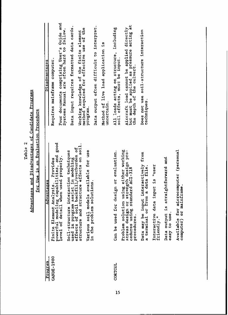
23. Based on the evaluations performed, it was found that each of the
two candidate programs had its major advantages and disadvantages. Table 2
summarizes these advantages and disadvantages. In the selection of a program
for use as the basis of a culvert evaluation procedure, one of the key points
for consideration was the intended user of the evaluation procedure. It is
anticipated that the typical user will be a civil engineer at a military
installation or other government design agency or a private engineering
organization.
24. Based on the advantages and disadvantages of the candidate programs
outlined in Table 2 and experience using both of the programs, the CORTCUL
program was selected for use in the development of the culvert evaluation
procedure. The CANDE-1980 program appears to be a good, powerful analytical
tool for evaluating all types of culverts. However, the major disadvantages
outlined in Table 2, especially the difficulty in defining the method of live
load application and the difficult and time-consuming data input requirements,
make the CANDE-1980 program less attractive for use in the development of a
routine evaluation procedure. The CANDE-1980 program will continue to be an
excellent tool for researchers and in other applications where there is suffi-
cient data and need to require the use of a sophisticated analytical model.
The CORTCUL program, while lacking some of the versatility of the CANDE-1980
program, is better suited for the intended application. The strength design
and working stress design procedures for reinforced concrete design used in
CORTCUL are familiar to structural engineers. Data input is easier using
CORTCUL and the analysis results are output in a logical, easy-to-use format.
An additional important consideration was the availability of the CORTIGL
14
v 4.)z 0 4.a) 0 Up 0 J-) bO 41 ho
10 r4 Cd 0) Ow C. r. -A
0 0 H)0 ) 4 4J 00 44 Ud r4 4.) m) 0 A740 co
4.) 0) 4) r 74 r. 10t $tfl 0 ~ Cl) '7n rq4 0)
4 0 . 0L 0 0 04 4141 0 .7 0 4 )) p.- 0 0~*
tO $4 0) r.> 4-) $4. r-4En(n $4 :: ) .V -A.-H 4. (d :14J P..U 0n 40) a) .4 V. 44. V r4 0 :j~ Pw $4)
w 4.) bl) Cd 0) : .,4 ca pU4 -co Z 0 0 H (1 d) C 4P4J 4-)41) m -4) P .'44 .74 PA (1)7 0 p 0
0 e u)4.V 0 4J 44 (44 P. 41.) V0)0 4)CO 0 7-AW44 0) 4-4 (d U)nO C > p>0 Q $P0 4-4 r74 .0 4i H 4.)
1 .t 0 0 $4 10 10 0 0 toC O 4) 0) 0 CU 0 4-i r. )( I(n 0 P$ $4 4-4 0 ca r ~.,4 T-47r4 CO 0 CO .-A bo W H4 bf): CUHO4 -A
4.4 M).-4 v 004 4-4 (0 .74 C)A4-3 U)CU 4) 4.)C 0 4 0 ;> 4 - '0C
5.4 14 t 5- 4 "74 0U r cd 4.4 0DCU 4) r 0 : 4.)i H Cd 4.) 004)0 9A*
0 z ~ 0 l ) .4 U)0 .) dU)
U) c 0 w.$4 4-1 0.74' ~44 4.341. 4J 00 0 0 U) pe b $ c cU C44 44UM1. 0 0
o4 $4 '0 .7 4 0 dc 0 It41) 004 CU :s ) -4 $4) r4 0 U U .0 H p1 0
co 10 : P4) 4.) $4.3 C - 4.3 (HZ.) 4 $4.3 00
.40Q 0 0 >- CU 0 d)$4 CU 4) r r40 -A:J4~ 004
4-
0 -A4
Ce4 0
0 H04)W f40 44-A
HCUd bO E) 0 0 0) h oi0J >) 4) m too
0 d0 -A4$4 0
>CU 0) r - r 0 $4 4.) $4 4-4 toU10 $ 4 744 0 CU 0~ r. $4
cd (1)- C r- :J 4-4 0 :bDi >. $4 0tI: >U). 00).0 4) H4 *,400 HOI 0) 4)
"4-A 004)0 O')40 0 C) 4)) OH U) v-4 (1 r C$.-A$4 4.00 H)4) > 4) 4) > -A :3 CU
P 4 V g 1 ~> 44 ,0 0) A 11 7A44 $4rq) r74 044 CU 4.) H- 4.) 0)
0 - d U) H-4 0 N HA $4 u7 ~ C.) U) t 0 4.)
CU 0 r .. 4) -A -A rH -A En 0 4 U. rdV 7r4 4-4 :3$4 W tnM( 4-) HO 4 CU 0 bo P $CU 413 Ow
U)l 0 ca 'I 'd U J-A 744 > 0 b' r.1 41 41i Ic4) 41 UVM P CUU) 44 CU*-A7h bO 4G$p 4.) :j bo 0
04.4 >.,C p r-I 4. 41 J.) .74 rq w4(d r.U d A7 OU (
0 CUr (U0O C 0U)0 E)n U) U) 4.J 10 74 I OW0$
4. (d CU 41))U HH 0 0 r- ., d) : ( .r= r $4440 r. . .0w4) 00 vo 4130 41.) 0
.4 H r4 HU 0 $4 p 4) 0.4 4. cl (n - 'U.AH*74 O(.4 M 0 0 44 J CU U
r.4)CU 4010 0) 4.4 4J 0bl .?4 W 1 .,4 w)04.) :JbOU) HHM 0 r- r4:jb V
e 0 4 4.3 0 cU A1 .. 44. H.,4*4 0q 0 4.0) 4.)40W0 ' 0$44 0 0 0 0 0 0 0 m .OH >~ :UH- P. 0O U)$ U) t U) (1 : 4 CU 4. 91-: 0-wH4-4 4 $4 0. 0 w4 . 41). 41 H4W
:30vV 0 :$ V~ ) E W) :3 ed 4 OH r-4 0 0 A044 (4 -4) 41 0 4) ) )O 0 CU'10 04V-i (414J$4 P 0- IQ0 010 r- u HU)$w 0 4 0
.A 4) 74) -44 $-A41 .0 0 4 j0 4)- 4.), 4) C .b ., Cl,
.7400> 0-A4J U ww $4)0$04J 4J V l 4 CUC >0
W .Pr-H W 4O) M >.7 -AU3 4r 0 tl, 0. W H 44 aO < 0
N I HD
15
program on floppy disk which allows rapid use of the program on a personal
computer without having to access a mainframe system.
25. The remainder of this report deals with the development of an eval-
uation procedure for reinforced concrete box culverts using the CORTCUL
program.
16
PART IV: DEVELOPMENT OF EVALUATION PROCEDURE
26. The culvert evaluation procedure reported herein is based on the
CORTCUL computer program for the design and investigation of orthogonal
culverts. The specific procedures developed herein are applicable to aircraft
loads; however, the general procedures are applicable to any highway or air-
craft type of loading. In the development of this procedure the strength
design procedure is used in the analysis of the structure.
27. The CORTCUL program is readily available through the Corps of Engi-
neers Conversationally Oriented Real-Time Program Generating System (CORPS)
library. The program is designated X0024 in the CORPS system and is available
for use on either a mainframe computer or on a personal computer. The devel-
opment of this evaluation procedure for airfield culverts did not require any
modifications to the CORTCUL program itself. The major part of the develop-
ment consisted of determining the best means for applying the aircraft loads
to the structure, developing the CULSTR program for determining the live load
acting on the culvert due to the aircraft and conducting parameter studies
using the CORTCUL program.
Introduction to CORTCUL
28. CORTCUL allows the user to select either the SD or the WSD proce-
dures for the design or analysis of an orthogonal, reinforced concrete cul-
vert. The WSD procedures used by the program are in accordance with the
Corps' most recent manual on culverts which is Engineer Manual EM 1110-2-2902
(Headquarters, Department of the Army 1969). The SD procedures are in accor-
dance with ACI 318-63 (American Concrete Institute 1963). These procedures
are generally the same in later editions of the ACI Code, most recent version
ACI 318-89, for the types of computations performed by CORTCUL. CORTCUL also
includes a computation developed specifically for computing the allowable
shear stress on thick-walled culverts as described in University of Illinois
Structural Research Series No. 440 (Gamble 1977).
29. In the CORTCUL program a 1-ft-wide slice of the culvert is assumed
to behave as a linearly elastic, plane frame structure. The culvert slice is
reduced to an assembladge of line frame members which lie along the center
lines of the culvert walls and slabs. Joints are defined at the intersections
17
of these members. A matrix stiffness method that has been modified to account
for conditions au the intersections of the members is used to analyze the
structure. CORTCUL assigns infinite axial and flexural stiffness to portions
of the members in the vicinity of the joints as recommended in the University
of Illinois Structural Research Series No. 164 (Diaz De Cossio and Siess 1959)
and the University of Illinois Structural Research Series No. 440 (Gamble
1977). In structural frames of normal proportions the frame is usually ideal-
ized as a line structure with member stiffnesses that are unaffected by mate-
rial in the joints. However, as the widths of the supporting members become
larger relative to the span, the effects of these widths on the moment distri-
bution should be considered. The analytical procedure in CORTCUL modifies the
stiffness matrix to account for the effects that the joint areas have on the
flexural stiffnesses of the members. The result is increased accuracy in
determining the forces acting within the members of a culvert.
30. The culvert used in the analysis is assumed to be a monolithic
reinforced concrete structure with the following characteristics:
a. A constant thickness horizontal roof slab covers the width ofthe structure.
b. The exterior vertical walls have the same thickness.
c. All interior vertical walls have the same thickness.
d. The horizontal base slab has a constant thickness throughoutthe width of the structure.
e. The culvert encloses from one to nine openings (cells).
f. All cell heights are constant.
g. Cell widths may differ in the investigation mode, but must be
constant in the design mode.
h. Haunches may be specified at the intersections of vertical andhorizontal members with 45 deg haunches of equal size assumedat every intersection.
j. The invert elevation is fixed.
j. Non-prestressed reinforcement is assumed to exist in eachmember of the culvert.
Additional details on the program can be found in the CORTCUL User's Guide
(Dawkins 1981).
18
Application of Loads
31. The loads applied to the culvert structural model are the dead load
of the roof member, dead load of the vertical walls applied to the bottom
slab, lateral earth pressure on the vertical side walls, vertical earth loads
applied to the roof member, vertical and horizontal loads imparted by the
internal water, and vertical loads applied to the roof member by the various
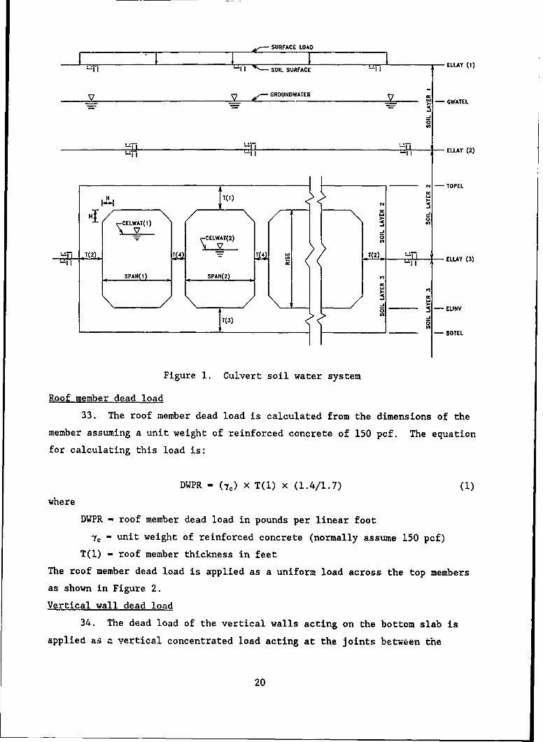
aircraft. Figure 1 shows the general culvert/soil/water system used in
CORTCUL along with the member designations. In this culvert evaluation proce-
dure the szandard load cases that are available in CORTCUL are not used. All
loads are applied as special loads using from one to four special load cases.
This means that all of the loads acting on the culvert are applied directly on
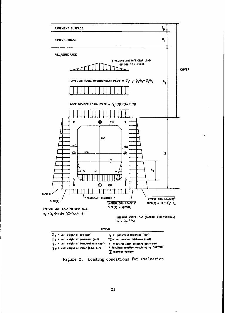
the member as program inputs. Figure 2 presents the typical loading condi-
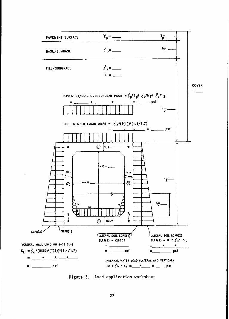
tions used in a culvert evaluation. Figure 3 is a worksheet that is used for
determining the loads to be applied to the members. Each of these loads will
be discussed in detail in the following paragraphs.
Load factors
32. The SD procedure used in CORTCUL is based on ACI 318 and requires
that the load, shear, or moment be obtained by applying load factors to the
service values. Typically, the dead load factor is 1.4 and the live load
factor is 1.7. Load factors are to account for the possibility that service
loads may be exceeded. Obviously, it is more probable that a specified live
load will be exceeded than will a dead load, which is generally fixed by the
weight of the construction. Although the soil surrounding a culvert is con-
sidered to be somewhat permanent, it is not considered a dead load in the
sense of being as well defined as the dead weight of the reinforced concrete
structure. Therefore, in the design and/or analysis of a structure the earth
pressure is typically accompanied by a load factor of 1.7 as specified in
ACI 318-89 (American Co,.-rete Institute 1989) and Engineer Technical Letter
ETL 1110-2-312 (Headquarters, Department of the Army 1988). All of the dead
loads due to the weight of the culvert members should be increased by a 1.4
dead load factor. Since the analytical procedure described in this report
uses the CORTCUL special load cases, and since CORTCUL assumes that all of the
special loads are live loads and automatically applies the 1.7 live load fac-
tor, an additional factor of 1.4/1.7 - 0.8235 must be applied to the dead
loads.
19
-- SURFACE LOAD
1 I - SOIL SURFACE - LAI
y ,"GROUNDWATER V -- GWATEL
ELLAY (2)
N -TOPEL
H1 0
, AT(2) - LAY (3)
SPAN(l) - SPAN(2)
aj :5- ELINV
17T(3 (4- BOTEL
Figure 1. Culvert soil water system
Roof member dead load
33. The roof member dead load is calculated from the dimensions of the
member assuming a unit weight of reinforced concrete of 150 pcf. The equation
for calculating this load is:
DWPR - (7c) x T(l) x (1.4/1.7) (1)
where
DWPR - roof member dead load in pounds per linear foot
1, unit weight of reinforced concrete (normally assume 150 pcf)
T(l) - roof member thickness in feet
The roof member dead load is applied as a uniform load across the top members
as shown in Figure 2.
Vertical wall dead load
34. The dead load of the vertical walls acting on the bottom slab is
applied as a vertical concentrated load acting at the joints between the
20
PAVEMENT SURFACE Tp
BASE/SUBBASE h
FILL/SUBGRADE
EFFECTIVE AIRCRAFT GEAR LOADON TOP OF CULVERT
.... .. ~COVER
PAVEMENT/SOIL OVERBURDEN: PSOB Y.T+ Y'bht+ Yh 2 h2
ROOF MEMBER LOAD: DWPR = 'Y (T(I)*(I.4/I.7))
-- © ?(l) 0
ffc
.-. ( VsAR h3
TD T T
S L P R ( 2 ) t -I I j T lAIRESULTANT REACTION * LTERAL SOIL LOAD(2)
sLP(I) LATERAL SOIL LOAOQ) SLIR(2) • K Y, h3
VERTICAL WALL LOAD ON BASE SLAN: SLPR(I) x K(PSOI]
D Ye '(RISE).(T(2)).(1.4/I.7)
INTERNAL WATER LOAD (LATERAL AND VERTICAL)IW• . w I h4
LEGEND
z unit weight of salt (pet) Tp a pavement thickness (feet))(p a unit weight of pavement (pet) TQ)" top member thickness (feet)
b w unit weight of base/subbaec (pat) K a lateral earth pressure coefficient
w a unit weight of water (62.4 pet) 0 Resultant reaction calculated by CORTCULG member number
Figure 2. Loading conditions for evaluation
21
PAVEMENT SURFACE -p T
h=BASE/SUBBASE 9b -
FILL/SUBGRADE-
K
COVER
PAVEMENT/SOIL OVERBURDEN; PSOB = p+p ebh I+ Xs"'2
+___ ___ + ____ ___PSf
ROOF MEMBER LOAD: DWPR = * (T(1 ))*(i.4/1.7)
-. . = _______Psf
*~ T(1)__ 0
RISE
T(2) T(2)
1 00PA
SLPR(2)7 YSLPR(1)LATERAL SOIL LOAD(1) LATERAL SOIL LOAD(2)SLPR(1) - K[PSoB] SLPR(2) = K * h3
VERTICAL WALL LOAD ON BASE SLAB:_______- * ____
DE 9C (RISE)(T(2))'(1.4/1.7) - ...... Psf -_____Psf
JNTERNAL WATER LOAD (LATERAL AND VERTICAL)
- _____psf 1 W= Y. -h 4 =.....*2.. - psi
Figure 3. Load application worksheet
22
vertical walls and the bottom slab. The loads, due to the external vertical
walls, are calculated using the equation:
DE = [[(c) x Rise x T(2)] + [DWPR/2]] x (1.4/1.7)] (2)
where
DE - load of exterior vertical wall acting on the base slab in pounds
jc " unit weight of reinforced concrete (normally assume 150 pcf)
Rise - height of the culvert opening in feet
T(2) - exterior wall thickness in feet
DWPR - roof member dead load in pounds per linear foot
If the culvert is a multicell culvert, the load on the base slab due to the
interior wall is calculated from Equation 3 as follows:
DI - [[(a) x Rise X T(4)] + (DWPR/(NIW + 2)]] X (1.4/1.7) (3)
where
DI - load of interior vertical wall acting on the base slab in pounds
-" unit weight of reinforced concrete (normally assume 150 pcf)
Rise - height of the culvert opening in feet
T(4) - interior wall thickness in feet
DWPR - roof member dead load in pounds per linear foot
NIW - number of interior walls
The weight of the base slab is assumed to have no influence on the internal
forces in the structure.
Soil pavement overburden
35. The vertical load applied to the roof member by the overlying soil
and pavement is taken to be the unit weight of the material multiplied by the
depth of the material. This load is calculated from Equation 4 and is applied
as a uniform load across the roof member, as shown in Figure 2.
PSOB - 7p * Tp + 7b * hl + 1. * hz (4)
where
PSOB - uniform load due to the pavement and soil in pounds per foot
lp " unit weight of the pavement surface material in pcf
Tp- thickness of the pavement surface material in feet
7- unit weight of the granular pavement materials (base/subbase) inpcf
23
h, - thickness of granular or soil material between the bottom of the
pavement surface and the top of subgrade in feet
?$ - unit weight of soil (backfill or subgrade) in pcf
h2 = thickness of soil between bottom of granular layer and top ofculvert in feet
Note that if the pavement is a composite pavement (asphalt over concrete) then
there would be two different values for Yp and Tp . In general for this
evaluation, the layers of granular material (base and subbase) can be con-
sidered as one layer providing that the density of both layers is approxi-
mately the same. The same is true for layers of soil backfill over the
culvert. If there is a significant difference in material density, the dif-
ferent material should be treated separately, adding another *h term to
Equation 4.
Lateral earth pressure
36. The lateral earth pressure against the vertical exterior walls is
calculated assuming a triangular distribution with depth. For input into the
program the loads are broken into two components, a uniform load and a trian-
gular load, as shown in Figure 2. The equations for calculating the lateral
earth pressure against the culvert walls are:
SLPR(1) = k * [PSOB] (5)
where
SLPR(l) - uniform load component of the lateral soil load in poundsper foot
k - coefficient of lateral earth pressure
PSOB - pavement/soil overburden load
and
SLPR(2) - k * 7s * h3 (6)
where
SLPR(2) - triangular load component of the lateral soil load in poundsper foot
k - coefficient of lateral earth pressure
7, - unit weight of soil in pcf
h3 - distance from top to bottom of culvert
American Society for Testing and Materials (ASTM) C-789 recommends a minimum
lateral earth pressure coefficient, k , of 0.25 (ASTM 1989). While it is
impossible to accurately access the actual lateral earth pressure loads on the
24
culvert walls, analysis of the adequacy of the culverts under aircraft loads
is not very sensitive to the assumed lateral earth pressure coefficient. This
will be discussed in the section dealing with parameter studies.
Internal water
37. For the standard load cases, CORTCUL computes the hydrostatic pres-
sures that result from a specified internal water level in each cell of the
culvert. Because only the special load cases are used in this evaluation, all
of the internal water loads must be input. These loads are appropriately
considered to be live loads. The effects of the internal water should be
included in the analysis if the water is present the majority of the time. As
shown in Figure 2, the force of the internal water will act on both the cul-
vert walls and the base slab. The force on the walls will be proportional to
the water depth with the maximum pressure at the bottom of the wall. The
force on the base slab is equal to the maximum force at the bottom of the wall
and is calculated as follows:
IW - Tw * h4 (7)'
where
IW - internal water pressure in pounds per foot
w unit weight of water or 62.4 pcf
h4 - height of internal water in feet
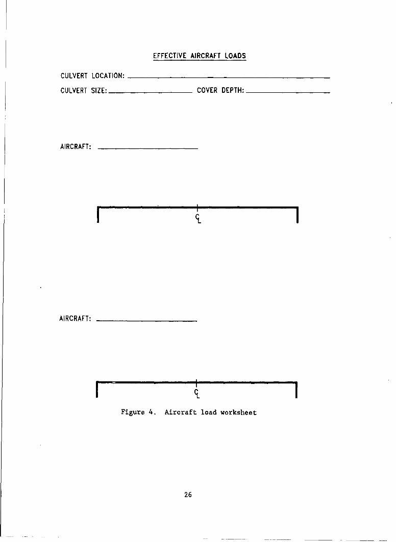
Aircraft live load
38. For this evaluation, the aircraft live load applied at the pavement
surface is the static load that is equal to the gross weight of the aircraft
traversing the culvert. The aircraft live load applied to the culvert is the
vertical stress at the top of the culvert resulting from the aircraft load on
the pavement surface. The recommended method for determining the vertical
stress on the culvert due to the aircraft is presented in the following sec-
tion. Figure 4 is a worksheet that will be helpful in determining the effec-
tive aircraft loads.
Reactions
39. Resultants due to vertical loads are automatically balanced by
vertical distributed forces acting on the horizontal members of the culvert.
Resultants due to horizontal loads are balanced by uniformly distributed hori-
zontal force on the top and bottom culvert members. Only compressive
25
EFFECTIVE AIRCRAFT LOADS
CULVERT LOCATION: ___________________________
CULVERT SIZE: ____________COVER DEPTH: ___________
AIRCRAFT: ______________
AIRCRAFT: ______________
I IFigure 4. Aircraft load worksheet
26
reactions are permitted. All of the reactions are accounted for automatically
within the computer program, and no user input is required for them.
Determination of Aircraft Live Loads
40. To assist in determining the aircraft load acting on top of the
culvert, an existing layered-elastic computer code was modified. The layered-
elastic approach was chosen because it is applicable to any type of pavement
construction (flexible, rigid, composite, and unsurfaced), provides a realis-
tic estimation of the stresses acting on the culvert due to the aircraft, and
provides one method for estimating the aircraft live load acting on the cul-
vert regardless of pavement type, and it could be developed with relative ease
using available layered-elastic computer programs. CULSTR uses the WES5
layered-elastic program (Van Cauwelaert, Delaunois, and Beaudoint 1987) along
with pavement structure and aircraft data to calculate the vertical stress at
the specified depth and preset offsets under the aircraft gear. An interac-
tive data input program INSTR was also developed and is used to build the data
file of the pavement structure and aircraft data that are required by CULSTR.
CULSTR uses WES5 as its basic calculation routine and has been preprogrammed
with the aircraft characteristics for a number of military and civilian air-
craft. These aircraft characteristics are contained in the data file VEHDATA.
For a given aircraft and depth below the pavement surface, CULSTR determines
the location of maximum vertical stress and then calculates the vertical
stress at a number of longitudinal offsets through that location. The program
then gives the user a choice of looking at a plot of the stress distribution
on the screen, printing the plot, or printing the calculated stresses.
41. To provide the user with a complete culvert evaluation package, the
program CULVERT has been developed and included in this report. This program
includes the files INSTR, CULSTR, VEHDATA, QUIKVIEW, X0024, and file manipula-
tion utilities. Computer requirements for running this package are a personal
computer running the DOS operating system (Version 3.3 or higher) with a
5-1/4-in. high-density floppy disk drive and a hard disk drive with at least
1 megabyte (mb) free. The system should have at least 512 kilobytes (k) of
RAM, a math co-processor and a graphics adapter card. A brief user's guide
for the CULVERT program is presented in Appendix A. The procedures and pro-
grams developed in this study and the information given on CORTCUL in this
27
report are presented as a supplement to the detailed information given in the
CORTCUL User's Guide (Dawkins 1981). It is recommended that the user obtain
and study the CORTCUL User's Guide prior to performing the culvert analysis
presented herein.
Verification of Aircraft Loading Methods
42. To verify that the method discussed above does provide a reasonable
estimate of the vertical stress that is to be applied to the top of the cul-
vert, a parameter study using a general purpose two-dimensional finite element
program and a general purpose three-dimensional finite element program was
performed. A typical reinforced concrete box culvert was modeled in the
finite element mesh. The aircraft wheel loads were applied to the mesh as a
surface load in the same mavner as the aircraft would load the pavement. The
vertical stresses and displacements in the soil above the culvert and at the
top of the culvert were determined. Comparisons of the results from the
layered elastic analysis with the results from the general finite element
programs indicated that the layered elastic analysis provided a reasonable
estimate of the vertical stress due to the aircraft load. Based on this veri-
fication, it is recommended that a layered elastic procedure be used to deter-
mine the vertical stress acting on the roof of the culvert.
Parameter Studies Performed
43. During the development of this culvert evaluation procedure several
parameter studies were performed using CORTCUL to determine the effect of
varying the lateral earth pressure coefficient, varying amount of internal
water, and using various combinations of live load and dead load factors. The
results of these parameter studies are presented in Appendix B and will be
discussed in the following paragraphs.
Varying lateral earth pressure
44. The first parameter that was varied to determine its effect on the
analysis was the lateral earth pressure coefficient, k. The CORTCUL program
was run for a 13-ft span with 3.0-ft cover. Runs were made using lateral
earth loads calculated using k values of 0.25, 0.40, and 0.50. The program
multiplies these loads by the load factor of 1.7 thereby increasing the
28
effective lateral earth pressure coefficient to 0.425, 0.68, and 0.85,
respectively. Detailed results of these evaluation runs are presented in
Table Bl of Appendix B. Based on the results of this study, it was concluded
that, although the midspan moment ratio is sensitive to the lateral earth
pressure coefficient for the soil only case, the change in midspan moment
ratios for culverts under aircraft loadings is relatively insensitive to
changes in the lateral earth pressure coefficient. This indicates that the
evaluation of box culverts under aircraft loads is relatively insensitive to
changes in the lateral earth pressure coefficient.
Varying internal water depth
45. CORTCUL runs were made for the 13-ft span by 11.5-ft rise culvert
with 3.0 ft of cover using the soil only load case, four different aircraft
loadings, and internal water depths of 0 ft (no water), 5.75 ft (50 percent
full), and 11.5 ft (100 percent full). These results are presented in
Table B2 of Appendix B. Comparison of the results indicates that for the soil
only case, the 100 percent full condition was the most critical in regard to
the moment ratio at the midspan of the top and side members. In this case the-
top member midspan moment ratio was 10 percent lower for the 100 percent full
condition as compared to the no water condition. In the side members the
midspan moment ratio for the completely full culvert was 80 percent lower than
the no water case. Analysis of the culvert under aircraft loadings continued
to show the 100 percent full condition as the most critical; however, the
change in moment ratio between the no internal water case and 100 percent full
case decreased as the aircraft load applied increased. For the relatively
light C-123 aircraft, the moment ratio at the midspan of the top member with
the culvert full was 10 percent less than the empty condition. However, the
midspan moment ratio of the side members decreased by approximately 27 percent
when the culvert was full. As the aircraft load increased the difference
between these side member moment ratios decreased to less than 10 percent. As
in tho soil only case for aircraft loadings, the internal water has the
greatest effect on the sidewall midspan moment ratio. However, the change in
the sidewall moment ratio due to changes in the internal water level is con-
siderably smaller when the culvert is subjected to the aircraft loadings.
Analysis for different aircraft indicates that as the aircraft load on the
culvert increases, the effect of the internal water on the culvert members
decreases.
29
Varying load factors
46. For this analysis four different load cases were considered. The
first case was the normal evaluation where the required strength was
Required Strength = (1.4 x roof member load) + (1.7 x overburden)
+ (1.7 x aircraft load) + (1.7 x lateral earth load).
The second case was where the required strength was
Required Strength = (1.2 x roof member load) + (1.2 x overburden)
+ (1.2 x lateral earth load) + (1.44 x aircraft load).
The required strength for load case three was defined by
Required Strength - (1.2 x roof member load) + (1.2 x overburden)
+ (1.2 x lateral earth load) + (1.74 x aircraft load).
The fourth load case required strength was defined by
Required Strength - (1.2 x roof member load) + (1.2 x overburden)
+ (1.2 x lateral earth load) + (2.24 x aircraft load).
Detailed results of this part of the parameter study is presented in Table B3
of Appendix B. Comparison of these results indicates that the moment and
shear ratios at the midspan of the top member increased by approximately 15 to
20 percent by reducing the load factors. Reduction of the load factors
resulted in the midspan moment ratios of the side members to be decreased by
approximately 28 to 31 percent while the shear ratios at midspan increased
from 7 to 18 percent.
Conclusions from parameter studies
47. It was concluded from the parameter studies that
a. Using a lateral earth pressure coefficient, k, of 0.25 is con-servative with respect to the moment ratio at the midspan ofthe top member.
b. Changing the lateral earth pressure coefficient, k, has littleeffect on the analysis of box culverts under aircraft loads.
c. Assuming no internal water in the culvert is unconservative inregard to the moment ratio at the midspan of the top and sidemembers; however, this unconservatism decreases as the aircraftload on the culvert increases. If the culvert being evaluatedcarries water the majority of the time, the effect of thisinternal water should be considered in the analysis.
d. If it is assumed that the loads are well-defined (possiblyjustifying use of lower load factors), then a reduction of theevaluation load factors as shown in the combinations above willproduce an increase in the moment ratio at the midspan of thetop member by as much as 20 percent. While the use of thelarger load factors is conservative and could possibly resultin some culverts being rated as inadequate, the uncertainties
30
in this procedure prohibit the reduction in the load factorsfrom those specified in Chapter 9.2.4 of the ACI Code (ACI1989).
31
PART V: PROCEDURE FOR EVALUATING REINFORCED CONCRETE
BOX CULVERTS UNDER AIRCRAFT LOADS
General
48. A general procedure is provided for the evaluation of reinforced
concrete box culverts under airfield pavements using the computer program
CORTCUL. Prior to using this procedure and the CORTCUL program, a field
inspection of the culvert is necessary. This field inspection should include
determination of the pavement structure that exists over the culvert. In
addition the culvert itself should be inspected. Details of the inspection
procedures are beyond the scope of this report but are covered in detail in
the FAA's Culvert Inspection Manual (Arnoult 1986). A recommended list of
tools and equipment and a summary of key items that should be documented dur-
ing the field inspection and data collection are given in the next section.
49. Evaluation of culverts under airfield pavements is not required
each time an airfield pavement is evaluated. It is recommended that culvert
evaluations be performed if the using agency planned to apply an aircraft
class not considered in the original design (e.g. a light duty airfield is to
support heavier aircraft), a highway or similar facility is being considered
for or transformed into an emergency landing strip, or if there are indica-
tions in the pavement over the culvert or in the culvert itself indicating
that the culvert is being overstressed.
Field Inspection of Culverts
50. Prior to conducting the field inspection of culverts under air-
fields or landing strips, the evaluation team should obtain a set of plans or
a listing showing the location, type, and size of all of the culverts under
the facility. For the box culverts a set of as-built or construction drawings
showing details including the wall thicknesses, reinforcement steel sizes and
locations and other details is required. If available, a copy of the con-
struction specifications should also be obtained. Having these on hand will
aid in the culvert inspections.
32
Tools and Equipment
51. Tools and equipment that will be helpful in the inspections
include:
a. Cloth tape (100 or 200 ft).
h. Tape (25 ft).
c. Ruler (6 ft).
d. Caliper (6 in.).
e. Geologist's hammer.
f. Wire brush.
,. Ice pick.
h. Surveyors level.
i. Level rod.
J.. Brush hook or machete.
k. Flashlight (hat-mounted preferable to hand held).
1. Camera and flash.
m. Marking instruments such as lumber crayon or paint.
Inspection of Reinforced Concrete Box Culvert
52. Items that must be documented during field inspections include:
A. Location: Station numberSkew (If any)
h. Geometry: Overall height (ft)Overall width (ft)Number of cellsCell rise, internal height (ft)Cell span internal width for each cell (ft)
Haunch width (in.)Roof thickness (in.)*Exterior wall thickness (in.)*Base slab thickness (in.)*Interior wall thickness (in.)
* Hay not be able to determine in the field,
. Structural propertes: (All Items Determined from Plans,Specifications, and Quality Control Reports)
Ultimate concrete strength (psi)Reinforcement steel yield strength (psi)Unit weight of concrete (pcf)
Reinforcement steel areas (sq in.)
Reinforcement steel cover distance (in.)
33
d. Pavement/soil layers:
Number of layers from top of pavement to top ofculvert.Layer thickness, density, and strength (CBR) for eachlayer. (This can be determined from nearby test pitor boring data.)Elevation of water table, if above the bottom ofculvert.
e. Depth: Distance from top of pavement to top of culvert and toculvert invert. In many cases you will not be ableto find the top of the culvert. The invert elevationcombined with measurements of cell rise and roofthickness data will allow the elevation of the top ofthe culvert to be determined. Also, do not be fooledby the headwall that is normally located at the endsof a box culvert. This is typically a foot or morehigher than the actual top of the culvert. This isa critical measurement and should be determined withcare. If unsure of the amount of cover over the topof the culvert, one should excavate (dig or auger)down to accurately determine the cover depth.
f. Internal water: Record if there is water present in theculvert. If there is, record the depth of thewater in the culvert and, if possible, inspectfor any high water marks that will indicatethe maximum elevation of the water in theculvert.
g. Condition: Note the condition of the culvert. Record theoccurrence of major cracks, breaks, broken joints,sags, and other abnormalities. These indicate thatthe culvert is or has been overstressed and may notsupport the full load that an undamaged culvertwould support.
h. Overall condition: Note the condition of the pavement over theculvert. Record any signs of settlement orcracking in the pavement directly over or adjacentto the culvert. Pavement cracking or depressionsover the culvert indicate that settlement isoccurring that may be increasing the loads actingon the culvert. Note the condition of the water-ways on both the upstream and downstream side ofthe culvert indicating whether the waterways areclear or is there vegetation growing, blocking theflow of water. Look for scour or blowouts at thedownstream end of the culvert that would under-mine the culvert. Record any of these conditionsor any other suspicious condition.
34
Evaluation of Reinforced Concrete Box Culverts
53. The structural capacity of reinforced concrete box culverts is
determined using the CORTCUL computer program. To use this, program informa-
tion on the culvert is input along with the live loads due to the aircraft and
the dead loads due to the surrounding soil and the members themselves. As
previously discussed, the CULSTR program can be used to estimate the aircraft
live loads. Details of using CULSTR are presented in Appendix A, and the
details of the analysis using CORTCUL are presented in the report User's
Guide: Computer Program For Design Or Investigation Of Orthogonal Culverts
(CORTCUL) (Dawkins 1981) hereafter referred to as the User's Guide.
54. It is recommended that each aircraft be evaluated for at least two
positions on the culvert. The first position should be with the aircraft load
centered over the center line of the culvert midspan. The second position
should have the aircraft load centered over one of the quarter points on the
culvert span. In the event the culvert under evaluation is a multicell cul-
vert the evaluation should be performed with the aircraft load centered over
the midspan of one cell, at the quarter-point of one cell, and over the
interior wall. The most critical evaluation for each member will then be
taken as the evaluation for the culvert.
55. Much of the information necessary to evaluate a box culvert will be
determined from pavement test data taken in the vicinity of the culvert, a
visual inspection of the culvert, and the culvert's design data. Even with
this information the engineer may have to make decisions about some parameters
required by the program. The following paragraphs provide an overview of the
steps in using the CORTOUL program. For details on the procedures, assump-
tions, and other requirements of using CORTCUL, see the CORTCUL User's Guide
(Dawkins 1981).
Data Input
56. All data input into the CORTCUL program is read in free field for-
mat which means that each data input must be separated by one or more blanks.
There are two ways in which data can be input into the CORTCUL program. Input
data may be provided interactively from the user terminal during execution or
from a previously prepared data file. Data entered during execution can be
35
stored to a file for later use or can be used in the executed run only.
Several options are available regarding the amount and destination of output
from the program. The user may direct the output to the terminal, to an out-
put file, or to both. It is recommended that the output be saved in a perma-
nent file and subsequently listed on a high speed printer. Appendix A in the
CORTCUL User's Guide provides additional detailed information on the data
input. Note that analysis of the culverts for aircraft loadings must be per-
formed using the special load cases. The standard load cases are set up to
run the "soil only" analysis and cannot take into account the aircraft load-
ings. When using the special load cases, all of the load data including the
member loads, internal water loads, soil loads, and aircraft loads must be
input into the data file. A brief step-by-step input data sequence and
description is listed below.
a. Heading--Alphanumeric characters used for job identification.
b. Mode--Choose investigation mode (I) for culvert evaluations.Method--Either working stress design (WSD) or strength design(SD). Normally choose SD.
c. Material properties--Ultimate concrete strength (psi), rein-
forcement yield strength (psi), and the concrete unit weight(pcf).Design factors--Maximum tension steel ratio and strength reduc-tion factor. Omit both if method = WSD. The maximum tension
steel ratio, p = As/bd where As - area of tension steel,
b = width of member, and d = effective depth of member (dis-tance from compression face to centroid of the tension steel).
The strength reduction factor, 0 , can be computed by CORTCULor may be user specified. ACI 318-89 specifies 0 = 0.90 for
flexure without axial load, or with axial tension 0 - 0.70for axial compression, or flexure with axial compression
- 0.85 for shear and torsion.
d. Culvert geometry--Number of cells, height of cell opening (ft),
haunch width (in.), elevation of invert (ft), and width of cell
opening (ft).
e. Reinforcement cover--Distance in inches from centoid of rein-
forcement to exterior surface of all exterior members, to inte-
rior surface of roof and exterior walls, to interior face of
base, and to tension face for all interior walls (Omit lastitem if number of cells - 1).
f. Member thicknesses--Thickness in inches of roof member,
exterior walls, base, and interior walls (Omit last item if
number of cells - 1).
g. Maximum reinforcement areas. (Omit for mode - Investigation)--
These are the maximum permissible reinforcement areas for cul-vert design and are not used in investigation.
36
h. Soil data--Number of soil layers, elevation at top of layer
(ft), saturated unit weight of layer (pcf), and the moist (sub-merged) unit weight of layer (pcf).
i. Standard load case data--For this evaluation procedure standardload cases are not used, enter 0 for number of standard loadcases, and none of the other data are required. Number of
standard load cases, unit weight of water (pcf), standard loadcase coefficients: coefficient for vertical soil pressures,
coefficient for horizontal soil pressures, surface surcharge(pcf), and groundwater elevation (ft).
j.. Special load data--All loads applied to the culvert in thisevaluation procedure are applied using the special load cases.Each load is input separately. Data for the special load casesinclude number of special load cases (enter 1 to 4) and specialload case data to be entered for each special load case. Spe-cial load case data are number of member load lines (enter 1
to 84) and member load line data as follows for each load:
(1) Member number
(2) Load type
(a) C for concentrated load
(b) U for uniform load
(c) T for triangular load
(3) Load magnitude
(a) pounds per linear foot for concentrated load (C)
(b) pounds per square foot for uniform load (U)
(c) maximum load magnitude in pounds per square foot for
triangular load (T)
(4) Distance from member coordinate origin to concentratedload or to start of distributed load (ft).
(5) Distance to end of aistributed load (ft). Omit if load
type - C
(6) Indicator for triangular load
(a) L if maximum occurs at the left end
(b) R if maximum occurs at the right end
(c) Omit for load type - C or U
k. Load factors--Input live load factor and dead load factor.Omit if method - WSD.
1. Internal water data--Input 0 for no internal water and 1 iftheir is internal water and the effective elevation (ft) of the
internal water in the cell or cells.
m. Member data for investigation--Number of members to be
investigated.
37
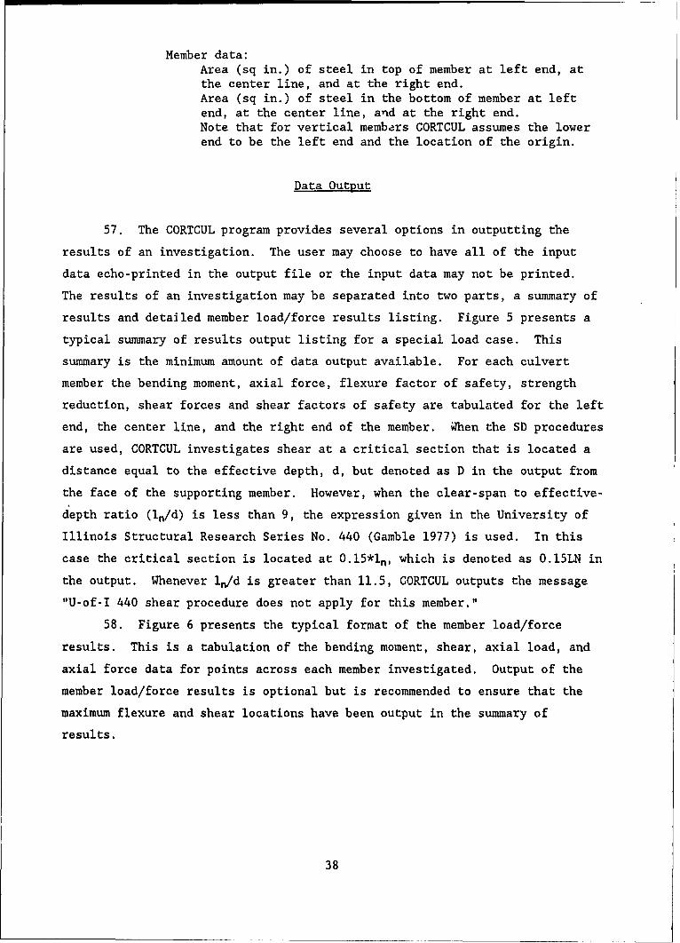
Member data:Area (sq in.) of steel in top of member at left end, atthe center line, and at the right end.Area (sq in.) of steel in the bottom of member at leftend, at the center line, and at the right end.Note that for vertical members CORTCUL assumes the lowerend to be the left end and the location of the origin.
Data Output
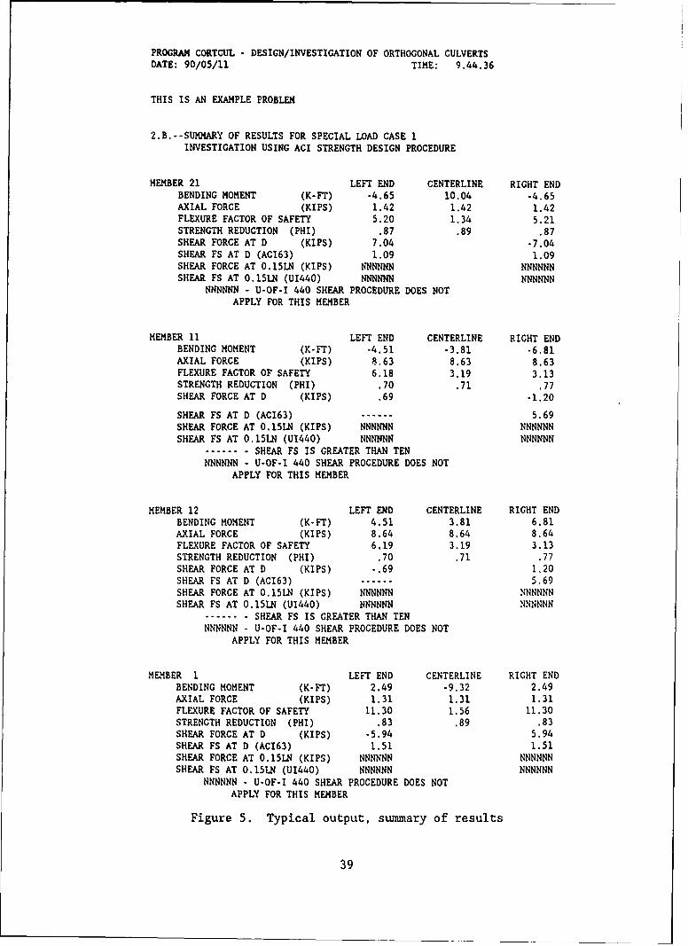
57. The CORTCUL program provides several options in outputting the
results of an investigation. The user may choose to have all of the input
data echo-printed in the output file or the input data may not be printed.
The results of an investigation may be separated into two parts, a summary of
results and detailed member load/force results listing. Figure 5 presents a
typical summary of results output listing for a special load case. This
summary is the minimum amount of data output available. For each culvert
member the bending moment, axial force, flexure factor of safety, strength
reduction, shear forces and shear factors of safety are tabulated for the left
end, the center line, and the right end of the member. WThen the SD procedures
are used, CORTCUL investigates shear at a critical section that is located a
distance equal to the effective depth, d, but denoted as D in the output from
the face of the supporting member. However, when the clear-span to effective-
depth ratio (In/d) is less than 9, the expression given in the University of
Illinois Structural Research Series No. 440 (Gamble 1977) is used. In this
case the critical section is located at 0.15*l, which is denoted as O.15LN in
the output. Whenever in/d is greater than 11.5, CORTCUL outputs the message
"U-of-I 440 shear procedure does not apply for this member."
58. Figure 6 presents the typical format of the member load/force
results. This is a tabulation of the bending moment, shear, axial load, and
axial force data for points across each member investigated. Output of the
member load/force results is optional but is recommended to ensure that the
maximum flexure and shear locations have been output in the summary of
results.
38
PROGRAM CORTCUL - DESIGN/INVESTIGATION OF ORTHOGONAL CULVERTS
DATE: 90/05/11 TIME: 9.44.36
THIS IS AN EXAMPLE PROBLEM
2.B.--SUMMARY OF RESULTS FOR SPECIAL LOAD CASE 1INVESTIGATION USING ACI STRENGTH DESIGN PROCEDURE
MEMBER 21 LEFT END CENTERLINE RIGHT ENDBENDING MOMENT (K-FT) -4.65 10.04 -4.65AXIAL FORCE (KIPS) 1.42 1.42 1.42FLEXURE FACTOR OF SAFETY 5.20 1.34 5.21STRENGTH REDUCTION (PHI) .87 .89 .87SHEAR FORCE AT D (KIPS) 7.04 -7.04SHEAR FS AT D (AC163) 1.09 1.09SHEAR FORCE AT 0.15LN (KIPS) NNNNNN NNNNNNSHEAR FS AT O.15LN (U1440) NNNNNN NNNNNN
NNNNNN - U-OF-I 440 SHEAR PROCEDURE DOES NOTAPPLY FOR THIS MEMBER
MEMBER 11 LEFT END CENTERLINE RIGHT ENDBENDING MOMENT (K-FT) -4.51 -3.81 -6.81AXIAL FORCE (KIPS) 8.63 8.63 8.63FLEXURE FACTOR OF SAFETY 6.18 3.19 3.13STRENGTH REDUCTION (PHI) .70 .71 .77SHEAR FORCE AT D (KIPS) .69 -1.20
SHEAR FS AT D (AC163) ...... 5.69SHEAR FORCE AT 0.15LN (KIPS) NNNNNN NNNNNNSHEAR FS AT O.15LN (U1440) NNNNNN NNNNNN
....... SHEAR FS IS GREATER THAN TENNNNNNN - U-OF-I 440 SHEAR PROCEDURE DOES NOT
APPLY FOR THIS MEMBER
MEMBER 12 LEFT END CENTERLINE RIGHT ENDBENDING MOMENT (K-FT) 4.51 3.81 6.81AXIAL FORCE (KIPS) 8.64 8.64 8.64FLEXURE FACTOR OF SAFETY 6.19 3.19 3.13STRENGTH REDUCTION (PHI) .70 .71 .77SHEAR FORCE AT D (KIPS) -.69 1.20SHEAR FS AT D (AC163) ...... 5.69SHEAR FORCE AT 0.15LN (KIPS) NNNNNN NNNNNNSHEAR FS AT O.15LN (U1440) NNNNNN NNNNNN
....... SHEAR FS IS GREATER THAN TENNNNNNN - U-OF-I 440 SHEAR PROCEDURE DOES NOT
APPLY FOR THIS MEMBER
MEMBER i LEFT END CENTERLINE RIGHT ENDBENDING MOMENT (K-FT) 2.49 -9.32 2.49AXIAL FORCE (KIPS) 1.31 1.31 1.31FLEXURE FACTOR OF SAFETY 11.30 1.56 11.30STRENGTH REDUCTION (PHI) .83 .89 .83SHEAR FORCE AT D (KIPS) -5.94 5.94SHEAR FS AT D (AC163) 1.51 1.51SHEAR FORCE AT O.15LN (KIPS) NNNNNN NNNNNNSHEAR FS AT 0.15LN (U1440) NNNNNN NNNNNN
NNNNNN - U-OF-I 440 SHEAR PROCEDURE DOES NOTAPPLY FOR THIS MEMBER
Figure 5. Typical output, summary of results
39
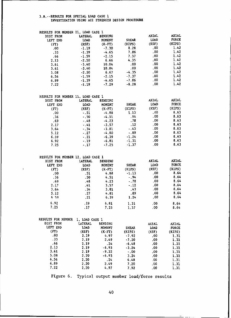
3.B.--RESULTS FOR SPECIAL LOAD CASE 1INVESTIGATION USING ACI STRENGTH DESIGN PROCEDURE
RESULTS FOR MEMBER 21, LOAD CASE 1DIST FROM LATERAL BENDING AXIAL AXIAL
LEFT END LOAD MOMENT SHEAR LOAD FORCE
(FT) (KSF) (K-FT) (KIPS) (KSF) (KIPS)
.00 -1.19 -7.30 8.28 .00 1.42
.33 -1.39 -4.65 7.86 .00 1.42
.66 -1.59 -2.15 7.37 .00 1.42
2.13 -2.50 6.66 4.35 .00 1.42
3.61 -3.40 10.04 .00 .00 1.42
3.61 -3.40 10.04 .00 .00 1.42
5.08 -2.50 6.67 -4.35 .00 1.42
6.56 -1.59 -2.15 -7.37 .00 1.42
6.89 -1.39 -4.65 -7.86 .00 1.42
7.22 -1.19 -7.29 -8.28 .00 1.42
RESULTS FOR MEMBER 11, LOAD CASE 1DIST FROM LATERAL BENDING AXIAL AXIAL
LEFT END LOAD MOMENT SHEAR LOAD FORCE
(FT) (KSF) (K-FT) (KIPS) (KSF) (KIPS)
.00 -.51 -4.88 1.13 .00 8.63
.36 -.50 -4.51 .94 .00 8.63
.69 -.48 -4.23 .78 .00 8.63
2.17 -.41 -3.57 .12 .00 8.63
3.64 -. 34 -3.81 -.43 .00 8.635.12 -. 27 -4.80 -. 89 .00 8.636.59 -.21 -6.39 -1.24 .00 8.636.92 -.19 -6.81 -1.31 .00 8.637.25 -.17 -7.25 -1.37 .00 8.63
RESULTS FOR MEMBER 12, LOAD CASE 1DIST FROM LATERAL BENDING AXIAL AXIAL
LEFT END LOAD MOMENT SHEAR LOAD FORCE(FT) (KSF) (K-FT) (KIPS) (KSF) (KIPS)
.00 .51 4.88 -1.13 .00 8.64
.36 .50 4.51 -.94 .00 8.64
.69 .48 4.23 -.78 .00 8.642.17 .41 3.57 -.12 .00 8.64
3.64 .34 3.81 .43 .00 8.645.12 .27 4.81 .89 .00 8.646 59 .21 6.39 1.24 .00 8.64
6.92 .19 6.81 1.31 .00 8.647.25 .17 7.25 1.37 .00 8.64
RESULTS FOR MEMBER 1, LOAD CASE IDIST FROM LATERAL BENDING AXIAL AXIALLEFT END LOAD MOMENT SHEAR LOAD FORCE
(FT) (KSF) (K-Fr) (KIPS) (KSF) (KIPS)
.00 2.19 4.97 -7.92 .00 1.31.33 2.19 2.49 -7.20 .00 1.31.66 2.19 .24 -6.48 .00 1.31
2.13 2.19 -6.93 -3.24 .00 1.313.61 2.19 -9.32 -.00 .00 1.315.08 2.20 -6.93 3.24 .00 1,316.56 2.20 .24 6.48 .00 1.316.89 2.20 2.49 7.20 .00 1.317.22 2.20 4.97 7.92 .00 1.31
Figure 6. Typical output member load/force results
40
Analysis of Output
59. The material stresses and factors of safety due to flexure and
shear are calculated for each member investigated and reported for cross sec-
tions at the left and right ends of the clear span, excluding haunches, and at
the center line of the clear span. The flexure factor of safety is simply the
nominal pure moment capacity, MN, multiplied by the calculated strength reduc-
tion factor, 0 , and divided by the applied moment, M. Throughout the
remainder of this report, we will refer to this as the moment ratio. The
shear factor of safety is calculated as the shear capacity, Vc, divided by the
applied shear, V. Throughout the remainder of this report, the shear factor
of safety will be referred to as the shear ratio.
60. Using the moment and shear ratios calculated by CORTCUL and
reported in the summary of results, the box culvert can be rated as struc-
turally adequate to support operations of a particular aircraft when both the
moment and shear ratios for each member of the culvert are equal to or greater
than one 1.0. The structure is inadequate if any of these ratios are less
than one 1.0. A culvert with an inadequate rating for a particular aircraft
must be upgraded or strengthened to sustain operations of that aircraft. When
evaluating culverts under an airfield, one will normally have to evaluate
several different structures for several different aircraft. Figure 7 pre-
sents a convenient way of reporting the results.
Example Problem
61. Appendix C presents a complete example problem which demonstrates
the use of the INSTR, CULSTR, QUICKVIEW, and CORTCUL programs. In this exam-
ple a 6.56-ft. span by 6.56-ft rise reinforced concrete box culvert under a
flexible pavement with 3.0 ft of cover is evaluated for two different types of
aircraft. All of the input data and assumptions are given in Appendix C.
41
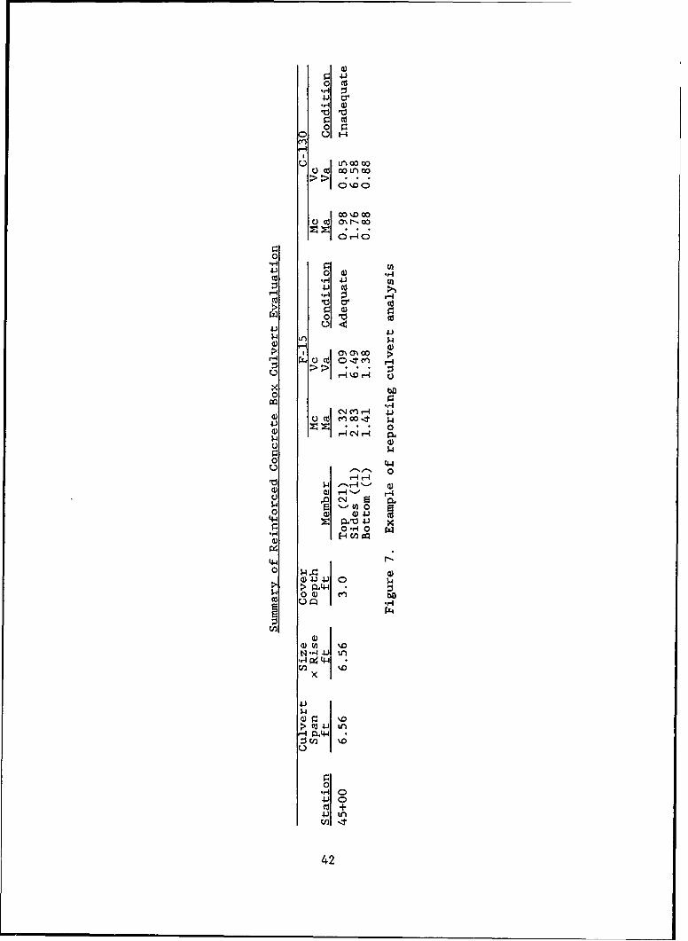
~4
0fr
co .0 V, 0
0'H U)
0 a)
r:s 'H -4
u 41)
a) a) $4) r- a
00
0 4
a)1--,' 0v -4H
0 aD)4
0-CE-4 (4-P
N) r4 " H
a))%
r-4-4.4
,r4 0
42 ~ 1
PART VI: SUMMARY, CONCLUSIONS, AND RECOMMENDATIONS
Summary
62. This report presents a method for evaluating the structural
capacity of reinforced concrete box culverts under aircraft type loadings.
The procedure used the computer code CORTCUL which is based on the require-
ments of the American Concrete Institute Building Code Requirements for Rein-
forced Concrete (ACI 318). Additional data input and file handling codes were
developed to assist in the determination of the aircraft live loads that must
be included in the analysis.
63. Other methods (e.g. finite element methods) are also available to
perform this type of analysis. These methods were investigated and considered
for use as the basis for this procedure. Consideration of the audience that
would be the primary user of this evaluation program and the inherent complex-
ities of using finite element computer codes lead to CORTCUL being chosen as
the base for this evaluation procedure.
Conclusions
64. This report provides a means of evaluating the structural adequacy
of reinforced concrete box culverts under airfield pavements, This evalua-
tion, while based on sound technical principles, is only as good as the data
and assumptions used in the analysis.
Recommendations
65. The evaluation procedure for reinforced concrete box culverts
described herein is recommended for use in evaluating culverts under air-
fields. While periodic evaluations of each culvert are not required, the
procedure is recommended for use when:
a. The using agency is planning to apply an aircraft class notconsidered in the original design (e.g. a light duty airfieldis to support heavier aircraft).
b. A highway or similar facility is being considered for or hasbeen transformed into an emergency landing strip.
43
c. If there are indications in the pavement over the culvert or inthe culvert itself indicating that the culvert is beingoverstressed.
66. It is also recommended that when culverts must be evaluated to
determine their structural capacity under aircraft loads, a detailed inspec-
tion of the culvert must be performed. This data along with the construction
plans and specifications and any nondestructive testing or possibly even
sampling and testing data will help ensure a complete and accurate evaluation
of the culvert.
44
REFERENCES
Ahlvin, R. G., and Ulery, H. H. 1962. "Tabulated Values for Determining theComplete Pattern of Stresses, Strains, and Deflections Beneath a Uniform Cir-cular Load on a Homogeneous Half Space," Stress Distribution in Earth Masses,Publication No. 1025, Bulletin 342, Highway Research Board, Washington, DC.
American Concrete Institute. 1963. "Building Code Requirements for Rein-forced Concrete," ACI 318-63, American Concrete Institute, Detroit, MI.
. 1989. "Building Code Requirements for Reinforced Concrete,"ACI 318-89, American Concrete Institute, Detroit, MI.
American Society for Testing and Materials. 1989. "Specification for PrecastReinforced Concrete Box Sections for Culverts, Storm Drains, and Sewers,"ASTM C-789 1989 Annual Book of ASTM Standards, Volume 4.05, Philadelphia, PA.
Arnoult, J. D. 1986 (Jul). "Culvert Inspection Manual," US Department ofTransportation, Federal Highway Administration, Report Number FHWA-IP-86-2,McLean, VA.
Dawkins, W. P. 1981 (Mar). "User's Guide: Computer Program for Design orInvestigation or Orthogonal Culverts (CORTCUL)," Instruction Report K-81-7, USArmy Engineer Waterways Experiment Station, Vicksburg, MS.
Diaz de Cossio, R., and Siess, C. P. 1959 (Feb). "Development of DesignCriteria for Reinforced Concrete Box Culverts--Part II: Recommendations forDesign," Civil Engineering Studies, Structural Research Series No. 164,University of Illinois, Urbana, IL.
Federal Aviation Administration. 1970 (Jul). "Airport Drainage," AdvisoryCircular No. 150/5320-5B, Washington, DC.
Feng, G. C. 1985 (Sep). "Development of an Evaluation Procedure for Rein-forced Concrete Culverts under Airfield Pavements," Letter Report, Chocktaw
Engineering Company, Houston, TX.
Gamble, W. L. 1977 (Apr). "Design of Thick-Walled Multiple Opening Conduitsto Resist Large Distributed Loads," Civil Engineering Studies, StructuralResearch Series No. 440, University of Illinois, Urbana, IL.
Headquarters, Department of the Army. 1969. "Design of Miscellaneous Struc-tures, Conduits, Culverts, and Pipes, "Engineer Manual EM 1110-2-2902,Washington, DC.
. 1988. "Strength Design Criteria for Reinforced Concrete Hydrau-lic Structures," Engineer Technical Letter ETL 1110-2-312, Washington, DC.
Headquarters, Departments of the Army and Air Force. 1968 (Sep). "Planningand Design of Roads, Airbases, and Heliports in the Theater of Operations,"Army Technical Manual TM 5-330, Air Force Manual AFM 86-3, Vol II, Washington,DC.
_ 1977 (Apr). "Surface Drainage Facilities for Airfields andHeliports," Army Technical Manual TM 5-820-1, Air Force Manual AFM 85-5,Chap. 1, Washington, DC.
_ 1978 (Jan). "Drainage and Erosion Control Structures for Air-fields and Heliports," Army Technical Manual TM 5-820-3, Air Force ManualAFM 88-5, Chap. 3, includes change I dated I Mar 81, Washington, DC.
45
Headquarters, Departments of the Army and Air Force. 1979 (Mar). "Drainageand Erosion Control Subsurface Drainage Facilities for Airfield Pavements,"Army Technical Manual TM 5-820-2, Air Force Manual AFM 88-5, Chap. 2,Washington, DC.
_ 1983 (Oct). "Drainage for Areas Other Than Airfields," ArmyTechnical Manual TM 5-820-4, Air Force Manual AFM 88-5, Chap. 4, Washington,DC.
International Civil Aviation Organization. 1983. Aerodrome Design ManualPart III Pavements, Document 9157-AN/901.
Katona, M. G. 1976 (Oct). "CANDE User Manual," FHWA-RD-77-6, Federal HighwayAdministration, Washington, DC.
Katona, M. G., Smith, J. M., Odello, R. S., and Allgood, J. R. 1976 (Oct)."CANDE-A Modern Approach for the Structural Design and Analysis of BuriedCulverts," FHWA-RD-77-5, Federal Highway Administration, Washington, DC.
Katona, M. G., Vittes, P. D., Lee, C. H., and Ho, H. T. 1981 (May). "CANDE-1980: Box Culverts and Soil Models," FHWA/RD-80/172, Federal Highway Adminis-tration, Washington, DC.
Naval Facilities Engineering Command. 1973 (Jun). "Airfield Pavements,"Design Manual DM-21, Alexandria, VA.
Van Cauwelaert, F., Delaunois, F., and Beaudoint, L. 1987 (Sep). "Stressesand Displacements in Two, Three, and Four Layered Structures Submitted toFlexible or Rigid Loads," US Army Engineer Waterways Experiment Station,Contract Report, Vicksburg, MS.
46
APPENDIX A: USER'S GUIDE FOR CULVERT: EVALUATION PACKAGE FOR THEEVALUATION OF REINFORCED CONCRETE BOX CULVERT UNDER AIRCRAFT LOADS
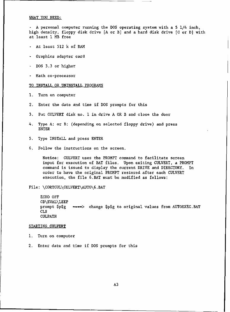
WHAT YOU NEED:
- A personal computer running the DOS operating system with a 5 1/4 inch,high density, floppy disk drive [A or B] and a hard disk drive [C or D) withat least 1 MB free
- At least 512 k of RAM
- Graphics adapter card
- DOS 3.3 or higher
- Math co-processor
TO INSTALL OR UNINSTALL PROGRAMS
1. Turn on computer
2. Enter the date and time if DOS prompts for this
3. Put CULVERT disk no. 1 in drive A OR B and close the door
4. Type A: or B: (depending on selected floppy drive) and pressENTER
5. Type INSTALL and press ENTER
6. Follow the instructions on the screen.
Notice: CULVERT uses the PROMPT command to facilitate screeninput for execution of BAT files. Upon exiting CULVERT, a PROMPTcommand is issued to display the current DRIVE and DIRECTORY. Inorder to have the original PROMPT restored after each CULVERTexecution, the file 6.BAT must be modified as follows:
File: \CORTCUL\CULVERT\AUTO\6.BAT
ECHO OFFCD\EVAL\LEEPprompt $p$g -- > change $p$g to original values from AUTOEXEC.BATCLSCULPATH
STARTING CULVERT
1. Turn on computer
2. Enter date and time if DOS prompts for this
A3
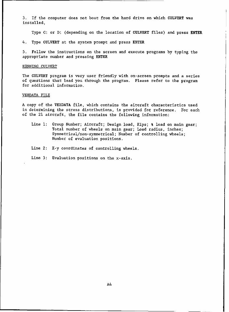
3. If the computer does not boot from the hard drive on which CULVERT was
installed,
Type C: or D: (depending on the location of CULVERT files) and press ENTER
4. Type CULVERT at the system prompt and press ENTER
5. Follow the instructions on the screen and execute programs by typing theappropriate number and pressing ENTER
RUNNING CULVERT
The CULVERT program is very user friendly with on-screen prompts and a seriesof questions that lead you through the program. Please refer to the programfor additional information.
VEHDATA FILE
A copy of the VEHDATA file, which contains the aircraft characteristics usedin determining the stress distributions, is provided for reference. For eachof the 21 aircraft, the file contains the following information:
Line 1: Group Number; Aircraft; Design load, Kips; % load on main gear;Total number of wheels on main gear; Load radius, inches;Symmetrical/non-symmetrical; Number of controlling wheels;Number of evaluation positions.
Line 2: X-y coordinates of controlling wheels.
Line 3: Evaluation positions on the x-axis.
A4
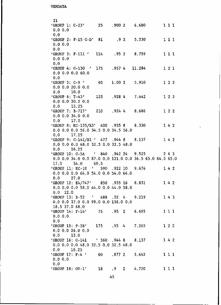
VEHDATA
21'GROUP 1: C-23' 25 .900 2 6.680 1 1 10.0 0.00.0'GROUP 2: F-15 C-D' 81 .9 2 5.230 1 1 10.0 0.00.0'GROUP 3: F-ill ' 114 .95 2 8.759 1 1 10.0 0.00.0'GROUP 4: C-130 ' 175 .957 4 11.284 1 2 10.0 0.0 0.0 60.00.0'GROUP 5: C-9 ' 60 1.00 2 5.910 1 2 20.0 0.0 20.0 0.00.0 10.0'GROUP 6: T-43' 125 .928 4 7.442 1 2 20.0 0.0 30.5 0.00.0 15.25'GROUP 7: B-727' 210 .924 4 8.686 1 2 20.0 0.0 34.0 0.00.0 17.0'GROUP 8: KC-135/E3' 400 .935 8 8.330 1 4 20.0 0.0 0.0 56.0 34.5 0.0 34.5 56.00.0 17.25
'GROUP 9: C-141/BI ' 477 .944 8 8.137 1 4 20.0 0.0 0.0 48.0 32.5 0.0 32.5 48.00.0 16.25'GROUP 10: C-5A ' 840 .942 24 9.525 2 6 30.0 0.0 34.0 0.0 87.0 0.0 121.0 0.0 36.5 65.0 84.5 65.017.0 34.0 60.5'GROUP 11: KC-10 ' 590 .922 10 9.674 1 4 20.0 0.0 0.0 64.0 54.0 0.0 54.0 64.0
0.0 27.0'GROUP 12: E4/747' 850 .935 16 8.831 1 4 20.0 0.0 0.0 58.0 44.0 0.0 44.0 58.0
0.0 22.0'GROUP 13: B-52 ' 488 .52 4 9.219 1 4 3
0.0 0.0 37.0 0.0 99.0 0.0 136.0 0.018.5 37.0 68.0'GROUP 14: F-14' 75 .95 2 6.695 1 1 10.0 0.00.0'GROUP 15: P-3B' 175 .95 4 7.265 1 2 2
0.0 0.0 26.0 0.00.0 13.0'GROUP 16: C-141 ' 360 .944 8 8.137 1 4 20.0 0.0 0.0 48.0 32.5 0.0 32.5 48.0
0.0 16.25'GROUP 17: F-4 ' 60 .877 2 5.642 1 1 10.0 0.00.0'GROUP 18: OV-1' 18 .9 2 4.720 1 1 1
A5
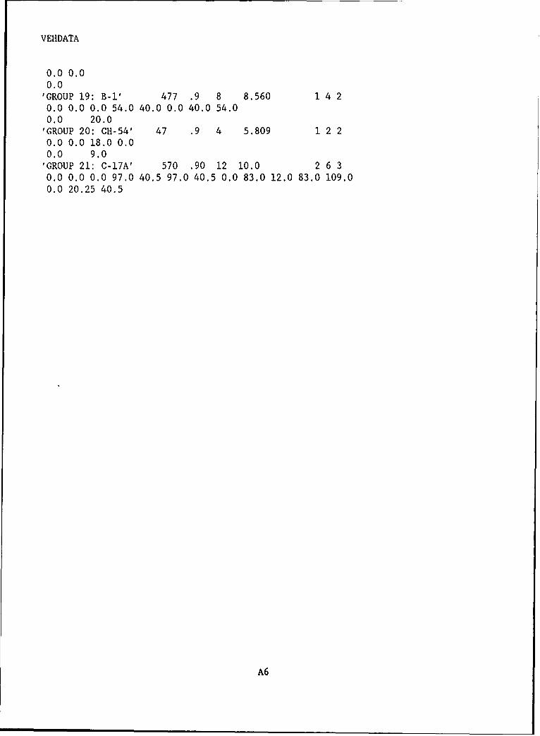
VEHDATA
0.0 0.00.0'GROUP 19: B-I' 477 .9 8 8.560 1 4 20.0 0.0 0.0 54.0 40.0 0.0 40.0 54.00.0 20.0'GROUP 20: CH-54' 47 .9 4 5.809 1 2 20.0 0.0 18.0 0.00.0 9.0'GROUP 21: C-17A' 570 .90 12 10.0 2 6 30.0 0.0 0.0 97.0 40.5 97.0 40.5 0.0 83.0 12.0 83.0 109.00.0 20.25 40.5
A6
APPENDIX B: RESULTS OF CORTCUL PARAMETER STUDIES
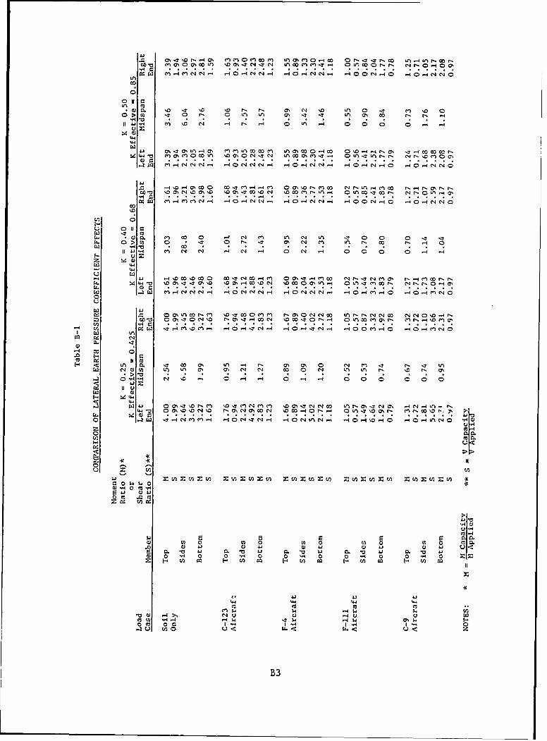
COHC .aO'~L . ... ~t- .L a Or -. .. .. .. OO..
C 0 . 10 -7 \r \0 a, N \ :'4 ' LA - 10 0O>CI)t -n 02 W1 00 LA L ' .r. r a o
~~C)
4-' 1-.a'A4 a' L 0com i 0%4- L ac0 1- 0 0 \o-4.--4 ,a\ -4 00 00 m r
, 44 CA-4CC'. 4-0CJCJeJ O.4cJC 4 1.4 0 J-14= -40 4eJC (N
4 W
4~4 CA-4 ~~C'4 -4 8 V'C'J C4 0IN'~ O 4J4 .- 40-4C4JC'J
W) 0 1; CJ ; 4A 4' C; C; 0 ; 0 0 4 C4
N~ 0 .0 LN a, a\J N N 00 N .-4 0na
Q ~ )
z u-'
m 1
0L0
LA)
14 0 m-00 M =ZC cn 1cd
.. 0 0 4 ' '0 0 4 - 0 -4 0 0 0 0 0
(n 14C 1-0 W1 4 '4U 4. t
00
CB3C
oz C C LAOA~S~ A'O' 4O t.-4 4
O1A OO 8 ' -
Cm 0 00 CL ' N a% -4 Lr 000 O
C1 .~4 N cn N 0; 0 .- .4 0 0
4.J O0 + ' CANI-9~ NO ) 09C% r.N-0S e)N
'T. qC- 0 :rN 140 C90 cn 4 4 0 0 N 4 -4 0.-4 0 N40 q C0- 4ON
-Aa nL %t 4 -4 -40 1 , ,1 0 0 c 1 4 ,
-00 ca%-r0 rA~ , " r 0% t0On0% 4 10% 1 nO0 - 0cAO0 ~~70 rL -- na ,
004 0, a n 0 0 1 7 C4 a - o ILA 0. V) m 0% C N 4 00 ~ . 0% N In r, 10
Eu 44 00 -A 0 0 CJ Le% C% (I rn N or m ON
43 w4 (n -4 Nn %0- 0 C14 00.l -4 0 C400 -4 0 - 0 - 0 40 -40 C0
-4-
444' f, N rn D 0 N.400 % n m r % 0"4 C4 0 .4 OlAIAC N N 00 04C40 ID r
.JW 0 ~-C n 4 17 Ni r ,0 00 4 10 00 0)N4 -0 -00 , M0l-4Oe'JO C
,4-
m W r, 17 cc C N% N 0)N '0 -. ION4 Otr% Lr sl* C, %D 0%
4-. C490 - q 0C. z 4) 0 -
0 U
0 0 ,1 N '7 0) %0 ITNiC4cic D z N 0 0 0 tn tA mA N. 1 \ 1 % n 4 (100 oo H , - - D - e , 0ma
1.4 en. N q m 'T - C4 0 04 -4 N q - 0 C4 .-%"4 -0 0 \0 0 0 - L 4
a wa) 0 -
0 C
w tk0O0 A 0Lo 0r(V 410 ,14 4 i z ) 4
14 00 0i 0. -0 w 0.v A . j 4 .0) 0 0 0 0 - 0 0 - 0 0 - 0 0 1 0
.0 0) 4.1 u u. J0 4
0 0n 1-4 0 04 q4 0 4 a% W
0 0 0 a0 H Ar
'00 U 4l wC 0 U4 .4-U-
B4
0~. CI 0 0;
- 4 LJ 4 U4
-4 tn D r, 00( Cn q T 0 to M4 M
000 000 000 4w$w
0( 1 4 0 10 t0H 0- 0 r-a H , C
0% -s c 0N EA 000 0+ +O + +
41 W 0 Vw0 S. 4 p.
1.4 w3
U14 .4!-4 -3H£ - t£*!.. (1(1 £> 0 0
0(1 030 0 0 0 0(0 0
0000 00 00 000..+
17~ 'T %o M
01 410z i04
0(10~~~~ 0.0 001 0(1 0 M 0 0£~£k%- .3 cd .4 Cz. x
%0~~~~~~ ~ ~ -- 4- 0I Hn H0 r ,c . D'.41 (7 0 O H 4 H L A m L A 01H 'h 's (n 00 %D 'S S
1>~. .0 .0 .. 0 4
%D (4O co 'OD4 V)o. 'D. co a, z r
OHH- 0o-4 00 OOH 00410 to0 to4r.C C C
00 rO a, o %U) LlCo0a 0r- -4 V ~ *00 % 0 m 1 a%0 c co o 4 ) 41) w1 w
C;~I- 1.4 2-4 14 8C
(1 ~ ~ ~ ~ ~ ~ ~ ~ Q 0( UH 0f)4 0)H*.4 .* d
0~~0 0' 0' En00'"t 4'£( DO01 41) Q W 41 41)
41 Na) -
0) M11.4 C 4 c CCn1 (4 4
41 (10 £40 (40 41 £1 £4B£5 4
APPENDIX C: EXAMPLE PROBLEM
1. In this example an 8-ft by 8-ft reinforced concrete box culvert
(6.56-ft span and a 6.56-ft rise) is located under an airfield. The culvert
has 3.0 ft of cover and is to be evaluated for the F-15 and the C-130 air-
craft. Figure Cl presents the completed load application worksheet. The data
used to complete the load application worksheet was obtained during an air-
field evaluation and field inspection of the culvert.
2. To determine the vertical stress (load) acting on the culvert due to
the aircraft, the program CULSTR was run. The output file from this program
was named EXAMP.OUT and is presented in Figure C2. To provide a visual plot
of the data the vertical stresses were plotted using the program QUIKVIEW.
These plots are shown in Figures C3 and C4. Since the CORTCUL program must
have the load data input as either a concentrated, uniform, or triangular load
the effective aircraft load worksheet is used to determine the applied loads
and their coordinates on the culvert. Figures C5 and C6 show these completed
worksheets for the F-15 and C-130, respectively. Note that for each aircraft
the load was centered over the midspan and then at the quarter point of the
top member.
3. After determining the soil and aircraft loads that are to be applied
to the culvert, the X0024 option of the CULVERT program was chosen and the
data input interactively. Figure C7 presents the CORTCUL input file which is
called EXAMPLE.IN. Note that all four special load cases were used in this
data file with Cases 1 and 2 being the F-15 aircraft (midspan and quarter
point, respectively) and Cases 3 and 4 being the C-130 aircraft at the midspan
and quarter point. After interactively building the data file the CORTCUL
program is run. Figure C8 presents a copy of the output file for this
analysis.
4. The moment and shear ratios are extracted from the output file and
summarized in the results table presented in Table Cl completing the culvert
analysis for these two aircraft.
C3
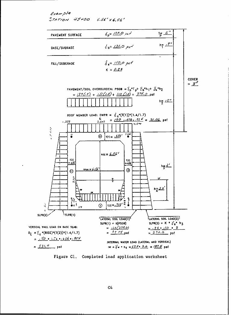
E-,,p/e
T, r,,M 4i,5#, ", o .$6 x 5 '5
PAVEMENT SURFACE dp ?7,0 T= 6
BASE/SUBBASE b = 131, 0 ". h0,
FILL/SUBGRADE i = 20
K = 2. .Z5
COVER
PAVEMENT/SOIL OVERBURDEN: PSOB = pT p+ b'h 1+ Ys*h2
-YK~)+ ,(,s+ // 'o 5~pSf
ROOF MEMBER LOAD: DWPR = c(T(1))°(1.4/1.7)1- = /0 .,,S6...Z4' = 3/,06 psf
.7,s
- ;(2 )-.{,o',
S U-RISE = , /
T(2) T(2)
SPAN N
1w g
SLPR()" SLPR(1)ILATERAL SOIL LOAD(I) LATERAL SOIL LOAD(2) I
SLPR(1) = K[PSOB] SLPR(2) K * , ' ° h3VERTICAL WALL LOAD ON BASE SLAB: = I?5(37 0) - 25 */0 *
DE =c *(RISE)0(T(2))*(1.4/j.7) = s if = 2 ,0.0 psf= ,S0 * .. :'.; ____*._ Z
JNTERNAL WATER LOAD (LATERAL AND VERTICAL)= S1, psf lW = * h4 =C.L 3,0 = /S.' psf
Figure Cl. Completed load application worksheet
C4
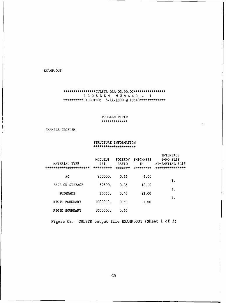
EXAMP.OUT
****************CULSTR DRA-03.90.07****************
PROBLEM NUMBER - 1**********EXECUTED: 5-11-1990 @ 10:48************
PROBLEM TITLE
EXAMPLE PROBLEM
STRUCTURE INFORMATION
INTERFACEMODULUS POISSON THICKNESS 1-NO SLIP
MATERIAL TYPE PSI RATIO IN >1-PARTIAL SLIP********************** ********* ******* ********* ***************
AC 250000. 0.35 6.001.
BASE OR SUBBASE 52500. 0.35 18.001.
SUBGRADE 15000. 0.40 12.001.
RIGID BOUNDARY 1000000. 0.50 1.00
RIGID BOUNDARY 1000000. 0.50
Figure C2. CULSTR output file EXAMP.OUT (Sheet 1 of 3)
C5
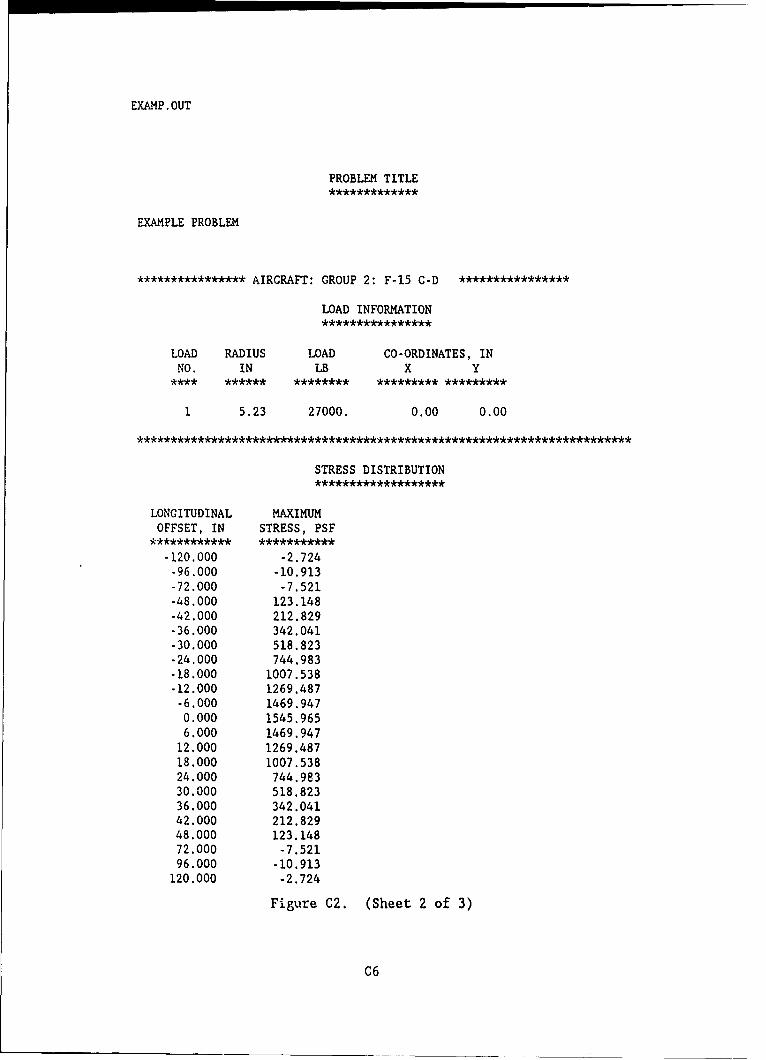
EXAMP.OUT
PROBLEM TITLE
EXAMPLE PROBLEM
**************** AIRCRAFT: GROUP 2: F-15 C-D ****************
LOAD INFORMATION
LOAD RADIUS LOAD CO-ORDINATES, INNO. IN LB X Y
1 5.23 27000. 0.00 0.00
STRESS DISTRIBUTION
LONGITUDINAL MAXIMUMOFFSET, IN STRESS, PSF
-120.000 -2.724-96.000 -10.913-72.000 -7.521-48.000 123.148-42.000 212.829-36.000 342.041-30.000 518.823-24.000 744.983-18.000 1007.538-12.000 1269.487-6.000 1469.9470.000 1545.9656.000 1469.947
12.000 1269.48718.000 1007.53824.000 744.98330.000 518.82336.000 342.04142.000 212.82948.000 123.14872.000 -7.52196.000 -10.913
120.000 -2.724
Figure C2. (Sheet 2 of 3)
C6
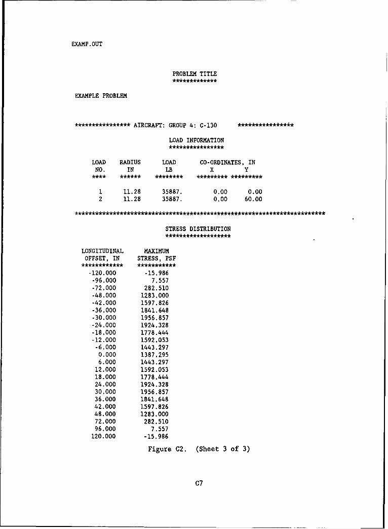
EXAMP.OUT
PROBLEM TITLE
EXAMPLE PROBLEM
**************** AIRCRAFT: GROUP 4: C-130
LOAD INFORMATION
LOAD RADIUS LOAD CO-ORDINATES, INNO. IN LB X Y
**** ****** ******** ********* *********
2 11.28 35887. 0.00 0.002 11.28 35887. 0.00 60.00
STRESS DISTRIBUTION* * *** ***** ******** *
LONGITUDINAL MAXIMUMOFFSET, IN STRESS, PSF
-120.000 -15.986-96.000 7.557-72.000 282.510-48.000 1283.000-42.000 1597.826-36.000 1841.648-30.000 1956.857-24.000 1924.328-18.000 1778.444-12.000 1592.053-6.000 1443.2970.000 1387.2956.000 1443.29712.000 1592.05318.000 1778.44424.000 1924.32830.000 1956.85736.000 1841.64842.000 1597.82648.000 1283.00072.000 282.51096.000 7.557120.000 -15.986
Figure C2. (Sheet 3 of 3)
C7
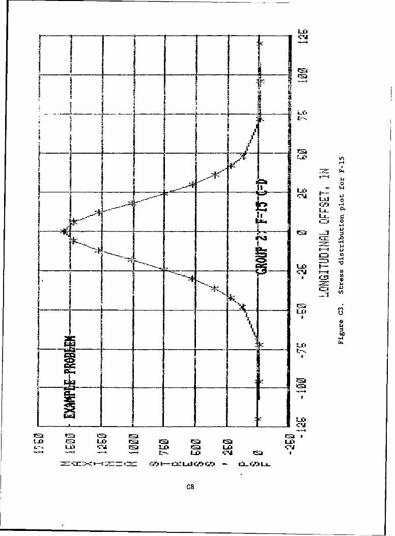
-~ -~ -t
7 1 1Io
I L. 44 94
44
Ia
44
LiO
t- "ImQc M- - L.*L O I r l- r. Lx ,j
___ __ __ __ __ uC 8
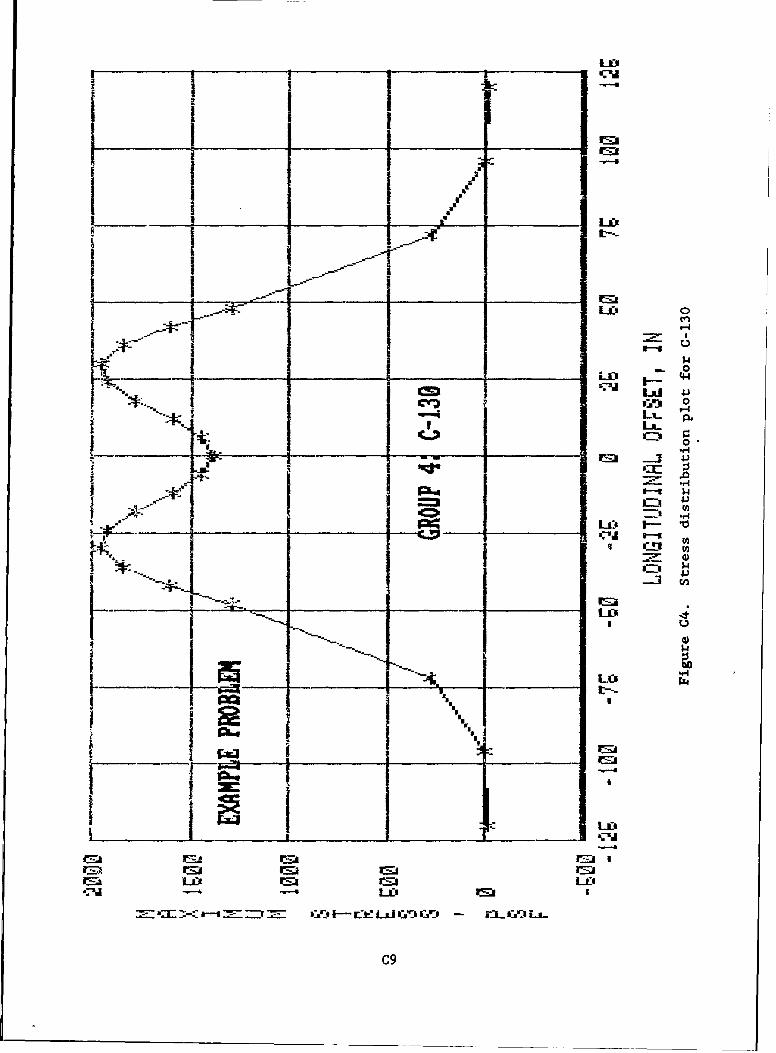
I- l
LXa 4-)
to
LI
la; In C ~ rj :C-=a~~ 'd9r_- IC
_ .__G ___O_ Ca_____ _ ______
am_ _____ 7!7 _ ___ _______ IF-- i- L ,l DI"
'"9-
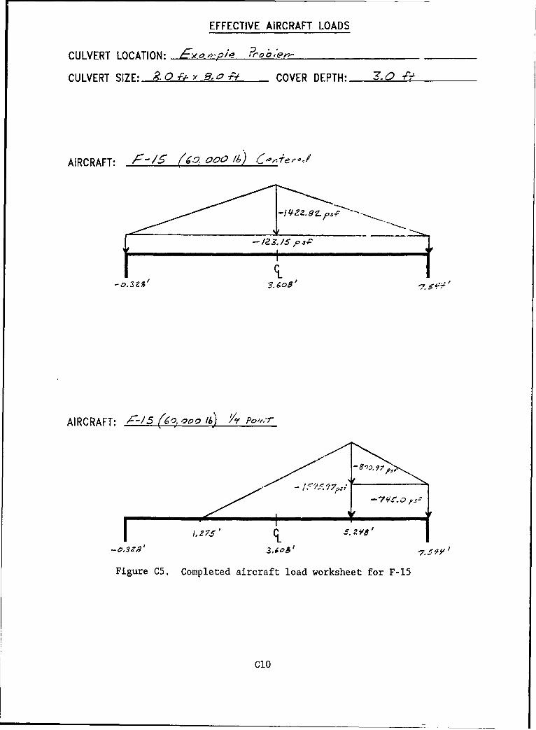
EFFECTIVE AIRCRAFT LOADS
CULVERT LOCATION: 7ex a e,,i/ io,2 ,e-_
CULVERT SIZE: . 0 - x -, 0 -F' COVER DEPTH: '. 0 -.#
AIRCRAFT: 000-/ ? O/C. /4) (' e,-/
12S - 5
AIRCRAFT: C-/5 (s ao° M) '/ Po,..,
/ ' - 1.< ,':.. 877.:
-743, I -7,p
Figure C5. Completed aircraft load worksheet for F-15
C10
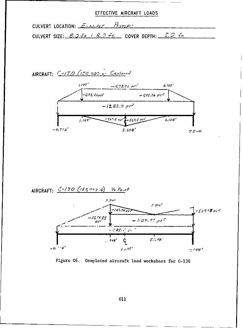
EFFECTIVE AIRCRAFT LOADS
CULVERT LOCATION: :,-Ae ,4z,
CULVERT SIZE: F 3.,t't / L-2'. COVER DEPTH: ,
AIRCRAFT: <-/30 .'-" O'o ,
IO?' r 73,.,-' a,/o?'
- . 7 2 ;. ' ,.-0 S .,
AIRCRAFT: - ,' ,) 7,
-0.
Figure C6. Completed aircraft load worksheet for C-130
CIl
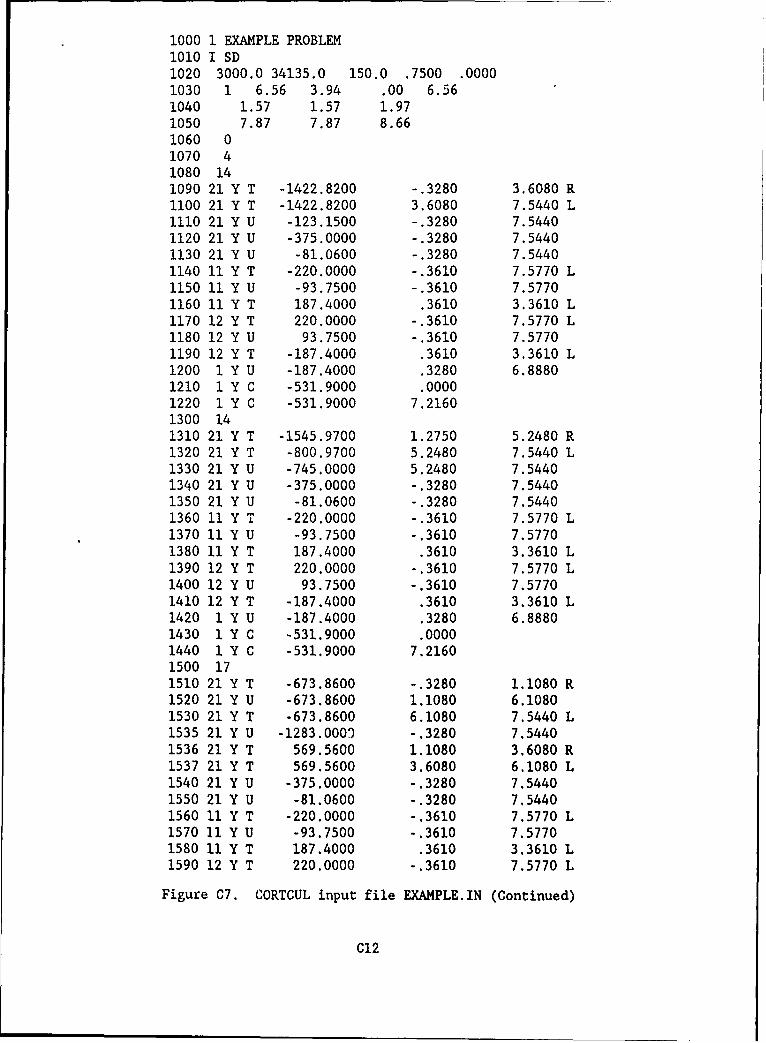
1000 1 EXAMPLE PROBLEM1010 1 SD1020 3000.0 34135.0 150.0 .7500 .00001030 1 6.56 3.94 .00 6.561040 1.57 1.57 1.971050 7.87 7.87 8.661060 01070 41080 141090 21 Y T -1422.8200 -.3280 3.6080 R1100 21 Y T -1422.8200 3.6080 7.5440 L1110 21 Y U -123.1500 -.3280 7.54401120 21 Y U -375.0000 -.3280 7.54401130 21 Y U -81.0600 -.3280 7.54401140 11 Y T -220.0000 -.3610 7.5770 L1150 11 Y U -93.7500 -.3610 7.57701160 11 Y T 187.4000 .3610 3.3610 L1170 12 Y T 220.0000 -.3610 7.5770 L1180 12 Y U 93.7500 -.3610 7.57701190 12 Y T -187.4000 .3610 3.3610 L1200 1 Y U -187.4000 .3280 6.88801210 1 Y C -531.9000 .00001220 1 Y C -531.9000 7.21601300 141310 21 Y T -1545.9700 1.2750 5.2480 R1320 21 Y T -800.9700 5.2480 7.5440 L1330 21 Y U -745.0000 5.2480 7.54401340 21 Y U -375.0000 -.3280 7.54401350 21 Y U -81.0600 -.3280 7.54401360 11 Y T -220.0000 -.3610 7.5770 L1370 11 Y U -93.7500 -.3610 7.57701380 11 Y T 187.4000 .3610 3.3610 L1390 12 Y T 220.0000 -.3610 7.5770 L1400 12 Y U 93.7500 -.3610 7.57701410 12 Y T -187.4000 .3610 3.3610 L1420 1 Y U -187.4000 .3280 6.88801430 1 Y C -531.9000 .00001440 1 Y C -531.9000 7.21601500 171510 21 Y T -673.8600 -.3280 1.1080 R1520 21 Y U -673.8600 1.1080 6.10801530 21 Y T -673.8600 6.1080 7.5440 L1535 21 Y U -1283.0009 -.3280 7.54401536 21 Y T 569.5600 1.1080 3.6080 R1537 21 Y T 569.5600 3.6080 6,1080 L1540 21 Y U -375.0000 -.3280 7.54401550 21 Y U -81.0600 -.3280 7,54401560 11 Y T -220.0000 -.3610 7.5770 L1570 ]1 Y U -93.7500 -.3610 7.57701580 11 Y T 187.4000 .3610 3.3610 L1590 12 Y T 220.0000 -.3610 7.5770 L
Figure C7. CORTCUL input file EXAMPLE.IN (Continued)
C12
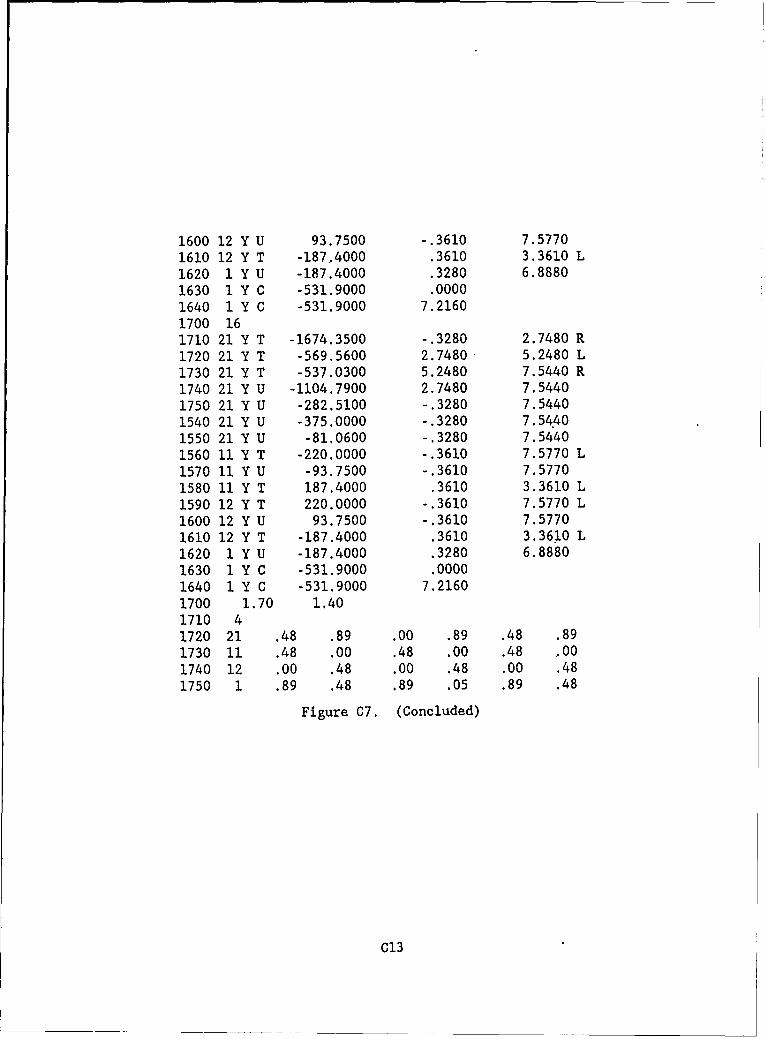
1600 12 Y U 93.7500 -.3610 7.57701610 12 Y T -187,4000 .3610 3.3610 L1620 1 Y U -187.4000 .3280 6.88801630 1 Y C -531.9000 .00001640 1 Y C -531.9000 7.21601700 161710 21 Y T -1674.3500 -.3280 2.7480 R1720 21 Y T -569.5600 2.7480 5.2480 L1730 21 Y T -537.0300 5.2480 7.5440 R1740 21 Y U -1104.7900 2.7480 7.54401750 21 Y U -282.5100 -.3280 7.54401540 21 Y U -375.0000 -.3280 7.54401550 21 Y U -81.0600 -.3280 7.54401560 11 Y T -220.0000 -.3610 7.5770 L1570 11 Y U -93.7500 -.3610 7.57701580 11 Y T 187.4000 .3610 3.3610 L1590 12 Y T 220.0000 -.3610 7.5770 L1600 12 Y U 93.7500 -.3610 7.57701610 12 Y T -187.4000 .3610 3.3610 L1620 1 Y U -187.4000 .3280 6.88801630 1 Y C -531.9000 .00001640 1 Y C -531.9000 7.21601700 1.70 1.401710 41720 21 .48 .89 .00 .89 .48 .891730 11 .48 .00 .48 .00 .48 '001740 12 .00 .48 .00 .48 .00 .481750 1 .89 .48 .89 .05 .89 .48
Figure C7. (Concluded)
C13
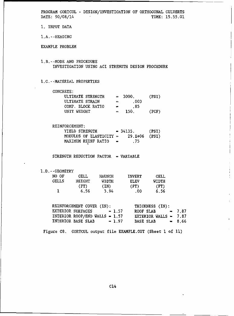
PROGRAM CORTCUL - DESIGN/INVESTIGATION OF ORTHOGONAL CULVERTSDATE: 90/08/14 TIME: 15.55.01
1. INPUT DATA
l.A.--HEADING
EXAMPLE PROBLEM
I.B.--MODE AND PROCEDUREINVESTIGATION USING ACI STRENGTH DESIGN PROCEDURE
I.0.--MATERIAL PROPERTIES
CONCRETE:ULTIMATE STRENGTH = 3000. (PSI)ULTIMATE STRAIN = .003COMP. BLOCK RATIO = .85UNIT WEIGHT = 150. (PCF)
REINFORCEMENT:YIELD STRENGTH - 34135. (PSI)MODULUS OF ELASTICITY = 29.E+06 (PSI)MAXIMUM REINF RATIO - .75
STRENGTH REDUCTION FACTOR = VARIABLE
I.D.--GEOMETRYNO OF CELL HAUNCH INVERT CELLCELLS HEIGHT WIDTH ELEV WIDTH
(FT) (IN) (FT) (FT)1 6.56 3.94 .00 6.56
REINFORCEMENT COVER (IN): THICKNESS (IN):EXTERIOR SURFACES = 1.57 ROOF SLAB - 7.87INTERIOR ROOF/END WALLS - 1.57 EXTERIOR WALLS - 7.87INTERIOR BASE SLAB - 1.97 BASE SLAB m 8.66
Figure C8. CORTCUL output file EXAMPLE.OUT (Sheet 1 of 11)
C14
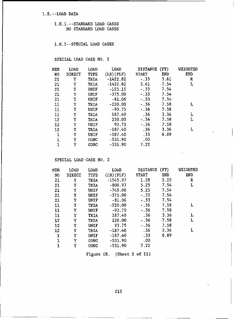
I.E.--LOAD DATA
I.E.I.--STANDARD LOAD CASESNO STANDARD LOAD CASES
I.E.2--SPECIAL LOAD CASES
SPECIAL LOAD CASE NO. 1
MEM LOAD LOAD LOAD DISTANCE (FT) WEIGHTEDNO DIRECT TYPE (LB)(PLF) START END END
21 Y TRIA -1422.82 -.33 3.61 R
21 Y TRIA -1422.82 3.61 7.54 L
21 Y UNIF -123.15 - .33 7.5421 Y UNIF -375.00 -.33 7.5421 Y UNIF -81.06 -.33 7.5411 Y TRIA -220.00 -.36 7.58 L
11 Y UNIF -93.75 -.36 7.58
11 Y TRIA 187.40 .36 3.36 L
12 Y TRIA 220.00 -.36 7.58 L12 Y UNIF 93.75 -.36 7.5812 Y TRIA -187.40 .36 3.36 L1 Y UNIF -187.40 .33 6.891 Y CONC -531.90 .001 Y CONC -531.90 7.22
SPECIAL LOAD CASE NO. 2
MEM LOAD LOAD LOAD DISTANCE (FT) WEIGHTED
NO DIRECT TYPE (LB)(PLF) START END END
21 Y TRIA -1545.97 1.28 5.25 R
21 Y TRIA -800.97 5.25 7.54 L21 Y UNIF -745.00 5.25 7.54
21 Y UNIF -375.00 -.33 7.5421 Y UNIF -81.06 -.33 7.54
11 Y TRIA -220.00 -.36 7.58 L11 Y UNIF -93.75 -.36 7.58
11 Y TRIA 187.40 .36 3.36 L12 Y TRIA 220.00 -.36 7.58 L
12 Y UNIF 93.75 -.36 7.58
12 Y TRIA -187.40 .36 3.36 L1 Y UNIF -187.40 .33 6.89
1 Y CONC -531.90 .00
1 Y CONC -531.90 7.22
Figure C8. (Sheet 2 of 11)
C15
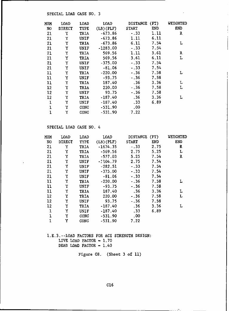
SPECIAL LOAD CASE NO. 3
MEM LOAD LOAD LOAD DISTANCE (FT) WEIGHTEDNO DIRECT TYPE (LB)(PLF) START END END21 Y TRIA -673.86 -.33 1.11 R21 Y UNIF -673.86 1.11 6.1121 Y TRIA -673.86 6.11 7.54 L21 Y UNIF -1283.00 -.33 7.5421 Y TRIA 569.56 1.11 3.61 R21 Y TRIA 569.56 3.61 6.11 L21 Y UNIF -375.00 -.33 7.5421 Y UNIF -81.06 -.33 7.5411 Y TRIA -220.00 -.36 7.58 L11 Y UNIF -93.75 -.36 7.5811 Y TRIA 187.40 .36 3.36 L12 Y TRIA 220.00 -.36 7.58 L12 Y UNIF 93.75 -.36 7.5812 Y TRIA -187.40 .36 3.36 L1 Y UNIF -187.40 .33 6.891 Y CONC -531.90 .00
1 Y CONC -531.90 7.22
SPECIAL LOAD CASE NO. 4
MEM LOAD LOAD LOAD DISTANCE (FT) WEIGHTEDNO DIRECT TYPE (LB)(PLF) START END END21 Y TRIA -1674.35 -.33 2.75 R21 Y TRIA -569.56 2.75 5.25 L21 Y TRIA -537.03 5.25 7.54 R21 Y UNIF -.104.79 2.75 7.5421 Y UNIF -282.51 -.33 7.5421 Y UNIF -375.00 -.33 7.5421 Y UNIF -81.06 -.33 7.5411 Y TRIA -220.00 -.36 7.58 L11 Y UNIF -93.75 -.36 7.5811 Y TRIA 187.40 .36 3.36 L12 Y TRIA 220.00 -.36 7.58 L12 Y UNIF 93.75 -.36 7.5812 Y TRIA -187.40 .36 3.36 L1 Y UNIF -187.40 .33 6.891 Y CONC -531.90 .00I Y CONC -531.90 7.22
I.E.3.--LOAD FACTORS FOR ACI STRENGTH DESIGN:LIVE LOAD FACTOR - 1.70DEAD LOAD FACTOR - 1.40
Figure C8. (Sheet 3 of 11)
C16
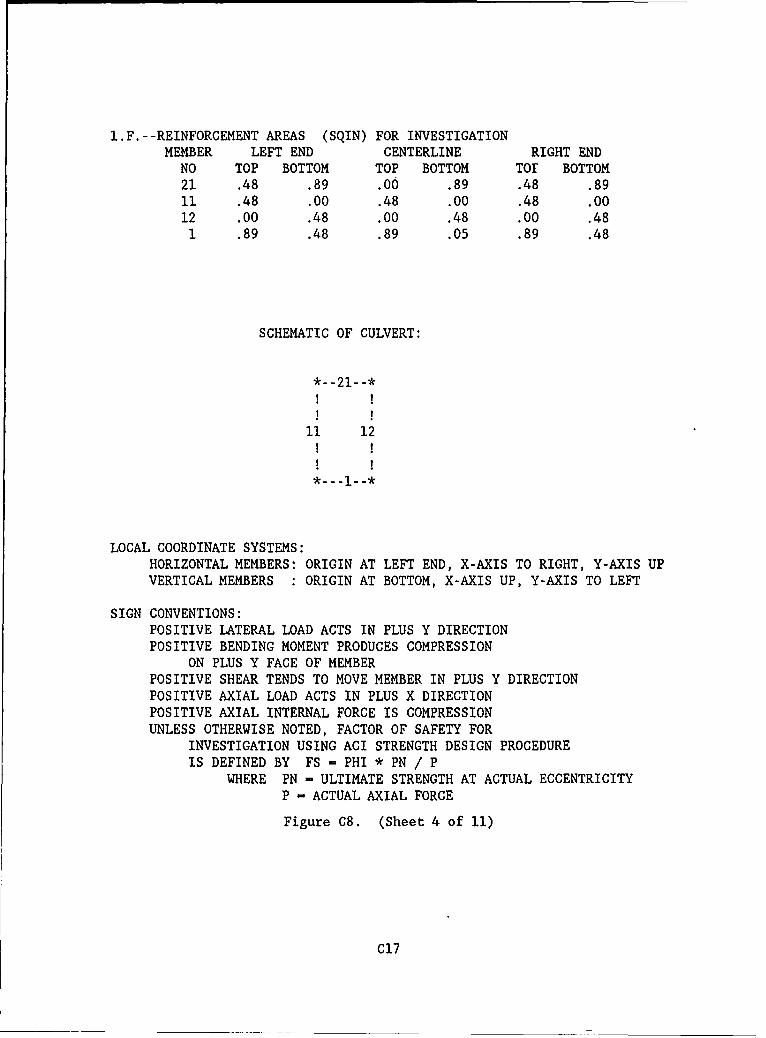
1.F.--REINFORCEMENT AREAS (SQIN) FOR INVESTIGATIONMEMBER LEFT END CENTERLINE RIGHT END
NO TOP BOTTOM TOP BOTTOM TOE BOTTOM21 .48 .89 .00 .89 .48 .8911 .48 .00 .48 .00 .48 .0012 .00 .48 .00 .48 .00 .481 .89 .48 .89 .05 .89 .48
SCHEMATIC OF CULVERT:
*--21--*
11 12
- -1- -*
LOCAL COORDINATE SYSTEMS:HORIZONTAL MEMBERS: ORIGIN AT LEFT END, X-AXIS TO RIGHT, Y-AXIS UPVERTICAL MEMBERS : ORIGIN AT BOTTOM, X-AXIS UP, Y-AXIS TO LEFT
SIGN CONVENTIONS:POSITIVE LATERAL LOAD ACTS IN PLUS Y DIRECTIONPOSITIVE BENDING MOMENT PRODUCES COMPRESSION
ON PLUS Y FACE OF MEMBERPOSITIVE SHEAR TENDS TO MOVE MEMBER IN PLUS Y DIRECTIONPOSITIVE AXIAL LOAD ACTS IN PLUS X DIRECTIONPOSITIVE AXIAL INTERNAL FORCE IS COMPRESSIONUNLESS OTHERWISE NOTED, FACTOR OF SAFETY FOR
INVESTIGATION USING ACI STRENGTH DESIGN PROCEDUREIS DEFINED BY FS - PHI * PN / P
WHERE PN = ULTIMATE STRENGTH AT ACTUAL ECCENTRICITY
P - ACTUAL AXIAL FORCE
Figure C8. (Sheet 4 of 11)
C17
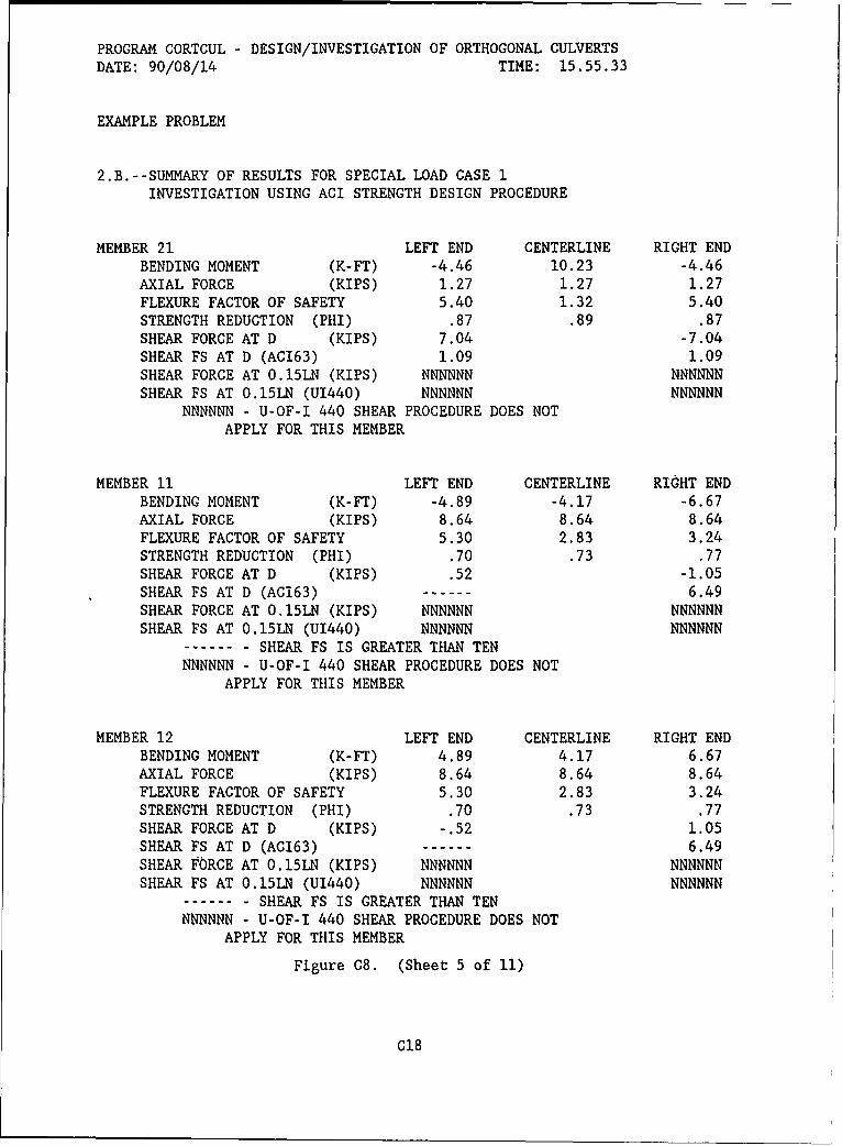
PROGRAM CORTCUL - DESIGN/INVESTIGATION OF ORTHOGONAL CULVERTS
DATE: 90/08/14 TIME: 15.55.33
EXAMPLE PROBLEM
2.B.--SUMMARY OF RESULTS FOR SPECIAL LOAD CASE 1INVESTIGATION USING ACI STRENGTH DESIGN PROCEDURE
MEMBER 21 LEFT END CENTERLINE RIGHT ENDBENDING MOMENT (K-FT) -4.46 10.23 -4.46AXIAL FORCE (KIPS) 1.27 1.27 1.27FLEXURE FACTOR OF SAFETY 5.40 1.32 5.40STRENGTH REDUCTION (PHI) .87 .89 .87SHEAR FORCE AT D (KIPS) 7.04 -7.04SHEAR FS AT D (AC163) 1.09 1.09SHEAR FORCE AT O.15LN (KIPS) NNNNNN NNNNNNSHEAR FS AT O.15LN (U1440) NNNNNN NNNNNN
NNNNNN - U-OF-I 440 SHEAR PROCEDURE DOES NOTAPPLY FOR THIS MEMBER
MEMBER 11 LEFT END CENTERLINE RIGHT ENDBENDING MOMENT (K-FT) -4.89 -4.17 -6.67AXIAL FORCE (KIPS) 8.64 8.64 8.64FLEXURE FACTOR OF SAFETY 5.30 2.83 3.24STRENGTH REDUCTION (PHI) .70 .73 .77SHEAR FORCE AT D (KIPS) .52 -1.05SHEAR FS AT D (ACi63) ------ 6.49SHEAR FORCE AT O.15LN (KIPS) NNNNNN NNNNNNSHEAR FS AT 0.15LN (U1440) NNNNNN NNNNNN
------- SHEAR FS IS GREATER THAN TENNNNNNN - U-OF-I 440 SHEAR PROCEDURE DOES NOT
APPLY FOR THIS MEMBER
MEMBER 12 LEFT END CENTERLINE RIGHT ENDBENDING MOMENT (K-FT) 4.89 4.17 6.67AXIAL FORCE (KIPS) 8.64 8.64 8.64FLEXURE FACTOR OF SAFETY 5.30 2.83 3.24STRENGTH REDUCTION (PHI) .70 .73 .77SHEAR FORCE AT D (KIPS) -.52 1.05SHEAR FS AT D (AC163) ------ 6.49SHEAR FORCE AT 0.15LN (KIPS) NNNNNN NNNNNNSHEAR FS AT 0.15LN (U1440) NNNNNN NNNNNN
------- SHEAR FS IS GREATER THAN TENNNNNNN - U-OF-I 440 SHEAR PROCEDURE DOES NOT
APPLY FOR THIS MEMBER
Figure C8. (Sheet 5 of 11)
C18
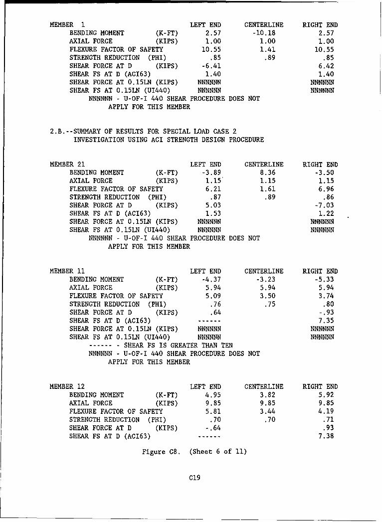
MEMBER 1 LEFT END CENTERLINE RIGHT ENDBENDING MOMENT (K-FT) 2.57 -10.18 2.57AXIAL FORCE (KIPS) 1.00 1.00 1.00FLEXURE FACTOR OF SAFETY 10.55 1.41 10.55STRENGTH REDUCTION (PHI) .85 .89 .85SHEAR FORCE AT D (KIPS) -6.41 6.42SHEAR FS AT D (AC163) 1.40 1.40SHEAR FORCE AT O.15LN (KIPS) NNNNNN NNNNNNSHEAR FS AT 0.15LN (U1440) NNNNNN NNNNNN
NNNNNN - U-OF-I 440 SHEAR PROCEDURE DOES NOTAPPLY FOR THIS MEMBER
2.B.--SUMMARY OF RESULTS FOR SPECIAL LOAD CASE 2INVESTIGATION USING ACI STRENGTH DESIGN PROCEDURE
MEMBER 21 LEFT END CENTERLINE RIGHT ENDBENDING MOMENT (K-FT) -3.89 8.36 -3.50AXIAL FORCE (KIPS) 1.15 1.15 1.15FLEXURE FACTOR OF SAFETY 6.21 1.61 6.96STRENGTH REDUCTION (PHI) .87 .89 .86SHEAR FORCE AT D (KIPS) 5.03 -7.03SHEAR FS AT D (AC163) 1.53 1.22SHEAR FORCE AT 0.15LN (KIPS) NNNNNN NNNNNNSHEAR FS AT 0.15LN (U1440) NNNNNN NNNNNN
NNNNNN - U-OF-I 440 SHEAR PROCEDURE DOES NOTAPPLY FOR THIS MEMBER
MEMBER 11 LEFT END CENTERLINE RIGHT ENDBENDING MOMENT (K-FT) -4.37 -3.23 -5.33AXIAL FORCE (KIPS) 5.94 5.94 5.94FLEXURE FACTOR OF SAFETY 5.09 3.50 3.74STRENGTH REDUCTION (PHI) .76 .75 .80SHEAR FORCE AT D (KIPS) .64 -.93SHEAR FS AT D (AC163) 7.35SHEAR FORCE AT 0.15LN (KIPS) NNNNNN NNNNNNSHEAR FS AT 0.15LN (U1440) NNNNNN NNNNNN
------ SHEAR FS IS GREATER THAN TENNNNNNN - U-OF-I 440 SHEAR PROCEDURE DOES NOT
APPLY FOR THIS MEMBER
MEMBER 12 LEFT END CENTERLINE RIGHT ENDBENDING MOMENT (K-FT) 4.95 3.82 5.92AXIAL FORCE (KIPS) 9.85 9.85 9.85FLEXURE FACTOR OF SAFETY 5.81 3.44 4.19STRENGTH REDUCTION (PHI) .70 .70 .71SHEAR FORCE AT D (KIPS) -.64 .93SHEAR FS AT D (AC163) ----- 7.38
Figure C8. (Sheet 6 of 11)
C19
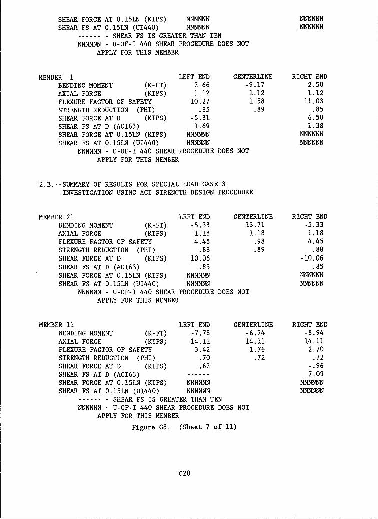
SHEAR FORCE AT O.15LN (KIPS) NNNNNN NNNNNN
SHEAR FS AT O.15LN (U1440) NNNNNN NNNNNN-------- SHEAR FS IS GREATER THAN TEN
NNNNNN - U-OF-I 440 SHEAR PROCEDURE DOES NOT
APPLY FOR THIS MEMBER
MEMBER 1 LEFT END CENTERLINE RIGHT ENDBENDING MOMENT (K-FT) 2.66 -9.17 2.50
AXIAL FORCE (KIPS) 1.12 1.12 1.12
FLEXURE FACTOR OF SAFETY 10.27 1.58 11.03
STRENGTH REDUCTION (PHI) .85 .89 .85
SHEAR FORCE AT D (KIPS) -5.31 6.50
SHEAR FS AT D (AC163) 1.69 1.38
SHEAR FORCE AT O.15LN (KIPS) NNNNNN NNNNNNSHEAR FS AT 0.15LN (U1440) NNNNNN NNNNNN
NNNNNN - U-OF-I 440 SHEAR PROCEDURE DOES NOT
APPLY FOR THIS MEMBER
2.B.--SUMMARY OF RESULTS FOR SPECIAL LOAD CASE 3INVESTIGATION USING ACI STRENGTH DESIGN PROCEDURE
MEMBER 21 LEFT END CENTERLINE RIGHT ENDBENDING MOMENT (K-FT) -5.33 13.71 -5.33AXIAL FORCE (KIPS) 1.18 1.18 1.18FLEXURE FACTOR OF SAFETY 4.45 .98 4.45STRENGTH REDUCTION (PHI) .88 .89 .88SHEAR FORCE AT D (KIPS) 10.06 -10.06SHEAR FS AT D (AC163) .85 .85
SHEAR FORCE AT 0.15LN (KIPS) NNNNNN NNNNNNSHEAR FS AT 0.15LN (U1440) NNNNNN NNNNNN
NNNNNN - U-OF-I 440 SHEAR PROCEDURE DOES NOT
APPLY FOR THIS MEMBER
MEMBER 11 LEFT END CENTERLINE RIGHT ENDBENDING MOMENT (K-FT) -7.78 -6.74 -8.94AXIAL FORCE (KIPS) 14.11 14.11 14.11
FLEXURE FACTOR OF SAFETY 3.42 1.76 2.70STRENGTH REDUCTION (PHI) .70 .72 .72SHEAR FORCE AT D (KIPS) .62 -.96
SHEAR FS AT D (AC163) 7.09SHEAR FORCE AT 0.!5LN (KIPS) NNNNNN NNNNNNSHEAR FS AT 0.15LN (U1440) NNNNNN NNNNNN
-------- SHEAR FS IS GREATER THAN TENNNNNNN - U-OF-I 440 SHEAR PROCEDURE DOES NOT
APPLY FOR THIS MEMBER
Figure C8. (Sheet 7 of 11)
C20
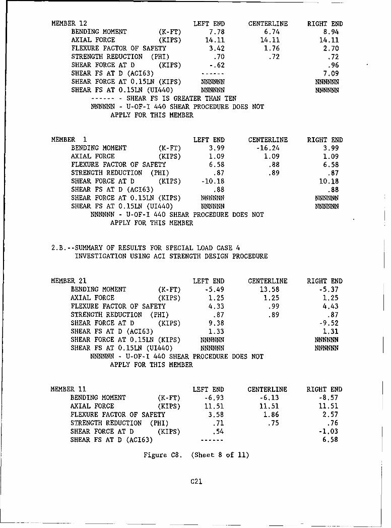
MEMBER 12 LEFT END CENTERLINE RIGHT ENDBENDING MOMENT (K-FT) 7.78 6.74 8.94AXIAL FORCE (KIPS) 14.11 14.11 14.11FLEXURE FACTOR OF SAFETY 3.42 1.76 2.70STRENGTH REDUCTION (PHI) .70 .72 .72SHEAR FORCE AT D (KIPS) -.62 .96SHEAR FS AT D (AC163) 7.09SHEAR FORCE AT 0.15LN (KIPS) NNNNNN NNNNNNSHEAR FS AT 0.15LN (U1440) NNNNNN NNNNNN
----- SHEAR FS IS GREATER THAN TENNNNNNN - U-OF-I 440 SHEAR PROCEDURE DOES NOT
APPLY FOR THIS MEMBER
MEMBER 1 LEFT END CENTERLINE RIGHT ENDBENDING MOMENT (K-FT) 3.99 -16.24 3.99AXIAL FORCE (KIPS) 1.09 1.09 1.09FLEXURE FACTOR OF SAFETY 6.58 .88 6.58STRENGTH REDUCTION (PHI) .87 .89 .87SHEAR FORCE AT D (KIPS) -10.18 10.18SHEAR FS AT D (AC163) .88 .88SHEAR FORCE AT 0.15LN (KIPS) NNNNNN NNNNNNSHEAR FS AT 0.15LN (U1440) NNNNNN NNNNNN
NNNNNN - U-OF-I 440 SHEAR PROCEDURE DOES NOTAPPLY FOR THIS MEMBER
2.B.--SUMMARY OF RESULTS FOR SPECIAL LOAD CASE 4INVESTIGATION USING ACI STRENGTH DESIGN PROCEDURE
MEMBER 21 LEFT END CENTERLINE RIGHT ENDBENDING MOMENT (K-FT) -5.49 13.58 -5.37AXIAL FORCE (KIPS) 1.25 1.25 1.25FLEXURE FACTOR OF SAFETY 4.33 .99 4.43STRENGTH REDUCTION (PHI) .87 .89 .87SHEAR FORCE AT D (KIPS) 9.38 -9.52SHEAR FS AT D (AC163) 1.33 1.31SHEAR FORCE AT 0.15LN (KIPS) NNNNNN NNNNNNSHEAR FS AT O.15LN (U1440) NNNNNN NNNNNN
NNNNNN - U-OF-I 440 SHEAR PROCEDURE DOES NOTAPPLY FOR THIS MEMBER
MEMBER 11 LEFT END CENTERLINE RIGHT ENDBENDING MOMENT (K-FT) -6.93 -6.13 -8.57AXIAL FORCE (KIPS) 11.51 11.51 11.51FLEXURE FACTOR OF SAFETY 3.58 1.86 2.57STRENGTH REDUCTION (PHI) .71 .75 .76SHEAR FORCE AT D (KIPS) .54 -1.03SHEAR FS AT D (AC163) 6.58
Figure C8. (Sheet 8 of 11)
C21
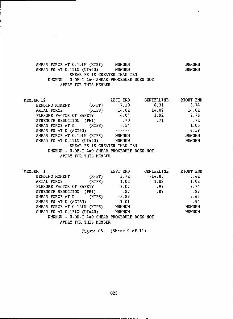
SHEAR FORCE AT O.15LN (KIPS) NNNNNN NNNNNNSHEAR FS AT O.15LN (U1440) NNNNNN NNNNNN
-------- SHEAR FS IS GREATER THAN TENNNNNNN - U-OF-I 440 SHEAR PROCEDURE DOES NOT
APPLY FOR THIS MEMBER
MEMBER 12 LEFT END CENTERLINE RIGHT ENDBENDING MOMENT (K-FT) 7.10 6.31 8.74AXIAL FORCE (KIPS) 14.02 14.02 14.02FLEXURE FACTOR OF SAFETY 4.04 1.92 2.78STRENGTH REDUCTION (PHI) .70 .71 .72SHEAR FORCE AT D (KIPS) -.54 1.03SHEAR FS AT D (AC163) 6.59SHEAR FORCE AT O.15LN (KIPS) NNNNNN NNNNNN
SHEAR FS AT O.15LN (U1440) NNNNNN NNNNNN-------- SHEAR FS IS GREATER THAN TENNNNNNN - U-OF-I 440 SHEAR PROCEDURE DOES NOT
APPLY FOR THIS MEMBER
MEMBER 1 LEFT END CENTERLINE RIGHT ENDBENDING MOMENT (K-FT) 3.72 -14.83 3.42AXIAL FORCE (KIPS) 1.02 1.02 1.02FLEXURE FACTOR OF SAFETY 7.07 .97 7.74STRENGTH REDUCTION (PHI) .87 .89 .87SHEAR FORCE AT D (KIPS) -8.89 9.62SHEAR FS AT D (AC163) 1.01 .94SHEAR FORCE AT 0.15LN (KIPS) NNNNNN NNNNNNSHEAR FS AT 0.151N (U1440) NNNNNN NNNNNN
NNNNNN - U-OF-I 440 SHEAR PROCEDURE DOES NOTAPPLY FOR THIS MEMBER
Figure C8. (Sheet 9 of 11)
C22
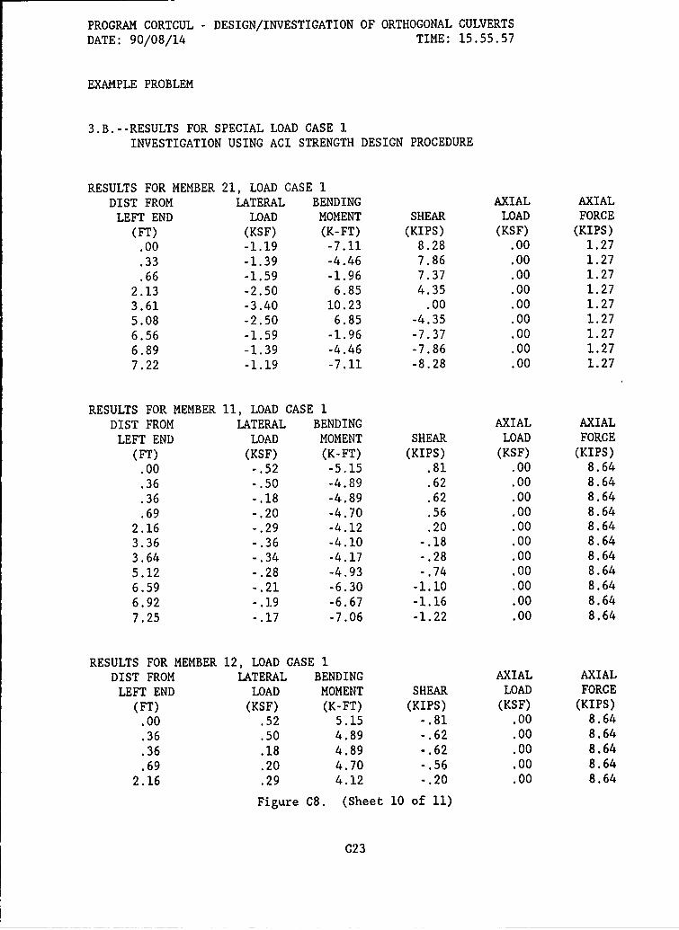
PROGRAM CORTCUL - DESIGN/INVESTIGATION OF ORTHOGONAL CULVERTS
DATE: 90/08/14 TIME: 15.55.57
EXAMPLE PROBLEM
3.B.--RESULTS FOR SPECIAL LOAD CASE 1
INVESTIGATION USING ACI STRENGTH DESIGN PROCEDURE
RESULTS FOR MEMBER 21, LOAD CASE 1DIST FROM LATERAL BENDING AXIAL AXIAL
LEFT END LOAD MOMENT SHEAR LOAD FORCE
(FT) (KSF) (K-FT) (KIPS) (KSF) (KIPS)
.00 -1.19 -7.11 8.28 .00 1.27
.33 -1.39 -4.46 7.86 .00 1.27
.66 -1.59 -1.96 7.37 .00 1.27
2.13 -2.50 6.85 4.35 .00 1.27
3.61 -3.40 10.23 .00 .00 1.27
5.08 -2.50 6.85 -4.35 .00 1.27
6.56 -1.59 -1.96 -7.37 .00 1.27
6.89 -1.39 -4.46 -7.86 .00 1.27
7.22 -1.19 -7.11 -8.28 .00 1.27
RESULTS FOR MEMBER 11, LOAD CASE 1
DIST FROM LATERAL BENDING AXIAL AXIAL
LEFT END LOAD MOMENT SHEAR LOAD FORCE
(FT) (KSF) (K-FT) (KIPS) (KSF) (KIPS)
.00 -.52 -5.15 .81 .00 8.64
.36 -.50 -4.89 .62 .00 8.64
.36 -.18 -4.89 .62 .00 8.64
.69 -.20 -4.70 .56 .00 8.64
2.16 -.29 -4.12 .20 .00 8.64
3.36 -.36 -4.10 -.18 .00 8.64
3.64 -.34 -4.17 -.28 .00 8.64
5.12 -.28 -4.93 -.74 .00 8.64
6.59 -.21 -6.30 -1.10 .00 8.64
6.92 -.19 -6.67 -1.16 .00 8.64
7.25 -.17 -7.06 -1.22 .00 8,64
RESULTS FOR MEMBER 12, LOAD CASE 1
DIST FROM LATERAL BENDING AXIAL AXIAL
LEFT END LOAD MOMENT SHEAR LOAD FORCE
(FT) (KSF) (K-FT) (KIPS) (KSF) (KIPS)
.00 .52 5.15 -.81 .00 8.64
.36 .50 4.89 -.62 .00 8.64
.36 .18 4.89 -.62 .00 8.64
.69 .20 4.70 -.56 .00 8.64
2.16 .29 4.12 -.20 .00 8.64
Figure C8. (Sheet 10 of 11)
C23
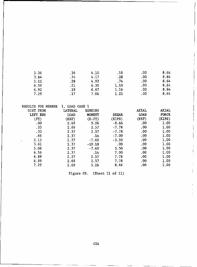
3.36 .36 4.10 .18 .00 8.643.64 .34 4.17 .28 .00 8.645.12 .28 4.93 .74 .00 8.646.59 .21 6.30 1.10 .00 8.646.92 .19 6.67 1.16 .00 8.647.25 .17 7.06 1.22 .00 8.64
RESULTS FOR MEMBER 1, LOAD CASE 1DIST FROM LATERAL BENDING AXIAL AXIALLEFT END LOAD MOMENT SHEAR LOAD FORCE
(FT) (KSF) (K-FT) (KIPS) (KSF) (KIPS).00 2.69 5.26 -8.66 .00 1.00.33 2.69 2.57 -7.78 .00 1.00.33 2.37 2.57 -7.78 .00 1.00.66 2.37 .14 -7.00 .00 1.00
2.13 2.37 -7.60 -3.50 .00 1.003.61 2.37 -10.18 .00 .00 1.005.08 2.37 -7.60 3.50 .00 1.006.56 2.37 .14 7.00 .00 1.006.89 2.37 2.57 7.78 .00 1.006.89 2.69 2.57 7.78 .00 1.007.22 2.69 5.26 8.66 .00 i.00
Figure C8. (Sheet 11 of 11)
C24
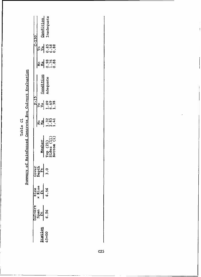
0 C
0Z
0 4
00
001
0
0 C%-C CH
rs-a0
$4- 1. (n00 (L) WI
44J 4.)0
00 4
N--44 ~ U
p 0 ) m3
x
4-)
nC25