Embed Size (px)
Citation preview

AMPLITUDE MODULATIONLecture Notes by:
Engr. Analene M. Nagayo

Modulation TheoryWhat is MODULATION?
- A process by which a low frequency signal is made to change a property of a
higher frequency signal to allow effective transmission and reception of the
desired information.
- A process of imposing information contained in lower-frequency signal onto a
higher frequency signal.
-The low frequency signal is called the modulating signal and the high
frequency signal is called the carrier.
Why modulate?
1.) Direct transmission of low-frequency information signal would cause to
interference problem since the resulting radio waves would all be at the same
frequency range.
2.) Transmitting low-frequency information signal in free space is not practical
since it will require a very high antenna.

Modulation Theory
Types of Modulation
A. Analog Modulation
I. Amplitude Modulation
II. Angle Modulation
a.) Frequency Modulation
b.) Phase Modulation
B. Digital Modulation
fmt2 sin Vm )( tVm
fct2 sin Vc )( tVc

Amplitude Modulation
What is AMPLITUDE MODULATION?
-Type of analog modulation wherein the amplitude of the carrier signal is
varied or changed according to the instantaneous amplitude of the
modulating signal.
- Process of modulation wherein the information is imposed on the carrier,
causing the amplitude of the carrier to vary in accordance with the
modulating signal. Note that the carrier frequency remains constant during
the modulation process.
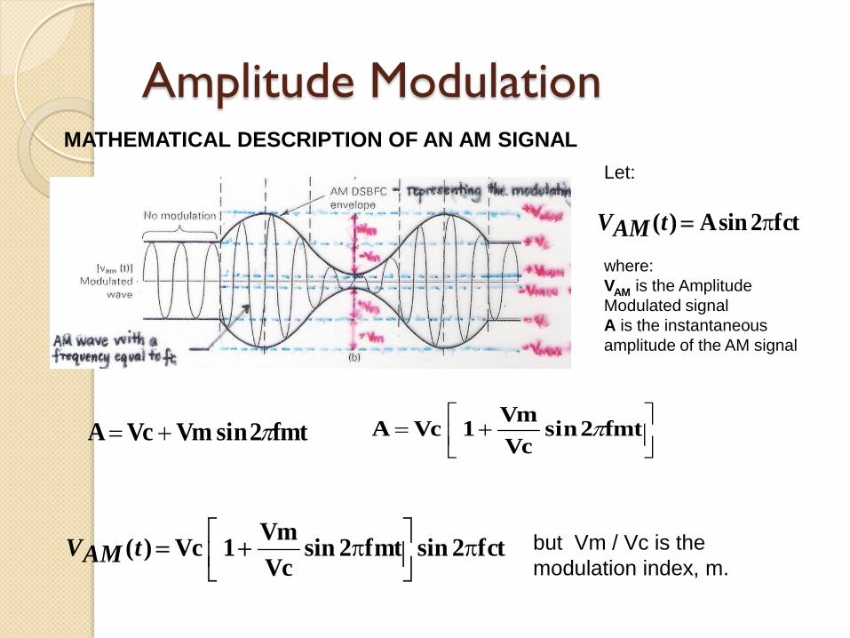
Amplitude ModulationMATHEMATICAL DESCRIPTION OF AN AM SIGNAL
Let:
fct2 sin A)( tAMV
where:
VAM is the Amplitude
Modulated signal
A is the instantaneous
amplitude of the AM signal
fmt2 sin Vm Vc A
fmt2 sin
Vc
Vm 1 Vc A
fct2 sin fmt2 sin Vc
Vm 1 Vc )(
tAMV but Vm / Vc is the
modulation index, m.

Amplitude Modulation
fct2 sin fmt2 sin m 1 Vc )( tAMV
fct2 sin fmt]2 sin mVc [Vc )( tAM
V
fct2 sinfmt 2 sin mVc fctsin2 Vc )( tAM
V
Note: Y) cos(X 2
1 - Y)-cos(X
2
1 Y sin Xsin
Let :
fmt2 Y andfct 2 X
fm)t(fccos22
mVc -fm)t-(fccos2
2
mVc fct 2 sin Vc )( tAMV
2
Vc)rms(CV
222
mVc)rms(LSBV)rms(USBV ;
mVc)pk(LSBV)pk(USBV

Amplitude Modulation

Amplitude ModulationFREQUENCY SPECTRUM OF AN AM SIGNAL
BANDWIDTH = 2 fm
PERCENT MODULATION, %M AND MODULATION INDEX, m
- show the relationship between amplitudes of the
modulating signal and carrier. Also referred to as
modulation factor or depth of modulation.
100x Vc
Vm M%
Vc
Vm m

Amplitude Modulation
Vmin Vmax
Vmin -Vmax m
where:
Vmax is the maximum peak value of the AM wave
Vmin is the minimum peak value of the AM wave

Amplitude Modulation
a) Undermodulation - %M < 100%, m < 1,
Vm < Vc (practical)
b) 100% modulation - m = 1, Vm = Vc
(ideal)
Three (3) degrees of modulation :
c) Over modulation – %M > 100%,
m > 1, Vm > Vc (with distortion)

Amplitude Modulation
POWER CONTENT OF AN AM SIGNAL
USBLSBT PP Pc P
Where:
PT = total transmitted power or total modulated
power in Watts
PLSB, PUSB = lower and upper sideband power in
Watts
Pc = unmodulated carrier power in Watts. Carrier
power remains the same, regardless of percent
modulation. Pc2
m USBP LSBP
4
Pcm
Pcm
Pc P 22
T44
2
2
T
m 1 Pc P

Amplitude ModulationCALCULATION OF VOLTAGE IN AM SYSTEMS
2
m 1 Vc v
2
T
where:
vT = total transmitted voltage or total voltage of
the modulated wave
Ic = unmodulated carrier voltage
m = modulation index

Amplitude ModulationCALCULATION OF CURRENTS IN AM SYSTEMS
m
1 Ic I 2
T2
where:
IT = total transmitted current or total current of
the modulated wave
Ic = unmodulated carrier current
m = modulation index
EFFICIENCY OF TRANSMISSION
-ratio of the total sideband power to the total transmitted power
SB
T
LSBUSB
T
SB P%100 x P
P P 100x
P
P (eta) %
100x m 2
m (eta) %
2
2
2
Pc2
m
4
Pc2
m
4
Pc2
m LSBP USBP SBP where:

MODULATION BY A COMPLEX INFORMATION SIGNAL OR BY SEVERAL
INFORMATION SIGNAL
Amplitude Modulation
The total modulating signal,
The total modulation index,
The total transmitted power,
The total sideband power,
......23Vm2
2Vm21Vm tVm
......23m2
2m21m tm
2
2tm
1 Pc TP
2
Pc2tm
tSBP

Amplitude ModulationFORMS OF AMPLITUDE MODULATION TRANSMISSION
1. Double Sideband, Full Carrier Transmission (DSBFC) or A3
- Standard AM transmission
- Component of the AM wave being transmitted: USB, LSB and carrier signal
- In conventional AM systems, at least two thirds of the transmitted power is in
the carrier. There is no information in the carrier; the sidebands contain the
information. Also the information contained in the upper sideband is
identical to the information contained in the lower sideband.
USBLSBT PP Pc P
2. Double Sideband, Suppressed Carrier Transmission (DSBSC)
- Component of the AM wave being transmitted: USB and LSB signals
- Produced by balanced modulator
USBLSBT PP P
Amplitude Modulation
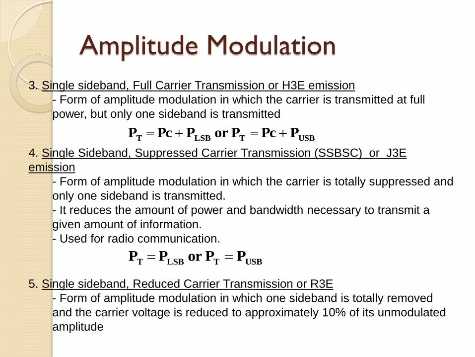
3. Single sideband, Full Carrier Transmission or H3E emission
- Form of amplitude modulation in which the carrier is transmitted at full
power, but only one sideband is transmitted
USBTLSBT P Pc Por P Pc P
4. Single Sideband, Suppressed Carrier Transmission (SSBSC) or J3E
emission
- Form of amplitude modulation in which the carrier is totally suppressed and
only one sideband is transmitted.
- It reduces the amount of power and bandwidth necessary to transmit a
given amount of information.
- Used for radio communication.
USBTLSBT PPor P P
5. Single sideband, Reduced Carrier Transmission or R3E
- Form of amplitude modulation in which one sideband is totally removed
and the carrier voltage is reduced to approximately 10% of its unmodulated
amplitude

Amplitude Modulation6. Two independent sidebands, with an attenuated or suppressed carrier
Transmission or B8E
- Also known as ISB (independent sideband emission).
- A form of amplitude modulation in which a single carrier frequency is
independently modulated by two different modulating signals.
- Used for HF point to point radiotelephony
7. Vestigial Sideband Transmission or C3F
- Used for TV video transmission
- A form of amplitude modulation in which the carrier and one complete
sideband are transmitted, but only part of the second sideband is
transmitted.
- Picture carrier and only a small vestige of the lower sideband is
transmitted to conserve bandwidth.
8. Amplitude Compandored Single Sideband (ACSSB)
- recently developed AM system in which the speech signal is compressed
at the transmitter and expanded at the receiver.

Amplitude Modulation
100x nsuppressiowithout power Total
nsuppressio during savedPower SAVING POWER %
PERCENTAGE POWER SAVING
SINGLE SIDEBAND TRANSMITTER RATING
R
VPK
2
2 PEP
Where: PEP = peak envelope power (W)
Vpk = peak voltage (V)
R = load resistance (ohms)

SAMPLE PROBLEM:
1. An audio signal whose mathematical representation is 25 sin 21000t
modulates a carrier described as 75 sin 2150000t. Determine the
following:
a) sketch of the modulating signal
b) sketch of the carrier
c) sketch of the AM wave
d) modulation index and percent modulation
e) instantaneous voltage equation of the AM signal
f) frequency spectrum of the AM signal
g) bandwidth
2. An antenna transmit an AM signal having a total power content of 15KW.
Determine the power being transmitted at the carrier and at each sideband
when the %M is 85% and find the efficiency of transmission.
3. An AM signal contains 4000W at the carrier frequency and 1000 W in
each of its sidebands. Determine the following:
a) total power of the AM signal
b) %M and m
c) total power of the AM signal when the %M is changed to 70%
4. When a broadcast transmitter is 50% modulated, its total antenna current
is 12 A. What is the carrier unmodulated current? What will be the total
modulated current when the modulation depth is increased to 0.9?

5. A certain transmitter radiates 9KW with the carrier unmodulated, and 12KW
when the carrier is sinusoidally modulated. Calculate the modulation index.
If another sine wave, corresponding to 30% modulation, is transmitted
simultaneously, determine the total modulation index and total radiated power.
6. The antenna current of an AM broadcast transmitter, modulated to a depth of
40% by an audio signal, is 10 A. It is increased to 12 A as a result of the
simultaneous modulation by another sine wave. Determine the following:
a) Carrier current
b) Total modulation index
c) Modulation index due to the second wave
7. A SSB transmission contains 800W. This transmission is to replaced by a
DSBFC AM signal with the same power content. Determine the power being
transmitted at the carrier and at each sideband when the %M is 85%. Find the
efficiency of transmission.
8. A SSB signal contains 10KW. How much power is contained in the sideband
and how much at the carrier?
9. A 500 W carrier is modulated to a depth of 75%. Calculate the total power in
the modulated wave in the following form of AM transmission.
a) DSBFC
b) DSBSC
c) SSBFC
d) SSBSC
REFERENCES
Electronic Communication Systems Through
Advanced by W. Tomasi
Communication Electronics by L. Frenzel
Lecture Notes in Principles of Communication
by A.H. Ballado and M.M. Sejera
Electronic Communication Systems by
G. Kennedy