Embed Size (px)
DESCRIPTION
Electrical machine design
Citation preview
04/17/2023 1
TRANSFORMERS
SARANATHAN COLLEGE OF ENGINEERING/Dept. of EEE
Transformer is a static device and its action is based on Faraday’s laws of electromagnetic induction principle that electrical energy may be efficiently transferred from one set of coils to another by means of varying magnetic flux with increase or decrease a voltage corresponding to decrease or increase a current without change in supply frequency
04/17/2023 2SARANATHAN COLLEGE OF ENGINEERING/Dept. of EEE
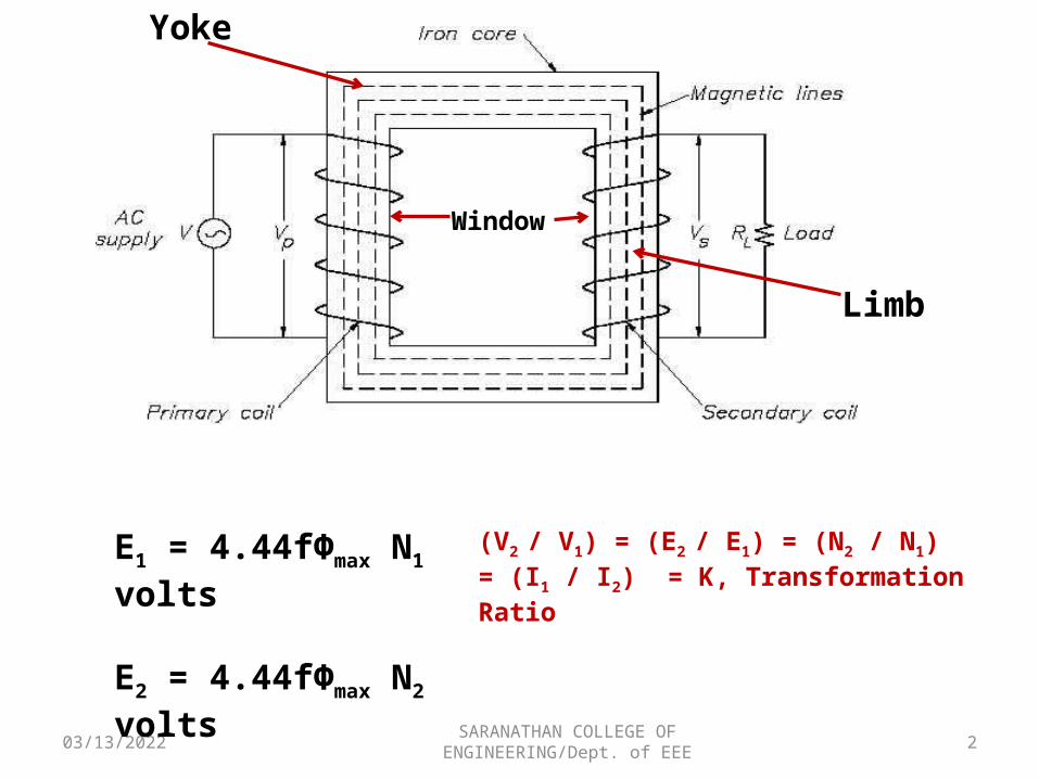
E1 = 4.44fФmax N1 volts
E2 = 4.44fФmax N2 volts
Limb
Yoke
(V2 / V1) = (E2 / E1) = (N2 / N1) = (I1 / I2) = K, Transformation Ratio
Window
04/17/2023 3SARANATHAN COLLEGE OF ENGINEERING/Dept. of EEE
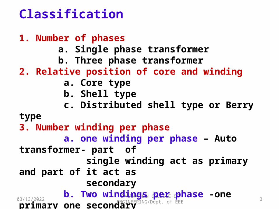
Classification
1. Number of phases a. Single phase transformer b. Three phase transformer2. Relative position of core and winding a. Core type b. Shell type c. Distributed shell type or Berry type3. Number winding per phase a. one winding per phase – Auto transformer- part of single winding act as primary and part of it act as secondary b. Two windings per phase -one primary one secondary winding is provided in each phase. The KVA rating of both windings are equal.
04/17/2023 4SARANATHAN COLLEGE OF ENGINEERING/Dept. of EEE
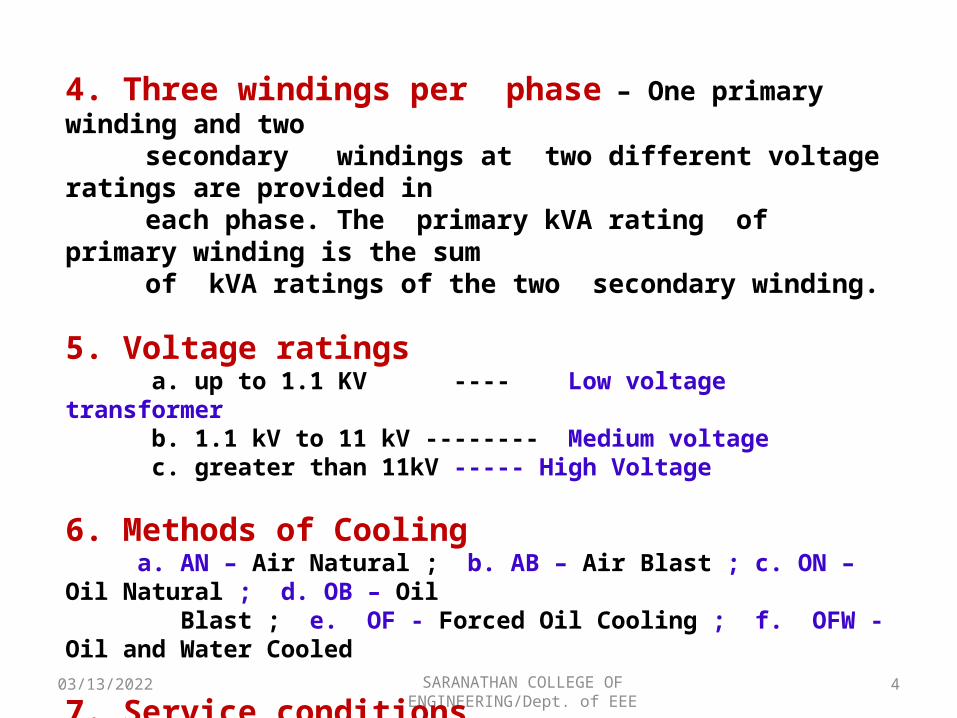
4. Three windings per phase – One primary winding and two secondary windings at two different voltage ratings are provided in each phase. The primary kVA rating of primary winding is the sum of kVA ratings of the two secondary winding.
5. Voltage ratings a. up to 1.1 KV ---- Low voltage transformer b. 1.1 kV to 11 kV -------- Medium voltage c. greater than 11kV ----- High Voltage
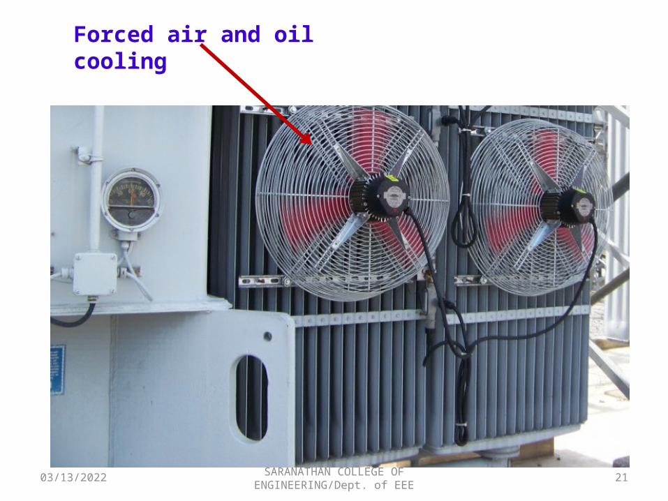
6. Methods of Cooling a. AN – Air Natural ; b. AB – Air Blast ; c. ON – Oil Natural ; d. OB – Oil Blast ; e. OF - Forced Oil Cooling ; f. OFW - Oil and Water Cooled
7. Service conditions a. Power Transformer b. Distribution Transformer
04/17/2023 5SARANATHAN COLLEGE OF ENGINEERING/Dept. of EEE
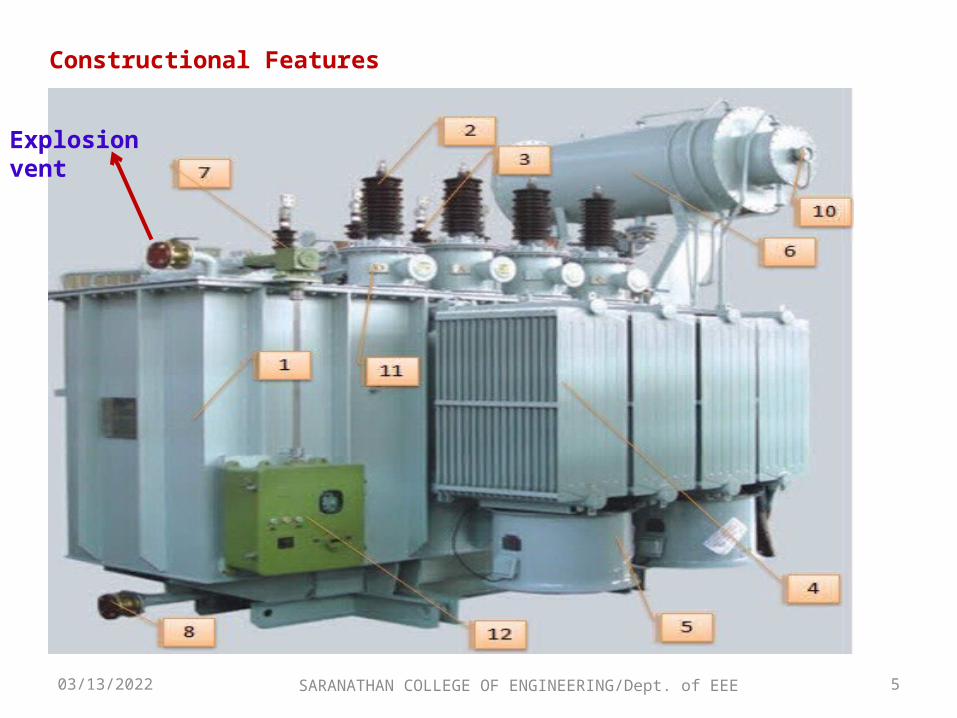
Constructional Features
Explosion vent
04/17/2023 6SARANATHAN COLLEGE OF ENGINEERING/Dept. of EEE
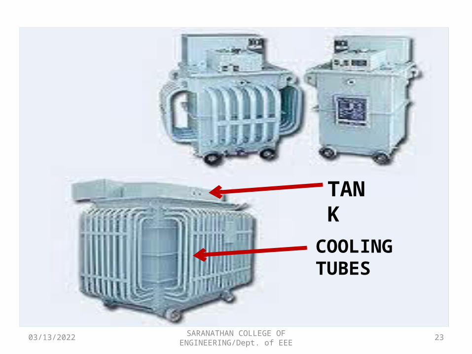
1. Transformer Tank – this holds the transformer windings and its insulating medium (oil-filled). Transformer tanks must be air-tightly sealed for it to isolate its content from any atmospheric contaminants.
2. High Voltage Bushing – this is the terminals where the primary windings of the transformer terminates and serves as an insulator from the transformer tank. Its creapage distance is dependent on the voltage rating of the transformer.
3. Low Voltage Bushing – like the high voltage bushing, this is the terminals where the secondary windings of the transformer terminates and serves as an insulator from the transformer tank. Low voltage bushing can be easily distinguished from its high voltage counterpart since low voltage bushings are usually smaller in size compared to the high voltage bushing.
4. Cooling Fins/Radiator – in order for the transformer to dissipate the heat it generated in its oil-insulation, cooling fins and radiators are usually attached to the transformer tanks. The capacity of the transformer is dependent to its temperature that is why it is imperative for it to have a cooling mechanism for better performance and higher efficiency.
04/17/2023 7SARANATHAN COLLEGE OF ENGINEERING/Dept. of EEE
5. Cooling Fans – can be usually found attached to the cooling fins. Cooling fans can be either be a timer controlled or a winding/oil temperature controlled. Cooling fans helps raises the transformer capacity during times when the temperature of the transformer rises due to its loading. Cooling fans used on the transformer are actuated by the help of a relaying device which when senses a relatively high temperature enables the fan to automatically run.
6. Conservator Tank – An oil preservation system in which the oil in the main tank is isolated from the atmosphere, over the temperature range specified, by means of an auxiliary tank partly filled with oil and connected to the completely filled main tank.
7. System Ground Terminal – system ground terminals in a power transformer are usually present whenever the connection type of the transformer windings has wye in it. This terminal can be found in-line with the main terminals of the transformer.
8. Drain Valve – can be usually found in the bottom part of the transformer tank. Drain valves are used whenever oil replacement is necessary. Through this valve, the replacement of oil in an oil-filled transformer can be easily done simply by opening this valve like that of a faucet.
04/17/2023 8SARANATHAN COLLEGE OF ENGINEERING/Dept. of EEE
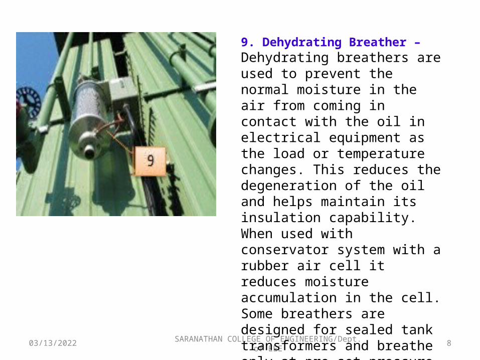
9. Dehydrating Breather – Dehydrating breathers are used to prevent the normal moisture in the air from coming in contact with the oil in electrical equipment as the load or temperature changes. This reduces the degeneration of the oil and helps maintain its insulation capability. When used with conservator system with a rubber air cell it reduces moisture accumulation in the cell. Some breathers are designed for sealed tank transformers and breathe only at pre-set pressure levels.
04/17/2023 9SARANATHAN COLLEGE OF ENGINEERING/Dept. of EEE
10. Oil Temperature/Pressure gauges – these are used for monitoring the internal characteristics of the transformer especially its windings. These gauges help the operator in knowing the level of temperature and pressure inside the transformer (oil & winding). This will also serve as an alarm whenever a certain level is reached that could be harmful to the transformer windings.
11. Bushing Current Transformers – modern transformer construction today now includes current transformers. These are usually found around the transformer terminals which will be later be used for metering and relaying purposes. Its terminals are found in the control panels attached to the transformer.
12. Control Panel – this houses all of the transformer’s monitoring devices terminals and auxiliary devices including the terminals of the bushing current transformers and cooling fans. Control panels are very useful especially when a remote control house is needed to be constructed, this will serve as their connection point.
13. Surge Arresters – this type of arresters are placed right directly before and after the transformer terminals in order to minimize the exposure of the transformer. Like any other surge arresters, its purpose is to clip sudden voltage surge that can be damaging to the winding of the transformer.
04/17/2023 SARANATHAN COLLEGE OF ENGINEERING/Dept. of EEE
10
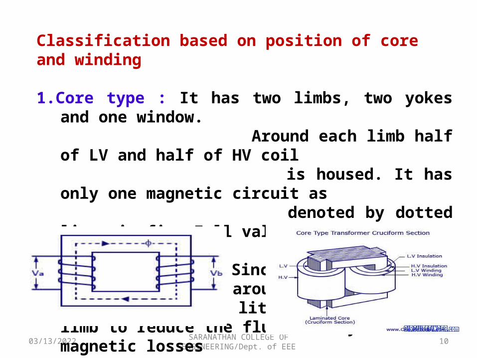
Classification based on position of core and winding
1.Core type : It has two limbs, two yokes and one window. Around each limb half of LV and half of HV coil
is housed. It has only one magnetic circuit as denoted by dotted lines in fig. Full value of flux
pass through both limbs and yokes. Since the
yokes do not have any windings around it, its area of cross-section is little more than the limb to reduce the flux density and hence magnetic losses
04/17/2023 11SARANATHAN COLLEGE OF ENGINEERING/Dept. of EEE
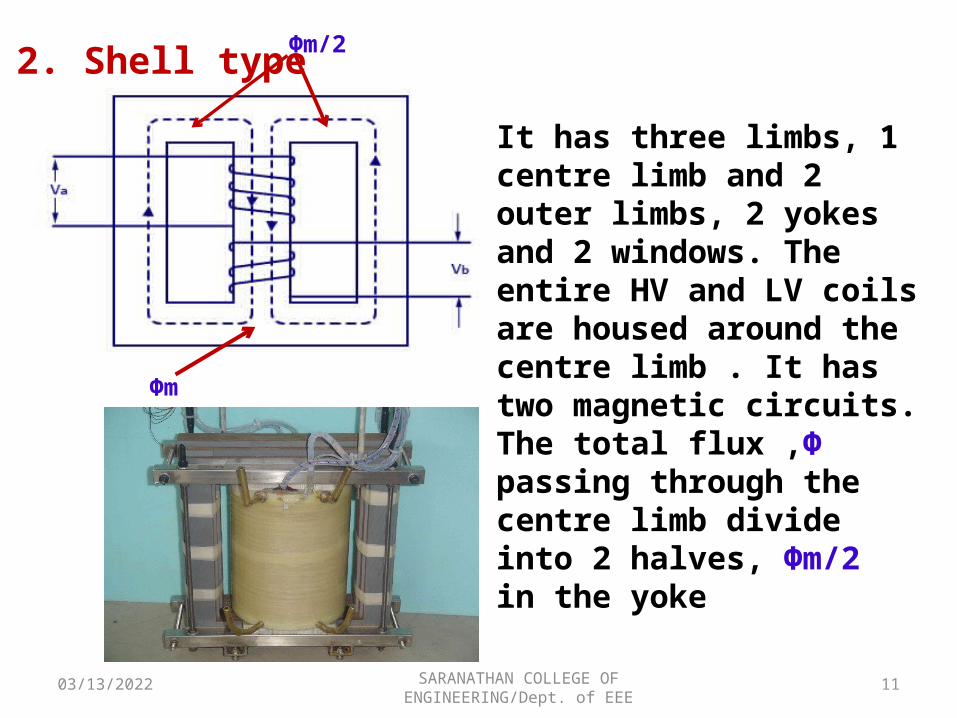
2. Shell type Фm/2
Фm
It has three limbs, 1 centre limb and 2 outer limbs, 2 yokes and 2 windows. The entire HV and LV coils are housed around the centre limb . It has two magnetic circuits. The total flux ,Ф passing through the centre limb divide into 2 halves, Фm/2 in the yoke
04/17/2023 12SARANATHAN COLLEGE OF ENGINEERING/Dept. of EEE
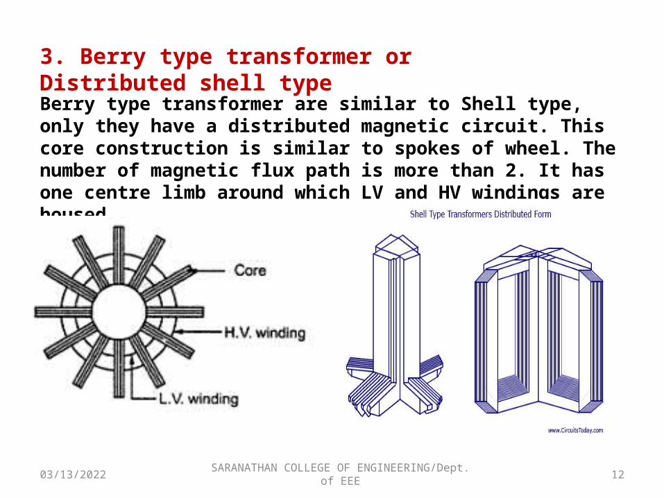
3. Berry type transformer or Distributed shell type
Berry type transformer are similar to Shell type, only they have a distributed magnetic circuit. This core construction is similar to spokes of wheel. The number of magnetic flux path is more than 2. It has one centre limb around which LV and HV windings are housed
04/17/2023 13SARANATHAN COLLEGE OF ENGINEERING/Dept. of EEE
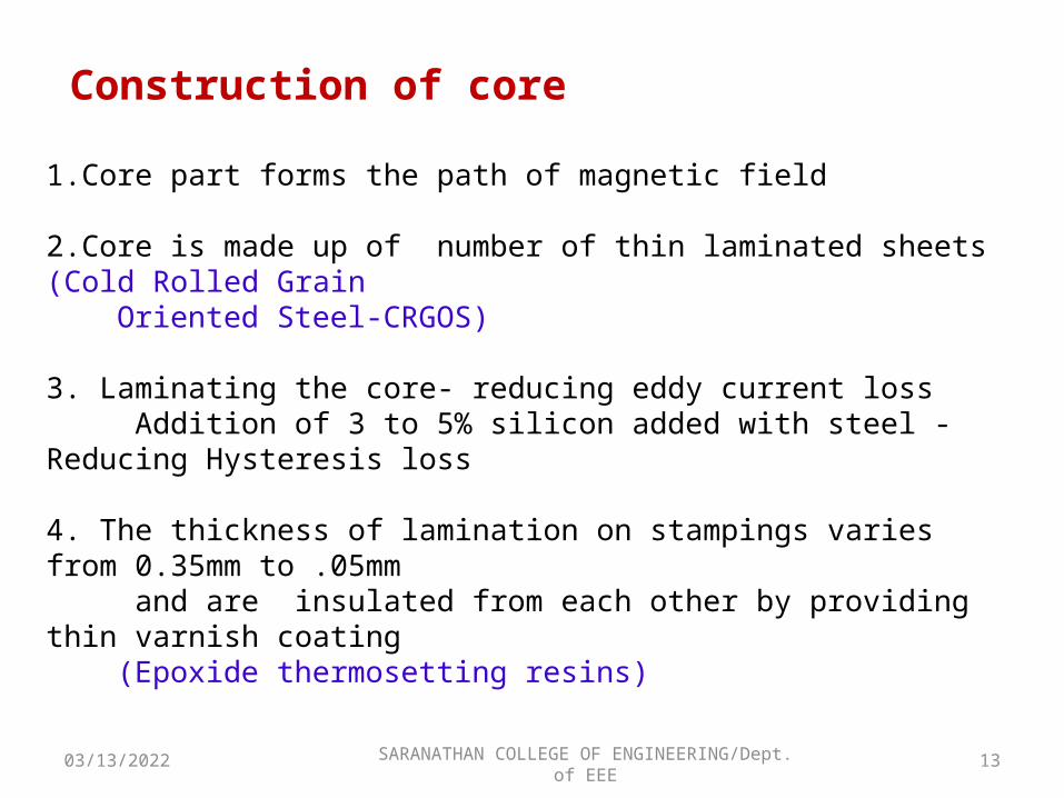
Construction of core
1.Core part forms the path of magnetic field
2.Core is made up of number of thin laminated sheets (Cold Rolled Grain Oriented Steel-CRGOS)
3. Laminating the core- reducing eddy current loss Addition of 3 to 5% silicon added with steel - Reducing Hysteresis loss
4. The thickness of lamination on stampings varies from 0.35mm to .05mm and are insulated from each other by providing thin varnish coating (Epoxide thermosetting resins)
04/17/2023 SARANATHAN COLLEGE OF ENGINEERING/Dept. of EEE
14
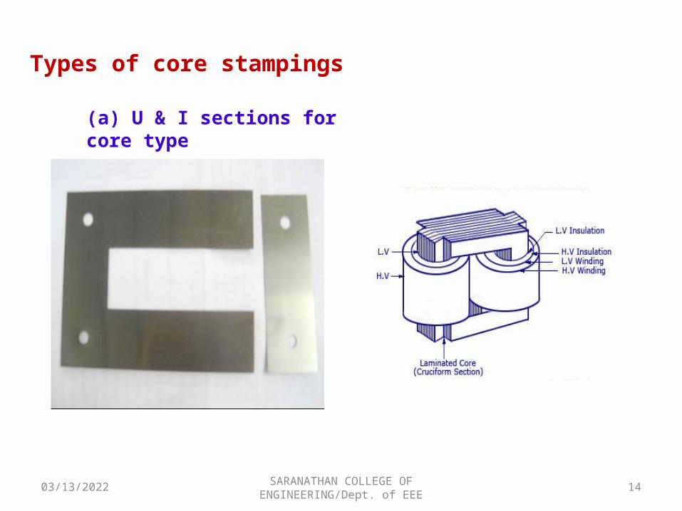
Types of core stampings
(a) U & I sections for core type
04/17/2023 15SARANATHAN COLLEGE OF ENGINEERING/Dept. of EEE
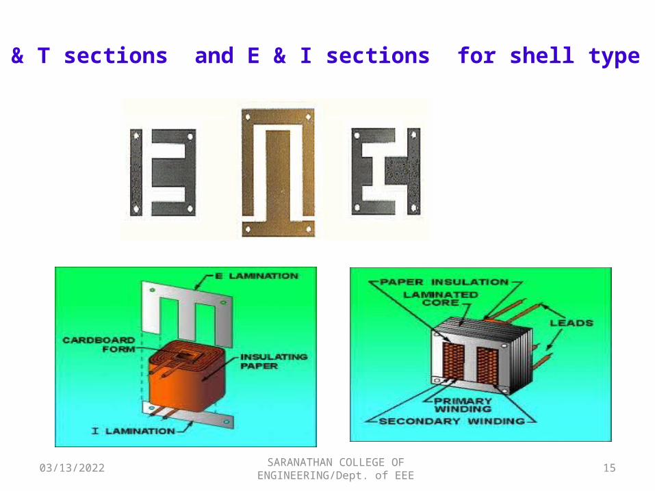
(b) U & T sections and E & I sections for shell type
04/17/2023 16SARANATHAN COLLEGE OF ENGINEERING/Dept. of EEE
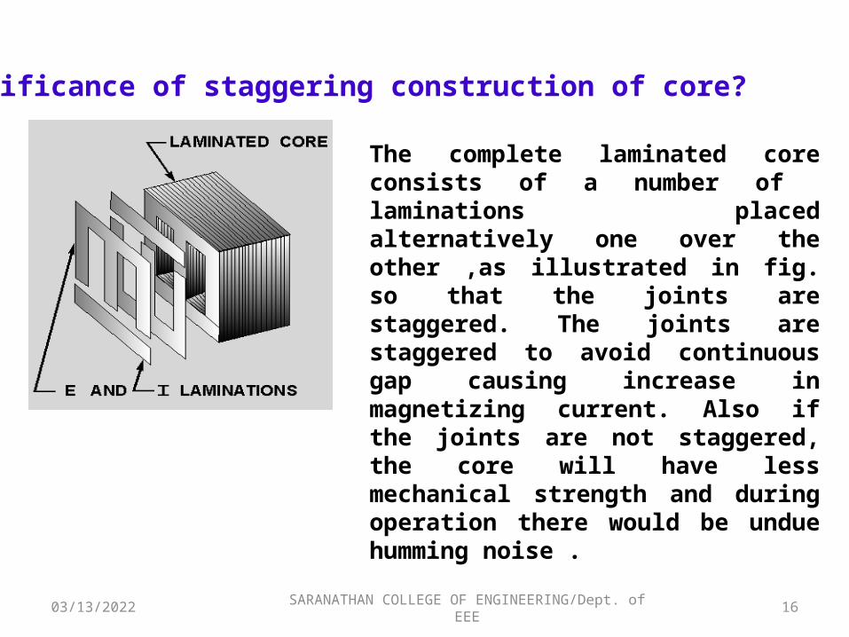
Significance of staggering construction of core?
The complete laminated core consists of a number of laminations placed alternatively one over the other ,as illustrated in fig. so that the joints are staggered. The joints are staggered to avoid continuous gap causing increase in magnetizing current. Also if the joints are not staggered, the core will have less mechanical strength and during operation there would be undue humming noise .
04/17/2023 17SARANATHAN COLLEGE OF ENGINEERING/Dept. of EEE
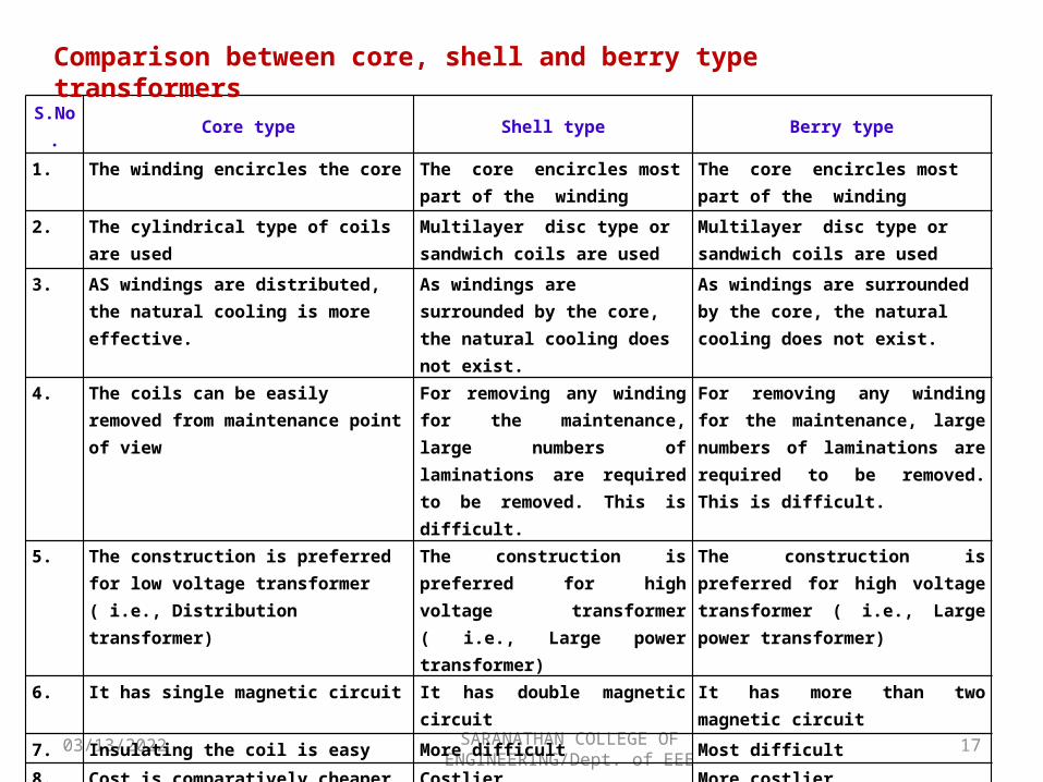
S.No. Core type Shell type Berry type
1. The winding encircles the core The core encircles most part of the winding
The core encircles most part of the winding
2. The cylindrical type of coils are used Multilayer disc type or sandwich coils are used
Multilayer disc type or sandwich coils are used
3. AS windings are distributed, the natural cooling is more effective.
As windings are surrounded by the core, the natural cooling does not exist.
As windings are surrounded by the core, the natural cooling does not exist.
4. The coils can be easily removed from maintenance point of view
For removing any winding for the maintenance, large numbers of laminations are required to be removed. This is difficult.
For removing any winding for the maintenance, large numbers of laminations are required to be removed. This is difficult.
5. The construction is preferred for low voltage transformer ( i.e., Distribution transformer)
The construction is preferred for high voltage transformer ( i.e., Large power transformer)
The construction is preferred for high voltage transformer ( i.e., Large power transformer)
6. It has single magnetic circuit It has double magnetic circuit It has more than two magnetic circuit
7. Insulating the coil is easy More difficult Most difficult
8. Cost is comparatively cheaper than other types
Costlier More costlier
Comparison between core, shell and berry type transformers
04/17/2023 18SARANATHAN COLLEGE OF ENGINEERING/Dept. of EEE
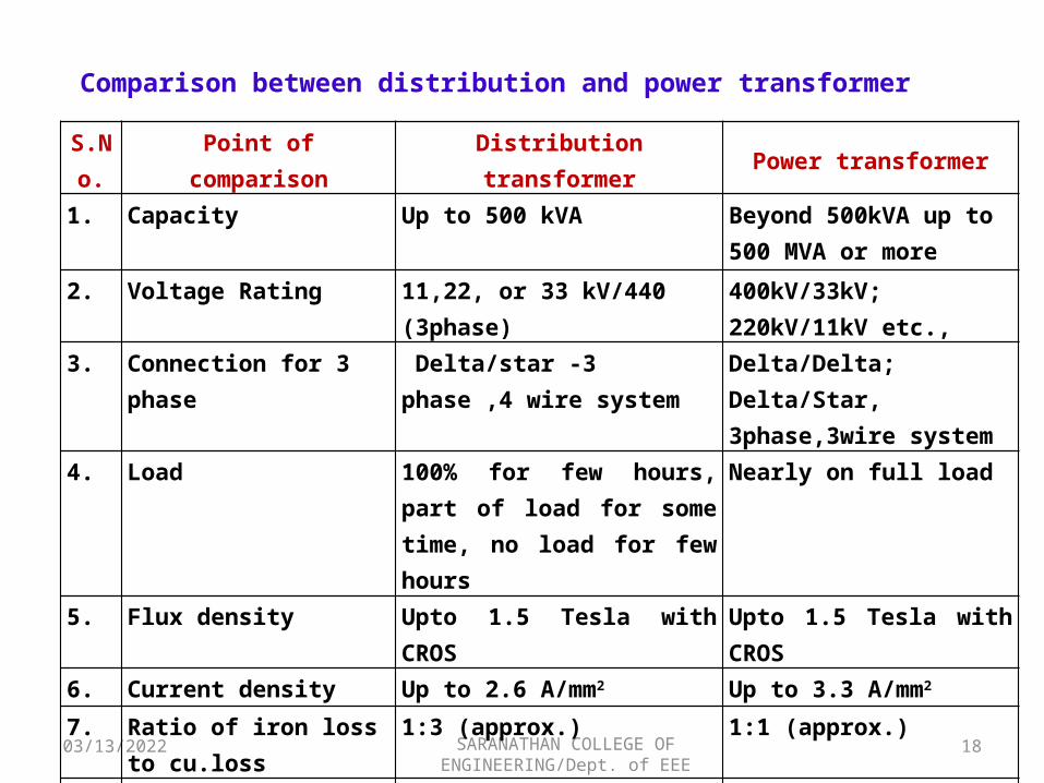
S.No. Point of comparison Distribution transformer Power transformer
1. Capacity Up to 500 kVA Beyond 500kVA up to 500 MVA or more
2. Voltage Rating 11,22, or 33 kV/440 (3phase) 400kV/33kV; 220kV/11kV etc.,
3. Connection for 3 phase Delta/star -3 phase ,4 wire system
Delta/Delta; Delta/Star, 3phase,3wire system
4. Load 100% for few hours, part of load for some time, no load for few hours
Nearly on full load
5. Flux density Upto 1.5 Tesla with CROS Upto 1.5 Tesla with CROS
6. Current density Up to 2.6 A/mm2 Up to 3.3 A/mm2
7. Ratio of iron loss to cu.loss 1:3 (approx.) 1:1 (approx.)
8. Regulation 4 to 9% 6 to 10%
9. Cooling Self oil cooled Forced oil and fan cooled
Comparison between distribution and power transformer
04/17/2023 SARANATHAN COLLEGE OF ENGINEERING/Dept. of EEE
19
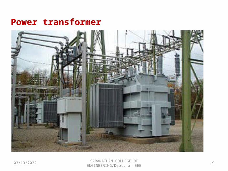
Power transformer
04/17/2023 SARANATHAN COLLEGE OF ENGINEERING/Dept. of EEE
20
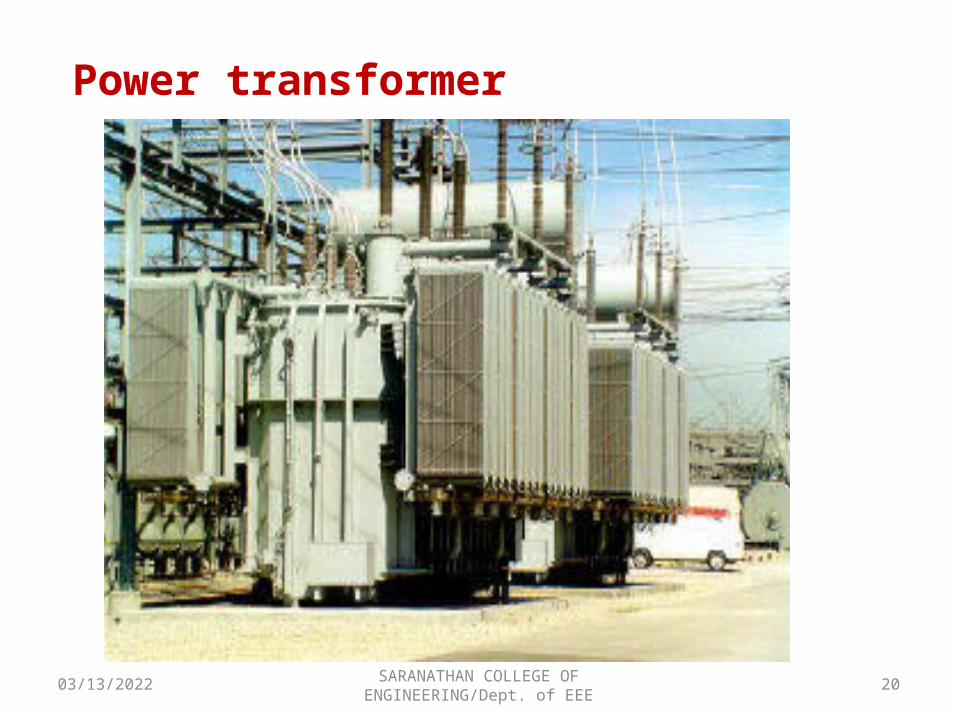
Power transformer
04/17/2023 SARANATHAN COLLEGE OF ENGINEERING/Dept. of EEE
21
Forced air and oil cooling
04/17/2023 SARANATHAN COLLEGE OF ENGINEERING/Dept. of EEE
22
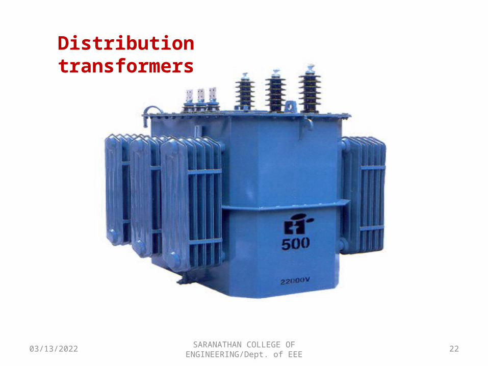
Distribution transformers
04/17/2023 SARANATHAN COLLEGE OF ENGINEERING/Dept. of EEE
23
TANK
COOLING TUBES
04/17/2023 SARANATHAN COLLEGE OF ENGINEERING/Dept. of EEE
24
04/17/2023 25
Applications
SARANATHAN COLLEGE OF ENGINEERING/Dept. of EEE
1.Stepping up of voltageGenerally generating stations are situated far away from the consumers, electrical energy is generated at a voltage of around 11kV,or 22kV. From transmitting the power from generating stations to the place of use by long transmission lines, it is more economical to raise the level of voltage transmission to 220 kV to 440kV. This stepping up of voltage is carried out by installing transformers. 2.Stepping down of voltageHT consumers are provided with electric power at 11kV or 6.6kV, 3phase and LT consumers are provided with electric power at 415 V , 3 phase. This stepping down of voltage is carried out by installing transformers.3. Instrument Extension To measures high currents in the order of several hundred amps and voltage of several kilo-volts, instrument transformers (CT and PT) are used along with ammeters and voltmeters of lower range .
04/17/2023 SARANATHAN COLLEGE OF ENGINEERING/Dept. of EEE
26
4. Electrical Isolation In transformer power is transferred from primary to secondary via magnetic field. There is no conductive connection between the primary and secondary.(i.e. Both windings are inductively connected through core.)
Although any transformer with a separate primary and secondary winding is an isolation transformer to some extent, The term is usually used to denote a special-purpose transformer built just for that use. It is tested and rated to withstand a very high voltage difference, called the withstand voltage, so that even if thousands of volts are applied to the primary, it will not leak through to the protected side. These transformers are used in the medical industry, to protect patients hooked up to monitoring instruments that are powered by utility mains, as well as other uses.
04/17/2023 SARANATHAN COLLEGE OF ENGINEERING/Dept. of EEE
27
5. Impedance matching According to maximum power transfer theorem, maximum power is transferred from source to load only if load impedance is equal to source impedance. In case the actual impedance is not equal to source impedance, in between source and load, a transformer can be used for impedance matching. For example , loud speakers being connected to amplifiers.
04/17/2023 SARANATHAN COLLEGE OF ENGINEERING/Dept. of EEE
28
6. Link between AC and DC systems
Appliances and equipments like radios, TV, electronic motor controllers, computers etc. function with electronic circuits. They require suitable DC Supply. As normal power is available is only AC in nature, rectifiers are used to convert AC supply to DC supply. In between AC supply and rectifier a transformer is used for two purposes, to change the level of voltage and also to provide electrical isolation.
04/17/2023
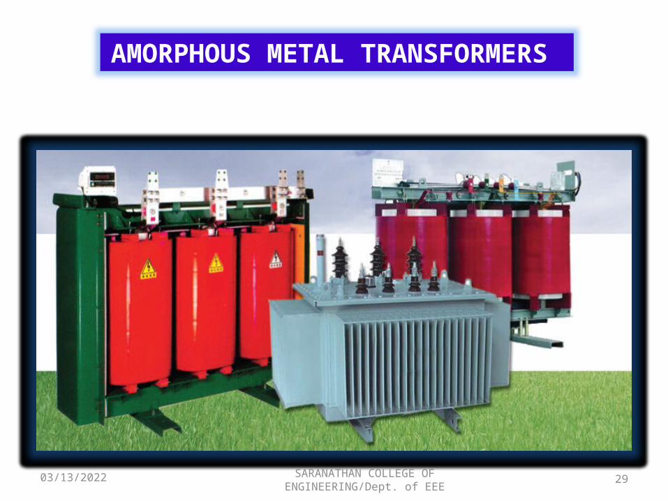
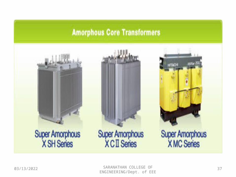
AMORPHOUS METAL TRANSFORMERS
29SARANATHAN COLLEGE OF ENGINEERING/Dept. of EEE
04/17/2023 30
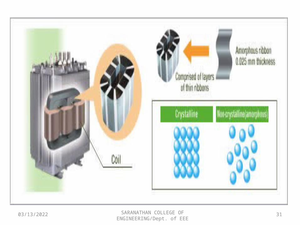
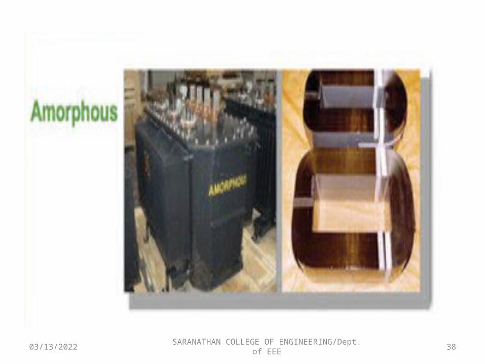
What is an amorphous alloy?
Metals have a crystalline structure with an orderly arrangement of atoms. A metal in a liquid state at a high temperature can retain its liquid structure upon solidifying if it is cooled rapidly. The resulting non-crystalline alloy has a random arrangement of crystals and is called an amorphous alloy. Amorphous alloys have excellent strength and electrical characteristics, but require advanced techniques for machining.
SARANATHAN COLLEGE OF ENGINEERING/Dept. of EEE
04/17/2023 31SARANATHAN COLLEGE OF ENGINEERING/Dept. of EEE
04/17/2023 SARANATHAN COLLEGE OF ENGINEERING/Dept. of EEE
32
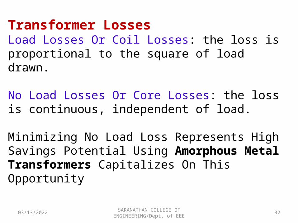
Transformer LossesLoad Losses Or Coil Losses: the loss is proportional to the square of load drawn.
No Load Losses Or Core Losses: the loss is continuous, independent of load.
Minimizing No Load Loss Represents High Savings Potential Using Amorphous Metal Transformers Capitalizes On This Opportunity
04/17/2023 SARANATHAN COLLEGE OF ENGINEERING/Dept. of EEE
33
Why Amorphous Metal for Transformers?No Load Losses
► Hysteresis LossRandom molecular structure of amorphous metal causes less friction than SiFe when a magnetic field is applied. This unique property which allows ease of magnetization & demagnetization significantly lowers hysteresis losses in amorphous metals.
► Eddy Current LossAmorphous metals have very thin laminations. Thin laminations result in lower eddy current losses as compared to SiFe.
04/17/2023 34SARANATHAN COLLEGE OF ENGINEERING/Dept. of EEE
What are amorphous metal transformers? Where do you find it?
Transformer that uses amorphous metal as magnetic core material. It is found at the distribution voltage level grid (below 35kV). Comparing with traditional silicon steel based transformer, AMT reduces core loss by about 70%.
04/17/2023 35SARANATHAN COLLEGE OF ENGINEERING/Dept. of EEE
Which countries have deployed this technology? Who can supply this type of transformer?
The AMT technology is applied extensively globally. Currently, China, India, the US, Japan and South Korea are the most steady users. China, for example, installed 25 - 30 million KVA of AMT in 2010. A number of ASEAN countries are at an early phase of deployment. Multinationals such as ABB (Asea Brown Boveri) , GE (General Electric) and Hitachi are all capable of supplying AMT. Meanwhile, a good number of regional manufacturers are also capable of supplying this type of transformer.
04/17/2023 SARANATHAN COLLEGE OF ENGINEERING/Dept. of EEE
36
Advantages of Amorphous Metal Transformers (AMT) ?
IMPROVED ENERGY EFFICIENCY: AMTs reduce power transformer “no-load” losses by around 70% compared to traditional silicon steel transformers.
COST SAVINGS: By reducing no-load loss, AMTs enhance distribution efficiency and offer savings in generation capacity investments.
ENVIRONMENTAL PROTECTION: Because of the reduced generation need, the use of AMTs lowers CO2 emission and helps to protect the environment.
04/17/2023 37SARANATHAN COLLEGE OF ENGINEERING/Dept. of EEE
04/17/2023 38SARANATHAN COLLEGE OF ENGINEERING/Dept. of EEE
04/17/2023 39SARANATHAN COLLEGE OF ENGINEERING/Dept. of EEE
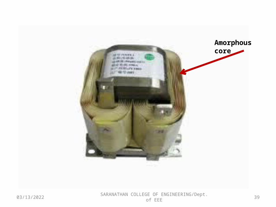
Amorphous core
04/17/2023 SARANATHAN COLLEGE OF ENGINEERING/Dept. of EEE
40
Why transformer rating in kVA? AS seen , cu. Loss of a transformer depends on current and iron loss on voltage. Hence, total transformer loss on volt-ampere (VA) and not on phase angle between voltage and current i.e. it is independent of load power factor. That is why rating of transformers is in kVA and not in kW
04/17/2023 SARANATHAN COLLEGE OF ENGINEERING/Dept. of EEE
41
What happen if a transformer connected to a DC source?
If a rated voltage dc voltage applied to the primary of a transformer , the flux produced in the transformer core will not vary but remains constant in magnitude and therefore, no emf will be induced in the secondary winding except at the moment of switching on. Thus the transformer is not capable of raising or lowering the dc voltage. Also there will be no self induced emf in the primary winding , which is only possible with varying flux linkage , to oppose the applied voltage and since the resistance of primary winding is quite low, therefore heavy current will flow through the primary winding which may result in the burning out of the primary winding. This is reason that dc is never applied to a transformer.