Embed Size (px)
Citation preview

Version 1.0 for
Contractors and Site Inspectors
A M E R I C A N S A M O A E R O S I O N & S E d I M E N t C O N t R O l
Field Guide

PurposeThis field guide was designed specifically for contractors in American Samoa involved in clearing, grading, stockpiling, and other earth-moving activities at all construction sites. Its provisions will be administered and enforced pursuant to the American Samoa Water Quality Standards, ASAC 24.02 and the American Samoa Coastal Management Program Administrative Rules, ASAC 26.02. To help contractors implement best management practices for erosion and sediment control (ESC), this field guide:
▪ Explains why ESC is an important part of the construction process
▪ Summarizes ESC practice design, installation, and maintenance tips
▪ Outlines inspection and project closeout considerations
▪ Serves as a reference for use in the field
▪ Relies primarily on graphical illustrations for multi-lingual users
▪ Is not a substitute for more detailed practice design or technical specifications
Prepared for:The American Samoa Environmental Protection Agency (AS-EPA) and the American Samoa Coastal Zone Management Program (ASCMP)
Prepared by:Horsley Witten Group, Inc.May 2011
Funding provided by: American Samoa Coastal Management Program (ASCMP)Department of Commerce, American Samoa Government
Adapted from: 2009 CNMI Erosion and Sediment Control Field Guide, CNMI DEQ

chapter why erosion and sediment control?Impacts of Construction ............................................1
Site Factors Contributing to Erosion ........................... 4
ESC Regulations and Principles ................................... 5
Proper Construction Sequencing ................................ 9
Contractor and Inspector Responsibilities ................10
chapter
chapter
chapter
chapter
2345
1sediment BarriersBuffer and Tree Protection .......................................11
Stabilized Construction Entrance ............................13
Silt Fencing ...............................................................16
Silt Fence Alternatives..............................................21
Turbidity Curtain ........................................................... 23
diversions and trapsDiversion Berms and Swales ...................................... 25
Check Dams ..............................................................28
Vegetated and Lined Waterways ............................... 30
Sediment Traps and Basins ......................................... 33
staBilization practicesStabilization with Vegetation, Mulch, or Topsoil .....37
Surface Roughening......................................................... 40
Pipe Slope Drains .................................................... 42
Erosion Control Blankets..........................................44
inlet and outlet protectionInlet Protection........................................................ 47
Rock Outlet Protection ........................................... 51
Level Spreader ......................................................... 54

chapter managing road constructionESC During Construction ................................. 57
Unpaved Roads .......................................................57
Road Maintenance ............................................ 62
chapter 76
maintaining and closing out projectsInspections and Maintenance......................... 63
Managing Trash, Supplies, and Materials ..... 65
Removing Temporary Practices . . . . . . . . . . . . . . . . . .65
Permanent Stormwater Management ............66

chapter
cha
pter
1
Impacts of Construction
Site Factors Contributing to Erosion
ESC Regulations and Principles
Proper Construction Sequencing
Contractor and Inspector Responsibilities
w h y e r o s i o n a n d s e d i m e n t c o n t r o l ?1
To protect the
environment and fulfill
your responsibilities, it is
important to understand
why ESC is a critical part of
the construction process.


| 1E R O S I O n & S E D I M E n T C O n T R O L F I E L D G U I D E
Impacts of ConstructionThere is a direct link between land
alteration and the health of streams,
wetlands, coastal waters, and aquifers. The
conversion of vegetated areas to buildings,
roads, and parking lots changes surface
and groundwater drainage processes,
which can have a negative impact on our local environment and economy. These impacts
begin during construction and
are influenced by rainfall, site
conditions, and our ability to
apply proper erosion and sediment
control (ESC) practices.

W h y E R O S I O n & S E D I M E n T C O n T R O L ?2 |
Before clearing and grading,
native vegetation absorbs rainfall, slows
runoff velocities, protects soil
from erosion, and allows for
infiltration into the ground.
Land cleared for new development removes vegetation and exposes valuable soil to erosion, and heavy equipment compacts
soils. These factors result in more surface runoff
and less recharge to important aquifers.
Sediment buildup can clog
drainage systems and lead to
flooding of roadways and
properties.
Sediment-laden runoff ultimately discharges
into streams, wetlands, and marine waters.
Sediment particles carry toxic pollutants and
nutrients that can reduce water quality.
| 3E R O S I O n & S E D I M E n T C O n T R O L F I E L D G U I D E
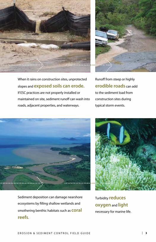
When it rains on construction sites, unprotected
slopes and exposed soils can erode. If ESC practices are not properly installed or
maintained on site, sediment runoff can wash into
roads, adjacent properties, and waterways.
Runoff from steep or highly
erodible roads can add
to the sediment load from
construction sites during
typical storm events.
Turbidity reduces oxygen and light
necessary for marine life.
Sediment deposition can damage nearshore
ecosystems by filling shallow wetlands and
smothering benthic habitats such as coral reefs.

W h y E R O S I O n & S E D I M E n T C O n T R O L ?4 |
Site Factors Contributing to ErosionSeveral factors contribute to increased erosion at construction sites (Figure 1.1). Erosion and sediment loss is more likely to occur when:
▪Native vegetation is removed, and soils are exposed to erosive rainfall and surface runoff.
▪erodible soils are present. Most soils in American Samoa are classified as highly erodible by USDA-NRCS.
▪steep slopes exist on site. Unlike flat terrain, water concentrates and travels faster down steep slopes. Sediment on cut and fill slopes is particularly vulnerable to erosion.
▪ESC practices are not properly installed or maintained. this field manual describes appropriate techniques to prevent erosion and control sediment.
▪Average annual rainfall on Tutuila ranges between 125 and 260 inches (Figure 1.2).
Figure 1.1. Factors contributing to construction site erosion (Adapted from: Tetra Tech).

| 5E R O S I O n & S E D I M E n T C O n T R O L F I E L D G U I D E
Regulatory Considerations for ESC
In American Samoa, the U.S. Environmental Protection Agency administers the National Pollutant Discharge Elimination System (NPDES), which was established under the federal Clean Water Act to address stormwater runoff from construction sites and other sources.
The practices in this guide are also necessary to ensure compliance with the American Samoa Water Quality Standards, ASAC 24.02, and the American Samoa Coastal Management Program, ASAC 26.02. Additional information can be found in AS-EPA’s Guidance Manual for Runoff Control and on the AS-EPA website at www.asepa.gov.
Figure 1.2. Mean annual precipitation for American Samoa (natural history Guide to American Samoa, 3rd Edition, 2009).

W h y E R O S I O n & S E D I M E n T C O n T R O L ?6 |
Core Principles of ESC
Best Management
Practices
1
3
6
9
4
7
10

| 7E R O S I O n & S E D I M E n T C O n T R O L F I E L D G U I D E
ESC Principles
1. Minimize unnecessary clearing and grading to preserve existing natural areas
2. Protect waterways and stabilize drainage ways
3. Phase construction to limit soil exposure
4. Stabilize exposed soils immediately (~7 days)
5. Protect steep slopes and cuts from erosion
6. Install perimeter controls to keep sediment on site
7. Employ advanced sediment settling control devices
8. Train and certify contractors on ESC plan implementation
9. Conduct a pre-construction site meeting and adjust plan if necessary
10. Where feasible, schedule construction during dry weather
11. Maintain ESC controls throughout the entire construction process
2
5
8
11

W h y E R O S I O n & S E D I M E n T C O n T R O L ?8 |
For effective ESC
practices, the order of
construction should
follow these steps:

| 9E R O S I O n & S E D I M E n T C O n T R O L F I E L D G U I D E
Proper Construction Sequencing 1. hold preconstruction meeting
2. Mark limits of disturbance to protect waterway buffer, existing vegetation, and other resources
3. Clear/grub areas necessary to construct ESC practices
4. Stabilize construction entrance and install neces-sary perimeter controls and diversions
5. Install temporary sediment trapping devices and runoff conveyance systems
6. Complete clearing and rough grading where necessary (minimized and phased)
7. Provide temporary stabiliza-tion with vegetation or mulch for inactive, disturbed areas
8. Construct utilities, roads, and buildings
9. Convert/install permanent stormwater practices
10. Stabilize with permanent vegetation
11. Remove temporary ESC devices
(Adapted from: Center for Watershed Protection)

W h y E R O S I O n & S E D I M E n T C O n T R O L ?1 0 |
Contractor ResponsibilitiesIt is the job of the contractor to:
Be trained in ESC principles, practice installation, and maintenance procedures.
Install ESC practices according to the ESC plan.
Follow appropriate construction sequencing.
Educate operators and site workers on the importance of proper ESC practices.
Protect waterways, trees, and other natural areas from construction activities.
Inspect ESC practices routinely, especially after rainfall events.
Make sure practices are maintained, repaired, and reinstalled when necessary.
Communicate with supervisor and/or inspector any concerns related to ESC.
Properly remove practices at end of construction only after site is permanently stabilized.
Inspector ResponsibilitiesIt is the job of the site inspector to:
Understand regulations affecting construction site activities and proper ESC practice application.
Be familiar with the approved ESC plan, construction sequencing, and specifications.
Communicate expectations for cooperative ESC implementation.
Inspect site weekly, within 24 hours of major rainfall event, and at critical points during the construction process.
Anticipate where ESC problems may occur.
Ensure ESC practices are properly installed, maintained, and performing adequately. Provide input for improvement or minor modifications in the field.
Maintain detailed records of inspections with reports, photos, and rainfall records.
Establish clear time frames for corrective actions to be completed. Follow up.
Initiate any enforcement actions.

chapter
Buffer and Tree Protection
Stabilized Construction Entrance
Silt Fencing
Silt Fence Alternatives
Turbidity Curtain
Before extensive clearing
and grading occurs, barriers
should be installed at vehicle
entrances and at key perimeter
locations to keep sediment
from leaving the site.
s e d i m e n t B a r r i e r s2 cha
pter
2


| 1 1E R O S I O n & S E D I M E n T C O n T R O L F I E L D G U I D E
B u f f e r a n d t r e e p r o t e c t i o n
DefinitionDuring construction activities, measures should be taken to ensure natural areas remain undisturbed. Where possible, clearing should be limited to areas needed to construct buildings, roadways, septic systems, and utilities. Preservation of natural vegetation, steep slopes, and buffers helps minimize erosion, protects water quality, and is cost-effective.
Design & Installation▪Before clearing, mark areas to be
preserved. Use temporary wood fencing, plastic construction fencing, flagging, and/or signage.
▪ Install fencing outside of the buffer zone and outside of tree dripline to protect roots.
▪ Locate temporary roadways, stockpiles, and layout areas to avoid stands of trees, shrubs, and grass.
▪Instruct all workers to honor protective devices.
▪Prohibit heavy equipment, vehicular traffic, or storage of construction materials within the protected area.
▪Consider the impact of grade changes to vegetation and roots.
▪Do not remove until site cleanup and final stabilization is complete.
Maintenance RequiredDuring construction, the limits of disturbance should remain clearly marked at all times. Verify that protective measures remain in place. Restore damaged protection measures immediately. Serious tree injuries shall be attended to by a tree specialist.
Common Problems▪protected areas not clearly
marked. Use construction fencing and signage.
▪sediment discharges into protected area. Remove deposited sediment and install proper ESC practices.
▪large tree roots cut or exposed. Extend fencing beyond dripline to protect roots. Remove the ends of damaged roots with a smooth cut. Cover exposed roots with soil.
▪soil compacted over roots. Aerate soil by punching holes 12 inches deep, 18 inches apart.

1 2 | S E D I M E n T B A R R I E R S
Good use of highly visible construction fencing to mark limit of disturbance. Additional bilingual signage installed to identify area as protected.
Good combination of a double row of silt fence, brush berm, and temporary seeding to protect buffer area from construction site erosion. = good use of practice = poor use of practice
Failure to adequately maintain/protect a buffer zone between the stream and construction activities. Encroachment reduces buffer filtering capacity and can lead to in-stream sediment deposition.
Wooden frame with construction fence to protect tree from heavy equipment and debris. Fence does not fully extend beyond tree dripline in this example leaving roots unprotected.

| 1 3E R O S I O n & S E D I M E n T C O n T R O L F I E L D G U I D E
s t a B i l i z e d c o n s t r u c t i o n e n t r a n c e
DefinitionStabilized construction entrances are temporary crushed rock pads located at all points where vehicles enter or leave a construction site. The purpose of a stabilized entrance is to reduce the tracking of sediment/mud from the site onto paved roads and parking lots.
Design & Installation▪Locate entrance to provide for
maximum use by all construction vehicles.
▪Place woven or non-woven geotextile fabric over entire area to be covered with rock.
▪Spread minimum 6-inch thick layer of 1- to 4-inch rock , or reclaimed/recycled concrete equivalent on top of fabric.
▪Minimum width of entrance should be 12 feet (24 feet if only access point), but not less than the full width of access point. Ends should be tapered to meet street.
▪Minimum length of 50 feet (30 feet on single residential lots).
▪Piping of surface water under entrance or a moundable berm shall be provided as required (Figure 2.1).
▪When necessary, wheels should be cleaned to remove sediment prior to leaving site. If a washing area is required, drainage should be directed to a sediment trap rather than storm drains, ditches, or watercourses.
Use available crushed
rock or recycled concrete
equivalent for temporary
construction entrance.

1 4 | S E D I M E n T B A R R I E R S
Maintenance RequiredThe condition of crushed rock should be monitored periodically and maintained after heavy use or heavy rainfall to prevent tracking or flowing of sediment onto rights-of-way. This may require periodic top dressing with additional rock.
All sediment spilled, dropped, or washed onto public rights-of-way must be removed immediately and more rock added as needed.
Common Problems▪crushed rock compacted into
ground. Install layer of fabric underneath and reapply rock.
▪crushed rock full of sediment. Top-dress with additional rock or wash and drain to sediment trapping device.
▪ vehicles going around stabilized entrance. Be sure to taper edges to street. Expand entrance width or install barriers to direct traffic to entrance.
Figure 2.1. Stabilized construction entrance with optional mountable berm.

| 1 5E R O S I O n & S E D I M E n T C O n T R O L F I E L D G U I D E
Entrance is paved and slopes back towards site. hoses (on left) are provided for washing tires; however, tracks indicate infrequent compliance. Stabilized entrances are supposed to be tempo-rary. Drainage should be directed to a sediment trapping device.
Good example of a stabilized entrance pad. Fabric is installed beneath rock layer. Fencing used to keep traffic on pad and block sediment from surrounding area (Source: University of Illinois).
Sediment accumulation shows that entrance has not been maintained. Fabric was not used beneath rock layer to prevent sinking. Rock should be washed or re-applied.

1 6 | S E D I M E n T B A R R I E R S
s i lt f e n c i n g
DefinitionA temporary barrier of geotextile fabric, silt fencing is installed across a slope, around stockpiles, or along a perimeter. The purpose of a silt fence is to intercept sediment-laden runoff from small drainage areas of disturbed soil, slow runoff velocity, and allow sediment to settle out.
Design & Installation▪Install before extensive land clearing
activities begin.
▪ Place fencing close to disturbed area, but ~10 feet from toe of slope to allow for sediment build up and maintenance access. The area beyond the fence should be undisturbed or stabilized.
▪ Install perpendicular to flow direction. Turn ends uphill to prevent bypass of water around fence.
▪ On long slopes, install multiple rows of fencing at separation distances based on slope steepness (Table 2.1 and Figure 2.3).
▪silt fence should receive only sheet flow, not concentrated flow.
▪Dig 4-inch wide by 6-inch deep trench. Install posts every 5-10 feet on downhill side of trench at least 16 inches deep. Use “T” or “U” type steel or sturdy wooden posts (3 square inch cross section).
▪ Place fabric along bottom of trench. Attach to posts with wire or plastic ties every ½ foot. Fold and tie posts together to overlap fabric at ends.
▪Backfill trench with soil and compact.
▪Reinforce fabric with heavy wire support fencing to prevent collapse where necessary (Figure 2.2).
Silt fences often fail due to
poor installation or lack
of maintenance.
slope steepnessmaximum length (ft)
2:1 25
3:1 50
4:1 75
5:1 or flatter 100
Table 2.1. Distance Between Rows

| 1 7E R O S I O n & S E D I M E n T C O n T R O L F I E L D G U I D E
Maintenance RequiredInspect daily. Repair if sagging, flapping, or bulging is noticeable, or if erosion or spillover is observed. Remove sediment and debris when build up reaches ⅓ height of fencing. If site is inactive, continue to inspect after every rain event.
Common Problems ▪not maintained. Should be
inspected daily. Remove accumulated sediment when buildup is ⅓ height of fence, and replace torn fabric immediately.
▪not trenched properly. Reinstall to prevent flow from going underneath.
▪stakes placed on uphill side of fence. Reinstall stakes 5-10 feet apart on downhill side.
▪installed across concentrated flow path (i.e., swale or stream). Identify source of concentrated flow and re-evaluate placement of silt fence. Use different ESC practice.
▪flow overtops or bypasses fencing. Add uphill row of fencing, add wire support, or turn ends uphill.
Figure 2.2. Silt fence installation with wire mesh support.

1 8 | S E D I M E n T B A R R I E R S
Figure 2.3. Reasons Silt Fences Fail (Adapted from: Center for Watershed Protection)
Silt fence is not aligned parallel to slope contours.
Fence receives concentrated flow.
spacing between posts is too great.
Fence not properly trenched into ground.

| 1 9E R O S I O n & S E D I M E n T C O n T R O L F I E L D G U I D E
sediment deposits behind fence not removed in time to prevent failure.
Fence placed uphill of disturbed area.
slope and/or length of slope too great for fence.
Ends do not curve uphill to prevent bypass.

2 0 | S E D I M E n T B A R R I E R S
Good use of fencing around stockpile. Area outside of fencing is stabilized with grass. Leave enough space behind fence for maintenance access.
The bottom of silt fencing should be securely trenched, not covered with a thin layer of dirt. Trench should be at least 6-8 inches deep, back-filled, and compacted.
Concentrated flow down this slope and improper use/installation of the silt fence have resulted in practice failure and sediment discharge beyond the site. Install multiple rows of fence on slopes.
Workers installing silt fence along the perimeter of construction area. Be sure to locate fencing based on ESC needs, not just placed around the property boundary.

| 2 1E R O S I O n & S E D I M E n T C O n T R O L F I E L D G U I D E
s i lt f e n c e a lt e r n a t i v e s
DefinitionBecause of the high failure rate and extensive maintenance burden of silt fences, consider using some of these alternatives:
earth berms: Linear barrier of compacted soil used to block or divert runoff (see Chapter 3, Diversion Berms).
compost socks: Mesh tubes (also called filter socks or wattles) filled by blower with organic or wood
mulch. They can be used around site perimeters, as conveyance checks, and as inlet protection (Figure 2.4).
silt dikes: Reusable, triangular, foam product covered in geotextile used along perimeters, curbs, and as check dams.
Design, Installation, & Maintenance Follow manufacturer’s installation and maintenance instructions.
Figure 2.4. Typical filter sock installation (Adapted from: Iowa Statewide Urban Design and Specifications Manual).

2 2 | S E D I M E n T B A R R I E R S
An alternative for small sites, silt dikes are relatively easy to install, are resistant to drive-overs, and are potentially reusable. note sediment line on backside of dike.
Construction fencing is not an approved alternative to silt fence.
Earth berms can be effective sediment barriers and diversion practices when installed correctly (see Chapter 3 on Diversion Berms). Berms should only be used on flat or shallow slopes if used as a “trap.”
Socks can be used on slopes, but remember to properly maintain practice by removing excessive sediment that has built up behind it.

| 2 3E R O S I O n & S E D I M E n T C O n T R O L F I E L D G U I D E
DefinitionA turbidity curtain is a flexible, floating barrier used to contain suspended sediment along a shoreline or within a waterbody for a short period of time. This curtain has a flotation system at the top and is weighted or anchored at the bottom.
Design & Installation▪Various types are available, see
manufacturer’s instructions for your application.
▪Do not use across flowing waters. Use in calm water surfaces.
▪Curtain height shall be 20% greater than current water depth to allow for changing water levels.
▪Remove obstacles and debris from area prior to installation.
▪Locate around perimeter of construction site and firmly anchor in place. Place shoreline anchors outside of areas to be disturbed by construction equipment (Figure 2.5).
▪For shallow installations, curtain can be secured by staking rather than using flotation system.
▪Anchor curtain toe as needed depending on wave action and boat traffic.
Maintenance RequiredInspect curtain weekly, and check anchors and attachments after heavy winds or wave action. All floating debris shall be removed to prevent damage to the curtain. Any problem or failure of the curtain must be repaired immediately.
When removal of sediment deposited behind curtain is necessary, remove by hand. Allow 24 hours for sediment to settle before removing the curtain. Remove curtain by carefully pulling it towards shoreline to minimize the release of remaining sediment. All removed silt should be disposed of properly.
t u r B i d i t y c u r t a i n
The turbidity curtain is the
last line of defense for land-
based construction runoff,
and is used in conjuction
with other ESC practices on
site .

2 4 | S E D I M E n T B A R R I E R S
Turbidity curtain being used to protect waterway during shoreline stabilization projects. See manufacturer’s instructions for installation and design specifications.
Good use of curtain to contain erodible stockpile along shoreline. Erodible materials should not be stored in waterway regardless of ESC practice usage. Be sure to firmly anchor ends of curtain to shoreline.
Figure 2.5. Typical turbidity curtain with flotation and anchoring devices.

chapter
Diversion Berms and Swales
Check Dams
Vegetated and Lined Waterways
Sediment Traps and Basins
Stabilized conveyance
systems can be used to divert
runoff into trapping devices
or around distrubed areas.
Ponding of runoff behind
dams allows sediment to
drop out before discharge.
d i v e r s i o n s a n d t r a p s3 ch
apt
er 3


| 2 5E R O S I O n & S E D I M E n T C O n T R O L F I E L D G U I D E
DefinitionBerms and swales, depending on their location, can be used to divert “clean” runoff around disturbed areas, or to move “dirty” runoff to sediment traps.
Berms (also called earth berms or diversion dikes) are mounds of compacted soil placed at the top or base of slopes, along the site perimeter, or across exposed areas (Figure 3.1).
swales are temporary channels used to convey runoff to a sediment trapping device (Figure 3.2).
Design & Installation ▪do not construct diversion practices
outside the site boundary without legal permission.
▪do not install diversions to redirect existing streams around your site.
▪All berms should be compacted by heavy equipment, except for the combined dike/swale (Figure 3.3).
▪Berms and swales should be stabilized within 1 week of installation.
▪All berms and swales must have a positive, uninterrupted grade to a
stabilized outlet. Typically minimum of 0.5% to 20% maximum slope (8% max on combined berm/swales, or if not using erosion control matting or riprap).
▪Outlets must slow runoff velocity to prevent erosion. Convey “dirty” runoff to a sediment trap.
Maintenance RequiredFull length of berms and swales should be inspected weekly and after every rain event in case of damage.
Common Problems1. drainage area too large. Install
additional practices to reduce contributing drainage area and prevent erosion and overtopping.
2. Berms not stabilized. Stabilize exposed soils with temporary seeding, mulch, matting, or rock.
3. erosion at outlets. Relocate or redesign outlet to slow runoff velocity and dissipate flow.
4. too steep. Install matting or riprap to reduce erosion.
d i v e r s i o n B e r m s a n d s w a l e s

2 6 | D I V E R S I O n S A n D T R A P S
Figure 3.3. Combined berm/swale cross section.
Figure 3.2. Diversion swale cross section with 2:1 side slopes.
Figure 3.1. Earth berm cross section for different sized drainage areas.

| 2 7E R O S I O n & S E D I M E n T C O n T R O L F I E L D G U I D E
Good use of a diversion berm at the base of a slope and along the perimeter to protect adjacent natural areas from construction site runoff. The berm was stabilized with erosion control matting and grass seed.
This diversion swale directs flows to a sediment trap. The slopes and surrounding area should be stabilized. Do not use swales to divert streams.
Great use of an earth berm to collect and divert runoff from the site into a stabilized outlet at the top of a ponding basin (behind chain fence on right). The berm should be stabilized with erosion control blankets or vegetation.

2 8 | D I V E R S I O n S A n D T R A P S
c h e c k d a m s
D I V E R S I O n S A n D T R A P S
DefinitionSmall check dams constructed of rock, bagged sand, compost tubes, or other durable materials are placed across an open drainage channel to reduce erosive runoff flows and allow sediment to settle out.
Design & Installation▪Maximum 2 acres drainage to
the dam.
▪Anchor check dams in the channel by a cutoff trench 1 ½ feet wide by ½ foot deep and lined with filter fabric.
▪Use a well-graded rock matrix 2 to 9 inches in size. For other materials, follow manufacturer’s specifications.
▪Height of check dam less than 2 feet. Center shall be 9 inches lower than sides at natural ground elevation (Figure 3.4). Side slopes shall be 2:1 or flatter. Be sure to tie into banks.
▪Space dams as directed in site plan. The top of the downstream dam should be at the same elevation as the toe of the upstream dam (Table 3.1).
Maintenance RequiredThe check dams should be inspected after each runoff event. Correct all damage immediately. Replace rocks as needed. Make sure culverts or other structures are not blocked by displaced check dam rocks.
Common Problems▪erosion occurring between
structures. Evaluate spacing. Install erosion control liner.
▪sediment accumulation behind dams. Remove sediment behind dam to allow channel to drain and prevent overtopping.
▪dams dislodged by heavy flow. Reduce drainage area or install additional check dams. Use larger size rock. Better anchoring.
slope spacing (ft)
< 2% 80
2.1–4% 40
4.1–7% 25
7.1–10% 15
>10% lined waterway
Table 3.1. Standard spacing (MDE, 1994).

| 2 9E R O S I O n & S E D I M E n T C O n T R O L F I E L D G U I D E
Do not use silt fence for check dams, which should extend fully across ditch to prevent erosive bypass and have a lower center to allow for controlled spillover.
Figure 3.4. Proper spacing and cross section of rock check dam.
Remove sediment when build up is ½ height of check dam to prevent overtopping. The center of the check should be lower than the ends to avoid run around.

3 0 | D I V E R S I O n S A n D T R A P S
v e g e t a t e d a n d l i n e d w a t e r w a y s
DefinitionVegetated or lined channels are used to safely convey flows from stabilized areas or outlets without damage from erosion. Waterways are typically stabilized with grass, erosion control matting, rock rip rap, gabions, or concrete depending on slope, soil, and runoff velocity.
Table 3.1 summarizes some key features of vegetated versus lined waterways.
Design & Installation▪Clear foundation of trees,
stumps, roots, loose rock, or other objectionable material.
▪Excavate and install as shown on the plans (Figure 3.5). Backfill over-excavated areas with moist soil compacted to the density of the surrounding material.
▪Do not allow abrupt deviations from design grade or horizontal alignment.
▪Stabilize channels according to specifications.
vegetated waterways lined waterways
▪May require subsurface drainage or additional outlets to reduce wet spots.
▪Seed with grass as soon as practical if low gradient (<3% slope).
▪Use sod and erosion control matting, particularly along centerline at mod-erate gradient (3-6% slope).
▪Vegetation must be established before use.
▪Used when vegetation will not prevent erosion (>6% slopes).
▪ Steepness of side slopes based on liner type.
▪Minimum lining thickness of 4 inches for concrete lining, or 1½ times the maximum rock size for rip rap.
▪Weep holes and underdrains should be provided for concrete.
Table 3.1. Features of Various Waterways

| 3 1E R O S I O n & S E D I M E n T C O n T R O L F I E L D G U I D E
▪Follow manufacturer’s instructions for installing erosion control matting in channels (Figure 3.6).
▪Hard linings shall be installed as shown on the plans. Non-woven geotextiles and cutoff walls may be used to prevent undermining.
▪Do not use until fully stabilized.
▪Requires a stable outlet that does not cause erosion at discharge.
Maintenance RequiredPavement or lining should be maintained as built to prevent undermining and deterioration. Existing trees next to pavements should be removed, as roots can cause uplift damage. Vegetation next to pavement should be maintained in
good condition to prevent scouring if overtopped.
Common Problems▪vegetation not establishing.
Use erosion control matting or sod. Install additional outlets or underdrain system.
▪out-of-bank flows are problematic. Reduce flows to channel, or redesign.
▪gullies forming in vegetated channel. Use liner in centerline of vegetated channel.
▪erosion beneath rock channels. Make sure filter fabric was installed.
Figure 3.5. Grassed channel cross sections.

3 2 | D I V E R S I O n S A n D T R A P S
Erosion control matting liner used in centerline of channel to prevent erosion and help establish vegetation.
Concrete lined waterways can be used as permanent drainage features; however, vegetated channels provide for better water quality in the long term.
Figure 3.6. Diagram of erosion control matting used to line channel. (Adapt-ed from State of California DOT Construction Site BMPs Manual, 2003)

| 3 3E R O S I O n & S E D I M E n T C O n T R O L F I E L D G U I D E
s e d i m e n t t r a p s a n d B a s i n s
DefinitionLarge basins and small traps are temporary ponding structures used to collect runoff and allow sediment to settle out before runoff leaves the site. Basins and traps are formed by an embankment and/or excavation.
Design & Installation▪Construct before clearing and
grubbing activities begin. Clear embankment area of all vegetation and debris.
▪Locate traps (Figure 3.7) and basins (Figure 3.8) to obtain maximum storage, ease cleanout, and
minimize interference with construction activities.
▪Design and construction of embankments, basins, and traps must comply with all engineering specifications (Table 3.2).
▪Maximize distance between inlet and outlet.
▪All pipe connections should be watertight.
▪Install water-permeable covers on basins to prevent trash and debris from clogging pipe. Dewatering holes in base of riser should be
Basins traps
max drainage area 100 acres 5 acres
size 5,500 cubic ft/acre of drainage; >2:1 length to width
dam height 10-15 ft max. 5 ft max.
dam width 8-10 ft min. 4 ft min.
dam side slopes 2.5:1 or flatter 2:1 or flatter
outlet Riser with spillway Riser or grass/rock outlet
riser height 2 ft below top of dam, 1 ft below spillway. 1 ½ ft below top of dam
status Temporary or Permanent Temporary
Table 3.2. Differences Between Basins and Traps

3 4 | D I V E R S I O n S A n D T R A P S
covered by filter fabric or rock. No holes allowed in outflow pipe.
▪Perforated risers should be wrapped in wire and filter cloth. Do not cover top of riser. No perforation within 6 inches of outflow pipe allowed.
▪ Outlets should be constructed and maintained to prevent sediment from leaving the trap and erosion from occurring below dam.
▪Stabilize all side slopes, inlets and basin outlets (including spillway).
* If basin is permanent, temporary riser will need to be replaced with permanent water quality control outlet structure.
Maintenance RequiredRepair any damage daily. Remove sediment to original design volume when pool volume is reduced by half (mark height on riser). Dispose of sediment according to approved
Figure 3.7. Examples of excavated traps with (a) pipe or (b) rock outlet (AS-EPA Guidance Manual for Runoff Control, 2001).
a)
b)

| 3 5E R O S I O n & S E D I M E n T C O n T R O L F I E L D G U I D E
site plan. In no case should removed sediments be disposed of in streams or other natural areas.
Do not remove basin until site has been fully stabilized for at least 30 days. Remove water by pumping or cutting riser prior to removing dam. Do not allow sediment to flush into a stream or drainage way. Basin sediments must be removed, safely disposed of, and backfilled with a structural fill.
*If converting to permanent practice, basin should be cleaned of deposited sediment and re-graded to meet new design specifications.
Common Problems▪outlet pipe clogged with debris.
Clean pipe, install filter fabric or trash rack cover.
▪Basin slopes eroding. Stabilize slopes with rock, vegetation, or matting. Pay close attention to inlets.
▪excessive sediment buildup. Remove sediment to retain holding capacity. Do not allow sediment to build up higher than 1 foot below spillway.
▪upstream drainage too large. Have engineer check drainage area calculations. Use other or additional practices.
Figure 3.8. Sediment basin spillway profile.

3 6 | D I V E R S I O n S A n D T R A P S
Large sediment basin to be converted to permanent stormwater practice once construction complete and accumulated sediment is removed. Good distance from inlet to outlet riser. Good stabilization of side slopes and spillway.
This sediment trap has a perforated riser with no filter cloth protection to filter out sediment and trash before water is discharged. Side slopes are not stabilized with vegetation, and there is erosion occurring at the inlet point (not shown).
outlet riser
inlet with rock apron

chapter
Stabilization with Vegetation, Mulch, or Topsoil
Surface Roughening
Pipe Slope Drains
Erosion Control Blankets
Aggressive protection of
slopes is critical since
erosion can occur rapidly
and contribute to extensive
sediment transport and
slope instability.
s t a B i l i z a t i o n p r a c t i c e s4 ch
apt
er 4


| 3 7E R O S I O n & S E D I M E n T C O n T R O L F I E L D G U I D E
s t a B i l i z a t i o n w i t h v e g e tat i o n , m u l c h , o r t o p s o i l
DefinitionCovering an area of bare ground with vegetation, topsoil, mulch, or erosion control blankets for temporary or permanent erosion prevention is critical. Temporary stabilization is often needed because grading operations can last several months and extend through rainy weather. Final stabilization will be required for project close out.
Vegetative cover can be established through a combination of seeding techniques, topsoil amendments, and mulching to conserve moisture and control weeds.
Design & Installation ▪Stabilize bare areas that will be
untouched for more than 7 days, after final grading, at completion of construction, or when waiting for optimal planting time.
▪Preserve existing topsoil in place where possible. Stockpile topsoil from excavated areas for later use.
▪Complete rough and final grading. Remove large woody debris and other litter.
▪Compact all fill material and roughen surface at least 12 inches deep in the area to be seeded.
▪Amend soil and add fertilizer where necessary.
▪Evenly apply seed mix per site plan specifications. Suitable plants include fast-growing and hardy species, such as grasses and legumes (Table 4.1).
▪Apply mulch or chemical stabilizers at specified application rates after or in combination with seeding (hydroseeding). Tackifiers are useful on slopes to help anchor soils and seed mixes.
▪As needed, install erosion control blankets to protect areas being stabilized.
Maintenance RequiredIrrigate as necessary to establish plants. Reapply seed, mulch, or topsoil as needed to provide uniform stabi-lization. Maintain associated ESC practices to protect stabilization area until plants are fully established.

3 8 | S T A B I L I z A T I O n P R A C T I C E S
common name scientific name/cultivar planting rate***
Bermuda grass Cynodon dactylon 35 lbs/PLS/ac
Paspalum Paspalum hieronymii ‘Tropic Lalo’
80 bu/ac
zoysia grass Zoysia japonica ‘El Toro’ 80 bu/ac
Vetiver grass**Chrysopogon zizanioide ‘Sunshine’
Sprigs planted 3 inches apart
Table 4.1. Common Grasses Suitable for Stabilizing Waterways and Exposed Soils (Source: 2008 nRCS Pacific Island Vegetation Guide)*
* List is not all-inclusive. Ideal species for seeding and stabilizing disturbed areas should be fast growing, non-invasive, tolerant of low fertility soils, and readily available.
**Vetiver grass is commonly used in American Samoa for permanent soil stabilization and vegetative buffers, but it takes time to establish. Seeding is a preferred option for stabilizing an area of disturbed soil as soon as possible. See the local NRCS office for additional details.
***Pure Live Seed (PLS). One bushel (bu) equals 1.25 cu. ft. May need to double these seeding rates when hydroseeding.

| 3 9E R O S I O n & S E D I M E n T C O n T R O L F I E L D G U I D E
Formation of gullies and rills due to lack of stabilization. Presence of weeds indicates that soil has been exposed for a long period of time.
A combination of erosion control blanket and coir fiber logs with live plugs are used here to establish shoreline vegetation.
Good use of hydroseed and coir fiber logs on an exposed slope to help quickly establish vegetative cover. Any areas of bare soil that will not be touched for more than 7 days should be temporarily stabilized. Permanent stabilization is required at the end of the construction period.
Topsoil may be required in poor soil conditions. here topsoil was spread evenly across surface to be seeded. Grass has started to grow.

4 0 | S T A B I L I z A T I O n P R A C T I C E S
DefinitionSurface roughening is a simple method to slow runoff and minimize by creating horizontal grooves, depres-sions, or steps that run parallel to the contour of the land. Surface roughen-ing should be done in conjunction with other stabilization activities. Roughening measures include:
tracking: Driving a crawler tractor up and down a slope, leaving the cleat tracks parallel to the slope
contour (Figure 4.1). This is the most convenient, but least effective of the roughening measures.
stair-step grading: Cutting stair-steps into slopes. Each step slopes towards the vertical wall (Figure 4.2). This works well with soils containing large amounts of small rock.
grooving: Use disks, spring harrows, or teeth on the bucket of a front-end loader to create series of small ridges and depressions.
s u r f a c e r o u g h e n i n g
Figure 4.1. Tracking with bulldozer (Source: US Army Corps of Engineers,1997).

| 4 1E R O S I O n & S E D I M E n T C O n T R O L F I E L D G U I D E
Design & Installation▪Perform surface roughening as soon
as possible after the vegetation has been removed from the slope.
▪Use with temporary seeding and temporary mulching to stabilize an area.
▪Avoid excessive compacting of the soil surface when tracking, since soil com-paction inhibits vegetation growth and causes higher runoff rates.
▪When step-grading, ratio of vertical cut to horizontal distance should not be steeper than 1:1. Maximum step width/height is 4 feet.
▪For slopes steeper than 3:1 but less than 2:1, grooving should be used. Install grooves a minimum of 3 inches deep and maximum 15 inches apart.
Maintenance RequiredMay need to reapply at the end of each day until other stabilization practices are installed. Inspect every 7 calendar days and within 24 hours after major rainfall event. If rills appear, re-grade and re-seed immediately.
Figure 4.2. Stair-step grading to protect slopes.

4 2 | S T A B I L I z A T I O n P R A C T I C E S
DefinitionA pipe slope drain is a temporary pipe or flexible tubing with a stabilized entrance section, used where a concentrated flow of surface runoff must be conveyed down a slope without causing erosion.
Design & Installation▪The maximum allowable drainage
area is 5 acres.
▪Direct flows along top of slope to inlet using earth berms or other diversion practice (Figure 4.3).
▪The inlet pipe leading to steep slope shall have a slope of 3% or steeper to prevent water pooling at top of slope.
▪Cover inlet pipe at least a foot with hand compacted earth berm.
▪Use corrugated metal pipe with watertight connecting bands or durable, flexible tubing of the same
diameter as inlet pipe (Table 4.2).
▪Securely anchor flexible tubing to the slope with stakes as needed.
▪Discharge pipe slope drain to riprap apron and then into a stabilized area, watercourse, or sediment trap.
Maintenance RequiredFollow-up inspection and any needed maintenance should be performed after each storm.
Common Problems▪erosion at discharge. Only
discharge to stabilized area.
▪pipe rolls or separates. Stake in place. Replace connection bands.
p i p e s l o p e d r a i n
Pipe slope drains are used
to convey concentrated
flow down a slope.
Table 4.2. Optimal Pipe Diameter
maximum drainage area
(acres)
pipe/tubing diameter (inches)
0.5 12
1.5 18
2.5 21
3.5 24
5.0 30

| 4 3E R O S I O n & S E D I M E n T C O n T R O L F I E L D G U I D E
Figure 4.3. Pipe slope drain discharging to sediment trapping device.
Lined waterways (see Chapter 3) are also used as a permanent method to convey runoff down slopes, although designs that prevent concentrated flows down slopes are preferred.
Flexible pipe slope drain used to convey concentrated flow down slope. note placement of large rocks to slow velocity at discharge point. Drain may need to be anchored with stakes to prevent movement.

4 4 | S T A B I L I z A T I O n P R A C T I C E S
DefinitionTemporary erosion control blankets (also called matting) are used to hold seed and soil in place, particularly on steep slopes. There are many types of products available made of biodegradable or synthetic materials.
Design & Installation▪Grade and compact area prior
to installation.
▪Remove large rocks, soil clods, vegetation, and other sharp objects.
▪Amend soil, add fertilizer, and seed prior to installation.
▪Always install according to manufacturer’s specifications.
▪ For slope installations:1. Dig anchor trench at top of slope
(Figure 4.5).
2. Extend end of blanket 6-12 inches beyond trench. Using staples/stakes, fasten blanket into trench. Backfill with soil and compact. Cover backfill with remaining edge of blanket and fasten on downhill side of trench.
3. Unroll matting down slope, ensuring direct contact with ground. Overlap edges a minimum of 3-6 inches.
4. Fasten with stakes/ staples per manufacturer’s specification. Do not stretch.
Maintenance RequiredRegular inspections should be made to identify cracks or tears in fabric, which should be repaired or replaced immediately. Synthetics may degrade in sunlight.
Common Problems▪ Blanket slipping down slope.
Re-anchor at top of slope. Use manufacturer’s staples/stakes and stapling pattern.
▪erosion occurs underneath the material. Make sure material is in contact with the ground.
e r o s i o n c o n t r o l B l a n k e t s
Always install erosion
control matting according to
manufacturer’s specifications.

| 4 5E R O S I O n & S E D I M E n T C O n T R O L F I E L D G U I D E
Figure 4.5. Erosion control blanket (Adapted from: State of California DOT Construction Site BMPs Manual, 2003).

4 6 | S T A B I L I z A T I O n P R A C T I C E S
Erosion control blanket was not installed vertically down slope and does not cover lower half of exposed bank. Disturbed areas above slope should also be stabilized. Good use of silt fence to protect top of slope.
Good coverage of slope with geotextile matting. Inspect routinely to make sure material is not torn, particularly if woody vegetation starts to grow up through material. Consider benefits of biodegradable vs synthetic materials.

chapter
Inlet protection practices
prevent sediment from
entering the drainage
network until the site is
stabilized and temporary
ESC practices removed.
i n l e t a n d o u t l e t p r o t e c t i o n5
Inlet Protection
Rock Outlet Protection
Level Spreader
cha
pter
5


| 4 7E R O S I O n & S E D I M E n T C O n T R O L F I E L D G U I D E
DefinitionVarious inlet protection devices can be used as temporary structures to keep silt, sediment, and construction debris from entering storm drains through open inlets. Practices should trap sediment while allowing water to slowly flow over or through materials.
Design & Installation▪Install protection device per
specifications on site plan.
▪Do not use in place of sediment traps, diversions, or other ESC practices.
▪Limit drainage area to 1 acre or less per inlet device.
▪The top elevations of these practices should provide storage and minimize bypass flow.
▪Do not remove until drainage area is permanently stabilized.
Excavated Drop Inlet Protection▪Excavate side slopes less than 2:1.
▪Depth should be between 1 to 2 feet as measured from top of inlet.
▪Provide weep holes, protected by fabric and/or rock, to drain temporary pool (Figure 5.1).
Fabric Drop Inlet Protection▪Use approved filter fabric cut from
continuous roll to avoid joints.
▪The maximum height of the fabric above the inlet crest shall not exceed 1 ½ feet unless reinforced. Stake material using 2x4 inch wood or equivalent metal.
▪Support stakes for fabric should be 3 feet long, spaced a maximum 3 feet apart.
▪Drive stakes into ground a minimum of 18 inches as close to the inlet as possible.
▪Trench fabric 1 foot and back fill. Fasten to stakes.
*Rock protection on outside of fabric can be added if available.
i n l e t p r o t e c t i o n

4 8 | I n L E T A n D O U T L E T P R O T E C T I O n
Block and Rock Drop Inlet Protection▪Double stack rows (1-2 feet above
top of inlet) of concrete blocks around drop inlet. Do not use mortar. Recess the first row of blocks 2 inches below the top of inlet (Figure 5.2).
▪ Orient a few blocks on bottom row for dewatering. Cover openings with cloth or wire mesh to support rock.
▪ Use clean rock ½-¾ inch diameter placed 2 inches below top of block on 2:1 slope or flatter.
Curb Inlet Protection▪Install pre-fabricated products
in front of curb inlet opening, extending 2 feet on either side. Allow for overflows at top into catch basin. Follow manufacturer’s specifications.
▪For block and rock curb inlet protection, place single row of concrete blocks across inlet opening with open ends facing outward. Place wire mesh over open ends of blocks to support rocks. Pile washed rock (<3 inch diameter) against mesh to top of blocks.
▪For fabric and rock protection, install wooden frame with spacers
Figure 5.1. Excavated drop inlet protection with weep holes.

| 4 9E R O S I O n & S E D I M E n T C O n T R O L F I E L D G U I D E
and overflow weir. Attach wire mesh and approved fabric to frame across inlet opening. Pile clean rock against mesh (2 inches minimum diameter). Structure should extend 2 feet on either side of inlet (Figure 5.3).
Maintenance RequiredInspect after each rain event and make repairs as needed. Check materials for proper anchorage and secure as necessary. Remove sediment when storage area is ½ full. Upon stabilization of the drainage area, remove all materials and sediment and dispose of properly. Seal weep holes.
Bring adjacent areas to grade, smooth, compact, and stabilize.
Common Problems▪ excessive sediment entering inlet.
Ensure protection devices installed properly. Ensure soil is stabilized and upstream practices are installed.
▪rock filter material clogged. Pull rocks away from inlet, clean, or replace with new/washed rock.
▪sediment accumulating outside of practice. Remove when ½ full.
Figures 5.2. Block and rock details.
Figure 5.3. Fabric and rock curb inlet protection.

5 0 | I n L E T A n D O U T L E T P R O T E C T I O n
Poor installation and maintenance of wire mesh. Rock missing on two sides of inlet. Use fabric with wire to help filter sediment.
Fabric liners inserted behind grate can clog and tear. They require daily inspection to prevent flooding and failure.
Failure to provide any form of inlet protection. Silt and debris from construction site is conveyed to entrance of inlet from road and unstabilized areas and is then directly discharged.
This prefabricated product is not suited for this type of inlet structure. Good extension of device on either side of inlet; however, “dirty” flows enter drain directly through grated opening. Consider covering with wire mesh/fabric and/or rock.

| 5 1E R O S I O n & S E D I M E n T C O n T R O L F I E L D G U I D E
DefinitionRock should be placed around and below an outlet to stabilize the outlet, reduce the depth and velocity of discharge waters, and prevent downstream erosion. Outlet protection applies to culverts, outfalls from basins, and other conduits.
Design & Installation▪Design depends on the location (not
at top of cuts or on slopes >10%) and tailwater depth. Follow specifications from approved drawings.
▪Prepare subgrade as specified. Compact fill to density similar to surrounding material.
▪Outlet aprons should be straight and flat. The end of the apron should be at same elevation as receiving channel or ground (Figure 5.4).
▪Use rock riprap composed of a well-graded mixture of rock size specified in ESC plan.
▪Apply layer of approved filter material between riprap and underlying soil surface. Overlaps should be >1 foot.
▪Place rock with equipment in one operation. Avoid displacement of, or damage to, underlying material. Follow with hand placement when necessary.
▪Place rock around and above outlets with no headwalls (Figure 5.5).
Maintenance RequiredOnce a riprap outlet has been installed, the maintenance needs are very low. It should be inspected after high flows for evidence of scour beneath the riprap or for dislodged rocks. Repairs should be made immediately.
Common Problems▪high flows cause scour.
Replace filter fabric and rearrange rock appropriately.
▪riprap dislodged. Replace by hand.
▪ripped filter cloth. Cover with another piece of cloth or replace.
▪riprap filled with sediment. Evaluate upstream ESC practices. Remove sediment by hand.
r o c k o u t l e t p r o t e c t i o n

5 2 | I n L E T A n D O U T L E T P R O T E C T I O n
Figure 5.4. Riprap outlet protection for discharge to unconfined section.
Figure 5.5. Protect outfalls without headwalls (Source: British Columbia, 2001).

| 5 3E R O S I O n & S E D I M E n T C O n T R O L F I E L D G U I D E
To help stabilize rock apron and reduce undermining, filter fabric should be placed below the layer of riprap, not on top as shown here.
This outlet is discharging to a non-stable area on a slope, which will result in erosion and undermining of pipe structure. This muddy discharge also indicates a general lack of compliance with ESC principles.
This outlet and surrounding area is well stabilized with rock and grass. A little sediment is depositing in the apron.
Good protection for outfall without a headwall. Discharge is dissipated in rock-lined pool which will then discharge as sheet flow to adjacent wetland. Berm behind outlet pipe is well stabilized with vegetation.

5 4 | I n L E T A n D O U T L E T P R O T E C T I O n
DefinitionLevel spreaders are temporary (or permanent) devices that take concentrated flow from a pipe, berm, or swale and release it evenly over a wider area to prevent erosion and promote infiltration. Particularly useful where sheet flow discharges through vegetated buffers are possible.
Design & Installation▪ Install in an undisturbed or finished
area. Do not install on fill, or above a slope steeper than 10%.
▪ Maximum drainage area to spreader is 2.5 acres.
▪ Minimum depression depth of 6 inches behind lip.
▪ spreader lip must be level (uniform height and zero grade) and reinforced with erosion control matting, concrete, or gravel.
▪Runoff entering spreader must not contain significant sediment. An upstream sediment removal practice, forebay, and/or energy dissipater at inlet may be required.
▪A level spreader should disperse onto a vegetated slope of less than 10:1.
▪The lip can be constructed of grass for low flows or timber/concrete for higher flows.
▪The length of the level spreader lip is dependent on the volume of water that must be discharged, but the minimum length for the level spreader lip is 6 feet.
▪Make sure area below level spreader is stabilized and uniform.
Maintenance Required Relatively low maintenance if installed correctly. Inspect regularly for sedi-ment removal in sump and erosion at inlet/outlet. Repair as needed.
l e v e l s p r e a d e r
Level spreaders convert
concentrated flow into
non-erosive sheet flow.

| 5 5E R O S I O n & S E D I M E n T C O n T R O L F I E L D G U I D E
Figure 5.7. Concrete and earth lipped level spreaders (Adapted from: RI Stormwater Manual and nC State University).
Earthen lip
Concrete lip

5 6 | I n L E T A n D O U T L E T P R O T E C T I O n
Concentrated flows are collected in small forebay and discharged into 6 inch deep “swale” before overflowing concrete lip as sheet flow (Source: nC State University).
Good application of level spreader at outfall from large ponding basin. Flows plunge into small pool, spread out evenly across level concrete lip, then sheet flow from lip across gravel into grass (Source: nC State University).

chapter
ESC During Construction
Unpaved Roads
Road Maintenance
Road runoff, especially
from unpaved roads,
represents one of
the largest sources of
chronic sediment loading
to coral reefs.
m a n a g i n g r o a d c o n s t r u c t i o n6 ch
apt
er 6


| 5 7E R O S I O n & S E D I M E n T C O n T R O L F I E L D G U I D E
ESC During Road ConstructionTemporary exposure of erodible soils during road construction and maintenance activities can impact water quality, road stability, and public safety.
Good road design and construction can minimize soil erosion and reduce drainage problems.
The challenge of road projects is that they are linear, space is limited, and there is an added element of traffic management. Road projects are highly visible, so problems with ESC are noticeable to the public. Preventing erosion and controlling sediment requires use of ESC practices illustrated in Figure 6.1, including.
▪Sediment barriers along perimeter
▪Check dams in roadside ditches
▪Slope stabilization
▪Inlet protection
▪Outlet protection
▪Stockpile management
▪ Traffic safety
Unpaved RoadsPermanently unpaved roads can be chronic sources of sediment. To reduce sediment loads coming off of unpaved roads:
▪Design roads for minimal disruption of drainage patterns.
▪Use outsloped roads with drain dips when fill slopes are stable.
▪Use insloped roads with ditches, water bars, and cross drains if steep enough (2-8%) to prevent sediment deposition and ditch erosion.
▪Vary road grades to reduce concen-trated flows. Space drainage struc-tures based on grade (Table 6.1).
▪Prevent sediment transport by using changes in road grade or recessed cut slopes.
▪Do not discharge drainage struc-tures onto erodible soils or fill slopes without outfall protection (rock piles, logs, etc.). Direct road drainage through vegetation or other sedi-ment trapping devices.
▪Surface with crushed rock, concrete, or pavement if road is highly erodible or heavily used.

5 8 | M A n A G I n G R O A D C O n S T R U C T I O n
Exposed soils were hydroseeded and temporary inlet protection applied on road construction project. Active roadway is clean of sediment.
no erosion control provided and sediment is directly entering stream through culvert. Sediment tracked onto active roadway. no protective barrier blocking sediment from adjacent natural areas.
Figure 6.1. Illustration of ESC practices used during road construction.
1. Drop inlet protection
2. Silt fence along perimeter with j-hooks
3. Rock outlet protection
4. Traffic safety
2
1
3
4

| 5 9E R O S I O n & S E D I M E n T C O n T R O L F I E L D G U I D E
5. Rock check dams
6. Erosion control blankets/vegetation on slope
7. Designated storage/stockpile area
Pave roads as soon as feasible. Good example of using wood check dams and rock fill to protect edge of pavement and slow down drainage.
Avoid situations where runoff from unpaved roads drains directly to drop inlets. This inlet will discharge sediment to waterways, and will quickly become clogged with debris and sediment causing road flooding.
5
6
7

6 0 | M A n A G I n G R O A D C O n S T R U C T I O n
Broad-based dips are wide (~20 feet) depressions used to convey ditch drainage across the road surface as sheet flow (Figure 6.2). Dips only work on roads with slopes <12%.
water bars are narrow, earthen berms built across roads to divert road surface runoff into vegetated areas (Figure 6.3). To install:
1. Excavate a trench at a 30- to 45-degree angle across the road. Trench outlet should be at least 3 inches lower than the upper end.
2. Build a berm on the downhill side of the trench (12-inch distance between berm top and trench bottom).
3. Extend water bars slightly beyond both ends of the road. Direct di-verted water into a stable, vegetated area, not into open water.
cross drain and open-top culverts intercept ditch or road surface runoff and divert flows across the road in underground pipes or grated trenches. Piped culverts should be no less than 12 inches in diameter, angled at 30-45 degrees, have 2% slope, and covered with fill at a depth of ½ pipe diameter (Figure 6.4). The entry and outlet of pipe should be armored with rock or concrete.
Open-top culverts should be covered with a grate material that can handle vehicle loads.
Open-top culverts should
be at least the width of a
shovel for easy maintenance.
Figure 6.2. Wide dips allow ditch runoff to be directed by berms to flow across road to stable outlet. not for use on grades greater than 12% (Adapted from: Wisconsin Department of natural Resources).
road grade
spacing (ft)water Bars dips cross
drains2% 250 300 135
5% 135 180 100
10% 80 140 80
15% 60Do not use
60
20% 45 45
25% 40 30Source: hI DFW (2003) and VICES (2003); Coeur d’Alene RMP/EIS (2006)
Table 6.1. Optimal Structure Spacing

| 6 1E R O S I O n & S E D I M E n T C O n T R O L F I E L D G U I D E
Figure 6.3. Water bars divert surface flows and are not intended to intercept roadside ditches (Source: British Columbia, 2001).
Figure 6.4. Cross drain and open-top culverts carry water under road surface to stable discharge points (Adapted from: University of Mn Extension Service).

6 2 | M A n A G I n G R O A D C O n S T R U C T I O n
Road MaintenanceTimely maintenance can prevent road-related sediment from entering streams and waterbodies.
▪ Inspect the road system at regular intervals, especially after heavy rainfall, to detect problems and to schedule repairs.
▪Road surface erosion from ditch overflow indicates a need for unplugging culverts, cleaning ditches, additional cross drains or dips, or other ditch stabilization.
▪Remove debris from culverts, outlets, and catch basins particularly before rainy weather.
▪Place the debris where it cannot be washed back into these structures or into open water.
▪Stabilize fill slopes and maintain roadside vegetation.
▪Keep traffic to a minimum during wet periods to reduce maintenance needs.
▪Grading (shaping) as necessary to maintain proper surface drainage, remove potholes or ruts, or mix surface rock and fines.
▪Grading should always push debris towards center of road for compacting or removal.
▪Debris should never be pushed to side where it will form a berm and cause more erosion/maintenance problems.
▪Avoid cutting the toe of cut slopes when grading roads or pulling ditches.
▪If dust control agents are used, keep compounds from entering waterways.

chapter
Inspections and Maintenance
Managing Trash, Supplies, and Materials
Removing Temporary Practices
Permanent Stormwater Management
Routine maintenance
during construction and
proper removal of temporary
practices prior to final
site stabilization will help
ensure ESC compliance.
m a i n t a i n i n g a n d c l o s i n g o u t p r o j e c t s7 ch
apt
er 7


| 6 3E R O S I O n & S E D I M E n T C O n T R O L F I E L D G U I D E
Inspections and MaintenanceErosion and sediment control practices need to be inspected and maintained during all stages of the construction process to ensure proper function.
routine maintenance by workers on site may include:▪Removing sediment tracked on
to roads.
▪Visual inspection and repair of silt fences and inlet protection devices.
▪Replacing fencing and signage protecting trees and natural areas.
▪Removal of accumulated sediment in traps, behind check dams, and on rock outlet aprons.
▪ Replacement of rock protection or filter fabric at outlets.
▪Filling of rills and gullies.
▪Irrigation for vegetative establishment.
inspectors should:▪Conduct inspections at required
frequency (every 7 days), after storm events, and during key times during construction (installation and closeout).
▪Evaluate practice effectiveness.
▪Evaluate locations where drainage leaves site, particularly along waterways, natural areas, and public roads.
▪Use approved inspection forms and checklists if available (Table 7.1).
See maintenance requirements
for individual ESC practices as
described in Chapters 2–5.

6 4 | M A I n T A I n I n G A n D C L O S I n G O U T P R O j E C T S
Table 7.1. ESC Inspection and Monitoring Form
Location of Potential Erosion, Sedimentation,
Blockage or Damage
Evidence of Erosion, Overflow,
Blockage or Damage?
Erosion/Sedimen-
tation Controls
Functioning Properly?
Describe Condition and Recommend Corrective
Action
yes no yes no
Silt Curtains/Fences
Sediment Traps
Swales/Berms/Drainage Ditches
Culverts/Storm Drains/Catch Basins
Roads/Entrances
Slopes
Coverings/Surface Protection/Vegetation
Discharge Points/Outfalls
Staging Areas/Stockpiles
To be filled out by inspector weekly and after each significant storm for the appropriate project controls.
Date: Inspector:
To be filled out by person responsible for erosion control plan:
Have corrective actions(s) been implemented to correct deficiencies noted during inspection?
Date(s) corrective action(s) completed:
Yes No

| 6 5E R O S I O n & S E D I M E n T C O n T R O L F I E L D G U I D E
Managing Trash, Supplies, and MaterialsTo keep debris and contaminants out of runoff during construction:
▪ Keep waste materials, stockpiles, and building supplies tied down or covered to protect from wind or stormwater.
▪Manage designated areas for equipment washing, fueling, or servicing to prevent runoff.
▪Store hazardous materials in a covered area to prevent contact with rain water. Concrete slabs and secondary containment berms are necessary to prevent spills from discharging into the environment.
▪Recycle or reuse construction materials where possible to reduce waste going to landfill.
▪Keep your site clean.
▪Provide for proper sewage disposal.
▪See AS-EPA’s Guidance Manual for Runoff Control for additional information on site management and good housekeeping practices.
Removing Temporary Practices When construction is completed, all temporary ESC practices will need to be removed or converted to permanent structures. All construction waste will need to be disposed of properly and the site cleaned.
No site can be closed out or practices removed until vegetation is established on all bare soil areas and all ditches and slopes are stable.

6 6 | M A I n T A I n I n G A n D C L O S I n G O U T P R O j E C T S
When removing practices, be sure to:
▪Remove accumulated sediment, regrade to new specifications, and replace/install water quality risers when converting temporary basins to permanent stormwater practices.
▪Do not remove protection devices from inlets leading to basins until the basin has been stabilized.
▪Fill in, grade, and seed traps/basins that have been removed. Double seeding rate where higher flows are expected.
▪Remove all silt fencing. Disperse accumulated sediment on-site or dispose of properly.
▪Replace dislodged rocks or soils at culverts and outlets. Stabilize with vegetation, and remove debris that could block outlets or clog inlets. Fill, grade, and stabilize eroded areas.
▪Remove inlet protection devices once drainage area has been stabilized.
▪ Check ditches and channels to make sure banks and bottoms are stabilized. Bare areas should be re-seeded and/or repaired.
▪Check areas where erosion control blankets were installed. Remove loose or excess materials. Re-seed bare areas.
Permanent Stormwater ManagementTo ensure proper drainage after construction, installation of permanent stormwater practices, drainage connections, and final site grading should be performed according to the stormwater plan. Special care should be given to make sure:
▪All permanent stormwater facilities and drainage structures are installed as designed. If required, final “as-builts” should be submitted to the approval authority to ensure facilities were built according to approved plan.
▪Final site grading directs stormwater to appropriate drainage structures.
▪Paving of parking lots, roads, and other impervious areas maintains proper drainage patterns.
▪Rooftop runoff drains to stabilized vegetated area or approved drainage structure.
▪Permanent stormwater facilities and drainage structures are inspected before temporary practices are removed.
▪Sediment or debris accumulated in stormwater practices is removed and disposed of properly.

| 6 7E R O S I O n & S E D I M E n T C O n T R O L F I E L D G U I D E
Final grading and paving at this site left inlet at a high point, causing surface runoff to bypass the stormdrain inlet.
Paving of parking area and use of trench drain (orange grating) occurred prior to installation of permanent stormwater controls downstream and final site stabilization. Drainage from parking lot discharges to exposed sediment rather than approved stormwater practice or drain pipe.

6 8 | M A I n T A I n I n G A n D C L O S I n G O U T P R O j E C T S
Before this temporary sediment basin can be converted to a permanent stormwater practice, accumulated sediment will be removed, the basin regraded, and vegetation established.
low res
Sediment will need to be removed from permanent practices such as permeable pavers left unprotected during construction.
Occupancy cannot occur until vegetation has been permanently established.
Good example of designating an area for equipment washing. Before project closeout, these areas will need to be removed and trash, waste materials, and supplies cleaned up (Source: SoCal Sandbags).

Key Contact Information For comments or questions regarding this guidance, please contact the AS-EPA Technical Services Division at 684-633-2304. Additional information and electronic copies of this guide are available at the AS-EPA website at www.asepa.gov.
Photo CreditsUnless specifically referenced, photos and graphics used in this guide are from:Horsley Witten Group, Inc.Center for Watershed ProtectionAmerican Samoa Environmental Protection AgencyPalau Environmental Quality Protection BoardMr. Brian Bearden, P.E.CNMI Division of Environmental Q ualityCoral Bay Community CouncilNational Oceanic and Atmospheric AdministrationAblemarle County, VADr. Patrick L. Collin, Coral Reef Research FoundationMr. Jon VogtVirginia Erosion and Sediment Control Handbook, Third Edition
Designed by Kathryn M. Foltin. Unless otherwise noted, design schematics for ESC practices were adapted from NY State Soil and Water Conservation Committee (2005).
Mention of trade names or commercial products, if any, does not constitute endorsement.