Embed Size (px)
Citation preview

ALTRONIC RESEARCH, INC. P.O. BOX 249
YELLVILLE, ARKANSAS 72687-0249 U.S.A.
LIQUID-COOLED COAXIAL LOAD RESISTOR
MODEL 9705
TABLE OF CONTENTS
INTRODUCTION ............................................................................................. 1 PRECAUTIONS................................................................................................ 2 GENERAL DESCRIPTION ............................................................................ 4 ELECTRICAL CHARACTERISTICS............................................................ 6 COOLANT ......................................................................................................... 9 COOLING SYSTEMS..................................................................................... 13 INSTALLATION............................................................................................. 17 OPERATION................................................................................................... 19 CALORIMETRY ............................................................................................. 20 SPECIFICATIONS......................................................................................... 23 MAINTENANCE............................................................................................. 25 WARRANTY .................................................................................................... 30
ILLUSTRATIONS, TABLES AND GRAPHS
Fig. 1 The OMEGALINE® Coaxial Load Resistor............................................... 5
Fig. 2 Applied Power & Coolant Flow vs. Coolant Temperature Rise........... 7
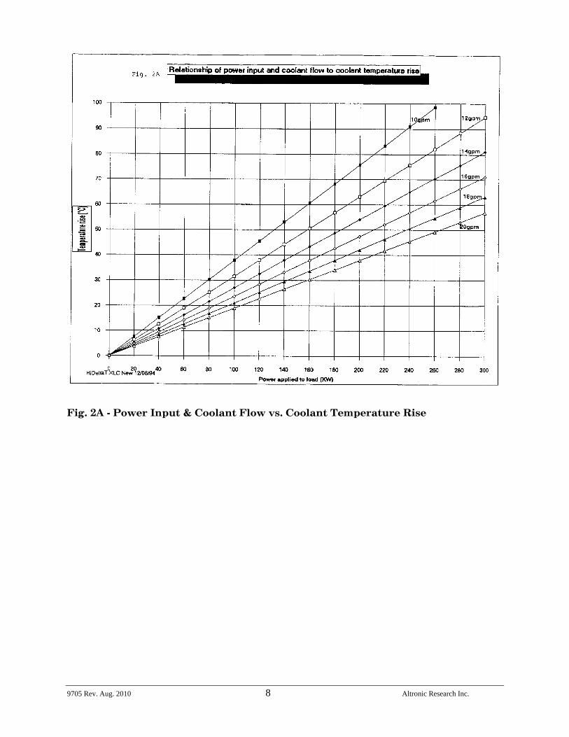
Fig. 2A Power Input & Coolant Flow vs. Coolant Temperature Rise ............... 8
Fig. 3 Freezing and Boiling Points of Glycol-Water Mixtures....................... 10
Fig. 3A Glycol Concentration Table ....................................................................... 11
Fig. 4 Minimum Water Flow Rate Requirements ............................................. 11
Fig. 5 Internal Pressure Drop vs. Flow Rate ..................................................... 12
Fig. 6 Alternative Cooling Systems...................................................................... 13
Fig. 7 Coolant Volume vs. Operating Time......................................................... 15
Fig. 8 Tank Sizes....................................................................................................... 16
Fig. 9 The Calorimetry Set-up............................................................................... 20
Fig. 10 Kt for Ethylene Glycol Mixtures vs. Temperature................................ 21
Fig. 11 Density of Ethylene Glycol Mixtures vs. Temperature........................ 22
Fig. 12 Flow-Meter Correction Factor................................................................... 22
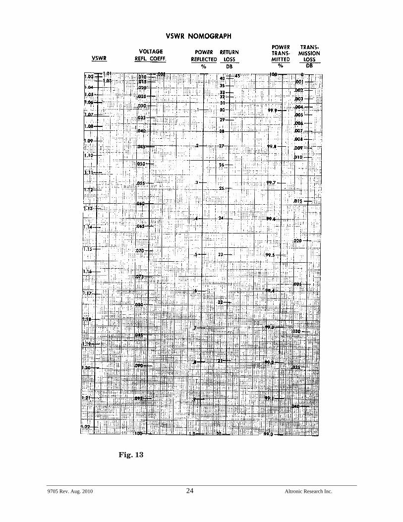
Fig. 13 VSWR Nomograph ........................................................................................ 24
Fig. 14 Model 9705 Exploded View/Parts List...................................................... 27
Fig. 15 Flange Assembly View ................................................................................. 28
Fig. 16 RF Input Assembly View............................................................................. 29
9705 Rev. Aug. 2010 1 Altronic Research Inc.
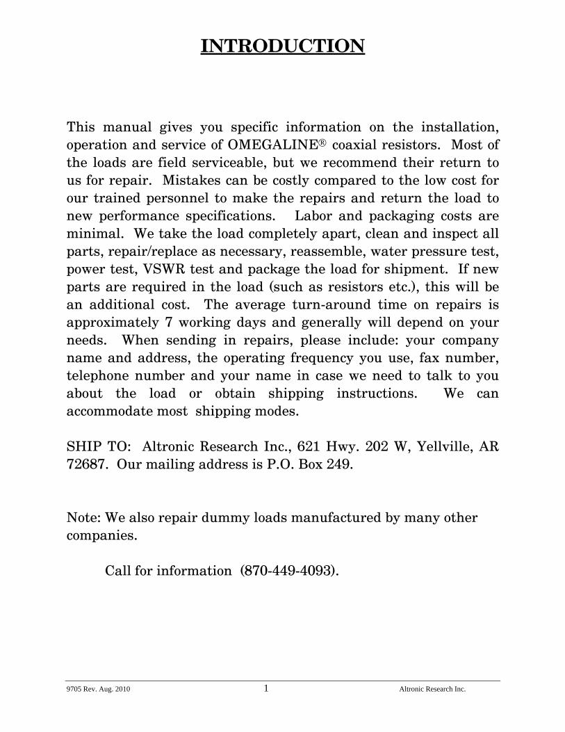
INTRODUCTION This manual gives you specific information on the installation, operation and service of OMEGALINE® coaxial resistors. Most of the loads are field serviceable, but we recommend their return to us for repair. Mistakes can be costly compared to the low cost for our trained personnel to make the repairs and return the load to new performance specifications. Labor and packaging costs are minimal. We take the load completely apart, clean and inspect all parts, repair/replace as necessary, reassemble, water pressure test, power test, VSWR test and package the load for shipment. If new parts are required in the load (such as resistors etc.), this will be an additional cost. The average turn-around time on repairs is approximately 7 working days and generally will depend on your needs. When sending in repairs, please include: your company name and address, the operating frequency you use, fax number, telephone number and your name in case we need to talk to you about the load or obtain shipping instructions. We can accommodate most shipping modes. SHIP TO: Altronic Research Inc., 621 Hwy. 202 W, Yellville, AR 72687. Our mailing address is P.O. Box 249. Note: We also repair dummy loads manufactured by many other companies. Call for information (870-449-4093).
9705 Rev. Aug. 2010 2 Altronic Research Inc.
PRECAUTIONS
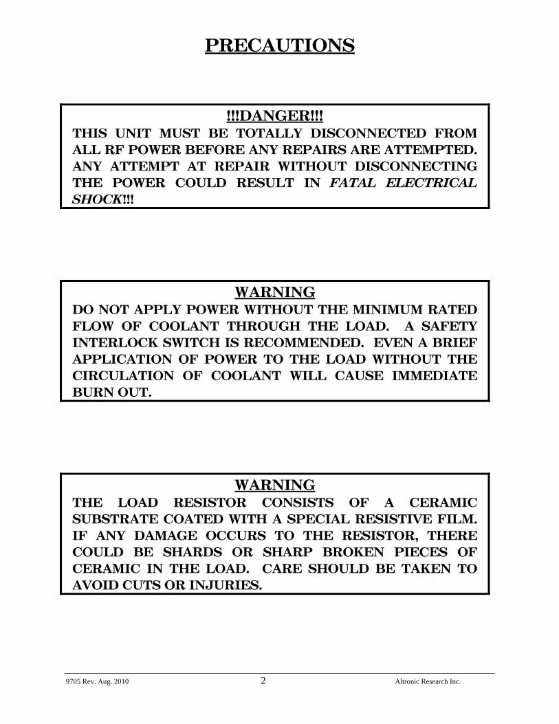
!!!DANGER!!! THIS UNIT MUST BE TOTALLY DISCONNECTED FROM ALL RF POWER BEFORE ANY REPAIRS ARE ATTEMPTED. ANY ATTEMPT AT REPAIR WITHOUT DISCONNECTING THE POWER COULD RESULT IN FATAL ELECTRICAL SHOCK!!!
WARNING DO NOT APPLY POWER WITHOUT THE MINIMUM RATED FLOW OF COOLANT THROUGH THE LOAD. A SAFETY INTERLOCK SWITCH IS RECOMMENDED. EVEN A BRIEF APPLICATION OF POWER TO THE LOAD WITHOUT THE CIRCULATION OF COOLANT WILL CAUSE IMMEDIATE BURN OUT.
WARNING THE LOAD RESISTOR CONSISTS OF A CERAMIC SUBSTRATE COATED WITH A SPECIAL RESISTIVE FILM. IF ANY DAMAGE OCCURS TO THE RESISTOR, THERE COULD BE SHARDS OR SHARP BROKEN PIECES OF CERAMIC IN THE LOAD. CARE SHOULD BE TAKEN TO AVOID CUTS OR INJURIES.
9705 Rev. Aug. 2010 3 Altronic Research Inc.
PRECAUTIONS
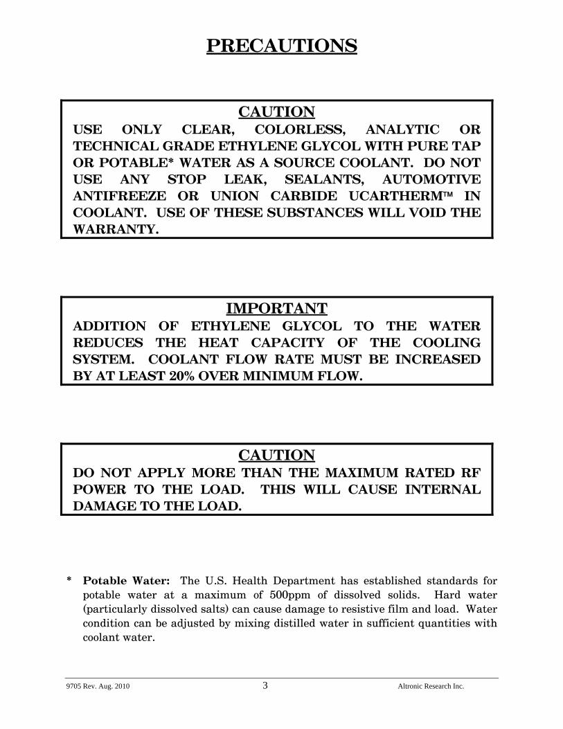
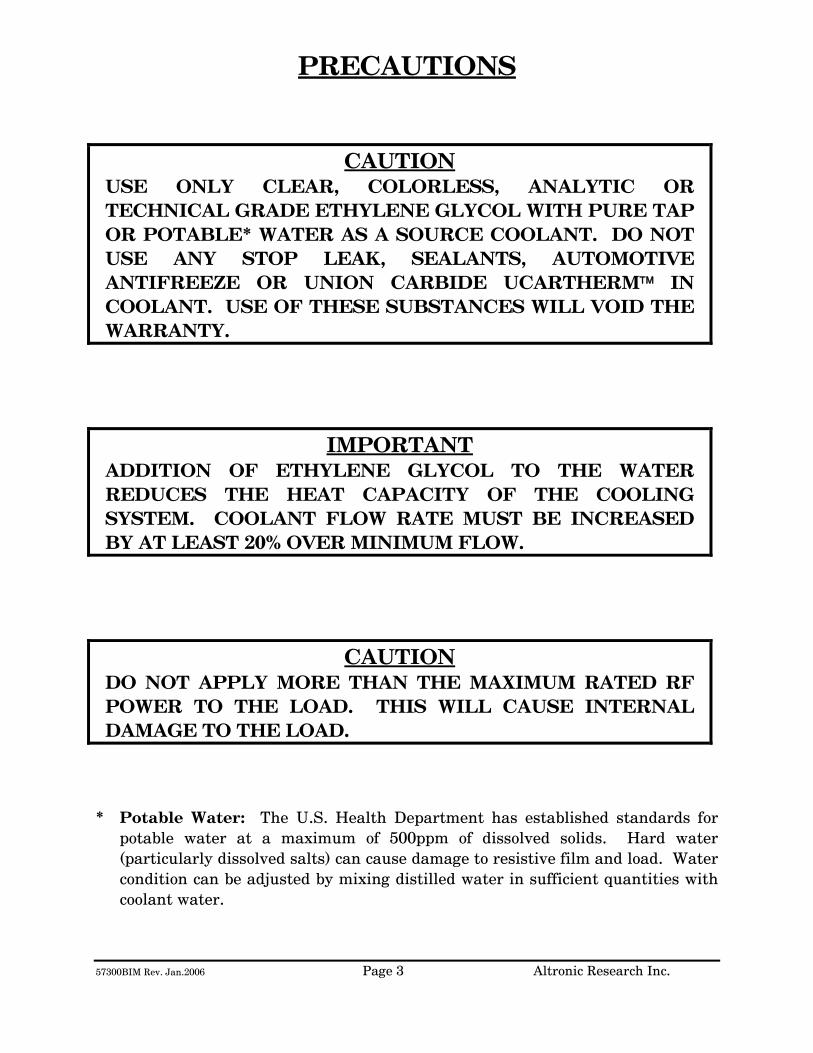
CAUTION USE ONLY CLEAR, COLORLESS, ANALYTIC OR TECHNICAL GRADE ETHYLENE GLYCOL WITH PURE TAP OR POTABLE* WATER AS A SOURCE COOLANT. DO NOT USE ANY STOP LEAK, SEALANTS, AUTOMOTIVE ANTIFREEZE OR UNION CARBIDE UCARTHERM™ IN COOLANT. USE OF THESE SUBSTANCES WILL VOID THE WARRANTY.
IMPORTANT ADDITION OF ETHYLENE GLYCOL TO THE WATER REDUCES THE HEAT CAPACITY OF THE COOLING SYSTEM. COOLANT FLOW RATE MUST BE INCREASED BY AT LEAST 20% OVER MINIMUM FLOW.
CAUTION DO NOT APPLY MORE THAN THE MAXIMUM RATED RF POWER TO THE LOAD. THIS WILL CAUSE INTERNAL DAMAGE TO THE LOAD.
* Potable Water: The U.S. Health Department has established standards for potable water at a maximum of 500ppm of dissolved solids. Hard water (particularly dissolved salts) can cause damage to resistive film and load. Water condition can be adjusted by mixing distilled water in sufficient quantities with coolant water.
9705 Rev. Aug. 2010 4 Altronic Research Inc.
GENERAL DESCRIPTION
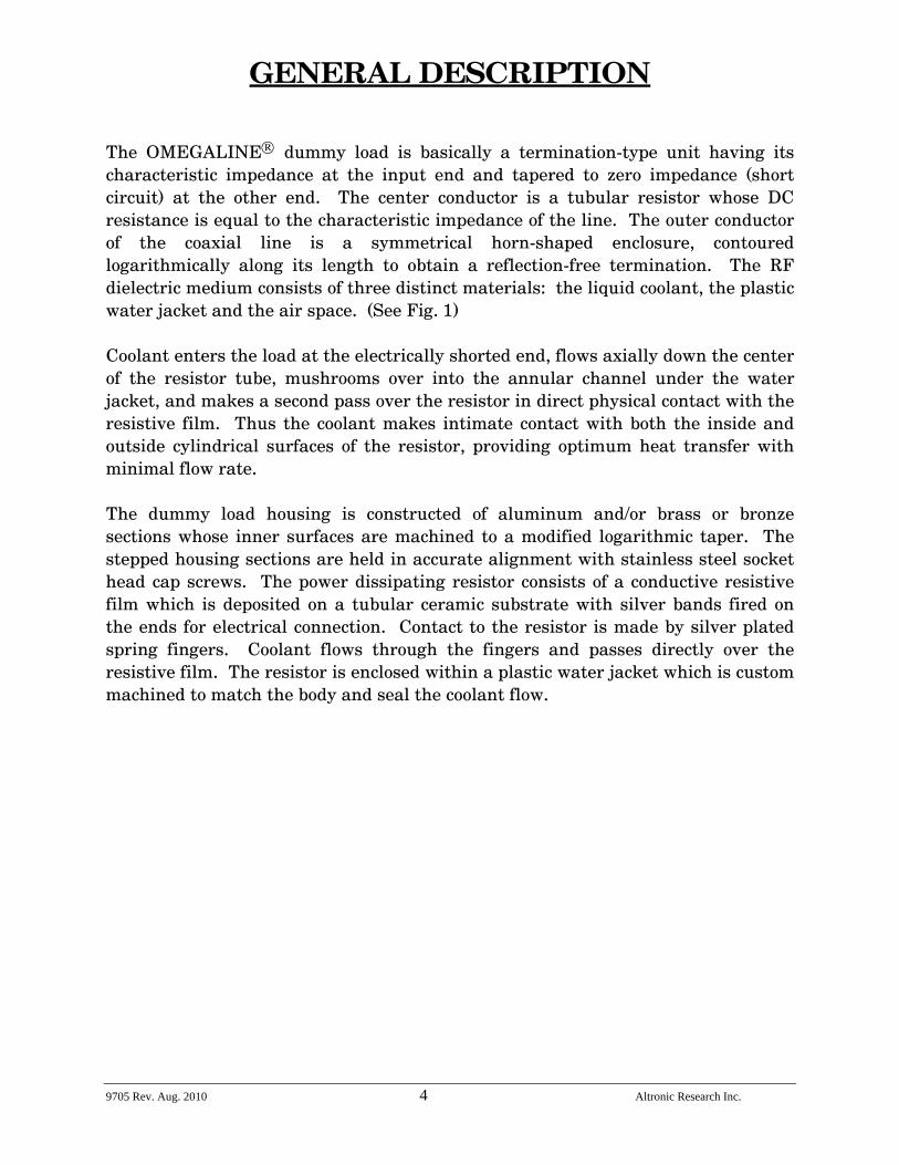
The OMEGALINE® dummy load is basically a termination-type unit having its characteristic impedance at the input end and tapered to zero impedance (short circuit) at the other end. The center conductor is a tubular resistor whose DC resistance is equal to the characteristic impedance of the line. The outer conductor of the coaxial line is a symmetrical horn-shaped enclosure, contoured logarithmically along its length to obtain a reflection-free termination. The RF dielectric medium consists of three distinct materials: the liquid coolant, the plastic water jacket and the air space. (See Fig. 1) Coolant enters the load at the electrically shorted end, flows axially down the center of the resistor tube, mushrooms over into the annular channel under the water jacket, and makes a second pass over the resistor in direct physical contact with the resistive film. Thus the coolant makes intimate contact with both the inside and outside cylindrical surfaces of the resistor, providing optimum heat transfer with minimal flow rate. The dummy load housing is constructed of aluminum and/or brass or bronze sections whose inner surfaces are machined to a modified logarithmic taper. The stepped housing sections are held in accurate alignment with stainless steel socket head cap screws. The power dissipating resistor consists of a conductive resistive film which is deposited on a tubular ceramic substrate with silver bands fired on the ends for electrical connection. Contact to the resistor is made by silver plated spring fingers. Coolant flows through the fingers and passes directly over the resistive film. The resistor is enclosed within a plastic water jacket which is custom machined to match the body and seal the coolant flow.
9705 Rev. Aug. 2010 5 Altronic Research Inc.
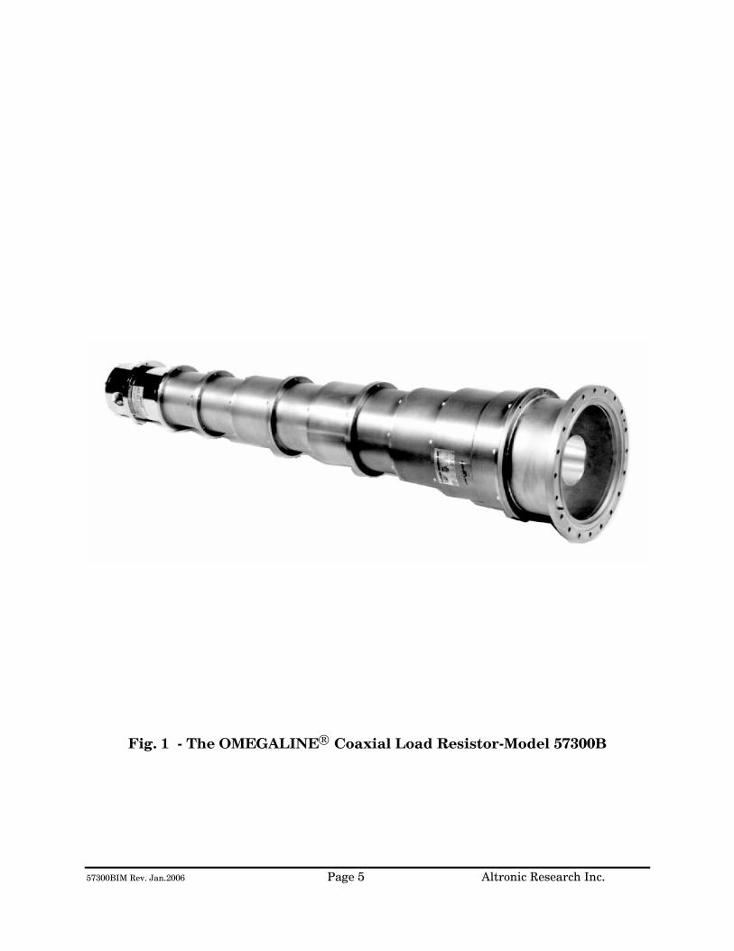
Fig. 1 - The OMEGALINE® Coaxial Load Resistor
9705 Rev. Aug. 2010 6 Altronic Research Inc.
ELECTRICAL CHARACTERISTICS
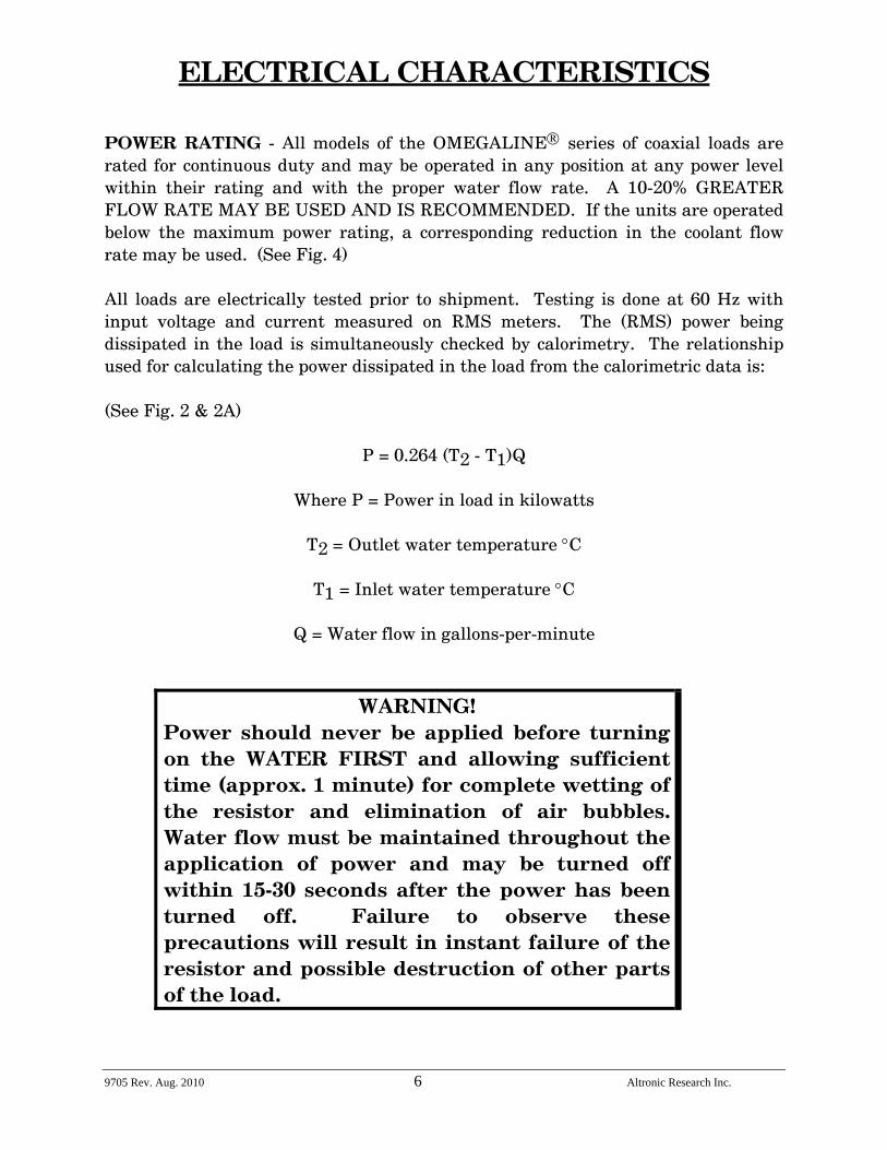
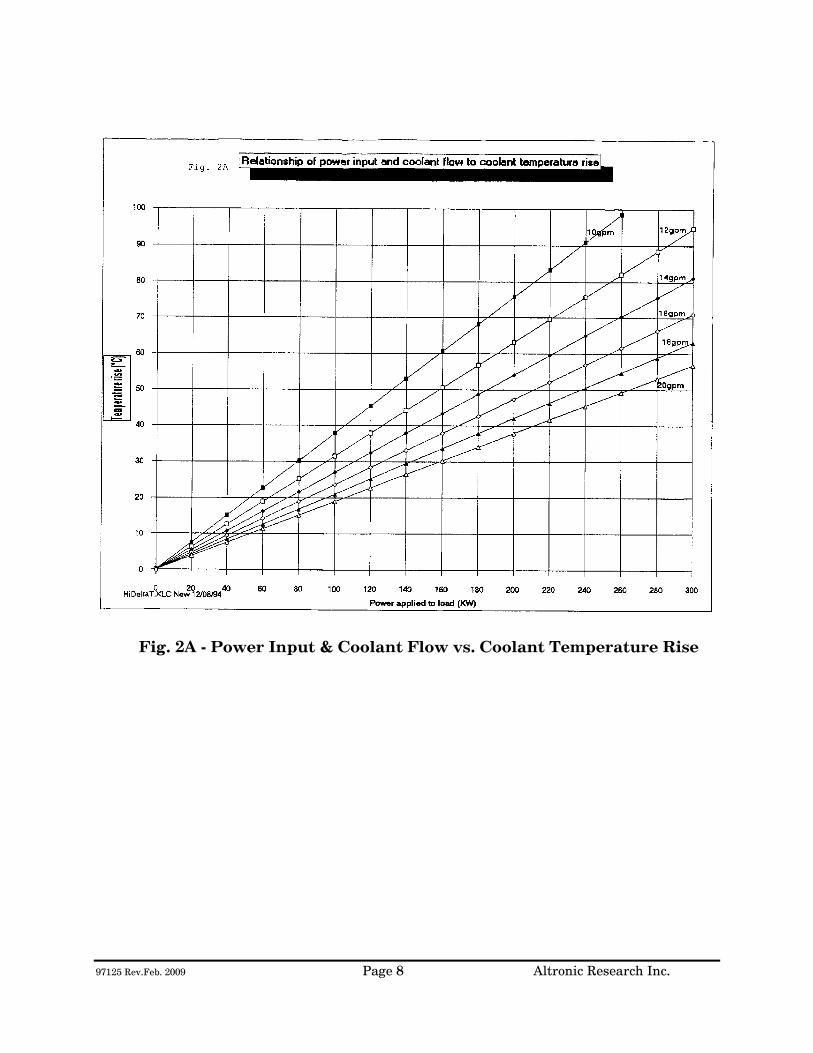
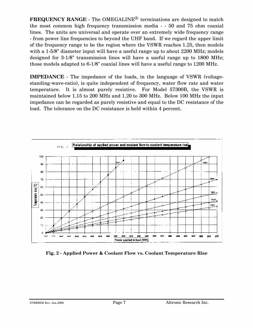
POWER RATING - All models of the OMEGALINE® series of coaxial loads are rated for continuous duty and may be operated in any position at any power level within their rating and with the proper water flow rate. A 10-20% GREATER FLOW RATE MAY BE USED AND IS RECOMMENDED. If the units are operated below the maximum power rating, a corresponding reduction in the coolant flow rate may be used. (See Fig. 4) All loads are electrically tested prior to shipment. Testing is done at 60 Hz with input voltage and current measured on RMS meters. The (RMS) power being dissipated in the load is simultaneously checked by calorimetry. The relationship used for calculating the power dissipated in the load from the calorimetric data is: (See Fig. 2 & 2A)
P = 0.264 (T2 - T1)Q
Where P = Power in load in kilowatts
T2 = Outlet water temperature °C
T1 = Inlet water temperature °C
Q = Water flow in gallons-per-minute
WARNING! Power should never be applied before turning on the WATER FIRST and allowing sufficient time (approx. 1 minute) for complete wetting of the resistor and elimination of air bubbles. Water flow must be maintained throughout the application of power and may be turned off within 15-30 seconds after the power has been turned off. Failure to observe these precautions will result in instant failure of the resistor and possible destruction of other parts of the load.
9705 Rev. Aug. 2010 7 Altronic Research Inc.
FREQUENCY RANGE - The OMEGALINE® terminations are designed to match the most common high frequency transmission media - - 50 and 75 ohm coaxial lines. The units are universal and operate over an extremely wide frequency range - from power line frequencies to beyond the UHF band. If we regard the upper limit of the frequency range to be the region where the VSWR reaches 1.25, then models with a 1-5/8" diameter input will have a useful range up to about 2200 MHz; models designed for 3-1/8" transmission lines will have a useful range up to 1800 MHz; those models adapted to 6-1/8" coaxial lines will have a useful range to 1200 MHz. IMPEDANCE - The impedance of the loads, in the language of VSWR (voltage-standing-wave-ratio), is quite independent of frequency, water flow rate and water temperature. It is almost purely resistive. For most models, the VSWR is maintained below 1.1 to 800 MHz. Below 100 MHz the input impedance can be regarded as purely resistive and equal to the DC resistance of the load. The tolerance on the DC resistance is held within 4 percent.
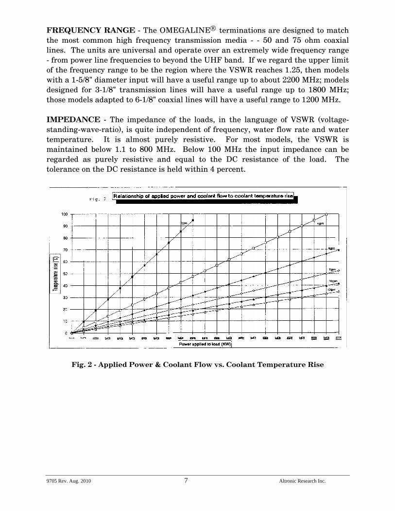
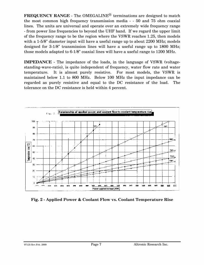
Fig. 2 - Applied Power & Coolant Flow vs. Coolant Temperature Rise
9705 Rev. Aug. 2010 8 Altronic Research Inc.
Fig. 2A - Power Input & Coolant Flow vs. Coolant Temperature Rise
9705 Rev. Aug. 2010 9 Altronic Research Inc.
COOLANT
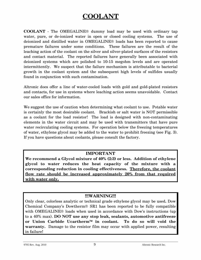
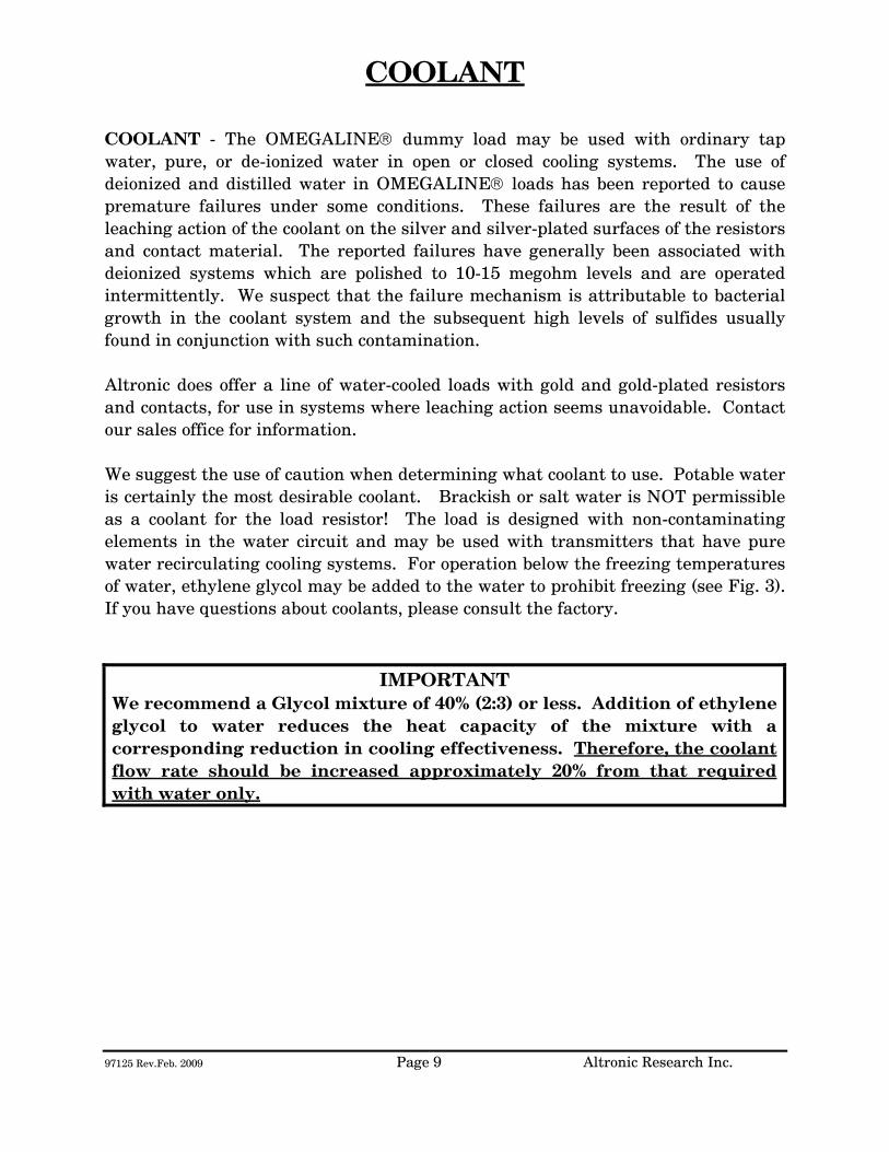
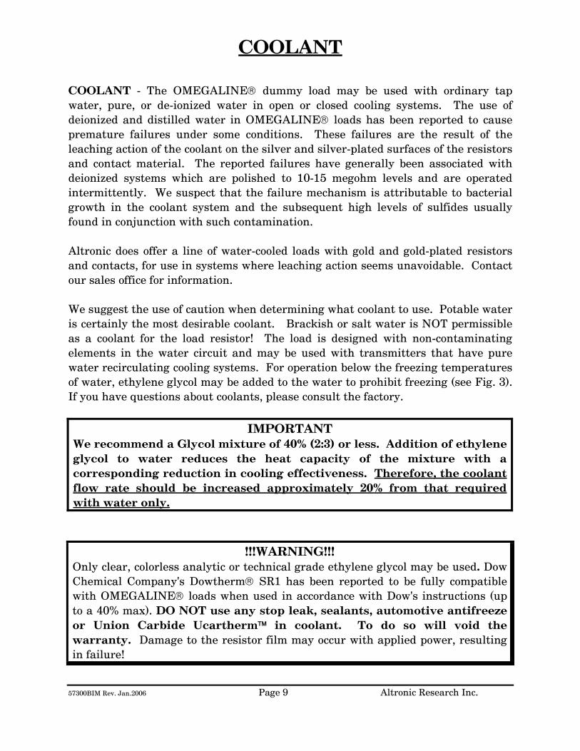
COOLANT - The OMEGALINE® dummy load may be used with ordinary tap water, pure, or de-ionized water in open or closed cooling systems. The use of deionized and distilled water in OMEGALINE® loads has been reported to cause premature failures under some conditions. These failures are the result of the leaching action of the coolant on the silver and silver-plated surfaces of the resistors and contact material. The reported failures have generally been associated with deionized systems which are polished to 10-15 megohm levels and are operated intermittently. We suspect that the failure mechanism is attributable to bacterial growth in the coolant system and the subsequent high levels of sulfides usually found in conjunction with such contamination. Altronic does offer a line of water-cooled loads with gold and gold-plated resistors and contacts, for use in systems where leaching action seems unavoidable. Contact our sales office for information. We suggest the use of caution when determining what coolant to use. Potable water is certainly the most desirable coolant. Brackish or salt water is NOT permissible as a coolant for the load resistor! The load is designed with non-contaminating elements in the water circuit and may be used with transmitters that have pure water recirculating cooling systems. For operation below the freezing temperatures of water, ethylene glycol may be added to the water to prohibit freezing (see Fig. 3). If you have questions about coolants, please consult the factory.
IMPORTANT We recommend a Glycol mixture of 40% (2:3) or less. Addition of ethylene glycol to water reduces the heat capacity of the mixture with a corresponding reduction in cooling effectiveness. Therefore, the coolant flow rate should be increased approximately 20% from that required with water only.
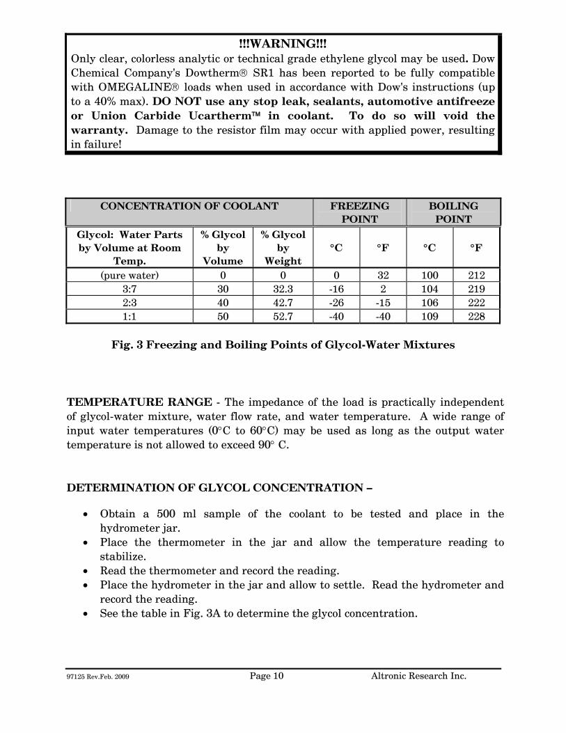
!!!WARNING!!! Only clear, colorless analytic or technical grade ethylene glycol may be used. Dow Chemical Company's Dowtherm® SR1 has been reported to be fully compatible with OMEGALINE® loads when used in accordance with Dow's instructions (up to a 40% max). DO NOT use any stop leak, sealants, automotive antifreeze or Union Carbide Ucartherm™ in coolant. To do so will void the warranty. Damage to the resistor film may occur with applied power, resulting in failure!
9705 Rev. Aug. 2010 10 Altronic Research Inc.
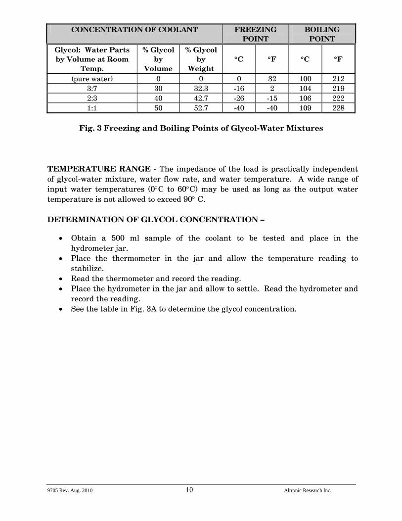
CONCENTRATION OF COOLANT FREEZING POINT
BOILING POINT
Glycol: Water Parts by Volume at Room
Temp.
% Glycol by
Volume
% Glycol by
Weight
°C
°F
°C
°F
(pure water) 0 0 0 32 100 212 3:7 30 32.3 -16 2 104 219 2:3 40 42.7 -26 -15 106 222 1:1 50 52.7 -40 -40 109 228
Fig. 3 Freezing and Boiling Points of Glycol-Water Mixtures
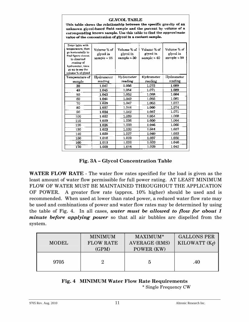
TEMPERATURE RANGE - The impedance of the load is practically independent of glycol-water mixture, water flow rate, and water temperature. A wide range of input water temperatures (0°C to 60°C) may be used as long as the output water temperature is not allowed to exceed 90° C. DETERMINATION OF GLYCOL CONCENTRATION –
• Obtain a 500 ml sample of the coolant to be tested and place in the hydrometer jar.
• Place the thermometer in the jar and allow the temperature reading to stabilize.
• Read the thermometer and record the reading. • Place the hydrometer in the jar and allow to settle. Read the hydrometer and
record the reading. • See the table in Fig. 3A to determine the glycol concentration.
9705 Rev. Aug. 2010 11 Altronic Research Inc.
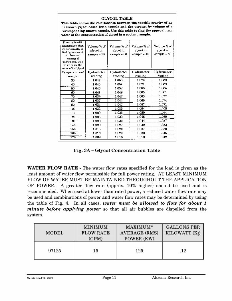
Fig. 3A – Glycol Concentration Table WATER FLOW RATE - The water flow rates specified for the load is given as the least amount of water flow permissible for full power rating. AT LEAST MINIMUM FLOW OF WATER MUST BE MAINTAINED THROUGHOUT THE APPLICATION OF POWER. A greater flow rate (approx. 10% higher) should be used and is recommended. When used at lower than rated power, a reduced water flow rate may be used and combinations of power and water flow rates may be determined by using the table of Fig. 4. In all cases, water must be allowed to flow for about 1 minute before applying power so that all air bubbles are dispelled from the system.
MODEL MINIMUM
FLOW RATE (GPM)
MAXIMUM* AVERAGE (RMS)
POWER (KW)
GALLONS PER KILOWATT (Kf)
9705
2
5
.40
Fig. 4 MINIMUM Water Flow Rate Requirements
* Single Frequency CW
9705 Rev. Aug. 2010 12 Altronic Research Inc.
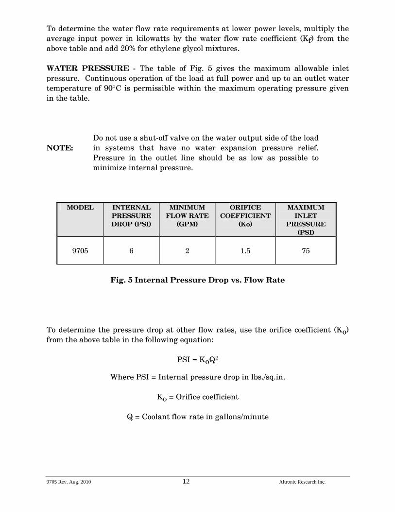
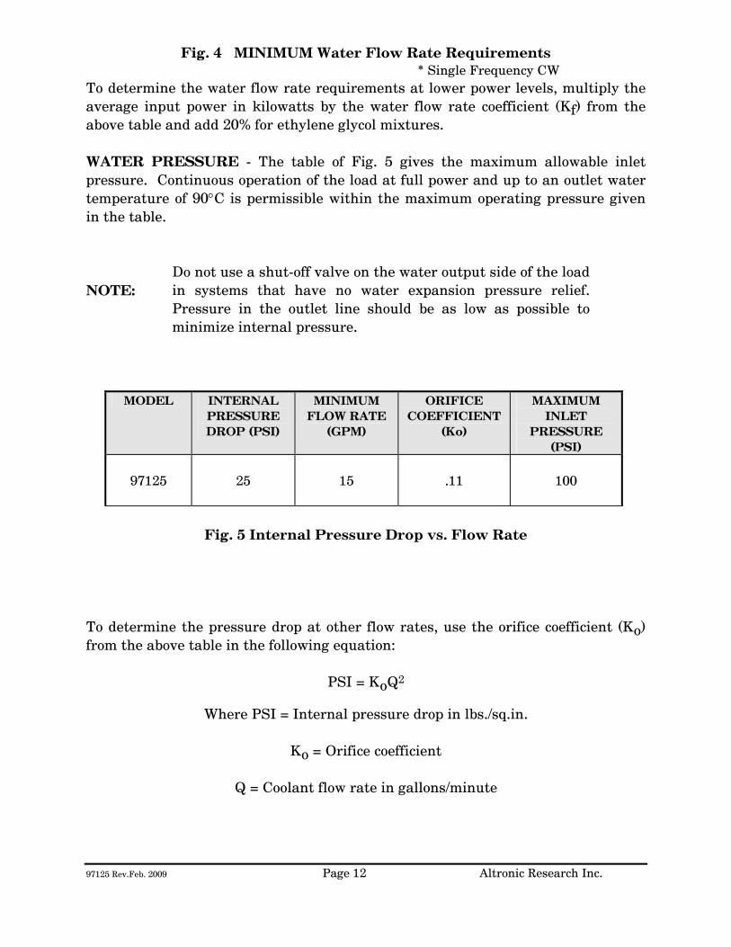
To determine the water flow rate requirements at lower power levels, multiply the average input power in kilowatts by the water flow rate coefficient (Kf) from the above table and add 20% for ethylene glycol mixtures. WATER PRESSURE - The table of Fig. 5 gives the maximum allowable inlet pressure. Continuous operation of the load at full power and up to an outlet water temperature of 90°C is permissible within the maximum operating pressure given in the table. NOTE:
Do not use a shut-off valve on the water output side of the load in systems that have no water expansion pressure relief. Pressure in the outlet line should be as low as possible to minimize internal pressure.
MODEL INTERNAL
PRESSURE DROP (PSI)
MINIMUM FLOW RATE
(GPM)
ORIFICE COEFFICIENT
(Ko)
MAXIMUM INLET
PRESSURE (PSI)
9705
6
2
1.5
75
Fig. 5 Internal Pressure Drop vs. Flow Rate
To determine the pressure drop at other flow rates, use the orifice coefficient (Ko) from the above table in the following equation:
PSI = KoQ2
Where PSI = Internal pressure drop in lbs./sq.in.
Ko = Orifice coefficient
Q = Coolant flow rate in gallons/minute
9705 Rev. Aug. 2010 13 Altronic Research Inc.
COOLING SYSTEMS
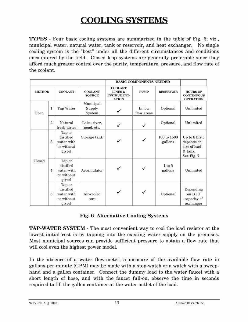
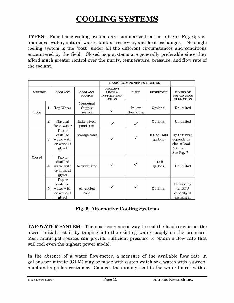
TYPES - Four basic cooling systems are summarized in the table of Fig. 6; viz., municipal water, natural water, tank or reservoir, and heat exchanger. No single cooling system is the "best" under all the different circumstances and conditions encountered by the field. Closed loop systems are generally preferable since they afford much greater control over the purity, temperature, pressure, and flow rate of the coolant.
BASIC COMPONENTS NEEDED
METHOD
COOLANT
COOLANT SOURCE
COOLANT LINES &
INSTRUMENT-ATION
PUMP
RESERVOIR
HOURS OF
CONTINUOUS OPERATION
Open
1
Tap Water
Municipal Supply System
In low
flow areas
Optional
Unlimited
2
Natural
fresh water
Lake, river, pond, etc.
Optional
Unlimited
3
Tap or distilled
water with or without
glycol
Storage tank
100 to 1500
gallons
Up to 8 hrs.; depends on size of load & tank. See Fig. 7
Closed
4
Tap or distilled
water with or without
glycol
Accumulator
1 to 5
gallons
Unlimited
5
Tap or distilled
water with or without
glycol
Air-cooled core
Optional
Depending
on BTU capacity of exchanger
Fig. 6 Alternative Cooling Systems
TAP-WATER SYSTEM - The most convenient way to cool the load resistor at the lowest initial cost is by tapping into the existing water supply on the premises. Most municipal sources can provide sufficient pressure to obtain a flow rate that will cool even the highest power model. In the absence of a water flow-meter, a measure of the available flow rate in gallons-per-minute (GPM) may be made with a stop-watch or a watch with a sweep-hand and a gallon container. Connect the dummy load to the water faucet with a short length of hose, and with the faucet full-on, observe the time in seconds required to fill the gallon container at the water outlet of the load.
9705 Rev. Aug. 2010 14 Altronic Research Inc.
When using the dummy load with a tap-water system, the flow rate is usually adjusted to 10-15% above the minimum requirement and left unattended. Since water lines ordinarily serve other appliances (flush toilets, etc.) over which there is no control, a flow switch should be installed to protect the load resistor element in case the flow rate drops due to a momentary change in water pressure. Choose a flow switch with a small "ON-OFF" flow rate dead band. The switch will also protect the resistor in cases where the RF power may be turned on before the water flow, or where accidental termination of water flow (pinched hose, debris, valve closing, etc.) may occur. In the tap-water system the heated water is discharged down the drain and therefore, the cost of the water becomes an important consideration. NATURAL WATER SYSTEM - A close proximity to a natural supply of fresh water may suggest its utilization. Brackish or salt water may NOT be used as a coolant for the load resistor. The natural water system usually requires more extensive piping and heavier pumping equipment to handle attendant pressure drop. The quality of natural water varies widely and straining is often necessary to handle the twigs, minnows, leaves and other debris frequently encountered. Small automatic self-cleaning strainers are available for this purpose. The strainer should be installed upstream from the pump to protect the pump as well as the load resistor. Additional filtering of smaller particles is sometimes required and this can be accomplished with finer mesh "Y-TYPE" strainers inserted in series with the line. In this system, the water from the natural source may not be directly usable as a coolant for the load resistor element due to a high contamination, such as silt, iron content, mud, etc.; but it may be used as "dirty" water coolant in a water-to-water heat exchanger. The contaminated water could be piped via plastic tubing or hose to copper coils immersed in a holding tank containing clean water coolant for the dummy load. This arrangement would require a dual pump - one section to pump the "dirty" natural-source water and the other section to pump the clean water coolant through the dummy load. HEAT EXCHANGER SYSTEM - In this system, an accumulator or receiving tank is used which only holds about one-half the flow rate in gallons-per-minute. Accordingly, a small quantity of coolant is required. The coolant functions solely as a heat transfer agent between the load resistor and the heat sink. A heat exchanger consisting of a radiator and a fan is the type recommended for this application. With ambient air as the ultimate heat sink, the operating temperature of the coolant will always be above the air temperature for heat to be transferred from the load to the air. Some consideration should be given to exhausting the hot air to the outside so as not to have a temperature rise problem in the transmitter area. The heat exchanger may be a complete self-contained unit (portable) which
9705 Rev. Aug. 2010 15 Altronic Research Inc.
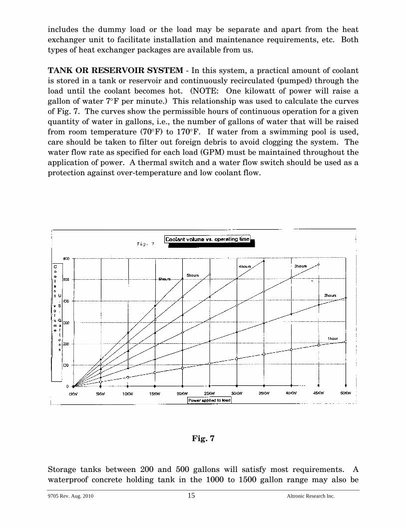
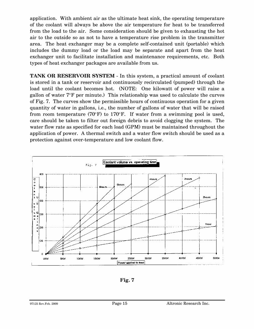
includes the dummy load or the load may be separate and apart from the heat exchanger unit to facilitate installation and maintenance requirements, etc. Both types of heat exchanger packages are available from us. TANK OR RESERVOIR SYSTEM - In this system, a practical amount of coolant is stored in a tank or reservoir and continuously recirculated (pumped) through the load until the coolant becomes hot. (NOTE: One kilowatt of power will raise a gallon of water 7°F per minute.) This relationship was used to calculate the curves of Fig. 7. The curves show the permissible hours of continuous operation for a given quantity of water in gallons, i.e., the number of gallons of water that will be raised from room temperature (70°F) to 170°F. If water from a swimming pool is used, care should be taken to filter out foreign debris to avoid clogging the system. The water flow rate as specified for each load (GPM) must be maintained throughout the application of power. A thermal switch and a water flow switch should be used as a protection against over-temperature and low coolant flow.
Fig. 7 Storage tanks between 200 and 500 gallons will satisfy most requirements. A waterproof concrete holding tank in the 1000 to 1500 gallon range may also be
9705 Rev. Aug. 2010 16 Altronic Research Inc.
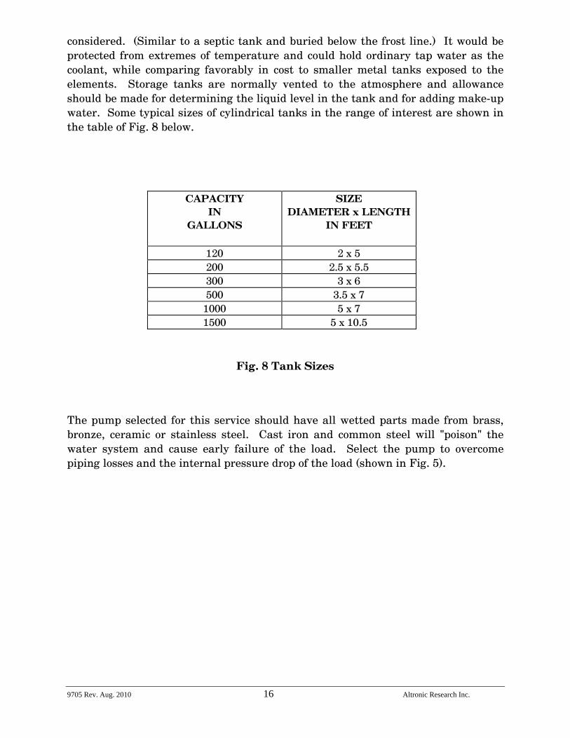
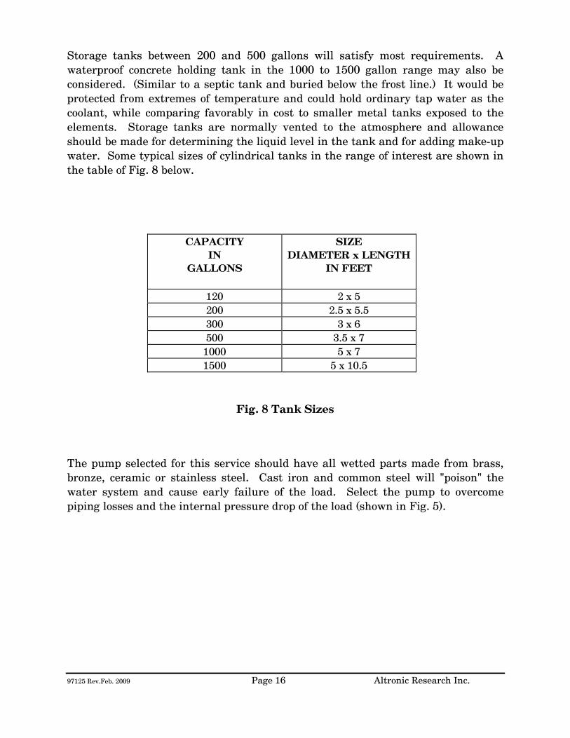
considered. (Similar to a septic tank and buried below the frost line.) It would be protected from extremes of temperature and could hold ordinary tap water as the coolant, while comparing favorably in cost to smaller metal tanks exposed to the elements. Storage tanks are normally vented to the atmosphere and allowance should be made for determining the liquid level in the tank and for adding make-up water. Some typical sizes of cylindrical tanks in the range of interest are shown in the table of Fig. 8 below.
CAPACITY IN
GALLONS
SIZE DIAMETER x LENGTH
IN FEET
120 2 x 5 200 2.5 x 5.5 300 3 x 6 500 3.5 x 7
1000 5 x 7 1500 5 x 10.5
Fig. 8 Tank Sizes
The pump selected for this service should have all wetted parts made from brass, bronze, ceramic or stainless steel. Cast iron and common steel will "poison" the water system and cause early failure of the load. Select the pump to overcome piping losses and the internal pressure drop of the load (shown in Fig. 5).
9705 Rev. Aug. 2010 17 Altronic Research Inc.
INSTALLATION
The OMEGALINE® loads may be used on both fixed and portable applications and they perform equally well in any mounting position. The units are very rugged and light and may be strapped, clamped, or secured with any practical and readily available mechanical device. They may be held by the RF connector on one end and by the plumbing on the other end. The coolant may be allowed to pass through the load in either direction without affecting its operation, but the axial water connector is normally used as the inlet since it contains the built-in filter screen. Water lines connecting the load should be 3/4" copper water tubing and rigid enough to support the load. NOTE: (A fifty-foot length of 1/2" pipe has a pressure drop of 45-PSI at 10-GPM water flow rate, while a 3/4" pipe under the same conditions only develops a 5-PSI drop.) In typical installations, the rigid piping is terminated within a few feet of the load, and flexible hose is used to bridge the last few feet. The hose should be 3/4" I.D. and capable of withstanding the temperature and pressure of the system. The water fittings on the load are 3/4" hose thread to accommodate standard hose couplings. Do not screw pipe thread fittings onto the hose thread - damage will result due to cross-threading. Pipe threads are tapered and hose threads are straight. If it is desired to mate with regular 3/4" pipe threads, use a hose-to-pipe adapter. The adapter is recommended since it eliminates the need of removing the side outlet water fitting and also allows the axial water fitting to be adapted directly to 3/4" pipe. The adapters may be obtained at a local hardware store or a plumbing supply house. Provisions should be made to allow interruption of the transmission line at any position where the transmitter is to be terminated by the load or measurements are contemplated. Coaxial switches may be inserted in the transmission line run to provide rapid load switching. Proceed as follows:
1. Install the unit in the selected location. 2. Connect the outlet water fitting of the dummy load to a convenient
drainage. 3. Connect the water inlet to a water source capable of delivering the
required flow in gallons per minute.
9705 Rev. Aug. 2010 18 Altronic Research Inc.
If the required source of water flow is not available from the local lines, refer to the previous section for a possible alternate cooling system. We highly recommend the use of a flow switch in the inlet piping to detect low flow conditions which could damage the load. We recommend the IMO DeLaval Model AFS200, Adjustable Flow Switch. This switch has low internal pressure drop and operates reliably in pilot-duty applications. (This switch is available from us.) Mount the switch in a horizontal section of pipe where there is a straight horizontal run of at least five inches on each side of the switch.
4. Connect the microswitch contacts of the flow switch in series with transmitter interlock circuit.
5. Connect the dummy load to the transmission line. The unit is designed
to connect to a 50 or 75 ohm line (or as stated on label).
9705 Rev. Aug. 2010 19 Altronic Research Inc.
OPERATION
To place the dummy load in operation, the following procedure is recommended:
1. Turn on the water pressure and make certain water is flowing through the load. Allow about 1 minute of water circulation to insure complete wetting of the resistor element in the load and exhaustion of air bubbles.
2. Check the water flow rate. This can be done with a five-gallon
container and a wristwatch with a sweep-hand if no water flow meter is available.
3. Apply RF power.
To cease operation, turn the RF power off and allow about 30 seconds before turning off the water.
9705 Rev. Aug. 2010 20 Altronic Research Inc.
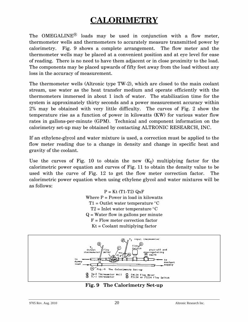
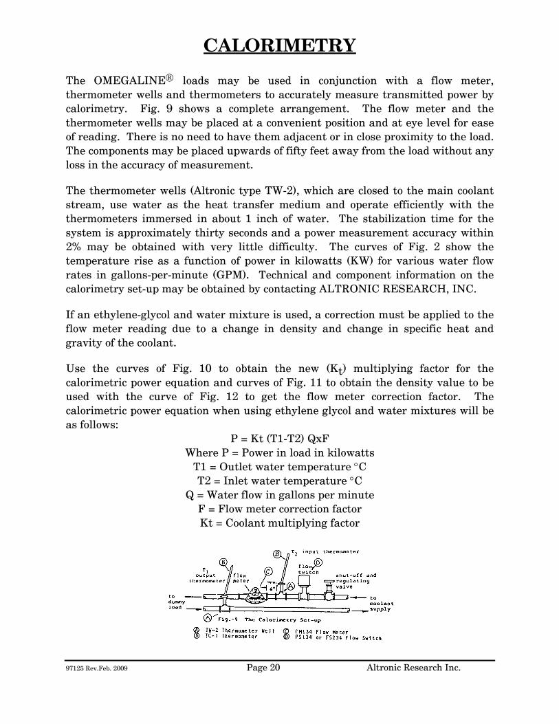
CALORIMETRY The OMEGALINE® loads may be used in conjunction with a flow meter, thermometer wells and thermometers to accurately measure transmitted power by calorimetry. Fig. 9 shows a complete arrangement. The flow meter and the thermometer wells may be placed at a convenient position and at eye level for ease of reading. There is no need to have them adjacent or in close proximity to the load. The components may be placed upwards of fifty feet away from the load without any loss in the accuracy of measurement.
The thermometer wells (Altronic type TW-2), which are closed to the main coolant stream, use water as the heat transfer medium and operate efficiently with the thermometers immersed in about 1 inch of water. The stabilization time for the system is approximately thirty seconds and a power measurement accuracy within 2% may be obtained with very little difficulty. The curves of Fig. 2 show the temperature rise as a function of power in kilowatts (KW) for various water flow rates in gallons-per-minute (GPM). Technical and component information on the calorimetry set-up may be obtained by contacting ALTRONIC RESEARCH, INC.
If an ethylene-glycol and water mixture is used, a correction must be applied to the flow meter reading due to a change in density and change in specific heat and gravity of the coolant.
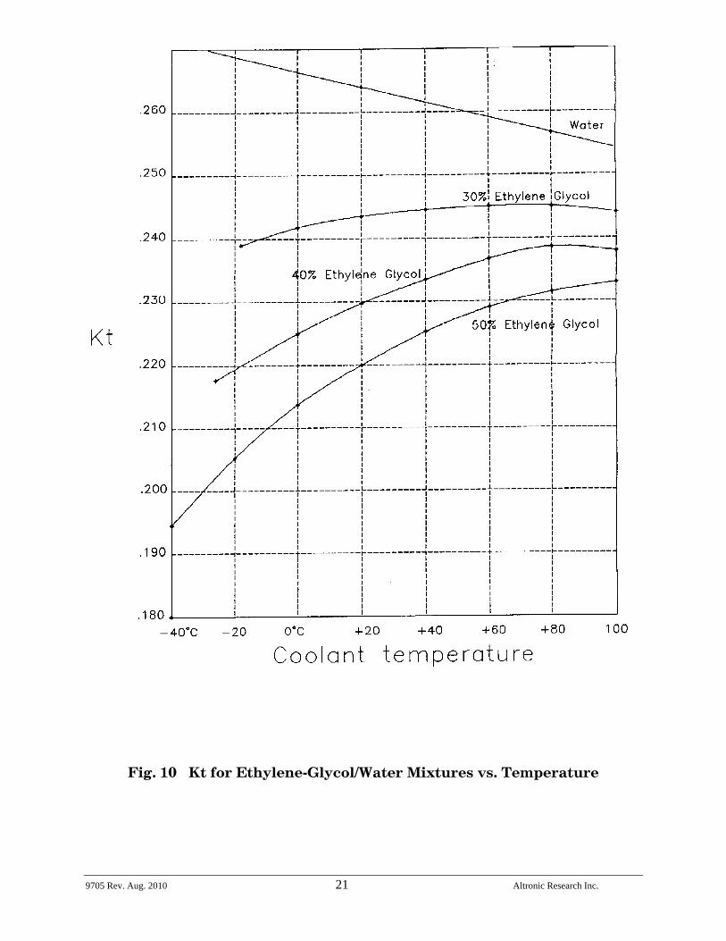
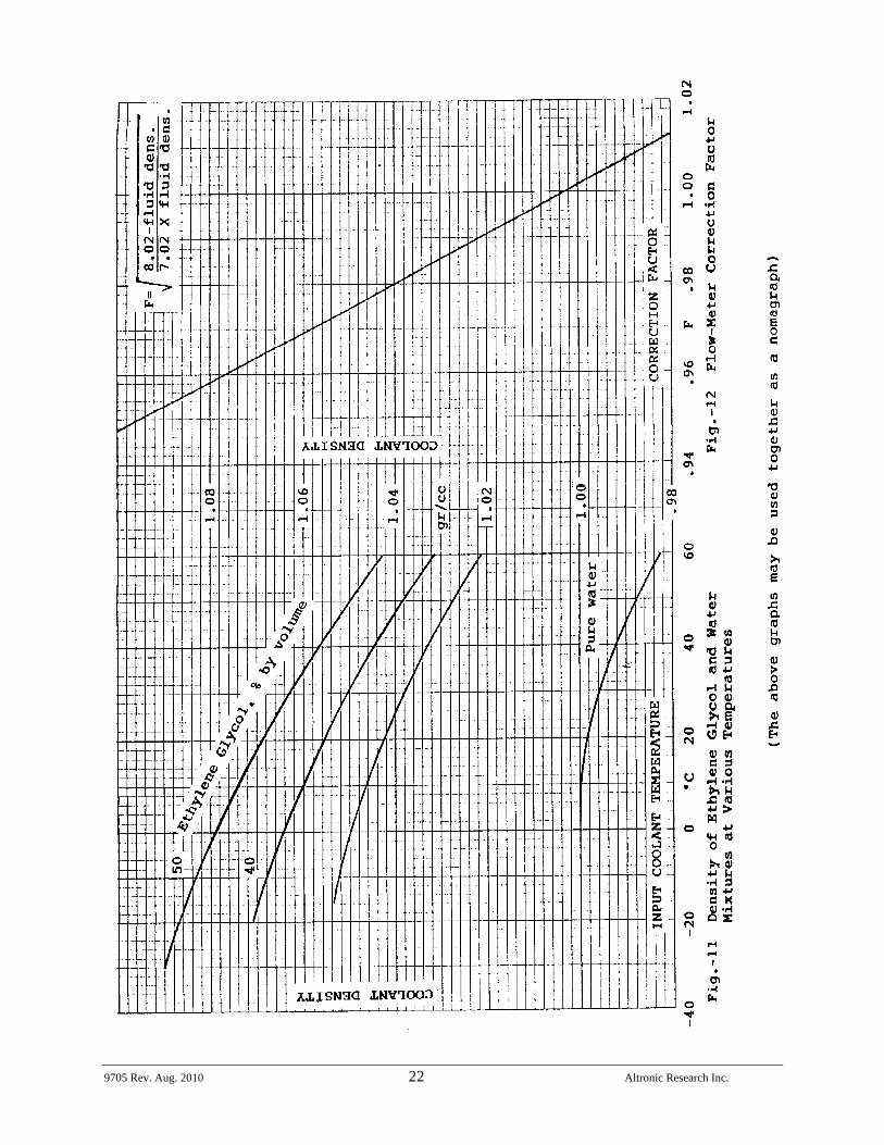
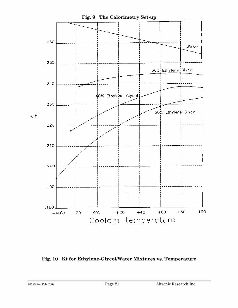
Use the curves of Fig. 10 to obtain the new (Kt) multiplying factor for the calorimetric power equation and curves of Fig. 11 to obtain the density value to be used with the curve of Fig. 12 to get the flow meter correction factor. The calorimetric power equation when using ethylene glycol and water mixtures will be as follows:
P = Kt (T1-T2) QxF Where P = Power in load in kilowatts
T1 = Outlet water temperature °C T2 = Inlet water temperature °C
Q = Water flow in gallons per minute F = Flow meter correction factor Kt = Coolant multiplying factor
Fig. 9 The Calorimetry Set-up
9705 Rev. Aug. 2010 21 Altronic Research Inc.
Fig. 10 Kt for Ethylene-Glycol/Water Mixtures vs. Temperature
9705 Rev. Aug. 2010 22 Altronic Research Inc.
9705 Rev. Aug. 2010 23 Altronic Research Inc.
Altronic Research Inc., Yellville, Arkansas
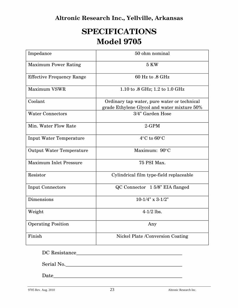
SPECIFICATIONS Model 9705
Impedance
50 ohm nominal
Maximum Power Rating
5 KW
Effective Frequency Range
60 Hz to .8 GHz
Maximum VSWR
1.10 to .8 GHz; 1.2 to 1.0 GHz
Coolant Ordinary tap water, pure water or technical grade Ethylene Glycol and water mixture 50%
Water Connectors
3/4" Garden Hose
Min. Water Flow Rate
2-GPM
Input Water Temperature
4°C to 60°C
Output Water Temperature
Maximum: 90°C
Maximum Inlet Pressure
75 PSI Max.
Resistor
Cylindrical film type-field replaceable
Input Connectors
QC Connector 1 5/8" EIA flanged
Dimensions
10-1/4" x 3-1/2"
Weight
4-1/2 lbs.
Operating Position
Any
Finish
Nickel Plate /Conversion Coating
DC Resistance Serial No. Date
9705 Rev. Aug. 2010 24 Altronic Research Inc.
Fig. 13
ALTRONIC RESEARCH, INC. P.O. BOX 249
YELLVILLE, ARKANSAS 72687-0249 U.S.A.
LIQUID-COOLED COAXIAL LOAD RESISTOR
MODEL 97125

TABLE OF CONTENTS
INTRODUCTION ............................................................................................. 1 PRECAUTIONS................................................................................................ 2 GENERAL DESCRIPTION ............................................................................ 4 ELECTRICAL CHARACTERISTICS............................................................ 6 COOLANT ......................................................................................................... 9 COOLING SYSTEMS..................................................................................... 13 INSTALLATION............................................................................................. 17 OPERATION................................................................................................... 19 CALORIMETRY ............................................................................................. 20 SPECIFICATIONS......................................................................................... 23 MAINTENANCE............................................................................................. 25 WARRANTY .................................................................................................... 26
ILLUSTRATIONS, TABLES AND GRAPHS
Fig. 1 The OMEGALINE® Coaxial Load Resistor............................................ 5
Fig. 2 Applied Power & Coolant Flow vs. Coolant Temperature Rise........ 7
Fig. 2A Power Input & Coolant Flow vs. Coolant Temperature Rise............ 8
Fig. 3 Freezing and Boiling Points of Glycol-Water Mixtures.................... 10
Fig. 3A Glycol Concentration Table .................................................................... 11
Fig. 4 Minimum Water Flow Rate Requirements .......................................... 11
Fig. 5 Internal Pressure Drop vs. Flow Rate .................................................. 12
Fig. 6 Alternative Cooling Systems................................................................... 13
Fig. 7 Coolant Volume vs. Operating Time ..................................................... 15
Fig. 8 Tank Sizes.................................................................................................... 16
Fig. 9 The Calorimetry Set-up............................................................................ 20
Fig. 10 Kt for Ethylene Glycol Mixtures vs. Temperature............................. 21
Fig. 11 Density of Ethylene Glycol Mixtures vs. Temperature..................... 22
Fig. 12 Flow-Meter Correction Factor................................................................ 22
Fig. 13 VSWR Nomograph ..................................................................................... 24

97125 Rev.Feb. 2009 Page 1 Altronic Research Inc.
INTRODUCTION This manual gives you specific information on the installation, operation and service of OMEGALINE® coaxial resistors. Most of the loads are field serviceable, but we recommend their return to us for repair. Mistakes can be costly compared to the low cost for our trained personnel to make the repairs and return the load to new performance specifications. Labor and packaging costs are minimal. We take the load completely apart, clean and inspect all parts, repair/replace as necessary, reassemble, water pressure test, power test, VSWR test and package the load for shipment. If new parts are required in the load (such as resistors etc.), this will be an additional cost. The average turn-around time on repairs is approximately 7 working days and generally will depend on your needs. When sending in repairs, please include: your company name and address, the operating frequency you use, fax number, telephone number and your name in case we need to talk to you about the load or obtain shipping instructions. We can accommodate most shipping modes. SHIP TO: Altronic Research Inc., 621 Hwy. 202 W, Yellville, AR 72687. Our mailing address is P.O. Box 249. Note: We also repair dummy loads manufactured by many other companies. Call for information (870-449-4093).

97125 Rev.Feb. 2009 Page 2 Altronic Research Inc.
PRECAUTIONS
!!!DANGER!!! THIS UNIT MUST BE TOTALLY DISCONNECTED FROM ALL RF POWER BEFORE ANY REPAIRS ARE ATTEMPTED. ANY ATTEMPT AT REPAIR WITHOUT DISCONNECTING THE POWER COULD RESULT IN FATAL ELECTRICAL SHOCK!!!
WARNING DO NOT APPLY POWER WITHOUT THE MINIMUM RATED FLOW OF COOLANT THROUGH THE LOAD. A SAFETY INTERLOCK SWITCH IS RECOMMENDED. EVEN A BRIEF APPLICATION OF POWER TO THE LOAD WITHOUT THE CIRCULATION OF COOLANT WILL CAUSE IMMEDIATE BURN OUT.
WARNING THE LOAD RESISTOR CONSISTS OF A CERAMIC SUBSTRATE COATED WITH A SPECIAL RESISTIVE FILM. IF ANY DAMAGE OCCURS TO THE RESISTOR, THERE COULD BE SHARDS OR SHARP BROKEN PIECES OF CERAMIC IN THE LOAD. CARE SHOULD BE TAKEN TO AVOID CUTS OR INJURIES.

97125 Rev.Feb. 2009 Page 3 Altronic Research Inc.
PRECAUTIONS
CAUTION USE ONLY CLEAR, COLORLESS, ANALYTIC OR TECHNICAL GRADE ETHYLENE GLYCOL WITH PURE TAP OR POTABLE* WATER AS A SOURCE COOLANT. DO NOT USE ANY STOP LEAK, SEALANTS, AUTOMOTIVE ANTIFREEZE OR UNION CARBIDE UCARTHERM™ IN COOLANT. USE OF THESE SUBSTANCES WILL VOID THE WARRANTY.
IMPORTANT ADDITION OF ETHYLENE GLYCOL TO THE WATER REDUCES THE HEAT CAPACITY OF THE COOLING SYSTEM. COOLANT FLOW RATE MUST BE INCREASED BY AT LEAST 20% OVER MINIMUM FLOW.
CAUTION DO NOT APPLY MORE THAN THE MAXIMUM RATED RF POWER TO THE LOAD. THIS WILL CAUSE INTERNAL DAMAGE TO THE LOAD.
* Potable Water: The U.S. Health Department has established standards for potable water at a maximum of 500ppm of dissolved solids. Hard water (particularly dissolved salts) can cause damage to resistive film and load. Water condition can be adjusted by mixing distilled water in sufficient quantities with coolant water.

97125 Rev.Feb. 2009 Page 4 Altronic Research Inc.
GENERAL DESCRIPTION
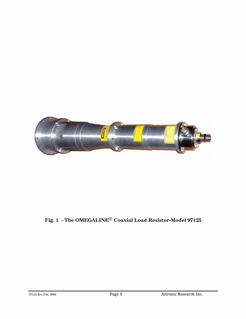
The OMEGALINE® dummy load is basically a termination-type unit having its characteristic impedance at the input end and tapered to zero impedance (short circuit) at the other end. The center conductor is a tubular resistor whose DC resistance is equal to the characteristic impedance of the line. The outer conductor of the coaxial line is a symmetrical horn-shaped enclosure, contoured logarithmically along its length to obtain a reflection-free termination. The RF dielectric medium consists of three distinct materials: the liquid coolant, the plastic water jacket and the air space. (See Fig. 1) Coolant enters the load at the electrically shorted end, flows axially down the center of the resistor tube, mushrooms over into the annular channel under the water jacket, and makes a second pass over the resistor in direct physical contact with the resistive film. Thus the coolant makes intimate contact with both the inside and outside cylindrical surfaces of the resistor, providing optimum heat transfer with minimal flow rate. The dummy load housing is constructed of aluminum and/or brass or bronze sections whose inner surfaces are machined to a modified logarithmic taper. The stepped housing sections are held in accurate alignment with stainless steel socket head cap screws. The power dissipating resistor consists of a conductive resistive film which is deposited on a tubular ceramic substrate with silver bands fired on the ends for electrical connection. Contact to the resistor is made by silver plated spring fingers. Coolant flows through the fingers and passes directly over the resistive film. The resistor is enclosed within a plastic water jacket which is custom machined to match the body and seal the coolant flow.
97125 Rev.Feb. 2009 Page 5 Altronic Research Inc.
Fig. 1 - The OMEGALINE® Coaxial Load Resistor-Model 97125

97125 Rev.Feb. 2009 Page 6 Altronic Research Inc.
ELECTRICAL CHARACTERISTICS
POWER RATING - All models of the OMEGALINE® series of coaxial loads are rated for continuous duty and may be operated in any position at any power level within their rating and with the proper water flow rate. A 10-20% GREATER FLOW RATE MAY BE USED AND IS RECOMMENDED. If the units are operated below the maximum power rating, a corresponding reduction in the coolant flow rate may be used. (See Fig. 4) All loads are electrically tested prior to shipment. Testing is done at 60 Hz with input voltage and current measured on RMS meters. The (RMS) power being dissipated in the load is simultaneously checked by calorimetry. The relationship used for calculating the power dissipated in the load from the calorimetric data is: (See Fig. 2 & 2A)
P = 0.264 (T2 - T1)Q
Where P = Power in load in kilowatts
T2 = Outlet water temperature °C
T1 = Inlet water temperature °C
Q = Water flow in gallons-per-minute
WARNING! Power should never be applied before turning on the WATER FIRST and allowing sufficient time (approx. 1 minute) for complete wetting of the resistor and elimination of air bubbles. Water flow must be maintained throughout the application of power and may be turned off within 15-30 seconds after the power has been turned off. Failure to observe these precautions will result in instant failure of the resistor and possible destruction of other parts of the load.
97125 Rev.Feb. 2009 Page 7 Altronic Research Inc.
FREQUENCY RANGE - The OMEGALINE® terminations are designed to match the most common high frequency transmission media - - 50 and 75 ohm coaxial lines. The units are universal and operate over an extremely wide frequency range - from power line frequencies to beyond the UHF band. If we regard the upper limit of the frequency range to be the region where the VSWR reaches 1.25, then models with a 1-5/8" diameter input will have a useful range up to about 2200 MHz; models designed for 3-1/8" transmission lines will have a useful range up to 1800 MHz; those models adapted to 6-1/8" coaxial lines will have a useful range to 1200 MHz. IMPEDANCE - The impedance of the loads, in the language of VSWR (voltage-standing-wave-ratio), is quite independent of frequency, water flow rate and water temperature. It is almost purely resistive. For most models, the VSWR is maintained below 1.1 to 800 MHz. Below 100 MHz the input impedance can be regarded as purely resistive and equal to the DC resistance of the load. The tolerance on the DC resistance is held within 4 percent.
Fig. 2 - Applied Power & Coolant Flow vs. Coolant Temperature Rise
97125 Rev.Feb. 2009 Page 8 Altronic Research Inc.
Fig. 2A - Power Input & Coolant Flow vs. Coolant Temperature Rise
97125 Rev.Feb. 2009 Page 9 Altronic Research Inc.
COOLANT
COOLANT - The OMEGALINE® dummy load may be used with ordinary tap water, pure, or de-ionized water in open or closed cooling systems. The use of deionized and distilled water in OMEGALINE® loads has been reported to cause premature failures under some conditions. These failures are the result of the leaching action of the coolant on the silver and silver-plated surfaces of the resistors and contact material. The reported failures have generally been associated with deionized systems which are polished to 10-15 megohm levels and are operated intermittently. We suspect that the failure mechanism is attributable to bacterial growth in the coolant system and the subsequent high levels of sulfides usually found in conjunction with such contamination. Altronic does offer a line of water-cooled loads with gold and gold-plated resistors and contacts, for use in systems where leaching action seems unavoidable. Contact our sales office for information. We suggest the use of caution when determining what coolant to use. Potable water is certainly the most desirable coolant. Brackish or salt water is NOT permissible as a coolant for the load resistor! The load is designed with non-contaminating elements in the water circuit and may be used with transmitters that have pure water recirculating cooling systems. For operation below the freezing temperatures of water, ethylene glycol may be added to the water to prohibit freezing (see Fig. 3). If you have questions about coolants, please consult the factory.
IMPORTANT We recommend a Glycol mixture of 40% (2:3) or less. Addition of ethylene glycol to water reduces the heat capacity of the mixture with a corresponding reduction in cooling effectiveness. Therefore, the coolant flow rate should be increased approximately 20% from that required with water only.
97125 Rev.Feb. 2009 Page 10 Altronic Research Inc.
!!!WARNING!!! Only clear, colorless analytic or technical grade ethylene glycol may be used. Dow Chemical Company's Dowtherm® SR1 has been reported to be fully compatible with OMEGALINE® loads when used in accordance with Dow's instructions (up to a 40% max). DO NOT use any stop leak, sealants, automotive antifreeze or Union Carbide Ucartherm™ in coolant. To do so will void the warranty. Damage to the resistor film may occur with applied power, resulting in failure!
CONCENTRATION OF COOLANT FREEZING POINT
BOILING POINT
Glycol: Water Parts by Volume at Room
Temp.
% Glycol by
Volume
% Glycol by
Weight
°C
°F
°C
°F
(pure water) 0 0 0 32 100 212 3:7 30 32.3 -16 2 104 219 2:3 40 42.7 -26 -15 106 222 1:1 50 52.7 -40 -40 109 228
Fig. 3 Freezing and Boiling Points of Glycol-Water Mixtures
TEMPERATURE RANGE - The impedance of the load is practically independent of glycol-water mixture, water flow rate, and water temperature. A wide range of input water temperatures (0°C to 60°C) may be used as long as the output water temperature is not allowed to exceed 90° C. DETERMINATION OF GLYCOL CONCENTRATION –
• Obtain a 500 ml sample of the coolant to be tested and place in the hydrometer jar.
• Place the thermometer in the jar and allow the temperature reading to stabilize.
• Read the thermometer and record the reading. • Place the hydrometer in the jar and allow to settle. Read the hydrometer and
record the reading. • See the table in Fig. 3A to determine the glycol concentration.
97125 Rev.Feb. 2009 Page 11 Altronic Research Inc.
Fig. 3A – Glycol Concentration Table WATER FLOW RATE - The water flow rates specified for the load is given as the least amount of water flow permissible for full power rating. AT LEAST MINIMUM FLOW OF WATER MUST BE MAINTAINED THROUGHOUT THE APPLICATION OF POWER. A greater flow rate (approx. 10% higher) should be used and is recommended. When used at lower than rated power, a reduced water flow rate may be used and combinations of power and water flow rates may be determined by using the table of Fig. 4. In all cases, water must be allowed to flow for about 1 minute before applying power so that all air bubbles are dispelled from the system.
MODEL MINIMUM
FLOW RATE (GPM)
MAXIMUM* AVERAGE (RMS)
POWER (KW)
GALLONS PER KILOWATT (Kf)
97125
15
125
.12
97125 Rev.Feb. 2009 Page 12 Altronic Research Inc.
Fig. 4 MINIMUM Water Flow Rate Requirements * Single Frequency CW To determine the water flow rate requirements at lower power levels, multiply the average input power in kilowatts by the water flow rate coefficient (Kf) from the above table and add 20% for ethylene glycol mixtures. WATER PRESSURE - The table of Fig. 5 gives the maximum allowable inlet pressure. Continuous operation of the load at full power and up to an outlet water temperature of 90°C is permissible within the maximum operating pressure given in the table. NOTE:
Do not use a shut-off valve on the water output side of the load in systems that have no water expansion pressure relief. Pressure in the outlet line should be as low as possible to minimize internal pressure.
MODEL INTERNAL
PRESSURE DROP (PSI)
MINIMUM FLOW RATE
(GPM)
ORIFICE COEFFICIENT
(Ko)
MAXIMUM INLET
PRESSURE (PSI)
97125
25
15
.11
100
Fig. 5 Internal Pressure Drop vs. Flow Rate
To determine the pressure drop at other flow rates, use the orifice coefficient (Ko) from the above table in the following equation:
PSI = KoQ2
Where PSI = Internal pressure drop in lbs./sq.in.
Ko = Orifice coefficient
Q = Coolant flow rate in gallons/minute
97125 Rev.Feb. 2009 Page 13 Altronic Research Inc.
COOLING SYSTEMS
TYPES - Four basic cooling systems are summarized in the table of Fig. 6; viz., municipal water, natural water, tank or reservoir, and heat exchanger. No single cooling system is the "best" under all the different circumstances and conditions encountered by the field. Closed loop systems are generally preferable since they afford much greater control over the purity, temperature, pressure, and flow rate of the coolant.
BASIC COMPONENTS NEEDED
METHOD
COOLANT
COOLANT SOURCE
COOLANT LINES &
INSTRUMENT-ATION
PUMP
RESERVOIR
HOURS OF
CONTINUOUS OPERATION
Open
1
Tap Water
Municipal Supply System
In low
flow areas
Optional
Unlimited
2
Natural
fresh water
Lake, river, pond, etc.
Optional
Unlimited
3
Tap or distilled
water with or without
glycol
Storage tank
100 to 1500
gallons
Up to 8 hrs.; depends on size of load & tank. See Fig. 7
Closed
4
Tap or distilled
water with or without
glycol
Accumulator
1 to 5
gallons
Unlimited
5
Tap or distilled
water with or without
glycol
Air-cooled core
Optional
Depending
on BTU capacity of exchanger
Fig. 6 Alternative Cooling Systems
TAP-WATER SYSTEM - The most convenient way to cool the load resistor at the lowest initial cost is by tapping into the existing water supply on the premises. Most municipal sources can provide sufficient pressure to obtain a flow rate that will cool even the highest power model. In the absence of a water flow-meter, a measure of the available flow rate in gallons-per-minute (GPM) may be made with a stop-watch or a watch with a sweep-hand and a gallon container. Connect the dummy load to the water faucet with a

97125 Rev.Feb. 2009 Page 14 Altronic Research Inc.
short length of hose, and with the faucet full-on, observe the time in seconds required to fill the gallon container at the water outlet of the load. When using the dummy load with a tap-water system, the flow rate is usually adjusted to 10-15% above the minimum requirement and left unattended. Since water lines ordinarily serve other appliances (flush toilets, etc.) over which there is no control, a flow switch should be installed to protect the load resistor element in case the flow rate drops due to a momentary change in water pressure. Choose a flow switch with a small "ON-OFF" flow rate dead band. The switch will also protect the resistor in cases where the RF power may be turned on before the water flow, or where accidental termination of water flow (pinched hose, debris, valve closing, etc.) may occur. In the tap-water system the heated water is discharged down the drain and therefore, the cost of the water becomes an important consideration. NATURAL WATER SYSTEM - A close proximity to a natural supply of fresh water may suggest its utilization. Brackish or salt water may NOT be used as a coolant for the load resistor. The natural water system usually requires more extensive piping and heavier pumping equipment to handle attendant pressure drop. The quality of natural water varies widely and straining is often necessary to handle the twigs, minnows, leaves and other debris frequently encountered. Small automatic self-cleaning strainers are available for this purpose. The strainer should be installed upstream from the pump to protect the pump as well as the load resistor. Additional filtering of smaller particles is sometimes required and this can be accomplished with finer mesh "Y-TYPE" strainers inserted in series with the line. In this system, the water from the natural source may not be directly usable as a coolant for the load resistor element due to a high contamination, such as silt, iron content, mud, etc.; but it may be used as "dirty" water coolant in a water-to-water heat exchanger. The contaminated water could be piped via plastic tubing or hose to copper coils immersed in a holding tank containing clean water coolant for the dummy load. This arrangement would require a dual pump - one section to pump the "dirty" natural-source water and the other section to pump the clean water coolant through the dummy load. HEAT EXCHANGER SYSTEM - In this system, an accumulator or receiving tank is used which only holds about one-half the flow rate in gallons-per-minute. Accordingly, a small quantity of coolant is required. The coolant functions solely as a heat transfer agent between the load resistor and the heat sink. A heat exchanger consisting of a radiator and a fan is the type recommended for this
97125 Rev.Feb. 2009 Page 15 Altronic Research Inc.
application. With ambient air as the ultimate heat sink, the operating temperature of the coolant will always be above the air temperature for heat to be transferred from the load to the air. Some consideration should be given to exhausting the hot air to the outside so as not to have a temperature rise problem in the transmitter area. The heat exchanger may be a complete self-contained unit (portable) which includes the dummy load or the load may be separate and apart from the heat exchanger unit to facilitate installation and maintenance requirements, etc. Both types of heat exchanger packages are available from us. TANK OR RESERVOIR SYSTEM - In this system, a practical amount of coolant is stored in a tank or reservoir and continuously recirculated (pumped) through the load until the coolant becomes hot. (NOTE: One kilowatt of power will raise a gallon of water 7°F per minute.) This relationship was used to calculate the curves of Fig. 7. The curves show the permissible hours of continuous operation for a given quantity of water in gallons, i.e., the number of gallons of water that will be raised from room temperature (70°F) to 170°F. If water from a swimming pool is used, care should be taken to filter out foreign debris to avoid clogging the system. The water flow rate as specified for each load (GPM) must be maintained throughout the application of power. A thermal switch and a water flow switch should be used as a protection against over-temperature and low coolant flow.
Fig. 7
97125 Rev.Feb. 2009 Page 16 Altronic Research Inc.
Storage tanks between 200 and 500 gallons will satisfy most requirements. A waterproof concrete holding tank in the 1000 to 1500 gallon range may also be considered. (Similar to a septic tank and buried below the frost line.) It would be protected from extremes of temperature and could hold ordinary tap water as the coolant, while comparing favorably in cost to smaller metal tanks exposed to the elements. Storage tanks are normally vented to the atmosphere and allowance should be made for determining the liquid level in the tank and for adding make-up water. Some typical sizes of cylindrical tanks in the range of interest are shown in the table of Fig. 8 below.
CAPACITY IN
GALLONS
SIZE DIAMETER x LENGTH
IN FEET
120 2 x 5 200 2.5 x 5.5 300 3 x 6 500 3.5 x 7
1000 5 x 7 1500 5 x 10.5
Fig. 8 Tank Sizes
The pump selected for this service should have all wetted parts made from brass, bronze, ceramic or stainless steel. Cast iron and common steel will "poison" the water system and cause early failure of the load. Select the pump to overcome piping losses and the internal pressure drop of the load (shown in Fig. 5).

97125 Rev.Feb. 2009 Page 17 Altronic Research Inc.
INSTALLATION
The OMEGALINE® loads may be used on both fixed and portable applications and they perform equally well in any mounting position. The units are very rugged and light and may be strapped, clamped, or secured with any practical and readily available mechanical device. They may be held by the RF connector on one end and by the plumbing on the other end. The coolant may be allowed to pass through the load in either direction without affecting its operation, but the axial water connector is normally used as the inlet since it contains the built-in filter screen. Water lines connecting the load should be 3/4" copper water tubing and rigid enough to support the load. NOTE: (A fifty-foot length of 1/2" pipe has a pressure drop of 45-PSI at 10-GPM water flow rate, while a 3/4" pipe under the same conditions only develops a 5-PSI drop.) In typical installations, the rigid piping is terminated within a few feet of the load, and flexible hose is used to bridge the last few feet. The hose should be 3/4" I.D. and capable of withstanding the temperature and pressure of the system. The water fittings on the load are 3/4" hose thread to accommodate standard hose couplings. Do not screw pipe thread fittings onto the hose thread - damage will result due to cross-threading. Pipe threads are tapered and hose threads are straight. If it is desired to mate with regular 3/4" pipe threads, use a hose-to-pipe adapter. The adapter is recommended since it eliminates the need of removing the side outlet water fitting and also allows the axial water fitting to be adapted directly to 3/4" pipe. The adapters may be obtained at a local hardware store or a plumbing supply house. Provisions should be made to allow interruption of the transmission line at any position where the transmitter is to be terminated by the load or measurements are contemplated. Coaxial switches may be inserted in the transmission line run to provide rapid load switching. Proceed as follows:
1. Install the unit in the selected location. 2. Connect the outlet water fitting of the dummy load to a convenient
drainage. 3. Connect the water inlet to a water source capable of delivering the
required flow in gallons per minute.
97125 Rev.Feb. 2009 Page 18 Altronic Research Inc.
If the required source of water flow is not available from the local lines, refer to the previous section for a possible alternate cooling system. We highly recommend the use of a flow switch in the inlet piping to detect low flow conditions which could damage the load. We recommend the IMO DeLaval Model AFS200, Adjustable Flow Switch. This switch has low internal pressure drop and operates reliably in pilot-duty applications. (This switch is available from us.) Mount the switch in a horizontal section of pipe where there is a straight horizontal run of at least five inches on each side of the switch.
4. Connect the microswitch contacts of the flow switch in series with transmitter interlock circuit.
5. Connect the dummy load to the transmission line. The unit is designed
to connect to a 50 or 75 ohm line (or as stated on label).

97125 Rev.Feb. 2009 Page 19 Altronic Research Inc.
OPERATION
To place the dummy load in operation, the following procedure is recommended:
1. Turn on the water pressure and make certain water is flowing through the load. Allow about 1 minute of water circulation to insure complete wetting of the resistor element in the load and exhaustion of air bubbles.
2. Check the water flow rate. This can be done with a five-gallon
container and a wristwatch with a sweep-hand if no water flow meter is available.
3. Apply RF power.
To cease operation, turn the RF power off and allow about 30 seconds before turning off the water.
97125 Rev.Feb. 2009 Page 20 Altronic Research Inc.
CALORIMETRY The OMEGALINE® loads may be used in conjunction with a flow meter, thermometer wells and thermometers to accurately measure transmitted power by calorimetry. Fig. 9 shows a complete arrangement. The flow meter and the thermometer wells may be placed at a convenient position and at eye level for ease of reading. There is no need to have them adjacent or in close proximity to the load. The components may be placed upwards of fifty feet away from the load without any loss in the accuracy of measurement. The thermometer wells (Altronic type TW-2), which are closed to the main coolant stream, use water as the heat transfer medium and operate efficiently with the thermometers immersed in about 1 inch of water. The stabilization time for the system is approximately thirty seconds and a power measurement accuracy within 2% may be obtained with very little difficulty. The curves of Fig. 2 show the temperature rise as a function of power in kilowatts (KW) for various water flow rates in gallons-per-minute (GPM). Technical and component information on the calorimetry set-up may be obtained by contacting ALTRONIC RESEARCH, INC. If an ethylene-glycol and water mixture is used, a correction must be applied to the flow meter reading due to a change in density and change in specific heat and gravity of the coolant. Use the curves of Fig. 10 to obtain the new (Kt) multiplying factor for the calorimetric power equation and curves of Fig. 11 to obtain the density value to be used with the curve of Fig. 12 to get the flow meter correction factor. The calorimetric power equation when using ethylene glycol and water mixtures will be as follows:
P = Kt (T1-T2) QxF Where P = Power in load in kilowatts
T1 = Outlet water temperature °C T2 = Inlet water temperature °C
Q = Water flow in gallons per minute F = Flow meter correction factor Kt = Coolant multiplying factor
97125 Rev.Feb. 2009 Page 21 Altronic Research Inc.
Fig. 9 The Calorimetry Set-up
Fig. 10 Kt for Ethylene-Glycol/Water Mixtures vs. Temperature

97125 Rev.Feb. 2009 Page 22 Altronic Research Inc.
97125 Rev.Feb. 2009 Page 23 Altronic Research Inc.
Altronic Research Inc., Yellville, Arkansas
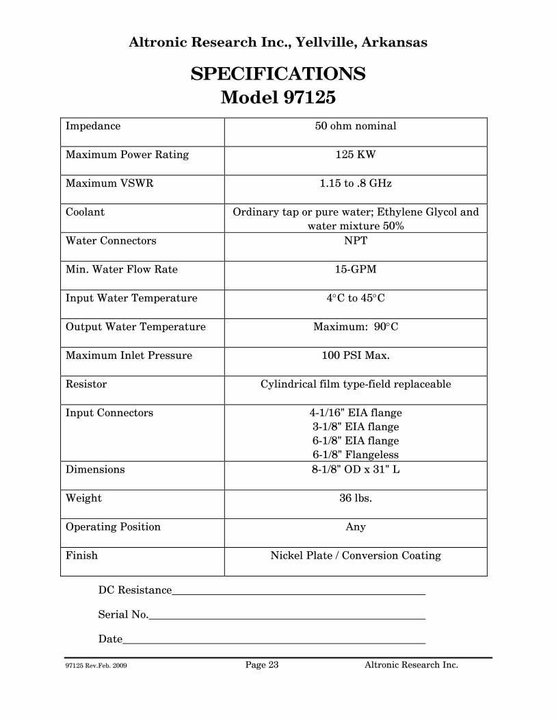
SPECIFICATIONS Model 97125
Impedance
50 ohm nominal
Maximum Power Rating
125 KW
Maximum VSWR
1.15 to .8 GHz
Coolant Ordinary tap or pure water; Ethylene Glycol and water mixture 50%
Water Connectors
NPT
Min. Water Flow Rate
15-GPM
Input Water Temperature
4°C to 45°C
Output Water Temperature
Maximum: 90°C
Maximum Inlet Pressure
100 PSI Max.
Resistor
Cylindrical film type-field replaceable
Input Connectors
4-1/16" EIA flange 3-1/8" EIA flange 6-1/8" EIA flange 6-1/8" Flangeless
Dimensions
8-1/8" OD x 31" L
Weight
36 lbs.
Operating Position
Any
Finish
Nickel Plate / Conversion Coating
DC Resistance
Serial No.
Date

97125 Rev.Feb. 2009 Page 24 Altronic Research Inc.
Fig. 13
97125 Rev.Feb. 2009 Page 25 Altronic Research Inc.
MAINTENANCE OMEGALINE® Water-cooled loads with power ratings of 100 kW or greater are not considered field-repairable and should be returned to Altronic Research for repairs. In the event of mechanical damage to the unit, operational difficulty, or information concerning a desired unusual application of the load, contact the factory. NOTE: ANY LEAK FROM THE MAIN BODY OF THE LOAD IS AN INDICATION THAT THE UNIT SHOULD BE RETURNED TO THE FACTORY FOR REPAIRS.
The following checks, tests and procedures may be used periodically, when necessary, or when a malfunction is suspected.
1. DC Resistance - The DC resistance of the load may be checked at the RF
input connector and a value within 4% of the required resistance is acceptable.
2. External Filter Screen - Should be checked regularly to prevent clogging. 3. VSWR - The voltage-standing-wave-ratio of the load is the same with "stand
still" water as it is with flowing water. To test for VSWR, fill the load with water. When filling with water, many small bubbles will form inside. These must be flushed out with excess water before measuring VSWR. After filling, cork it, connect to a slotted line or directional coupler and measure the VSWR at SIGNAL GENERATOR LEVELS ONLY.
For technical assistance, call 870-449-4093 or fax 870-449-6000.
97125 Rev.Feb. 2009 Page 26 Altronic Research Inc.
LIMITED WARRANTY We take pride in manufacturing products of the highest quality and we warrant them to the original purchaser to be free from defects in material and workmanship for the period of one year from date of invoice. Additionally, products of our manufacture repaired by us are warranted against defects in material and workmanship for a period of 90 days from date of invoice, with the provisions described herein. Should a product, or a portion of a product of our manufacture prove faulty, in material or workmanship, during the life of this warranty, we hereby obligate ourselves, at our own discretion, to repair or replace such portions of the product as required to remedy such defect. If, in our judgment, such repair or replacement fails to be a satisfactory solution, our limit of obligation shall be no more than full refund of the purchase price. This warranty is limited to products of our own manufacture. Equipment and components originating from other manufacturers are warranted only to the limits of that manufacturer's warranty to us. Furthermore, we shall not be liable for any injury, loss or damage, direct or consequential, arising out of the use, or misuse (by operation above rated capacities, repairs not made by us, or any misapplication) of the equipment. Before using, the user shall determine the suitability of the product for the intended use; and the user assumes all risk and liability whatsoever in connection therewith. The foregoing is the only warranty of Altronic Research Incorporated and is in lieu of all other warranties expressed or implied. Warranty returns shall first be authorized by the Customer Service Department and shall be shipped prepaid. Warranty does not cover freight charges.

ALTRONIC RESEARCH, INC. P.O. BOX 249
YELLVILLE, ARKANSAS 72687-0249 U.S.A.
LIQUID-COOLED COAXIAL LOAD RESISTOR
MODEL 57300B

TABLE OF CONTENTS
INTRODUCTION ............................................................................................. 1 PRECAUTIONS................................................................................................ 2 GENERAL DESCRIPTION ............................................................................ 4 ELECTRICAL CHARACTERISTICS............................................................ 6 COOLANT ......................................................................................................... 9 COOLING SYSTEMS..................................................................................... 13 INSTALLATION............................................................................................. 17 OPERATION................................................................................................... 18 CALORIMETRY ............................................................................................. 19 SPECIFICATIONS......................................................................................... 22 MAINTENANCE............................................................................................. 24 WARRANTY .................................................................................................... 25
ILLUSTRATIONS, TABLES AND GRAPHS
Fig. 1 The OMEGALINE® Coaxial Load Resistor............................................ 5
Fig. 2 Applied Power & Coolant Flow vs. Coolant Temperature Rise........ 7
Fig. 2A Power Input & Coolant Flow vs. Coolant Temperature Rise............ 8
Fig. 3 Freezing and Boiling Points of Glycol-Water Mixtures.................... 10
Fig. 3A Glycol Concentration Table .................................................................... 11
Fig. 4 Minimum Water Flow Rate Requirements .......................................... 11
Fig. 5 Internal Pressure Drop vs. Flow Rate .................................................. 12
Fig. 6 Alternative Cooling Systems................................................................... 13
Fig. 7 Coolant Volume vs. Operating Time ..................................................... 15
Fig. 8 Tank Sizes.................................................................................................... 16
Fig. 9 The Calorimetry Set-up............................................................................ 19
Fig. 10 Kt for Ethylene Glycol Mixtures vs. Temperature............................. 20
Fig. 11 Density of Ethylene Glycol Mixtures vs. Temperature..................... 21
Fig. 12 Flow-Meter Correction Factor................................................................ 21
Fig. 13 VSWR Nomograph ..................................................................................... 23
57300BIM Rev. Jan.2006 Page 1 Altronic Research Inc.
INTRODUCTION This manual gives you specific information on the installation, operation and service of OMEGALINE® coaxial resistors. The Model 57300B is not considered field serviceable and should be sent to us for any repairs. Mistakes can be costly compared to the low cost for our trained personnel to make the repairs and return the load to new performance specifications. Labor and packaging costs are minimal. We take the load completely apart, clean and inspect all parts, repair/replace as necessary, reassemble, water pressure test, power test, VSWR test and package the load for shipment. If new parts are required in the load (such as resistors etc.), this will be an additional cost. The average turn-around time on Model 57300B repairs is 4-6 weeks and generally will depend on your needs. Call for an RMA# before sending in repairs. Include with repairs: your company name and address, the operating frequency you use, fax number, telephone number and your name in case we need to talk to you about the load or obtain shipping instructions. We can accommodate most shipping modes. SHIP TO: Altronic Research Inc., 621 Hwy. 202 W, Yellville, AR 72687. Our mailing address is P.O. Box 249. Note: We also repair dummy loads manufactured by many other companies. Call for information 870-449-4093.
57300BIM Rev. Jan.2006 Page 2 Altronic Research Inc.
PRECAUTIONS
!!!DANGER!!! THIS UNIT MUST BE TOTALLY DISCONNECTED FROM ALL RF POWER BEFORE ANY REPAIRS ARE ATTEMPTED. ANY ATTEMPT AT REPAIR WITHOUT DISCONNECTING THE POWER COULD RESULT IN FATAL ELECTRICAL SHOCK!!!
WARNING DO NOT APPLY POWER WITHOUT THE MINIMUM RATED FLOW OF COOLANT THROUGH THE LOAD. A SAFETY INTERLOCK SWITCH IS RECOMMENDED. EVEN A BRIEF APPLICATION OF POWER TO THE LOAD WITHOUT THE CIRCULATION OF COOLANT WILL CAUSE IMMEDIATE BURN OUT.
WARNING THE LOAD RESISTOR CONSISTS OF A CERAMIC SUBSTRATE COATED WITH A SPECIAL RESISTIVE FILM. IF ANY DAMAGE OCCURS TO THE RESISTOR, THERE COULD BE SHARDS OR SHARP BROKEN PIECES OF CERAMIC IN THE LOAD. CARE SHOULD BE TAKEN TO AVOID CUTS OR INJURIES.
57300BIM Rev. Jan.2006 Page 3 Altronic Research Inc.
PRECAUTIONS
CAUTION USE ONLY CLEAR, COLORLESS, ANALYTIC OR TECHNICAL GRADE ETHYLENE GLYCOL WITH PURE TAP OR POTABLE* WATER AS A SOURCE COOLANT. DO NOT USE ANY STOP LEAK, SEALANTS, AUTOMOTIVE ANTIFREEZE OR UNION CARBIDE UCARTHERM™ IN COOLANT. USE OF THESE SUBSTANCES WILL VOID THE WARRANTY.
IMPORTANT ADDITION OF ETHYLENE GLYCOL TO THE WATER REDUCES THE HEAT CAPACITY OF THE COOLING SYSTEM. COOLANT FLOW RATE MUST BE INCREASED BY AT LEAST 20% OVER MINIMUM FLOW.
CAUTION DO NOT APPLY MORE THAN THE MAXIMUM RATED RF POWER TO THE LOAD. THIS WILL CAUSE INTERNAL DAMAGE TO THE LOAD.
* Potable Water: The U.S. Health Department has established standards for potable water at a maximum of 500ppm of dissolved solids. Hard water (particularly dissolved salts) can cause damage to resistive film and load. Water condition can be adjusted by mixing distilled water in sufficient quantities with coolant water.
57300BIM Rev. Jan.2006 Page 4 Altronic Research Inc.
GENERAL DESCRIPTION
The OMEGALINE® dummy load is basically a termination-type unit having its characteristic impedance at the input end and tapered to zero impedance (short circuit) at the other end. The center conductor is a tubular resistor whose DC resistance is equal to the characteristic impedance of the line. The outer conductor of the coaxial line is a symmetrical horn-shaped enclosure, contoured logarithmically along its length to obtain a reflection-free termination. The RF dielectric medium consists of three distinct materials: the liquid coolant, the plastic water jacket and the air space. Coolant enters the load at the electrically shorted end, flows axially down the center of the resistor tube, mushrooms over into the annular channel under the water jacket, and makes a second pass over the resistor in direct physical contact with the resistive film. Thus the coolant makes intimate contact with both the inside and outside cylindrical surfaces of the resistor, providing optimum heat transfer with minimal flow rate. The dummy load housing is constructed of aluminum and/or brass or bronze sections whose inner surfaces are machined to a modified logarithmic taper. The stepped housing sections are held in accurate alignment with stainless steel socket head cap screws. The power dissipating resistor consists of a conductive resistive film which is deposited on a tubular ceramic substrate with silver bands fired on the ends for electrical connection. Contact to the resistor is made by silver plated spring fingers. Coolant flows through the fingers and passes directly over the resistive film. The resistor is enclosed within a plastic water jacket which is custom machined to match the body and seal the coolant flow.
57300BIM Rev. Jan.2006 Page 5 Altronic Research Inc.
Fig. 1 - The OMEGALINE® Coaxial Load Resistor-Model 57300B

57300BIM Rev. Jan.2006 Page 6 Altronic Research Inc.
ELECTRICAL CHARACTERISTICS
POWER RATING - All models of the OMEGALINE® series of coaxial loads are rated for continuous duty and may be operated in any position at any power level within their rating and with the proper water flow rate. A 10-20% GREATER FLOW RATE MAY BE USED AND IS RECOMMENDED. If the units are operated below the maximum power rating, a corresponding reduction in the coolant flow rate may be used. (See Fig. 4) All loads are electrically tested prior to shipment. Testing is done at 60 Hz with input voltage and current measured on RMS meters. The (RMS) power being dissipated in the load is simultaneously checked by calorimetry. The relationship used for calculating the power dissipated in the load from the calorimetric data is: (See Fig. 2 & 2A)
P = 0.264 (T2 - T1)Q
Where P = Power in load in kilowatts
T2 = Outlet water temperature °C
T1 = Inlet water temperature °C
Q = Water flow in gallons-per-minute
WARNING! Power should never be applied before turning on the WATER FIRST and allowing sufficient time (approx. 1 minute) for complete wetting of the resistor and elimination of air bubbles. Water flow must be maintained throughout the application of power and may be turned off within 15-30 seconds after the power has been turned off. Failure to observe these precautions will result in instant failure of the resistor and possible destruction of other parts of the load.
57300BIM Rev. Jan.2006 Page 7 Altronic Research Inc.
FREQUENCY RANGE - The OMEGALINE® terminations are designed to match the most common high frequency transmission media - - 50 and 75 ohm coaxial lines. The units are universal and operate over an extremely wide frequency range - from power line frequencies to beyond the UHF band. If we regard the upper limit of the frequency range to be the region where the VSWR reaches 1.25, then models with a 1-5/8" diameter input will have a useful range up to about 2200 MHz; models designed for 3-1/8" transmission lines will have a useful range up to 1800 MHz; those models adapted to 6-1/8" coaxial lines will have a useful range to 1200 MHz. IMPEDANCE - The impedance of the loads, in the language of VSWR (voltage-standing-wave-ratio), is quite independent of frequency, water flow rate and water temperature. It is almost purely resistive. For Model 57300B, the VSWR is maintained below 1.15 to 200 MHz and 1.20 to 300 MHz. Below 100 MHz the input impedance can be regarded as purely resistive and equal to the DC resistance of the load. The tolerance on the DC resistance is held within 4 percent.
Fig. 2 - Applied Power & Coolant Flow vs. Coolant Temperature Rise

57300BIM Rev. Jan.2006 Page 8 Altronic Research Inc.
Fig. 2A - Power Input & Coolant Flow vs. Coolant Temperature Rise
57300BIM Rev. Jan.2006 Page 9 Altronic Research Inc.
COOLANT
COOLANT - The OMEGALINE® dummy load may be used with ordinary tap water, pure, or de-ionized water in open or closed cooling systems. The use of deionized and distilled water in OMEGALINE® loads has been reported to cause premature failures under some conditions. These failures are the result of the leaching action of the coolant on the silver and silver-plated surfaces of the resistors and contact material. The reported failures have generally been associated with deionized systems which are polished to 10-15 megohm levels and are operated intermittently. We suspect that the failure mechanism is attributable to bacterial growth in the coolant system and the subsequent high levels of sulfides usually found in conjunction with such contamination. Altronic does offer a line of water-cooled loads with gold and gold-plated resistors and contacts, for use in systems where leaching action seems unavoidable. Contact our sales office for information. We suggest the use of caution when determining what coolant to use. Potable water is certainly the most desirable coolant. Brackish or salt water is NOT permissible as a coolant for the load resistor! The load is designed with non-contaminating elements in the water circuit and may be used with transmitters that have pure water recirculating cooling systems. For operation below the freezing temperatures of water, ethylene glycol may be added to the water to prohibit freezing (see Fig. 3). If you have questions about coolants, please consult the factory.
IMPORTANT We recommend a Glycol mixture of 40% (2:3) or less. Addition of ethylene glycol to water reduces the heat capacity of the mixture with a corresponding reduction in cooling effectiveness. Therefore, the coolant flow rate should be increased approximately 20% from that required with water only.
!!!WARNING!!! Only clear, colorless analytic or technical grade ethylene glycol may be used. Dow Chemical Company's Dowtherm® SR1 has been reported to be fully compatible with OMEGALINE® loads when used in accordance with Dow's instructions (up to a 40% max). DO NOT use any stop leak, sealants, automotive antifreeze or Union Carbide Ucartherm™ in coolant. To do so will void the warranty. Damage to the resistor film may occur with applied power, resulting in failure!

57300BIM Rev. Jan.2006 Page 10 Altronic Research Inc.
CONCENTRATION OF COOLANT FREEZING POINT
BOILING POINT
Glycol: Water Parts by Volume at Room
Temp.
% Glycol by
Volume
% Glycol by
Weight
°C
°F
°C
°F
(pure water) 0 0 0 32 100 212 3:7 30 32.3 -16 2 104 219 2:3 40 42.7 -26 -15 106 222 1:1 50 52.7 -40 -40 109 228
Fig. 3 Freezing and Boiling Points of Glycol-Water Mixtures
TEMPERATURE RANGE - The impedance of the load is practically independent of glycol-water mixture, water flow rate, and water temperature. A wide range of input water temperatures (0°C to 60°C) may be used as long as the output water temperature is not allowed to exceed 90° C. DETERMINATION OF GLYCOL CONCENTRATION –
• Obtain a 500 ml sample of the coolant to be tested and place in the hydrometer jar.
• Place the thermometer in the jar and allow the temperature reading to stabilize.
• Read the thermometer and record the reading. • Place the hydrometer in the jar and allow to settle. Read the hydrometer and
record the reading. • See the table in Fig. 3A to determine the glycol concentration.
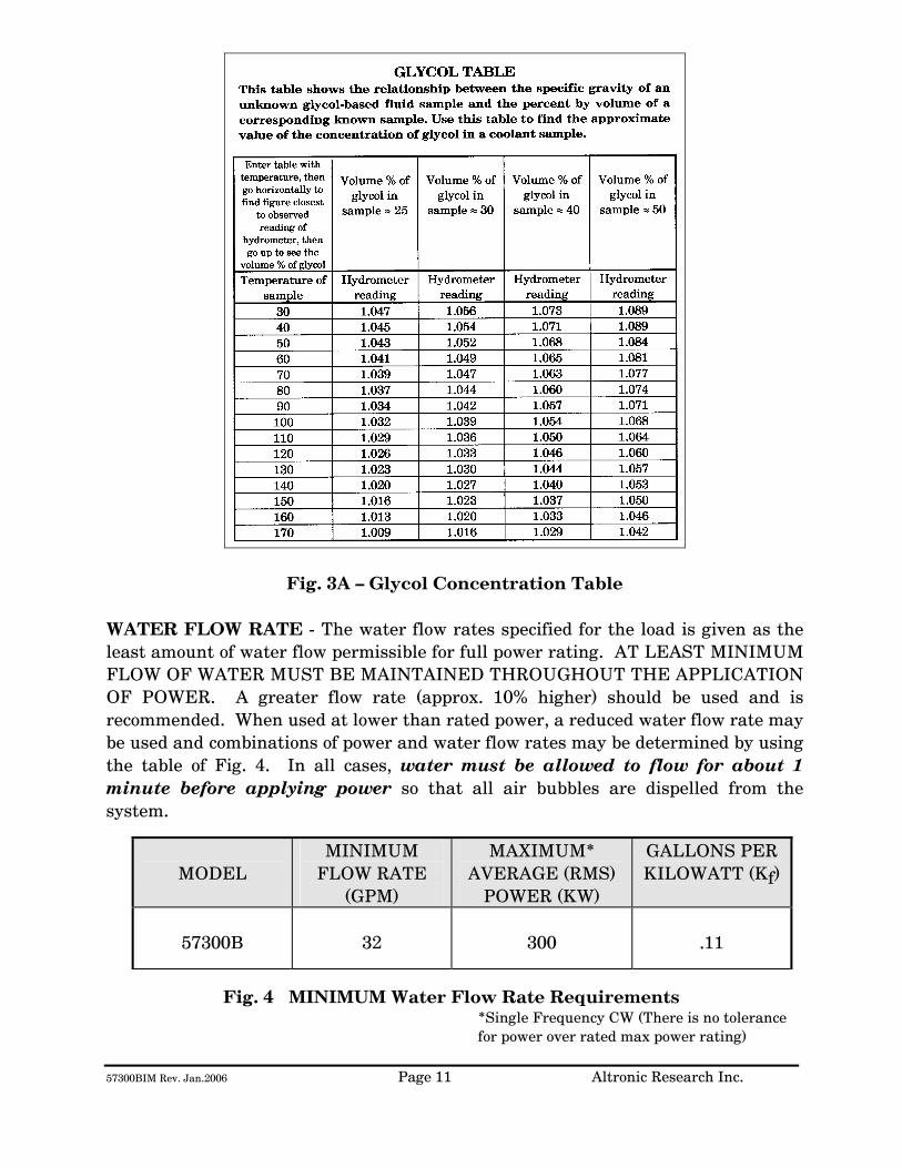
57300BIM Rev. Jan.2006 Page 11 Altronic Research Inc.
Fig. 3A – Glycol Concentration Table WATER FLOW RATE - The water flow rates specified for the load is given as the least amount of water flow permissible for full power rating. AT LEAST MINIMUM FLOW OF WATER MUST BE MAINTAINED THROUGHOUT THE APPLICATION OF POWER. A greater flow rate (approx. 10% higher) should be used and is recommended. When used at lower than rated power, a reduced water flow rate may be used and combinations of power and water flow rates may be determined by using the table of Fig. 4. In all cases, water must be allowed to flow for about 1 minute before applying power so that all air bubbles are dispelled from the system.
MODEL
MINIMUM FLOW RATE
(GPM)
MAXIMUM* AVERAGE (RMS)
POWER (KW)
GALLONS PER KILOWATT (Kf)
57300B
32
300
.11
Fig. 4 MINIMUM Water Flow Rate Requirements *Single Frequency CW (There is no tolerance for power over rated max power rating)
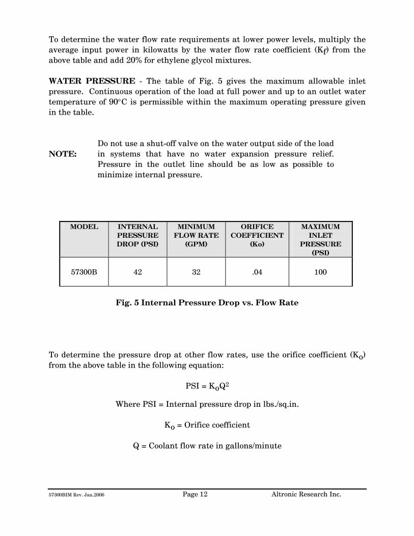
57300BIM Rev. Jan.2006 Page 12 Altronic Research Inc.
To determine the water flow rate requirements at lower power levels, multiply the average input power in kilowatts by the water flow rate coefficient (Kf) from the above table and add 20% for ethylene glycol mixtures. WATER PRESSURE - The table of Fig. 5 gives the maximum allowable inlet pressure. Continuous operation of the load at full power and up to an outlet water temperature of 90°C is permissible within the maximum operating pressure given in the table. NOTE:
Do not use a shut-off valve on the water output side of the load in systems that have no water expansion pressure relief. Pressure in the outlet line should be as low as possible to minimize internal pressure.
MODEL INTERNAL
PRESSURE DROP (PSI)
MINIMUM FLOW RATE
(GPM)
ORIFICE COEFFICIENT
(Ko)
MAXIMUM INLET
PRESSURE (PSI)
57300B
42
32
.04
100
Fig. 5 Internal Pressure Drop vs. Flow Rate
To determine the pressure drop at other flow rates, use the orifice coefficient (Ko) from the above table in the following equation:
PSI = KoQ2
Where PSI = Internal pressure drop in lbs./sq.in.
Ko = Orifice coefficient
Q = Coolant flow rate in gallons/minute

57300BIM Rev. Jan.2006 Page 13 Altronic Research Inc.
COOLING SYSTEMS
TYPES - Four basic cooling systems are summarized in the table of Fig. 6; viz., municipal water, natural water, tank or reservoir, and heat exchanger. No single cooling system is the "best" under all the different circumstances and conditions encountered by the field. Closed loop systems are generally preferable since they afford much greater control over the purity, temperature, pressure, and flow rate of the coolant.
BASIC COMPONENTS NEEDED
METHOD
COOLANT
COOLANT SOURCE
COOLANT LINES &
INSTRUMENT-ATION
PUMP
RESERVOIR
HOURS OF
CONTINUOUS OPERATION
Open
1
Tap Water
Municipal Supply System
In low
flow areas
Optional
Unlimited
2
Natural
fresh water
Lake, river, pond, etc.
Optional
Unlimited
3
Tap or distilled
water with or without
glycol
Storage tank
100 to 1500
gallons
Up to 8 hrs.; depends on size of load & tank. See Fig. 7
Closed
4
Tap or distilled
water with or without
glycol
Accumulator
1 to 5
gallons
Unlimited
5
Tap or distilled
water with or without
glycol
Air-cooled core
Optional
Depending
on BTU capacity of exchanger
Fig. 6 Alternative Cooling Systems
TAP-WATER SYSTEM - The most convenient way to cool the load resistor at the lowest initial cost is by tapping into the existing water supply on the premises. Most municipal sources can provide sufficient pressure to obtain a flow rate that will cool even the highest power model. In the absence of a water flow-meter, a measure of the available flow rate in gallons-per-minute (GPM) may be made with a stop-watch or a watch with a sweep-hand and a gallon container. Connect the dummy load to the water faucet with a
57300BIM Rev. Jan.2006 Page 14 Altronic Research Inc.
short length of hose, and with the faucet full-on, observe the time in seconds required to fill the gallon container at the water outlet of the load. When using the dummy load with a tap-water system, the flow rate is usually adjusted to 10-15% above the minimum requirement and left unattended. Since water lines ordinarily serve other appliances (flush toilets, etc.) over which there is no control, a flow switch should be installed to protect the load resistor element in case the flow rate drops due to a momentary change in water pressure. Choose a flow switch with a small "ON-OFF" flow rate dead band. The switch will also protect the resistor in cases where the RF power may be turned on before the water flow, or where accidental termination of water flow (pinched hose, debris, valve closing, etc.) may occur. In the tap-water system the heated water is discharged down the drain and therefore, the cost of the water becomes an important consideration. NATURAL WATER SYSTEM - A close proximity to a natural supply of fresh water may suggest its utilization. Brackish or salt water may NOT be used as a coolant for the load resistor. The natural water system usually requires more extensive piping and heavier pumping equipment to handle attendant pressure drop. The quality of natural water varies widely and straining is often necessary to handle the twigs, minnows, leaves and other debris frequently encountered. Small automatic self-cleaning strainers are available for this purpose. The strainer should be installed upstream from the pump to protect the pump as well as the load resistor. Additional filtering of smaller particles is sometimes required and this can be accomplished with finer mesh "Y-TYPE" strainers inserted in series with the line. In this system, the water from the natural source may not be directly usable as a coolant for the load resistor element due to a high contamination, such as silt, iron content, mud, etc.; but it may be used as "dirty" water coolant in a water-to-water heat exchanger. The contaminated water could be piped via plastic tubing or hose to copper coils immersed in a holding tank containing clean water coolant for the dummy load. This arrangement would require a dual pump - one section to pump the "dirty" natural-source water and the other section to pump the clean water coolant through the dummy load. HEAT EXCHANGER SYSTEM - In this system, an accumulator or receiving tank is used which only holds about one-half the flow rate in gallons-per-minute. Accordingly, a small quantity of coolant is required. The coolant functions solely as a heat transfer agent between the load resistor and the heat sink. A heat exchanger consisting of a radiator and a fan is the type recommended for this application. With ambient air as the ultimate heat sink, the operating temperature

57300BIM Rev. Jan.2006 Page 15 Altronic Research Inc.
of the coolant will always be above the air temperature for heat to be transferred from the load to the air. Some consideration should be given to exhausting the hot air to the outside so as not to have a temperature rise problem in the transmitter area. The heat exchanger may be a complete self-contained unit (portable) which includes the dummy load or the load may be separate and apart from the heat exchanger unit to facilitate installation and maintenance requirements, etc. Both types of heat exchanger packages are available from us. TANK OR RESERVOIR SYSTEM - In this system, a practical amount of coolant is stored in a tank or reservoir and continuously recirculated (pumped) through the load until the coolant becomes hot. (NOTE: One kilowatt of power will raise a gallon of water 7°F per minute.) This relationship was used to calculate the curves of Fig. 7. The curves show the permissible hours of continuous operation for a given quantity of water in gallons, i.e., the number of gallons of water that will be raised from room temperature (70°F) to 170°F. If water from a swimming pool is used, care should be taken to filter out foreign debris to avoid clogging the system. The water flow rate as specified for each load (GPM) must be maintained throughout the application of power. A thermal switch and a water flow switch should be used as a protection against over-temperature and low coolant flow.
Fig. 7

57300BIM Rev. Jan.2006 Page 16 Altronic Research Inc.
Storage tanks between 200 and 500 gallons will satisfy most requirements. A waterproof concrete holding tank in the 1000 to 1500 gallon range may also be considered. (Similar to a septic tank and buried below the frost line.) It would be protected from extremes of temperature and could hold ordinary tap water as the coolant, while comparing favorably in cost to smaller metal tanks exposed to the elements. Storage tanks are normally vented to the atmosphere and allowance should be made for determining the liquid level in the tank and for adding make-up water. Some typical sizes of cylindrical tanks in the range of interest are shown in the table of Fig. 8 below.
CAPACITY IN
GALLONS
SIZE DIAMETER x LENGTH
IN FEET
120 2 x 5 200 2.5 x 5.5 300 3 x 6 500 3.5 x 7
1000 5 x 7 1500 5 x 10.5
Fig. 8 Tank Sizes
The pump selected for this service should have all wetted parts made from brass, bronze, ceramic or stainless steel. Cast iron and common steel will "poison" the water system and cause early failure of the load. Select the pump to overcome piping losses and the internal pressure drop of the load (shown in Fig. 5).
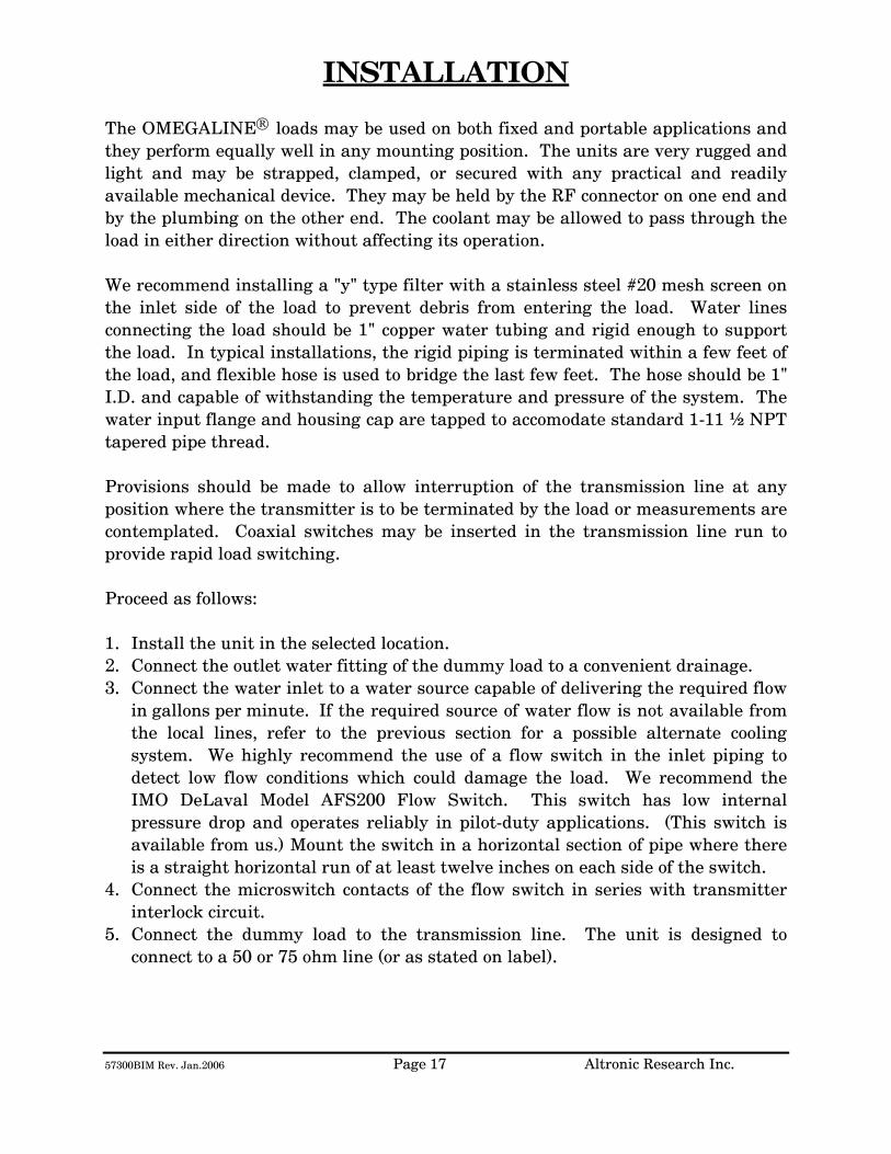
57300BIM Rev. Jan.2006 Page 17 Altronic Research Inc.
INSTALLATION
The OMEGALINE® loads may be used on both fixed and portable applications and they perform equally well in any mounting position. The units are very rugged and light and may be strapped, clamped, or secured with any practical and readily available mechanical device. They may be held by the RF connector on one end and by the plumbing on the other end. The coolant may be allowed to pass through the load in either direction without affecting its operation. We recommend installing a "y" type filter with a stainless steel #20 mesh screen on the inlet side of the load to prevent debris from entering the load. Water lines connecting the load should be 1" copper water tubing and rigid enough to support the load. In typical installations, the rigid piping is terminated within a few feet of the load, and flexible hose is used to bridge the last few feet. The hose should be 1" I.D. and capable of withstanding the temperature and pressure of the system. The water input flange and housing cap are tapped to accomodate standard 1-11 ½ NPT tapered pipe thread. Provisions should be made to allow interruption of the transmission line at any position where the transmitter is to be terminated by the load or measurements are contemplated. Coaxial switches may be inserted in the transmission line run to provide rapid load switching. Proceed as follows: 1. Install the unit in the selected location. 2. Connect the outlet water fitting of the dummy load to a convenient drainage. 3. Connect the water inlet to a water source capable of delivering the required flow
in gallons per minute. If the required source of water flow is not available from the local lines, refer to the previous section for a possible alternate cooling system. We highly recommend the use of a flow switch in the inlet piping to detect low flow conditions which could damage the load. We recommend the IMO DeLaval Model AFS200 Flow Switch. This switch has low internal pressure drop and operates reliably in pilot-duty applications. (This switch is available from us.) Mount the switch in a horizontal section of pipe where there is a straight horizontal run of at least twelve inches on each side of the switch.
4. Connect the microswitch contacts of the flow switch in series with transmitter interlock circuit.
5. Connect the dummy load to the transmission line. The unit is designed to connect to a 50 or 75 ohm line (or as stated on label).
57300BIM Rev. Jan.2006 Page 18 Altronic Research Inc.
OPERATION
To place the dummy load in operation, the following procedure is recommended:
1. Turn on the water pressure and make certain water is flowing through the load. Allow about 1 minute of water circulation to insure complete wetting of the resistor element in the load and exhaustion of air bubbles.
2. Check the water flow rate. This can be done with a five-gallon
container and a wristwatch with a sweep-hand if no water flow meter is available.
3. Apply RF power.
To cease operation, turn the RF power off and allow about 30 seconds before turning off the water.

57300BIM Rev. Jan.2006 Page 19 Altronic Research Inc.
CALORIMETRY The OMEGALINE® loads may be used in conjunction with a flow meter, thermometer wells and thermometers to accurately measure transmitted power by calorimetry. Fig. 9 shows a complete arrangement. The flow meter and the thermometer wells may be placed at a convenient position and at eye level for ease of reading. There is no need to have them adjacent or in close proximity to the load. The components may be placed upwards of fifty feet away from the load without any loss in the accuracy of measurement.
The thermometer wells (Altronic type TW-3), which are closed to the main coolant stream, use water as the heat transfer medium and operate efficiently with the thermometers immersed in about 1 inch of water. The stabilization time for the system is approximately thirty seconds and a power measurement accuracy within 2% may be obtained with very little difficulty. The curves of Fig. 2 show the temperature rise as a function of power in kilowatts (KW) for various water flow rates in gallons-per-minute (GPM). Technical and component information on the calorimetry set-up may be obtained by contacting ALTRONIC RESEARCH, INC.
If an ethylene-glycol and water mixture is used, a correction must be applied to the flow meter reading due to a change in density and change in specific heat and gravity of the coolant.
Use the curves of Fig. 10 to obtain the new (Kt) multiplying factor for the calorimetric power equation and curves of Fig. 11 to obtain the density value to be used with the curve of Fig. 12 to get the flow meter correction factor. The calorimetric power equation when using ethylene glycol and water mixtures will be as follows:
P = Kt (T1-T2) QxF Where P = Power in load in kilowatts
T1 = Outlet water temperature °C T2 = Inlet water temperature °C
Q = Water flow in gallons per minute F = Flow meter correction factor Kt = Coolant multiplying factor
Fig. 9 The Calorimetry Set-up
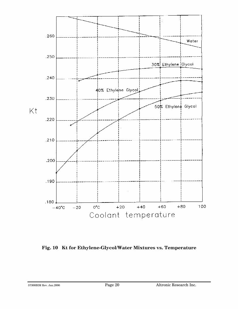
57300BIM Rev. Jan.2006 Page 20 Altronic Research Inc.
Fig. 10 Kt for Ethylene-Glycol/Water Mixtures vs. Temperature
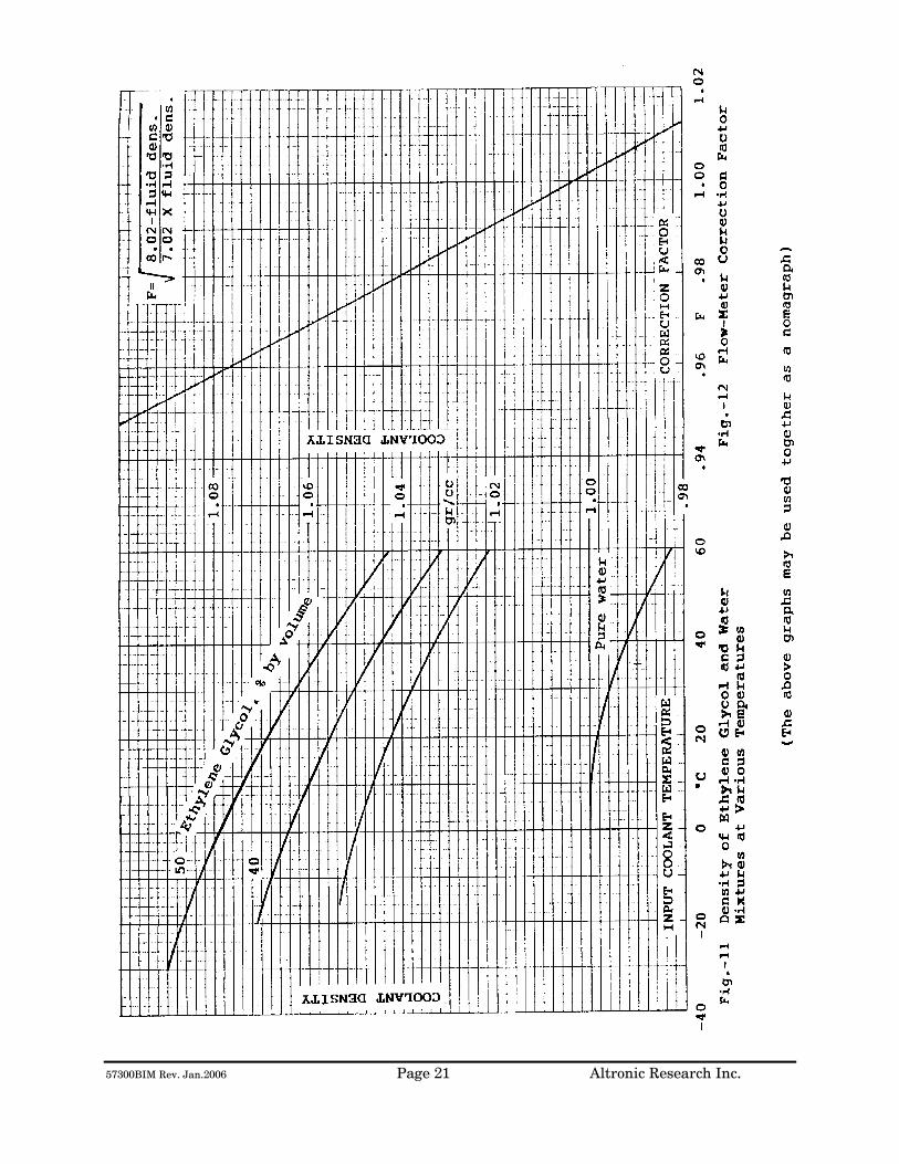
57300BIM Rev. Jan.2006 Page 21 Altronic Research Inc.
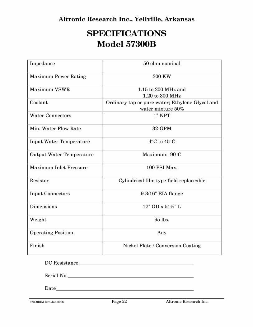
57300BIM Rev. Jan.2006 Page 22 Altronic Research Inc.
Altronic Research Inc., Yellville, Arkansas
SPECIFICATIONS Model 57300B
Impedance
50 ohm nominal
Maximum Power Rating
300 KW
Maximum VSWR
1.15 to 200 MHz and 1.20 to 300 MHz
Coolant Ordinary tap or pure water; Ethylene Glycol and water mixture 50%
Water Connectors
1" NPT
Min. Water Flow Rate
32-GPM
Input Water Temperature
4°C to 45°C
Output Water Temperature
Maximum: 90°C
Maximum Inlet Pressure
100 PSI Max.
Resistor
Cylindrical film type-field replaceable
Input Connectors
9-3/16" EIA flange
Dimensions
12" OD x 51½" L
Weight
95 lbs.
Operating Position
Any
Finish
Nickel Plate / Conversion Coating
DC Resistance
Serial No.
Date

57300BIM Rev. Jan.2006 Page 23 Altronic Research Inc.
Fig. 13
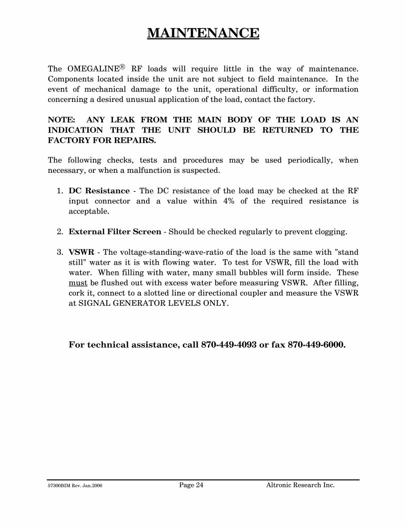
57300BIM Rev. Jan.2006 Page 24 Altronic Research Inc.
MAINTENANCE The OMEGALINE® RF loads will require little in the way of maintenance. Components located inside the unit are not subject to field maintenance. In the event of mechanical damage to the unit, operational difficulty, or information concerning a desired unusual application of the load, contact the factory. NOTE: ANY LEAK FROM THE MAIN BODY OF THE LOAD IS AN INDICATION THAT THE UNIT SHOULD BE RETURNED TO THE FACTORY FOR REPAIRS.
The following checks, tests and procedures may be used periodically, when necessary, or when a malfunction is suspected.
1. DC Resistance - The DC resistance of the load may be checked at the RF
input connector and a value within 4% of the required resistance is acceptable.
2. External Filter Screen - Should be checked regularly to prevent clogging. 3. VSWR - The voltage-standing-wave-ratio of the load is the same with "stand
still" water as it is with flowing water. To test for VSWR, fill the load with water. When filling with water, many small bubbles will form inside. These must be flushed out with excess water before measuring VSWR. After filling, cork it, connect to a slotted line or directional coupler and measure the VSWR at SIGNAL GENERATOR LEVELS ONLY.
For technical assistance, call 870-449-4093 or fax 870-449-6000.

57300BIM Rev. Jan.2006 Page 25 Altronic Research Inc.
LIMITED WARRANTY We take pride in manufacturing products of the highest quality and we warrant them to the original purchaser to be free from defects in material and workmanship for the period of one year from date of invoice. Additionally, products of our manufacture repaired by us are warranted against defects in material and workmanship for a period of 90 days from date of invoice, with the provisions described herein. Should a product, or a portion of a product of our manufacture prove faulty, in material or workmanship, during the life of this warranty, we hereby obligate ourselves, at our own discretion, to repair or replace such portions of the product as required to remedy such defect. If, in our judgment, such repair or replacement fails to be a satisfactory solution, our limit of obligation shall be no more than full refund of the purchase price. This warranty is limited to products of our own manufacture. Equipment and components originating from other manufacturers are warranted only to the limits of that manufacturer's warranty to us. Furthermore, we shall not be liable for any injury, loss or damage, direct or consequential, arising out of the use, or misuse (by operation above rated capacities, repairs not made by us, or any misapplication) of the equipment. Before using, the user shall determine the suitability of the product for the intended use; and the user assumes all risk and liability whatsoever in connection therewith. The foregoing is the only warranty of Altronic Research Incorporated and is in lieu of all other warranties expressed or implied. Warranty returns shall first be authorized by the Customer Service Department and shall be shipped prepaid. Warranty does not cover freight charges.
ALTRONIC RESEARCH, INC. P.O. BOX 249
YELLVILLE, ARKANSAS 72687-0249 U.S.A.
LIQUID-COOLED COAXIAL LOAD RESISTOR
MODEL 57200B
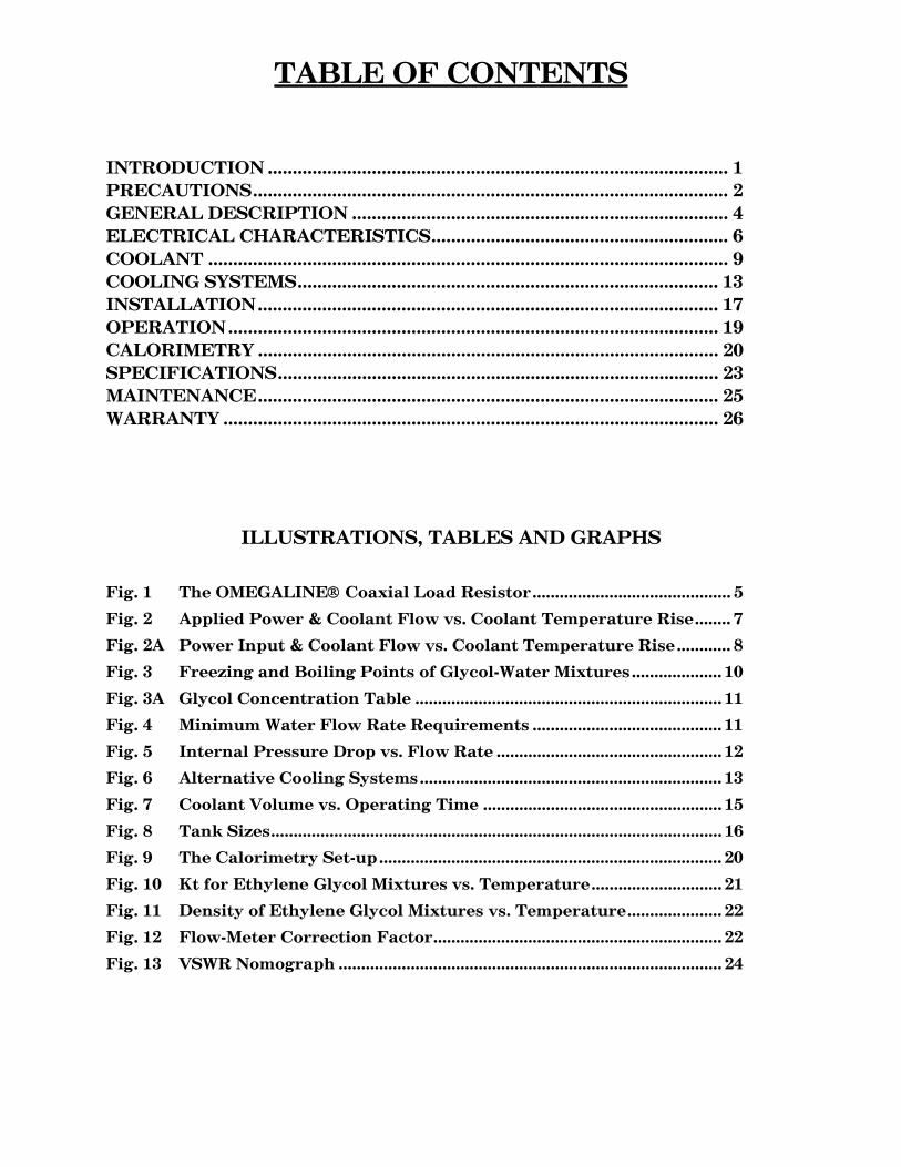
TABLE OF CONTENTS
INTRODUCTION ............................................................................................. 1 PRECAUTIONS................................................................................................ 2 GENERAL DESCRIPTION ............................................................................ 4 ELECTRICAL CHARACTERISTICS............................................................ 6 COOLANT ......................................................................................................... 9 COOLING SYSTEMS..................................................................................... 13 INSTALLATION............................................................................................. 17 OPERATION................................................................................................... 19 CALORIMETRY ............................................................................................. 20 SPECIFICATIONS......................................................................................... 23 MAINTENANCE............................................................................................. 25 WARRANTY .................................................................................................... 26
ILLUSTRATIONS, TABLES AND GRAPHS
Fig. 1 The OMEGALINE® Coaxial Load Resistor............................................ 5
Fig. 2 Applied Power & Coolant Flow vs. Coolant Temperature Rise........ 7
Fig. 2A Power Input & Coolant Flow vs. Coolant Temperature Rise............ 8
Fig. 3 Freezing and Boiling Points of Glycol-Water Mixtures.................... 10
Fig. 3A Glycol Concentration Table .................................................................... 11
Fig. 4 Minimum Water Flow Rate Requirements .......................................... 11
Fig. 5 Internal Pressure Drop vs. Flow Rate .................................................. 12
Fig. 6 Alternative Cooling Systems................................................................... 13
Fig. 7 Coolant Volume vs. Operating Time ..................................................... 15
Fig. 8 Tank Sizes.................................................................................................... 16
Fig. 9 The Calorimetry Set-up............................................................................ 20
Fig. 10 Kt for Ethylene Glycol Mixtures vs. Temperature............................. 21
Fig. 11 Density of Ethylene Glycol Mixtures vs. Temperature..................... 22
Fig. 12 Flow-Meter Correction Factor................................................................ 22
Fig. 13 VSWR Nomograph ..................................................................................... 24
57200BIM Rev Jan 2006 Page 1 Altronic Research Inc.
INTRODUCTION This manual gives you specific information on the installation, operation and service of OMEGALINE® coaxial resistors. Most of the loads are field serviceable, but we recommend their return to us for repair. Mistakes can be costly compared to the low cost for our trained personnel to make the repairs and return the load to new performance specifications. Labor and packaging costs are minimal. We take the load completely apart, clean and inspect all parts, repair/replace as necessary, reassemble, water pressure test, power test, VSWR test and package the load for shipment. If new parts are required in the load (such as resistors etc.), this will be an additional cost. The average turn-around time on repairs is approximately 7 working days and generally will depend on your needs. When sending in repairs, please include: your company name and address, the operating frequency you use, fax number, telephone number and your name in case we need to talk to you about the load or obtain shipping instructions. We can accommodate most shipping modes. SHIP TO: Altronic Research Inc., 621 Hwy. 202 W, Yellville, AR 72687. Our mailing address is P.O. Box 249. Note: We also repair dummy loads manufactured by many other companies. Call for information (870-449-4093).

57200BIM Rev Jan 2006 Page 2 Altronic Research Inc.
PRECAUTIONS
!!!DANGER!!! THIS UNIT MUST BE TOTALLY DISCONNECTED FROM ALL RF POWER BEFORE ANY REPAIRS ARE ATTEMPTED. ANY ATTEMPT AT REPAIR WITHOUT DISCONNECTING THE POWER COULD RESULT IN FATAL ELECTRICAL SHOCK!!!
WARNING DO NOT APPLY POWER WITHOUT THE MINIMUM RATED FLOW OF COOLANT THROUGH THE LOAD. A SAFETY INTERLOCK SWITCH IS RECOMMENDED. EVEN A BRIEF APPLICATION OF POWER TO THE LOAD WITHOUT THE CIRCULATION OF COOLANT WILL CAUSE IMMEDIATE BURN OUT.
WARNING THE LOAD RESISTOR CONSISTS OF A CERAMIC SUBSTRATE COATED WITH A SPECIAL RESISTIVE FILM. IF ANY DAMAGE OCCURS TO THE RESISTOR, THERE COULD BE SHARDS OR SHARP BROKEN PIECES OF CERAMIC IN THE LOAD. CARE SHOULD BE TAKEN TO AVOID CUTS OR INJURIES.
57200BIM Rev Jan 2006 Page 3 Altronic Research Inc.
PRECAUTIONS
CAUTION USE ONLY CLEAR, COLORLESS, ANALYTIC OR TECHNICAL GRADE ETHYLENE GLYCOL WITH PURE TAP OR POTABLE* WATER AS A SOURCE COOLANT. DO NOT USE ANY STOP LEAK, SEALANTS, AUTOMOTIVE ANTIFREEZE OR UNION CARBIDE UCARTHERM™ IN COOLANT. USE OF THESE SUBSTANCES WILL VOID THE WARRANTY.
IMPORTANT ADDITION OF ETHYLENE GLYCOL TO THE WATER REDUCES THE HEAT CAPACITY OF THE COOLING SYSTEM. COOLANT FLOW RATE MUST BE INCREASED BY AT LEAST 20% OVER MINIMUM FLOW.
CAUTION DO NOT APPLY MORE THAN THE MAXIMUM RATED RF POWER TO THE LOAD. THIS WILL CAUSE INTERNAL DAMAGE TO THE LOAD.
* Potable Water: The U.S. Health Department has established standards for potable water at a maximum of 500ppm of dissolved solids. Hard water (particularly dissolved salts) can cause damage to resistive film and load. Water condition can be adjusted by mixing distilled water in sufficient quantities with coolant water.

57200BIM Rev Jan 2006 Page 4 Altronic Research Inc.
GENERAL DESCRIPTION
The OMEGALINE® dummy load is basically a termination-type unit having its characteristic impedance at the input end and tapered to zero impedance (short circuit) at the other end. The center conductor is a tubular resistor whose DC resistance is equal to the characteristic impedance of the line. The outer conductor of the coaxial line is a symmetrical horn-shaped enclosure, contoured logarithmically along its length to obtain a reflection-free termination. The RF dielectric medium consists of three distinct materials: the liquid coolant, the plastic water jacket and the air space. (See Fig. 1) Coolant enters the load at the electrically shorted end, flows axially down the center of the resistor tube, mushrooms over into the annular channel under the water jacket, and makes a second pass over the resistor in direct physical contact with the resistive film. Thus the coolant makes intimate contact with both the inside and outside cylindrical surfaces of the resistor, providing optimum heat transfer with minimal flow rate. The dummy load housing is constructed of aluminum and/or brass or bronze sections whose inner surfaces are machined to a modified logarithmic taper. The stepped housing sections are held in accurate alignment with stainless steel socket head cap screws. The power dissipating resistor consists of a conductive resistive film which is deposited on a tubular ceramic substrate with silver bands fired on the ends for electrical connection. Contact to the resistor is made by silver plated spring fingers. Coolant flows through the fingers and passes directly over the resistive film. The resistor is enclosed within a plastic water jacket which is custom machined to match the body and seal the coolant flow.
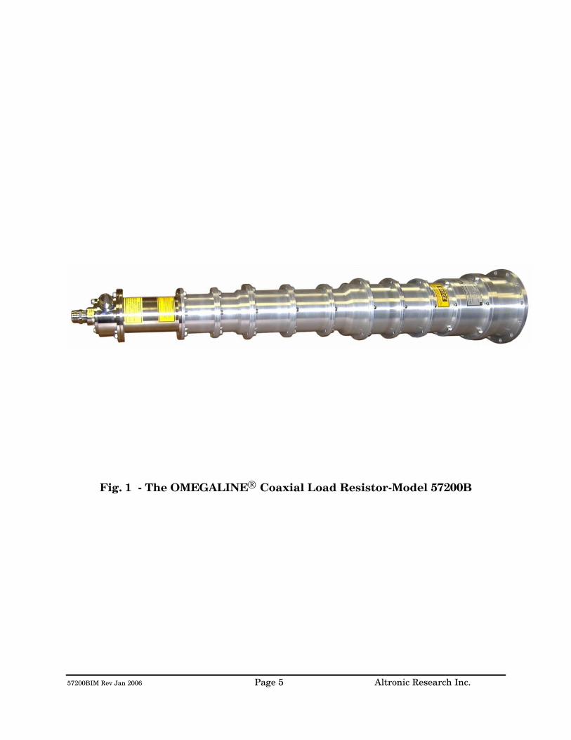
57200BIM Rev Jan 2006 Page 5 Altronic Research Inc.
Fig. 1 - The OMEGALINE® Coaxial Load Resistor-Model 57200B
57200BIM Rev Jan 2006 Page 6 Altronic Research Inc.
ELECTRICAL CHARACTERISTICS POWER RATING - All models of the OMEGALINE® series of coaxial loads are rated for continuous duty and may be operated in any position at any power level within their rating and with the proper water flow rate. A 10-20% GREATER FLOW RATE MAY BE USED AND IS RECOMMENDED. If the units are operated below the maximum power rating, a corresponding reduction in the coolant flow rate may be used. (See Fig. 4) All loads are electrically tested prior to shipment. Testing is done at 60 Hz with input voltage and current measured on RMS meters. The (RMS) power being dissipated in the load is simultaneously checked by calorimetry. The relationship used for calculating the power dissipated in the load from the calorimetric data is: (See Fig. 2 & 2A)
P = 0.264 (T2 - T1)Q
Where P = Power in load in kilowatts
T2 = Outlet water temperature °C
T1 = Inlet water temperature °C
Q = Water flow in gallons-per-minute
WARNING! Power should never be applied before turning on the WATER FIRST and allowing sufficient time (approx. 1 minute) for complete wetting of the resistor and elimination of air bubbles. Water flow must be maintained throughout the application of power and may be turned off within 15-30 seconds after the power has been turned off. Failure to observe these precautions will result in instant failure of the resistor and possible destruction of other parts of the load.

57200BIM Rev Jan 2006 Page 7 Altronic Research Inc.
FREQUENCY RANGE - The OMEGALINE® terminations are designed to match the most common high frequency transmission media - - 50 and 75 ohm coaxial lines. The units are universal and operate over an extremely wide frequency range - from power line frequencies to beyond the UHF band. If we regard the upper limit of the frequency range to be the region where the VSWR reaches 1.25, then models with a 1-5/8" diameter input will have a useful range up to about 2200 MHz; models designed for 3-1/8" transmission lines will have a useful range up to 1800 MHz; those models adapted to 6-1/8" coaxial lines will have a useful range to 1200 MHz. IMPEDANCE - The impedance of the loads, in the language of VSWR (voltage-standing-wave-ratio), is quite independent of frequency, water flow rate and water temperature. It is almost purely resistive. For most models, the VSWR is maintained below 1.1 to 800 MHz. Below 100 MHz the input impedance can be regarded as purely resistive and equal to the DC resistance of the load. The tolerance on the DC resistance is held within 4 percent.
Fig. 2 - Applied Power & Coolant Flow vs. Coolant Temperature Rise

57200BIM Rev Jan 2006 Page 8 Altronic Research Inc.
Fig. 2A - Power Input & Coolant Flow vs. Coolant Temperature Rise
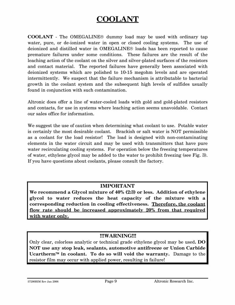
57200BIM Rev Jan 2006 Page 9 Altronic Research Inc.
COOLANT
COOLANT - The OMEGALINE® dummy load may be used with ordinary tap water, pure, or de-ionized water in open or closed cooling systems. The use of deionized and distilled water in OMEGALINE® loads has been reported to cause premature failures under some conditions. These failures are the result of the leaching action of the coolant on the silver and silver-plated surfaces of the resistors and contact material. The reported failures have generally been associated with deionized systems which are polished to 10-15 megohm levels and are operated intermittently. We suspect that the failure mechanism is attributable to bacterial growth in the coolant system and the subsequent high levels of sulfides usually found in conjunction with such contamination. Altronic does offer a line of water-cooled loads with gold and gold-plated resistors and contacts, for use in systems where leaching action seems unavoidable. Contact our sales office for information. We suggest the use of caution when determining what coolant to use. Potable water is certainly the most desirable coolant. Brackish or salt water is NOT permissible as a coolant for the load resistor! The load is designed with non-contaminating elements in the water circuit and may be used with transmitters that have pure water recirculating cooling systems. For operation below the freezing temperatures of water, ethylene glycol may be added to the water to prohibit freezing (see Fig. 3). If you have questions about coolants, please consult the factory.
IMPORTANT We recommend a Glycol mixture of 40% (2:3) or less. Addition of ethylene glycol to water reduces the heat capacity of the mixture with a corresponding reduction in cooling effectiveness. Therefore, the coolant flow rate should be increased approximately 20% from that required with water only.
!!!WARNING!!! Only clear, colorless analytic or technical grade ethylene glycol may be used. DO NOT use any stop leak, sealants, automotive antifreeze or Union Carbide Ucartherm™ in coolant. To do so will void the warranty. Damage to the resistor film may occur with applied power, resulting in failure!
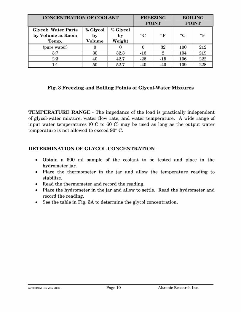
57200BIM Rev Jan 2006 Page 10 Altronic Research Inc.
CONCENTRATION OF COOLANT FREEZING POINT
BOILING POINT
Glycol: Water Parts by Volume at Room
Temp.
% Glycol by
Volume
% Glycol by
Weight
°C
°F
°C
°F
(pure water) 0 0 0 32 100 212 3:7 30 32.3 -16 2 104 219 2:3 40 42.7 -26 -15 106 222 1:1 50 52.7 -40 -40 109 228
Fig. 3 Freezing and Boiling Points of Glycol-Water Mixtures
TEMPERATURE RANGE - The impedance of the load is practically independent of glycol-water mixture, water flow rate, and water temperature. A wide range of input water temperatures (0°C to 60°C) may be used as long as the output water temperature is not allowed to exceed 90° C. DETERMINATION OF GLYCOL CONCENTRATION –
• Obtain a 500 ml sample of the coolant to be tested and place in the hydrometer jar.
• Place the thermometer in the jar and allow the temperature reading to stabilize.
• Read the thermometer and record the reading. • Place the hydrometer in the jar and allow to settle. Read the hydrometer and
record the reading. • See the table in Fig. 3A to determine the glycol concentration.
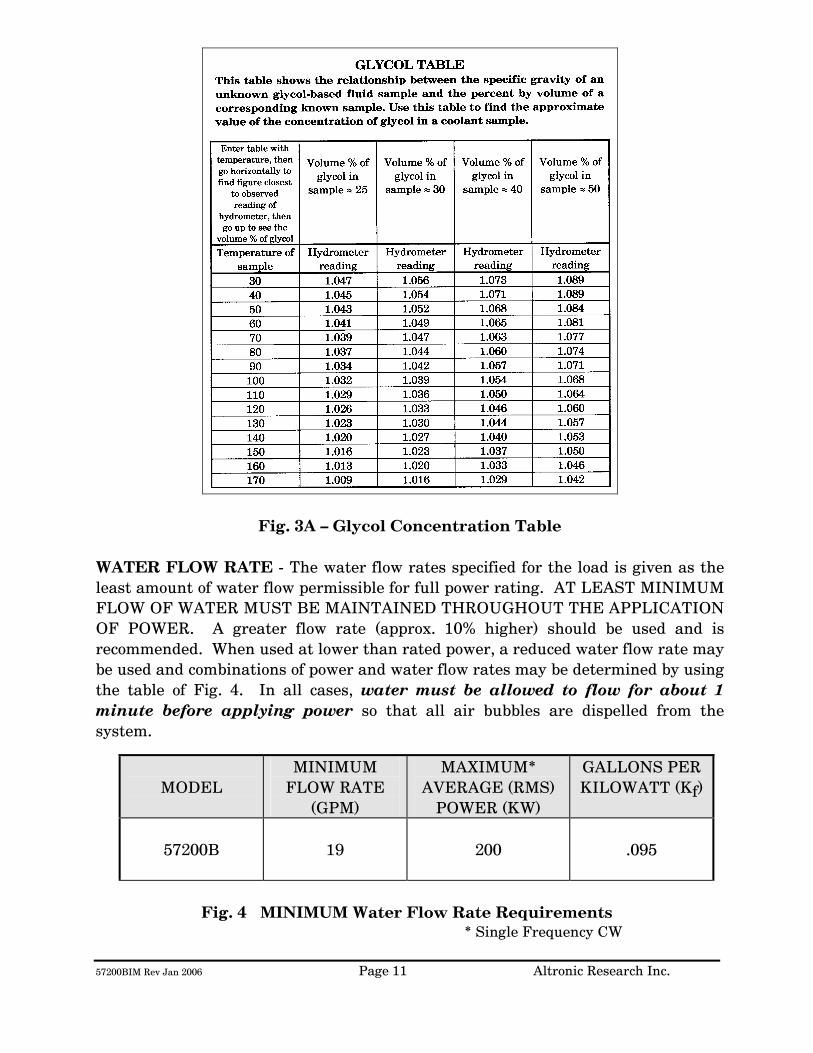
57200BIM Rev Jan 2006 Page 11 Altronic Research Inc.
Fig. 3A – Glycol Concentration Table WATER FLOW RATE - The water flow rates specified for the load is given as the least amount of water flow permissible for full power rating. AT LEAST MINIMUM FLOW OF WATER MUST BE MAINTAINED THROUGHOUT THE APPLICATION OF POWER. A greater flow rate (approx. 10% higher) should be used and is recommended. When used at lower than rated power, a reduced water flow rate may be used and combinations of power and water flow rates may be determined by using the table of Fig. 4. In all cases, water must be allowed to flow for about 1 minute before applying power so that all air bubbles are dispelled from the system.
MODEL
MINIMUM FLOW RATE
(GPM)
MAXIMUM* AVERAGE (RMS)
POWER (KW)
GALLONS PER KILOWATT (Kf)
57200B
19
200
.095
Fig. 4 MINIMUM Water Flow Rate Requirements
* Single Frequency CW

57200BIM Rev Jan 2006 Page 12 Altronic Research Inc.
To determine the water flow rate requirements at lower power levels, multiply the average input power in kilowatts by the water flow rate coefficient (Kf) from the above table and add 20% for ethylene glycol mixtures. WATER PRESSURE - The table of Fig. 5 gives the maximum allowable inlet pressure. Continuous operation of the load at full power and up to an outlet water temperature of 90°C is permissible within the maximum operating pressure given in the table. NOTE:
Do not use a shut-off valve on the water output side of the load in systems that have no water expansion pressure relief. Pressure in the outlet line should be as low as possible to minimize internal pressure.
MODEL INTERNAL
PRESSURE DROP (PSI)
MINIMUM FLOW RATE
(GPM)
ORIFICE COEFFICIENT
(Ko)
MAXIMUM INLET
PRESSURE (PSI)
57200B
50
19
.14
100
Fig. 5 Internal Pressure Drop vs. Flow Rate
To determine the pressure drop at other flow rates, use the orifice coefficient (Ko) from the above table in the following equation:
PSI = KoQ2
Where PSI = Internal pressure drop in lbs./sq.in.
Ko = Orifice coefficient
Q = Coolant flow rate in gallons/minute

57200BIM Rev Jan 2006 Page 13 Altronic Research Inc.
COOLING SYSTEMS
TYPES - Four basic cooling systems are summarized in the table of Fig. 6; viz., municipal water, natural water, tank or reservoir, and heat exchanger. No single cooling system is the "best" under all the different circumstances and conditions encountered by the field. Closed loop systems are generally preferable since they afford much greater control over the purity, temperature, pressure, and flow rate of the coolant.
BASIC COMPONENTS NEEDED
METHOD
COOLANT
COOLANT SOURCE
COOLANT LINES &
INSTRUMENT-ATION
PUMP
RESERVOIR
HOURS OF
CONTINUOUS OPERATION
Open
1
Tap Water
Municipal Supply System
In low
flow areas
Optional
Unlimited
2
Natural
fresh water
Lake, river, pond, etc.
Optional
Unlimited
3
Tap or distilled
water with or without
glycol
Storage tank
100 to 1500
gallons
Up to 8 hrs.; depends on size of load & tank. See Fig. 7
Closed
4
Tap or distilled
water with or without
glycol
Accumulator
1 to 5
gallons
Unlimited
5
Tap or distilled
water with or without
glycol
Air-cooled core
Optional
Depending
on BTU capacity of exchanger
Fig. 6 Alternative Cooling Systems
TAP-WATER SYSTEM - The most convenient way to cool the load resistor at the lowest initial cost is by tapping into the existing water supply on the premises. Most municipal sources can provide sufficient pressure to obtain a flow rate that will cool even the highest power model. In the absence of a water flow-meter, a measure of the available flow rate in gallons-per-minute (GPM) may be made with a stop-watch or a watch with a sweep-hand and a gallon container. Connect the dummy load to the water faucet with a

57200BIM Rev Jan 2006 Page 14 Altronic Research Inc.
short length of hose, and with the faucet full-on, observe the time in seconds required to fill the gallon container at the water outlet of the load. When using the dummy load with a tap-water system, the flow rate is usually adjusted to 10-15% above the minimum requirement and left unattended. Since water lines ordinarily serve other appliances (flush toilets, etc.) over which there is no control, a flow switch should be installed to protect the load resistor element in case the flow rate drops due to a momentary change in water pressure. Choose a flow switch with a small "ON-OFF" flow rate dead band. The switch will also protect the resistor in cases where the RF power may be turned on before the water flow, or where accidental termination of water flow (pinched hose, debris, valve closing, etc.) may occur. In the tap-water system the heated water is discharged down the drain and therefore, the cost of the water becomes an important consideration. NATURAL WATER SYSTEM - A close proximity to a natural supply of fresh water may suggest its utilization. Brackish or salt water may NOT be used as a coolant for the load resistor. The natural water system usually requires more extensive piping and heavier pumping equipment to handle attendant pressure drop. The quality of natural water varies widely and straining is often necessary to handle the twigs, minnows, leaves and other debris frequently encountered. Small automatic self-cleaning strainers are available for this purpose. The strainer should be installed upstream from the pump to protect the pump as well as the load resistor. Additional filtering of smaller particles is sometimes required and this can be accomplished with finer mesh "Y-TYPE" strainers inserted in series with the line. In this system, the water from the natural source may not be directly usable as a coolant for the load resistor element due to a high contamination, such as silt, iron content, mud, etc.; but it may be used as "dirty" water coolant in a water-to-water heat exchanger. The contaminated water could be piped via plastic tubing or hose to copper coils immersed in a holding tank containing clean water coolant for the dummy load. This arrangement would require a dual pump - one section to pump the "dirty" natural-source water and the other section to pump the clean water coolant through the dummy load. HEAT EXCHANGER SYSTEM - In this system, an accumulator or receiving tank is used which only holds about one-half the flow rate in gallons-per-minute. Accordingly, a small quantity of coolant is required. The coolant functions solely as a heat transfer agent between the load resistor and the heat sink. A heat exchanger consisting of a radiator and a fan is the type recommended for this application. With ambient air as the ultimate heat sink, the operating temperature
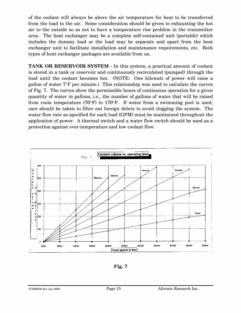
57200BIM Rev Jan 2006 Page 15 Altronic Research Inc.
of the coolant will always be above the air temperature for heat to be transferred from the load to the air. Some consideration should be given to exhausting the hot air to the outside so as not to have a temperature rise problem in the transmitter area. The heat exchanger may be a complete self-contained unit (portable) which includes the dummy load or the load may be separate and apart from the heat exchanger unit to facilitate installation and maintenance requirements, etc. Both types of heat exchanger packages are available from us. TANK OR RESERVOIR SYSTEM - In this system, a practical amount of coolant is stored in a tank or reservoir and continuously recirculated (pumped) through the load until the coolant becomes hot. (NOTE: One kilowatt of power will raise a gallon of water 7°F per minute.) This relationship was used to calculate the curves of Fig. 7. The curves show the permissible hours of continuous operation for a given quantity of water in gallons, i.e., the number of gallons of water that will be raised from room temperature (70°F) to 170°F. If water from a swimming pool is used, care should be taken to filter out foreign debris to avoid clogging the system. The water flow rate as specified for each load (GPM) must be maintained throughout the application of power. A thermal switch and a water flow switch should be used as a protection against over-temperature and low coolant flow.
Fig. 7

57200BIM Rev Jan 2006 Page 16 Altronic Research Inc.
Storage tanks between 200 and 500 gallons will satisfy most requirements. A waterproof concrete holding tank in the 1000 to 1500 gallon range may also be considered. (Similar to a septic tank and buried below the frost line.) It would be protected from extremes of temperature and could hold ordinary tap water as the coolant, while comparing favorably in cost to smaller metal tanks exposed to the elements. Storage tanks are normally vented to the atmosphere and allowance should be made for determining the liquid level in the tank and for adding make-up water. Some typical sizes of cylindrical tanks in the range of interest are shown in the table of Fig. 8 below.
CAPACITY IN
GALLONS
SIZE DIAMETER x LENGTH
IN FEET
120 2 x 5 200 2.5 x 5.5 300 3 x 6 500 3.5 x 7
1000 5 x 7 1500 5 x 10.5
Fig. 8 Tank Sizes
The pump selected for this service should have all wetted parts made from brass, bronze, ceramic or stainless steel. Cast iron and common steel will "poison" the water system and cause early failure of the load. Select the pump to overcome piping losses and the internal pressure drop of the load (shown in Fig. 5).

57200BIM Rev Jan 2006 Page 17 Altronic Research Inc.
INSTALLATION
The OMEGALINE® loads may be used on both fixed and portable applications and they perform equally well in any mounting position. The units are very rugged and light and may be strapped, clamped, or secured with any practical and readily available mechanical device. They may be held by the RF connector on one end and by the plumbing on the other end. The coolant may be allowed to pass through the load in either direction without affecting its operation, but the axial water connector is normally used as the inlet since it contains the built-in filter screen. Water lines connecting the load should be 3/4" copper water tubing and rigid enough to support the load. NOTE: (A fifty-foot length of 1/2" pipe has a pressure drop of 45-PSI at 10-GPM water flow rate, while a 3/4" pipe under the same conditions only develops a 5-PSI drop.) In typical installations, the rigid piping is terminated within a few feet of the load, and flexible hose is used to bridge the last few feet. The hose should be 3/4" I.D. and capable of withstanding the temperature and pressure of the system. The water fittings on the load are 3/4" hose thread to accommodate standard hose couplings. Do not screw pipe thread fittings onto the hose thread - damage will result due to cross-threading. Pipe threads are tapered and hose threads are straight. If it is desired to mate with regular 3/4" pipe threads, use a hose-to-pipe adapter. The adapter is recommended since it eliminates the need of removing the side outlet water fitting and also allows the axial water fitting to be adapted directly to 3/4" pipe. The adapters may be obtained at a local hardware store or a plumbing supply house. Provisions should be made to allow interruption of the transmission line at any position where the transmitter is to be terminated by the load or measurements are contemplated. Coaxial switches may be inserted in the transmission line run to provide rapid load switching. Proceed as follows:
1. Install the unit in the selected location. 2. Connect the outlet water fitting of the dummy load to a convenient
drainage. 3. Connect the water inlet to a water source capable of delivering the
required flow in gallons per minute.
57200BIM Rev Jan 2006 Page 18 Altronic Research Inc.
If the required source of water flow is not available from the local lines, refer to the previous section for a possible alternate cooling system. We highly recommend the use of a flow switch in the inlet piping to detect low flow conditions which could damage the load. We recommend the IMO DeLaval Model AFS200, Adjustable Flow Switch. This switch has low internal pressure drop and operates reliably in pilot-duty applications. (This switch is available from us.) Mount the switch in a horizontal section of pipe where there is a straight horizontal run of at least five inches on each side of the switch.
4. Connect the microswitch contacts of the flow switch in series with transmitter interlock circuit.
5. Connect the dummy load to the transmission line. The unit is designed
to connect to a 50 or 75 ohm line (or as stated on label).

57200BIM Rev Jan 2006 Page 19 Altronic Research Inc.
OPERATION
To place the dummy load in operation, the following procedure is recommended:
1. Turn on the water pressure and make certain water is flowing through the load. Allow about 1 minute of water circulation to insure complete wetting of the resistor element in the load and exhaustion of air bubbles.
2. Check the water flow rate. This can be done with a five-gallon
container and a wristwatch with a sweep-hand if no water flow meter is available.
3. Apply RF power.
To cease operation, turn the RF power off and allow about 30 seconds before turning off the water.
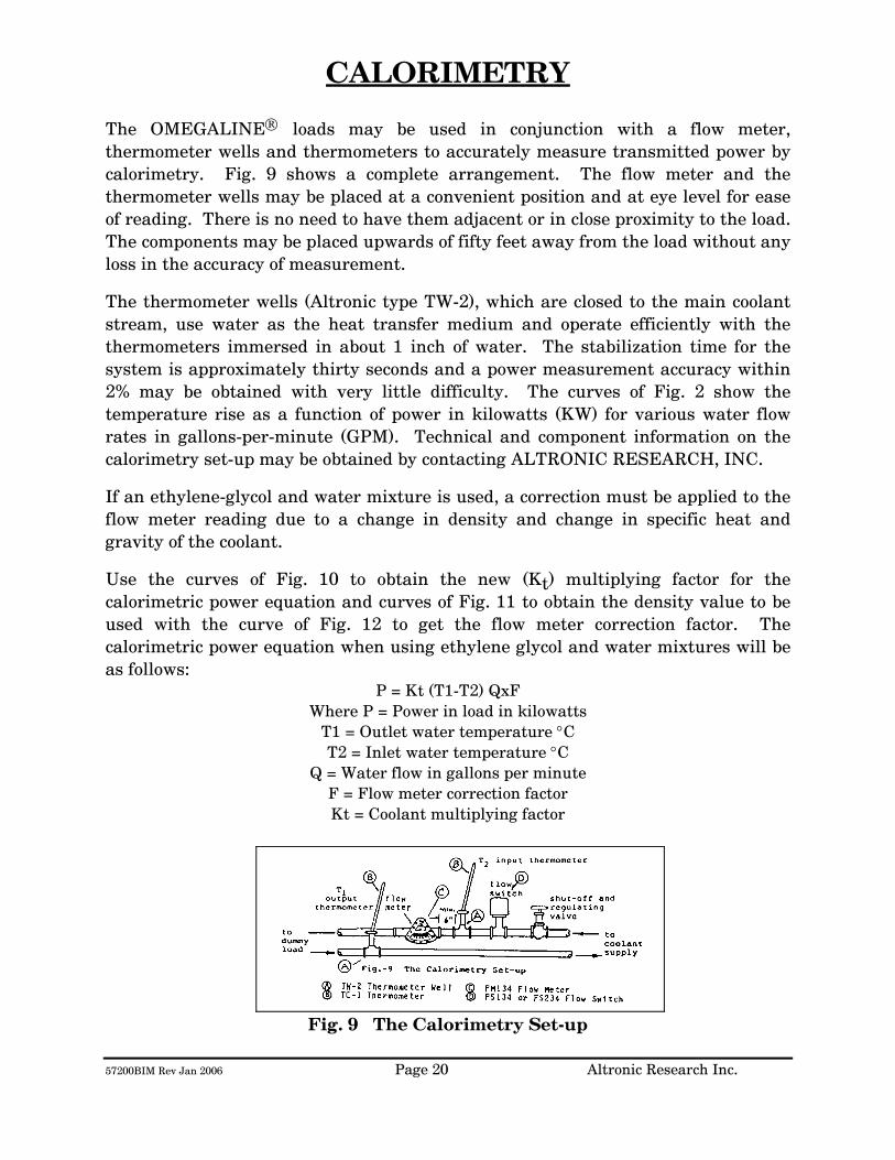
57200BIM Rev Jan 2006 Page 20 Altronic Research Inc.
CALORIMETRY The OMEGALINE® loads may be used in conjunction with a flow meter, thermometer wells and thermometers to accurately measure transmitted power by calorimetry. Fig. 9 shows a complete arrangement. The flow meter and the thermometer wells may be placed at a convenient position and at eye level for ease of reading. There is no need to have them adjacent or in close proximity to the load. The components may be placed upwards of fifty feet away from the load without any loss in the accuracy of measurement.
The thermometer wells (Altronic type TW-2), which are closed to the main coolant stream, use water as the heat transfer medium and operate efficiently with the thermometers immersed in about 1 inch of water. The stabilization time for the system is approximately thirty seconds and a power measurement accuracy within 2% may be obtained with very little difficulty. The curves of Fig. 2 show the temperature rise as a function of power in kilowatts (KW) for various water flow rates in gallons-per-minute (GPM). Technical and component information on the calorimetry set-up may be obtained by contacting ALTRONIC RESEARCH, INC.
If an ethylene-glycol and water mixture is used, a correction must be applied to the flow meter reading due to a change in density and change in specific heat and gravity of the coolant.
Use the curves of Fig. 10 to obtain the new (Kt) multiplying factor for the calorimetric power equation and curves of Fig. 11 to obtain the density value to be used with the curve of Fig. 12 to get the flow meter correction factor. The calorimetric power equation when using ethylene glycol and water mixtures will be as follows:
P = Kt (T1-T2) QxF Where P = Power in load in kilowatts
T1 = Outlet water temperature °C T2 = Inlet water temperature °C
Q = Water flow in gallons per minute F = Flow meter correction factor Kt = Coolant multiplying factor
Fig. 9 The Calorimetry Set-up
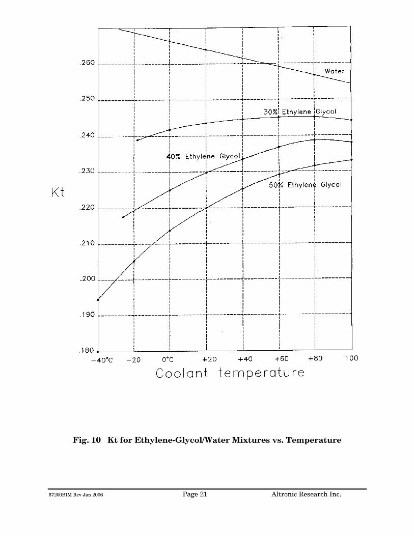
57200BIM Rev Jan 2006 Page 21 Altronic Research Inc.
Fig. 10 Kt for Ethylene-Glycol/Water Mixtures vs. Temperature

57200BIM Rev Jan 2006 Page 22 Altronic Research Inc.
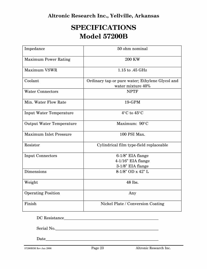
57200BIM Rev Jan 2006 Page 23 Altronic Research Inc.
Altronic Research Inc., Yellville, Arkansas
SPECIFICATIONS Model 57200B
Impedance
50 ohm nominal
Maximum Power Rating
200 KW
Maximum VSWR
1.15 to .45 GHz
Coolant Ordinary tap or pure water; Ethylene Glycol and water mixture 40%
Water Connectors
NPTF
Min. Water Flow Rate
19-GPM
Input Water Temperature
4°C to 45°C
Output Water Temperature
Maximum: 90°C
Maximum Inlet Pressure
100 PSI Max.
Resistor
Cylindrical film type-field replaceable
Input Connectors
6-1/8" EIA flange 4-1/16" EIA flange 3-1/8" EIA flange
Dimensions
8-1/8" OD x 42" L
Weight
48 lbs.
Operating Position
Any
Finish
Nickel Plate / Conversion Coating
DC Resistance
Serial No.
Date

57200BIM Rev Jan 2006 Page 24 Altronic Research Inc.
Fig. 13
57200BIM Rev Jan 2006 Page 25 Altronic Research Inc.
MAINTENANCE OMEGALINE® Water-cooled loads with power ratings of 100 kW or greater are not considered field-repairable and should be returned to Altronic Research for repairs. In the event of mechanical damage to the unit, operational difficulty, or information concerning a desired unusual application of the load, contact the factory. NOTE: ANY LEAK FROM THE MAIN BODY OF THE LOAD IS AN INDICATION THAT THE UNIT SHOULD BE RETURNED TO THE FACTORY FOR REPAIRS.
The following checks, tests and procedures may be used periodically, when necessary, or when a malfunction is suspected.
1. DC Resistance - The DC resistance of the load may be checked at the RF
input connector and a value within 4% of the required resistance is acceptable.
2. External Filter Screen - Should be checked regularly to prevent clogging. 3. VSWR - The voltage-standing-wave-ratio of the load is the same with "stand
still" water as it is with flowing water. To test for VSWR, fill the load with water. When filling with water, many small bubbles will form inside. These must be flushed out with excess water before measuring VSWR. After filling, cork it, connect to a slotted line or directional coupler and measure the VSWR at SIGNAL GENERATOR LEVELS ONLY.
For technical assistance, call 870-449-4093 or fax 870-449-6000.
57200BIM Rev Jan 2006 Page 26 Altronic Research Inc.
LIMITED WARRANTY We take pride in manufacturing products of the highest quality and we warrant them to the original purchaser to be free from defects in material and workmanship for the period of one year from date of invoice. Additionally, products of our manufacture repaired by us are warranted against defects in material and workmanship for a period of 90 days from date of invoice, with the provisions described herein. Should a product, or a portion of a product of our manufacture prove faulty, in material or workmanship, during the life of this warranty, we hereby obligate ourselves, at our own discretion, to repair or replace such portions of the product as required to remedy such defect. If, in our judgment, such repair or replacement fails to be a satisfactory solution, our limit of obligation shall be no more than full refund of the purchase price. This warranty is limited to products of our own manufacture. Equipment and components originating from other manufacturers are warranted only to the limits of that manufacturer's warranty to us. Furthermore, we shall not be liable for any injury, loss or damage, direct or consequential, arising out of the use, or misuse (by operation above rated capacities, repairs not made by us, or any misapplication) of the equipment. Before using, the user shall determine the suitability of the product for the intended use; and the user assumes all risk and liability whatsoever in connection therewith. The foregoing is the only warranty of Altronic Research Incorporated and is in lieu of all other warranties expressed or implied. Warranty returns shall first be authorized by the Customer Service Department and shall be shipped prepaid. Warranty does not cover freight charges.

ALTRONIC RESEARCH, INC. P.O. BOX 249
YELLVILLE, ARKANSAS 72687-0249 U.S.A.
LIQUID-COOLED COAXIAL LOAD RESISTOR
MODEL 9780

TABLE OF CONTENTS
INTRODUCTION ............................................................................................. 1 PRECAUTIONS................................................................................................ 2 GENERAL DESCRIPTION ............................................................................ 4 ELECTRICAL CHARACTERISTICS............................................................ 6 COOLANT ......................................................................................................... 9 COOLING SYSTEMS..................................................................................... 13 INSTALLATION............................................................................................. 17 OPERATION................................................................................................... 19 CALORIMETRY ............................................................................................. 20 SPECIFICATIONS......................................................................................... 23 MAINTENANCE............................................................................................. 25 WARRANTY .................................................................................................... 29
ILLUSTRATIONS, TABLES AND GRAPHS
Fig. 1 The OMEGALINE® Coaxial Load Resistor............................................ 5
Fig. 2 Applied Power & Coolant Flow vs. Coolant Temperature Rise........ 7
Fig. 2A Power Input & Coolant Flow vs. Coolant Temperature Rise............ 8
Fig. 3 Freezing and Boiling Points of Glycol-Water Mixtures.................... 10
Fig. 3A Glycol Concentration Table .................................................................... 11
Fig. 4 Minimum Water Flow Rate Requirements .......................................... 11
Fig. 5 Internal Pressure Drop vs. Flow Rate .................................................. 12
Fig. 6 Alternative Cooling Systems................................................................... 13
Fig. 7 Coolant Volume vs. Operating Time ..................................................... 15
Fig. 8 Tank Sizes.................................................................................................... 16
Fig. 9 The Calorimetry Set-up............................................................................ 20
Fig. 10 Kt for Ethylene Glycol Mixtures vs. Temperature............................. 21
Fig. 11 Density of Ethylene Glycol Mixtures vs. Temperature..................... 22
Fig. 12 Flow-Meter Correction Factor................................................................ 22
Fig. 13 VSWR Nomograph ..................................................................................... 24
Fig. 14 Model 9780 Exploded View/Parts List................................................... 27

9780IM Rev.Jan. 2006 Page 1 Altronic Research Inc.
INTRODUCTION This manual gives you specific information on the installation, operation and service of OMEGALINE® coaxial resistors. Most of the loads are field serviceable, but we recommend their return to us for repair. Mistakes can be costly compared to the low cost for our trained personnel to make the repairs and return the load to new performance specifications. Labor and packaging costs are minimal. We take the load completely apart, clean and inspect all parts, repair/replace as necessary, reassemble, water pressure test, power test, VSWR test and package the load for shipment. If new parts are required in the load (such as resistors etc.), this will be an additional cost. The average turn-around time on repairs is approximately 7 working days and generally will depend on your needs. When sending in repairs, please include: your company name and address, the operating frequency you use, fax number, telephone number and your name in case we need to talk to you about the load or obtain shipping instructions. We can accommodate most shipping modes. SHIP TO: Altronic Research Inc., 621 Hwy. 202 W, Yellville, AR 72687. Our mailing address is P.O. Box 249. Note: We also repair dummy loads manufactured by many other companies. Call for information (870-449-4093).
9780IM Rev.Jan. 2006 Page 2 Altronic Research Inc.
PRECAUTIONS
!!!DANGER!!! THIS UNIT MUST BE TOTALLY DISCONNECTED FROM ALL RF POWER BEFORE ANY REPAIRS ARE ATTEMPTED. ANY ATTEMPT AT REPAIR WITHOUT DISCONNECTING THE POWER COULD RESULT IN FATAL ELECTRICAL SHOCK!!!
WARNING DO NOT APPLY POWER WITHOUT THE MINIMUM RATED FLOW OF COOLANT THROUGH THE LOAD. A SAFETY INTERLOCK SWITCH IS RECOMMENDED. EVEN A BRIEF APPLICATION OF POWER TO THE LOAD WITHOUT THE CIRCULATION OF COOLANT WILL CAUSE IMMEDIATE BURN OUT.
WARNING THE LOAD RESISTOR CONSISTS OF A CERAMIC SUBSTRATE COATED WITH A SPECIAL RESISTIVE FILM. IF ANY DAMAGE OCCURS TO THE RESISTOR, THERE COULD BE SHARDS OR SHARP BROKEN PIECES OF CERAMIC IN THE LOAD. CARE SHOULD BE TAKEN TO AVOID CUTS OR INJURIES.
9780IM Rev.Jan. 2006 Page 3 Altronic Research Inc.
PRECAUTIONS
CAUTION USE ONLY CLEAR, COLORLESS, ANALYTIC OR TECHNICAL GRADE ETHYLENE GLYCOL WITH PURE TAP OR POTABLE* WATER AS A SOURCE COOLANT. DO NOT USE ANY STOP LEAK, SEALANTS, AUTOMOTIVE ANTIFREEZE OR UNION CARBIDE UCARTHERM™ IN COOLANT. USE OF THESE SUBSTANCES WILL VOID THE WARRANTY.
IMPORTANT ADDITION OF ETHYLENE GLYCOL TO THE WATER REDUCES THE HEAT CAPACITY OF THE COOLING SYSTEM. COOLANT FLOW RATE MUST BE INCREASED BY AT LEAST 20% OVER MINIMUM FLOW.
CAUTION DO NOT APPLY MORE THAN THE MAXIMUM RATED RF POWER TO THE LOAD. THIS WILL CAUSE INTERNAL DAMAGE TO THE LOAD.
* Potable Water: The U.S. Health Department has established standards for potable water at a maximum of 500ppm of dissolved solids. Hard water (particularly dissolved salts) can cause damage to resistive film and load. Water condition can be adjusted by mixing distilled water in sufficient quantities with coolant water.

9780IM Rev.Jan. 2006 Page 4 Altronic Research Inc.
GENERAL DESCRIPTION
The OMEGALINE® dummy load is basically a termination-type unit having its characteristic impedance at the input end and tapered to zero impedance (short circuit) at the other end. The center conductor is a tubular resistor whose DC resistance is equal to the characteristic impedance of the line. The outer conductor of the coaxial line is a symmetrical horn-shaped enclosure, contoured logarithmically along its length to obtain a reflection-free termination. The RF dielectric medium consists of three distinct materials: the liquid coolant, the plastic water jacket and the air space. (See Fig. 1) Coolant enters the load at the electrically shorted end, flows axially down the center of the resistor tube, mushrooms over into the annular channel under the water jacket, and makes a second pass over the resistor in direct physical contact with the resistive film. Thus the coolant makes intimate contact with both the inside and outside cylindrical surfaces of the resistor, providing optimum heat transfer with minimal flow rate. The dummy load housing is constructed of aluminum and/or brass or bronze sections whose inner surfaces are machined to a modified logarithmic taper. The stepped housing sections are held in accurate alignment with stainless steel socket head cap screws. The power dissipating resistor consists of a conductive resistive film which is deposited on a tubular ceramic substrate with silver bands fired on the ends for electrical connection. Contact to the resistor is made by silver plated spring fingers. Coolant flows through the fingers and passes directly over the resistive film. The resistor is enclosed within a plastic water jacket which is custom machined to match the body and seal the coolant flow.
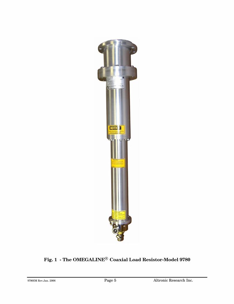
9780IM Rev.Jan. 2006 Page 5 Altronic Research Inc.
Fig. 1 - The OMEGALINE® Coaxial Load Resistor-Model 9780

9780IM Rev.Jan. 2006 Page 6 Altronic Research Inc.
ELECTRICAL CHARACTERISTICS
POWER RATING - All models of the OMEGALINE® series of coaxial loads are rated for continuous duty and may be operated in any position at any power level within their rating and with the proper water flow rate. A 10-20% GREATER FLOW RATE MAY BE USED AND IS RECOMMENDED. If the units are operated below the maximum power rating, a corresponding reduction in the coolant flow rate may be used. (See Fig. 4) All loads are electrically tested prior to shipment. Testing is done at 60 Hz with input voltage and current measured on RMS meters. The (RMS) power being dissipated in the load is simultaneously checked by calorimetry. The relationship used for calculating the power dissipated in the load from the calorimetric data is: (See Fig. 2 & 2A)
P = 0.264 (T2 - T1)Q
Where P = Power in load in kilowatts
T2 = Outlet water temperature °C
T1 = Inlet water temperature °C
Q = Water flow in gallons-per-minute
WARNING! Power should never be applied before turning on the WATER FIRST and allowing sufficient time (approx. 1 minute) for complete wetting of the resistor and elimination of air bubbles. Water flow must be maintained throughout the application of power and may be turned off within 15-30 seconds after the power has been turned off. Failure to observe these precautions will result in instant failure of the resistor and possible destruction of other parts of the load.
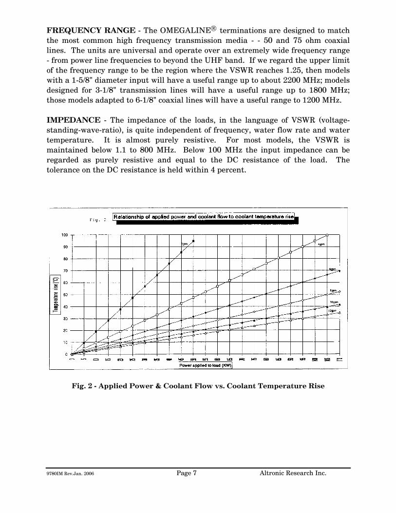
9780IM Rev.Jan. 2006 Page 7 Altronic Research Inc.
FREQUENCY RANGE - The OMEGALINE® terminations are designed to match the most common high frequency transmission media - - 50 and 75 ohm coaxial lines. The units are universal and operate over an extremely wide frequency range - from power line frequencies to beyond the UHF band. If we regard the upper limit of the frequency range to be the region where the VSWR reaches 1.25, then models with a 1-5/8" diameter input will have a useful range up to about 2200 MHz; models designed for 3-1/8" transmission lines will have a useful range up to 1800 MHz; those models adapted to 6-1/8" coaxial lines will have a useful range to 1200 MHz. IMPEDANCE - The impedance of the loads, in the language of VSWR (voltage-standing-wave-ratio), is quite independent of frequency, water flow rate and water temperature. It is almost purely resistive. For most models, the VSWR is maintained below 1.1 to 800 MHz. Below 100 MHz the input impedance can be regarded as purely resistive and equal to the DC resistance of the load. The tolerance on the DC resistance is held within 4 percent.
Fig. 2 - Applied Power & Coolant Flow vs. Coolant Temperature Rise
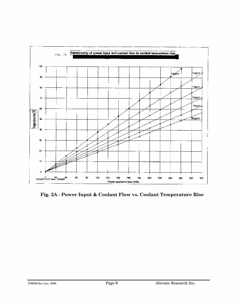
9780IM Rev.Jan. 2006 Page 8 Altronic Research Inc.
Fig. 2A - Power Input & Coolant Flow vs. Coolant Temperature Rise

9780IM Rev.Jan. 2006 Page 9 Altronic Research Inc.
COOLANT
COOLANT - The OMEGALINE® dummy load may be used with ordinary tap water, pure, or de-ionized water in open or closed cooling systems. The use of deionized and distilled water in OMEGALINE® loads has been reported to cause premature failures under some conditions. These failures are the result of the leaching action of the coolant on the silver and silver-plated surfaces of the resistors and contact material. The reported failures have generally been associated with deionized systems which are polished to 10-15 megohm levels and are operated intermittently. We suspect that the failure mechanism is attributable to bacterial growth in the coolant system and the subsequent high levels of sulfides usually found in conjunction with such contamination. Altronic does offer a line of water-cooled loads with gold and gold-plated resistors and contacts, for use in systems where leaching action seems unavoidable. Contact our sales office for information. We suggest the use of caution when determining what coolant to use. Potable water is certainly the most desirable coolant. Brackish or salt water is NOT permissible as a coolant for the load resistor! The load is designed with non-contaminating elements in the water circuit and may be used with transmitters that have pure water recirculating cooling systems. For operation below the freezing temperatures of water, ethylene glycol may be added to the water to prohibit freezing (see Fig. 3). If you have questions about coolants, please consult the factory.
IMPORTANT We recommend a Glycol mixture of 40% (2:3) or less. Addition of ethylene glycol to water reduces the heat capacity of the mixture with a corresponding reduction in cooling effectiveness. Therefore, the coolant flow rate should be increased approximately 20% from that required with water only.
!!!WARNING!!! Only clear, colorless analytic or technical grade ethylene glycol may be used. Dow Chemical Company's Dowtherm® SR1 has been reported to be fully compatible with OMEGALINE® loads when used in accordance with Dow's instructions (up to a 40% max). DO NOT use any stop leak, sealants, automotive antifreeze or Union Carbide Ucartherm™ in coolant. To do so will void the warranty. Damage to the resistor film may occur with applied power, resulting in failure!
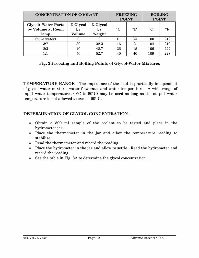
9780IM Rev.Jan. 2006 Page 10 Altronic Research Inc.
CONCENTRATION OF COOLANT FREEZING POINT
BOILING POINT
Glycol: Water Parts by Volume at Room
Temp.
% Glycol by
Volume
% Glycol by
Weight
°C
°F
°C
°F
(pure water) 0 0 0 32 100 212 3:7 30 32.3 -16 2 104 219 2:3 40 42.7 -26 -15 106 222 1:1 50 52.7 -40 -40 109 228
Fig. 3 Freezing and Boiling Points of Glycol-Water Mixtures
TEMPERATURE RANGE - The impedance of the load is practically independent of glycol-water mixture, water flow rate, and water temperature. A wide range of input water temperatures (0°C to 60°C) may be used as long as the output water temperature is not allowed to exceed 90° C. DETERMINATION OF GLYCOL CONCENTRATION –
• Obtain a 500 ml sample of the coolant to be tested and place in the hydrometer jar.
• Place the thermometer in the jar and allow the temperature reading to stabilize.
• Read the thermometer and record the reading. • Place the hydrometer in the jar and allow to settle. Read the hydrometer and
record the reading. • See the table in Fig. 3A to determine the glycol concentration.

9780IM Rev.Jan. 2006 Page 11 Altronic Research Inc.
Fig. 3A – Glycol Concentration Table WATER FLOW RATE - The water flow rates specified for the load is given as the least amount of water flow permissible for full power rating. AT LEAST MINIMUM FLOW OF WATER MUST BE MAINTAINED THROUGHOUT THE APPLICATION OF POWER. A greater flow rate (approx. 10% higher) should be used and is recommended. When used at lower than rated power, a reduced water flow rate may be used and combinations of power and water flow rates may be determined by using the table of Fig. 4. In all cases, water must be allowed to flow for about 1 minute before applying power so that all air bubbles are dispelled from the system.
MODEL
MINIMUM FLOW RATE
(GPM)
MAXIMUM* AVERAGE (RMS)
POWER (KW)
GALLONS PER KILOWATT (Kf)
9780
10
80
.125
Fig. 4 MINIMUM Water Flow Rate Requirements
* Single Frequency CW
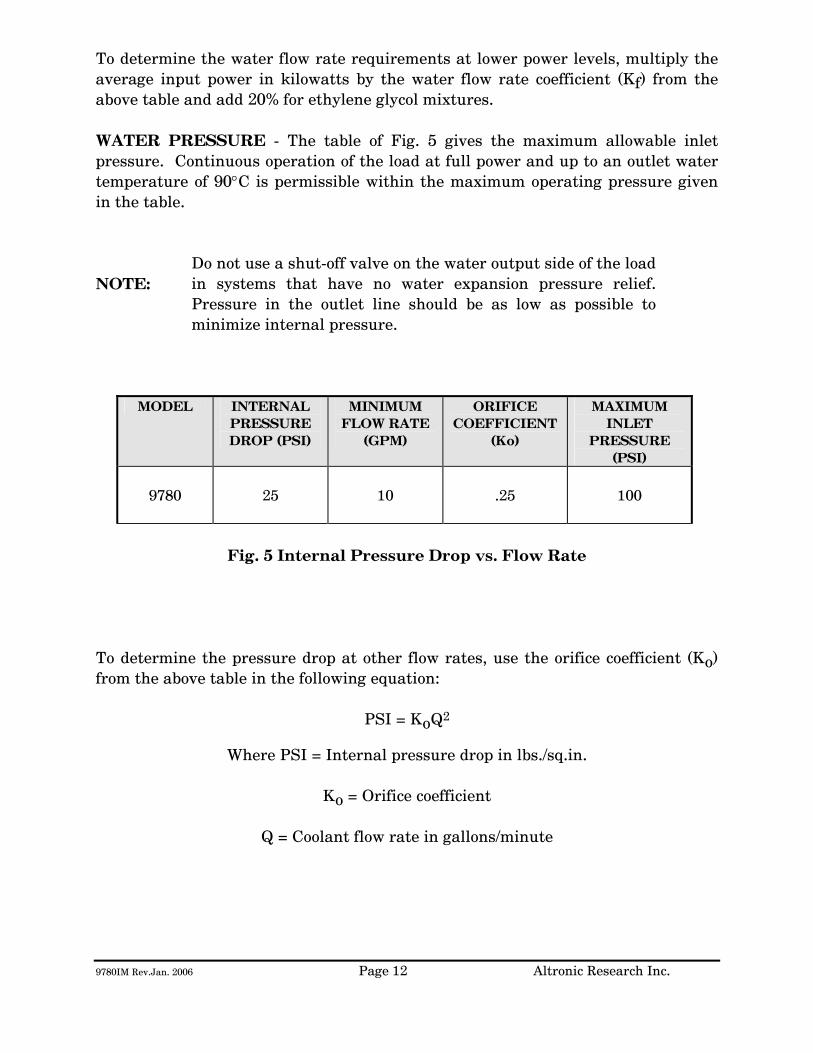
9780IM Rev.Jan. 2006 Page 12 Altronic Research Inc.
To determine the water flow rate requirements at lower power levels, multiply the average input power in kilowatts by the water flow rate coefficient (Kf) from the above table and add 20% for ethylene glycol mixtures. WATER PRESSURE - The table of Fig. 5 gives the maximum allowable inlet pressure. Continuous operation of the load at full power and up to an outlet water temperature of 90°C is permissible within the maximum operating pressure given in the table. NOTE:
Do not use a shut-off valve on the water output side of the load in systems that have no water expansion pressure relief. Pressure in the outlet line should be as low as possible to minimize internal pressure.
MODEL INTERNAL
PRESSURE DROP (PSI)
MINIMUM FLOW RATE
(GPM)
ORIFICE COEFFICIENT
(Ko)
MAXIMUM INLET
PRESSURE (PSI)
9780
25
10
.25
100
Fig. 5 Internal Pressure Drop vs. Flow Rate
To determine the pressure drop at other flow rates, use the orifice coefficient (Ko) from the above table in the following equation:
PSI = KoQ2
Where PSI = Internal pressure drop in lbs./sq.in.
Ko = Orifice coefficient
Q = Coolant flow rate in gallons/minute
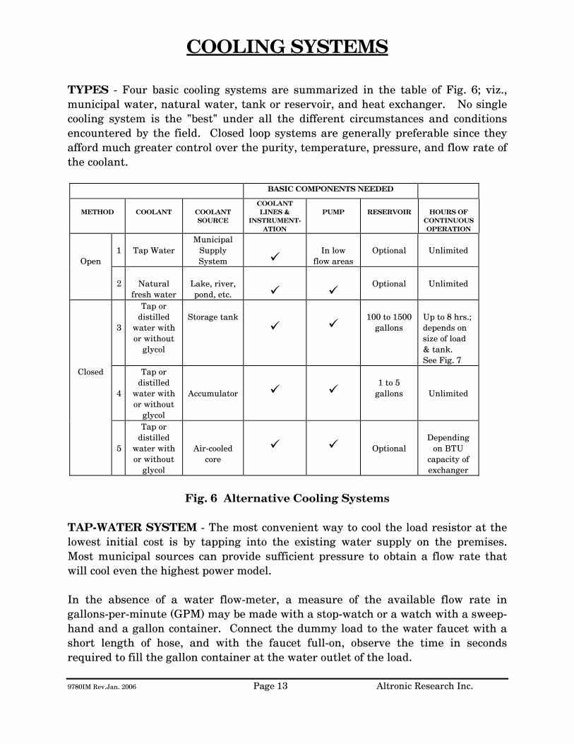
9780IM Rev.Jan. 2006 Page 13 Altronic Research Inc.
COOLING SYSTEMS
TYPES - Four basic cooling systems are summarized in the table of Fig. 6; viz., municipal water, natural water, tank or reservoir, and heat exchanger. No single cooling system is the "best" under all the different circumstances and conditions encountered by the field. Closed loop systems are generally preferable since they afford much greater control over the purity, temperature, pressure, and flow rate of the coolant.
BASIC COMPONENTS NEEDED
METHOD
COOLANT
COOLANT SOURCE
COOLANT LINES &
INSTRUMENT-ATION
PUMP
RESERVOIR
HOURS OF
CONTINUOUS OPERATION
Open
1
Tap Water
Municipal Supply System
In low
flow areas
Optional
Unlimited
2
Natural
fresh water
Lake, river, pond, etc.
Optional
Unlimited
3
Tap or distilled
water with or without
glycol
Storage tank
100 to 1500
gallons
Up to 8 hrs.; depends on size of load & tank. See Fig. 7
Closed
4
Tap or distilled
water with or without
glycol
Accumulator
1 to 5
gallons
Unlimited
5
Tap or distilled
water with or without
glycol
Air-cooled core
Optional
Depending
on BTU capacity of exchanger
Fig. 6 Alternative Cooling Systems
TAP-WATER SYSTEM - The most convenient way to cool the load resistor at the lowest initial cost is by tapping into the existing water supply on the premises. Most municipal sources can provide sufficient pressure to obtain a flow rate that will cool even the highest power model. In the absence of a water flow-meter, a measure of the available flow rate in gallons-per-minute (GPM) may be made with a stop-watch or a watch with a sweep-hand and a gallon container. Connect the dummy load to the water faucet with a short length of hose, and with the faucet full-on, observe the time in seconds required to fill the gallon container at the water outlet of the load.
9780IM Rev.Jan. 2006 Page 14 Altronic Research Inc.
When using the dummy load with a tap-water system, the flow rate is usually adjusted to 10-15% above the minimum requirement and left unattended. Since water lines ordinarily serve other appliances (flush toilets, etc.) over which there is no control, a flow switch should be installed to protect the load resistor element in case the flow rate drops due to a momentary change in water pressure. Choose a flow switch with a small "ON-OFF" flow rate dead band. The switch will also protect the resistor in cases where the RF power may be turned on before the water flow, or where accidental termination of water flow (pinched hose, debris, valve closing, etc.) may occur. In the tap-water system the heated water is discharged down the drain and therefore, the cost of the water becomes an important consideration. NATURAL WATER SYSTEM - A close proximity to a natural supply of fresh water may suggest its utilization. Brackish or salt water may NOT be used as a coolant for the load resistor. The natural water system usually requires more extensive piping and heavier pumping equipment to handle attendant pressure drop. The quality of natural water varies widely and straining is often necessary to handle the twigs, minnows, leaves and other debris frequently encountered. Small automatic self-cleaning strainers are available for this purpose. The strainer should be installed upstream from the pump to protect the pump as well as the load resistor. Additional filtering of smaller particles is sometimes required and this can be accomplished with finer mesh "Y-TYPE" strainers inserted in series with the line. In this system, the water from the natural source may not be directly usable as a coolant for the load resistor element due to a high contamination, such as silt, iron content, mud, etc.; but it may be used as "dirty" water coolant in a water-to-water heat exchanger. The contaminated water could be piped via plastic tubing or hose to copper coils immersed in a holding tank containing clean water coolant for the dummy load. This arrangement would require a dual pump - one section to pump the "dirty" natural-source water and the other section to pump the clean water coolant through the dummy load. HEAT EXCHANGER SYSTEM - In this system, an accumulator or receiving tank is used which only holds about one-half the flow rate in gallons-per-minute. Accordingly, a small quantity of coolant is required. The coolant functions solely as a heat transfer agent between the load resistor and the heat sink. A heat exchanger consisting of a radiator and a fan is the type recommended for this application. With ambient air as the ultimate heat sink, the operating temperature of the coolant will always be above the air temperature for heat to be transferred
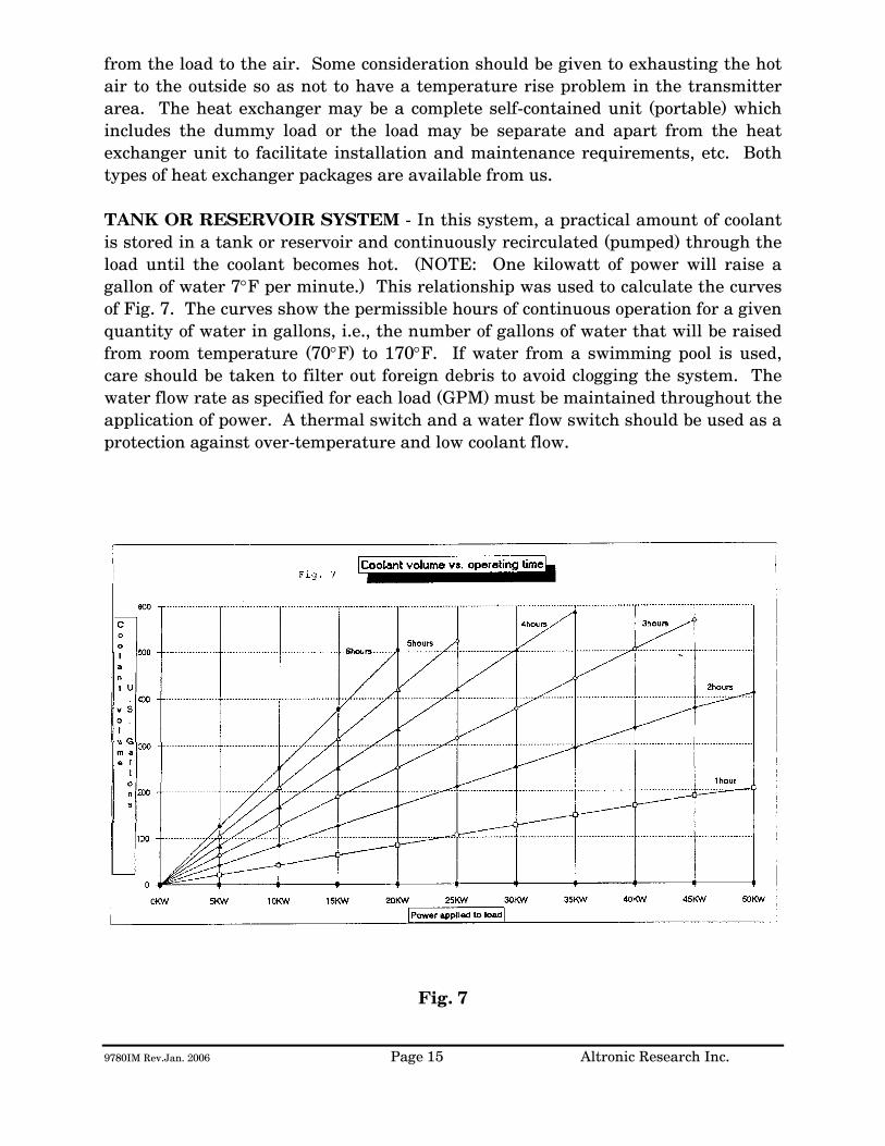
9780IM Rev.Jan. 2006 Page 15 Altronic Research Inc.
from the load to the air. Some consideration should be given to exhausting the hot air to the outside so as not to have a temperature rise problem in the transmitter area. The heat exchanger may be a complete self-contained unit (portable) which includes the dummy load or the load may be separate and apart from the heat exchanger unit to facilitate installation and maintenance requirements, etc. Both types of heat exchanger packages are available from us. TANK OR RESERVOIR SYSTEM - In this system, a practical amount of coolant is stored in a tank or reservoir and continuously recirculated (pumped) through the load until the coolant becomes hot. (NOTE: One kilowatt of power will raise a gallon of water 7°F per minute.) This relationship was used to calculate the curves of Fig. 7. The curves show the permissible hours of continuous operation for a given quantity of water in gallons, i.e., the number of gallons of water that will be raised from room temperature (70°F) to 170°F. If water from a swimming pool is used, care should be taken to filter out foreign debris to avoid clogging the system. The water flow rate as specified for each load (GPM) must be maintained throughout the application of power. A thermal switch and a water flow switch should be used as a protection against over-temperature and low coolant flow.
Fig. 7

9780IM Rev.Jan. 2006 Page 16 Altronic Research Inc.
Storage tanks between 200 and 500 gallons will satisfy most requirements. A waterproof concrete holding tank in the 1000 to 1500 gallon range may also be considered. (Similar to a septic tank and buried below the frost line.) It would be protected from extremes of temperature and could hold ordinary tap water as the coolant, while comparing favorably in cost to smaller metal tanks exposed to the elements. Storage tanks are normally vented to the atmosphere and allowance should be made for determining the liquid level in the tank and for adding make-up water. Some typical sizes of cylindrical tanks in the range of interest are shown in the table of Fig. 8 below.
CAPACITY IN
GALLONS
SIZE DIAMETER x LENGTH
IN FEET
120 2 x 5 200 2.5 x 5.5 300 3 x 6 500 3.5 x 7
1000 5 x 7 1500 5 x 10.5
Fig. 8 Tank Sizes
The pump selected for this service should have all wetted parts made from brass, bronze, ceramic or stainless steel. Cast iron and common steel will "poison" the water system and cause early failure of the load. Select the pump to overcome piping losses and the internal pressure drop of the load (shown in Fig. 5).

9780IM Rev.Jan. 2006 Page 17 Altronic Research Inc.
INSTALLATION
The OMEGALINE® loads may be used on both fixed and portable applications and they perform equally well in any mounting position. The units are very rugged and light and may be strapped, clamped, or secured with any practical and readily available mechanical device. They may be held by the RF connector on one end and by the plumbing on the other end. The coolant may be allowed to pass through the load in either direction without affecting its operation, but the axial water connector is normally used as the inlet since it contains the built-in filter screen. Water lines connecting the load should be 3/4" copper water tubing and rigid enough to support the load. NOTE: (A fifty-foot length of 1/2" pipe has a pressure drop of 45-PSI at 10-GPM water flow rate, while a 3/4" pipe under the same conditions only develops a 5-PSI drop.) In typical installations, the rigid piping is terminated within a few feet of the load, and flexible hose is used to bridge the last few feet. The hose should be 3/4" I.D. and capable of withstanding the temperature and pressure of the system. The water fittings on the load are 3/4" hose thread to accommodate standard hose couplings. Do not screw pipe thread fittings onto the hose thread - damage will result due to cross-threading. Pipe threads are tapered and hose threads are straight. If it is desired to mate with regular 3/4" pipe threads, use a hose-to-pipe adapter. The adapter is recommended since it eliminates the need of removing the side outlet water fitting and also allows the axial water fitting to be adapted directly to 3/4" pipe. The adapters may be obtained at a local hardware store or a plumbing supply house. Provisions should be made to allow interruption of the transmission line at any position where the transmitter is to be terminated by the load or measurements are contemplated. Coaxial switches may be inserted in the transmission line run to provide rapid load switching. Proceed as follows:
1. Install the unit in the selected location. 2. Connect the outlet water fitting of the dummy load to a convenient
drainage. 3. Connect the water inlet to a water source capable of delivering the
required flow in gallons per minute.

9780IM Rev.Jan. 2006 Page 18 Altronic Research Inc.
If the required source of water flow is not available from the local lines, refer to the previous section for a possible alternate cooling system. We highly recommend the use of a flow switch in the inlet piping to detect low flow conditions which could damage the load. We recommend the IMO DeLaval Model AFS200, Adjustable Flow Switch. This switch has low internal pressure drop and operates reliably in pilot-duty applications. (This switch is available from us.) Mount the switch in a horizontal section of pipe where there is a straight horizontal run of at least five inches on each side of the switch.
4. Connect the microswitch contacts of the flow switch in series with transmitter interlock circuit.
5. Connect the dummy load to the transmission line. The unit is designed
to connect to a 50 or 75 ohm line (or as stated on label).

9780IM Rev.Jan. 2006 Page 19 Altronic Research Inc.
OPERATION
To place the dummy load in operation, the following procedure is recommended:
1. Turn on the water pressure and make certain water is flowing through the load. Allow about 1 minute of water circulation to insure complete wetting of the resistor element in the load and exhaustion of air bubbles.
2. Check the water flow rate. This can be done with a five-gallon
container and a wristwatch with a sweep-hand if no water flow meter is available.
3. Apply RF power.
To cease operation, turn the RF power off and allow about 30 seconds before turning off the water.
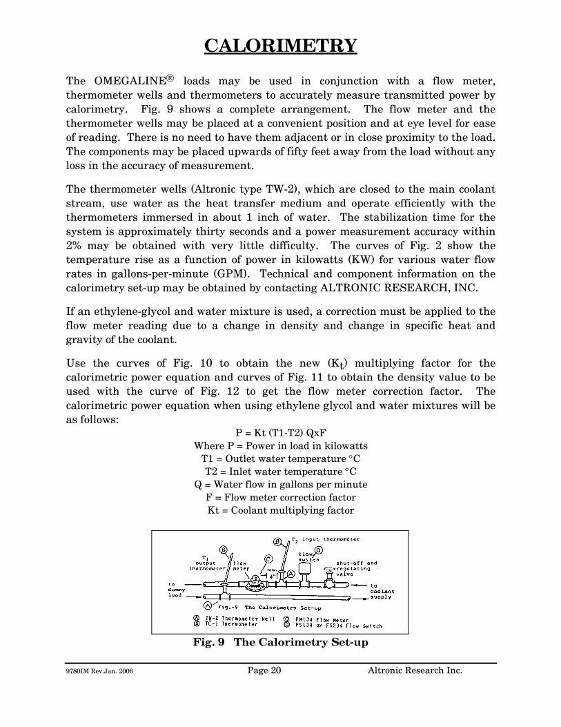
9780IM Rev.Jan. 2006 Page 20 Altronic Research Inc.
CALORIMETRY The OMEGALINE® loads may be used in conjunction with a flow meter, thermometer wells and thermometers to accurately measure transmitted power by calorimetry. Fig. 9 shows a complete arrangement. The flow meter and the thermometer wells may be placed at a convenient position and at eye level for ease of reading. There is no need to have them adjacent or in close proximity to the load. The components may be placed upwards of fifty feet away from the load without any loss in the accuracy of measurement.
The thermometer wells (Altronic type TW-2), which are closed to the main coolant stream, use water as the heat transfer medium and operate efficiently with the thermometers immersed in about 1 inch of water. The stabilization time for the system is approximately thirty seconds and a power measurement accuracy within 2% may be obtained with very little difficulty. The curves of Fig. 2 show the temperature rise as a function of power in kilowatts (KW) for various water flow rates in gallons-per-minute (GPM). Technical and component information on the calorimetry set-up may be obtained by contacting ALTRONIC RESEARCH, INC.
If an ethylene-glycol and water mixture is used, a correction must be applied to the flow meter reading due to a change in density and change in specific heat and gravity of the coolant.
Use the curves of Fig. 10 to obtain the new (Kt) multiplying factor for the calorimetric power equation and curves of Fig. 11 to obtain the density value to be used with the curve of Fig. 12 to get the flow meter correction factor. The calorimetric power equation when using ethylene glycol and water mixtures will be as follows:
P = Kt (T1-T2) QxF Where P = Power in load in kilowatts
T1 = Outlet water temperature °C T2 = Inlet water temperature °C
Q = Water flow in gallons per minute F = Flow meter correction factor Kt = Coolant multiplying factor
Fig. 9 The Calorimetry Set-up

9780IM Rev.Jan. 2006 Page 21 Altronic Research Inc.
Fig. 10 Kt for Ethylene-Glycol/Water Mixtures vs. Temperature
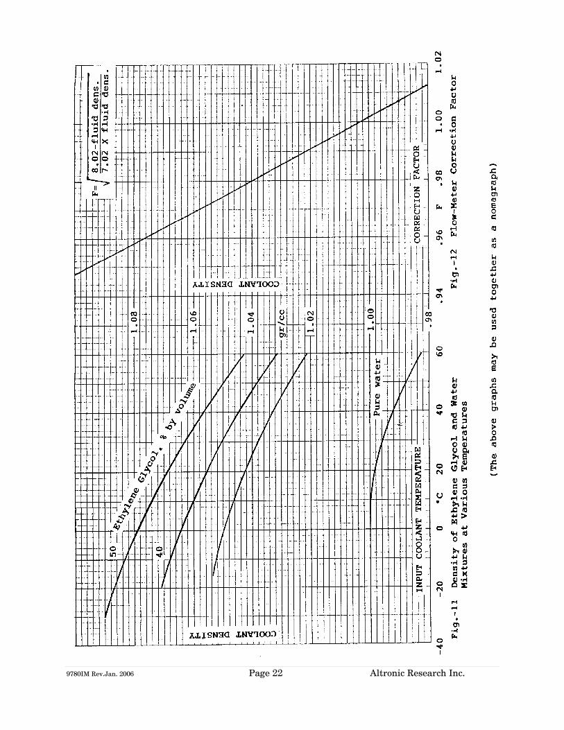
9780IM Rev.Jan. 2006 Page 22 Altronic Research Inc.
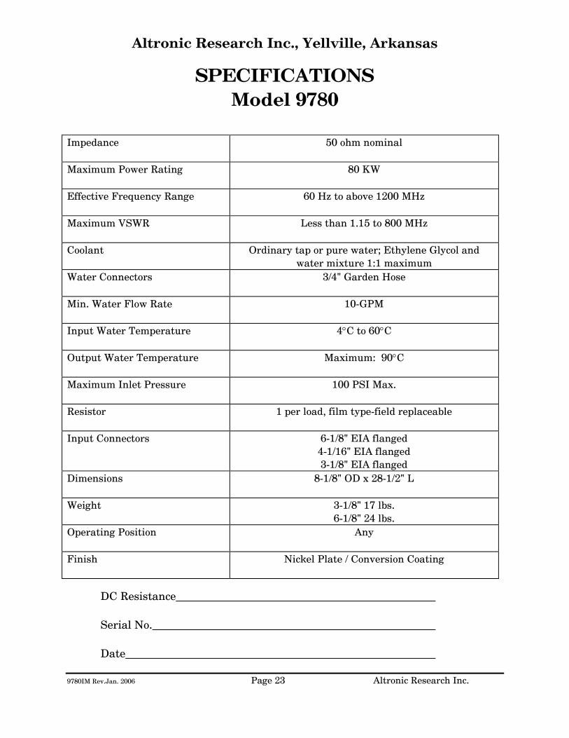
9780IM Rev.Jan. 2006 Page 23 Altronic Research Inc.
Altronic Research Inc., Yellville, Arkansas
SPECIFICATIONS Model 9780
Impedance
50 ohm nominal
Maximum Power Rating
80 KW
Effective Frequency Range
60 Hz to above 1200 MHz
Maximum VSWR
Less than 1.15 to 800 MHz
Coolant Ordinary tap or pure water; Ethylene Glycol and water mixture 1:1 maximum
Water Connectors
3/4" Garden Hose
Min. Water Flow Rate
10-GPM
Input Water Temperature
4°C to 60°C
Output Water Temperature
Maximum: 90°C
Maximum Inlet Pressure
100 PSI Max.
Resistor
1 per load, film type-field replaceable
Input Connectors
6-1/8" EIA flanged 4-1/16" EIA flanged 3-1/8" EIA flanged
Dimensions
8-1/8" OD x 28-1/2" L
Weight
3-1/8" 17 lbs. 6-1/8" 24 lbs.
Operating Position
Any
Finish
Nickel Plate / Conversion Coating
DC Resistance
Serial No.
Date
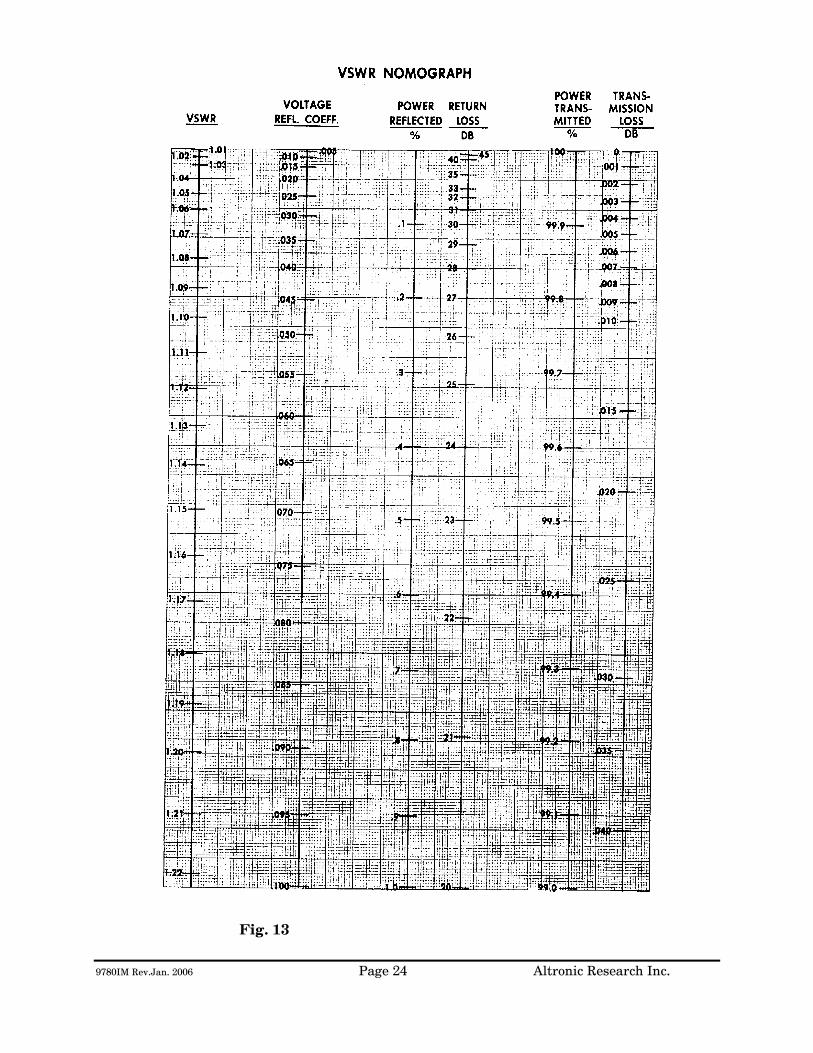
9780IM Rev.Jan. 2006 Page 24 Altronic Research Inc.
Fig. 13

ALTRONIC RESEARCH, INC. P.O. BOX 249
YELLVILLE, ARKANSAS 72687-0249 U.S.A.
LIQUID-COOLED COAXIAL LOAD RESISTOR
MODEL 9750
TABLE OF CONTENTS
INTRODUCTION ............................................................................................. 1 PRECAUTIONS................................................................................................ 2 GENERAL DESCRIPTION ............................................................................ 4 ELECTRICAL CHARACTERISTICS............................................................ 6 COOLANT ......................................................................................................... 9 COOLING SYSTEMS..................................................................................... 13 INSTALLATION............................................................................................. 17 OPERATION................................................................................................... 19 CALORIMETRY ............................................................................................. 20 SPECIFICATIONS......................................................................................... 23 MAINTENANCE............................................................................................. 25 WARRANTY .................................................................................................... 29
ILLUSTRATIONS, TABLES AND GRAPHS
Fig. 1 The OMEGALINE® Coaxial Load Resistor............................................ 5
Fig. 2 Applied Power & Coolant Flow vs. Coolant Temperature Rise........ 7
Fig. 2A Power Input & Coolant Flow vs. Coolant Temperature Rise............ 8
Fig. 3 Freezing and Boiling Points of Glycol-Water Mixtures.................... 10
Fig. 3A Glycol Concentration Table .................................................................... 11
Fig. 4 Minimum Water Flow Rate Requirements .......................................... 11
Fig. 5 Internal Pressure Drop vs. Flow Rate .................................................. 12
Fig. 6 Alternative Cooling Systems................................................................... 13
Fig. 7 Coolant Volume vs. Operating Time ..................................................... 15
Fig. 8 Tank Sizes.................................................................................................... 16
Fig. 9 The Calorimetry Set-up............................................................................ 20
Fig. 10 Kt for Ethylene Glycol Mixtures vs. Temperature............................. 21
Fig. 11 Density of Ethylene Glycol Mixtures vs. Temperature..................... 22
Fig. 12 Flow-Meter Correction Factor................................................................ 22
Fig. 13 VSWR Nomograph ..................................................................................... 24
Fig. 14 Model 9750 Exploded View/Parts List.................................................. 27
Fig. 15 BOM 9799E1 Exploded View/Parts List................................................ 28
9750 Rev Aug. 2010 Page 1 Altronic Research Inc.
INTRODUCTION This manual gives you specific information on the installation, operation and service of OMEGALINE® coaxial resistors. Most of the loads are field serviceable, but we recommend their return to us for repair. Mistakes can be costly compared to the low cost for our trained personnel to make the repairs and return the load to new performance specifications. Labor and packaging costs are minimal. We take the load completely apart, clean and inspect all parts, repair/replace as necessary, reassemble, water pressure test, power test, VSWR test and package the load for shipment. If new parts are required in the load (such as resistors etc.), this will be an additional cost. The average turn-around time on repairs is approximately 7 working days and generally will depend on your needs. When sending in repairs, please include: your company name and address, the operating frequency you use, fax number, telephone number and your name in case we need to talk to you about the load or obtain shipping instructions. We can accommodate most shipping modes. SHIP TO: Altronic Research Inc., 621 Hwy. 202 W, Yellville, AR 72687. Our mailing address is P.O. Box 249. Note: We also repair dummy loads manufactured by many other companies. Call for information (870-449-4093).

9750 Rev Aug. 2010 Page 2 Altronic Research Inc.
PRECAUTIONS
!!!DANGER!!! THIS UNIT MUST BE TOTALLY DISCONNECTED FROM ALL RF POWER BEFORE ANY REPAIRS ARE ATTEMPTED. ANY ATTEMPT AT REPAIR WITHOUT DISCONNECTING THE POWER COULD RESULT IN FATAL ELECTRICAL SHOCK!!!
WARNING DO NOT APPLY POWER WITHOUT THE MINIMUM RATED FLOW OF COOLANT THROUGH THE LOAD. A SAFETY INTERLOCK SWITCH IS RECOMMENDED. EVEN A BRIEF APPLICATION OF POWER TO THE LOAD WITHOUT THE CIRCULATION OF COOLANT WILL CAUSE IMMEDIATE BURN OUT.
WARNING THE LOAD RESISTOR CONSISTS OF A CERAMIC SUBSTRATE COATED WITH A SPECIAL RESISTIVE FILM. IF ANY DAMAGE OCCURS TO THE RESISTOR, THERE COULD BE SHARDS OR SHARP BROKEN PIECES OF CERAMIC IN THE LOAD. CARE SHOULD BE TAKEN TO AVOID CUTS OR INJURIES.
9750 Rev Aug. 2010 Page 3 Altronic Research Inc.
PRECAUTIONS
CAUTION USE ONLY CLEAR, COLORLESS, ANALYTIC OR TECHNICAL GRADE ETHYLENE GLYCOL WITH PURE TAP OR POTABLE* WATER AS A SOURCE COOLANT. DO NOT USE ANY STOP LEAK, SEALANTS, AUTOMOTIVE ANTIFREEZE OR UNION CARBIDE UCARTHERM™ IN COOLANT. USE OF THESE SUBSTANCES WILL VOID THE WARRANTY.
IMPORTANT ADDITION OF ETHYLENE GLYCOL TO THE WATER REDUCES THE HEAT CAPACITY OF THE COOLING SYSTEM. COOLANT FLOW RATE MUST BE INCREASED BY AT LEAST 20% OVER MINIMUM FLOW.
CAUTION DO NOT APPLY MORE THAN THE MAXIMUM RATED RF POWER TO THE LOAD. THIS WILL CAUSE INTERNAL DAMAGE TO THE LOAD.
* Potable Water: The U.S. Health Department has established standards for potable water at a maximum of 500ppm of dissolved solids. Hard water (particularly dissolved salts) can cause damage to resistive film and load. Water condition can be adjusted by mixing distilled water in sufficient quantities with coolant water.

9750 Rev Aug. 2010 Page 4 Altronic Research Inc.
GENERAL DESCRIPTION
The OMEGALINE® dummy load is basically a termination-type unit having its characteristic impedance at the input end and tapered to zero impedance (short circuit) at the other end. The center conductor is a tubular resistor whose DC resistance is equal to the characteristic impedance of the line. The outer conductor of the coaxial line is a symmetrical horn-shaped enclosure, contoured logarithmically along its length to obtain a reflection-free termination. The RF dielectric medium consists of three distinct materials: the liquid coolant, the plastic water jacket and the air space. (See Fig. 1) Coolant enters the load at the electrically shorted end, flows axially down the center of the resistor tube, mushrooms over into the annular channel under the water jacket, and makes a second pass over the resistor in direct physical contact with the resistive film. Thus the coolant makes intimate contact with both the inside and outside cylindrical surfaces of the resistor, providing optimum heat transfer with minimal flow rate. The dummy load housing is constructed of aluminum and/or brass or bronze sections whose inner surfaces are machined to a modified logarithmic taper. The stepped housing sections are held in accurate alignment with stainless steel socket head cap screws. The power dissipating resistor consists of a conductive resistive film which is deposited on a tubular ceramic substrate with silver bands fired on the ends for electrical connection. Contact to the resistor is made by silver plated spring fingers. Coolant flows through the fingers and passes directly over the resistive film. The resistor is enclosed within a plastic water jacket which is custom machined to match the body and seal the coolant flow.
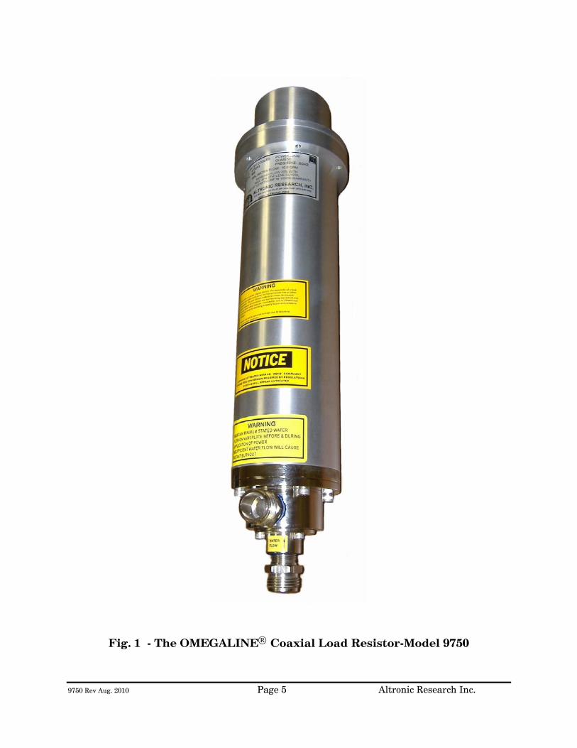
9750 Rev Aug. 2010 Page 5 Altronic Research Inc.
Fig. 1 - The OMEGALINE® Coaxial Load Resistor-Model 9750
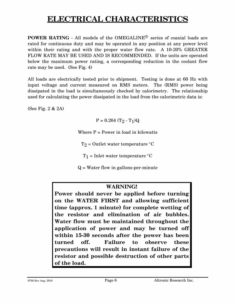
9750 Rev Aug. 2010 Page 6 Altronic Research Inc.
ELECTRICAL CHARACTERISTICS
POWER RATING - All models of the OMEGALINE® series of coaxial loads are rated for continuous duty and may be operated in any position at any power level within their rating and with the proper water flow rate. A 10-20% GREATER FLOW RATE MAY BE USED AND IS RECOMMENDED. If the units are operated below the maximum power rating, a corresponding reduction in the coolant flow rate may be used. (See Fig. 4) All loads are electrically tested prior to shipment. Testing is done at 60 Hz with input voltage and current measured on RMS meters. The (RMS) power being dissipated in the load is simultaneously checked by calorimetry. The relationship used for calculating the power dissipated in the load from the calorimetric data is: (See Fig. 2 & 2A)
P = 0.264 (T2 - T1)Q
Where P = Power in load in kilowatts
T2 = Outlet water temperature °C
T1 = Inlet water temperature °C
Q = Water flow in gallons-per-minute
WARNING! Power should never be applied before turning on the WATER FIRST and allowing sufficient time (approx. 1 minute) for complete wetting of the resistor and elimination of air bubbles. Water flow must be maintained throughout the application of power and may be turned off within 15-30 seconds after the power has been turned off. Failure to observe these precautions will result in instant failure of the resistor and possible destruction of other parts of the load.
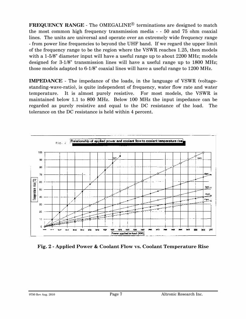
9750 Rev Aug. 2010 Page 7 Altronic Research Inc.
FREQUENCY RANGE - The OMEGALINE® terminations are designed to match the most common high frequency transmission media - - 50 and 75 ohm coaxial lines. The units are universal and operate over an extremely wide frequency range - from power line frequencies to beyond the UHF band. If we regard the upper limit of the frequency range to be the region where the VSWR reaches 1.25, then models with a 1-5/8" diameter input will have a useful range up to about 2200 MHz; models designed for 3-1/8" transmission lines will have a useful range up to 1800 MHz; those models adapted to 6-1/8" coaxial lines will have a useful range to 1200 MHz. IMPEDANCE - The impedance of the loads, in the language of VSWR (voltage-standing-wave-ratio), is quite independent of frequency, water flow rate and water temperature. It is almost purely resistive. For most models, the VSWR is maintained below 1.1 to 800 MHz. Below 100 MHz the input impedance can be regarded as purely resistive and equal to the DC resistance of the load. The tolerance on the DC resistance is held within 4 percent.
Fig. 2 - Applied Power & Coolant Flow vs. Coolant Temperature Rise
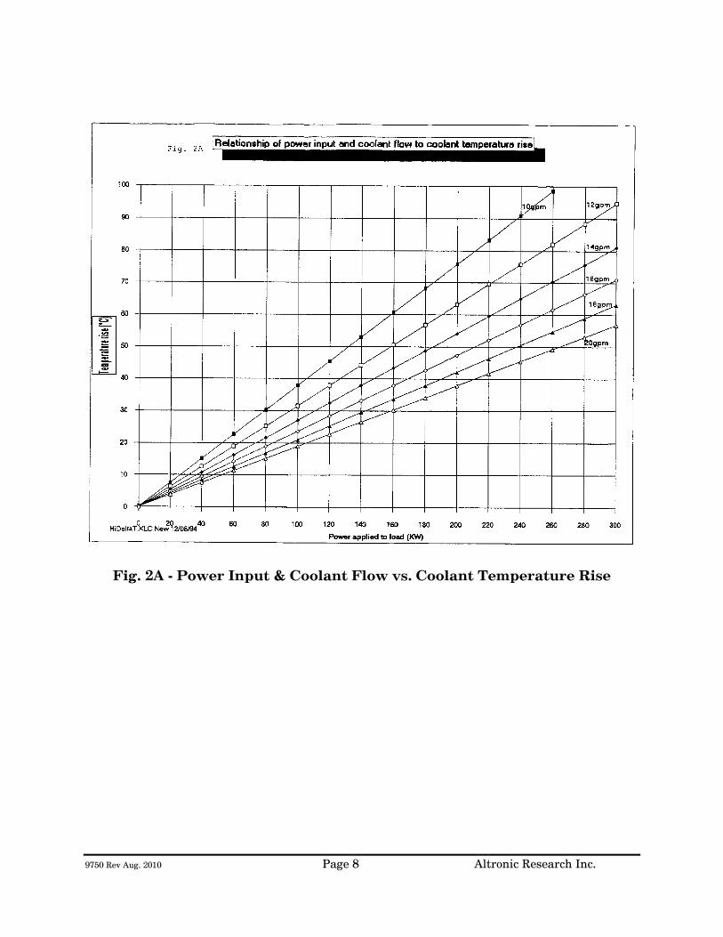
9750 Rev Aug. 2010 Page 8 Altronic Research Inc.
Fig. 2A - Power Input & Coolant Flow vs. Coolant Temperature Rise

9750 Rev Aug. 2010 Page 9 Altronic Research Inc.
COOLANT
COOLANT - The OMEGALINE® dummy load may be used with ordinary tap water, pure, or de-ionized water in open or closed cooling systems. The use of deionized and distilled water in OMEGALINE® loads has been reported to cause premature failures under some conditions. These failures are the result of the leaching action of the coolant on the silver and silver-plated surfaces of the resistors and contact material. The reported failures have generally been associated with deionized systems which are polished to 10-15 megohm levels and are operated intermittently. We suspect that the failure mechanism is attributable to bacterial growth in the coolant system and the subsequent high levels of sulfides usually found in conjunction with such contamination. Altronic does offer a line of water-cooled loads with gold and gold-plated resistors and contacts, for use in systems where leaching action seems unavoidable. Contact our sales office for information. We suggest the use of caution when determining what coolant to use. Potable water is certainly the most desirable coolant. Brackish or salt water is NOT permissible as a coolant for the load resistor! The load is designed with non-contaminating elements in the water circuit and may be used with transmitters that have pure water recirculating cooling systems. For operation below the freezing temperatures of water, ethylene glycol may be added to the water to prohibit freezing (see Fig. 3). If you have questions about coolants, please consult the factory.
IMPORTANT We recommend a Glycol mixture of 40% (2:3) or less. Addition of ethylene glycol to water reduces the heat capacity of the mixture with a corresponding reduction in cooling effectiveness. Therefore, the coolant flow rate should be increased approximately 20% from that required with water only.
!!!WARNING!!!
Only clear, colorless analytic or technical grade ethylene glycol may be used. Dow Chemical Company's Dowtherm® SR1 has been reported to be fully compatible with OMEGALINE® loads when used in accordance with Dow's instructions (up to a 40% max). DO NOT use any stop leak, sealants, automotive antifreeze or Union Carbide Ucartherm™ in coolant. To do so will void the warranty. Damage to the resistor film may occur with applied power, resulting in failure!
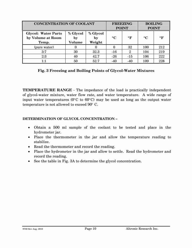
9750 Rev Aug. 2010 Page 10 Altronic Research Inc.
CONCENTRATION OF COOLANT FREEZING POINT
BOILING POINT
Glycol: Water Parts by Volume at Room
Temp.
% Glycol by
Volume
% Glycol by
Weight
°C
°F
°C
°F
(pure water) 0 0 0 32 100 212 3:7 30 32.3 -16 2 104 219 2:3 40 42.7 -26 -15 106 222 1:1 50 52.7 -40 -40 109 228
Fig. 3 Freezing and Boiling Points of Glycol-Water Mixtures
TEMPERATURE RANGE - The impedance of the load is practically independent of glycol-water mixture, water flow rate, and water temperature. A wide range of input water temperatures (0°C to 60°C) may be used as long as the output water temperature is not allowed to exceed 90° C. DETERMINATION OF GLYCOL CONCENTRATION –
• Obtain a 500 ml sample of the coolant to be tested and place in the hydrometer jar.
• Place the thermometer in the jar and allow the temperature reading to stabilize.
• Read the thermometer and record the reading. • Place the hydrometer in the jar and allow to settle. Read the hydrometer and
record the reading. • See the table in Fig. 3A to determine the glycol concentration.
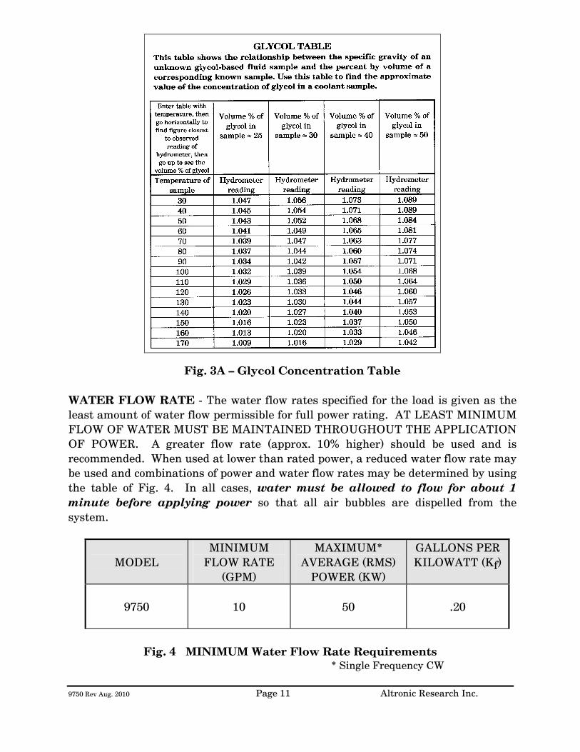
9750 Rev Aug. 2010 Page 11 Altronic Research Inc.
Fig. 3A – Glycol Concentration Table WATER FLOW RATE - The water flow rates specified for the load is given as the least amount of water flow permissible for full power rating. AT LEAST MINIMUM FLOW OF WATER MUST BE MAINTAINED THROUGHOUT THE APPLICATION OF POWER. A greater flow rate (approx. 10% higher) should be used and is recommended. When used at lower than rated power, a reduced water flow rate may be used and combinations of power and water flow rates may be determined by using the table of Fig. 4. In all cases, water must be allowed to flow for about 1 minute before applying power so that all air bubbles are dispelled from the system.
MODEL MINIMUM
FLOW RATE (GPM)
MAXIMUM* AVERAGE (RMS)
POWER (KW)
GALLONS PER KILOWATT (Kf)
9750
10
50
.20
Fig. 4 MINIMUM Water Flow Rate Requirements
* Single Frequency CW

9750 Rev Aug. 2010 Page 12 Altronic Research Inc.
To determine the water flow rate requirements at lower power levels, multiply the average input power in kilowatts by the water flow rate coefficient (Kf) from the above table and add 20% for ethylene glycol mixtures. WATER PRESSURE - The table of Fig. 5 gives the maximum allowable inlet pressure. Continuous operation of the load at full power and up to an outlet water temperature of 90°C is permissible within the maximum operating pressure given in the table. NOTE:
Do not use a shut-off valve on the water output side of the load in systems that have no water expansion pressure relief. Pressure in the outlet line should be as low as possible to minimize internal pressure.
MODEL INTERNAL
PRESSURE DROP (PSI)
MINIMUM FLOW RATE
(GPM)
ORIFICE COEFFICIENT
(Ko)
MAXIMUM INLET
PRESSURE (PSI)
9750
30
10
.30
100
Fig. 5 Internal Pressure Drop vs. Flow Rate
To determine the pressure drop at other flow rates, use the orifice coefficient (Ko) from the above table in the following equation:
PSI = KoQ2
Where PSI = Internal pressure drop in lbs./sq.in.
Ko = Orifice coefficient
Q = Coolant flow rate in gallons/minute

9750 Rev Aug. 2010 Page 13 Altronic Research Inc.
COOLING SYSTEMS
TYPES - Four basic cooling systems are summarized in the table of Fig. 6; viz., municipal water, natural water, tank or reservoir, and heat exchanger. No single cooling system is the "best" under all the different circumstances and conditions encountered by the field. Closed loop systems are generally preferable since they afford much greater control over the purity, temperature, pressure, and flow rate of the coolant.
BASIC COMPONENTS NEEDED
METHOD
COOLANT
COOLANT SOURCE
COOLANT LINES &
INSTRUMENT-ATION
PUMP
RESERVOIR
HOURS OF
CONTINUOUS OPERATION
Open
1
Tap Water
Municipal Supply System
In low
flow areas
Optional
Unlimited
2
Natural
fresh water
Lake, river, pond, etc.
Optional
Unlimited
3
Tap or distilled
water with or without
glycol
Storage tank
100 to 1500
gallons
Up to 8 hrs.; depends on size of load & tank. See Fig. 7
Closed
4
Tap or distilled
water with or without
glycol
Accumulator
1 to 5
gallons
Unlimited
5
Tap or distilled
water with or without
glycol
Air-cooled core
Optional
Depending
on BTU capacity of exchanger
Fig. 6 Alternative Cooling Systems
TAP-WATER SYSTEM - The most convenient way to cool the load resistor at the lowest initial cost is by tapping into the existing water supply on the premises. Most municipal sources can provide sufficient pressure to obtain a flow rate that will cool even the highest power model. In the absence of a water flow-meter, a measure of the available flow rate in gallons-per-minute (GPM) may be made with a stop-watch or a watch with a sweep-hand and a gallon container. Connect the dummy load to the water faucet with a
9750 Rev Aug. 2010 Page 14 Altronic Research Inc.
short length of hose, and with the faucet full-on, observe the time in seconds required to fill the gallon container at the water outlet of the load. When using the dummy load with a tap-water system, the flow rate is usually adjusted to 10-15% above the minimum requirement and left unattended. Since water lines ordinarily serve other appliances (flush toilets, etc.) over which there is no control, a flow switch should be installed to protect the load resistor element in case the flow rate drops due to a momentary change in water pressure. Choose a flow switch with a small "ON-OFF" flow rate dead band. The switch will also protect the resistor in cases where the RF power may be turned on before the water flow, or where accidental termination of water flow (pinched hose, debris, valve closing, etc.) may occur. In the tap-water system the heated water is discharged down the drain and therefore, the cost of the water becomes an important consideration. NATURAL WATER SYSTEM - A close proximity to a natural supply of fresh water may suggest its utilization. Brackish or salt water may NOT be used as a coolant for the load resistor. The natural water system usually requires more extensive piping and heavier pumping equipment to handle attendant pressure drop. The quality of natural water varies widely and straining is often necessary to handle the twigs, minnows, leaves and other debris frequently encountered. Small automatic self-cleaning strainers are available for this purpose. The strainer should be installed upstream from the pump to protect the pump as well as the load resistor. Additional filtering of smaller particles is sometimes required and this can be accomplished with finer mesh "Y-TYPE" strainers inserted in series with the line. In this system, the water from the natural source may not be directly usable as a coolant for the load resistor element due to a high contamination, such as silt, iron content, mud, etc.; but it may be used as "dirty" water coolant in a water-to-water heat exchanger. The contaminated water could be piped via plastic tubing or hose to copper coils immersed in a holding tank containing clean water coolant for the dummy load. This arrangement would require a dual pump - one section to pump the "dirty" natural-source water and the other section to pump the clean water coolant through the dummy load. HEAT EXCHANGER SYSTEM - In this system, an accumulator or receiving tank is used which only holds about one-half the flow rate in gallons-per-minute. Accordingly, a small quantity of coolant is required. The coolant functions solely as a heat transfer agent between the load resistor and the heat sink. A heat exchanger consisting of a radiator and a fan is the type recommended for this
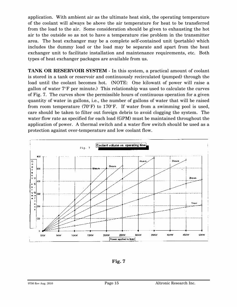
9750 Rev Aug. 2010 Page 15 Altronic Research Inc.
application. With ambient air as the ultimate heat sink, the operating temperature of the coolant will always be above the air temperature for heat to be transferred from the load to the air. Some consideration should be given to exhausting the hot air to the outside so as not to have a temperature rise problem in the transmitter area. The heat exchanger may be a complete self-contained unit (portable) which includes the dummy load or the load may be separate and apart from the heat exchanger unit to facilitate installation and maintenance requirements, etc. Both types of heat exchanger packages are available from us. TANK OR RESERVOIR SYSTEM - In this system, a practical amount of coolant is stored in a tank or reservoir and continuously recirculated (pumped) through the load until the coolant becomes hot. (NOTE: One kilowatt of power will raise a gallon of water 7°F per minute.) This relationship was used to calculate the curves of Fig. 7. The curves show the permissible hours of continuous operation for a given quantity of water in gallons, i.e., the number of gallons of water that will be raised from room temperature (70°F) to 170°F. If water from a swimming pool is used, care should be taken to filter out foreign debris to avoid clogging the system. The water flow rate as specified for each load (GPM) must be maintained throughout the application of power. A thermal switch and a water flow switch should be used as a protection against over-temperature and low coolant flow.
Fig. 7
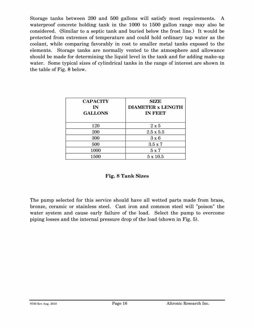
9750 Rev Aug. 2010 Page 16 Altronic Research Inc.
Storage tanks between 200 and 500 gallons will satisfy most requirements. A waterproof concrete holding tank in the 1000 to 1500 gallon range may also be considered. (Similar to a septic tank and buried below the frost line.) It would be protected from extremes of temperature and could hold ordinary tap water as the coolant, while comparing favorably in cost to smaller metal tanks exposed to the elements. Storage tanks are normally vented to the atmosphere and allowance should be made for determining the liquid level in the tank and for adding make-up water. Some typical sizes of cylindrical tanks in the range of interest are shown in the table of Fig. 8 below.
CAPACITY IN
GALLONS
SIZE DIAMETER x LENGTH
IN FEET
120 2 x 5 200 2.5 x 5.5 300 3 x 6 500 3.5 x 7
1000 5 x 7 1500 5 x 10.5
Fig. 8 Tank Sizes
The pump selected for this service should have all wetted parts made from brass, bronze, ceramic or stainless steel. Cast iron and common steel will "poison" the water system and cause early failure of the load. Select the pump to overcome piping losses and the internal pressure drop of the load (shown in Fig. 5).

9750 Rev Aug. 2010 Page 17 Altronic Research Inc.
INSTALLATION
The OMEGALINE® loads may be used on both fixed and portable applications and they perform equally well in any mounting position. The units are very rugged and light and may be strapped, clamped, or secured with any practical and readily available mechanical device. They may be held by the RF connector on one end and by the plumbing on the other end. The coolant may be allowed to pass through the load in either direction without affecting its operation, but the axial water connector is normally used as the inlet since it contains the built-in filter screen. Water lines connecting the load should be 3/4" copper water tubing and rigid enough to support the load. NOTE: (A fifty-foot length of 1/2" pipe has a pressure drop of 45-PSI at 10-GPM water flow rate, while a 3/4" pipe under the same conditions only develops a 5-PSI drop.) In typical installations, the rigid piping is terminated within a few feet of the load, and flexible hose is used to bridge the last few feet. The hose should be 3/4" I.D. and capable of withstanding the temperature and pressure of the system. The water fittings on the load are 3/4" hose thread to accommodate standard hose couplings. Do not screw pipe thread fittings onto the hose thread - damage will result due to cross-threading. Pipe threads are tapered and hose threads are straight. If it is desired to mate with regular 3/4" pipe threads, use a hose-to-pipe adapter. The adapter is recommended since it eliminates the need of removing the side outlet water fitting and also allows the axial water fitting to be adapted directly to 3/4" pipe. The adapters may be obtained at a local hardware store or a plumbing supply house. Provisions should be made to allow interruption of the transmission line at any position where the transmitter is to be terminated by the load or measurements are contemplated. Coaxial switches may be inserted in the transmission line run to provide rapid load switching. Proceed as follows:
1. Install the unit in the selected location. 2. Connect the outlet water fitting of the dummy load to a convenient
drainage. 3. Connect the water inlet to a water source capable of delivering the
required flow in gallons per minute.
9750 Rev Aug. 2010 Page 18 Altronic Research Inc.
If the required source of water flow is not available from the local lines, refer to the previous section for a possible alternate cooling system. We highly recommend the use of a flow switch in the inlet piping to detect low flow conditions which could damage the load. We recommend the IMO DeLaval Model AFS200, Adjustable Flow Switch. This switch has low internal pressure drop and operates reliably in pilot-duty applications. (This switch is available from us.) Mount the switch in a horizontal section of pipe where there is a straight horizontal run of at least five inches on each side of the switch.
4. Connect the microswitch contacts of the flow switch in series with transmitter interlock circuit.
5. Connect the dummy load to the transmission line. The unit is designed
to connect to a 50 or 75 ohm line (or as stated on label).

9750 Rev Aug. 2010 Page 19 Altronic Research Inc.
OPERATION
To place the dummy load in operation, the following procedure is recommended:
1. Turn on the water pressure and make certain water is flowing through the load. Allow about 1 minute of water circulation to insure complete wetting of the resistor element in the load and exhaustion of air bubbles.
2. Check the water flow rate. This can be done with a five-gallon
container and a wristwatch with a sweep-hand if no water flow meter is available.
3. Apply RF power.
To cease operation, turn the RF power off and allow about 30 seconds before turning off the water.

9750 Rev Aug. 2010 Page 20 Altronic Research Inc.
CALORIMETRY The OMEGALINE® loads may be used in conjunction with a flow meter, thermometer wells and thermometers to accurately measure transmitted power by calorimetry. Fig. 9 shows a complete arrangement. The flow meter and the thermometer wells may be placed at a convenient position and at eye level for ease of reading. There is no need to have them adjacent or in close proximity to the load. The components may be placed upwards of fifty feet away from the load without any loss in the accuracy of measurement.
The thermometer wells (Altronic type TW-2), which are closed to the main coolant stream, use water as the heat transfer medium and operate efficiently with the thermometers immersed in about 1 inch of water. The stabilization time for the system is approximately thirty seconds and a power measurement accuracy within 2% may be obtained with very little difficulty. The curves of Fig. 2 show the temperature rise as a function of power in kilowatts (KW) for various water flow rates in gallons-per-minute (GPM). Technical and component information on the calorimetry set-up may be obtained by contacting ALTRONIC RESEARCH, INC.
If an ethylene-glycol and water mixture is used, a correction must be applied to the flow meter reading due to a change in density and change in specific heat and gravity of the coolant.
Use the curves of Fig. 10 to obtain the new (Kt) multiplying factor for the calorimetric power equation and curves of Fig. 11 to obtain the density value to be used with the curve of Fig. 12 to get the flow meter correction factor. The calorimetric power equation when using ethylene glycol and water mixtures will be as follows:
P = Kt (T1-T2) QxF Where P = Power in load in kilowatts
T1 = Outlet water temperature °C T2 = Inlet water temperature °C
Q = Water flow in gallons per minute F = Flow meter correction factor Kt = Coolant multiplying factor
Fig. 9 The Calorimetry Set-up

9750 Rev Aug. 2010 Page 21 Altronic Research Inc.
Fig. 10 Kt for Ethylene-Glycol/Water Mixtures vs. Temperature

9750 Rev Aug. 2010 Page 22 Altronic Research Inc.
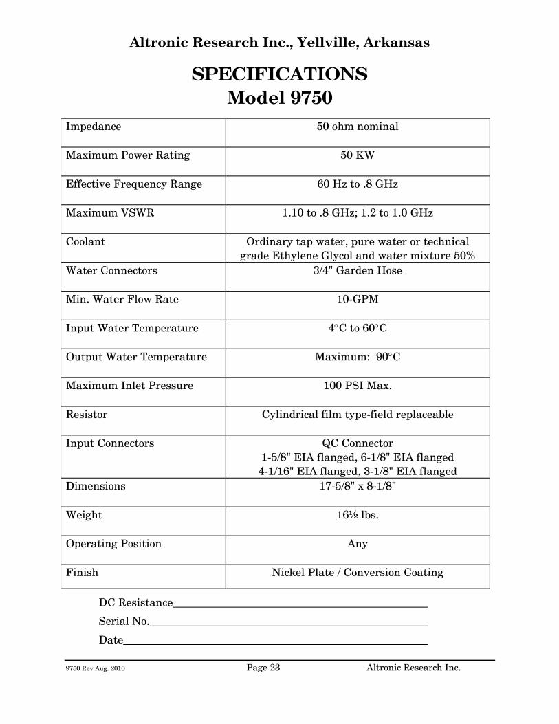
9750 Rev Aug. 2010 Page 23 Altronic Research Inc.
Altronic Research Inc., Yellville, Arkansas
SPECIFICATIONS Model 9750
Impedance
50 ohm nominal
Maximum Power Rating
50 KW
Effective Frequency Range
60 Hz to .8 GHz
Maximum VSWR
1.10 to .8 GHz; 1.2 to 1.0 GHz
Coolant Ordinary tap water, pure water or technical grade Ethylene Glycol and water mixture 50%
Water Connectors
3/4" Garden Hose
Min. Water Flow Rate
10-GPM
Input Water Temperature
4°C to 60°C
Output Water Temperature
Maximum: 90°C
Maximum Inlet Pressure
100 PSI Max.
Resistor
Cylindrical film type-field replaceable
Input Connectors
QC Connector 1-5/8" EIA flanged, 6-1/8" EIA flanged 4-1/16" EIA flanged, 3-1/8" EIA flanged
Dimensions
17-5/8" x 8-1/8"
Weight
16½ lbs.
Operating Position
Any
Finish
Nickel Plate / Conversion Coating
DC Resistance
Serial No.
Date

9750 Rev Aug. 2010 Page 24 Altronic Research Inc.
Fig. 13

ALTRONIC RESEARCH, INC. P.O. BOX 249
YELLVILLE, ARKANSAS 72687-0249 U.S.A.
LIQUID-COOLED COAXIAL LOAD RESISTOR
MODEL 9725
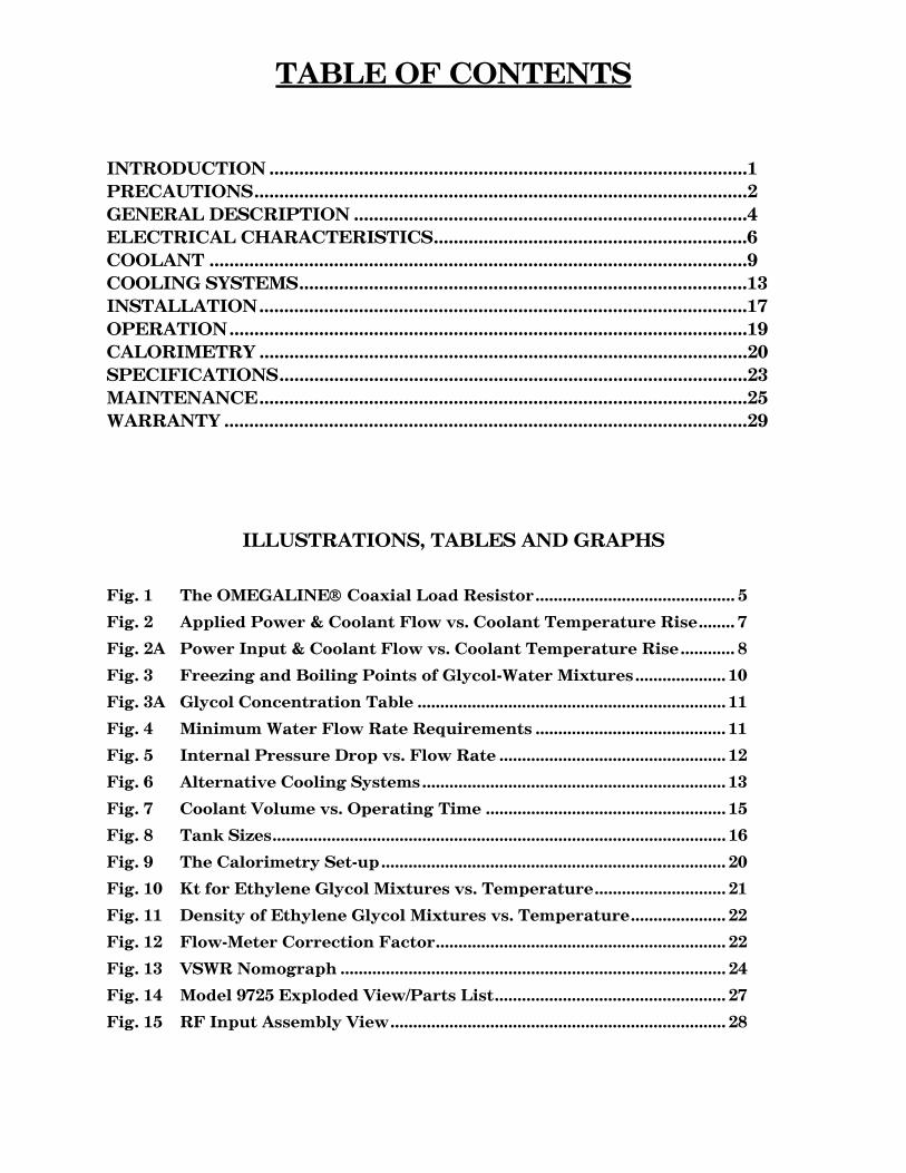
TABLE OF CONTENTS
INTRODUCTION ................................................................................................1 PRECAUTIONS...................................................................................................2 GENERAL DESCRIPTION ...............................................................................4 ELECTRICAL CHARACTERISTICS...............................................................6 COOLANT ............................................................................................................9 COOLING SYSTEMS..........................................................................................13 INSTALLATION..................................................................................................17 OPERATION........................................................................................................19 CALORIMETRY ..................................................................................................20 SPECIFICATIONS..............................................................................................23 MAINTENANCE..................................................................................................25 WARRANTY .........................................................................................................29
ILLUSTRATIONS, TABLES AND GRAPHS
Fig. 1 The OMEGALINE® Coaxial Load Resistor............................................ 5
Fig. 2 Applied Power & Coolant Flow vs. Coolant Temperature Rise........ 7
Fig. 2A Power Input & Coolant Flow vs. Coolant Temperature Rise............ 8
Fig. 3 Freezing and Boiling Points of Glycol-Water Mixtures.................... 10
Fig. 3A Glycol Concentration Table .................................................................... 11
Fig. 4 Minimum Water Flow Rate Requirements .......................................... 11
Fig. 5 Internal Pressure Drop vs. Flow Rate .................................................. 12
Fig. 6 Alternative Cooling Systems................................................................... 13
Fig. 7 Coolant Volume vs. Operating Time ..................................................... 15
Fig. 8 Tank Sizes.................................................................................................... 16
Fig. 9 The Calorimetry Set-up............................................................................ 20
Fig. 10 Kt for Ethylene Glycol Mixtures vs. Temperature............................. 21
Fig. 11 Density of Ethylene Glycol Mixtures vs. Temperature..................... 22
Fig. 12 Flow-Meter Correction Factor................................................................ 22
Fig. 13 VSWR Nomograph ..................................................................................... 24
Fig. 14 Model 9725 Exploded View/Parts List................................................... 27
Fig. 15 RF Input Assembly View.......................................................................... 28
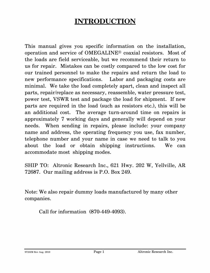
9725IM Rev Aug. 2010 Page 1 Altronic Research Inc.
INTRODUCTION This manual gives you specific information on the installation, operation and service of OMEGALINE® coaxial resistors. Most of the loads are field serviceable, but we recommend their return to us for repair. Mistakes can be costly compared to the low cost for our trained personnel to make the repairs and return the load to new performance specifications. Labor and packaging costs are minimal. We take the load completely apart, clean and inspect all parts, repair/replace as necessary, reassemble, water pressure test, power test, VSWR test and package the load for shipment. If new parts are required in the load (such as resistors etc.), this will be an additional cost. The average turn-around time on repairs is approximately 7 working days and generally will depend on your needs. When sending in repairs, please include: your company name and address, the operating frequency you use, fax number, telephone number and your name in case we need to talk to you about the load or obtain shipping instructions. We can accommodate most shipping modes. SHIP TO: Altronic Research Inc., 621 Hwy. 202 W, Yellville, AR 72687. Our mailing address is P.O. Box 249. Note: We also repair dummy loads manufactured by many other companies. Call for information (870-449-4093).

9725IM Rev Aug. 2010 Page 2 Altronic Research Inc.
PRECAUTIONS
!!!DANGER!!! THIS UNIT MUST BE TOTALLY DISCONNECTED FROM ALL RF POWER BEFORE ANY REPAIRS ARE ATTEMPTED. ANY ATTEMPT AT REPAIR WITHOUT DISCONNECTING THE POWER COULD RESULT IN FATAL ELECTRICAL SHOCK!!!
WARNING DO NOT APPLY POWER WITHOUT THE MINIMUM RATED FLOW OF COOLANT THROUGH THE LOAD. A SAFETY INTERLOCK SWITCH IS RECOMMENDED. EVEN A BRIEF APPLICATION OF POWER TO THE LOAD WITHOUT THE CIRCULATION OF COOLANT WILL CAUSE IMMEDIATE BURN OUT.
WARNING THE LOAD RESISTOR CONSISTS OF A CERAMIC SUBSTRATE COATED WITH A SPECIAL RESISTIVE FILM. IF ANY DAMAGE OCCURS TO THE RESISTOR, THERE COULD BE SHARDS OR SHARP BROKEN PIECES OF CERAMIC IN THE LOAD. CARE SHOULD BE TAKEN TO AVOID CUTS OR INJURIES.
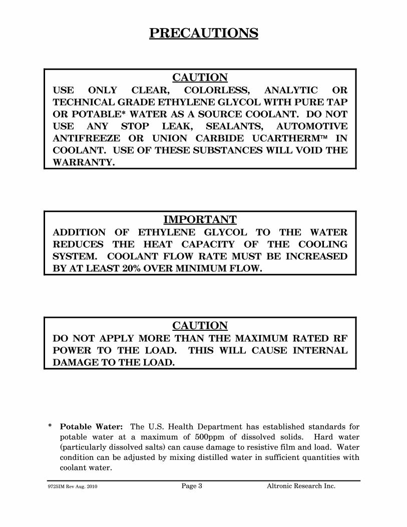
9725IM Rev Aug. 2010 Page 3 Altronic Research Inc.
PRECAUTIONS
CAUTION
USE ONLY CLEAR, COLORLESS, ANALYTIC OR TECHNICAL GRADE ETHYLENE GLYCOL WITH PURE TAP OR POTABLE* WATER AS A SOURCE COOLANT. DO NOT USE ANY STOP LEAK, SEALANTS, AUTOMOTIVE ANTIFREEZE OR UNION CARBIDE UCARTHERM™ IN COOLANT. USE OF THESE SUBSTANCES WILL VOID THE WARRANTY.
IMPORTANT ADDITION OF ETHYLENE GLYCOL TO THE WATER REDUCES THE HEAT CAPACITY OF THE COOLING SYSTEM. COOLANT FLOW RATE MUST BE INCREASED BY AT LEAST 20% OVER MINIMUM FLOW.
CAUTION DO NOT APPLY MORE THAN THE MAXIMUM RATED RF POWER TO THE LOAD. THIS WILL CAUSE INTERNAL DAMAGE TO THE LOAD.
* Potable Water: The U.S. Health Department has established standards for potable water at a maximum of 500ppm of dissolved solids. Hard water (particularly dissolved salts) can cause damage to resistive film and load. Water condition can be adjusted by mixing distilled water in sufficient quantities with coolant water.

9725IM Rev Aug. 2010 Page 4 Altronic Research Inc.
GENERAL DESCRIPTION
The OMEGALINE® dummy load is basically a termination-type unit having its characteristic impedance at the input end and tapered to zero impedance (short circuit) at the other end. The center conductor is a tubular resistor whose DC resistance is equal to the characteristic impedance of the line. The outer conductor of the coaxial line is a symmetrical horn-shaped enclosure, contoured logarithmically along its length to obtain a reflection-free termination. The RF dielectric medium consists of three distinct materials: the liquid coolant, the plastic water jacket and the air space. (See Fig. 1) Coolant enters the load at the electrically shorted end, flows axially down the center of the resistor tube, mushrooms over into the annular channel under the water jacket, and makes a second pass over the resistor in direct physical contact with the resistive film. Thus the coolant makes intimate contact with both the inside and outside cylindrical surfaces of the resistor, providing optimum heat transfer with minimal flow rate. The dummy load housing is constructed of aluminum and/or brass or bronze sections whose inner surfaces are machined to a modified logarithmic taper. The stepped housing sections are held in accurate alignment with stainless steel socket head cap screws. The power dissipating resistor consists of a conductive resistive film which is deposited on a tubular ceramic substrate with silver bands fired on the ends for electrical connection. Contact to the resistor is made by silver plated spring fingers. Coolant flows through the fingers and passes directly over the resistive film. The resistor is enclosed within a plastic water jacket which is custom machined to match the body and seal the coolant flow.
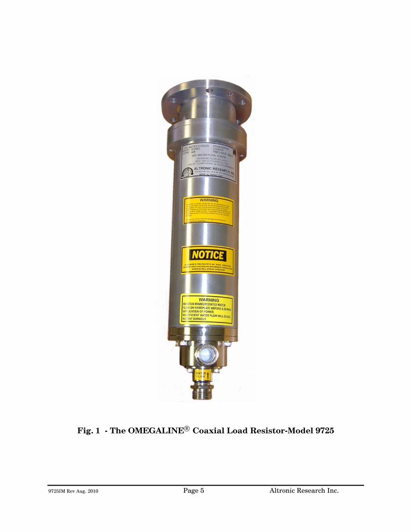
9725IM Rev Aug. 2010 Page 5 Altronic Research Inc.
Fig. 1 - The OMEGALINE® Coaxial Load Resistor-Model 9725

9725IM Rev Aug. 2010 Page 6 Altronic Research Inc.
ELECTRICAL CHARACTERISTICS
POWER RATING - All models of the OMEGALINE® series of coaxial loads are rated for continuous duty and may be operated in any position at any power level within their rating and with the proper water flow rate. A 10-20% GREATER FLOW RATE MAY BE USED AND IS RECOMMENDED. If the units are operated below the maximum power rating, a corresponding reduction in the coolant flow rate may be used. (See Fig. 4) All loads are electrically tested prior to shipment. Testing is done at 60 Hz with input voltage and current measured on RMS meters. The (RMS) power being dissipated in the load is simultaneously checked by calorimetry. The relationship used for calculating the power dissipated in the load from the calorimetric data is: (See Fig. 2 & 2A)
P = 0.264 (T2 - T1)Q
Where P = Power in load in kilowatts
T2 = Outlet water temperature °C
T1 = Inlet water temperature °C
Q = Water flow in gallons-per-minute
WARNING! Power should never be applied before turning on the WATER FIRST and allowing sufficient time (approx. 1 minute) for complete wetting of the resistor and elimination of air bubbles. Water flow must be maintained throughout the application of power and may be turned off within 15-30 seconds after the power has been turned off. Failure to observe these precautions will result in instant failure of the resistor and possible destruction of other parts of the load.
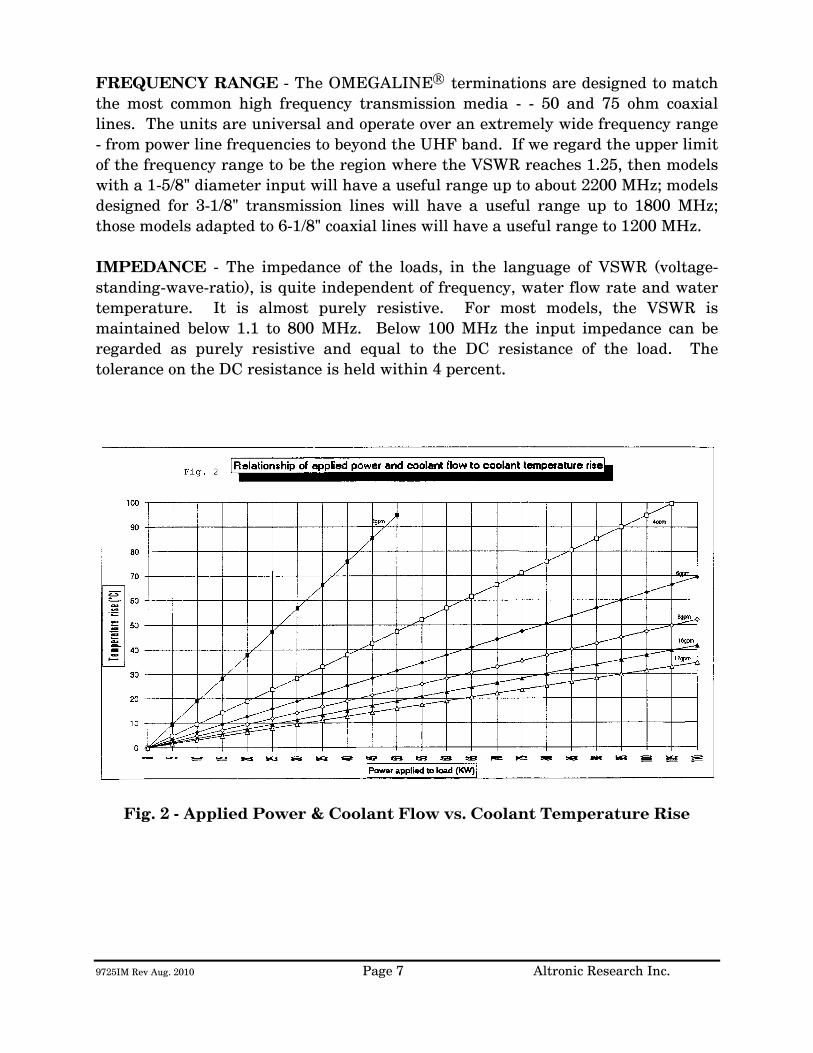
9725IM Rev Aug. 2010 Page 7 Altronic Research Inc.
FREQUENCY RANGE - The OMEGALINE® terminations are designed to match the most common high frequency transmission media - - 50 and 75 ohm coaxial lines. The units are universal and operate over an extremely wide frequency range - from power line frequencies to beyond the UHF band. If we regard the upper limit of the frequency range to be the region where the VSWR reaches 1.25, then models with a 1-5/8" diameter input will have a useful range up to about 2200 MHz; models designed for 3-1/8" transmission lines will have a useful range up to 1800 MHz; those models adapted to 6-1/8" coaxial lines will have a useful range to 1200 MHz. IMPEDANCE - The impedance of the loads, in the language of VSWR (voltage-standing-wave-ratio), is quite independent of frequency, water flow rate and water temperature. It is almost purely resistive. For most models, the VSWR is maintained below 1.1 to 800 MHz. Below 100 MHz the input impedance can be regarded as purely resistive and equal to the DC resistance of the load. The tolerance on the DC resistance is held within 4 percent.
Fig. 2 - Applied Power & Coolant Flow vs. Coolant Temperature Rise

9725IM Rev Aug. 2010 Page 8 Altronic Research Inc.
Fig. 2A - Power Input & Coolant Flow vs. Coolant Temperature Rise

9725IM Rev Aug. 2010 Page 9 Altronic Research Inc.
COOLANT
COOLANT - The OMEGALINE® dummy load may be used with ordinary tap water, pure, or de-ionized water in open or closed cooling systems. The use of deionized and distilled water in OMEGALINE® loads has been reported to cause premature failures under some conditions. These failures are the result of the leaching action of the coolant on the silver and silver-plated surfaces of the resistors and contact material. The reported failures have generally been associated with deionized systems which are polished to 10-15 megohm levels and are operated intermittently. We suspect that the failure mechanism is attributable to bacterial growth in the coolant system and the subsequent high levels of sulfides usually found in conjunction with such contamination. Altronic does offer a line of water-cooled loads with gold and gold-plated resistors and contacts, for use in systems where leaching action seems unavoidable. Contact our sales office for information. We suggest the use of caution when determining what coolant to use. Potable water is certainly the most desirable coolant. Brackish or salt water is NOT permissible as a coolant for the load resistor! The load is designed with non-contaminating elements in the water circuit and may be used with transmitters that have pure water recirculating cooling systems. For operation below the freezing temperatures of water, ethylene glycol may be added to the water to prohibit freezing (see Fig. 3). If you have questions about coolants, please consult the factory.
IMPORTANT We recommend a Glycol mixture of 40% (2:3) or less. Addition of ethylene glycol to water reduces the heat capacity of the mixture with a corresponding reduction in cooling effectiveness. Therefore, the coolant flow rate should be increased approximately 20% from that required with water only.
!!!WARNING!!! Only clear, colorless analytic or technical grade ethylene glycol may be used. Dow Chemical Company's Dowtherm® SR1 has been reported to be fully compatible with OMEGALINE® loads when used in accordance with Dow's instructions (up to a 40% max). DO NOT use any stop leak, sealants, automotive antifreeze or Union Carbide Ucartherm™ in coolant. To do so will void the warranty. Damage to the resistor film may occur with applied power, resulting in failure!
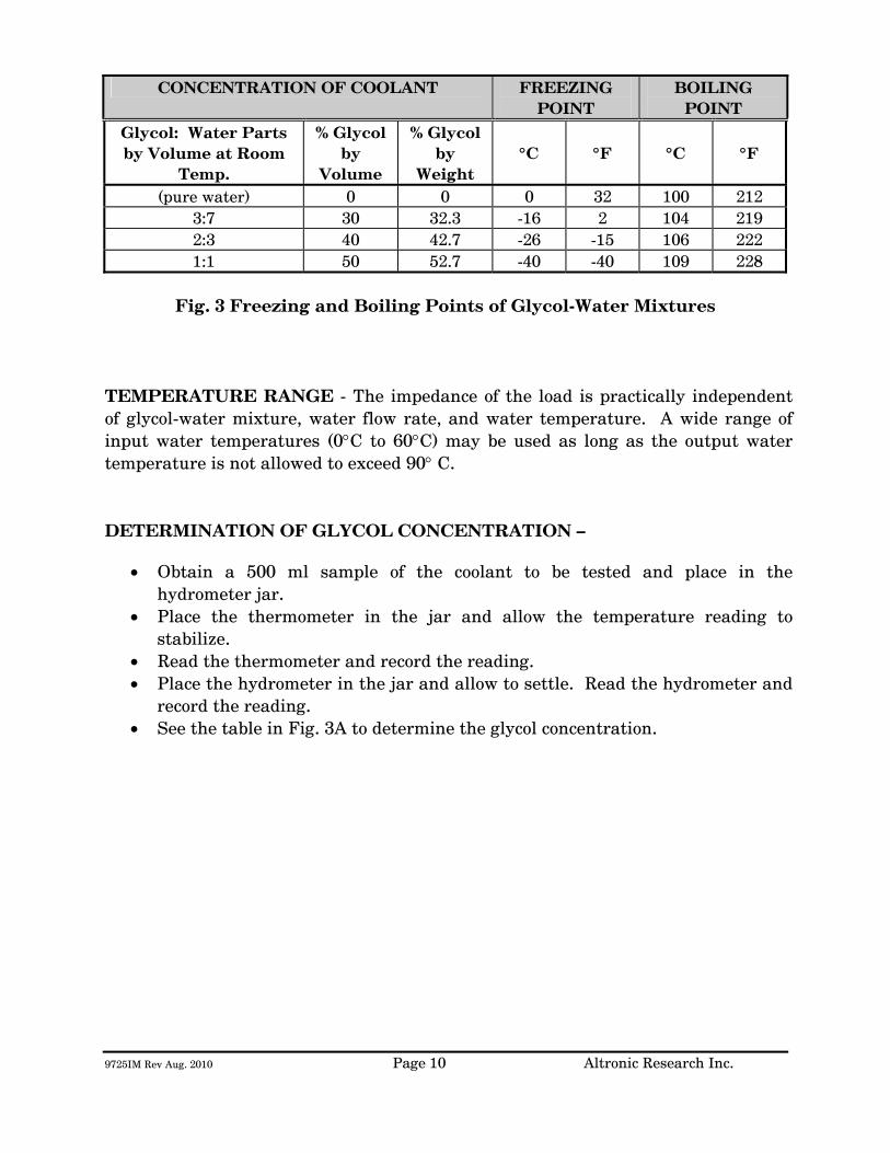
9725IM Rev Aug. 2010 Page 10 Altronic Research Inc.
CONCENTRATION OF COOLANT FREEZING
POINT BOILING
POINT Glycol: Water Parts by Volume at Room
Temp.
% Glycol by
Volume
% Glycol by
Weight
°C
°F
°C
°F
(pure water) 0 0 0 32 100 212 3:7 30 32.3 -16 2 104 219 2:3 40 42.7 -26 -15 106 222 1:1 50 52.7 -40 -40 109 228
Fig. 3 Freezing and Boiling Points of Glycol-Water Mixtures
TEMPERATURE RANGE - The impedance of the load is practically independent of glycol-water mixture, water flow rate, and water temperature. A wide range of input water temperatures (0°C to 60°C) may be used as long as the output water temperature is not allowed to exceed 90° C. DETERMINATION OF GLYCOL CONCENTRATION –
• Obtain a 500 ml sample of the coolant to be tested and place in the hydrometer jar.
• Place the thermometer in the jar and allow the temperature reading to stabilize.
• Read the thermometer and record the reading. • Place the hydrometer in the jar and allow to settle. Read the hydrometer and
record the reading. • See the table in Fig. 3A to determine the glycol concentration.
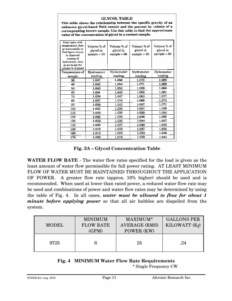
9725IM Rev Aug. 2010 Page 11 Altronic Research Inc.
Fig. 3A – Glycol Concentration Table
WATER FLOW RATE - The water flow rates specified for the load is given as the least amount of water flow permissible for full power rating. AT LEAST MINIMUM FLOW OF WATER MUST BE MAINTAINED THROUGHOUT THE APPLICATION OF POWER. A greater flow rate (approx. 10% higher) should be used and is recommended. When used at lower than rated power, a reduced water flow rate may be used and combinations of power and water flow rates may be determined by using the table of Fig. 4. In all cases, water must be allowed to flow for about 1 minute before applying power so that all air bubbles are dispelled from the system.
MODEL MINIMUM
FLOW RATE (GPM)
MAXIMUM* AVERAGE (RMS)
POWER (KW)
GALLONS PER KILOWATT (Kf)
9725
6
25
.24
Fig. 4 MINIMUM Water Flow Rate Requirements
* Single Frequency CW
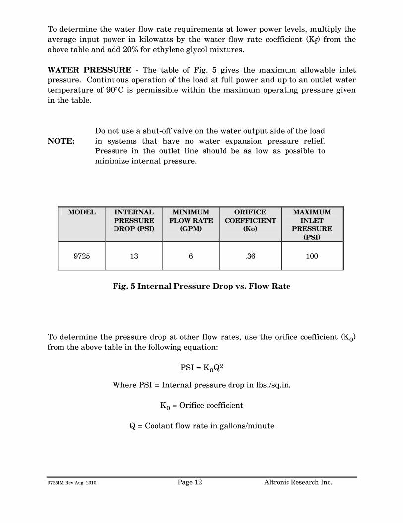
9725IM Rev Aug. 2010 Page 12 Altronic Research Inc.
To determine the water flow rate requirements at lower power levels, multiply the average input power in kilowatts by the water flow rate coefficient (Kf) from the above table and add 20% for ethylene glycol mixtures. WATER PRESSURE - The table of Fig. 5 gives the maximum allowable inlet pressure. Continuous operation of the load at full power and up to an outlet water temperature of 90°C is permissible within the maximum operating pressure given in the table. NOTE:
Do not use a shut-off valve on the water output side of the load in systems that have no water expansion pressure relief. Pressure in the outlet line should be as low as possible to minimize internal pressure.
MODEL INTERNAL
PRESSURE DROP (PSI)
MINIMUM FLOW RATE
(GPM)
ORIFICE COEFFICIENT
(Ko)
MAXIMUM INLET
PRESSURE (PSI)
9725
13
6
.36
100
Fig. 5 Internal Pressure Drop vs. Flow Rate
To determine the pressure drop at other flow rates, use the orifice coefficient (Ko) from the above table in the following equation:
PSI = KoQ2
Where PSI = Internal pressure drop in lbs./sq.in.
Ko = Orifice coefficient
Q = Coolant flow rate in gallons/minute
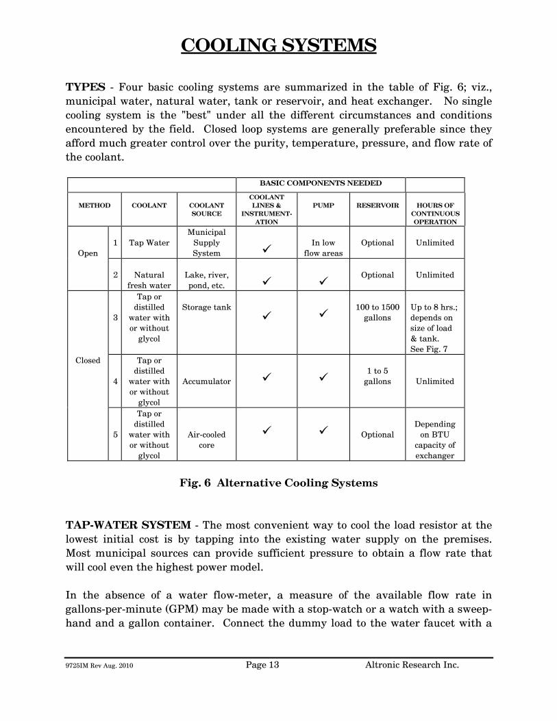
9725IM Rev Aug. 2010 Page 13 Altronic Research Inc.
COOLING SYSTEMS
TYPES - Four basic cooling systems are summarized in the table of Fig. 6; viz., municipal water, natural water, tank or reservoir, and heat exchanger. No single cooling system is the "best" under all the different circumstances and conditions encountered by the field. Closed loop systems are generally preferable since they afford much greater control over the purity, temperature, pressure, and flow rate of the coolant.
BASIC COMPONENTS NEEDED
METHOD
COOLANT
COOLANT SOURCE
COOLANT LINES &
INSTRUMENT-ATION
PUMP
RESERVOIR
HOURS OF
CONTINUOUS OPERATION
Open
1
Tap Water
Municipal Supply System
In low
flow areas
Optional
Unlimited
2
Natural
fresh water
Lake, river, pond, etc.
Optional
Unlimited
3
Tap or distilled
water with or without
glycol
Storage tank
100 to 1500
gallons
Up to 8 hrs.; depends on size of load & tank. See Fig. 7
Closed
4
Tap or distilled
water with or without
glycol
Accumulator
1 to 5
gallons
Unlimited
5
Tap or distilled
water with or without
glycol
Air-cooled core
Optional
Depending
on BTU capacity of exchanger
Fig. 6 Alternative Cooling Systems
TAP-WATER SYSTEM - The most convenient way to cool the load resistor at the lowest initial cost is by tapping into the existing water supply on the premises. Most municipal sources can provide sufficient pressure to obtain a flow rate that will cool even the highest power model. In the absence of a water flow-meter, a measure of the available flow rate in gallons-per-minute (GPM) may be made with a stop-watch or a watch with a sweep-hand and a gallon container. Connect the dummy load to the water faucet with a

9725IM Rev Aug. 2010 Page 14 Altronic Research Inc.
short length of hose, and with the faucet full-on, observe the time in seconds required to fill the gallon container at the water outlet of the load. When using the dummy load with a tap-water system, the flow rate is usually adjusted to 10-15% above the minimum requirement and left unattended. Since water lines ordinarily serve other appliances (flush toilets, etc.) over which there is no control, a flow switch should be installed to protect the load resistor element in case the flow rate drops due to a momentary change in water pressure. Choose a flow switch with a small "ON-OFF" flow rate dead band. The switch will also protect the resistor in cases where the RF power may be turned on before the water flow, or where accidental termination of water flow (pinched hose, debris, valve closing, etc.) may occur. In the tap-water system the heated water is discharged down the drain and therefore, the cost of the water becomes an important consideration. NATURAL WATER SYSTEM - A close proximity to a natural supply of fresh water may suggest its utilization. Brackish or salt water may NOT be used as a coolant for the load resistor. The natural water system usually requires more extensive piping and heavier pumping equipment to handle attendant pressure drop. The quality of natural water varies widely and straining is often necessary to handle the twigs, minnows, leaves and other debris frequently encountered. Small automatic self-cleaning strainers are available for this purpose. The strainer should be installed upstream from the pump to protect the pump as well as the load resistor. Additional filtering of smaller particles is sometimes required and this can be accomplished with finer mesh "Y-TYPE" strainers inserted in series with the line. In this system, the water from the natural source may not be directly usable as a coolant for the load resistor element due to a high contamination, such as silt, iron content, mud, etc.; but it may be used as "dirty" water coolant in a water-to-water heat exchanger. The contaminated water could be piped via plastic tubing or hose to copper coils immersed in a holding tank containing clean water coolant for the dummy load. This arrangement would require a dual pump - one section to pump the "dirty" natural-source water and the other section to pump the clean water coolant through the dummy load. HEAT EXCHANGER SYSTEM - In this system, an accumulator or receiving tank is used which only holds about one-half the flow rate in gallons-per-minute. Accordingly, a small quantity of coolant is required. The coolant functions solely as a heat transfer agent between the load resistor and the heat sink. A heat exchanger consisting of a radiator and a fan is the type recommended for this application. With ambient air as the ultimate heat sink, the operating temperature
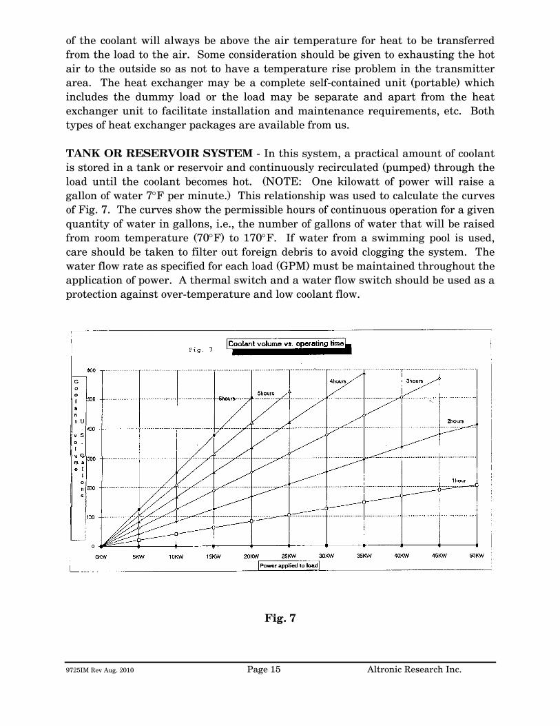
9725IM Rev Aug. 2010 Page 15 Altronic Research Inc.
of the coolant will always be above the air temperature for heat to be transferred from the load to the air. Some consideration should be given to exhausting the hot air to the outside so as not to have a temperature rise problem in the transmitter area. The heat exchanger may be a complete self-contained unit (portable) which includes the dummy load or the load may be separate and apart from the heat exchanger unit to facilitate installation and maintenance requirements, etc. Both types of heat exchanger packages are available from us. TANK OR RESERVOIR SYSTEM - In this system, a practical amount of coolant is stored in a tank or reservoir and continuously recirculated (pumped) through the load until the coolant becomes hot. (NOTE: One kilowatt of power will raise a gallon of water 7°F per minute.) This relationship was used to calculate the curves of Fig. 7. The curves show the permissible hours of continuous operation for a given quantity of water in gallons, i.e., the number of gallons of water that will be raised from room temperature (70°F) to 170°F. If water from a swimming pool is used, care should be taken to filter out foreign debris to avoid clogging the system. The water flow rate as specified for each load (GPM) must be maintained throughout the application of power. A thermal switch and a water flow switch should be used as a protection against over-temperature and low coolant flow.
Fig. 7

9725IM Rev Aug. 2010 Page 16 Altronic Research Inc.
Storage tanks between 200 and 500 gallons will satisfy most requirements. A waterproof concrete holding tank in the 1000 to 1500 gallon range may also be considered. (Similar to a septic tank and buried below the frost line.) It would be protected from extremes of temperature and could hold ordinary tap water as the coolant, while comparing favorably in cost to smaller metal tanks exposed to the elements. Storage tanks are normally vented to the atmosphere and allowance should be made for determining the liquid level in the tank and for adding make-up water. Some typical sizes of cylindrical tanks in the range of interest are shown in the table of Fig. 8 below.
CAPACITY IN
GALLONS
SIZE DIAMETER x LENGTH
IN FEET
120 2 x 5 200 2.5 x 5.5 300 3 x 6 500 3.5 x 7
1000 5 x 7 1500 5 x 10.5
Fig. 8 Tank Sizes
The pump selected for this service should have all wetted parts made from brass, bronze, ceramic or stainless steel. Cast iron and common steel will "poison" the water system and cause early failure of the load. Select the pump to overcome piping losses and the internal pressure drop of the load (shown in Fig. 5).

9725IM Rev Aug. 2010 Page 17 Altronic Research Inc.
INSTALLATION
The OMEGALINE® loads may be used on both fixed and portable applications and they perform equally well in any mounting position. The units are very rugged and light and may be strapped, clamped, or secured with any practical and readily available mechanical device. They may be held by the RF connector on one end and by the plumbing on the other end. The coolant may be allowed to pass through the load in either direction without affecting its operation, but the axial water connector is normally used as the inlet since it contains the built-in filter screen. Water lines connecting the load should be 3/4" copper water tubing and rigid enough to support the load. NOTE: (A fifty-foot length of 1/2" pipe has a pressure drop of 45-PSI at 10-GPM water flow rate, while a 3/4" pipe under the same conditions only develops a 5-PSI drop.) In typical installations, the rigid piping is terminated within a few feet of the load, and flexible hose is used to bridge the last few feet. The hose should be 3/4" I.D. and capable of withstanding the temperature and pressure of the system. The water fittings on the load are 3/4" hose thread to accommodate standard hose couplings. Do not screw pipe thread fittings onto the hose thread - damage will result due to cross-threading. Pipe threads are tapered and hose threads are straight. If it is desired to mate with regular 3/4" pipe threads, use a hose-to-pipe adapter. The adapter is recommended since it eliminates the need of removing the side outlet water fitting and also allows the axial water fitting to be adapted directly to 3/4" pipe. The adapters may be obtained at a local hardware store or a plumbing supply house. Provisions should be made to allow interruption of the transmission line at any position where the transmitter is to be terminated by the load or measurements are contemplated. Coaxial switches may be inserted in the transmission line run to provide rapid load switching. Proceed as follows:
1. Install the unit in the selected location. 2. Connect the outlet water fitting of the dummy load to a convenient
drainage. 3. Connect the water inlet to a water source capable of delivering the
required flow in gallons per minute.
9725IM Rev Aug. 2010 Page 18 Altronic Research Inc.
If the required source of water flow is not available from the local lines, refer to the previous section for a possible alternate cooling system. We highly recommend the use of a flow switch in the inlet piping to detect low flow conditions which could damage the load. We recommend the IMO DeLaval Model AFS200, Adjustable Flow Switch. This switch has low internal pressure drop and operates reliably in pilot-duty applications. (This switch is available from us.) Mount the switch in a horizontal section of pipe where there is a straight horizontal run of at least five inches on each side of the switch.
4. Connect the microswitch contacts of the flow switch in series with transmitter interlock circuit.
5. Connect the dummy load to the transmission line. The unit is designed
to connect to a 50 or 75 ohm line (or as stated on label).

9725IM Rev Aug. 2010 Page 19 Altronic Research Inc.
OPERATION
To place the dummy load in operation, the following procedure is recommended:
1. Turn on the water pressure and make certain water is flowing through the load. Allow about 1 minute of water circulation to insure complete wetting of the resistor element in the load and exhaustion of air bubbles.
2. Check the water flow rate. This can be done with a five-gallon
container and a wristwatch with a sweep-hand if no water flow meter is available.
3. Apply RF power.
To cease operation, turn the RF power off and allow about 30 seconds before turning off the water.
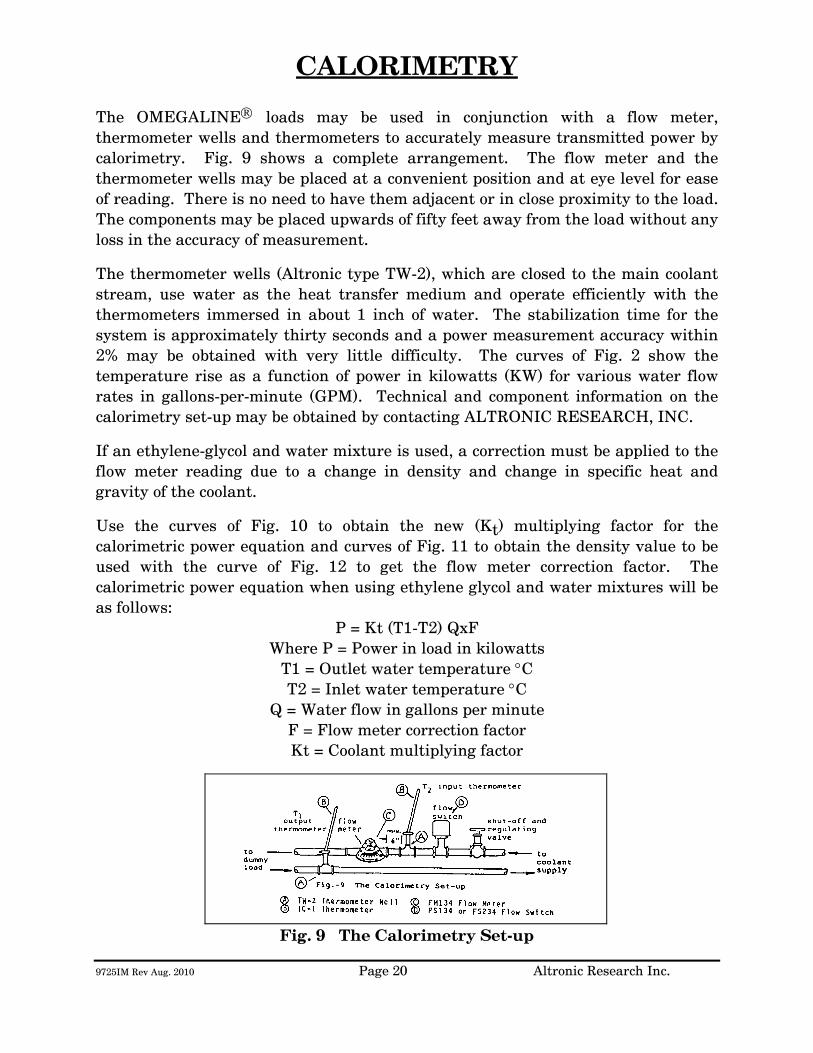
9725IM Rev Aug. 2010 Page 20 Altronic Research Inc.
CALORIMETRY The OMEGALINE® loads may be used in conjunction with a flow meter, thermometer wells and thermometers to accurately measure transmitted power by calorimetry. Fig. 9 shows a complete arrangement. The flow meter and the thermometer wells may be placed at a convenient position and at eye level for ease of reading. There is no need to have them adjacent or in close proximity to the load. The components may be placed upwards of fifty feet away from the load without any loss in the accuracy of measurement.
The thermometer wells (Altronic type TW-2), which are closed to the main coolant stream, use water as the heat transfer medium and operate efficiently with the thermometers immersed in about 1 inch of water. The stabilization time for the system is approximately thirty seconds and a power measurement accuracy within 2% may be obtained with very little difficulty. The curves of Fig. 2 show the temperature rise as a function of power in kilowatts (KW) for various water flow rates in gallons-per-minute (GPM). Technical and component information on the calorimetry set-up may be obtained by contacting ALTRONIC RESEARCH, INC.
If an ethylene-glycol and water mixture is used, a correction must be applied to the flow meter reading due to a change in density and change in specific heat and gravity of the coolant.
Use the curves of Fig. 10 to obtain the new (Kt) multiplying factor for the calorimetric power equation and curves of Fig. 11 to obtain the density value to be used with the curve of Fig. 12 to get the flow meter correction factor. The calorimetric power equation when using ethylene glycol and water mixtures will be as follows:
P = Kt (T1-T2) QxF Where P = Power in load in kilowatts
T1 = Outlet water temperature °C T2 = Inlet water temperature °C
Q = Water flow in gallons per minute F = Flow meter correction factor Kt = Coolant multiplying factor
Fig. 9 The Calorimetry Set-up

9725IM Rev Aug. 2010 Page 21 Altronic Research Inc.
Fig. 10 Kt for Ethylene-Glycol/Water Mixtures vs. Temperature

9725IM Rev Aug. 2010 Page 22 Altronic Research Inc.
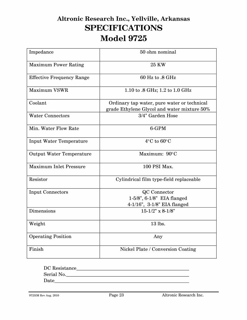
9725IM Rev Aug. 2010 Page 23 Altronic Research Inc.
Altronic Research Inc., Yellville, Arkansas
SPECIFICATIONS Model 9725
Impedance
50 ohm nominal
Maximum Power Rating
25 KW
Effective Frequency Range
60 Hz to .8 GHz
Maximum VSWR
1.10 to .8 GHz; 1.2 to 1.0 GHz
Coolant Ordinary tap water, pure water or technical grade Ethylene Glycol and water mixture 50%
Water Connectors
3/4" Garden Hose
Min. Water Flow Rate
6-GPM
Input Water Temperature
4°C to 60°C
Output Water Temperature
Maximum: 90°C
Maximum Inlet Pressure
100 PSI Max.
Resistor
Cylindrical film type-field replaceable
Input Connectors
QC Connector 1-5/8", 6-1/8" EIA flanged 4-1/16", 3-1/8" EIA flanged
Dimensions
15-1/2" x 8-1/8"
Weight
13 lbs.
Operating Position
Any
Finish
Nickel Plate / Conversion Coating
DC Resistance Serial No.
Date

9725IM Rev Aug. 2010 Page 24 Altronic Research Inc.
Fig. 13

ALTRONIC RESEARCH, INC. P.O. BOX 249
YELLVILLE, ARKANSAS 72687-0249 U.S.A.
LIQUID-COOLED COAXIAL LOAD RESISTOR
MODEL 9715

TABLE OF CONTENTS
INTRODUCTION ............................................................................................. 1 PRECAUTIONS................................................................................................ 2 GENERAL DESCRIPTION ............................................................................ 4 ELECTRICAL CHARACTERISTICS............................................................ 6 COOLANT ......................................................................................................... 9 COOLING SYSTEMS..................................................................................... 13 INSTALLATION............................................................................................. 17 OPERATION................................................................................................... 19 CALORIMETRY ............................................................................................. 20 SPECIFICATIONS......................................................................................... 23 MAINTENANCE............................................................................................. 25 WARRANTY .................................................................................................... 29
ILLUSTRATIONS, TABLES AND GRAPHS
Fig. 1 The OMEGALINE® Coaxial Load Resistor............................................ 5
Fig. 2 Applied Power & Coolant Flow vs. Coolant Temperature Rise........ 7
Fig. 2A Power Input & Coolant Flow vs. Coolant Temperature Rise............ 8
Fig. 3 Freezing and Boiling Points of Glycol-Water Mixtures.................... 10
Fig. 3A Glycol Concentration Table .................................................................... 11
Fig. 4 Minimum Water Flow Rate Requirements .......................................... 11
Fig. 5 Internal Pressure Drop vs. Flow Rate .................................................. 12
Fig. 6 Alternative Cooling Systems................................................................... 13
Fig. 7 Coolant Volume vs. Operating Time ..................................................... 15
Fig. 8 Tank Sizes.................................................................................................... 16
Fig. 9 The Calorimetry Set-up............................................................................ 20
Fig. 10 Kt for Ethylene Glycol Mixtures vs. Temperature............................. 21
Fig. 11 Density of Ethylene Glycol Mixtures vs. Temperature..................... 22
Fig. 12 Flow-Meter Correction Factor................................................................ 22
Fig. 13 VSWR Nomograph ..................................................................................... 24
Fig. 14 Model 9715 Exploded View/Parts List................................................... 27
Fig. 15 Flange Assembly View .............................................................................. 28
9715 Rev Aug. 2010 Page 1 Altronic Research Inc.
INTRODUCTION This manual gives you specific information on the installation, operation and service of OMEGALINE® coaxial resistors. Most of the loads are field serviceable, but we recommend their return to us for repair. Mistakes can be costly compared to the low cost for our trained personnel to make the repairs and return the load to new performance specifications. Labor and packaging costs are minimal. We take the load completely apart, clean and inspect all parts, repair/replace as necessary, reassemble, water pressure test, power test, VSWR test and package the load for shipment. If new parts are required in the load (such as resistors etc.), this will be an additional cost. The average turn-around time on repairs is approximately 7 working days and generally will depend on your needs. When sending in repairs, please include: your company name and address, the operating frequency you use, fax number, telephone number and your name in case we need to talk to you about the load or obtain shipping instructions. We can accommodate most shipping modes. SHIP TO: Altronic Research Inc., 621 Hwy. 202 W, Yellville, AR 72687. Our mailing address is P.O. Box 249. Note: We also repair dummy loads manufactured by many other companies. Call for information (870-449-4093).
9715 Rev Aug. 2010 Page 2 Altronic Research Inc.
PRECAUTIONS
!!!DANGER!!! THIS UNIT MUST BE TOTALLY DISCONNECTED FROM ALL RF POWER BEFORE ANY REPAIRS ARE ATTEMPTED. ANY ATTEMPT AT REPAIR WITHOUT DISCONNECTING THE POWER COULD RESULT IN FATAL ELECTRICAL SHOCK!!!
WARNING DO NOT APPLY POWER WITHOUT THE MINIMUM RATED FLOW OF COOLANT THROUGH THE LOAD. A SAFETY INTERLOCK SWITCH IS RECOMMENDED. EVEN A BRIEF APPLICATION OF POWER TO THE LOAD WITHOUT THE CIRCULATION OF COOLANT WILL CAUSE IMMEDIATE BURN OUT.
WARNING THE LOAD RESISTOR CONSISTS OF A CERAMIC SUBSTRATE COATED WITH A SPECIAL RESISTIVE FILM. IF ANY DAMAGE OCCURS TO THE RESISTOR, THERE COULD BE SHARDS OR SHARP BROKEN PIECES OF CERAMIC IN THE LOAD. CARE SHOULD BE TAKEN TO AVOID CUTS OR INJURIES.
PRECAUTIONS
9715 Rev Aug. 2010 Page 3 Altronic Research Inc.
CAUTION USE ONLY CLEAR, COLORLESS, ANALYTIC OR TECHNICAL GRADE ETHYLENE GLYCOL WITH PURE TAP OR POTABLE* WATER AS A SOURCE COOLANT. DO NOT USE ANY STOP LEAK, SEALANTS, AUTOMOTIVE ANTIFREEZE OR UNION CARBIDE UCARTHERM™ IN COOLANT. USE OF THESE SUBSTANCES WILL VOID THE WARRANTY.
IMPORTANT ADDITION OF ETHYLENE GLYCOL TO THE WATER REDUCES THE HEAT CAPACITY OF THE COOLING SYSTEM. COOLANT FLOW RATE MUST BE INCREASED BY AT LEAST 20% OVER MINIMUM FLOW.
CAUTION DO NOT APPLY MORE THAN THE MAXIMUM RATED RF POWER TO THE LOAD. THIS WILL CAUSE INTERNAL DAMAGE TO THE LOAD.
* Potable Water: The U.S. Health Department has established standards for potable water at a maximum of 500ppm of dissolved solids. Hard water (particularly dissolved salts) can cause damage to resistive film and load. Water condition can be adjusted by mixing distilled water in sufficient quantities with coolant water.
9715 Rev Aug. 2010 Page 4 Altronic Research Inc.
GENERAL DESCRIPTION
The OMEGALINE® dummy load is basically a termination-type unit having its characteristic impedance at the input end and tapered to zero impedance (short circuit) at the other end. The center conductor is a tubular resistor whose DC resistance is equal to the characteristic impedance of the line. The outer conductor of the coaxial line is a symmetrical horn-shaped enclosure, contoured logarithmically along its length to obtain a reflection-free termination. The RF dielectric medium consists of three distinct materials: the liquid coolant, the plastic water jacket and the air space. (See Fig. 1) Coolant enters the load at the electrically shorted end, flows axially down the center of the resistor tube, mushrooms over into the annular channel under the water jacket, and makes a second pass over the resistor in direct physical contact with the resistive film. Thus the coolant makes intimate contact with both the inside and outside cylindrical surfaces of the resistor, providing optimum heat transfer with minimal flow rate. The dummy load housing is constructed of aluminum and/or brass or bronze sections whose inner surfaces are machined to a modified logarithmic taper. The stepped housing sections are held in accurate alignment with stainless steel socket head cap screws. The power dissipating resistor consists of a conductive resistive film which is deposited on a tubular ceramic substrate with silver bands fired on the ends for electrical connection. Contact to the resistor is made by silver plated spring fingers. Coolant flows through the fingers and passes directly over the resistive film. The resistor is enclosed within a plastic water jacket which is custom machined to match the body and seal the coolant flow.
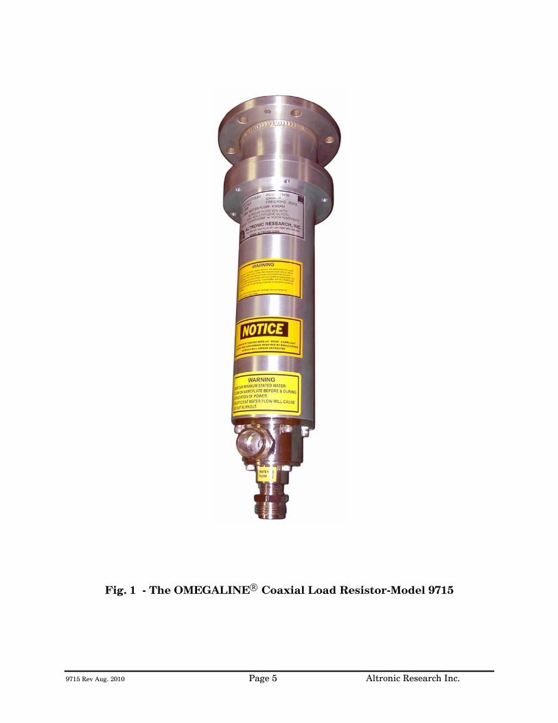
9715 Rev Aug. 2010 Page 5 Altronic Research Inc.
Fig. 1 - The OMEGALINE® Coaxial Load Resistor-Model 9715
9715 Rev Aug. 2010 Page 6 Altronic Research Inc.
ELECTRICAL CHARACTERISTICS
POWER RATING - All models of the OMEGALINE® series of coaxial loads are rated for continuous duty and may be operated in any position at any power level within their rating and with the proper water flow rate. A 10-20% GREATER FLOW RATE MAY BE USED AND IS RECOMMENDED. If the units are operated below the maximum power rating, a corresponding reduction in the coolant flow rate may be used. (See Fig. 4) All loads are electrically tested prior to shipment. Testing is done at 60 Hz with input voltage and current measured on RMS meters. The (RMS) power being dissipated in the load is simultaneously checked by calorimetry. The relationship used for calculating the power dissipated in the load from the calorimetric data is: (See Fig. 2 & 2A)
P = 0.264 (T2 - T1)Q
Where P = Power in load in kilowatts
T2 = Outlet water temperature °C
T1 = Inlet water temperature °C
Q = Water flow in gallons-per-minute
WARNING! Power should never be applied before turning on the WATER FIRST and allowing sufficient time (approx. 1 minute) for complete wetting of the resistor and elimination of air bubbles. Water flow must be maintained throughout the application of power and may be turned off within 15-30 seconds after the power has been turned off. Failure to observe these precautions will result in instant failure of the resistor and possible destruction of other parts of the load.
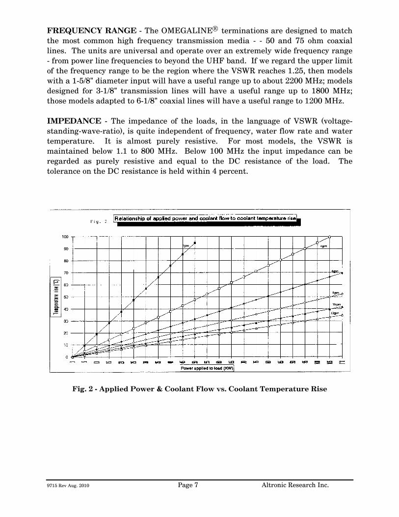
9715 Rev Aug. 2010 Page 7 Altronic Research Inc.
FREQUENCY RANGE - The OMEGALINE® terminations are designed to match the most common high frequency transmission media - - 50 and 75 ohm coaxial lines. The units are universal and operate over an extremely wide frequency range - from power line frequencies to beyond the UHF band. If we regard the upper limit of the frequency range to be the region where the VSWR reaches 1.25, then models with a 1-5/8" diameter input will have a useful range up to about 2200 MHz; models designed for 3-1/8" transmission lines will have a useful range up to 1800 MHz; those models adapted to 6-1/8" coaxial lines will have a useful range to 1200 MHz. IMPEDANCE - The impedance of the loads, in the language of VSWR (voltage-standing-wave-ratio), is quite independent of frequency, water flow rate and water temperature. It is almost purely resistive. For most models, the VSWR is maintained below 1.1 to 800 MHz. Below 100 MHz the input impedance can be regarded as purely resistive and equal to the DC resistance of the load. The tolerance on the DC resistance is held within 4 percent.
Fig. 2 - Applied Power & Coolant Flow vs. Coolant Temperature Rise
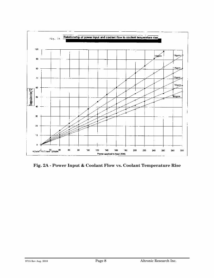
9715 Rev Aug. 2010 Page 8 Altronic Research Inc.
Fig. 2A - Power Input & Coolant Flow vs. Coolant Temperature Rise
9715 Rev Aug. 2010 Page 9 Altronic Research Inc.
COOLANT
COOLANT - The OMEGALINE® dummy load may be used with ordinary tap water, pure, or de-ionized water in open or closed cooling systems. The use of deionized and distilled water in OMEGALINE® loads has been reported to cause premature failures under some conditions. These failures are the result of the leaching action of the coolant on the silver and silver-plated surfaces of the resistors and contact material. The reported failures have generally been associated with deionized systems which are polished to 10-15 megohm levels and are operated intermittently. We suspect that the failure mechanism is attributable to bacterial growth in the coolant system and the subsequent high levels of sulfides usually found in conjunction with such contamination. Altronic does offer a line of water-cooled loads with gold and gold-plated resistors and contacts, for use in systems where leaching action seems unavoidable. Contact our sales office for information. We suggest the use of caution when determining what coolant to use. Potable water is certainly the most desirable coolant. Brackish or salt water is NOT permissible as a coolant for the load resistor! The load is designed with non-contaminating elements in the water circuit and may be used with transmitters that have pure water recirculating cooling systems. For operation below the freezing temperatures of water, ethylene glycol may be added to the water to prohibit freezing (see Fig. 3). If you have questions about coolants, please consult the factory.
IMPORTANT We recommend a Glycol mixture of 40% (2:3) or less. Addition of ethylene glycol to water reduces the heat capacity of the mixture with a corresponding reduction in cooling effectiveness. Therefore, the coolant flow rate should be increased approximately 20% from that required with water only.
!!!WARNING!!!
Only clear, colorless analytic or technical grade ethylene glycol may be used. Dow Chemical Company's Dowtherm® SR1 has been reported to be fully compatible with OMEGALINE® loads when used in accordance with Dow's instructions (up to a 40% max). DO NOT use any stop leak, sealants, automotive antifreeze or Union Carbide Ucartherm™ in coolant. To do so will void the warranty. Damage to the resistor film may occur with applied power, resulting in failure!
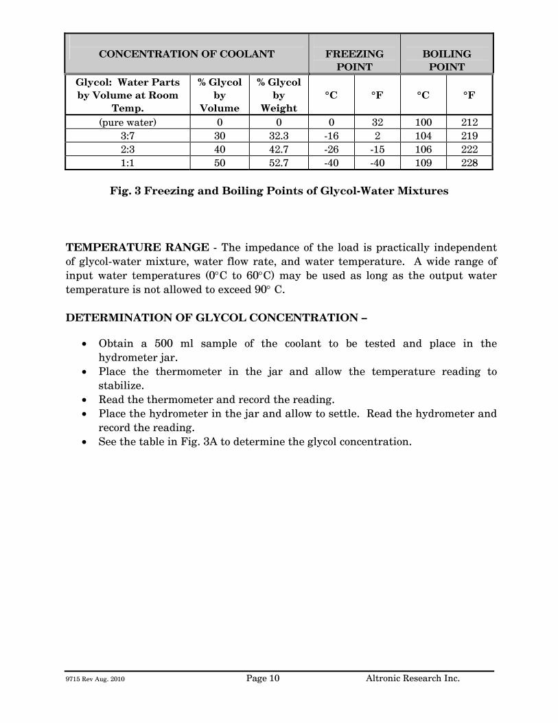
9715 Rev Aug. 2010 Page 10 Altronic Research Inc.
CONCENTRATION OF COOLANT
FREEZING
POINT
BOILING
POINT Glycol: Water Parts by Volume at Room
Temp.
% Glycol by
Volume
% Glycol by
Weight
°C
°F
°C
°F
(pure water) 0 0 0 32 100 212 3:7 30 32.3 -16 2 104 219 2:3 40 42.7 -26 -15 106 222 1:1 50 52.7 -40 -40 109 228
Fig. 3 Freezing and Boiling Points of Glycol-Water Mixtures
TEMPERATURE RANGE - The impedance of the load is practically independent of glycol-water mixture, water flow rate, and water temperature. A wide range of input water temperatures (0°C to 60°C) may be used as long as the output water temperature is not allowed to exceed 90° C. DETERMINATION OF GLYCOL CONCENTRATION –
• Obtain a 500 ml sample of the coolant to be tested and place in the hydrometer jar.
• Place the thermometer in the jar and allow the temperature reading to stabilize.
• Read the thermometer and record the reading. • Place the hydrometer in the jar and allow to settle. Read the hydrometer and
record the reading. • See the table in Fig. 3A to determine the glycol concentration.
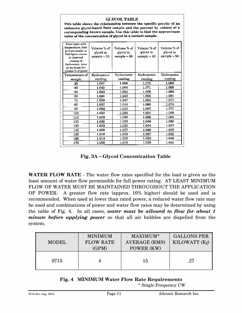
9715 Rev Aug. 2010 Page 11 Altronic Research Inc.
Fig. 3A – Glycol Concentration Table WATER FLOW RATE - The water flow rates specified for the load is given as the least amount of water flow permissible for full power rating. AT LEAST MINIMUM FLOW OF WATER MUST BE MAINTAINED THROUGHOUT THE APPLICATION OF POWER. A greater flow rate (approx. 10% higher) should be used and is recommended. When used at lower than rated power, a reduced water flow rate may be used and combinations of power and water flow rates may be determined by using the table of Fig. 4. In all cases, water must be allowed to flow for about 1 minute before applying power so that all air bubbles are dispelled from the system.
MODEL MINIMUM
FLOW RATE (GPM)
MAXIMUM* AVERAGE (RMS)
POWER (KW)
GALLONS PER KILOWATT (Kf)
9715
4
15
.27
Fig. 4 MINIMUM Water Flow Rate Requirements
* Single Frequency CW
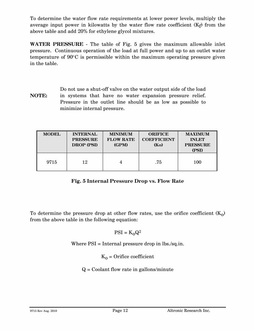
9715 Rev Aug. 2010 Page 12 Altronic Research Inc.
To determine the water flow rate requirements at lower power levels, multiply the average input power in kilowatts by the water flow rate coefficient (Kf) from the above table and add 20% for ethylene glycol mixtures. WATER PRESSURE - The table of Fig. 5 gives the maximum allowable inlet pressure. Continuous operation of the load at full power and up to an outlet water temperature of 90°C is permissible within the maximum operating pressure given in the table. NOTE:
Do not use a shut-off valve on the water output side of the load in systems that have no water expansion pressure relief. Pressure in the outlet line should be as low as possible to minimize internal pressure.
MODEL INTERNAL
PRESSURE DROP (PSI)
MINIMUM FLOW RATE
(GPM)
ORIFICE COEFFICIENT
(Ko)
MAXIMUM INLET
PRESSURE (PSI)
9715
12
4
.75
100
Fig. 5 Internal Pressure Drop vs. Flow Rate
To determine the pressure drop at other flow rates, use the orifice coefficient (Ko) from the above table in the following equation:
PSI = KoQ2
Where PSI = Internal pressure drop in lbs./sq.in.
Ko = Orifice coefficient
Q = Coolant flow rate in gallons/minute
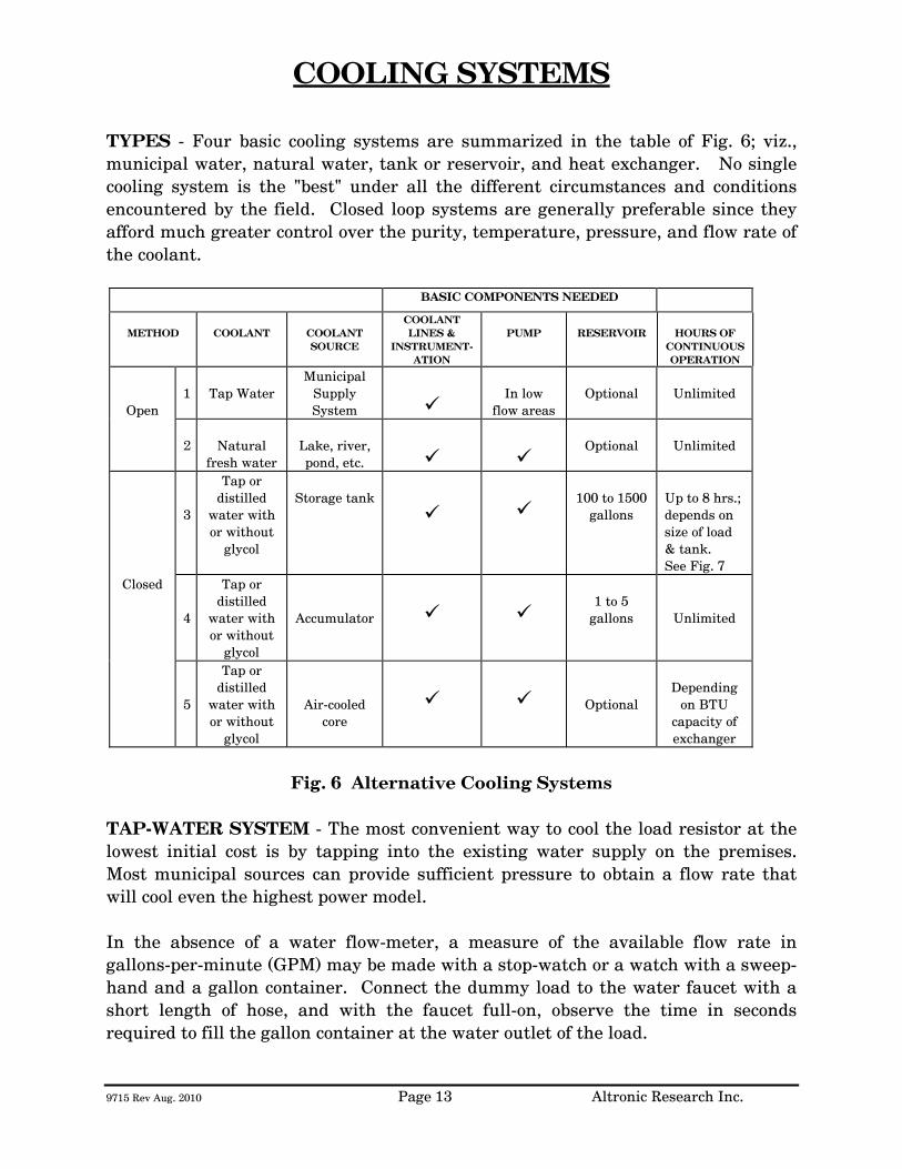
9715 Rev Aug. 2010 Page 13 Altronic Research Inc.
COOLING SYSTEMS
TYPES - Four basic cooling systems are summarized in the table of Fig. 6; viz., municipal water, natural water, tank or reservoir, and heat exchanger. No single cooling system is the "best" under all the different circumstances and conditions encountered by the field. Closed loop systems are generally preferable since they afford much greater control over the purity, temperature, pressure, and flow rate of the coolant.
BASIC COMPONENTS NEEDED
METHOD
COOLANT
COOLANT SOURCE
COOLANT LINES &
INSTRUMENT-ATION
PUMP
RESERVOIR
HOURS OF
CONTINUOUS OPERATION
Open
1
Tap Water
Municipal Supply System
In low
flow areas
Optional
Unlimited
2
Natural
fresh water
Lake, river, pond, etc.
Optional
Unlimited
3
Tap or distilled
water with or without
glycol
Storage tank
100 to 1500
gallons
Up to 8 hrs.; depends on size of load & tank. See Fig. 7
Closed
4
Tap or distilled
water with or without
glycol
Accumulator
1 to 5
gallons
Unlimited
5
Tap or distilled
water with or without
glycol
Air-cooled core
Optional
Depending
on BTU capacity of exchanger
Fig. 6 Alternative Cooling Systems
TAP-WATER SYSTEM - The most convenient way to cool the load resistor at the lowest initial cost is by tapping into the existing water supply on the premises. Most municipal sources can provide sufficient pressure to obtain a flow rate that will cool even the highest power model. In the absence of a water flow-meter, a measure of the available flow rate in gallons-per-minute (GPM) may be made with a stop-watch or a watch with a sweep-hand and a gallon container. Connect the dummy load to the water faucet with a short length of hose, and with the faucet full-on, observe the time in seconds required to fill the gallon container at the water outlet of the load.
9715 Rev Aug. 2010 Page 14 Altronic Research Inc.
When using the dummy load with a tap-water system, the flow rate is usually adjusted to 10-15% above the minimum requirement and left unattended. Since water lines ordinarily serve other appliances (flush toilets, etc.) over which there is no control, a flow switch should be installed to protect the load resistor element in case the flow rate drops due to a momentary change in water pressure. Choose a flow switch with a small "ON-OFF" flow rate dead band. The switch will also protect the resistor in cases where the RF power may be turned on before the water flow, or where accidental termination of water flow (pinched hose, debris, valve closing, etc.) may occur. In the tap-water system the heated water is discharged down the drain and therefore, the cost of the water becomes an important consideration. NATURAL WATER SYSTEM - A close proximity to a natural supply of fresh water may suggest its utilization. Brackish or salt water may NOT be used as a coolant for the load resistor. The natural water system usually requires more extensive piping and heavier pumping equipment to handle attendant pressure drop. The quality of natural water varies widely and straining is often necessary to handle the twigs, minnows, leaves and other debris frequently encountered. Small automatic self-cleaning strainers are available for this purpose. The strainer should be installed upstream from the pump to protect the pump as well as the load resistor. Additional filtering of smaller particles is sometimes required and this can be accomplished with finer mesh "Y-TYPE" strainers inserted in series with the line. In this system, the water from the natural source may not be directly usable as a coolant for the load resistor element due to a high contamination, such as silt, iron content, mud, etc.; but it may be used as "dirty" water coolant in a water-to-water heat exchanger. The contaminated water could be piped via plastic tubing or hose to copper coils immersed in a holding tank containing clean water coolant for the dummy load. This arrangement would require a dual pump - one section to pump the "dirty" natural-source water and the other section to pump the clean water coolant through the dummy load. HEAT EXCHANGER SYSTEM - In this system, an accumulator or receiving tank is used which only holds about one-half the flow rate in gallons-per-minute. Accordingly, a small quantity of coolant is required. The coolant functions solely as a heat transfer agent between the load resistor and the heat sink. A heat exchanger consisting of a radiator and a fan is the type recommended for this application. With ambient air as the ultimate heat sink, the operating temperature of the coolant will always be above the air temperature for heat to be transferred from the load to the air. Some consideration should be given to exhausting the hot air to the outside so as not to have a temperature rise problem in the transmitter area. The heat exchanger may be a complete self-contained unit (portable) which
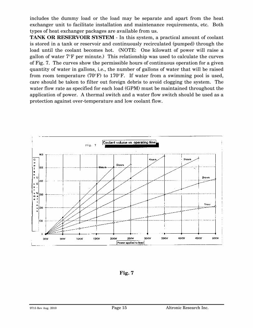
9715 Rev Aug. 2010 Page 15 Altronic Research Inc.
includes the dummy load or the load may be separate and apart from the heat exchanger unit to facilitate installation and maintenance requirements, etc. Both types of heat exchanger packages are available from us. TANK OR RESERVOIR SYSTEM - In this system, a practical amount of coolant is stored in a tank or reservoir and continuously recirculated (pumped) through the load until the coolant becomes hot. (NOTE: One kilowatt of power will raise a gallon of water 7°F per minute.) This relationship was used to calculate the curves of Fig. 7. The curves show the permissible hours of continuous operation for a given quantity of water in gallons, i.e., the number of gallons of water that will be raised from room temperature (70°F) to 170°F. If water from a swimming pool is used, care should be taken to filter out foreign debris to avoid clogging the system. The water flow rate as specified for each load (GPM) must be maintained throughout the application of power. A thermal switch and a water flow switch should be used as a protection against over-temperature and low coolant flow.
Fig. 7
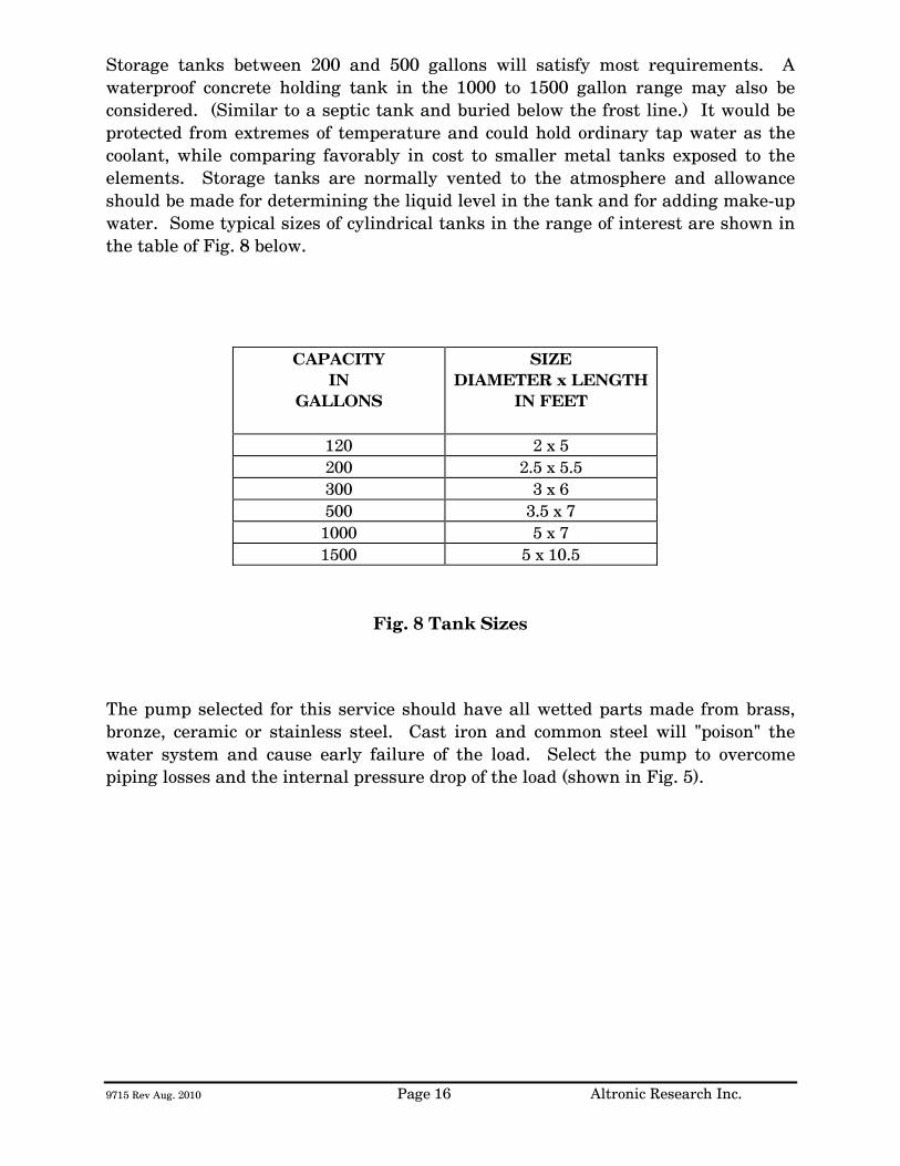
9715 Rev Aug. 2010 Page 16 Altronic Research Inc.
Storage tanks between 200 and 500 gallons will satisfy most requirements. A waterproof concrete holding tank in the 1000 to 1500 gallon range may also be considered. (Similar to a septic tank and buried below the frost line.) It would be protected from extremes of temperature and could hold ordinary tap water as the coolant, while comparing favorably in cost to smaller metal tanks exposed to the elements. Storage tanks are normally vented to the atmosphere and allowance should be made for determining the liquid level in the tank and for adding make-up water. Some typical sizes of cylindrical tanks in the range of interest are shown in the table of Fig. 8 below.
CAPACITY IN
GALLONS
SIZE DIAMETER x LENGTH
IN FEET
120 2 x 5 200 2.5 x 5.5 300 3 x 6 500 3.5 x 7
1000 5 x 7 1500 5 x 10.5
Fig. 8 Tank Sizes
The pump selected for this service should have all wetted parts made from brass, bronze, ceramic or stainless steel. Cast iron and common steel will "poison" the water system and cause early failure of the load. Select the pump to overcome piping losses and the internal pressure drop of the load (shown in Fig. 5).
9715 Rev Aug. 2010 Page 17 Altronic Research Inc.
INSTALLATION
The OMEGALINE® loads may be used on both fixed and portable applications and they perform equally well in any mounting position. The units are very rugged and light and may be strapped, clamped, or secured with any practical and readily available mechanical device. They may be held by the RF connector on one end and by the plumbing on the other end. The coolant may be allowed to pass through the load in either direction without affecting its operation, but the axial water connector is normally used as the inlet since it contains the built-in filter screen. Water lines connecting the load should be 3/4" copper water tubing and rigid enough to support the load. NOTE: (A fifty-foot length of 1/2" pipe has a pressure drop of 45-PSI at 10-GPM water flow rate, while a 3/4" pipe under the same conditions only develops a 5-PSI drop.) In typical installations, the rigid piping is terminated within a few feet of the load, and flexible hose is used to bridge the last few feet. The hose should be 3/4" I.D. and capable of withstanding the temperature and pressure of the system. The water fittings on the load are 3/4" hose thread to accommodate standard hose couplings. Do not screw pipe thread fittings onto the hose thread - damage will result due to cross-threading. Pipe threads are tapered and hose threads are straight. If it is desired to mate with regular 3/4" pipe threads, use a hose-to-pipe adapter. The adapter is recommended since it eliminates the need of removing the side outlet water fitting and also allows the axial water fitting to be adapted directly to 3/4" pipe. The adapters may be obtained at a local hardware store or a plumbing supply house. Provisions should be made to allow interruption of the transmission line at any position where the transmitter is to be terminated by the load or measurements are contemplated. Coaxial switches may be inserted in the transmission line run to provide rapid load switching. Proceed as follows:
1. Install the unit in the selected location. 2. Connect the outlet water fitting of the dummy load to a convenient
drainage. 3. Connect the water inlet to a water source capable of delivering the
required flow in gallons per minute.
9715 Rev Aug. 2010 Page 18 Altronic Research Inc.
If the required source of water flow is not available from the local lines, refer to the previous section for a possible alternate cooling system. We highly recommend the use of a flow switch in the inlet piping to detect low flow conditions which could damage the load. We recommend the IMO DeLaval Model AFS200, Adjustable Flow Switch. This switch has low internal pressure drop and operates reliably in pilot-duty applications. (This switch is available from us.) Mount the switch in a horizontal section of pipe where there is a straight horizontal run of at least five inches on each side of the switch.
4. Connect the microswitch contacts of the flow switch in series with transmitter interlock circuit.
5. Connect the dummy load to the transmission line. The unit is designed
to connect to a 50 or 75 ohm line (or as stated on label).
9715 Rev Aug. 2010 Page 19 Altronic Research Inc.
OPERATION
To place the dummy load in operation, the following procedure is recommended:
1. Turn on the water pressure and make certain water is flowing through the load. Allow about 1 minute of water circulation to insure complete wetting of the resistor element in the load and exhaustion of air bubbles.
2. Check the water flow rate. This can be done with a five-gallon
container and a wristwatch with a sweep-hand if no water flow meter is available.
3. Apply RF power.
To cease operation, turn the RF power off and allow about 30 seconds before turning off the water.
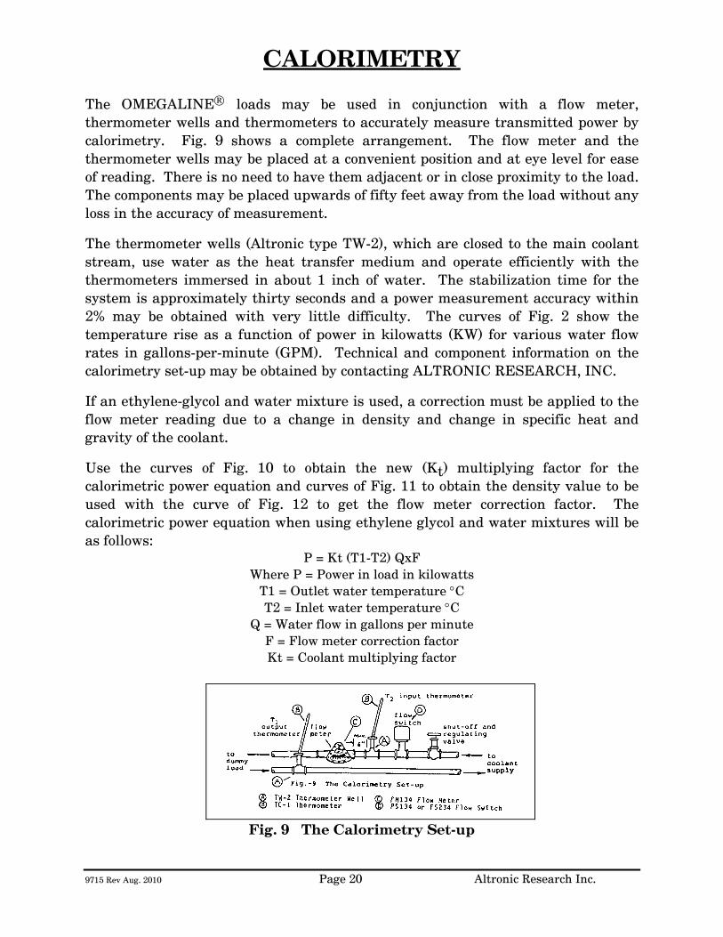
9715 Rev Aug. 2010 Page 20 Altronic Research Inc.
CALORIMETRY The OMEGALINE® loads may be used in conjunction with a flow meter, thermometer wells and thermometers to accurately measure transmitted power by calorimetry. Fig. 9 shows a complete arrangement. The flow meter and the thermometer wells may be placed at a convenient position and at eye level for ease of reading. There is no need to have them adjacent or in close proximity to the load. The components may be placed upwards of fifty feet away from the load without any loss in the accuracy of measurement.
The thermometer wells (Altronic type TW-2), which are closed to the main coolant stream, use water as the heat transfer medium and operate efficiently with the thermometers immersed in about 1 inch of water. The stabilization time for the system is approximately thirty seconds and a power measurement accuracy within 2% may be obtained with very little difficulty. The curves of Fig. 2 show the temperature rise as a function of power in kilowatts (KW) for various water flow rates in gallons-per-minute (GPM). Technical and component information on the calorimetry set-up may be obtained by contacting ALTRONIC RESEARCH, INC.
If an ethylene-glycol and water mixture is used, a correction must be applied to the flow meter reading due to a change in density and change in specific heat and gravity of the coolant.
Use the curves of Fig. 10 to obtain the new (Kt) multiplying factor for the calorimetric power equation and curves of Fig. 11 to obtain the density value to be used with the curve of Fig. 12 to get the flow meter correction factor. The calorimetric power equation when using ethylene glycol and water mixtures will be as follows:
P = Kt (T1-T2) QxF Where P = Power in load in kilowatts
T1 = Outlet water temperature °C T2 = Inlet water temperature °C
Q = Water flow in gallons per minute F = Flow meter correction factor Kt = Coolant multiplying factor
Fig. 9 The Calorimetry Set-up
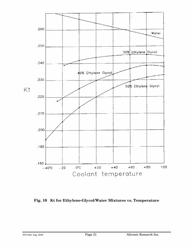
9715 Rev Aug. 2010 Page 21 Altronic Research Inc.
Fig. 10 Kt for Ethylene-Glycol/Water Mixtures vs. Temperature
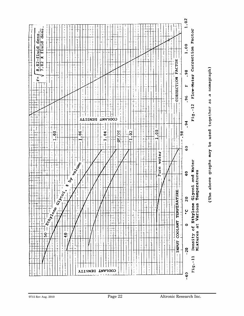
9715 Rev Aug. 2010 Page 22 Altronic Research Inc.
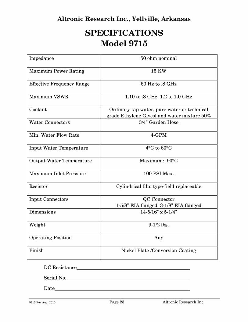
9715 Rev Aug. 2010 Page 23 Altronic Research Inc.
Altronic Research Inc., Yellville, Arkansas
SPECIFICATIONS Model 9715
Impedance
50 ohm nominal
Maximum Power Rating
15 KW
Effective Frequency Range
60 Hz to .8 GHz
Maximum VSWR
1.10 to .8 GHz; 1.2 to 1.0 GHz
Coolant Ordinary tap water, pure water or technical grade Ethylene Glycol and water mixture 50%
Water Connectors
3/4" Garden Hose
Min. Water Flow Rate
4-GPM
Input Water Temperature
4°C to 60°C
Output Water Temperature
Maximum: 90°C
Maximum Inlet Pressure
100 PSI Max.
Resistor
Cylindrical film type-field replaceable
Input Connectors
QC Connector 1-5/8" EIA flanged, 3-1/8" EIA flanged
Dimensions
14-5/16" x 5-1/4"
Weight
9-1/2 lbs.
Operating Position
Any
Finish
Nickel Plate /Conversion Coating
DC Resistance
Serial No. Date

9715 Rev Aug. 2010 Page 24 Altronic Research Inc.
Fig. 13