Embed Size (px)
Citation preview

Alternative Technologies for
Making Holes Conductive
Solutions forPrinted Wiring BoardManufacturers
EPA 744-R-98-002April 1998

Making Holes Conductive
Alternative Technologies for MakingHoles Conductive
Cleaner Technologies for Printed Wiring BoardManufacturers
This document was produced by Microelectronics and Computer
Technology Corporation under grant #X-824617 from EPA�s Design for the
Environment Branch, Economics, Exposure, & Technology Division, Office
of Pollution Prevention and Toxics. Funding was provided through EPA�s
Environmental Technology Initiative Program.

Making Holes Conductive
Acknowledgments
This document was prepared by Abt Associates Inc., Cambridge, MA, for Microelectronics
and Computer Technology Corporation, as part of the collaborative Design for the
Environment Printed Wiring Board Project. This document is based primarily on the full
project report, Printed Wiring Board Cleaner Technologies Substitutes Assessment:
Making Holes Conductive (CTSA), prepared by the University of Tennessee, Knoxville,
Center for Clean Products and Clean Technologies, under a grant from the U.S.
Environmental Protection Agency. The EPA Project Officer was Kathy Hart of the Design
for the Environment Program, in the Economics, Exposure, and Technology Division, Office
of Pollution Prevention and Toxics. The CTSA would not have been possible without the
assistance of the technology vendors and their customers, who voluntarily participated in the
project. The project Core Group provided valuable guidance and feedback throughout the
preparation of the report. Core Group members included: Kathy Hart of U.S. EPA;
Christopher Rhodes of the Institute for Interconnecting and Packaging Electronic Circuits
(IPC); Dipti Singh of U.S. EPA; John Lott of DuPont Electronic Materials; Michael Kerr of
Circuit Center Inc.; Gary Roper of McDonald Technologies, Inc.; John Sharp of Merix
Corp.; Jack Geibig, Lori Kincaid, and Mary Swanson of the University of Tennessee Center
for Clean Products and Clean Technologies; Greg Pitts of MCC; Ted Smith of Silicon Valley
Toxics Coalition; and Jim Dee, an independent consultant to the University of Tennessee.
The cover photo�a microsection of a multi-layer printed wiring board through-hole�
was provided by IPC.

Making Holes Conductive
Contents
Introduction............................................................................................. 1
Question 1: Why Should I Switch to an Alternative Technology for MakingHoles Conductive (MHC)? .......................................................................... 3
Question 2: Which MHC Technologies Were Evaluated in the DfE Project? ......5
Question 3: How May MHC Technologies Affect Worker Health and theEnvironment? ........................................................................................... 9
Question 4: What Kind of Performance Can I Expect from Direct MetallizationTechnologies? ........................................................................................ 17
Question 5: Will Direct Metallization Reduce My Costs? ............................ 25
Question 6: Does Direct Metallization Use Less Water and Energy? ............. 29
Question 7: How Does Direct Metallization Compare to Electroless CopperOverall? ................................................................................................ 33
Question 8: How Can I Make Direct Metallization Work for My Facility? ...... 35
Question 9: What Steps Do I Take to Switch to Direct Metallization? ............ 39
Question 10: Where Can I Find More Information about Pollution Prevention inthe PWB Industry? ................................................................................. 43

Making Holes Conductive

Making Holes Conductive
IntroductionPrinted wiring boards (PWBs) are an intrinsic part of many products in the electronics,
defense, communication, and automotive industries. The traditional manufacture of PWBs
requires materials and technologies that raise a number of environmental and human health
concerns.
Specifically, wet chemical processes such as those used in PWB fabrication are a
significant source of hazardous waste and consume large amounts of water and energy.
One such wet chemical process is the method used by PWB manufacturers to make PWB
through-holes conductive prior to electrolytic plating. The technology most commonly used
today to accomplish this function is the electroless copper process. This technology
typically employs formaldehyde as a copper-reducing agent and requires large amounts of
water and energy. Alternative technologies are available to accomplish the �making holes
conductive� (MHC) function; most of them eliminate the use of formaldehyde, reduce
water and energy use, and generate less waste.
The potential environmental and cost advantages of the alternatives are beginning to
become apparent and have generated strong interest on the part of industry. To date,
however, reliable data comparing these alternative technologies have not been available. To
address this data gap, the U.S. Environmental Protection Agency (EPA) teamed up with
industry experts in the Design for the Environment (DfE) PWB Project. The project
partners include:
n Institute for Interconnecting and Packaging Electronic Circuits (IPC)
n University of Tennessee Center for Clean Products and Clean Technologies
n Microelectronics and Computer Technology Corporation (MCC)
n Silicon Valley Toxics Coalition
n suppliers of MHC technologies
n individual PWB manufacturers
The key to the successful completion of this analysis was the active participation of this
diverse project team. The project was open to any MHC chemical supplier who wanted to
submit a technology, provided they supplied the necessary data. Although every effort was
made to include all emerging and existing technologies, not all technologies are represented
in this project.
The project team performed a comparative evaluation of seven different MHC
technologies. The analysis focused on evaluating human health and environmental risk,
performance, and cost. The technologies evaluated were:
For the first time, PWB
manufacturers have access
to information on the risk,
cost, and performance of the
alternative technologies for
making holes conductive.
The success of the project
was due to the active
participation and expertise
of a diverse group of
partners.
1

Making Holes Conductive
n electroless copper
n carbon
n conductive polymer
n graphite
n non-formaldehyde electroless copper
n organic-palladium
n tin-palladium
The results of the complete analysis can be found in the full, two volume project report
titled Printed Wiring Board Cleaner Technologies Substitutes Assessment (CTSA):
Making Holes Conductive (EPA 744-R-97-002a and 002b).
To disseminate the results of the evaluation to as many interested readers as possible, this
booklet was developed to summarize some of the key project findings. For more detailed
information on any of the results presented in this booklet, please refer to the CTSA. This
booklet and the CTSA are intended to provide PWB manufacturers with information that
can assist them in making decisions that consider environmental concerns, along with
performance and cost, when choosing an MHC technology.
Data for the comparative analyses were based on a workplace practices survey of PWB
manufacturers, supplier information, industry trade association information, and in-facility
evaluations conducted by the DfE Project team.
Through the on-site evaluations, performance data were collected from the making holes
conductive processes of 25 volunteer PWB manufacturing facilities. These evaluations
were intended to be a �snapshot� of the technologies in real-world production conditions,
rather than a statistically significant analysis. Multi-layer test panels were designed and
manufactured to represent industry �middle-of-the-road� technology. Test panels were
sent to each test site and were processed through their MHC lines. Subsequent electrical
and mechanical tests were done to evaluate the performance of the MHC interconnects.
For each MHC technology, the risk analysis examined occupational health risks, public
health risks, ecological hazards, and process safety concerns. This comparative analysis
was based on exposures estimated for a model facility, rather than exposures estimated
for a specific facility. The cost, energy, and water use evaluations were also comparative
analyses based on a model facility.
The results of the analyses suggest that when implemented correctly, all of the alternative
MHC technologies perform as well or better than the standard electroless copper
technology. Test results also indicated that the alternative technologies can reduce costs
and pose less risk to human health and the environment.
This booklet summarizes the
technical information
presented in the full project
report.
Performance demonstrations
provided data on how these
technologies work under
�real-world� production
conditions.
Risk, cost, and natural
resources analyses were
based on a model facility that
manufactures 350,000
surface square feet (ssf) of
PWBs per year.
Alternative technologies
perform at least as well as
electroless copper if
operated according to
specifications.
2

Making Holes Conductive
Question 1Why Should I Switch to an Alternative Technology forMaking Holes Conductive (MHC)?
Until the last decade, virtually all PWB manufacturers used an electroless copper plating
process for the �making holes conductive� (MHC) step in PWB manufacturing. This
process is used to deposit a thin, conductive layer of copper into the drilled through-holes
of multi-layer PWBs prior to electroplating. Although the traditional electroless copper
process is a mature technology that produces reliable interconnects, it is also a source of
significant environmental and health concerns. Today, many alternatives to electroless
copper exist. These alternative MHC technologies are also often referred to as �direct
metallization� processes. The potential advantages of switching to an alternative MHC
technology include:
n Improved worker health
n Faster production
n Reduced water and energy consumption
n Simplified waste water treatment
n Reduced waste generation
Improved worker healthEliminating formaldehyde, a probable human carcinogen, has been one of the driving
forces behind the development of alternatives to electroless copper. Direct metallization
processes don�t use formaldehyde. Additionally, some systems are completely enclosed
in conveyorized units, further reducing worker exposure to chemicals during operation.
Faster productionThe electroless copper line can be a bottle-neck process for PWB manufacturing. As the
demand for PWBs increases rapidly, a quicker turn-around time translates into a
competitive advantage for PWB manufacturers. Direct metallization technologies can
complete the MHC step two to eight times faster than a typical non-conveyorized
electroless copper line. Furthermore, alternative processes are relatively easy to �cold
start,� compared to a two- to three-hour start-up time required for some electroless
copper lines.
Most users of alternative MHC technologies see additional improvements in their process
efficiency because they spend less time on lab analysis and bath maintenance than with
electroless copper. Some users attribute this change to the automation of tank pump-outs,
3

Making Holes Conductive
chemical additions, and other bath maintenance tasks that may be reduced by some direct
metallization processes. Other users credit the reduced time to bath compositions that can
operate in a wider process window and are easier to analyze.
Reduced water and energy consumptionThe typical electroless copper process line consumes a substantial amount of water. It
may include 17 or more tanks, depending on rinse configurations. Energy is required for
heated baths, pumps, air blowers, and other devices. Direct metallization processes
consume significantly less water because they tend to have fewer rinsing steps and greater
rinse efficiency. This is particularly true for the conveyorized lines. MHC alternatives are
also more energy efficient than electroless copper, primarily because they have a faster
cycle time.
Simplified waste water treatmentChelating agents, such as EDTA, are used to hold metal ions in solution in the electroless
copper bath. As a result, these agents inhibit precipitation of metals during waste water
treatment. Direct metallization processes don�t use chelators. Eliminating chelating
agents from bath chemistries may reduce the need for some treatment chemicals and
simplify the treatment process.
Reduced waste generationWhen compared to an electroless copper process, many facilities have found that direct
metallization processes can reduce the copper concentration in their waste water. Some
facilities have also reduced the volume of sludge they generate by switching to a direct
metallization process.
4
Making Holes Conductive
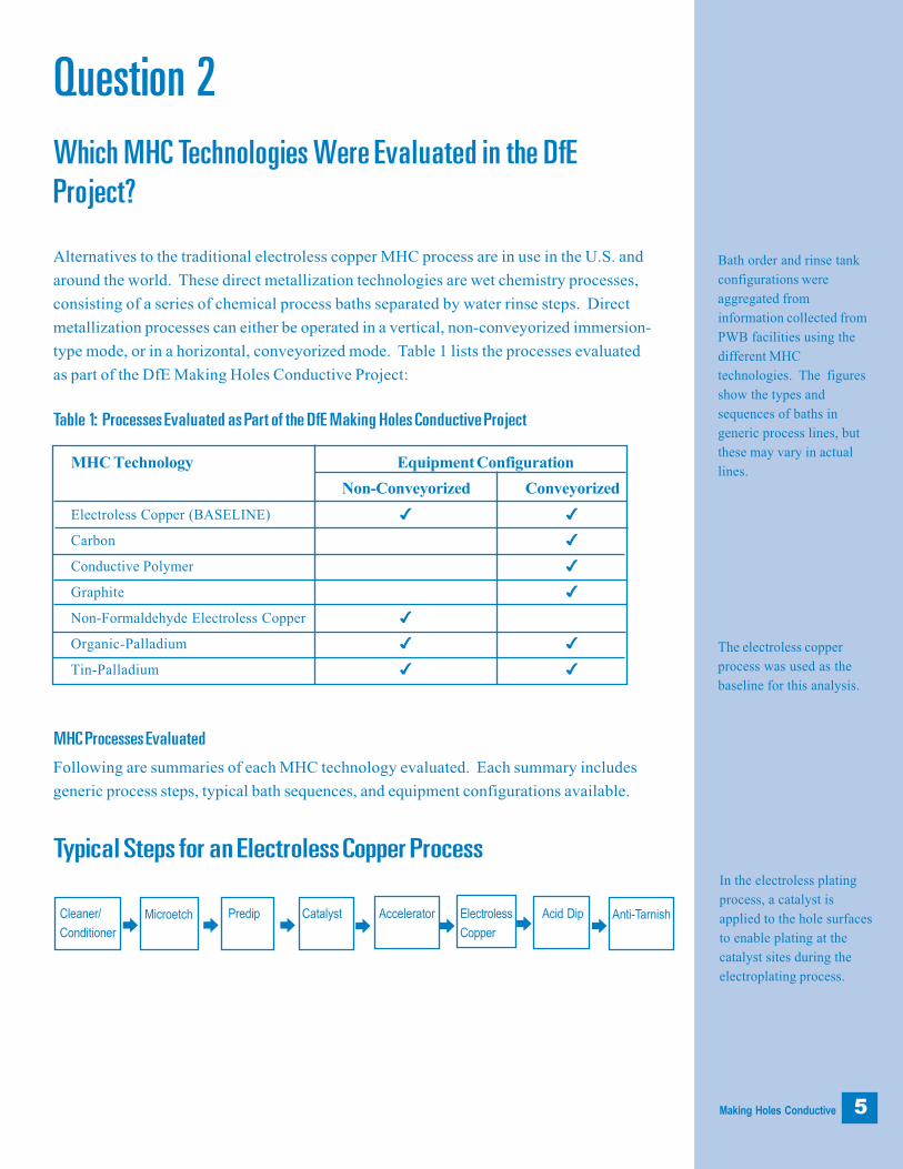
Bath order and rinse tank
configurations were
aggregated from
information collected from
PWB facilities using the
different MHC
technologies. The figures
show the types and
sequences of baths in
generic process lines, but
these may vary in actual
lines.
In the electroless plating
process, a catalyst is
applied to the hole surfaces
to enable plating at the
catalyst sites during the
electroplating process.
The electroless copper
process was used as the
baseline for this analysis.
5
Question 2Which MHC Technologies Were Evaluated in the DfEProject?
Alternatives to the traditional electroless copper MHC process are in use in the U.S. and
around the world. These direct metallization technologies are wet chemistry processes,
consisting of a series of chemical process baths separated by water rinse steps. Direct
metallization processes can either be operated in a vertical, non-conveyorized immersion-
type mode, or in a horizontal, conveyorized mode. Table 1 lists the processes evaluated
as part of the DfE Making Holes Conductive Project:
Table 1: Processes Evaluated as Part of the DfE Making Holes Conductive Project
MHC Processes Evaluated
Following are summaries of each MHC technology evaluated. Each summary includes
generic process steps, typical bath sequences, and equipment configurations available.
Typical Steps for an Electroless Copper Process
Anti-TarnishAcid DipElectroless
Copper
AcceleratorCatalystPredipMicroetchCleaner/
Conditioner è è è èèè è
MHC Technology Equipment Configuration
Non-Conveyorized Conveyorized
Electroless Copper (BASELINE) 4 4
Carbon 4
Conductive Polymer 4
Graphite 4
Non-Formaldehyde Electroless Copper 4
Organic-Palladium 4 4
Tin-Palladium 4 4

Making Holes Conductive
Electroless copper has been the standard MHC method used in the manufacture of double-
sided and multi-layered boards, and it was used as the baseline for the DfE
analysis. A palladium/tin colloid is adsorbed onto the through-hole walls, and then acts as
the catalyst for the electroless plating of copper. The autocatalytic copper bath uses
formaldehyde as a reducing agent in the principle chemical reaction that applies a thin,
conductive layer of copper to the nonconducting barrels of PWB through-holes. The
process is typically operated in a non-conveyorized mode, although conveyorized systems
are also available. Electroless copper processes are compatible with all types of substrates
and desmear processes.
Several chemical manufacturers market electroless copper processes for use in MHC
applications. The processes differ slightly in types of chelating agents or stabilizing
compounds used, but all are based on the electroless copper process described above.
Typical Steps for a Carbon-based Process
Carbon processes utilize a suspension of carbon black particles to deposit a conductive
layer of carbon onto the substrate surface. The spherical carbon black particles form an
amorphous, or noncrystalline, structure of randomly scattered crystallites, which create a
conductive layer. The process is typically operated in a conveyorized fashion, but can be
modified to be run in a non-conveyorized mode. It is compatible with all common
substrates and, in the conveyorized mode, can be fed directly into a cut-sheet dry-film
laminator.
Typical Process Steps for a Conductive Polymer Process
This MHC process forms a conductive polymer layer, polypyrolle, on the substrate
surfaces of PWB through-holes. The polymer is formed through a surface reaction during
which an immobilized oxidant reacts with an organic compound in solution. The
conductive polymer process can be operated horizontally and is compatible with most
common substrates as well as traditional etch-back and desmear processes. Because of
In direct metallization
processes, low conductivity
material is deposited on the
hole surfaces.
CatalystCleaner/
Conditionerè è è è èMicroetch Conductive
PolymerMicroetch Copper
Flash
MicroetchConditionerAir Knife/
Dry
Carbon
Blackè è è èè èCarbon
Black
Air Knife/
Dry
Cleaner
6

Making Holes Conductive
the potential instability of the polymer layer, the conductive polymer-covered through-
holes are flash plated with copper in an acid copper electroplating bath. Flash plating may
not be required in instances where hold times between the formation of the polymer and
the pattern plating step are minimal.
Typical Process Steps for a Graphite-based Process
Graphite methods disperse graphite (another form of carbon) onto the substrate surface.
Similar to the carbon method, a conditioner solution creates a positive charge on the
substrate surface, including the through-holes. Graphite particles are then adsorbed onto
the exposed surfaces. Graphite has a three-dimensional, crystalline structure as opposed
to the amorphous, randomly arranged structure found in carbon black. This crystalline
structure creates a conductive layer covering both the copper and the nonconductive
surfaces of the outer layer and interconnects. A copper microetch removes the unwanted
graphite from the copper surfaces, leaving a conductive, graphite layer on the glass and
epoxy surfaces of the vias.
The graphite process typically is operated in a conveyorized mode but can be modified for
non-conveyorized applications.
Typical Steps for a Non-Formaldehyde Electroless Copper Process
This process is a vertical, non-conveyorized immersion process that allows the electroless
deposition of copper onto the substrate surfaces of a PWB without the use of
formaldehyde. The process uses hypophosphite in place of the standard formaldehyde as
a reducing agent in the electroless copper bath. The hypophosphite electroless bath is not
autocatalytic, which reduces plate-out concerns, and is self-limiting once the palladium
catalyst sites have been plated. Once a thin layer of copper is applied, the panel is placed
under an electrical potential and electroplated while still in the bath to increase the copper
deposition thickness.
Anti-TarnishElectroless
Cu/Cu Flash
AcceleratorPost-dipCatalystPredipMicroetchCleaner/
Conditionerè è è èèè è
MicroetchFixer
(optional)Graphite
è è èèAir Knife/
DryCleaner/
Conditioner
7

Making Holes Conductive
This non-conveyorized immersion process is compatible with all substrate types but
requires an etchback process prior to desmear.
Typical Steps for a Palladium-based Process
Two types of alternatives use dispersed palladium particles to catalyze non-conducting
surfaces of PWB through-holes: organic-palladium and tin-palladium. In both of these
processes, the palladium particles are adsorbed from solution directly onto the non-
conducting substrate, creating a conductive layer that can be electroplated with copper.
Palladium particles dispersed in solution tend to agglomerate unless they are stabilized
through the formation of a protective layer, or colloid, which surrounds the individual
palladium particles.
The organic-palladium process uses a water-soluble organic polymer to form the colloid
around the palladium particles. This protective layer surrounds the individual palladium
particles, preventing them from agglomerating while in solution. After the particles have
been deposited onto the board, the protective colloid is removed, making the layer of
palladium particles conductive. Organic-palladium can be operated successfully in either
conveyorized or non-conveyorized modes. The process is compatible with all common
substrates.
Tin-palladium processes use tin to form the colloid with palladium. After the adsorption
of the tin-stabilized palladium colloid, the tin is removed, creating a layer of conductive
palladium particles on the surface of the substrate. Tin-palladium processes are similar up
to the accelerator step but use different methods to optimize the conductivity of the
palladium deposit. Tin-palladium can be operated successfully in either conveyorized or
non-conveyorized modes.
PredipCleaner/
Conditioner è è è è èMicroetch Conductor
or CatalystPostdip or
Accelerator
Acid Dip
Direct metallization
technologies differ in their
ability to increase surface
coverage, improve
conductivity, and increase
plating speed.
8

Making Holes Conductive
Question 3How May MHC Technologies Affect Worker Health and theEnvironment?
Through the Design for the Environment PWB Project, ten MHC technologies were
evaluated for their risk to human health and the environment. The purpose of the
assessment was to compare risks of the traditional electroless copper process to direct
metallization processes. Four different components of risk were evaluated:
n Worker health (from inhalation and from skin contact)
n Public health
n Ecological hazards
n Process safety concerns
The assessment was based on exposures estimated for a model facility. Information used
to estimate exposures was gathered from a number of sources, including PWB facilities,
supplier data, and engineering calculations. The model facility is not entirely representative
of any one facility, and actual risk could vary substantially, depending on site-specific
operating conditions and other factors. Risks were evaluated for chronic exposures to
long-term, day-to-day releases from the MHC line rather than to short-term, acute
exposures resulting from a fire, spill, or other accidental releases.
Assumptions and uncertainties are a part of all risk assessments. Some of the major
sources of uncertainty in this study included:
n Incomplete identification of all chemicals by some suppliers
n Limited dermal toxicity data available for some MHC chemicals
n Uncertainty in the accuracy of air concentration models used to estimate
worker exposure
Worker Health Risks from Inhalation
If inhaled, chemicals in some MHC processes may cause employeehealth problems.Workers may be exposed to chemicals by breathing air containing vapor or aerosols from non-
conveyorized MHC process lines. Inhalation exposure to workers from conveyorized MHC
lines is assumed to be negligible because the lines are typically enclosed and vented to the
outside. In non-conveyorized lines, however, some MHC chemicals present concerns
When estimating risk,
exposures were estimated
for a �model� facility
producing 350,000 ssf/year.
9
Uncertainties are part of all
risk assessments.

Making Holes Conductive
because workers may be exposed to inhaled doses that pose potential risks of adverse health
effects. Table 2 presents those chemicals that pose a potential risk to worker health as a
result of inhalation (i.e., chemicals of concern). This risk is called systematic health risk and
does not address cancer-causing chemicals.
Table 2: MHC Chemicals of Concern for Potential Inhalation Riska
Inhalation exposures and therefore cancer risks are negligiblefor conveyorized systems.Cancer risk from inhalation was also evaluated. To estimate the inhalation cancer risk of the
MHC technologies, the technology must contain cancer-causing chemicals. Only the
electroless copper, graphite, and carbon processes contained chemicals that could possibly
cause cancer when inhaled, or inhalation carcinogens. None of the other technologies are
known to contain inhalation carcinogens, and therefore they do not pose an inhalation cancer
risk.
In conveyorized processes, inhalation exposure to these chemicals is assumed to be
negligible. The graphite and carbon systems are conveyorized, and there is a conveyorized
version of the electroless copper process. Therefore, although these processes may contain
possible inhalation carcinogens, they do not pose an inhalation cancer risk.
Inhalation exposure to
workers from conveyorized
MHC lines is assumed to be
negligible.
Formaldehyde, found in the
electroless copper process, is
classified as a �probable�
human carcinogen.
10
Chemical Electroless Copper Non-Formaldehyde Tin-Palladium
Electroless Copper
Copper Chloride 4
Ethanolamine 4 4
2-Ethoxyethanol 4
Ethylene Glycol 4
Formaldehyde 4
Methanol 4
Sulfuric Acid 4 4 4
Formic Acid 4
Sodium Hydroxide 4
Alkene Diol 4
a For technologies with more than one chemical supplier (e.g., electroless copper andtin-palladium), all chemicals of concern may not be present in any one product line.

Making Holes Conductive
Chemicals are classified into carcinogen categories based on how strong the evidence is that
indicates the chemical does cause cancer. The classification as probable human carcinogen
means there is some evidence that it causes cancer in humans, but not sufficient evidence to
classify it as a human carcinogen. The classification as possible carcinogen means that
there is sufficient evidence that the substance causes cancer in animals with inadequate or
lack of evidence in humans.
Inhalation of formaldehyde in the non-conveyorized electrolesscopper process may present a cancer risk.The non-conveyorized electroless copper process uses formaldehyde, a probable human
carcinogen. One supplier uses alkyl oxide and cyclic ether. These chemicals have been
classified as probable human carcinogens (although cyclic ether is classified in the lesser
category of possible human carcinogen by another rating system). The risk estimates for alkyl
oxide and cyclic ether indicate low concern for inhalation exposure. For inhalation of
formaldehyde, the upper-bound1 estimate of the potential excess2 cancer risk may be as high
as one in 1,000 or as low as one in 50,000 for line operators. This range reflects the
uncertainty and exposure data used in assessing formaldehyde cancer risk. Risks to other
workers were assumed to be proportional to the amount of time spent in the process area, which
ranged from 3 percent to 61 percent of the risk for a line operator.
Other chemicals in the process are possible carcinogens.Dimethylformamide, trisodium acetate amine B, and carbon black are found in some MHC
processes and are classified as possible carcinogens. Cancer risk for these chemicals was
not quantified, since there are not enough data to quantify their carcinogenic potency.
Dimethylformamide is used in one of the electroless copper processes evaluated. Trisodium
acetate amine B is used in one supplier�s electroless copper process. Note that six
electroless copper systems were evaluated, representing five different chemical suppliers.
Of these, there was only one system that used dimethylformamide and one system that used
trisodium acetate amine B. Carbon black is used in the carbon process.
11
1 �Upper bound� refers to the highest value of a given range of values for a chemical�s carcinogenic potency.The laboratory data is statistically analyzed and the results of this analysis are a range of values. As aconservative measure, the highest value is selected.2 �Excess� means the estimated cancer risk strictly associated with exposure to the chemical. This is inaddition to the background cancer risks associated with other factors including genetic predisposition, diet,expoure to other chemicals outside the workplace, etc.

Making Holes Conductive
Worker Health Risks from Dermal ContactMHC chemicals can enter the body through the skin ifworkers do not wear gloves.Dermal (skin) exposure can occur when skin comes in contact with the bath solution while
dipping boards, adding bath replacement chemicals, or performing other bath maintenance
activities. Although an industry survey suggests that most MHC line operators do wear
gloves, the study evaluated the risk to those workers who do not wear gloves. Otherwise,
dermal exposure is expected to be negligible. Dermal exposure to workers on non-
conveyorized lines occurs from routine line operation and maintenance (i.e., bath
replacement, filter replacement, etc.). Dermal exposure to workers on conveyorized lines
occurs from bath maintenance activities alone. The carcinogenic risks from dermal exposure
to two chemicals, alkyl oxide and cyclic ether, were quantified. The risk estimates for these
chemicals indicate low concern for dermal exposure.
Table 3 presents chemicals of concern for potential occupational risk from dermal contact if
workers are not wearing gloves. None of the chemicals evaluated in the other alternatives
were found to present health concerns from dermal contact.
Table 3: MHC Chemicals of Concern for Potential Dermal Riska
12
Copper Chloride 4 4 4 4 4 4
Fluoroboric Acid 4 4 4 4 4 4
Formadehyde 4 4
Palladium 4 4 4 4 4 4
Palladium Chloride 4 4 4
Sodium Chlorit e 4 4 4
Stannous Chloride 4 4 4 4 4
Palladium Salt 4 4 4
Nitrogen H.b 4 4
Tin Salt 4
Sodium Carboxylate A 4 4
a For technologies with more than one chemical supplier (e.g., electroless copper and tin-palladium), all chemicals of concern may not be present in any one product line.b Nitrogen H. = Nitrogen Heterocycle.NC: Non-conveyorized. C: Conveyorized.
LineOperator
NC CLabTech
LineOperator
NC CLabTech
LineOperator
(NC)
LineOperator
NC CLabTech
Chemical Electroless Non-Formaldehyde Organic- Tin-PalladiumCopper Electroless Copper Palladium

Making Holes Conductive
A conclusive ecological
risk comparison among
alternative technologies
could not be made
because the
concentrations of toxics
in effluents is not known.
Summary of Worker Health RisksIn summary, alternatives to the non-conveyorized electrolesscopper process appear to pose lower health risks to workers.Based on the results of the risk study, it appears that alternatives to the non-conveyorized
electroless copper process pose lower occupational risks. This decrease is due primarily to
reduced cancer risk to PWB workers when the use of formaldehyde is eliminated.
Occupational inhalation risk is assumed to be negligible for conveyorized processes. However,
there are inhalation risk concerns for some chemicals in the non-formaldehyde electroless
copper, and tin-palladium non-conveyorized processes. In addition, there are also dermal risk
concerns for workers who do not wear gloves while working on the conveyorized and
nonconveyorized electroless copper, organic-palladium, and tin-palladium processes and the
nonconveyorized non-formaldehyde electroless copper process.
There is insufficient information to compare the alternatives amongthemselves to determine which poses the least risk.While alternatives to electroless copper appear to pose less overall risk, there is not enough
information to compare the alternatives to electroless copper processes among themselves for
all their environmental and health consequences. This is because not all proprietary chemicals
have been identified, and because toxicity values are not available for some chemicals.
Public Health RisksLong-term exposure risks are minimal for nearby residents.Public health risk was estimated for inhalation exposure for people living near a facility. The
results indicated that there is very little concern for any of the MHC technologies. For example,
the upper-bound excess individual cancer risk for nearby residents from the non-conveyorized
electroless copper process was estimated to be from nearly zero to one in ten million. For the
conveyorized electroless copper process it was nearly zero to one in three million.
Ecological RisksSome MHC chemicals are potentially damaging to aquaticecosystems.The discharge of waste water from industrial facilities is regulated under the federal Clean
Water Act, which limits the concentrations of the chemicals that may be discharged.
Facilities discharging to the local sewer or to surface water must have a permit from their
federal, state, or local authority. State and local permits may require even stricter limits
than are required by the federal government.
13

Making Holes Conductive
In this study, ecological risks of MHC technologies were evaluated qualitatively, in terms of
aquatic toxicity hazards. Aquatic risk could not be estimated quantitatively because
chemical concentrations in MHC line effluents and receiving waters were not available and
could not be estimated. However, most of the MHC technologies contain copper
compounds that can result in aquatic toxicity problems if discharged to surface waters.
Table 4 presents the number of chemicals with high aquatic toxicity for each MHC
technology. For each technology, the table also lists the chemical with the lowest concern
concentration (CC), and the bath concentrations of the chemicals with the lowest CC�i.e.,
the most toxic chemicals. A CC is the concentration of a chemical in the aquatic environment
which, if exceeded, may result in significant risk to aquatic organisms. For example, a CC of
0.00002 mg/l means that the chemical may be toxic to aquatic organisms in stream
concentrations greater than 0.00002 mg/l. It should be noted that the CC is not a measured
quantity. Instead, it is based on the evidence available from existing studies and reflects the
uncertainty associated with the data.
Table 4: MHC Chemicals with High Aquatic Toxicity Potential
Chemicals were ranked for
aquatic toxicity using
established EPA criteria.
14
Alternative No. of Chemicalsa Chemical with Lowest CCwith high aquatic toxicity
Electroless Copper 1 1 copper sulfate0.00002 mg/l
Carbon 2 copper sulfate0.00002 mg/l
Conductive Polymer 0 peroxymonosulfuric acid0.030 mg/l
Graphite 3 copper sulfate0.00002 mg/l
Non-Formaldehyde 3 copper sulfateElectroless Copper 0.00002 mg/l
Organic-Palladium 2 sodium hypophosphite0.006 mg/l
Tin-Palladium 8 copper sulfate0.00002 mg/l
a For technologies with more than one chemical supplier (e.g., electroless copper, graphite,and tin-palladium), all chemicals may not be present in any one product line.

Making Holes Conductive 15
Electroless copper processes contain the greatest number of chemicals with high toxicity to
aquatic organisms. The most toxic (lowest CC) MHC chemical is copper sulfate, which may be
found in five of the MHC technology categories: electroless copper, carbon, graphite, non-
formaldehyde electroless copper, and tin-palladium. Note that the table illustrates only the
presence of these chemicals in the baths. The chemicals� effect on aquatic risk could not be
determined, because bath concentrations vary greatly and the concentrations of these chemicals
in process effluents vary with differences in treatment systems and operating conditions.
Process Safety ConcernsWorkers can be exposed to two types of hazards affecting occupational safety and health:
chemical hazards and process hazards.
MHC technologies may present chemical safety concerns.To evaluate the chemical safety hazards of the various MHC technologies, MSDSs for chemical
products used with each of the MHC technologies were reviewed. Table 5 summarizes the
hazardous properties listed on MSDSs for MHC chemical products.
MHC Technology Types of Hazardous Properties Reported on MSDSsb
Electroless Copper flammable, combustible, explosive, fire hazard, corrosive,oxidizer, reactive, unstable, acute health hazard, chronic healthhazard, eye damage
Carbon flammable, corrosive, oxidizer, reactive, acute health hazard,chronic health hazard, eye damage
Conductive Polymer flammable, corrosive, eye damage
Graphite unstable, acute health hazard, chronic health hazard, eyedamage
Non-Formaldehyde flammable, corrosive, oxidizer, reactive, acute health hazard,Electroless Copper chronic health hazard, eye damage
Organic-Palladium unstable, eye damage
Tin-Palladium flammable, combustible, explosive, fire hazard, corrosive, oxidizer,reactive, sensitizer, acute health hazard, chronic health hazard,eye damage
a Information in this table is based on the chemical product in its concentrated form. Theseproperties may not apply to the bath solution as it is used in production. For example, althoughseveral chemical products are flammable in their concentrated form, most chemical baths in theMHC process line are non-flammable aqueous solutions.b For technologies with more than one chemical supplier (i.e., electroless copper, graphite, and tin-palladium), all hazardous properties may not be contained in any one product line.
Table 5: Hazardous Propertiesa of MHC Chemical Products in their Concentrated Form

Making Holes Conductive16
Other chemical hazards can occur because of hazardousdecomposition and chemical product incompatibilities.Most chemicals used in MHC processes can decompose to form potentially hazardous
products. All of the MHC processes have chemical incompatibilities that can pose a threat to
worker safety. Common chemical incompatibilities are listed on the MSDS and include acids,
alkalis, oxidizers, metals, and reducing agents. Some MHC technologies have
incompatibilities among chemical products used on the same process line. Users should be
familiar with these incompatibilities to avoid potential problems.
Ongoing process safety training is a must.Work-related injuries from equipment, improper use of equipment, bypassing equipment
safety features, failure to use personal protective equipment, and physical stresses that may
appear gradually as a result of repetitive motion are all potential process safety hazards to
workers. Without appropriate training, the number of work-related accidents and injuries is
likely to increase, regardless of the technology used.

Making Holes Conductive
The study was intended to
provide a �snapshot� of the
performance of different
MHC technologies. It was
not intended to substitute for
thorough testing at your
facility to determine what
works best for your operation.
Testing was conducted with
extensive input and
participation from PWB
manufacturers, their
suppliers, and PWB testing
laboratories. Test sites were
recommended by suppliers of
the technologies.
17
Question 4What Kind of Performance Can I Expect from DirectMetallization Technologies?
The performance of the MHC technologies was evaluated by processing standardized test panels
at 25 volunteer PWB facilities in the U.S. and Europe where the technologies were already in
use. All test panels were manufactured and drilled at one facility. Three panels were then
shipped to each test site for processing through the site�s MHC line. The test panel was a 24" ×
18" × 0.062" 8-layer PWB produced from B and C stage FR4 materials. The through-holes on
the test panels had plated diameters of 0.013", 0.018", or 0.036". After panels went through the
MHC process at the test facilities, they were shipped to one central facility, where they were
electroplated with 1.0 mil of copper. The panels then underwent microsection and electrical
testing to distinguish variability in the performance of the MHC interconnect.
For the performance analysis, organic-palladium and tin-palladium technologies were
evaluated in one category as �palladium.� For cost, risk, and natural resource analyses, these
technologies were treated as two separate categories.
Metallurgical microsections of the plated through-holes were evaluated on 18 coupons from
each of the 25 sites (450 coupons total). The microsections were examined in the �as
received� condition and again after thermal stress. The evaluations examined plating voids,
drill smear, average copper plating thickness, resin recession, and inner layer separation.
The microsection evaluation demonstrated that directmetallization can perform as well as electroless copper.
n Plating voids. There were no plating voids noted on any of the coupons
evaluated. The electrolytic copper plating was continuous and very even, with
no indication of any voids.
n Drill smear. Drill smear negatively impacts inner layer connections to the
plated hole wall if not removed. Results are shown in Chart 1.
n Average copper plating thickness. Average hole wall thickness varied from
0.95 to 1.7 mils.
n Resin recession. No samples failed current specification requirements for
resin recession. There was, however, a significant difference in resin
recession among test sites, as shown in Chart 1.
n Inner layer separation. Over half of the test sites submitted product that did
not exhibit inner layer separations on as-received or the thermal stressed

Making Holes Conductive18
microsections. Some of the product exhibited inner layer separation in the
as- received sample which further degraded after thermal stress. Other test
sites had product that showed very good interconnect as received and
became separated as a result of thermal stress. Results are shown in
Chart 1.
Electrical screening tested 1.4 million holes.Prior to electrical testing, a total of 1,971 coupons each received two resistance
measurements to identify defective coupons considered unacceptable for electrical testing
because of opens and shorts. A total of 1.4 million holes were tested. One percent (19
coupons) were found to be defective. Opens were caused by voiding, usually within a single
via. Shorts were caused by misregistration. The type of MHC technology did not contribute
to the shorts.
31.6%
31.6%21.0%
Conductive Polymer
Non-formaldehyde
Palladium
Graphite
Carbon
Electroless
Me
tall
iza
tio
n
Percentage of Panels
0 10 20 30 40 50 60
0%
0%0%
50.0%
0%0%
55.6%
0%
0%0%
Percentage of panels exhibiting inner layer separation
Percentage of panels exhibiting drill smear
Percentage of panels exhibiting resin recession
43.3%
26.5%3.3%
0%11.0%
Chart 1: Microsection Results�Percentage of Panels Exhibiting DefectsThe number of test sites for
each technology ranged
from one to ten. Due to the
smaller number of test sites
for some technologies,
results for these
technologies could more
easily be due to chance
than could the results from
technologies with more test
sites.

Making Holes Conductive
Interconnect Stress TestingTwelve coupons were subjected to electrical stress testing from each test site, for a total of 300
coupons and 8,400 vias. Electrical stress testing measured plated through-hole cycles to failure,
and post separation. The cycles to failure indicate how much stress the individual coupons can
withstand before failing to function (measuring barrel integrity). Post separation tests the
integrity of the bond between the internal lands (posts) and plated through-hole.
The electrical stress testing demonstrates that All MHCtechnologies can produce high integrity plated through-holes.The reference line on Chart 2 identifies the mean cycles to failure (solid line) for all 300
coupons tested (324 cycles). Panels that met or exceeded mean performance are those that
measured 324 cycles or higher, respectively. Most test sites had at least one panel that
5 0 0
4 5 0
4 0 0
3 5 0
3 0 0
2 5 0
2 0 0
1 5 0
1 0 0
5 0
0
Me
an
C
yc
les
to
F
ail
ure
�1,000 Hour Line�
○ ○ ○ ○ ○ ○ ○ ○ ○ ○ ○ ○ ○ ○ ○ ○ ○ ○ ○ ○ ○ ○ ○ ○ ○ ○ ○ ○ ○ ○ ○ ○ ○ ○ ○ ○ ○ ○ ○ ○ ○ ○ ○ ○ ○ ○ ○ ○ ○ ○ ○ ○ ○ ○ ○ ○ ○
○ ○ ○ ○ ○ ○ ○ ○ ○ ○ ○ ○ ○ ○ ○ ○ ○ ○ ○ ○ ○ ○ ○ ○ ○ ○ ○ ○ ○ ○ ○ ○ ○ ○ ○ ○ ○ ○ ○ ○ ○ ○ ○ ○ ○ ○ ○ ○ ○ ○ ○ ○ ○ ○ ○ ○ ○
○ ○ ○ ○ ○ ○ ○ ○ ○ ○ ○ ○ ○ ○ ○ ○ ○ ○ ○ ○ ○ ○ ○ ○ ○ ○ ○ ○ ○ ○ ○ ○ ○ ○ ○ ○ ○ ○ ○ ○ ○ ○ ○ ○ ○ ○ ○ ○ ○ ○ ○ ○ ○ ○ ○ ○ ○
○ ○ ○ ○ ○ ○ ○ ○ ○ ○ ○ ○ ○ ○ ○ ○ ○ ○ ○ ○ ○ ○ ○ ○ ○ ○ ○ ○ ○ ○ ○ ○ ○ ○ ○ ○ ○ ○ ○ ○ ○ ○ ○ ○ ○ ○ ○ ○ ○ ○ ○ ○ ○ ○ ○ ○ ○
○ ○ ○ ○ ○ ○ ○ ○ ○ ○ ○ ○ ○ ○ ○ ○ ○ ○ ○ ○ ○ ○ ○ ○ ○ ○ ○ ○ ○ ○ ○ ○ ○ ○ ○ ○ ○ ○ ○ ○ ○ ○ ○ ○ ○ ○ ○ ○ ○ ○ ○ ○ ○ ○ ○ ○ ○
E l e c t r o l e s s Carbon G r a p h i t e P a l l a d i u m N o n - F C P
Chart 2: Electrical Test Results: Cycles to Failure
Metallization Test Sites
Non-F = Non-Formaldehyde; CP = Conductive Polymer.
1 2 3 4 5 6 7 8 9 1 0 1 1 1 2 1 3 1 4 1 5 1 6 1 7 1 8 1 9 2 0 2 1 2 2 2 3 2 4 2 5
19

Making Holes Conductive
Performance testing indicates
that each MHC technology
has the capability to achieve
levels of performance
comparable to electroless
copper.
exceeded the 324 cycles. It is interesting to note the variability in performance among sites
using the same direct metallization process. These differences highlight the importance of
properly installing and maintaining the process.
Post separation was the primary cause for rejection for all MHCtechnologies tested.Interconnect Stress Testing also determined post interconnect performance. An industry
failure criterion for post separation has not been established. For this study, however, the
rejection criterion was based on a 15 milliohm resistance increase (the mean resistance
degradation measurement for all 300 coupons tested). The mean resistance degradation of the
post interconnect was determined at the time the PTH failed. The readings for the post
interconnect for each test site (12 coupons from each site) and for each MHC technology are
shown in Chart 3. A mean resistance degradation column above the reference line of 15
milliohms indicates post separation.
Post separation results indicated percentages of post separation that were unexpected by many
members of the industry. It was apparent that all MHC technologies, including electroless
copper, are susceptible to this type of failure. Variations in performance were attributed to test
sites, as opposed to type of MHC technology.
20

Making Holes Conductive
Chart 3: Electrical Test Results: Post Resistance Degradation
The correlation of results between the electrical andmicrosection tests was excellent.Microsection electrical tests were run independently. When the post separation test results were
later compared, they were found to be consistent for 74 of the 75 test panels. To illustrate the
consistency of the test results, Table 6 identifies both test methods and their results for post
separation detection.
50
45
40
35
30
25
20
15
10
5
0
Po
st
De
gre
da
tio
n (
mil
lio
hm
s)
○ ○ ○ ○ ○ ○ ○ ○ ○ ○ ○ ○ ○ ○ ○ ○ ○ ○ ○ ○ ○ ○ ○ ○ ○ ○ ○ ○ ○ ○ ○ ○ ○ ○ ○ ○ ○ ○ ○ ○ ○ ○ ○ ○ ○ ○ ○ ○ ○ ○ ○ ○ ○ ○ ○ ○ ○
○ ○ ○ ○ ○ ○ ○ ○ ○ ○ ○ ○ ○ ○ ○ ○ ○ ○ ○ ○ ○ ○ ○ ○ ○ ○ ○ ○ ○ ○ ○ ○ ○ ○ ○ ○ ○ ○ ○ ○ ○ ○ ○ ○ ○ ○ ○ ○ ○ ○ ○ ○ ○ ○ ○ ○ ○
○ ○ ○ ○ ○ ○ ○ ○ ○ ○ ○ ○ ○ ○ ○ ○ ○ ○ ○ ○ ○ ○ ○ ○ ○ ○ ○ ○ ○ ○ ○ ○ ○ ○ ○ ○ ○ ○ ○ ○ ○ ○ ○ ○ ○ ○ ○ ○ ○ ○ ○ ○ ○ ○ ○ ○ ○
○ ○ ○ ○ ○ ○ ○ ○ ○ ○ ○ ○ ○ ○ ○ ○ ○ ○ ○ ○ ○ ○ ○ ○ ○ ○ ○ ○ ○ ○ ○ ○ ○ ○ ○ ○ ○ ○ ○ ○ ○ ○ ○ ○ ○ ○ ○ ○ ○ ○ ○ ○ ○ ○ ○ ○ ○
○ ○ ○ ○ ○ ○ ○ ○ ○ ○ ○ ○ ○ ○ ○ ○ ○ ○ ○ ○ ○ ○ ○ ○ ○ ○ ○ ○ ○ ○ ○ ○ ○ ○ ○ ○ ○ ○ ○ ○ ○ ○ ○ ○ ○ ○ ○ ○ ○ ○ ○ ○ ○ ○ ○ ○ ○
Electroless Carbon Graphite Palladium Non-F CP
Metallization Test Sites
Non-F = Non-Formaldehyde; CP = Conductive Polymer.
1 2 3 4 5 6 7 8 9 10 11 12 13 14 15 16 17 18 19 20 21 22 23 24 25
21

Making Holes Conductive
Table 6: Microsection/Electrical Test Data Correlation for Post Separation
22
�Y� or �N� (yes or no) denotes whether post separation was detected on any coupon or panel
from each test site. The �Panels Affected� column refers to how many of the panels within
each test site exhibited post separation. Test Site #17 was the only site where post separation
was found in the microsection but not on electrical testing.
MHC Technology Test Site # Microsection Panels Affected Electrical Panels Affected
Electroless Copper 1 N 0 N 0
Electroless Copper 2 Y 3 Y 3
Electroless Copper 3 N 0 N 0
Electroless Copper 4 N 0 N 0
Electroless Copper 5 N 0 N 0
Electroless Copper 6 Y 3 Y 3
Electroless Copper 7 N 0 N 0
Carbon 8 N 0 N 0
Carbon 9 N 0 N 0
Graphite 10 N 0 N 0
Graphite 11 Y 2 Y 1
Graphite 12 Y 3 Y 2
Palladium 13 N 0 N 0
Palladium 14 N 0 N 0
Palladium 15 Y 1 Y 1
Palladium 16 Y 3 Y 3
Palladium 17 Y 1 N 0
Palladium 18 Y 2 Y 2
Palladium 19 N 0 N 0
Palladium 20 Y 3 Y 2
Palladium 21 Y 3 Y 3
Palladium 22 N 0 N 0
Non-Formaldehyde 23 Y 3 Y 3Electroless Copper
Non-Formaldehyde 24 N 0 N 0Electroless Copper
Conductive Polymer 25 N 0 N 0

Making Holes Conductive 23
Performance variability was related to test sites, as opposed tometallization types.Technologies tested at more than one site showed good performance at some sites, but
performed poorly at others. These findings highlight the importance of properly installing and
running the technology, and of good system maintenance practices. The test sites all used the
same type of test board. The results will not necessarily be the same for other board materials
or constructions. It will, therefore, be important for you to evaluate alternative technologies on
your product, preferably by installing test equipment at your facility. Technology vendors may
also help you arrange to send your boards to another facility already using the alternative system.
Any new MHC technology will need to be customized for your site, processes, chemistries, and
products.

Making Holes Conductive
Making Holes Conductive 25
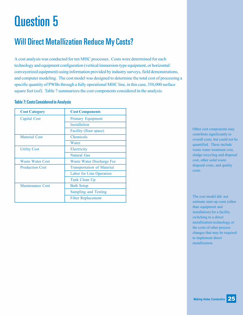
Other cost components may
contribute significantly to
overall costs, but could not be
quantified. These include
waste water treatment cost,
sludge recycling and disposal
cost, other solid waste
disposal costs, and quality
costs.
The cost model did not
estimate start-up costs (other
than equipment and
installation) for a facility
switching to a direct
metallization technology, or
the costs of other process
changes that may be required
to implement direct
metallization.
Cost Category Cost Components
Capital Cost Primary Equipment
Installation
Facility (floor space)
Material Cost Chemicals
Water
Utility Cost Electricity
Natural Gas
Waste Water Cost Waste Water Discharge Fee
Production Cost Transportation of Material
Labor for Line Operation
Tank Clean Up
Maintenance Cost Bath Setup
Sampling and Testing
Filter Replacement
Question 5Will Direct Metallization Reduce My Costs?
A cost analysis was conducted for ten MHC processes. Costs were determined for each
technology and equipment configuration (vertical/immersion-type equipment, or horizontal/
conveyorized equipment) using information provided by industry surveys, field demonstrations,
and computer modeling. The cost model was designed to determine the total cost of processing a
specific quantity of PWBs through a fully operational MHC line, in this case, 350,000 surface
square feet (ssf). Table 7 summarizes the cost components considered in the analysis.
Table 7: Costs Considered in Analysis

Making Holes Conductive26
The costing was based on a
facility producing of 350,000
ssf because this was the
average annual throughput
for facilities responding to a
workplace practices survey.
Conveyorized processes
generally cost less than non-
conveyorized processes.MHC Alternative Cost ($/ssf)
Conductive Polymer, conveyorized $0.09
Tin-Palladium, conveyorized $0.12
Tin-Palladium, non-conveyorized $0.14
Electroless Copper, conveyorized $0.15
Organic-Palladium, non-conveyorized $0.15
Organic-Palladium, conveyorized $0.17
Carbon, conveyorized $0.18
Graphite, conveyorized $0.22
Non-Formaldehyde Electroless Copper, non-conveyorized $0.40
Electroless Copper, non-conveyorized (BASELINE) $0.51
MHC Alternatives Cost Less to Use.Table 8 presents the cost per surface square foot (ssf) of PWB produced for each of the
MHC technologies evaluated.
The results show that:
n MHC alternatives are more economical than the non-conveyorized
electroless copper process.
n Conveyorized processes generally cost less than non-conveyorized
processes.
Costs ranged from $0.51/ssf for the baseline process to $0.09/ssf for the conveyorized
conductive polymer process. With the exception of the non-conveyorized, non-formaldehyde
electroless copper process, all of the alternatives cost at least 50 percent less than the
baseline.
Table 8: MHC Alternative Unit Costs
The analysis also revealed that:
n Chemical cost was the single largest component cost for nine of the ten
processes.
n Equipment cost was the largest cost for the non-conveyorized electroless
copper process.
n The costs of chemicals, production labor, and equipment have the greatest
effect on the overall cost results.

Making Holes Conductive 27
The high costs of the baseline process are due primarily to the length of time it took the model
facility to produce 350,000 ssf (401 days) using this process. The baseline process took more
than twice as long as the next process (183 days for non-conveyorized, non-formaldehyde
electroless copper).
Lower Costs Drive PWB Manufacturers Abroad to Switch.Several suppliers indicated that market shares of the direct metallization processes are
increasing more quickly internationally than in the U.S. The cost-effectiveness of an
alternative has been the main driver causing PWB manufacturers abroad to switch from an
electroless copper process to one of the newer alternatives. In addition to the increased
capacity and decreased labor requirements of some of the direct metallization technologies
over the electroless copper process, environmental concerns also affected the process
choice. For instance, the rate at which an alternative consumes water and the presence or
absence of strictly regulated chemicals are two factors that have a substantial effect on the
cost-effectiveness of direct metallization processes abroad.

Making Holes Conductive

Making Holes Conductive
Water and energy
consumption rates were
determined using:
1) the daily water
consumption rate and
hourly energy consumption
rate of each MHC
technology, based on
industry survey data; and
2) the operating time
required to produce 350,000
ssf of PWB, using a
computer simulation.
Question 6Does Direct Metallization Use Less Water and Energy?
Traditional electroless copper processes use a substantial amount of rinse water. As a result,
they generate a large volume of waste water that must be treated. Not surprisingly, PWB
manufacturers view water conservation as a significant issue. Energy use has also become an
important consideration because much of the PWB manufacturing process requires energy-
intensive operations, such as heating process baths and electroplating. Businesses are finding
that by conserving water and energy, they can cut costs and improve the environment.
Water and energy consumption rates of the MHC process alternatives were calculated to
determine if implementing an alternative to the baseline process would reduce consumption of
these resources during the manufacturing process.
All of the alternatives consume significantly less water than the traditional electroless copper
process.
Water consumption rates ranged from 0.45 gal/ssf for the graphite process to 11.7 gal/ssf for
the non-conveyorized electroless copper process, as shown in Chart 4. The reduction in water
usage is due primarily to the decreased operating time required to process a set number of
boards. The conveyorized version of a process typically consumes less water during operation
than the non-conveyorized version of the same process. Water is saved because conveyorized
processes have fewer rinsing steps and greater rinse efficiencies.
Some companies have taken water conservation a step further by developing equipment
systems that monitor water quality and usage to optimize rinse performance. Using
countercurrent rinsing and installing flow control devices are other common pollution prevention
techniques. These methods further reduce water consumption and, thus, wastewater
generation. Further discussion of these and other pollution prevention techniques can be found
in the Design for the Environment PWB Project pollution prevention case studies. See
Question 10 of this booklet for information on ordering free copies.
29

Making Holes Conductive
Conveyorized processes
typically use less water than
non-conveyorized processes.
30
Direct Metallization may simplify wastewater treatment.Chelating agents, such as EDTA, are used to hold metal ions in solution in the electroless
copper bath. As a result, these agents inhibit precipitation of metals during waste water
treatment. Direct metallization processes don�t use chelators. Eliminating chelating agents
from bath chemistries may reduce the need for some water treatment chemicals (those used
to break down chelators). Additionally, treatment of the non-chelated waste stream
produces less sludge than if chelators were present. For these reasons, direct metallization
processes may have advantages over electroless copper in waste water treatment.
All of the MHC alternatives are more energy-efficient than thetraditional electroless copper process.As shown in Chart 5, energy consumption rates ranged from 66.9 Btu/ssf for the non-
conveyorized organic-palladium process to 573 Btu/ssf for the non-conveyorized
electroless copper process. All of the alternatives use substantially less energy per ssf of
PWB produced, with the exception of the carbon technology, which has only a slight
decrease (about 10 percent) in energy use from the baseline. For alternatives with both types of
orientation (conveyorized and non-conveyorized), the conveyorized version of the process
Graphite [c]
Tin-Palladium [c]
Conductive Polymer [c]
Organic-Palladium [c]
Electroless Copper [c]
Carbon [c]
Organic-Palladium [nc]
Tin-Palladium [nc]
Non-formaldehyde EC [nc]
Electroless Copper [nc]
Chart 4: Water Consumption Rates of MHC Processes
11.7
3.74
1.80
1.35
1.29
1.15
0.73
0.57
0.45
0 2 4 6 8 10 12
gal/ssf
1.13

Making Holes Conductive 31
Organic-Palladium [nc]
Conductive Polymer [c]
Tin-Palladium [c]
Tin-Palladium [nc]
Electroless Copper [c]
Organic-Palladium [c]
Graphite [c]
Non-formaldehyde EC [nc]
Carbon [c]
Electroless Copper [nc]
Chart 5: Energy Consumption Rates of MHC Processes
573
514
270
213
148
138
131
96.4
94.7
66.9
0 100 200 300 400 500 600
Btu/ssf
is typically more energy efficient. Although conveyorized processes typically have higher hourly
energy consumption rates than non-conveyorized processes, these differences are more than
offset by the shorter operating times required to process an equivalent volume of PWBs. One
notable exception is the organic-palladium process. The non-conveyorized version of this
process has a low hourly energy consumption rate and a faster operating time. These factors
combine to give the non-conveyorized organic-palladium process a lower energy consumption
rate than the conveyorized version, and make it the most energy-efficient process evaluated.
Your facility�s energy use will also depend greatly on your unique operating practices and
energy conservation measures. Implementing simple energy conservation measures can
minimize energy use. Such measures can include insulating heated process baths, using
thermostats on heaters, and turning off equipment when not in use.

Making Holes Conductive
Reduced energy generation required for direct metallizationprocesses results in less harm to health and the environment.Pollutants released to air, water, and soil resulting from energy generation can be detrimental
to both human health and the environment. Consumption of natural gas can result in releases
to the air that contribute to odor, smog, and global warming, while the generation of electricity
can result in pollutant releases to air and water with a wide range of possible effects. Because
all of the direct metallization processes consume less energy than the baseline, they all result in
less pollutant releases to the environment from energy production.
32

Making H
oles Conductive
33
Question 7: How Does Direct Metallization Compare to Electroless Copper Overall?Table 9: Summary results of the evaluation
Alternative Worker Health Risks Environmental Concerns Performance Productionsee Question 3 see Questions 3 and 6 see Question 4 Costs
see Quest. 5
Inhalation Risk Dermal Risk Water Use Energy Use # Chemicals with ($/ssf)# chemicals of # chemicals of (gal/ssf) (Btu/ssf) High Aquatic
concern concern Toxicity
Electroless Copper- 10 8 12 573 11, including Performance for all 0.51Non-conveyorized copper sulfate technologies varied(BASELINE) among test sites
Electroless Copper- H H = H H H H = Comparable H H
Conveyorized or superior
Carbon H H H H H H = = Comparable or superior H H
Conductive Polymer H H H H H H H H H Comparable or superior H H
Graphite H H H H H H H H = Comparable or superior H H
Non-Formaldehyde H H H H H H = Comparable or superior HElectroless Copper
Organic Palladium- H H H H H H H H Comparable or superior H HNon-Conveyorized
Organic Palladium- H H H H H H H H Comparable or superior H H
Conveyorized
Tin Palladium- H H H H H H = Comparable or superior H HNon-Conveyorized
Tin Palladium- H H H H H H H = Comparable or superior H HConveyorized
H H Greatest improvement over the baseline.H Some improvement over the baseline.= Little or no improvement over the baseline.

Making Holes Conductive

Making Holes Conductive 35
Question 8How Can I Make Direct Metallization Work for My Facility?
Manufacturers considering a switch to an alternative process want to know what to expect
when they implement the new technology. They want to know what is it like to install,
debug, and work with the new system day to day. A change in technology may mean
changes in maintenance, lab analysis, and waste treatment requirements. Processes
upstream or downstream from the new MHC line may need to be altered. Some of the best
sources of information about alternative technologies are those PWB manufacturers who
have actually installed and used the systems under real-world operating conditions.
A companion document from the Design for the Environment PWB Project, Implementing
Cleaner Technologies in the Printed Wiring Board Industry: Making Holes Conductive
(EPA document #744-R-97-001), details the specific experiences of 20 manufacturers and
seven vendors. The guide presents first-hand accounts of the problems, solutions, time, and
effort involved in implementing and operating alternative MHC technologies. Carbon,
graphite (two types), palladium (five types), and conductive polymer technologies are
discussed in the guide.
Experiences varied among facilities, even among those using the same technology. Some
common suggestions emerged for successfully implementing an alternative MHC
technology:
3 Both management and line operators must make astrong commitment to the new technology.
Because there can be major differences between direct metallization and electroless copper
processes, line operators need to be willing to accept changes and retraining. Line
operators need to be involved during the entire implementation process � installation,
start-up, and debugging � to understand the changes that have been made along the way.
Management must make a firm commitment to switch to the alternative technology,
supporting all phases of implementation.

Making Holes Conductive
3 Take a �whole process view� of implementation.
Process changes upstream and/or downstream may be necessary to optimize the direct
metallization process. Both vendors and manufacturers have found that facilities can�t just
pull out the electroless line and drop in an alternative process. It is important to look at how
the manufacturing process will change overall. One facility using a carbon technology was
able to eliminate one of the two acid cleaners from its pre-clean line in the plating process.
This change was possible because the new system provided a more consistent surface than
their previous process, electroless copper. Another company using a graphite technology
found that they needed to adjust the current density on the downstream electrolytic plating
operation. Before implementing a new technology, be sure to evaluate your current
electrolytic plating quality.
Some facilities found that problems in drilling or desmear operations caused problems in the
direct metallization step. Several manufacturers emphasized that fixing these upstream
processes is critical to implementing a new MHC technology successfully. Facilities should
take a whole process view of the MHC technology installation.
3 Work closely with your vendor during installationand debugging.
Switching to a new technology may entail retrofitting tanks you already have or installing a
completely new conveyorized system. Installation and debugging times vary, even for the
same system. Installation of conveyorized systems can range from one week to several
months if the facility encounters problems with equipment or other sources. PWB
manufacturers emphasized that quality support from the vendor is key to successful
implementation. One facility that switched to a non-conveyorized palladium technology
completed the retrofit of their old line in one day. At another facility, installation of an
entirely new non-conveyorized (vertical) process took one month.
Debugging can take several weeks to several months. Facilities retrofitting existing tanks
usually go through a phase during which line operators discover unique qualities of the
process that require adjustments, such as analytical frequency, dumping schedules, and
interactions with other equipment. Integrating new conveyorized equipment, especially
equipment from different manufacturers, can often be the greatest challenge in the
debugging process. Automated equipment may take some time to debug, but facilities
have found that long-term process efficiency improvements are well worth the up-front
effort.
36

Making Holes Conductive
3 Aggressive preventive maintenance is necessaryfor most conveyorized (horizontal) systems.
Many of the PWB manufacturers using conveyorized (horizontal) systems experienced some
degree of equipment-related difficulties. Problems included plugged nozzles, squeegee rollers
collecting solids or not removing enough water, failing controllers and probes, and improperly
adjusted water spray pressures. Most facilities spend more time on equipment maintenance
than they did when using electroless copper. To minimize downtime, most direct metallization
users feel that equipment problems can usually be eliminated by aggressive preventive
maintenance. To further avoid potentially costly problems, many PWB manufacturers
interviewed also stressed the importance of using high-quality equipment for conveyorized
(horizontal) systems.
3 Implementing a direct metallization process mayrequire changes to waste water treatment.
Nearly all PWB manufacturers interviewed noted that implementing direct metallization
resulted in simplified waste water treatment. They no longer have to treat the chelated
copper that was present in the electroless copper waste stream. Some facilities noted
reduced sludge generation and less copper in the waste water overall.
In contrast, one user of an organic-palladium process could not treat the resulting
palladium-containing waste water in its resin-based treatment system. The waste had to
be shipped off-site. Another facility had to purchase different waste treatment chemicals
due to a change in microetch solution. A change to a peroxide microetch necessitated the
addition of sodium metabisulfite to help suppress gas formation. Therefore, carefully
evaluate the effects on waste water treatment of any alternative process you are
considering. Changes may be necessary.
37

Making Holes Conductive

Making Holes Conductive
Question 9What Steps Do I Take to Switch to Direct Metallization?
3 Take a look at the boards your facility produces nowand what you expect to produce in the future.
Some direct metallization technologies have limitations for parameters such as substrate type
or board thickness that can be processed effectively. Knowing your specifications will help
identify alternatives that may be appropriate for your facility.
3 Ask vendors a lot of questions.
Vendors will be the primary source of technical information about alternative MHC
technologies and can be a valuable source of information for evaluating your current
operation and alternative processes. Here are some of the questions you may want to
ask them:
n What type of PWBs have been successfully processed using this technology?
Ask about limitations on substrate, hole size, board thickness, and aspect ratio.
n What is the cycle time for this process?
n What chemicals does the process use?
n What are the floor space requirements?
n What are the energy and water requirements?
n Which regulations might apply?
n What health risks are associated with the use of this technology?
n What process or other changes may be necessary?
n What wastes will this system produce?
n How will this system affect waste water treatment?
n Can I speak with other customers about their experience with installation,
debugging, and full production?
39

Making Holes Conductive
3 Evaluate the alternative technology.
The only way you will know if the technology is right for your facility is to test it on your
boards. Some vendors may be able to conduct a thorough evaluation of the process in
your facility. Alternatively, vendors may be able to arrange to have your boards through-
hole plated at a customer�s facility where the system is already in place, or at the vendor�s
testing site.
3 Do a total cost analysis of switching to thealternative technology.
Consider traditional costs for equipment, chemicals, and labor. But also calculate costs and
savings associated with water and energy usage, waste treatment and disposal, monitoring,
maintenance, and other activities. Vendors will need to supply a good deal of the cost
information.
Computer software can help you analyze the full costs of switching to a new technology.
The University of Tennessee has developed a software tool to allow a printed wiring board
manufacturer to determine the cost of running different direct metallization processes, as
compared to running an electroless copper line. This tool is available through:University of Tennessee Dept. of Industrial Engineering
Dr. Rupy Sawhney
153 Alumni Memorial Building
Knoxville, TN 37996
ph: 423-974-3333
�P2/FINANCE PWB� is another software tool designed specifically for the PWB industry.
This software is more general and helps you evaluate many different investments so that
you can choose those that will work best for your facility. For more information, contact:Tellus Institute
11 Arlington Street
Boston, MA 02116
ph: (617) 266-5400
e-mail: [email protected]
internet: http://www.tellus.org
40

Making Holes Conductive
3 Talk to others who have implemented the directmetallization technologies.
Technology vendors will often provide references for facilities that are currently using the
alternative technology.
3 Tell your customers about your plans to test orimplement a new technology.
Some customers may require extensive qualification testing.
41

Making Holes Conductive

Making Holes Conductive
Question 10Where Can I Find More Information about PollutionPrevention in the PWB Industry?
Some excellent resources have been developed on pollution prevention information specifically
for the PWB industry. Some of these resources are listed below. Also check with your state
technical assistance office to see what other resources may be available.
Documents from the Design for the Environment Printed WiringBoard ProjectAlternative Technologies for Making Holes Conductive: Cleaner Technologies for Printed
Wiring Board Manufacturers is based on information presented in the full technical report
of the DfE PWB Project, titled Cleaner Technologies Substitutes Assessment: Making
Holes Conductive (EPA 744-R-97-002a and -002b). Other documents developed by the
DfE PWB Project include:
Implementing Cleaner Technologies in the PWB Industry: MHC EPA 744-R-97-001
PWB Industry and Use Cluster Profile EPA 744-R-95-005
PWB Pollution Prevention and Control: Analysis of Survey Results EPA 744-R-95-006
Federal Environmental Regulations Affecting the Electronics Industry EPA 744-B-95-001
Pollution Prevention Workpractices, PWB Case Study 1 EPA 744-F-95-004
On-Site Etchant Generation, PWB Case Study 2 EPA 744-F-95-005
Opportunities for Acid Recovery and Management, PWB Case Study 3 EPA 744-F-95-009
Plasma Desmear, PWB Case Study 4 EPA 744-F-96-003
A Continuous-Flow System for Reusing Microetchant, PWB Case Study 5 EPA 744-F-96-024
Pollution Prevention Beyond Regulated Materials, PWB Case Study 6 EPA 744-F-97-006
Building an Environmental Management System, PWB Case Study 7 EPA 744-F-97-009
Identifying Objectives for Your EMS, PWB Case Study 8 EPA 744-F-97-010
All of these documents, along with additional copies of this booklet, are available free of
charge from:Pollution Prevention Information Clearinghouse (PPIC)
U.S. EPA
401 M Street S.W. (7409)
Washington, DC 20460
phone: 202-260-1023
fax: 202-260-4659
E-mail: [email protected]
http://www.epa.gov/envirosense/p2pubs/ppic/ppic.html
43

Making Holes Conductive44
Internet Sites
IPC/DfE Printed Wiring Board Projecthttp://www.ipc.org/html/ehstypes.htm#design
This web site contains DfE Printed Wiring Board Project documents.
Design for the Environment Programhttp://www.epa.gov/dfe
This web site also contains DfE Printed Wiring Board Project documents, the document, Cleaner
Technology Substitutes Assessment: A Methodology and Resource Guide, which describes the
basic methodology used in the DfE PWB Project. Click on �Industry Project� to get to the PWB-
specific information.
University of Tennessee Center for Clean Products and CleanTechnologieshttp://eerc.ra.utk.edu/cleanprod/
This site provides information on the Center for Clean Products and Clean Technologies at the
University of Tennessee in Knoxville.
Printed Wiring Board Resource Centerhttp://www.pwbrc.org/
This site was developed by the National Center for Manufacturing Sciences (NCMS) in partnership
with IPC, and receives funding from EPA. The site provides PWB industry-specific regulatory
compliance and pollution prevention information.
Trade Association, Research, and Academic Institutions
Institute for Interconnecting and Packaging Electronic Circuits(IPC)2215 Sanders Rd.
Northbrook, IL 60062-6135
phone: 847-509-9700; fax: 847-509-9798
http://www.ipc.org
Microelectronics and Computer Technology Corporation (MCC)3500 W. Balcones Center Dr.
Austin, TX 78759-5398
phone: 512-343-0978; fax: 512-338-3885
http://www.mcc.com
University of Tennessee Center for Clean Products and CleanTechnologies600 Henley Street, Suite 311
Knoxville, TN 37996-4134
phone: 423-974-8979; fax: 423-974-1838
http://eerc.ra.utk.edu/cleanprod/