Embed Size (px)
Citation preview

ALL PRODUCT BROCHURE
AMETEK Solidstate Controls is a recognized leader in the manufacturing of industrial power equipment. We provide continuity of electrical power to businesses by designing industrial Uninterruptible Power Supply (UPS) systems, inverters, power conditioners, remote bypass switches and more. We've been customizing and manufacturing power solutions to meet the demands of the most rugged environments since 1962. Our industrial markets include, but are not limited to, oil and gas, petrochemical, power generation, process industries, pipelines and nuclear.
PROVIDING CONTINUITY OF ELECTRICAL POWER

DPP/3DPP UPS
DSE UPS
3DPP/IEC UPS
BTECH® S5™BATTERY MONITOR
UPSVIEWSOFTWARE NUCLEARINTELLISHED
SOFTWARE
DPI/3DPI INVERTER
ISN REGULATING TRANSFORMER
DVS REGULATING TRANSFORMER
DSS INVERTER
FUSIBLE PANELBOARDS
RIPPLE CHOKEFILTERS
DCRBATTERY CHARGER
Industrial Pulse Width Modulated Uninterruptible Power Supply SystemDPP SINGLE PHASE 5 - 100 kVA 3DPP THREE PHASE 10 - 225 kVA
REMOTE MANUAL BYPASS SWITCHES
The Digital ProcessPower (DPP) Uninterruptible Power Supply (UPS) system from AMETEK Solidstate Controls is a true on-line, double conversion UPS system that provides continuous, clean, regulated power for critical AC loads. Designed specifically for process control and industrial applications, the DPP systems utilize state of the art Pulse Width Modulation (PWM) technology. PWM incorporates high power IGBT semiconductors and digital control for enhanced communications, monitoring, control and diagnostics capabilities.
Also essential to the DPP design is the use of fiber optic cables for control and communications; allowing for better isolation and faster, more accurate signals between processors. The DPP system also include an LCD panel and user-friendly touch screen display for the ultimate in user control.
Industrial Pulse Width Modulated Uninterruptible Power Supply System IEC CompliantTHREE PHASE 10 - 225 kVA
The three phase Digital ProcessPower Uninterruptible Power Supply (UPS) system from AMETEK Solidstate Controls is a true on-line, double conversion UPS system that provides continuous, clean, regulated power for critical AC loads and is IEC compliant.
The 3DPP is designed for process control and industrial applications and offers better isolation and faster, more accurate signals between processors.
3DPP/IEC
3ALL PRODUCT BROCHURE
DPP/3DPP
2 ALL PRODUCT BROCHURE
PRODUCT OFFERINGS
SERVICE

Digitally Controlled Ferroresonant Industrial Uninterruptible Power Supply SystemSINGLE PHASE 3 - 50 kVA
The DSE Uninterruptible Power Supply (UPS) system from AMETEK Solidstate Controls combines the best of both worlds: (1) The reliability and robust design of a Ferroresonant UPS (2) The digital control and communications typically found
only in Pulse Width Modulation products The DSE is a true on-line, double conversion UPS system that provides continuous, clean, regulated power for critical AC loads. Designed specifically for process control and harsh industrial applications, the DSE combines digital control for enhanced communications, monitoring, control and diagnostics capabilities with proven ferroresonant transformer design. The DSE also includes the LCD panel and user-friendly touch screen display found in our Digital ProcessPower systems for the ultimate in user control.
DSE
4 ALL PRODUCT BROCHURE
Industrial Pulse Width Modulated InverterDPI SINGLE PHASE 5 - 100 kVA 3DPI THREE PHASE 10 - 125 kVA
Regulating Transformer SINGLE PHASE 5 - 225 kVA THREE PHASE 10 - 225 kVA
The DVS accommodates wide variations of incoming AC line voltage, while regulating and conditioning the AC output to preset limits. Suitable for harsh environments, the robust design utilizes a copper-wound, triple-shielded, low-impedance isolation transformer. The DVS incorporates state-of-the-art microprocessor technology and independent phase regulation engineered to eliminate voltage spikes and sags.
DVSThe Digital ProcessPower Inverter (DPI) from AMETEK Solidstate Controls is a true on-line inverter system that provides continuous, clean, regulated power for critical AC loads. Designed specifically for process control and industrial applications, the DPI systems utilize state of the art Pulse Width Modulation (PWM) technology, incorporating high power IGBT semiconductors, and digital control for enhanced communications, monitoring, control and diagnostics capabilities.
Also essential to the DPI design is the use of fiber optic cables for control and communications; allowing for better isolation and faster, more accurate signals between processors. The DPI designs also include an LCD panel and user-friendly touch screen display for the ultimate in user control.
DPI/3DPI
5 ALL PRODUCT BROCHURE
Digitally Controlled Ferroresonant Industrial InverterSINGLE PHASE 3 - 50 kVA
The DSS Inverter from AMETEK Solidstate Controls combines the best of both worlds: (1) The reliability and robust design
of a Ferroresonant Inverter(2) The digital control and communications typically found
only in Pulse Width Modulation (PWM) products The DSS is a true on-line inverter system that provides continuous, clean, regulated power for critical AC loads. Designed specifically for process control and harsh industrial applications, the DSS combines digital control for enhanced communications, monitoring, and diagnostics capabilities with proven ferroresonant transformer design. The DSS also includes the LCD panel and user-friendly touch screen display found in our Digital ProcessPower systems for the ultimate in user control.
DSS
Digital Battery Charger SystemsTHREE PHASE INPUT VOLTAGE: 208, 380, 480, 600 VACAMPERAGE: 32 - 630 AOUTPUT VOLTAGE: 110, 120, 220, 240 VDC
The DCR from AMETEK Solidstate Controls is a microprocessor-controlled, thyristor-based system designed for high-efficiency conversion of incoming commercial AC power to clean DC power. It is used for charging batteries while supplying power to continuous DC loads such as inverters.
The rugged solid-state design utilizes SCR phase control to provide regulated, current-limited DC power. The DCR can operate with or without batteries and is intended for use in UPS systems. The DCR can also be used as a stand-alone device for battery-charging-only applications.
DCR
• Latest digital and power electronics technology
• Reliable industrial design; MTBF >205,000 hours
• User definable control and alarm set-points
• Simultaneous voltage and current readings
• CE safety and EMC standards compliant
• UL1012 (UL, cUL) Approved• Vacuum impregnated
magnetics, 200˚C• Efficiency up to 95%
BATTERY VALIDATION SYSTEM
The BTECH S5 Battery Validation System provides the most effective and reliable assurance that your system's batteries are functioning properly and are ready to perform in the event of a power outage. Unlike traditional periodic discharge testing, the BTECH S5 continuously monitors each individual battery unit.
This gives more time to respond to failing batteries and to schedule the appropriate maintenance – preventing the cost and lost revenue of system downtime caused by a power outage and battery plant failure. The accurate monitoring of BTECH S5 helps ensure that the battery condition is known so timely replacement of a failed battery or battery maintenance can be performed.
BTECH® S5™
6 ALL PRODUCT BROCHURE
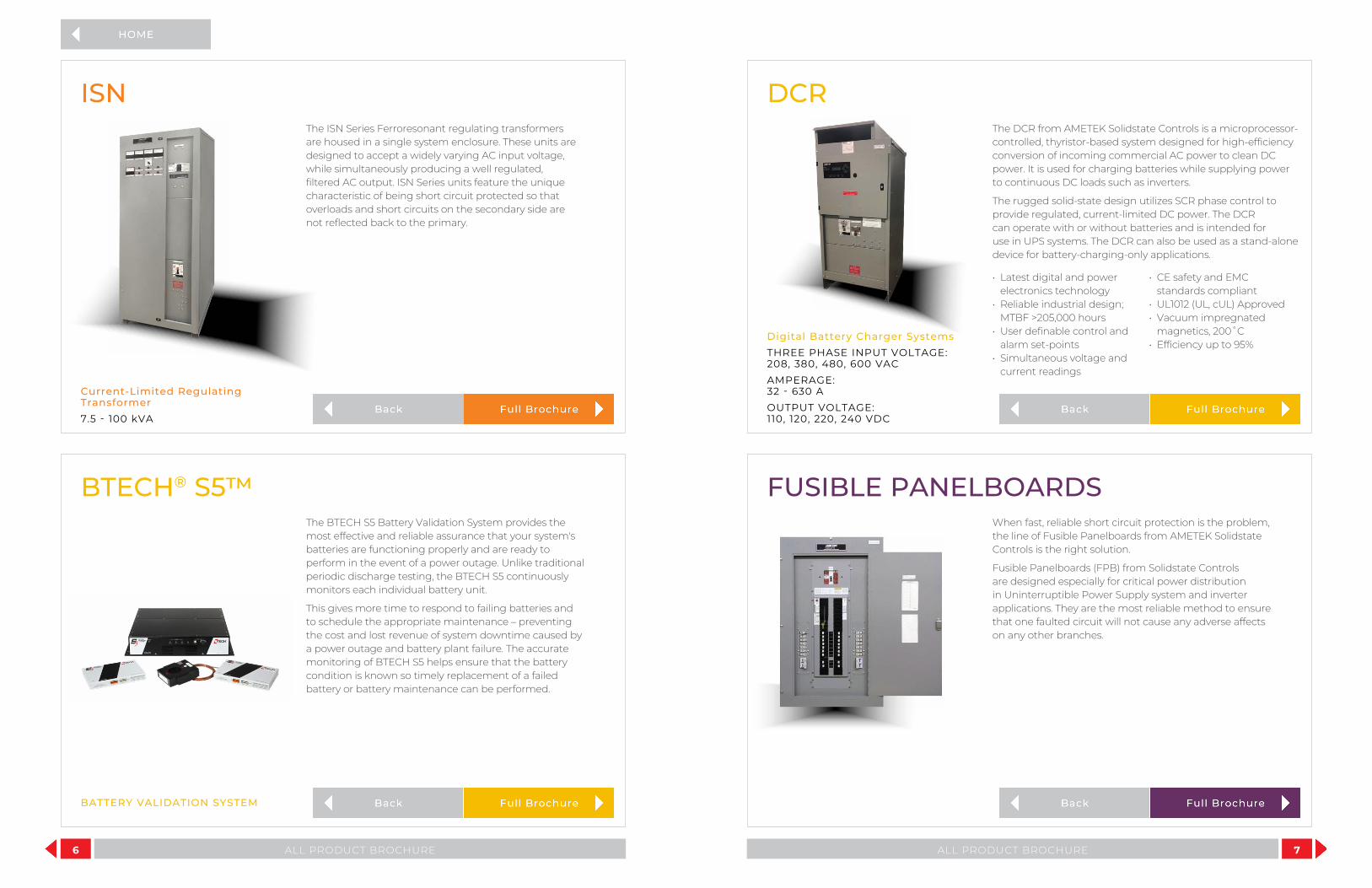
When fast, reliable short circuit protection is the problem, the line of Fusible Panelboards from AMETEK Solidstate Controls is the right solution.
Fusible Panelboards (FPB) from Solidstate Controls are designed especially for critical power distribution in Uninterruptible Power Supply system and inverter applications. They are the most reliable method to ensure that one faulted circuit will not cause any adverse affects on any other branches.
FUSIBLE PANELBOARDS
7ALL PRODUCT BROCHURE
Current-Limited Regulating Transformer7.5 - 100 kVA
The ISN Series Ferroresonant regulating transformers are housed in a single system enclosure. These units are designed to accept a widely varying AC input voltage, while simultaneously producing a well regulated, filtered AC output. ISN Series units feature the unique characteristic of being short circuit protected so that overloads and short circuits on the secondary side are not reflected back to the primary.
ISN

Remote Manual Bypass Switch with isolation transformer optionSINGLE PHASE 3 - 100 kVATHREE PHASE 10 - 100 kVA
Solidstate Controls RMBS Series, Remote Manual Bypass Switch (RMBS) is a 3-position switch that allows for complete isolation of a UPS or inverter in order to perform routine or emergency maintenance on the equipment.
The RMBS-T unit includes an isolation transformer that isolates the bypass supply. Depending on your equipment line up and space constraints, you may consider combining your transformer and RMBS to create an all-in-one, consolidated unit.
The load is temporarily transferred from the inverter (UPS) onto the bypass (alternate) AC power source. This make-before-break switch is designed to transfer between two in-sync sources to enable a zero-break transfer in both directions, so there is no disruption of power to the connected load(s).
RMBS/RMBS-T
8 ALL PRODUCT BROCHURE
Maintain control of the most complex remote pumping stations with state-of-the-art server control software. This enhanced Uninterruptible Power Supply (UPS) system software is designed to help operators maintain control of complex remote pumping stations. The software is equipped with the following capabilities:
• Control of up to four groups of four servers (16 total)• Ability to shutdown servers in a predetermined order• Ability to test server shutdown functionality from the
Web interface• Alerts based on customer preference• Retrieves 2,000 Event Data Log over TCP/IP using a Web
interface• Total system time synchronization – Network Time
Protocol (NTP)
INTELLISHED
UPSView remotely monitors your AMETEK Solidstate Controls digital inverter, charger/rectifier or Uninterruptible Power Supply (UPS) System, giving you a real-time view of the health and status of your power quality system.
The user-friendly communication package operates as an interactive and secure web interface, monitoring multiple units from any web enabled device. UPSView enhanced online capabilities include:
• Annunciation of system measurements and status on the Homepage or Web browser tab
• Extended data logging, including event description, time and date stamping and system readings
• Single-click navigation to user-configured alarms and system settings
• Report generation of Data Logs, Battery History Logs and Battery Test Logs
• Pause and Play capabilities to freeze momentary data• Access to snapshots of all Data Log parameters
UPSVIEW
9ALL PRODUCT BROCHURE
AMETEK Solidstate Controls Ripple Choke Filters are designed to help reduce the AC ripple current kickback that exists in battery chargers, inverters and UPS systems. This will help your batteries last longer, spare sensitive electronics the deterioration an excessive ripple current can cause and reduce electrical noise.
RIPPLE CHOKE FILTERS
RC Series SERVER CONTROL SOFTWARE
REMOTE MONITORING SOFTWARE

SERVICE OPTIONS AMETEK Solidstate Controls’ products are known for their high quality. To keep them running smoothly, do not trust the maintenance of them to just anyone. No one will have the in-depth knowledge and familiarity as we do. We care about our products and we provide superior service agreements that ensure your critical power equipment continuously functions as designed.We offer three levels of multi-year service agreements, designed to support our preventative maintenance schedules.
General Services Basic CSA1 CSA+1
Pre-Inspection Interview Annually Annually Annually
Post-Inspection Interview Annually Annually Annually
Detailed Service Report Annually Annually Annually
UPS/Inverter/Charger Services Basic CSA CSA+
Visual Inspection Annually Annually Annually
Scheduled Parts Replacement Every 5 Years Annually Annually
System Operational and Functional Testing Every 5 Years Annually Annually
Infrared Scanning/Thermal Imaging Optional Annually Annually
Battery Inspection & Continuity Test Basic CSA CSA+
Visual Inspection Annually Annually Annually
Individual Cell Voltages Every 5 Years Annually Annually
Continuity Test Every 5 Years Annually Annually
Inter-cell resistance Optional Optional Annually
Specific Gravity Optional Optional Annually
System AC Load testing Optional Optional Annually
Battery Capacitance Discharge Testing per IEEE Recommended Schedule Optional Optional Optional
Parts and Service Coverage Basic CSA CSA+
Emergency Service Fee Waived Waived Waived
Guaranteed Emergency Response Time Not Specified 72 Hours2 24 Hours2
Minimum Repair Service Cost per Repair Trip Waived Waived Waived
Parts Covered Under Warranty Only PM parts covered All Parts in System All Parts in System
Transformers (Less than 20 years) No Coverage Covered Covered
Travel and Living Expenses Billed at cost Covered Covered
Labor Standard Rates Covered Covered
Replacement System Manuals $350 each $175 each No Cost
Financial Benefits Basic CSA CSA+
Spare Parts Discount 5% 15% 20%
Annualized Pricing Included Included Included
Discount on Training Seminars None 25% 50%
1 CSA and CSA+ meet factory recommended guidelines for preventative maintenance 2 System restored to safe and stable condition
10 ALL PRODUCT BROCHURE 11ALL PRODUCT BROCHURE
The Nuclear Power Industry requires the most stringent process and quality control procedures. Due to the critical nature of these applications, AMETEK Solidstate Controls engineers our equipment for a 40-year design life. To ensure that this requirement is met, each piece of equipment undergoes rigorous environmental qualification, aging analysis, seismic qualification and testing in accordance with applicable IEEE and IEC standards. We can also provide Class 1E Safety Related product upgrades.
More than 75% of the nuclear generating stations in the United States rely on our products to provide power protection for their critical plant control systems. We also have extensive experience in supplying power systems for nuclear facilities outside of the United States, including facilities in China, Mexico, South America and Europe.
We offer start-up, preventative maintenance, product service training and managed inventory agreements for replacement parts. We are able to provide direct replacements for obsolete power equipment no longer manufactured or supported by the original suppliers. Our nuclear team offers a full range of design support and consulting services. To learn more about our Nuclear products, please contact us.
NUCLEAR

12 ALL PRODUCT BROCHURE
REV 03/2019
THE PURPOSE OF OUR BUSINESS IS TO PROVIDE CONTINUITY OF ELECTRICAL POWER TO KEEP BUSINESSES IN BUSINESS.
WE DO THIS BY HELPING CLIENTS SOLVE THEIR POWER PROBLEMS AND BY CREATING THE MOST ECONOMICAL LONG-TERM RESULTS.
WORLD HEADQUARTERS875 Dearborn Drive Columbus, Ohio 43085 Phone: +1-614-846-7500 Toll Free: +1-800-635-7300 Fax: +1-614-885-3990
GLOBAL OFFICES LOCATED INMexicoAsia Pacific Brazil
WEBSITEwww.solidstatecontrolsinc.com
[email protected] Middle East
IndiaArgentina

DPP/3DPP DIGITAL PROCESS POWERIndustrial Pulse Width Modulated Uninterruptible Power Supply SystemDPP SINGLE PHASE 5-100 kVA 3DPP THREE PHASE 10-225 kVA
• True on-line, double conversion UPS
• Provides continuous, clean, regulated power for critical AC loads
• High power IGBT semiconductors and digital control
• Fiber optic cables used for control and communications
• LCD panel and user-friendly touch screen display
• Digital ProcessPower has lower audible noise
The Digital ProcessPower (DPP) Uninterruptible Power Supply (UPS) system from AMETEK Solidstate Controls is a true on-line, double conversion UPS system that provides continuous, clean, regulated power for critical AC loads. Designed specifically for process control and industrial applications, the DPP systems utilize state of the art Pulse Width Modulation (PWM) technology. PWM incorporates high power IGBT semiconductors and digital control for enhanced communications, monitoring, control and diagnostics capabilities.
Also essential to the DPP design is the use of fiber optic cables for control and communications; allowing for better isolation and faster, more accurate signals between processors. The DPP designs also include an LCD panel and user-friendly touch screen display for the ultimate in user control.
DPP/3DPP DIGITAL PROCESS POWER
Keypad Controls and Switches• Float/Equalize Initialization with Light• Battery Test Initialization• Inverter to Load with Light• Bypass to Load with Light• Static Switch Reset Retransfer• Latching Alarm Reset• Audible Alarm Silence• Display On• Inverter Enable (On/Off) Switch*Standard LED Indicators: UPS Normal and UPS Trouble
Standard LCD Panel Indicators• Equalize Time Remaining• Charger Status (OK/Fail)• Float/Equalize Status• Inverter Status (OK/Fail)• Synchronism Status (In/Out of Sync)• Static Switch Position
(Inverter or Bypass)• Manual Bypass Position
(Normal or Bypass)• Bypass Status (OK/Fail)
New Option! The Slimmer DPPOur single phase DPP system is now available in a compact slimmer cabinet while maintaining the reliability and quality you expect from AMETEK. This is designed for off-shore platforms and space-sensitive applications.
Save 8" in width and 8.5" in depth. The slimmer DPP offers the smallest footprint for industrial UPS systems!
Width 24" x Depth 27.5" x Height 79"
The slimmer DPP seamlessly connects with an optional remote manual bypass switch, which can either be mounted on a wall or paired with an isolation bypass transformer in a separate slimmer cabinet. These units are top cable entry only and come with a maintenance bypass switch.
PROCESSPOWER UPS SYSTEM LCD AND TOUCH SCREEN USER PANELShown with optional indicator lights
The Power Behind the Process
Input Parameters System ConfigurationAC Input Voltage 208, 480 VAC AC Input BreakerAC Input Phase 3 Ø Bypass Input BreakerAC Input Frequency 60/50 Hz Battery Input BreakerAC Voltage Tolerance ± 10% Optional AC Output BreakerDC Bus Voltage 125, 240 VDC Optional AC Output Breaker
Output Parameters Top-Cable Entry ONLY
Output Power 5-20 kVA 6 or 12-Pulse Rectifier/ChargerPower Factor 0.8 Make-Before-Break Static SwitchAC Output Voltage 120 VAC Optional Remote Manual Bypass Switch (3 position)1
AC Output Phase 1 Ø 1 Manual Bypass Switch must be in external enclosure with this cabinet style AC Output Frequency 60/50 Hz
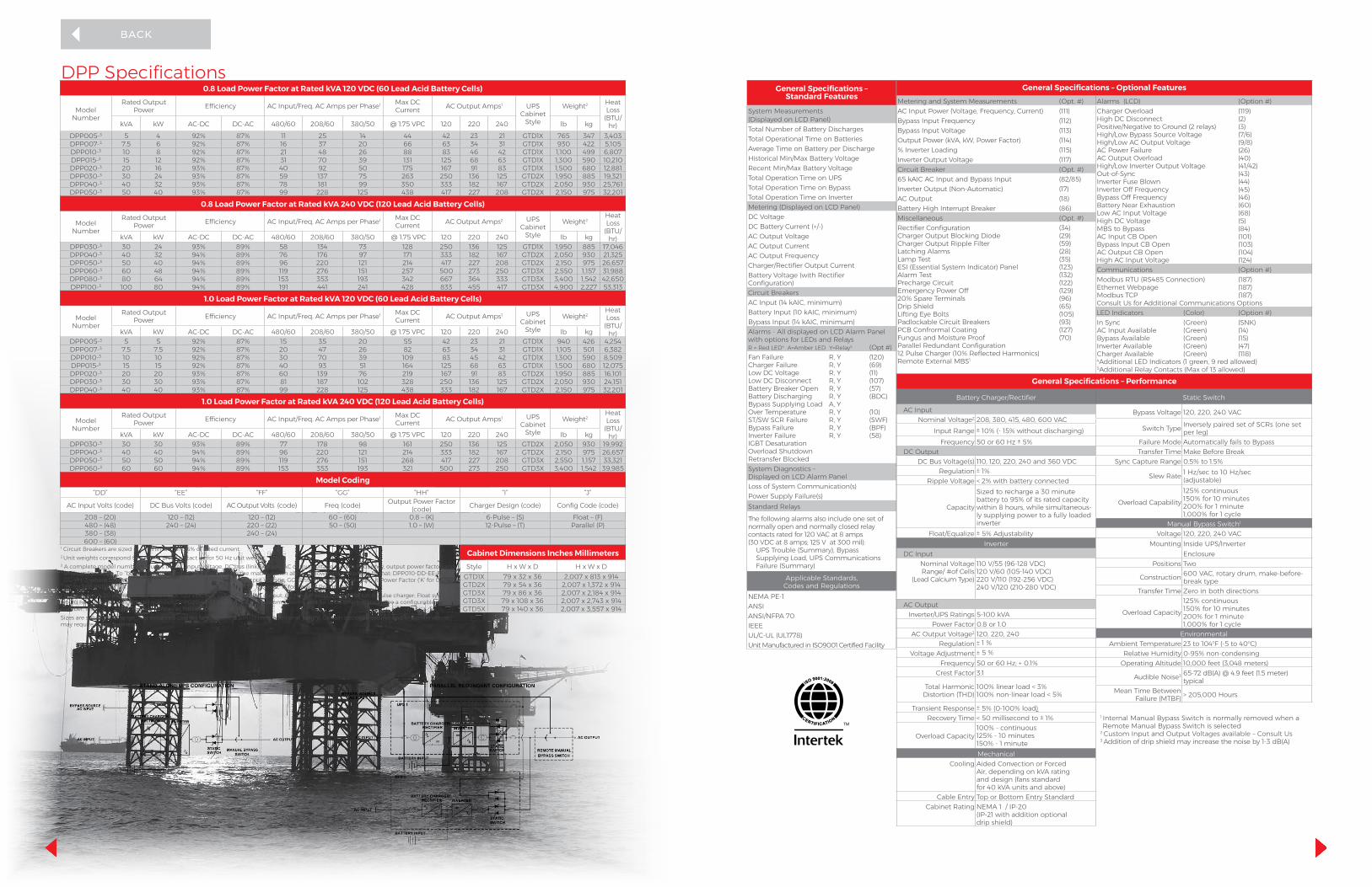
DPP Specifications0.8 Load Power Factor at Rated kVA 120 VDC (60 Lead Acid Battery Cells)
Model Number
Rated Output Power Efficiency AC Input/Freq. AC Amps per Phase1 Max DC
Current AC Output Amps1 UPS Cabinet
Style
Weight2 Heat Loss
(BTU/hr)kVA kW AC-DC DC-AC 480/60 208/60 380/50 @ 1.75 VPC 120 220 240 lb kg
DPP005-3 5 4 92% 87% 11 25 14 44 42 23 21 GTD1X 765 347 3,403DPP007-3 7.5 6 92% 87% 16 37 20 66 63 34 31 GTD1X 930 422 5,105DPP010-3 10 8 92% 87% 21 48 26 88 83 46 42 GTD1X 1,100 499 6,807DPP015-3 15 12 92% 87% 31 70 39 131 125 68 63 GTD1X 1,300 590 10,210DPP020-3 20 16 93% 87% 40 92 50 175 167 91 83 GTD1X 1,500 680 12,881DPP030-3 30 24 93% 87% 59 137 75 263 250 136 125 GTD2X 1,950 885 19,321DPP040-3 40 32 93% 87% 78 181 99 350 333 182 167 GTD2X 2,050 930 25,761DPP050-3 50 40 93% 87% 99 228 125 438 417 227 208 GTD2X 2,150 975 32,201
0.8 Load Power Factor at Rated kVA 240 VDC (120 Lead Acid Battery Cells)
Model Number
Rated Output Power Efficiency AC Input/Freq. AC Amps per Phase1 Max DC
Current AC Output Amps2 UPS Cabinet
Style
Weight2Heat Loss
(BTU/hr)kVA kW AC-DC DC-AC 480/60 208/60 380/50 @ 1.75 VPC 120 220 240 lb kg
DPP030-3 30 24 93% 89% 58 134 73 128 250 136 125 GTD1X 1,950 885 17,046DPP040-3 40 32 94% 89% 76 176 97 171 333 182 167 GTD2X 2,050 930 21,325DPP050-3 50 40 94% 89% 96 220 121 214 417 227 208 GTD2X 2,150 975 26,657DPP060-3 60 48 94% 89% 119 276 151 257 500 273 250 GTD3X 2,550 1,157 31,988DPP080-3 80 64 94% 89% 153 353 193 342 667 364 333 GTD3X 3,400 1,542 42,650DPP100-3 100 80 94% 89% 191 441 241 428 833 455 417 GTD3X 4,900 2,227 53,313
1.0 Load Power Factor at Rated kVA 120 VDC (60 Lead Acid Battery Cells)
Model Number
Rated Output Power Efficiency AC Input/Freq. AC Amps per Phase1 Max DC
Current AC Output Amps1 UPS Cabinet
Style
Weight2Heat Loss
(BTU/hr)kVA kW AC-DC DC-AC 480/60 208/60 380/50 @ 1.75 VPC 120 220 240 lb kg
DPP005-3 5 5 92% 87% 15 35 20 55 42 23 21 GTD1X 940 426 4,254DPP007-3 7.5 7.5 92% 87% 20 47 26 82 63 34 31 GTD1X 1,105 501 6,382DPP010-3 10 10 92% 87% 30 70 39 109 83 45 42 GTD1X 1,300 590 8,509DPP015-3 15 15 92% 87% 40 93 51 164 125 68 63 GTD1X 1,500 680 12,075DPP020-3 20 20 93% 87% 60 139 76 219 167 91 83 GTD2X 1,950 885 16,101DPP030-3 30 30 93% 87% 81 187 102 328 250 136 125 GTD2X 2,050 930 24,151DPP040-3 40 40 93% 87% 99 228 125 438 333 182 167 GTD2X 2,150 975 32,201
1.0 Load Power Factor at Rated kVA 240 VDC (120 Lead Acid Battery Cells)
Model Number
Rated Output Power Efficiency AC Input/Freq. AC Amps per Phase1 Max DC
Current AC Output Amps1 UPS Cabinet
Style
Weight2Heat Loss
(BTU/hr)kVA kW AC-DC DC-AC 480/60 208/60 380/50 @ 1.75 VPC 120 220 240 lb kg
DPP030-3 30 30 93% 89% 77 178 98 161 250 136 125 GTD2X 2,050 930 19,992DPP040-3 40 40 94% 89% 96 220 121 214 333 182 167 GTD2X 2,150 975 26,657DPP050-3 50 50 94% 89% 119 276 151 268 417 227 208 GTD3X 2,550 1,157 33,321DPP060-3 60 60 94% 89% 153 353 193 321 500 273 250 GTD3X 3,400 1,542 39,985
Model Coding“DD” “EE” “FF” “GG” “HH” “I” “J”
AC Input Volts (code) DC Bus Volts (code) AC Output Volts (code) Freq (code) Output Power Factor (code) Charger Design (code) Config Code (code)
208 – (20) 120 – (12) 120 – (12) 60 – (60) 0.8 – (K) 6-Pulse – (S) Float – (F)480 – (48) 240 – (24) 220 – (22) 50 – (50) 1.0 – (W) 12-Pulse – (T) Parallel (P)380 – (38) 240 – (24)600 – (60)
1 Circuit Breakers are sized at a minimum of 125% of rated current.2 Unit weights correspond to a 60 Hz unit. Contact us for 50 Hz unit weight.3 A complete model number includes the AC input voltage, DC bus (link) voltage, AC output voltage, system frequency, output power factor, and
UPS configuration. To “build” a model number, use the “code” in the matrix shown above, following the example format: DPP010-DD-EE-FF-GG-H-I-J; where DD=AC Input Voltage; EE=DC bus voltage; FF=AC Output Voltage; GG=System Frequency; H=Output Power Factor (‘K’ for 0.8; ‘W’ for 1.0); I=6(S) or 12(T) Pulse Charger design; J=UPS configuration (‘F’ for Float, ‘P’ for Parallel Redundant).
For Example: A 20 kVA with 480 VAC input; 120 VDC bus voltage; 120 VAC output; 60 Hz; 0.8 output power factor; 6 pulse charger; Float system would have the following model number: DPP020-48-12-12-60-K-S-F. For custom systems and for units which do not have a configurable model number, insert a ‘C’ in the model number as follows: DPP020CSizes are subject to change. Top mounted cooling fans require 0.5 in (13 mm) additional height. Certain optional features and/or combinations may require larger cabinets.
Cabinet Dimensions Inches MillimetersStyle H x W x D H x W x D
GTD1X 79 x 32 x 36 2,007 x 813 x 914GTD2X 79 x 54 x 36 2,007 x 1,372 x 914GTD3X 79 x 86 x 36 2,007 x 2,184 x 914GTD3X 79 x 108 x 36 2,007 x 2,743 x 914GTD5X 79 x 140 x 36 2,007 x 3,557 x 914
General Specifications – Optional FeaturesMetering and System Measurements (Opt. #) Alarms (LCD) (Option #)AC Input Power (Voltage, Frequency, Current) (111) Charger Overload (119)
High DC Disconnect (2)Positive/Negative to Ground (2 relays) (3)High/Low Bypass Source Voltage (7/6)High/Low AC Output Voltage (9/8)AC Power Failure (26)AC Output Overload (40)High/Low Inverter Output Voltage (41/42)Out-of-Sync (43)Inverter Fuse Blown (44)Inverter Off Frequency (45)Bypass Off Frequency (46) Battery Near Exhaustion (60) Low AC Input Voltage (68) High DC Voltage (5) MBS to Bypass (84) AC Input CB Open (101) Bypass Input CB Open (103) AC Output CB Open (104) High AC Input Voltage (124)
Bypass Input Frequency (112)Bypass Input Voltage (113)Output Power (kVA, kW, Power Factor) (114)% Inverter Loading (115)Inverter Output Voltage (117)Circuit Breaker (Opt. #)65 kAIC AC Input and Bypass Input (82/85)Inverter Output (Non-Automatic) (17)AC Output (18)Battery High Interrupt Breaker (86)Miscellaneous (Opt. #)Rectifier Configuration (34)Charger Output Blocking Diode (29)Charger Output Ripple Filter (59)Latching Alarms (28)Lamp Test (35)ESI (Essential System Indicator) Panel (123)Alarm Test (132)Precharge Circuit (122)Emergency Power Off (129)20% Spare Terminals (96)Drip Shield (65)Lifting Eye Bolts (105)Padlockable Circuit Breakers (93)PCB Confrormal Coating (127)Fungus and Moisture Proof (70)Parallel Redundant Configuration12 Pulse Charger (10% Reflected Harmonics)Remote External MBS1
Communications (Option #)Modbus RTU (RS485 Connection) (187)Ethernet Webpage (187) Modbus TCP (187) Consult Us for Additional Communications Options LED Indicators (Color) (Option #)In Sync (Green) (SNK)AC Input Available (Green) (14)Bypass Available (Green) (15)Inverter Available (Green) (47)Charger Available (Green) (118)4Additional LED Indicators (1 green, 9 red allowed) 5Additional Relay Contacts (Max of 13 allowed)
General Specifications – Standard Features
System Measurements (Displayed on LCD Panel)Total Number of Battery DischargesTotal Operational Time on BatteriesAverage Time on Battery per DischargeHistorical Min/Max Battery VoltageRecent Min/Max Battery VoltageTotal Operation Time on UPSTotal Operation Time on BypassTotal Operation Time on InverterMetering (Displayed on LCD Panel)DC VoltageDC Battery Current (+/-)AC Output VoltageAC Output CurrentAC Output FrequencyCharger/Rectifier Output CurrentBattery Voltage (with Rectifier Configuration)Circuit BreakersAC Input (14 kAIC, minimum)Battery Input (10 kAIC, minimum)Bypass Input (14 kAIC, minimum)Alarms - All displayed on LCD Alarm Panel with options for LEDs and Relays R = Red LED4 A=Amber LED Y=Relay5 (Opt #)Fan Failure R, Y (120)Charger Failure R, Y (69)Low DC Voltage R, Y (11)Low DC Disconnect R, Y (107)Battery Breaker Open R, Y (57)Battery Discharging R, Y (BDC)Bypass Supplying Load A, YOver Temperature R, Y (10)ST/SW SCR Failure R, Y (SWF)Bypass Failure R, Y (BPF)Inverter Failure R, Y (58)IGBT DesaturationOverload ShutdownRetransfer BlockedSystem Diagnostics – Displayed on LCD Alarm PanelLoss of System Communication(s)Power Supply Failure(s)Standard Relays
The following alarms also include one set of normally open and normally closed relay contacts rated for 120 VAC at 8 amps (30 VDC at 8 amps; 125 V at 300 mil):
UPS Trouble (Summary), Bypass Supplying Load, UPS Communications Failure (Summary)
Applicable Standards, Codes and Regulations
NEMA PE-1ANSIANSI/NFPA 70IEEEUL/C-UL (UL1778)Unit Manufactured in ISO9001 Certified Facility
General Specifications – Performance
Battery Charger/Rectifier Static Switch
AC Input Bypass Voltage 120, 220, 240 VACNominal Voltage2 208, 380, 415, 480, 600 VAC
Switch Type Inversely paired set of SCRs (one set per leg)Input Range ± 10% (- 15% without discharging)
Frequency 50 or 60 Hz ± 5% Failure Mode Automatically fails to Bypass DC Output Transfer Time Make Before Break
DC Bus Voltage(s) 110, 120, 220, 240 and 360 VDC Sync Capture Range 0.5% to 1.5%Regulation ± 1%
Slew Rate 1 Hz/sec to 10 Hz/sec (adjustable)Ripple Voltage < 2% with battery connected
Capacity
Sized to recharge a 30 minute battery to 95% of its rated capacity within 8 hours, while simultaneous-ly supplying power to a fully loaded inverter
Overload Capability125% continuous 150% for 10 minutes200% for 1 minute1,000% for 1 cycle
Manual Bypass Switch1
Float/Equalize ± 5% Adjustability Voltage 120, 220, 240 VACInverter Mounting Inside UPS/Inverter
DC Input EnclosureNominal Voltage Range/ #of Cells
(Lead Calcium Type)
110 V/55 (96-128 VDC)120 V/60 (105-140 VDC)220 V/110 (192-256 VDC)240 V/120 (210-280 VDC)
Positions Two
Construction 600 VAC, rotary drum, make-before-break type
Transfer Time Zero in both directions
Overload Capacity125% continuous 150% for 10 minutes 200% for 1 minute 1,000% for 1 cycle
AC OutputInverter/UPS Ratings 5-100 kVA
Power Factor 0.8 or 1.0AC Output Voltage2 120, 220, 240 Environmental
Regulation ± 1 % Ambient Temperature 23 to 104oF (-5 to 40oC) Voltage Adjustment ± 5 % Relative Humidity 0-95% non-condensing
Frequency 50 or 60 Hz; + 0.1% Operating Altitude 10,000 feet (3,048 meters) Crest Factor 3:1 Audible Noise3 65-72 dB(A) @ 4.9 feet (1.5 meter)
typicalTotal Harmonic
Distortion (THD)100% linear load < 3%100% non-linear load < 5% Mean Time Between
Failure (MTBF) > 205,000 Hours
Transient Response ± 5% (0-100% load)Recovery Time < 50 millisecond to ± 1% 1 Internal Manual Bypass Switch is normally removed when a
Remote Manual Bypass Switch is selected2 Custom Input and Output Voltages available – Consult Us3 Addition of drip shield may increase the noise by 1-3 dB(A)
Overload Capacity100% - continuous125% - 10 minutes150% - 1 minuteMechanical
Cooling Aided Convection or ForcedAir, depending on kVA ratingand design (fans standard for 40 kVA units and above)
Cable Entry Top or Bottom Entry StandardCabinet Rating NEMA 1 / IP-20
(IP-21 with addition optional drip shield)

3DPP Specifications0.8 Load Power Factor at Rated kVA 120VDC (60 Lead Acid Battery Cells)
Model NumberRated Output
Power Efficiency 3PH AC Input/Freq AC Amps Per Phase1
Max DC Current
3PH AC Output Amps Per Phase1 Cabinet
StyleWeight2 Heat Loss
(BTU/hr)kVA kW AC-DC DC-AC 208/60 480/60 600/60 380/50 @ 1.75 VPC 208 480 380 lb kg
3DPP010-3 10 8 92% 87% 48 21 17 26 88 28 12 15 GTD1X 1,100 499 6,8073DPP015-3 15 12 92% 87% 70 31 24 39 131 42 18 23 GTD1X 1,300 590 10,2103DPP020-3 20 16 93% 87% 92 40 32 50 175 56 24 30 GTD1X 1,500 680 12,8803DPP030-3 30 24 93% 87% 137 59 47 75 263 83 36 46 GTD2X 1,950 885 19,3213DPP040-3 40 32 93% 87% 181 78 63 99 350 111 48 61 GTD2X 2,050 930 25,7613DPP050-3 50 40 93% 87% 228 99 79 125 438 139 60 76 GTD3X 2,150 1,315 32,201
0.8 Load Power Factor at Rated kVA 240VDC (120 Lead Acid Battery Cells)
Model NumberRated Output
Power Efficiency 3PH AC Input/Freq AC Amps Per Phase1
Max DC Current
3PH AC Output Amps Per Phase1 Cabinet
StyleWeight2 Heat Loss
(BTU/hr)kVA kW AC-DC DC-AC 208/60 480/60 600/60 380/50 @ 1.75 VPC 208 480 380 lb kg
3DPP030-3 30 24 93% 89% 134 58 46 73 128 83 36 46 GTD1X 1,950 885 17,0463DPP040-3 40 32 94% 89% 176 76 61 97 171 111 48 61 GTD2X 2,050 930 21,3253DPP050-3 50 40 94% 89% 220 96 77 121 214 139 60 76 GTD2X 2,150 975 26,6573DPP060-3 60 48 94% 89% 276 119 96 151 257 167 72 91 GTD2X 2,550 1,157 31,9883DPP080-3 80 64 94% 89% 353 153 122 193 342 222 96 122 GTD2X 3,400 1,452 42,6503DPP100-3 100 80 94% 89% 441 191 153 241 428 278 120 152 GTD4X 4,400 1,996 53,3133DPP125-3 125 100 94% 89% 551 239 191 302 535 347 151 190 GTD4X 4,900 2,227 66,6413DPP160-3 160 128 94% 89% 708 307 245 387 685 444 192 243 GTD4X 5,880 2,667 85,301
0.8 Load Power Factor at Rated kVA 360VDC (180 Lead Acid Battery Cells)
Model NumberRated Output
Power Efficiency 3PH AC Input/Freq AC Amps Per Phase1
Max DC Current
3PH AC Output Amps Per Phase1
UPS Cabinet
StyleWeight2 Heat Loss
(BTU/hr)kVA kW AC-DC DC-AC 208/60 480/60 600/60 380/50 @ 1.75 VPC 208 480 380 lb kg
3DPP200-3 200 160 94% 89% 885 383 307 484 571 555 241 304 GTD5X 7,060 3,203 106,6263DPP225-3 225 180 94% 89% 995 431 345 545 642 625 271 342 GTD5X 8,470 3,842 119,954
1.0 Load Power Factor at Rated kVA 120VDC (60 Lead Acid Battery Cells)
Model NumberRated Output
Power Efficiency 3PH AC Input/Freq AC Amps Per Phase*
Max DC Current
3PH AC Output Amps Per Phase1
UPS Cabinet
StyleWeight2 Heat Loss
(BTU/hr)kVA kW AC-DC DC-AC 208/60 480/60 600/60 380/50 @ 1.75 VPC 208 480 380 lb kg
3DPP010-3 10 10 92% 87% 70 31 24 39 110 28 12 15 GTD1X 1,300 590 8,5093DPP015-3 15 15 93% 87% 92 40 32 50 164 42 18 23 GTD1X 1,500 680 12,0753DPP020-3 20 20 93% 87% 137 59 47 75 219 56 24 30 GTD2X 1,950 885 16,1013DPP030-3 30 30 93% 87% 181 78 63 99 328 83 36 46 GTD2X 2,050 930 24,1513DPP040-3 40 40 93% 87% 228 99 79 125 438 111 48 61 GTD3X 2,150 975 32,201
1.0 Load Power Factor at Rated kVA 240VDC (120 Lead Acid Battery Cells)
Model NumberRated Output
Power Efficiency 3PH AC Input/Freq AC Amps Per Phase1
Max DC Current
3PH AC Output Amps Per Phase1
UPS Cabinet
StyleWeight2 Heat Loss
(BTU/hr)kVA kW AC-DC DC-AC 208/60 480/60 600/60 380/50 @ 1.75 VPC 208 480 380 lb kg
3DPP030-3 30 30 94% 89% 176 76 61 97 161 83 36 46 GTD2X 2,050 930 19,9923DPP040-3 40 40 94% 89% 220 96 77 121 214 111 48 61 GTD2X 2,150 975 26,6573DPP050-3 50 50 94% 89% 276 119 95 151 268 139 60 76 GTD2X 2,550 1,157 33,3213DPP060-3 60 60 94% 89% 353 153 122 193 321 167 72 91 GTD2X 3,400 1,542 39,9853DPP080-3 80 80 94% 89% 441 191 153 241 428 222 96 122 GTD4X 4,400 1,996 53,3133DPP100-3 100 100 94% 89% 551 239 191 302 535 278 120 152 GTD4X 4,900 2,227 66,641
Model Coding“DD” “EE” “FF” “GG” “HH” “I” “J”
AC Input Volts (code) DC Bus Volts (code) AC Output Volts (code) Freq (code) Output Power Factor (code) Charger Design (code) Config Code (code)208 – (20) 120 – (12) 120/208 – (20) 60 – (60) 0.8 – (K) 6-Pulse – (S) Float – (F)480 – (48) 240 – (24) 277/480 – (48) 50 – (50) 1.0 – (W) 12-Pulse – (T) Parallel (P)600 – (60) 360 – (36) 220/380 – (38)380 – (38)
Cabinet Dimensions Inches MillimetersStyle H x W x D H x W x D
GTD1X 79 x 32 x 36 2,007 x 813 x 914GTD2X 79 x 54 x 36 2,007 x 1,372 x 914GTD3X 79 x 86 x 36 2,007 x 2,184 x 914GTD4X 79 x 108 x 36 2,007 x 2,743 x 914GTD5X 79 x 140 x 36 2,007 x 3,557 x 914
1 Circuit Breakers are sized at a minimum of 125% of rated current.2 Unit weights correspond to a 60 Hz unit. Contact us for 50 Hz unit weight.3 A complete model number includes the AC input voltage, DC bus (link) voltage, AC output voltage, system frequency, output power factor, and UPS configuration. To “build” a model number, use the “code” in the matrix shown above, following the example format: 3DPP010-DD-EE-FF-GG-H-I-J; where DD=AC Input Voltage; EE=DC bus voltage; FF=AC Output Voltage; GG=System Frequency; H=Output Power Factor (‘K’ for 0.8; ‘W’ for 1.0); I=6(S) or 12(T) Pulse Charger design; J=UPS configuration (‘F’ for Float, ‘P’ for Parallel Redundant).
For Example: A 20 kVA with 480 VAC input; 120 VDC bus voltage; 120/208 VAC output; 60 Hz; 0.8 output power factor; 6 pulse charger; Float system would have the following model number: 3DPP020-48-12-20-60-K-S-F. For custom systems and for units which do not have a configurable model number, insert a ‘C’ in the model number as follows: 3DPP020CSizes are subject to change. Top mounted cooling fans require 0.5 in (13 mm) additional height. Certain optional features and/or combinations may require larger cabinets.
General Specifications – Optional FeaturesMetering and System Measurements (Opt. #) Alarms (LCD) (Option #)AC Input Power (Voltage, Frequency, Current) (111) Charger Overload (119)
High DC Disconnect (2)Positive/Negative to Ground (2 relays) (3)High/Low Bypass Source Voltage (7/6)High/Low AC Output Voltage (9/8)AC Power Failure (26)AC Output Overload (40)High/Low Inverter Output Voltage (41/42)Out-of-Sync (43)Inverter Fuse Blown (44)Inverter Off Frequency (45)Bypass Off Frequency (46) Rectifier/Charger Fuse Blown (67) Battery Near Exhaustion (60) Low AC Input Voltage (68) High DC Voltage (5) MBS to Bypass (84) AC Input CB Open (101) Bypass Input CB Open (103) AC Output CB Open (104) High AC Input Voltage (124)
Bypass Input Frequency (112)Bypass Input Voltage (113)Output Power (kVA, kW, Power Factor) (114)% Inverter Loading (115)Inverter Output Voltage (117)Circuit Breaker (Opt. #)65 kAIC AC Input and Bypass Input (82/85)Inverter Output (Non-Automatic) (17)AC Output (18)Battery High Interrupt Breaker (86)Miscellaneous (Opt. #)Rectifier Configuration (34)Charger Output Blocking Diode (29)Charger Output Ripple Filter (59)Latching Alarms (28)Lamp Test (35)ESI (Essential System Indicator) Panel (123)Alarm Test (132)Precharge Circuit (122)Emergency Power Off (129)20% Spare Terminals (96)Drip Shield (65)Lifting Eye Bolts (105)Padlockable Circuit Breakers (93)PCB Confrormal Coating (127)Fungus and Moisture Proof (70)Parallel Redundant Configuration12 Pulse Charger (10% Reflected Harmonics)Remote External MBS1
Communications (Option #)Modbus RTU (RS485 Connection) (187)Ethernet Webpage (187) Modbus TCP (187) Consult Us for Additional Communications Options LED Indicators (Color) (Option #)In Sync (Green) (SNK)AC Input Available (Green) (14)Bypass Available (Green) (15)Inverter Available (Green) (47)Charger Available (Green) (118)4Additional LED Indicators (1 green, 9 red allowed) 5Additional Relay Contacts (Max of 13 allowed)
General Specifications – Standard Features
System Measurements (Displayed on LCD Panel)Total Number of Battery DischargesTotal Operational Time on BatteriesAverage Time on Battery per DischargeHistorical Min/Max Battery VoltageRecent Min/Max Battery VoltageTotal Operation Time on UPSTotal Operation Time on BypassTotal Operation Time on InverterMetering (Displayed on LCD Panel)DC VoltageDC Battery Current (+/-)AC Output VoltageAC Output CurrentAC Output FrequencyCharger/Rectifier Output CurrentBattery Voltage (with Rectifier Configuration)Circuit BreakersAC Input (14 kAIC, minimum)Battery Input (10 kAIC, minimum)Bypass Input (14 kAIC, minimum)Alarms - All displayed on LCD Alarm Panel with options for LEDs and Relays R = Red LED4 A=Amber LED Y=Relay5 (Opt #)Fan Failure R, Y (120)Charger Failure R, Y (69)Low DC Voltage R, Y (11)Low DC Disconnect R, Y (107)Battery Breaker Open R, Y (57)Battery Discharging R, Y (BDC)Bypass Supplying Load A, YOver Temperature R, Y (10)ST/SW SCR Failure R, Y (SWF)Bypass Failure R, Y (BPF)Inverter Failure R, Y (58)IGBT DesaturationOverload ShutdownRetransfer BlockedSystem Diagnostics – Displayed on LCD Alarm PanelLoss of System Communication(s)Power Supply Failure(s)Standard Relays
The following alarms also include one set of normally open and normally closed relay contacts rated for 120 VAC at 8 amps (30 VDC at 8 amps; 125 V at 300 mil):
UPS Trouble (Summary), Bypass Supplying Load, UPS Communications Failure (Summary)
Applicable Standards, Codes and Regulations
NEMA PE-1ANSIANSI/NFPA 70IEEEUL/C-UL (UL1778)Unit Manufactured in ISO9001 Certified Facility
General Specifications – Performance Battery Charger/Rectifier Static Switch
AC Input Bypass Voltage 208, 380, 415, 480, 600 (3Ø)Nominal Voltage2 208, 380, 415, 480, 600 VAC (3Ø)
Switch Type Inversely paired set of SCRs (one set per leg)Input Range ± 10% (- 15% without discharging)
Frequency 50 or 60 Hz ± 5% Failure Mode Automatically fails to Bypass DC Output Transfer Time Make Before Break
DC Bus Voltage(s) 110, 120, 220, 240 and 360 VDC Sync Capture Range 0.5% to 1.5%Regulation ± 1%
Slew Rate 1 Hz/sec to 10 Hz/sec (adjustable)Ripple Voltage < 2% with battery connected
Capacity
Sized to recharge a 30 minute battery to 95% of its rated capacity within 8 hours, while simultaneously supplying power to a fully loaded inverter
Overload Capability125% continuous 150% for 10 minutes200% for 1 minute1,000% for 1 cycle
Manual Bypass Switch1
Float/Equalize ± 5% Adjustability Voltage 208, 380, 415, 480, 600 (3Ø)Inverter Mounting Inside UPS/Inverter
DC Input EnclosureNominal Voltage Range/ #of Cells
(Lead Calcium Type)
110 V/55 (96-128 VDC)120 V/60 (105-140 VDC)220 V/110 (192-256 VDC)240 V/120 (210-280 VDC)360 V/180 (315-419 VDC)
Positions Two
Construction 600 VAC, rotary drum, make-before-break type
Transfer Time Zero in both directions
Overload Capacity125% continuous 150% for 10 minutes 200% for 1 minute 1,000% for 1 cycle
AC OutputInverter/UPS Ratings 10-225 kVA
Power Factor 0.8 or 1.0AC Output Voltage2 120/208, 220/380, 277/480 VAC Environmental
Regulation ± 1 % Ambient Temperature 23 to 104oF (-5 to 40oC)Voltage Adjustment ± 5 % Relative Humidity 0-95% non-condensing
Frequency 50 or 60 Hz; + 0.1% Operating Altitude 10,000 feet (3,048 meters) Crest Factor 3:1
Audible Noise3 65-72 dB(A) @ 4.9 feet (1.5 meter) typicalTotal Harmonic 100% linear load < 3%
Distortion (THD) 100% non-linear load < 5% Mean Time Between Failure (MTBF) > 205,000 Hours
Transient Response ± 5% (0-100% load)Recovery Time < 50 millisecond to ± 1% 1 Internal Manual Bypass Switch is normally removed when a
Remote Manual Bypass Switch is selected2 Custom Input and Output Voltages available – Consult Us 3 Addition of drip shield may increase the noise by 1-3 dB(A)
Overload Capacity100% - continuous125% - 10 minutes150% - 1 minuteMechanical
CoolingAided Convection or ForcedAir, depending on kVA ratingand design (fans standard for 40 kVA units and above)
Cable Entry Top or Bottom Entry Standard
Cabinet RatingNEMA 1 / IP-20(IP-21 with addition optional drip shield)

PROCESSPOWER UPS SYSTEM LCD AND TOUCH SCREEN USER PANELShown with optional indicator lights
The Power Behind the Process
Keypad Controls andSwitches• Float/Equalize
Initialization with Light
• Battery Test Initialization
• Inverter to Load with Light
• Bypass to Load with Light
• Static Switch Reset Retransfer
• Latching Alarm Reset
• Audible Alarm Silence
• Display On• Inverter Enable
(On/Off) Switch
LCD Panel Indicators• Equalize Time
Remaining• Charger Status
(OK/Fail)• Float/Equalize
Status• Inverter Status
(OK/Fail)• Synchronism Status
(In/Out of Sync)• Static Switch
Position (Inverter or Bypass)
• Manual Bypass Position (Normal or Bypass)
• Bypass Status (OK/Fail)
3DPP/IECIndustrial Pulse Width Modulated Uninterruptible Power Supply System IEC CompliantTHREE PHASE 10-225 kVA
The three phase Digital ProcessPower Uninterruptible Power Supply (UPS) system from AMETEK Solidstate Controls is a true on-line, double conversion UPS system that provides continuous, clean, regulated power for critical AC loads and is IEC compliant.The 3DPP is designed for process control and industrial applications and offers better isolation and faster, more accurate signals between processors.
* Standard LED Indicators: UPS Normal and UPS Trouble
General Specifications – Standard Features
System Measurements (Displayed on LCD Panel)Total Number of Battery DischargesTotal Operational Time on BatteriesAverage Time on Battery per DischargeHistorical Min/Max Battery VoltageRecent Min/Max Battery VoltageTotal Operation Time on UPSTotal Operation Time on BypassTotal Operation Time on InverterMetering (Displayed on LCD Panel)DC VoltageDC Battery Current (+/-)AC Output VoltageAC Output CurrentAC Output FrequencyCharger/Rectifier Output CurrentBattery Voltage (with Rectifier Configuration)Circuit BreakersAC Input (14 kAIC, minimum)Battery Input (10 kAIC, minimum)Bypass Input (14 kAIC, minimum)Alarms (Displayed on LCD Alarm Panel)Fan FailureCharger FailureLow DC VoltageLow DC DisconnectBattery Breaker OpenST/SW Retransfer BlockedBattery DischargingIGBT DesaturationOverload ShutdownBypass Supplying LoadST/SW Bridge Over TemperatureInverter Bridge Over TemperatureST/SW SCR FailureBypass FailureInverter FailureSystem Diagnostics (Displayed on LCD Alarm Panel)Loss of System Communication(s)Power Supply Failure(s)Standard Relays
The following alarms also include one set of normally open and normally closed relay contacts rated for 120 VAC at 8 amps (30 VDC at 8 amps; 125 V at 300 mil): UPS Trouble (Summary)Bypass
Supplying Loa UPS Communications Failure (Summary)
Applicable Standards, Codes and Regulations
NEMA PE-1ANSIANSI/NFPA 70IEEEIEC 60240 Parts 1, 2, & 3UL/C-UL (UL1778)Unit Manufactured in ISO9001 Certified Facility
General Specifications – Optional FeaturesMetering and System Measurements (Option #) Miscellaneous – Continued (Option #)AC Input Power (Voltage, Frequency, Current) (111) Latching Alarms (28)Bypass Input Frequency (112) Lamp Test (35)Bypass Input Voltage (113) ESI (Essential System Indicator) Panel (123)Output Power (kVA, kW, Power Factor) (114) Alarm Relay Test (132)% Inverter Loading (115)Inverter Output Voltage (117) Alarms (Option #)Circuit Breaker (Option #) Charger Overload (119)
High DC Disconnect (2)Positive/Negative to Ground (2 relays) (3)High/Low Bypass Source Voltage (7/6)High/Low AC Output Voltage (9/8)AC Power Failure (26)AC Output Overload (48)High/Low Inverter Output Voltage (41/42)Out-of-Sync (43)Inverter Fuse Blown (44)Inverter Off Frequency (45)Bypass Off Frequency (46)Rectifier/Charger Fuse Blown (67)Battery Near Exhaustion (60)Low AC Input Voltage (68)High DC Voltage (5)Rectifier/Charger Failure (69)MBS to Bypass (78)AC Input CB Open (101)Bypass Input CB Open (103)AC Output CB Open (104)
65 kAIC AC Input and Bypass Input (82/85)Inverter Output (Non-Automatic) (17)AC Output (18)Battery High Interrupt Breaker (86)Communications (Option #)Modbus RTU (RS485 Connection) (187)Ethernet Webpage (187)Modbus TCP (187)SCI-Link Consult Factory for Additional Communication OptionsMiscellaneous (Option #)Rectifier Configuration (34)Charger Output Blocking Diode (29)Charger Output Ripple Filter Cascade Redundant ConfigurationParallel Redundant Configuration 12 Pulse Charger (10% Reflected Harmonics)Additional Relay Contacts (Max of 13 available)Additional LED Indicators (1 green, 9 red available)Remote External MBS1
General Specifications – Performance Battery Charger/Rectifier Static Switch
AC Input Bypass Voltage 120/208, 220/380, and 277/480: 3-phase, 4-wireNominal Voltage2 208, 380, 415, 480, 600:
3-phase/ 3- wire Switch Type Inversely paired set of SCRs (one set per leg)Input Range ± 10% (- 15% without discharging)
Frequency 50 or 60 Hz ± 5% Failure Mode Automatically fails to bypass
DC Output Transfer Time Make Before BreakDC Bus Voltage(s) 110,120,220, 240 and 360 VDC Sync Capture Range 0.5% to 1.5% adjustable
Regulation ± 1% Slew Rate 1 Hz/sec to 10 Hz/sec (adjustable)Ripple Voltage < 2% with battery connected
Capacity Sized to recharge a 30 minute battery to 95% of its rated capacity within 8 hours, while simultaneously supplying power to a fully loaded inverter
Overload Capability 125% continuous 150% for 10 minutes200% for 1 minute1,000% for 1 cycle
Manual Bypass Switch1
Float/Equalize ± 5% Adjustability Voltage 120/208, 220/380, and277/480: 3-phase, 4-wire
Inverter Mounting Inside UPS/Inverter DC Input Enclosure
Nominal Voltage 110 V/55 (96-128 VDC) Positions TwoRange/ #of Cells 120 V/60 (105-140 VDC) Construction 600 VAC, rotary drum, make-be-
fore-break type (Lead Calcium Type) 220 V/110 (192-256 VDC)240 V/120 (210-280 VDC) Transfer Time Zero in both directions
Overload Capacity 125% continuous 150% for 10 minutes 200% for 1 minute 1,000% for 1 cycle
AC OutputInverter/UPS Ratings 10-225 kVA
Power Factor 0.8 or 1.0 EnvironmentalAC Output Voltage2 120/208, 220/380 and
277/480: 3-phase, 4-wireAmbient Temperature 23 to 104oF (-5 to 40oC)
Regulation ± 1% Relative Humidity 0-95% non-condensingVoltage Adjustment ± 5% Operating Altitude 10,000 feet (3,048 meters)
Frequency 50 or 60 Hz; + 0.1% Audible Noise3 65-72 dB(A) @ 4.9 feet (1.5 meter) typicalCrest Factor 3:1
Total Harmonic 100% linear load < 3% Cooling Aided Convection or ForcedDistortion (THD) 100% non-linear load < 5% Air, depending on kVA rating
Transient Response ± 5% (0-100% load) and design (fans standard Recovery Time < 50 millisecond to ± 1% for 40 kVA units and above)
Overload Capacity 100% - continuous125% - 10 minutes150% - 1 minute
Cable Entry Top and Bottom Entry Standard
Mean Time Between Failure (MTBF)
> 205,000 Hours
Cabinet Rating NEMA 1 / IP-20(IP-21 with addition optional drip shield)
1 Internal Manual Bypass Switch is normally removed when a Remote Manual Bypass Switch is selected2 Custom Input and Output Voltages available – Contact Us3 Addition of drip shield may increase the noise by 1-3 dB(A)
3DPP/IEC

0.8 Load Power Factor at Rated kVA 120 VDC (60 Lead Acid Battery Cells)
Model Number
Rated Output Power Efficiency 3PH AC Input/Freq AC Amps
Per Phase1Max DC Current
3PH AC Output Amps Per Phase1
UPS Cabinet
StyleWeight2 Heat Loss
(BTU/hr)kVA kW AC-DC DC-AC 208/60 480/60 600/60 380/50 @ 1.75 VPC 208 480 380 lb kg
3DPP010-3 10 8 92% 87% 48 21 17 26 88 28 12 15 GTD1X 1,100 499 6,8073DPP015-3 15 12 92% 87% 70 31 24 39 131 42 18 23 GTD1X 1,300 590 10,2103DPP020-3 20 16 93% 87% 92 40 32 50 175 56 24 30 GTD1X 1,500 680 12,8803DPP030-3 30 24 93% 87% 137 59 47 75 263 83 36 46 GTD2X 1,950 885 19,3213DPP040-3 40 32 93% 87% 181 78 63 99 350 111 48 61 GTD2X 2,050 930 25,7613DPP050-3 50 40 93% 87% 228 99 79 125 438 139 60 76 GTD3X 2,900 1,315 32,201
0.8 Load Power Factor at Rated kVA 240 VDC (120 Lead Acid Battery Cells)
Model Number
Rated Output Power Efficiency 3PH AC Input/Freq AC Amps
Per Phase1Max DC Current
3PH AC Output Amps Per Phase1
UPS Cabinet
StyleWeight2 Heat Loss
(BTU/hr)kVA kW AC-DC DC-AC 208/60 480/60 600/60 380/50 @ 1.75 VPC 208 480 380 lb kg
3DPP030-3 30 24 93% 89% 134 58 46 73 128 83 36 46 GTD1X 1,950 885 17,0463DPP040-3 40 32 94% 89% 176 76 61 97 171 111 48 61 GTD2X 2,050 930 21,3253DPP050-3 50 40 94% 89% 220 96 77 121 214 139 60 76 GTD2X 2,150 975 26,6573DPP060-3 60 48 94% 89% 276 119 96 151 257 167 72 91 GTD2X 2,550 1,157 31,9883DPP080-3 80 64 94% 89% 353 153 122 193 342 222 96 122 GTD2X 3,200 1,452 42,6503DPP100-3 100 80 94% 89% 441 191 153 241 428 278 120 152 GTD4X 4,400 1,996 53,3133DPP125-3 125 100 94% 89% 551 239 191 302 535 347 151 190 GTD4X 4,900 2,227 66,6413DPP160-3 160 128 94% 89% 708 307 245 387 685 444 192 243 GTD4X 5,880 2,667 85,301
0.8 Load Power Factor at Rated kVA 360 VDC (180 Lead Acid Battery Cells)
Model Number
Rated Output Power Efficiency 3PH AC Input/Freq AC Amps
Per Phase1Max DC Current
3PH AC Output Amps Per Phase1
UPS Cabinet
StyleWeight2 Heat Loss
(BTU/hr)kVA kW AC-DC DC-AC 208/60 480/60 600/60 380/50 @ 1.75 VPC 208 480 380 lb kg
3DPP200-3 200 160 94% 89% 885 383 307 484 571 555 241 304 GTD5X 7,060 3,203 106,6263DPP225-3 225 180 94% 89% 995 431 345 545 642 625 271 342 GTD5X 8,470 3,842 119,954
1.0 Load Power Factor at Rated kVA 120 VDC (60 Lead Acid Battery Cells)
Model Number
Rated Output Power Efficiency 3PH AC Input/Freq AC Amps
Per Phase1Max DC Current
3PH AC Output Amps Per Phase1
UPS Cabinet
StyleWeight2 Heat Loss
(BTU/hr)kVA kW AC-DC DC-AC 208/60 480/60 600/60 380/50 @ 1.75 VPC 208 480 380 lb kg
3DPP010-3 10 10 92% 87% 70 31 24 39 110 28 12 15 GTD1X 1,300 590 8,5093DPP015-3 15 15 93% 87% 92 40 32 50 164 42 18 23 GTD1X 1,500 680 12,0753DPP020-3 20 20 93% 87% 137 59 47 75 219 56 24 30 GTD2X 1,950 885 16,1013DPP030-3 30 30 93% 87% 181 78 63 99 328 83 36 46 GTD2X 2,050 930 24,1513DPP040-3 40 40 93% 87% 228 99 79 125 438 111 48 61 GTD3X 2,900 975 32,201
1.0 Load Power Factor at Rated kVA 240 VDC (120 Lead Acid Battery Cells)
Model Number
Rated Output Power Efficiency 3PH AC Input/Freq AC Amps
Per Phase1Max DC Current
3PH AC Output Amps Per Phase1
UPS Cabinet
StyleWeight2 Heat Loss
(BTU/hr)kVA kW AC-DC DC-AC 208/60 480/60 600/60 380/50 @ 1.75 VPC 208 480 380 lb kg
3DPP030-3 30 30 94% 89% 176 76 61 97 161 83 36 46 GTD2X 2,050 930 19,9923DPP040-3 40 40 94% 89% 220 96 77 121 214 111 48 61 GTD2X 2,150 975 26,6573DPP050-3 50 50 94% 89% 276 119 95 151 268 139 60 76 GTD2X 2,550 1,157 33,3213DPP060-3 60 60 94% 89% 353 153 122 193 321 167 72 91 GTD2X 3,400 1,542 39,9853DPP080-3 80 80 94% 89% 441 191 153 241 428 222 96 122 GTD4X 4,400 1,996 53,3133DPP100-3 100 100 94% 89% 551 239 191 302 535 278 120 152 GTD4X 4,900 2,227 66,641
Model Coding“DD” “EE” “FF” “GG” “HH” “I” “J”
AC Input Volts (code) DC Bus Volts (code) AC Output Volts (code) Freq (code) Output Power Factor (code) Charger Design (code) Config Code (code)208 – (20) 120 – (12) 120/208 – (20) 60 – (60) 0.8 – (K) 6-Pulse – (S) Float – (F)480 – (48) 240 – (24) 277/480 – (48) 50 – (50) 1.0 – (W) 12-Pulse – (T) Cascaded – (C)600 – (60) 360 – (36) 220/380 – (38) Parallel (P)380 – (38)
Cabinet Dimensions Inches MillimetersStyle H x W x D H x W x D
GTD1X 79 x 32 x 36 2,007 x 813 x 914GTD2X 79 x 54 x 36 2,007 x 1,372 x 914GTD3X 79 x 86 x 36 2,007 x 2,184 x 914GTD4X 79 x 108 x 36 2,007 x 2,743 x 914GTD5X 79 x 140 x 36 2,007 x 3,557 x 914
1 Circuit Breakers are sized at a minimum of 125% of rated current.2 Unit weights correspond to a 60 Hz unit. Contact us for 50 Hz unit weight.3 A complete model number includes the AC input voltage, DC bus (link) voltage, AC output voltage, system frequency, output power factor, and UPS configuration. To “build” a model number, use the “code” in the matrix shown above, following the example format: 3DPP010-DD-EE-FF-GG-H-I-J; where DD=AC Input Voltage; EE=DC bus voltage; FF=AC Output Voltage; GG=System Frequency; H=Output Power Factor (‘K’ for 0.8; ‘W’ for 1.0); I=6(S) or 12(T) Pulse Charger design; J=UPS configuration (‘F’ for Float, ‘C’ for Cascaded Redundant, ‘P’ for Parallel Redundant). For Example: A 20 kVA with 480 VAC input; 120 VDC bus voltage; 120/208 VAC output; 60 Hz; 0.8 output power factor; 6 pulse charger; Float system would have the following model number: 3DPP020-48-12-20-60-K-S-F.. For custom systems and for units which do not have a configurable model number, insert a ‘C’ in the model number as follows: 3DPP020CSizes are subject to change. Top mounted cooling fans require 0.5 in (13 mm) additional height. Certain optional features and/or combinations may require larger cabinets.
REV 12/2018
THE PURPOSE OF OUR BUSINESS IS TO PROVIDE CONTINUITY OF ELECTRICAL POWER TO KEEP BUSINESSES IN BUSINESS.WE DO THIS BY HELPING CLIENTS SOLVE THEIR POWER PROBLEMS AND BY CREATING THE MOST ECONOMICAL LONG-TERM RESULTS.
WORLD HEADQUARTERS875 Dearborn Drive Columbus, Ohio 43085 Phone: +1-614-846-7500 Toll Free: +1-800-635-7300 Fax: +1-614-885-3990
GLOBAL OFFICES LOCATED INMexicoAsia Pacific Brazil
WEBSITEwww.solidstatecontrolsinc.com
[email protected] Middle East
IndiaArgentina

DSEDigitally Controlled Ferroresonant Industrial Uninterruptible Power Supply SystemSINGLE PHASE 3-50 kVA
The DSE Uninterruptible Power Supply (UPS) system from AMETEK Solidstate Controls combines the best of both worlds: (1) The reliability and robust design of a
Ferroresonant UPS (2) The digital control and communications
typically found only in Pulse Width Modulation products
The DSE is a true on-line, double conversion UPS system that provides continuous, clean, regulated power for critical AC loads. Designed specifically for process control and harsh industrial applications, the DSE combines digital control for enhanced communications, monitoring, control and diagnostics capabilities with proven ferroresonant transformer design. The DSE also includes the LCD panel and user-friendly touch screen display found in our Digital ProcessPower systems for the ultimate in user control.
PROCESSPOWER UPS SYSTEM LCD AND TOUCH SCREEN USER PANELShown with optional indicator lights
The Power Behind the Process
Keypad Controls andSwitches• Float/Equalize
Initialization with Light
• Battery Test Initialization
• Inverter to Load with Light
• Bypass to Load with Light
• Static Switch Reset Retransfer
• Latching Alarm Reset
• Audible Alarm Silence
• Display On
Standard LCD Panel Indicators• Equalize Time
Remaining• Charger Status
(OK/Fail)• Float/Equalize
Status• Inverter Status
(OK/Fail)• Synchronism
Status (In/Out of Sync)
• Static Switch Position (Inverter or Bypass)
• Manual Bypass Position (Normal or Bypass)
• Bypass Status (OK/Fail)
* Standard LED Indicators: UPS Normal and UPS Trouble
Benefits of the DSE: • Exceeds 205,000 hours MTBF • Vacuum pressure impregnated
(VPI) magnetics with 200ºC epoxy insulation (Class N)
• Unique crest factor circuitry provides full capacity for non-linear loads
• All components are front accessible with no side or back clearance required
• Integral system event recording for diagnostics (logs last 500 events)
• Microprocessor based alarms • 6 or 12 pulse charger available • Available in single phase, 3-wire
output for split phase
DSE General Specifications – Standard Features
System Measurements (Displayed on LCD Panel)Total Number of Battery DischargesTotal Operational Time on BatteriesAverage Time on Battery per DischargeHistorical Min/Max Battery VoltageRecent Min/Max Battery VoltageTotal Operation Time on UPSTotal Operation Time on BypassTotal Operation Time on InverterMetering (Displayed on LCD Panel)DC VoltageDC Battery Current (+/-)AC Output VoltageAC Output CurrentAC Output FrequencyCharger/Rectifier Output CurrentCircuit BreakersAC Input (14 kAIC, minimum)Battery Input (10 kAIC, minimum)Bypass Input (14 kAIC, minimum)Alarms (Displayed on LCD Alarm Panel)Fan FailureCharger FailureLow DC VoltageLow DC DisconnectBattery Breaker OpenST/SW Retransfer BlockedBattery DischargingOverload ShutdownBypass Supplying LoadST/SW Bridge Over TemperatureInverter Bridge Over TemperatureST/SW SCR FailureBypass FailureInverter FailureSystem Diagnostics (Displayed on LCD Alarm Panel)Loss of System Communication(s)Power Supply Failure(s)Relay ControlsThe following alarms also include one set of normally open and normally closed relay contacts rated for 120 VAC at 8 amps (30 VDC at 8 amps): UPS Trouble (Summary) Bypass
Supplying Load UPS Communications Failure (Summary)
Applicable Standards, Codes and Regulations
NEMA PE-1ANSIANSI/NFPA 70IEEEUL/C-UL (UL1778)ISO9001 Certified Facility
General Specifications – Optional FeaturesMetering and System Measurements (Option #) Miscellaneous – Continued (Option #)AC Input Power (Voltage, Frequency, Current) (111)Bypass Input Frequency (112)Bypass Input Voltage (113)Output Power (kVA, kW, Power Factor) (114)% Inverter Loading (115)Inverter Output Voltage (117)Analog Meters (196)
Latching Alarms (28)Lamp Test (35)Alarm Relay Test (132)Alarms (Option #)Charger Overload (119)High DC Disconnect (2)Positive/Negative to Ground (2 relays) (3)High/Low Bypass Source Voltage (7/6)High/Low AC Output Voltage (9/8)AC Power Failure (26)AC Output Overload (48)High/Low Inverter Output Voltage (41/42)Out-of-Sync (43)Inverter Fuse Blown (44)Inverter Off Frequency (45)Bypass Off Frequency (46)Rectifier/Charger Fuse Blown (67)Battery Near Exhaustion (60)Low AC Input Voltage (68)High DC Voltage (5)Rectifier/Charger Failure (69)MBS to Bypass (78)AC Input CB Open (101)Bypass Input CB Open (103)AC Output CB Open (104)
Circuit Breaker (Option #)65 kAIC AC Input and Bypass Input (82/85)Inverter Output (Non-Automatic) (17)AC Output (18)Battery High Interrupt Breaker (86)Communications (Option #)Modbus RTU (RS485 Connection) (187)Ethernet Webpage (187)Modbus TCP (187)SCI-LinkConsult Factory for Additional Communication OptionsMiscellaneous (Option #)Rectifier Configuration (34)Charger Output Blocking Diode (29)Charger Output Ripple Filter Cascade Redundant Configuration12 Pulse Charger (10% Reflected Harmonics) Additional Relay Contacts (Max of 13 available)Additional LED Indicators (1 green, 9 red available)Remote External MBS1
General Specifications – Performance Battery Charger/Rectifier Static Switch
AC Input Bypass Voltage 120 Single Phase, 2-wire120/240 Single Phase, 3-wireNominal Voltage2 208, 480: 3-phase/ 3-wire
Switch Type Inversely paired set of SCRs (one set per leg)Input Range ± 10% (- 15% without discharging)
Frequency 60 Hz ± 5% Failure Mode Automatically fails to bypass
DC Output Transfer Time Make Before BreakDC Bus Voltage(s) 120, 240 VDC Sync Capture Range 0.5% to 0.8% adjustable
Regulation ± 1% Slew Rate 1 Hz/sec to 10 Hz/sec (adjustable)Ripple Voltage < 2% with battery connected
Capacity Sized to recharge a 30 minute battery to 95% of its rated capacity within 8 hours, while simultaneously supplying power to a fully loaded inverter
Overload Capability 125% continuous 150% for 10 minutes200% for 1 minute1,000% for 1 cycle
Manual Bypass Switch1
Float/Equalize ± 5% Adjustability Voltage 120: Single phase, 2 wire120/240: Single phase, 3 wire
Inverter Mounting Inside UPS/Inverter DC Input Enclosure
Nominal Voltage Range/ # of Cells
(Lead Acid Type)
120 V/60 (105-140 VDC) 240 V/120 (210-280 VDC)
Positions TwoConstruction 600 VAC, rotary drum, make-
before-break typeTransfer Time Zero in both directions
Overload Capacity 125% continuous 150% for 10 minutes 200% for 1 minute 1,000% for 1 cycle
AC OutputInverter/UPS Ratings 3 - 50 kVAPower Factor Range 0.8 - 1.0 EnvironmentalAC Output Voltage2 120: Single phase, 2 wire
120/240: Single phase, 3 wireAmbient Temperature 32 to 104oF (0 to 40oC)
Relative Humidity 0-95% non-condensingRegulation ± 2% Operating Altitude 10,000 feet (3,048 meters) Frequency 60 Hz; ± 0.1% Audible Noise3 65-72 dB(A) @ 4.9 feet
(1.5 meter) typicalCrest Factor 3:1Total HarmonicDistortion (THD)
100% linear load < 5%
Cooling Aided Convection or ForcedAir, depending on kVA ratingand design (fans standard for 30 kVA units and above)
Transient Response 23% for ½ cycle2% after 50 milliseconds
Recovery Time < 50 millisecond to ± 1%Overload Capacity 120% - continuous
125% - 10 minutes150% - 1 minute
Cable Entry Top and Bottom Entry Standard
Mean Time Between Failure (MTBF)
> 205,000 Hours
Cabinet Rating NEMA 1 / IP-20(IP-21 with addition of optional drip shield)
1 Internal Manual Bypass Switch is normally removed when a Remote Manual Bypass Switch is selected2 Custom Input and Output Voltages available – Consult Us3 Addition of drip shield may increase the noise by 1-3 dB(A)

1 Circuit Breakers are sized at a minimum of 125% of rated current.2 A complete model number includes the AC input voltage, DC bus (link) voltage, AC output voltage and system frequency. To “build” a model number, use the “code” in the matrix shown above, following
the example format: DSE020-DD-EE-FF-GG-I; where DD=AC Input Voltage; EE=DC bus voltage; FF=AC Output Voltage; GG=System Frequency; I=6(S) or 12(T) Pulse Charger design.For Example: A 20 kVA with 480 VAC input; 120 VDC bus voltage; 120 VAC output; 60 Hz; 6-pulse charger design; would have the following model number: DSE020-48-12-12-60-S.For 120/240 VAC output units, add “2” before DSE model numberFor custom systems and for units which do not have a configurable model number, insert a ‘C’ in the model number as follows: DSE020CSpecifications are subject to change. Top mounted cooling fans require 0.5 in (13 mm) additional height. Certain optional features and/or combinations may require larger cabinets.
120 VDC (60 Lead Acid Battery Cells)
Model Number
Rated Output Power Efficiency
AC Amps per Phase1
(AC Input/Freq)Max DC Current
AC Output Amps1 UPS
Cabinet Style
AC I/P Circuit Breaker
Battery I/P Breaker
Bypass Breaker Weight Heat
Loss (BTU)kVA kW AC-DC DC-AC 480/60 208/60 @ 1.75
VPC 120 240 208 480 120 120 120/240 lb kg
DSE003-2 3 3 91% 83% 10 23 34 25 13 GTD1X 30 15 50 35 20 885 402 3,316DSE005-2 5 5 91% 85% 12 29 56 42 21 GTD1X 35 15 70 60 30 885 426 4,996DSE007-2 7.5 7.5 91% 85% 19 43 84 63 31 GTD1X 60 25 100 80 40 1,100 500 7,493DSE010-2 10 10 92% 85% 24 56 112 83 42 GTD1X 70 30 125 125 60 1,325 602 9,512DSE015-2 15 15 93% 86% 36 83 166 125 63 GTD1X 125 50 200 175 80 2,050 932 12,811DSE020-2 20 20 93% 86% 48 111 221 167 83 GTD1X 150 60 250 225 110 2,100 955 17,081DSE030-2 30 30 94% 87% 72 165 328 250 125 GTD2X 225 90 400 350 175 2,650 1,205 22,805DSE040-2 40 40 94% 88% 96 220 432 333 167 GTD2X 300 125 500 500 225 3,050 1,386 28,510DSE050-2 50 50 94% 88% 120 275 541 417 208 GTD2X 400 150 600 600 300 3,700 1,682 35,638
240 VDC (120 Lead Acid Battery Cells)
Model Number
Rated Output Power Efficiency
AC Amps Per Phase1
(AC Input/Freq)Max DC Current
AC Output Amps1 UPS
Cabinet Style
AC I/P Circuit Breaker
Battery I/P Breaker
Bypass Breaker Weight Heat
Loss (BTU)
kVA kW AC-DC DC-AC 480/60 208/60 @ 1.75 VPC 120 240 208 480 240 120 120/240 lb kg
DSE003-2 3 3 91% 84% 11 23 17 25 13 GTD1X 30 15 25 35 20 885 402 3,155DSE005-2 5 5 91% 87% 12 29 27 42 21 GTD1X 35 15 40 60 30 885 426 4,489DSE007-2 7.5 7.5 91% 88% 20 46 41 63 31 GTD1X 60 25 50 80 40 1,100 500 6,366DSE010-2 10 10 92% 88% 24 56 54 83 42 GTD1X 70 30 70 125 60 1,325 602 8,024DSE015-2 15 15 93% 88% 36 84 81 125 63 GTD1X 125 50 100 175 80 2,050 932 11,357DSE020-2 20 20 93% 88% 48 111 108 167 83 GTD1X 150 60 125 225 110 2,100 955 15,142DSE030-2 30 30 94% 88% 72 165 162 250 125 GTD2X 225 90 200 350 175 2,650 1,205 21,383DSE040-2 40 40 94% 88% 96 220 217 333 167 GTD2X 300 125 250 500 225 3,050 1,386 28,510DSE050-2 50 50 94% 88% 120 275 270 417 208 GTD2X 400 150 350 600 300 3,700 1,682 35,638
Cabinet Dimensions Inches MillimetersStyle H x W x D H x W x D
GTD1X 79 x 32 x 36 2,007 x 813 x 914GTD2X 79 x 54 x 36 2,007 x 1,372 x 914
Model Coding“DD” “EE” “FF” “GG” “I”
AC Input Volts (code) DC Bus Volts (code) AC Output Volts (code) Freq (code) Charger Design (code)480 – (48) 120 – (12) 120 – (12) 60 – (60) 6-Pulse – (S)208 – (20) 240 – (24) 120/240 - (24) 12-Pulse – (T)
REV 12/2018
THE PURPOSE OF OUR BUSINESS IS TO PROVIDE CONTINUITY OF ELECTRICAL POWER TO KEEP BUSINESSES IN BUSINESS.WE DO THIS BY HELPING CLIENTS SOLVE THEIR POWER PROBLEMS AND BY CREATING THE MOST ECONOMICAL LONG-TERM RESULTS.
WORLD HEADQUARTERS875 Dearborn Drive Columbus, Ohio 43085 Phone: +1-614-846-7500 Toll Free: +1-800-635-7300 Fax: +1-614-885-3990
GLOBAL OFFICES LOCATED INMexicoAsia Pacific Brazil
WEBSITEwww.solidstatecontrolsinc.com
[email protected] Middle East
IndiaArgentina

DPI/3DPI DIGITAL PROCESS POWERIndustrial Pulse Width Modulated InverterDPI SINGLE PHASE 5-100 kVA3DPI THREE PHASE 10-125 kVA
• True on-line inverter system
• Designed specifically for process control and harsh industrial applications
• High power IGBT semiconductors and digital control
• Fiber optic cables used for control and communications
• LCD panel and user-friendly touch screen display
• Offers a better transient response to step-load changes
• Digital ProcessPower has lower audible noise
The Digital ProcessPower Inverter (DPI) from AMETEK Solidstate Controls is a true on-line inverter system that provides continuous, clean, regulated power for critical AC loads. Designed specifically for process control and industrial applications, the DPI systems utilize state of the art Pulse Width Modulation (PWM) technology, incorporating high power IGBT semiconductors, and digital control for enhanced communications, monitoring, control and diagnostics capabilities. Also essential to the DPI design is the use of fiber optic cables for control and communications; allowing for better isolation and faster, more accurate signals between processors. The DPI designs also include an LCD panel and user-friendly touch screen display for the ultimate in user control.
DPI/3DPI DIGITAL PROCESS POWER
Keypad Controls and Switches• Inverter to Load with Light• Bypass to Load with Light• Static Switch Reset Retransfer• Latching Alarm Reset• Audible Alarm Silence• Display On*Standard LED Indicators: UPS Normal and UPS Trouble
Standard LCD Panel Indicators• Inverter Status (OK/Fail)• Synchronism Status (In/Out of Sync)• Static Switch Position
(Inverter or Bypass)• Manual Bypass Position
(Normal or Bypass)• Bypass Status (OK/Fail)
PROCESSPOWER UPS SYSTEM LCD AND TOUCH SCREEN USER PANELShown with optional indicator lights
The Power Behind the Process

1 Circuit Breakers are sized at a minimum of 125% of rated current.2 Unit weights correspond to a 60 Hz unit. Contact factory for 50 Hz unit weight. 3 A complete model number includes the DC bus (link) voltage, AC output voltage, system frequency, output power factor, and UPS configuration. To “build” a model number, use the “code” in the matrix shown above, following the example format: DPI010-EE-FF-GG-H-J; where EE=DC bus voltage; FF=AC Output Voltage; GG=System Frequency; H=Power Factor; J=Inverter configuration (‘F’ for Float, ‘P’ for Parallel Redundant). For Example: A 30 kVA inverter with a 240 VDC bus voltage; 120 output voltage; 60 Hz would have the following model number: DPI030-24-12-60-K-C For custom systems and for units which do not have a configurable model number, insert a ‘C’ in the model number as follows: DPI020CSizes are subject to change. Top mounted cooling fans require 0.5 in (13 mm) additional height. Certain optional features and/or combinations may require larger cabinets
DPI Specifications0.8 Load Power Factor at Rated kVA 120 VDC (60 Lead Calcium Battery Cells)
Model Number
Rated Output Power Efficiency AC Output Amps Max DC Current Cabinet Style
Weight2 Heat Loss (BTU/hr)kVA kW DC-AC 120 220 240 @ 1.75 VPC lb kg
DPI005-3 5 4 87% 42 23 21 44 GTD1X 650 295 2,039DPI007-3 7.5 6 87% 63 34 31 66 GTD1X 750 340 3,059DPI010-3 10 8 87% 83 45 42 88 GTD1X 900 408 4,079DPI015-3 15 12 87% 125 68 63 131 GTD1X 1,050 476 6,118DPI020-3 20 16 87% 167 91 83 175 GTD1X 1,150 522 8,157DPI030-3 30 24 87% 250 136 125 263 GTD1X 1,200 544 12,236DPI040-3 40 32 87% 333 182 167 350 GTD1X 1,250 567 16,315DPI050-3 50 40 87% 417 228 208 438 GTD2X 1,950 885 20,394
0.8 Load Power Factor at Rated kVA 240 VDC (120 Lead Acid Battery Cells)Model
NumberRated Output Power Efficiency AC Output Amps Max DC Current
Cabinet StyleWeight2 Heat Loss
(BTU/hr)kVA kW DC-AC 120 220 240 @ 1.75 VPC lb kgDPI030-3 30 24 89% 250 136 125 128 GTD1X 1,200 544 10,121DPI040-3 40 32 89% 333 182 167 171 GTD1X 1,500 680 13,495DPI050-3 50 40 89% 417 227 208 214 GTD2X 1,725 782 16,868DPI060-3 60 48 89% 500 273 250 257 GTD3X 2,050 930 20,242DPI080-3 80 64 89% 667 364 333 342 GTD3X 2,300 1,043 26,989DPI100-3 100 80 89% 833 454 417 428 GTD3X 3,300 1,497 33,737
Model Coding“EE” “FF” “GG” “H” “J”
DC Bus Volts (code) AC Output Volts (code) Frequency (code) Output Power Factor (code) Configuration (code)
110 - (11) 120 - (12) 60 - (60) 0.8 - (K) Cascaded - (C)120 - (12) 220 - (22) 50 - (50) Parallel - (P)220 - (22)240 - (24)
Cabinet Dimensions Inches MillimetersStyle H x W x D H x W x D
GTD1X 79 x 32 x 36 2,007 x 813 x 914GTD2X 79 x 54 x 36 2,007 x 1,372 x 914GTD3X 79 x 86 x 36 2,007 x 2,184 x 914GTD4X 79 x 108 x 36 2,007 x 2,743 x 914
General Specifications – Standard Features
System Measurements (Displayed on LCD Panel)Total Operation Time on BypassTotal Operation Time on InverterMetering (Displayed on LCD Panel)DC VoltageDC Battery Current (+/-)AC Output VoltageAC Output CurrentAC Output Frequency Circuit BreakersDC Input (10 kAIC, minimum)Bypass Input (14 kAIC, minimum)Alarms - All displayed on LCD Alarm Panel with options for LEDs and Relays R = Red LED4 A=Amber LED Y=Relay5 (Option #)Fan Failure R, Y (120)Low DC Voltage R, Y (11)Low DC Disconnect R, Y (107)Battery Breaker Open R, Y (57)Bypass Supplying Load A, YOver Temperature R, Y (10)ST/SW SCR Failure (SWF) R, Y Bypass Failure (BPF) R, Y Inverter Failure R, Y (58)IGBT DesaturationOverload ShutdownRetransfer BlockedSystem Diagnostics (Displayed on LCD Alarm Panel)Loss of System Communication(s)Power Supply Failure(s)
Relay ControlsThe following alarms also include one set of normally open and normally closed relay contacts rated for 120 VAC at 8 amps (30 VDC at 8 amps): Trouble (Summary) Bypass
Supplying Load Communications Failure (Summary)
Applicable Standards, Codes and Regulations
NEMA PE-1ANSIANSI/NFPA 70IEEEUL/C-UL (UL1778)Unit Manufactured in ISO9001 Certified Facility
General Specifications – Optional FeaturesMetering and System Measurements (Option #) Alarms (LCD) (Option #)Bypass Input Frequency (112)Bypass Input Voltage (113)Output Power (kVA, kW, Power Factor) (114)% Inverter Loading (115)Inverter Output Voltage (117)
High DC Disconnect (2) Positive/Negative to Ground (2 relays) (3) High/Low Bypass Source Voltage (7/6) High/Low AC Output Voltage (9/8) AC Output Overload (40) High/Low Inverter Output Voltage (41/42) Out-of-Sync (43) Inverter Fuse Blown (44) Inverter Off Frequency (45) Bypass Off Frequency (46) Battery Near Exhaustion (60) High DC Voltage (5) MBS in Bypass to Load (84) Inverter Output CB Open (102) Bypass Input CB Open (103) AC Output CB Open (104) Battery Time Remaining (157)
Circuit Breaker (Option #)65 kAIC Bypass Input (85)Inverter Output (Non-Automatic) (17)AC Output (18)
Miscellaneous (Option #) Communications (Option #)Latching Alarms (28)Lamp Test (35)ESI (Essential System Indicator) Panel (123)Alarm Test (132)Precharge Circuit (122)Emergency Power Off (129)Key Lock Enclosure (159)Drip Shield (65)Lifting Eye Bolts (105)Padlockable Circuit Breakers (93)Padlockable MBS (30P)MBS with Sync Lockout (32)DC Rated Contacts (72)Space Heater (88)PCB Confrormal Coating (127)Fungus and Moisture Proof (70)Parallel Redundant Configuration Remote External MBS1
Modbus RTU (RS485 Connection) (187)Ethernet Webpage (187)Modbus TCP (187)
Consult Us for Additional Communications Options
LED Indicators (Color) (Option #)In Sync (Green) (SNK) Bypass Available (Green) (15) Inverter Available (Green) (47)
General Specifications – Performance Inverter Static Switch
DC Input Bypass Voltage 120, 220 VACNominal Voltage 110 V/55 (96-128 VDC)Range/ #of Cells 120 V/60 (105-140 VDC) Switch Type Inversely paired set of SCRs (one
set per leg) (Lead Calcium Type) 220 V/110 (192-256 VDC)240 V/120 (210-280 VDC) Failure Mode Automatically fails to Bypass
Transfer Time Make Before Break AC Output Sync Capture Range 0.5% to 1.5%
Inverter/UPS Ratings 5-100 kVA Slew Rate 1 Hz/sec to 10 Hz/sec (adjustable)Power Factor 0.8
AC Output Voltage2 120, 220 Overload Capability 125% continuous 150% for 10 minutes200% for 1 minute1000% for 1 cycle
Regulation ± 1 %
Voltage Adjustment ± 5 %
Frequency 50 or 60 Hz; ± 0.1% Manual Bypass Switch1
Crest Factor 3:1 Voltage 120, 220 VACTotal Harmonic 100% linear load < 3% Mounting Inside UPS/Inverter
EnclosureDistortion (THD) 100% non-linear load < 5%Positions Two
Transient Response ± 5% (0-100% load) Construction 600 VAC, rotary drum, make- before-break typeRecovery Time < 50 millisecond to + 1%
Overload Capacity 100% - continuous Transfer Time Zero in both directions125% - 10 minutes150% - 1 minute Overload Capacity 125% continuous
150% for 10 minutes 200% for 1 minute 1,000% for 1 cycle
MechanicalCooling Aided Convection or Forced
Air, depending on kVA ratingand design (fans standard for 40 kVA units and above)
Environmental
Ambient Temperature 23 to 104oF (-5 to 40oC) Cable Entry Top or Bottom Entry Standard Relative Humidity 0-95% non-condensing
Cabinet Rating
NEMA 1 / IP-20(IP-21 with addition optional drip shield)
Operating Altitude 10,000 feet (3,048 meters)
Audible Noise3 65-72 dB(A) @ 4.9 feet - (1.5 meter) Typical
Mean Time Between Failure (MTBF)
> 205,000 Hours
1 Internal Manual Bypass Switch is normally removed when a Remote Manual Bypass Switch is selected2 Custom Input and Output Voltages available - Consult Us3 Addition of drip shield may increase the noise by 1-3 dB(A)
4 Additional LED Indicators (1 green, 9 red allowed) 5 Additional Relay Contacts (Max of 13 allowed)

1 Circuit Breakers are sized at a minimum of 125% of rated current.2 Unit weights correspond to a 60 Hz unit. Contact factory for 50 Hz unit weight. 3 A complete model number includes the DC bus (link) voltage, AC output voltage, system frequency, output power factor, and UPS configuration. To “build” a model number, use the “code” in the matrix shown above, following the
example format: 3DPI010-EE-FF-GG-H-J; where EE=DC bus voltage; FF=AC Output Voltage; GG=System Frequency;H=Power Factor; J=Inverter configuration (‘F’ for Float, ‘C’ for Cascaded Redundant, ‘P’ for Parallel Redundant). For Example: A 30 kVA inverter with a 240 VDC bus voltage; 208 output voltage; 60 Hz would have the following model number: 3DPI030-24-20-60-K-C
For custom systems and for units which do not have a configurable model number, insert a ‘C’ in the model number as follows: 3DPP020CSizes are subject to change. Top mounted cooling fans require 0.5 in (13 mm) additional height. Certain optional features and/or combinations may require larger cabinets - consult us
3DPI Specifications0.8 Load Power Factor at Rated kVA 120VDC (60 Lead Calcium Battery Cells)
Model Number
Rated Output PowerEfficiency
Max DC Current 3PH AC Output Amps Per Phase1 Cabinet Style
Weight2 Heat Loss (BTU/hr)kVA kW @ 1.75 VPC 208 480 380 lb kg
3DPI010-3 10 8 87% 88 28 12 15 GTD1X 715 325 4,0773DPI015-3 15 12 87% 131 42 18 23 GTD1X 845 383 5,0983DPI020-3 20 16 87% 175 56 24 30 GTD1X 975 442 8,1583DPI030-3 30 24 87% 263 83 36 46 GTD2X 1,268 575 12,2353DPI040-3 40 32 87% 350 111 48 61 GTD2X 1,333 605 16,3173DPI050-3 50 40 87% 438 139 60 76 GTD3X 1,398 634 20,394
Load Power Factor at Rated kVA 240VDC (120 Lead Acid Battery Cells)Model
NumberRated Output Power
EfficiencyMax DC Current 3PH AC Output Amps Per Phase1 Cabinet
StyleWeight2 Heat Loss
(BTU/hr)kVA kW @ 1.75 VPC 208 480 380 lb kg3DPI060-3 60 48 89% 257 167 72 91 GTD2X 1,658 752 20,2443DPI080-3 80 64 89% 342 222 96 122 GTD3X 2,210 1,002 26,9903DPI100-3 100 80 89% 428 278 120 152 GTD4X 2,860 1,297 33,7393DPI125-3 125 100 89% 535 348 150 190 GTD4X 3,185 1,445 42,174
Model Coding“EE” “FF” “GG” “H” “J”
DC Bus Volts (code) AC Output Volts (code) Freq (code) Output Power Factor (code) Config Code (code)110 - (11) 208 - (20) 50 - (50) 0.8 - (K) Cascaded - (C)120 - (12) 380 - (38) 60 -(60) Cascaded - (C)220 - (22) 480 - (48)240 - (24)
Cabinet Dimensions Inches MillimetersStyle H x W x D H x W x D
GTD1X 79 x 32 x 36 2,007 x 813 x 914GTD2X 79 x 54 x 36 2,007 x 1,372 x 914GTD3X 79 x 86 x 36 2,007 x 2,184 x 914GTD4X 79 x 108 x 36 2,007 x 2,743 x 914
General Specifications – Standard Features
System Measurements (Displayed on LCD Panel)Total Operation Time on UPSTotal Operation Time on BypassTotal Operation Time on InverterMetering (Displayed on LCD Panel)DC VoltageDC Battery Current (+/-)AC Output VoltageAC Output CurrentAC Output FrequencyCircuit BreakersDC Input (10 kAIC, minimum)Bypass Input (14 kAIC, minimum)Alarms (Displayed on LCD Alarm Panel)Fan FailureCharger FailureLow DC VoltageLow DC DisconnectDC Breaker OpenST/SW Retransfer BlockedBattery DischargingIGBT DesaturationOverload ShutdownBypass Supplying LoadST/SW Bridge Over TemperatureInverter Bridge Over TemperatureST/SW SCR FailureBypass FailureInverter FailureSystem Diagnostics (Displayed on LCD Alarm Panel)Loss of System Communication(s)Power Supply Failure(s)Relay ControlsThe following alarms also include one set of normally open and normally closed relay contacts rated for 120 VAC at 8 amps (30 VDC at 8 amps): Trouble (Summary) Bypass
Supplying Load Communications Failure (Summary)
Applicable Standards, Codes and Regulations
ANSIANSI/NFPA 70IEEEUL/C-UL (UL1778)
General Specifications – Optional FeaturesMetering and System Measurements (Option #) Miscellaneous – Continued (Option #)Bypass Input Frequency (112) Latching Alarms (28)Bypass Input Voltage (113) Lamp Test (35)Output Power (kVA, kW, Power Factor) (114) ESI (Essential System Indicator) Panel (123)% Inverter Loading (115) Alarm Relay Test (132)Inverter Output Voltage (117) Alarms (Option #)Circuit Breaker (Option #) High DC Disconnect (2)
Positive/Negative to Ground (2 relays) (3)High/Low Bypass Source Voltage (7/6)High/Low AC Output Voltage (9/8)AC Output Overload (48)High/Low Inverter Output Voltage (41/42)Out-of-Sync (43)Inverter Fuse Blown (44)Inverter Off Frequency (45)Bypass Off Frequency (46)Battery Near Exhaustion (60)Low AC Input Voltage (68)High DC Voltage (5)MBS to Bypass (78)Bypass Input CB Open (103)AC Output CB Open (104)
65 kAIC Bypass Input (82/85)Inverter Output (Non-Automatic) (17)AC Output (18)Battery High Interrupt Breaker (86)Communications (Option #)Modbus RTU (RS485 Connection) (187)Ethernet Webpage (187)Modbus TCP (187)SCI-Link Consult Us for Additional Communication OptionsMiscellaneousParallel Redundant Configuration Additional Relay Contacts (Max of 13 available)Additional LED Indicators(1 green, 9 red available)Remote External MBS1
General Specifications – Performance Inverter Static Switch
DC Input Bypass Voltage 120/208, 220/380, and 277/480: 3-phase, 4-wireNominal Voltage 110 V/55 (96-128 VDC)
Range/ #of Cells 120 V/60 (105-140 VDC) Switch Type Inversely paired set of SCRs (one set per leg) (Lead Calcium Type) 220 V/110 (192-256 VDC)
240 V/120 (210-280 VDC) Failure Mode Automatically fails to Bypass277/480: 3-phase, 4-wire Transfer Time Make Before Break
AC Output Sync Capture Range 0.5% to 1.5% adjustableInverter/UPS Ratings 10-225 kVA Slew Rate 1 Hz/sec to 10 Hz/sec
(adjustable)Power Factor 0.8 or 1.0AC Output Voltage2 120/208, 220/380 and
277/480: 3-phase, 4-wireOverload Capability 125% continuous
150% for 10 minutes200% for 1 minute1,000% for 1 cycle
Regulation ± 1%Voltage Adjustment ± 5%
Frequency 50 or 60 Hz; ± 0.1% Manual Bypass Switch1
Crest Factor 3:1 Voltage 120/208, 220/380, andTotal Harmonic 100% linear load < 3% 277/480: 3-phase, 4-wireDistortion (THD) 100% non-linear load < 5% Mounting Inside UPS/Inverter
Transient Response ± 5% (0-100% load) EnclosureRecovery Time < 50 millisecond to ± 1% Positions Two
Overload Capacity 100% - continuous Construction 600 VAC, rotary drum, make- before-break type125% - 10 minutes
150% - 1 minute Transfer Time Zero in both directions
Overload Capacity 125% continuous 150% for 10 minutes 200% for 1 minute 1,000% for 1 cycle
Environmental Ambient Temperature 23 to 104oF (-5 to 40oC) Relative Humidity 0-95% non-condensing Operating Altitude 10,000 feet (3,048 meters) Audible Noise3 65-72 dB(A) @ 4.9 feet
(1.5 meter) typical Cooling Aided Convection or Forced Air, depending on kVA rating and design (fans standard for 40 kVA units and above) Cable Entry Top and Bottom Entry
StandardMean Time Between
Failure (MTBF)> 205,000 Hours
Cabinet Rating NEMA 1 / IP-20(IP-21 with addition of optional drip shield)
1 Internal Manual Bypass Switch is normally removed when a Remote Manual Bypass Switch is selected2 Custom Input and Output Voltages available - Consult Us3 Addition of drip shield may increase the noise by 1-3 dB(A)

DSSDigitally Controlled Ferroresonant Industrial InverterSINGLE PHASE 3-50 kVA
The DSS Inverter from AMETEK Solidstate Controls combines the best of both worlds: (1) The reliability and robust design
of a Ferroresonant Inverter(2) The digital control and
communications typically found only in Pulse Width Modulation (PWM) products
The DSS is a true on-line inverter system that provides continuous, clean, regulated power for critical AC loads. Designed specifically for process control and harsh industrial applications, the DSS combines digital control for enhanced communications, monitoring, and diagnostics capabilities with proven ferroresonant transformer design. The DSS also includes the LCD panel and user-friendly touch screen display found in our Digital ProcessPower systems for the ultimate in user control.
PROCESSPOWER UPS SYSTEM LCD AND TOUCH SCREEN USER PANELShown with optional indicator lights
The Power Behind the Process
Keypad Controls and Switches• Inverter to Load
with Light• Bypass to Load
with Light• Static Switch Reset
Retransfer• Latching Alarm
Reset• Audible Alarm
Silence• Display On
Standard LCD Panel Indicators• Inverter Status
(OK/Fail)• Synchronism Status
(In/Out of Sync)• Static Switch
Position (Inverter or Bypass)
• Manual Bypass Position (Normal or Bypass)
• Bypass Status (OK/Fail)
* Standard LED Indicators: Inverter Normal and Inverter Trouble
Benefits of the DSS: • Exceeds 205,000 hours MTBF • Vacuum pressure impregnated
(VPI) magnetics with 200ºC epoxy insulation (Class N)
• Unique crest factor circuitry provides full capacity for non-linear loads
• All components are front accessible with no side or back clearance required
• Integral system event recording for diagnostics (logs last 500 events)
• Microprocessor based alarms • Available in single phase, 3-wire output
for split phase
General Specifications – Optional FeaturesMetering and System Measurements (Option #) Miscellaneous – Continued (Option #)Bypass Input Frequency (112)Bypass Input Voltage (113)Output Power (kVA, kW, Power Factor) (114)% Inverter Loading (115)Inverter Output Voltage (117)Analog Meters (198)
Latching Alarms (28)Lamp Test (35)Alarm Relay Test (132)Alarms (Option #)High DC Disconnect (2)Positive/Negative to Ground (2 relays) (3)High/Low Bypass Source Voltage (7/6)High/Low AC Output Voltage (9/8)AC Output Overload (48)High/Low Inverter Output Voltage (41/42)Out-of-Sync (43)Inverter Fuse Blown (44)Inverter Off Frequency (45)Bypass Off Frequency (46)Battery Near Exhaustion (60)High DC Voltage (5)MBS to Bypass (78)Bypass Input CB Open (103)AC Output CB Open (104)
Circuit Breaker (Option #)65 kAIC Bypass Breaker (85)Inverter Output (Non-Automatic) (17)AC Output (18)DC High Interrupt Breaker (86)Communications (Option #)Modbus RTU (RS485 Connection) (187)Ethernet Webpage (187)Modbus TCP (187)SCI-LinkConsult Factory for Additional Communication OptionsMiscellaneousCascade Redundant Configuration Additional Relay Contacts (Max of 13 available)Additional LED Indicators(1 green, 9 red available)Remote External MBS1
General Specifications – Performance Inverter Static Switch
DC Input Bypass Voltage 120 Single Phase, 2-wire120/240 Single Phase, 3-wireNominal Voltage
Range/ #of Cells (Lead Acid Type)
120 V/60 (105-140 VDC) 240 V/120 (210-280 VDC)
Switch Type Inversely paired set of SCRs (one set per leg)
Failure Mode Automatically fails to bypass
AC Output Transfer Time Make Before BreakInverter/UPS Ratings 3 - 50 kVA Sync Capture Range 0.5% to 0.8% adjustablePower Factor Range 0.8 - 1.0 Slew Rate 1 Hz/sec to 10 Hz/sec
(adjustable)AC Output Voltage2 120: Single phase, 2 wire120/240: Single phase, 3 wire Overload Capability 125% continuous
150% for 10 minutes200% for 1 minute1,000% for 1 cycle
Regulation ± 2%Frequency 60 Hz; ± 0.1%
Crest Factor 3:1 Manual Bypass Switch1
Total HarmonicDistortion (THD)
100% linear load < 5%
Voltage 120: Single phase, 2 wire
Transient Response 23% for ½ cycle2% after 50 millisecond
120/240: Single phase, 3 wire
Recovery Time < 50 millisecond to ± 1% Mounting Inside UPS/Inverter
Overload Capacity 120% - continuous125% - 10 minutes150% - 1 minute
Enclosure
Positions Two
Construction 600 VAC, rotary drum, make-before-break type
Transfer Time Zero in both directions
Overload Capacity 125% continuous 150% for 10 minutes 200% for 1 minute 1,000% for 1 cycle
EnvironmentalAmbient Temperature 32 to 104oF (0 to 40oC)
Relative Humidity 0-95% non-condensingOperating Altitude 10,000 feet (3,048 meters)
Audible Noise3 65-72 dB(A) @ 4.9 feet (1.5 meter) typical
Cooling Aided Convection or ForcedAir, depending on kVA ratingand design (fans standard for 30 kVA units and above)
Cable Entry Top and Bottom Entry Standard
Mean Time Between Failure (MTBF)
> 205,000 Hours
Cabinet Rating NEMA 1 / IP-20(IP-21 with addition of optional drip shield)
1 Internal Manual Bypass Switch is normally removed when a Remote Manual Bypass Switch is selected2 Custom Input and Output Voltages available - Consult Us3 Addition of drip shield may increase the noise by 1-3 dB(A)
General Specifications – Standard Features
System Measurements (Displayed on LCD Panel)Total Number of Battery DischargesTotal Operational Time on BatteriesAverage Time on Battery per DischargeHistorical Min/Max Battery VoltageRecent Min/Max Battery VoltageTotal Operation Time on BypassTotal Operation Time on InverterMetering (Displayed on LCD Panel)DC VoltageDC Battery Current (+/-)AC Output VoltageAC Output CurrentAC Output FrequencyCircuit BreakersDC Input (10 kAIC, minimum)Bypass Input (14 kAIC, minimum)Alarms (Displayed on LCD Alarm Panel)Fan FailureLow DC VoltageLow DC DisconnectDC Breaker OpenST/SW Retransfer BlockedBattery DischargingOverload ShutdownBypass Supplying LoadST/SW Bridge Over TemperatureInverter Bridge Over TemperatureST/SW SCR FailureBypass FailureInverter FailureSystem Diagnostics (Displayed on LCD Alarm Panel)Loss of System Communication(s)Power Supply Failure(s)Relay ControlsThe following alarms also include one set of normally open and normally closed relay contacts rated for 120 VAC at 8 amps (30 VDC at 8 amps): Inverter Trouble (Summary)
Bypass Supplying Load Inverter Communications Failure (Summary)
Applicable Standards, Codes and Regulations
NEMA PE-1ANSIANSI/NFPA 70IEEEUL/C-UL (UL1778)ISO9001 Certified Facility
DSS

1 Circuit Breakers are sized at a minimum of 125% of rated current.2 A complete model number includes the DC bus (link) voltage, AC output voltage and system frequency. To “build” a model number, use the “code” in the matrix shown above, following the example
format: DSS020-EE-FF-GG; where EE=DC bus voltage; FF=AC Output Voltage; GG=System Frequency.For Example: A 20 kVA with 120 VDC bus voltage; 120 VAC output, 60 Hz frequency; would have the following model number: DSS020-12-12-60.For 120/240 VAC output units, add “2” before DSE model numberFor custom systems and for units which do not have a configurable model number, insert a ‘C’ in the model number as follows: DSS020CSpecifications are subject to change. Top mounted cooling fans require 0.5 in (13 mm) additional height. Certain optional features and/or combinations may require larger cabinets.
Cabinet Dimensions Inches MillimetersStyle H x W x D H x W x D
GTD1X 79 x 32 x 36 2,007 x 813 x 914
GTD2X 79 x 54 x 36 2,007 x 1,372 x 914
Model Coding“EE” “FF” “GG”
DC Bus Volts (code) AC Output Volts (code) Freq (code)
120 – (12) 120 – (12) 60 – (60)
240 – (24) 120/240 - (24) 120/240 - (24)
120 VDC (60 Lead Acid Battery Cells)
Model Number
Rated Output Power Efficiency Max DC
Current AC Output Amps1
Cabinet StyleDC I/P
Breaker Bypass Breaker Weight Heat Loss (BTU)
kVA kW DC-AC @ 1.75 VPC 120 240 120 120 120/240 lb kgDSS003-2 3 3 83% 34 25 13 GTD1X 50 35 20 885 402 2,097
DSS005-2 5 5 85% 56 42 21 GTD1X 70 60 30 885 402 3,011
DSS007-2 7.5 7.5 85% 84 63 31 GTD1X 100 80 40 1,100 500 4,516
DSS010-2 10 10 85% 112 83 42 GTD1X 125 125 60 1,325 602 6,021
DSS015-2 15 15 86% 166 125 63 GTD1X 200 175 80 2,050 932 8,332
DSS020-2 20 20 86% 221 167 83 GTD1X 250 225 110 2,100 955 11,109
DSS030-2 30 30 87% 328 250 125 GTD1X 400 350 175 2,650 1,205 15,295
DSS040-2 40 40 88% 432 333 167 GTD1X 500 500 225 3,050 1,386 18,611
DSS050-2 50 50 88% 541 417 208 GTD2X 600 600 300 3,700 1,682 23,264
240 VDC (120 Lead Acid Battery Cells)
Model Number
Rated Output Power Efficiency Max DC
Current AC Output Amps1
Cabinet StyleDC I/P
Breaker Bypass Breaker Weight Heat Loss (BTU)
kVA kW DC-AC @ 1.75 VPC 120 240 240 120 120/240 lb kgDSS003-2 3 3 84% 17 25 13 GTD1X 25 35 20 685 311 1,950
DSS005-2 5 5 87% 27 42 21 GTD1X 40 60 30 685 311 2,549
DSS007-2 7.5 7.5 88% 41 63 31 GTD1X 50 80 40 830 377 3,490
DSS010-2 10 10 88% 54 83 42 GTD1X 70 125 60 1,125 511 4,653
DSS015-2 15 15 88% 81 125 63 GTD1X 100 175 80 1,455 661 6,979
DSS020-2 20 20 88% 108 167 83 GTD1X 125 225 110 1,635 743 9,305
DSS030-2 30 30 88% 162 250 125 GTD1X 200 350 175 1,995 906 13,958
DSS040-2 40 40 88% 217 333 167 GTD1X 250 500 225 2,240 1,017 18,611
DSS050-2 50 50 88% 270 417 208 GTD2X 350 600 300 2,940 1,335 23,264
REV 12/2018
THE PURPOSE OF OUR BUSINESS IS TO PROVIDE CONTINUITY OF ELECTRICAL POWER TO KEEP BUSINESSES IN BUSINESS.WE DO THIS BY HELPING CLIENTS SOLVE THEIR POWER PROBLEMS AND BY CREATING THE MOST ECONOMICAL LONG-TERM RESULTS.
WORLD HEADQUARTERS875 Dearborn Drive Columbus, Ohio 43085 Phone: +1-614-846-7500 Toll Free: +1-800-635-7300 Fax: +1-614-885-3990
GLOBAL OFFICES LOCATED INMexicoAsia Pacific Brazil
WEBSITEwww.solidstatecontrolsinc.com
[email protected] Middle East
IndiaArgentina

DVSSingle or Three Phase Regulating Transformer 5-225 kVA
The DVS accommodates wide variations of incoming AC line voltage, while regulating and conditioning the AC output to preset limits. Suitable for harsh environments, the robust design utilizes a copper-wound, triple-shielded, low-impedance isolation transformer. The DVS incorporates state-of-the-art microprocessor technology and independent phase regulation engineered to eliminate voltage spikes and sags.
Unit displayed with optional features
• High reliability – Exceeds 205,000 hours MTBF
• Low-audible noise of 65-72 dBA
• High efficiency – Operating at 95% efficiency at full load
• Transient response time of less than 2 cycles
• Correction time does not exceed 5 cycles
• Low total harmonic distortion of ≤ 1%
• Industrial grade – built to operate in extreme environmental conditions
• Designed to be used with Inverter/UPS systems or as stand-alone operation
• Tight AC output regulation of ± 2% (± 1% optional)
DVS
1 Custom input and output voltages available - Consult us 2 AC Input voltage range shifts upon output voltage adjustment3 Addition of drip shield may increase noise by 1-3 dBA 4 We recommend the 3-Position Manual Bypass Switch optional feature can help save on space, wiring and overall installation costs.5 A complete model number includes kVA, AC input voltage (DD), AC output voltage (EE), Frequency (FF) and regulation percentage (GG). To “build” a model number, use the “code” in the matrix shown
above, following the example format: DVS1010-DD-EE-FF-GG For example: A 10 kVA DVS with 120 VAC input, 120 VAC output, 60 Hz frequency, and 2% output voltage regulation would have the model number “DVS1010-12-12-60-2R” For 3-Phase output voltage, place a “3” before the DVS model number Specifications subject to change without notice
6 For additional cabinet styles or footprints, contact us.
Model Number kVA Input Amps Input Breaker Ampacity Output Amps Heat Loss BTU/Hr Cabinet Style6 Weight lb Weight kg208 VAC 480 VAC 208 VAC 480 VAC 208 VAC
3DVS1010 10 34 15 50 20 28 1,422 GTD1X 572 2603DVS1015 15 51 22 70 30 42 2,133 GTD1X 676 3073DVS1020 20 68 30 90 40 56 2,843 GTD1X 875 3973DVS1030 30 102 44 150 60 83 4,265 GTD1X 936 4253DVS1040 40 136 59 175 80 111 5,687 GTD1X 1,235 5613DVS1050 50 170 74 225 100 139 7,108 GTD1X 1,352 6143DVS1060 60 206 89 300 125 167 10,775 GTD2X 1,431 6493DVS1080 80 275 119 350 150 222 14,366 GTD2X 1,580 7173DVS1100 100 344 149 500 200 278 17,958 GTD2X 2,035 9233DVS1125 125 430 186 600 250 347 22,447 GTD2X 2,563 1,1633DVS1160 160 551 239 700 300 445 28,733 GTD2X 3,152 1,4303DVS1200 200 688 298 Contact us 400 556 35,916 GTD2X 3,844 1,7443DVS1225 225 774 336 500 625 40,405 GTD2X 4,290 1,946
General SpecificationsPerformance Standard Features
AC Input Circuit BreakerAC Input Circuit Breaker (14 kAIC minimum)
Relays & LEDsCommon AlarmRegulator FailureFan Failure
Nominal Voltage1 60 Hz: 1ø – 120, 220, 480; 3ø – 208, 480, 60050 Hz: 1ø – 220, 380, 415; 3ø – 220, 380, 415
Input Range + 10% to - 15%Frequency 50 or 60 Hz, ± 3 HzAC Output Optional Features (Option #)kVA Ratings 5-225 kVA Metering and System Measurements
AC Input Voltage (20) AC Input Current (80) AC Output Voltage (81) AC Output Current (66) AC Output Frequency (79)
Circuit BreakerAC Output Circuit Breaker (14kAIC minimum) (18)Hi-K AC Input Circuit Breaker (65kAIC minimum) (82)
Alarm – All alarm options below include front panel LEDs and relays Low AC Output Voltage (8) High AC Output Voltage (9) AC Output Overload (40) Cabinet Over Temperature (10)Heatsink Over Temperature (222)
MiscellaneousDrip Shield (65) Lifting Eye Bolts (105) Padlockable Circuit Breakers (93) PCB Confrormal Coating (127) Fungus and Moisture Proof (70)3-Position Manual Bypass Switch4 (MBS) (Refer to RMBS datasheet for optional features)
AC Output Voltage1 60 Hz – 120, 208/120, 480/277 50 Hz – 220, 415/240, 380/220
Regulation ± 2 % (± 1% optional)Voltage Adjustment2 + 4%, - 2%Frequency 50 or 60 HzTotal Harmonic Distortion (THD) ≤ 1%Load PF 0.6 leading/laggingMaximum Correction Time < 5 cyclesOverload Capacity 200% for 30 seconds, 1,000% for 1 cycle
Load Transient Response ≤ 2.5% (no load to full load) Recovery < 2 cycles
Efficiency ≥ 95%Environmental & Mechanical
Ambient Temperature 32 to 104°F (0 to 40°C) Relative Humidity 0-95% non-condensing
Operating Altitude 10,000 feet (3,048 meters)
Audible Noise3 65-72 dB(A) @ 4.9 feet (1.5 meter)Mean Time Between Failure (MTBF) > 205,000 Hours
Cooling Aided convection or forced air, depending on kVA rating and design
Applicable Standards, Codes and Regulations
NEMA PE-1 IEEEANSI IEC ANSI/NFPA 70 Unit Manufactured in ISO9001 Certified Facility
Cable Entry Top or bottom entry standardCabinet Rating NEMA 1 / IP-20 (IP-21 with optional drip shield)
Model Number kVA Input Amps Input Breaker Ampacity Output Amps Heat Loss BTU/Hr Cabinet Style6 Weight lb Weight kg120 VAC 480 VAC 120 VAC 480 VAC 120 VAC
DVS1005 5 51 13 70 20 42 711 GTD1X 447 203DVS1007 7.5 77 19 100 25 63 1,066 GTD1X 497 226DVS1010 10 102 26 150 35 83 1,422 GTD1X 569 258DVS1015 15 153 38 200 50 125 2,133 GTD1X 651 296DVS1020 20 206 52 300 60 167 3,592 GTD1X 824 374DVS1030 30 310 77 400 70 250 5,387 GTD1X 842 382DVS1040 40 413 103 600 150 333 7,183 GTD1X 1,050 477DVS1050 50 516 129 700 175 417 8,979 GTD1X 1,222 555DVS1060 60 619 155 800 200 500 10,775 GTD1X 1,287 584DVS1080 80 826 206 Contact us 300 667 14,366 GTD2X 1,350 612DVS1100 100 1,032 258 350 833 17,958 GTD2X 1,960 889
Style H x W x D (Inches) H x W x D (Millimeters)GTD1X 79 x 32 x 36 2,007 x 813 x 914GTD2X 79 x 54 x 36 2,007 x 1372 x 914
DVS Model Coding (Code)5
"DD" "EE" "FF" "GG"AC Input Volts (code) AC Output Volts (code) Frequency (code) Output Volts Regulation (code)
120 - (12) 120 - (12) 60 - (60) 2% - (2R)208 - (20) 208 - (20) 50 - (50) 1% - (1R)220 - (22) 220 - (22)380 - (38) 380 - (38)415 - (41) 415 - (41)
480 - (48) 480 - (48)600 - (60)

ISNCurrent-Limited Regulating Transformer 7.5 kVA - 100 kVA
The ISN Series Ferroresonant regulating transformers are housed in a single system enclosure. These units are designed to accept a widely varying AC input voltage, while simultaneously producing a well regulated, filtered AC output. ISN Series units feature the unique characteristic of being short circuit protected so that overloads and short circuits on the secondary side are not reflected back to the primary.
• High reliability - 205,000 hours MTBF
• Constructed with entirely passive magnetic components
• Low Audible Noise < 65 dBA
• High Efficiency
• 1/4 cycle output ride-through
• Compatible with non-linear loads
• Industrial grade - built to operate in extreme environmental conditions
• For use with Inverter/UPS systems or in stand alone operations
ISN General Specifications
Isolimiter Environmental
AC Input Ambient Temperature 32°F to 104°F (0°C) Voltage 120, 220, 380, 480 1-phase Relative Humidity 0-95% non-condensingRange - 15% to + 10% Operating Altitude 10,000 feet (3,048 meters) Frequency1 60 Hz ± 1% Audible Noise 65-72 dB (A) @ 4.9 feet (1.5 meter)
Addition of drip shield may increase the noise by 1-3 dB (A)Cooling Convection < 37.5 kKA
Forced Air > 50 kVAAC Output Cable Entry Top or BottomVoltage 120, 220, 380, 480 VAC 1-PhaseRegulation + 2% Efficiency > 88% at full loadFrequency1 60Load Power Factor 0.8 to 1.0 Standard FeaturesHarmonic Distortion 5% (or less) THD Circuit Breakers AC InputOverload 150% to 200% fault clearing Indicators and Alarms2 Fan Failure (> 50 kVA)Also available in 120/240 VAC 3-wire, 60 Hz and 600 VAC. Consult us. Optional Features
Internal Manual Bypass Switch 3-Position; Make Before BreakCircuit Breakers AC Output Meters Voltmeters, Ammeters and Frequency Meter
Indicators & Alarms2 Over Temperature, Low AC Output, High AC Output, AC Output Overload
TransformerNoise Attenuation 120 dB common mode
80 dB transverse modeConstruction All copper windings, electrostatic shield
Isolimiter Block Diagrams< 50 kVA > 75 kVA
Model Number kVA Efficiency AC Input
Current3Input Circuit
Breaker AmpacityAC Output
Current3Heat Loss
Dimensions Inches
Dimensions Millimeters Weight
120 VAC
220 VAC
380 VAC
480 VAC
120 VAC
220 VAC
380 VAC
480 VAC
120 VAC
220 VAC
240 VAC BTU/hr H x W x D H x W x D lb kg
ISN1007 7.5 85% 86 47 27 22 125 60 35 30 62 34 31 4,516 79 x 32 x 36 2,007 x 813 x 914 740 336
ISN1010 10 88% 111 61 35 30 150 80 45 40 83 45 42 4,653 79 x 32 x 36 2,007 x 813 x 914 825 374
ISN1015 15 88% 167 91 53 42 225 125 70 60 125 68 62 6,979 79 x 32 x 36 2,007 x 813 x 914 950 431
ISN1020 20 89% 220 120 70 55 300 175 90 70 167 91 83 8,434 79 x 32 x 36 2,007 x 813 x 914 1,235 560
ISN1025 25 89% 275 150 87 69 350 150 110 90 208 114 104 10,543 79 x 32 x 36 2,007 x 813 x 914 1,390 630
ISN1030 30 90% 327 178 103 82 500 200 150 125 250 136 125 11,373 79 x 32 x 36 2,007 x 813 x 914 1,645 746
ISN1037 37.5 91% 404 220 128 101 600 300 175 150 312 170 156 12,654 79 x 32 x 36 2,007 x 813 x 914 1,800 816
ISN1050 50 91% 539 294 170 135 700 400 225 175 417 227 208 16,873 79.5 x 32 x 36 2,019 x 813 x 914 1,965 891
ISN1075 75 88% ------- 456 264 209 ------- 600 350 300 625 341 312 34,895 79.5 x 54 x 36 2,019 x 1372 x 914 3,935 1,785
ISN1100 100 90% ------- 594 344 272 ------- 800 500 350 833 454 417 37,911 79.5 x 32 x 36 2,019 x 813 x 914 4,750 2,155
Specifications subject to change without notice1 50 Hz available, contact us2 Alarms provide one SPDT contact rated for 3 Amps at 120 VAC3 At Nominal Line
Certain optional features and/or combinations may require larger cabinets. Contact us. Image shown with optional meters and breakers.

The BTECH S5 Battery Validation System provides the most effective and reliable assurance that your system's batteries are functioning properly and are ready to perform in the event of a power outage. Unlike traditional periodic discharge testing, the BTECH S5 continuously monitors each individual battery unit.This gives more time to respond to failing batteries and to schedule the appropriate maintenance – preventing the cost and lost revenue of system downtime caused by a power outage and battery plant failure. The accurate monitoring of BTECH S5 helps ensure that the battery condition is known so timely replacement of a failed battery or battery maintenance can be performed.
BATTERY VALIDATION SYSTEM
KEY FEATURES:• Unit voltage and impedance monitoring• String current and voltage monitoring• Pilot cell and ambient temperature monitoring• Real time data reporting with the BVM software suite• Predictive analytics provide advance notice of battery failures• Remote centralized system monitoring capability• Automated data retrieval, event logging and archiving• Compatible with vented lead acid (VLA), valve regulated
lead acid (VRLA) and NiCad batteries
Reduce your maintenance cost and extend the life of the dc power plant batteriesHave confidence in your dc power plant reliability Minimize the risK of revenue loss and power outage downtime
AMETEK Solidstate Controls has teamed with BTECH to provide the most reliable industrial critical process UPS systems. AMETEK Solidstate Controls' commitment to keeping their clients up and running in the event of a power outage is further enhanced with BTECH Battery Validation and Monitoring Systems.
PROVIDING CONTINUITY OF ELECTRICAL POWER
• Measurement Capability: - Total Voltage: 0 - 600 V - Unit Voltage: 6 - 16 VD - Unit Impedance: 100 μΩ to
20mΩ• Temperature: - Unit and Ambient: -32°F to l60°F - Differential: 15°F from default
ambient• Discharge Events: - Date & Time - System Voltage - Load Current - Power Removed - Unit Voltage Decay• Discharging Logging: - Programmable• Connection Capacity: - Total Number Strings: 8 - Total Number of Units: 520
• Measurement Accuracy & Repeatability:
- System Voltage: ± 0.1% Full Scale - Unit Voltage: ± 0.1% of Reading - Unit Impedance: ± 0.01 mΩ - Temperature: ± l.0°F• Power Requirements: - 110 - 250 VAC 50/60 Hz and
26 - 60 VDC, 95 - 145 VDC (UPS protected power max .110 watts)
• Enclosure: - SCM - 600 Controller: NEMA
1 Metal Vertical Wall Mount (Standard)
- VM24i Module: Flame Retardant ABS Rack
- Mount 'ears' for 19" rack (Standard)
- Vertical Wall Mount (Standard) - Wall Mount Open Frame
Relay Rack Available1
- Wall Mounted NEMA 4 Enclosure Available1
• LED Indicators - VM24i DCM: - Green= Power On• LED Indicators - SCM 600
Controller: - Green= Summary No Alarms - Yellow= Summary Maintenance
Alarms - Red= Summary Critical Alarms - Red Equipment= Hardware
Failure - Alternating Green= Performing
Measurement• Software: - BVM 4.x Windows based
software package - BVM Observer 4.x designed
for Windows® 7 or above
Dashboard View of Battery System Status
1 Please contact us for more information on these offerings.
Real Time Battery System Measurements Unit/Cell Level Data Analytics
DATA ANALYTICS WITH THE BTECH BVM SOFTWARE SUITECommunications: • RS-232 and USB Port Connection For Local Data
Acquisition• Integral Ethernet Card For Remote Data
Acquisition
• Modbus Over TCP/IP Capable• SNMP Capable• 6 Programmable Dry Contacts Outputs• 4 Programmable Dry Contact Inputs
Enclosure TypeDimensions (H x W x D) Weight
Inches Millimeters lb kgNEMA 1 17 x 4 x 17 432 x 102 x 432 24 11
NEMA 4 36 x 24 x 8 914 x 607 x 203 80 36
REV 01/2019
THE PURPOSE OF OUR BUSINESS IS TO PROVIDE CONTINUITY OF ELECTRICAL POWER TO KEEP BUSINESSES IN BUSINESS.WE DO THIS BY HELPING CLIENTS SOLVE THEIR POWER PROBLEMS AND BY CREATING THE MOST ECONOMICAL LONG-TERM RESULTS.
WORLD HEADQUARTERS875 Dearborn Drive Columbus, Ohio 43085 Phone: +1-614-846-7500 Toll Free: +1-800-635-7300 Fax: +1-614-885-3990
GLOBAL OFFICES LOCATED INMexicoAsia Pacific Brazil
WEBSITEwww.solidstatecontrolsinc.com
[email protected] Middle East
IndiaArgentina

DCRDigital Battery Charger SystemsTHREE PHASE INPUT VOLTAGE: 208, 380, 480, 600 VACAMPERAGE: 32 - 630 A1
OUTPUT VOLTAGE: 110, 120, 220, 240 VDC
Control Display
With the DCR’s Digital Display, you have all the vital system information right at your fingertips. The user-friendly display menu provides the link between operator, all monitoring controls and alarms. Set points for control and alarm parameters are customer configurable.
The Display Features:• Adjustable Backlit Status Display• Charger Condition LEDs - AC On - Fault - High DC Voltage - Low DC Voltage - Charger Fail (Loss of AC Input)• Soft-touch Menu Scrolling Keypad• Float and Manual Equalize Controls
with LEDs• Lamp Test and Alarm Silence Control 1 Consult us for additional sizes
The DCR from AMETEK Solidstate Controls is a microprocessor-controlled, thyristor-based system designed for high-efficiency conversion of incoming commercial AC power to clean DC power. It is used for charging batteries while supplying power to continuous DC loads such as inverters. The rugged solid-state design utilizes SCR phase control to provide regulated, current-limited DC power. The DCR can operate with or without batteries and is intended for use in UPS systems. The DCR can also be used as a stand-alone device for battery-charging-only applications. • Latest digital and power
electronics technology• Reliable industrial design;
MTBF >205,000 hours• User definable control and
alarm set-points• Simultaneous voltage and
current readings• CE safety and EMC
standards compliant• UL1012 (UL, cUL) Approved• Vacuum impregnated
magnetics, 200˚C• Efficiency up to 95%
DCR General Specifications - Standard FeaturesDesign Features
SCR (Thyristor) based rectifier with double wound isolation transformerElectronic control, current limiting and voltage regulation Floating ground output Event counter retains up to 64,000 events Detailed data logging for the last 500 events Long life LED indicators Protected from phase rotation
Standard Protection Devices
AC Input Breaker (14 kAIC Minimum) DC Output Fuse
Standard Metering
DC Output Voltage DC Charger Current
Standard Relays
Fault (Common) Low DC Voltage
Standard Indications (Optional Relay)
AC ‘ON’ Green LED “Float” Green LED Fault (Common) Alarm Red LED DC High Voltage Alarm Red LED DC Low Voltage Alarm Red LED Loss of AC Input Alarm Red LED 192R “Equalize” Amber LED 185R
Control Modes
6 Pulse Standard or 12 Pulse Optional Stand Alone or Parallel (Capacity and/or Redundancy)
Display Default Alarms (Optional Relay)
AC Input Available Low DC Voltage Charger Loss of Communications Charger Board Reset AC Power Supply Fail AC Input Failure High DC Shutdown System Reset System Over Temperature DC Power Supply Fail Charger Bridge Over Temperature 193R Charger Failure 69R High DC Voltage 5R
General Specifications - Optional FeaturesOption Packages (Option #) LCD Indicators
Communications Package (187) MODBUS RTUMODBUS over EthernetEthernet Web-page CapabilityMODBUS TCP-IPConsult us for additional Communications options
AC Input Monitoring Package (188) AC Input CB Open AC Input Failure Low AC Input High AC Input
Battery Monitoring Package (189) Battery TestBattery Time RemainingHigh DC DisconnectLow DC DisconnectBattery I & V MeteringBattery Current LimitBattery DischargingRemote Battery Circuit Breaker OpenBattery Near Exhaustion
Optional Relays (Option #) Notes
AC Input Failure (26R)Low AC Input (68R)AC Input CB Open (101R)High AC Input (124R)
Available When Package 188 is Selected
High DC Disconnect (2R)Remote Battery Cicuit Breaker Open (57R)Battery Near Exhaustion (60R)Low DC Disconnect (107R)Battery Discharging (197R)
Available When Package 189 is Selected
General Specifications - Optional FeaturesOptional Circuit Breakers (Option #) 65 kAIC Rated AC Input Breaker (82)DC Output Breaker (10 kAIC) (182)DC Output Breaker (High kAIC) (183)
Optional Alarms (Option #) (Optional Relay)
Charger Fan Fail (120) (120R) Charger Overload (119) (119R) Charger Fuse Blown (67) (67R) Pos/Neg to Ground (3) (3R) Charger Output Circuit Breaker open (191) (191R) Additional Options (Option #) NotesCharger Output Diode (29) Blocking diode
Note: temperature compensation option disabled
Auto-equalize (130) After AC power failure > 5 minutesAlarm Relay Test (132) Facilitate testing of the alarms through LCD
screensCharger Ripple Filter (59) Extra filtering can be added to the charger
for lower ripple requirementsPercent Loading (115) Displays the percentage of output current
being used as compared to total output current
Input Power Metering (111) Optional charger AC input metering for the LCD Display. (Volts, Amps, Frequency)
Equalize Inhibit (155) External potential free dry contact closure input will prevent the charger from going into equalize mode.
Dual Charger Current Limit Control (186) Optional external inputBattery Temperature Compensation (108) DC battery float voltage is adjusted based on
room ambient temperature over a range of 32°F and 104°F (0°C to +40°C)
Latching Alarms (28) Requires manual reset
Additional Relays Additional relay contacts (maximum of 15 allowed)
General Specifications - PerformanceElectrical Specifications
AC Input Available Voltages: 3-phase: 208, 380, 480, 600 (± 10%)Frequency: 50 or 60 Hz (± 5%)
DC Output Nominal voltages: 110, 120, 220, 240 VDC (± 0.5% Float, ± 1.0% Equalize)
Ripple (RMS) Unfiltered Units: < 2% with battery connectedFiltered: 0.1% with battery connected
Mechanical SpecificationsEnclosure NEMA1 (IP20), 14 GA (2 mm) steel with
hinged front access door and drip shieldCable Entry Top or BottomFinish Standard Powder Coat ANSI 61, Light GrayCooling Convection cooling up to 50 A Output
CurrentOptional Mechanical Features (Option #)
Lifting Eye Bolts (105) Key-lockable Enclosure (159)Pad Lockable Breakers (93) IP-21 Rated Cabinet w/optional
Drip Shield (65)20% Spare Alarm Terminals (96) DC Rated Alarm Contacts (72)Conformal Coating of PC Boards (127) Space Heater (88)Fungus/moisture spay (70) Labeling in Other Languages
EnvironmentalAudible Noise 65-72 dB(A) at 3 feet (1 meter) at half
equipment heightOperating Temp 32°F to 104°F (-0°C to +40°C), To 55°C with
derateStorage Temp -4°F to 158°F (-20°C to 70°C)Operating Humidity Up to 95% (Non-condensing)Altitude 10,000 feet (3,048 meters) without derate
Cabinet Type Dimensions Inches MillimetersFS11 H x W x D 48 x 24 x 24 1,220 x 610 x 610FS2 H x W x D 79 x 32 x 36 2,007 x 813 x 915
1 The drip shield adds 5 in (127 mm) to the heightCurrent Limit: 100 = 100% Current Limit, 115 = 115% Current Limit
Specifications subject to change. Consult us for lead times, optional packages and additional information

110/120 VDC Output
Model Number Output Amps DC Volts AC/DC
Efficiency %
3Φ AC Input/Frequency1
Cabinet Style
Heat Loss (BTU/hr)
Circuit Breaker Ampacity2
Weight3
AC Amps/PhaseDC Output
Main AC Input
208/60 480/60 208/60 480/60 lb kg
DCR-120-0032-5 32 120 91 20 9 FS1 1,297 45 25 15 420 191
DCR-120-0040-5 40 120 91 25 11 FS1 1,620 60 35 15 430 195
DCR-120-0050-5 50 120 91 31 13 FS1 2,025 70 40 20 450 204
DCR-120-0063-5 63 120 91 39 17 FS1 2,551 80 50 25 485 220
DCR-120-0080-5 80 120 91 49 21 FS1 3,240 110 70 30 520 236
DCR-120-0100-5 100 120 91 62 27 FS1 4,050 150 80 35 540 245
DCR-120-0125-5 125 120 92 76 33 FS1 4,449 175 100 45 651 295
DCR-120-0160-5 160 120 93 97 42 FS1 4,931 225 125 60 760 345
DCR-120-0200-5 200 120 93 121 52 FS2 6,162 300 175 70 880 399
DCR-120-0250-5 250 120 93 151 65 FS2 7,705 350 200 90 1,100 499
DCR-120-0320-5 320 120 94 191 83 FS2 8,363 500 250 110 1,235 560
DCR-120-0400-5 400 120 95 236 102 FS2 8,619 600 300 150 1,340 608
DCR-120-0500-5 500 120 95 295 128 FS2 10,775 600 400 175 1,815 823
DCR-120-0630-5 630 120 95 372 161 FS2 13,576 800 500 200 2,000 907
220/240 VDC Output
Model Number Output Amps DC Volts AC/DC
Efficiency %
3Φ AC Input/Frequency1
Cabinet Style
Heat Loss (BTU/hr)
Circuit Breaker Ampacity2
Weight3
AC Amps/PhaseDC Output
Main AC Input
208/60 480/60 208/60 480/60 lb kg
DCR-240-0032-5 32 240 91 40 17 FS1 2,593 45 50 25 490 222
DCR-240-0040-5 40 240 91 49 21 FS1 3,240 60 70 30 510 231
DCR-240-0050-5 50 240 91 62 27 FS1 4,050 70 80 35 535 243
DCR-240-0063-5 63 240 91 78 34 FS1 5,102 80 100 45 560 254
DCR-240-0080-5 80 240 91 99 43 FS1 6,479 110 125 60 610 277
DCR-240-0100-5 100 240 91 123 54 FS1 8,008 150 175 70 650 295
DCR-240-0125-5 125 240 92 153 66 FS2 8,902 175 200 90 720 327
DCR-240-0160-5 160 240 93 193 84 FS2 9,861 225 250 110 1,033 469
DCR-240-0200-5 200 240 93 241 105 FS2 12,328 300 350 150 1,326 601
DCR-240-0250-5 250 240 93 302 131 FS2 15,409 350 400 175 1,470 667
DCR-240-0320-5 320 240 94 382 166 FS2 16,726 500 500 225 1,618 734
DCR-240-0400-5 400 240 95 472 205 FS2 17,242 600 600 300 1,720 780
DCR-240-0500-5 500 240 95 591 256 FS2 21,551 700 800 350 2,685 1,218
DimensionsCabinet Type Dimensions Inches Millimeters
FS14 (H x W x D) 48 x 24 x 24 1,220 x 610 x 610FS2 (H x W x D) 79 x 32 x 36 2,007 x 813 x 915
1 Custom sizes available, please contact us2 Circuit breakers are sized for a minimum of 125% rated current 3 Unit weight corresponds to 60 Hz configuration, consult us for 50 Hz unit weights 4 The drip shield adds 5 in (127 mm) to the height 5 Model Number Designation System
DCR — 120 — 0100 — 480 — 3 — 60 — 06 — 100 — BA B C D E F G H I
A – Indicates Base Model NumberB – Indicates DC Output Voltage – 120 = 120 VDC, 240 = 240 VDCC – Indicates DC Output Current – 0032 = 32 A, 0160 = 160 AD – Indicates AC Input Voltage – 480 = 480 VAC, 380 = 380 VAC E – Indicates number of Input Phases – 3 = 3 PhaseF – Indicates Input Frequency – 60 = 60 Hz, 50 = 50 HzG – Indicates Charger configuration – 06 = 6 Pulse Charger, 12 = 12 Pulse ChargerH – Indicates Current Limit – 100 = 100% Current Limit, 115 = 115% Current LimitI – Indicates Customization – B = Base, C = Custom
REV 12/2018
THE PURPOSE OF OUR BUSINESS IS TO PROVIDE CONTINUITY OF ELECTRICAL POWER TO KEEP BUSINESSES IN BUSINESS.WE DO THIS BY HELPING CLIENTS SOLVE THEIR POWER PROBLEMS AND BY CREATING THE MOST ECONOMICAL LONG-TERM RESULTS.
WORLD HEADQUARTERS875 Dearborn Drive Columbus, Ohio 43085 Phone: +1-614-846-7500 Toll Free: +1-800-635-7300 Fax: +1-614-885-3990
GLOBAL OFFICES LOCATED INMexicoAsia Pacific Brazil
WEBSITEwww.solidstatecontrolsinc.com
[email protected] Middle East
IndiaArgentina

FUSIBLE PANELBOARDS
When fast, reliable short circuit protection is the problem, the line of Fusible Panelboards from AMETEK Solidstate Controls is the right solution.
Fusible Panelboards (FPB) from Solidstate Controls are designed especially for critical power distribution in Uninterruptible Power Supply system and inverter applications. They are the most reliable method to ensure that one faulted circuit will not cause any adverse affects on any other branches.
The Fusible Panelboards Feature:• Extremely fast, semi-conductor
(current limiting) fuses for sub-cycle fault clearing
• Flexible configuration enables up to 30 amperes per circuit
• Blown fuse indicators• UL Listed• Properly coordinated fuse/breaker
clearing times for critical UPS and Inverter applications
• Lockable, secure door to restrict unauthorized access
• All dead-front construction• UltraSafe fuse holder• Suitable for solid-state load protection• Accommodates all standard midget
size fuses• Provides both high speed branch
circuit fault
General Specifications
Available Voltage Ratings Branch Circuits
- 120, 1-phase, 2-wire- 120/240, 1-phase, 3-wire- 120/208, 3-phase, 4-wire
- Series connected current limiting fuses and molded case (30 amp) breaker; accepts #14-#4 awg wire
- Connected line to neutral–consult us for other configurations
- 10 kAIC fault interrupting rating standard; consult us for higher short circuit ratings
- Available with 12, 24, 36 or 42 branch circuits (12 circuits not available on 400 amp panels)
Available Bus Ratings
- 100 Amperes- 225 Amperes- 400 Amperes
Mains Connection
- Main Lugs Standard- Main Breaker available as option
Enclosure Dimensions Available Fuse Sizes
Inches Millimeters - 5, 10, 15, 20, 25 or 30 amperes; accepts #14-#6 awg wire
- Any combination of fuse sizes can be accommodated (total number of fuses cannot exceed total number of branch circuits)
Style H x W x D H x W x D
FPB1 36 x 28 x 5.75 914 x 711 x 146
FPB2 48 x 28 x 5.75 1,219 x 711 x 146 The FPB series model number can be configured using the following parameters:
Voltage Rating, Ampere rating, # of branch circuits, Main connection.
Model Number Structure: FPBXXX-YY-ZZZ-AWhere: XXX= amp rating; YY= # of branch circuits; ZZZ= voltage rating; A= mains connection
FPB3 60 x 28 x 5.75 1,524 x 711 x 146
FPB4 72 x 28 x 5.75 1,829 x 711 x 146
1 Note: Panels rated 120/240 3-wire or 120/208 4-wire utilize all single-pole branch circuits. Consult us for 2-pole or 3-pole applications.
Ampere Rating Code
Number of Branch Circuits
CodeVoltage Rating Code Mains Connection
Code
100 100 12 12 120 120 Lugs Breaker
225 225 24 24 120/240 240 L B
400 400 36 36 120/208 208
42 42
Example: FPB100-12-240-B: 100 amp Panel with 12 circuits. 120/240 volts, main breaker
120 and 120/2401 Rated Panels (Main Lugs)
Ampere Rating
Number of Circuits
Enclosure Style
Main Input Lug Size
Weight
lb kg
100 12 FPB1 #14-1/0 123 56
100 24 FPB2 #14-1/0 164 74
100 36 FPB2 #14-1/0 170 77
100 42 FPB3 #14-1/0 225 102
225 12 FPB1 #6-300 kcmil 124 56
225 24 FPB2 #6-300 kcmil 165 74
225 36 FPB2 #6-300 kcmil 172 78
225 42 FPB3 #6-300 kcmil 227 103
400 24 FPB2 2 500-750 kcmil 177 80
400 36 FPB2 2 500-750 kcmil 179 81
400 42 FPB3 2 500-750 kcmil 234 106
120/2081 Rated Panels (Main Breaker)
Ampere Rating
Number of Circuits
Enclosure Style
Main Input Lug Size
Weight
lb kg
100 12 FPB1 #14-1/0 123 56
100 24 FPB2 #14-1/0 164 74
100 36 FPB2 #14-1/0 170 77
100 42 FPB3 #14-1/0 225 102
225 12 FPB1 #6-300 kcmil 124 56
225 24 FPB2 #6-300 kcmil 165 74
225 36 FPB2 #6-300 kcmil 172 78
225 42 FPB3 #6-300 kcmil 227 103
400 24 FPB2 2 500-750 kcmil 177 80
400 36 FPB3 2 500-750 kcmil 179 81
400 42 FPB4 2 500-750 kcmil 234 106
120/2081 Rated Panels (Main Lugs)
Ampere Rating
Number of Circuits
Enclosure Style
Main Input Lug Size
Weight
lb kg
100 12 FPB1 #14-1/0 123 56
100 24 FPB2 #14-1/0 164 74
100 36 FPB2 #14-1/0 170 77
100 42 FPB3 #14-1/0 225 102
225 12 FPB1 #6-300 kcmil 124 56
225 24 FPB2 #6-300 kcmil 165 74
225 36 FPB2 #6-300 kcmil 172 78
225 42 FPB3 #6-300 kcmil 227 103
400 24 FPB2 2 500-750 kcmil 177 80
400 36 FPB2 2 500-750 kcmil 179 81
400 42 FPB3 2 500-750 kcmil 234 106
120 and 120/2401 Rated Panels (Main Breaker)
Ampere Rating Number of Circuits Enclosure Style Main Input Lug
Size
Weight
lb kg
100 12 FPB1 #14-1/0 123 56
100 24 FPB2 #14-1/0 164 74
100 36 FPB2 #14-1/0 170 77
100 42 FPB3 #14-1/0 225 102
225 12 FPB1 #6-300 kcmil 124 56
225 24 FPB2 #6-300 kcmil 165 74
225 36 FPB2 #6-300 kcmil 172 78
225 42 FPB3 #6-300 kcmil 227 103
400 24 FPB2 2 500-750 kcmil 177 80
400 36 FPB3 2 500-750 kcmil 179 81
400 42 FPB4 2 500-750 kcmil 234 106

As your UPS system ages, an induced kickback AC ripple current and voltage may appear on the DC bus between the battery system and UPS. Over time this may result in the deterioration of the capacitors and other components of your UPS. Battery manufactures suggest that excessive AC ripple current on the DC bus can adversely affect the life and performance of batteries. Typically the AC ripple current on the DC bus should not exceed 5% of the amp hour rating of the batteries. Protect your equipment from ripple current with the a Ripple Choke Filter.
We recommend regularly scheduled preventative maintenance, including the 10 year PM (PM 10), which will replace the DC capacitors and mitigate the AC ripple. If the replacement of DC capacitors does not reduce the AC ripple current to the desired level, then a RC Series AC Ripple Current Filter should be installed to further reduce AC ripple.
Notes: a. The size of the AC Ripple Filter is determined based on your UPS Size and DC bus voltage configuration. Refer to the table to select the part number for the desired AC Ripple Filter.b. The AC Ripple Filter comes standard with a disconnect breaker. As an option, the filter can be supplied without a breaker. c. The Solidstate Controls AC Ripple Filter is designed as a floor mount installation d. Installation, wiring and conduit sized and installed by customer within 50’ of the Battery System and 50’ of the Inverter.
lb
Part Number Reference
UPS Size Choke Size Bus VoltageCabinet Dimensions Weight
H x W x D Inches H x W x D Millimeters lb kg
5 kVA50 A 120 VDC 26 x 24 x 20 661 x 610 x 508 60 28
50 A 240 VDC 26 x 24 x 20 661 x 610 x 508 60 28
7.5 kVA50 A 240 VDC 26 x 24 x 20 661 x 610 x 508 60 28
100 A 120 VDC 26 x 24 x 20 661 x 610 x 508 70 32
10 kVA50 A 240 VDC 26 x 24 x 20 661 x 610 x 508 60 28
100 A 120 VDC 26 x 24 x 20 661 x 610 x 508 70 32
15 kVA100 A 240 VDC 26 x 24 x 20 661 x 610 x 508 70 32
200 A 120 VDC 26 x 24 x 20 661 x 610 x 508 100 46
20 kVA100 A 240 VDC 26 x 24 x 20 661 x 610 x 508 70 32
200 A 120 VDC 26 x 24 x 20 661 x 610 x 508 100 46
30 kVA200 A 240 VDC 26 x 24 x 20 661 x 610 x 508 100 46
300 A 120 VDC 26 x 24 x 20 661 x 610 x 508 125 57
40 kVA200 A 240 VDC 26 x 24 x 20 661 x 610 x 508 100 46
400 A 120 VDC 26 x 24 x 20 661 x 610 x 508 325 148
50 kVA300 A 240 VDC 26 x 24 x 20 661 x 610 x 508 125 57
500 A 120 VDC 26 x 24 x 20 661 x 610 x 508 325 148
REV 12/2018
THE PURPOSE OF OUR BUSINESS IS TO PROVIDE CONTINUITY OF ELECTRICAL POWER TO KEEP BUSINESSES IN BUSINESS.WE DO THIS BY HELPING CLIENTS SOLVE THEIR POWER PROBLEMS AND BY CREATING THE MOST ECONOMICAL LONG-TERM RESULTS.
WORLD HEADQUARTERS875 Dearborn Drive Columbus, Ohio 43085 Phone: +1-614-846-7500 Toll Free: +1-800-635-7300 Fax: +1-614-885-3990
GLOBAL OFFICES LOCATED INMexicoAsia Pacific Brazil
WEBSITEwww.solidstatecontrolsinc.com
[email protected] Middle East
IndiaArgentina
RIPPLE CHOKEFILTERS
RC SERIES
AMETEK Solidstate Controls Ripple Choke Filters are designed to help reduce the AC ripple current kickback that exists in battery chargers, inverters and UPS systems. This will help your batteries last longer, spare sensitive electronics the deterioration an excessive ripple current can cause and reduce electrical noise.
PROVIDING CONTINUITY OF ELECTRICAL POWER
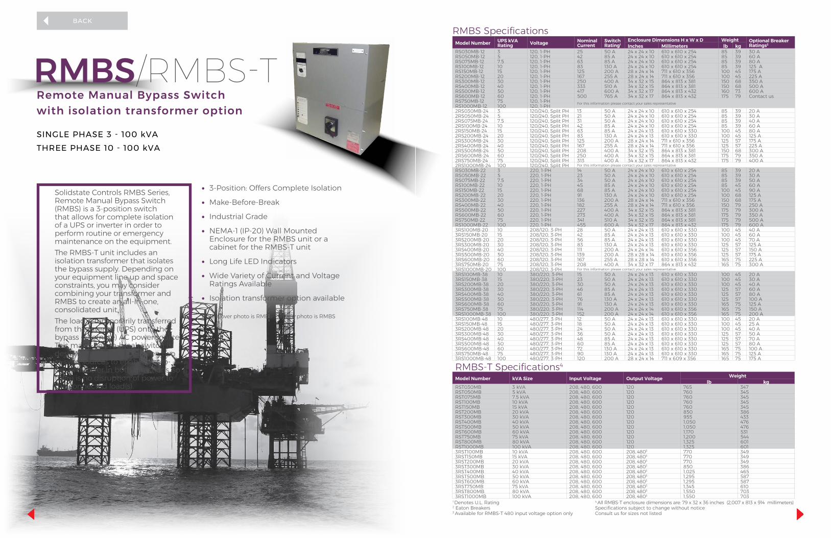
Remote Manual Bypass Switch with isolation transformer option
SINGLE PHASE 3 - 100 kVATHREE PHASE 10 - 100 kVA
• 3-Position: Offers Complete Isolation
• Make-Before-Break
• Industrial Grade
• NEMA-1 (IP-20) Wall Mounted Enclosure for the RMBS unit or a cabinet for the RMBS-T unit
• Long Life LED Indicators
• Wide Variety of Current and Voltage Ratings Available
• Isolation transformer option available
Solidstate Controls RMBS Series, Remote Manual Bypass Switch (RMBS) is a 3-position switch that allows for complete isolation of a UPS or inverter in order to perform routine or emergency maintenance on the equipment. The RMBS-T unit includes an isolation transformer that isolates the bypass supply. Depending on your equipment line up and space constraints, you may consider combining your transformer and RMBS to create an all-in-one, consolidated unit. The load is temporarily transferred from the inverter (UPS) onto the bypass (alternate) AC power source. This make-before-break switch is designed to transfer between two in-sync sources to enable a zero-break transfer in both directions, so there is no disruption of power to the connected load(s).
RMBS/RMBS-T
Note: Cover photo is RMBS-T, inside photo is RMBS
RMBS-T Specifications4
Model Number kVA Size Input Voltage Output Voltage Weightlb kg
RST030MB 3 kVA 208, 480, 600 120 765 347 RST050MB 5 kVA 208, 480, 600 120 760 345 RST075MB 7.5 kVA 208, 480, 600 120 760 345 RST100MB 10 kVA 208, 480, 600 120 760 345 RST150MB 15 kVA 208, 480, 600 120 760 345 RST200MB 20 kVA 208, 480, 600 120 850 386 RST300MB 30 kVA 208, 480, 600 120 955 433 RST400MB 40 kVA 208, 480, 600 120 1,050 476 RST500MB 50 kVA 208, 480, 600 120 1,050 476 RST600MB 60 kVA 208, 480, 600 120 1,170 531 RST750MB 75 kVA 208, 480, 600 120 1,200 544 RST800MB 80 kVA 208, 480, 600 120 1,325 601 RST1000MB 100 kVA 208, 480, 600 120 1,325 601 3RST100MB 10 kVA 208, 480, 600 208, 4803 770 349 3RST150MB 15 kVA 208, 480, 600 208, 4803 770 349 3RST200MB 20 kVA 208, 480, 600 208, 4803 770 349 3RST300MB 30 kVA 208, 480, 600 208, 4803 850 386 3RST400MB 40 kVA 208, 480, 600 208, 4803 1,025 465 3RST500MB 50 kVA 208, 480, 600 208, 4803 1,295 587 3RST600MB 60 kVA 208, 480, 600 208, 4803 1,295 587 3RST750MB 75 kVA 208, 480, 600 208, 4803 1,345 610 3RST800MB 80 kVA 208, 480, 600 208, 4803 1,550 703 3RST1000MB 100 kVA 208, 480, 600 208, 4803 1,550 703
1 Denotes U.L. Rating 2 Eaton Breakers 3 Available for RMBS-T 480 input voltage option only
4 All RMBS-T enclosure dimensions are: 79 x 32 x 36 inches (2,007 x 813 x 914 millimeters) Specifications subject to change without notice Consult us for sizes not listed
RMBS SpecificationsModel Number UPS kVA
Rating Voltage Nominal Current
Switch Rating1
Enclosure Dimensions H x W x D Weight Optional Breaker Ratings2Inches Millimeters lb kg
RS030MB-12 3 120, 1-PH 25 50 A 24 x 24 x 10 610 x 610 x 254 85 39 30 ARS050MB-12 5 120, 1-PH 42 85 A 24 x 24 x 10 610 x 610 x 254 85 39 60 ARS075MB-12 7.5 120, 1-PH 63 85 A 24 x 24 x 10 610 x 610 x 254 85 39 80 ARS100MB-12 10 120, 1-PH 83 130 A 24 x 24 x 10 610 x 610 x 254 85 39 125 ARS150MB-12 15 120, 1-PH 125 200 A 28 x 24 x 14 711 x 610 x 356 100 45 175 ARS200MB-12 20 120, 1-PH 167 255 A 28 x 24 x 14 711 x 610 x 356 100 45 225 ARS300MB-12 30 120, 1-PH 250 400 A 34 x 32 x 15 864 x 813 x 381 150 68 350 ARS400MB-12 40 120, 1-PH 333 510 A 34 x 32 x 15 864 x 813 x 381 150 68 500 ARS500MB-12 50 120, 1-PH 417 600 A 34 x 32 x 17 864 x 813 x 432 160 73 600 ARS600MB-12 60 120, 1-PH 500 765 A 34 x 32 x 17 864 x 813 x 432 175 79 Contact usRS750MB-12 75 120, 1-PH For this information please contact your sales representativeRS1000MB-12 100 120, 1-PH2RS030MB-24 3 120/240, Split PH 13 50 A 24 x 24 x 10 610 x 610 x 254 85 39 20 A2RS050MB-24 5 120/240, Split PH 21 50 A 24 x 24 x 10 610 x 610 x 254 85 39 30 A2RS075MB-24 7.5 120/240, Split PH 31 50 A 24 x 24 x 10 610 x 610 x 254 85 39 40 A2RS100MB-24 10 120/240, Split PH 42 85 A 24 x 24 x 10 610 x 610 x 254 85 39 60 A2RS150MB-24 15 120/240, Split PH 63 85 A 24 x 24 x 13 610 x 610 x 330 100 45 80 A2RS200MB-24 20 120/240, Split PH 83 130 A 24 x 24 x 13 610 x 610 x 330 100 45 125 A2RS300MB-24 30 120/240, Split PH 125 200 A 28 x 24 x 14 711 x 610 x 356 125 57 175 A2RS400MB-24 40 120/240, Split PH 167 255 A 28 x 24 x 14 711 x 610 x 356 125 57 225 A2RS500MB-24 50 120/240, Split PH 208 400 A 34 x 32 x 15 864 x 813 x 381 150 68 300 A2RS600MB-24 60 120/240, Split PH 250 400 A 34 x 32 x 15 864 x 813 x 381 175 79 350 A2RS750MB-24 75 120/240, Split PH 313 400 A 34 x 32 x 17 864 x 813 x 432 175 79 400 A2RS1000MB-24 100 120/240, Split PH For this information please contact your sales representativeRS030MB-22 3 220, 1-PH 14 50 A 24 x 24 x 10 610 x 610 x 254 85 39 20 ARS050MB-22 5 220, 1-PH 23 50 A 24 x 24 x 10 610 x 610 x 254 85 39 30 ARS075MB-22 7.5 220, 1-PH 34 50 A 24 x 24 x 10 610 x 610 x 254 85 39 50 ARS100MB-22 10 220, 1-PH 45 85 A 24 x 24 x 10 610 x 610 x 254 85 45 60 ARS150MB-22 15 220, 1-PH 68 85 A 24 x 24 x 10 610 x 610 x 254 100 45 90 ARS200MB-22 20 220, 1-PH 91 130 A 24 x 24 x 10 610 x 610 x 254 100 68 125 ARS300MB-22 30 220, 1-PH 136 200 A 28 x 24 x 14 711 x 610 x 356 150 68 175 ARS400MB-22 40 220, 1-PH 182 255 A 28 x 24 x 14 711 x 610 x 356 150 79 250 ARS500MB-22 50 220, 1-PH 227 400 A 34 x 32 x 15 864 x 813 x 381 175 79 300 ARS600MB-22 60 220, 1-PH 273 400 A 34 x 32 x 15 864 x 813 x 381 175 79 350 ARS750MB-22 75 220, 1-PH 341 510 A 34 x 32 x 15 864 x 813 x 381 175 79 500 ARS1000MB-22 100 220, 1-PH 455 600 A 34 x 32 x 17 864 x 813 x 432 175 79 600 A3RS100MB-20 10 208/120, 3-PH 28 50 A 24 x 24 x 13 610 x 610 x 330 100 45 40 A3RS150MB-20 15 208/120, 3-PH 42 85 A 24 x 24 x 13 610 x 610 x 330 100 45 60 A3RS200MB-20 20 208/120, 3-PH 56 85 A 24 x 24 x 13 610 x 610 x 330 100 45 70 A3RS300MB-20 30 208/120, 3-PH 83 130 A 24 x 24 x 13 610 x 610 x 330 125 57 125 A3RS400MB-20 40 208/120, 3-PH 111 200 A 24 x 24 x 14 610 x 610 x 356 125 57 150 A3RS500MB-20 50 208/120, 3-PH 139 200 A 28 x 28 x 14 610 x 610 x 356 125 57 175 A3RS600MB-20 60 208/120, 3-PH 167 255 A 28 x 28 x 14 610 x 610 x 356 165 75 225 A3RS750MB-20 75 208/120, 3-PH 208 400 A 34 x 32 x 17 864 x 813 x 432 165 75 300 A3RS1000MB-20 100 208/120, 3-PH For this information please contact your sales representative3RS100MB-38 10 380/220, 3-PH 15 50 A 24 x 24 x 13 610 x 610 x 330 100 45 20 A3RS150MB-38 15 380/220, 3-PH 23 50 A 24 x 24 x 13 610 x 610 x 330 100 45 30 A3RS200MB-38 20 380/220, 3-PH 30 50 A 24 x 24 x 13 610 x 610 x 330 100 45 40 A3RS300MB-38 30 380/220, 3-PH 46 85 A 24 x 24 x 13 610 x 610 x 330 125 57 60 A3RS400MB-38 40 380/220, 3-PH 61 85 A 24 x 24 x 13 610 x 610 x 330 125 57 80 A3RS500MB-38 50 380/220, 3-PH 76 130 A 24 x 24 x 13 610 x 610 x 330 125 57 100 A3RS600MB-38 60 380/220, 3-PH 91 130 A 24 x 24 x 13 610 x 610 x 330 165 75 125 A3RS750MB-38 75 380/220, 3-PH 114 200 A 24 x 24 x 14 610 x 610 x 356 165 75 150 A3RS1000MB-38 100 380/220, 3-PH 152 200 A 24 x 24 x 14 610 x 610 x 356 165 75 200 A3RS100MB-48 10 480/277, 3-PH 12 50 A 24 x 24 x 13 610 x 610 x 330 100 45 20 A3RS150MB-48 15 480/277, 3-PH 18 50 A 24 x 24 x 13 610 x 610 x 330 100 45 25 A3RS200MB-48 20 480/277, 3-PH 24 50 A 24 x 24 x 13 610 x 610 x 330 100 45 40 A3RS300MB-48 30 480/277, 3-PH 36 50 A 24 x 24 x 13 610 x 610 x 330 125 57 50 A3RS400MB-48 40 480/277, 3-PH 48 85 A 24 x 24 x 13 610 x 610 x 330 125 57 70 A3RS500MB-48 50 480/277, 3-PH 60 85 A 24 x 24 x 13 610 x 610 x 330 125 57 80 A3RS600MB-48 60 480/277, 3-PH 72 130 A 24 x 24 x 13 610 x 610 x 330 165 75 100 A3RS750MB-48 75 480/277, 3-PH 90 130 A 24 x 24 x 13 610 x 610 x 330 165 75 125 A3RS1000MB-48 100 480/277, 3-PH 120 200 A 28 x 24 x 14 711 x 609 x 356 165 75 175 A
RMBS/RMBS-T

General SpecificationsStandard Features Optional Features (Option #)
• Nema-1 (IP-20) wall mounted enclosure for the RMBS models and a cabinet for the RMBS-T models
• ANSI 61 light gray• 3-positions for complete isolation:
– Normal-load fed from Inverter (UPS) – Bypass (test)-load fed from bypass source through RMBS – Isolation-load fed from utility, completely isolating the RMBS
and inverter• Indicating lights for:
– In-sync – Bypass source available – Normal source available
• Lamp test push button• Clearance for top cable entry - contact us for bottom entry requirements
(RMBS only)• Power cable connections made to copper bus bars, allowing greater
cable bending radius • Isolation transformer (RMBS-T only)• Top and bottom cabinet entry (Standard on RMBS-T models)
• Padlockable handle to lock switch in a position
• Solenoid (electronic) interlock to prevent switch operation if inverter and bypass source are not in sync
• Output circuit breaker1
• Bypass source input circuit breaker1
• Padlockable breakers
• Aux contacts for CBs
• Indicating light package; includes: – Not in sync – Switch in normal source to load – Switch in bypass to load – Switch in isolation bypass
• Voltmeter with selector switch to indicate: – Normal input – Bypass input – AC output voltage
1Eaton breakers: Available in high kAIC ratings.
(S800P)
(S800L)
(18)
(95)
(93)
(145)
(90)
(89)
Remote Manual Bypass Switch One Line Diagram
Specifications subject to change without notice
REV 12/2018
THE PURPOSE OF OUR BUSINESS IS TO PROVIDE CONTINUITY OF ELECTRICAL POWER TO KEEP BUSINESSES IN BUSINESS.WE DO THIS BY HELPING CLIENTS SOLVE THEIR POWER PROBLEMS AND BY CREATING THE MOST ECONOMICAL LONG-TERM RESULTS.
WORLD HEADQUARTERS875 Dearborn Drive Columbus, Ohio 43085 Phone: +1-614-846-7500 Toll Free: +1-800-635-7300 Fax: +1-614-885-3990
GLOBAL OFFICES LOCATED INMexicoAsia Pacific Brazil
WEBSITEwww.solidstatecontrolsinc.com
[email protected] Middle East
IndiaArgentina

SERVER CONTROL SOFTWARE
• Control of up to four groups of four servers (16 total)• Ability to shutdown servers in a predetermined order• Ability to test server shutdown functionality from
the Web interface• Alerts based on customer preference• Retrieves 2,000 Event Data Log over TCP/IP using a
Web interface• Total system time synchronization – Network Time
Protocol (NTP)
Maintain control of the most complex remote pumping stations with state-of-the-art server control software. This enhanced Uninterruptible Power Supply (UPS) system software is designed to help operators maintain control of complex remote pumping stations. The software is equipped with the following capabilities:
PROVIDING CONTINUITY OF ELECTRICAL POWER
UNSAFE SHUTDOWNS POSE PROBLEMSImproper sequencing of pump valve shutdown protocols can lead to problems, such as, valves not activating causing a rupture in the pipelines. As the UPS system approaches the design life of the backup battery duration and eventual power loss, the control systems deployed at a pumping station or pipeline control mechanism may malfunction.
Dashboard allows for full control of all server protocols
IntelliShed’s real time system monitoring
THE SOLUTIONAMETEK Solidstate Controls' IntelliShed provides the UPS system with the capability to monitor your system and control server shutdown protocols based on real time information of battery life. This software package allows users to program battery specifications and calculates, in real time, the estimated battery time remaining during the UPS backup operation (battery discharge cycles). The UPS communicates constantly with all servers in the circuit and if a backup power situation arises, the UPS will determine when, and in what sequence the servers are to power down.As a failsafe mode, the UPS also times out servers based on a pre-determined time interval to eliminate any chance of premature server power failure.
REV 12/2018
THE PURPOSE OF OUR BUSINESS IS TO PROVIDE CONTINUITY OF ELECTRICAL POWER TO KEEP BUSINESSES IN BUSINESS.WE DO THIS BY HELPING CLIENTS SOLVE THEIR POWER PROBLEMS AND BY CREATING THE MOST ECONOMICAL LONG-TERM RESULTS.
WORLD HEADQUARTERS875 Dearborn Drive Columbus, Ohio 43085 Phone: +1-614-846-7500 Toll Free: +1-800-635-7300 Fax: +1-614-885-3990
GLOBAL OFFICES LOCATED INMexicoAsia Pacific Brazil
WEBSITEwww.solidstatecontrolsinc.com
[email protected] Middle East
IndiaArgentina

• Annunciation of system measurements and status on the Homepage or Web browser tab
• Extended data logging, including event description, time and date stamping and system readings
• Single-click navigation to user-configured alarms and system settings
• Report generation of Data Logs, Battery History Logs and Battery Test Logs
• Pause and Play capabilities to freeze momentary data• Access to snapshots of all Data Log parameters
REMOTE MONITORING SOFTWARE
UPSView remotely monitors your AMETEK Solidstate Controls digital inverter, charger/rectifier or Uninterruptible Power Supply (UPS) System, giving you a real-time view of the health and status of your power quality system.The user-friendly communication package operates as an interactive and secure web interface, monitoring multiple units from any web enabled device. UPSView enhanced online capabilities include:
PROVIDING CONTINUITY OF ELECTRICAL POWER
MONITOR YOUR SYSTEMUPSView allows the user to completely monitor and maintain familiarity with their systems. The Homepage for each system displays the unique system configuration, active alarms and critical system measurements.The UPSView Homepage will react to the data it is collecting, accented by a green background during normal system operation and red when a system is experiencing trouble. The interface supports multi-system monitoring, annunciating trouble in a specific system on its corresponding Web browser tab.
NAVIGATE SIMPLY• Easily navigate through the interactive UPSView Web interface by
simply clicking one of the buttons on the Homepage.• Monitor all enabled alarms and meters and their current status.• Open data history logs in new web pages to maintain records
locally or troubleshoot your system.• All logs are capable of being exported and generated as a report.• Observe communication between the Web browser and the server
through an I/O Terminal.• Control the polling of information from the server using the Pause/
Play Button. When the polling is active, the system readings will be updated every 2 seconds.
TRACK HISTORY• Track events through UPSView’s extensive
Data History Logging Features.• Retain battery history and statistics through
the use of a detailed Battery History Log.• Generate Battery Test reports
REV 12/2018
THE PURPOSE OF OUR BUSINESS IS TO PROVIDE CONTINUITY OF ELECTRICAL POWER TO KEEP BUSINESSES IN BUSINESS.WE DO THIS BY HELPING CLIENTS SOLVE THEIR POWER PROBLEMS AND BY CREATING THE MOST ECONOMICAL LONG-TERM RESULTS.
WORLD HEADQUARTERS875 Dearborn Drive Columbus, Ohio 43085 Phone: +1-614-846-7500 Toll Free: +1-800-635-7300 Fax: +1-614-885-3990
GLOBAL OFFICES LOCATED INMexicoAsia Pacific Brazil
WEBSITEwww.solidstatecontrolsinc.com
[email protected] Middle East
IndiaArgentina