Embed Size (px)
Citation preview
All About
ServicingR-410a Refrigerant Systems
™
August 2010
©2010 Electrolux Home Products Inc.10200 David Taylor DriveCharlotte, NC 28262

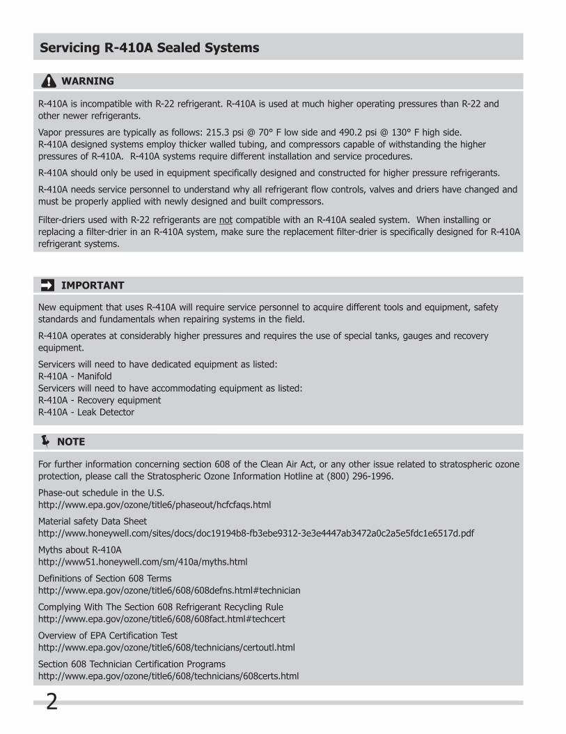
Servicing R-410A Sealed Systems
1
The purpose of this service manual is to give the service technician an understanding of the changes in refrigerants and sealed system service. Persons attempting to use this service manual to make repairs to sealed system refrigeration systems should have electrical training as well as training in sealed system repairs. The person making the repairs must know and understand all laws (Local and International) governing handling of all refrigerants. The technician must be trained in the use of recovery and recycling equipment. Electrolux Home Products, Inc. cannot be responsible, nor assume any liability, for injury or damage of any kind arising from the use of this manual.
NOTE
Electrolux does not permit the use of recovered refrigerant in the servicing of our products for in-warranty and out-of-warranty repairs or for products covered by service contracts. Therefore, only new refrigerant or refrigerant that has been reclaimed back to new specifications by a refrigerant manufacturer is to be used.
IMPORTANT
Effective July 1, 1992, the United States clean air act governs the disposal of refrigerants such as R-22. Therefore, when discharging or purging the sealed system use an EPA approved refrigerant recovery system as outlined in the final rule on the protection of stratospheric ozone and refrigerant recycling, which was published in the Federal Register May 14, 1993.
IMPORTANT
Safety and CFC CertificationComplying with Section 608 Refrigerant Recycling Rule: http://www.epa.gov/ozone/title6/608/608fact.html#techcert
EPA has established a technician certification program for persons (“technicians”) who perform maintenance, service, repair, or disposal that could be reasonably expected to release refrigerants into the atmosphere. The definition of “technician” specifically includes and excludes certain activities as follows:Any person who performs maintenance, service, or repair that could reasonably be expected to release class I (CFC) or class II (HCFC) substances from appliances, into the atmosphere. Technician also means any person performing disposal of appliances, except for small appliances, MVACs, and MVAC-like appliances that, could be reasonably expected to release class I or class II refrigerants from appliances into the atmosphere.
Small appliance is defined as:Any of the following products that are fully manufactured, charged, and hermetically sealed in a factory with five pounds or less of refrigerant: refrigerators and freezers designed for home use, room air conditioners (including window air conditioners and packaged terminal air conditioners), packaged terminal heat pumps, dehumidifiers, under-the-counter ice makers, vending machines, and drinking water coolers.
The Agency has developed four types of certification: 1. For servicing small appliances (Type I). 2. For servicing or disposing of high- or very high-pressure appliances, except small appliances and MVACs (Type II). 3. For servicing or disposing of low-pressure appliances (Type III). 4. For servicing all types of equipment (Universal).Technicians are required to pass an EPA-approved test given by an EPA-approved certifying organization to become certified under the mandatory program. Section 608 Technician Certification credentials do not expire. Overview of Issues on EPA Certification Test: http://www.epa.gov/ozone/title6/608/technicians/certoutl.htmlR-410A requires training of installation and service personnel in the proper and safe handling of R-410A.Many equipment manufacturers are well aware of the concerns and safety issues of working with R-410A and other HFC refrigerants and are requiring installation and service professionals who purchase their R-410A systems to be R-410A Certified.
IMPORTANT
Servicing R-410A Sealed Systems
2
WARNING
R-410A is incompatible with R-22 refrigerant. R-410A is used at much higher operating pressures than R-22 and other newer refrigerants.
Vapor pressures are typically as follows: 215.3 psi @ 70° F low side and 490.2 psi @ 130° F high side.R-410A designed systems employ thicker walled tubing, and compressors capable of withstanding the higher pressures of R-410A. R-410A systems require different installation and service procedures.
R-410A should only be used in equipment specifically designed and constructed for higher pressure refrigerants.
R-410A needs service personnel to understand why all refrigerant flow controls, valves and driers have changed and must be properly applied with newly designed and built compressors.
Filter-driers used with R-22 refrigerants are not compatible with an R-410A sealed system. When installing or replacing a filter-drier in an R-410A system, make sure the replacement filter-drier is specifically designed for R-410A refrigerant systems.
IMPORTANT
New equipment that uses R-410A will require service personnel to acquire different tools and equipment, safety standards and fundamentals when repairing systems in the field.
R-410A operates at considerably higher pressures and requires the use of special tanks, gauges and recovery equipment.
Servicers will need to have dedicated equipment as listed:R-410A - ManifoldServicers will need to have accommodating equipment as listed:R-410A - Recovery equipmentR-410A - Leak Detector
NOTE
For further information concerning section 608 of the Clean Air Act, or any other issue related to stratospheric ozone protection, please call the Stratospheric Ozone Information Hotline at (800) 296-1996.
Phase-out schedule in the U.S.http://www.epa.gov/ozone/title6/phaseout/hcfcfaqs.html
Material safety Data Sheethttp://www.honeywell.com/sites/docs/doc19194b8-fb3ebe9312-3e3e4447ab3472a0c2a5e5fdc1e6517d.pdf
Myths about R-410Ahttp://www51.honeywell.com/sm/410a/myths.html
Definitions of Section 608 Termshttp://www.epa.gov/ozone/title6/608/608defns.html#technician
Complying With The Section 608 Refrigerant Recycling Rulehttp://www.epa.gov/ozone/title6/608/608fact.html#techcert
Overview of EPA Certification Testhttp://www.epa.gov/ozone/title6/608/technicians/certoutl.html
Section 608 Technician Certification Programshttp://www.epa.gov/ozone/title6/608/technicians/608certs.html
Servicing R-410A Sealed Systems
3
Safe Handling Practices for R-410A
1. Always wear protective goggles when working with refrigerant. If liquid refrigerant gets in your eye, permanent blindness may result.
2. Do not allow refrigerant to come in contact with your skin. Refrigerant has a very low boiling point, which will cause frostbite.
3. All refrigerant handling, charging, and recycling operations should be performed in locations with adequate ventilation of at least four air changes per hour. Avoid prolonged breathing of the vapor. Prolonged inhalation of refrigerant is extremely dangerous; death can occur without warning.
4. Do not use a recovery unit in the vicinity of spilled or open containers of gasoline, thinners, or any other flammable liquid or vapor unless the equipment is expressly designed (explosion proof designs) for such environments. Do not operate where flammable vapor is present.
5. Do not leave any recovery or recycling machine on and unsupervised.6. Do not attempt to fill any vessels, containers, cylinders, charging equipment, or storage tanks that are not D.O.T. approved and equipped with a safety-vent valve. Do not transfer refrigerant to non-refillable cylinders.7. Do not fill any storage tank or vessel with refrigerant beyond 80% of its capacity.8. Do not disconnect or tamper with the electrical high-pressure, low-pressure, or liquid-level safety shut-off.9. The pressure of R-410A is significantly higher than R-22. This does not mean that R-410A, or equipment containing R-410A is unsafe, but it does mean you need tools and equipment that were designed for this higher
pressure. You must use AC equipment; cylinders and service tools have been re-engineered to handle the higher pressure.
10. When servicing R-410A equipment make sure you use reversing valves, expansion valves, filter-driers, and other components specifically designed for R-410A.
11. Cylinders used for new R-410A, as well as recovered R-410A have both been redesigned for the higher pressure.
Service equipment must also be designed for R-410A: High-pressure manifold gauge and hose sets (must have 4000 psi burst pressure and 800 psi working pressure). High-pressure recovery machine certified for use with R-410A. High-pressure recovery tanks, such as DOT 4BA400 or 4BW400.
Service Diagnostic Tips
A prime requisite on the initial contact is: Always allow the customer to explain the problem. Many times the trouble can be diagnosed more quickly, based on the customer’s explanation. Most of all, do not jump to conclusions until you have heard the full story and have evaluated the information obtained from the customer. Then proceed with your diagnosis.
Before starting a test procedure, connect the product service cord to the power source, through a wattmeter, combined with a voltmeter. Then make a visual inspection and operational check of the air conditioner to determine the following:1. Is the product properly leveled?2. Is the product located for proper dissipation of heat from the condenser? Check install location.3. Feel condenser. With compressor in operation, condenser should be hot, with gradual reduction in temperature
from entry to exit of condenser.4. Is evaporator fan properly located on motor shaft?5. Is the thermostat sensing element properly positioned?6. Observe frost pattern on evaporator.7. Check control setting.For air-conditioners, check room size, temperature, amount of people, windows, and other factors that increase the load on the product. After this phase of diagnosis is completed, a thorough operational check should be made of the refrigeration system.
Servicing R-410A Sealed Systems
4
R-410A Refrigerant Overview
The U.S. Clean Air Act of 1990 and the MontrealProtocol call for the phaseout of HCFC-22 (commonlyknown as R-22). This has caused manufacturers to fi nd a replacement for the standard R-22 refrigerant.
The EPA is not mandating the use of R-410A. They are mandating that R-22 can no longer be used in new equipment in 2010, and production of R-22 will cease in2020. Manufacturers must use alternative refrigerants, and so far, most of them are choosing R-134A or R-410A.However, R-407C is being used in many rooftop units and other refrigerants as well, depending on the application.
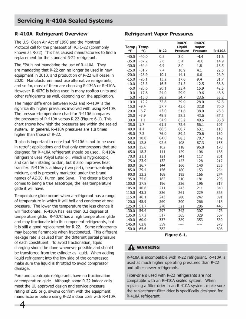
The major difference between R-22 and R-410A is the signifi cantly higher pressures involved with using R-410A.The pressure-temperature chart for R-410A comparesthe pressures of R-410A versus R-22 (Figure 6-1). This chart shows how high the pressures are within the sealed system. In general, R-410A pressures are 1.8 times higher than those of R-22.
It also is important to note that R-410A is not to be used in retrofi t applications and that only compressors that are designed for R-410A refrigerant should be used. R-410A refrigerant uses Polyol Ester oil, which is hygroscopic, and can be irritating to skin, but it also improves heat transfer. R-410A is a binary (two part), near-azeotropic mixture, and is presently marketed under the brand names of AZ-20, Puron, and Suva. The closer a blend comes to being a true azeotrope, the less temperature glide it will have. Temperature glide occurs when a refrigerant has a range of temperature in which it will boil and condense at one pressure. The lower the temperature the less chance it will fractionate. R-410A has less then 0.3 degrees oftemperature glide. R-407C has a high temperature glide and may fractionate into its component refrigerants, but it is still a good replacement for R-22. Some refrigerants may become fl ammable when fractionated. This different leakage rate is caused from the different partial pressure of each constituent. To avoid fractionation, liquid charging should be done whenever possible and should be transferred from the cylinder as liquid. When adding liquid refrigerant into the low side of the compressor, make sure the liquid is throttled to avoid compressor damage.
Pure and azeotropic refrigerants have no fractionation or temperature glide. Although some R-22 indoor coils meet the UL approved design and service pressure rating of 235 psig, always confi rm with the equipment manufacturer before using R-22 indoor coils with R-410A.
-40.0-35.0-30.0-25.0-20.0-15.0-10.0-5.00.05.0
10.015.020.025.030.035.040.045.050.055.060.065.070.075.080.085.090.095.0
100.0105.0110.0115.0120.0125.0130.0135.0140.0145.0150.0
3.05.48.0 10.9 14.1 17.6 21.3 25.4 29.9 34.7 39.9 45.6 51.6 58.2 65.2 72.6 80.7 89.298.3108118129141153166180195210226243261280300 321342 365 389 --------
-4.4-0.6 1.8 4.1 6.6 9.4 12.5 15.919.623.628.032.838.043.649.656.163.170.678.787.396.8106117128140153166181196211229247266286307329353--------
11.614.9 18.5 22.5 26.9 31.7 36.8 42.548.655.262.370.078.387.396.8107118130142155170185201217235254274295317340365391418446476507539573608
0.52.64.97.410.113.216.520.124.028.232.837.743.048.854.961.568.576.084.092.6102111121132144156168182196211226243260278297317337359382
-40.0-37.2-34.4-31.7-28.9-26.1-23.3-20.6-17.8-15.0-12.2-9.4-6.7-3.9-1.11.74.47.210.012.815.618.321.123.926.729.432.235.037.840.643.346.148.951.754.457.260.062.865.6
R-22 Pressure Pressure R-410A Temp
°FTemp
°C
Refrigerant Vapor Pressures
R407CLiquid
R407CVapor
Figure 6-1.
WARNING
R-410A is incompatible with R-22 refrigerant. R-410A is used at much higher operating pressures than R-22 and other newer refrigerants.
Filter-driers used with R-22 refrigerants are not compatible with an R-410A sealed system. When replacing a filter-drier in an R-410A system, make sure the replacement filter drier is specifically designed for R-410A refrigerant.
Servicing R-410A Sealed Systems
5
Recovery Equipment
Refrigerant recovery equipment needs to be R-410A compatible. To determine if your existing unit is approved, check the Air-Conditioning and Refrigeration Institute’s (ARI) website at www.ari.org or the UL website at www.ul.com. Recovery units must be approved for Class V refrigerants including R-407C, R-404A and R-507 and others per ARI 740-98. For best performance with your R-410A recovery equipment, it should have the following features:1. Oversized condenser2. Oversized fan3. Crankcase pressure regulator (CPR) valve4. High-pressure cutout switch rated for at least 510
psi.
Recovery equipment also is available with a subcoolingfeature, which aids in recovering R-410A. Subcooling keeps the recovery tank pressure lower by ensuring that the refrigerant is fully condensed before putting it into the recovery cylinder. This will increase the rate ofrecovery and reduce the wear and tear on recovery equipment. Subcooling also can be accomplished by submerging the recovery cylinder in a bucket of ice.
Oversized condenser
Helps completely condense the refrigerant and to keep the recovery tank temperatures down.
Fan The larger the fan and the more aggressive the pitch of the blades, the more air is moved over the condenser.More airfl ow also keeps critical internal componentscool, increasing their service life.
Crankcase pressure regulator (CPR) This device will regulate the pressures so the recovery equipment is not overwhelmed with high pressures when working with R-410A. Units that use a CPR valve do not require the technician to throttle or regulate the fl ow of refrigerant to the recovery unit to prevent damage to the compressor.
Dedicated Equipment Needed
A standard manifold set, hoses, recovery equipmentand recovery cylinder cannot be used when recoveringR-410A. The pressures encountered when working with R-410A are too high for your standard equipment.Here are the items a technician will need to safelywork with R-410A.
Manifold set
The pressures encountered while working with R-410A require a manifold gauge set that has a low-side gauge that reads up to 500 psi and a highside gauge that reads up to 800 psi. This is higher than your standard manifold set.Use a micron gauge to pull a vacuum of 500 micron toremove moisture and to change a fi lter-drier. Liquid line fi lter-driers must have a working rating pressure of no less than 600 psi and must be approved for use with R-410A.
Hoses
R-410A hoses and assemblies should be Underwriters Laboratories (UL) recognized and have a minimum 800 psi pressure rating with a 4,000 psi burst. Manufacturers recommend the use of a ball valve type connection rather than an anti-blowback connector. An anti-blowback connector traps refrigerant in the hose making it diffi cult to disconnect the hose under high-pressure conditions. Although most R-410A units come with the standard 1/4-inch fi ttings, some manufacturers use 5/16-inch access fi ttings.
When buying hoses for R-410A make sure the complete hose assembly has been recognized by Underwriters Laboratories. Some hose manufacturers use UL-recognized hose, but fail to have the complete assembly certifi ed for R-410A pressures. Always use the shortest hoses possible. Using 3/8-inch hose will greatly increase the recovery rates.
Recovery cylinders
A U.S. DOT 400 recovery cylinder must be used when recovering R-410A. Recovery cylinders have a DOT rating of 4BA 400 or 4BW 400. A standard DOT 350 recovery cylinder will not safely handle the high pressures used with R-410A. Clearly mark all of the R-410A tanks and have them re-certifi ed every fi ve years.
Servicing R-410A Sealed Systems
6
High-pressure cutout
A high-pressure cut-out switch with a rating higher than 510 psi will keep the recovery unit from prematurely relieving high pressure when recovering R-410A. Some manufacturers offer equipment with an override switch so a higher-pressure switch is used when recovering R-410A. The problem with having a dual switch (550 psior higher) is that an R-410A recovery cylinder (DOT 400) and a standard recovery cylinder (DOT 350) are virtually indistinguishable unless marked. Using recovery equipment with a high-pressure switch rated at 550 psiwith a standard DOT 350 recovery cylinder can cause the relief valve to blow, creating an extremely dangerous situation.
Maintaining Equipment
Proper maintenance of equipment is critical for safety. Calibrate the gauges on the manifold set before every use and annually check the manifold set for leakage. Inspect the hoses for nicks or cracks and that the gaskets are in good shape. Make sure the valve assemblies are not leaking. Inspect the recovery unit periodically to ensure that it is safe to use. If degradation in the rate of recovery is noticed, check the built-in or external fi lter.
Definitions
Recovery:
To remove refrigerant in any condition from a system and store it in an external container without necessarily testing or processing it in any way.
Recycling:
To clean refrigerant for reuse by oil separation and single or multiple passes through devices, such as replaceable core filter-driers, which reduce moisture, acidity and particulate matter. This term usually applies to procedures implemented at the field job site or at a local service shop.
Reclaim:
To reprocess refrigerant to new product specifications by means which may include distillation, will require chemical analysis of the refrigerant to determine that appropriate product specifications are met. This term usually implies the use of processes or procedures available only at a reprocessing or manufacturing facility.
Basic Components
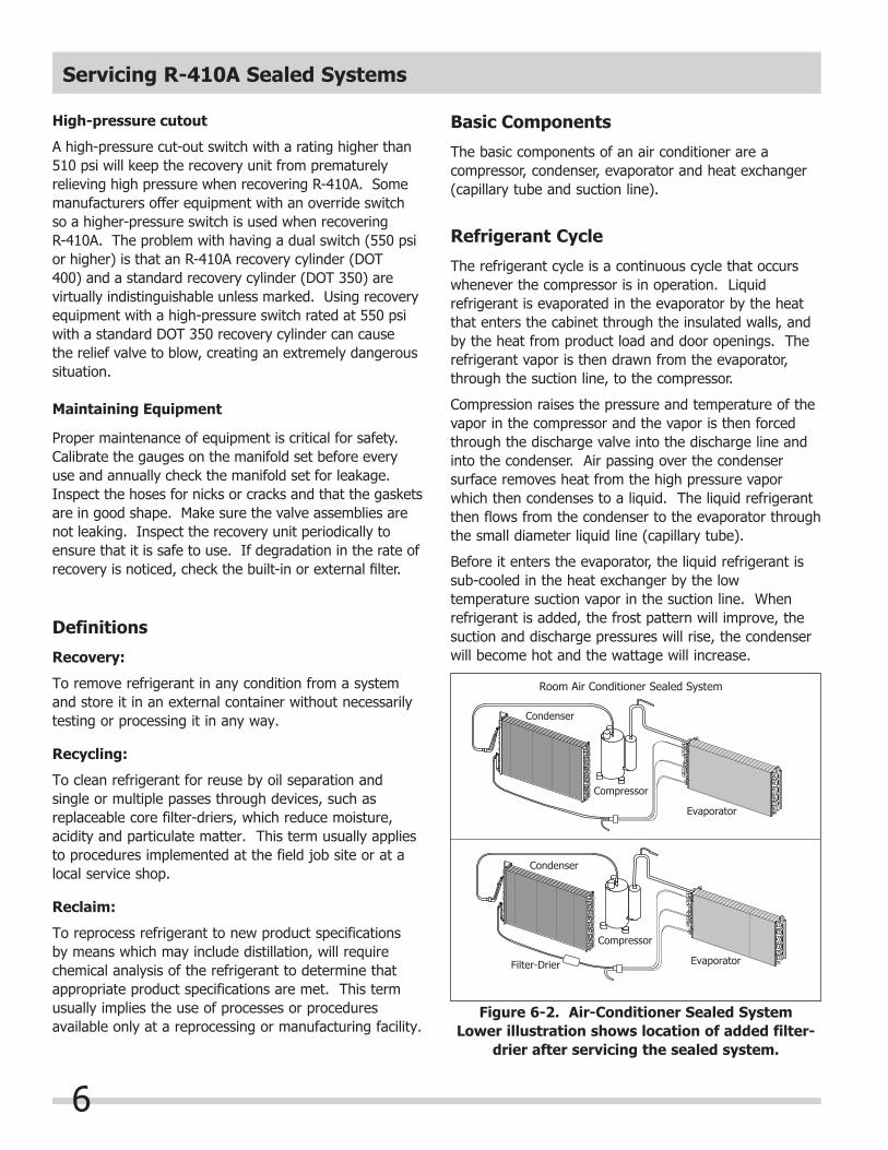
The basic components of an air conditioner are a compressor, condenser, evaporator and heat exchanger (capillary tube and suction line).
Refrigerant Cycle
The refrigerant cycle is a continuous cycle that occurs whenever the compressor is in operation. Liquid refrigerant is evaporated in the evaporator by the heat that enters the cabinet through the insulated walls, and by the heat from product load and door openings. The refrigerant vapor is then drawn from the evaporator, through the suction line, to the compressor.
Compression raises the pressure and temperature of the vapor in the compressor and the vapor is then forced through the discharge valve into the discharge line and into the condenser. Air passing over the condenser surface removes heat from the high pressure vapor which then condenses to a liquid. The liquid refrigerant then flows from the condenser to the evaporator through the small diameter liquid line (capillary tube).
Before it enters the evaporator, the liquid refrigerant is sub-cooled in the heat exchanger by the low temperature suction vapor in the suction line. When refrigerant is added, the frost pattern will improve, the suction and discharge pressures will rise, the condenser will become hot and the wattage will increase.
Condenser
Compressor
Evaporator
Condenser
Compressor
Filter-Drier Evaporator
Room Air Conditioner Sealed System
Figure 6-2. Air-Conditioner Sealed SystemLower illustration shows location of added filter-
drier after servicing the sealed system.

Servicing R-410A Sealed Systems
7
Recovering Refrigerant
Recovering refrigerant is the first step in preventivemaintenance or repair of equipment. Simply put, recovery means transferring the system’s refrigerant into a refillable refrigerant cylinder.
The first step is to have on hand, clean, safe, refillable cylinders evacuated to 25 microns, and labeled for each different type of refrigerant you will be working with. Example; for repairing Electrolux Home Products Inc. built products you will need one cylinder for R-12, one for R-22, one for R-410A, one for R-134A, and one for R-500 if working on dehumidifiers.
Second step is you must have dedicated equipmentfor HFC (R-410A) refrigerant. Because of the difference in the oil and the refrigerant, you can not use the same equipment on HFC based refrigerants as used on CFC based refrigerants.
To recover the refrigerant:
1. Disconnect unit from source of power.2. Attach an approved self tapping line tap valve to the
process tube. Connect refrigerant recovery system to tap valve. Turn on recovery system, open the line tap valve, and allow refrigerant to flow into an approved tank. (See Figure 6-3 )
3. Allow the recovery pump to run until the system has reached 13 inches of vacuum.
4. Shut system down and allow to set for two minutes. If pressure is below (0) pounds per square inch, disconnect equipment and proceed with repair.5. If pressure does not stay bellow (0) pounds per
square inch, repeat steps 3 and 4 until all refrigerant is removed and system remains in a vacuum.
Always make sure your equipment is in good condition and all manufacture instructions are followed to prevent the accidental rupture of a hose, connection fitting, or a tank, that could cause a serious injury. Always sit the tank on a scale when you are transferring refrigerant into the tank. Always check the weight to see when the tank is full, do not over fill the tank.
Drier
Inlet
OutletPressure Guage
Recovery UnitCompound
Guage
Vapor
LiquidPiercingValve
Tube
Process Tube
Scale
DischargeLine
CompressorOr Disabled
Unit
SuctionLine
RefillableRefrigerant
Tank
Figure 6-3. Installation of Recovery Equipment
IMPORTANT
Your Country may have regulations or restrictions governing the discharging of chlorofl uorocarbons(CFC’s) such as R-12 and R-22 to the atmosphere. Therefore, when discharging or purging the sealed system, use an approved refrigerant recovery system.
Servicing R-410A Sealed Systems
8
Recovery Methods
Even though refrigerant properties are different, the basic recovery process is the same for R-410A and R-22.R-410A is much more dense than R-22 and has a higher vapor pressure making it more diffi cult to recover. The hook-up and recovery instructions will vary from manufacturer to manufacturer so be sure to read and understand all of the operation instructions for the refrigerant recovery unit being used.
Push-Pull Recovery
Quickly removes the liquid refrigerant, but you must change the hose connections to recover vapor refrigerant after all of the liquid is removed. This method is not recommended unless trying to recover more than 10 pounds of refrigerant.
Liquid Recovery
Not all recovery equipment is capable of handling direct liquid recovery. Check with the manufacturer of the recovery equipment used to fi nd out if the unit is capable and if there are any special instructions for direct liquid recovery.
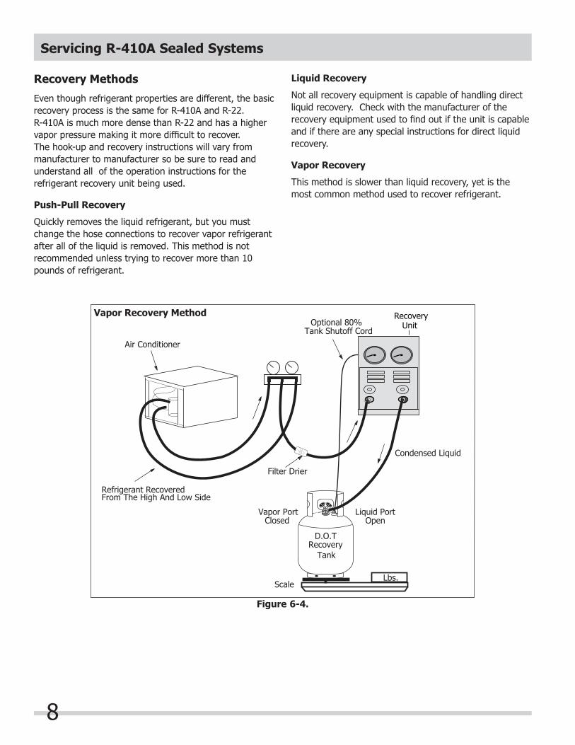
Vapor Recovery
This method is slower than liquid recovery, yet is the most common method used to recover refrigerant.
Recovery Unit
Lbs.
Liquid PortVapor PortOpenClosed
D.O.TRecovery Tank
Condensed Liquid
Filter Drier
Refrigerant RecoveredFrom The High And Low Side
Air Conditioner
Optional 80%Tank Shutoff Cord
I OU
Scale
Vapor Recovery Method
Figure 6-4.
Servicing R-410A Sealed Systems
9
Charging Sealed Systems
Overcharging a refrigeration system with refrigerant can be dangerous. If the overcharge is sufficient to immerse the major parts of the motor and compressor in liquid refrigerant, a situation has been created which, when followed by a sequence of circumstances, can lead to the compressor shell seam separating.
A hydraulic block occurs preventing the compressor from starting. This condition is known as locked rotor.Electric current continues to flow through the compressor motor windings which become, in effect, electric resistance heaters. The heat produced begins to vaporize the excess refrigerant liquid, causing a rapid increase in system pressure. If the compressor protective devices fail, the pressure within the system may rise to extremes far in excess of the design limits. Under these conditions, the weld seam around the compressor shell can separate with explosive force, spewing oil and refrigerant vapor, which could ignite.
To eliminate this exceedingly rare but potential hazard, never add refrigerant to a sealed system. If refrigerant is required, evacuate the existing charge and recharge with the correct measured amount of the refrigerant specified for the system.
Always make sure your equipment is in good condition and all manufacturer’s instructions are followed to prevent the accidental rupture of a hose, connectionfitting, or a tank, which could cause a serious injury. Run equipment until system has reached 13 inches of vacuum. Shut system down and allow to sit for two minutes, if pressure remains below (0) pounds per square inch, disconnect equipment and proceed. If pressure does not stay below (0) pounds per square inch, repeat above procedure until all refrigerant is removed and system remains in a vacuum.
Soldering
1. All joints to be soldered must have a proper fit. Clearance between tubes to be soldered should be from .001” to .006”. It is not practical to actually measure this; however, you do not want a dry fit or loose fit. Tubing joints should overlap about the
distance of their diameter except for restrictor tubes, which should be inserted 1.25”.
2. Clean all joint areas with fine steel wool or prefer-ably an abrasive cloth, such as grit cloth No. 23 or Scotch-Brite.
3. Apply a thin film of liquid flux recommended for silver soldering to surfaces to be joined, and to surfaces immediately adjacent to joint.
4. Align tubing so no stress is on joint. Do not move tubing while solder is solidifying or leaks will result.
5. Use a torch of adequate capacity so joint can be quickly heated with a minimum of heat travel to other points. Use a good grade of silver solder.
6. Solder connections. If tubing is properly cleaned and fluxed, solder will flow readily. Use only enough
solder to make a good bond. 7. Allow joint to cool, then wash exterior with water to
remove flux.
R-410A refrigerant molecules are smaller than R-22 molecules. This means that R-410A will pass more minor leaks and the rate of flow will be greater than for R-22. Therefore, it is now more important than ever to follow good brazing practices. Use a good grade of silver solder. A 45% silver solder is recommended.
Wear approved safety glasses when working with or on any pressurized system or equipment. have an approved dry type fire extinguisher handy when using any type of gas operated torch.
During application of heat, use wet cloths to prevent heat from conducting to areas other than the soldered joint. Use a sheet of metal or torch guard pad as a heat deflector to keep flame away from inflammable materials and painted surfaces.
NOTE
Attach an approved self tapping line tap valve to the process tube. Connect refrigerant recovery system to tap valve. Turn on recovery system, open the line tap valve, and allow refrigerant to flow into an approved tank.
Servicing R-410A Sealed Systems
10
Low/High Side Leak or Undercharge
A loss of refrigerant can result in any of the following:1. Excessive or continuous compressor operation.2. Air from AC unit is not cold.3. A partially frosted evaporator (depending on amount
of refrigerant loss).4. Low suction pressure (vacuum).5. Low wattage.
The condenser will be “warm to cool”, depending on the amount of refrigerant lost.
In the case of a low side refrigerant leak resulting in complete loss of refrigerant, the compressor will run but will not refrigerate. Suction pressure will drop below atmospheric pressure and air and moisture will be drawn into the system, saturating the filter drier. A system with R-410A refrigerant will become saturated with moisture much faster than a system with R-22. Therefore, you must obtain a sample of the oil and check with an oil test kit to determine the amount of contamination. You will find that the oil in an R-410A system will have to be replaced after most low side leaks.
If there is reason to believe the system has operated for a considerable length of time with no refrigerant and the leak occurred in the low side of the system, excessive amounts of moisture may have entered the system. The system will probably require a system flush and a compressor replacement. If a slight undercharge of refrigerant is indicated and no leak can be found after a thorough leak test, the charge can be corrected without changing the compressor.If you are “topping off” the charge, it is necessary to charge R-410A refrigerant into the low side of an operating system.
If a high side leak is located and some refrigerant remains in the system it may not be necessary to change the compressor.
Electrolux Home Products Inc. does not approve the use of the Sweep Charge for sealed system repair. This method of servicing sealed systems is often used to repair products in the field. The Sweep Charge does not adequately remove moisture from the oil in the compressor. In a R-410A system you will need to replace the compressor if the product has had a low side leak.
Testing for Refrigerant Leaks
If the system is diagnosed as short of refrigerant and the system has not been recently opened, there is probably a leak in the system. Adding refrigerant without first locating and repairing the leak or replacing the component will not permanently correct the difficulty.
The leak must be found!
Sufficient refrigerant may have escaped to make it impossible to leak test effectively. In such cases, add a ¼” line piercing valve to the compressor process tube. Add sufficient refrigerant vapor to increase the pressure to 75 lbs. per sq. in. Through this procedure, leaks are more easily detected before discharging the system into reprocess/recapture equipment. Check the low side for leaks. Run the compressor 2 or 3 minutes and check the high side for leaks. Recover refrigerant using an EPA approved recovery system.
Checking For Internal Leaks
Before checking for internal leaks, check all accessible system components and joints for leaks.
If an internal leak is suspected, it must be confirmed. Use the following procedure:
1. Discharge the system by using refrigerant recovery equipment.
2. Pinch off and solder closed one end of the part of the system to be tested.
3. Solder a 1/4” charging hose fitting to the open end of the part of the system to be tested.
4. Connect a pressure gauge and access valve to the open end of the part of the system to be tested. Pressurize to 250 lbs. using dry nitrogen or carbon dioxide.
5. Leave the pressure on for 24 hours. Any drop in pressure is an indication of a leak.
NOTE
The line piercing valve (clamp-on type) should be used for test purposes only. It must be removed from system after it has served its purpose.
Servicing R-410A Sealed Systems
11
If dry nitrogen or carbon dioxide is not available.Follow instructions 1 through 3, then use 4 and 5 listed below as an alternative method.
4. Connect gauges to charging hose fittings. Pull a vacuum on each side of the system.
5. Leave the vacuum on each side of the system for 24 hours. Any loss of vacuum is an indication of a leak.
Compressor Replacement
Before installing new compressor, check for possible system contamination by obtaining an oil sample from the old compressor. On R-410A systems use an oil test kit to check for contamination. If oil has a burned odor or shows contamination (dark color), the system should be flushed to remove as much of the contamination as possible before installing a new compressor. If this contamination is allowed to remain in the system it will mix with the new oil causing it to become contaminated and damage the new compressor or cause a restriction in the cap tube.
Flushing The System With NitrogenIt is recommended that system be flushed with dry Nitrogen. However, if refrigerant is used to flush the system you must look at the serial plate to see what type of refrigerant is used in the system. This is the only refrigerant that can be used to flush the system and it must be recovered.
NEVER PRESSURIZE WITH OXYGEN. NEVER OPEN A HIGH PRESSURE TANK UNLESS IT IS EQUIPPED WITH A PRESSURE REGULATOR.NEVER PUT HIGH PRESSURE ON THE DOME OF THE COMPRESSOR - IT MIGHT EXPLODE. MAKE SURE GAUGE FITTINGS ARE IN GOOD CONDITION AND DO NOT LEAK.
Use extreme care when using Dry Nitrogen to flush systems. Pressure in nitrogen cylinder could be as high as 2500 psi. Nitrogen cylinder must be equipped with approved pressure regulator and pressure relief valve. Ensure that your hoses have adequate ratings for pressure involved and that all of your equipment is in good condition.When flushing with nitrogen there MUST Be a pressure regulator on the tank with the maximum pressure on the low side of the sealed system (evaporator) at 150 PSI and at the High side, 300 PSI.The end of the flushing hose on this tank regulator must be equipped with a hand shut-off valve (Robinair No. 40380). Close hand shut-off valve and adjust nitrogen regulator to correct pressure before proceeding with flushing procedure.
1. Remove compressor. Connect process coupling to outlet tube of condenser.
2. Fasten cloth over other end of coil to prevent old oil from spraying over room.
3. Connect hand shut-off valve on flushing hose to process coupling.
4. Slowly open hand shut-off valve and allow nitrogen to flow through condenser until discharge is clear.
5. Disconnect cap tube from evaporator. Flush evaporator in same manner as condenser.
6. Flush cap tube. This is only possible if you have a proper service valve adapter.
7. Reassemble system.
DO NOT EXCEED 300 PSI.
DO NOT EXCEED 300 PSI.
DO NOT EXCEED 150 PSI.
Servicing R-410A Sealed Systems
12
Follow the numbered sequence for all products:
1. Disconnect electrical supply to unit.2. Remove all components necessary to access the compressor assembly in the unit.3. Attach an approved self tapping line tap valve to the
process tube. Connect refrigerant recovery system to tap valve. Turn on recovery system, open the line tap valve, and allow refrigerant to flow into an approved tank.
4. Remove leads from compressor motor terminals.5. Remove mounting nuts and washers.6. After refrigerant is completely recovered, cut suction
and discharge lines as close to compressor as possible. Leave only enough tubing to pinch off and
seal defective compressor. Plug or tape any open system tubing to avoid entrance of moisture and air into system. Remove inoperable compressor and transfer mounting parts to new compressor.
7. Release holding charge (release slowly to avoid oil discharge) on new compressor to ensure there is no leak in seam or tubing. Reinstall rubber plug.
8. Install new compressor in exact same manner as original compressor.
9. Reform both suction and discharge lines to align with new compressor. If they are too short, use
additional lengths of tubing. Joints should overlap 0.5” to provide sufficient area for good solder joints. Clean and mark area where tubing should be cut. Cut tubing with tubing cutter. Work quickly to avoid
letting moisture and air into system.10. Solder all connections according to soldering procedure.
DO NOT OPERATE RECIPROCATING COMPRESSORS WHEN CHARGING LIQUID REFRIGERANT INTO SYSTEM THROUGH ITS PROCESS TUBE.
NOTE If low-side process tube is too short, silver solder four inch piece of tubing onto process tube at this time.
On R-410A systems, compressor must NOT be left open to atmosphere for more than 10 minutes to prevent moisture contamination of oil.
Installing a New Compressor
Manufacturers have redesigned their compressors with increased wall thickness due to the higher pressure associated with R-410A. The internal pressure relief for R-410A will open at 550-625 psi. Suction and discharged pressure are 40% to 70% greater than R-22 and the discharge temperature of R-410A is lower due to its higher vapor heat capacity. Never heat an R-410A cylinder over 125°F.Replacement of the compressor must be done in a continuous sequence so the system is exposed to the atmosphere no longer than necessary.All replacement compressors are shipped with rubber plugs in the suction and discharge tubes and contain the correct oil charge and a holding charge of inert gas. Before installing the replacement compressor, remove the discharge plug and check for the pop sound of the inert gas leaving the compressor.
If the compressor checks OK, reinstall the plug. Do not remove any of the plugs again until the compressor is in position and you are ready to braze the lines.A new compressor which is cold (e.g. after having been kept in a cold service van) should be left to warm to the surrounding temperature before the plugs on the compressor connections are removed. This will help prevent condensation from forming in the oil and the compressor. Also, avoid opening the system when any of the components or lines are cold.
A process tube is connected onto the high-side process tube where the line splits into capillary tubes. The other process tube is connected to the tubing prior to entering the accumulator.
CAUTION
Entirely new compressors have been developed for use with R-410A refrigeration systems. Both compressor and electric motor have been modified. Old compressors intended for R-22 refrigerant must not be used for new systems charged with R-410A.
DO NOT use compressor if you do not hear this sound.
Servicing R-410A Sealed Systems
13
11. Install filter-drier between condenser outlet and the capillary tube connection.
12. Evacuate and charge system using recommended procedure described under Evacuating and
Recharging.13. Reconnect compressor terminal leads in accordance
with unit wiring diagram and reassemble unit.
Evaporator and Suction Line Replacement
1. Disconnect electrical supply to unit.2. Disassemble the product enough to get access to the
compressor (refer to Component Removal Section).3. Attach an approved self tapping line tap valve to the
process tube. Connect refrigerant recovery system to tap valve. Turn on recovery system, open the
line tap valve, and allow refrigerant to flow into an approved tank.
4. Remove evaporator from its installation position.5. Clean suction and capillary lines with abrasive cloth.
Connect lines to replacement evaporator and solder joints.
6. Install evaporator assembly in air conditioner. 7. Install filter-drier between condenser outlet and the
capillary tube connection.8. Evacuate and charge system using recommended procedure described under Evacuating and
Recharging, then reassemble unit.
Condenser Replacement
1. Disconnect electrical supply to unit.2. Disassemble the product enough to get access to the
compressor (refer to Component Removal Section).3. Attach an approved self tapping line tap valve to the
process tube. Connect refrigerant recovery system to tap valve. Turn on recovery system, open the
line tap valve, and allow refrigerant to flow into an approved tank.
4. After refrigerant is completely recovered, disconnect inlet and discharge lines from condenser.
5. Remove condenser. 6. Install replacement condenser.7. Install filter-drier between condenser outlet and the
capillary tube connection.8. Evacuate and charge system using recommended procedure described under Evacuating and
Recharging, then reassemble unit.
Evacuating and RechargingEquipment Needed for Evacuation & Recharging:
1. 1 - Charging cylinder with heat blanket and scale.2. 1 - Recovery/Recycling equipment.3. 1- Tank for each type of refrigerant you use in service. (Do not mix refrigerants in the same tank)4. 1 - External vacuum pump.5. Process tube adapter kit (Robinair No.12458)6. Tubing cutter.7. Pinch-off tool capable of making leak proof seal.8. Leak detector.9. Complete brazing torch set.10. Small 3-corner file.11. Grit cloth or Scotch-Brite.12. 45% silver solder and flux.13. 1 - Gauge and Manifold sets.14. 2 - Tube piercing valves.15. Oil test kits.16. Heat Gun.
Installing Evacuation and Recharging Equipment
1. Disconnect electrical supply to unit.2. Attach an approved self tapping line tap valve to the
process tube. Connect refrigerant recovery system to tap valve. Turn on recovery system, open the line tap valve, and allow refrigerant to flow into an approved tank.
3. If compressor was replaced, install correct sized process tube adapter on process tube.
If compressor was not replaced, cut process tube with tubing cutter, leaving as much tube as possible, but removing the line tap valve installed to remove the refrigerant. Install the correct sized process tube adapter.
4. Attach refrigeration service gauge manifold to system in following order:
a. Low-side (compound gauge) hose to suction side process tube adapter.
b. High-side (pressure gauge) hose to high-side process tube adapter.
c. Center port manifold hose before hand shut-off valve to charging cylinder.
d. Center port manifold hose after hand shut-off valve to vacuum pump.
Servicing R-410A Sealed Systems
14
Evacuating the System
To achieve the required levels of evacuation, a properly maintained two stage vacuum pump in good condition is required. It is absolutely essential to maintain your vacuum pump according to the manufacturer’s instructions, including required oil changes at the recommended intervals. Vacuum pump oil should always be changed after evacuating a contaminated system. Vacuum pump performance should be checked periodically with a micron gauge. 1. Ensuring that the valve on the charging cylinder is
closed, start the vacuum pump. Slowly open both manifold valves, counterclockwise, for two full turns.
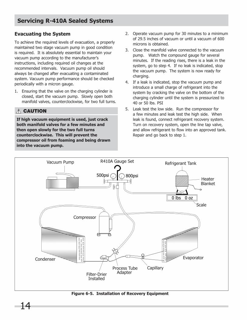
500psi 800psi
0 lbs 0 oz
Vacuum Pump R410A Gauge Set Refrigerant Tank
HeaterBlanket
Scale
Evaporator
CapillaryProcess TubeAdapterFilter-Drier
Condenser
Compressor
Installed
Figure 6-5. Installation of Recovery Equipment
If high vacuum equipment is used, just crackboth manifold valves for a few minutes andthen open slowly for the two full turns counterclockwise. This will prevent the compressor oil from foaming and being drawn into the vacuum pump.
2. Operate vacuum pump for 30 minutes to a minimum of 29.5 inches of vacuum or until a vacuum of 600 microns is obtained.
3. Close the manifold valve connected to the vacuum pump. Watch the compound gauge for several
minutes. If the reading rises, there is a leak in the system, go to step 4. If no leak is indicated, stop the vacuum pump. The system is now ready for
charging.4. If a leak is indicated, stop the vacuum pump and
introduce a small charge of refrigerant into the system by cracking the valve on the bottom of the
charging cylinder until the system is pressurized to 40 or 50 lbs. PSI
5. Leak test the low side. Run the compressor for a few minutes and leak test the high side. When leak is found, connect refrigerant recovery system. Turn on recovery system, open the line tap valve, and allow refrigerant to flow into an approved tank. Repair and go back to step 1.
Servicing R-410A Sealed Systems
15
7. Allow system to sit for five minutes.8. Turn on refrigerator compressor. Run compressor
for a few minutes and monitor system pressures.9. When satisfied unit is operating correctly, clamp the
process tube with pinch-off tool with the unit still running. Using a tubing cutter, cut the process tube about 2 inches from the pinch-off tool. Use Sil-fos solder and solder process tube closed.
10. Turn off the product and allow the unit to set for a few minutes. Check the process tube for refrigerant leaks.
Final Leak Test
1. With the refrigerator turned OFF leak test all low-side system components.2. Turn unit ON and run until the condenser is warm.
Leak test the high-side system components.
Line VoltageIt is essential to know the line voltage at the product. A voltage reading should be taken at the instant the compressor starts, and also while the compressor is running. Line voltage fluctuation should not exceed 10% plus or minus, from nominal rating. Low voltage will cause overheating of the compressor motor windings, resulting in compressor cycling on thermal overload, or the compressor may fail to start. Inadequate line wire size, and overloaded lines, are common reasons for low voltage at the product.
Charging The System
Preparing The Charging Cylinder:
R-410A systems should be liquid charged. This is done via a dip tube in the cylinder. However if your cylinder does not have a dip tube then you must invert the cylinder to ensure only liquid is transferred.
1. Charging cylinder must have at least eight (8) ounces more refrigerant than required charge.2. Plug in cylinder heater and bring pressure up 30
pounds above gauge pressure at ambient temperature.
To charge the system:
1. Make certain that hand shut-off valve to vacuum pump is closed.
2. Close high-side manifold gauge valve.3. Set charging cylinder scale to pressure indicated on
cylinder pressure gauge.4. Observe refrigerant level in sight glass. Subtract
amount to be charged into system and note shut off point.
5. Open charging cylinder valve slowly and allow proper charge to enter system.
6. As soon as refrigerant in sight glass has gone down to predetermined level, close charging cylinder valve.
Check the serial plate for the correct refrigerant type. It is extremely important to verify the type of refrigerant in the system before starting any sealed system repairs. After charging the system with liquid, be certain to wait at least 5 minutes before starting the compressor to give the refrigerant a chance to disperse throughout the system. Otherwise the compressor could be damaged by attempting to pump excessive quantities of liquid.
Disconnect charging cylinder heater at this time to prevent cylinder pressure from exceeding its maximum limits.
DO NOT USE EXTERNAL HEAT SOURCE ON CYLINDER OR EXCEED MAXIMUM GAUGE PRESSURE ON CHARGING CYLINDER.
Servicing R-410A Sealed Systems
16
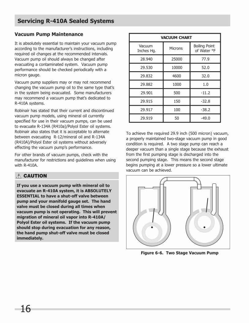
Vacuum Pump Maintenance
It is absolutely essential to maintain your vacuum pump according to the manufacturer’s instructions, including required oil changes at the recommended intervals. Vacuum pump oil should always be changed after evacuating a contaminated system. Vacuum pump performance should be checked periodically with a micron gauge.
Vacuum pump suppliers may or may not recommend changing the vacuum pump oil to the same type that’s in the system being evacuated. Some manufacturers may recommend a vacuum pump that’s dedicated to R-410A systems.
Robinair has stated that their current and discontinued vacuum pump models, using mineral oil currently specified for use in their vacuum pumps, can be used to evacuate R-134A (R410a)/Polyol Ester oil systems. Robinair also states that it is acceptable to alternate between evacuating R-12/mineral oil and R-134A (R410A)/Polyol Ester oil systems without adversely effecting the vacuum pump’s performance.
For other brands of vacuum pumps, check with the manufacturer for restrictions and guidelines when using with R-410A.
If you use a vacuum pump with mineral oil to evacuate an R-410A system, it is ABSOLUTELY ESSENTIAL to have a shut-off valve between pump and your manifold gauge set. The hand valve must be closed during all times when vacuum pump is not operating. This will prevent migration of mineral oil vapor into R-410A/Polyol Ester oil systems. If the vacuum pump should stop during evacuation for any reason, the hand pump shut-off valve must be closed immediately.
To achieve the required 29.9 inch (500 micron) vacuum, a properly maintained two-stage vacuum pump in good condition is required. A two stage pump can reach a deeper vacuum than a single stage because the exhaust from the first pumping stage is discharged into the second pumping stage. This means the second stage begins pumping at a lower pressure so a lower ultimate vacuum can be achieved.
Figure 6-6. Two Stage Vacuum Pump
Servicing R-410A Sealed Systems
17
R-410A Physical Properties:
Chemical formula ....... 50% CH2F2 / 50% CHF2CF3Molecular weight ........ 72.6Odor: ....................... Faint Ethereal OdorSpecific Gravity (Water=1.0): ............ 1.08 @ 21.1°C (70°F)PH: .......................... NeutralBoiling Point: ............. -48.5°C (-55.4°F)Freezing Point: ......... Not DeterminedVapor Pressure: ........ 215.3Psi@ 70°F/490.2Psi@ 130°FVapor Density (Air = 1.0): .............. 3.0Evaporation Rate: ..... >1 Compared To: CCl4= 1% Volatiles: .............. 100Flash Point: .............. Not Applicable
Evaporating Pressure (psi) ...............................Condensing Pressure (psi) ...............................Compression Ratio ..........................................Compressor Discharge Pressure °F ...................Temperature of Suction Gas °F ........................Specific Volume of Suction Vapor (cu. ft./lb) .....Latent Heat of Vaporization (Btu/lb.) ................Net Refrigerating Effect (Btu/lb.) ......................Coefficient of Performance (C.O.P.) ..................Horsepower per Ton of Refrigerant ..................Refrigerant Circulated per Ton (lbs/min) ...........Compressor Suction Gas Volume per Ton *** ...Liquid Circulated per Ton (cu. in./ min) ............
56.6261.33.8712750.92109.579.34.471.052.522.368.8
Spills or Leaks
If a large release of vapor occurs, such as from a large spill or leak, the vapors may concentrate near the floor or low spots and displace the oxygen available for breathing, causing suffocation.
Evacuate everyone until the area has been ventilated. Use blowers or fans to circulate the air at floor level. DO NOT re-enter the affected area unless you are equipped with a self-contained breathing apparatus or unless an area monitor indicates that the concentration of R-410A vapors in the area is below the AEL.
Always use self-contained breathing apparatus or an air-line mask when entering tanks or other areas where vapors might exist. For accidental release or non-ventilated situations, or release into confined space, where the concentration may be above the PEL of 1,000 ppm, use a self-contained, NIOSH- approved breathing apparatus or supplied air respirator. For escape: use the former or a NIOSH-approved gas mask with organic vapor canister. Use the buddy system and a lifeline. Refer to the Material Safety Data Sheet (MSDS) for R-410A information.
R-410A vapors have a slightly sweet odor that can be difficult to detect. Therefore, frequent leak checks and the installation of permanent area monitors may be necessary in enclosed spaces. Refer to ASHRAE Standards 15 and 34 for refrigeration machinery rooms.
To ensure safety when working with R-410A in enclosed areas:1. Route relief and purge vent piping (if present) outdoors, away from air intakes.2. Make certain area is well ventilated, using auxiliary ventilation if needed to move vapors.3. Make sure area is clear of vapors prior to beginning
work.4. Install air monitoring equipment to detect leaks.
Servicing R-410A Sealed Systems
18
Inhalation Toxicity
(Short-term exposures to high concentrations, such as accidental leakages)
Both R-410A and CFC 12, are very low in toxicity by the inhalation route. The 4-hour LC50 for R-410A is greater than 520,000 ppm, and for CFC 12 it is 760,000 ppm. As with other halogenated hydrocarbons, CFC 12 and R-410A can, at high dose levels, sensitize the heart to adrenaline. For CFC 12, the threshold level for cardiac sensitization is 50,000 ppm, while for R-410A it is 100,000 ppm.
R-410A poses no acute or chronic hazard when it is handled in accordance with DuPont recommendations and when exposures are maintained at or below the DuPont Acceptable Exposure Limit (AEL) of 1,000 ppm (8 and 12 hour Time-Weighted Average or TWA).
An AEL is an airborne exposure limit established by DuPont scientists that specifies time-weighted average (TWA) airborne concentrations to which nearly all workers may be repeatedly exposed without adverse effects. The AEL for R-410A has the same value as the Threshold Limit Values (TLVs) established for CFC-12 and HCFC-22. TLVs are established by the American Conference of Governmental and Industrial Hygienists (ACGIH).
However, inhaling high concentrations of R-410A vapor may cause temporary central nervous system depression with narcosis, lethargy and anesthetic effects. Other effects that may occur include dizziness, a feeling of intoxication and a loss of coordination. Continued breathing of high concentrations of R-410A vapors may produce cardiac irregularities (cardiac sensitization), unconsciousness, and with gross overexposure, death. Intentional misuse or deliberate inhalation of R-410A may cause death without warning. This practice is extremely dangerous. If you experience any of the initial symptoms, move to fresh air and seek medical attention.
Cardiac Sensitization
If vapors are inhaled at a concentration of 75,000 ppm, which is well above the AEL, the heart may become sensitized to adrenaline, leading to cardiac irregularities and, possibly, to cardiac arrest. The likelihood of these cardiac problems increases if you are under physical or emotional stress.
Medical attention must be given immediately if exposed to high concentrations of R-410A. DO NOT treat with adrenaline (epinephrine) or similar drugs. These drugs may increase the risk of cardiac arrhythmia and cardiac arrest. If the person is having difficulty breathing, administer oxygen. If breathing has stopped, give artificial respiration.
Skin and Eye Contact
At room temperature, R-410A vapors have little or no effect on the skin or eyes. However, in liquid form, R-410A can freeze skin or eyes on contact, causing frostbite. Following contact, soak the exposed area in lukewarm water, not cold or hot. If medical treatment cannot begin immediately, apply a light coat of a nonmedicated ointment, such as petroleum jelly. If the exposed area is in a location where the presence of the ointment would be awkward, such as on the eye, apply a light bandage. In all cases of frostbite, seek medical attention as soon as possible. Always wear protective clothing when there is a risk of exposure to liquid R-410A. Where splashing is possible, always wear eye protection and a face shield.
Servicing R-410A Sealed Systems
19
Combustibility of R-410A
R-410A is nonflammable at ambient temperatures and atmospheric pressure. However, tests have shown R-410A to be combustible at pressures as low as 5.5 psi (139.3 kPa absolute) at 177°C (350°F) when mixed with air at concentrations generally greater than 60% volume air. At lower temperatures, higher pressures are required for combustibility. (R-410A is also combustible at pressures above atmospheric in the presence of high air concentrations). Test results and calculations have shown:• At ambient temperature, all concentrations of R-410A in air are nonflammable at pressures below
15 psi (205 kPa absolute).• Combustible mixtures of air and R-410A will not
form when liquid R-410A is pumped into closed vessel if initial air pressure in vessel is limited to one atmosphere absolute and final pressure is limited to 400 psi. If initial air pressure is greater than one atmosphere, combustible mixtures may form as tank is filled.
Based on above information, the following operating practices are recommended:
Leak Testing• Equipment should NEVER be leak tested with a
pressurized mixture of R-410A and air. R-410A may be safely pressured with dry nitrogen.
Refrigerant Recovery Systems
Efficient recovery of refrigerant from equipment or containers requires evacuation at the end of the recovery cycle. Suction lines to a recovery compressor should be periodically checked for leaks to prevent compressing air into the recovery cylinder during evacuation. In addition, the recovery cylinder pressure should be monitored, and evacuation stopped in the event of a rapid pressure rise indicating the presence of non condensable air. The recovery cylinder contents should then be analyzed for NAG, and the recovery system leak checked if air is present. DO NOT continue to evacuate a refrigeration system that has a major leak.
Filling and Charging Operations
1. Before evacuating cylinders or refrigeration equipment, any remaining refrigerant should be
removed by recovery system.2. Vacuum pump discharge lines should be free of
restrictions that could increase discharge pressures above 15 psi (205 kPa) and result in formation of combustible mixtures.
3. Cylinders or refrigeration equipment should normally be evacuated at start of filling, and should never be filled while under positive air pressure.
4. Final pressures should not exceed 400 psi. 5. Filled cylinders should periodically be analyzed
for air (non absorbable gas or NAG).
Thermal Decomposition
R-410A vapors will decompose when exposed to high temperatures from flames or electric resistance heaters. Decomposition may produce toxic and irritating compounds, such as halogens, halogen acids and possibly carbonyl halides. The pungent odors released will irritate the nose and throat and generally force people to evacuate the area. Therefore, it is important to prevent decomposition by avoiding exposure to high temperatures.
Servicing R-410A Sealed Systems
20
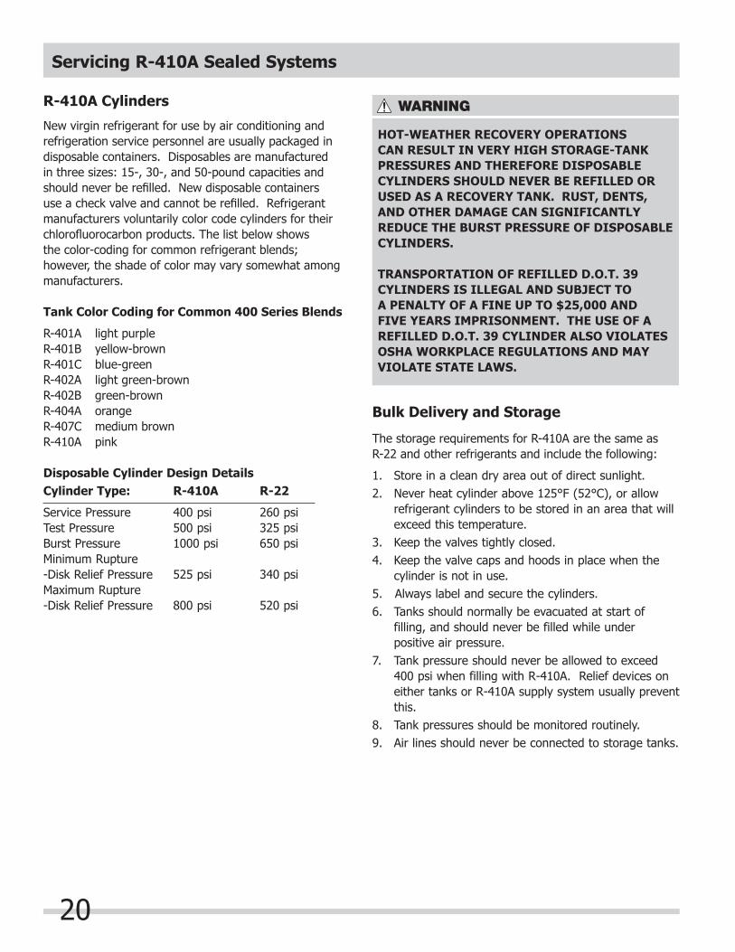
R-410A Cylinders
New virgin refrigerant for use by air conditioning and refrigeration service personnel are usually packaged in disposable containers. Disposables are manufactured in three sizes: 15-, 30-, and 50-pound capacities and should never be refi lled. New disposable containers use a check valve and cannot be refi lled. Refrigerant manufacturers voluntarily color code cylinders for their chlorofl uorocarbon products. The list below shows the color-coding for common refrigerant blends; however, the shade of color may vary somewhat among manufacturers.
Tank Color Coding for Common 400 Series Blends
R-401A light purple R-401B yellow-brown R-401C blue-green R-402A light green-brown R-402B green-brown R-404A orange R-407C medium brown R-410A pink
Disposable Cylinder Design Details Cylinder Type: R-410A R-22 Service Pressure 400 psi 260 psi Test Pressure 500 psi 325 psi Burst Pressure 1000 psi 650 psi Minimum Rupture-Disk Relief Pressure 525 psi 340 psi Maximum Rupture-Disk Relief Pressure 800 psi 520 psi
HOT-WEATHER RECOVERY OPERATIONS CAN RESULT IN VERY HIGH STORAGE-TANK PRESSURES AND THEREFORE DISPOSABLE CYLINDERS SHOULD NEVER BE REFILLED OR USED AS A RECOVERY TANK. RUST, DENTS, AND OTHER DAMAGE CAN SIGNIFICANTLY REDUCE THE BURST PRESSURE OF DISPOSABLE CYLINDERS.
TRANSPORTATION OF REFILLED D.O.T. 39 CYLINDERS IS ILLEGAL AND SUBJECT TO A PENALTY OF A FINE UP TO $25,000 AND FIVE YEARS IMPRISONMENT. THE USE OF A REFILLED D.O.T. 39 CYLINDER ALSO VIOLATES OSHA WORKPLACE REGULATIONS AND MAY VIOLATE STATE LAWS.
Bulk Delivery and Storage
The storage requirements for R-410A are the same as R-22 and other refrigerants and include the following:
1. Store in a clean dry area out of direct sunlight.2. Never heat cylinder above 125°F (52°C), or allow
refrigerant cylinders to be stored in an area that will exceed this temperature.
3. Keep the valves tightly closed. 4. Keep the valve caps and hoods in place when the
cylinder is not in use.5. Always label and secure the cylinders.6. Tanks should normally be evacuated at start of filling, and should never be filled while under positive air pressure. 7. Tank pressure should never be allowed to exceed
400 psi when filling with R-410A. Relief devices on either tanks or R-410A supply system usually prevent this.
8. Tank pressures should be monitored routinely.9. Air lines should never be connected to storage tanks.