Embed Size (px)
Citation preview
ALICE Rad.Tolerant Electronics, 30 Aug 2004 Børge Svane Nielsen, NBI 1
FMD – Forward Multiplicity Detector
FMD – Forward Multiplicity Detector
ALICE Meeting on Rad. Tolerant Electronics
CERN, 30 August 2004
Børge Svane Nielsen
Henrik Bertelsen
Niels Bohr Institute
1. Silicon strip sensors: Hamamatsu2. Preamp-shaper chips: VA1_ALICE in production3. Hybrids: VA1_ALICE with passive components4. FMD Digitiser Card: Design based on TPC FEC and ”known” VA1 read-out protocol5. Read-out and Controls: TPC RCU
ALICE Rad.Tolerant Electronics, 30 Aug 2004 Børge Svane Nielsen, NBI 2
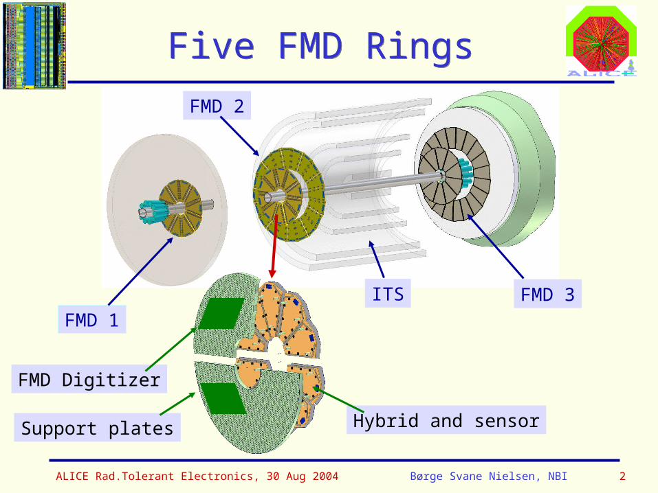
Five FMD RingsFive FMD Rings
FMD 3
FMD 1
FMD 2
ITS
Support plates Hybrid and sensor
FMD Digitizer

ALICE Rad.Tolerant Electronics, 30 Aug 2004 Børge Svane Nielsen, NBI 3
Radiation environmentRadiation environment
Doses and Fluences in Central ALICE (10 years running):
Belle measurements
=0.33 Mrd
Doses in FMD:Dose
[Gy]
h-[cm**-2]
FMD3 80-1350 9-14 E+11
FMD2 40-2300 1.4-6.5 E+11
FMD1 900-3300 2.5-5.6 E+11
ALICE Rad.Tolerant Electronics, 30 Aug 2004 Børge Svane Nielsen, NBI 4
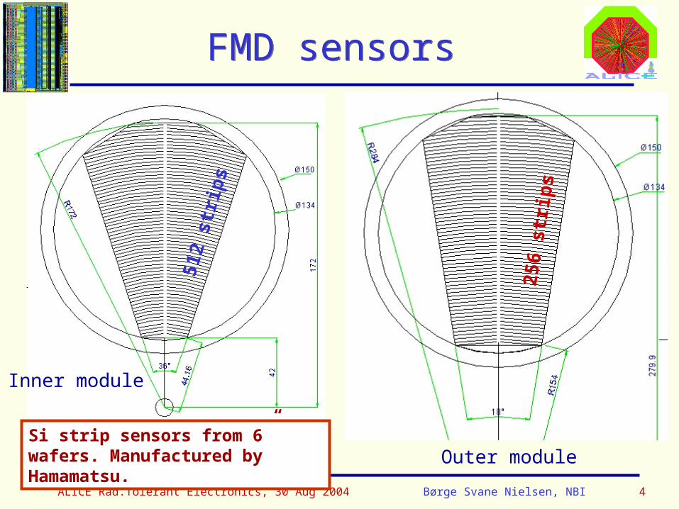
FMD sensorsFMD sensors
512
stri
ps
256
stri
ps
Inner module
Outer moduleSi strip sensors from 6” wafers. Manufactured by Hamamatsu.
ALICE Rad.Tolerant Electronics, 30 Aug 2004 Børge Svane Nielsen, NBI 5
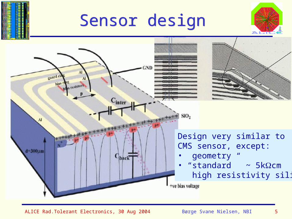
Sensor designSensor design
Design very similar toCMS sensor, except:• geometry• “standard” ~ 5kcm high resistivity silicon
ALICE Rad.Tolerant Electronics, 30 Aug 2004 Børge Svane Nielsen, NBI 6
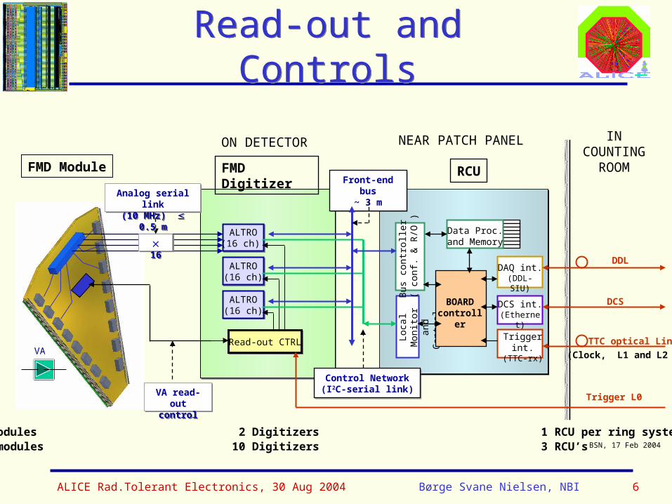
Read-out and ControlsRead-out and Controls
FMD Module
ON DETECTOR INCOUNTING
ROOM
VA
1 ring: 10/20 modules 2 Digitizers 1 RCU per ring systemFull FMD: 70 modules 10 Digitizers 3 RCU’s
VA read-outcontrol
VA read-outcontrol
TTC-RX
BOARDCTRL
FMD Digitizer
ALTRO(16 ch) ALTRO(16 ch)
ALTRO(16 ch)ALTRO(16 ch)
ALTRO(16 ch)ALTRO(16 ch)
Read-out CTRLRead-out CTRL
BSN, 17 Feb 2004
Loca
l Mon
itor
and
Con
trol
BOARDcontroller
Bus
con
trol
ler
( co
nf. &
R/O
)
DCS int.(Ethernet)
DAQ int.(DDL-SIU)
Trigger int.(TTC-rx)
Data Proc.and Memory
DCS
DDL
TTC optical Link
(Clock, L1 and L2 )
RCUFront-end bus
~ 3 mFront-end bus
~ 3 m
16 16
Control Network(I2C-serial link)
Control Network(I2C-serial link)
Trigger L0
NEAR PATCH PANEL
Analog serial link(10 MHz) 0.5 mAnalog serial link(10 MHz) 0.5 m
ALICE Rad.Tolerant Electronics, 30 Aug 2004 Børge Svane Nielsen, NBI 7
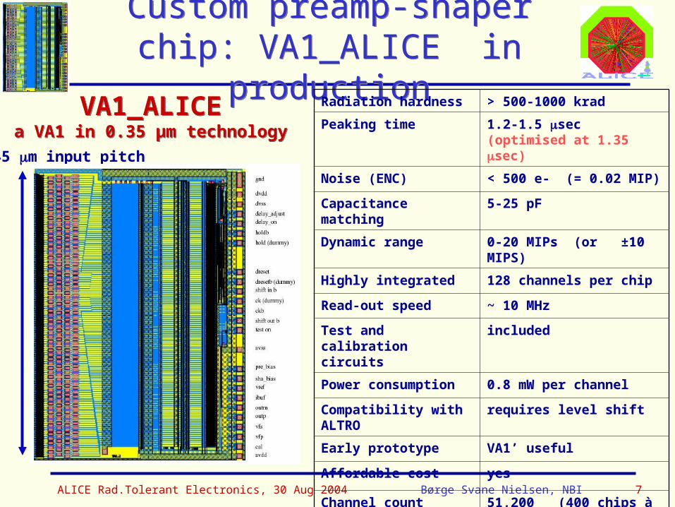
Custom preamp-shaper chip: VA1_ALICE in production
Custom preamp-shaper chip: VA1_ALICE in production
VA1_ALICEa VA1 in 0.35 µm technology
VA1_ALICEa VA1 in 0.35 µm technology
Radiation hardness > 500-1000 krad
Peaking time 1.2-1.5 sec (optimised at 1.35 sec)
Noise (ENC) < 500 e- (= 0.02 MIP)
Capacitance matching 5-25 pF
Dynamic range 0-20 MIPs (or ±10 MIPS)
Highly integrated 128 channels per chip
Read-out speed ~ 10 MHz
Test and calibration circuits
included
Power consumption 0.8 mW per channel
Compatibility with ALTRO
requires level shift
Early prototype VA1’ useful
Affordable cost yes
Channel count 51,200 (400 chips à 128 channels)
45 m input pitch
ALICE Rad.Tolerant Electronics, 30 Aug 2004 Børge Svane Nielsen, NBI 8
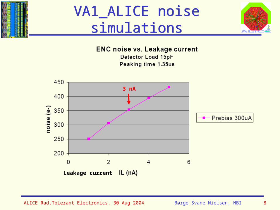
VA1_ALICE noise simulationsVA1_ALICE noise simulations
Leakage current
3 nA
ALICE Rad.Tolerant Electronics, 30 Aug 2004 Børge Svane Nielsen, NBI 9
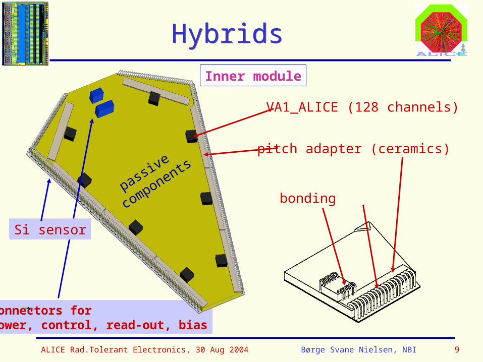
Connectors forpower, control, read-out, bias
Hybrids Hybrids
VA1_ALICE (128 channels)
Inner module
pitch adapter (ceramics)
bonding
Si sensor
passive
components
ALICE Rad.Tolerant Electronics, 30 Aug 2004 Børge Svane Nielsen, NBI 10
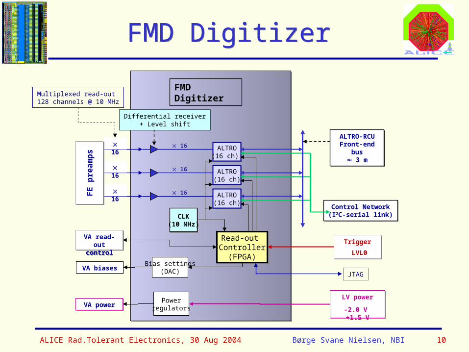
FMD DigitizerFMD Digitizer
VA read-outcontrol
VA read-outcontrol
FMD Digitizer
ALTRO(16 ch) ALTRO(16 ch)
ALTRO(16 ch)ALTRO(16 ch)
ALTRO(16 ch)ALTRO(16 ch)
Read-out Controller(FPGA)
Read-out Controller(FPGA)
ALTRO-RCUFront-end bus
3 m
ALTRO-RCUFront-end bus
3 m
Control Network(I2C-serial link)
Control Network(I2C-serial link)
16
CLK(10 MHz)
CLK(10 MHz)
Powerregulators
Trigger
LVL0
Trigger
LVL0
LV power
-2.0 V +1.5 V
LV power
-2.0 V +1.5 VVA powerVA power
Differential receiver+ Level shift
16
16
16
16
16
FE
pre
am
ps
FE
pre
am
ps
Bias settings(DAC)VA biasesVA biases
Multiplexed read-out128 channels @ 10 MHz
JTAG
ALICE Rad.Tolerant Electronics, 30 Aug 2004 Børge Svane Nielsen, NBI 11
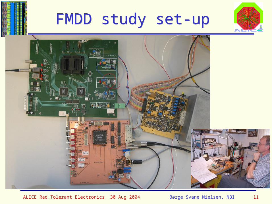
FMDD study set-upFMDD study set-up
ALICE Rad.Tolerant Electronics, 30 Aug 2004 Børge Svane Nielsen, NBI 12
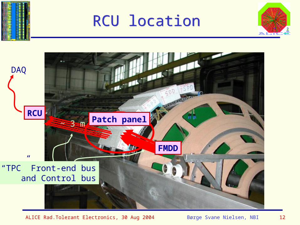
RCU locationRCU location
RCU
FMDD
DAQ
Patch panel
“TPC” Front-end busand Control bus
~ 3 m
ALICE Rad.Tolerant Electronics, 30 Aug 2004 Børge Svane Nielsen, NBI 13
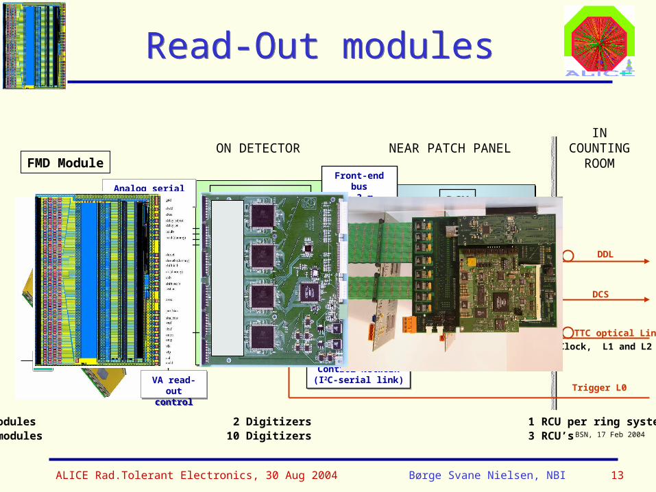
FMD ModuleON DETECTOR
INCOUNTING
ROOM
VA
1 ring: 10/20 modules 2 Digitizers 1 RCU per ring systemFull FMD: 70 modules 10 Digitizers 3 RCU’s
VA read-outcontrol
VA read-outcontrol
TTC-RX
BOARDCTRL
FMD Digitizer
ALTRO(16 ch) ALTRO(16 ch)
ALTRO(16 ch)ALTRO(16 ch)
ALTRO(16 ch)ALTRO(16 ch)
Read-out CTRLRead-out CTRL
BSN, 17 Feb 2004
Loca
l Mon
itor
and
Con
trol
BOARDcontroller
Bus
con
trol
ler
( co
nf. &
R/O
)
DCS int.(Ethernet)
DAQ int.(DDL-SIU)
Trigger int.(TTC-rx)
Data Proc.and Memory
DCS
DDL
TTC optical Link
(Clock, L1 and L2 )
RCU
Front-end bus~ 3 m
Front-end bus~ 3 m
16 16
Control Network(I2C-serial link)
Control Network(I2C-serial link)
Trigger L0
NEAR PATCH PANEL
Analog serial link(10 MHz) 0.5 mAnalog serial link(10 MHz) 0.5 m
Read-Out modulesRead-Out modules
ALICE Rad.Tolerant Electronics, 30 Aug 2004 Børge Svane Nielsen, NBI 14
SummarySummary
Electronics components of FMD:
Preamp-shaper-multiplexer on hybrid: VA1_ALICE in 0.35 µm technology by IDEAS, Oslo Rad.level 200-3300 Gy
FMD Digitizer: use ALTROs and TPC FEC schematics + VA1 read-out protocol with common 10 MHz clock, to be built at NBI, Copenhagen Need to be aware of higher rad. levels than at TPC Rad.level 100-1000 Gy
RCU identical to the one from TPC and PHOS Rad.level 10-100 Gy