Embed Size (px)
Citation preview
ALESIS
ADAT LX20 Reference Manual
Contents
ADAT LX20 Reference Manual 1
CONTENTSIntroduction 5How To Use This Manual 6
Conventions 6
1 SETTING UP AND MAKING CONNECTIONS 7
Unpacking and Inspection 7Operating Environment 7
Thermal Considerations in Rack Mounting 7Mounting on a Shelf or Non-Rack Enclosure 8Avoiding Electromagnetic Interference 8
AC Power Hookup 8Avoiding Ground Loops 9Line Conditioners and Protectors 10
Analog Audio Connections 11About Audio Cables 11Rear Panel Input and Output Layout 11Inputs 11Typical input jack hookups 12Outputs 13
Sync In/Out 14Digital Audio Connections 15
About Digital Audio In/Out 15Footswitches 16
2 LX20 ESSENTIALS 20
About The Display 20Time Counter 20Meters 20Record/Input Lights 20Blocks 21Status Indicators 21Interpolation Indicator 21
Buttons and Controls 21Power Switch 21Record Enable Buttons 21Transport Controls 21Eject Button 21Input Select Buttons 22Pitch Control Buttons 22Location Buttons 22Edit, Format, and Select Buttons 22Auto Motion Buttons 22
Differences Compared to Analog Recording 23“Threaded” vs. “Unthreaded” Tape 23Digital Distortion and Headroom 23
Choosing the Right S-VHS Cassette Tape 24

Contents
2 ADAT LX20 Reference Manual
What is Tape Formatting? 24
3 POWER-UP AND TAPE FORMATTING 26
Power-up and Tape Insertion 26Setting Tape Length 27How to Format Tapes 28
About Type I and Type II Formats 28Defeating The Write Protect Tab 28General Formatting Procedure 29Recording While Formatting 31Re-Formatting a Previously Formatted Tape 31Notes About Formatting 31
Recording a “Benchmark” Tape 31
4 RECORD AND PLAYBACK BASICS 33
Understanding the Time Counter 33Change Display Format 33
Set the Input Mode for Analog Audio 33Choose Analog Or Digital Input 34
Digital Input Re-Routing 34Select Track(s) for Recording 35Tape Motion Control: The Transport 35
Stop 35Play 36Record 36Other Transport Buttons 36
Step-By-Step Procedures 37Recording 37Playback 37Reviewing and Cueing 38
Monitoring 38Default Mode 38Auto Input 38All Input 39
5 AUTOLOCATION AND LOOP FUNCTIONS 41
Autolocation 41Return to Zero 41Locate Points 41
Auto Play 42Auto Return 42Looped Playback 43
Loop Limit 44Deferred Play and Record 44
6 PUNCHING AND AUTOMATED RECORDING 45
Contents
ADAT LX20 Reference Manual 3
Manual Punching Options 45Transport Controls 45Record Enable Buttons 45Footswitch 46
Automated Recording 46Looped Recording 47Rehearsing 47Adjusting Punch Crossfade Time 48
7 PITCH CONTROL 49
8 ABOUT DIGITAL AUDIO IN/OUT 51
ADAT Optical Interface Basics 51About 16-bit and 20-bit signal transfers 51Selecting The Digital Output Mode 52
Type II (20-bit) to Type II (20-bit) 52Type II (20-bit) to Type I (16-bit) 52
9 USING THE LX20 LRC REMOTE 53
10 MULTIPLE LX20/ADAT OPERATION 55
Overview 55Synchronizing Machines 55
Automatic Renumbering 56Master/Slave Interaction 57Achieving Lock 57Independent Slave Mode 57
Formatting Multiple Tapes 57Recording Digital Audio 58
Bouncing Tracks Between ADATs 58Reassigning Channels to Different Tracks 59Making Digital Backups 60Making a 16-bit copy from a 20-bit master 61Recording Digital Audio from Other Sources 61Digital Clock Considerations 62
Combining LX20s and ADATs 62LX20 Transport Speed 62Sample Rate vs. Pitch Control 62Input Monitoring 63Polarity Differences 63Connections 64
11 APPLICATIONS 65
Overview 65Combined Multitrack/Mixdown Deck 65

Contents
4 ADAT LX20 Reference Manual
Live/Long-Term Recording 66Locking to Video: Code-Only Master 66Libraries and Archives 67Modular Recording 67Computer Control and MIDI 67
MIDI Systems: Virtual Tracking 67MIDI Systems: Automated Mixdown 68MIDI Systems: Virtual Tracks and Automated Mixdown 68MIDI Machine Control: Virtual Remote Control 68
The ADAT Optical Interface and Hard Disk Recording 69Digital Audio Transfer Options 69Typical applications 70The ADAT-PCR Computer Interface 70A Real-World Example 71Sync Issues 71
Hard Disk Backup 71Pre-Mastering with the LX20 72
APPENDIX A DIGITAL RECORDING CONCEPTS 73
Analog Recording Basics 73Digital Recording Basics 73
The Advantages of 20-Bit Recording 74Why S-VHS? 75
APPENDIX B TROUBLESHOOTING 76
Re-Initializing: Try This First 76Troubleshooting Index 76Checking Software Version 77Error Rate Display 78
About Error Rate Readings 78ADAT Head Life 79ADAT Head Maintenance 79Drum Time Display 79Tape Care and Maintenance 81Maintenance/Service 82
Cleaning 82Maintenance 82Obtaining Repair Service 83
APPENDIX C ERROR CODES 84
Automatic Brake Calibration Procedure 86Steps To Take Before Calling For Help 87
APPENDIX D SPECIFICATIONS 88
GLOSSARY 90
Introduction
ADAT LX20 Reference Manual 5
INTRODUCTIONThank you for purchasing the Alesis ADAT-LX20 20-Bit Digital Audio Recorder.To take full advantage of the LX20’s functions, and to enjoy long and trouble-freeuse, please read this manual carefully.
Here are some of the LX20’s most significant features:
• Low tape cost. The LX20 can record over an hour of audio on a standard S-VHStape cassette.
• Superb fidelity. The LX20 offers 20-bit recording to tape using the ADAT TypeII format, along with a choice of a 44.1 or 48 kHz sampling rate (with 64 timesoversampling), for better-than-CD quality sound.
• Digital and analog inputs/outputs. In addition to conventional analog inputsand outputs, a “master” digital I/O carries all eight tracks simultaneously viaoptical cable, allowing for lossless signal transfers between ADAT interface-compatible devices (tape recorders, hard disk recorders, synthesizers, signalprocessors, etc.).
• Easy expandability for more tracks. Multiple LX20s can be synchronizedwithout any external hardware, and without giving up any tracks, to expandyour digital recording system. Two LX20s give 16 tracks, three LX20s 24 tracks,and so on. Up to 16 LX20s or other ADAT-family digital recorders can worktogether, and all are locked within 20 microseconds (1 sample) accuracy.
• Included remote control. Each LX20 comes with the LRC (Little Remote Control)for remote control of transport, autolocation, and input select functions.
• Optional remote control. The BRC (Big Remote Control) allows forsophisticated synchronization and overdubbing functions for multiple ADAT-compatible machines, remote control of virtually all recorder functions, andSMPTE read/generate.
• International no-hassles power compatibility. The LX20 accepts any ACvoltage between 90 and 250 volts, so you can use it whether you’re laying downtracks in L.A, mixing in Munich, or synching in Seoul. (Or dealing with abrownout in New York City, for that matter.)
• Built-in time code. Each LX20 tape is formatted with a proprietary time codethat is much more accurate than SMPTE, and time-stamps the tape with single-sample accuracy. This allows for machine synchronization without giving up anaudio track, accurate tape counter readings without “slippage,” and intelligentautolocation functions.
• Compatibility with multi-channel mixdown formats. The LX20 is ideal forquadraphonic, surround, and theatrical sound applications that require morethan two channels for the final master.
Introduction
6 ADAT LX20 Reference Manual
HOW TO USE THIS MANUALThough we recommend you read through the entire manual once, those havinggeneral knowledge about multitrack recorders should use the table of contents andindex to reference specific functions while using the LX20. Here’s how the manual isorganized:
Chapter 1: Setting Up and Making Connections. This covers installation issues aswell as how to connect up the LX20 to other gear in a system.
Chapter 2: LX20 Essentials. This section provides a brief tour of LX20 highlights,dsecribes some of the buttons and controls, and discusses how to choose the righttape.
Chapter 3: Power-Up and Tape Formatting. Time to turn on the power and format atape before recording.
Chapter 4: Recording and Playback Basics. Here’s the lowdown on shuttling tape,recording, and playing back.
Chapter 5: Autolocation and Loop Functions. The LX20 can find specific points ontape, as well as loop continuously between two points.
Chapter 6: Punching and Automated Recording. This chapter describes how toreplace sections of previously-recorded tracks.
Chapter 7: Pitch Control. If you’re ever had to retune a piano to a track, you’llappreciate the LX20’s ability to tune a track to piano instead.
Chapter 8: About Digital Audio In/Out. All ADAT-compatible devices include afiber optic interface that can carry 8 channels of audio simultaneously. Thischapter tells how to get the most out of this advanced interface.
Chapter 9: Using the LRC Remote. The LX20 comes with a remote control unit thatduplicates many front panel functions.
Chapter 10: Multiple LX20/ADAT Operation. ADAT-compatible devices can worktogether synergistically to create a sophisticated recording system, as detailed inthis chapter.
Chapter 11: Applications. There’s a lot more to the LX20 than meets the eye, suchas “snapshot” automation, combined master/mixdown deck, virtual MIDI tracks forinstrument parts and signal processor control, and more.
Appendices. Features an explanation of digital audio recording concepts, trouble-shooting, maintenance and service information, specifications, a Glossary and anIndex.
ConventionsAll front panel buttons and rear panel connectors are referred to in this manual justas their names appear on the LX20, using all capital letters (Examples: PLAYbutton, AUTO INPUT button, etc.).
When something important appears in the manual, an icon (like the one on the left)appears in the left margin. This symbol indicates that this information is vitalwhen operating the LX20.
Chapter 1 - Setting Up and Making Connections
ADAT LX20 Reference Manual 7
CHAPTER 1
SETTING UP ANDMAKING CONNECTIONS
UNPACKING AND INSPECTIONYour ADAT-LX20 was packed carefully at the factory. The shipping carton wasdesigned to protect the unit during shipping. Please retain this container in thehighly unlikely event that you need to return the LX20 for servicing.
The shipping carton should contain the following:
• ADAT-LX20 with the same serial number as shown on shipping carton• Power Cable• Optical Cable• LRC remote control unit• This instruction manual• Blank S-VHS ST-120 cassette• Alesis warranty card
Register your purchase so that you may be informed of upgrades. If you have notalready filled out your warranty card and mailed it back to Alesis, please do sonow.
OPERATING ENVIRONMENT
THERMAL CONSIDERATIONS IN RACK MOUNTINGYou can mount the LX20 in an equipment rack (taking up 3 rack spaces) or place it ona table or shelf. When you install it, note that heat is the major enemy of electronicequipment. Please observe the following:
• The LX20 is designed to perform properly over a range of ambient temperaturesfrom 10° C to +40° C (50° F to 104° F), in up to 80% non-condensing humidity.These are not absolute limits, but Alesis cannot guarantee that the LX20 willmeet its published specs or remain reliable if operated outside of these ranges.
• Always allow adequate ventilation behind the LX20. Do not seal any enclosurethat holds the LX20. It is not necessary to leave an empty rack space above orbelow the LX20 unless it runs hot enough to affect equipment above or below it.If your environment is unusually warm and not air conditioned, space betweenunits will help the units run cooler and may lessen tape oxide shedding.
• Do not mount the LX20’s rack at a an angle. The LX20 should not be angled backor mounted vertically.
Setting Up and Making Connections - Chapter 1
8 ADAT LX20 Reference Manual
MOUNTING ON A SHELF OR NON-RACK ENCLOSURETo mount the LX20 on a shelf or other flat surface, Alesis recommends attachingstick-on rubber feet to avoid scratching the shelf’s surface with the deck’s bottom.Please observe the general comments on thermal considerations given under“Thermal Considerations in Rack Mounting” no matter where or how the deck ismounted.
AVOIDING ELECTROMAGNETIC INTERFERENCELike all tape machines, the LX20 uses magnetic tape that can be sensitive toelectromagnetic interference. Generally this is not a problem, but avoid mountingthe LX20 next to devices that generate strong magnetic fields such as poweramplifiers, monitors and video display devices, speakers, etc.
AC POWER HOOKUPWith the LX20 off, plug the power cord’s female end into the LX20’s POWERINPUT socket, and the male (plug) end into a source of AC power. It’s good practicenot to turn on the LX20 until all other cables are hooked up.
The LX20 works with any AC voltage from 90 to 250 volts, 50 to 60 Hz. Thiseliminates the need for transformers or voltage switches. Your LX20 was suppliedwith the correct power cord for your country or local area, however only thefollowing alternative power cords are approved for use with ADAT:
• For 90-120 VAC 50/60 Hz operation in the US, Canada and/or Japan, use AlesisUL/CSA power cord #7-41-0001.
• For 240 VAC 50 Hz operation in England, use Alesis Power cord #7-41-0004.• For 220 VAC 50 Hz operation in Europe and Scandinavia, use Alesis EU power
cord #7-41-0002.• For 240 VAC 50 Hz operation in Australia, use Alesis AS power cord #7-41-0003.
The LX20’s IEC-spec AC cord (do not substitute any other AC cord) is designed to feedan outlet that includes three pins, with the third, round pin connected to ground. Theground connection is an important safety feature and should never be “lifted.”
Unfortunately, the presence of a third ground pin does not always indicate that anoutlet is properly grounded. Use an AC line tester to determine this. If the outlet isnot grounded, consult with a licensed electrician.
Alesis cannot be responsible for problems caused by using the LX20 or any associatedequipment with improper AC wiring.
Chapter 1 - Setting Up and Making Connections
ADAT LX20 Reference Manual 9
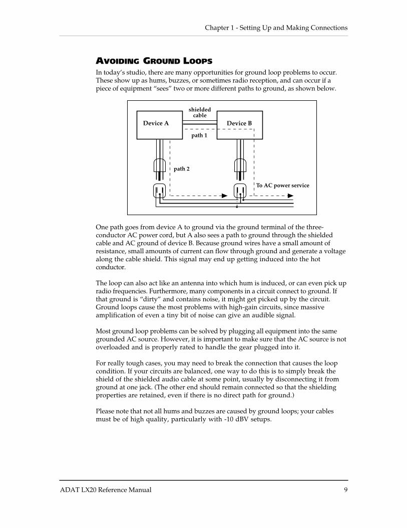
AVOIDING GROUND LOOPSIn today’s studio, there are many opportunities for ground loop problems to occur.These show up as hums, buzzes, or sometimes radio reception, and can occur if apiece of equipment “sees” two or more different paths to ground, as shown below.
Device A Device B
shielded cable
path 1
path 2
To AC power service
One path goes from device A to ground via the ground terminal of the three-conductor AC power cord, but A also sees a path to ground through the shieldedcable and AC ground of device B. Because ground wires have a small amount ofresistance, small amounts of current can flow through ground and generate a voltagealong the cable shield. This signal may end up getting induced into the hotconductor.
The loop can also act like an antenna into which hum is induced, or can even pick upradio frequencies. Furthermore, many components in a circuit connect to ground. Ifthat ground is “dirty” and contains noise, it might get picked up by the circuit.Ground loops cause the most problems with high-gain circuits, since massiveamplification of even a tiny bit of noise can give an audible signal.
Most ground loop problems can be solved by plugging all equipment into the samegrounded AC source. However, it is important to make sure that the AC source is notoverloaded and is properly rated to handle the gear plugged into it.
For really tough cases, you may need to break the connection that causes the loopcondition. If your circuits are balanced, one way to do this is to simply break theshield of the shielded audio cable at some point, usually by disconnecting it fromground at one jack. (The other end should remain connected so that the shieldingproperties are retained, even if there is no direct path for ground.)
Please note that not all hums and buzzes are caused by ground loops; your cablesmust be of high quality, particularly with -10 dBV setups.
Setting Up and Making Connections - Chapter 1
10 ADAT LX20 Reference Manual
LINE CONDITIONERS AND PROTECTORSAlthough the LX20 can tolerate typical voltage variations, the AC line voltagemay contain spikes or transients that can possibly stress your gear and, over time,cause a failure. There are three main ways to protect against this, listed inascending order of cost and complexity:
• Line spike/surge protectors. Relatively inexpensive, these are designed toprotect against strong surges and spikes, acting somewhat like fuses in thatthey need to be replaced if they’ve been hit by an extremely strong spike.
• Line filters. These generally combine spike/surge protection with filters thatremove some line noise (dimmer hash, transients from other appliances, etc.).
• Uninterruptible power supply (UPS). This is the most sophisticated option. AUPS provides power even if the AC power line fails completely. Intended forcomputer applications, a UPS allows you to complete an orderly shutdown of acomputer system in the event of a power outage, and the isolation it providesfrom the power line minimizes all forms of interference — spikes, noise, etc.
If your AC power is unstable or subject to occasional browns-outs or interruptions, usea professional power conditioner or uninterruptible power supply. Some people whohave experienced problems with ADAT operation have had those problemsdisappear completely after installing proper power conditioning.
Chapter 1 - Setting Up and Making Connections
ADAT LX20 Reference Manual 11
ANALOG AUDIO CONNECTIONS
ABOUT AUDIO CABLESThe connections between the LX20 and your studio are your music’s lifeline, so useonly high quality cables. These should be low-capacitance shielded cables with astranded (not solid) internal conductor and a low-resistance shield. Althoughquality cables cost more, they do make a difference. Here’s how to route cables tothe LX20:
• Do not bundle audio cables with AC power cords.
• Avoid running audio cables near sources of electromagnetic interference such astransformers, monitors, computers, etc.
• Do not place cables where they can be stepped on. Stepping on a cable may notcause immediate damage, but it can compress the insulation between the centerconductor and shield (degrading performance) or reduce the cable’s reliability.
• Avoid twisting the cable or having it make sharp, right angle turns.
• Never unplug a cable by pulling on the wire itself. Always unplug by firmlygrasping the body of the plug and pulling directly outward.
When connecting audio cables and/or turning power on and off, make sure that alldevices in your system are turned off and the volume controls are turned down.
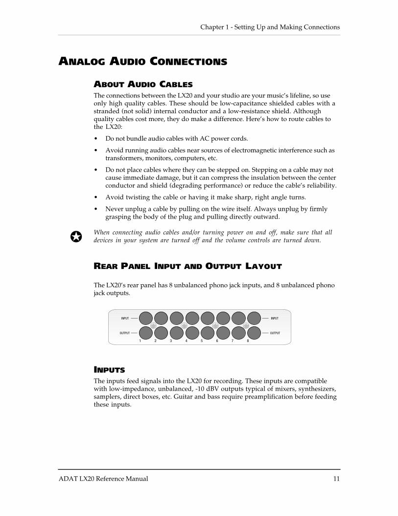
REAR PANEL INPUT AND OUTPUT LAYOUT
The LX20’s rear panel has 8 unbalanced phono jack inputs, and 8 unbalanced phonojack outputs.
INPUTSThe inputs feed signals into the LX20 for recording. These inputs are compatiblewith low-impedance, unbalanced, -10 dBV outputs typical of mixers, synthesizers,samplers, direct boxes, etc. Guitar and bass require preamplification before feedingthese inputs.
Setting Up and Making Connections - Chapter 1
12 ADAT LX20 Reference Manual
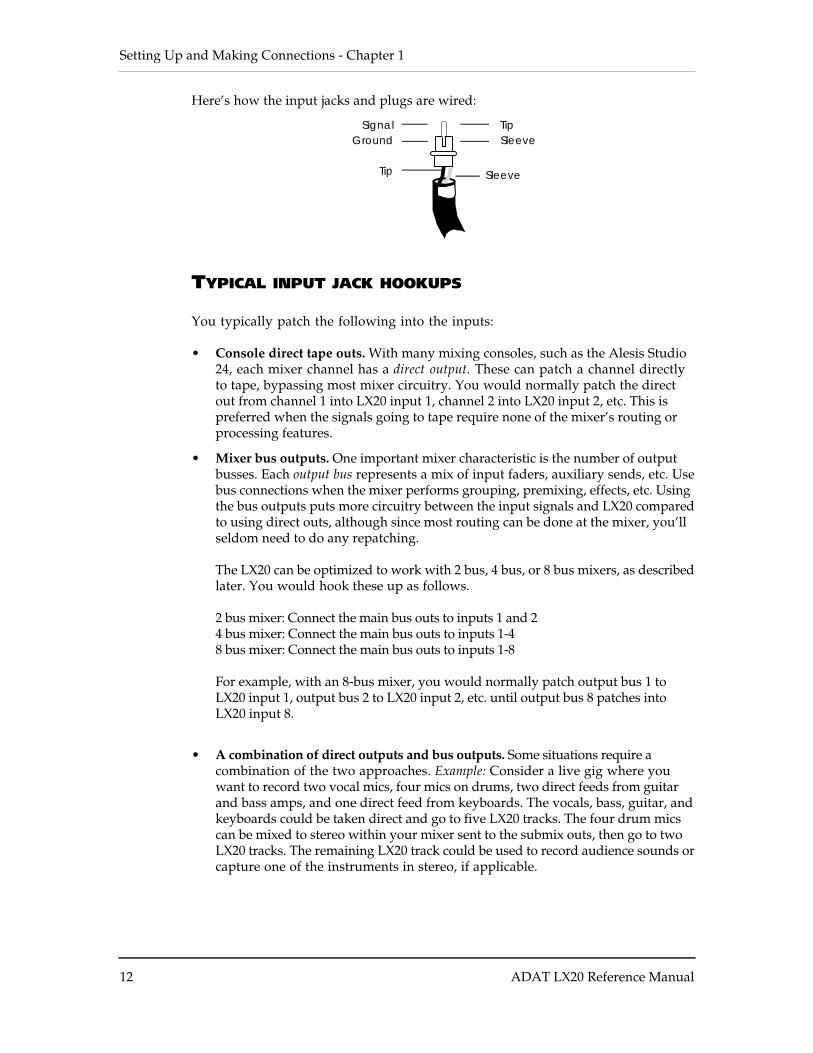
Here’s how the input jacks and plugs are wired:
TipSignalSleeveGround
Tip Sleeve
TYPICAL INPUT JACK HOOKUPS
You typically patch the following into the inputs:
• Console direct tape outs. With many mixing consoles, such as the Alesis Studio24, each mixer channel has a direct output. These can patch a channel directlyto tape, bypassing most mixer circuitry. You would normally patch the directout from channel 1 into LX20 input 1, channel 2 into LX20 input 2, etc. This ispreferred when the signals going to tape require none of the mixer’s routing orprocessing features.
• Mixer bus outputs. One important mixer characteristic is the number of output
busses. Each output bus represents a mix of input faders, auxiliary sends, etc. Usebus connections when the mixer performs grouping, premixing, effects, etc. Usingthe bus outputs puts more circuitry between the input signals and LX20 comparedto using direct outs, although since most routing can be done at the mixer, you’llseldom need to do any repatching.
The LX20 can be optimized to work with 2 bus, 4 bus, or 8 bus mixers, as describedlater. You would hook these up as follows.
2 bus mixer: Connect the main bus outs to inputs 1 and 24 bus mixer: Connect the main bus outs to inputs 1-48 bus mixer: Connect the main bus outs to inputs 1-8
For example, with an 8-bus mixer, you would normally patch output bus 1 toLX20 input 1, output bus 2 to LX20 input 2, etc. until output bus 8 patches intoLX20 input 8.
• A combination of direct outputs and bus outputs. Some situations require a
combination of the two approaches. Example: Consider a live gig where youwant to record two vocal mics, four mics on drums, two direct feeds from guitarand bass amps, and one direct feed from keyboards. The vocals, bass, guitar, andkeyboards could be taken direct and go to five LX20 tracks. The four drum micscan be mixed to stereo within your mixer sent to the submix outs, then go to twoLX20 tracks. The remaining LX20 track could be used to record audience sounds orcapture one of the instruments in stereo, if applicable.
Chapter 1 - Setting Up and Making Connections
ADAT LX20 Reference Manual 13
OUTPUTSThe -10 dBV outputs use phono jacks, and carry signals at a nominal -10 dBV level.These connect to your mixer’s channel tape returns or line inputs. You wouldnormally connect output 1 to mixer line input 1 or tape return 1, output 2 to mixer lineinput 2 or tape return 2, etc.
Setting Up and Making Connections - Chapter 1
14 ADAT LX20 Reference Manual
SYNC IN/OUT
The two rear panel DB-9 connectors marked SYNC IN and SYNC OUT synchronizetwo or more ADAT-family devices, such as the LX20, XT20, M20, original ADAT,ADAT-XT, and/or a computer hard disk audio recording/editing system using theADAT-PCR sound card or similar device.
Synchronization requires a male-to-male, 9-pin D connector cable for eachadditional machine in the chain. These cables are available in various lengthsfrom Alesis or your dealer and should be Alesis-approved; improper cables (such asthose used for computers) may not function correctly.
In such a system, you are basically treating all connected machines as though theywere a large multitrack unit. The first LX20 or ADAT in the chain is the “master,”and all other connected units are called “slaves.” However, each slave can also beused independently when the master machine is stopped.
For details about using multiple LX20s and/or ADATs, refer to Chapter 10.
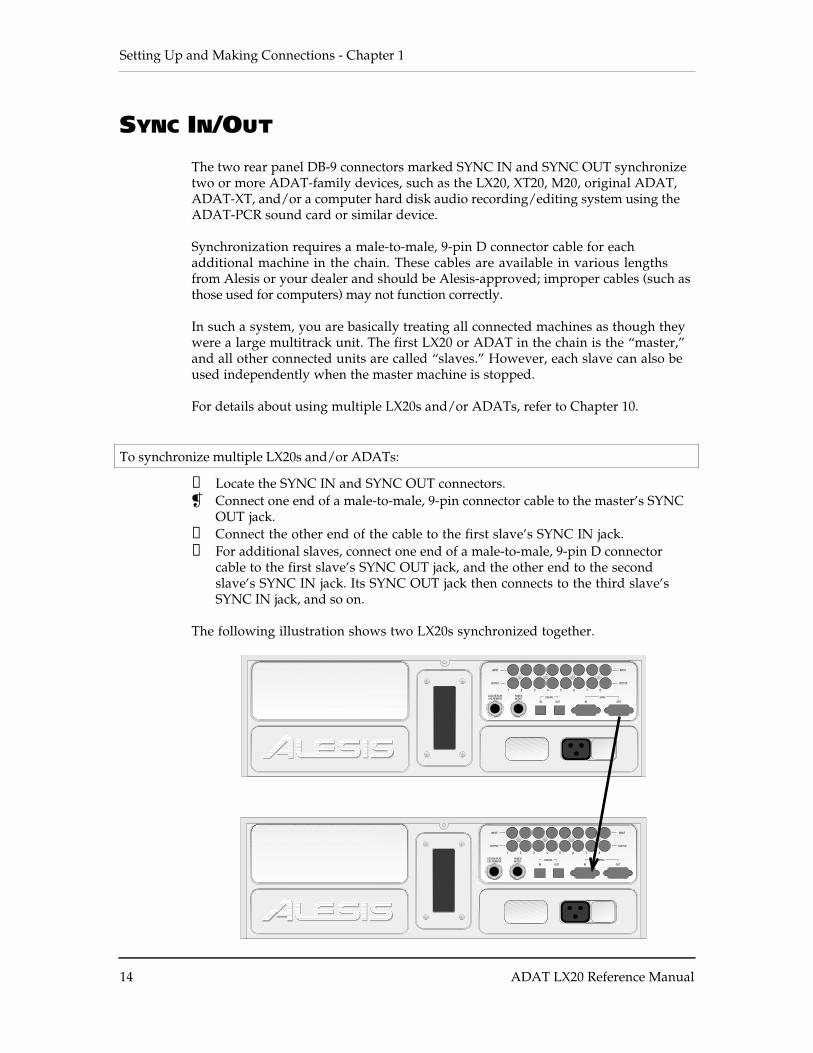
To synchronize multiple LX20s and/or ADATs:
❿ Locate the SYNC IN and SYNC OUT connectors. Connect one end of a male-to-male, 9-pin connector cable to the master’s SYNC
OUT jack.① Connect the other end of the cable to the first slave’s SYNC IN jack.➃ For additional slaves, connect one end of a male-to-male, 9-pin D connector
cable to the first slave’s SYNC OUT jack, and the other end to the secondslave’s SYNC IN jack. Its SYNC OUT jack then connects to the third slave’sSYNC IN jack, and so on.
The following illustration shows two LX20s synchronized together.
INPUT
OUTPUT
INPUT
OUTPUT
Chapter 1 - Setting Up and Making Connections
ADAT LX20 Reference Manual 15
DIGITAL AUDIO CONNECTIONS
The digital input and output carries all eight tracks on a single fiber optical cable(called the ADAT Optical Interface, and sometimes nicknamed the ADAT “LightPipe”). This powerful feature allows you to transfer digital audio between multipleADAT-compatible devices.
ABOUT DIGITAL AUDIO IN/OUTThe ADAT Optical Interface cables carry digital audio between ADAT compatibleproducts such as multiple LX20s and ADATs, the QuadraVerb 2, Q20, many Alesiskeyboards, the ADAT-PCR computer interface card, and third-party products suchas the Digidesign ADAT Bridge and Yamaha 02R digital mixer. Since the fiberoptic connector carries the digital information for all 8 tracks, it is also useful forbacking up all tracks in one pass.
Digital bussing requires a fiber optical cable (included) for each LX20 in the system(or any other ADAT-compatible product). Additional cables are available fromAlesis or your dealer in various lengths up to 16 feet. You can make this connectionwhile power is on or off, and the machines do not need to be turned on in anyparticular order.
Examples: Probably the most common application is “cloning” one ADAT tape to asecond machine for backup. Basically, you patch the fiber optic output from themachine with the tape to be backed up (the master) to the fiber optic input of themachine doing the backup (the slave). Record-enable the slave tracks and pressplay on the master to copy the original tape.
Another application is transferring all 8 tracks from an ADAT to a hard diskrecording system for editing. You would patch the ADAT fiber optic output to anADAT-PCR interface card’s fiber optic input, press play on the ADAT, and record onthe hard disk system. To transfer the edited data back to the ADAT for storageand/or backup, patch the ADAT-PCR interface’s fiber optic out to the ADAT’s fiberoptic in, and play back the hard disk data while the ADAT is recording.
These and other applications are described in more detail in Chapters 10 and 11.
To connect the digital optical network:
❿ Locate the DIGITAL IN and DIGITAL OUT connectors.Remove the connectors’ plugs (if present) and store for later use.
Connect one end of the fiber optic cable into the DIGITAL OUT jack of the firstmachine in the system.Remove the clear, plastic tube covering each end of the cable (if present). Thecable is non-polarized, so either end can insert into the optical output.
① Connect the other end of the fiber optic cable to the DIGITAL IN of the secondmachine in the system.Tip: if the machines are on, the end of the cable from the source machine willglow red.
Setting Up and Making Connections - Chapter 1
16 ADAT LX20 Reference Manual
➃ For each additional machine, connect one end of an additional fiber optic cableto the second machine’s DIGITAL OUT jack, and the other end to the thirdmachine’s DIGITAL IN jack. Its DIGITAL OUT jack then connects to the fourthmachine’s DIGITAL IN jack, and so on.
➄ Finally, connect one end of a fiber optic cable to the last machine’s DIGITALOUT jack, and the other end to the first machine’s DIGITAL IN jack.This last step creates a loop, making the digital bus accessible to all machinesconnected to it.
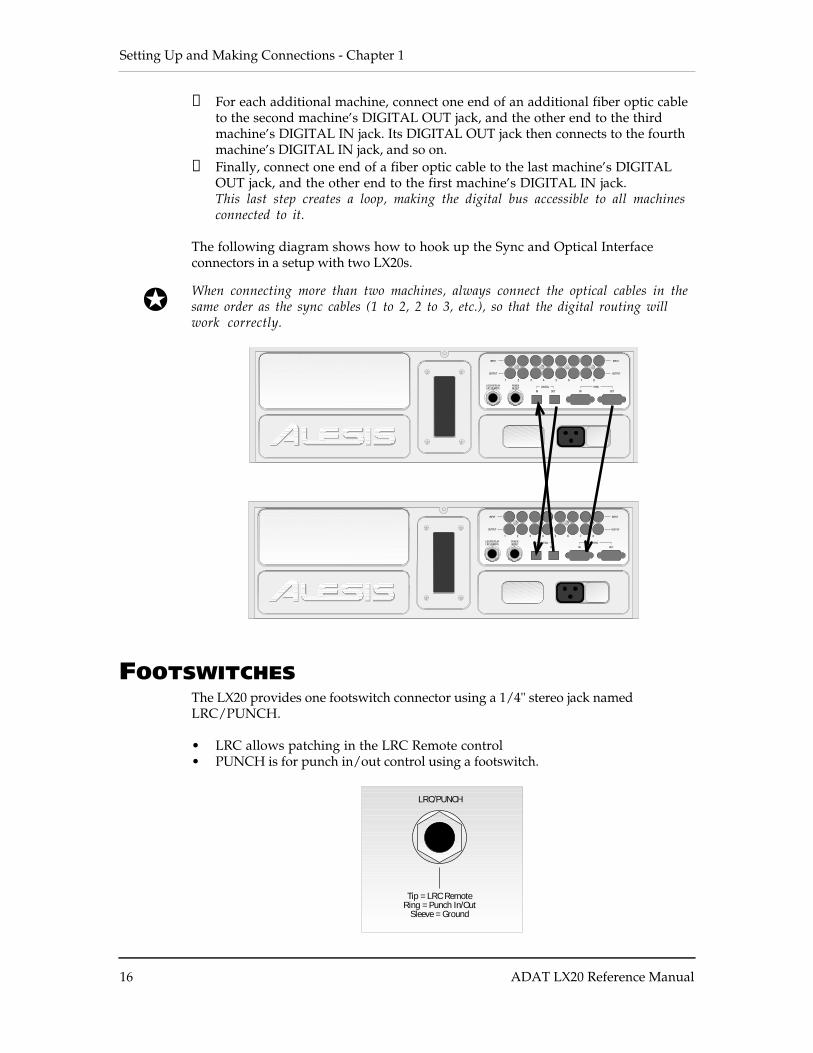
The following diagram shows how to hook up the Sync and Optical Interfaceconnectors in a setup with two LX20s.
When connecting more than two machines, always connect the optical cables in thesame order as the sync cables (1 to 2, 2 to 3, etc.), so that the digital routing willwork correctly.
INPUT
OUTPUT
INPUT
OUTPUT
FOOTSWITCHESThe LX20 provides one footswitch connector using a 1/4" stereo jack namedLRC/PUNCH.
• LRC allows patching in the LRC Remote control• PUNCH is for punch in/out control using a footswitch.
LRC/PUNCH
Tip = LRC RemoteRing = Punch In/Out
Sleeve = Ground

Chapter 1 - Setting Up and Making Connections
ADAT LX20 Reference Manual 17
Setting Up and Making Connections - Chapter 1
18 ADAT LX20 Reference Manual
There are three ways to use this jack.
• Footswitch only. Plug a momentary, single-pole/single-throw footswitch(either normally open or normally closed) halfway into the jack so that thefootswitch plug tip connects to the jack ring connection. In other word, plug inonly until the tip reaches the first detent. Plug in the footswitch prior topower-up so that the LX20 can configure itself for the type of footswitch beingused. If you decide to plug in a footswitch after already starting a session, turnoff the LX20, plug in the footswitch, then turn theLX20 back on again.
• LRC only. Plug the LRC plug fully into the jack.
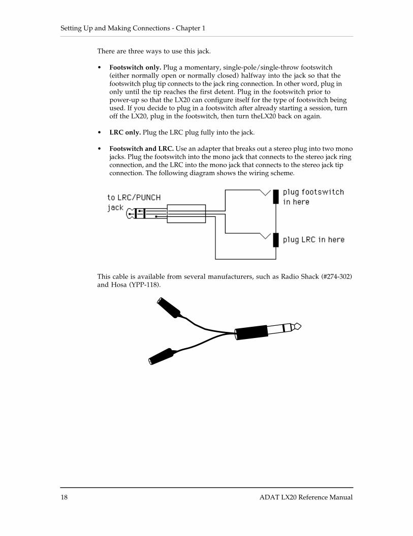
• Footswitch and LRC. Use an adapter that breaks out a stereo plug into two monojacks. Plug the footswitch into the mono jack that connects to the stereo jack ringconnection, and the LRC into the mono jack that connects to the stereo jack tipconnection. The following diagram shows the wiring scheme.
This cable is available from several manufacturers, such as Radio Shack (#274-302)and Hosa (YPP-118).

Chapter 1 - Setting Up and Making Connections
ADAT LX20 Reference Manual 19
LX20 Essentials - Chapter 2
20 ADAT LX20 Reference Manual
CHAPTER 2
LX20 ESSENTIALS
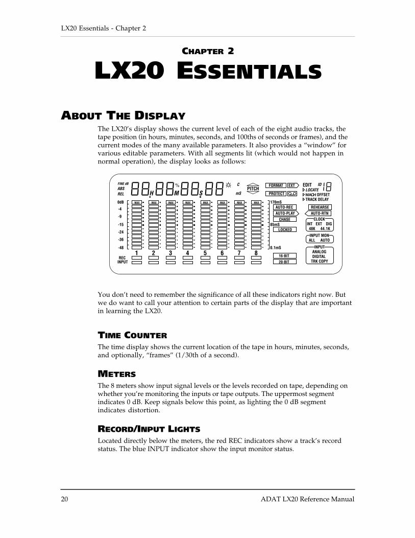
ABOUT THE DISPLAYThe LX20’s display shows the current level of each of the eight audio tracks, thetape position (in hours, minutes, seconds, and 100ths of seconds or frames), and thecurrent modes of the many available parameters. It also provides a “window” forvarious editable parameters. With all segments lit (which would not happen innormal operation), the display looks as follows:
MACH
You don’t need to remember the significance of all these indicators right now. Butwe do want to call your attention to certain parts of the display that are importantin learning the LX20.
TIME COUNTERThe time display shows the current location of the tape in hours, minutes, seconds,and optionally, “frames” (1/30th of a second).
METERSThe 8 meters show input signal levels or the levels recorded on tape, depending onwhether you’re monitoring the inputs or tape outputs. The uppermost segmentindicates 0 dB. Keep signals below this point, as lighting the 0 dB segmentindicates distortion.
RECORD/INPUT LIGHTSLocated directly below the meters, the red REC indicators show a track’s recordstatus. The blue INPUT indicator show the input monitor status.
Chapter 2 - LX20 Essentials
ADAT LX20 Reference Manual 21
BLOCKSThere are three ”blocks” located in the lower right-hand corner: Clock, Input Mon,and Input. Each block shows the selected option for the block’s parameter.
STATUS INDICATORSThese are individual status indicators. For example, to the left of the Input Monblock, there are status indicators that show whether the tape being played is in 16-bit or 20-bit format. Other indicators show whether particular locate functions areenabled, whether a cassette is inserted in the cassette well, and so on.
INTERPOLATION INDICATORA small asterisk-like indicator to the upper right of the time counter’s last digitlights whenever the LX20 detects an error significant enough to requireinterpolating data (in others words, the LX20 has to make an educated guess as towhat the audio should be). Should this light flash, it’s a good idea to clean thetape heads and make a backup copy of your tape. See Chapter 10, section QQ, formore information.
BUTTONS AND CONTROLS
There are several buttons on the front panel that control LX20 functions, as shownbelow:
POWER SWITCHThe LX20 power switch is an “intelligent” switch. It operates normally (push onceto turn and once to turn off) but also does two cool tricks:
• If the LX20 is connected to a barrier strip, it will detect when the barrier striphas been turned on, and automatically power-up.
• If the LX20 is turned off and you insert a cassette into the well, the LX20 willautomatically power-up.
RECORD ENABLE BUTTONSEach recording enable button corresponds to its like-numbered track, and controlsthe track’s record status. They are also sometimes used in combination with otherbuttons to select more advanced options.
TRANSPORT CONTROLSThese control tape movement (REWIND, FFWD, STOP, PLAY, and RECORD).
EJECT BUTTONIf you guessed this ejects the cassette, you’re right.
LX20 Essentials - Chapter 2
22 ADAT LX20 Reference Manual
INPUT SELECT BUTTONSThese determine how signals, both analog and digital, are routed to the LX20.
PITCH CONTROL BUTTONSThese increase or slow down the playback and record speeds to change pitch.
LOCATION BUTTONSThe LX20 can find particular places on tape. Example: You might want to shuttlerapidly between a chorus and verse while overdubbing; by storing these locations,you can push the corresponding button to tell the tape to “go fetch,” and park thetape at the desired location.
EDIT, FORMAT, AND SELECT BUTTONSThese are really individual functions grouped in the same general area. They willbe described in detail as needed.
AUTO LOOP/AUTO RECORD BUTTONSThe LX20 can automate certain tape movement procedures, such as automaticallyreturning to a particular point after overdubbing, playing a section repeatedly,automated “punching” to record over a specific section of a track (e.g., a bad phrasein an otherwise perfect vocal), and so on. The Auto Play, Auto Return and AutoRecord buttons, in conjunction with the Location buttons, control the auto functions.
Chapter 2 - LX20 Essentials
ADAT LX20 Reference Manual 23
DIFFERENCES COMPARED TO ANALOG RECORDING
Recording on the LX20 is very similar to most multitrack tape machines. With aformatted tape loaded, put one or more tracks into record-ready, adjust record levelson your mixer, set the input monitor mode, locate to where you want to beginrecording, and engage record. However, there are two main differences, describednext.
“THREADED” VS. “UNTHREADED” TAPEThe LX20 uses a rotating head drum which records and plays back digital audiosignals from tape. Even when the tape is stopped, it remains “threaded” or engagedagainst the spinning head drum for a period of time. This allows for going into playor record faster, as well as provides “cue” and “review” functions that let youmonitor the tape audio at faster-than-normal play speeds. When threaded andstopped, the STOP button LED is lit steadily.
When the tape is unthreaded (the STOP LED flashes), it takes a little bit of timefor the tape to wrap around the head drum before it can go into play or record. Cueand review functions are not possible while the tape is unthreaded.
When the tape is threaded and stopped, you can manually unthread it by pressingthe STOP button. The STOP LED will flash, indicating the tape is now unthreaded.Pressing either PLAY or STOP, or PLAY and RECORD to engage recording, re-threads the tape.
If the tape is threaded, and no transport activity (play, record, rewind, etc.) occursfor 4 minutes, the tape will automatically unthread itself to minimize tape wear.
DIGITAL DISTORTION AND HEADROOMWith analog tape, it is common to record “in the red” as distortion increases slowlywith increasing level. Small amounts of analog distortion may not only be difficultto hear, but may even be considered desirable. Another reason for recording atelevated levels is the limited dynamic range of analog tape — hitting it with asmuch level as possible minimizes noise.
With digital recording, signals remain undistorted up to the 0 (clipping) point, atwhich point distortion increases dramatically. Alesis recommends never exceeding0, and recording at an average level of around -15 to -10 dB. With the exceptionaldynamic range made possible with 20-bit recording, there is no need to “slam”levels. Giving your signals a little bit of headroom provides a margin of safetyagainst distortion.
LX20 Essentials - Chapter 2
24 ADAT LX20 Reference Manual
CHOOSING THE RIGHT S-VHS CASSETTE TAPE
We cannot overemphasize the importance of using only premium quality, namebrand S-VHS cassettes such as Quantegy 489 DM Digital Mastering Audio Tape, orAlesis ADAT Mastering Audio Cassettes. Other acceptable brands include MaxellXR-S Black, JVC XZ, Sony DASV, BASF Digital Master 938, Apogee AA-40, HHBADAT45, and TDK SP Super Pro. The cassette shell, hubs, rollers and tape guides inS-VHS cassettes are precision devices that properly handle and protect the tapewithin them.
Although VHS cassettes may appear to work at first, their unpredictable qualityand less-than-premium formulation will decrease the reliability of your recording.Inferior tapes not only jeopardize the recordings made on them, they may shedoxide and leave behind a coating of dirt that will interfere with future recordings,even if you switch back to premium quality tape. Defective tape may even clog thehead, requiring service. Don’t trust your work to anything less than premiumquality S-VHS tape.
Rewind and fast forward a new tape several times from end to end before attemptingto record on it. This crucial step “unpacks” the tape properly, and leads to morereliable long-term operation (this is also recommended practice for DAT tapes).
Treat your tapes as the precision, fragile components that they are. Do not exposethem to extremes of heat, cold, or humidity (in other words, don’t leave them inyour car). Never place tapes near magnetic fields (such as power amps, TVs,monitors, magnets, etc.) and handle tapes gently.
WHAT IS TAPE FORMATTING?Standard blank S-VHS tapes must first be formatted in an ADAT-family machinebefore they can be used. Formatting prepares the tape for recording andsynchronization, as described later.
Chapter 2 - LX20 Essentials
ADAT LX20 Reference Manual 25

Power-Up and Tape Formatting - Chapter 3
26 ADAT LX20 Reference Manual
CHAPTER 3
POWER-UP AND TAPEFORMATTING
POWER-UP AND TAPE INSERTIONPatch the LX20’s power cord between the rear panel, three-prong power socket anda properly-wired AC outlet receptacle. Please take account of the groundingconsiderations mentioned in Chapter 1.
The LX20 can produce a transient audio signal during power up and power down.When turning the LX20 on or off, keep the monitor levels low.
Turn the LX20’s power on by pressing the POWER button. At power-up the displaybriefly looks like this:
In a few seconds, the display will change depending on the status of the tape in thetransport.
• If a formatted tape is present, the TIME counter will show the elapsed timesince the beginning of the tape (unless it is somewhere in the first two minutesof tape, called the “lead” and “data” sections):
ABS 0H 15M 48S 21• If an unformatted tape is present, the FORMAT indicator will flash and the
TIME counter will read:
ABS n0 F0
• If there is no tape, the display shows:
ABS -- -- -- --Insert the tape with the hinged door end first, label side up, until you encounter aslight bit of resistance. Push gently on the center of the tape cassette until the LX20draws the tape inward. Never force the tape into the cassette door.
Chapter 3 - Power-Up and Tape Formatting
ADAT LX20 Reference Manual 27
SETTING TAPE LENGTH
The LX20 can use tapes longer than the standard ST-120 length (an ST-180 tapegives over one hour of recording time, an ST-160 gives 53 minutes). The LX20automatically recognizes ST-60 tapes and adjusts itself accordingly, but cannot tellapart ST-120, ST-160 or ST-180 tapes.
The LX20 assumes you are using a ST-120 tape. Therefore, you need to set the tapelength on the LX20 when using either ST-160 or ST-180 tapes. To do this, hold theSET LOCATE button and press the FORMAT button. Each press of the format buttoncycles through the following options: ST-60, ST-160, ST-180, and ST-120. When thedisplay shows the correct tape length, release both buttons.
• Ejecting a tape does not reset the tape length, but powering down resets to T-120.
• If you insert a tape with Tape Length set to something other than ST-120, thedisplay will briefly flash the selected length to remind you that you are usinga non-standard setting.
• If using multiple LX20s/ADATs, all connected machines must use tapes of thesame length.
The Tape Length setting and the actual tape’s length must be the same. Never use ashorter tape length than what the LX20 thinks you’re using.
Below is a list of the four S-VHS tapes the LX20 accepts, with their Europeanequivalents and approximate recording times:
Type Euro Rec. Time
ST-60 n/a 22 min.
ST-120 SE-180 40 min.
ST-160 SE-240 54 min.
ST-180 SE-260 62 min.
If using tapes longer than ST-120, locating for the first time past the 39 minuteposition temporarily slows down (but does not stop) the transport. Each subsequentlocation beyond this point acts normally. This safeguard protects ST-120 tapes fromdamage should a longer tape length setting have been entered erroneously.
Power-Up and Tape Formatting - Chapter 3
28 ADAT LX20 Reference Manual
HOW TO FORMAT TAPES
What it does: Formatting an LX20 tape “time-stamps” the tape every 1/48,000 of asecond (at a 48 kHz sample rate), and stores reference information about the tape ina data header at the tape’s beginning.
Caution: Formatting a tape erases audio on all eight tracks. Always check that thetape is either blank or contains unwanted material before formatting.
Why formatting is important Formatting enables ultra-tight synchronizationamong the LX20 and ADAT-compatible machines, and provides both accurate tapecounter readings and intelligent autolocation functions.
Formatting options You can:• Format a tape completely before recording (recommended)• Format while you are recording for only as long as needed• Extend the format of a tape that was not completely formatted
ABOUT TYPE I AND TYPE II FORMATSThere are two ADAT tape formats, Type I (used in the original ADAT family ofproducts and featuring 16-bit audio resolution) and Type II (used in all ADATproducts released after July 1, 1997 and featuring 20-bit resolution).
A tape cannot be 16-bit for one section and 20-bit for another. To change theresolution, you must reformat the entire tape, which erases all existing audio.
Type I tapes will play back in Type I or Type II machines. Type II tapes will playback only in Type II machines. If it is necessary to play back a Type II tape in aType I machine, copy the Type II tape to a Type I tape as described in Chapter 8.
DEFEATING THE WRITE PROTECT TABTo record on or erase/format a S-VHS cassette, the write protect tab (located on thecassette’s spine) must be closed or taped over. If you try to record on a tape that hashad the write protect tab broken off or is slid open, the PROT indicator in thedisplay will light and the LX20 will not record on the tape. This preventsaccidental erasure of valuable recordings.
To record on a tape that has been protected, eject the tape and slide the writeprotect tab so that it is closed. If the tab has been broken off, it is still possible todefeat write protection.
To defeat write protection:
❿ Press and hold the SET LOCATE button. While holding the SET LOCATE button, press the Track 1 RECORD ENABLE
button (located immediately to the right of the power switch).① Each press of the Track 1 RECORD ENABLE button toggles between protect on
and protect off (shown in the display as Prot On and Prot OFF respectively).The PROTECT indicator in the display turns on and off to confirm the setting.
Chapter 3 - Power-Up and Tape Formatting
ADAT LX20 Reference Manual 29
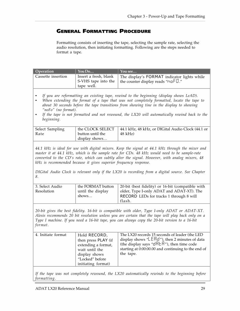
GENERAL FORMATTING PROCEDURE
Formatting consists of inserting the tape, selecting the sample rate, selecting theaudio resolution, then initiating formatting. Following are the steps needed toformat a tape.
Operation You Do… You see…Cassette insertion Insert a fresh, blank
S-VHS tape into thetape well.
The display’s FORMAT indicator lights whilethe counter display reads “noFO.”
• If you are reformatting an existing tape, rewind to the beginning (display shows LeAD).• When extending the format of a tape that was not completely formatted, locate the tape to
about 30 seconds before the tape transitions from showing tine in the display to showing“noFo” (no format).
• If the tape is not formatted and not rewound, the LX20 will automatically rewind back to thebeginning.
Select SamplingRate
the CLOCK SELECTbutton until thedisplay shows…
44.1 kHz, 48 kHz, or DIGital Audio Clock (44.1 or48 kHz)
44.1 kHz is ideal for use with digital mixers. Keep the signal at 44.1 kHz through the mixer andmaster it at 44.1 kHz, which is the sample rate for CDs. 48 kHz would need to be sample-rateconverted to the CD’s rate, which can subtly alter the signal. However, with analog mixers, 48kHz is recommended because it gives superior frequency response.
DIGital Audio Clock is relevant only if the LX20 is recording from a digital source. See Chapter8.
3. Select AudioResolution
the FORMAT buttonuntil the displayshows…
20-bit (best fidelity) or 16-bit (compatible witholder, Type I-only ADAT and ADAT-XT). TheRECORD LEDs for tracks 1 through 8 willflash.
20-bit gives the best fidelity. 16-bit is compatible with older, Type I-only ADAT or ADAT-XT.Alesis recommends 20 bit resolution unless you are certain that the tape will play back only on aType I machine. If you need a 16-bit tape, you can always copy the 20-bit version to a 16-bitformat.
4. Initiate format Hold RECORD,then press PLAY (ifextending a format,wait until thedisplay shows“Locked” beforeinitiating format)
The LX20 records 15 seconds of leader (the LEDdisplay shows “LEAd”), then 2 minutes of data(the display says “dAtA”), then time codestarting at 0:00:00.00 and continuing to the end ofthe tape.
If the tape was not completely rewound, the LX20 automatically rewinds to the beginning beforeformatting.
Power-Up and Tape Formatting - Chapter 3
30 ADAT LX20 Reference Manual
Chapter 3 - Power-Up and Tape Formatting
ADAT LX20 Reference Manual 31
RECORDING WHILE FORMATTINGTo record onto tape while formatting, before pressing the FORMAT button press theRECORD ENABLE button(s) 1–8 associated with the track(s) to be recorded. Thesecan accept analog or digital signals, as described in Chapter 4.
• Do not begin recording before the time display shows 0:00:00.00.• Tracks not in record-ready (safe) will be recorded with silence while
formatting.
RE-FORMATTING A PREVIOUSLY FORMATTED TAPEIf you re-format over a previously formatted tape, do not stop in the middle of re-formatting. When the tape transitions from the newly-formatted section to thepreviously-formatted section, there will be timing discontinuities and the audiowill “stutter.” Also, during that transition the tape will be non-functional and youwill not be able to record over it. When in doubt, either re-format the entire tapefrom beginning to end, or rewind a bit and extend the format.
NOTES ABOUT FORMATTING
• To stop formatting, press STOP — punching out is not sufficient.
• Tapes can be bulk-erased with a video tape eraser.
• In a multiple LX20 setup where one is the master and the other LX20s areslaves, there are a few other considerations. See Chapter 10, “FormattingMultiple Tapes”.
• If the tape is already formatted but is in the leader or data sections of the tape(i.e., prior to time 0:00:00.00), entering format mode will automatically rewindthe tape to the beginning and start reformatting. While rewinding, the TIMEcounter will read “FO” (which means “format over”) and the REWIND LEDwill flash. This is telling you that the LX20 must format over from the lead(beginning) portion of the tape.
RECORDING A “BENCHMARK” TAPEAlesis recommends that during the first week of operation, you format and record anew tape with any signal, such as a test tone, in a single pass with no overdubs.Store this tape in a safe, dry location and don’t use it for any other purpose. Such a“benchmark” tape can help determine if the error correction rate is increasing overtime because the heads need to be cleaned, or if a tape is defective.

Power-Up and Tape Formatting - Chapter 3
32 ADAT LX20 Reference Manual
Chapter 4 - Record and Playback Basics
ADAT LX20 Reference Manual 33
CHAPTER 4
RECORD AND PLAYBACKBASICS
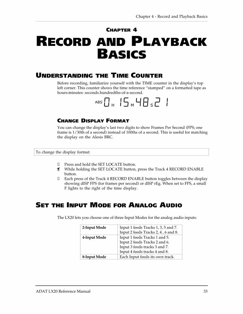
UNDERSTANDING THE TIME COUNTERBefore recording, familiarize yourself with the TIME counter in the display’s topleft corner. This counter shows the time reference “stamped” on a formatted tape ashours:minutes: seconds.hundredths-of-a-second.
ABS 0H 15M 48S 21
CHANGE DISPLAY FORMATYou can change the display’s last two digits to show Frames Per Second (FPS; oneframe is 1/30th of a second) instead of 100ths of a second. This is useful for matchingthe display on the Alesis BRC.
To change the display format:
❿ Press and hold the SET LOCATE button. While holding the SET LOCATE button, press the Track 4 RECORD ENABLE
button.① Each press of the Track 4 RECORD ENABLE button toggles between the display
showing dISP FPS (for frames per second) or dISP rEg. When set to FPS, a smallF lights to the right of the time display.
SET THE INPUT MODE FOR ANALOG AUDIO
The LX20 lets you choose one of three Input Modes for the analog audio inputs:
2-Input Mode Input 1 feeds Tracks 1, 3, 5 and 7.Input 2 feeds Tracks 2, 4 , 6 and 8.
4-Input Mode Input 1 feeds Tracks 1 and 5.Input 2 feeds Tracks 2 and 6.Input 3 feeds tracks 3 and 7.Input 4 feeds tracks 4 and 8.
8-Input Mode Each Input feeds its own track.
Record and Playback Basics - Chapter 4
34 ADAT LX20 Reference Manual
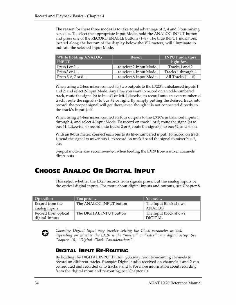
The reason for these three modes is to take equal advantage of 2, 4 and 8 bus mixingconsoles. To select the appropriate Input Mode, hold the ANALOG INPUT buttonand press one of the RECORD ENABLE buttons (1–8). The blue INPUT indicators,located along the bottom of the display below the VU meters, will illuminate toindicate the selected Input Mode.
While holding ANALOGINPUT
Result INPUT indicatorslight for…
Press 1 or 2… …to select 2-Input Mode. Tracks 1 and 2Press 3 or 4… …to select 4-Input Mode. Tracks 1 through 4Press 5, 6, 7 or 8… …to select 8-Input Mode. All Tracks (1 – 8)
When using a 2-bus mixer, connect its two outputs to the LX20’s unbalanced inputs 1and 2, and select 2-Input Mode. Any time you want to record on an odd-numberedtrack, route the signal(s) to bus #1 or left. Likewise, to record onto an even-numberedtrack, route the signal(s) to bus #2 or right. By simply putting the desired track intorecord, the proper signal will get there, even though it is not connected directly tothe track’s input jack.
When using a 4-bus mixer, connect its four outputs to the LX20’s unbalanced inputs 1through 4, and select 4-Input Mode. To record on track 1 or 5, route the signal(s) tobus #1. Likewise, to record onto tracks 2 or 6, route the signal(s) to bus #2, and so on.
With an 8-bus mixer, connect each bus to its like-numbered input. To record on track1, send the signal to mixer bus 1, to record on track 2 send the signal to mixer bus 2,etc.
8-input mode is also recommended when feeding the LX20 from a mixer channels’direct outs.
CHOOSE ANALOG OR DIGITAL INPUT
This select whether the LX20 records from signals present at the analog inputs orthe optical digital inputs. For more about digital inputs and outputs, see Chapter 8.
Operation You press… You see…Record from theanalog inputs
The ANALOG INPUT button The Input Block showsANALOG
Record from opticaldigital inputs
The DIGITAL INPUT button The Input Block showsDIGITAL
Choosing Digital Input may involve setting the Clock parameter as well,depending on whether the LX20 is the “master” or “slave” in a digital setup. SeeChapter 10, “Digital Clock Considerations”.
DIGITAL INPUT RE-ROUTINGBy holding the DIGITAL INPUT button, you may reroute incoming channels torecord on different tracks. Example: Digital audio received on channels 1 and 2 canbe rerouted and recorded onto tracks 3 and 4. For more information about recordingfrom the digital input and re-routing, see Chapter 10.
Chapter 4 - Record and Playback Basics
ADAT LX20 Reference Manual 35
SELECT TRACK(S) FOR RECORDING
A track can be in one of 3 states:
• Safe The track RECORD indicator (the red bar located right below the meter)is off.
• Record-ready The track RECORD indicator flashes• Recording The track RECORD indicator is lit solid
Here’s how to enable a track for recording, as well as place it in “safe” mode. Notethat the Record Enable switch “toggles” between two possible states each time youpress it.
Operation You press… You see…Enable track forrecording
The track’s associated RECORDENABLE button (1–8) until…
The selected track’s REClight flashes to indicate it isrecord-ready.
Place track in safemode
The record-enabled track’s RECORDENABLE button (1–8) until…
The selected track’s RECindicator will turn off toindicate it cannot record
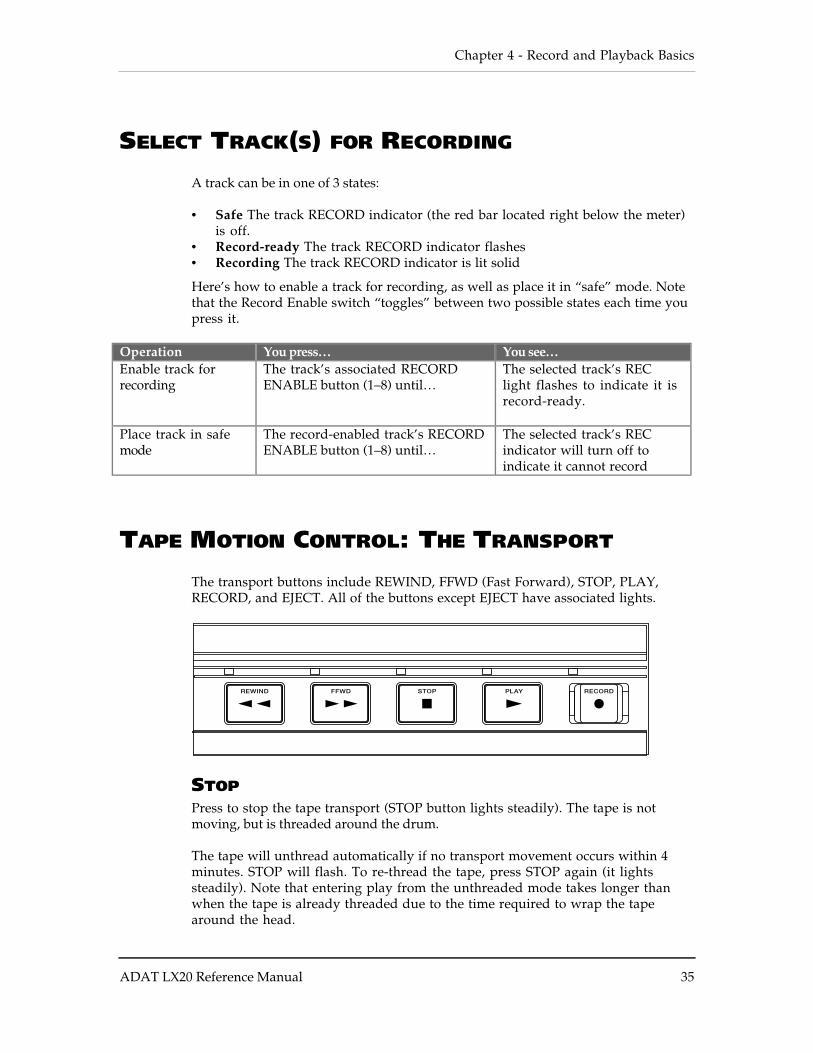
TAPE MOTION CONTROL: THE TRANSPORT
The transport buttons include REWIND, FFWD (Fast Forward), STOP, PLAY,RECORD, and EJECT. All of the buttons except EJECT have associated lights.
STOPPress to stop the tape transport (STOP button lights steadily). The tape is notmoving, but is threaded around the drum.
The tape will unthread automatically if no transport movement occurs within 4minutes. STOP will flash. To re-thread the tape, press STOP again (it lightssteadily). Note that entering play from the unthreaded mode takes longer thanwhen the tape is already threaded due to the time required to wrap the tapearound the head.
Record and Playback Basics - Chapter 4
36 ADAT LX20 Reference Manual
PLAYPress to start playback from the current tape location. The PLAY button also hasspecial functions in Record and Autolocation modes, as described in Chapter 5.
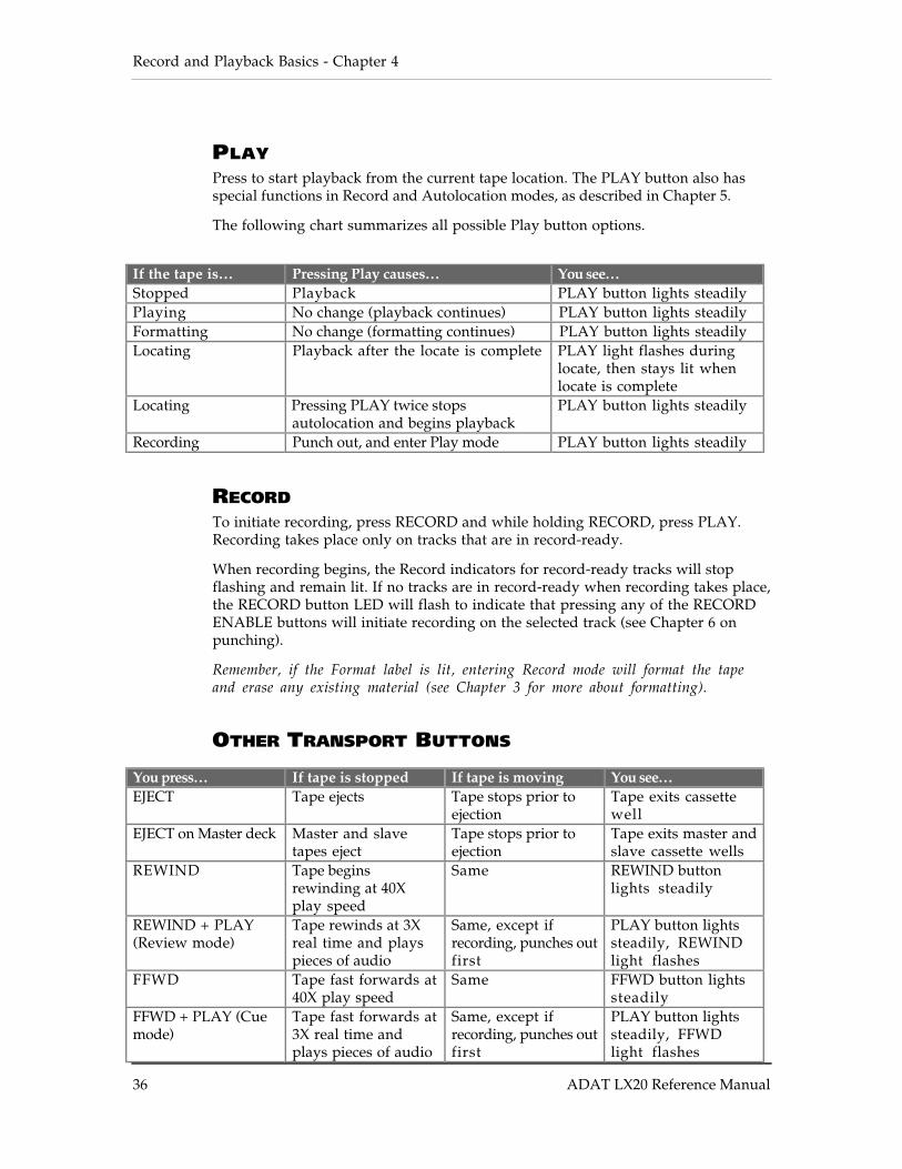
The following chart summarizes all possible Play button options.
If the tape is… Pressing Play causes… You see…Stopped Playback PLAY button lights steadilyPlaying No change (playback continues) PLAY button lights steadilyFormatting No change (formatting continues) PLAY button lights steadilyLocating Playback after the locate is complete PLAY light flashes during
locate, then stays lit whenlocate is complete
Locating Pressing PLAY twice stopsautolocation and begins playback
PLAY button lights steadily
Recording Punch out, and enter Play mode PLAY button lights steadily
RECORDTo initiate recording, press RECORD and while holding RECORD, press PLAY.Recording takes place only on tracks that are in record-ready.
When recording begins, the Record indicators for record-ready tracks will stopflashing and remain lit. If no tracks are in record-ready when recording takes place,the RECORD button LED will flash to indicate that pressing any of the RECORDENABLE buttons will initiate recording on the selected track (see Chapter 6 onpunching).
Remember, if the Format label is lit, entering Record mode will format the tapeand erase any existing material (see Chapter 3 for more about formatting).
OTHER TRANSPORT BUTTONS
You press… If tape is stopped If tape is moving You see…EJECT Tape ejects Tape stops prior to
ejectionTape exits cassettewell
EJECT on Master deck Master and slavetapes eject
Tape stops prior toejection
Tape exits master andslave cassette wells
REWIND Tape beginsrewinding at 40Xplay speed
Same REWIND buttonlights steadily
REWIND + PLAY(Review mode)
Tape rewinds at 3Xreal time and playspieces of audio
Same, except ifrecording, punches outfirst
PLAY button lightssteadily, REWINDlight flashes
FFWD Tape fast forwards at40X play speed
Same FFWD button lightssteadily
FFWD + PLAY (Cuemode)
Tape fast forwards at3X real time andplays pieces of audio
Same, except ifrecording, punches outfirst
PLAY button lightssteadily, FFWDlight flashes
Chapter 4 - Record and Playback Basics
ADAT LX20 Reference Manual 37
To end a Cue or Review operation, press PLAY, STOP, REWIND, or FFWD.
STEP-BY-STEP PROCEDURES
The following sections describe in detail how to record, play back, cue, and review.
Note: When recording for the first time, be sure the Auto Input function is off. Whenrecording over previous material (also known as punching), turn the Auto Inputfunction on. Use the AUTO INPUT button to turn Auto Input on and off. Thedisplay’s AUTO INPUT indicator lights when Auto Input is on.
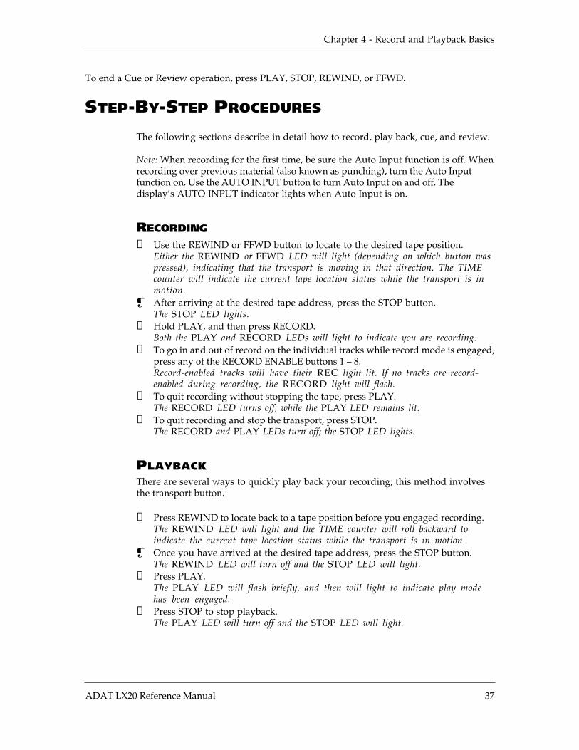
RECORDING
❿ Use the REWIND or FFWD button to locate to the desired tape position.Either the REWIND or FFWD LED will light (depending on which button waspressed), indicating that the transport is moving in that direction. The TIMEcounter will indicate the current tape location status while the transport is inmotion.
After arriving at the desired tape address, press the STOP button.The STOP LED lights.
① Hold PLAY, and then press RECORD.Both the PLAY and RECORD LEDs will light to indicate you are recording.
➃ To go in and out of record on the individual tracks while record mode is engaged,press any of the RECORD ENABLE buttons 1 – 8.Record-enabled tracks will have their REC light lit. If no tracks are record-enabled during recording, the RECORD light will flash.
➄ To quit recording without stopping the tape, press PLAY.The RECORD LED turns off, while the PLAY LED remains lit.
➅ To quit recording and stop the transport, press STOP.The RECORD and PLAY LEDs turn off; the STOP LED lights.
PLAYBACKThere are several ways to quickly play back your recording; this method involvesthe transport button.
❿ Press REWIND to locate back to a tape position before you engaged recording.The REWIND LED will light and the TIME counter will roll backward toindicate the current tape location status while the transport is in motion.
Once you have arrived at the desired tape address, press the STOP button.The REWIND LED will turn off and the STOP LED will light.
① Press PLAY.The PLAY LED will flash briefly, and then will light to indicate play modehas been engaged.
➃ Press STOP to stop playback.The PLAY LED will turn off and the STOP LED will light.
Record and Playback Basics - Chapter 4
38 ADAT LX20 Reference Manual
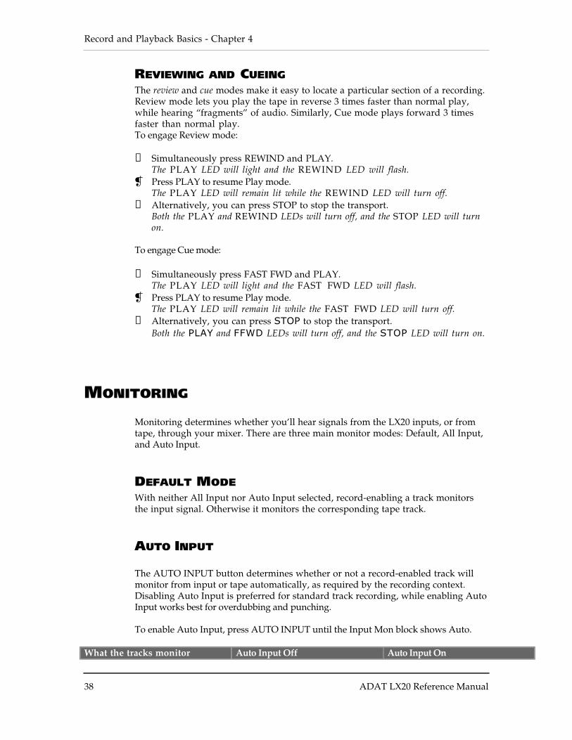
REVIEWING AND CUEINGThe review and cue modes make it easy to locate a particular section of a recording.Review mode lets you play the tape in reverse 3 times faster than normal play,while hearing “fragments” of audio. Similarly, Cue mode plays forward 3 timesfaster than normal play.To engage Review mode:
❿ Simultaneously press REWIND and PLAY.The PLAY LED will light and the REWIND LED will flash.
Press PLAY to resume Play mode.The PLAY LED will remain lit while the REWIND LED will turn off.
① Alternatively, you can press STOP to stop the transport.Both the PLAY and REWIND LEDs will turn off, and the STOP LED will turnon.
To engage Cue mode:
❿ Simultaneously press FAST FWD and PLAY.The PLAY LED will light and the FAST FWD LED will flash.
Press PLAY to resume Play mode.The PLAY LED will remain lit while the FAST FWD LED will turn off.
① Alternatively, you can press STOP to stop the transport.Both the PLAY and FFWD LEDs will turn off, and the STOP LED will turn on.
MONITORING
Monitoring determines whether you’ll hear signals from the LX20 inputs, or fromtape, through your mixer. There are three main monitor modes: Default, All Input,and Auto Input.
DEFAULT MODEWith neither All Input nor Auto Input selected, record-enabling a track monitorsthe input signal. Otherwise it monitors the corresponding tape track.
AUTO INPUT
The AUTO INPUT button determines whether or not a record-enabled track willmonitor from input or tape automatically, as required by the recording context.Disabling Auto Input is preferred for standard track recording, while enabling AutoInput works best for overdubbing and punching.
To enable Auto Input, press AUTO INPUT until the Input Mon block shows Auto.
What the tracks monitor Auto Input Off Auto Input On
Chapter 4 - Record and Playback Basics
ADAT LX20 Reference Manual 39
Record-enabled tracks monitorthe…
Input signal Input while recording or stopped,tape while playing
Non-record-enabled tracksmonitor the…
Tape Tape while playing or recording,input signal when stopped
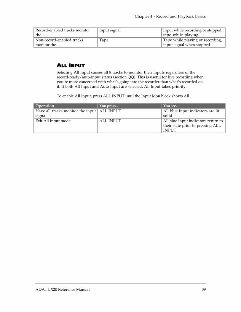
ALL INPUTSelecting All Input causes all 8 tracks to monitor their inputs regardless of therecord-ready/auto-input status (section QQ). This is useful for live recording whenyou’re more concerned with what’s going into the recorder than what’s recorded onit. If both All Input and Auto Input are selected, All Input takes priority.
To enable All Input, press ALL INPUT until the Input Mon block shows All.
Operation You press… You see…Have all tracks monitor the inputsignal
ALL INPUT All blue Input indicators are litsolid
Exit All Input mode ALL INPUT All blue Input indicators return totheir state prior to pressing ALLINPUT

Record and Playback Basics - Chapter 4
40 ADAT LX20 Reference Manual
Chapter 5 - Autolocation and Loop Functions
ADAT LX20 Reference Manual 41
CHAPTER 5
AUTOLOCATION ANDLOOP FUNCTIONS
The LX20 lets you concentrate on making music by automating several commonprocesses, including location, recording, and playback.
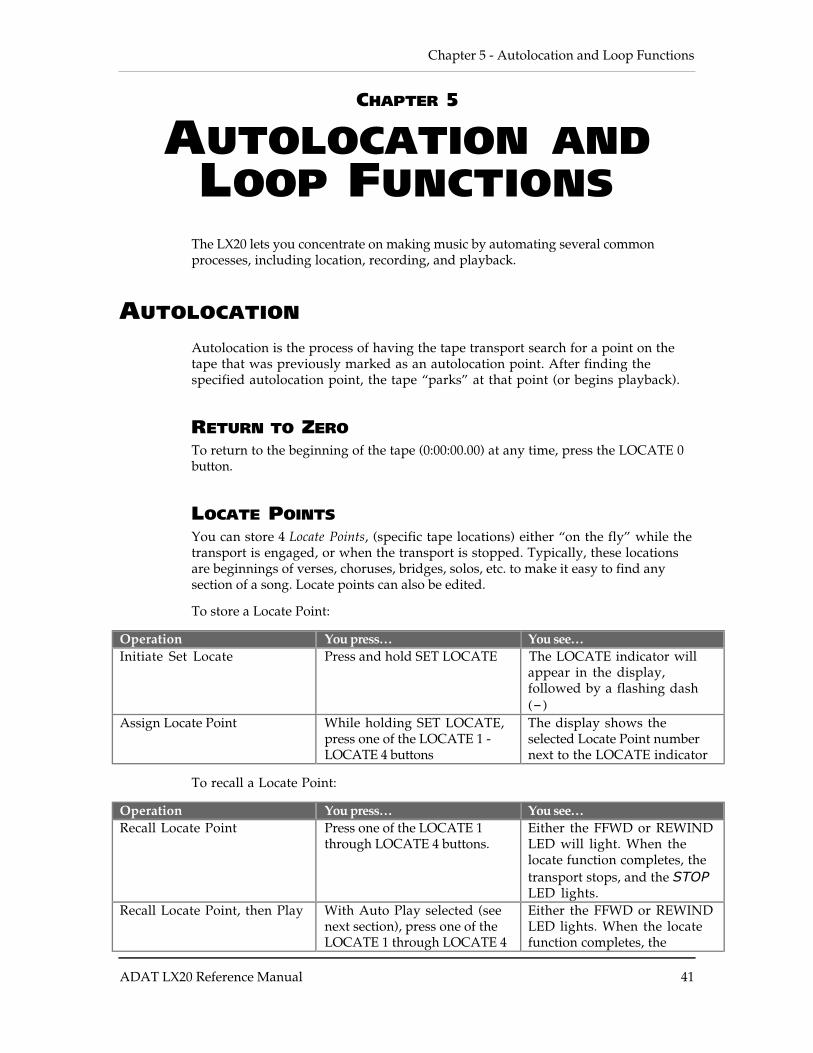
AUTOLOCATION
Autolocation is the process of having the tape transport search for a point on thetape that was previously marked as an autolocation point. After finding thespecified autolocation point, the tape “parks” at that point (or begins playback).
RETURN TO ZEROTo return to the beginning of the tape (0:00:00.00) at any time, press the LOCATE 0button.
LOCATE POINTSYou can store 4 Locate Points, (specific tape locations) either “on the fly” while thetransport is engaged, or when the transport is stopped. Typically, these locationsare beginnings of verses, choruses, bridges, solos, etc. to make it easy to find anysection of a song. Locate points can also be edited.
To store a Locate Point:
Operation You press… You see…Initiate Set Locate Press and hold SET LOCATE The LOCATE indicator will
appear in the display,followed by a flashing dash(–)
Assign Locate Point While holding SET LOCATE,press one of the LOCATE 1 -LOCATE 4 buttons
The display shows theselected Locate Point numbernext to the LOCATE indicator
To recall a Locate Point:
Operation You press… You see…Recall Locate Point Press one of the LOCATE 1
through LOCATE 4 buttons.Either the FFWD or REWINDLED will light. When thelocate function completes, thetransport stops, and the STOPLED lights.
Recall Locate Point, then Play With Auto Play selected (seenext section), press one of theLOCATE 1 through LOCATE 4
Either the FFWD or REWINDLED lights. When the locatefunction completes, the
Autolocation and Loop Functions - Chapter 5
42 ADAT LX20 Reference Manual
buttons. transport plays, and the PLAYLED lights.
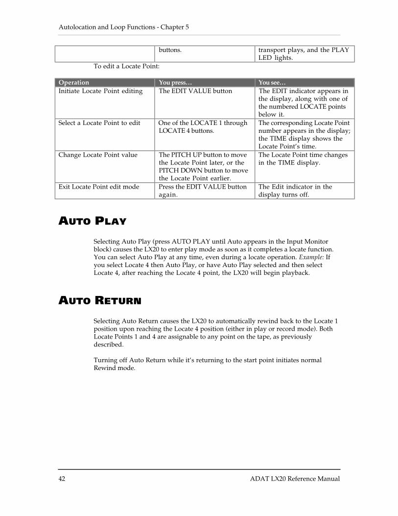
To edit a Locate Point:
Operation You press… You see…Initiate Locate Point editing The EDIT VALUE button The EDIT indicator appears in
the display, along with one ofthe numbered LOCATE pointsbelow it.
Select a Locate Point to edit One of the LOCATE 1 throughLOCATE 4 buttons.
The corresponding Locate Pointnumber appears in the display;the TIME display shows theLocate Point’s time.
Change Locate Point value The PITCH UP button to movethe Locate Point later, or thePITCH DOWN button to movethe Locate Point earlier.
The Locate Point time changesin the TIME display.
Exit Locate Point edit mode Press the EDIT VALUE buttonagain.
The Edit indicator in thedisplay turns off.
AUTO PLAY
Selecting Auto Play (press AUTO PLAY until Auto appears in the Input Monitorblock) causes the LX20 to enter play mode as soon as it completes a locate function.You can select Auto Play at any time, even during a locate operation. Example: Ifyou select Locate 4 then Auto Play, or have Auto Play selected and then selectLocate 4, after reaching the Locate 4 point, the LX20 will begin playback.
AUTO RETURN
Selecting Auto Return causes the LX20 to automatically rewind back to the Locate 1position upon reaching the Locate 4 position (either in play or record mode). BothLocate Points 1 and 4 are assignable to any point on the tape, as previouslydescribed.
Turning off Auto Return while it’s returning to the start point initiates normalRewind mode.
Chapter 5 - Autolocation and Loop Functions
ADAT LX20 Reference Manual 43
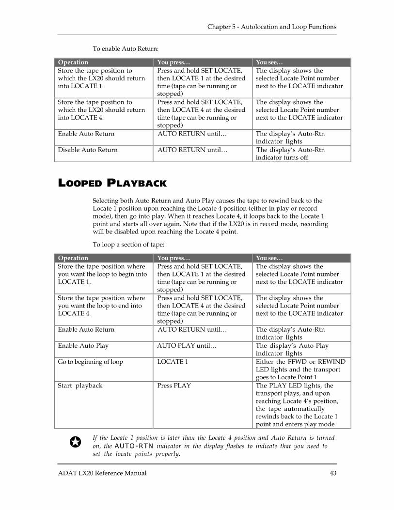
To enable Auto Return:
Operation You press… You see…Store the tape position towhich the LX20 should returninto LOCATE 1.
Press and hold SET LOCATE,then LOCATE 1 at the desiredtime (tape can be running orstopped)
The display shows theselected Locate Point numbernext to the LOCATE indicator
Store the tape position towhich the LX20 should returninto LOCATE 4.
Press and hold SET LOCATE,then LOCATE 4 at the desiredtime (tape can be running orstopped)
The display shows theselected Locate Point numbernext to the LOCATE indicator
Enable Auto Return AUTO RETURN until… The display’s Auto-Rtnindicator lights
Disable Auto Return AUTO RETURN until… The display’s Auto-Rtnindicator turns off
LOOPED PLAYBACK
Selecting both Auto Return and Auto Play causes the tape to rewind back to theLocate 1 position upon reaching the Locate 4 position (either in play or recordmode), then go into play. When it reaches Locate 4, it loops back to the Locate 1point and starts all over again. Note that if the LX20 is in record mode, recordingwill be disabled upon reaching the Locate 4 point.
To loop a section of tape:
Operation You press… You see…Store the tape position whereyou want the loop to begin intoLOCATE 1.
Press and hold SET LOCATE,then LOCATE 1 at the desiredtime (tape can be running orstopped)
The display shows theselected Locate Point numbernext to the LOCATE indicator
Store the tape position whereyou want the loop to end intoLOCATE 4.
Press and hold SET LOCATE,then LOCATE 4 at the desiredtime (tape can be running orstopped)
The display shows theselected Locate Point numbernext to the LOCATE indicator
Enable Auto Return AUTO RETURN until… The display’s Auto-Rtnindicator lights
Enable Auto Play AUTO PLAY until… The display’s Auto-Playindicator lights
Go to beginning of loop LOCATE 1 Either the FFWD or REWINDLED lights and the transportgoes to Locate Point 1
Start playback Press PLAY The PLAY LED lights, thetransport plays, and uponreaching Locate 4’s position,the tape automaticallyrewinds back to the Locate 1point and enters play mode
If the Locate 1 position is later than the Locate 4 position and Auto Return is turnedon, the AUTO-RTN indicator in the display flashes to indicate that you need toset the locate points properly.
Autolocation and Loop Functions - Chapter 5
44 ADAT LX20 Reference Manual
LOOP LIMITTo protect against unnecessary wear and tear, the LX20 automatically disablesAuto Loop after completing 100 consecutive loops. To disable this safeguard, holdthe SET LOCATE button and press AUTO RETURN. Pressing STOP restores the 100loop limit.
Alesis strongly recommends leaving loop limit enabled.
While the LX20 is Auto Looping, you can check how many loops have elapsed byholding SET LOCATE and pressing AUTO PLAY.
DEFERRED PLAY AND RECORDTo automatically enter play mode after locating, press PLAY before a locatecompletes. To cancel deferred play while the tape is moving, press STOP,REWIND, FFWD, or a LOCATE POINT button.
To automatically enter Record mode after locating, press PLAY and RECORD beforea locate completes. To cancel deferred recording while the tape is moving, pressPLAY, STOP, REWIND, FFWD, or a LOCATE POINT button.
Chapter 6 - Punching and Automated Recording
ADAT LX20 Reference Manual 45
CHAPTER 6
PUNCHING ANDAUTOMATEDRECORDING
Punching is the process of recording over a section of tape (for example, to replace abad note in an otherwise good performance). Punch-in is where recording begins, andpunch-out is where it ends.
There are several ways to punch into and out of recording, either manually orautomatically.
If you’re used to punching with analog tape machines, note that punch-out isimmediate; there is no brief, silent “gap” after punching out.
MANUAL PUNCHING OPTIONS
TRANSPORT CONTROLSTo punch-in: Select a track to record, press and hold RECORD, then press PLAY atthe punch-in point.
To punch-out:
• Press STOP. The transport punches out of record, then stops.• Press PLAY.• Press and hold RECORD, then press PLAY.
RECORD ENABLE BUTTONS
If you press PLAY and RECORD with no tracks record-enabled, the Record lightwill flash. Pressing individual track RECORD ENABLE buttons (simultaneously orin any order) can punch individual tracks in or out independently. The Record lightwill remain lit (or flashing in Rehearse mode; see “Rehearsing”) until you punchout of Record, usually by pressing PLAY or any other transport key.
Operation You press… You see…Punch in using RECORD ENABLEbutton
While in Record mode and thetape is running, press RECORDENABLE button
Record Enable indicator lightssolid
Punch out using RECORDENABLE button
While recording, press RECORDENABLE button
Record Enable indicator turns off
Punching and Automated Recording - Chapter 6
46 ADAT LX20 Reference Manual
FOOTSWITCH
Pressing the punch footswitch is equivalent to pressing RECORD and PLAY.
If the LX20 is already recording, pressing the punch footswitch exits Record modebut the transport continues to play.
Note: Footswitch-controlled recording also works in conjunction with Rehearsemode and Auto Record mode.
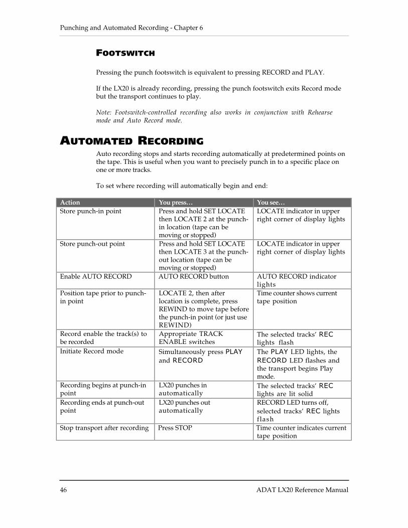
AUTOMATED RECORDINGAuto recording stops and starts recording automatically at predetermined points onthe tape. This is useful when you want to precisely punch in to a specific place onone or more tracks.
To set where recording will automatically begin and end:
Action You press… You see…Store punch-in point Press and hold SET LOCATE
then LOCATE 2 at the punch-in location (tape can bemoving or stopped)
LOCATE indicator in upperright corner of display lights
Store punch-out point Press and hold SET LOCATEthen LOCATE 3 at the punch-out location (tape can bemoving or stopped)
LOCATE indicator in upperright corner of display lights
Enable AUTO RECORD AUTO RECORD button AUTO RECORD indicatorlights
Position tape prior to punch-in point
LOCATE 2, then afterlocation is complete, pressREWIND to move tape beforethe punch-in point (or just useREWIND)
Time counter shows currenttape position
Record enable the track(s) tobe recorded
Appropriate TRACKENABLE switches
The selected tracks’ REClights flash
Initiate Record mode Simultaneously press PLAYand RECORD
The PLAY LED lights, theRECORD LED flashes andthe transport begins Playmode.
Recording begins at punch-inpoint
LX20 punches inautomatically
The selected tracks’ REClights are lit solid
Recording ends at punch-outpoint
LX20 punches outautomatically
RECORD LED turns off,selected tracks’ REC lightsflash
Stop transport after recording Press STOP Time counter indicates currenttape position

Chapter 6 - Punching and Automated Recording
ADAT LX20 Reference Manual 47
If Locate 2’s position is later than Locate 3’s position, the TIME counter willtemporarily read “invALid”.
Initiating record past Locate 2’s position but before Locate 3’s position startsrecording immediately. Initiating record after Locate 3’s position has no effect, andthe transport remains in play mode.
LOOPED RECORDING
You can use the Auto Return and Auto Play functions (see Chapter 5) with AutoRecord to create a recording loop. So, you can record a take over and over until youget it right. Simply set Locate 1 to a position before Locate 2, and Locate 4 afterLocate 3.
REHEARSING
Rehearse mode allows checking the accuracy of punch points without actuallyentering Record mode. This way you can try out your punch locations first withoutrecording over anything. At the punch-in point, record-enabled tracks will switchfrom tape monitor to input monitor. At the punch-out point, record-enabled trackswill resume monitoring the tape signal.
Auto Input must be enabled for rehearsal mode to work.
Operation You press… You see…Enable Rehearse mode Rehearse button Rehearse label lights in display.Start rehearsal Play and Record (or
use footswitch)Record light flashes whilerehearsing the punch
Disable Rehearse mode Rehearse button Rehearse label turns off
You can edit the punch in and out points by editing Locations 2 and 3. See Chapter 5, “LocatePoints”.
Punching and Automated Recording - Chapter 6
48 ADAT LX20 Reference Manual
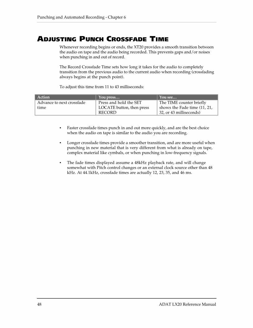
ADJUSTING PUNCH CROSSFADE TIMEWhenever recording begins or ends, the XT20 provides a smooth transition betweenthe audio on tape and the audio being recorded. This prevents gaps and/or noiseswhen punching in and out of record.
The Record Crossfade Time sets how long it takes for the audio to completelytransition from the previous audio to the current audio when recording (crossfadingalways begins at the punch point).
To adjust this time from 11 to 43 milliseconds:
Action You press… You see…Advance to next crossfadetime
Press and hold the SETLOCATE button, then pressRECORD
The TIME counter brieflyshows the Fade time (11, 21,32, or 43 milliseconds)
• Faster crossfade times punch in and out more quickly, and are the best choicewhen the audio on tape is similar to the audio you are recording.
• Longer crossfade times provide a smoother transition, and are more useful when
punching in new material that is very different from what is already on tape,complex material like cymbals, or when punching in low-frequency signals.
• The fade times displayed assume a 48kHz playback rate, and will changesomewhat with Pitch control changes or an external clock source other than 48kHz. At 44.1kHz, crossfade times are actually 12, 23, 35, and 46 ms.
Chapter 7 - Pitch Control
ADAT LX20 Reference Manual 49
CHAPTER 7
PITCH CONTROL
The Pitch function controls the tape’s speed, which changes the pitch of the audiorecorded on tape. The LX20’s Pitch control range covers -300 to +100 cents with a48kHz sample rate, and -200 to +200 cents at 44.1kHz.
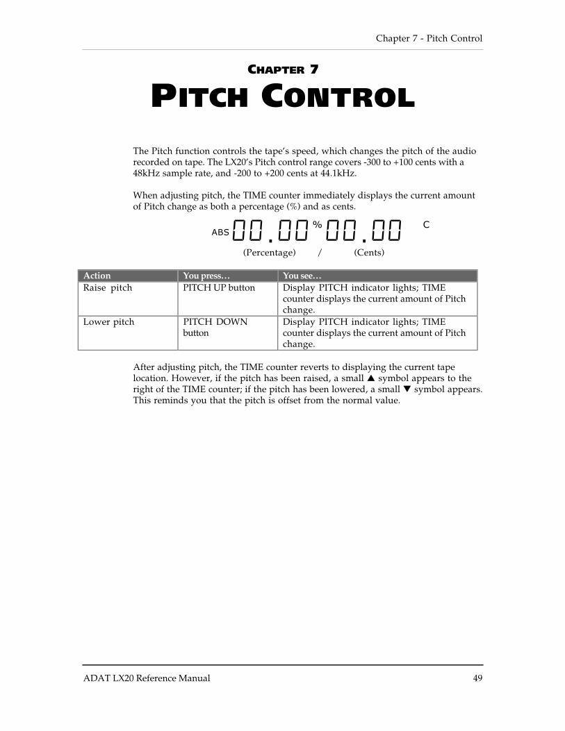
When adjusting pitch, the TIME counter immediately displays the current amountof Pitch change as both a percentage (%) and as cents.
ABS 00. 00%
00. 00 C
(Percentage) / (Cents)
Action You press… You see…Raise pitch PITCH UP button Display PITCH indicator lights; TIME
counter displays the current amount of Pitchchange.
Lower pitch PITCH DOWNbutton
Display PITCH indicator lights; TIMEcounter displays the current amount of Pitchchange.
After adjusting pitch, the TIME counter reverts to displaying the current tapelocation. However, if the pitch has been raised, a small symbol appears to theright of the TIME counter; if the pitch has been lowered, a small symbol appears.This reminds you that the pitch is offset from the normal value.

Punching and Automated Recording - Chapter 6
50 ADAT LX20 Reference Manual
Chapter 8 - About Digital Audio In/Out
ADAT LX20 Reference Manual 51
CHAPTER 8
ABOUT DIGITAL AUDIOIN/OUT
The ADAT Optical Interface carries 8 tracks of digital audio between ADATcompatible products such as:
• Multiple LX20s and ADAT• QuadraVerb 2• Q20• Many Alesis keyboards• ADAT-PCR computer interface card• 3rd-party products (Digidesign ADAT Bridge, Yamaha 02R digital mixer, etc.)
Digital bussing requires one fiber optical cable (included) for each LX20 or otherADAT-compatible product. Additional cables are available from your dealer invarious lengths up to 16 feet (about 5 meters). This connection can be made whilepower is on or off.
ADAT OPTICAL INTERFACE BASICSThe Optical Interface sends (or receives) up to 8 simultaneous channels of digitalI/O over a single fiber optic cable. Compared to wire cables, fiber optics contributesno noise or interference, the optical isolation prevents ground loops, and if you needto know if something’s sending a signal, just look at the cable’s output connector tocheck for a glowing red light.
As cable capacitance is not an issue, waveforms retain all their high frequencies asthey pass through the cable, thus maintaining the integrity of the waveformshape. However, fiber optic cables are somewhat fragile, so route them out ofharm’s way.
ABOUT 16-BIT AND 20-BIT SIGNAL TRANSFERSThe ADAT Optical Interface is designed for the future, and can transfer digitaldata with up to 24-bit resolution. Current Alesis products use 20-bit resolution, aquantum improvement over earlier 16-bit designs.
At the receiving end, ADAT Type I machines (the original ADAT “classic” and XT)convert any incoming signal to 16 bits. Type II machines (e.g., the M20, LX20, XT20,and PCR card with proper software) can accept 16 or 20-bit signals, and convert 24-bit signals to 20 bits.
Note: Type II machines will convert 16-bit signals to 20 bits, however the last 4 bitswill be zeroes, and not increase the actual resolution beyond 16 bits.
About Digital Audio In/Out - Chapter 8
52 ADAT LX20 Reference Manual
SELECTING THE DIGITAL OUTPUT MODEMany applications involve sending the LX20’s digital output to another device,such as another ADAT for backup, or the ADAT-PCR card for digital editing. Thetype of transfer will require a particular digital output mode, as set with theDIGITAL OUT button.
TYPE II (20-BIT) TO TYPE II (20-BIT)Press the DIGITAL OUT button repeatedly until the display shows “OUt 20”,then release. The LX20 sends a signal with 20-bit resolution.
TYPE II (20-BIT) TO TYPE I (16-BIT)You have three options for transferring from a Type II to Type I machine. The firsttwo options listed are sonically equivalent.
• Press the DIGITAL OUT button until the display shows “OUt 20”, thenrelease. The LX20 sends a signal with 20-bit resolution. The Type I deviceignores the last four bits, essentially cutting them off.
• Press the DIGITAL OUT button until the display shows “OUt 16”, then
release. The LX20 sends a signal with 16-bit resolution and fills the “extra” 4bits with zeroes, which a Type I machine ignores.
• Press the DIGITAL OUT button until the display shows “OUt 16 dt”, then
release. The LX20 adds “dither” (a carefully synthesized mathmatical noise)to the signal, which “smooths out” the transition at low levels and providesbetter apparent resolution even though the signal is 16 bits. Use ditheringunless the signal will be dithered again later on; dithering a previously-dithered signal alters the sound.

Chapter 8 - About Digital Audio In/Out
ADAT LX20 Reference Manual 53
CHAPTER 9
USING THE LX20 LRCREMOTE
The hand-held LRC remote provides the following functions:
• Transport functions: Rewind, Fast Forward, Stop, Play and Record.
• Autolocation functions: Locate 1, Locate 2, Locate 3, Locate 4, Set Locate, andAuto Loop
• Track functions: Auto Record and Rehearse.
All buttons work the same as the front panel controls. If connected to the masterLX20 in a multiple ADAT system, the LRC can control the entire chain of ADATs.
The AUTO LOOP button, which does not exist on the LX20 front panel, toggles boththe Auto Play and Auto Return functions on and off simultaneously.
Note: To enable the Auto Play function by itself without the Auto Return function(i.e. without looping), initiate a deferred play with the Play button — that is,press any of the LOCATE 1 – LOCATE 4 buttons followed by the PLAY button.
To use the LX20 Remote, plug it into the LRC/PUNCH jack. If you want to use afootswitch too, see the adapter described in Chapter 1.

Using the LX20 LRC Remote - Chapter 9
54 ADAT LX20 Reference Manual

Chapter 10 - Multiple LX20/ADAT Operation
ADAT LX20 Reference Manual 55
CHAPTER 10
MULTIPLELX20/ADATOPERATION
OVERVIEWThe LX20 can work together with up to 15 other ADAT-family machines to providea total of 128 tracks.
ADAT machines have a sync bus that provides timing information for all ADATs ina system. When linking multiple ADATs together, the first machine in the chain isthe “master,” and the rest are “slaves.” Each slave locks to the master andsynchronizes to the master machine’s time reference.
Using the 8-channel ADAT Optical Interface, you can also bounce (copy) tracksbetween machines in the digital realm. The result is a perfect copy (ideal for safetybackups and archives) that is synchronized to the original with single-sampleaccuracy.
See the applications section for creative ways to use multiple ADATs.
SYNCHRONIZING MACHINESEach slave to be synchronized requires a dual male, 9-pin D connector cable. Useonly Alesis cables, which are available in three different lengths: 8", 30", and 30'.Other cables may cause erratic sync performance.
To connect the bus (power must be off), patch one 9-pin D connector cable from themaster SYNC OUT to the slave SYNC IN. A slave will automatically detect amaster and enter slave mode. With more slaves, connect slave 2’s SYNC OUT toslave 3’s SYNC IN, slave 3’s SYNC OUT to slave 4’s SYNC IN, etc.
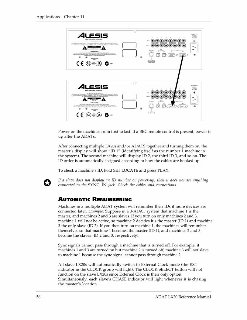
Applications - Chapter 11
56 ADAT LX20 Reference Manual
POWER INPUT 90-250 V
50-60 Hz80 W MAX
LISTED
3T55
COMMERCIALRECORDERU
®
U.S. Patents 5,297,181 5,321,561 5,541,781
THIS DEVICE COMPLIES WITH PART 15 OF THE FCC RULES. OPERATION IS SUBJECT TO THE FOLLOWING TWO CONDITIONS:(1) THIS DEVICE MAY NOT CAUSE HARMFUL INTERFERENCE, AND (2) THIS DEVICE MUST ACCEPT ANY INTERFERENCE RECEIVED,
INCLUDING INTERFERENCE THAT MAY CAUSE UNDESIRED OPERATION.
1 2 3 4 5 6 7 8
OUTPUT
INPUT
LRC/PUNCHADAT
OPTICAL SYNC
OUTIN OUTIN
Tip = LRC RemoteRing = Punch In/Out
Sleeve = Ground
ALESIS CORPORATION, LOS ANGELES
TO REDUCE THE RISK OF FIRE OR ELECTRIC SHOCK DO NOT EXPOSE THIS EQUIPMENT TO RAIN OR MOISTURE.TO REDUCE THE RISK OF ELECTRIC SHOCK DO NOT REMOVE COVER (OR BACK). NO USER SERVICEABLE PARTS INSIDE.
REFER SERVICING TO QUALIFIED SERVICE PERSONNEL.
SHOCK HAZARD Ð DO NOT OPEN. RISQUE DE CHOC ELECTRIQUE Ð NE PAS OUVRIR.WARNING/AVIS:
U®
INGRESS PROTECTIONIPXO
N382C
!CAUTION
RISK OF ELECTRIC SHOCKDO NOT OPEN
Power on the machines from first to last. If a BRC remote control is present, power itup after the ADATs.
After connecting multiple LX20s and/or ADATS together and turning them on, themaster’s display will show “ID 1” (identifying itself as the number 1 machine inthe system). The second machine will display ID 2, the third ID 3, and so on. TheID order is automatically assigned according to how the cables are hooked up.
To check a machine’s ID, hold SET LOCATE and press PLAY.
If a slave does not display an ID number on power-up, then it does not see anythingconnected to the SYNC IN jack. Check the cables and connections.
AUTOMATIC RENUMBERINGMachines in a multiple ADAT system will renumber their IDs if more devices areconnected later. Example: Suppose in a 3-ADAT system that machine 1 is themaster, and machines 2 and 3 are slaves. If you turn on only machines 2 and 3,machine 1 will not be active, so machine 2 decides it’s the master (ID 1) and machine3 the only slave (ID 2). If you then turn on machine 1, the machines will renumberthemselves so that machine 1 becomes the master (ID 1), and machines 2 and 3become the slaves (ID 2 and 3, respectively).
Sync signals cannot pass through a machine that is turned off. For example, ifmachines 1 and 3 are turned on but machine 2 is turned off, machine 3 will not slaveto machine 1 because the sync signal cannot pass through machine 2.
All slave LX20s will automatically switch to External Clock mode (the EXTindicator in the CLOCK group will light). The CLOCK SELECT button will notfunction on the slave LX20s since External Clock is their only option.Simultaneously, each slave’s CHASE indicator will light whenever it is chasingthe master’s location.

Chapter 10 - Multiple LX20/ADAT Operation
ADAT LX20 Reference Manual 57
MASTER/SLAVE INTERACTIONPressing any of the transport buttons (PLAY, STOP, etc.), or AUTO REC, PITCH or , LOCATE 0 – LOCATE 4, ALL INPUT, or AUTO INPUT will automaticallytrigger the same functions on the slave machine(s).
As slaves can operate independently, to minimize confusion initiate all operationsfrom the master, including transport control functions. When you press PLAY on themaster, the slave(s) will locate to the same time code point and begin playing oncesync is achieved (indicated by a lit LOCKED indicator).
Eject protocol: Pressing EJECT on the master also ejects all slave’s tapes. To ejectonly the master’s tape, press and hold SET LOCATE, then press EJECT on themaster.
Recording or punching in on slaves: Initiate recording on the master but do notrecord-enable any master tracks (unless, of course, you need to record tracks on themaster). Any slave tracks that are record-enabled will go into record, while themaster will simply play (this is why record enable is an independent function foreach slave). Digital Input is also independent for the slave(s) since you may wantto record via the analog inputs on some machines, and the digital inputs on others.
Formatting: This is initiated independently on each slave (described later),however, simultaneous formatting on all slaves is possible.
ACHIEVING LOCKIn a multiple-ADAT system, the slaves will “chase” the master (CHASE indicatorlights on the LX20) and can only enter record once they are locked. Audio will notappear at an ADAT’s outputs until it is locked, as shown by a lit LOCKEDindicator. For the fastest chase-lock performance in a multi-ADAT system, whenpossible use the Locate points to go to different tape locations.
INDEPENDENT SLAVE MODEIf the master LX20 is stopped, each slave functions independently. Example: PressPLAY on one of the slaves and it will play, but the other slaves and master will notrespond. However, any time you press PLAY on the master or initiate any transportfunction, it will take over and control the slaves.
FORMATTING MULTIPLE TAPESFormatting multiple ADATs works similarly to formatting on a single LX20,however there are some considerations unique to formatting multiple tapes. (Forbasic information on formatting, see Chapter 3.)
The following chart indicates the possibilities for various slave and master formatcombinations. Remember that any record-enabled tracks will start recording at00:00:00 of the formatting process.
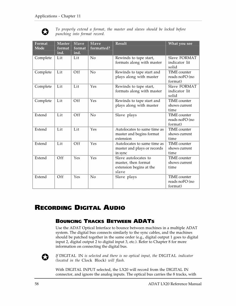
Applications - Chapter 11
58 ADAT LX20 Reference Manual
To properly extend a format, the master and slaves should be locked beforepunching into format record.
FormatMode
Masterformatind.
Slaveformatind.
Slaveformatted?
Result What you see
Complete Lit Lit No Rewinds to tape start,formats along with master
Slave FORMATindicator litsolid
Complete Lit Off No Rewinds to tape start andplays along with master
TIME counterreads noFO (noformat)
Complete Lit Lit Yes Rewinds to tape start,formats along with master
Slave FORMATindicator litsolid
Complete Lit Off Yes Rewinds to tape start andplays along with master
TIME countershows currenttime
Extend Lit Off No Slave plays TIME counterreads noFO (noformat)
Extend Lit Lit Yes Autolocates to same time asmaster and begins formatextension
TIME countershows currenttime
Extend Lit Off Yes Autolocates to same time asmaster and plays or recordsin sync
TIME countershows currenttime
Extend Off Yes Yes Slave autolocates tomaster, then formatextension begins at theslave
TIME countershows currenttime
Extend Off Yes No Slave plays TIME counterreads noFO (noformat)
RECORDING DIGITAL AUDIO
BOUNCING TRACKS BETWEEN ADATSUse the ADAT Optical Interface to bounce between machines in a multiple ADATsystem. The digital bus connects similarly to the sync cables, and the machinesshould be patched together in the same order (e.g., digital output 1 goes to digitalinput 2, digital output 2 to digital input 3, etc.). Refer to Chapter 8 for moreinformation on connecting the digital bus.
If DIGITAL IN is selected and there is no optical input, the DIGITAL indicator(located in the Clock Block) will flash.
With DIGITAL INPUT selected, the LX20 will record from the DIGITAL INconnector, and ignore the analog inputs. The optical bus carries the 8 tracks, with
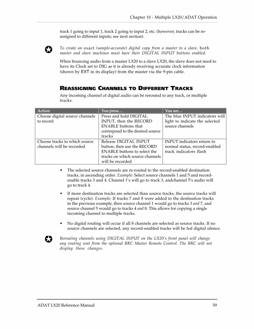
Chapter 10 - Multiple LX20/ADAT Operation
ADAT LX20 Reference Manual 59
track 1 going to input 1, track 2 going to input 2, etc. (however, tracks can be re-assigned to different inputs; see next section).
To create an exact (sample-accurate) digital copy from a master to a slave, bothmaster and slave machines must have their DIGITAL INPUT buttons enabled.
When bouncing audio from a master LX20 to a slave LX20, the slave does not need tohave its Clock set to DIG as it is already receiving accurate clock information(shown by EXT in its display) from the master via the 9-pin cable.
REASSIGNING CHANNELS TO DIFFERENT TRACKSAny incoming channel of digital audio can be rerouted to any track, or multipletracks.
Action You press… You see…Choose digital source channelsto record
Press and hold DIGITALINPUT, then the RECORDENABLE buttons thatcorrespond to the desired sourcetracks
The blue INPUT indicators willlight to indicate the selectedsource channels
Choose tracks to which sourcechannels will be recorded
Release DIGITAL INPUTbutton, then use the RECORDENABLE buttons to select thetracks on which source channelswill be recorded
INPUT indicators return tonormal status, record-enabledtrack indicators flash
• The selected source channels are re-routed to the record-enabled destinationtracks, in ascending order. Example: Select source channels 1 and 5 and record-enable tracks 3 and 4. Channel 1’s will go to track 3, andchannel 5’s audio willgo to track 4.
• If more destination tracks are selected than source tracks, the source tracks willrepeat (cycle). Example: If tracks 7 and 8 were added to the destination tracksin the previous example, then source channel 1 would go to tracks 3 and 7, andsource channel 5 would go to tracks 4 and 8. This allows for copying a singleincoming channel to multiple tracks.
• No digital routing will occur if all 8 channels are selected as source tracks. If nosource channels are selected, any record-enabled tracks will be fed digital silence.
Rerouting channels using DIGITAL INPUT on the LX20’s front panel will changeany routing sent from the optional BRC Master Remote Control. The BRC will notdisplay these changes.
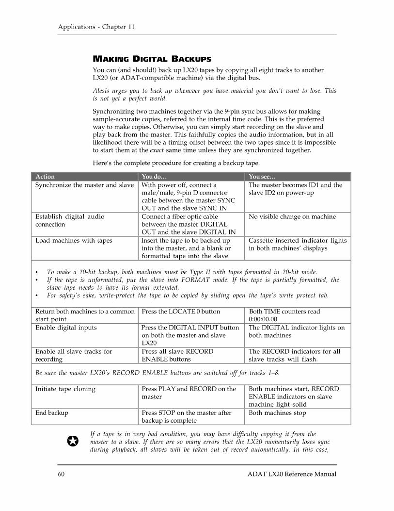
Applications - Chapter 11
60 ADAT LX20 Reference Manual
MAKING DIGITAL BACKUPSYou can (and should!) back up LX20 tapes by copying all eight tracks to anotherLX20 (or ADAT-compatible machine) via the digital bus.
Alesis urges you to back up whenever you have material you don’t want to lose. Thisis not yet a perfect world.
Synchronizing two machines together via the 9-pin sync bus allows for makingsample-accurate copies, referred to the internal time code. This is the preferredway to make copies. Otherwise, you can simply start recording on the slave andplay back from the master. This faithfully copies the audio information, but in alllikelihood there will be a timing offset between the two tapes since it is impossibleto start them at the exact same time unless they are synchronized together.
Here’s the complete procedure for creating a backup tape.
Action You do… You see…Synchronize the master and slave With power off, connect a
male/male, 9-pin D connectorcable between the master SYNCOUT and the slave SYNC IN
The master becomes ID1 and theslave ID2 on power-up
Establish digital audioconnection
Connect a fiber optic cablebetween the master DIGITALOUT and the slave DIGITAL IN
No visible change on machine
Load machines with tapes Insert the tape to be backed upinto the master, and a blank orformatted tape into the slave
Cassette inserted indicator lightsin both machines’ displays
• To make a 20-bit backup, both machines must be Type II with tapes formatted in 20-bit mode.• If the tape is unformatted, put the slave into FORMAT mode. If the tape is partially formatted, the
slave tape needs to have its format extended.• For safety’s sake, write-protect the tape to be copied by sliding open the tape’s write protect tab.
Return both machines to a commonstart point
Press the LOCATE 0 button Both TIME counters read0:00:00.00
Enable digital inputs Press the DIGITAL INPUT buttonon both the master and slaveLX20
The DIGITAL indicator lights onboth machines
Enable all slave tracks forrecording
Press all slave RECORDENABLE buttons
The RECORD indicators for allslave tracks will flash.
Be sure the master LX20’s RECORD ENABLE buttons are switched off for tracks 1–8.
Initiate tape cloning Press PLAY and RECORD on themaster
Both machines start, RECORDENABLE indicators on slavemachine light solid
End backup Press STOP on the master afterbackup is complete
Both machines stop
If a tape is in very bad condition, you may have difficulty copying it from themaster to a slave. If there are so many errors that the LX20 momentarily loses syncduring playback, all slaves will be taken out of record automatically. In this case,
Chapter 10 - Multiple LX20/ADAT Operation
ADAT LX20 Reference Manual 61
put the new tape into the master, the damaged tape in the slave, and copy from the slave tothe master.
MAKING A 16-BIT COPY FROM A 20-BIT MASTERWith over 100,000 ADAT 16-bit Type I machines in use, you may need to trade tapeswith someone who owns an older machine. You can still record with your LX20 in 20-bit Type II mode, and make Type I-compatible “clones.” You can also use an olderType I machine as a slave to an LX20.
Alesis recommends creating 16-bit copies using dithering, a process that providesbetter apparent resolution than standard 16-bit copies, unless the tape will be re-dithered later on. The process is the same as making a standard backup, except thatyou select a dithered 16-bit digital output at the master, as described in Chapter 8.
RECORDING DIGITAL AUDIO FROM OTHER SOURCES
Recording digital audio onto the LX20 from a source other than an ADAT-compatible device requires a digital audio interface, like the Otari UFC-24 orKurzweil DMTi. These convert other digital audio formats to the Alesis Opticalformat. The ADAT-PCR card can also output audio recorded into a hard diskediting program as ADAT Optical Interface data.
When recording digital audio into the LX20 within a multiple ADAT system, theLX20 recording the audio (whether slave or master) is already synchronized withthe other machines because all slave machines are automatically set to ExternalClock mode (EXT indicator lights in the Clock block). This means they follow themaster precisely.
When recording digital audio from some other source, the LX20 must synchronize tothe incoming digital audio. The procedure for doing this depends on whether you areusing a single LX20 or a multiple ADAT system. We will assume the incomingdigital audio is being carried by an ADAT Optical interface cable (perhaps from anADAT-PCR card).
With a single LX20, connect the ADAT-PCR card’s OPTICAL OUT to the LX20’sDIGITAL IN using a single fiber optic connector. Press the LX20’s DIGITAL INPUTbutton, and set its Clock Source to Digital (press CLOCK SELECT until the DIGindicator lights in the Clock block). The LX20 will synchronize to the OPTICALOUT clock information.
In a multiple ADAT system, you have two choices: synchronize the digital audiosource to the ADAT system (as described above for a single ADAT), or sync theADAT system to the digital audio source.
If the source cannot sync to an external clock, you need to choose the latter option.Connect the OPTICAL OUT to the master ADAT’s DIGITAL IN, whose DIGITALOUT already connects to the next slave’s input, and so on. Set the master’s ClockSource to Digital (press CLOCK SELECT until the DIG indicator lights in theCLOCK block). If no digital audio clock is detected, the master LX20’s DIGindicator will flash and it will continue using its own internal clock. When themaster receives digital audio, the master LX20 will sync to the incoming digitalclock. The LX20’s DIG clock indicator will stop flashing and remain lit.
Applications - Chapter 11
62 ADAT LX20 Reference Manual
DIGITAL CLOCK CONSIDERATIONS
Switching between the LX20’s two internal clock sample rates (48 kHz and 44.1kHz) changes the reference used for computing tape location. Therefore, the sametape location will appear to have two different time addresses depending on theselected sample rate.
Since the LX20 cannot detect an external clock’s sample rate, you need to choose thereference base the LX20 should use to calculate tape position while syncing to adigital clock. Select either DIG 48K or DIG 44.1K (shown in the Clock block) withthe CLOCK SELECT button.
COMBINING LX20S AND ADATS
LX20 TRANSPORT SPEEDThe LX20’s rewind/fast forward speed is four times faster in engaged mode than theoriginal ADAT. Because of this and other unique features, make the LX20 themaster (ID 1). Older ADAT(s) should be the slave(s).
When locating, the LX20 will locate to a specific tape position, stop, and wait forthe ADAT(s) to catch up. Therefore, until you need more than 8 tracks, don’t put anytape(s) into the slave unit(s) so that the LX20 won’t have to wait for the slave(s) tolocate.
SAMPLE RATE VS. PITCH CONTROLThe LX20’s Clock Select function, which allows choosing between 48 kHz or 44.1kHz sampling rates, was not available on the original ADAT. This function alsoalows selecting a digital clock for applications involving the recording of digitalaudio from a non-ADAT source.
The LX20 writes sample rate information when formatting a tape, so that itautomatically knows a formatted tape’s sample rate (even though either rate maybe used).
Example: When playing back a tape formatted at 48 kHz with the Clock set to 44.1kHz, the 44.1K indicator will flash, to indicate that you are using 44.1 kHz but itisn’t the original sample rate used when the tape was formatted.
The LX20 Pitch Controls supplement the sample rate selection. With the originalADAT, you had to pitch a tape down to play back at a 44.1 kHz sample rate. Thisis no longer necessary on the LX20 due to the addition of the Clock Select function.
If you play back a tape that was formatted on an original ADAT, it will not haveany sample rate information written on it. The LX20 will automatically select the48 kHz setting. If you had been pitching-down such a tape to play at 44.1 kHz, youmust press the LX20’s CLOCK SELECT button to manually change its clock to 44.1kHz.

Chapter 10 - Multiple LX20/ADAT Operation
ADAT LX20 Reference Manual 63
INPUT MONITORINGThe ADAT LX20 monitors the input signals through the A/D and D/A converters atall times. This lets you hear eactly what the audio will sound like when it’splayed back from tape. However, there’s a minuscule delay as the digital audiopasses through the converters’ buffers. If you monitor both the original signal andthe tape return of the same signal coming back from the LX20 through your mixer,the LX20’s delay would cause some phase cancellation when combined with theoriginal signal. Therefore, it is important that you monitor either the originalsignal or the tape’s input signal on your mixer, but not both.
POLARITY DIFFERENCESThe original ADAT inverted the polarity of the signal being recorded on tape, thenflipped polarity again before going to the output jacks. As a result, the output wasthe same polarity as the input, so no phase problems were possible when using asingle ADAT or a multiple ADAT system.
However, neither the digital input nor the digital output was inverted. Therefore,if you digitally transfer the ADAT’s digital audio data to a DAT machine or harddisk recording system, the audio output from the other device would likely be out ofphase with the ADAT, since it probably does not invert the analog signal after itsD/A converters. Although this is not usually a problem, it may cause some confusionwhen mixing multiple audio signals from multiple sources, since there is apossibility that signals could become out of phase.
To prevent this from occurring, the LX20 design has been improved so that thepolarity remains constant from the analog to digital, and back to analog, domain.Like the original ADAT, the result from one machine, or multiples of the samemachine, is the same: The input to output phase is correct. However, if two clonedtapes (copied digitally either with ADATs, ADAT LX20s, or both) are played backin sync on both an ADAT and an LX20, the outputs of the two machines will be out ofphase relative to each other.
The only known situation where this could cause a problem is as follows:
Suppose you had been using a multiple ADAT system and you recorded a stereosignal across two machines (e.g., a stereo drum recording on tracks 8 and 9), wherethere is a common element to each track (i.e. center signal). If you replace one ofthese machines with an LX20 but play back the same type, the track playing backfrom the LX20 will be out of phase from the track played on the ADAT, cancelingthe center signal.

Applications - Chapter 11
64 ADAT LX20 Reference Manual
Here are some possible solutions:
• Use a phase switch on your mixer (if your mixing board provides this) to invertthe phase of a “problem track” to compensate.
• Wire your patchbay to reverse the input and output polarity of the LX20s in thesystem, but use standard cables on the ADATs in the system. This isrecommended only for studios where master tapes will be exchanged betweenunits or sent out of house.
• Digitally bounce one of the stereo tracks to the other ADAT so that both sidesplay back from the same machine.
• Better yet, plan recording sessions so that stereo tracks reside on the samephysical tape in a multiple ADAT system.
CONNECTIONSIf you are replacing one or more of your ADATs with LX20s and have been using theshort, 8" sync cables, you will need to use 1 meter cables (or longer) to make theconnection between ADATs and LX20s. This is because the SYNC IN and SYNCOUT connectors have been moved on the LX20 rear panel compared to the originalADAT.
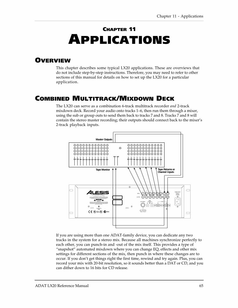
Chapter 11 - Applications
ADAT LX20 Reference Manual 65
CHAPTER 11
APPLICATIONS
OVERVIEWThis chapter describes some typical LX20 applications. These are overviews thatdo not include step-by-step instructions. Therefore, you may need to refer to othersections of this manual for details on how to set up the LX20 for a particularapplication.
COMBINED MULTITRACK/MIXDOWN DECKThe LX20 can serve as a combination 6-track multitrack recorder and 2-trackmixdown deck. Record your audio onto tracks 1–6, then run them through a mixer,using the sub or group outs to send them back to tracks 7 and 8. Tracks 7 and 8 willcontain the stereo master recording; their outputs should connect back to the mixer’s2-track playback inputs.
Master Outputs
Tape Monitor Tape Returns orChannel Inputs
If you are using more than one ADAT-family device, you can dedicate any twotracks in the system for a stereo mix. Because all machines synchronize perfectly toeach other, you can punch-in and -out of the mix itself. This provides a type of“snapshot” automated mixdown where you can change EQ, effects and other mixsettings for different sections of the mix, then punch in where these changes are tooccur. If you don’t get things right the first time, rewind and try again. Plus, you canrecord your mix with 20-bit resolution, so it sounds better than a DAT or CD, and youcan dither down to 16 bits for CD release.
Applications - Chapter 11
66 ADAT LX20 Reference Manual
Example: Suppose a guitar lick is too loud in the mix. Rewind to before theoffending lick, reduce only the guitar level at the mixer, then press Play. Punch inat the point where you want the lower guitar level. Punch out at the end of the loudguitar lick to return to the previous volume level. Note that unlike analogrecording, there is no punch-out gap where silence occurs; punch-out is immediate.
LIVE/LONG-TERM RECORDINGThe LX20 excels at live recording because of its compact size and easy operation. 8tracks allow for recording audience sounds, ambience, and individual soloists aswell as a stereo PA feed. Interconnecting and synchronizing multiple machinesallows for more tracks if needed.
When using more than one LX20, you can increase the recording time by manuallyplacing the second machine into record just before the first machine is at the end ofits tape. Of course, the audio signals to be recorded would need to be split andconnected to both sets of inputs.
Using an Alesis BRC with a multiple ADAT system allows for a feature calledcontinuous recording. By splitting the system into two (or into two sets of machines),you can offset the second set by a specific amount of time. Example: Assuming thatyou’re using ST-120 tapes with 40 minutes of record time, a 35 minute offset wouldprovide 5 minutes of overlap. The second set of machines would automatically kickinto record just before the first set’s tape ran out. Refer to Chapter 10 for moredetails on connecting multiple ADATs; refer to the BRC Reference Manual for moreon continuous recording.
For live use, remember that the LX20 can accept ST-160 tapes (which provide over53 minutes recording time) and ST-180 tapes (over an hour of recording). Set up theLX20 for the length of tape being used, as described in Chapter 3.
LOCKING TO VIDEO: CODE-ONLY MASTERA common application in audio post-production is locking to video using time coderecorded on the video tape. This requires a synchronizer interface, such as theAlesis AI-2 or BRC. The connections are:
• Run a balanced 1/4" TRS cable between the VTR’s SMPTE OUT connector andthe AI-2’s SMPTE IN (if time code is recorded onto the tape’s left or right audiotrack, connect the cable to the proper channel’s output connector).
• Patch a BNC connector from the house sync feeding the VTR (such as a black-burst generator), or the VTR’s video out, to the AI-2 VIDEO IN.
• Connect the AI-2’s SYNC OUT to the LX20’s SYNC IN connector.
When the LX20 detects an on-line AI-2 or BRC, it will ID itself as a slave (ID 1)and the Clock will automatically switch to External (the EXT indicator will lightin the Clock block). The AI-2 and BRC Reference Manuals contain more information.

Chapter 11 - Applications
ADAT LX20 Reference Manual 67
LIBRARIES AND ARCHIVESThe LX20 is superb for archiving purposes, such as speeches and broadcasts, stereomixes or libraries of stereo samples. The LX20 can record over eight hours of monomaterial by recording approx. 60 minutes on each track (using ST-180 tape). Overfour hours of stereo mixes or samples can be recorded by mixing down to four sets ofstereo pairs (1/2, 3/4, 5/6, and 7/8).
MODULAR RECORDINGCollaborations work particularly well with a system consisting of two or moreLX20s (and/or ADATs). You can record your tracks onto the master machine, then doa premix onto two tracks of a slave machine, which is perfectly synchronized to themaster. Send this tape to your partner, who adds parts on the other tracks. Whenthe tape comes back, just pop it into one of your machines, and your partner’s partswill be in sync with the original tracks you laid down.
Include documentation with your tape that indicates info such as sample rate andLocate Point positions. Or, if you’re both using BRC remotes, save your setup to the“data” section of tape (this is called saving the Table of Contents, or TOC). Thisway, you partner can pick up right where you left off.
COMPUTER CONTROL AND MIDI
MIDI SYSTEMS: VIRTUAL TRACKINGMany sequencing software manufacturers now integrate digital audio hard diskrecording and playback into their sequencers. However, these types of systems taxcomputers to their limits, and in many cases require an expensive upgrade (fasterprocessor, more RAM, additional hard drives and cards, backup system for thedigital audio data, etc.) to obtain adequate results.
Synching your existing MIDI sequencer to an LX20 can offer much of the sameflexibility, as you can add digital audio to an existing sequence by recording intothe LX20 as you monitor the sequenced instruments. Conversely, you can record MIDIdata into the sequencer while it’s synched to the LX20.
Synchronizing the LX20 and sequencer requires a time code interface, such as theAlesis BRC, Steinberg ACI, or JLCooper DataSync 2, allof which can convert theLX20’s SYNC OUT to SMPTE or MIDI Time Code (the most common time referencesfor MIDI sequencers). Here’s the general hookup procedure.
• Connect the LX20’s SYNC OUT (or SYNC out from the last slave in a multipleADAT system) to the time code interface SYNC IN.
• Connect the timecode interface’s MIDI OUT to your sequencer’s MIDI IN.• Set your sequencer to synchronize to the MTC being received from the time code
interface (usually by selecting the sequencer’s “MTC sync” mode). As you controlthe LX20’s tape motion with the transport controls, the sequencer willautomatically follow along, letting you mix digital recordings with “virtual”MIDI tracks recorded in a MIDI sequencer. However, virtual tracks also havelimitations, such as the occasional stuck note or limited polyphony.
Applications - Chapter 11
68 ADAT LX20 Reference Manual
Doing a premix of virtual tracks to two or more tape tracks can solve these andother problems. Many times this premix will have that kind of special energy thatexists only during the early process of constructing a song, and will be preferable to amore laboriously-done premix during the final mixing stage. Besides, if you need tochange the premix later, no problem: resync the sequencer to tape, and re-record thepremix.
There are other reasons to record virtual tracks. A keyboard might not have enoughpolyphony to credibly drive several sounds at once; record a polyphony-hungrypart (e.g., piano) to tape, thus freeing up voices for the remaining instruments. Also,many older synths had global effects sections, but if it’s playing multiple parts, youmight not want all parts to have the same effect. Recording each part that uses aparticular effect to its own track(s) solves this problem.
MIDI SYSTEMS: AUTOMATED MIXDOWNMIDI not only plays back notes, but control messages such as pan, volume, and thelike. Using a mixer or accessory box that can respond to these control signals allowfor automated mixdown.
The setup is similar to the previous application: A MIDI sequencer syncs to theLX20, and plays back MIDI data in tandem with the digital audio data emanatingfrom the LX20. However, the MIDI data can feed signal processors, mixers, andother devices that respond to MIDI control, and the sequence would consist of thesecontrol messages.
Example: A Q20 can be used as a complete “MIDI automatable mixer channel” as itsEQ, level, and other parameters can all be MIDI-controlled. Feeding an LX20 trackinto the Q20, while controlling its parameters with a MIDI sequencer, createsautomated mixing effects.
MIDI SYSTEMS: VIRTUAL TRACKS AND AUTOMATED
MIXDOWNYou can, of course, combine the two approaches mentioned above to generate virtualtracks and control messages for devices processing the LX20’s audio tracks. Is this acool world, or what?
MIDI MACHINE CONTROL: VIRTUAL REMOTE CONTROLMany computer-based sequencing programs implement MIDI Machine Control(MMC), a set of messages that allows sequencers, tape machines, and similar gearto communicate their status to each other. Messages include basic transportfunctions (like Play, Stop and Record), Locate functions (go to a specific tapelocation), Track functions (record-enable, input monitor, track delay), etc.
However, not all sequencers send out all these messages. For example, some sendonly basic transport commands. The extent to which a sequencer can control an LX20depends on the extent to which the sequencer implements the full MMCspecification.
Chapter 11 - Applications
ADAT LX20 Reference Manual 69
To set up a system for MMC control, first lock the sequencer to the LX20’s time code;the transport commands you issue from the sequencer act like a remote control.Here’s the basic hookup:
• Make sure your sequencer is receiving MTC from the LX20.• Connect your computer’s MIDI interface’s MIDI OUT to the time code interface’s
MIDI IN• Connect the time code interface’s SYNC OUT to the LX20 SYNC IN (in a
multiple ADAT system, this should be the master LX20)• Enable MMC control by editing the appropriate parameters in your time code
interface and computer-based sequencer (refer to their respective manuals formore information).
If your sequencer generates MMC commands, the LX20 should follow along when youselect Play on the sequencer. However, the LX20 may not immediately go into play,as it may have to fast forward or rewind to reach the same location as thesequencer. Once this is done, the LX20 should resume playback when its time codereaches the time code interface, as the interface converts this to MTC, which in turncauses the sequencer to go into play.
THE ADAT OPTICAL INTERFACE AND HARD DISK
RECORDING
Two major limitations for hard disk recording have been media and file formatincompatibility. Some people save to Jaz drives, some to magneto-optical, others toCD-R or DAT…some systems like AIFF file formats, while others use WAV or aproprietary format. As a result, projects created on one system often remain withinthat system. Yet it doesn’t have to be that way.
DIGITAL AUDIO TRANSFER OPTIONSTransferring multichannel digital audio has never been easy. The S/PDIF andAES/EBU digital audio protocols, which are ancient by today’s standards, arelimited to a stereo pair. (They do have the advantage of universality; a DAT deckcan receive signals from a CD player, which can then transfer over to a computerusing a sound board with a SPDIF interface.) MADI, a 56-channel protocol, is little-used. Firewire (IEEE 1396) has tremendous potential, but as of this writing is notcommon.
However, these problems are becoming less vexing as the ADAT Optical Interfacebecomes incorporated into more and more equipment.
Applications - Chapter 11
70 ADAT LX20 Reference Manual
TYPICAL APPLICATIONSOver 100 manufacturers support the ADAT Optical Interface. Compatible productsinclude computer interfaces (such as the Alesis ADAT-PCR), signal processors,keyboards (Korg Trinity, Alesis QS Series), data translators, and more. (In fact, fordigital audio transfer Silicon Graphics now includes the ADAT Optical Interfaceas an option for lower-end machines, and makes it a standard feature for higher-end computers.) Several stand-alone hard disk recorders (Akai DR8/DR16, OtariRADAR, and E-mu Darwin) and digital mixers also support this interface, makingit easy to transfer audio directly between these systems, as well as do backups toADAT.
THE ADAT-PCR COMPUTER INTERFACEIf your computer (Macintosh or Windows-compatible) includes a PCI slot, considerusing the Alesis ADAT-PCR to control your LX20 directly from a computer, as wellas transfer audio to and from hard-disk editing software.
The ADAT-PCR is treated as “another ADAT” in the chain since it has ADAT Syncand ADAT Optical In and Out connections; therefore, the hard disk tracks and tapetracks are synchronized with sample accuracy. This gives the best of both worlds:on-screen computer-based editinge, and the simplicity and low cost of taperecording. With the ADAT-PCR, no MIDI time code or MIDI machine controlconverter is required; all conversions are handled in the computer software itself.
Caution: Not all digital audio editing software can record and play back 8 tracks atonce. Check the software’s specs for the ability to record and play back multiplechannels simultaneously. With software that cannot do this, you may need totransfer 2 tracks at a time, and do multiple passes to record all 8 tracks.
The basic procedure to transfer 8 ADAT tracks to/from a computer-based digitalaudio editor is:
• Make sure the LX20 and ADAT-PCR sync connectors are patched properly sothat the two are in sync
• Patch the ADAT fiber optic output to the ADAT-PCR interface card’s fiber opticinput
• Enable record on the hard disk system• Press play on the ADAT• The hard disk system will now record the 8 ADAT tracks.
To transfer the edited data back to the ADAT for storage and/or backup, patch theADAT-PCR interface’s fiber optic out to the ADAT’s fiber optic in, enable recordingon the LX20, and play back the hard disk system.
Chapter 11 - Applications
ADAT LX20 Reference Manual 71
A REAL-WORLD EXAMPLESuppose you did a great tape on your ADAT at home, and now want to edit it in ahard disk recording setup at a commercial studio. You then want to transfer thehard disk material over to a different digital tape format, which happens to bethe digital tape recorder used by a musical collaborator, who will then mix thisdown using a digital mixer while adding more tracks. Furthermore, suppose thestudio saves all their hard disk sessions to magneto-optical drives, but you need asafety copy on ADAT format tape.
Before the ADAT Optical Interface, this scenario would have been a nightmare.Now it’s relatively simple to do these sorts of tasks.
First, the hard disk editing system needs an ADAT-compatible interface. These areavailable for both Windows and Mac computers from a variety of manufacturers.This allows transferring 8 tracks at a time between the LX20 and hard disk editingprogram. You can later use the same interface to bounce the edited tracks over toADAT for the remixing project, or as redundant storage should the main backupsystem fail.
After editing the material on the hard disk system, a device such as the SpectralTranslator Plus can convert the audio to a variety of other formats. When it’s timeto mix down those tracks, no problem. Yamaha, RSP Technologies, Korg,RAMSA/Panasonic, and Mackie all make digital mixers with either optional orbuilt-in ADAT Optical Interfaces.
SYNC ISSUESTransferring more than 8 tracks at a time requires some special considerations.Suppose you have two LX20s and need to transfer 16 tracks over to a PC hard diskrecording program, but your interface can handle only 8 channels at a time. Youwould need to sync the ADATs to the hard disk recorder so that the second group of8 tracks ended up in the proper timing relative to the first group of 8 tracks.
However, this transfer will not be sample-accurate unless the ADAT 9-pin syncconnection is used as well as the ADAT Optical Interface (the Alesis, E-mu Darwin,Digidesign, Sonorus, and Korg 1212 interfaces can provide this signal).Nonetheless, using SMPTE or MTC sync will still be at least as tight as slaving two24 track analog machines together, and people didn’t seem to mind that. The onlytime you might hear a problem is if you transferred one half of a stereo pair on onepass, and the other half on another pass.
Another option is to transfer all tracks in real time. Otari’s UFC-24 universalformat translator can accommodate up to 3 ADAT optical connections. If the sourceADAT-compatible signals are synched properly (e.g., synchronized ADATs), thentransferring all 24 tracks simultaneously will occur with single-sample accuracy.
HARD DISK BACKUPOne of the biggest limitations of hard disk recording is how to back up the hugeamounts of data generated by multitrack digital audio. With an ADAT-PCR orsimilar interface, you can save audio to inexpensive, rugged ADAT-formatcassettes. Not only is this far less costly than using removable hard drives, theyare easy to exchange with other ADAT owners, and can be cloned to makeadditional safety copies.
Applications - Chapter 11
72 ADAT LX20 Reference Manual
PRE-MASTERING WITH THE LX20Mastering has typically been the weak link in the project studio. Sure, you can mixdown to DAT—but how about assembling those mixes into a smooth, well-integrated recording?
The following summarizes how to do pre-mastering with a DAT, hard disk editingprogram with digital audio interface capable of “talking to” the DAT, and anLX20. You shouldn’t have trouble modifying this procedure to fit your specificsetup; it’s the principles that count.
To do pre-mastering:
❿ Record mixes of all your tunes to DAT or two LX20/ADAT tracks.
Bounce the DAT mixes digitally to the hard disk editor, then do whateverediting is required to optimize the song (EQ, noise reduction, etc.).
① Bounce the processed tune digitally back to DAT or ADAT, but don’t record overyour original mix so you have it as backup.
➃ Repeat steps 1-3 until all the tunes are done. Then, determine the optimumorder for the tunes. Do this by recording them all into the hard disk system andtrying out several play lists until you get the right order.
➄ Now it’s time to assemble. Patch your DAT outs to LX20 tracks 1 and 2 (use theanalog outs if you want to include any analog processing), and record the firsttune into the LX20.
➅ Record the next tune on tracks 3 and 4. Notice how easy it is to do crossfadeswith this technique; just start recording the second tune sometime before thefirst tune ends.
➆ Record the third tune into tracks 1 and 2, and keep alternating tunes betweentracks 1/2 and 3/4 until all the tunes are in the LX20.
♠ Note that you still have four tracks left over. You can use these to insertadditional effects or transitions (great for dance mixes), or add time code forreasons we’ll get into next.
Now mix the ADAT tracks back down to DAT to end up with a final 2-trackDAT master. If you need to make any volume tweaks, you can do so manually orby synching automation to time code recorded on an ADAT track (as described insection QQ).
➉ If needed, you can now bounce the DAT back to the hard disk editor to createadditional masters for different purposes. For example, if the piece is going tobe duplicated on cassette as well as CD, consider adding some extra compressionand “exciter” treble enhancement to compensate for losses in the duplicatingprocess.
Appendix A - Digital Recording Concepts
ADAT LX20 Reference Manual 73
APPENDIX A
DIGITAL RECORDINGCONCEPTS
ANALOG RECORDING BASICSDigital recording works very differently from analog recording. With analogrecording, tape containing millions of tiny magnetizable particles move past arecord head. The magnetic field around this head fluctuates according to the audiosignal present at the tape recorder’s input. These fluctuations permanentlyrearrange the particles on the tape to form a pattern that is analogous to theoriginal audio signal.
On playback, the patterns on tape are read by a separate playback head (or fromthe record head, set up to read instead of record signals) that converts the magneticfluctuations back into an audio signal.
The biggest problem with analog recording is that the tape itself alters the soundoriginally recorded on tape. Tape hiss is one problem; it superimposes a low-levelrushing noise onto the audio signal. Although there are ways to minimize noise,such as noise reduction circuitry, this colors the sound in the process of masking thenoise.
Tape’s frequency response is also an issue. Tape has a hard time “absorbing” higherfrequencies, which can dullen the sound. Moving tape faster allows the heads tomagnetize more particles and extends the high frequency response, but the tradeoffis increased tape costs, and heftier transports to move bigger reels of tape.
DIGITAL RECORDING BASICSWith digital recording, the technology is similar — tape moves past a record head,and plays back through a playback head. However, the signal recorded on tape isvery different.
Audio signals entering each channel of the LX20 first pass through an analog-to-digital (A/D) converter, a device that takes 48,000 samples or “snapshots” of thesignal level every second1. Each sample is assigned a specific numeric value thatcorresponds to its level.
148,000 samples are taken per second at a sampling rate of 48 kHz; 44,100samples are taken per second at a sampling rate of 44.1 kHz.
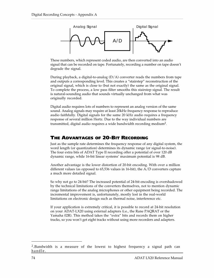
Digital Recording Concepts - Appendix A
74 ADAT LX20 Reference Manual
A/D
Analog Signal Digital Signal
These numbers, which represent coded audio, are then converted into an audiosignal that can be recorded on tape. Fortunately, recording a number on tape doesn’tdegrade the signal.
During playback, a digital-to-analog (D/A) converter reads the numbers from tapeand outputs a corresponding level. This creates a “stairstep” reconstruction of theoriginal signal, which is close to (but not exactly) the same as the original signal.To complete the process, a low pass filter smooths this stairstep signal. The resultis natural-sounding audio that sounds virtually unchanged from what wasoriginally recorded.
Digital audio requires lots of numbers to represent an analog version of the samesound. Analog signals may require at least 20kHz frequency response to reproduceaudio faithfully. Digital signals for the same 20 kHz audio requires a frequencyresponse of several million Hertz. Due to the way individual numbers aretransmitted, digital audio requires a wide bandwidth recording medium2.
THE ADVANTAGES OF 20-BIT RECORDINGJust as the sample rate determines the frequency response of any digital system, theword length (or quantization) determines its dynamic range (or signal-to-noise).The four extra bits of ADAT Type II recording offer a potential of over 120 dBdynamic range, while 16-bit linear systems’ maximum potential is 98 dB.
Another advantage is the lower distortion of 20-bit encoding. With over a milliondifferent values (as opposed to 65,536 values in 16-bit), the A/D converters capturea much more detailed signal.
So why not go to 24-bit? The increased potential of 24-bit encoding is overshadowedby the technical limitations of the converters themselves, not to mention dynamicrange limitations of the analog microphones or other equipment being recorded. Theincremental improvement is, unfortunately, mostly lost in the real-worldlimitations on electronic design such as thermal noise, interference etc.
If your application is extremely critical, it is possible to record at 24-bit resolutionon your ADAT-LX20 using external adapters (i.e., the Rane PAQRAT or theYamaha 02R). This method takes the “extra” bits and records them on highertracks, so you won’t get eight tracks without using more recorders and adapters.
2.Bandwidth is a measure of the lowest to highest frequency a signal path canh a n d l e .
Appendix A - Digital Recording Concepts
ADAT LX20 Reference Manual 75
WHY S-VHS?S-VHS recording technology offers more than enough bandwidth to record eighttracks of digital audio. S-VHS tapes are built to higher standards than standardVHS tapes, and can take the tape shuttling required by professional audioapplications. S-VHS tape cassettes are also inexpensive compared to reel-to-reeltape, readily available, compact, and easy to transport and store.
Troubleshooting - Appendix B
76 ADAT LX20 Reference Manual
APPENDIX B
TROUBLESHOOTING
RE-INITIALIZING: TRY THIS FIRSTIf your unit behaves erratically or “freezes,” do not assume you need to clean theheads or perform any type of servicing. This situation can sometimes occur due toline voltage spikes, temporary brownouts, and other problems related to AC power.
To fix the problem:
• Eject the Tape. • Power down the unit, then power it back up again. Many times this is all you
need to do. • If there’s still a problem, re-initialize the software by holding down RECORD
and PLAY buttons while turning on the POWER switch. This will reset allparameters (locate points, etc.) to their default settings.
If the LX20 freezes up often, consider buying an uninterruptible power supply. Manyusers who experienced inconsistent ADAT operation reported that these problemsdisappeared after cleaning up the power feeding the ADATs.
CHECKING SOFTWARE VERSIONTo show the current operating software version in the TIME counter, hold SETLOCATE and press FAST FWD.

Appendix B - Troubleshooting
ADAT LX20 Reference Manual 77
TROUBLESHOOTING INDEXIf you experience problems while operating the LX20, please use the followingtable to locate possible causes and solutions before contacting Alesis customerservice for assistance.
Symptom Cause SolutionThe display does not lightwhen the POWER switchis turned on.
No power. Check that the power cable isplugged in properly.
FORMAT indicatorflashes.
Tape is not formatted. Format the tape, or reinsert.
The record-enabled tracks’meters do not indicate
Cables are not connectedproperly or are shorted.
Check your audio cables.
input levels. DIGITAL INPUT isselected.
Press ANALOG INPUT.
Can’t change the samplerate/clock source.
If slave in a multipleADAT system, EXT clockis selectedautomatically.
Set the sample rate/clocksource on the master LX20.
Pressing AUTO RECdisplays “invALid”.
Locate Point 3’s positionis before Locate Point 2.
Set Locate Point 3 past LocatePoint 2.
AUTO RETURN indicatorflashes.
Locate Point 4’s positionis before Locate Point 1.
Set Locate Point 4 past LocatePoint 1.
When used as a slave in amultiple ADAT system,doesn’t follow the master.
No ADAT master isdetected.
Check sync cables. Power downthe Master only, then restart.
TIME counter does notshow tape position.
Edit mode is turned on. Press EDIT VALUE to turn Editmode off.
Interpolation indicator( ) lights/flashes.
One or more errors havebeen detected/corrected
Clean the tape heads.Make a backup copy of yourtape.
48K or 44.1K indicatorflashes.
Tape was formatted atdifferent sample ratethan currently selected.
If desired, press CLOCKSELECT to use original samplerate.
Error Message in display Several possible See Appendix C: Error Codes
Troubleshooting - Appendix B
78 ADAT LX20 Reference Manual
ERROR RATE DISPLAYThe TIME counter has a secondary mode which, when selected, will display onlythe minutes and seconds of the tape position, and the error rate while the transportis engaged in play or record. This error rate is viewed as a count of the number ofsync block errors per 14 drum revolutions (every 280ms), up to a theoreticalmaximum of 6720 errors. Selecting this display mode during any other mode thanplay or record will always give a reading of “0000”.
To view the error rate display:
♣ Hold SET LOCATE and press RECORD ENABLE 3.The TIME counter will briefly read:
ABS d1 SP E rrWhen PLAY or RECORD are engaged, the TIME counter will change to showminutes and seconds on the left, and a 4-digit error rate counter on the rate.
② Repeat step ♣ to return the TIME display to its normal state.The TIME counter will briefly read:
ABS d1 SP r E9…and will then change back to show hours, minutes, seconds and 100ths-of-a-second.
ABOUT ERROR RATE READINGS
A new, perfect tape on a clean machine will normally read “0000” with occasionalflashes up to “0005” or “0010”. Errors of 3 or below are 100% correctable, and theodds are that significantly higher readings will also be 100% correctable. Manynew tapes out of the box from some manufacturers have readings up to 100. Readingsabove 1000, however, are guaranteed to cause some interpolation to take place.
Therefore, readings up to about 10-15 aren’t anything to worry about unlessaccompanied by the Interpolation indicator; but they do show you that there issomething less than ideal about current conditions. If readings rise above 20, youshould take action (see section QQ, ADAT Head Cleaning). If your brand of tapehas a typical error rate above 20, that's acceptable, but you want to look out forincreases above the usual.
Appendix B - Troubleshooting
ADAT LX20 Reference Manual 79
ADAT HEAD LIFEThe expected head life for each ADAT varies according to a number of factors.Properly cared for, your heads should last for thousands of hours. If abused, theywill wear out dramatically sooner.
You should not subject your ADAT to environmental extremes, humidity or moistureof any kind, dust, dirt, extreme temperatures, extreme temperature fluctuations orany kind of physical abuse (drops, shocks).
Under no circumstances should you remove the ADAT’s top or bottom covers. Youalready know that there are NO user serviceable parts inside. However, youshould also be aware that it is extremely easy to damage your heads and othersensitive parts of your ADAT. Do not open up your ADAT to clean the heads.
What it comes to is this: ADAT is a very sophisticated piece of digital technology.It is going to be used for your important projects so take the best care of your ADATand your ADAT heads possible.
DRUM TIME DISPLAYThe LX20 keeps track of how long the head has been actively spinning against tape(i.e., threaded in stop, or play, or cue/review). This can help determine how long ithas been since the last time it was serviced or cleaned.
To display the head time counter, hold SET LOCATE and press STOP. The numberof drum hours will briefly appear in the TIME counter.

Troubleshooting - Appendix B
80 ADAT LX20 Reference Manual
ADAT HEAD MAINTENANCE
The heads of each ADAT are pre-aligned at Alesis. No user adjustment isnecessary. Eventually, depending on the quality of the tapes used and theenvironmental conditions where the ADAT and its tapes are stored, head cleaningmay become necessary. Unlike analog or even video tape recorders, the actual soundquality of an ADAT recording will not be affected until there is quite a bit of dirt onthe drum and heads. When the Interpolation Indicator (the sunburst at the end ofthe location display) starts appearing frequently, even on brand new tapes, werecommend that you bring your ADAT to an authorized Alesis Service Center forcleaning. If the indicator is not appearing and the unit is performing normally,there is no reason to clean the heads. Periodic or preventative maintenance shouldnot be overdone to prevent premature wear on the head stack.
If head cleaning is necessary and you are unable to bring your ADAT to a servicecenter, try using a DRY VHS head cleaning cassette. We recommend3M VHSHC Black Watch Head Cleaner Video Cassette or 3M ASD HC DigitalAudio Head Cleaning Cassette.
• Do NOT use any other type of head cleaning cassette. They are abrasive andwill damage or wear out your heads.
• Do NOT use head cleaning cassettes that require any kind of liquid.
• Do not use the Black Watch cassette any more often than necessary. Over-cleaning the heads wears them down, reducing their life span.
• Do NOT attempt to clean the heads yourself unless you are a skilled technicianexperienced in the maintenance of video cassette recorders. Information for suchtechnicians is available from Alesis Product Support. ADAT head cleaningrequires different materials and procedures from analog head cleaning, similarto VCR maintenance. Cleaning the heads with a cotton swab, or rubbing in thewrong direction, will destroy them. Opening your ADAT’s case will void thewarranty.
Base the need for ADAT maintenance on the Interpolation Indicator (or Error CountDisplay, see previous page) or if the unit begins to behave erratically. Todetermine if these symptoms are caused by dirty heads, (not a defective or worntape), keep a “benchmark” tape from the first weeks of operation set aside in a safeplace. If the Interpolation Indicator lights frequently when playing back this tape,it is likely that head cleaning is needed, particularly if several hundred drum-onhours have elapsed since the last cleaning (see next section). Call Alesis ProductSupport for more information about head cleaning and authorized Alesis ServiceCenters.
Appendix B - Troubleshooting
ADAT LX20 Reference Manual 81
TAPE CARE AND MAINTENANCEADAT tapes are no different than any standard tape: they must be treated withcare. Never expose ADAT tapes to temperature extremes, strong magnetic fields(such as speakers), high humidity, dust and so on.
You should always practice SAFE TAPE:
• At the end of every session, rewind the tape back to the leader. Stop, eject thetape, remove it from the ADAT, and place it in its protective case. This cutsdown on the amount of dust that can enter the transport and keeps wear on thetape at a minimum.
• Don’t leave your tapes near speakers, power amps or other potential magneticfields such as televisions or electrical devices.
• Don’t subject your tapes to extreme temperatures or wild temperaturefluctuations.
• Don’t expose your tapes to high humidity, moisture or high dust levels.
• Don’t leave your tapes on the dashboard of your car. (In fact, never leave ADATtapes in a car EVER. Keep them with you at all times!)
• No matter how tempted you are to open the shutter to see what is inside,NEVER TOUCH THE TAPE. The magnetic particles on your ADAT tape need tobe preserved in the condition in which they were recorded. The oils from yourfingers WILL damage your tapes as well as get on the heads and damage them.
• Never turn off the ADAT power while the tape is threaded. This leaves thetape bent around the rollers and head. Press STOP until the tape is unthreadedbefore turning off power.
Practice “safe tape” at all times because you can never retrieve lost data.
If you are archiving your tapes, make sure they are stored in environmentallystable conditions, i.e. a cool dry place. If you do archive your tapes, you need tocheck them once a year. Run each tape through your ADAT from end to end. Thiswill prevent buildup that can occur when a tape is left simply “sitting.”
Of course, for your super sensitive or important material, nothing beats makingmultiple digital backups. Every year or so, simply do another digital backup onto abrand new tape.
Troubleshooting - Appendix B
82 ADAT LX20 Reference Manual
MAINTENANCE/SERVICE
CLEANINGDisconnect the AC cord, then use a damp cloth to clean the LX-20’s metal and plasticsurfaces. For heavy dirt, use a non-abrasive household cleaner such as Formula 409or Fantastik. DO NOT SPRAY THE CLEANER DIRECTLY ONTO THE FRONT OFTHE UNIT AS IT MAY DESTROY THE LUBRICANTS USED IN THE SWITCHESAND CONTROLS! Spray onto a cloth, then use the cloth to clean the unit.
MAINTENANCEHere are some tips for preventive maintenance.
• Periodically check the AC cord for signs of fraying or damage.
• Unplug the LX20 when not in use for extended periods of time.
• Do not leave tapes inserted halfway into the LX20 when not in use, as thisallows dust to enter the transport chamber. Always leave tapes either fullyinserted, or remove them completely.
REFER ALL SERVICING TO ALESISWe believe that the LX20 is one of the most reliable digital recorders that can bemade using current technology, and should provide years of trouble-free use.However, should problems occur, DO NOT attempt to service the unit yourself. Thefull AC line voltage, as well as high voltage/high current DC voltages, are presentat several points within the chassis. Service on this product should be performedonly by qualified technicians. THERE ARE NO USER-SERVICEABLE PARTSINSIDE.

Appendix B - Troubleshooting
ADAT LX20 Reference Manual 83
OBTAINING REPAIR SERVICEBefore contacting Alesis, check over all your connections, and make sure you’ve readthe manual.
Customers in the USA:If the problem persists, call Alesis USA at 1-800-5ALESIS and request the ProductSupport department. Please have your serial number (located on the back of themachine and starting with a “4D”) when you call. Talk the problem over with oneof our technicians; if necessary, you will be given a repair order (RO) number andinstructions on how to return the unit. All units must be shipped prepaid and CODshipments will not be accepted.
For prompt service, indicate the RO number on the shipping label. If you do nothave the original packing, ship the LX20 in a sturdy carton, with shock-absorbingmaterials such as styrofoam pellets (the kind without CFCs, please) or “bubble-pack” surrounding the unit. Shipping damage caused by inadequate packing is notcovered by the Alesis warranty.
Tape a note to the top of the unit describing the problem, include your name and aphone number where Alesis can contact you if necessary, as well as instructions onwhere you want the product returned. Alesis will pay for standard one-wayshipping back to you on any repair covered under the terms of this warranty. Nextday service is available for a surcharge.
Field repairs are not normally authorized during the warranty period, and repairattempts by unqualified personnel may invalidate the warranty.
Correspondence address for customers in the USA:
Alesis Product Support1633 26th StreetSanta Monica, CA 90404
This is not a service location. Do not ship units to the above address.
Customers outside the USA:Contact your local Alesis dealer for warranty assistance. The Alesis LimitedWarranty applies only to products sold to users in the USA and Canada. Customersoutside the USA and Canada are not convered by this Limited Warranty and mayor may not be covered by independent distributor warranty in the county of sale. Donot return products to the factory unless you have been given specific instructions todo so.

Error Codes - Appendix C
84 ADAT LX20 Reference Manual
APPENDIX C
ERROR CODESThe following errors codes may appear from time to time in the TIME counterdisplay. Use this reference to learn the possible cause of the error code beforeattempting to contact Alesis Product Support.
dv Dew Sensor: The unit has been subjected to overly high humidity. Do notoperate the unit. Turn on the power without installing a tape. This willallow the unit to warm up and disperse the moisture. If the “dv” messagedoes not go out after 2 hours contact Alesis for service.
noFo No Format: The tape is located at a point that has not been formatted.Rewind the tape to the beginning. Press play. If the tape is formatted themessage will change to “LEAd” for 15 seconds then “dAtA” for 2 minutesprior to the beginning of the audio section. If these messages do not appear,the tape should be formatted.
FULL Serial Buffer Full: Not seen very often. “FULL” occurs when a slave LX20 isslow to sync to the master LX20. The serial buffer within the microcontroller has become full of data. This could be the result of unlike versionsof software within each unit. Sometimes the problem is related to the synccable itself. It is recommended that only shielded and grounded cables beused as sync cables.
Finally, this error may occur in slave machines that are playing damagedtapes. The edges of the tape have become damaged. If only one tape isfound to cause this problem, don't use it. If the problem is seen with severaltapes, the machine should be taken in for service. Contact Alesis forservice.
Er 0 Tape Load Error: This may be a problem with the TAPE LOAD or (insert)switch. This can be caused by labels that have been applied to the cassetteoutside of the designated area. If this error message is displayed with onlyone tape, the cassette may be at fault. If the message is displayed withseveral tapes, with and without labels, you should contact Alesis forservice.
Er 1 – Er 4 Tape Threading: These error codes are usually related to tape threading.Eject the tape and load it again. If this error message is displayed withonly one tape, the cassette may be at fault. If the message is displayedwith several tapes, with and without labels, you should contact Alesis forservice.
Er 5 Drum/Capstan: This error points to the head drum and capstan servos. Theproblem is caused by anything creating extra resistance in the tape path, anunevenly wound cassette or a misalligned cassette shell. You should fastforward and rewind the cassette from end to end to flex the tape then trythe tape again. If this error message is displayed with only one tape thecassette may be at fault. If the message is displayed with several tapes,with and without labels, you should contact Alesis for service.
Appendix C - Error Codes
ADAT LX20 Reference Manual 85
Er 7 Clean Heads: If this error message is seen, it may indicate that the headsare in need of cleaning. See ADAT Head Maintenance for information aboutcleaning your heads.
Er 8 Sync Lost: Error message 8 normally occurs when the tape reaches the endwhile formatting or recording. It is caused by the fact that the LX20 cannotread timing data from the leader. The error is caused by the unit losingsync. If the unit is being run in the slave mode check the sync cableconnection. It is recommended that only shielded and grounded cables beused as sync cables.
Er 9 Take-up Reel. This error indicates that the take-up reel didn’t move afterPLAY or RECORD was engaged. This can spool tape out of the cassette, sothe LX20 stops the tape immediately. It’s possible that the take up reel ofthe tape is jammed; try a blank or unimportant tape to see if the errorrecurs. The idler wheel that turns the take-up reel may need cleaning orreplacement.
no 9ood tc No Time Code. The LX20 is reading control track pulses, but no helical scantime code. Usually, a video tape has been inserted into the LX20. Formatthe tape in the ADAT format.
NOTE: “No good tc” will also appear if you insert a Type II (20-bit) tapeinto an older, Type I-only machine. Make a 16-bit clone of any 20-bit tapesfor use in older-generation machines.
(Error 10 through 13 and 16 are not used)
Error 14-15 Crossfade buffer, state or channel error. This indicates a problem with theRAM buffer used for crossfading. Reinitialize the LX20 using the procedureon page 76. If the problem recurs, the unit must be serviced.
Error 17 End sensor error. One of the optical sensors used to detect the clear leader atthe head and tail of the tape cartridge is not working or is blockedtemporarily. If the error recurs on other tapes, the unit needs to be serviced.
AL P This error message may appear when you turn on power to the LX20. If thedisplay also reads "CAL brAC", there may be something wrong with thebattery backup of RAM, or the RAM was accidentally scrambled. If noother error messages occur during operation, and the Interpolation Indicatoris not flashing, playback and recording are still possible. However, do notformat any blank tapes on the LX20 until the PG is reset .
AL brAc If this message appears during the turn-on cycle, the brake settings havebeen set to the default settings due to a problem with RAM memory or thebackup battery. Perform the automatic brake calibration (see below). Ifthis message appears in the midst of normal operation more than once inevery ten hours of operation, perform the automatic brake calibration (see"Automatic Brake Calibration Procedure", next page).
Error Codes - Appendix C
86 ADAT LX20 Reference Manual
AUTOMATIC BRAKE CALIBRATION PROCEDUREIf the "CAL brAc" error message appears, the internal braking system of the LX20may need to be adjusted. The intelligent transport software is capable of calibratingthe LX20’s brakes automatically in a self-test procedure. You may perform thisprocedure as a regular maintenance procedure every 250 hours of head drumoperation (to see the hours on your unit, hold SET LOCATE and press STOP).
❿ Obtain a standard ST-120 length tape (preferably a Quantegy 489 such as theone shipped with your unit) that has already been completely formatted frombeginning to end. Use a non-essential tape (i.e., don't insert your only copy of amaster tape). Do not use other lengths of tape such as ST-180 or ST-60.
Turn off the POWER switch. Hold REWIND and FAST FORWARD whileturning the power back on again. The display will read "CALIbrAt".
① Insert the tape into the transport.➃ The unit will now adjust the brake tension automatically. The transport will
shuttle back and forth for about 5 minutes. During the operation, the tape willhalf-eject twice. This is normal.
➄ The display should briefly read "PaSS" before ejecting the tape fully andreturning to the "20 Bit LX" start-up screen. The brakes have now beenrecalibrated.
If the "CAL brAc" message appears again shortly after a brake calibration hasbeen performed, there may be something wrong with the tape being used. Checkoperation with another tape. If the message persists, the unit must beprofessionally serviced.
Note: If these errors occur only with a certain tape, or display once in a while, it’sprobably not cause for concern. Errors 1 through 3 and 9 can indicate conditions thatmay damage a tape; the other errors won’t damage the tape or the machine.Backup the data from that tape to another machine, if possible, and continueworking from the backup copy.
Appendix C - Error Codes
ADAT LX20 Reference Manual 87
STEPS TO TAKE BEFORE CALLING FOR HELPIf an error message is displayed or if an ADAT starts behaving strangely, it will behelpful if you can pinpoint the problem as precisely as possible.
Before calling Alesis, please try the suggested tests below:
❿ Stop the tape playing (or recording). Does the error go away? Rewind the tape a minute or two. Press PLAY. Does the error recur?① Eject the tape. Place it back in the LX20 and press PLAY. Does the error recur?➃ Turn down the volume of any mixer or amplifier you have connected to the
outputs of the LX20. Turn the power of the LX20 off, wait a minute and then re-power the LX20. Repeat steps 1 to 3. Does the error come back?If it does, then try a different tape. Repeat steps 1 to 3. Does the problem recur?
➄ Try the tape in a different LX20 or ADAT. (If you are using a single ADATsystem, see if you can visit your dealer.) It does not make sense to send your LX20in for service when there may be only a problem with, for example, some tapesthat you are using. If the same problems occur in another LX20 or ADAT, theneither the tape is faulty or it was formatted on an out of alignment LX20 orADAT. At this point, you should call Alesis Product Support. If the problemdoes not occur, and the tape works fine, then we need to look at your LX20. CallAlesis Product Support.
Whatever happens, the answers to all these questions are useful information for ourProduct Support representatives. The more we know, the faster we can discover thecause of your problems. You will help us isolate whether the problem lies in the LX,the tape or somewhere else.
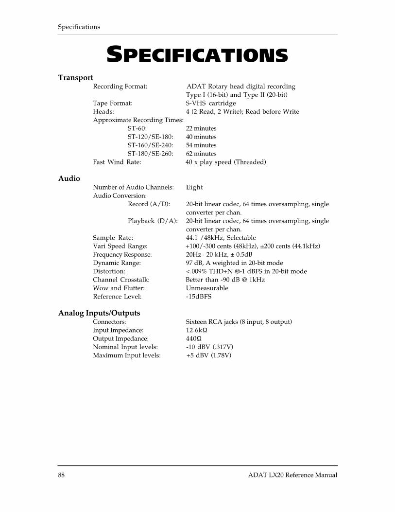
Specifications
88 ADAT LX20 Reference Manual
SPECIFICATIONSTransport
Recording Format: ADAT Rotary head digital recordingType I (16-bit) and Type II (20-bit)
Tape Format: S-VHS cartridgeHeads: 4 (2 Read, 2 Write); Read before WriteApproximate Recording Times:
ST-60: 22 minutesST-120/SE-180: 40 minutesST-160/SE-240: 54 minutesST-180/SE-260: 62 minutes
Fast Wind Rate: 40 x play speed (Threaded)
AudioNumber of Audio Channels: EightAudio Conversion:
Record (A/D): 20-bit linear codec, 64 times oversampling, singleconverter per chan.
Playback (D/A): 20-bit linear codec, 64 times oversampling, singleconverter per chan.
Sample Rate: 44.1 /48kHz, SelectableVari Speed Range: +100/-300 cents (48kHz), ±200 cents (44.1kHz)Frequency Response: 20Hz– 20 kHz, ± 0.5dBDynamic Range: 97 dB, A weighted in 20-bit modeDistortion: <.009% THD+N @-1 dBFS in 20-bit modeChannel Crosstalk: Better than -90 dB @ 1kHzWow and Flutter: UnmeasurableReference Level: -15dBFS
Analog Inputs/OutputsConnectors: Sixteen RCA jacks (8 input, 8 output)Input Impedance: 12.6kΩOutput Impedance: 440ΩNominal Input levels: -10 dBV (.317V)Maximum Input levels: +5 dBV (1.78V)
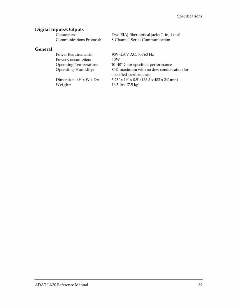
Specifications
ADAT LX20 Reference Manual 89
Digital Inputs/OutputsConnectors: Two EIAJ fiber optical jacks (1 in, 1 out)Communications Protocol: 8-Channel Serial Communication
GeneralPower Requirements: 90V–250V AC, 50/60 HzPower Consumption: 40WOperating Temperature: 10–40° C for specified performanceOperating Humidity: 80% maximum with no dew condensation for
specified performanceDimensions (H x W x D): 5.25" x 19" x 8.5" (133.3 x 482 x 241mm)Weight: 16.5 lbs. (7.5 kg)
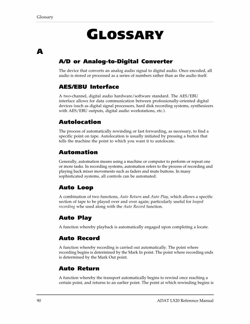
Glossary
90 ADAT LX20 Reference Manual
GLOSSARYA
A/D or Analog-to-Digital ConverterThe device that converts an analog audio signal to digital audio. Once encoded, allaudio is stored or processed as a series of numbers rather than as the audio itself.
AES/EBU InterfaceA two-channel, digital audio hardware/software standard. The AES/EBUinterface allows for data communication between professionally-oriented digitaldevices (such as digital signal processors, hard disk recording systems, synthesizerswith AES/EBU outputs, digital audio workstations, etc.).
AutolocationThe process of automatically rewinding or fast forwarding, as necessary, to find aspecific point on tape. Autolocation is usually initiated by pressing a button thattells the machine the point to which you want it to autolocate.
AutomationGenerally, automation means using a machine or computer to perform or repeat oneor more tasks. In recording systems, automation refers to the process of recording andplaying back mixer movements such as faders and mute buttons. In manysophisticated systems, all controls can be automated.
Auto LoopA combination of two functions, Auto Return and Auto Play, which allows a specificsection of tape to be played over and over again; particularly useful for loopedrecording whe used along with the Auto Record function.
Auto PlayA function whereby playback is automatically engaged upon completing a locate.
Auto RecordA function whereby recording is carried out automatically. The point whererecording begins is determined by the Mark In point. The point where recording endsis determined by the Mark Out point.
Auto ReturnA function whereby the transport automatically begins to rewind once reaching acertain point, and returns to an earlier point. The point at which rewinding begins is

Glossary
ADAT LX20 Reference Manual 91
called the Auto Return End point. The point that is returned to is called the AutoReturn Start point.

Glossary
92 ADAT LX20 Reference Manual
BBalanced Audio SignalsSignals that are carried on three-conductor cables, with two of the conductorscarrying the same signal 180° out of phase and third as ground. Balancedconnections usually cost more than unbalanced connections, but are less susceptible topicking up hum and interference with low-level signals.
BounceBouncing means taking audio from one track and placing it on another. The term,sometimes called “bouncing down,” also describes the process of mixing severaltracks onto one or two.
BusA bus generally refers to any common signal pathway. In a mixer, a bus is usually awire that is or can be made common to the outputs of any or all channels in themixer. Examples of buses include the main stereo mix, sub-mixes, monitor buses andaux sends.
CChannelIn audio, a channel is an internal audio path maintained separately from otheraudio paths of identical function. Mixer input strips are examples of channels, butan audio snake also has channels.
Chase/LockChase/Lock refers to a tape machine’s ability to read incoming timecode, locate itstape to the position indicated by the timecode, and synchronize playback to theincoming timecode.
ClipIn the analog world, clipping occurs when the input to a circuit exceeds the gain ofthe circuit. The circuit passes the signal at its maximum value. All input valuesexceeding the maximum value are “clipped.” The result is audio distortion. Indigital audio, clipping occurs when the input to an A/D exceeds the voltagerepresented by the maximum number the A/D is capable of transmitting.
CrossfadeA crossfade is a gradual “dissolve” between two portions of audio; one segment ofaudio fades out while the other fades in. When punching in on the XT20, the audioon tape is faded out while the new audio which is being recorded is faded in.

Glossary
ADAT LX20 Reference Manual 93
DDATDigital Audio Tape. This term has come to mean specific digital audio taperecorders that use cartridges smaller than those of a standard cassette, and whichrecord two tracks of digital audio (and sometimes timecode).
Digital I/OInput and output connections where signals passed from one stage to another remainin the digital domain. The XT20 has digital I/O connectors that carry digital datafor all eight tracks.
D/A or Digital-to-Analog ConverterThe device that converts digital signals back into an analog format so that they canbe heard.
EF
Fiber Optical ConnectorA device that transmits signals through light instead of conventional wire.Advantages include higher speed and the ability to carry multiple chanels ofinformation over a single, thin cable.
GH
House SyncA video signal distributed to any device that requires a reference to maintainproper sync relationship with other devices. The signal comes in several forms:Blackburst results in a black video screen when fed to a video monitor; Color barsare the standard reference for adjusting video equipment. Color bars can be seen onmany stations just before they come on the air.
IInputAn input is a path through which audio passes from one electronic device intoanother. types of inputs vary in connector type, level, use (sends, monitor, mix), andelectrical characteristics (impedance, balanced or unbalanced). They can be analogor digital.
JK

Glossary
94 ADAT LX20 Reference Manual
L
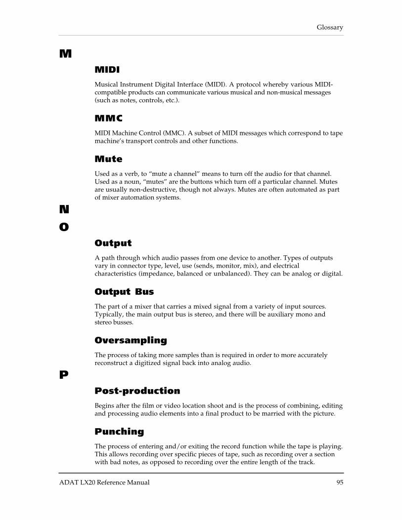
Glossary
ADAT LX20 Reference Manual 95
MMIDIMusical Instrument Digital Interface (MIDI). A protocol whereby various MIDI-compatible products can communicate various musical and non-musical messages(such as notes, controls, etc.).
MMCMIDI Machine Control (MMC). A subset of MIDI messages which correspond to tapemachine’s transport controls and other functions.
MuteUsed as a verb, to “mute a channel” means to turn off the audio for that channel.Used as a noun, “mutes” are the buttons which turn off a particular channel. Mutesare usually non-destructive, though not always. Mutes are often automated as partof mixer automation systems.
NO
OutputA path through which audio passes from one device to another. Types of outputsvary in connector type, level, use (sends, monitor, mix), and electricalcharacteristics (impedance, balanced or unbalanced). They can be analog or digital.
Output BusThe part of a mixer that carries a mixed signal from a variety of input sources.Typically, the main output bus is stereo, and there will be auxiliary mono andstereo busses.
OversamplingThe process of taking more samples than is required in order to more accuratelyreconstruct a digitized signal back into analog audio.
PPost-productionBegins after the film or video location shoot and is the process of combining, editingand processing audio elements into a final product to be married with the picture.
PunchingThe process of entering and/or exiting the record function while the tape is playing.This allows recording over specific pieces of tape, such as recording over a sectionwith bad notes, as opposed to recording over the entire length of the track.
Glossary
96 ADAT LX20 Reference Manual
QR
Record-ReadyA track mode, often called “armed.” When you want to record on a track, you“ready” or “arm” the track. When you push the record button, all tracks that areready or armed will go into record mode.
Rotary HeadA type of tape head, as used in the XT20, that spins at a high rate of speed in orderto create the same effect as having the tape moving by at rates not physicallypossible with today’s tapes and transports.
SSafeA track mode. When a track is safe, it is not ready for recording.
Sample Accurate SynchronizationThis means synchronization is accurate not just to individual frames or milliseconds,but to 1/48,000th of a second (with 48 kHz sampling rate). This means twosynchronized ADATs will never be more than 20 millionths of a second apart.
Sample RateA digital representation of an analog signal created by checking, or sampling, theanalog voltage a fixed number of times per second. The greater the number ofsamples, the more accurate the representation of the analog signal. The CD uses asampling rate of 44.1 kHz; it checks the analog signal 44,100 times per second.
Sample Rate ConversionSample rate conversion is the process by which audio originally recorded at onesample rate is converted to another sample rate. The audio is converted by shiftingits pitch up or down, and then played back at the new sample rate.
SMPTE/LTCSociety of Motion Picture and Television Engineers (SMPTE and Longitudinal TimeCode (LTC). A standard for LTC was specified by the SMPTE, and has been adoptedby the motion picture and television industries. A complete description of LTC canbe found in The Time Code Handbook, by Walter Hickman. SMPTE timecode is thestandard sync reference for professional audio and video post-production.
S/PDIF Interface
Glossary
ADAT LX20 Reference Manual 97
Similar to the AES/EBU interface, but created by Sony and Philips with consumerapplications in mind. The optional AI-1 from Alesis offers both the consumerS/PDIF interface and professional AES/EBU format for use with the XT20.
S-VHSAcronym for Super Video Home System, an improved version of VHS with greaterresolution and dubbing capabilities, as well as improved sound.
TTrackAn area of tape on which audio is recorded. A track can be thought of as a picture ofan output over time.
UUnbalanced Audio SignalsSignals that are carried on two-conductor cables, one “hot” and one ground.Unbalanced connections save costs, but are more prone to picking up hum andinterference with low-level signals.
VVHSAcronym for Video Home System, a video recording system introduced for consumeruse and using standardized cartridges.
VITCVertical Interval Time Code (VITC) is timecode information encoded in thevertical retrace interval of the video signal (this is the time when the beam isgetting back to the top of the screen). The advantage of VITC is that the timecodevalue can be read when the video deck is paused, and is accurate to the frame.