Embed Size (px)
DESCRIPTION
Alcatel OmniSwitch. Boot Camp Labs Edoardo Berera April 2005. Command Line Interface (CLI) reload MiniBoot spacebar, then Y to break boot process jumper needed on Chassis Management Module (CMM) ? to view Commands change parameters default IP @ for EMP serial port settings - PowerPoint PPT Presentation
Citation preview
1
Alcatel OmniSwitch
Boot Camp Labs
Edoardo BereraApril 2005

2
3
4
5
Boot Sequence - Lab 2 CLI
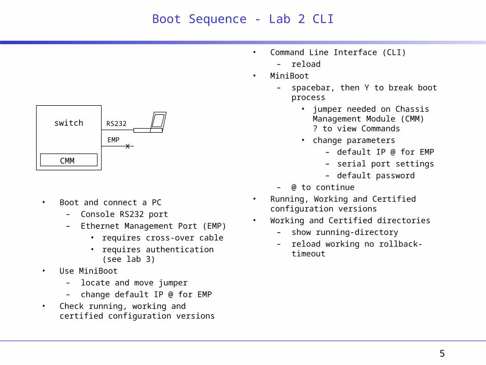
• Command Line Interface (CLI)– reload
• MiniBoot– spacebar, then Y to break boot process
• jumper needed on Chassis Management Module (CMM) ? to view Commands
• change parameters– default IP @ for EMP– serial port settings– default password
– @ to continue• Running, Working and Certified configuration
versions• Working and Certified directories
– show running-directory– reload working no rollback-timeout
RS232
EMP
switch
CMM
• Boot and connect a PC– Console RS232 port– Ethernet Management Port (EMP)
• requires cross-over cable• requires authentication (see lab 3)
• Use MiniBoot– locate and move jumper– change default IP @ for EMP
• Check running, working and certified configuration versions
x
6
Enable Remote Access - Lab 3 CLI / WebView
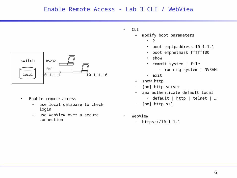
• CLI– modify boot parameters
• ?• boot empipaddress 10.1.1.1• boot empnetmask ffffff00• show• commit system | file
– running system | NVRAM• exit
– show http– [no] http server– aaa authenticate default local
• default | http | telnet | …– [no] http ssl
• WebView– https://10.1.1.1
local
RS232
EMP
switch
x10.1.1.1 10.1.1.10
• Enable remote access– use local database to check login– use WebView over a secure connection

7
Hardware Overview - Lab 1 and 5 CLI / Lab 1 WebView
• CLI– show hardware info– show microcode [history]– show chassis|cmm|ni|power supply|…– [no] power ni [slot #]– interface slot/port speed […]|…– reload primary|secondary|ni [slot #]– takeover– copy flash-synchro
• sync cert primary to sec working and certified directories
• WebView– Physical group
• Chassis Mgmt– Configuration menu
» Hardware» Modules
– Network Interfaces• Ethernet
– Interface Configuration
RS232
EMP
switch
x
CATALINAnet interfaces
CORONADOclassifier
NANTUCKETswitching fabric
SPARCprocessor
FlashMEMORY
CMM
SDRAMMEMORY
Pri. CMM
Sec. CMM
ENI GNI
• Check hardware, microcode, interface info– test failover between primary and
secondary CMM
8
Operating System - Lab 4 CLI / Lab 2 WebView
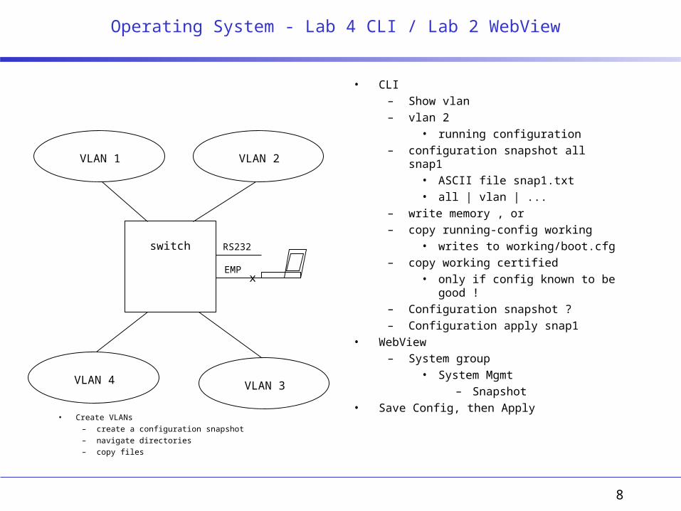
• CLI– Show vlan– vlan 2
• running configuration– configuration snapshot all snap1
• ASCII file snap1.txt• all | vlan | ...
– write memory , or– copy running-config working
• writes to working/boot.cfg– copy working certified
• only if config known to be good !– Configuration snapshot ?– Configuration apply snap1
• WebView– System group
• System Mgmt– Snapshot
• Save Config, then Apply
RS232
EMP
switch
VLAN 2VLAN 1
VLAN 4 VLAN 3
x
• Create VLANs– create a configuration snapshot– navigate directories– copy files

9
Installing and Upgrading Code - Lab 6 CLI / Lab 4 WebView
• Copy .img files to working directory and install• CLI
– show microcode [history]– rz
• with zmodem• ftp is preferred
– over EMP or NI• MiniBoot if necessary
– see manual– install *.img
• WebView– System group
• System Mgmt– Configuration menu
» Loaded Images» Images in Certified|Working
• Install, then Y, Add [all] and Apply• Register and View Images
RS232
EMP
switch
x
• Install and upgrade code– upgrade should be
performed first in the Working directory
– then, once the configuration has been verified, copy Working to Certified
• copy working certified
NI
10
Switch Security - Lab 7 CLI / Lab 4 WebView
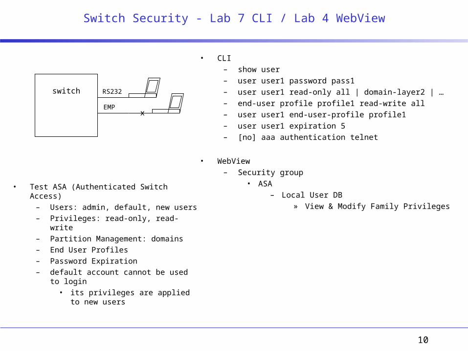
• Test ASA (Authenticated Switch Access)– Users: admin, default, new users– Privileges: read-only, read-write– Partition Management: domains– End User Profiles– Password Expiration– default account cannot be used to login
• its privileges are applied to new users
• CLI– show user– user user1 password pass1– user user1 read-only all | domain-layer2 | …– end-user profile profile1 read-write all– user user1 end-user-profile profile1– user user1 expiration 5– [no] aaa authentication telnet
• WebView– Security group
• ASA– Local User DB
» View & Modify Family Privileges
RS232
EMP
switch
x

11
VLANs - Lab 8 CLI / Lab 5 WebView
• Port type: default (static), mobile• Group Mobility• Rules
• CLI– show vlan [#]– show vlan [#] port [slot/port]– vlan 1 router ip @– vlan 2– show vlan router ip– vlan 2 port default slot/port
• static association– vlan port mobile slot/port
• needs a traffic matching rule– Show vlan rules– vlan 2 ip 192.168.11.0 255.255.255.0– show mac-address-table [slot #]
• will show the mac @ the switch has learned• WebView
– Layer 2 group• VLAN Mgmt
– Configuration menu» Vlan Config
RS232
EMP
switch
router
192.168.10.1
192.168.11.1
192.168.11.102
192.168.10.101
VLAN 1192.168.10.0 / 24
192.168.11.0 / 24VLAN 2
12
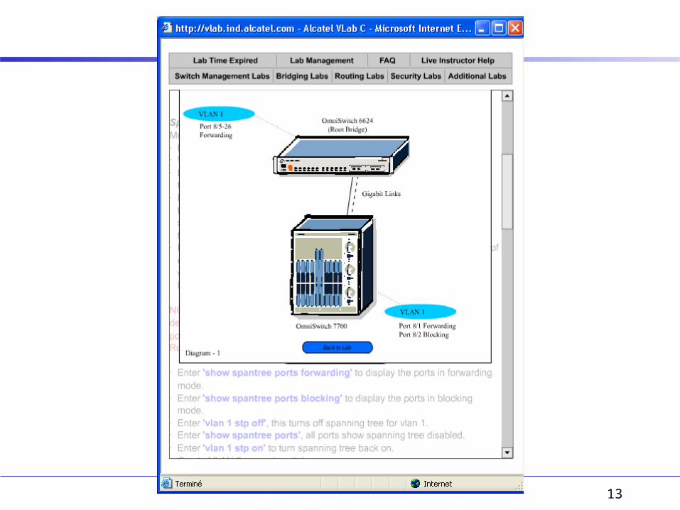
Spanning Tree - Lab 9 CLI / Lab 6 WebView
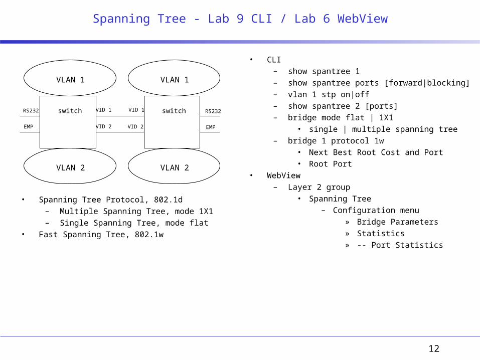
• Spanning Tree Protocol, 802.1d– Multiple Spanning Tree, mode 1X1– Single Spanning Tree, mode flat
• Fast Spanning Tree, 802.1w
• CLI– show spantree 1– show spantree ports [forward|blocking]– vlan 1 stp on|off– show spantree 2 [ports]– bridge mode flat | 1X1
• single | multiple spanning tree– bridge 1 protocol 1w
• Next Best Root Cost and Port• Root Port
• WebView– Layer 2 group
• Spanning Tree– Configuration menu
» Bridge Parameters» Statistics» -- Port Statistics
switch RS232
EMP
switchRS232
EMP
VLAN 1 VLAN 1
VLAN 2VLAN 2
VID 1 VID 1
VID 2VID 2
13

14
15
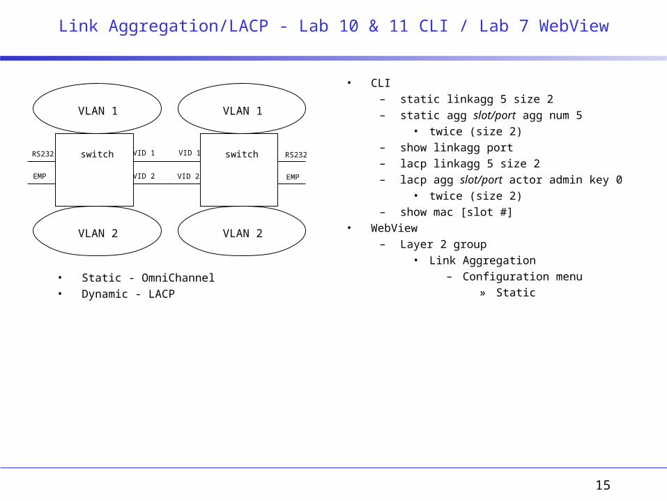
Link Aggregation/LACP - Lab 10 & 11 CLI / Lab 7 WebView
• Static - OmniChannel• Dynamic - LACP
• CLI– static linkagg 5 size 2– static agg slot/port agg num 5
• twice (size 2)– show linkagg port– lacp linkagg 5 size 2– lacp agg slot/port actor admin key 0
• twice (size 2)– show mac [slot #]
• WebView– Layer 2 group
• Link Aggregation– Configuration menu
» Static
switch RS232
EMP
switchRS232
EMP
VLAN 1 VLAN 1
VLAN 2VLAN 2
VID 1 VID 1
VID 2VID 2

16
17
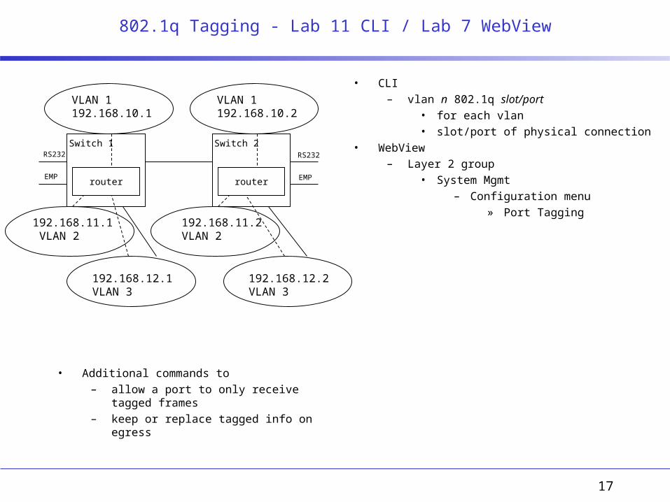
802.1q Tagging - Lab 11 CLI / Lab 7 WebView
• Additional commands to– allow a port to only receive tagged frames– keep or replace tagged info on egress
• CLI– vlan n 802.1q slot/port
• for each vlan• slot/port of physical connection
• WebView– Layer 2 group
• System Mgmt– Configuration menu
» Port Tagging
Switch 2RS232
EMP
Switch 1RS232
EMP
VLAN 1192.168.10.1
VLAN 1192.168.10.2
192.168.11.2 VLAN 2
192.168.11.1 VLAN 2
192.168.12.1 VLAN 3
192.168.12.2 VLAN 3
router router

18
19
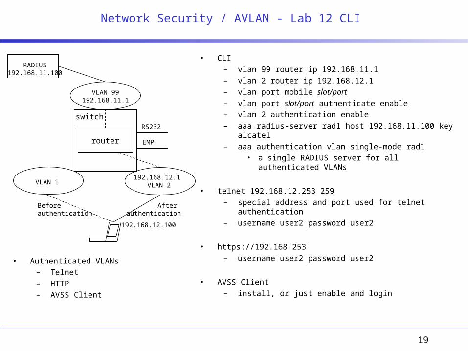
Network Security / AVLAN - Lab 12 CLI
• Authenticated VLANs – Telnet– HTTP– AVSS Client
• CLI– vlan 99 router ip 192.168.11.1– vlan 2 router ip 192.168.12.1– vlan port mobile slot/port– vlan port slot/port authenticate enable– vlan 2 authentication enable– aaa radius-server rad1 host 192.168.11.100 key alcatel– aaa authentication vlan single-mode rad1
• a single RADIUS server for all authenticated VLANs
• telnet 192.168.12.253 259– special address and port used for telnet authentication– username user2 password user2
• https://192.168.253– username user2 password user2
• AVSS Client– install, or just enable and login
RS232
EMP
switch
VLAN 1192.168.12.1
VLAN 2
VLAN 99192.168.11.1
RADIUS192.168.11.100
router
192.168.12.100
Before authentication
After authentication
20
RS232
EMP
switch
VLAN 1192.168.11.1
VLAN 2
router
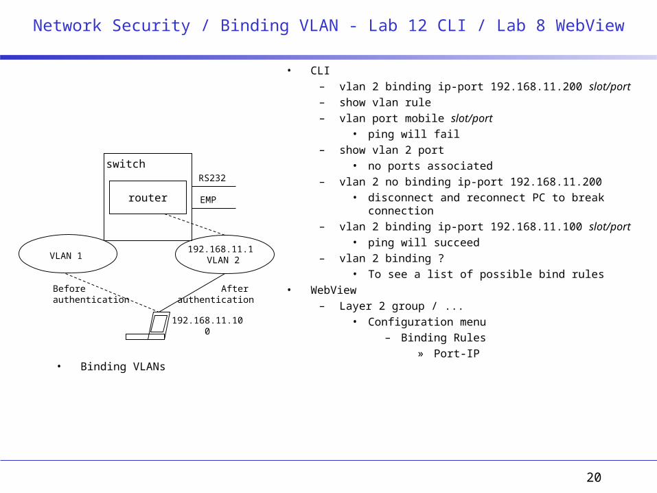
Network Security / Binding VLAN - Lab 12 CLI / Lab 8 WebView
• Binding VLANs
• CLI– vlan 2 binding ip-port 192.168.11.200 slot/port– show vlan rule– vlan port mobile slot/port
• ping will fail– show vlan 2 port
• no ports associated– vlan 2 no binding ip-port 192.168.11.200
• disconnect and reconnect PC to break connection– vlan 2 binding ip-port 192.168.11.100 slot/port
• ping will succeed– vlan 2 binding ?
• To see a list of possible bind rules• WebView
– Layer 2 group / ...• Configuration menu
– Binding Rules» Port-IP
192.168.11.100
Before authentication
After authentication
21
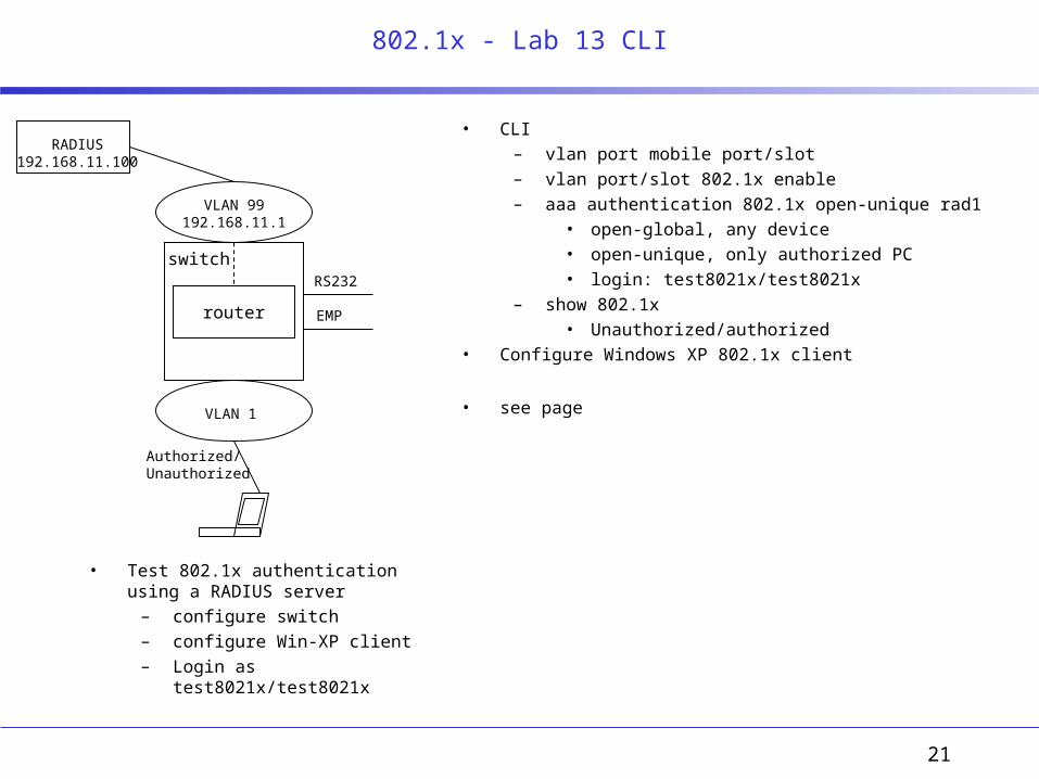
802.1x - Lab 13 CLI
• Test 802.1x authentication using a RADIUS server
– configure switch– configure Win-XP client– Login as test8021x/test8021x
• CLI– vlan port mobile port/slot– vlan port/slot 802.1x enable– aaa authentication 802.1x open-unique rad1
• open-global, any device• open-unique, only authorized PC• login: test8021x/test8021x
– show 802.1x• Unauthorized/authorized
• Configure Windows XP 802.1x client
• see page
RS232
EMP
switch
VLAN 1
VLAN 99192.168.11.1
RADIUS192.168.11.100
router
Authorized/Unauthorized
22
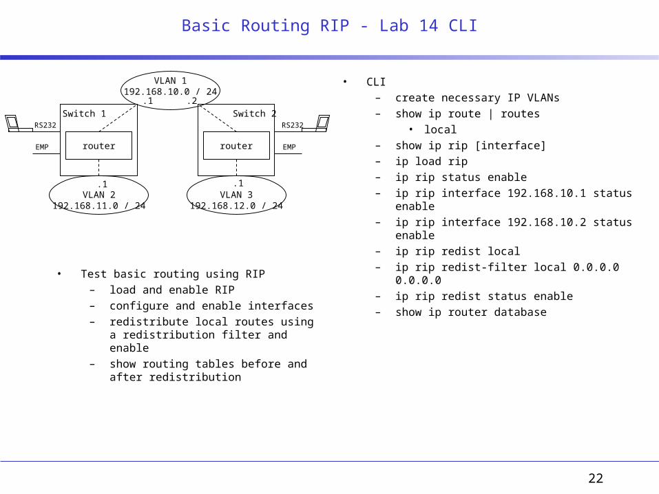
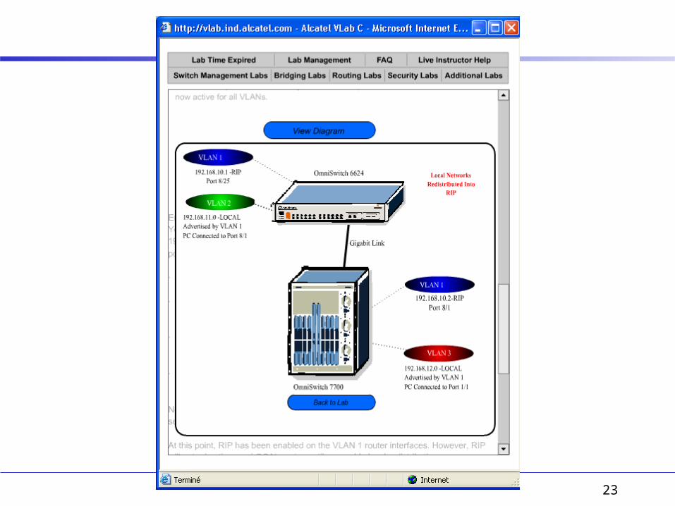
Basic Routing RIP - Lab 14 CLI
• Test basic routing using RIP– load and enable RIP– configure and enable interfaces– redistribute local routes using a
redistribution filter and enable– show routing tables before and after
redistribution
• CLI– create necessary IP VLANs– show ip route | routes
• local– show ip rip [interface]– ip load rip– ip rip status enable– ip rip interface 192.168.10.1 status enable– ip rip interface 192.168.10.2 status enable– ip rip redist local– ip rip redist-filter local 0.0.0.0 0.0.0.0– ip rip redist status enable– show ip router database
Switch 2
router
RS232
EMP
VLAN 1192.168.10.0 / 24
Switch 1
router
RS232
EMP
VLAN 2192.168.11.0 / 24
VLAN 3192.168.12.0 / 24
.1 .1
.1 .2
23
24
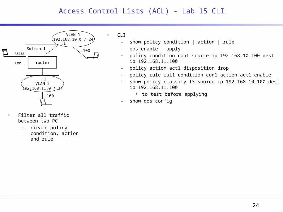
Access Control Lists (ACL) - Lab 15 CLI
• Filter all traffic between two PC– create policy condition,
action and rule
• CLI– show policy condition | action | rule– qos enable | apply– policy condition con1 source ip 192.168.10.100 dest ip 192.168.11.100– policy action act1 disposition drop– policy rule rul1 condition con1 action act1 enable– show policy classify l3 source ip 192.168.10.100 dest ip
192.168.11.100• to test before applying
– show qos config
VLAN 1192.168.10.0 / 24
Switch 1
router
RS232
EMP
VLAN 2192.168.11.0 / 24
.1
.1
.100
.100

25
Server Load Balancing - Lab 17 CLI
• Configure server load balancing– create a cluster– configure Windows 2000 servers with
virtual IP addresses– create a rule to do load balancing– test
• CLI– ip slb admin enable– ip slb cluster WorldWideWeb vip 192.168.10.250– ip slb server ip 192.168.10.101 cluster WorldWideWeb – ip slb server ip 192.168.10.102 cluster WorldWideWeb – show ip slb [servers | cluster]– show ip slb cluster WorldWideWeb server 192.168.10.101
– qos enable– policy condition slb_c destination 192.168.10.250– policy action slb_a load balance group WorldWideWeb – policy rule slb_r condition slb_c action slb_a– qos apply– show applied policy rule slb_r
• Windows 2000 Server– configure Virtual IP address to MS Loopback Adapter
switch
router
RS232
EMP
192.168.11.0 / 24VLAN 2
SVR 1 SVR 2
VLAN 1192.168.10.0 / 24
.101 .102.250
Virtual IP
WorldWideWeb cluster
.10
.10
.1
.1
26
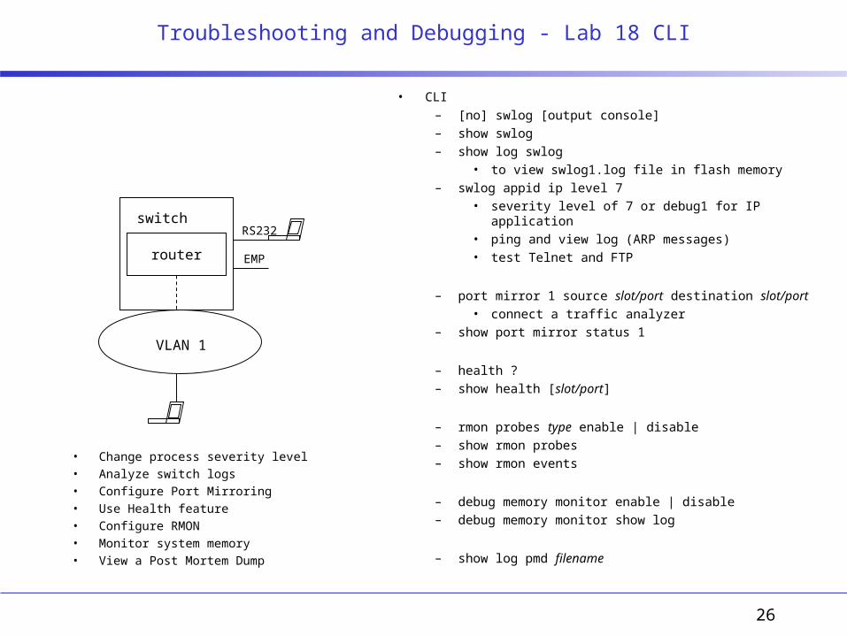
Troubleshooting and Debugging - Lab 18 CLI
• Change process severity level• Analyze switch logs• Configure Port Mirroring• Use Health feature• Configure RMON• Monitor system memory• View a Post Mortem Dump
• CLI– [no] swlog [output console]– show swlog– show log swlog
• to view swlog1.log file in flash memory– swlog appid ip level 7
• severity level of 7 or debug1 for IP application• ping and view log (ARP messages)• test Telnet and FTP
– port mirror 1 source slot/port destination slot/port• connect a traffic analyzer
– show port mirror status 1
– health ?– show health [slot/port]
– rmon probes type enable | disable– show rmon probes– show rmon events
– debug memory monitor enable | disable– debug memory monitor show log
– show log pmd filename
switch
router
RS232
EMP
VLAN 1

27
Secure Shell - Lab 19 CLI
• Login remotely to an OmniSwitch using a secure mechanism
• CLI– ssh 192.168.10.2
• login as admin/switch– who– whoami
– sftp 192.168.10.2
VLAN 1192.168.10.0 /24
Switch 2
router
RS232
EMP
Switch 1
router
RS232
EMP
.1
.2
28
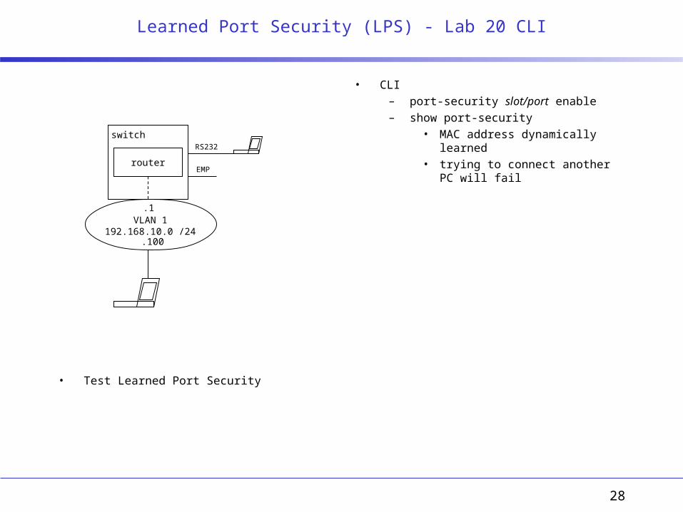
Learned Port Security (LPS) - Lab 20 CLI
• Test Learned Port Security
• CLI– port-security slot/port enable– show port-security
• MAC address dynamically learned• trying to connect another PC will fail
VLAN 1192.168.10.0 /24
switch
router
RS232
EMP
.1
.100
29
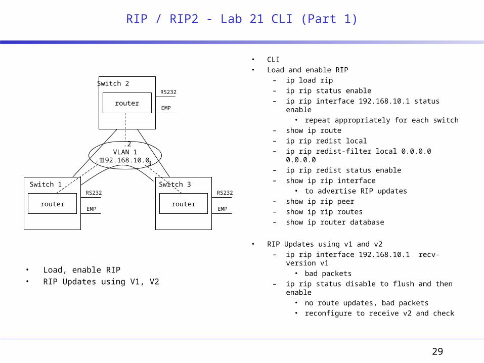
RIP / RIP2 - Lab 21 CLI (Part 1)
• Load, enable RIP• RIP Updates using V1, V2
• CLI• Load and enable RIP
– ip load rip– ip rip status enable– ip rip interface 192.168.10.1 status enable
• repeat appropriately for each switch– show ip route– ip rip redist local– ip rip redist-filter local 0.0.0.0 0.0.0.0– ip rip redist status enable– show ip rip interface
• to advertise RIP updates– show ip rip peer– show ip rip routes– show ip router database
• RIP Updates using v1 and v2– ip rip interface 192.168.10.1 recv-version v1
• bad packets– ip rip status disable to flush and then enable
• no route updates, bad packets• reconfigure to receive v2 and check
Switch 2
router
RS232
EMP
.1VLAN 1
192.168.10.0
Switch 1
router
RS232
EMP
Switch 3
router
RS232
EMP
.2
.3

30
RIP / RIP2 - Lab 21 CLI (Part 2)
• RIP Redistribution• Metrics• RIP Authentication - Simple
• CLI• RIP Redistribution• ping between sw2 and sw3 using VLAN 102
– show ip route• no routes to remote nets on sw3
– ip rip interface 192.168.102.2 status enable (sw2)– ip rip interface 192.168.102.3 status enable (sw3)– show ip rip peer– show ip route
• net 192.168.101.0 should show up on sw3• Metrics
– show ip router database• metric of 2 on sw1 for 192.168.102.0
– ip rip interface 192.168.10.1 metric 5
• RIP Authentication - Simple– ip rip interface 192.168.10.3 auth-type simple– ip rip interface 192.168.10.3 auth-key alcatel
• routes will be removed after their aging period– show ip rip peer
• bad packets from sw2• configure sw2 for simple authentication• now should receive valid RIP updates
Switch 2
router
RS232
EMP
.1VLAN 1
192.168.10.0
Switch 1
router
RS232
EMP
Switch 3
router
RS232
EMP
VLAN 103192.168.103.0
VLAN 101192.168.101.0
VLAN 102192.168.102.0.2
.3
.1
.3
.1
.2

31
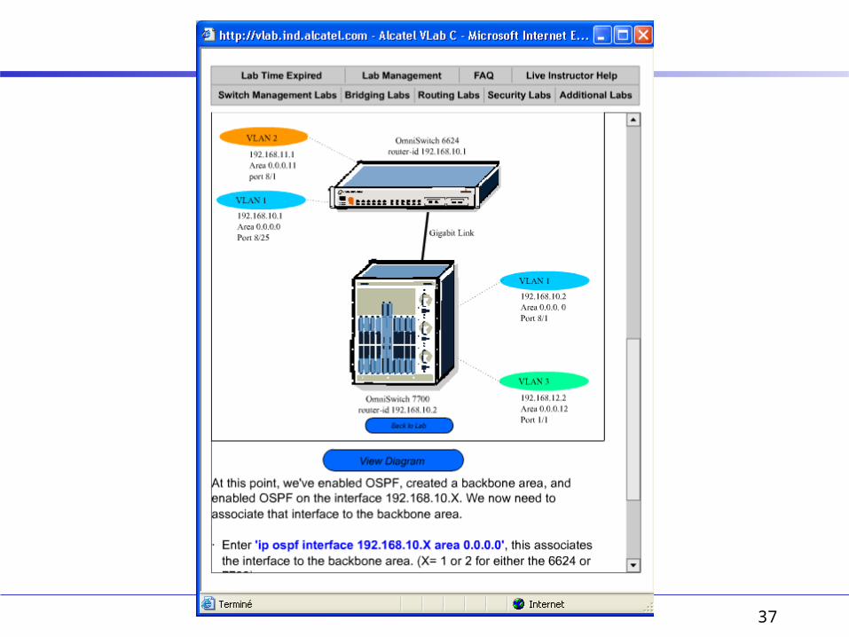
OSPF Backbone - Lab 22 CLI
• Configure OSPF Backbone Area• Determine DR, BDR• Test Hello and Dead intervals
• CLI• Router ID
– ip router router-id 192.168.10.X (for ea. switch)• Load, enable ospf and create backbone area (on ea. sw. ?)
– ip load ospf– ip ospf status enable– ip ospf area 0.0.0.0– ip ospf area 0.0.0.0 status enable
• Create and enable OSPF interfaces– ip ospf interface 192.168.10.X– ip ospf interface 192.168.10.X status enable
• Associate interfaces to backbone area– ip ospf interface 192.168.10.X area 0.0.0.0
– show ip route– show ip ospf route / show ip ospf lsdb– show ip ospf neighbor / show ip ospf interface– show ip ospf area 0.0.0.0
• Determine the current DR and lower its priority– ip ospf interface 192.168.10.x priority 0
• Test Hello and Dead intervals (default is 10)– ip ospf interface 192.168.10.x hello-interval x
• check that communication is lost
Switch 2
router
RS232
EMP
.1
VLAN 1192.168.10.0Backbone
Area 0.0.0.0
Switch 1
router
RS232
EMP
Switch 3
router
RS232
EMP
.2
.3
32
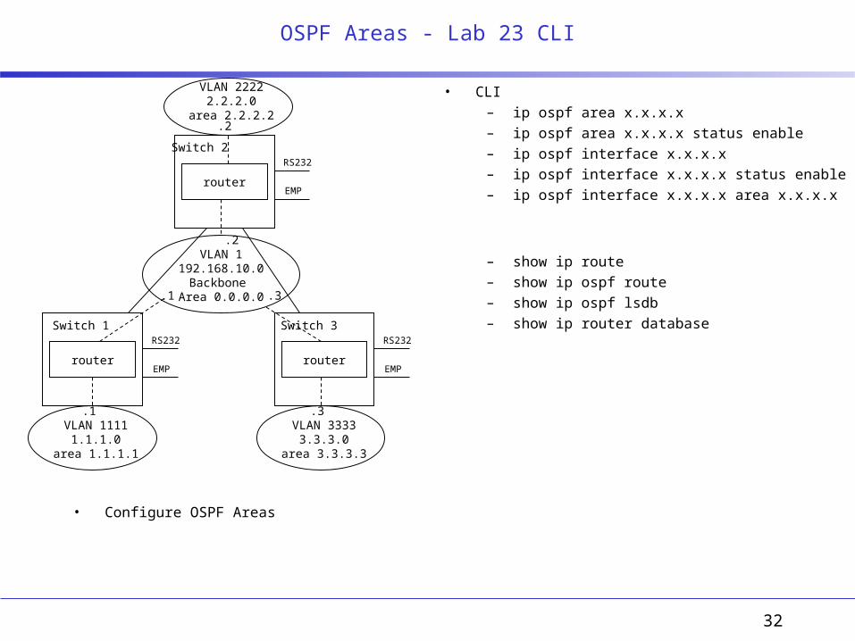
OSPF Areas - Lab 23 CLI
• Configure OSPF Areas
• CLI– ip ospf area x.x.x.x– ip ospf area x.x.x.x status enable– ip ospf interface x.x.x.x– ip ospf interface x.x.x.x status enable– ip ospf interface x.x.x.x area x.x.x.x
– show ip route– show ip ospf route– show ip ospf lsdb– show ip router database
Switch 2
router
RS232
EMP
.1
VLAN 1192.168.10.0Backbone
Area 0.0.0.0
Switch 1
router
RS232
EMP
Switch 3
router
RS232
EMP
.2
.3
VLAN 11111.1.1.0
area 1.1.1.1
VLAN 22222.2.2.0
area 2.2.2.2
VLAN 33333.3.3.0
area 3.3.3.3
.1
.2
.3
33
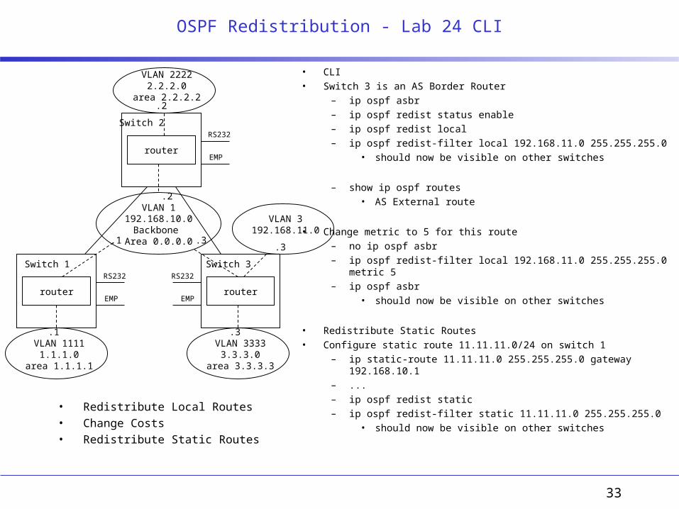
OSPF Redistribution - Lab 24 CLI
• Redistribute Local Routes• Change Costs• Redistribute Static Routes
• CLI• Switch 3 is an AS Border Router
– ip ospf asbr– ip ospf redist status enable– ip ospf redist local– ip ospf redist-filter local 192.168.11.0 255.255.255.0
• should now be visible on other switches
– show ip ospf routes• AS External route
• Change metric to 5 for this route– no ip ospf asbr– ip ospf redist-filter local 192.168.11.0 255.255.255.0 metric 5– ip ospf asbr
• should now be visible on other switches
• Redistribute Static Routes• Configure static route 11.11.11.0/24 on switch 1
– ip static-route 11.11.11.0 255.255.255.0 gateway 192.168.10.1– ...– ip ospf redist static– ip ospf redist-filter static 11.11.11.0 255.255.255.0
• should now be visible on other switches
Switch 2
router
RS232
EMP
.1
VLAN 1192.168.10.0Backbone
Area 0.0.0.0
Switch 1
router
RS232
EMP
Switch 3
router
RS232
EMP
.2
.3
VLAN 11111.1.1.0
area 1.1.1.1
VLAN 22222.2.2.0
area 2.2.2.2
VLAN 33333.3.3.0
area 3.3.3.3
.1
.2
.3
VLAN 3192.168.11.0
.3
34
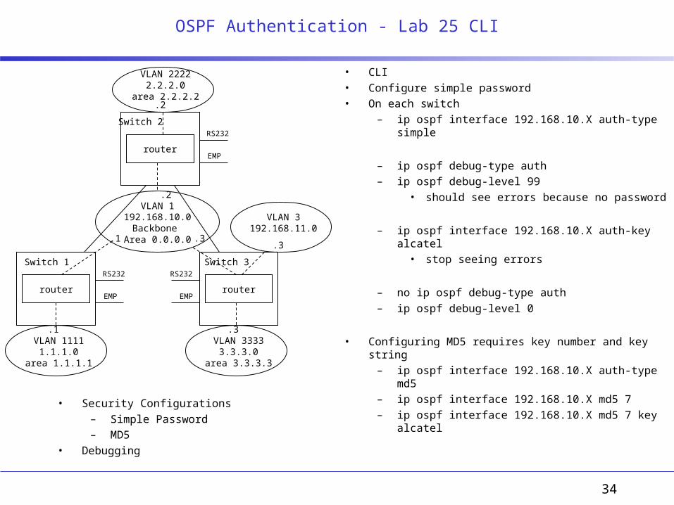
OSPF Authentication - Lab 25 CLI
• Security Configurations– Simple Password– MD5
• Debugging
• CLI• Configure simple password• On each switch
– ip ospf interface 192.168.10.X auth-type simple
– ip ospf debug-type auth– ip ospf debug-level 99
• should see errors because no password
– ip ospf interface 192.168.10.X auth-key alcatel• stop seeing errors
– no ip ospf debug-type auth– ip ospf debug-level 0
• Configuring MD5 requires key number and key string– ip ospf interface 192.168.10.X auth-type md5– ip ospf interface 192.168.10.X md5 7 – ip ospf interface 192.168.10.X md5 7 key alcatel
Switch 2
router
RS232
EMP
.1
VLAN 1192.168.10.0Backbone
Area 0.0.0.0
Switch 1
router
RS232
EMP
Switch 3
router
RS232
EMP
.2
.3
VLAN 11111.1.1.0
area 1.1.1.1
VLAN 22222.2.2.0
area 2.2.2.2
VLAN 33333.3.3.0
area 3.3.3.3
.1
.2
.3
VLAN 3192.168.11.0
.3

35
OSPF Stub Area - Lab 26 CLI
• Configure Stub Area
• CLI• Configure sw3 VLAN and area 2.2.2.2 with router-id 192.168.10.3• Configure switch 2 as ASBR
– ip ospf asbr– ip ospf redist status enable– ip ospf redist local– ip ospf redist-filter local 2.2.4.0 255.255.255.0
• 2.2.4.0 should appear on sw1 and sw3 as AS-Ext route
• Configure Stub Area– ip ospf area 2.2.2.2 type stub
• on both sw2 and sw3• 2.2.4.0 should no longer appear on sw3
• Configure static route on sw3– ip static-route 0.0.0.0 gateway 2.2.2.2
Switch 2 ASBR
router
RS232
EMP
.1
VLAN 1192.168.10.0Backbone
Area 0.0.0.0
Switch 1
router
RS232
EMP
Switch 3
routerRS232
EMP
.2
.2
VLAN 11111.1.1.0
area 1.1.1.1
VLAN 22222.2.2.0
stub area 2.2.2.2
.1
.3
VLAN 22422.2.4.0
.2
36
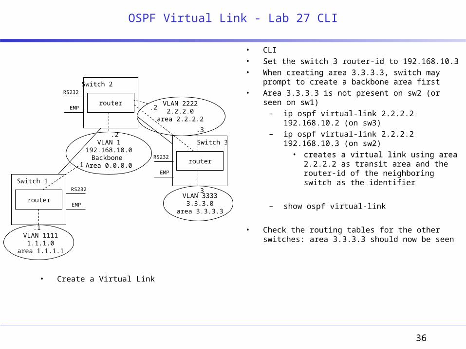
OSPF Virtual Link - Lab 27 CLI
• Create a Virtual Link
• CLI• Set the switch 3 router-id to 192.168.10.3• When creating area 3.3.3.3, switch may prompt to create
a backbone area first• Area 3.3.3.3 is not present on sw2 (or seen on sw1)
– ip ospf virtual-link 2.2.2.2 192.168.10.2 (on sw3)– ip ospf virtual-link 2.2.2.2 192.168.10.3 (on sw2)
• creates a virtual link using area 2.2.2.2 as transit area and the router-id of the neighboring switch as the identifier
– show ospf virtual-link
• Check the routing tables for the other switches: area 3.3.3.3 should now be seen
Switch 2
router
RS232
EMP
.1
VLAN 1192.168.10.0Backbone
Area 0.0.0.0
Switch 1
router
RS232
EMP
Switch 3
routerRS232
EMP
.2
VLAN 11111.1.1.0
area 1.1.1.1
VLAN 22222.2.2.0
area 2.2.2.2
.1
.3
VLAN 33333.3.3.0
area 3.3.3.3
.2
.3
37

38
VLAN N
switch
router
switch
router
RS232
EMP
RS232
EMP
switch
switch
router
RS232
EMP
local
xxVLAN N
AP
WLAN switch
WLAN switch

39
Wireless LANs

40
System Setup / System Upgrade
• Use CLI and Switch Web to do initial system config and upgrade – Startup Wizard– Commands
• CLI– <ESC> for boot options
• Primary image | Clear Config | ...– show ?
• Switchconfig | interface summary | …– clear ?
• Switch Web– http://192.168.1.1
• admin/admin– Configuration Wizard
• System Info• Service Interface• Management Interface• Misc• Virtual Interface• WLAN Policy• RADIUS Server• 802.11
– Commands• Download file
– Monitor• Summary
WLAN switch WLAN switch. . . . .
AP AP
AAA Server
switch
router
Management NetworkVlan0 (Vlan1)untagged10.9.4.0 / 24
.10
.20 .70
.1
RS232
Service Interf.
RS232
SI .7
SW2 SW7
RADIUSport 1812
Virtual IP 1.1.1.7Virtual IP 1.1.1.2
Switch Web192.168.1.1
Mobility / RF Group Name training2
Mobility / RF Group Name training7
Switch Web192.168.1.1192.168.1.0 / 24 192.168.1.0 / 24
.70
Version 1
41
WLAN switch WLAN switch. . . . .
AP AP
AAA Server
switch
router
Management Network vlan010.9.4.0 / 24
.10
.20Port 1
.70Port 1
.1
RS232
Service Interf.
RS232
SI .7
SW2 SW7
RADIUSport 1812
Virtual IP 1.1.1.1Virtual IP 1.1.1.1
Switch Web 192.168.1.1
Mobility / RF Group Name training2
Mobility / RF Group Name training7
Switch Web 192.168.1.1192.168.1.0 / 24 192.168.1.0 / 24
.70
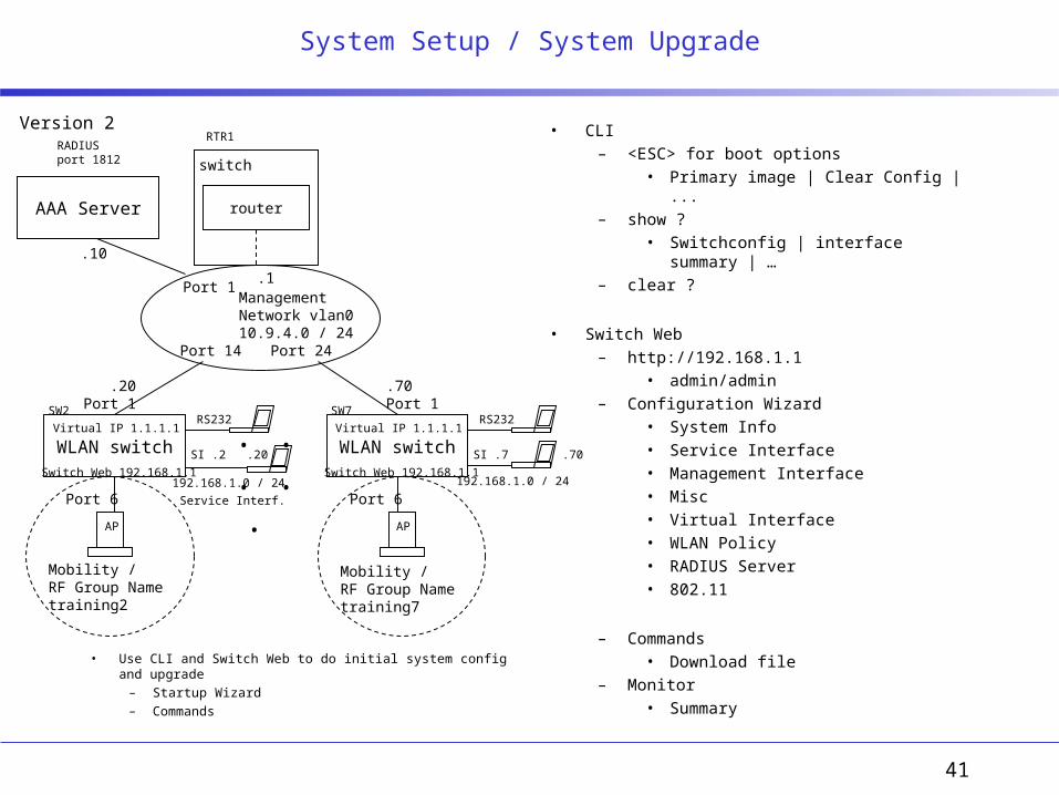
System Setup / System Upgrade
• Use CLI and Switch Web to do initial system config and upgrade – Startup Wizard– Commands
• CLI– <ESC> for boot options
• Primary image | Clear Config | ...– show ?
• Switchconfig | interface summary | …– clear ?
• Switch Web– http://192.168.1.1
• admin/admin– Configuration Wizard
• System Info• Service Interface• Management Interface• Misc• Virtual Interface• WLAN Policy• RADIUS Server• 802.11
– Commands• Download file
– Monitor• Summary
Port 1
Port 14 Port 24
Port 6 Port 6
RTR1
SI .2 .20
Version 2
42
WLAN controller WLAN controller
. . . . . AP AP
AAA ServerDHCP, AD
WCS
switch
router
.10
Port 1 Port 1RS232
Service Interf.
RS232
Serv I/f .7
RADIUSport 1812
SW7 Virtual IP 1.1.1.7SW2 Virtual IP 1.1.1.2
Switch Web 192.168.1.1
Mobility / RF Group Name training2
Mobility / RF Group Name training7
Switch Web 192.168.1.1192.168.1.0 / 24 192.168.1.0 / 24
.70
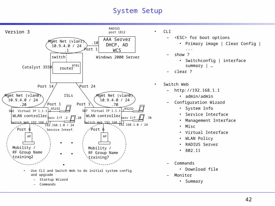
System Setup
• Use CLI and Switch Web to do initial system config and upgrade – Startup Wizard– Commands
• CLI– <ESC> for boot options
• Primary image | Clear Config | ...– show ?
• Switchconfig | interface summary | …– clear ?
• Switch Web– http://192.168.1.1
• admin/admin– Configuration Wizard
• System Info• Service Interface• Management Interface• Misc• Virtual Interface• WLAN Policy• RADIUS Server• 802.11
– Commands• Download file
– Monitor• Summary
Port 14 Port 24
Port 6 Port 6
RTR1
Serv I/f .2 .20
Version 3
Mgmt Net (vlan0)10.9.4.0 / 24
.20
Mgmt Net (vlan0)10.9.4.0 / 24
.70
Mgmt Net (vlan1)10.9.4.0 / 24
.1
ISLs
Port 1
Catalyst 3550
Windows 2000 Server
43
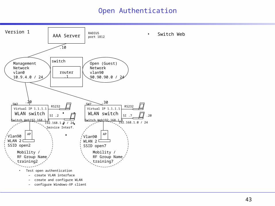
Open Authentication
• Test open authentication – create VLAN interface– create and configure WLAN– configure Windows-XP client
• Switch Web
WLAN switch WLAN switch. . . . .
AP AP
AAA Server
switch
router
Management Networkvlan010.9.4.0 / 24
.10
.20 .30
.1
RS232
Service Interf.
RS232
SI .7
SW2 SW7
RADIUSport 1812
Virtual IP 1.1.1.1Virtual IP 1.1.1.1
Switch Web192.168.1.1
Mobility / RF Group Name training2
Mobility / RF Group Name training7
Switch Web192.168.1.1192.168.1.0 / 24 192.168.1.0 / 24
.20
Vlan90WLAN 2 SSID open2
Vlan90WLAN 2 SSID open7
Open (Guest) Networkvlan9090.90.90.0 / 24
SI .2
Version 1
44
WLAN switch WLAN switch. . . . .
AP AP
AAA Server
switch
router
Management Network vlan010.9.4.0 / 24
.10
.20Port 1
.72Port 1
.1
RS232
Service Interf.
RS232
SI .7
SW2 SW7
RADIUS port 1812DHCP
Virtual IP 1.1.1.1Virtual IP 1.1.1.1
Switch Web 192.168.1.1
Mobility / RF Group Name training2
Mobility / RF Group Name training7
Switch Web 192.168.1.1192.168.1.0 / 24 192.168.1.0 / 24
.70
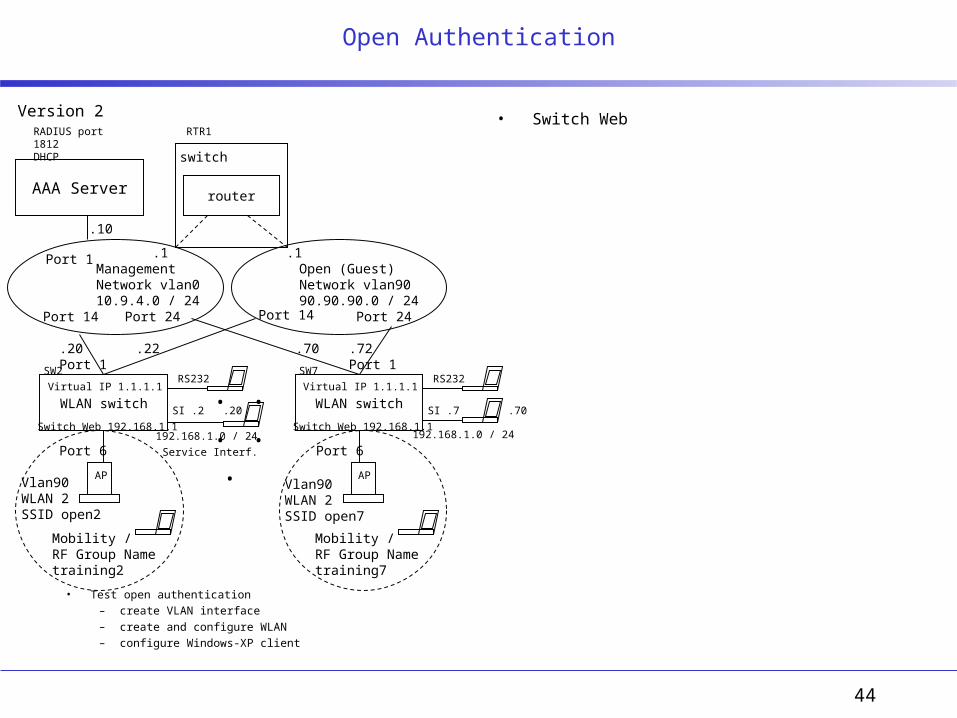
Open Authentication
• Switch Web
Port 1
Port 14 Port 24
Port 6 Port 6
RTR1
SI .2 .20
• Test open authentication – create VLAN interface– create and configure WLAN– configure Windows-XP client
Open (Guest) Network vlan9090.90.90.0 / 24
.1
Port 14 Port 24
.22 .70
Vlan90WLAN 2 SSID open2
Vlan90WLAN 2 SSID open7
Version 2
45
WLAN switch WLAN switch
. . . . . AP AP
RS232
Service Interf.
RS232
SI .7
Virtual IP 1.1.1.1Virtual IP 1.1.1.1
Switch Web 192.168.1.1
Mobility / RF Group Name training2
Mobility / RF Group Name training7
Switch Web 192.168.1.1192.168.1.0 / 24 192.168.1.0 / 24
.70
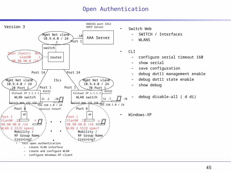
Open Authentication
• Switch Web– SWITCH / Interfaces– WLANS
• CLI– configure serial timeout 160– show serial– save configuration– debug dot11 management enable– debug dot11 state enable– show debug
– debug disable-all ( d di)
• Windows-XPPort 6 Port 6
SI .2 .20
• Test open authentication – create VLAN interface– create and configure WLAN– configure Windows-XP client
Port 1 Vlan90 .2290.90.90.0 /24WLAN 2 SSID open2
Port 1Vlan90 .7290.90.90.0 /24WLAN 2 SSID open7
AAA Server
switch
router
.10
Port 1 Port 1
RADIUS port 1812DHCP Server
Port 14 Port 24
Version 3
Mgmt Net vlan010.9.4.0 / 24
.20 Port 1
Mgmt Net vlan010.9.4.0 / 24
.70 Port 1
Mgmt Net vlan010.9.4.0 / 24
.1
ISLs
Port 1
Open (Guest) Net vlan90
90.90.90.0 /24
.x .y
.1

46
Layer 3 Configuration
• Learn how to “Prime” an AP for layer 3 deployment
• Understand the different methods an Access Point can obtain an IP address
• Configure high availability into the network
• CLI– show ap summary– clear ap-config ap– config ap reset ap
• Switch Web (on SW2)– WIRELESS/Acces Points/Airespace APs
• Detail , Reset AP Now (button)– SWITCH/General/LWAPP Transport Mode
• Layer 3, Apply, Save Configuration– COMMANDS/Reboot– SWITCH/Interfaces
• configure AP-Manager interface– WIRELESS/Acces Points/Airespace APs
• Detail, Primary, Secondary switch– SWITCH/Master Switch Mode
• only one Master switch– SWITCH/General
• Disable Over The Air Provisioning of AP• Enable AP Fallback• RF Mobility Domain name: training23
– SWITCH/Mobility Management/Mobility Groups• New member:SW3, Apply, Save Conf, ping
switch
router
AAA Server.10Mgmt Net vlan010.9.4.0 / 24
.1 Port 1
AP
Port 13.192
AP
Port 15.193
WLAN Pri. switch
RS232
Service Interf.
Virtual IP 1.1.1.1
Switch Web 192.168.1.1192.168.1.0 / 24
Port 14
SI .2 .20
Port 1Mgmt Net vlan010.9.4.0 / 24
.20 Port 1 ISLs
WLAN Sec. switch
RS232
SI .3
Virtual IP 1.1.1.1
Switch Web 192.168.1.1192.168.1.0 / 24
.30
Port 1 Mgmt Net vlan010.9.4.0 / 24
.30 Port 1Port 16
L3 Mobility / RF Group Name training23
L3 Mobility / RF Group Name training23
SW2 SW3
RTR1
SWn Master ModeVERSION 1
47
WLAN Pri. switch WLAN Sec. switch
AP AP
RS232
Service Interf.
RS232
SI .3
Virtual IP 1.1.1.1Virtual IP 1.1.1.1
Switch Web 192.168.1.1
Mobility / RF Group Name training23
Mobility / RF Group Name training23
Switch Web 192.168.1.1192.168.1.0 / 24 192.168.1.0 / 24
.30
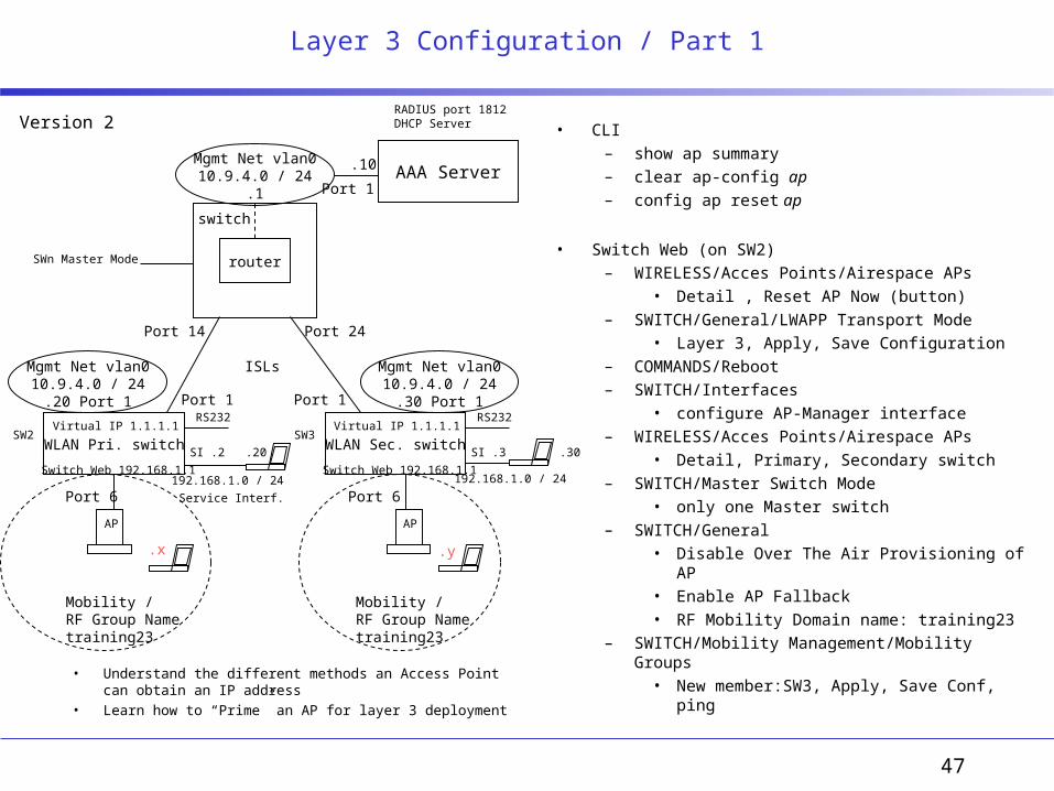
Layer 3 Configuration / Part 1
Port 6 Port 6
SI .2 .20
• Understand the different methods an Access Point can obtain an IP address
• Learn how to “Prime” an AP for layer 3 deployment
AAA Server
switch
router
.10
Port 1 Port 1
RADIUS port 1812DHCP Server
Port 14 Port 24
Version 2
Mgmt Net vlan010.9.4.0 / 24
.20 Port 1
Mgmt Net vlan010.9.4.0 / 24
.30 Port 1
Mgmt Net vlan010.9.4.0 / 24
.1
ISLs
Port 1
.x .y
• CLI– show ap summary– clear ap-config ap– config ap reset ap
• Switch Web (on SW2)– WIRELESS/Acces Points/Airespace APs
• Detail , Reset AP Now (button)– SWITCH/General/LWAPP Transport Mode
• Layer 3, Apply, Save Configuration– COMMANDS/Reboot– SWITCH/Interfaces
• configure AP-Manager interface– WIRELESS/Acces Points/Airespace APs
• Detail, Primary, Secondary switch– SWITCH/Master Switch Mode
• only one Master switch– SWITCH/General
• Disable Over The Air Provisioning of AP• Enable AP Fallback• RF Mobility Domain name: training23
– SWITCH/Mobility Management/Mobility Groups• New member:SW3, Apply, Save Conf, ping
SWn Master Mode
SW2 SW3
48
switch
router
AAA Server.10Mgmt Net vlan010.9.4.0 / 24
.1 Port 1
AP
Port 13.192
AP
Port 15.193
WLAN Pri. switch
RS232
Service Interf.
Virtual IP 1.1.1.1
Switch Web 192.168.1.1192.168.1.0 / 24
Port 14
SI .2 .20
Port 1Mgmt Net vlan010.9.4.0 / 24
.20 Port 1 ISLs
WLAN Sec. switch
RS232
SI .3
Virtual IP 1.1.1.1
Switch Web 192.168.1.1192.168.1.0 / 24
.30
Port 1 Mgmt Net vlan010.9.4.0 / 24
.30 Port 1Port 16
L3 Mobility / RF Group Name training23
L3 Mobility / RF Group Name training23
SW2 SW3
RTR1
SWn Master ModeVersion 2
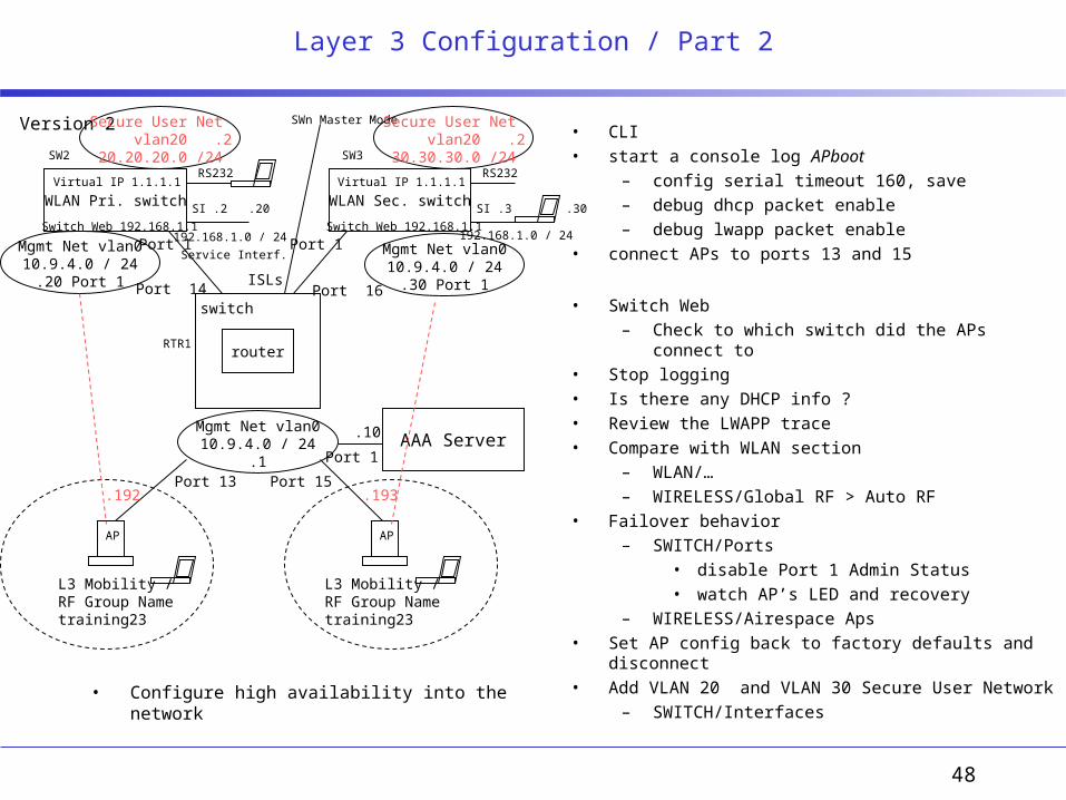
Layer 3 Configuration / Part 2
• Configure high availability into the network
• CLI• start a console log APboot
– config serial timeout 160, save– debug dhcp packet enable– debug lwapp packet enable
• connect APs to ports 13 and 15
• Switch Web– Check to which switch did the APs connect to
• Stop logging• Is there any DHCP info ?• Review the LWAPP trace• Compare with WLAN section
– WLAN/…– WIRELESS/Global RF > Auto RF
• Failover behavior– SWITCH/Ports
• disable Port 1 Admin Status• watch AP’s LED and recovery
– WIRELESS/Airespace Aps• Set AP config back to factory defaults and disconnect • Add VLAN 20 and VLAN 30 Secure User Network
– SWITCH/Interfaces
Secure User Net vlan20
20.20.20.0 /24.2
Secure User Net vlan20
30.30.30.0 /24.2

49
WLAN switch WLAN switch
. . . . . AP AP
RS232
Service Interf.
RS232
SI .7
Virtual IP 1.1.1.1Virtual IP 1.1.1.1
Switch Web 192.168.1.1
Mobility / RF Group Name training2
Mobility / RF Group Name training7
Switch Web 192.168.1.1192.168.1.0 / 24 192.168.1.0 / 24
.70
Web Authentication Configuration
• Switch Web– WLAN/New
• WLAN SSID: webauthx• Interface Name: vlan90• L3 Security: Web Authentication
– WLAN/Summary• Enable Admin Status webauthx• Disable Admin status openx
– Apply, Save and Reboot– SECURITY/AAA/Local Net User
• Username, psw, WLAN ID
• Windows-XP– Wireless Networks/Preferred networks
• remove openx• add webauthx• disable WEP for Web authentication to work
• Client Login– http://1.1.1.x (https://1.1.1.x) (https://1.1.1.1)– Understand Security Alert– Login page, logout page– test correct and wrong passwords– count number of max wrong attempts– check SECURITY/AAA/User Login Policies
Port 6 Port 6
SI .2 .20
• Test web authentication – create WLAN to support Web Auth subscriber– create a Local Net User– configure Windows-XP client and connect using the web browser
Port 1 Vlan90 .2290.90.90.0 /24WLAN 2 SSID webauth2
Port 1Vlan90 .7290.90.90.0 /24WLAN 7 SSID webauth7
AAA Server
switch
router
.10
Port 1 Port 1
RADIUS port 1812DHCP Server
Port 14 Port 24
Mgmt Net vlan010.9.4.0 / 24
.20 Port 1
Mgmt Net vlan010.9.4.0 / 24
.70 Port 1
Mgmt Net vlan010.9.4.0 / 24
.1
ISLs
Port 1
Open (Guest) Net vlan90
90.90.90.0 /24
.x .y
.1
50
Web Authentication Configuration
51
WEP Authentication Configuration
52
802.1x EAP-PEAP-MSCHAPv2 Configuration
53
WPA EAP-PEAP-MSCHAPv2 Configration
54
IPSec Configuration
55
IPSec Over L2TP Configuration Using Win-XP Client

56
Airespace Control System

57
AS Site Survey

58
Troubleshooting
59
VLAN N
switch
router
switch
router
RS232
EMP
RS232
EMP
switch
switch
router
RS232
EMP
local
xxVLAN N
AP
WLAN switch
WLAN switch

60
OSPF Authentication - Lab 25 CLI
• Security Configurations– Simple Password– MD5
• Debugging
• CLI• Configure simple password• On each switch
– ip ospf interface 192.168.10.X auth-type simple
– ip ospf debug-type auth– ip ospf debug-level 99
• should see errors because no password
– ip ospf interface 192.168.10.X auth-key alcatel• stop seeing errors
– no ip ospf debug-type auth– ip ospf debug-level 0
• Configuring MD5 requires key number and key string– ip ospf interface 192.168.10.X auth-type md5– ip ospf interface 192.168.10.X md5 7 – ip ospf interface 192.168.10.X md5 7 key alcatel
Switch 2
router
RS232
EMP
.1
VLAN 1192.168.10.0Backbone
Area 0.0.0.0
Switch 1
router
RS232
EMP
Switch 3
router
RS232
EMP
.2
.3
VLAN 11111.1.1.0
area 1.1.1.1
VLAN 22222.2.2.0
area 2.2.2.2
VLAN 33333.3.3.0
area 3.3.3.3
.1
.2
.3
VLAN 3192.168.11.0
.3
61
Configurations labs IPv6
62
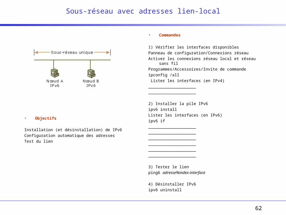
Sous-réseau avec adresses lien-local
• Objectifs
Installation (et désinstallation) de IPv6
Configuration automatique des adresses
Test du lien
• Commandes
1) Vérifier les interfaces disponibles
Panneau de configuration/Connexions réseau
Activer les connexions réseau local et réseau sans fil
Programmes/Accessoires/Invite de commande
ipconfig /all
Lister les interfaces (en IPv4)
____________________
____________________
2) Installer la pile IPv6
ipv6 install
Lister les interfaces (en IPv6)
ipv6 if
____________________
____________________
____________________
____________________
____________________
____________________
3) Tester le lien
ping6 adresse%index-interface
4) Désinstaller IPv6
ipv6 uninstall
63
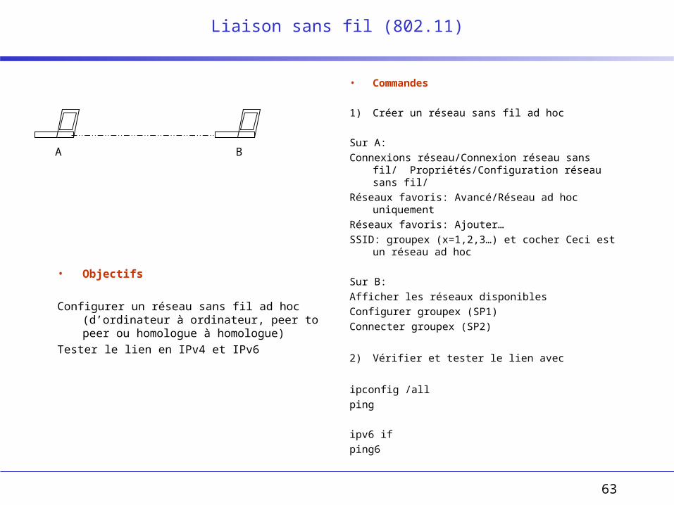
Liaison sans fil (802.11)
• Objectifs
Configurer un réseau sans fil ad hoc (d’ordinateur à ordinateur, peer to peer ou homologue à homologue)
Tester le lien en IPv4 et IPv6
• Commandes
1) Créer un réseau sans fil ad hoc
Sur A:
Connexions réseau/Connexion réseau sans fil/ Propriétés/Configuration réseau sans fil/
Réseaux favoris: Avancé/Réseau ad hoc uniquement
Réseaux favoris: Ajouter…
SSID: groupex (x=1,2,3…) et cocher Ceci est un réseau ad hoc
Sur B:
Afficher les réseaux disponibles
Configurer groupex (SP1)
Connecter groupex (SP2)
2) Vérifier et tester le lien avec
ipconfig /all
ping
ipv6 if
ping6
A B

64
Trafic entre deux nœuds de sous-réseaux différents
• Objectifs
Configuration routeur
Utilisation d’adresses site-local (qui ne sont plus utilisées) et globales
• Commandes
1) Configurer les deux interfaces routeur
ipv6 ifc index-interface forwards advertises
ipv6 rtu fec0:0:0:x::/64 index-interface publish
Attendre 30 secondes pour permettre au routeur d’envoyer ses annonces et aux hôtes de se autoconfigurer
2) Vérifier les adresses et tester la connectivité avec les commandes:
ipv6 if
ping6
tracert6
3) Refaire la configuration avec des adresses globales

65
Routage statique et dynamique
• Objectifs
• Commandes

66
IPsec
• Objectifs
• Commandes
67
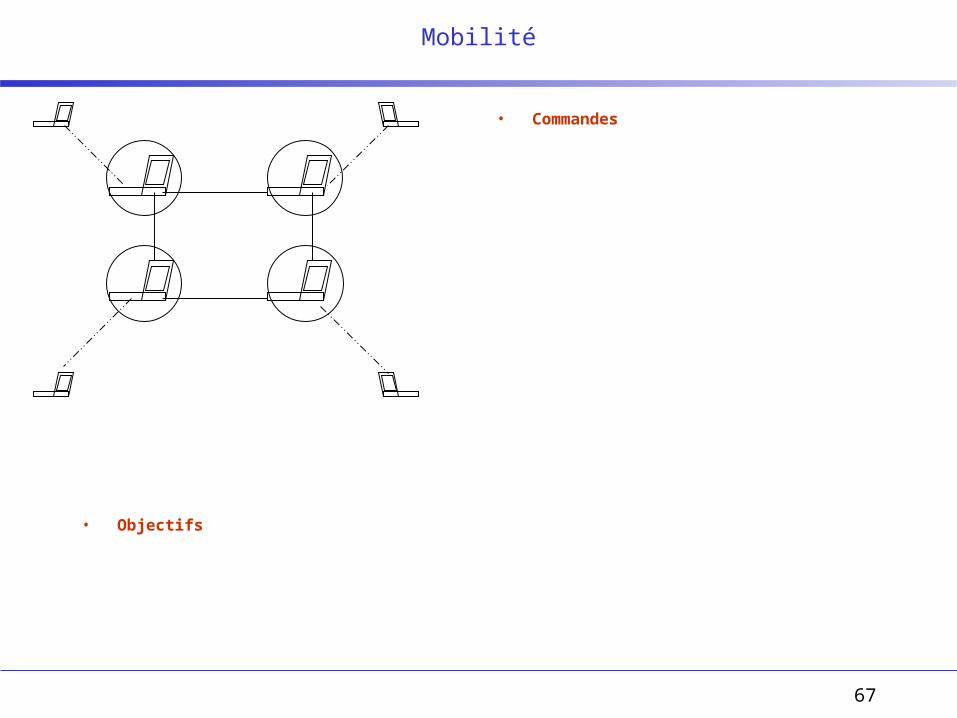
Mobilité
• Objectifs
• Commandes

68
Transition IPv4 à IPv6
69
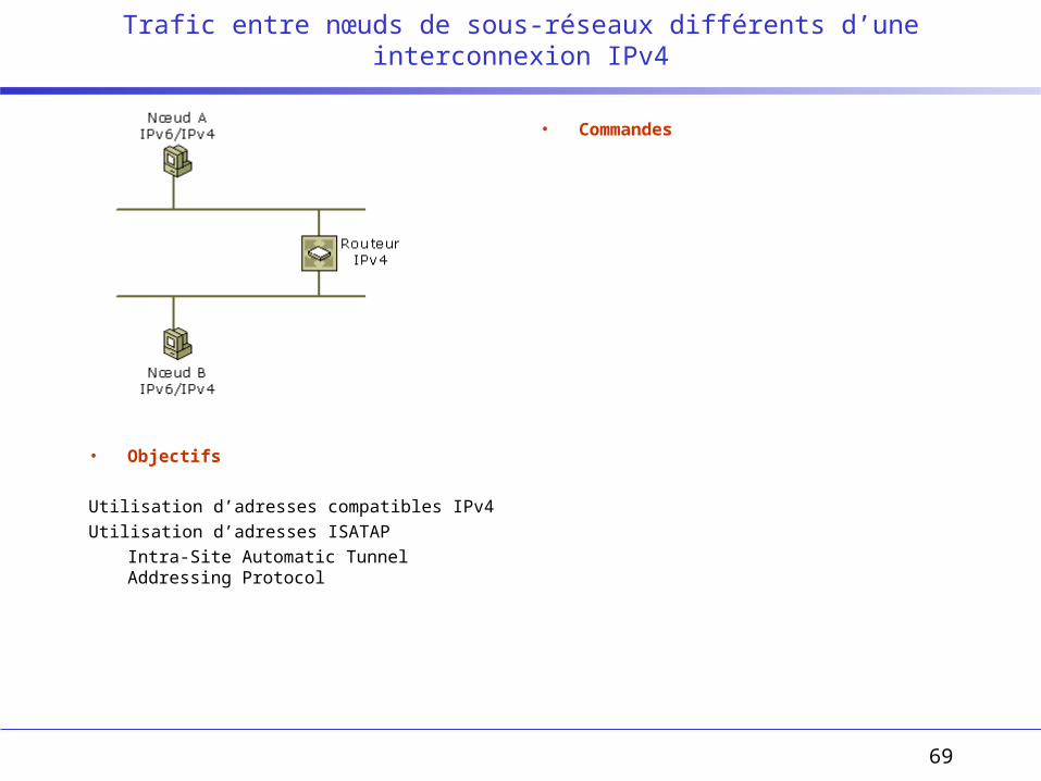
Trafic entre nœuds de sous-réseaux différents d’une interconnexion IPv4
• Objectifs
Utilisation d’adresses compatibles IPv4
Utilisation d’adresses ISATAP
Intra-Site Automatic Tunnel Addressing Protocol
• Commandes
70
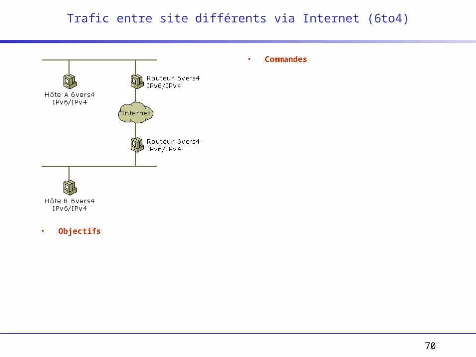
Trafic entre site différents via Internet (6to4)
• Objectifs
• Commandes
71
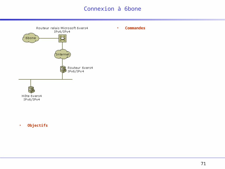
Connexion à 6bone
• Objectifs
• Commandes
72
Utilisation de DNS (et DHCPv6)
73
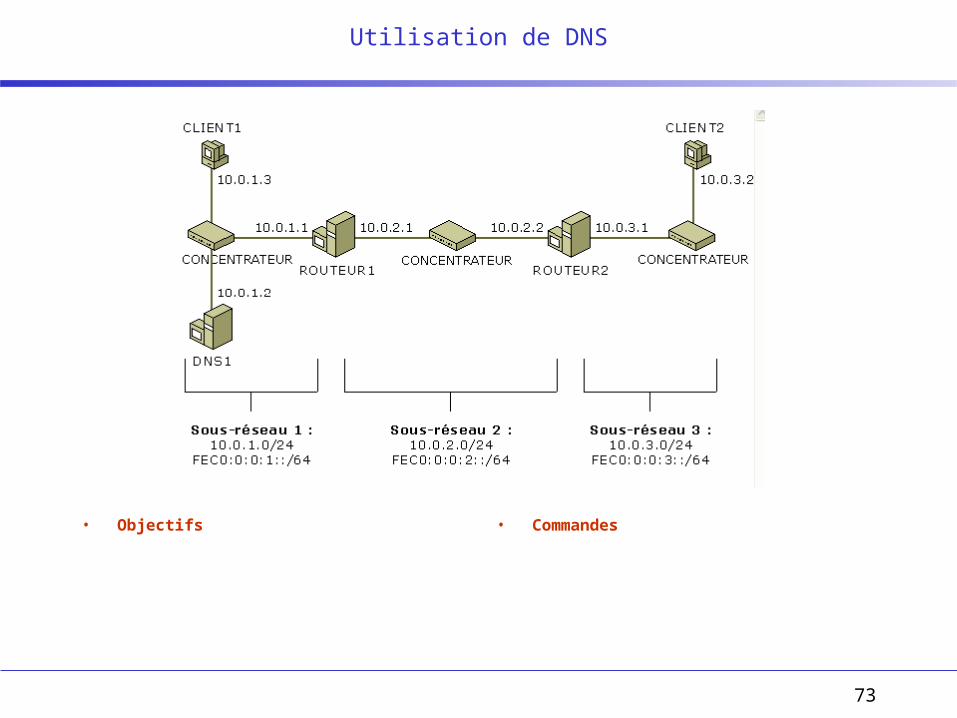
Utilisation de DNS
• Objectifs • Commandes

74
• Objectifs
• Commandes