Embed Size (px)
Citation preview

2 Edition 07.12Technical Information · GB
• To maintain a constant gas/air mixture• For continuous and staged burner control• Design with inlet pressure compensation diaphragm
ensures high control accuracy• Wide control range• EC type-tested and certified• Certified by Gosstandart pursuant to GOST-TR
Air/gas ratio controls GIK

GIK · Edition 07.12 2▼ = To be continued
ContentsAir/gas ratio controls GIK . . . . . . . . . . . . . . . . . . . . . . . . . . 1Contents . . . . . . . . . . . . . . . . . . . . . . . . . . . . . . . . . . . . . . . . 21 Application . . . . . . . . . . . . . . . . . . . . . . . . . . . . . . . . . . . . . 31.1 Examples of application. . . . . . . . . . . . . . . . . . . . . . . . . . 4
2 Certification . . . . . . . . . . . . . . . . . . . . . . . . . . . . . . . . . . . . 53 Function . . . . . . . . . . . . . . . . . . . . . . . . . . . . . . . . . . . . . . . 64 Flow rate . . . . . . . . . . . . . . . . . . . . . . . . . . . . . . . . . . . . . . 74.1 Bypass screw flow rate . . . . . . . . . . . . . . . . . . . . . . . . . . 8
5 Selection . . . . . . . . . . . . . . . . . . . . . . . . . . . . . . . . . . . . . . 95.1 Type code . . . . . . . . . . . . . . . . . . . . . . . . . . . . . . . . . . . . . 9
6 Project planning information . . . . . . . . . . . . . . . . . . . . . 106.1 Installation . . . . . . . . . . . . . . . . . . . . . . . . . . . . . . . . . . . 10
7 Accessories . . . . . . . . . . . . . . . . . . . . . . . . . . . . . . . . . . . .117.1 Conversion kit for zero pressure control. . . . . . . . . . . . .117.2 Bypass screw GIK 15 – 25, variable . . . . . . . . . . . . . . . .117.3 Bypass screw, diameter to order . . . . . . . . . . . . . . . . . .11
8 Technical data . . . . . . . . . . . . . . . . . . . . . . . . . . . . . . . . 128.1 Dimensions . . . . . . . . . . . . . . . . . . . . . . . . . . . . . . . . . . 13
9 Maintenance cycles . . . . . . . . . . . . . . . . . . . . . . . . . . . . 14Feedback . . . . . . . . . . . . . . . . . . . . . . . . . . . . . . . . . . . . . . 15Contact . . . . . . . . . . . . . . . . . . . . . . . . . . . . . . . . . . . . . . . . 15

GIK · Edition 07.12 3
1 Application
GIK..R
Air/gas ratio controls GIK with inlet pressure compensation diaphragm and zero shut-off serve to maintain a constant gas/air ratio and to control the gas pressure upstream of gas burners in systems without preheated combustion air. For use in gas control lines in all sectors of the iron, steel, glass and ceramics industries, as well as in commercial heat genera-tion, such as the packaging, paper and foodstuffs industries.
GIK..F

GIK · Edition 07.12 4
1 .1 Examples of application
Metallurgical industry: bogie hearth furnace
Aluminium industry: smelting furnace
Ceramics industry: intermittent shuttle kiln
Application

GIK · Edition 07.12 5
2 CertificationEC type-tested and certified
pursuant to– Gas Appliances Directive (2009/142/EC) in conjunction
with DIN EN 12067-1.
Approval for Russia
Certified by Gosstandart pursuant to GOST-TR.Approved by Rostekhnadzor (RTN).Scan of the approval for Russia (RUS) – see www.docuthek.com ➔ Elster Kromschröder ➔ Products ➔ 02 Pressure regulators ➔ Air/gas ratio controls GIK ➔ Kind of document: Certificate ➔ GIK B00093 (nationales Zertifikat Russland) (RUS).

GIK · Edition 07.12 6
GIK..FGIK..R
3 Function
Working diaphragm
Inlet pres-sure com-pensation
diaphragm
Valve disc
Valve seat
Air/gas ratio control GIK is actuated by the air line pressure. The valve disc is lifted from the valve seat and the gas flows into the regulator outlet area via the open valve seat. The outlet pressure is applied to the space above the working diaphragm via the impulse line. The outlet pressure is controlled in a ratio of 1:1 to the air control pressure. The inlet pressure compensa-tion diaphragm ensures high control accuracy.The burner capacity can be adjusted using the air control valve. Furnace pressure fluctuations have the same effect on the gas and air throughput so that the gas/air mixture will remain unchanged.The spring can be used for compensating the weight of the measuring unit. In the low-fire range, the gas/air mixture can
be set by adjusting the spring. For staged control, the spring is decompressed at the factory in such a way that the low-fire rate only flows through the bypass.Adjustment at high-fire rate is carried out using restrictors or valves on the burner.The zero shut-off prevents an increase in the outlet pressure when the consumer is switched off.Test nipples have been installed to measure the static inlet, outlet and control pressures.
Bypass screw
Spring Spring
Impulse line
Impulse line
Control pressure connection
Control pressure connection
Working diaphragm
Safety diaphragm
Adjusting screw

GIK · Edition 07.12 7
4 Flow rate
2
3
4
5
6
8
10 20 30 40 50 60 80 100 200 300 400 5001
20 30 40 50 60 80 100 200 300 400 5002
7 8 10 20 30 40 50 60 80 100 200 300 4004
6 7 8 10 20 30 40 50 60 80 100
2000 3000
2000 3000
8001000200 3003
600
Qn [m3/h]
600 8001000
8001000
500600 8001000 2000
400 500600
10
20
30
40
50
60
80
100
200
GIK
80
GIK
65
GIK
20
GIK
25
GIK
50
GIK
15
GIK
40
GIK
100
GIK
150
∆p [m
bar]
P1
= natural gas (ρ = 0.80 kg/m3) = town gas (ρ = 0.64 kg/m3) = LPG (ρ = 2.01 kg/m3) = air (ρ = 1.29 kg/m3)
Gas type: natural gas, flow rate Q = 150 m3/h, inlet pressure pu = 50 mbar, outlet pressure pd = 20 mbar, pressure loss ∆p = pu - pd = 30 mbar.The result is intersection P1. The next largest nominal size is se-lected: GIK 50.
GIK · Edition 07.12 8
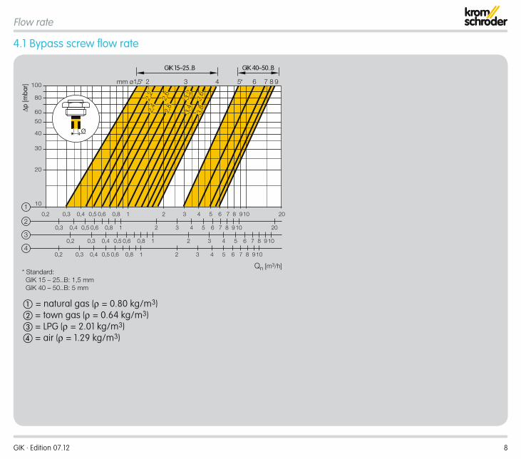
4 .1 Bypass screw flow rate
0,2 0,3 0,4 0,5 0,6 0,8 1 2 3 97
0,3 0,4 0,5 0,6 0,8 1 2 32
1
0,2 0,3 0,4 0,5 0,6 0,8 1 2 94
0,2 0,3 0,4 0,5 0,6 0,8 1
20
20
10
4 5 6 8 10
4 975 6 8 10
3 4 75 6 8 10
2 3 4 75 6 983
Qn [m3/h]
10
20
30
40
50
60
80
100
GIK 15–25 . .B GIK 40–50 . .B
1,5* 5* 6 7 8 942 3mm ø
2,2
2,6
2,8
3,2
3,4
3,6
3,8
ø
2,4∆p
[mba
r]
* Standard: GIK 15 – 25..B: 1,5 mm GIK 40 – 50..B: 5 mm
= natural gas (ρ = 0.80 kg/m3) = town gas (ρ = 0.64 kg/m3) = LPG (ρ = 2.01 kg/m3) = air (ρ = 1.29 kg/m3)
Flow rate

GIK · Edition 07.12 9
5 SelectionType R F 02 -5 -6 L BGIK 15 – –
GIK 20 – –
GIK 25 – –
GIK 40 – –
GIK 50 – –
GIK 65 – – –GIK 80 – – –GIK 100 – – –GIK 150 – – –
= standard, = availableOrder exampleGIK 40R02-5
5 .1 Type codeCode DescriptionGIK Air/gas ratio control15-150 Nominal sizeRF
Rp internal threadFlange to ISO 7005
02 pu max. 200 mbar-5-6
Pressure test point at the outletPressure test point at the inlet and outlet
L* For air only (without approval)B* Bypass screw
* If “none”, this letter is omitted.

GIK · Edition 07.12 10
6 Project planning informationThe gas inlet pressure pu must always be greater that the air control pressure pL + pressure loss ∆p to ensure that the air/gas ratio control is not overloaded.
6 .1 Installation
GIK
Installation position: spring dome pointing downwards.
> 20 mm
The air/gas ratio control GIK must not be in contact with ma-sonry. Minimum clearance 20 mm.Do not store or install the unit in the open air.
GIK
VAS..L
Safety valves must always be installed upstream of the air/gas ratio control GIK. For continuous control, we recommend using slow opening safety valves VAS..L.

GIK · Edition 07.12 11
7 Accessories7 .1 Conversion kit for zero pressure control
The conversion kit for zero pressure control is screwed in in-stead of the air impulse line.Order No.: GIK 15 – 50: 03351039, GIK 65 – 150: 74910853.
7 .2 Bypass screw GIK 15 – 25, variable
The bore hole diameter for the flow rate can be adjusted as desired and corresponds to holes of 1.5 – 4 mm, see page 8 (Bypass screw flow rate).Order No.: GIK 15 – 25: 74919806.
7 .3 Bypass screw, diameter to order
The bore hole diameter of the bypass screw is made to order.Order No.: GIK 15 – 25: 74919820, GIK 40 – 50: 74919821.

GIK · Edition 07.12 12
8 Technical dataGas types: natural gas, town gas, LPG (gaseous) and biologi-cally produced methane (max. 0.02 %-by-vol. H2S), GIK..L also for air. The medium must be dry in all temperature conditions and must not contain condensate.Air control pressure: 0.5 to 120 mbar.Outlet pressure: 0.2 to 119 mbar.Differential pressure between inlet area and outlet pres-sure: max. 100 mbar.Transmission ratio: 1:1.Control range: 1:10.Internal thread: Rp 1 to ISO 7-1.Flanged connection: PN 16 to ISO 7005.Bypass screw: brass.GIK 15 – 25: Standard: 1.5 mm, up to 4 mm possible.GIK 40 – 50: Standard: 5 mm, up to 9 mm possible.GIK 15 – 150:Housing: AlSi.Diaphragms: NBR.GIK 15 – 50:Adjusting range at low fire: -3 to +3 mbar.Connection for control line: Rp ¼.Ambient temperature: -20 to +60°C.Storage temperature: -20 to +40°C.Valve disc: plastic.Valve disc seal: NBR.
GIK 65 – 150:Adjusting range at low fire: -2 to +2 mbar.Connection for control line: Rp ½.Ambient temperature: -15 to +60°C.Storage temperature: -15 to +40°C.Valve disc: aluminium.Valve disc seal: vulcanized NBR seal.

GIK · Edition 07.12 13
Technical data
8 .1 Dimensions
H1
L
H2
∅ D
Rp 1/4
d2kD2
H2
∅ D
H1L
Rp 1/2
GIK 15-50 GIK 65-150
Type Dimensions pu max. Flange Drilling WeightL H1 H2 D
DN Connection mm mm mm mm mbar D2 k d2 No. kgGIK 15 15 Rp ½ 120 34 132 134 200 – – – – 1.0GIK 20 25 Rp ¾ 125 34 132 134 200 – – – – 1.1GIK 25 40 Rp 1 125 34 132 134 200 – – – – 1.1GIK 40 40 Rp 1½ 155 45 149 185 200 – – – – 1.8GIK 50 50 Rp 2 200 52 167 240 200 – – – – 2.8GIK 65 65 65 290 89 412 260 200 185 145 18 4 12.0GIK 80 80 80 310 100 446 310 200 200 160 18 8 16.1GIK 100 100 100 350 115 501 396 200 229 180 18 8 26.0GIK 150 150 150 480 150 573 520 200 285 240 22 8 46.5

GIK · Edition 07.12 14
9 Maintenance cyclesAt least once a year, twice a year in the case of biologically produced methane.

GIK · Edition 07.12
FeedbackFinally, we are offering you the opportunity to assess this “Technical Information (TI)” and to give us your opinion, so that we can improve our documents further and suit them to your needs.
ClarityFound information quicklySearched for a long timeDidn’t find informationWhat is missing?
ComprehensionCoherentToo complicatedNo answer
ScopeToo littleSufficientToo wideNo answer
No answer
NavigationI can find my way aroundI got “lost”No answer
UseTo get to know the productTo choose a productPlanningTo look for information
My scope of functionsTechnical departmentSalesNo answer
Remarks
(Adobe Reader 7 or higher required) www.adobe.com
Elster GmbH Postfach 2809 · 49018 Osnabrück Strotheweg 1 · 49504 Lotte (Büren) GermanyT +49 541 1214-0 F +49 541 1214-370 [email protected]
The current addresses of our international agents are available on the Internet:www.kromschroeder.de/index.php?id=718&L=1
We reserve the right to make technical modifications in the interests of progress.Copyright © 2012 Elster GmbH All rights reserved.
Contact
0325
1253
Contact
Feedback