Embed Size (px)
Citation preview
ENGINEER MANUAL
ENGINEERING AND DESIGN
Airfield Flexible, Pavement
Mobilization Construction
DEPARTMENT OF THE ARMYCORPS OF ENGINEERS
OFFICE OF THE CHIEF OF ENGINEERS
EM 1110-3-141April 1984

DEPARTMENT OF THE ARMY
EM 1110-3-141U .S. Army Corps of Engineers
DAEN-ECE-G
Washington, D.C. 20314
Engineer ManualNo . 1110-3-141
FOR THE COMMANDER:
Engineering and DesignAIRFIELD FLEXIBLE PAVEMENTMobilization Construction
1 . Purpose . This manual provides guidance for designing airfield flexiblepavement for U .S . Army mobilization facilities .
2 . Applicability. This manual is applicable to all field operatingactivities having mobilization construction responsibilities .
3 . Discussion . Criteria and standards presented herein apply to constructionconsidered crucial to a mobilization effort. These requirements may bealtered when necessary to satisfy special conditions on the basis of goodengineering practice consistent with the nature of the construction . Designand construction of mobilization facilities must be completed within 180 daysfrom the date notice to proceed is given with the projected life expectancy offive years . Hence, rapid construction of a facility should be reflected inits design . Time-consuming methods and procedures, normally preferred overquicker methods for better quality, should be de-emphasized . Lesser gradematerials should be substituted for higher grade materials when the lessergrade materials would provide satisfactory service and when use of highergrade materials would extend construction time. Work items not immediatelynecessary for the adequate functioning of the facility should be deferreduntil such time as they can be completed without delaying the mobilizationeffort .
PAUL F . VVANAUGHColonel, Corps of EngineersChief Staff
9 April 1984
Engineer ManualNo . 1110-3-141
DEPARTMENT OF THE ARMYUS Amy Corps of EngineersWashington, DC 20314
Engineering and DesignAIRFIELD FLEXIBLE PAVEMENTMobilization Construction
EM 1110-3-141
9 April 1984
Paragraph Page
CHAPTER 1 . INTRODUCTION
Purpose and scope . . . . . . . . 1-1 1-1Traffic classes . . . . . . . . . 1-2 1-1Definition . . . . . . . . . . . 1-3 1-1Use of flexible pavements . . . . 1-4 1-1
CHAPTER 2 . PRELIMINARY DESIGN DATA
Investigation . . . . . . . . . . 2-1 2-1Exploratory borings . . . . . . . 2-2 2-2Soil classification and tests . . 2-3 2-2Fill and subbase borrow areas . 2-4 2-6Availability of base and surfacing
aggregate . . . . . . . . . . 2-5 2-6Availability of other construction
materials . . . . . . . . . . . 2-6 2-6
CHAPTER 3 . SUBGRADE EVALUATION AND PREPARATION
General . . . . . . . . . . . . . 3-1 3-1Establishment of grade line . . . 3-2 3-1Subgrade evaluation test by CBR . 3-3 3-1Subgrade density and compaction . 3-4 3-1Subgrade stabilization . . . . . . 3-5 3-6Fill quality . . . . . . . . . . . 3-6 3-6
CHAPTER 4 . SUBBASE COURSE
General . . . . . . . . . . . . . 4-1Material source . . . . . . . . . 4-2 4-1Suitable materials . . . . . . . . 4-3° 4-1Additional requirements . . . . . 4-4
i4-3
CHAPTER 5 . BASE COURSE
General . . . . . . . . . . . . . 5-1 5-1Suitable materials . . . . . . . . 5-2 5-1Design CBR of base course . . . . 5-3 5-1
EM 1110-3-141g Apr 84
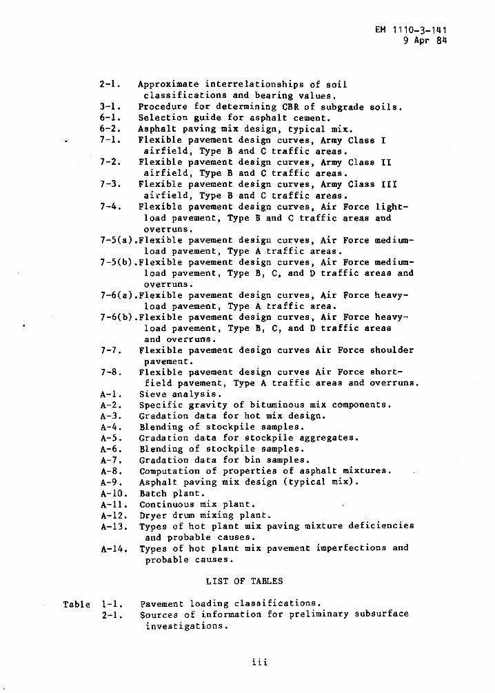
Figure 1-1 .
Typical flexible pavement and terminology .1-2 .
Typical all bituminous concrete pavement .1-3 .
Typical stabilized base section .
LIST OF FIGURES
Minimum base course and surface
Paragraph Page
thicknesses . . . . . . . . . . 5-4 5-1Base course gradation and tests . 5-5 5-1Base course compaction . . . . . . 5-6 5-4Proof rolling . . . . . . . . . . 5-7 5-4
CHAPTER 6 . BITUMINOUS MATERIALS COURSES
General . . . . . . . . . . . 6-1 6-1Selection of materials . . . 6-2 6-1Design of bituminous concrete mix 6-3 6-3Testing for mix design . . . . . . 6-4 6-6Thickness of bituminous courses . 6-5 6-10Bituminous spray coats . . . . . . 6-6 6-11
CHAPTER 7 . FLEXIBLE PAVEMENT THICKNESS DESIGN
General . . . . . . . . . . . 7-1 7-1Flexible pavement design curves . 7-2 7-1Design requirements . . . . . . . 7-3 7-1Thickness design . . . . . . . . . 7-4 7-1Design examples . . . . . . . . 7-5 7-13Stabilized pavement sections . . . 7-6 7-16Special areas . . . . . . . . . . 7-7 7-17
CHAPTER 8 . SPECIAL SURFACE TREATMENTS AND SPECIALDETAILS
General . . . . . . . . . . . . . 8-1 8-1Surface treatment for improved
skid resistance . . . . . . . . 8-2 8-1Porous friction surface course . . 8-3 8-1Prior preparation . . . . . . . . 8-4 8-1Fuel resistant surfacings . . . . 8-5 8-1Fuel resistant seal coat . . . . . 8-6 8-2Juncture between rigid andflexible pavements . . . . . . . .8-7 8-2
APPENDIX A . HO'r-MIX BITUMINOUS PAVEMENTS,DESIGN AND CONTROL A-1
APPENDIX B . REFERENCES B-1
2-1 .
Approximate interrelationships of soilclassifications and bearing values .
3-1 .
Procedure for determining CBR of subgrade soils .6-1 .
Selection guide for asphalt cement .6-2 .
Asphalt paving mix design, typical mix .7-1 .
Flexible pavement design curves, Army Class Iairfield, Type B and C traffic areas .
7-2 .
Flexible pavement design curves, Army Class IIairfield, Type B and C traffic areas .
7-3 .
Flexible pavement design curves, Army Class IIIairfield, Type Band C traffic areas .
7-4 .
Flexible pavement design curves, Air Force light-load pavement, Type B and C traffic areas andoverruns .
7-5(a) .Flexible pavement design curves, Air Force medium-load pavement, Type A traffic areas .
7-5(b) .Flexible pavement design curves, Air Force medium-load pavement, Type B, C, and D traffic areas andoverruns .
7-6(a) .Flexible pavement design curves, Air Force heavy-load pavement, Type A traffic area .
7-6(b) .Flexible pavement design curves, Air Force heavy-load pavement, Type B, C, and D traffic areasand overruns .
7-7 .
Flexible pavement design curves Air Force shoulderpavement .
7-8 .
Flexible pavement design curves Air Force short-field pavement, Type A traffic areas and overruns .
A-1 .
Sieve analysis .A-2 .
Specific gravity of bituminous mix components .A-3 .
Gradation da',ta for hot mix design .A-4 .
Blending of stockpile samples .A-5 .
Gradation data for stockpile aggregates .A-6 .
Blending of stockpile samples .A-7 .
Gradation data for bin samples .A-8 .
Computation of properties of asphalt mixtures .A-9 .
Asphalt paving mix design (typical mix) .A-10 . Batch plant .A-11 . Continuous mix plant .A-12 . Dryer drum mixing plant .A-13 . Types of hot plant mix paving mixture deficiencies
and probable causes .A-14 . Types of hot plant mix pavement imperfections and
probable causes .
LIST OF TABLES
Table 1-1 .
Pavement loading classifications .2-1 .
Sources of information for preliminary subsurfaceinvestigations .
EM 1110-3-1419 Apr 8b

EM 1110-3-1419 Apr 84
2-2 .
Minimum requirements for spacing and depth ofexploratory borings .
2-3 .
Soil characteristics pertinent to roads andairfields .
3-1 .
Primary factors affecting subgrade evaluation andsuitability .
3-2 .
Choice of C$R tests for pavement design .3-3 .
Subgrade compaction requirements .3-4 .
Compaction equipment and methods .`3-5 .
Special cases of subgrade treatment .4-1 .
Test methods for subbase and base .4-2 .
Maximum permissible values for unbound subbase .5-1 .
Base course materials for flexible pavements .5-2 .
Minimum surface and base thickness criteria .5-3 .
Gradation of aggregates for graded crushedaggregate base course .
6-1 .
Specialized terminology for bituminous pavement6-2 .
Tests for aggregate and bitumen mix .6-3 .
Specifications for bituminous materials .6-4 .
Aggregate gradations for bituminous concrete pave-ments .
6-5 .
Procedure for determining optimum bitumen contentand adequacy of mix for use with aggregate showingwater absorption of 2-1/2 percent or less .
7-1 .
Flexible pavement design curves .7-2 .
CBR flexible pavement design procedure .7-3 .
Equivalency factors .A-1 .
Design criteria for use with ASTM apparent specificgravity .
A-2 .
Design criteria for use with bulk impregnatedspecific gravity .
CHAPTER 1
INTRODUCTION
EM 1110-3-1419 Apr 84
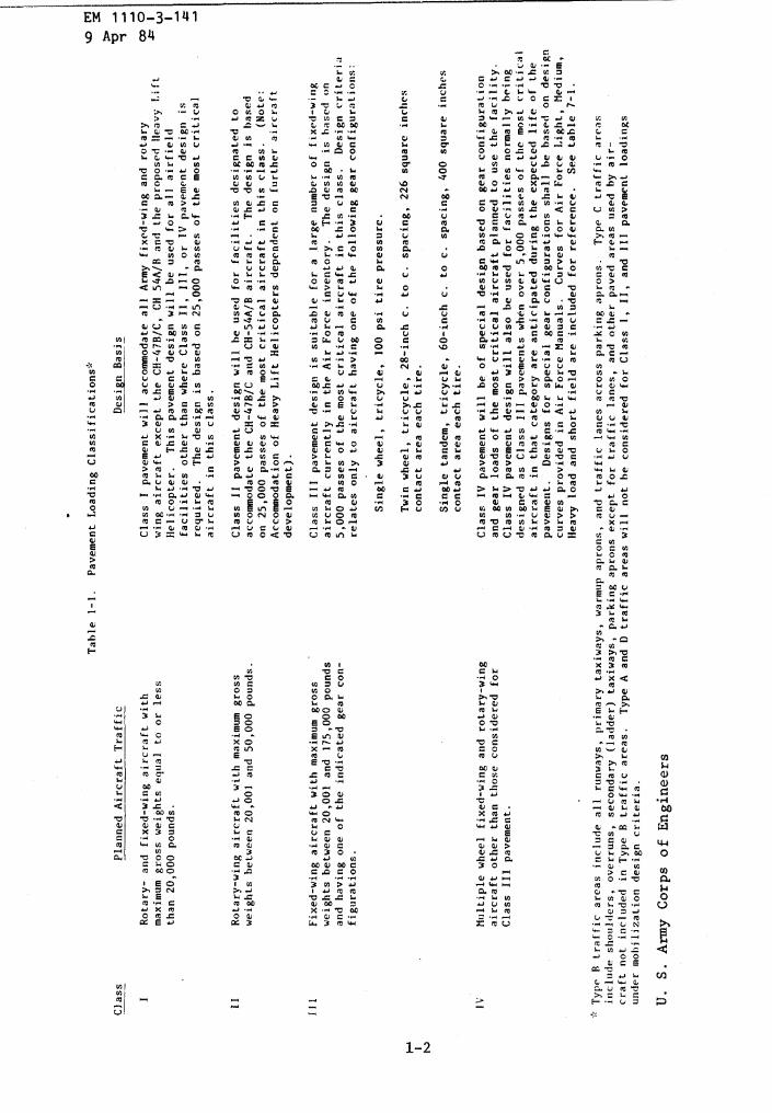
1-1 . Purpose and scope . This manual prescribes the standards to behsed for airfield flexible pavement design for mobilizationconstruction at Army installations .
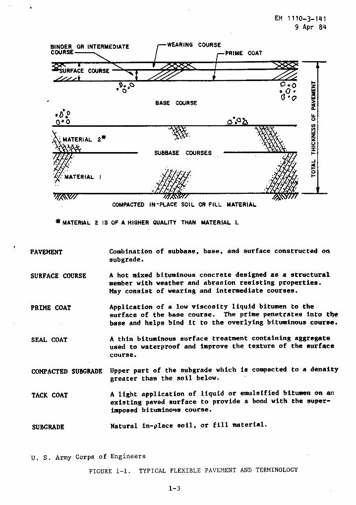
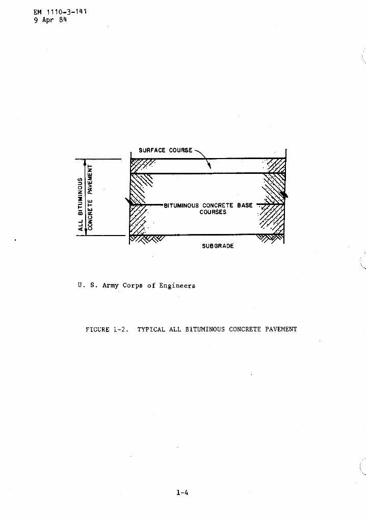
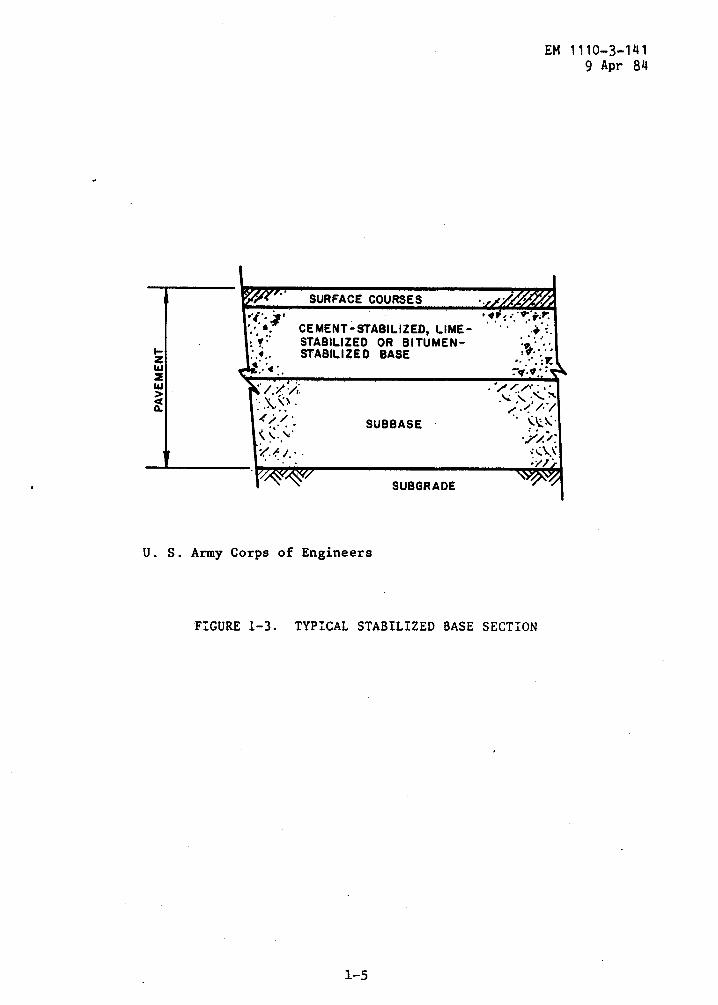
1-3 . Definition . Flexible pavements are so designated due to theirflexibility under load and their ability to withstand small degrees ofsettlement without serious detriment . The design of a flexiblepavement structure is based on the requirement to limit the deflectionsunder load and to reduce the stresses transmitted to the naturalsubsoil . The principal components of the pavement include a bituminousconcrete surface, a high-quality base course or stabilized material,and a subbase course . Figure 1-1 defines the components and theterminology used in flexible pavements . Examples of flexible pavementsutilizing stabilized layers are shown in figures 1-2 and 1-3 .
1-4 . Use of flexible pavements . The use of flexible pavements onairfields must be limited to those areas not subjected to detrimentaleffects of jet fuel spillage and jet blast . Asphalt surfacedpavements have little resistance to jet fuel spillage and jet blast,and their use is limited in areas where these effects are severe .Flexible pavements are generally satisfactory for runway interiors,taxiways, shoulders, and overruns . Special types of flexible pavement(that is, tar rubber) or rigid pavement should be specified in critica}operational areas .
1-2 . Traffic classes . Airfield pavement areas have been categorizedaccording to the weight of the using aircraft and the distribution ofthe traffic . Criteria for airfield pavement . classes are presented intable 1-1 .
Rota
ry-w
ing
aircraft
with
maxi
mum
gross
weights
between
20,001
and
50,0
00po
unds
.
Fixe
d-wi
ngai
rcra
ftwi
thma
ximu
mgross
weightsbetween
20,001
and
175,000
pounds
and
having
one
ofthe
indicate
dgear
con-
figu
rati
ons
.
Mult
iple
wheel
fixe
d-wi
ngand
rota
ry-w
ing
airc
raft
other
than
thos
econs
idered
for
Class
III
pavement
.
Type
Rtraffic
areas
include
all
runw
ays,
primary
taxiways,
warm
upap
rons
,and
traffic
lanes
across
park
ing
aprons
.Type
Ctraffic
areas
include
shoulders,
over
runs
,secondary
(lad
der)
taxiways,
parking
aprons
except
for
traffic
lanes,
andot
her
pavedar
eas
used
byair-
craf
tno
tin
clud
edin
Type
Btraffic
areas
.Ty
peA
and
Dtrafficar
eas
will
not
heconsidered
forCl
ass
l,II
,and
III
pavement
load
ing-
,un
dermo
bili
zati
ondesign
criteria
.
U.
S.Army
Corps
ofEn
gine
ers
required
.Th
edesign
isba
sed
on25,000
passes
ofthemost
critical
aircraft
inthis
class
.
Class
11pavement
design
will
heused
for
faci
liti
esdesignated
toac
comm
odat
eth
eCH-47B/C
and
CH-54A/B
aircraft
.The
design
isbased
on25,000
passes
ofth
emost
critical
aircraft
inthis
class
.(Note
:Ac
comm
odat
ion
ofHe
avy
Lift
Helicopters
dependent
onfu
rthe
raircraft
deve
lopm
ent)
.
Clas
sIl
lpavement
design
issuitable
for
alarge
number
offi
xed-
wing
aircraft
currently
inth
eAirFo
rce
inventory
.The
design
isba
sed
on5,
000
passes
ofth
emost
critical
aircraft
inthis
class
.Design
criteria
relates
only
toaircraft
having
one
ofth
efollowing
gear
configurations
:
Single
wheel,
tric
ycle
,10
0ps
itire
pressure
.
Twin
whee
l,tricyc
le,
28-i
nchc
.to
c.spacing,
226
square
inches
contact
area
each
tire
.
Single
tand
em,
tric
ycle
,60-inch
c.
toc
.spacing,
400
square
inches
contact
area
each
tire
.
Clas
sIV
pavement
will
beof
special
design
base
don
gear
configuration
andge
arloadsof
themost
critical
aircraft
planned
tous
eth
efacility
.Cl
ass
IVpavement
design
will
also
beused
for
faci
liti
esnormally
bein
gdesigned
asClass
IIIpavements
when
over
5,000
passes
ofth
emost
critical
aircraft
inthat
category
areanticipated
during
theexpected
life
ofth
epavement
.Designs
forspecial
gear
configurations
shall
beba
sedon
design
curves
provided
inAir
ForceMa
nual
s.
Curves
forAirFo
rce
Light,
Medium,
Heav
yload
andsh
ort
field
are
included
forreference
.See
table
7-1
.
PlannedAircraft
Traffic
Table
1-1
.Pavement
LoadingCl
assi
fica
tions*
Design
Basis
%oM 3
a b
Rotary-an
dfixed-wing
aircraft
with
Class
Ipavement
will
accommodate
all
Army
fixed-wing
and
rotary
p~O
maximum
gross
weights
equal
toor
less
wing
aircraft
except
theCH-47B/C,
CH54
A/B
and
the
proposed
Heavy
Lift
Wth
an20,000
pounds
.He
lico
pter
.This
pavement
design
will
beused
for
all
airfield
Ifacilities
other
than
whereCl
ass
11,
111,
orIV
pavement
design
ist
BINDER OR INTERMEDIATECOURSE
'SURFACE COURSE
.(S.0
1300
COMPACTED SUBGRADE
9~,0
-WEARING COURSEPRIME COAT
BASE COURSE
7COMPACTED IN-PLACE SOIL OR FILL MATERIAL
MATERIAL 2 IS OF A HIGHER QUALITY THAN MATERIAL I .
SUBGRADE
Natural in-place soil, or fill material .
EM 1110-3-1419 Apr 84
flopo Q
PAVEMENT
Combination of subbase, base, and surface constructed onsubgrade .
SURFACE COURSE
A hot mixed bituminous concrete designed as a structuralmember with weather and abrasion resisting properties .May consist of wearing and intermediate courses .
PRIME COAT
Application of a low viscosity liquid bitumen to thesurface of the base course . The prime penetrates into thebase and helps bind it to the overlying bituminous course .
SEAL COAT
A thin bituminous surface treatment containing aggregateused to waterproof . and improve the texture of the surfacecourse .
Upper part of the subgrade which is compacted to a densitygreater than the soil below .
TACK COAT
A light application of liquid or emulsified bitumen on anexisting paved surface to provide a bond with the super-imposed bituminous course .
U . S . Army Corps of Engineers
FIGURE 1-1 . TYPICAL FLEXIBLE PAVEMENT AND TERMINOLOGY
1-3
t-zWWQaO
WzYV
F-JHOH
EM 1110-3-1419 Apr 84
U . S . Army Corps of Engineers
FIGURE 1-2 . TYPICAL ALL BITUMINOUS CONCRETE PAVEMENT
HzWWa
SURFACE COURSES
.s ;v W
SUBBASE
U . S . Army Corps of Engineers
CEMENT-STABILIZED, LIME-STABILIZED OR BITUMEN-STABILIZED BASE
SUBGRADE
FIGURE 1- 3 . TYPICAL STABILIZED BASE SECTION
EM 1110-3-1419 Apr 84
CHAPTER 2
PRELIMINARY DESIGN DATA
EM 1110-3-1419 Apr 84
2-1 . Investigation . Before commencing with the design, completeinvestigations of the climatic conditions, topographicalconditions, subgrade conditions, borrow areas, disposal areas, andsources of subbase, base, paving aggregates, and other pavingmaterials of construction should be made .
a . Previous investigations . Previous subsurfaceinvestigations, pavement evaluation reports, construction records,and condition surveys from division, district, station files, andlocal paving agencies should be utilized to the maximum advantagepossible .
b . Publications . Publications and other information fromgovernmental agencies and professional societies as well as stateagencies that may define surface and subsurface conditions anddrainage patterns should be obtained . (See table 2-1) .
Table 2-1 . Sources of Information for Preliminary SubsurfaceInvestigations
Available Material
Source
Geologic maps ; topographic maps ; U .S . Geological Survey (USGS) .maps of surface material ; aerial See "USGS Index to Publica-photographs
tions," Superintendent of Documents, Washington, DC 20402
Soil maps ; reports ; aerial
U.S . Department of Agriculturephotographs
(USDA) . See "Bulletin 22-RTransportation Research Board"for listings
Aerial photographs ; topographic
National Oceanic and Atmosphericfeatures of coastal areas
Administration (formerlyU .S . C&GS), Rockville, MD 20852
Bulletins ; papers on geological
Geological Society of Americasubjects
(GSA) P .O . Box 1719, Boulder,CO 80302 . Consult index to GSA
c . Field reconnaissance . A field reconnaissance with theavailable topographical, geographical, and soil maps ; aerialphotographs ; meteorological data ; previous investigations ;condition surveys ; and pavement evaluation reports should be made .This step should precede an exploratory boring program .
EM 1110-3-1419 Apr 84
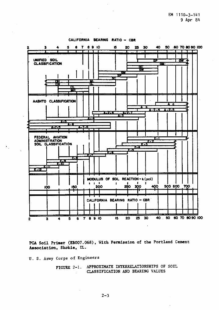
2-2 . Exploratory borings . Exploratory borings according to thespacings and depths given in table 2-2 should be conducted . These areminimum values and should be supplemented with additional or deeperborings to cover unusual features . See figure 2-land table 2-3 fortypical soil profiles and soil characteristics . Use figure 2-1 forapproximate relationships between soil classifications and soilstrength values when actual test results or existing information is notavailable .
Table 2-2 . Minimum Requirements for Spacing and Depth of`Exploratory Borings
Item
Spacing Requirements
Runways and taxiways less than
200 to 300 feet on center200 feet wide
longitudinally, onalternating sides of thecenterline
Runways 200 feet wide or ,
two borings every 200 to 300greater
feet longitudinally, oneboring 50 feet on each sideof the centerline
Parking aprons and pads
one boring per 10,000-square footarea
Item
Depth Requirements
Cut areas
to a minimum of 10 feet belowfinished grade
Shallow fill (areas where not
to a minimum of 10 feet belowmore than 6 feet of fill will
existing ground surfacebe placed)
High fill areas
to 50 feet below existingground surface or to rock
2-3 . Soil classification and tests .
a . Soil classification. All soils will be classified in accordancewith the Unified Soil Classification System . There have been instanceswhere the use in construction specifications of such terms as "loam,""gumbo mud," and "muck" have resulted in misunderstandings . Theseterms are not specific and are subject to different interpretationsthroughout the United States . Such terms will not be used unlessproperly identified . Sufficient investigations will be performed at aparticular site so that all soils to be used or removed duringconstruction can be described in accordance with the Unified Soil
2-2
CALIFORNIA BEARING RATIO - CBR
EM 1110-3-1419 Apr 84
PCA Soil Primer (EB007 .068), With Permission of the Portland CementAssociation, Skokie, IL.
U . S . Army Corps of Engineers
FIGURE 2-1 . APPROXIMATE INTERRELATIONSHIPS OF SOILCLASSIFICATION AND BEARING VALUES
2-3
Z 3 4 3 6 7 8 9 10 13 20 25 30 40 30 .60 70 80 90 li
,UNIFIED SOILCLASSIFICATION
id~til~F
AASHTO CLASSIFICATION
_d..Q . Emu_~ "FEDERAL AVIATION
ADMINISTRATIONSOIL CLASSIFICATION
( I I I I
100
I150
I MODULUS OF SOIL
200
REACTION-k(pci)
500 600 700
CALIFORNIA BEARING RATIO - CBR
2 3 4 5 6 7 8 9 10 16 20 25 30 40 . 80 60 70 8090 1

EN11
10-3
-141
gApr
84
TABLE
2-3
.So
ilCharacteristics
Pert
inen
tTo
Roadsand
Airfields
%te:
I.Column
3,dtst
.ton
ofM..
dSK
{twos
ln,a
asof
dsadu
<forroadssadalrrtrldlonto
.su
Wtvl
-ion
l.u'
baste
orA[["
,brr
.Itdta
:.arr1R
a(s
ass .
tau)
aulW
saes
uWn
the
It.1.u.1t
1.zn
er
adinn
pl..[Irty
mars
faser
t<..
:,n..afff.
aau
lI"<n".a
1,Mr
v1.,
.x.
t.cn1oWu,
,W
agatparntu.cod
.,titwoauy
prodw,
th,r,
"Ire
ddensities.1[11.
mink
numMr
ofv"
-.<s
ahem
-1-[e
rrrlnaui
.,ns
and
lnlrcn-a
.of
_,la
nce
Property
controlled
.
insome
twta
poes
,as
r.l
typesof
equlpaw,
as
tt.
rd~b,<su
.eva
riab
l"loll
rharar,eriaiirs
vlan
in.,g1v,nsi
tgrog
adyrpulte
differentwol=
.
Insame
I.-Is
.s
ewbtadtl-
oftoogprs
on,Mn«e
dry.
_rr«arses
bow1a
erla
l.an
dotWr
.-I.,w
er1.b
.stool-Meeled
stdrobber-[IrN
rollersa
-Mod
for
hard,
angu
lar-.-l.
ul,h
llat
adti,w
sen ,MS
.RWWr-dyad
raameMN
[tarse
tterw
«lal-
aubr
ert'
to"d",
radati-
.1b.
ilalahiad.
aaob
er-bradequlpret
is-=Z
11111.1-11
nRduring
find
ahaptnRopeueson.
lay
moat
.It.
aM
processedsa..
..I-
C-I.-
i
a0r~lrat
sire
.7M
(all
wpq.lsasof
ngli
tpm.
ntseae
cwwr
Yto
aawr,
the
high
*Pnsl[1<.
required
forarlleId
construrtl
.n
W
.ree
tr.etot--
totalwlaht
Ina
.1)0,000
lb.
farr-[1rN
isP"at
--wheel
load
toes
11of
15.000
lb.vheet
loansa1
nigh
as"O,.
towvM
n<.escarr
oub
esln
tbr_lrvd
a.natl
.xfarsawwterlals
(Weedm
contactpreswre
Of-.
pproslnstely
6Sto
ISOpan
.Sh
eeps
fpot
callsr
--I'll
peel""
(on6-
to12-a4-t-
foot)to
beIn"x
c
aof
750
p,isad
unit
pressuresas
AtRn
as115
11p.iv
n
acv
,",obtan
the
rpul
raddewltlas
tee
same
---list-
.7W
area
oftae
I,e,
ssho
utd
bea1
leastS
perc
ent
ntthetotal
D.rlvnru
:+r.a
tafr,n.s
drwins
,Wdt
awta
rad.wrad
totheraces
e(the
fast
.3.
Colo
r14
.mat
drywisnn
.reforce+artwwit
.roval..ounce'-to"
r1,"u-sto-611,wtnM
oloo.a
ssrasps;
[Inn
.(fascia
A.1'
coi.lu,
cadwaiv
oatentWtonW
mans
to.,
.fan
ofafritsld"
la,law.,
law-
.Il.i
l.db,
gr.d.1t..andvla"
itrl
tyc,paicesrnl..
(Tall.
v,MIL-,j;'
-61yg1r
12June
)gig)
-U.
S,ArmyCorps
ofEngineers
2-4
Sysbnl
rer~
el..
acr
rarf
lron
<ei
Perl
clan
[--
valu
easubarade
vslw
asS.M.-
valueu4as
P.1-1.1
Cespl...
Ibflity
:e1t
0- s+b
ona"
bd+I
o"
WhenW[
Subject
Xhen
Hat
Sub)
rct
Wwn
hot
Sub)
e<t
Frost
aad
Dral
na.e
WtsM
Xaer
Divisions
Letter
Matthias
Color
Sell
type
toFront
Actt
anoFrost
Acti
rn[o
FrostAatlon
ktton
Lzpanslan
Ghata ;
lerl.rlo
C-",tte.
Eq.lpsent
.ppar.o
([Ca.
1.i
(1)
(7)
(3)
(")
(s)
(br
(7)
Ip(91
(10)
(111
17.1
1111
,t.l
tIS~
i1sV
CIF
Well-gradeddrawls
orgr
avel
-wad
[lie
n"[
Eace
lle.
egood
MOM
tov<p
Almo
st-w
Fzcellent
Crwl
er-t
yp"
traccec,
ra"M
r-,ir<d
1:5-
Le_O-a0
)00-5110
3.1-ro,
litab
oran
it",
flan[
rell
"r."
rci-,A».La
ranr
rGr
4Is
Poorly
Sr.ded
travelsor
grav
el-w
adGood
to.-.Meet
Coed
Fair
togood
soar
toveryAI-
IGRAVEL
-mtstute.
,tittle
eran
it-
.llsht
roller,
.r
.",ire
r...
YRt
11111
Good
toeuellent
laud
fair
euvatr
(1111
rudada
Slight
.eat
s.Very
slig
htfait
topoor
tabb"r
-,ir
ra. <a
nrrai'e(.o
pal-
"."1
..,.
aIW
-Set
a
'.~
su,r
gr.wu
.gr
.-al-wad-au
.fatal"
reu"
r:.to..
.oily.
sorts
II 1If;
Coed
Rlr
tart
[owe
soluble
,.lc---'
.,_t
Slight
[o--
Sllz
ntPoor
,opt
artl"a
1lY
^-
_;:;;T-l,-,H
wdlir
Iprvlew
roll
erm
~rat,
eoAItSe-
/_~
CI.yerso
wn.d
rawl_'sad-clay
mlxcare.
land
ropy
ca-c
.-lt.bl-
Slig
htto
~fw
sligh
tPeer
l.,P-11-nr
twervi-s
g.bb,r-area"all-
.h, .PI-t
roll
erIu
,-1:
5:o_:
n:uo_SDu
GRAIXED
Vet
SOILS
3YWl
t-gr
aded
wads
orar
'wtlrsand',
Cool
Fall
enpled
I
Poor
Wee
toAt
".[
none
Etcs
ll"nt
Cra1
d"r-
tops
hart..
,rWMr-t
lrN
l10-
1b
:0-.
0:W
-.110
_little
oras
flora
slid
.[rutl"r
SrPeerl7
Rested
wad.
etrlravellysaadn,
h1r
togood
Fat,
Poor
tonot
.It,
bl.
Wne
tov"r
Alouat
man
Excellent
Crwier_r
",p<
trlc,er,
rabs
er-1
11"
.05_115
i0-.0
i50-aO0
SAID
little
orw
clew
slig
htro
ller
d'
Fair
togoof
Fair
togeed
Poor
sllt
ht1.
Vary
alig
htr.I,
topoor
aubb
rr-i
1rNre
liq,
sadrraloor
izo-115
ItIS
O-sW
Yaan
reli
es;<1ev
.ntr
nla(
r,iuo
SOILS
smSiltywads,
wad-silt
.iuucas
Fair--
Poor
tofair
--
hot
saltabrr
Slig
htto--
Slla
htto
sedlus--
Poor
t"P1-1-11v----
t-bb
,r_,
iara
.-M(oot
in-1w
u--
iW-t
eaI
hti
r.Inu .
,1111.,
x11
.y-y
wad..
.and-ct.y
mix[ar,.
P,a,r
[e1.1,
rapt
X�1..-hl,
slig
htto
Sush
im
meat
,.rpm,
1.W6Wr_[IrW
cell
ar.
.h.,v.r.
,.�iW_In
s_:o
-IOO_w1~
hlan
lyer
vlw.p:-ity
your
,
3aInurtanie
it,.
ad-
if-
..ad.,
tort
Poor
tofair
Net
sale
abl.
We
.att
.bl<
74d1,r
[elu
sh,
tont
at,-
Far
top-r
a1bM
.-fir<a
,eti
<,."M
" P"fe.
.,Wi_I
IeIs
.,1uv
-:oo
SILTS
deer
..(Ic
yor
riser
ttaswad
s1r
v err
high
rour
r:
,roar<e
atr1l
e(pol.
ierr
rall
y
AND
clayey
sofa
.1,b
slight
plasticity
miwcpattsly.
Oftooto
ardlad
plastic-
Poor
tofair
hotsu
u.bt,
hot..tt.bl.
aad1,.
[nWar,.
rr.<ur
.uv
aabb
ar-t
ires
call
s,.M<v
"i-t
Of1_I
lit11
Dun
LLltr.
RrwW
n+yn,
allayclaw
.alts
high
Says
-IS
LESS
tine,
lea.
clay.
rim-
711113
1s0
OL,
'-"~
Orpnir
..t.
.ld
orga
nic
lilt
-nay
sof
Pops
slol
1.Il.bl.
Xul
.u1l.ble
Xadtu.
to"edion
tohigh
Peer
aabMr-etredco
rky,
.h....f-
lwl
_w5
5..r
_.On
uAlpgn
Iuvpla.
,lrur
nigh
reue
r1"..
SOILS
SILTS
7x3
r1w"'°
tits
al-s
ons.radiant.
nracer
hot
.attab(,-
X .,t
wlc.
bl,
::dl-
"ISh
calm
",pear
rdslp "alo�
1.11-
-bb"
r-,1.rd
AI-1
01,rsrr
su_I
mY
rrt(tn
CHIeoraa'Itclay'
ofhigh
Pran
tlcl
tv.fat
reps
tofat,
u.t
..hall
.got
..tlabl,
Xedl-
Xt,h
rr.r
tl<an
sM
.r"f-,
yens
,.
,nob
ly-,
ir,a
vn_I
nIs
�sn
_ISu
cuYSu.
-vt. ..
,1ll
,ri<..
IsGga7u
O11
Org.
n1<
cl.r.
.f-Ins
tohigh
P-r
tovery
pony
Sot
-ultahl,
flatsalubie
X,dias
X1ah
vurt
lral
lyX.....
:...-11--11.r_,:,n:
eO-1
1e.,
-uq
TW
soPl
ntletty,
orpoll
lit .
Ispenl-1
reli
es
11uxLr
aeA111esotLS
PtS
.am
athathighly
arpnic
.1111
IXo[-11.
bt.
not.altabl"
I.w,1.a
t.bt.
1.I.
h,r,rY
nigh
Fat,
r."P
enn
eap.
c,t.
.ee,
.,Pr
a-I-
t_
EM 1110-3-1419 Apr 84
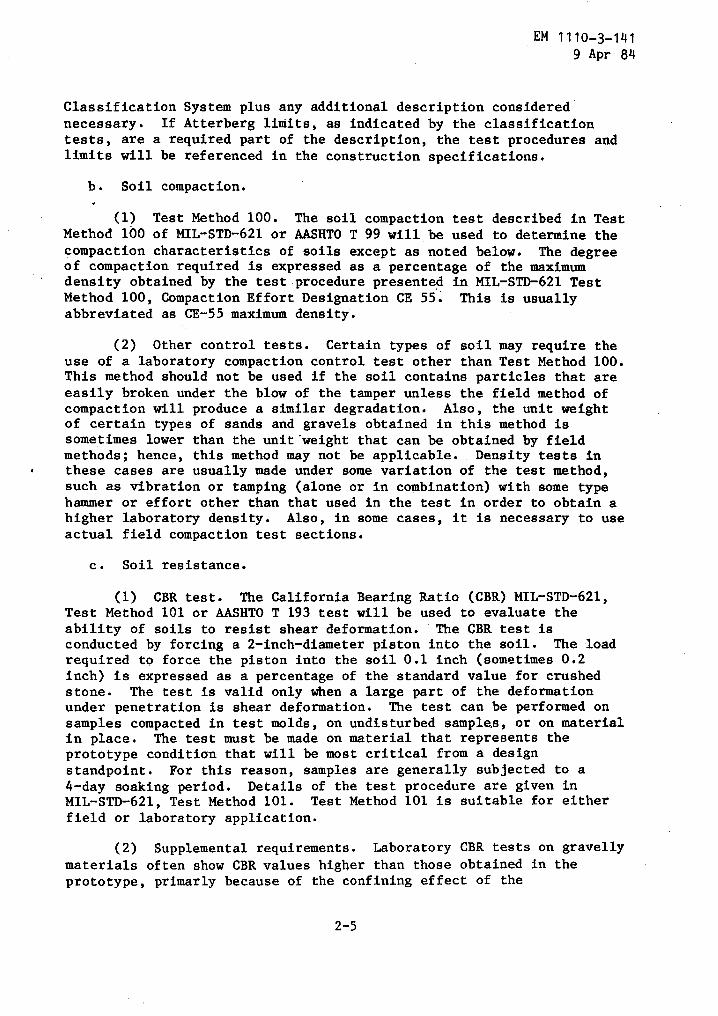
Classification System plus any additional description considerednecessary . If Atterberg limits, as indicated by the classificationtests, are a required part of the description, the test procedures andlimits will be referenced in the construction specifications .
b . Soil compaction .
(1) Test Method 100 . The soil compaction test described in TestMethod 100 of MIL-STD-621 or AASHTO T 99 will be used to determine thecompaction characteristics of soils except as noted below . The degreeof compaction required is expressed as a percentage of the maximumdensity obtained by the test procedure presented in MIL-STD-621 TestMethod 100, Compaction Effort Designation CE 55 . This is usuallyabbreviated as CE-55 maximum density.
(2) Other control tests . Certain types of soil may require theuse of a laboratory compaction control test other than Test Method 100 .This method should not be used if the soil contains particles that areeasily broken under the blow of the tamper unless the field method ofcompaction will produce a similar degradation . Also, the unit weightof certain types of sands and gravels obtained in this method issometimes lower than the unit'weight that can be obtained by fieldmethods ; hence, this method may not be applicable . . Density tests inthese cases are usually made under some variation of the test method,such as vibration or tamping (alone or in combination) with some typehammer or effort other than that used in the test in order to obtain ahigher laboratory density . Also, in some cases, it is necessary to useactual field compaction test sections .
c . Soil resistance .
(1) CBR test . The California Bearing Ratio (CBR) MIL-STD-621,Test Method 101 or AASHTO T 193 test will be used to evaluate theability of soils to resist shear deformation . The CBR test isconducted by forcing a 2-inch-diameter piston into the soil . The loadrequired to force the piston into the soil 0 .1 inch (sometimes 0.2inch) is expressed as a percentage of the standard value for crushedstone . The test is valid only when a large part of the deformationunder penetration is shear deformation . The test can be performed onsamples compacted in test molds, on undisturbed samplers, or on materialin place .
The test must be made on material that represents theprototype condition that will be most critical from a designstandpoint . For this reason, samples are generally subjected to a4-day soaking period . Details of the test procedure are given inMIL-STD-621, Test Method 101 . Test Method 101 is suitable for eitherfield or laboratory application .
(2) Supplemental requirements . Laboratory CBR tests on gravellymaterials often show CBR values higher than those obtained in theprototype, primarly because of the confining effect of the
2-5
EM 1110-3-1419 Apr 84
6-inch-diameter mold . Therefore the CBR test has been supplemented bygradation and Atterberg limit requirements for gravelly materials .
d . Approximate relationships . Use figure 2-1 for approximaterelationships between soil classifications and soil strength valueswhen actual test results or existing information are not available .
2-4 . Fill and subbase borrow areas . During reconnaissance, the sitewill be explored for potential borrow sources . See table 2-3 forcomparative values of soils for use as subgrade and subbase ; use fieldapproximations of classifications as a guide,to desirable sources .During preliminary exploration, samples of borrow materials will betaken to a depth of 2 to 4 feet below the anticipated depth of borrowon 50-foot centers . Surveys of local suppliers to determine thequality and quantity of commercially available fill materials will bemade .
2-5 . Availability of base and surfacing aggregate . Since these aregenerally crushed and processed materials, a survey should be made ofthe commercial suppliers in the general area . Available materialsshould be sampled, classified, and tested . In remote areas wherecommercial production is limited or nonexistent, investigate and testfor quarry site location near the construction site .
2-6 . Availability of other construction materials . Availability andquality of bituminous materials can be sought from the suppliers ofthese materials . The knowledge of the availability and type ofportland cement, lime, fly ash, and other materials will also aid inthe evaluation and applicability of structural layers . Thisinformation will be helpful in developing designs and alertingdesigners to unusual local conditions and shortages .
CHAPTER 3
SUBGRADE EVALUATION AND PREPARATION
EM 1110-3-1419 Apr 84
3-1 . General . The primary factors affecting subgrade suitability arelisted in table 3-1 .
3-2 . Establishment of grade line . The subgrade line should beestablished to obtain the optimum natural support for the pavementconsistent with economic utilization of available materials .
a . Rock . Rock excavation is to be avoided for economic reasons .Where excavation of rock is unavoidable, undercut to provide for fulldepth of base course under surface courses .
b . Ground water . The subgrade line will be above the flood plainand a minimum of 2 feet above wet season ground water level . Where notpracticable, provide for permanent lowering of water table by drainage .(See EM 1110-3-136) .
c . Balancing cut and fill . Balancing cut and fill should beconsidered but may not be a controlling mobilization factor in thedesign and construction of airfield pavements . Optimizing subgradesupport and drainage should take precedence over balancing cut andfill .
3-3 . Subgrade evaluation test by CBR . The basic CBR test is performedon compacted samples of the subgrade soil after a 4-day soaking .Samples are prepared at varying moisture contents and with threediffering compactive efforts . The complete procedure is illustrated infigure 3-1and the test methods are described fully in MIL-STD-621,Method 101 . CBR tests can also be performed on the subgrade soil inplace or on undisturbed samples of the subgrade soil . However, fordesign the latter test is used only in special cases . See table 3-2for additional guidance on the use of CBR tests .
3-4 .
Subgrade density and compaction .
For the CBR method of design,the in-place densities of the subgrade soils for the design aircraftmust be at least equal to the values specified in table 3-3 . Ifnatural densities are less than the required values, the subgrade maybe treated by one of the following procedures, as applicable :
- Compact from the surface (cohesionless soils except silts) .
Remove, process to desired water content, replace in lifts, andcompact . Minimum compaction for replaced soils is 95 percent forcohesionless and 90 percent for cohesive soils . For a definitionof cohesive and cohesionless soils see MIL-STD-621, Method 101 .

EM 1110-3-1419 Apr 84
Table 3-1 . Primary Factors Affecting Subgrade Evaluation andSuitability
Factor
Remarks
Characteristics o£ subgrade soils
Determine as shown inchapter 2 .
Relative value as subgrade
See table 2-3 .
Depth, to rock
Determine duringexploration of subgrade,if close to surface.
Depth to ground water
Determine seasonalfluctuations and effectsof drainage .
In-place density of subgrade
From undisturbed samplesor in-place tests .
Strength of subgrade :
Natural Condition
Determine during explorationAfter compaction
and testing. ConsiderUltimate values
ultimate water contentsafter construction and theireffect on strengthcharacteristics . Followprocedure in MIL-STD-621Method 101 .
Settlement under fill loading
Determine effect of fillloading from consolidationtests . May requiresurcharge to consolidate aclay subgrade . Wherelocal settlement dataexists it should be used .
Frost susceptibility
See EM 1110-3-138 to deter-mine during testing andexploration .
Weak or compressive layers in sub-
Consider compaction, removalsoil
and replacement withgranular material, or designpavement on basis of in-place strength and density .
Drainage
See EM 1110-3-136 .
Variability of generalized soil
May cause differentialprofile
surface movements .
U . S . Army Corps o'f Engineers
3-2
zf 30
20
10
0
120
115(L
110
105z
50
40
100
95
° 905
10
15
20
25
95
100
105
110
115
120MOLDING WATER CONTENT IN %DRY WEIGHT
MOLDED DRY DENSITY IN POUNDS PER CUBIC FEETA
C
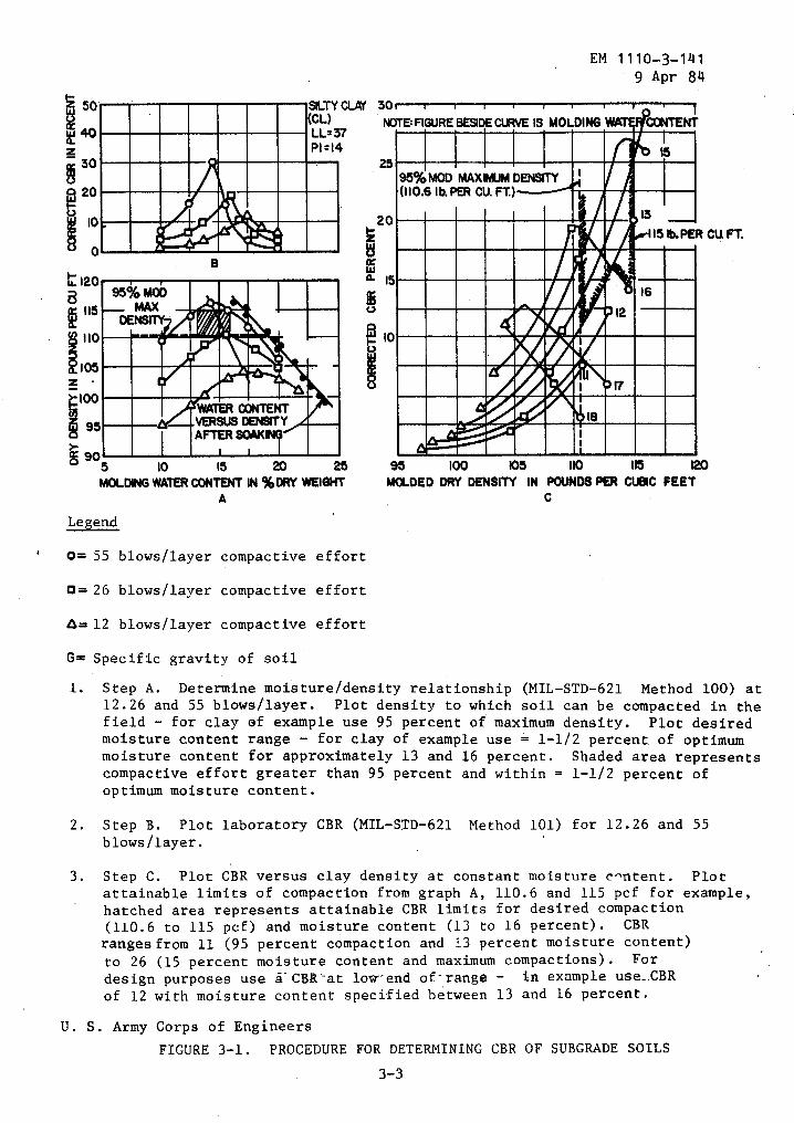
Legend
0= 55 blows/layer compactive effort
O = 26 blows/layer compactive effort
&= 12 blows/layer compactive effort
G= Specific gravity of soil
U . S . Army Corps of Engineers
SILTY CLAY 30,(CL)
NOTE: FIGURE BESIDE CURVE IS MOLDINGLL=37
X20zis15°- 15
10
EM 1110-3-1419 Apr 84
95°J6MOD MAXMIUM DENSIT`r ~(110 .6 IbPER CU. FT.)=
.
16
l . Step A . Determine moisture/density relationship (MIL-STD-621 Method 100) at12 .26 and 55 blows/layer . Plot density to which soil can be compacted in thefield - for clay of example use 95 percent of maximum density .
Plot desiredmoisture content range - for clay of example use = 1-1/2 percent of optimummoisture content for approximately 13 and 16 percent . Shaded area representscompactive effort greater than 95 percent and within = 1-1/2 percent ofoptimum moisture content .
2 . Step B . Plot laboratory CBR (MIL-STD-621 Method 101) for 12 .26 and 55blows/layer .
3 . Step C . Plot CBR versus clay density at constant moisture c-ntent . Plotattainable limits of compaction from graph A, 110 .6 and 115 pcf for example,hatched area represents attainable CBR limits for desired compaction(110 .6 to 115 pcf) and moisture content (13 to 16 percent) . CBRranges from 11 (95 percent compaction and 13 percent moisture content)to 26 (15 percent moisture content and maximum compactions) . Fordesign purposes use a - CBR -at low-- end of - range - in example use_.CBRof 12 with moisture content specified between 13 and 16 percent .
FIGURE 3-1 . PROCEDURE FOR DETERMINING CBR OF SUBGRADE SOILS
3-3
CONTENT
EM 1110-3-1419 Apr 84
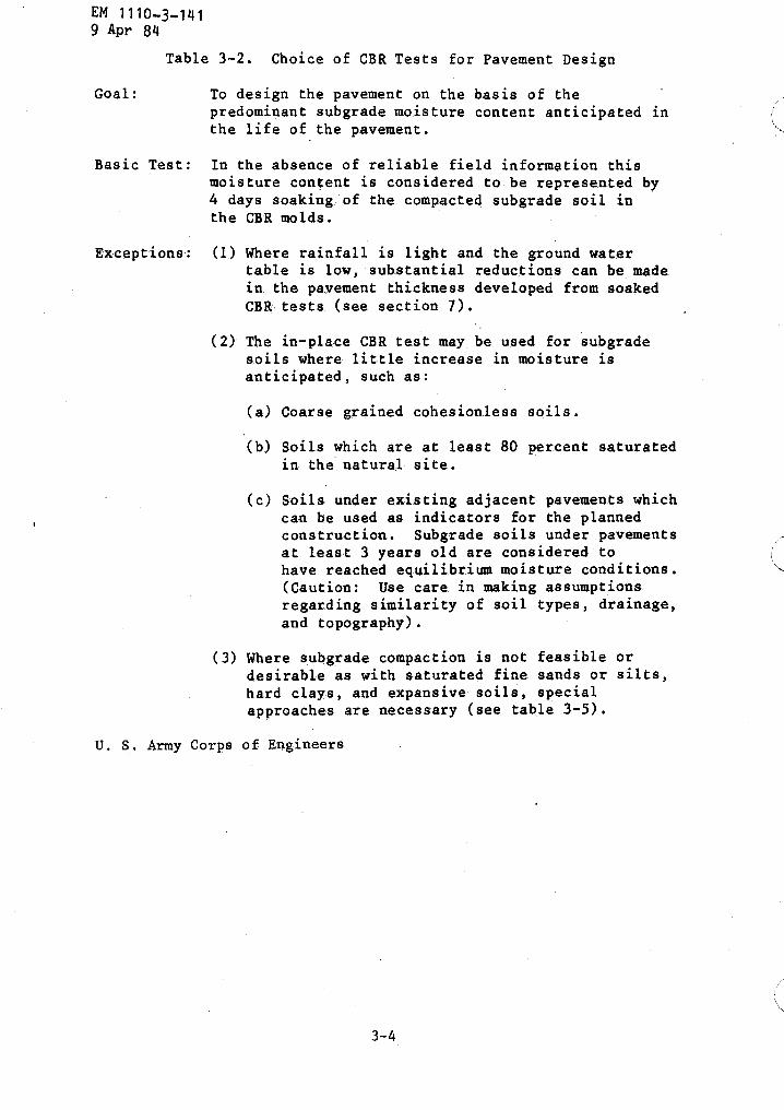
Table 3-2 . Choice of CBR Tests for Pavement Design
Goal :
To design the pavement on the basis of thepredominant subgrade moisture content anticipated inthe life of the pavement .
Basic Test : In the absence of reliable field information thismoisture content is considered to be represented by4 days soaking of the compacted subgrade soil inthe CBR molds .
Exceptions :
(1) Where rainfall is light and the ground watertable is low, substantial reductions can be madein the pavement thickness developed from soakedCBR tests (see section 7) .
(2) The in-place CBR test may, be used for subgradesoils where little increase in moisture isanticipated, such as :
U . S . Army Corps of Engineers
(a) Coarse grained cohesionless soils .
(b) Soils which are at least 80 percent saturatedin the natural site .
(c) Soils- under existing adjacent pavements whichcan be used as indicators for the plannedconstruction . Subgrade soils under pavementsat least 3 years old are considered tohave reached equilibrium moisture conditions .(Caution : Use care in making assumptionsregarding similarity of soil types, drainage,and topography) .
(3) Where subgrade compaction is not feasible ordesirable . as with saturated fine sands or silts,hard clays, and expansive soils, specialapproaches are necessary (see table 3-5) .
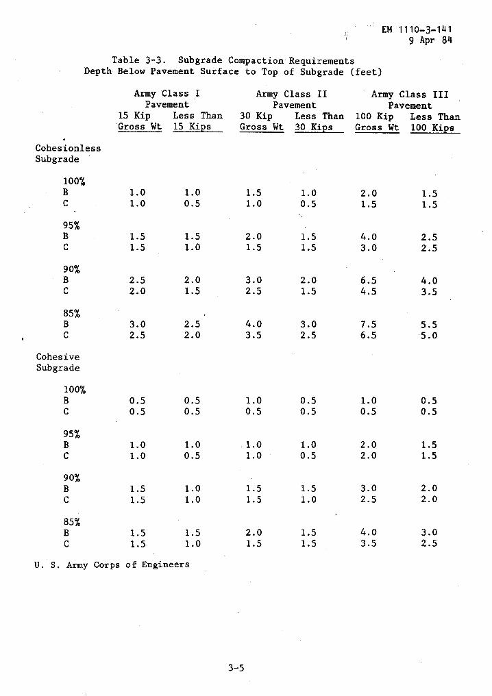
Table 3-3 . Subgrade Compaction RequirementsDepth Below Pavement Surface to Top of Subgrade (feet)
EM 1110-3-1419 Apr 84
U . S . Army Corps of Engineers
CohesionlessSubgrade
Army
15 KipGross Wt
Class _IPavement
Less Than15 Kips
Army
30 KipGross Wt
Class IIPavement
Less Than30 Kips
Army
100 KipGross Wt
Class IIIPavement
Less Than100 Kips
100%B 1 .0 1 .0 1 .5 1 .0 2 .0 1 .5C 1 .0 0 .5 1 .0 0 .5 1 .5 1 .5
95%B 1 .5 1 .5 2 .0 1 .5 4 .0 2 .5C 1 .5 1 .0 1 .5 1 .5 3 .0 2 .5
90%B 2 .5 2 .0 3 .0 2 .0 6 .5 4 .0C 2 .0 1 .5 2 .5 1 .5 4 .5 3 .5
85%B 3 .0 2 .5 4 .0 3 .0 7 .5 5 .5C 2 .5 2 .0 3 .5 2 .5 6 .5 5 .0
CohesiveSubgrade
100%B 0 .5 0 .5 1 .0 0 .5 1 .0 0 .5C 0 .5 0 .5 0 .5 0 .5 0 .5 0 .5
95%B 1 .0 1 .0 1 .0 1 .0 2 .0 1 .5C 1 .0 0 .5 1 .0 0 .5 2 .0 1 .5
90%B 1 .5 1 .0 1 .5 1 .5 3 .0 2 .0C 1 .5 1 .0 1 .5 1 .0 2 .5 2 .0
85%B 1 .5 1 .5 2 .0 1 .5 4 .0 3 .0C 1 .5 1 .0 1 .5 1 .5 3 .5 2 .5
EM 1110-3-1419 Apr 84
- Replace with suitable borrow material .
- Raise the grade so that natural densities meet required values .
- Stabilize : See EM 1110-3-137 .
Thickness of compacted lifts can vary with type-of equipment used,classification of soil, number of passes, and compaction requirements .Guidelines for varying thicknesses of lifts for 95 to 100 percentcompaction are shown in table 3-4 .
a . Additional requirements . In addition to the above requirements :
(1) Compact subgrad'e to a minimum of 95 percent for a depth of 6inches below subbase .
(2) Place fill in subgrades at a minimum of 95 percentcompaction for cohesionless soils and 90 percent for cohesive soils .
b . Special cases . Although compaction increases the strength ofmost soils, some soils lose strength when scarified and recompacted andsome soils shrink or expand excessively under moisture changes . Whenthese soils are encountered, special treatment is required . (See table3-5 for recommended procedures .)
3-5 . Subgrade stabilization . Subgrade material may be stabilized (a)to improve the soil quality by reducing plasticity and controllingexpansion, (b) to provide a "working platform," and (c) to upgrade thematerial for use as subbase . Soil stabilization for qualityimprovement is discussed in EM 1110-3-137 .
3-6 . Fill quality . In general, coarse grain material is preferred tofine grain material . Fill material should be restricted as follows :
- Do not use expansive soils .
- Do not use peat or organic clays and silts .

~uipme
.ntqpe
Sheepsfoot
rollers
Rubb
erti
rerollers
Smooth
wheel
roll
ers
vibrating
baseplete
compactors
Crawler
trac
tor
Power
tamp,,
ror
ream
er
For
clea
n,coar
se-g
rain
edsoils
with
4to
8pe
rcen
tpa
ssin
gthe
No.
2110
siev
e.
For
fine-grained
soils
orwell-graded,
dirt
yco
arse
-grained
soilswi
thmo
reth
an8
percent
pass
ing
the
No.20
0siev
e.
Appropriate
for
subg
rade
orba
seco
urse
comp
acti
onof
well-graded
sand
-gra
vel
mixtures
.
May
beused
for
fine-
grained
soils
othe
rthan
inearth
dams
.Not
suitable
for
clean
well-g
rade
dsands
orsilty
unifor
msa
nds
.
For
coarse-grain
edso
ils
with
less
than
abou
t12
perc
ent
passing
No.200
sieve
.Be
atsu
ited
for
materials
with
4to
8pe
rcen
tpaxeing
No.200,
plac
e,!thorough
lywet
.
Best
suit
edfo
rco
arse
-gr
aine
dsoils
with
less
then
4to
Rpe
rcent
pass
inggo
.700
sieve,
pla-d
thorough
lywet
.
For
difficult
acce
ss,
trench
back
fill
.Su
itab
lefo
rall
inor
ganic
soil
s.
U.S
.Army
Corp
sof
Engi
neer
s
ty
10
6to8
8to
12
6toa
8to
10
10to
12
Effi
cien
tco
mpac
tion
ofso
ils
wet
ofop
timu
mrequires
less
contact
pres-
sure
sthan
the
same
soil
sat
lowe
rmo
istu
reco
nten
ts
3to
5co
vera
ges
Tire
infl
atio
npressure
sof
60to
NOpsi
for
clea
ngranular
material
orba
seco
urse
and
subgrade
compaction
.Wh
eat
load
18,000
to25,000
lb.
4to
6co
vera
ges
Tire
inflation
pressure
sIn
excess
of65
psi
for
fine
-gra
ined
soil
sof
high
plas
tici
ty.
For
unif
orm
clea
nsa
nds
orsi
lty
fine
sands,
use
larg
esize
tire
@wi
thpressure
of40
to50
psi
.
4co
vera
ges
Tand
emtype
roll
ers
for
base
.course
orsubgrade
compaction,
10to
15to
nwe
ight
,300
to500
lbpe
rli
neal
inch
ofwi
dth
ofrear
roll
er.
6co
vera
ges
3-wheel
roller
for
compaction
of-
fine
-gra
ined
soil
;we
ights
from
Sto
6tons
for
mate
rial
sof
low
plasticity
to10
tone
for
mate
rials
ofhigh
plas
tici
ty.
3co
vera
ges
Sing
lepads
orplates
shou
ldwe
igh
noless
than
200
lb.
May
beused
inta
ndem
wher
ewo
rkin
gsp
ace
isavail
able
.For
clea
nco
erse
-gra
ined
,noi
l,vi
brat
ion
frequency
shou
ldbe
noless
than
1,60
0cycles
per
minute
.
3to
4co
vera
gea
Nosmaller
than
D8trac
tor
with
blade,
34,500
lhwe
ight,
for
high
comp
acti
on.
4to
6in
.for
2coverages
30-l
bmi
nimu
mwe
ight
.Considerable
silt
orcl
ay,
rang
eis
tole
rabl
e,de
pending
on6
in.forco
arse
-
mate
rial
sand
conditions,
grai
ned
soil
s.
Possible
variations
._.-_
.._
ineg
niemo_nt--
For
airfield
work
,drum
of60
-in
die
.,lo
aded
to1.5
to3
tons
per
line
alfoot
ofdrum
generally
isuti-
lised
.Fo
rsmaller
proj
-ects
40-indie
.dr
um,
load
edto
0.7
5to
1.75
tons
per
line
alfoot
ofdrum
isused
.Foot
contact
pres
-sure
shou
ldbe
regulated
soas
toav
oid
shearing
soil
onth
ethird
orfo
urth
pass
.
wide
variety
ofrubber
tire
comp
acti
onequipment
inavailable
.Fo
rcohesive
soil
s,light-wheel
load
s,such
asprovided
bywo
bble
-wh
eel
equipment,
maybe
subs
titu
ted
forheavy-wheel
load
iflift
thickness
isdecreased
.Forcohesion-
less
soil
s,large-size
tire
@ar
edesirable
toav
oid
shea
ran
dru
ttin
g.
3-wheel
rollers
obtainable
inwide
rang
eof
size
s.
2-wheel
tandem
rollers
are
available
inthe
rang
eof
1to
20to
nwe
ight
.3-
axle
tandem
rollers
are
general-
tyused
inth
era
nge
of10
to20
tooweight
.Very
heav
yro
ller
sar
eused
for
proo
frollingof
subgrade
orbase
course
.
Vibratingpads
orpl
ates
are
avai
labl
e,ha
nd-
propelled
orself-
prop
elle
d,si
ngle
orin
gang
s,with
widt
hof
cover-
age
from
1-1/
2to
15ft
.Various
type
sof
vibrating-
drum
equipment
shou
ldbe
cons
ider
edfor
compaction
inlarge
area
s.
Tractor
weights
upto
60,000
lb.
Weights
up'to
250
lb,
foot
diameter
4to
10in
.
Tabl
e3-4
.Co
mpac
tion
Equi
pmen
tand
Meth
ods
Requ
ireme
nts
for
of95
to100
AASR
TOMaxi
mum_
_Dens
Compacted
Comp
a_c_tion
Perc
ent__Modi
fied
lift
Passes
Aeplicabil
ijY
thick
ness
,in
.or
cove
ragea
-Dim
ensi
ons
and
weig
htof
equipment
For
fine-grained
soil
s6
Foot
Foot
ordirty
coarse
-Bra
ined
cont
act
contact
soils
with
more
then
20ar
ea,
in2
pressures,
percent
pass
ing
the
No.
Soil
tTpe
-~
i20
0sieve
.No
tsu
itab
le4
to6
passes
Fine
-gra
ined
5to
1225
0to
500
for
clean
coarse
-gra
ined
for
fine
-gra
ined
soil
P1>
30soils
.soil
;6
to8
Fine
-gra
ined
7to
1420
0to
400
passes
for
soil
PIC
30co
arse
-gra
ined
Coar
se-g
rain
ed10
to14
150
to25
0soil
soil
Soil
Type
Stif
f,pr
econ
soli
date
dclays
Silts
andvery
fine
sands
Expa
nsiv
esoils
U.S
.Army
Corps
ofEngineersTa
ble
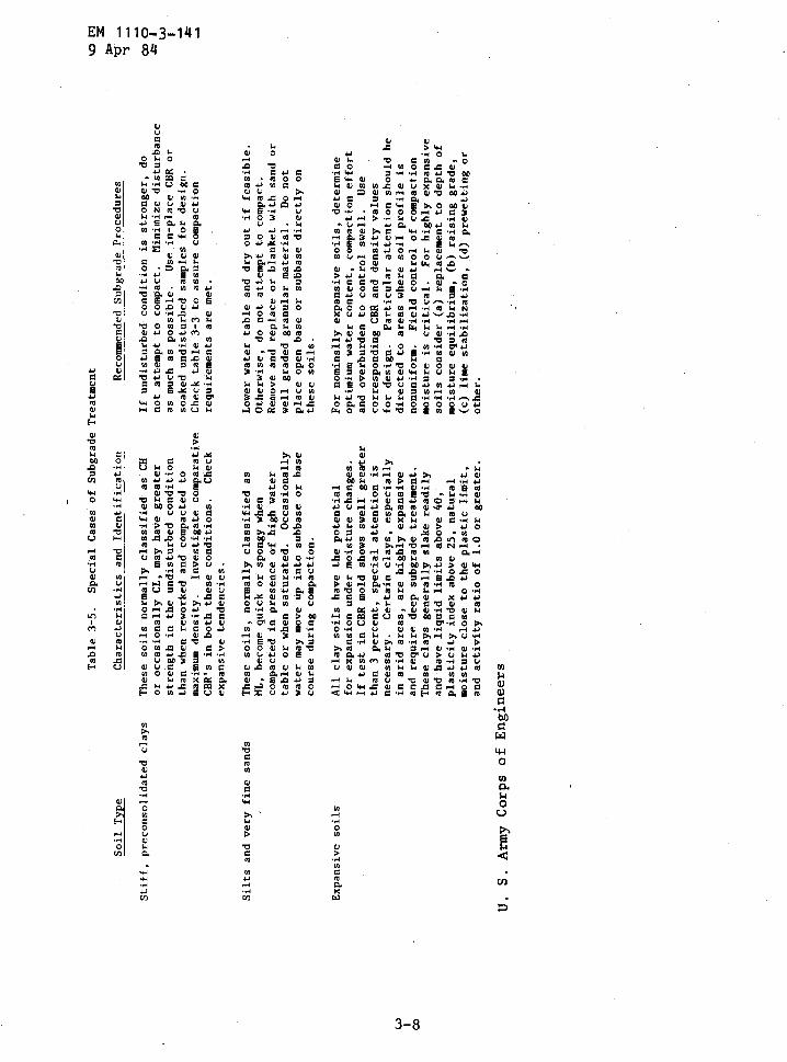
3-5
.Sp
ecia
lCasesof
Subgrade
Treatment
Characteristics
and
Identification
Thes
esoils
normally
classified
asCH
oroccasionally
CL,ma
yhave
grea
ter
strength
inthe
undi
stur
bed
condition
than
when
reworked
andco
mpac
tedto
maxi
mum
density
.In
vest
igat
eco
mpar
ativ
eCB
R's
inboth
these
conditions
.Ch
eck
expansive
tendencies
.
Thes
esoils,
norm
ally
classified
asML
,become
quic
kor
spongy
when
compacted
inpresence
ofhi
ghwa
ter
tabl
eor
when
saturated
.Oc
casi
onal
lywa
termaymove
upinto
subbaseor
base
course
during
compaction
.
All
clay
soils
have
thepotential
forexpansion
under
moisture
changes
.If
test
inCBR
mold
shows
swellgr
eate
rthan
3percent,
specialat
tent
ion
isne
cessary
.Certain
clay
s,especially
inarid
area
s,are
highly
expansive
and
require
deep
subgrade
treatment
.Th
ese
clay
sgenerally
slake
readily
andha
veli
quid
limi
tsab
ove
40,
plasticity
inde
xabove
25,
natural
mois
ture
close
tothepl
asti
cli
mit,
andactivity
ratioof
1.0
orgreater
.
Recommended
Subgrade
Proc
edur
es
Ifundisturbed
condition
isstronger,
dono
tattempt
tocompact
.Minimize
disturbance
asmuch
aspossible
.Us
ein-place
CBR
orsoaked
undisturbed
samp
les
fordesign
.Checkta
ble
3-3
toassure
comp
acti
onrequirements
aremet
.
Lowe
rwa
ter
tableanddryout
iffeasible
.Othe
rwis
e,do
notattempt
tocompact
.Remove
and
repl
aceor
blanketwith
sand
orwell
graded
granular
material
.Do
not
plac
eopen
base
orsubbasedirectly
onth
ese
soils
.
For
nominally
expansive
soils,
determine
optimium
water
content,
compaction
effort
and
overburden
toco
ntro
lswell
.Use
correspondingCBRand
density
values
for
design
.Particular
attention
should
bedirected
toareaswh
ere
soil
prof
ile
isnonuniform
.Fi
eld
cont
rol
ofcompact.
ion
moisture
iscritical
.For
highly
expa
nsiv
esoils
consider
(a)
replacementto
depthof
moisture
equilibrium,
(b)ra
isin
ggrade,
(c)
lime
stab
iliz
atio
n,(d)
prewetting
orother
.
CHAPTER 4
SUBBASE COURSE
4-1 .
General . Suitable borrow material or other processed orstabilized material should be used between the subgrade and base tomake up the pavement section . These layers are designated the subbasecourse .
4-2 . Material source . Investigations and tests described in chapter 2should be used to determine the location of suitable material for useas subbase . (See table 4-1 for test methods for subbase and basematerials .) For mobilization conditions, material qualitycertification can be used to replace initial testing, especially in thecase of local existing stockpiles, pits, or quarries .
4-3 . Suitable materials . Subbase material can consist of thefollowing :
- Naturally occurring coarse grained materials :
Uncrushed gravel and sandWell-graded sandsDisintegrated granite
- Special and processed material :
Limerock
Quarry and nonhazardous minewaste
Coral
SlagCaliche
Sand-shell mixturesCrushed stone or gravel
- Blends of natural or processed materials . Subgrade materialsused for blending should meet the requirements for liquid limitand plasticity index prior to mixing .
- Stabilized materials : See EM 1110-3-137 .
a . Selection of design CBR for subbase . Determine the CBR value ofthe subbase from methods described in MIL-STD-621, Test Method 101 .If the CBR exceeds the maximum permissible values, use the value shownin table 4-2 .
EM 1110-3-1419 Apr 84
EM 1110-3-1419 Apr 84
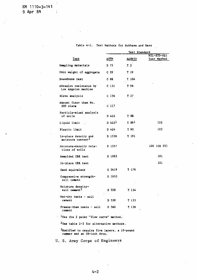
lUse the 3 point "flow curve" method .
2See table 2-3 for alternative methods .
3Modified to require five layers, a 10-poundrammer and an 18-inch drop .
U . S . Army Corps of Engineers
4-2
Table 4-1 . Test Methods for Subbase
Test
and Base
StandardMIL-STD-621
Test ASTM AASHTO Test Method
Sampling materials D 75 T 2
Unit weight of aggregate C 29 T 19
Soundness test C 88 T 104
Abrasion resistance by C 131 T 96Los Angeles machine
Sieve analysis C 136 T 27
Amount finer than No .200 sieve C 117
Particle-sized analysisof soils D 422 T 88
Liquid limit D 4231 T 89 1 103
Plastic limit D 424 T 90 103
In-place density and D 1556 T 191moisture content 2
Moisture-density rela- D 1557 100 (CE 55)tions of soils
Remolded CBR test D 1883 101
In-place CBR test 101
Sand equivalent D 2419 T 176
Compressive strength- D 1633soil cement
Moisture density-soil cement3 D 558 T 134
Wet-dry tests - soilcement D 559 T 135
Freeze-thaw tests - soil D 560 T 136cement
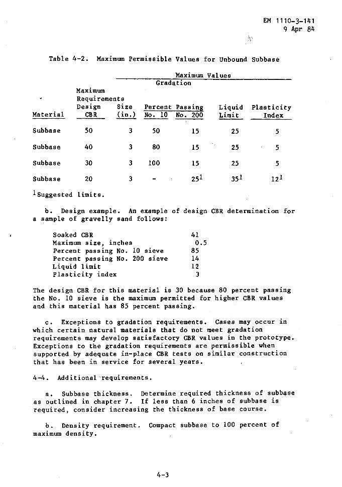
Table 4-2 . Maximum Permissible Values for Unbound Subbase
Maximum Values
1 Suggested limits .
b . Design example . An example of design CBR determination fora sample of gravelly sand follows :
The design CBR for this material is 30 because 80 percent passingthe No . 10 sieve is the maximum permitted for higher CBR valuesand this material has 85 percent passing .
c . Exceptions to gradation requirements . Cases may occur inwhich certain natural materials that do not meet gradationrequirements may develop satisfactory CBR values in the prototype .Exceptions to the gradation requirements are permissible whensupported by adequate in-place CBR tests on similar constructionthat has been in service for several years .
4-4 . Additional requirements .
a . Subbase thickness . Determine required thickness of subbaseas outlined in chapter 7 . If less than 6 inches of subbase isrequired, consider increasing the thickness of base course .
b . Density requirement . Compact subbase to 100 percent ofmaximum density .
4-3
EM 1110- 3-1419 Apr 84
MaximumGradation
Requirements
MaterialDesignCBR
Size(in .)
PercentNo . 10
PassingNo . 200
LiquidLimit
PlasticityIndex
Subbase 50 3 50 15 25 5
Subbase 40 3 80 15 25 5
Subbase 30 3 100 15 25 5
Subbase 20 3 - 25 1 351 12 1
Soaked CBRMaximum size, inches
410 .5
Percent passing No . 10 sieve 85Percent passing No . 200 sieve 14Liquid limit 12Plasticity index 3
EM 1110-3-1419 Apr 84
c . Frost susceptibility . In areas where frost penetration is aproblem, consult criteria in EM 1110-3-138.
d . Expansive material . Do nct use material which has a swell of 3percent or greater, as determined from the CBR mold, for subbase .
CHAPTER 5
BASE COURSE
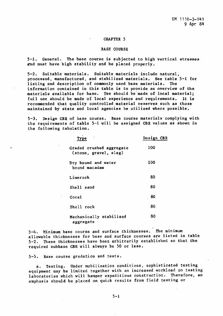
5-1 . General . The base course is subjected to high vertical stressesand must have high stability and be placed properly .
5-2 . Suitable materials . Suitable materials include natural,processed, manufactured, and stabilized materials . See table 5-1 forlisting and description of commonly used base materials . Theinformation contained in this table is to provide an overview of thematerials available for base . Use should be''made of local material ;full use should be made of local experience and requirements . It isrecommended that quality controlled material reserves such as thosemaintained by state and local agencies be utilized where possible .
5-3 . Design CBR of base course . Base course materials complying withthe requirements of table 5-1 will be assigned CBR values as shown inthe
5-4 . Minimum base course and surface thicknesses . . The minimumallowable thicknesses for base and surface courses are listed in table5-2 . These thicknesses have been arbitrarily established so that therequired subbase CBR will always be 50 or less .
5-5 . Base course gradation and tests .
a . Testing . Under mobilization conditions, sophisticated testingequipment may be limited together with an increased workload on testinglaboratories which will hamper expeditious construction . Therefore, anemphasis should be, placed on quick results from field testing or
EM 1110-3-1419 Apr 84
following tabulation .
Type Design CBR
Graded crushed aggregate 100(stone, gravel, slag)
Dry bound and water 100bound macadam
Limerock 80
Shell sand 80
Coral 80
Shell rock 80
Mechanically stabilized 80aggregate

EM 1110-3-1419 Apr 84
Materials
Crushed Stoneand crushedgravel
Slag
Macadam
Shell Sand
Coral
Limerock
Shell-Rock
MechanicallyStabilizedAggregate
StabilizedMaterials
U . S . Army Corps of Engineers
Table 5-1 . Base
Description-Source
Stone quarried from formations ofgranite, traprock and limestone .Gravel from deposits of riveror glacial origin
Air-cooled, blast-furnace slagis by-product of steel manu-facturing . Material iscompetitive in areas adjacentto steel mills . Slag islighter in weight than stone,highly stable, hard, and roughtextured . Slag also has Abilityto drain rapidly
Crushed stone, crushed slag, orcrushed gravel
The shells are dredged from deadreefs in the gulf coast watersof the United States . Shellsconsist of oyster and clam shells
Coral consists of hard, cementeddeposits of skeletal origin .Coral is found in the reefs andinland deposits at atolls andislands in tropical regions .Caroline limestone, quarriedfrom inland deposits anddesignated as quarry coral, isstructurally soundest of thevarious coral materials available .Other types also useful for basematerial are reef coral and bankrun coral . Cascajo or "gravellycoral" found as lagoon sedimentat Guam, is also useful as base
Limerock is a fossiliferous lime-stone of the oolitic type . Itsmain constituents are carbonatesof calcium and magnesium . Commer-cial limerock deposits are locatedin Florida
Shell-rock or marine limestoneare deposits or hard, cementedshells . Deposits are locatedin the coastal areas of North andSouth Carolina
Course Materials for Flexible Pavements
5-2
Processing
The quarried rock and gravelaye crushed and screened toproduce a dense graded mix .See table 5-2 for gradation
Slag is air-cooled, crushed, andand graded to produce dense mix .Fines from other sources maybe used for blending . See table5-2 for gradation
See EM 1110-3-137
See EM 1110-3-137
Crushed aggregate is screened andgraded to produce coarse aggre-gate, choker aggregate, keyaggregate, and screenings . SeeType specifications for gradation
Shells are washed, crushed,screened and blended with sandfiller . Ratio of the blend shallbe not less than 67 percentshell to 33 percent sand . Referto local guide specificiationswhere available
Shell-rock is crushed, screenedand graded to a dense mix . Referto local guide specificationswhere available .
Crushed and uncrushed coarse aggre- A blend of crushed and naturalgate, fine aggregate, and binder
materials processed to providea dense graded mix . See table5-2 for gradation
Requirements-Comments
Percentage of wear not toexceed 40 . Liquid limit notto exceed 25 . Plasticityindex not to exceed 5 .
Requirements for crushed stoneapply . Slag weight to be notless than 65 pcf .
Procedure is to place alter-nate layers of the varioussize aggregate to form dry-bound, or wet-bound macadambase .
Liquid limit not to exceed 25 .Plasticity index not to exceed5 . Minimum CBR requirement is60 at 100 percent compactionfor layers following construc-tion
Reef coral is removed by blasting Percentage of wear not toand dredging and is stockpiled
exceed 50 . Liquid limit not toashore, prior to crushing and
exceed 25 . Plasticity indexgrading . Quarry coral is obtained not to exceed 5 . Minimumby blasting, and is crushed and
CBR requirement is 60 atgraded to produce a dense mix .
100 percent compaction forUse the following gradation :
layers. following construction
Limerock is crushed, screened, and Minimum CBR requirement isuniformly graded from 3-1/2 inches 60 at 95 percent compaction .maximum to dust . Refer to local
Liquid limit not to exceedguide specifications where avail- 25 . Plasticity index not toable
exceed 5 .
Percentage of wear not toexceed 50 . Liquid limitnot to exceed 25 . Plasticityindex not to exceed 5 . Mini-mum CBR requirement is 60at 100 percent compaction forlayers following construction
Liquid limit not to exceed 25 ;plasticity index not to exceed5 . Percentage of wear not toexceed 50 .
See EM 1110-3-137
Sieve Designation
2 inch
Percent Passing
1001-1/2 inch 70-1003/4 inch 40-90No . 4 25-60
No . 40 5-20No . 200 0-10
EM 1110-3-1419 Apr 84
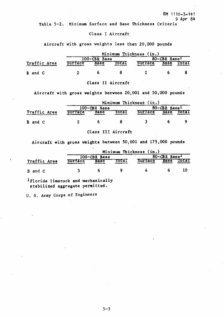
Table 5-2 . Minimum Surface and Base Thickness Criteria
Class I Aircraft
Aircraft with gross weights less than 20,000 pounds
Minimum Thickness (in .)100-CBR Base
80-CBR BaselTraffic Area
surface
ase
o a
Surface
base
o a
Band C
2
6
8
2
6
8
Class II Aircraft
Aircraft with gross weights between 20,001-and 50,000 pounds
Minimum Thickness (in .)100-CBR Base
80-CBR BaseTraffic Area
Surface
Base
Total
Surface
ase
o a
B and C
2
6
8
3
6
9
Class III Aircraft
Aircraft with gross weights between 50,001 and 175,000 pounds
100-CBR Base
80-CBR BaselTraffic Area
Surface
ase
Total
Surface
ase
o a
B and C
3
6
9
4
6
10
lFlorida limerock and mechanicallystabilized aggregate permitted .
U . S . Army Corps of Engineers
Minimum Thickness (in .)
EM 1110- 3-1419 Apr 84
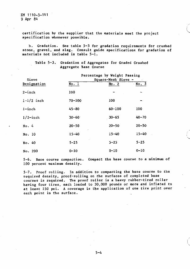
certification by the supplier that the materials meet the projectspecification whenever possible .
b . Gradation . See table 5-3 for gradation requirements for crushedstone, gravel, and slag . Consult guide specifications for gradation ofmaterials not included in table 5-1 .
Table 5-3 . Gradation of Aggregates for Graded CrushedAggregate Base Course
5-6 . Base course compactinn . Compact the base course to a minimum of100 percent maximum density .
5-7 . Proof rolling . In addition to compacting the base course to therequired density, -proof-rolling on the surfaces of completed basecourses is required . The proof roller is a heavy rubber-tired rollerhaving four tires, each loaded to 30,000 pounds or more and inflated toat least 150 psi . A coverage is the application of one tire print overeach point in the surface .
Percentage by Weight PassingSieve
Designation No . 1Square-Mesh'Sieve
No . 2-
No . 3
2-inch 100
1-1/2 inch 70-100 100
1-inch 45-80 60-100 100
1/2-inch 30-60' 30-65 40-70
No . 4 20-50 20-50 20-50
No . 10 15-40 15-40 15-40
No . 40 5-25 5-25 5-25
No . 200 0-10 0-10 0-10
6-2 . Selection of materials .
b . Aggregates .
CHAPTER 6
BITUMINOUS MATERIALS COURSES
EM 1110-3-1419 Apr 84
6-1 . General . Bituminous surfaces provide a resilient, waterproof,load distributing medium that protects the base course against thedetrimental effects of water and the abrasive action of traffic . Theflexibility of bituminous pavement permits slight adjustments in thepavement structure, owing to consolidation, without detrimental effect .However, bituminous concrete is unsatisfactory for use where heat andblast effects from jet aircraft are severe ., Also, asphaltic concreteis .not resistant to fuel spillage and is saisfactory only wherespillage is slight and very infrequent .
a . Bituminous mixes . The following part of. this chapter providesan abbreviated guide to the design of hot mix bituminous surface andbase courses . For a complete treatment on the criteria requirements,selection of materials, testing, design, and plant control of hotmixes, tar-rubber mixes, and surface treatments, refer to appendix A .
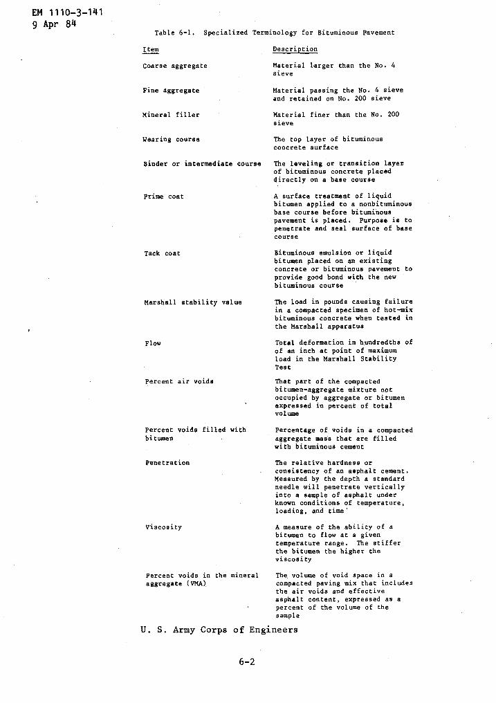
b . Definitions . See table 6-1 for terminology used in flexiblepavement design .
a . Bituminous materials . Bituminous materials include asphalts,tars, and tar-rubber blends .
(1) Asphalts . Asphalt products are the normal choice for use inbituminous mixes for reasons of availability, serviceability, andeconomy .
(2) Tars . Tars are more susceptible to temperature changes thansimilar grades of asphalt ; tars are also more toxic and difficult tohandle . However, tars are more resistant to jet fuel spillage and areless likely than asphalts to strip from hydrophilic aggregates in thepresence of water .
(3) Tar rubber blends . Mixtures of tar and,synthetic rubberhave increased resistance to fuel spillage and temperature changes .Consider use of tar-rubber blends for pavements where jet fuel spillageis infrequent .
(1) Suitability of rock types . Alkaline rocks (limestone,dolomite) provide better adhesion with asphaltic films in the presenceof water than acid or silicious rocks (granite, quartzite) . Where acidrocks are used, addition of an antistripping agent or hydrated lime maybe required .
EM 1110-3-141
9 Apr 84Table 6-1 . Specialized Terminology for Bituminous Pavement
Item
Description
Coarse aggregate
Material larger than the No . 4sieve
Fine aggregate
Material passing the No . 4 sieveand retained on No . 200 sieve
Mineral filler
Material finer than the No . 200sieve
Wearing course
The top layer of bituminousconcrete surface
Binder or intermediate course
The leveling or transition layerof bituminous concrete placeddirectly on a base course
Prime coat
A surface treatment of liquidbitumen applied to a nonbituminousbase course before bituminouspavement is placed . Purpose is topenetrate and seal surface of basecourse
Tack coat
Bituminous emulsion or liquidbitumen placed on an existingconcrete or bituminous pavement toprovide good bond with the newbituminous course
Marshall stability value
The load in pounds causing failurein a compacted specimen of hot-mixbituminous concrete when tested inthe Marshall apparatus
Flow
Total deformation in hundredths ofof an inch at point of maximumload in the Marshall StabilityTest
Percent air voids
That part of the compactedbitumen-aggregate mixture notoccupied by aggregate or bitumen
'
expressed in percent of totalvolume
Percent voids filled with
Percentage of voids in a compactedbitumen
aggregate mass that are filledwith bituminous cement
Penetration
The relative hardness orconsistency of an asphalt cement .Measured by the depth a standardneedle will penetrate verticallyinto a sample of asphalt underknown conditions of temperature,loading, and time'
viscosity
A measure of the ability of abitumen to flow at a giventemperature range . The stifferthe bitumen the higher theviscosity
Percent voids in the mineral
The volume of void space in aaggregate (VMA)
compacted paving mix that includesthe air voids and effectiveasphalt content, expressed as apercent of the volume of thesample
U . S . Army Corps of Engineers
6-2

EM 1110-31419 Apr 84
(2) Crushed aggregate .
The coarse and fine aggregates used forairfield pavement surface should be crushed materials, in order toassure high stability and performance . Bituminous base courses,however, may include natural materials in the fine fraction .
"
(3) Maximum size . In general, the maximum size of aggregate forthe wearing course should not exceed 3/4 inch ; in no case should theaggregate size exceed one-half the thickness of the compacted wearingcourse or two-thirds the thickness of any binder or intermediatecourse .
(4) Mineral filler . The type and quantity of mineral fillerused affects the stability of the mix . For surface course mixes,mineral filler should be limestone dust, Portland cement, or otherinert similar materials . For bituminous bases natural filler isfrequently adequate .
6-3 . Design of bituminous concrete mix .
a . Criteria . Use the procedures and criteria described in appendixA and as condensed below for the design of hot mix bituminous concrete .Approved design mixes are available from Army, Federal, and stateagencies which would meet the requirements outlined in this manual formobilization construction . Existing acceptable design mixes should beutilized whenever possible . Where tests for aggregate and bituminousmix are required see table 6-2 .
b . Asphalt cement grades . At present, in the United States,asphalt cement is specified by one of the following :
- Penetration grades
- AC viscosity grades
- AR viscosity grades
Correlation between penetration grades and viscosity grades forasphalts from different producers is not possible .
Figure 6-1 givesthe recommended grades for each area of the United States bypenetration and viscosity designation . These recommendations should betempered by local practice . Use the penetration grade designation inthe areas when penetration grade asphalt is produced . The penetrationsof AC and AR grades do not necessarily fall within the range ofrecommended values . In areas where viscosity grades are produced,determine the sources with acceptable penetration and approve thosegrades . See table 6-3 for specifications for asphalt, tars, andtar-rubber blends .
6- 3
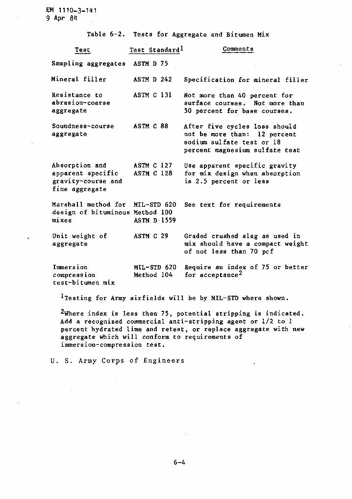
EM 1110-3-1419 Apr 84
Table 6-2 . Tests for Aggregate and Bitumen Mix
Test
Test Standardl
Comments
Sampling aggregates ASTM-D 75
Mineral filler
ASTM D 242
Specification for mineral filler
Resistance to
ASTM C 131
Not more than 40 percent forabrasion-coarse
surface courses . Not more thanaggregate
50 percent for base courses .
Soundness-course
ASTM C 88
After five cycles loss shouldaggregate
not be more than : 12 percentsodium sulfate test or 18percent magnesium sulfate test
Absorption and
ASTM C 127
Use apparent specific gravityapparent specific
ASTM C 128
for mix design when absorptiongravity-course and
is 2 .5 percent or lessfine aggregate
Marshall method for MIL-STD 620 See text for requirementsdesign of bituminous Method 100mixes
ASTM D-1559
Unit weight of
ASTM C 29
Graded crushed slag as used inaggregate
mix should have a compact weightof not less than 70 pcf
Immersion
MIL-STD 620 Require an index of 75 or bettercompression
Method 104
for acceptance2test-bitumen mix
1 Testing for Army airfields will be by MIL-STD where shown .
2Where index is less than 75, potential stripping is indicated .Add a recognized commercial anti-stripping agent or 1/2 to 1percent hydrated lime and retest, or -replace aggregate with newaggregate which will conform to requirements ofimmersion-compression test .
U . S . Army Corps of Engineers
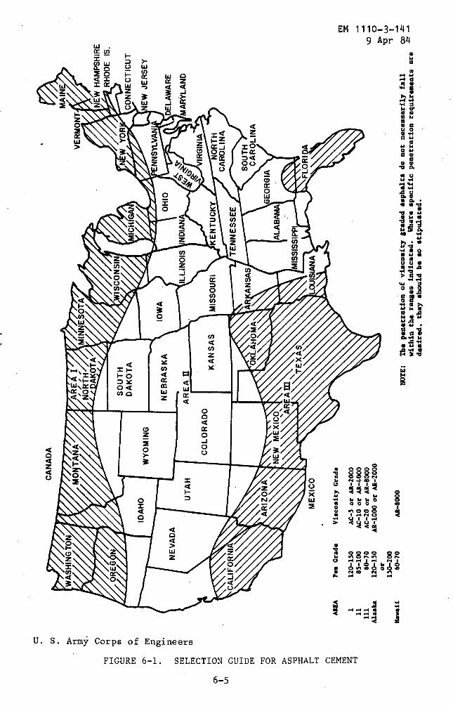
0H
b o rha~
~yi
oa co
r n Ho,
o z H d
NEVADA
UTAH
COLORADO
NEBRASKA
AREA
II
KANSAS
OKLAHOMA
IOWA MISSOURI
ARKANSAS
ILLINOIS
NDIANA
OHIO
NEW
YOR
~tv'
~?ma r1 \J~e
VIRGINIA
-NORTH
CAROLINA
R
CANADA
SOUTH
CAROLINA
CONNECTICUT
NEW
JERSEY
DELAWARE
MARYLAND
0Y
GEORGIA
NEW
MEXI
COW
ALABAMA
a
&\NN
NIAREA
ib x
TEXAS
MISSISSIPPI
aFLORIDA
rMEXICO
LOUISIANA
H C7AR
EAPe
nGr
ade
Viscosit
yGr
ade
z1
120-150
AC-5
orAR
-200
03
H11
85-1
00AC-10or
AR-4
000
111
60-7
0AC-20or
AR-8
000
Alas
ka120-150
AR-1000or
AR-2
000
oor
a 'zsw
150-200
-s,
Hawa
ii60
-70
AA-800
0NOTE
:Thepe
netr
atio
nof
visc
osit
ygraded
asphalts
donot
necessarily
fall
CDwithinthe
ranges
indi
cate
d.
Wher
especific
penetration
requirements
are
desired,
they
shou
ldbe
sostipulated
.
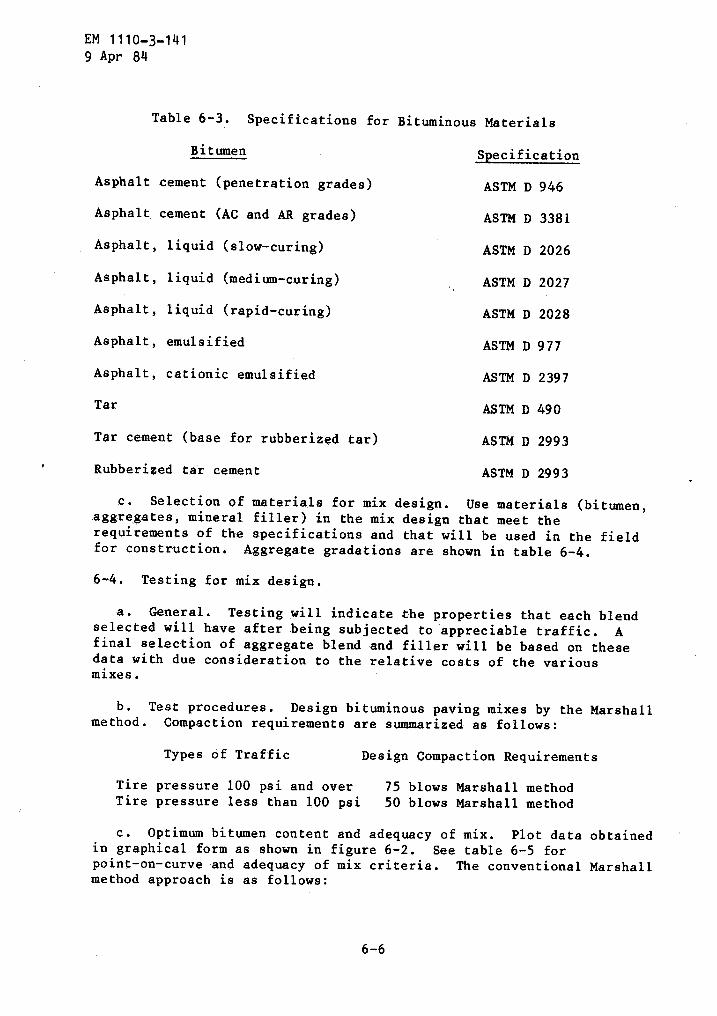
EM 1110-3-1419 Apr 84
Table 6-3 . Specifications for Bituminous Materials
Bitumen Specification
Asphalt cement (penetration grades)
ASTM D 946
Asphalt cement (AC and AR grades)
ASTM D 3381
Asphalt, liquid (slow-curing)
ASTM D 2026
Asphalt, liquid (medium-curing)
ASTM D 2027
Asphalt, liquid (rapid-curing)
ASTM D 2028
Asphalt, emulsified
ASTM D 977
Asphalt, cationic emulsified
ASTM D 2397
Tar
ASTM D 490
Tar cement (base for rubberized tar)
ASTM D 2993
Rubberized tar cement
ASTM D 2993
c . Selection of materials for mix design . Use materials (bitumen,aggregates, mineral filler) in the mix design that meet therequirements of the specifications and that will be used in the fieldfor construction . Aggregate gradations are shown in table 6-4 .
6-4 . Testing for mix design .
a . General . Testing will indicate the properties that each blendselected will have after being subjected to appreciable traffic . Afinal selection of aggregate blend and filler will be based on thesedata with due consideration to the relative costs of the variousmixes .
b . Test procedures . Design bituminous paving mixes by the Marshallmethod . Compaction requirements are summarized as follows :
Types of Traffic
Design Compaction Requirements
Tire pressure 100 psi and over
75 blows Marshall methodTire pressure less than 100 psi
50 blows Marshall method
c . Optimum bitumen content and adequacy of mix . Plot data obtainedin graphical form as shown in figure 6-2 . See table 6-5 forpoint-on-curve and adequacy of mix criteria . The conventional Marshallmethod approach is as follows :
6-6

Table
6-4
.Aggregate
Gradations
- for
Bituminous
Concrete
Pavements
PercentPassing
byWeight
i1-
112-
in.
Plax
as~"m
1-in
.Ma
ximu
m
3/4-in
.Maximum
1/2-
in.Ma
ximu
m
3/8-in
.Ma
ximu
m
No.4
Maxims Pr
11-
1/2
inch
maximum
surface
course
gradationwill
beused
only
for
thick-lift
pavements
(3-inchor
more)
.2Us
elo
w-pr
essu
regradationfo
rpa
veme
nts
subjecte
dto
aircraft
with
tire
pressures
less
than
100psi
.3
Ilse
high-press
ure
gradation
for
pave
ment
ssubjec
ted
toaircraft
with
tire
pressures
of10
0ps
ior
greater
.
U.
S.Army
Corps
of
Engi
neer
s
.Si
eve
Size
Low
2Hi
gh3
Low
High
Low
High
Low
High
Low
High
Low
Pres
sure
Pres
sure
Pres
sure
Pressure
Pressure
Pressure
Pressure
Pressure
Pressure
Pressure
Pressure
Wearing
Course
1-1/
2inch
100
1in
ch87
±8--
100
100
----
----
----
--3/4
inch
79±9
--90
±790±6
100
100
----
----
--1/2
inch
70±9
--81
±981±7
89±9
89±7
100
100
----
--3/8
inch
63=9
__75
±975±7
82±9
82±7
86±9
86±7
100
No.4
51-9
--60
±960±7
66±9
66±7
66±9
66±7
85±1
0--
100±
No.8
429
--47
±947±7
53±9
53±7
53±9
53±7
72±1
0--
86±12
No.
1634
±9--
37±9
37±7
41±9
41±7
41±9
41±7
56±1
2--
72±16
No.30
26±9
--27
±927±7
31±9
31±7
31±9
31±7
42±1
0--
57±12
No.50
19±8
--19
±819±6
21±8
21±6
21±8
21±6
29±9
--43±17
No.100
12±6
--12
±613±5
13±6
13±5
13±6
13±5
18±7
--28±12
No.200
4±3
--4±
34.5±1
.54±3
4.5±1
.54±3
4.5±1
.58±3
--9±5
Binder
orIntermediate
Course
1-1/
2inch
100
----
----
----
1inch
-84
±9--
100
100
----
--3/4
inch
76±9
--83
±990±6
100
100
----
1/2
inch
66±9
--73±9"
81±7
82±9
89±7
100
100
3/8
inch
59±9
--64
±975±7
72±9
82±7
83±9
86±7
No.
445
±9--
48±9
60±7
54±9
66±7
62±9
66±7
No.
835
±9--
37±9
47±7
41±9
53±7
47±9
5317
No.
1627
t9--
28±9
37±7
32±9
41t7
36±9
41±7
No.
3020
±9--
21±9
27±7
24±9
31±7
28±9
31±7
No.
5014
±7--
16±7
19±6
17±7
21±6
20±7
21±6
No.
100
9±5
--11±5
13±5
12±5
13±5
14±5
13±5
No.200
5±2
--5±
24.5±1
.55±
24.5±1
.55±2
4.5±1
.5
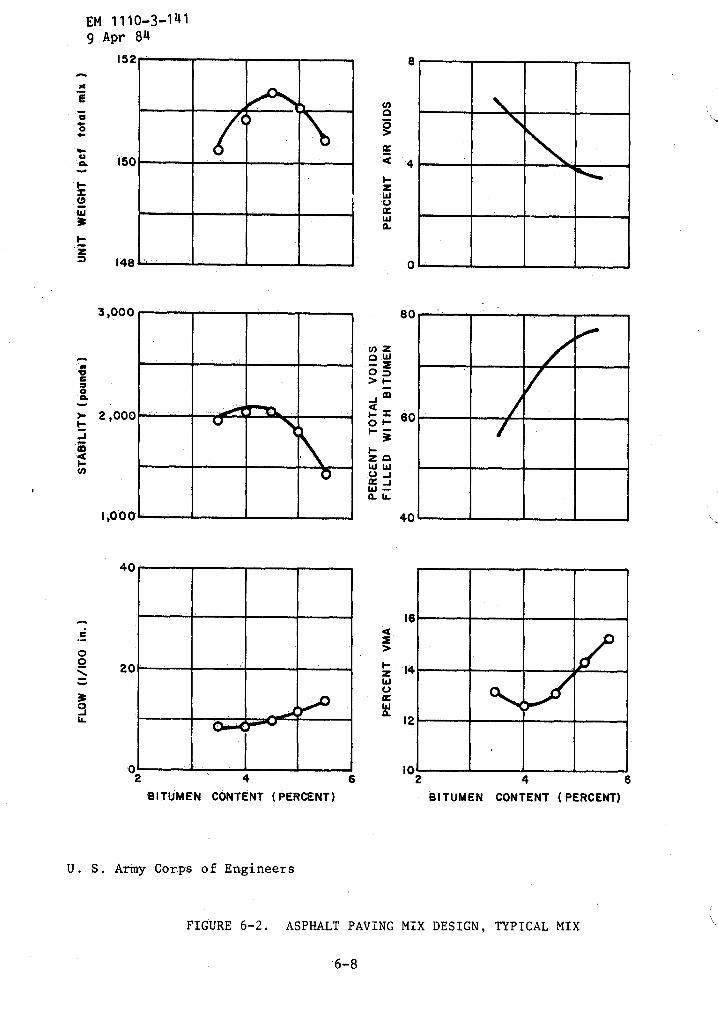
xEv0
f-s0W3z0
rrdoaF-N
eO0
30a
EM 1110-3-1419 Apr 84
152
150
148
3,000
2,000
1,000
40
20
I
U . S . Army Corps of Engineers
6- 8
Q
ZvWa
~zo W
> F0-
zoW WU Jw JWa U..
4
4
80
40
z 14WU
Wa
12
1002
4
6 2
4
6`BITUMEN CONTENT (PERCENT)
BITUMEN CONTENT (PERCENT)
FIGURE 6-2 . ASPHALT PAVING MIX DESIGN, TYPICAL MIX

(1) Determine the optimum bitumen content by averaging thefollowing values :
and
Bitumen content at peak of stability curve
Bitumen content at peak of unit weight curve (for wearingcourse only)
Bitumenbitumen
(2) Check for adequacy of mix for stability, flow;voids filled with asphalt .
Table 6-5 .
EM 1110-3-1419 Apr 84
Bitumen content at the appropriate point of air voids curve
content at the appropriate point on voids filled withcurve
air
Procedure for Determining Optimum Bitumen Contentand Adequacy of Mix for Use With Aggregate ShowingWater Absorption of 2-1/2 Percent or Less
(1) Determination of optimum bitumen content
6-9
voids,
d . Typical,example . The determination of bitumen content andadequacy of mix is illustrated by the following example using thecurves in figure 6-2 and criteria in table 6-5 . The example is for awearing course mix with 3/4-inch maximum aggregate .
IntermediateWearing
Point onCurve for
Course and BasePoint onCurve for
Course
Optimum Adequacy Optimum AdequacyBitumen of Mix Bitumen of Mix
Test Property Content Criteria Content Criteria
Marshall Stability peak of 1,800 or peak of 1,800 or75 blows curve higher curve higher
Unit weight peak of not used not used not usedcurve
Flow not used 16 or less not used 16 or less .
Percent air voids 4 3-5 6 5-7
Percent voids filledwith bitumen 75 70-80 60 50-70
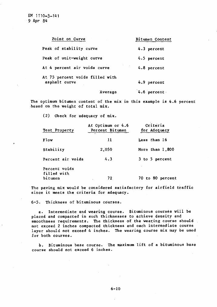
EM 1110-3-1419 Apr 84
Point on Curve
Bitumen Content
Peak of stability curve
4 .3 percent
Peak of unit-weight curve
4 .5 percent
At 4 percent air voids curve
4 .8 percent
At 75 percent voids filled withasphalt curve
4.9 percent
Average
4 .6 percent
The optimum bitumen content of the mix in this example is 4 .6 percentbased on the weight of total mix .
The paving mix would be considered satisfactory for airfield trafficsince it meets the criteria for adequacy .
6-5 . Thickness of bituminous courses .
a . Intermediate and wearing course . Bituminous courses will beplaced and compacted in such thicknesses to achieve density andsmoothness requirements . The thickness of the wearing course shouldnot exceed 2 inches compacted thickness and each intermediate courselayer should not exceed 4 inches . The wearing course mix may be usedfor both courses .
b . Bituminous base course . The maximum lift of a bituminous basecourse should not exceed 6 inches .
(2) Check for adequacy
AtTest Property
of mix .
optimum or 4 .6Percent Bitumen
Criteriafor Adequacy
Flow 11 Less than 16
Stability 2,050 More than 1,800
Percent air voids 4 .3 3 to 5 percent
Percent voidsfilled withbitumen 72 70 to 80 percent
6-6 . Bituminous spray coats .
a . Prime coats . Prime coats should be applied to accomplish thefollowing :
(1) To seal surface of base course in areas where rain may beexpected prior to placement of the asphalt surface .
(2) To bind together "dusty" base surfaces .
(3) To bind together a base surface for protection against
EM 1110-3-1419 Apr 84
per square yard . Sufficient bitumen should be used to seal the voidsbut not more than can' be readily absorbed .
Asphalt emulsions have beenused experimentally with varying success for prime coats . Emulsions donot penetrate as do liquid asphalts and may require a sand seal toprevent tracking . Emulsions used for priming are SS-1 and SS-lhdiluted with 50 percent water and applied at approximately 0 .1 gallonper square yard .
b . Tack coats . Tack coats are required on existing pavements toinsure a bond with the new overlying bituminous concrete course . Tackcoats may not be required between new layers of pavement where theupper layer is immediately constructed as the lower layer is completed .However, tack coats should be used on layers where construction ishalted and placement of the overlaying layer is delayed . Tack coatsshould also be installed on surfaces which have become coated with finesand or dust and on surfaces soiled from construction traffic . Soiledsurfaces must be cleaned before application of a tack coat .
(1) Materials . Use emulsified asphalt SS-1, SS-1h, CSS-1, orCSS-lh diluted with equal parts of water . The following liquidasphalts or tars may also be used, RC-70, RT-6, and,RT-7 .
(2) Application . Apply tack coats with a pressure distributorat the rate of 0 .05 to 0 .15 gallon per square yard .
construction traffic .
(4) To bind over bituminous courses to the base .
Preferred materials for use as prime coats are the liquid asphaltsMC-70, MC-250, RC-70, RC-250, and the tars RT-2 and RT-3 . Applicationrates of the liquid asphalts and tars are between 0 .15 and 0 .4 gallon
CHAPTER 7
FLEXIBLE PAVEMENT THICKNESS DESIGN
7-1 . General . This section presents procedures for the thicknessdesign of flexible pavements for runways, taxiways, and other airfieldareas .
a . Flexible pavements . Flexible pavements include the following :
(1) Conventional flexible pavements consisting of a bituminousconcrete surface on a high quality granular base and subbase course .
(2) Stabilized pavement consisting of bituminous concretesurface course over a section which may include a stabilized base, astabilized subbase, or any combination of the aforementioned .
(3) All bituminous pavement consisting of asphalt concretemixtures for all courses from top of surface to subgrade .
b . Basis for thickness design . The thickness design proceduresincluded herein for conventional flexible pavement construction arebased on CBR design methods developed for airfields .
The designmethods for pavements that include stabilized layers are based onmodifications of the conventional procedures utilizing thicknessequivalencies developed from highway and airfield test experience .
7-2 . Flexible pavement design curves . Table 7-1 tabulates theflexible pavement design curves for use in this manual . The curves areidentified by class or category, gear configuration, and a typicaldesign aircraft where appropriate . The individual curves indicate thetotal required thickness of pavement for gross aircraft weight andaircraft passes . The Army defines a pass as one .movement of the designaircraft past a given point on the pavement .
7-3 . Design requirements . Flexible pavement designs must provide :
Sufficient compaction of the subgrade and each pavement layer toprevent objectionable settlement under concentrated and repeatedtraffic . Compaction requirements are given in table 3-3 .
Adequate thickness of quality pavement components above thesubgrade to prevent detrimental subgrade deformation, excessivedeflection of the pavement surface, and excessive tensile strainin the bituminous pavement material under traffic .
- A stable, weather resistant, wear resistant, nonskid surface .
7-4 : Thickness design . From the procedures included herein, the totalthickness of the pavement, as well as the individual courses, may be
EM 1110-3-1419 Apr 84
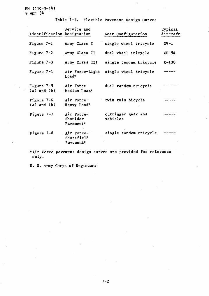
EM 1110-3-1419 Apr 84
Table 7-1 . Flexible Pavement Design Curves
U . S, Army Corps of Engineers
*Air Force pavement design curves are provided for referenceonly .
IdentificationService andDesignation Gear Configuration
TypicalAircraft
Figure 7-1 Army Class I single wheel tricycle OV-1
Figure 7-2 Army Class II dual wheel tricycle CH-54
Figure 7-3 Army Class III single tandem tricycle C-130
Figure 7-4 Air Force-Light single wheel tricycle -----Load*
Figure 7-5 Air Force- dual tandem tricycle(a) and (b) Medium Load*
Figure 7-6 Air Force- twin twin bicycle(a) and (b) Hearty Load*
Figure 7-7 Air Force- outrigger gear andShoulder vehiclesPavement*
Figure 7-8 Air Force- single tandem tricycleShortfieldPavement*
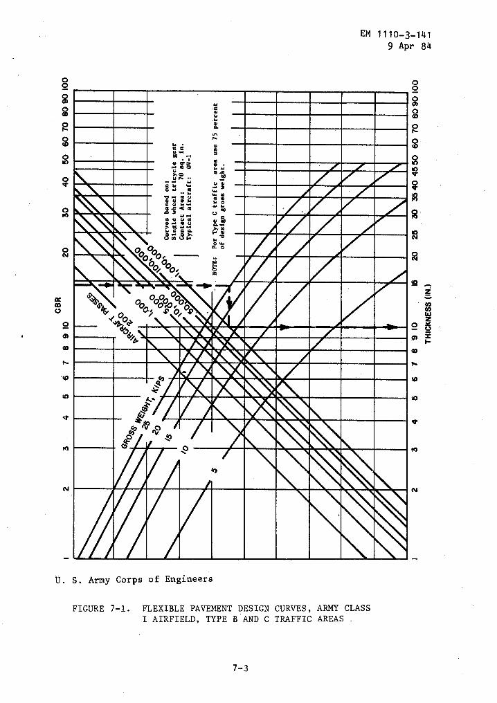
00
0
OCmV
M
O
M
N
EM 1110-3-1419 Apr 84
U . S . Army Corps of Engineers
FIGURE 7-l . FLEXIBLE PAVEMENT DESIGN CURVES, ARMY CLASSI AIRFIELD, TYPE B AND C TRAFFIC AREAS .
7-3
M
N
N
YuwYa
n6' Y
40
.+ ei u °" moV 41 41 11ms<m twov
>Y
0""C uw d .~e e a a. m
"0
i
i
Jb, _~bL%!4j. MWAr W,AFAV7 i!: "W8NWA!TA.WWI,
40
EVA ones
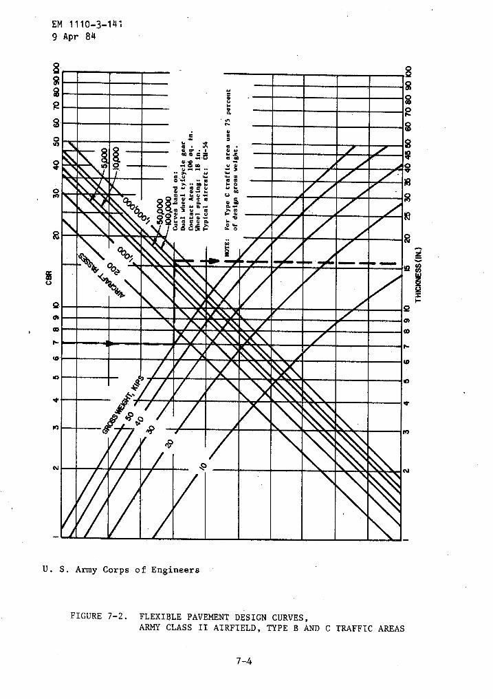
EM 1110-3-14,9 Apr 84
U . S . Army Corps of Engineers
FIGURE 7-2 . FLEXIBLE PAVEMENT DESIGN CURVES,ARMY CLASS II AIRFIELD, TYPE B AND C TRAFFIC AREAS
7-4
Qdus+
Q
u
Q w
EVA
® r~j ~w o e u s °r
das F o
Q P \®1
Q
~r'r"
AM"01..
MANOM051 S,
ONAIKM~s96,
N
w
`
M
N
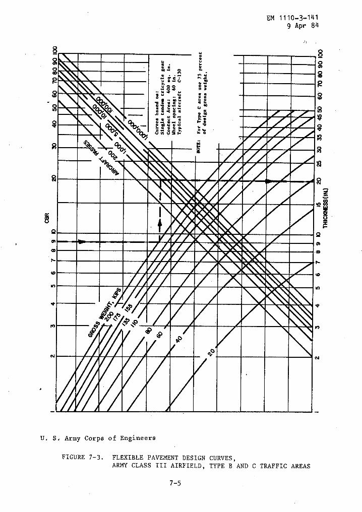
8
EM 1110-3-141
g Apr 84
U. S . Army Corps of Engineers
FIGURE 7-3 . FLEXIBLE PAVEMENT DESIGN CURVES,ARMY CLASS III AIRFIELD, TYPE B AND C TRAFFIC AREAS
7-5
12
O L
12,Y+ PC 1+ AL
O`.~
Q y wo~ y
Y Ca .4
~ ~ e m av
0t0
O __, ~ e
~1 V C,,c
t~/f Vz F WC
g
00
r
. ~ .e 'Apo. ,
g
CIDFAWArAF""M owl cc
~I =AWAOWN&W",I/
3 tic~~1h ~
N
w w
w
, `M
leir ~ r
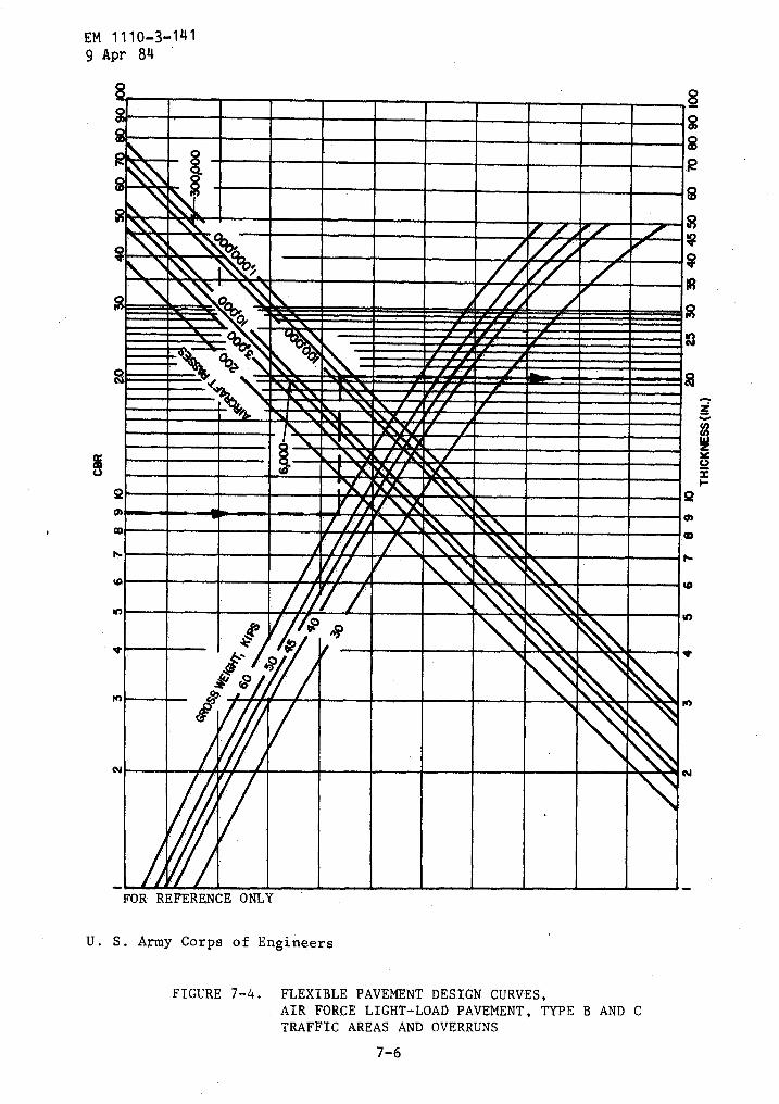
EM 1110-3-141g Apr 84
FOR REFERENCE ONLY
U . S . Army Corps of Engineers
7-6
19
FIGURE 7-4 . FLEXIBLE PAVEMENT DESIGN CURVES,AIR FORCE : LIGHT-LOAD PAVEMENT, TYPE B AND CTRAFFIC AREAS AND OVERRUNS

..-iii..
".tee.sir,
PFAON W4
iiimurAdOrAiiir,",m
FOR REFERENCE ONLY
U . S . Army Corps of Engineers
7-7
F-M 1110-3-1419 Apr 84
FIGURE 7-5a . FLEXIBLE PAVEMENT DESIGN CURVES,AIR FORCE MEDIUM-LOAD PAVEMENT, TYPE A TRAFFIC AREAS

EM 1110-3-141g Apr 84
FOR REFERENCE ONLY
00 ~Iriir,".0001
AWAMA
U . S . Army Corps of Engineers
\milr`i.\7AV,rAN.`ri \lw'i%.lwArAv'"̀t~WA'~'t~VWA
I~"MNLXWIW""!OMAY!i
7/.e°Irk.'"\FZIf4
rrroi®i~1400%XL®mssMiMM
7-8
FIGURE 7-5b . FLEXIBLE PAVEMENT DESIGN CURVES,AIR FORCE MEDIUM-LOAD PAVEMENT, TYPE B, C, AND DTRAFFIC AREAS AND OVERRUNS
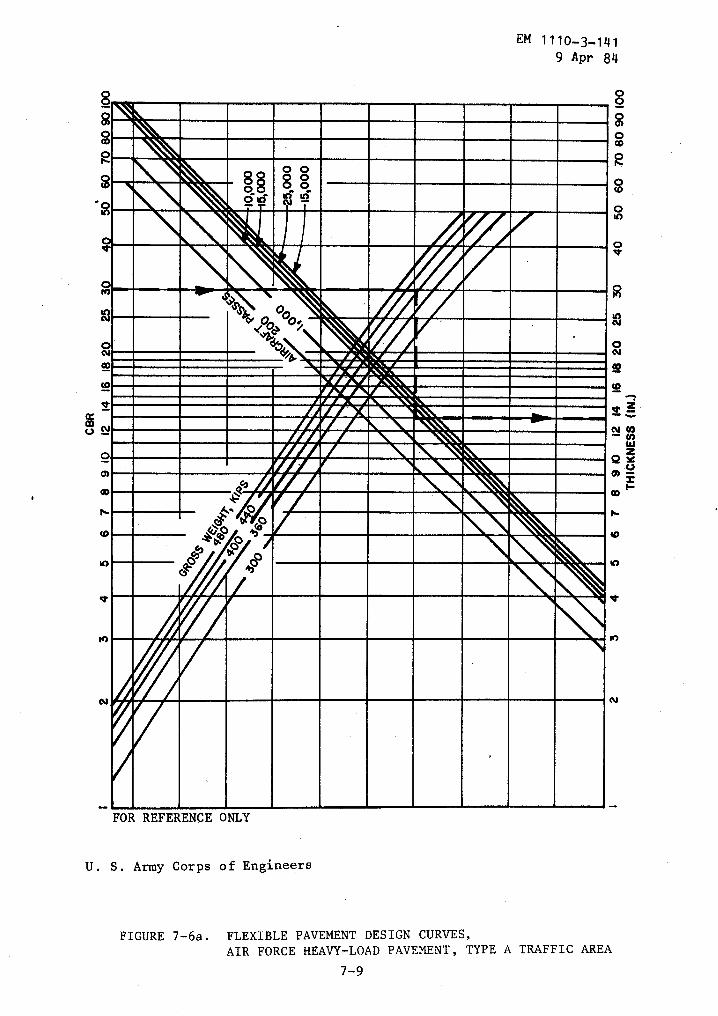
m
FOR REFERENCE ONLYU . S . Army Corps of Engineers
7- 9
EM 1110-3-1419 Apr 84
FIGURE 7-6a . FLEXIBLE PAVEMENT DESIGN CURVES,AIR FORCE HEAVY-LOAD PAVEMENT, TYPE A TRAFFIC AREA
00
W2YV
cMOM_ 1 0
cOD a
OWN 00 0 0 caLNE6001 _UJ c
r 11WHOElNLN11ailml!'4__ N vy,- c
04Ll002
LOvI®.WIW.S&\'M
~si1W4a~ \~
O
01 nrisi~Mll=\0~~ O!
rto
> mmmm \0===M'611' .ON0
OMMMMON07aM N '
~r
N N
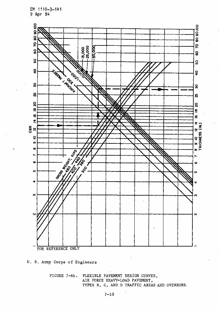
EM 1110-3-1419 Apr 84
0o
w
c
O
A0100u"
'1000-
Ilk
FOR REFERENCE ONLY
U . S . Army Corps of Engineers
7-10
FIGURE 7-6b . FLEXIBLE PAVEMENT DESIGN CURVES,AIR FORCE HEAVY-LOAD PAVEMENT,TYPES B, C, AND D TRAFFIC AREAS AND OVERRUNS .
r0
0
000m0CD
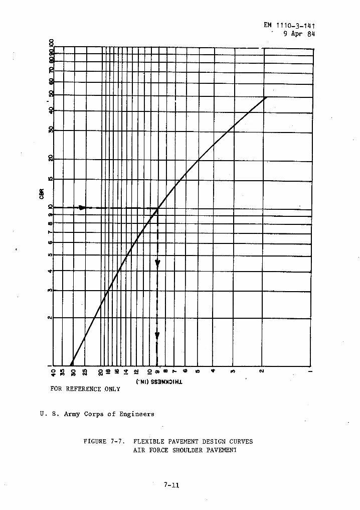
M
N
MA I
I z
OOLlt0 1 N
O 0 m r- 0
a
V'
M
N
('NI) SS3N)I3IHlFOR REFERENCE ONLY
U . S . Army Corps of Engineers
FIGURE 7-7 . FLEXIBLE PAVEMENT DESIGN CURVESAIR FORCE SHOULDER PAVEMENT
7-11
EM 1110-3-141"
9 Apr 84
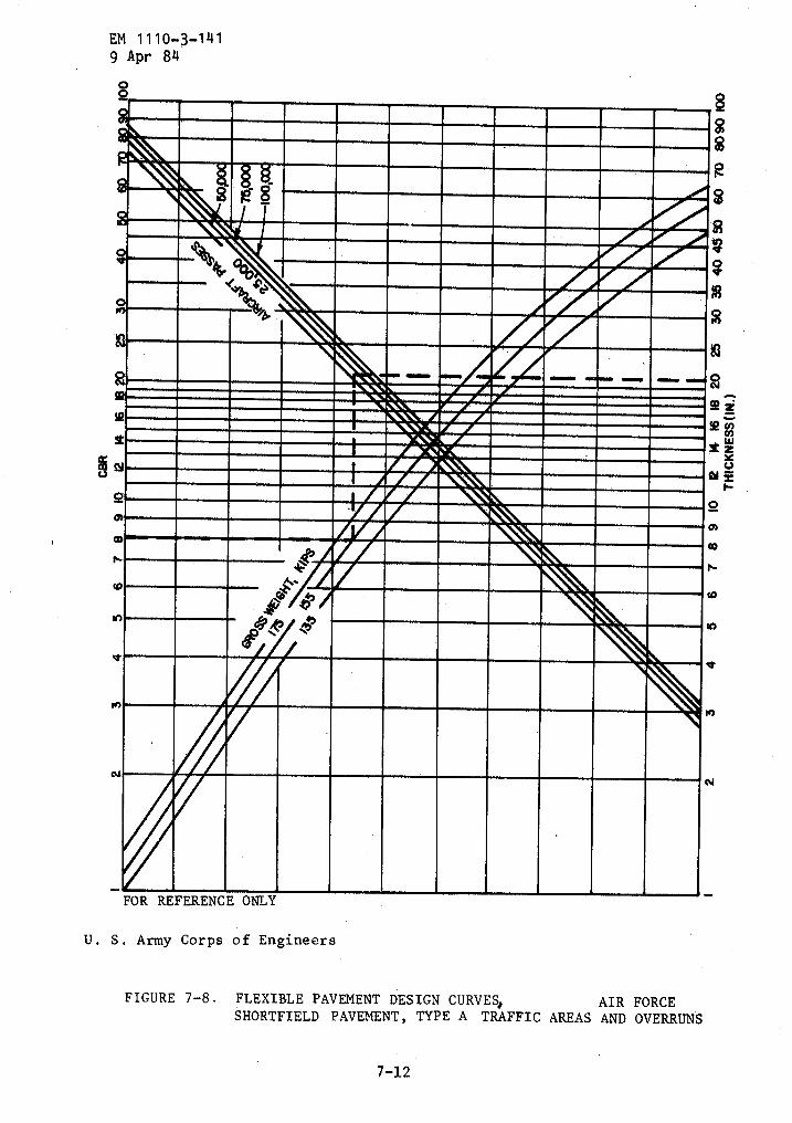
EM 1110-3-141g Apr 84
40
M
N
0
mss, WANW.sMr~rmr~~r~,~,~r~l.`AX''!'!.~-rXX\WAIVAMWAA
----~_XN,a'%r--~---
W-496
RL\0
FOR REFERENCE ONLY
U . S . Army Corps of Engineers
FIGURE 7-8 . FLEXIBLE PAVEMENT DESIGN CURVES*AIR FORCESHORTFIELD PAVEMENT, TYPE A TRAFFIC AREAS AND OVERRUNS
7-12
se a)
3 Y
mss'F-
a
M
N
determined . These thicknesses together with the minimum thicknessesfor surface and base courses provide the basis for pavement sectiondesign . Use table 5-2 for minimum thickness of base and surfacecourse . See table 7-2 for an outline of the flexible pavementthickness design procedure .
In addition, consider the following :
a . CBR values less than 3 . Normally sites which include largeareas of the natural subgrade with CBR values of less than 3 are notconsidered adequate for airfield construction . However, CBR values ofless than 3 are acceptable for occasional isolated weak areas .
b . Frost areas .
Pavement sections in frost areas must be designedand constructed with non-frost-susceptible materials of such depth toprevent destructive frost penetration into underlying susceptiblematerials . Design for frost areas should be in accordance with EM1110-3-138 .
c . Expansive subgrade . Determine if moisture condition ofexpansive subgrade is controlled and if adequate overburden isprovided . (See table 3-5) .
d . Limited subgrade compaction . Where subgrade compaction mustlimited for special conditions (see tables 3-3 and 3-5), providepavement thickness in conformance with reduced density and CBR of theprepared subgrade .
e . Rainfall and water table . In regions where the annualprecipitation is less than 15 inches and the water table (including
15 feet below the finishedsubgradethesenotdetermined20
perched water table) will be at leastpavement surface, the danger of high moisture content in theis reduced . Where in-place tests on similar construction inregions indicate that the water content of the subgrade willincrease above the optimum, the total pavement thickness, asby CBR tests on soaked samples, may be reduced by as much aspercent .
EM 1110-3-1419 Apr 84
f . Pavement section comparison . Compare design pavement sectionswith field behavior of similar pavement sections on comparable soilconditions ; assess the traffic on similar pavement-sections with thedesign traffic loading .
7-5 . Design examples . The examples are not to be used as designcriteria . They are intended solely to illustrate how the criteriathis manual would be used in an assumed situation . Any attempt toarbitrarily apply these examples to actual design problems withoutcomplete design analysis, following the procedures outlined in thismanual, may result in faulty pavement design .
a
be
in
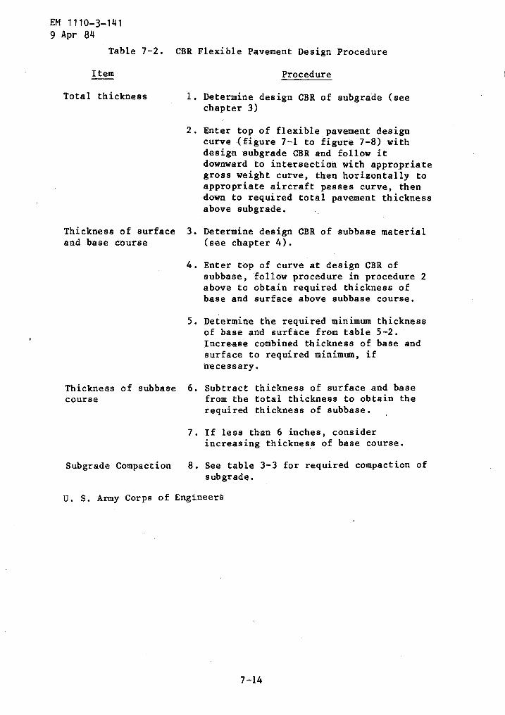
EM 1110-3-1419 Apr 84
Table 7-2 . CBR Flexible Pavement Design Procedure
Item
Procedure
Total thickness
1 . Determine design CBR of subgrade (seechapter 3)
Thickness of subbase 6 . Subtract thickness of surface and basecourse
from the total thickness to obtain therequired thickness of subbase .
U . S . Army Corps of Engineers
2 . Enter top of flexible pavement designcurve (figure 7-1 to figure 7-8) withdesign subgrade CBR and follow itdownward to intersection with appropriategross weight curve, then horizontally toappropriate aircraft passes curve, thendown to required total pavement thicknessabove subgrade .
Thickness of surface 3 . Determine design CBR of subbase materialand base course
(see chapter 4) .
4 . Enter top of curve at design CBR ofsubbase, follow procedure in procedure 2above to obtain required thickness ofbase and surface above subbase course .
5 . Determine the required minimum thicknessof base and surface from table 5-2 .'Increase combined thickness of base andsurface to required minimum, ifnecessary .
7 . If less than 6 inches, considerincreasing thickness of base course .
Subgrade Compaction
8 . See table 3-3 for required compaction ofsubgrade .

a . Design example 1 .
(1) Design an airfield, Type B traffic area for a single-wheeltricycle gear aircraft with a gross load of 25-kips for 1,000,000passes . Subgrade is a poorly graded sand with a design CBR of 16 ;in-place density of the subgrade is 90 percent to a depth of 10 feet .
(2) From figure 7-1 the total pavement section required is 10inches .
(3) From table 5-2 the minimum required surface and basethicknesses are 2 inches and 6 inches respectively, for a - total of 8inches .
(4) Use a 10-inch pavement section consisting of 2 inches ofasphalt concrete surface and 8 inches of 100 CBR base on subgrade toprovide the 10 inches required above the subgrade .
(5) Determine the compaction requirements from table 3-3 . Thedesign section is as follows :
b . Design example 2 .
1 Base and subbase compacted to 100 percent .
Since the existing subgrade has an in-placecompaction of the 8 inch upper layer of themoistening and compacting in place .
top of subgrade
100 percent compaction
95 percent compaction
(cohesionless subgrade)
90 percent compaction
EM 1110-3-1419 Apr 84
density of 90 percent, thesubgrade may be achieved by
(1) Design a heavy load pavement to accommodate a 480-kip grossload twin twin gear assembly aircraft in a Type B traffic area for15,000 passes . Design CBR of the .lean clay subgrade is 13, the naturalin-place density of the clay is 87 percent extending to 10 feet . Theanalysis that follows assumes that subgrade does not require specialtreatment and frost penetration is not a problem .
7-15
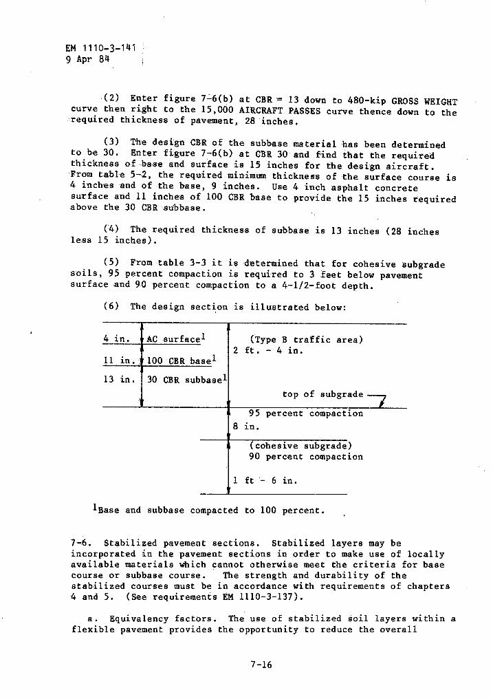
EM 1110-3-1419 Apr 84
(2)
Enter figure 7-6(b) at CBR = 13 down to 480-kip GROSS WEIGHTcurve then right to the 15,000 AIRCRAFT PASSES curve thence down to therequired thickness of pavement, 28 inches .
(3) The design CBR of the -subbase material has been determinedto be 30 . Enter figure 7-6(b) at CBR 30 and find that the requiredthickness of ba-se and surface is 15 inches for the design aircraft .From table 5-2, the required minimum thickness of the surface course is4 inches and of the base, 9 inches . Use 4 inch asphalt concretesurface and 11 inches of 100 CBR base to provide the 15 inches requiredabove the 30 CBR subbas-e .
(4) The required thickness of subbase is 13 inches (28 inchesleas 15 inches) .
(5) From table 3-3 it is determined that for cohesive subgradesoils, 95 percent compaction is required to 3 feet below pavementsurface and 90 percent compaction to a 4-1/2-foot depth .
(6) The design section is illustrated below:
4- in .
AC surface l
(Type B traffic area)2 ft . - 4 in .
11 in . 100 CBR basel
13 in . 30 CBR subbas,eltop of subgrade
95 percent compaction8 in .
(cohesive subgrade)90 percent compaction
1 ft - 6 in .
lBase and subbase compacted to 100 percent .
7-16
7-6 . Stabilized pavement sections . Stabilized layers may beincorporated in the pavement sections in order to make use of locallyavailable materials which cannot otherwise meet the criteria for basecourse or subbase course .
The strength and durability of thestabilized courses must be in accordance with requirements of chapters4 and 5 . (See requirements EM 1110-3-137) .
a . Equivalency factors . The use of stabilized soil layers within aflexible pavement provides the opportunity to reduce the overall
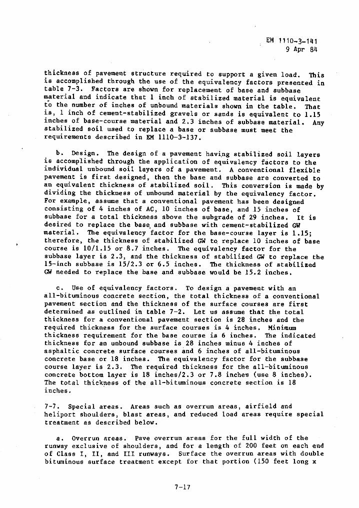
EM 1110- 3-1419 Apr 84
thickness of pavement structure required to support a given load . Thisis accomplished through the use of the equivalency factors presented intable 7-3 . Factors are shown for replacement of base and subbasematerial and indicate that 1 inch of stabilized material is equivalentto the number of inches of unbound materials shown in the table . Thatis, 1 inch of cement-stabilized gravels or sands is equivalent to 1 .15inches of base-course material and 2 .3 inches o ¬ subbase material . Anystabilized soil used to replace a base or subbase must meet therequirements described in EM 1110-3-137 .
b . Design . The design of a pavement having stabilized soil layersis accomplished through the application of equivalency factors to theindividual unbound soil layers of a pavement . A conventional flexiblepavement is first designed, then the base and subbase are converted toan equivalent thickness of stabilized soil . This conversion is made bydividing the thickness of unbound material by the equivalency factor .For example, assume that a conventional pavement has been designedconsisting of 4 inches of AC, 10 inches of base, and .15 inches ofsubbase for a total thickness above the subgrade of 29 inches . It isdesired to replace the base and subbase with cement-stabilized GWmaterial . The equivalency factor for the base-course layer is 1 .15 ;therefore, the thickness of stabilized GW to replace 10 inches of basecourse is 10/1 .15 or 8 .7 inches . The equivalency factor for thesubbase layer is 2 .3, and the thickness of stabilized GW to replace the15-inch subbase is 15/2 .3 or 6 .5 inches . The thickness of stabilizedGW needed to replace the base and subbase would be 15 .2 inches .
c . Use of equivalency factors . To design a pavement with anall-bituminous concrete section, the total thickness of a conventionalpavement section and the thickness of the surface courses are firstdetermined as outlined in table 7-2 . Let us assume that the totalthickness for a conventional pavement section is 28 inches and therequired thickness for the surface courses is 4 inches . Minimumthickness requirement for the base course is 6 inches . The indicatedthickness for an unbound subbase is 28 inches minus 4 inches ofasphaltic concrete surface courses and 6 inches of all-bituminousconcrete base or 18 inches . The equivalency factor for the subbasecourse layer is 2 .3 . The required thickness for the all-bituminousconcrete bottom layer is 18 inches/2 .3 or 7 .8 inches (use 8 inches) .The total thickness of the all-bituminous concrete section is 18inches .
7-7 . Special areas . Areas such as overrun areas, airfield andheliport shoulders, blast areas, and reduced load areas require specialtreatment as described below .
a . Overrun areas . Pave overrun areas for the full width of therunway exclusive of shoulders, and for a length of 200 feet on each endof Class I, II ; and III runways . Surface the overrun areas with doublebituminous surface treatment except for that portion (150 feet long x
7-17
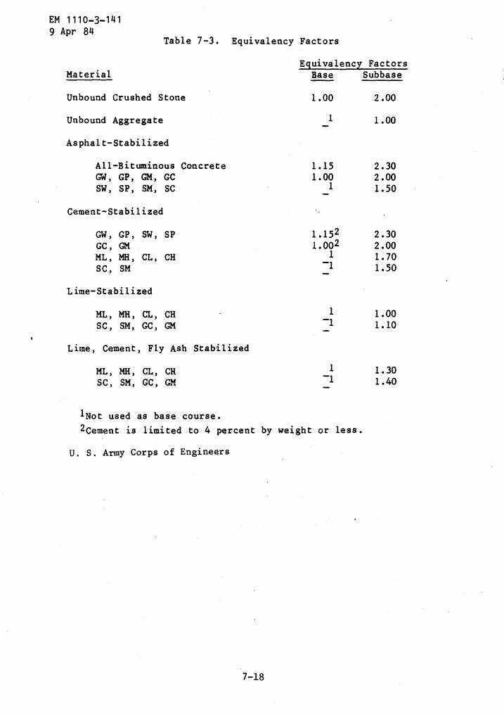
EM 1110-3-141
1 Not used as base course.
7-18
2 Cement is limited to 4 percent by weight or less .
U . S . Army Corps of Engineers
9 Apr 84Table 7- .3 . Equivalency
Material
Factors
EquivalencyBase
FactorsSubbase
Unbound Crushed Stone 1 .00 2 .00
Unbound Aggregate 1 1 .00
Asphalt-Stabilized
All-Bituminous Concrete 1 .15 2 .30GW, GP, GM, GC 1 .00 2 .00SW, SP, SM, SC 1 1 .50
Cement-Stabilized
GW, GP, SW, SP 1 .15 2 2 .30GC, GM 1 .002 2 .00ML, MH, CL, CH 1 1 .70SC, SM '1 1 .50
Lime-Stabilized
ML, MH, CL, CH 1 1 .00SC, SM, GC, GM 1 .10
Lime, Cement, Fly Ash Stabilized
ML, MH, CL, CH 1 1 .30SC, SM, GC, GM -1 1 .40
runway width) abutting the runway pavement end which will have wearingsurface of 2 inches .of dense graded asphaltic concrete for blast
lAny 80 CBR type base course listed in chapter 5 .
2Must meet all requirements for 50 CBR subbase materialslisted in chapter 4 .
EM 1110-3-1419 Apr 84
b . Paved shoulders . Shoulder areas will be paved to support theaircraft outrigger gear and for protection against jet blast . Thewearing surface will be 2 inches of dense graded asphaltic concrete ;design the pavement thickness in accordance with figure 7-7 .
c . Shoulders . Design shoulders adjacent to hardstand and apronareas to sustain traffic of support vehicles . Design the pavementthickness of shoulder areas in accordance with figure 7-7 . Use adouble bituminous surface treatment on a minimum 6-inch base consistingof 40 CBR material or better .
d . Overrun areas and other shoulder areas . Compact surface ofoverrun areas and shoulder areas, except shoulders adjacent to apronsand hardstands, to 90 percent maximum density for a depth of 6 inches .Stabilize the shoulders for dust and erosion control against blast ofmotor blades . Provide vegetative cover, anchored mulch, coarse gradedaggregate, liquid palliatives, or a double bituminous surfacetreatment . When a double bituminous surface treatment is specified,provide a 4-inch base of 40 CBR material or better.
protection . Minimum base
Design - Loading
course CBR values are as follows :
Minimum Base Course CBR
Class III 801
Class II 801
Class I 502
SPECIAL SURFACE TREATMENTS AND SPECIAL DETAILS
8-1 . General . This section covers surface treatments for improvementof skid resistance, reduction of hydroplaning tendency, and resistanceto fuel spillage .
Some disadvantages include :
CHAPTER 8
8-2 . Surface treatment for improved skid resistance . Improved skidresistance and the elimination of the tendency to hydroplane may beaccomplished by proper drainage and proper aggregate selection or byapplication of a porous friction course or by-grooving the pavementsurface . These surface treatments are applicable to runways and highspeed taxiways .
8-3 . Porous friction surface course . Porous friction surface courseconsists of an open graded bituminous concrete containing a largeproportion of one-sized coarse aggregate . The large void contentpermits water to drain through the layer laterally out to theshoulders . Porous friction courses are also described as "open gradedmix," "plant mix seal," and'"popcorn mix ." In addition to improvingskid resistance and preventing hydroplaning, porous friction coursesprovide the following additional advantages :
- Improved visibility of pavement marking .
- Reduced tire splash and spray .
Susceptibility to fuel spills .
Susceptibility to clogging by mud, blow sand, and rubber .
8-4 . Prior preparation . Porous friction courses and grooving shouldonly be applied to structurally adequate sections capable of supportingexisting and future aircraft traffic . The pavement surface should bechecked for proper surface drainage ; transverse grades should be aminimum of 1 percent . Pavements which are understrength, haveinsufficient slope for drainage, contain depressed'areas, or arecracked, should be strengthened and should have deficiencies correctedprior to applying a porous friction course or grooving .
8-5 . Fuel resistant surfacings . Jet fuel-resistant bituminoussurfacings may be used in new construction, where expedient, or asoverlays . See appendix A for criteria on fuel resistantrubberized-tar mixes . Design fuel resistant flexible pavement asoutlined in chapter 7 for conventional pavement, except that thesurface will consist of a tar or asphalt binder topped with aminimum of 1-1/2 inches of rubberized tar wearing course . Joints
EM 1110-3-1419 Apr 84
EM 1110-3-1419 Apr 84
in the wearing course are particularly critical and care must be takenin bonding the joints to prevent leakage which would result indeterioration of the asphalt below .
8-6 . Fuel resistant seal coat . Structurally adequate asphalticpavements in good condition subject to fuel spillage may be protectedby a rubberized-tar slurry seal . Rubberized-tar slurry seal provides afine grained, slippery surface which is resistant to fuel spillage .Because of the slippage surface imparted by this type seal, it is notto be used on runways and taxiways .
8-7 . Juncture between rigid and flexible pavements . Experience hasshown that objectionable roughness often develops at the juncture of arigid and flexible pavement under aircraft traffic . This roughnessgenerally takes the form of subsidence or shoving . For details on thisjuncture, see EM 1110-3-142 .
AI . General .
APPENDIX A
HOT-MIX BITUMINOUS PAVEMENTS, DESIGN AND CONTROL
EM 1110-3-1419 Apr 84
Al-1 . Procedures and criteria . Procedures and criteria in thisappendix apply to design and control of hot-mix bituminous pavementsusing penetration grades of asphalt cement, tar cement, or rubberizedtar .
Al-2 . Alternative approaches . It is anticipated that undermobilization conditions, bituminous pavement materials will be suppliedby established local sources . In most cases these sources have beenutilized by Federal or state agencies in the past and have approveddesign mixes available to meet the needs as outlined in this manual .Review of the available mix results along with the associated materialtest results and supplemented by field inspections and testing ofpresent materials should supply sufficient information to proceed withdesign and construction .
.
Al-3 . Design requirements . The following discussion is presented toprovide the designer with design requirements as an aid to evaluatingavailable materials and to provide information on methods of obtainingdesign data if not locally available .
A2 . Design .
A2-1 .
Survey of materials . A survey of materials available insuitable quantities for use in construction of the pavement is thefirst step in the design of a paving mixture . Materials normallyrequired for the paving mixture are coarse aggregate, fine aggregate,mineral filler, and bitumen .
A2-2 . Sampling . Sufficient quantities of materials are to be obtainedto provide for laboratory pavement design tests subsequentlydescribed .
a . Fine and coarse aggregate . Sampling of fine-and coarse aggregatewill be in accordance with ASTM D 75 .
b . Mineral filler . Sampling of mineral filler will be in accordancewith ASTM C 183 .
c . Asphalt cement, tar cement, and rubberized tar . Sampling of allbituminous materials will be in accordance with ASTM D 140 .
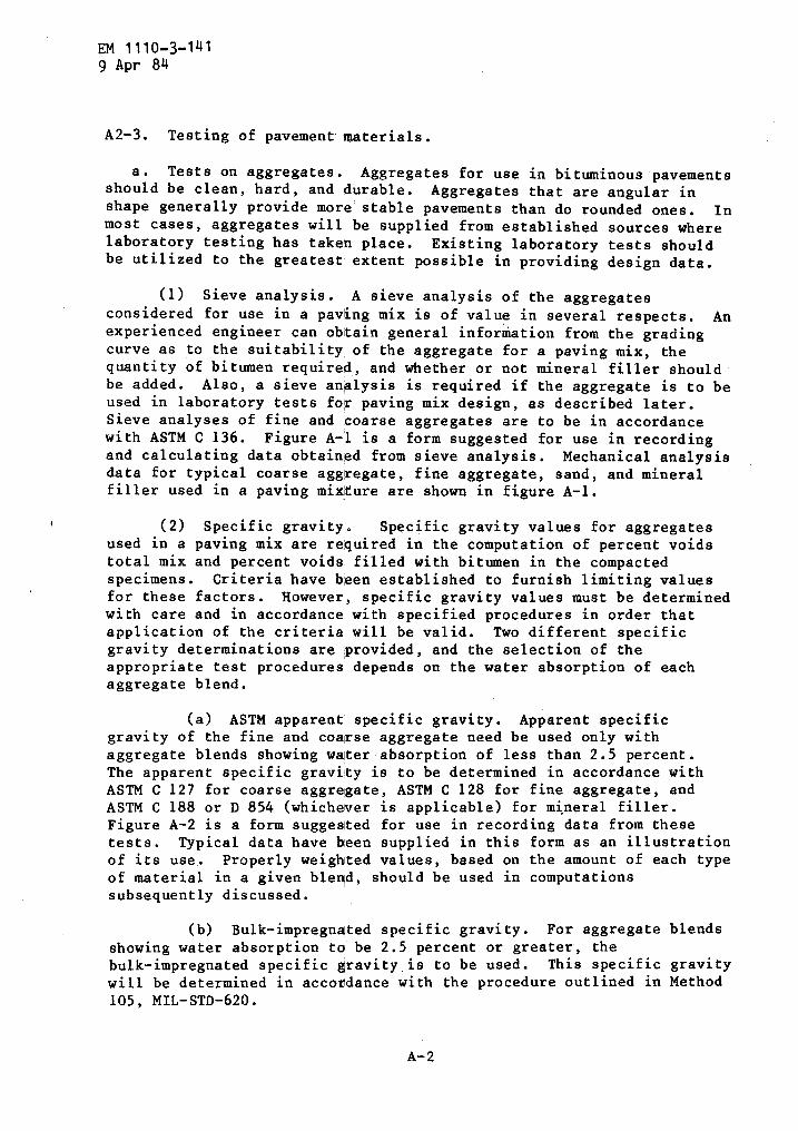
EM 1110-3-1419 Apr 84
A2-3 . Testing of pavement- materials .
a . Tests on aggregates . Aggregates for use in bituminous pavementsshould be clean, hard, and durable . Aggregates that are angular inshape generally provide more' stable pavements than do rounded ones .
Inmost cases, aggregates will be supplied from established sources wherelaboratory testing has taken place . Existing laboratory tests shouldbe utilized to the greatest extent possible in providing design data .
(1) Sieve analysis . A sieve analysis of the aggregatesconsidered for use in a paving mix is of value in several respects . Anexperienced engineer can obtain general information from the gradingcurve as to the suitability of the aggregate for a paving mix, thequantity of bitumen required, and whether or not mineral filler shouldbe added . Also, a sieve analysis is required if .the aggregate is to beused in laboratory tests for paving mix design, as described later .Sieve analyses of fine and coarse aggregates are to be in accordancewith ASTM C 136 . Figure A-1 is a form suggested for use in recordingand calculating data obtained from sieve analysis . Mechanical analysisdata for typical coarse aggregate, fine aggregate, sand, and mineralfiller used in a paving mixture are shown in figure A-1 .
(2) Specific gravity .
Specific gravity values for aggregatesused in a paving mix are required in the computation of percent voidstotal mix and percent voids filled with bitumen in the compactedspecimens . Criteria have been established to furnish limiting valuesfor these factors . However, specific gravity values must be determinedwith care and in accordance with specified procedures in order thatapplication of the criteria will be valid . Two different specificgravity determinations are ;provided, and the selection of theappropriate test procedures depends on the water absorption of eachaggregate blend .
(a) ASTM apparent specific gravity . Apparent specificgravity of the fine and coarse aggregate need be used only withaggregate blends showing water absorption of less than 2 .5 percent .The apparent specific gravity is to be determined in accordance withASTM C 127 for coarse aggregate, ASTM C 128 for fine aggregate, andASTM C 188 or D 854 (whichever is applicable) for mineral filler .Figure A-2 is a form suggested for use in recording data from thesetests . Typical data have been supplied in this form as an illustrationof its use . Properly weighted values, based on the amount of each typeof material in a given blend, should be used in computationssubsequently discussed .
(b) Bulk-impregnated specific gravity . For aggregate blendsshowing water absorption to be 2 .5 percent or greater, thebulk-impregnated specific gravity . is to be used .
This specific gravitywill be determined in accordance with the procedure outlined in Method105, MIL-STD-620 .
A-2

U . S . Army Corps of EngineersFIGURE A-1 . SIEVE ANALYSIS
A-3
EM 1110-3-1419 Apr 84
SIEVE ANALYSIS
JOB NO : PRI)JECT : TYPICAL MIX DATE :
STOCKPILE SAMPLES DRY GRADATION
SAMPLE No . Crushed Coarse re ate SAMPLE N0. Crushed Fine Aggregate
U.S. STANDSIEVE NO.
WEIGHTRETAINED
zRETAINED
zPASS
U.S . STAND.SIEVE NO .
WEIGHTRETAINED
zRETAINED
zPASS
344 _ 100 _ 3/4_1/2-
. -225 .9- 30. 70.0 1/2 100
3/6 267 .3 35 .5 34 .5 3/8 ,1 0.2 99 .8NO . 4 237 .2 31 .5 3.0 NO . 4 ' 53 .9 9. . 8 90.0NO . 8 22.6 3 .0 No . S 104 .6 19.0 71 .0NO . 16 NO- 1 104 .6 19.0 52 .0NO . 30 NO . 30 96.3 17 .5 34 .5No . 50 No . so 82 .5 15.0 19 .59D.10 NO. 100 60 .5 11.0 8 .5NO. 20b No " 30 . 5.5 3 .0
-200/ m~~®TOTAL 753 . /
WEIGHT ORIGINAL SAMPLE WEIGHT ORIGINAL SAMPLE
WASHED GRADATION
SAMPLE No . Natural Sand SAMPLE No . Limestone Filler
U.S . STANDSIEVE NO.
WEIGHTRETAINED
zRETAINED
zPASS
U.S . STAND.SIEVE NO .
WEIGHTRETAINED
zRETAINED
zPASS
3/4 3/4
1/2 1/2
3/8 3/8
NO . 4 50 . 490 . g NO . 8
NO . 16 NO . 16
NO . 30 100 NO . 30
NO . 50 9 .4 4.5 95 .5 No . 5o 100NO . 100 54 .6 26 .0 69.5 No . 100 2 .3 2 . 0 " 090 " 200 124 .9 59 .5 10.0 NO . 200 9 . 8 .0 90 .0_200
TOTAL
(T) 21.0209 .9
05
MZZMAVVIA145,NA(A) WEIGHT ORIGINAL SAMPLE 2 9 .2 GH(B) WEIGHT AFTER WASHED J.I am(C) WASH LOSS (A - B GM(S) -200 FROM SIEVING GK(T) TOTAL -200 C +
---GM
USE "T" TO CALCULATE PERCENTAG S
(A) WEIGHT ORIGINAL SAMPLE 117 .4-(B) WEIGHT AFTER WASHED 18.9
(C) WASH LOSS (A - B) 98 .5 GH(S) -200 FROM SIEVING 6 .8(T) TOTAL -2000 C + S 105 .3USE "T" TO CALCULATE PERCENTAGES
I
TESTED BY : COMPUTED By. -T-CHECKED BY :
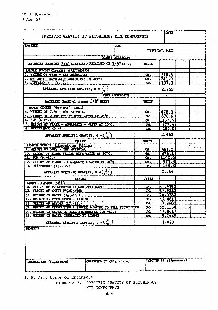
EM 1110-3-1419 Apr 84
U . S . Army Corps of Engineers
FIGURE A-2 . SPECIFIC GRAVITY OF BITUMINOUSMIX COMPONENTS
A-4
SPECIFIC GRAVITY OF $ITUMINOUS MIX COMPONENTSDATE
PROJECT JOBTYPICAL MIX
COARSE AGGREGATE
MATERIAL PASSING JW SIEVE AND RETAINED ON 'SIEVE UNITS
SAMPLE NUMBER Coarse a re ate1. WEIGHT OF OVEN - DRY AGGREGATE GM . rt2 . WRIGHT OF SAXURATtD AGGREGA IN WATER GM.3 . DIFFERENCE .-2. GM. E )r -
APPARENT SPECIFIC GRAvITY, G - 2.755FINE AGGREGATE .
MATEBI& PASSING NUMBER 3 ~STEVE UNITS
SAMPLE NUMBER Natural san4 . WEIGHT OF OVEN - DRY MATERIAL Gl( . [ ~5 . WEIGHT OF FLASK FILL2D AT 20-C GM.6 . SUM (4 .+5.) REM7 . WEIGHT OF FLASK + AGGREGATE + WA a' GM .8 . DIFFERENCE (6 .-7 .) GM. 8
APPARENT spacirzc GEAviTY, G4 . 2 .660
FI1LER UNITS_SAMLE NUMBER9 . WEIGHT OF OVEN - DRY MATERIAL M
10 . WEIGHT of FLASK FILLED WITH W AT 20-C i11 . Sum (9 .+10 . ~1A_;~kj12 . WEIGHT OF FLASK + AGGREGATE + T 0-C mww13. DIFFERENCE (11.-12.) ~/MIX.]
APPARENT SPECIFIC GRAVITY, G - (13.2 .764
BINDER UNITSSAMPLE IMER 6873
14 . WEIGHT OF PYCNOMETER c +~ w a WATER GM. 915. WEIGHT OF EMPTY PYCN0METER ~c;K A&16. WEIGHT OF WATER (14.-13 .)
_
17 . WEIGHT OF PYCNOMBTER + BINDER18 . WEIGHT of BINDER 17.-15 . GM. 919 . WEIGHT OF PYCNOMETHR + BINDER + W TER 12 F PYCNOMLTER20. WRIGRT OF WATER To FII.L PYC L-j::j:--~ (19 .-17.) GM . 7.8621 . WEIGHT OF WATER DISPLACED BY BIND GM. .742
APPARENT SPECIFIC GRAVITY, G - (2E~ 1 .020
TECHNICIAN (Signature) CO "~~D BY (Signature) CHECZED BY (Signature)
(3) Wear requirements for coarse aggregate . The determinationof percentage of wear for coarse aggregates may not be necessary if theaggregate has been found satisfactory by previous tests . However,coarse aggregates obtained from new or doubtful deposits must be testedfor conformance to specification requirements using ASTM C 131 .
(4) Soundness test . The soundness test is used where damagefrom freezing is expected to be a problem . It is not necessary toconduct the soundness test on aggregate that has been foundsatisfactory by previous tests . However, aggregate obtained from newor doubtful deposits will be tested for conformance to specificationrequirements using ASTM C 88 .
(5) Swell test . Experience has indicated that bituminouspavements produced from clean, sound stone, slag, or gravel aggregatesand from mineral filler produced from limestone will show values in theswell test of less than 1 .5 percent . However, aggregates considered tobe of doubtful character will be tested for conformance tospecification requirements for percentage of swell in accordance withAASHTO T 101 .
EM 1110-3-1419 Apr 84
(6) Immersion-compression test . This test should be conductedon all paving mixes considered for construction of pavements .
(SeeMethod 104, MIL-STD-620) .
b . Tests on mineral filler . Some mineral fillers have been foundto be more satisfactory in asphalt paving mixtures than others . Forexample, fine sands and clays are normally less suitable fillers thanlimestone filler or portlan4 cement . Well-graded materials are moresuitable than poorly graded materials . A limited amount of laboratorywork has indicated that mineral fillers of reasonably uniform gradationand falling within the limits set forth in paragraph A2-3 .f .hereinafter, are generally satisfactory . Satisfactory pavements may bedesigned using commercial fullers that conform to ASTM Standards . Thespecific gravity of the mineral filler is required in void computation .It will be determined in accordance with ASTM D 854, or alternatively,ASTM C 188, except that when the bulk-impregnated specific gravity isused, the mineral filler is to be included in the blended aggregate(See Method 103, MIL-STD-620) . Figure A-2 is a form suggested fortabulation and computation of these data ; typical data have beenentered in this form to illustrate its use .
c . Tests on bitumen . Test requirements for asphalt cement, tar forrubberized-tar blends, rubberized-tar blends, and tar are outlined inthe mobilization specifications . Figure A-2 is a form suggested foruse in determining specific gravity of bitumen ; typical data areincluded in this form .
d . Selection of materials for mix design . The first step in thedesign of a paving mix is the tentative selection of materials . The
A- 5
EM 1110-3-141g Apr 84
bitumen used in the laboratory tests must be the same as that whichwill be used in field construction . The selection of aggregates andmineral filler for the paving mix is more involved than the selectionof the bitumen . Aggregates and mineral fillers that do not meet therequirements of the specifications previously discussed should beeliminated from further consideration . The remaining aggregates andfiller must then be examined from both technical and economicalviewpoints . The final objective is to determine the most economicalblend of aggregates and mineral filler that will produce a pavementmeeting the engineering requirements set forth in this manual . Ingeneral, several blends should be selected for laboratory mix-designtests . The mix-design gradation (i .e ., job-mix formula) plus or minusjob-mix tolerances must fall within the gradation tolerances specifiedin the appropriate guide specification .
e . Combining aggregates . In the production of paving mixes, it isgenerally necessary to combine aggregates from two or more sources .Mathematical equations are available for making such combinations, butthey are not presented herein because they are lengthy and normally itis easier to use trial-and-error procedures . Methods and proceduresdescribed herein will permit determination of the most suitableaggregate or blend available, and will prescribe the proper bitumencontent for the particular aggregate blend determined to be the mostsuitable . Whenever a paving mix will not meet established criteria, assubsequently outlined, it is necessary either to improve the gradationof the aggregate being used or to use another aggregate . The choice asto improvement of gradation or the use of another aggregate is a matterof engineering judgment involving an analysis of the availableaggregate supplies and various economic considerations .
f . Addition of mineral filler . The filler requirements of eachaggregate blend must be estimated after the blends to be tested in thelaboratory have been selected . Considerations should be given to theitems discussed in paragraph A2-3 .b . in selecting the mineral filler tobe used . The quantity of mineral filler to be added depends on severalfactors, among which are the amount of filler naturally present in theaggregate, desired reduction in voids, the extent to which additionalincrements of filler will decrease the optimum bitumen content of themixture, the extent to which it may be necessary to-improve thestability of the mixture, and the cost of the filler . The addition ofmineral filler reduces the quantity of bitumen required for the pavingmixture . The addition of excessive amounts of filler is noteconomical, as a limit is reached at which no further reduction inoptimum bitumen content occurs with an increase in filler . It also hasbeen indicated that the addition of a satisfactory mineral fillerwithin practical limits increases the stability of a paving mixture .Excessive amount of filler, however, may decrease the durability of thepaving mixture . Therefore, while-the addition of some mineral filleris normally beneficial to the paving mixture, the addition of largequantities of filler not only is uneconomical, but may also be
A-6
A2-4 . Laboratory testing for mix design .
A-7
EM 1110-3-1419 Apr 84
detrimental to the paving mixture . Experience has indicated thatfiller contents should not exceed about 10 percent for bituminousconcretes and about 20 percent for sand asphalts . Practicalconsiderations usually will dictate quantities of about 5 percentfiller for bituminous concrete and 10 percent for sand asphalts . Whenthere has been no previous experience with a particular aggregate, itmay be desirable to conduct laboratory tests at more than one fillercontent in order that the best mixture can be selected .
a . General procedure . Laboratory testing will indicate theproperties that each blend selected would have after being subjected toappreciable traffic . A final selection of aggregate blend and fillerwill be based on these data with due consideration to relative costs ofthe various mixes . The procedures set forth in the followingparagraphs are directly applicable to all mixes containing not morethan 10 percent of aggregate retained on the 1-inch sieve . Theprocedure to follow when a mix contains more than 10 percent aggregateexceeding the 1-inch-maximum size is outlined in Method 103,MIL-STD-620 .
b .
Preparation of test specimens . The selection of materials foruse in designing the paving mix was discussed in paragraph 6-2 . Forpurposes of illustration, suppose that it has been determined that anaggregate gradation for a hot-mix design should be the median of thelimiting gradation curves in figure A-3 . This is the blend on whichdesign data are required . The initial pavement mix design tests willusually be made in a central testing laboratory . The initial testswill be conducted on sample's of stockpile materials submitted by theContractor . Paragraph (1) below outlines the procedure forproportioning stockpile samples to produce a blend of materials to meeta specified gradation . The final mix will be based on bin samplestaken from the bituminous plant ; in this step, it will again benecessary to determine what proportions of the bin materials will berequired to meet a specified gradation . The final mix design willusually be made in a field laboratory near the plant, or the binsamples may be sent to the central laboratory that conducted theinitial design tests on the stockpile samples . Paragraph (2) belowoutlines the procedure for combining processed bin samples to meet aspecified gradation .
(1) Proportioning of stockpile samples . As a preliminary stepin mixture design and manufacture, it is necessary to determine theapproximate proportions of the different available stockpiled materialsrequired to produce the desired gradation of aggregate . This isnecessary in order to determine whether a suitable blend can beproduced and, if so, the approximate proportion of aggregates to be fedfrom the cold feed into the dryer . Sieve analyses are run on materialfrom each of the stockpiles and these data entered in a form as
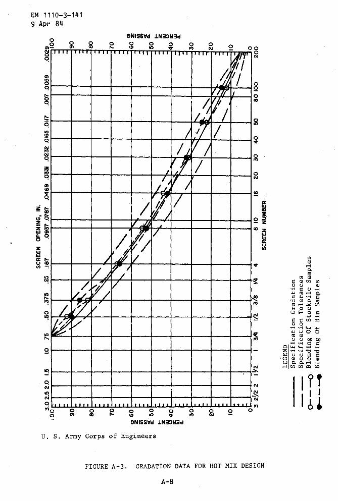
LEGEND
Specification
Gradation
Specification
Tolerances
Blending
Of
Stockpile
Samples
Blending
Of
Bin
Samples
SCREEN
NUMBER
SCREEN
OPENING,
IN.
a
0 0
0 0z Z w U w a
%0M w
3.02.52
.01.5
1.0
.75
.50
.375
.25
.187
.093
7.0787
.0469
.0331
.0232
.0165
.0117
.007
.0059
.0029
INMI
kl qvommmlmmmmm
IIIC 9 8 T 6 5( 3C 2
(
10
32
1/2
21%2
3/4
1/2
3/8
I/4
48
1016
20
30
40
50
80
100
200
100
a90
1-1
nH
O80
aTO
(IQ
(960
G7
"
C1 H
(D "(a a
50
9O0
W0.
zv40
Hd
a30
0 z 020
H H10
C7
Cr1
0H z
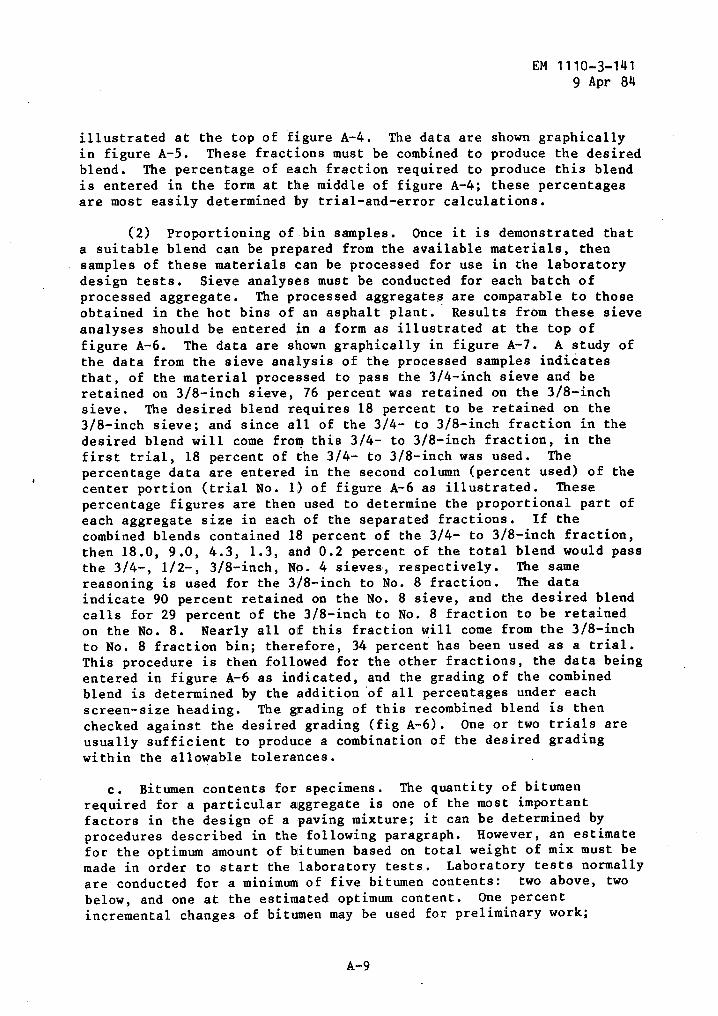
A-9
EM 1110-3-1419 Apr 84
illustrated at the top of figure A-4 . The data are shown graphicallyin figure A-5 . These fractions must be combined to produce the desiredblend . The percentage of each fraction required to produce this blendis entered in the form at the middle of figure A-4 ; these percentagesare most easily determined by trial-and-error calculations .
(2) Proportioning of bin samples . Once it is demonstrated thata suitable blend can be prepared from the available materials, thensamples of these materials can be processed for use in the laboratorydesign tests . Sieve analyses must be conducted for each batch ofprocessed aggregate . The processed aggregates are comparable to thoseobtained in the hot bins of an asphalt plant . Results from these sieveanalyses should be entered in a form as illustrated at the top offigure A-6 . The data are shown graphically in figure A-7 . A study ofthe data from the sieve analysis of the processed samples indicatesthat, of the material processed to pass the 3/4-inch sieve and beretained on 3/8-inch sieve, 76 percent was retained on the 3/8-inchsieve . The desired blend requires 18 percent to be retained on the3/8-inch sieve ; and since all of the 3/4- to 3/8-inch fraction in thedesired blend will come from this 3/4- to 3/8-inch fraction, in thefirst trial, 18 percent of the 3/4- to 3/8-inch was used . Thepercentage data are entered in the second column (percent used) of thecenter portion (trial No . 1) of figure A-6 as illustrated . Thesepercentage figures are then used to determine the proportional part ofeach aggregate size in each of the separated fractions . If thecombined blends contained 18 percent of the 3/4- to 3/8-inch fraction,then 18 .0, 9 .0, 4 .3, 1 .3, and 0 .2 percent of the total blend would passthe 3/4-, 1/2-, 3/8-inch, No . 4 sieves, respectively . The samereasoning is used for the 3/8-inch to No . 8 fraction . The dataindicate 90 percent retained on the No . 8 sieve, and the desired blendcalls for 29 percent of the 3/8-inch to No . 8 fraction to be retainedon the No . 8 . Nearly all of this fraction will come from the 3/8-inchto No . 8 fraction bin ; therefore, 34 percent has been used as a trial .This procedure is then followed for the other fractions, the data beingentered in figure A-6 as indicated, and the grading of the combinedblend is determined by the addition 'of all percentages under eachscreen-size heading . The grading of this recombined blend is thenchecked against the desired grading (fig A-6) . One or two trials areusually sufficient to produce a combination of the desired gradingwithin the allowable tolerances .
c . Bitumen contents for specimens . The quantity of bitumenrequired for a particular aggregate is one of the most importantfactors in the design of a paving mixture ; it can be determined byprocedures described in the following paragraph . However, an estimatefor the optimum amount of bitumen based on total weight of mix must bemade in order to start the laboratory tests . Laboratory tests normallyare conducted for a minimum of five bitumen contents two above, twobelow, and one at the estimated optimum content . One percentincremental changes of bitumen may be used for preliminary work;
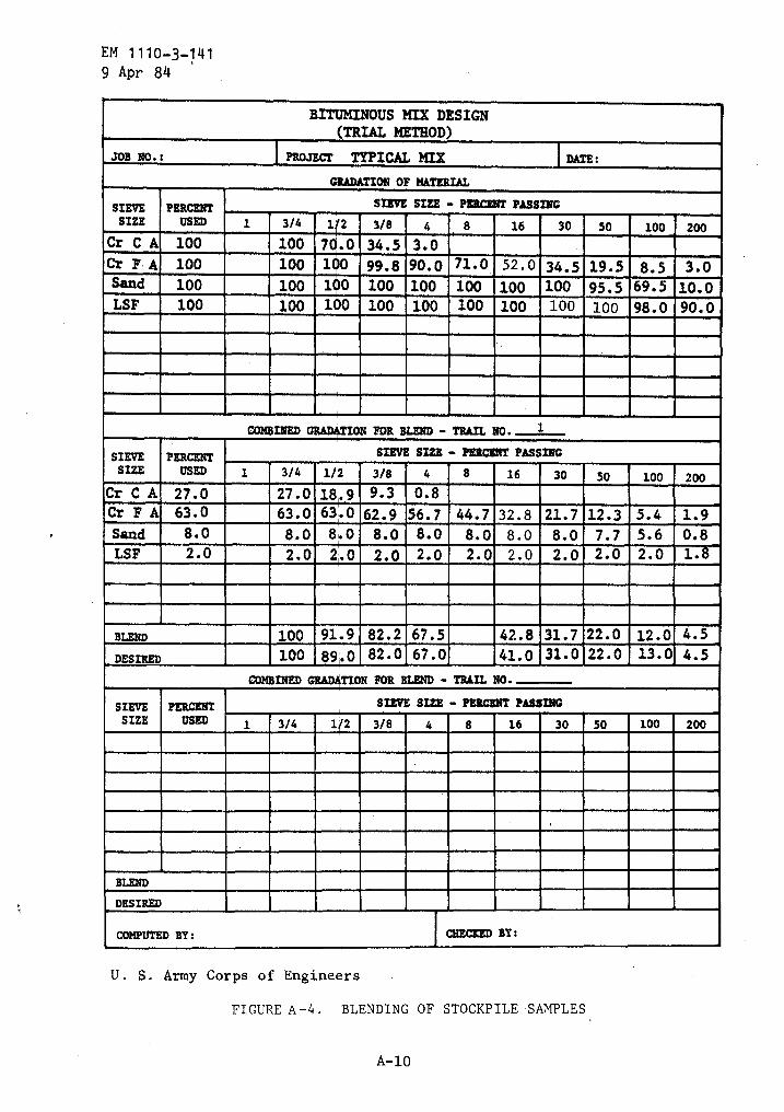
EM 1110-3-1419 Apr 84
U . S . Army Corps of Engineers
FIGURE A-4 .
BLENDING OF STOCKPILE SAMPLES
A-10
BITUMINOUS MIX DESIGNTRIAL METHOD)
JOB No. : PROJECT TYPICAL MIX DATE :
RADATION OF MATERIAL
SIEVE PERCENT SIEVE SIZE -PERCENT PASSINGSIZE USED 1 3/4 1'2 3/8 4 8 16 30 50 100 200
Cr C A 100 100 70 .0 34 .5 3 .0Cr F,A 100 100 1 0 99.8 90 .0 71 .0 . 52 .0 34 .5 19.5 8.5 3.0Sand 100 100 10 100 100 100 100 100 95 .5 69 .5 10 .0LSF 100 100 100 100 100 100 100 100 98.0 90 .0
COMBINED ON FOR BLEND - TRAIL NO . 1
SIEVE PERCENT SIEVE SIZE " PERCENT PASSINGSIZE USED 1 3/4 1/2 3/8 4 8 16 30 50 100 200
Cr C A 27 .0 27 .0 18'.9 9 .3 0 .8Cr F A 63 .0 63 .0 63 .0 62 .9 56 .7 44 .7 32 .8 21.7 12 .3 5 .4 1 .9Sand 8 .0 8 .0 8 .0 8.0 8 .0 8 .0 8 .0 8 .0 7 .7 5 .6 0 .8LSF 2 .0 2 .0 2'.0 2 .0 2 .0 2 .0 2 .0 2 .0 2 .0 2 .0 1 .
BLEND 100 91 .9 82 .2 67 .5 42 .8 31 .7 22 .0 12-A 4 .5DESIRED 100 89 .0 82 .0 67 .0 41 .0 31 .0 22 .0
_13 .0 4 .5
COMBINED TION FOR BLEND - TRAIL N0 .
SIEVE PERCENT SIEVE SIZE - PERCENT PASSINGSIZE USED 1 3/4 1/2 3/8 4 8 16 30 50 100 200
BLEND
DESIRED
COMPUTED BY : CBE= BY:
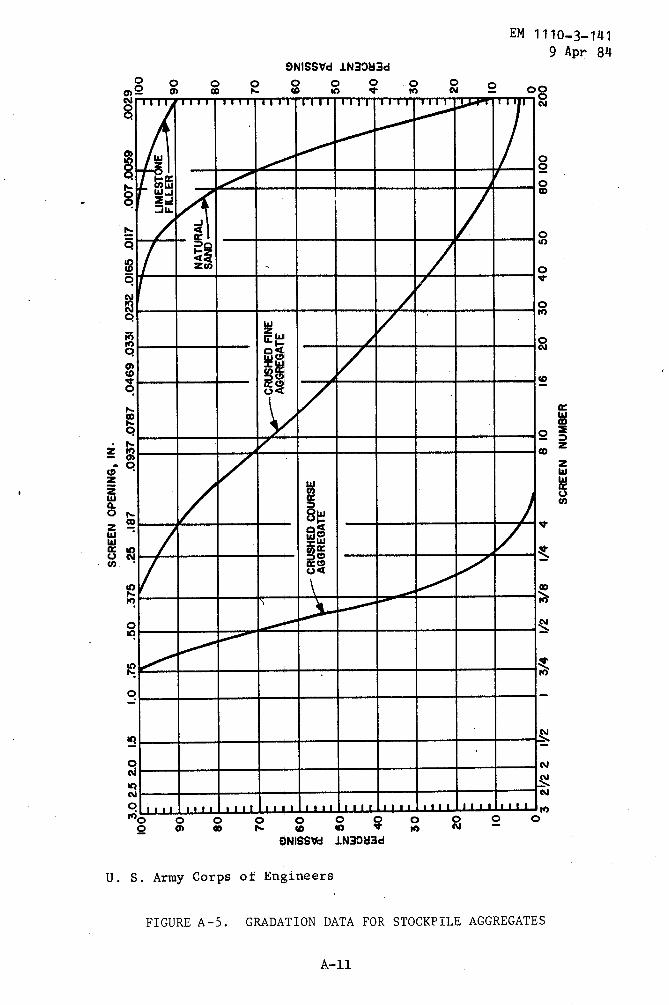
SCREEN
OPENING,
IN.
SCREEN
NUMBER
0 0 0 0 0z y a
0f- z W 0
0w W a
0 0
0a1
'dw t
0o
-Ar
3.0
252.
01 .5
1.0
.75
.50
.3T5
.25
.187
.093T.0787
.0469
.033
1cj
z3z
.0167
M11!
.0070059
0029
_~I
II10Limonl%klmmmmm&lk=
9
mmim
B 7\
MEN,
6-
COURSE
AGGR
EGAT
E5
la, 54
-mmiummimmEL
I lommia
llMEL
qn=jME
E§,bqhL Mi
ni3 2
, =
it O3
21/2
2-IV2
13/
41/
23/8
1/4
48
1016
2030
40
5080
100
200
100
H,~D
90re a
o n b80
.m 0 rn
70ty a
GQ0
H.
H Or60
zm
an
19
rH
z50
ra
W a K0
W aH O
30b r
20a
10H
0
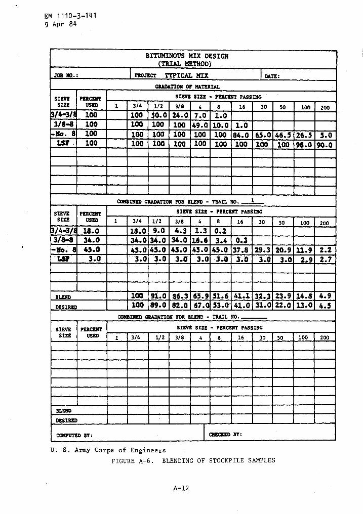
EM 1110-3-1419 Apr 84
U . S . Army Corps of EngineersFIGURE A-6 . BLENDING OF STOCKPILE SAMPLES
A-12
BITUMINOUS MIX DESIGN(TRIAL METHOD)
303 NO . : Pz=CT TYPICAL MIX DATE :
GRADATION OF MATERIAL
SIEVE PERCENT SIISVE SIZE - PERCENT PASSINGSIZE USED 1 3/4 1/2 3/8 4 8 16 30 50 100 200~._ ._
24 .0 7 .0 1.0-3/8-8 _100 100 " 100 49.0 10.0 1.0-No - 8 100 100 ~ " 100 100 100 84 .0 65 .0 46 .5 26 .5 5 .0LSB . 100 1.00 E +3100 100, 100 100 100 100 98 .0 90.0
CaReINED ION FOR BLEND - TRAIL NO. 1
SIEVE PERCENT SIEVE SIZE - PERCENT PASSINGSIZE USED 1 3/4 1/2 3/8 4 8 16 30 50 100 200
/4-1/ 18.0 18 .0 "0 4. 3
I
1.3 0.23/84 34..0 34.0 El ] 34:.0 16 .6- 3.4 _0..3No. 8 45.0 454 0am 45A 45.0 45 .0 37.8 29.3 20.9 U.9- 2 .2T.3? 3.0 3.0Kim 3.0 3 .0 -3.0 3.6 3 .0 3 .6 2.4 2.7
BLEND 100 .0 86 .3 65 .9 51.6 41.1 32.3 23 .9 14 .6 4.9DESIRED 100 80.0 82.0 67 .0 - 33 .0, 41 .0 31.022.0 13-014.3
COMBINED TION FOR BLEND -TRAIL NO .
SIEVE PERCENT SIEVE SIZE - PERCENT PASSINGSIZE USED 1 3/4 3/8 4 8 16 30 SO 100 200
-_. --BLEND
DESIRED
COMPUTED BT : CHECKED BY :

ri z20 10 0
SCREEN
OPENING,
IN.
100.0
2'.S2.
0
1.5
1.0
.T5
.50
.375
.25
.187
.0937
.0787
.046
9.0331
.023
2.0165
.0117
.007
.005
9
.00290
ILIMES70NE
90
FILLER
90
n~+
0
80
80
a
0
NO
.8
i
3/8-NO
.870
.
703/
4-A/N
.
co60
m
c~60
c~t
z
1
z
wz
150
50
ca
w40
40
aw
it
30
30
H3
2~2
2
11/2
J
1
3/4
1/8
3/8
1/4
4
,
810
IS
20
30
40
50
80
100
200
,~w
.s1
SCREENNUMBER
co.9
=
20
10 0
3
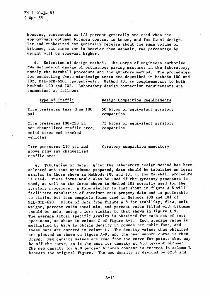
EM 1110-3-1419 Apr 84
however, increments of 1/2 percent generally are used when theapproximate optimum bitumen content is known, and for final design .Tar and rubberized tar generally require about the same volume ofbitumen, but since tar is heavier than asphalt, the percentage byweight will be somewhat higher .
d . Selection of design method . The Corps of Engineers authorizetwo methods of design of bituminous paving mixtures in the laboratory,namely the Marshall procedure and the gyratory method . The proceduresfor conducting these mix-design tests are described in Methods 100 and102, MIL-STD-620, respectively . Method 101 is complementary to bothMethods 100 and 102 . Laboratory design compaction requirements aresummarized as follows :
Type of Traffic
Design Compaction Requirements
Tire pressures less than 100
50 blows or equivalent gyratorypsi
compaction
Tire pressures 100-250 in
75 blows or equivalent gyratorynon-channelized traffic area,
compactionsolid tires and trackedvehicles
Tire pressures 250 psi and
Gyratory compaction mandatoryabove plus any channelizedtraffic area
e . Tabulation of data . After the laboratory design method has beenselected and test specimens prepared, data should be tabulated on formssimilar to those shown in Methods 100 and 101 if the Marshall procedureis used . These forms would also be used if the gyratory procedure isused, as well as the forms shown in Method 102 normally used for thegyratory procedure . A form similar to that shown in figure A-8 willfacilitate tabulation of specimen test propery data and is preferableto similar but less complete forms used in Methods 100 and 101 ofMIL-STD-620 . Plots of data from figure A-8 for stability, flow, unitweight, percent voids total mix, and percent voids filled with bitumenshould be made, using a form similar to that shown in figure A-9 .The average actual specific gravity is obtained for each set of testspecimens, as shown in column G of figure A-8 . Each average value ismultiplied by 62 .4 to obtain density in pounds per cubic foot, andthese data are entered in column L . The density values thus obtainedare plotted as shown on figure A-9, and the best smooth curve is thendrawn. New density values are read from the curve for points that maybe off the curve, as is the case for density at 4 .0 percent bitumen .The new density for 4 .0 percent bitumen content is entered in column Lbeneath the original figure . The.new density is divided by 62 .4 and
A- 1 4

U.S
.Army
Corps
ofEn
gine
ers
FIGU
REA-
8.
COMP
UTAT
ION
OFPR
OPER
TIES
OFAS
PHAL
TMI
XTUR
ES
Cr33
v0O
'C3W
CIO
J=
COMP
UTAT
ION
OFPR
OPER
TIES
-OFAS
PHAL
TMI
XTUR
ES
Job
No.
:Pr
ojec
t:
Typi
cal
Mix
Desc
ript
ion
ofBl
end
:Dates
Spec
imen
Asphalt
Thic
knes
sWe
ight
-Gra
msVo
lume
Spec
ific
Grav
ity
ACby
Voids
-Pe
rcen
tUnit
Weight
Stability-
LbFlow
No.
Ceme
nt-
ZTn
.In
Air
InWa
ter
ccAc
tual
Theo
r.
Volu
me-
XTo
tal
Mix
Filled
Total
Mix
lb/C
uFt
Measured
Converted
Unit
sof
1/100
In.
AB
CD
EF
GH
IJ
RL
.!i
N0
(D)
BxG
_GI
(D-E
)(F)
(Sp
.Gr
.of
AC)
(100
-IOO
H)I+
J(C
x62.h)
A-3.5
13.5
512.0
2.399
2020
2020
11
2_ 12
19.5
712
.2507
.32.404
1862
1936
10
31205
.570
5.3
500.2
2.4
101821
1894
8
412
06.2
708.4
497.8
2.423
1892_
1968
8
Avg
2.409----~-~
9
Curve
2.409
2.579
_8.3
6.6
55.
150.3
-
A-4.0
14.0
~®
212
52.6
733.3
_519.3
-F-2-
412
2025
9
31243
.573
0.7
512.8
2.4
251995
1995
9
41230
.472
2.8
507.6
2.424
2020
.2101
9
Avg
2.4
18150.9
-2037
-9
-Curve
2.4
212.5
599.5
5.4
63.8
151.1
A-4.5
14.5
1254
.473
8.2
516.2
2.430
2^50
2050
12
21238
.372
6.8
-511.5
2.421
2095
2095
9
131239
.0724.9
514.1
2.4
102110
2110
10
41273
.5752.0
521.5
2.441
2045
2045
10
Avg
2.4
26-----®
Curve
2.4
262.539
10.7
4.5
70.4
151.4
A-5.0
15.0
1237
.972
7.0
510.9
2.42
31875
1875
14
21300
.076
3.7
536.3
2.424
2130
1981
10
31273
.674
6.9
526.7
f2.418
1-
1-
_~_
-L-
.1
1900
11824
112
Avg
Curve
_-
i~-s®®®-®
'
A-5.5
15.5
1237
.372
4.1
513
.22.4
111450
1450
122
1264
.074
0.6
523.4
2.415
3_
1286
.475
2.4
534.0
2.409
1615
1550
134
1253
.573
3.8
519
.72.412
1505
1505
16Av
g2.412
150.5
1494
14Curve
2.4
092.500
13.0
3.6
78.3
150.3
*Fromconversion
table
Comp
uted
by:
Chec
ked
by:
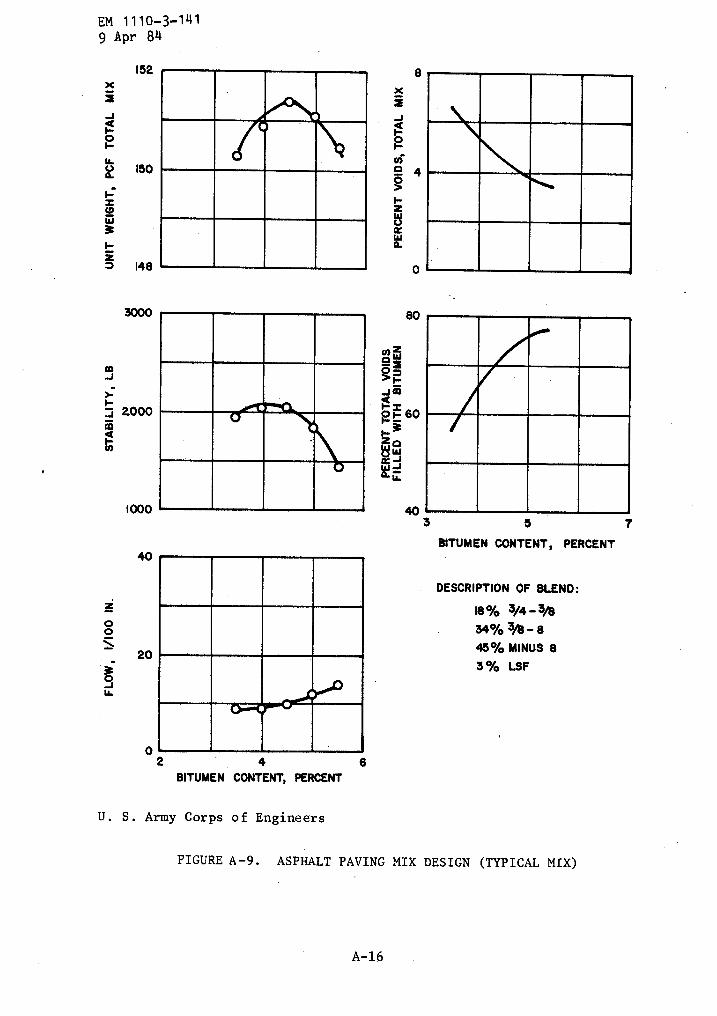
EM 1110-3-1419 Apr 84
x
JHOFW
FSC9W3Fz
zOOv
152
150
148
3000
F2000
mN
1000
20
0 162
4BITUMEN CONTENT, PERCENT
U . S . Army Corps of Engineers
A-16
yWexORFJm4.4 S
0WJ
0
80
60F ., 3
403
5
TBITUMEN CONTENT, PERCENT
DESCRIPTION OF BLEND :18% 3/4-3/g
34% ~% - 845% MINUS 83% LSF
FIGURE A-9 .
ASPHALT PAVING MIX DESIGN (TYPICAL MIX)

EM 1110-3-1419 Apr 84
the corrected specific gravity thus obtained is entered in column G ; itis called the "curve" specific gravity in figure A-8 . The curvespecific gravity values for each bitumen content, whether they arecorrected or original values, are used to compute the voids data shownin columns I, J, and K . The data from columns J and K are used to plotcurves for percent voids total mix and voids filled with bitumen,respectively on figure A-9 .
f . Relationship of test properties to bitumen content . Testproperty curves, plotted as described above, have been found to followa reasonably consistent pattern for mixes made with penetration gradesof asphalt cement, tar cement, and rubberized tar . Trends generallynoted are outlined as follows .
(1) Flow . The flow value increases with increasing bitumencontent at a progressive rate except at very low bitumen contents .
(2) Stability . The Marshall stability increases with increasingbitumen content up to a certain point, after which it decreases .
(3) Unit weight . The curve for unit weight of total mix issimilar to the curve for stability, except that the peak of theunit-weight curve is normally at a slightly higher bitumen content thanthe peak of the stability curve .
(4) Voids total mix . Voids total mix decreased with increasingbitumen content in the lower range of bitumen contents . There is aminimum void content for each aggregate blend and compaction effortused herein, and the voids cannot be decreased below this minimumwithout increasing or otherwise changing the compaction effort . Thevoid content of the compacted mix approaches this minimum void contentas the bitumen content of the mix is increased .
(5) Voids filled with bitumen . Percent voids filled withbitumen increases with increasing bitumen content and approaches amaximum value in much the same manner as the voids total mix discussedabove approaches a minimum value .
g . Requirement for additional test specimens . Curves illustratedin figure A-9 are typical of those normally obtained when penetrationgrades of asphalt cement, tar cement, or rubberized tar are used withaggregate mixes . Aggregate blends may be encountered that will furnisherratic data such that plotting of the typical curves is difficult . Ina majority of these cases, an increase in the number of specimenstested at each bitumen content will normally result in data that willplot as typical curves .
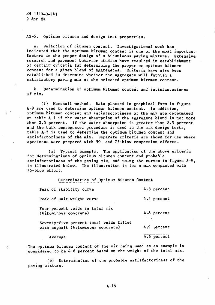
EM 1110-3-1419 Apr 84
A2-5 . Optimum bitumen and design test properties .
a . Selection of bitumen content . Investigational work hasindicated that the optimum bitumen content is one of the most importantfactors in the proper design of a bituminous paving mixture . Extensiveresearch and pavement behavior studies have resulted in establishmentof certain criteria for determining the proper or optimum bitumencontent for a given blend of aggregates . Criteria have also beenestablished to determine whether the aggregate will furnish asatisfactory paving mix at the selected optimum bitumen content .
b . Determination of optimum bitumen content and satisfactorinessof mix .
(1) Marshall method . Data plotted in graphical form in figureA-9 are used to determine optimum bitumen content . In addition,optimum bitumen content and satisfactoriness of the mix are determinedon table A-1 if the water absorption of the aggregate blend is not morethan 2 .5 percent . If the water absorption is greater than 2 .5 percentand the bulk impregnated procedure is used in the mix design tests,table A-2 is used to determine the optimum bitumen content andsatisfactoriness of the mix . Separate criteria are shown for use wherespecimens were prepared with 50- and 75-blow compaction efforts .
(a) Typical example . The application of the above criteriafor determinations of optimum bitumen content and probablesatisfactoriness of the paving mix, and using the curves in figure A-9,is illustrated below . The illustration is for a mix compacted with75-blow effort .
Determination of Optimum Bitumen Content
Peak of stability curve
4. .3 percent
Peak of unit-weight curve
4 .5 percent
Four percent voids in total mix(bituminous concrete)
4.8 percent
A- 18
Seventy-five percent total voids filledwith asphalt (bituminous concrete)
4 .9 percent
Average
4.6 percent
The optimum bitumen content of the mix being used as an example isconsidered to be 4 .6 percent based on the weight of the total mix .
(b) Determination of the probable satisfactoriness of thepaving mixture .
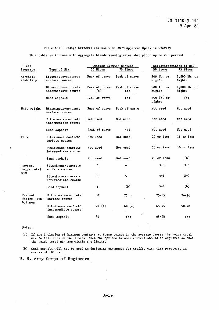
Table A-1 . Design Criteria For Use With ASTM Apparent Specific Gravity
EM 1110-3-1419 Apr 84
This table is for use with aggregate blends showing water absorption up to 2 .5 percent
Sand asphalt
Not used
Not used
20 or less
(b)
Notes :
Sand asphalt
70
(b)
65-75
(b)
U . S . Army Corps of Engineers
(a) If the inclusion of bitumen contents at these points in the average causes the voids totalmix to fall outside the limits, then the optimum bitumen content should be adjusted so thatthe voids total mix are within the limits .
(b) Sand asphalt will not be used in designing pavements for traffic with tire pressures inexcess of 100 psi .
Test Bitumen Content-Optimum Satisfactorines s of MixProperty Type of Mix 50 Blows 75 Blows 50 Blows 75 Blows
Marshall Bituminous-concrete Peak of curve Peak of curve 500 lb . or 1,800 lb . orstability surface course higher higher
Bituminous-concrete Peak of curve Peak of curve 500 lb . or 1,800 lb . orintermediate course (a) (a) higher higher
Sand asphalt Peak of curve (b) 500 lb . or (b)higher
Unit weight Bituminous-concrete Peak of curve Peak of curve Not used Not usedsurface course
Bituminous-concrete Not used Not used Not used Not usedintermediate course
Sand asphalt Peak of curve (b) Not used Not used
Flow Bituminous-concrete Not used Not used 20 or less 16 or lesssurface course
Bituminous-concrete Not used Not used 20 or less 16 or lessintermediate course
Percent Bituminous-concrete 4 4 3-5 3-5voids total surface coursemix
Bituminous-concrete 5 5 4-6 5-7intermediate course
Sand asphalt 6 (b) 5-7 (b)
Percent Bituminous-concrete 80 75 75-85 70-80filled with surface coursebitumen
Bituminous-concrete 70 (a) 60 (a) 65-75 50-70intermediate course
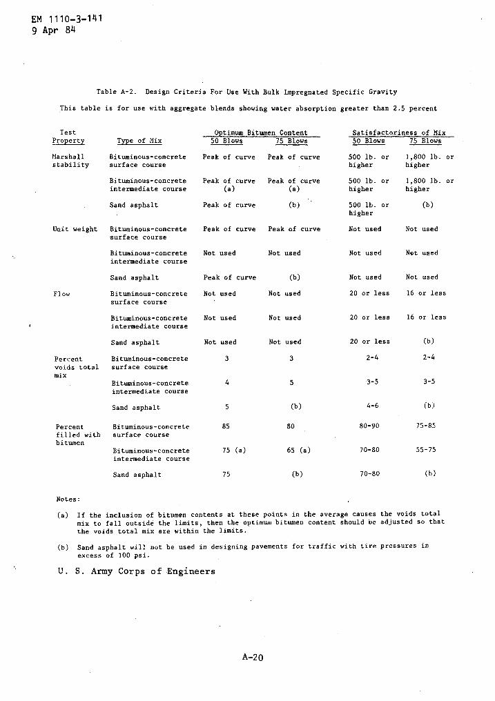
EM 1110- 3-1419 Apr 84
Table A-2 . Design Criteria For Use With Bulk Impregnated Specific Gravity
This table is for use with aggregate blends showing water absorption greater than 2 .5 percent
Notes :
Sand asphalt
Not used
Not used
20 or less
(b)
Sand asphalt
75
(b)
(a) If the inclusion of bitumen contents at these points in the average causes the voids totalmix to fall outside the limits, then the optimum bitumen content should be adjusted so thatthe voids total mix are within the limits .
(b) Sand asphalt will not be used in designing pavements for traffic with tire pressures inexcess of 100 psi .
U . S . Army Corps of Engineers
Test Optimum Bitumen Content Satisfactoriness of MixProperty Type of Mix 50 Blows 75 Blows 50 Blows 75 Blows
Marshall Bituminous-concrete Peak of curve Peak of curve 500 lb . or 1,800 lb . orstability surface course higher higher
Bituminous-concrete Peak of curve Peak of curve 500 lb . or 1,800 lb . orintermediate course (a) (a) higher higher
Sand asphalt Peak of curve (b) 500 lb : or (b)higher
Unit weight Bituminous-concrete Peak of curve Peak of curve Not used Not usedsurface course
Bituminous-concrete Not used Not used Not used Not usedintermediate course
Sand asphalt Peak of curve (b) Not used Not used
Flow Bituminous-concrete Not used Not used 20 or less 16 or lesssurface course
Bituminous-concrete Not used Not used 20 or less 16 or lessintermediate course
Percent Bituminous-concrete 3 3 2-4 2-4voids total surface coursemix
Bituminous-concrete 4 5 3-5 3-5intermediate course
Sand asphalt 5 (b) 4-6 (b)
Percent Bituminous-concrete 85 80 80-90 75-85filled with surface coursebitumen
Bituminous-concrete 75 (a) 65 (a) 70-80 55-75intermediate course
0-80 (b)
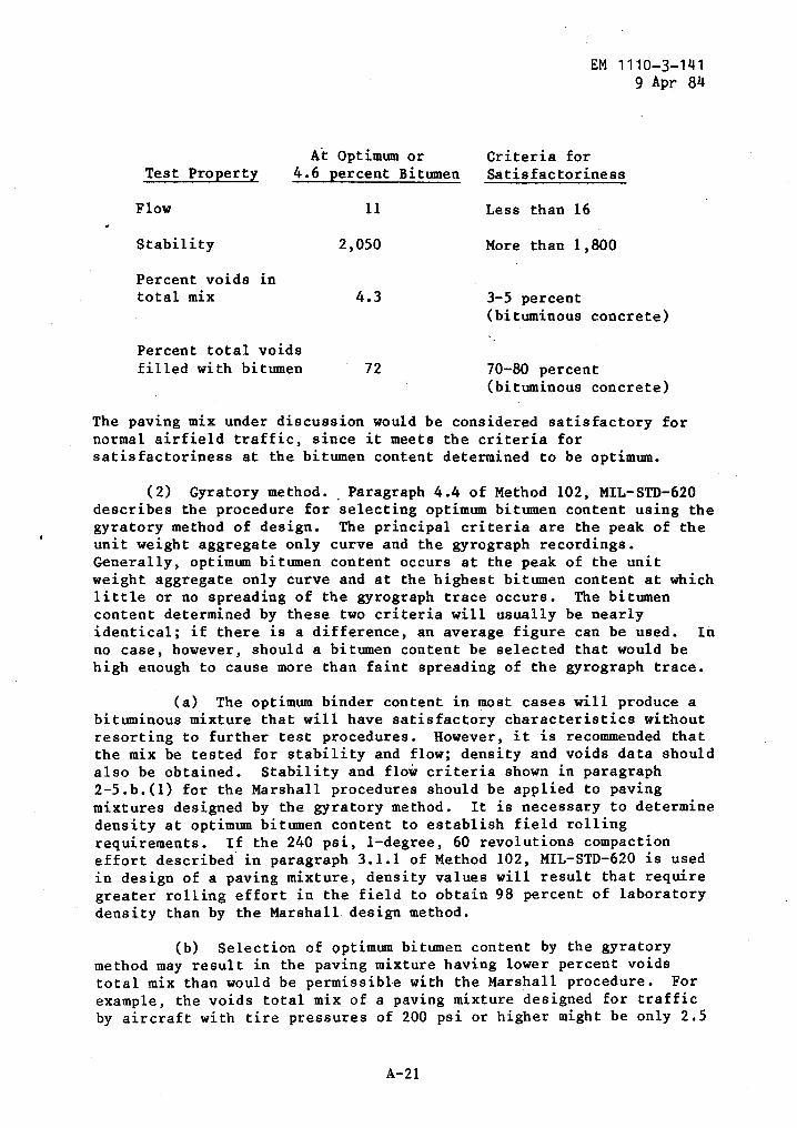
At Optimum or
Criteria forTest Property
4 .6 percent Bitumen
Satisfactoriness
Flow
11
Less than 16
Stability
2,050
More than 1,800
Percent voids intotal mix
4.3
3-5 percent(bituminous concrete)
A-21
EM 1110-3-1419 Apr 84
Percent total voidsfilled with bitumen
72
70-80 percent(bituminous concrete)
The paving mix under discussion would be considered satisfactory fornormal airfield traffic, since it meets the criteria forsatisfactoriness at the bitumen content determined to be optimum .
(2) Gyratory method . . Paragraph 4 .4 of Method 102, MIL-STD-620describes the procedure for selecting optimum bitumen content using thegyratory method of design . The principal criteria are the peak of theunit weight aggregate only curve and the gyrograph recordings .Generally, optimum bitumen content occurs at the peak of the unitweight aggregate only curve and at the highest bitumen content at whichlittle or no spreading of the gyrograph trace occurs . The bitumencontent determined by these two criteria will usually be nearlyidentical ; if there is a difference, an average figure can be used . Inno case, however, should a bitumen content be selected that would behigh enough to cause more than faint spreading of the gyrograph trace .
(a) The optimum binder content in most cases will produce abituminous mixture that will have satisfactory characteristics withoutresorting to further test procedures . However, it is recommended thatthe mix be tested for stability and flow ; density and voids data shouldalso be obtained . Stability and flow criteria shown in paragraph2-5 .b .(1) for the Marshall procedures should be applied to pavingmixtures designed by the gyratory method . It is necessary to determinedensity at optimum bitumen content to establish field rollingrequirements . If the 240 psi, 1-degree, 60 revolutions compactioneffort described in paragraph 3 .1 .1 of Method 102, MIL-STD-620 is usedin design of a paving mixture, density values will result that requiregreater rolling effort in the field to obtain 98 percent of laboratorydensity than by the Marshall design method .
(b) Selection of optimum bitumen content by the gyratorymethod may result in the paving mixture having lower percent voidstotal mix than would be permissible with the Marshall procedure . Forexample, the voids total mix of a paving mixture designed for trafficby aircraft with tire pressures of 200 psi or higher might be only 2 .5
EM 1110-3-1419 Apr 84
percent, as compared to a specified range of 3 to 5 percent in theMarshall criteria . The lower percent voids total mix is acceptablewhen using the gyratory procedure . This is because the compactioneffort used the laboratory design results in densities in the mixsufficiently high that further densification under traffic isminimized, as compared to lower densities obtained by the Marshallprocedure .
c .
Selection of paving mix . When two or more paving mixes havebeen investigated, the one used for field construction should be themost economical mix that satisfies all of the established criteria .The mix showing the highest stability should be selected, if economicconsiderations are equal .
d . Tolerances for pavement properties . Occassionally it may not bepossible, for economic or other reasons, to develop a mix that willmeet all of the criteria set forth above . A tolerance of 1 percent ofvoids in the total mix and 5 percent of total voids filled with bitumenmay be allowed in some circumstances, but under no circumstances willthe mix be considered satisfactory if the flow value is in excess of 20or the stability value is less than 500 pounds for mixes compacted withthe 50-blow effort, or if the flow is in excess of 16 or the stabilityless than 1,800 pounds for mixes compacted with the 75-blow effort .
A3 . Plant control .
A3-1 . Plant operation .
a . Types of plants . Figures A-10, A-11, and A-12 show a typicalbatch plant, a typical continuous-mix plant, and a dryer drum mixingplant, respectively . It is generally necessary, in the operation of abituminous paving plant, to combine aggregates from two or more sourcesto produce an aggregate mixture having the desired gradation .Aggregates from the different sources are fed into the aggregate dryerin the approximate proportions required to produce the desiredgradation . This initial proportioning generally is accomplished bymeans of a hopper-type mechanical feeder on one or more bins that feedsthe aggregates into a cold elevator, which, in turn, delivers them tothe dryer . The mechanical feeder generally is loaded by a clam shellor other suitable means in the approximate proportions of aggregatesdesired . The aggregates pass through the dryer where the moisture isdriven off and the aggregates are heated to the desired temperature .In the dryer drum mix plant, the binder is added to the aggregateduring drying and leaves the dryer as mixed pavement material ready fortruck loading . Upon leaving the dryer of batch and continuous-mixplants, the aggregates pass over vibrating screens where they areseparated according to size . When using emulsified asphalt as thebinder, the dryer operation is omitted . The usual screening equipmentfor a three-bin plant consists of a rejection screen for eliminatingoversize material and screens for dividing the coarse aggregate into
A-22
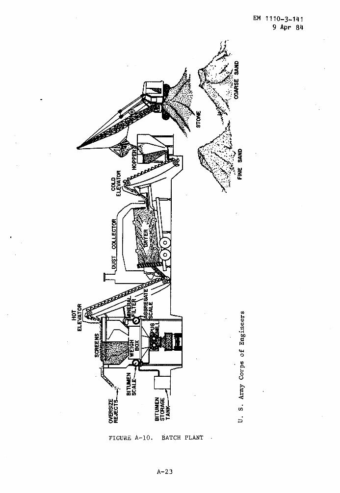
0
aBITUMEN
iW
.STORAGE
wy
TANK---"'
x ro r a z H
HOT
ELEVATOR
U.S
.Army
Corps
ofEn
gine
ers
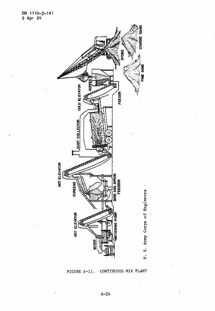
It H M
HOTEL
EVAT
OR
z 0
ohm-
COARSE
U.S
.Army
Corps
ofEn
gineers
FINE
SAND
SAND
3
HOTELEVATOR
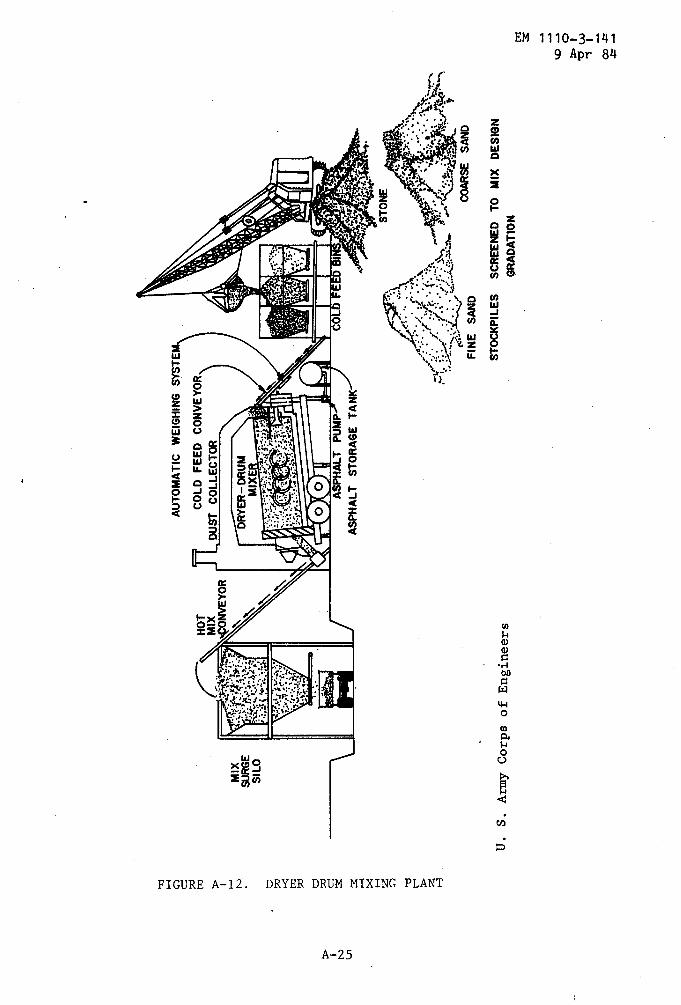
a N
H d t%j a H N d 7J
h7 'T7
d r H H z b r a z H
U.S
.Army
Corp
sof
Engineers
AUTO
MATI
CWEIGHING
SYSTE
COLD
FEED
CONVEYOR
DUST
COLLECTOR
COARSE
SAND
STOCKPILES
SCREENED
TOMIX
DESIGN
GRAD
ATIO
Nra
EM 1110-3-1419 Apr 84
A3-2 .
Plant laboratory .
two separate bins with the fine dried, the fine bin screen size shouldnot be smaller than 3/8 inch . An additional screen is provided forfurther separation of the coarse aggregate in a four-bin plant . Whenadditional mineral filler is required, usually it is stored and weighedor proportioned into the mix separately . Plant screens vary in size ofopening, and the size employed is largely dependent upon the type ofmixture being produced . In some cases, it may be necessary to changethe size of screens to obtain a proper balance of aggregate sizes ineach bin .
b . Adjustments to maintain proper proportions . The aggregates mustbe fed through the plant uniformly, preferably by a mechanical feeder,in order to obtain efficient plant operation and produce a mixtureconforming to the desired gradation . The proper proportion ofaggregates to be fed into the dryer may be determined approximatelyfrom the laboratory design . However, it is usually necessary to makesome adjustments in these proportions because (a) a screen analysis ofthe stockpile aggregates generally will not entirely duplicate thescreen analyis of the aggregate samples obtained for laboratory designuse ; (b) fines may be lost while passing through the dryer unless theequipment includes an effective dust collector ; (c) aggregate maydegrade in the dryer ; and (d) the plant screens are not 100 percentefficient in separation of the aggregate and some fines are carriedover into the coarser bins .
a . Equipment and personnel requirements . In order to control theplant output and secure the best possible paving mixture, a reasonablycomplete plant laboratory is necessary . The laboratory should belocated at the plant site and should contain about the same equipmentas is listed in Method 100 of MIL-STD-620 .
Due to the large capacityof most asphalt plants now in use, it is recommended that twotechnicians be assigned to conduct control tests ; otherwise, thetesting will fall too far behind, and considerable quantities ofunsatisfactory mix could be produced and placed before the laboratorytest results revealed that the mix is not in conformance with jobspecifications .
b . Laboratory work to initiate plant production . The heaviestdemands on plant laboratory facilities arise at the initiation of plantproduction . Preliminary computations may be made to determine theweight of material from each bin that will provide the gradation onwhich the mixture design was based . However, it should be recognizedthat the gradation of the aggregate supplied by the plant in accordancewith computed bin weights may not precisely reproduce the desiredgradation . The gradation of the plant-produced aggregate generallyapproximates the gradation used in design, within reasonabletolerances, if initial sampling for design purposes has beenaccomplished properly and if the plant is operated efficiently .
A-2 6
EM 1110-3-1419 Apr 84
Certain steps should be taken, however, to insure that satisfactorymixtures are produced from the beginning and throughout the period ofplant production . Procedures subsequently outlined will insuresatisfactory paving mixes .
c . Sieve analysis . All sieve analyses should be conducted inaccordance with the appropriate ASTM procedures . Recommended sievesfor plant sieve analysis are : 3/4- and 3/8-inch, Mos . 4, 8, 30, 100,and 200 . Sieves larger than 3/4 inch should be used, if necessary .Sieve analysis should be made on material from each plant bin . Samplesfor these sieve analyses should be obtained after a few tons ofaggregate have been processed through the dryer and screens in orderthat the sample will be representative . Final bin proportions may bedetermined on the basis of these analyses .
d . Provision for redesign of mix . The aggregates obtained from thebins (as described in the previous paragraph) sometimes cannot beproportioned to reproduce satisfactorily the gradation of the aggregateused. in the laboratory design . It then is necessary to redesign themix using plant-produced aggregates . Specimens are prepared and testedfor the new design in the same manner as for the original design tests .Optimum bitumen content and probable satisfactoriness of the mix thatwill be produced by the plant are determined thereby . Occasions mayarise where the gradation of the plant-produced aggregate will differfrom that on which the laboratory design was based to the extent that apart of the aggregates must be wasted . Consideration should be givento redesigning the mix on the basis of additional tests of theplant-produced material in order to use all of the available aggregate .Sufficient additional tests should be performed to establish optimumbitumen requirements and ensure that the mix will meet applicablecriteria for satisfactoriness .
e . Controlling plant production . A plant inspector should obtain asample of paving mix from a truck as it leaves the plant after theplant has been in production about 30 minutes . The sample should belarge enough to prepare four Marshall specimens and should be obtainedby digging far enough into the load in several locations to obtain arepresentative sample of the paving mixture . The four specimens shouldbe compacted and tested as rapidly as possible, in accordance withstandard procedures cited previously . Plant production must besuspended until data from the tests are available and a determinationmade that the plant-produced mix conforms to final design data . If thetest data on the plant mix show it to be within reasonable tolerances,plant production can be resumed ; otherwise, necessary adjustmentsshould be made to secure a conformable mix . Such procedures to insureinitial production of satisfactory mixes will generally delay plantproduction less than 2 hours .
(1) Flow and stability . Resumption of plant production may beexpedited by comparing only the values of flow, stability, and unit
A-27
EM 1110-3-1419 Apr 84
weight of specimens compacted from plant-produced mixtures withcorresponding data from the final design . Data from tests of theplant-produced mix for voids in the compacted mix and percent of voidsfilled with bitumen may be compared with corresponding design dataafter plant production has been resumed . When the plant is incontinuous operation, the average flow and stability values obtainedfrom truck samples should be in substantial agreement with flow andstability values from the final design . Variations of not more thantwo points in flow and not more than 10 percent in stability areallowable . In no case, however, will the plant-produced mix beconsidered acceptable if the flow or the stability does not meet therequirements of design criteria .
(2) Variations . If test property variations exceed those notedabove, plant production should be delayed until the cause of thevariations is determined . Computations for scale weights should bechecked first . If no error is found in these computations, the plantproportioning equipment should be recalibrated . Variations of only afew tenths of 1 percent in bitumen content may cause variations of twoor three points in the flow . values .
Small variations in aggregateweight generally are not particularly effective in changing testproperties . Plant proportioning equipment found to be inaccurateshould be adjusted and after an additional 30 minutes of plantoperation, the paving mix should be sampled and tested ; the plant willnot be placed in continuous operation until the variations in testproperties are within allowable tolerances . Once the plant has beenplaced in continuous operation, test specimens should be prepared foreach 5-hours operation or fraction thereof . The tests conducted shouldinclude stability, flow, unit weight, voids in the total mix, andpercent voids filled with bitumen . Normal variations in plant-producedaggregates will require minor adjustments in bin proportions, whichwill cause slight variations in test properties . Variations citedabove are allowable for continuous plant production .
f . Significance of changes in mixture properties . A materialincrease in flow value generally indicates that either the gradation ofthe mix has changed sufficiently to require a revision in the optimumbitumen content for the mix, or too much bitumen is being incorporatedin the mix . Substantial changes in stability or void content also mayserve as an indication of these factors . As a general rule, however,the flow and stability values are obtainable quickly and are reasonablyreliable indicators of the consistency of the plant-produced mix . Thesatisfactoriness of the plant produced mix may be judged quickly bymaintaining close observance of the flow and stability values . Mixproportions must be adjusted whenever any of the test properties fallsoutside of the specified tolerances . In the case of batch plants,failure of the operator to weigh accurately the required proportions ofmaterials or use of faulty scales.are common causes for paving-mixturedeficiencies . The total weight of each load of mixture produced shouldnot vary more than plus or minus 2 percent from the total of the batch
A-28
EM 1110-3-1419 Apr 84
weights dumped into the truck . Improper weighing or faulty scales maybe detected readily and corrective measures taken by maintaining closecheck of load weights . Other probable causes of paving-mixturedeficiencies for. both batch-and continuous-mixing plants are shown in,figure A-13 .
g . Other tests . In addition to the design and control testsdescribed above, certain tests are desirable for record purposes and toinsure quality and consistency of materials .
(1) Extraction tests . Representative samples of paving mixtureshould be obtained twice daily for extraction tests to determine thepercentage of bitumen in the mix and the gradation of the extractedaggregates . Extraction tests are to be made in accordance with ASTM D2172 using trichloroethylene as the extraction .solvent .
Sieve analysesof recovered aggregates should be in accordance with proceduresspecified previously .
(2) Hot-bin gradations . Hot-bin gradation tests should bedetermined on the aggregate in the fine bin at 2-hour intervals duringoperation . Hot-bin gradations must be determined on all bins inconjunction with sampling of the pavement mixture . Washed sieveanalyses are to be determined initially and when gradations vary toestablish a correction factor to be applied to unwashed (dry)gradation . Dry sieve analyses should be conducted frequently asrequired to maintain control .
h . Construction control . It has been determined that well-designedmixes can be compacted readily by adequate field rolling to about 98percent or greater of the density obtained by compacting specimens withpreviously specified laboratory procedures . Every reasonable effort isto be made, within practicable limits, to provide an in-place pavementdensity of at least 98 percent of the compacted density as determinedby the laboratory tests .
Bituminous intermediate or base course mixesare to be rolled to the density specified in applicable Corps ofEngineers guide specifications .
(1) Pavement sampling . Samples for determining pavement densityand thickness may be taken either with a coring machine or by cuttingout a section of pavement at least 4 inches square with a concrete sawand should include the entire thickness of the pavement . A set of thesamples will be taken from areas containing mix that was previouslysampled from trucks and from which specimens were compacted in theplant laboratory . A set of samples will consist of. a t least threesawed or cored samples . Density samples of each day's productionshould be taken and delivered to the project laboratory by noon of thefollowing day, and the density determinations made by the end of thatday . This will permit any changes in placing technique necessary toobtain the required density to be made before too much pavement isplaced . One-half the total number of all density samples will be taken
A- 29
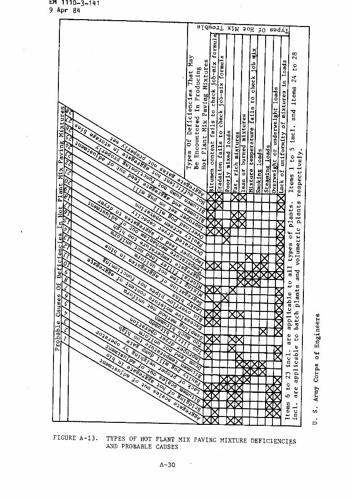
EM 1110-3-141
9 Apr 84
111114//1~l
O~1~4/01
A-30
W
N4.JH
00N
O44
N
0
v
u cdq u
M ac~ a
co+Or Gl
u u1.1C:H "rl
FIGURE A-13 . TYPES OF HOT PLANT MIX PAVING MIXTURE DEFICIENCIESAND PROBABLE CAUSES

EM 1110-3-1419 Apr 84
at a joint so that the joint is approximately in the center of thesample to be tested .
(2) Testing pavement samples . Pavement samples are to beprepared for testing by carefully removing all particles of basematerial or other matter . All broken or damaged edges of sawed samplesfor density tests will be carefully trimmed from the sample . Thicknessmeasurements are to be made prior to splitting . A sample consisting ofan intermediate course and surface course will be split at theinterface of these layers prior to testing . The density of the sawedsamples then will be determined by weighing in air and in water aspreviously described .
Samples from which density measurements aredesired should be discarded if they are damaged .
(3) Density data . Density data obtained from specimens in themanner previously described will be compared to the laboratorydensities that have been determined from the sample plant-mix materialpreviously taken from loaded trucks .
i . Pavement imperfections and probable causes . There are manytypes of pavement imperfections resulting from improper laying androlling operations as well as from improper mixes or faulty plantoperation . These imperfections can be controlled only by properinspection . Pavement imperfections that may result from layingimproper mixes or using faulty construction procedures are shown infigure A-14 .
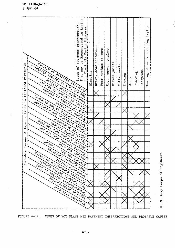
EM
1110-3-141
9
Apr 84
$4vaaoww0
aOCJ
FIGURE
A-14
.
TYPES OF HOT PLANT MIX PAVEMENT IMPERFECTIONS AND PROBABLE CAUSES
A-3 2
0
cu
.° a vL ,~.U 9: O0) 41u ..,
co
v v za ~4
H 4J00, vG
.u Du a.
Gro
v
4.J
v
w'vvv
4.J s
a,~~
c
s
00~ory~
'~kr
wm a~w .n
o ro cubo
a°'cu
'vco4)
ai41
uca4-1
zU)
vap
"n
-114$4
w
wQ)ro
~~o~ a~4
ma
o ,
., 0toH
s° G
Q .
~
.21`0
4 o~
"v
o°Ur
s
a~4 T oa a,~
r
Toa 'lo
"H
H x
rss,N,-, Os4as
Oow=ox
4
41
a rI
-1
oxO.ccn
>co3
m~4Uaox
coWe-+*co
s
s
s
ao00
040
-to
?oN
caUa~a
U
.r
~o,~r ~Ab6
Ua
4
"'o
aAt~
1"Mm00
a& 4 &&
s
o a
o
9 ok
MA MAJ 00
~0 00,1
7T.H .~U4-1 40
0
000
rpU ?
,1 MEMOS~I FAB4-4pToo
a4as~UooA1oTTa 4a~To
�"" 1,1a409
00 o~kt asa9 P,?"
w0oof
Ua9M '00
10
al'2,9 ~
U
a,t 9A-2sU
0Dow°akr
o ~T4°
0 RN 1IpaU
d
-r,)
'op k
o
t~ TrT
1~~~IMM"Fill,0tI~~
v 4?o
~Q 40
a~
4 ~ T
~IIaa~
Q 0 a
.~0 MM" I0,
0
ta
4?
.0g,
40 O'>
AA
U 4
o
Sri &0
rMA ILI
FA
OWA 10WA MA OWAw As04 .r,~&Too
d k0 A,
02-
& a 40
U~
d
sa
~r9aQ has aa~BaAs
aJk~~.?O
titUorQ~~0pU~~
JL'
400
~~~IFARMENM"
"WA
III~~~~a o4
d
d
4s~',?AS
BEM0II1"~PA0II0~rsd
0
~0a
'~d
x,1.11X1."11.11~IFAN.2's- MA IOWA I
Government Publications .
Department- of - the - Army .
APPENDIX B
REFERENCES
EM 1110-3-136
Drainage and Erosion Control .
EM 1110-3-137
Soil Stabilization for Pavements .
EM 1110-3-138
Pavement Criteria for SeasonalFrost Conditions .
EM 1110-3-142
Airfield Rigid Pavement,
Mi litary Standards .
MIL-STD-620A
Test Methods for Bituminous& Notice 1
Paving Materials .
MIL-STD-621A
Test Methods for Pavement& Notices 1,2
Subgrade, Subbase, and Base-Course Materials .
Nongovernment Publications .
American Association of State Highway and TransportationOfficials (AASHTO), 444 North Capitol, Washington, D .C . 20001
T 2-74
Sampling Stone, Slag, Gravel,Sand and Stone Block for Useas Highway Materials .
T 19-76
Unit Weight of Aggregate .
T 27-74
Sieve Analysis of Fine,andCoarse Aggregates.
T 88-72
Mechanical Analysis of Soils .
T 89-68
Determining the Liquid Limit ofSoils .
T 90-70
Determining the Plastic Limit andPlasticity Index of Soils .
EM 1110-3-1419 Apr 84
EM 1110-3-1419 Apr 84
T 96-74
Abrasion of Coarse Aggregate byUse of the Los Angeles Machine .
T 99-74
Moisture-Density Relations ofSoils, Using a 5 .5 lb (2 .5 kg)Rammer and a 12 in . (305mm)Drop .
T 101
Determining Swell Characteristicsof Aggregates When Mixed withBituminous Materials .
T 104
Soundness of Aggregates by use ofSodium Sulfate or MagnesiumSulfate
T 134-70
Moisture-Density Relations ofSoil-Cement Mixtures .
T 135-70
Wetting-and-Drying Test ofCompacted Soil-Cement Mixtures .
T 136-70
Freezing-and-Thawing Tests ofCompacted Soil-Cement Mixtures .
T 176-73
Plastic Fines in GradedAggregates and Soils by Use ofthe Sand Equivalent Test .
T 191-61
Density of Soil In Place by the(R 1982)
Sand Cone Method .
T 193-801
The California Bearing Ratio .
American Society for Testing and'Materials (ASTM), 1916Race Street, Philadelphia, PA 19103
C 29-78
Unit Weight and Voids^inAggregate .
C 88-76
Soundness of Aggregates by Use ofSodium Sulfate or MagnesiumSulfate .
C 117-80
Material Finer Than 76 u m (No .
200)Sieve in Mineral Aggregates byWashing .
B-2

C 127-81
Specific Gravity and Absorptionof Coarse Aggregate .
C 128-79
Specific Gravity and Absorptionoc Fine Aggregate .
C 131-81
Resistance to Degradation ofSmall-Size Coarse Aggregateby Abrasion and Impact in theLos Angeles Machine .
C 136-82
Sieve Analysis of Fine and CoarseAggregates .
C 183-82
Sampling and Acceptance ofHydraulic Cement .
C 188-78
Density of Hydraulic Cement .
D 75-81
Sampling Aggregates .
D 140-70
Sampling Bituminous Materials .(R 1981)
D 242-70
Mineral Filler for Bituminous(R 1980)
Paving Mixtures .
D 422-63
Particle-Size Analysis of Soils .(R 1972)
D 423-66
Liquid Limit of Soils .(R 1972)
D 490-77
Tar .
D 558-57
Moisture-Density Relations of(R 1976)
Soil-Cement Mixtures .
D 559-57
Wetting and Drying Tests of(R 1976)
Compacted Soil-CementMixtures .
D 854-58
Tests for Specific Gravity ofSoils .
B-3
EM 1110-3-1419 Apr 84
D 424-59
Plastic Limit and Plasticity Index(R 1971)
of Soils .
D 560-57
Freezing-and-Thawing Tests of(R 1976)
Compacted Soil-Cement Mixtures .
EM 1110-3-1419 Apr 84
D 946-82
Penetration-Graded Asphalt Cementfor Use in PavementConstruction .
D 977-80
Emulsified Asphalt .
D 1556-64
Density of Soil In Place by the(R 1974)
Sand-Cone Method .
D 1557-78
Moisture-Density Relations ofSoils and Soil,-AggregateMixtures Using 10-lb (4 .5 Kg) Rammerand 18-in . (457-mm) Drop .
D 1559-76
Resistance to Plastic Flow ofBituminous Mixtures UsingMarshall Apparatus .
D 1633-63
Compressive Strength of Molded(R 1979)
Soil-Cement Cylinders .
D 1883-73
Bearing Ratio of Laboratory-(R 1978)
Compacted Soils .
D 2026-72
Cutback Asphalt (Slow-Curing(R 1979)
Type) .
D 2027-76
Cutback Asphalt (Medium-Curing(R 1981)
Type) .
D 2028-76
Cutback Asphalt (Rapid-Curing(R 1981)
Type) .
D 2172-81
Quantitative Extraction ofBitumen from BituminousPaving Mixtures .
D 2397-79
Cationic Emulsified Asphalt .
D 2419-74
Sand Equivalent Value of Soils(R 1979)
and Fine Aggregate .
D 2993-71
Acrylonitrile-Butadiene(R 1977)
Rubberized Tar .
D 3381-81
Viscosity-Graded Asphalt Cementfor Use in PavementConstruction .
B-4
Asphalt Institute (AI), Asphalt Institute Building, CollegePark, MD 20740
. MS-2
Mix Design for Asphalt Concreteand Other Hot-Mix Types .
EM 1110-3-1419 Apr 84
GPO 908-520