Embed Size (px)
Citation preview
custom & “hygienic” air handling units
fan coil units
close control units
smartpac - factory packaged controls
Air Handling Systems& Terminal Devices
56/57
york air-conditioning products
So why choose YORK® Air Handling Units?
Energy recovery options
The exhaust air stream from an AHU represents another opportunity to save energy. A heat recovery ‘thermal’ wheel can economically transfer heat and moisture between the exhaust-air and outside-air paths, reducing the cost of conditioning the supply air.
For the simplest form of heat recovery, you can take advantage of “free” cooling with mixing box sections. During spring and autumn operation, cool/dry outside air cools and dehumidifies the facility, reducing the need for mechanical cooling.
Alternatively, you can use recuperative plate heat exchangers. These also allow free cooling in summer by use of face and bypass dampers which by-pass the air around the exchanger so that it is not warmed by the extracted air.
We can also offer refrigerant heat pipe and heat recovery coils on your AHU to maximise energy savings.
Reduce fan operating costs
In an AHU, the fan is traditionally the largest source of energy consumption. We can help reduce this by offering a range of energy-saving options.
• High- or premium-efficiency motors can be specified.
• Direct-drive plenum fans eliminate belt-and-pulley energy losses.
• If the air system is designed for variable-air volume (VAV), YORK® AHUs fitted with variable speed drives offer the most efficient method of VAV fan control.
• Factory-mounting a variable speed drive reduce jobsite labour costs, unit energy consumption and unit Life Cycle Costs.
We recognise that your reputation depends on the quality of the products you choose and how well they are installed. That’s why we work hard to make selecting, installing and operating our products as easy as possible. Our YMA range includes a number of additional options that make YORK® Air Handling Units the professionals’ choice.
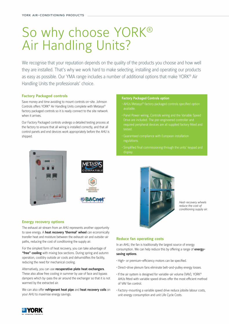
Factory Packaged Controls option
• AHUs Metasys® factory packaged controls specified option available.
• Panel Power wiring, Controls wiring and the Variable Speed Drive are included. The pre-engineered controller and required peripheral devices are all supplied factory fitted and tested.
• Guaranteed compliance with European installation regulations.
• Simplified final commissioning through the units’ keypad and display.
Heat-recovery wheels reduce the cost of conditioning supply air.
Factory Packaged controls
Save money and time avoiding to mount controls on-site. Johnson Controls offers YORK® Air Handling Units complete with Metasys® factory packaged controls so it is ready connect to the site network when it arrives.
Our Factory Packaged controls undergo a detailed testing process at the factory to ensure that all wiring is installed correctly, and that all control panels and end devices work appropriately before the AHU is shipped.
58/59
Air
Han
dlin
g Sy
stem
s &
Ter
min
al D
evic
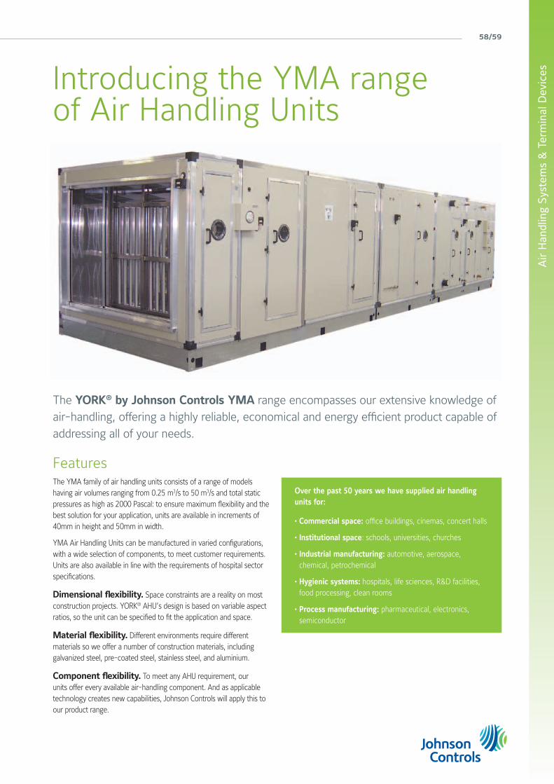
esIntroducing the YMA range of Air Handling Units
Over the past 50 years we have supplied air handling units for:
• Commercial space: office buildings, cinemas, concert halls
• Institutional space: schools, universities, churches
• Industrial manufacturing: automotive, aerospace, chemical, petrochemical
• Hygienic systems: hospitals, life sciences, R&D facilities, food processing, clean rooms
• Process manufacturing: pharmaceutical, electronics, semiconductor
FeaturesThe YMA family of air handling units consists of a range of models having air volumes ranging from 0.25 m3/s to 50 m3/s and total static pressures as high as 2000 Pascal: to ensure maximum flexibility and the best solution for your application, units are available in increments of 40mm in height and 50mm in width.
YMA Air Handling Units can be manufactured in varied configurations, with a wide selection of components, to meet customer requirements. Units are also available in line with the requirements of hospital sector specifications.
Dimensional flexibility. Space constraints are a reality on most construction projects. YORK® AHU’s design is based on variable aspect ratios, so the unit can be specified to fit the application and space.
Material flexibility. Different environments require different materials so we offer a number of construction materials, including galvanized steel, pre-coated steel, stainless steel, and aluminium.
Component flexibility. To meet any AHU requirement, our units offer every available air-handling component. And as applicable technology creates new capabilities, Johnson Controls will apply this to our product range.
The YORK® by Johnson Controls YMA range encompasses our extensive knowledge of air-handling, offering a highly reliable, economical and energy efficient product capable of addressing all of your needs.
york air-conditioning products
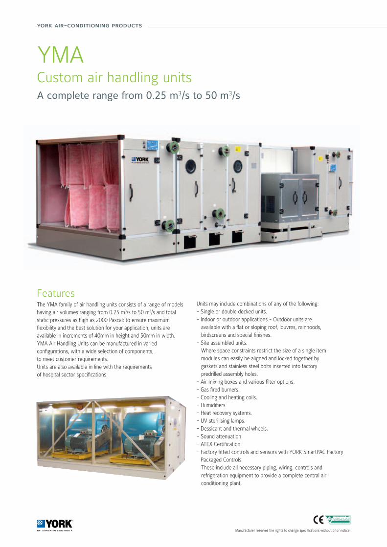
YMACustom air handling unitsA complete range from 0.25 m3/s to 50 m3/s
FeaturesThe YMA family of air handling units consists of a range of models having air volumes ranging from 0.25 m3/s to 50 m3/s and total static pressures as high as 2000 Pascal: to ensure maximum flexibility and the best solution for your application, units are available in increments of 40mm in height and 50mm in width.YMA Air Handling Units can be manufactured in variedconfigurations, with a wide selection of components,to meet customer requirements. Units are also available in line with the requirementsof hospital sector specifications.
Units may include combinations of any of the following:- Single or double decked units.- Indoor or outdoor applications - Outdoor units are available with a flat or sloping roof, louvres, rainhoods, birdscreens and special finishes.- Site assembled units. Where space constraints restrict the size of a single item modules can easily be aligned and locked together by gaskets and stainless steel bolts inserted into factory predrilled assembly holes.- Air mixing boxes and various filter options.- Gas fired burners.- Cooling and heating coils.- Humidifiers- Heat recovery systems.- UV sterilising lamps.- Dessicant and thermal wheels.- Sound attenuation.- ATEX Certification.- Factory fitted controls and sensors with YORK SmartPAC Factory
Packaged Controls. These include all necessary piping, wiring, controls and
refrigeration equipment to provide a complete central air conditioning plant.
Manufacturer reserves the rights to change specifications without prior notice.
60/61
Air
Han
dlin
g Sy
stem
s &
Ter
min
al D
evic
es
Manufacturer reserves the rights to change specifications without prior notice.
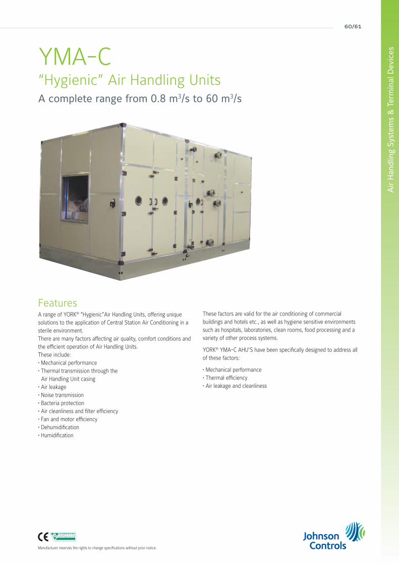
YMA-C“Hygienic” Air Handling UnitsA complete range from 0.8 m3/s to 60 m3/s
FeaturesA range of YORK® “Hygienic”Air Handling Units, offering unique solutions to the application of Central Station Air Conditioning in a sterile environment.There are many factors affecting air quality, comfort conditions and the efficient operation of Air Handling Units.These include:• Mechanical performance• Thermal transmission through the Air Handling Unit casing• Air leakage• Noise transmission • Bacteria protection• Air cleanliness and filter efficiency• Fan and motor efficiency• Dehumidification• Humidification
These factors are valid for the air conditioning of commercial buildings and hotels etc., as well as hygiene sensitive environments such as hospitals, laboratories, clean rooms, food processing and a variety of other process systems.
YORK® YMA-C AHU’S have been specifically designed to address all of these factors:
• Mechanical performance• Thermal efficiency• Air leakage and cleanliness
york air-conditioning products
YORK® Fan Coil unitsDriven by innovative trends and modern technology, the YORK® Fan Coil Units have been designed around a platform of models, versions and accessories, which have been independently tested and certified by Eurovent. The YORK® Fan Coil range meets today’s demanding requirements of performance, size, acoustics, low energy, ease of installation and maintenance.
62/63
Air
Han
dlin
g Sy
stem
s &
Ter
min
al D
evic
es
Manufacturer reserves the rights to change specifications without prior notice.
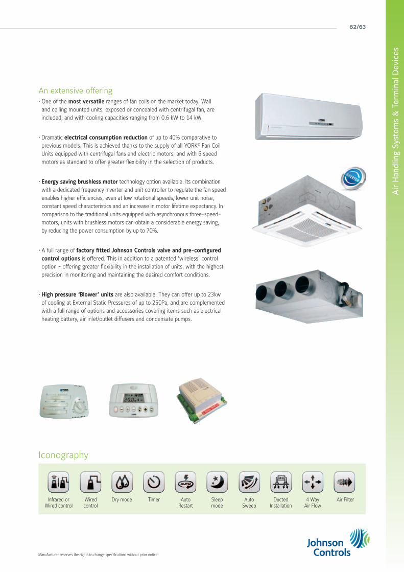
An extensive offering • One of the most versatile ranges of fan coils on the market today. Wall and ceiling mounted units, exposed or concealed with centrifugal fan, are included, and with cooling capacities ranging from 0.6 kW to 14 kW.
• Dramatic electrical consumption reduction of up to 40% comparative to previous models. This is achieved thanks to the supply of all YORK® Fan Coil Units equipped with centrifugal fans and electric motors, and with 6 speed motors as standard to offer greater flexibility in the selection of products.
• Energy saving brushless motor technology option available. Its combination with a dedicated frequency inverter and unit controller to regulate the fan speed enables higher efficiencies, even at low rotational speeds, lower unit noise, constant speed characteristics and an increase in motor lifetime expectancy. In comparison to the traditional units equipped with asynchronous three-speed-motors, units with brushless motors can obtain a considerable energy saving, by reducing the power consumption by up to 70%.
• A full range of factory fitted Johnson Controls valve and pre-configured control options is offered. This in addition to a patented ‘wireless’ control option - offering greater flexibility in the installation of units, with the highest precision in monitoring and maintaining the desired comfort conditions.
• High pressure ‘Blower’ units are also available. They can offer up to 23kw of cooling at External Static Pressures of up to 250Pa, and are complemented with a full range of options and accessories covering items such as electrical heating battery, air inlet/outlet diffusers and condensate pumps.
Iconography
Infrared or Wired control
Dry modeWiredcontrol
Sleepmode
Timer AutoSweep
AutoRestart
4 WayAir Flow
DuctedInstallation
Air Filter
york air-conditioning products
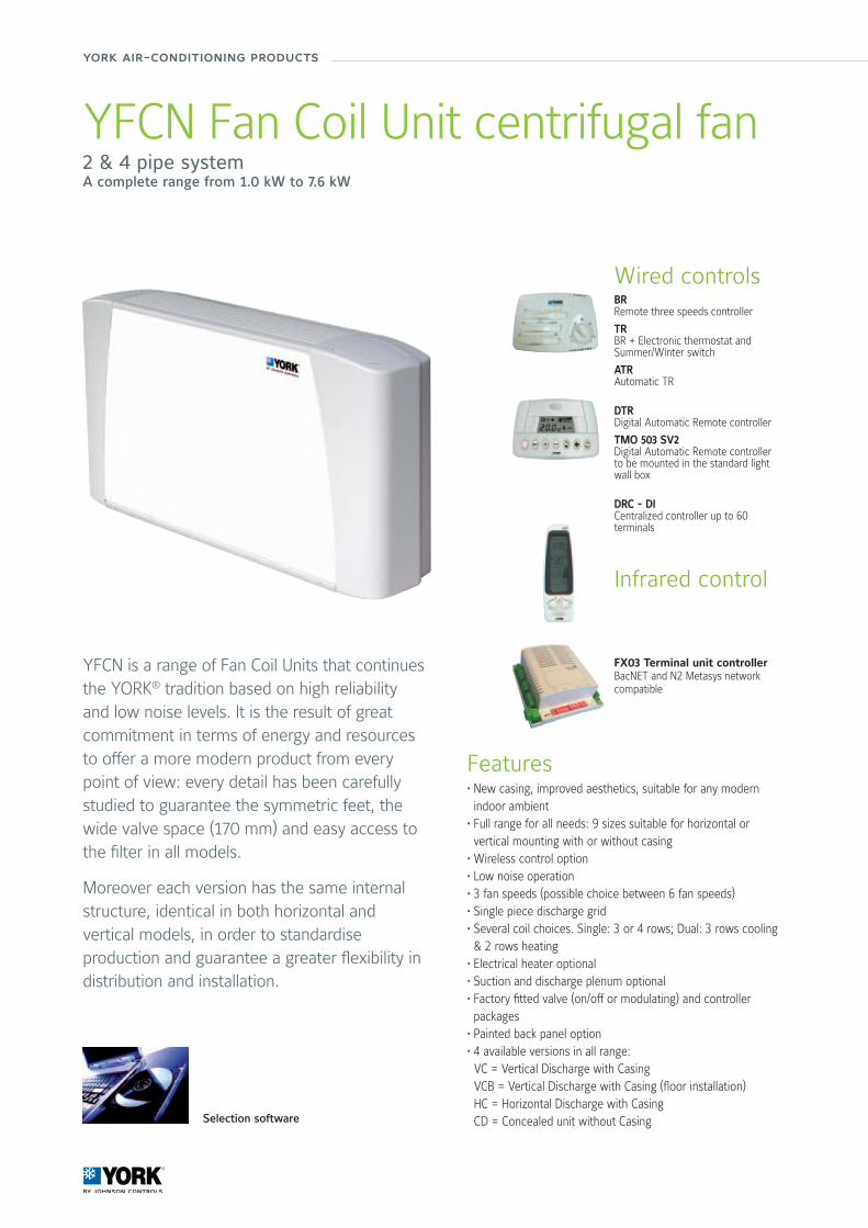
YFCN Fan Coil Unit centrifugal fan2 & 4 pipe systemA complete range from 1.0 kW to 7.6 kW
Features• New casing, improved aesthetics, suitable for any modern indoor ambient
• Full range for all needs: 9 sizes suitable for horizontal or vertical mounting with or without casing
• Wireless control option• Low noise operation • 3 fan speeds (possible choice between 6 fan speeds)• Single piece discharge grid • Several coil choices. Single: 3 or 4 rows; Dual: 3 rows cooling & 2 rows heating
• Electrical heater optional • Suction and discharge plenum optional • Factory fitted valve (on/off or modulating) and controller packages
• Painted back panel option • 4 available versions in all range: VC = Vertical Discharge with Casing VCB = Vertical Discharge with Casing (floor installation) HC = Horizontal Discharge with Casing CD = Concealed unit without Casing
YFCN is a range of Fan Coil Units that continues the YORK® tradition based on high reliability and low noise levels. It is the result of great commitment in terms of energy and resources to offer a more modern product from every point of view: every detail has been carefully studied to guarantee the symmetric feet, the wide valve space (170 mm) and easy access to the filter in all models.
Moreover each version has the same internal structure, identical in both horizontal and vertical models, in order to standardise production and guarantee a greater flexibility in distribution and installation.
Selection software
Wired controlsBRRemote three speeds controller
TRBR + Electronic thermostat and Summer/Winter switch
ATRAutomatic TR
DTRDigital Automatic Remote controller
TMO 503 SV2Digital Automatic Remote controllerto be mounted in the standard light wall box
DRC - DICentralized controller up to 60 terminals
Infrared control
FX03 Terminal unit controllerBacNET and N2 Metasys network compatible
64/65
Air
Han
dlin
g Sy
stem
s &
Ter
min
al D
evic
es
Manufacturer reserves the rights to change specifications without prior notice.
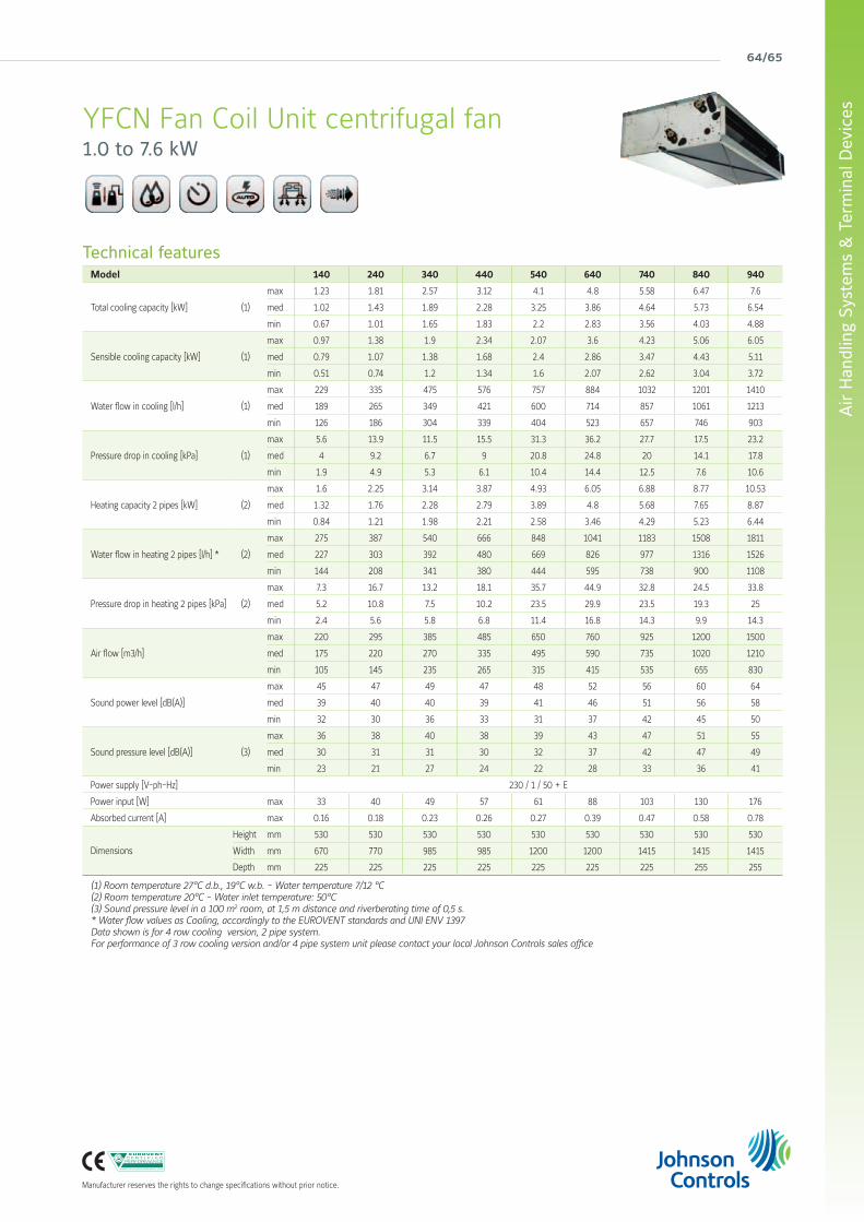
YFCN Fan Coil Unit centrifugal fan1.0 to 7.6 kW
Technical featuresModel 140 240 340 440 540 640 740 840 940
Total cooling capacity [kW] (1)
max 1.23 1.81 2.57 3.12 4.1 4.8 5.58 6.47 7.6
med 1.02 1.43 1.89 2.28 3.25 3.86 4.64 5.73 6.54
min 0.67 1.01 1.65 1.83 2.2 2.83 3.56 4.03 4.88
Sensible cooling capacity [kW] (1)
max 0.97 1.38 1.9 2.34 2.07 3.6 4.23 5.06 6.05
med 0.79 1.07 1.38 1.68 2.4 2.86 3.47 4.43 5.11
min 0.51 0.74 1.2 1.34 1.6 2.07 2.62 3.04 3.72
Water flow in cooling [l/h] (1)
max 229 335 475 576 757 884 1032 1201 1410
med 189 265 349 421 600 714 857 1061 1213
min 126 186 304 339 404 523 657 746 903
Pressure drop in cooling [kPa] (1)
max 5.6 13.9 11.5 15.5 31.3 36.2 27.7 17.5 23.2
med 4 9.2 6.7 9 20.8 24.8 20 14.1 17.8
min 1.9 4.9 5.3 6.1 10.4 14.4 12.5 7.6 10.6
Heating capacity 2 pipes [kW] (2)
max 1.6 2.25 3.14 3.87 4.93 6.05 6.88 8.77 10.53
med 1.32 1.76 2.28 2.79 3.89 4.8 5.68 7.65 8.87
min 0.84 1.21 1.98 2.21 2.58 3.46 4.29 5.23 6.44
Water flow in heating 2 pipes [l/h] * (2)
max 275 387 540 666 848 1041 1183 1508 1811
med 227 303 392 480 669 826 977 1316 1526
min 144 208 341 380 444 595 738 900 1108
Pressure drop in heating 2 pipes [kPa] (2)
max 7.3 16.7 13.2 18.1 35.7 44.9 32.8 24.5 33.8
med 5.2 10.8 7.5 10.2 23.5 29.9 23.5 19.3 25
min 2.4 5.6 5.8 6.8 11.4 16.8 14.3 9.9 14.3
Air flow [m3/h]
max 220 295 385 485 650 760 925 1200 1500
med 175 220 270 335 495 590 735 1020 1210
min 105 145 235 265 315 415 535 655 830
Sound power level [dB(A)]
max 45 47 49 47 48 52 56 60 64
med 39 40 40 39 41 46 51 56 58
min 32 30 36 33 31 37 42 45 50
Sound pressure level [dB(A)] (3)
max 36 38 40 38 39 43 47 51 55
med 30 31 31 30 32 37 42 47 49
min 23 21 27 24 22 28 33 36 41
Power supply [V-ph-Hz] 230 / 1 / 50 + E
Power input [W] max 33 40 49 57 61 88 103 130 176
Absorbed current [A] max 0.16 0.18 0.23 0.26 0.27 0.39 0.47 0.58 0.78
Dimensions
Height mm 530 530 530 530 530 530 530 530 530
Width mm 670 770 985 985 1200 1200 1415 1415 1415
Depth mm 225 225 225 225 225 225 225 255 255
(1) Room temperature 27°C d.b., 19°C w.b. - Water temperature 7/12 °C(2) Room temperature 20°C - Water inlet temperature: 50°C(3) Sound pressure level in a 100 m2 room, at 1,5 m distance and riverberating time of 0,5 s.* Water flow values as Cooling, accordingly to the EUROVENT standards and UNI ENV 1397Data shown is for 4 row cooling version, 2 pipe system. For performance of 3 row cooling version and/or 4 pipe system unit please contact your local Johnson Controls sales office
york air-conditioning products
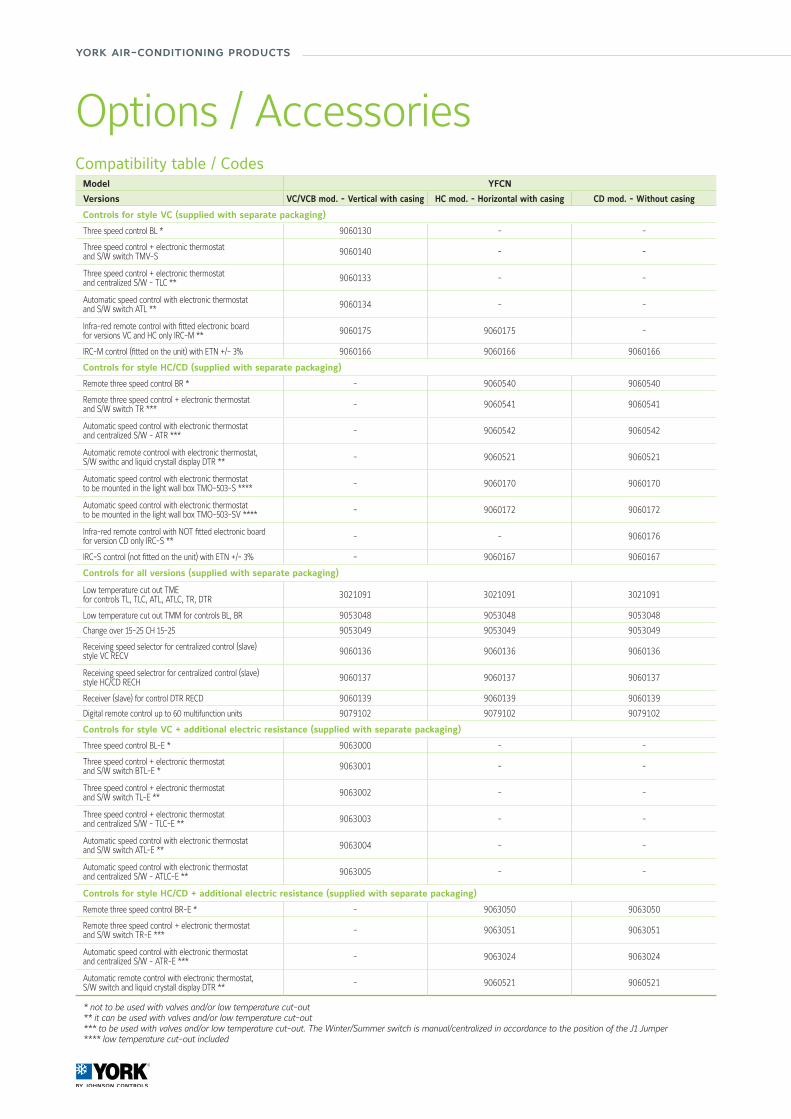
Compatibility table / CodesModel YFCN
Versions VC/VCB mod. - Vertical with casing HC mod. - Horizontal with casing CD mod. - Without casing
Controls for style VC (supplied with separate packaging)
Three speed control BL * 9060130 - -
Three speed control + electronic thermostat and S/W switch TMV-S 9060140 - -
Three speed control + electronic thermostat and centralized S/W - TLC ** 9060133 - -
Automatic speed control with electronic thermostat and S/W switch ATL ** 9060134 - -
Infra-red remote control with fitted electronic board for versions VC and HC only IRC-M ** 9060175 9060175 -
IRC-M control (fitted on the unit) with ETN +/- 3% 9060166 9060166 9060166
Controls for style HC/CD (supplied with separate packaging)
Remote three speed control BR * - 9060540 9060540
Remote three speed control + electronic thermostat and S/W switch TR *** - 9060541 9060541
Automatic speed control with electronic thermostat and centralized S/W - ATR *** - 9060542 9060542
Automatic remote controol with electronic thermostat, S/W swithc and liquid crystall display DTR ** - 9060521 9060521
Automatic speed control with electronic thermostat to be mounted in the light wall box TMO-503-S **** - 9060170 9060170
Automatic speed control with electronic thermostat to be mounted in the light wall box TMO-503-SV **** - 9060172 9060172
Infra-red remote control with NOT fitted electronic board for version CD only IRC-S ** - - 9060176
IRC-S control (not fitted on the unit) with ETN +/- 3% - 9060167 9060167
Controls for all versions (supplied with separate packaging)
Low temperature cut out TME for controls TL, TLC, ATL, ATLC, TR, DTR 3021091 3021091 3021091
Low temperature cut out TMM for controls BL, BR 9053048 9053048 9053048
Change over 15-25 CH 15-25 9053049 9053049 9053049
Receiving speed selector for centralized control (slave) style VC RECV 9060136 9060136 9060136
Receiving speed selectror for centralized control (slave) style HC/CD RECH 9060137 9060137 9060137
Receiver (slave) for control DTR RECD 9060139 9060139 9060139
Digital remote control up to 60 multifunction units 9079102 9079102 9079102
Controls for style VC + additional electric resistance (supplied with separate packaging)
Three speed control BL-E * 9063000 - -
Three speed control + electronic thermostat and S/W switch BTL-E * 9063001 - -
Three speed control + electronic thermostat and S/W switch TL-E ** 9063002 - -
Three speed control + electronic thermostat and centralized S/W - TLC-E ** 9063003 - -
Automatic speed control with electronic thermostat and S/W switch ATL-E ** 9063004 - -
Automatic speed control with electronic thermostat and centralized S/W - ATLC-E ** 9063005 - -
Controls for style HC/CD + additional electric resistance (supplied with separate packaging)
Remote three speed control BR-E * - 9063050 9063050
Remote three speed control + electronic thermostat and S/W switch TR-E *** - 9063051 9063051
Automatic speed control with electronic thermostat and centralized S/W - ATR-E *** - 9063024 9063024
Automatic remote control with electronic thermostat, S/W switch and liquid crystall display DTR ** - 9060521 9060521
* not to be used with valves and/or low temperature cut-out** it can be used with valves and/or low temperature cut-out*** to be used with valves and/or low temperature cut-out. The Winter/Summer switch is manual/centralized in accordance to the position of the J1 Jumper**** low temperature cut-out included
Options / Accessories
66/67
Air
Han
dlin
g Sy
stem
s &
Ter
min
al D
evic
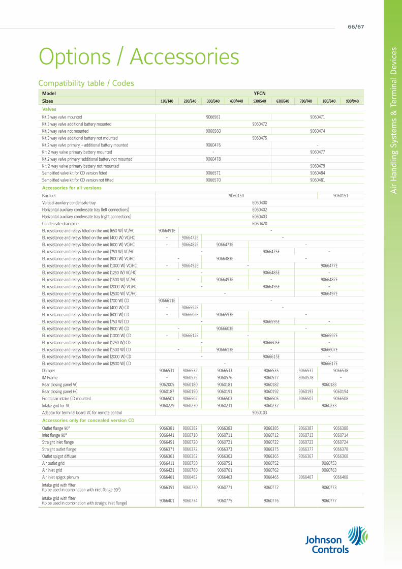
esOptions / AccessoriesCompatibility table / Codes
Model YFCN
Sizes 130/140 230/240 330/340 430/440 530/540 630/640 730/740 830/840 930/940
Valves
Kit 3 way valve mounted 9066561 9060471
Kit 3 way valve additional battery mounted 9060472
Kit 3 way valve not mounted 9066560 9060474
Kit 3 way valve additional battery not mounted 9060475
Kit 2 way valve primary + additional battery mounted 9060476 -
Kit 2 way valve primary battery mounted - 9060477
Kit 2 way valve primary+additional battery not mounted 9060478 -
Kit 2 way valve primary battery not mounted - 9060479
Semplified valve kit for CD version fitted 9066571 9060484
Semplified valve kit for CD version not fitted 9066570 9060481
Accessories for all versions
Pair feet 9060150 9060151
Vertical auxiliary condensate tray 6060400
Horizontal auxiliary condensate tray (left connections) 6060402
Horizontal auxiliary condensate tray (right connections) 6060403
Condensate drain pipe 6060420
El. resistance and relays fitted on the unit (650 W) VC/HC 9066491E -
El. resistance and relays fitted on the unit (400 W) VC/HC - 9066472E -
El. resistance and relays fitted on the unit (600 W) VC/HC - 9066482E 9066473E -
El. resistance and relays fitted on the unit (750 W) VC/HC - 9066475E -
El. resistance and relays fitted on the unit (900 W) VC/HC - 9066483E -
El. resistance and relays fitted on the unit (1000 W) VC/HC - 9066492E - 9066477E
El. resistance and relays fitted on the unit (1250 W) VC/HC - 9066485E -
El. resistance and relays fitted on the unit (1500 W) VC/HC - 9066493E - 9066487E
El. resistance and relays fitted on the unit (2000 W) VC/HC - 9066495E -
El. resistance and relays fitted on the unit (2500 W) VC/HC - 9066497E
El. resistance and relays fitted on the unit (700 W) CD 9066611E -
El. resistance and relays fitted on the unit (400 W) CD - 9066592E -
El. resistance and relays fitted on the unit (600 W) CD - 9066602E 9066593E -
El. resistance and relays fitted on the unit (750 W) CD - 9066595E -
El. resistance and relays fitted on the unit (900 W) CD - 9066603E -
El. resistance and relays fitted on the unit (1000 W) CD - 9066612E - 9066597E
El. resistance and relays fitted on the unit (1250 W) CD - 9066605E -
El. resistance and relays fitted on the unit (1500 W) CD - 9066613E - 9066607E
El. resistance and relays fitted on the unit (2000 W) CD - 9066615E -
El. resistance and relays fitted on the unit (2500 W) CD - 9066617E
Damper 9066531 9066532 9066533 9066535 9066537 9066538
IM Frame - 9060575 9060576 9060577 9060578 -
Rear closing panel VC 9062005 9060180 9060181 9060182 9060183
Rear closing panel HC 9060187 9060190 9060191 9060192 9060193 9060194
Frontal air intake CD mounted 9066501 9066502 9066503 9066505 9066507 9066508
Intake grid for VC 9060229 9060230 9060231 9060232 9060233
Adaptor for terminal board VC for remote control 9060103
Accessories only for concealed version CD
Outlet flange 90° 9066381 9066382 9066383 9066385 9066387 9066388
Inlet flange 90° 9066441 9060710 9060711 9060712 9060713 9060714
Straight inlet flange 9066451 9060720 9060721 9060722 9060723 9060724
Straight outlet flange 9066371 9066372 9066373 9066375 9066377 9066378
Outlet spigot diffuser 9066361 9066362 9066363 9066365 9066367 9066368
Air outlet grid 9066411 9060750 9060751 9060752 9060753
Air inlet grid 9066421 9060760 9060761 9060762 9060763
Air inlet spigot plenum 9066461 9066462 9066463 9066465 9066467 9066468
Intake grid with filter (to be used in combination with inlet flange 90°) 9066391 9060770 9060771 9060772 9060773
Intake grid with filter (to be used in combination with straight inlet flange) 9066401 9060774 9060775 9060776 9060777
york air-conditioning products
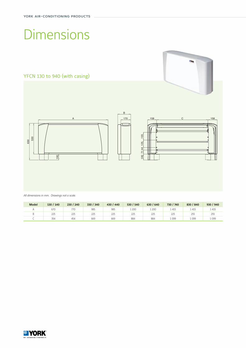
All dimensions in mm. Drawings not a scale.
YFCN 130 to 940 (with casing)
Dimensions
Model 130 / 140 230 / 240 330 / 340 430 / 440 530 / 540 630 / 640 730 / 740 830 / 840 930 / 940
A 670 770 985 985 1 200 1 200 1 415 1 415 1 415
B 225 225 225 225 225 225 225 255 255
C 354 454 669 669 884 884 1 099 1 099 1 099
B
170 158 158
7144
125
133
C
001
A
001
530
630
68/69
Air
Han
dlin
g Sy
stem
s &
Ter
min
al D
evic
es
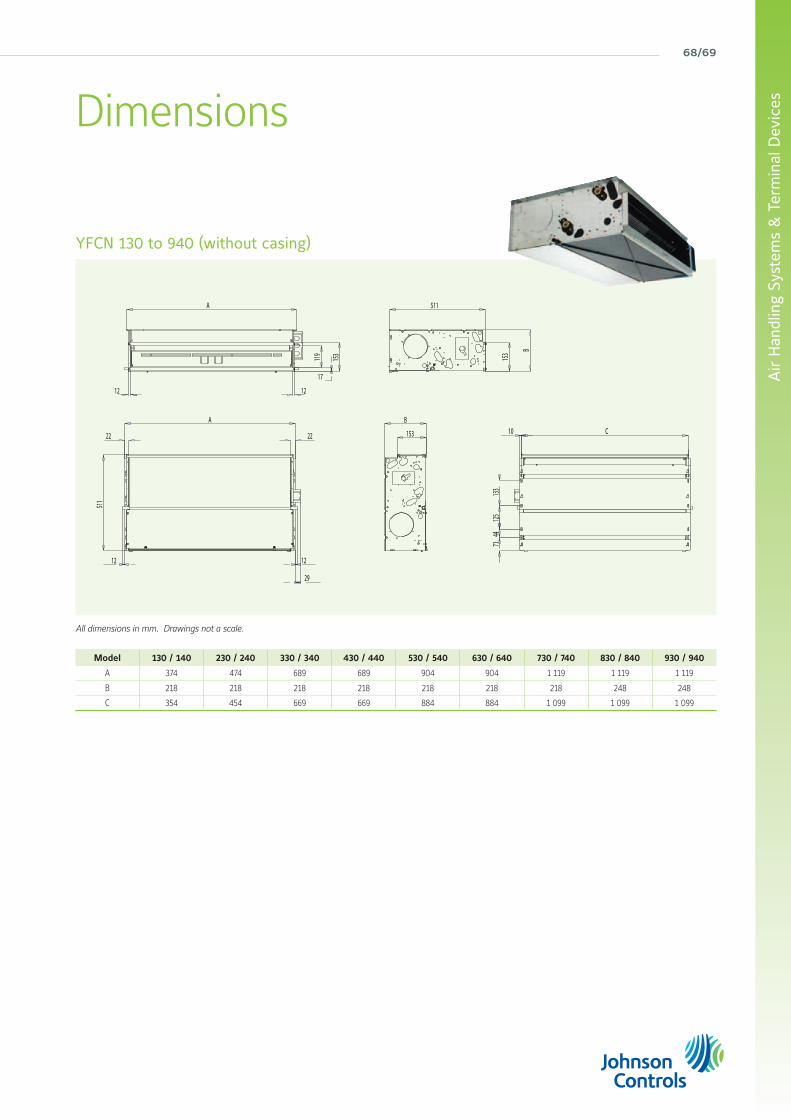
All dimensions in mm. Drawings not a scale.
YFCN 130 to 940 (without casing)
Dimensions
B
153
511
A
22 22
29
12 12
7144
125
133
10 C
153
17
119
A
12 12
153 B
511
Model 130 / 140 230 / 240 330 / 340 430 / 440 530 / 540 630 / 640 730 / 740 830 / 840 930 / 940
A 374 474 689 689 904 904 1 119 1 119 1 119
B 218 218 218 218 218 218 218 248 248
C 354 454 669 669 884 884 1 099 1 099 1 099
york air-conditioning products
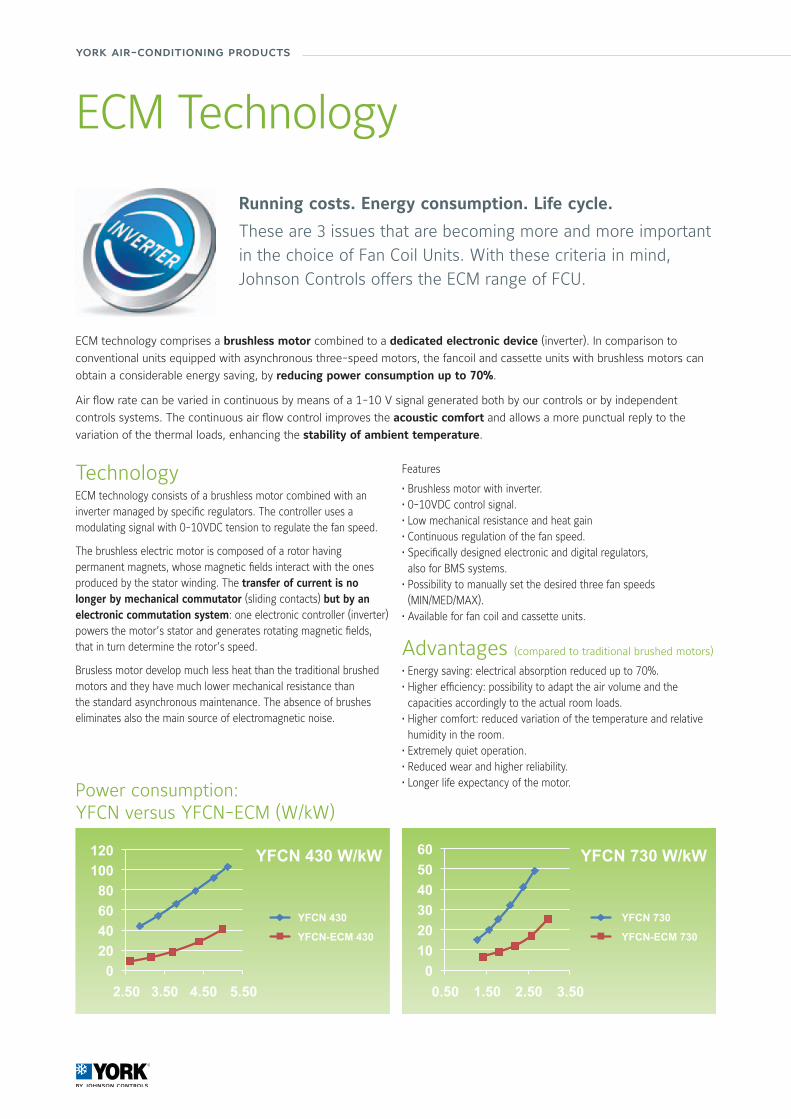
ECM Technology
Advantages (compared to traditional brushed motors)
• Energy saving: electrical absorption reduced up to 70%.• Higher efficiency: possibility to adapt the air volume and the capacities accordingly to the actual room loads.
• Higher comfort: reduced variation of the temperature and relative humidity in the room.
• Extremely quiet operation.• Reduced wear and higher reliability.• Longer life expectancy of the motor.
Features
• Brushless motor with inverter.• 0-10VDC control signal.• Low mechanical resistance and heat gain• Continuous regulation of the fan speed.• Specifically designed electronic and digital regulators, also for BMS systems.
• Possibility to manually set the desired three fan speeds (MIN/MED/MAX).
• Available for fan coil and cassette units.
Running costs. Energy consumption. Life cycle.
These are 3 issues that are becoming more and more important in the choice of Fan Coil Units. With these criteria in mind, Johnson Controls offers the ECM range of FCU.
ECM technology comprises a brushless motor combined to a dedicated electronic device (inverter). In comparison to
conventional units equipped with asynchronous three-speed motors, the fancoil and cassette units with brushless motors can
obtain a considerable energy saving, by reducing power consumption up to 70%.
Air flow rate can be varied in continuous by means of a 1-10 V signal generated both by our controls or by independent
controls systems. The continuous air flow control improves the acoustic comfort and allows a more punctual reply to the
variation of the thermal loads, enhancing the stability of ambient temperature.
TechnologyECM technology consists of a brushless motor combined with an inverter managed by specific regulators. The controller uses a modulating signal with 0-10VDC tension to regulate the fan speed.
The brushless electric motor is composed of a rotor having permanent magnets, whose magnetic fields interact with the ones produced by the stator winding. The transfer of current is no longer by mechanical commutator (sliding contacts) but by an electronic commutation system: one electronic controller (inverter) powers the motor’s stator and generates rotating magnetic fields, that in turn determine the rotor’s speed.
Brusless motor develop much less heat than the traditional brushed motors and they have much lower mechanical resistance than the standard asynchronous maintenance. The absence of brushes eliminates also the main source of electromagnetic noise.
Power consumption:YFCN versus YFCN-ECM (W/kW)
YFCN 430
YFCN-ECM 430
YFCN 730
YFCN-ECM 730
YFCN 430 W/kW YFCN 730 W/kW
0.502.50 1.503.50 2.504.50 3.505.50
70/71
Air
Han
dlin
g Sy
stem
s &
Ter
min
al D
evic
es
Manufacturer reserves the rights to change specifications without prior notice.
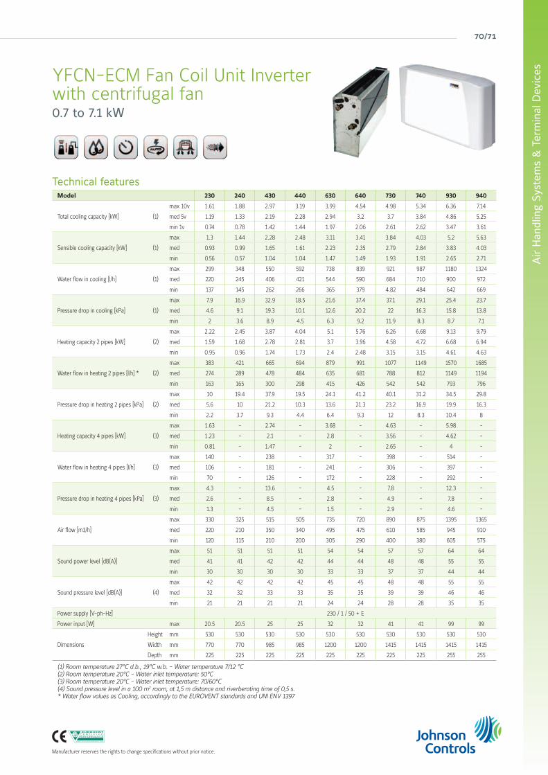
YFCN-ECM Fan Coil Unit Inverterwith centrifugal fan0.7 to 7.1 kW
Technical featuresModel 230 240 430 440 630 640 730 740 930 940
Total cooling capacity [kW] (1)
max 10v 1.61 1.88 2.97 3.19 3.99 4.54 4.98 5.34 6.36 7.14
med 5v 1.19 1.33 2.19 2.28 2.94 3.2 3.7 3.84 4.86 5.25
min 1v 0.74 0.78 1.42 1.44 1.97 2.06 2.61 2.62 3.47 3.61
Sensible cooling capacity [kW] (1)
max 1.3 1.44 2.28 2.48 3.11 3.41 3.84 4.03 5.2 5.63
med 0.93 0.99 1.65 1.61 2.23 2.35 2.79 2.84 3.83 4.03
min 0.56 0.57 1.04 1.04 1.47 1.49 1.93 1.91 2.65 2.71
Water flow in cooling [l/h] (1)
max 299 348 550 592 738 839 921 987 1180 1324
med 220 245 406 421 544 590 684 710 900 972
min 137 145 262 266 365 379 4.82 484 642 669
Pressure drop in cooling [kPa] (1)
max 7.9 16.9 32.9 18.5 21.6 37.4 37.1 29.1 25.4 23.7
med 4.6 9.1 19.3 10.1 12.6 20.2 22 16.3 15.8 13.8
min 2 3.6 8.9 4.5 6.3 9.2 11.9 8.3 8.7 7.1
Heating capacity 2 pipes [kW] (2)
max 2.22 2.45 3.87 4.04 5.1 5.76 6.26 6.68 9.13 9.79
med 1.59 1.68 2.78 2.81 3.7 3.96 4.58 4.72 6.68 6.94
min 0.95 0.96 1.74 1.73 2.4 2.48 3.15 3.15 4.61 4.63
Water flow in heating 2 pipes [l/h] * (2)
max 383 421 665 694 879 991 1077 1149 1570 1685
med 274 289 478 484 635 681 788 812 1149 1194
min 163 165 300 298 415 426 542 542 793 796
Pressure drop in heating 2 pipes [kPa] (2)
max 10 19.4 37.9 19.5 24.1 41.2 40.1 31.2 34.5 29.8
med 5.6 10 21.2 10.3 13.6 21.3 23.2 16.9 19.9 16.3
min 2.2 3.7 9.3 4.4 6.4 9.3 12 8.3 10.4 8
Heating capacity 4 pipes [kW] (3)
max 1.63 - 2.74 - 3.68 - 4.63 - 5.98 -
med 1.23 - 2.1 - 2.8 - 3.56 - 4.62 -
min 0.81 - 1.47 - 2 - 2.65 - 4 -
Water flow in heating 4 pipes [l/h] (3)
max 140 - 238 - 317 - 398 - 514 -
med 106 - 181 - 241 - 306 - 397 -
min 70 - 126 - 172 - 228 - 292 -
Pressure drop in heating 4 pipes [kPa] (3)
max 4.3 - 13.6 - 4.5 - 7.8 - 12.3 -
med 2.6 - 8.5 - 2.8 - 4.9 - 7.8 -
min 1.3 - 4.5 - 1.5 - 2.9 - 4.6 -
Air flow [m3/h]
max 330 325 515 505 735 720 890 875 1395 1365
med 220 210 350 340 495 475 610 585 945 910
min 120 115 210 200 305 290 400 380 605 575
Sound power level [dB(A)]
max 51 51 51 51 54 54 57 57 64 64
med 41 41 42 42 44 44 48 48 55 55
min 30 30 30 30 33 33 37 37 44 44
Sound pressure level [dB(A)] (4)
max 42 42 42 42 45 45 48 48 55 55
med 32 32 33 33 35 35 39 39 46 46
min 21 21 21 21 24 24 28 28 35 35
Power supply [V-ph-Hz] 230 / 1 / 50 + E
Power input [W] max 20.5 20.5 25 25 32 32 41 41 99 99
Dimensions
Height mm 530 530 530 530 530 530 530 530 530 530
Width mm 770 770 985 985 1200 1200 1415 1415 1415 1415
Depth mm 225 225 225 225 225 225 225 225 255 255
(1) Room temperature 27°C d.b., 19°C w.b. - Water temperature 7/12 °C(2) Room temperature 20°C - Water inlet temperature: 50°C(3) Room temperature 20°C - Water inlet temperature: 70/60°C(4) Sound pressure level in a 100 m2 room, at 1,5 m distance and riverberating time of 0,5 s.* Water flow values as Cooling, accordingly to the EUROVENT standards and UNI ENV 1397
york air-conditioning products
Technical featuresModel LASER: YLV, YLV-AF, YLH, YLH-AF, YLIV, YLIV-AF, YLIH, YLIH-AF LOW BODY: YLVR, YLIVRSizes 110 112 114 216 218 220 222 224 226 228 110 112 114 216 218Cooling capacity (1) W 1 169 1 746 2 291 3 467 3 804 4 664 5 570 6 789 7 599 9 974 942 1 460 2 115 2 719 3 372
Heating capacity (2) W 1 628 2 296 2 981 4 514 5 076 6 013 7 304 8 677 9 800 12 739 1 159 1 839 2 432 3 270 3 656
Pressure drop (4) kPa 3.9 7.6 6.5 13.8 13.6 23.1 31.6 18.8 20.9 37.1 6.1 1.4 5.4 9.1 24.2
Power supply V/Ph/Hz 230 / 1 / 50 + E
Input W 46 48 57 81 86 89 119 145 156 200 46 48 57 81 86
Sound power level (3) dB(A) 49 50 53 53 55 55 59 60 63 67 49 50 53 53 55
Sound pressure level at 3 m (3) dB(A) 31 32 35 35 37 37 41 42 45 49 31 32 35 35 37Water connections inch 1/2 “
Dimensions indicated next page. (1) Cooling capacities based on 7°C EWT ∆t 5°C indoor temperature 27°C DB / 19°C WB (2 pipes - high speed fan) (3 rows).(2) Heating capacities based on 50°C EWT (LASER) / 70°C EWT (LOW BODY) at nominal flow rate indoor temperature 20°C (2 pipes - high speed fan) (3 rows for LASER
and 1 row for LOW BODY). (3) Sound level at high speed fan . (4) In cooling mode. For other conditions contact Johnson Controls
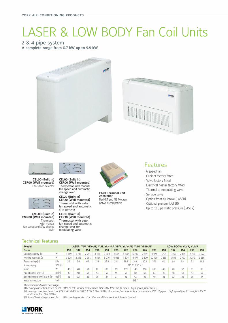
LASER & LOW BODY Fan Coil Units2 & 4 pipe systemA complete range from 0.7 kW up to 9.9 kW
CSL00 (Built in)CSR00 (Wall mounted)
Fan speed selector
CML00 (Built in)CMR00 (Wall mounted)
Thermostatwith manual
fan speed and S/W change over
CEL00 (Built in)CER00 (Wall mounted)Thermostat with manual fan speed and automatic change over
CEL20 (Built in)CER20 (Wall mounted)Thermostat with auto. fan speed and automatic change over
CEL30 (Built in)CER30 (Wall mounted)Thermostat with auto. fan speed and automatic change over for modulating valve
FX03 Terminal unit controllerBacNET and N2 Metasys network compatible
Features• 6 speed fan• Cabinet factory fitted• Valve factory fitted• Electrical heater factory fitted• Thermal or modulating valve• Service valve• Option front air intake (LASER)• Optional plenum (LASER)• Up to 110 pa static pressure (LASER)
72/73
Air
Han
dlin
g Sy
stem
s &
Ter
min
al D
evic
es
Manufacturer reserves the rights to change specifications without prior notice.
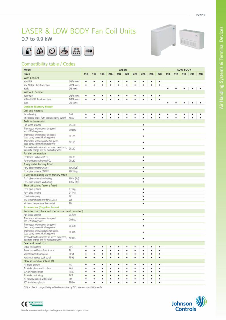
Compatibility table / CodesModel LASER LOW BODY
Sizes 110 112 114 216 218 220 222 224 226 228 110 112 114 216 218With CabinetYLV-YLH 2/3/4 rows l l l l l l l l l l
YLV-YLH/AF Front air intake 2/3/4 rows l l l l l l l l l l
YLVR 2/3 rows l l l l l
Without CabinetYLIV-YLIH 2/3/4 rows l l l l l l l l l l
YLIV-YLIH/AF Front air intake 2/3/4 rows l l l l l l l l l l
YLIVR 2/3 rows l l l l l
Options (Factory fitted)Coil and heaters1 row heating BA1 l l l l l l l l l l l l l l l
Kit electrical heater (with relay and safety switch) KREL l l l l l l l l l l l l l l l
Built in thermostat Fan speed selector CSL00 l
Thermostat with manual fan speedand S/W change over CML00 l
Thermostat with manual fan speed,dead band, automatic change over CEL00 l
Thermostat with automatic fan speed,dead band, automatic change over CEL20 l
Thermostat with automatic fan speed, dead band, automatic change over for modulating valve CEL30 l
Parallel connectionFor ON/OFF valve one/FCU CBL20 l
For modulating valve one/FCU CBL30 l
3 way valve factory fittedFor 2 pipe systems ON/OFF J3A2 (2p) l
For 4 pipe systems ON/OFF J3A2 (4p) l
3 way modulating valve factory fittedFor 2 pipe systems Modulating J3AM (2p) l
For 4 pipe systems Modulating J3AM (4p) l
Shut off valves factory fittedFor 2 pipe systems DT (2p) l
For 4 pipe systems DT (4p) l
Condensate pump PC l
WS sensor change over for CEL/CER WS l
Minimum temperature thermostat TM l
Accessories (Supplied loose)Remote controllers and thermostat (wall mounted)Fan speed selector CSR00 l
Thermostat with manual fan speedand S/W change over CMR00 l
Thermostat with manual fan speed,dead band, automatic change over CER00 l
Thermostat with automatic fan speed,dead band, automatic change over CER20 l
Thermostat with automatic fan speed, dead band, automatic change over for modulating valve CER30 l
Feet and panel (1)Set of painted feet CP1 l l l l l l l l l l
Set of painted feet + frontal socle ZL1 l l l l l l l l l l
Vertical painted back panel PPV1 l l l l l l l l l l
Horizontal painted back panel PPH1 l l l l l l l l l l
Plenums and air intake (1)Air intake plenum PA l l l l l l l l l l
Air intake plenum with collars PAS l l l l l l l l l l
90° air intake plenum PA90 l l l l l l l l l l
Air intake duct fitting RCA l l l l l l l l l l
Air delivery plenum with collars PM l l l l l l l l l l
90° air delivery plenum PM90 l l l l l l l l l l
(1) for check compatibility with the models of FCU see compatibility table
LASER & LOW BODY Fan Coil Units0.7 to 9.9 kW
york air-conditioning products
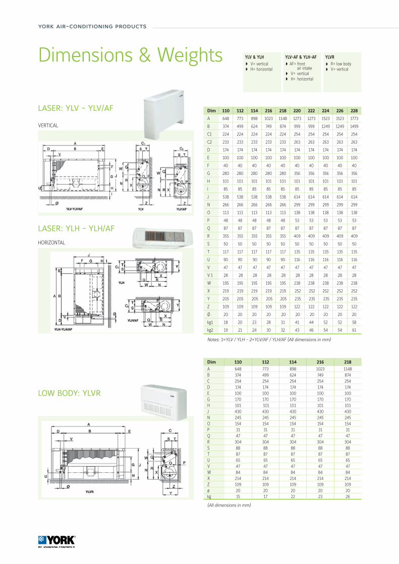
LASER: YLV - YLV/AF
LASER: YLH - YLH/AF
Dim 110 112 114 216 218 220 222 224 226 228
A 648 773 898 1023 1148 1273 1273 1523 1523 1773
B 374 499 624 749 874 999 999 1249 1249 1499
C1 224 224 224 224 224 254 254 254 254 254
C2 233 233 233 233 233 263 263 263 263 263
D 174 174 174 174 174 174 174 174 174 174
E 100 100 100 100 100 100 100 100 100 100
F 40 40 40 40 40 40 40 40 40 40
G 280 280 280 280 280 356 356 356 356 356
H 101 101 101 101 101 101 101 101 101 101
I 85 85 85 85 85 85 85 85 85 85
J 538 538 538 538 538 614 614 614 614 614
N 266 266 266 266 266 299 299 299 299 299
O 113 113 113 113 113 138 138 138 138 138
P 48 48 48 48 48 53 53 53 53 53
Q 87 87 87 87 87 87 87 87 87 87
R 355 355 355 355 355 409 409 409 409 409
S 50 50 50 50 50 50 50 50 50 50
T 117 117 117 117 117 135 135 135 135 135
U 90 90 90 90 90 116 116 116 116 116
V 47 47 47 47 47 47 47 47 47 47
V 1 28 28 28 28 28 28 28 28 28 28
W 195 195 195 195 195 238 238 238 238 238
X 219 219 219 219 219 252 252 252 252 252
Y 205 205 205 205 205 235 235 235 235 235
Z 109 109 109 109 109 122 122 122 122 122
Ø 20 20 20 20 20 20 20 20 20 20
kg1 18 20 23 28 31 41 44 52 52 58
kg2 19 21 24 30 32 43 46 54 54 61
Notes: 1=YLV / YLH - 2=YLV/AF / YLH/AF (All dimensions in mm)
YLV & YLH V= vertical H= horizontal
YLV-AF & YLH-AF AF= front air intake V= vertical H= horizontal
Dimensions & Weights YLVR R= low body V= vertical
VERTICAL
HORIZONTAL
LOW BODY: YLVR
Dim 110 112 114 216 218 A 648 773 898 1023 1148B 374 499 624 749 874C 254 254 254 254 254D 174 174 174 174 174E 100 100 100 100 100G 170 170 170 170 170H 101 101 101 101 101J 430 430 430 430 430N 245 245 245 245 245O 154 154 154 154 154P 31 31 31 31 31Q 47 47 47 47 47R 304 304 304 304 304S 88 88 88 88 88T 87 87 87 87 87U 65 65 65 65 65V 47 47 47 47 47W 84 84 84 84 84X 214 214 214 214 214Z 109 109 109 109 109ø 20 20 20 20 20kg 15 17 22 23 26
(All dimensions in mm)
74/75
Air
Han
dlin
g Sy
stem
s &
Ter
min
al D
evic
es
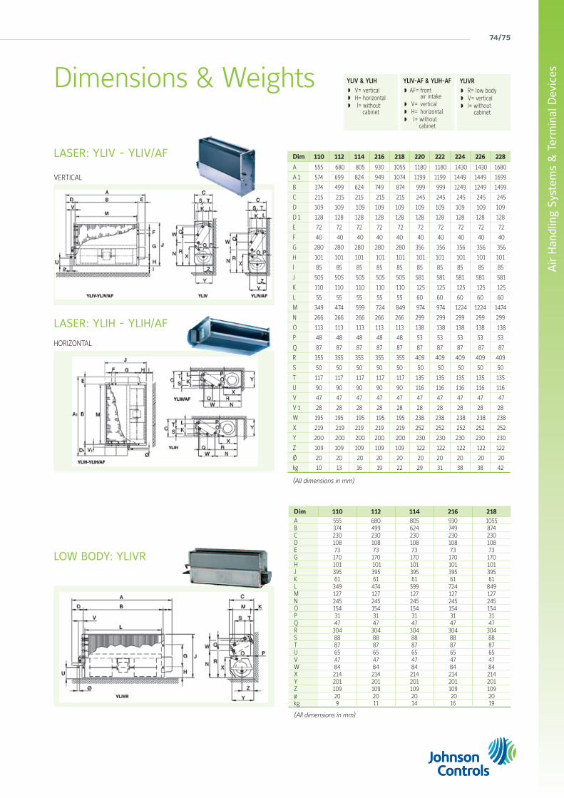
LASER: YLIV - YLIV/AF Dim 110 112 114 216 218 220 222 224 226 228
A 555 680 805 930 1055 1180 1180 1430 1430 1680
A 1 574 699 824 949 1074 1199 1199 1449 1449 1699
B 374 499 624 749 874 999 999 1249 1249 1499
C 215 215 215 215 215 245 245 245 245 245
D 109 109 109 109 109 109 109 109 109 109
D 1 128 128 128 128 128 128 128 128 128 128
E 72 72 72 72 72 72 72 72 72 72
F 40 40 40 40 40 40 40 40 40 40
G 280 280 280 280 280 356 356 356 356 356
H 101 101 101 101 101 101 101 101 101 101
I 85 85 85 85 85 85 85 85 85 85
J 505 505 505 505 505 581 581 581 581 581
K 110 110 110 110 110 125 125 125 125 125
L 55 55 55 55 55 60 60 60 60 60
M 349 474 599 724 849 974 974 1224 1224 1474
N 266 266 266 266 266 299 299 299 299 299
O 113 113 113 113 113 138 138 138 138 138
P 48 48 48 48 48 53 53 53 53 53
Q 87 87 87 87 87 87 87 87 87 87
R 355 355 355 355 355 409 409 409 409 409
S 50 50 50 50 50 50 50 50 50 50
T 117 117 117 117 117 135 135 135 135 135
U 90 90 90 90 90 116 116 116 116 116
V 47 47 47 47 47 47 47 47 47 47
V 1 28 28 28 28 28 28 28 28 28 28
W 195 195 195 195 195 238 238 238 238 238
X 219 219 219 219 219 252 252 252 252 252
Y 200 200 200 200 200 230 230 230 230 230
Z 109 109 109 109 109 122 122 122 122 122
Ø 20 20 20 20 20 20 20 20 20 20
kg 10 13 16 19 22 29 31 38 38 42
(All dimensions in mm)
LASER: YLIH - YLIH/AF
YLIV-AF & YLIH-AF AF= front air intake V= vertical H= horizontal I= without cabinet
YLIV & YLIH V= vertical H= horizontal I= without cabinet
Dimensions & Weights YLIVR R= low body V= vertical I= without cabinet
VERTICAL
HORIZONTAL
Dim 110 112 114 216 218 A 555 680 805 930 1055B 374 499 624 749 874C 230 230 230 230 230D 108 108 108 108 108E 73 73 73 73 73G 170 170 170 170 170H 101 101 101 101 101J 395 395 395 395 395K 61 61 61 61 61L 349 474 599 724 849M 127 127 127 127 127N 245 245 245 245 245O 154 154 154 154 154P 31 31 31 31 31Q 47 47 47 47 47R 304 304 304 304 304S 88 88 88 88 88T 87 87 87 87 87U 65 65 65 65 65V 47 47 47 47 47W 84 84 84 84 84X 214 214 214 214 214Y 201 201 201 201 201Z 109 109 109 109 109ø 20 20 20 20 20kg 9 11 14 16 19
(All dimensions in mm)
LOW BODY: YLIVR
york air-conditioning products
CSL00 (Built in)CSR00 (Wall mounted)
Fan speed selector
CML00 (Built in)CMR00 (Wall mounted)
Thermostatwith manual
fan speed and S/W change over
CEL00 (Built in)CER00 (Wall mounted)Thermostat with manual fan speed and automatic change over
CEL20 (Built in)CER20 (Wall mounted)Thermostat with auto. fan speed and automatic change over
CEL30 (Built in)CER30 (Wall mounted)Thermostat with auto. fan speed and automatic change over for modulating valve
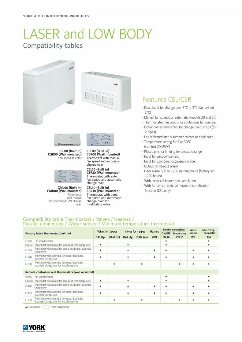
Features CEL/CER• Dead band for change over 5°C or 2°C (factory set
2°C) • Manual fan speeds or automatic (models 20 and 30) • Thermostated fan control or continuous fan running • Option water sensor WS for change over on coil (for
2 pipes) • Led indicated status summer, winter or dead band • Temperature setting for 7 to 30°C (comfort 20-25°C) • Plastic pins for limiting temperature range• Input for window contact • Input for Economy/ occupancy mode • Output for remote alarm • Filter alarm 600 or 1200 running hours (factory set
1200 hours) • With electrical heater post ventilation • With Air sensor in the air intake destratification
function (CEL only)
Compatibility table Thermostats / Valves / Heaters /Parallel connection / Water sensor / Minimum temperature thermostat
Factory fitted thermostat (built in)Valves for 2 pipes Valves for 4 pipes Heaters
Parallel connection Water sensor
Min. Temp. ThermostatON/OFF Modulating
J3A2 (2p) J3AM (2p) J3A2 (4p) J3AM (4p) KREL CBL20 CBL30 WS TMCSL00 Fan speed selector l l
CML00 Thermostat with manual fan speed and S/W change over l l l l
CEL00 Thermostat with manual fan speed, dead band, automatic change over
l l l l l l
CEL20 Thermostat with automatic fan speed, dead band, automatic change over
l l l l l l
CEL30 Thermostat with automatic fan speed, dead band, automatic change over for modulating valve
l l l l l
Remote controllers and thermostats (wall mounted)
CSR00 Fan speed selector l l
CMR00 Thermostat with manual fan speed and S/W change over l l l l
CER00 Thermostat with manual fan speed, dead band, automatic change over
l l l l l l
CER20 Thermostat with automatic fan speed, dead band, automatic change over
l l l l l l
CER30 Thermostat with automatic fan speed, dead band, automatic change over for modulating valve
l l l l l
l Compatible Not compatible
LASER and LOW BODYCompatibility tables
76/77
Air
Han
dlin
g Sy
stem
s &
Ter
min
al D
evic
es
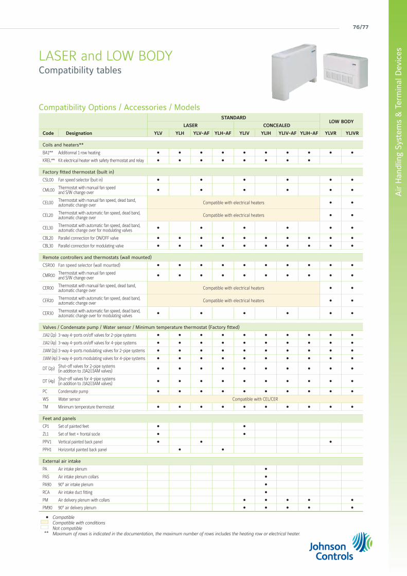
Compatibility Options / Accessories / ModelsSTANDARD
LOW BODYLASER CONCEALED
Code Designation YLV YLH YLV-AF YLH-AF YLIV YLIH YLIV-AF YLIH-AF YLVR YLIVR
Coils and heaters**
BA1** Additionnal 1 row heating l l l l l l l l l l
KREL** Kit electrical heater with safety thermostat and relay l l l l l l l l
Factory fitted thermostat (built in)
CSL00 Fan speed selector (buit in) l l l l l l
CML00 Thermostat with manual fan speed and S/W change over
l l l l l l
CEL00 Thermostat with manual fan speed, dead band, automatic change over Compatible with electrical heaters l l
CEL20 Thermostat with automatic fan speed, dead band, automatic change over Compatible with electrical heaters l l
CEL30 Thermostat with automatic fan speed, dead band, automatic change over for modulating valves
l l l l l l
CBL20 Parallel connection for ON/OFF valve l l l l l l l l l l
CBL30 Parallel connection for modulating valve l l l l l l l l l l
Remote controllers and thermostats (wall mounted)
CSR00 Fan speed selector (wall mounted) l l l l l l l l l l
CMR00 Thermostat with manual fan speed and S/W change over
l l l l l l l l l l
CER00 Thermostat with manual fan speed, dead band, automatic change over Compatible with electrical heaters l l
CER20 Thermostat with automatic fan speed, dead band, automatic change over Compatible with electrical heaters l l
CER30 Thermostat with automatic fan speed, dead band, automatic change over for modulating valves
l l l l l l
Valves / Condensate pump / Water sensor / Minimum temperature thermostat (Factory fitted)
J3A2 (2p) 3-way 4-ports on/off valves for 2-pipe systems l l l l l l l l l l
J3A2 (4p) 3-way 4-ports on/off valves for 4-pipe systems l l l l l l l l l l
J3AM (2p) 3-way 4-ports modulating valves for 2-pipe systems l l l l l l l l l l
J3AM (4p) 3-way 4-ports modulating valves for 4-pipe systems l l l l l l l l l l
DT (2p) Shut-off valves for 2-pipe systems (in addition to J3A2/J3AM valves)
l l l l l l l l l l
DT (4p) Shut-off valves for 4-pipe systems (in addition to J3A2/J3AM valves)
l l l l l l l l l l
PC Condensate pump l l l l l l l l l l
WS Water sensor Compatible with CEL/CER
TM Minimum temperature thermostat l l l l l l l l l l
Feet and panels
CP1 Set of painted feet l l
ZL1 Set of feet + frontal socle l l
PPV1 Vertical painted back panel l l l
PPH1 Horizontal painted back panel l l
External air intake
PA Air intake plenum l
PAS Air intake plenum collars l
PA90 90° air intake plenum l
RCA Air intake duct fitting l
PM Air delivery plenum with collars l l l l l
PM90 90° air delivery plenum l l l l l
Compatible Compatible with conditionsNot compatibleMaximum of rows is indicated in the documentation, the maximum number of rows includes the heating row or electrical heater.
l
**
LASER and LOW BODYCompatibility tables
york air-conditioning products
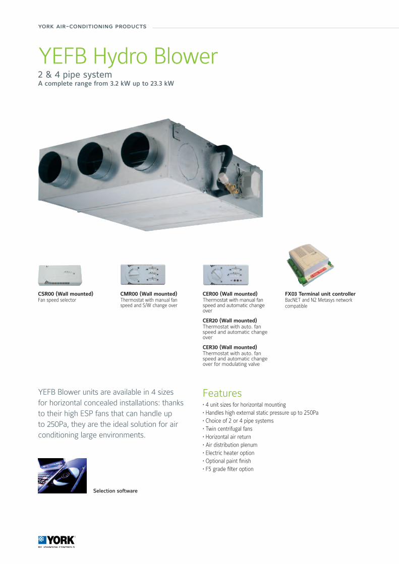
YEFB Hydro Blower2 & 4 pipe systemA complete range from 3.2 kW up to 23.3 kW
Features• 4 unit sizes for horizontal mounting• Handles high external static pressure up to 250Pa• Choice of 2 or 4 pipe systems• Twin centrifugal fans• Horizontal air return• Air distribution plenum• Electric heater option• Optional paint finish• F5 grade filter option
YEFB Blower units are available in 4 sizes for horizontal concealed installations: thanks to their high ESP fans that can handle up to 250Pa, they are the ideal solution for air conditioning large environments.
Selection software
FX03 Terminal unit controllerBacNET and N2 Metasys network compatible
CSR00 (Wall mounted)Fan speed selector
CMR00 (Wall mounted)Thermostat with manual fan speed and S/W change over
CER00 (Wall mounted)Thermostat with manual fan speed and automatic change over
CER20 (Wall mounted)Thermostat with auto. fan speed and automatic change over
CER30 (Wall mounted)Thermostat with auto. fan speed and automatic change over for modulating valve
78/79
Air
Han
dlin
g Sy
stem
s &
Ter
min
al D
evic
es
Manufacturer reserves the rights to change specifications without prior notice.
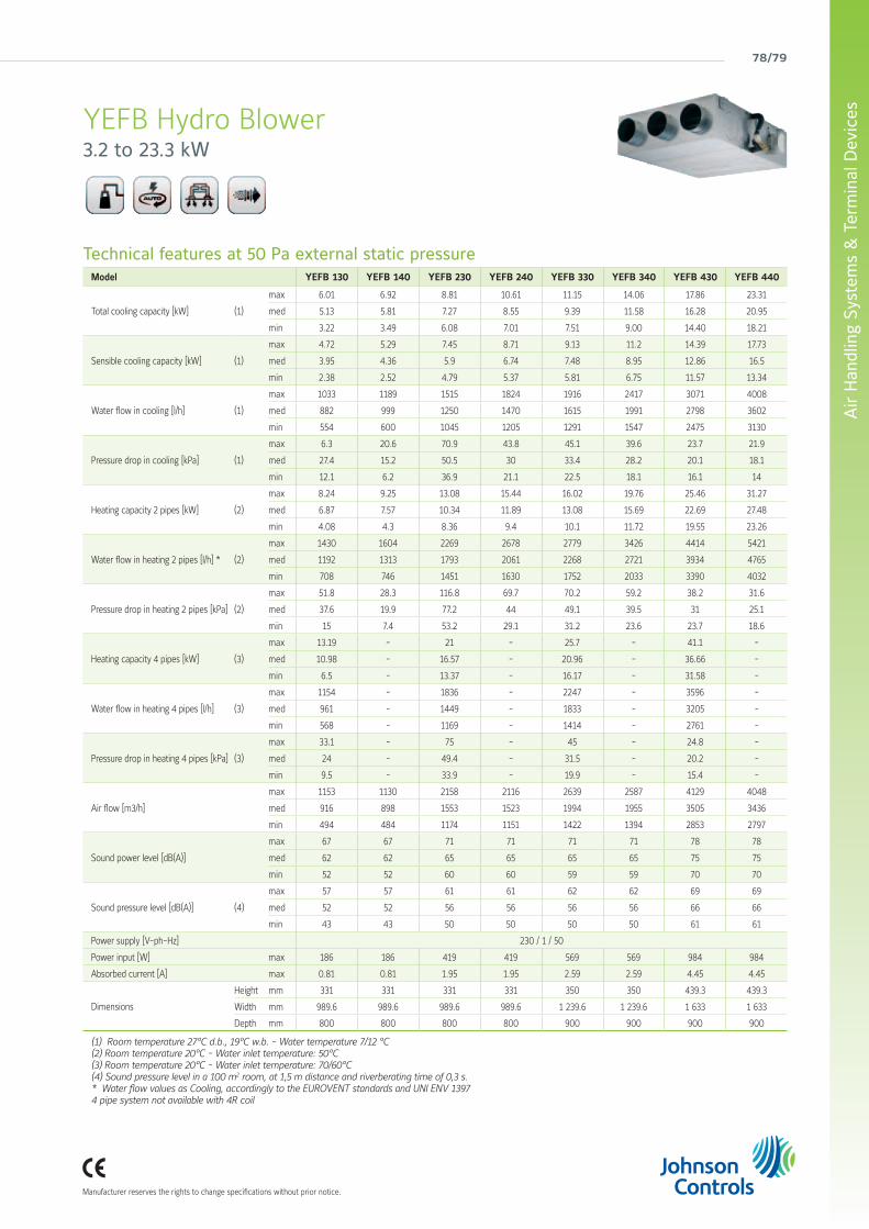
YEFB Hydro Blower3.2 to 23.3 kW
Technical features at 50 Pa external static pressureModel YEFB 130 YEFB 140 YEFB 230 YEFB 240 YEFB 330 YEFB 340 YEFB 430 YEFB 440
Total cooling capacity [kW] (1)
max 6.01 6.92 8.81 10.61 11.15 14.06 17.86 23.31
med 5.13 5.81 7.27 8.55 9.39 11.58 16.28 20.95
min 3.22 3.49 6.08 7.01 7.51 9.00 14.40 18.21
Sensible cooling capacity [kW] (1)
max 4.72 5.29 7.45 8.71 9.13 11.2 14.39 17.73
med 3.95 4.36 5.9 6.74 7.48 8.95 12.86 16.5
min 2.38 2.52 4.79 5.37 5.81 6.75 11.57 13.34
Water flow in cooling [l/h] (1)
max 1033 1189 1515 1824 1916 2417 3071 4008
med 882 999 1250 1470 1615 1991 2798 3602
min 554 600 1045 1205 1291 1547 2475 3130
Pressure drop in cooling [kPa] (1)
max 6.3 20.6 70.9 43.8 45.1 39.6 23.7 21.9
med 27.4 15.2 50.5 30 33.4 28.2 20.1 18.1
min 12.1 6.2 36.9 21.1 22.5 18.1 16.1 14
Heating capacity 2 pipes [kW] (2)
max 8.24 9.25 13.08 15.44 16.02 19.76 25.46 31.27
med 6.87 7.57 10.34 11.89 13.08 15.69 22.69 27.48
min 4.08 4.3 8.36 9.4 10.1 11.72 19.55 23.26
Water flow in heating 2 pipes [l/h] * (2)
max 1430 1604 2269 2678 2779 3426 4414 5421
med 1192 1313 1793 2061 2268 2721 3934 4765
min 708 746 1451 1630 1752 2033 3390 4032
Pressure drop in heating 2 pipes [kPa] (2)
max 51.8 28.3 116.8 69.7 70.2 59.2 38.2 31.6
med 37.6 19.9 77.2 44 49.1 39.5 31 25.1
min 15 7.4 53.2 29.1 31.2 23.6 23.7 18.6
Heating capacity 4 pipes [kW] (3)
max 13.19 - 21 - 25.7 - 41.1 -
med 10.98 - 16.57 - 20.96 - 36.66 -
min 6.5 - 13.37 - 16.17 - 31.58 -
Water flow in heating 4 pipes [l/h] (3)
max 1154 - 1836 - 2247 - 3596 -
med 961 - 1449 - 1833 - 3205 -
min 568 - 1169 - 1414 - 2761 -
Pressure drop in heating 4 pipes [kPa] (3)
max 33.1 - 75 - 45 - 24.8 -
med 24 - 49.4 - 31.5 - 20.2 -
min 9.5 - 33.9 - 19.9 - 15.4 -
Air flow [m3/h]
max 1153 1130 2158 2116 2639 2587 4129 4048
med 916 898 1553 1523 1994 1955 3505 3436
min 494 484 1174 1151 1422 1394 2853 2797
Sound power level [dB(A)]
max 67 67 71 71 71 71 78 78
med 62 62 65 65 65 65 75 75
min 52 52 60 60 59 59 70 70
Sound pressure level [dB(A)] (4)
max 57 57 61 61 62 62 69 69
med 52 52 56 56 56 56 66 66
min 43 43 50 50 50 50 61 61
Power supply [V-ph-Hz] 230 / 1 / 50
Power input [W] max 186 186 419 419 569 569 984 984
Absorbed current [A] max 0.81 0.81 1.95 1.95 2.59 2.59 4.45 4.45
Dimensions
Height mm 331 331 331 331 350 350 439.3 439.3
Width mm 989.6 989.6 989.6 989.6 1 239.6 1 239.6 1 633 1 633
Depth mm 800 800 800 800 900 900 900 900
(1) Room temperature 27°C d.b., 19°C w.b. - Water temperature 7/12 °C(2) Room temperature 20°C - Water inlet temperature: 50°C(3) Room temperature 20°C - Water inlet temperature: 70/60°C(4) Sound pressure level in a 100 m2 room, at 1,5 m distance and riverberating time of 0,3 s.* Water flow values as Cooling, accordingly to the EUROVENT standards and UNI ENV 13974 pipe system not available with 4R coil
york air-conditioning products
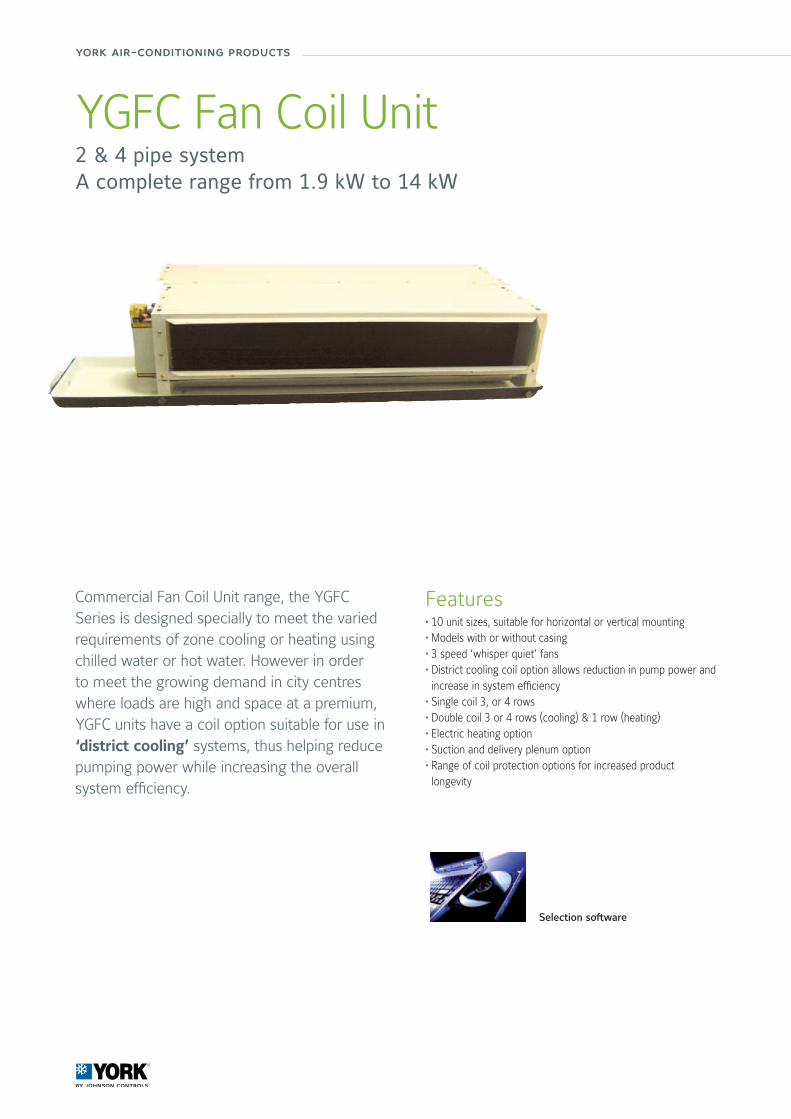
YGFC Fan Coil Unit2 & 4 pipe systemA complete range from 1.9 kW to 14 kW
Features• 10 unit sizes, suitable for horizontal or vertical mounting• Models with or without casing• 3 speed ‘whisper quiet’ fans• District cooling coil option allows reduction in pump power and increase in system efficiency
• Single coil 3, or 4 rows• Double coil 3 or 4 rows (cooling) & 1 row (heating)• Electric heating option• Suction and delivery plenum option• Range of coil protection options for increased product longevity
Commercial Fan Coil Unit range, the YGFC Series is designed specially to meet the varied requirements of zone cooling or heating using chilled water or hot water. However in order to meet the growing demand in city centres where loads are high and space at a premium, YGFC units have a coil option suitable for use in ‘district cooling’ systems, thus helping reduce pumping power while increasing the overall system efficiency.
Selection software
80/81
Air
Han
dlin
g Sy
stem
s &
Ter
min
al D
evic
es
Manufacturer reserves the rights to change specifications without prior notice.
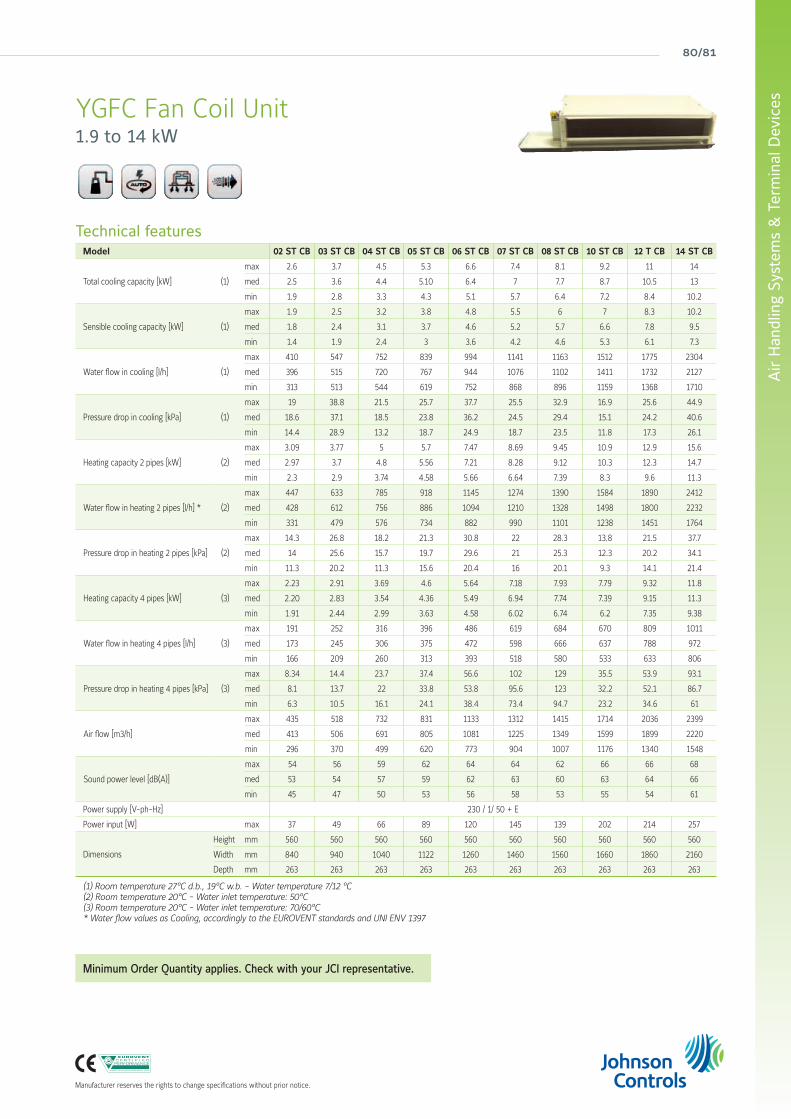
YGFC Fan Coil Unit1.9 to 14 kW
Technical featuresModel 02 ST CB 03 ST CB 04 ST CB 05 ST CB 06 ST CB 07 ST CB 08 ST CB 10 ST CB 12 T CB 14 ST CB
Total cooling capacity [kW] (1)
max 2.6 3.7 4.5 5.3 6.6 7.4 8.1 9.2 11 14
med 2.5 3.6 4.4 5.10 6.4 7 7.7 8.7 10.5 13
min 1.9 2.8 3.3 4.3 5.1 5.7 6.4 7.2 8.4 10.2
Sensible cooling capacity [kW] (1)
max 1.9 2.5 3.2 3.8 4.8 5.5 6 7 8.3 10.2
med 1.8 2.4 3.1 3.7 4.6 5.2 5.7 6.6 7.8 9.5
min 1.4 1.9 2.4 3 3.6 4.2 4.6 5.3 6.1 7.3
Water flow in cooling [l/h] (1)
max 410 547 752 839 994 1141 1163 1512 1775 2304
med 396 515 720 767 944 1076 1102 1411 1732 2127
min 313 513 544 619 752 868 896 1159 1368 1710
Pressure drop in cooling [kPa] (1)
max 19 38.8 21.5 25.7 37.7 25.5 32.9 16.9 25.6 44.9
med 18.6 37.1 18.5 23.8 36.2 24.5 29.4 15.1 24.2 40.6
min 14.4 28.9 13.2 18.7 24.9 18.7 23.5 11.8 17.3 26.1
Heating capacity 2 pipes [kW] (2)
max 3.09 3.77 5 5.7 7.47 8.69 9.45 10.9 12.9 15.6
med 2.97 3.7 4.8 5.56 7.21 8.28 9.12 10.3 12.3 14.7
min 2.3 2.9 3.74 4.58 5.66 6.64 7.39 8.3 9.6 11.3
Water flow in heating 2 pipes [l/h] * (2)
max 447 633 785 918 1145 1274 1390 1584 1890 2412
med 428 612 756 886 1094 1210 1328 1498 1800 2232
min 331 479 576 734 882 990 1101 1238 1451 1764
Pressure drop in heating 2 pipes [kPa] (2)
max 14.3 26.8 18.2 21.3 30.8 22 28.3 13.8 21.5 37.7
med 14 25.6 15.7 19.7 29.6 21 25.3 12.3 20.2 34.1
min 11.3 20.2 11.3 15.6 20.4 16 20.1 9.3 14.1 21.4
Heating capacity 4 pipes [kW] (3)
max 2.23 2.91 3.69 4.6 5.64 7.18 7.93 7.79 9.32 11.8
med 2.20 2.83 3.54 4.36 5.49 6.94 7.74 7.39 9.15 11.3
min 1.91 2.44 2.99 3.63 4.58 6.02 6.74 6.2 7.35 9.38
Water flow in heating 4 pipes [l/h] (3)
max 191 252 316 396 486 619 684 670 809 1011
med 173 245 306 375 472 598 666 637 788 972
min 166 209 260 313 393 518 580 533 633 806
Pressure drop in heating 4 pipes [kPa] (3)
max 8.34 14.4 23.7 37.4 56.6 102 129 35.5 53.9 93.1
med 8.1 13.7 22 33.8 53.8 95.6 123 32.2 52.1 86.7
min 6.3 10.5 16.1 24.1 38.4 73.4 94.7 23.2 34.6 61
Air flow [m3/h]
max 435 518 732 831 1133 1312 1415 1714 2036 2399
med 413 506 691 805 1081 1225 1349 1599 1899 2220
min 296 370 499 620 773 904 1007 1176 1340 1548
Sound power level [dB(A)]
max 54 56 59 62 64 64 62 66 66 68
med 53 54 57 59 62 63 60 63 64 66
min 45 47 50 53 56 58 53 55 54 61
Power supply [V-ph-Hz] 230 / 1/ 50 + E
Power input [W] max 37 49 66 89 120 145 139 202 214 257
Dimensions
Height mm 560 560 560 560 560 560 560 560 560 560
Width mm 840 940 1040 1122 1260 1460 1560 1660 1860 2160
Depth mm 263 263 263 263 263 263 263 263 263 263
(1) Room temperature 27°C d.b., 19°C w.b. - Water temperature 7/12 °C(2) Room temperature 20°C - Water inlet temperature: 50°C(3) Room temperature 20°C - Water inlet temperature: 70/60°C* Water flow values as Cooling, accordingly to the EUROVENT standards and UNI ENV 1397
Minimum Order Quantity applies. Check with your JCI representative.
york air-conditioning products
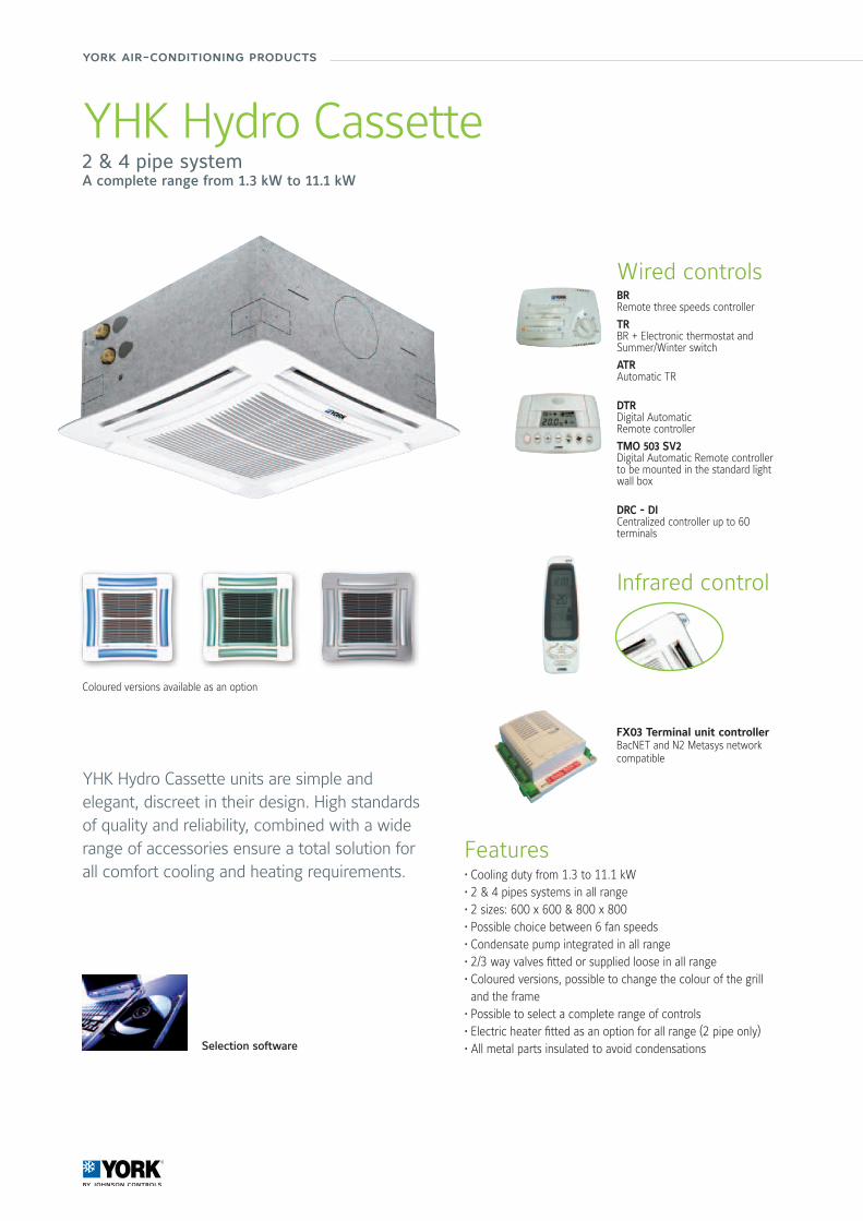
YHK Hydro Cassette2 & 4 pipe systemA complete range from 1.3 kW to 11.1 kW
Features• Cooling duty from 1.3 to 11.1 kW• 2 & 4 pipes systems in all range• 2 sizes: 600 x 600 & 800 x 800• Possible choice between 6 fan speeds• Condensate pump integrated in all range• 2/3 way valves fitted or supplied loose in all range• Coloured versions, possible to change the colour of the grill and the frame
• Possible to select a complete range of controls• Electric heater fitted as an option for all range (2 pipe only)• All metal parts insulated to avoid condensations
YHK Hydro Cassette units are simple and elegant, discreet in their design. High standards of quality and reliability, combined with a wide range of accessories ensure a total solution for all comfort cooling and heating requirements.
Coloured versions available as an option
Selection software
Wired controlsBRRemote three speeds controller
TRBR + Electronic thermostat and Summer/Winter switch
ATRAutomatic TR
DTRDigital AutomaticRemote controller
TMO 503 SV2Digital Automatic Remote controller to be mounted in the standard light wall box
DRC - DICentralized controller up to 60 terminals
Infrared control
FX03 Terminal unit controllerBacNET and N2 Metasys network compatible
82/83
Air
Han
dlin
g Sy
stem
s &
Ter
min
al D
evic
es
Manufacturer reserves the rights to change specifications without prior notice.
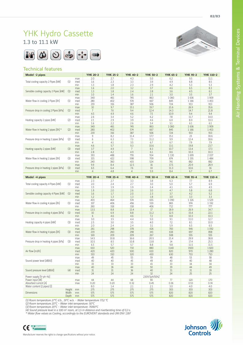
YHK Hydro Cassette1.3 to 11.1 kW
Technical featuresModel -2 pipes YHK 20-2 YHK 25-2 YHK 40-2 YHK 50-2 YHK 65-2 YHK 95-2 YHK 110-2
Total cooling capacity 2 Pipes [kW] (1) max 2.0 2.7 4.3 5.0 6.2 9.5 11.1 med 1.6 2.3 3.3 3.9 4.9 6.8 8.5 min 1.3 1.8 2.3 2.9 4.2 5.3 5.3
Sensible cooling capacity 2 Pipes [kW] (1) max 1.6 2.0 3.2 3.7 4.6 6.5 8.3 med 1.3 1.8 2.4 2.8 3.6 4.5 6.1 min 1.0 1.4 1.6 2.1 3.0 3.5 3.7
Water flow in cooling 2 Pipes [l/h] (1) max 340 461 745 863 1 060 1 636 1 909 med 280 402 574 667 845 1 166 1 453 min 219 316 387 506 724 913 913
Pressure drop in cooling 2 Pipes [kPa] (1) max 10 9.7 15.1 19.7 21.6 26.9 35.6 med 7 7.6 9.4 12.4 14.3 14.7 21.8 min 4.5 4.9 4.6 7.5 10.9 9.4 9.4
Heating capacity 2 pipes [kW] (2) max 2.6 3.4 5.2 6.2 7.8 11.7 14.0 med 2.1 2.9 3.9 4.6 6.0 8.0 10.3 min 1.6 2.2 2.6 3.4 5.1 6.1 6.1
Water flow in heating 2 pipes [l/h] * (2) max 340 461 745 863 1 060 1 636 1 909 med 280 402 574 667 845 1 166 1 453 min 219 316 387 506 724 913 913
Pressure drop in heating 2 pipes [kPa] (2) max 9 8.2 11.4 17.7 15.1 23 30.6 med 6 6.3 7.3 11.2 9.9 12.4 18.6 min 4 4.1 3.5 6.7 6.7 7.9 7.9
Heating capacity 2 pipes [kW] (3) max 4.6 5.7 9.3 10.6 13.1 19.8 23.7 med 3.7 4.9 7 8.3 10.7 13.4 17.3 min 2.8 4.2 4.9 6.1 8.6 10.3 10.3
Water flow in heating 2 pipes [l/h] (3) max 393 488 795 914 1 130 1 699 2 037 med 315 422 598 709 874 1 155 1 484 min 240 360 415 524 741 882 882
Pressure drop in heating 2 pipes [kPa] (3) max 9.9 8.4 12.5 16 17.5 20.9 28.9 med 6.5 6.4 7.6 10 11.3 10.6 16min 4 4.8 4 5.9 8.4 6.7 6.7
Model -4 pipes YHK 20-4 YHK 25-4 YHK 40-4 YHK 50-4 YHK 65-4 YHK 95-4 YHK 110-4
Total cooling capacity 4 Pipes [kW] (1) max 2.3 2.7 3.3 3.8 6.3 7.7 8.9 med 2.0 2.4 2.7 3.0 5.0 5.7 6.9 min 1.5 1.9 1.9 2.4 4.1 4.5 4.5
Sensible cooling capacity 4 Pipes [kW] (1) max 1.9 2.0 2.6 3.0 4.7 5.8 6.8 med 1.6 1.7 2.0 2.3 3.7 4.2 5.2 min 1.2 1.3 1.3 1.8 3.0 3.3 3.3
Water flow in cooling 4 pipes [l/h] (1) max 401 464 574 655 1 090 1 326 1 529 med 337 406 456 519 865 974 1 192 min 260 318 318 406 712 777 777
Pressure drop in cooling 4 pipes [kPa] (1) max 13.5 8.8 13.4 17 18.9 26.9 34.7 med 10 6.9 8.8 11.2 12.5 15.4 22.1 min 6 4.6 4.6 7.2 8.8 10.3 10.3
Heating capacity 4 pipes [kW] (3) max 3.0 3.5 4.4 5.0 9.1 11.0 12.7 med 2.5 3.0 3.5 4.0 7.2 8.1 10.0 min 2.0 2.4 2.4 3.1 5.9 6.5 6.5
Water flow in heating 4 pipes [l/h] (3) max 261 298 378 426 783 946 1 092 med 219 260 298 341 618 697 858min 169 209 209 267 508 555 555
Pressure drop in heating 4 pipes [kPa] (3) max 14.5 10.8 16.6 20.5 21.4 29.9 38.8 med 10.5 8.5 10.8 13.8 14 17.4 25.3 min 6.5 5.7 5.7 8.8 9.8 11.5 11.5
Air flow [m3/h] max 610 520 710 880 1140 1500 1 820 med 420 420 500 610 820 970 1 280 min 310 310 320 430 630 710 710
Sound power level [dB(A)] max 49 45 53 59 48 53 58med 40 40 45 49 40 40 48min 33 33 33 41 33 34 34
Sound pressure level [dB(A)] (4) max 40 36 44 50 39 44 49med 31 31 36 40 31 31 39min 24 24 24 32 24 25 25
Power supply [V-ph-Hz] 230V/1ph/50hZPower input [W] max 44 44 68 90 77 120 170Absorbed current [A] max 0.20 0.20 0.32 0.45 0.36 0.53 0.74 Water content (2 pipes) [l] 8.0 1.4 2.1 2.1 3.0 4.0 4.0
Dimensions Height mm 275 275 275 275 303 303 303Width mm 575 575 575 575 820 820 820Depth mm 575 575 575 575 820 820 820
(1) Room temperature 27°C d.b., 19°C w.b. - Water temperature 7/12 °C(2) Room temperature 20°C - Water inlet temperature: 50°C(3) Room temperature 20°C - Water inlet temperature: 70/60°C(4) Sound pressure level in a 100 m2 room, at 1,5 m distance and riverberating time of 0,3 s.* Water flow values as Cooling, accordingly to the EUROVENT standards and UNI ENV 1397
york air-conditioning products
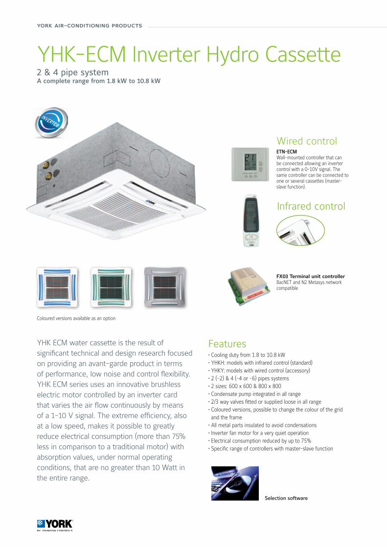
YHK-ECM Inverter Hydro Cassette2 & 4 pipe systemA complete range from 1.8 kW to 10.8 kW
Features• Cooling duty from 1.8 to 10.8 kW • YHKH: models with infrared control (standard)• YHKY: models with wired control (accessory)• 2 (-2) & 4 (-4 or -6) pipes systems• 2 sizes: 600 x 600 & 800 x 800 • Condensate pump integrated in all range • 2/3 way valves fitted or supplied loose in all range • Coloured versions, possible to change the colour of the grid and the frame
• All metal parts insulated to avoid condensations • Inverter fan motor for a very quiet operation • Electrical consumption reduced by up to 75% • Specific range of controllers with master-slave function
YHK ECM water cassette is the result of significant technical and design research focused on providing an avant-garde product in terms of performance, low noise and control flexibility. YHK ECM series uses an innovative brushless electric motor controlled by an inverter card that varies the air flow continuously by means of a 1-10 V signal. The extreme efficiency, also at a low speed, makes it possible to greatly reduce electrical consumption (more than 75% less in comparison to a traditional motor) with absorption values, under normal operating conditions, that are no greater than 10 Watt in the entire range.
Wired controlETN-ECMWall-mounted controller that can be connected allowing an inverter control with a 0-10V signal. The same controller can be connected to one or several cassettes (master-slave function).
Infrared control
Coloured versions available as an option
Selection software
FX03 Terminal unit controllerBacNET and N2 Metasys network compatible
84/85
Air
Han
dlin
g Sy
stem
s &
Ter
min
al D
evic
es
Manufacturer reserves the rights to change specifications without prior notice.
Condensate pump integrated in all sizes
Metal parts insulatedto avoid condensation
2 or 3 way valves fittedor supplied loosein all sizes
Outer casing as an option to integrate the water cassette into any enviroment
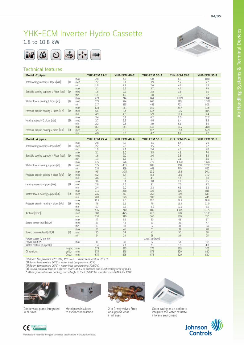
YHK-ECM Inverter Hydro Cassette1.8 to 10.8 kW
Technical featuresModel -2 pipes YHK-ECM 25-2 YHK-ECM 40-2 YHK-ECM 50-2 YHK-ECM 65-2 YHK-ECM 95-2
Total cooling capacity 2 Pipes [kW] (1) max 2.8 4.3 5.0 6.3 10.8med 2.2 3.1 3.9 5.2 7.7min 1.8 2.2 2.6 4.2 5.3
Sensible cooling capacity 2 Pipes [kW] (1) max 2.1 3.2 3.7 4.7 7.9med 1.6 2.2 2.8 3.8 5.5min 1.4 1.6 1.8 3.0 3.7
Water flow in cooling 2 Pipes [l/h] (1) max 473 744 864 1 089 1 848med 373 524 666 885 1 328min 317 385 441 723 909
Pressure drop in cooling 2 Pipes [kPa] (1) max 10.1 15.1 19.7 22.7 33.6med 6.6 9.4 12.4 15.6 18.5min 4.9 4.6 5.9 10.9 9.4
Heating capacity 2 pipes [kW] (2) max 3.4 5.2 6.2 8.0 12.7med 2.7 3.6 4.6 6.4 8.8min 2.2 2.6 3.0 5.1 5.9
Pressure drop in heating 2 pipes [kPa] (2) max 8.7 13.1 17.7 19.5 28.8med 5.5 6.6 10.5 12.8 14.9min 4.0 3.6 4.7 8.7 7.2
Model -4 pipes YHK-ECM 25-4 YHK-ECM 40-6 YHK-ECM 50-6 YHK-ECM 65-4 YHK-ECM 95-6
Total cooling capacity 4 Pipes [kW] (1) max 2.8 3.9 4.5 6.5 9.9med 2.2 2.8 3.5 5.3 7.2min 1.9 2.1 2.4 4.3 5.0
Sensible cooling capacity 4 Pipes [kW] (1) max 2.1 3.0 3.5 4.8 7.4med 1.6 2.0 2.6 3.8 5.2min 1.3 1.5 1.7 3.1 3.5
Water flow in cooling 4 pipes [l/h] (1) max 476 676 779 1 120 1 697med 375 483 608 908 1 233min 318 359 409 740 856
Pressure drop in cooling 4 pipes [kPa] (1) max 9.5 10.5 13.1 19.8 30.1med 6.2 5.7 8.4 13.6 17.0min 4.6 3.5 4.1 9.4 8.8
Heating capacity 4 pipes [kW] (3) max 3.6 3.4 3.8 9.4 9.5med 2.9 2.5 3.1 7.5 7.2min 2.4 2.0 2.2 6.1 5.2
Water flow in heating 4 pipes [l/h] (3) max 311 288 326 805 818med 245 217 263 649 616min 209 170 189 528 449
Pressure drop in heating 4 pipes [kPa] (3) max 11.7 9.0 11.0 22.5 18.0med 7.6 5.5 7.5 15.5 11.0min 5.7 3.5 4.5 10.5 6.5
Air flow [m3/h] max 535 710 880 1 165 1 770med 380 445 610 870 1 130min 310 310 360 630 710
Sound power level [dB(A)] max 47 54 60 48 57med 39 43 50 39 47min 33 33 37 33 34
Sound pressure level [dB(A)] (4) max 38 45 51 39 48med 30 34 41 30 38min 24 24 28 24 25
Power supply [V-ph-Hz] 230V/1ph/50hZPower input [W] max 16 31 62 53 108Water content (2 pipes) [l] 1.4 2.1 2.1 3.0 4.0
Dimensions Height mm 275 275 275 303 303 Width mm 575 575 575 820 820 Depth mm 575 575 575 820 820
(1) Room temperature 27°C d.b., 19°C w.b. - Water temperature 7/12 °C(2) Room temperature 20°C - Water inlet temperature: 50°C(3) Room temperature 20°C - Water inlet temperature: 70/60°C(4) Sound pressure level in a 100 m2 room, at 1,5 m distance and riverberating time of 0,3 s.* Water flow values as Cooling, accordingly to the EUROVENT standards and UNI ENV 1397
york air-conditioning products
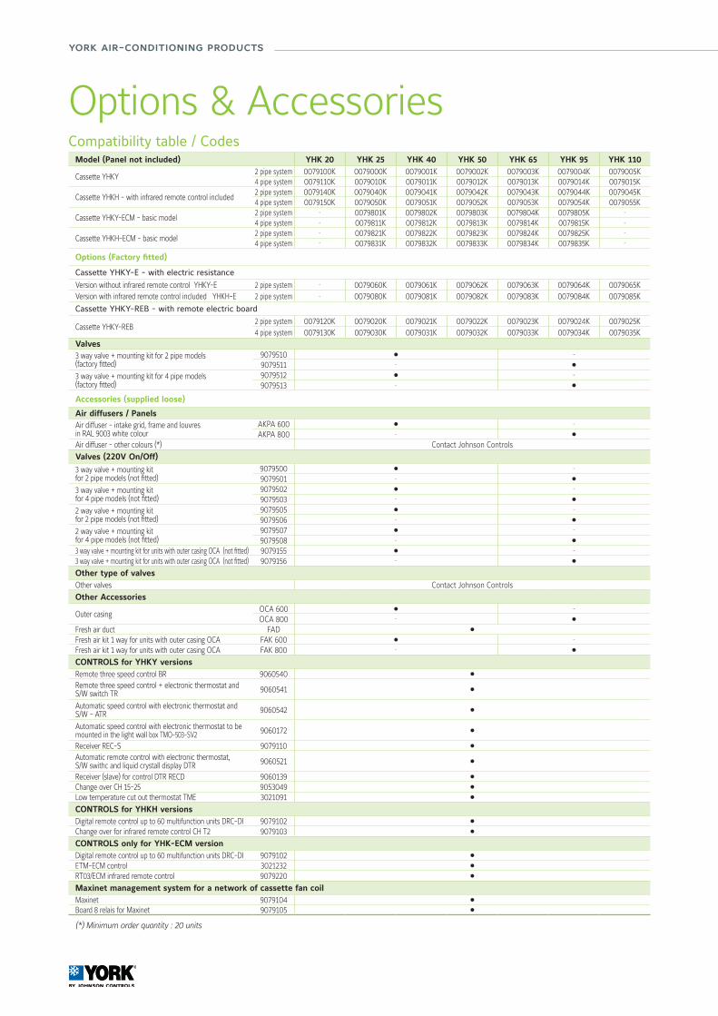
Compatibility table / CodesModel (Panel not included) YHK 20 YHK 25 YHK 40 YHK 50 YHK 65 YHK 95 YHK 110
Cassette YHKY 2 pipe system 0079100K 0079000K 0079001K 0079002K 0079003K 0079004K 0079005K4 pipe system 0079110K 0079010K 0079011K 0079012K 0079013K 0079014K 0079015K
Cassette YHKH - with infrared remote control included2 pipe system 0079140K 0079040K 0079041K 0079042K 0079043K 0079044K 0079045K4 pipe system 0079150K 0079050K 0079051K 0079052K 0079053K 0079054K 0079055K
Cassette YHKY-ECM - basic model2 pipe system - 0079801K 0079802K 0079803K 0079804K 0079805K -
4 pipe system - 0079811K 0079812K 0079813K 0079814K 0079815K -
Cassette YHKH-ECM - basic model2 pipe system - 0079821K 0079822K 0079823K 0079824K 0079825K -
4 pipe system - 0079831K 0079832K 0079833K 0079834K 0079835K -
Options (Factory fitted)
Cassette YHKY-E - with electric resistance
Version without infrared remote control YHKY-E 2 pipe system - 0079060K 0079061K 0079062K 0079063K 0079064K 0079065KVersion with infrared remote control included YHKH-E 2 pipe system - 0079080K 0079081K 0079082K 0079083K 0079084K 0079085K
Cassette YHKY-REB - with remote electric board
Cassette YHKY-REB2 pipe system 0079120K 0079020K 0079021K 0079022K 0079023K 0079024K 0079025K4 pipe system 0079130K 0079030K 0079031K 0079032K 0079033K 0079034K 0079035K
Valves3 way valve + mounting kit for 2 pipe models(factory fitted)
9079510 l -
9079511 - l
3 way valve + mounting kit for 4 pipe models(factory fitted)
9079512 l -
9079513 - l
Accessories (supplied loose)
Air diffusers / PanelsAir diffuser - intake grid, frame and louvres in RAL 9003 white colour
AKPA 600 l -
AKPA 800 - l
Air diffuser - other colours (*) Contact Johnson Controls
Valves (220V On/Off)
3 way valve + mounting kitfor 2 pipe models (not fitted)
9079500 l -
9079501 - l
3 way valve + mounting kitfor 4 pipe models (not fitted)
9079502 l -
9079503 - l
2 way valve + mounting kitfor 2 pipe models (not fitted)
9079505 l -
9079506 - l
2 way valve + mounting kitfor 4 pipe models (not fitted)
9079507 l -
9079508 - l
3 way valve + mounting kit for units with outer casing OCA (not fitted) 9079155 l -
3 way valve + mounting kit for units with outer casing OCA (not fitted) 9079156 - l
Other type of valvesOther valves Contact Johnson Controls
Other Accessories
Outer casingOCA 600 l -
OCA 800 - l
Fresh air duct FAD l
Fresh air kit 1 way for units with outer casing OCA FAK 600 l -
Fresh air kit 1 way for units with outer casing OCA FAK 800 - l
CONTROLS for YHKY versionsRemote three speed control BR 9060540 l
Remote three speed control + electronic thermostat and S/W switch TR 9060541 l
Automatic speed control with electronic thermostat and S/W - ATR 9060542 l
Automatic speed control with electronic thermostat to be mounted in the light wall box TMO-503-SV2 9060172 l
Receiver REC-S 9079110 l
Automatic remote control with electronic thermostat, S/W swithc and liquid crystall display DTR 9060521 l
Receiver (slave) for control DTR RECD 9060139 l
Change over CH 15-25 9053049 l
Low temperature cut out thermostat TME 3021091 l
CONTROLS for YHKH versionsDigital remote control up to 60 multifunction units DRC-DI 9079102 l
Change over for infrared remote control CH T2 9079103 l
CONTROLS only for YHK-ECM versionDigital remote control up to 60 multifunction units DRC-DI 9079102 l
ETM-ECM control 3021232 l
RT03/ECM infrared remote control 9079220 l
Maxinet management system for a network of cassette fan coilMaxinet 9079104 l
Board 8 relais for Maxinet 9079105 l
(*) Minimum order quantity : 20 units
Options & Accessories
86/87
Air
Han
dlin
g Sy
stem
s &
Ter
min
al D
evic
es
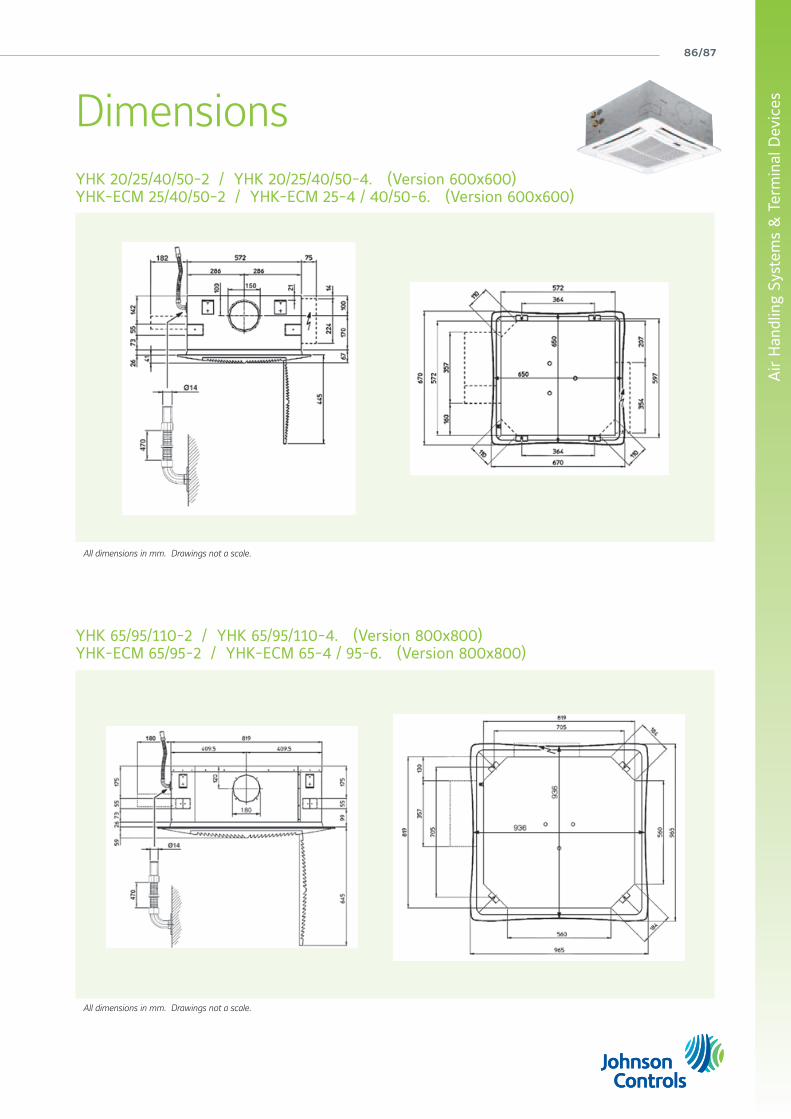
All dimensions in mm. Drawings not a scale.
All dimensions in mm. Drawings not a scale.
YHK 20/25/40/50-2 / YHK 20/25/40/50-4. (Version 600x600)YHK-ECM 25/40/50-2 / YHK-ECM 25-4 / 40/50-6. (Version 600x600)
YHK 65/95/110-2 / YHK 65/95/110-4. (Version 800x800)YHK-ECM 65/95-2 / YHK-ECM 65-4 / 95-6. (Version 800x800)
Dimensions
york air-conditioning products
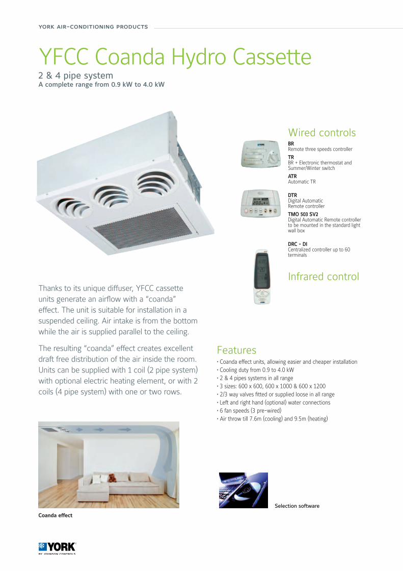
YFCC Coanda Hydro Cassette2 & 4 pipe systemA complete range from 0.9 kW to 4.0 kW
Features• Coanda effect units, allowing easier and cheaper installation • Cooling duty from 0.9 to 4.0 kW • 2 & 4 pipes systems in all range • 3 sizes: 600 x 600, 600 x 1000 & 600 x 1200 • 2/3 way valves fitted or supplied loose in all range • Left and right hand (optional) water connections • 6 fan speeds (3 pre-wired) • Air throw till 7.6m (cooling) and 9.5m (heating)
Thanks to its unique diffuser, YFCC cassette units generate an airflow with a “coanda” effect. The unit is suitable for installation in a suspended ceiling. Air intake is from the bottom while the air is supplied parallel to the ceiling.
The resulting “coanda” effect creates excellent draft free distribution of the air inside the room.Units can be supplied with 1 coil (2 pipe system) with optional electric heating element, or with 2 coils (4 pipe system) with one or two rows.
Selection software
Coanda effect
Wired controlsBRRemote three speeds controller
TRBR + Electronic thermostat and Summer/Winter switch
ATRAutomatic TR
DTRDigital AutomaticRemote controller
TMO 503 SV2Digital Automatic Remote controller to be mounted in the standard light wall box
DRC - DICentralized controller up to 60 terminals
Infrared control
88/89
Air
Han
dlin
g Sy
stem
s &
Ter
min
al D
evic
es
Manufacturer reserves the rights to change specifications without prior notice.
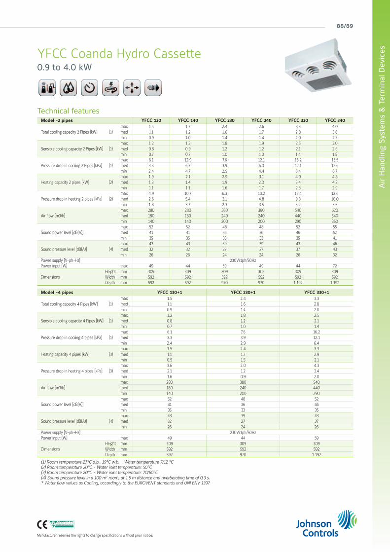
YFCC Coanda Hydro Cassette0.9 to 4.0 kW
Technical featuresModel -2 pipes YFCC 130 YFCC 140 YFCC 230 YFCC 240 YFCC 330 YFCC 340
Total cooling capacity 2 Pipes [kW] (1) max 1.5 1.7 2.4 2.6 3.3 4.0med 1.1 1.2 1.6 1.7 2.8 3.6min 0.9 1.0 1.4 1.4 2.0 2.5
Sensible cooling capacity 2 Pipes [kW] (1) max 1.2 1.3 1.8 1.9 2.5 3.0med 0.8 0.9 1.2 1.2 2.1 2.6min 0.7 0.7 1.0 1.0 1.4 1.8
Pressure drop in cooling 2 Pipes [kPa] (1) max 6.1 12.9 7.6 12.1 16.2 15.5med 3.3 6.7 3.9 6.0 12.1 12.6min 2.4 4.7 2.9 4.4 6.4 6.7
Heating capacity 2 pipes [kW] (2) max 1.9 2.1 2.9 3.1 4.0 4.8med 1.3 1.4 1.9 2.0 3.4 4.2min 1.1 1.1 1.6 1.7 2.3 2.9
Pressure drop in heating 2 pipes [kPa] (2) max 4.9 10.7 6.3 10.2 13.4 12.6med 2.6 5.4 3.1 4.8 9.8 10.0min 1.8 3.7 2.3 3.5 5.2 5.5
Air flow [m3/h] max 280 280 380 380 540 620med 180 180 240 240 440 540min 140 140 200 200 290 360
Sound power level [dB(A)] max 52 52 48 48 52 55med 41 41 36 36 46 52min 35 35 33 33 35 41
Sound pressure level [dB(A)] (4) max 43 43 39 39 43 46med 32 32 27 27 37 43min 26 26 24 24 26 32
Power supply [V-ph-Hz] 230V/1ph/50HzPower input [W] max 49 44 59 49 44 72
Dimensions Height mm 309 309 309 309 309 309Width mm 592 592 592 592 592 592Depth mm 592 592 970 970 1 192 1 192
Model -4 pipes YFCC 130+1 YFCC 230+1 YFCC 330+1
Total cooling capacity 4 Pipes [kW] (1) max 1.5 2.4 3.3med 1.1 1.6 2.8min 0.9 1.4 2.0
Sensible cooling capacity 4 Pipes [kW] (1) max 1.2 1.8 2.5med 0.8 1.2 2.1min 0.7 1.0 1.4
Pressure drop in cooling 4 pipes [kPa] (1) max 6.1 7.6 16.2med 3.3 3.9 12.1min 2.4 2.9 6.4
Heating capacity 4 pipes [kW] (3) max 1.5 2.4 3.3med 1.1 1.7 2.9min 0.9 1.5 2.1
Pressure drop in heating 4 pipes [kPa] (3) max 3.6 2.0 4.3med 2.1 1.2 3.4min 1.6 0.9 2.0
Air flow [m3/h] max 280 380 540med 180 240 440min 140 200 290
Sound power level [dB(A)] max 52 48 52med 41 36 46min 35 33 35
Sound pressure level [dB(A)] (4) max 43 39 43med 32 27 37min 26 24 26
Power supply [V-ph-Hz] 230V/1ph/50HzPower input [W] max 49 44 59
Dimensions Height mm 309 309 309Width mm 592 592 592Depth mm 592 970 1 192
(1) Room temperature 27°C d.b., 19°C w.b. - Water temperature 7/12 °C(2) Room temperature 20°C - Water inlet temperature: 50°C(3) Room temperature 20°C - Water inlet temperature: 70/60°C(4) Sound pressure level in a 100 m2 room, at 1,5 m distance and riverberating time of 0,3 s.* Water flow values as Cooling, accordingly to the EUROVENT standards and UNI ENV 1397
york air-conditioning products
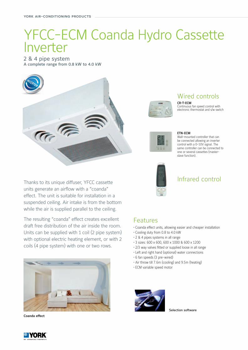
YFCC-ECM Coanda Hydro Cassette Inverter2 & 4 pipe systemA complete range from 0.8 kW to 4.0 kW
Features• Coanda effect units, allowing easier and cheaper installation • Cooling duty from 0.8 to 4.0 kW • 2 & 4 pipes systems in all range • 3 sizes: 600 x 600, 600 x 1000 & 600 x 1200 • 2/3 way valves fitted or supplied loose in all range • Left and right hand (optional) water connections • 6 fan speeds (3 pre-wired) • Air throw till 7.6m (cooling) and 9.5m (heating)• ECM variable speed motor
Thanks to its unique diffuser, YFCC cassette units generate an airflow with a “coanda” effect. The unit is suitable for installation in a suspended ceiling. Air intake is from the bottom while the air is supplied parallel to the ceiling.
The resulting “coanda” effect creates excellent draft free distribution of the air inside the room.Units can be supplied with 1 coil (2 pipe system) with optional electric heating element, or with 2 coils (4 pipe system) with one or two rows.
Selection software
Coanda effect
Wired controlsCR-T-ECMContinuous fan speed control with electronic thermostat and s/w switch
Infrared control
ETN-ECMWall-mounted controller that can be connected allowing an inverter control with a 0-10V signal. The same controller can be connected to one or several cassettes (master-slave function).
90/91
Air
Han
dlin
g Sy
stem
s &
Ter
min
al D
evic
es
Manufacturer reserves the rights to change specifications without prior notice.
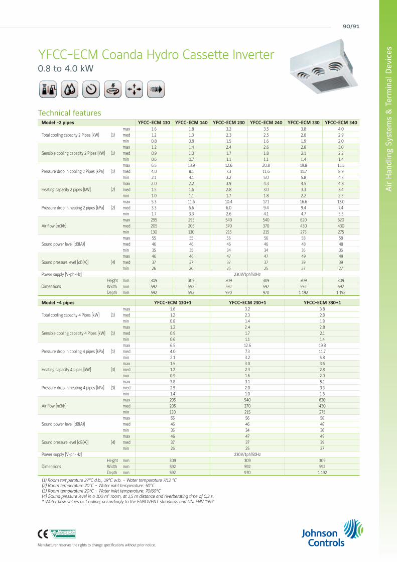
YFCC-ECM Coanda Hydro Cassette Inverter0.8 to 4.0 kW
Technical featuresModel -2 pipes YFCC-ECM 130 YFCC-ECM 140 YFCC-ECM 230 YFCC-ECM 240 YFCC-ECM 330 YFCC-ECM 340
Total cooling capacity 2 Pipes [kW] (1) max 1.6 1.8 3.2 3.5 3.8 4.0med 1.2 1.3 2.3 2.5 2.8 2.9min 0.8 0.9 1.5 1.6 1.9 2.0
Sensible cooling capacity 2 Pipes [kW] (1) max 1.2 1.4 2.4 2.6 2.8 3.0med 0.9 1.0 1.7 1.8 2.1 2.2min 0.6 0.7 1.1 1.1 1.4 1.4
Pressure drop in cooling 2 Pipes [kPa] (1) max 6.5 13.9 12.6 20.8 19.8 15.5med 4.0 8.1 7.3 11.6 11.7 8.9min 2.1 4.1 3.2 5.0 5.8 4.3
Heating capacity 2 pipes [kW] (2) max 2.0 2.2 3.9 4.3 4.5 4.8med 1.5 1.6 2.8 3.0 3.3 3.4min 1.0 1.1 1.7 1.8 2.2 2.3
Pressure drop in heating 2 pipes [kPa] (2) max 5.3 11.6 10.4 17.1 16.6 13.0med 3.3 6.6 6.0 9.4 9.4 7.4min 1.7 3.3 2.6 4.1 4.7 3.5
Air flow [m3/h] max 295 295 540 540 620 620med 205 205 370 370 430 430min 130 130 215 215 275 275
Sound power level [dB(A)] max 55 55 56 56 58 58med 46 46 46 46 48 48min 35 35 34 34 36 36
Sound pressure level [dB(A)] (4) max 46 46 47 47 49 49med 37 37 37 37 39 39min 26 26 25 25 27 27
Power supply [V-ph-Hz] 230V/1ph/50Hz
Dimensions Height mm 309 309 309 309 309 309Width mm 592 592 592 592 592 592Depth mm 592 592 970 970 1 192 1 192
Model -4 pipes YFCC-ECM 130+1 YFCC-ECM 230+1 YFCC-ECM 330+1
Total cooling capacity 4 Pipes [kW] (1) max 1.6 3.2 3.8med 1.2 2.3 2.8min 0.8 1.4 1.8
Sensible cooling capacity 4 Pipes [kW] (1) max 1.2 2.4 2.8med 0.9 1.7 2.1min 0.6 1.1 1.4
Pressure drop in cooling 4 pipes [kPa] (1) max 6.5 12.6 19.8med 4.0 7.3 11.7min 2.1 3.2 5.8
Heating capacity 4 pipes [kW] (3) max 1.5 3.0 3.6med 1.2 2.3 2.8min 0.9 1.6 2.0
Pressure drop in heating 4 pipes [kPa] (3) max 3.8 3.1 5.1med 2.5 2.0 3.3min 1.4 1.0 1.8
Air flow [m3/h] max 295 540 620med 205 370 430min 130 215 275
Sound power level [dB(A)] max 55 56 58med 46 46 48min 35 34 36
Sound pressure level [dB(A)] (4) max 46 47 49med 37 37 39min 26 25 27
Power supply [V-ph-Hz] 230V/1ph/50Hz
Dimensions Height mm 309 309 309Width mm 592 592 592Depth mm 592 970 1 192
(1) Room temperature 27°C d.b., 19°C w.b. - Water temperature 7/12 °C(2) Room temperature 20°C - Water inlet temperature: 50°C(3) Room temperature 20°C - Water inlet temperature: 70/60°C(4) Sound pressure level in a 100 m2 room, at 1,5 m distance and riverberating time of 0,3 s.* Water flow values as Cooling, accordingly to the EUROVENT standards and UNI ENV 1397
york air-conditioning products
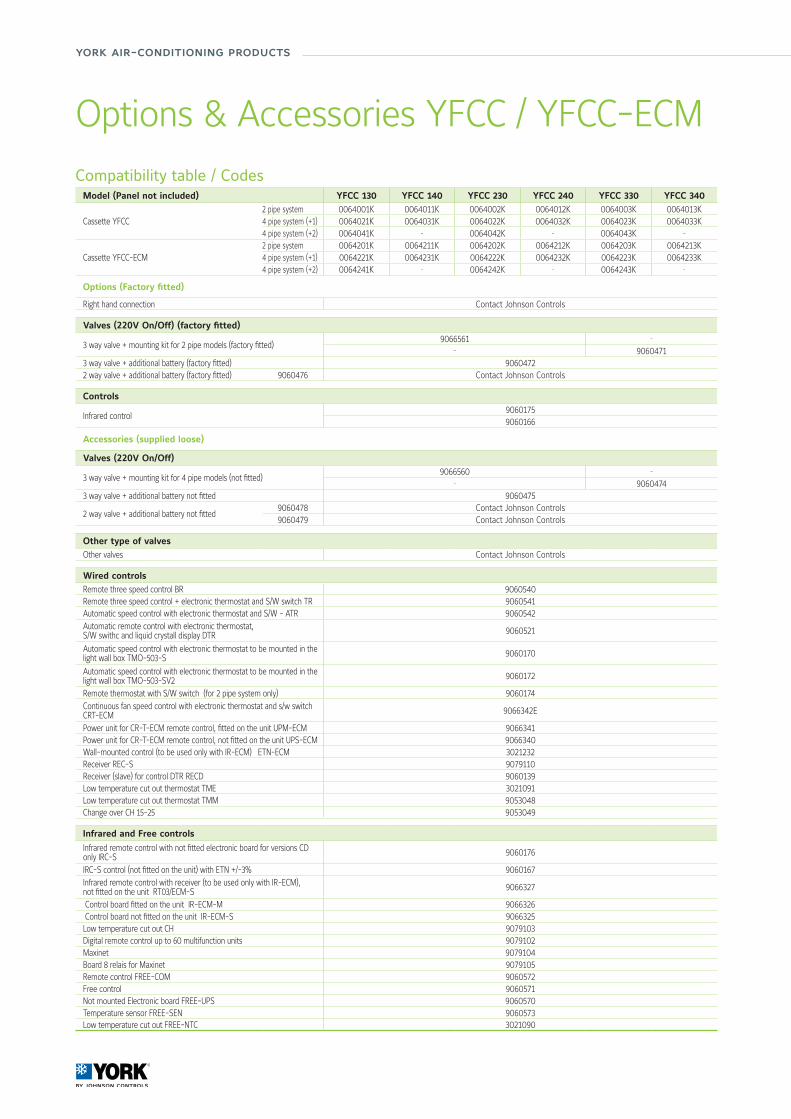
Options & Accessories YFCC / YFCC-ECM
Compatibility table / CodesModel (Panel not included) YFCC 130 YFCC 140 YFCC 230 YFCC 240 YFCC 330 YFCC 340
Cassette YFCC 2 pipe system 0064001K 0064011K 0064002K 0064012K 0064003K 0064013K4 pipe system (+1) 0064021K 0064031K 0064022K 0064032K 0064023K 0064033K4 pipe system (+2) 0064041K - 0064042K - 0064043K -
Cassette YFCC-ECM2 pipe system 0064201K 0064211K 0064202K 0064212K 0064203K 0064213K4 pipe system (+1) 0064221K 0064231K 0064222K 0064232K 0064223K 0064233K4 pipe system (+2) 0064241K - 0064242K - 0064243K -
Options (Factory fitted)
Right hand connection Contact Johnson Controls
Valves (220V On/Off) (factory fitted)
3 way valve + mounting kit for 2 pipe models (factory fitted)9066561 -
- 90604713 way valve + additional battery (factory fitted) 90604722 way valve + additional battery (factory fitted) 9060476 Contact Johnson Controls
Controls
Infrared control90601759060166
Accessories (supplied loose)
Valves (220V On/Off)
3 way valve + mounting kit for 4 pipe models (not fitted)9066560 -
- 90604743 way valve + additional battery not fitted 9060475
2 way valve + additional battery not fitted9060478 Contact Johnson Controls9060479 Contact Johnson Controls
Other type of valvesOther valves Contact Johnson Controls
Wired controlsRemote three speed control BR 9060540Remote three speed control + electronic thermostat and S/W switch TR 9060541Automatic speed control with electronic thermostat and S/W - ATR 9060542Automatic remote control with electronic thermostat, S/W swithc and liquid crystall display DTR 9060521
Automatic speed control with electronic thermostat to be mounted in the light wall box TMO-503-S 9060170
Automatic speed control with electronic thermostat to be mounted in the light wall box TMO-503-SV2 9060172
Remote thermostat with S/W switch (for 2 pipe system only) 9060174Continuous fan speed control with electronic thermostat and s/w switch CRT-ECM 9066342E
Power unit for CR-T-ECM remote control, fitted on the unit UPM-ECM 9066341Power unit for CR-T-ECM remote control, not fitted on the unit UPS-ECM 9066340Wall-mounted control (to be used only with IR-ECM) ETN-ECM 3021232Receiver REC-S 9079110Receiver (slave) for control DTR RECD 9060139Low temperature cut out thermostat TME 3021091Low temperature cut out thermostat TMM 9053048Change over CH 15-25 9053049
Infrared and Free controls
Infrared remote control with not fitted electronic board for versions CD only IRC-S 9060176
IRC-S control (not fitted on the unit) with ETN +/-3% 9060167Infrared remote control with receiver (to be used only with IR-ECM), not fitted on the unit RT03/ECM-S 9066327
Control board fitted on the unit IR-ECM-M 9066326 Control board not fitted on the unit IR-ECM-S 9066325Low temperature cut out CH 9079103Digital remote control up to 60 multifunction units 9079102Maxinet 9079104Board 8 relais for Maxinet 9079105Remote control FREE-COM 9060572Free control 9060571Not mounted Electronic board FREE-UPS 9060570Temperature sensor FREE-SEN 9060573Low temperature cut out FREE-NTC 3021090
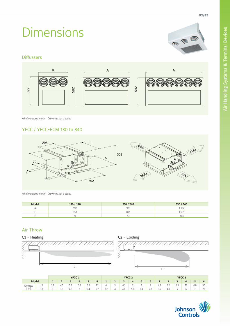
92/93
Air
Han
dlin
g Sy
stem
s &
Ter
min
al D
evic
es
All dimensions in mm. Drawings not a scale.
All dimensions in mm. Drawings not a scale.
Diffussers
YFCC / YFCC-ECM 130 to 340
Air Throw
C1 - Heating C2 - Cooling
Dimensions
A
592
A59
2A
592
72
298
309
592
E
A
F
F
E
100
Model 130 / 140 230 / 240 330 / 340A 592 970 1 192
E 454 884 1 099F 78 43 46.5
YFCC 1 YFCC 2 YFCC 3Model 1 2 3 4 5 6 1 2 3 4 5 6 1 2 3 4 5 6
Air throwL (m)
C1 3.8 4.5 5.8 6.3 6.8 7.2 4 5 6.1 7 8 9 4.5 5.2 6.3 7.5 8.8 9.5C2 3 3.6 4.6 5 5.4 5.7 3.2 4 4.8 5.6 6.4 7.2 3.6 4.1 5 6 7 7.6
LL
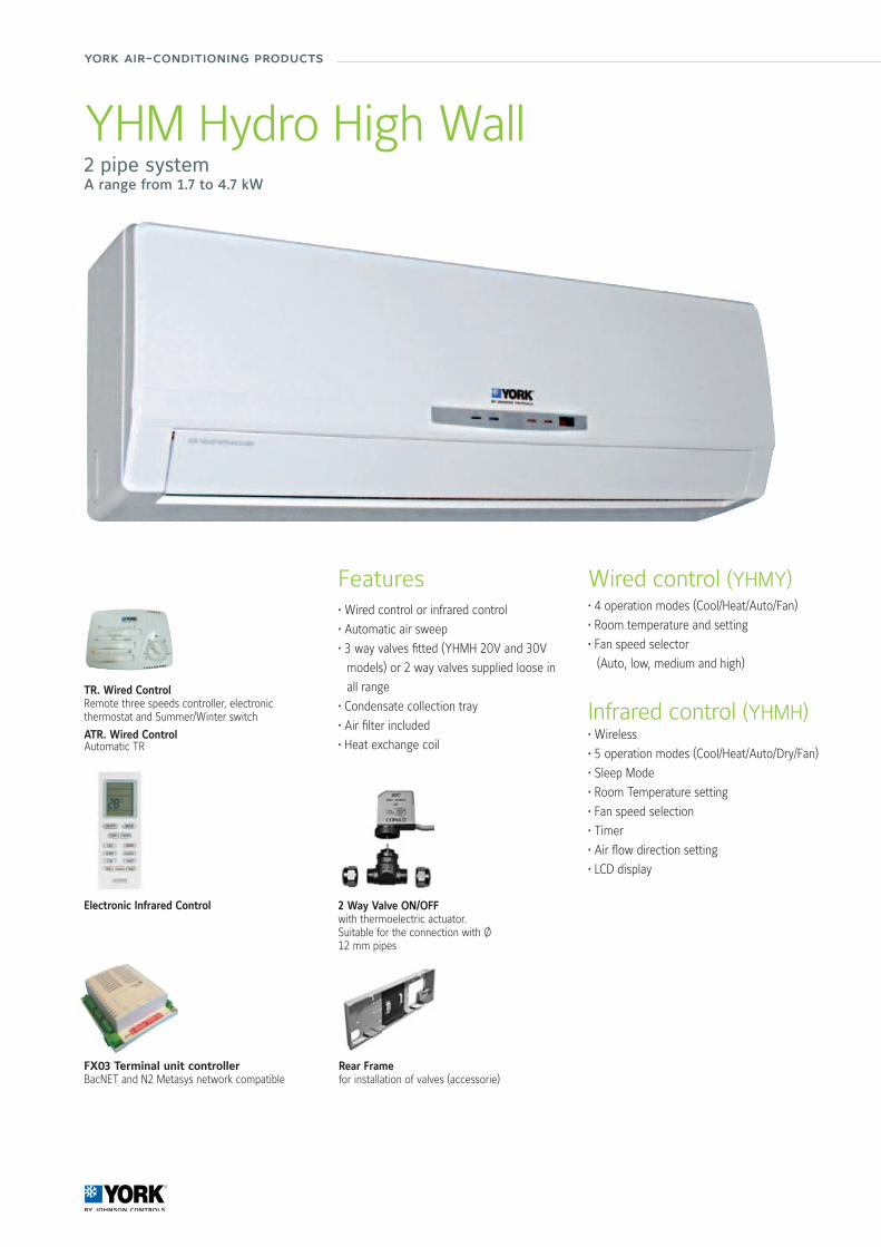
york air-conditioning products
Wired control (YHMY)• 4 operation modes (Cool/Heat/Auto/Fan)
• Room temperature and setting
• Fan speed selector
(Auto, low, medium and high)
Infrared control (YHMH)• Wireless
• 5 operation modes (Cool/Heat/Auto/Dry/Fan)
• Sleep Mode
• Room Temperature setting
• Fan speed selection
• Timer
• Air flow direction setting
• LCD display
Features• Wired control or infrared control
• Automatic air sweep
• 3 way valves fitted (YHMH 20V and 30V
models) or 2 way valves supplied loose in
all range
• Condensate collection tray
• Air filter included
• Heat exchange coil
TR. Wired ControlRemote three speeds controller, electronic thermostat and Summer/Winter switch
ATR. Wired ControlAutomatic TR
2 Way Valve ON/OFF with thermoelectric actuator.Suitable for the connection with Ø 12 mm pipes
Rear Framefor installation of valves (accessorie)
Electronic Infrared Control
FX03 Terminal unit controllerBacNET and N2 Metasys network compatible
YHM Hydro High Wall2 pipe systemA range from 1.7 to 4.7 kW
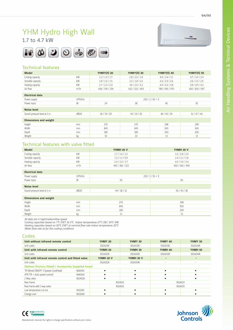
94/95
Air
Han
dlin
g Sy
stem
s &
Ter
min
al D
evic
es
Manufacturer reserves the rights to change specifications without prior notice.
Technical featuresModel YHMY(H) 20 YHMY(H) 30 YHMY(H) 40 YHMY(H) 50
Cooling capacity kW 2.2 / 1.9 / 1.7 2.8 / 2.0 / 1.8 4.0 / 3.4 / 3.1 4.7 / 3.9 / 3.4
Sensible capacity kW 1.8 / 1.6 / 1.5 2.5 / 1.8 / 1.6 3.4 / 2.9 / 2.6 3.6 / 3.3 / 2.9
Heating capacity kW 2.7 / 2.3 / 2.0 3.6 / 2.6 / 2.2 4.9 / 4.2 / 3.8 5.8 / 4.9 / 4.2
Air flow m3/h 436 / 376 / 334 632 / 522 / 403 780 / 691 / 570 920 / 810 / 697
Electrical data
Power supply V/Ph/Hz 230 / 1 / 50 + E
Power input W 24 28 40 50
Noise level
Sound pressure level at 1 m dB(A) 36 / 33 / 29 43 / 33 / 30 46 / 43 / 39 51 / 47 / 44
Dimensions and weight
Height mm 270 270 298 298
Width mm 845 845 920 920
Depth mm 180 180 200 200Weight kg 10 10 13 13
Technical features with valve fittedModel YHMH 20 V YHMH 30 V
Cooling capacity kW 1.7 / 1.6 / 1.2 3.2 / 2.8 / 2.4
Sensible capacity kW 1.3 / 1.1 / 0.9 2.4 / 2.1 / 1.8
Heating capacity kW 2.4 / 2.0 / 1.7 4.5 / 3.9 / 3.4
Air flow m3/h 450 / 383 / 323 650 / 560 / 490
Electrical data
Power supply V/Ph/Hz 230 / 1 / 50 + E
Power input W 50 60
Noise level
Sound pressure level at 1 m dB(A) 44 / 38 / 32 50 / 43 / 38
Dimensions and weight
Height mm 270 298
Width mm 845 920
Depth mm 180 200Weight kg 11 13
All data are in high/medium/low speedCooling capacities based on 7°C EWT ∆t 5°C Indoor temperature 27°C DB / 19°C WB Heating capacities based on 50°C EWT at nominal flow rate Indoor temperature 20°CWater flow rate as for the cooling conditions
CodesUnit without infrared remote control YHMY 20 YHMY 30 YHMY 40 YHMY 50
Unit codes 0024231K 0024232K 0024233K 0024234K
Unit with infrared remote control YHMH 20 YHMH 30 YHMH 40 YHMH 50
Unit codes 0024241K 0024242K 0024243K 0024244K
Unit with infrared remote control and fitted valve YHMH 20 V YHMH 30 V - -
Unit codes 0024252K 0024254K - -
Options (Factory fitted) / Accessories (supplied loose)
TR (Wired ON/OFF 3 Speeds Cool/Heat) 9060541 l l l l
ATR (TR + Auto speed control) 9060542 l l l l
2 Way valve 9024000 l l l l
Rear frame 9024021 9024023
Rear frame with 3 way valve 9024031 9024033
Low temperature cut out 3021091 l l l l
Change over 9053049 l l l l
YHM Hydro High Wall1.7 to 4.7 kW