Embed Size (px)
Citation preview
AIR CONDITIONER
C
D
E
SECTION MTC A
B
MANUAL AIR CONDITIONER
F
G
H
I
K
L
M
TC
N
O
P
CONTENTS
M
SERVICE INFORMATION ............................ 3
PRECAUTIONS ................................................... 3Precaution for Supplemental Restraint System (SRS) "AIR BAG" and "SEAT BELT PRE-TEN-SIONER" ...................................................................3Precaution Necessary for Steering Wheel Rota-tion After Battery Disconnect .....................................3Precaution for Procedure without Cowl Top Cover ......4Precaution for Working with HFC-134a (R-134a) ......4General Refrigerant Precaution ................................4Oil Precaution ............................................................5Precaution for Refrigerant Connection ......................5Precaution for Service of Compressor ......................7Precaution for Service Equipment .............................8Precaution for Leak Detection Dye ...........................9
PREPARATION ..................................................11HFC-134a (R-134a) Service Tool and Equipment ....11Commercial Service Tool ........................................13
REFRIGERATION SYSTEM ..............................15Refrigerant Cycle ....................................................15Refrigerant System Protection ................................15Component Part Location .......................................16
OIL ......................................................................17Maintenance of Oil Quantity in Compressor ...........17
AIR CONDITIONER CONTROL .........................19Control Operation ....................................................19Discharge Air Flow ..................................................20System Description .................................................20
TROUBLE DIAGNOSIS .....................................22CONSULT-II Function (BCM) ..................................22How to Perform Trouble Diagnosis for Quick and Accurate Repair ......................................................22Component Parts and Harness Connector Loca-tion ..........................................................................23Schematic ...............................................................25Wiring Diagram - Heater - .......................................26
Wiring Diagram - A/C,M - ........................................27Operational Check ...................................................30Mode Door ...............................................................31Air Mix Door .............................................................32Intake Door ..............................................................33Front Blower Motor Circuit .......................................33Magnet Clutch Circuit (If Equipped) .........................37Insufficient Cooling ..................................................45Insufficient Heating ..................................................52Noise .......................................................................53
CONTROLLER ..................................................55Removal and Installation .........................................55Disassembly and Assembly .....................................56
THERMO CONTROL AMPLIFIER ....................57Removal and Installation .........................................57
A/C UNIT ASSEMBLY ......................................58Removal and Installation .........................................58Disassembly and Assembly .....................................60
BLOWER MOTOR ............................................62Removal and Installation .........................................62
INTAKE DOOR ..................................................63Intake Door Cable Adjustment .................................63
AIR MIX DOOR .................................................64Air Mix Door Cable Adjustment ...............................64
MODE DOOR ....................................................65Mode Door Cable Adjustment .................................65
BLOWER FAN RESISTOR ...............................66Removal and Installation .........................................66
HEATER CORE .................................................67Removal and Installation .........................................67
AIR CONDITIONER FILTER .............................68Removal and Installation .........................................68
MTC-1

DUCTS AND GRILLES ...................................... 69Removal and Installation ........................................ 69
REFRIGERANT LINES ...................................... 74HFC-134a (R-134a) Service Procedure ................. 74Component ............................................................. 76Removal and Installation of Compressor - HR16DE ................................................................. 78Removal and Installation of Compressor - MR18DE ................................................................. 80Removal and Installation of Low-Pressure Flexi-ble Hose ................................................................. 81Removal and Installation of High-Pressure Flexi-ble Hose ................................................................. 82Removal and Installation of High-Pressure Pipe .... 83Removal and Installation of Refrigerant Pressure Sensor .................................................................... 83
Removal and Installation of Condenser .................. 84Removal and Installation of Liquid Tank ................. 84Removal and Installation of Evaporator .................. 85Removal and Installation of Expansion Valve ......... 86Checking of Refrigerant Leaks ................................ 86Checking System for Leaks Using the Fluorescent Leak Detector .......................................................... 87Dye Injection ........................................................... 87Electronic Refrigerant Leak Detector ...................... 87
SERVICE DATA AND SPECIFICATIONS (SDS) ................................................................. 90
Compressor ............................................................ 90Oil ............................................................................ 90Refrigerant .............................................................. 90
MTC-2
PRECAUTIONS
C
D
E
F
G
H
I
K
L
M
A
B
TC
N
O
P
< SERVICE INFORMATION >
M
SERVICE INFORMATIONPRECAUTIONSPrecaution for Supplemental Restraint System (SRS) "AIR BAG" and "SEAT BELT PRE-TENSIONER" INFOID:0000000004784399
The Supplemental Restraint System such as “AIR BAG” and “SEAT BELT PRE-TENSIONER”, used alongwith a front seat belt, helps to reduce the risk or severity of injury to the driver and front passenger for certaintypes of collision. This system includes seat belt switch inputs and dual stage front air bag modules. The SRSsystem uses the seat belt switches to determine the front air bag deployment, and may only deploy one frontair bag, depending on the severity of a collision and whether the front occupants are belted or unbelted.Information necessary to service the system safely is included in the SRS and SB section of this Service Man-ual.WARNING:• To avoid rendering the SRS inoperative, which could increase the risk of personal injury or death in
the event of a collision which would result in air bag inflation, all maintenance must be performed byan authorized NISSAN/INFINITI dealer.
• Improper maintenance, including incorrect removal and installation of the SRS can lead to personalinjury caused by unintentional activation of the system. For removal of Spiral Cable and Air BagModule, see the SRS section.
• Do not use electrical test equipment on any circuit related to the SRS unless instructed to in thisService Manual. SRS wiring harnesses can be identified by yellow and/or orange harnesses or har-ness connectors.
PRECAUTIONS WHEN USING POWER TOOLS (AIR OR ELECTRIC) AND HAMMERSWARNING:• When working near the Airbag Diagnosis Sensor Unit or other Airbag System sensors with the Igni-
tion ON or engine running, DO NOT use air or electric power tools or strike near the sensor(s) with ahammer. Heavy vibration could activate the sensor(s) and deploy the air bag(s), possibly causingserious injury.
• When using air or electric power tools or hammers, always switch the Ignition OFF, disconnect thebattery, and wait at least 3 minutes before performing any service.
Precaution Necessary for Steering Wheel Rotation After Battery DisconnectINFOID:0000000004687764
NOTE:• This Procedure is applied only to models with Intelligent Key system and NATS (NISSAN ANTI-THEFT SYS-
TEM).• Remove and install all control units after disconnecting both battery cables with the ignition knob in the″LOCK″ position.
• Always use CONSULT-III to perform self-diagnosis as a part of each function inspection after finishing work.If DTC is detected, perform trouble diagnosis according to self-diagnostic results.
For models equipped with the Intelligent Key system and NATS, an electrically controlled steering lock mech-anism is adopted on the key cylinder.For this reason, if the battery is disconnected or if the battery is discharged, the steering wheel will lock andsteering wheel rotation will become impossible.If steering wheel rotation is required when battery power is interrupted, follow the procedure below beforestarting the repair operation.
OPERATION PROCEDURE1. Connect both battery cables.
NOTE:Supply power using jumper cables if battery is discharged.
2. Use the Intelligent Key or mechanical key to turn the ignition switch to the ″ACC″ position. At this time, thesteering lock will be released.
3. Disconnect both battery cables. The steering lock will remain released and the steering wheel can berotated.
4. Perform the necessary repair operation.
MTC-3
PRECAUTIONS
< SERVICE INFORMATION >5. When the repair work is completed, return the ignition switch to the ″LOCK″ position before connectingthe battery cables. (At this time, the steering lock mechanism will engage.)6. Perform a self-diagnosis check of all control units using CONSULT-III.
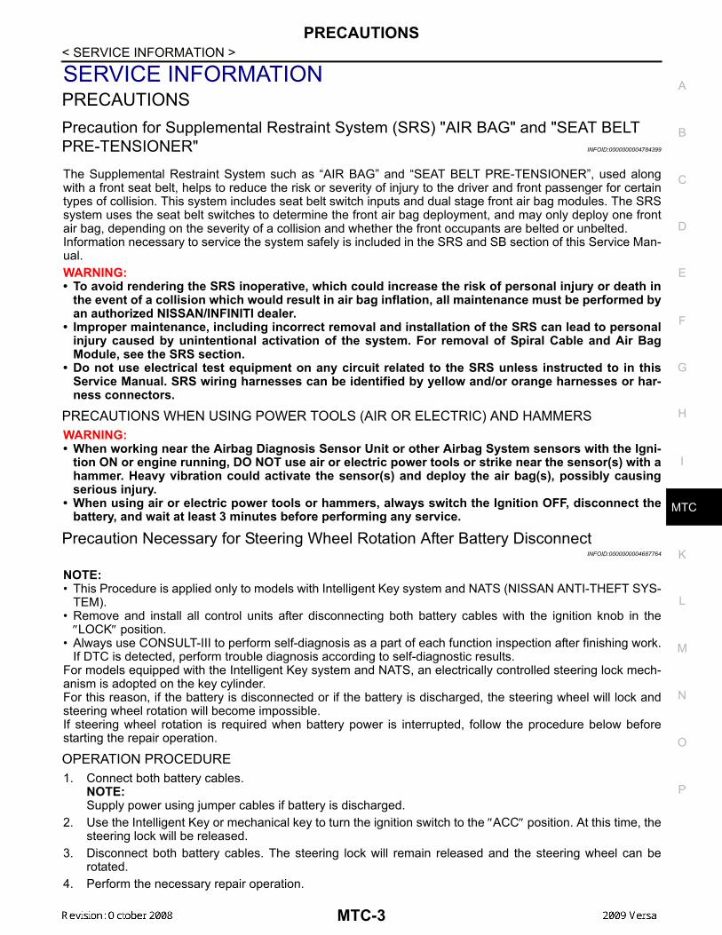
Precaution for Procedure without Cowl Top Cover INFOID:0000000004307042
When performing the procedure after removing cowl top cover, coverthe lower end of windshield with urethane, etc.
Precaution for Working with HFC-134a (R-134a) INFOID:0000000004307043
WARNING:• CFC-12 (R-12) refrigerant and HFC-134a (R-134a) refrigerant are not compatible. These refrigerants
must never be mixed, even in the smallest amounts. If the refrigerants are mixed a compressor mal-function is likely to occur.
• Use only specified oil for the HFC-134a (R-134a) A/C system and HFC-134a (R-134a) components. Ifoil other than that specified is used, compressor malfunction is likely to occur.
• The specified HFC-134a (R-134a) oil rapidly absorbs moisture from the atmosphere. The followinghandling precautions must be observed:
- When removing refrigerant components from a vehicle, immediately cap (seal) the component tominimize the entry of moisture from the atmosphere.
- When installing refrigerant components to a vehicle, do not remove the caps (unseal) until justbefore connecting the components. Connect all refrigerant loop components as quickly as possibleto minimize the entry of moisture into system.
- Only use the specified oil from a sealed container. Immediately reseal containers of oil. Withoutproper sealing, oil will become moisture saturated and should not be used.
- Avoid breathing A/C refrigerant and oil vapor or mist. Exposure may irritate eyes, nose and throat.Use only approved recovery/recycling equipment to discharge HFC-134a (R-134a) refrigerant. If acci-dental system discharge occurs, ventilate work area before resuming service. Additional health andsafety information may be obtained from refrigerant and oil manufacturers.
- Do not allow A/C oil to come in contact with styrofoam parts. Damage may result.
General Refrigerant Precaution INFOID:0000000004307044
WARNING:• Avoid breathing A/C refrigerant and oil vapor or mist. Exposure may irritate eyes, nose and throat.
Use only approved recovery/recycling equipment to discharge HFC-134a (R-134a) refrigerant. If acci-dental system discharge occurs, ventilate work area before resuming service. Additional health andsafety information may be obtained from refrigerant and oil manufacturers.
• Do not release refrigerant into the air. Use approved recovery/recycling equipment to capture therefrigerant every time an air conditioning system is discharged.
• Always wear eye and hand protection (goggles and gloves) when working with any refrigerant or airconditioning system.
• Do not store or heat refrigerant containers above 52°C (126° F).• Do not heat a refrigerant container with an open flame; if container warming is required, place the
bottom of the container in a warm pail of water.• Do not intentionally drop, puncture, or incinerate refrigerant containers.• Keep refrigerant away from open flames: poisonous gas will be produced if refrigerant burns.• Refrigerant will displace oxygen, therefore be certain to work in well ventilated areas to prevent suf-
focation.• Do not pressure test or leak test HFC-134a (R-134a) service equipment and/or vehicle air condition-
ing systems with compressed air during repair. Some mixtures of air and HFC-134a (R-134a) have
PIIB3706J
MTC-4
PRECAUTIONS
C
D
E
F
G
H
I
K
L
M
A
B
TC
N
O
P
< SERVICE INFORMATION >
M
been shown to be combustible at elevated pressures. These mixtures, if ignited, may cause injury orproperty damage. Additional health and safety information may be obtained from refrigerant manu-facturers.
Oil Precaution INFOID:0000000004307045
• Use only specified oil for the HFC-134a (R-134a) A/C system and HFC-134a (R-134a) components. If oilother than that specified is used, compressor malfunction is likely to occur.
• The specified HFC-134a (R-134a) oil rapidly absorbs moisture from the atmosphere. The following handlingprecautions must be observed:
- When removing refrigerant components from a vehicle, immediately cap (seal) the component to minimizethe entry of moisture from the atmosphere.
- When installing refrigerant components to a vehicle, do not remove the caps (unseal) until just before con-necting the components. Connect all refrigerant loop components as quickly as possible to minimize theentry of moisture into system.
- Only use the specified oil from a sealed container. Immediately reseal containers of oil. Without proper seal-ing, oil will become moisture saturated and should not be used.
• Avoid breathing A/C refrigerant and oil vapor or mist. Exposure may irritate eyes, nose and throat. Use only approved recovery/recycling equipment to discharge HFC-134a (R-134a) refrigerant. If accidentalsystem discharge occurs, ventilate work area before resuming service. Additional health and safety informa-tion may be obtained from refrigerant and oil manufacturers.
• Do not allow A/C oil to come in contact with styrofoam parts. Damage may result.
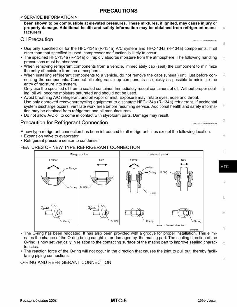
Precaution for Refrigerant Connection INFOID:0000000004307046
A new type refrigerant connection has been introduced to all refrigerant lines except the following location.• Expansion valve to evaporator• Refrigerant pressure sensor to condenser
FEATURES OF NEW TYPE REFRIGERANT CONNECTION
• The O-ring has been relocated. It has also been provided with a groove for proper installation. This elimi-nates the chance of the O-ring being caught in, or damaged by, the mating part. The sealing direction of theO-ring is now set vertically in relation to the contacting surface of the mating part to improve sealing charac-teristics.
• The reaction force of the O-ring will not occur in the direction that causes the joint to pull out, thereby facili-tating piping connections.
O-RING AND REFRIGERANT CONNECTION
SHA815E
MTC-5
PRECAUTIONS
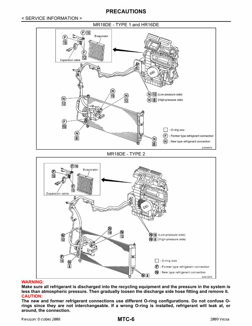
< SERVICE INFORMATION >MR18DE - TYPE 1 and HR16DE
MR18DE - TYPE 2
WARNING:Make sure all refrigerant is discharged into the recycling equipment and the pressure in the system isless than atmospheric pressure. Then gradually loosen the discharge side hose fitting and remove it.CAUTION:The new and former refrigerant connections use different O-ring configurations. Do not confuse O-rings since they are not interchangeable. If a wrong O-ring is installed, refrigerant will leak at, oraround, the connection.
SJIA0697E
SJIA1327E
MTC-6
PRECAUTIONS
C
D
E
F
G
H
I
K
L
M
A
B
TC
N
O
P
< SERVICE INFORMATION >
M
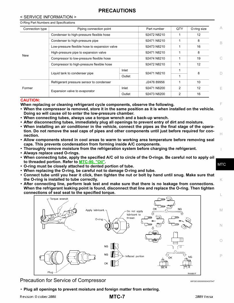
O-Ring Part Numbers and Specifications
CAUTION:When replacing or cleaning refrigerant cycle components, observe the following.• When the compressor is removed, store it in the same position as it is when installed on the vehicle.
Doing so will cause oil to enter the low-pressure chamber.• When connecting tubes, always use a torque wrench and a back-up wrench.• After disconnecting tubes, immediately plug all openings to prevent entry of dirt and moisture.• When installing an air conditioner in the vehicle, connect the pipes as the final stage of the opera-
tion. Do not remove the seal caps of pipes and other components until just before required for con-nection.
• Allow components stored in cool areas to warm to working area temperature before removing sealcaps. This prevents condensation from forming inside A/C components.
• Thoroughly remove moisture from the refrigeration system before charging the refrigerant.• Always replace used O-rings.• When connecting tube, apply the specified A/C oil to circle of the O-rings. Be careful not to apply oil
to threaded portion. Refer to MTC-90, "Oil".• O-ring must be closely attached to dented portion of tube.• When replacing the O-ring, be careful not to damage O-ring and tube.• Connect tube until you hear it click, then tighten the nut or bolt by hand until snug. Make sure that
the O-ring is installed to tube correctly.• After connecting line, perform leak test and make sure that there is no leakage from connections.
When the refrigerant leaking point is found, disconnect that line and replace the O-ring. Then tightenconnections of seal seat to the specified torque.
Precaution for Service of Compressor INFOID:0000000004307047
• Plug all openings to prevent moisture and foreign matter from entering.
Connection type Piping connection point Part number QTY O-ring size
New
Condenser to high-pressure flexible hose 92472 N8210 1 12
Condenser to high-pressure pipe 92471 N8210 1 8
Low-pressure flexible hose to expansion valve 92473 N8210 1 16
High-pressure pipe to expansion valve 92471 N8210 1 8
Compressor to low-pressure flexible hose 92474 N8210 1 19
Compressor to high-pressure flexible hose 92472 N8210 1 12
Liquid tank to condenser pipeInlet
92471 N82101
8Outlet 1
Former
Refrigerant pressure sensor to condenser J2476 89956 1 10
Expansion valve to evaporatorInlet 92471 N8200 2 12
Outlet 92473 N8200 2 16
RHA861F
MTC-7
PRECAUTIONS
< SERVICE INFORMATION >• When the compressor is removed, store it in the same position as it is when mounted on the car.• When replacing or repairing compressor, follow “Maintenance of Oil Quantity in Compressor”exactly. Refer to MTC-17, "Maintenance of Oil Quantity in Compressor".• Keep friction surfaces between clutch and pulley clean. If the surface is contaminated, with oil, wipe
it off by using a clean waste cloth moistened with thinner.• After compressor service operation, turn the compressor shaft by hand more than five turns in both
directions. This will equally distribute oil inside the compressor. After the compressor is installed,let the engine idle and operate the compressor for one hour.
• After replacing the compressor magnet clutch, apply voltage to the new one and check for usualoperation.
Precaution for Service Equipment INFOID:0000000004307048
RECOVERY/RECYCLING EQUIPMENTBe certain to follow the manufacturer’s instructions for machine operation and machine maintenance. Neverintroduce any refrigerant other than that specified into the machine.
ELECTRONIC LEAK DETECTORBe certain to follow the manufacturer’s instructions for tester operation and tester maintenance.
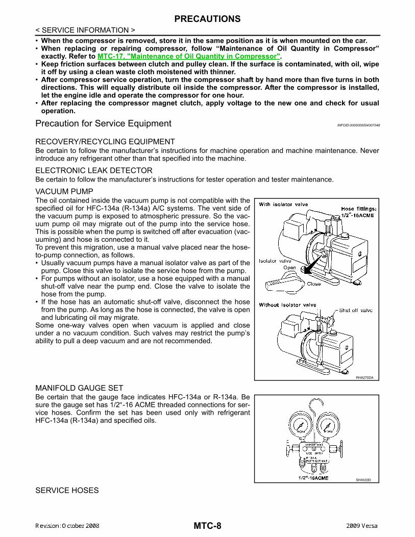
VACUUM PUMPThe oil contained inside the vacuum pump is not compatible with thespecified oil for HFC-134a (R-134a) A/C systems. The vent side ofthe vacuum pump is exposed to atmospheric pressure. So the vac-uum pump oil may migrate out of the pump into the service hose.This is possible when the pump is switched off after evacuation (vac-uuming) and hose is connected to it.To prevent this migration, use a manual valve placed near the hose-to-pump connection, as follows.• Usually vacuum pumps have a manual isolator valve as part of the
pump. Close this valve to isolate the service hose from the pump.• For pumps without an isolator, use a hose equipped with a manual
shut-off valve near the pump end. Close the valve to isolate thehose from the pump.
• If the hose has an automatic shut-off valve, disconnect the hosefrom the pump. As long as the hose is connected, the valve is openand lubricating oil may migrate.
Some one-way valves open when vacuum is applied and closeunder a no vacuum condition. Such valves may restrict the pump’sability to pull a deep vacuum and are not recommended.
MANIFOLD GAUGE SETBe certain that the gauge face indicates HFC-134a or R-134a. Besure the gauge set has 1/2″-16 ACME threaded connections for ser-vice hoses. Confirm the set has been used only with refrigerantHFC-134a (R-134a) and specified oils.
SERVICE HOSES
RHA270DA
SHA533D
MTC-8

PRECAUTIONS
C
D
E
F
G
H
I
K
L
M
A
B
TC
N
O
P
< SERVICE INFORMATION >
M
Be certain that the service hoses display the markings described(colored hose with black stripe). All hoses must include positive shut-off devices (either manual or automatic) near the end of the hosesopposite the manifold gauge.
SERVICE COUPLERSNever attempt to connect HFC-134a (R-134a) service couplers to aCFC-12 (R-12) A/C system. The HFC-134a (R-134a) couplers willnot properly connect to the CFC-12 (R-12) system. However, if animproper connection is attempted, discharging and contaminationmay occur.
REFRIGERANT WEIGHT SCALEVerify that no refrigerant other than HFC-134a (R-134a) and speci-fied oils have been used with the scale. If the scale controls refriger-ant flow electronically, the hose fitting must be 1/2″-16 ACME.
CHARGING CYLINDERUsing a charging cylinder is not recommended. Refrigerant may be vented into air from cylinder’s top valvewhen filling the cylinder with refrigerant. Also, the accuracy of the cylinder is generally less than that of anelectronic scale or of quality recycle/recharge equipment.
Precaution for Leak Detection Dye INFOID:0000000004307049
• The A/C system contains a fluorescent leak detection dye used for locating refrigerant leaks. An ultraviolet(UV) lamp is required to illuminate the dye when inspecting for leaks.
• Always wear fluorescence enhancing UV safety goggles to protect your eyes and enhance the visibility ofthe fluorescent dye.
• The fluorescent dye leak detector is not a replacement for an electronic refrigerant leak detector. The fluo-rescent dye leak detector should be used in conjunction with an electronic refrigerant leak detector to pin-point refrigerant leaks.
• For your safety and your customer’s satisfaction, read and follow all manufacture’s operating instructionsand precautions prior to performing the work.
• A compressor shaft seal should not be repaired because of dye seepage. The compressor shaft seal shouldonly be repaired after confirming the leak with an electronic refrigerant leak detector.
• Always remove any remaining dye from the leak area after repairs are complete to avoid a misdiagnosis dur-ing a future service.
• Do not allow dye to come into contact with painted body panels or interior components. If dye is spilled,clean immediately with the approved dye cleaner. Fluorescent dye left on a surface for an extended period oftime cannot be removed.
RHA272D
Shut-off valve rotation A/C service valve
Clockwise Open
Counterclockwise Close
RHA273D
RHA274D
MTC-9
PRECAUTIONS
< SERVICE INFORMATION >• Do not spray the fluorescent dye cleaning agent on hot surfaces (engine exhaust manifold, etc.).• Do not use more than one refrigerant dye bottle (1/4 ounce /7.4 cc) per A/C system.• Leak detection dyes for HFC-134a (R-134a) and CFC-12 (R-12) A/C systems are different. Do not use HFC-134a (R-134a) leak detection dye in CFC-12 (R-12) A/C system or CFC-12 (R-12) leak detector dye in HFC-134a (R-134a) A/C system or A/C system damage may result.
• The fluorescent properties of the dye will remain for over three (3) years unless a compressor malfunctionoccurs.
IDENTIFICATION LABEL FOR VEHICLEVehicles with factory installed fluorescent dye have an identification label on the front underside of the hood.NOTE:• Vehicles with factory installed fluorescent dye have a green label.• Vehicles without factory installed fluorescent dye have a blue label.
MTC-10
PREPARATION
C
D
E
F
G
H
I
K
L
M
A
B
TC
N
O
P
< SERVICE INFORMATION >
M
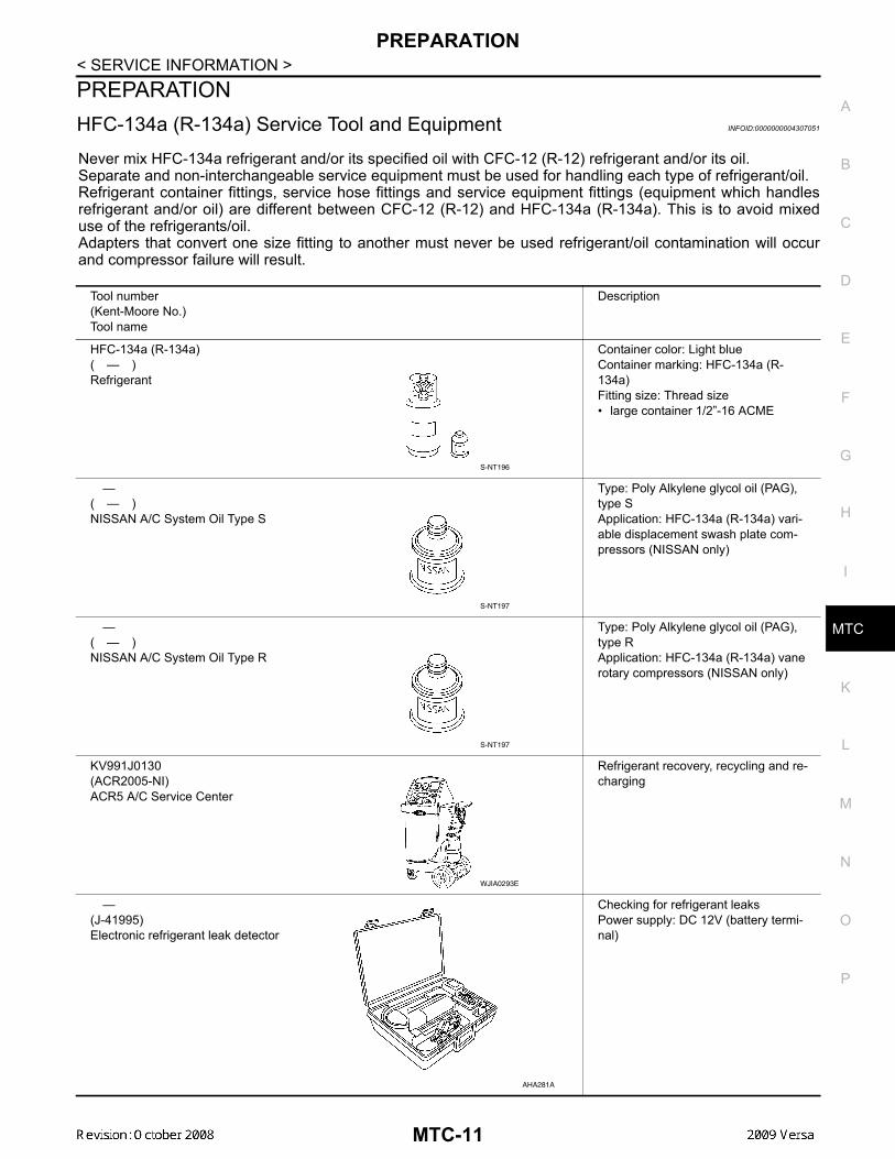
PREPARATIONHFC-134a (R-134a) Service Tool and Equipment INFOID:0000000004307051
Never mix HFC-134a refrigerant and/or its specified oil with CFC-12 (R-12) refrigerant and/or its oil.Separate and non-interchangeable service equipment must be used for handling each type of refrigerant/oil.Refrigerant container fittings, service hose fittings and service equipment fittings (equipment which handlesrefrigerant and/or oil) are different between CFC-12 (R-12) and HFC-134a (R-134a). This is to avoid mixeduse of the refrigerants/oil.Adapters that convert one size fitting to another must never be used refrigerant/oil contamination will occurand compressor failure will result.
Tool number(Kent-Moore No.)Tool name
Description
HFC-134a (R-134a)( — )Refrigerant
Container color: Light blueContainer marking: HFC-134a (R-134a)Fitting size: Thread size• large container 1/2”-16 ACME
—( — )NISSAN A/C System Oil Type S
Type: Poly Alkylene glycol oil (PAG), type SApplication: HFC-134a (R-134a) vari-able displacement swash plate com-pressors (NISSAN only)
—( — )NISSAN A/C System Oil Type R
Type: Poly Alkylene glycol oil (PAG), type RApplication: HFC-134a (R-134a) vane rotary compressors (NISSAN only)
KV991J0130(ACR2005-NI)ACR5 A/C Service Center
Refrigerant recovery, recycling and re-charging
—(J-41995)Electronic refrigerant leak detector
Checking for refrigerant leaksPower supply: DC 12V (battery termi-nal)
S-NT196
S-NT197
S-NT197
WJIA0293E
AHA281A
MTC-11
PREPARATION
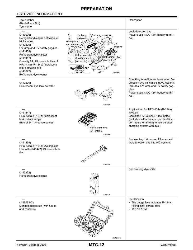
< SERVICE INFORMATION >—(J-43926)Refrigerant dye leak detection kitKit includes:(J-42220)UV lamp and UV safety goggles(J-41459)Refrigerant dye injector(J-41447)Quantity 24, 1/4 ounce bottles of HFC-134a (R-134a) fluorescent leak detection dye(J-43872)Refrigerant dye cleaner
Leak detection dyePower supply: DC 12V (battery termi-nal)
—(J-42220)Fluorescent dye leak detector
Checking for refrigerant leaks when flu-orescent dye is installed in A/C system.Includes: UV lamp and UV safety gog-glesPower supply: DC 12V (battery termi-nal)
—(J-41447)HFC-134a (R-134a) fluorescent leak detection dye(Box of 24, 1/4 ounce bottles)
Application: For HFC-134a (R-134a) PAG oilContainer: 1/4 ounce (7.4cc) bottle(Includes self-adhesive dye identifica-tion labels for affixing to vehicle after charging system with dye.)
—(J-41459)HFC-134a (R-134a) Dye injectorUse with (J-41447) 1/4 ounce bot-tles
For injecting 1/4 ounce of fluorescent leak detection dye into A/C system.
—(J-43872)Refrigerant dye cleaner
For cleaning dye spills.
—(J-39183-C)Manifold gauge set (with hoses and couplers)
Identification:• The gauge face indicates R-134a.
Fitting size: Thread size• 1/2”-16 ACME
Tool number(Kent-Moore No.)Tool name
Description
ZHA200H
SHA438F
SHA439F
SHA440F
SHA441F
RJIA0196E
MTC-12
PREPARATION
C
D
E
F
G
H
I
K
L
M
A
B
TC
N
O
P
< SERVICE INFORMATION >
M
Commercial Service Tool INFOID:0000000004307052
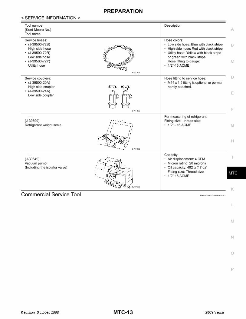
Service hoses:• (J-39500-72B)
High side hose• (J-39500-72R)
Low side hose• (J-39500-72Y)
Utility hose
Hose colors:• Low side hose: Blue with black stripe• High side hose: Red with black stripe• Utility hose: Yellow with black stripe
or green with black stripeHose fitting to gauge:
• 1/2”-16 ACME
Service couplers:• (J-39500-20A)
High side coupler• (J-39500-24A)
Low side coupler
Hose fitting to service hose:• M14 x 1.5 fitting is optional or perma-
nently attached.
—(J-39699)Refrigerant weight scale
For measuring of refrigerantFitting size - thread size:• 1/2” - 16 ACME
—(J-39649)Vacuum pump(Including the isolator valve)
Capacity:• Air displacement: 4 CFM• Micron rating: 20 microns• Oil capacity: 482 g (17 oz)
Fitting size: Thread size• 1/2”-16 ACME
Tool number(Kent-Moore No.)Tool name
Description
S-NT201
S-NT202
S-NT200
S-NT203
MTC-13
PREPARATION
< SERVICE INFORMATION >(Kent-Moore No.)Tool name
Description
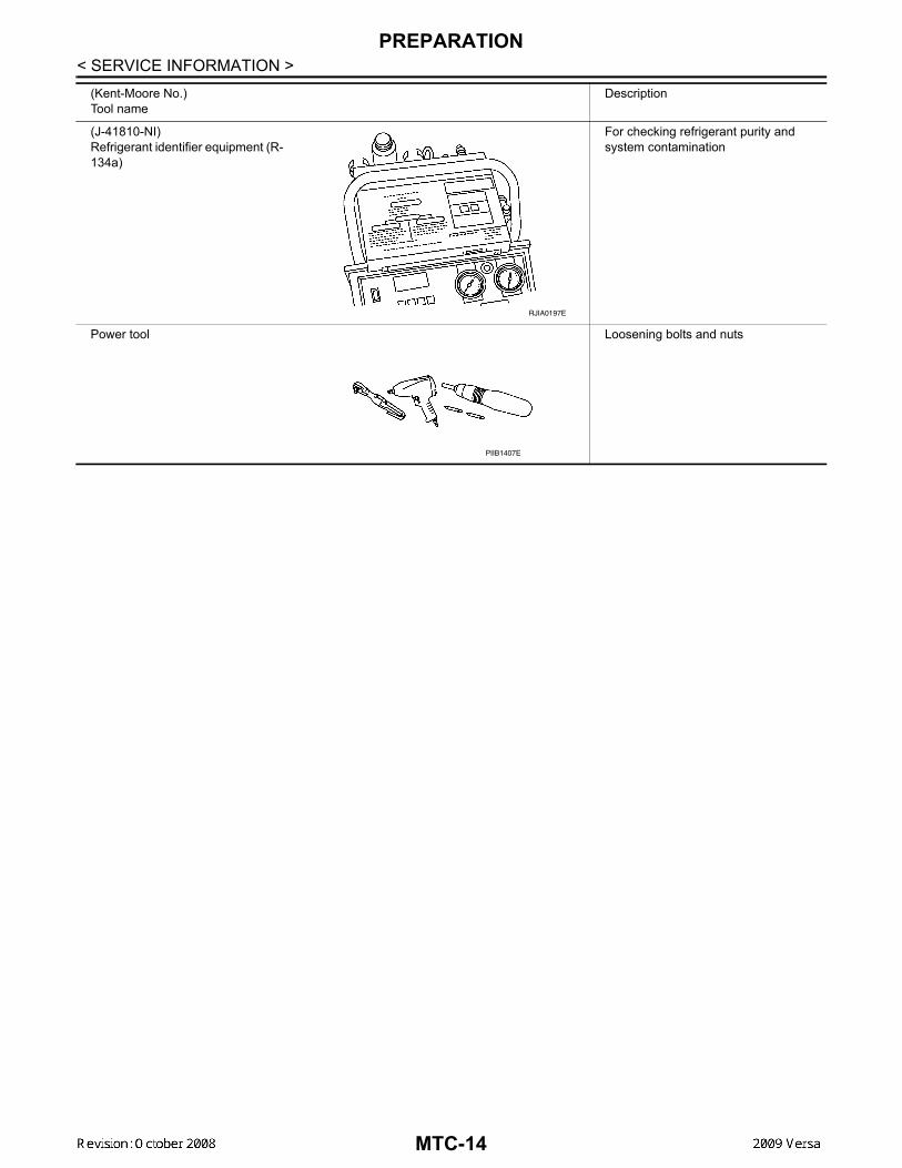
(J-41810-NI)Refrigerant identifier equipment (R-134a)
For checking refrigerant purity and system contamination
Power tool Loosening bolts and nuts
RJIA0197E
PIIB1407E
MTC-14
REFRIGERATION SYSTEM
C
D
E
F
G
H
I
K
L
M
A
B
TC
N
O
P
< SERVICE INFORMATION >
M
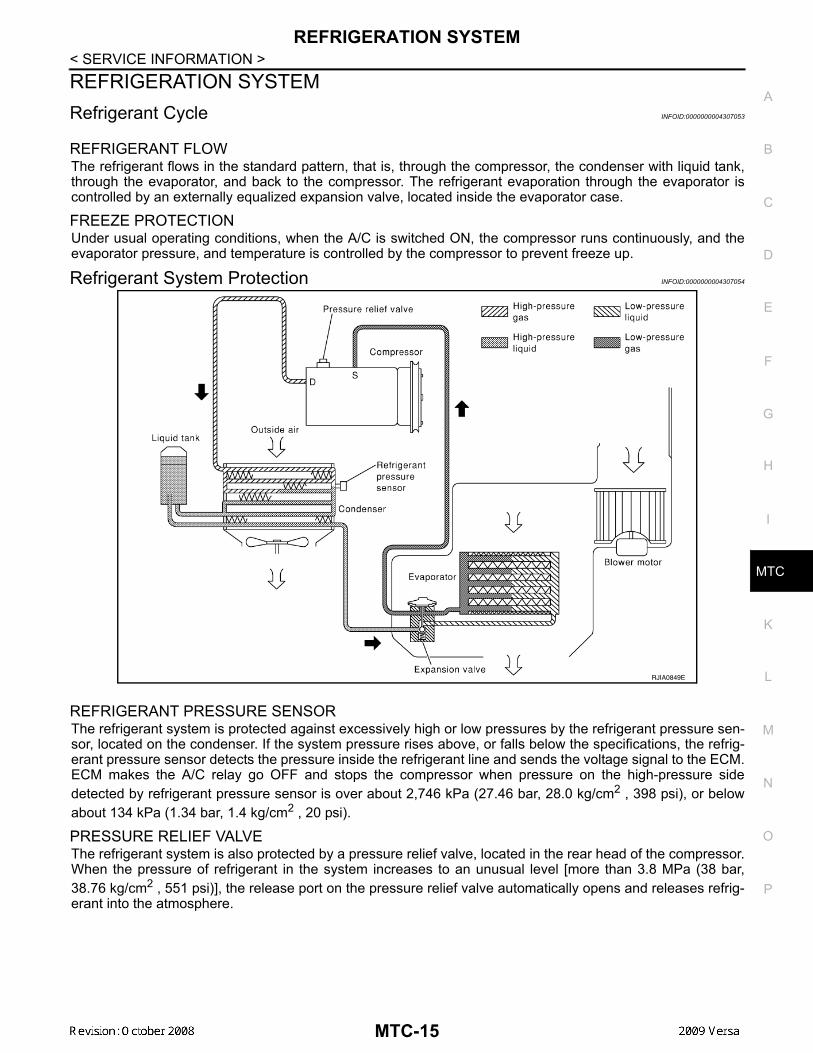
REFRIGERATION SYSTEMRefrigerant Cycle INFOID:0000000004307053
REFRIGERANT FLOWThe refrigerant flows in the standard pattern, that is, through the compressor, the condenser with liquid tank,through the evaporator, and back to the compressor. The refrigerant evaporation through the evaporator iscontrolled by an externally equalized expansion valve, located inside the evaporator case.
FREEZE PROTECTIONUnder usual operating conditions, when the A/C is switched ON, the compressor runs continuously, and theevaporator pressure, and temperature is controlled by the compressor to prevent freeze up.
Refrigerant System Protection INFOID:0000000004307054
REFRIGERANT PRESSURE SENSORThe refrigerant system is protected against excessively high or low pressures by the refrigerant pressure sen-sor, located on the condenser. If the system pressure rises above, or falls below the specifications, the refrig-erant pressure sensor detects the pressure inside the refrigerant line and sends the voltage signal to the ECM.ECM makes the A/C relay go OFF and stops the compressor when pressure on the high-pressure sidedetected by refrigerant pressure sensor is over about 2,746 kPa (27.46 bar, 28.0 kg/cm2 , 398 psi), or belowabout 134 kPa (1.34 bar, 1.4 kg/cm2 , 20 psi).
PRESSURE RELIEF VALVEThe refrigerant system is also protected by a pressure relief valve, located in the rear head of the compressor.When the pressure of refrigerant in the system increases to an unusual level [more than 3.8 MPa (38 bar,38.76 kg/cm2 , 551 psi)], the release port on the pressure relief valve automatically opens and releases refrig-erant into the atmosphere.
RJIA0849E
MTC-15
REFRIGERATION SYSTEM
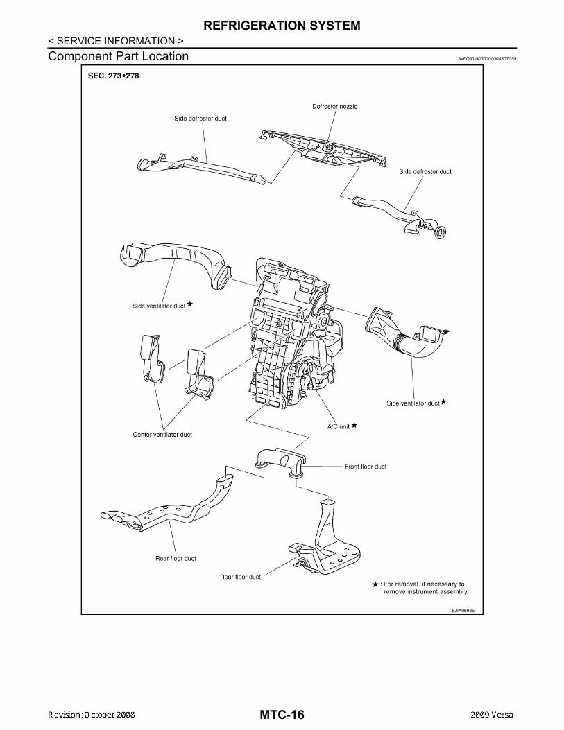
< SERVICE INFORMATION >Component Part Location INFOID:0000000004307055SJIA0698E
MTC-16
OIL
C
D
E
F
G
H
I
K
L
M
A
B
TC
N
O
P
< SERVICE INFORMATION >
M
OILMaintenance of Oil Quantity in Compressor INFOID:0000000004307056
The oil in the compressor circulates through the system with the refrigerant. Add oil to compressor whenreplacing any component or after a large refrigerant leakage occurred. It is important to maintain the specifiedamount.If oil quantity is not maintained properly, the following malfunctions may result:• Lack of oil: May lead to a seized compressor.• Excessive oil: Inadequate cooling (thermal exchange interference)
OIL
OIL ADJUSTING PROCEDURE FOR COMPONENTS REPLACEMENT EXCEPT COMPRESSORAfter replacing any of the following major components, add the correct amount of oil to the system.Amount Of Oil To Be Added
*1: If refrigerant leak is small, no addition of oil is needed.
OIL ADJUSTING PROCEDURE FOR COMPRESSOR REPLACEMENT
TYPE 1 Compressor (CR-10) : NISSAN A/C System Oil Type RTYPE 2 Compressor (CSV511) : NISSAN A/C System Oil Type S
Part replacedOil to be added to system
RemarksAmount of oilm (US fl oz, Imp fl oz)
Evaporator 35 (1.2, 1.2) -
Condenser 15 (0.5, 0.5) -
Liquid tank 5 (0.2, 0.2) -
In case of refrigerant leak30 (1.0, 1.1) Large leak
None *1 Small leak *1
MTC-17
OIL
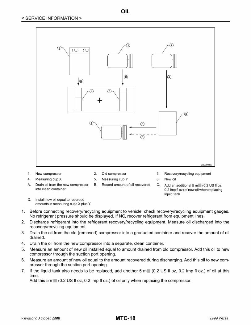
< SERVICE INFORMATION >1. Before connecting recovery/recycling equipment to vehicle, check recovery/recycling equipment gauges.No refrigerant pressure should be displayed. If NG, recover refrigerant from equipment lines.
2. Discharge refrigerant into the refrigerant recovery/recycling equipment. Measure oil discharged into therecovery/recycling equipment.
3. Drain the oil from the old (removed) compressor into a graduated container and recover the amount of oildrained.
4. Drain the oil from the new compressor into a separate, clean container.5. Measure an amount of new oil installed equal to amount drained from old compressor. Add this oil to new
compressor through the suction port opening.6. Measure an amount of new oil equal to the amount recovered during discharging. Add this oil to new com-
pressor through the suction port opening.7. If the liquid tank also needs to be replaced, add another 5 m (0.2 US fl oz, 0.2 Imp fl oz.) of oil at this
time.Add this 5 m (0.2 US fl oz, 0.2 Imp fl oz.) of oil only when replacing the compressor.
1. New compressor 2. Old compressor 3. Recovery/recycling equipment4. Measuring cup X 5. Measuring cup Y 6. New oilA. Drain oil from the new compressor
into clean containerB. Record amount of oil recovered C. Add an additional 5 m (0.2 US fl oz,
0.2 Imp fl oz) of new oil when replacing liquid tank
D. Install new oil equal to recorded amounts in measuring cups X plus Y
WJIA1716E
MTC-18
AIR CONDITIONER CONTROL
C
D
E
F
G
H
I
K
L
M
A
B
TC
N
O
P
< SERVICE INFORMATION >
M
AIR CONDITIONER CONTROLControl Operation INFOID:0000000004307057
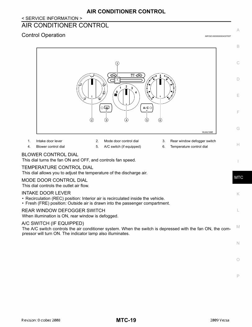
BLOWER CONTROL DIALThis dial turns the fan ON and OFF, and controls fan speed.
TEMPERATURE CONTROL DIAL This dial allows you to adjust the temperature of the discharge air.
MODE DOOR CONTROL DIALThis dial controls the outlet air flow.
INTAKE DOOR LEVER• Recirculation (REC) position: Interior air is recirculated inside the vehicle.• Fresh (FRE) position: Outside air is drawn into the passenger compartment.
REAR WINDOW DEFOGGER SWITCHWhen illumination is ON, rear window is defogged.
A/C SWITCH (IF EQUIPPED)The A/C switch controls the air conditioner system. When the switch is depressed with the fan ON, the com-pressor will turn ON. The indicator lamp also illuminates.
1. Intake door lever 2. Mode door control dial 3. Rear window defogger switch4. Blower control dial 5. A/C switch (if equipped) 6. Temperature control dial
WJIA2189E
MTC-19
AIR CONDITIONER CONTROL
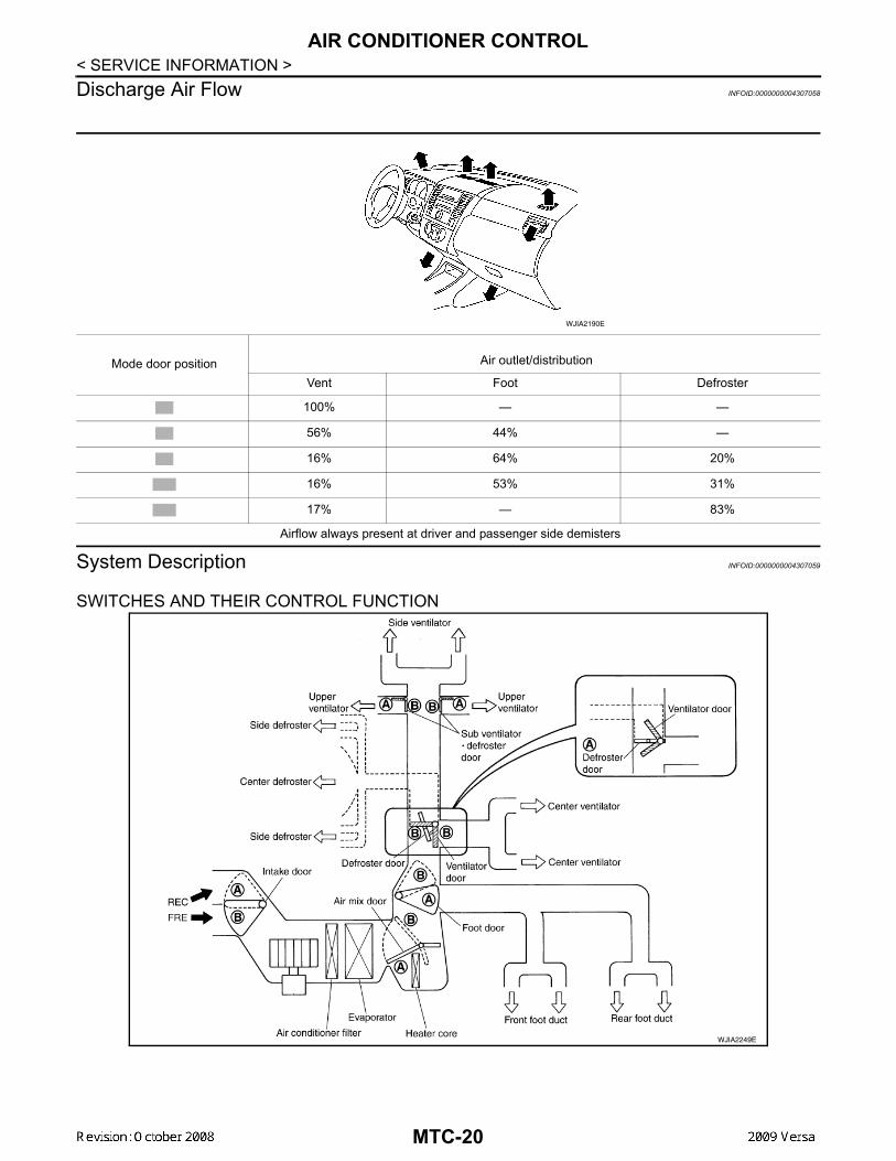
< SERVICE INFORMATION >Discharge Air Flow INFOID:0000000004307058System Description INFOID:0000000004307059
SWITCHES AND THEIR CONTROL FUNCTION
Mode door position Air outlet/distribution
Vent Foot Defroster
100% — —
56% 44% —
16% 64% 20%
16% 53% 31%
17% — 83%
Airflow always present at driver and passenger side demisters
WJIA2190E
WJIA2249E
MTC-20
AIR CONDITIONER CONTROL
C
D
E
F
G
H
I
K
L
M
A
B
TC
N
O
P
< SERVICE INFORMATION >
M
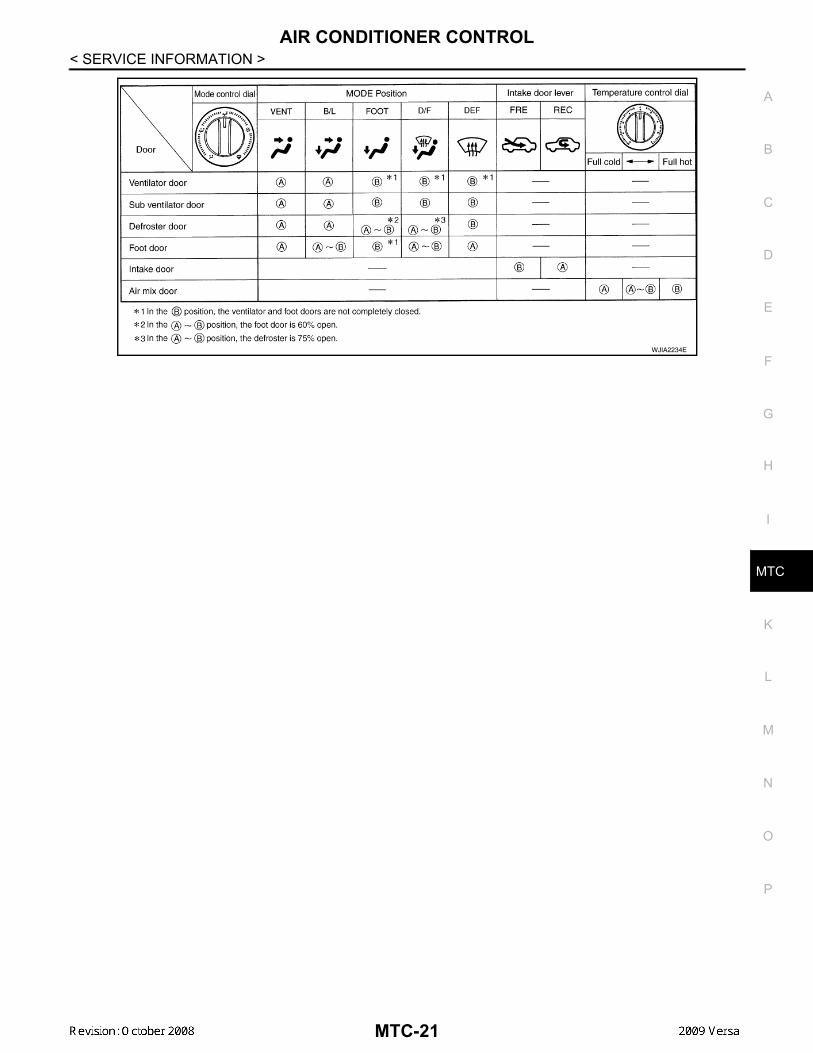
WJIA2234E
MTC-21
TROUBLE DIAGNOSIS
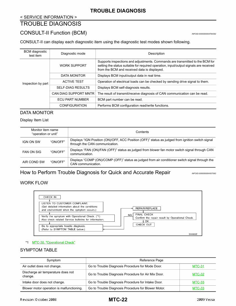
< SERVICE INFORMATION >TROUBLE DIAGNOSISCONSULT-II Function (BCM) INFOID:0000000004784392CONSULT-II can display each diagnostic item using the diagnostic test modes shown following.
DATA MONITORDisplay Item List
How to Perform Trouble Diagnosis for Quick and Accurate Repair INFOID:0000000004307062
WORK FLOW
SYMPTOM TABLE
BCM diagnostic test item Diagnostic mode Description
Inspection by part
WORK SUPPORTSupports inspections and adjustments. Commands are transmitted to the BCM for setting the status suitable for required operation, input/output signals are received from the BCM and received data is displayed.
DATA MONITOR Displays BCM input/output data in real time.
ACTIVE TEST Operation of electrical loads can be checked by sending drive signal to them.
SELF-DIAG RESULTS Displays BCM self-diagnosis results.
CAN DIAG SUPPORT MNTR The result of transmit/receive diagnosis of CAN communication can be read.
ECU PART NUMBER BCM part number can be read.
CONFIGURATION Performs BCM configuration read/write functions.
Monitor item name“operation or unit” Contents
IGN ON SW “ON/OFF” Displays “IGN Position (ON)/OFF, ACC Position (OFF)” status as judged from ignition switch signal through the CAN communication.
FAN ON SIG “ON/OFF” Displays “FAN (ON)/FAN (OFF)” status as judged from blower fan motor switch signal through CAN communication.
AIR COND SW “ON/OFF” Displays “COMP (ON)/COMP (OFF)” status as judged from air conditioner switch signal through the CAN communication.
*1 MTC-30, "Operational Check"
SHA900E
Symptom Reference Page
Air outlet does not change. Go to Trouble Diagnosis Procedure for Mode Door. MTC-31
Discharge air temperature does not change. Go to Trouble Diagnosis Procedure for Air Mix Door. MTC-32
Intake door does not change. Go to Trouble Diagnosis Procedure for Intake Door. MTC-33
Blower motor operation is malfunctioning. Go to Trouble Diagnosis Procedure for Blower Motor. MTC-33
MTC-22
TROUBLE DIAGNOSIS
C
D
E
F
G
H
I
K
L
M
A
B
TC
N
O
P
< SERVICE INFORMATION >
M
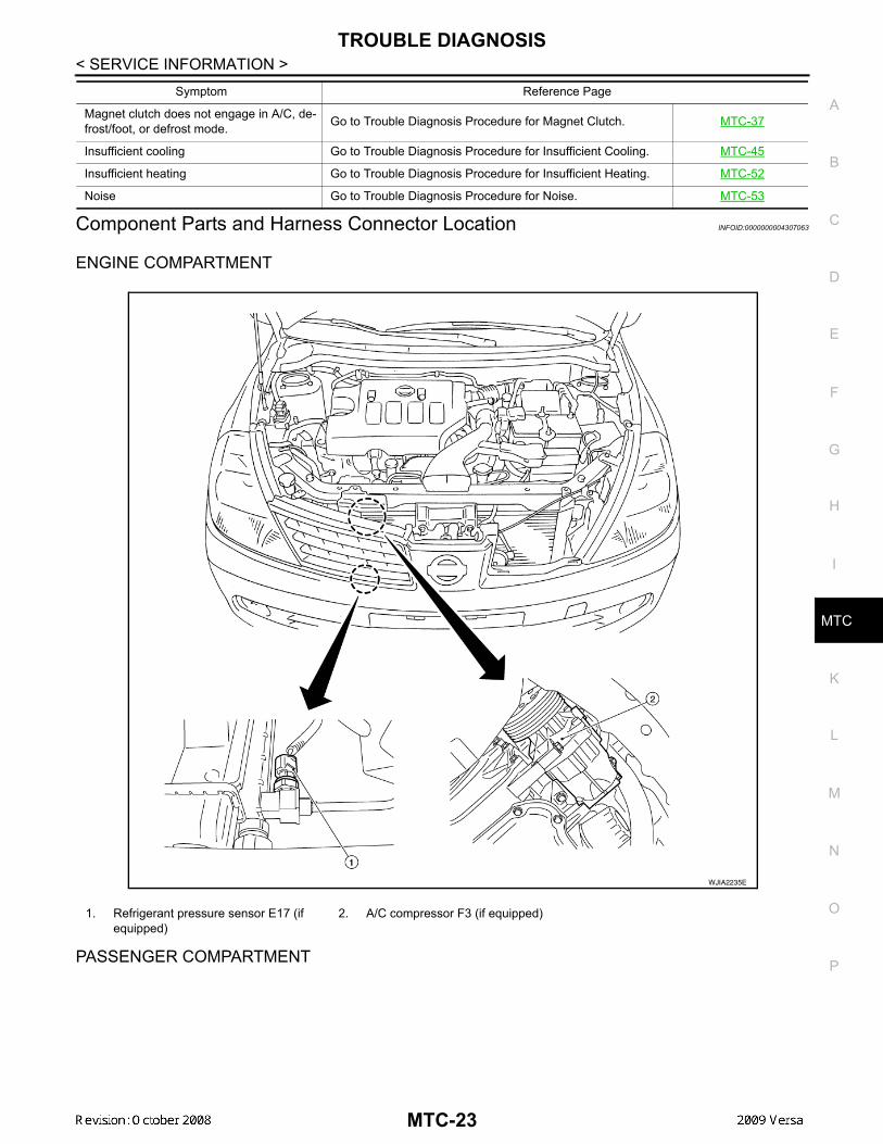
Component Parts and Harness Connector Location INFOID:0000000004307063
ENGINE COMPARTMENT
PASSENGER COMPARTMENT
Magnet clutch does not engage in A/C, de-frost/foot, or defrost mode. Go to Trouble Diagnosis Procedure for Magnet Clutch. MTC-37
Insufficient cooling Go to Trouble Diagnosis Procedure for Insufficient Cooling. MTC-45
Insufficient heating Go to Trouble Diagnosis Procedure for Insufficient Heating. MTC-52
Noise Go to Trouble Diagnosis Procedure for Noise. MTC-53
Symptom Reference Page
1. Refrigerant pressure sensor E17 (if equipped)
2. A/C compressor F3 (if equipped)
WJIA2235E
MTC-23
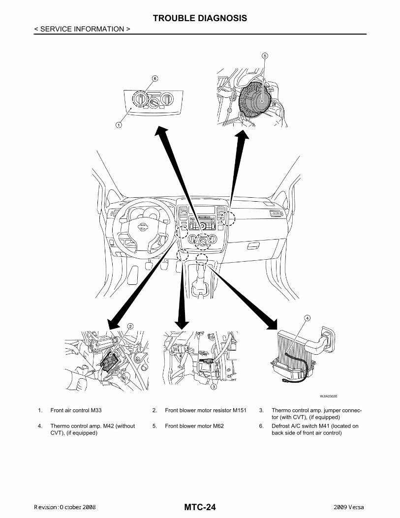
TROUBLE DIAGNOSIS
< SERVICE INFORMATION >1. Front air control M33 2. Front blower motor resistor M151 3. Thermo control amp. jumper connec-tor (with CVT), (if equipped)
4. Thermo control amp. M42 (without CVT), (if equipped)
5. Front blower motor M62 6. Defrost A/C switch M41 (located on back side of front air control)
WJIA2302E
MTC-24
TROUBLE DIAGNOSIS
C
D
E
F
G
H
I
K
L
M
A
B
TC
N
O
P
< SERVICE INFORMATION >
M
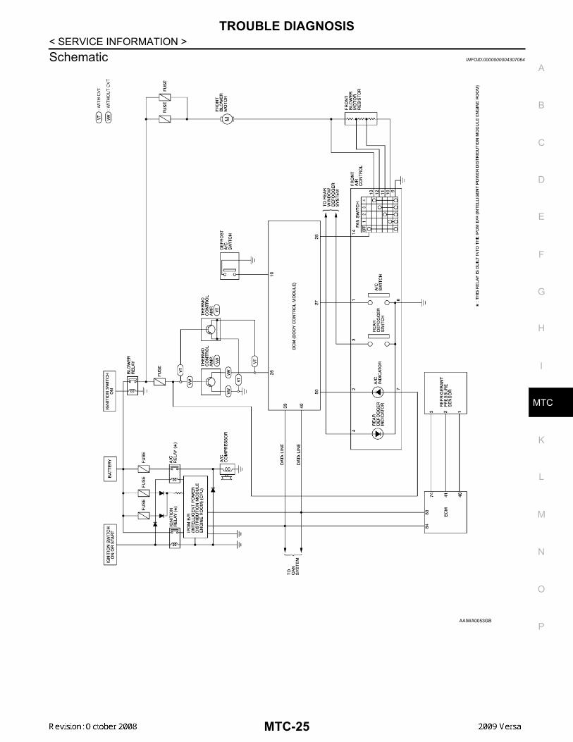
Schematic INFOID:0000000004307064
AAIWA0053GB
MTC-25
TROUBLE DIAGNOSIS
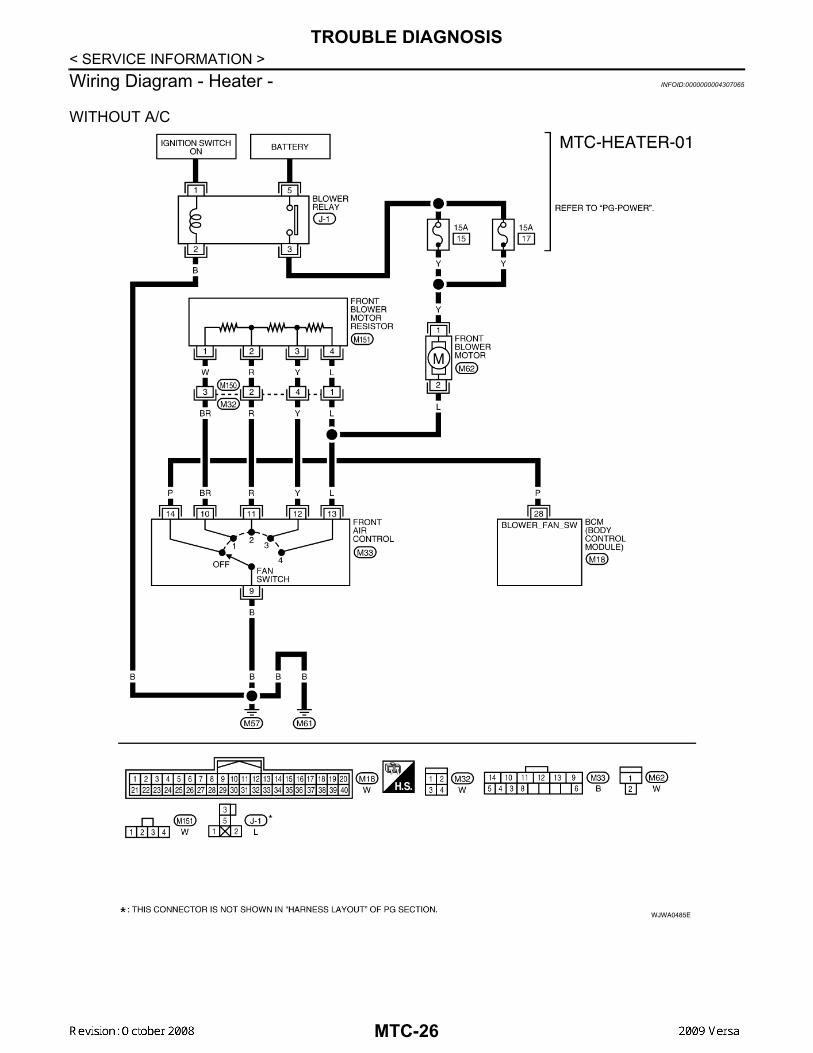
< SERVICE INFORMATION >Wiring Diagram - Heater - INFOID:0000000004307065WITHOUT A/C
WJWA0485E
MTC-26
TROUBLE DIAGNOSIS
C
D
E
F
G
H
I
K
L
M
A
B
TC
N
O
P
< SERVICE INFORMATION >
M
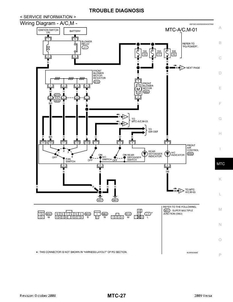
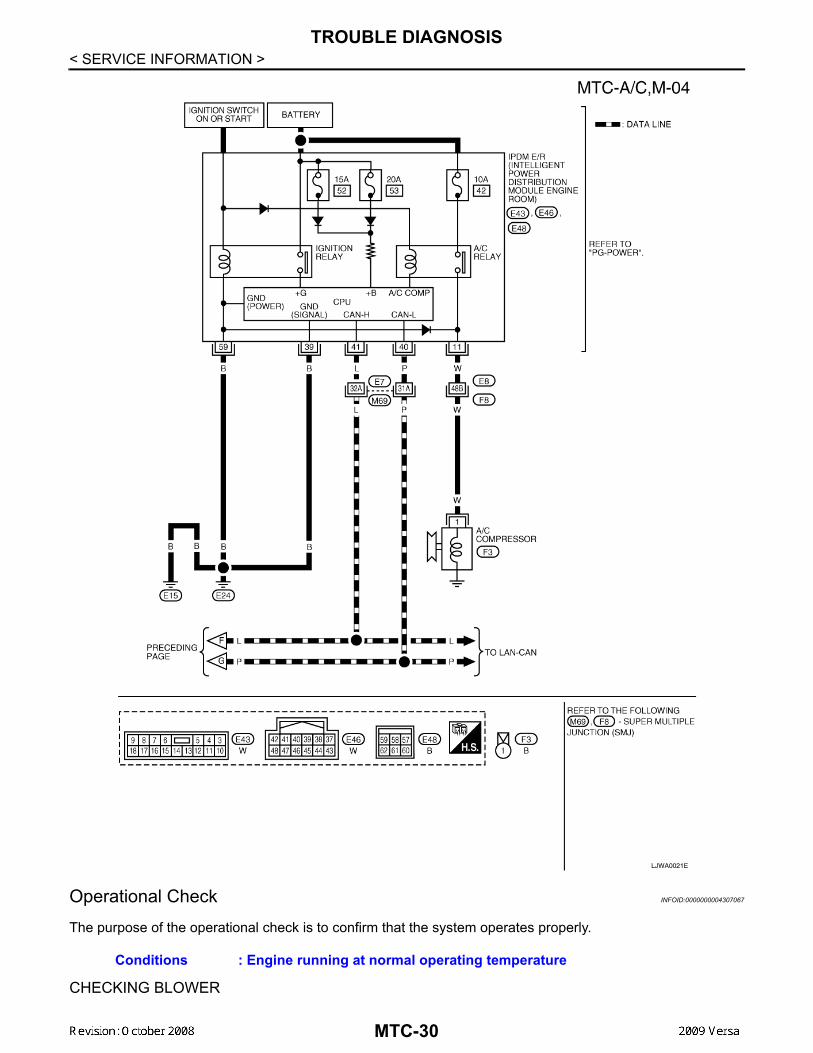
Wiring Diagram - A/C,M - INFOID:0000000004307066
WJWA0484E
MTC-27
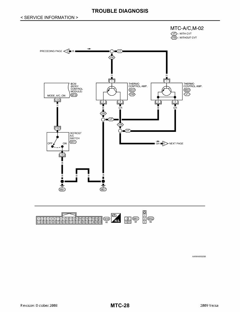
TROUBLE DIAGNOSIS
< SERVICE INFORMATION >AAIWA0052GB
MTC-28
TROUBLE DIAGNOSIS
C
D
E
F
G
H
I
K
L
M
A
B
TC
N
O
P
< SERVICE INFORMATION >
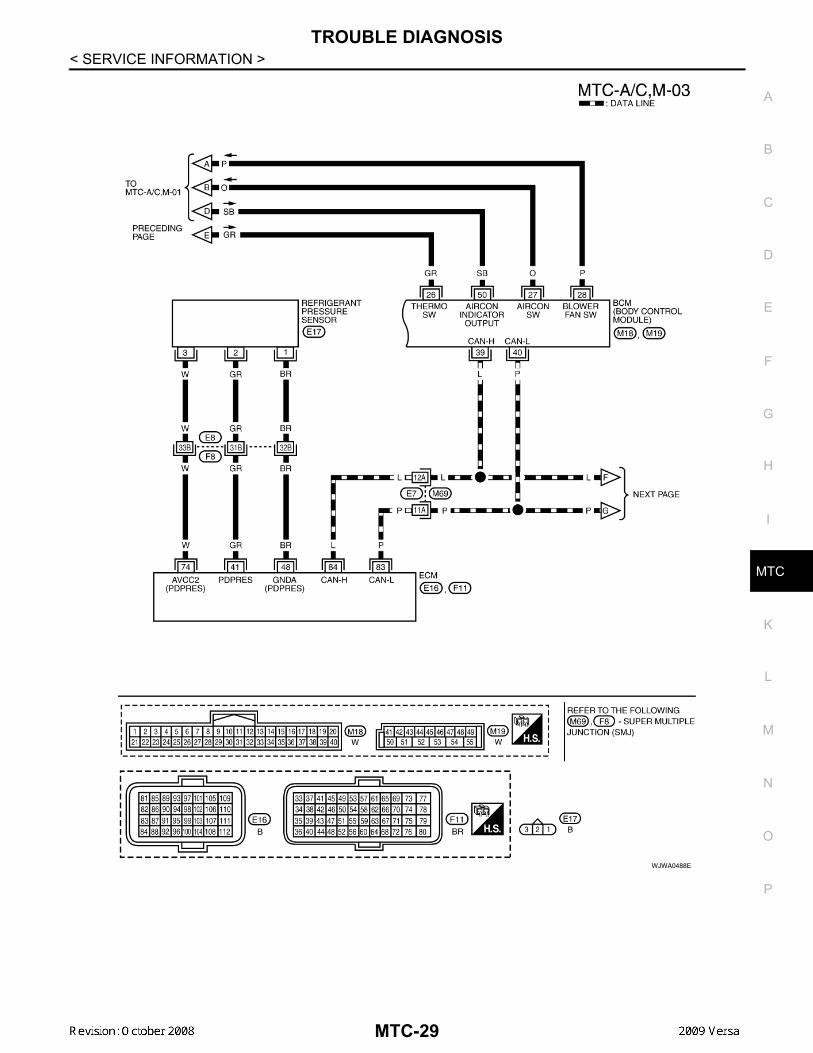
M
WJWA0488E
MTC-29
TROUBLE DIAGNOSIS
< SERVICE INFORMATION >Operational Check INFOID:0000000004307067
The purpose of the operational check is to confirm that the system operates properly.
CHECKING BLOWER
LJWA0021E
Conditions : Engine running at normal operating temperature
MTC-30
TROUBLE DIAGNOSIS
C
D
E
F
G
H
I
K
L
M
A
B
TC
N
O
P
< SERVICE INFORMATION >
M
1. Turn blower control dial clockwise to "1" position. Blower should operate on low speed.2. Turn blower control dial clockwise to "2" position, and continue checking blower speed until all speeds are
checked.3. Leave blower on Maximum speed. If NG, go to trouble diagnosis procedure for MTC-33, "Front Blower Motor Circuit".If OK, continue the check.
CHECKING DISCHARGE AIR1. Turn mode door control dial to each position.
2. Confirm that discharge air comes out according to the air distribution table. Refer to MTC-20, "DischargeAir Flow".
If NG, go to trouble diagnosis procedure for MTC-31, "Mode Door".If OK, continue the check.
CHECKING RECIRCULATION1. Set intake door lever to REC position.2. Operate intake door lever to FRE position.3. Listen for intake door position change (you should hear blower sound change slightly).If NG, go to trouble diagnosis procedure for MTC-33, "Intake Door".If OK, continue the check.
CHECKING TEMPERATURE DECREASE1. Turn temperature control dial counterclockwise to full cold position.2. Check for cold air at discharge air outlets.If NG, go to trouble diagnosis procedure for MTC-45, "Insufficient Cooling".If OK, continue the check.
CHECKING TEMPERATURE INCREASE1. Turn temperature control dial clockwise to full hot position.2. Check for hot air at discharge air outlets.If NG, go to trouble diagnosis procedure for MTC-52, "Insufficient Heating".If OK, continue the check.
CHECKING A/C SWITCH (IF EQUIPPED)1. Turn fan control dial to the desired (1 to 4 speed) position.2. Press A/C switch.3. A/C switch indicator will turn ON.
• Confirm that the compressor clutch engages (sound or visual inspection).If NG, go to trouble diagnosis procedure for MTC-37, "Magnet Clutch Circuit (If Equipped)".If OK, continue the check.
CHECKING DEFROST A/C SWITCH (IF EQUIPPED)1. Turn fan control dial to the desired (1 to 4 speed) position.2. Turn mode dial to ( ) DEF.3. Confirm that the compressor clutch engages (sound or visual inspection) and the A/C switch indicator illu-
minates.If NG, go to trouble diagnosis procedure for MTC-37, "Magnet Clutch Circuit (If Equipped)".If all operational checks are OK (symptom cannot be duplicated), go to MTC-22, "How to Perform TroubleDiagnosis for Quick and Accurate Repair" and perform tests as outlined. If symptom appears, refer to MTC-22,"How to Perform Trouble Diagnosis for Quick and Accurate Repair" and perform applicable trouble diagnosisprocedures.
Mode Door INFOID:0000000004307068
SYMPTOM: Air outlet does not change.
INSPECTION FLOW
MTC-31
TROUBLE DIAGNOSIS
< SERVICE INFORMATION >1.CONFIRM SYMPTOM BY PERFORMING OPERATIONAL CHECK - DISCHARGE AIR
1. Rotate the mode door control dial to each position.2. Confirm that discharge air comes out according to the air distribution table. Refer to MTC-20, "Discharge
Air Flow".NOTE:Confirm that the compressor clutch (with A/C) is engaged (visual inspection) when DEF ( ) or D/F ( )is selected.
Can a symptom be duplicated?YES >> GO TO 3.NO >> GO TO 2.
2.PERFORM COMPLETE OPERATIONAL CHECK
Perform a complete operational check and check for any symptoms. Refer to MTC-30, "Operational Check".Can a symptom be duplicated?YES >> Refer to MTC-22, "How to Perform Trouble Diagnosis for Quick and Accurate Repair".NO >> System OK.
3.CHECK FOR SERVICE BULLETINS
Check for any service bulletins.
>> GO TO 4.4.CHECK MODE DOOR CONTROL CABLE
Check and verify mode door mechanism for smooth operation in each mode.OK or NGOK >> If the symptom still exists, perform a complete operational check and check for other symptoms.
Refer to MTC-30, "Operational Check". If other symptoms exist, refer to MTC-22, "How to PerformTrouble Diagnosis for Quick and Accurate Repair" .
NG >> Repair or adjust mode door control cable. Refer to MTC-65, "Mode Door Cable Adjustment".
Air Mix Door INFOID:0000000004307069
SYMPTOM: Air mix door does not change.
INSPECTION FLOW1.CONFIRM SYMPTOM BY PERFORMING OPERATIONAL CHECK - TEMPERATURE INCREASE
1. Turn the temperature control dial clockwise until maximum heat.2. Check for hot air at discharge air outlets.
>> GO TO 2.2.CONFIRM SYMPTOM BY PERFORMING OPERATIONAL CHECK - TEMPERATURE DECREASE
1. Turn the temperature control dial counterclockwise until maximum cold.2. Check for cold air at discharge air outlets.Can a symptom be duplicated?YES >> GO TO 4.NO >> GO TO 3.
3.PERFORM COMPLETE OPERATIONAL CHECK
Perform a complete operational check and check for any symptoms. Refer to MTC-30, "Operational Check".Can a symptom be duplicated?YES >> Refer to MTC-22, "How to Perform Trouble Diagnosis for Quick and Accurate Repair".NO >> System OK.
4.CHECK FOR SERVICE BULLETINS
Check for any service bulletins.
MTC-32
TROUBLE DIAGNOSIS
C
D
E
F
G
H
I
K
L
M
A
B
TC
N
O
P
< SERVICE INFORMATION >
M
>> GO TO 5.5.CHECK AIR MIX DOOR CONTROL LINKAGE
Check and verify air mix door mechanism for smooth operation. OK or NGOK >> If the symptom still exists, perform a complete operational check. Refer to MTC-30, "Operational
Check" If other symptoms exist, refer to MTC-22, "How to Perform Trouble Diagnosis for Quickand Accurate Repair".
NG >> Repair or adjust air mix door control linkage. Refer to MTC-64, "Air Mix Door Cable Adjustment".
Intake Door INFOID:0000000004307070
SYMPTOM:• Intake door does not change.
INSPECTION FLOW1.CONFIRM SYMPTOM BY PERFORMING OPERATIONAL CHECK - REC ( )
1. Slide the intake door lever to the REC ( ) position.2. Turn the blower motor to maximum speed.3. Slide the intake door lever to the FRE position.4. Listen for intake door position change (you should hear blower sound change slightly).Can a symptom be duplicated?YES >> GO TO 3.NO >> GO TO 2.
2.PERFORM COMPLETE OPERATIONAL CHECK
Perform a complete operational check and check for any symptoms. Refer to MTC-30, "Operational Check" .Can a symptom be duplicated?YES >> Refer to MTC-22, "How to Perform Trouble Diagnosis for Quick and Accurate Repair" .NO >> System OK.
3.CHECK FOR SERVICE BULLETINS
Check for any service bulletins.
>> GO TO 4.4.CHECK INTAKE DOOR CONTROL LINKAGE
Check intake door control linkage mechanism for smooth operation. OK or NGOK >> If the symptom still exists, perform a complete operational check. Refer to MTC-30, "Operational
Check" . If other symptoms exist, refer to MTC-22, "How to Perform Trouble Diagnosis for Quickand Accurate Repair" .
NG >> Repair or adjust control linkage. Refer to MTC-63, "Intake Door Cable Adjustment" .
Front Blower Motor Circuit INFOID:0000000004307071
SYMPTOM: Front blower motor operation is malfunctioning.
INSPECTION FLOW1.CONFIRM SYMPTOM BY PERFORMING OPERATIONAL CHECK - FRONT BLOWER
1. Turn blower control dial to "1" position. Blower should operate on low speed.2. Turn the blower control dial to "2" position, and continue checking blower speed until all speeds are
checked.Can the symptom be duplicated?YES >> GO TO 3.
MTC-33

TROUBLE DIAGNOSIS
< SERVICE INFORMATION >NO >> GO TO 2.2.PERFORM COMPLETE OPERATIONAL CHECK
Perform a complete operational check and check for any symptoms. Refer to MTC-30, "Operational Check".Can a symptom be duplicated?YES >> Refer to MTC-22, "How to Perform Trouble Diagnosis for Quick and Accurate Repair".NO >> System OK.
3.CHECK FOR SERVICE BULLETINS
Check for any service bulletins.
>> GO TO 4.4.CHECK FRONT BLOWER MOTOR CIRCUIT
Check front blower motor circuit. Refer to "DIAGNOSTIC PROCEDURE FOR FRONT BLOWER MOTOR" .OK or NGOK >> If the symptom still exists, perform a complete operational check. Refer to MTC-30, "Operational
Check". If other symptoms exist, refer to MTC-22, "How to Perform Trouble Diagnosis for Quickand Accurate Repair".
NG >> Repair as necessary.
DIAGNOSTIC PROCEDURE FOR FRONT BLOWER MOTORSYMPTOM: Blower motor operation is malfunctioning.
1.CHECK FRONT BLOWER MOTOR OPERATION
1. Turn ignition switch ON.2. Check front blower motor operation at each fan speed.OK or NGOK >> Inspection End.NG >> • Front blower motor does not operate at any speed, GO TO 2.
• Front blower motor does not operate at one or more of the four speeds, GO TO 10.2.CHECK POWER SUPPLY FOR FRONT BLOWER MOTOR
1. Turn ignition switch OFF.2. Disconnect front blower motor connector.3. Turn ignition switch ON.4. Check voltage between front blower motor harness connector
M62 terminal 1 and ground.
OK or NGOK >> GO TO 6.
WJIA2259E
TerminalsVoltage
(Approx.)(+) (−)
Connector TerminalGroundFront blower
motor: M62 1 Battery voltage WJIA2228E
MTC-34
TROUBLE DIAGNOSIS
C
D
E
F
G
H
I
K
L
M
A
B
TC
N
O
P
< SERVICE INFORMATION >
M
NG >> Check power supply circuit and 15A fuses [Nos. 15 and 17, located in the fuse block (J/B)].Refer to PG-3, "Schematic".
• If fuses are OK, reinstall fuses and GO TO 3. • If fuses are NG, replace fuse and check harness for short circuit. Repair or replace if necessary.
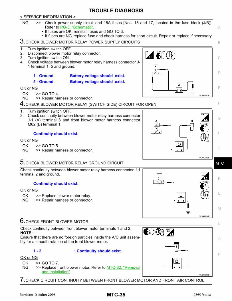
3.CHECK BLOWER MOTOR RELAY POWER SUPPLY CIRCUITS
1. Turn ignition switch OFF.2. Disconnect blower motor relay connector.3. Turn ignition switch ON.4. Check voltage between blower motor relay harness connector J-
1 terminal 1, 5 and ground.
OK or NGOK >> GO TO 4.NG >> Repair harness or connector.
4.CHECK BLOWER MOTOR RELAY (SWITCH SIDE) CIRCUIT FOR OPEN
1. Turn ignition switch OFF.2. Check continuity between blower motor relay harness connector
J-1 (A) terminal 3 and front blower motor harness connectorM62 (B) terminal 1.
OK or NGOK >> GO TO 5.NG >> Repair harness or connector.
5.CHECK BLOWER MOTOR RELAY GROUND CIRCUIT
Check continuity between blower motor relay harness connector J-1terminal 2 and ground.
OK or NGOK >> Replace blower motor relay.NG >> Repair harness or connector.
6.CHECK FRONT BLOWER MOTOR
Check continuity between front blower motor terminals 1 and 2.NOTE:Ensure that there are no foreign particles inside the A/C unit assem-bly for a smooth rotation of the front blower motor.
OK or NGOK >> GO TO 7.NG >> Replace front blower motor. Refer to MTC-62, "Removal
and Installation".
7.CHECK CIRCUIT CONTINUITY BETWEEN FRONT BLOWER MOTOR AND FRONT AIR CONTROL
1 - Ground Battery voltage should exist.5 - Ground Battery voltage should exist.
WJIA1783E
Continuity should exist.
WJIA2263E
Continuity should exist.
WJIA2264E
1 - 2 : Continuity should exist.
WJIA2230E
MTC-35

TROUBLE DIAGNOSIS
< SERVICE INFORMATION >1. Disconnect front air control connector.2. Check continuity between front blower motor harness connectorM62 (A) terminal 2 and front air control harness connector M33(B) terminal 13.
OK or NGOK >> GO TO 8.NG >> Repair harness or connector.
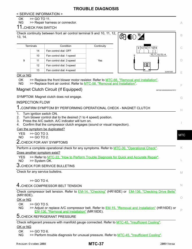
8.CHECK FAN SWITCH
Check continuity between front air control terminal 9 and 10, 11, 12,13, 14.
OK or NGOK >> GO TO 9.NG >> Replace front air control. Refer to MTC-58, "Removal and Installation".
9.CHECK FAN SWITCH GROUND CIRCUIT
Check continuity between front air control harness connector M33terminal 9 and ground.
OK or NGOK >> Inspection End.NG >> Repair harness or connector.
10.CHECK CIRCUIT CONTINUITY BETWEEN FRONT AIR CONTROL AND FRONT BLOWER MOTORRESISTOR1. Turn ignition switch OFF.2. Disconnect front blower motor resistor and front air control con-
nectors.3. Check continuity between front air control harness connector
M33 (A) terminals and front blower motor resistor harness con-nector M6 (B) terminals.
OK or NG
2 - 13 : Continuity should exist.
AWIIA0339ZZ
Terminals Condition Continuity
9
14 Blower control dial: OFF
Yes
10 Blower control dial: 1-speed
11 Blower control dial: 2-speed
12 Blower control dial: 3-speed
13 Blower control dial: 4-speedSJIA0732E
Continuity should exist.
SJIA0734E
A BContinuity
Connector Terminal Connector Terminal
Front air control: M33
10Front blower
motor resistor: M6
1
Yes11 2
12 3
13 4
SJIA0733E
MTC-36
TROUBLE DIAGNOSIS
C
D
E
F
G
H
I
K
L
M
A
B
TC
N
O
P
< SERVICE INFORMATION >
M
OK >> GO TO 11.NG >> Repair harness or connector.
11.CHECK FAN SWITCH
Check continuity between front air control terminal 9 and 10, 11, 12,13, 14.
OK or NGOK >> Replace the front blower motor resistor. Refer to MTC-66, "Removal and Installation".NG >> Replace front air control. Refer to MTC-58, "Removal and Installation".
Magnet Clutch Circuit (If Equipped) INFOID:0000000004307072
SYMPTOM: Magnet clutch does not engage.
INSPECTION FLOW1.CONFIRM SYMPTOM BY PERFORMING OPERATIONAL CHECK - MAGNET CLUTCH
1. Turn ignition switch ON.2. Turn blower control dial to the desired (1 to 4 speed) position.3. Press the A/C switch. A/C indicator will turn on. 4. Confirm that the compressor clutch engages (sound or visual inspection).Can the symptom be duplicated?YES >> GO TO 3.NO >> GO TO 2.
2.CHECK FOR ANY SYMPTOMS
Perform a complete operational check for any symptoms. Refer to MTC-30, "Operational Check".Does another symptom exist?YES >> Refer to MTC-22, "How to Perform Trouble Diagnosis for Quick and Accurate Repair". NO >> System OK.
3.CHECK FOR SERVICE BULLETINS
Check for any service bulletins.
>> GO TO 4.4.CHECK COMPRESSOR BELT TENSION
Check compressor belt tension. Refer to EM-14, "Checking" (HR16DE) or EM-136, "Checking Drive Belts"(MR18DE).OK or NGOK >> GO TO 5.NG >> Adjust or replace A/C compressor belt. Refer to EM-15, "Removal and Installation" (HR16DE) or
EM-136, "Removal and Installation" (MR18DE).5.CHECK REFRIGERANT PRESSURE
Check refrigerant pressure with manifold gauge connected. Refer to MTC-45, "Insufficient Cooling". OK or NGOK >> GO TO 6.NG >> Perform trouble diagnosis for unusual pressure. Refer to MTC-45, "Insufficient Cooling".
Terminals Condition Continuity
9
14 Fan control dial: OFF
Yes
10 Fan control dial: 1-speed
11 Fan control dial: 2-speed
12 Fan control dial: 3-speed
13 Fan control dial: 4-speedSJIA0732E
MTC-37
TROUBLE DIAGNOSIS
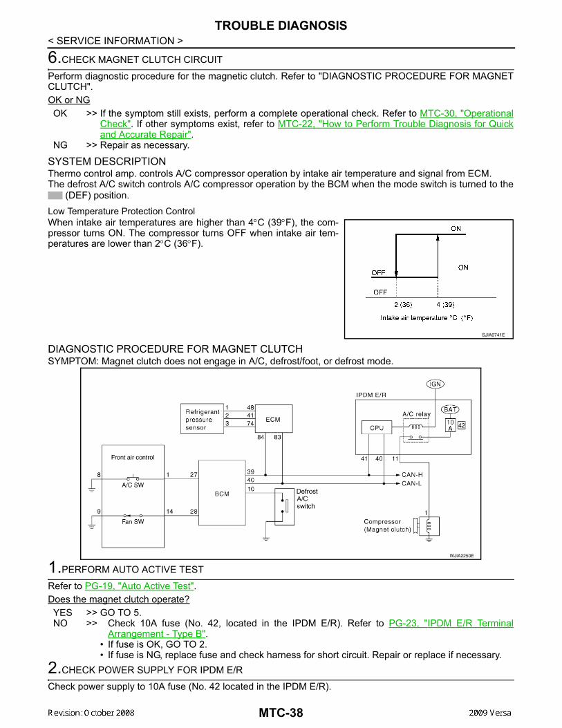
< SERVICE INFORMATION >6.CHECK MAGNET CLUTCH CIRCUIT
Perform diagnostic procedure for the magnetic clutch. Refer to "DIAGNOSTIC PROCEDURE FOR MAGNETCLUTCH".OK or NGOK >> If the symptom still exists, perform a complete operational check. Refer to MTC-30, "Operational
Check". If other symptoms exist, refer to MTC-22, "How to Perform Trouble Diagnosis for Quickand Accurate Repair".
NG >> Repair as necessary.
SYSTEM DESCRIPTIONThermo control amp. controls A/C compressor operation by intake air temperature and signal from ECM.The defrost A/C switch controls A/C compressor operation by the BCM when the mode switch is turned to the
(DEF) position.Low Temperature Protection ControlWhen intake air temperatures are higher than 4°C (39°F), the com-pressor turns ON. The compressor turns OFF when intake air tem-peratures are lower than 2°C (36°F).
DIAGNOSTIC PROCEDURE FOR MAGNET CLUTCHSYMPTOM: Magnet clutch does not engage in A/C, defrost/foot, or defrost mode.
1.PERFORM AUTO ACTIVE TEST
Refer to PG-19, "Auto Active Test".Does the magnet clutch operate?YES >> GO TO 5.NO >> Check 10A fuse (No. 42, located in the IPDM E/R). Refer to PG-23, "IPDM E/R Terminal
Arrangement - Type B".• If fuse is OK, GO TO 2.• If fuse is NG, replace fuse and check harness for short circuit. Repair or replace if necessary.
2.CHECK POWER SUPPLY FOR IPDM E/R
Check power supply to 10A fuse (No. 42 located in the IPDM E/R).
SJIA0741E
WJIA2250E
MTC-38
TROUBLE DIAGNOSIS
C
D
E
F
G
H
I
K
L
M
A
B
TC
N
O
P
< SERVICE INFORMATION >
M
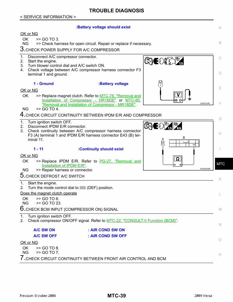
OK or NGOK >> GO TO 3. NG >> Check harness for open circuit. Repair or replace if necessary.
3.CHECK POWER SUPPLY FOR A/C COMPRESSOR
1. Disconnect A/C compressor connector.2. Start the engine.3. Turn blower control dial and A/C switch ON.4. Check voltage between A/C compressor harness connector F3
terminal 1 and ground.
OK or NGOK >> Replace magnet clutch. Refer to MTC-78, "Removal and
Installation of Compressor - HR16DE" or MTC-80,"Removal and Installation of Compressor - MR18DE".
NG >> GO TO 4.4.CHECK CIRCUIT CONTINUITY BETWEEN IPDM E/R AND COMPRESSOR
1. Turn ignition switch OFF.2. Disconnect IPDM E/R connector.3. Check continuity between A/C compressor harness connector
F3 (A) terminal 1 and IPDM E/R harness connector E43 (B) ter-minal 11.
OK or NGOK >> Replace IPDM E/R. Refer to PG-27, "Removal and
Installation of IPDM E/R".NG >> Repair harness or connector.
5.CHECK DEFROST A/C SWITCH
1. Start the engine.2. Turn the mode control dial to (DEF) position.Does the magnet clutch operateOK >> GO TO 6.NG >> GO TO 23.
6.CHECK BCM INPUT (COMPRESSOR ON) SIGNAL
1. Turn ignition switch OFF.2. Check compressor ON/OFF signal. Refer to MTC-22, "CONSULT-II Function (BCM)".
OK or NGOK >> GO TO 8.NG >> GO TO 7.
7.CHECK CIRCUIT CONTINUITY BETWEEN FRONT AIR CONTROL AND BCM
:Battery voltage should exist
1 - Ground :Battery voltage
SJIA0743E
1 - 11 :Continuity should exist
WJIA2233E
A/C SW ON : AIR COND SW ONA/C SW OFF : AIR COND SW OFF
MTC-39
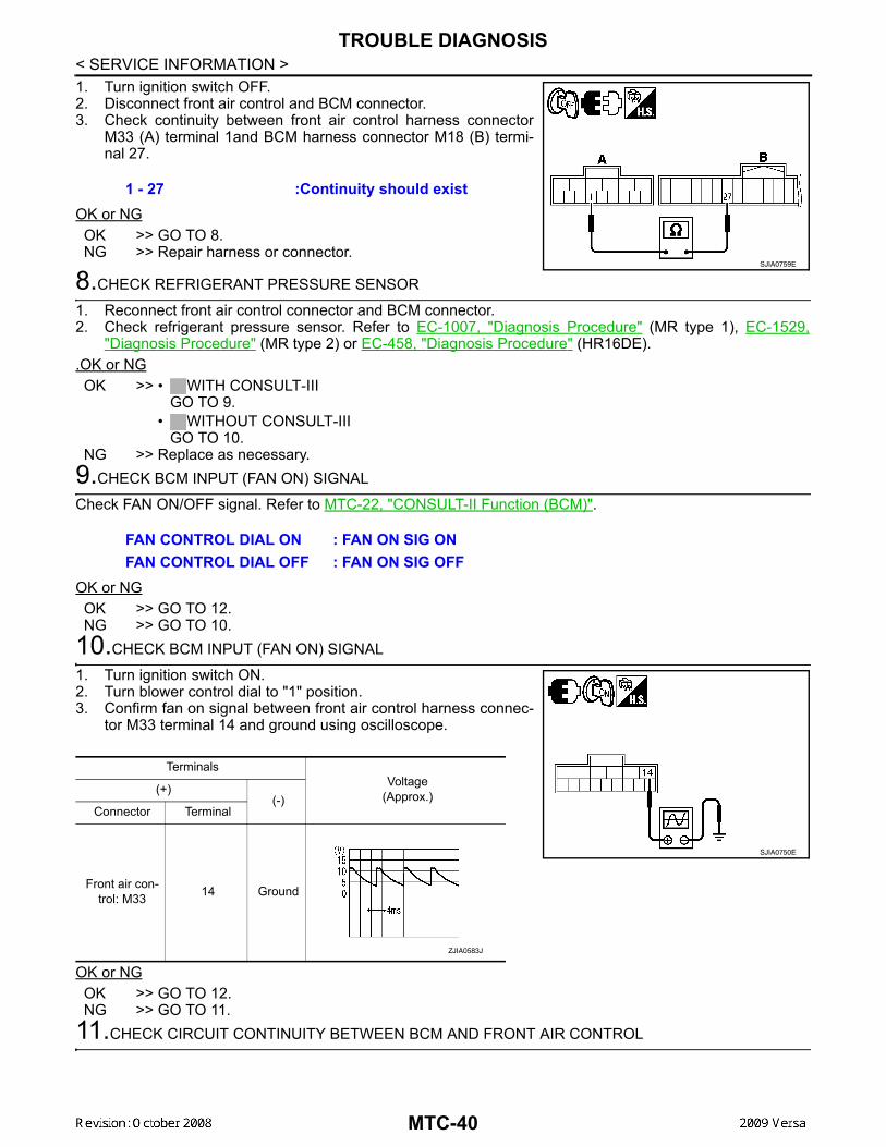
TROUBLE DIAGNOSIS
< SERVICE INFORMATION >1. Turn ignition switch OFF.2. Disconnect front air control and BCM connector.3. Check continuity between front air control harness connectorM33 (A) terminal 1and BCM harness connector M18 (B) termi-nal 27.
OK or NGOK >> GO TO 8.NG >> Repair harness or connector.
8.CHECK REFRIGERANT PRESSURE SENSOR
1. Reconnect front air control connector and BCM connector.2. Check refrigerant pressure sensor. Refer to EC-1007, "Diagnosis Procedure" (MR type 1), EC-1529,
"Diagnosis Procedure" (MR type 2) or EC-458, "Diagnosis Procedure" (HR16DE)..OK or NGOK >> • WITH CONSULT-III
GO TO 9.• WITHOUT CONSULT-III
GO TO 10.NG >> Replace as necessary.
9.CHECK BCM INPUT (FAN ON) SIGNAL
Check FAN ON/OFF signal. Refer to MTC-22, "CONSULT-II Function (BCM)".
OK or NGOK >> GO TO 12.NG >> GO TO 10.
10.CHECK BCM INPUT (FAN ON) SIGNAL
1. Turn ignition switch ON.2. Turn blower control dial to "1" position.3. Confirm fan on signal between front air control harness connec-
tor M33 terminal 14 and ground using oscilloscope.
OK or NGOK >> GO TO 12.NG >> GO TO 11.
11.CHECK CIRCUIT CONTINUITY BETWEEN BCM AND FRONT AIR CONTROL
1 - 27 :Continuity should exist
SJIA0759E
FAN CONTROL DIAL ON : FAN ON SIG ONFAN CONTROL DIAL OFF : FAN ON SIG OFF
TerminalsVoltage
(Approx.)(+)(-)
Connector Terminal
Front air con-trol: M33 14 Ground
SJIA0750E
ZJIA0583J
MTC-40
TROUBLE DIAGNOSIS
C
D
E
F
G
H
I
K
L
M
A
B
TC
N
O
P
< SERVICE INFORMATION >
M
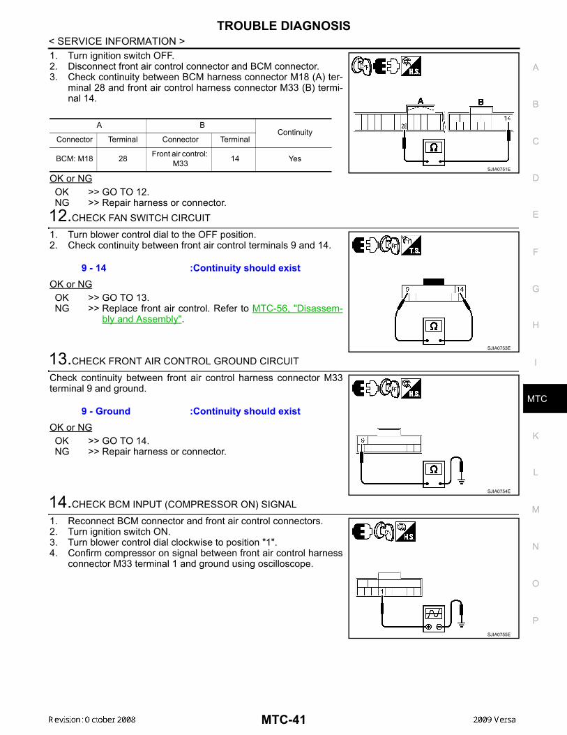
1. Turn ignition switch OFF.2. Disconnect front air control connector and BCM connector.3. Check continuity between BCM harness connector M18 (A) ter-
minal 28 and front air control harness connector M33 (B) termi-nal 14.
OK or NGOK >> GO TO 12.NG >> Repair harness or connector.
12.CHECK FAN SWITCH CIRCUIT
1. Turn blower control dial to the OFF position.2. Check continuity between front air control terminals 9 and 14.
OK or NGOK >> GO TO 13.NG >> Replace front air control. Refer to MTC-56, "Disassem-
bly and Assembly".
13.CHECK FRONT AIR CONTROL GROUND CIRCUIT
Check continuity between front air control harness connector M33terminal 9 and ground.
OK or NGOK >> GO TO 14.NG >> Repair harness or connector.
14.CHECK BCM INPUT (COMPRESSOR ON) SIGNAL
1. Reconnect BCM connector and front air control connectors.2. Turn ignition switch ON.3. Turn blower control dial clockwise to position "1".4. Confirm compressor on signal between front air control harness
connector M33 terminal 1 and ground using oscilloscope.
A BContinuity
Connector Terminal Connector Terminal
BCM: M18 28 Front air control: M33 14 Yes
SJIA0751E
9 - 14 :Continuity should exist
SJIA0753E
9 - Ground :Continuity should exist
SJIA0754E
SJIA0755E
MTC-41
TROUBLE DIAGNOSIS
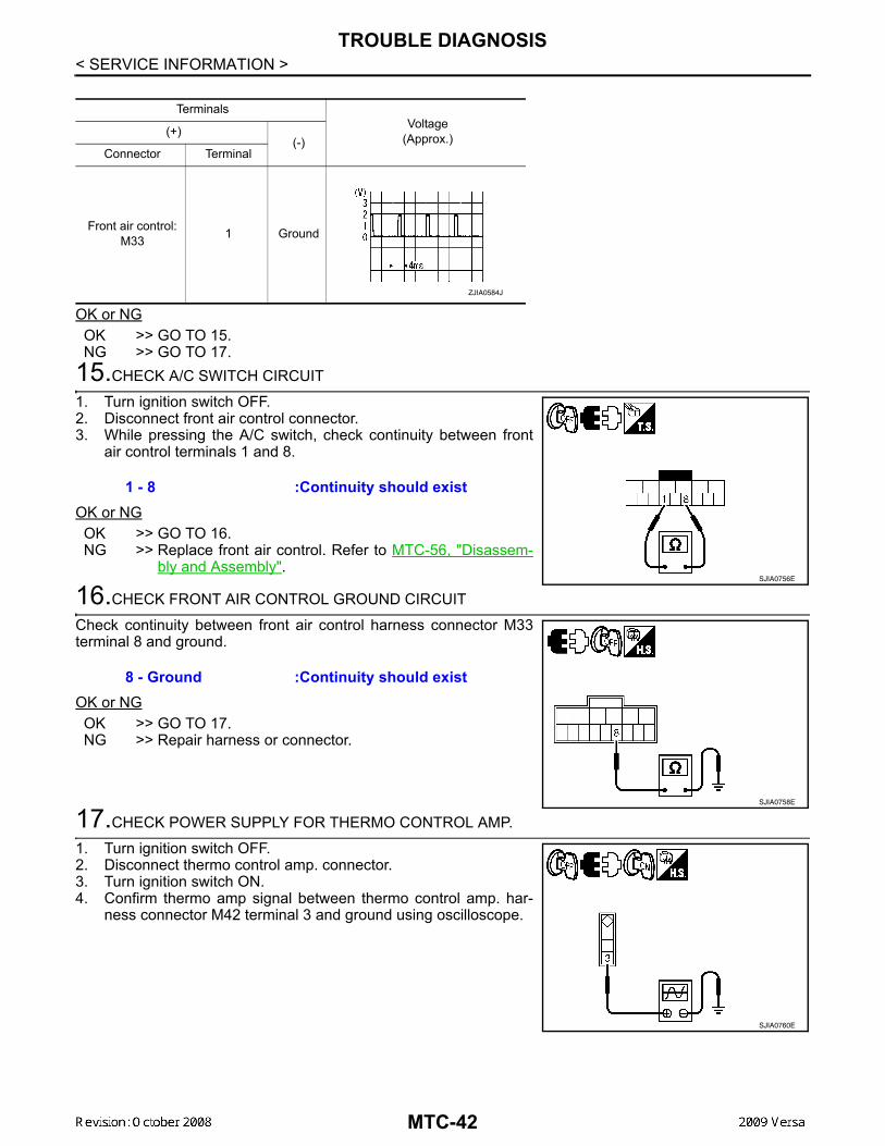
< SERVICE INFORMATION >OK or NGOK >> GO TO 15.NG >> GO TO 17.
15.CHECK A/C SWITCH CIRCUIT
1. Turn ignition switch OFF.2. Disconnect front air control connector.3. While pressing the A/C switch, check continuity between front
air control terminals 1 and 8.
OK or NGOK >> GO TO 16.NG >> Replace front air control. Refer to MTC-56, "Disassem-
bly and Assembly".
16.CHECK FRONT AIR CONTROL GROUND CIRCUIT
Check continuity between front air control harness connector M33terminal 8 and ground.
OK or NGOK >> GO TO 17.NG >> Repair harness or connector.
17.CHECK POWER SUPPLY FOR THERMO CONTROL AMP.
1. Turn ignition switch OFF.2. Disconnect thermo control amp. connector.3. Turn ignition switch ON.4. Confirm thermo amp signal between thermo control amp. har-
ness connector M42 terminal 3 and ground using oscilloscope.
TerminalsVoltage
(Approx.)(+)(-)
Connector Terminal
Front air control: M33 1 Ground
ZJIA0584J
1 - 8 :Continuity should exist
SJIA0756E
8 - Ground :Continuity should exist
SJIA0758E
SJIA0760E
MTC-42
TROUBLE DIAGNOSIS
C
D
E
F
G
H
I
K
L
M
A
B
TC
N
O
P
< SERVICE INFORMATION >
M
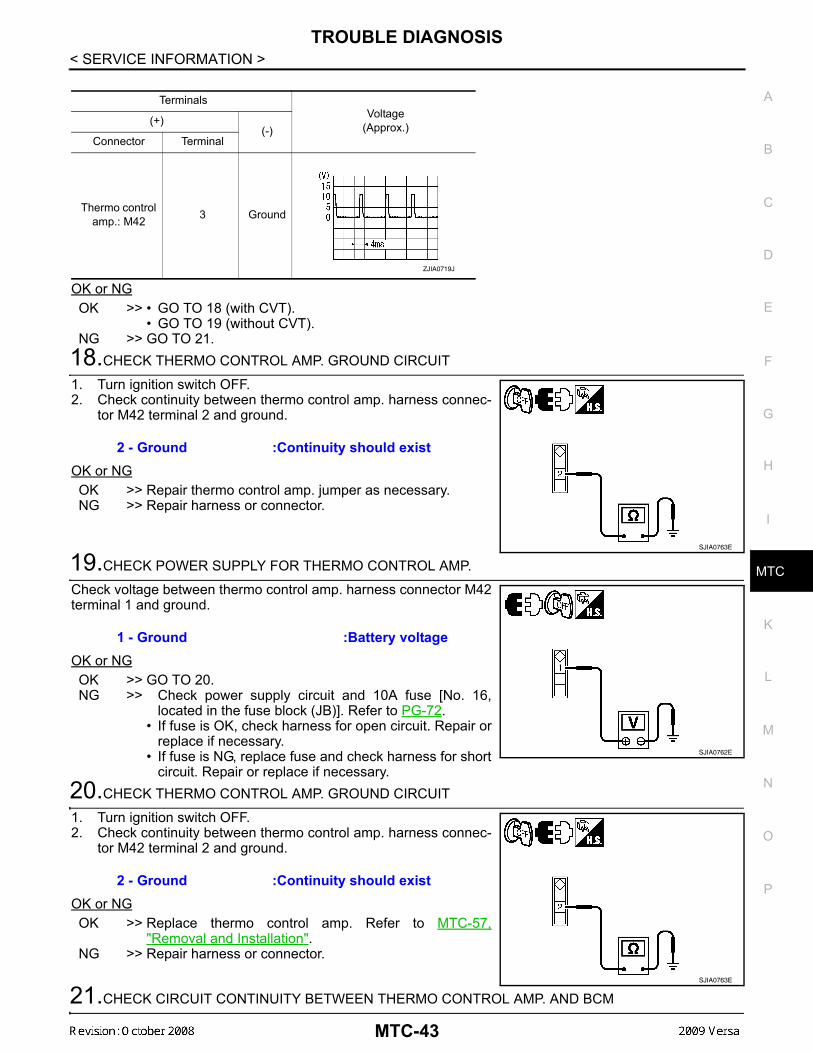
OK or NGOK >> • GO TO 18 (with CVT).
• GO TO 19 (without CVT).NG >> GO TO 21.
18.CHECK THERMO CONTROL AMP. GROUND CIRCUIT
1. Turn ignition switch OFF.2. Check continuity between thermo control amp. harness connec-
tor M42 terminal 2 and ground.
OK or NGOK >> Repair thermo control amp. jumper as necessary.NG >> Repair harness or connector.
19.CHECK POWER SUPPLY FOR THERMO CONTROL AMP.
Check voltage between thermo control amp. harness connector M42terminal 1 and ground.
OK or NGOK >> GO TO 20.NG >> Check power supply circuit and 10A fuse [No. 16,
located in the fuse block (JB)]. Refer to PG-72.• If fuse is OK, check harness for open circuit. Repair or
replace if necessary.• If fuse is NG, replace fuse and check harness for short
circuit. Repair or replace if necessary.20.CHECK THERMO CONTROL AMP. GROUND CIRCUIT
1. Turn ignition switch OFF.2. Check continuity between thermo control amp. harness connec-
tor M42 terminal 2 and ground.
OK or NGOK >> Replace thermo control amp. Refer to MTC-57,
"Removal and Installation".NG >> Repair harness or connector.
21.CHECK CIRCUIT CONTINUITY BETWEEN THERMO CONTROL AMP. AND BCM
TerminalsVoltage
(Approx.)(+)(-)
Connector Terminal
Thermo control amp.: M42 3 Ground
ZJIA0719J
2 - Ground :Continuity should exist
SJIA0763E
1 - Ground :Battery voltage
SJIA0762E
2 - Ground :Continuity should exist
SJIA0763E
MTC-43
TROUBLE DIAGNOSIS
< SERVICE INFORMATION >1. Turn ignition switch OFF.2. Disconnect BCM connector.3. Check continuity between thermo control amp. harness connec-tor M42 (A) terminal 3 and BCM harness connector M18 (B) ter-minal 26.
OK or NGOK >> GO TO 22.NG >> Repair harness or connector.
22.CHECK CAN COMMUNICATION
Check CAN communication. Refer to LAN-17, "Trouble Diagnosis Flow Chart".• BCM – ECM• ECM – IPDM E/ROK or NGOK >> Replace BCM. Refer to BCS-18, "Removal and Installation of BCM".NG >> Repair or replace malfunctioning part(s).
23.CHECK DEFROST A/C SWITCH CIRCUIT
1. Turn ignition switch OFF.2. Disconnect BCM connector.3. Press the defrost A/C switch.
NOTE:The defrost A/C switch is located on back side of the front aircontrol.
4. Check continuity between BCM harness connector M18 terminal10 and ground.
OK or NGOK >> Replace BCM. Refer to BCS-18, "Removal and Installation of BCM".NG >> GO TO 24.
24.CHECK CIRCUIT CONTINUITY BETWEEN DEFROST A/C SWITCH AND BCM
1. Disconnect defrost A/C switch connector.2. Check continuity between BCM harness connector M18 (B) ter-
minal 10 and defrost A/C switch harness connector M41 (A) ter-minal 15.
OK or NGOK >> GO TO 25.NG >> Repair harness or connector.
25.CHECK CIRCUIT CONTINUITY BETWEEN DEFROST A/C SWITCH AND GROUND
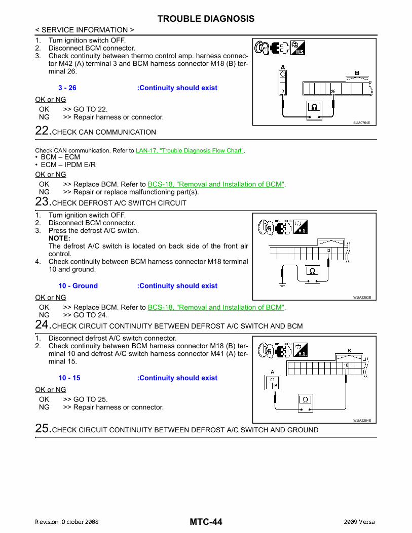
3 - 26 :Continuity should exist
SJIA0764E
10 - Ground :Continuity should existWJIA2252E
10 - 15 :Continuity should exist
WJIA2254E
MTC-44

TROUBLE DIAGNOSIS
C
D
E
F
G
H
I
K
L
M
A
B
TC
N
O
P
< SERVICE INFORMATION >
M
Check continuity between A/C defrost switch harness connectorM41 terminal 16 and ground.
OK or NGOK >> Replace defrost A/C switch. NG >> Repair harness or connector.
Insufficient Cooling INFOID:0000000004307073
SYMPTOM: Insufficient cooling
INSPECTION FLOW1.CONFIRM SYMPTOM BY PERFORMING OPERATIONAL CHECK - TEMPERATURE DECREASE
1. Turn temperature control dial counterclockwise to maximum cold position.2. Check for cold air at discharge air outlets.Can the symptom be duplicated?YES >> GO TO 3.NO >> GO TO 2.
2.CHECK FOR ANY SYMPTOMS
Perform a complete operational check for any symptoms. Refer to MTC-30, "Operational Check".Does another symptom exist?YES >> Refer to MTC-22, "How to Perform Trouble Diagnosis for Quick and Accurate Repair". NO >> System OK.
3.CHECK FOR SERVICE BULLETINS
Check for any service bulletins.
>> GO TO 4.4.CHECK COMPRESSOR DRIVE BELT TENSION
Check compressor belt tension. Refer to EM-14, "Checking" (HR16DE) or EM-136, "Checking Drive Belts"(MR18DE).OK or NGOK >> GO TO 5.NG >> Adjust or replace compressor belt. Refer to EM-15, "Removal and Installation" (HR16DE) or EM-
136, "Removal and Installation" (MR18DE).5.CHECK AIR MIX DOOR CABLE
Check and verify air mix door cable operation. Refer to MTC-64, "Air Mix Door Cable Adjustment". Does air mix door operate correctly?YES >> GO TO 6.NO >> Repair or replace as necessary.
6.CHECK COOLING FAN MOTOR OPERATION
Check and verify cooling fan motor for smooth operation. Refer to EC-887, "Overall Function Check" (MRTYPE 1), EC-1409, "Overall Function Check" (MR TYPE 2) or EC-368, "Component Function Check"(HR16DE).Does cooling fan motor operate correctly?YES >> GO TO 7.NO >> Check cooling fan motor. Refer to EC-890, "Diagnosis Procedure" (MR TYPE 1), EC-1412, "Diag-
nosis Procedure" (MR TYPE 2) or EC-368, "Component Function Check" (HR16DE).
16 - Ground :Continuity should exist
WJIA2255E
MTC-45
TROUBLE DIAGNOSIS
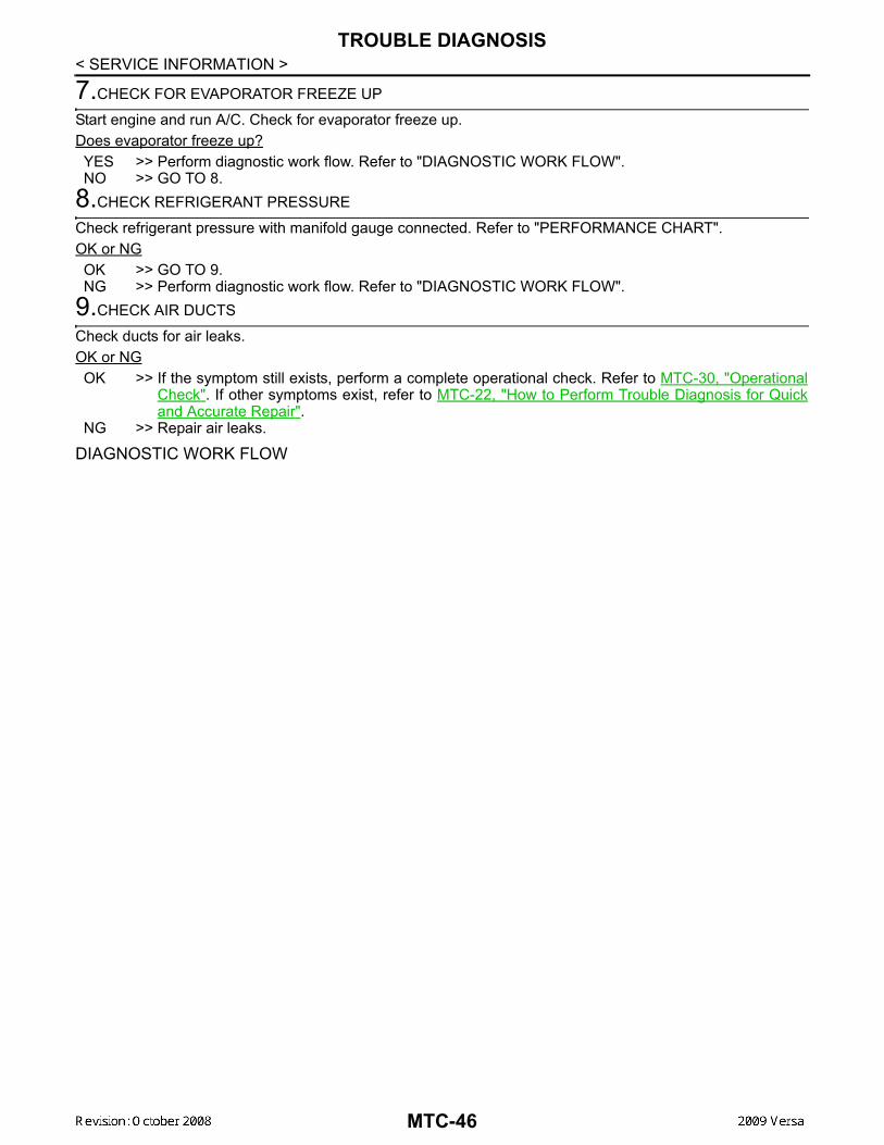
< SERVICE INFORMATION >7.CHECK FOR EVAPORATOR FREEZE UP
Start engine and run A/C. Check for evaporator freeze up.Does evaporator freeze up?YES >> Perform diagnostic work flow. Refer to "DIAGNOSTIC WORK FLOW".NO >> GO TO 8.
8.CHECK REFRIGERANT PRESSURE
Check refrigerant pressure with manifold gauge connected. Refer to "PERFORMANCE CHART". OK or NGOK >> GO TO 9.NG >> Perform diagnostic work flow. Refer to "DIAGNOSTIC WORK FLOW".
9.CHECK AIR DUCTS
Check ducts for air leaks.OK or NGOK >> If the symptom still exists, perform a complete operational check. Refer to MTC-30, "Operational
Check". If other symptoms exist, refer to MTC-22, "How to Perform Trouble Diagnosis for Quickand Accurate Repair".
NG >> Repair air leaks.
DIAGNOSTIC WORK FLOW
MTC-46

TROUBLE DIAGNOSIS
C
D
E
F
G
H
I
K
L
M
A
B
TC
N
O
P
< SERVICE INFORMATION >
M
*1 MTC-87, "Checking System for Leaks Using the Fluorescent Leak Detector"
*2 MTC-78, "Removal and Installation of Compressor - HR16DE" or MTC-80, "Removal and Installation of Com-pressor - MR18DE"
*3 "PERFORMANCE CHART"
*4 "TROUBLE DIAGNOSIS FOR AB-NORMAL PRESSURE"
*5 MTC-32, "Air Mix Door"
AWIIA0999GB
MTC-47

TROUBLE DIAGNOSIS
< SERVICE INFORMATION >PERFORMANCE CHARTTest Condition
*1 MTC-62, "Removal and Installation" *2 MTC-33, "Front Blower Motor Circuit" *3 MTC-78, "Removal and Installation of Compressor - HR16DE" or MTC-80, "Removal and Installation of Com-pressor - MR18DE"
*4 EM-14, "Checking" (HR16DE) EM-136, "Checking Drive Belts" (MR18DE)
*5 MTC-78, "Removal and Installation of Compressor - HR16DE" or MTC-80, "Removal and Installation of Com-pressor - MR18DE"
AWIIA1000GB
MTC-48
TROUBLE DIAGNOSIS
C
D
E
F
G
H
I
K
L
M
A
B
TC
N
O
P
< SERVICE INFORMATION >
M
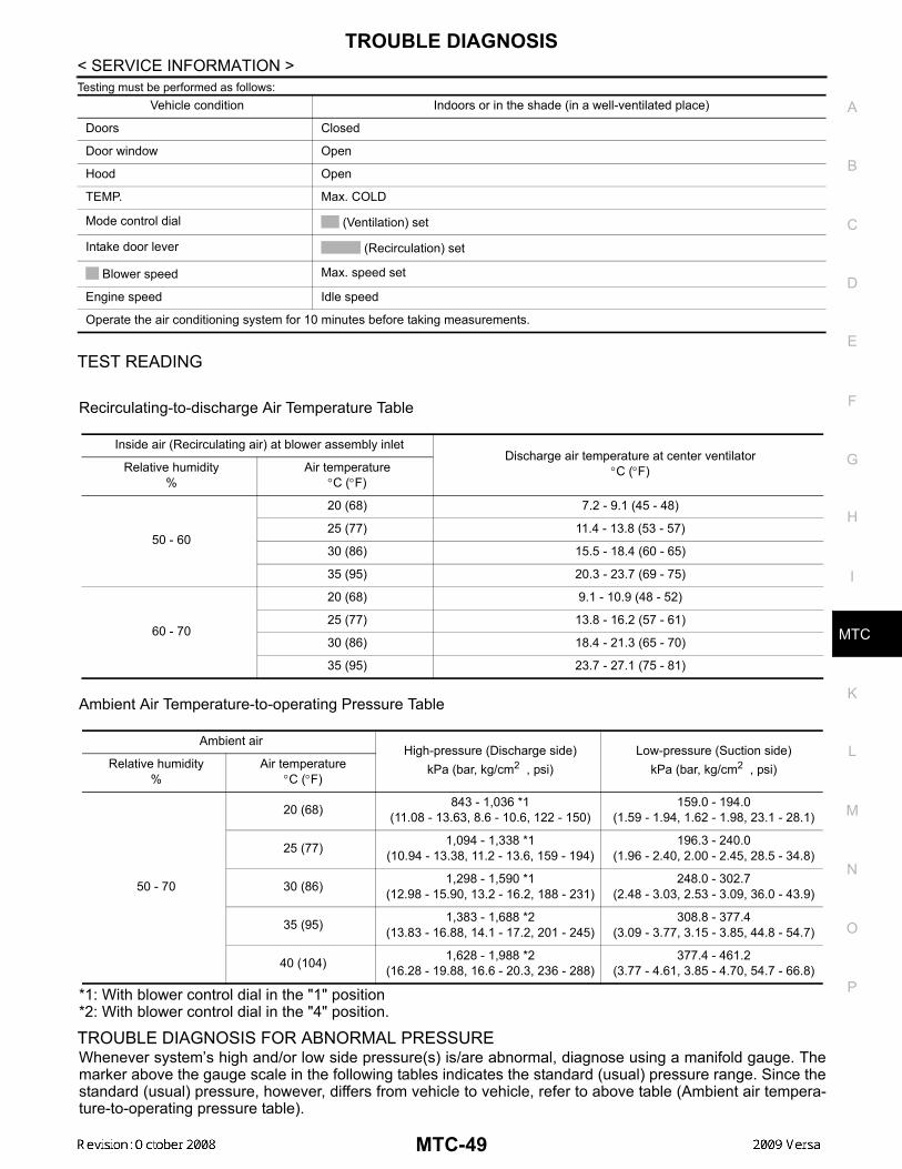
Testing must be performed as follows:
TEST READING
Recirculating-to-discharge Air Temperature Table
Ambient Air Temperature-to-operating Pressure Table
*1: With blower control dial in the "1" position*2: With blower control dial in the "4" position.
TROUBLE DIAGNOSIS FOR ABNORMAL PRESSURE Whenever system’s high and/or low side pressure(s) is/are abnormal, diagnose using a manifold gauge. Themarker above the gauge scale in the following tables indicates the standard (usual) pressure range. Since thestandard (usual) pressure, however, differs from vehicle to vehicle, refer to above table (Ambient air tempera-ture-to-operating pressure table).
Vehicle condition Indoors or in the shade (in a well-ventilated place)
Doors Closed
Door window Open
Hood Open
TEMP. Max. COLD
Mode control dial (Ventilation) set
Intake door lever (Recirculation) set
Blower speed Max. speed set
Engine speed Idle speed
Operate the air conditioning system for 10 minutes before taking measurements.
Inside air (Recirculating air) at blower assembly inletDischarge air temperature at center ventilator
°C (°F)Relative humidity%
Air temperature°C (°F)
50 - 60
20 (68) 7.2 - 9.1 (45 - 48)
25 (77) 11.4 - 13.8 (53 - 57)
30 (86) 15.5 - 18.4 (60 - 65)
35 (95) 20.3 - 23.7 (69 - 75)
60 - 70
20 (68) 9.1 - 10.9 (48 - 52)
25 (77) 13.8 - 16.2 (57 - 61)
30 (86) 18.4 - 21.3 (65 - 70)
35 (95) 23.7 - 27.1 (75 - 81)
Ambient airHigh-pressure (Discharge side)
kPa (bar, kg/cm2 , psi)Low-pressure (Suction side)
kPa (bar, kg/cm2 , psi)Relative humidity%
Air temperature°C (°F)
50 - 70
20 (68) 843 - 1,036 *1(11.08 - 13.63, 8.6 - 10.6, 122 - 150)
159.0 - 194.0(1.59 - 1.94, 1.62 - 1.98, 23.1 - 28.1)
25 (77) 1,094 - 1,338 *1(10.94 - 13.38, 11.2 - 13.6, 159 - 194)
196.3 - 240.0(1.96 - 2.40, 2.00 - 2.45, 28.5 - 34.8)
30 (86) 1,298 - 1,590 *1(12.98 - 15.90, 13.2 - 16.2, 188 - 231)
248.0 - 302.7(2.48 - 3.03, 2.53 - 3.09, 36.0 - 43.9)
35 (95) 1,383 - 1,688 *2(13.83 - 16.88, 14.1 - 17.2, 201 - 245)
308.8 - 377.4(3.09 - 3.77, 3.15 - 3.85, 44.8 - 54.7)
40 (104) 1,628 - 1,988 *2(16.28 - 19.88, 16.6 - 20.3, 236 - 288)
377.4 - 461.2(3.77 - 4.61, 3.85 - 4.70, 54.7 - 66.8)
MTC-49
TROUBLE DIAGNOSIS
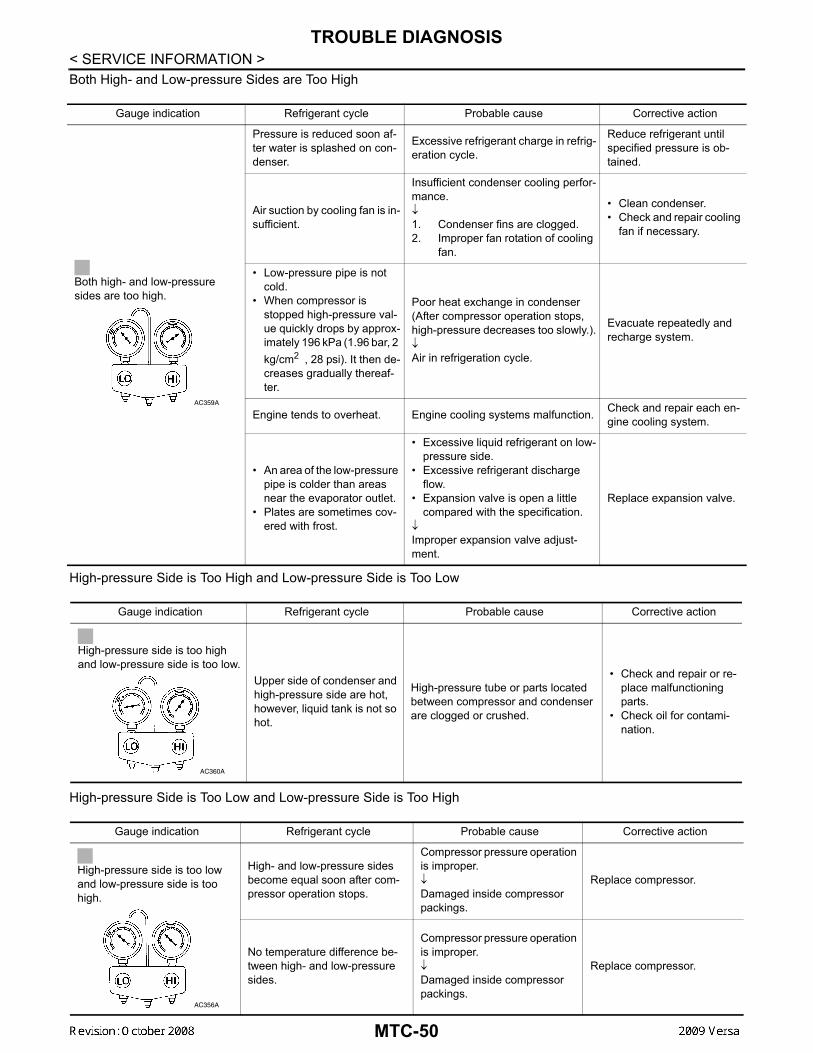
< SERVICE INFORMATION >Both High- and Low-pressure Sides are Too HighHigh-pressure Side is Too High and Low-pressure Side is Too Low
High-pressure Side is Too Low and Low-pressure Side is Too High
Gauge indication Refrigerant cycle Probable cause Corrective action
Both high- and low-pressure sides are too high.
Pressure is reduced soon af-ter water is splashed on con-denser.
Excessive refrigerant charge in refrig-eration cycle.
Reduce refrigerant until specified pressure is ob-tained.
Air suction by cooling fan is in-sufficient.
Insufficient condenser cooling perfor-mance.↓1. Condenser fins are clogged.2. Improper fan rotation of cooling
fan.
• Clean condenser.• Check and repair cooling
fan if necessary.
• Low-pressure pipe is not cold.
• When compressor is stopped high-pressure val-ue quickly drops by approx-imately 196 kPa (1.96 bar, 2 kg/cm2 , 28 psi). It then de-creases gradually thereaf-ter.
Poor heat exchange in condenser(After compressor operation stops, high-pressure decreases too slowly.).↓Air in refrigeration cycle.
Evacuate repeatedly and recharge system.
Engine tends to overheat. Engine cooling systems malfunction. Check and repair each en-gine cooling system.
• An area of the low-pressure pipe is colder than areas near the evaporator outlet.
• Plates are sometimes cov-ered with frost.
• Excessive liquid refrigerant on low-pressure side.
• Excessive refrigerant discharge flow.
• Expansion valve is open a little compared with the specification.
↓Improper expansion valve adjust-ment.
Replace expansion valve.
AC359A
Gauge indication Refrigerant cycle Probable cause Corrective action
High-pressure side is too high and low-pressure side is too low.
Upper side of condenser and high-pressure side are hot, however, liquid tank is not so hot.
High-pressure tube or parts located between compressor and condenser are clogged or crushed.
• Check and repair or re-place malfunctioning parts.
• Check oil for contami-nation.
AC360A
Gauge indication Refrigerant cycle Probable cause Corrective action
High-pressure side is too low and low-pressure side is too high.
High- and low-pressure sides become equal soon after com-pressor operation stops.
Compressor pressure operation is improper.↓Damaged inside compressor packings.
Replace compressor.
No temperature difference be-tween high- and low-pressure sides.
Compressor pressure operation is improper.↓Damaged inside compressor packings.
Replace compressor.
AC356A
MTC-50
TROUBLE DIAGNOSIS
C
D
E
F
G
H
I
K
L
M
A
B
TC
N
O
P
< SERVICE INFORMATION >
M
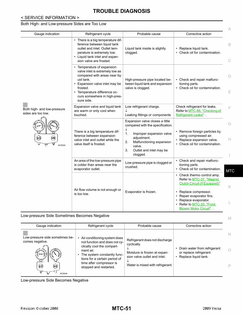
Both High- and Low-pressure Sides are Too Low
Low-pressure Side Sometimes Becomes Negative
Low-pressure Side Becomes Negative
Gauge indication Refrigerant cycle Probable cause Corrective action
Both high- and low-pressure sides are too low.
• There is a big temperature dif-ference between liquid tank outlet and inlet. Outlet tem-perature is extremely low.
• Liquid tank inlet and expan-sion valve are frosted.
Liquid tank inside is slightly clogged.
• Replace liquid tank.• Check oil for contamination.
• Temperature of expansion valve inlet is extremely low as compared with areas near liq-uid tank.
• Expansion valve inlet may be frosted.
• Temperature difference oc-curs somewhere in high-pres-sure side.
High-pressure pipe located be-tween liquid tank and expansion valve is clogged.
• Check and repair malfunc-tioning parts.
• Check oil for contamination.
Expansion valve and liquid tank are warm or only cool when touched.
Low refrigerant charge.↓Leaking fittings or components
Check refrigerant for leaks. Refer to MTC-86, "Checking of Refrigerant Leaks" .
There is a big temperature dif-ference between expansion valve inlet and outlet while the valve itself is frosted.
Expansion valve closes a little compared with the specification.↓1. Improper expansion valve
adjustment.2. Malfunctioning expansion
valve.3. Outlet and inlet may be
clogged.
• Remove foreign particles by using compressed air.
• Replace expansion valve.• Check oil for contamination.
An area of the low-pressure pipe is colder than areas near the evaporator outlet.
Low-pressure pipe is clogged or crushed.
• Check and repair malfunc-tioning parts.
• Check oil for contamination.
Air flow volume is not enough or is too low. Evaporator is frozen.
• Check thermo control amp.Refer to MTC-37, "Magnet Clutch Circuit (If Equipped)" .
• Replace compressor.• Repair evaporator fins.• Replace evaporator.• Refer to MTC-33, "Front
Blower Motor Circuit" .
AC353A
Gauge indication Refrigerant cycle Probable cause Corrective action
Low-pressure side sometimes be-comes negative.
• Air conditioning system does not function and does not cy-clically cool the compart-ment air.
• The system constantly func-tions for a certain period of time after compressor is stopped and restarted.
Refrigerant does not discharge cyclically.↓Moisture is frozen at expan-sion valve outlet and inlet.↓Water is mixed with refrigerant.
• Drain water from refrigerant or replace refrigerant.
• Replace liquid tank.
AC354A
MTC-51
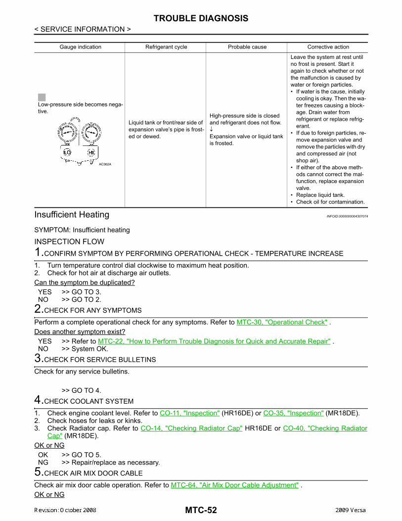
TROUBLE DIAGNOSIS
< SERVICE INFORMATION >Insufficient Heating INFOID:0000000004307074
SYMPTOM: Insufficient heating
INSPECTION FLOW1.CONFIRM SYMPTOM BY PERFORMING OPERATIONAL CHECK - TEMPERATURE INCREASE
1. Turn temperature control dial clockwise to maximum heat position.2. Check for hot air at discharge air outlets.Can the symptom be duplicated?YES >> GO TO 3.NO >> GO TO 2.
2.CHECK FOR ANY SYMPTOMS
Perform a complete operational check for any symptoms. Refer to MTC-30, "Operational Check" .Does another symptom exist?YES >> Refer to MTC-22, "How to Perform Trouble Diagnosis for Quick and Accurate Repair" . NO >> System OK.
3.CHECK FOR SERVICE BULLETINS
Check for any service bulletins.
>> GO TO 4.4.CHECK COOLANT SYSTEM
1. Check engine coolant level. Refer to CO-11, "Inspection" (HR16DE) or CO-35, "Inspection" (MR18DE).2. Check hoses for leaks or kinks. 3. Check Radiator cap. Refer to CO-14, "Checking Radiator Cap" HR16DE or CO-40, "Checking Radiator
Cap" (MR18DE).OK or NGOK >> GO TO 5.NG >> Repair/replace as necessary.
5.CHECK AIR MIX DOOR CABLE
Check air mix door cable operation. Refer to MTC-64, "Air Mix Door Cable Adjustment" . OK or NG
Gauge indication Refrigerant cycle Probable cause Corrective action
Low-pressure side becomes nega-tive.
Liquid tank or front/rear side of expansion valve’s pipe is frost-ed or dewed.
High-pressure side is closed and refrigerant does not flow.↓Expansion valve or liquid tank is frosted.
Leave the system at rest until no frost is present. Start it again to check whether or not the malfunction is caused by water or foreign particles.• If water is the cause, initially
cooling is okay. Then the wa-ter freezes causing a block-age. Drain water from refrigerant or replace refrig-erant.
• If due to foreign particles, re-move expansion valve and remove the particles with dry and compressed air (not shop air).
• If either of the above meth-ods cannot correct the mal-function, replace expansion valve.
• Replace liquid tank.• Check oil for contamination.
AC362A
MTC-52
TROUBLE DIAGNOSIS
C
D
E
F
G
H
I
K
L
M
A
B
TC
N
O
P
< SERVICE INFORMATION >
M
YES >> GO TO 6.NO >> Adjust or replace air mix door cable. Refer to MTC-64, "Air Mix Door Cable Adjustment" .
6.CHECK AIR DUCTS
Check ducts for air leaks.OK or NGOK >> GO TO 7.NG >> Repair air leaks.
7.CHECK HEATER HOSE TEMPERATURES
1. Start engine and warm it up to normal operating temperature.2. Touch both the inlet and outlet heater hoses.Is the inlet hose hot and the outlet hose warm?YES >> GO TO 8.NO >> Both hoses warm: GO TO 9.
8.CHECK ENGINE COOLANT TEMPERATURE SENSOR
Check engine control temperature sensor. Refer to EC-678, "Component Inspection" (MR TYPE 1), EC-1196,"Component Inspection" (MR TYPE 2) or EC-169, "Component Inspection" (HR16DE).OK or NGOK >> System OK.NG >> Repair or replace as necessary. Retest.
9.CHECK HEATER HOSES
Check heater hoses for proper installation.OK or NGOK >> GO TO 10.NG >> Repair /replace as necessary. Retest GO TO 7.
10.BACK FLUSH HEATER CORE
1. Back flush heater core.2. Drain the water from the system. 3. Refill system with new engine coolant. Refer to CO-11, "Changing Engine Coolant" (HR16DE) or CO-35,
"Changing Engine Coolant" (MR18DE) . 4. Start engine and warm it up to normal operating temperature.5. Touch both the inlet and outlet heater hoses.Is the inlet hose hot and the outlet hose warm?YES >> System OK.NO >> Replace heater core and refill engine coolant. Refer to MTC-67, "Removal and Installation" .
Noise INFOID:0000000004307075
SYMPTOM: Noise
INSPECTION FLOW
MTC-53
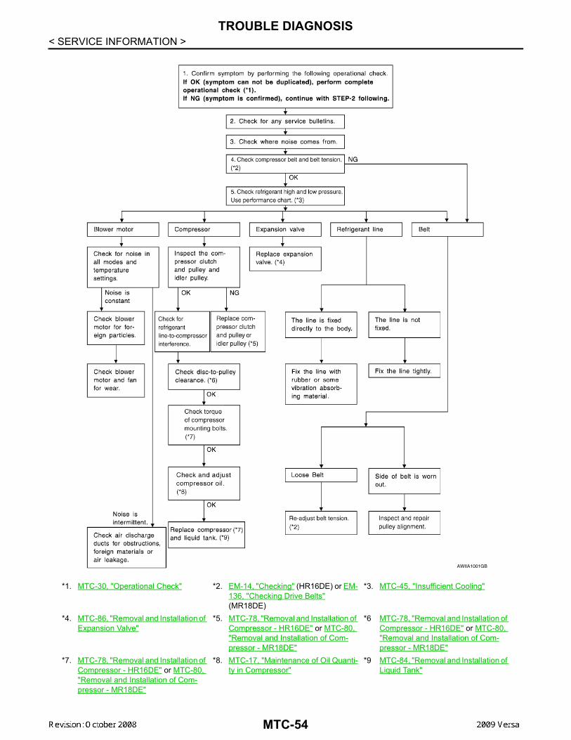
TROUBLE DIAGNOSIS
< SERVICE INFORMATION >*1. MTC-30, "Operational Check" *2. EM-14, "Checking" (HR16DE) or EM-136, "Checking Drive Belts" (MR18DE)
*3. MTC-45, "Insufficient Cooling"
*4. MTC-86, "Removal and Installation of Expansion Valve"
*5. MTC-78, "Removal and Installation of Compressor - HR16DE" or MTC-80, "Removal and Installation of Com-pressor - MR18DE"
*6 MTC-78, "Removal and Installation of Compressor - HR16DE" or MTC-80, "Removal and Installation of Com-pressor - MR18DE"
*7. MTC-78, "Removal and Installation of Compressor - HR16DE" or MTC-80, "Removal and Installation of Com-pressor - MR18DE"
*8. MTC-17, "Maintenance of Oil Quanti-ty in Compressor"
*9 MTC-84, "Removal and Installation of Liquid Tank"
AWIIA1001GB
MTC-54
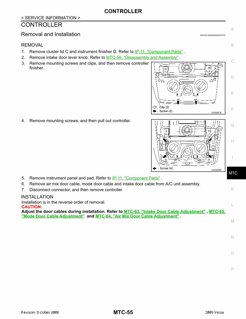
CONTROLLER
C
D
E
F
G
H
I
K
L
M
A
B
TC
N
O
P
< SERVICE INFORMATION >
M
CONTROLLERRemoval and Installation INFOID:0000000004307076
REMOVAL1. Remove cluster lid C and instrument finisher D. Refer to IP-11, "Component Parts" .2. Remove intake door lever knob. Refer to MTC-56, "Disassembly and Assembly" .3. Remove mounting screws and clips, and then remove controller
finisher.
4. Remove mounting screws, and then pull out controller.
5. Remove instrument panel and pad. Refer to IP-11, "Component Parts" .6. Remove air mix door cable, mode door cable and intake door cable from A/C unit assembly.7. Disconnect connector, and then remove controller.
INSTALLATIONInstallation is in the reverse order of removal.CAUTION:Adjust the door cables during installation. Refer to MTC-63, "Intake Door Cable Adjustment" , MTC-65,"Mode Door Cable Adjustment" and MTC-64, "Air Mix Door Cable Adjustment" .
ZJIA0697E
ZJIA0698E
MTC-55

CONTROLLER
< SERVICE INFORMATION >Disassembly and Assembly INFOID:0000000004307077CAUTION:Install inner cable of each door cable to the correspondinglever, as shown in the figure. Press outer cable until it hooks onthe tabs and becomes secure.
1. Air mix door cable 2. Intake door cable 3. Mode door cable4. A/C controller assembly 5. Mode control dial 6. Rear DEF button7. A/C button 8. Temperature control dial 9. Illumination bulb10. Intake door lever knob 11. Fan control dial
ZJIA0106J
MJIA0038E
MTC-56

THERMO CONTROL AMPLIFIER
C
D
E
F
G
H
I
K
L
M
A
B
TC
N
O
P
< SERVICE INFORMATION >
M
THERMO CONTROL AMPLIFIERRemoval and Installation INFOID:0000000004307078
NOTE:Only MR18DE - TYPE 2 systems are equipped with a thermo control amplifier.
REMOVAL1. Remove evaporator. Refer to MTC-85, "Removal and Installation of Evaporator" .
CAUTION:Cap or wrap the joint of the pipe with suitable material such as vinyl tape to avoid the entry of air.
2. Mark the mounting position of the thermo control amp. and thenremove thermo control amp. (1) from evaporator (2).
INSTALLATIONInstallation is in the reverse order of removal.CAUTION:• Replace O-rings for A/C piping with new ones, and apply compressor oil when installing.• Install the thermo control amp. at the mark made during removal of the thermo control amp.• When recharging refrigerant, check for leaks.
ZJIA0798J
MTC-57

A/C UNIT ASSEMBLY
< SERVICE INFORMATION >A/C UNIT ASSEMBLYRemoval and Installation INFOID:0000000004307079REMOVAL1. Use a recovery/recycling equipment (for HFC-134a) to discharge refrigerant.2. Drain coolant from cooling system. Refer to CO-35, "Changing Engine Coolant".3. Remove cowl top cover. Refer to EI-22, "Removal and Installation".4. Remove upper clip and position the lower dash insulator aside.5. Remove bolt (A), and then disconnect low-pressure flexible
hose (1) and high-pressure pipe (2) from evaporator.CAUTION:Cap or wrap the joint of the pipe with suitable material suchas vinyl tape to avoid the entry of air.
6. Remove clamps (A), and then disconnect heater hoses (1) fromheater core.
7. Remove console box assembly. Refer to IP-11, "Component Parts".
A. A/C unit assembly bolts B. Steering member bolts C. Steering column nuts
SJIA0648E
SJIA0644E
SJIA0645E
MTC-58
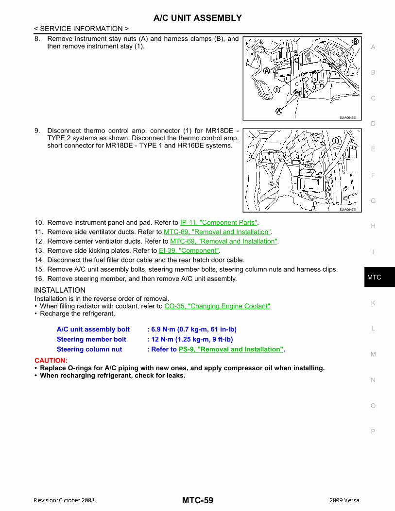
A/C UNIT ASSEMBLY
C
D
E
F
G
H
I
K
L
M
A
B
TC
N
O
P
< SERVICE INFORMATION >
M
8. Remove instrument stay nuts (A) and harness clamps (B), andthen remove instrument stay (1).
9. Disconnect thermo control amp. connector (1) for MR18DE -TYPE 2 systems as shown. Disconnect the thermo control amp.short connector for MR18DE - TYPE 1 and HR16DE systems.
10. Remove instrument panel and pad. Refer to IP-11, "Component Parts".11. Remove side ventilator ducts. Refer to MTC-69, "Removal and Installation".12. Remove center ventilator ducts. Refer to MTC-69, "Removal and Installation".13. Remove side kicking plates. Refer to EI-39, "Component".14. Disconnect the fuel filler door cable and the rear hatch door cable.15. Remove A/C unit assembly bolts, steering member bolts, steering column nuts and harness clips.16. Remove steering member, and then remove A/C unit assembly.
INSTALLATIONInstallation is in the reverse order of removal.• When filling radiator with coolant, refer to CO-35, "Changing Engine Coolant".• Recharge the refrigerant.
CAUTION:• Replace O-rings for A/C piping with new ones, and apply compressor oil when installing.• When recharging refrigerant, check for leaks.
SJIA0646E
SJIA0647E
A/C unit assembly bolt : 6.9 N·m (0.7 kg-m, 61 in-lb)Steering member bolt : 12 N·m (1.25 kg-m, 9 ft-lb)Steering column nut : Refer to PS-9, "Removal and Installation".
MTC-59
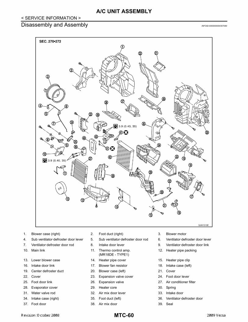
A/C UNIT ASSEMBLY
< SERVICE INFORMATION >Disassembly and Assembly INFOID:00000000043070801. Blower case (right) 2. Foot duct (right) 3. Blower motor4. Sub ventilator·defroster door lever 5. Sub ventilator·defroster door rod 6. Ventilator·defroster door lever7. Ventilator·defroster door rod 8. Intake door lever 9. Ventilator·defroster door link10. Main link 11. Thermo control amp.
(MR18DE - TYPE1)12. Heater pipe packing
13. Lower blower case 14. Heater pipe cover 15. Heater pipe clip16. Intake door link 17. Blower fan resistor 18. Intake case (left)19. Center defroster duct 20. Blower case (left) 21. Cover22. Cover 23. Expansion valve cover 24. Foot door lever25. Foot door link 26. Expansion valve 27. Air conditioner filter28. Evaporator cover 29. Heater core 30. Spring31. Water valve rod 32. Air mix door lever 33. Intake door34. Intake case (right) 35. Foot duct (left) 36. Ventilator·defroster door37. Foot door 38. Air mix door 39. Seal
SJIA1515E
MTC-60
A/C UNIT ASSEMBLY
C
D
E
F
G
H
I
K
L
M
A
B
TC
N
O
P
< SERVICE INFORMATION >
M
40. Expansion valve grommet 41. O-ring 42. Evaporator43. Cooler pipe assembly
MTC-61

BLOWER MOTOR
< SERVICE INFORMATION >BLOWER MOTORRemoval and Installation INFOID:0000000004307081REMOVAL1. Remove instrument panel and pad. Refer to IP-11, "Component Parts".2. Remove side ventilator duct (right). Refer to MTC-69, "Removal and Installation".3. Disconnect blower motor connector (1).4. Push the flange holding hook (A) toward the blower motor (2),
then rotate the blower motor (2) clockwise and remove it fromthe A/C unit assembly.CAUTION:When blower fan and blower motor are assembled, the bal-ance is adjusted, do not disassemble to replace the individ-ual parts.
INSTALLATIONInstallation is in the reverse order of removal.CAUTION:Rotate the blower motor until the blower motor flange holding hook locks securely into the A/C unitassembly.
LJIA0199E
MTC-62
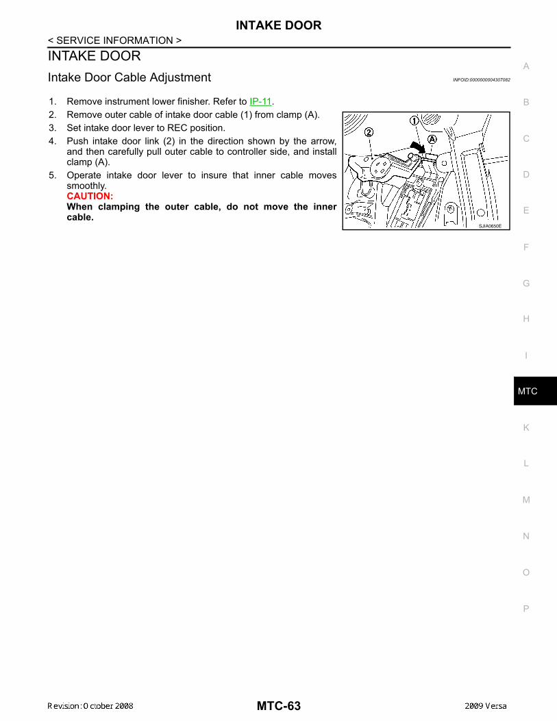
INTAKE DOOR
C
D
E
F
G
H
I
K
L
M
A
B
TC
N
O
P
< SERVICE INFORMATION >
M
INTAKE DOORIntake Door Cable Adjustment INFOID:0000000004307082
1. Remove instrument lower finisher. Refer to IP-11.2. Remove outer cable of intake door cable (1) from clamp (A).3. Set intake door lever to REC position.4. Push intake door link (2) in the direction shown by the arrow,
and then carefully pull outer cable to controller side, and installclamp (A).
5. Operate intake door lever to insure that inner cable movessmoothly.CAUTION:When clamping the outer cable, do not move the innercable.
SJIA0650E
MTC-63
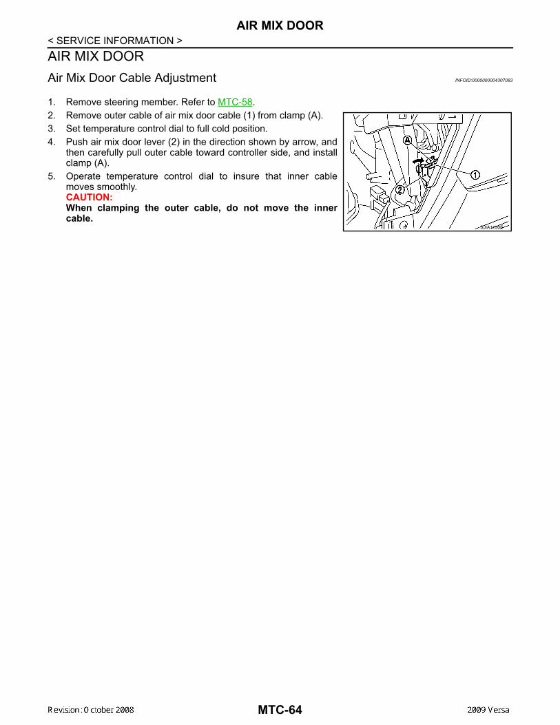
AIR MIX DOOR
< SERVICE INFORMATION >AIR MIX DOORAir Mix Door Cable Adjustment INFOID:00000000043070831. Remove steering member. Refer to MTC-58.2. Remove outer cable of air mix door cable (1) from clamp (A).3. Set temperature control dial to full cold position.4. Push air mix door lever (2) in the direction shown by arrow, and
then carefully pull outer cable toward controller side, and installclamp (A).
5. Operate temperature control dial to insure that inner cablemoves smoothly.CAUTION:When clamping the outer cable, do not move the innercable.
SJIA1150E
MTC-64
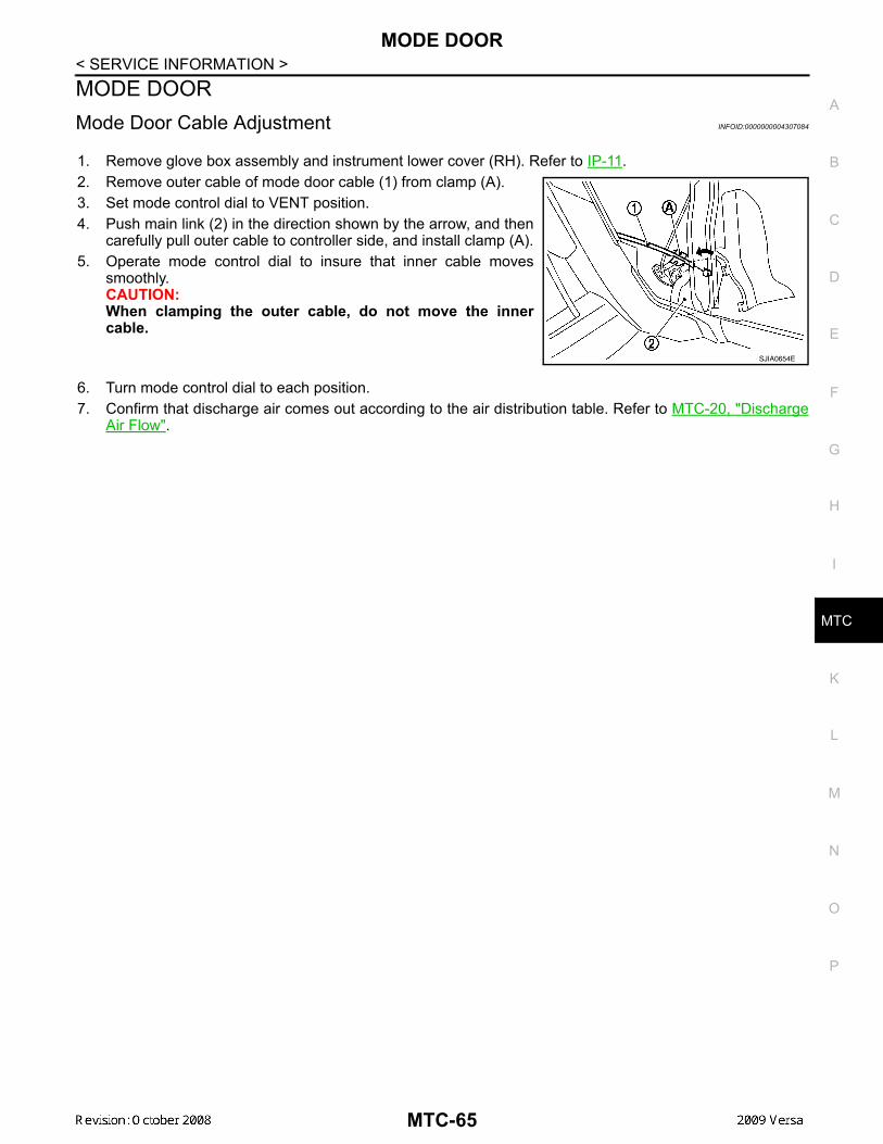
MODE DOOR
C
D
E
F
G
H
I
K
L
M
A
B
TC
N
O
P
< SERVICE INFORMATION >
M
MODE DOORMode Door Cable Adjustment INFOID:0000000004307084
1. Remove glove box assembly and instrument lower cover (RH). Refer to IP-11.2. Remove outer cable of mode door cable (1) from clamp (A).3. Set mode control dial to VENT position.4. Push main link (2) in the direction shown by the arrow, and then
carefully pull outer cable to controller side, and install clamp (A).5. Operate mode control dial to insure that inner cable moves
smoothly.CAUTION:When clamping the outer cable, do not move the innercable.
6. Turn mode control dial to each position.7. Confirm that discharge air comes out according to the air distribution table. Refer to MTC-20, "Discharge
Air Flow".
SJIA0654E
MTC-65
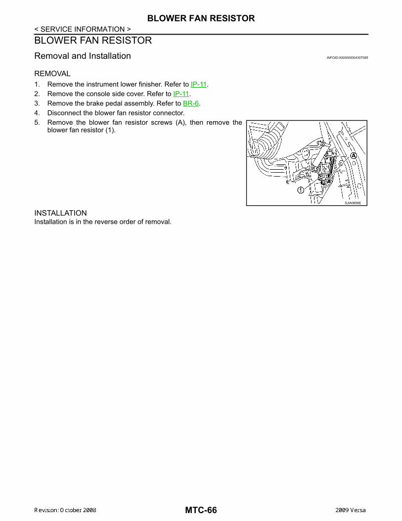
BLOWER FAN RESISTOR
< SERVICE INFORMATION >BLOWER FAN RESISTORRemoval and Installation INFOID:0000000004307085REMOVAL1. Remove the instrument lower finisher. Refer to IP-11.2. Remove the console side cover. Refer to IP-11.3. Remove the brake pedal assembly. Refer to BR-6.4. Disconnect the blower fan resistor connector.5. Remove the blower fan resistor screws (A), then remove the
blower fan resistor (1).
INSTALLATIONInstallation is in the reverse order of removal.
SJIA0656E
MTC-66
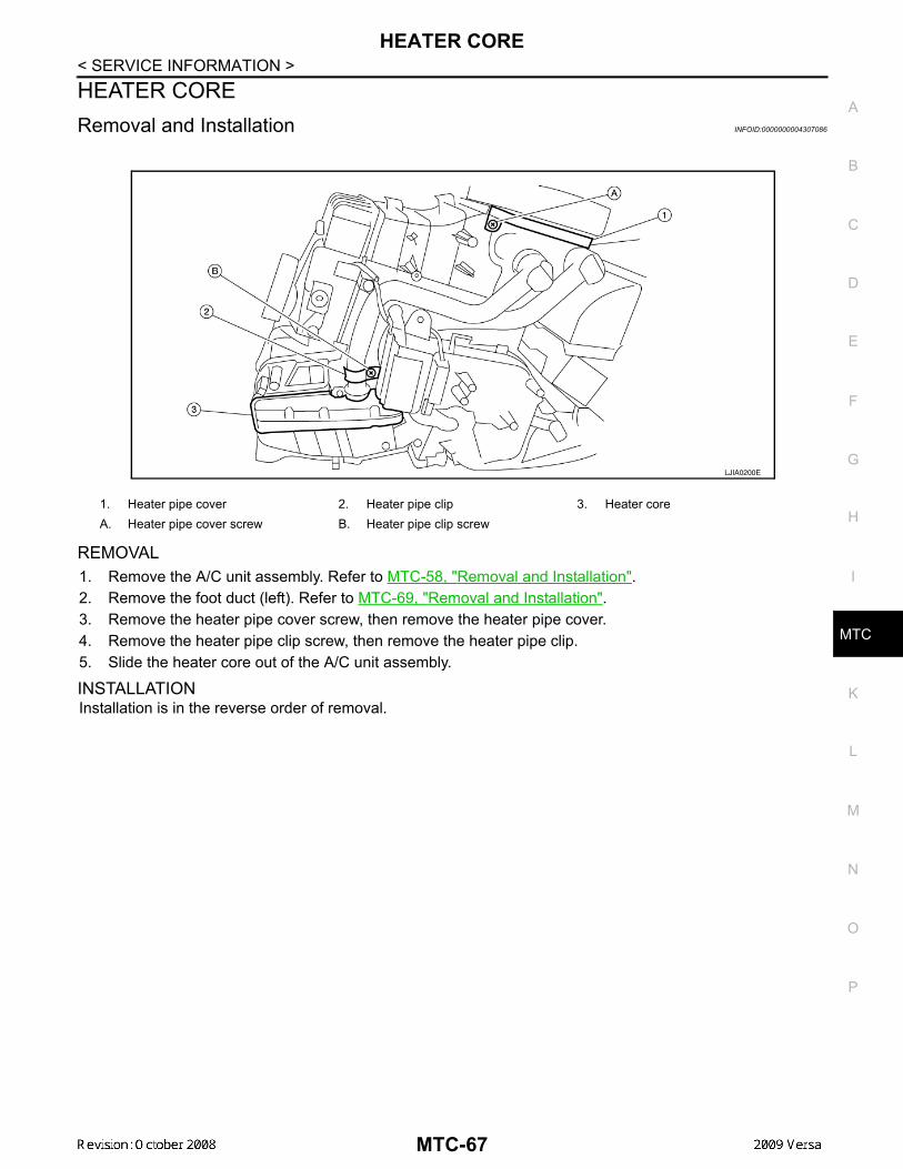
HEATER CORE
C
D
E
F
G
H
I
K
L
M
A
B
TC
N
O
P
< SERVICE INFORMATION >
M
HEATER CORERemoval and Installation INFOID:0000000004307086
REMOVAL1. Remove the A/C unit assembly. Refer to MTC-58, "Removal and Installation".2. Remove the foot duct (left). Refer to MTC-69, "Removal and Installation".3. Remove the heater pipe cover screw, then remove the heater pipe cover.4. Remove the heater pipe clip screw, then remove the heater pipe clip. 5. Slide the heater core out of the A/C unit assembly.
INSTALLATIONInstallation is in the reverse order of removal.
1. Heater pipe cover 2. Heater pipe clip 3. Heater core A. Heater pipe cover screw B. Heater pipe clip screw
LJIA0200E
MTC-67
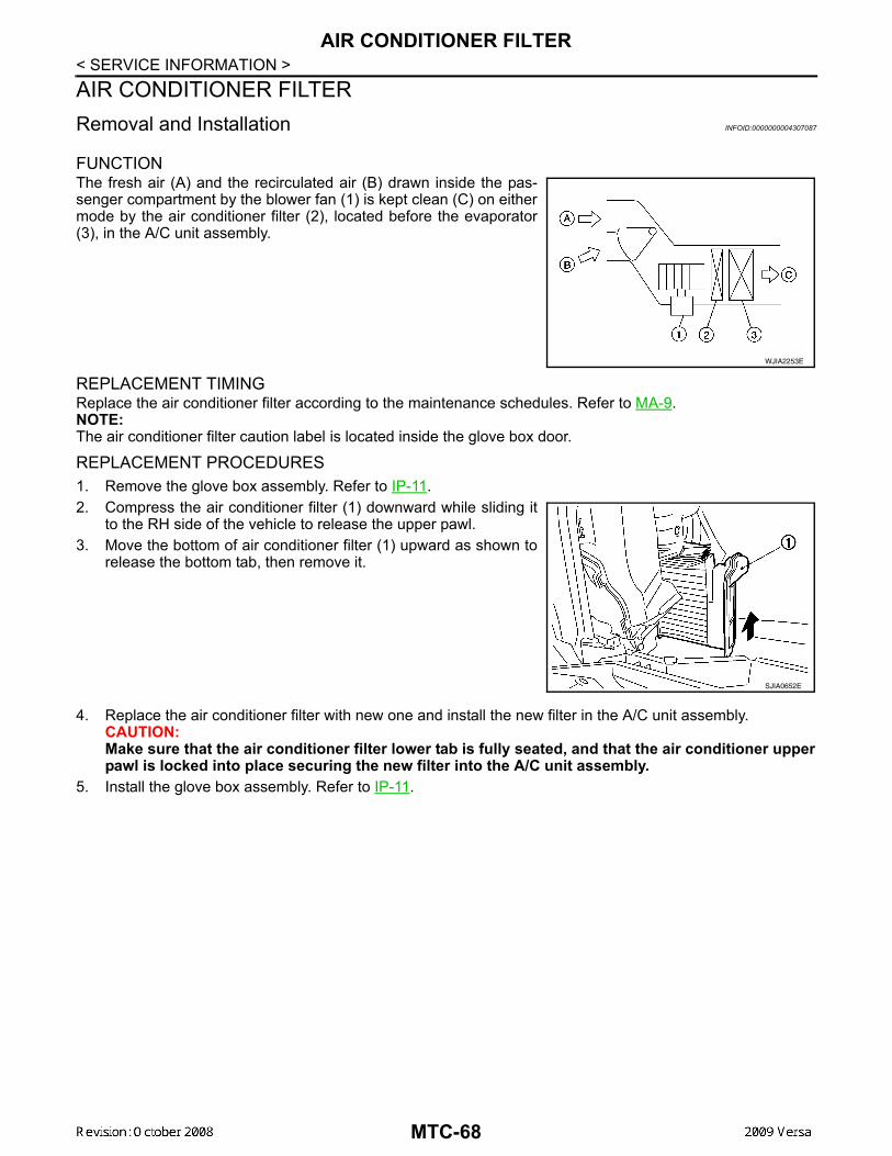
AIR CONDITIONER FILTER
< SERVICE INFORMATION >AIR CONDITIONER FILTERRemoval and Installation INFOID:0000000004307087FUNCTIONThe fresh air (A) and the recirculated air (B) drawn inside the pas-senger compartment by the blower fan (1) is kept clean (C) on eithermode by the air conditioner filter (2), located before the evaporator(3), in the A/C unit assembly.
REPLACEMENT TIMINGReplace the air conditioner filter according to the maintenance schedules. Refer to MA-9.NOTE:The air conditioner filter caution label is located inside the glove box door.
REPLACEMENT PROCEDURES1. Remove the glove box assembly. Refer to IP-11.2. Compress the air conditioner filter (1) downward while sliding it
to the RH side of the vehicle to release the upper pawl.3. Move the bottom of air conditioner filter (1) upward as shown to
release the bottom tab, then remove it.
4. Replace the air conditioner filter with new one and install the new filter in the A/C unit assembly. CAUTION:Make sure that the air conditioner filter lower tab is fully seated, and that the air conditioner upperpawl is locked into place securing the new filter into the A/C unit assembly.
5. Install the glove box assembly. Refer to IP-11.
WJIA2253E
SJIA0652E
MTC-68
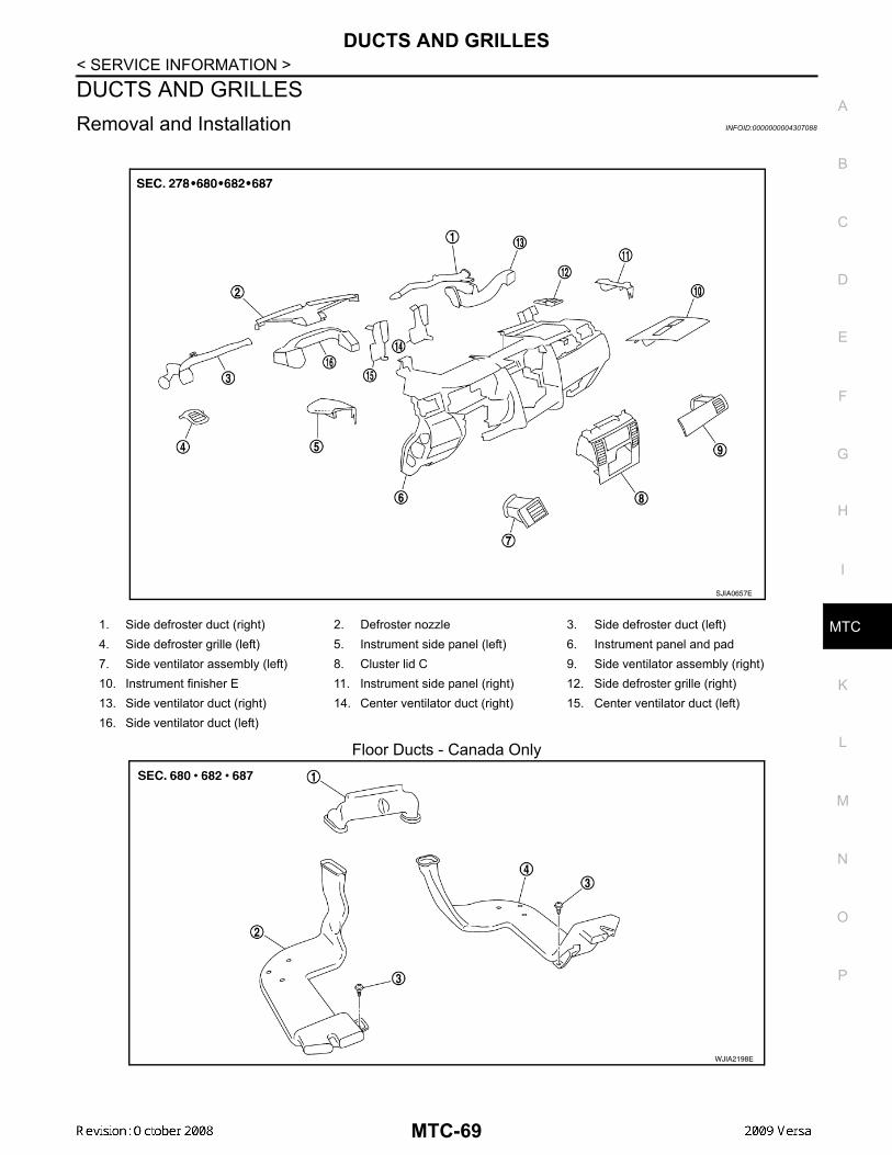
DUCTS AND GRILLES
C
D
E
F
G
H
I
K
L
M
A
B
TC
N
O
P
< SERVICE INFORMATION >
M
DUCTS AND GRILLESRemoval and Installation INFOID:0000000004307088
Floor Ducts - Canada Only
1. Side defroster duct (right) 2. Defroster nozzle 3. Side defroster duct (left)4. Side defroster grille (left) 5. Instrument side panel (left) 6. Instrument panel and pad7. Side ventilator assembly (left) 8. Cluster lid C 9. Side ventilator assembly (right)10. Instrument finisher E 11. Instrument side panel (right) 12. Side defroster grille (right)13. Side ventilator duct (right) 14. Center ventilator duct (right) 15. Center ventilator duct (left)16. Side ventilator duct (left)
SJIA0657E
WJIA2198E
MTC-69
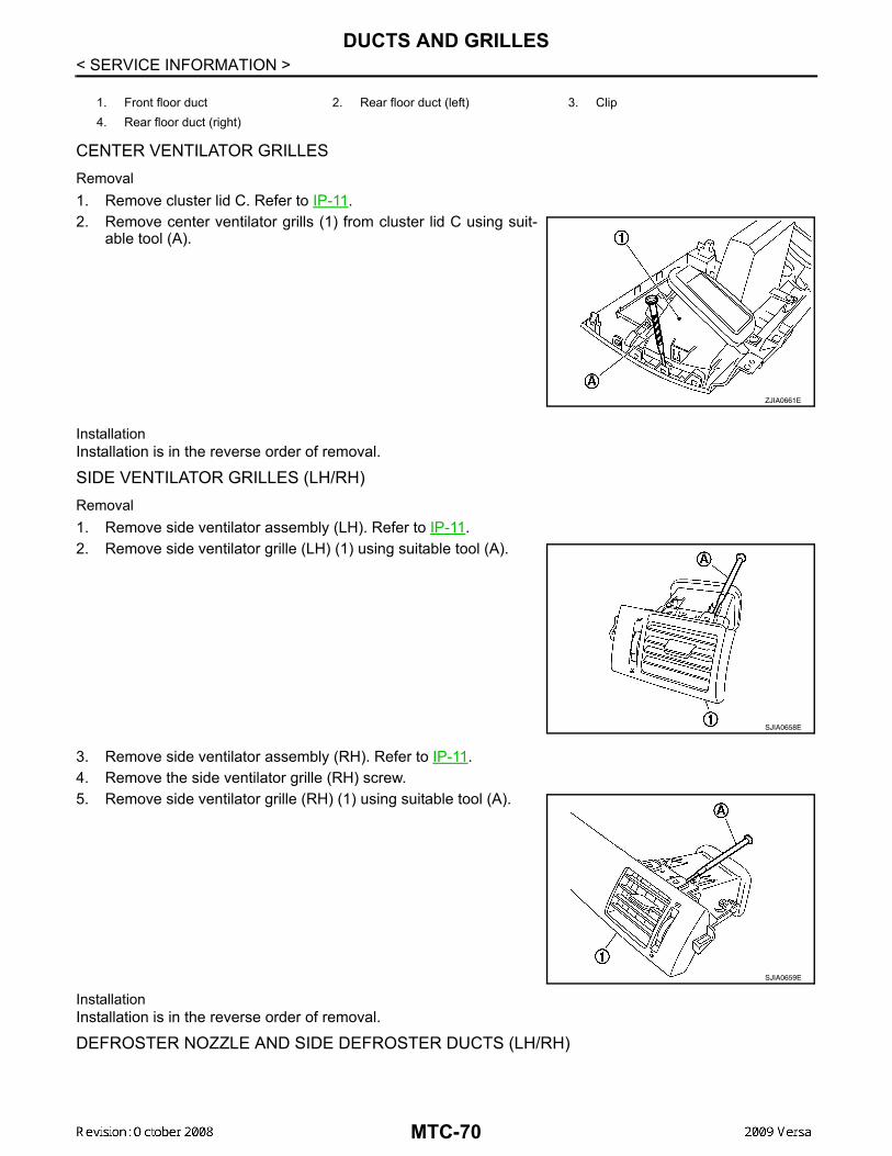
DUCTS AND GRILLES
< SERVICE INFORMATION >CENTER VENTILATOR GRILLESRemoval1. Remove cluster lid C. Refer to IP-11.2. Remove center ventilator grills (1) from cluster lid C using suit-
able tool (A).
InstallationInstallation is in the reverse order of removal.
SIDE VENTILATOR GRILLES (LH/RH)Removal1. Remove side ventilator assembly (LH). Refer to IP-11.2. Remove side ventilator grille (LH) (1) using suitable tool (A).
3. Remove side ventilator assembly (RH). Refer to IP-11.4. Remove the side ventilator grille (RH) screw.5. Remove side ventilator grille (RH) (1) using suitable tool (A).
InstallationInstallation is in the reverse order of removal.
DEFROSTER NOZZLE AND SIDE DEFROSTER DUCTS (LH/RH)
1. Front floor duct 2. Rear floor duct (left) 3. Clip4. Rear floor duct (right)
ZJIA0661E
SJIA0658E
SJIA0659E
MTC-70

DUCTS AND GRILLES
C
D
E
F
G
H
I
K
L
M
A
B
TC
N
O
P
< SERVICE INFORMATION >
M
Removal1. Remove instrument upper finisher. Refer to IP-11.2. Remove screws and then remove side defroster duct (RH) and side defroster duct (LH).3. Remove screws, and then remove defroster nozzle.InstallationInstallation is in the reverse order of removal.
SIDE VENTILATOR DUCTSRemoval1. Remove instrument panel and pad. Refer to IP-11.2. Remove screws (A), and then remove side ventilator duct (left)
(1).
3. Remove screw (A) and clip (B), and then remove side ventilatorduct (right) (1).
InstallationInstallation is in the reverse order of removal.
1. Side defroster duct (RH) 2. Side defroster duct (LH) 3. Defroster nozzleA. Side defroster duct screw B. Defroster nozzle screw
WJIA2199E
SJIA0661E
SJIA0662E
MTC-71
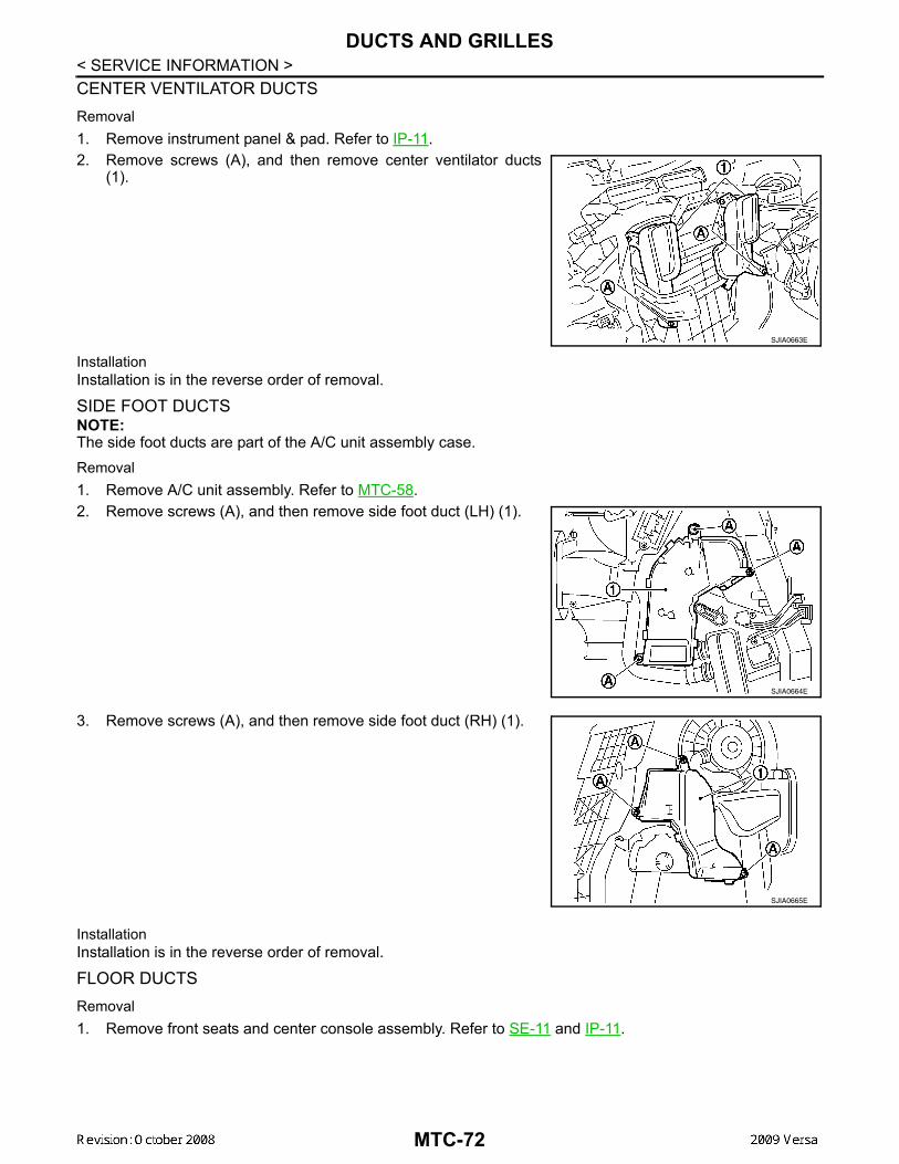
DUCTS AND GRILLES
< SERVICE INFORMATION >CENTER VENTILATOR DUCTSRemoval1. Remove instrument panel & pad. Refer to IP-11.2. Remove screws (A), and then remove center ventilator ducts(1).
InstallationInstallation is in the reverse order of removal.
SIDE FOOT DUCTSNOTE:The side foot ducts are part of the A/C unit assembly case.Removal1. Remove A/C unit assembly. Refer to MTC-58.2. Remove screws (A), and then remove side foot duct (LH) (1).
3. Remove screws (A), and then remove side foot duct (RH) (1).
InstallationInstallation is in the reverse order of removal.
FLOOR DUCTSRemoval1. Remove front seats and center console assembly. Refer to SE-11 and IP-11.
SJIA0663E
SJIA0664E
SJIA0665E
MTC-72

DUCTS AND GRILLES
C
D
E
F
G
H
I
K
L
M
A
B
TC
N
O
P
< SERVICE INFORMATION >
M
2. Disengage pawls (A), and then remove front floor duct (1).
3. Peel back floor trim to a point where floor duct is visible.4. Remove clips (A), and then remove rear floor duct (left) (1) and
rear floor duct (right) (2).
InstallationInstallation is in the reverse order of removal.
SJIA0667E
SJIA0668E
MTC-73

REFRIGERANT LINES
< SERVICE INFORMATION >REFRIGERANT LINESHFC-134a (R-134a) Service Procedure INFOID:0000000004307089SETTING OF SERVICE TOOLS AND EQUIPMENTDischarging Refrigerant
WARNING:Avoid breathing A/C refrigerant and oil vapor or mist. Exposure may irritate eyes, nose and throat.Remove HFC-134a (R-134a) refrigerant from the A/C system using certified service equipment meetingrequirements of SAE J2210 HFC-134a (R-134a) recycling equipment or SAE J2201 HFC-134a (R-134a)recovery equipment. If an accidental system discharge occurs, ventilate the work area before resum-ing service. Additional health and safety information may be obtained from the refrigerant and oil man-ufacturers.Evacuating System and Charging Refrigerant
1. Shut-off valve 2. A/C service valve 3. Recovery/recycling equipmentA. Preferred (best) method
WJIA2195E
1. Shut-off valve 2. A/C service valve 3. Recovery/recycling equipment4. Refrigerant container (HFC-134a) 5. Weight scale (J-39650) 6. Evacuating vacuum pump (J-39699)
WJIA2196E
MTC-74
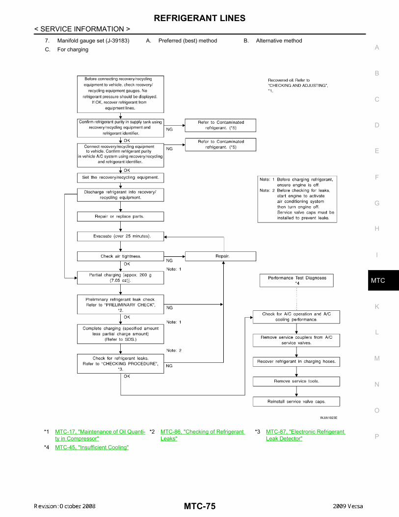
REFRIGERANT LINES
C
D
E
F
G
H
I
K
L
M
A
B
TC
N
O
P
< SERVICE INFORMATION >
M
7. Manifold gauge set (J-39183) A. Preferred (best) method B. Alternative methodC. For charging
*1 MTC-17, "Maintenance of Oil Quanti-ty in Compressor"
*2 MTC-86, "Checking of Refrigerant Leaks"
*3 MTC-87, "Electronic Refrigerant Leak Detector"
*4 MTC-45, "Insufficient Cooling"
WJIA1923E
MTC-75
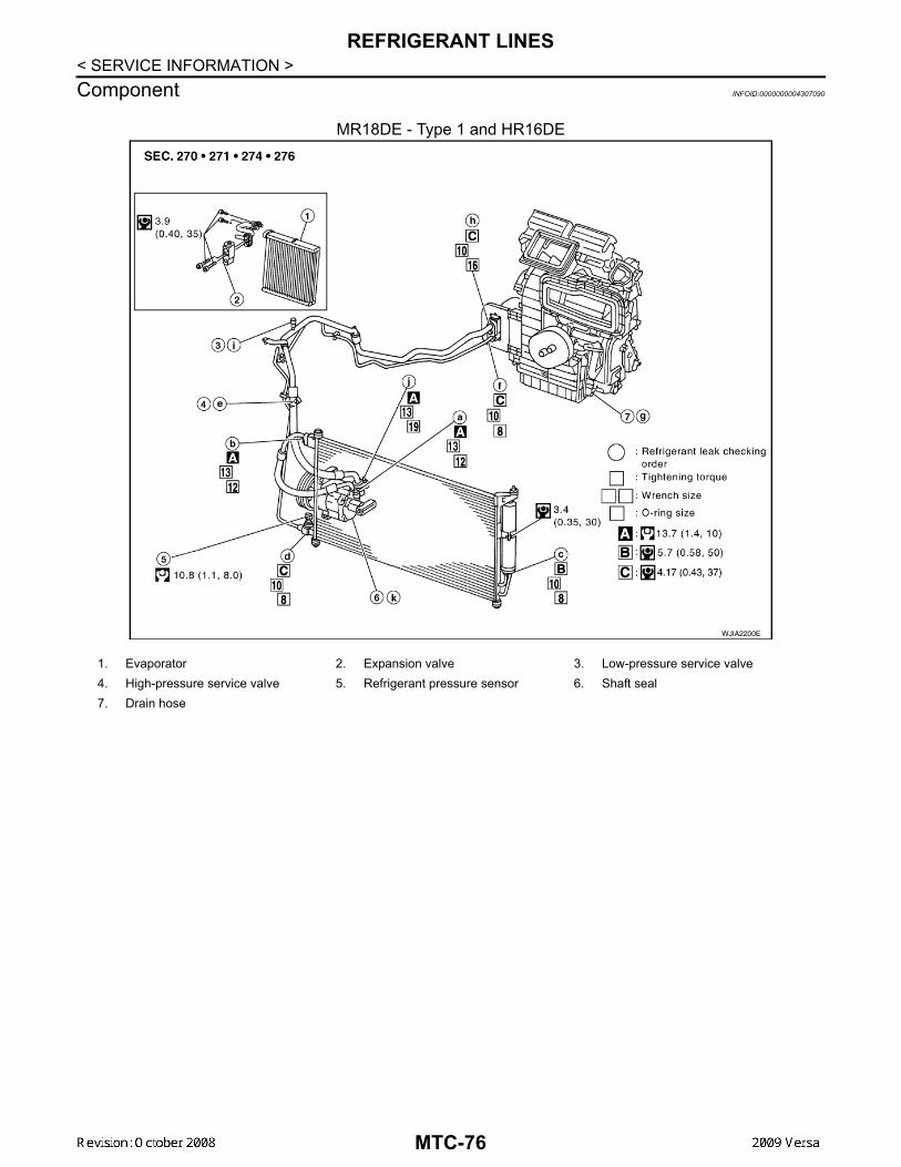
REFRIGERANT LINES
< SERVICE INFORMATION >Component INFOID:0000000004307090MR18DE - Type 1 and HR16DE
WJIA2200E
1. Evaporator 2. Expansion valve 3. Low-pressure service valve4. High-pressure service valve 5. Refrigerant pressure sensor 6. Shaft seal7. Drain hose
MTC-76

REFRIGERANT LINES
C
D
E
F
G
H
I
K
L
M
A
B
TC
N
O
P
< SERVICE INFORMATION >
M
MR18DE - Type 2
WJIA2202E
1. Evaporator 2. Expansion valve 3. Low-pressure service valve4. High-pressure service valve 5. Refrigerant pressure sensor 6. Shaft seal7. Drain hose
MTC-77

REFRIGERANT LINES
< SERVICE INFORMATION >Idler Pulley - Without A/C
Refer to MTC-5, "Precaution for Refrigerant Connection".
Removal and Installation of Compressor - HR16DE INFOID:0000000004800722
HR16DE
REMOVAL
WJIA2204E
1. Idler pulley 2. Bracket 3. Shaft
ALIIA0093GB
MTC-78
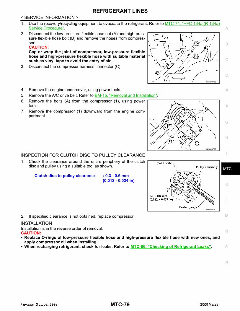
REFRIGERANT LINES
C
D
E
F
G
H
I
K
L
M
A
B
TC
N
O
P
< SERVICE INFORMATION >
M
1. Use the recovery/recycling equipment to evacuate the refrigerant. Refer to MTC-74, "HFC-134a (R-134a)Service Procedure".
2. Disconnect the low-pressure flexible hose nut (A) and high-pres-sure flexible hose bolt (B) and remove the hoses from compres-sor.CAUTION:Cap or wrap the joint of compressor, low-pressure flexiblehose and high-pressure flexible hose with suitable materialsuch as vinyl tape to avoid the entry of air.
3. Disconnect the compressor harness connector (C)
4. Remove the engine undercover, using power tools.5. Remove the A/C drive belt. Refer to EM-15, "Removal and Installation".6. Remove the bolts (A) from the compressor (1), using power
tools.7. Remove the compressor (1) downward from the engine com-
partment.
INSPECTION FOR CLUTCH DISC TO PULLEY CLEARANCE1. Check the clearance around the entire periphery of the clutch
disc and pulley using a suitable tool as shown.
2. If specified clearance is not obtained, replace compressor.
INSTALLATIONInstallation is in the reverse order of removal.CAUTION:• Replace O-rings of low-pressure flexible hose and high-pressure flexible hose with new ones, and
apply compressor oil when installing.• When recharging refrigerant, check for leaks. Refer to MTC-86, "Checking of Refrigerant Leaks".
SJIA0671E
SJIA0672E
Clutch disc to pulley clearance : 0.3 - 0.6 mm (0.012 - 0.024 in)
RHA087E
MTC-79
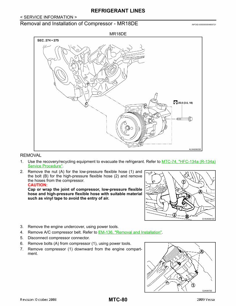
REFRIGERANT LINES
< SERVICE INFORMATION >Removal and Installation of Compressor - MR18DE INFOID:0000000004800721MR18DE
REMOVAL1. Use the recovery/recycling equipment to evacuate the refrigerant. Refer to MTC-74, "HFC-134a (R-134a)
Service Procedure".2. Remove the nut (A) for the low-pressure flexible hose (1) and
the bolt (B) for the high-pressure flexible hose (2) and removethe hoses from the compressor.CAUTION:Cap or wrap the joint of compressor, low-pressure flexiblehose and high-pressure flexible hose with suitable materialsuch as vinyl tape to avoid the entry of air.
3. Remove the engine undercover, using power tools. 4. Remove A/C compressor belt. Refer to EM-136, "Removal and Installation".5. Disconnect compressor connector.6. Remove bolts (A) from compressor (1), using power tools.7. Remove compressor (1) downward from the engine compart-
ment.
ALIIA0092GB
E1KIA0067ZZ
SJIA0672E
MTC-80
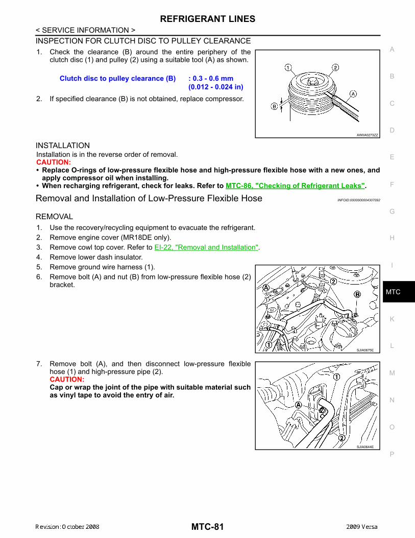
REFRIGERANT LINES
C
D
E
F
G
H
I
K
L
M
A
B
TC
N
O
P
< SERVICE INFORMATION >
M
INSPECTION FOR CLUTCH DISC TO PULLEY CLEARANCE1. Check the clearance (B) around the entire periphery of the
clutch disc (1) and pulley (2) using a suitable tool (A) as shown.
2. If specified clearance (B) is not obtained, replace compressor.
INSTALLATIONInstallation is in the reverse order of removal.CAUTION:• Replace O-rings of low-pressure flexible hose and high-pressure flexible hose with a new ones, and
apply compressor oil when installing.• When recharging refrigerant, check for leaks. Refer to MTC-86, "Checking of Refrigerant Leaks".
Removal and Installation of Low-Pressure Flexible Hose INFOID:0000000004307092
REMOVAL1. Use the recovery/recycling equipment to evacuate the refrigerant.2. Remove engine cover (MR18DE only).3. Remove cowl top cover. Refer to EI-22, "Removal and Installation".4. Remove lower dash insulator.5. Remove ground wire harness (1).6. Remove bolt (A) and nut (B) from low-pressure flexible hose (2)
bracket.
7. Remove bolt (A), and then disconnect low-pressure flexiblehose (1) and high-pressure pipe (2).CAUTION:Cap or wrap the joint of the pipe with suitable material suchas vinyl tape to avoid the entry of air.
Clutch disc to pulley clearance (B) : 0.3 - 0.6 mm (0.012 - 0.024 in)
AWIIA0273ZZ
SJIA0675E
SJIA0644E
MTC-81

REFRIGERANT LINES
< SERVICE INFORMATION >8. Remove nut (A), and then remove low-pressure flexible hose (1)from compressor (2).CAUTION:Cap or wrap the joint of the pipe with suitable material suchas vinyl tape to avoid the entry of air.
INSTALLATIONInstallation is in the reverse order of removal.CAUTION:• Replace O-rings for A/C piping with new ones, and apply compressor oil when installing.• When recharging refrigerant, check for leaks.
Removal and Installation of High-Pressure Flexible Hose INFOID:0000000004307093
REMOVAL1. Use the recovery/recycling equipment to evacuate the refrigerant.2. Remove high-pressure flexible hose (1) bolt (A) from condenser
(2).
3. Remove bolt (A), and then remove high-pressure flexible hose(1) from compressor (2).CAUTION:Cap or wrap the joint of the pipe with suitable material suchas vinyl tape to avoid the entry of air.
INSTALLATIONInstallation is in the reverse order of removal.CAUTION:• Replace O-rings of high-pressure flexible hose with a new ones, and apply compressor oil when
installing.• When recharging refrigerant, check for leaks.
SJIA0676E
SJIA0677E
SJIA0678E
MTC-82

REFRIGERANT LINES
C
D
E
F
G
H
I
K
L
M
A
B
TC
N
O
P
< SERVICE INFORMATION >
M
Removal and Installation of High-Pressure Pipe INFOID:0000000004307094
REMOVAL1. Remove low-pressure flexible hose. Refer to MTC-81, "Removal and Installation of Low-Pressure Flexible
Hose".2. Remove high-pressure pipe from the clips.3. Remove high-pressure pipe bolt (A), and then remove high-
pressure pipe (1) from condenser (2).CAUTION:Cap or wrap the joint of the pipe with suitable material suchas vinyl tape to avoid the entry of air.
INSTALLATIONInstallation is in the reverse order of removal.CAUTION:• Replace O-rings of high-pressure pipe with a new ones, and apply compressor oil when installing.• When recharging refrigerant, check for leaks.
Removal and Installation of Refrigerant Pressure Sensor INFOID:0000000004307095
REMOVAL1. Use the recovery/recycling equipment to evacuate the refrigerant.2. Disconnect connector, and then remove refrigerant pressure
sensor (1) from condenser (2).CAUTION:When working, be careful not to damage the condenserfins.
INSTALLATIONInstallation is in the reverse order of removal.CAUTION:• Replace O-rings of refrigerant pressure sensor with a new one, and apply compressor oil when
installing.
1. High-pressure pipe A. High-pressure pipe clips
SJIA0679E
SJIA0680E
SJIA0681E
MTC-83
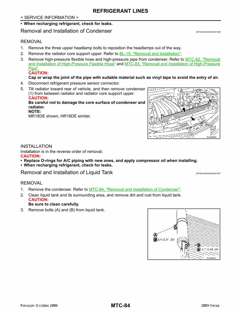
REFRIGERANT LINES
< SERVICE INFORMATION >• When recharging refrigerant, check for leaks.Removal and Installation of Condenser INFOID:0000000004307096
REMOVAL1. Remove the three upper headlamp bolts to reposition the headlamps out of the way.2. Remove the radiator core support upper. Refer to BL-19, "Removal and Installation".3. Remove high-pressure flexible hose and high-pressure pipe from condenser. Refer to MTC-82, "Removal
and Installation of High-Pressure Flexible Hose" and MTC-83, "Removal and Installation of High-PressurePipe".CAUTION:Cap or wrap the joint of the pipe with suitable material such as vinyl tape to avoid the entry of air.
4. Disconnect refrigerant pressure sensor connector.5. Tilt radiator toward rear of vehicle, and then remove condenser
(1) from between radiator and radiator core support upper.CAUTION:Be careful not to damage the core surface of condenser andradiator.NOTE:MR18DE shown, HR16DE similar.
INSTALLATIONInstallation is in the reverse order of removal.CAUTION:• Replace O-rings for A/C piping with new ones, and apply compressor oil when installing.• When recharging refrigerant, check for leaks.
Removal and Installation of Liquid Tank INFOID:0000000004307097
REMOVAL1. Remove the condenser. Refer to MTC-84, "Removal and Installation of Condenser".2. Clean liquid tank and its surrounding area, and remove dirt and rust from liquid tank.
CAUTION:Be sure to clean carefully.
3. Remove bolts (A) and (B) from liquid tank.
SJIA0682E
ZJIA0842J
MTC-84
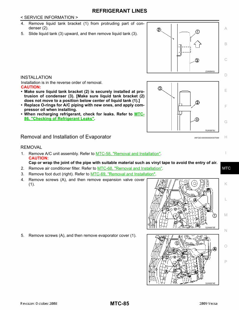
REFRIGERANT LINES
C
D
E
F
G
H
I
K
L
M
A
B
TC
N
O
P
< SERVICE INFORMATION >
M
4. Remove liquid tank bracket (1) from protruding part of con-denser (2).
5. Slide liquid tank (3) upward, and then remove liquid tank (3).
INSTALLATIONInstallation is in the reverse order of removal.CAUTION:• Make sure liquid tank bracket (2) is securely installed at pro-
trusion of condenser (3). [Make sure liquid tank bracket (2)does not move to a position below center of liquid tank (1).]
• Replace O-rings for A/C piping with new ones, and apply com-pressor oil when installing.
• When recharging refrigerant, check for leaks. Refer to MTC-86, "Checking of Refrigerant Leaks".
Removal and Installation of Evaporator INFOID:0000000004307098
REMOVAL1. Remove A/C unit assembly. Refer to MTC-58, "Removal and Installation".
CAUTION:Cap or wrap the joint of the pipe with suitable material such as vinyl tape to avoid the entry of air.
2. Remove air conditioner filter. Refer to MTC-68, "Removal and Installation".3. Remove foot duct (right). Refer to MTC-69, "Removal and Installation".4. Remove screws (A), and then remove expansion valve cover
(1).
5. Remove screws (A), and then remove evaporator cover (1).
ZJIA0843J
RJIA3879J
SJIA0673E
SJIA0674E
MTC-85
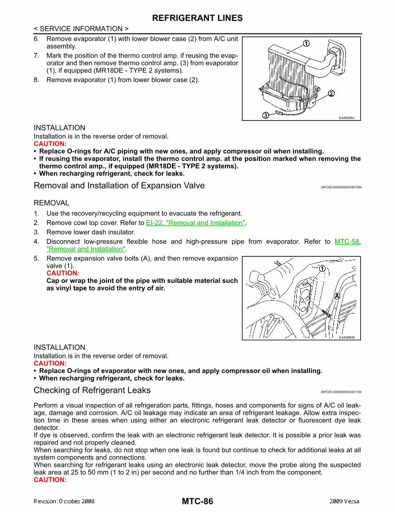
REFRIGERANT LINES
< SERVICE INFORMATION >6. Remove evaporator (1) with lower blower case (2) from A/C unitassembly.7. Mark the position of the thermo control amp. if reusing the evap-
orator and then remove thermo control amp. (3) from evaporator(1), if equipped (MR18DE - TYPE 2 systems).
8. Remove evaporator (1) from lower blower case (2).
INSTALLATIONInstallation is in the reverse order of removal.CAUTION:• Replace O-rings for A/C piping with new ones, and apply compressor oil when installing.• If reusing the evaporator, install the thermo control amp. at the position marked when removing the
thermo control amp., if equipped (MR18DE - TYPE 2 systems).• When recharging refrigerant, check for leaks.
Removal and Installation of Expansion Valve INFOID:0000000004307099
REMOVAL1. Use the recovery/recycling equipment to evacuate the refrigerant.2. Remove cowl top cover. Refer to EI-22, "Removal and Installation".3. Remove lower dash insulator.4. Disconnect low-pressure flexible hose and high-pressure pipe from evaporator. Refer to MTC-58,
"Removal and Installation".5. Remove expansion valve bolts (A), and then remove expansion
valve (1).CAUTION:Cap or wrap the joint of the pipe with suitable material suchas vinyl tape to avoid the entry of air.
INSTALLATIONInstallation is in the reverse order of removal.CAUTION:• Replace O-rings of evaporator with new ones, and apply compressor oil when installing.• When recharging refrigerant, check for leaks.
Checking of Refrigerant Leaks INFOID:0000000004307100
Perform a visual inspection of all refrigeration parts, fittings, hoses and components for signs of A/C oil leak-age, damage and corrosion. A/C oil leakage may indicate an area of refrigerant leakage. Allow extra inspec-tion time in these areas when using either an electronic refrigerant leak detector or fluorescent dye leakdetector.If dye is observed, confirm the leak with an electronic refrigerant leak detector. It is possible a prior leak wasrepaired and not properly cleaned.When searching for leaks, do not stop when one leak is found but continue to check for additional leaks at allsystem components and connections.When searching for refrigerant leaks using an electronic leak detector, move the probe along the suspectedleak area at 25 to 50 mm (1 to 2 in) per second and no further than 1/4 inch from the component.CAUTION:
SJIA0599J
SJIA0683E
MTC-86

REFRIGERANT LINES
C
D
E
F
G
H
I
K
L
M
A
B
TC
N
O
P
< SERVICE INFORMATION >
M
Moving the electronic leak detector probe slower and closer to the suspected leak area will improvethe chances of finding a leak.
Checking System for Leaks Using the Fluorescent Leak Detector INFOID:0000000004307101
1. Check A/C system for leaks using the UV lamp and safety goggles J-42220 in a low sunlight area (areawithout windows preferable). Illuminate all components, fittings and lines. The dye will appear as a brightgreen/yellow area at the point of leakage. Fluorescent dye observed at the evaporator drain opening indi-cates an evaporator core assembly (tubes, core or expansion valve) leak.
2. If the suspected area is difficult to see, use an adjustable mirror or wipe the area with a clean shop rag orcloth, with the UV lamp for dye residue.
3. After the leak is repaired, remove any residual dye using dye cleaner J-43872 to prevent future misdiag-nosis.
4. Perform a system performance check and verify the leak repair with an approved electronic refrigerantleak detector.
NOTE:Other gases in the work area or substances on the A/C components, for example, anti-freeze, windshieldwasher fluid, solvents and oils, may falsely trigger the leak detector. Make sure the surfaces to be checked areclean.Clean with a dry cloth or blow off with shop air.Do not allow the sensor tip of the detector to contact with any substance. This can also cause false readingsand may damage the detector.
Dye Injection INFOID:0000000004307102
(This procedure is only necessary when recharging the system or when the compressor has seized and wasreplaced.)1. Check A/C system static (at rest) pressure. Pressure must be at least 345 kPa (3.45 bar, 3.52 kg/cm2, 50
psi).2. Pour one bottle (1/4 ounce / 7.4 cc) of the A/C refrigerant dye into the injector tool J-41459.3. Connect the injector tool to the A/C low-pressure side service fitting.4. Start engine and switch A/C ON.5. When the A/C operating (compressor running), inject one bottle (1/4 ounce / 7.4 cc) of fluorescent dye
through the low-pressure service valve using dye injector tool J-41459 (refer to the manufacture’s operat-ing instructions).
6. With the engine still running, disconnect the injector tool from the service fitting.CAUTION:Be careful the A/C system or replacing a component, pour the dye directly into the open systemconnection and proceed with the service procedures.
7. Operate the A/C system for a minimum of 20 minutes to mix the dye with the system oil. Depending on theleak size, operating conditions and location of the leak, it may take from minutes to days for the dye topenetrate a leak and become visible.
Electronic Refrigerant Leak Detector INFOID:0000000004307103
PRECAUTIONS FOR HANDLING LEAK DETECTORWhen performing a refrigerant leak check, use an A/C electrical leakdetector (SST) or equivalent. Ensure that the instrument is calibratedand set properly per the operating instructions.The leak detector is a delicate device. In order to use the leak detec-tor properly, read the operating instructions and perform any speci-fied maintenance.
AHA281A
MTC-87
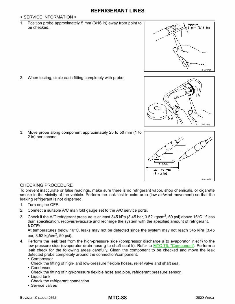
REFRIGERANT LINES
< SERVICE INFORMATION >1. Position probe approximately 5 mm (3/16 in) away from point tobe checked.
2. When testing, circle each fitting completely with probe.
3. Move probe along component approximately 25 to 50 mm (1 to2 in) per second.
CHECKING PROCEDURETo prevent inaccurate or false readings, make sure there is no refrigerant vapor, shop chemicals, or cigarettesmoke in the vicinity of the vehicle. Perform the leak test in calm area (low air/wind movement) so that theleaking refrigerant is not dispersed.1. Turn engine OFF.2. Connect a suitable A/C manifold gauge set to the A/C service ports.3. Check if the A/C refrigerant pressure is at least 345 kPa (3.45 bar, 3.52 kg/cm2, 50 psi) above 16°C. If less
than specification, recover/evacuate and recharge the system with the specified amount of refrigerant.NOTE:At temperatures below 16°C, leaks may not be detected since the system may not reach 345 kPa (3.45bar, 3.52 kg/cm2, 50 psi).
4. Perform the leak test from the high-pressure side (compressor discharge a to evaporator inlet f) to thelow-pressure side (evaporator drain hose g to shaft seal k). Refer to MTC-76, "Component". Perform aleak check for the following areas carefully. Clean the component to be checked and move the leakdetected probe completely around the connection/component.• Compressor
Check the fitting of high- and low-pressure flexible hoses, relief valve and shaft seal.• Condenser
Check the fitting of high-pressure flexible hose and pipe, refrigerant pressure sensor.• Liquid tank
Check the refrigerant connection.• Service valves
SHA707EA
SHA706E
SHA708EA
MTC-88
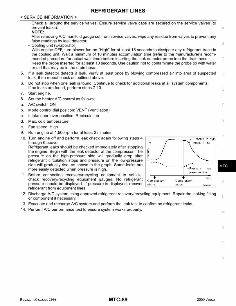
REFRIGERANT LINES
C
D
E
F
G
H
I
K
L
M
A
B
TC
N
O
P
< SERVICE INFORMATION >
M
Check all around the service valves. Ensure service valve caps are secured on the service valves (toprevent leaks).NOTE:After removing A/C manifold gauge set from service valves, wipe any residue from valves to prevent anyfalse readings by leak detector.
• Cooling unit (Evaporator)With engine OFF, turn blower fan on “High” for at least 15 seconds to dissipate any refrigerant trace inthe cooling unit. Wait a minimum of 10 minutes accumulation time (refer to the manufacturer’s recom-mended procedure for actual wait time) before inserting the leak detector probe into the drain hose.Keep the probe inserted for at least 10 seconds. Use caution not to contaminate the probe tip with wateror dirt that may be in the drain hose.
5. If a leak detector detects a leak, verify at least once by blowing compressed air into area of suspectedleak, then repeat check as outlined above.
6. Do not stop when one leak is found. Continue to check for additional leaks at all system components.If no leaks are found, perform steps 7-10.
7. Start engine.8. Set the heater A/C control as follows;a. A/C switch: ONb. Mode control dial position: VENT (Ventilation)c. Intake door lever position: Recirculationd. Max. cold temperaturee. Fan speed: High9. Run engine at 1,500 rpm for at least 2 minutes.10. Turn engine off and perform leak check again following steps 4
through 6 above.Refrigerant leaks should be checked immediately after stoppingthe engine. Begin with the leak detector at the compressor. Thepressure on the high-pressure side will gradually drop afterrefrigerant circulation stops and pressure on the low-pressureside will gradually rise, as shown in the graph. Some leaks aremore easily detected when pressure is high.
11. Before connecting recovery/recycling equipment to vehicle,check recovery/recycling equipment gauges. No refrigerantpressure should be displayed. If pressure is displayed, recoverrefrigerant from equipment lines.
12. Discharge A/C system using approved refrigerant recovery/recycling equipment. Repair the leaking fittingor component if necessary.
13. Evacuate and recharge A/C system and perform the leak test to confirm no refrigerant leaks.14. Perform A/C performance test to ensure system works properly.
SHA839E
MTC-89
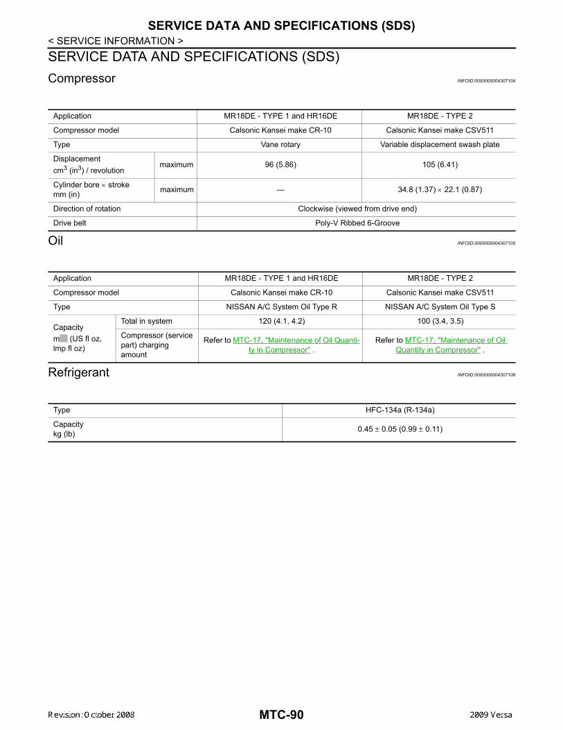
SERVICE DATA AND SPECIFICATIONS (SDS)
< SERVICE INFORMATION >SERVICE DATA AND SPECIFICATIONS (SDS)Compressor INFOID:0000000004307104Oil INFOID:0000000004307105
Refrigerant INFOID:0000000004307106
Application MR18DE - TYPE 1 and HR16DE MR18DE - TYPE 2
Compressor model Calsonic Kansei make CR-10 Calsonic Kansei make CSV511
Type Vane rotary Variable displacement swash plate
Displacementcm3 (in3) / revolution
maximum 96 (5.86) 105 (6.41)
Cylinder bore × strokemm (in) maximum — 34.8 (1.37) × 22.1 (0.87)
Direction of rotation Clockwise (viewed from drive end)
Drive belt Poly-V Ribbed 6-Groove
Application MR18DE - TYPE 1 and HR16DE MR18DE - TYPE 2
Compressor model Calsonic Kansei make CR-10 Calsonic Kansei make CSV511
Type NISSAN A/C System Oil Type R NISSAN A/C System Oil Type S
Capacitym (US fl oz, lmp fl oz)
Total in system 120 (4.1, 4.2) 100 (3.4, 3.5)
Compressor (service part) charging amount
Refer to MTC-17, "Maintenance of Oil Quanti-ty in Compressor" .
Refer to MTC-17, "Maintenance of Oil Quantity in Compressor" .
Type HFC-134a (R-134a)
Capacitykg (lb) 0.45 ± 0.05 (0.99 ± 0.11)
MTC-90